Embed Size (px)
Citation preview
March 2017www.taegutec.com
1/9
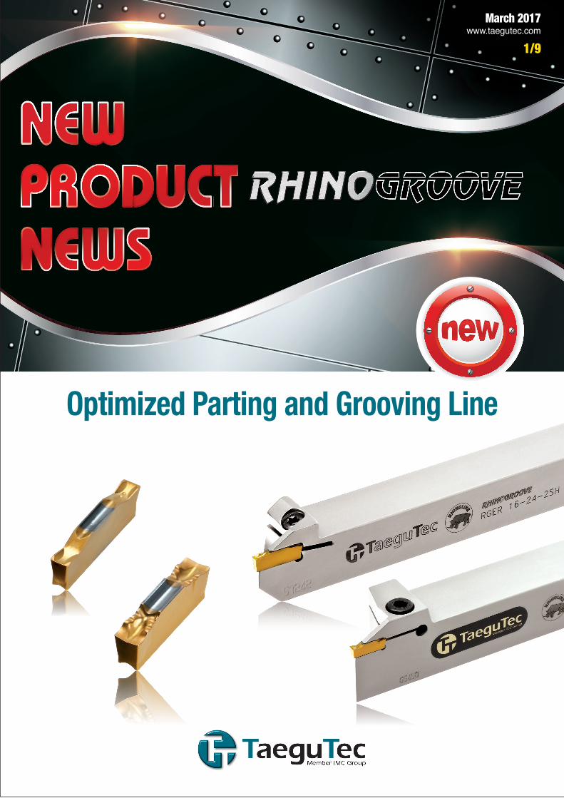
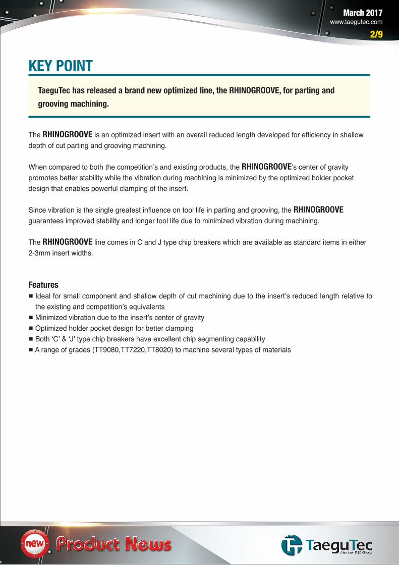
Optimized Parting and Grooving Line
March 2017www.taegutec.com
2/9
The RHINOGROOVE is an optimized insert with an overall reduced length developed for efficiency in shallow depth of cut parting and grooving machining.
When compared to both the competition’s and existing products, the RHINOGROOVE’s center of gravity promotes better stability while the vibration during machining is minimized by the optimized holder pocket design that enables powerful clamping of the insert.
Since vibration is the single greatest influence on tool life in parting and grooving, the RHINOGROOVE guarantees improved stability and longer tool life due to minimized vibration during machining.
The RHINOGROOVE line comes in C and J type chip breakers which are available as standard items in either 2-3mm insert widths.
Features Ideal for small component and shallow depth of cut machining due to the insert’s reduced length relative to
the existing and competition’s equivalents Minimized vibration due to the insert’s center of gravity Optimized holder pocket design for better clamping Both ‘C’ & ‘J’ type chip breakers have excellent chip segmenting capability A range of grades (TT9080,TT7220,TT8020) to machine several types of materials
KEY POINTTaeguTec has released a brand new optimized line, the RHINOGROOVE, for parting and grooving machining.
March 2017www.taegutec.com
3/9
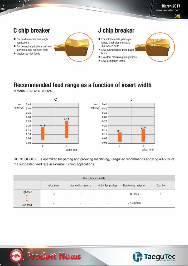
C chip breaker For hard materials and tough
applications For general applications on steel,
alloy steel and stainless steel Medium-to-high feeds
J chip breaker For soft materials, parting of
tubes, small diameters and thin-walled parts Low cutting forces and smaller
burrs Excellent machining straightness Low-to-medium feeds
Recommended feed range as a function of insert widthMaterial: SAE4140 (HB240)
RHINOGROOVE is optimized for parting and grooving machining, TaeguTec recommends applying 40-50% of the suggested feed rate in external turning applications.
Feed(mm/rev)
Width (mm)
JFeed
(mm/rev)
Width (mm)
C0.450.400.350.300.250.200.150.100.060.02
0.450.400.350.300.250.200.150.100.060.02
2 3
0.18
0.25
0.120.16
2 3
Workpiece materials
Alloy steel Austenitic stainless High - Temp alloys Nonferrous materials Cast iron
High feed
Low feed
C C C C Brass C
J J J J Aluminum
March 2017www.taegutec.com
4/9
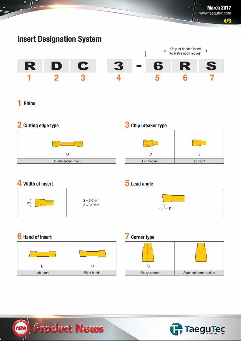
1 Rhino
2
4 5
3Cutting edge type
Width of insert Lead angle
Chip breaker type
21 3 4 5 6 7DR C -3 6 R S
Only for handed insert(Available upon request)
Double-ended insert
2 = 2.0 mm3 = 3.0 mm
D
Left hand Right hand
6 7Hand of insert Corner type
L R
For medium For light
C J
K˚
Sharp corner Standard corner radius
S
Insert Designation System

March 2017www.taegutec.com
5/9
Holder Designation System
1 2 3 4 8G RR E 5
5 6 725 3-25
1 Rhino
2 3Application type Machining type
G Grooving E External machining
Left-hand Right-hand
4 Hand of holder
L R
5 Shank height
12, 16, 20, 25h
6 7 8Shank width Insert size Maximum depth of cut
12, 16, 20, 25
Tmax 16mmb
2, 3
T16
March 2017www.taegutec.com
6/9
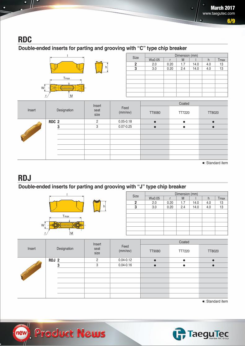
RDC
RDJ
Double-ended inserts for parting and grooving with “C” type chip breaker
Double-ended inserts for parting and grooving with “J” type chip breaker
Insert DesignationInsert seat size
Feed(mm/rev)
Coated
TT9080 TT7220 TT8020
RDC 2 2 0.05-0.183 3 0.07-0.25
Insert DesignationInsert seat size
Feed(mm/rev)
Coated
TT9080 TT7220 TT8020
RDJ 2 2 0.04-0.123 3 0.04-0.16
Size Dimension (mm)W±0.05 r M l h Tmax
2 2.0 0.20 1.7 14.0 4.0 133 3.0 0.20 2.4 14.0 4.0 13
Size Dimension (mm)W±0.05 r M l h Tmax
2 2.0 0.20 1.7 14.0 4.0 133 3.0 0.20 2.4 14.0 4.0 13
: Standard item
: Standard item
M
l
Tmax
W
h
r
M
l
Tmax
W
h
r
March 2017www.taegutec.com
7/9
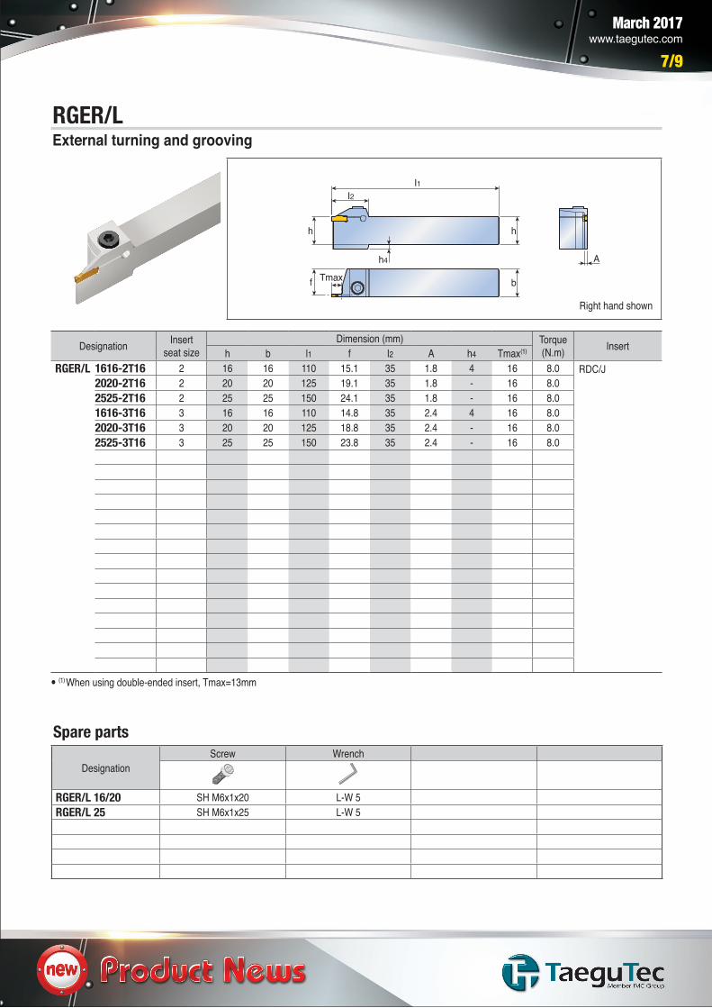
RGER/LExternal turning and grooving
Right hand shown
Designation Insert seat size
Dimension (mm) Torque(N.m) Inserth b l1 f l2 A h4 Tmax(1)
RGER/L 1616-2T16 2 16 16 110 15.1 35 1.8 4 16 8.0 RDC/J2020-2T16 2 20 20 125 19.1 35 1.8 - 16 8.02525-2T16 2 25 25 150 24.1 35 1.8 - 16 8.01616-3T16 3 16 16 110 14.8 35 2.4 4 16 8.02020-3T16 3 20 20 125 18.8 35 2.4 - 16 8.02525-3T16 3 25 25 150 23.8 35 2.4 - 16 8.0
Spare parts
DesignationScrew Wrench
RGER/L 16/20 SH M6x1x20 L-W 5RGER/L 25 SH M6x1x25 L-W 5
I1
h4
f
I2
h h
A
bTmax
(1) When using double-ended insert, Tmax=13mm
March 2017www.taegutec.com
8/9
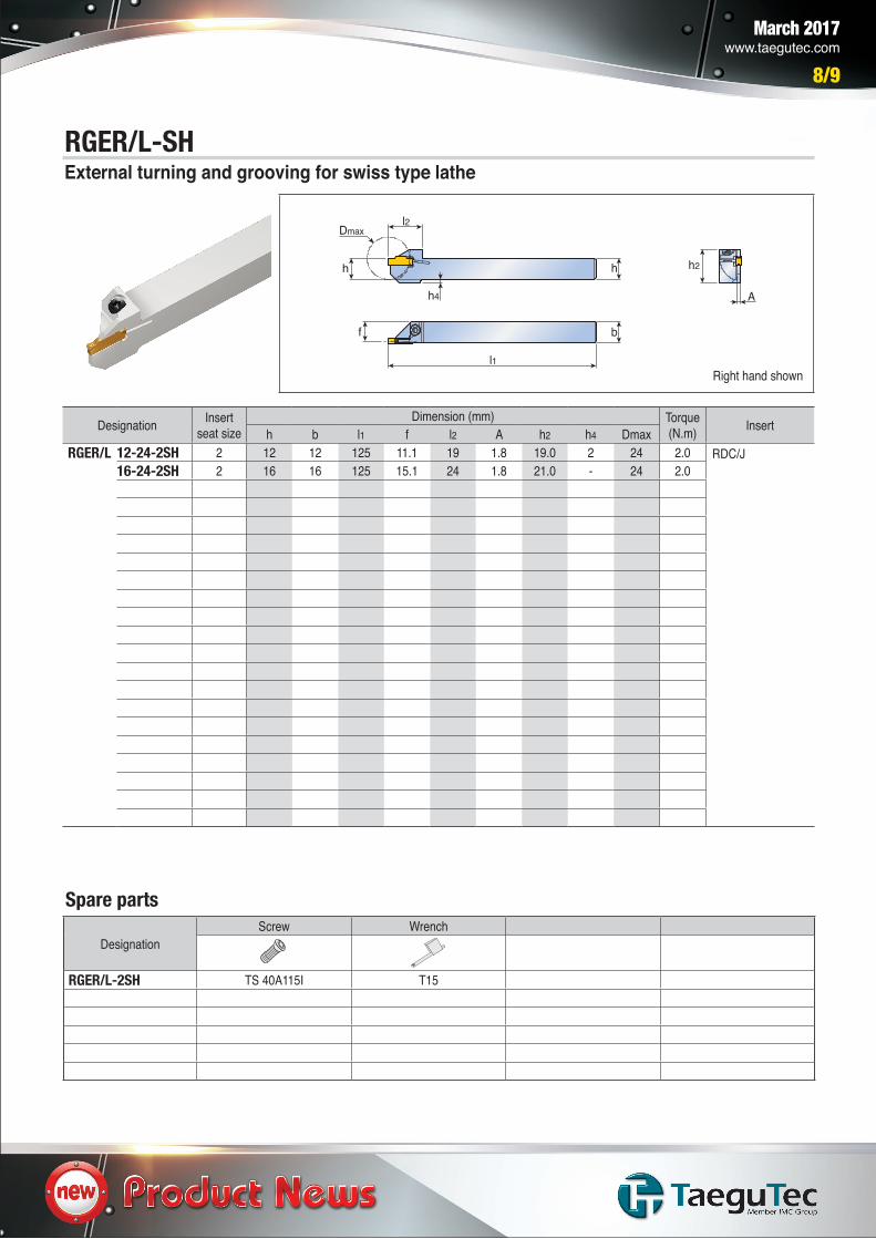
RGER/L-SHExternal turning and grooving for swiss type lathe
Designation Insert seat size
Dimension (mm) Torque(N.m) Inserth b l1 f l2 A h2 h4 Dmax
RGER/L 12-24-2SH 2 12 12 125 11.1 19 1.8 19.0 2 24 2.0 RDC/J16-24-2SH 2 16 16 125 15.1 24 1.8 21.0 - 24 2.0
Spare parts
DesignationScrew Wrench
RGER/L-2SH TS 40A115I T15
h
b
A
l1
Dmaxl2
h2h
f
h4
Right hand shown
March 2017www.taegutec.com
9/9
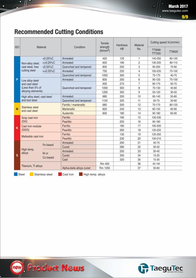
Recommended Cutting Conditions
Steel Stainless steel Cast iron High temp. alloys
ISO Material ConditionTensilestrength(N/mm2)
HardnessHB
Material No.
Cutting speed Vc(m/min)
TT9080TT7220 TT8020
P
Non-alloy steel,cast steel, free cutting steel
<0.25%C Annealed 420 125 1 140-250 80-120>=0.25%C Annealed 650 190 2 130-220 80-110<0.55%C Quenched and tempered 850 250 3 90-200 70-90>=0.55%C Annealed 750 220 4 100-220 70-100
Quenched and tempered 1000 300 5 70-170 40-70Low alloy steeland cast steel(Less than 5% ofalloying elements)
Annealed 600 200 6 90-120 70-100
Quenched and tempered930 275 7 80-170 50-70
1000 300 8 70-130 40-601200 350 9 50-120 30-50
High alloy steel, cast steel and tool steel
Annealed 680 200 10 60-140 50-80Quenched and tempered 1100 325 11 50-70 30-60
M Stainless steeland cast steel
Ferritic / martensitic 680 200 12 70-170 80-120Martensitic 820 240 13 60-150 60-90Austenitic 600 180 14 90-180 60-90
K
Gray cast iron (GG)
Ferritic 160 15 100-230Pearlitic 250 16 90-180
Cast iron nodular (GGG)
Ferritic 180 17 190-300Pearlitic 260 18 120-220
Malleable cast iron Ferritic 130 19 120-250Pearlitic 230 20 100-210
S
High temp. alloys
Fe based Annealed 200 31 40-70Cured 280 32 30-50
Ni orCo based
Annealed 250 33 30-40Cured 350 34 15-25Cast 320 35 15-30
Titanium, Ti alloys Rm 400 36 90-190Alpha+beta alloys cured Rm 1050 37 30-60