Embed Size (px)
Citation preview
Mechanics and Mechanical EngineeringVol. 11, No 1 (2007) 37–48c© Technical University of Lodz
Optimization of Thin-Walled Beams Subjected to Bendingin Respect of Local Stability and Strenght
Tadeusz GaÃLkiewicz, Marian Krolak and Tomasz Kubiak
Technical University of ÃLodz, Department of Strength of Materials and StructuresStefanowskiego 1/15, 90-924 ÃLodz, Poland
Received (1 March 2007)Revised (15 March 2007)Accepted (8 May 2007)
A method for optimization (with some limitations) of thin-walled beams with a trape-zoidal cross-section is presented in the paper. Beams are subjected to bending. Theyundergo local buckling in the elastic range. The dimensions of beam cross-section wallsare optimized. Two cases was consider. In the first one the smallest weight of the beam(the smallest area cross-section) for given critical buckling moment was calculated. Inthe second case the maximum critical moment for given area of the cross-section wascalculated. Next, the ultimate bending moment in the postcritical state is found for theoptimized beams.
Keywords: thin-walled beams, buckling, optimization, postbucling state, ultimate loadlimit
1. Introduction
Thin-walled beams that are light due to the fact their material strength proper-ties are better exploited are often used as load-carrying elements in mechanical(e.g. crane beams) and civil engineering (e.g. bridges) structures. Compressed thinwalls of such beams, especially walls of larger widths, are subjected to buckling(local stability loss) at low values of compressive stresses.
The present study is aimed at such a selection of dimensions of the beam cross-section as to obtain either the smallest area of the beam cross-section (the smallestweight of the beam) under the given critical bending moment or the largest criticalbending moment (the highest load-carrying capacity of the beam) for the given areaof the beam cross-section, as well as the ratio of the thickness to the width t1/b1 ofthe compressed flange..
As thin-walled beams, especially those with closed profiles and flat walls, canoperate safely after elastic local buckling, a reserve of the load-carrying capabilityresiding in postcritical elastic states should be employed in the calculations of limitloads [1, 2].
38 GaÃlkiewicz T., Krolak M.and Kubiak T.
In the present paper, an analytical optimization method of cross-section dimen-sions of thin-walled single-cell beams with an isosceles-trapezoidal shape (in thespecial case, with a rectangular shape), subjected to pure plane bending in theplane going through the beam axis and the symmetry axis of the cross-section, willbe presented [5]. The considerations will be devoted to beams in which the localbuckling of walls occurs within the range of elastic strains (σcr ≤ σprop) and theload-carrying capacity of beams is in the postcritical (postbuckling) state.
2. Formulation of the Problem. Basic Assumptions
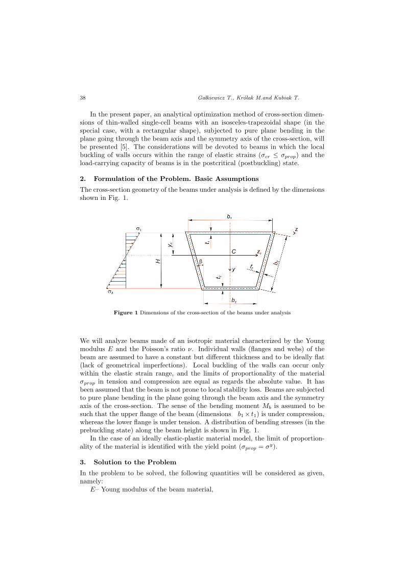
The cross-section geometry of the beams under analysis is defined by the dimensionsshown in Fig. 1.
Figure 1 Dimensions of the cross-section of the beams under analysis
We will analyze beams made of an isotropic material characterized by the Youngmodulus E and the Poisson’s ratio ν. Individual walls (flanges and webs) of thebeam are assumed to have a constant but different thickness and to be ideally flat(lack of geometrical imperfections). Local buckling of the walls can occur onlywithin the elastic strain range, and the limits of proportionality of the materialσprop in tension and compression are equal as regards the absolute value. It hasbeen assumed that the beam is not prone to local stability loss. Beams are subjectedto pure plane bending in the plane going through the beam axis and the symmetryaxis of the cross-section. The sense of the bending moment Mb is assumed to besuch that the upper flange of the beam (dimensions b1× t1) is under compression,whereas the lower flange is under tension. A distribution of bending stresses (in theprebuckling state) along the beam height is shown in Fig. 1.
In the case of an ideally elastic-plastic material model, the limit of proportion-ality of the material is identified with the yield point (σprop = σy).
3. Solution to the Problem
In the problem to be solved, the following quantities will be considered as given,namely:
E– Young modulus of the beam material,
Optimization of Thin-Walled Beams ... 39
ν – Poisson’s ratio,σprop – limit of proportionality,β – angle of deflection of side walls (webs) from the vertical plane,k1 – stability coefficient of the compressed (upper) flange,σ1cr – critical stress of local buckling of the upper flange,σ2cr – critical stress of local buckling of webs,α – parameter dependent of the position of the center of gravity of the beam
cross-section.Instead of stresses σ1cr, the ratio t1/b1 (ratio of the thickness to the width of
the flange under compression) can be adopted and then the critical stress can becalculated from the following formula:
σ1cr = k1π2E
12 (1− ν2)
(t1b1
)2
(1)
The characteristics of the beam cross-section (Fig. 1), such as:– cross-section area A,– position of the center of cross-section area yc,– inertia moment Izc with respect to the bending neutral axis zc,– sectional modulus Z,– parameter α,can be expressed by the following formulae:
A =4∑
i=1
Ai =4∑
i=1
biti
yc =A2 + A3
A·H
Izc =(
H
α
)2 [A (α− 1)−A2
α2
3
](2)
Z =Izc
ymax=
H
α
[A− α2
3 (α− 1)A2
]
α =H
yc= 1 +
∣∣∣∣σ3
σ1
∣∣∣∣ =A
A2 + A3
The quantities occurring in formulae (2) such as bi, ti (for i= 1,2,3,4), yc, H,σ1 and σ2 are shown in Fig. 1. The parameter α depends on the position of thecenter of area of the beam cross-section or on the value of membrane stresses in beamflanges (for a linear distribution of stresses along the beam height H). Further on, itwill be assumed that α ≥ 2, that is to say, yc = 1
2H and ymax = H−yc = Hα (α− 1).
The bending moment of the beam (in the precritical state) is described with theformula:
Mb = Z · σ3 =H
α
[(α− 1) A− α2
3A2
]σ1 (3)
40 GaÃlkiewicz T., Krolak M.and Kubiak T.
or
Mb = σ1 cos β
[α− 1
αA · b2 − α
3t2b
22
](4)
In webs of the analyzed beams, there exist normal stresses that are linearlyvariable along beam widths, compressive stresses σ1 in the junction with the upperflange, and tensile stresses σ3 in the junction with the lower flange (Fig. 1).
Critical stresses of local buckling of the long rectangular plate loaded in such amanner can be described by the formula:
σ2cr = k2π2E
12 (1− ν2)
(t2b2
)2
, (5)
where σ2cr corresponds to the highest (as regards the absolute value) compressivestress in the web. The stress σ2cr described by formula (5) has been assumed to bepositive.
Minimum values of the stability coefficient k2 can be calculated from the follow-ing approximated formulae:
k2 = 6.15α2 − 2.35α + 4 for 0 ≤ α ≤ 4 (6)
ork2 = 78α− 149.5
√α + 79.3 for 1 ≤ α ≤ 4 (7)
Formula (6) results from the parabolic distribution of k2 = k2(α) presented inthe form of a diagram in [3], whereas formula (7) has been taken from [4]. In furthercalculations we will employ formula (7) as it yields slightly lower values of k2 in theα range of interest to us.
The optimization of the beams under consideration in respect of local stabilitywill be conducted on the assumption that the compressed flange and webs aresubjected to buckling simultaneous, i.e.:
σ1cr = σ2cr (8)
It follows from this assumption (see formulae (1) and (5)) that:
t2 =t1b1
√k1
k2b2 (9)
To simplify the further formulae, we will introduce two dimensionless quantities,namely:
B1 = b1t1
= π√
k1E12(1−ν2)σ1cr
B2 = b1t1
√k2k1
= π√
k2E12(1−ν2)σ1cr
(10)
Formula (4), after employing relationships (9) and (10), takes the following form:
Mcr = σ1cr cosβ
(α− 1
αA · b2 − α
3b32
B2
)(11)
Optimization of Thin-Walled Beams ... 41
3.1. Case of A=const
In this subsection, formulae for the optimal dimensions of the cross-section of flangesand webs and the maximum value of the critical bending moment for the given totalarea of the beam cross-section (A = const) are derived. When the derivative of thecritical bending moment (11) with respect to the web width b2 equals zero:
dMcr
db2= σ1cr cos β
(α− 1
αA− α
B2b22
)= 0
then:bopt2 =
1α
√(α− 1) B2A. (12)
It follows from (9) and (12) that:
topt2 =
1α
√(α− 1)
A
B2(13)
and thus :Aopt
2 = bopt2 topt
2 =α− 1α2
A. (14)
When the optimal web width (12) is substituted into formula (11), a formulafor the maximum value of the critical bending moment is obtained:
Mmaxcr =
23
α− 1α2
√(α− 1)B2A
32 σ1cr cos β, (15)
where:
α =A
Aopt2 + Aopt
3
. (16)
From (16) and (14) we obtain:
Aopt3 =
A
α−Aopt
2 =A
α2. (17)
Formulae for the remaining optimal dimensions of the beam cross-section are asfollows:
Aopt1 = A− 2A2opt −Aopt
3 =(
α−1α
)2 ·Abopt1 = α−1
α
√B1 ·A, bopt
3 = bopt1 − 2bopt
2 · sin β
topt1 = α−1
α
√AB1
, topt3 = Aopt
3b3
(18)
Taking into consideration the assumption that buckling of the compressed flangeand webs is simultaneous and a slightly safer design of the beam with respect to thewall local stability loss, it is postulated to assume the stability coefficient k1 for theuniformly compressed upper flange to be equal to the coefficient for the compressed,simply supported at all edges, rectangular plate, that is to say, k1= 4.
For sufficiently thick beam walls (and strictly speaking, for certain values of t1/b1
and t2/b2), the beam load-carrying capacity is affected by the material strength
42 GaÃlkiewicz T., Krolak M.and Kubiak T.
and not by the local stability loss. In this case, the maximum value of the bendingmoment (4) has been determined on the assumption that A= const for the specific(assumed) thickness t2 of the web.
From the condition that dMb
db2= 0, the optimal width of webs has been obtained:
bopt2 =
3 (α− 1)2α2
A
t2,
for which the final formula for the maximum bending moment of the beam (withrespect to the material strength) has the following form:
Mmaxb =
3 (α− 1)2
2α2
A
t2. (19)
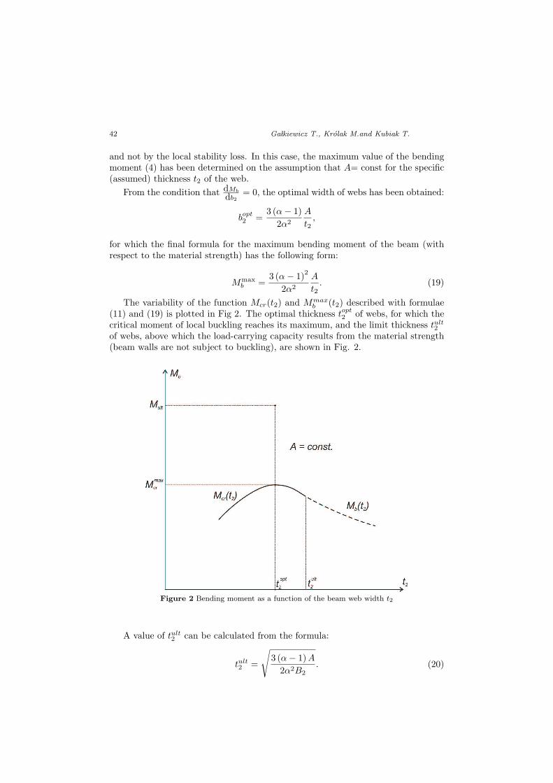
The variability of the function Mcr(t2) and Mmaxb (t2) described with formulae
(11) and (19) is plotted in Fig 2. The optimal thickness topt2 of webs, for which the
critical moment of local buckling reaches its maximum, and the limit thickness tult2
of webs, above which the load-carrying capacity results from the material strength(beam walls are not subject to buckling), are shown in Fig. 2.
Figure 2 Bending moment as a function of the beam web width t2
A value of tult2 can be calculated from the formula:
tult2 =
√3 (α− 1) A
2α2B2. (20)
Optimization of Thin-Walled Beams ... 43
In Fig. 2, the limit moment Mult corresponding to the optimal thickness topt2 of
webs (and to the optimal dimensions of the beam cross-section with respect to thelocal stability loss), after reaching of which a beam failure phase begins, is markedwith a point. The value of Mult can be calculated with professional FEM software.
3.2. Case of M b=const
Here, the optimal values – with respect to the local stability or strength – of thick-ness and width of beam walls, for which (for the given bending moment Mb) thebeam cross-section area will reach its minimum value, will be determined. Theformula for the beam cross-section area has been obtained from relationship (11):
A =α
α− 1
(Mcr
b2σ1cr cosβ+
αb22
3B2
). (21)
From the condition that dA
db2= 0, we obtain:
bopt2 = 3
√3B2Mcr
2ασ1cr cos β, (22)
which allows us to derive a formula for the minimum area of the beam cross-section:
Amin =
3Mcrα
2
2√
(α− 1)3 B2σ1cr cosβ
23
(23)
The remaining optimal dimensions of the beam cross-section can be calculated fromformulae (13) and (18), respectively.
If the thickness of webs t2 is larger that the limit thickness tult2 , described by
relationship (20), then not the local stability but strength decides about the load-carrying capacity of the beam. Thus, the beam cross-section area determined fromrelationship (4) is defined by the following formula:
A =α
α− 1
(Mb
σ1b2 cos β+
α
3t2b2
)(24)
From the condition that dA
db2= 0 (for t2= const), we obtain:
b2 =
√3Mb
ασ1t2 cosβfor b2 ≥ bult
2 (25)
After the substitution of (25) into (24), the formula for A = A(t2) takes thefollowing form:
A = 2α
α− 1
√αMbt2
3σ1 cosβfor t2 ≥ tult
2 (26)
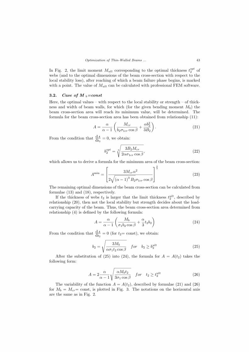
The variability of the function A = A(t2), described by formulae (21) and (26)for Mb = Mcr= const, is plotted in Fig. 3. The notations on the horizontal axisare the same as in Fig. 2.
44 GaÃlkiewicz T., Krolak M.and Kubiak T.
Figure 3 Change in the beam cross-section area A as a function of the web thickness t2
4. Parametric Analysis
After solving the problem, an influence of some parameters on maximum values ofthe critical moments of local buckling Mmax
cr has been analyzed and limit values ofthe bending moments Mult (that cause a failure of the beam) have been calculatedby means of an analysis of the postcritical state with FEM codes.
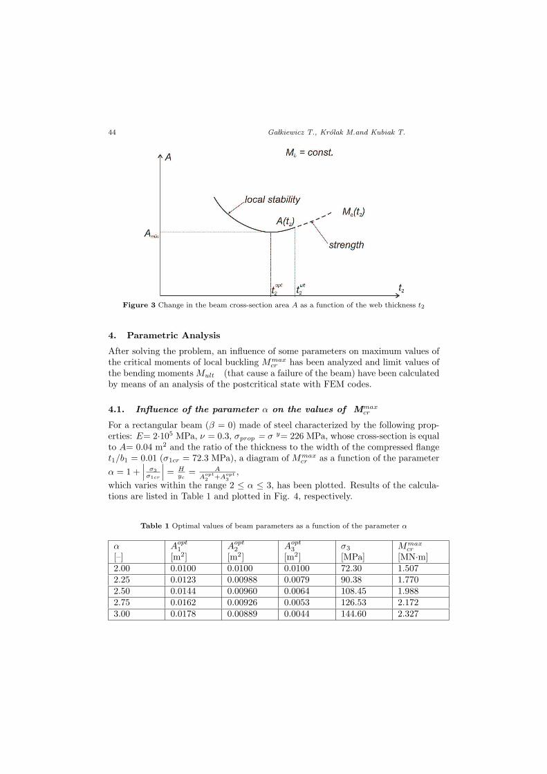
4.1. Influence of the parameter α on the values of Mmaxcr
For a rectangular beam (β = 0) made of steel characterized by the following prop-erties: E= 2·105 MPa, ν = 0.3, σprop = σ y= 226 MPa, whose cross-section is equalto A= 0.04 m2 and the ratio of the thickness to the width of the compressed flanget1/b1 = 0.01 (σ1cr = 72.3 MPa), a diagram of Mmax
cr as a function of the parameterα = 1 +
∣∣∣ σ3σ1cr
∣∣∣ = Hyc
= AAopt
2 +Aopt3
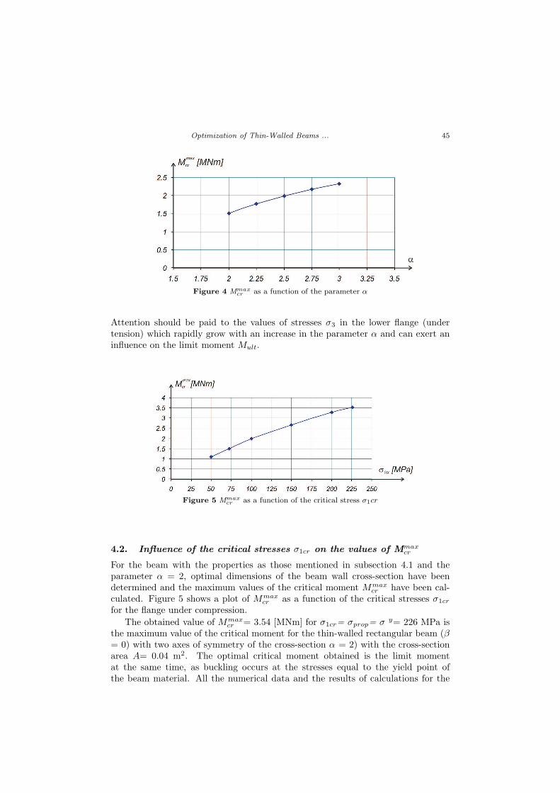
,which varies within the range 2 ≤ α ≤ 3, has been plotted. Results of the calcula-tions are listed in Table 1 and plotted in Fig. 4, respectively.
Table 1 Optimal values of beam parameters as a function of the parameter α
α[–]
Aopt1
[m2]Aopt
2
[m2]Aopt
3
[m2]σ3
[MPa]Mmax
cr
[MN·m]2.00 0.0100 0.0100 0.0100 72.30 1.5072.25 0.0123 0.00988 0.0079 90.38 1.7702.50 0.0144 0.00960 0.0064 108.45 1.9882.75 0.0162 0.00926 0.0053 126.53 2.1723.00 0.0178 0.00889 0.0044 144.60 2.327
Optimization of Thin-Walled Beams ... 45
Figure 4 Mmaxcr as a function of the parameter α
Attention should be paid to the values of stresses σ3 in the lower flange (undertension) which rapidly grow with an increase in the parameter α and can exert aninfluence on the limit moment Mult.
Figure 5 Mmaxcr as a function of the critical stress σ1cr
4.2. Influence of the critical stresses σ1cr on the values of Mmaxcr
For the beam with the properties as those mentioned in subsection 4.1 and theparameter α = 2, optimal dimensions of the beam wall cross-section have beendetermined and the maximum values of the critical moment Mmax
cr have been cal-culated. Figure 5 shows a plot of Mmax
cr as a function of the critical stresses σ1cr
for the flange under compression.The obtained value of Mmax
cr = 3.54 [MNm] for σ1cr= σprop= σ y= 226 MPa isthe maximum value of the critical moment for the thin-walled rectangular beam (β= 0) with two axes of symmetry of the cross-section α = 2) with the cross-sectionarea A= 0.04 m2. The optimal critical moment obtained is the limit momentat the same time, as buckling occurs at the stresses equal to the yield point ofthe beam material. All the numerical data and the results of calculations for the
46 GaÃlkiewicz T., Krolak M.and Kubiak T.
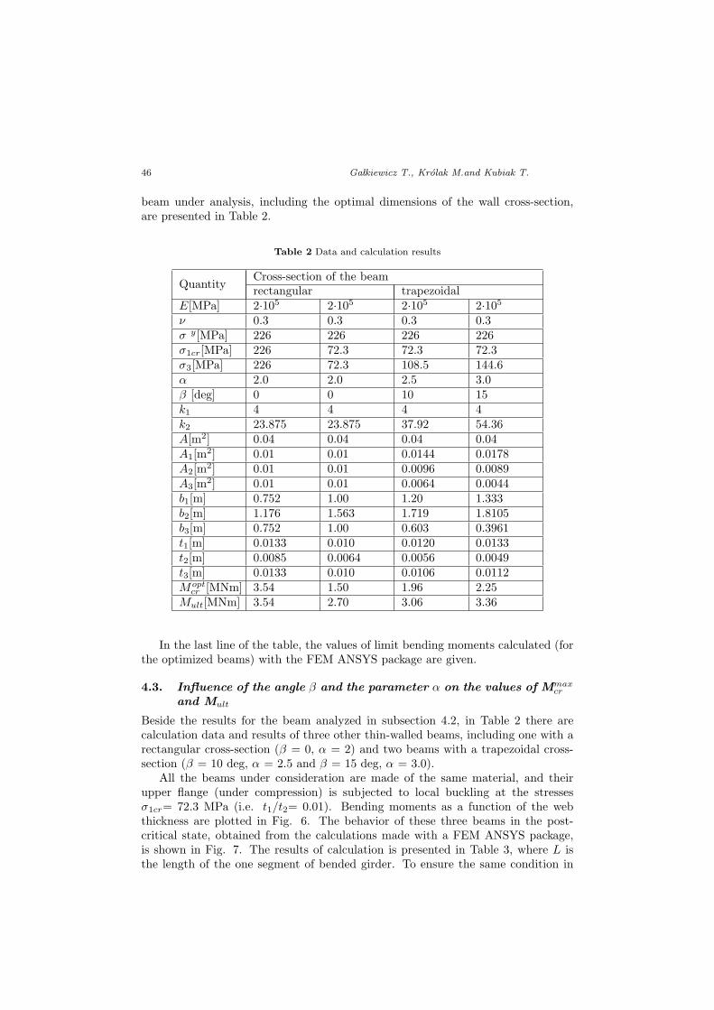
beam under analysis, including the optimal dimensions of the wall cross-section,are presented in Table 2.
Table 2 Data and calculation results
QuantityCross-section of the beamrectangular trapezoidal
E[MPa] 2·105 2·105 2·105 2·105
ν 0.3 0.3 0.3 0.3σ y[MPa] 226 226 226 226σ1cr[MPa] 226 72.3 72.3 72.3σ3[MPa] 226 72.3 108.5 144.6α 2.0 2.0 2.5 3.0β [deg] 0 0 10 15k1 4 4 4 4k2 23.875 23.875 37.92 54.36A[m2] 0.04 0.04 0.04 0.04A1[m2] 0.01 0.01 0.0144 0.0178A2[m2] 0.01 0.01 0.0096 0.0089A3[m2] 0.01 0.01 0.0064 0.0044b1[m] 0.752 1.00 1.20 1.333b2[m] 1.176 1.563 1.719 1.8105b3[m] 0.752 1.00 0.603 0.3961t1[m] 0.0133 0.010 0.0120 0.0133t2[m] 0.0085 0.0064 0.0056 0.0049t3[m] 0.0133 0.010 0.0106 0.0112Mopt
cr [MNm] 3.54 1.50 1.96 2.25Mult[MNm] 3.54 2.70 3.06 3.36
In the last line of the table, the values of limit bending moments calculated (forthe optimized beams) with the FEM ANSYS package are given.
4.3. Influence of the angle β and the parameter α on the values of Mmaxcr
and Mult
Beside the results for the beam analyzed in subsection 4.2, in Table 2 there arecalculation data and results of three other thin-walled beams, including one with arectangular cross-section (β = 0, α = 2) and two beams with a trapezoidal cross-section (β = 10 deg, α = 2.5 and β = 15 deg, α = 3.0).
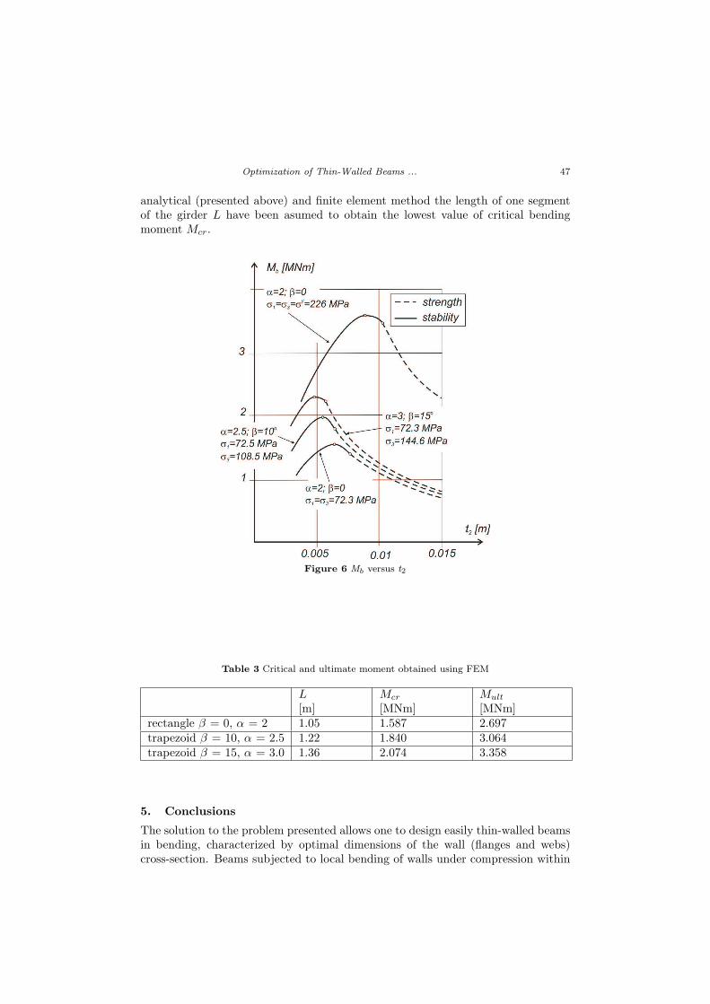
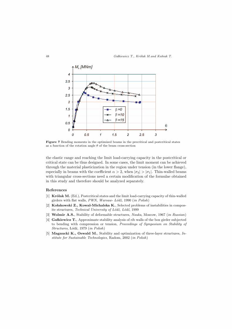
All the beams under consideration are made of the same material, and theirupper flange (under compression) is subjected to local buckling at the stressesσ1cr= 72.3 MPa (i.e. t1/t2= 0.01). Bending moments as a function of the webthickness are plotted in Fig. 6. The behavior of these three beams in the post-critical state, obtained from the calculations made with a FEM ANSYS package,is shown in Fig. 7. The results of calculation is presented in Table 3, where L isthe length of the one segment of bended girder. To ensure the same condition in
Optimization of Thin-Walled Beams ... 47
analytical (presented above) and finite element method the length of one segmentof the girder L have been asumed to obtain the lowest value of critical bendingmoment Mcr.
Figure 6 Mb versus t2
Table 3 Critical and ultimate moment obtained using FEM
L[m]
Mcr
[MNm]Mult
[MNm]rectangle β = 0, α = 2 1.05 1.587 2.697trapezoid β = 10, α = 2.5 1.22 1.840 3.064trapezoid β = 15, α = 3.0 1.36 2.074 3.358
5. Conclusions
The solution to the problem presented allows one to design easily thin-walled beamsin bending, characterized by optimal dimensions of the wall (flanges and webs)cross-section. Beams subjected to local bending of walls under compression within
48 GaÃlkiewicz T., Krolak M.and Kubiak T.
Figure 7 Bending moments in the optimized beams in the precritical and postcritical statesas a function of the rotation angle θ of the beam cross-section
the elastic range and reaching the limit load-carrying capacity in the postcritical orcritical state can be thus designed. In some cases, the limit moment can be achievedthrough the material plasticization in the region under tension (in the lower flange),especially in beams with the coefficient α > 2, when |σ3| > |σ1|. Thin-walled beamswith triangular cross-sections need a certain modification of the formulae obtainedin this study and therefore should be analyzed separately.
References
[1] Krolak M. (Ed.), Postcritical states and the limit load-carrying capacity of thin-walledgirders with flat walls, PWN, Warsaw- ÃLodz, 1990 (in Polish)
[2] KoÃlakowski Z., Kowal-Michalska K., Selected problems of instabilities in compos-ite structures, Technical University of ÃLodz, ÃLodz, 1999
[3] Wolmir A.S., Stability of deformable structures, Nauka, Moscow, 1967 (in Russian)
[4] GaÃlkiewicz T., Approximate stability analysis of rib walls of the box girder subjectedto bending with compression or tension, Proceedings of Symposium on Stability ofStructures, ÃLodz, 1979 (in Polish)
[5] Magnucki K., Oswald M., Stability and optimization of three-layer structures, In-stitute for Sustainable Technologies, Radom, 2002 (in Polish)