Embed Size (px)
Citation preview

Optimization in Engineering Design
1
Georgia Institute of TechnologySystems Realization Laboratory
Types of Optimization ModelsTypes of Optimization Models
Optimization in Engineering Design
2
Georgia Institute of TechnologySystems Realization Laboratory
Model FormulationsModel Formulations
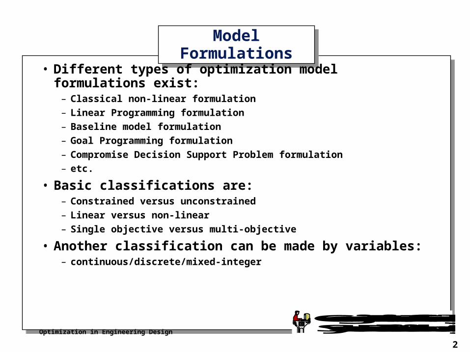
• Different types of optimization model formulations exist:– Classical non-linear formulation
– Linear Programming formulation
– Baseline model formulation
– Goal Programming formulation
– Compromise Decision Support Problem formulation
– etc.
• Basic classifications are:– Constrained versus unconstrained
– Linear versus non-linear
– Single objective versus multi-objective
• Another classification can be made by variables:– continuous/discrete/mixed-integer
Optimization in Engineering Design
3
Georgia Institute of TechnologySystems Realization Laboratory
Introduction to Multi-Objective Optimization
Introduction to Multi-Objective Optimization
Optimization in Engineering Design
4
Georgia Institute of TechnologySystems Realization Laboratory
Single versus Multi-ObjectiveSingle versus Multi-Objective
What should you use and what is available?
Most important rule:
Never restrict yourself in modeling!
• Design is multi-objective by nature, so we will look at some multi-objective formulations first.
Optimization in Engineering Design
5
Georgia Institute of TechnologySystems Realization Laboratory
Different formulationsDifferent formulations
• There are different ways to formulate a multi-objective optimization model
• Some covered are:– Baseline model
– Goal Programming (GP) model
– Compromise Decision Support Problem model
• Others exist
Optimization in Engineering Design
6
Georgia Institute of TechnologySystems Realization Laboratory
Baseline ModelBaseline Model
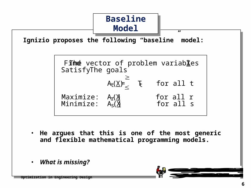
Ignizio proposes the following “baseline” model:
• He argues that this is one of the most generic and flexible mathematical programming models.
• What is missing?
Find The vector of problem variables XSatisfy The goals
At(X) = T t for all t
Maximize: Ar(X) for all rMinimize: As(X) for all s
Optimization in Engineering Design
7
Georgia Institute of TechnologySystems Realization Laboratory
Goal Programming (GP)Goal Programming (GP)
• Another multiobjective mathematical “programming” technique is Goal Programming (GP)
• The term "goal programming" is used by its developers to indicate the search for an "optimal" program (i.e., a set of policies to be implemented) for a mathematical model that is composed solely of goals.
• Developers argue that any mathematical programming model may find an equivalent representation in GP.
• “GP provides an alternative representation that often is more effective in capturing the nature of real world problems.”
Optimization in Engineering Design
8
Georgia Institute of TechnologySystems Realization Laboratory
Difference between Objectives and GoalsDifference between Objectives and Goals
In Goal Programming a distinction is made between an objective and a goal:
• Objective: In mathematical programming, an objective is a function that we seek to optimize, via changes in the problem variables.
The most common forms of objectives are those in which we seek to maximize or minimize. For example,
Minimize Z = A(X)
• Goal: In short, a goal is an objective with a “right hand side”.
This right hand side (T) is the target value or aspiration level associated with the goal. For example,
A(X) T
Optimization in Engineering Design
9
Georgia Institute of TechnologySystems Realization Laboratory
Solving Multi-objective ModelsSolving Multi-objective Models
• Solving multi-objective models is NOT standard practice (yet).
• Often, a first step in solving these models is a model transformation into a model that CAN be solved using an existing algorithm/solver.
• How do we solve such a baseline model?
• For example, for solving a baseline model, we can convert it to:– single objective nonlinear programming (NLP) problem.
– multi-objective Goal Programming (GP) problem.
– multi-objective compromise Decision Support Problem (DSP).
– other...
Optimization in Engineering Design
10
Georgia Institute of TechnologySystems Realization Laboratory
Some Model Transformation BasicsSome Model Transformation Basics
Optimization in Engineering Design
11
Georgia Institute of TechnologySystems Realization Laboratory
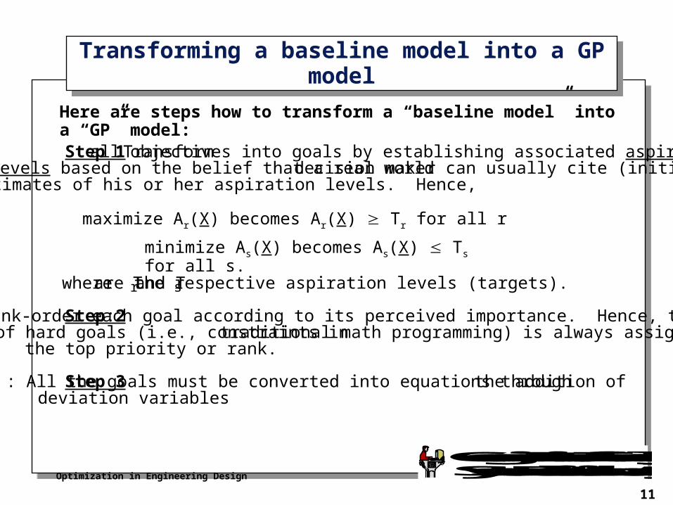
Step 1: Transform all objectives into goals by establishing associated aspirationlevels based on the belief that a real world decision maker can usually cite (initial)
estimates of his or her aspiration levels. Hence,
where Tr and Ts are the respective aspiration levels (targets).
Step 2: Rank-order each goal according to its perceived importance. Hence, the setof hard goals (i.e., constraints in traditional math programming) is always assignedthe top priority or rank.
Step 3: All the goals must be converted into equations through the addition ofdeviation variables
Transforming a baseline model into a GP modelTransforming a baseline model into a GP model
maximize Ar(X) becomes Ar(X) Tr for all r
minimize As(X) becomes As(X) Ts for all s.
Here are steps how to transform a “baseline model” into a “GP” model:

Optimization in Engineering Design
12
Georgia Institute of TechnologySystems Realization Laboratory
Going from Inequalities to Equalities
Going from Inequalities to Equalities
Optimization in Engineering Design
13
Georgia Institute of TechnologySystems Realization Laboratory
Converting Inequalities - Standard ApproachConverting Inequalities - Standard Approach
• Note: A computer does not “like” inequalities.
• Thus: Inequalities have to be converted to equalities
• In general, converting equalities to inequalities is achieved by adding variables.
• This is a VERY common practice in optimization.
Optimization in Engineering Design
14
Georgia Institute of TechnologySystems Realization Laboratory
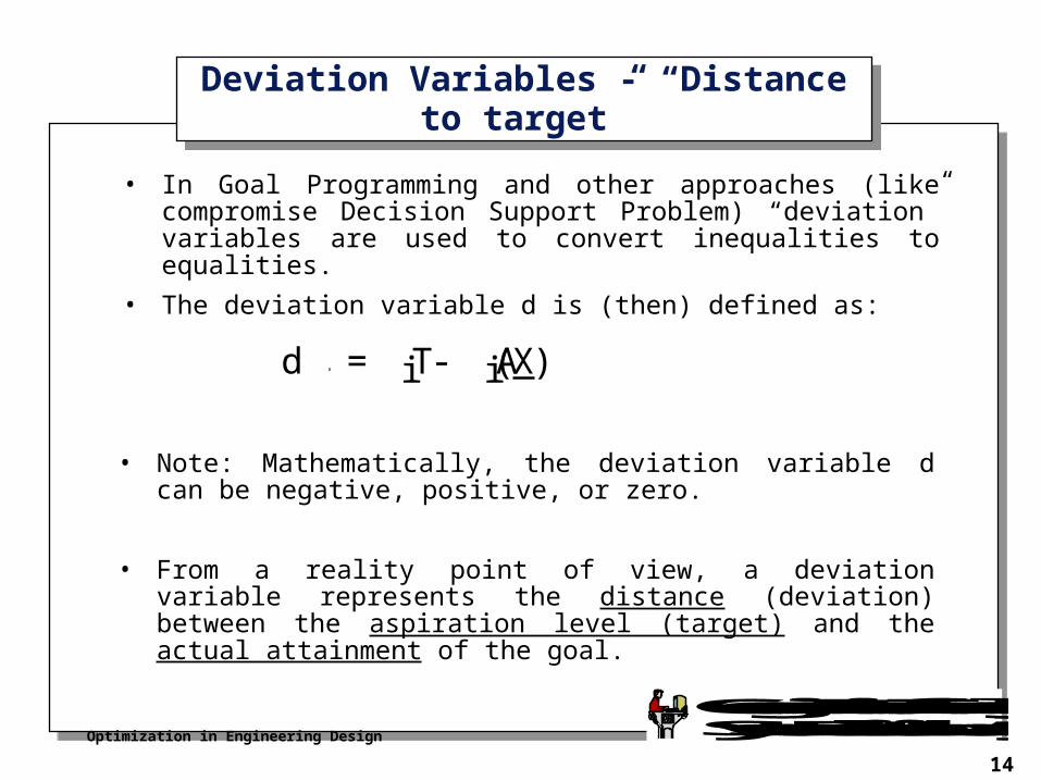
• In Goal Programming and other approaches (like compromise Decision Support Problem) “deviation” variables are used to convert inequalities to equalities.
• The deviation variable d is (then) defined as:
Deviation Variables - “Distance to target”Deviation Variables - “Distance to target”
d = Ti - Ai(X)
• Note: Mathematically, the deviation variable d can be negative, positive, or zero.
• From a reality point of view, a deviation variable represents the distance (deviation) between the aspiration level (target) and the actual attainment of the goal.
Optimization in Engineering Design
15
Georgia Institute of TechnologySystems Realization Laboratory
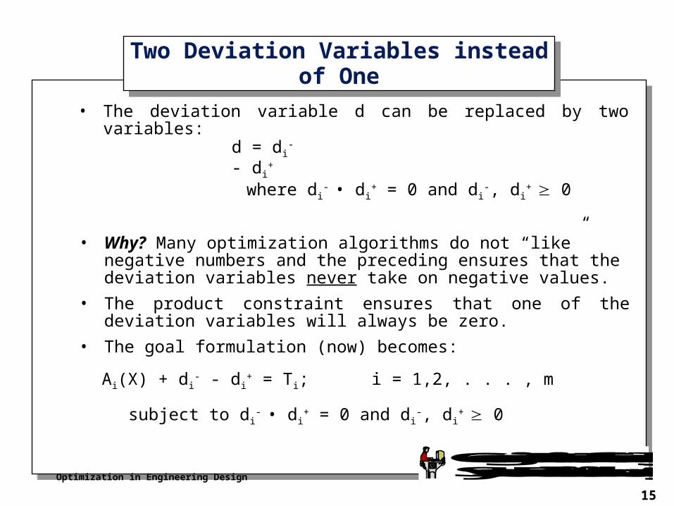
• The deviation variable d can be replaced by two variables:
Two Deviation Variables instead of OneTwo Deviation Variables instead of One
d = di- - di
+
where di- • di
+ = 0 and di-, di
+ 0
Ai(X) + di- - di
+ = Ti; i = 1,2, . . . , m
subject to di- • di
+ = 0 and di-, di
+ 0
• Why? Many optimization algorithms do not “like” negative numbers and the preceding ensures that the deviation variables never take on negative values.
• The product constraint ensures that one of the deviation variables will always be zero.
• The goal formulation (now) becomes:
Optimization in Engineering Design
16
Georgia Institute of TechnologySystems Realization Laboratory
Values of Deviation VariablesValues of Deviation Variables
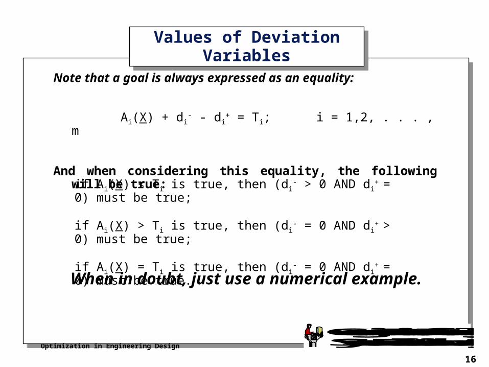
Note that a goal is always expressed as an equality:
Ai(X) + di- - di
+ = Ti; i = 1,2, . . . , m
And when considering this equality, the following will be true:
if Ai(X) < Ti is true, then (di- > 0 AND di
+ = 0) must be true;
if Ai(X) > Ti is true, then (di- = 0 AND di
+ > 0) must be true;
if Ai(X) = Ti is true, then (di- = 0 AND di
+ = 0) must be true.
When in doubt, just use a numerical example.
Optimization in Engineering Design
17
Georgia Institute of TechnologySystems Realization Laboratory
“Desired” Values of Deviation Variables“Desired” Values of Deviation Variables
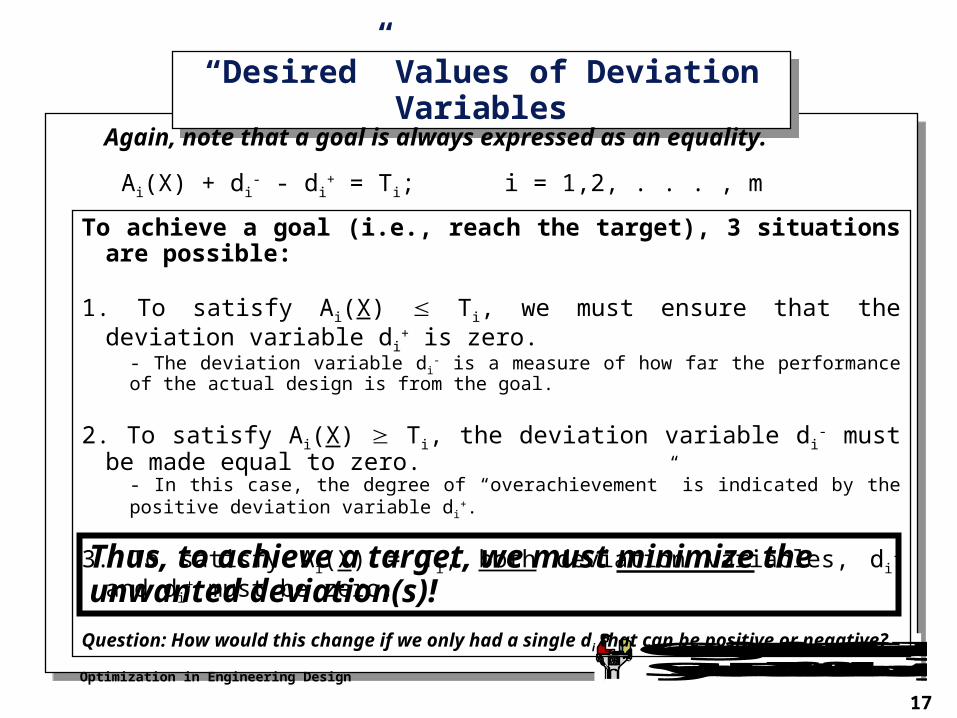
Again, note that a goal is always expressed as an equality.
To achieve a goal (i.e., reach the target), 3 situations are possible:
1. To satisfy Ai(X) Ti, we must ensure that the deviation variable di+ is zero.
- The deviation variable di- is a measure of how far the performance of the actual design is from the
goal.
2. To satisfy Ai(X) Ti, the deviation variable di- must be made equal to zero.
- In this case, the degree of “overachievement” is indicated by the positive deviation variable d i+.
3. To satisfy Ai(X) = Ti, both deviation variables, di- and di
+ must be zero.
Question: How would this change if we only had a single d i that can be positive or negative?
Ai(X) + di- - di
+ = Ti; i = 1,2, . . . , m
Thus, to achieve a target, we must minimize the unwanted deviation(s)!
Optimization in Engineering Design
18
Georgia Institute of TechnologySystems Realization Laboratory
Minimizing deviationsMinimizing deviations
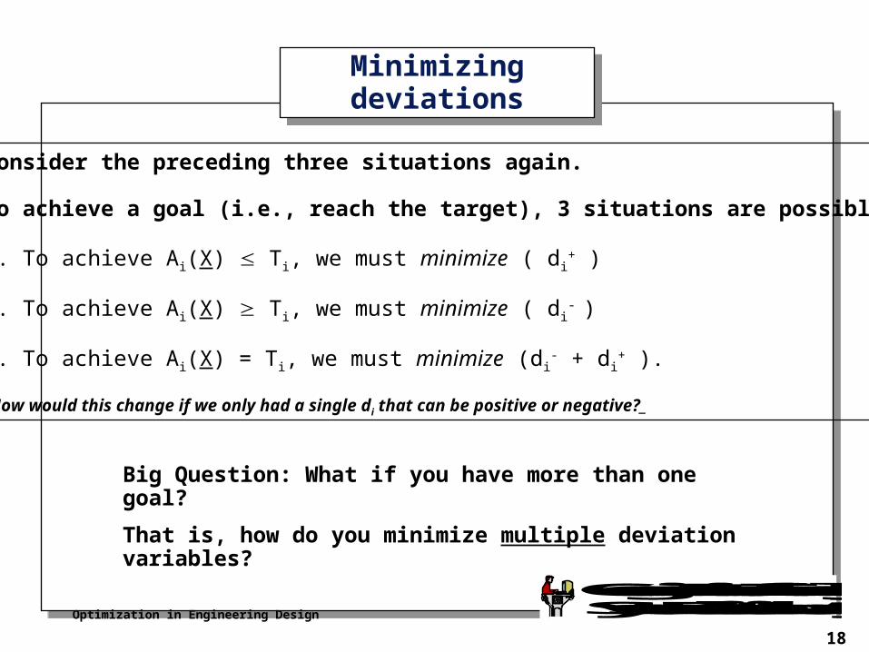
Consider the preceding three situations again.
To achieve a goal (i.e., reach the target), 3 situations are possible:
1. To achieve Ai(X) Ti, we must minimize ( di+ )
2. To achieve Ai(X) Ti, we must minimize ( di- )
3. To achieve Ai(X) = Ti, we must minimize (di- + di
+ ).
(How would this change if we only had a single di that can be positive or negative?_
Big Question: What if you have more than one goal?
That is, how do you minimize multiple deviation variables?
Optimization in Engineering Design
19
Georgia Institute of TechnologySystems Realization Laboratory
Prioritizing GoalsPrioritizing Goals
Optimization in Engineering Design
20
Georgia Institute of TechnologySystems Realization Laboratory
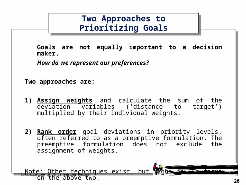
Two Approaches to Prioritizing GoalsTwo Approaches to Prioritizing Goals
Goals are not equally important to a decision maker.
How do we represent our preferences?
Two approaches are:
1) Assign weights and calculate the sum of the deviation variables (‘distance to target’) multiplied by their individual weights.
2) Rank order goal deviations in priority levels, often referred to as a preemptive formulation. The preemptive formulation does not exclude the assignment of weights.
Note: Other techniques exist, but right now we focus on the above two.
Optimization in Engineering Design
21
Georgia Institute of TechnologySystems Realization Laboratory
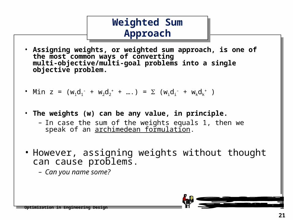
Weighted Sum ApproachWeighted Sum Approach
• Assigning weights, or weighted sum approach, is one of the most common ways of converting multi-objective/multi-goal problems into a single objective problem.
• Min z = (w1d1- + w2d2
+ + ….) = (widi- + wkdk
+ )
• The weights (w) can be any value, in principle.– In case the sum of the weights equals 1, then we speak of an
archimedean formulation.
• However, assigning weights without thought can cause problems.
– Can you name some?
Optimization in Engineering Design
22
Georgia Institute of TechnologySystems Realization Laboratory
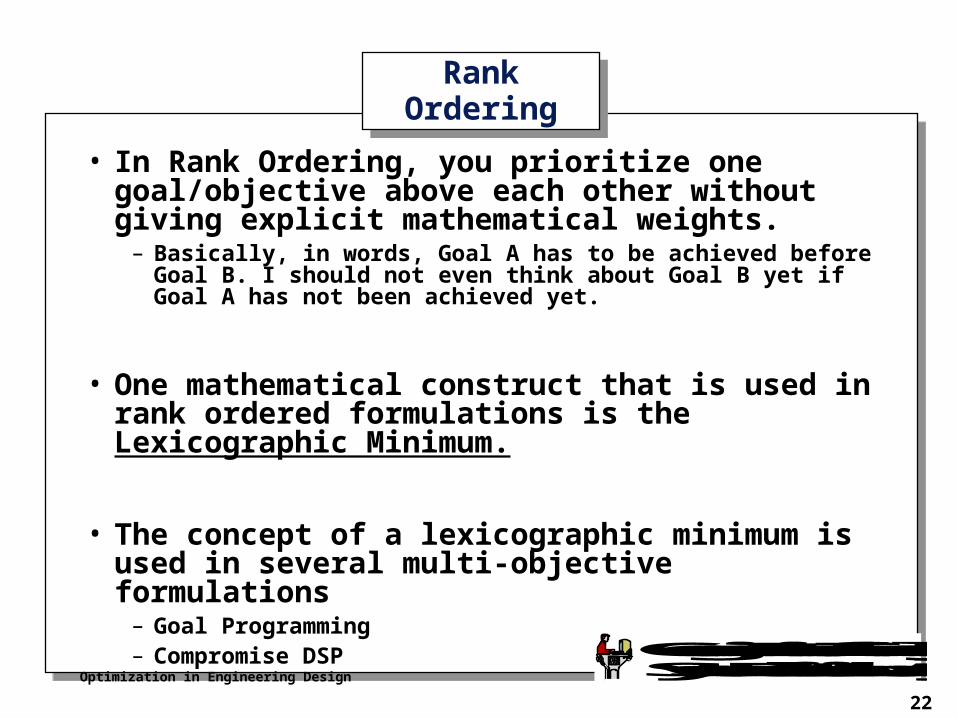
Rank OrderingRank Ordering
• In Rank Ordering, you prioritize one goal/objective above each other without giving explicit mathematical weights.
– Basically, in words, Goal A has to be achieved before Goal B. I should not even think about Goal B yet if Goal A has not been achieved yet.
• One mathematical construct that is used in rank ordered formulations is the Lexicographic Minimum.
• The concept of a lexicographic minimum is used in several multi-objective formulations
– Goal Programming– Compromise DSP
Optimization in Engineering Design
23
Georgia Institute of TechnologySystems Realization Laboratory
Lexicographic Minimum - DefinitionLexicographic Minimum - Definition
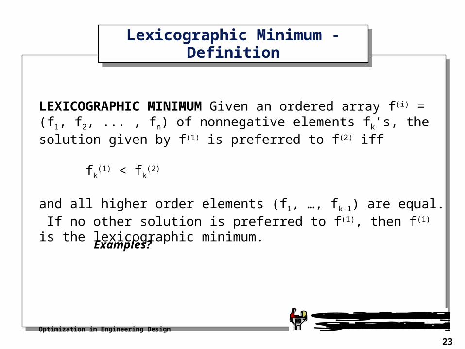
LEXICOGRAPHIC MINIMUM Given an ordered array f(i) = (f1, f2, ... , fn) of nonnegative elements fk’s, the solution given by f(1) is preferred to f(2) iff
fk(1) < fk
(2)
and all higher order elements (f1, …, fk-1) are equal. If no other solution is preferred to f(1), then f(1) is the lexicographic minimum.
Examples?
Optimization in Engineering Design
24
Georgia Institute of TechnologySystems Realization Laboratory
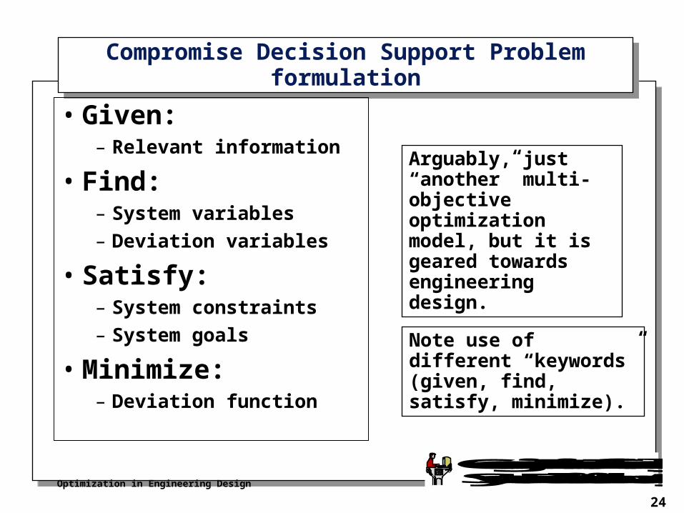
Compromise Decision Support Problem formulationCompromise Decision Support Problem formulation
• Given:– Relevant information
• Find:– System variables
– Deviation variables
• Satisfy:– System constraints
– System goals
• Minimize:– Deviation function
Arguably, just “another” multi-objective optimization model, but it is geared towards engineering design.
Note use of different “keywords” (given, find, satisfy, minimize).
Optimization in Engineering Design
25
Georgia Institute of TechnologySystems Realization Laboratory
The Effect of Selecting a FormulationThe Effect of Selecting a Formulation
• It is important to note that differences in formulation CAN cause differences in results.
• The most influential factors are the choices of:– Objectives versus goals
– Goal Priorities
– Constraints versus goals (constraints are higher priority)
– Goal targets
Optimization in Engineering Design
26
Georgia Institute of TechnologySystems Realization Laboratory
Case Study/Example Case Study/Example
Optimization in Engineering Design
27
Georgia Institute of TechnologySystems Realization Laboratory
Rotating Disk (Flywheel) ExampleRotating Disk (Flywheel) Example
w(r)
r
w1(r)w2(r)
w3(r)
w4(r)
P1 = 0.10 P5 = 1.0
U
(L +
U
)/2.
0
L
P2 P3
P4
Z
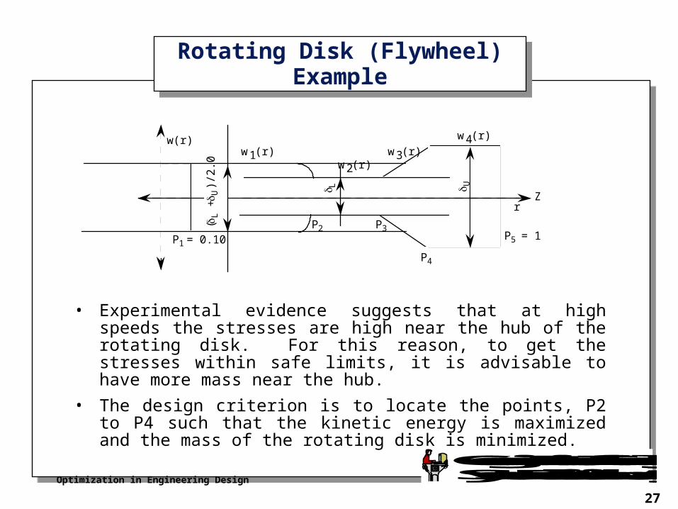
• Experimental evidence suggests that at high speeds the stresses are high near the hub of the rotating disk. For this reason, to get the stresses within safe limits, it is advisable to have more mass near the hub.
• The design criterion is to locate the points, P2 to P4 such that the kinetic energy is maximized and the mass of the rotating disk is minimized.
Optimization in Engineering Design
28
Georgia Institute of TechnologySystems Realization Laboratory
“Baseline” Model for Flywheel“Baseline” Model for Flywheel
are the radial stress, tangential stress and yield stress
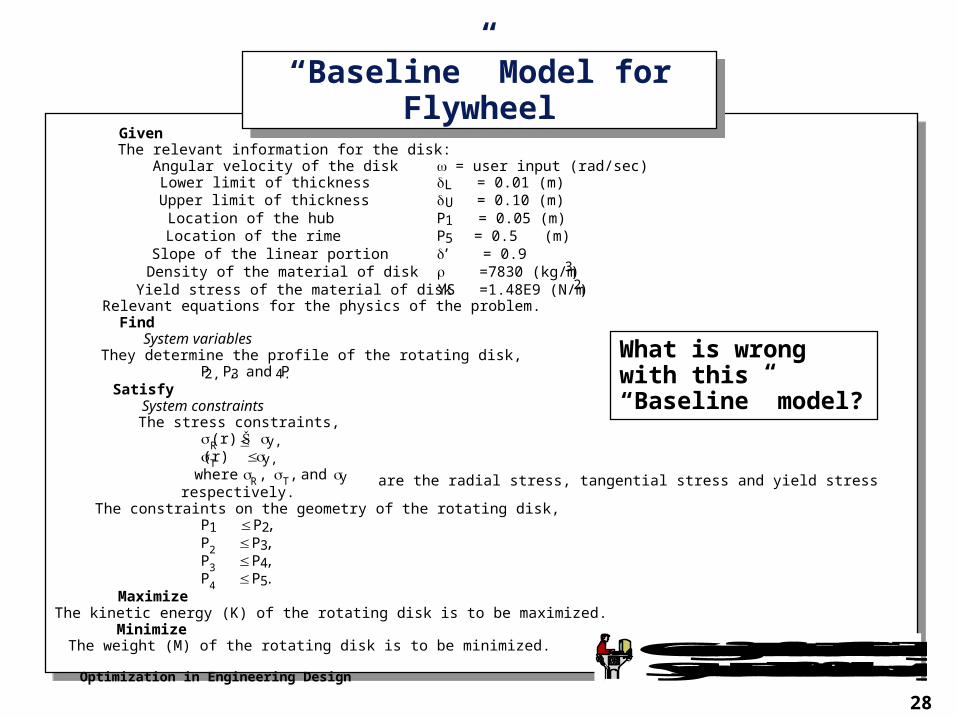
GivenThe relevant information for the disk:
Angular velocity of the disk = user input (rad/sec)Lower limit of thickness L = 0.01 (m)Upper limit of thickness U = 0.10 (m)Location of the hub P1 = 0.05 (m)Location of the rime P5 = 0.5 (m)Slope of the linear portion ’ = 0.9Density of the material of disk =7830 (kg/m3)Yield stress of the material of disk YS =1.48E9 (N/m2)
Relevant equations for the physics of the problem.Find
System variablesThey determine the profile of the rotating disk,
P2, P3, and P4.Satisfy
System constraintsThe stress constraints,
R(r) Š y,T(r) y,where R , T , and y respectively.
The constraints on the geometry of the rotating disk,P1 P2,P2 P3,P3 P4,P4 P5.
MaximizeThe kinetic energy (K) of the rotating disk is to be maximized.
MinimizeThe weight (M) of the rotating disk is to be minimized.
What is wrong with this “Baseline” model?
Optimization in Engineering Design
29
Georgia Institute of TechnologySystems Realization Laboratory
Different single objective functionsDifferent single objective functions
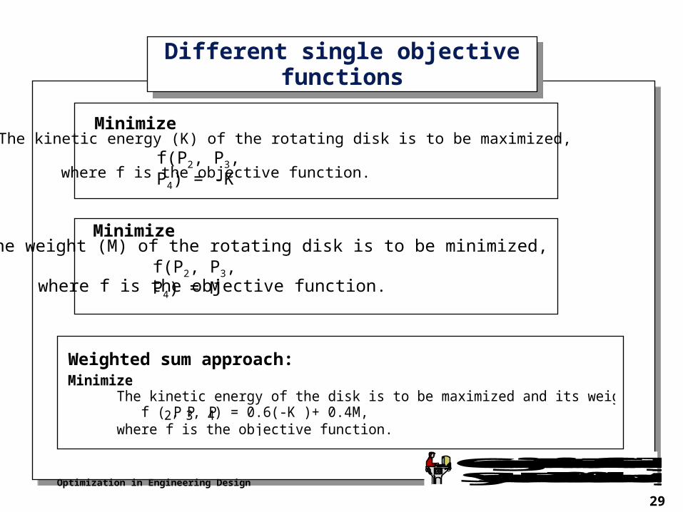
MinimizeThe kinetic energy of the disk is to be maximized and its weight (M) is to be minimized,
f ( P2, P3, P4) = 0.6(-K )+ 0.4M,where f is the objective function.
Weighted sum approach:
MinimizeThe kinetic energy (K) of the rotating disk is to be maximized,
where f is the objective function.f(P2, P3, P4) = -K
MinimizeThe weight (M) of the rotating disk is to be minimized,
where f is the objective function.f(P2, P3, P4) = M
Optimization in Engineering Design
30
Georgia Institute of TechnologySystems Realization Laboratory
Different Design ScenariosDifferent Design Scenarios
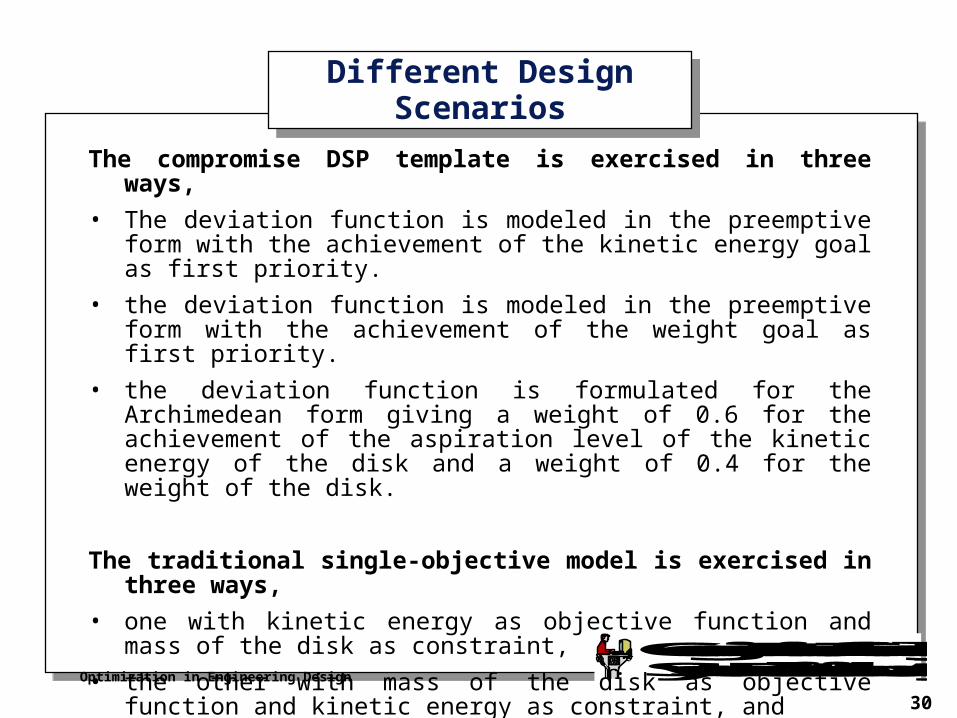
The compromise DSP template is exercised in three ways,
• The deviation function is modeled in the preemptive form with the achievement of the kinetic energy goal as first priority.
• the deviation function is modeled in the preemptive form with the achievement of the weight goal as first priority.
• the deviation function is formulated for the Archimedean form giving a weight of 0.6 for the achievement of the aspiration level of the kinetic energy of the disk and a weight of 0.4 for the weight of the disk.
The traditional single-objective model is exercised in three ways,
• one with kinetic energy as objective function and mass of the disk as constraint,
• the other with mass of the disk as objective function and kinetic energy as constraint, and
• as a weighted sum of the two objectives.
Optimization in Engineering Design
31
Georgia Institute of TechnologySystems Realization Laboratory
Differences in ResultsDifferences in Results
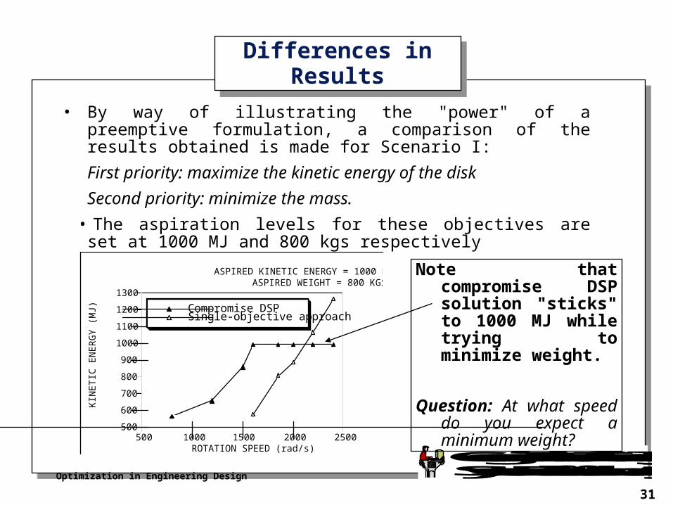
• By way of illustrating the "power" of a preemptive formulation, a comparison of the results obtained is made for Scenario I:
First priority: maximize the kinetic energy of the disk
Second priority: minimize the mass.
• The aspiration levels for these objectives are set at 1000 MJ and 800 kgs respectively
500
600
700
800
900
1000
1100
1200
1300
KIN
ET
IC E
NE
RG
Y (
MJ)
500 1000 1500 2000 2500ROTATION SPEED (rad/s)
Compromise DSPSingle-objective approach
ASPIRED KINETIC ENERGY = 1000 MJASPIRED WEIGHT = 800 KGS
Note that compromise DSP solution "sticks" to 1000 MJ while trying to minimize weight.
Question: At what speed do you expect a minimum weight?