Embed Size (px)
Citation preview

International Journal of Hybrid Information Technology
Vol. x, No. x, xxxxx, 2008
83
Opportunistic Wireless Internet Access in Vehicular Environments
Using Enhanced WAVE Devices
Yunpeng Zang, Erik Weiss, Lothar Stibor, Bernhard Walke, Hui Chen, Xi Cheng Chair of Communication Networks, RWTH Aachen University
{zyp, erw, lsr, walke, hui, bcx}@comnets.rwth-aachen.de
Abstract
The emerging Car-to-Car communication (C2C) technology, known as Wireless Access in
Vehicular Environments (WAVE), enables vehicles on the roadway to communicate with each
other and with the roadside infrastructure. In addition to safety-relevant services, drivers may
also need Internet access through C2C communications for infotainment services and car
maintenance services, as specified in MobilitY and CollAboRative Work in European Vehicle
Emergency NeTworks (MYCAREVENT) project. In this article we propose solutions for
providing on-board Internet access service to automotive users through C2C
communications. The proposed solutions make use of roadside infrastructure and the novel
MYCAREVENT Vehicular Communication Gateway (VCG) device. A management scheme is
developed for the opportunistic wireless links between On-Board Units (OBUs) and Road-
Side Units (RSUs), as well as between OBUs and VCGs in vehicular communications.
Furthermore, we invent a novel MAC queue architecture addressing the drawback of the
current WAVE MAC protocol in supporting unicast traffic in highly dynamic vehicular
environments. At the end, stochastic simulation results are presented to prove the concepts
and validate the proposed solutions.
1. Introduction
The emerging wireless vehicular communication technologies are intended to improve
safety and comfort of transportation systems. The newly standardized Wireless Access in
Vehicular Environments (WAVE) system is based on the IEEE Wireless Local Area Network
(WLAN) technology. It is able to provide broadband Car-to-Car (C2C) and Car-to-Roadside
(C2X) communications for both safety relevant and commercial applications.
One of the typical commercial services in vehicular environments is the onboard Internet
access for car maintenance, which is specified by the MobilitY and CollAboRative Work in
European Vehicle Emergency NeTworks (MYCAREVENT) project [1]. MYCAREVENT
project is aiming to optimize the European market for after-sales and repair services. Within
the project, partners develop and implement new applications and services, which can be
accessed remotely and securely. These services will provide the customers with manufacturer
specific repair information according to the problems identified by vehicle diagnosis systems.
Mobile communication is used to communicate with the On-Board Diagnostic (OBD), to
gather breakdown information and to access web based services for repair information. [1]

International Journal of Hybrid Information Technology
Vol. 1, No. 2, April, 2008
84
Database
Diagnostic Tools:
Knowledge Management
Expert System
Artificial intelligenceReceive repair info and
spare parts requirement
Communication to a Manufacturer
Road Side Assistance
Arrive at breakdown location
and perform the relevant repairs
Database
Diagnostic Tools:
Knowledge Management
Expert System
Artificial intelligence
Spare Parts Supplier
Receive repair info and
spare parts requirement
Communication to a Manufacturer
Road Side Assistance
Arrive at breakdown location
and perform the relevant repairs
Failure Message
Always Best Connected
- GPRS, UMTS, WLAN, etc.
- Secure Transmission
- Reliable Transmission
Access Central
Information Ressource
Repair Informations
Request
Spare Parts
Database
Diagnostic Tools:
Knowledge Management
Expert System
Artificial intelligenceReceive repair info and
spare parts requirement
Communication to a Manufacturer
Road Side Assistance
Arrive at breakdown location
and perform the relevant repairs
Database
Diagnostic Tools:
Knowledge Management
Expert System
Artificial intelligence
Spare Parts Supplier
Receive repair info and
spare parts requirement
Communication to a Manufacturer
Road Side Assistance
Arrive at breakdown location
and perform the relevant repairs
Failure Message
Always Best Connected
- GPRS, UMTS, WLAN, etc.
- Secure Transmission
- Reliable Transmission
Access Central
Information Ressource
Repair Informations
Request
Spare Parts
Figure Figure Figure Figure 1111. MYCAREVENT information flow. MYCAREVENT information flow. MYCAREVENT information flow. MYCAREVENT information flow
Figure 1 shows the information flow to conduct this service from vehicle failure to the
restored mobility. Starting with the car reporting a failure, subsequent information is
transmitted to a service provider using mobile communication. This error message is analyzed
with an existing database, guidance and repair instructions are provided, and if necessary, a
process to deliver additional spare parts is initiated. Transmitting the information enables the
roadside assistance solving the problem.
This example shows that the ubiquitous Internet access is essential to the future automotive
users. To solve the problem the MYCAREVENT consortium investigated the potential of
various mobile devices and communication networks and designed an “always best
connected” Vehicle Communication Gateway (VCG) for the roadside patrol and the driver.
The VCG is able to seamlessly switch among multiple of available mobile communication
networks, e.g. GRPS, UMTS or WLAN, and provide continuous, secure and always best data
communication between the end user and the backend MYCAREVENT service portal. [2]
However, cost and high system complexity make it difficult for VCG devices to achieve a
high market penetration ratio in either short- or long-term market perspective. On the
contrary, the emerging WAVE C2C technology is becoming more and more prevailing due to
its important role in future active driving safety systems [8]. Furthermore, the WAVE system
was designed keeping in mind supports for generic IP services through C2C and C2X
wireless links.
In this article, we investigate the feasibility of using the WAVE technology to provide
Internet access for automotive users in vehicular environments. Two architectures are studied
in this paper. The one is to make use of the direct communication between WAVE On-Board
Units (OBUs) and Road Side Unit (RSU), while the other integrates the MYCAREVENT
VCGs and WAVE OBUs. Contributions of this work are threefold: 1. We propose and prove
the concept of using WAVE system to provide the Internet access for on-road automotive
users. 2. In order to make use of the opportunistic wireless communication links between
OBUs and RSUs/VCGs we developed a dynamic wireless link management solution in
vehicular environments. 3. We reveal a drawback of the current WAVE MAC protocol in
supporting the unicast IP communication in highly dynamic Vehicular Ad-Hoc Network
(VANET) and invent a novel MAC queue architecture to solve the problem.
International Journal of Hybrid Information Technology
Vol. 1, No. 2, April, 2008
85
The rest of the article is organized as follows: In section 2 and section 3 we briefly review
the WAVE system for vehicular communication and the VCG solution developed in
MYCAREVENT project [2], respectively. The two kinds of Internet access solutions in
vehicular environments using C2C/C2X technologies are described in section 4. In section 5,
we concentrate on the MAC layer protocol of the solutions and present the dynamic link
management scheme and the enhanced MAC queue architecture regarding the high mobility
in VANETs. Section 6 presents stochastic simulation results and discussions. Section 7
concludes the paper with outlooks to future work.
2. The Wireless Access in Vehicular Environments (WAVE) system
In order to support various safety and commercial applications in vehicular environments,
the IEEE 1609 and IEEE 802.11p [3] task groups developed an IEEE 802.11 WLAN based
C2C/C2X communication system, known as Wireless Access in Vehicular Environments
(WAVE). This system works on the 5.9GHz ITS frequency band regulated by FCC in the
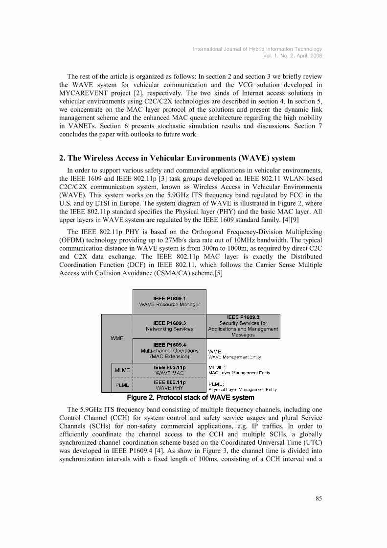
U.S. and by ETSI in Europe. The system diagram of WAVE is illustrated in Figure 2, where
the IEEE 802.11p standard specifies the Physical layer (PHY) and the basic MAC layer. All
upper layers in WAVE system are regulated by the IEEE 1609 standard family. [4][9]
The IEEE 802.11p PHY is based on the Orthogonal Frequency-Division Multiplexing
(OFDM) technology providing up to 27Mb/s data rate out of 10MHz bandwidth. The typical
communication distance in WAVE system is from 300m to 1000m, as required by direct C2C
and C2X data exchange. The IEEE 802.11p MAC layer is exactly the Distributed
Coordination Function (DCF) in IEEE 802.11, which follows the Carrier Sense Multiple
Access with Collision Avoidance (CSMA/CA) scheme.[5]
Figure Figure Figure Figure 2222. Protocol stack of WAVE system. Protocol stack of WAVE system. Protocol stack of WAVE system. Protocol stack of WAVE system
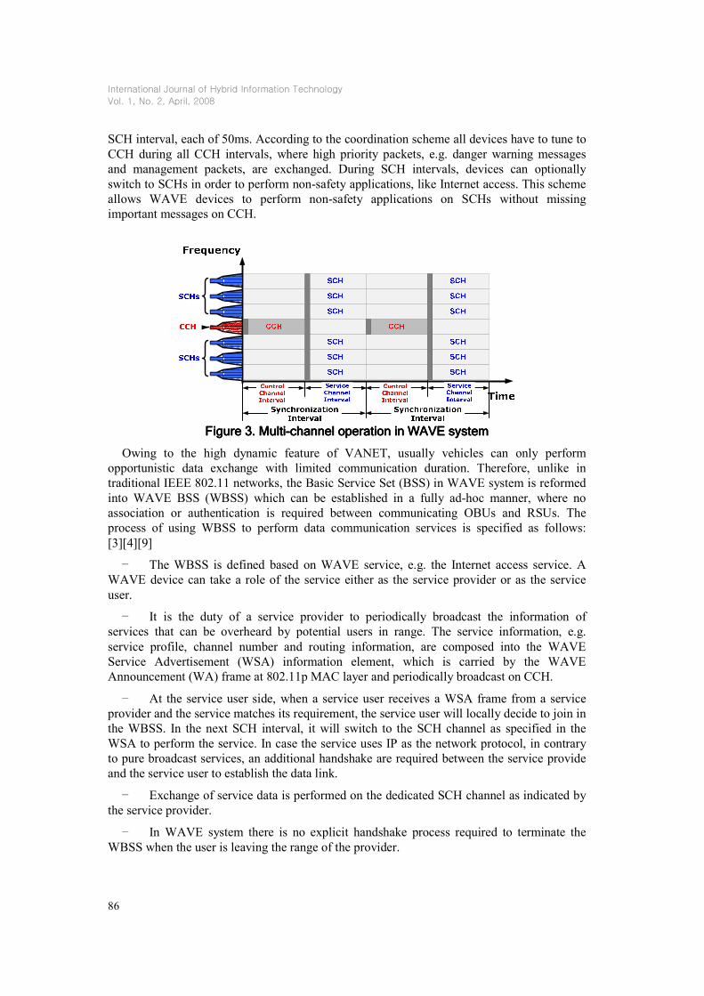
The 5.9GHz ITS frequency band consisting of multiple frequency channels, including one
Control Channel (CCH) for system control and safety service usages and plural Service
Channels (SCHs) for non-safety commercial applications, e.g. IP traffics. In order to
efficiently coordinate the channel access to the CCH and multiple SCHs, a globally
synchronized channel coordination scheme based on the Coordinated Universal Time (UTC)
was developed in IEEE P1609.4 [4]. As show in Figure 3, the channel time is divided into
synchronization intervals with a fixed length of 100ms, consisting of a CCH interval and a
International Journal of Hybrid Information Technology
Vol. 1, No. 2, April, 2008
86
SCH interval, each of 50ms. According to the coordination scheme all devices have to tune to
CCH during all CCH intervals, where high priority packets, e.g. danger warning messages
and management packets, are exchanged. During SCH intervals, devices can optionally
switch to SCHs in order to perform non-safety applications, like Internet access. This scheme
allows WAVE devices to perform non-safety applications on SCHs without missing
important messages on CCH.
Figure Figure Figure Figure 3333. . . . MultiMultiMultiMulti----channel operation in WAVEchannel operation in WAVEchannel operation in WAVEchannel operation in WAVE system system system system
Owing to the high dynamic feature of VANET, usually vehicles can only perform
opportunistic data exchange with limited communication duration. Therefore, unlike in
traditional IEEE 802.11 networks, the Basic Service Set (BSS) in WAVE system is reformed
into WAVE BSS (WBSS) which can be established in a fully ad-hoc manner, where no
association or authentication is required between communicating OBUs and RSUs. The
process of using WBSS to perform data communication services is specified as follows:
[3][4][9]
– The WBSS is defined based on WAVE service, e.g. the Internet access service. A WAVE device can take a role of the service either as the service provider or as the service
user.
– It is the duty of a service provider to periodically broadcast the information of services that can be overheard by potential users in range. The service information, e.g.
service profile, channel number and routing information, are composed into the WAVE
Service Advertisement (WSA) information element, which is carried by the WAVE
Announcement (WA) frame at 802.11p MAC layer and periodically broadcast on CCH.
– At the service user side, when a service user receives a WSA frame from a service provider and the service matches its requirement, the service user will locally decide to join in
the WBSS. In the next SCH interval, it will switch to the SCH channel as specified in the
WSA to perform the service. In case the service uses IP as the network protocol, in contrary
to pure broadcast services, an additional handshake are required between the service provide
and the service user to establish the data link.
– Exchange of service data is performed on the dedicated SCH channel as indicated by the service provider.
– In WAVE system there is no explicit handshake process required to terminate the WBSS when the user is leaving the range of the provider.

International Journal of Hybrid Information Technology
Vol. 1, No. 2, April, 2008
87
It can be seen that the organization of WBSS in WAVE is in favor of reducing the
management overhead and tolerating the mobility of vehicle in VANET. Based on this idea
and the above described protocol we develop a dynamic link management scheme for
wireless Internet access in vehicular environments, as presented in section 5.
3. MYCAREVENT Vehicular Communication Gateway (VCG)
The main idea of MYCAREVENT VCG is to incorporate several communication systems
such as GPRS, UMTS and WLAN and to provide the gateway users “always best connected”
Internet access services. Figure 4 shows the architecture and functionalities of VCG.
Car Communication
Gateway
BT
WLAN
Serial
…
Network
Bridge
Mobility
Management
Encryption
Authentication
(VPN)
Reliability
QoS
Routing Service network
Dynamic
Network
Selection
DHCP
Ethernet
Communication towards
Service Provider
Car-Side
Communication
UMTS
GSM/GPRS
WLAN
Ethernet
4G, …
Car Communication
Gateway
BT
WLAN
Serial
…
Network
Bridge
Mobility
Management
Encryption
Authentication
(VPN)
Reliability
QoS
Routing Service network
Dynamic
Network
Selection
DHCP
Ethernet
Communication towards
Service Provider
Car-Side
Communication
UMTS
GSM/GPRS
WLAN
Ethernet
4G, …
UMTS
GSM/GPRS
WLAN
Ethernet
4G, …
Figure Figure Figure Figure 4444. . . . MYCAREVENT Vehicular Communication GatewayMYCAREVENT Vehicular Communication GatewayMYCAREVENT Vehicular Communication GatewayMYCAREVENT Vehicular Communication Gateway (VGC) (VGC) (VGC) (VGC)
On the right hand side of Figure 4 the communication towards the service provider is
depicted. Several communication media are envisaged. A dynamic network selection chooses
the most suitable communication medium according to Quality of Service (QoS) criteria.
Moreover, this could also be a combination of two or more parallel communication
technologies for better QoS support. The left part describes a classical gateway design, except
that many different technologies can be used to attach to the gateway as the central point of
communication. Mobile devices, such as the roadside patrol’s laptop, driver’s PDA or other
C2C OBUs will be able to connect to the gateway. The functions mobility management
(MM), encryption, authentication, QoS mapping, enhanced reliability and routing are shown
in the middle of Figure 4. Thus, the gateway offers an advanced and flexible communication
service, through which the Car-side users can enjoy the encrypted and reliable
communication within the range of VCG. Opportunistic internet access is also possible for
occasionally passing by OBUs, if an efficient service discovery and link management scheme
can be used between the VCG and the OBUs.
4. Internet access in vehicular environments with WAVE devices
Two architectures of Internet access in vehicular environments using WAVE technology
are presented in this section, as shown in Figure 5 and Figure 6, respectively.

International Journal of Hybrid Information Technology
Vol. 1, No. 2, April, 2008
88
Figure Figure Figure Figure 5555. . . . Wireless Internet access through WAVE RSUsWireless Internet access through WAVE RSUsWireless Internet access through WAVE RSUsWireless Internet access through WAVE RSUs
4.1. WAVE RSU Solution
In the WAVE system, the roadside infrastructure, i.e., RSUs usually have connection to the
IP backbone and can act as the Internet access service providers for passing by OBUs. The
Internet access will be a WAVE service provided on SCHs. This solution is also known as
drive-thru Internet in [6], where the original IEEE 802.11 WLAN technology is used.
4.2 MYCAREVENT VCG solution
The second solution integrates WAVE C2C/C2X communications with the
MYCAREVENT VCGs. As shown in Figure 6, for safety reason all WAVE OBUs have to
self-organize into VANET on the roadway and keep communicating with each other. Some of
these vehicles that have VCG equipped may operate as the Internet access gateways of the
autonomously formed VANET. The VCGs, in this case, on the one hand connect to the
Internet service provider through UMTS, GPRS or WiMAX, while on the other hand provide
Internet access using the WAVE C2C communication to other surrounding vehicles. In the
example illustrated in Figure 6 a broken vehicle located outside the RSU range may have
opportunity to get Internet access via the passing by VCGs.
Figure Figure Figure Figure 6666. . . . Wireless Internet access through MYCAREVENT VCGWireless Internet access through MYCAREVENT VCGWireless Internet access through MYCAREVENT VCGWireless Internet access through MYCAREVENT VCG
The common point of these two architectures is that WAVE C2C users have to detect the
opportunistic Internet access services provided by either RSUs or VCGs, and perform data
communication within the limited duration in VANET.

International Journal of Hybrid Information Technology
Vol. 1, No. 2, April, 2008
89
5. MAC enhancements to WAVE protocol for Internet access in VANET
Challenges of providing Internet access to automotive users include the unreliable quality
of wireless link, non-deterministic communication opportunities and the limited
communication duration, which are all owing to high vehicle mobility.
The performance of providing Internet access to automotive users using IEEE WLAN
technologies has been studied with field test in [6][7][10][11]. The architecture being studied
in these works is known as drive-thru Internet and is similar to the WAVE RSU solution we
described in the previous section. Common conclusions from these works include: (1)
Although the communication range and duration are limited, the amount of data being
delivered is still considerable; (2) The whole communication process of drive-thru Internet
consists three phases, namely entry phase, production phase and exit phase and only the
production phase is considered to be really productive; (3) The currently protocol can achieve
only a small portion of the possible throughput, e.g. 50% [10], due to the sub-optimized
protocol; (4) Protocol overhead and efficiency in high mobility environments are the main
reasons for the unsatisfied performance. Therefore, one direction to solve these problems is to
redesign the protocol taking consideration of the high dynamic feature of VANET. In the
following subsections we concentrate on the MAC layer and proposed two mechanisms in
this direction. Unlike previous works, our study uses the newly standardized WAVE system,
instead of the traditional IEEE 802.11 WLAN, since WAVE is specifically developed for
high mobility vehicular environments. Another extension to the previous works is that instead
of the simple scenario with only one Internet service user and one provider, we try to figure
out the solution for more realistic VANET scenarios consisting of multiple Internet users and
access providers.
5.1.1. Dynamic Link Management in VANET
As studied by Hadaller et al. [10] the ability of MAC layer protocol in dealing the highly
dynamic opportunistic wireless link is essential to the throughput performance. In this section,
we propose a highly efficient dynamic link management scheme using the WBSS concept
developed in WAVE.
The main idea is that instead of treating the drive-thru process as a while session, the
process is divided into multiple of sub-sessions, which are mapped to the synchronization
intervals at WAVE MAC layer. The links between OBUs and RSUs are consistently
monitored and managed in each session. That means the MAC entities of OBUs and RSUs
can perform data communication only when the link state is healthy enough. This is important
in realistic VANET scenarios, as when multiple users share the same channel resource,
unnecessary transmissions may produce pure interference and congest the channel.
Based on the CCH/SCH interval structure and the WBSS concept in WAVE we design a
link state monitor and management scheme composed with the periodical WSA frame from
RUS and a hand shake process before the each data exchange on SCH.
The Message Sequence Chart (MSC) for the service discovery and link establishment
process is shown in Figure 7. Generally the process follows the WBSS operation specified in
section 2. In order to cope with the high mobility in VANET, we propose to suspend all
existing wireless links at the end of each SCH interval. A suspended link can be resumed in

International Journal of Hybrid Information Technology
Vol. 1, No. 2, April, 2008
90
the next SCH interval only if a successful WSA and service request handshake is performed
between the corresponding provider and user in the CCH preceding the next SCH. Otherwise
it keeps suspended. If a link has been suspended for n continuous synchronization intervals, it
is will be abandoned, as the pair may have already been out the range of communication.
According to the WAVE standard, the synchronization interval is 100ms, consisting 50ms
CCH interval and 50ms SCH interval, which is short enough to trace the position update of
vehicles. Although this process introduces overhead for link management, the overhead is on
the CCH and will not hinder the data transmission on SCHs. This link management scheme
can efficiently reduce unnecessary interference and guarantee the system throughput,
especially when the number of user and provider is large.
Figure Figure Figure Figure 7777. . . . MSC of dynamic link management scheme for WAVE IP traffic servicesMSC of dynamic link management scheme for WAVE IP traffic servicesMSC of dynamic link management scheme for WAVE IP traffic servicesMSC of dynamic link management scheme for WAVE IP traffic services
5.1.2. Enhanced WAVE MAC Queue Architecture for VANET
In this section we invent a novel architecture of packet queuing scheme to the current
WAVE MAC for better performance in highly dynamic VANET.
In order to support data traffics of different priorities the current WAVE MAC employ the
same MAC queue architecture as in IEEE 802.11e [5], which is shown in Figure 8. In the
WAVE system, two groups of traffic queues are maintained independently for CCH and SCH
access. In each group four traffic queues are assigned to four Access Categories (ACs), which
are mapped to four different user priorities of the traffic. Each queue is a virtual station
conducting backoff independently and competing for the channel access with other queues in

International Journal of Hybrid Information Technology
Vol. 1, No. 2, April, 2008
91
the same group. The Internal Contention is to choose a winner of the competition according to
user priorities. These two groups of queues work alternatively during CCH and SCH interval,
which is managed by the Channel Selector. It can be seen that all data packets of the same
priority are filled in to the same queue, no matter which wireless link they belong to.
Moreover, according to the IEEE 802.11p MAC, the queue works in a First-In-First-Out
(FIFO) way and a packet will not be removed from the queue until it is successfully
acknowledged or the retry limit of the packet is reached.
Figure Figure Figure Figure 8888. . . . IEEE 1609.4 WAVE MAC queue architectureIEEE 1609.4 WAVE MAC queue architectureIEEE 1609.4 WAVE MAC queue architectureIEEE 1609.4 WAVE MAC queue architecture
However, this scheme has a drawback in high mobility VANET. As shown in Figure 9,
packets of the same priority but for different wireless links are buffered into the same FIFO
queue. The problem occurs when a wireless link is broken because of vehicle movement. The
obsolete packets of the broken link are retransmitted again and again, which blocks the
packets for the other wireless links that are alive, until the dynamic wireless link management
realizes the link is out of date and discards all its obsolete packets from the queue.
Figure Figure Figure Figure 9999. . . . Obsolete packet problem with WAVE MAC queueObsolete packet problem with WAVE MAC queueObsolete packet problem with WAVE MAC queueObsolete packet problem with WAVE MAC queue
To solve this problem we propose a new MAC queue architecture, namely wireless Link
Based Queue (LBQ) architecture, as shown in Figure 10. Comparing to the old architecture
there are two major differences. The first one is that for each wireless link there is a unique
queue, i.e. only packets of this wireless link are stored. The second change is that in addition
to the Internal Contention among different ACs, we introduce a second level of Internal
Contention among different wireless links of the same AC. Combined with the dynamic

International Journal of Hybrid Information Technology
Vol. 1, No. 2, April, 2008
92
wireless link manage scheme described in the previous subsection, this architecture allows
only packets of wireless links that are alive compete the channel access. Therefore, the waste
of channel resource caused by obsolete packets can be avoided, i.e. achieving better system
performance, as we shown with simulation results in section 6.
Figure Figure Figure Figure 10101010. . . . Wireless link based MAC queue architecture for WAVEWireless link based MAC queue architecture for WAVEWireless link based MAC queue architecture for WAVEWireless link based MAC queue architecture for WAVE
6. Simulation results
Simulative performance evaluations are conducted with the Wireless Access Radio
Protocol II (WARP2) simulation environment developed in chair of communication
networks, RWTH Aachen University. The WAVE MAC and PHY protocols have been
implemented in WARP2. [12] All simulations are performed with the WAVE CCH/SCH
multi-channel architecture, as specified in section 2. In the simulations, all devices are
assumed to be perfectly synchronized in order to perform the CCH/SCH switching. It has to
be mentioned that the CCH interval takes only half of the overall channel time. Thus, the
results shown here represent half of the capability of IEEE 802.11p PHY. The simulation
parameters are taken from the current IEEE 802.11p standard draft, as shown in Table 1.
Table Table Table Table 1111. . . . PHY&MAC PHY&MAC PHY&MAC PHY&MAC relevant parametersrelevant parametersrelevant parametersrelevant parameters Parameter Value
OFDM symbol duration 8 µs
PLCL preamble length 32 µs
PLCP header length 8 µs
pSlotTime 16 µs
pSIFS 32 µs
pDIFS 64 µs
MAC frame header size 30 B
ACK frame header size 10 B

International Journal of Hybrid Information Technology
Vol. 1, No. 2, April, 2008
93
First of all, we show the effectiveness of the dynamic link management scheme and the
enhanced MAC queue architecture. The simulation scenario is depicted in Figure 11, where
three OBUs pass by two WAVE RSUs in sequence. Each vehicle initiates an IP link
according to the link management process specified in section 5 and downloads data from the
RSU. All OBU and RSU use queue size of 50 at MAC layer, PHY mode of 16QAM½, i.e.
12Mb/s, MAC Service Data Unit (MSDU) size of 512B and overloaded traffic source for
each link. Figure 12 shows the distance between each vehicle and the closest RSU to it.
Transmit
Queue
(AC=2)
7
9
1023
1
8
1
Figure Figure Figure Figure 11111111. . . . Simulation scenario for the MAC queue enhancementSimulation scenario for the MAC queue enhancementSimulation scenario for the MAC queue enhancementSimulation scenario for the MAC queue enhancement
0 2 4 6 8 10 12 14 16 18 20
101
102
Distance to RSU (m)
Simulation time (s)
Mobility Information (Validation of LBQ)
Link 1
Link 2
Link 3
Figure Figure Figure Figure 12121212. D. D. D. Distance between each vehicle and RSUsistance between each vehicle and RSUsistance between each vehicle and RSUsistance between each vehicle and RSUs
Figure 13 and Figure 14 show the instant throughput over time, during which vehicles are
moving from the range of RSU1 to that of RSU2. The instant throughput is evaluated with the
time interval of 100ms. In Figure 13, it is observed that with the original WAVE MAC queue
architecture the throughputs of the later two cars, i.e. the green one and the blue one, are
seriously deteriorated due to the obsolete packets of the first car (red) in the same queue.
However, with the proposed Link Based Queue (LBQ) architecture and the dynamic link
management scheme the instant throughputs of the green and the blue vehicles are greatly
improved, as shown in Figure 14, since according to the LBQ scheme the packets of each
wireless link are maintained in logically separated queues. Consequently, the overall system
throughput with LBQ architecture is much higher than that with the current WAVE MAC
queue architecture.

International Journal of Hybrid Information Technology
Vol. 1, No. 2, April, 2008
94
0 2 4 6 8 10 12 14 16 18 200
0.5
1
1.5
2
2.5
3
Current Throughput (M
b/s)
Simulation time (s)
WAVE Priority Based Queue
link 1
link 2
link 3
Figure Figure Figure Figure 13131313. . . . Instant throughput withInstant throughput withInstant throughput withInstant throughput withoutoutoutout link based MAC queue link based MAC queue link based MAC queue link based MAC queue
0 2 4 6 8 10 12 14 16 18 200
0.5
1
1.5
2
2.5
3
Current Throughput (M
b/s)
Simulation time (s)
LBQ
Link 1
Link 2
Link 3
Figure Figure Figure Figure 14141414. . . . InstInstInstInstant throughant throughant throughant throughput with link based MAC queue (bput with link based MAC queue (bput with link based MAC queue (bput with link based MAC queue (b))))
Secondly, we evaluate the MYCAREVENT VCG solution for Internet access in vehicular
environments taking account of the VCG market penetration ratio. The scenario is shown in
Figure 6, where a crashed vehicle stops at the roadside and uses WAVE C2C communication
to VCG for the opportunistic Internet access. In this work, our focus is on the performance of
opportunistic WAVE C2C communication. For the reason of simplicity, we model the link
between each VCG and the UMTS base station as the constant bit rate link of 384kb/s, and
the data buffer on each VCG can hold 50 packets for each C2C link. In this scenario a threeIn this scenario a threeIn this scenario a threeIn this scenario a three----lane highway on one direction is considered with vehicles lane highway on one direction is considered with vehicles lane highway on one direction is considered with vehicles lane highway on one direction is considered with vehicles allocated with iallocated with iallocated with iallocated with internternternter----vehicle distance of 60, 80 and 100 on slow, middle and fast vehicle distance of 60, 80 and 100 on slow, middle and fast vehicle distance of 60, 80 and 100 on slow, middle and fast vehicle distance of 60, 80 and 100 on slow, middle and fast
lanes, respectively. The scenario parameters are given in lanes, respectively. The scenario parameters are given in lanes, respectively. The scenario parameters are given in lanes, respectively. The scenario parameters are given in
Table 2.

International Journal of Hybrid Information Technology
Vol. 1, No. 2, April, 2008
95
Table Table Table Table 2222. Simulation parameters of MYCAREVENT VCG solution. Simulation parameters of MYCAREVENT VCG solution. Simulation parameters of MYCAREVENT VCG solution. Simulation parameters of MYCAREVENT VCG solution
Parameter Value
Vehicle speed 80, 120 and 160 km/h
Vehicle density 39 vehicle/km
TX Power 200 mW
PHY mode BPSK 1/2 (3Mb/s)
Traffic load 384 kb/s/VCG
Packet size 512 B
Penetration ratio of VCG 1%-9%, 10%-100%
The VCG penetration ratio is defined as the ratio of vehicles equipped with VCG devices
to overall number of vehicles in the scenarios. Vehicles with VCG are randomly distributed in
each simulation.
0 20 40 60 80 100 120 140 160 1800
0.25
0.5
0.75
1
1.25
Simulation Time (s)
Instant
Throughput (Mb/s)
Instant Throughput at the Broken Car, VCG Penetration Ratio: 2.6%
Figure Figure Figure Figure 15151515. Instant throughput at the broken car (VCG penetration ratio 2.6%). Instant throughput at the broken car (VCG penetration ratio 2.6%). Instant throughput at the broken car (VCG penetration ratio 2.6%). Instant throughput at the broken car (VCG penetration ratio 2.6%)
0 20 40 60 80 100 120 140 160 1800
0.250.50.75
11.251.5
Simulation Time (s)
Instant
Throughput (Mb/s)
Instant Throughput at the Broken Car, VCG Penetration Ratio: 20%
FigurFigurFigurFigure e e e 16161616. Instant throughput at the broken car (VCG penetration ratio 20.5%). Instant throughput at the broken car (VCG penetration ratio 20.5%). Instant throughput at the broken car (VCG penetration ratio 20.5%). Instant throughput at the broken car (VCG penetration ratio 20.5%)
0 20 40 60 80 100 120 140 160 1800
0.250.50.75
11.251.5
Simulation Time (s)
Instant
Throughput (Mb/s)
Instant Throughput at the Broken Car, VCG Penetration Ratio 100%
Figure Figure Figure Figure 17171717. . . . Instant throughput at the broken car Instant throughput at the broken car Instant throughput at the broken car Instant throughput at the broken car (VCG penetration ratio 100%)(VCG penetration ratio 100%)(VCG penetration ratio 100%)(VCG penetration ratio 100%)
Figure 15-Figure 17 show the instant throughput when the penetration ratio of VCG is
2.6%, i.e., 2 out of 78 vehicles have VCG devices, 20.5% and 100%, respectively. It is
obvious that due to the limited communication range of OBUs and VCGs, the link can be
established only when the broken car and certain VCG are in range of each other, which is
referred to as opportunistic communication. When the market penetration ratio of VCG is
low, e.g. 2.6% in Figure 15, the link between OBU and VCG are intermittent and the average
throughput is fairly low. If the VCG penetration ratio reaches 20.5%, the broken car can have
almost continuous Internet access all through the time. The reason is that with the given
vehicle density, communication range and penetration rate of 20.5%, statistically there are
always 3-4 VCGs in the range of the broken car.

International Journal of Hybrid Information Technology
Vol. 1, No. 2, April, 2008
96
1.3 2.6 3.8 5.1 6.4 7.7 9.0 10.3 11.50
0.1
0.2
0.3
0.4
0.5
0.6
0.7
0.8
0.9
1
VCG Penetration Ratio (%)
Average Throughput (Mb/s)
Average Throughput vs. VCG Penetration Ratio
Figure Figure Figure Figure 18181818. Average throughput vs. VCG penetration ratio (a). Average throughput vs. VCG penetration ratio (a). Average throughput vs. VCG penetration ratio (a). Average throughput vs. VCG penetration ratio (a)
10 20 30 40 50 60 70 80 90 1000
0.1
0.2
0.3
0.4
0.5
0.6
0.7
0.8
0.9
1
VCG Penetration Ratio (%)
Average Throughput (Mb/s)
Average Throughput vs. VCG Penetration Ratio
Figure Figure Figure Figure 19191919. . . . Average throughput vs. VAverage throughput vs. VAverage throughput vs. VAverage throughput vs. VCG penetration ratioCG penetration ratioCG penetration ratioCG penetration ratio (b) (b) (b) (b)
By multiplexing the simultaneously existing C2C links to multiple VCGs, the broken car
can reach the maximum throughput that is supported by the IEEE 802.11p SCH, i.e. about
1Mb/s using BPSK1/2 mode. The results in Figure 18 also show a almost linearity
relationship between the average throughput and increasing penetration ratio of VCG till
11.5%. However, simply increasing the penetration ratio of VCGs does not help anymore
after 20%. As shown in both Figure 17 and Figure 19, the average throughput decreases with
the increasing VCG penetration ratio. It is due to the CSMA scheme of IEEE 802.11p MAC,
whose performance deteriorates with the increasing number of contending stations in range.
7. Conclusion
Starting from a typical Internet access application on the roadway for car maintenance, in
this article we studied the solution for providing Internet access to automotive users through
WAVE C2C/C2X wireless communication. Two architectures of providing Internet access to
drivers using OBU to RSU communication and using OBU to VCG communication are
presented. Additionally, our study on the MAC layer protocol shows that using the proposed
dynamic link management scheme and the link status based MAC queue architecture, the

International Journal of Hybrid Information Technology
Vol. 1, No. 2, April, 2008
97
WAVE system can efficiently support Internet access application even in highly dynamic
vehicular environments.
In this work we conducted an early attempt toward using WAVE C2C/C2X
communication for providing general IP services to automotive users. However, to make the
wireless Internet access really happen on the roadway we have still many open problems,
such as the user privacy and information security problems, routing and data buffering issues
in dynamic network, cost and billing problems, etc. During the study, we realize that most of
the challenging issues are results from the movement of vehicles and the dynamic network
topology. To deal with these problems, the ability of environment awareness is required at
each of the OBU. For the future work, we would like to enhance the current WAVE protocol
with mobility awareness and use the acquired information to further improve the channel
access efficiency.
8. Acknowledgement
The authors would like to thank Guido Hiertz, Dr. C.-H. Rokitansky, Hans-Jürgen
Reumerman and Fahad Aijaz for their support and insightful advices to this work.
9. References [1] MobilitY and CollAboRative Work in European Vehicle Emergency NeTworks, 6th Framework European
Project, IST-004403; www.mycarevent.com
[2] Weiss, E.; Gehlen, G.; Muehleisen, M.; Rokitansky, C.-H.; Walke, B.; Georgi, L., Architecture of an Always Best Connected Vehicular Communication Gateway, In Proceedings of the 64th IEEE Vehicular Technology conference, p. 6, Montreal, Canada
[3] IEEE Standard for Information technology –Part 11: Wireless Medium Access Control (MAC) and Physical Layer (PHY) specifications: Amendment 3: Wireless Access in Vehicular Environments (WAVE), IEEE Draft Amendment P802.11p/D1.0, Feb. 2006
[4] IEEE P1609.4, Wireless Access in Vehicular Environments (WAVE) Multi-Channel Operation, IEEE Draft Standard P1609.4/D08, Apr. 2006
[5] Mangold, S.; Choi, S.; Hiertz, G.; Klein, O. and Walke, B. Analysis of IEEE 802.11e for QoS support in wireless LANs, Wireless Communications Magazine, IEEE, 2003, Volume 10, Page 40 – 50
[6] Ott, J. and Kutscher, D., The "drive-thru" architecture: WLAN-based Internet access on the road Vehicular Technology Conference, 2004. VTC 2004-Spring. 2004 IEEE 59th
[7] Gass, R.; Scott, J. and Diot, C. Measurements of In-Motion 802.11 Networking 7th IEEE Workshop on Mobile Computing Systems and Applications, 2006. WMCSA '06. 2006, 69 – 74
[8] The CAMP Vehicle Safety Communications Consortium consisting of BMW, D. and VW. Vehicle Safety Communications Project, Task 3 Final Report, Identify Intelligent Vehicle Safety Applications, Enabled by DSRC U.S. Department of Transportation, National Highway Traffic Safety Administration, 2005
[9] IEEE P1609.3, Wireless Access in Vehicular Environments (WAVE) Networking Services, IEEE Draft Standard P1609.3/D17, Nov. 2005
[10] Hadaller, D.; Keshav, S.; Brecht, T. and Agarwal, S. Vehicular opportunistic communication under the microscope MobiSys '07: Proceedings of the 5th international conference on Mobile systems, applications and services ACM Press, 2007, p. 206-219
[11] Ott, J. and Kutscher, D. Drive-thru Internet: IEEE 802.11b for "automobile" users Twenty-third Annual Joint Conference of the IEEE Computer and Communications Societies INFOCOM 2004
[12] Zang, Y.; Stibor, L.; Orfanos, G.; Guo, S. and Reumerman, H.-J., An Error Model for Inter-Vehicle Communications in Highway Scenarios at 5.9GHz Proceedings of the Second ACM International Workshop on Performance Evaluation of Wireless Ad Hoc, Sensor, and Ubiquitous Networks 2005, 49-56

International Journal of Hybrid Information Technology
Vol. 1, No. 2, April, 2008
98
Authors
Yunpeng Zang received his B.Engr. and M.Sc. from Beijing
University of Posts and Telecommunications, China, in 1999 and 2002,
respectively. Since 2003, he works as a research assistant towards his
PhD in Chair of Communication Networks (ComNets), RWTH Aachen
University, Germany. His current research interests are in wireless
vehicular communications, wireless personal area networks and wireless
mesh networks. He is a student member of IEEE since 2000.
Erik P. Weiss received his diploma degree in Electrical Engineering
from Aachen University, RWTH, Germany, in 2001. After his studies,
he joined the Chair of Communication Networks (ComNets) at RWTH
Aachen University, where he is working towards his Ph.D. degree. He
participates in the IPonAir project in cooperation with T-Systems. He
was involved in the European 6th framework project IST-
MYCAREVENT for vehicular diagnosis and maintenance and led the
work package for mobile communication (WP4). At present, he is
working for T-Mobile Deutschland GmbH in the area of network
deployment strategy. He is a student member of IEEE, inventor/co-
inventor of several patents and has authored/ co-authored several papers
at IEEE conferences.
Lothar Stibor received his diploma degree in Electrical Engineering
in 2004 from RWTH Aachen University. Since then, he is with the
Chair of Communication Networks where he is working towards his
Ph.D. His research interests are distributed medium access protocols for
vehicular ad-hoc networks. He is involved in the design and
standardization of IEEE 802.11p.

International Journal of Hybrid Information Technology
Vol. 1, No. 2, April, 2008
99
Bernhard H. Walke for 18 years now is running the Chair for
Communication Networks at RWTH Aachen University, Germany,
where his group of about 30 researchers works on air-interface design
and development of tools for performance evaluation of services and
protocols of future wireless and mobile systems. This research is mainly
funded from third parties' grants. He has published about 180 reviewed
conference/journal papers and eight textbooks on architecture, traffic
performance evaluation and design of future communication systems.
Some of which show more than 100 scholar.google citations.
Prior to joining academia, Prof. Walke worked for 18 years in various
industry positions at AEG-Telefunken (now EADS AG). Prof. Walke
holds a diploma and Dr. in information engineering, both from
University of Stuttgart, Germany. He is a founder of the annual
European Wireless conference, Senior Member of IEEE COMSOC and
member of the IEEE COMSOC Awards Committee.
Hui Chen received her B.S. degree in automation engineering from
Shanghai Jiaotong University in 2003 and her Master’s degree in
communications engineering at RWTH, Aachen University in 2006.
From 2006 until early 2007, she worked in Chair of Communication
Networks (ComNets) for her master thesis focusing on Vehicular Ad-
Hoc Network MAC Protocols on QoS support, and later on worked as
student research assistant with interest in dynamic network protocol
study.
Xi Cheng received his B.Engr from Huazhong University of Science
& Technology, China, 2004 and his M.Sc from RWTH Aachen
University, Germany, 2007, respectively. Currently he is working as a
student research assistant in Chair of Communication Networks
(ComNets), RWTH Aachen. His research interests include wireless
vehicular communications and wireless mobile communications of next
generation.

International Journal of Hybrid Information Technology
Vol. 1, No. 2, April, 2008
100

![Opportunistic Geographic Forwarding in Wireless Sensor ... · Opportunistic forwarding algorithms for ad-hoc wireless networks have long been studied [8, 9, 10] yet as far as the](https://img.dokumen.tips/doc/110x75/5ff0f4dc4bd8b80879642076/opportunistic-geographic-forwarding-in-wireless-sensor-opportunistic-forwarding.jpg)