Embed Size (px)
Citation preview

STT ®-10 BENCH MODEL
Operator’s Manual
Save for future reference
Date Purchased
Code: (ex: 10859)
Serial: (ex: U1060512345)
IM586-B | Issue D ate 7-Aug
© Lincoln Global, Inc. All Rights Reserved.
For use with machines having Code Numbers:
STT-10 Control - Boom Mount Code 10447, 10832 10 Series Wire Drive - Boom Mount Code 10443, 10763, 10818 STT-10 Boom Package Code 10448 Synergic 7F Wire Drive Code 10190, 10191 STT-10 Bench Model Code 10446, 10766, 10821 STT-10 Zipline Boom Package Code 10499, 10500, 10773
Register your machine: www.lincolnelectric.com/register
Authorized Service and Distributor Locator: www.lincolnelectric.com/locator
THANK YOU FOR SELECTING A QUALITY PRODUCT BY LINCOLN ELEC TRIC.
PLEASE EXAMINE CARTON AND EQUIPMENT FORDAMAGE IMMEDIATELY
When this equipment is shipped, title passes to the purchaserupon receipt by the carrier. Consequently, claims for materialdamaged in shipment must be made by the purchaser against thetransportation company at the time the shipment is received.
SAFETY DEPENDS ON YOU
Lincoln arc welding and cutting equipment is designed and builtwith safety in mind. However, your overall safety can be increasedby proper installation ... and thoughtful operation on your part. DO NOT INSTALL, OPERATE OR REPAIR THIS EQUIPMENT WITHOUT READING THIS MANUAL AND THE SAFETYPRECAUTIONS CONTAINED THROUGHOUT. And, most importantly,think before you act and be careful.
This statement appears where the information must be followedexactly to avoid serious personal injury or loss of life.
This statement appears where the information must be followedto avoid minor personal injury or damage to this equipment.
KEEP YOUR HEAD OUT OF THE FUMES.
DON’T get too close to the arc.Use corrective lenses if necessaryto stay a reasonable distanceaway from the arc.
READ and obey the Safety DataSheet (SDS) and the warning labelthat appears on all containers ofwelding materials.
USE ENOUGH VENTILATION orexhaust at the arc, or both, tokeep the fumes and gases from your breathing zone and the general area.
IN A LARGE ROOM OR OUTDOORS, natural ventilation may beadequate if you keep your head out of the fumes (See below).
USE NATURAL DRAFTS or fans to keep the fumes away from your face.
If you de velop unusual symptoms, see your supervisor. Perhaps the welding atmosphere and ventilation system should be checked.
WEAR CORRECT EYE, EAR & BODY PROTECTION
PROTECT your eyes and face with welding helmetproperly fitted and with proper grade of filter plate(See ANSI Z49.1).
PROTECT your body from welding spatter and arcflash with protective clothing including woolenclothing, flame-proof apron and gloves, leatherleggings, and high boots.
PROTECT others from splatter, flash, and glarewith protective screens or barriers.
IN SOME AREAS, protection from noise may be appropriate.
BE SURE protective equipment is in good condition.
Also, wear safety glasses in work areaAT ALL TIMES.
SPECIAL SITUATIONSDO NOT WELD OR CUT containers or materials which previouslyhad been in contact with hazardous substances unless they areproperly cleaned. This is extremely dangerous.
DO NOT WELD OR CUT painted or plated parts unless specialprecautions with ventilation have been taken. They can releasehighly toxic fumes or gases.
Additional precautionary measuresPROTECT compressed gas cylinders from excessive heat,mechanical shocks, and arcs; fasten cylinders so they cannot fall.
BE SURE cylinders are never grounded or part of an electrical circuit.
REMOVE all potential fire hazards from welding area.
ALWAYS HAVE FIRE FIGHTING EQUIPMENT READY FORIMMEDIATE USE AND KNOW HOW TO USE IT.
WARNING
CAUTION
Safety 01 of 04 - 06/15/2016
SECTION A:WARNINGS
CALIFORNIA PROPOSITION 65 WARNINGS
Diesel EnginesDiesel engine exhaust and some of its constituents are known to the State of California to cause cancer, birth defects, and otherreproductive harm.
Gasoline EnginesThe engine exhaust from this product contains chemicals known to the State of California to cause cancer, birth defects, or otherreproductive harm.
ARC WELDING CAN BE HAZARDOUS. PROTECTYOURSELF AND OTHERS FROM POSSIBLE SERIOUSINJURY OR DEATH. KEEP CHILDREN AWAY. PACEMAKER WEARERS SHOULD CONSULT WITHTHEIR DOCTOR BEFORE OPERATING.
Read and understand the following safety highlights. Foradditional safety information, it is strongly recommended that you purchase a copy of “Safety in Welding & Cutting - ANSI Standard Z49.1” from the American Welding Society, P.O. Box 351040, Miami, Florida 33135 or CSA Standard W117.2-1974. A Free copy of “Arc Welding Safety” booklet E205 is available from the Lincoln Electric Company, 22801 St. Clair Avenue, Cleveland, Ohio 44117-1199.
BE SURE THAT ALL INSTALLATION, OPERATION,MAINTENANCE AND REPAIR PROCEDURES AREPERFORMED ONLY BY QUALIFIED INDIVIDUALS.
FOR ENGINE POWEREDEQUIPMENT.
1.a. Turn the engine off before troubleshootingand maintenance work unless themaintenance work requires it to be running.
1.b. Operate engines in open, well-ventilatedareas or vent the engine exhaust fumes outdoors.
1.c. Do not add the fuel near an open flamewelding arc or when the engine is running.Stop the engine and allow it to cool beforerefueling to prevent spilled fuel fromvaporizing on contact with hot engine partsand igniting. Do not spill fuel when fillingtank. If fuel is spilled, wipe it up and do not start engine untilfumes have been eliminated.
1.d. Keep all equipment safety guards, covers and devices in position and in good repair.Keep hands, hair, clothing and tools away from V-belts, gears, fans and all other moving parts when starting, operating orrepairing equipment.
1.e. In some cases it may be necessary to remove safety guards toperform required maintenance. Remove guards only whennecessary and replace them when the maintenance requiringtheir removal is complete. Always use the greatest care whenworking near moving parts.
1.f. Do not put your hands near the engine fan. Do not attempt tooverride the governor or idler by pushing on the throttle controlrods while the engine is running.
1.g. To prevent accidentally starting gasoline engines while turningthe engine or welding generator during maintenance work,disconnect the spark plug wires, distributor cap or magneto wireas appropriate.
1.h. To avoid scalding, do not remove the radiatorpressure cap when the engine is hot.
ELECTRIC ANDMAGNETIC FIELDS MAYBE DANGEROUS
2.a. Electric current flowing through any conductorcauses localized Electric and Magnetic Fields (EMF). Welding current creates EMF fields around welding cables and welding machines
2.b. EMF fields may interfere with some pacemakers, and welders having a pacemaker should consult their physicianbefore welding.
2.c. Exposure to EMF fields in welding may have other health effectswhich are now not known.
2.d. All welders should use the following procedures in order tominimize exposure to EMF fields from the welding circuit:
2.d.1. Route the electrode and work cables together - Securethem with tape when possible.
2.d.2. Never coil the electrode lead around your body.
2.d.3. Do not place your body between the electrode and workcables. If the electrode cable is on your right side, thework cable should also be on your right side.
2.d.4. Connect the work cable to the workpiece as close as pos-sible to the area being welded.
2.d.5. Do not work next to welding power source.
SAFETY
Safety 02 of 04 - 06/15/2016
ELECTRIC SHOCK CAN KILL.
3.a. The electrode and work (or ground) circuits areelectrically “hot” when the welder is on. Donot touch these “hot” parts with your bare skin or wet clothing.Wear dry, hole-free gloves to insulate hands.
3.b. Insulate yourself from work and ground using dry insulation.Make certain the insulation is large enough to cover your full areaof physical contact with work and ground.
In addition to the normal safety precautions, ifwelding must be performed under electricallyhazardous conditions (in damp locations or whilewearing wet clothing; on metal structures such asfloors, gratings or scaffolds; when in crampedpositions such as sitting, kneeling or lying, if thereis a high risk of unavoidable or accidental contactwith the workpiece or ground) use the followingequipment:
• Semiautomatic DC Constant Voltage (Wire) Welder.
• DC Manual (Stick) Welder.
• AC Welder with Reduced Voltage Control.
3.c. In semiautomatic or automatic wire welding, the electrode,electrode reel, welding head, nozzle or semiautomatic weldinggun are also electrically “hot”.
3.d. Always be sure the work cable makes a good electricalconnection with the metal being welded. The connection shouldbe as close as possible to the area being welded.
3.e. Ground the work or metal to be welded to a good electrical (earth)ground.
3.f. Maintain the electrode holder, work clamp, welding cable andwelding machine in good, safe operating condition. Replacedamaged insulation.
3.g. Never dip the electrode in water for cooling.
3.h. Never simultaneously touch electrically “hot” parts of electrodeholders connected to two welders because voltage between thetwo can be the total of the open circuit voltage of bothwelders.
3.i. When working above floor level, use a safety belt to protectyourself from a fall should you get a shock.
3.j. Also see It ems 6.c. and 8.
ARC RAYS CAN BURN.
4.a. Use a shield with the proper filter and cover plates to protect youreyes from sparks and the rays of the arc when welding orobserving open arc welding. Headshield and filter lens shouldconform to ANSI Z87. I standards.
4.b. Use suitable clothing made from durable flame-resistant materialto protect your skin and that of your helpers from the arc rays.
4.c. Protect other nearby personnel with suitable, non-flammablescreening and/or warn them not to watch the arc nor exposethemselves to the arc rays or to hot spatter or metal.
FUMES AND GASESCAN BE DANGEROUS.
5.a. Welding may produce fumes and gaseshazardous to health. Avoid breathing these fumes and gases.When welding, keep your head out of the fume. Use enoughventilation and/or exhaust at the arc to keep fumes and gasesaway from the breathing zone. When welding hardfacing(see instructions on container or SDS) or on leador cadmium plated steel and other metals orcoatings which produce highly toxic fumes, keepexposure as low as possible and within applicableOSHA PEL and ACGIH TLV limits using localexhaust or mechanical ventilation unless exposureassessments indicate otherwise. In confinedspaces or in some circumstances, outdoors, arespirator may also be required. Additionalprecautions are also required when welding on galvanized steel.
5. b. The operation of welding fume control equipment is affected byvarious factors including proper use and positioning of theequipment, maintenance of the equipment and the specificwelding procedure and application involved. Worker exposurelevel should be checked upon installation and periodicallythereafter to be certain it is within applicable OSHA PEL andACGIH TLV limits.
5.c. Do not weld in locations near chlorinated hydrocarbon vaporscoming from degreasing, cleaning or spraying operations. Theheat and rays of the arc can react with solvent vapors to formphosgene, a highly toxic gas, and other irritating products.
5.d. Shielding gases used for arc welding can displace air and causeinjury or death. Always use enough ventilation, especially inconfined areas, to insure breathing air is safe.
5.e. Read and understand the manufacturer’s instructions for thisequipment and the consumables to be used, including theSafety Data Sheet (SDS) and follow your employer’s safetypractices. SDS forms are available from your weldingdistributor or from the manufacturer.
5.f. Also see item 1.b.
SAFETY
Safety 03 of 04 - 06/15/2016

WELDING AND CUTTINGSPARKS CAN CAUSEFIRE OR EXPLOSION.
6.a. Remove fire hazards from the welding area. Ifthis is not possible, cover them to prevent the welding sparksfrom starting a fire. Remember that welding sparks and hotmaterials from welding can easily go through small cracks andopenings to adjacent areas. Avoid welding near hydraulic lines.Have a fire extinguisher readily available.
6.b. Where compressed gases are to be used at the job site, specialprecautions should be used to prevent hazardous situations.Refer to “Safety in Welding and Cutting” (ANSI Standard Z49.1)and the operating information for the equipment being used.
6.c. When not welding, make certain no part of the electrode circuit istouching the work or ground. Accidental contact can causeoverheating and create a fire hazard.
6.d. Do not heat, cut or weld tanks, drums or containers until theproper steps have been taken to insure that such procedures will not cause flammable or toxic vapors from substances inside.They can cause an explosion even though they have been“cleaned”. For information, purchase “Recommended SafePractices for the Preparation for Welding and Cutting ofContainers and Piping That Have Held Hazardous Substances”,AWS F4.1 from the American Welding Society (see address above).
6.e. Vent hollow castings or containers before heating, cutting orwelding. They may explode.
6.f. Sparks and spatter are thrown from the welding arc. Wear oil freeprotective garments such as leather gloves, heavy shirt, cufflesstrousers, high shoes and a cap over your hair. Wear ear plugswhen welding out of position or in confined places. Always wearsafety glasses with side shields when in a welding area.
6.g. Connect the work cable to the work as close to the welding areaas practical. Work cables connected to the building framework orother locations away from the welding area increase thepossibility of the welding current passing through lifting chains,crane cables or other alternate circuits. This can create firehazards or overheat lifting chains or cables until they fail.
6.h. Also see item 1.c.
6.I. Read and follow NFPA 51B “Standard for Fire Prevention DuringWelding, Cutting and Other Hot Work”, available from NFPA, 1Batterymarch Park, PO box 9101, Quincy, MA 022690-9101.
6.j. Do not use a welding power source for pipe thawing.
CYLINDER MAY EXPLODE IFDAMAGED.
7.a. Use only compressed gas cylinders containingthe correct shielding gas for the process usedand properly operating regulators designed forthe gas and pressure used. All hoses, fittings,etc. should be suitable for the application andmaintained in good condition.
7.b. Always keep cylinders in an upright position securely chained toan undercarriage or fixed support.
7.c. Cylinders should be located:
• Away from areas where they may be struck or subjectedto physical damage.
• A safe distance from arc welding or cutting operationsand any other source of heat, sparks, or flame.
7.d. Never allow the electrode, electrode holder or any otherelectrically “hot” parts to touch a cylinder.
7.e. Keep your head and face away from the cylinder valve outletwhen opening the cylinder valve.
7.f. Valve protection caps should always be in place and hand tightexcept when the cylinder is in use or connected for use.
7.g. Read and follow the instructions on compressed gas cylinders,associated equipment, and CGA publication P-l, “Precautions forSafe Handling of Compressed Gases in Cylinders,” available fromthe Compressed Gas Association, 14501 George Carter WayChantilly, VA 20151.
FOR ELECTRICALLYPOWERED EQUIPMENT.
8.a. Turn off input power using the disconnectswitch at the fuse box before working on the equipment.
8.b. Install equipment in accordance with the U.S. National ElectricalCode, all local codes and the manufacturer’s recommendations.
8.c. Ground the equipment in accordance with the U.S. NationalElectrical Code and the manufacturer’s recommendations.
Refer tohttp://www.lincolnelectric.com/safetyfor additional safety information.
SAFETY
Safety 04 of 04 - 06/15/2016
ivSAFETYiv
Mar. ʻ93
PRÉCAUTIONS DE SÛRETÉ
Pour votre propre protection lire et observer toutes les instructionset les précautions de sûreté specifiques qui parraissent dans cemanuel aussi bien que les précautions de sûreté générales suiv-antes:
Sûreté Pour Soudage A LʼArc
1. Protegez-vous contre la secousse électrique:
a. Les circuits à lʼélectrode et à la piéce sont sous tensionquand la machine à souder est en marche. Eviter toujourstout contact entre les parties sous tension et la peau nueou les vétements mouillés. Porter des gants secs et sanstrous pour isoler les mains.
b. Faire trés attention de bien sʼisoler de la masse quand onsoude dans des endroits humides, ou sur un planchermetallique ou des grilles metalliques, principalement dans les positions assis ou couché pour lesquelles une grandepartie du corps peut être en contact avec la masse.
c. Maintenir le porte-électrode, la pince de masse, le câblede soudage et la machine à souder en bon et sûr étatdefonctionnement.
d.Ne jamais plonger le porte-électrode dans lʼeau pour lerefroidir.
e. Ne jamais toucher simultanément les parties sous tensiondes porte-électrodes connectés à deux machines à souderparce que la tension entre les deux pinces peut être letotal de la tension à vide des deux machines.
f. Si on utilise la machine à souder comme une source decourant pour soudage semi-automatique, ces precautionspour le porte-électrode sʼapplicuent aussi au pistolet desoudage.
2. Dans le cas de travail au dessus du niveau du sol, se protégercontre les chutes dans le cas ou on recoit un choc. Ne jamaisenrouler le câble-électrode autour de nʼimporte quelle partiedu corps.
3. Un coup dʼarc peut être plus sévère quʼun coup de soliel,donc:
a. Utiliser un bon masque avec un verre filtrant appropriéainsi quʼun verre blanc afin de se protéger les yeux du ray-onnement de lʼarc et des projections quand on soude ouquand on regarde lʼarc.
b. Porter des vêtements convenables afin de protéger lapeau de soudeur et des aides contre le rayonnement delʻarc.
c. Protéger lʼautre personnel travaillant à proximité ausoudage à lʼaide dʼécrans appropriés et non-inflammables.
4. Des gouttes de laitier en fusion sont émises de lʼarc desoudage. Se protéger avec des vêtements de protection libresde lʼhuile, tels que les gants en cuir, chemise épaisse, pan-talons sans revers, et chaussures montantes.
5. Toujours porter des lunettes de sécurité dans la zone desoudage. Utiliser des lunettes avec écrans lateraux dans leszones où lʼon pique le laitier.
6. Eloigner les matériaux inflammables ou les recouvrir afin deprévenir tout risque dʼincendie dû aux étincelles.
7. Quand on ne soude pas, poser la pince à une endroit isolé dela masse. Un court-circuit accidental peut provoquer unéchauffement et un risque dʼincendie.
8. Sʼassurer que la masse est connectée le plus prés possiblede la zone de travail quʼil est pratique de le faire. Si on placela masse sur la charpente de la construction ou dʼautresendroits éloignés de la zone de travail, on augmente le risquede voir passer le courant de soudage par les chaines de lev-age, câbles de grue, ou autres circuits. Cela peut provoquerdes risques dʼincendie ou dʼechauffement des chaines et descâbles jusquʼà ce quʼils se rompent.
9. Assurer une ventilation suffisante dans la zone de soudage.Ceci est particuliérement important pour le soudage de tôlesgalvanisées plombées, ou cadmiées ou tout autre métal quiproduit des fumeés toxiques.
10. Ne pas souder en présence de vapeurs de chlore provenantdʼopérations de dégraissage, nettoyage ou pistolage. Lachaleur ou les rayons de lʼarc peuvent réagir avec les vapeursdu solvant pour produire du phosgéne (gas fortement toxique)ou autres produits irritants.
11. Pour obtenir de plus amples renseignements sur la sûreté,voir le code “Code for safety in welding and cutting” CSAStandard W 117.2-1974.
PRÉCAUTIONS DE SÛRETÉ POUR
LES MACHINES À SOUDER À
TRANSFORMATEUR ET À
REDRESSEUR
1. Relier à la terre le chassis du poste conformement au code delʼélectricité et aux recommendations du fabricant. Le dispositifde montage ou la piece à souder doit être branché à unebonne mise à la terre.
2. Autant que possible, Iʼinstallation et lʼentretien du poste seronteffectués par un électricien qualifié.
3. Avant de faires des travaux à lʼinterieur de poste, la debranch-er à lʼinterrupteur à la boite de fusibles.
4. Garder tous les couvercles et dispositifs de sûreté à leurplace.

vi vi TABLE OF CONTENTS
PageInstallation .......................................................................................................Section A
Technical Specifications.......................................................................................................A-1General Description..............................................................................................................A-2Recommended Processes and Equipment ..........................................................................A-2Installation of the STT-10 Boom Mount Wire Feeder Components......................................A-2
Mounting the 10 Series Wire Drive Unit ........................................................................A-2Mounting Synergic 7F Wire Drive Unit ..........................................................................A-3Mounting the STT-10 Control Box ................................................................................A-3Connecting Wire Drive Unit to Control Box ...................................................................A-3Electrode Routing..........................................................................................................A-4
Wire Drive Speed Range Selection......................................................................................A-4Control Speed Range Setting .......................................................................................A-410 Series Wire Drive Ratio Selection ............................................................................A-4
Wire Feed Drive Roll Kits .....................................................................................................A-5Procedure to Install Drive Roll and Guide Tubes .................................................................A-5
Synergic 7F Wire Drive 4-Roll Kits (KP655 and KP656)...............................................A-510 Series Wire Drive Roll Kit Installation (KP1505) ......................................................A-5
Gun Connection-General .....................................................................................................A-6Gun and Cable Assemblies with Standard Connection........................................................A-6
GMAW Guns .................................................................................................................A-6Gun Cable Connection with Standard Connection........................................................A-6
Gun and Cable Assemblies with Fast-Mate Connection ......................................................A-6GMAW Guns .................................................................................................................A-6Gun Cable Connection with Fast-Mate Connection ......................................................A-7
Water Connections (For Water Cooled Guns) .....................................................................A-710 Series Wire Drives ...................................................................................................A-7Synergic 7F Drives (K679) ............................................................................................A-7GMAW Shielding Gas ...................................................................................................A-7Gas Guard Regulator ....................................................................................................A-7
Electrical Installation.............................................................................................................A-8Input Cable: STT-10 Control to Power Source..............................................................A-8Work Cable ...................................................................................................................A-8
Optional Features Installation...............................................................................................A-9Boom and Bench Conversions............................................................................................. A-9
Operation ............................................................................................................Section BSafety Precautions ..............................................................................................................B-1Duty Cycle ............................................................................................................................B-1STT-10 Control DIP Switch Setup........................................................................................B-1Keypad and Display Operation.............................................................................................B-4Wire Reel Loading................................................................................................................B-6Feeding Electrode and Brake Adjustment............................................................................B-7Drive Roll Pressure Setting ..................................................................................................B-7Procedure for Setting Angle of Feedplate ............................................................................B-8Gas Guard Regulator Setting ...............................................................................................B-8Making a Weld......................................................................................................................B-8Wire Reel Changing .............................................................................................................B-9Wire Feed Overload Protection ............................................................................................B-9Grounding Lead Protector ....................................................................................................B-9Explanation of Prompting and Error Messages....................................................................B-9
Accessories .....................................................................................................Section CDrive Roll and Guide Tube Kits ............................................................................................C-1Other Optional Features.........................................................................................C-2 thru C-4
Maintenance ....................................................................................................Section DSafety Precautions ...............................................................................................................D-1Routine Maintenance ...........................................................................................................D-1Avoiding Wire Feeding Problems.........................................................................................D-1Periodic Maintenance...........................................................................................................D-1Procedure for Removing Feedplate from Wire Feeder ........................................................D-1
Troubleshooting ..............................................................................................Section ESafety Precautions ...............................................................................................................E-1Troubleshooting Guide ...........................................................................................E-2 thru E-6Procedure for Replacing PC Boards ................................................................................... E-7

TABLE OF CONTENTSPage ......
Diagrams ..........................................................................................................Section F
Wiring (STT-10 Control).........................................................................................F-1Wiring (10 Series Wire Drive) ..........................................................................F-2, F3Dimension Prints ......................................................................................F-4 thru F-6
Parts List................................................................................................P312 Series
vii vii
A-1INSTALLATION
STT-10
A-1
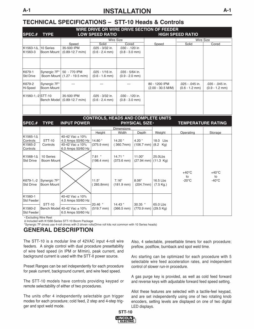
TECHNICAL SPECIFICATIONS – STT-10 Heads & ControlsWIRE DRIVE OR WIRE DRIVE SECTION OF FEEDER
SPEC.# TYPE LOW SPEED RATIO HIGH SPEED RATIO
• Excluding Wire ReelΔ Included with K1568-Series STT-10 Boom Package*Synergic 7F drives use 4-roll drives with 2 driven rolls(Drive roll kits not common with 10 Series heads)
Wire Size Wire SizeSpeed Solid Cored Speed Solid Cored
K1563-1Δ, 10 Series 35-500 IPM .025 - 3/32 in. .030 - .120 inK1563-3 Boom Mount (0.89-12.7 m/m) (0.6 - 2.4 mm) (0.8 - 3.0 mm)
K679-1 Synergic 7F* 50 - 770 IPM .025 - 1/16 in. .035 - 5/64 in.Std Drive Boom Mount (1.27 - 19.5 m/m) (0.6 - 1.6 mm) (0.9 - 2.0 mm)
K679-2 Synergic 7F* --- --- --- 80 - 1200 IPM .025 - .045 in. .035 - .045 in.Hi-Speed Boom Mount (2.00 - 30.5 M/M) (0.6 - 1.2 mm) (0.9 - 1.2 mm)
K1560-1,-2 STT-10 35-500 IPM .025 - 3/32 in. .030 - .120 in.Bench Model (0.89-12.7 m/m) (0.6 - 2.4 mm) (0.8 - 3.0 mm)
CONTROLS, HEADS AND COMPLETE UNITS
SPEC.# TYPE INPUT POWER PHYSICAL SIZE• TEMPERATURE RATING
DimensionsHeight Width Depth Weight Operating Storage
K1565-1Δ 40-42 Vac ± 10%Controls STT-10 4.0 Amps 50/60 Hz 14.80 “ 14.20 “ 4.20 “ 18.0 LbsK1565-2 Controls 40-42 Vac ± 10% (375.9 mm) ( 360.7mm) (106.7 mm) (8.2 Kg)Controls 6.0 Amps 50/60 Hz
K1568-1Δ 10 Series 7.81 “ 14.71 “ 11.00“ 25.0LbsStd Drive Boom Mount (198.4 mm) (373.6 mm) (27.94 mm) (11.3 Kg)
+40°C +40°Cto to
K679-1,-2 Synergic 7F* 11.5“ 7.16“ 8.06“ 16.5 Lbs -20°C -40°CStd Drive Boom Mount ( 285.8mm) (181.9 mm) (204.7mm) (7.5 Kg.)
K1560-1 40-42 Vac ± 10%Std Feeder 4.0 Amps 50/60 Hz
STT-10 20.46 “ 14.43 “ 30.35 “ 65.0 LbsK1560-2 Bench Model 40-42 Vac ± 10% (519.7 mm) (366.5 mm) (770.9 mm) (29.5 Kg)Std Feeder 6.0 Amps 50/60 Hz
GENERAL DESCRIPTION
The STT-10 is a modular line of 42VAC input 4-roll wirefeeders. A single control with dual procedure presettabilityof wire feed speed (in IPM or M/min), peak current, andbackground current is used with the STT-II power source.
Preset Ranges can be set independently for each procedurefor peak current, background current, and wire feed speed.
The STT-10 models have controls providing keypad orremote selectability of either of two procedures.
The units offer 4 independently selectable gun triggermodes for each procedure; cold feed, 2 step and 4-step trig-ger and spot weld mode.
Also, 4 selectable, presettable timers for each procedure;preflow, postflow, burnback and spot weld time.
Arc starting can be optimized for each procedure with 5selectable wire feed acceleration rates, and independentcontrol of slower run-in procedure.
A gas purge key is provided, as well as cold feed forwardand reverse keys with adjustable forward feed speed setting.
Allot these features are selected with a tactile-feel keypad,and are set independently using one of two rotating knobencoders, setting levels are displayed on one of two digitalLED displays.
A-2INSTALLATION
STT-10
A-2
The 10 Series Wire Drive assemblies include a heavy dutyhead with an externally changeable gear ratio and 4 drivenroll drives housed together in a single combination mountingand connection box. Gun adapters are available to permituse with a variety of standard welding guns.
Available Models:The STT-10 Wire Feeder system is available configured inboth Bench and Boom models.
Bench Models consists of an STT-10 control and a 10Series wire drive assembly premounted on a platformwith a 2" O.D. spindle mounting.
Boom Models consist of a STT-10 control and a wire drivedesigned to be mounted separately and joined by availablehead to control cable assemblies.
The head to control cable assemblies are available asstated below:
K1567-”L” Includes a control cable with a 14-pinms style connection on each end, anda weld cable. Available in lengths “L”of 16, 20 or 25 ft. (4.9, 6.1 or 7.6 m)
K681-”L” Same as above but does not includeweld cable available in lengths “L” of12, 16 or 25 ft. (3.6, 4.9 or 7.6 m).
STT-10 Boom Package (K1568-Series) is also avail-able which includes:
• STT-10 Control Box• 10 Series Wire Drive• Appropriate length Control and Weld Cables to
connect Control to Wire Drive• Accessories specific to the Boom package
ordered
RECOMMENDED PROCESSES
AND EQUIPMENTGMAW is the only process supported by the STT-10.It is similar to “short-circuiting transfer” or “short arc”welding in that metal transfer is by physical contact.Non-shorting modes such as axial spray and pulsewelding are not supported by STT technology.
The wire type and size range for the wire drive used,and speed range, are given in the TechnicalSpecifications.
The STT-10 requires a STT-II Power Source.
SAFETY PRECAUTIONS
INSTALLATION OF THE STT-10
BOOM MOUNT WIRE FEEDER
COMPONENTS
Mounting the 10 Series Wire Drive Unit
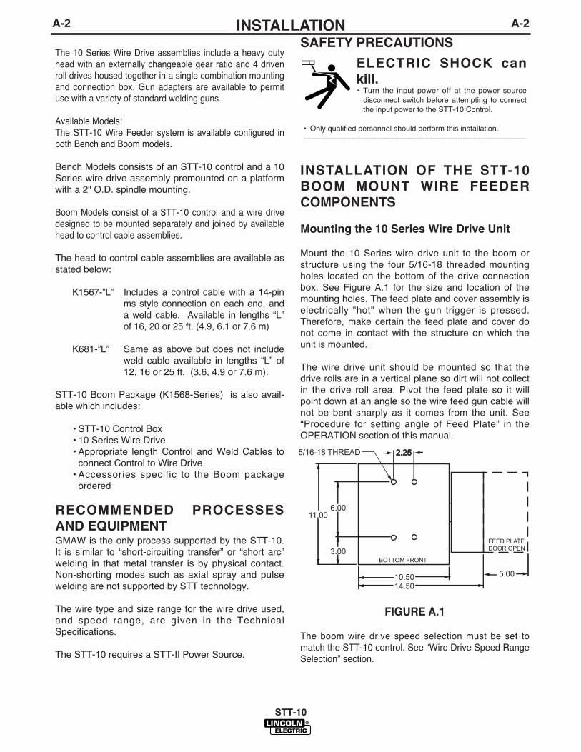
Mount the 10 Series wire drive unit to the boom orstructure using the four 5/16-18 threaded mountingholes located on the bottom of the drive connectionbox. See Figure A.1 for the size and location of themounting holes. The feed plate and cover assembly iselectrically "hot" when the gun trigger is pressed.Therefore, make certain the feed plate and cover donot come in contact with the structure on which theunit is mounted.
The wire drive unit should be mounted so that thedrive rolls are in a vertical plane so dirt will not collectin the drive roll area. Pivot the feed plate so it willpoint down at an angle so the wire feed gun cable willnot be bent sharply as it comes from the unit. See“Procedure for setting angle of Feed Plate” in theOPERATION section of this manual.
FIGURE A.1
The boom wire drive speed selection must be set tomatch the STT-10 control. See “Wire Drive Speed RangeSelection” section.
ELECTRIC SHOCK can
kill.• Turn the input power off at the power source
disconnect switch before attempting to connectthe input power to the STT-10 Control.
• Only qualified personnel should perform this installation.----------------------------------------------------------------------------------------
5/16-18 THREAD 2.252.25
FEED PLATEDOOR OPEN
5.0010.5014.50
3.00
6.0011.00
BOTTOM FRONT

A-3INSTALLATION
STT-10
A-3
Mounting Synergic 7F Wire Drive Unit
Mount the wire feed unit by means of the insulated mountingbracket attached to the bottom of the gearbox. ReferenceL9777 (included with Drive unit) to find the size and locationof the mounting holes. The gearbox assembly is electrically“hot” when the gun trigger is pressed. Therefore, make cer-tain the gearbox does not come in contact with the structureon which the unit is mounted.
The wire feed unit should be mounted so that the drive rollsare in a vertical plane so dirt will not collect in the drive rollarea. Position the mechanism so it will point down at abouta 45° angle so the wire feed gun cable will not be bentsharply as it comes from the unit.Note: The K1565-1 Control Box must be used with theK679 drives.
Mounting the STT-10 Control Box (K1565-2)
(Boom Model)
The STT-10 Boom Model has two keyhole slots and onebottom slot for mounting. See Figure A.2 for the size andlocation of these slots. Mount the box at some convenientlocation close to the wire drive unit which will enable thedesired control cable to reach between the control box andthe drive unit.
FIGURE A.2
a) Drill the required holes in the mounting surface, partiallyInstall 1/4-20 screws.
b) Mount the box.c) Tighten the screws.
Mounting the STT-10 Control Box (K1565-2)(Removed from the wire drive unit.) (See Figure A.3)
Remove reed switch energizer assembly which includes:4-pin connections, energizer spacer, insulation, mountingscrews and washers from reel stand.
Mount the reed switch energizer assembly on the mountingbracket (G2868) as shown In Figure A.3. Then installmounting bracket G2868 to the rear of STT-10 control box.Secure it on the sides of box with (4) # 10-3/8” long screws.
FIGURE A.3
a) Drill the required holes in the mounting surface, partially Install1/4-20 screws.
b) Mount the box.c) Tighten the screws.
Connecting Wire Drive Unit to Control Box.
One K1567-“L” head to control cable is needed to connect betweenthe control box and the wire drive.
K1567-“L” Includes a control cable with 14-pin MS style connec-tion on each end, and a weld cable (rated 300 amps, 60% dutycycle) to route between the wire drive and the control box.Avaialble in lengths “L” of 16,20 or 25 ft. (4.9, 6.1m or 7.6m).
a) Making certain the cables are protectedfrom any sharp cornerswhich may damage their jackets, mount the cable assemblyalong the boom so the end with the female amphenol connectorpins is at the wire feed unit.
b) Take the cables and connect the 14 pin cable between the 14 pinreceptacles on the wire drive unit and 14 pin receptacle on theSTT-10 Control Box.
c) Take electrode cable thatʼs part of the cable and connect one endof the ½ connection bolt on the front of wire drive and the otherend to one side of the energizer assembly.
CLEARANCEFOR 1/4 BOLT
2.63
12.75
14.50
13.75
5.25
CLEARANCEFOR 1/4 BOLT
10.50.50
10.00
2.63
14.00
2.622.62 BOLT PATTERN FOR SWITCH ENERGIZER ASSEMBLY, DRILL (4) HOLES IN MOUNTINGBRACKET
CONTROL BOX AND REED SWITCHENERGIZER ASSEMBLY REMOVEFROM REEL STAND AND ADDED TOMOUNTING BRACKET G2868

A-4INSTALLATION
STT-10
A-4
Electrode Routing
The electrode supply may be either from reels, Readi-Reels, spools, or bulk packaged drums or reels.Observe the following precautions:
a) The electrode must be routed to the wire drive unitso that the bends in the wire are at a minimum,and also that the force required to pull the wirefrom the reel into the wire drive unit is kept at aminimum.
b) The electrode is "hot" when the gun trigger is pressedand must be insulated from the boom and structure.
c) If more than one wire feed unit shares the sameboom and are not sharing the some power sourceoutput stud, their wire and reels must be insulatedfrom each other as well as insulated from theirmounting structure.
WIRE DRIVE SPEED RANGE
SELECTION
The rated speed and wire size range for each wiredrive head is shown in the SPECIFICATIONS in thefront of this section.
Control Speed Range Setting
The STT-10 Control is factory set for the 10 Serieslow speed ratio wire drives. If using the Synergic 7Fwire drive, the speed range must be set up to matchthis wire feed head by properly setting the switch (S1)code on the control board inside the control box. SeeOPERATION “Setting the DIP Switch” for settinginstructions.
10 Series Wire Drive Ratio Selection
The STT-10 Bench and Boom model packages comewith a 1" dia. gear only.
The K1563-1,-3 10 Series type Boom model wire driveincludes two external gear sizes; a 1"(25.4mm) dia.gear and a 1-1/2"(38.1mm) dia. gear. The smallergear provides the desired low speed range ratio,appropriate for the STT process per the SPECIFICA-TIONS in the front of this section.
The following procedure is for changing ratio of the 10Series Boom wire drive (K1563-1,-3):
1) Pull open the Pressure Door.
2) Remove the Phillips head screw retaining the pin-ion gear to be changed and remove the gear. Ifthe gear is not easily accessible or difficult toremove, remove the feedplate from the gearbox.To remove feedplate:
a) Loosen the clamping collar screw using a 3/16"Allen wrench. The clamping collar screw isaccessed from the bottom of the feedplate. It isthe screw which is perpendicular to the feedingdirection.
b) Loosen the retaining screw, which is alsoaccessed from bottom of feeder, using a 3/16"Allen wrench. Continue to loosen the screwuntil the feedplate can be easily pulled off of thewire feeder.
3) Loosen, but do not remove, the screw on the lower rightface of the feedplate with a 3/16" Allen wrench.
4) Remove the screw on the left face of the feedplate. Ifchanging from high speed (larger gear) to low speed(smaller gear), line the lower hole on the left face of thefeedplate with the threads on the clamping collar. Linethe upper hole with the threads to install larger gear forhigh speed feeder. If feedplate does not rotate to allowholes to line up, further loosen the screw on right face offeedplate.
5) Install the smaller, 1.00”(25.4mm) dia., gear onto outputshaft and secure with flat washer, lock washer, andPhillips head screw which were previously removed.
6) Tighten the screw on lower right face of feedplate.
7) Install gear onto output shaft and secure with flat washer,lock washer, and Phillips head screw which were previ-ously removed.
8) Re-attach feedplate to wire feeder if removed in Step 2.
9 Feedplate will be rotated out-of-position due to the gearchange. To re-adjust angle of feedplate:
a) Loosen the clamping collar using a 3/16" Allenwrench. The clamping collar screw is accessedfrom the bottom of the feedplate. It is the screwwhich is perpendicular to the feeding direction.
b) Rotate feedplate to the desired angle and tight-en clamping collar screw.
10) Make sure to properly set the switch (S1) code on thecontrol board inside the control box for the new gearsize installed. See OPERATION “Setting the DIPSwitch” for setting instructions.
A-5INSTALLATION
STT-10
A-5
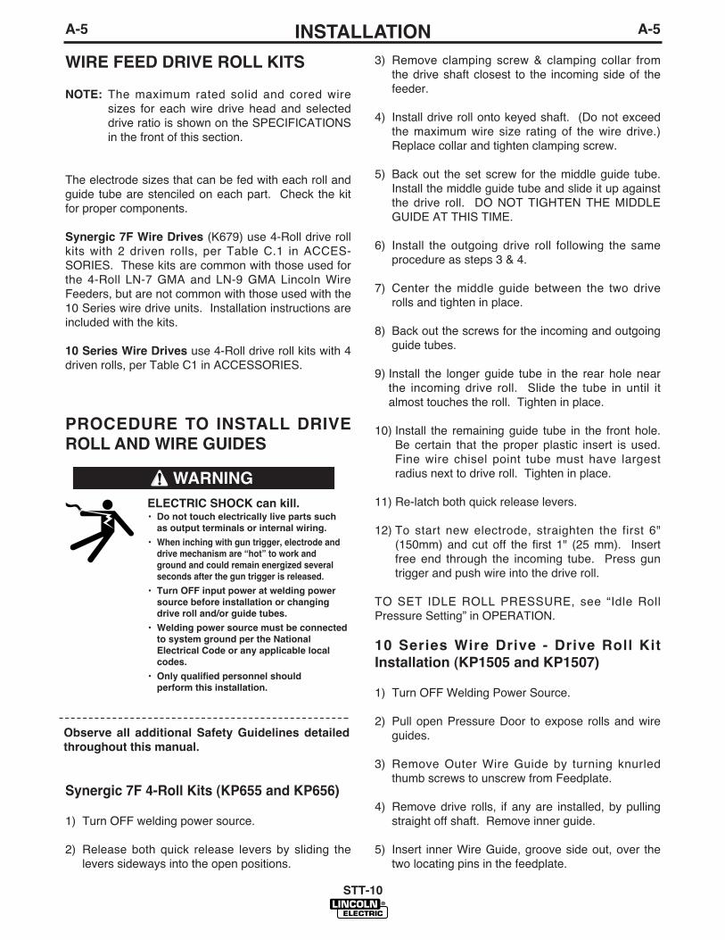
WIRE FEED DRIVE ROLL KITS
NOTE: The maximum rated solid and cored wiresizes for each wire drive head and selecteddrive ratio is shown on the SPECIFICATIONSin the front of this section.
The electrode sizes that can be fed with each roll andguide tube are stenciled on each part. Check the kitfor proper components.
Synergic 7F Wire Drives (K679) use 4-Roll drive rollkits with 2 driven rolls, per Table C.1 in ACCES-SORIES. These kits are common with those used forthe 4-Roll LN-7 GMA and LN-9 GMA Lincoln WireFeeders, but are not common with those used with the10 Series wire drive units. Installation instructions areincluded with the kits.
10 Series Wire Drives use 4-Roll drive roll kits with 4driven rolls, per Table C1 in ACCESSORIES.
PROCEDURE TO INSTALL DRIVE
ROLL AND WIRE GUIDES
Synergic 7F 4-Roll Kits (KP655 and KP656)
1) Turn OFF welding power source.
2) Release both quick release levers by sliding thelevers sideways into the open positions.
3) Remove clamping screw & clamping collar fromthe drive shaft closest to the incoming side of thefeeder.
4) Install drive roll onto keyed shaft. (Do not exceedthe maximum wire size rating of the wire drive.)Replace collar and tighten clamping screw.
5) Back out the set screw for the middle guide tube.Install the middle guide tube and slide it up againstthe drive roll. DO NOT TIGHTEN THE MIDDLEGUIDE AT THIS TIME.
6) Install the outgoing drive roll following the sameprocedure as steps 3 & 4.
7) Center the middle guide between the two driverolls and tighten in place.
8) Back out the screws for the incoming and outgoingguide tubes.
9) Install the longer guide tube in the rear hole nearthe incoming drive roll. Slide the tube in until italmost touches the roll. Tighten in place.
10) Install the remaining guide tube in the front hole.Be certain that the proper plastic insert is used.Fine wire chisel point tube must have largestradius next to drive roll. Tighten in place.
11) Re-latch both quick release levers.
12) To start new electrode, straighten the first 6"(150mm) and cut off the first 1" (25 mm). Insertfree end through the incoming tube. Press guntrigger and push wire into the drive roll.
TO SET IDLE ROLL PRESSURE, see “Idle RollPressure Setting” in OPERATION.
10 Series Wire Drive - Drive Roll Kit
Installation (KP1505 and KP1507)
1) Turn OFF Welding Power Source.
2) Pull open Pressure Door to expose rolls and wireguides.
3) Remove Outer Wire Guide by turning knurledthumb screws to unscrew from Feedplate.
4) Remove drive rolls, if any are installed, by pullingstraight off shaft. Remove inner guide.
5) Insert inner Wire Guide, groove side out, over thetwo locating pins in the feedplate.
WARNING
Observe all additional Safety Guidelines detailed
throughout this manual.
ELECTRIC SHOCK can kill.• Do not touch electrically live parts such
as output terminals or internal wiring.
• When inching with gun trigger, electrode and
drive mechanism are “hot” to work and
ground and could remain energized several
seconds after the gun trigger is released.
• Turn OFF input power at welding power
source before installation or changing
drive roll and/or guide tubes.
• Welding power source must be connected
to system ground per the National
Electrical Code or any applicable local
codes.
• Only qualified personnel should
perform this installation.

A-6INSTALLATION
STT-10
A-6
6) Install each drive roll by pushing over shaft until itbutts up against locating shoulder on the drive rollshaft. (Do Not exceed maximum wire size rating ofthe wire drive).
7) Install Outer Wire Guide by sliding over locatingpins and tightening in place.
8) Engage upper drive rolls if they are in the “open”position and close Pressure Door.
TO SET IDLE ROLL PRESSURE, see “Idle RollPressure Setting” in OPERATION.
GUN CONNECTIONS - GENERAL
4-roll feed plates are equipped with a brass connectorbar at the gun-end of the feed plate to allow a boltedbrass-to-brass electrical connection to be made direct-ly to either standard or Fast-mate gun adapter bush-ings. Use a 1/4” inch allen key on the factory-installedsocket head cap screw to insure that the connectorbar is securely tightened to the adapter bushing.
GUN AND CABLE ASSEMBLIES
WITH STANDARD CONNECTION
The 10 Series Wire Drive Head requires a K1500 GunAdapter installed See “Gun Adapters” in ACCES-SORIES section. The K1500-2 Gun Adapter andTrigger Cable for Magnum 200-400 guns are factoryincluded with the STT-10.
GMAW Guns
An expanding line of Magnum gun and cable assem-blies are available to allow welding with solid andcored electrodes using the GMAW process. See theappropriate Magnum literature for descriptions of the200 to 550 ampere air cooled gun and cables that areavailable. Gun cable lengths range from 10 ft. (3.0 m)to 25 ft. (7.6 m) and feed electrode sizes .025" (0.6mm) to 3/32" (2.4 mm). The entire line of MagnumFast-Mate gun and cable assemblies can also beused by installing a K489-2 Fast-Mate adapter kit.See “Gun and Cable Assemblies with Fast-MateConnection” in this section for details.
Gun Cable Connection with Standard
Connection
1. Check that the drive rolls and guide tubes areproper for the electrode size and type being used.If necessary, change them per “Wire Drive RollKits” in this section.
2. Lay the cable out straight. Insert the connector onthe welding conductor cable into the brass conduc-tor block on the front of the wire drive head. Makesure it is all the way in and tighten the hand clamp.Keep this connection clean and bright. Connectthe trigger control cable polarized plug into themating 5 cavity receptacle on the front of the wiredrive unit.
3. For GMA Gun Cables with separate gas fitting (10Series Wire Drive using K1500-1 Gun Adapter),connect the 3/16" I.D. gas hose from the wire driveunit to the gun cable barbed fitting.
GUN AND CABLE ASSEMBLIES
WITH FAST-MATE CONNECTION(Requires K489-2 Fast Mate™ Adapter Kit used withthe K1500-1 Gun Adapter)
GMAW Guns
An expanding line of Magnum Fast-Mate™ air cooledand water cooled gun and cable assemblies are avail-able to allow welding with solid and cored electrodesusing the GMAW process. See the appropriateMagnum literature for descriptions of the 200 to 400ampere air cooled gun and cables that are availableas well as the Magnum “Super Cool” 450 amperewater cooled gun and cable. Gun cable lengths rangefrom 10 ft. (3.0 m) to 25 ft. (7.6 m) and feed electrodesizes .025" (0.6 mm) to 5/64" (20 mm).
An expanding line of Magnum X-Tractor gun andcable assemblies provides fume extraction capabilityfor welding with solid and cored electrodes using theGMAW process. See the appropriate Magnum litera-ture for descriptions of the 250 to 400 ampere aircooled gun and cables that are available. Gun cablelengths range from 10 ft. (3.0 m) to 15 ft. (4.5 m) andfeed electrode sizes .035" (0.9 mm) to 1/16" (1.6 mm).These guns require the use of either the K173-1 orK184* vacuum units.
* Requires S14927-8 connector hose and an S20591hose adapter.
A-7INSTALLATION
STT-10
A-7
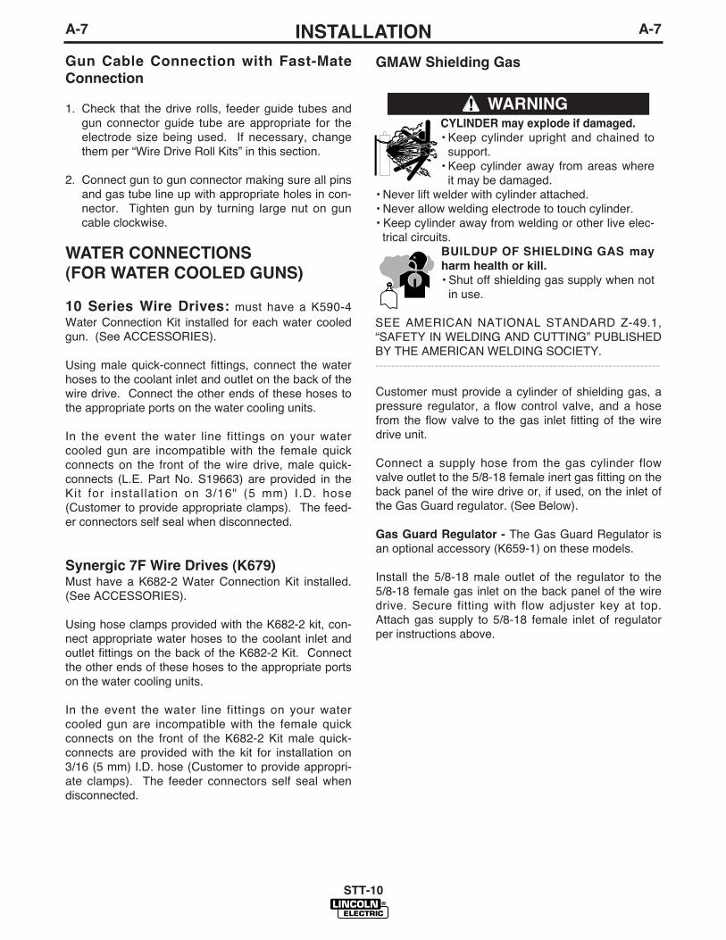
Gun Cable Connection with Fast-Mate
Connection
1. Check that the drive rolls, feeder guide tubes andgun connector guide tube are appropriate for theelectrode size being used. If necessary, changethem per “Wire Drive Roll Kits” in this section.
2. Connect gun to gun connector making sure all pinsand gas tube line up with appropriate holes in con-nector. Tighten gun by turning large nut on guncable clockwise.
WATER CONNECTIONS
(FOR WATER COOLED GUNS)
10 Series Wire Drives: must have a K590-4Water Connection Kit installed for each water cooledgun. (See ACCESSORIES).
Using male quick-connect fittings, connect the waterhoses to the coolant inlet and outlet on the back of thewire drive. Connect the other ends of these hoses tothe appropriate ports on the water cooling units.
In the event the water line fittings on your watercooled gun are incompatible with the female quickconnects on the front of the wire drive, male quick-connects (L.E. Part No. S19663) are provided in theKit for installation on 3/16" (5 mm) I.D. hose(Customer to provide appropriate clamps). The feed-er connectors self seal when disconnected.
Synergic 7F Wire Drives (K679)Must have a K682-2 Water Connection Kit installed.(See ACCESSORIES).
Using hose clamps provided with the K682-2 kit, con-nect appropriate water hoses to the coolant inlet andoutlet fittings on the back of the K682-2 Kit. Connectthe other ends of these hoses to the appropriate portson the water cooling units.
In the event the water line fittings on your watercooled gun are incompatible with the female quickconnects on the front of the K682-2 Kit male quick-connects are provided with the kit for installation on3/16 (5 mm) I.D. hose (Customer to provide appropri-ate clamps). The feeder connectors self seal whendisconnected.
GMAW Shielding Gas
Customer must provide a cylinder of shielding gas, apressure regulator, a flow control valve, and a hosefrom the flow valve to the gas inlet fitting of the wiredrive unit.
Connect a supply hose from the gas cylinder flowvalve outlet to the 5/8-18 female inert gas fitting on theback panel of the wire drive or, if used, on the inlet ofthe Gas Guard regulator. (See Below).
Gas Guard Regulator - The Gas Guard Regulator isan optional accessory (K659-1) on these models.
Install the 5/8-18 male outlet of the regulator to the5/8-18 female gas inlet on the back panel of the wiredrive. Secure fitting with flow adjuster key at top.Attach gas supply to 5/8-18 female inlet of regulatorper instructions above.
CYLINDER may explode if damaged.
• Keep cylinder upright and chained tosupport.
• Keep cylinder away from areas whereit may be damaged.
• Never lift welder with cylinder attached.• Never allow welding electrode to touch cylinder.• Keep cylinder away from welding or other live elec-
trical circuits.BUILDUP OF SHIELDING GAS may
harm health or kill.
• Shut off shielding gas supply when notin use.
SEE AMERICAN NATIONAL STANDARD Z-49.1,“SAFETY IN WELDING AND CUTTING” PUBLISHEDBY THE AMERICAN WELDING SOCIETY.------------------------------------------------------------------------
WARNING
A-8INSTALLATION
STT-10
A-8
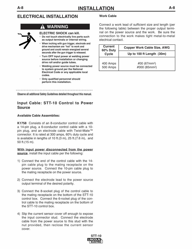
ELECTRICAL INSTALLATION
Input Cable: STT-10 Control to Power
Source
Available Cable Assemblies:
K1758 Consists of an 8-conductor control cable witha 14-pin plug, a 6-conductor control cable with a 10-pin plug, and an electrode cable with Twist-Mate™connector. It is rated at 300 amps, 60% duty cycle andis available in lengths of 10 ft.(3 m), 25 ft.(7.6 m), and50 ft.(15 m).
With input power disconnected from the power
source, install the input cable per the following:
1) Connect the end of the control cable with the 14-pin cable plug to the mating receptacle on thepower source. Connect the 10-pin cable plug tothe mating receptacle on the power source.
2) Connect the electrode lead to the power sourceoutput terminal of the desired polarity.
3) Connect the 8-socket plug of the control cable tothe mating receptacle on the bottom of the STT-10control box. Connect the 6-rocket plug of the con-trol cable to the mating receptacle on the bottom ofthe STT-10 control box.
4) Slip the current sensor cover off enough to exposethe input connector stud. Connect the electrodecable from the power source to this stud with thenut provided, then reclose the current sensorcover.
Work Cable
Connect a work lead of sufficient size and length (perthe following table) between the proper output termi-nal on the power source and the work. Be sure theconnection to the work makes tight metal-to-metalelectrical contact.
Observe all additional Safety Guidelines detailed throughout this manual.
ELECTRIC SHOCK can kill.• Do not touch electrically live parts such
as output terminals or internal wiring.
• When inching with gun trigger, electrode and
drive mechanism are “hot” to work and
ground and could remain energized several
seconds after the gun trigger is released.
• Turn OFF input power at welding power
source before installation or changing
drive roll and/or guide tubes.
• Welding power source must be connected
to system ground per the National
Electrical Code or any applicable local
codes.
• Only qualified personnel should
perform this installation.
WARNING
Copper Work Cable Size, AWG
Up to 100 ft Length (30m)
Current
60% Duty
Cycle
400 Amps500 Amps
#00 (67mm2)#000 (85mm2)

A-9INSTALLATION
STT-10
A-9
OPTIONAL FEATURES
INSTALLATION
K1758 Input Cable Assembly
See “Electrical Installation” for instructions.
Dual Procedure Switch Options
K683-1 Dual Procedure Switch - Requires K686-2Adapter for STT-10. Kit includes gun switch, andmountings for Lincoln Innershield and Magnum guns,with 15 ft. (4.5 m) control cable and 3-pin plug. K686-2 Adapter permits 3-pin plug and 5-pin gun triggerplug to be connected to STT-10 5-pin Trigger/DualProcedure receptacle.
Connect the 5-pin plug of the K686-2 Adapter to theSTT-10 Wire Feeder Trigger/Dual Procedure 5-socketreceptacle.
The 3-pin plug of the K683-1 Dual Procedure switchconnects to the 3-socket receptacle of the Adapter,and the 5-pin plug of the welding gun connects to the5-socket receptacle of the Adapter.
K683-3 Dual Procedure Switch - Kit includes gunswitch, and mountings for Lincoln Innershield andMagnum guns, with 15 ft. (4.5m) control cable and 5-pin plug with two leads to connect to gun trigger.
Connect the 5-pin plug of the K683-3 Dual procedureSwitch to the STT-10 Wire Feeder Trigger/DualProcedure 5-socket receptacle.
The two lead plug cord extending out of the 5-pin plugof the Dual Procedure switch is to be connected to thetwo trigger leads of the welding gun per the instruc-tions shipped with the kit.
K659-1 Gas Guard Regulator - Adjustable flow regula-tor with removable adjustor key for CO2 and Argonblend gases. Mounts onto feeder inlet, and reducesgas waste and arc start “blow” by reducing surgecaused by excess pressure in supply hose.
Install the 5/8-18 male outlet of the regulator to one, orboth of the 5/8-18 female gas inlets on the back panelof the wire drive. Secure fitting with flow adjuster keyat top. Attach gas supply to 5/8-18 female inlet of reg-ulator per “GMAW Shielding Gas” section.
K1561-1 Robotics Interface Module - The moduleplugs directly into the STT-10 control board and pro-vides an interface to a properly equipped Fanuc robot.(ArcTool software and an additional process I/O boardare needed).
When installed and properly configured, the K1561-1Robotics Interface Module allows complete control ofthe welding process from the robot controller.
The Lincoln Electric Companyʼs Automation Centershould be contacted for questions regarding installa-tion or operation of the Robotics Interface Module.
All other options, see ACCESSORIES section, areshipped with installation instructions.
K1558-1 Remote Switch Interface Module - TheModule plugs directly into the SST-10 Control Boardand provides for user interface connection of an exter-nal switch (flow switch, etc.) which must be closed toenable the feeder welding operation. Also, the Moduleprovides for interface connection of external equip-ment (fume extractor, etc.) to the Moduleʼs isolatedrelay contacts (rated for 125VAC, 1 amp externallysupplied loads) which actuate when the feeder weld-ing gas solenoid is activated (representing weldingoperation in process).
Installation and operation instructions are includedwith the kit.
BOOM AND BENCH CONVERSIONSThe modular design of these feeders allows them tobe converted from bench to boom models or viseversa. Some additional parts are required to make thisconversion.
Materials Required for bench to boom
conversion:S13100-197 Plug and Lead assembly, allows a con-trol cable to connect from control box to the wire drive.
G2868 Mounting Bracket, allows reed switch to berelocated to control box.
K1567-“L” head to control cables are needed to con-nect between the control box and the wire drive.
Materials Required for boom to bench
conversion:
L10286-1 Wire Reel Stand, for LN-10 or STT-10,mount the reed switch onto the reel stand.
S22777 Control Box Support Bracket, to mount thecontrol box onto the wire drive.
S13100-198 Plug and Lead Assembly, electrical con-nection between control box and wire drive.
B-1OPERATIONB-1
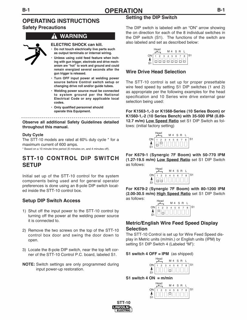
Setting the DIP Switch
The DIP switch is labeled with an “ON” arrow showingthe on direction for each of the 8 individual switches inthe DIP switch (S1). The functions of the switch arealso labeled and set as described below:
Wire Drive Head Selection
The STT-10 control is set up for proper presettablewire feed speed by setting S1 DIP switches (1 and 2)as appropriate per the following examples for the headspecification and 10 Series wire drive external gearselection being used:
For K1563-1,-3 or K1568-Series (10 Series Boom) or
K1560-1,-2 (10 Series Bench) with 35-500 IPM (0.89-
12.7 m/m) Low Speed Ratio set S1 DIP Switch as fol-lows: (initial factory setting)
For K679-1 (Synergic 7F Boom) with 50-770 IPM
(1.27-19.5 m/m) Low Speed Ratio set S1 DIP Switchas follows:
For K679-2 (Synergic 7F Boom) with 80-1200 IPM
(2.00-30.5 m/m) High Speed Ratio set S1 DIP Switchas follows:
Metric/English Wire Feed Speed Display
SelectionThe STT-10 Control is set up for Wire Feed Speed dis-play in Metric units (m/min.) or English units (IPM) bysetting S1 DIP Switch 4 (Labeled “M”):
S1 switch 4 OFF = IPM (as shipped)
S1 switch 4 ON = m/min
STT-10
OPERATING INSTRUCTIONSSafety Precautions
Duty Cycle
The STT-10 models are rated at 60% duty cycle * for amaximum current of 600 amps.* Based on a 10 minute time period (6 minutes on, and 4 minutes off).
STT-10 CONTROL DIP SWITCH
SETUP
Initial set up of the STT-10 control for the systemcomponents being used and for general operatorpreferences is done using an 8-pole DIP switch locat-ed inside the STT-10 control box.
Setup DIP Switch Access
1) Shut off the input power to the STT-10 control byturning off the power at the welding power sourceit is connected to.
2) Remove the two screws on the top of the STT-10control box door and swing the door down toopen.
3) Locate the 8-pole DIP switch, near the top left cor-ner of the STT-10 Control P.C. board, labeled S1.
NOTE: Switch settings are only programmed duringinput power-up restoration.
ELECTRIC SHOCK can kill.• Do not touch electrically live parts such
as output terminals or internal wiring.
• Unless using cold feed feature when inch-
ing with gun trigger, electrode and drive mech-
anism are “hot” to work and ground and could
remain energized several seconds after the
gun trigger is released.
• Turn OFF input power at welding power
source before Control switch setup or
changing drive roll and/or guide tubes.
• Welding power source must be connected
to system ground per the National
Electrical Code or any applicable local
codes.
• Only qualified personnel should
operate this Equipment.
WARNING
Observe all additional Safety Guidelines detailed
throughout this manual.
HeadM 4 S R
S1ON
S1
1 2 3 4 5 6 7 8
L
HeadM 4 S R
S1ON
S1
1 2 3 4 5 6 7 8
L
HeadM 4 S R
S1ON
S1
1 2 3 4 5 6 7 8
L
HeadM 4 S R
S1ON
S1
1 2 3 4 5 6 7 8
L
HeadM 4 S R
S1ON
S1
1 2 3 4 5 6 7 8
L
HeadM 4 S R
S1ON
S1
1 2 3 4 5 6 7 8
L
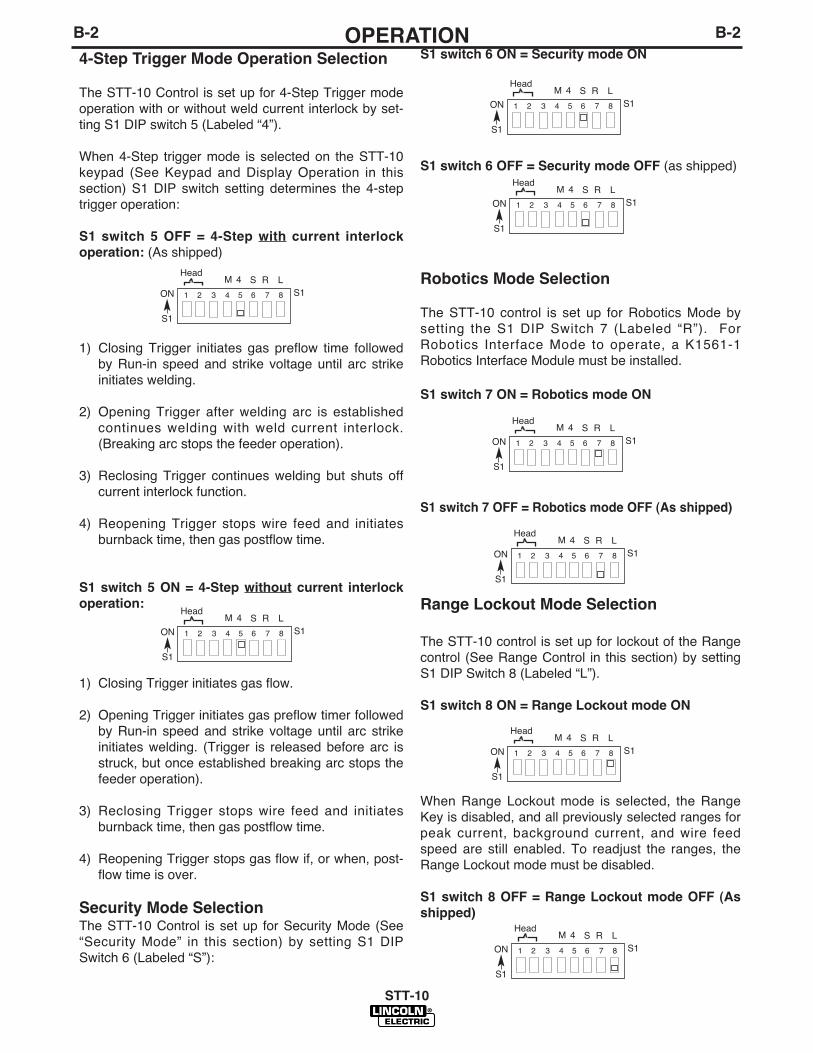
4-Step Trigger Mode Operation Selection
The STT-10 Control is set up for 4-Step Trigger modeoperation with or without weld current interlock by set-ting S1 DIP switch 5 (Labeled “4”).
When 4-Step trigger mode is selected on the STT-10keypad (See Keypad and Display Operation in thissection) S1 DIP switch setting determines the 4-steptrigger operation:
S1 switch 5 OFF = 4-Step with current interlock
operation: (As shipped)
1) Closing Trigger initiates gas preflow time followedby Run-in speed and strike voltage until arc strikeinitiates welding.
2) Opening Trigger after welding arc is establishedcontinues welding with weld current interlock.(Breaking arc stops the feeder operation).
3) Reclosing Trigger continues welding but shuts offcurrent interlock function.
4) Reopening Trigger stops wire feed and initiatesburnback time, then gas postflow time.
S1 switch 5 ON = 4-Step without current interlock
operation:
1) Closing Trigger initiates gas flow.
2) Opening Trigger initiates gas preflow timer followedby Run-in speed and strike voltage until arc strikeinitiates welding. (Trigger is released before arc isstruck, but once established breaking arc stops thefeeder operation).
3) Reclosing Trigger stops wire feed and initiatesburnback time, then gas postflow time.
4) Reopening Trigger stops gas flow if, or when, post-flow time is over.
Security Mode SelectionThe STT-10 Control is set up for Security Mode (See“Security Mode” in this section) by setting S1 DIPSwitch 6 (Labeled “S”):
HeadM 4 S R
S1ON
S1
1 2 3 4 5 6 7 8
L
HeadM 4 S R
S1ON
S1
1 2 3 4 5 6 7 8
L
HeadM 4 S R
S1ON
S1
1 2 3 4 5 6 7 8
L
HeadM 4 S R
S1ON
S1
1 2 3 4 5 6 7 8
L
HeadM 4 S R
S1ON
S1
1 2 3 4 5 6 7 8
L
HeadM 4 S R
S1ON
S1
1 2 3 4 5 6 7 8
L
B-2OPERATIONB-2
STT-10
HeadM 4 S R
S1ON
S1
1 2 3 4 5 6 7 8
L
HeadM 4 S R
S1ON
S1
1 2 3 4 5 6 7 8
L
S1 switch 6 ON = Security mode ON
S1 switch 6 OFF = Security mode OFF (as shipped)
Robotics Mode Selection
The STT-10 control is set up for Robotics Mode bysetting the S1 DIP Switch 7 (Labeled “R”). ForRobotics Interface Mode to operate, a K1561-1Robotics Interface Module must be installed.
S1 switch 7 ON = Robotics mode ON
S1 switch 7 OFF = Robotics mode OFF (As shipped)
Range Lockout Mode Selection
The STT-10 control is set up for lockout of the Rangecontrol (See Range Control in this section) by settingS1 DIP Switch 8 (Labeled “L”).
S1 switch 8 ON = Range Lockout mode ON
When Range Lockout mode is selected, the RangeKey is disabled, and all previously selected ranges forpeak current, background current, and wire feedspeed are still enabled. To readjust the ranges, theRange Lockout mode must be disabled.
S1 switch 8 OFF = Range Lockout mode OFF (As
shipped)
B-3OPERATIONB-3
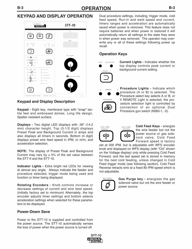
Keypad and Display Description
Keypad - Eight key, membrane type with "snap" tac-tile feel and embossed domes. Long life design.Spatter resistant surface.
Displays - Two digital LED displays with .56" (14.2mm) character height. Top (3-1/2 digit) displaysPreset Peak and Background Current in amps andalso displays all timers in seconds. Bottom (4 digit)displays preset wire feed speed in IPM, or m/m, andacceleration selection.
NOTE: The display of Preset Peak and BackgroundCurrent may vary by ± 5% of the set value betweenthe STT-II and the STT-10.
Indicator Lights - Extra bright red LEDs for viewingat almost any angle. Always indicate the feeder andprocedure selected, trigger mode being used andfunction or timer being displayed.
Rotating Encoders - Knob controls increase ordecrease settings of current and wire feed speed.(initially factory set to minimum) Alternately, the topencoder adjusts timer settings and bottom selectsacceleration settings when selected for these parame-ters to be displayed.
Power-Down Save
Power to the STT-10 is supplied and controlled fromthe power source. The STT-10 automatically sensesthe loss of power when the power source is turned off.
Dual procedure settings, including; trigger mode, coldfeed speed, Run-in and weld speed and current,timers ranges and acceleration are automaticallysaved when power is removed. This feature does notrequire batteries and when power is restored it willautomatically return all settings to the state they werein when power was removed. The operator may over-write any or all of these settings following power uprecall.
Operation Keys
Current Lights - Indicates whether thetop display controls peak current orbackground current setting.
Procedure Lights - Indicate whichprocedure (A or B) is selected. TheProcedure select key selects A or B, orif REMOTE Light is selected, the pro-cedure selection light is controlled byconnection of an optional DualProcedure gun switch (K683-1, -2).
Cold Feed Keys - energizethe wire feeder but not thepower source or gas sole-noid valve. Cold FeedForward speed is factory
set at 200 IPM, but is adjustable with WFS encoderknob and displayed on WFS display (with ”Cld” shownon the Voltage display) only while pressing Cold FeedForward, and the last speed set is stored in memoryfor the next cold feeding, unless changed in ColdFeed trigger mode (see following section). Cold FeedReverse retracts wire at a fixed 80 IPM speed which isnot adjustable.
Gas Purge key - energizes the gassolenoid valve but not the wire feeder orpower source.
STT-10
KEYPAD AND DISPLAY OPERATION
SPOT
PEAK MAX
CURRENT
SPOT
PREFLOW1
RUN-INWFS
PEAK MIN
BACKGROUND MAX
CONTROL
WIRE FEED SPEED
G3152
BURNBACK
POSTFLOW
GAS PURGEFORWARDCOLD FEED
2
BACKGROUND MIN
WFS MAX
WFS MIN
RANGE
THE LINCOLN ELECTRIC COMPANY CLEVELAND, OHIO U.S.A.
COLD FEEDREVERSE
CURRENT
BACKGROUND
PROCEDURE
PEAK
TRIGGER
COLD FEED
2-STEP STD
4-STEP LOCK
WFS
A
A
BA REMOTE
RLINCOLN
A
CURRENT
BACKGROUNDPEAK
A
GAS PURGE
FORWARDCOLD FEED
REVERSECOLD FEED
A B
PROCEDURE
REMOTE

B-4OPERATIONB-4
Trigger Mode Selection
Trigger Mode Select key
- enables operator tochoose mode of operationshown by the indicatorlights. Pressing key caus-es mode l ights to
sequence (top to bottom) starting from the currentindicated selection.
Top Light - Indicates gun trigger has been selected toperform the Cold Feed Forward function in exactly thesame manner as Cold Feed Forward key (SeeOperation Keys - Cold Feed Keys) with the samememory stored adjustable speed setting, and “Cld”shown on the top display.
Second Light - indicates 2-step (standard) triggermode.
1. Trigger closure energizes the solenoid valve, thenthe wire feeder and the power source afterPreflow time.
2. Releasing the trigger turns off the wire feeder,then power source after burnback time and thenthe gas solenoid valve after Postflow time.
Third Light - indicates 4-step (lock) trigger mode.This mode may be selected to include or exclude weldcurrent interlock. (See “4-Step Trigger ModeOperation Selection” in this section for 4 step TriggerMode operation)
Bottom Light - indicates Spot Weld Mode, which willonly light if a spot time is set (See “Display ControlKeys” in this section). If set to 0.0 seconds, spotmode light selection will be skipped. Trigger closureenergizes the gas solenoid valve, then wire feederand the power source. The spot timer starts whencurrent flows. The wire feeder and power source thensolenoid valve are all turned off when the spot ontimer times out even though the trigger is opened or isstill closed. Preflow/Postflow and burnback timers arealso functional in spot mode. (See “Display ControlKeys” in this section).
Display Control Keys
Control Select key - enables operator tochoose Run-in WFS, burnback, spot orgas timers, as indicated by the appro-priate light. Pressing the key causeslights to sequence (top to bottom, thenall off) starting from the current indicat-ed selection.
When burnback spot, or gas timers are selected thecurrent display shows the time setting in seconds, asindicated by “SEC” displayed on the speed display.The times are set using the top encoder knob.
When Run-in WFS is selected the WFS display showsthe Run-in WFS setting in in/min. or m/min.
Top Light - indicates Run-in WFS is being displayed.Speed encoder knob can adjust, Run in speed
between minimum. Rated speedand up to the Weld speed setting.Run-in speed can not be set aboveweld speed setting. A Run-inspeed setting of 100 IPM or less isrecommended for optimum start-ing. Factory sett ing is nearminimum rated speed.
If set below minimum rated speed “- -” will show onWFS display, indicated Run-In speed is set to matchWeld speed setting.
When trigger is closed (and preflow time is over) thewire feeds at Run-In speed until the welding arcstrikes, which causes the feed speed and volts tochange to Weld settings.
If the arc does not strike within about 2 seconds, theRun-In speed automatically changes to Weld speed topermit “Hot” feeding at higher speed setting for load-ing wire.
Second Light - indicates preflow time is being dis-played, settable 0.0 to 2.5 seconds. (0.2 sec asshipped). This is the time the shielding gas flowsbefore the wire feed and power source are activated.
Third Light - indicates spot time is being displayed,settable 0.0 to 199.9 seconds (0.0 sec as shipped).
Fourth Light - indicates burnback time is being dis-played, settable 0.00 to 0.25 seconds (0.0 sec asshipped). This is the time the arc power is delayed atthe stop of the weld, and should be set to the lowesttime required to prevent the wire sticking in the weld.
Bottom Light - indicates postflow time is being dis-played, settable 0.0 to 10.0 seconds (0.5 sec asshipped). This is the time the shielding gas flows afterthe wire feed and power source are deactivated.
Pressing Control Select Key again, or closing the guntrigger, shuts all control lights off, indicating currentand Wire Feed Speed are again being displayed, andset by the appropriate encoder knob.
STT-10
SPOT
TRIGGER
COLD FEED
2-STEP STD
4-STEP LOCK
CONTROL
SPOT
PREFLOW1
RUN-INWFS
BURNBACK
POSTFLOW2

B-5OPERATIONB-5
Range Select key - enables operator tochoose which weld parameter to set the maxi-mum or minimum range. Pressing the keycauses the range mode lights to sequence (topto bottom) starting from the current indicatedselection. The range settings can be set inde-pendently for each procedure.
Top Light - PEAK MAX - Indicates that themaximum peak current setting is being dis-played on the top LED display. This para-meter is settable from 17 to 464 amps.
Second Light - PEAK MIN - Indicates thatthe minimum peak current setting is beingdisplayed on the top LED display. Thisparameter is settable from 17 to 464 amps.
Third Light - BACKGROUND MAX - Indicates that the maximumbackground current setting is being displayed on the top LEDdisplay. This parameter is settable from 6 to 153 amps.
Fourth Light - BACKGROUND MIN - Indicates that the minimumbackground current setting is being displayed on the top LEDdisplay. This parameter is settable from 6 to 153 amps.
Fifth Light - WFS MAX - Indicates that the maximum wire feedsetting is being displayed on the bottom LED display. This para-meter is settable for the entire wire feed speed range of the cur-rent wire feed head.
Bottom Light - WFS MIN - Indicates that the minimum wire feedsetting is being displayed on the bottom LED display. This para-meter is settable for the entire wire feed speed range of the cur-rent wire feed head.
Acceleration SelectionTo provide optimum starting of various processes and proce-dures, the wire feed acceleration of the STT-10 can be set tofive levels; 1 thru 5, for each procedure. 1 is the slowest accel-eration and 5 is the fastest. (Factory set to 4.)
To change acceleration hold the Gas PurgeKey closed, then press the Range key. The topdisplay shows “Acc” indicating acceleration set-ting, 1 thru 5, is displayed on the bottom(Speed) display. Use the speed encoder knobto change setting from 1 thru 5.
To exit this function, and enter the accelerationsetting into the procedure memory, press bothkeys again or close the trigger.
Security Mode
Security mode is provided to capture and prevent changing ofprocedure settings. Security mode is activated, or deactivatedby setting S1 DIP switch located inside the STT-10 Control Box.
Security mode is used to capture control, acceleration, andrange selections and settings, then to disable these selectionsuntil security mode is deactivated. Encoder knob settingchanges of cold feed, weld speed, peak current, and back-ground current are not disabled.
Security mode is activated, or deactivated, by shutting off theinput power to the STT-10 with all Range and Control settingsas desired for both procedures. Then setting S1 DIP switch 6inside the STT-10 Control Box ON or OFF and restoring inputpower (See “Security Mode Selection” in this section).
When activated, the Range and Control selections no longerlight, but function with the captured settings. All other keys andencoder knob controls function normally.
STT-10
RANGE
GAS PURGE
RANGE
PEAK MAX
PEAK MIN
BACKGROUND MAX
BACKGROUND MIN
WFS MAX
WFS MIN
B-6OPERATIONB-6
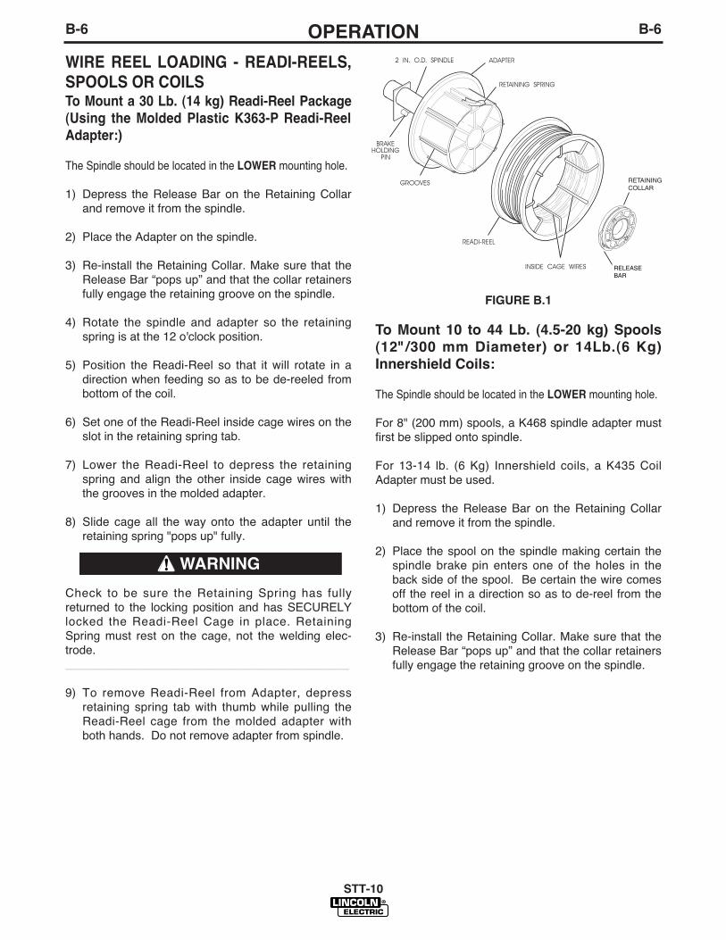
WIRE REEL LOADING - READI-REELS,
SPOOLS OR COILS To Mount a 30 Lb. (14 kg) Readi-Reel Package
(Using the Molded Plastic K363-P Readi-Reel
Adapter:)
The Spindle should be located in the LOWER mounting hole.
1) Depress the Release Bar on the Retaining Collarand remove it from the spindle.
2) Place the Adapter on the spindle.
3) Re-install the Retaining Collar. Make sure that theRelease Bar “pops up” and that the collar retainersfully engage the retaining groove on the spindle.
4) Rotate the spindle and adapter so the retainingspring is at the 12 o'clock position.
5) Position the Readi-Reel so that it will rotate in adirection when feeding so as to be de-reeled frombottom of the coil.
6) Set one of the Readi-Reel inside cage wires on theslot in the retaining spring tab.
7) Lower the Readi-Reel to depress the retainingspring and align the other inside cage wires withthe grooves in the molded adapter.
8) Slide cage all the way onto the adapter until theretaining spring "pops up" fully.
Check to be sure the Retaining Spring has fullyreturned to the locking position and has SECURELYlocked the Readi-Reel Cage in place. RetainingSpring must rest on the cage, not the welding elec-trode.___________________________________________
9) To remove Readi-Reel from Adapter, depressretaining spring tab with thumb while pulling theReadi-Reel cage from the molded adapter withboth hands. Do not remove adapter from spindle.
FIGURE B.1
To Mount 10 to 44 Lb. (4.5-20 kg) Spools
(12"/300 mm Diameter) or 14Lb.(6 Kg)
Innershield Coils:
The Spindle should be located in the LOWER mounting hole.
For 8" (200 mm) spools, a K468 spindle adapter mustfirst be slipped onto spindle.
For 13-14 lb. (6 Kg) Innershield coils, a K435 CoilAdapter must be used.
1) Depress the Release Bar on the Retaining Collarand remove it from the spindle.
2) Place the spool on the spindle making certain thespindle brake pin enters one of the holes in theback side of the spool. Be certain the wire comesoff the reel in a direction so as to de-reel from thebottom of the coil.
3) Re-install the Retaining Collar. Make sure that theRelease Bar “pops up” and that the collar retainersfully engage the retaining groove on the spindle.
STT-10
WARNING
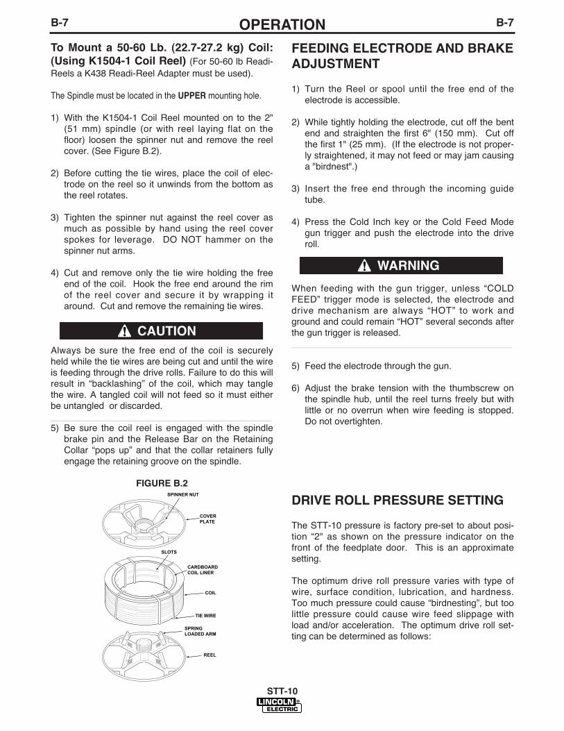
B-7OPERATIONB-7
To Mount a 50-60 Lb. (22.7-27.2 kg) Coil:
(Using K1504-1 Coil Reel) (For 50-60 lb Readi-Reels a K438 Readi-Reel Adapter must be used).
The Spindle must be located in the UPPER mounting hole.
1) With the K1504-1 Coil Reel mounted on to the 2"(51 mm) spindle (or with reel laying flat on thefloor) loosen the spinner nut and remove the reelcover. (See Figure B.2).
2) Before cutting the tie wires, place the coil of elec-trode on the reel so it unwinds from the bottom asthe reel rotates.
3) Tighten the spinner nut against the reel cover asmuch as possible by hand using the reel coverspokes for leverage. DO NOT hammer on thespinner nut arms.
4) Cut and remove only the tie wire holding the freeend of the coil. Hook the free end around the rimof the reel cover and secure it by wrapping itaround. Cut and remove the remaining tie wires.
Always be sure the free end of the coil is securelyheld while the tie wires are being cut and until the wireis feeding through the drive rolls. Failure to do this willresult in “backlashing” of the coil, which may tanglethe wire. A tangled coil will not feed so it must eitherbe untangled or discarded.___________________________________________5) Be sure the coil reel is engaged with the spindle
brake pin and the Release Bar on the RetainingCollar “pops up” and that the collar retainers fullyengage the retaining groove on the spindle.
FIGURE B.2
FEEDING ELECTRODE AND BRAKE
ADJUSTMENT
1) Turn the Reel or spool until the free end of theelectrode is accessible.
2) While tightly holding the electrode, cut off the bentend and straighten the first 6" (150 mm). Cut offthe first 1" (25 mm). (If the electrode is not proper-ly straightened, it may not feed or may jam causinga "birdnest".)
3) Insert the free end through the incoming guidetube.
4) Press the Cold Inch key or the Cold Feed Modegun trigger and push the electrode into the driveroll.
When feeding with the gun trigger, unless “COLDFEED” trigger mode is selected, the electrode anddrive mechanism are always “HOT” to work andground and could remain “HOT” several seconds afterthe gun trigger is released.___________________________________________
5) Feed the electrode through the gun.
6) Adjust the brake tension with the thumbscrew onthe spindle hub, until the reel turns freely but withlittle or no overrun when wire feeding is stopped.Do not overtighten.
DRIVE ROLL PRESSURE SETTING
The STT-10 pressure is factory pre-set to about posi-tion “2" as shown on the pressure indicator on thefront of the feedplate door. This is an approximatesetting.
The optimum drive roll pressure varies with type ofwire, surface condition, lubrication, and hardness.Too much pressure could cause “birdnesting”, but toolittle pressure could cause wire feed slippage withload and/or acceleration. The optimum drive roll set-ting can be determined as follows:
STT-10
SPINNER NUT
COVER PLATE
SLOTS
CARDBOARD COIL LINER
COIL
TIE WIRE
SPRING LOADED ARM
REEL
CAUTION
WARNING
B-8OPERATIONB-8
1) Press end of gun against a solid object that iselectrically isolated from the welder output andpress the gun trigger for several seconds.
2) If the wire "birdnests", jams, or breaks at the driveroll, the drive roll pressure is too great. Back thepressure setting out 1/2 turn, run new wire throughgun, and repeat above steps.
3) If the only result is drive roll slippage, disengagethe gun, pull the gun cable forward about 6" (150mm). There should be a slight waviness in theexposed wire. If there is no waviness, the pres-sure is too low. Increase the pressure settingturn, reconnect the gun, tighten locking clamp andrepeat the above steps.
PROCEDURE FOR SETTING ANGLE
OF FEEDPLATE
1) Loosen the clamping collar screw using a 3/16"Allen wrench. The clamping collar screw isaccessed from the bottom of the feedplate. It isthe screw which is perpendicular to the feedingdirection.
2) Rotate feedplate to the desired angle and tightenclamping collar screw.
GAS GUARD REGULATOR SETTING
NOTE: Gas supply pressure must be regulated to amaximum of 80 psi(5.5 bar).
1) With the gas supply shut off, the Gas Guard regu-lator flow adjusting Key should be set to maximum(full clockwise) which is rated to be 60 SCFH (28l/min).
2) Adjust gas supply flow rate for a level higher thanwill be required, then adjust Gas Guard flowadjusting Key counterclockwise to the desired gasflow rate.
MAKING A WELD
1) Use only an STT-II power source with the STT-10Wire Feeder.
2) Properly connect the electrode and work leads forthe correct electrode polarity.
3) Use the Trigger Mode Selection key to set desiredtrigger mode for each procedure. (Refer to “TriggerMode Selection” in this section)
4) Use Control Select and encoder knobs to set desiredWeld feed speed and current then Run-in speed tooptimize arc starting. (Set for each procedure ifusing front panel, or optional dual procedure switch.)(Refer to “Operation Keys” and “Display ControlKeys” in this section)
5) Adjust the wire feed acceleration if desired, foreach feeder and procedure. (Refer to “AccelerationSelection” in this section)
6) Use Control Select and top Encoder knob to setdesired timers. (Refer to “Trigger Mode Selection”in this section)
7) Feed the electrode through the gun and cable andthen cut the electrode within approximately 3/8”(9.5 mm) of the end of the contact tip for solid wireand within approximately 3/4” (19mm) of the exten-sion guide for cored wire.
8) Connect work cable to metal to be welded. Workcable must make good electrical contact to thework. The work must also be grounded as statedin "Arc Welding Safety Precautions".
9) If used, be sure shielding gas valve is turned on.
10) Position electrode over joint. End of electrodemay be lightly touching the work.
11) Lower welding helmet, close gun trigger, and startwelding. Hold the gun so the contact tip to workdistance gives the correct electrical stickout asrequired for the procedure being used.
12) To stop welding, release the gun trigger and thenpull the gun away from the work after the arc goesout and Postflow time, if used, is over.
13) If necessary to optimize arc starting, readjust wirespeed acceleration, (Refer to “AccelerationSelection” in this section) and/or Run-In speed,(Refer to “Display Control Keys” in this section).
STT-10
• When using an Open Arc process, it
is necessary to use correct eye,
head, and body protection.
____________________________________
WARNING
B-9OPERATIONB-9
WIRE REEL CHANGINGAt the end of a coil, remove the last of the old electrodecoil from the conductor cable by either pulling it out atthe nozzle end of the gun or by using the following pro-cedure:1) Cut the end of the electrode off at the gun end. Do
not break it off by hand because this puts a slightbend in the wire making it difficult to pull it backthrough the nozzle.
2) Disconnect the gun cable from the gun connector onthe STT-10 wire drive unit and lay the gun and cableout straight.
3) Using pliers to grip the wire, pull it out of the cablefrom the connector end.
4) After the electrode has been removed, reconnectthe gun cable to the drive. Load a new reel of elec-trode per the instructions in “Wire Reel Loading” inthis section.
WIRE FEED OVERLOAD PROTECTIONThe STT-10 has solid-state overload protection of thewire drive motor. If the wire drive motor becomes over-loaded for an extended period of time, the protection cir-cuitry turns off the power source, wire feed and gassolenoid, and then displays “H30” on the WFS display(with blank Voltage display). This indicates the wiredrive motor is overloaded and will remain shut down forabout 30 seconds before the unit will automaticallyreset. The “H30” display decrements every second untilit reaches “H00”. At that time, the unit resets automati-cally and the previous displays will return indicating theunit is ready to operate again. Overloads can result fromimproper tip size, liner, drive rolls, or guide tubes,obstructions or bends in the gun cable, feeding wire thatis larger than the rated capacity of the feeder or anyother factors that would impede normal wire feeding.(See “Avoiding Wire Feeding Problems” in the MAINTE-NANCE section).
GROUNDING LEAD PROTECTORThe frame of the STT-10 Control is grounded to theframe of the power source by a lead in the control cable.An overload protector prevents welding current fromdamaging this lead if the electrode circuit touches thewire feeder frame while the electrode is electrically hot.
If such a grounding lead fault occurs, the WFS displaywill show “GLP,” (with blank Voltage display) and thetrigger circuit will be disabled. To reset the circuit,release the trigger, make sure that the electrode is nottouching the wire feeder frame, and then either pressany key on the keypad or close the trigger. When theGLP circuit is reset, the “GLP” display is removed andthe wire feeder is returned to normal operating mode.
STT-10
EXPLANATION OF PROMPTING
AND ERROR MESSAGES
Display Prompt or Error
Acc Displayed on top display, indicates WFSdisplay is showing acceleration setting, “1"to “5" (See “Acceleration Selection” in thissection).
SEC Displayed on WFS display, indicatesVoltage display is showing a Timer settingin seconds. (See “Display Control Keys” inthis section)
GLP Displayed on WFS display, indicates thatthe Grounding Lead Protector circuit wasactivated due to excessive current flow intothe wire feeder frame. When the GLP cir-cuit is activated the wire feeder is disabled(the trigger output to the power source isopened up, the motor is stopped, and thegas solenoid is turned off). To resume nor-mal operation, release the trigger, makesure that the electrode is not touching thewire feeder frame, and then either press akey on the keypad or close the trigger.(See “Grounding Lead Protector” in thissection)
Cld Displayed on top display when Cold FeedForward or Cold Feed Reverse Key ispressed, or Cold Feed Trigger mode isselected. Indicates wire is fed “cold” (noweld voltage) at the speed indicated on theWFS display. (See “Operation Keys” and“Trigger Mode Selection” in this section).
--- Displayed on bottom display with RUN-INselected, indicates setting will match thoseset for Wire Feed Speed (See “DisplayControl Keys” in this section).
HXX Displayed on WFS display, indicates wire feed over-load. XX indicates time remaining in seconds beforeunit resets automatically. (See “Wire Feed OverloadProtection” in this section and “Avoiding WireFeeding Problems” in the MAINTENANCE section).
Er EEPROM error. Usually occurs at power-up.Indicates one or more of the recalled settings is outof acceptable limits. Press any key to return to nor-mal operation. Be sure to check all current, wirefeed speed, acceleration and timer settings beforeyou proceed.
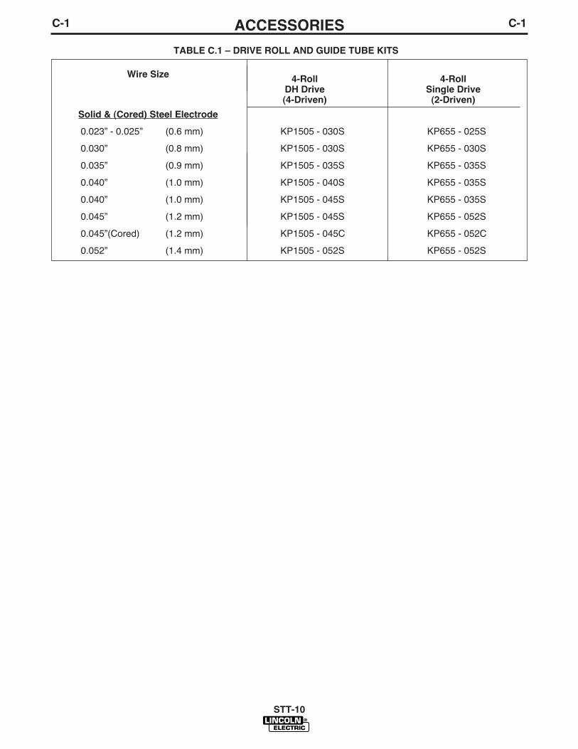
TABLE C.1 – DRIVE ROLL AND GUIDE TUBE KITS
Wire Size4-Roll 4-Roll
DH Drive Single Drive(4-Driven) (2-Driven)
Solid & (Cored) Steel Electrode
0.023” - 0.025” (0.6 mm) KP1505 - 030S KP655 - 025S
0.030” (0.8 mm) KP1505 - 030S KP655 - 030S
0.035” (0.9 mm) KP1505 - 035S KP655 - 035S
0.040” (1.0 mm) KP1505 - 040S KP655 - 035S
0.040” (1.0 mm) KP1505 - 045S KP655 - 035S
0.045” (1.2 mm) KP1505 - 045S KP655 - 052S
0.045”(Cored) (1.2 mm) KP1505 - 045C KP655 - 052C
0.052” (1.4 mm) KP1505 - 052S KP655 - 052S
C-1ACCESSORIESC-1
STT-10

C-2ACCESSORIESC-2
K1758-”L” INPUT CABLE ASSEM-
BLYConsists of an 8-conductor control cable with a 14-pinplug, a 6-conductor control cable with a 10-pin plug,and an electrode cable with Twist-Mate™ connector.It is rated at 300 amps, 60% duty cycle and is avail-able in lengths of 10 ft. (3 mm), 25 ft. (7.6 m), and 50ft. (15 m).
K2147 CONTROL CABLE AND
WELD CABLEConsists of an 8-conductor control cable with a 14-pinplug, a 6-conductor control cable with a 10-pin plug,and a co-axil weld cable. It is rated at 300 amps, 60%duty cycle and is available in lengths of 75 ft. (22.6m),100 ft. (30m).
K659-1 GAS GUARD REGULATORAdjustable flow regulator with removable adjustor keyfor CO2 and Argon blend gases. Mounts onto wiredrive gas inlet, and reduces gas waste and arc start"blow" by reducing surge caused by excess pressurein supply hose.
K590-4 WATER CONNECTION KIT(For 10 Series Wire Drive Only)Install per the instructions shipped with the kit.
K682-2 WATER CONNECTION KIT(K679 Synergic 7F Wire Drive Only)Install to either side of wire feed unit mounting bracketper instructions shipped with the kit.
K683-1 DUAL PROCEDURE SWITCH- Requires K686-2 Adapter for STT-10. Kit includes
gun switch, and mountings for Lincoln Innershield andMagnum guns, with 15 ft. (4.5 m) control cable and 3-pin plug. K686-2 Adapter permits 3-pin plug and 5-pingun trigger plug to be connected to STT-10 5-pinTrigger/Dual Procedure receptacle.
K683-3 DUAL PROCEDURE SWITCHKit includes gun switch, and mountings for LincolnInnershield and Magnum guns, with 15 ft. (4.5m) con-trol cable and 5-pin plug with two leads to connect togun trigger.
K1558-1 REMOTE SWITCH
INTERFACE MODULEThe Module provides for user interface connection ofan external switch (flow switch, etc.) which must beclosed to enable the feeder welding operation.
Also, the Module provides for interface connection ofexternal equipment (fume extractor, etc.) to theModuleʼs isolated relay contacts which actuate whenthe feeder welding gas solenoid is activated (repre-senting welding operation in process).
K1561-1 ROBOTICS INTERFACE
MODULEThe module plugs directly into the STT-10 controlboard and provides an interface to a properlyequipped Fanuc robot. (ArcTool software and an addi-tional process I/O board are needed). When installedand properly configured, the K1561-1 RoboticsInterface Module allows complete control of the weld-ing process form the robot controller.
The Lincoln Electric Companyʼs Automation Centershould be contacted for questions regarding installa-tion or operation of the Robotics Interface Module.
K1557-1 SWIVEL MOUNT
The K1557-1 Swivel mount attaches to the powersource. This kit includes a feeder adapter plate thatallows the feeder to rotate on top of the power source.The feeder can be easily separated from the swivelmount at any time. This option is compatible with theK1556-1 Light Duty Caster Kit.
K1556-1 LIGHT DUTY CASTER KIT
This option provides 4 casters and all required hard-ware to mount it to the Power Feed 10. This option iscompatible with the K1557-1 Swivel Mount.
K1555-1 INSULATED LIFT HOOK
For applications where an insulated lift hook isrequired. This kit provides an easily installed, heavyduty insulated lift eye that mounts to the wire reelstand mast. See the instructions provided with the kitfor installation.
SPINDLE ADAPTERS:
K162H (Not required for STT-10 Bench Models)Spindle for boom mounting Readi-Reels and 2" (51mm) I.D. spools with 60 lb. (27.2 kg) capacity. Usermounted to appropriately prepared boom framework.Includes an easily adjustable friction brake for controlof overrun.
When a 2" (51 mm) spindle is used with Readi-Reelsor coils not on 12" (305 mm) O.D. spools, an adapteris required:
STT-10

C-3ACCESSORIESC-3
Coil Adapter:
K1504-1 Permits 50 lb to 60 lb (22.7-27.2 Kg.)Coils to be mounted on 2: (51 mm) O.D. spindles.
K435 Permits 14 lb. (6 kg) Innershield coils to bemounted on 2" (51 mm) O.D. spindles.
K468 Permits 8" (203 mm) O.D. spools to bemounted on 2" (51 mm) O.D. spindles. :
K363P Adapts Lincoln Readi-Reel coils of elec-trode 30 lb. (14 kg) and 22 lb. (10 kg) to a 2" (51mm) spindle. Durable molded plastic one piece con-struction. Designed for easy loading; adapterremains on spindle for quick changeover.
K438 Adapts Lincoln Readi-Reel coils of electrode50-60 lb. (22.7-27.2 kg) to a 2" (51 mm) spindle.
GUN ADAPTERS (FOR 10 SERIES
WIRE DRIVE HEADS)
The STT-10 wire feeder is equipped with a factoryinstalled K1500-2 gun connection kit. This kit is forguns having a Tweco #2-#4 type connector. The STT-10 has been designed to make connecting a variety ofguns easy and inexpensive with the K1500 series ofgun connection kits. Gun trigger and dual procedurelead connections connect to the single 5 pin recepta-cle on the front of the feed head box.
MAGNUM 200/300/400 GUNSThe easiest and least expensive way to use Magnum200/300/400 guns with the STT-10 wire feeder is toorder them with the K466-2 connector kit, or to buy acompletely assembled Magnum gun having the K466-2 connector (such as the K497-21,-22,-23 dedicatedMagnum 400 guns and the K497-20,-21 dedicatedMagnum 200 guns).
MAGNUM 550 GUNSThe easiest and least expensive way to use theMagnum 550 guns with STT-10 wire feeders is toorder the gun with the K613-2 connector kit, andinstall a K1500-3 gun connection kit to the wire feeder.
LINCOLN INNERSHIELD AND SUB ARC GUNSAll of these guns can be connected to the STT-10 byusing the K1500-1 Adapter Kit.
LINCOLN FUME EXTRACTION GUNSThe K556 (250XA) and K566 (400XA) guns requirethat a K489-7 Fast-Mate adapter kit be installed.
K206, K289, and K309require only the installation of a K1500-1 connector inthe STT-10 wire feeder.
NON-LINCOLN GUNS
Most competitive guns can be connected to the STT-10 by using one of the K1500 series adapter kits,shown in the following column.
Gun Receiver Bushings and Gun Adapters
K489-7 (Dual Schedule Fast-Mate Adapter)This adapter installs directly into the wire drive feed-plate, to provide for use of guns with Fast-Mate orEuropean style gun connections. This K489-7 willhandle both standard Fast-Mate and Dual ScheduleFast-Mate guns.
K1500-1 (Lincoln Innershield gun standard connection) Use this kit to connect the following guns: Guns hav-ing a Lincoln standard innershield gun connector,Magnum 200/300/400 with K466-1 connector kit, andMagnum 550 guns with the K613-1 gun connectionkit.
K1500-2 (Tweco #2-#4 type connection) The K1500-2 gun adapter comes factory installed onthe STT-10 wire feeder. Use this adapter for guns thathave a Tweco #2-#4 connector. Such guns includeMagnum 200/300/400 guns with K466-2 connector kit,and completely factory assembled Magnum guns thatare factory equipped with the K466-2 connector (suchas the K471-21, -22, and -23 dedicated Magnum 400guns and the K497-20 and -21 Magnum 200 guns).
K1500-3 (Tweco #5 connection)For Magnum 550 gun with K613-2 Connection Kit,and any other gun having a Tweco #5 connector .
K1500-4 (Miller connection) For any gun having a newer style Miller connector.
STT-10

C-4ACCESSORIESC-4
GUN AND CABLE ASSEMBLIESThe following Lincoln gun and cable assemblies arecompatible with 10 Series Wire Feed heads withappropriate K1500 Gun Adapter:
K126 (Requires K1500-1) Innershield gun and cableassemblies are rated at 350 amps, 60% duty cycle.(Consult sales specifications for appropriate models)
K115 (Requires K1500-1) Innershield gun and cableassemblies are rated at 450 amps, 60% duty cycle.(Consult sales specifications for appropriate models)
K470 (With K466-9 requires K1500-2) Magnum 300GMAW gun and cable assemblies are rated 300amps, 60% duty cycle. (Consult sales specificationsfor appropriate models)
K471 (With K466-9 requires K1500-2) Magnum 400GMAW gun and cable assemblies are rated 400amps, 60% duty cycle. (Consult sales specificationsfor appropriate models)
K497 (With K466-9 requires K1500-2) Magnum 200GMAW gun and cable assemblies are rated 200amps, 60% duty cycle. (Consult sales specificationsfor appropriate models)
K541 (With K466-9 requires K1500-2) Magnum 400Short Neck GMAW gun and cable assemblies arerated 400 amps, 60% duty cycle. (Consult sales speci-fications for appropriate models)The following Lincoln gun and cable assemblies areequipped with a Fast-Mate™ connector. They can beused with 10 Series wire feed models by installing aK489-2 Fast-Mate™ adapter kit and a K1500-1Lincoln Gun adapter.
K684 Magnum "Super Cool" FM water cooledGMAW gun and cable assemblies are rated 450amps, 100% duty cycle (CO2). (Consult sales specifi-cations for appropriate models)
K498 Magnum 200 FM GMAW gun and cableassemblies are rated for 200 amps 60% duty cycle.(Consult sales specifications for appropriate models)
K534 Magnum 250L FM GMAW gun and cableassemblies are rated for 250 amps, 30% duty cycle.(Consult sales specifications for appropriate models)
K478 Magnum 300 FM GMAW gun and cableassemblies are rated for 300 amps, 60% duty cycle.(Consult sales specifications for appropriate models)
K479 Magnum 400 FM GMAW gun and cableassemblies are rated for 400 amps, 60% duty cycle.(Consult sales specifications for appropriate models)
K1634-1 WIRE REEL ENCLOSURE KIT
The K1634-1 Wire Reel Enclosure Kit provides thenecessary parts to cover the wire and protect it fromexcessive dirt and contamination. The kit is not for usewith 60lb coils (most 30 lb, 15kg, 44 lb fiber spools,and smaller coils will work). The kit includes a 2 partplastic reel cover, a Magnum conduit adapter for theincoming end of the wire feeder feed plate, and ashort length of Magnum conduit to go between thereel cover and the feedplate.
STT-10
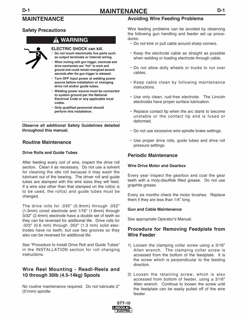
D-1MAINTENANCED-1
STT-10
Avoiding Wire Feeding Problems
Wire feeding problems can be avoided by observingthe following gun handling and feeder set up proce-dures:• Do not kink or pull cable around sharp corners.
• Keep the electrode cable as straight as possiblewhen welding or loading electrode through cable.
• Do not allow dolly wheels or trucks to run overcables.
• Keep cable clean by following maintenanceinstructions.
• Use only clean, rust-free electrode. The Lincolnelectrodes have proper surface lubrication.
• Replace contact tip when the arc starts to becomeunstable or the contact t ip end is fused ordeformed.
• Do not use excessive wire spindle brake settings.
• Use proper drive rolls, guide tubes and drive rollpressure settings.
Periodic Maintenance
Wire Drive Motor and Gearbox
Every year inspect the gearbox and coat the gearteeth with a moly-disulfide filled grease. Do not usegraphite grease.
Every six months check the motor brushes. Replacethem if they are less than 1/4” long.
Gun and Cable Maintenance
See appropriate Operatorʼs Manual.
Procedure for Removing Feedplate from
Wire Feeder
1) Loosen the clamping collar screw using a 3/16"Allen wrench. The clamping collar screw isaccessed from the bottom of the feedplate. It isthe screw which is perpendicular to the feedingdirection.
2) Loosen the retaining screw, which is alsoaccessed from bottom of feeder, using a 3/16"Allen wrench. Continue to loosen the screw untilthe feedplate can be easily pulled off of the wirefeeder.
MAINTENANCE
Safety Precautions
Routine Maintenance
Drive Rolls and Guide Tubes
After feeding every coil of wire, inspect the drive rollsection. Clean it as necessary. Do not use a solventfor cleaning the idle roll because it may wash thelubricant out of the bearing. The driver roll and guidetubes are stamped with the wire sizes they will feed.If a wire size other than that stamped on the roll(s) isto be used, the roll(s) and guide tubes must bechanged.
The drive rolls for .035” (0.9mm) through .052”(1.3mm) cored electrode and 1/16” (1.6mm) through3/32” (2.4mm) electrode have a double set of teeth sothey can be reversed for additional life. Drive rolls for.023" (0.6 mm) through .052" (1.3 mm) solid elec-trodes have no teeth, but use two grooves so theyalso can be reversed for additional life.
See “Procedure to Install Drive Roll and Guide Tubes”in the INSTALLATION section for roll changinginstructions.
Wire Reel Mounting - Readi-Reels and
10 through 30lb (4.5-14kg) Spools
No routine maintenance required. Do not lubricate 2”(51mm) spindle.
WARNING
Observe all additional Safety Guidelines detailed
throughout this manual.
ELECTRIC SHOCK can kill.• Do not touch electrically live parts such
as output terminals or internal wiring.
• When inching with gun trigger, electrode and
drive mechanism are “hot” to work and
ground and could remain energized several
seconds after the gun trigger is released.
• Turn OFF input power at welding power
source before installation or changing
drive roll and/or guide tubes.
• Welding power source must be connected
to system ground per the National
Electrical Code or any applicable local
codes.
• Only qualified personnel should
perform this installation.
E-1TROUBLESHOOTINGE-1
If for any reason you do not understand the test procedures or are unable to perform the tests/repairs safely, contact your
CAUTION
This Troubleshooting Guide is provided to help youlocate and repair possible machine malfunctions.Simply follow the three-step procedure listed below.
Step 1. LOCATE PROBLEM (SYMPTOM).
Look under the column labeled “PROBLEM (SYMP-TOMS)”. This column describes possible symptomsthat the machine may exhibit. Find the listing thatbest describes the symptom that the machine isexhibiting.
Step 2. POSSIBLE CAUSE.
The second column labeled “POSSIBLE CAUSE” liststhe obvious external possibilities that may contributeto the machine symptom.
Step 3. RECOMMENDED COURSE OF ACTION
This column provides a course of action for thePossible Cause, generally it states to contact yourlocal Lincoln Authorized Field Service Facility.
If you do not understand or are unable to perform theRecommended Course of Action safely, contact yourlocal Lincoln Authorized Field Service Facility.
HOW TO USE TROUBLESHOOTING GUIDE
Service and Repair should only be performed by Lincoln Electric Factory Trained Personnel.Unauthorized repairs performed on this equipment may result in danger to the technician andmachine operator and will invalidate your factory warranty. For your safety and to avoid ElectricalShock, please observe all safety notes and precautions detailed throughout this manual.
__________________________________________________________________________
WARNING
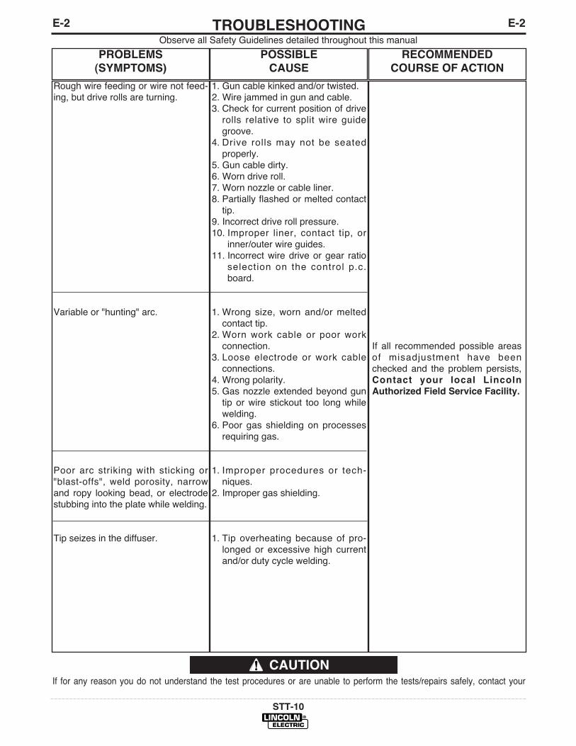
E-2TROUBLESHOOTINGE-2
STT-10
Observe all Safety Guidelines detailed throughout this manual
If for any reason you do not understand the test procedures or are unable to perform the tests/repairs safely, contact your
CAUTION
PROBLEMS
(SYMPTOMS)
POSSIBLE
CAUSE
RECOMMENDED
COURSE OF ACTION
Rough wire feeding or wire not feed-ing, but drive rolls are turning.
Variable or "hunting" arc.
Poor arc striking with sticking or"blast-offs", weld porosity, narrowand ropy looking bead, or electrodestubbing into the plate while welding.
Tip seizes in the diffuser.
1. Gun cable kinked and/or twisted.2. Wire jammed in gun and cable.3. Check for current position of drive
rolls relative to split wire guidegroove.
4. Drive rolls may not be seatedproperly.
5. Gun cable dirty.6. Worn drive roll.7. Worn nozzle or cable liner.8. Partially flashed or melted contact
tip.9. Incorrect drive roll pressure.10. Improper liner, contact tip, or
inner/outer wire guides.11. Incorrect wire drive or gear ratio
selection on the control p.c.board.
1. Wrong size, worn and/or meltedcontact tip.
2. Worn work cable or poor workconnection.
3. Loose electrode or work cableconnections.
4. Wrong polarity.5. Gas nozzle extended beyond gun
tip or wire stickout too long whilewelding.
6. Poor gas shielding on processesrequiring gas.
1. Improper procedures or tech-niques.
2. Improper gas shielding.
1. Tip overheating because of pro-longed or excessive high currentand/or duty cycle welding.
If all recommended possible areasof misadjustment have beenchecked and the problem persists,Contact your local Lincoln
Authorized Field Service Facility.
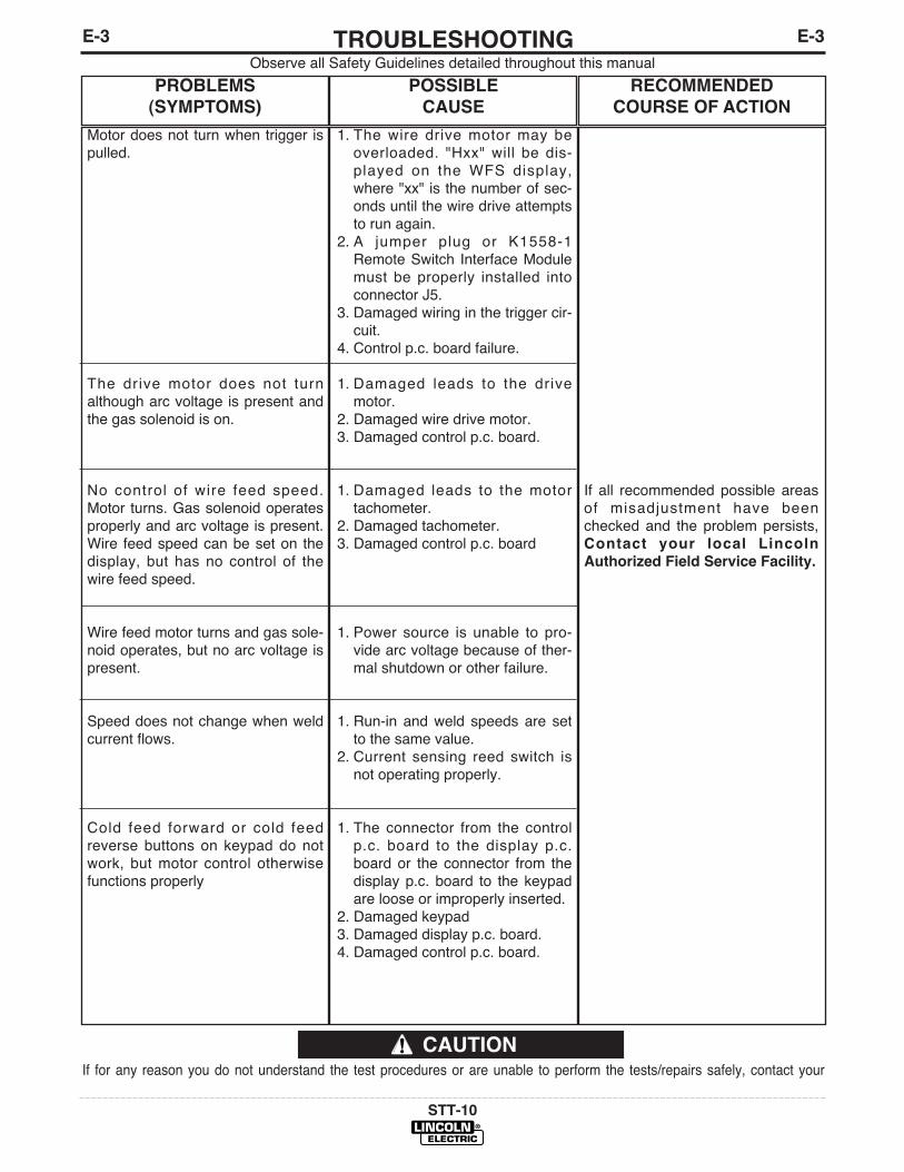
E-3TROUBLESHOOTINGE-3
STT-10
Observe all Safety Guidelines detailed throughout this manual
If for any reason you do not understand the test procedures or are unable to perform the tests/repairs safely, contact your
CAUTION
PROBLEMS
(SYMPTOMS)
POSSIBLE
CAUSE
RECOMMENDED
COURSE OF ACTION
Motor does not turn when trigger ispulled.
The drive motor does not turnalthough arc voltage is present andthe gas solenoid is on.
No control of wire feed speed.Motor turns. Gas solenoid operatesproperly and arc voltage is present.Wire feed speed can be set on thedisplay, but has no control of thewire feed speed.
Wire feed motor turns and gas sole-noid operates, but no arc voltage ispresent.
Speed does not change when weldcurrent flows.
Cold feed forward or cold feedreverse buttons on keypad do notwork, but motor control otherwisefunctions properly
1. The wire drive motor may beoverloaded. "Hxx" will be dis-played on the WFS display,where "xx" is the number of sec-onds until the wire drive attemptsto run again.
2. A jumper plug or K1558-1Remote Switch Interface Modulemust be properly installed intoconnector J5.
3. Damaged wiring in the trigger cir-cuit.
4. Control p.c. board failure.
1. Damaged leads to the drivemotor.
2. Damaged wire drive motor.3. Damaged control p.c. board.
1. Damaged leads to the motortachometer.
2. Damaged tachometer.3. Damaged control p.c. board
1. Power source is unable to pro-vide arc voltage because of ther-mal shutdown or other failure.
1. Run-in and weld speeds are setto the same value.
2. Current sensing reed switch isnot operating properly.
1. The connector from the controlp.c. board to the display p.c.board or the connector from thedisplay p.c. board to the keypadare loose or improperly inserted.
2. Damaged keypad3. Damaged display p.c. board.4. Damaged control p.c. board.
If all recommended possible areasof misadjustment have beenchecked and the problem persists,Contact your local Lincoln
Authorized Field Service Facility.
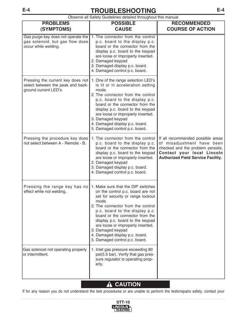
E-4TROUBLESHOOTINGE-4
STT-10
Observe all Safety Guidelines detailed throughout this manual
If for any reason you do not understand the test procedures or are unable to perform the tests/repairs safely, contact your
CAUTION
PROBLEMS
(SYMPTOMS)
POSSIBLE
CAUSE
RECOMMENDED
COURSE OF ACTION
Gas purge key does not operate thegas solenoid, but gas flow doesoccur while welding.
Pressing the current key does notselect between the peak and back-ground current LEDʼs.
Pressing the procedure key doesnot select between A - Remote - B.
Pressing the range key has noeffect while not welding.
Gas solenoid not operating properlyor intermittent.
1. The connector from the controlp.c. board to the display p.c.board or the connector from thedisplay p.c. board to the keypadare loose or improperly inserted.
2. Damaged keypad3. Damaged display p.c. board.4. Damaged control p.c. board.
1. One of the range selection LEDʼsis lit or in acceleration settingmode.
2. The connector from the controlp.c. board to the display p.c.board or the connector from thedisplay p.c. board to the keypadare loose or improperly inserted.
3. Damaged keypad4. Damaged display p.c. board.5. Damaged control p.c. board.
1. The connector from the controlp.c. board to the display p.c.board or the connector from thedisplay p.c. board to the keypadare loose or improperly inserted.
2. Damaged keypad3. Damaged display p.c. board.4. Damaged control p.c. board.
1. Make sure that the DIP switcheson the control p.c. board are notset for security or range lockoutmode.
2. The connector from the controlp.c. board to the display p.c.board or the connector from thedisplay p.c. board to the keypadare loose or improperly inserted.
3. Damaged keypad4. Damaged display p.c. board.5. Damaged control p.c. board.
1. Inlet gas pressure exceeding 80psi(5.5 bar). Verify that gas pres-sure regulator is operating prop-erly.
If all recommended possible areasof misadjustment have beenchecked and the problem persists,Contact your local Lincoln
Authorized Field Service Facility.
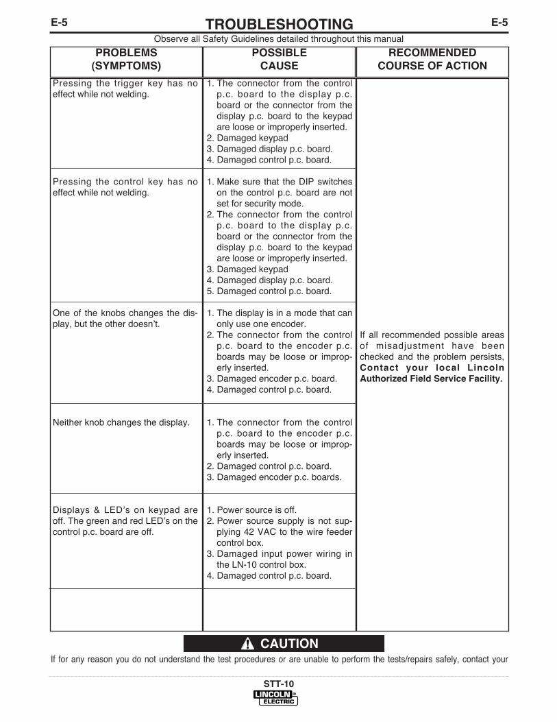
E-5TROUBLESHOOTINGE-5
STT-10
Observe all Safety Guidelines detailed throughout this manual
If for any reason you do not understand the test procedures or are unable to perform the tests/repairs safely, contact your
CAUTION
PROBLEMS
(SYMPTOMS)
POSSIBLE
CAUSE
RECOMMENDED
COURSE OF ACTION
Pressing the trigger key has noeffect while not welding.
Pressing the control key has noeffect while not welding.
One of the knobs changes the dis-play, but the other doesnʼt.
Neither knob changes the display.
Displays & LEDʼs on keypad areoff. The green and red LEDʼs on thecontrol p.c. board are off.
1. The connector from the controlp.c. board to the display p.c.board or the connector from thedisplay p.c. board to the keypadare loose or improperly inserted.
2. Damaged keypad3. Damaged display p.c. board.4. Damaged control p.c. board.
1. Make sure that the DIP switcheson the control p.c. board are notset for security mode.
2. The connector from the controlp.c. board to the display p.c.board or the connector from thedisplay p.c. board to the keypadare loose or improperly inserted.
3. Damaged keypad4. Damaged display p.c. board.5. Damaged control p.c. board.
1. The display is in a mode that canonly use one encoder.
2. The connector from the controlp.c. board to the encoder p.c.boards may be loose or improp-erly inserted.
3. Damaged encoder p.c. board.4. Damaged control p.c. board.
1. The connector from the controlp.c. board to the encoder p.c.boards may be loose or improp-erly inserted.
2. Damaged control p.c. board.3. Damaged encoder p.c. boards.
1. Power source is off.2. Power source supply is not sup-
plying 42 VAC to the wire feedercontrol box.
3. Damaged input power wiring inthe LN-10 control box.
4. Damaged control p.c. board.
If all recommended possible areasof misadjustment have beenchecked and the problem persists,Contact your local Lincoln
Authorized Field Service Facility.

E-6TROUBLESHOOTINGE-6
STT-10
Observe all Safety Guidelines detailed throughout this manual
If for any reason you do not understand the test procedures or are unable to perform the tests/repairs safely, contact your
CAUTION
PROBLEMS
(SYMPTOMS)
POSSIBLE
CAUSE
RECOMMENDED
COURSE OF ACTION
Displays & LEDʼs on keypad areoff. The green and red LEDʼs on thecontrol p.c. board are both blinkingat about one second intervals.
Displays & LEDʼs on keypad areoff. The green or red LED on thecontrol p.c. board is blinking at avery fast or erratic rate.
Dual procedure switch is not func-tioning at the gun.
Wire feed speed is consistent andadjustable, but operates at thewrong speed.
ʻErʼ is displayed on power up.
ʻGLPʼ is displayed.
The knobs do not control the com-plete range of wire feed speed,peak current, or background cur-rent.
1. The connectors from the controlp.c. board to the display p.c.board are loose or improperlyinserted.
2. Damaged display p.c. board.3. Damaged control p.c. board.
1. Damaged control p.c. board.
1.STT-10 control not properly setfor using a dual procedure switchat the gun2. Disconnected or damaged wiring
between the wire drive and con-trol box.
3. Damaged wiring in the STT-10wire drive.
4. Damaged wiring in the STT-10control box.
5. Damaged control p.c. board.
1. DIP switch S1 is incorrectly setfor the wrong wire drive or gearratio.
2. Damaged control p.c. board.
1. EEPROM error detected.2. Damaged control p.c. board.
1. Ground Loop Protection faultoccurred.
2. GLP reed switch failure.3. Damaged control p.c. board.
1. Ranges are set for wire feedspeed, peak current, or back-ground current.
2. DIP switch is incorrectly set forthe wrong wire drive or gearratio.
If all recommended possible areasof misadjustment have beenchecked and the problem persists,Contact your local Lincoln
Authorized Field Service Facility.
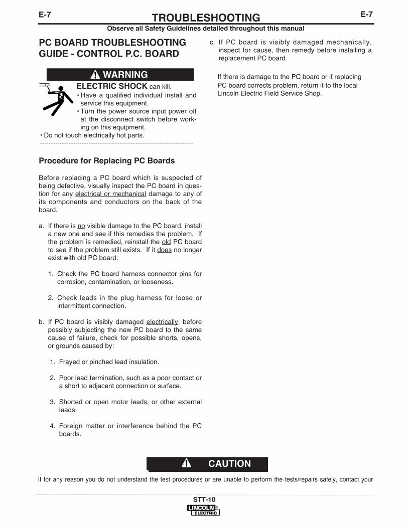
CAUTION
TROUBLESHOOTINGE-7
STT-10
Observe all Safety Guidelines detailed throughout this manual
PC BOARD TROUBLESHOOTING
GUIDE - CONTROL P.C. BOARD
c. If PC board is visibly damaged mechanically,inspect for cause, then remedy before installing areplacement PC board.
If there is damage to the PC board or if replacingPC board corrects problem, return it to the localLincoln Electric Field Service Shop.
E-7
ELECTRIC SHOCK can kill.• Have a qualified individual install and
service this equipment.• Turn the power source input power off
at the disconnect switch before work-ing on this equipment.
• Do not touch electrically hot parts.---------------------------------------------------------------------
WARNING
Procedure for Replacing PC Boards
Before replacing a PC board which is suspected ofbeing defective, visually inspect the PC board in ques-tion for any electrical or mechanical damage to any ofits components and conductors on the back of theboard.
a. If there is no visible damage to the PC board, installa new one and see if this remedies the problem. Ifthe problem is remedied, reinstall the old PC boardto see if the problem still exists. If it does no longerexist with old PC board:
1. Check the PC board harness connector pins forcorrosion, contamination, or looseness.
2. Check leads in the plug harness for loose orintermittent connection.
b. If PC board is visibly damaged electrically, beforepossibly subjecting the new PC board to the samecause of failure, check for possible shorts, opens,or grounds caused by:
1. Frayed or pinched lead insulation.
2. Poor lead termination, such as a poor contact ora short to adjacent connection or surface.
3. Shorted or open motor leads, or other externalleads.
4. Foreign matter or interference behind the PCboards.
If for any reason you do not understand the test procedures or are unable to perform the tests/repairs safely, contact your
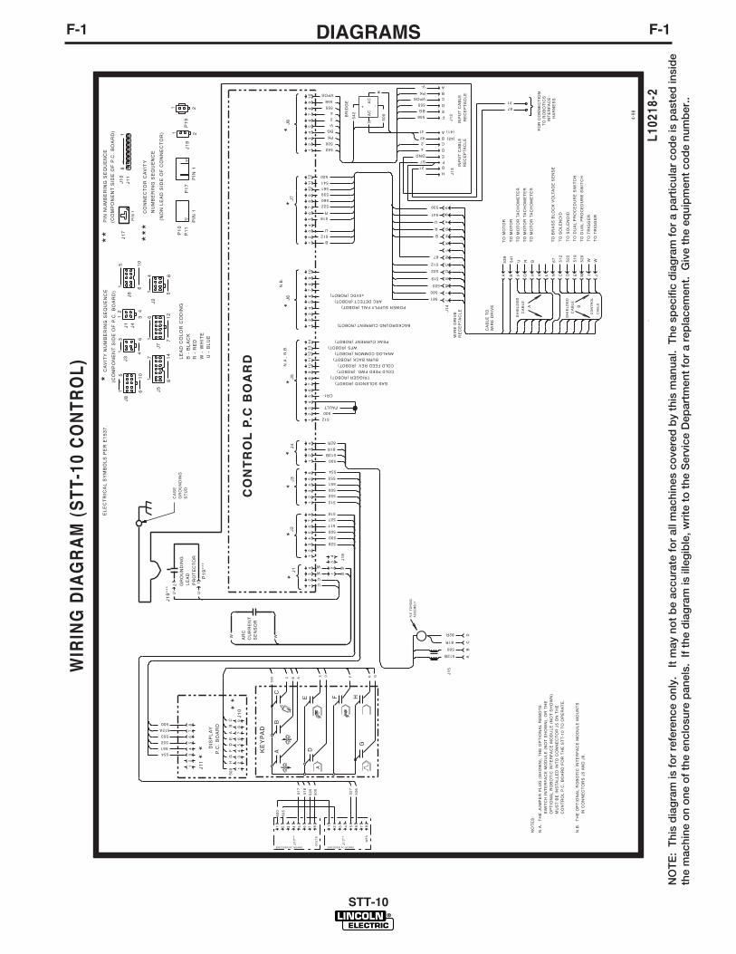
F-1DIAGRAMSF-1
STT-10
NO
TE
: T
his
dia
gra
m is
fo
r re
fere
nce
onl
y.
It m
ay n
ot
be
accu
rate
fo
r al
l mac
hine
s co
vere
d b
y th
is m
anua
l. T
he s
pec
ific
dia
gra
m f
or
a p
artic
ular
co
de
is p
aste
d in
sid
eth
e m
achi
ne o
n o
ne o
f th
e en
clo
sure
pan
els.
If
the
dia
gra
m is
ille
gib
le, w
rite
to
the
Ser
vice
Dep
artm
ent
for
a re
pla
cem
ent.
Giv
e th
e eq
uip
men
t co
de
num
ber
..
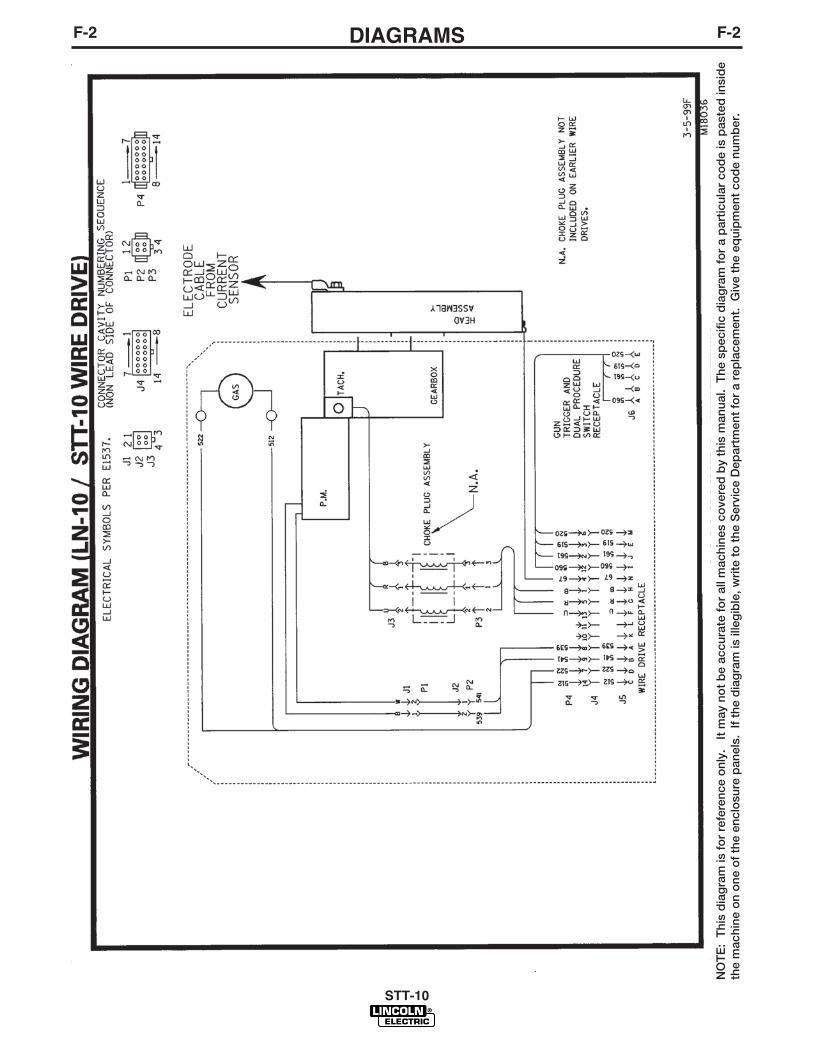
F-2DIAGRAMSF-2
STT-10
NO
TE
: T
his
dia
gra
m is
fo
r re
fere
nce
onl
y.
It m
ay n
ot
be
accu
rate
fo
r al
l mac
hine
s co
vere
d b
y th
is m
anua
l. T
he s
pec
ific
dia
gra
m f
or
a p
artic
ular
co
de
is p
aste
d in
sid
eth
e m
achi
ne o
n o
ne o
f th
e en
clo
sure
pan
els.
If
the
dia
gra
m is
ille
gib
le, w
rite
to
the
Ser
vice
Dep
artm
ent
for
a re
pla
cem
ent.
Giv
e th
e eq
uip
men
t co
de
num
ber
.
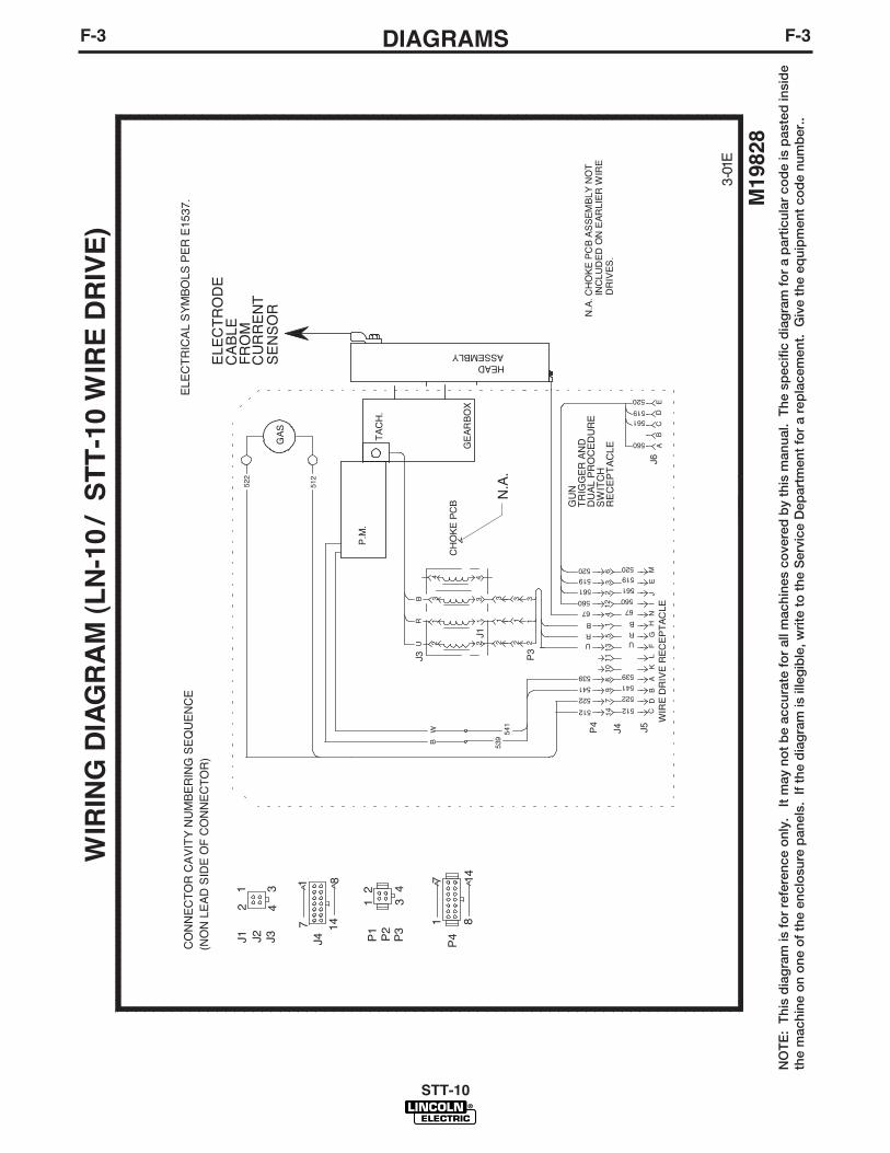
F-3DIAGRAMSF-3
STT-10
NO
TE
: T
his
dia
gra
m is
fo
r re
fere
nce
onl
y.
It m
ay n
ot
be
accu
rate
fo
r al
l mac
hine
s co
vere
d b
y th
is m
anua
l. T
he s
pec
ific
dia
gra
m f
or
a p
artic
ular
co
de
is p
aste
d in
sid
eth
e m
achi
ne o
n o
ne o
f th
e en
clo
sure
pan
els.
If
the
dia
gra
m is
ille
gib
le, w
rite
to
the
Ser
vice
Dep
artm
ent
for
a re
pla
cem
ent.
Giv
e th
e eq
uip
men
t co
de
num
ber
..
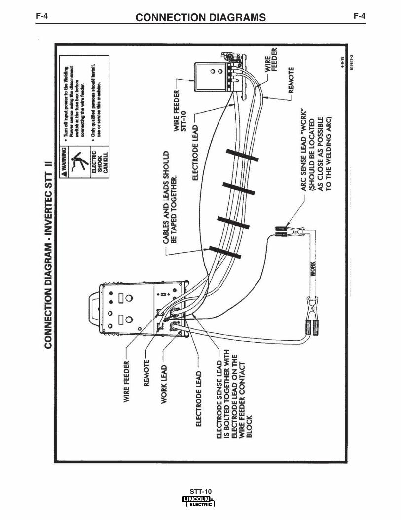
F-4CONNECTION DIAGRAMSF-4
STT-10
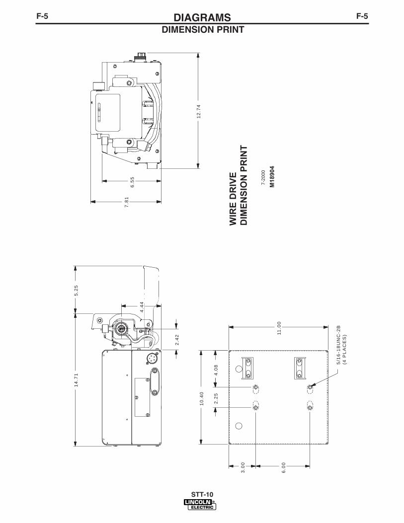
F-5DIAGRAMSF-5
STT-10
DIMENSION PRINT
3.00
6.00
2.42
12.7
4
7.81
6.55
14.7
1
4.44
5/16
-18U
NC
-2B
(4 P
LAC
ES
)
5.25
11.0
0
2.25
4.08
10.4
0
WIR
E D
RIV
ED
IMEN
SIO
N P
RIN
T
M18
904
7-20
00
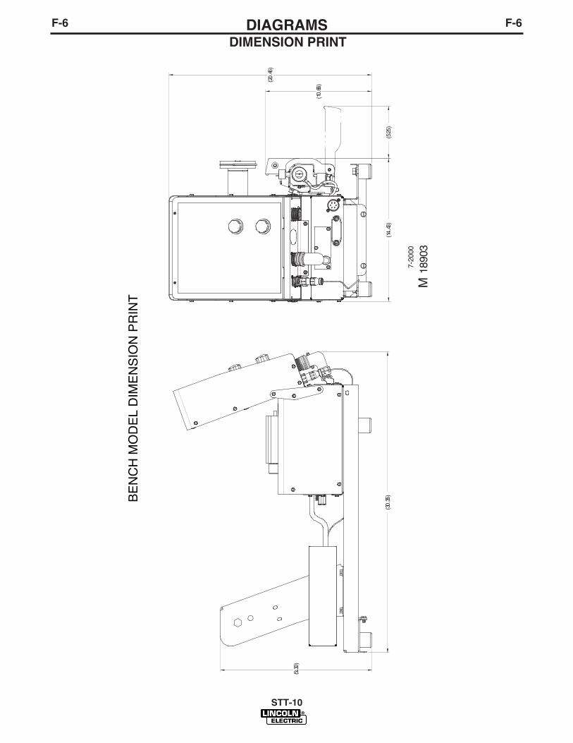
F-6DIAGRAMSF-6
STT-10
DIMENSION PRINT
M18
903
7-20
00
(15.30
)
(30
.35)
(20
.46)
(14
.43)
(5.2
5)
(10
.66)
BE
NC
H M
OD
EL
DIM
EN
SIO
N P
RIN
T

F-7DIAGRAMSF-7
STT-10
WARNING
GRAPHICS SHOWN REPRESENT M17869-1.
3YEAR
WARRANTY
4.58
4.27
5.25
2.80
R.141
(3 SLOTS)
10.92
13.75
2.63
10.10
12.75
14.67
14.65
5-2-
97•
M18
299
Boo
m M
odel
Con
trol
Box
D
imen
sion
Prin
t
DIMENSION PRINT

NOTES
STT-10

NOTES
STT-10
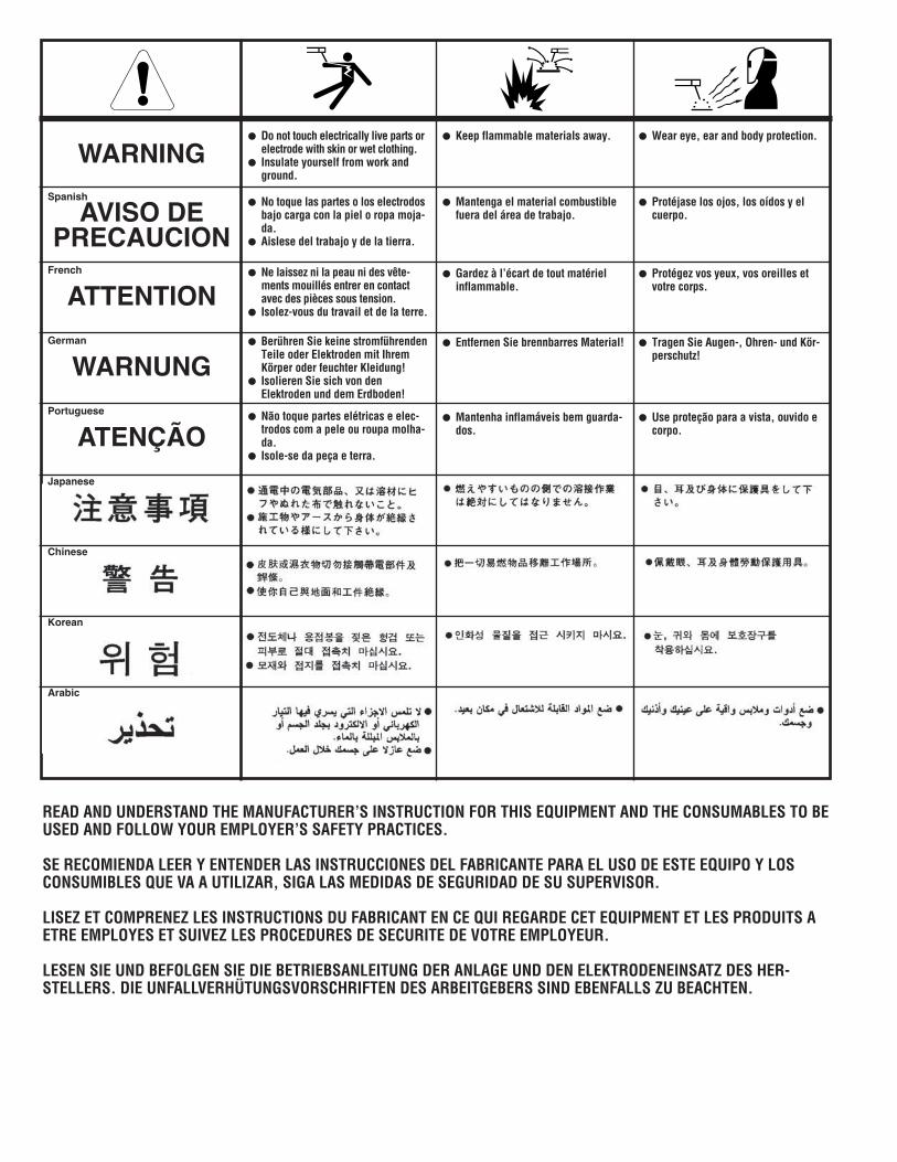
WARNING
AVISO DEPRECAUCION
ATTENTION
WARNUNG
ATENÇÃO
Spanish
French
German
Portuguese
Japanese
Chinese
Korean
Arabic
READ AND UNDERSTAND THE MANUFACTURER’S INSTRUCTION FOR THIS EQUIPMENT AND THE CONSUMABLES TO BEUSED AND FOLLOW YOUR EMPLOYER’S SAFETY PRACTICES.
SE RECOMIENDA LEER Y ENTENDER LAS INSTRUCCIONES DEL FABRICANTE PARA EL USO DE ESTE EQUIPO Y LOSCONSUMIBLES QUE VA A UTILIZAR, SIGA LAS MEDIDAS DE SEGURIDAD DE SU SUPERVISOR.
LISEZ ET COMPRENEZ LES INSTRUCTIONS DU FABRICANT EN CE QUI REGARDE CET EQUIPMENT ET LES PRODUITS AETRE EMPLOYES ET SUIVEZ LES PROCEDURES DE SECURITE DE VOTRE EMPLOYEUR.
LESEN SIE UND BEFOLGEN SIE DIE BETRIEBSANLEITUNG DER ANLAGE UND DEN ELEKTRODENEINSATZ DES HER-STELLERS. DIE UNFALLVERHÜTUNGSVORSCHRIFTEN DES ARBEITGEBERS SIND EBENFALLS ZU BEACHTEN.
● Do not touch electrically live parts orelectrode with skin or wet clothing.
● Insulate yourself from work andground.
● No toque las partes o los electrodosbajo carga con la piel o ropa moja-da.
● Aislese del trabajo y de la tierra.
● Ne laissez ni la peau ni des vête-ments mouillés entrer en contactavec des pièces sous tension.
● Isolez-vous du travail et de la terre.
● Berühren Sie keine stromführendenTeile oder Elektroden mit IhremKörper oder feuchter Kleidung!
● Isolieren Sie sich von denElektroden und dem Erdboden!
● Não toque partes elétricas e elec-trodos com a pele ou roupa molha-da.
● Isole-se da peça e terra.
● Keep flammable materials away.
● Mantenga el material combustiblefuera del área de trabajo.
● Gardez à l’écart de tout matérielinflammable.
● Entfernen Sie brennbarres Material!
● Mantenha inflamáveis bem guarda-dos.
● Wear eye, ear and body protection.
● Protéjase los ojos, los oídos y elcuerpo.
● Protégez vos yeux, vos oreilles etvotre corps.
● Tragen Sie Augen-, Ohren- und Kör-perschutz!
● Use proteção para a vista, ouvido ecorpo.
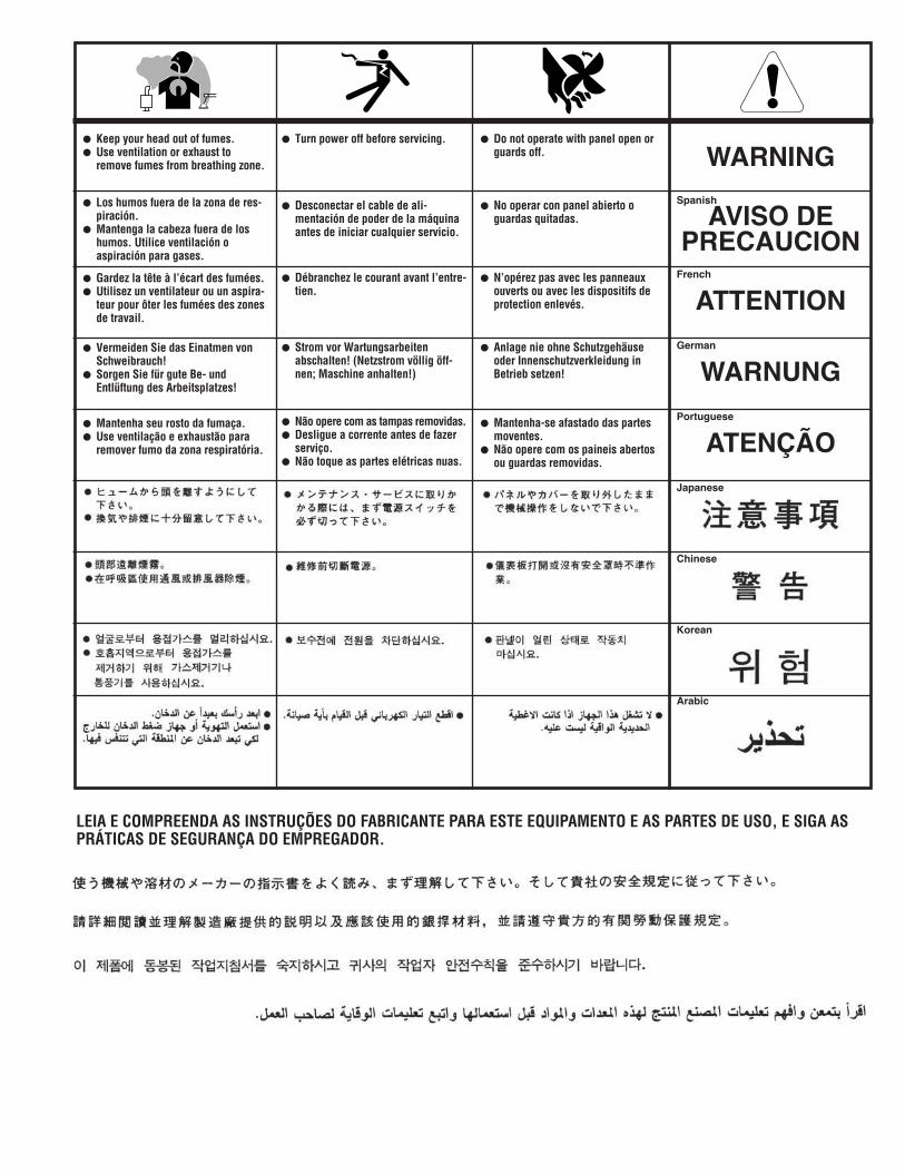
WARNING
AVISO DEPRECAUCION
ATTENTION
WARNUNG
ATENÇÃO
Spanish
French
German
Portuguese
Japanese
Chinese
Korean
Arabic
LEIA E COMPREENDA AS INSTRUÇÕES DO FABRICANTE PARA ESTE EQUIPAMENTO E AS PARTES DE USO, E SIGA ASPRÁTICAS DE SEGURANÇA DO EMPREGADOR.
● Keep your head out of fumes.● Use ventilation or exhaust to
remove fumes from breathing zone.
● Los humos fuera de la zona de res-piración.
● Mantenga la cabeza fuera de loshumos. Utilice ventilación oaspiración para gases.
● Gardez la tête à l’écart des fumées.● Utilisez un ventilateur ou un aspira-
teur pour ôter les fumées des zonesde travail.
● Vermeiden Sie das Einatmen vonSchweibrauch!
● Sorgen Sie für gute Be- undEntlüftung des Arbeitsplatzes!
● Mantenha seu rosto da fumaça.● Use ventilação e exhaustão para
remover fumo da zona respiratória.
● Turn power off before servicing.
● Desconectar el cable de ali-mentación de poder de la máquinaantes de iniciar cualquier servicio.
● Débranchez le courant avant l’entre-tien.
● Strom vor Wartungsarbeitenabschalten! (Netzstrom völlig öff-nen; Maschine anhalten!)
● Não opere com as tampas removidas.● Desligue a corrente antes de fazer
serviço.● Não toque as partes elétricas nuas.
● Do not operate with panel open orguards off.
● No operar con panel abierto oguardas quitadas.
● N’opérez pas avec les panneauxouverts ou avec les dispositifs deprotection enlevés.
● Anlage nie ohne Schutzgehäuseoder Innenschutzverkleidung inBetrieb setzen!
● Mantenha-se afastado das partesmoventes.
● Não opere com os paineis abertosou guardas removidas.

• Sales and Service through Subsidiaries and Distributors Worldwide •
Cleveland, Ohio 44117-1199 U.S.A. TEL: 216.481.8100 FAX: 216.486.1751 WEB SITE: www.lincolnelectric.com
• World's Leader in Welding and Cutting Products •