Embed Size (px)
Citation preview

Operators Manual for M.A.R.V.E.L.
Manual providesInstallation, Operation, and Maintenance Instructions
Model: M.A.R.V.E.L. (Model-based Automated Regulation of Ventilation Exhaust Levels)
Form#: OM070_M.A.R.V.E.L. Date: 09-2017 - Rev2
PT

2 M.A.R.V.E.L. Installation Operation & Maintenance Manual O
M-0
70/0
9201
7/re
v2/E
N
Table of Contents
M.A.R.V.E.L. System Overview ......................................................................................................... 3
M.A.R.V.E.L. System Components ................................................................................................... 5
M.A.R.V.E.L. Sequence of Operations .............................................................................................. 9
M.A.R.V.E.L. Touch Screen Operations ........................................................................................... 11
M.A.R.V.E.L. System Operation ..................................................................................................... 17 M.A.R.V.E.L. System Installation ................................................................................................... 18 M.A.R.V.E.L. System Maintenance ................................................................................................ 22
M.A.R.V.E.L. System Monitoring and Support ............................................................................. 28
FAQs (Frequently Asked Questions) .............................................................................................. 30
M.A.R.V.E.L Parts List ..................................................................................................................... 30
Contact List ..................................................................................................................................... 31
Halton Limited Warranty ................................................................................................................ 32
3 M.A.R.V.E.L. Installation Operation & Maintenance Manual O
M-0
70/0
9201
7/re
v2/E
N
M.A.R.V.E.L. System Overview
General Description
Halton’s M.A.R.V.E.L. (Model based Automated Regulation of Ventilation Exhaust Levels) system offers a demand control ventilation (DCV) solution. M.A.R.V.E.L. builds upon the existing Halton product line, such as the Capture JetTM technology, to deliver a product that reduces energy costs by scheduling and adjusting exhaust airflow based on hours of operation and appliance use.
Halton’s M.A.R.V.E.L. delivers:
• Hood exhaust airflow adjustment depending on cooking activities• Control of common exhaust fan for minimum energy consumption at all times • Automatic or on schedule start/ stops• Automatic balancing dampers• Direct appliance communication (where available)• Early fire warning signals• Internet monitoring and programming
M.A.R.V.E.L. Unique Design
Starting with the Halton extensive product line of commercial foodservice ventilation solutions, M.A.R.V.E.L. adds the following four unique components:
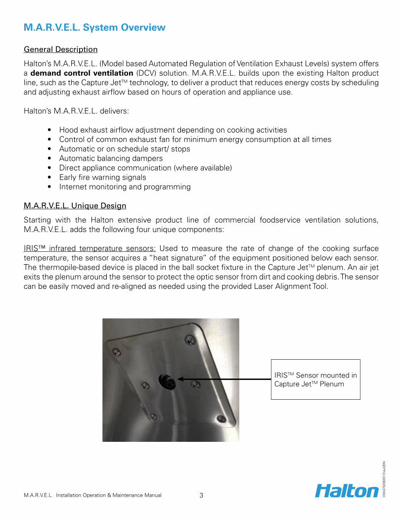
IRIS™ infrared temperature sensors: Used to measure the rate of change of the cooking surface temperature, the sensor acquires a “heat signature” of the equipment positioned below each sensor. The thermopile-based device is placed in the ball socket fixture in the Capture JetTM plenum. An air jet exits the plenum around the sensor to protect the optic sensor from dirt and cooking debris. The sensor can be easily moved and re-aligned as needed using the provided Laser Alignment Tool.
IRISTM Sensor mounted in Capture JetTM Plenum

4 M.A.R.V.E.L. Installation Operation & Maintenance Manual O
M-0
70/0
9201
7/re
v2/E
N
MC8 Controller: The heart of the system, the controller features 22 inputs/outputs and is designed to collect real time information and to implement various automation control algorithms. The MC8 Controller responds to the infrared sensor(s) and duct temperature sensor to measure changes in cooking status.
Example:
Differential Pressure Transducer: Used in conjunction with the value from the temperature sensor and IR Index to measure and control the airflow thru each hood.
Temperature Sensor: Located in the hood collar, the temperature sensor is used in conjunction with the pressure transducer value and IR Index to control the airflow.
5 M.A.R.V.E.L. Installation Operation & Maintenance Manual O
M-0
70/0
9201
7/re
v2/E
N
M.A.R.V.E.L. System Components
Overview
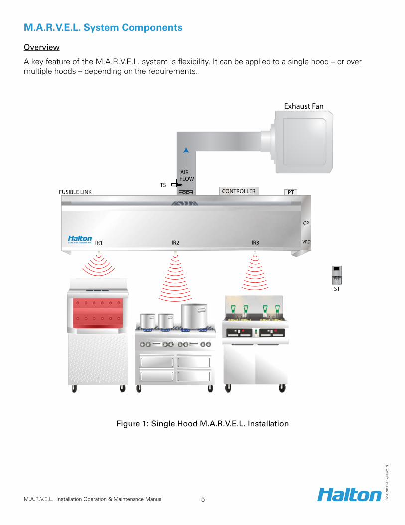
A key feature of the M.A.R.V.E.L. system is flexibility. It can be applied to a single hood – or over multiple hoods – depending on the requirements.
FLOWAIR
TSFUSIBLE LINK
IR1 IR2 IR3
Exhaust Fan
PTCONTROLLER
ST
VFD
CP
Figure 1: Single Hood M.A.R.V.E.L. Installation

6 M.A.R.V.E.L. Installation Operation & Maintenance Manual O
M-0
70/0
9201
7/re
v2/E
N
FLOWAIR
TSFUSIBLE LINK
IR1 IR2 IR3
Exhaust Fan
PTTS
FUSIBLE LINK
IR1 IR2 IR3
PT
ABD ABD
CONTROLLER
ST
VFD
CP
CONTROLLER
Figure 2: Multiple Hood M.A.R.V.E.L. Installation
Components
NOTE: Refer to Figure 1+2
Equipment Description Power + Connection Details
IR1, IR2, IR3, IR4
Infrared radiation sensor (IRIS™)
• Mount 1 to 4 IRIS™ sensors per hood depending on the length of the hood.
• Calculates an index which averages the temperature radiation over the sensor’s field-of-view.
• Used to detect when one or more pieces of cooking equipment are turned on and it is necessary to start the hood fan in idle mode.
• Used to measure a rapid change in temperature of cooking surfaces (for example, cooking activities) and adjust the air flow in the hood to the required level.
Power source: 5 volt DC power supply located behind a cover on the Capture JetTM plenum.
Connection: at terminal block located behind a cover on the Capture JetTM plenum.
TS
Duct temperature sensor
• Measures the temperature of the exhaust air.• Located in the hood collar.• Used (in conjunction with the IR Index) to detect
the event of cooking equipment start-up. Duct temperature is often a better indicator of start-up in the case of certain types of equipment such as a gas fryer.
• Used to activate the early fire detection alarm, activated before the fire system is triggered.
Connection: at terminal block located behind a cover on the Capture JetTM plenum.

7 M.A.R.V.E.L. Installation Operation & Maintenance Manual O
M-0
70/0
9201
7/re
v2/E
N
Equipment Description Power + Connection Details
PT
Hood plenum pressure sensor
• Used to calculate air flow in a hood in real time. Power source: 24 V DC power supply located behind a cover on the Capture JetTM plenum.
Connection: at terminal block located behind a cover on the Capture JetTM plenum.
ABD
Automatic balancing damper
NOTE: For multiple hood installations with a single exhaust fan only• Adjusts air flow with motorized balancing
dampers attached to a collar at each hood. • Damper controlled by a 0-10 V DC position
reference signal generated by a controller.• Upon power failure, the automatic balancing
damper fully opens.
Power source: 24 V AC transformer located behind a cover on the Capture JetTM plenum
Connection: at terminal block located behind a cover on the Capture JetTM plenum
Alarm light status on a touch screen
• Activated when any alarm condition is detected. • Common alarm conditions include: filter missing,
filter clogged, fire suppression system activated, duct temperature dangerously high, sensor failed, or VFD is in fault.
NOTE: To easily diagnose the alarm, use the remote Konsole™ Diagnostic Software.
Override push button
• Used to override pre programmed operation, push button illuminated when activated.
• Two modes:1. Press and hold for 1 second to accelerate
the exhaust rate to 100% of the design air flow for a pre programmed period of time (default 5 minutes.)
2. Press and hold for 3 seconds to accelerate the exhaust rate to 100% of the design air flow for a pre programmed period of time (default 1 hour.) Starts the hood if it has been overridden by a schedule or an ‘off’ state.
Connection: at terminal block located behind a cover on the Capture JetTM plenum.
Room temperature sensor
• Mounted on a kitchen wall close to a thermostat. Connections: to the control panel with 2 wires
VFD
Variable Frequency Drive
• Controls the speed of a three-phase fan motor by changing the frequency of the current to the motor.
• For smaller fans, mount the VFD in a cabinet attached to a hood.
• For larger exhaust fan units, attach the VFDs to a fan unit or cabinet or mount remotely.
Power source: varies as per fan’s voltage requirement Connection: at terminal block in VFD control panel to main control panelSpeed reference: 0-10 VDC

8 M.A.R.V.E.L. Installation Operation & Maintenance Manual O
M-0
70/0
9201
7/re
v2/E
N
Equipment Description Power + Connection Details
CP
Control Panel
• Mounted on top of each hood with access from the bottom.
NOTE: For multiple units with a single fan, a separate control panel (see below) is also required.• Provides permanent Ethernet connection
(optional). • Provides temporary Ethernet connection for
service.• Provides USB B Serial connection for on-site
service
Power source: 120 VAC, 5 amp. fuse, grounded
Central control panel (for multiple units with single fan)
• Separate control panel mounted at a convenient location to link that individual control panels on the hoods with the VFD controller.
Power source: 120 VAC, 5 amp. fuse, grounded
SafetyOnly authorized personnel should have access to the control panel.
In case of occurrence of any problem please call an authorized agency to help you.
WarningsTo reduce risk of electric shock do not expose control panel to any water.
Disconnect the power from the mains before accessing the control panel.
To provide protection against electric shock connect to a properly grounded power supply.
Improper grounding can result in a risk of electric shock.
Consult a qualified electrician if the grounding instructions are not properly understood, or if any doubt exists as to whether the control panel is properly grounded.
Only authorized and qualified personnel should work on the control panel in event of a problem.

9 M.A.R.V.E.L. Installation Operation & Maintenance Manual O
M-0
70/0
9201
7/re
v2/E
N
M.A.R.V.E.L. Sequence of OperationsOverview
A sequence of operations is a series of steps required to perform a given task. The DCV system uses the following sequence of operations to control the exhaust hood operation.
Sequence of Operations
Startup & Shutdown
Operation Step Details
Startup• Turns exhaust system on.• Can be started by:
• 24/7 pre-programmed schedule.• The building management system or via an internet connection remotely.• Using a locally mounted on/off switch.• Reaching a pre-determined IR Index or duct temperature level.• Pressing the override button.
• After startup, enters Idle mode.
Shutdown • Turns system off.• Can be shutdown by any of the parameters listed in the Startup step (above)
except the override button. Idle Mode • System starts up in Idle mode (after startup).
• Pending until signs of cooking activity sensed from IRIS™ sensor(s).• Minimal exhaust flow captures any appliance-generated heat. Default is 40%
of design air flow or as adjusted to meet requirements. • After idle mode, enters Active mode.
Cooking Mode • System moves into cooking mode when an IRIS™ sensor detects cooking activities under the hood.
• Exhaust fan speed increased to design air flow and balancing dampers (if present) adjusts the airflow in the hood to design level to assure sufficient capture and containment.
• Air flow in the hood is maintained for a predetermined cooking time before returning to the Idle mode.
NOTE: If during this time more cooking activities are detected, the cooking timer will be restarted.
Override Mode • Used to override pre programmed operation.• Two modes:
1. Press and hold for 1 second to accelerate the exhaust rate to 100% of the design air flow for a pre programmed period of time (default 5 minutes).
2. Press and hold for 3 seconds to accelerate the exhaust rate to 100% of the design air flow for a pre programmed period of time (default 1 hour.) Starts the hood if it has been overridden by a schedule or an ‘off’ state.

10 M.A.R.V.E.L. Installation Operation & Maintenance Manual O
M-0
70/0
9201
7/re
v2/E
N
Operation Step DetailsFire Mode • If a fire signal is detected in the kitchen, the system triggers a fire alarm and
stops the make-up air fan.• The exhaust fan will either stop or continue running depending on the local
fire code requirements.
Off Mode • Exhaust and make-up air fans stop when no appliances are operating (e.g., turned off and cooled down).
Airflow Reporting and Replacement Air Control
• System continuously monitors exhaust airflow at each hood and generates a signal 0 to 10 V proportional to total exhaust airflow as fraction of total design. 0 V - system is off; 7 V - system operates at 70% of design airflow, etc. This signal is used to control Replacement air to maintain building pressurization.
Alarm and Fault Conditions
• System constantly monitors various parameters.If any unusual or abnormal condition is detected, an alarm is activated.
• An alarm indicator can include:• Indication on HMI (Touch Screen).• Email or text message sent to a computer or a mobile device, pager,
visual display on a computer screen or through a SCADA interface.

11 M.A.R.V.E.L. Installation Operation & Maintenance Manual O
M-0
70/0
9201
7/re
v2/E
N
M.A.R.V.E.L. Touch Screen Operation
The central control panel features a user friendly touch screen interface. The following illustrations depict the navigation and features of the touch screen.
Note: Touch screen samples shown below are for the basic M.A.R.V.E.L. system, for all other M.A.R.V.E.L. systems including UV, Water Wash, Ecology & KGS or combination thereof, please refer to the Quick Reference Guides.
Menu Option Screen
Main Screen
This screen will allow you to jump ahead to any of the below screens.

12 M.A.R.V.E.L. Installation Operation & Maintenance Manual O
M-0
70/0
9201
7/re
v2/E
N
Individual Hood Selection Screen This screen will allow you to move to your choice of Individual Hood Status screen.
Individual Hood Status ScreenThis screen will display all the information pertaining to each individual hood separately.

13 M.A.R.V.E.L. Installation Operation & Maintenance Manual O
M-0
70/0
9201
7/re
v2/E
N
Hood Summary Screen
The Hood Summary screen shows the overall performance of the current hood.
The System Check screen will be used by your service agent only. System Check Screen

14 M.A.R.V.E.L. Installation Operation & Maintenance Manual O
M-0
70/0
9201
7/re
v2/E
N
Alarm History ScreenThis screen will display your current alarms along with the alarm history.
Information ScreenThis Technical Information screen provides our USA and Canadian phone numbers for technical help.

15 M.A.R.V.E.L. Installation Operation & Maintenance Manual O
M-0
70/0
9201
7/re
v2/E
N
Security Features ScreenThis screen will be used by your service agent only.
If you are a Halton Certified Service Agent that requires a password for the screen above, please contact Halton Service Network at 1 (800) 442-5866 (USA) or 1 (800) 565-2981.
General Maintenance InstructionsThese screens will provide general maintenance instructions for your system.
16 M.A.R.V.E.L. Installation Operation & Maintenance Manual O
M-0
70/0
9201
7/re
v2/E
N
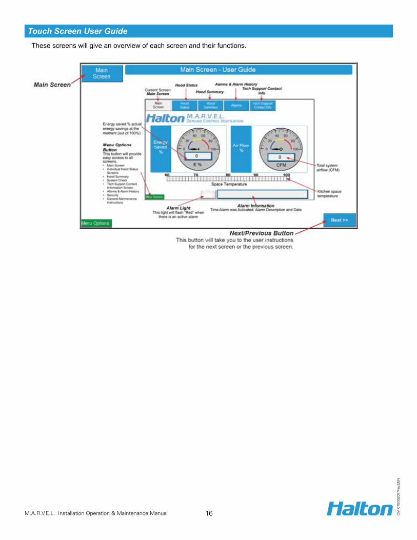
Touch Screen User Guide These screens will give an overview of each screen and their functions.
17 M.A.R.V.E.L. Installation Operation & Maintenance Manual O
M-0
70/0
9201
7/re
v2/E
N
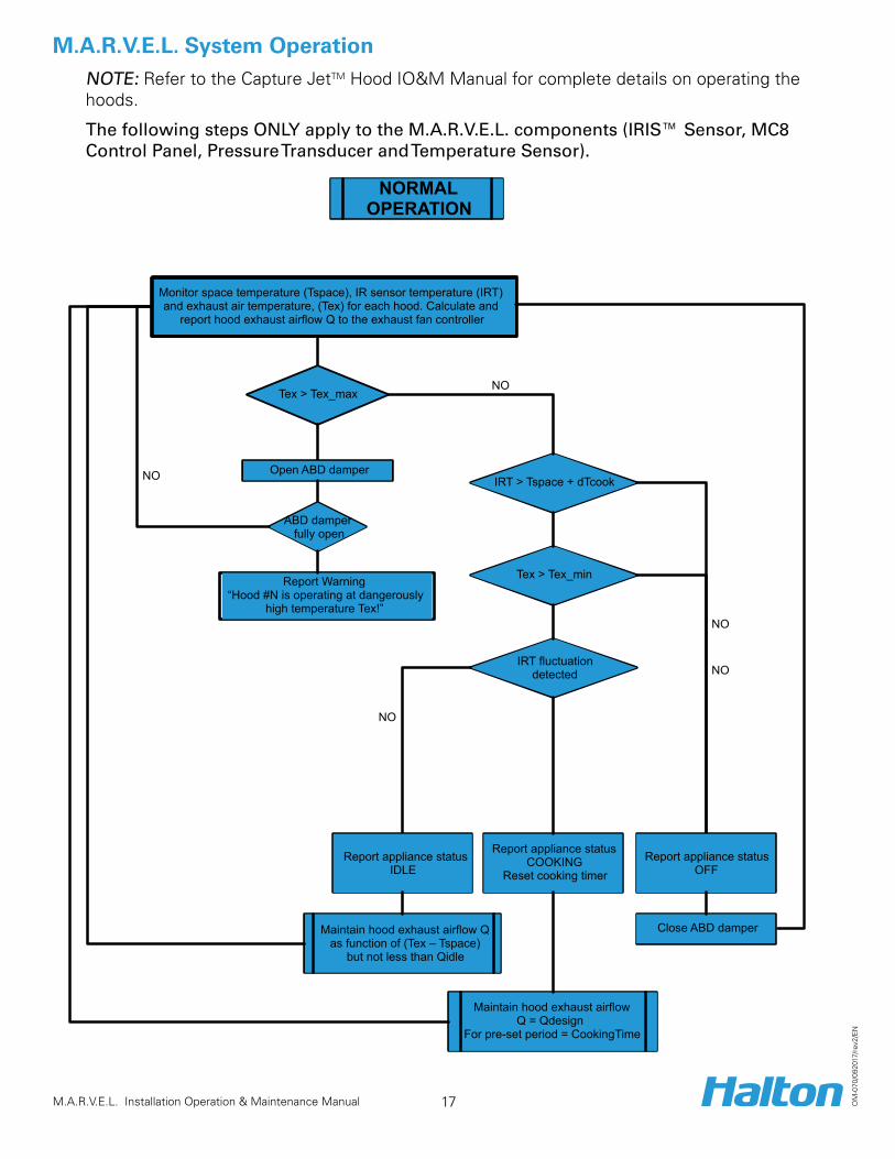
M.A.R.V.E.L. System OperationNOTE: Refer to the Capture JetTM Hood IO&M Manual for complete details on operating the hoods.
The following steps ONLY apply to the M.A.R.V.E.L. components (IRIS™ Sensor, MC8 Control Panel, Pressure Transducer and Temperature Sensor).
NORMALOPERATION
Monitor space temperature (Tspace), IR sensor temperature (IRT) and exhaust air temperature, (Tex) for each hood. Calculate and
report hood exhaust airflow Q to the exhaust fan controller
IRT > Tspace + dTcook
Tex > Tex_min
Maintain hood exhaust airflowQ = Qdesign
For pre-set period = CookingTime
NO
IRT fluctuationdetected
Report appliance status COOKING
Reset cooking timer
Maintain hood exhaust airflow Q as function of (Tex – Tspace)
but not less than Qidle
Tex > Tex_maxNO
Report Warning“Hood #N is operating at dangerously
high temperature Tex!”
NO
NO
Open ABD damper
ABD damper fully open
NO
Report appliance status OFF
Report appliance statusIDLE
Close ABD damper
18 M.A.R.V.E.L. Installation Operation & Maintenance Manual O
M-0
70/0
9201
7/re
v2/E
N
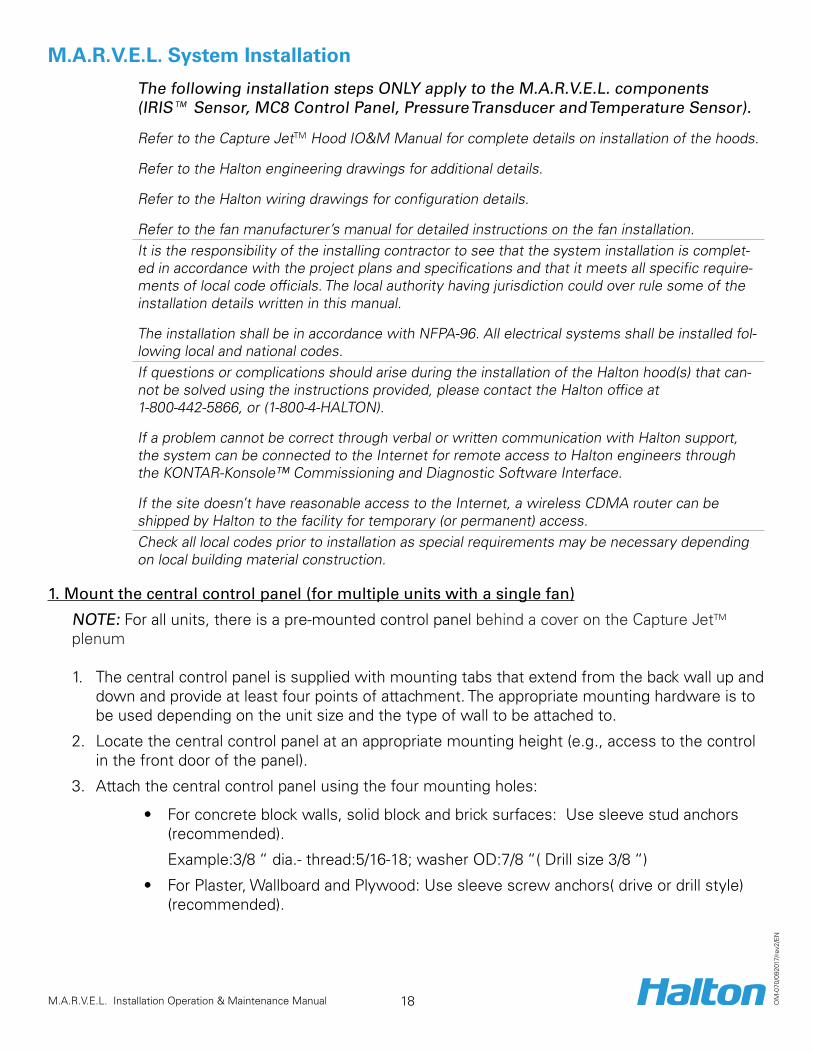
M.A.R.V.E.L. System Installation
The following installation steps ONLY apply to the M.A.R.V.E.L. components (IRIS™ Sensor, MC8 Control Panel, Pressure Transducer and Temperature Sensor).
Refer to the Capture JetTM Hood IO&M Manual for complete details on installation of the hoods.
Refer to the Halton engineering drawings for additional details.
Refer to the Halton wiring drawings for configuration details.
Refer to the fan manufacturer’s manual for detailed instructions on the fan installation.It is the responsibility of the installing contractor to see that the system installation is complet-ed in accordance with the project plans and specifications and that it meets all specific require-ments of local code officials. The local authority having jurisdiction could over rule some of the installation details written in this manual.
The installation shall be in accordance with NFPA-96. All electrical systems shall be installed fol-lowing local and national codes.If questions or complications should arise during the installation of the Halton hood(s) that can-not be solved using the instructions provided, please contact the Halton office at 1-800-442-5866, or (1-800-4-HALTON).
If a problem cannot be correct through verbal or written communication with Halton support, the system can be connected to the Internet for remote access to Halton engineers through the KONTAR-Konsole™ Commissioning and Diagnostic Software Interface.
If the site doesn’t have reasonable access to the Internet, a wireless CDMA router can be shipped by Halton to the facility for temporary (or permanent) access.Check all local codes prior to installation as special requirements may be necessary depending on local building material construction.
1. Mount the central control panel (for multiple units with a single fan)
NOTE: For all units, there is a pre-mounted control panel behind a cover on the Capture JetTM plenum
1. The central control panel is supplied with mounting tabs that extend from the back wall up and down and provide at least four points of attachment. The appropriate mounting hardware is to be used depending on the unit size and the type of wall to be attached to.
2. Locate the central control panel at an appropriate mounting height (e.g., access to the control in the front door of the panel).
3. Attach the central control panel using the four mounting holes:
• For concrete block walls, solid block and brick surfaces: Use sleeve stud anchors (recommended). Example:3/8 “ dia.- thread:5/16-18; washer OD:7/8 “( Drill size 3/8 “)
• For Plaster, Wallboard and Plywood: Use sleeve screw anchors( drive or drill style) (recommended).

19 M.A.R.V.E.L. Installation Operation & Maintenance Manual O
M-0
70/0
9201
7/re
v2/E
N
Example: 1/4” - 20 drill size 7/16”
NOTE: If more than one control panel is used in a M.A.R.V.E.L. system with a single exhaust fan, connect them together to ensure that proper operation of the exhaust fan. Refer to the Halton supplied wiring diagram for details.
2. Make central control panel connections (for multiple units with a single fan)
Make the following connections at the central control panel:
a. 120 VAC, 5 amp power to control panel.b. Space temperature sensor to control panel (2 wires).c. VFD terminal block to control panel (8 wires shielded).d. Connection to individual hood (2 wires shielded) (cable provided by Halton).e. Connection to kitchen fire system (2 wires)f. Permanent Ethernet connection (if specified).g. UV or Water Wash control.

20 M.A.R.V.E.L. Installation Operation & Maintenance Manual O
M-0
70/0
9201
7/re
v2/E
N
3. Connect VFD controller
Connect VFD controller as per instructions provided. This includes:
a. Main power connection for the fan motor.b. Connection to central control panel.
4. Connect hood control panel to central control panel (for multiple units with a single fan) Using 2 wire shielded cable provided by Halton, connect each unit to the central control panel. This includes:
1. Attach the wire to the terminal block in the box on top of the hood.
2. Run the wire to the central control panel and connect the marked terminal block (identified by hood number)
3. Connections can be also made between hoods with 2 wire shielded cable and connect the hood closest to the control panel to terminals in the panel.
5. Check pressure transducer
1. Check the condition of the pressure transducer tubing on the top of the Capture JetTM hood. The tubing should be free from kinks.

21 M.A.R.V.E.L. Installation Operation & Maintenance Manual O
M-0
70/0
9201
7/re
v2/E
N
6. Calibrate the Capture JetTM exhaust air flows
Calibrate the Capture JetTM exhaust air flows using the T.A.B.™ (Testing and Balancing Ports).
To determine the correct T.A.B. port reading for the exhaust hoods, follow these steps:
1. Ensure that the equipment is operating to create a thermal plume prior to the air balancer.
2. Determine the correct T.A.B. port reading (IWC) based on the Capture JetTM hood model.
Capture Jet T.A.B. Port ReadingsHood Model Design T.A.B. (inches WC)
KVE/KVC 0.25KVW 0.25KVR 0.25KVL 0.28
“Example Only”
3. Using the T.A.B. Port, take a reading in IWC.
4. Using the table below, confirm the design airflow (e.g., 1700 cfm), based on the T.A.B. Reading (e.g., 0.19 IWC).
“Example Only”
Close up view of T.A.B. Port

22 M.A.R.V.E.L. Installation Operation & Maintenance Manual O
M-0
70/0
9201
7/re
v2/E
N
M.A.R.V.E.L. System MaintenanceGeneral
NOTE: A preventive maintenance program is an important aspect of an effective safety program. Consult your manufacturing or other qualified consultant with question concerning changes observed during periodic inspections and routine maintenance.
Refer to the Capture JetTM Hood IO&M Manual for complete details on maintaining the hoods.
The following maintenance steps ONLY apply to the M.A.R.V.E.L. components (IRIS™ Sensor and Temperature Sensor).
IRIS™ Sensor Cleaning NOTE: The IRIS™ Sensor is mounted on the Capture JetTM plenum door to allow an air jet to protect the sensor optics from contaminants. However, periodic cleaning may be required to keep the optics clear.
Gently clean the IRIS™ socket with isopropyl alcohol on a cotton swab (Q-tip™), as required.
Take care not to move the position of the optic; see below on how to realign the IRIS™ Sensor.
IRIS™ Sensor Alignment (Quarterly or as required)
To align the IRIS™ Sensor, follow these steps:
1. Insert the Laser Alignment Tool into the socket at the bottom of the IRIS™ sensor.
2. Press the laser button, located on the side of the Laser Alignment Tool.
3. Gently move the IRIS™ sensor to position the laser beam point at the center of the cooking surface. NOTE: The actual field of view for most applications will be 60 degrees.
4. Remove the Laser Alignment Tool.
Insert into IRIS optic
Press to turn on laser
23 M.A.R.V.E.L. Installation Operation & Maintenance Manual O
M-0
70/0
9201
7/re
v2/E
N
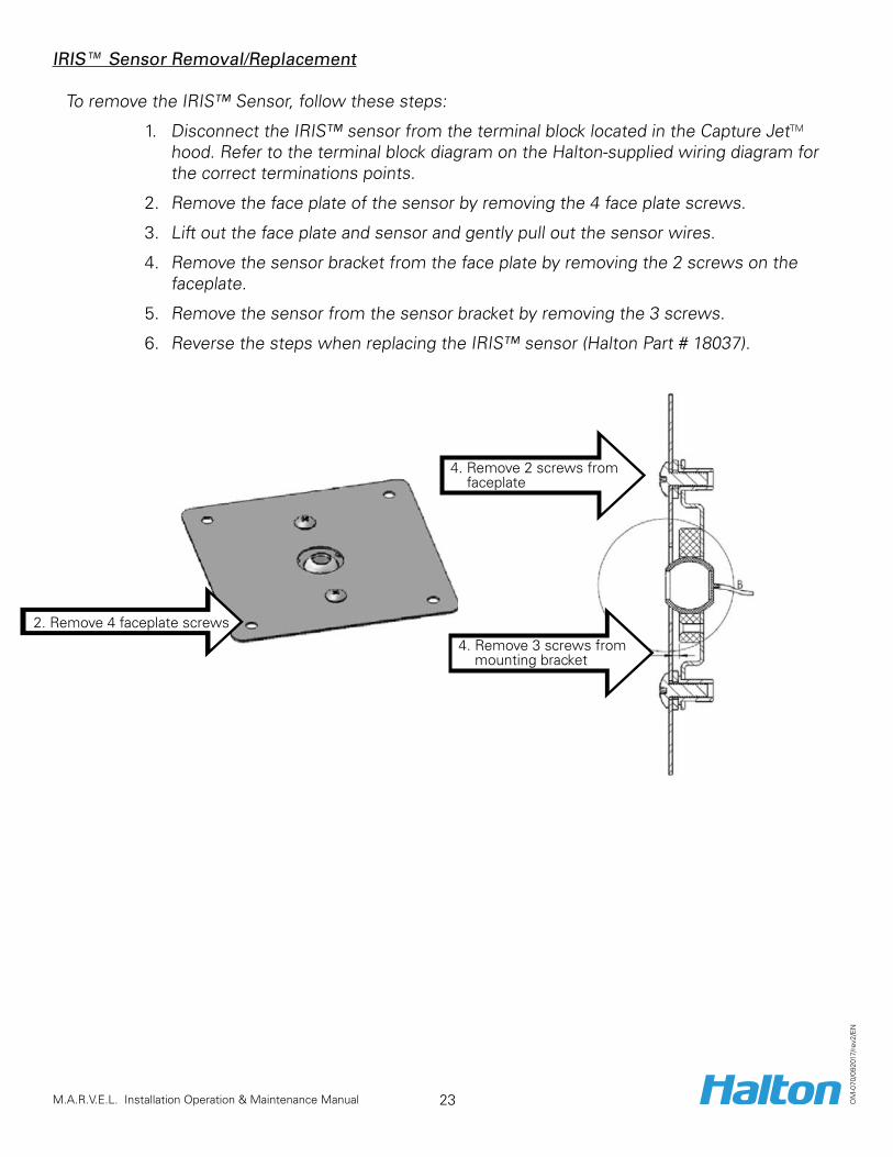
IRIS™ Sensor Removal/Replacement To remove the IRIS™ Sensor, follow these steps:
1. Disconnect the IRIS™ sensor from the terminal block located in the Capture JetTM hood. Refer to the terminal block diagram on the Halton-supplied wiring diagram for the correct terminations points.
2. Remove the face plate of the sensor by removing the 4 face plate screws.
3. Lift out the face plate and sensor and gently pull out the sensor wires.
4. Remove the sensor bracket from the face plate by removing the 2 screws on the faceplate.
5. Remove the sensor from the sensor bracket by removing the 3 screws.
6. Reverse the steps when replacing the IRIS™ sensor (Halton Part # 18037).
2. Remove 4 faceplate screws
4. Remove 2 screws from faceplate
4. Remove 3 screws from mounting bracket
24 M.A.R.V.E.L. Installation Operation & Maintenance Manual O
M-0
70/0
9201
7/re
v2/E
N
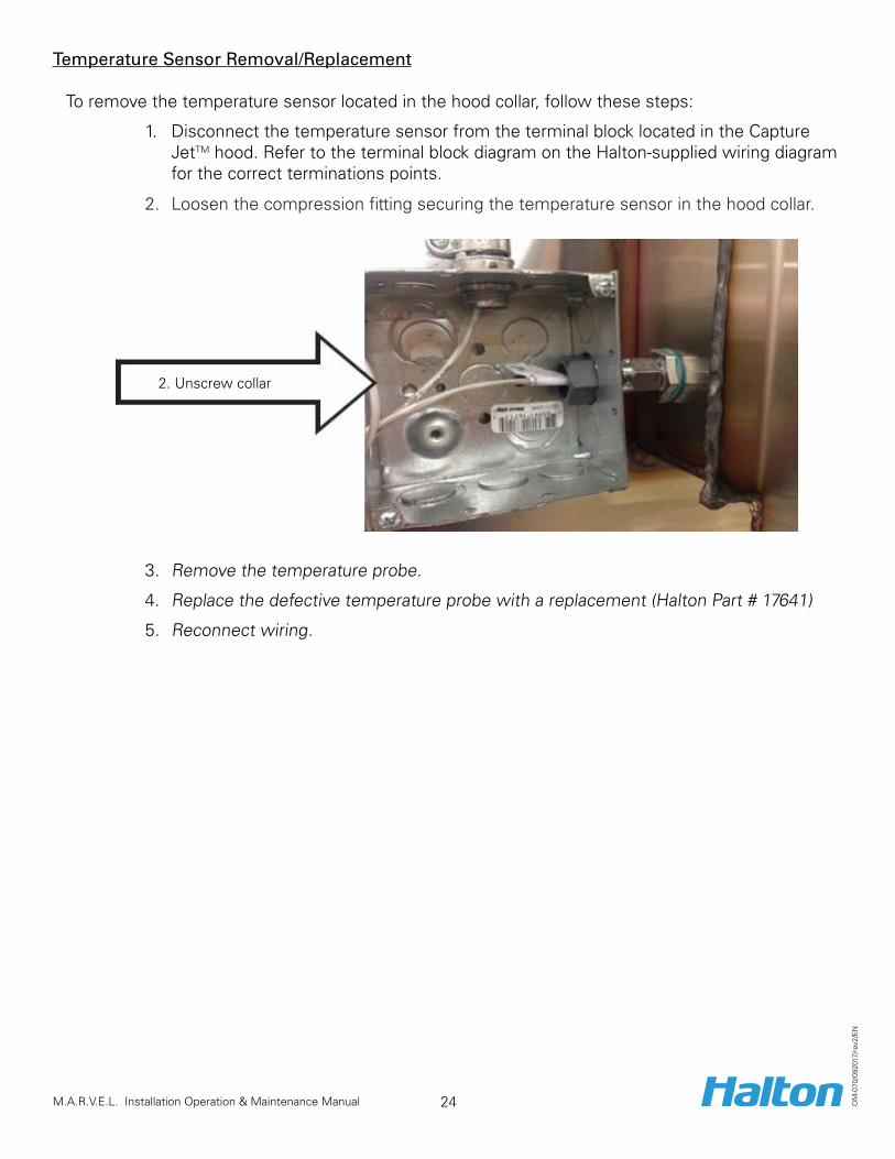
Temperature Sensor Removal/Replacement To remove the temperature sensor located in the hood collar, follow these steps:
1. Disconnect the temperature sensor from the terminal block located in the Capture JetTM hood. Refer to the terminal block diagram on the Halton-supplied wiring diagram for the correct terminations points.
2. Loosen the compression fitting securing the temperature sensor in the hood collar.
3. Remove the temperature probe.
4. Replace the defective temperature probe with a replacement (Halton Part # 17641)
5. Reconnect wiring.
2. Unscrew collar

25 M.A.R.V.E.L. Installation Operation & Maintenance Manual O
M-0
70/0
9201
7/re
v2/E
N
Balancing Damper Actuator Removal/Replacement To remove and replace the actuator on the balancing damper, follow these steps:
1. Remove exterior metal cover by removing the 6 mounting screws around the perimeter.
2. Remove the actuator cover by removing the 1 screw on the side.
3. Disconnect the power to the actuator.
4. Record the DIP switch values, located in the red holder on the bottom of the actuator.
5. Note the position of the stop screws.
6. Remove the U-bolt that attaches the actuator to the balancing damper shaft. Refer to the Actuator Specification and Installation instructions with the replacement part.
Record DIP Switch settings
Stop screws
U-bolt on shaft

26 M.A.R.V.E.L. Installation Operation & Maintenance Manual O
M-0
70/0
9201
7/re
v2/E
N
7. Replace with a replacement actuator (Halton Part # 16012). Tighten the U-bolt on the drive shaft.
8. Reset the DIP switches.
9. Reset the stop screws.
10. Reconnect the power.
11. Calibrate the new actuator by pressing the Reset button. The dampers will open and close.
DIP Switch
To terminal block in control box
Tighten U-bolt
27 M.A.R.V.E.L. Installation Operation & Maintenance Manual O
M-0
70/0
9201
7/re
v2/E
N
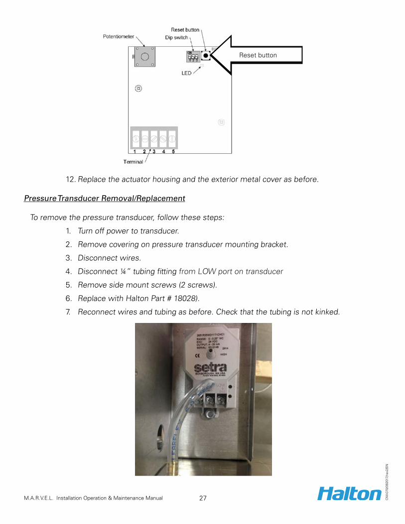
12. Replace the actuator housing and the exterior metal cover as before.
Pressure Transducer Removal/Replacement To remove the pressure transducer, follow these steps:
1. Turn off power to transducer.
2. Remove covering on pressure transducer mounting bracket.
3. Disconnect wires.
4. Disconnect ¼” tubing fitting from LOW port on transducer
5. Remove side mount screws (2 screws).
6. Replace with Halton Part # 18028).
7. Reconnect wires and tubing as before. Check that the tubing is not kinked.
Reset button

28 M.A.R.V.E.L. Installation Operation & Maintenance Manual O
M-0
70/0
9201
7/re
v2/E
N
M.A.R.V.E.L. System Monitoring and SupportTypes of Monitoring
Type of Mounting DetailsPermanent Ethernet-connection for 24/7 monitoring
• Optional.
• Permanent internet monitoring using SCADA graphical interface.
• By using a unique password and ID, user can check system status and, depending on access levels, change parameters and alarms.
Temporary Ethernet connection, as required, for support
• Temporary Ethernet connection for startup/troubleshooting by Halton Technical Support only
Temporary cable to laptop connection, as required, for support
• USB cable connection to laptop pre loaded with KONSOLE™ software for diagnostic support.
Connection to Third Party Devices
• Able to communicate natively to Modbus RTU slave devices over RS232 or RS485.• Able to communicate via BACnet MSTP, BACnet IP, Modbus RTU as a Slave or JCI N2
protocols via optional gateway.
Ethernet connectionUSB Cable connection
29 M.A.R.V.E.L. Installation Operation & Maintenance Manual O
M-0
70/0
9201
7/re
v2/E
N
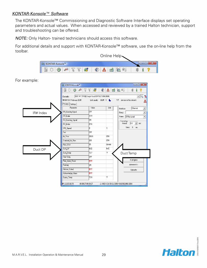
KONTAR-Konsole™ Software
The KONTAR-Konsole™ Commissioning and Diagnostic Software Interface displays set operating parameters and actual values. When accessed and reviewed by a trained Halton technician, support and troubleshooting can be offered.
NOTE: Only Halton- trained technicians should access this software. For additional details and support with KONTAR-Konsole™ software, use the on-line help from the toolbar.
For example:
IR# Index
Duct DPDuct Temp
Online Help
30 M.A.R.V.E.L. Installation Operation & Maintenance Manual O
M-0
70/0
9201
7/re
v2/E
N
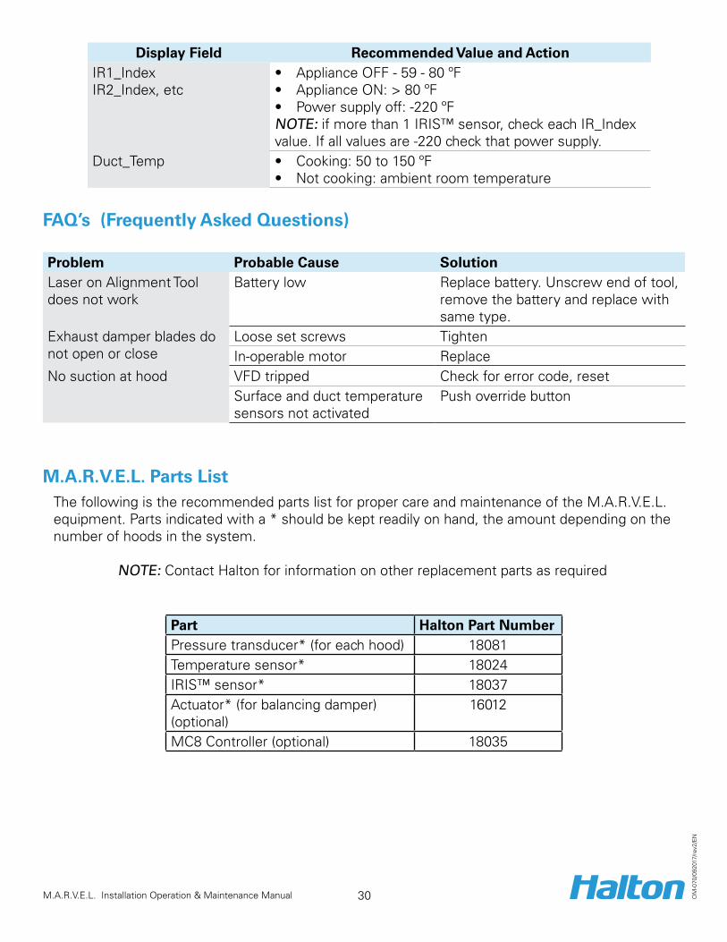
Display Field Recommended Value and ActionIR1_Index IR2_Index, etc
• Appliance OFF - 59 - 80 ºF• Appliance ON: > 80 ºF• Power supply off: -220 ºFNOTE: if more than 1 IRIS™ sensor, check each IR_Index value. If all values are -220 check that power supply.
Duct_Temp • Cooking: 50 to 150 ºF• Not cooking: ambient room temperature
FAQ’s (Frequently Asked Questions)
Problem Probable Cause SolutionLaser on Alignment Tool does not work
Battery low Replace battery. Unscrew end of tool, remove the battery and replace with same type.
Exhaust damper blades do not open or close
Loose set screws TightenIn-operable motor Replace
No suction at hood VFD tripped Check for error code, reset Surface and duct temperature sensors not activated
Push override button
M.A.R.V.E.L. Parts List The following is the recommended parts list for proper care and maintenance of the M.A.R.V.E.L. equipment. Parts indicated with a * should be kept readily on hand, the amount depending on the number of hoods in the system.
NOTE: Contact Halton for information on other replacement parts as required
Part Halton Part NumberPressure transducer* (for each hood) 18081Temperature sensor* 18024IRIS™ sensor* 18037Actuator* (for balancing damper) (optional)
16012
MC8 Controller (optional) 18035

31 M.A.R.V.E.L. Installation Operation & Maintenance Manual O
M-0
70/0
9201
7/re
v2/E
N
Contact Information
United States Halton Company101 Industrial Drive Scottsville, Kentucky42164 www.haltoncompany.com
Tel: 270-237-5600 Toll Free: 800-442-5866 Fax: 270-237-5700
Canada Halton Indoor Climate Systems 1021 Brevik Place Mississauga, Ontario L4W 3R7
www.haltoncanada.com
Tel: 905-624-0301 Toll Free: 800-565-2981 Fax: 905-624-5547


![CASH-Interface MC8 [CHANGER] - Casino Software · CASH-Interface MC8 [CHANGER] – User manual 1. DESCRIPTION With the CI MC8 board it is possible to build a money changer machine,](https://img.dokumen.tips/doc/110x75/6021656b1c262911845b50c9/cash-interface-mc8-changer-casino-software-cash-interface-mc8-changer-a.jpg)