Embed Size (px)
Citation preview
Operator´s Manual Elotest B1 V4
Operator's Manual Elotest B1-V4 Since Vers.V6.02, rev. 1,12/00gl

Elotest B1-V4
Operator´s Manual Page 2
Table of Contents 1. Introduction .................................................................................................................. 6
1.1. General .................................................................................................................. 6 1.2. Example Set-ups and User Set-ups....................................................................... 6 1.3. Probes ................................................................................................................... 7 1.4. ELOTEST B1-versions........................................................................................... 7 1.5 Controls & Functions ............................................................................................ 10
1.5.1. Keypad........................................................................................................... 10 1.5.1.1. ON/OFF Key ............................................................................................... 10 1.5.1.2. HOME Key .................................................................................................. 10 1.5.2. Compensation Key (Z) ................................................................................... 10 1.5.3. Menu Key....................................................................................................... 11 1.5.4. F1-F4 ............................................................................................................. 11 1.5.5. Direct Access Keys ........................................................................................ 11 1.5.5.1. Frequency Key............................................................................................ 11 1.5.5.2. dB................................................................................................................ 12 1.5.5.3. Phase Key................................................................................................... 13 1.5.5.4. Filter Key..................................................................................................... 14 1.5.5.4.1. Filter Key (SM versions) .......................................................................... 14 1.5.5.4.2. Filter Key (BM versions) .......................................................................... 14 1.5.5.4.3. Filter Key (UM and UMC versions) .......................................................... 15
1.6. LCD-Display......................................................................................................... 16 1.7. LEDs .................................................................................................................... 16 Menu-guided instrument operation ............................................................................. 17 1.8. HOME .................................................................................................................. 19
1.8.1. SETTINGS Menu ........................................................................................... 19 1.8.1.1. LOAD user settings (without memory card drive) ....................................... 20 1.8.1.2. LOAD user settings (with memory card drive) ............................................ 20 1.8.1.3. STORE User Setups................................................................................... 21 1.8.1.4. STORE User Settings (without memory card)............................................. 22 1.8.1.5. STORE User Setups (with memory card) ................................................... 22 1.8.1.6. DELETE User Settings (without memory card) ........................................... 23 1.8.1.7. DELETE User Settings (with memory card) ................................................ 23 1.8.1.8. EXAMPLE SET-UPS................................................................................... 23 1.8.1.8.1. Probe Catalog.......................................................................................... 25 1.8.1.8.2. Application Catalog.................................................................................. 26 1.8.2. PARAMETER Menu....................................................................................... 28 1.8.2.1. THRESHOLD Menu.................................................................................... 28 1.8.2.2. ALARM Menu.............................................................................................. 29 1.8.2.3. Timebase (y/t) Display ................................................................................ 29 1.8.2.4. Dot Position ................................................................................................ 30 1.8.3. FUNCTION Menu .......................................................................................... 30 1.8.3.1. PIC-MEM..................................................................................................... 30 1.8.3.1.1. STORE Mode........................................................................................... 31 1.8.3.1.2. SNAPSHOT Mode ................................................................................... 32 1.8.3.1.3. REFERENCE........................................................................................... 33 1.8.3.1.4. PRINT Menu ............................................................................................ 34 1.8.3.2. CARD-FUNC............................................................................................... 34 1.8.3.2.1. COPYSET (Copy from and to the memory card) ..................................... 35

Elotest B1-V4
Operator´s Manual Page 3
1.8.3.2.1.1. B1>CARD (Copy the B1-setting-block to the memory-card)................. 36 1.8.3.2.1.2. CARD>B1 (Copy a memory-card setting-block to the B1) .................... 36 1.8.3.2.1.3. Delete a setting-block from the memory-card ....................................... 36 1.8.3.2.2. PRT DIR (Print directory of the memory-card) ......................................... 36 1.8.3.2.3. >FORMAT (Format a memory card) ........................................................ 36 1.8.3.3. SERVICE Menu .......................................................................................... 37 1.8.3.3.1. INFO Menu .............................................................................................. 37 1.8.3.3.2. SETUP1 Menu: ........................................................................................ 38 1.8.3.3.3. SETUP2 Menu ......................................................................................... 38 1.8.3.3.4. AUTOTST Menu ...................................................................................... 40
2. Instrument Functions/Instrument setup...................................................................... 41 2.1. Signal Display Modes .......................................................................................... 41
2.1.1. Change from impedance plane (y/x) to timebase (y/t) display modes: .......... 41 2.2. Focus and Brilliance (Intensity) ........................................................................... 42 2.3. Filter..................................................................................................................... 42
2.3.1. Filter types available in the B1:...................................................................... 42 2.3.2. Filter Principles .............................................................................................. 42 2.3.2.1. Lowpass Filter (SM and UM versions) ........................................................ 43 2.3.2.2. Highpass Filter............................................................................................ 43 2.3.2.3. Bandpass Filter (BM, UM and UMC versions) ............................................ 45
2.4. Instrument Configuration ..................................................................................... 46 2.4.1. Instrument Automatic Switch-Off - Enabling/Disabling .................................. 46
2.5. Instrument Setup.................................................................................................. 46 2.5.1. Initial Set-Up Procedure - Using Example Settings ....................................... 47 2.5.2. Initial Set-up Procedure - Using User Set-ups............................................... 48
2.6. Manual Instrument Set-up.................................................................................... 49 2.6.1. Manual Set Up Procedure - Typical Hand-Held Probe Applications.............. 49 2.6.1.1. SM versions ................................................................................................ 49 2.6.1.2. BM versions ................................................................................................ 50 2.6.1.3. UM and UMC versions................................................................................ 51 2.6.2. Set-Up Procedure - Typical High Speed Dynamic Probe and Rotor Applications ............................................................................................................. 54 2.6.2.1. BM Versions................................................................................................ 54 2.6.2.2. UM and UMC Versions ............................................................................... 55
2.7. User Set-ups........................................................................................................ 57 2.7.1. Storing Set-ups (with names)......................................................................... 57 2.7.2. Storing Settings (without names) ................................................................... 58 2.7.3. Amending Stored Setups ............................................................................... 58 2.7.4. Deleting Stored Set-ups................................................................................. 59
2.8. Signal Storage ..................................................................................................... 60 2.8.1. Storing Signals............................................................................................... 60 2.8.1.1. Storing Manually Created Signals Using Store Mode................................. 60 2.8.1.2. Using Stored Signals as a Reference......................................................... 60 2.8.1.3. Storing High Speed Rotary Signals Using the Snapshot Mode.................. 61 2.8.1.4. Storing Signals Using the Roll Mode .......................................................... 61 2.8.2. Playing Back Stored Signals on the B1 Screen ............................................. 62
2.9. Printing................................................................................................................. 63 2.9.1. Signal printout (protocol) on an external printer ............................................ 63 2.9.2. Print out a list of contents on an external printer ........................................... 64
2.10. Procedure for Carrying out the Elotest B1 Self-Test Routine ............................ 65
Elotest B1-V4
Operator´s Manual Page 4
2.10.1. Self-Test Routine of the Elotest B1.............................................................. 65 2.10.1.1. Vector-rotation and Compensation Test (VECT:/COMP).......................... 65 2.10.1.2. Demodulation Test (DEMODUL)............................................................... 65 2.10.1.3. Amplifier Test (AMPLIFIER)...................................................................... 66 2.10.1.4 Pre-amplification test (PREAMP) ............................................................... 66 2.10.1.5 Axis spread test (X + Y Amp) ..................................................................... 66 2.10.1.6 Threshold test (THRESHOLDS) ................................................................ 66 2.10.1.7 Filter test (FILTER) .................................................................................... 66
3. Interfaces ................................................................................................................... 68 3.1. Memory-Card drive (only UMC) ........................................................................... 68 3.2. Changeable Probe Adaptors ............................................................................... 68 3.3. Input/Output Sockets and External Fuses ........................................................... 71
3.3.1. RS232 Socket ................................................................................................ 72 3.3.2. Battery Charger/Mains Unit Socket................................................................ 72 3.3.3. Optocoupler Out Socket................................................................................. 72 3.3.4. In/Out Socket ................................................................................................. 73
3.4. Use of Computers or Printers .............................................................................. 74 3.4.1. Use of External Printers ................................................................................. 74 3.4.2. Use of computers/external software............................................................... 75
4. Power Supplies.......................................................................................................... 76 4.1. Batteries............................................................................................................... 76
4.1.1. Checking Battery Charge State ..................................................................... 76 4.1.2. Battery Replacement ..................................................................................... 76 4.1.3. Care of Batteries............................................................................................ 77 4.1.4. Battery Chargers........................................................................................... 77 4.1.4.1. Standard Battery Charger BLE-1 ................................................................ 77 4.1.4.2. Rapid Battery Charger / Mains Unit (BLU-1)............................................... 78 4.1.4.2.1. Rapid Battery Charger/Mains Unit (BLU-1) - Fault Diagnosis ................. 80 4.1.5. Fuses ............................................................................................................. 81 4.1.5.1. Battery Pack Fuses..................................................................................... 81 4.1.5.2. Rapid Battery Charger/Mains Unit Fuse ..................................................... 81
4.2. Mains Operation .................................................................................................. 81 4.2.1. Mains Operation (Standard Battery Charger BLE-1) ..................................... 81 4.2.2. Mains Operation (Rapid Battery Charger / Mains Unit BLU-1) ...................... 82 4.2.3. MAINS Operation ('Mains Only' instruments fitted with an integral Mains Power Pack L-1 230/115 VAC) ................................................................................ 82
Elotest B1-V4
Operator´s Manual Page 5
List of Illustrations Figure 1: Signal Flow Chart ............................................................................................. 8 Figure 2: ELOTEST B1 V4............................................................................................... 9 Figure 3: Probe Catalog................................................................................................. 25 Figure 4: Application Catalog ........................................................................................ 26 Figure 5: Amplitude of the Y-Axis Spread in the Timebase-mode ................................. 41 Figure 6: B1-RS Probe Adapter Pin Assignment ........................................................... 69 Figure 7: Input/Ouput Sockets and External Fuses ....................................................... 71 Figure 8: RS232 Socket Pin Assignment....................................................................... 72 Figure 9: Charger Socket Pin Assignment..................................................................... 72 Figure 10: Optocoupler Socket Pin Assignment ............................................................ 72 Figure 11: In/out Socket Pin Assignment....................................................................... 73 Figure 12: Standard Battery Charger BLE-1.................................................................. 77 Figure 13: Rapid Charger/Mains Unit BLU-1 ................................................................. 79 Figure 14: Mains Power Pack ........................................................................................ 83 Appendices: I. Typical Eddy Current Test Protocol (without Reference picture) II. Typical Eddy Current Test Protocol (with Reference picture) III. Typical Printout of a Memory Card Table of Contents
Elotest B1-V4
Operator´s Manual Page 6
1. Introduction
1.1. General The Elotest B1 is a portable, microprocessor controlled, impedance plane, eddy current test instrument with an oscilloscope display screen. Changes in the probe coil impedance due to changes in the specimen under test are displayed on the screen by the movement of a dot of light. By observing the direction and pattern of the dot movement, an analysis can be made of the cause of the movement. For example, when using an absolute pencil probe at high frequency to detect surface cracks in aluminum alloy, the dot will move in different directions for cracks, edge-effect and lift-off (e.g. variations in paint thickness). The signal flow diagram (Fig 1) shows the principle of operation of the instrument. Parameters to be adjusted are shown in a liquid crystal display (LCD) window and are selected using push keys beside the window. Most adjustments are made using a single rotary control knob. An RS 232 digital interface allows the B1 to be controlled by an external computer (additional software required). The instrument can be powered by its internal rechargeable battery pack or directly from the mains using a battery charger/mains unit. 'Mains only' instruments have an integral mains power pack fitted in the position usually occupied by the battery pack.
1.2. Example Set-ups and User Set-ups Two kinds of setups are stored in the instrument: The User set-ups enable users to store, recall and delete up to 50 set-ups (techniques) of their choice. A back-up batery ensures that these set-ups will remain stored for a minimum of 120 days if the batterypack or mains unit is removed from the B1. A software key is provided to restrict the use of the User set-ups to prevent acidential overwriting or erasure. When using an instrument with memory card drive, 600 more set-ups can be stored on one memory card. The Example setups are stored during manufacture with 50 non-eraseable set-ups which cover a range of test applications using a variety of probe types. The purpose of the Example set-ups is to approxiately set up the B1 for a particular application. When the relevant settings have been loaded, they can be refined (if required) to optimize the set-up to suit the user’s needs. If so desired, the set-up can then be given a name by the user and stored in the User set-ups for future recall. Tha Example set-ups can also be used when using probes from other manufacturers.

Elotest B1-V4
Operator´s Manual Page 7
1.3. Probes The B1 is designed for use with driver/receiver probes but can also be used with bridge and resonant probes using changeable probe sockets. On dynamic versions of the B1, rotary hole inspection can be carried out using Rototest rotors and probes. A receiver preamplifier which is adjustable automatically or manually is used for probe matching to optimize test sensitivity.
1.4. ELOTEST B1-versions Seven versions of the ELOTEST B1 are available and are listed below. Outwardly, all versions look the same, the version of each instrument is shown briefly in the LCD window when switching on the instrument or can be found in the software menu. Elotest B1-version Function SM-version Static applications - with lowpass filter and 3 signal display
memories BM Dynamic applications - with variable bandpass and 3 signal
display memories UM Static & dynamic applications.
Lowpass filter for static applications and U-bandpass filter for dynamic applications and separately adjustable bandwidth, formed by overlapping lowpass and highpass filters. With 3 signal display memories
UMC As UM-version but with additional memory card drive

Elotest B1-V4
Operator´s Manual Page 8
Figure 1: Signal Flow Chart
Elotest B1-V4
Operator´s Manual Page 9
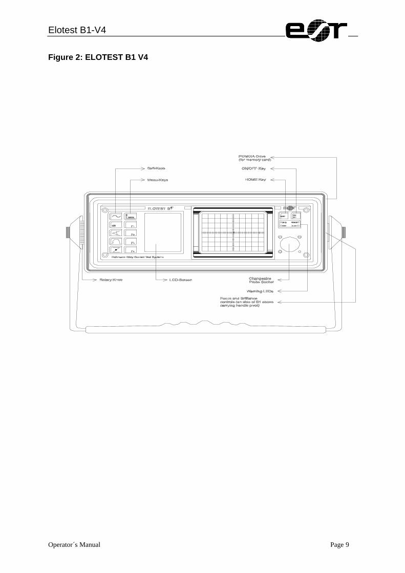
Figure 2: ELOTEST B1 V4

Elotest B1-V4
Operator´s Manual Page 10
1.5 Controls & Functions Parameters to be adjusted are displayed in the LDC window and are selected by pressing soft keys. Most Parameter values are adjusted by using the rotary knob on the left-hand side of the front panel. Soft key functions are as follows:
1.5.1. Keypad
1.5.1.1. ON/OFF Key Pushing this key (see fig.)will switch the B1 on and off. On switching on, the B1 version and serial number will be shown for a few seconds and then the display will change to the HOME menu. The charging state of the battery is shown by the battery.symbol. It will only be updated once in the beginning. To update it later, push the HOME-key at least once.
1.5.1.2. HOME Key Pushing this key will select the HOME menu, irrespective of which menu is shown in the LCD window. If the HOME menu is displayed and this key is pushed again, the display will change to show all the important parameters selected, i.e. frequency, gain, phase, filter, gate and alarm.
1.5.2. Compensation Key (Z) Pushing this key will display the spot on the screen and is known as the Compensation key (sometimes referred to as 'balance' or 'null'). The compensated dot position can be selected to any position on the screen (page 22). This key is inoperative on BM versions and also on UM versions when the highpass filter is switched on.

Elotest B1-V4
Operator´s Manual Page 11
1.5.3. Menu Key This key can be used to page through the main menu (SETTING, PARAMETER and FUNCTION). It can also be used to revert back to the last menu which was selected prior to selecting one of the directly accessible functions (frequency, gain, etc.).
1.5.4. F1-F4 These keys usually correspond to the texts on the LCD display.
1.5.5. Direct Access Keys These keys provide direct access to frequency, sensitivity, phase and filters.
1.5.5.1. Frequency Key Pushing this key will display the parameters shown - test frequency, entry filter (BWL) and pre-amplifier gain adjustment (>>PREAMP). FREQUENCY: The frequency can be adjusted by turning the knob. Adjustment range: 10 Hz to 10 MHz BWL: The purpose of the entry filter (BWL) is to prevent interference from external sources such as radio stations and should not be confused with the instrument lowpass and highpass filters of the instrument. It is switched on or off by pushing the F3-key. Although, for the majority of application, best results are achieved with the BWL switched on, in some cases better results are provided with the BWL switched off. If in doubt, the most suitable BWL setting for a particular application can best be determined by practical experiment. If the BWL was changed, the preamp should be rechecked (see below).
FREQUENCY
?? 2,8 MHz
BW: HF MF NF
BB auto manual >> PREAMP

Elotest B1-V4
Operator´s Manual Page 12
>>PREAMP: Pushing F4 will automatically adjust the preamplifier gain to match the probe and frequency being used The result will be shown in the field next to the F4-key. The value will be shown until the display is updated by another function in this mask or even a mask change. If the preamplifier is adjusted with the probe in air, it is possible that it may be overloaded when the probe is placed in contact with the test sample; preamplifier overload is indicated by a OVLD warning LED above the probe adapter. If this occurs, F4 should be pushed again with the probe in contact with the test sample. Conversely, with some probe/material combinations, the preamplifier may be overloaded when the probe is lifted off the test sample. It should be noted that adjustment of the preamplifier gain will also adjust the overall gain. The preamplifier can also be adjusted manually in the GAIN key menu. Adjustment range: -20 dB to +40 dB.
1.5.5.2. dB Pressing this key will display the parameters gain, preamplifier gain (PREAMP), Y-axis spread (Y-SPREAD) and X-axis spread (X-SPREAD). GAIN: The overall gain can be adjusted in 1dB steps by turning the knob when the cursor is pointing to GAIN. If Y or X-axis spread is used, the gain shown will be a split value. For example, 32/20dB indicates that 12dB of Y-axis gain has been selected, 20/32 dB would indicate the 12 dB of X-axis gain has been selected. Adjustment range 0 dB - 60 dB. PREAMP: The preamplifier gain normally should be adjusted when the frequency is selected. However, if required, it can also be adjusted manually in 10dB steps by pushing F2 and turning the knob. For optimum results, the preamplifier should be selected to as high a value as possible without causing the preamplifier to be overloaded, overload is indicated by a OVLD warning LED above the probe-socket. If the preamplifier is adjusted with the probe in air, it is possible that it may be overloaded when the probe is placed in contact with the test sample, if this occurs, the preamplifier should be readjusted with the probe in contact with the test sample. Conversely, with some probe/material combinations, the preamplifier may be overloaded when the probe is lifted off the test sample. It should be noted that increasing/decreasing the preamplifier gain will increase/decrease the overall gain. Adjustment range: -20 dB to +40 dB. Y-SPREAD: Y-axis spread can be adjusted in 1dB steps by pushing F3 and adjusting the knob. This facility can be used to provide increased amplification in the Y (vertical) axis. Adjustment range: 0 dB - 20 dB.
GAIN ?? 32/26 dB PREAMP: 24 dB Y-SPREAD: 6 dB X-SPREAD: 0 dB

Elotest B1-V4
Operator´s Manual Page 13
X-SPREAD: X-axis spread can be adjusted in 1dB steps by pushing F4 and adjusting the knob. This facility can be used to provide increased amplification in the x (horizontal) axis. Adjustment range: 0 dB - 20 dB. Please note that changing the Y-spread will set the X-spread to 0 dB and vice versa.
1.5.5.3. Phase Key Pushing this key will display the variables - phase angle and the signal display mode (DISP). In addition, a phase angle measuring facility and a lift-off phase angle adjustment facility are provided at F2 and F3 respectively. (Only applicable for static application). PHASE: The phase angle can be adjusted in 1 degree steps by turning the knob. Adjustment range 0° - 359°. ? The phase angle measuring facility at F2 can be used to change the phase angle of a signal by the required number of degrees. Pushing F2 sets the reading to 0 degrees, on changing the phase angle (clockwise or anticlockwise), the change of angle will be shown in degrees. Contrary to mathematic counting the value will be increased clockwise. >LIFTOFF The lift-off angle adjustment facility at F3 can be used to position the lift-off signal to horizontal. When the dot is at the compensated dot position and the probe is either angled or slightly lifted off the test surface (to move the dot away from the compensated dot position), F3 can be pushed to adjust the phase so that the spot moves horizontally to the left when the probe is lifted off the test surface. It is recommended to tilt the probe only slightly or place a piece of paper underneath it when using this feature. This ensures that the lift-off signal is horizontal. If the probe is fully lifted off, the dot follows usually a curve, the end-point of which will be horizontal but the displayed signal may show a y-component. Note: This function is only available together with the highpass switched off (static application). Summary: 1. Place probe on material
2. Compensate 3. Produce offset by slightly lifting or tilting the probe 4. Execute lift-off correction by pushing F3.
PHASE ?? 209 Ø >? 0 Ø LIFTOFF DISP: Y/X Y/t
Elotest B1-V4
Operator´s Manual Page 14
1.5.5.4. Filter Key
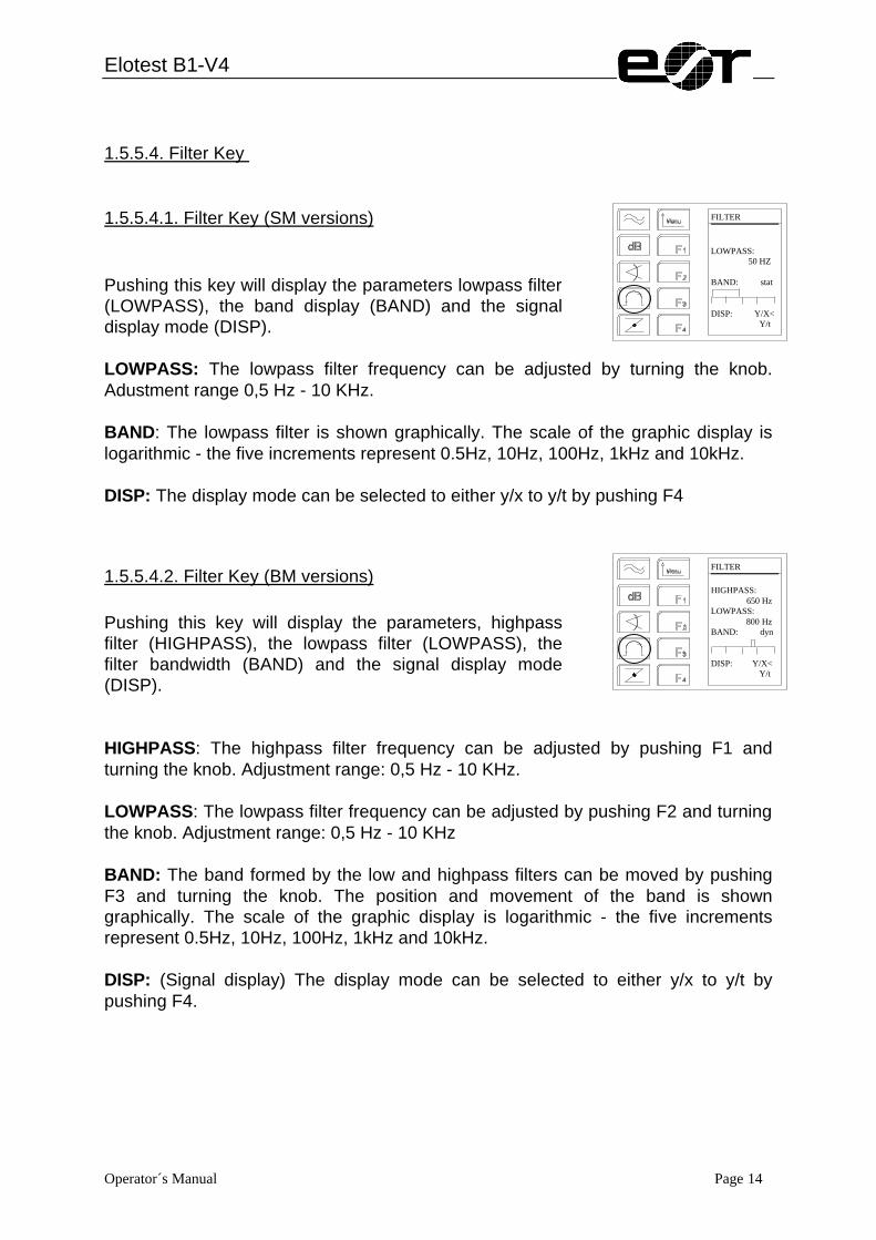
1.5.5.4.1. Filter Key (SM versions) Pushing this key will display the parameters lowpass filter (LOWPASS), the band display (BAND) and the signal display mode (DISP). LOWPASS: The lowpass filter frequency can be adjusted by turning the knob. Adustment range 0,5 Hz - 10 KHz. BAND: The lowpass filter is shown graphically. The scale of the graphic display is logarithmic - the five increments represent 0.5Hz, 10Hz, 100Hz, 1kHz and 10kHz. DISP: The display mode can be selected to either y/x to y/t by pushing F4
1.5.5.4.2. Filter Key (BM versions) Pushing this key will display the parameters, highpass filter (HIGHPASS), the lowpass filter (LOWPASS), the filter bandwidth (BAND) and the signal display mode (DISP). HIGHPASS: The highpass filter frequency can be adjusted by pushing F1 and turning the knob. Adjustment range: 0,5 Hz - 10 KHz. LOWPASS: The lowpass filter frequency can be adjusted by pushing F2 and turning the knob. Adjustment range: 0,5 Hz - 10 KHz BAND: The band formed by the low and highpass filters can be moved by pushing F3 and turning the knob. The position and movement of the band is shown graphically. The scale of the graphic display is logarithmic - the five increments represent 0.5Hz, 10Hz, 100Hz, 1kHz and 10kHz. DISP: (Signal display) The display mode can be selected to either y/x to y/t by pushing F4.
FILTER LOWPASS: 50 HZ BAND: stat DISP: Y/X< Y/t
FILTER HIGHPASS: 650 Hz LOWPASS: 800 Hz BAND: dyn DISP: Y/X< Y/t
Elotest B1-V4
Operator´s Manual Page 15
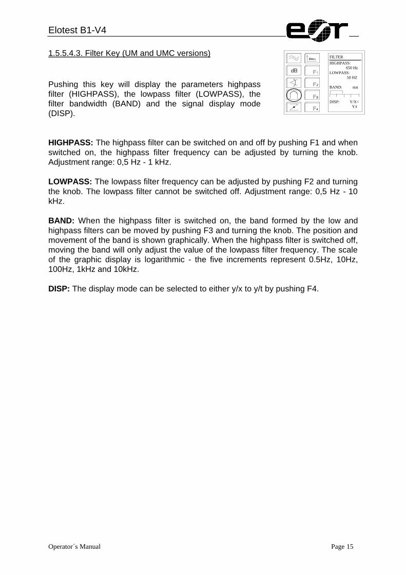
1.5.5.4.3. Filter Key (UM and UMC versions) Pushing this key will display the parameters highpass filter (HIGHPASS), the lowpass filter (LOWPASS), the filter bandwidth (BAND) and the signal display mode (DISP). HIGHPASS: The highpass filter can be switched on and off by pushing F1 and when switched on, the highpass filter frequency can be adjusted by turning the knob. Adjustment range: 0,5 Hz - 1 kHz. LOWPASS: The lowpass filter frequency can be adjusted by pushing F2 and turning the knob. The lowpass filter cannot be switched off. Adjustment range: 0,5 Hz - 10 kHz. BAND: When the highpass filter is switched on, the band formed by the low and highpass filters can be moved by pushing F3 and turning the knob. The position and movement of the band is shown graphically. When the highpass filter is switched off, moving the band will only adjust the value of the lowpass filter frequency. The scale of the graphic display is logarithmic - the five increments represent 0.5Hz, 10Hz, 100Hz, 1kHz and 10kHz. DISP: The display mode can be selected to either y/x to y/t by pushing F4.
FILTER HIGHPASS: 650 Hz LOWPASS: 50 HZ BAND: stat DISP: Y/X< Y/t

Elotest B1-V4
Operator´s Manual Page 16
1.6. LCD-Display An LCD-display is used for menu-guided operation and parameter display. The display has a resulution of 64 points (horizontal) up to 128 points (vertical). The display is illuminated to improve its legibility.
1.7. LEDs On the front panel of the instrument, above the probe connection sockets there are 4 LEDs with the following functions: Description of the LED
off flashing on
OVLD ok preamplifier overloaded - PRBT ok No probe or defect
probe connected -
POWER no electricity Voltage too low (charge battery)
ok
ALARM ok - Gate alarm was caused by passing a threshold

Elotest B1-V4
Operator´s Manual Page 17
Menu-guided instrument operation In addition to the direct function keys, meu-guided operation is available which can be selected by pressing the menu-key. In the menu level the function keys F1 to F4 correspond to the texts in the display. The next function is selected by the function key. The menu-key can be used to step back to the previous level or the gape through the lowest level. The HOME-key calls up the HOME-menu from each position of the menu.
PROBE CATALOG
APPLICATION CATALOG
DOT POS
TIMEBASE
ALARM
THRESHOLD
EXAMPLES
DELETE
STORE
LOAD
PARAMETER
SETTINGS
HOME
INFO
Elotest B1-V4
Operator´s Manual Page 18
>AUTOTEST
SETUP2
SETUP1
SERVICE
INFO
>>FORMAT
>PRT DIR
CARD FUNCT
COPYSET
SETTINGS
REFERENCE
ROLL MODE
SNAPSHOT
STORE
PIC-MEM
FUNCTION

Elotest B1-V4
Operator´s Manual Page 19
1.8. HOME When switching on the B1, the system information is shown for about 5 seconds. Then the HOME menu is displayed with its 4 submenus. Starting at any other display the user can switch to the main menu by pushing the HOME-Key. Pushing HOME one more time will show the main instrument settings. The HOME-submenu options are: SETTINGS: Stored user and example set-ups PARAMETERS: Selection and adjustment of threshold gates, alarm, timebase sweep and dot position FUNCTION: Digital signal display mode, instrument service and card functions (UMC) >>REPORT: Immediate printout of the current signal and parameter. The signal storage time is adjustable between 0.35 and 60 sec. in the storage mode. The four function keys (F1-F4) can now be used to select the menu choice desired.
1.8.1. SETTINGS Menu The Settings menu provides the following choices: LOAD: To select and load set-ups which were stored by the user STORE: To store up to 50 set-ups. The UMC version even provides the possibility to store up to 65 user set-ups. DELETE: To select and delete set-ups which were stored by the user and which are no longer required. NOTE: The functions load and delete can be protected in order to avoid accidental overwriting or deleting of instrument parameters. Also see SETUP2/SETTINGS. EXAMPLES:
HOME SETTINGS PARAMETERS FUNCTIONS >REPORT
SETTING LOAD STORE DELETE EXAMPLES
Elotest B1-V4
Operator´s Manual Page 20
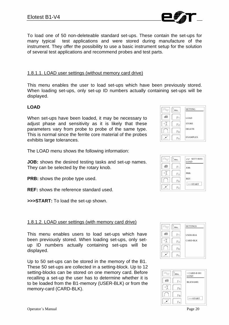
To load one of 50 non-deleteable standard set-ups. These contain the set-ups for many typical test applications and were stored during manufacture of the instrument. They offer the possibility to use a basic instrument setup for the solution of several test applications and recommend probes and test parts.
1.8.1.1. LOAD user settings (without memory card drive) This menu enables the user to load set-ups which have been previously stored. When loading set-ups, only set-up ID numbers actually containing set-ups will be displayed. LOAD When set-ups have been loaded, it may be necessary to adjust phase and sensitivity as it is likely that these parameters vary from probe to probe of the same type. This is normal since the ferrite core material of the probes exhibits large tolerances. The LOAD menu shows the following information: JOB: shows the desired testing tasks and set-up names. They can be selected by the rotary knob. PRB: shows the probe type used. REF: shows the reference standard used. >>>START: To load the set-up shown.
1.8.1.2. LOAD user settings (with memory card drive) This menu enables users to load set-ups which have been previously stored. When loading set-ups, only set-up ID numbers actually containing set-ups will be displayed. Up to 50 set-ups can be stored in the memory of the B1. These 50 set-ups are collected in a setting-block. Up to 12 setting-blocks can be stored on one memory card. Before recalling a set-up the user has to determine whether it is to be loaded from the B1-memory (USER-BLK) or from the memory-card (CARD-BLK).
SETTING LOAD STORE DELETE EXAMPLES
?? SETT 00/01 LOAD JOB: PRB: REF: >>>START
SETTINGS USER-BLK CARD-BLK
> CARD-B 001 LOAD BLKNAME: >>>START
Elotest B1-V4
Operator´s Manual Page 21
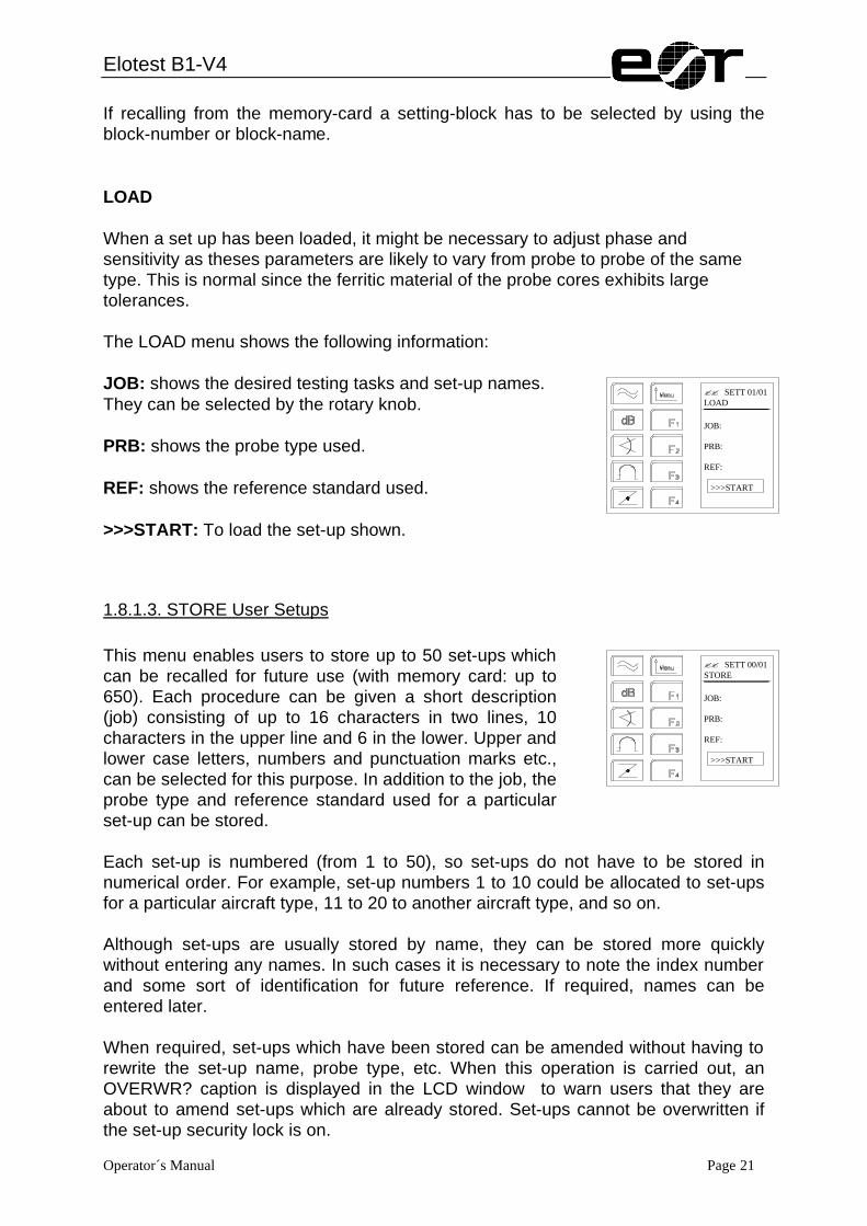
If recalling from the memory-card a setting-block has to be selected by using the block-number or block-name. LOAD When a set up has been loaded, it might be necessary to adjust phase and sensitivity as theses parameters are likely to vary from probe to probe of the same type. This is normal since the ferritic material of the probe cores exhibits large tolerances. The LOAD menu shows the following information: JOB: shows the desired testing tasks and set-up names. They can be selected by the rotary knob. PRB: shows the probe type used. REF: shows the reference standard used. >>>START: To load the set-up shown.
1.8.1.3. STORE User Setups This menu enables users to store up to 50 set-ups which can be recalled for future use (with memory card: up to 650). Each procedure can be given a short description (job) consisting of up to 16 characters in two lines, 10 characters in the upper line and 6 in the lower. Upper and lower case letters, numbers and punctuation marks etc., can be selected for this purpose. In addition to the job, the probe type and reference standard used for a particular set-up can be stored. Each set-up is numbered (from 1 to 50), so set-ups do not have to be stored in numerical order. For example, set-up numbers 1 to 10 could be allocated to set-ups for a particular aircraft type, 11 to 20 to another aircraft type, and so on. Although set-ups are usually stored by name, they can be stored more quickly without entering any names. In such cases it is necessary to note the index number and some sort of identification for future reference. If required, names can be entered later. When required, set-ups which have been stored can be amended without having to rewrite the set-up name, probe type, etc. When this operation is carried out, an OVERWR? caption is displayed in the LCD window to warn users that they are about to amend set-ups which are already stored. Set-ups cannot be overwritten if the set-up security lock is on.
?? SETT 01/01 LOAD JOB: PRB: REF: >>>START
?? SETT 00/01 STORE JOB: PRB: REF: >>>START
Elotest B1-V4
Operator´s Manual Page 22
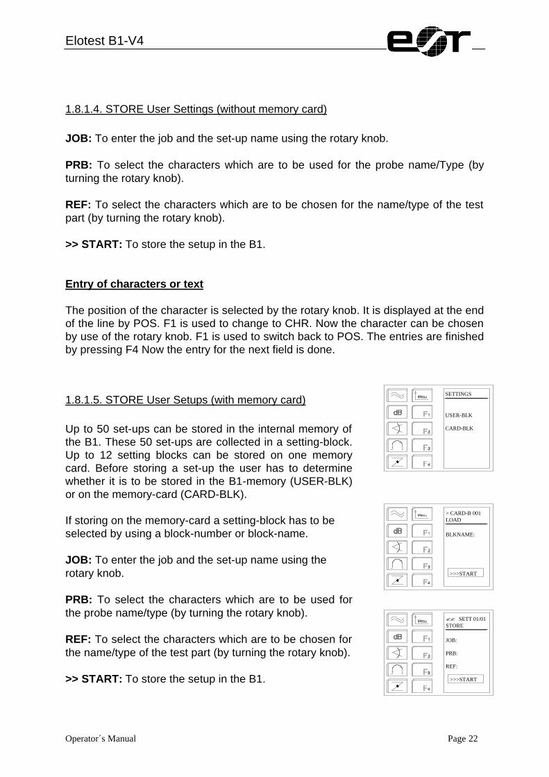
1.8.1.4. STORE User Settings (without memory card) JOB: To enter the job and the set-up name using the rotary knob. PRB: To select the characters which are to be used for the probe name/Type (by turning the rotary knob). REF: To select the characters which are to be chosen for the name/type of the test part (by turning the rotary knob). >> START: To store the setup in the B1. Entry of characters or text The position of the character is selected by the rotary knob. It is displayed at the end of the line by POS. F1 is used to change to CHR. Now the character can be chosen by use of the rotary knob. F1 is used to switch back to POS. The entries are finished by pressing F4 Now the entry for the next field is done.
1.8.1.5. STORE User Setups (with memory card) Up to 50 set-ups can be stored in the internal memory of the B1. These 50 set-ups are collected in a setting-block. Up to 12 setting blocks can be stored on one memory card. Before storing a set-up the user has to determine whether it is to be stored in the B1-memory (USER-BLK) or on the memory-card (CARD-BLK). If storing on the memory-card a setting-block has to be selected by using a block-number or block-name. JOB: To enter the job and the set-up name using the rotary knob. PRB: To select the characters which are to be used for the probe name/type (by turning the rotary knob). REF: To select the characters which are to be chosen for the name/type of the test part (by turning the rotary knob). >> START: To store the setup in the B1.
SETTINGS USER-BLK CARD-BLK
> CARD-B 001 LOAD BLKNAME: >>>START
?? SETT 01/01 STORE JOB: PRB: REF: >>>START

Elotest B1-V4
Operator´s Manual Page 23
1.8.1.6. DELETE User Settings (without memory card) This menu enables users to delete stored set-ups. When deleting set-ups, a SURE? warning caption is displayed in the LCD window. Set-ups cannot be deleted when the setting security lock is on. This menu offers the following possibilities: JOB: Can be selected by the rotary knob- shows the setup to be deleted. PRB: Shows the probe type of the setup to be deleted. REF: Shows the test part for the setup to be deleted. >>START: To delete the shown setup.
1.8.1.7. DELETE User Settings (with memory card) Up to 50 set-ups can be stored in the memory of the B1. These 50 set-ups are collected in a setting-block. Up to 12 setting-blocks can be stored on one memory card. Before deleting a set-up the user has to determine whether it is to be deleted from the B1-memory (USER-BLK) or from the memory card (CARD-BLK). If deleting from the memory-card the setting block has to be selected by using a block-number or block name. Select the desired set-up block by the rotary knob. This menu offers the following possibilities: JOB: Can be selected by the rotary knob- shows the setup to be deleted. PRB: Shows the probe type of the setup to be deleted. REF: Shows the test part for the setup to be deleted. >>START: To delete the shown setup.
1.8.1.8. EXAMPLE SET-UPS This menu enables users to select and load one of the non-eraseable standard set-ups which were stored during manufacture.
?? SETT 00/01 DELETE JOB: PRB: REF: >>>START
SETTINGS USER-BLK CARD-BLK
> CARD-B 001 DELETE BLKNAME: >>>START
?? SETT 01/01 DELETE JOB: PRB: REF: >>>START

Elotest B1-V4
Operator´s Manual Page 24
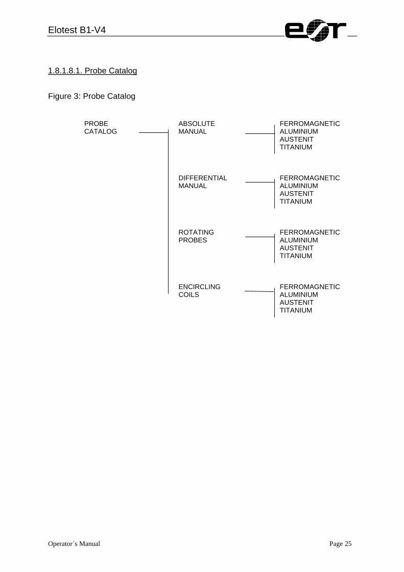
These set-ups can also be used when using probes from other manufacturers, but the pre-amplifier may require adjusting after loading the settings, prior to adjusting phase and sensitivity. Testing problems are approached by 1. Choice by task (application catalog) 2. Choice by probe (probe catalog) The following catalogs show possible approaches to solving a test problem. If a problem is solved and the appropriate adjustment of frequency, amplification and filter has been made, the settings can be stored as a user set-up.
EXAMPLES APPLICATION CATALOG PROBE CATALOG
Elotest B1-V4
Operator´s Manual Page 25
1.8.1.8.1. Probe Catalog
Figure 3: Probe Catalog
PROBE CATALOG
ABSOLUTE MANUAL
FERROMAGNETIC ALUMINIUM AUSTENIT TITANIUM
FERROMAGNETIC ALUMINIUM AUSTENIT TITANIUM
DIFFERENTIAL MANUAL
FERROMAGNETIC ALUMINIUM AUSTENIT TITANIUM
ROTATING PROBES
FERROMAGNETIC ALUMINIUM AUSTENIT TITANIUM
ENCIRCLING COILS
Elotest B1-V4
Operator´s Manual Page 26
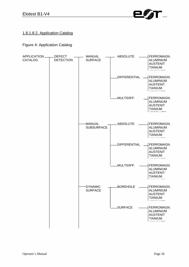
1.8.1.8.2. Application Catalog
Figure 4: Application Catalog
APPLICATION CATALOG
DEFECT DETECTION
MANUAL SURFACE
MANUAL SUBSURFACE
DYNAMIC SURFACE
ABSOLUTE
ABSOLUTE
BOREHOLE
FERROMAGN. ALUMINIUM AUSTENIT TIANIUM ABSOLUTE
FERROMAGN. ALUMINIUM AUSTENIT TIANIUM ABSOLUTE
FERROMAGN. ALUMINIUM AUSTENIT TIANIUM ABSOLUTE
DIFFERENTIAL
DIFFERENTIAL
SURFACE
FERROMAGN. ALUMINIUM AUSTENIT TIANIUM ABSOLUTE
FERROMAGN. ALUMINIUM AUSTENIT TIANIUM ABSOLUTE
FERROMAGN. ALUMINIUM AUSTENIT TIANIUM ABSOLUTE
MULTIDIFF.
MULTIDIFF.
FERROMAGN. ALUMINIUM AUSTENIT TIANIUM ABSOLUTE
FERROMAGN. ALUMINIUM AUSTENIT TIANIUM ABSOLUTE

Elotest B1-V4
Operator´s Manual Page 27
MATERIALS PROPERTY
OTHERS
ENCIRCLING COILS
MANUAL SURFACE
MANUAL SUBSURFACE
ENCIRCLING COILS SURFACE
ENCIRCLING COILS SUBSURFACE
FERROMAGN. ALUMINIUM AUSTENIT TIANIUM ABSOLUTE
FERROMAGN. ALUMINIUM AUSTENIT TIANIUM ABSOLUTE
FERROMAGN. ALUMINIUM AUSTENIT TIANIUM ABSOLUTE
FERROMAGN. ALUMINIUM AUSTENIT TIANIUM ABSOLUTE
FERROMAGN. ALUMINIUM AUSTENIT TIANIUM ABSOLUTE
CORROSION CONDUCTIVITY THICKNESS INTERNAL TUBE TEST

Elotest B1-V4
Operator´s Manual Page 28
1.8.2. PARAMETER Menu This menu provides the following choices: THRESHOLD: To select and adjust threshold gate functions. ALARM: To select alarm functions (see below). TIMEBASE: To select timebase sweep synchronization and the signal display mode y/x or y/t (next page). DOT POSITION: To select and adjust the compensated dot position (next page).
1.8.2.1. THRESHOLD Menu This menu provides the following options to enable the threshold gates to be selected and adjusted. The visibility of the gates on the screen can be selected using the F1 key. The visual and acoustic (if selected) alarms, are activated as soon as the signal crosses a threshold (whether visual or not). X-LEV: To adjust the X-axis threshold level. Adjustment range: 0-255. Y-LEV: To adjust the Y-axis threshold level. Adjustment range: 0-255. TYPE: To select either a box or cross gate. The box gate consists of symmetric X and Y thresholds (+ and -) which form a box centered on the screen. Threshold levels can be continuously adjusted from the screen center to the left-and right-hand sides of the screen (X-level) and to the top and bottom of the screen (Y-level). The cross gate consists of an X-level threshold on the left-hand half of the screen and a Y-level threshold on the upper half of the screen. Both X and Y threshold levels can be continuously adjusted from the screen center to the left and top edges of the screen, respectively. The parameters for X-gate and Y-gate are filed separately for box and cross.
PARAMETER THRESHOLD ALARM TIMEBASE DOT POSITION
THRESHOLD visible < invisible >> X-LEV: 255 Y-LEV: 255 TYPE: Box < Cross

Elotest B1-V4
Operator´s Manual Page 29
1.8.2.2. ALARM Menu This menu provides the following alarm functions to be selected: BEEP: To select the audio alarm on or off. The visual alarm LED (above the probe socket) operates in the same manner as the audio alarm, with the exception that it cannot be switched off. MODE: To select the alarm mode to triggered or store. In triggered mode, the alarm operates only when a gate threshold is crossed. In store mode, the alarm will operate when a gate threshold level is crossed and will continue to operate even when the dot has moved back outside the gate threshold levels. The signal can be deleted by switching to the triggered mode. It can further be switched off in the HOME2-mask (push the HOME-key twice) with F4 BEEP being switched off. LOG: To select the logic mode normal or invert. When normal mode is selected and the cross gate is used, the alarms operate when the dot moves upwards through the Y-level gate or towards the left of the screen through the X-level gate. When the box gate is used, the alarms operate when the dot moves outside the box. When invert mode is selected, the alarms operate in the opposite sense to normal mode, i.e. when the cross gate is used, the alarms operate when the dot is below the Y-level gate or to the right of the X-level gate; when the box gate is used, the alarms operate only when the dot is inside the box.
1.8.2.3. Timebase (y/t) Display This menu enables the timebase sweep synchronization to be selected to either automatic or to a fixed sweep speed which can be adjusted from 25 ms/div to 1000 ms/div, in 25 ms/div steps: SYNC: The sweep synchronization can be switched to either automatic or manual. Automatic is used for rotor applications or when an external trigger element is used. When automatic is selected, the timebase sweep is triggered by a sensor in the rotor (or external trigger) and is automatically synchronized to suit the rotor speed. If y/t-display is selected in error when using a hand-held probe, only a vertical dot movement will be displayed. When SYNC is selected to automatic and the rotor is not running, the dot may oscillate horizontally across the screen. DISP: To select the display mode to either y/x or y/t by using the F4-key.
ALARM BEEP: on off < MODE: trig < store LOG: norm < invert
TIMEBASE SYNC: auto < select DISP: Y/X < Y/t
Elotest B1-V4
Operator´s Manual Page 30
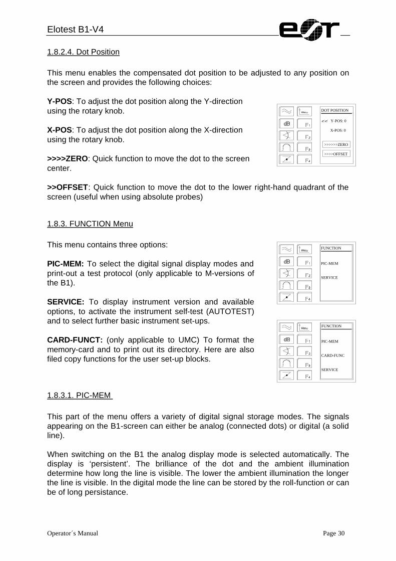
1.8.2.4. Dot Position This menu enables the compensated dot position to be adjusted to any position on the screen and provides the following choices: Y-POS: To adjust the dot position along the Y-direction using the rotary knob. X-POS: To adjust the dot position along the X-direction using the rotary knob. >>>>ZERO: Quick function to move the dot to the screen center. >>OFFSET: Quick function to move the dot to the lower right-hand quadrant of the screen (useful when using absolute probes)
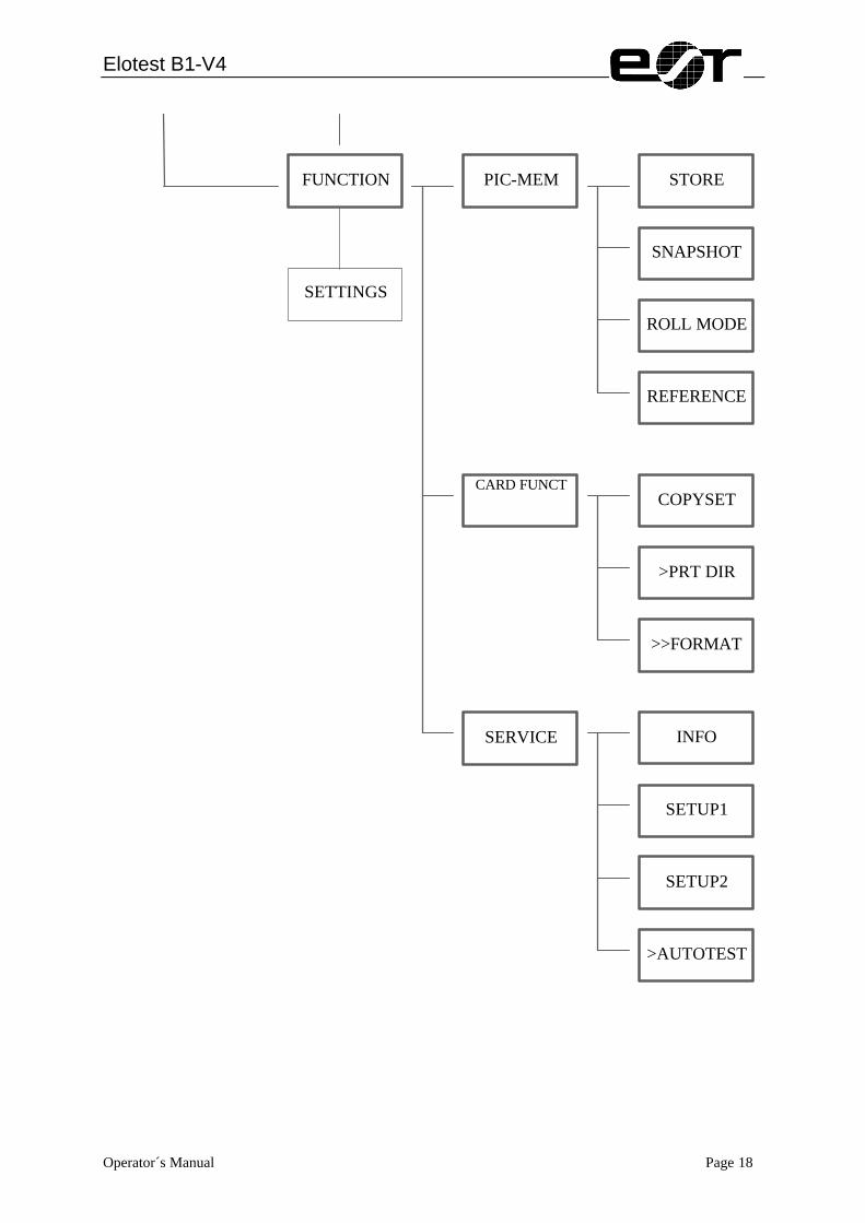
1.8.3. FUNCTION Menu This menu contains three options: PIC-MEM: To select the digital signal display modes and print-out a test protocol (only applicable to M-versions of the B1). SERVICE: To display instrument version and available options, to activate the instrument self-test (AUTOTEST) and to select further basic instrument set-ups. CARD-FUNCT: (only applicable to UMC) To format the memory-card and to print out its directory. Here are also filed copy functions for the user set-up blocks.
1.8.3.1. PIC-MEM This part of the menu offers a variety of digital signal storage modes. The signals appearing on the B1-screen can either be analog (connected dots) or digital (a solid line). When switching on the B1 the analog display mode is selected automatically. The display is ‘persistent’. The brilliance of the dot and the ambient illumination determine how long the line is visible. The lower the ambient illumination the longer the line is visible. In the digital mode the line can be stored by the roll-function or can be of long persistance.
DOT POSITION ?? Y-POS: 0 X-POS: 0 >>>>>>ZERO >>>>OFFSET
FUNCTION PIC-MEM SERVICE
FUNCTION PIC-MEM CARD-FUNC SERVICE

Elotest B1-V4
Operator´s Manual Page 31
In the digital mode 3 memories are available which are called area 1 to area 3. The signals remain stored (even if the instrument was shut off meanwhile) until they are overwritten or deleted. A backup battery ensures that the signals are stored for at least 120 days even if the instrument is disconnected from the power supply. Instruments with integrated memory drive offer up to 224 more areas for storage (depending on the capacity of the card). A character is inserted before the no. of the picture indicating I-internal, C-card and R-reference picture. These characters are an additional aid to classify the pictures. This part of the menu offers the following functions: STORE: To store either a continuous signal or a signal triggered by a threshold gate crossing. One can select the memory position and then view and print the signals. SNAPSHOT: To store a signal over a preselected time or a triggered signal. One can choose between a digital signal snapshot or signal storage induced by a threshold gate crossing. The memory position can be selected, the signal can be viewed and printed. The length of the shot can be set between 0.3 and 60 secs. ROLL MODE: If the digital signal roll mode was selected, the memory positions can be viewed and printed. REFERENCE: To overlay a stored signal during regular instrument usage, as a direct reference signal. The instrument settings used to obtain the reference signal can be loaded additionally.
1.8.3.1.1. STORE Mode One can select between continous storage or signal storage triggered by threshold gate crossing. The memory position can be chosen, stored signals can be viewed and printed. You can also view any signals previously stored and compare them with the current signal. The digital pictures are in the background for reference purposes. The functions in the store mode are: AREA: To select the memory area by using the rotary knob STORE: Either continous or gate (starting with the threshold gate crossing). START: To erase previously stored signals and initiate signal storage. When storing signals, the storing process can be stopped by pushing F3 (>>>>STOP).
PIC-MEM STORE MODE SNAPSHOT ROLL MODE REFERENCE
>>>>>>>>>I 003 STORE MODE NAME: TYPE: contin. < Threshold >>>>START >>>>PRINT

Elotest B1-V4
Operator´s Manual Page 32
>>>>PRINT: To print out a stored signal.
1.8.3.1.2. SNAPSHOT Mode The SNAPSHOT mode is mainly used for storing rotary signals, but can also be used for storing signals from other applications. The length of a 'snapshot' can be selected from 0.3 to 60 seconds. During the snapshot period, the trace is displayed in analog mode, at the end of the shot period selected, signals which occurred during the period are stored and displayed on the screen. When storing rotary signals, it is usual to select the shot period of 0.3 seconds. A shot can be initiated manually, by pushing F3. You can view and print any signals previously stored and compare them with the current signal. The digital pictures are in the background for reference purposes. The choices available in the SNAPSHOT mode menu are: AREA: To select the memory area by using the rotary knob. TIME: Press F3 to set the shot length to between 0,3 and 60 secs. START: Use the F3-key to manually trigger a snapshot. >>>PRINT: To print out a stored signal (next page). ROLL MODE In this mode, signals can be stored which roll-off (self-erase) automatically after a selectable period of time (8 - 70 seconds). The trace is erased in the order in which it was displayed. You can view and print any signals previously stored and compare them with the current signal. The digital pictures are in the background for reference purposes. The functions in the ROLL MODE menu are: AREA: To select the memory area by using the rotary knob. TIME: To select the time (F2-key) after which signals will self-erase. >>>START: To initiate signal storage and the self-erasing process. The process can be stopped by pushing F3 (>>>STOP).
>>>>>>>>>I 003 SNAPSHOT NAME: TIME: .3 s >>>>START >>>>PRINT
>>>>>>>>>I 003 ROLL MODE NAME: TIME: 8 s >>>>START >>>>PRINT
Elotest B1-V4
Operator´s Manual Page 33
>>>PRINT: To print out a stored signal.
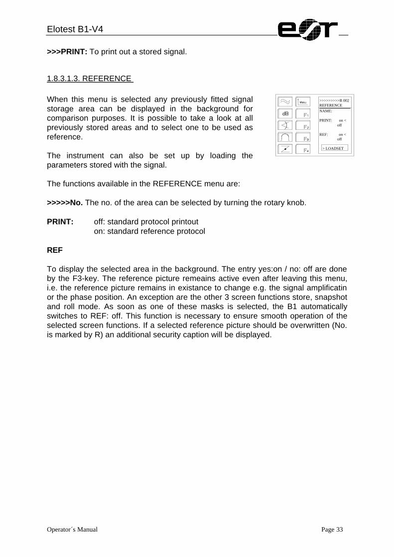
1.8.3.1.3. REFERENCE When this menu is selected any previously fitted signal storage area can be displayed in the background for comparison purposes. It is possible to take a look at all previously stored areas and to select one to be used as reference. The instrument can also be set up by loading the parameters stored with the signal. The functions available in the REFERENCE menu are: >>>>>No. The no. of the area can be selected by turning the rotary knob. PRINT: off: standard protocol printout on: standard reference protocol REF To display the selected area in the background. The entry yes:on / no: off are done by the F3-key. The reference picture remeains active even after leaving this menu, i.e. the reference picture remains in existance to change e.g. the signal amplificatin or the phase position. An exception are the other 3 screen functions store, snapshot and roll mode. As soon as one of these masks is selected, the B1 automatically switches to REF: off. This function is necessary to ensure smooth operation of the selected screen functions. If a selected reference picture should be overwritten (No. is marked by R) an additional security caption will be displayed.
>>>>>>>>>R 002 REFERENCE NAME: PRINT: on < off REF: on < off > LOADSET
Elotest B1-V4
Operator´s Manual Page 34
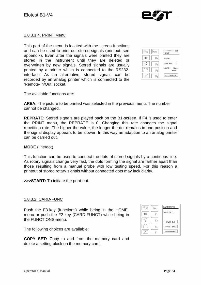
1.8.3.1.4. PRINT Menu This part of the menu is located with the screen-functions and can be used to print out stored signals (printout: see appendix). Even after the signals were printed they are stored in the instrument until they are deleted or overwritten by new signals. Stored signals are usually printed by a printer which is connected to the RS232-interface. As an alternative, stored signals can be recorded by an analog printer which is connected to the ‘Remote-In/Out’ socket. The available functions are: AREA: The picture to be printed was selected in the previous menu. The number cannot be changed. REPRATE: Stored signals are played back on the B1-screen. If F4 is used to enter the PRINT menu, the REPRATE is 0. Changing this rate changes the signal repetition rate. The higher the value, the longer the dot remains in one position and the signal display appears to be slower. In this way an adaption to an analog printer can be carried out. MODE (line/dot) This function can be used to connect the dots of stored signals by a continous line. As rotary signals change very fast, the dots forming the signal are farther apart than those resulting from a manual probe with low testing speed. For this reason a printout of stored rotary signals without connected dots may lack clarity. >>>START: To initiate the print-out.
1.8.3.2. CARD-FUNC Push the F3-key (functions) while being in the HOME-menu or push the F2-key (CARD-FUNCT) while being in the FUNCTIONS-menu. The following choices are available: COPY SET: Copy to and from the memory card and delete a setting block on the memory card.
>>>>>>>>>I 003 PRINT NAME: REPRATE: 0 MODE Line < Point >>>>START
CARD FUNC COPY SET: Ø 256 KB >>>PRT DIR >>>FORMAT

Elotest B1-V4
Operator´s Manual Page 35
Possible displays. Display Description 128 kB Indication of the CARD-type of the formatted CARD 256 kB Indication of the CARD-type of the formatted CARD 512 kB Indication of the CARD-type of the formatted CARD 1 MB Indication of the CARD-type of the formatted CARD protect The writeprotect-key of the card is active Low Batt The battery is flat, exchange it, preferably while the card is
inserted and the instrument is switched on (because of the card’s power supply)
????????? no card inserted CARD????? Non-formatted card >PRT DIR: print a directory of the memory-card. Part of it are: 1. Setting block catalog with the descriptions (JOB, PROBE and REFERENCE) of each set-up (see appendix) 2. Signal picture catalog with contents, signal pictures and related set-ups (see appendix) >>FORMAT: format the inserted memory card. If a memory card is inserted in the drive, its capacity will be displayed.
1.8.3.2.1. COPYSET (Copy from and to the memory card) The B1 internal memory has only one setting block containing up to 50 user-set-ups. A memory-card provides space for 12 setting-blocks. The following functions are used to copy a complete block between B1 and memory-card. From the Home-menu push keys F3 (FUNCTIONS), F2 (CARD-FUNCT) and F1 (COPY SET).
COPYSET CARD > B1 B1 > CARD BLK DELETE

Elotest B1-V4
Operator´s Manual Page 36
1.8.3.2.1.1. B1>CARD (Copy the B1-setting-block to the memory-card) Push F2 (B1>CARD). Then select the block index on the card to which the block is to be copied to by turning the rotary knob. Then push F4 (>>>START). Now the set-up block and the name will be copied to the memory card. A 16-digit-description can then be given to the setting-block. Switch between position and text by using F1 and select the desired position or text by turning the rotary knob. Lastly push F4 (>>STORE).
1.8.3.2.1.2. CARD>B1 (Copy a memory-card setting-block to the B1) Push F1 (CARD>B1). Now select the block on the memory card which is to be copied to the B1 by turning the rotary knob. Then push F4 (>>>START). The selected setting-block will be copied to the B1-memory. The message 'DONE!' appears on the screen and the menu will be exited automatically.
1.8.3.2.1.3. Delete a setting-block from the memory-card Starting at the HOME-menu push the keys F3 (FUNCTIONS), F2 (CARD-FUNCT), F1 (COPY SET) and F3 (BLK DELETE). Select the setting-block which is to be deleted by turning the rotary knob (only used blocks will be shown).
ATTENTION: There is no affirmation/verification request!!! If you are sure to have selected the correct setting-block push F4 (>>>START). The setting-block will be deleted.
1.8.3.2.2. PRT DIR (Print directory of the memory-card) From the HOME-menu push keys F3 (FUNCTIONS), F2 (CARD-FUNCT) and F3 (PRT DIR). The printout starts immediately. Please ensure that the correct printer type and transmittal speed (baud rate) are selected prior to printing.
1.8.3.2.3. >FORMAT (Format a memory card)

Elotest B1-V4
Operator´s Manual Page 37
From the HOME-menu push keys F3 (Functions) , F2 (CARD-FUNCT) and F4 (FORMAT). As any data which might be stored on the memory card will be deleted, the system will ask if you are SURE? If you confirm by pushing F4, the formatting will be started. Any other key will leave the formatting function. The memory card will be formatted in the determined FORMAT. Then a file will be created which occupies the entire memory. The settings and picture areas are entered into fixed positions of this file. The formatted card can be read by any common PC with CARD-adapter. The format is DOS-compatible.
1.8.3.3. SERVICE Menu The Service Menu provides the following choices: INFO: To display the instrument model, software version, standard set-up version and serial number. SETUP1: To select the type of filter, the language (english/german or french/german) and to enable/disable the automatic switch-off facility. SETUP2: To adjust the transmittal speed of the RS 232-interface, the printer type, the lock function for the user set-ups and to switch the adapter to probe A or probe B. AUTOTEST: To start the instrument self-test routine.
1.8.3.3.1. INFO Menu This menu shows information about the instrument. Please always state this information when contacting Rohmann with questions about the instrument. Display Description ELOTEST B1 V4 Instrument version Prog. 6.02 Version of the installed software SETT.: 1.06 Status of the installed set-up Sno: 87778 Serial number of the instrument B1-PWR Hardware option ‘increased transmittal speed’
SERVICE INFO SETUP1 SETUP2 >AUTOTST
INFO
ESR
ELOTEST B1 UMC
Prog.: 6.02 Sett: 1.06 SNr. 87778

Elotest B1-V4
Operator´s Manual Page 38
1.8.3.3.2. SETUP1 Menu: The functions available in this menu are: AUTO-OFF: The automatic switch-off can either be activated or deactivated. If activated the instrument turns off if there has not been a signal response for 15 minutes. LANGUAGE: To select the language in which the instrument is to be operated. English/German or English/French version are usually available. If your order does not state anything to the contrary, the English/German combination will be installed.
1.8.3.3.3. SETUP2 Menu This menu provides the following functions: RS 232: The transmittal speed (baud rate) can be set to 300, 1200 or 9600, in order to communicate with a printer/computer or modem. PRINTER: This function is used to select the appropriate printer driver which may be Diconix Model 150, IBM Proprinter XL, Canon BJ (LQ mode) Laserjet series II, NEC P6 pinwriter and Epson FX-80. A printout is usually not dependent on the printer type, however, the layout may vary so the printout may be too wide or too high. SETTINGS: This function is used to secure, i.e. lock, existing user set-ups. It is activated /deactivated by pushing the F3-key (key symbol visible means 'lock' is active). The key is also displayed in the set-up mask as a reminder. ADAPTER: When using a changeable probe adapter of the type B1-2RS one can select which sensor is activated. The B1-2RS adapter is very similar to the B1-RS adapter except for having 2 Fischer connectors instead of one. The adapter is mainly used for automatic testing systems. This enables the selection between two different types of sensors (or a sensor and a rotor) without having to change the probe cables. The appropriate set-up parameters must be loaded using the user set-up. If the adapter selection has been adjusted to probe A, the upper connector of the B1-2RS is activated. The lower connector is activated in connection with 'probe B'. If a B1-2RS is used with a single probe it should be connected to the upper connector with the adapter selection set to 'probe A'. If the selection 'probe B' is made, the lower connector can also be used. In this case, however, both internal adapter relays are active, reducing battery life. If any adapter other than a B1-2RS is
SETUP1
AUTO-OFF. enable disable <
LANGUAGE: English < German
SETUP2
> RS232 9600 Baud > PRINTER: Diconix Model 150 > SETTINGS:
ADAPTER: Probe A < Probe B

Elotest B1-V4
Operator´s Manual Page 39
used the ADAPTER selection can be either 'probe A' or 'probe B' without affecting internal adapter relays.

Elotest B1-V4
Operator´s Manual Page 40
1.8.3.3.4. AUTOTST Menu The AUTOTEST menu enables users to rapidly test important instrument parameters for correct functioning without the need for special test instruments. During each part of the self-test sequence, the name of the parameter being tested is shown in the header of the LCD window. Correct functioning is assessed by viewing the screen display. The following instrument parameters are included in the test routine. Vector rotation and compensation (VECT./COMP) - used to check the compensation and then the vector-rotation (Phase). Demodulation (DEMODULAT) - used to check the accuracy of the receiver circuits (including frequency). Amplifier (AMPLIFIER) - used to check the function and linearity of the amplifier. Pre-amplifier (PREAMP.) - used to check the function and linearity of the receiver Pre-amplifier. Axis-spread (AXISSPREAD) - used to check the function of the X and Y-axis spread. Gate (GATE) - used to check the function of the gates and the visual and audio alarms. Filter (FILTER) - used to check the correct functioning of the filters.

Elotest B1-V4
Operator´s Manual Page 41
2. Instrument Functions/Instrument setup
2.1. Signal Display Modes Signals can be displayed on the screen in either y/x (a dot of light commonly referred to as 'Spot Display') or y/t (a horizontal trace commonly referred to as 'Line Display'). The y/t display is normally only used for dynamic applications but could also be used for static applications if required. It should be noted that when y/t mode is selected, the amplitude of the signals displayed corresponds to the y-axis amplitude of y/x signals, and not to the vector length of signals. As an example, it can be seen that signal A has a greater vector length than signal B when displayed in y/x mode, but is displayed at a smaller amplitude when y/t mode is selected. Figure 5: Amplitude of the Y-Axis Spread in the Timebase-mode
2.1.1. Change from impedance plane (y/x) to timebase (y/t) display modes: There are 3 ways to switch between impedance plane and timebase display modes: - by pushing first the PHASE direct access key, then F4 - by pushing first the FILTER direct access key, then F4 - by selecting the timebase display in the parameter menu, then pushing F3.

Elotest B1-V4
Operator´s Manual Page 42
2.2. Focus and Brilliance (Intensity) Focus and Brilliance (Intensity) can be adjusted using the two small rotary knobs on the right-hand side of the instrument casing above the carrying handle pivot. As in common to all cathode ray tubes, care should be taken to ensure that the spot is not left in the same position on the screen for prolonged periods, especially at high intensity levels, as burning of the screen coating can occur. If the instrument is left switched on for long periods with the spot in the same position on the screen, the intensity should be reduced as much as possible, or, if using a rotor, the display should be selected to y/t mode.
2.3. Filter
2.3.1. Filter types available in the B1: The filters installed in the various versions of B1 are: SM versions: Lowpass filter only (static applications): BM versions: Lowpass and highpass filters - used simultaneously to provide a
variable bandwidth bandpass filter (dynamic applications). UM versions: Lowpass and highpass or bandpass filters (static and dynamic
applications).
2.3.2. Filter Principles When only the lowpass filter is used, the dot is 'free floating' and will move to different positions on the screen when placed on materials of different electrical conductivities. The dot will remain at a particular position while the probe is in contact with a particular material. When a highpass or bandpass filter is used, the dot will always return to the compensated dot position and can be likened to an 'auto-zero' function. Therefore, if the probe is placed on materials of different electrical conductivities, the dot will move to different positions on the screen momentarily but will then return to the selected dot position. The purpose of filters is to improve signal-to-noise ratios and/or to filter out other unwanted signals in order to optimize test sensitivities. Noise can be 'electronic' (from the instrument and probe) or can be caused by other factors, such as signals from rough scan surfaces. Electronic noise can be recognized by the dot appearing as a 'ball of wool' shape rather than as a steady dot of light and is more commonly encountered when testing at low frequencies or when very high gain levels are used.
Elotest B1-V4
Operator´s Manual Page 43
Filter frequencies are not associated with the frequency of current through the coil but are related to the rate at which signals are changing. For example, when scanning over a crack, the rate of change of the crack signal will depend on how fast the probe is moved across the crack.
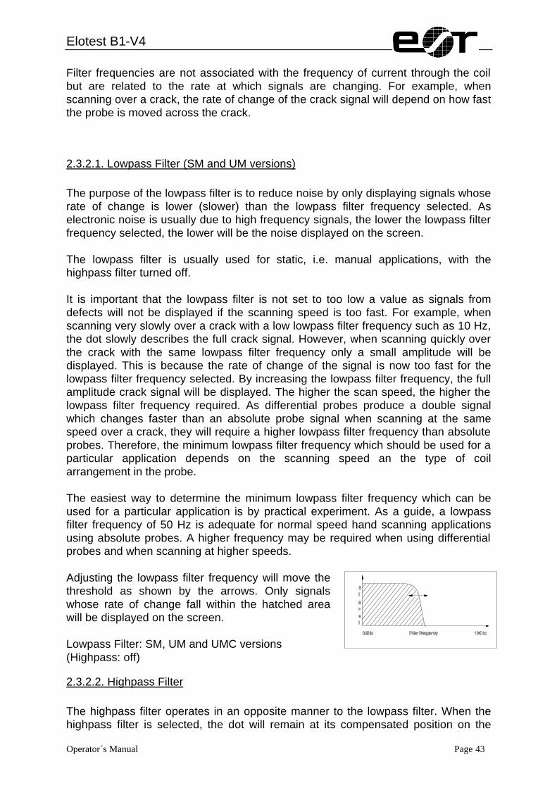
2.3.2.1. Lowpass Filter (SM and UM versions) The purpose of the lowpass filter is to reduce noise by only displaying signals whose rate of change is lower (slower) than the lowpass filter frequency selected. As electronic noise is usually due to high frequency signals, the lower the lowpass filter frequency selected, the lower will be the noise displayed on the screen. The lowpass filter is usually used for static, i.e. manual applications, with the highpass filter turned off. It is important that the lowpass filter is not set to too low a value as signals from defects will not be displayed if the scanning speed is too fast. For example, when scanning very slowly over a crack with a low lowpass filter frequency such as 10 Hz, the dot slowly describes the full crack signal. However, when scanning quickly over the crack with the same lowpass filter frequency only a small amplitude will be displayed. This is because the rate of change of the signal is now too fast for the lowpass filter frequency selected. By increasing the lowpass filter frequency, the full amplitude crack signal will be displayed. The higher the scan speed, the higher the lowpass filter frequency required. As differential probes produce a double signal which changes faster than an absolute probe signal when scanning at the same speed over a crack, they will require a higher lowpass filter frequency than absolute probes. Therefore, the minimum lowpass filter frequency which should be used for a particular application depends on the scanning speed an the type of coil arrangement in the probe. The easiest way to determine the minimum lowpass filter frequency which can be used for a particular application is by practical experiment. As a guide, a lowpass filter frequency of 50 Hz is adequate for normal speed hand scanning applications using absolute probes. A higher frequency may be required when using differential probes and when scanning at higher speeds. Adjusting the lowpass filter frequency will move the threshold as shown by the arrows. Only signals whose rate of change fall within the hatched area will be displayed on the screen. Lowpass Filter: SM, UM and UMC versions (Highpass: off)
2.3.2.2. Highpass Filter The highpass filter operates in an opposite manner to the lowpass filter. When the highpass filter is selected, the dot will remain at its compensated position on the

Elotest B1-V4
Operator´s Manual Page 44
screen and will only be moved from that position by signals whose rate of change is higher (faster) than the highpass filter frequency selected Adjusting the highpass filter frequency will move the threshold as shown by the arrows. Only signals whose rate of change fall within the hatched area will be displayed on the screen. Highpass Filter: BM, UM and UMC (Lowpass:10 kHz)

Elotest B1-V4
Operator´s Manual Page 45
2.3.2.3. Bandpass Filter (BM, UM and UMC versions) By overlapping the lowpass and highpass filters, a bandpass filter is formed whose bandwidth can be adjusted to suit the application. The lowpass filter only permits signals whose rate of change is lower (slower) than the lowpass filter frequency selected to be displayed, the highpass filter only permits signals whose rate of change is higher (faster) than the highpass filter frequency selected to be displayed. Hence, the dot will only move from its compensated position by signals whose rate of change fall within the band created by the lowpass and highpass filters. The bandpass filter is therefore used for dynamic applications where it is desirable to filter out slow changing signals such as gradual changes in geometry or conductivity. It also has the advantage of filtering out high frequency noise signals. The B1 microprocessor ensures that the highpass and lowpass filters will always overlap. The minimum bandwidth is achieved when both the highpass and lowpass filter frequencies have the same value. If the highpass filter frequency is set at 50 Hz and the lowpass filter frequency is adjusted to 40 Hz, the highpass filter frequency will automatically change to 40 Hz. The bandpass filter can also be used for manual scanning applications in an 'auto-zero' mode. Signals due to cracks will be changing at a greater rate than gradual changes due to geometry and lift-off. Therefore, if the bandwidth is selected to a value to suit the scanning speed, the dot will only be displaced by cracks and not by gradual changes. Ideally, scans should be carried out at uniform speed if the bandpass filter is being used. The danger with using the bandpass filter for hand scanning applications is that a crack which is scanned over too slowly or too quickly will not be displayed unless the crack signal is changing at a rate which falls within the bandwidth selected. However, operators can satisfy themselves of the acceptable latitude in scanning speeds by practical experiment. Adjusting the lowpass and highpass filter frequencies will alter the filter bandwidth as shown by the arrows. Only signals whose rate of change fall within the hatched area will be displayed on the screen. Bandpass Filter (overlapping High- and Lowpass Filters): BM, UM and UMC versions

Elotest B1-V4
Operator´s Manual Page 46
2.4. Instrument Configuration
2.4.1. Instrument Automatic Switch-Off - Enabling/Disabling Switch on the instrument. Push F3 to select the FUNCTIONS menu, then again F3 to select the SERVICE menu, then F2 to select the SETUP1 menu. Push F1 as required to enable/disable the instrument automatic switch-off. The use of this function makes sense to avoid burning of the screen coating.
2.5. Instrument Setup The initial instrument set-ups to be used for a particular application can be determined in three ways: - by using the EXAMPLE Set-ups to load approximate settings for the test application. - by using the User Set-ups, if the application set-ups have previously been stored in the User Setups. - by manual selection: - Typical hand-held probe applications: - SM versions of B1 - UM versions of B1 - UMC versions of B1 - Typical high speed dynamic probe and rotor applications - BM versions of B1 - UM versions of B1 - UMC versions of B1 Operators should ensure that they are familiar with the different types of filters and their principles of operation, especially when setting-up by manual selection.

Elotest B1-V4
Operator´s Manual Page 47
2.5.1. Initial Set-Up Procedure - Using Example Settings Switch on the B1. By means of the menu EXAMPLE setups the operator can select and load one of the non-deletable example setups. These setups can also be used if probes by other manufacturers are connected. After loading the setups it might be necessary to readjust the preamplifier which must be done prior to setting phase and sensitivity. Push the F1-key to enter the SETTING menu. Then press the F4-key and select the EXAMPLES-menu. Now an application can be chosen which is as similar as possible to the current job and which the proposed probe is available for. By pushing the F4-key this parameter set will be activated in the B1 which is confirmed by the message ‘LOADED’ in the LCD-window. Then the operator is asked to connect the appropriate probe (after having pushed the F4-key). Please ensure the correct probe and the appropriate probe cable are connected to the relevant probe adapter. After having pushed F4 a message appears asking the operator to check probe, instrument and the chosen parameters using the reference standards proposed in the display and to make changes (mainly sensitivity, dB, phase location) which might be necessary due to probe tolerances. In case the proposed reference standard is not available it is recommended to use an equivalent one. If the instrument setup will be needed in future it can be stored as a user set-up.
Elotest B1-V4
Operator´s Manual Page 48
2.5.2. Initial Set-up Procedure - Using User Set-ups Switch on the B1. Load user set-up from the B1-memory Push function key F1 to select the set-up menu and then press it again to select the block of stored user set-ups. By turning the rotary knob one can page through the stored user-set-ups. Load user set-up from the B1-memory (UMC) Push function key F1 to select the set-up menu and then press it again to select the set-up-selection menu. Then choose the B1-memory (USER-BLK) by pushing F1. By turning the rotary knob one can page through the stored user set-ups. Load user set-up from the B1-memory (UMC versions only) Push function key F1 to select the set-up meu. Push F2 to select that the set-up is to be read from the memory-card. Now choose the setting block by turning the rotary knob and push F4 to load the set-up. By turning the rotary knob one can page through the stored user set-ups. Ensure the correct probe adapter socket is installed in the B1. You also have to ensure that the probe types and reference standards displayed on the LCD-display are the same than those which are to be used for the test application. Connect the probe to the B1 by an adequate cable. Activate the set of parameters by using F4 to check the instrument set-up and the probe by means of the existing reference standard. Ensure that the preamplifier display (OVLD) does not illuminate. If necessary, carry out adjustments. It is possible that phase and sensitivity will require adjustments, too, as these parameters can vary from probe to probe of the same type. After having optimized the instrument set-up, proceed with testing.

Elotest B1-V4
Operator´s Manual Page 49
2.6. Manual Instrument Set-up
2.6.1. Manual Set Up Procedure - Typical Hand-Held Probe Applications
2.6.1.1. SM versions Switch on the B1. Ensure that the appropriate probe adapter is fitted to the B1 and connect the probe by the appropriate probe cable. Push the FREQUENCY direct access key and select the frequency required by turning the knob. The probe data sheets or probe protocols contain the suitable test frequencies and other parameters. Place the probe on the test object and push F4 to automatically adjust the pre-amplifier. When the pre-amplifier has been adjusted, the cursor will move back to the F1-line. Check that the pre-amplifier overload warning LED (OVLD) above the probe socket is not illuminated. Push the dB direct function key and set the GAIN to minimum and the Y and X-SPREAD to 0 using the rotary knob. Push the PHASE direct function key and then F4 to set the display mode to y/x (impedance plane display). Push the red COMPENSATION key to display the dot on the screen and, if required, adjust the compensated dot position (DOT POSITION menu in the PARAMETER menu). If the threshold gates are not being used, ensure that both the box and cross gates are at their maximum size and are set to "invisible" (THRESHOLD menu in the PARAMETER menu). If gates are to be used, select and adjust as required. The visual and audio (if selected "on") alarms will operate when gate thresholds have been exceeded, irrespective of whether or not the gates are set to "visible" or "invisible". Select alarm functions as required (ALARM menu in the PARAMETER menu). Push the FILTER direct function key and adjust the LOWPASS filter frequency as required by turning the knob. A filter frequency of 50 Hz should be adequate for most typical hand-scanning applications although a filter frequency of as low as 5 or 10 Hz may be required to reduce noise and vibrations when carrying out more sensitive applications, such as ring probe applications. For fastener hole inspections using sliding probe techniques, a filter frequency higher than 50 Hz may be required, depending on the scan speed and probe type. Confirm by practical experiment that the filter frequency selected is suitable for the technique being carried out and adjust

Elotest B1-V4
Operator´s Manual Page 50
if necessary. Please ensure that the testing speed during the examination is not higher than the scanning speed during the practical experiment. Place the probe on a fault-free area of the reference standard and check that the pre-amplifier overload warning LED (OVLD) does not illuminate. If it is illuminated, it is necessary to adjust the preamplifier. Push the red COMPENSATION key to display the dot on the screen. Push the PHASE direct function key and adjust the phase to suit the technique. For the majority of applications it is adjusted so that the spot moves horizontally towards the left of the screen when the probe is tilted or lifted slightly off the test surface. Push the dB-direct function key and, while moving the probe across the reference defect, adjust the GAIN to provide the desired sensitivity. If required, adjust Y or X-SPREAD as necessary. After the sensitivity has been adjusted to the desired level, do not adjust the preamplifier as doing so will change the overall sensitivity. If the OVLD LED does light up repeat the procedure as described above. Digital signal storage is possible. If the settings are required for future recall, they can be allocated a name and stored in the User Set-ups.
2.6.1.2. BM versions NOTE: The BM versions of the ELOTEST B1 are normally used for dynamic applications (e.g. using a rotor or where the probe is moved across defects at a fairly uniform speed). WARNING: For this instrument type there must be a relative movement between probe and test object. If there is no movement (testing speed = 0) it is not possible to evaluate any defects. In this case instrument versions SM=static or UM= universal applications should be used. Switch on the B1. Ensure that the appropriate probe adapter is fitted to the B1 and connect the probe by the appropriate cable. Push the FREQUENCY direct function key and select the frequency required by turning the knob. Place the probe on the scan surface and push F4 to automatically adjust the pre-amplifier. When the preamplifier has been adjusted, the cursor will move back to the F1 line. Check that the preamplifier overload warning LED (OVLD) above the probe adapter is not illuminated. Push the dB direct function key, set the GAIN to minimum and the Y and X-SPREAD to 0 using the rotary knob. Push the PHASE direct function key and push F4 (DISP) to set the display mode to y/x (spot display).

Elotest B1-V4
Operator´s Manual Page 51
Adjust the compensated dot position to the desired position on the screen (DOT POSITION menu in the PARAMETER menu). If the threshold gates are not being used, ensure that both the box and cross gates are at their maximum size and are set to "invisible" (THRESHOLD menu in the PARAMETER menu). If gates are to be used, select and adjust as required. The visual and audio (if selected "on") alarms will operate when gate thresholds have been exceeded, irrespective of whether or not the gates are set to "visible" or "invisible." Select alarm functions as required (ALARM menu in PARAMETER menu). Push the FILTER direct function key and adjust the HIGHPASS and LOWPASS filter frequencies as required. For typical hand scanning applications, setting the LOWPASS to 50 Hz and the HIGHPASS to 3.5 Hz should provide a good starting point and can be adjusted later if required. Move the probe back and forth across the reference defect at the approximate scanning speed to be used for the inspection. Check that the preamplifier overload warning LED (OVLD) above the probe socket does not illuminate, if necessary, carry out adjustments. Optimize the signal from the defect by adjusting the LOWPASS and HIGHPASS filter frequencies to suit the scan speed/probe. Push the PHASE direct function key and adjust the phase to suit the technique, for the majority of applications, it is adjusted so that the spot moves horizontally when the probe is placed on and off the test surface. Push the dB direct access key and, while moving the probe over the reference defect at the approximate scanning speed to be used for the inspection, adjust the GAIN to provide the desired sensitivity. If required, adjust Y or X-SPREAD as necessary. After the sensitivity has been adjusted to the desired level, do not adjust the preamplifier as doing so will change the overall sensitivity. Proceed with testing. If the settings are required for future recall, they can be allocated a name and stored in the User Settings.
2.6.1.3. UM and UMC versions Switch on the B1. Ensure that the appropriate probe adapter is fitted to the B1 and connect the probe. Push the FREQUENCY direct function key and select the frequency required by turning the knob. Place the probe on the scan surface and push F4 to automatically adjust the pre-amplifier. When the pre-amplifier has been adjusted , the cursor will move back to the F1 line. Check that the preamplifier overload warning LED (OVLD) above the probe adapter is not illuminated.

Elotest B1-V4
Operator´s Manual Page 52
Push the dB direct function key and select the y/x-GAIN to minimum and the Y and X-SPREAD to 0 using the rotary knob. Push the PHASE direct access key and then F4 (DISP) to select the display mode to y/x (spot display). Push the red COMPENSATION key to display the dot on the screen. If required, adjust the compensated dot position (DOT POSITION menu in the PARAMETER menu). If the threshold gates are not being used, ensure that both the box and cross gates are at their maximum size and are set to"invisible" (THRESHOLD menu in the PARAMETER menu). If gates are to be used, select and adjust as required. The visual and audio (if selected "on") alarms will operate when gate thresholds have been exceeded, irrespective of whether or not the gates are set to "visible" or "invisible." Select alarm functions as required (ALARM menu in PARAMETER menu). Push the FILTER direct function key. Filter selection will depend on the particular application and the filter frequencies to be used will depend on the scanning speed and probe type as follows: For conventional hand-scanning applications, ensure that the HIGHPASS filter is switched off. If an 'auto-zero' technique is being used, the HIGHPASS filter should be switched on. The HIGHPASS filter can be switched on/off by pushing F1 (HIGHPASS). If the HIGHPASS filter is switched off, a LOWPASS filter frequency of 50 Hz should be adequate for most typical hand-scanning applications although a filter frequency of as low as 5 or 10 Hz may be required to reduce noise and vibrations when carrying out ring probe applications. For fastener hole inspections using sliding probe techniques, a LOWPASS filter frequency higher than 50 Hz may be required, depending on the scan speed and probe type. Confirm by practical experiment that the filter frequency selected is suitable for the technique being carried out and adjust if necessary. If carrying out an 'auto-zero' technique, setting the LOWPASS filter frequency to 50 Hz and the HIGHPASS filter frequency to 3.5 Hz should provide a good starting point and can be adjusted later if required. Place the probe on a fault-free area of the reference standard and push the red COMPENSATION key. Check that the pre-amplifier overload warning LED (OVLD) does not illuminate; if necessary, carry out adjustments. Push the PHASE direct access key and adjust the phase as required to suit the technique. For the majority of applications, it is adjusted so that the spot moves horizontally towards the left of the screen when the probe is tilted or slightly lifted off the test surface. If the HIGHPASS filter is switched off, push the dB direct function key. Place the probe on the surface of the test object and adjust the GAIN to provide the required

Elotest B1-V4
Operator´s Manual Page 53
sensitivity. If required, adjust X or Y-SPREAD as necessary. After the sensitivity has been adjusted to the desired level, do not adjust the preamplifier as doing so will change the overall sensitivity. If carrying out an 'auto-zero' technique (i.e. the HIGHPASS filter is switched on), push the FILTER direct function key and with the probe passing back and forth over the defect at the approximate speed which will be used for the inspection, optimize the defect signal by adjusting the LOWPASS and the HIGHPASS filter frequencies. Push the dB direct function key and with the probe passing back and forth over the defect at the approximate speed which will be used for the inspection, adjust the GAIN to provide the desired sensitivity. If required, adjust Y or X-SPREAD as necessary. After the sensitivity has been adjusted to the desired level, do not adjust the preamplifier as doing so will change the overall sensitivity. Proceed with testing. If the settings are required for future recall, they can be allocated a name and stored in the User Settings.
Elotest B1-V4
Operator´s Manual Page 54
2.6.2. Set-Up Procedure - Typical High Speed Dynamic Probe and Rotor Applications
2.6.2.1. BM Versions Switch on the B1. Ensure that the appropriate adapter is fitted to the B1 and connect the probe. Push the FREQUENCY direct function key and select the frequency required by turning the knob. Place the probe on the scan surface and push F4 (>>>PREAMP) to automatically adjust the pre-amplifier; if a rotor is being used, this adjustment can be carried out with the probe in air. When the pre-amplifier has been adjusted, the cursor will move back to the F1 line. Check that the pre-amplifier overload warning LED (OVLD) is not illuminated. Push the dB direct function key and set the GAIN to minimum and the Y and X-SPREAD to 0 using the rotary knob. Push the PHASE direct function key and then F4 (DISP) to select the display mode to y/x (spot display). Adjust the compensated dot position to the screen center (DOT POSITION menu in the PARAMETER menu). If the threshold gates are not being used, ensure that both the box and cross gates are at their maximum size and are set to "invisible" (THRESHOLD menu in the PARAMETER menu). If gates are to be used, select and adjust as required. The visual and audio (if selected"on") alarms will operate when gate thresholds have been exceeded, irrespective of whether or not the gates are set to "visible" or "invisible". Select alarm functions as required (ALARM menu in PARAMETER menu). Push the FILTER direct function key and adjust the HIGHPASS and LOWPASS filter frequencies as required. The filter frequencies required will depend on the application; for a typical hand rotor application, setting the LOWPASS filter frequency to 1 kHz and the HIGHPASS filter frequency to 800 Hz should provide a good starting point for most rotor/probe combinations and can be adjusted later if required. Push F3 (BAND) and with the signal from the reference defect maximized, turn the knob to move the filter frequency band until the best signals are displayed to suit the application. During use, check that the pre-amplifier overload warning LED (OVLD) above the probe adapter does not illuminate; if necessary, carry out adjustments. Push the PHASE direct function key and adjust the phase to suit the technique. It is usual to adjust the PHASE so that noise signals (e.g. from surface roughness) are oriented horizontally. For rotary hole inspection on aircraft aluminum alloy structures where defect evaluation is required, it is usual to adjust the PHASE so that tight

Elotest B1-V4
Operator´s Manual Page 55
fatigue cracks are oriented vertically to enable them to be differentiated from noise signals (e.g. scores) and wide cracks. Push the dB direct function key and adjust the GAIN to provide the desired sensitivity. If required, adjust Y or X-SPREAD as necessary. After the sensitivity has been adjusted to the desired level, do not adjust the preamplifier as doing so will change the overall sensitivity. Proceed with testing. If the settings are required for future recall, they can be allocated a name and stored in the User Settings.
2.6.2.2. UM and UMC Versions Switch on the B1. Ensure that the appropriate adapter is fitted to the B1 and connect the probe or rotor. Push the FREQUENCY direct function key and select the frequency required by turning the knob. Place the probe on the scan surface and push F4 to automatically adjust the pre-amplifier; if a rotor is being used, this adjustment can be carried out with the probe in air. When the pre-amplifier has been adjusted, the cursor will move back to the F1 line. Check that the pre-amplifier overload warning LED (OVLD) is not illuminated. Push the dB direct function key and set the GAIN to minimum and the Y and X-SPREAD to 0 using the rotary knob. Push the PHASE direct function key and then F4 (DISP) to set the display mode to y/x (impedance plane display). Push the red COMPENSATION key to display the dot on the screen and adjust the compensated dot position to the screen center (DOT POSITION menu in the PARAMETER menu). If the threshold gates are not being used, ensure that both the box and cross gates are at their maximum size and are set to "invisible" (THRESHOLD menu in the PARAMETER menu). If gates are to be used, select and adjust as required. The visual and audio (if selected "on") alarms will operate when gate thresholds have been exceeded, irrespective of whether or not the gates are set to "visible" or "invisible". Select alarm functions as required (ALARM menu in PARAMETER menu). Push the FILTER direct function key and adjust the HIGHPASS and LOWPASS filter frequencies as required. The filter frequencies required will depend on the application; for a typical hand rotor application, setting the LOWPASS filter frequency to 1 kHz and the HIGHPASS filter frequency to 800 Hz should provide a

Elotest B1-V4
Operator´s Manual Page 56
good starting point for most rotor/probe combinations and can be adjusted later if required. Push F3 (BAND) and with the signal from the reference defect maximized, turn the knob to move the filter frequency band until the best signals are displayed to suit the application. During use, check that the pre-amplifier overload warning LED (OVLD) above the probe adapter does not illuminate; if necessary, carry out adjustments. Push the PHASE direct function key and adjust the phase to suit the technique. It is usual to adjust the PHASE so that noise signals (e.g. from surface roughness) are oriented horizontally. For rotary hole inspection on aircraft aluminum alloy structures where defect evaluation is required, it is usual to adjust the PHASE so that tight fatigue cracks are oriented vertically to enable them to be differentiated from noise signals (e.g. scores) and wide cracks. Push the dB direct function key and adjust the GAIN to provide the desired sensitivity. If required, adjust Y or X-SPREAD as necessary. After the sensitivity has been adjusted to the desired level, do not adjust the preamplifier as doing so will change the overall sensitivity. Proceed with testing. If the settings are required for future recall, they can be allocated a name and stored in the User Settings.

Elotest B1-V4
Operator´s Manual Page 57
2.7. User Set-ups
2.7.1. Storing Set-ups (with names) Ensure that the instrument parameters are set to the desired values. Storing set-ups in the internal memory of the ELOTEST B1: Starting from the HOME-menu, press F1 to select the SETUP-menu. Use the rotary knob to choose a free JOB-No. by which the instrument set-up will be stored. Storing set-ups in the internal memory of the B1 (UMC version): Starting from the HOME-menu, press F1 to select the SETUP-menu. Then push F2 to select the STORE-menu. Press F1 to choose the B1 memory (USER BLK). Use the rotary knob to choose a free JOB-No. by which the instrument set-up will be stored. Storing set-ups on the B1 memory card (UMC version only) Starting from the HOME-menu, press F1 to select the SETUP-menu. Then push F2 to select the STORE-menu. Press F1 to choose the memory card (CARD BLK). Use the rotary knob to choose a free JOB-No. by which the instrument set-up will be stored. Press F4 ( >>>START). A black square-shaped cursor now appears below ‘JOB’ and the lable 'POS' is displayed (cursor position). * Now use the rotary knob to move the cursor to the position where the first letter of the text of the user set-up is to be entered and press F1. Now te letter A is displayed in the square of the cursor and the display POS turns to TXT (text). * Turn the rotary nob until the desired letter (or character) is displayed and push F1 again in order to select POS instead of TXT. Use the rotary knob to move the cursor to the next position where a letter is to be entered and press F1 again. Repeat this procedure until the complete name of the user set-up is entered. Push the F4-key (>>>NEXT) and repeat the paragraphs marked by an * until the probe data is entered completely. The same procedure applies for entering the reference standards: Push F4 (>>>NEXT) and repeat the paragraphs marked by an * until all entries were made. Now press F4 again, the message DONE! will appear and the set-up is stored. The display now starts again at the beginning. Press the MENU-key to exit.

Elotest B1-V4
Operator´s Manual Page 58
2.7.2. Storing Settings (without names) Ensure that the instrument parameters are set to the desired values. Storing set-ups in the internal memory of the ELOTEST B1: Starting from the HOME-menu, press F1 to select the SETUP-menu and then F2 to select the STORE menu. Use the rotary knob to choose a free JOB-No. by which the instrument set-up will be stored. Storing set-ups in the internal memory of the B1 (UMC version): Starting from the HOME-menu, press F1 to select the SETUP-menu and then F2 to select the STORE-menu. Press F1 to choose the B1 memory (USER BLK). Use the rotary knob to choose a free JOB-No. by which the instrument set-up will be stored. Storing set-ups on the B1 memory card (UMC version only) Starting from the HOME-menu, press F1 to select the SETUP-menu and then F2 to select the STORE-menu. Press F2 to choose the memory card (CARD BLK). Use the rotary knob to choose a free JOB-No. by which the instrument set-up will be stored. Now press F4 four times (>>>START, >>>NEXT), and the set-ups are stored
2.7.3. Amending Stored Setups Ensure that the User Setup software lock (key symbol) in the SETUP2 menu is deactivated. Ensure the instrument has been set up with the changed test parameters. Amendments in the B1-memory: Starting at the HOME menu, push F1 to select the SETUP menu and then F2 to select the STORE menu. Turn the rotary knob to select the appropriate set-up. Amendments in the B1-memory (UMC): Starting at the HOME-menu, push F1 to select the SETUP menu and then F2 to select the STORE menu. Use F1 to select the B1-memory (USER-BLK). Turn the rotary knob to select the appropriate set-up.
Elotest B1-V4
Operator´s Manual Page 59
Amendments on the B1-memory-card (UMC only): Starting at the HOME-menu, push F1 to select the SETUP menu and then F2 to select the STORE menu. Use F2 to select the memory-card (CARD-BLK). Turn the rotary knob to select the user set-up. Push F4 (>>>START, >>>NEXT) five times which will store the set-ups and change the display back to the SETUP menu. After the first push, OVERWR? is displayed beside F4 to warn that the set-ups already stored in that set-up will be overwritten.
2.7.4. Deleting Stored Set-ups Ensure that the User Set-up software lock (key symbol) in the SETUP2 menu is switched off. Deleting from B1 memory: Starting at the HOME menu, push F1 to select the SETUP menu and then F3 to select the DELETE menu. Turn the rotary knob to select the set-up to be deleted. Deletions from the B1-memory (UMC) Starting at the HOME menu, push F1 to select the SETUP menu and then F3 to select the DELETE menu. Use F1 to select the B1-memory (USER-BLK). Turn the rotary knob to select the set-up to be deleted. Deletions from the memory-card (UMC only): Starting at the HOME-menu, push F1 to select the SETUP menu and then F3 to select the DELETE menu. Use F2 to select the memory-card. Turn the rotary knob to select the set-up to be deleted. Now push F4 (>>START) twice. The user set-up will be deleted and the display will be changed back to the SETUP menu. After having pressed F4 for the first time the message SURE? will appear in the display to warn that the instrument set-ups already stored in that user set-up will be overwritten.
Elotest B1-V4
Operator´s Manual Page 60
2.8. Signal Storage
2.8.1. Storing Signals
2.8.1.1. Storing Manually Created Signals Using Store Mode Starting at the HOME menu, push F3 to select the FUNCTIONS menu, then F1 to select the PIC-MEM menu, then F1 to select the STORE MODE menu. Using the rotary knob select the signal memory storage area which is to be used. Place the probe on the scan surface and push the red COMPENSATION key to display the dot on the screen. Now a previously stored (digital) signal and the current (analog) signal are displayed on the screen. The signals are not stored yet, so the current signal can continously be compared with the stored signal. If continuous ("contin's") mode is selected, push F3 (>>>START) to erase previously stored signals and to store new signals. To stop the signal storage, push F3 (>>>STOP). To erase the signals which have just been stored and to commence new signal storage, push F3 (>>>START) again. If triggered store mode is required (i.e. where signals will only be stored after the gate threshold level has been exceeded), push F2 to move the cursor to triggered. When the gate threshold has been exceeded, signals which were previously stored will be erased, new signals will be stored and >>>STOP will be displayed beside F3. If F3 (>>>STOP) is now pushed, signal storage will stop and the cursor will move to the line beside F1 for the entry of a name (beside the F3-key the message ENTER Name! will appear). Push F4 to store the signals by the entered name. If the display of further stored signals is desired, turn the rotary knob to display an alternative memory storage area index.
2.8.1.2. Using Stored Signals as a Reference Any stored signal can be displayed as a reference signal during normal operation in order to compare responses. When doing a comparison, the compensation points of the stored signal and the actual signals should match. In the HOME-menu press F3 (FUNCTIONS), F1 (PIC-MEM) and F4 (REFERENCE). Using the rotary knob select the appropriate signal storage area (001- ) and press F3 to turn REFERENCE mode on. Press F4 (LOADSET) to load the instrument parameter settings associated with the reference signal, if desired. You can now change any parameter with the reference signal display in place.
Elotest B1-V4
Operator´s Manual Page 61
Place the probe on the test object and press the red compensation key to move the dot onto the screen. The screen will now display the digital reference signal as well as the actual analog signal. No signal storage takes place. Move the probe across the reference standard to verify the reference signal response and make adjustments as necessary. NOTE: Any other PIC-MEM function will turn off the reference display mode.
2.8.1.3. Storing High Speed Rotary Signals Using the Snapshot Mode (Rotor: approximately 2400 rpm) Starting at the HOME menu, push F3 to select the FUNCTIONS menu, then F1 to call up the PIC-MEM-menu. Press F2 to select the snapshot mode. By turning the rotary knob the PIC-MEM area can be chosen. By repeatedly pushing F2 the snapshot time =TIME can be chosen. For storing rotary signals the snapshot time is usually set to 0.3 seconds. Display the rotary signal to be stored and hold as steady as possible. Push F3 to initiate a snapshot. During this time, a rotor spinning at 2400 rpm will display 12 stored superimposed signals. If necessary, repeat the procedure until the required stored signal definition is achieved. After the recording stops you can enter a name, then press F4 to store the snapshot. If further signals are to be stored use the rotary knob to display an alternative memory storage area.
2.8.1.4. Storing Signals Using the Roll Mode Starting at the HOME menu, push F3 to select the FUNCTIONS menu, then F1 to select the PIC-MEM menu, then F3 to select the ROLL MODE menu. Turn the rotary knob to select the signal storage area (001 - ) which is to be used. Select the roll-off (self-erase) TIME to the required value by pressing F2 (adjustable from 8 to 70 seconds). Place the probe on the fault-free area of the reference standard and push the red COMPENSATION key to display the dot on the screen. Now, the stored (digital) and the current (analog) signal are visible on the screen. Signals are not stored yet, so the current signal can continously be compared with the stored signal.
Elotest B1-V4
Operator´s Manual Page 62
Push F3 (>>>START) to start the signal roll-off (self-erase) process. Signals will now be stored and will self-erase after the roll TIME selected. To stop signals self-erasing, push F3 (>>>>STOP) again. Give the signal a name and press F4 to store it.
2.8.2. Playing Back Stored Signals on the B1 Screen Starting at the HOME menu, push F3 to select the FUNCTIONS menu, then F1 to select the PIC-MEM menu, then F1 again to select the STORE MODE menu. *Turn the rotary knob to select the signal memory storage area (001- ) which is to be played back and push F4 to select the PRINT menu. *To play back the stored signal, turn the knob to increase the delay value (REPRATE). The higher the REPRATE, the slower the signal will be played back. There may be intervals between each play-back; this is because only part of the available memory was used to store the signal and the interval represents the unused part of the memory. To play back the signal from another memory, push the Menu key to return to the STORE MODE menu and repeat the paragraphs marked by an *.
Elotest B1-V4
Operator´s Manual Page 63
2.9. Printing
2.9.1. Signal printout (protocol) on an external printer Starting at the HOME menu, push F3 to select the FUNCTIONS menu, then F3 to select the SERVICE menu and F3 for the SETUP2 menu. Ensure that the selected RS232 baud rate (beside the F1-key) and the PRINTER type (beside the F2-key) are compatible with the printer being used. Switch off the B1 and connect the printer to the RS232 socket of the instrument. Switch on the printer, select 'On Line' and ensure paper is loaded. Switch on the B1 and starting at the HOME menu, push F3 to select the FUNCTIONS menu, then F1 to select the PIC-MEM menu, then F1 again to select the STORE MODE menu. *With the rotary knob select the PIC-MEM-area to be printed, then push F4 (>>>PRINT) to select the PRINT menu. *Push F3 to select MODE: line (to connect dots) or point (for dots only). *Push F4 (START) to initiate the print-out. During the printing process, BUSY! is displayed on the LCD. When the complete print-out data has been loaded into the printer buffer, the display will change back to the STORE MODE menu. To print-out another signal memory area, repeat the paragraphs marked by an *. If the reference picture is to appear on the printout, select PRINT:on from the REFERENCE menu. If not (standard protocol) select the set-up PRINT:off.
Elotest B1-V4
Operator´s Manual Page 64
2.9.2. Print out a list of contents on an external printer Starting at the HOME menu, push F3 to select the FUNCTIONS menu, then F3 to select the SERVICE menu and F3 for calling up the SETUP2 menu. Ensure that the selected RS232 baud rate (beside the F1-key) and the PRINTER type (beside the F2-key) are compatible with the printer being used. Switch off the B1 and connect the printer to the RS232 socket of the instrument. Switch on the printer, select 'On Line' and ensure paper is loaded. Switch on the B1 and starting from the HOME menu push F3 to select the FUCTIONS-menu. Push F2 to select the CARD-FUNCT-menu. The printout will be initiated by pushing F3 (PRT DIR). During the printing process, BUSY! is displayed on the LCD.
Elotest B1-V4
Operator´s Manual Page 65
2.10. Procedure for Carrying out the Elotest B1 Self-Test Routine Ensure that probes and cables are disconnected from the B1. Remove the changeable probe adapter if an adapter other than the B1-RS is set in place. Starting at the HOME menu, push F3 to select the FUNCTIONS menu, then F3 to select the SERVICE menu. Pressing F4 will now initiate the self-test routine (AUTOTEST). The self-test routine will now be performed and will be repeated continually until the battery charge state has reduced to such a level that the B1 will automatically switch off. During each part of the test sequence, the parameter being tested is shown in the LCD window. To repeat a particular part of the test routine indefinitely, push F1 while the particular test is being carried out; to continue with the test routine, push F2. Correct functioning of each parameter included in the test is assessed by viewing the screen display and ensuring that the correct displays are achieved as described on the following pages.
2.10.1. Self-Test Routine of the Elotest B1
2.10.1.1. Vector-rotation and Compensation Test (VECT:/COMP) The dot is displayed in the center of the screen momentarily and then revolves around the screen to describe a circle. The circle should be centered on the screen center and have a radius of between 3 and 4 mainscale divisions when the test is carried out using a fully charged battery or mains power. The greater the battery charge state, the smaller the circle diameter. Faulty compensation is indicated by the circle not being described, or by the circle size (diameter) being greater than 8 mainscale divisions. Faulty vector rotation is indicated by the described circle being non-circular.
2.10.1.2. Demodulation Test (DEMODUL) A circle (size unimportant) is displayed. Inaccuracy is indicated by the circle being 'flattened' to such an extent that the radius at the flattened part of the circle is less than 85% of the full circle radius. If the test is repeated (by pushing F1), the center of the circle may move to different positions close to the screen center, which is acceptable.

Elotest B1-V4
Operator´s Manual Page 66
2.10.1.3. Amplifier Test (AMPLIFIER) A circle is displayed whose diameter changes in 1dB steps (from 0dB to 17dB). During the test the dB value is displayed in the LCD window.
2.10.1.4 Pre-amplification test (PREAMP) A circle is displayed whose diameter changes in 10-dB-steps. The circle diameter is reduced or enlarged by each 10-dB-step. During the test the dB-value is displayed on the LCD-window.
2.10.1.5 Axis spread test (X + Y Amp) A circle is displayed whose diameter is enlarged first and then reduced in one axis only (alternating between x- and y-axis). Its diameter ranges from 0 to 10 dB on the y-axis and from 0 to 12 dB on the x-axis.
2.10.1.6 Threshold test (THRESHOLDS) During this test a rectangular threshold with a circle in its centre is displayed (here the circle diameter is of no importance).The x-threshold is reduced continuously until one or both thresholds (upper or lower) touch the circle and thus a visual or acoustic alarm is released. The x-threshold is then reset to its original position and the test is repeated for the y-threshold.
2.10.1.7 Filter test (FILTER) The proper functioning of the filter is examined by this test. At first the LOW-PASS FILTER is set to its max. value (10 KHz), ensuring that it will not influence the subsequent HIGH-PASS FILTER test. In the course of this test, frequencies between 0,5 Hz and 10 KHz are displayed. The noise signal and its amplitude should finally be star-shaped. The HIGH-PASS FILTER test is started directly upon the LOW-PASS FILTER test. The HIGH-PASS FILTER is set to 0,5 Hz to make sure that the following LOW-PASS FILTER test is not affected. During the LOW-PASS FILTER test frequencies between 0,5 Hz and 10 KHz are set. A very small circle (or a point) is displayed whose diameter is enlarged step-by-step. Subsequently the circle diameter is reduced until just a point or a small cross is

Elotest B1-V4
Operator´s Manual Page 67
displayed. The largest diameter is obtained with a LOW-PASS FILTER of approx. 650 Hz.

Elotest B1-V4
Operator´s Manual Page 68
3. Interfaces
3.1. Memory-Card drive (only UMC) The memory-card drive (PCMCIA) is part of the UMC-version (C=card) of the B1. It substantially increases its storage capacities by adding the memory-card memory to the existing memory of the B1, thus creating more space for settings and display storage areas. The higher the capacity of the memory card, the more display areas can be stored on it. The storage of the memory-card is divided as follows:
Card capacity
Contents
128 KB 12 Blocks of 50 set-ups 14 display areas
256 KB
12 Blocks of 50 set-ups 44 display areas
512 KB 12 Blocks of 50 set-ups 104 display areas
1 MB 12 Blocks of 50 set-ups 224 display areas
In each case 12 set-up blocks can be used and 14 to 224 display areas. The data stored on the memory-card is DOS-compatible. That means the data can be recalled and copied using a PC, except for one restriction:
The memory-card must be formatted using the B1. As PCs have tables with all information required they can handle different kinds of formats. The B1-operation has been reduced to handling only 1 format in order to save memory-space. The formatting works like on a PC. Then a file will be established which covers the complete memory. This file contains all required information about the card and its memory. After formatting in the B1 the card is completely occupied by this file. Now the card can be regularly used in any PC.
3.2. Changeable Probe Adaptors

Elotest B1-V4
Operator´s Manual Page 69
Probe adapters are changeable so that probes of different arrangements (driver/receiver, bridge and resonant) and those from other manufacturers can be used. The B1-RS (Fischer 8-pin) is the standard adapter supplied with the B1. Pin functions are shown below.
Figure 6: B1-RS Probe Adapter Pin Assignment
Each probe adapter is secured in place by a small knurled screw. To remove the probe adapter the knurled screw has to be loosened. Then the adapter pedestal can be pulled out of the instrument. To build-in another adapter proceed in reverse order. It is important to tightly fasten the knurled screw in order to ensure adequate grounding of the adapter . The B1-RS adapter can be used as a standard adapter for all Rohmann manual probes and rotors. A B1-RS/LF adapter is recommended for rotating probe testing using low frequency. NOTE: Contrary to the older models the new Elotest B1.V3 has a centering pin located opposite to the fastening knob. For this reason all future probe adapters will have the centering hole. The bore hole can be added to older adapters by the use of a template. If this is not possible, the centering pin can be screwed out of the panel so an adapter without bore holes can be used. Additional adapters are continously being developed. The range of adapters available at the time of preparing this manual are:
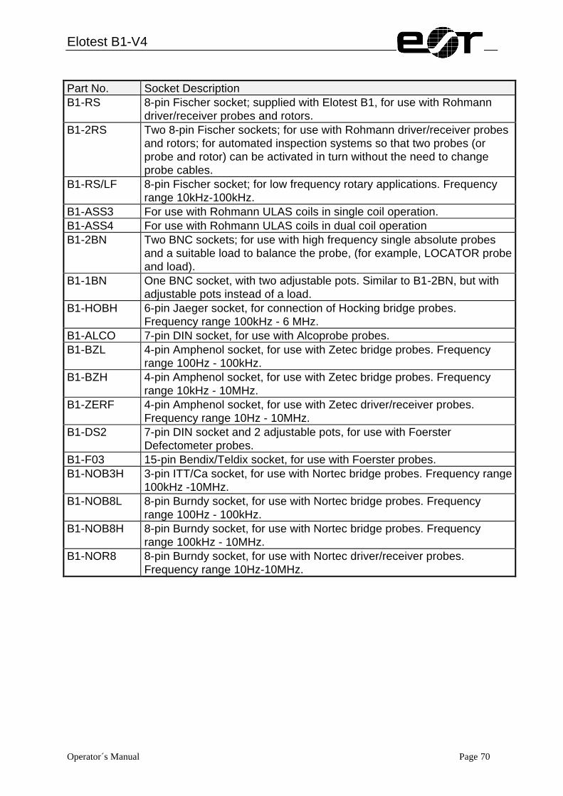
Elotest B1-V4
Operator´s Manual Page 70
Part No. Socket Description B1-RS 8-pin Fischer socket; supplied with Elotest B1, for use with Rohmann
driver/receiver probes and rotors. B1-2RS Two 8-pin Fischer sockets; for use with Rohmann driver/receiver probes
and rotors; for automated inspection systems so that two probes (or probe and rotor) can be activated in turn without the need to change probe cables.
B1-RS/LF 8-pin Fischer socket; for low frequency rotary applications. Frequency range 10kHz-100kHz.
B1-ASS3 For use with Rohmann ULAS coils in single coil operation. B1-ASS4 For use with Rohmann ULAS coils in dual coil operation B1-2BN Two BNC sockets; for use with high frequency single absolute probes
and a suitable load to balance the probe, (for example, LOCATOR probe and load).
B1-1BN One BNC socket, with two adjustable pots. Similar to B1-2BN, but with adjustable pots instead of a load.
B1-HOBH 6-pin Jaeger socket, for connection of Hocking bridge probes. Frequency range 100kHz - 6 MHz.
B1-ALCO 7-pin DIN socket, for use with Alcoprobe probes. B1-BZL 4-pin Amphenol socket, for use with Zetec bridge probes. Frequency
range 100Hz - 100kHz. B1-BZH 4-pin Amphenol socket, for use with Zetec bridge probes. Frequency
range 10kHz - 10MHz. B1-ZERF 4-pin Amphenol socket, for use with Zetec driver/receiver probes.
Frequency range 10Hz - 10MHz. B1-DS2 7-pin DIN socket and 2 adjustable pots, for use with Foerster
Defectometer probes. B1-F03 15-pin Bendix/Teldix socket, for use with Foerster probes. B1-NOB3H 3-pin ITT/Ca socket, for use with Nortec bridge probes. Frequency range
100kHz -10MHz. B1-NOB8L 8-pin Burndy socket, for use with Nortec bridge probes. Frequency
range 100Hz - 100kHz. B1-NOB8H 8-pin Burndy socket, for use with Nortec bridge probes. Frequency
range 100kHz - 10MHz. B1-NOR8 8-pin Burndy socket, for use with Nortec driver/receiver probes.
Frequency range 10Hz-10MHz.
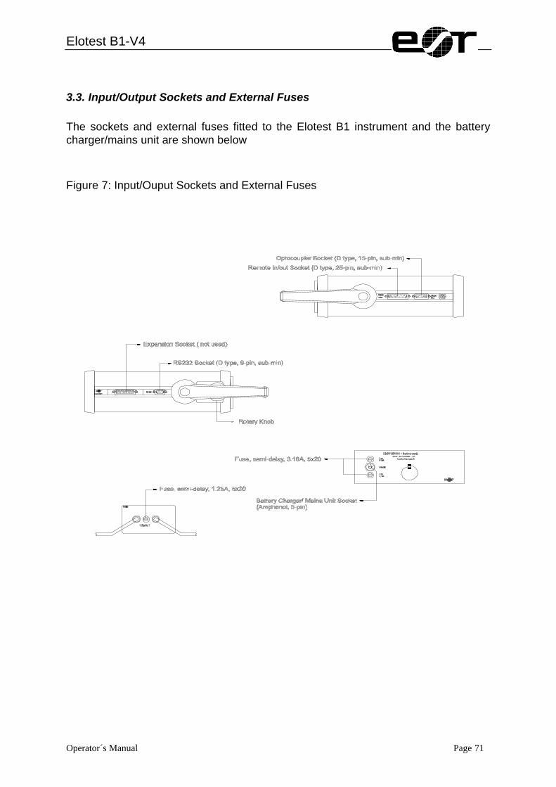
Elotest B1-V4
Operator´s Manual Page 71
3.3. Input/Output Sockets and External Fuses The sockets and external fuses fitted to the Elotest B1 instrument and the battery charger/mains unit are shown below
Figure 7: Input/Ouput Sockets and External Fuses
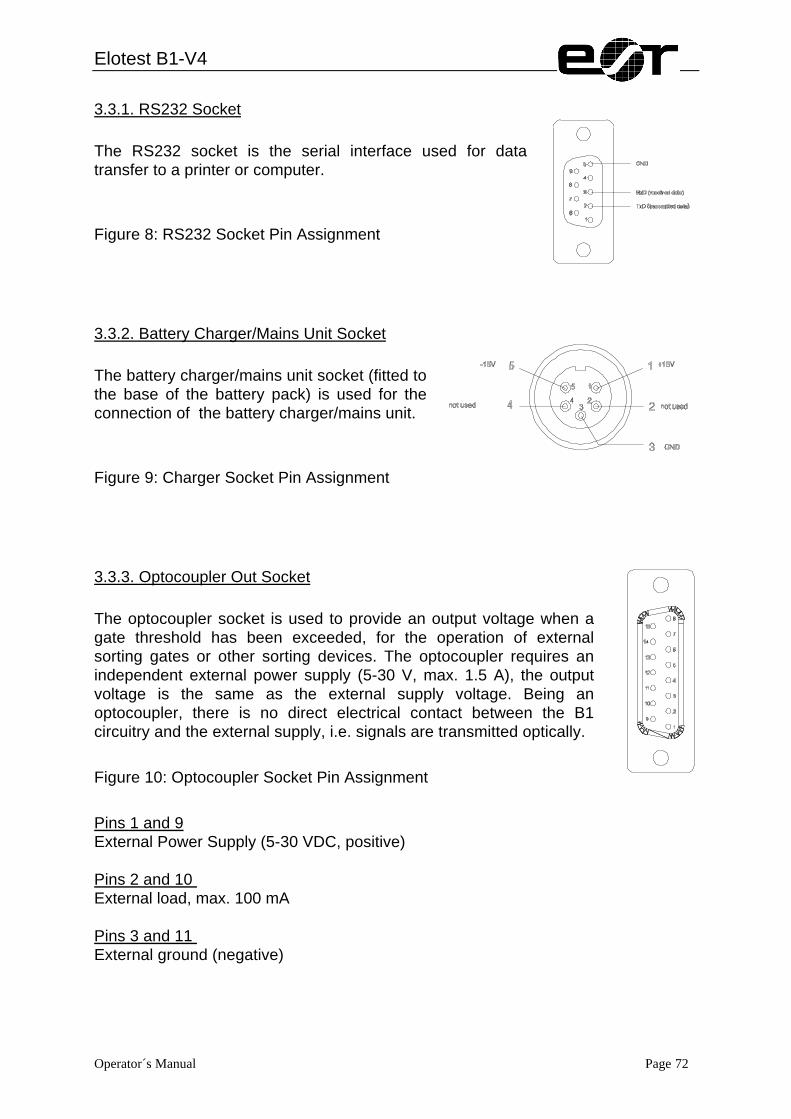
Elotest B1-V4
Operator´s Manual Page 72
3.3.1. RS232 Socket The RS232 socket is the serial interface used for data transfer to a printer or computer.
Figure 8: RS232 Socket Pin Assignment
3.3.2. Battery Charger/Mains Unit Socket The battery charger/mains unit socket (fitted to the base of the battery pack) is used for the connection of the battery charger/mains unit.
Figure 9: Charger Socket Pin Assignment
3.3.3. Optocoupler Out Socket The optocoupler socket is used to provide an output voltage when a gate threshold has been exceeded, for the operation of external sorting gates or other sorting devices. The optocoupler requires an independent external power supply (5-30 V, max. 1.5 A), the output voltage is the same as the external supply voltage. Being an optocoupler, there is no direct electrical contact between the B1 circuitry and the external supply, i.e. signals are transmitted optically.
Figure 10: Optocoupler Socket Pin Assignment
Pins 1 and 9 External Power Supply (5-30 VDC, positive) Pins 2 and 10 External load, max. 100 mA Pins 3 and 11 External ground (negative)

Elotest B1-V4
Operator´s Manual Page 73
3.3.4. In/Out Socket The In/Out socket is used for input/output functions. Please note that remote control units from earlier versions of the Elotest B1 are not compatible and should not be used with V3 versions of the B1.
Figure 11: In/out Socket Pin Assignment

Elotest B1-V4
Operator´s Manual Page 74
3.4. Use of Computers or Printers
3.4.1. Use of External Printers Many commercially available printers can be used with the Elotest B1. For ease of connection, a printer with a serial interface is preferable, as it only requires a cable connection from the printer to the B1. When using a printer fitted with a Centronics interface a Serial-Centronics adapter box is required between the printer and the B1. The printout is in the form of an Eddy Current Inspection Report on A4 size paper (see appendix). The format of the printout shown is the standard format which is loaded into the B1 during manufacture. The formats of the protocols can be fitted to the individual requirements by an optional PC-software. Cable pin connections are: ELOTEST B1 (D-Sub9) Signal Printer (D-Sub 25) Pin 2 (TxD) Serial data -> printer Pin 3 (RxD) Pin 3 (RxD) Serial data -> B1 Pin 2 (TxD) Pin 5 (GND) Signal Ground Pin 7 (GND) Bridge to CTS Request to Send Pin 4 (RTS) Bridge to RTS Clear to Send Pin 5 (CTS) Bridge to DTR Data Set Ready Pin 6 (DSR) Bridge to DSR Data Terminal Ready Pin 20 (DTR) Printer set-ups are: 8 Bits 1 Start bit 1 Stop bit No parity XON/XOFF
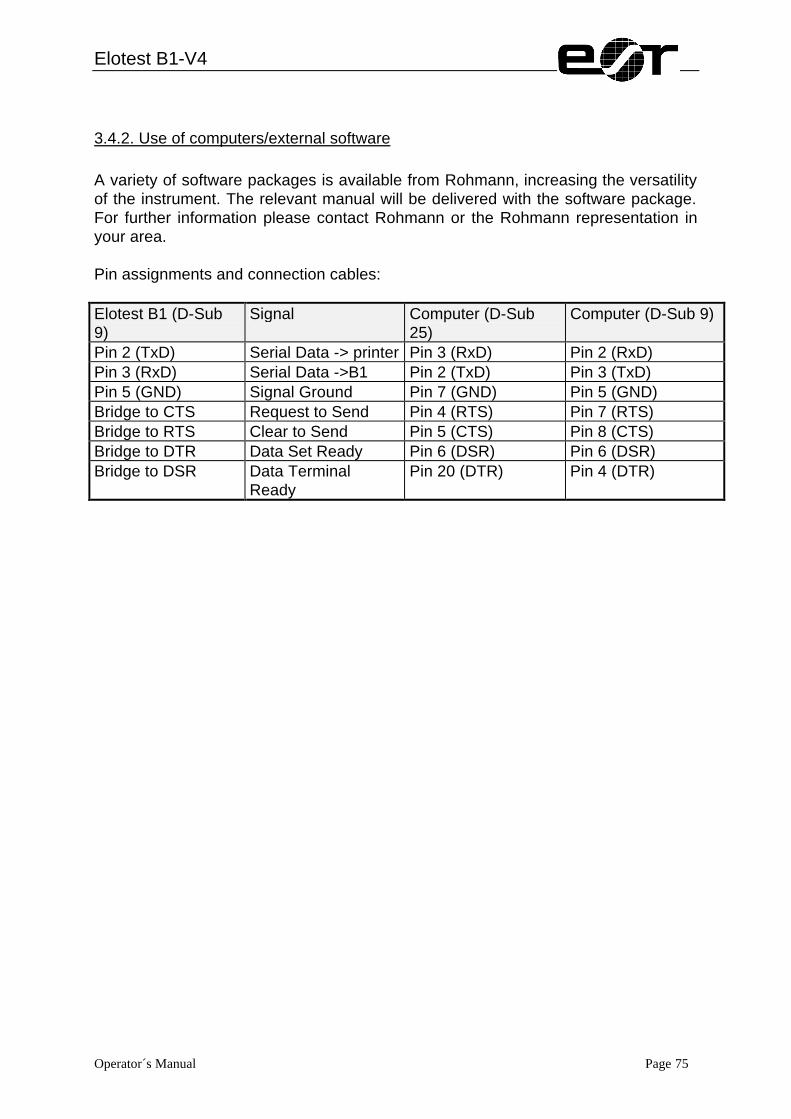
Elotest B1-V4
Operator´s Manual Page 75
3.4.2. Use of computers/external software A variety of software packages is available from Rohmann, increasing the versatility of the instrument. The relevant manual will be delivered with the software package. For further information please contact Rohmann or the Rohmann representation in your area. Pin assignments and connection cables: Elotest B1 (D-Sub 9)
Signal Computer (D-Sub 25)
Computer (D-Sub 9)
Pin 2 (TxD) Serial Data -> printer Pin 3 (RxD) Pin 2 (RxD) Pin 3 (RxD) Serial Data ->B1 Pin 2 (TxD) Pin 3 (TxD) Pin 5 (GND) Signal Ground Pin 7 (GND) Pin 5 (GND) Bridge to CTS Request to Send Pin 4 (RTS) Pin 7 (RTS) Bridge to RTS Clear to Send Pin 5 (CTS) Pin 8 (CTS) Bridge to DTR Data Set Ready Pin 6 (DSR) Pin 6 (DSR) Bridge to DSR Data Terminal
Ready Pin 20 (DTR) Pin 4 (DTR)

Elotest B1-V4
Operator´s Manual Page 76
4. Power Supplies The Elotest B1 can be powered by a rechargeable Nickel-Cadmium battery pack or by mains power using a mains unit which fits into the position usually occupied by the battery pack. The Rapid charger (Part No. BLU-1) can also be used to operate the B1 from the mains supply but the Standard charger (Part No BLE-1) can only be used for mains operation in a limited capacity (see below). Two battery chargers are available - The Standard version, Part No. BLE-1 (see below), for recharging the battery pack in approximately 14 hours, or the Rapid-charging version, Part No. BLU-1 for recharging in approximately 1 hour. The battery pack is compatible with both chargers. The chargers can be left connected to the B1 when they are disconnected from the mains supply as the battery pack will not discharge through the chargers. Battery packs can be charged while in the B1, or separately if required.
4.1. Batteries
4.1.1. Checking Battery Charge State Starting at the HOME menu push F3 to select the FUNCTIONS menu, then F3 to select the SERVICE menu, then F1 to select the INFO menu. The battery charge state is displayed graphically as a battery at the top of the LCD window. Four levels of charge state are indicated, 100 %, 75 %, 50 % and 25 %. When the battery has discharged to 25 %, the green POWER LED above the probe socket illuminates to warn that there are approximately 20 - 30 minutes of usable battery life remaining before the instrument automatically switches off when the voltage reduces to 12.6 V. This time may vary from battery to battery due to the characteristics of Nickel-Cadmium cells. To avoid wasting battery capacity, the instrument can be configured so that the instrument will automatically switch off when there has not been a signal for approximately 15 minutes.
4.1.2. Battery Replacement Battery removal is carried out by unscrewing the knurled screw beside the charger socket, withdrawing the battery pack and disconnecting the connecting plug. When re-fitting the battery pack, care should be taken to ensure that the battery pack connecting cable does not become trapped.
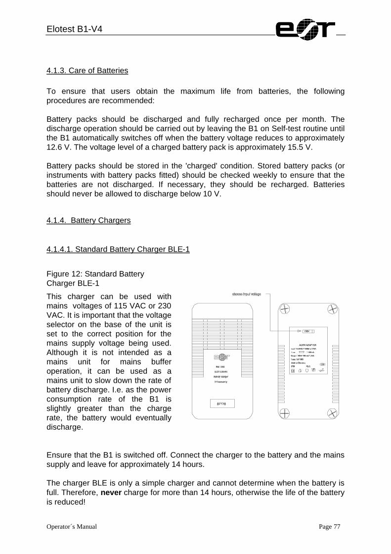
Elotest B1-V4
Operator´s Manual Page 77
4.1.3. Care of Batteries To ensure that users obtain the maximum life from batteries, the following procedures are recommended: Battery packs should be discharged and fully recharged once per month. The discharge operation should be carried out by leaving the B1 on Self-test routine until the B1 automatically switches off when the battery voltage reduces to approximately 12.6 V. The voltage level of a charged battery pack is approximately 15.5 V. Battery packs should be stored in the 'charged' condition. Stored battery packs (or instruments with battery packs fitted) should be checked weekly to ensure that the batteries are not discharged. If necessary, they should be recharged. Batteries should never be allowed to discharge below 10 V.
4.1.4. Battery Chargers
4.1.4.1. Standard Battery Charger BLE-1
Figure 12: Standard Battery Charger BLE-1
This charger can be used with mains voltages of 115 VAC or 230 VAC. It is important that the voltage selector on the base of the unit is set to the correct position for the mains supply voltage being used. Although it is not intended as a mains unit for mains buffer operation, it can be used as a mains unit to slow down the rate of battery discharge. I.e. as the power consumption rate of the B1 is slightly greater than the charge rate, the battery would eventually discharge. Ensure that the B1 is switched off. Connect the charger to the battery and the mains supply and leave for approximately 14 hours. The charger BLE is only a simple charger and cannot determine when the battery is full. Therefore, never charge for more than 14 hours, otherwise the life of the battery is reduced!

Elotest B1-V4
Operator´s Manual Page 78
4.1.4.2. Rapid Battery Charger / Mains Unit (BLU-1) This charger can be used with a wide range of supply voltage (90 - 260 VAC, 40-60 Hz) and automatically adapts to the voltage to which it is connected. It can be used to rapidly charge B1 battery packs (press CHARGE) and also to operate the B1 by mains power (press BUFFER). The charging voltage is determined by the battery charge state to prevent overheating or over-charging during the charging process. In the unlikely event of the battery pack overheating (ambient temperature > 45°C), two integral thermal cut-out switches in the battery pack will operate to interrupt the supply from the charger/mains unit. If this occurs, the B1 can still be operated directly from the battery pack. When the battery pack cools, the thermal switches are automatically reset. Ensure that the charger has convection cooling from all sides during the charging procedure. I.e. neither may objects be placed on or beside the charger nor may any sources of heat influence the instrument. Carry out a functional check of the battery charger as follows: Ensure the charger is disconnected from the B1. Connect the charger to a suitable mains supply and select the Power on rocker switch to on. Ensure that the Power on switch and both green Battery cond + and - LEDs illuminate. Push the red Charge button and ensure that both the red CHARGE On LEDs illuminate. The Battery cond + and - LEDs will glow more brightly than when Buffer (mains operation) is selected. Push the black Buffer button and ensure that both the red Charge On LEDs extinguish. Select the rocker switch to off and ensure that its lamp extinguishes, followed by both green LEDs two or three seconds later. During battery charging, it is important that the B1 is switched off and that the mains supply is not interrupted. Ensure that the B1 is switched off. Connect the charger to the battery and turn it on. Push the red Charge button and ensure that both red CHARGE ON LEDs illuminate. If only one red LED illuminates, the red CHARGE button should be pushed again for one or two seconds. One or both of the green Battery cond + and - LEDs may become dim, depending on the battery charge state and will increase in brightness as the batteries become charged. The battery pack consists of both positive and negative circuits which are charged independently, as each circuit is fully charged, the associated red Charge-On LED extinguishes. The charge cycle is complete when both red LEDs are extinguished. It is usual for one LED to extinguish several minutes before the other due to the varied

Elotest B1-V4
Operator´s Manual Page 79
discharging of the positive and negative circuits and depends on the kind of operation (e.g. rotor operation) which was carried out. It is important that rapid charge cycles are not repeated for at least 30 minutes, i.e. not until both the battery pack and charger have cooled. It is recommended to recharge shortly before beginning to work with the instrument if you intend to use it with batteries for a long period of time in order to have fully charged batteries for 4-8 hours.
Figure 13: Rapid Charger/Mains Unit BLU-1
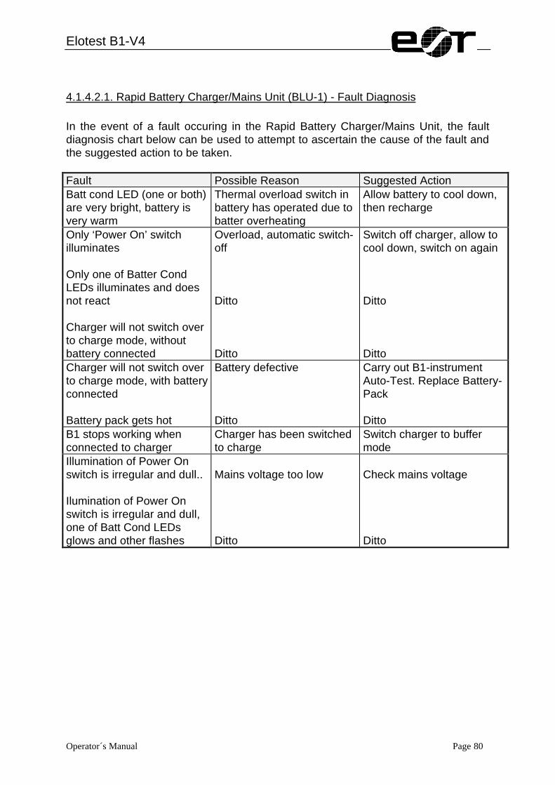
Elotest B1-V4
Operator´s Manual Page 80
4.1.4.2.1. Rapid Battery Charger/Mains Unit (BLU-1) - Fault Diagnosis In the event of a fault occuring in the Rapid Battery Charger/Mains Unit, the fault diagnosis chart below can be used to attempt to ascertain the cause of the fault and the suggested action to be taken. Fault Possible Reason Suggested Action Batt cond LED (one or both) are very bright, battery is very warm
Thermal overload switch in battery has operated due to batter overheating
Allow battery to cool down, then recharge
Only ‘Power On’ switch illuminates Only one of Batter Cond LEDs illuminates and does not react Charger will not switch over to charge mode, without battery connected
Overload, automatic switch-off Ditto Ditto
Switch off charger, allow to cool down, switch on again Ditto Ditto
Charger will not switch over to charge mode, with battery connected Battery pack gets hot
Battery defective Ditto
Carry out B1-instrument Auto-Test. Replace Battery-Pack Ditto
B1 stops working when connected to charger
Charger has been switched to charge
Switch charger to buffer mode
Illumination of Power On switch is irregular and dull.. Ilumination of Power On switch is irregular and dull, one of Batt Cond LEDs glows and other flashes
Mains voltage too low Ditto
Check mains voltage Ditto

Elotest B1-V4
Operator´s Manual Page 81
4.1.5. Fuses
4.1.5.1. Battery Pack Fuses The two semi-delay fuses at the back of the battery pack are used to protect the battery and instrument circuitry against overcharge. Spare fuses are included with the B1.
4.1.5.2. Rapid Battery Charger/Mains Unit Fuse The 1.25 A fuse fitted to the rear panel of the rapid charger/mains unit is used to protect the charger/mains unit against overcharge.
4.2. Mains Operation
4.2.1. Mains Operation (Standard Battery Charger BLE-1) IMPORTANT: The standard battery charger BLE-1 can be operated with a voltage of 115 V or 230 V. This battery charger is not intended as a mains unit for mains buffer operation and can only be used as a mains unit to slow down the rate of battery discharge. As the power consumption rate of the B1 is slightly greater than the charger charge rate, the battery will eventually discharge. Ensure that the mains voltage selector of the charger is selected to the correct position for the supply voltage being used (115 or 230 VAC). NOTE: When making very sensitive tests, the signals may be disturbed by the BLE-1 charger. In this case disconnect the B1 from the charger. Prior to using the mains unit, ensure that the available power voltage is the same than the one indicated on the charger. Ensure that the B1 is switched off when charging the battery. Then connect the charger to the instrument and to the mains power.

Elotest B1-V4
Operator´s Manual Page 82
During the end-stage of charging a high battery voltage may result. The ELOTEST B1 senses this voltage and turns itself off. If the B1 cannot be turned on, the battery voltage is either too high or too low. The charger may need to be switched off.
4.2.2. Mains Operation (Rapid Battery Charger / Mains Unit BLU-1) Ensure that the mains voltage is between 90 and 260 VAC. Ensure that the B1 is switched off. Connect the charger to the battery and turn it on. Ensure that both green Battery cond + and - LEDs are illuminated and that both red Charge-On LEDs are extinguished. Switch on the B1 and proceed testing. In Buffer mode, the charger can remain connected to the battery indefinitely. IMPORTANT: While the B1 is switched on, the CHARGE button should not be pressed.
4.2.3. MAINS Operation ('Mains Only' instruments fitted with an integral Mains Power Pack L-1 230/115 VAC) This unit can be fitted in the battery compartment of the B1 instead of a battery pack and is used to power the B1 directly from the mains supply. It is important that the jumpers inside the unit are fitted in the correct positions for the mains supply voltage being used (115 or 230 VAC). During manufacture the voltage was set to 230 V. By exchanging the jumpers it can be changed to 115 V. Ensure that the power pack is compatible with the mains voltage being used. Where doubt exists, proceed as follows: Remove the power pack from the B1 by unscrewing the knurled screw, withdrawing the power pack and disconnecting the internal plug. Ensure that the jumpers inside the power pack are fitted to the correct positions for the mains supply voltage being used. If required, move the jumpers to the correct positions (see below) and refit the power pack to the B1. Ensure that the B1 is switched off. Connect the Power Pack to the mains supply and switch it on by pressing the rocker switch on the rear panel of the instrument (rocker switch will light up green). Switch on the B1 by pressing the on/off key on the front panel.

Elotest B1-V4
Operator´s Manual Page 83
4.2.4. Mains power pack - Voltage selection
Figure 14: Mains Power Pack
The mains power pack is fitted with jumpers in the Active and Parking sockets. One jumper is marked with 115 V and the other 230 V. The jumpers fitted to the active socket determines the mains supply voltage with which the power pack can be used. The parking socket is a dummy socket and is not connected to any circuitry. It is used to store the jumper which is not used. 04/97
Parking Socket (not active)
Active Socket