Embed Size (px)
Citation preview

Operator’s Manual
Operator’s Manual
Ingersoll Rand’s Climate Solutions sector delivers energy-effi cient HVACR solutions for customers globally. Its world class brands include Thermo King, the leader in transport temperature control and Trane, a provider of energy effi cient heating, ventilating and air conditioning systems, building and contracting services, parts support and advanced controls for commercial buildings and homes.
Ingersoll Rand’s Climate Solutions sector delivers energy-effi cient HVACR solutions for customers globally. Its world class brands include Thermo King, the leader in transport temperature control and Trane, a provider of energy effi cient heating, ventilating and air conditioning systems, building and contracting services, parts support and advanced controls for commercial buildings and homes.
©2011 Ingersoll-Rand Company Printed in U.S.A.
©2011 Ingersoll-Rand Company Printed in U.S.A.
T-1080S SPECTRUMWith Premium HMI
TK 55710-1-OP (Rev. 2, 09/17)
T-1080S SPECTRUMWith Premium HMI
TK 55710-1-OP (Rev. 2, 09/17)

Copyright© 2013 Thermo King Corp., Minneapolis, MN, USAPrinted in USA
T-1080S & T-1280R SPECTRUM
with Premium HMI TK 55710-1-OP (Rev. 2, 09/17)
2
DisclaimerThis manual is published for informational purposes only. Thermo King Corporation makes norepresentations or warranties, express or implied, with respect to the information, recommendationsand descriptions contained in this manual and such information, recommendations and descriptionsshould not be regarded as all-inclusive or covering all contingencies. In the event you have anyquestions or require further information, please contact your local Thermo King dealer.
The procedures described herein should only be undertaken by suitably qualified personnel. Failure toimplement these procedures correctly may cause damage to the Thermo King unit or other property orpersonal injury.
Thermo King Corporation and its affiliates shall have no liability in contract or tort (including negligenceand/or strict liability) or otherwise, to any person or entity for any personal injury, property damage orany other direct, indirect, special or consequential damage or liability whatsoever, arising out of orresulting from any actions by any person that are contrary to this manual or any of the information,recommendations or descriptions contained herein or the failure of any person to implement theprocedures described herein correctly or to follow caution and safety decals located on the ThermoKing unit.
3
Table of ContentsIntroduction . . . . . . . . . . . . . . . . . . . . . . . . . . . . . . . . . 7
Safety Precautions . . . . . . . . . . . . . . . . . . . . . . . . . . . 8Automatic Start/Stop Operation . . . . . . . . . . . . . . . . . . 8Battery Installation and Cable Routing . . . . . . . . . . . . . 9Electrical Hazard . . . . . . . . . . . . . . . . . . . . . . . . . . . . . 10Refrigerant . . . . . . . . . . . . . . . . . . . . . . . . . . . . . . . . . 10Refrigerant Oil . . . . . . . . . . . . . . . . . . . . . . . . . . . . . . . 10First Aid . . . . . . . . . . . . . . . . . . . . . . . . . . . . . . . . . . . . 11
First Aid–Refrigerant . . . . . . . . . . . . . . . . . . . . . . . 11First Aid–Refrigerant Oil . . . . . . . . . . . . . . . . . . . . 11
Safety Decals and Locations . . . . . . . . . . . . . . . . . . . 11Model 50 Units (Electric Standby) . . . . . . . . . . . . 14
Emission Control . . . . . . . . . . . . . . . . . . . . . . . . . . . 15California Emission Control System Warranty Statement . . . . . . . . . . . . . . . . . . . . . . . . . . . . . . . . . . 18
Your Warranty Rights And Obligations . . . . . . . . . 18Manufacturer’s Warranty Coverage . . . . . . . . . . . 19Owner’s Warranty Responsibilities . . . . . . . . . . . . 19
Manufacturer Explanation Of Emission Control System Warranty Coverage . . . . . . . . . . . . . . . . . . . . . . . . . . .20EPA Emission Control System Warranty Statement . .22
Responsibilities . . . . . . . . . . . . . . . . . . . . . . . . . . .23Thermo King Corporation Responsibilities . . . . . . . . . .23Owner Responsibilities . . . . . . . . . . . . . . . . . . . . . . . .23
Limitations . . . . . . . . . . . . . . . . . . . . . . . . . . . . . . .24
Unit Description . . . . . . . . . . . . . . . . . . . . . . . . . . . . .25General Description . . . . . . . . . . . . . . . . . . . . . . . . . . .25Design Features . . . . . . . . . . . . . . . . . . . . . . . . . . . . . .26Unit Options . . . . . . . . . . . . . . . . . . . . . . . . . . . . . . . . .27Engine . . . . . . . . . . . . . . . . . . . . . . . . . . . . . . . . . . . . .27
ELC (Extended Life Coolant) . . . . . . . . . . . . . . . . .28Clutch . . . . . . . . . . . . . . . . . . . . . . . . . . . . . . . . . .28
Scroll Compressor (T-1080S) . . . . . . . . . . . . . . . . . . .28Reciprocating Compressor (T-1280R) . . . . . . . . . . . . .28Premium HMI Control Panel . . . . . . . . . . . . . . . . . . . .28CYCLE-SENTRYTM Start/Stop System . . . . . . . . . . .29Defrost . . . . . . . . . . . . . . . . . . . . . . . . . . . . . . . . . . . . .29
Table of Contents
4
DAS - Data Acquisition System (Optional) . . . . . . . . . 30CargoLink™ (Optional) . . . . . . . . . . . . . . . . . . . . . 30
Electric Standby (Model 50 Units Only) . . . . . . . . . . . . 30Standard Model 50 Features . . . . . . . . . . . . . . . . 30Optional Model 50 Features . . . . . . . . . . . . . . . . . 31
Engine Compartment Components . . . . . . . . . . . . . . . 31Unit Protection Devices . . . . . . . . . . . . . . . . . . . . . . . . 32
Unit Operation . . . . . . . . . . . . . . . . . . . . . . . . . . . . . . 35Premium HMI Control Panel Features . . . . . . . . . 35Display . . . . . . . . . . . . . . . . . . . . . . . . . . . . . . . . . 36Hard Keys . . . . . . . . . . . . . . . . . . . . . . . . . . . . . . . 37
Soft Keys . . . . . . . . . . . . . . . . . . . . . . . . . . . . . . . . . . . 38Typical soft key functions: . . . . . . . . . . . . . . . . . . . . . .39
Turning the Unit On and Off . . . . . . . . . . . . . . . . . 39The Two Zone Standard Display . . . . . . . . . . . . . . . . . 43
The Three Zone Standard Display . . . . . . . . . . . . 44The Single Zone Control Standard Display . . . . . . 45Operating The Unit in Single Zone Control Mode . 46Operating The Unit at a Single Temperature . . . . 46Changing the Setpoint . . . . . . . . . . . . . . . . . . . . . 47Turning a Zone On and Off . . . . . . . . . . . . . . . . . . 49Starting the Diesel Engine . . . . . . . . . . . . . . . . . . 51Starting the Electric Motor . . . . . . . . . . . . . . . . . . . 52
Switching from Diesel to Electric . . . . . . . . . . . . . 53Switching from Electric to Diesel . . . . . . . . . . . . . 54Initiating a Manual Defrost Cycle . . . . . . . . . . . . . 55Terminating a Defrost Cycle . . . . . . . . . . . . . . . . 56Selecting High Speed Lock-Out Mode (if enabled) 56Main Menu Overview . . . . . . . . . . . . . . . . . . . . . . 58Main Menu Choices . . . . . . . . . . . . . . . . . . . . . . . 60Using the Main Menu . . . . . . . . . . . . . . . . . . . . . . 60Languages Menu . . . . . . . . . . . . . . . . . . . . . . . . . 62
Mix and Match Language Feature. . . . . . . . . . . . . . . . 63Alarms Menu . . . . . . . . . . . . . . . . . . . . . . . . . . . . 66Alarm Code Notification . . . . . . . . . . . . . . . . . . . . 66Alarm Types . . . . . . . . . . . . . . . . . . . . . . . . . . . . . 67Log Alarms . . . . . . . . . . . . . . . . . . . . . . . . . . . . . . 67Check Alarms . . . . . . . . . . . . . . . . . . . . . . . . . . . . 68Unit Level Prevent Alarms . . . . . . . . . . . . . . . . . . 68Zone Level Prevent Alarms . . . . . . . . . . . . . . . . . 69Unit Level Shutdown Alarms . . . . . . . . . . . . . . . . 69Zone Level Shutdown Alarms . . . . . . . . . . . . . . . 70Pretrip Alarm Codes . . . . . . . . . . . . . . . . . . . . . . . 70Alarm Codes When Switching Between Diesel and Electric . . . . . . . . . . . . . . . . . . . . . . . . . . . . . 70Clearing Alarm Codes . . . . . . . . . . . . . . . . . . . . . 70Displaying and Clearing Alarm Codes . . . . . . . . . 71
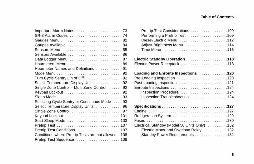
Table of Contents
5
Important Alarm Notes . . . . . . . . . . . . . . . . . . . . . 73SR-3 Alarm Codes . . . . . . . . . . . . . . . . . . . . . . . . 74Gauges Menu . . . . . . . . . . . . . . . . . . . . . . . . . . . . 82Gauges Available . . . . . . . . . . . . . . . . . . . . . . . . . 84Sensors Menu . . . . . . . . . . . . . . . . . . . . . . . . . . . 85Sensors Available . . . . . . . . . . . . . . . . . . . . . . . . . 86Data Logger Menu . . . . . . . . . . . . . . . . . . . . . . . . 87Hourmeters Menu . . . . . . . . . . . . . . . . . . . . . . . . . 89Hourmeter Names and Definitions . . . . . . . . . . . . 91Mode Menu . . . . . . . . . . . . . . . . . . . . . . . . . . . . . . 92Turn Cycle Sentry On or Off . . . . . . . . . . . . . . . . . 92Select Temperature Display Units . . . . . . . . . . . . 92Single Zone Control – Multi Zone Control . . . . . . 92Keypad Lockout . . . . . . . . . . . . . . . . . . . . . . . . . . 92Sleep Mode . . . . . . . . . . . . . . . . . . . . . . . . . . . . . 93Selecting Cycle Sentry or Continuous Mode . . . . 93Select Temperature Display Units . . . . . . . . . . . . 96Single Zone Control . . . . . . . . . . . . . . . . . . . . . . . 97Keypad Lockout . . . . . . . . . . . . . . . . . . . . . . . . . 101Start Sleep Mode . . . . . . . . . . . . . . . . . . . . . . . . 103Pretrip Test . . . . . . . . . . . . . . . . . . . . . . . . . . . . . 107Pretrip Test Conditions . . . . . . . . . . . . . . . . . . . . 107Conditions where Pretrip Tests are not allowed . 108Pretrip Test Sequence . . . . . . . . . . . . . . . . . . . . 108
Pretrip Test Considerations . . . . . . . . . . . . . . . . .109Performing a Pretrip Test . . . . . . . . . . . . . . . . . .109Diesel/Electric Menu . . . . . . . . . . . . . . . . . . . . . .112Adjust Brightness Menu . . . . . . . . . . . . . . . . . . .114Time Menu . . . . . . . . . . . . . . . . . . . . . . . . . . . . .116
Electric Standby Operation . . . . . . . . . . . . . . . . . . .118Electric Power Receptacle . . . . . . . . . . . . . . . . . . . . .118
Loading and Enroute Inspections . . . . . . . . . . . . .120Pre-Loading Inspection . . . . . . . . . . . . . . . . . . . . . . .120Post-Loading Inspection . . . . . . . . . . . . . . . . . . . . . .121Enroute Inspections . . . . . . . . . . . . . . . . . . . . . . . . . .124
Inspection Procedure . . . . . . . . . . . . . . . . . . . . .124Inspection Troubleshooting . . . . . . . . . . . . . . . . .124
Specifications . . . . . . . . . . . . . . . . . . . . . . . . . . . . . .127Engine . . . . . . . . . . . . . . . . . . . . . . . . . . . . . . . . . . . .127Refrigeration System . . . . . . . . . . . . . . . . . . . . . . . . .129Fuses . . . . . . . . . . . . . . . . . . . . . . . . . . . . . . . . . . . . .130Electrical Standby (Model 50 Units Only) . . . . . . . . .132
Electric Motor and Overload Relay . . . . . . . . . . .132Standby Power Requirements . . . . . . . . . . . . . . .132

Table of Contents
6
Maintenance Inspection Schedule . . . . . . . . . . . . . 133
Serial Number and Refrigerant Label Locations . 140
Recover Refrigerant . . . . . . . . . . . . . . . . . . . . . . . . 143
Emergency Cold Line . . . . . . . . . . . . . . . . . . . . . . . 144
CaliforniaProposition 65 Warning . . . . . . . . . . . . . . . . . . . . . 145
Warranty . . . . . . . . . . . . . . . . . . . . . . . . . . . . . . . . . . 146
7
IntroductionThere is nothing complicated about operating and maintaining your Thermo King unit, but a few minutes studying this manual will be time well spent.
Performing pre-trip checks and enroute inspections on a regular basis will minimize on-the-road operating problems. A regular maintenance program will also help to keep your unit in top operating condition. If factory recommended procedures are followed, you will find that you have purchased the most efficient and dependable temperature control system available.
All service requirements, major and minor, should be handled by a Thermo King dealer for four very important reasons:
• They are equipped with the factory recommended tools to perform all service functions
• They have factory trained and certified technicians
• They have genuine Thermo King replacement parts
• The warranty on your new unit is valid only when the repair and replacement of component parts is performed by an authorized Thermo King dealer.
IMPORTANT: This manual is published for informational purposes only and the information furnished herein should not be considered as all-inclusive or meant to cover all contingencies. If more information is required, consult your Thermo King Service Directory for the location and telephone number of the local dealer.
8
Safety PrecautionsThermo King recommends that all services be performed by a Thermo King dealer. However, there are several general safety practices which you should be aware of:
Automatic Start/Stop OperationThis unit is capable of automatic operation and may start at any time without prior warning.
WARNING: Always wear goggles or safety glasses when working with or around the refrigeration system or battery. Refrigerant or battery acid can cause permanent damage if it comes in contact with your eyes.
WARNING: Keep hands and loose clothing clear of fans and belts at all times when the unit is operating or when opening or closing compressor service valves.
WARNING: Exposed coil fins can cause painful lacerations. Service work on the evaporator or condenser coils is best left to a certified Thermo King technician.
CAUTION: Use extreme caution when drilling holes in the unit. Drilling into electrical wiring or refrigerant lines could cause a fire. Never drill into structural components.
WARNING: The unit may start at any time when the controller is turned on. The controller display lights up when the controller is turned on.
WARNING: Units equipped with electric standby may start at any time when the unit is connected to live electric power and the controller is turned on.
Safety Precautions
9
Battery Installation and Cable Routing
WARNING: Be sure to press the OFF key to turn the controller off before opening doors or inspecting any part of the unit.
WARNING: Improperly installed battery could result in a fire or explosion! A Thermo King approved battery must be installed and properly secured to the battery tray.
WARNING: Improperly installed battery cables could result in fire or explosion! Battery cables must be installed, routed and secured properly to prevent them from rubbing, chaffing or making contact with hot, sharp or rotating components.
WARNING: Do not attach fuel lines or any additional wiring harnesses to the battery cables as this could cause an electrical fire!
CAUTION: Do not connect other manufacturer’s equipment or accessories to the Thermo King unit. This could result in severe damage to equipment and void the warranty!
CAUTION: Set all unit electrical controls to the OFF position before connecting battery cables to the battery to prevent unit from starting unexpectedly and causing personal injury.
CAUTION: Always wear protective clothing, gloves and eye wear when handling and installing batteries. Battery acid can cause serious burns when exposed to eyes or skin. If battery acid contacts skin or clothing, wash immediately with soap and water. If acid enters your eye, immediately flood it with running cold water for at least twenty minutes and get medical attention immediately.
Sa
10
fety Precautions
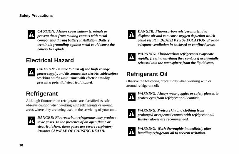
Electrical Hazard
RefrigerantAlthough fluorocarbon refrigerants are classified as safe, observe caution when working with refrigerants or around areas where they are being used in the servicing of your unit.
Refrigerant OilObserve the following precautions when working with or around refrigerant oil:
CAUTION: Always cover battery terminals to prevent them from making contact with metal components during battery installation. Battery terminals grounding against metal could cause the battery to explode.
CAUTION: Be sure to turn off the high voltage power supply, and disconnect the electric cable before working on the unit. Units with electric standby present a potential electrical hazard.
DANGER: Fluorocarbon refrigerants may produce toxic gases. In the presence of an open flame or electrical short, these gases are severe respiratory irritants CAPABLE OF CAUSING DEATH.
DANGER: Fluorocarbon refrigerants tend to displace air and can cause oxygen depletion which could result in DEATH BY SUFFOCATION. Provide adequate ventilation in enclosed or confined areas.
WARNING: Fluorocarbon refrigerants evaporate rapidly, freezing anything they contact if accidentally released into the atmosphere from the liquid state.
WARNING: Always wear goggles or safety glasses to protect eyes from refrigerant oil contact.
WARNING: Protect skin and clothing from prolonged or repeated contact with refrigerant oil. Rubber gloves are recommended.
WARNING: Wash thoroughly immediately after handling refrigerant oil to prevent irritation.
Safety Precautions
11
First AidFirst Aid–RefrigerantEyes: For contact with liquid, immediately flush eyes with large amounts of water. Get prompt medical attention.
Skin: Flush areas with large amounts of warm water. Do not apply heat. Wrap burns with dry, sterile, bulky dressing to protect from infection or injury. Get prompt medical attention.
Inhalation: Move victim to fresh air and restore breathing if necessary. Stay with victim until arrival of emergency medical personnel.
First Aid–Refrigerant OilEyes: Immediately flush eyes with large amounts of water for at least 15 minutes while holding the eyelids open. Get prompt medical attention.
Skin: Remove contaminated clothing. Wash thoroughly with soap and water. Get medical attention if irritation persists.
Inhalation: Move victim to fresh air and restore breathing if necessary. Stay with victim until arrival of emergency personnel.
Ingestion: Do not induce vomiting. Immediately contact local poison control center or physician.
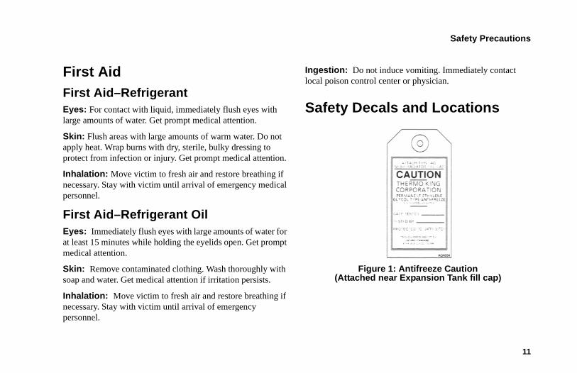
Safety Decals and Locations
Figure 1: Antifreeze Caution (Attached near Expansion Tank fill cap)
Safety Precautions
12
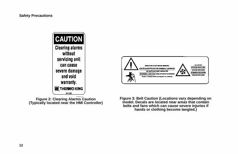
Figure 2: Clearing Alarms Caution(Typically located near the HMI Controller)
Figure 3: Belt Caution (Locations vary depending on model. Decals are located near areas that contain belts and fans which can cause severe injuries if
hands or clothing become tangled.)
Safety Precautions
13
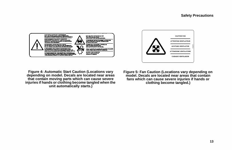
Figure 4: Automatic Start Caution (Locations vary depending on model. Decals are located near areas that contain moving parts which can cause severe
injuries if hands or clothing become tangled when the unit automatically starts.)
Figure 5: Fan Caution (Locations vary depending on model. Decals are located near areas that contain fans which can cause severe injuries if hands or
clothing become tangled.)
CAUTION FAN
ATTENZIONE VENTILATORE
ATTENTION VENTILATEUR
ACHTUNG VENTILATOR
CUIDADO VENTILADOR
91-4815
Safety Precautions
14
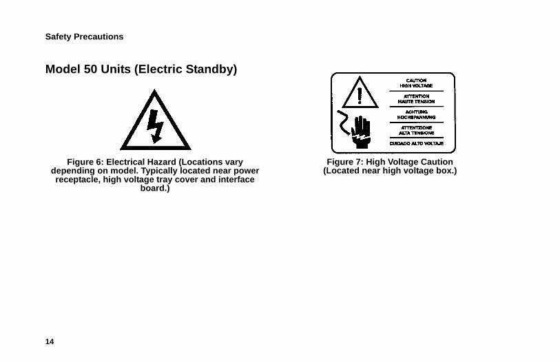
Model 50 Units (Electric Standby)
Figure 6: Electrical Hazard (Locations vary depending on model. Typically located near power receptacle, high voltage tray cover and interface
board.)
Figure 7: High Voltage Caution(Located near high voltage box.)
8
Emission ControlIn compliance with the California ULG (Utility, Lawn and Garden) Rules, the following information is provided:
1. Selection Of Fuel Oil: Use diesel fuel only.
2-1. Modification To Any Engine Component:
Modifications to any engine component which many cause engine exhaust emission output changes are not allowed.
Any engine modification not in compliance with regulation will be the responsibility of the engine manufacturer, dealer or customer who made the modification.
2-2. Air Induction System: Air induction system must remain intact and receive regular prescribed maintenance. Example: Air cleaner element replacement at required operation hour interval.
2-3. Exhaust System: Exhaust system must remain intact and cannot be modified in any manner that will further restrict exhaust flow.
2-4. Fuel Oil System: Fuel oil system must remain intact and receive regular prescribed maintenance. Example: Fuel filter replacement at required operation hour interval.
3. Engine Identification: Engines must be identified in a manner that will determine when they were built and what regulations they comply with. The engine must be labeled with an emission control label and the engine family name, both described below.
Emission Control
9
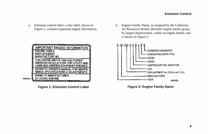
a. Emission control label: a new label, shown in Figure 1, contains important engine information.
Figure 1: Emission Control Label
b. Engine Family Name, as assigned by the California Air Resources Board, identifies engine family group, by largest displacement, within an engine family, and is shown in Figure 2.
Figure 2: Engine Family Name
AMA04AMA06
Emission Control
10
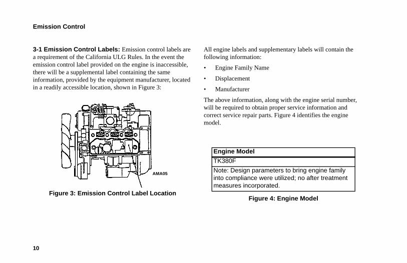
3-1 Emission Control Labels: Emission control labels are a requirement of the California ULG Rules. In the event the emission control label provided on the engine is inaccessible, there will be a supplemental label containing the same information, provided by the equipment manufacturer, located in a readily accessible location, shown in Figure 3:
Figure 3: Emission Control Label Location
All engine labels and supplementary labels will contain the following information:
• Engine Family Name
• Displacement
• Manufacturer
The above information, along with the engine serial number, will be required to obtain proper service information and correct service repair parts. Figure 4 identifies the engine model.
Figure 4: Engine Model
AMA05
Engine Model
TK380F
Note: Design parameters to bring engine family into compliance were utilized; no after treatment measures incorporated.
Emission Control
11
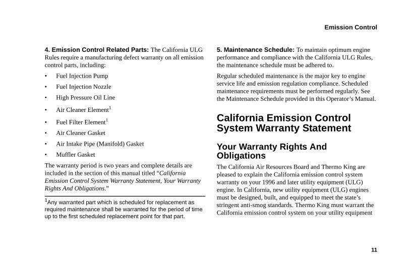
4. Emission Control Related Parts: The California ULG Rules require a manufacturing defect warranty on all emission control parts, including:
• Fuel Injection Pump
• Fuel Injection Nozzle
• High Pressure Oil Line
• Air Cleaner Element1
• Fuel Filter Element1
• Air Cleaner Gasket
• Air Intake Pipe (Manifold) Gasket
• Muffler Gasket
The warranty period is two years and complete details are included in the section of this manual titled “California Emission Control System Warranty Statement, Your Warranty Rights And Obligations.”
1Any warranted part which is scheduled for replacement as required maintenance shall be warranted for the period of time up to the first scheduled replacement point for that part.
5. Maintenance Schedule: To maintain optimum engine performance and compliance with the California ULG Rules, the maintenance schedule must be adhered to.
Regular scheduled maintenance is the major key to engine service life and emission regulation compliance. Scheduled maintenance requirements must be performed regularly. See the Maintenance Schedule provided in this Operator’s Manual.
California Emission Control System Warranty Statement
Your Warranty Rights And ObligationsThe California Air Resources Board and Thermo King are pleased to explain the California emission control system warranty on your 1996 and later utility equipment (ULG) engine. In California, new utility equipment (ULG) engines must be designed, built, and equipped to meet the state’s stringent anti-smog standards. Thermo King must warrant the California emission control system on your utility equipment
Emission Control
12
(ULG) engine for the time listed below, provided there has been no abuse, neglect or improper maintenance of your utility equipment (ULG) engine.
Your California emission control system includes parts such as the fuel injection pump, the fuel injection nozzle, and the high-pressure fuel line. Also included are the air filter element and the fuel filter element which are covered under this California emission control system warranty only up to the first scheduled maintenance replacement.
Where a warrantable condition exists, Thermo King will repair your utility equipment (ULG) engine with California emission control system parts or components at no cost to you, including diagnosis, parts and labor.
Manufacturer’s Warranty Coverage1996 and later utility equipment (ULG) engines: California emission control system parts and components are warranted for the period of two years (24 months). If any California emission control system part or component on your utility equipment (ULG) engine is defective, the part or component will be repaired or replaced by Thermo King.
Owner’s Warranty ResponsibilitiesAs the utility equipment (ULG) engine owner, you are responsible for the performance of the required maintenance listed in this Operator’s Manual. Thermo King recommends that you retain all receipts covering maintenance on your utility equipment (ULG) engine, but Thermo King cannot deny warranty solely for the lack of receipts or your failure to ensure the performance of all scheduled maintenance.
As the utility equipment (ULG) engine owner, you should be aware that Thermo King may deny you warranty coverage if your utility equipment (ULG) engine, or a part or component, has failed due to abuse, neglect, improper maintenance, or unapproved modifications.
You are responsible for presenting your utility equipment (ULG) engine to an authorized Thermo King dealer as soon as a problem exists. The emission control system parts or component repairs should be completed in a reasonable amount of time not to exceed 30 days.
If you have any questions regarding your warranty rights and responsibilities, contact a Thermo King service representative at 952-887-2337.
Emission Control
13
Manufacturer Explanation Of Emission Control System Warranty CoverageA. Warranty Commencement Date
The California emission control system warranty period begins on the date the engine or equipment is delivered to the original retail purchaser.
B. Length Of Coverage
Thermo King warrants to the original purchaser, and each subsequent purchaser, that the engine emission control system is free from defects in material and workmanship that cause the failure of the warranted California emission control system part or component for a period of two years (24 months) beginning on the day the utility equipment (ULG) engine is delivered to the original purchaser.
C. What Is Covered
1. Repair or Replacement of Parts: Repair or replacement of any California emission control system warranted part or component will be performed at no charge to the owner
at a Thermo King authorized service dealer. To obtain the phone number of your nearest Thermo King authorized service dealer, call the Cold Line at: 952-887-2202.
2. Warranty Period: Any warranted California emission control system part or component that is not scheduled for replacement as required maintenance, or that is scheduled only for regular inspection to the effect of repair or replacement as necessary, shall be warranted for the warranty period. Any warranted part that is scheduled for replacement as required maintenance shall be warranted for the period of time up to the first scheduled replacement point for that part or component.
3. Diagnosis: The owner shall not be charged for diagnostic labor which leads to the determination that a California emission control system warranted part or component is defective, if the diagnostic work is performed at a Thermo King authorized service dealer.
4. Consequential Damages: Thermo King is liable for damages to other engine parts or components caused by the failure of an emission control system part or component within the above stated California emission control system warranty period.
Emission Control
14
D. What is Not Covered
1. Failures caused by abuse, neglect, or improper maintenance.
2. Add-On or Modified Parts. The use of add-on or modified parts can be grounds for disallowing a warranty claim. Thermo King is not liable for failures of emission control system parts or components caused by the use of add-on or modified parts.
3. Use of fuel other than the California Title 13, CCR Section 2282 (g)(3), low sulfur, low aromatic, with a cetane number of 48 minimum, will nullify this warranty.
E. How to File a Claim
Warranty claims for California emission control system parts or components are to be filed by the Thermo King authorized servicing dealer on behalf of the engine owner.
F. Where to Get Warranty Service
Warranty service or repairs shall be provided at all Thermo King authorized service dealers. You can generally find dealers in the Yellow Pages of your regional telephone directory, or
call the customer service representative at 888-887-2202 for the location of the nearest Thermo King authorized service dealer.
G. Maintenance, Replacement and Repair of Emission Control System Related Parts
Any Thermo King approved replacement part can be used in the performance of any warranty maintenance or repairs on emission control system parts or components, and must be provided without charge to the owner if the part is still under the California emission control system warranty.
H. Emission Control System Warranty Parts List
• Part Name
• Fuel Injection Pump
• Fuel injection Nozzle
• High Pressure Fuel Oil Line
• Air Cleaner Element
• Fuel Filter Element
• Air Cleaner Gasket
• Air Intake Pipe (Manifold)
Emission Control
15
• Gasket Muffler Gasket
I. Maintenance Statements
The owner is responsible for the performance of the required maintenance as defined by Thermo King within this Operator’s Manual.
EPA Emission Control System Warranty StatementThermo King warrants to the initial owner and each subsequent owner that the certified non-road diesel engine in your unit is:
1. Designed, built and equipped so as to conform, at the time of sale, with all applicable regulations adopted by the United States Environmental Protection Agency (EPA).
2. Free from defects in materials and workmanship in specific, emission-related parts for a period of five years or 3,000 hours of operation, whichever comes first, after date of delivery to the initial owner.
If an emission-related part or component fails during the warranty period, it will be repaired or replaced. Any such part or component repaired or replaced under warranty is warranted for the warranty period.
During the term of this warranty, Thermo King will provide, through a Thermo King authorized service dealer or other establishment authorized by Thermo King, repair or replacement of any warranted part at no charge to the non-road engine owner.
In an emergency, repairs can be performed at any service establishment, or by the owner, using any replacement part. Thermo King will reimburse the owner for their expenses, including diagnostic charges, for such emergency repair. These expenses shall not exceed Thermo King’s suggested retail price for all warranted parts replaced, and labor changes based on Thermo King’s recommended time allowance for the warranty repair and the geographically appropriate hourly labor rate.
Any replacement part can be used for maintenance or repairs. The owner should ensure that such parts are equivalent in design and durability to genuine Thermo King parts. However, Thermo King is not liable for parts which are not genuine Thermo King parts.
Emission Control
16
A part not being available within 30 days or repair not being completed within 30 days constitutes an emergency.
As a condition of reimbursement, replaced parts and received invoices must be presented at a place of business of a Thermo King authorized service dealer or other establishment authorized by Thermo King.
This warranty covers the following emission-related parts and components:
• Fuel Injection System
• Intake Manifold
• Exhaust Manifold
• Miscellaneous hoses, clamps, connectors and sealing devices used in the above systems.
If failure of one of these parts or components results in failure of another part or component, both will be covered by this warranty.
ResponsibilitiesThis warranty is subject to the following:
Thermo King Corporation ResponsibilitiesDuring the emission warranty period, if a defect in material or workmanship of a warranted part or component is found, Thermo King will provide:
• New, remanufactured, or repaired parts or components required to correct the defect.
NOTE: Items replaced under this warranty become the property of Thermo King.
• Labor, during normal working hours, required to make the warranty repair. This includes diagnosis and labor to remove and install the engine, if necessary.
Owner ResponsibilitiesDuring the emission warranty period, the owner is responsible for:
• The performance of all required maintenance. A warranty claim will not be denied because the scheduled maintenance was not performed. However, if the lack of required maintenance was the reason for the repair, then the claim will be denied.
Emission Control
17
• Premium of overtime cost.
• Cost to investigate complaints that are not caused by defect in Thermo King material or workmanship.
• Providing timely notice of a warrantable failure and promptly making the product available for repair.
LimitationsThermo King is not responsible for resultant damages to an emission-related part or component resulting from:
• Any application or installation Thermo King deems improper as explained in this Operator’s Manual, or any other manuals provided with the unit.
• Attachments, accessory items, or parts not authorized for use by Thermo King.
• Improper off-road engine maintenance, repair, or abuse.
• Owner’s unreasonable delay in making the product available after being notified of a potential product problem.
This warranty is in addition to Thermo King’s standard warranty applicable to the off-road engine product involved.
Remedies under this warranty are limited to the provision of material and services as specified herein. Thermo King is not responsible for incidental or consequential damages such as downtime or loss of engine-powered equipment.
18
Unit Description
General DescriptionThe T-1080S and T-1280R SPECTRUM™ units are a microprocessor based transport temperature control systems that use the SR-3 Truck HMI microcontroller to manage system functions.
These self-powered multi-temperature units for straight trucks include the latest in compressor technology: T-1080S units utilize scroll compressors and T-1280R units use reciprocating compressors. The condensing unit mounts on the front of the truck cargo compartment. Remote evaporators are used to control temperatures in up to three individual cargo compartments.
These unit’s are designed for use with chlorine free R-404A refrigerant. Two basic models provide the following:
Model 30: Cooling and hot gas heating on engine operation.
Model 50: Cooling and hot gas heating on engine operation and electric standby operation. Electric evaporator heaters are optional.
Engine power for the unit is provided by a diesel engine. Optional electric standby power (Model 50) is provided by an electric motor. A clutch on the diesel engine isolates the engine during electric standby operation.
The continuous monitoring function of the microprocessor optimizes the unit’s performance, reducing fuel consumption and unit down time. The unit has a self check feature that can be run before the daily distribution route to identify possible malfunctions.
The built-in CYCLE-SENTRY, an exclusive Thermo King feature, automatically starts and stops the unit according to temperature demands.
Unit Description
19
Design Features• Microprocessor Controller, SR-3 Truck
• Alarm Code Display
• Continuous System Monitoring
• CYCLE-SENTRYTM Start/Stop Controls
• Engine and Electric (Model 50) Hour Display
• In-Cab Remote
• Smart Defrost
• Symbolic Controller Interface
• Unit Self Check-pretripping
• Aerodynamic Thermo Plastic Recyclable Injection Molded Skins with In-mold Color
• Air Cleaner, Dry Type
• Alternator, 12 Volt, 120 Amp
• Automatic Phase Correction (Model 50)
• Bypass Oil Filter
• Coolant Expansion Tank with Overflow Bottle
• Diesel/Electric Autoswitching (Model 50)
• Economy Mode
• Fahrenheit and Celsius Scales
• Fuel Filter, Spin On
• Low Decibel Kit
• Oil Filter, Full Flow
• Poly-V Belt System with Quiet Channel Technology
• R-404A Chlorine-free Refrigerant
• Robotic Welded Steel Frame with Automotive Grade 2 Coat Paint Finish
• Scroll Compressor, New Generation TK06
• Reciprocating Compressor, X-430P (T-1280R)
• ETV (Electronic Throttling Valve)
• Stainless Steel Condenser and Evaporator Hardware
• TK380F Tier 4 Diesel Engine
• Top Cover System
Unit Description
20
Unit Options• SmartPower™ Electric Standby (standard 230 v/3
phase/60 Hz) 460/3/60, 400/3/50
• Hand Held TSR-3 Diagnostic Tool
• Body Mount Enclosure for HMI
• Rear Remote Control (flush mount)
• Easy-Read Thermometer
• Remote Indicator Lights
• DAS (Data Acquisition System)
• Door Switch
• CargoLink™ Wireless Sensors
• Battery Box
• Battery (truck)
• Heat (electric)
• Engine Block Heater
• Fuel Tank (30 gal. aluminum side-fill)
• Quick Oil Drain Kit
• Whisper™ Plus Sound Kit
• Silicone Hoses
• Hose Management Channel
• Top Cover and Screen
• Evaporator Side Screens
• Snow Cover
• Special Finish Paint
EngineEngine power for both T-1080S or T-1280R SPECTRUM units is provided by the TK380F, a three cylinder, EPA Tier 4, special clean and quiet diesel engine rated at 16.2 continuous horsepower (12.1 kW) at 2200 RPM. A belt drive system transfers energy to the compressor, unit fans and alternator.
Unit Description
21
ELC (Extended Life Coolant)The maintenance interval for ELC is five years or 12,000 hours. A nameplate on the coolant expansion tank identifies units with ELC (see “Safety Decals and Locations”). The new engine coolant, Texaco Extended Life Coolant, is Red instead of the previous Green or Blue-Green coolants.
NOTE: The use of 50/50% pre-mixed ELC is recommended to ensure that deionized water is being used. If 100% full strength concentrate is used, deionized or distilled water is recommended instead of tap water to ensure the integrity of the cooling system is maintained.
ClutchThe centrifugal clutch engages fully at 600 ± 100 RPM on engine operation, constantly turning the compressor, alternator, and fans at both high and low speed. The clutch isolates the engine from the belt drive system during electric standby operation on Model 50 units.
Scroll Compressor (T-1080S)The unit features the high performance new generation TK06 scroll compressor.
Reciprocating Compressor (T-1280R)The unit features the X430P 4-cylinder reciprocating compressor with 29.8 cu in (492 cc) displacement.
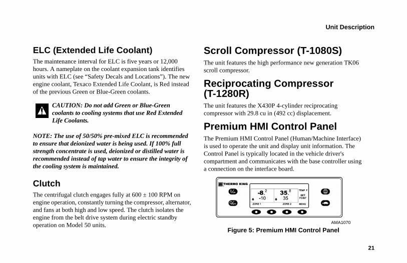
Premium HMI Control PanelThe Premium HMI Control Panel (Human/Machine Interface) is used to operate the unit and display unit information. The Control Panel is typically located in the vehicle driver's compartment and communicates with the base controller using a connection on the interface board.
Figure 5: Premium HMI Control Panel
CAUTION: Do not add Green or Blue-Green coolants to cooling systems that use Red Extended Life Coolants.
AMA1070
Unit Description
22
CYCLE-SENTRYTM Start/Stop SystemThe CYCLE-SENTRY Start/Stop fuel saving system provides optimum operating economy.
The CYCLE-SENTRY system automatically starts the unit on microprocessor demand and shuts down the unit when all demands are satisfied.
The system monitors and maintains the compartment temperature, the engine block temperature, and battery charge levels at a point where quick, easy starts are possible.
DefrostFrost will gradually build up on the evaporator coils as a result of normal operation. Periodically this frost must be melted to prevent a loss of cooling and airflow.
Defrost is accomplished by passing hot refrigerant gas through the evaporator coil, thus melting the frost (or ice). Melted frost drains out of the unit onto the ground through the drain tubes. The defrost damper closes during defrost to prevent warm air from entering the cargo area. The optional electric heater strips are also energized in defrost during electric standby operation.
Defrost can be initiated at any time the evaporator coil temperature is below 42 F (5.5 C).
There are two methods of defrost initiation:
SR-3 Microprocessor Controller: The Microprocessor Controller is programmed to automatically initiate timed and forced defrost cycles. The SR-3 uses temperature sensors to determine if forced defrost is required.
Manual Defrost: Manual Defrost allows the operator to initiate a defrost cycle by pressing the DEFROST key. See “Initiating a Manual Defrost Cycle.”
WARNING: Turn the unit off by pressing the OFF key before opening doors or inspecting any part of the unit. The unit can start at any time without warning if it has been turned on by pressing the ON key.
Unit Description
23
DAS - Data Acquisition System (Optional)The DAS (Data Acquisition System) monitors and records the temperatures of (up to) six additional sensors. The sensors are independent from the microprocessor controller and are normally located in the truck box to monitor load temperatures. DAS data can be downloaded through a serial port to an IBM® PC compatible computer. WinTrac™ 4.0 (or higher) software is used to view and analyze the data. Brief reports can be printed on a micro-printer connected to the serial port.
CargoLink™ (Optional)CargoLink™ is a wireless sensor system. The main components are the coordinator module, interconnect harness, antenna, and wireless sensors. The coordinator module receives information from the wireless sensors through the antenna, and communicates with the controller through the interconnect harness.
Electric Standby (Model 50 Units Only)The Electric Standby option allows the unit to be operated on either the diesel engine or external electric power.
Standard Model 50 FeaturesThe following features are standard equipment on units equipped with Electric Standby.
Automatic Diesel/Electric Selection: The unit will automatically switch to electric operation when a power cord is connected and the standby power is switched On.
Overload Relay: The overload relay is self-resetting.
Hot Gas Heat: Hot gas heat is utilized on all units.
DANGER: High voltage AC power is present whenever the unit is operating in the Electric mode and whenever the unit is connected to external standby power. Voltages of this magnitude can be lethal. Exercise extreme caution when working on the unit.
Unit Description
24
Automatic Phase Correction: The control system features two motor contactors. This allows correct motor rotation regardless of phase rotation on the incoming power.
Optional Model 50 FeaturesThe following features are available as options on units equipped with Electric Standby.
• Electric Heater Strips
• Auto Switching
Engine Compartment ComponentsCoolant Expansion Tank: The coolant level and temperature inside the expansion tank are monitored by the base controller. If the coolant temperature becomes too high or the level becomes too low, an alarm will occur. The expansion tank must always be completely full of coolant when cool.
Coolant Overflow Bottle: The overflow bottle captures coolant expelled from the expansion tank during normal diesel operation. Coolant returns to expansion tank when the unit is
off and coolant has cooled. Coolant level in the overflow bottle must always be at or above the FULL COLD mark of the bottle when cool.
The engine must have antifreeze protection to –30 F (–34 C). Check and add coolant in the expansion tank and overflow bottle as needed.
Engine Oil Dipstick: Use the engine oil dipstick to check the engine oil level.
Receiver Tank Sight Glass: The receiver tank sight glass is used to assist in checking the amount of refrigerant in the system.
Compressor Oil Sight Glass: The compressor oil sight glass is used to check the relative level of compressor oil in the compressor sump.
CAUTION: Do not remove expansion tank cap while the coolant is hot.
CAUTION: Do not add Green or Blue-Green coolants to cooling systems that use Red Extended Life Coolants.
Unit Description
25
Unit Protection DevicesHigh Pressure Cutout Switch (HPCO): This normally closed switch monitors the discharge pressure at the compressor. It opens on high discharge pressure to shut the unit down to prevent damage.
Electronic Throttling Valve (ETV): This component is an electromechanical control device used to limit the suction pressure to the compressor. The valve is controlled by the microprocessor controller.
Engine Oil Pressure Switch/Sensor: The engine oil pressure switch/sensor is located on the filter head above the bypass oil filter. Engine oil pressure should rise immediately on starting. If engine oil pressure drops below 10 ± 2 psig (69 ± 14 kPa), the switch/sensor signals the microprocessor to stop the engine.
Preheat Buzzer: The preheat buzzer sounds when the CYCLE-SENTRYTM system energizes the glow plugs. This should warn anyone near the unit that the CYCLE-SENTRYTM system is about to start the diesel engine.
Coolant Temperature Sensor: This sensor provides an engine coolant temperature input to the microprocessor. If the engine coolant temperature is too high, the controller stops the unit and records an alarm.
Electric Motor Overload Relay (Model 50): The overload relay protects the electric standby motor. The overload relay opens the circuit from the contactor to the electric motor if the motor overloads for any reason and an alarm will occur. The relay resets when the alarm code is cleared.
Fuses: Sizes and functions are described in the Specifications section of this manual.
Unit Description
26
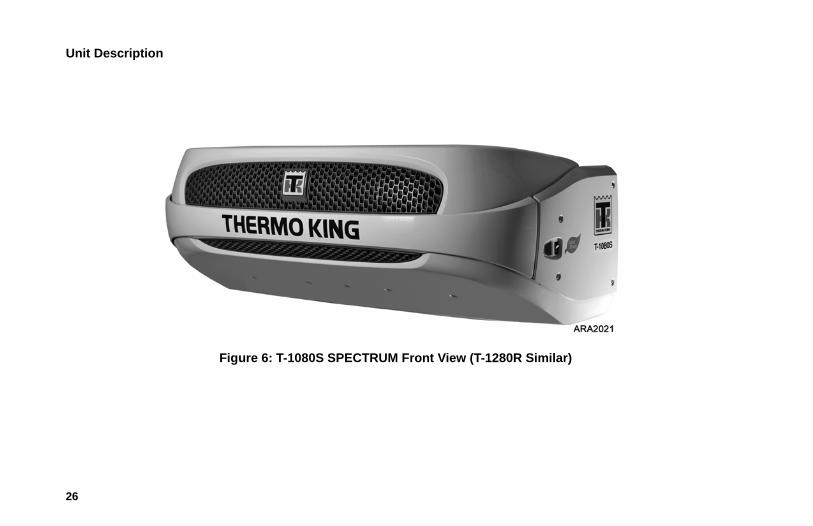
Figure 6: T-1080S SPECTRUM Front View (T-1280R Similar)
Unit Description
27
2
4
6
3
5
7
1
8
1. Engine (dipstick on side of engine) 5. Alternator
2. Coolant Overflow Bottle 6. Compressor
3. Coolant Expansion Tank 7. Dehydrator (Filter-Drier)
4. Electric Motor (Model 50 only) 8. On/Off Switch
Figure 7: Main Components
28
Unit Operation
Premium HMI Control Panel FeaturesThe Premium Truck HMI (Human/Machine Interface) Control Panel is available as an option on SR-3 Truck applications. It is used to operate the unit, display unit information and access all SR-3 Maintenance and Guarded Access Menus. The Premium HMI Control Panel communicates with the base controller via the CAN (Controller Area Network) bus. It is connected to the base controller via CAN Connector J14 on the interface board. The Premium HMI Control Panel is typically located in the vehicle driver's compartment. It may be installed in the truck instrument panel using a DIN mounting ring or under the instrument panel using an under dash mounting kit.
The Premium HMI Control Panel is also available as a Mechanics HMI Control Panel. The Mechanics HMI Control Panel is required to display all unit information and to access the Maintenance Menu and Guarded Access Menu on units equipped with the Standard HMI Control Panel. See Service Procedure H05A in Section 6 of the controller diagnostic manual for details of the Mechanics HMI Control Panel.
Figure 8: Premium HMI Control Panel
The HMI control panel consists of a display and 8 touch-sensitive keys.
The display is capable of showing both text and graphics.
The keys on the left and right sides of the display are dedicated single function "hard" keys.
The four keys under the display are "soft" keys. The functions of these soft keys change depending on the operation being performed. If a soft key is active the current key function is shown in the display directly above the key.
AMA1070
Unit Operation
29
DisplayThe display presents information to the operator. This information includes setpoint and temperature for each zone, unit or zone operating information, gauge readings, temperatures and other information as selected by the operator.
Figure 9: Premium HMI Control Panel Display
The Standard Display of box temperature and setpoint for 3 zones is shown in Figure 9. The CYCLE SENTRY Icon in the upper right of the display shows the unit is running in CYCLE SENTRY (Start-Stop) Mode. Zone 1 has a setpoint of -10°F, and a return air temperature of -8.2°F. The downward pointing arrow shows this zone is cooling. Zone 2 has a setpoint of 35°F, and a return air temperature of 35.8°F. The absence of an
arrow indicates that this zone is in null. Zone 3 has a setpoint of 50°F, and a return air temperature of 48.8°F. The upward pointing arrow shows this zone is heating.
NOTE: The zone temperature shown is always return air temperature.
The keys on either side of the display are dedicated or "hard" keys. Their function always remains the same.
The four keys under the display are termed "soft" keys. The functions of these keys change depending on the operation being performed. The function of each soft key is shown by labels in the display located directly above each soft key. The soft key under each zone is used to turn that zone on and off and allows the Setpoint for that zone to be changed. Pressing the soft key under MENU accesses the MAIN MENU.
AMA1071
Unit Operation
30
Hard Keys
Figure 10: Hard Keys
The keys on either side of the display are dedicated or "hard" keys. Their function always remains the same.
Hard Key Description
This key is used to turn the unit on. First the display will briefly show the Thermo King Logo and then the statement "Configuring System - Please Wait". When the power-up sequence is complete the display shows the Standard Display of box temperature and setpoint. For more information see "Turning the Unit On and Off" later in this section.
This key is used to turn the unit off. First the display will briefly show "System is Powering Down - Please Wait. Press On to Resume" and then "Off" will appear momentarily. When the power-down sequence is complete the display will be blank. For more information see "Turning the Unit On and Off" later in this section.

Unit Operation
31
NOTE: The Thermo King Premium Truck HMI Control Panel features a High Speed Lock-Out key as shown here. The Thermo King Trailer HMI Control Panel features a Cycle Sentry key in this position. When using the Thermo King Premium Truck HMI Control Panel, Cycle Sentry Mode or Continuous Mode is selected from the Main Menu - Mode Sub menu as shown later in this section
Soft Keys
Figure 11: Soft Keys
This key is used to initiate a manual defrost cycle. For more information see “Initiating a Manual Defrost Cycle" later in this section.
This key is used to lock out high speed operation in noise sensitive areas. For more information see "Selecting High Speed Lock-Out" later in this section.
Hard Key Description
Unit Operation
32
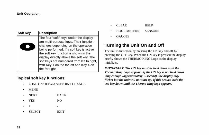
Typical soft key functions:• ZONE ON/OFF and SETPOINT CHANGE
• MENU
• NEXT BACK
• YES NO
• + -
• SELECT EXIT
• CLEAR HELP
• HOUR METERS SENSORS
• GAUGES
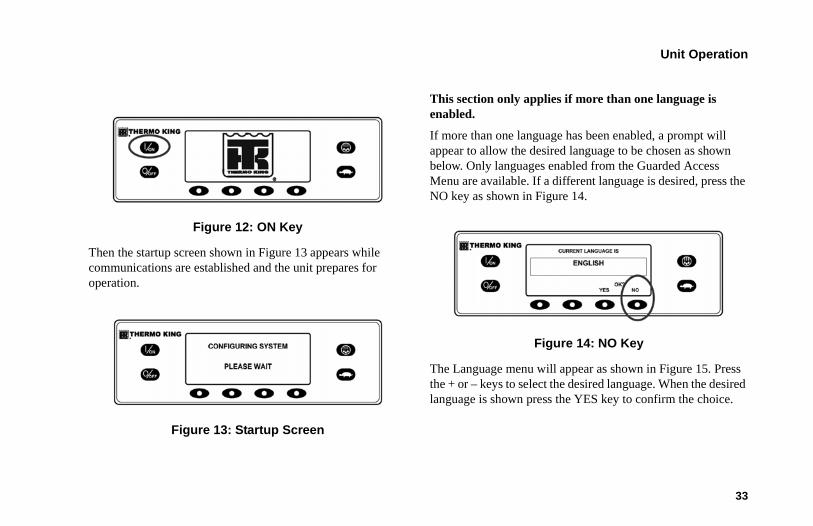
Turning the Unit On and OffThe unit is turned on by pressing the ON key and off by pressing the OFF key. When the ON key is pressed the display briefly shows the THERMO KING Logo as the display initializes.
IMPORTANT: The ON key must be held down until the Thermo King Logo appears. If the ON key is not held down long enough (approximately ½ second), the display may flicker but the unit will not start up. If this occurs, hold the ON key down until the Thermo King logo appears.
Soft Key Description
The four "soft" keys under the display are multi-purpose keys. Their function changes depending on the operation being performed. If a soft key is active the soft key function is shown in the display directly above the soft key. The soft keys are numbered from left to right, with Key 1 on the far left and Key 4 on the far right.
Unit Operation
33
Figure 12: ON Key
Then the startup screen shown in Figure 13 appears while communications are established and the unit prepares for operation.
Figure 13: Startup Screen
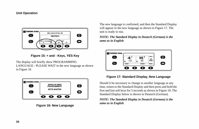
This section only applies if more than one language is enabled.
If more than one language has been enabled, a prompt will appear to allow the desired language to be chosen as shown below. Only languages enabled from the Guarded Access Menu are available. If a different language is desired, press the NO key as shown in Figure 14.
Figure 14: NO Key
The Language menu will appear as shown in Figure 15. Press the + or – keys to select the desired language. When the desired language is shown press the YES key to confirm the choice.
Unit Operation
34
Figure 15: + and - Keys, YES Key
The display will briefly show PROGRAMMING LANGUAGE - PLEASE WAIT in the new language as shown in Figure 16
Figure 16: New Language
The new language is confirmed, and then the Standard Display will appear in the new language as shown in Figure 17. The unit is ready to run.
NOTE: The Standard Display in Deutsch (German) is the same as in English
Figure 17: Standard Display, New Language
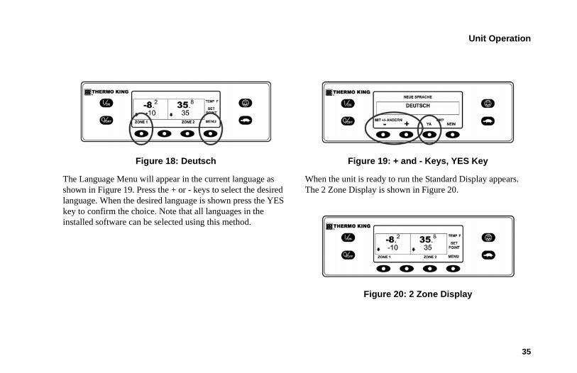
Should it be necessary to change to another language at any time, return to the Standard Display and then press and hold the first and last soft keys for 5 seconds as shown in Figure 18. The Standard Display below is shown in Deutsch (German).
NOTE: The Standard Display in Deutsch (German) is the same as in English
Unit Operation
35
Figure 18: Deutsch
The Language Menu will appear in the current language as shown in Figure 19. Press the + or - keys to select the desired language. When the desired language is shown press the YES key to confirm the choice. Note that all languages in the installed software can be selected using this method.
Figure 19: + and - Keys, YES Key
When the unit is ready to run the Standard Display appears. The 2 Zone Display is shown in Figure 20.
Figure 20: 2 Zone Display
Unit Operation
36
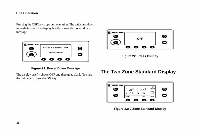
Pressing the OFF key stops unit operation. The unit shuts down immediately and the display briefly shows the power down message.
Figure 21: Power Down Message
The display briefly shows OFF and then goes blank. To start the unit again, press the ON key.
Figure 22: Press ON Key
The Two Zone Standard Display
Figure 23: 2 Zone Standard Display
Unit Operation
37
The Standard Display is the default display that appears if no other display function is selected. A 2 Zone Standard display is shown here. The 2 Zone Standard Display in Figure 23 shows the return air temperature and setpoint for two zones.
• The Cycle Sentry Icon in the upper right of the display shows that the unit is operating in Cycle Sentry mode.
• The return air temperature for Zone 1 is -8.2°F with a -10°F setpoint. The down-pointing arrow indicates that Zone 1 is cooling.
• The return air temperature for Zone 2 is 35.8°F with a 35°F setpoint. The down-pointing arrow indicates that Zone 2 is also cooling.
• The soft key under each zone is used to turn that zone on and off and allows the Setpoint for that zone to be changed.
• The soft key labeled MENU allows the Main Menu to be selected.
The Three Zone Standard Display
Figure 24: 3 Zone Standard Display
The 3 Zone Standard Display adds the third zone for units equipped with three zones. The 3 Zone Standard Display functions the same way as the 2 Zone Standard Display.
• The Cycle Sentry Icon in the upper right of the display shows that the unit is operating in Cycle Sentry mode.
• The return air temperature for Zone 1 is -8.2°F with a -10°F setpoint. The down-pointing arrow indicates that Zone 1 is cooling.
• The return air temperature for Zone 2 is 35.8°F with a 35°F setpoint. The down-pointing arrow indicates that Zone 2 is also cooling.
Unit Operation
38
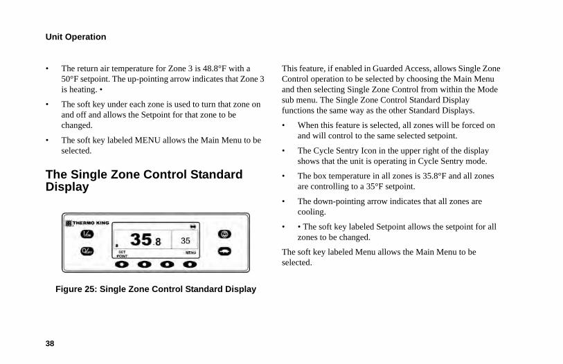
• The return air temperature for Zone 3 is 48.8°F with a 50°F setpoint. The up-pointing arrow indicates that Zone 3 is heating. •
• The soft key under each zone is used to turn that zone on and off and allows the Setpoint for that zone to be changed.
• The soft key labeled MENU allows the Main Menu to be selected.
The Single Zone Control Standard Display
Figure 25: Single Zone Control Standard Display
This feature, if enabled in Guarded Access, allows Single Zone Control operation to be selected by choosing the Main Menu and then selecting Single Zone Control from within the Mode sub menu. The Single Zone Control Standard Display functions the same way as the other Standard Displays.
• When this feature is selected, all zones will be forced on and will control to the same selected setpoint.
• The Cycle Sentry Icon in the upper right of the display shows that the unit is operating in Cycle Sentry mode.
• The box temperature in all zones is 35.8°F and all zones are controlling to a 35°F setpoint.
• The down-pointing arrow indicates that all zones are cooling.
• • The soft key labeled Setpoint allows the setpoint for all zones to be changed.
The soft key labeled Menu allows the Main Menu to be selected.
Unit Operation
39
Operating The Unit in Single Zone Control ModeThe following differences exist when operating the unit in Single Zone Control Mode.
• Single Zone Control Mode will appear in the Main Menu/Mode Menu only if the Single Zone Control feature has been enabled in the Guarded Access/Main Menu Configuration menu.
• If Single Zone Control operation is selected then all zones will be forced on and will control to the same setpoint.
• Unit control is based on the temperature sensors of one zone, usually Zone 1.
• All bulkheads should be taken down to create one large compartment.
• With the exception of defrost the operating mode of each zone evaporator(s) will be same when in this mode. Unit control is based on the temperature sensors of one zone, usually Zone 1.
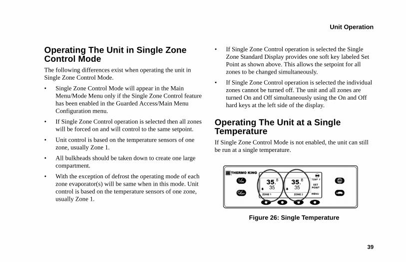
• If Single Zone Control operation is selected the Single Zone Standard Display provides one soft key labeled Set Point as shown above. This allows the setpoint for all zones to be changed simultaneously.
• If Single Zone Control operation is selected the individual zones cannot be turned off. The unit and all zones are turned On and Off simultaneously using the On and Off hard keys at the left side of the display.
Operating The Unit at a Single TemperatureIf Single Zone Control Mode is not enabled, the unit can still be run at a single temperature.
Figure 26: Single Temperature
Unit Operation
40
• All bulkheads should be taken down to create one large compartment.
• Turn all zones on.
• Set all zones to the same setpoint.
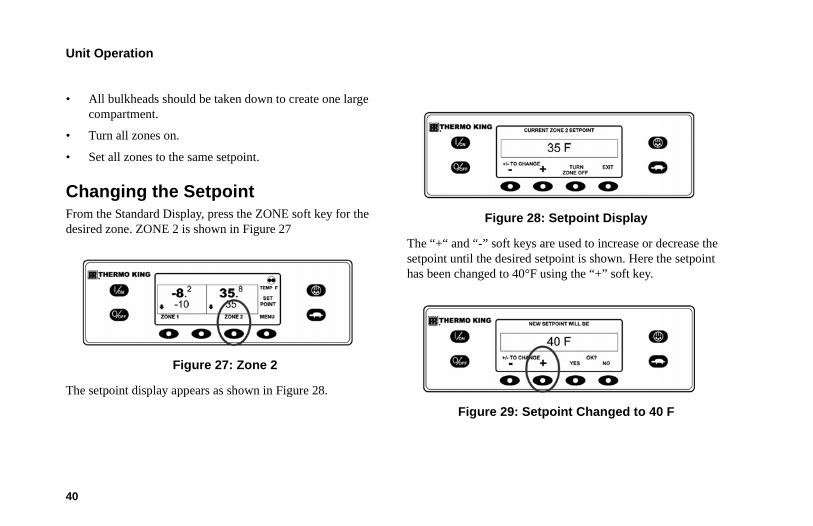
Changing the SetpointFrom the Standard Display, press the ZONE soft key for the desired zone. ZONE 2 is shown in Figure 27
Figure 27: Zone 2
The setpoint display appears as shown in Figure 28.
Figure 28: Setpoint Display
The “+“ and “-” soft keys are used to increase or decrease the setpoint until the desired setpoint is shown. Here the setpoint has been changed to 40°F using the “+” soft key.
Figure 29: Setpoint Changed to 40 F
Unit Operation
41
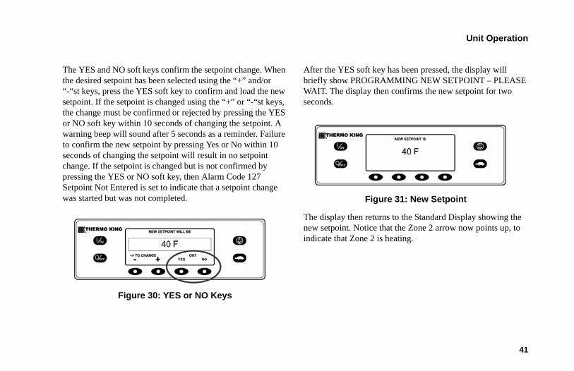
The YES and NO soft keys confirm the setpoint change. When the desired setpoint has been selected using the “+” and/or “-“st keys, press the YES soft key to confirm and load the new setpoint. If the setpoint is changed using the “+” or “-“st keys, the change must be confirmed or rejected by pressing the YES or NO soft key within 10 seconds of changing the setpoint. A warning beep will sound after 5 seconds as a reminder. Failure to confirm the new setpoint by pressing Yes or No within 10 seconds of changing the setpoint will result in no setpoint change. If the setpoint is changed but is not confirmed by pressing the YES or NO soft key, then Alarm Code 127 Setpoint Not Entered is set to indicate that a setpoint change was started but was not completed.
Figure 30: YES or NO Keys
After the YES soft key has been pressed, the display will briefly show PROGRAMMING NEW SETPOINT – PLEASE WAIT. The display then confirms the new setpoint for two seconds.
Figure 31: New Setpoint
The display then returns to the Standard Display showing the new setpoint. Notice that the Zone 2 arrow now points up, to indicate that Zone 2 is heating.
Unit Operation
42
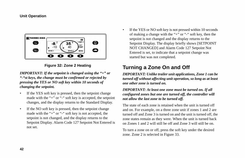
Figure 32: Zone 2 Heating
IMPORTANT: If the setpoint is changed using the “+” or “-“st keys, the change must be confirmed or rejected by pressing the YES or NO soft key within 10 seconds of changing the setpoint.
• If the YES soft key is pressed, then the setpoint change made with the “+” or “-“ soft key is accepted, the setpoint changes, and the display returns to the Standard Display.
• If the NO soft key is pressed, then the setpoint change made with the “+” or “-“ soft key is not accepted, the setpoint is not changed, and the display returns to the Setpoint Display. Alarm Code 127 Setpoint Not Entered is not set.
• If the YES or NO soft key is not pressed within 10 seconds of making a change with the “+” or “-“ soft key, then the setpoint is not changed and the display returns to the Setpoint Display. The display briefly shows [SETPOINT NOT CHANGED] and Alarm Code 127 Setpoint Not Entered is set, to indicate that a setpoint change was started but was not completed.
Turning a Zone On and OffIMPORTANT: Unlike trailer unit applications, Zone 1 can be turned off without affecting unit operation, so long as at least one other zone is turned on.
IMPORTANT: At least one zone must be turned on. If all configured zones but one are turned off, the controller will not allow the last zone to be turned off.
The state of each zone is retained when the unit is turned off and on. For example, on a three zone unit if zones 1 and 2 are turned off and Zone 3 is turned on and the unit is turned off, the zone states remain as they were. When the unit is turned back on Zones 1 and 2 will still be off and Zone 3 will still be on.
To turn a zone on or off, press the soft key under the desired zone. Zone 2 is selected in Figure 33.
Unit Operation
43
Figure 33: Zone 2
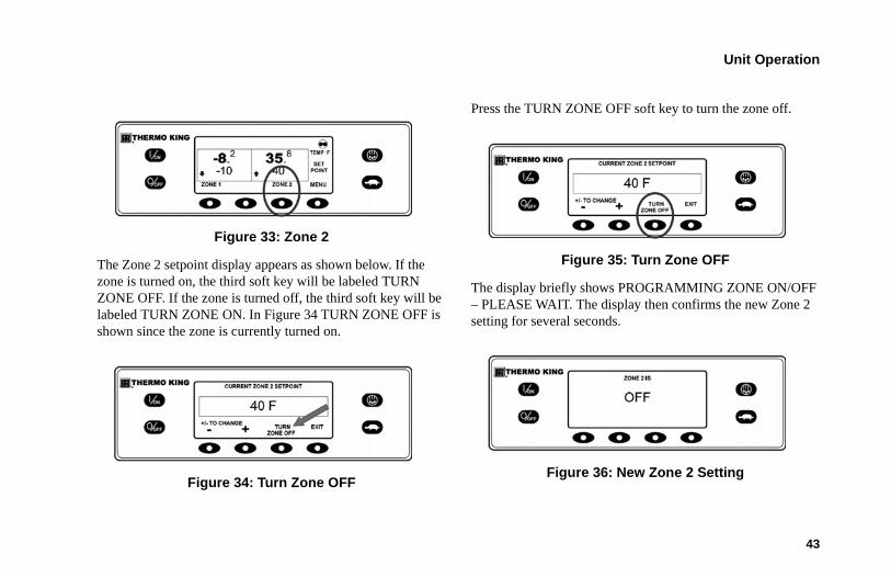
The Zone 2 setpoint display appears as shown below. If the zone is turned on, the third soft key will be labeled TURN ZONE OFF. If the zone is turned off, the third soft key will be labeled TURN ZONE ON. In Figure 34 TURN ZONE OFF is shown since the zone is currently turned on.
Figure 34: Turn Zone OFF
Press the TURN ZONE OFF soft key to turn the zone off.
Figure 35: Turn Zone OFF
The display briefly shows PROGRAMMING ZONE ON/OFF – PLEASE WAIT. The display then confirms the new Zone 2 setting for several seconds.
Figure 36: New Zone 2 Setting
Unit Operation
44
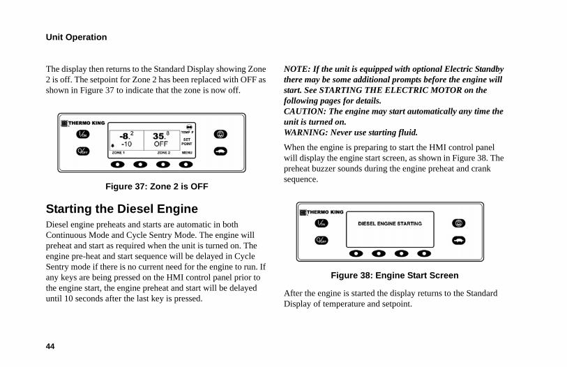
The display then returns to the Standard Display showing Zone 2 is off. The setpoint for Zone 2 has been replaced with OFF as shown in Figure 37 to indicate that the zone is now off.
Figure 37: Zone 2 is OFF
Starting the Diesel EngineDiesel engine preheats and starts are automatic in both Continuous Mode and Cycle Sentry Mode. The engine will preheat and start as required when the unit is turned on. The engine pre-heat and start sequence will be delayed in Cycle Sentry mode if there is no current need for the engine to run. If any keys are being pressed on the HMI control panel prior to the engine start, the engine preheat and start will be delayed until 10 seconds after the last key is pressed.
NOTE: If the unit is equipped with optional Electric Standby there may be some additional prompts before the engine will start. See STARTING THE ELECTRIC MOTOR on the following pages for details.CAUTION: The engine may start automatically any time the unit is turned on.WARNING: Never use starting fluid.
When the engine is preparing to start the HMI control panel will display the engine start screen, as shown in Figure 38. The preheat buzzer sounds during the engine preheat and crank sequence.
Figure 38: Engine Start Screen
After the engine is started the display returns to the Standard Display of temperature and setpoint.
Unit Operation
45
Figure 39: Standard Display
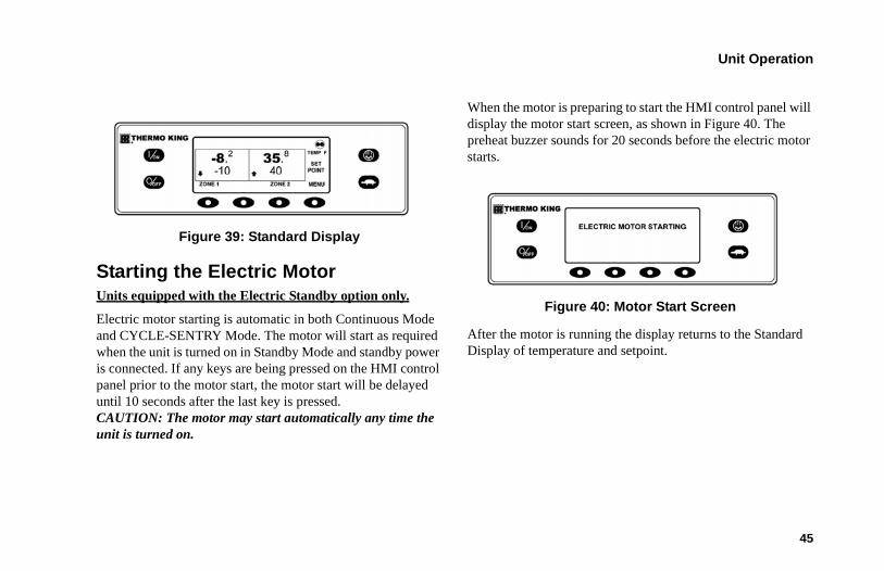
Starting the Electric MotorUnits equipped with the Electric Standby option only.
Electric motor starting is automatic in both Continuous Mode and CYCLE-SENTRY Mode. The motor will start as required when the unit is turned on in Standby Mode and standby power is connected. If any keys are being pressed on the HMI control panel prior to the motor start, the motor start will be delayed until 10 seconds after the last key is pressed. CAUTION: The motor may start automatically any time the unit is turned on.
When the motor is preparing to start the HMI control panel will display the motor start screen, as shown in Figure 40. The preheat buzzer sounds for 20 seconds before the electric motor starts.
Figure 40: Motor Start Screen
After the motor is running the display returns to the Standard Display of temperature and setpoint.
Unit Operation
46
Figure 41: Standard Display
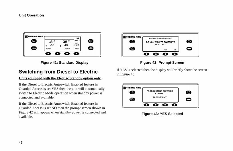
Switching from Diesel to ElectricUnits equipped with the Electric Standby option only.
If the Diesel to Electric Autoswitch Enabled feature in Guarded Access is set YES then the unit will automatically switch to Electric Mode operation when standby power is connected and available.
If the Diesel to Electric Autoswitch Enabled feature in Guarded Access is set NO then the prompt screen shown in Figure 42 will appear when standby power is connected and available.
Figure 42: Prompt Screen
If YES is selected then the display will briefly show the screen in Figure 43.
Figure 43: YES Selected
Unit Operation
47
Electric Mode operation will briefly be confirmed. If unit operation is required the electric motor will start as shown previously in Starting The Electric Motor.
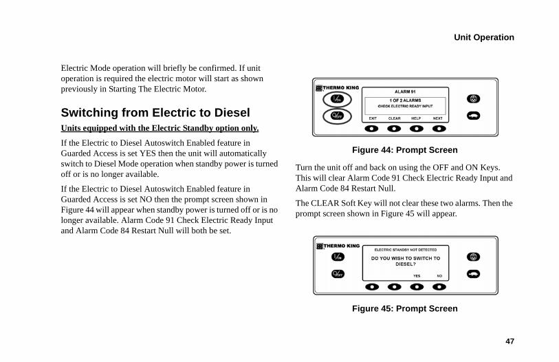
Switching from Electric to DieselUnits equipped with the Electric Standby option only.
If the Electric to Diesel Autoswitch Enabled feature in Guarded Access is set YES then the unit will automatically switch to Diesel Mode operation when standby power is turned off or is no longer available.
If the Electric to Diesel Autoswitch Enabled feature in Guarded Access is set NO then the prompt screen shown in Figure 44 will appear when standby power is turned off or is no longer available. Alarm Code 91 Check Electric Ready Input and Alarm Code 84 Restart Null will both be set.
Figure 44: Prompt Screen
Turn the unit off and back on using the OFF and ON Keys. This will clear Alarm Code 91 Check Electric Ready Input and Alarm Code 84 Restart Null.
The CLEAR Soft Key will not clear these two alarms. Then the prompt screen shown in Figure 45 will appear.
Figure 45: Prompt Screen
Unit Operation
48
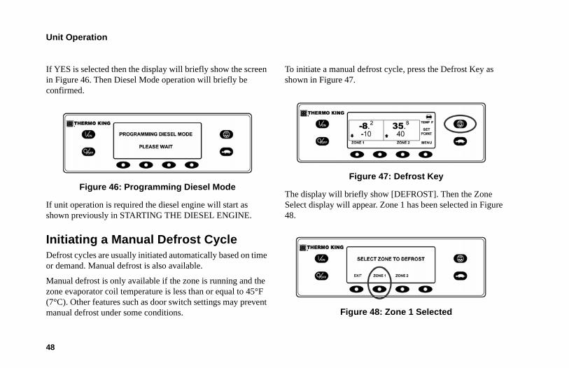
If YES is selected then the display will briefly show the screen in Figure 46. Then Diesel Mode operation will briefly be confirmed.
Figure 46: Programming Diesel Mode
If unit operation is required the diesel engine will start as shown previously in STARTING THE DIESEL ENGINE.
Initiating a Manual Defrost CycleDefrost cycles are usually initiated automatically based on time or demand. Manual defrost is also available.
Manual defrost is only available if the zone is running and the zone evaporator coil temperature is less than or equal to 45°F (7°C). Other features such as door switch settings may prevent manual defrost under some conditions.
To initiate a manual defrost cycle, press the Defrost Key as shown in Figure 47.
Figure 47: Defrost Key
The display will briefly show [DEFROST]. Then the Zone Select display will appear. Zone 1 has been selected in Figure 48.
Figure 48: Zone 1 Selected
Unit Operation
49
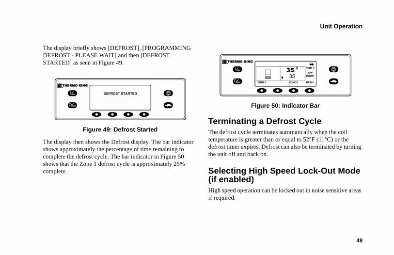
The display briefly shows [DEFROST], [PROGRAMMING DEFROST - PLEASE WAIT] and then [DEFROST STARTED] as seen in Figure 49.
Figure 49: Defrost Started
The display then shows the Defrost display. The bar indicator shows approximately the percentage of time remaining to complete the defrost cycle. The bar indicator in Figure 50 shows that the Zone 1 defrost cycle is approximately 25% complete.
Figure 50: Indicator Bar
Terminating a Defrost CycleThe defrost cycle terminates automatically when the coil temperature is greater than or equal to 52°F (11°C) or the defrost timer expires. Defrost can also be terminated by turning the unit off and back on.
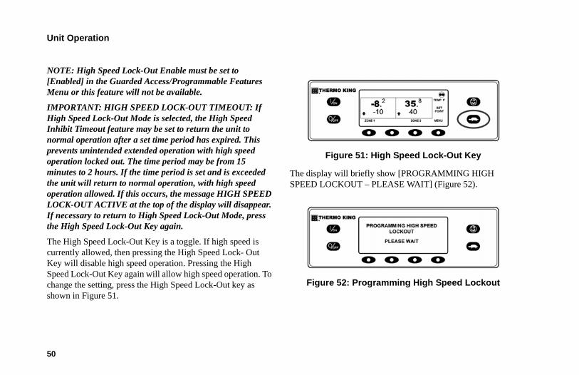
Selecting High Speed Lock-Out Mode (if enabled)High speed operation can be locked out in noise sensitive areas if required.
Unit Operation
50
NOTE: High Speed Lock-Out Enable must be set to [Enabled] in the Guarded Access/Programmable Features Menu or this feature will not be available.
IMPORTANT: HIGH SPEED LOCK-OUT TIMEOUT: If High Speed Lock-Out Mode is selected, the High Speed Inhibit Timeout feature may be set to return the unit to normal operation after a set time period has expired. This prevents unintended extended operation with high speed operation locked out. The time period may be from 15 minutes to 2 hours. If the time period is set and is exceeded the unit will return to normal operation, with high speed operation allowed. If this occurs, the message HIGH SPEED LOCK-OUT ACTIVE at the top of the display will disappear. If necessary to return to High Speed Lock-Out Mode, press the High Speed Lock-Out Key again.
The High Speed Lock-Out Key is a toggle. If high speed is currently allowed, then pressing the High Speed Lock- Out Key will disable high speed operation. Pressing the High Speed Lock-Out Key again will allow high speed operation. To change the setting, press the High Speed Lock-Out key as shown in Figure 51.
Figure 51: High Speed Lock-Out Key
The display will briefly show [PROGRAMMING HIGH SPEED LOCKOUT – PLEASE WAIT] (Figure 52).
Figure 52: Programming High Speed Lockout
Unit Operation
51
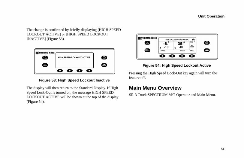
The change is confirmed by briefly displaying [HIGH SPEED LOCKOUT ACTIVE] or [HIGH SPEED LOCKOUT INACTIVE] (Figure 53).
Figure 53: High Speed Lockout Inactive
The display will then return to the Standard Display. If High Speed Lock-Out is turned on, the message HIGH SPEED LOCKOUT ACTIVE will be shown at the top of the display (Figure 54).
Figure 54: High Speed Lockout Active
Pressing the High Speed Lock-Out key again will turn the feature off.
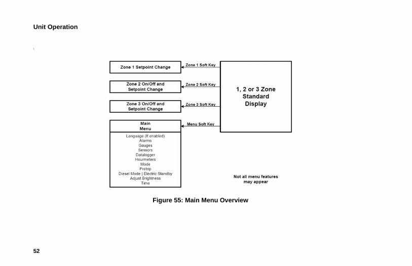
Main Menu OverviewSR-3 Truck SPECTRUM M/T Operator and Main Menu.
Unit Operation
52
\
Figure 55: Main Menu Overview
Unit Operation
53
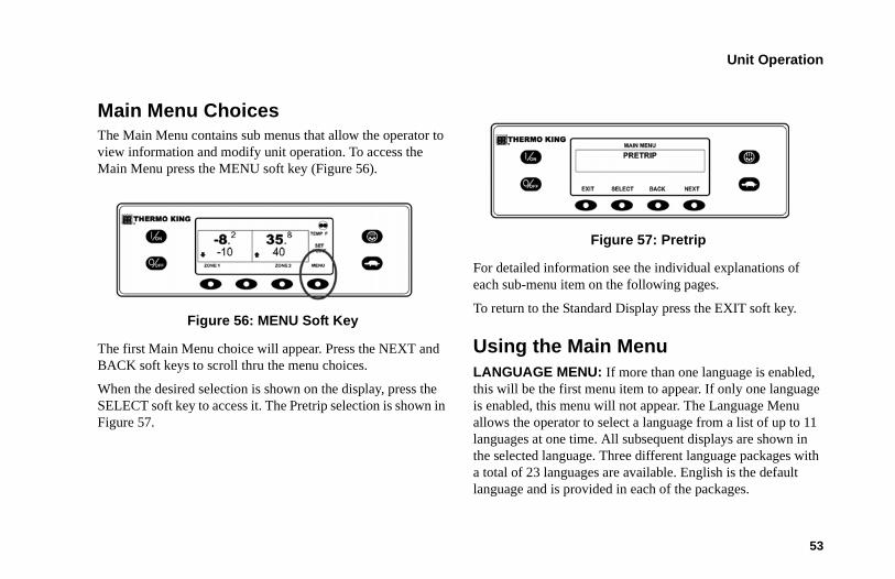
Main Menu ChoicesThe Main Menu contains sub menus that allow the operator to view information and modify unit operation. To access the Main Menu press the MENU soft key (Figure 56).
Figure 56: MENU Soft Key
The first Main Menu choice will appear. Press the NEXT and BACK soft keys to scroll thru the menu choices.
When the desired selection is shown on the display, press the SELECT soft key to access it. The Pretrip selection is shown in Figure 57.
Figure 57: Pretrip
For detailed information see the individual explanations of each sub-menu item on the following pages.
To return to the Standard Display press the EXIT soft key.
Using the Main MenuLANGUAGE MENU: If more than one language is enabled, this will be the first menu item to appear. If only one language is enabled, this menu will not appear. The Language Menu allows the operator to select a language from a list of up to 11 languages at one time. All subsequent displays are shown in the selected language. Three different language packages with a total of 23 languages are available. English is the default language and is provided in each of the packages.
Unit Operation
54
ALARMS MENU: Allows the operator to view all alarms, and allows most alarms to be cleared. If only one language is enabled this will be the first menu item to appear.
GAUGES MENU: Allows the operator to view the unit gauges and the state of the Inputs and Outputs on both the Interface Board and the Expansion Module.
SENSORS MENU: Allows the operator to view the unit temperature sensors. If a DAS Data Logger is installed the data logger sensors may also be viewed.
DATA LOGGER MENU: Allows the operator to send a Start of Trip marker to the ServiceWatch Data Logger and the optional DAS Data Logger (if installed). A Print request can also be sent to the optional DAS Data Logger (if installed) to print the most recent trip record.
HOURMETERS MENU: Allows the operator to view the unit hourmeters that have the view feature enabled in the Guarded Access menu. If the view feature for a particular hourmeter is not enabled then that hourmeter will continue to accumulate time but cannot be viewed from the Main Menu. However, all hourmeters can be viewed from the Maintenance Menu, even if they are not enabled.
MODE MENU: Allows the operator to change the unit operating modes if allowed. Not all modes may appear depending on the settings made from the Guarded Access menu and the HMI Control Panel software version
• Turn off Cycle Sentry Mode/turn on Cycle Sentry Mode (If Cycle Sentry Mode is off the unit runs in Continuous Mode).
• Allows Temperature Units to be selected as Fahrenheit or Celsius.
• Allows Single Zone Control or Multi Zone Control to be selected.
• Allows Keypad Lock-Out to be selected.
• Allows Sleep Mode to be entered.
PRETRIP MENU: Allows the operator to start a Pretrip Test. If an alarm is active, the Pretrip Test is not allowed and the operator is prompted to clear the alarm(s).
ELECTRIC STANDBY MENU: If the Electric Standby option is present and the Diesel to Electric Auto-switch feature is set NO, this feature allows the operator to manually select
Unit Operation
55
electric mode operation. This feature does not appear if the unit does not feature optional Electric Standby or if the Diesel to Electric Auto-switch feature is set YES.
DIESEL MODE MENU: If a unit equipped with electric standby is running in electric mode and the Electric to Diesel Auto-switch feature is set NO, this feature allows the operator to manually select diesel mode operation. This feature does not appear if the unit does not feature optional Electric Standby or if the Electric to Diesel Autoswitch feature is set YES.
ADJUST BRIGHTNESS MENU: Allows the operator to adjust the HMI control panel display backlight intensity as required by local conditions.
TIME MENU: Allows the operator to view the unit time and date. The time and date cannot be changed from this menu.
Languages Menu If the Language feature is enabled, an alternate language can be selected from the Language Menu. After a new language is chosen, all subsequent displays will appear in that language. If the language feature is not enabled this menu does not appear. The default language is English. Only languages that have
been enabled in Guarded Access will appear. Exercise care when changing languages, as once changed all HMI Control panel displays will be in the new language. If the user is not familiar with the new language, problems may be experienced returning to the default language.
The languages available are dependent on the HMI Control Panel Software Revision. Other than the supported languages, Software Revisions 65xx, 66xx, 67xx and 68xx are functionally identical.
• Languages currently supported by Software Revision 6530 and later are English, Spanish, French, German, Italian, Dutch, Portuguese, Greek, Turkish, Hebrew and Arabic.
• Languages currently supported by Software Revision 6630 and later are English, Danish, Russian, Norwegian, Swedish, Finnish, Polish, Hungarian, Romanian, Bulgarian and Czech.
• Languages currently supported by Software Revision 6730 and later are English, Japanese and Chinese.
Unit Operation
56
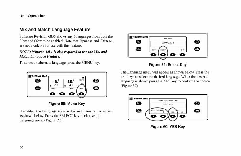
Mix and Match Language Feature Software Revision 6830 allows any 5 languages from both the 65xx and 66xx to be enabled. Note that Japanese and Chinese are not available for use with this feature.
NOTE: Wintrac 4.8.1 is also required to use the Mix and Match Language Feature.
To select an alternate language, press the MENU key.
Figure 58: Menu Key
If enabled, the Language Menu is the first menu item to appear as shown below. Press the SELECT key to choose the Language menu (Figure 59).
Figure 59: Select Key
The Language menu will appear as shown below. Press the + or – keys to select the desired language. When the desired language is shown press the YES key to confirm the choice (Figure 60).
Figure 60: YES Key
Unit Operation
57
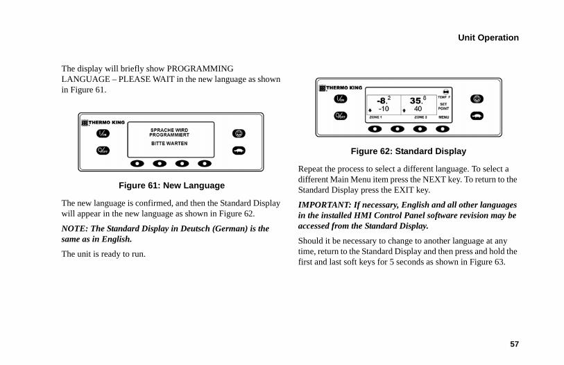
The display will briefly show PROGRAMMING LANGUAGE – PLEASE WAIT in the new language as shown in Figure 61.
Figure 61: New Language
The new language is confirmed, and then the Standard Display will appear in the new language as shown in Figure 62.
NOTE: The Standard Display in Deutsch (German) is the same as in English.
The unit is ready to run.
Figure 62: Standard Display
Repeat the process to select a different language. To select a different Main Menu item press the NEXT key. To return to the Standard Display press the EXIT key.
IMPORTANT: If necessary, English and all other languages in the installed HMI Control Panel software revision may be accessed from the Standard Display.
Should it be necessary to change to another language at any time, return to the Standard Display and then press and hold the first and last soft keys for 5 seconds as shown in Figure 63.
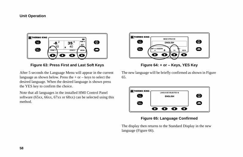
Unit Operation
58
Figure 63: Press First and Last Soft Keys
After 5 seconds the Language Menu will appear in the current language as shown below. Press the + or – keys to select the desired language. When the desired language is shown press the YES key to confirm the choice.
Note that all languages in the installed HMI Control Panel software (65xx, 66xx, 67xx or 68xx) can be selected using this method.
Figure 64: + or – Keys, YES Key
The new language will be briefly confirmed as shown in Figure 65.
Figure 65: Language Confirmed
The display then returns to the Standard Display in the new language (Figure 66).
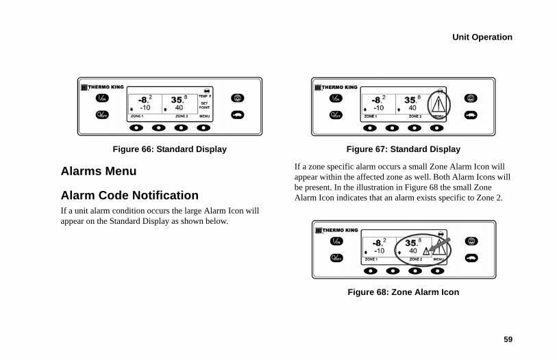
Unit Operation
59
Figure 66: Standard Display
Alarms Menu
Alarm Code NotificationIf a unit alarm condition occurs the large Alarm Icon will appear on the Standard Display as shown below.
Figure 67: Standard Display
If a zone specific alarm occurs a small Zone Alarm Icon will appear within the affected zone as well. Both Alarm Icons will be present. In the illustration in Figure 68 the small Zone Alarm Icon indicates that an alarm exists specific to Zone 2.
Figure 68: Zone Alarm Icon
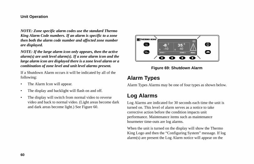
Unit Operation
60
NOTE: Zone specific alarm codes use the standard Thermo King Alarm Code numbers. If an alarm is specific to a zone then both the alarm code number and affected zone number are displayed.
NOTE: If the large alarm icon only appears, then the active alarm(s) are unit level alarm(s). If a zone alarm icon and the large alarm icon are displayed there is a zone level alarm or a combination of zone level and unit level alarms present.
If a Shutdown Alarm occurs it will be indicated by all of the following:
• The Alarm Icon will appear.
• The display and backlight will flash on and off.
• The display will switch from normal video to reverse video and back to normal video. (Light areas become dark and dark areas become light.) See Figure 60.
Figure 69: Shutdown Alarm
Alarm TypesAlarm Types Alarms may be one of four types as shown below.
Log AlarmsLog Alarms are indicated for 30 seconds each time the unit is turned on. This level of alarm serves as a notice to take corrective action before the condition impacts unit performance. Maintenance items such as maintenance hourmeter time-outs are log alarms.
When the unit is turned on the display will show the Thermo King Logo and then the “Configuring System” message. If log alarm(s) are present the Log Alarm notice will appear on the
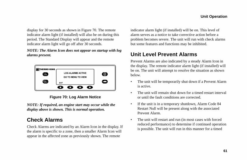
Unit Operation
61
display for 30 seconds as shown in Figure 70. The remote indicator alarm light (if installed) will also be on during this period. The Standard Display will appear and the remote indicator alarm light will go off after 30 seconds.
NOTE: The Alarm Icon does not appear on startup with log alarms present.
Figure 70: Log Alarm Notice
NOTE: If required, an engine start may occur while the display above is shown. This is normal operation.
Check AlarmsCheck Alarms are indicated by an Alarm Icon in the display. If the alarm is specific to a zone, then a smaller Alarm Icon will appear in the affected zone as previously shown. The remote
indicator alarm light (if installed) will be on. This level of alarm serves as a notice to take corrective action before a problem becomes severe. The unit will run with check alarms but some features and functions may be inhibited.
Unit Level Prevent Alarms Prevent Alarms are also indicated by a steady Alarm Icon in the display. The remote indicator alarm light (if installed) will be on. The unit will attempt to resolve the situation as shown below.
• The unit will be temporarily shut down if a Prevent Alarm is active.
• The unit will remain shut down for a timed restart interval or until the fault conditions are corrected.
• If the unit is in a temporary shutdown, Alarm Code 84 Restart Null will be present along with the associated Prevent Alarm.
• The unit will restart and run (in most cases with forced reduced performance) to determine if continued operation is possible. The unit will run in this manner for a timed
Unit Operation
62
interval. If the unit is running with forced reduced performance, Alarm Code 85 Forced Unit Operation will also be present under some conditions.
• If the alarm does not reoccur during the timed running interval with reduced performance, the unit will return to full performance to determine if continued operation is possible. The unit will run in this manner for a timed interval. If the unit is successfully able to return to full performance for the timed interval without the alarm re-occurring, the alarm is auto cleared and the unit will run normally.
• All Prevent Alarm events and conditions are logged by the ServiceWatch Data Logger.
• In general, if the alarm condition re-occurs a defined number of times, the alarm is set as a shutdown alarm and no further restarts are possible.
NOTE: If the Restart After Shutdown feature in the Guarded Access Menu is set for CONTINUOUS, then an unlimited number of restart attempts are allowed.
Zone Level Prevent Alarms A Zone Level Prevent Alarm will force the affected zone into a temporary shutdown, but allow the unit to continue to run as required by the host unit or other zones.
• A small Alarm Icon will appear next to the affected zone.
• If a Zone Prevent Alarm occurs in all zones then the unit will be forced into a unit level Prevent shut down.
Unit Level Shutdown Alarms A Unit Level Shutdown Alarm will be set if continued operation could cause damage to the unit or the load. Shutdown Alarms are indicated by the following:
• The Alarm Icon will appear in the display.
• The display and backlight will flash on and off.
• The display will switch from normal video to reverse video and back to normal video. (Light areas become dark and dark areas become light.)
• The remote indicator alarm light (if installed) will be on.
Unit Operation
63
Unit Level Shutdown Alarms will force the unit into shutdown to prevent potential damage to the unit or load. The unit will remain in shutdown until the Shutdown Alarm is manually cleared. Exceptions are some engine and electric Shutdown Alarms that become log alarms when switched to the alternate operating mode (diesel to electric or electric to diesel).
Zone Level Shutdown Alarms A Zone Level Shutdown Alarm will force the affected zone to shutdown, but allow the unit to continue to run as required by the host unit or other zones.
• A small Alarm Icon will appear next to the affected zone and blink with a period of 1/2 second on - 1/2 second off.
• If a Zone Shutdown Alarm occurs in all zones then the unit will shut down and Alarm Code 114 Multiple Alarms – Can Not Run will be set.
Pretrip Alarm CodesIf an alarm occurs during a Pretrip Test the alarm code will be displayed as Pretrip Alarm XX, where XX is the alarm code.
Alarm Codes When Switching Between Diesel and Electric If a shutdown alarm occurs that affects only diesel mode operation and the unit is switched to electric, the diesel mode shutdown alarm becomes an electric mode log alarm. This allows the unit to run in electric mode without clearing the shutdown alarm that is preventing diesel mode operation. If the unit is switched back to diesel mode, the alarm again become a diesel mode shutdown alarm and prevents unit operation.
In the same manner, if a shutdown alarm occurs that affects only electric mode operation and the unit is switched to diesel, the electric mode shutdown alarm becomes a diesel mode log alarm to allow diesel mode operation. If the unit is switched back to electric mode, the alarm reverts to an electric mode shutdown alarm and prevents unit operation. If the unit is configured for electric to diesel auto switch, it automatically starts and runs in diesel mode if an electric shutdown occurs.
Clearing Alarm Codes Most alarm codes can be cleared conventionally from the Alarm Menu using the CLEAR key.
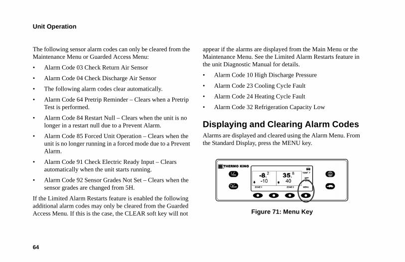
Unit Operation
64
The following sensor alarm codes can only be cleared from the Maintenance Menu or Guarded Access Menu:
• Alarm Code 03 Check Return Air Sensor
• Alarm Code 04 Check Discharge Air Sensor
• The following alarm codes clear automatically.
• Alarm Code 64 Pretrip Reminder – Clears when a Pretrip Test is performed.
• Alarm Code 84 Restart Null – Clears when the unit is no longer in a restart null due to a Prevent Alarm.
• Alarm Code 85 Forced Unit Operation – Clears when the unit is no longer running in a forced mode due to a Prevent Alarm.
• Alarm Code 91 Check Electric Ready Input – Clears automatically when the unit starts running.
• Alarm Code 92 Sensor Grades Not Set – Clears when the sensor grades are changed from 5H.
If the Limited Alarm Restarts feature is enabled the following additional alarm codes may only be cleared from the Guarded Access Menu. If this is the case, the CLEAR soft key will not
appear if the alarms are displayed from the Main Menu or the Maintenance Menu. See the Limited Alarm Restarts feature in the unit Diagnostic Manual for details.
• Alarm Code 10 High Discharge Pressure
• Alarm Code 23 Cooling Cycle Fault
• Alarm Code 24 Heating Cycle Fault
• Alarm Code 32 Refrigeration Capacity Low
Displaying and Clearing Alarm Codes Alarms are displayed and cleared using the Alarm Menu. From the Standard Display, press the MENU key.
Figure 71: Menu Key
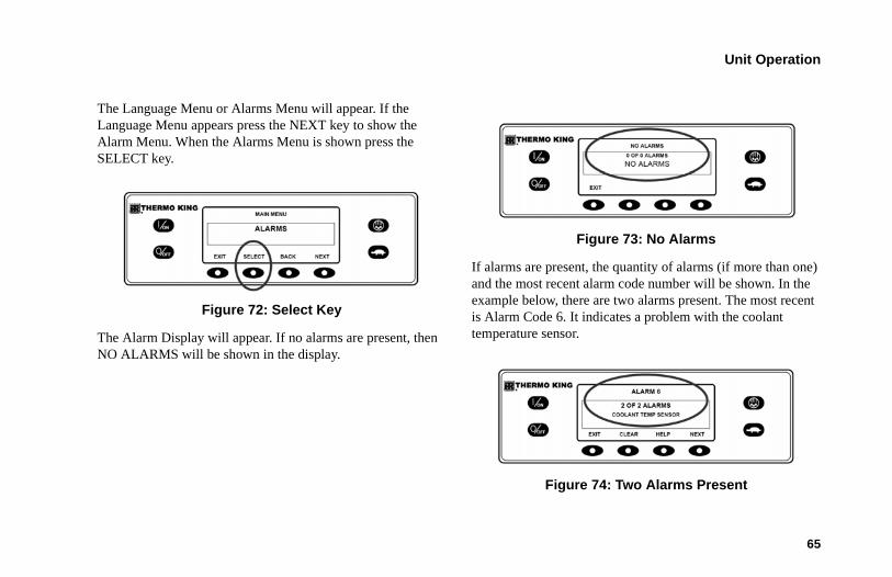
Unit Operation
65
The Language Menu or Alarms Menu will appear. If the Language Menu appears press the NEXT key to show the Alarm Menu. When the Alarms Menu is shown press the SELECT key.
Figure 72: Select Key
The Alarm Display will appear. If no alarms are present, then NO ALARMS will be shown in the display.
Figure 73: No Alarms
If alarms are present, the quantity of alarms (if more than one) and the most recent alarm code number will be shown. In the example below, there are two alarms present. The most recent is Alarm Code 6. It indicates a problem with the coolant temperature sensor.
Figure 74: Two Alarms Present
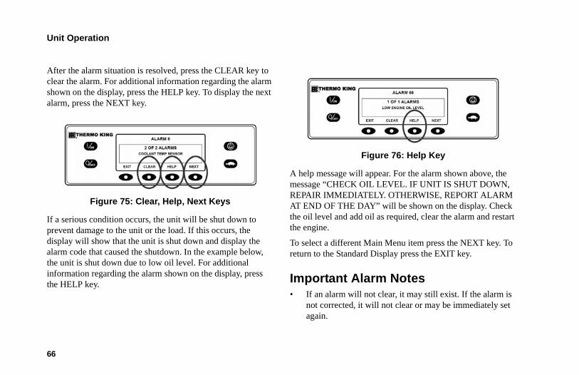
Unit Operation
66
After the alarm situation is resolved, press the CLEAR key to clear the alarm. For additional information regarding the alarm shown on the display, press the HELP key. To display the next alarm, press the NEXT key.
Figure 75: Clear, Help, Next Keys
If a serious condition occurs, the unit will be shut down to prevent damage to the unit or the load. If this occurs, the display will show that the unit is shut down and display the alarm code that caused the shutdown. In the example below, the unit is shut down due to low oil level. For additional information regarding the alarm shown on the display, press the HELP key.
Figure 76: Help Key
A help message will appear. For the alarm shown above, the message “CHECK OIL LEVEL. IF UNIT IS SHUT DOWN, REPAIR IMMEDIATELY. OTHERWISE, REPORT ALARM AT END OF THE DAY” will be shown on the display. Check the oil level and add oil as required, clear the alarm and restart the engine.
To select a different Main Menu item press the NEXT key. To return to the Standard Display press the EXIT key.
Important Alarm Notes• If an alarm will not clear, it may still exist. If the alarm is
not corrected, it will not clear or may be immediately set again.
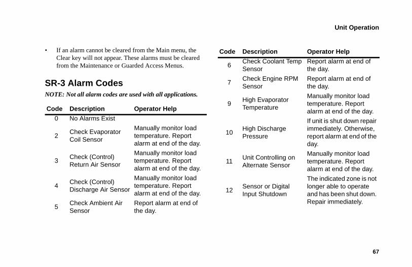
Unit Operation
67
• If an alarm cannot be cleared from the Main menu, the Clear key will not appear. These alarms must be cleared from the Maintenance or Guarded Access Menus.
SR-3 Alarm CodesNOTE: Not all alarm codes are used with all applications.
Code Description Operator Help
0 No Alarms Exist
2Check Evaporator Coil Sensor
Manually monitor load temperature. Report alarm at end of the day.
3Check (Control) Return Air Sensor
Manually monitor load temperature. Report alarm at end of the day.
4Check (Control) Discharge Air Sensor
Manually monitor load temperature. Report alarm at end of the day.
5Check Ambient Air Sensor
Report alarm at end of the day.
6Check Coolant Temp Sensor
Report alarm at end of the day.
7Check Engine RPM Sensor
Report alarm at end of the day.
9High Evaporator Temperature
Manually monitor load temperature. Report alarm at end of the day.
10High Discharge Pressure
If unit is shut down repair immediately. Otherwise, report alarm at end of the day.
11Unit Controlling on Alternate Sensor
Manually monitor load temperature. Report alarm at end of the day.
12Sensor or Digital Input Shutdown
The indicated zone is not longer able to operate and has been shut down. Repair immediately.
Code Description Operator Help
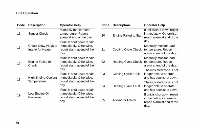
Unit Operation
68
13 Sensor CheckManually monitor load temperature. Report alarm at end of the day.
15Check Glow Plugs or Intake Air Heater
If unit is shut down repair immediately. Otherwise, report alarm at end of the day.
17Engine Failed to Crank
If unit is shut down repair immediately. Otherwise, report alarm at end of the day.
18High Engine Coolant Temperature
If unit is shut down repair immediately. Otherwise, report alarm at end of the day.
19Low Engine Oil Pressure
If unit is shut down repair immediately. Otherwise, report alarm at end of the day.
Code Description Operator Help
20 Engine Failed to Start
If unit is shut down repair immediately. Otherwise, report alarm at end of the day.
21 Cooling Cycle CheckManually monitor load temperature. Report alarm at end of the day.
22 Heating Cycle CheckManually monitor load temperature. Report alarm at end of the day.
23 Cooling Cycle FaultThe indicated zone is not longer able to operate and has been shut down.
24 Heating Cycle FaultThe indicated zone is not longer able to operate and has been shut down.
25 Alternator Check
If unit is shut down repair immediately. Otherwise, report alarm at end of the day.
Code Description Operator Help
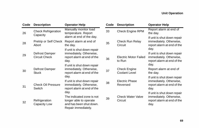
Unit Operation
69
26Check Refrigeration Capacity
Manually monitor load temperature. Report alarm at end of the day.
28Pretrip or Self Check Abort
Report alarm at end of the day.
29Defrost Damper Circuit Check
If unit is shut down repair immediately. Otherwise, report alarm at end of the day.
30Defrost Damper Stuck
If unit is shut down repair immediately. Otherwise, report alarm at end of the day.
31Check Oil Pressure Switch
If unit is shut down repair immediately. Otherwise, report alarm at end of the day.
32Refrigeration Capacity Low
The indicated zone is not longer able to operate and has been shut down. Repair immediately.
Code Description Operator Help
33 Check Engine RPMReport alarm at end of the day.
35Check Run Relay Circuit
If unit is shut down repair immediately. Otherwise, report alarm at end of the day.
36Electric Motor Failed to Run
If unit is shut down repair immediately. Otherwise, report alarm at end of the day.
37Check Engine Coolant Level
Report alarm at end of the day.
38Electric Phase Reversed
If unit is shut down repair immediately. Otherwise, report alarm at end of the day.
39Check Water Valve Circuit
If unit is shut down repair immediately. Otherwise, report alarm at end of the day.
Code Description Operator Help
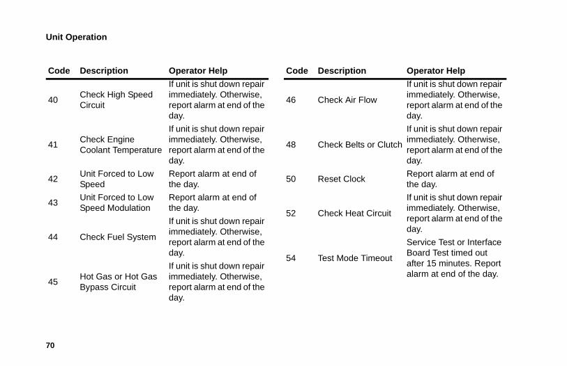
Unit Operation
70
40Check High Speed Circuit
If unit is shut down repair immediately. Otherwise, report alarm at end of the day.
41Check Engine Coolant Temperature
If unit is shut down repair immediately. Otherwise, report alarm at end of the day.
42Unit Forced to Low Speed
Report alarm at end of the day.
43Unit Forced to Low Speed Modulation
Report alarm at end of the day.
44 Check Fuel System
If unit is shut down repair immediately. Otherwise, report alarm at end of the day.
45Hot Gas or Hot Gas Bypass Circuit
If unit is shut down repair immediately. Otherwise, report alarm at end of the day.
Code Description Operator Help
46 Check Air Flow
If unit is shut down repair immediately. Otherwise, report alarm at end of the day.
48 Check Belts or Clutch
If unit is shut down repair immediately. Otherwise, report alarm at end of the day.
50 Reset ClockReport alarm at end of the day.
52 Check Heat Circuit
If unit is shut down repair immediately. Otherwise, report alarm at end of the day.
54 Test Mode Timeout
Service Test or Interface Board Test timed out after 15 minutes. Report alarm at end of the day.
Code Description Operator Help
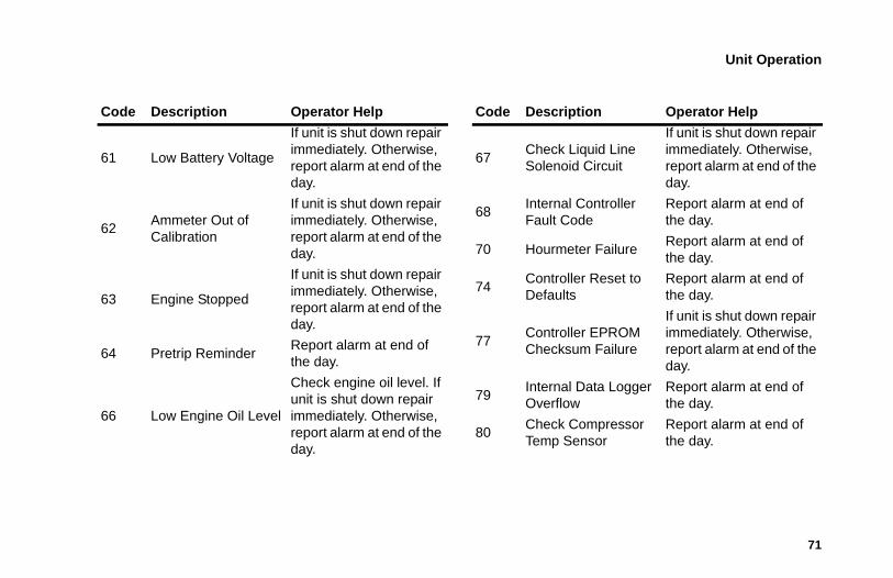
Unit Operation
71
61 Low Battery Voltage
If unit is shut down repair immediately. Otherwise, report alarm at end of the day.
62Ammeter Out of Calibration
If unit is shut down repair immediately. Otherwise, report alarm at end of the day.
63 Engine Stopped
If unit is shut down repair immediately. Otherwise, report alarm at end of the day.
64 Pretrip ReminderReport alarm at end of the day.
66 Low Engine Oil Level
Check engine oil level. If unit is shut down repair immediately. Otherwise, report alarm at end of the day.
Code Description Operator Help
67Check Liquid Line Solenoid Circuit
If unit is shut down repair immediately. Otherwise, report alarm at end of the day.
68Internal Controller Fault Code
Report alarm at end of the day.
70 Hourmeter FailureReport alarm at end of the day.
74Controller Reset to Defaults
Report alarm at end of the day.
77Controller EPROM Checksum Failure
If unit is shut down repair immediately. Otherwise, report alarm at end of the day.
79Internal Data Logger Overflow
Report alarm at end of the day.
80Check Compressor Temp Sensor
Report alarm at end of the day.
Code Description Operator Help
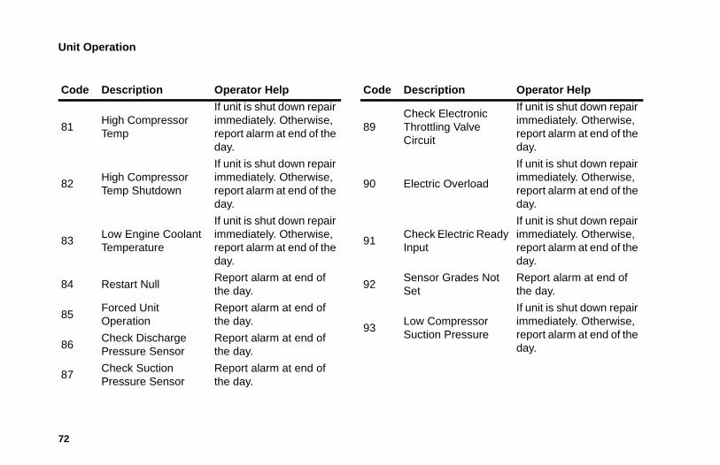
Unit Operation
72
81High Compressor Temp
If unit is shut down repair immediately. Otherwise, report alarm at end of the day.
82High Compressor Temp Shutdown
If unit is shut down repair immediately. Otherwise, report alarm at end of the day.
83Low Engine Coolant Temperature
If unit is shut down repair immediately. Otherwise, report alarm at end of the day.
84 Restart NullReport alarm at end of the day.
85Forced Unit Operation
Report alarm at end of the day.
86Check Discharge Pressure Sensor
Report alarm at end of the day.
87Check Suction Pressure Sensor
Report alarm at end of the day.
Code Description Operator Help
89Check Electronic Throttling Valve Circuit
If unit is shut down repair immediately. Otherwise, report alarm at end of the day.
90 Electric Overload
If unit is shut down repair immediately. Otherwise, report alarm at end of the day.
91Check Electric Ready Input
If unit is shut down repair immediately. Otherwise, report alarm at end of the day.
92Sensor Grades Not Set
Report alarm at end of the day.
93Low Compressor Suction Pressure
If unit is shut down repair immediately. Otherwise, report alarm at end of the day.
Code Description Operator Help
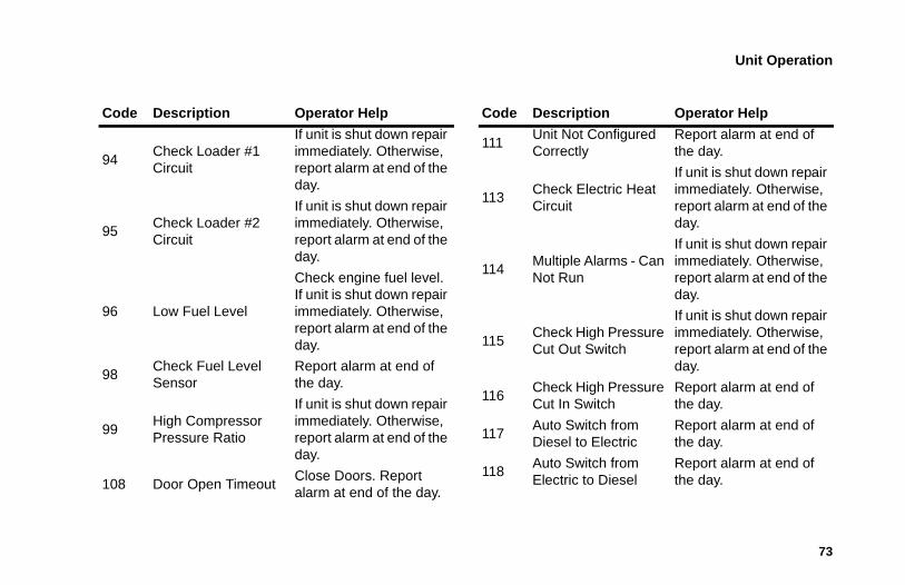
Unit Operation
73
94Check Loader #1 Circuit
If unit is shut down repair immediately. Otherwise, report alarm at end of the day.
95Check Loader #2 Circuit
If unit is shut down repair immediately. Otherwise, report alarm at end of the day.
96 Low Fuel Level
Check engine fuel level. If unit is shut down repair immediately. Otherwise, report alarm at end of the day.
98Check Fuel Level Sensor
Report alarm at end of the day.
99High Compressor Pressure Ratio
If unit is shut down repair immediately. Otherwise, report alarm at end of the day.
108 Door Open TimeoutClose Doors. Report alarm at end of the day.
Code Description Operator Help
111Unit Not Configured Correctly
Report alarm at end of the day.
113Check Electric Heat Circuit
If unit is shut down repair immediately. Otherwise, report alarm at end of the day.
114Multiple Alarms - Can Not Run
If unit is shut down repair immediately. Otherwise, report alarm at end of the day.
115Check High Pressure Cut Out Switch
If unit is shut down repair immediately. Otherwise, report alarm at end of the day.
116Check High Pressure Cut In Switch
Report alarm at end of the day.
117Auto Switch from Diesel to Electric
Report alarm at end of the day.
118Auto Switch from Electric to Diesel
Report alarm at end of the day.
Code Description Operator Help
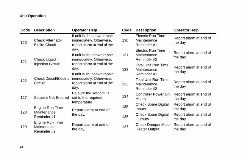
Unit Operation
74
120Check Alternator Excite Circuit
If unit is shut down repair immediately. Otherwise, report alarm at end of the day.
121Check Liquid Injection Circuit
If unit is shut down repair immediately. Otherwise, report alarm at end of the day.
122Check Diesel/Electric Circuit
If unit is shut down repair immediately. Otherwise, report alarm at end of the day.
127 Setpoint Not EnteredBe sure the setpoint is set to the required temperature.
128Engine Run Time Maintenance Reminder #1
Report alarm at end of the day.
129Engine Run Time Maintenance Reminder #2
Report alarm at end of the day.
Code Description Operator Help
130Electric Run Time Maintenance Reminder #1
Report alarm at end of the day.
131Electric Run Time Maintenance Reminder #2
Report alarm at end of the day.
132Total Unit Run Time Maintenance Reminder #1
Report alarm at end of the day.
133Total Unit Run Time Maintenance Reminder #2
Report alarm at end of the day.
134Controller Power On Hours
Report alarm at end of the day.
135Check Spare Digital Inputs
Report alarm at end of the day.
136Check Spare Digital Outputs
Report alarm at end of the day.
137Check Damper Motor Heater Output
Report alarm at end of the day.
Code Description Operator Help
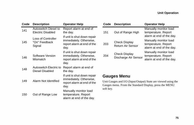
Unit Operation
75
Gauges MenuUnit Gauges and I/O (Input/Output) State are viewed using the Gauges menu. From the Standard Display, press the MENU soft key.
141Autoswitch Diesel to Electric Disabled
Report alarm at end of the day.
145Loss of Controller "On" Feedback Signal
If unit is shut down repair immediately. Otherwise, report alarm at end of the day.
146Software Version Mismatch
If unit is shut down repair immediately. Otherwise, report alarm at end of the day.
148Autoswitch Electric to Diesel Disabled
Report alarm at end of the day.
149 Alarm Not Identified
If unit is shut down repair immediately. Otherwise, report alarm at end of the day.
150 Out of Range LowManually monitor load temperature. Report alarm at end of the day.
Code Description Operator Help
151 Out of Range HighManually monitor load temperature. Report alarm at end of the day.
203Check Display Return Air Sensor
Manually monitor load temperature. Report alarm at end of the day.
204Check Display Discharge Air Sensor
Manually monitor load temperature. Report alarm at end of the day.
Code Description Operator Help
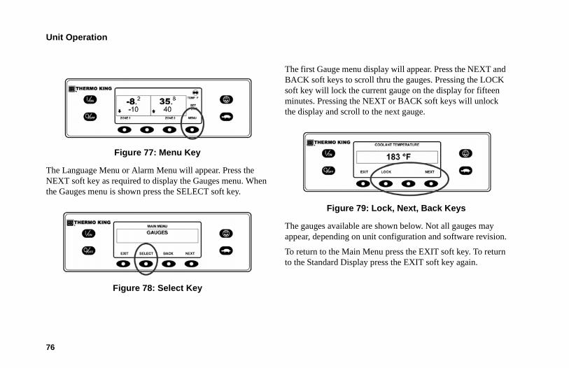
Unit Operation
76
Figure 77: Menu Key
The Language Menu or Alarm Menu will appear. Press the NEXT soft key as required to display the Gauges menu. When the Gauges menu is shown press the SELECT soft key.
Figure 78: Select Key
The first Gauge menu display will appear. Press the NEXT and BACK soft keys to scroll thru the gauges. Pressing the LOCK soft key will lock the current gauge on the display for fifteen minutes. Pressing the NEXT or BACK soft keys will unlock the display and scroll to the next gauge.
Figure 79: Lock, Next, Back Keys
The gauges available are shown below. Not all gauges may appear, depending on unit configuration and software revision.
To return to the Main Menu press the EXIT soft key. To return to the Standard Display press the EXIT soft key again.
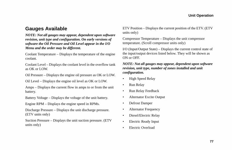
Unit Operation
77
Gauges Available NOTE: Not all gauges may appear, dependent upon software revision, unit type and configuration. On early versions of software the Oil Pressure and Oil Level appear in the I/O Menu and the order may be different.
Coolant Temperature – Displays the temperature of the engine coolant.
Coolant Level – Displays the coolant level in the overflow tank as OK or LOW.
Oil Pressure – Displays the engine oil pressure as OK or LOW.
Oil Level – Displays the engine oil level as OK or LOW.
Amps – Displays the current flow in amps to or from the unit battery.
Battery Voltage – Displays the voltage of the unit battery.
Engine RPM – Displays the engine speed in RPMs.
Discharge Pressure – Displays the unit discharge pressure. (ETV units only)
Suction Pressure – Displays the unit suction pressure. (ETV units only)
ETV Position – Displays the current position of the ETV. (ETV units only)
Compressor Temperature – Displays the unit compressor temperature. (Scroll compressor units only)
I/O (Input/Output State) – Displays the current control state of the input/output devices listed below. They will be shown as ON or OFF.
NOTE: Not all gauges may appear, dependent upon software revision, unit type, number of zones installed and unit configuration.
• High Speed Relay
• Run Relay
• Run Relay Feedback
• Alternator Excite Output
• Defrost Damper
• Alternator Frequency
• Diesel/Electric Relay
• Electric Ready Input
• Electric Overload
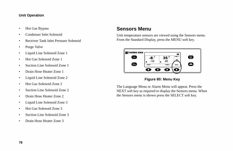
Unit Operation
78
• Hot Gas Bypass
• Condenser Inlet Solenoid
• Receiver Tank Inlet Pressure Solenoid
• Purge Valve
• Liquid Line Solenoid Zone 1
• Hot Gas Solenoid Zone 1
• Suction Line Solenoid Zone 1
• Drain Hose Heater Zone 1
• Liquid Line Solenoid Zone 2
• Hot Gas Solenoid Zone 2
• Suction Line Solenoid Zone 2
• Drain Hose Heater Zone 2
• Liquid Line Solenoid Zone 3
• Hot Gas Solenoid Zone 3
• Suction Line Solenoid Zone 3
• Drain Hose Heater Zone 3
Sensors MenuUnit temperature sensors are viewed using the Sensors menu. From the Standard Display, press the MENU soft key.
Figure 80: Menu Key
The Language Menu or Alarm Menu will appear. Press the NEXT soft key as required to display the Sensors menu. When the Sensors menu is shown press the SELECT soft key.
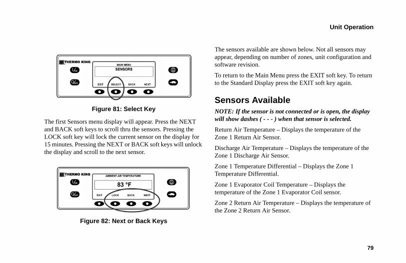
Unit Operation
79
Figure 81: Select Key
The first Sensors menu display will appear. Press the NEXT and BACK soft keys to scroll thru the sensors. Pressing the LOCK soft key will lock the current sensor on the display for 15 minutes. Pressing the NEXT or BACK soft keys will unlock the display and scroll to the next sensor.
Figure 82: Next or Back Keys
The sensors available are shown below. Not all sensors may appear, depending on number of zones, unit configuration and software revision.
To return to the Main Menu press the EXIT soft key. To return to the Standard Display press the EXIT soft key again.
Sensors AvailableNOTE: If the sensor is not connected or is open, the display will show dashes ( - - - ) when that sensor is selected.
Return Air Temperature – Displays the temperature of the Zone 1 Return Air Sensor.
Discharge Air Temperature – Displays the temperature of the Zone 1 Discharge Air Sensor.
Zone 1 Temperature Differential – Displays the Zone 1 Temperature Differential.
Zone 1 Evaporator Coil Temperature – Displays the temperature of the Zone 1 Evaporator Coil sensor.
Zone 2 Return Air Temperature – Displays the temperature of the Zone 2 Return Air Sensor.
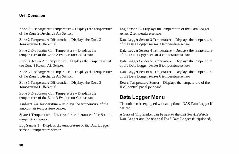
Unit Operation
80
Zone 2 Discharge Air Temperature – Displays the temperature of the Zone 2 Discharge Air Sensor.
Zone 2 Temperature Differential – Displays the Zone 2 Temperature Differential.
Zone 2 Evaporator Coil Temperature – Displays the temperature of the Zone 2 Evaporator Coil sensor.
Zone 3 Return Air Temperature – Displays the temperature of the Zone 3 Return Air Sensor.
Zone 3 Discharge Air Temperature – Displays the temperature of the Zone 3 Discharge Air Sensor.
Zone 3 Temperature Differential – Displays the Zone 3 Temperature Differential.
Zone 3 Evaporator Coil Temperature – Displays the temperature of the Zone 3 Evaporator Coil sensor.
Ambient Air Temperature – Displays the temperature of the ambient air temperature sensor.
Spare 1 Temperature – Displays the temperature of the Spare 1 temperature sensor.
Log Sensor 1 – Displays the temperature of the Data Logger sensor 1 temperature sensor.
Log Sensor 2 – Displays the temperature of the Data Logger sensor 2 temperature sensor.
Data Logger Sensor 3 Temperature – Displays the temperature of the Data Logger sensor 3 temperature sensor.
Data Logger Sensor 4 Temperature – Displays the temperature of the Data Logger sensor 4 temperature sensor.
Data Logger Sensor 5 Temperature – Displays the temperature of the Data Logger sensor 5 temperature sensor.
Data Logger Sensor 6 Temperature – Displays the temperature of the Data Logger sensor 6 temperature sensor.
Board Temperature Sensor – Displays the temperature of the HMI control panel pc board.
Data Logger MenuThe unit can be equipped with an optional DAS Data Logger if desired.
A Start of Trip marker can be sent to the unit ServiceWatch Data Logger and the optional DAS Data Logger (if equipped).
Unit Operation
81
If equipped with the optional DAS Data Logger, the most recent DAS trip record can be printed. The most recent trip is defined as the trip following the last Start of Trip marker sent to the data logger.
The ServiceWatch Data Logger and DAS Data Logger (if equipped) are accessed using the Data Logger Menu.
From the Standard Display, press the MENU key.
Figure 83: Menu Key
The Language Menu or Alarm Menu will appear. Press the NEXT key as required to display the Data Logger Menu. When the Data Logger Menu is shown press the SELECT key.
Figure 84: Select Key
The first feature that appears is the Start of Trip. To send a Start of Trip to the ServiceWatch Data Logger and DAS Data Logger (if equipped), press the SELECT key to select the feature, and then press it again to send the Start of Trip. The display will briefly show START OF TRIP COMPLETE to confirm that a Start of Trip marker was set in the data logger(s).
Unit Operation
82
Figure 85: Start of Trip
NOTE: The start of trip marker is sent to both the ServiceWatch Data Logger and DAS Data Logger (if equipped).
Press the NEXT key to select the PRINT feature. The PRINT screen will appear. Press the SELECT key to print the most recent trip record.
Figure 86: Select Key
To return to the Main Menu press the EXIT soft key. To return to the Standard Display press the EXIT soft key again.
Hourmeters MenuHourmeters are displayed using the Hourmeter Menu. Only hourmeters enabled in the Guarded Access Menu will be shown. From the Standard Display, press the MENU key.
Unit Operation
83
Figure 87: Menu Key
The Language Menu or Alarm Menu will appear. Press the NEXT key as required to display the Hourmeter Menu. When the Hourmeter Menu is shown press the SELECT key. The Hourmeter Display will appear.
Figure 88: Select Key
Press the NEXT or PREVIOUS key to scroll through the enabled hourmeters.
Figure 89: Next or Previous Keys
Hourmeter names and definitions are shown below in the order they appear. Not all hourmeters may appear, depending on number of zones, unit configuration and software revision. Only hourmeters enabled in the Guarded Access Menu will be shown.
To return to the Main Menu press the EXIT soft key. To return to the Standard Display press the EXIT soft key again.
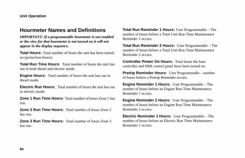
Unit Operation
84
Hourmeter Names and DefinitionsIMPORTANT: If a programmable hourmeter is not enabled or the view for that hourmeter is not turned on it will not appear in the display sequence.
Total Hours: Total number of hours the unit has been turned on (protection hours).
Total Run Time Hours: Total number of hours the unit has run in both diesel and electric mode.
Engine Hours: Total number of hours the unit has run in diesel mode.
Electric Run Hours: Total number of hours the unit has run in electric mode.
Zone 1 Run Time Hours: Total number of hours Zone 1 has run.
Zone 2 Run Time Hours: Total number of hours Zone 2 has run.
Zone 3 Run Time Hours: Total number of hours Zone 3 has run.
Total Run Reminder 1 Hours: User Programmable – The number of hours before a Total Unit Run Time Maintenance Reminder 1 occurs.
Total Run Reminder 2 Hours: User Programmable – The number of hours before a Total Unit Run Time Maintenance Reminder 2 occurs.
Controller Power On Hours: Total hours the base controller and HMI control panel have been turned on.
Pretrip Reminder Hours: User Programmable – number of hours before a Pretrip Reminder occurs.
Engine Reminder 1 Hours: User Programmable – The number of hours before an Engine Run Time Maintenance Reminder 1 occurs.
Engine Reminder 2 Hours: User Programmable – The number of hours before an Engine Run Time Maintenance Reminder 2 occurs.
Electric Reminder 1 Hours: User Programmable – The number of hours before an Electric Run Time Maintenance Reminder 1 occurs.
Unit Operation
85
Electric Reminder 2 Hours: User Programmable – The number of hours before an Electric Run Time Maintenance Reminder 2 occurs.
Mode MenuVarious operating modes can be selected using the Mode menu. Not all modes may be available, depending on settings of other programmable features. The following modes may be available.
Turn Cycle Sentry On or OffCycle Sentry Mode can be turned On or Off. If Cycle Sentry Mode is turned off the unit will run in Continuous mode.
Select Temperature Display UnitsIf enabled in Guarded Access, temperature display units can be selected by the driver to be either Fahrenheit or Celsius degrees.
Single Zone Control – Multi Zone ControlIf enabled in Guarded Access, Single Zone Control allows single temperature operation. If Single Zone Control operation is selected then all zones will be forced on and will control to the same setpoint. All bulkheads should be down to create one large compartment. Multi Zone Control allows separate control for each configured zone. For additional details see Operating the Unit in Single Zone Mode earlier in this section.
Keypad LockoutIf enabled in Guarded Access, the keypad can be locked to prevent unauthorized use. If the keypad is locked only the On and OFF Keys function. The keypad will remain locked even if the unit is turned off and back on. If Keypad Lockout is active, press and hold any soft key for 5 seconds to deactivate the feature.

Unit Operation
86
Sleep ModeIf enabled in Guarded Access, Sleep Mode is used to keep the engine warm and the battery charged when the unit is not in use. When the unit is Sleep Mode the display will show “SLEEP” and the current time. When Sleep Mode is entered the unit will start and run to confirm proper battery charge level and engine temperature.
IMPORTANT: While in Sleep Mode the unit will not monitor or maintain setpoint and load temperature. Fuel level should be monitored as the unit may run periodically, particularly in cold weather.
The following features are available in Sleep Mode.
Program Wakeup Time: This feature allows a wakeup time to be specified. When the selected time is reached the unit will start and resume normal operation. If a Wakeup Time is selected the following features are available:
Day to Wake Up: This feature allows the day the unit is to wake up to be specified.
Hour to Wake Up: This feature allows the hour the unit is to wake up to be specified.
Minute to Wake Up: This feature allows the minute the unit is to wake up to be specified.
Run Pretrip on Wakeup: This feature allows a Pretrip Test to be automatically run when the unit wakes up.
Selecting Cycle Sentry or Continuous ModeWhen Cycle Sentry mode is selected the unit will start and stop automatically to maintain setpoint, keep the engine warm and the battery charged. When Continuous Mode is selected, the unit will start automatically and run continuously to maintain setpoint and provide constant airflow. From the Standard Display, press the MENU key.
Figure 90: Menu Key
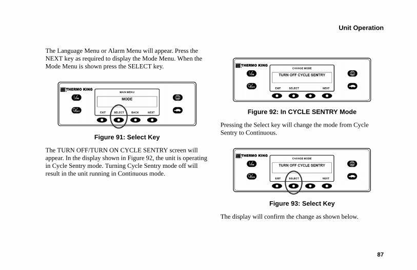
Unit Operation
87
The Language Menu or Alarm Menu will appear. Press the NEXT key as required to display the Mode Menu. When the Mode Menu is shown press the SELECT key.
Figure 91: Select Key
The TURN OFF/TURN ON CYCLE SENTRY screen will appear. In the display shown in Figure 92, the unit is operating in Cycle Sentry mode. Turning Cycle Sentry mode off will result in the unit running in Continuous mode.
Figure 92: In CYCLE SENTRY Mode
Pressing the Select key will change the mode from Cycle Sentry to Continuous.
Figure 93: Select Key
The display will confirm the change as shown below.
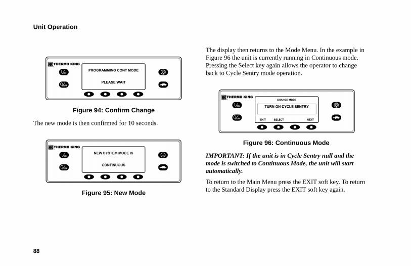
Unit Operation
88
Figure 94: Confirm Change
The new mode is then confirmed for 10 seconds.
Figure 95: New Mode
The display then returns to the Mode Menu. In the example in Figure 96 the unit is currently running in Continuous mode. Pressing the Select key again allows the operator to change back to Cycle Sentry mode operation.
Figure 96: Continuous Mode
IMPORTANT: If the unit is in Cycle Sentry null and the mode is switched to Continuous Mode, the unit will start automatically.
To return to the Main Menu press the EXIT soft key. To return to the Standard Display press the EXIT soft key again.
Unit Operation
89
Select Temperature Display UnitsThis feature, if enabled in Guarded Access, allows the driver to set temperature units to be display in either Fahrenheit or Celsius. From the Standard Display, press the MENU key.
Figure 97: Menu Key
The Language Menu or Alarm Menu will appear. Press the NEXT key as required to display the Mode Menu. When the Mode Menu is shown press the SELECT key.
Figure 98: Select Key
The TURN OFF/TURN ON CYCLE SENTRY screen will appear. Press the NEXT key as required to display the Temperature Display Screen.
NOTE: This feature must be enabled or it will not appear in the Mode Menu.
Figure 99: Temperature Display Screen
Unit Operation
90
The Temperature Display screen will appear. Use the “+“ and “-” soft keys to chose either FAHREHEIT or CELSIUS. When the desired temperature units are shown, press the YES soft key to select.
Figure 100: Yes Key
After the YES soft key has been pressed, the display will briefly show PROGRAMMING TEMPERATURE UNITS – PLEASE WAIT. The display confirms the new setting for two seconds and then returns to the Standard Display.
Single Zone ControlThis feature, if enabled in Guarded Access, allows Single Zone Control operation to be selected by choosing the Main Menu and then selecting Single Zone Control from within the Mode
sub menu. The Single Zone Control Standard Display shown in Figure 101 functions the same way as the other Standard Displays.
Figure 101: Single Zone Control Standard Display
• When this feature is selected, all zones will be forced on and will control to the same selected setpoint.
• The Cycle Sentry Icon in the upper right of the display shows that the unit is operating in Cycle Sentry mode.
• The box temperature in all zones is 35.8°F and all zones are controlling to a 35°F setpoint.
• The down-pointing arrow indicates that all zones are cooling.
Unit Operation
91
• The soft key labeled Setpoint allows the setpoint for all zones to be changed.
• The soft key labeled Menu allows the Main Menu to be selected.
The following differences exist when operating the unit in Single Zone Control Mode.
• Single Zone Control Mode will appear in the Main Menu/Mode Menu only if the Single Zone Control feature has been enabled in the Guarded Access/Main Menu Configuration menu.
• If Single Zone Control operation is selected then all zones will be forced on and will control to the same setpoint.
• Unit control is based on the temperature sensors of one zone, usually Zone 1.
• All bulkheads should be taken down to create one large compartment.
• With the exception of defrost the operating mode of each zone evaporator(s) will be same when in this mode. Unit control is based on the temperature sensors of one zone, usually Zone 1.
• If Single Zone Control operation is selected the Single Zone Standard Display provides one soft key labeled Set Point as shown above. This allows the setpoint for all zones to be changed simultaneously.
• If Single Zone Control operation is selected the individual zones cannot be turned off. The unit and all zones are turned On and Off simultaneously using the On and Off hard keys at the left side of the display.
Single Zone Control is turned on by choosing the Main Menu and then selecting Single Zone Control from within the Mode sub menu. From the Standard Display, press the MENU key.
Figure 102: Menu Key
Unit Operation
92
The Language Menu or Alarm Menu will appear. Press the NEXT key as required to display the Mode Menu. When the Mode Menu is shown press the SELECT key.
Figure 103: Select Key
The TURN OFF/TURN ON CYCLE SENTRY screen will appear. Press the NEXT key as required to display the Single Zone Display.
NOTE: This feature must be enabled or it will not appear in the Mode Menu.
Figure 104: Single Zone Display
After the SELECT soft key has been pressed, the display will briefly show PROGRAMMING SINGLE ZONE CONTROL – PLEASE WAIT. The display confirms the new setting for two seconds and then shows the Single Zone Standard Display.
Figure 105: Single Zone Standard Display
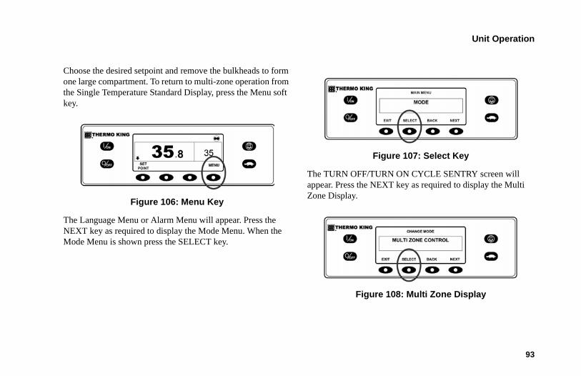
Unit Operation
93
Choose the desired setpoint and remove the bulkheads to form one large compartment. To return to multi-zone operation from the Single Temperature Standard Display, press the Menu soft key.
Figure 106: Menu Key
The Language Menu or Alarm Menu will appear. Press the NEXT key as required to display the Mode Menu. When the Mode Menu is shown press the SELECT key.
Figure 107: Select Key
The TURN OFF/TURN ON CYCLE SENTRY screen will appear. Press the NEXT key as required to display the Multi Zone Display.
Figure 108: Multi Zone Display
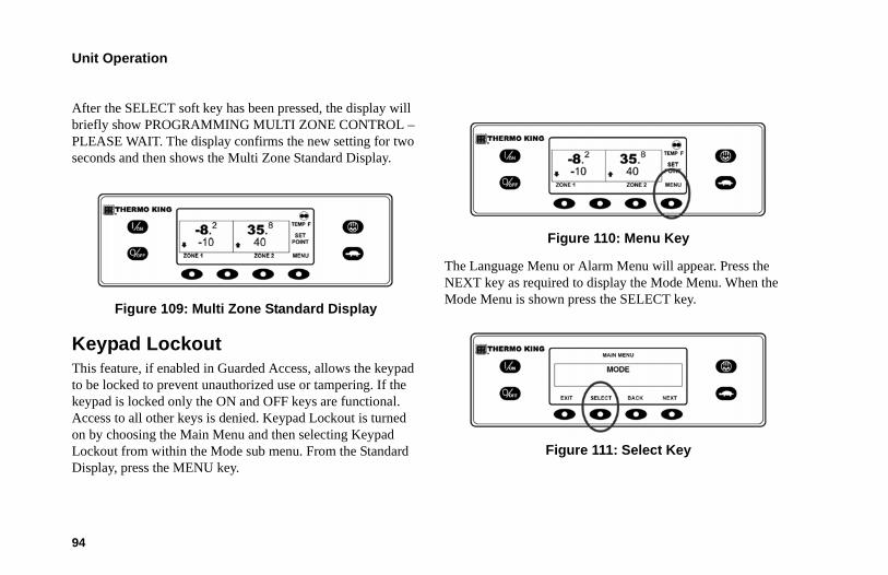
Unit Operation
94
After the SELECT soft key has been pressed, the display will briefly show PROGRAMMING MULTI ZONE CONTROL – PLEASE WAIT. The display confirms the new setting for two seconds and then shows the Multi Zone Standard Display.
Figure 109: Multi Zone Standard Display
Keypad LockoutThis feature, if enabled in Guarded Access, allows the keypad to be locked to prevent unauthorized use or tampering. If the keypad is locked only the ON and OFF keys are functional. Access to all other keys is denied. Keypad Lockout is turned on by choosing the Main Menu and then selecting Keypad Lockout from within the Mode sub menu. From the Standard Display, press the MENU key.
Figure 110: Menu Key
The Language Menu or Alarm Menu will appear. Press the NEXT key as required to display the Mode Menu. When the Mode Menu is shown press the SELECT key.
Figure 111: Select Key
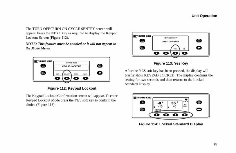
Unit Operation
95
The TURN OFF/TURN ON CYCLE SENTRY screen will appear. Press the NEXT key as required to display the Keypad Lockout Screen (Figure 112).
NOTE: This feature must be enabled or it will not appear in the Mode Menu.
Figure 112: Keypad Lockout
The Keypad Lockout Confirmation screen will appear. To enter Keypad Lockout Mode press the YES soft key to confirm the choice (Figure 113).
Figure 113: Yes Key
After the YES soft key has been pressed, the display will briefly show KEYPAD LOCKED. The display confirms the setting for two seconds and then returns to the Locked Standard Display.
Figure 114: Locked Standard Display
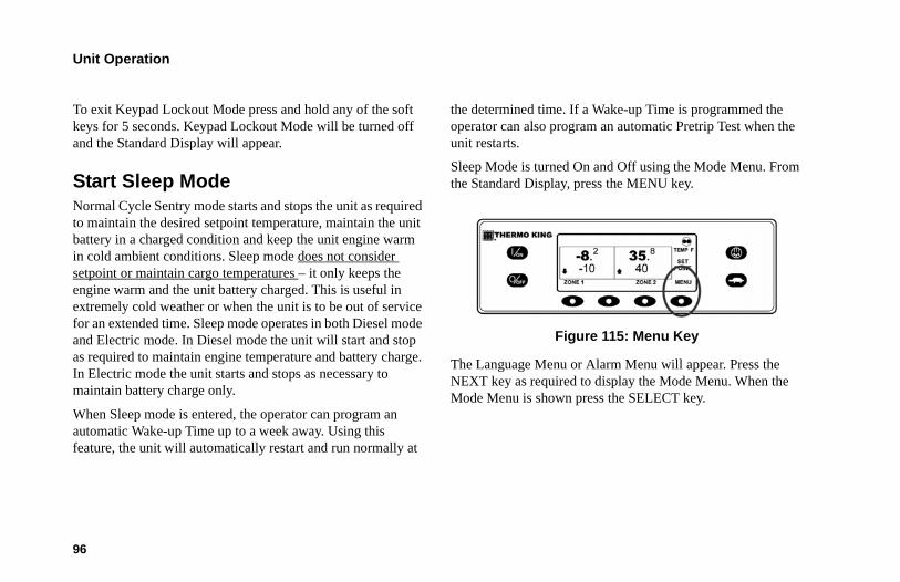
Unit Operation
96
To exit Keypad Lockout Mode press and hold any of the soft keys for 5 seconds. Keypad Lockout Mode will be turned off and the Standard Display will appear.
Start Sleep Mode Normal Cycle Sentry mode starts and stops the unit as required to maintain the desired setpoint temperature, maintain the unit battery in a charged condition and keep the unit engine warm in cold ambient conditions. Sleep mode does not consider setpoint or maintain cargo temperatures – it only keeps the engine warm and the unit battery charged. This is useful in extremely cold weather or when the unit is to be out of service for an extended time. Sleep mode operates in both Diesel mode and Electric mode. In Diesel mode the unit will start and stop as required to maintain engine temperature and battery charge. In Electric mode the unit starts and stops as necessary to maintain battery charge only.
When Sleep mode is entered, the operator can program an automatic Wake-up Time up to a week away. Using this feature, the unit will automatically restart and run normally at
the determined time. If a Wake-up Time is programmed the operator can also program an automatic Pretrip Test when the unit restarts.
Sleep Mode is turned On and Off using the Mode Menu. From the Standard Display, press the MENU key.
Figure 115: Menu Key
The Language Menu or Alarm Menu will appear. Press the NEXT key as required to display the Mode Menu. When the Mode Menu is shown press the SELECT key.
Unit Operation
97
Figure 116: Select Key
The TURN OFF/TURN ON CYCLE SENTRY screen will appear. Press the NEXT key as required to display the Start Sleep Mode Screen.
NOTE: This feature must be enabled or it will not appear in the Mode Menu.
Figure 117: Start Sleep Mode Screen
The screen shown in Figure 118 will appear.
Figure 118: Program Wake Up Time
The operator can now choose a Sleep Mode Wake-up Time or simply enter Sleep Mode immediately. If NO is pressed the unit will immediately enter Sleep Mode.
Figure 119: NO Key
Unit Operation
98
The display will show SLEEP and the unit will start and stop as required to keep the engine warm and/or the battery charged. Sleep Mode does not consider setpoint or maintain cargo temperatures. To exit Sleep Mode press the EXIT key or turn the unit off and back on. The unit will resume normal operation and control to setpoint.
Figure 120: Sleep Mode
To enter a Wake-up Time, verify the unit clock is set properly. Then press the YES key at the PROGRAM A WAKE-UP TIME? prompt.
Figure 121: PROGRAM A WAKE-UP TIME? Prompt
The display will prompt the operator for the DAY the unit is to restart in normal operation. Use the – key and + key to select the desired day. In this example Monday has been chosen. Press the YES key to confirm the DAY.
Figure 122: YES Key
Unit Operation
99
The display will now prompt the operator for the Hour the unit is to restart in normal operation. Use the – key and + key to select the desired hour. In this example 4:00 am has been chosen. Press the YES key to confirm the HOUR. Note that 24 hour “military time” is used (Figure 123).
Figure 123: YES Key
The display will now prompt the operator for the MINUTE the unit is to restart in normal operation. Use the – key and + key to select the desired minute. In this example 4:30 am has been chosen (Figure 124). Press the YES key to confirm the MINUTE.
Figure 124: YES Key
The display will now prompt for a Pretrip Test on Wake-up. Press the YES key (Figure 125) to perform a Pretrip Test on Wake-up. If the No key is pressed the unit will resume normal operation on Wake-up.
Figure 125: YES Key
Unit Operation
100
The display will show SLEEP and the unit will start and stop as required to keep the engine warm and/or the battery charged. Sleep Mode does not consider setpoint or maintain cargo temperatures.
Figure 126: SLEEP Display
The unit will restart at the programmed time (in this example 4:30 am) and perform a Pretrip Test (if selected). After the Pretrip Test is complete the test results will be displayed and the unit will resume normal operation and control to setpoint.
To exit Sleep Mode before the selected Wake-up time press the EXIT key or turn the unit off and back on. The unit will resume normal operation and control to setpoint.
Pretrip Test A Pretrip Test verifies unit operation. This display allows a Pretrip Test to be selected and initiated by the operator. If the Pretrip Test is entered with the unit shut down a Full Pretrip Test with device amp checks will be performed. If the Pretrip Test is entered with the unit running in either diesel or electric mode a Running Pretrip Test is performed, but the device amps checks are not performed. Test results are reported as PASS, CHECK or FAIL when the Pretrip Test is completed. If an alarm occurs during a Pretrip Test the alarm code will be displayed as Pretrip Alarm XX, where XX is the alarm code.
Pretrip Test Conditions• Current unit settings such as zones on or off and setpoints
are saved and restored at the end of the Pretrip Test or if the unit is turned off and back on.
• All zones are forced on.
• Pretrip Test can be run in either Diesel or Electric Mode.
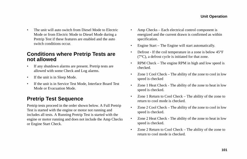
Unit Operation
101
• The unit will auto switch from Diesel Mode to Electric Mode or from Electric Mode to Diesel Mode during a Pretrip Test if these features are enabled and the auto switch conditions occur.
Conditions where Pretrip Tests are not allowed • If any shutdown alarms are present. Pretrip tests are
allowed with some Check and Log alarms.
• If the unit is in Sleep Mode.
• If the unit is in Service Test Mode, Interface Board Test Mode or Evacuation Mode.
Pretrip Test Sequence Pretrip tests proceed in the order shown below. A Full Pretrip Test is started with the engine or motor not running and includes all tests. A Running Pretrip Test is started with the engine or motor running and does not include the Amp Checks or Engine Start Check.
• Amp Checks – Each electrical control component is energized and the current drawn is confirmed as within specification.
• Engine Start – The Engine will start automatically.
• Defrost - If the coil temperature in a zone is below 45°F (7°C), a defrost cycle is initiated for that zone.
• RPM Check – The engine RPM in high and low speed is checked.
• Zone 1 Cool Check – The ability of the zone to cool in low speed is checked
• Zone 1 Heat Check - The ability of the zone to heat in low speed is checked.
• Zone 1 Return to Cool Check – The ability of the zone to return to cool mode is checked.
• Zone 2 Cool Check – The ability of the zone to cool in low speed is checked.
• Zone 2 Heat Check - The ability of the zone to heat in low speed is checked.
• Zone 2 Return to Cool Check – The ability of the zone to return to cool mode is checked.
Unit Operation
102
• Zone 3 Cool Check – The ability of the zone to cool in low speed is checked.
• Zone 3 Heat Check - The ability of the zone to heat in low speed is checked.
• Zone 3 Return to Cool Check – The ability of the zone to return to cool mode is checked.
• Report Test Results – The test results are reported as PASS, CHECK or FAIL when the Pretrip Test is completed. If test results are CHECK or FAIL alarm codes will exist to direct the technician to the source of the problem.
Pretrip Test Considerations When performing a Pretrip Test, the following issues should be considered.
• If running a Pretrip Test on a truck or trailer loaded with dry cargo, insure that proper airflow can occur around the load. If the load restricts airflow, false test results may occur. Also, SR-34 units have high refrigeration capacity which results in rapid temperature changes. Sensitive dry cargo may be damaged as a result.
• If running a Pretrip Test on a truck or trailer that has just been washed down, the extremely high humidity inside the truck or trailer cargo compartment may result in false test results.
• If running a Pretrip Test on a truck or trailer loaded with sensitive cargo, monitor the load temperature during the test as normal temperature control is suspended during a Pretrip Test.
• Always perform Pretrip Tests with the truck or trailer cargo doors closed to prevent false test failures.
Performing a Pretrip Test If a Pretrip Test is initiated with the engine shut down a Full Pretrip Test will be performed. If a Pretrip Test is initiated with the engine or motor running a Running Pretrip Test is performed.
• Before initiating a Pretrip Test, clear all alarm codes.
• To stop a Pretrip Test at any time, turn the unit off. Alarm Code 28 Pretrip Abort will be set. Other alarms may also be set, depending upon test in progress when the test was terminated.
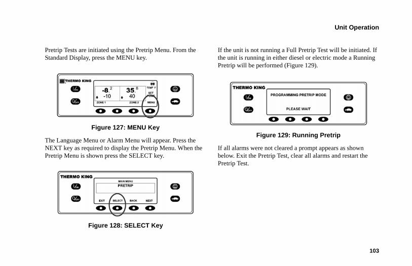
Unit Operation
103
Pretrip Tests are initiated using the Pretrip Menu. From the Standard Display, press the MENU key.
Figure 127: MENU Key
The Language Menu or Alarm Menu will appear. Press the NEXT key as required to display the Pretrip Menu. When the Pretrip Menu is shown press the SELECT key.
Figure 128: SELECT Key
If the unit is not running a Full Pretrip Test will be initiated. If the unit is running in either diesel or electric mode a Running Pretrip will be performed (Figure 129).
Figure 129: Running Pretrip
If all alarms were not cleared a prompt appears as shown below. Exit the Pretrip Test, clear all alarms and restart the Pretrip Test.
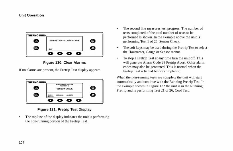
Unit Operation
104
Figure 130: Clear Alarms
If no alarms are present, the Pretrip Test display appears.
Figure 131: Pretrip Test Display
• The top line of the display indicates the unit is performing the non-running portion of the Pretrip Test.
• The second line measures test progress. The number of tests completed of the total number of tests to be performed is shown. In the example above the unit is performing Test 1 of 26, Sensor Check.
• The soft keys may be used during the Pretrip Test to select the Hourmeter, Gauge or Sensor menus.
• To stop a Pretrip Test at any time turn the unit off. This will generate Alarm Code 28 Pretrip Abort. Other alarm codes may also be generated. This is normal when the Pretrip Test is halted before completion.
When the non-running tests are complete the unit will start automatically and continue with the Running Pretrip Test. In the example shown in Figure 132 the unit is in the Running Pretrip and is performing Test 21 of 26, Cool Test.
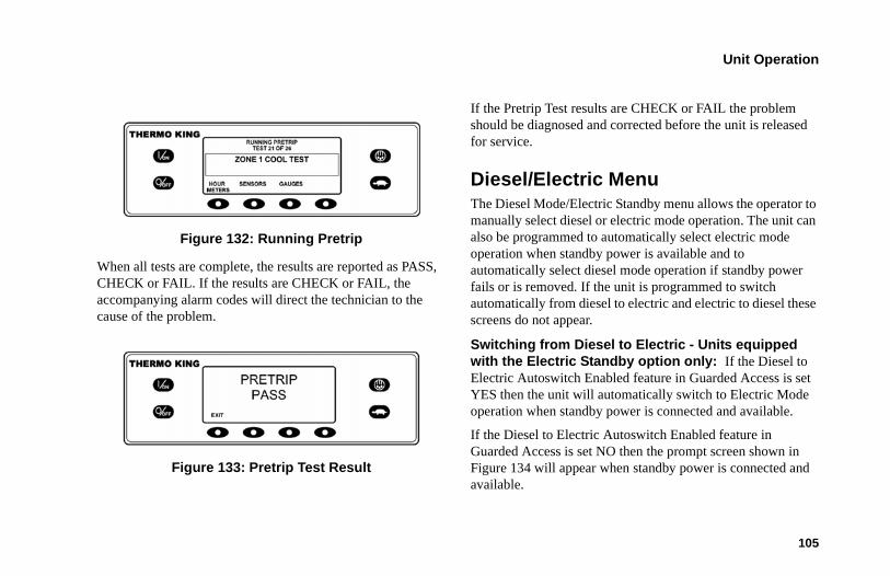
Unit Operation
105
Figure 132: Running Pretrip
When all tests are complete, the results are reported as PASS, CHECK or FAIL. If the results are CHECK or FAIL, the accompanying alarm codes will direct the technician to the cause of the problem.
Figure 133: Pretrip Test Result
If the Pretrip Test results are CHECK or FAIL the problem should be diagnosed and corrected before the unit is released for service.
Diesel/Electric Menu The Diesel Mode/Electric Standby menu allows the operator to manually select diesel or electric mode operation. The unit can also be programmed to automatically select electric mode operation when standby power is available and to automatically select diesel mode operation if standby power fails or is removed. If the unit is programmed to switch automatically from diesel to electric and electric to diesel these screens do not appear.
Switching from Diesel to Electric - Units equipped with the Electric Standby option only: If the Diesel to Electric Autoswitch Enabled feature in Guarded Access is set YES then the unit will automatically switch to Electric Mode operation when standby power is connected and available.
If the Diesel to Electric Autoswitch Enabled feature in Guarded Access is set NO then the prompt screen shown in Figure 134 will appear when standby power is connected and available.
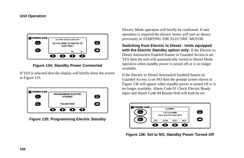
Unit Operation
106
Figure 134: Standby Power Connected
If YES is selected then the display will briefly show the screen in Figure 135.
Figure 135: Programming Electric Standby
Electric Mode operation will briefly be confirmed. If unit operation is required the electric motor will start as shown previously in STARTING THE ELECTRIC MOTOR.
Switching from Electric to Diesel - Units equipped with the Electric Standby option only: If the Electric to Diesel Autoswitch Enabled feature in Guarded Access is set YES then the unit will automatically switch to Diesel Mode operation when standby power is turned off or is no longer available.
If the Electric to Diesel Autoswitch Enabled feature in Guarded Access is set NO then the prompt screen shown in Figure 136 will appear when standby power is turned off or is no longer available. Alarm Code 91 Check Electric Ready Input and Alarm Code 84 Restart Null will both be set.
Figure 136: Set to NO, Standby Power Turned Off
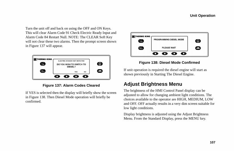
Unit Operation
107
Turn the unit off and back on using the OFF and ON Keys. This will clear Alarm Code 91 Check Electric Ready Input and Alarm Code 84 Restart Null. NOTE: The CLEAR Soft Key will not clear these two alarms. Then the prompt screen shown in Figure 137 will appear.
Figure 137: Alarm Codes Cleared
If YES is selected then the display will briefly show the screen in Figure 138. Then Diesel Mode operation will briefly be confirmed.
Figure 138: Diesel Mode Confirmed
If unit operation is required the diesel engine will start as shown previously in Starting The Diesel Engine.
Adjust Brightness Menu The brightness of the HMI Control Panel display can be adjusted to allow for changing ambient light conditions. The choices available to the operator are HIGH, MEDIUM, LOW and OFF. OFF actually results in a very dim screen suitable for low light conditions.
Display brightness is adjusted using the Adjust Brightness Menu. From the Standard Display, press the MENU key.
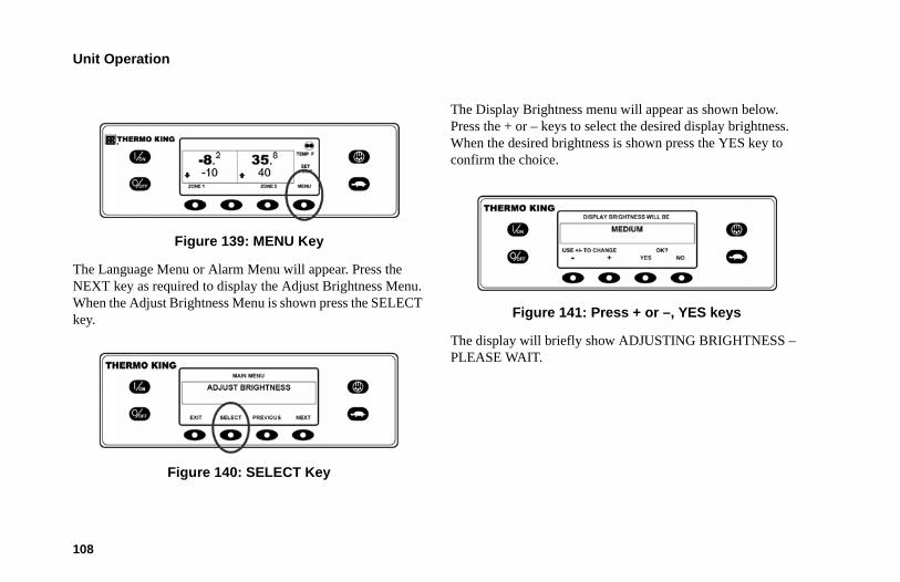
Unit Operation
108
Figure 139: MENU Key
The Language Menu or Alarm Menu will appear. Press the NEXT key as required to display the Adjust Brightness Menu. When the Adjust Brightness Menu is shown press the SELECT key.
Figure 140: SELECT Key
The Display Brightness menu will appear as shown below. Press the + or – keys to select the desired display brightness. When the desired brightness is shown press the YES key to confirm the choice.
Figure 141: Press + or –, YES keys
The display will briefly show ADJUSTING BRIGHTNESS – PLEASE WAIT.
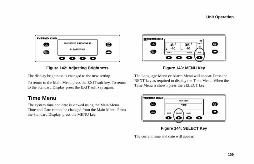
Unit Operation
109
Figure 142: Adjusting Brightness
The display brightness is changed to the new setting.
To return to the Main Menu press the EXIT soft key. To return to the Standard Display press the EXIT soft key again.
Time MenuThe system time and date is viewed using the Main Menu. Time and Date cannot be changed from the Main Menu. From the Standard Display, press the MENU key.
Figure 143: MENU Key
The Language Menu or Alarm Menu will appear. Press the NEXT key as required to display the Time Menu. When the Time Menu is shown press the SELECT key.
Figure 144: SELECT Key
The current time and date will appear.
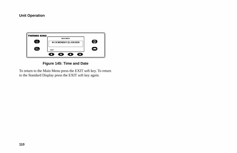
Unit Operation
110
Figure 145: Time and Date
To return to the Main Menu press the EXIT soft key. To return to the Standard Display press the EXIT soft key again.
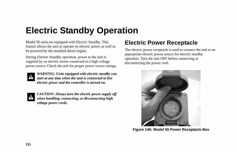
111
Electric Standby OperationModel 50 units are equipped with Electric Standby. This feature allows the unit to operate on electric power as well as be powered by the standard diesel engine.
During Electric Standby operation, power to the unit is supplied by an electric motor connected to a high voltage power source. Check the unit for proper power source ratings.
Electric Power ReceptacleThe electric power receptacle is used to connect the unit to an appropriate electric power source for electric standby operation. Turn the unit OFF before connecting or disconnecting the power cord.
Figure 146: Model 50 Power Receptacle Box
WARNING: Units equipped with electric standby can start at any time when the unit is connected to live electric power and the controller is turned on.
CAUTION: Always turn the electric power supply off when handling, connecting, or disconnecting high voltage power cords.
Electric Standby Operation
112
NOTE: The Model 50 control system automatically determines if diesel or electric power is desired.
See “Starting the Electric Motor” in the Unit Operation chapter of this manual.
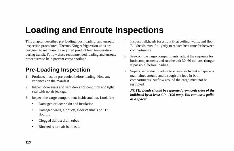
113
Loading and Enroute InspectionsThis chapter describes pre-loading, post loading, and enroute inspection procedures. Thermo King refrigeration units are designed to maintain the required product load temperature during transit. Follow these recommended loading and enroute procedures to help prevent cargo spoilage.
Pre-Loading Inspection1. Products must be pre-cooled before loading. Note any
variances on the manifest.
2. Inspect door seals and vent doors for condition and tight seal with no air leakage.
3. Inspect the cargo compartment inside and out. Look for:
• Damaged or loose skin and insulation
• Damaged walls, air ducts, floor channels or “T” flooring
• Clogged defrost drain tubes
• Blocked return air bulkhead.
4. Inspect bulkheads for a tight fit at ceiling, walls, and floor. Bulkheads must fit tightly to reduce heat transfer between compartments.
5. Pre-cool the cargo compartments: adjust the setpoints for both compartments and run the unit 30–60 minutes (longer if possible) before loading.
6. Supervise product loading to ensure sufficient air space is maintained around and through the load in both compartments. Airflow around the cargo must not be restricted.
NOTE: Loads should be separated from both sides of the bulkhead by at least 4 in. (100 mm). You can use a pallet as a spacer.
Loading and Enroute Inspections
114
Post-Loading InspectionPost-loading inspections ensure the cargo has been loaded properly. To perform a post-load inspection:
1. Inspect the evaporator outlets for blockage.
2. Turn the unit off before opening the cargo box doors to maintain efficient operation.
NOTE: You can run the unit with the cargo box doors open if the truck is backed into a refrigerated warehouse with tight door seals.
3. Perform a final check of the load temperature. If the load is above or below temperature, make a final notation on the manifest.
4. Close or supervise the closing of the cargo box doors. Make sure they are securely locked.
5. Make sure the setpoint is at the temperature listed on the manifest.
6. If the unit was stopped, restart using the correct starting procedure. See the 'Unit Operation” chapter in this manual.
7. Repeat the after-start inspection. See the “Unit Operation” chapter in this manual.
8. Defrost the unit 30 minutes after loading by starting a manual defrost cycle.
CAUTION: Pre-cool cargo to the correct temperature before loading. The unit is designed to maintain temperature, not cool an above-temperature load.
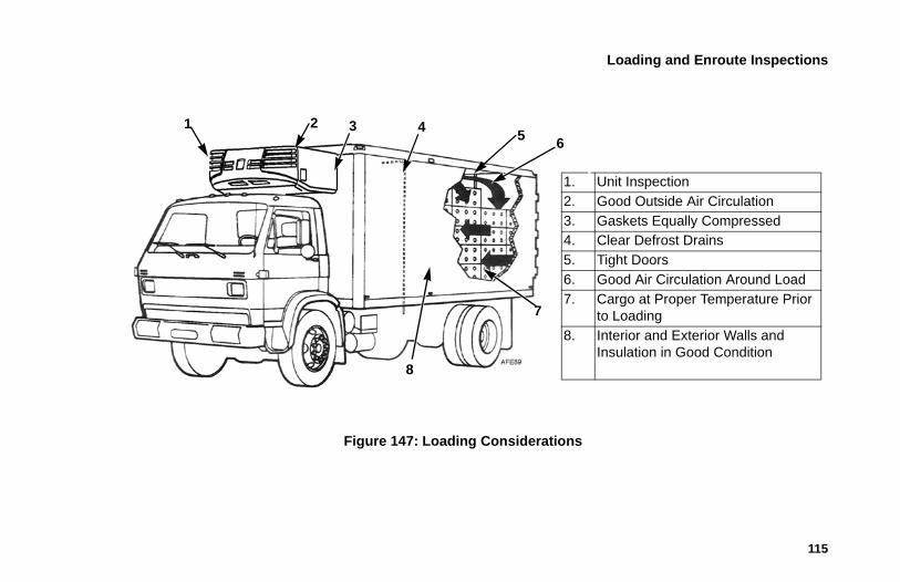
Loading and Enroute Inspections
115
Figure 147: Loading Considerations
1. Unit Inspection2. Good Outside Air Circulation3. Gaskets Equally Compressed4. Clear Defrost Drains5. Tight Doors6. Good Air Circulation Around Load7. Cargo at Proper Temperature Prior
to Loading8. Interior and Exterior Walls and
Insulation in Good Condition
3 45 6
8
1
7
2
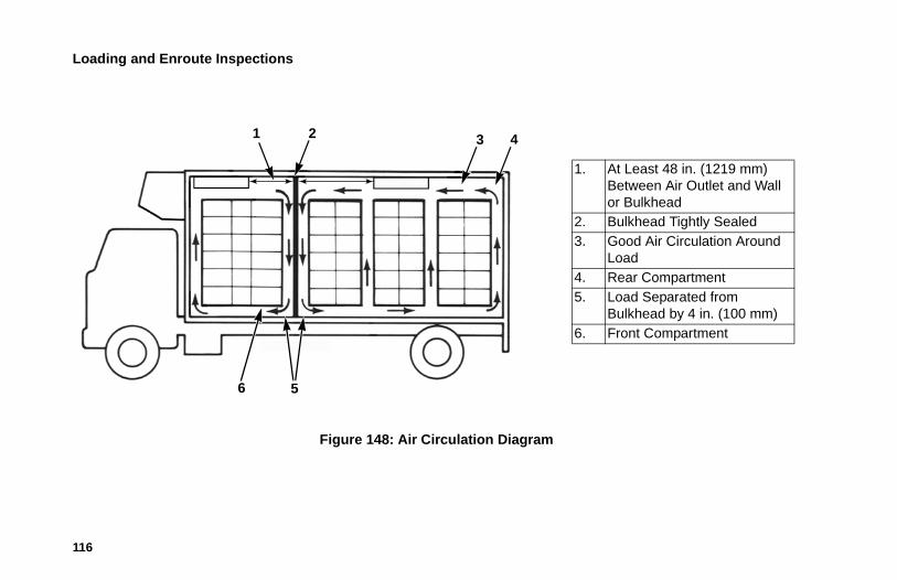
Loading and Enroute Inspections
116
Figure 148: Air Circulation Diagram
32 4
6 5
1. At Least 48 in. (1219 mm) Between Air Outlet and Wall or Bulkhead
2. Bulkhead Tightly Sealed 3. Good Air Circulation Around
Load 4. Rear Compartment5. Load Separated from
Bulkhead by 4 in. (100 mm)6. Front Compartment
1
Loading and Enroute Inspections
117
Enroute InspectionsTo help prevent damage to the cargo, complete the following enroute inspection every four hours.
Inspection Procedure1. Verify that the setpoints are correct.
2. Check the return air temperature readings. The temperature readings should be within the desired temperature range. If the readings are not within this range, see the “Inspection Troubleshooting” procedure below.
3. Initiate a manual defrost cycle after each enroute inspection.
Inspection Troubleshooting1. If a return air temperature reading is not within the desired
temperature range, refer to the troubleshooting table on the following pages. Correct the problem as needed.
2. Repeat the Enroute Inspection every 30 minutes until the compartment temperature is within the desired temperature range. Stop the unit if the compartment temperature is not within desired temperature range on two consecutive 30 minute inspections, especially if the compartment temperature appears to be moving away from the setpoint.
3. Immediately contact the nearest Thermo King Service Center or your company office.
4. Take the necessary steps to protect and maintain proper load temperature.
CAUTION: Stop the unit if the compartment temperature remains more than desired temperature range from the setpoint on two consecutive 30 minute inspections. Contact the nearest Thermo King Service Center or your company office immediately. Take all necessary steps to protect and maintain proper load temperature.
Loading and Enroute Inspections
118
Inspection Troubleshooting
Problem Cause Remedy
A return air temperature reading is not within desired temperature range of the setpoint.
The unit has not had time to cool down to correct temperature.
Refer to the load log history. Look for above temperature load records, properly pre-cooled cargo compartment, length of time on road, etc. Correct as required. Continue monitoring return air temperature until reading is within desired temperature range of the setpoint.
The unit may have a low refrigerant charge.
Check the receiver tank sight glass for refrigerant level. If liquid is not showing in the receiver tank sight glass, the refrigerant charge could be low. A competent refrigeration technician is required to add refrigerant or repair the system. Contact the nearest Thermo King dealer, authorized Service Center, or call the Thermo King Cold Line for referral. Consult the Table of Contents for Cold Line information.
The unit is in defrost or has just completed a defrost cycle.
Monitor the return air temperature after the defrost cycle is completed to see if the temperature returns to the desired temperature range of the setpoint.
The evaporator is plugged with frost.
Initiate a manual defrost cycle. The defrost cycle will automatically terminate when complete. Continue monitoring return air temperature until reading is within desired temperature range of the setpoint.
Loading and Enroute Inspections
119
Improper air circulation in the cargo compartment.
Inspect the unit and cargo compartment to determine if the evaporator fans are working and properly circulating the air. Poor air circulation may be due to improper loading of the cargo, shifting of the load. Correct as required. Continue monitoring return air temperature until problem is corrected.WARNING: The unit could start at any time when turned on. Turn the unit off before opening doors or inspecting any part of the unit.
The unit did not start automatically.
Determine the cause for not starting. Correct as required. Continue monitoring return air temperature until reading is within desired temperature range of the setpoint.
Inspection Troubleshooting (Continued)
Problem Cause Remedy
120
SpecificationsEngineModel TK380F (Tier 4)
Fuel Type No. 2 Diesel fuel under normal conditionsNo. 1 Diesel fuel is acceptable cold weather fuel
Oil Capacity:Crankcase & Oil Filterw/Bypass Oil Filter
12.0 quarts (11.4 liters) 13.0 quarts (12.3 liters) Fill to full mark on dipstick
Oil Type API Classification CI-4 or better.API Rating CI or CH, as available, if low sulfur diesel fuel (up to 500ppm sulfur) is used.(ACEA Rating E3 or better for Europe)
Oil Viscosity 14 F to 122 F (-10 C to 50 C): SAE 15W-40 (Synthetic) 5 to 104 F (-15 to 40 C): SAE 15W-40 -13 to 104 F (-25 to 40 C): SAE 10W-40 -13 to 86 F (-25 to 30 C): SAE 10W-30 -22 to 122 F (-30 to 50 C): SAE 5W-40 (Synthetic) Below -22 F (-30 C): SAE 0W-30 (Synthetic)
Specifications
121
Engine Coolant Type ELC (Extended Life Coolant), which is “RED” Use a 50/50 concentration of any of the following equivalents:Chevron Dex-CoolTexaco ELC Havoline Dex-Cool® Havoline XLC for Europe Shell Dexcool® Shell RotellaSaturn/General Motors Dex-Cool® Caterpillar ELC Detroit Diesel POWERCOOL® Plus
CAUTION: Do not add “GREEN” or “BLUE-GREEN” conventional coolant to cooling systems using “RED” Extended Life Coolant, except in an emergency. If conventional coolant is added to Extended Life Coolant, the coolant must be changed after 2 years instead of 5 years.
Units Built Prior to October 2016
Coolant System Capacity:
Units with coolant expansion tank only.
6.5 quarts (6.2 liters)
Engine (Continued)
Sp
12
ecifications
2
Refrigeration SystemContact your Thermo King dealer for refrigeration system service or maintenance.
Coolant Expansion Tank Cap Pressure 15 psig (103 kPa)7 psig (48 kPa) after November 2015
Units Built After October 2016
Coolant System Capacity:
Units with coolant expansion tank and overflow bottle.
8.36 quarts (7.91 liters)
Coolant Expansion Tank Cap Pressure 10 psig (69 kPa)
Engine (Continued)
Specifications
123
FusesFuse Size Function
F2 15A Power to On/Off Switch
F3 40A Fuel Sol Pull-In/Starter Circuit
F4 None2A
No Fuse - All Bosch and Thermo King Alternators 2A Fuse - All Prestolite Alternators
F5 40A Preheat Circuit
F6 15A High Speed Circuits
F7 2A 8XP Circuit - Controller On Feedback to HMI
F8 5A 2A Power to CAN Connector J12
F9 5A 2A Power to CAN Connector J14
F10 10A 8X Power (Install fuse in upper position)
F11 10A Zone 1 LLS
F12 5A CAN Connector J13
F13 2A 8FC Circuit (Remote Lights)
Specifications
124
F15 P/S On/Off Relay
F20 2A Alternator Sense
F21 60A Main Fuse (2 Circuit)
F25 7.5A HPCO/Run Circuit
F4 Remove fuse F4 for Model 30 units with Australian Bosch or Thermo King Alternators. Install fuse F4 for Model 50 units with Prestolite Alternator.
F10 When fuse F10 is installed in the upper position the On/Off keys on the HMI turn the unit on and off. When fuse F10 is installed in the lower position the unit will start and run without the HMI control panel.
F15 The device identified as F15 is a poly switch. These over-current devices reset automatically and are not replaceable.
Fuses (Continued)Fuse Size Function
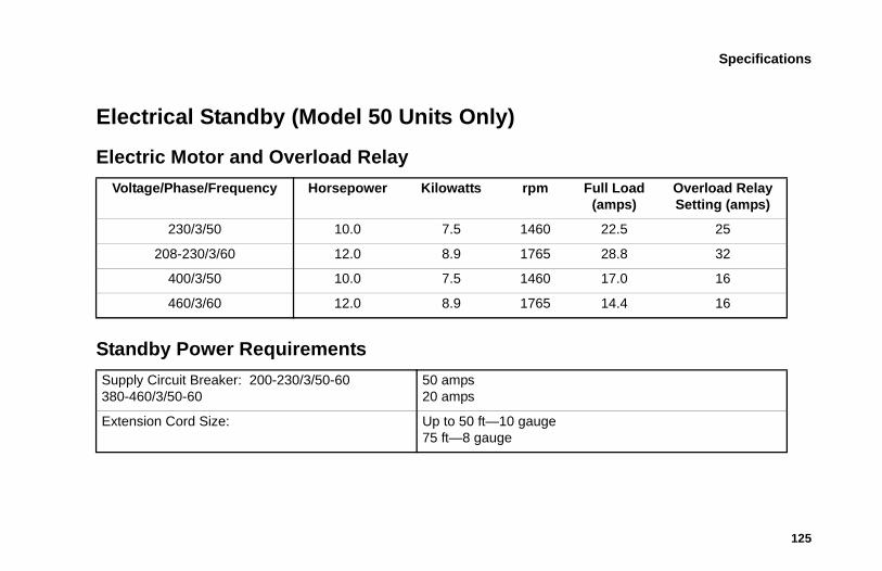
Specifications
125
Electrical Standby (Model 50 Units Only)
Electric Motor and Overload Relay
Voltage/Phase/Frequency Horsepower Kilowatts rpm Full Load (amps)
Overload Relay Setting (amps)
230/3/50 10.0 7.5 1460 22.5 25
208-230/3/60 12.0 8.9 1765 28.8 32
400/3/50 10.0 7.5 1460 17.0 16
460/3/60 12.0 8.9 1765 14.4 16
Standby Power Requirements
Supply Circuit Breaker: 200-230/3/50-60380-460/3/50-60
50 amps20 amps
Extension Cord Size: Up to 50 ft—10 gauge 75 ft—8 gauge
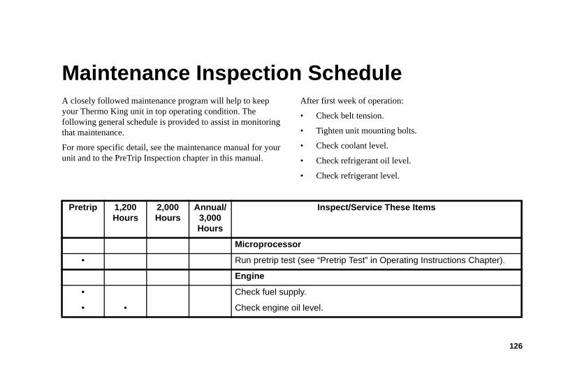
126
Maintenance Inspection ScheduleA closely followed maintenance program will help to keep your Thermo King unit in top operating condition. The following general schedule is provided to assist in monitoring that maintenance.
For more specific detail, see the maintenance manual for your unit and to the PreTrip Inspection chapter in this manual.
After first week of operation:
• Check belt tension.
• Tighten unit mounting bolts.
• Check coolant level.
• Check refrigerant oil level.
• Check refrigerant level.
Pretrip 1,200Hours
2,000Hours
Annual/3,000Hours
Inspect/Service These Items
Microprocessor
• Run pretrip test (see “Pretrip Test” in Operating Instructions Chapter).
Engine
• Check fuel supply.
• • Check engine oil level.
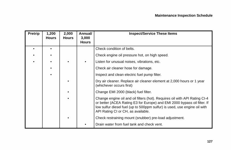
Maintenance Inspection Schedule
127
• • Check condition of belts.
• • Check engine oil pressure hot, on high speed.
• • • • Listen for unusual noises, vibrations, etc.
• Check air cleaner hose for damage.
• Inspect and clean electric fuel pump filter.
• Dry air cleaner. Replace air cleaner element at 2,000 hours or 1 year (whichever occurs first)
• Change EMI 2000 (black) fuel filter.
• Change engine oil and oil filters (hot). Requires oil with API Rating CI-4 or better (ACEA Rating E3 for Europe) and EMI 2000 bypass oil filter. If low sulfur diesel fuel (up to 500ppm sulfur) is used, use engine oil with API Rating CI or CH, as available.
• Check restraining mount (snubber) pre-load adjustment.
• Drain water from fuel tank and check vent.
Pretrip 1,200Hours
2,000Hours
Annual/3,000Hours
Inspect/Service These Items
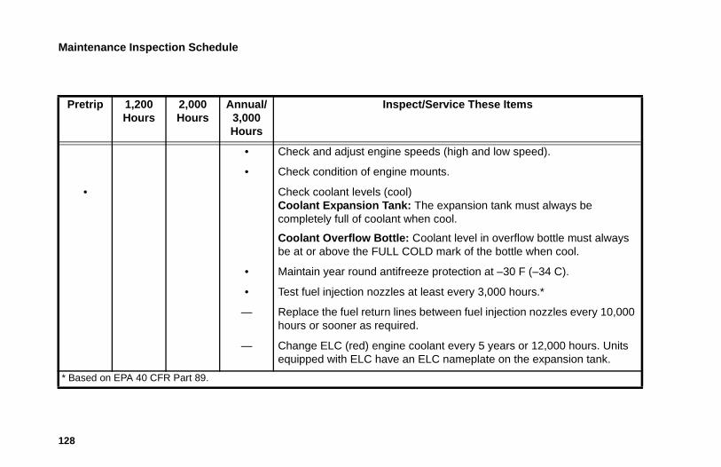
Maintenance Inspection Schedule
128
• Check and adjust engine speeds (high and low speed).
• Check condition of engine mounts.
• Check coolant levels (cool)Coolant Expansion Tank: The expansion tank must always be completely full of coolant when cool.
Coolant Overflow Bottle: Coolant level in overflow bottle must always be at or above the FULL COLD mark of the bottle when cool.
• Maintain year round antifreeze protection at –30 F (–34 C).
• Test fuel injection nozzles at least every 3,000 hours.*
— Replace the fuel return lines between fuel injection nozzles every 10,000 hours or sooner as required.
— Change ELC (red) engine coolant every 5 years or 12,000 hours. Units equipped with ELC have an ELC nameplate on the expansion tank.
* Based on EPA 40 CFR Part 89.
Pretrip 1,200Hours
2,000Hours
Annual/3,000Hours
Inspect/Service These Items
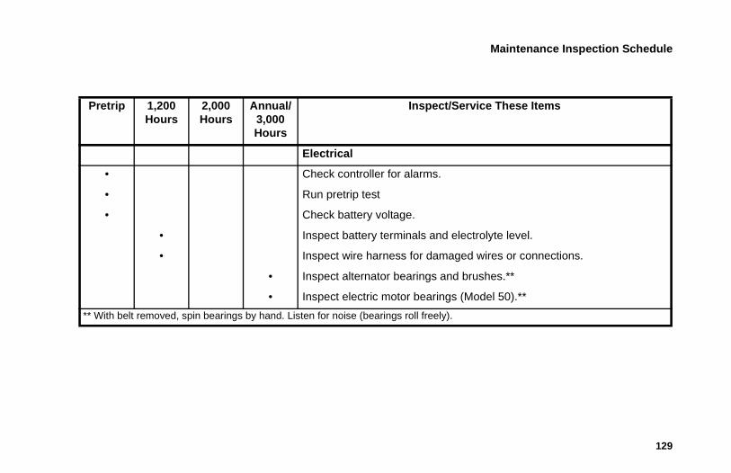
Maintenance Inspection Schedule
129
Electrical
• Check controller for alarms.
• Run pretrip test
• Check battery voltage.
• Inspect battery terminals and electrolyte level.
• Inspect wire harness for damaged wires or connections.
• Inspect alternator bearings and brushes.**
• Inspect electric motor bearings (Model 50).**
** With belt removed, spin bearings by hand. Listen for noise (bearings roll freely).
Pretrip 1,200Hours
2,000Hours
Annual/3,000Hours
Inspect/Service These Items
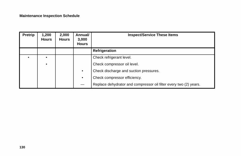
Maintenance Inspection Schedule
130
Refrigeration
• • Check refrigerant level.
• Check compressor oil level.
• Check discharge and suction pressures.
• Check compressor efficiency.
— Replace dehydrator and compressor oil filter every two (2) years.
Pretrip 1,200Hours
2,000Hours
Annual/3,000Hours
Inspect/Service These Items
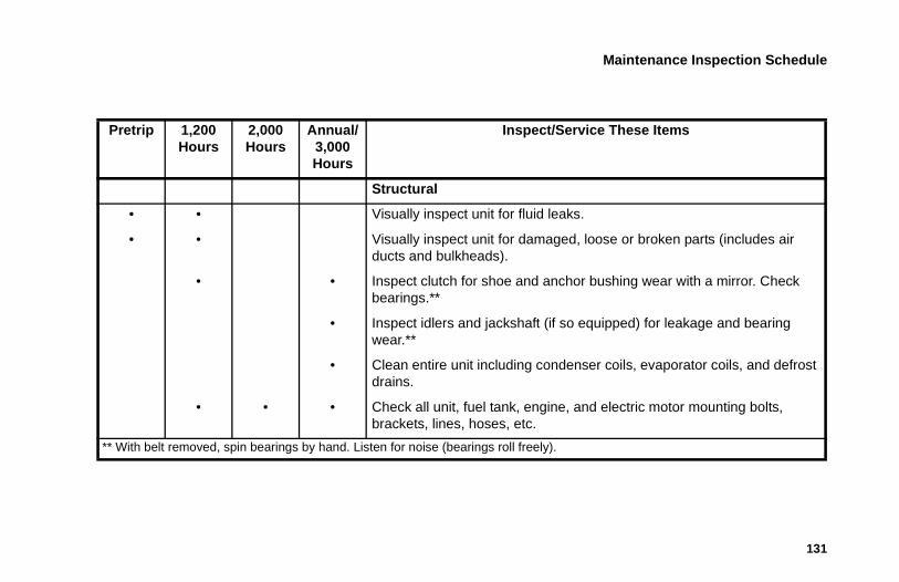
Maintenance Inspection Schedule
131
Structural
• • Visually inspect unit for fluid leaks.
• • Visually inspect unit for damaged, loose or broken parts (includes air ducts and bulkheads).
• • Inspect clutch for shoe and anchor bushing wear with a mirror. Check bearings.**
• Inspect idlers and jackshaft (if so equipped) for leakage and bearing wear.**
• Clean entire unit including condenser coils, evaporator coils, and defrost drains.
• • • Check all unit, fuel tank, engine, and electric motor mounting bolts, brackets, lines, hoses, etc.
** With belt removed, spin bearings by hand. Listen for noise (bearings roll freely).
Pretrip 1,200Hours
2,000Hours
Annual/3,000Hours
Inspect/Service These Items
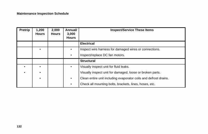
Maintenance Inspection Schedule
132
Pretrip 1,200Hours
2,000Hours
Annual/3,000Hours
Inspect/Service These Items
Electrical
• • Inspect wire harness for damaged wires or connections.
• Inspect/replace DC fan motors.
Structural
• • • Visually inspect unit for fluid leaks.
• • Visually inspect unit for damaged, loose or broken parts.
• • Clean entire unit including evaporator coils and defrost drains.
• Check all mounting bolts, brackets, lines, hoses, etc.
133
Serial Number and Refrigerant Label LocationsWrite the unit model and unit serial number in the spaces provided in the following Emergency Cold Line chapter. This information is needed to service the unit.
Figure 149: Engine Serial Number LocationFigure 150: Scroll Compressor Serial
Number Location (T-1080S)
AMA832
Serial Number and Refrigerant Label Locations
134
Figure 151: Reciprocating Compressor Serial Number Location (T-1280R)
1. Unit Serial Plate 2. Refrigerant Type
Figure 152: Label Locations
1
2
Serial Number and Refrigerant Label Locations
135
Figure 153: Laminated Unit Serial Number Plate
Figure 154: Refrigerant Type Label
• This label identifies the type of refrigerant in the unit.
136
Recover Refrigerant
At Thermo King, we recognize the need to preserve the environment and limit the potential harm to the ozone layer that can result from allowing refrigerant to escape into the atmosphere.
We strictly adhere to a policy that promotes the recovery and limits the loss of refrigerant into the atmosphere.
In addition, service personnel must be aware of Federal regulations concerning the use of refrigerants and the certification of technicians. For additional information on regulations and technician certification programs, contact your local THERMO KING dealer.
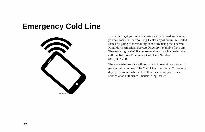
137
Emergency Cold LineIf you can’t get your unit operating and you need assistance, you can locate a Thermo King Dealer anywhere in the United States by going to thermoking.com or by using the Thermo King North American Service Directory (available from any Thermo King dealer) If you are unable to reach a dealer, then call the Toll Free Emergency Cold Line Number (888) 887-2202.
The answering service will assist you in reaching a dealer to get the help you need. The Cold Line is answered 24 hours a day by personnel who will do their best to get you quick service at an authorized Thermo King Dealer.
138
CaliforniaProposition 65 Warning
Diesel exhaust is a chemical known to the State of California to cause cancer.
139
WarrantyTerms of the Thermo King Warranty are available on request. Please reference document TK 50047 for the Thermo King Self-Powered Truck Unit Warranty.


Operator’s Manual
Operator’s Manual
Ingersoll Rand’s Climate Solutions sector delivers energy-effi cient HVACR solutions for customers globally. Its world class brands include Thermo King, the leader in transport temperature control and Trane, a provider of energy effi cient heating, ventilating and air conditioning systems, building and contracting services, parts support and advanced controls for commercial buildings and homes.
Ingersoll Rand’s Climate Solutions sector delivers energy-effi cient HVACR solutions for customers globally. Its world class brands include Thermo King, the leader in transport temperature control and Trane, a provider of energy effi cient heating, ventilating and air conditioning systems, building and contracting services, parts support and advanced controls for commercial buildings and homes.
©2011 Ingersoll-Rand Company Printed in U.S.A.
©2011 Ingersoll-Rand Company Printed in U.S.A.
T-1080S SPECTRUMWith Premium HMI
TK 55710-1-OP (Rev. 2, 09/17)
T-1080S SPECTRUMWith Premium HMI
TK 55710-1-OP (Rev. 2, 09/17)