Embed Size (px)
Citation preview

OPERATOR’S MANUAL
IMPORTANT: READ SAFETY RULES AND INSTRUCTIONS CAREFULLY
CUB CADET LLC P.O. BOX 361131 CLEVELAND, OHIO 44136-0019 [www.cubcadet.com]
PRINTED IN U.S.A.
Warning: This unit is equipped with an internal combustion engine and should not be used on or near any unimproved forest-covered, brush-covered or grass-covered land unless the engine’s exhaust system is equipped with a spark arrester meeting applicable local or state laws (if any). If a spark arrester is used, it should be maintained in effective working order by the operator.In the State of California the above is required by law (Section 4442 of the California Public Resources Code). Other states may have similar laws. Federal laws apply on federal lands. A spark arrester for the muffler is available through your nearest engine authorized service dealer or contact the service department, P.O. Box 361131 Cleveland, Ohio 44136-0019.
FORM NO. 770-10282C
2000TRACTOR
Model Number2166
(11/01)

2
KOHLER CO.FEDERAL AND CALIFORNIA EMISSION CONTROL SYSTEMS
LIMITED WARRANTYSMALL OFF-ROAD EQUIPMENT ENGINES
The U.S. Environmental Protection Agency (EPA), the California Air Resources Board (CARB), and Kohler Co. are pleased to explain the Federal and California Emission Control Systems Warranty on your small off-road equipment engine. For California, engines produced in 1995 and later must be designed, built and equipped to meet the state’s stringent anti-smog standards. In other states, 1997 and later model year engines must be designed, built and equipped, to meet the U.S. EPA regulations for small non-road engines. The engine must be free from defects in materials and workmanship which cause it to fail to conform with U.S. EPA standards for the first two years of engine use from the date of sale to the ultimate purchaser. Kohler Co. must warrant the emission control system on the engine for the period of time listed above, provided there has been no abuse, neglect or improper main-tenance.
The emission control system may include parts such as the carburetor or fuel injection system, the ignition system, and catalytic converter. Also included are the hoses, belts and connectors and other emission related assemblies.
Where a warrantable condition exists, Kohler Co. will repair the engine at no cost, including diagnosis (if the diagnostic work is performed at an autho-rized dealer), parts and labor.
MANUFACTURER’S WARRANTY COVERAGEEngines produced in 1995 or later are warranted for two years in California. In other states, 1997 and later model year engines are warranted for two years. if any emission related part on the engine is defective, the part will be repaired or replaced by Kohler Co. free of charge.
OWNER’S WARRANTY RESPONSIBILITIES(a) The engine owner is responsible for the performance of the required maintenance listed in the owner’s manual. Kohler Co. recommends that you
retain all receipts covering maintenance on the engine. But Kohler Co. cannot deny warranty solely for the lack of receipts or for your failure to assure that all scheduled maintenance was performed.
(b) Be aware, however, that Kohler Co. may deny warranty coverage if the engine or a part has failed due to abuse, neglect, improper maintenance or unapproved modifications.
(c) For warranty repairs, the engine must be presented to a Kohler Co. service center as soon as a problem exists. Call 1-800-544-2444, or access our web site at: www.kohlerengines.com, for the names of the nearest service centers. The warranty repairs should be completed in a reasonable amount of time, not to exceed 30 days.
If you have any questions regarding warranty rights and responsibilities, you should contact Kohler Co. at 1-920-457-4441 and ask for an Engine Service representative.
COVERAGEKohler Co. warrants to the ultimate purchaser and each subsequent purchaser that the engine will be designed, built and equipped, at the time of sale, to meet all applicable regulations. Kohler Co. also warrants to the initial purchaser and each subsequent purchaser, that the engine is free from defects in material and workmanship which cause the engine to fail to conform with applicable regulations for a period of two years.
Engines produced in 1995 or later are warranted for to years in California. For 1997 and later model years, EPA requires manufacturers to warrant engines for two years in all other states. These warranty periods will be begin on the date the engine is purchased by the initial purchaser. If any emis-sion related part on the engine is defective, the part will be replaced by Kohler Co. at no cost to the owner. Kohler Co. is liable for damages to other engine components caused by the failure of a warranted part still under warranty.
Kohler Co. shall remedy warranty defects at any authorized Kohler Co. engine dealer or warranty station. Warranty repair work done at an authorized dealer or warranty station shall be free of charge to the owner if such work determines that a warranted part is defective.
Listed below are the parts covered by the Federal and California Emission Control Systems Warranty. Some parts listed below may require scheduled maintenance and are warranted up to the first scheduled replacement point for that part. The warranted parts are:
LIMITATIONSThis Emission Control System Warranty shall not cover any of the following:
(a) repair or replacement required because of misuse or neglect, improper maintenance, repairs improperly performed or replacement not conforming to Kohler Co. specifications that adversely affect performance and/or durability and alterations or modifications not recommended or approved in writing by Kohler Co.,
(b) replacement of parts and other services and adjustments necessary for required maintenance at and after the first scheduled replacement point,
(c) consequential damages such as loss of time, inconvenience, loss of use of the engine or equipment, etc.,
(d) diagnosis and inspection fees that do not result in eligible warranty service being performed, and
(e) any add-on or modified part, or malfunction of authorized parts due to the use of add-on or modified parts.
MAINTENANCE AND REPAIRS REQUIREMENTSThe owner is responsible for the proper use and maintenance of the engine. Kohler Co. recommends that all receipts and records covering the perfor-mance of regular maintenance be retained in case questions arise. If the engine is resold during the warranty period, the maintenance records should be transferred to each subsequent owner. Kohler Co. reserves the right to deny warranty coverage if the engine has not been properly maintained; how-ever, Kohler Co. may not deny warranty repairs solely because of the lack of repair maintenance or failure to keep maintenance records.
Normal maintenance, replacement or repair of emission control devices and systems may be performed by any repair establishment or individual; how-ever, warranty repair must be performed by a Kohler authorized service center. Any replacement part or service that is equivalent in performance and durability may be used in non-warranty maintenance or repairs, and shall not reduce the warranty obligations of the engine manufacturer.
• Oxygen sensor (if equipped) • Intake manifold (if equipped)• Exhaust manifold (if equipped) • Catalytic muffler (if equipped)• Fuel metering valve (if equipped) • Spark advance module (if equipped)
• Crankcase breather • Ignition module(s) with high tension lead• Gaseous fuel regulator (if equipped) • Electronic control unit (if equipped)• Carburetor or fuel injection system • Fuel lines (if equipped)
• Air filter, fuel filter, and spark plugs (only to first scheduled replacement point)

3
TRACTOR AND DECK PREPARATION
1. ATTACHING THE CHUTE DEFLECTOR
For shipping purposes, the mulching plug has been in-stalled in the mower deck. The mulching plug must beremoved to install the chute deflector assembly.
WARNINGDo not operate the mower deck, even with themulching plug installed, unless the chutedefelector has been properly installed.
1. Remove the wing nut, bell washer, and carriage boltsecuring the mulching plug to the deck and with-draw the plug from the discharge opening of thedeck.
2. Remove the hex cap screws, bell washers and hexnuts installed in the deck at the chute opening.
3. Positon the deflector assembly to align its hingebracket holes with those of the deck. Install the hexcap screws from the underside of the deck andsecure with the bell washers and hex nuts. Note:the crowned (rounded) surface of the washers gotoward the hex nuts.
4. Refer to SECTION V-MOWER DECK when re-installing the mulching plug.
2. CONNECT THE BATTERY
WARNING
Battery posts, terminals and related accessoriescontain lead and lead compounds. Wash handsafter handling.
The tractor is shipped with an activated sealed battery,with the positive battery cable factory connected. Thenegative cable must be connected.
Note: Make sure the ignition switch is in the "OFF" po-sition before attaching the battery cables.
1. Pull the protective cap off the negative terminal ofthe battery, and remove the hex cap screw and nutfrom the free end of the negative battery cable.
2. Connect the negative battery cable (heavy black)and ground wire (green) to negative terminal (—)of the battery using the hex cap screw and nut.
3. Slide the black terninal cover over the negativeterminal of the battery.
WING NUT
HEX NUTSBELLWASHERS
CHUTEDEFLECTOR
HEX CAPSCREWS
MULCHINGPLUG
CARRIAGEBOLT
BELLWASHER
CONTENTSSection Page
Emission Control Systems Warranty ... 2Tractor and Deck Preparation.............. 3Safe Operation Practices..................... 4Product Graphics ................................. 7To The Owner ...................................... 8Calling Service Information.................. 8Recording Model & Serial Number ...... 8
I Controls and Indicators........................ 9II Operation ............................................. 14III Adjustments ......................................... 18IV Maintenance ........................................ 23V Mower Deck......................................... 33
Section Page
VI Off-Season Storage ............................. 45VII Mowing................................................. 46
Optional Equipment and Accessories . 47Maintenance Chart............................... 48Trouble Shooting.................................. 49Lubrication Table ................................. 51Lubrication Guide................................. 52Slope Gauge........................................ 55Specifications....................................... 57Warranty — Commercial Use ............. 58Warranty — Residential Use ............... 59Maintenance Parts Chart .................... 60

4
WARNING
• The engine exhaust, some of its constituents, and certain vehicle components contain or emit chemicals knownto the State of California to cause cancer, birth defects or other reproductive harm.
• This unit is equipped with an internal combustion engine and should not be used on or near any unimprovedforest-covered, brush-covered, or grass-covered land unless the engine’s exhaust system is equipped with aspark arrester meeting applicable local or state laws (if any). If a spark arrester is used, it should be maintainedin effective working order by the operator.
• In the State of California, the above is required by law (Section 4442 of the California Public Resources Code).Other States may have similar laws. Federal laws apply to federal lands. A spark arrester muffler is availableat your nearest engine authorized service center.
IMPORTANTTHIS SYMBOL POINTS OUT IMPORTANT SAFETY INSTRUCTIONS WHICH, IF NOT FOLLOWED,COULD ENDANGER THE PERSONAL SAFETY AND/OR PROPERTY OF YOURSELF ANDOTHERS. READ AND FOLLOW ALL INSTRUCTIONS IN THIS MANUAL BEFORE ATTEMPTINGTO OPERATE YOUR UNIT. FAILURE TO COMPLY WITH THESE INSTRUCTIONS MAY RESULTIN PERSONAL INJURY. WHEN YOU SEE THIS SYMBOL— HEED ITS WARNING.
SAFE OPERATION PRACTICES
Your lawn mower was built to be operated according to the rules for safe operationin this manual. As with any type of power equipment, carelessness or error on thepart of the operator can result in injury. This lawn mower is capable of amputatinghands and feet or throwing objects. Failure to observe the following safetyinstructions could result in serious injury or death.
I. GENERAL OPERATION
1. Read, understand and follow all instructions in themanual and on the machine before starting. Keepthis manual in a safe place for future and regularreference and for ordering replacement parts
2. Only allow responsible individuals familiar withthe instructions to operate the machine. Know thecontrols and how to stop the machine quickly.
3. Do not put hands or feet under the cutting deck ornear rotating parts.
4. Clear the area of objects such as rocks, toys,wire, etc. which could be picked up and thrown bythe blades. A small object may have beenoverlooked and could be accidentally thrown bythe mower in any direction and cause injury toyou or a bystander. To help avoid a thrownobjects injury, keep children, animals, bystandersand helpers at least 75 feet from the mower whileit is in operation. Always wear safety glasses withside shields or safety goggles during operation orwhile performing an adjustment or repair, toprotect eyes from foreign objects. Stop the bladeswhen crossing gravel drives, walks or roads.
5. Be sure the area is clear of other people beforemowing. Stop machine if anyone enters the area.
6. Never carry passengers.
7. Disengage the blades before shifting into reverseand backing up. Always look down and behindbefore and while backing.
8. Be aware of the mower and attachment dischargedirection and do not point it at anyone. Do notoperate the mower without either the entire grasscatcher or the chute guard in place.
9. Slow down before turning. Operate the machinesmoothly. Avoid erratic operation and excessivespeed.
10. Never leave a running machine unattended.Always turn off the blades, place the transmissionin neutral, set the parking brake, stop the engineand remove key before dismounting.
11. Turn off blades when not mowing.
12. Stop the engine and wait until the blades come toa complete stop before (a) removing the grasscatcher or unclogging chute, or (b) making anyrepairs, adjusting or removing any grass or debris.
DANGER

5
13. Mow only in daylight or good artificial light.
14. Do not operate the machine while under theinfluence of alcohol or drugs.
15. Watch for traffic when operating near or crossingroadways.
16. Use extra care when loading or unloading themachine into a trailer or truck. This unit should notbe driven up or down a ramp onto a trailer or truckunder power, because the unit could tip overcausing serious personal injury. The unit must bepushed manually on a ramp to load or unloadproperly.
17. Never make a cutting height adjustment while theengine is running if the operator must dismount todo so.
18. Wear sturdy, rough-soled work shoes and close-fitting slacks and shirts. Do not wear loose fittingclothes or jewelry. They can be caught in movingparts. Never operate a unit in bare feet, sandalsor sneakers.
19. Check overhead clearance carefully beforedriving under power lines, wires, bridges or lowhanging tree branches, before entering or leavingbuildings, or in any other situation where theoperator may be struck or pulled from the unit,which could result in serious injury.
20. Disengage all attachment clutches, thoroughlydepress the brake pedal and shift into neutralbefore attempting to start the engine.
21. Your mower is designed to cut normal residentialgrass of a height no more than 10”. Do notattempt to mow through unusually tall, dry grass(e.g. pasture) or piles of dry leaves. Debris maybuild up on the mower deck or contact the engineexhaust presenting a potential fire hazard.
22. Use only accessories approved for this machineby Cub Cadet. Read, understand and follow allinstructions provided with the approvedaccessory.
II. SLOPE OPERATION
Slopes are a major factor related to loss of control andtip-over accidents, which can result in severe injury ordeath. All slopes require extra caution. If you cannotback up the slope or if you feel uneasy on it, do notmow it.
For your safety, use the slope gauge included as partof this manual to measure slopes before operating thisunit on a sloped or hilly area. If the slope is greaterthan 15° as shown on the slope gauge, do not operatethis unit on that area or serious injury could result.
DO:
Mow up and down slopes, not across.
Remove obstacles such as rocks, limbs, etc.
Watch for holes, ruts or bumps. Uneven terrain couldoverturn the machine. Tall grass can hide obstacles.
Use slow speed. Choose a low enough gear so thatyou will not have to stop or shift while on the slope. Al-ways keep the machine in gear when going downslopes to take advantage of engine braking action.
Follow the manufacturer’s recommendations for wheelweights or counterweights to improve stability.
Use extra care with grass catchers or other attach-ments. These can change the stability of the machine.
Keep all movement on the slopes slow and gradual.Do not make sudden changes in speed or direction.Rapid engagement or braking could cause the front ofthe machine to lift and rapidly flip over backwards,which could cause serious injury.
Avoid starting or stopping on a slope. If the tires losetraction, disengage the blades and proceed slowlystraight down the slope.
DO NOT:
Do not turn on slopes unless necessary; then, turnslowly and gradually downhill, if possible.
Do not mow near drop-offs, ditches or embankments.The mower could suddenly turn over if a wheel is overthe edge of a cliff or ditch, or if an edge caves in.
Do not mow on wet grass. Reduced traction couldcause sliding.
Do not try to stabilize the machine by putting your footon the ground.
Do not use the grass catcher on steep slopes.
III. CHILDREN
Tragic accidents can occur if the operator is not alertto the presence of children. Children are oftenattracted to the machine and the mowing activity.Never assume that children will remain where youlast saw them.
1. Keep children out of the mowing area and inwatchful care of an adult other than the operator.
2. Be alert and turn the machine off if children enterthe area.
3. Before and when backing up, look behind anddown for small children.
4. Never carry children, even with the blades off.Children may fall off and be seriously injured ormay interfere with safe machine operation.
6
5. Never allow children under 14 years old tooperate the machine. Children 14 years and overshould only operate the machine under closeparental supervision and proper instruction.
6. Use extra care when approaching blind corners,shrubs, trees or other objects that may obscureyour vision of a child or other hazard.
7. Remove the key when the machine is leftunattended to prevent unauthorized operation.
IV. SERVICE
1. Use extreme care in handling gasoline and otherfuels. They are extremely flammable and thevapors are explosive.
a. Use only an approved container.b. Never remove fuel cap or add fuel with the en-
gine running. Allow the engine to cool at leasttwo minutes before refueling.
c. Replace the fuel cap securely and wipe off anyspilled fuel before starting the engine as it maycause a fire or explosion.
d. Extinguish all cigarettes, cigars, pipes and oth-er sources of ignition.
e. Never refuel the machine indoors because fuelvapors will accumulate in the area.
f. Never store the fuel container or machineinside where there is an open flame or spark,such as a gas hot water heater, space heateror furnace.
2. Never run a machine inside a closed area.
3. To reduce fire hazard, keep the machine free ofgrass, leaves or other debris build-up. Clean upoil or fuel spillage. Allow the machine to cool atleast 5 minutes before storing.
4. Before cleaning, repairing or inspecting, makecertain the blade and all moving parts havestopped. Disconnect the spark plug wire, andkeep the wire away from the spark plug to preventaccidental starting.
5. Check the blade and engine mounting bolts at fre-quent intervals for proper tightness. Also visuallyinspect blades for damage (e.g., excessive wear,bent, cracked). Replace with blades which meetoriginal equipment specifications.
6. Keep all nuts, bolts and screws tight to be surethe equipment is in safe working condition.
7. Never tamper with safety devices. Check theirproper operation regularly. Use all guards asinstructed in this manual.
8. After striking a foreign object, stop the engine,remove the wire from the spark plug andthoroughly inspect the mower for any damage.Repair the damage before restarting andoperating the mower.
9. Grass catcher components are subject to wear,damage and deterioration, which could exposemoving parts or allow objects to be thrown. Foryour safety protection, frequently check thecomponents and replace with manufacturer’srecommended parts when necessary.
10. Mower blades are sharp and can cut. Wrap theblades or wear gloves, and use extra cautionwhen servicing blades.
11. Check brake operation frequently. Adjust andservice as required.
12. Muffler, engine and belt guards become hotduring operation and can cause a burn. Allow tocool down before touching.
13. Do not change the engine governor settings oroverspeed the engine. Excessive engine speedsare dangerous.
14. Observe proper disposal laws and regulations.Improper disposal of fluids and materials canharm the environment and the ecology.
a. Prior to disposal, contact your localEnvironmental Protection Agency todetermine the proper method for disposing ofthe waste. Recycling centers are establishedto properly dispose of materials in anenvironmentally safe fashion.
b. Use proper containers when draining fluids.Do not use food or beverage containers thatmay mislead someone into drinking fromthem. Properly dispose of the containers im-mediately following the draining of fluids.
c. DO NOT pour oil or other fluids into theground, down a drain or into a stream, pond,lake, or other body of water. Observe Environ-mental Protection Agency regulations whendisposing of oil, fuel, coolant, brake fluid, fil-ters, batteries, tires and other harmful waste.
15. We do not recommend the use of a pressurewasher or garden hose to clean your unit. Theymay cause damage to electrical components;spindles; pulleys; bearings; or the engine. Theuse of water will result in shortened life andreduce serviceability.
WARNING - YOUR RESPONSIBILITY: Restrict the use of this power machine to persons whoread, understand and follow the warnings and instructions in this manual and on the machine.
7
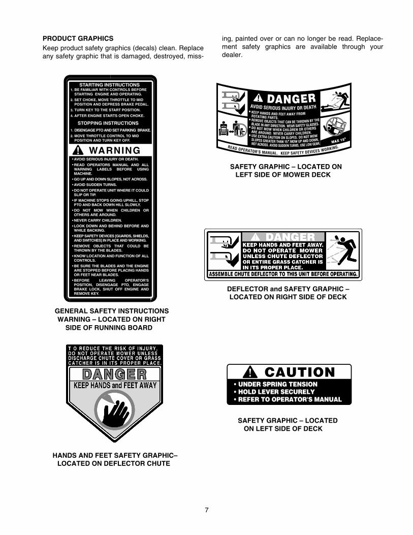
PRODUCT GRAPHICSKeep product safety graphics (decals) clean. Replaceany safety graphic that is damaged, destroyed, miss-
ing, painted over or can no longer be read. Replace-ment safety graphics are available through yourdealer.
GENERAL SAFETY INSTRUCTIONSWARNING – LOCATED ON RIGHT
SIDE OF RUNNING BOARD
SAFETY GRAPHIC – LOCATED ON LEFT SIDE OF MOWER DECK
HANDS AND FEET SAFETY GRAPHIC–LOCATED ON DEFLECTOR CHUTE
DEFLECTOR and SAFETY GRAPHIC – LOCATED ON RIGHT SIDE OF DECK
WARNING!
BE FAMILIAR WITH CONTROLS BEFORESTARTING ENGINE AND OPERATING.
SET CHOKE, MOVE THROTTLE TO MID POSITION AND DEPRESS BRAKE PEDAL.
TURN KEY TO THE START POSITION.
AFTER ENGINE STARTS OPEN CHOKE.
STOPPING INSTRUCTIONSDISENGAGE PTO AND SET PARKING BRAKE.
MOVE THROTTLE CONTROL TO MID POSITION AND TURN KEY OFF.
STARTING INSTRUCTIONS
AVOID SERIOUS INJURY OR DEATH.
READ OPERATORS MANUAL AND ALLWARNING LABELS BEFORE USINGMACHINE.
GO UP AND DOWN SLOPES, NOT ACROSS.
AVOID SUDDEN TURNS.
DO NOT OPERATE UNIT WHERE IT COULDSLIP OR TIP.
IF MACHINE STOPS GOING UPHILL, STOPPTO AND BACK DOWN HILL SLOWLY.
DO NOT MOW WHEN CHILDREN OROTHERS ARE AROUND.
NEVER CARRY CHILDREN.
LOOK DOWN AND BEHIND BEFORE ANDWHILE BACKING.
KEEP SAFETY DEVICES [GUARDS, SHIELDS,AND SWITCHES] IN PLACE AND WORKING.
REMOVE OBJECTS THAT COULD BETHROWN BY THE BLADES.
KNOW LOCATION AND FUNCTION OF ALLCONTROLS.
BE SURE THE BLADES AND THE ENGINEARE STOPPED BEFORE PLACING HANDSOR FEET NEAR BLADES.
BEFORE LEAVING OPERATOR'SPOSITION, DISENGAGE PTO, ENGAGEBRAKE LOCK, SHUT OFF ENGINE ANDREMOVE KEY.
2.
3.
1.
2.
4.
1.
•
•
•
•
•
•
•
•
•
•
•
•
•
•
SAFETY GRAPHIC – LOCATED ON LEFT SIDE OF DECK

8
TO THE OWNERThis Operator’s Manual is an important part of your new tractor. The information contained in this manual has beenprepared in detail to help you better understand the features, correct operation, adjustments, and maintenance ofyour tractor. The performance and dependability of this tractor rely greatly on the manner in which it is operated andmaintained. Therefore, it is recommended that all operators of the tractor carefully read this manual and fully under-stand its operation. Also keep the manual available for reference to ensure proper operation, and that maintenanceprocedures are performed as scheduled to assure the tractor’s optimal mechanical condition.
NOTE: All references to LEFT, RIGHT, FRONT, and REAR, unless specifically stated otherwise, indicate that rela-tive position on the tractor when facing forward while seated in the operator’s seat.
CAUTION: DO NOT tow your Model 2166 tractor. Towing may damage the transmission. Place the tractor on aLEVEL SURFACE before pulling the transmission release lever to the disengaged position.
Your local authorized Cub Cadet dealer is interested in the performance you receive from your tractor, and with themaintenance needed to ensure the satisfactory operation of your tractor. The dealer has trained service personnelfamiliar with the latest servicing information, is equipped with the latest tools, and has a complete line of genuineCub Cadet service parts which assure proper fit and high quality.
CALLING SERVICE INFORMATIONThe engine manufacturer is responsible for all engine-related issues with regards to performance, power-rating, andspecifications.
If you have difficulties with the tractor and/or equipment; have any questions regarding the operation or maintenanceof this equipment; or desire additional information not found in this manual, contact your nearest authorized CubCadet dealer. If you need assistance in locating a dealer in your area, contact the Customer Dealer Referral Line bycalling:
1-877-282-8684To obtain top performance and assure economical operation, the tractor should be inspected by your authorizeddealer periodically or at least once a year, depending on its hours of use. Before calling your dealer, make sure thatyou have your model number(s) and manufacturing date available for the dealer.
RECORDING MODEL AND SERIAL NUMBER INFORMATIONProduct identification plates are provided for major components of your tractor. The numbers on these plates areimportant if your tractor should require dealer service, or if you need additional information on your tractor. Prior tousing your tractor for the first time, record the numbers from the identification plates in the appropriate spaces pro-vided below.
The chassis model plate, showing the factory model number and Mfg. Date (See Figure 1) can be found on theunderside of the seat mounting base. Pivot the seat foward to locate the decal.
The engine serial number decal (See Figure 2) is located on the engine blower housing.
Hood Model Factory Model No. Mfg. Date
Delivery Date Engine Model/Spec. No. Engine Serial No.
Figure 1 Figure 2
www.cubcadet.com
CUB CADET LLCP. O. BOX 361131CLEVELAND, OH 44136
DEALER LOCATOR PHONE NUMBER: 877-282-8684
Model Number Mfg. Date
XXXXXXXXXXX XXXXXXXXXX

9
SECTION I. CONTROLS AND INDICATORS
Your Cub Cadet Tractor has been safety engineered.This section gives a brief description of the functionand location of the various controls and indicators.
Thoroughly acquaint yourself with all the controls andindicators before attempting to start or operate thetractor.
A. Low Oil IndicatorB. Hour MeterC. Power Take-Off (PTO) Control SwitchD. Ignition/Light SwitchE. Throttle Control LeverF. Choke ControlG. Brake Pedal Lock H. Cruise Control Lever
I. Brake PedalJ. Forward Control PedalK. Reverse Control PedalL. Lift HandleM. Lift Height IndicatorN. Seat Adjustment LeverO. Transmission Release LeverP. Fuses (Not Shown)Q. Safety Interlock Switches (Not Shown)
Figure 3
A B
C
F
E
H G
D
I
J
K
O
L
N
M

10
A. LOW OIL INDICATORThis indicator will illuminate when the engine oil level islow. If this indicator illuminates, stop the tractor imme-diately and check the engine oil level. If the oil level iswithin the operating range, but the light remains on,contact your Cub Cadet dealer.
CAUTION
Operating the tractor with low oil level or pres-sure could result in severe engine damage.
B. HOUR METERThe hour meter operates whenever the ignition key isin the “ON” position. Record the actual hours of tractoroperation to ensure all maintenance procedures arecompleted according to the schedule in this manual.
C. POWER TAKE–OFF (PTO) CONTROL SWITCHThe power take-off control switch operates the frontelectric PTO clutch. Pull the switch knob to engage(“RUN”), or push the knob to disengage (“OFF”) thePTO clutch.
D. IGNITION/LIGHT SWITCH
WARNING
To prevent accidental starting and/or batterydischarge, remove the key from the ignitionswitch when the tractor is not in use.
The combination lights and ignition switch is a fourposition switch. (See Figure 4)
Figure 4
E. THROTTLE CONTROL LEVER
This lever controls the speed of the engine. Whenset in a given position, the control cable will maintaina uniform engine speed.
NOTEWhen using power take-off operated equip-ment, best performance is achieved with thethrottle lever in the “FAST” position.
F. CHOKE CONTROL
The choke control is operated manually. Pull theknob out to ckoke the engine; push the knob in toopen the choke.
G. BRAKE PEDAL LOCK
WARNING
The hydrostatic transmission will not hold thetractor on a hill. Normal internal leakage in thetransmission will allow the tractor to roll down-hill. To avoid an accident and/or possible inju-ry, engage the brake pedal lock.
The brake lock lever, located in the center of thedash panel below the steering wheel, is identifiedwith the symbol. Always engage the brakepedal lock when dismounting the tractor. To engagethe brake pedal lock, depress the brake pedal andpush down on the brake pedal lock lever. Hold thelever down while releasing the brake pedal. The le-ver should lock in the down position.
H. CRUISE CONTROL LEVER
The cruise control lever, located in the center of thedash panel below the steering wheel, is identified withthe symbol. This lever can be used to main-tain a desired “foot free” forward speed in areaswhere constant speed changes are not required. Re-fer to Section II- OPERATION for instructions on howto use this feature.
This symbol shows slow position.
This symbol shows fast position.
P

11
I. BRAKE PEDAL
The brake pedal is located at the front of the right run-ning board above the forward control pedal. Pressdown to stop the tractor and disengage the cruise con-trol. The brake pedal must be fully depressed to acti-vate the safety interlock switch when starting thetractor.
J. FORWARD CONTROL PEDAL
The forward control pedal is located at the front of theright running board below the brake pedal. Slowlypress down on the pedal to start moving forward. Theforward ground speed of the tractor is directly affectedby the distance the pedal is depressed.
K. REVERSE CONTROL PEDAL
WARNING
Check behind the tractor to be sure the area isclear of people, pets or obstacles. Use a slowerspeed to maintain control of the tractor whentraveling in reverse.
The reverse control pedal is located in the right frontrunning board rearward of the the brake and forwardcontrol pedals. Press the pedal downward to move inreverse.
L. LIFT HANDLE
The lift handle is located in the left fender and is usedto raise and lower equipment used with the tractor. Theequipment can be set in any of six positions by de-pressing the top button on the handle, moving the han-dle to the desired position, then releasing the button. Itmay be necessary to push or pull slightly on the handleto depress the button. There is a lift assist spring whichreduces the effort needed to lift attachments. To adjustspring tension refer to ADJUSTMENTS in Section III.
M. LIFT HEIGHT INDICATOR
The lift height indicator is located in the left fender andindicates the height of the deck attachment when in-stalled.
N. SEAT ADJUSTMENT LEVER
The seat adjustment lever (see Figure 5) is used tomove the seat forward or rearward into one of five po-sitions. See ADJUSTING THE SEAT in Section III.
Figure 5
O. TRANSMISSION RELEASE LEVER
The transmission release lever is located at the back ofthe tractor in the rear drawbar. This lever disconnectsthe hydro transmission pump from the rear axle to al-low the unit to be pushed a short distance by hand.
To disengage the transmission, pull back on the leveruntil its locking flange is visible outside the drawbar,then lift the lever up into the slot and release. To re-en-gage the transmission, pull back on the lever, drop outof the slot and release.
P. FUSES
The fuses are located under the hood between the in-dicator lamps and the hour meter (see Figure 6). Fusesare installed to protect the tractor’s electrical circuitryand components from damage caused by excessiveamperage.
Figure 6

12
Q. SAFETY INTERLOCK SWITCHES
This tractor is equipped with a safety interlock systemfor the protection of the operator. If the interlock sys-tem should ever malfunction, do not operate the trac-tor. Contact your authorized Cub Cadet Dealer. Thesafety interlock system prevents the engine fromcranking or starting unless the brake pedal is fully de-pressed, and the PTO switch is in the “OFF” position.
The safety interlock system will automatically shut offthe engine if the operator leaves the seat before en-gaging the brake lock.
The safety interlock system will automatically shut offthe engine if the operator leaves the seat with the PTOin the “RUN” position, regardless of whether the brakelock is engaged. The PTO switch must be moved to the“OFF” position to restart the engine.
The safety interlock system will automatically shut offthe PTO if the reverse control pedal is depressed withthe PTO in the “RUN” position. To re-engage the PTO,release the reverse control pedal, move the PTOswitch to the “OFF” position, then again pull the switchto the “RUN” position.
FUEL TANK
The fuel tank is located under the rear fender. The fillercap is in the center/rear of the fender (see Figure 7).
Figure 7
HOOD AND SIDE PANELS
The tractor hood is arranged to swing up and forwardfor easy access to the engine compartment (see Fig-ure 8). Whenever engine maintenance is required, theside panels can be removed.
WARNING
If the engine has been recently run, the engine,muffler and surrounding metal surfaces will behot and can cause burns to the skin. Allow thetractor to cool and use caution when removingthe side panels.
To remove either the right or left side panel, refer toFigure 8 and proceed as follows:
1. Engage the brake lock and raise the hood.
2. Loosen, but do not remove, the rear wing nut andupper front wing nut.
3. Grasp the side panel just behind the grille and pulloutward to release the side panel from thetapered bushings on the grille.
4. Slide the side panel forward and out of the groovein the dash panel.
To install either the right or left side panel, refer to Fig-ure 8 and proceed as follows:
1. Slide the rear of panel into the groove in the dashpanel.
2. Position the notch of the rear side panel tab onthe threads of the bulkhead rod, between thebulkhead and wing nut.
3. Press the slots of the front side panel flange ontothe tapered retainers, between the retainers andthe grille.
4. Tighten the rear and upper front wing nuts andclose the hood.

13
Figure 8
UPPER FRONTWING NUT
RETAINER WITHTAPERED GUIDE
REAR WING NUT
GRILLE
REAR TABON PANEL
SIDE PANEL
GROOVE INDASH PANEL GRASP
GRASP

14
SECTION II. OPERATION
WARNING
RECEIVE INSTRUCTION - Read theoperator’s manual. Learn to operate thismachine SAFELY. Don’t risk INJURY orDEATH.
1. Before starting the engine or beginning op-eration, be familiar with the controls. Theoperator must be seated, the PTO switch inthe “OFF” position and the brake pedal fullydepressed.
2. Keep all shields in place. Keep away frommoving parts.
3. NO RIDERS! Keep all people and pets asafe distance away. Look behind to bothsides before backing up.
4. DO NOT direct the mower discharge atpeople.
5. Avoid slopes. Tractors can be rolled over.
6. Before leaving the operator’s seat: Shutoff the PTO, engage the brake pedal lock,shut off the engine and remove the ignitionkey. Wait for all movement to stop beforeservicing or cleaning.
7. Do not fill the fuel tank when the engine isrunning or while the engine is hot. Tightenthe fuel cap securely.
BEFORE OPERATING YOUR TRACTOR 1. Before you operate the tractor, study this manual
carefully. It has been prepared to help you operateand maintain your tractor with utmost efficiency.
2. Familiarize yourself with the operations of all theinstruments and controls.
3. This engine is certified to operate on unleadedgasoline. For best results, fill the fuel tank withonly clean, fresh, unleaded gasoline with a pumpsticker octane rating of 87 or higher. In countriesusing the Research method, it should be 90octane minimum.
Unleaded gasoline is recommended because itleaves less combustion chamber deposits. Lead-ed gasoline may be used in areas where unleadedis not available and exhaust emissions are not reg-ulated. Be aware however, that the cylinder headmay require more frequent service.
Gasohol (up to 10% ethyl alcohol, 90% unleadedgasoline by volume) is an approved fuel. Othergasoline/alcohol blends are not approved.
Methyl Tertiary Butyl Ether (MTBE) and unleadedgasoline blends (up to a maximum of 15% MTBEby volume) are approved fuels. Other gasoline/ether blends are not approved.
4. Check the engine and transmission oil levels.
5. Clean the air cleaner element if necessary.
6. Check the tire inflation pressures.
7. Adjust the seat for operator’s maximum comfort,visibility and for maintaining complete control ofthe tractor.
8. Remove the side panels and clean anyaccumulated grass and debris from the engine airinlet screen. Also clean the dash air intakescreen, grille and side panels to ensure adequatecooling.
9. Refer to the various sections of the Owner’sManual for additional information.
STARTING THE ENGINE
WARNING
For personal safety, the operator must be sittingin the tractor seat when starting the engine.
WARNING
This unit is equipped with a safety inerlocksystem designed for the protection of theoperator. Do not operate the tractor if any partof the interlock system is malfunctioning.Periodically check the functions of the interlocksystem for proper operation as describedbelow:
• The safety interlock system prevents the en-gine from cranking or starting unless thebrake pedal is fully depressed and the PTOclutch engagement switch is in the “OFF” po-sition.

15
• The safety interlock system will automatical-ly shut off the engine if the operator leavesthe seat before engaging the brake pedallock.
• The safety interlock system will automatical-ly disengage the PTO if the reverse controlpedal is pressed down with the PTO in the“RUN” position. To re-engage the PTO, re-lease the reverse control pedal, move thePTO switch into the “OFF” position and thenengage the PTO while seated.
• The safety interlock system will automatical-ly shut off the tractor engine if the operatorleaves the seat with the PTO in the “RUN”position.
1. Operator must be sitting in the tractor seat.
2. Pull choke control knob to full choke position.Less choking may be necessary due to variationsin temperature, grade of fuel, etc. Little or nochoking will be needed when the engine is warm.
3. Place the throttle midway between the “SLOW”and “FAST” position.
4. Place the PTO switch in the “OFF” position.
5. Fully depress the brake pedal.
6. Turn the ignition key clockwise to the “START”position and release it as soon as the enginestarts; however, do not crank the enginecontinuously for more than 10 seconds at a time.If the engine does not start within this time, turnthe key “OFF” and wait a minute to allow theengine’s starter motor to cool, then try again.
7. After the engine starts, slowly release the brakepedal. As the engine warms up, gradually pushthe choke control knob all the way in. Do not usethe choke to enrich the fuel mixture, except asnecessary to start the engine.
STOPPING THE ENGINE
CAUTION
Remove the key from the ignition switch toprevent accidental starting or battery dischargeif the equipment is left unattended.
Place the PTO switch in the “OFF” position. Move thethrottle control lever between the “MID” and “FAST”positions. Wait a moment to allow the engine speed tostabilize, then turn the ignition key to the “OFF” posi-tion. Remove the key from the ignition switch.
TRACTOR BREAK-IN PROCEDURE
CAUTION
Never operate a new engine immediatelyunder full load. Break it in carefully as shownin the table below.
COLD WEATHER STARTING
WARNING
Engine exhaust gases are dangerous. Do notrun the engine in a confined area such as astorage building any longer than is necessary.Immediately move the tractor outdoors.
WARNING
For personal safety, the operator must be sittingin the tractor seat before starting the tractor.
When starting the engine at temperatures near or belowfreezing, ensure the correct viscosity motor oil is used inthe engine and the battery is fully charged. Start the en-gine as follows:
1. Pull the choke all the way out to full choke position.
2. Move the throttle control lever to midway betweenthe “SLOW” and “FAST” position.
3. Place the PTO switch in the “OFF” position.
4. Fully depress the brake pedal.

16
5. Turn the ingnition key to the “START” position andhold until the engine starts; however, do not crankthe engine continuously for more than 10seconds at a time. Once the engine starts, graduallyadjust the choke as needed to keep the enginerunning until warmed up, then push the choke controlall the way in.
NOTEIf the engine fails to start after several attempts,the engine may become flooded. If thishappens, wait a minute to allow the startermotor to cool. Move the throttle control to the“SLOW” position, push the choke in all the wayand momentarily crank the engine to help clearthe cylinders. With the throttle control in the“SLOW” position and the choke all the way in,turn the ignition key to the “START” positionwhile slowly pulling the choke out to a positionthat will allow the engine to start. Graduallyadjust the choke as needed to keep the enginerunning until warmed up, then push the chokecontrol all the way in.
DRIVING THE TRACTOR
CAUTION
Avoid sudden starts, excessive speed andsudden stops.
CAUTION
Do not leave the seat of the tractor withoutdisengaging the PTO, depressing the brakepedal and engaging the brake pedal lock. Ifleaving the tractor unattended, also turn theignition key off and remove the key.
NOTEWhen using power take-off operatedequipment, best performance is achieved withthe throttle lever in the “FAST” position.
1. Depress the brake pedal to release the brake pedallock and let the pedal up. Move the throttle lever tothe position where the engine operates best for theload to be handled.
2. Driving with forward or reverse pedals.
CAUTION
Do not use the forward or reverse controlpedals to change the direction of travel whenthe tractor is in motion. Use the brake pedal tobring the tractor to a stop before depressingeither the forward or reverse control pedal.
a. To move forward, slowly depress the forwardcontrol pedal until the desired speed isachieved.
b. To move in reverse, check that the area be-hind is clear then fully depress the reversecontrol pedal.
3. Using the cruise control lever.
NOTEThe cruise control feature can only be operatedin the forward direction.
a. Slowly depress the forward control pedal untilthe desired speed is achieved.
b. Lightly push the cruise control lever downwardas far as possible and hold in this position.
c. While continuing to hold the cruise lever down,lift your foot from the forward control pedal(you should feel the cruise latch engage).
d. If properly engaged, the cruise lever and for-ward control pedal should lock in the down po-sition, and the tractor will maintain the sameforward speed.
e. Disengage the cruise control using one of thefollowing methods:
• Depress the brake pedal to disengage thecruise control and stop the tractor.
• Lightly depress the forward control pedal.• Lift the cruise control lever upward.
NOTEAlthough not recommended, depressing thereverse pedal will also disengage the cruisecontrol.
f. To change to the reverse direction when oper-ating with cruise control, depress the brakepedal to disengage the cruise control and stopthe tractor; then depress the reverse controlpedal.

17
DRIVING ON SLOPESRefer to the SLOPE GAUGE on page 55 to help deter-mine slopes where you may not operate safely.
WARNING
Do not mow on inclines with a slope in excessof 15 degrees (a rise of approximately 2-1/2 feetevery 10 feet). The tractor could overturn andcause serious injury.
WARNING
Operate the tractor up and down slopes, neveracross slopes. Always drive up or down the faceof a slope. Do not drive so that the tractor maytip over sideways .
Before operating the tractor on any slope, walk theslope to look for possible hazards such as rocks.mounds, ruts, stumps or other surface irregularitieswhich could cause the tractor to be upset.
Back the tractor with implement up the steepest portionof each slope you intend to work. If the tractor cannotnegotiate the slope in reverse, the slope is too steep tobe worked.
Avoid turns when driving on a slope. If a turn must bemade, turn down the slope. Turning up a slope greatlyincreases the chance of a roll over.
Avoid stopping when driving up a slope. If it is neces-sary to stop while driving up a slope, start up smoothlyand carefully to reduce the possibility of flipping thetractor over backward.
STOPPING THE TRACTOR
CAUTION
Always engage the brake pedal lock, push thePTO switch to the “OFF” position, lower theequipment and shut off the engine beforedismounting. Never try to start the engine whilestanding on the ground.
Fully depress the brake pedal to bring the tractor to acomplete stop (and disengage the cruise control), en-gage the brake pedal lock, disengage the PTO, turnthe ignition switch to “OFF’” and remove the key fromthe switch before dismounting.
OPERATING THE POWER TAKE-OFF (PTO) CLUTCH
Before operating the new clutch under load (mowinggrass, etc.), perform the following break-in procedure:
1. Start and run the engine a few minutes to warm up.
2. With the mowing deck, snow thrower, etc. installedand the engine running at approximately 50%throttle, engage and disengage the clutch at tensecond intervals (ten seconds ON-ten secondsOFF) five times. The engine choke may have tobe pulled out slightly to accomplish this.
3. Increase the engine speed to 75% throttle andagain engage and disengage the PTO clutch atten second intervals five times.
4. Make certain the PTO is disengaged and stop theengine.
Operate the PTO clutch as follows:
1. Move the throttle control lever to approximately themid throttle position.
2. Pull the PTO switch to the “RUN” position.
3. Advance the throttle lever to the operating speed(full engine speed).
4. The operator must remain in the tractor seat at alltimes. If the operator should leave the seatwithout turning off the power take-off switch, thetractor’s engine will shut off.
5. The PTO clutch cannot be operated when thetractor is driving in the reverse direction. The PTOswitch must in the “OFF” position when thereverse control pedal is depressed, or the PTOclutch will automatically disengage. To re-engagethe PTO clutch, release the reverse control pedal,move the PTO switch to the “OFF” position, thenagain pull the switch to the “RUN” position.
DRAWBAR
Drawbar type equipment must be hitched to the tractoronly at the hitch hole in the drawbar (See Figure 9).
Figure 9

18
SECTION III. ADJUSTMENTS
This section contains adjustment information for theModel 2166 tractor. Adjustment information for the 42-inch deck is located in Section V – Mower Deckbeginning on page 33.
ADJUSTING THE SEAT
WARNING
Do not adjust the seat when the tractor ismoving. Adjusting the seat while the tractor ismoving could cause the operator to lose controlof the tractor.
Before starting the tractor, adjust the seat forward orrearward to the most comfortable driving position. Toreposition the seat, move the seat adjustment lever(see Figure 10) upward and slide the seat forward orrearward. Release the adjustment lever when the seatis comfortably positioned. Gently rock the seat forwardand rearward once to be sure the seat is locked inplace.
Figure 10
ADJUSTING THE BRAKES
During normal operation of this tractor, the brakes aresubject to wear and will need periodic examination andadjustment.
To check the brake adjustment, position the tractor ona firm and level surface. Stop the tractor engine andremove the ignition key. Pull and lock the transmissionrelease lever in the “TRANSMISSION RELEASED”position. Perform the following checks:
1. Engage the brake pedal lock. If the tractor can bepushed forward or rearward, the braking forcemust be increased.
2. Release the brake pedal lock. If the tractor cannotbe pushed forward or rearward, the braking forcemust be decreased.
To adjust the braking force, refer to Figure 11 andproceed as follows:
1. Place the tractor on a level surface with the brakepedal lock disengaged. Stop the tractor engineand remove the ignition key.
2. While working from the underside of the tractor,facing the threaded end of the rod, remove thehairpin cotter from the brake rod adjustmentferrule. Remove the ferrule from the brake cam.
To increase the braking force—
Turn the ferrule clockwise (inward) one fullturn at a time until the ferrule can be insertedinto the brake cam while applying a minimaltension on the spring.
To decrease the braking force—Turn the ferrule counterclockwise (outward)one full turn at a time until the ferrule can beinserted into the brake cam while applying aminimal tension on the spring.
3. Turn the ferrule counterclockwise (outward) onefull turn to release the slight spring tension, theninsert the ferrule into the brake cam and securewith the hairpin cotter.
Figure 11. Viewed from top (fender off).
Recheck the brake adjustment to ensure proper brakeoperation before operating the tractor. If brake rodadjustment does not correct the problem, see yourauthorized Cub Cadet dealer.
SPRING
BRAKE ROD
HAIRPINCOTTER
ADJUSTMENTFERRULE
BRAKECAM

19
WHEEL ALIGNMENT
The front wheels should toe-in approximately 1/8 to1/4 inch, as measured across dimensions A and Bshown in Figure 12.
Figure 12. Viewed from beneath the tractor.
FRONT WHEEL ADJUSTMENT
WARNING
Place the tractor on a firm and level surface.
To adjust the toe-in, proceed as follows:
1. Check the lower steering arm to ensure it isperpendicular to the tractor frame (See Figure 12).
2. Place a mark at the same spot on both frontwheels; preferably the inner bead flange of thewheel rims.
3. Rotate the wheels to position the marks at the fronthorizontal diameter of the wheels, then measurethe distance between the marks and the bottomedges of the tractor frame channels (Seemeasurement D in Figure 12). These twomeasurements should be equal.
4. While holding the steering arms to prevent thesteering knuckles from moving, rotate the marks tothe rear horizontal diameter. Measure the distancebetween the marks and the frame (Seemeasurement C in Figure 12). Measurement Dshould be approximately 1/16 to 1/8 inch less thanmeasurement C on each side of the tractor.
5. Disconnect the front ball joints from the steeringarms by removing the hex lock nuts (Refer toFigure 13). Manually move each wheel to achievethe required toe-in and equal D measurements.
6. Loosen the jam nuts from the ball joints (SeeFigure 13).
Figure 13
7. Making sure not to move the lower steering arm oreither wheel, turn the ball joint in or out on each tierod as necessary to align with the hole in eachsteering arm.
8. Reinstall the ball joints in the steering arms andsecure with the hex lock nuts. Tighten the jam nutsagainst the ball joints.
PIVOT BAR ADJUSTMENT
CAUTION
The tractor should be checked every 50 hoursof operation for play between the frame axlechannel and the pivot axle.
Check and adjust the pivot axle as follows:
1. Raise the front ot the tractor and set it on jackstands, so the front wheels are suspended abovethe ground.
CAUTION
For safety, block the rear wheels to prevent thetractor from rolling and tipping or sliding the jackstands.
PERPENDICULARTO FRAME
LOWERSTEERING ARM
JAM NUT
STEERINGARM
HEXLOCK
NUT
BALL JOINT
TIE ROD
20
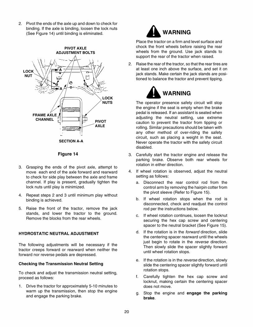
2. Pivot the ends of the axle up and down to check forbinding. If the axle is binding, loosen the lock nuts(See Figure 14) until binding is eliminated.
Figure 14
3. Grasping the ends of the pivot axle, attempt tomove each end of the axle forward and rearwardto check for side play between the axle and framechannel. If play is present, gradually tighten thelock nuts until play is minimized.
4. Repeat steps 2 and 3 until minimum play withoutbinding is achieved.
5. Raise the front of the tractor, remove the jackstands, and lower the tractor to the ground.Remove the blocks from the rear wheels.
HYDROSTATIC NEUTRAL ADJUSTMENT
The following adjustments will be necessary if thetractor creeps forward or rearward when neither theforward nor reverse pedals are depressed.
Checking the Transmission Neutral Setting
To check and adjust the transmission neutral setting,proceed as follows:
1. Drive the tractor for approximately 5-10 minutes towarm up the transmission, then stop the engineand engage the parking brake.
WARNING
Place the tractor on a firm and level surface andchock the front wheels before raising the rearwheels from the ground. Use jack stands tosupport the rear of the tractor when raised.
2. Raise the rear of the tractor, so that the rear tires areat least one inch above the surface, and set it onjack stands. Make certain the jack stands are posi-tioned to balance the tractor and prevent tipping.
WARNING
The operator presence safety circuit will stopthe engine if the seat is empty when the brakepedal is released. If an assistant is seated whenadjusting the neutral setting, use extremecaution to prevent the tractor from tipping orrolling. Similar precautions should be taken withany other method of over-riding the safetycircuit, such as placing a weight in the seat.Never operate the tractor with the safety circuitdisabled.
3. Carefully start the tractor engine and release theparking brake. Observe both rear wheels forrotation in either direction.
4. If wheel rotation is observed, adjust the neutralsetting as follows:
a. Disconnect the rear control rod from thecontrol arm by removing the hairpin cotter fromthe pivot sleeve (Refer to Figure 15).
b. If wheel rotation stops when the rod isdisconnected, check and readjust the controlrod per the instructions below.
c. If wheel rotation continues, loosen the locknutsecuring the hex cap screw and centeringspacer to the neutral bracket (See Figure 15).
d. If the rotation is in the forward direction, slidethe centering spacer rearward until the wheelsjust begin to rotate in the reverse direction.Then slowly slide the spacer slightly forwarduntil wheel rotation stops.
e. If the rotation is in the reverse direction, slowlyslide the centering spacer slightly forward untilrotation stops.
f. Carefully tighten the hex cap screw andlocknut, making certain the centering spacerdoes not move.
g. Stop the engine and engage the parkingbrake.
SECTION A-A
PIVOTAXLE
LOCKNUTS
A
A
FRAME AXLECHANNEL
PIVOT AXLEADJUSTMENT BOLTS
LOCKNUT

21
1
2
3
4
56
7
89
105
CONTROLCAM
Adjusting the Control Rod
After completing the previous steps (1 thru 4) forchecking neutral setting, adjust the control rod ( SeeFigure 15) as follows:
NOTEThe brake pedal lock MUST be engaged toproperly adjust the control rod.
1. Loosen, but do not remove, the hex tap screwsthat fasten the front and rear control rods together.
2. While making certain to not move the front controlrod, control cam or control arm (See Figure 15),slide the rear control rod in the direction necessaryto directly align the pin of the pivot sleeve with thelower hole of the control arm.
3. Insert the pivot sleeve pin into the control arm andsecure with the hairpin cotter, then tighten the hextap screws. Make sure to maintain the adjustedposition of the control rods when tightening thescrews.
4. Raise the rear of the tractor, remove the jackstands and lower the tractor.
ADJUSTING LIFT ASSIST SPRING TENSION
The effort required to operate the implement lift handlecan be varied by loosening or tightening the lift assistspring adjusting bolt (See Figure 16). The bolt can beaccessed from the rear of the tractor, inside the leftrear wheel. Turning the adjusting bolt clockwise willdecrease the manual effort required for liftingattachments; turning counterclockwise will increasethe effort needed to lift the attachment.
Figure 16
LIFT ASSISTSPRING
ADJUSTINGBOLT
1. Front Control Rod2. Rear Control Rod3. Hex Tap Screw4. Pivot Sleeve5. Neutral Arm6. Control Arm7. Hex Cap Screw8. Centering Spacer9. Neutral Bracket
10. Hairpin Cotter(Not Shown)
Figure 15.

22
CARBURETOR ADJUSTMENTS
WARNING
When making adjustments to the carburetorwhile the engine is running, disengage the PTOclutch and engage the brake pedal lock. Keepclear of all moving parts and be careful of all hotsurfaces.
WARNING
Carbon monoxide fumes can be fatal! Do notmake any adjustments to the carburetor in aconfined area such as a storage building. Movethe tractor outside into the air.
The carburetor is adjusted at the factory and undernormal operating conditions it will not requirereadjusting. The high idle is set at the factory andcannot be adjusted. If the engine does not operateproperly and the problem appears to be fuel systemrelated, check the following areas before adjusting thecarburetor: Refer to MAINTENANCE section.
• Check for fuel in fuel tank• Check fuel cap vent for blockage• Check fuel line for pinched or obstructed areas• Check for fuel filter blockage• Check for a clogged air filter
If, however, the engine is hard-starting or runs roughlyor stalls at low idle speed, it may be necessary toadjust or service the carburetor. Minor carburetoradjustment may also be needed to compensate fordifferences in fuel, temperature or altitude.
The air filter element and element cover must beassembled to the carburetor when running the engine.
Adjust the carburetor idle fuel mixture in the orderstated as follows (Refer to Figure 17):
NOTECarburetor adjustments should be made onlyafter the engine has warmed up.
1. Start the engine and run at half throttle for 5 to 10minutes to warm up. The engine must be warmbefore making the final settings. Check that thethrottle and choke plates can fully open.
2. Idle Speed Setting: Place the throttle control intothe “idle” or “slow” position. Set the low idle speedto 1200 rpm (± 75 rpm) by turning the low idlespeed adjusting screw in or out. Check the speedusing a tachometer (See Figure 17).
Figure 17
NOTEThe recommended low idle speed for basicengines is 1200 rpm. To ensure best resultswhen setting the low idle fuel needle, the lowidle speed must not exceed 1500 rpm.
CAUTIONThe tip of the low idle fuel adjusting needle istapered to critical dimensions. Damage to theneedle and the seat in the carburetor body willresult if the needle is forced.
3. Low Idle Fuel Needle Setting: Place the throttleinto the “idle” or “slow” position. Turn the low idlefuel adjusting needle out (counterclockwise) slowlyfrom the preliminary setting until the engine speeddecreases (rich). Note the position of the needle.
Now turn the adjusting needle in (the enginespeed will initially increase) until the engine speeddecreases (lean). Note the position of the needle.
Set the adjusting needle midway between the richand lean settings by backing out the needleapproximately 1/8 to 1/4 turn (See Figure 18).
Figure 18
4. Recheck the idle speed using a tachometer.Readjust the speed to the tractor specification.
LOW IDLE SPEEDADJUSTMENT SCREW
LOW IDLE FUELADJUSTMENT NEEDLE
LEAN
RICH
ADJUSTMENTTO MIDPOINT

23
SECTION IV. MAINTENANCE
ENGINE MAINTENANCEMaintenance, repair, or replacement of the emissioncontrol devices and systems, which are being done atthe customer’s expense, may be performed by anyengine repair establishment or individual. Warrantyrepairs must be performed by an authorized Kohlerservice outlet.
ENGINE OIL
The engine-crankcase is filled with ship-away oil. Thisoil may be used for the first 5 hours of engine operationat temperatures between 0° and 90°F. If temperaturesare not within this range, drain the oil from the oil filterand crankcase and replace with new oil as specified inthe LUBRICATION TABLE.
To aid starting, the selection of crankcase lubricatingoils should be based on the lowest anticipatedtemperatures until the next scheduled oil change.
For oil change intervals of 100 hours, the following oilsare recommended.
Ambient Temperature Viscosity (Grade SG/SH)
+32°F and Above — Cub Cadet Engine Oil S.A.E.10W30 or S.A.E. 10W40
Below +32°F — Cub Cadet Engine Oil S.A.E.5W20 or S.A.E. 5W30*
*Synthetic Engine Oil S.A.E. 5W20 or S.A.E. 5W30 isacceptable.
CHECKING THE OIL LEVEL
Regularly checking and maintaining the engine oil levelin the crankcase cannot be overemphasized. Closemonitoring of the oil level during the first 10 hours ofoperation is especially important. Referring to Figure19, check the oil level BEFORE EACH USE as follows:
• The engine must be cool so the oil has had time todrain into the sump of the crankcase.
• Clean the area around the oil level dipstick to pre-vent debris from entering the crankcase.
• Unscrew the oil fill cap/dipstick and wipe the dip-stick clean. Reinsert the dipstick into the tube andrest the oil fill cap on the tube. Do not thread thecap onto the tube.
• Remove the dipstick and check the oil level.• Always keep the oil level at or near the “F” mark on
the dipstick. If the oil is low, add oil of the propertype up to the “F” mark. Always check the oil levelwith the dipstick before adding more oil.
• Never operate the engine with the oil level belowthe “L” mark or above the “F” mark on the dipstick.
NOTECheck the oil level only while the engine isstopped and the tractor is level.
CAUTIONThe engine oil level should be checked everyhour during the first 5 hours of operation andprior to every use there after.
Figure 19
ADDING OIL
CAUTIONNever overfill the engine crankcase. The enginemay overheat and/or damage may result if thecrankcase is below the “LOW” mark or over the“FULL” mark on the dipstick.
NOTEFor best results, fill to the “FULL” mark on thedipstick as opposed to adding a given quantityof oil. Always check the level on the dipstickbefore adding more oil.
F
L
OPERATINGRANGE
OIL LEVELDIPSTICK

24
Refer to the LUBRICATION TABLE for informationregarding the proper type of oil to add to thecrankcase.
1. Place the tractor on a level surface and engage thebrake pedal lock. Stop the tractor engine andremove the ignition key.
2. Clean the area around the oil fill tube, and the oilfill cap/dipstick to prevent debris from entering thecrankcase.
3. Remove the oil fill cap/dipstick from the oil fill tubeand SLOWLY pour oil into the oil fill tube. Fill thecrankcase until the oil level reaches the “FULL”mark on the dipstick (Refer to Figure 19).
4. Reinstall the oil fill cap/dipstick securely into the oilfill tube.
CAUTION
The oil fill cap/dipstick MUST BE INSTALLEDSECURELY ONTO THE TUBE AT ALL TIMESWHEN THE ENGINE IS OPERATING. Severeengine damage could result from failure to doso.
DRAINING OIL AND REPLACING OIL FILTER
NOTEThe engine oil should be changed after the first5 hours of operation. Then oil should bechanged after every 100 hours of operation.
WARNING
If the tractor has recently been operated, theengine and surrounding areas may be hot. Usecaution not to burn yourself when removing theside panels, draining the oil from the crankcase,and changing the oil filter.
NOTEThe oil filter should be changed at every oilchange interval. The filters can be obtainedthrough your Cub Cadet dealer under partnumber KH-12-050-08.
Refer to the MAINTENANCE CHART and theLUBRICATION TABLE for information regarding thefrequency of required oil changes and the quantity andtype of oil needed.
The oil filter is located behind the left side panel and ismounted on the engine (See Figure 20).
Figure 20
Run the engine for a few minutes to allow the oil in thecrankcase to warm up. Warm oil will flow more freelyand carry away more of the engine sediment whichmay have settled at the bottom of the crankcase. Usecare to avoid burns from hot oil.
While the engine oil is warm, proceed as follows:
NOTEA 12 inch length of flexible tubing is supplied inthe owner’s manual package and should beused to drain the engine oil.
1. Place the tractor on a level surface and engage thebrake pedal lock. Stop the tractor engine andremove the ignition key.
2. Clean around the base of the oil filter, the oil fillcap/dipstick, and the oil fill tube to prevent debrisfrom entering the crankcase.
3. Unseat the plastic dust cap from the engine oildrain valve. To prevent loss of the cap, do notremove the cap’s retaining ring from the drainvalve (Refer to Figure 20). Remove the dipstick.
4. Attach the flexible tubing (supplied in owner’smanual package) to the drain valve. Place anappropriate container below the open end of thetubing to collect the old oil.
5. To open the drain valve, push it slightly inward andturn it counterclockwise until it stops, then pull itoutward.
OILFILTER
OILDRAINVALVE
PLASTICCAP
FLEXIBLETUBING
25
6. Remove the filter by turning it counterclockwiseusing an automotive type filter wrench to loosen.
7. Allow the old oil to completely drain from theengine crankcase into the container below. Toclose the drain valve, push it inward, turnclockwise until it stops and then release it.
8. Remove the flexible tubing from the drain valve.Clean the tubing and store in a safe place for futureuse.
9. Clean the drain valve and push the plastic dust caponto the valve.
10. To assure a continuous flow of oil to all criticallubrication points within the engine, pour somenew oil into the threaded center hole of the filterand allow time for the oil to be absorbed into thefilter material.
11. Apply a light coating of clean oil on the gasket ofthe new oil filter. Thread the filter on by hand untilthe gasket contacts the oil filter adapter, thentighten the filter an additional 1/2 to 3/4 turn.
Refer to FILLING THE CRANKCASE and to theLUBRICATION TABLE and refill the crankcase withthe quantity and type of oil specified.
FILLING THE CRANKCASE
CAUTIONNever overfill the engine crankcase. The enginemay overheat and/or damage may result if thecrankcase is below the “LOW” mark or over the“FULL” mark on the dipstick. For best results, fillto the “FULL” mark on the dipstick as opposedto adding a given quantity of oil. Always checkthe level on the dipstick before adding more oil.
Refer to the LUBRICATION TABLE for informationregarding the oil capacity and the proper type of oil topour into the crankcase.
1. Place the tractor on a level surface and engage thebrake pedal lock. Stop the tractor engine andremove the ignition key.
2. Clean the area around the oil fill tube and oil fillcap/dipstick to prevent debris from entering thecrankcase.
3. Remove the oil fill cap/dipstick from the oil fill tubeand SLOWLY pour oil into the fill tube. The oilcapacity is approximately 4 pints. Fill thecrankcase until the oil level reaches the “FULL”mark on the dipstick (Refer to Figure 19).
4. Reinstall the oil fill cap/dipstick securely into the oilfill tube
CAUTION
The oil fill capdipstick MUST BE INSTALLEDSECURELY INTO THE TUBE AT ALL TIMESWHEN THE ENGINE IS OPERATING. Severeengine damage could result from failure to do so.
5. Start the tractor engine and allow it to run for 30seconds, then stop the engine and remove theignition key.
6. Check the oil level and add oil if necessary. DONOT OVERFILL THE ENGINE CRANKCASE.
7. Check the oil filter and drain plug for leaks.
CHECKING TRANSMISSION OIL LEVEL
NOTECheck the oil level only while the engine isstopped and the tractor is level.
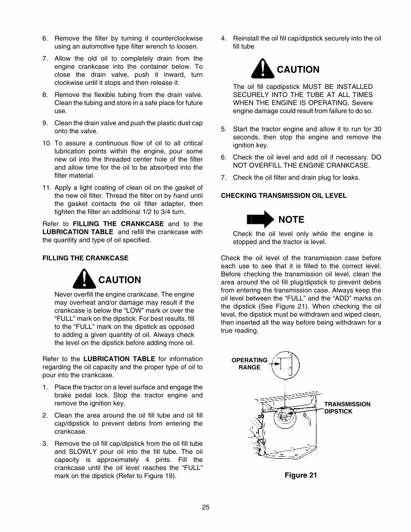
Check the oil level of the transmission case beforeeach use to see that it is filled to the correct level.Before checking the transmission oil level, clean thearea around the oil fill plug/dipstick to prevent debrisfrom entering the transmission case. Always keep theoil level between the “FULL” and the “ADD” marks onthe dipstick (See Figure 21). When checking the oillevel, the dipstick must be withdrawn and wiped clean,then inserted all the way before being withdrawn for atrue reading.
Figure 21
OPERATINGRANGE
TRANSMISSIONDIPSTICK

26
ADDING TRANSMISSION OIL
CAUTIONNever overfill the transmission case. Damageor leakage may result if the oil level in thetransmission case is below the “ADD” mark orover the “FULL” mark of the dipstick.For bestresults, fill to the “FULL” mark on the dipstick asopposed to adding a given quantity of oil.Always check the level on the dipstick beforeadding more oil.
Refer to the LUBRICATION TABLE for informationregarding the proper type of oil to add to thetransmission case.
1. Place the tractor on a level surface and engage thebrake pedal lock. Stop the tractor engine andremove the ignition key.
2. Clean the area around the oil fill plug/dipstick toprevent debris from entering the transmissioncase.
3. Remove the oil fill plug/dipstick from the oil fill portand SLOWLY pour oil into the oil fill port. Fill thetransmission case until the oil level reaches the“FULL” mark on the dipstick (Refer to Figure 21).
4. Reinstall the oil fill plug/dipstick securely into theoil fill port.
CAUTION
The oil fill plug/dipstick MUST BE INSTALLEDSECURELY INTO THE FILL PORT AT ALLTIMES WHEN THE ENGINE IS OPERATING.
HYDROSTATIC DRIVE OIL FILTER
CAUTIONNever overfill the transmission case. Damageor leakage may result if the oil level in thetransmission case is below the “ADD” mark orover the “FULL” mark of the dipstick. For bestresults, fill to the “FULL” mark on the dipstick asopposed to adding a given quantity of oil.Always check the level on the dipstick beforeadding more oil.
Refer to the MAINTENANCE CHART for informationregarding the frequency of the hydrostatictransmission oil filter replacement. The filter can beobtained through your Cub Cadet dealer under the partnumber 923-3014.
Refer to the LUBRICATION TABLE for informationregarding the oil capacity and the proper type of oil topour into the transmission case.
1. Place the tractor on a level surface and engage thebrake pedal lock. Stop the tractor engine andremove the ignition key.
2. Clean the area around the transmission drain plugto prevent debris from entering the transmissioncase. Remove the drain plug and allow thetransmission oil to drain into a clean containerhaving a capacity of more than 7 quarts. Reinstallthe drain plug (Refer to Figure 22).
Figure 22
CAUTION
If the transmission oil is to be re-used, cover thecontainer holding the drained oil to preventcontamination. Contaminated transmission oilcan damage the hydro transmission.
3. Clean around the base of the transmission oil filterand remove the filter by turning it counterclockwise(Refer to Figure 23).
4. Apply a light coating of clean transmission oil to thegasket of the new filter. Install the filter by turningit clockwise, by hand, until the gasket contacts thefilter base on the transmission housing; thentighten the filter an additional 1/2 turn.
5. Clean the area around the transmission oil fillplug/dipstick to prevent debris from entering thetransmission case.
TRANSMISSIONDRAIN PLUG

27
6. Remove the oil fill plug/dipstick from the oil fill portand SLOWLY pour oil into the oil fill port. Fill thetransmission case until the oil level reaches the“FULL” mark on the dipstick (Refer to Figure 21).
Figure 23
7. Reinstall the oil fill plug/dipstick securely into theoil fill port.
8. Start the engine and allow it to run for a fewminutes. Shut the engine off, then check for leaksand re-check the oil level in the transmission case.
CAUTION
The oil fill plug/dipstick MUST BE INSTALLEDSECURELY INTO THE FILL PORT AT ALLTIMES WHEN THE ENGINE IS OPERATING.
AIR CLEANER
Check the air cleaner daily or before starting theengine. Check for loose or damaged components andcheck the condition of the filter element. Remove anybuildup of dirt and debris in the air cleaner housing.
NOTEOperating the engine with loose or damaged aircleaner components will allow unfiltered air intothe carburetor; causing extensive wear andeventual failure of the engine.
Figure 24. Air Cleaner Assembly.
Servicing the Precleaner
Wash and re-oil the foam precleaner at one monthintervals or after every 10 hours of operation (moreoften under extremely dusty or dirty conditions),whichever occurs first.
1. Unfasten the air cleaner cover retaining knob andremove the air cleaner cover (See Figure 24).
2. Remove the foam precleaner by sliding it up off thepaper element (See Figure 24).
3. Wash the precleaner in warm water withdetergent. Rinse the precleaner thoroughly until alltraces of the detergent are eliminated. Squeezeout (do not wring) excess water in a dry cloth.Allow the precleaner to air dry.
4. Saturate the foam precleaner with new engine oil.Squeeze out all excess oil.
5. Reinstall the foam precleaner over the paperelement.
6. Reinstall the air cleaner cover and secure with theretaining knob.
TRANSMISSIONOIL FILTER
1
2
3
4
5
6
8
7
9
1.2.3.4.5.6.7.8.9.
COVER W/KNOBWING NUTCOVER PLATEFOAM PRECLEANERPAPER ELEMENTGROMMET SEALRETAINING RINGBASE BACKPLATECARRIAGE BOLT

28
Servicing the Paper Element
Every 100 hours of operation (more often underextremely dusty or dirty conditions), inspect the paperelement. Replace the element as necessary.
1. Unfasten the air cleaner cover retaining knob andremove the air cleaner cover (See Figure 24).
2. Remove the foam precleaner by sliding it up off thepaper element (See Figure 24).
CAUTION
The air cleaner element cover plate (See Figure24) must be properly installed to seal againstthe gasket surface of the paper element.
3. Remove the wing nut and element cover plate,then lift out the paper air filter element.
4. Do not wash the paper element or use pressurizedair, as this will damage the element. Replace adirty, bent or damaged element. Handle newelements carefully; do not use if the sealingsurfaces are bent or damaged.
5. When servicing the air cleaner, check the aircleaner base. Make sure it is secured and not bentor damaged. Also check the element cover fordamage or improper fit. Replace all damaged aircleaner components.
6. Inspect the rubber grommet seal (See Figure 24)for deterioration, cracks, and for a snug fit on thecarriage bolt. Replace if damaged or worn.
7. After making certain the carriage bolt is secured inposition by the retaining ring, slide the grommetseal fully onto carriage bolt. See Figure 24.
8. Install the cover plate on the carriage bolt andsecure with the wing nut. Do not overtighten thewing nut, which could deform the cover plate.
9. Reinstall the air cleaner cover. Make certain thecover retaining knob is tightened securely.
Properly cleaned and installed air cleaner elementssignificantly contribute to prolonging engine life.
CLEANING ENGINE
This tractor has an air-cooled engine. Air must be ableto circulate freely around the engine through theflywheel screen, through the cooling shrouds and overthe fins of the cylinder head and cylinder block. Keepthese areas free of accumulated dirt and debris or theengine will overheat; possibly causing extensiveengine damage. Regularly clean the inside of the sidepanels, dash intake screen and grille to ensureadequate cooling. If debris has accumulated inside thecooling shrouds of the engine, the blower housing andcooling shrouds should be removed and the coolingfins cleaned.
NOTEThis machine is designed to cool properly withthe side panels in place. Operating without thepanels could cause premature accumulation ofdirt and debris on the engine, resulting ininadequate cooling.
SPARK PLUG
WARNING
To avoid possible injury, be sure the engine isoff and has cooled before making anyadjustments or repairs.
NOTERemove all dirt from around the spark plugbefore removing.
To remove the spark plugs, always use a spark plugwrench. Check the gap after every 100 hours ofoperation.

29
Replace a defective plug with a new plug. Set thespark plug gap at .030 inch (See Figure 25). Tightenthe plug to 28-32 ft-lbs. See your authorized dealer forthe correct replacement plug.
Figure 25
FUEL FILTER
WARNING
Do not replace the fuel filter when engine is hot.
The engine is equipped with an inline fuel filter.Visually inspect the filter periodically for a build-up ofresidue inside the filter body, and for a dirty elementwhich can be indicated by discoloration. Replace thefuel filter when dirty.
HEADLIGHTS
Refer to SPECIFICATIONS when replacement ofhead lamp bulbs is necessary.
WARNING
Allow the engine and surrounding surfaces tocool before changing the head lamp bulbs.
Replace headlight bulbs as follows: (See Figure 26)
1. Unplug the wire harness leads from the headlightsocket terminals. Note which wire connects toeach terminal before disconnecting.
2. Rotate the socket assembly as follows to removefrom the reflector housing:• Left headlight — appoximately 1/4 turn counter-
clockwise.• Right headlight — approximately 1/4 turn clock-
wise.
3. Push the bulb inward and turn counterclockwise toremove from the socket.
Figure 26
4. Align a locking post of the bulb base with the notchin the socket, then push the bulb inward and turnclockwise to lock
5. With the terminals pointing upward, align the tab ofthe socket with the notch of the reflector. Push thesocket inward and turn as follows to lock:• Left headlight — appoximately 1/4 turn clock-
wise.• Right headlight — approximately 1/4 turn coun-
terclockwise.
6. Connect the wire harness leads to the appropriatesocket terminals.
FUSES
Always use the same capacity fuse for replacement.Refer to SPECIFICATIONS. If the electrical systemdoes not function, check the fuses.
To replace a fuse, pull the old fuse from the fuse holderand install the new fuse.
SPARK PLUG
REFLECTORNOTCH
SOCKET TAB
TERMINAL
SOCKET
REFLECTORHOUSING

30
GENERAL BATTERY INFORMATION
WARNING
a. Battery posts, terminals and relatedaccessories contain lead and leadcompounds. Wash Hands after handling.
b. Battery acid must be handled with great care,as contact with it can burn and blister the skin.It is advisable to wear protective clothing(goggles, rubber gloves and apron) whenworking with acid.
c. Should battery acid accidentally splatter intothe eyes or onto the skin, rinse the affectedarea immediately with clean cold water. Ifthere is any further discomfort, seek promptmedical attention.
d. If acid spills on clothing, first dilute it with cleanwater, then neutralize with a solution ofammonia/water or baking soda/water.
e. Since battery acid is corrosive, do not pour itinto any sink or drain. Before discarding anempty electrolyte container, rinse it thoroughlywith a neutralizing solution.
f. NEVER connect (or disconnect) batterycharger clips to the battery while the charger isturned on, as it can cause sparks.
g. Keep all sources of ignition (cigarettes,matches, lighters) away from the battery. Thehydrogen gas generated during charging canbe combustible.
h. As a further precaution, only charge thebattery in a well ventilated area.
ALWAYS SHIELD EYES AND PROTECT SKIN ANDCLOTHING WHEN WORKING NEAR BATTERIES.
DANGER
BATTERIES CONTAIN SULFURIC ACID ANDMAY EMIT EXPLOSIVE GASES. USEEXTREME CAUTION WHEN HANDLINGBATTERIES.
KEEP BATTERIES OUT OF THE REACH OFCHILDREN.
MAINTENANCE OF BATTERY
The tractor is shipped with a wet battery — the batteryacid has already been added and the battery sealed.Although the battery is maintenance free, the followingcare should be taken when handling the battery and toassure its proper life cycle.
1. Spray the terminals and exposed wire with abattery terminal sealer, or coat the terminals with athin coat of grease or petroleum jelly, to protectagainst corrosion.
2. The battery should be kept clean. Any deposits ofacid should be neutralized with baking soda andwater. Be careful not to get this solution in thecells.
3. Avoid tipping the battery. Even a “sealed” batterywill leak electrolyte when tipped.
STORAGE OF THE BATTERY
1. When storing the tractor for extended periods,disconnect the battery cables. Removing thebattery from the unit is recommended.
2. All batteries discharge during storage. Keep theexterior of the battery clean, especially the top. Adirty battery will discharge itself more rapidly.
3. The battery must be stored with a full charge. Adischarged battery will freeze at a highertemperature.
Specific Gravity Freezing Point1.265 –71°F1.250 –62°F1.200 –16°F1.150 5°F1.100 16°F
COMMON CAUSES FOR BATTERY FAILURE
1. Overcharging
2. Undercharging
3. Loose and/or corroded connections
4. Excessive loads
5. Freezing of electrolyte
* These causes do not constitute warranty inthe event of a battery failure.

31
BATTERY REMOVAL OR INSTALLATION
WARNINGBattery posts, terminals and relatedaccessories contain lead and lead compounds.Wash Hands after handling.
When removing the battery, disconnect thebattery cables in the following order to avoidarcing and the resulting sparks:Battery Removal:1. Disconnect the Negative cable.2. Disconnect the Positive cable.Battery Installation:1. Connect the Positive cable.2. Connect the Negative cable.
To replace the battery, proceed as follows:
1. Remove the negative cable from the negativeterminal of the battery, then remove the positivecable from the positive terminal.
2. Remove the wing nut securing the LH mountingrod to the mounting tab on the left side of thebulkhead (Refer to Figure 27). Pull the roddownward from the bulkhead tab.
Figure 27
3. Rotate the mounting rod fully upward toward thedash panel to provide clearance for batteryremoval (See Figure 28).
4. Pull downward on the bottom of the batteryholddown strap to release it from the tab beneaththe battery tray.
5. Loosen the hose clamp and pull the drain tubefrom the battery.
6. Lift the battery upward and remove from the leftside of the tractor.
Figure 28
7. Install the new battery from the left side of thetractor and lower into the battery tray.
8. Install the drain tube onto the battery and securewith the hose clamp.
9. Stretch the battery holddown strap downwardacross the front of the battery and hook to the tabbelow the battery tray.
10. Rotate the mounting rod downward and insertthrough the bottom of the hole in the bulkheadmounting tab (See Figure 27).
11. Install the wing nut onto the mounting rod, but donot tighten until after the side panels are installed.
12. Connect the positive cable to the positive terminalof the battery, then connect the negative cable tothe negative terminal.
JUMP STARTING
WARNING
Failure to use this jump starting procedurecould cause sparking, which could result in anexplosion of either battery.
1. Attach the first jumper cable from the positiveterminal of the good battery to the positive terminalof the dead battery.
2. Attach the second jumper cable from the negativeterminal of the good battery to the FRAME OF THEUNIT WITH THE DEAD BATTERY.
WING NUT
MOUNTING ROD
HOLDDOWNSTRAP
MOUNTINGROD
ROTATEUPWARD

32
TIRES
Keep the pneumatic tires properly inflated. Over-inflation will cause operator discomfort. Under-inflationwill cause short tire life.
Improperly inflated tires will also affect the leveling ofthe mower deck and quality of cut.
Inflate the front and rear tires as shown in the followingtable:
Tire Size Pounds per Square Inch
Front Tires15 x 6–6 14
Rear Tires20 x 9–8 10
Always ensure that the tire valve caps are in place andtightened securely to prevent loss of air and to protectthe valve core and stem.
Do not overload the tractor tires by mountingequipment on the tractor which exceeds the loadcapacity of the size of the tires on the tractor.
MOUNTING TIRES ON THE RIM
WARNING
Do not mount a tire unless you have the properequipment. Do not inflate the tire above therecommended pressure. Do not stand over thetire assembly when inflating. Accidental overinflation could cause an explosive separation ofthe tire and rim, which could result in seriousinjury of death.
After mounting a new or old tire on the rim, inflate it to20 pounds (maximum) pressure to seat the tire beadon the rim flange. Then deflate the tire to the corrrectoperating pressure.
NOTEAfter the first 10 hours of operation, check andretorque the rear wheel lug nuts (both sides) to35 ft-lbs to make sure they are seated in the rimand are properly tightened.

33
SECTION V. MOWER DECK
This section contains adjustment, removal, installation,and maintenance information for the 42-inch mowerdeck. Instructions for installation and removal of theoptional mulching plug are located at the end of thissection.
A. DECK LEVELING ADJUSTMENTS
In order to achieve even cutting, the mower deck mustbe properly leveled. This leveling procedure will resultin the left and right blades having corresponding frontcutting-edge-to ground measurements within 1/16 inchof each other. Also, the right and the left blades willeach have a 1/8 to 1/4 inch downward tilt toward thefront of the tractor. To level the mower deck, proceedas follows:
WARNING
Before making any adjustments, place the PTOswitch in the “OFF” position, engage the brakepedal lock, turn the ignition key to the “OFF”position, remove the key from the switch andremove the spark plug wire to avoid accidentalstarting and injury.
WARNING
When adjusting the mower deck, be careful notto cut yourself on the sharp blades.
NOTEIf the mower deck is not level, the mower will notcut your lawn evenly.
NOTECheck the tires for proper inflation beforemaking a leveling adjustment. To level the deck,the tractor and deck MUST be placed on a hard,level surface during adjustment.
SIDE-TO-SIDE LEVELING ADJUSTMENT
1. Position the tractor and mower deck on a hard,level surface.
2. Open the tractor hood and disconnect the sparkplug wire.
3. The mower deck front and rear gauge wheelsshould be installed in their uppermost position inthe deck brackets to prevent contact with the hard,level surface below. Refer to GAUGE WHEELADJUSTMENT.
4. Raise the tractor implement lift handle to itshighest setting.
5. Position the mower blades so that the ends of eachblade face the right and left sides of the tractor(Refer to Figure 29).
Figure 29
6. Referring to Figure 30, measure and record thedistance from the hard, level surface to the outer-most cutting edge of the right blade. Repeat thisstep for the left blade. If the two blade heights arenot within 1/16 inch, proceed to steps 7, 8 and 9. Ifthe two blade heights are within 1/16 inch, proceedto FRONT TO BACK LEVELING ADJUSTMENT.
DECKINSTALLED
MOWERBLADES

34
Figure 30
7. Lower the deck onto the hard, level surface.
8. Side-to-side leveling is obtained utilizing theadjustment ferrule and right hand hanger bracket(Refer to Figure 31).
Figure 31
9. Loosen the upper jam nut on the hanger bracketand turn away from the adjustment ferrule. Turnthe lower lock nut upward (tighten) on the threadsof the hanger bracket to raise the right side of themower deck. Turn the lock nut down (loosen) onthe threads to lower the right side of the mowerdeck (Refer to Figure 31).
10. Raise the lift handle to the highest position andrecheck the blade measurements described instep 6. If the blade measurements are not within1/16 inch, repeat steps 7, 8 and 9.
11. Tighten the upper jam nut against the adjustmentferrule after side-to-side leveling is completed.
FRONT TO BACK LEVELING ADJUSTMENT
1. Raise the deck to its highest position.
2. Position the mower blades so the ends of eachblade point to the front and the rear of the tractor(Refer to Figure 32).
Figure 32
1. Finger guard2. Blade3. Hard Level Surface4. Measure This Distance
2
1 3
4
RIGHT HANDHANGER BRACKET
UPPERJAM NUT
ADJUSTABLEFERRULE LOWER
LOCK NUT
DECKINSTALLED
MOWERBLADES

35
3. Initially adjust the front lift rod to allow 5/8 inch ofthread to protrude beyond both lock nuts of thefront lift rod/bracket assembly (Refer to Figure 33).
Figure 33
4. Refer to Figure 34. Measure and record thedistance from the front cutting edge to the ground(measurement A), and from the rear cutting edgeto the ground (measurement B), for each of theblades. The front edge of each blade(measurement A) should be lower than its backedge (measurement B) by 1/8 to 1/4 inch.
5. Lower the deck onto the hard, level surface.
6. To adjust the downward tilt of the blades,adjustment of the front lift rod is required. Refer toFigure 33 and proceed as follows:
7. Loosen the rear jam nuts on the front lift rod. Fromthe front of the tractor, turn the front lock nuts clock-wise to raise the front of the mower deck, or counter-clockwise to lower the front of the mower deck.
8. Raise the deck to the highest position. Recheckthe blade measurements described in step 4. If theresultant measurements are not correct, repeatsteps 5, 6 and 7 until the proper measurements areobtained.
NOTEThe front lift rod must be against the back ofboth slots in the deck front roller bracket. If oneside of the rod is not against the back of the slotafter attaining the correct front pitch to the deck,tighten the front lock nut on that side until therod just contacts the back of the slot.
9. Tighten the rear jam nuts after adjustment iscompleted.
10. Connect the spark plug wire.
GAUGE WHEEL ADJUSTMENT
WARNING
Before making any adjustments, place the PTOswitch in the “OFF” position, engage the brakepedal lock, turn the ignition key to the “OFF”position, remove the key from the switch andremove the spark plug wire to avoid accidentalstarting and injury.
WARNING
When adjusting the mower deck, be careful notto cut yourself on the sharp blades.
NOTEGauge wheel adjustment should be performedonly AFTER the mower deck has been properlyleveled.
FRONTLIFT ROD
JAM NUT
LOCK NUT
FRONT LIFTROD BRACKET
5/8"
Figure 34
REARCUTTING EDGE FRONT
CUTTING EDGE
CUTTINGBLADE
AB

36
NOTEGauge wheels are intended to prevent scalpingof the lawn, and are not meant to be used to setthe cutting height. Do not run the deck on theguage wheels.
To adjust the height of the gauge wheels, place thetractor on a firm and level surface. Refer to Figure 35,and proceed as follows:
1. Place the tractor implement lift handle in thenormally desired mowing height setting, thencheck the gauge wheels for contact or excessiveclearance with the surface below.
2. If the wheels contact the surface adjust as follows:
a. Raise the implement lift handle to its highestsetting.
b. Remove the rear gauge wheels by removingthe lock nuts, shoulder screws, and flatwashers. Remove the lock nuts, shoulderscrews, and bell washers fastening the frontball wheels to the deck gauge wheel brackets.
c. Again place the tractor implement lift handle inthe normally desired mowing height setting.
Figure 35
d. Insert the shoulder screw and flat washer withthe rear gauge wheel into the adjustmentindex hole that provides approximately 1/2"
clearance between the wheel and levelsurface. Secure with the lock nut.
e. Note the position of the index hole used; theninstall the other rear gauge wheel and the frontball wheels into the corresponding index holeof the other guage wheel brackets.
NOTEThe crowned (rounded) surface of the front bellwashers should be against the shoulder of theshoulder screw, between the front ball wheeland deck gauge wheel bracket.
3. If the gauge wheels have excessive clearance withthe surface below, lower the wheels to the indexhole that provides the approximate 1/2" clearanceas described above.
NOTEAll gauge wheels shoud be installed in the samerelative adjustment index hole location in eachof the gauge wheel brackets.
CUTTING HEIGHT ADJUSTMENT
The mower can be set in multiple positions. Proceedas follows:
NOTEIf multiple positions are used while mowing, itmay be necessary to adjust the gauge wheelsfor each setting to prevent scalping.
1. Pull the tractor implement lift handle up slightly anddepress the button on the top of the lift handle.
2. Raise or lower the lift handle to obtain the desiredmower deck cutting height.
3. Release the button when the desired mowerposition is obtained.
NOTETo return the mower deck to a specific position,note the position of the lift lever indicator beforeraising or lowering the mower deck.
SHOULDERSCREW
BELLWASHER
FRONT BALLWHEEL GAUGE
WHEELBRACKET
ADJUSTMENT
HOLES
LOCKNUTLOCK
NUT
REAR
WHEELGAUGE
FLATWASHER
SHOULDERSCREW
GAUGEWHEEL
BRACKET
INDEX

37
B. REMOVAL AND INSTALLATION OFDECK ASSEMBLY
REMOVAL OF DECK
WARNING
Before removing the mower deck, place thePTO switch in the “OFF” position, engage thebrake pedal lock, turn the ignition key to the“OFF” position and remove the key from theswitch. Disconnect the spark plug wire foradditional safety.
1. Position the tractor and mower deck on a firm,level surface.
WARNING
When handling the mower deck, be careful notto cut yourself on the sharp blades. The deckidler arm lever is spring loaded. Release itslowly.
2. Lower the tractor implement lift handle to its lowestsetting (adjust gauge wheels if necessary).Disengage the deck idler arm lever from its stopbracket and release the spring tension by rotatingthe lever out and rearward (Refer to Figure 36).
Figure 36
3. Remove the rearward end of the PTO belt from theupper pulley of the deck center double-pulley(Refer to Figure 37). Engage the deck idler armlever back into its stop bracket (See to Figure 38).
Figure 37
Figure 38
Figure 39
IDLER ARMLEVER
LEVER STOPBRACKET
MOWER DECKCENTER DOUBLEPULLEY
PTO BELT
FRONT OF DECK
IDLER ARMLEVER
LEVER STOPBRACKET
PTOCLUTCHPULLEY
PTOBELT

38
WARNING
The exhaust system is HOT. To avoid personalinjury, allow the engine and exhaust system tocool before proceeding with the following PTObelt removal instructions.
4. Open the tractor hood and remove the forward endof the PTO belt from the PTO clutch pulley (Referto Figure 39).
5. Pass the PTO belt downward, inside the tractorframe, until the belt is below the two tractor frontlower pulleys and pull the belt clear of the tractor(Refer to Figure 40).
Figure 40
6. Pull the deck support pins outward, turn downwardand release so both spring-loaded pins are held inthe disengaged position against the outer surfaceof the deck brackets (Refer to Figure 41).
Figure 41
7. Raise the tractor implement lift handle to itshighest setting, Slide the mower deck forward, sothe front lift rod rests to the rear of, and free of, thefront roller bracket slots of the deck (Refer toFigure 42).
Figure 42
8. Raise the front lift rod upward and slide the mowerdeck rearward. Lower the front lift rod so it rests onthe front roller bracket of the deck, forward of theslots (Refer to Figure 43).
Figure 43
9. From the front of the tractor, push downward andhold the tractor quick-attach rod. Pull the front liftrod/bracket assembly forward to release theshoulder bolts on each side of the bracket from theleft and right tractor latch receivers. Release thetractor quick-attach rod. Refer to Figure 44
TRACTOR FRONTLOWER PULLEYS
PTO BELTFRONT LIFT
ROD/BRACKETASSEMBLY
DECK
REAR DECKBRACKET
DECK SUPPORTPIN DISENGAGED(BOTH SIDES)
FRONT LIFT ROD
FRONTROLLERBRACKET
FRONT LIFT ROD
FRONTROLLERBRACKET

39
Figure 44
CAUTION
To avoid possible equipment damage, makesure that the tractor implement lift handle israised to its highest setting before sliding thedeck out from under the tractor.
10. With the tractor implement lift handle raised to itshighest setting, slide the deck to the right and outfrom under the tractor (Refer to Figure 45).
Figure 45
11. Connect the spark plug wire.
INSTALLATION OF DECK
WARNING
Before performing the mower deck installation,place the PTO switch in the “OFF” position,engage the brake pedal lock, turn the ignitionkey to the “OFF” position and remove the keyfrom the switch. Disconnect the spark plug wirefor additional safety.
WARNING
When handling the mower deck, be careful notto cut yourself on the sharp blades.
1. Position the tractor and mower deck on a firm,level surface.
CAUTION
To avoid possible equipment damage, makesure that the tractor implement lift handle israised to its highest setting before sliding thedeck under the tractor.
2. Refer to Figure 46 and position the deck on theright side of the tractor with the front of the deckfacing toward the front of the tractor. Raise thetractor implement lift handle to its highest settingand slide the deck under the tractor.
Figure 46
QUICKATTACH
ROD
SHOULDER BOLT(BOTH SIDES)
FRONT LIFTROD/BRACKET
ASSEMBLY
TRACTORLATCH RECEIVER
(BOTH SIDES)
SLIDEOUT
SLIDEUNDER

40
3. Make sure the slot in both rear deck bracketsaligns with the implement lift links on each side ofthe tractor (Refer to Figure 47).
Figure 47
4. Refer to Figure 48 to ensure the correct orientationof the front lift rod/bracket assembly [form (bend)in sides of rod point downward]. From the front ofthe tractor, push downward and hold the tractorquick-attach rod. Slide the shoulder bolts on eachside of the front lift rod/bracket assembly fully intothe left and right tractor latch receivers. Releasethe tractor quick-attach rod to capture the front liftrod/bracket assembly in the tractor latch receivers(Refer to Figure 49).
Figure 48
Figure 49
5. While holding the front lift rod up, slide the mowerdeck forward until the rod aligns with both frontroller bracket slots. Lower the lift rod into the frontroller bracket slots and slide the deck rearward toengage the lift rod fully forward in the slots of thedeck front roller bracket (Refer to Figure 50).
Figure 50
6. If not already done, pull the deck support pinsoutward, turn downward and relesase so bothspring-loaded pins are held in the disengagedposition against the outer surface of the deckbrackets (Refer to Figure 51).
IMPLEMENTLIFT LINKS
(BOTH SIDES)
SLOT IN REARDECK BRACKETS
(BOTH SIDES)
QUICKATTACH
ROD
SHOULDER BOLT(BOTH SIDES)
FRONT LIFTROD/BRACKET
ASSEMBLY
TRACTORLATCH RECEIVER
(BOTH SIDES)
FORM
QUICK ATTACH ROD
FRONT LIFT ROD/BRACKET ASSEMBLY
FRONTLIFT ROD
FRONT ROLLERBRACKET

41
Figure 51
7. Carefully guide the tractor inplement lift links (leftand right) into the rear deck bracket slots (left andright) as the tractor implement lift handle islowered to its lowest setting (Refer to Figure 52).
8. Pull both deck support pins outward and rotaterearward to disengage the outer surface ot the reardeck brackets. Release the pins, making certaineach deck support pin passes through the innerhole of the rear deck bracket. The spring tensionwill push the pins inward and, if aligned, throughthe hole in each implement lift link (Refer to Figure52).
Figure 52
NOTEIt may be necessary to lift each side of the deckand maneuver it slightly to align the supportpins with the holes of the lift links. Make certainthe support pins are fully extended through thelift links to prevent the mower deck fromdisengaging the lift links while mowing.
WARNING
The deck idler arm lever is spring loaded.Release it slowly.
9. Disengage the deck idler arm lever from its stopbracket and release the spring tension by rotatingthe lever out and rearward (Refer to Figure 53).
Figure 53
WARNING
The exhaust system is HOT. To avoid personalinjury, allow the engine and exhaust system tocool before proceeding with the following PTObelt installation instructions.
10. Install the forward end of the PTO belt on the PTOclutch pulley by passing the belt upward inside thefront of the tractor frame. Ensure that the narrowside of the PTO belt engages the groove of theclutch pulley (Refer to Figure 54).
REAR DECKBRACKET SLOTS
DECK SUPPORTPIN DISENGAGED
DECK
IMPLEMENTLIFT LINKS
(BOTH SIDES)LIFT LINK HOLE(BOTH SIDES)
SLOT IN REARDECK BRACKET
DECK SUPPORTPIN ENGAGED
IDLER ARMLEVER
LEVER STOPBRACKET

42
Figure 54
11. Twist the PTO belt 1/4 turn to engage the narrowsides of the belt into the grooves of the two tractorfront-lower pulleys (Refer to Figure 55).
Figure 55
12. From the front of the tractor, push the PTO beltthrough the front lift rod, then to the center of thedeck. Ensure that the forward end of the beltremains positioned inside the front lower pulleys.
13. Install the rearward end of the PTO belt on theupper pulley of the deck center double-pulley(Refer to Figure 56). Ensure that the narrow sideof the belt engages the groove of the upper pulley.
14. While holding the belt in position, rotate andengage the deck idler arm lever into its stopbracket to provide tension on the PTO belt (Referto Figure 57).
15. Connect the spark plug wire.
Figure 56
Figure 57
C. MAINTENANCE
CLEANING AND BLADE CARE
WARNING
Before performing any maintenance, place thePTO switch in the “OFF” position, engage thebrake pedal lock, turn the ignition key to the“OFF” position and remove the key from theswitch to avoid accidental starting and injury.
PTOCLUTCHPULLEY
PTOBELT
TRACTOR FRONTLOWER PULLEYS
PTO BELTFRONT LIFT
ROD/BRACKETASSEMBLY
MOWER DECKCENTER DOUBLEPULLEY
PTO BELT
FRONT OF DECK
IDLER ARMLEVER
LEVER STOPBRACKET
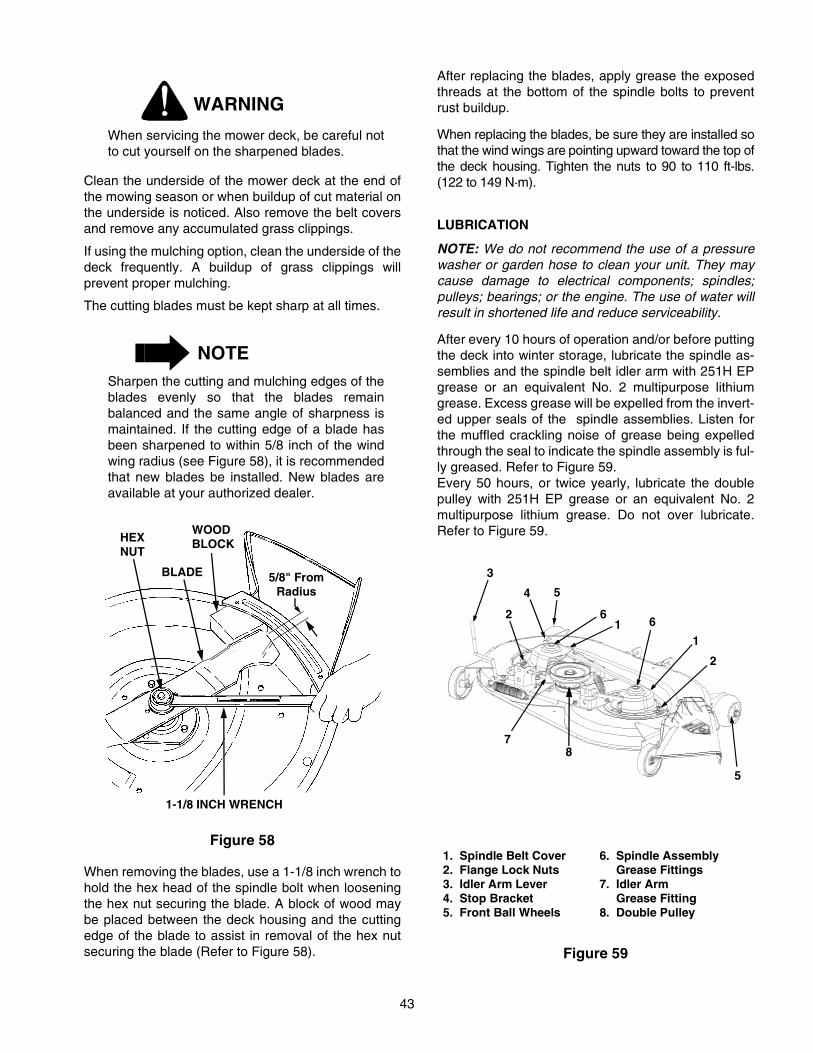
43
WARNING
When servicing the mower deck, be careful notto cut yourself on the sharpened blades.
Clean the underside of the mower deck at the end ofthe mowing season or when buildup of cut material onthe underside is noticed. Also remove the belt coversand remove any accumulated grass clippings.
If using the mulching option, clean the underside of thedeck frequently. A buildup of grass clippings willprevent proper mulching.
The cutting blades must be kept sharp at all times.
NOTESharpen the cutting and mulching edges of theblades evenly so that the blades remainbalanced and the same angle of sharpness ismaintained. If the cutting edge of a blade hasbeen sharpened to within 5/8 inch of the windwing radius (see Figure 58), it is recommendedthat new blades be installed. New blades areavailable at your authorized dealer.
Figure 58
When removing the blades, use a 1-1/8 inch wrench tohold the hex head of the spindle bolt when looseningthe hex nut securing the blade. A block of wood maybe placed between the deck housing and the cuttingedge of the blade to assist in removal of the hex nutsecuring the blade (Refer to Figure 58).
After replacing the blades, apply grease the exposedthreads at the bottom of the spindle bolts to preventrust buildup.
When replacing the blades, be sure they are installed sothat the wind wings are pointing upward toward the top ofthe deck housing. Tighten the nuts to 90 to 110 ft-lbs.(122 to 149 N·m).
LUBRICATION
NOTE: We do not recommend the use of a pressurewasher or garden hose to clean your unit. They maycause damage to electrical components; spindles;pulleys; bearings; or the engine. The use of water willresult in shortened life and reduce serviceability.
After every 10 hours of operation and/or before puttingthe deck into winter storage, lubricate the spindle as-semblies and the spindle belt idler arm with 251H EPgrease or an equivalent No. 2 multipurpose lithiumgrease. Excess grease will be expelled from the invert-ed upper seals of the spindle assemblies. Listen forthe muffled crackling noise of grease being expelledthrough the seal to indicate the spindle assembly is ful-ly greased. Refer to Figure 59.Every 50 hours, or twice yearly, lubricate the doublepulley with 251H EP grease or an equivalent No. 2multipurpose lithium grease. Do not over lubricate.Refer to Figure 59.
Figure 59
5/8" FromRadius
1-1/8 INCH WRENCH
WOODBLOCK
BLADE
HEXNUT
1. Spindle Belt Cover2. Flange Lock Nuts 3. Idler Arm Lever4. Stop Bracket
6. Spindle Assembly Grease Fittings7. Idler Arm Grease Fitting
5. Front Ball Wheels
1
2
3
4 5
1
2
5
6
7
6
8. Double Pulley
8

44
SPINDLE DRIVE BELT REPLACEMENT
In order to replace the spindle drive belt, refer toFigures 59 and 60 and proceed as follows:
1. Disengage the idler arm lever from its stop bracketand rotate the lever to the outside of the deck torelease the spring tension.
2. Remove the hardware that secures the spindlebelt covers and stop bracket to the deck.
3. Remove the spindle belt covers to expose the belt.
4. Pull the flat idler pulley away from the backside ofthe belt and remove the old drive belt.
5. Install a new belt around the spindle pulleys andbottom pulley of the center double pulley; thenposition the flat idler pulley against the backside ofthe belt so that the belt is tensioned. Refer toFigure 60 for the proper routing of the belt.
6. Reinstall the spindle belt covers and stop bracket.
7. Engage the idler arm lever into its stop bracket.
Figure 60
D. INSTALLATION OF MULCHING PLUG
WARNING
Before installing the mulching plug, place thePTO switch in the “OFF” position, engage thebrake pedal lock, turn the ignition key to the“OFF” position and remove the key from theswitch to avoid accidental starting and injury.
1. If the mower deck has been used, clean anybuildup of grass clippings from the dischargeopening of the deck.
2. Lift the chute deflector upward and insert themulching plug into the discharge opening of thedeck (Refer to Figure 61).
3. Position the mulching plug so that its top holealigns with the hole in the top of the deck housing.Install the carriage bolt through both surfaces andsecure with the bell washer and wing nut (SeeFigure 61).
4. To remove the mulching plug; remove the wingnut, bell washer and carriage bolt, then withdrawthe plug from the discharge opening. Insert thecarriage bolt through the mulching plug and installthe bell washer and wing nut onto the bolt toprevent their loss.
Figure 61
1. Idler Pulley2. Spindle Drive Belt 4. Stop Bracket
12
3
45
3. Idler Arm Lever 5. Center Double Pulley
MULCHINGPLUG
CHUTEDEFLECTOR
WING NUT
CARRIAGEBOLT
BELL WASHER
HOLE INDECK HSG.

45
SECTION VI. OFF-SEASON STORAGE
If the machine is to be inoperative for a period longerthan 30 days, the following procedures arerecommended:
WARNING
Never store the tractor with fuel in the tankindoors or in poorly ventilated enclosures,where fuel fumes may reach an open flame,spark or pilot light as on a furnace, water heater,clothes dryer, etc.
CAUTION
Fuel left in the fuel tank during warm weatherdeteriorates and will cause serious startingproblems.
1. To prevent gum deposits from forming inside theengine’s carburetor and causing possiblemalfunction of the engine, remove all gasolinefrom the fuel tank as follows:
WARNING
Do not drain fuel when the engine is hot. Allowthe engine adequate time to cool.
Drain fuel into an approved container outdoors, awayfrom open flame.
a. Drain any large volume of fuel from the tank bydisconnecting the fuel line from the in-line fuelfilter near the engine.
b. Reconnect the fuel line and run the engineuntil it starts to falter, then use the choke tokeep the engine running until all fuel in thecarburetor has been exhausted.
c. Again disconnect the fuel line and drain anyremaining gasoline from the system.
2. Remove the spark plug and pour one (1) ounce ofengine oil through the spark plug hole into thecylinder. Crank the engine several times todistribute the oil. Replace the spark plugs.
3. Clean the engine and the entire tractor thoroughly.
NOTE: We do not recommend the use of a pressurewasher or garden hose to clean your unit. They maycause damage to electrical components; spindles;pulleys; bearings; or the engine. The use of water willresult in shortened life and reduce serviceability.
4. Lubricate all lubrication points.
5. Follow the battery storage instructions on page 30.
6. Protect the tires and seat from sunlight. Regularlycheck the tires to maintain proper inflation.

46
SECTION VII. MOWING
MOWING
WARNING
To avoid possible injury, do not allow anyone inthe area opposite the discharge chute whilemowing. Although the area has beensupposedly cleared of foreign objects, smallobjects may be picked up and discharged bythe mower.
WARNING
Never direct the discharge of material towardbystanders or allow anyone near the machinewhile in operation.
For best results it is recommended that the first twolaps should be cut with the discharge thrown towardsthe center. After the first two laps, reverse the directionto throw the discharge to the outside for the balance ofcutting. This will give a better appearance to the lawn.
Do not cut the grass too short, as the mower will tendto scalp the grass. Short grass invites weed growthand yellows quickly in dry weather.
Mowing should be done with the engine at full throttle.Do not mow at high ground speed.
During certain times of the year and under someconditions, the mower may leave streaks of uncutgrass.
Streaking may occur when attempting to mow heavyweeds and tall grass. Under these conditions it may benecessary to go back over the cut area a second timeto get a clean cut.
The following practices will help eliminate streaking:
1. Mow the area more often so the grass doesn’t gettoo tall and heavy.
2. Operate the tractor at full throttle and slowerforward speeds.
3. Keep the blades sharp and replace the bladeswhen worn.
4. Follow the mowing pattern shown in Figure 62.
Figure 62
MOWING WITH MULCHING OPTION
1. Do not cut wet grass. For effective mulching donot cut wet grass. Wet grass sticks to theunderside of the deck prevention proper mulchingand dispersal of grass clippings.
2. Cut no more than 1/3 the length of the grass.When mulching long grass, it may be necessary tomow twice, lowering the deck another 1/3 of thelength for the second cut, and perhaps cutting in adifferent pattern. Overlap the cut on each pass tohelp clean up any heavy clippings left on the lawn.
3. Use a slow ground speed. Adjust ground speedso clippings can be evenly dispersed into thelawn.When cutting heavy grass, it may benecessary to use a slower ground speed in orderto get a well mulched cut.
4. Always operate the tractor at full throttle. Toobtain the best cut and do the most effective job ofmulching, the engine should be run at full throttle.
5. Clean underside of deck. Be certain to clean theunderside of the deck often to avoid a buildup ofgrass clippings, which will prevent propermulching.

47
OPTIONAL EQUIPMENT AND ACCESSORIES
When you purchased your tractor, you probably had itcompletely equipped for your particular needs at thetime. However, later you may wish to obtain optionalequipment or accessories. These items and otherallied equipment can be purchased from, and installedby, your authorized Cub Cadet dealer.
The tractor is used for so many different types of work,and because it is called on to operate under so manydifferent conditions, a variety or equipment is availableto adapt it to the requirements of the user. Refer to theattachment guide for a complete description ofequipment and required components that can beutilized with your tractor.

48
MAINTENANCE CHART
NOTEMaintenance information for optional equipment may be found in the manual which is included with thatspecific piece of equipment.
Operation tobe performed
Before each use
10 hoursor oncea month
30 hours orthree timesa season
50 hoursor twice a season
100 hoursor yearly
Beforestorage
Clean grille, engine air inlet screen, dashintake screen and sidepanel screens
More oftenunder dirtyconditions
X
Check engine oil level X
Fill fuel tank X
Change engine oil& oil filter
After first5 hours
More often underdirty conditions
X
Check transmissionoil level X
Replace transmissionoil filter
After first10 hours
X
After first50 hours
X
Every 100 hoursthereafter
X
Clean & re-oil foamair precleaner X
Check battery terminalsand case X
Grease front axlepivot bolt X
Grease steeringknuckles X
Retorque rear wheel lug nuts
After first 10 hours
X
Clean cooling fins & external surfaces X
Service air cleanerpaper cartridge
More often under dirty conditions
Check spark plugs X X
Grease steering gear housing X X
Grease front wheel bearings X X
Drain fuel X
Pivot bar adjustment bolts X
Deck spindles and Spindle belt idler arm X X
Lube deck double pulley X X
Deck front gauge wheels X X
Lubricate all foot andlift control pivot points X X

49
TROUBLE SHOOTING
Possible Cause Possible Remedy
HARD TO START
No gasoline in fuel tank or carburetor ..................... Fill the tank with gasoline. Check the fuel line, carburetorand fuel filter.
Fuel line or carburetor clogged................................ Clean the fuel line and carburetor with a commercialcarburetor cleaner.
Fuel filter plugged.................................................... Replace.
Water in gasoline..................................................... Drain the fuel tank and carburetor. Use new fuel and dry thespark plugs.
Choked improperly. Flooded engine ....................... Follow the starting instructions.
Defective ignition or loose wiring............................. Check the wiring, spark plugs or fuse.
Defective battery ..................................................... Check and service. Refer to “BATTERY.”
Spark plug dirty or improper gap ............................. Clean, adjust the gap to .030-inch or replace the plug.
ENGINE OPERATES IRREGULARLY OR KNOCKS
Engine incorrectly timed .......................................... *
Spark plug dirty; wrong gap or wrong type.............. Clean, reset the gap or replace.
Poor or weak spark ................................................. Check the spark plugs and wiring.
Carburetor setting incorrect..................................... Adjust. Refer to “ADJUSTMENTS.”
Poor grade fuel or water in fuel ............................... Drain and use a good grade of clean fuel.
Engine overheating ................................................. Refer to “MAINTENANCE.”
Engine valves at fault .............................................. *
Engine smokes........................................................ Adjust the carburetor.*
Oil level rises due to gasoline in crankcase ............ *
Air filter becomes oil and fuel soaked...................... *
Engine leaks oil ....................................................... *
Misfiring ................................................................... *
Other engine problems............................................ *
Excessive oil in air cleaner ...................................... Be sure that oil dipstick is fully seated and all excess oil issqueezed out of the pre-cleaner foam element.
PTO CLUTCH WILL NOT ENGAGE
Low or zero voltage ................................................. Check battery. Charge or replace. Check charging system.Check for worn or broken wiring or connections. Checkclutch coil resistance. Check switch.
Rotor/armature air gap too large ............................. Rotor/armature worn. Replace PTO clutch.
* See your authorized dealer.

50
TROUBLE SHOOTING
Possible Cause Possible Remedy
LACK OF POWERAir cleaner clogged ................................................. Service the air cleaner element. Refer to “MAINTE-
NANCE.”
Engine overload ...................................................... Reduce the load.
Engine overheated.................................................. Make sure the air intake screen, shrouding, engine fins, sidepanels, dash intake screen and grille are free ofaccumulated dirt and debris. Refer to “MAINTENANCE.”
Fuel tank air vent clogged....................................... Remove obstruction from the vent in the fuel tank cap.
Air leakage between carburetor and engine ........... Remove air cleaner. Tighten the carburetor and manifoldmounting nuts. Replace any damaged parts as indicated in“MAINTENANCE.”
Incorrect timing or faulty ignition ............................. *
Brake dragging........................................................ Adjust the brake. Refer to “ADJUSTMENTS.”
Insufficient cooling air — dirt or debris clogging the: air intake screen • shrouds • cooling fins • sidepanels • dash intake screen • or grille ..................... Keep the air intake area, side panels, grille, dash intake
screen and cooling fins clean; refer to “MAINTENANCE.”
Oil level incorrect .................................................... Engine oil level must not be over the “FULL” mark or belowthe “LOW” mark on dipstick. Refer to “MAINTENANCE.”
* See your authorized dealer.

51
LUBRICATION TABLE
Point ofLubrication
Checkat
Hours
Changeat
HoursCapacity
Anticipated Air Temperature
Above + 32°F Below + 32°F
Engine crankcase Checkbeforeeach use
100 Approx.4 pints
Cub CadetEngine Oil SAE
10W30 or 10W40
Cub CadetEngine Oil SAE5W20 or 5W30
Hydro transmission and transaxle with filter
Checkbefore each use
Add asneeded
Approx.6 qts
Cub Cadet Drive System Fluid PlusNOTE: Cub Cadet Drive System Fluid Plus is speciallyformulated for this application. If any other oil is usedCub Cadet will not be responsible for substandardperformance. Failures due to use of improper fluidare not covered by warranty. For maximum protec-tion, use Cub Cadet Drive System Fluid Plus.
Steering knuckles and front axlepivot bolt
10 Use 251H EP grease or equivalent No. 2 multi-purpose lithium grease and apply two strokes(minimum) or sufficient grease to flush out old grease and dirt.
Front wheel bearings
30 Two strokes (minimum) of the lubricator using 251H EP grease or equivalent No. 2 multi-purpose lithiumgrease.
Steering gearhousing
30 Two strokes (minimum) of the lubricator using 251H EP grease or equivalent No. 2 multi-purpose lithiumgrease.
Deck spindles 10 Two strokes (minimum) of the lubricator using 251H EP grease or equivalent No. 2 multi-purpose lithiumgrease.
Spindle belt idler arm
10 Two strokes (minimum) of the lubricator using 251H EP grease or equivalent No. 2 multi-purpose lithiumgrease.
Deck Double Pulley 50 Use 251H EP grease or equivalent No. 2 multi-purposelithum grease. Do not over lubricate.
Deck front gauge wheels
50 Use 251H EP grease or equivalent No. 2 multi-purposelithum grease.
Foot and lift con-trol pivot points
10 Use a liberal amount of high grade lubricating oil.

52
LUBRICATION GUIDE
The service life and reliability of any machine depends upon the care it is given. Proper lubrication is a veryimportant part of that care. This lubrication schedule reflects the minimal requirements to maintain theequipment. More frequent inspections and maintenance is preferable.
NOTE: We do not recommend the use of a pressurewasher or garden hose to clean your unit. They maycause damage to electrical components; spindles;pulleys; bearings; or the engine. The use of water willresult in shortened life and reduce serviceability.
Using the lubrication illustration as a guide, makecertain that all lubrication fittings are installed andfunctioning.
Be sure all fittings are free from dirt and paint so thelubricant is certain to enter the bearing.
Using a pressure lubricating gun, always force thelubricant through the full length of each bearing until itemerges at the end, carrying with it the worn lubricantand any dirt that may have entered the bearing.
Miscellaneous working parts not provided withlubrication fittings should be oiled regularly with a goodgrade of lubricating oil.
Always lubricate the tractor thoroughly before taking itto a remote location for a prolonged period of time.
Lubricant is cheap. Use plenty of it. Worn parts can beexpensive to replace.
Keep your supply of lubricating oil and grease stored inclean containers, and covered to protect from dust anddirt.
Keep the lubricating gun nozzle clean and wipe dirtfrom the grease fittings before lubricating.
The symbols in the illlustrations indicate the method ofapplication and the hourly intervals to apply thelubricant.
Use a pressure lubricating gunand apply 251H EP grease (orequivalent No. 2 multi-purposelithium grease) sufficient to flushout the old grease and dirt.Lubricate at the hourly intervalsindicated on the symbols.
Dipstick, use to check engine andtransmission oil before each use.
WARNING

53
LUBRICATION GUIDE
—Before Each Use
NOTELubrication information for optional equipment may be found in the manual which is included with thespecific piece of optional equipment.
1. Engine filler cap and dipstick
Check the oil (with the engine stopped) and add sufficient new oil to bring it tothe “FULL” mark on the dipstick. Do not overfill. Do not operate the engine ifthe oil level is below the “LOW” mark on the dipstick.
2. Transmission oil level and fill port
Check the oil with the engine stopped. Keep the lubricant up to the “FULL”mark on the dipstick.NOTE: The transmission oil level and fill port services the following:
1. Rear axle2. Hydrostatic transmission
—After Every 10 Hours of Operation
3. Steering knuckles (2) (both sides)
Use 251H EP grease or an equivalent No. 2 multi-purpose lithium grease andapply sufficient grease to flush out old grease and dirt.
4. Transmission oil filter NOTE: After the first 10 hours only, remove the transmission oil filter andreplace with a new filter. Refer to “MAINTENANCE.” Change the transmissionoil filter after 50 hours and every 100 hours of operation thereafter.
5. Front axle pivot bolt Use 251H EP grease or an equivalent No. 2 multi-purpose lithium grease andapply sufficient grease to flush out old grease and dirt.
6. Foot and lift control pivot points
Use a liberal amount of high grade lubricating oil.
7. Deck spindles Use 251H EP grease or an equivalent No. 2 multi-purpose lithium grease andapply 2 strokes (minimum) or sufficient grease to flush out old grease and dirt.
8. Spindle belt idler arm Use 251H EP grease or an equivalent No. 2 multi-purpose lithium grease andapply 2 strokes (minimum) or sufficient grease to flush out old grease and dirt.
—After Every 30 Hours of Operation
9. Front wheel bearings Two or three strokes minimum of the lubricator using 251H EP grease or anequivalent No. 2 multi-purpose lithium grease.
10. Steering gear housing (2)
Every 30 hours or three times a season, use 251H EP grease or an equivalentNo. 2 multi-purpose lithium grease. Apply two strokes with lubricator.
—After Every 50 Hours of Operation
11. Transmission oil filter NOTE: After the first 50 hours only, remove the transmission oil filter andreplace with a new filter. Refer to “MAINTENANCE.” Change the transmissionoil filter every 100 hours of operation thereafter.
12. Deck front gauge wheels
Use 251H EP grease or an equivalent No. 2 multi-purpose lithium grease andapply sufficient grease to flush out old grease and dirt
13. Deck double pulley Use 251H EP grease or an equivalent No. 2 multi-purpose lithium grease andapply sufficient grease to maintain lubrication.
—After Every 100 Hours of Operation
14. Transmission oil filter Change the transmission oil filter and replace with a new filter. Refer to“MAINTENANCE.”
15. Engine oil drain valve and oil filter
While the engine oil is warm, open the drain valve and remove the oil filter, anddrain all of the oil from the crankcase. Close the drain valve. Refer to“MAINTENANCE,” “FILLING THE CRANKCASE” and “OIL FILTER” forproper oil filling procedure. Refer to “LUBRICATION TABLE” for the properquantity and viscosity to use.

54
LUBRICATION GUIDE
10
10
30
10
10 30
10
10
100
10
LE
FT
SID
E
BO
TH
SID
ES
BO
TH
SID
ES
CH
EC
K O
ILL
EV
EL
BE
FO
RE
EA
CH
US
E
CH
EC
K O
IL L
EV
EL
BE
FO
RE
EA
CH
US
E
10 50 100
5050
— 5
— 1
0
— 9
— 3
— 1
5
— 6
— 2— 6
— 8
— 1
2—
12
— 7
— 6
— 1
4
— 1
1
— 4
1 —
50—
13

55
SLOPE GAUGE(Keep this sheet in a safe place for future reference.)
15°
SIG
HT
AN
D H
OLD
TH
IS L
EV
EL
WIT
H A
VE
RT
ICA
L T
RE
E
A P
OW
ER
PO
LE
A C
OR
NE
R O
F A
BU
ILD
ING
OR
A F
EN
CE
PO
ST
FO
LD O
N D
OT
TE
D L
INE
, RE
PR
ES
EN
TIN
G A
15°
SLO
PE
US
E T
HIS
PA
GE
AS
A G
UID
E T
O D
ET
ER
MIN
E S
LO
PE
S W
HE
RE
YO
U M
AY
NO
T O
PE
RA
TE
SA
FE
LY
.
WA
RN
ING
Do
not m
ow o
n in
clin
es w
ith a
slo
pe in
exc
ess
of 1
5 de
gree
s (a
ris
e of
app
roxi
mat
ely
2-1/
2 fe
et e
very
10
feet
).
A r
idin
g m
ower
cou
ld o
vert
urn
and
caus
e se
rious
inju
ry.
If op
erat
ing
a w
alk-
behi
nd m
ower
on
such
a s
lope
, it i
s ex
trem
ely
diffi
cult
to m
aint
ain
your
foot
ing
and
you
coul
d sl
ip, r
esul
ting
in s
erio
us in
jury
.O
pera
te R
IDIN
G m
ower
s up
and
dow
n sl
opes
, nev
er a
cros
s th
e fa
ce o
f slo
pes.
Ope
rate
WA
LK-B
EH
IND
mow
ers
acro
ss th
e fa
ce o
f slo
pes,
nev
er u
p an
d do
wn
slop
es.

56

57
2166
2-1/8 gallons4 pints6 qts.
0 to 5.5 mph0 to 3 mph
Kohler Command16 HP
13.55 in.2.67 in.
26.0
1400 RPM
3600 RPM ± 75Battery.030 in.
12 volt neg. ground725-1706
15 amp regulated25 amp
725-0963Internal expanding
15 x 6-620 x 9-8
30.00 in.27.50 in.47.00 in.72.00 in.51.00 in.42.00 in.6.00 in.26.50 in.
CAPACITIESFuel Tank ........................................................................Crankcase (approximately) .............................................Transmission Case (approximately) ................................HYDROSTATIC DRIVESpeed: Forward................................................................
Reverse ................................................................ENGINE
Make and Model ..............................................................Horsepower .....................................................................Cylinders .........................................................................Bore .................................................................................Stroke ..............................................................................Displacement (cubic inches) ...........................................Engine Speed (governed)
Low Speed ...................................................................High Speed (no load) ...................................................
Ignition .............................................................................Spark Plug Gap (Cub Cadet No. 759-3336) ....................
ELECTRICAL SYSTEMSystem Voltage ...............................................................Battery .............................................................................Alternator .........................................................................Fuse (auto type) ..............................................................Head Lamp Bulb ..............................................................
BRAKES ............................................................................TIRE SIZES
Front ...............................................................................Rear .................................................................................
DIMENSIONSTread:
Front with 15 x 6-6 tires ................................................Rear with 20 x 9-8 tires ................................................
Wheelbase ......................................................................Length, over all ................................................................Width, over all (w/ mower deck - chute up) .....................Height, over all (to top of steering wheel) ........................Ground Clearance ...........................................................Turning Radius ................................................................
SPECIFICATIONS
Specifications are subject to change without notice.

58
CUB CADET LLCMANUFACTURER’S ONE YEAR LIMITED WARRANTY
(COMMERCIAL USE)
The limited warranty set forth below is given by CUB CADETLLC (“CUB CADET”) with respect to new merchandisepurchased and used in the United States, its possessions andterritories.
CUB CADET warrants this product against defects in materialand workmanship for a period of one (1) year for commercialusers, commencing on the date of original purchase and will,at its option, repair or replace, free of charge, any part foundto be defective in material or workmanship. This limitedwarranty shall only apply if this product has been operatedand maintained in accordance with the Operator’s Manualfurnished with the product, and has not been subject tomisuse, abuse, neglect, accident, improper maintenance,alteration, vandalism, theft, fire, water or damage because ofother peril or natural disaster.
Batteries and belts are subject to separate terms as follows:
a. Batteries have a one-year prorated limited warrantywith 100% replacement during the first threemonths. After three months, the battery replacementcredit is based on the months remaining in thetwelve (12) month period dating back to the originaldate of sale. Any replacement battery will bewarranted only for the remainder of the originalwarranty period.
b. All belts are covered by a one (1) year limitedwarranty against defects in material andworkmanship.
HOW TO OBTAIN SERVICE: Warranty service is available,WITH PROOF OF PURCHASE, THROUGH YOUR LOCALAUTHORIZED CUB CADET DEALER. To locate the dealerin your area, please check for a listing in the Yellow Pages orcontact CUB CADET by calling 1-877-282-8684 or writing toP.O. Box 361131, Cleveland, Ohio 44136-0019. You mayalso log on to our Web site at www.cubcadet.com.
This limited warranty does not provide coverage inthe following cases:
a. Routine maintenance items such as lubricants, fil-ters, blade sharpening and tune-ups, or adjustmentssuch as brake adjustments, clutch adjustments ordeck adjustments; and normal deterioration of theexterior finish due to use or exposure.
b. Normal wear parts or components, including blades,blade adapters, grass bags, rider deck wheels,seats, snow thrower skid shoes, shave plates andtires.
c. CUB CADET does not extend any warranty forproducts sold or exported outside of the UnitedStates of America, its possessions and territories,except those sold through CUB CADET’Sauthorized channels of export distribution.
No implied warranty, including any implied warranty ofmerchantability or fitness for a particular purpose,applies after the applicable period of express writtenwarranty above. No other express warranty orguaranty, whether written or oral, except as mentionedabove, given by any person or entity, including thedealer, with respect to any product shall bind CUBCADET. During the period of the Warranty, theexclusive remedy is repair or replacement of theproduct as set forth above. (Some states do not allowlimitations on how long an implied warranty lasts, so theabove limitation may not apply to you.)
The provisions as set forth in this Warranty providethe sole and exclusive remedy arising from the sale.CUB CADET shall not be liable for incidental orconsequential loss or damages including, withoutlimitation, to any claim for loss of profits, loss ofsavings or revenue, loss of the use of the equipment orany associated equipment, facilities or service,downtime, the claims or costs of third parties includingcustomers, and injury to property, and furtherincluding expenses incurred for substitute orreplacement lawn care services, for transportation orfor related expenses, or for rental expenses totemporarily replace a warranted product. (Some statesdo not allow the exclusion or limitation of incidental orconsequential damages, so the above exclusion may notapply to you.)
In no event shall recovery of any kind be greater than theamount of the purchase price of the product sold. Alterationof the safety features of the product shall void this Warranty.You assume the risk and liability for loss, damage, or injury toyou and your property and/or to others and their propertyarising out of the use or misuse or inability to use the product.
This limited warranty shall not extend to anyone other thanthe original purchaser or original lessee.
How State Law Relates to this Warranty: This limitedwarranty gives you specific legal rights, and you may alsohave other rights which vary from state to state.

59
CUB CADET LLCMANUFACTURER’S LIMITED WARRANTY
(RESIDENTIAL USE)
The limited warranty set forth below is given by CUB CADETLLC (“CUB CADET”) with respect to new merchandisepurchased and used in the United States, its possessions andterritories.
CUB CADET warrants this product against defects in materialand workmanship for a period of two (2) years for residentialusers, (one (1) year for commercial users), commencing on thedate of original purchase and will, at its option, repair orreplace, free of charge, any part found to be defective inmaterial or workmanship. This limited warranty shall only applyif this product has been operated and maintained inaccordance with the Operator’s Manual furnished with theproduct, and has not been subject to misuse, abuse, neglect,accident, improper maintenance, alteration, vandalism, theft,fire, water or damage because of other peril or natural disaster.
Batteries and belts are subject to separate terms as follows:a. Batteries have a one-year prorated limited warranty
with 100% replacement during the first three months.After three months, the battery replacement credit isbased on the months remaining in the twelve (12)month period dating back to the original date of sale.Any replacement battery will be warranted only forthe remainder of the original warranty period.
b. All belts are covered by a one (1) year limitedwarranty against defects in material andworkmanship.
3 Year Limited Warranty - PTO ClutchCUB CADET warrants the power take off (“PTO”) clutch andmounting hardware against defects in material andworkmanship for a period of three (3) years for Series 2000products manufactured after August 1, 1997 for residentialusers, commencing on the date of original purchase or leaseand CUB CADET will, at its option, repair or replace, free ofcharge, any PTO clutch or mounting hardware found to bedefective in material or workmanship provided this producthas been operated and maintained as set forth above.
5 Year/500 Hour Limited WarrantyCUB CADET warrants the frame, front cast iron pivot axle anddrive shaft on Series 2000 and 3000 models against defectsin material and workmanship for a period of five (5) years or500 hours, whichever occurs first, for residential users,commencing on the date of original purchase or lease andCUB CADET will, at its option, repair or replace, free ofcharge, any part found to be defective in material orworkmanship provided this product has been operated andmaintained as set forth above. In addition to any other reasonset forth herein, CUB CADET may deny warranty coverage ifthe hour meter, or any part thereof, is altered, modified,disconnected or otherwise tampered with.
HOW TO OBTAIN SERVICE: Warranty service is available,WITH PROOF OF PURCHASE, THROUGH YOUR LOCALAUTHORIZED CUB CADET DEALER. To locate the dealer inyour area, please check for a listing in the Yellow Pages orcontact CUB CADET by calling 1-877-282-8684 or writing toP.O. Box 361131, Cleveland, Ohio 44136-0019. You may alsolog on to our Web site at www.cubcadet.com.
This limited warranty does not provide coverage inthe following cases:
a. Routine maintenance items such as lubricants, filters,blade sharpening and tune-ups, or adjustments suchas brake adjustments, clutch adjustments or deckadjustments; and normal deterioration of the exteriorfinish due to use or exposure.
b. CUB CADET does not extend any warranty forproducts sold or exported outside of the UnitedStates of America, its possessions and territories,except those sold through CUB CADET’s authorizedchannels of export distribution.
c. Normal wear parts or components, including blades,blade adapters, grass bags, rider deck wheels,seats, snow thrower skid shoes, rubber augerspirals, shave plates and tires.
No implied warranty, including any implied warranty ofmerchantability or fitness for a particular purpose,applies after the applicable period of express writtenwarranty above as to the parts as identified. No otherexpress warranty or guaranty, whether written or oral,except as mentioned above, given by any person orentity, including the dealer, with respect to any productshall bind CUB CADET. During the period of theWarranty, the exclusive remedy is repair or replacementof the product as set forth above. (Some states do notallow limitations on how long an implied warranty lasts, sothe above limitation may not apply to you.)
The provisions as set forth in this Warranty provide thesole and exclusive remedy arising from the sales. CUBCADET shall not be liable for incidental or consequentialloss or damages including, without limitation, expensesincurred for substitute or replacement lawn careservices, for transportation or for related expenses, orfor rental expenses to temporarily replace a warrantedproduct. (Some states do not allow the exclusion orlimitation of incidental or consequential damages, so theabove exclusion or limitation may not apply to you.)
In no event shall recovery of any kind be greater than theamount of the purchase price of the product sold. Alterationof the safety features of the product shall void this Warranty.You assume the risk and liability for loss, damage, or injuryto you and your property and/or to others and their propertyarising out of the use or misuse or inability to use theproduct.
This limited warranty shall not extend to anyone other than theoriginal purchaser or original lessee.
How State Law Relates to this Warranty: Thislimited warranty gives you specific legal rights, and you mayalso have other rights which vary from state to state.

MODEL 2166 SERIES 2000 16 HP KOHLER
Engine Oil Requirements approx. . . 4 pints Part No.
Cub Cadet engine oilAmbient temperature viscosity (Grade SG or SH)Above +32°F SAE 10W30 or 10W40Below +32°F SAE 5W20 or 5W30
737-3030A (10W30)737-3049 (5W30)
Air Filter Requirements Part No.
Clean air filter per instructionsin your Operator’s Manual . . . .under Maintenance - Air cleaner.
Cartridge759-3547
FoamPre-cleaner
KH-52-083-01
Engine Oil Filter Requirements Part No.
Change every 100 hours KH-12-050-08
Gap Requirements Part No.
.030 inch gap 759-3336
Oil Filter Requirements Part No.
Change every 100 hours 923-3014
Transmission Oil Requirements approx. . . 6 qts Part No.
Check before each use 1 quart1 gallon
737-3120737-3121
Deck Blade Belt Tractor to Deck Belt
Model Part No. Model Part No.
42” Deck 954-3073 42” Deck 954-3055A
Mower Deck Blade Part No.
42” Deck 3 in 1 Blade 759-3830 (2)
MAINTENANCE PARTS CHART
ENGINE OIL
AIR FILTER
CARTRIDGE
FOAMPRE-CLEANER
ENGINE OIL FILTER
SPARK PLUG
TRANSMISSION OILFILTER
TRANSMISSIONOIL
BELTS
BLADES