Embed Size (px)
Citation preview
MFR-RU Series MFR-16/40RU
MFR-16RUD
MFR-16/32/64RUW
MFR-18RU/RUA
MFR-39RU/RUA
MFR-16RUTA
Remote Control Unit
2nd Edition
OPERATION
MANUAL

2
Edition Revision History
Edit. Rev. Date Description Section/Page
1 - 2017/08/23 First edition
2 - 2018/02/09 Throughout
3
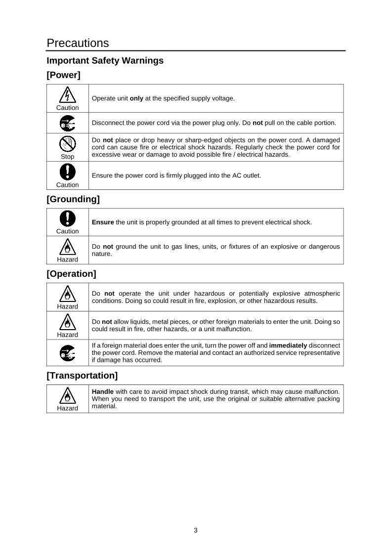
Precautions
Important Safety Warnings
[Power]
Caution
Operate unit only at the specified supply voltage.
Disconnect the power cord via the power plug only. Do not pull on the cable portion.
Stop
Do not place or drop heavy or sharp-edged objects on the power cord. A damaged cord can cause fire or electrical shock hazards. Regularly check the power cord for excessive wear or damage to avoid possible fire / electrical hazards.
Caution
Ensure the power cord is firmly plugged into the AC outlet.
[Grounding]
Caution
Ensure the unit is properly grounded at all times to prevent electrical shock.
Hazard
Do not ground the unit to gas lines, units, or fixtures of an explosive or dangerous nature.
[Operation]
Hazard
Do not operate the unit under hazardous or potentially explosive atmospheric conditions. Doing so could result in fire, explosion, or other hazardous results.
Hazard
Do not allow liquids, metal pieces, or other foreign materials to enter the unit. Doing so could result in fire, other hazards, or a unit malfunction.
If a foreign material does enter the unit, turn the power off and immediately disconnect the power cord. Remove the material and contact an authorized service representative if damage has occurred.
[Transportation]
Hazard
Handle with care to avoid impact shock during transit, which may cause malfunction. When you need to transport the unit, use the original or suitable alternative packing material.
4
[Circuitry Access]
Do not remove covers, panels, casing, or access the circuitry with power applied to the unit. Turn the power off and disconnect the power cord prior to removal. Internal servicing / adjustment of unit should only be performed by qualified personnel.
Stop
Do not touch any parts / circuitry with a high heat factor. Capacitors can retain enough electric charge to cause mild to serious shock, even after the power has been disconnected. Capacitors associated with the power supply are especially hazardous.
Hazard
Unit should not be operated or stored with cover, panels, and / or casing removed. Operating the unit with circuitry exposed could result in electric shock / fire hazards or a unit malfunction.
[Potential Hazards]
Caution
If abnormal odors or noises are noticed coming from the unit, immediately turn the power off and disconnect the power cord to avoid potentially hazardous conditions. If problems similar to the above occur, contact an authorized service representative before attempting to operate the unit again.
[Rack Mount Brackets, Ground Terminal, and Rubber Feet]
Caution
To rack-mount or ground the unit, or to install rubber feet, do not use screws or materials other than those supplied. Doing so may cause damage to the internal circuits or components of the unit. If you remove the rubber feet that are attached to the unit, do not reinsert the screws that secure the rubber feet.
[Consumables]
Caution
Consumable items that are used in the unit must be periodically replaced. For further details on which parts are consumables and when they should be replaced, refer to the specifications at the end of the Operation Manual. Since the service life of the consumables varies greatly depending on the environment in which they are used, such items should be replaced at an early date. For details on replacing consumable items, contact your dealer.
5
Upon Receipt
MFR-RU Series units and their accessories are fully inspected and adjusted prior to shipment. Check
your received items against the packing list below. Check to ensure no damage has occurred during
shipment. If damage has occurred, or items are missing, inform your supplier immediately.
Remote Control Unit
ITEM QTY REMARKS
MFR-16/40RU
MFR-16RUD
MFR-16/32/64RUW
MFR-18RU/RUA
MFR-39RU/RUA
MFR-16RUTA
1
AC cable 1
AC Adaptor (*1) 1 With DC lock plug (MFR-40RU/39RUA/18RUA)
DC cable retaining clip 1 set For AC adapters w/o DC lock plug
Rack Mount Brackets 1 set EIA standard type (MFR-16/32/64RUW/16RUTA is supplied w/o Rack Mount Brackets.)
Tool used to change button labels
1
LAN Cable (straight) (*2) 1
MFR-39/40/18RU/16RUTA/18RUA/39RUA:
UTP cable, 3m MFR-16RU/16RUD: STP cable, 3m (MFR-16/32/64RUW is supplied w/o LAN Cable.)
(*1) Depending on the production date, AC adapters are supplied without DC lock plugs, but with DC
cable retaining clips. (*2) User-prepared LAN cables are able to be used. Shielded Twist Pair cables are recommended
for MFR-16RU/16RUD/16RUW/32RUW/64RUW.
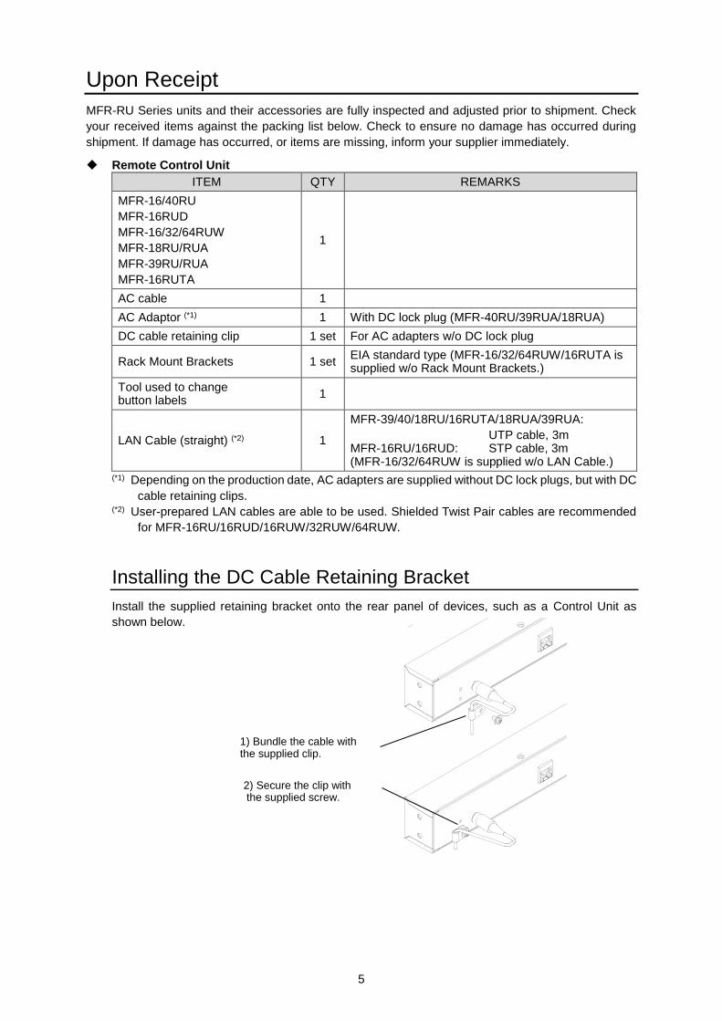
Installing the DC Cable Retaining Bracket
Install the supplied retaining bracket onto the rear panel of devices, such as a Control Unit as
shown below.
2) Secure the clip with the supplied screw.
1) Bundle the cable with the supplied clip.
6
Table of Contents
1. Prior to Starting ..................................................................................................................................... 9 1-1. Overview ..................................................................................................................................... 9 1-2. Features ...................................................................................................................................... 9
2. Panel Descriptions ..............................................................................................................................10 2-1. Front Panel ................................................................................................................................10 2-2. Rear Panel ................................................................................................................................13
3. Remote Control Unit Operation ..........................................................................................................15 3-1. Function and Operation .............................................................................................................15 3-2. Basic Operations .......................................................................................................................16
3-2-1. Operating Buttons ..............................................................................................................16 3-2-2. Switching Pages ................................................................................................................17
3-2-2-1. Switching Pages per Group ........................................................................................17 3-2-3. Level Control ......................................................................................................................19
3-2-3-1. Displaying Levels on the Remote Control Unit ...........................................................20 3-2-4. Operating with CONTROL (Rotary Selector) .....................................................................21
3-3. Function Buttons .......................................................................................................................23 3-4. MODE Button and Mode Menu (MFR-18RU/18RUA/39RU/39RUA/16RUTA) .........................26
3-4-1. Outline ................................................................................................................................26 3-4-2. Mode Menu ........................................................................................................................27 3-4-3. Setting Mode Menu (MFR-39RU) ......................................................................................29
3-4-3-1. DEF MODE .................................................................................................................30 3-4-3-2. DEF DEST ..................................................................................................................30 3-4-3-3. DEF LEVEL ................................................................................................................30 3-4-3-4. DEF PAGE .................................................................................................................31 3-4-3-5. DEF Page A to DEF PAGE D .....................................................................................31 3-4-3-6. PAGE MODE ..............................................................................................................31 3-4-3-7. PAGE ASSIGN ...........................................................................................................32 3-4-3-8. WRAPAROUND .........................................................................................................32 3-4-3-9. DSTINHIBIT ................................................................................................................32 3-4-3-10. SRCINHIBIT .............................................................................................................33 3-4-3-11. NAME TYPE .............................................................................................................33 3-4-3-12. TENKEY MOD ..........................................................................................................34 3-4-3-13. TENKEY NO .............................................................................................................34 3-4-3-14. SALVO CLR .............................................................................................................34 3-4-3-15. BTN ASSIGN ............................................................................................................34
3-4-4. Setting Mode Menu (MFR-39RUA)....................................................................................36 3-4-4-1. NETWORK .................................................................................................................37 3-4-4-2. VER/ALARM ...............................................................................................................37 3-4-4-3. DEFAULT ...................................................................................................................38 3-4-4-4. BUTTON ASSIGN ......................................................................................................39 3-4-4-5. INHIBIT .......................................................................................................................40 3-4-4-6. NAME TYPE ...............................................................................................................40 3-4-4-7. BRIGHTNESS ............................................................................................................41 3-4-4-8. RU-RU CONNECT .....................................................................................................41 3-4-4-9. TENKEY .....................................................................................................................41 3-4-4-10. PAGE ........................................................................................................................42 3-4-4-11. SALVO CLEAR .........................................................................................................42
3-5. Operation Using the Menu Display (MFR-16RUD) ...................................................................43 3-5-1. Crosspoint Switching .........................................................................................................43 3-5-2. Changing Button Assignment ............................................................................................44
3-6. Setup Menu (MFR-16/40RU, MFR-16RUD, MFR-16/32/64RUW) ...........................................46 3-6-1. Displaying Network Settings ..............................................................................................47
7
3-6-2. Changing the RU IP Address .............................................................................................48 3-6-3. Rebooting MU PC-LAN ......................................................................................................49
3-7. Setup Menu (MFR-18RU/18RUA) ............................................................................................50 3-7-1. Displaying Network Settings ..............................................................................................50 3-7-2. Changing the RU Network Settings ...................................................................................51 3-7-3. Rebooting MU PC-LAN ......................................................................................................51
3-8. Setup Menu (MFR-39RU) .........................................................................................................52 3-8-1. IP ADDRESS[RU] ..............................................................................................................52 3-8-2. SUBNET MASK[RU] ..........................................................................................................53 3-8-3. PC-LAN[MU] ......................................................................................................................53 3-8-4. RU CONN ID ......................................................................................................................53 3-8-5. RU CONNECT ...................................................................................................................54 3-8-6. BRIGHTNESS....................................................................................................................54 3-8-7. BTN ASSIGN .....................................................................................................................54 3-8-8. VER/ALARM ......................................................................................................................54 3-8-9. REBOOT ............................................................................................................................54
3-9. Setup Menu (MFR-39RUA) .......................................................................................................55 3-10. Setup Menu (MFR-16RUTA) ..................................................................................................55
3-10-1. Displaying Network Settings ............................................................................................55 3-10-2. Changing the RU Network Settings .................................................................................56 3-10-3. Rebooting MU PC-LAN ....................................................................................................56
3-11. Multi-Panel Operation .............................................................................................................57 3-11-1. Outline ..............................................................................................................................57 3-11-2. Enabling Multi-Panel Operation .......................................................................................58
4. Crosspoint Control ..............................................................................................................................59 4-1. One Crosspoint Switching .........................................................................................................59
4-1-1. One Crosspoint Switching by X-Y Setting .........................................................................59 4-1-1-1. SKIP-FWD/BWD .........................................................................................................60 4-1-1-2. TENKEY (MFR-39RU/39RUA) ...................................................................................60
4-1-2. A Crosspoint Switching Using a Bus Button ......................................................................61 4-1-3. CHOP Function ..................................................................................................................62 4-1-4. Crosspoint Switching Using TAKE Function ......................................................................62
4-2. Simultaneous Crosspoint Switching ..........................................................................................63 4-2-1. Main Unit Stored Salvos ....................................................................................................63 4-2-2. Remote Control Stored Salvos ..........................................................................................63 4-2-3. Simultaneous Switching Using the Take Function ............................................................65 4-2-4. Simultaneous Switching by the Link Function ...................................................................65
4-3. Lock ...........................................................................................................................................65 4-3-1. LOCK LOCAL ....................................................................................................................65 4-3-2. LOCK OTHER / LOCK ALL ...............................................................................................66
4-4. Monitor Output Function ............................................................................................................68 4-5. Preview Function .......................................................................................................................69
5. Troubleshooting ..................................................................................................................................69 5-1. Tuning the Text Color on Remote Unit Buttons ........................................................................70
5-1-1. MFR-18RU/39RU Color Tuning Procedure .......................................................................70 5-1-2. MFR-39RUA/18RUA/16RUTA Color Tuning Procedure ...................................................71
6. Specifications and Dimensions ..........................................................................................................72 6-1. Unit Specifications .....................................................................................................................72
6-1-1. MFR-16RU/16RUD ............................................................................................................72 6-1-2. MFR-40RU .........................................................................................................................72 6-1-3. MFR-16RUW .....................................................................................................................73 6-1-4. MFR-32RUW .....................................................................................................................73 6-1-5. MFR-64RUW .....................................................................................................................73 6-1-6. MFR-18RU .........................................................................................................................74
8
6-1-7. MFR-18RUA ......................................................................................................................74 6-1-8. MFR-39RU .........................................................................................................................75 6-1-9. MFR-39RUA ......................................................................................................................75 6-1-10. MFR-16RUTA ..................................................................................................................76
6-2. External Dimensions .................................................................................................................77 6-2-1. MFR-16RU .........................................................................................................................77 6-2-2. MFR-40RU .........................................................................................................................77 6-2-3. MFR-16RUD ......................................................................................................................78 6-2-4. MFR-16RUW .....................................................................................................................78 6-2-5. MFR-32RUW .....................................................................................................................79 6-2-6. MFR-64RUW .....................................................................................................................79 6-2-7. MFR-18RU .........................................................................................................................80 6-2-8. MFR-18RUA ......................................................................................................................80 6-2-9. MFR-39RU .........................................................................................................................81 6-2-10. MFR-39RUA ....................................................................................................................81 6-2-11. MFR-16RUTA ..................................................................................................................82
Appendix: Operation Tips .......................................................................................................................83 How to use Page buttons .................................................................................................................83
9
1. Prior to Starting
1-1. Overview
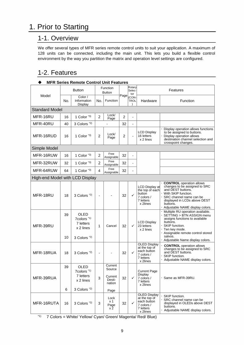
We offer several types of MFR series remote control units to suit your application. A maximum of
128 units can be connected, including the main unit. This lets you build a flexible control
environment by the way you partition the matrix and operation level settings are configured.
1-2. Features
MFR Series Remote Control Unit Features
Model
Button Function
Button Page
Rotary Selec-
tor
(CON- TROL
)
Features
No. Color /
Information Display
No. Function Hardware Function
Standard Model
MFR-16RU 16 1 Color *3) 2 Lock/ Page 2 -
MFR-40RU 40 3 Colors *2) - 32 -
MFR-16RUD 16 1 Color *3) 2 Lock/ Page 2 -
LCD Display 16 letters x 2 lines
Display operation allows functions to be assigned to buttons.
Display operation allows destination channel selection and crosspoint changes.
Simple Model
MFR-16RUW 16 1 Color *3) 2 Free
Assignable 32 -
MFR-32RUW 32 1 Color *3) 2 Free
Assignable 32 -
MFR-64RUW 64 1 Color *3) 4 Free
Assignable 32 -
High-end Model with LCD Display
MFR-18RU 18 3 Colors *2) - - 32
LCD Display at the top of each button 7 colors / 7 letters x 2lines
CONTROL operation allows changes to be assigned to SRC and DEST buttons.
With SKIP function. SRC channel name can be
displayed in LCDs above DEST buttons.
Adjustable NAME display colors.
MFR-39RU
39
10
OLED
7colors *1)
7 letters
x 2 lines
3 Colors *2)
1 Cancel 32 LCD Display 23 letters x 2 lines
Multiple RU operation available. SETTING > BTN ASSIGN menu
assigns functions to available buttons.
SKIP function. Ten key mode. Assignable remote control stored
salvos. Adjustable Name display colors.
MFR-18RUA 18 3 Colors *2) - - 32
OLED Display at the top of each button 7 colors / 7 letters x 2lines
CONTROL operation allows changes to be assigned to SRC and DEST buttons.
SKIP function. Adjustable NAME display colors.
MFR-39RUA
39
6
OLED
7colors *1)
7 letters
x 2 lines
3 Colors *2)
3
Current Source
Current Desti- nation
Page
32
Current Page Display 7 colors / 7 letters x 2lines
Same as MFR-39RU.
MFR-16RUTA 16 3 Colors *2) 3
Lock x 1
Page x 2
32
OLED Display at the top of each button 7 colors / 7 letters x 2lines
SKIP function. SRC channel name can be
displayed in OLEDs above DEST buttons.
Adjustable NAME display colors.
*1) 7 Colors = White/ Yellow/ Cyan/ Green/ Magenta/ Red/ Blue)
10
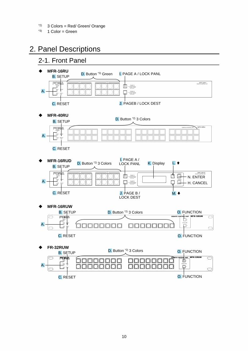
*2) 3 Colors = Red/ Green/ Orange *3) 1 Color = Green
2. Panel Descriptions
2-1. Front Panel
MFR-16RU
PAGE A
(HOLD 3SEC)
PAGE B
LOCK RESET
POWER
BUSY SETUP
LOCK DEST
(HOLD 3SEC)
LOCK PANL
A B
REMOTE CONTROL UNIT
MFR-16RU
MFR-40RU
POWER
BUSY SETUP
LOCK RESET
MFR-40RUREMOTE CONTROL UNIT
MFR-16RUD
PAGE A
(HOLD 3SEC)
PAGE B
LOCK RESET
POWER
BUSY SETUP
LOCK DEST
(HOLD 3SEC)
LOCK PANL
CANCEL
ENTER
A B MFR-16RUDREMOTE CONTROL UNIT
MFR-16RUW
POW ER
BUSY SE TUP
LOCK RE SET
MFR-16RUW
FUNC TION
1
2
REMOTE CONTROL UNIT
FR-32RUW
POW ER
BU SY SET UP
LO CK RESET
FUNCTION
1
2
REMOTE CONTROL UNIT MFR-32RUW
D. Button *2) 3 Colors
I. PAGE A / LOCK PANL K. Display L.
H. CANCEL
N. ENTER A.
B. SETUP
C. RESET J. PAGE B / LOCK DEST
M.
D. Button *2) 3 Colors
O. FUNCTION
A.
B. SETUP
C. RESET O. FUNCTION
C. RESET
B. SETUP D. Button *3) Green
J. PAGEB / LOCK DEST
I. PAGE A / LOCK PANL
A.
A.
B. SETUP
C. RESET
O. FUNCTION
O. FUNCTION
D. Button *2) 3 Colors
D. Button *2) 3 Colors
C. RESET
B. SETUP
A.
11
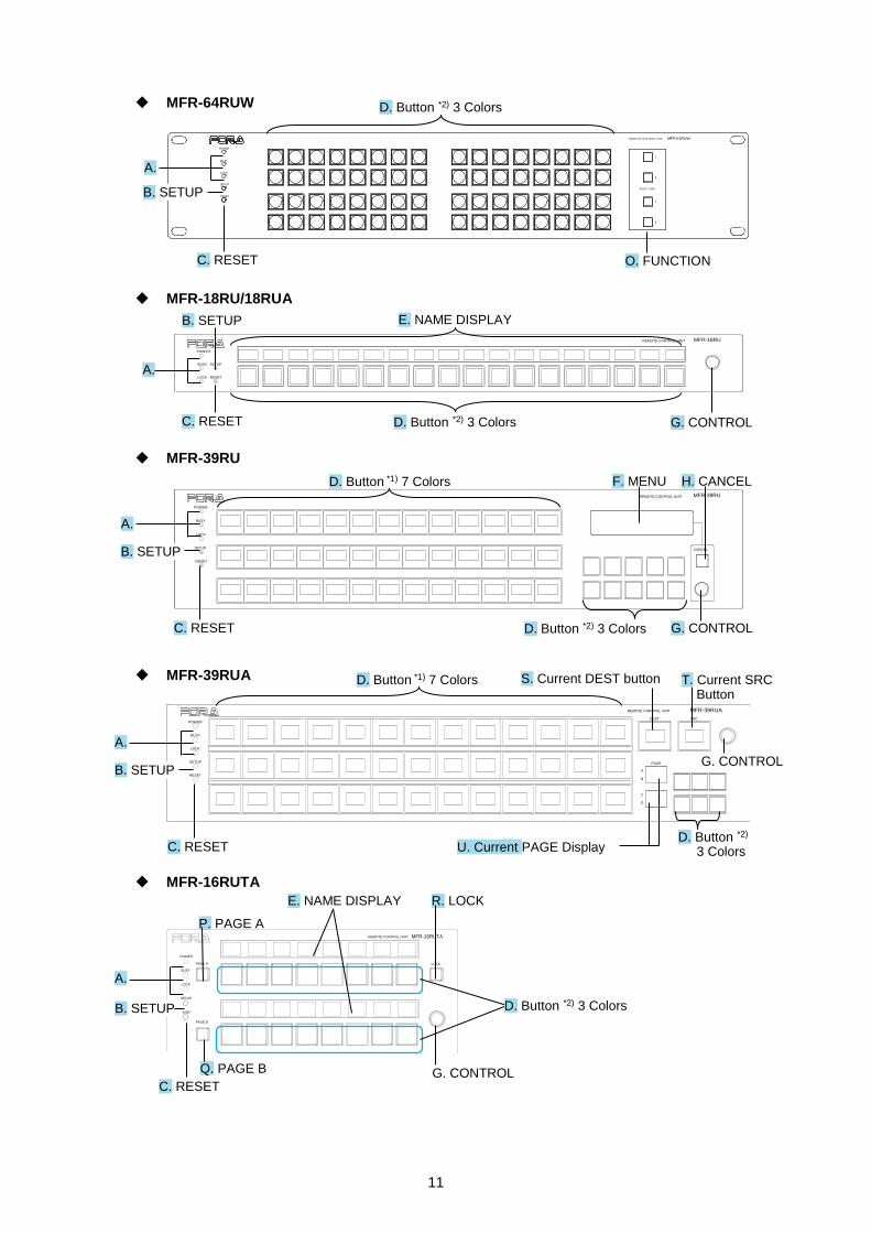
MFR-64RUW
MFR-6 4RUWREMOTE CO NTROL UNIT
1
2
1
2
POWER
BUSY
LOCK
SETUP
RESET
FUNC TION
MFR-18RU/18RUA
POWER
BUSY SETUP
LOCK RESET
MFR-18RUREMOTE CONTROL UNIT
MFR-39RU
RESET
CANCEL
MFR-39RUREMOTE CONTROL UNIT
POWER
BUSY
LOCK
SETUP
MFR-39RUA
POWER
BUSY
LOCK
SETUP
RESET
DEST SRC
A
B
C
D
PAGE
MFR-39RUAREMOTE COMTROL UNIT
MFR-16RUTA
MFR-16RUTAREMOTE CONTROL UNIT
LOCK
POWER
BUSY
PAGE A
LOCK
SETUP
RESET
PAGE B
D. Button *1) 7 Colors
G. CONTROL
F. MENU
D. Button *2) 3 Colors
B. SETUP
A.
C. RESET
H. CANCEL
B. SETUP
A.
C. RESET O. FUNCTION
D. Button *2) 3 Colors
E. NAME DISPLAY
D. Button *2) 3 Colors
G. CONTROL
B. SETUP
C. RESET
A.
E. NAME DISPLAY R. LOCK
D. Button *2) 3 Colors
G. CONTROL
P. PAGE A
Q. PAGE B
B. SETUP
C. RESET IN 1, 2
A. MFR-LAN
G. CONTROL
D. Button *2) 3 Colors
S. Current DEST button
U. Current PAGE Display
B. SETUP
A.
C. RESET
D. Button *1) 7 Colors
T. Current SRC Button
12
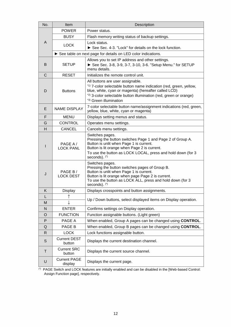
No. Item Description
A
POWER Power status.
BUSY Flash memory writing status of backup settings.
LOCK Lock status.
► See Sec. 4-3. "Lock" for details on the lock function.
► See table on next page for details on LED color indications.
B SETUP
Allows you to set IP address and other settings.
► See Sec. 3-8, 3-9, 3-7, 3-10, 3-6. "Setup Menu." for SETUP menu details.
C RESET Initializes the remote control unit.
D Buttons
All buttons are user assignable. *1) 7-color selectable button name indication (red, green, yellow, blue, white, cyan or magenta) (hereafter called LCD) *2) 3-color selectable button illumination (red, green or orange) *3) Green illumination
E NAME DISPLAY 7-color selectable button name/assignment indications (red, green, yellow, blue, white, cyan or magenta)
F MENU Displays setting menus and status.
G CONTROL Operates menu settings.
H CANCEL Cancels menu settings.
I PAGE A /
LOCK PANL
Switches pages. Pressing the button switches Page 1 and Page 2 of Group A. Button is unlit when Page 1 is current. Button is lit orange when Page 2 is current.
To use the button as LOCK LOCAL, press and hold down (for 3 seconds). (*)
J PAGE B /
LOCK DEST
Switches pages. Pressing the button switches pages of Group B. Button is unlit when Page 1 is current. Button is lit orange when page Page 2 is current. To use the button as LOCK ALL, press and hold down (for 3 seconds). (*)
K Display Displays crosspoints and button assignments.
L ↑ Up / Down buttons, select displayed items on Display operation.
M ↓
N ENTER Confirms settings on Display operation.
O FUNCTION Function assignable buttons. (Light green)
P PAGE A When enabled, Group A pages can be changed using CONTROL.
Q PAGE B When enabled, Group B pages can be changed using CONTROL.
R LOCK Lock functions assignable button.
S Current DEST
button Displays the current destination channel.
T Current SRC
button Displays the current source channel.
U Current PAGE
display Displays the current page.
(*) PAGE Switch and LOCK features are initially enabled and can be disabled in the [Web-based Control:
Assign Function page], respectively.
13
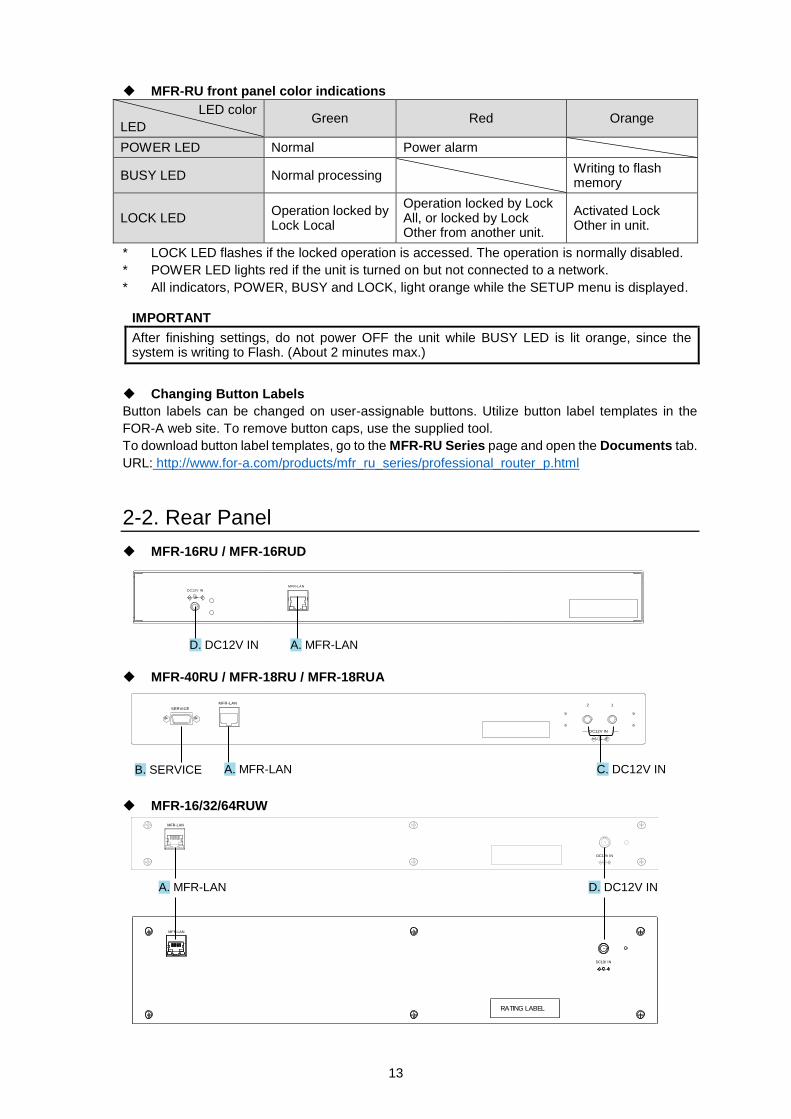
MFR-RU front panel color indications
LED color
LED Green Red Orange
POWER LED Normal Power alarm
BUSY LED Normal processing Writing to flash
memory
LOCK LED Operation locked by Lock Local
Operation locked by Lock All, or locked by Lock Other from another unit.
Activated Lock Other in unit.
* LOCK LED flashes if the locked operation is accessed. The operation is normally disabled.
* POWER LED lights red if the unit is turned on but not connected to a network.
* All indicators, POWER, BUSY and LOCK, light orange while the SETUP menu is displayed.
IMPORTANT
After finishing settings, do not power OFF the unit while BUSY LED is lit orange, since the system is writing to Flash. (About 2 minutes max.)
Changing Button Labels
Button labels can be changed on user-assignable buttons. Utilize button label templates in the
FOR-A web site. To remove button caps, use the supplied tool.
To download button label templates, go to the MFR-RU Series page and open the Documents tab.
URL: http://www.for-a.com/products/mfr_ru_series/professional_router_p.html
2-2. Rear Panel
MFR-16RU / MFR-16RUD
DC12V IN
MFR-LAN
MFR-40RU / MFR-18RU / MFR-18RUA
DC12V IN
2 1SERVICE
MFR-LAN
MFR-16/32/64RUW
A. MFR-LAN D. DC12V IN
C. DC12V IN A. MFR-LAN B. SERVICE
RATING LABEL
DC12V IN
MFR-LAN
MFR-LAN
DC12V IN
A. MFR-LAN D. DC12V IN
14
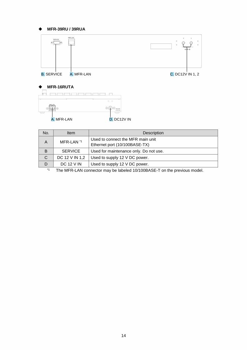
MFR-39RU / 39RUA
DC12V IN
2 1SERVICE
MFR-LAN
MFR-16RUTA
DC12V IN
MFR-LAN
No. Item Description
A MFR-LAN *1 Used to connect the MFR main unit
Ethernet port (10/100BASE-TX)
B SERVICE Used for maintenance only. Do not use.
C DC 12 V IN 1,2 Used to supply 12 V DC power.
D DC 12 V IN Used to supply 12 V DC power.
*1 The MFR-LAN connector may be labeled 10/100BASE-T on the previous model.
A. MFR-LAN C. DC12V IN 1, 2 B. SERVICE
A. MFR-LAN D. DC12V IN
15
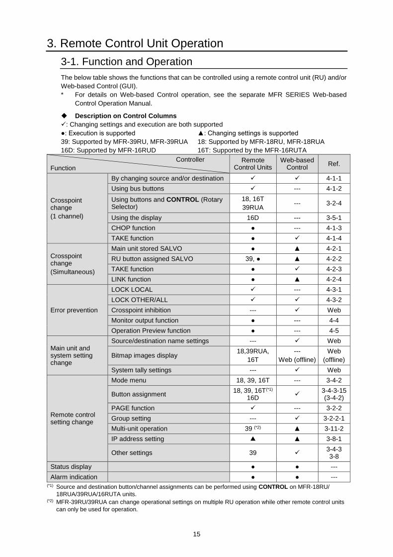
3. Remote Control Unit Operation
3-1. Function and Operation
The below table shows the functions that can be controlled using a remote control unit (RU) and/or
Web-based Control (GUI).
* For details on Web-based Control operation, see the separate MFR SERIES Web-based
Control Operation Manual.
Description on Control Columns
: Changing settings and execution are both supported
●: Execution is supported ▲: Changing settings is supported
39: Supported by MFR-39RU, MFR-39RUA 18: Supported by MFR-18RU, MFR-18RUA
16D: Supported by MFR-16RUD 16T: Supported by the MFR-16RUTA
Controller
Function
Remote Control Units
Web-based Control
Ref.
Crosspoint change
(1 channel)
By changing source and/or destination 4-1-1
Using bus buttons --- 4-1-2
Using buttons and CONTROL (Rotary Selector)
18, 16T
39RUA --- 3-2-4
Using the display 16D --- 3-5-1
CHOP function ● --- 4-1-3
TAKE function ● 4-1-4
Crosspoint change
(Simultaneous)
Main unit stored SALVO ● ▲ 4-2-1
RU button assigned SALVO 39, ● ▲ 4-2-2
TAKE function ● 4-2-3
LINK function ● ▲ 4-2-4
Error prevention
LOCK LOCAL --- 4-3-1
LOCK OTHER/ALL 4-3-2
Crosspoint inhibition --- Web
Monitor output function ● --- 4-4
Operation Preview function ● --- 4-5
Main unit and system setting change
Source/destination name settings --- Web
Bitmap images display 18,39RUA,
16T
---
Web (offline)
Web
(offline)
System tally settings --- Web
Remote control setting change
Mode menu 18, 39, 16T --- 3-4-2
Button assignment 18, 39, 16T(*1)
16D
3-4-3-15 (3-4-2)
PAGE function --- 3-2-2
Group setting --- 3-2-2-1
Multi-unit operation 39 (*2) ▲ 3-11-2
IP address setting ▲ ▲ 3-8-1
Other settings 39 3-4-3 3-8
Status display ● ● ---
Alarm indication ● ● --- (*1) Source and destination button/channel assignments can be performed using CONTROL on MFR-18RU/
18RUA/39RUA/16RUTA units. (*2) MFR-39RU/39RUA can change operational settings on multiple RU operation while other remote control units
can only be used for operation.
16
3-2. Basic Operations
This section describes basic operation of remote control units and how to set and execute various
functions.
3-2-1. Operating Buttons
1) Assigning functions to buttons (changing assignments)
First of all, assign RU front panel button functions using Web-based Control: Assign Function
page. Any function can be assigned to any button except for CANCEL, PAGE A, PAGE B, UP,
DOWN, ENTER, CURRENT DEST, CURRENT SRC or LOCK buttons.
How to assign functions to buttons
1. In Web-based Control, click to open the menu tree in the left pane. Click to select Assign
Function to display the menu page.
2. Select a page and a button to assign function and select an assigning function. Buttons
can be selected by inputting Button IDs or clicking on button icons.
3. After selecting a function, specify parameters for each function.
4. Click Send to apply the settings when all settings are completed.
As for MFR-16RUD, you can use the front panel display to assign functions to buttons.
► See Sec. 3-5-2. “Changing Button Assignments” for details
As for MFR-18RU/ 18RUA/ 39RU/ 39RUA/ 16RUTA units, Source and Destination button/
channel assignments can be performed using CONTROL.
► See Sec. 3-2-4. “Operating with CONTROL (Rotary Selector)”
The MFR-39RU menu display can also assign functions.
► See Sec. 3-4-3-15 “BTN ASSIGN”
The MFR-39RUA menu display can also assign functions.
► See Sec. 3-4-4-4 “BUTTON ASSIGN”
2) Press buttons to execute functions
Press a button to execute assigned function. The button LED indication, NAME DISPLAY,
and MENU display change according to the assigned function.
17
3-2-2. Switching Pages
Function assignment to RU front panel buttons are controlled per page. Page functions allow
you to switch all button-assigned functions by switching pages. Pages can be changed either
by using the PAGE button (see Sec. 3-3 “Function Buttons”) or CONTROL in the Mode menu.
(See Sec. 3-4 “MODE Button and Mode Menu.")
There are also Page function settings in the Mode and Setting menus. Also refer to the
following sections for miscellaneous settings.
PAGE button assignment: 3-4-3-7 “PAGE ASSIGN”
You can select the PAGE button to be assigned in certain pages or in all pages. Having
PAGE buttons assigned to all pages helps you to find the PAGE button easily.
Mode menu settings: 3-4-3-6 “PAGE MODE”
This section describes how to select pages using CONTROL.
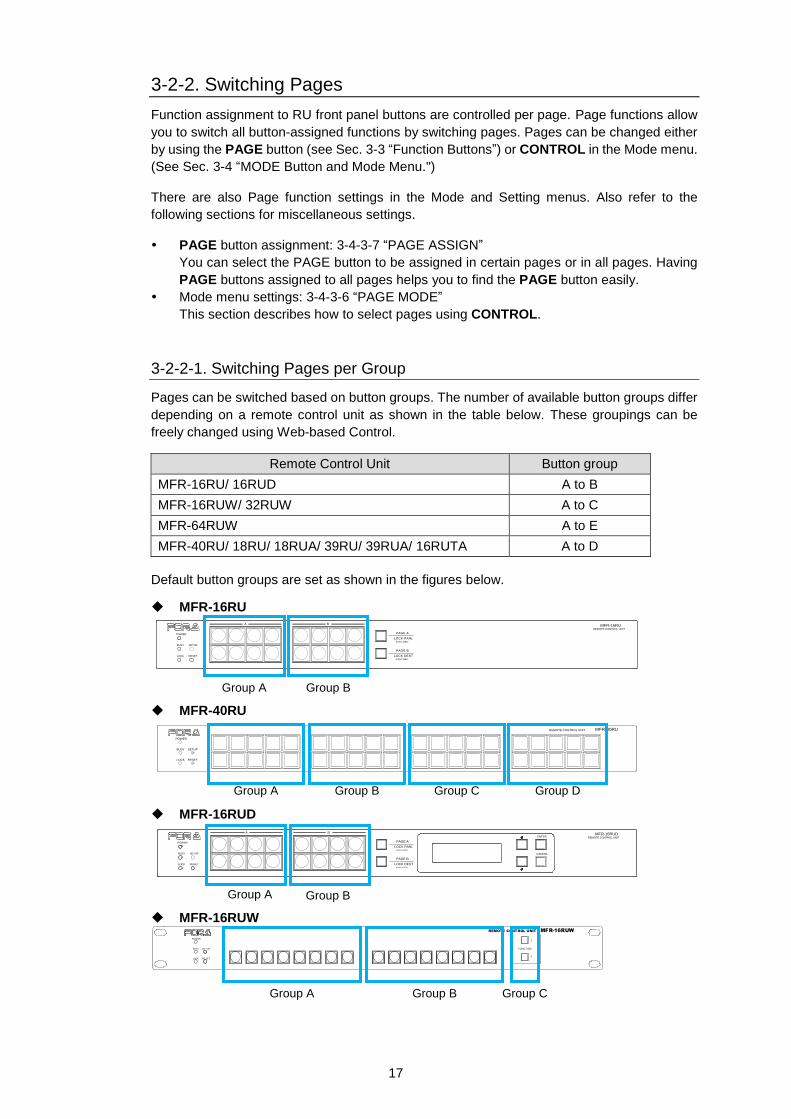
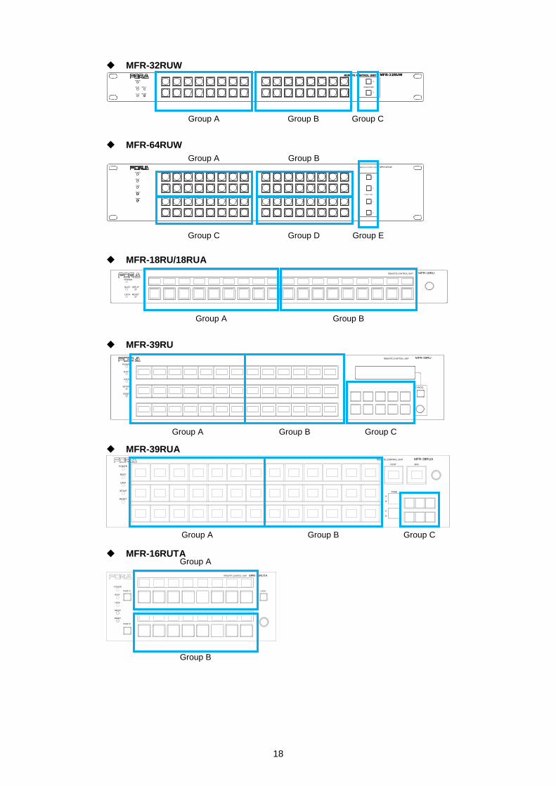
3-2-2-1. Switching Pages per Group
Pages can be switched based on button groups. The number of available button groups differ
depending on a remote control unit as shown in the table below. These groupings can be
freely changed using Web-based Control.
Remote Control Unit Button group
MFR-16RU/ 16RUD A to B
MFR-16RUW/ 32RUW A to C
MFR-64RUW A to E
MFR-40RU/ 18RU/ 18RUA/ 39RU/ 39RUA/ 16RUTA A to D
Default button groups are set as shown in the figures below.
MFR-16RU
PAGE A
(HOLD 3SEC)
PAGE B
LOCK RESET
POWER
BUSY SETUP
LOCK DEST
(HOLD 3SEC)
LOCK PANL
A B
REMOTE CONTROL UNIT
MFR-16RU
MFR-40RU
POWER
BUSY SETUP
LOCK RESET
MFR-40RUREMOTE CONTROL UNIT
MFR-16RUD
PAGE A
(HOLD 3SEC)
PAGE B
LOCK RESET
POWER
BUSY SETUP
LOCK DEST
(HOLD 3SEC)
LOCK PANL
CANCEL
ENTER
A B MFR-16RUDREMOTE CONTROL UNIT
MFR-16RUW
POW ER
BUSY SE TUP
LOCK RE SET
MFR-16RUW
FUNC TION
1
2
REMOTE CONTROL UNIT
Group A Group B
Group A Group B Group C Group D
Group C Group A Group B
Group A Group B
18
MFR-32RUW
POW ER
BU SY SET UP
LO CK RESET
FUNCTION
1
2
REMOTE CONTROL UNIT MFR-32RUW
MFR-64RUW
MFR-6 4RUWREMOTE CO NTROL UNIT
1
2
1
2
POWER
BUSY
LOCK
SETUP
RESET
FUNC TION
MFR-18RU/18RUA
POWER
BUSY SETUP
LOCK RESET
MFR-18RUREMOTE CONTROL UNIT
MFR-39RU
RESET
CANCEL
MFR-39RUREMOTE CONTROL UNIT
POWER
BUSY
LOCK
SETUP
MFR-39RUA
POWER
BUSY
LOCK
SETUP
RESET
DEST SRC
A
B
C
D
PAGE
MFR-39RUAREMOTE COMTROL UNIT
MFR-16RUTA
MFR-16RUTAREMOTE CONTROL UNIT
LOCK
POWER
BUSY
PAGE A
LOCK
SETUP
RESET
PAGE B
Group A Group B Group C
Group C Group D Group E
Group A Group B
Group A
Group B
Group A Group B Group C
Group A Group B Group C
Group A Group B
19
Page Limit and Maximum Page Number Setting
Maximum number of assignable pages (page limit):
32 for MFR-40RU/ 16RUW/ 32RUW/ 64RUW/ 18RU/ 18RUA/ 39RU/ 39RUA/ 16RUTA
2 for MFR-16RU/ 16RUD
Maximum page numbers are selectable for pages selected by Mode menu or Page
buttons. (Excluding MFR-16RU/16RUD).
Maximum page number settings are applied to all groups.
Any page assignments or jumps are possible, but do not work if they exceed maximum
page limits. (Buttons are masked with "x" in MFR-18RU/18RUA/39RU/39RUA/16RUTA
units.)
Maximum page numbers can be set under Page-Max number in the [Web-based
Control: RU Settings page]. A warning dialog box will appear when the number is
reduced and sent.
If the currently displayed page number is over the maximum page number setting due to a
change, the new maximum page is displayed as soon as the setting is changed.
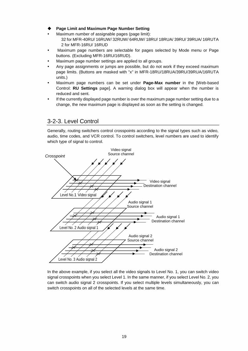
3-2-3. Level Control
Generally, routing switchers control crosspoints according to the signal types such as video,
audio, time codes, and VCR control. To control switchers, level numbers are used to identify
which type of signal to control.
In the above example, if you select all the video signals to Level No. 1, you can switch video
signal crosspoints when you select Level 1. In the same manner, if you select Level No. 2, you
can switch audio signal 2 crosspoints. If you select multiple levels simultaneously, you can
switch crosspoints on all of the selected levels at the same time.
Video signal
Source channel
Level No. 3 Audio signal 2
Level No. 2 Audio signal 1
Level No.1 Video signal
Crosspoint
Video signal Destination channel
Audio signal 1 Source channel
Audio signal 1 Destination channel
Audio signal 2 Source channel
Audio signal 2 Destination channel
20
Assigning levels
Signals can be assigned to logical inputs and outputs using [Web-based Control: Assign
Function page]. When assigning the signals, select a level for respective signals to be
assigned to.
Selecting levels on remote control units
The remote control unit can select channels on the current level. The current level can be
changed using the LEVEL button or CONTROL. Multiple levels can be set to the current levels
using the LEVEL button or CONTROL.
Pressing the LEVEL button allows you to go to the level that was selected when signals were
assigned.
To change levels using CONTROL, press the MODE button and select Level menu in the
Mode menu.
► See Sec. 3-4 “MODE Button and Mode Menu.”
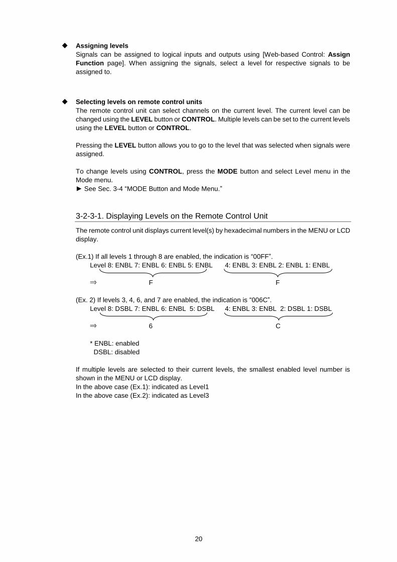
3-2-3-1. Displaying Levels on the Remote Control Unit
The remote control unit displays current level(s) by hexadecimal numbers in the MENU or LCD
display.
(Ex.1) If all levels 1 through 8 are enabled, the indication is “00FF”.
Level 8: ENBL 7: ENBL 6: ENBL 5: ENBL 4: ENBL 3: ENBL 2: ENBL 1: ENBL
⇒ F F
(Ex. 2) If levels 3, 4, 6, and 7 are enabled, the indication is “006C”.
Level 8: DSBL 7: ENBL 6: ENBL 5: DSBL 4: ENBL 3: ENBL 2: DSBL 1: DSBL
⇒ 6 C
* ENBL: enabled
DSBL: disabled
If multiple levels are selected to their current levels, the smallest enabled level number is
shown in the MENU or LCD display.
In the above case (Ex.1): indicated as Level1
In the above case (Ex.2): indicated as Level3
21
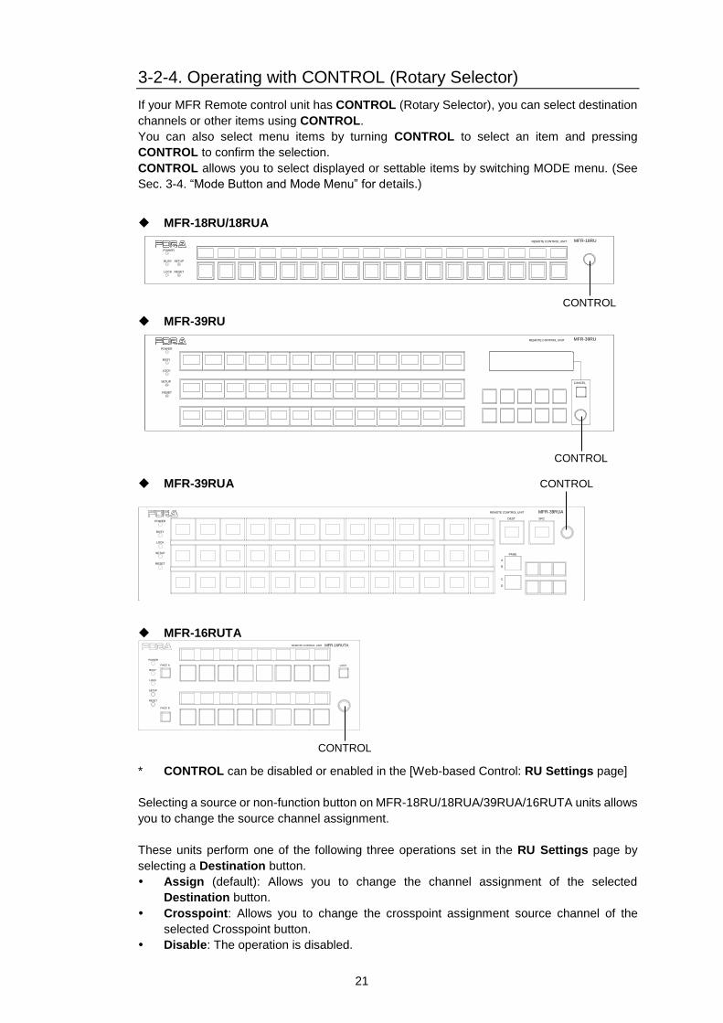
3-2-4. Operating with CONTROL (Rotary Selector)
If your MFR Remote control unit has CONTROL (Rotary Selector), you can select destination
channels or other items using CONTROL.
You can also select menu items by turning CONTROL to select an item and pressing
CONTROL to confirm the selection.
CONTROL allows you to select displayed or settable items by switching MODE menu. (See
Sec. 3-4. “Mode Button and Mode Menu” for details.)
MFR-18RU/18RUA
POWER
BUSY SETUP
LOCK RESET
MFR-18RUREMOTE CONTROL UNIT
MFR-39RU
RESET
CANCEL
MFR-39RUREMOTE CONTROL UNIT
POWER
BUSY
LOCK
SETUP
MFR-39RUA
POWER
BUSY
LOCK
SETUP
RESET
DEST SRC
A
B
C
D
PAGE
MFR-39RUAREMOTE COMTROL UNIT
MFR-16RUTA MFR-16RUTAREMOTE CONTROL UNIT
LOCK
POWER
BUSY
PAGE A
LOCK
SETUP
RESET
PAGE B
* CONTROL can be disabled or enabled in the [Web-based Control: RU Settings page]
Selecting a source or non-function button on MFR-18RU/18RUA/39RUA/16RUTA units allows
you to change the source channel assignment.
These units perform one of the following three operations set in the RU Settings page by
selecting a Destination button.
Assign (default): Allows you to change the channel assignment of the selected
Destination button.
Crosspoint: Allows you to change the crosspoint assignment source channel of the
selected Crosspoint button.
Disable: The operation is disabled.
CONTROL
CONTROL
CONTROL
CONTROL
22
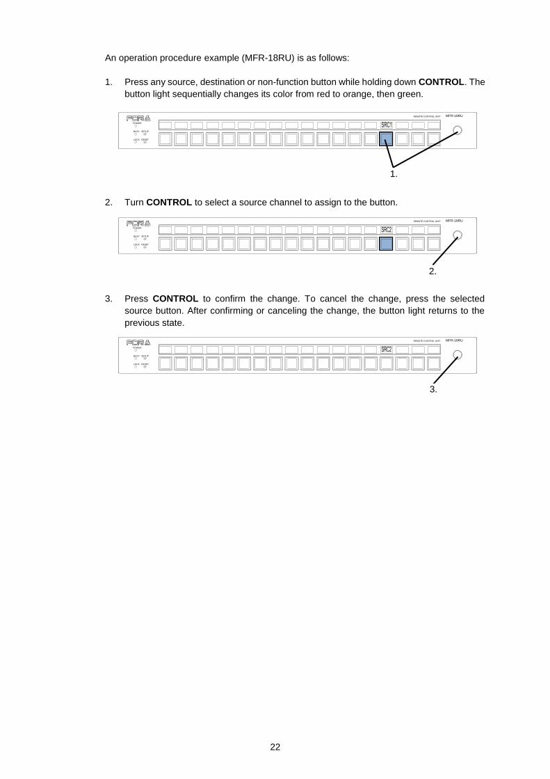
An operation procedure example (MFR-18RU) is as follows:
1. Press any source, destination or non-function button while holding down CONTROL. The
button light sequentially changes its color from red to orange, then green.
2. Turn CONTROL to select a source channel to assign to the button.
3. Press CONTROL to confirm the change. To cancel the change, press the selected
source button. After confirming or canceling the change, the button light returns to the
previous state.
POWER
BUSY SETUP
LOCK RESET
MFR-18RUREMOTE CONTROL UNIT
1.
POWER
BUSY SETUP
LOCK RESET
MFR-18RUREMOTE CONTROL UNIT
2.
POWER
BUSY SETUP
LOCK RESET
MFR-18RUREMOTE CONTROL UNIT
3.
23
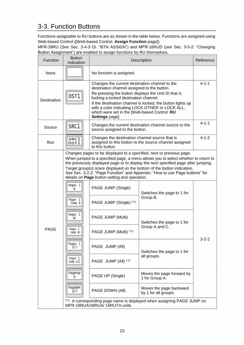
3-3. Function Buttons
Functions assignable to RU buttons are as shown in the table below. Functions are assigned using
Web-based Control ([Web-based Control: Assign Function page]).
MFR-39RU (See Sec. 3-4-3-15. “BTN ASSIGN”) and MFR-16RUD (see Sec. 3-5-2. “Changing
Button Assignment”) are enabled to assign functions by RU themselves.
Function Button
indication Description Reference
None
No function is assigned.
Destination
Changes the current destination channel to the destination channel assigned to the button.
Re-pressing the button displays the Unit ID that is locking a locked destination channel.
If the destination channel is locked, the button lights up with a color indicating LOCK OTHER or LOCK ALL, which were set in the [Web-based Control: RU Settings page].
4-1-1
Source
Changes the current destination channel source to the source assigned to the button.
4-1-1
Bus
Changes the destination channel source that is assigned to this button to the source channel assigned to this button.
4-1-2
PAGE
Changes pages to be displayed to a specified, next or previous page.
When jumped to a specified page, a menu allows you to select whether to return to the previously displayed page or to display the next specified page after jumping.
Target group(s) is/are displayed on the bottom of the button indication. See Sec. 3-2-2. “Page Function” and Appendix: “How to use Page buttons” for details on Page button setting and operation.
PAGE JUMP (Single)
Switches the page to 1 for Group B.
3-2-2
PAGE JUMP (Single) (*1)
PAGE JUMP (Multi)
Switches the page to 1 for Group A and C.
PAGE JUMP (Multi) (*1)
PAGE JUMP (All)
Switches the page to 1 for all groups.
PAGE JUMP (All) (*1)
PAGE UP (Single) Moves the page forward by 1 for Group A.
PAGE DOWN (All) Moves the page backward by 1 for all groups.
(*1) A corresponding page name is displayed when assigning PAGE JUMP on MFR-18RUA/39RUA/ 16RUTA units.
24
Function Button
indication Description Reference
Function
Destination mode
3-4
Source mode
Level mode
Page mode (*1)
(PAGE_Grp-All / A / B / C / D)
* The example at left shows the PAGE_Grp-All mode (*1) The name set under Page Name Settings is displayed for PAGE Grp-A/B/C/D. (MFR-18RUA/39RUA/16RUTA only)
Setting mode
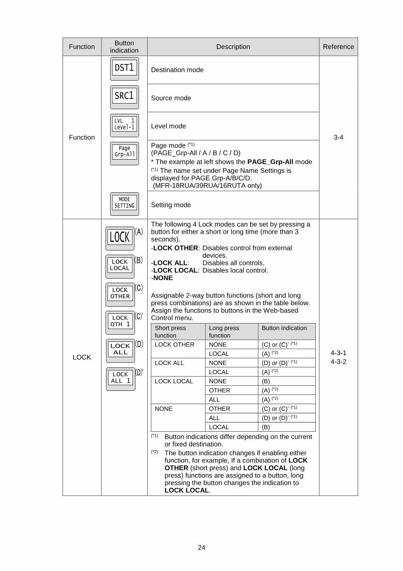
LOCK
The following 4 Lock modes can be set by pressing a button for either a short or long time (more than 3 seconds).
-LOCK OTHER: Disables control from external devices. -LOCK ALL: Disables all controls. -LOCK LOCAL: Disables local control. -NONE
Assignable 2-way button functions (short and long press combinations) are as shown in the table below. Assign the functions to buttons in the Web-based Control menu.
Short press
function
Long press
function
Button indication
LOCK OTHER NONE (C) or (C)’ (*1)
LOCAL (A) (*2)
LOCK ALL NONE (D) or (D)’ (*1)
LOCAL (A) (*2)
LOCK LOCAL NONE (B)
OTHER (A) (*2)
ALL (A) (*2)
NONE OTHER (C) or (C)’ (*1)
ALL (D) or (D)’ (*1)
LOCAL (B)
(*1) Button indications differ depending on the current or fixed destination. (*2) The button indication changes if enabling either function, for example, If a combination of LOCK OTHER (short press) and LOCK LOCAL (long press) functions are assigned to a button, long pressing the button changes the indication to LOCK LOCAL.
4-3-1
4-3-2
25
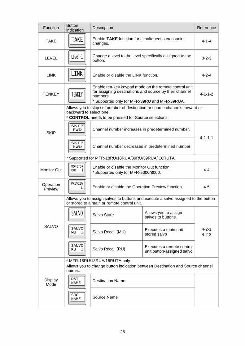
Function Button indication
Description Reference
TAKE
Enable TAKE function for simultaneous crosspoint changes.
4-1-4
LEVEL
Change a level to the level specifically assigned to the button.
3-2-3
LINK
Enable or disable the LINK function. 4-2-4
TENKEY
Enable ten-key keypad mode on the remote control unit for assigning destinations and source by their channel numbers.
* Supported only for MFR-39RU and MFR-39RUA.
4-1-1-2
SKIP
Allows you to skip set number of destination or source channels forward or backward to select one.
* CONTROL needs to be pressed for Source selections.
Channel number increases in predetermined number.
4-1-1-1
Channel number decreases in predetermined number.
* Supported for MFR-18RU/18RUA/39RU/39RUA/ 16RUTA.
Monitor Out
Enable or disable the Monitor Out function.
* Supported only for MFR-5000/8000. 4-4
Operation Preview
Enable or disable the Operation Preview function. 4-5
SALVO
Allows you to assign salvos to buttons and execute a salvo assigned to the button or stored to a main or remote control unit.
Salvo Store Allows you to assign salvos to buttons.
4-2-1
4-2-2
Salvo Recall (MU) Executes a main unit- stored salvo
Salvo Recall (RU) Executes a remote control unit button-assigned salvo
Display Mode
* MFR-18RU/18RUA/16RUTA only
Allows you to change button indication between Destination and Source channel names.
Destination Name
Source Name
26
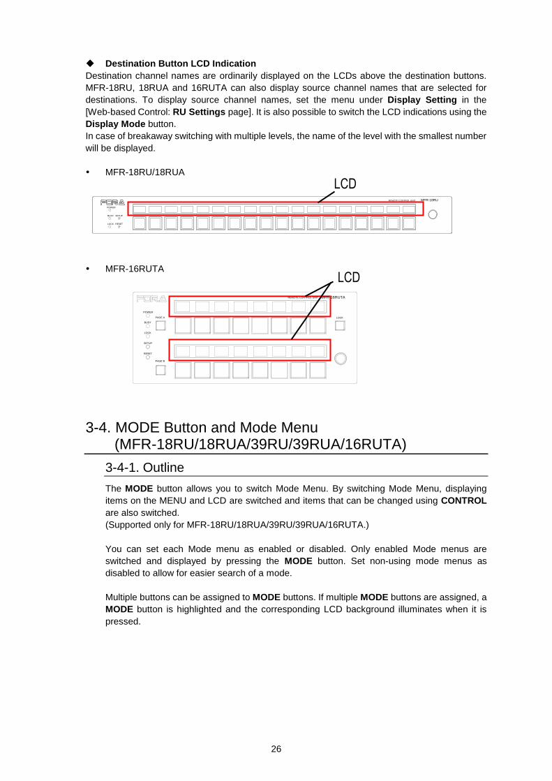
Destination Button LCD Indication
Destination channel names are ordinarily displayed on the LCDs above the destination buttons.
MFR-18RU, 18RUA and 16RUTA can also display source channel names that are selected for
destinations. To display source channel names, set the menu under Display Setting in the
[Web-based Control: RU Settings page]. It is also possible to switch the LCD indications using the
Display Mode button.
In case of breakaway switching with multiple levels, the name of the level with the smallest number
will be displayed.
MFR-18RU/18RUA
MFR-16RUTA
3-4. MODE Button and Mode Menu (MFR-18RU/18RUA/39RU/39RUA/16RUTA)
3-4-1. Outline
The MODE button allows you to switch Mode Menu. By switching Mode Menu, displaying
items on the MENU and LCD are switched and items that can be changed using CONTROL
are also switched.
(Supported only for MFR-18RU/18RUA/39RU/39RUA/16RUTA.)
You can set each Mode menu as enabled or disabled. Only enabled Mode menus are
switched and displayed by pressing the MODE button. Set non-using mode menus as
disabled to allow for easier search of a mode.
Multiple buttons can be assigned to MODE buttons. If multiple MODE buttons are assigned, a
MODE button is highlighted and the corresponding LCD background illuminates when it is
pressed.
POWER
BUSY SETUP
LOCK RESET
MFR-18RUREMOTE CONTROL UNIT
MFR-16RUTAREMOTE CONTROL UNIT
LOCK
POWER
BUSY
PAGE A
LOCK
SETUP
RESET
PAGE B
27
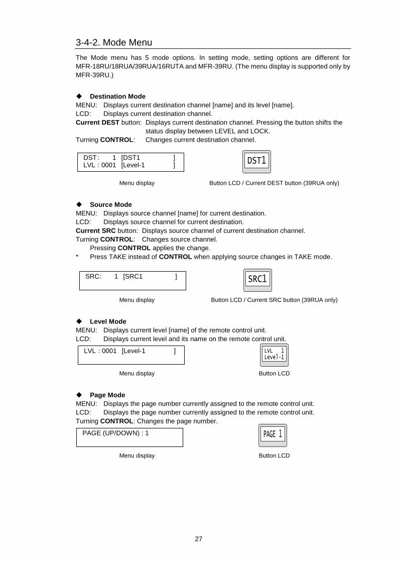
3-4-2. Mode Menu
The Mode menu has 5 mode options. In setting mode, setting options are different for
MFR-18RU/18RUA/39RUA/16RUTA and MFR-39RU. (The menu display is supported only by
MFR-39RU.)
Destination Mode
MENU: Displays current destination channel [name] and its level [name].
LCD: Displays current destination channel.
Current DEST button: Displays current destination channel. Pressing the button shifts the
status display between LEVEL and LOCK.
Turning CONTROL: Changes current destination channel.
Menu display Button LCD / Current DEST button (39RUA only)
Source Mode
MENU: Displays source channel [name] for current destination.
LCD: Displays source channel for current destination.
Current SRC button: Displays source channel of current destination channel.
Turning CONTROL: Changes source channel.
Pressing CONTROL applies the change.
* Press TAKE instead of CONTROL when applying source changes in TAKE mode.
Menu display Button LCD / Current SRC button (39RUA only)
Level Mode
MENU: Displays current level [name] of the remote control unit.
LCD: Displays current level and its name on the remote control unit.
Menu display Button LCD
Page Mode
MENU: Displays the page number currently assigned to the remote control unit.
LCD: Displays the page number currently assigned to the remote control unit.
Turning CONTROL: Changes the page number.
Menu display Button LCD
DST : 1 [DST1 ] LVL : 0001 [Level-1 ]
SRC : 1 [SRC1 ]
LVL : 0001 [Level-1 ]
PAGE (UP/DOWN) : 1
28
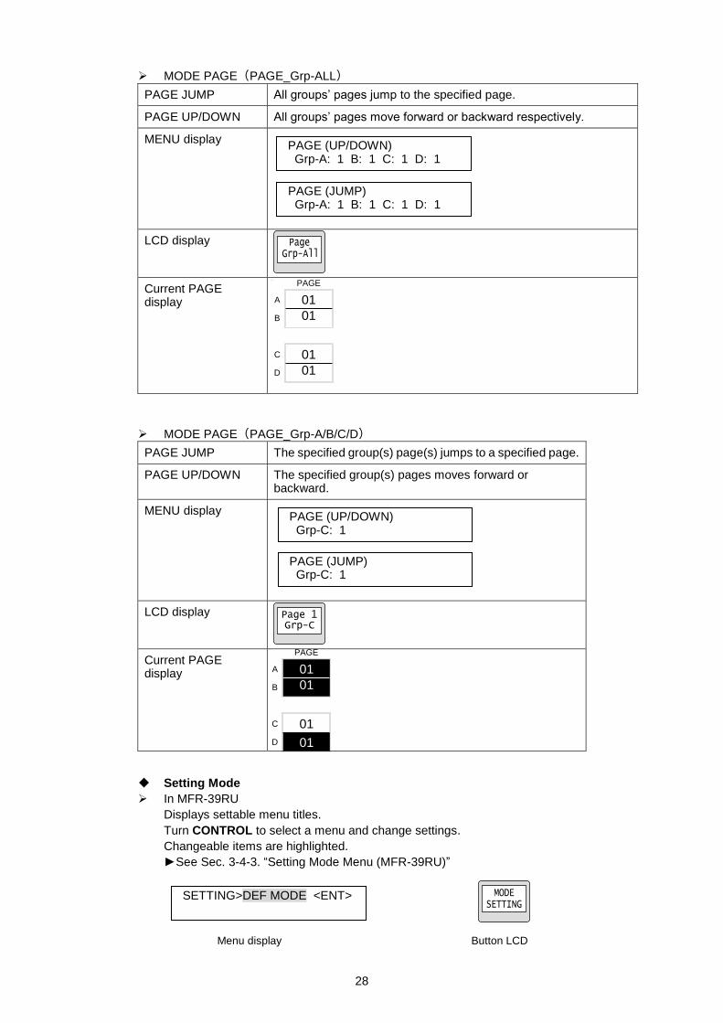
MODE PAGE(PAGE_Grp-ALL)
PAGE JUMP All groups’ pages jump to the specified page.
PAGE UP/DOWN All groups’ pages move forward or backward respectively.
MENU display
LCD display
Current PAGE display
MODE PAGE(PAGE_Grp-A/B/C/D)
PAGE JUMP The specified group(s) page(s) jumps to a specified page.
PAGE UP/DOWN The specified group(s) pages moves forward or backward.
MENU display
LCD display
Current PAGE display
Setting Mode
In MFR-39RU
Displays settable menu titles.
Turn CONTROL to select a menu and change settings.
Changeable items are highlighted.
►See Sec. 3-4-3. “Setting Mode Menu (MFR-39RU)”
Menu display Button LCD
PAGE (UP/DOWN) Grp-A: 1 B: 1 C: 1 D: 1
PAGE (JUMP) Grp-A: 1 B: 1 C: 1 D: 1
PAGE (UP/DOWN) Grp-C: 1
PAGE (JUMP) Grp-C: 1
A
B
C
D
PAGE
01
01
01
01
A
B
C
D
PAGE
01
01
01
01
01
SETTING>DEF MODE <ENT>
29
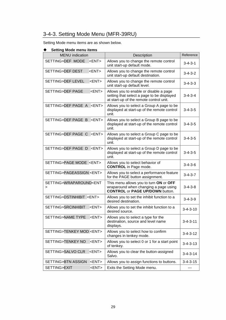
3-4-3. Setting Mode Menu (MFR-39RU)
Setting Mode menu items are as shown below.
Setting Mode menu items
MENU indication Description Reference
SETTING>DEF MODE <ENT> Allows you to change the remote control unit start-up default mode.
3-4-3-1
SETTING>DEF DEST <ENT> Allows you to change the remote control unit start-up default destination.
3-4-3-2
SETTING>DEF LEVEL <ENT> Allows you to change the remote control unit start-up default level.
3-4-3-3
SETTING>DEF PAGE <ENT> Allows you to enable or disable a page setting that select a page to be displayed at start-up of the remote control unit.
3-4-3-4
SETTING>DEF PAGE A <ENT> Allows you to select a Group A page to be displayed at start-up of the remote control unit.
3-4-3-5
SETTING>DEF PAGE B <ENT> Allows you to select a Group B page to be displayed at start-up of the remote control unit.
3-4-3-5
SETTING>DEF PAGE C <ENT> Allows you to select a Group C page to be displayed at start-up of the remote control unit.
3-4-3-5
SETTING>DEF PAGE D <ENT> Allows you to select a Group D page to be displayed at start-up of the remote control unit.
3-4-3-5
SETTING>PAGE MODE <ENT> Allows you to select behavior of CONTROL in Page mode.
3-4-3-6
SETTING>PAGEASSIGN <ENT> Allows you to select a performance feature for the PAGE button assignment.
3-4-3-7
SETTING>WRAPAROUND<ENT>
This menu allows you to turn ON or OFF wraparound when changing a page using CONTROL or PAGE UP/DOWN button.
3-4-3-8
SETTING>DSTINHIBIT <ENT> Allows you to set the inhibit function to a desired destination.
3-4-3-9
SETTING>SRCINHIBIT <ENT> Allows you to set the inhibit function to a desired source.
3-4-3-10
SETTING>NAME TYPE <ENT> Allows you to select a type for the destination, source and level name displays.
3-4-3-11
SETTING>TENKEY MOD <ENT> Allows you to select how to confirm changes in tenkey mode.
3-4-3-12
SETTING>TENKEY NO <ENT> Allows you to select 0 or 1 for a start point of tenkey.
3-4-3-13
SETTING>SALVO CLR <ENT> Allows you to clear the button-assigned Salvo.
3-4-3-14
SETTING>BTN ASSIGN <ENT> Allows you to assign functions to buttons. 3-4-3-15
SETTING>EXIT <ENT> Exits the Setting Mode menu. ---
30
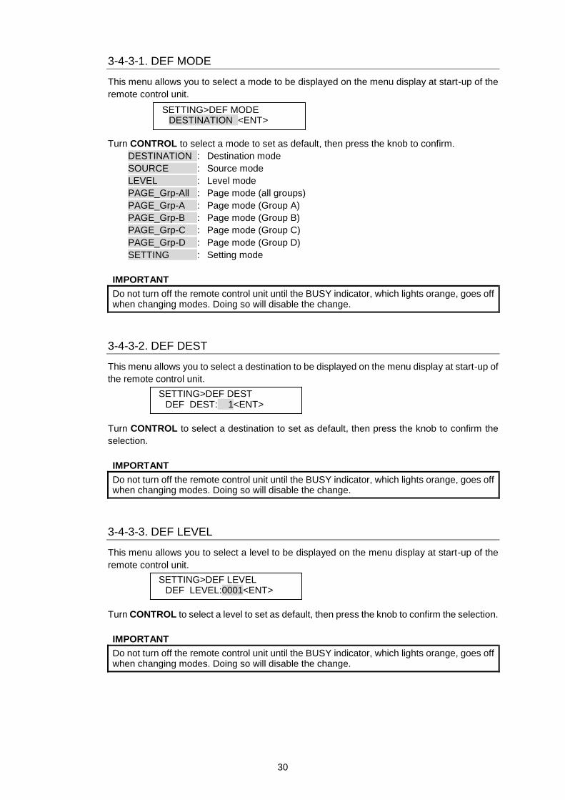
3-4-3-1. DEF MODE
This menu allows you to select a mode to be displayed on the menu display at start-up of the
remote control unit.
Turn CONTROL to select a mode to set as default, then press the knob to confirm.
DESTINATION : Destination mode
SOURCE : Source mode
LEVEL : Level mode
PAGE_Grp-All : Page mode (all groups)
PAGE_Grp-A : Page mode (Group A)
PAGE_Grp-B : Page mode (Group B)
PAGE_Grp-C : Page mode (Group C)
PAGE_Grp-D : Page mode (Group D)
SETTING : Setting mode
IMPORTANT
Do not turn off the remote control unit until the BUSY indicator, which lights orange, goes off when changing modes. Doing so will disable the change.
3-4-3-2. DEF DEST
This menu allows you to select a destination to be displayed on the menu display at start-up of
the remote control unit.
Turn CONTROL to select a destination to set as default, then press the knob to confirm the
selection.
IMPORTANT
Do not turn off the remote control unit until the BUSY indicator, which lights orange, goes off when changing modes. Doing so will disable the change.
3-4-3-3. DEF LEVEL
This menu allows you to select a level to be displayed on the menu display at start-up of the
remote control unit.
Turn CONTROL to select a level to set as default, then press the knob to confirm the selection.
IMPORTANT
Do not turn off the remote control unit until the BUSY indicator, which lights orange, goes off when changing modes. Doing so will disable the change.
SETTING>DEF MODE DESTINATION <ENT>
SETTING>DEF DEST DEF DEST: 1<ENT>
SETTING>DEF LEVEL DEF LEVEL:0001<ENT>
31
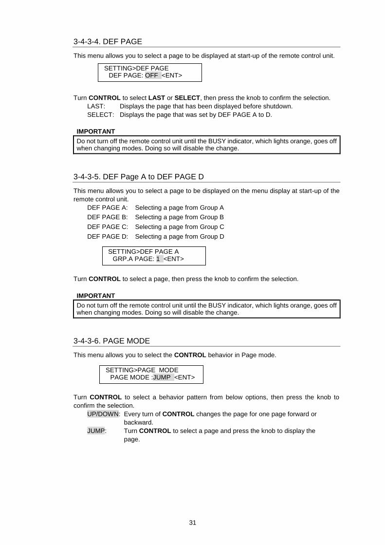
3-4-3-4. DEF PAGE
This menu allows you to select a page to be displayed at start-up of the remote control unit.
Turn CONTROL to select LAST or SELECT, then press the knob to confirm the selection.
LAST: Displays the page that has been displayed before shutdown.
SELECT: Displays the page that was set by DEF PAGE A to D.
IMPORTANT
Do not turn off the remote control unit until the BUSY indicator, which lights orange, goes off when changing modes. Doing so will disable the change.
3-4-3-5. DEF Page A to DEF PAGE D
This menu allows you to select a page to be displayed on the menu display at start-up of the
remote control unit.
DEF PAGE A: Selecting a page from Group A
DEF PAGE B: Selecting a page from Group B
DEF PAGE C: Selecting a page from Group C
DEF PAGE D: Selecting a page from Group D
Turn CONTROL to select a page, then press the knob to confirm the selection.
IMPORTANT
Do not turn off the remote control unit until the BUSY indicator, which lights orange, goes off when changing modes. Doing so will disable the change.
3-4-3-6. PAGE MODE
This menu allows you to select the CONTROL behavior in Page mode.
Turn CONTROL to select a behavior pattern from below options, then press the knob to
confirm the selection.
UP/DOWN: Every turn of CONTROL changes the page for one page forward or
backward.
JUMP: Turn CONTROL to select a page and press the knob to display the
page.
SETTING>PAGE MODE PAGE MODE :JUMP <ENT>
SETTING>DEF PAGE DEF PAGE: OFF <ENT>
SETTING>DEF PAGE A GRP.A PAGE: 1 <ENT>
32
3-4-3-7. PAGE ASSIGN
This menu allows you to select whether to assign the PAGE button to a selected page or all
pages.
Turn CONTROL to select a performance feature from the below options and press the knob to
confirm the selection.
ONE PAGE: Assigns the PAGE button to a selected page.
ALL PAGE: Assigns the PAGE button to all pages.
3-4-3-8. WRAPAROUND
This menu allows you to turn ON or OFF Wraparound when changing a page using
CONTROL or PAGE UP/DOWN button.
Turn CONTROL to select ON or OFF and press the knob to confirm the selection.
ON: When a page is switched to Page MAX, next page is continued as Page MAX to
Page 1 to Page 2…as a continuous circular series.
OFF: Wraparound is turned off.
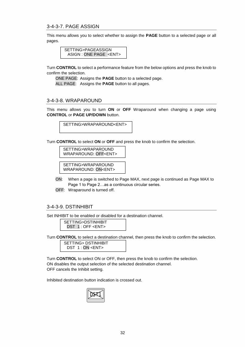
3-4-3-9. DSTINHIBIT
Set INHIBIT to be enabled or disabled for a destination channel.
Turn CONTROL to select a destination channel, then press the knob to confirm the selection.
Turn CONTROL to select ON or OFF, then press the knob to confirm the selection.
ON disables the output selection of the selected destination channel.
OFF cancels the Inhibit setting.
Inhibited destination button indication is crossed out.
SETTING>PAGEASSIGN ASIGN : ONE PAGE <ENT>
SETTING> DSTINHIBIT DST 1 : ON <ENT>
SETTING>DSTINHIBIT DST 1 : OFF <ENT>
SETTING>WRAPAROUND<ENT>
SETTING>WRAPAROUND WRAPAROUND: OFF<ENT>
SETTING>WRAPAROUND WRAPAROUND: ON<ENT>
33
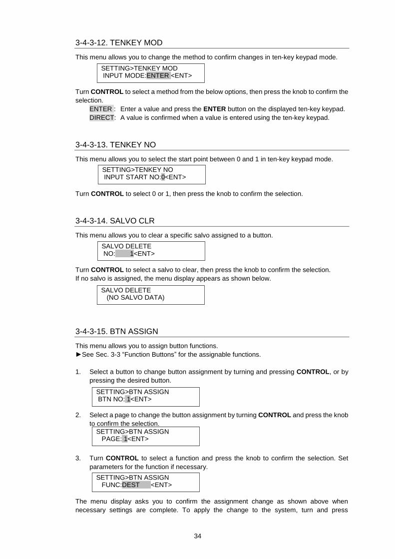
3-4-3-10. SRCINHIBIT
Set INHIBIT as ON or OFF for a source channel.
Turn CONTROL to select a source channel, then press the knob to confirm the selection.
Turn CONTROL to select ON or OFF and press the knob to confirm the selection.
ON disables the output selection of the selected source channel.
OFF cancels the Inhibit setting.
Inhibited Source button indication is crossed out.
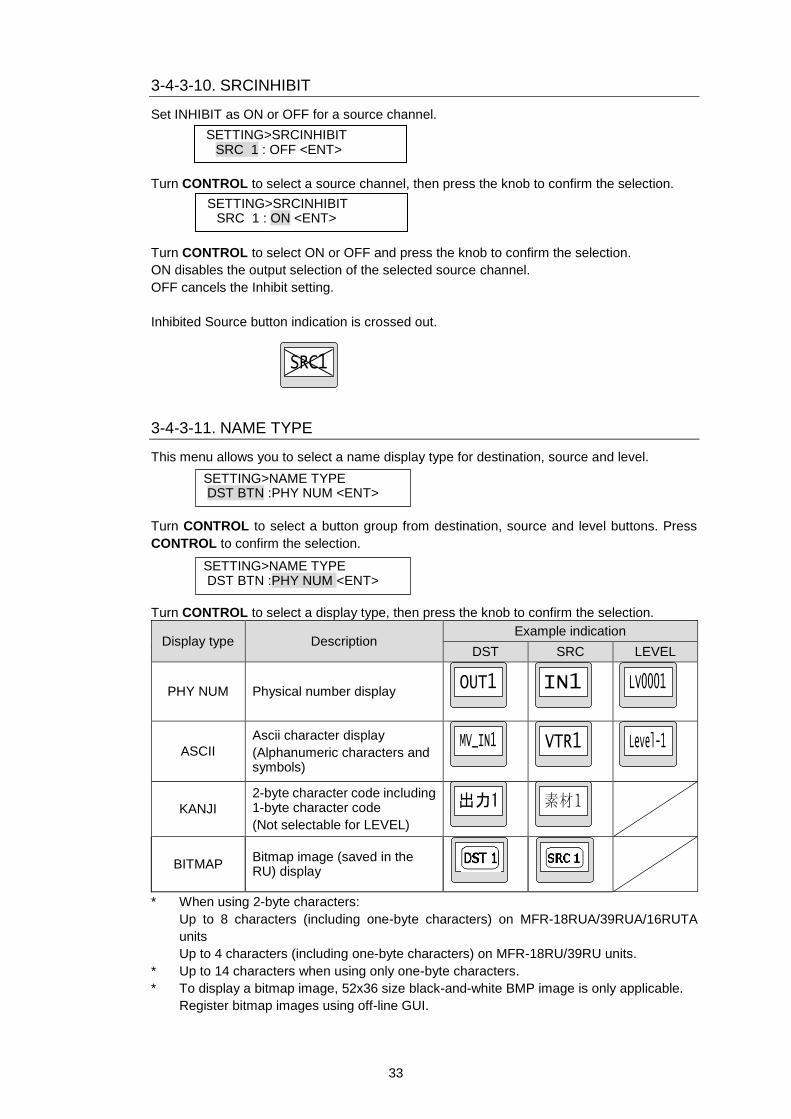
3-4-3-11. NAME TYPE
This menu allows you to select a name display type for destination, source and level.
Turn CONTROL to select a button group from destination, source and level buttons. Press
CONTROL to confirm the selection.
Turn CONTROL to select a display type, then press the knob to confirm the selection.
Display type Description Example indication
DST SRC LEVEL
PHY NUM Physical number display
ASCII
Ascii character display
(Alphanumeric characters and symbols)
KANJI
2-byte character code including 1-byte character code
(Not selectable for LEVEL)
BITMAP Bitmap image (saved in the RU) display
* When using 2-byte characters:
Up to 8 characters (including one-byte characters) on MFR-18RUA/39RUA/16RUTA
units
Up to 4 characters (including one-byte characters) on MFR-18RU/39RU units.
* Up to 14 characters when using only one-byte characters.
* To display a bitmap image, 52x36 size black-and-white BMP image is only applicable.
Register bitmap images using off-line GUI.
SETTING>NAME TYPE DST BTN :PHY NUM <ENT>
SETTING>SRCINHIBIT SRC 1 : OFF <ENT>
SETTING>SRCINHIBIT SRC 1 : ON <ENT>
SETTING>NAME TYPE DST BTN :PHY NUM <ENT>
34
3-4-3-12. TENKEY MOD
This menu allows you to change the method to confirm changes in ten-key keypad mode.
Turn CONTROL to select a method from the below options, then press the knob to confirm the
selection.
ENTER : Enter a value and press the ENTER button on the displayed ten-key keypad.
DIRECT: A value is confirmed when a value is entered using the ten-key keypad.
3-4-3-13. TENKEY NO
This menu allows you to select the start point between 0 and 1 in ten-key keypad mode.
Turn CONTROL to select 0 or 1, then press the knob to confirm the selection.
3-4-3-14. SALVO CLR
This menu allows you to clear a specific salvo assigned to a button.
Turn CONTROL to select a salvo to clear, then press the knob to confirm the selection.
If no salvo is assigned, the menu display appears as shown below.
3-4-3-15. BTN ASSIGN
This menu allows you to assign button functions.
►See Sec. 3-3 “Function Buttons” for the assignable functions.
1. Select a button to change button assignment by turning and pressing CONTROL, or by
pressing the desired button.
2. Select a page to change the button assignment by turning CONTROL and press the knob
to confirm the selection.
3. Turn CONTROL to select a function and press the knob to confirm the selection. Set
parameters for the function if necessary.
The menu display asks you to confirm the assignment change as shown above when
necessary settings are complete. To apply the change to the system, turn and press
SETTING>TENKEY MOD INPUT MODE:ENTER <ENT>
SETTING>TENKEY NO INPUT START NO:0<ENT>
SETTING>BTN ASSIGN BTN NO: 1<ENT>
SETTING>BTN ASSIGN PAGE: 1<ENT>
SETTING>BTN ASSIGN FUNC:DEST <ENT>
SALVO DELETE NO: 1<ENT>
SALVO DELETE (NO SALVO DATA)
35
CONTROL to select Yes. Selecting No cancels the change and returns to the menu display to
select buttons.
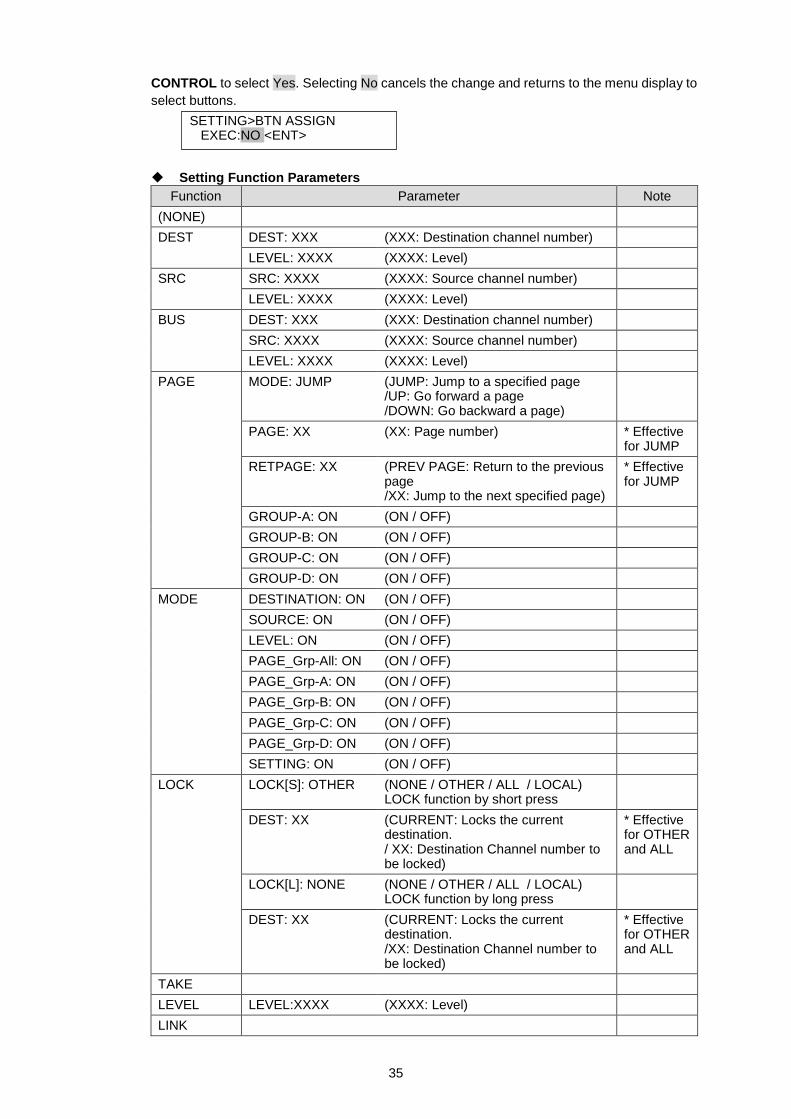
Setting Function Parameters
Function Parameter Note
(NONE)
DEST DEST: XXX (XXX: Destination channel number)
LEVEL: XXXX (XXXX: Level)
SRC SRC: XXXX (XXXX: Source channel number)
LEVEL: XXXX (XXXX: Level)
BUS DEST: XXX (XXX: Destination channel number)
SRC: XXXX (XXXX: Source channel number)
LEVEL: XXXX (XXXX: Level)
PAGE MODE: JUMP (JUMP: Jump to a specified page /UP: Go forward a page /DOWN: Go backward a page)
PAGE: XX (XX: Page number) * Effective for JUMP
RETPAGE: XX (PREV PAGE: Return to the previous page /XX: Jump to the next specified page)
* Effective for JUMP
GROUP-A: ON (ON / OFF)
GROUP-B: ON (ON / OFF)
GROUP-C: ON (ON / OFF)
GROUP-D: ON (ON / OFF)
MODE DESTINATION: ON (ON / OFF)
SOURCE: ON (ON / OFF)
LEVEL: ON (ON / OFF)
PAGE_Grp-All: ON (ON / OFF)
PAGE_Grp-A: ON (ON / OFF)
PAGE_Grp-B: ON (ON / OFF)
PAGE_Grp-C: ON (ON / OFF)
PAGE_Grp-D: ON (ON / OFF)
SETTING: ON (ON / OFF)
LOCK LOCK[S]: OTHER (NONE / OTHER / ALL / LOCAL) LOCK function by short press
DEST: XX (CURRENT: Locks the current destination. / XX: Destination Channel number to be locked)
* Effective for OTHER and ALL
LOCK[L]: NONE (NONE / OTHER / ALL / LOCAL) LOCK function by long press
DEST: XX (CURRENT: Locks the current destination. /XX: Destination Channel number to be locked)
* Effective for OTHER and ALL
TAKE
LEVEL LEVEL:XXXX (XXXX: Level)
LINK
SETTING>BTN ASSIGN EXEC:NO <ENT>
36
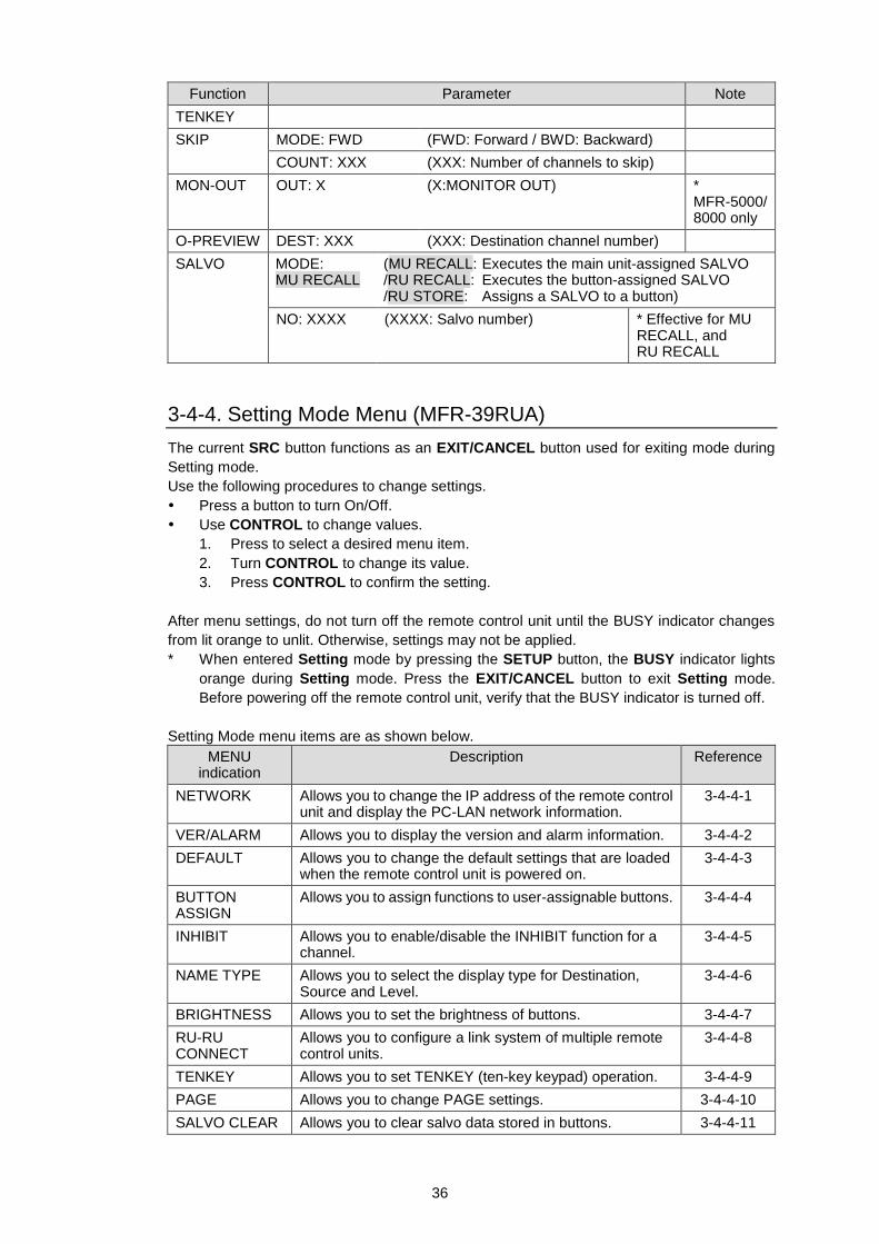
Function Parameter Note
TENKEY
SKIP MODE: FWD (FWD: Forward / BWD: Backward)
COUNT: XXX (XXX: Number of channels to skip)
MON-OUT OUT: X (X:MONITOR OUT) * MFR-5000/ 8000 only
O-PREVIEW DEST: XXX (XXX: Destination channel number)
SALVO MODE: MU RECALL
(MU RECALL: Executes the main unit-assigned SALVO /RU RECALL: Executes the button-assigned SALVO /RU STORE: Assigns a SALVO to a button)
NO: XXXX (XXXX: Salvo number) * Effective for MU RECALL, and RU RECALL
3-4-4. Setting Mode Menu (MFR-39RUA)
The current SRC button functions as an EXIT/CANCEL button used for exiting mode during
Setting mode.
Use the following procedures to change settings.
Press a button to turn On/Off.
Use CONTROL to change values.
1. Press to select a desired menu item.
2. Turn CONTROL to change its value.
3. Press CONTROL to confirm the setting.
After menu settings, do not turn off the remote control unit until the BUSY indicator changes
from lit orange to unlit. Otherwise, settings may not be applied.
* When entered Setting mode by pressing the SETUP button, the BUSY indicator lights
orange during Setting mode. Press the EXIT/CANCEL button to exit Setting mode.
Before powering off the remote control unit, verify that the BUSY indicator is turned off.
Setting Mode menu items are as shown below.
MENU indication
Description Reference
NETWORK Allows you to change the IP address of the remote control unit and display the PC-LAN network information.
3-4-4-1
VER/ALARM Allows you to display the version and alarm information. 3-4-4-2
DEFAULT Allows you to change the default settings that are loaded when the remote control unit is powered on.
3-4-4-3
BUTTON ASSIGN
Allows you to assign functions to user-assignable buttons. 3-4-4-4
INHIBIT Allows you to enable/disable the INHIBIT function for a channel.
3-4-4-5
NAME TYPE Allows you to select the display type for Destination, Source and Level.
3-4-4-6
BRIGHTNESS Allows you to set the brightness of buttons. 3-4-4-7
RU-RU CONNECT
Allows you to configure a link system of multiple remote control units.
3-4-4-8
TENKEY Allows you to set TENKEY (ten-key keypad) operation. 3-4-4-9
PAGE Allows you to change PAGE settings. 3-4-4-10
SALVO CLEAR Allows you to clear salvo data stored in buttons. 3-4-4-11
37
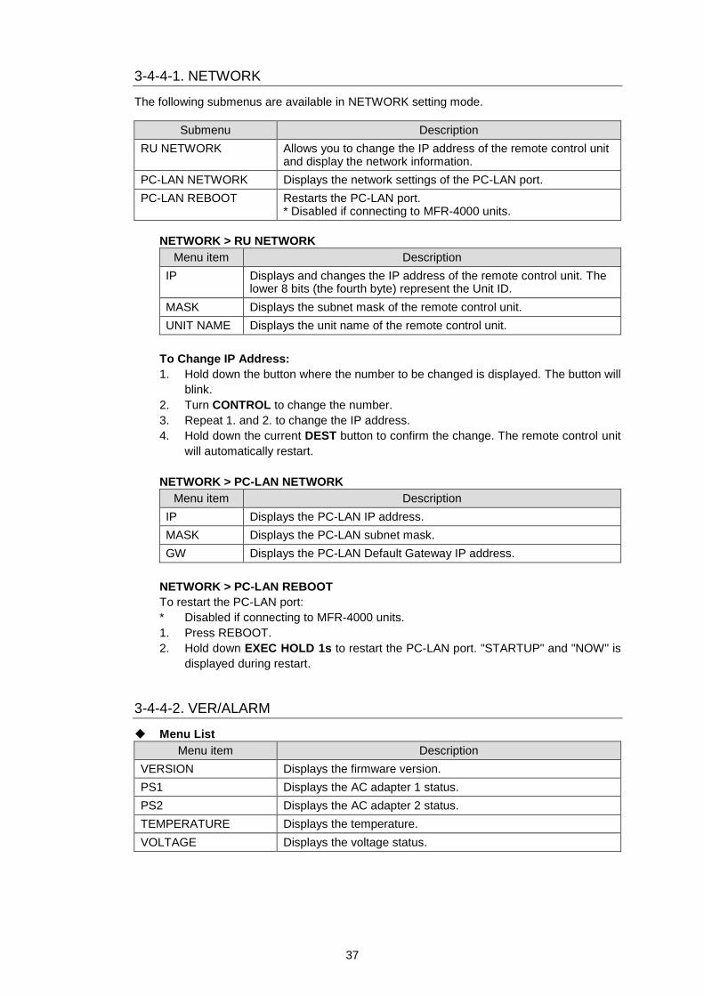
3-4-4-1. NETWORK
The following submenus are available in NETWORK setting mode.
Submenu Description
RU NETWORK Allows you to change the IP address of the remote control unit and display the network information.
PC-LAN NETWORK Displays the network settings of the PC-LAN port.
PC-LAN REBOOT Restarts the PC-LAN port. * Disabled if connecting to MFR-4000 units.
NETWORK > RU NETWORK
Menu item Description
IP Displays and changes the IP address of the remote control unit. The lower 8 bits (the fourth byte) represent the Unit ID.
MASK Displays the subnet mask of the remote control unit.
UNIT NAME Displays the unit name of the remote control unit.
To Change IP Address:
1. Hold down the button where the number to be changed is displayed. The button will
blink.
2. Turn CONTROL to change the number.
3. Repeat 1. and 2. to change the IP address.
4. Hold down the current DEST button to confirm the change. The remote control unit
will automatically restart.
NETWORK > PC-LAN NETWORK
Menu item Description
IP Displays the PC-LAN IP address.
MASK Displays the PC-LAN subnet mask.
GW Displays the PC-LAN Default Gateway IP address.
NETWORK > PC-LAN REBOOT
To restart the PC-LAN port:
* Disabled if connecting to MFR-4000 units.
1. Press REBOOT.
2. Hold down EXEC HOLD 1s to restart the PC-LAN port. "STARTUP" and "NOW" is
displayed during restart.
3-4-4-2. VER/ALARM
Menu List
Menu item Description
VERSION Displays the firmware version.
PS1 Displays the AC adapter 1 status.
PS2 Displays the AC adapter 2 status.
TEMPERATURE Displays the temperature.
VOLTAGE Displays the voltage status.
38
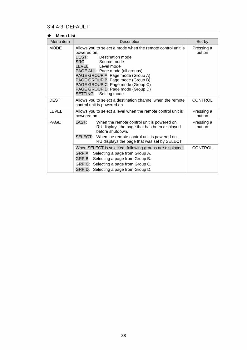
3-4-4-3. DEFAULT
Menu List
Menu item Description Set by
MODE Allows you to select a mode when the remote control unit is powered on. DEST: Destination mode SRC: Source mode LEVEL: Level mode PAGE ALL: Page mode (all groups) PAGE GROUP A: Page mode (Group A) PAGE GROUP B: Page mode (Group B) PAGE GROUP C: Page mode (Group C) PAGE GROUP D: Page mode (Group D) SETTING: Setting mode
Pressing a button
DEST Allows you to select a destination channel when the remote control unit is powered on.
CONTROL
LEVEL Allows you to select a level when the remote control unit is powered on.
Pressing a button
PAGE LAST: When the remote control unit is powered on, RU displays the page that has been displayed before shutdown.
SELECT: When the remote control unit is powered on. RU displays the page that was set by SELECT
Pressing a button
When SELECT is selected, following groups are displayed.
GRP A: Selecting a page from Group A.
GRP B: Selecting a page from Group B.
GRP C: Selecting a page from Group C.
GRP D: Selecting a page from Group D.
CONTROL
39
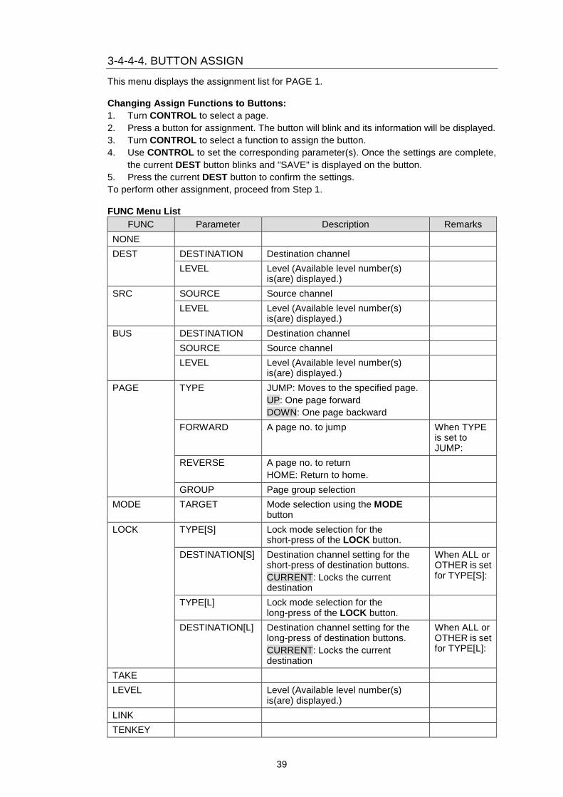
3-4-4-4. BUTTON ASSIGN
This menu displays the assignment list for PAGE 1.
Changing Assign Functions to Buttons:
1. Turn CONTROL to select a page.
2. Press a button for assignment. The button will blink and its information will be displayed.
3. Turn CONTROL to select a function to assign the button.
4. Use CONTROL to set the corresponding parameter(s). Once the settings are complete,
the current DEST button blinks and "SAVE" is displayed on the button.
5. Press the current DEST button to confirm the settings.
To perform other assignment, proceed from Step 1.
FUNC Menu List
FUNC Parameter Description Remarks
NONE
DEST DESTINATION Destination channel
LEVEL Level (Available level number(s) is(are) displayed.)
SRC SOURCE Source channel
LEVEL Level (Available level number(s) is(are) displayed.)
BUS DESTINATION Destination channel
SOURCE Source channel
LEVEL Level (Available level number(s) is(are) displayed.)
PAGE TYPE JUMP: Moves to the specified page.
UP: One page forward
DOWN: One page backward
FORWARD A page no. to jump When TYPE is set to JUMP:
REVERSE A page no. to return
HOME: Return to home.
GROUP Page group selection
MODE TARGET Mode selection using the MODE button
LOCK TYPE[S] Lock mode selection for the short-press of the LOCK button.
DESTINATION[S] Destination channel setting for the short-press of destination buttons.
CURRENT: Locks the current destination
When ALL or OTHER is set for TYPE[S]:
TYPE[L] Lock mode selection for the long-press of the LOCK button.
DESTINATION[L] Destination channel setting for the long-press of destination buttons.
CURRENT: Locks the current destination
When ALL or OTHER is set for TYPE[L]:
TAKE
LEVEL Level (Available level number(s) is(are) displayed.)
LINK
TENKEY
40
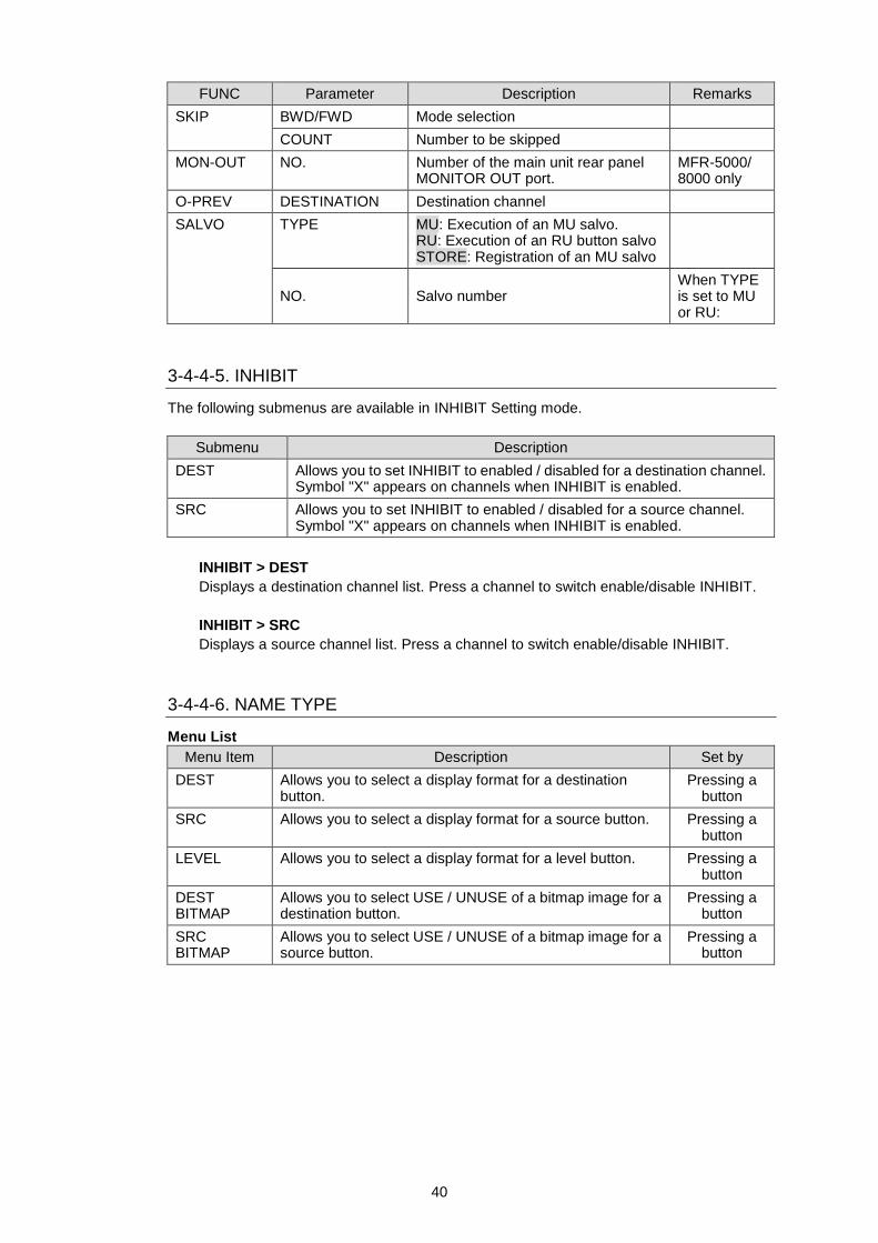
FUNC Parameter Description Remarks
SKIP BWD/FWD Mode selection
COUNT Number to be skipped
MON-OUT NO. Number of the main unit rear panel MONITOR OUT port.
MFR-5000/ 8000 only
O-PREV DESTINATION Destination channel
SALVO TYPE MU: Execution of an MU salvo. RU: Execution of an RU button salvo STORE: Registration of an MU salvo
NO. Salvo number When TYPE is set to MU or RU:
3-4-4-5. INHIBIT
The following submenus are available in INHIBIT Setting mode.
Submenu Description
DEST Allows you to set INHIBIT to enabled / disabled for a destination channel. Symbol "X" appears on channels when INHIBIT is enabled.
SRC Allows you to set INHIBIT to enabled / disabled for a source channel. Symbol "X" appears on channels when INHIBIT is enabled.
INHIBIT > DEST
Displays a destination channel list. Press a channel to switch enable/disable INHIBIT.
INHIBIT > SRC
Displays a source channel list. Press a channel to switch enable/disable INHIBIT.
3-4-4-6. NAME TYPE
Menu List
Menu Item Description Set by
DEST Allows you to select a display format for a destination button.
Pressing a button
SRC Allows you to select a display format for a source button. Pressing a button
LEVEL Allows you to select a display format for a level button. Pressing a button
DEST BITMAP
Allows you to select USE / UNUSE of a bitmap image for a destination button.
Pressing a button
SRC BITMAP
Allows you to select USE / UNUSE of a bitmap image for a source button.
Pressing a button
41
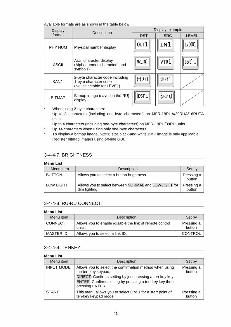
Available formats are as shown in the table below.
Display format
Description Display example
DST SRC LEVEL
PHY NUM Physical number display
ASCII Ascii character display (Alphanumeric characters and symbols)
KANJI 2-byte character code including 1-byte character code (Not selectable for LEVEL)
BITMAP Bitmap image (saved in the RU) display
* When using 2-byte characters:
Up to 8 characters (including one-byte characters) on MFR-18RUA/39RUA/16RUTA
units
Up to 4 characters (including one-byte characters) on MFR-18RU/39RU units
* Up 14 characters when using only one-byte characters
* To display a bitmap image, 52x36 size black-and-white BMP image is only applicable.
Register bitmap images using off-line GUI.
3-4-4-7. BRIGHTNESS
Menu List
Menu item Description Set by
BUTTON Allows you to select a button brightness. Pressing a button
LOW LIGHT Allows you to select between NORMAL and LOWLIGHT for dim lighting.
Pressing a button
3-4-4-8. RU-RU CONNECT
Menu List
Menu item Description Set by
CONNECT Allows you to enable /disable the link of remote control units.
Pressing a button
MASTER ID Allows you to select a link ID. CONTROL
3-4-4-9. TENKEY
Menu List
Menu item Description Set by
INPUT MODE Allows you to select the confirmation method when using the ten-key keypad.
DIRECT: Confirms setting by just pressing a ten-key key.
ENTER: Confirms setting by pressing a ten-key key then pressing ENTER.
Pressing a button
START This menu allows you to select 0 or 1 for a start point of ten-key keypad mode.
Pressing a button
42
3-4-4-10. PAGE
Menu List
Menu item Description Set by
MODE Allows you to select CONTROL behavior in Page mode.
UP/DOWN: Turn CONTROL to move one page forward/back.
JUMP: Turn CONTROL to select a page then press CONTROL to move to the page.
Pressing a button
ASSIGN Allows you to select PAGE button assignment.
ONE PAGE: Assigns a PAGE button to a specified page.
ALL PAGES: Assigns a PAGE button to all pages respectively.
Pressing a button
DISPLAY Allows you to select whether to display unit names for Current PAGE display (C/D).
PAGE C&D: Current PAGE display for Group C and D.
UNIT NAME: Displays unit names.
Pressing a button
WRAPAROUND Allows you to turn ON or OFF wraparound when changing a page using CONTROL or PAGE UP/DOWN button.
ON: When a page is switched to Page MAX, next page is continued as Page 1 to Page 2…as a continuous circular series.
OFF: Wraparound is turned off.
Pressing a button
3-4-4-11. SALVO CLEAR
This menu displays the button-assigned salvo list and allows you to clear salvos.
To Clear a Button-assigned Salvo:
1. Press a salvo button to clear. The button will blink and CLEAR is displayed on the current
DEST button.
2. Press the current DEST button.
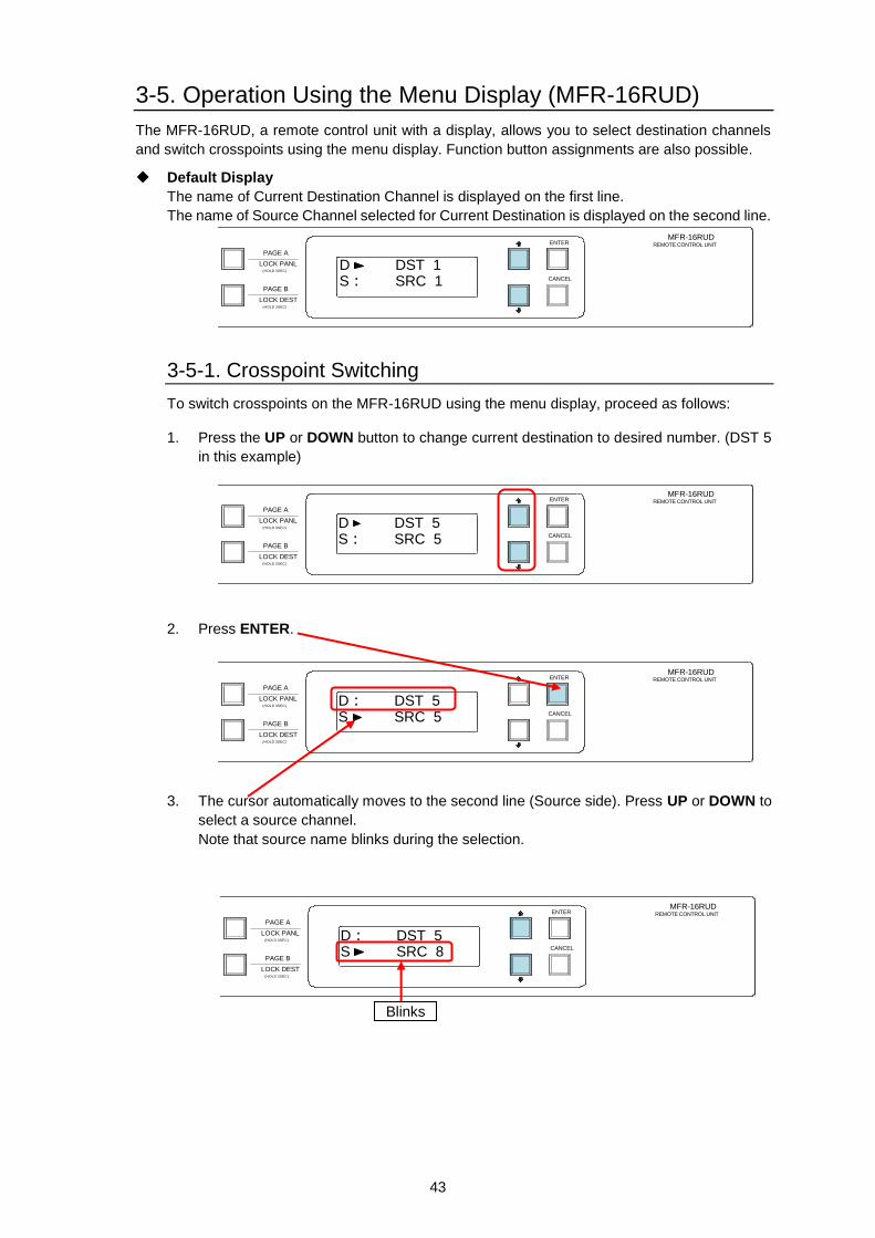
43
3-5. Operation Using the Menu Display (MFR-16RUD)
The MFR-16RUD, a remote control unit with a display, allows you to select destination channels
and switch crosspoints using the menu display. Function button assignments are also possible.
Default Display
The name of Current Destination Channel is displayed on the first line.
The name of Source Channel selected for Current Destination is displayed on the second line.
3-5-1. Crosspoint Switching
To switch crosspoints on the MFR-16RUD using the menu display, proceed as follows:
1. Press the UP or DOWN button to change current destination to desired number. (DST 5
in this example)
2. Press ENTER.
3. The cursor automatically moves to the second line (Source side). Press UP or DOWN to
select a source channel.
Note that source name blinks during the selection.
D
DST 1 S: SRC 1
PAGE A
(HOLD 3SEC)
PAGE B
LOCK RESET
POWER
BUSY SETUP
LOCK DEST
(HOLD 3SEC)
LOCK PANL
CANCEL
ENTER
A B MFR-16RUDREMOTE CONTROL UNIT
D
DST 5 S: SRC 5
PAGE A
(HOLD 3SEC)
PAGE B
LOCK RESET
POWER
BUSY SETUP
LOCK DEST
(HOLD 3SEC)
LOCK PANL
CANCEL
ENTER
A B MFR-16RUDREMOTE CONTROL UNIT
D: DST 5 S
SRC 5
PAGE A
(HOLD 3SEC)
PAGE B
LOCK RESET
POWER
BUSY SETUP
LOCK DEST
(HOLD 3SEC)
LOCK PANL
CANCEL
ENTER
A B MFR-16RUDREMOTE CONTROL UNIT
D: DST 5 S
SRC 8
PAGE A
(HOLD 3SEC)
PAGE B
LOCK RESET
POWER
BUSY SETUP
LOCK DEST
(HOLD 3SEC)
LOCK PANL
CANCEL
ENTER
A B MFR-16RUDREMOTE CONTROL UNIT
Blinks
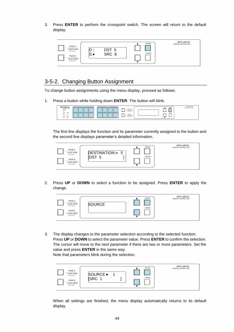
44
3. Press ENTER to perform the crosspoint switch. The screen will return to the default
display.
3-5-2. Changing Button Assignment
To change button assignments using the menu display, proceed as follows:
1. Press a button while holding down ENTER. The button will blink.
The first line displays the function and its parameter currently assigned to the button and
the second line displays parameter’s detailed information.
2. Press UP or DOWN to select a function to be assigned. Press ENTER to apply the
change.
3. The display changes to the parameter selection according to the selected function.
Press UP or DOWN to select the parameter value. Press ENTER to confirm the selection.
The cursor will move to the next parameter if there are two or more parameters. Set the
value and press ENTER in the same way.
Note that parameters blink during the selection.
When all settings are finished, the menu display automatically returns to its default
display.
PAGE A
(HOLD 3SEC)
PAGE B
LOCK RESET
POWER
BUSY SETUP
LOCK DEST
(HOLD 3SEC)
LOCK PANL
CANCEL
ENTER
A B MFR-16RUDREMOTE CONTROL UNIT
DESTINATION
5 [DST 5 ]
D: DST 5 S
SRC 8
PAGE A
(HOLD 3SEC)
PAGE B
LOCK RESET
POWER
BUSY SETUP
LOCK DEST
(HOLD 3SEC)
LOCK PANL
CANCEL
ENTER
A B MFR-16RUDREMOTE CONTROL UNIT
PAGE A
(HOLD 3SEC)
PAGE B
LOCK RESET
POWER
BUSY SETUP
LOCK DEST
(HOLD 3SEC)
LOCK PANL
CANCEL
ENTER
A B MFR-16RUDREMOTE CONTROL UNIT
SOURCE PAGE A
(HOLD 3SEC)
PAGE B
LOCK RESET
POWER
BUSY SETUP
LOCK DEST
(HOLD 3SEC)
LOCK PANL
CANCEL
ENTER
A B MFR-16RUDREMOTE CONTROL UNIT
SOURCE
1 [SRC 1 ]
PAGE A
(HOLD 3SEC)
PAGE B
LOCK RESET
POWER
BUSY SETUP
LOCK DEST
(HOLD 3SEC)
LOCK PANL
CANCEL
ENTER
A B MFR-16RUDREMOTE CONTROL UNIT
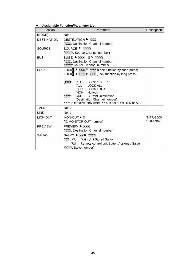
45
Assignable Function/Parameter List
Function Parameter Description
(NONE) None
DESTINATION DESTINATION XXX
(XXX: Destination Channel number)
SOURCE SOURCE YYYY
(YYYY: Source Channel number)
BUS BUS D XXX S YYYY
(XXX: Destination Channel number YYYY: Source Channel number)
LOCK LOCKS XXX YYY (Lock function by short press)
LOCKL XXX YYY (Lock function by long press)
(XXX: OTH LOCK OTHER /ALL LOCK ALL /LOC LOCK LOCAL /NON No lock YYY: CUR Current Destination /Destination Channel number) YYY is effective only when XXX is set to OTHER or ALL.
TAKE None
LINK None
MON-OUT MON-OUT X
(X: MONITOR OUT number)
*MFR-5000 /8000 only
PREVIEW PREVIEW XXX
(XXX: Destination Channel number)
SALVO SALVO XX YYYY
(XX : MU Main Unit Stored Salvo
/RU Remote control unit Button Assigned Salvo
YYYY: Salvo number)
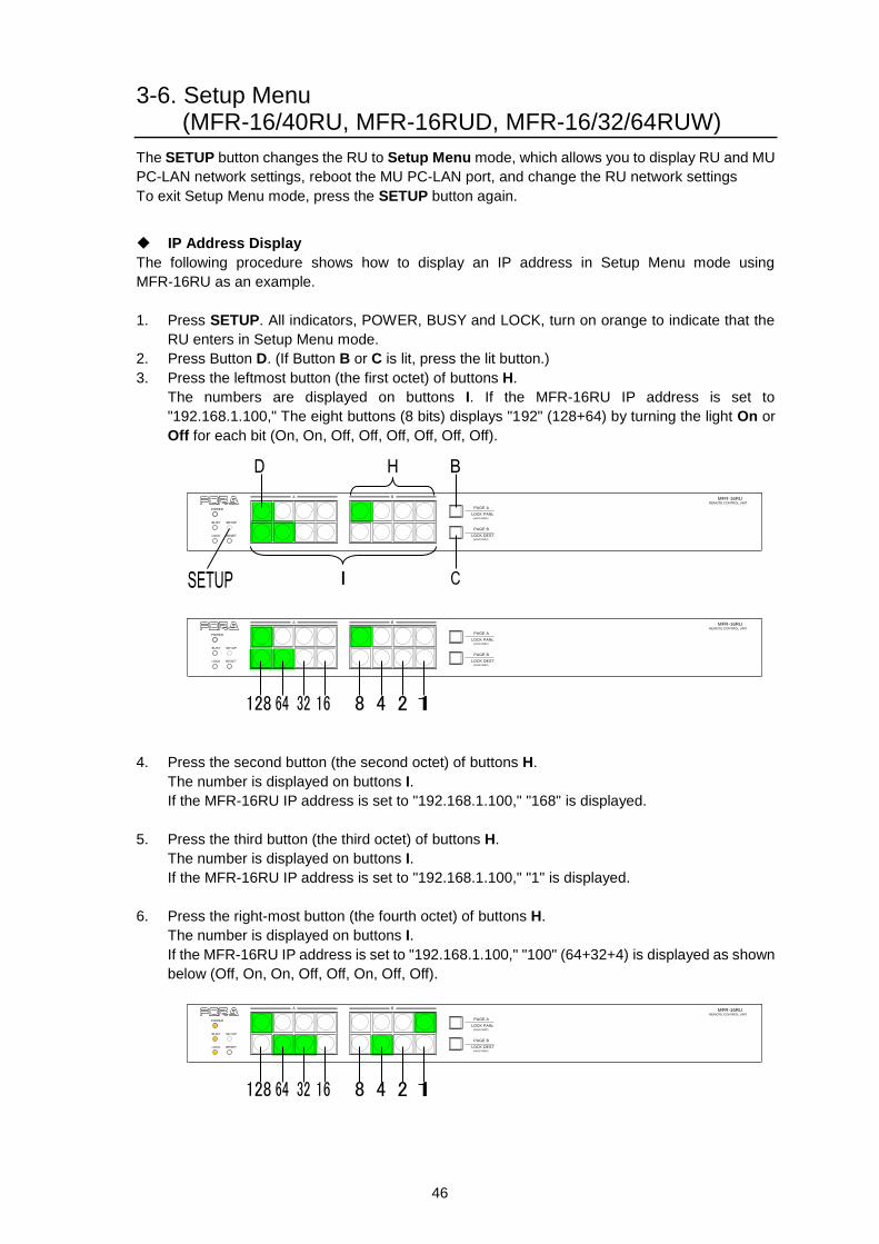
46
3-6. Setup Menu (MFR-16/40RU, MFR-16RUD, MFR-16/32/64RUW)
The SETUP button changes the RU to Setup Menu mode, which allows you to display RU and MU
PC-LAN network settings, reboot the MU PC-LAN port, and change the RU network settings
To exit Setup Menu mode, press the SETUP button again.
IP Address Display
The following procedure shows how to display an IP address in Setup Menu mode using
MFR-16RU as an example.
1. Press SETUP. All indicators, POWER, BUSY and LOCK, turn on orange to indicate that the
RU enters in Setup Menu mode.
2. Press Button D. (If Button B or C is lit, press the lit button.)
3. Press the leftmost button (the first octet) of buttons H.
The numbers are displayed on buttons I. If the MFR-16RU IP address is set to
"192.168.1.100," The eight buttons (8 bits) displays "192" (128+64) by turning the light On or
Off for each bit (On, On, Off, Off, Off, Off, Off, Off).
4. Press the second button (the second octet) of buttons H.
The number is displayed on buttons I.
If the MFR-16RU IP address is set to "192.168.1.100," "168" is displayed.
5. Press the third button (the third octet) of buttons H.
The number is displayed on buttons I.
If the MFR-16RU IP address is set to "192.168.1.100," "1" is displayed.
6. Press the right-most button (the fourth octet) of buttons H.
The number is displayed on buttons I.
If the MFR-16RU IP address is set to "192.168.1.100," "100" (64+32+4) is displayed as shown
below (Off, On, On, Off, Off, On, Off, Off).
PAGE A
(HOLD 3SEC)
PAGE B
LOCK RESET
POWER
BUSY SETUP
LOCK DEST
(HOLD 3SEC)
LOCK PANL
A B
REMOTE CONTROL UNIT
MFR-16RU
PAGE A
(HOLD 3SEC)
PAGE B
LOCK RESET
POWER
BUSY SETUP
LOCK DEST
(HOLD 3SEC)
LOCK PANL
A B
REMOTE CONTROL UNIT
MFR-16RU
PAGE A
(HOLD 3SEC)
PAGE B
LOCK RESET
POWER
BUSY SETUP
LOCK DEST
(HOLD 3SEC)
LOCK PANL
A B
REMOTE CONTROL UNIT
MFR-16RU
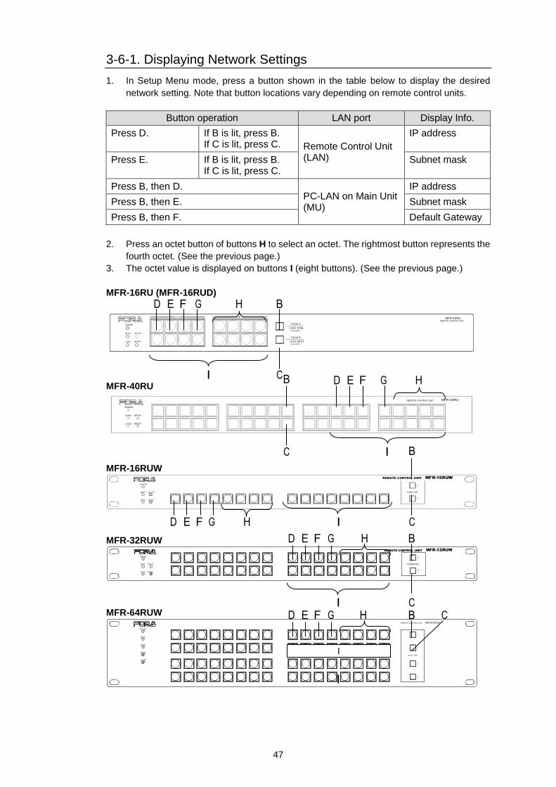
47
3-6-1. Displaying Network Settings
1. In Setup Menu mode, press a button shown in the table below to display the desired
network setting. Note that button locations vary depending on remote control units.
Button operation LAN port Display Info.
Press D. If B is lit, press B. If C is lit, press C. Remote Control Unit
(LAN)
IP address
Press E. If B is lit, press B. If C is lit, press C.
Subnet mask
Press B, then D. PC-LAN on Main Unit (MU)
IP address
Press B, then E. Subnet mask
Press B, then F. Default Gateway
2. Press an octet button of buttons H to select an octet. The rightmost button represents the
fourth octet. (See the previous page.)
3. The octet value is displayed on buttons I (eight buttons). (See the previous page.)
MFR-16RU (MFR-16RUD)
PAGE A
(HOLD 3SEC)
PAGE B
LOCK RESET
POWER
BUSY SETUP
LOCK DEST
(HOLD 3SEC)
LOCK PANL
A B
REMOTE CONTROL UNIT
MFR-16RU
MFR-40RU
POWER
BUSY SETUP
LOCK RESET
MFR-40RUREMOTE CONTROL UNIT
MFR-16RUW
POW ER
BUSY SE TUP
LOCK RE SET
MFR-16RUW
FUNC TION
1
2
REMOTE CONTROL UNIT
MFR-32RUW
POW ER
BU SY SET UP
LO CK RESET
FUNCTION
1
2
REMOTE CONTROL UNIT MFR-32RUW
MFR-64RUW MFR-6 4RUWREMOTE CO NTROL UNIT
1
2
1
2
POWER
BUSY
LOCK
SETUP
RESET
FUNC TION
I
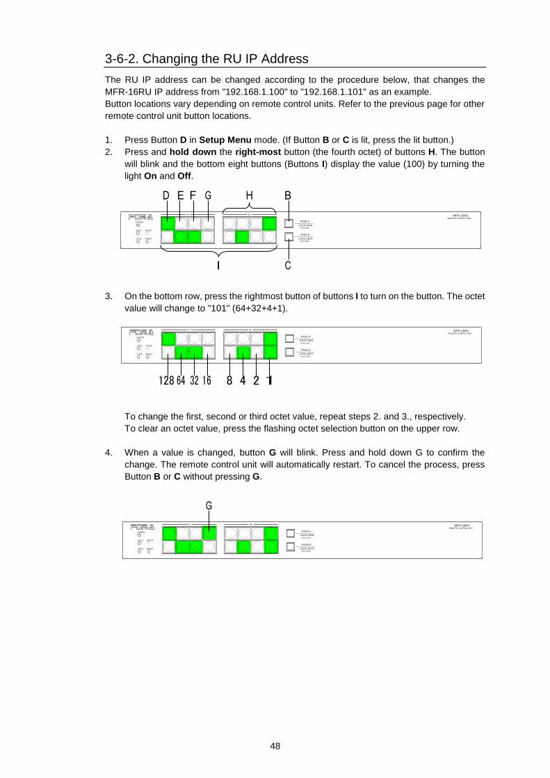
48
3-6-2. Changing the RU IP Address
The RU IP address can be changed according to the procedure below, that changes the
MFR-16RU IP address from "192.168.1.100" to "192.168.1.101" as an example.
Button locations vary depending on remote control units. Refer to the previous page for other
remote control unit button locations.
1. Press Button D in Setup Menu mode. (If Button B or C is lit, press the lit button.)
2. Press and hold down the right-most button (the fourth octet) of buttons H. The button
will blink and the bottom eight buttons (Buttons I) display the value (100) by turning the
light On and Off.
3. On the bottom row, press the rightmost button of buttons I to turn on the button. The octet
value will change to "101" (64+32+4+1).
To change the first, second or third octet value, repeat steps 2. and 3., respectively.
To clear an octet value, press the flashing octet selection button on the upper row.
4. When a value is changed, button G will blink. Press and hold down G to confirm the
change. The remote control unit will automatically restart. To cancel the process, press
Button B or C without pressing G.
PAGE A
(HOLD 3SEC)
PAGE B
LOCK RESET
POWER
BUSY SETUP
LOCK DEST
(HOLD 3SEC)
LOCK PANL
A B
REMOTE CONTROL UNIT
MFR-16RU
PAGE A
(HOLD 3SEC)
PAGE B
LOCK RESET
POWER
BUSY SETUP
LOCK DEST
(HOLD 3SEC)
LOCK PANL
A B
REMOTE CONTROL UNIT
MFR-16RU
PAGE A
(HOLD 3SEC)
PAGE B
LOCK RESET
POWER
BUSY SETUP
LOCK DEST
(HOLD 3SEC)
LOCK PANL
A B
REMOTE CONTROL UNIT
MFR-16RU
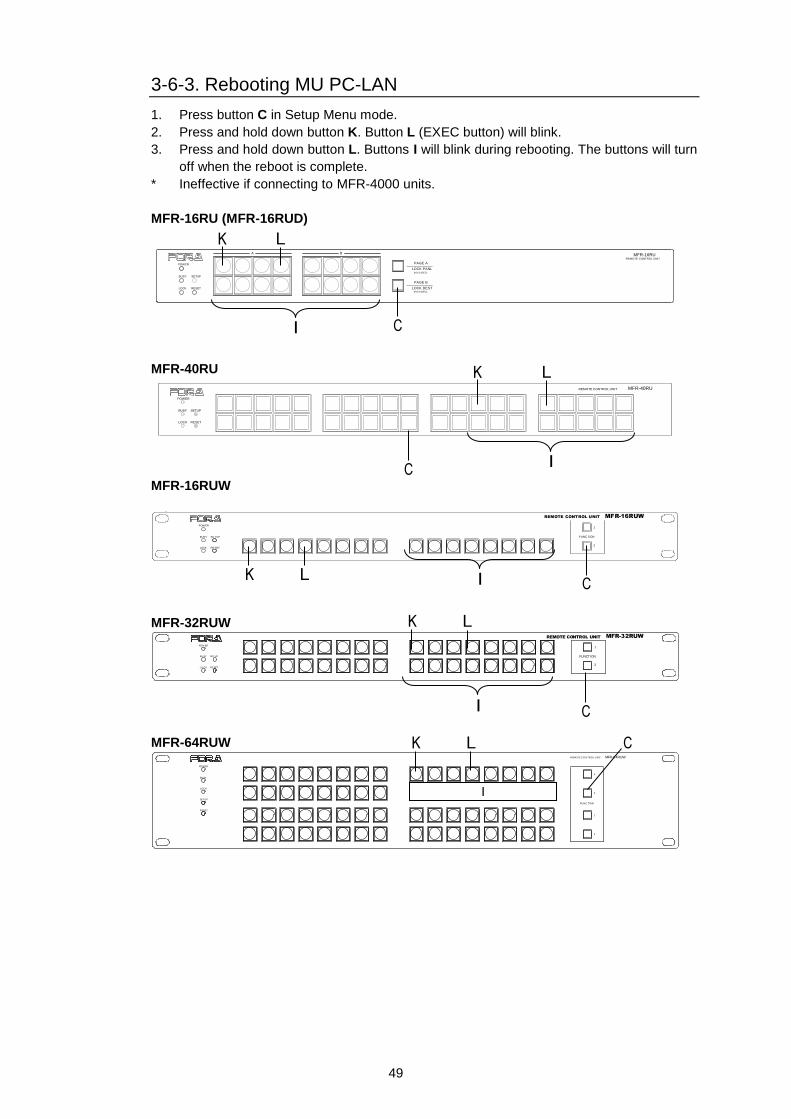
49
3-6-3. Rebooting MU PC-LAN
1. Press button C in Setup Menu mode.
2. Press and hold down button K. Button L (EXEC button) will blink.
3. Press and hold down button L. Buttons I will blink during rebooting. The buttons will turn
off when the reboot is complete.
* Ineffective if connecting to MFR-4000 units.
MFR-16RU (MFR-16RUD)
PAGE A
(HOLD 3SEC)
PAGE B
LOCK RESET
POWER
BUSY SETUP
LOCK DEST
(HOLD 3SEC)
LOCK PANL
A B
REMOTE CONTROL UNIT
MFR-16RU
MFR-40RU
POWER
BUSY SETUP
LOCK RESET
MFR-40RUREMOTE CONTROL UNIT
MFR-16RUW
POW ER
BUSY SE TUP
LOCK RE SET
MFR-16RUW
FUNC TION
1
2
REMOTE CONTROL UNIT
MFR-32RUW
POW ER
BU SY SET UP
LO CK RESET
FUNCTION
1
2
REMOTE CONTROL UNIT MFR-32RUW
MFR-64RUW MFR-6 4RUWREMOTE CO NTROL UNIT
1
2
1
2
POWER
BUSY
LOCK
SETUP
RESET
FUNC TION
I
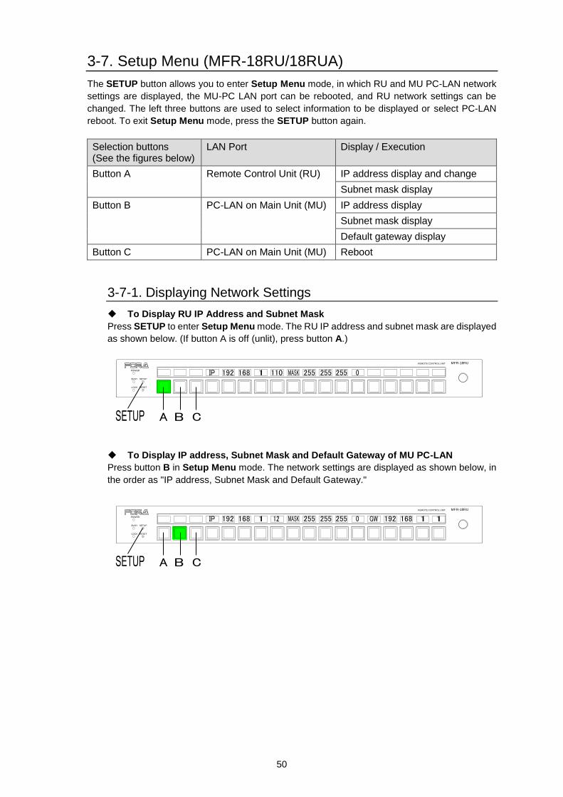
50
3-7. Setup Menu (MFR-18RU/18RUA)
The SETUP button allows you to enter Setup Menu mode, in which RU and MU PC-LAN network
settings are displayed, the MU-PC LAN port can be rebooted, and RU network settings can be
changed. The left three buttons are used to select information to be displayed or select PC-LAN
reboot. To exit Setup Menu mode, press the SETUP button again.
Selection buttons (See the figures below)
LAN Port Display / Execution
Button A Remote Control Unit (RU) IP address display and change
Subnet mask display
Button B PC-LAN on Main Unit (MU) IP address display
Subnet mask display
Default gateway display
Button C PC-LAN on Main Unit (MU) Reboot
3-7-1. Displaying Network Settings
To Display RU IP Address and Subnet Mask
Press SETUP to enter Setup Menu mode. The RU IP address and subnet mask are displayed
as shown below. (If button A is off (unlit), press button A.)
To Display IP address, Subnet Mask and Default Gateway of MU PC-LAN
Press button B in Setup Menu mode. The network settings are displayed as shown below, in
the order as "IP address, Subnet Mask and Default Gateway."
POWER
BUSY SETUP
LOCK RESET
MFR-18RUREMOTE CONTROL UNIT
POWER
BUSY SETUP
LOCK RESET
MFR-18RUREMOTE CONTROL UNIT
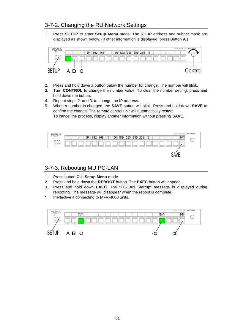
51
3-7-2. Changing the RU Network Settings
1. Press SETUP to enter Setup Menu mode. The RU IP address and subnet mask are
displayed as shown below. (If other information is displayed, press Button A.)
2. Press and hold down a button below the number for change. The number will blink.
3. Turn CONTROL to change the number value. To clear the number setting, press and
hold down the button.
4. Repeat steps 2. and 3. to change the IP address.
5. When a number is changed, the SAVE button will blink. Press and hold down SAVE to
confirm the change. The remote control unit will automatically restart.
To cancel the process, display another information without pressing SAVE.
3-7-3. Rebooting MU PC-LAN
1. Press button C in Setup Menu mode.
2. Press and hold down the REBOOT button. The EXEC button will appear.
3. Press and hold down EXEC. The "PC-LAN Startup" message is displayed during
rebooting. The message will disappear when the reboot is complete.
* Ineffective if connecting to MFR-4000 units.
POWER
BUSY SETUP
LOCK RESET
MFR-18RUREMOTE CONTROL UNIT
POWER
BUSY SETUP
LOCK RESET
MFR-18RUREMOTE CONTROL UNIT
POWER
BUSY SETUP
LOCK RESET
MFR-18RUREMOTE CONTROL UNIT
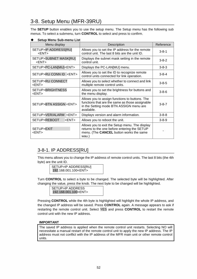
52
3-8. Setup Menu (MFR-39RU)
The SETUP button enables you to use the setup menu. The Setup menu has the following sub
menus. To select a submenu, turn CONTROL to select and press to confirm.
Setup Menu Sub-menu List
Menu display Description Reference
SETUP>IP ADDRESS[RU] <ENT>
Allows you to set the IP address for the remote control unit. The last 8 bits are the unit ID.
3-8-1
SETUP>SUBNET MASK[RU] <ENT>
Displays the subnet mask setting in the remote control unit.
3-8-2
SETUP>PC-LAN[MU]<ENT> Displays the PC-LAN[MU] menu. 3-8-3
SETUP>RU CONN ID <ENT> Allows you to set the ID to recognize remote control units connected for link operation.
3-8-4
SETUP>RU CONNECT <ENT>
Allows you to select whether to connect and link multiple remote control units.
3-8-5
SETUP>BRIGHTNESS <ENT>
Allows you to set the brightness for buttons and the menu display.
3-8-6
SETUP>BTN ASSIGN <ENT>
Allows you to assign functions to buttons. The functions that are the same as those assignable in the Setting mode BTN ASSIGN menu are available.
3-8-7
SETUP>VER/ALARM <ENT> Displays version and alarm information. 3-8-8
SETUP>REBOOT <ENT> Allows you to reboot the unit. 3-8-9
SETUP>EXIT <ENT>
Allows you to exit the Setup menu. The display returns to the one before entering the SETUP menu. (The CANCEL button works the same wau.)
-
3-8-1. IP ADDRESS[RU]
This menu allows you to change the IP address of remote control units. The last 8 bits (the 4th
byte) are the unit ID.
Turn CONTROL to select a byte to be changed. The selected byte will be highlighted. After
changing the value, press the knob. The next byte to be changed will be highlighted.
Pressing CONTROL while the 4th byte is highlighted will highlight the whole IP address, and
the changed IP address will be saved. Press CONTROL again. A message appears to ask if
restarting the remote control unit. Select YES and press CONTROL to restart the remote
control unit with the new IP address.
IMPORTANT
The saved IP address is applied when the remote control unit restarts. Selecting NO will necessitate a manual restart of the remote control unit to apply the new IP address. The IP address must not conflict with the IP address of the MFR main unit or other remote control units.
SETUP>IP ADDRESS[RU] 192.168.001.100<ENT>
SETUP>IP ADDRESS 192.168.001.100<ENT>
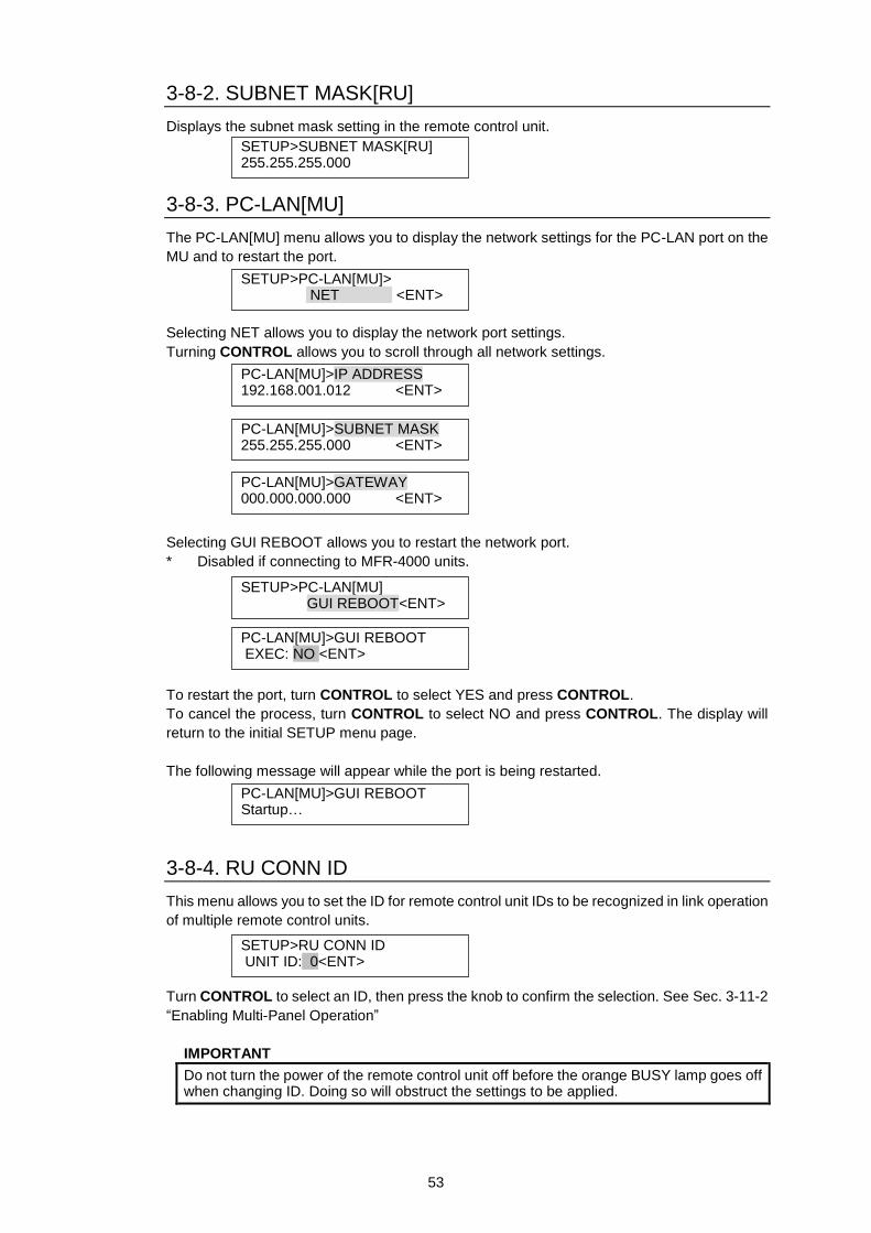
53
3-8-2. SUBNET MASK[RU]
Displays the subnet mask setting in the remote control unit.
3-8-3. PC-LAN[MU]
The PC-LAN[MU] menu allows you to display the network settings for the PC-LAN port on the
MU and to restart the port.
Selecting NET allows you to display the network port settings.
Turning CONTROL allows you to scroll through all network settings.
Selecting GUI REBOOT allows you to restart the network port.
* Disabled if connecting to MFR-4000 units.
To restart the port, turn CONTROL to select YES and press CONTROL.
To cancel the process, turn CONTROL to select NO and press CONTROL. The display will
return to the initial SETUP menu page.
The following message will appear while the port is being restarted.
3-8-4. RU CONN ID
This menu allows you to set the ID for remote control unit IDs to be recognized in link operation
of multiple remote control units.
Turn CONTROL to select an ID, then press the knob to confirm the selection. See Sec. 3-11-2
“Enabling Multi-Panel Operation”
IMPORTANT
Do not turn the power of the remote control unit off before the orange BUSY lamp goes off when changing ID. Doing so will obstruct the settings to be applied.
SETUP>RU CONN ID UNIT ID: 0<ENT>
SETUP>SUBNET MASK[RU] 255.255.255.000
SETUP>PC-LAN[MU]> NET <ENT>
PC-LAN[MU]>IP ADDRESS 192.168.001.012 <ENT>
PC-LAN[MU]>SUBNET MASK 255.255.255.000 <ENT>
PC-LAN[MU]>GATEWAY 000.000.000.000 <ENT>
SETUP>PC-LAN[MU] GUI REBOOT<ENT>
PC-LAN[MU]>GUI REBOOT EXEC: NO <ENT>
PC-LAN[MU]>GUI REBOOT Startup…
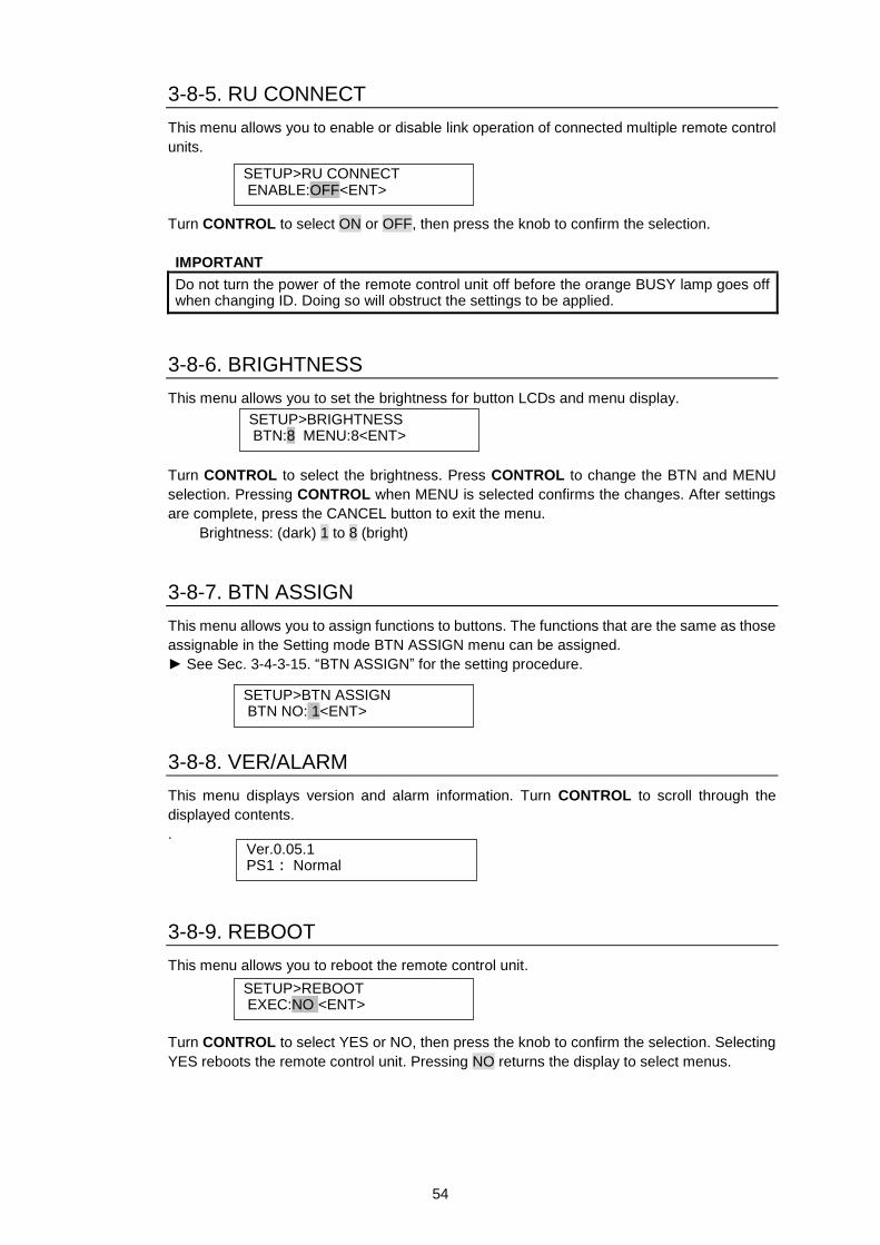
54
3-8-5. RU CONNECT
This menu allows you to enable or disable link operation of connected multiple remote control
units.
Turn CONTROL to select ON or OFF, then press the knob to confirm the selection.
IMPORTANT
Do not turn the power of the remote control unit off before the orange BUSY lamp goes off when changing ID. Doing so will obstruct the settings to be applied.
3-8-6. BRIGHTNESS
This menu allows you to set the brightness for button LCDs and menu display.
Turn CONTROL to select the brightness. Press CONTROL to change the BTN and MENU
selection. Pressing CONTROL when MENU is selected confirms the changes. After settings
are complete, press the CANCEL button to exit the menu.
Brightness: (dark) 1 to 8 (bright)
3-8-7. BTN ASSIGN
This menu allows you to assign functions to buttons. The functions that are the same as those
assignable in the Setting mode BTN ASSIGN menu can be assigned.
► See Sec. 3-4-3-15. “BTN ASSIGN” for the setting procedure.
3-8-8. VER/ALARM
This menu displays version and alarm information. Turn CONTROL to scroll through the
displayed contents.
.
3-8-9. REBOOT
This menu allows you to reboot the remote control unit.
Turn CONTROL to select YES or NO, then press the knob to confirm the selection. Selecting
YES reboots the remote control unit. Pressing NO returns the display to select menus.
SETUP>RU CONNECT ENABLE:OFF<ENT>
SETUP>BRIGHTNESS BTN:8 MENU:8<ENT>
SETUP>BTN ASSIGN BTN NO: 1<ENT>
Ver.0.05.1 PS1: Normal
SETUP>REBOOT EXEC:NO <ENT>
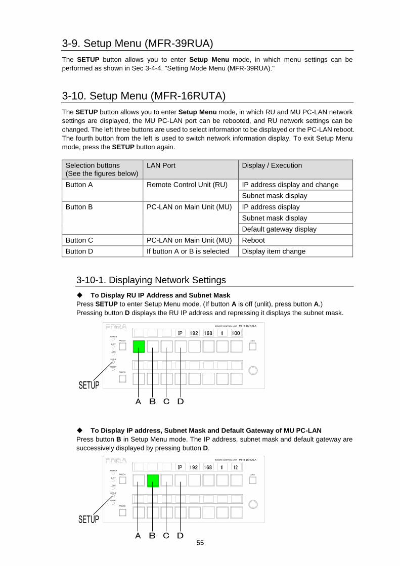
55
3-9. Setup Menu (MFR-39RUA)
The SETUP button allows you to enter Setup Menu mode, in which menu settings can be
performed as shown in Sec 3-4-4. "Setting Mode Menu (MFR-39RUA)."
3-10. Setup Menu (MFR-16RUTA)
The SETUP button allows you to enter Setup Menu mode, in which RU and MU PC-LAN network
settings are displayed, the MU PC-LAN port can be rebooted, and RU network settings can be
changed. The left three buttons are used to select information to be displayed or the PC-LAN reboot.
The fourth button from the left is used to switch network information display. To exit Setup Menu
mode, press the SETUP button again.
Selection buttons (See the figures below)
LAN Port Display / Execution
Button A Remote Control Unit (RU) IP address display and change
Subnet mask display
Button B PC-LAN on Main Unit (MU) IP address display
Subnet mask display
Default gateway display
Button C PC-LAN on Main Unit (MU) Reboot
Button D If button A or B is selected Display item change
3-10-1. Displaying Network Settings
To Display RU IP Address and Subnet Mask
Press SETUP to enter Setup Menu mode. (If button A is off (unlit), press button A.)
Pressing button D displays the RU IP address and repressing it displays the subnet mask.
To Display IP address, Subnet Mask and Default Gateway of MU PC-LAN
Press button B in Setup Menu mode. The IP address, subnet mask and default gateway are
successively displayed by pressing button D.
MFR-16RUTAREMOTE CONTROL UNIT
LOCK
POWER
BUSY
PAGE A
LOCK
SETUP
RESET
PAGE B
MFR-16RUTAREMOTE CONTROL UNIT
LOCK
POWER
BUSY
PAGE A
LOCK
SETUP
RESET
PAGE B
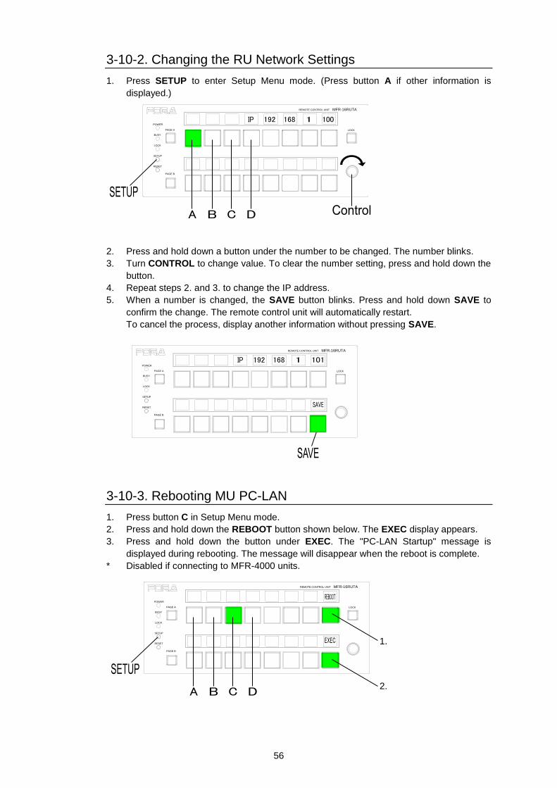
56
3-10-2. Changing the RU Network Settings
1. Press SETUP to enter Setup Menu mode. (Press button A if other information is
displayed.)
2. Press and hold down a button under the number to be changed. The number blinks.
3. Turn CONTROL to change value. To clear the number setting, press and hold down the
button.
4. Repeat steps 2. and 3. to change the IP address.
5. When a number is changed, the SAVE button blinks. Press and hold down SAVE to
confirm the change. The remote control unit will automatically restart.
To cancel the process, display another information without pressing SAVE.
3-10-3. Rebooting MU PC-LAN
1. Press button C in Setup Menu mode.
2. Press and hold down the REBOOT button shown below. The EXEC display appears.
3. Press and hold down the button under EXEC. The "PC-LAN Startup" message is
displayed during rebooting. The message will disappear when the reboot is complete.
* Disabled if connecting to MFR-4000 units.
MFR-16RUTAREMOTE CONTROL UNIT
LOCK
POWER
BUSY
PAGE A
LOCK
SETUP
RESET
PAGE B
MFR-16RUTAREMOTE CONTROL UNIT
LOCK
POWER
BUSY
PAGE A
LOCK
SETUP
RESET
PAGE B
MFR-16RUTAREMOTE CONTROL UNIT
LOCK
POWER
BUSY
PAGE A
LOCK
SETUP
RESET
PAGE B
1.
2.
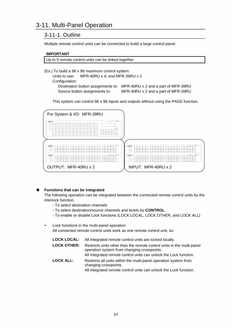
57
3-11. Multi-Panel Operation
3-11-1. Outline
Multiple remote control units can be connected to build a large control panel.
IMPORTANT
Up to 5 remote control units can be linked together.
(Ex.) To build a 96 x 96 maximum control system:
Units to use: MFR-40RU x 4, and MFR-39RU x 1
Configuration:
Destination button assignments to: MFR-40RU x 2 and a part of MFR-39RU
Source button assignments to: MFR-40RU x 2 and a part of MFR-39RU
This system can control 96 x 96 inputs and outputs without using the PAGE function.
Functions that can be integrated
The following operation can be integrated between the connected remote control units by the
interlock function.
- To select destination channels
- To select destination/source channels and levels by CONTROL.
- To enable or disable Lock functions (LOCK LOCAL, LOCK OTHER, and LOCK ALL)
Lock functions in the multi-panel operation
All connected remote control units work as one remote control unit, so:
LOCK LOCAL: All integrated remote control units are locked locally.
LOCK OTHER: Restricts units other than the remote control units in the multi-panel operation system from changing crosspoints.
All integrated remote control units can unlock the Lock function.
LOCK ALL: Restricts all units within the multi-panel operation system from changing crosspoints.
All integrated remote control units can unlock the Lock function.
RESET
CANCEL
MFR-39RUREMOTE CONTROL UNIT
POWER
BUSY
LOCK
SETUP
POWER
BUSY SETUP
LOCK RESET
MFR-40RUREMOTE CONTROL UNIT
POWER
BUSY SETUP
LOCK RESET
MFR-40RUREMOTE CONTROL UNIT
POWER
BUSY SETUP
LOCK RESET
MFR-40RUREMOTE CONTROL UNIT
POWER
BUSY SETUP
LOCK RESET
MFR-40RUREMOTE CONTROL UNIT
For System & I/O: MFR-39RU
OUTPUT: MFR-40RU x 2
INPUT: MFR-40RU x 2
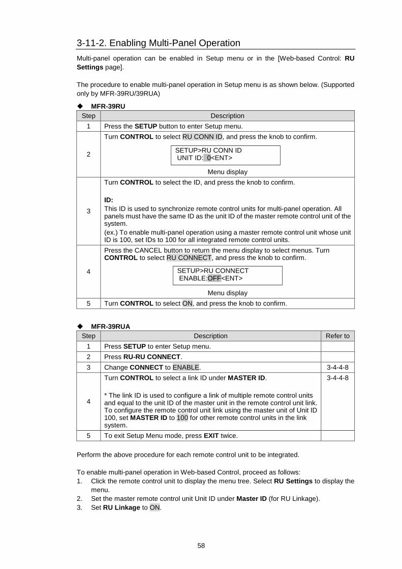
58
3-11-2. Enabling Multi-Panel Operation
Multi-panel operation can be enabled in Setup menu or in the [Web-based Control: RU
Settings page].
The procedure to enable multi-panel operation in Setup menu is as shown below. (Supported
only by MFR-39RU/39RUA)
MFR-39RU
Step Description
1 Press the SETUP button to enter Setup menu.
2
Turn CONTROL to select RU CONN ID, and press the knob to confirm.
Menu display
3
Turn CONTROL to select the ID, and press the knob to confirm.
ID:
This ID is used to synchronize remote control units for multi-panel operation. All panels must have the same ID as the unit ID of the master remote control unit of the system.
(ex.) To enable multi-panel operation using a master remote control unit whose unit ID is 100, set IDs to 100 for all integrated remote control units.
4
Press the CANCEL button to return the menu display to select menus. Turn CONTROL to select RU CONNECT, and press the knob to confirm.
Menu display
5 Turn CONTROL to select ON, and press the knob to confirm.
MFR-39RUA
Step Description Refer to
1 Press SETUP to enter Setup menu.
2 Press RU-RU CONNECT.
3 Change CONNECT to ENABLE. 3-4-4-8
4
Turn CONTROL to select a link ID under MASTER ID.
* The link ID is used to configure a link of multiple remote control units and equal to the unit ID of the master unit in the remote control unit link. To configure the remote control unit link using the master unit of Unit ID 100, set MASTER ID to 100 for other remote control units in the link system.
3-4-4-8
5 To exit Setup Menu mode, press EXIT twice.
Perform the above procedure for each remote control unit to be integrated.
To enable multi-panel operation in Web-based Control, proceed as follows:
1. Click the remote control unit to display the menu tree. Select RU Settings to display the
menu.
2. Set the master remote control unit Unit ID under Master ID (for RU Linkage).
3. Set RU Linkage to ON.
SETUP>RU CONN ID UNIT ID: 0<ENT>
SETUP>RU CONNECT ENABLE:OFF<ENT>
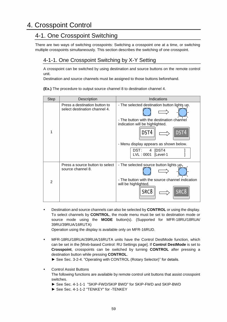
59
4. Crosspoint Control
4-1. One Crosspoint Switching
There are two ways of switching crosspoints: Switching a crosspoint one at a time, or switching
multiple crosspoints simultaneously. This section describes the switching of one crosspoint.
4-1-1. One Crosspoint Switching by X-Y Setting
A crosspoint can be switched by using destination and source buttons on the remote control
unit.
Destination and source channels must be assigned to those buttons beforehand.
(Ex.) The procedure to output source channel 8 to destination channel 4.
Step Description Indications
1
Press a destination button to select destination channel 4.
- The selected destination button lights up.
- The button with the destination channel indication will be highlighted.
- Menu display appears as shown below.
2
Press a source button to select source channel 8.
- The selected source button lights up.
- The button with the source channel indication will be highlighted.
Destination and source channels can also be selected by CONTROL or using the display.
To select channels by CONTROL, the mode menu must be set to destination mode or
source mode using the MODE button(s). (Supported for MFR-18RU/18RUA/
39RU/39RUA/16RUTA)
Operation using the display is available only on MFR-16RUD.
MFR-18RU/18RUA/39RUA/16RUTA units have the Control DestMode function, which
can be set in the [Web-based Control: RU Settings page]. If Control DestMode is set to
Crosspoint, crosspoints can be switched by turning CONTROL after pressing a
destination button while pressing CONTROL.
► See Sec. 3-2-4. “Operating with CONTROL (Rotary Selector)” for details.
Control Assist Buttons
The following functions are available by remote control unit buttons that assist crosspoint
switches.
► See Sec. 4-1-1-1 "SKIP-FWD/SKIP BWD" for SKIP-FWD and SKIP-BWD
► See Sec. 4-1-1-2 "TENKEY" for -TENKEY
DST : 4 [DST4 ] LVL : 0001 [Level-1 ]
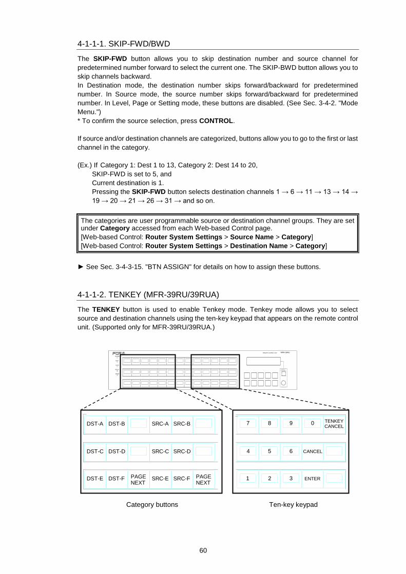
60
4-1-1-1. SKIP-FWD/BWD
The SKIP-FWD button allows you to skip destination number and source channel for
predetermined number forward to select the current one. The SKIP-BWD button allows you to
skip channels backward.
In Destination mode, the destination number skips forward/backward for predetermined
number. In Source mode, the source number skips forward/backward for predetermined
number. In Level, Page or Setting mode, these buttons are disabled. (See Sec. 3-4-2. "Mode
Menu.")
* To confirm the source selection, press CONTROL.
If source and/or destination channels are categorized, buttons allow you to go to the first or last
channel in the category.
(Ex.) If Category 1: Dest 1 to 13, Category 2: Dest 14 to 20,
SKIP-FWD is set to 5, and
Current destination is 1.
Pressing the SKIP-FWD button selects destination channels 1 → 6 → 11 → 13 → 14 →
19 → 20 → 21 → 26 → 31 → and so on.
The categories are user programmable source or destination channel groups. They are set under Category accessed from each Web-based Control page.
[Web-based Control: Router System Settings > Source Name > Category]
[Web-based Control: Router System Settings > Destination Name > Category]
► See Sec. 3-4-3-15. "BTN ASSIGN" for details on how to assign these buttons.
4-1-1-2. TENKEY (MFR-39RU/39RUA)
The TENKEY button is used to enable Tenkey mode. Tenkey mode allows you to select
source and destination channels using the ten-key keypad that appears on the remote control
unit. (Supported only for MFR-39RU/39RUA.)
Category buttons Ten-key keypad
RESET
CANCEL
MFR-39RUREMOTE CONTROL UNIT
POWER
BUSY
LOCK
SETUP
DST-A
DST-C
DST-E
DST-B
DST-D
DST-F
SRC-A SRC-B
SRC-C
SRC-E
SRC-D
SRC-FPAGENEXT
PAGENEXT
CANCEL
ENTER
0987
4
1
5
2
6
3
TENKEYCANCEL
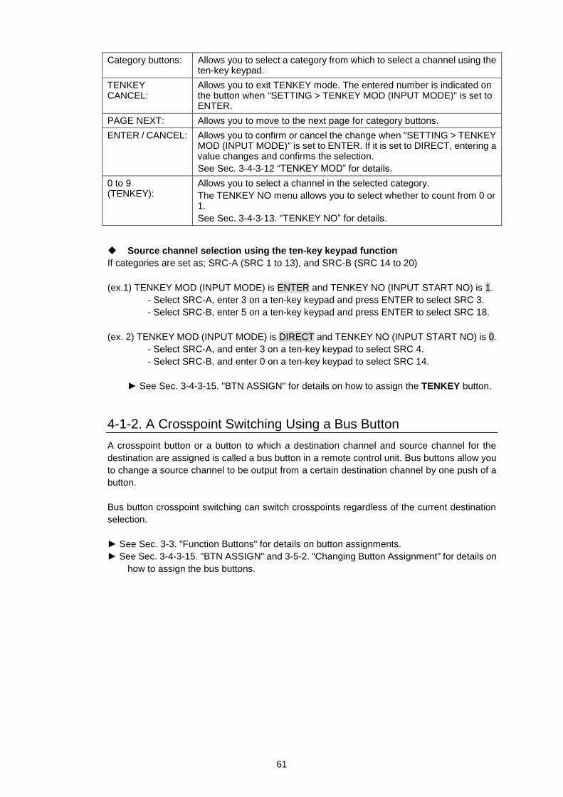
61
Category buttons: Allows you to select a category from which to select a channel using the ten-key keypad.
TENKEY CANCEL:
Allows you to exit TENKEY mode. The entered number is indicated on the button when "SETTING > TENKEY MOD (INPUT MODE)" is set to ENTER.
PAGE NEXT: Allows you to move to the next page for category buttons.
ENTER / CANCEL: Allows you to confirm or cancel the change when "SETTING > TENKEY MOD (INPUT MODE)" is set to ENTER. If it is set to DIRECT, entering a value changes and confirms the selection.
See Sec. 3-4-3-12 “TENKEY MOD” for details.
0 to 9 (TENKEY):
Allows you to select a channel in the selected category.
The TENKEY NO menu allows you to select whether to count from 0 or 1.
See Sec. 3-4-3-13. “TENKEY NO” for details.
Source channel selection using the ten-key keypad function
If categories are set as; SRC-A (SRC 1 to 13), and SRC-B (SRC 14 to 20)
(ex.1) TENKEY MOD (INPUT MODE) is ENTER and TENKEY NO (INPUT START NO) is 1.
- Select SRC-A, enter 3 on a ten-key keypad and press ENTER to select SRC 3.
- Select SRC-B, enter 5 on a ten-key keypad and press ENTER to select SRC 18.
(ex. 2) TENKEY MOD (INPUT MODE) is DIRECT and TENKEY NO (INPUT START NO) is 0.
- Select SRC-A, and enter 3 on a ten-key keypad to select SRC 4.
- Select SRC-B, and enter 0 on a ten-key keypad to select SRC 14.
► See Sec. 3-4-3-15. "BTN ASSIGN" for details on how to assign the TENKEY button.
4-1-2. A Crosspoint Switching Using a Bus Button
A crosspoint button or a button to which a destination channel and source channel for the
destination are assigned is called a bus button in a remote control unit. Bus buttons allow you
to change a source channel to be output from a certain destination channel by one push of a
button.
Bus button crosspoint switching can switch crosspoints regardless of the current destination
selection.
► See Sec. 3-3. "Function Buttons" for details on button assignments.
► See Sec. 3-4-3-15. "BTN ASSIGN" and 3-5-2. "Changing Button Assignment" for details on
how to assign the bus buttons.
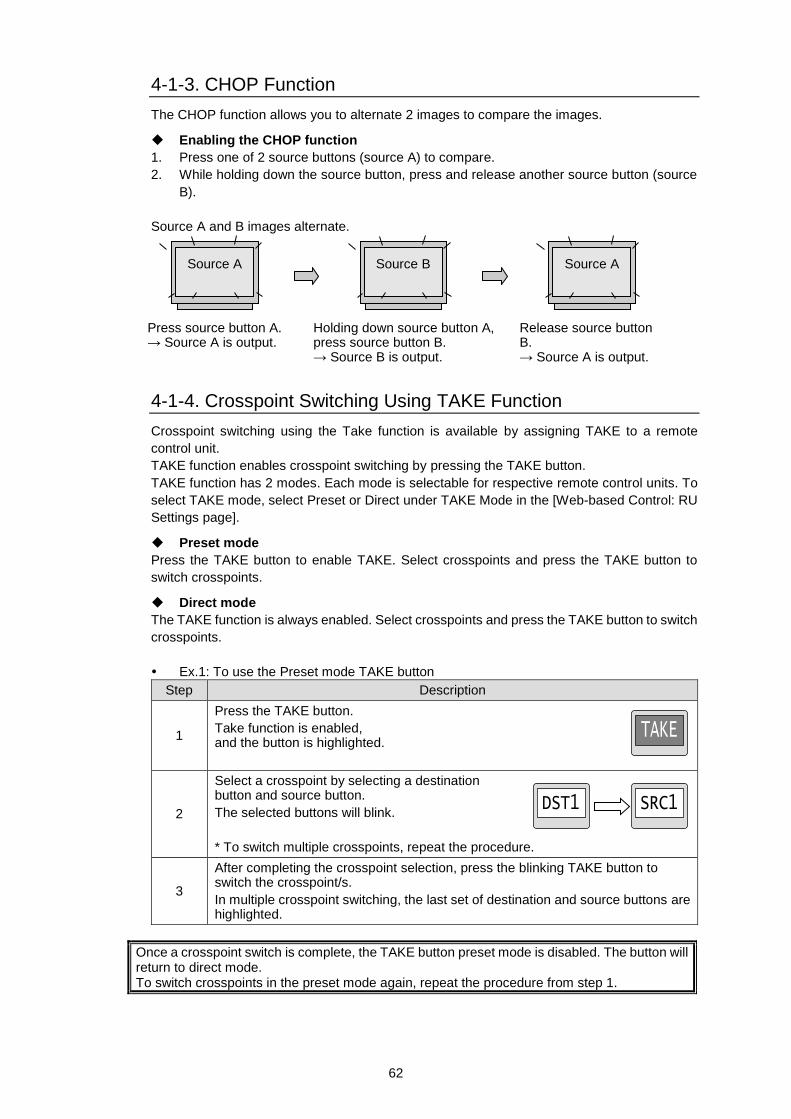
62
4-1-3. CHOP Function
The CHOP function allows you to alternate 2 images to compare the images.
Enabling the CHOP function
1. Press one of 2 source buttons (source A) to compare.
2. While holding down the source button, press and release another source button (source
B).
Source A and B images alternate.
4-1-4. Crosspoint Switching Using TAKE Function
Crosspoint switching using the Take function is available by assigning TAKE to a remote
control unit.
TAKE function enables crosspoint switching by pressing the TAKE button.
TAKE function has 2 modes. Each mode is selectable for respective remote control units. To
select TAKE mode, select Preset or Direct under TAKE Mode in the [Web-based Control: RU
Settings page].
Preset mode
Press the TAKE button to enable TAKE. Select crosspoints and press the TAKE button to
switch crosspoints.
Direct mode
The TAKE function is always enabled. Select crosspoints and press the TAKE button to switch
crosspoints.
Ex.1: To use the Preset mode TAKE button
Step Description
1
Press the TAKE button.
Take function is enabled, and the button is highlighted.
2
Select a crosspoint by selecting a destination button and source button.
The selected buttons will blink.
* To switch multiple crosspoints, repeat the procedure.
3
After completing the crosspoint selection, press the blinking TAKE button to switch the crosspoint/s.
In multiple crosspoint switching, the last set of destination and source buttons are highlighted.
Once a crosspoint switch is complete, the TAKE button preset mode is disabled. The button will return to direct mode. To switch crosspoints in the preset mode again, repeat the procedure from step 1.
Source A Source B Source A
Press source button A. → Source A is output.
Holding down source button A, press source button B. → Source B is output.
Release source button B. → Source A is output.
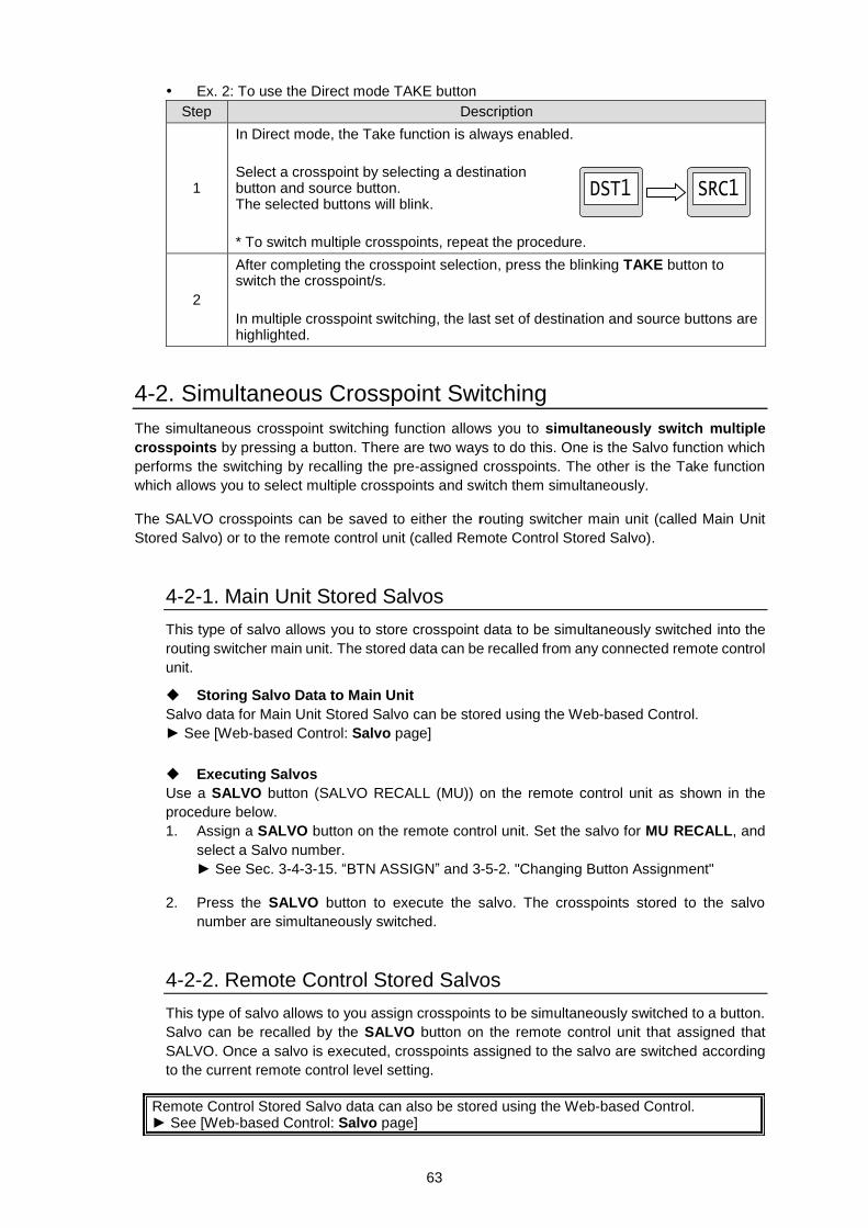
63
Ex. 2: To use the Direct mode TAKE button
Step Description
1
In Direct mode, the Take function is always enabled.
Select a crosspoint by selecting a destination button and source button. The selected buttons will blink.
* To switch multiple crosspoints, repeat the procedure.
2
After completing the crosspoint selection, press the blinking TAKE button to switch the crosspoint/s.
In multiple crosspoint switching, the last set of destination and source buttons are highlighted.
4-2. Simultaneous Crosspoint Switching
The simultaneous crosspoint switching function allows you to simultaneously switch multiple
crosspoints by pressing a button. There are two ways to do this. One is the Salvo function which
performs the switching by recalling the pre-assigned crosspoints. The other is the Take function
which allows you to select multiple crosspoints and switch them simultaneously.
The SALVO crosspoints can be saved to either the routing switcher main unit (called Main Unit
Stored Salvo) or to the remote control unit (called Remote Control Stored Salvo).
4-2-1. Main Unit Stored Salvos
This type of salvo allows you to store crosspoint data to be simultaneously switched into the
routing switcher main unit. The stored data can be recalled from any connected remote control
unit.
Storing Salvo Data to Main Unit
Salvo data for Main Unit Stored Salvo can be stored using the Web-based Control.
► See [Web-based Control: Salvo page]
Executing Salvos
Use a SALVO button (SALVO RECALL (MU)) on the remote control unit as shown in the
procedure below.
1. Assign a SALVO button on the remote control unit. Set the salvo for MU RECALL, and
select a Salvo number.
► See Sec. 3-4-3-15. “BTN ASSIGN” and 3-5-2. "Changing Button Assignment"
2. Press the SALVO button to execute the salvo. The crosspoints stored to the salvo
number are simultaneously switched.
4-2-2. Remote Control Stored Salvos
This type of salvo allows to you assign crosspoints to be simultaneously switched to a button.
Salvo can be recalled by the SALVO button on the remote control unit that assigned that
SALVO. Once a salvo is executed, crosspoints assigned to the salvo are switched according
to the current remote control level setting.
Remote Control Stored Salvo data can also be stored using the Web-based Control. ► See [Web-based Control: Salvo page]
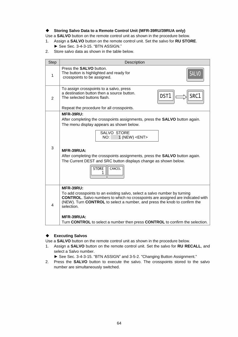
64
Storing Salvo Data to a Remote Control Unit (MFR-39RU/39RUA only)
Use a SALVO button on the remote control unit as shown in the procedure below.
1. Assign a SALVO button on the remote control unit. Set the salvo for RU STORE.
► See Sec. 3-4-3-15. “BTN ASSIGN.”
2. Store salvo data as shown in the table below.
Step Description
1
Press the SALVO button. The button is highlighted and ready for crosspoints to be assigned.
2
To assign crosspoints to a salvo, press a destination button then a source button. The selected buttons flash.
Repeat the procedure for all crosspoints.
3
MFR-39RU:
After completing the crosspoints assignments, press the SALVO button again.
The menu display appears as shown below.
MFR-39RUA:
After completing the crosspoints assignments, press the SALVO button again.
The Current DEST and SRC button displays change as shown below.
4
MFR-39RU:
To add crosspoints to an existing salvo, select a salvo number by turning CONTROL. Salvo numbers to which no crosspoints are assigned are indicated with (NEW). Turn CONTROL to select a number, and press the knob to confirm the selection.
MFR-39RUA:
Turn CONTROL to select a number then press CONTROL to confirm the selection.
Executing Salvos
Use a SALVO button on the remote control unit as shown in the procedure below.
1. Assign a SALVO button on the remote control unit. Set the salvo for RU RECALL, and
select a Salvo number.
► See Sec. 3-4-3-15. “BTN ASSIGN” and 3-5-2. "Changing Button Assignment."
2. Press the SALVO button to execute the salvo. The crosspoints stored to the salvo
number are simultaneously switched.
SALVO STORE NO: 1 (NEW) <ENT>
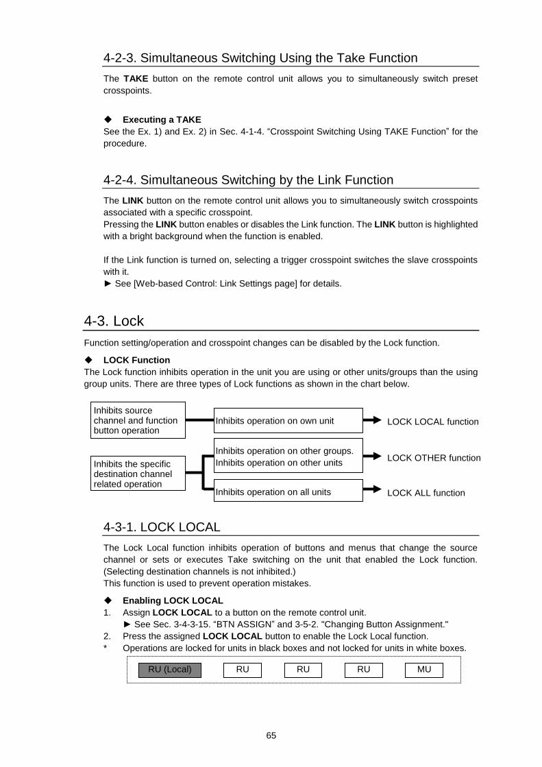
65
4-2-3. Simultaneous Switching Using the Take Function
The TAKE button on the remote control unit allows you to simultaneously switch preset
crosspoints.
Executing a TAKE
See the Ex. 1) and Ex. 2) in Sec. 4-1-4. “Crosspoint Switching Using TAKE Function” for the
procedure.
4-2-4. Simultaneous Switching by the Link Function
The LINK button on the remote control unit allows you to simultaneously switch crosspoints
associated with a specific crosspoint.
Pressing the LINK button enables or disables the Link function. The LINK button is highlighted
with a bright background when the function is enabled.
If the Link function is turned on, selecting a trigger crosspoint switches the slave crosspoints
with it.
► See [Web-based Control: Link Settings page] for details.
4-3. Lock
Function setting/operation and crosspoint changes can be disabled by the Lock function.
LOCK Function
The Lock function inhibits operation in the unit you are using or other units/groups than the using
group units. There are three types of Lock functions as shown in the chart below.
4-3-1. LOCK LOCAL
The Lock Local function inhibits operation of buttons and menus that change the source
channel or sets or executes Take switching on the unit that enabled the Lock function.
(Selecting destination channels is not inhibited.)
This function is used to prevent operation mistakes.
Enabling LOCK LOCAL
1. Assign LOCK LOCAL to a button on the remote control unit.
► See Sec. 3-4-3-15. “BTN ASSIGN” and 3-5-2. "Changing Button Assignment."
2. Press the assigned LOCK LOCAL button to enable the Lock Local function.
* Operations are locked for units in black boxes and not locked for units in white boxes.
RU (Local) RU RU RU MU
LOCK OTHER function
LOCK ALL function
Inhibits source channel and function button operation
Inhibits operation on own unit LOCK LOCAL function
Inhibits the specific destination channel related operation
Inhibits operation on other groups.
Inhibits operation on other units
Inhibits operation on all units
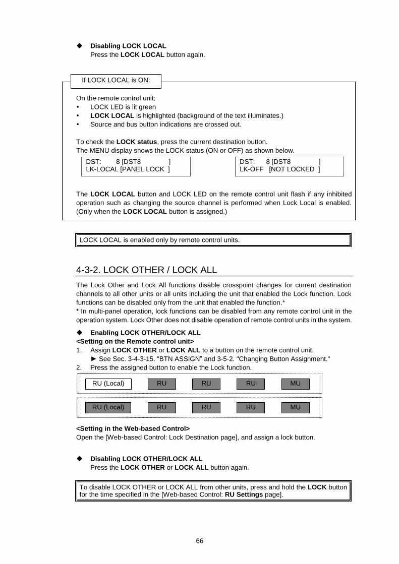
66
Disabling LOCK LOCAL
Press the LOCK LOCAL button again.
On the remote control unit:
LOCK LED is lit green
LOCK LOCAL is highlighted (background of the text illuminates.)
Source and bus button indications are crossed out.
To check the LOCK status, press the current destination button.
The MENU display shows the LOCK status (ON or OFF) as shown below.
The LOCK LOCAL button and LOCK LED on the remote control unit flash if any inhibited
operation such as changing the source channel is performed when Lock Local is enabled.
(Only when the LOCK LOCAL button is assigned.)
LOCK LOCAL is enabled only by remote control units.
4-3-2. LOCK OTHER / LOCK ALL
The Lock Other and Lock All functions disable crosspoint changes for current destination
channels to all other units or all units including the unit that enabled the Lock function. Lock
functions can be disabled only from the unit that enabled the function.*
* In multi-panel operation, lock functions can be disabled from any remote control unit in the
operation system. Lock Other does not disable operation of remote control units in the system.
Enabling LOCK OTHER/LOCK ALL
<Setting on the Remote control unit>
1. Assign LOCK OTHER or LOCK ALL to a button on the remote control unit.
► See Sec. 3-4-3-15. “BTN ASSIGN” and 3-5-2. "Changing Button Assignment."
2. Press the assigned button to enable the Lock function.
<Setting in the Web-based Control>
Open the [Web-based Control: Lock Destination page], and assign a lock button.
Disabling LOCK OTHER/LOCK ALL
Press the LOCK OTHER or LOCK ALL button again.
To disable LOCK OTHER or LOCK ALL from other units, press and hold the LOCK button for the time specified in the [Web-based Control: RU Settings page].
DST: 8 [DST8 ] LK-LOCAL [PANEL LOCK ]
DST: 8 [DST8 ] LK-OFF [NOT LOCKED ]
If LOCK LOCAL is ON:
RU (Local) RU RU RU MU
RU (Local) RU RU RU MU
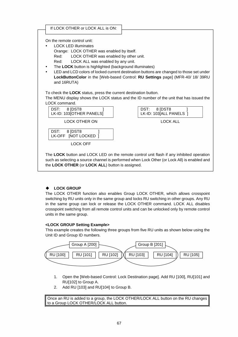
67
On the remote control unit:
LOCK LED illuminates
Orange: LOCK OTHER was enabled by itself.
Red: LOCK OTHER was enabled by other unit.
Red: LOCK ALL was enabled by any unit.
The LOCK button is highlighted (background illuminates)
LED and LCD colors of locked current destination buttons are changed to those set under
LockButtonColor in the [Web-based Control: RU Settings page] (MFR-40/ 18/ 39RU
and 16RUTA)
To check the LOCK status, press the current destination button.
The MENU display shows the LOCK status and the ID number of the unit that has issued the
LOCK command.
The LOCK button and LOCK LED on the remote control unit flash if any inhibited operation
such as selecting a source channel is performed when Lock Other (or Lock All) is enabled and
the LOCK OTHER (or LOCK ALL) button is assigned.
LOCK GROUP
The LOCK OTHER function also enables Group LOCK OTHER, which allows crosspoint
switching by RU units only in the same group and locks RU switching in other groups. Any RU
in the same group can lock or release the LOCK OTHER command. LOCK ALL disables
crosspoint switching from all remote control units and can be unlocked only by remote control
units in the same group.
<LOCK GROUP Setting Example>
This example creates the following three groups from five RU units as shown below using the
Unit ID and Group ID numbers.
1. Open the [Web-based Control: Lock Destination page]. Add RU [100], RU[101] and
RU[102] to Group A.
2. Add RU [103] and RU[104] to Group B.
Once an RU is added to a group, the LOCK OTHER/LOCK ALL button on the RU changes to a Group LOCK OTHER/LOCK ALL button.
DST: 8 [DST8 ] LK-ID: 103[OTHER PANELS]
LOCK OTHER ON
DST: 8 [DST8 ] LK-ID: 103[ALL PANELS ]
LOCK ALL
DST: 8 [DST8 ] LK-OFF [NOT LOCKED ]
LOCK OFF
If LOCK OTHER or LOCK ALL is ON:
RU [102] RU [103] RU [100] RU [101] RU [104] RU [105]
Group A [200] Group B [201]
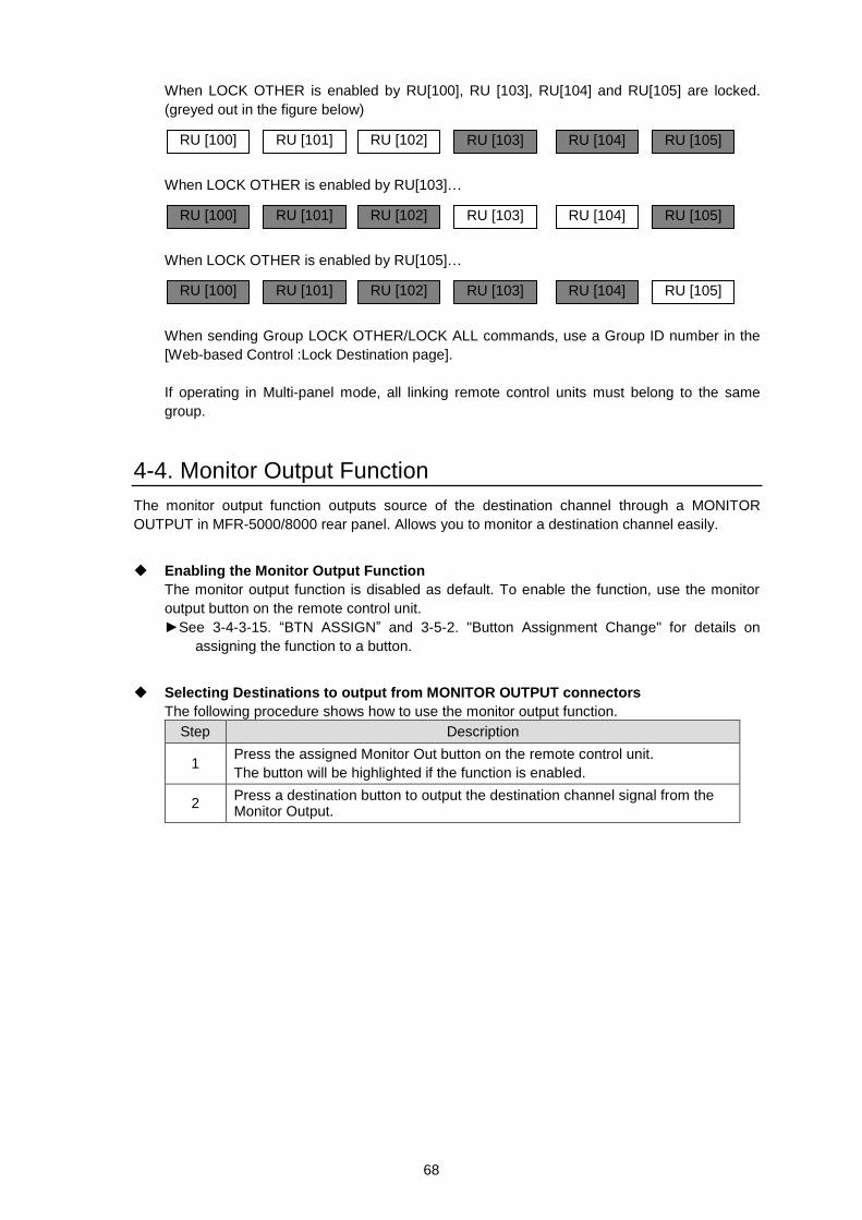
68
When LOCK OTHER is enabled by RU[100], RU [103], RU[104] and RU[105] are locked.
(greyed out in the figure below)
When LOCK OTHER is enabled by RU[103]…
When LOCK OTHER is enabled by RU[105]…
When sending Group LOCK OTHER/LOCK ALL commands, use a Group ID number in the
[Web-based Control :Lock Destination page].
If operating in Multi-panel mode, all linking remote control units must belong to the same
group.
4-4. Monitor Output Function
The monitor output function outputs source of the destination channel through a MONITOR
OUTPUT in MFR-5000/8000 rear panel. Allows you to monitor a destination channel easily.
Enabling the Monitor Output Function
The monitor output function is disabled as default. To enable the function, use the monitor
output button on the remote control unit.
►See 3-4-3-15. “BTN ASSIGN” and 3-5-2. "Button Assignment Change" for details on
assigning the function to a button.
Selecting Destinations to output from MONITOR OUTPUT connectors
The following procedure shows how to use the monitor output function.
Step Description
1 Press the assigned Monitor Out button on the remote control unit.
The button will be highlighted if the function is enabled.
2 Press a destination button to output the destination channel signal from the Monitor Output.
RU [102] RU [103] RU [100] RU [101] RU [104] RU [105]
RU [102] RU [103] RU [100] RU [101] RU [104] RU [105]
RU [102] RU [103] RU [100] RU [101] RU [104] RU [105]
69
4-5. Preview Function
The preview function allows you to set an output port in Main Unit rear panel to be used for the
preview.
(ex.) When pressing a source button on the remote control unit for a simultaneous crosspoint
switch, the selected source will be output to the preview output. You can check images of the
source channels before applying Take function.
When pressing a destination button, the source channel assigned for the destination channel
will be output to the preview output.
Assigning Operation Preview to a Button on the Remote Control Unit
The Operation Preview function is disabled as default. To enable the function, assign the function
to a button on the remote control unit in the Web-based Control.
Only MFR-39RU and MFR-16RUD units can assign Operation Preview by front panel operation.
► See [Web-based Control: Assign Function page].
► See Sec.s 3-4-3-15. "BTN ASSIGN" and 3-5-2. "Changing Button Assignment."
Outputting the Operation Preview
Press the O-PREVIEW button on the remote control unit to output the preview signal from the set
destination channel.
5. Troubleshooting
If any of the following problems occur during operation of your remote control unit, proceed as indicated
below to see if the problem can be corrected before assuming a unit malfunction has occurred.
IMPORTANT
If the problem cannot be corrected by performing the procedures below, turn the unit power off and then on again. If this still does not correct the problem, contact your FOR-A agent.
Problem Check Remedy
Unable to control using the remote control unit.
Is the LAN cable properly connected?
Properly re-connect the LAN cable.
Is the RU Info page in the Web-based Control indicating NG?
Check the item that is indicated as NG.
If the Voltage is indicated as NG, contact your FOR-A agent.
The text color has changed from the original color.
Button displays may be deteriorated over time.
Refer to Sec. 5-1 to fine-tune colors.
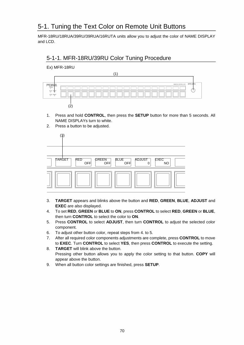
70
5-1. Tuning the Text Color on Remote Unit Buttons
MFR-18RU/18RUA/39RU/39RUA/16RUTA units allow you to adjust the color of NAME DISPLAY
and LCD.
5-1-1. MFR-18RU/39RU Color Tuning Procedure
Ex) MFR-18RU
1. Press and hold CONTROL, then press the SETUP button for more than 5 seconds. All
NAME DISPLAYs turn to white.
2. Press a button to be adjusted.
3. TARGET appears and blinks above the button and RED, GREEN, BLUE, ADJUST and
EXEC are also displayed.
4. To set RED, GREEN or BLUE to ON, press CONTROL to select RED, GREEN or BLUE,
then turn CONTROL to select the color to ON.
5. Press CONTROL to select ADJUST, then turn CONTROL to adjust the selected color
component.
6. To adjust other button color, repeat steps from 4. to 5.
7. After all required color components adjustments are complete, press CONTROL to move
to EXEC. Turn CONTROL to select YES, then press CONTROL to execute the setting.
8. TARGET will blink above the button.
Pressing other button allows you to apply the color setting to that button. COPY will
appear above the button.
9. When all button color settings are finished, press SETUP.
GREEN OFF
TARGET
RED OFF
ADJUST 0
POWER
BUSY SETUP
LOCK RESET
MFR-18RUREMOTE CONTROL UNIT
BLUE OFF
EXEC NO
(3)
POWER
BUSY SETUP
LOCK RESET
MFR-18RUREMOTE CONTROL UNIT
(1)
(2)
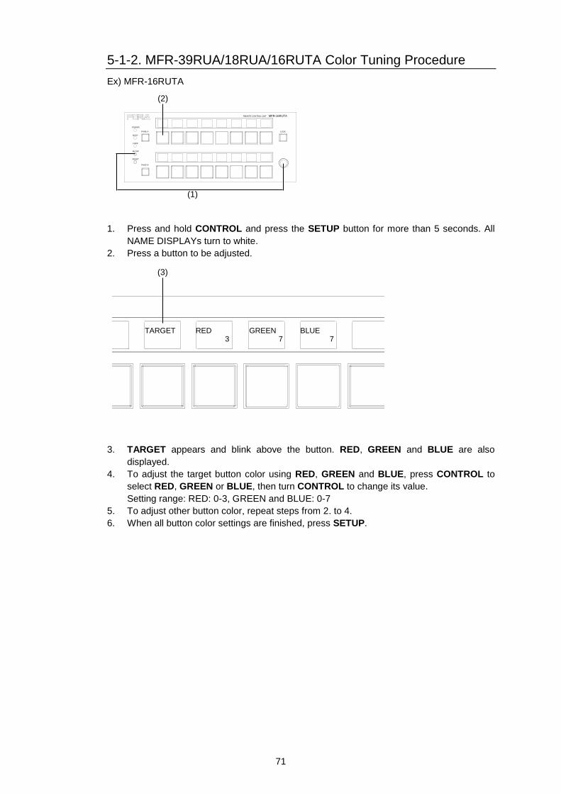
71
5-1-2. MFR-39RUA/18RUA/16RUTA Color Tuning Procedure
Ex) MFR-16RUTA
1. Press and hold CONTROL and press the SETUP button for more than 5 seconds. All
NAME DISPLAYs turn to white.
2. Press a button to be adjusted.
3. TARGET appears and blink above the button. RED, GREEN and BLUE are also
displayed.
4. To adjust the target button color using RED, GREEN and BLUE, press CONTROL to
select RED, GREEN or BLUE, then turn CONTROL to change its value.
Setting range: RED: 0-3, GREEN and BLUE: 0-7
5. To adjust other button color, repeat steps from 2. to 4.
6. When all button color settings are finished, press SETUP.
MFR-16RUTAREMOTE CONTROL UNIT
LOCK
POWER
BUSY
PAGE A
LOCK
SETUP
RESET
PAGE B
GREEN 7
TARGET
RED 3
BLUE 7
(3)
MFR-16RUTAREMOTE CONTROL UNIT
LOCK
POWER
BUSY
PAGE A
LOCK
SETUP
RESET
PAGE B
(1)
(2)
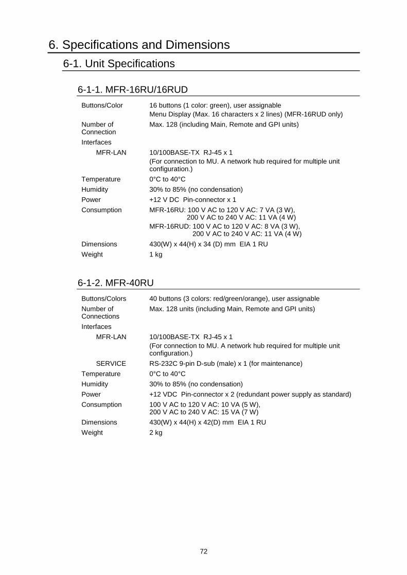
72
6. Specifications and Dimensions
6-1. Unit Specifications
6-1-1. MFR-16RU/16RUD
Buttons/Color 16 buttons (1 color: green), user assignable
Menu Display (Max. 16 characters x 2 lines) (MFR-16RUD only)
Number of Connection
Max. 128 (including Main, Remote and GPI units)
Interfaces
MFR-LAN 10/100BASE-TX RJ-45 x 1
(For connection to MU. A network hub required for multiple unit configuration.)
Temperature 0°C to 40°C
Humidity 30% to 85% (no condensation)
Power +12 V DC Pin-connector x 1
Consumption MFR-16RU: 100 V AC to 120 V AC: 7 VA (3 W), 200 V AC to 240 V AC: 11 VA (4 W)
MFR-16RUD: 100 V AC to 120 V AC: 8 VA (3 W), 200 V AC to 240 V AC: 11 VA (4 W)
Dimensions 430(W) x 44(H) x 34 (D) mm EIA 1 RU
Weight 1 kg
6-1-2. MFR-40RU
Buttons/Colors 40 buttons (3 colors: red/green/orange), user assignable
Number of Connections
Max. 128 units (including Main, Remote and GPI units)
Interfaces
MFR-LAN 10/100BASE-TX RJ-45 x 1
(For connection to MU. A network hub required for multiple unit configuration.)
SERVICE RS-232C 9-pin D-sub (male) x 1 (for maintenance)
Temperature 0°C to 40°C
Humidity 30% to 85% (no condensation)
Power +12 VDC Pin-connector x 2 (redundant power supply as standard)
Consumption 100 V AC to 120 V AC: 10 VA (5 W), 200 V AC to 240 V AC: 15 VA (7 W)
Dimensions 430(W) x 44(H) x 42(D) mm EIA 1 RU
Weight 2 kg
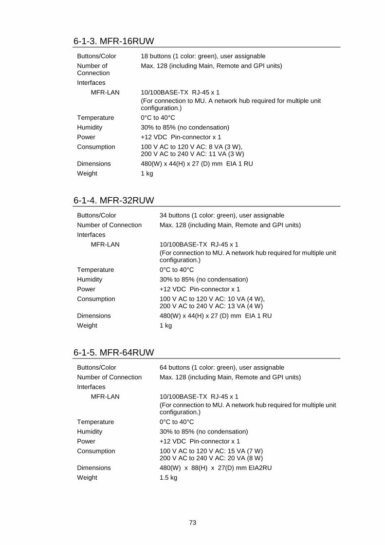
73
6-1-3. MFR-16RUW
Buttons/Color 18 buttons (1 color: green), user assignable
Number of Connection
Max. 128 (including Main, Remote and GPI units)
Interfaces
MFR-LAN 10/100BASE-TX RJ-45 x 1
(For connection to MU. A network hub required for multiple unit configuration.)
Temperature 0°C to 40°C
Humidity 30% to 85% (no condensation)
Power +12 VDC Pin-connector x 1
Consumption 100 V AC to 120 V AC: 8 VA (3 W), 200 V AC to 240 V AC: 11 VA (3 W)
Dimensions 480(W) x 44(H) x 27 (D) mm EIA 1 RU
Weight 1 kg
6-1-4. MFR-32RUW
Buttons/Color 34 buttons (1 color: green), user assignable
Number of Connection Max. 128 (including Main, Remote and GPI units)
Interfaces
MFR-LAN 10/100BASE-TX RJ-45 x 1
(For connection to MU. A network hub required for multiple unit configuration.)
Temperature 0°C to 40°C
Humidity 30% to 85% (no condensation)
Power +12 VDC Pin-connector x 1
Consumption 100 V AC to 120 V AC: 10 VA (4 W), 200 V AC to 240 V AC: 13 VA (4 W)
Dimensions 480(W) x 44(H) x 27 (D) mm EIA 1 RU
Weight 1 kg
6-1-5. MFR-64RUW
Buttons/Color 64 buttons (1 color: green), user assignable
Number of Connection Max. 128 (including Main, Remote and GPI units)
Interfaces
MFR-LAN 10/100BASE-TX RJ-45 x 1
(For connection to MU. A network hub required for multiple unit configuration.)
Temperature 0°C to 40°C
Humidity 30% to 85% (no condensation)
Power +12 VDC Pin-connector x 1
Consumption 100 V AC to 120 V AC: 15 VA (7 W) 200 V AC to 240 V AC: 20 VA (8 W)
Dimensions 480(W) x 88(H) x 27(D) mm EIA2RU
Weight 1.5 kg
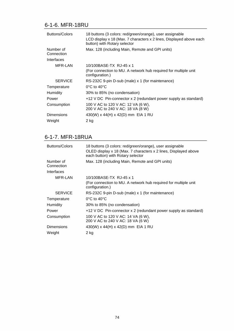
74
6-1-6. MFR-18RU
Buttons/Colors 18 buttons (3 colors: red/green/orange), user assignable
LCD display x 18 (Max. 7 characters x 2 lines, Displayed above each button) with Rotary selector
Number of Connection
Max. 128 (including Main, Remote and GPI units)
Interfaces
MFR-LAN 10/100BASE-TX RJ-45 x 1
(For connection to MU. A network hub required for multiple unit configuration.)
SERVICE RS-232C 9-pin D-sub (male) x 1 (for maintenance)
Temperature 0°C to 40°C
Humidity 30% to 85% (no condensation)
Power +12 V DC Pin-connector x 2 (redundant power supply as standard)
Consumption 100 V AC to 120 V AC: 12 VA (6 W), 200 V AC to 240 V AC: 18 VA (8 W)
Dimensions 430(W) x 44(H) x 42(D) mm EIA 1 RU
Weight 2 kg
6-1-7. MFR-18RUA
Buttons/Colors 18 buttons (3 colors: red/green/orange), user assignable
OLED display x 18 (Max. 7 characters x 2 lines, Displayed above each button) with Rotary selector
Number of Connection
Max. 128 (including Main, Remote and GPI units)
Interfaces
MFR-LAN 10/100BASE-TX RJ-45 x 1
(For connection to MU. A network hub required for multiple unit configuration.)
SERVICE RS-232C 9-pin D-sub (male) x 1 (for maintenance)
Temperature 0°C to 40°C
Humidity 30% to 85% (no condensation)
Power +12 V DC Pin-connector x 2 (redundant power supply as standard)
Consumption 100 V AC to 120 V AC: 14 VA (6 W), 200 V AC to 240 V AC: 18 VA (6 W)
Dimensions 430(W) x 44(H) x 42(D) mm EIA 1 RU
Weight 2 kg
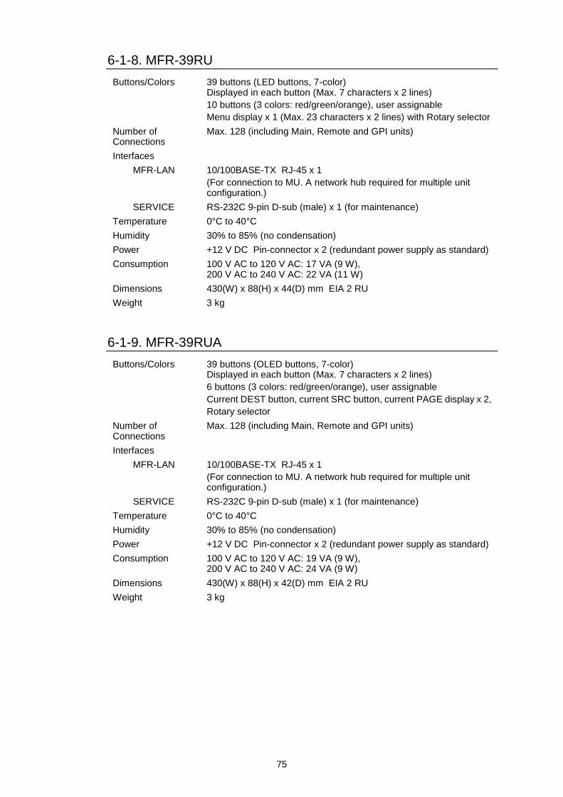
75
6-1-8. MFR-39RU
Buttons/Colors 39 buttons (LED buttons, 7-color) Displayed in each button (Max. 7 characters x 2 lines)
10 buttons (3 colors: red/green/orange), user assignable
Menu display x 1 (Max. 23 characters x 2 lines) with Rotary selector
Number of Connections
Max. 128 (including Main, Remote and GPI units)
Interfaces
MFR-LAN 10/100BASE-TX RJ-45 x 1
(For connection to MU. A network hub required for multiple unit configuration.)
SERVICE RS-232C 9-pin D-sub (male) x 1 (for maintenance)
Temperature 0°C to 40°C
Humidity 30% to 85% (no condensation)
Power +12 V DC Pin-connector x 2 (redundant power supply as standard)
Consumption 100 V AC to 120 V AC: 17 VA (9 W), 200 V AC to 240 V AC: 22 VA (11 W)
Dimensions 430(W) x 88(H) x 44(D) mm EIA 2 RU
Weight 3 kg
6-1-9. MFR-39RUA
Buttons/Colors 39 buttons (OLED buttons, 7-color) Displayed in each button (Max. 7 characters x 2 lines)
6 buttons (3 colors: red/green/orange), user assignable
Current DEST button, current SRC button, current PAGE display x 2,
Rotary selector
Number of Connections
Max. 128 (including Main, Remote and GPI units)
Interfaces
MFR-LAN 10/100BASE-TX RJ-45 x 1
(For connection to MU. A network hub required for multiple unit configuration.)
SERVICE RS-232C 9-pin D-sub (male) x 1 (for maintenance)
Temperature 0°C to 40°C
Humidity 30% to 85% (no condensation)
Power +12 V DC Pin-connector x 2 (redundant power supply as standard)
Consumption 100 V AC to 120 V AC: 19 VA (9 W), 200 V AC to 240 V AC: 24 VA (9 W)
Dimensions 430(W) x 88(H) x 42(D) mm EIA 2 RU
Weight 3 kg
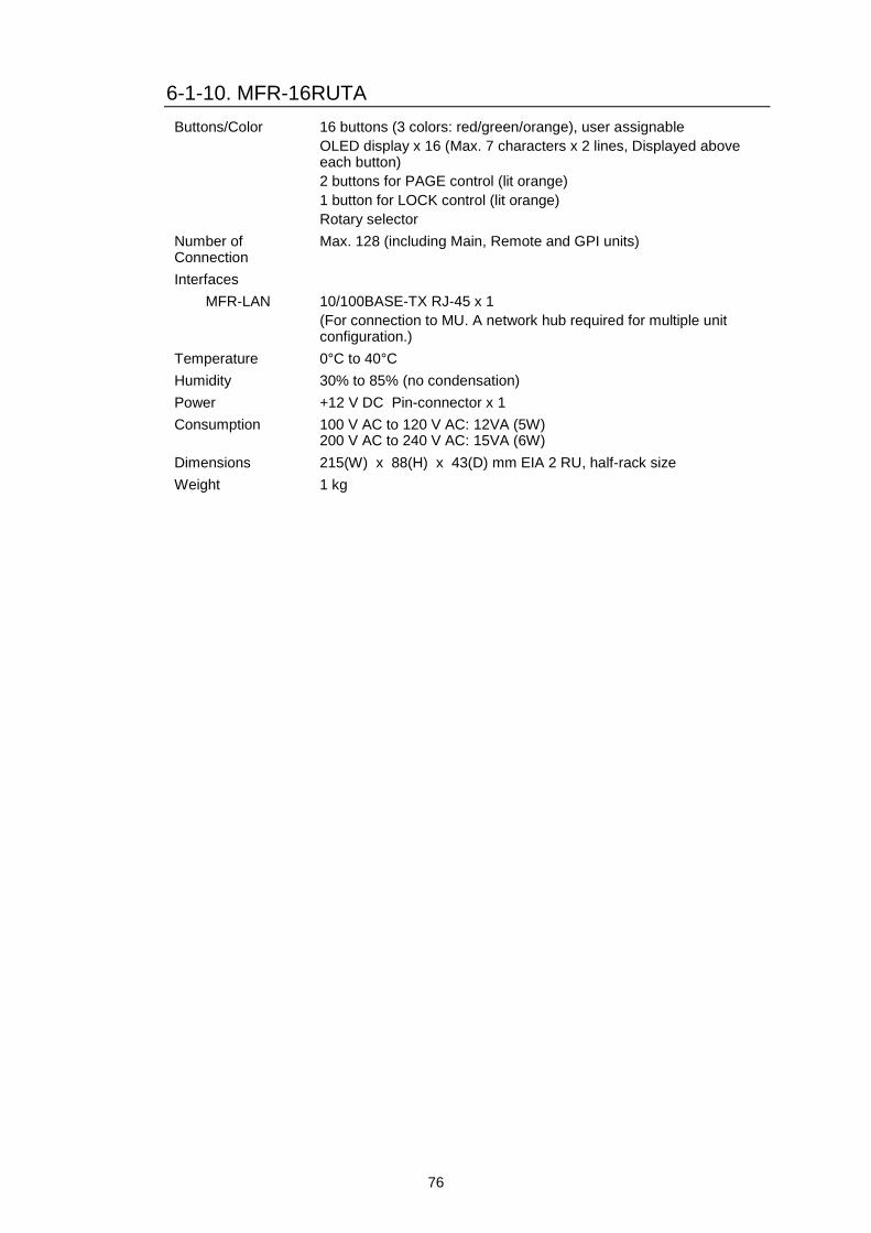
76
6-1-10. MFR-16RUTA
Buttons/Color 16 buttons (3 colors: red/green/orange), user assignable
OLED display x 16 (Max. 7 characters x 2 lines, Displayed above each button)
2 buttons for PAGE control (lit orange)
1 button for LOCK control (lit orange)
Rotary selector
Number of Connection
Max. 128 (including Main, Remote and GPI units)
Interfaces
MFR-LAN 10/100BASE-TX RJ-45 x 1
(For connection to MU. A network hub required for multiple unit configuration.)
Temperature 0°C to 40°C
Humidity 30% to 85% (no condensation)
Power +12 V DC Pin-connector x 1
Consumption 100 V AC to 120 V AC: 12VA (5W) 200 V AC to 240 V AC: 15VA (6W)
Dimensions 215(W) x 88(H) x 43(D) mm EIA 2 RU, half-rack size
Weight 1 kg
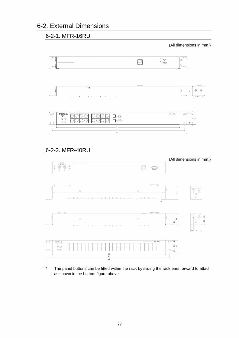
77
6-2. External Dimensions
6-2-1. MFR-16RU
(All dimensions in mm.)
PAG E A
(HOLD 3SEC)
PAG E B
LOCK RESET
POW ER
BUSY SETUP
LOC K D EST
(HOLD 3SEC)
LOC K PAN L
A B
430
462
480
44
32
66
6.4
REMOTE CONTROL UNIT
M FR-16RU
34
DC12V INMFR-LAN
6-2-2. MFR-40RU
(All dimensions in mm.)
480
462
430
44
632
6
42
2.3
122012
28
9
9
51
DC12V IN
21SERVICE
MFR-LAN
POWER
BUSY
LOCK
SETUP
RESET
REMOTE CONTROL UNIT MFR-40RU
* The panel buttons can be fitted within the rack by sliding the rack ears forward to attach
as shown in the bottom figure above.
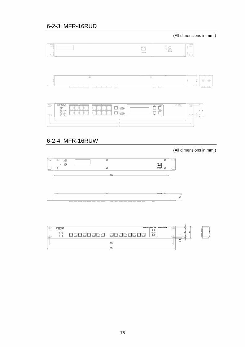
78
6-2-3. MFR-16RUD
(All dimensions in mm.)
PAGE A
(HOLD 3SEC)
PAGE B
LOCK RESET
POWER
BUSY SETUP
LOCK DEST
(HOLD 3SEC)
LOCK PANL
CANCEL
ENTER
A B
430
462
480
44
632
6
6.4
MFR-16RUDREMOTE CONTROL UNIT
DC12V INMFR-LAN
34
6-2-4. MFR-16RUW
(All dimensions in mm.)
462
480
32
44
66
6.4
429
27
POWER
BUSY SETUP
LOCK RESET
MFR-LAN
DC12V IN
MFR-16RUW
FUNCTION
1
2
REMOTE CONTROL UNIT
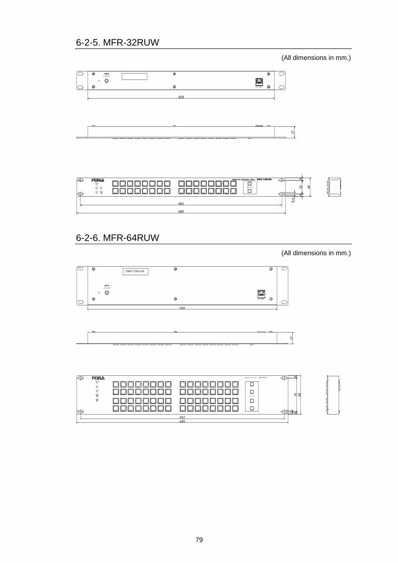
79
6-2-5. MFR-32RUW
(All dimensions in mm.)
POWER
BUSY SETUP
LOCK RESET
DC12V IN
462
480
32
44
66
6.4
429
27
MFR-LAN
FUNCTION
1
2
REMOTE CONTROL UNIT MFR-32RUW
6-2-6. MFR-64RUW
(All dimensions in mm.)
RATING LABEL
DC12V IN
MFR-LAN
27
MFR-64RUWREMOTE CO NTROL UNIT
1
2
1
2
88
76
6.4
66
POWER
BUSY
LOCK
SETUP
RESET
462
480
429
FUNCTION
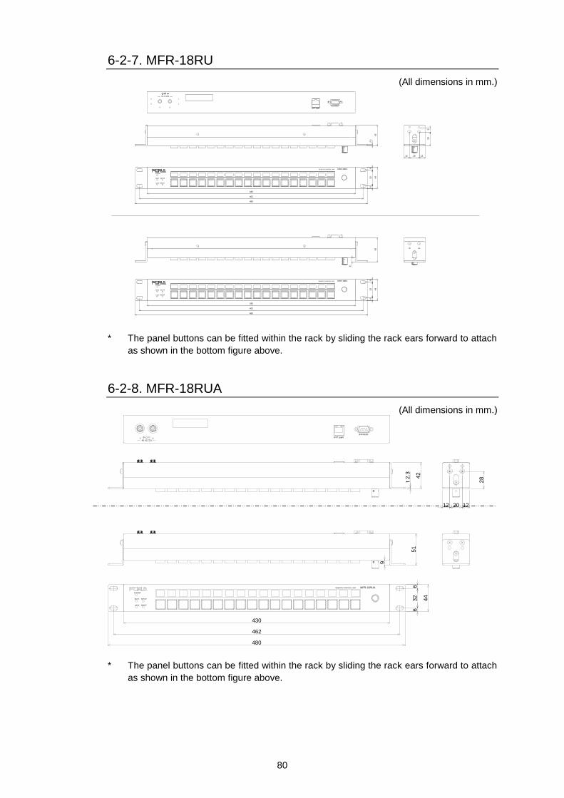
80
6-2-7. MFR-18RU
(All dimensions in mm.)
DC12V IN
21SERVICE
2.3
12 20 12
28
9
POWER
BUSY SETUP
LOCK RESET
430
462
480
MFR-18RUREMOTE CONTROL UNIT
63
26
44
POWER
BUSY SETUP
LOCK RESET
430
462
480
MFR-18RUREMOTE CONTROL UNIT
9
50
63
26
44
42
MFR-LAN
* The panel buttons can be fitted within the rack by sliding the rack ears forward to attach
as shown in the bottom figure above.
6-2-8. MFR-18RUA
(All dimensions in mm.)
POWER
BUSY SETUP
LOCK RESET
63
26
44
430
462
480
REMOTE CONTROL UNIT MFR-18RUA
DC12V IN21
SERVICE
MFR-LAN
42
28
12 20 12
t 2
.351
9
* The panel buttons can be fitted within the rack by sliding the rack ears forward to attach
as shown in the bottom figure above.

81
6-2-9. MFR-39RU
(All dimensions in mm.)
DC12V IN
21SERVICE
44
16 56 16
30
9
RESET
430
462
480
CANCEL
MFR-39RUREMOTE CONTROL UNIT
67
66
88
RESET
POWER
BUSY
LOCK
SETUP
POWER
BUSY
LOCK
SETUP
430
462
480
MFR-39RUREMOTE CONTROL UNIT
53
67
6
88
6
CANCEL
9
MFR-LAN
* The panel buttons can be fitted within the rack by sliding the rack ears forward to attach
as shown in the bottom figure above.
6-2-10. MFR-39RUA
(All dimensions in mm.)
POWER
BUSY
LOCK
SETUP
RESET
DEST SRC
A
B
C
D
PAGE
MFR-39RUAREMOTE COMTROL UNIT
430
462
480
676
6
88
SERVICE
MFR-LAN
DC12V IN21
42
16 56 16
28t 2
.3
9
51
* The panel buttons can be fitted within the rack by sliding the rack ears forward to attach
as shown in the bottom figure above.
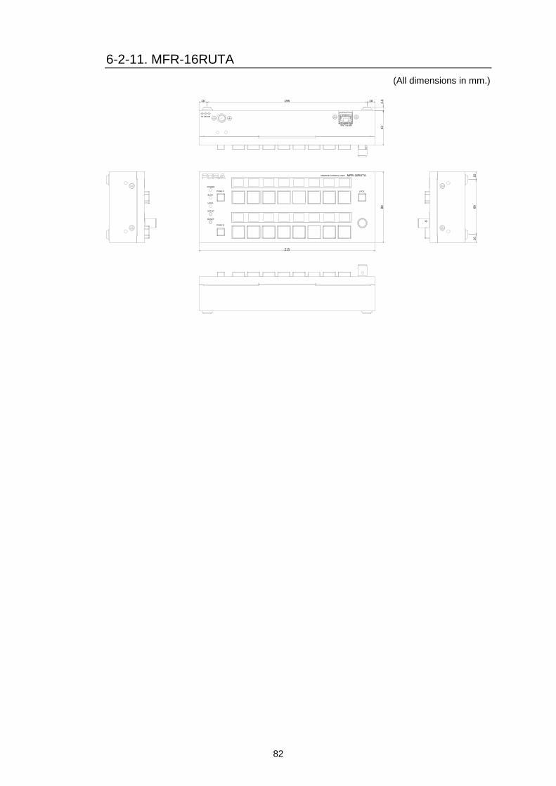
82
6-2-11. MFR-16RUTA
(All dimensions in mm.)
43
3.610 195 10
10
68
10
215
88
DC12V IN
MFR-LAN
MFR-16RUTAREMOTE CONTROL UNIT
LOCK
POWER
BUSY
PAGE A
LOCK
SETUP
RESET
PAGE B
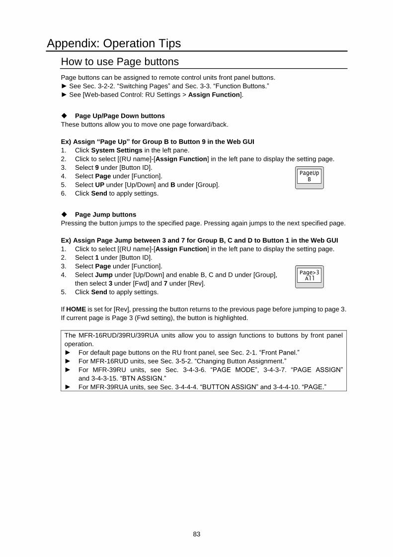
83
Appendix: Operation Tips
How to use Page buttons
Page buttons can be assigned to remote control units front panel buttons.
► See Sec. 3-2-2. “Switching Pages” and Sec. 3-3. “Function Buttons.”
► See [Web-based Control: RU Settings > Assign Function].
Page Up/Page Down buttons
These buttons allow you to move one page forward/back.
Ex) Assign “Page Up” for Group B to Button 9 in the Web GUI
1. Click System Settings in the left pane.
2. Click to select [(RU name]-[Assign Function] in the left pane to display the setting page.
3. Select 9 under [Button ID].
4. Select Page under [Function].
5. Select UP under [Up/Down] and B under [Group].
6. Click Send to apply settings.
Page Jump buttons
Pressing the button jumps to the specified page. Pressing again jumps to the next specified page.
Ex) Assign Page Jump between 3 and 7 for Group B, C and D to Button 1 in the Web GUI
1. Click to select [(RU name]-[Assign Function] in the left pane to display the setting page.
2. Select 1 under [Button ID].
3. Select Page under [Function].
4. Select Jump under [Up/Down] and enable B, C and D under [Group],
then select 3 under [Fwd] and 7 under [Rev].
5. Click Send to apply settings.
If HOME is set for [Rev], pressing the button returns to the previous page before jumping to page 3.
If current page is Page 3 (Fwd setting), the button is highlighted.
The MFR-16RUD/39RU/39RUA units allow you to assign functions to buttons by front panel
operation.
► For default page buttons on the RU front panel, see Sec. 2-1. “Front Panel.”
► For MFR-16RUD units, see Sec. 3-5-2. “Changing Button Assignment.”
► For MFR-39RU units, see Sec. 3-4-3-6. “PAGE MODE”, 3-4-3-7. “PAGE ASSIGN”
and 3-4-3-15. “BTN ASSIGN.”
► For MFR-39RUA units, see Sec. 3-4-4-4. “BUTTON ASSIGN” and 3-4-4-10. “PAGE.”