Embed Size (px)
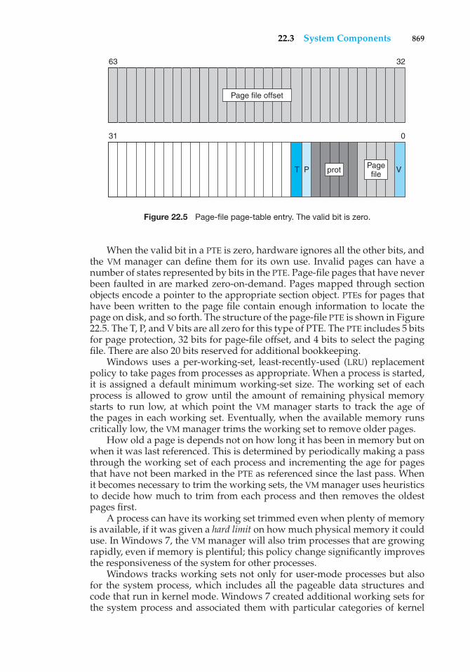
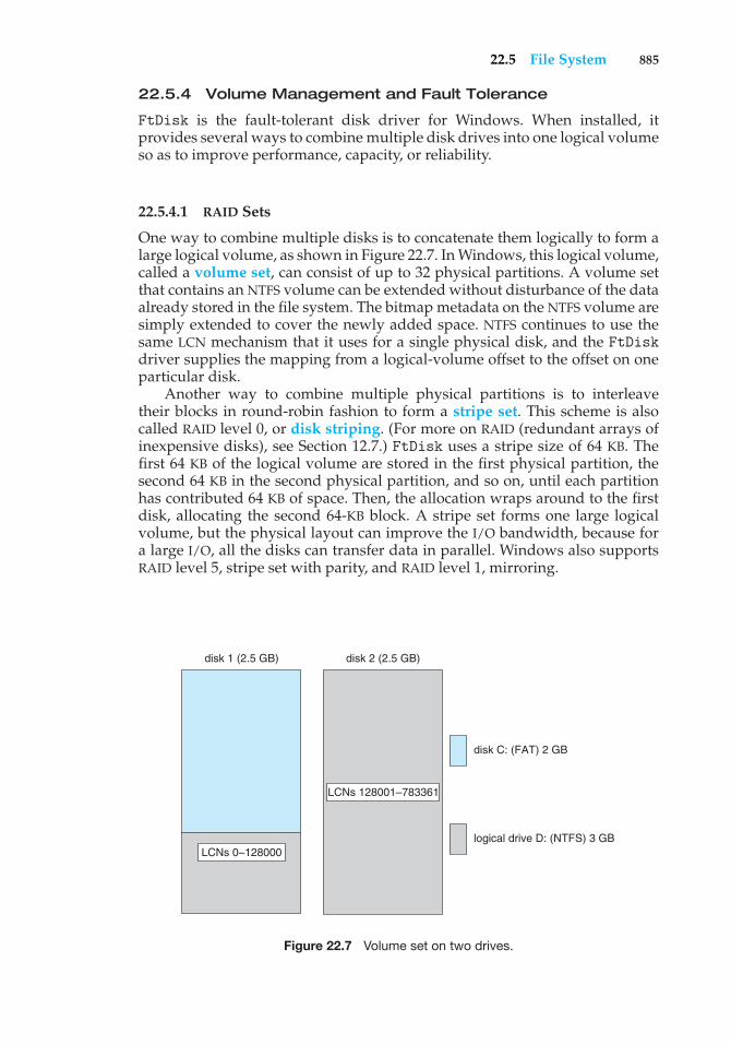
Citation preview

This page intentionally left blank
The integrated, online text offers students a low-cost alternative to the printed text, enhanced with direct links to specific portions of the text, plus interactive animations and videos to help students visualize concepts.
Select WileyPLUS courses include LabRat, the programming assignment tool allows you to choose from hundreds of programming exercises to automate the process of assigning, completing, compiling, testing, submitting, and evaluating programming assignments. When students spend more time practicing, they come to class better prepared.
See—and Try WileyPLUS in action! Details and Demo: www.wileyplus.com
Try WileyPLUS with LabRat: www.wileyplus.com/tours
Why WileyPLUS for Computer Science?
W ileyPLUS for Computer Science is a dynamic online environment that motivates students to spend more time practicing the problems and explore the material they need to master
in order to succeed.
Why WileyPLUS for Computer Science?
“I used the homework problems to practice before quizzes and tests. I re-did
the problems on my own and then checked WileyPLUS to compare answers.”
— Student Alexandra Leifer, Ithaca College
Students easily access source code for example problems, as well as self-study materials and all the exercises and readings you assign.
All instructional materials, including PowerPoints, illustrations and visual tools, source code, exercises, solutions and gradebook organized in one easy-to-use system.
WileyPLUS combines robust course management tools with the complete online text and all of the interactive teaching & learning resources you and your students need in one easy-to-use system.
“Overall the WileyPLUS package made the
material more interesting than if it was just a book with
no additional material other than what you need to know.”
— Edin Alic, North Dakota State University
“WileyPLUS made it a lot easier to study. I got an A!”
— Student Jeremiah Ellis Mattson, North Dakota State University
ASSOCIATE PUBLISHER Dan Sayre
EXECUTIVE EDITOR Beth Lang Golub
EDITORIAL ASSISTANT Carolyn Weisman
SENIOR PRODUCTION EDITOR Ken Santor/John Curley
COVER DESIGNER Howard Grossman
COVER ILLUSTRATIONS Susan Cyr
TEXT DESIGNER Judy Allan
This book was set in Palatino by the author using LaTeX and printed and bound by R.R. Donnelley/Jefferson City. The cover was printed by R.R. Donnelley/Jefferson City
This book is printed on acid free paper. �
Copyright © 2009, 2012 John Wiley & Sons, Inc. All rights reserved.
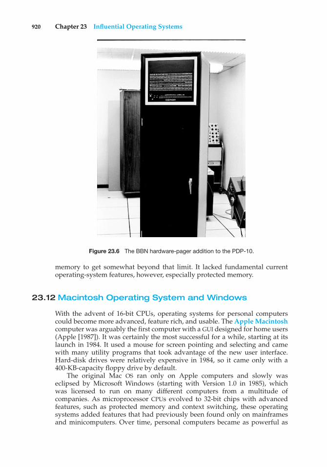
Credits: Figure 1.11: From Hennesy and Patterson, Computer Architecture: A Quantitative Approach,Third Edition, 2002, © Morgan Kaufmann Publishers, Figure 5.3, p. 394. Reprinted with permissionof the publisher. Figure 5.13: adapted with permission from Sun Microsystems, Inc. Figure 9.18:From IBM Systems Journal, Vol. 10, No. 3, © 1971, International Business Machines Corporation.Reprinted by permission of IBM Corporation.Figure 11.9: From Leffler/McKusick/Karels/Quarterman, The Design and Implementation of the4.3BSD UNIX Operating System, © 1989 by Addison-Wesley Publishing Co., Inc., Reading, MA.Figure 7.6, p. 196. Reprinted with permission of the publisher. Figure 13.4: From PentiumProcessor User’s Manual: Architecture and Programming Manual, Volume 3, © 1993. Reprinted bypermission of Intel Corporation. Figures 16.6, 16.7, and 16.9: From Halsall, Data Communications,Computer Networks, and Open Systems, Third Edition, © 1992, Addison-Wesley Publishing Co.,Inc., Reading, MA. Figure 1.9, p. 14, Figure 1.10, p. 15, and Figure 1.11, p. 18. Reprinted withpermission of the publisher. Figure 19.5: From Khanna/Sebree/Zolnowsky, “Realtime Schedulingin SunOS 5.0,” Proceedings of Winter USENIX, January 1992, San Francisco, CA. Derived withpermission of the authors.Figure 23.6: Dan Murphy (http://tenex.opost.com/kapix.html). Sections of Chapter 6 andChapter 18: From Silberschatz/Korth, Database System Concepts, Third Edition, © 1997, McGraw-Hill, Inc., New York, NY. Section 13.5, p. 451-454, 14.1.1, p. 471-742, 14.1.3, p. 476-479,14.2, p. 482-485, 15.2.1, p. 512-513, 15.4, p. 517-518, 15.4.3, p. 523-524, 18.7, p. 613-617, 18.8, p. 617-622. Reprinted with permission of the publisher.
No part of this publication may be reproduced, stored in a retrieval system or transmitted in any form or by any means, electronic, mechanical, photocopying, recording, scanning or otherwise, except as permitted under Sections 107 or 108 of the 1976 United StatesCopyright Act, without either the prior written permission of the Publisher, or authorizationthrough payment of the appropriate per-copy fee to the Copyright Clearance Center, Inc. 222 Rosewood Drive, Danvers, MA 01923, (978)750-8400, fax (978)750-4470. Requests to thePublisher for permission should be addressed to the Permissions Department, John Wiley & Sons, Inc., 111 River Street, Hoboken, NJ 07030 (201)748-6011, fax (201)748-6008, E-Mail:[email protected] order books or for customer service call 1-800-CALL WILEY (225-5945).
ISBN: 978-1-118-11273-1
Printed in the United States of America
10 9 8 7 6 5 4 3 2 1
To my children, Lemor, Sivan, and Aaronand my Nicolette
Avi Silberschatz
To my wife, Carla,and my children, Gwen, Owen, and Maddie
Peter Baer Galvin
To my wife, Pat,and our sons, Tom and Jay
Greg Gagne
Abraham Silberschatz is the Sidney J. Weinberg Professor & Chair of Com-puter Science at Yale University. Prior to joining Yale, he was the Vice Presidentof the Information Sciences Research Center at Bell Laboratories. Prior to that,he held a chaired professorship in the Department of Computer Sciences at theUniversity of Texas at Austin.
Professor Silberschatz is an ACM Fellow and an IEEE Fellow. He receivedthe 2002 IEEE Taylor L. Booth Education Award, the 1998 ACM Karl V. Karl-strom Outstanding Educator Award, and the 1997 ACM SIGMOD ContributionAward. In recognition of his outstanding level of innovation and technicalexcellence, he was awarded the Bell Laboratories President’s Award for threedifferent projects—the QTM Project (1998), the DataBlitz Project (1999), andthe NetInventory Project (2004).
Professor Silberschatz’ writings have appeared in numerous ACM andIEEE publications and other professional conferences and journals. He is acoauthor of the textbook Database System Concepts. He has also written Op-Edarticles for the New York Times, the Boston Globe, and the Hartford Courant,among others.
Peter Baer Galvin is the chief technologist for Corporate Technologies(www.cptech.com), a computer facility reseller and integrator. Before that, Mr.Galvin was the systems manager for Brown University’s Computer ScienceDepartment. He is also Sun columnist for ;login: magazine. Mr. Galvin haswritten articles for Byte and other magazines, and has written columns forSunWorld and SysAdmin magazines. As a consultant and trainer, he has giventalks and taught tutorials on security and system administration worldwide.
Greg Gagne is chair of the Computer Science department at WestminsterCollege in Salt Lake City where he has been teaching since 1990. In additionto teaching operating systems, he also teaches computer networks, distributedsystems, and software engineering. He also provides workshops to computerscience educators and industry professionals.
Preface
Operating systems are an essential part of any computer system. Similarly,a course on operating systems is an essential part of any computer-scienceeducation. This field is undergoing rapid change, as computers are nowprevalent in virtually every application, from games for children through themost sophisticated planning tools for governments and multinational firms.Yet the fundamental concepts remain fairly clear, and it is on these that we basethis book.
We wrote this book as a text for an introductory course in operating systemsat the junior or senior undergraduate level or at the first-year graduate level.We hope that practitioners will also find it useful. It provides a clear descriptionof the concepts that underlie operating systems. As prerequisites, we assumethat the reader is familiar with basic data structures, computer organization,and a high-level language, such as C or Java. The hardware topics requiredfor an understanding of operating systems are included in Chapter 1. For codeexamples, we use predominantly C, with some Java, but the reader can stillunderstand the algorithms without a thorough knowledge of these languages.
Concepts are presented using intuitive descriptions. Important theoreticalresults are covered, but formal proofs are omitted. The bibliographical notesat the end of each chapter contain pointers to research papers in which resultswere first presented and proved, as well as references to material for furtherreading. In place of proofs, figures and examples are used to suggest why weshould expect the result in question to be true.
The fundamental concepts and algorithms covered in the book are oftenbased on those used in existing commercial operating systems. Our aimis to present these concepts and algorithms in a general setting that isnot tied to one particular operating system. We present a large number ofexamples that pertain to the most popular and the most innovative operatingsystems, including Sun Microsystems’ Solaris; Linux; Microsoft WindowsVista, Windows 2000, Windows XP, and Windows 7; and Apple Mac OS X.When we refer to Windows 7 as an example operating system, we are implyingWindows Vista, Windows 2000, Windows XP, and WinSEVEN. If a feature existsin a specific release, we state this explicitly.
vii
viii Preface
Organization of This Book
The organization of this text reflects our many years of teaching courses onoperating systems. Consideration was also given to the feedback provided bythe reviewers of the text, as well as comments submitted by readers of earliereditions. In addition, the content of the text corresponds to the suggestionsfrom Computing Curricula 2005 for teaching operating systems, published bythe Joint Task Force of the IEEE Computing Society and the Association forComputing Machinery (ACM).
On the supporting Web site for this text, we provide several samplesyllabi that suggest various approaches for using the text in both introductoryand advanced courses. As a general rule, we encourage readers to progresssequentially through the chapters, as this strategy provides the most thoroughstudy of operating systems. However, by using the sample syllabi, a reader canselect a different ordering of chapters (or subsections of chapters).
On-line support for the text is provided by WileyPLUS. On this site, studentscan find sample exercises and programming problems, and instructors canassign and grade problems. In addition, in WileyPLUS, students can access newoperating-system simulators, which are used to work through exercises andhands-on lab activities. References to the simulators and associated activitiesappear at the ends of several chapters in the text.
Content of This Book
The text is organized in eight major parts:
• Overview. Chapters 1 and 2 explain what operating systems are, what theydo, and how they are designed and constructed. These chapters discuss whatthe common features of an operating system are, what an operating systemdoes for the user, and what it does for the computer-system operator. Thepresentation is motivational and explanatory in nature. We have avoided adiscussion of how things are done internally in these chapters. Therefore,they are suitable for individual readers or for students in lower-level classeswho want to learn what an operating system is without getting into thedetails of the internal algorithms.
• Process management. Chapters 3 through 7 describe the process conceptand concurrency as the heart of modern operating systems. A processis the unit of work in a system. Such a system consists of a collectionof concurrently executing processes, some of which are operating-systemprocesses (those that execute system code) and the rest of which are userprocesses (those that execute user code). These chapters cover methods forprocess scheduling, interprocess communication, process synchronization,and deadlock handling. Also included is a discussion of threads, as wellas an examination of issues related to multicore systems.
• Memory management. Chapters 8 and 9 deal with the management ofmain memory during the execution of a process. To improve both theutilization of the CPU and the speed of its response to its users, thecomputer must keep several processes in memory. There are many differentmemory-management schemes, reflecting various approaches to memory
Preface ix
management, and the effectiveness of a particular algorithm depends onthe situation.
• Storage management. Chapters 10 through 13 describe how the file system,mass storage, and I/O are handled in a modern computer system. Thefile system provides the mechanism for on-line storage of and accessto both data and programs. We describe the classic internal algorithmsand structures of storage management and provide a firm practicalunderstanding of the algorithms used—their properties, advantages, anddisadvantages. Our discussion of storage also includes matters relatedto secondary and tertiary storage. Since the I/O devices that attach to acomputer vary widely, the operating system needs to provide a wide rangeof functionality to applications to allow them to control all aspects of thesedevices. We discuss system I/O in depth, including I/O system design,interfaces, and internal system structures and functions. In many ways,I/O devices are the slowest major components of the computer. Becausethey represent a performance bottleneck, we also examine performanceissues associated with I/O devices.
• Protection and security. Chapters 14 and 15 discuss the mechanismsnecessary for the protection and security of computer systems. Theprocesses in an operating system must be protected from one another’sactivities, and to provide such protection, we must ensure that onlyprocesses that have gained proper authorization from the operating systemcan operate on the files, memory, CPU, and other resources of the system.Protection is a mechanism for controlling the access of programs, processes,or users to the resources defined by a computer system. This mechanismmust provide a means of specifying the controls to be imposed, aswell as a means of enforcement. Security protects the integrity of theinformation stored in the system (both data and code), as well as thephysical resources of the system, from unauthorized access, maliciousdestruction or alteration, and accidental introduction of inconsistency.
• Distributed systems. Chapters 16 through 18 deal with a collection ofprocessors that do not share memory or a clock—a distributed system. Byproviding the user with access to the various resources that it maintains, adistributed system can improve computation speed and data availabilityand reliability. Such a system also provides the user with a distributed filesystem, which is a file-service system whose users, servers, and storagedevices are dispersed among the sites of a distributed system. A distributedsystem must provide various mechanisms for process synchronizationand communication, as well as for dealing with deadlock problems and avariety of failures that are not encountered in a centralized system.
• Special-purpose systems. Chapters 19 and 20 deal with systems used forspecific purposes, including real-time systems and multimedia systems.These systems have specific requirements that differ from those of thegeneral-purpose systems that are the focus of the remainder of the text.Real-time systems may require not only that computed results be “correct”but also that the results be produced within a specified deadline period.Multimedia systems require quality-of-service guarantees ensuring thatthe multimedia data are delivered to clients within a specific time frame.
x Preface
• Case studies. Chapters 21 through 23 in the book, and Appendices Athrough C (which are available on www.wiley.com/college/silberschatzand in WileyPLUS), integrate the concepts described in the earlier chaptersby describing real operating systems. These systems include Linux, Win-dows XP, FreeBSD, Mach, and Windows 2000. We chose Linux and FreeBSDbecause UNIX—at one time—was almost small enough to understand yetwas not a “toy” operating system. Most of its internal algorithms wereselected for simplicity, rather than for speed or sophistication. Both Linuxand FreeBSD are readily available to computer-science departments, somany students have access to these systems. We chose Windows XP andWindows 2000 because they provide an opportunity for us to study amodern operating system with a design and implementation drasticallydifferent from those of UNIX. Chapter 23 briefly describes a few otherinfluential operating systems.
Operating-System Environments
This book uses examples of many real-world operating systems to illustratefundamental operating-system concepts. However, particular attention is paidto the Microsoft family of operating systems (including Windows Vista,Windows 2000, Windows XP, and WinSEVEN) and various versions of UNIX(including Solaris, BSD, and Mac OS X). We also provide a significant amountof coverage of the Linux operating system reflecting the most recent version ofthe kernel—Version 2.6—at the time this book was written.
The text also provides several example programs written in C andJava. These programs are intended to run in the following programmingenvironments:
• Windows systems. The primary programming environment for Windowssystems is the Win32 API (application programming interface), which pro-vides a comprehensive set of functions for managing processes, threads,memory, and peripheral devices. We provide several C programs illustrat-ing the use of the Win32 API. Example programs were tested on systemsrunning Windows Vista, Windows 2000, Windows XP, and Windows 7.
• POSIX. POSIX (which stands for Portable Operating System Interface) repre-sents a set of standards implemented primarily for UNIX-based operatingsystems. Although Windows Vista, Windows NT, Windows XP, and Win-dows 7 systems can also run certain POSIX programs, our coverage of POSIXfocuses primarily on UNIX and Linux systems. POSIX-compliant systemsmust implement the POSIX core standard (POSIX.1): Linux, Solaris, and MacOS X are examples of POSIX-compliant systems. POSIX also defines severalextensions to the standards, including real-time extensions (POSIX1.b) andan extension for a threads library (POSIX1.c, better known as Pthreads). Weprovide several programming examples written in C illustrating the POSIXbase API, as well as Pthreads and the extensions for real-time programming.These example programs were tested on Debian Linux 2.4 and 2.6 systems,Mac OS X 10.5, and Solaris 10 using the gcc 3.3 and 4.0 compilers.
• Java. Java is a widely used programming language with a rich API andbuilt-in language support for thread creation and management. Java
Preface xi
programs run on any operating system supporting a Java virtual machine(or JVM). We illustrate various operating system and networking conceptswith several Java programs tested using the Java 1.5 JVM.
We have chosen these three programming environments because it is ouropinion that they best represent the two most popular models of operatingsystems: Windows and UNIX/Linux, along with the widely used Java environ-ment. Most programming examples are written in C, and we expect readers tobe comfortable with this language; readers familiar with both the C and Javalanguages should easily understand most programs provided in this text.
In some instances—such as thread creation—we illustrate a specificconcept using all three programming environments, allowing the readerto contrast the three different libraries as they address the same task. Inother situations, we may use just one of the APIs to demonstrate a concept.For example, we illustrate shared memory using just the POSIX API; socketprogramming in TCP/IP is highlighted using the Java API.
The Eighth Edition
As we wrote the Eighth Edition of Operating System Concepts, we were guidedby the many comments and suggestions we received from readers of ourprevious editions, as well as by our own observations about the rapidlychanging fields of operating systems and networking. We have rewrittenmaterial in most of the chapters by bringing older material up to date andremoving material that was no longer of interest or relevance.
We have made substantive revisions and organizational changes in manyof the chapters. Most importantly, we have added coverage of open-sourceoperating systems in Chapter 1. We have also added more practice exercisesfor students and included solutions in WileyPLUS, which also includes newsimulators to provide demonstrations of operating-system operation. Below,we provide a brief outline of the major changes to the various chapters:
• Chapter 1, Introduction, has been expanded to include multicore CPUs,clustered computers, and open-source operating systems.
• Chapter 2, Operating-System Structures, provides significantly updatedcoverage of virtual machines, as well as multicore CPUs, the GRUB bootloader, and operating-system debugging.
• Chapter 3, Processes, provides new coverage of pipes as a form ofinterprocess communication.
• Chapter 4, Threads, adds new coverage of programming for multicoresystems.
• Chapter 5, CPU Scheduling, adds coverage of virtual machine schedulingand multithreaded, multicore architectures.
• Chapter 6, Process Synchronization, adds a discussion of mutual exclu-sion locks, priority inversion, and transactional memory.
• Chapter 8, Main Memory, includes discussion of NUMA.
xii Preface
• Chapter 9, Virtual Memory, updates the Solaris example to include Solaris10 memory management.
• Chapter 10, File-System Interface, is updated with current technologiesand capacities.
• Chapter 11, File-System Implementation, includes a full description ofSun’s ZFS file system and expands the coverage of volumes and directories.
• Chapter 12, Mass-Storage Structure, adds coverage of iSCSI, volumes, andZFS pools.
• Chapter 13, I/O Systems, adds coverage of PCIX PCI Express, and Hyper-Transport.
• Chapter 16, Distributed System Structures, adds coverage of 802.11wireless networks.
• Chapter 21, The Linux System, has been updated to cover the latest versionof the Linux kernel.
• Chapter 23, Influential Operating Systems, increases coverage of veryearly computers as well as TOPS-20, CP/M, MS-DOS, Windows, and theoriginal Mac OS.
Programming Problems and Projects
To emphasize the concepts presented in the text, we have added severalprogramming problems and projects that use the POSIX and Win32 APIs, aswell as Java. We have added more than 15 new programming problems, whichemphasize processes, threads, shared memory, process synchronization, andnetworking. In addition, we have added or modified several programmingprojects that are more involved than standard programming exercises. Theseprojects include adding a system call to the Linux kernel, using pipes onboth UNIX and Windows systems, using UNIX message queues, creatingmultithreaded applications, and solving the producer–consumer problemusing shared memory.
The Eighth Edition also incorporates a set of operating-system simulatorsdesigned by Steven Robbins of the University of Texas at San Antonio. Thesimulators are intended to model the behavior of an operating system as itperforms various tasks, such as CPU and disk-head scheduling, process creationand interprocess communication, starvation, and address translation. Thesesimulators are written in Java and will run on any computer system withJava 1.4. Students can download the simulators from WileyPLUS and observethe behavior of several operating system concepts in various scenarios. Inaddition, each simulator includes several exercises that ask students to setcertain parameters of the simulator, observe how the system behaves, and thenexplain this behavior. These exercises can be assigned through WileyPLUS. TheWileyPLUS course also includes algorithmic problems and tutorials developedby Scott M. Pike of Texas A&M University.
Preface xiii
Teaching Supplements
The following teaching supplements are available in WileyPLUS and onwww.wiley.com/college/silberschatz: a set of slides to accompany the book,model course syllabi, all C and Java source code, up-to-date errata, threecase study appendices and the Distributed Communication appendix. TheWileyPLUS course also contains the simulators and associated exercises, addi-tional practice exercises (with solutions) not found in the text, and a testbankof additional problems. Students are encouraged to solve the practice exerciseson their own and then use the provided solutions to check their own answers.
To obtain restricted supplements, such as the solution guide to the exercisesin the text, contact your local John Wiley & Sons sales representative. Note thatthese supplements are available only to faculty who use this text. You can findyour Wiley representative by going to www.wiley.com/college and clicking“Who’s my rep?”
Mailing List
We use the mailman system for communication among the users of OperatingSystem Concepts. If you wish to use this facility, please visit the following URLand follow the instructions there to subscribe:
http://mailman.cs.yale.edu/mailman/listinfo/os-bookThe mailman mailing-list system provides many benefits, such as an archiveof postings, as well as several subscription options, including digest and Webonly. To send messages to the list, send e-mail to:
[email protected] on the message, we will either reply to you personally or forwardthe message to everyone on the mailing list. The list is moderated, so you willreceive no inappropriate mail.
Students who are using this book as a text for class should not use the listto ask for answers to the exercises. They will not be provided.
Suggestions
We have attempted to clean up every error in this new edition, but—ashappens with operating systems—a few obscure bugs may remain. We wouldappreciate hearing from you about any textual errors or omissions that youidentify.
If you would like to suggest improvements or to contribute exercises,we would also be glad to hear from you. Please send correspondence [email protected].
Acknowledgments
This book is derived from the previous editions, the first three of whichwere coauthored by James Peterson. Others who helped us with previous
xiv Preface
editions include Hamid Arabnia, Rida Bazzi, Randy Bentson, David Black,Joseph Boykin, Jeff Brumfield, Gael Buckley, Roy Campbell, P. C. Capon, JohnCarpenter, Gil Carrick, Thomas Casavant, Bart Childs, Ajoy Kumar Datta,Joe Deck, Sudarshan K. Dhall, Thomas Doeppner, Caleb Drake, M. RacsitEskicioglu, Hans Flack, Robert Fowler, G. Scott Graham, Richard Guy, MaxHailperin, Rebecca Hartman, Wayne Hathaway, Christopher Haynes, DonHeller, Bruce Hillyer, Mark Holliday, Dean Hougen, Michael Huangs, AhmedKamel, Morty Kewstel, Richard Kieburtz, Carol Kroll, Morty Kwestel, ThomasLeBlanc, John Leggett, Jerrold Leichter, Ted Leung, Gary Lippman, CarolynMiller, Michael Molloy, Euripides Montagne, Yoichi Muraoka, Jim M. Ng,Banu Ozden, Ed Posnak, Boris Putanec, Charles Qualline, John Quarterman,Mike Reiter, Gustavo Rodriguez-Rivera, Carolyn J. C. Schauble, Thomas P.Skinner, Yannis Smaragdakis, Jesse St. Laurent, John Stankovic, Adam Stauffer,Steven Stepanek, John Sterling, Hal Stern, Louis Stevens, Pete Thomas, DavidUmbaugh, Steve Vinoski, Tommy Wagner, Larry L. Wear, John Werth, JamesM. Westall, J. S. Weston, and Yang Xiang
Parts of Chapter 12 were derived from a paper by Hillyer and Silberschatz[1996]. Parts of Chapter 17 were derived from a paper by Levy and Silberschatz[1990]. Chapter 21 was derived from an unpublished manuscript by StephenTweedie. Chapter 22 was derived from an unpublished manuscript by DaveProbert, Cliff Martin, and Avi Silberschatz. Appendix C was derived froman unpublished manuscript by Cliff Martin. Cliff Martin also helped withupdating the UNIX appendix to cover FreeBSD. Some of the exercises andaccompanying solutions were supplied by Arvind Krishnamurthy.
Mike Shapiro, Bryan Cantrill, and Jim Mauro answered several Solaris-related questions. Bryan Cantrill from Sun Microsystems helped with the ZFScoverage. Steve Robbins of the University of Texas at San Antonio designedthe set of simulators that we incorporate in WileyPLUS. Reece Newmanof Westminster College initially explored this set of simulators and theirappropriateness for this text. Josh Dees and Rob Reynolds contributed coverageof Microsoft’s .NET. The project for POSIX message queues was contributed byJohn Trono of Saint Michael’s College in Colchester, Vermont.
Marilyn Turnamian helped generate figures and presentation slides. MarkWogahn has made sure that the software to produce the book (e.g., Latexmacros, fonts) works properly.
Our Associate Publisher, Dan Sayre, provided expert guidance as weprepared this edition. He was assisted by Carolyn Weisman, who managedmany details of this project smoothly. The Senior Production Editor KenSantor, was instrumental in handling all the production details. Lauren Sapiraand Cindy Johnston have been very helpful with getting material ready andavailable for WileyPlus.
The cover illustrator was Susan Cyr, and the cover designer was HowardGrossman. Beverly Peavler copy-edited the manuscript. The freelance proof-reader was Katrina Avery; the freelance indexer was WordCo, Inc.
Abraham Silberschatz, New Haven, CT, 2008Peter Baer Galvin, Burlington, MA, 2008Greg Gagne, Salt Lake City, UT, 2008
Contents
PART ONE OVERVIEW
Chapter 1 Introduction1.1 What Operating Systems Do 31.2 Computer-System Organization 61.3 Computer-System Architecture 121.4 Operating-System Structure 181.5 Operating-System Operations 201.6 Process Management 231.7 Memory Management 241.8 Storage Management 25
1.9 Protection and Security 291.10 Distributed Systems 301.11 Special-Purpose Systems 321.12 Computing Environments 341.13 Open-Source Operating Systems 371.14 Summary 40
Exercises 42Bibliographical Notes 46
Chapter 2 Operating-System Structures2.1 Operating-System Services 492.2 User Operating-System Interface 522.3 System Calls 552.4 Types of System Calls 582.5 System Programs 662.6 Operating-System Design and
Implementation 682.7 Operating-System Structure 70
2.8 Virtual Machines 762.9 Operating-System Debugging 84
2.10 Operating-System Generation 882.11 System Boot 892.12 Summary 90
Exercises 91Bibliographical Notes 98
PART TWO PROCESS MANAGEMENT
Chapter 3 Processes3.1 Process Concept 1013.2 Process Scheduling 1053.3 Operations on Processes 1103.4 Interprocess Communication 1163.5 Examples of IPC Systems 123
3.6 Communication in Client–Server Systems 128
3.7 Summary 140Exercises 141Bibliographical Notes 152
xv
xvi Contents
Chapter 4 Threads4.1 Overview 1534.2 Multithreading Models 1574.3 Thread Libraries 1594.4 Threading Issues 165
4.5 Operating-System Examples 1714.6 Summary 174
Exercises 174Bibliographical Notes 182
Chapter 5 CPU Scheduling5.1 Basic Concepts 1835.2 Scheduling Criteria 1875.3 Scheduling Algorithms 1885.4 Thread Scheduling 1995.5 Multiple-Processor Scheduling 200
5.6 Operating System Examples 2065.7 Algorithm Evaluation 2135.8 Summary 217
Exercises 218Bibliographical Notes 223
Chapter 6 Process Synchronization6.1 Background 2256.2 The Critical-Section Problem 2276.3 Peterson’s Solution 2296.4 Synchronization Hardware 2316.5 Semaphores 2346.6 Classic Problems of
Synchronization 239
6.7 Monitors 2446.8 Synchronization Examples 2526.9 Atomic Transactions 257
6.10 Summary 267Exercises 267Bibliographical Notes 280
Chapter 7 Deadlocks7.1 System Model 2837.2 Deadlock Characterization 2857.3 Methods for Handling Deadlocks 2907.4 Deadlock Prevention 2917.5 Deadlock Avoidance 294
7.6 Deadlock Detection 3017.7 Recovery from Deadlock 3047.8 Summary 306
Exercises 307Bibliographical Notes 311
PART THREE MEMORY MANAGEMENT
Chapter 8 Main Memory8.1 Background 3158.2 Swapping 3228.3 Contiguous Memory Allocation 3248.4 Paging 3288.5 Structure of the Page Table 337
8.6 Segmentation 3428.7 Example: The Intel Pentium 3458.8 Summary 349
Exercises 350Bibliographical Notes 354
Contents xvii
Chapter 9 Virtual Memory9.1 Background 3579.2 Demand Paging 3619.3 Copy-on-Write 3679.4 Page Replacement 3699.5 Allocation of Frames 3829.6 Thrashing 3869.7 Memory-Mapped Files 390
9.8 Allocating Kernel Memory 3969.9 Other Considerations 399
9.10 Operating-System Examples 4059.11 Summary 407
Exercises 409Bibliographical Notes 417
PART FOUR STORAGE MANAGEMENT
Chapter 10 File-System Interface10.1 File Concept 42110.2 Access Methods 43010.3 Directory and Disk Structure 43310.4 File-System Mounting 44410.5 File Sharing 446
10.6 Protection 45110.7 Summary 456
Exercises 457Bibliographical Notes 459
Chapter 11 File-System Implementation11.1 File-System Structure 46111.2 File-System Implementation 46411.3 Directory Implementation 47011.4 Allocation Methods 47111.5 Free-Space Management 47911.6 Efficiency and Performance 482
11.7 Recovery 48611.8 NFS 49011.9 Example: The WAFL File System 496
11.10 Summary 498Exercises 499Bibliographical Notes 502
Chapter 12 Mass-Storage Structure12.1 Overview of Mass-Storage
Structure 50512.2 Disk Structure 50812.3 Disk Attachment 50912.4 Disk Scheduling 51012.5 Disk Management 51612.6 Swap-Space Management 520
12.7 RAID Structure 52212.8 Stable-Storage Implementation 53312.9 Tertiary-Storage Structure 534
12.10 Summary 543Exercises 545Bibliographical Notes 552
Chapter 13 I/O Systems13.1 Overview 55513.2 I/O Hardware 55613.3 Application I/O Interface 56513.4 Kernel I/O Subsystem 57113.5 Transforming I/O Requests to
Hardware Operations 578
13.6 STREAMS 58013.7 Performance 58213.8 Summary 585
Exercises 586Bibliographical Notes 588
xviii Contents
PART FIVE PROTECTION AND SECURITY
Chapter 14 Protection14.1 Goals of Protection 59114.2 Principles of Protection 59214.3 Domain of Protection 59314.4 Access Matrix 59814.5 Implementation of Access Matrix 60214.6 Access Control 605
14.7 Revocation of Access Rights 60614.8 Capability-Based Systems 60714.9 Language-Based Protection 610
14.10 Summary 615Exercises 616Bibliographical Notes 618
Chapter 15 Security15.1 The Security Problem 62115.2 Program Threats 62515.3 System and Network Threats 63315.4 Cryptography as a Security Tool 63815.5 User Authentication 64915.6 Implementing Security Defenses 65415.7 Firewalling to Protect Systems and
Networks 661
15.8 Computer-SecurityClassifications 662
15.9 An Example: Windows XP 66415.10 Summary 665
Exercises 666Bibliographical Notes 668
PART SIX DISTRIBUTED SYSTEMS
Chapter 16 Distributed System Structures16.1 Motivation 67316.2 Types of Network-
based Operating Systems 67516.3 Network Structure 67916.4 Network Topology 68316.5 Communication Structure 68416.6 Communication Protocols 690
16.7 Robustness 69416.8 Design Issues 69716.9 An Example: Networking 699
16.10 Summary 701Exercises 701Bibliographical Notes 704
Chapter 17 Distributed File Systems17.1 Background 70517.2 Naming and Transparency 70717.3 Remote File Access 71017.4 Stateful Versus Stateless Service 71517.5 File Replication 716
17.6 An Example: AFS 71817.7 Summary 723
Exercises 724Bibliographical Notes 725
Chapter 18 Distributed Coordination18.1 Event Ordering 72718.2 Mutual Exclusion 73018.3 Atomicity 73318.4 Concurrency Control 73618.5 Deadlock Handling 740
18.6 Election Algorithms 74718.7 Reaching Agreement 75018.8 Summary 752
Exercises 753Bibliographical Notes 755
Contents xix
PART SEVEN SPECIAL -PURPOSE SYSTEMS
Chapter 19 Real-Time Systems19.1 Overview 75919.2 System Characteristics 76019.3 Features of Real-Time Kernels 76219.4 Implementing Real-Time Operating
Systems 764
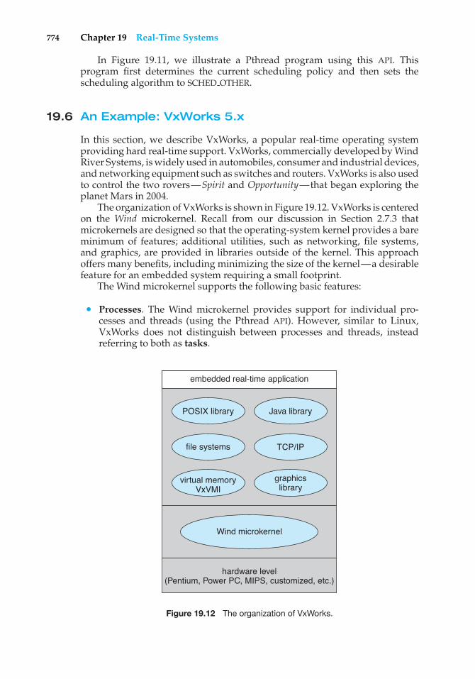
19.5 Real-Time CPU Scheduling 76819.6 An Example: VxWorks 5.x 77419.7 Summary 776
Exercises 777Bibliographical Notes 778
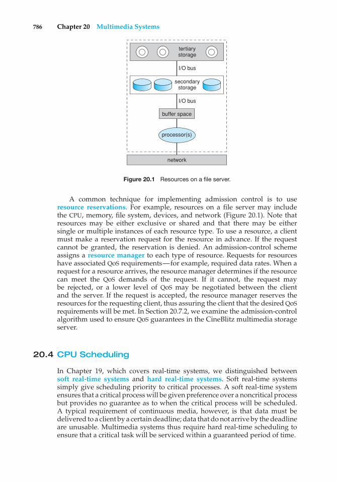
Chapter 20 Multimedia Systems20.1 What Is Multimedia? 77920.2 Compression 78220.3 Requirements of Multimedia
Kernels 78420.4 CPU Scheduling 78620.5 Disk Scheduling 787
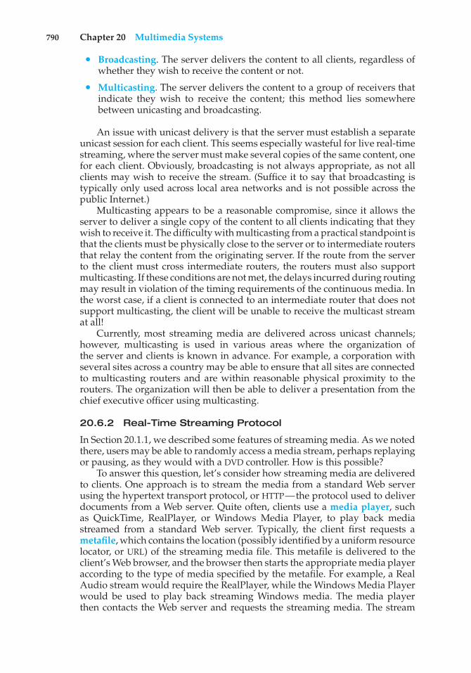
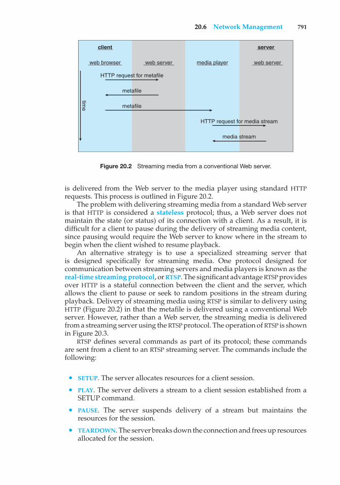
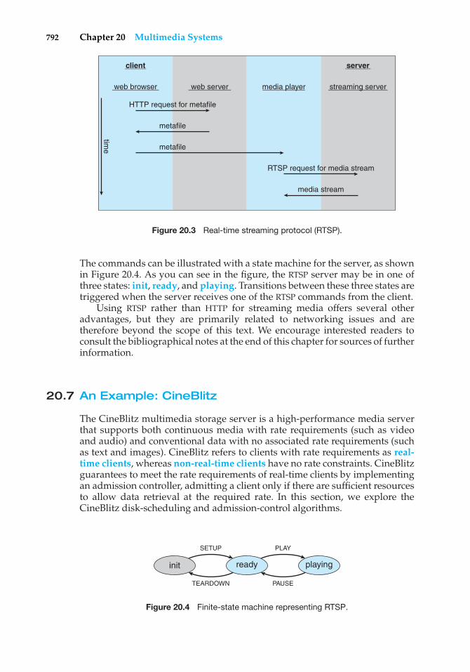
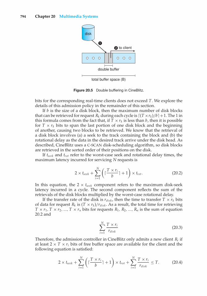
20.6 Network Management 78920.7 An Example: CineBlitz 79220.8 Summary 795
Exercises 795Bibliographical Notes 797
PART EIGHT CASE STUDIES
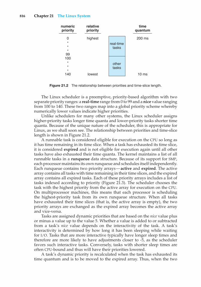
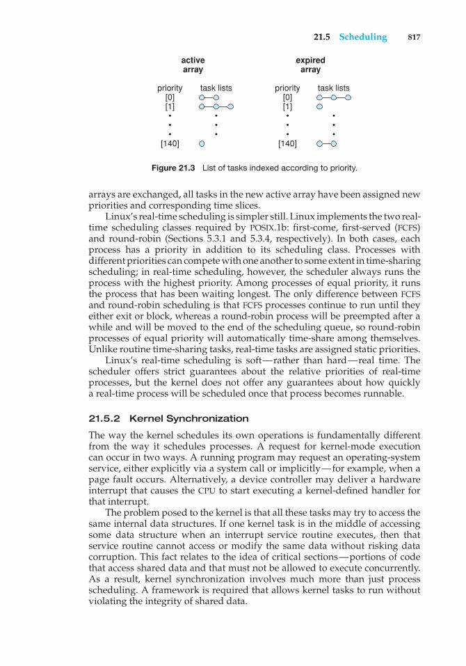
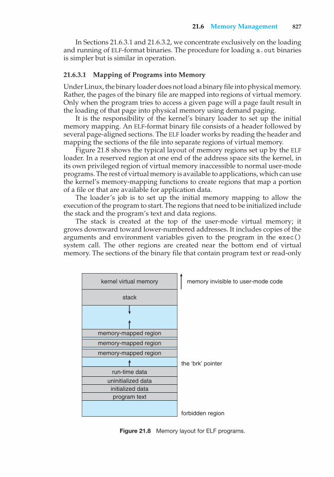
Chapter 21 The Linux System21.1 Linux History 80121.2 Design Principles 80621.3 Kernel Modules 80921.4 Process Management 81221.5 Scheduling 81521.6 Memory Management 82021.7 File Systems 828
21.8 Input and Output 83421.9 Interprocess Communication 837
21.10 Network Structure 83821.11 Security 84021.12 Summary 843
Exercises 844Bibliographical Notes 845
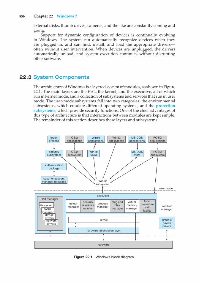
Chapter 22 Windows 722.1 History 84722.2 Design Principles 84922.3 System Components 85622.4 Terminal Services and Fast User
Switching 88022.5 File System 881
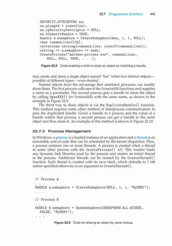
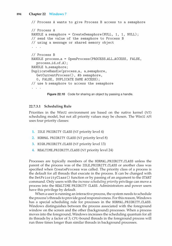
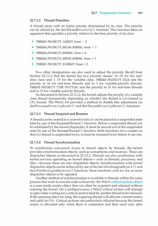
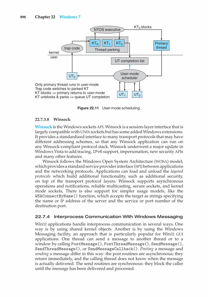
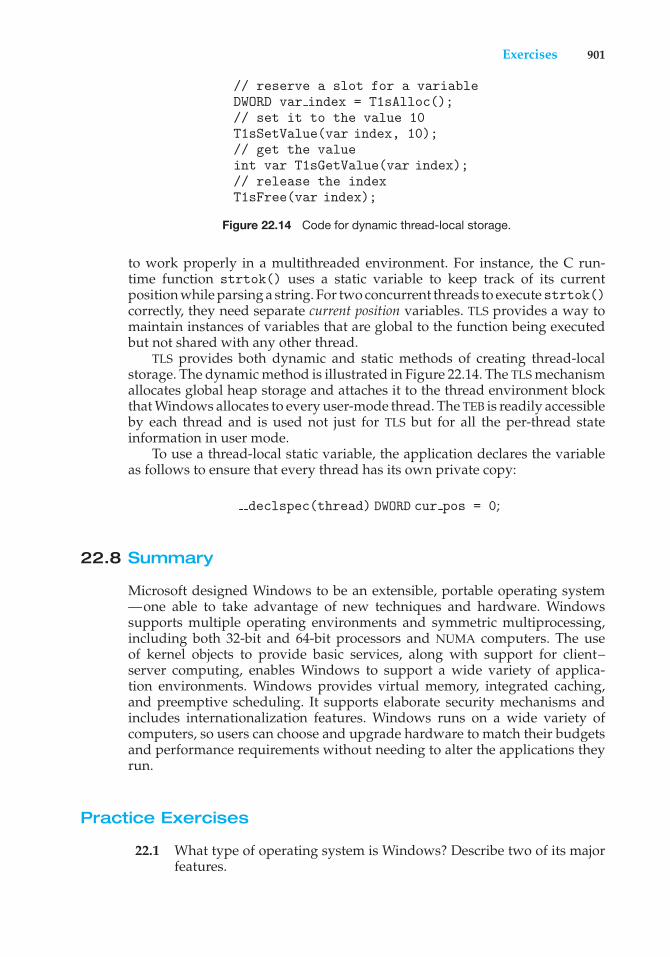
22.6 Networking 88722.7 Programmer Interface 89222.8 Summary 901
Exercises 903Bibliographical Notes 901
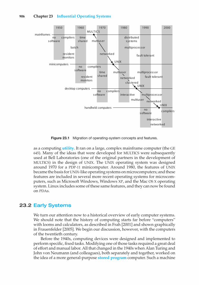
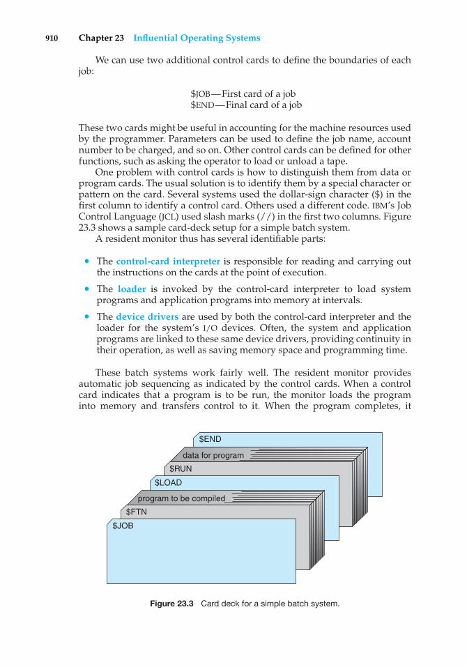
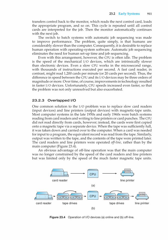
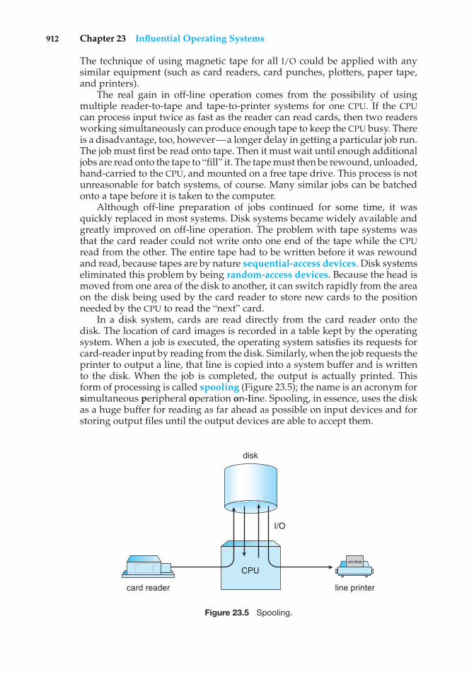
Chapter 23 Influential Operating Systems23.1 Feature Migration 90523.2 Early Systems 90623.3 Atlas 91323.4 XDS-940 91423.5 THE 91523.6 RC 4000 91523.7 CTSS 91623.8 MULTICS 917
23.9 IBM OS/360 91723.10 TOPS-20 91923.11 CP/M and MS/DOS 91923.12 Macintosh Operating System and
Windows 91823.13 Mach 92123.14 Other Systems 922
Exercises 923
xx Contents
PART NINE APPENDICES
Appendix A BSD UNIX (contents online)A.1 UNIX History A1A.2 Design Principles A6A.3 Programmer Interface A8A.4 User Interface A15A.5 Process Management A18A.6 Memory Management A22
A.7 File System A24A.8 I/O System A32A.9 Interprocess Communication A35
A.10 Summary A40Exercises A41Bibliographical Notes A42
Appendix B The Mach System (contents online)B.1 History of the Mach System B1B.2 Design Principles B3B.3 System Components B4B.4 Process Management B7B.5 Interprocess Communication B13
B.6 Memory Management B18B.7 Programmer Interface B23B.8 Summary B24
Exercises B25Bibliographical Notes B26
Appendix C Windows 2000 (contents online)C.1 History C1C.2 Design Principles C2C.3 System Components C3C.4 Environmental Subsystems C19C.5 File System C21
C.6 Networking C28C.7 Programmer Interface C33C.8 Summary C40
Exercises C40Bibliographical Notes C41
Bibliography 925
Index 943
Part One
OverviewAn operating system acts as an intermediary between the user of acomputer and the computer hardware. The purpose of an operatingsystem is to provide an environment in which a user can executeprograms in a convenient and efficient manner.
An operating system is software that manages the computer hard-ware. The hardware must provide appropriate mechanisms to ensure thecorrect operation of the computer system and to prevent user programsfrom interfering with the proper operation of the system.
Internally, operating systems vary greatly in their makeup, since theyare organized along many different lines. The design of a new operatingsystem is a major task. It is important that the goals of the system be welldefined before the design begins. These goals form the basis for choicesamong various algorithms and strategies.
Because an operating system is large and complex, it must be createdpiece by piece. Each of these pieces should be a well delineated portionof the system, with carefully defined inputs, outputs, and functions.

This page intentionally left blank
1C H A P T E R
Introduction
An operating system is a program that manages the computer hardware. Italso provides a basis for application programs and acts as an intermediarybetween the computer user and the computer hardware. An amazing aspectof operating systems is how varied they are in accomplishing these tasks.Mainframe operating systems are designed primarily to optimize utilizationof hardware. Personal computer (PC) operating systems support complexgames, business applications, and everything in between. Operating systemsfor handheld computers are designed to provide an environment in which auser can easily interface with the computer to execute programs. Thus, someoperating systems are designed to be convenient, others to be efficient, and otherssome combination of the two.
Before we can explore the details of computer system operation, we needto know something about system structure. We begin by discussing the basicfunctions of system startup, I/O, and storage. We also describe the basiccomputer architecture that makes it possible to write a functional operatingsystem.
Because an operating system is large and complex, it must be createdpiece by piece. Each of these pieces should be a well-delineated portion of thesystem, with carefully defined inputs, outputs, and functions. In this chapter,we provide a general overview of the major components of an operatingsystem.
CHAPTER OBJECTIVES
• To provide a grand tour of the major components of operating systems.
• To describe the basic organization of computer systems.
1.1 What Operating Systems Do
We begin our discussion by looking at the operating system’s role in theoverall computer system. A computer system can be divided roughly into
3
4 Chapter 1 Introduction
user1
user2
user3
computer hardware
operating system
system and application programs
compiler assembler text editor databasesystem
usern…
…
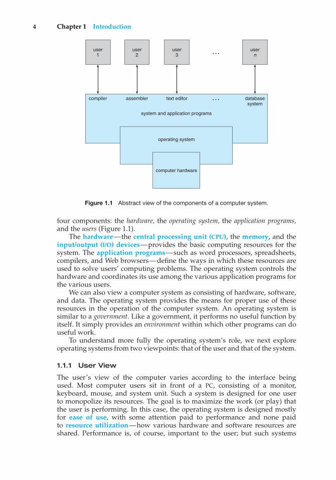
Figure 1.1 Abstract view of the components of a computer system.
four components: the hardware, the operating system, the application programs,and the users (Figure 1.1).
The hardware—the central processing unit (CPU), the memory, and theinput/output (I/O) devices—provides the basic computing resources for thesystem. The application programs—such as word processors, spreadsheets,compilers, and Web browsers—define the ways in which these resources areused to solve users’ computing problems. The operating system controls thehardware and coordinates its use among the various application programs forthe various users.
We can also view a computer system as consisting of hardware, software,and data. The operating system provides the means for proper use of theseresources in the operation of the computer system. An operating system issimilar to a government. Like a government, it performs no useful function byitself. It simply provides an environment within which other programs can douseful work.
To understand more fully the operating system’s role, we next exploreoperating systems from two viewpoints: that of the user and that of the system.
1.1.1 User View
The user’s view of the computer varies according to the interface beingused. Most computer users sit in front of a PC, consisting of a monitor,keyboard, mouse, and system unit. Such a system is designed for one userto monopolize its resources. The goal is to maximize the work (or play) thatthe user is performing. In this case, the operating system is designed mostlyfor ease of use, with some attention paid to performance and none paidto resource utilization—how various hardware and software resources areshared. Performance is, of course, important to the user; but such systems
1.1 What Operating Systems Do 5
are optimized for the single-user experience rather than the requirements ofmultiple users.
In other cases, a user sits at a terminal connected to a mainframe or aminicomputer. Other users are accessing the same computer through otherterminals. These users share resources and may exchange information. Theoperating system in such cases is designed to maximize resource utilization—to assure that all available CPU time, memory, and I/O are used efficiently andthat no individual user takes more than her fair share.
In still other cases, users sit at workstations connected to networks ofother workstations and servers. These users have dedicated resources at theirdisposal, but they also share resources such as networking and servers—file,compute, and print servers. Therefore, their operating system is designed tocompromise between individual usability and resource utilization.
Recently, many varieties of handheld computers have come into fashion.Most of these devices are standalone units for individual users. Some areconnected to networks, either directly by wire or (more often) through wirelessmodems and networking. Because of power, speed, and interface limitations,they perform relatively few remote operations. Their operating systems aredesigned mostly for individual usability, but performance per unit of batterylife is important as well.
Some computers have little or no user view. For example, embeddedcomputers in home devices and automobiles may have numeric keypads andmay turn indicator lights on or off to show status, but they and their operatingsystems are designed primarily to run without user intervention.
1.1.2 System View
From the computer’s point of view, the operating system is the programmost intimately involved with the hardware. In this context, we can viewan operating system as a resource allocator. A computer system has manyresources that may be required to solve a problem: CPU time, memory space,file-storage space, I/O devices, and so on. The operating system acts as themanager of these resources. Facing numerous and possibly conflicting requestsfor resources, the operating system must decide how to allocate them to specificprograms and users so that it can operate the computer system efficiently andfairly. As we have seen, resource allocation is especially important where manyusers access the same mainframe or minicomputer.
A slightly different view of an operating system emphasizes the need tocontrol the various I/O devices and user programs. An operating system is acontrol program. A control program manages the execution of user programsto prevent errors and improper use of the computer. It is especially concernedwith the operation and control of I/O devices.
1.1.3 Defining Operating Systems
We have looked at the operating system’s role from the views of the userand of the system. How, though, can we define what an operating systemis? In general, we have no completely adequate definition of an operatingsystem. Operating systems exist because they offer a reasonable way to solvethe problem of creating a usable computing system. The fundamental goalof computer systems is to execute user programs and to make solving user
6 Chapter 1 Introduction
STORAGE DEFINITIONS AND NOTATION
A bit is the basic unit of computer storage. It can contain one of two values,zero and one. All other storage in a computer is based on collections of bits.Given enough bits, it is amazing how many things a computer can represent:numbers, letters, images, movies, sounds, documents, and programs, to namea few. A byte is 8 bits, and on most computers it is the smallest convenientchunk of storage. For example, most computers don’t have an instructionto move a bit but do have one to move a byte. A less common term isword, which is a given computer architecture’s native storage unit. A word isgenerally made up of one or more bytes. For example, a computer may haveinstructions to move 64-bit (8-byte) words.
A kilobyte, or KB, is 1,024 bytes; a megabyte, or MB, is 1,0242 bytes; anda gigabyte, or GB, is 1,0243 bytes. Computer manufacturers often round offthese numbers and say that a megabyte is 1 million bytes and a gigabyte is 1billion bytes.
problems easier. Toward this goal, computer hardware is constructed. Sincebare hardware alone is not particularly easy to use, application programs aredeveloped. These programs require certain common operations, such as thosecontrolling the I/O devices. The common functions of controlling and allocatingresources are then brought together into one piece of software: the operatingsystem.
In addition, we have no universally accepted definition of what is part of theoperating system. A simple viewpoint is that it includes everything a vendorships when you order “the operating system.” The features included, however,vary greatly across systems. Some systems take up less than 1 megabyte ofspace and lack even a full-screen editor, whereas others require gigabytes ofspace and are entirely based on graphical windowing systems. A more commondefinition, and the one that we usually follow, is that the operating systemis the one program running at all times on the computer—usually calledthe kernel. (Along with the kernel, there are two other types of programs:systems programs, which are associated with the operating system but are notpart of the kernel, and application programs, which include all programs notassociated with the operation of the system.)
The matter of what constitutes an operating system has become increas-ingly important. In 1998, the United States Department of Justice filed suitagainst Microsoft, in essence claiming that Microsoft included too much func-tionality in its operating systems and thus prevented application vendors fromcompeting. For example, a Web browser was an integral part of the operatingsystems. As a result, Microsoft was found guilty of using its operating-systemmonopoly to limit competition.
1.2 Computer-System Organization
Before we can explore the details of how computer systems operate, we needgeneral knowledge of the structure of a computer system. In this section,we look at several parts of this structure. The section is mostly concerned
1.2 Computer-System Organization 7
THE STUDY OF OPERATING SYSTEMS
There has never been a more interesting time to study operating systems, andit has never been easier. The open-source movement has overtaken operatingsystems, causing many of them to be made available in both source and binary(executable) format. This list includes Linux, BSD UNIX, Solaris, and part ofMac OS X. The availability of source code allows us to study operating systemsfrom the inside out. Questions that previously could only be answered bylooking at documentation or the behavior of an operating system can now beanswered by examining the code itself.
In addition, the rise of virtualization as a mainstream (and frequently free)computer function makes it possible to run many operating systems on top ofone core system. For example, VMware (http://www.vmware.com) providesa free “player” on which hundreds of free “virtual appliances” can run. Usingthis method, students can try out hundreds of operating systems within theirexisting operating systems at no cost.
Operating systems that are no longer commercially viable have beenopen-sourced as well, enabling us to study how systems operated in atime of fewer CPU, memory, and storage resources. An extensive but notcomplete list of open-source operating-system projects is available fromhttp://dmoz.org/Computers/Software/Operating Systems/Open Source/.Simulators of specific hardware are also available in some cases, allowingthe operating system to run on “native” hardware, all within the confinesof a modern computer and modern operating system. For example, aDECSYSTEM-20 simulator running on Mac OS X can boot TOPS-20, load thesource tapes, and modify and compile a new TOPS-20 kernel. An interestedstudent can search the Internet to find the original papers that describe theoperating system and the original manuals.
The advent of open-source operating systems also makes it easy to makethe move from student to operating-system developer. With some knowledge,some effort, and an Internet connection, a student can even create a newoperating-system distribution! Just a few years, ago it was difficult orimpossible to get access to source code. Now that access is limited onlyby how much time and disk space a student has.
with computer-system organization, so you can skim or skip it if you alreadyunderstand the concepts.
1.2.1 Computer-System Operation
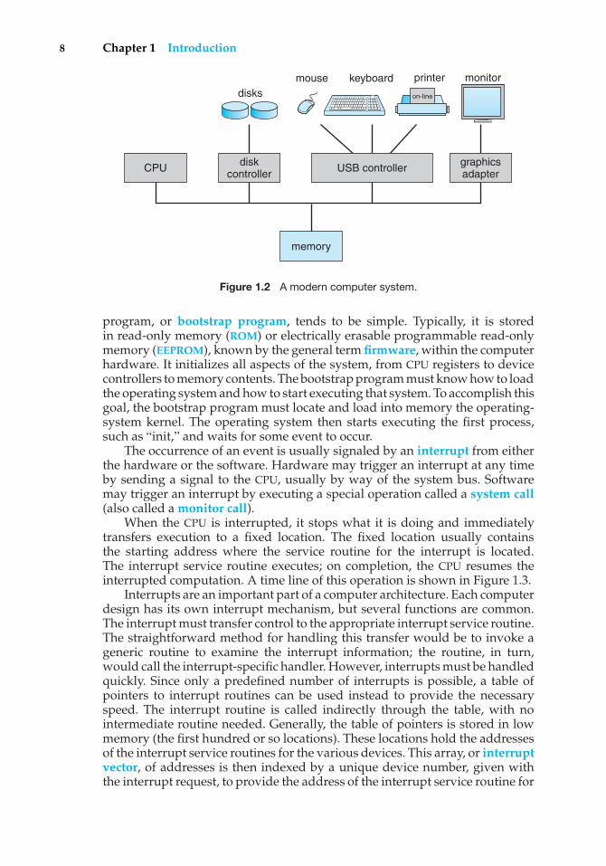
A modern general-purpose computer system consists of one or more CPUsand a number of device controllers connected through a common bus thatprovides access to shared memory (Figure 1.2). Each device controller is incharge of a specific type of device (for example, disk drives, audio devices, andvideo displays). The CPU and the device controllers can execute concurrently,competing for memory cycles. To ensure orderly access to the shared memory,a memory controller is provided whose function is to synchronize access to thememory.
For a computer to start running—for instance, when it is poweredup or rebooted—it needs to have an initial program to run. This initial
8 Chapter 1 Introduction
USB controller
keyboard printermouse monitordisks
graphicsadapter
diskcontroller
memory
CPU
on-line
Figure 1.2 A modern computer system.
program, or bootstrap program, tends to be simple. Typically, it is storedin read-only memory (ROM) or electrically erasable programmable read-onlymemory (EEPROM), known by the general term firmware, within the computerhardware. It initializes all aspects of the system, from CPU registers to devicecontrollers to memory contents. The bootstrap program must know how to loadthe operating system and how to start executing that system. To accomplish thisgoal, the bootstrap program must locate and load into memory the operating-system kernel. The operating system then starts executing the first process,such as “init,” and waits for some event to occur.
The occurrence of an event is usually signaled by an interrupt from eitherthe hardware or the software. Hardware may trigger an interrupt at any timeby sending a signal to the CPU, usually by way of the system bus. Softwaremay trigger an interrupt by executing a special operation called a system call(also called a monitor call).
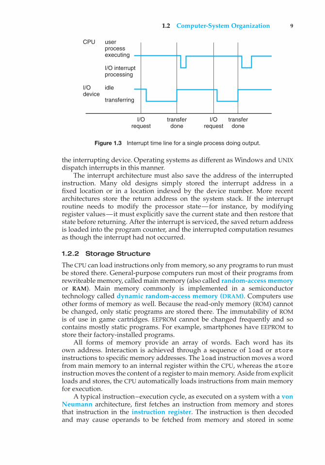
When the CPU is interrupted, it stops what it is doing and immediatelytransfers execution to a fixed location. The fixed location usually containsthe starting address where the service routine for the interrupt is located.The interrupt service routine executes; on completion, the CPU resumes theinterrupted computation. A time line of this operation is shown in Figure 1.3.
Interrupts are an important part of a computer architecture. Each computerdesign has its own interrupt mechanism, but several functions are common.The interrupt must transfer control to the appropriate interrupt service routine.The straightforward method for handling this transfer would be to invoke ageneric routine to examine the interrupt information; the routine, in turn,would call the interrupt-specific handler. However, interrupts must be handledquickly. Since only a predefined number of interrupts is possible, a table ofpointers to interrupt routines can be used instead to provide the necessaryspeed. The interrupt routine is called indirectly through the table, with nointermediate routine needed. Generally, the table of pointers is stored in lowmemory (the first hundred or so locations). These locations hold the addressesof the interrupt service routines for the various devices. This array, or interruptvector, of addresses is then indexed by a unique device number, given withthe interrupt request, to provide the address of the interrupt service routine for
1.2 Computer-System Organization 9
userprocessexecuting
CPU
I/O interruptprocessing
I/Orequest
transferdone
I/Orequest
transferdone
I/Odevice
idle
transferring
Figure 1.3 Interrupt time line for a single process doing output.
the interrupting device. Operating systems as different as Windows and UNIXdispatch interrupts in this manner.
The interrupt architecture must also save the address of the interruptedinstruction. Many old designs simply stored the interrupt address in afixed location or in a location indexed by the device number. More recentarchitectures store the return address on the system stack. If the interruptroutine needs to modify the processor state—for instance, by modifyingregister values—it must explicitly save the current state and then restore thatstate before returning. After the interrupt is serviced, the saved return addressis loaded into the program counter, and the interrupted computation resumesas though the interrupt had not occurred.
1.2.2 Storage Structure
The CPU can load instructions only from memory, so any programs to run mustbe stored there. General-purpose computers run most of their programs fromrewriteable memory, called main memory (also called random-access memoryor RAM). Main memory commonly is implemented in a semiconductortechnology called dynamic random-access memory (DRAM). Computers useother forms of memory as well. Because the read-only memory (ROM) cannotbe changed, only static programs are stored there. The immutability of ROMis of use in game cartridges. EEPROM cannot be changed frequently and socontains mostly static programs. For example, smartphones have EEPROM tostore their factory-installed programs.
All forms of memory provide an array of words. Each word has itsown address. Interaction is achieved through a sequence of load or storeinstructions to specific memory addresses. The load instruction moves a wordfrom main memory to an internal register within the CPU, whereas the storeinstruction moves the content of a register to main memory. Aside from explicitloads and stores, the CPU automatically loads instructions from main memoryfor execution.
A typical instruction–execution cycle, as executed on a system with a vonNeumann architecture, first fetches an instruction from memory and storesthat instruction in the instruction register. The instruction is then decodedand may cause operands to be fetched from memory and stored in some
10 Chapter 1 Introduction
internal register. After the instruction on the operands has been executed, theresult may be stored back in memory. Notice that the memory unit sees onlya stream of memory addresses; it does not know how they are generated (bythe instruction counter, indexing, indirection, literal addresses, or some othermeans) or what they are for (instructions or data). Accordingly, we can ignorehow a memory address is generated by a program. We are interested only inthe sequence of memory addresses generated by the running program.
Ideally, we want the programs and data to reside in main memorypermanently. This arrangement usually is not possible for the following tworeasons:
1. Main memory is usually too small to store all needed programs and datapermanently.
2. Main memory is a volatile storage device that loses its contents whenpower is turned off or otherwise lost.
Thus, most computer systems provide secondary storage as an extensionof main memory. The main requirement for secondary storage is that it be ableto hold large quantities of data permanently.
The most common secondary-storage device is a magnetic disk, whichprovides storage for both programs and data. Most programs (system andapplication) are stored on a disk until they are loaded into memory. Manyprograms then use the disk as both the source and the destination of theirprocessing. Hence, the proper management of disk storage is of centralimportance to a computer system, as we discuss in Chapter 12.
In a larger sense, however, the storage structure that we have described—consisting of registers, main memory, and magnetic disks—is only one of manypossible storage systems. Others include cache memory, CD-ROM, magnetictapes, and so on. Each storage system provides the basic functions of storinga datum and holding that datum until it is retrieved at a later time. The maindifferences among the various storage systems lie in speed, cost, size, andvolatility.
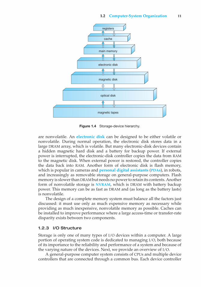
The wide variety of storage systems in a computer system can be organizedin a hierarchy (Figure 1.4) according to speed and cost. The higher levels areexpensive, but they are fast. As we move down the hierarchy, the cost per bitgenerally decreases, whereas the access time generally increases. This trade-offis reasonable; if a given storage system were both faster and less expensivethan another—other properties being the same—then there would be noreason to use the slower, more expensive memory. In fact, many early storagedevices, including paper tape and core memories, are relegated to museumsnow that magnetic tape and semiconductor memory have become faster andcheaper. The top four levels of memory in Figure 1.4 may be constructed usingsemiconductor memory.
In addition to differing in speed and cost, the various storage systemsare either volatile or nonvolatile. As mentioned earlier, volatile storage losesits contents when the power to the device is removed. In the absence ofexpensive battery and generator backup systems, data must be written tononvolatile storage for safekeeping. In the hierarchy shown in Figure 1.4, thestorage systems above the electronic disk are volatile, whereas those below
1.2 Computer-System Organization 11
registers
cache
main memory
electronic disk
magnetic disk
optical disk
magnetic tapes
Figure 1.4 Storage-device hierarchy.
are nonvolatile. An electronic disk can be designed to be either volatile ornonvolatile. During normal operation, the electronic disk stores data in alarge DRAM array, which is volatile. But many electronic-disk devices containa hidden magnetic hard disk and a battery for backup power. If externalpower is interrupted, the electronic-disk controller copies the data from RAMto the magnetic disk. When external power is restored, the controller copiesthe data back into RAM. Another form of electronic disk is flash memory,which is popular in cameras and personal digital assistants (PDAs), in robots,and increasingly as removable storage on general-purpose computers. Flashmemory is slower than DRAM but needs no power to retain its contents. Anotherform of nonvolatile storage is NVRAM, which is DRAM with battery backuppower. This memory can be as fast as DRAM and (as long as the battery lasts)is nonvolatile.
The design of a complete memory system must balance all the factors justdiscussed: it must use only as much expensive memory as necessary whileproviding as much inexpensive, nonvolatile memory as possible. Caches canbe installed to improve performance where a large access-time or transfer-ratedisparity exists between two components.
1.2.3 I/O Structure
Storage is only one of many types of I/O devices within a computer. A largeportion of operating system code is dedicated to managing I/O, both becauseof its importance to the reliability and performance of a system and because ofthe varying nature of the devices. Next, we provide an overview of I/O.
A general-purpose computer system consists of CPUs and multiple devicecontrollers that are connected through a common bus. Each device controller
12 Chapter 1 Introduction
is in charge of a specific type of device. Depending on the controller, morethan one device may be attached. For instance, seven or more devices can beattached to the small computer-systems interface (SCSI) controller. A devicecontroller maintains some local buffer storage and a set of special-purposeregisters. The device controller is responsible for moving the data betweenthe peripheral devices that it controls and its local buffer storage. Typically,operating systems have a device driver for each device controller. This devicedriver understands the device controller and presents a uniform interface tothe device to the rest of the operating system.
To start an I/O operation, the device driver loads the appropriate registerswithin the device controller. The device controller, in turn, examines thecontents of these registers to determine what action to take (such as “reada character from the keyboard”). The controller starts the transfer of data fromthe device to its local buffer. Once the transfer of data is complete, the devicecontroller informs the device driver via an interrupt that it has finished itsoperation. The device driver then returns control to the operating system,possibly returning the data or a pointer to the data if the operation was a read.For other operations, the device driver returns status information.
This form of interrupt-driven I/O is fine for moving small amounts of databut can produce high overhead when used for bulk data movement such as diskI/O. To solve this problem, direct memory access (DMA) is used. After settingup buffers, pointers, and counters for the I/O device, the device controllertransfers an entire block of data directly to or from its own buffer storage tomemory, with no intervention by the CPU. Only one interrupt is generated perblock, to tell the device driver that the operation has completed, rather thanthe one interrupt per byte generated for low-speed devices. While the devicecontroller is performing these operations, the CPU is available to accomplishother work.
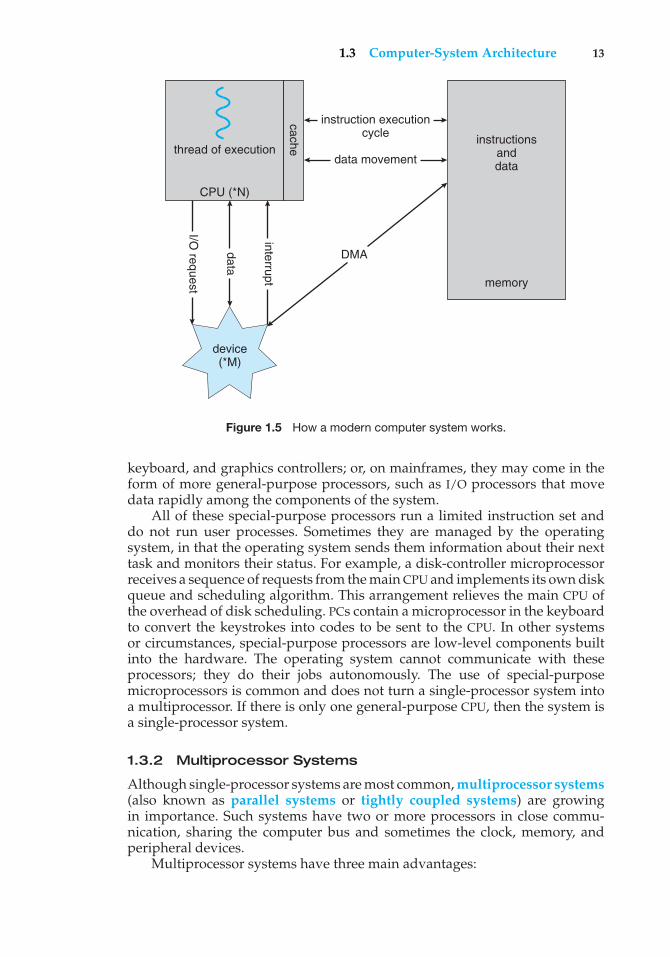
Some high-end systems use switch rather than bus architecture. On thesesystems, multiple components can talk to other components concurrently,rather than competing for cycles on a shared bus. In this case, DMA is evenmore effective. Figure 1.5 shows the interplay of all components of a computersystem.
1.3 Computer-System Architecture
In Section 1.2, we introduced the general structure of a typical computer system.A computer system may be organized in a number of different ways, which wecan categorize roughly according to the number of general-purpose processorsused.
1.3.1 Single-Processor Systems
Most systems use a single processor. The variety of single-processor systemsmay be surprising, however, since these systems range from PDAs throughmainframes. On a single-processor system, there is one main CPU capableof executing a general-purpose instruction set, including instructions fromuser processes. Almost all systems have other special-purpose processors aswell. They may come in the form of device-specific processors, such as disk,
1.3 Computer-System Architecture 13
thread of executioninstructions
anddata
instruction executioncycle
data movement
DMA
memory
interrupt
cache
data
I/O request
CPU (*N)
device(*M)
Figure 1.5 How a modern computer system works.
keyboard, and graphics controllers; or, on mainframes, they may come in theform of more general-purpose processors, such as I/O processors that movedata rapidly among the components of the system.
All of these special-purpose processors run a limited instruction set anddo not run user processes. Sometimes they are managed by the operatingsystem, in that the operating system sends them information about their nexttask and monitors their status. For example, a disk-controller microprocessorreceives a sequence of requests from the main CPU and implements its own diskqueue and scheduling algorithm. This arrangement relieves the main CPU ofthe overhead of disk scheduling. PCs contain a microprocessor in the keyboardto convert the keystrokes into codes to be sent to the CPU. In other systemsor circumstances, special-purpose processors are low-level components builtinto the hardware. The operating system cannot communicate with theseprocessors; they do their jobs autonomously. The use of special-purposemicroprocessors is common and does not turn a single-processor system intoa multiprocessor. If there is only one general-purpose CPU, then the system isa single-processor system.
1.3.2 Multiprocessor Systems
Although single-processor systems are most common, multiprocessor systems(also known as parallel systems or tightly coupled systems) are growingin importance. Such systems have two or more processors in close commu-nication, sharing the computer bus and sometimes the clock, memory, andperipheral devices.
Multiprocessor systems have three main advantages:
14 Chapter 1 Introduction
1. Increased throughput. By increasing the number of processors, we expectto get more work done in less time. The speed-up ratio with N processorsis not N, however; rather, it is less than N. When multiple processorscooperate on a task, a certain amount of overhead is incurred in keepingall the parts working correctly. This overhead, plus contention for sharedresources, lowers the expected gain from additional processors. Similarly,N programmers working closely together do not produce N times theamount of work a single programmer would produce.
2. Economy of scale. Multiprocessor systems can cost less than equivalentmultiple single-processor systems, because they can share peripherals,mass storage, and power supplies. If several programs operate on thesame set of data, it is cheaper to store those data on one disk and to haveall the processors share them than to have many computers with localdisks and many copies of the data.
3. Increased reliability. If functions can be distributed properly amongseveral processors, then the failure of one processor will not halt thesystem, only slow it down. If we have ten processors and one fails, theneach of the remaining nine processors can pick up a share of the work ofthe failed processor. Thus, the entire system runs only 10 percent slower,rather than failing altogether.
Increased reliability of a computer system is crucial in many applications.The ability to continue providing service proportional to the level of survivinghardware is called graceful degradation. Some systems go beyond gracefuldegradation and are called fault tolerant, because they can suffer a failure ofany single component and still continue operation. Note that fault tolerancerequires a mechanism to allow the failure to be detected, diagnosed, and, ifpossible, corrected. The HP NonStop (formerly Tandem) system uses bothhardware and software duplication to ensure continued operation despitefaults. The system consists of multiple pairs of CPUs, working in lockstep.Both processors in the pair execute each instruction and compare the results. Ifthe results differ, then one CPU of the pair is at fault, and both are halted. Theprocess that was being executed is then moved to another pair of CPUs, and theinstruction that failed is restarted. This solution is expensive, since it involvesspecial hardware and considerable hardware duplication.
The multiple-processor systems in use today are of two types. Somesystems use asymmetric multiprocessing, in which each processor is assigneda specific task. A master processor controls the system; the other processorseither look to the master for instruction or have predefined tasks. This schemedefines a master–slave relationship. The master processor schedules andallocates work to the slave processors.
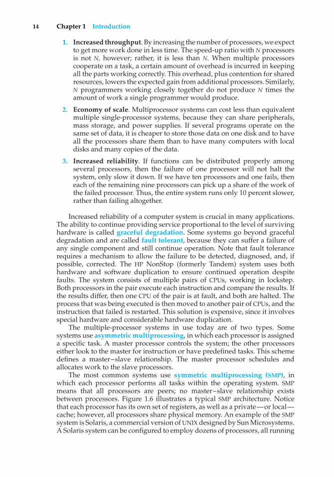
The most common systems use symmetric multiprocessing (SMP), inwhich each processor performs all tasks within the operating system. SMPmeans that all processors are peers; no master–slave relationship existsbetween processors. Figure 1.6 illustrates a typical SMP architecture. Noticethat each processor has its own set of registers, as well as a private—or local—cache; however, all processors share physical memory. An example of the SMPsystem is Solaris, a commercial version of UNIX designed by Sun Microsystems.A Solaris system can be configured to employ dozens of processors, all running
1.3 Computer-System Architecture 15
CPU0
registers
cache
CPU1
registers
cache
CPU2
registers
cache
memory
Figure 1.6 Symmetric multiprocessing architecture.
Solaris. The benefit of this model is that many processes can run simultaneously—N processes can run if there are N CPUs—without causing a significantdeterioration of performance. However, we must carefully control I/O toensure that the data reach the appropriate processor. Also, since the CPUsare separate, one may be sitting idle while another is overloaded, resulting ininefficiencies. These inefficiencies can be avoided if the processors share certaindata structures. A multiprocessor system of this form will allow processes andresources—such as memory—to be shared dynamically among the variousprocessors and can lower the variance among the processors. Such a systemmust be written carefully, as we shall see in Chapter 6. Virtually all modernoperating systems—including Windows, Windows XP, Mac OS X, and Linux—now provide support for SMP.
The difference between symmetric and asymmetric multiprocessing mayresult from either hardware or software. Special hardware can differentiate themultiple processors, or the software can be written to allow only one master andmultiple slaves. For instance, Sun’s operating system SunOS Version 4 providedasymmetric multiprocessing, whereas Version 5 (Solaris) is symmetric on thesame hardware.
Multiprocessing adds CPUs to increase computing power. If the CPU has anintegrated memory controller, then adding CPUs can also increase the amountof memory addressable in the system. Either way, multiprocessing can causea system to change its memory access model from uniform memory access(UMA) to non-uniform memory access (NUMA). UMA is defined as the situationin which access to any RAM from any CPU takes the same amount of time. WithNUMA, some parts of memory may take longer to access than other parts,creating a performance penalty. Operating systems can minimize the NUMApenalty through resource management, as discussed in Section 9.5.4.
A recent trend in CPU design is to include multiple computing cores ona single chip. In essence, these are multiprocessor chips. They can be moreefficient than multiple chips with single cores because on-chip communicationis faster than between-chip communication. In addition, one chip with multiplecores uses significantly less power than multiple single-core chips. As a result,multicore systems are especially well suited for server systems such as databaseand Web servers.
16 Chapter 1 Introduction
CPU core0
registers
cache
CPU core1
registers
cache
memory
Figure 1.7 A dual-core design with two cores placed on the same chip.
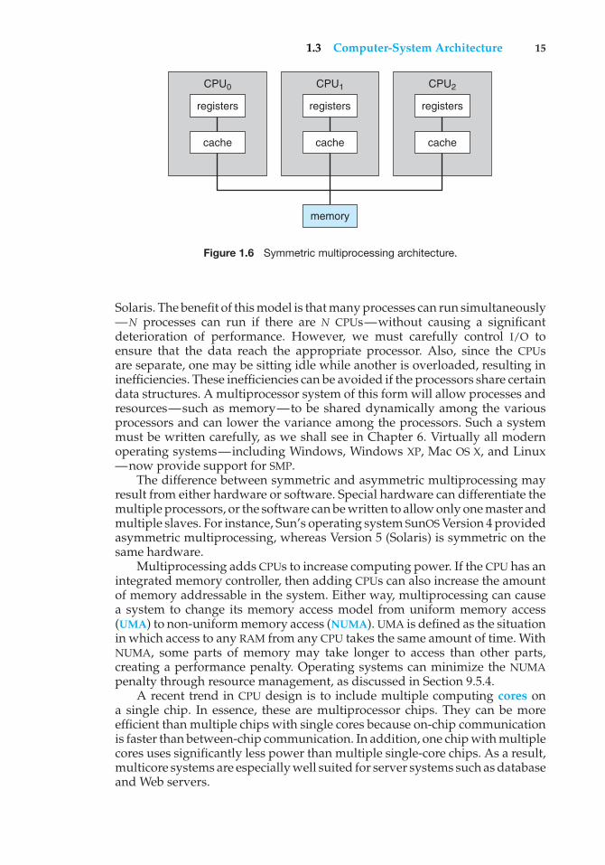
In Figure 1.7, we show a dual-core design with two cores on the samechip. In this design, each core has its own register set as well as its own localcache; other designs might use a shared cache or a combination of local andshared caches. Aside from architectural considerations, such as cache, memory,and bus contention, these multicore CPUs appear to the operating systemas N standard processors. This tendency puts pressure on operating systemdesigners—and application programmers—to make use of those CPUs.
Finally, blade servers are a recent development in which multiple processorboards, I/O boards, and networking boards are placed in the same chassis.The difference between these and traditional multiprocessor systems is thateach blade-processor board boots independently and runs its own operatingsystem. Some blade-server boards are multiprocessor as well, which blurs thelines between types of computers. In essence, these servers consist of multipleindependent multiprocessor systems.
1.3.3 Clustered Systems
Another type of multiple-CPU system is the clustered system. Like multipro-cessor systems, clustered systems gather together multiple CPUs to accomplishcomputational work. Clustered systems differ from multiprocessor systems,however, in that they are composed of two or more individual systems—ornodes—joined together. The definition of the term clustered is not concrete;many commercial packages wrestle with what a clustered system is and whyone form is better than another. The generally accepted definition is that clus-tered computers share storage and are closely linked via a local-area network(LAN) (as described in Section 1.10) or a faster interconnect, such as InfiniBand.
Clustering is usually used to provide high-availability service; that is,service will continue even if one or more systems in the cluster fail. Highavailability is generally obtained by adding a level of redundancy in thesystem. A layer of cluster software runs on the cluster nodes. Each node canmonitor one or more of the others (over the LAN). If the monitored machinefails, the monitoring machine can take ownership of its storage and restart theapplications that were running on the failed machine. The users and clients ofthe applications see only a brief interruption of service.
1.3 Computer-System Architecture 17
BEOWULF CLUSTERS
Beowulf clusters are designed for solving high-performance computingtasks. These clusters are built using commodity hardware—such as personalcomputers—that are connected via a simple local area network. Interestingly,a Beowulf cluster uses no one specific software package but rather consistsof a set of open-source software libraries that allow the computing nodesin the cluster to communicate with one another. Thus, there are a variety ofapproaches for constructing a Beowulf cluster, although Beowulf computingnodes typically run the Linux operating system. Since Beowulf clustersrequire no special hardware and operate using open-source software thatis freely available, they offer a low-cost strategy for building a high-performance computing cluster. In fact, some Beowulf clusters built fromcollections of discarded personal computers are using hundreds of computingnodes to solve computationally expensive problems in scientific computing.
Clustering can be structured asymmetrically or symmetrically. In asym-metric clustering, one machine is in hot-standby mode while the other isrunning the applications. The hot-standby host machine does nothing butmonitor the active server. If that server fails, the hot-standby host becomes theactive server. In symmetric mode, two or more hosts are running applicationsand are monitoring each other. This mode is obviously more efficient, as it usesall of the available hardware. It does require that more than one application beavailable to run.
As a cluster consists of several computer systems connected via a network,clusters may also be used to provide high-performance computing environ-ments. Such systems can supply significantly greater computational powerthan single-processor or even SMP systems because they are capable of runningan application concurrently on all computers in the cluster. However, appli-cations must be written specifically to take advantage of the cluster by usinga technique known as parallelization, which consists of dividing a programinto separate components that run in parallel on individual computers in thecluster. Typically, these applications are designed so that once each computingnode in the cluster has solved its portion of the problem, the results from allthe nodes are combined into a final solution.
Other forms of clusters include parallel clusters and clustering over awide-area network (WAN) (as described in Section 1.10). Parallel clusters allowmultiple hosts to access the same data on the shared storage. Because mostoperating systems lack support for simultaneous data access by multiple hosts,parallel clusters are usually accomplished by use of special versions of softwareand special releases of applications. For example, Oracle Real ApplicationCluster is a version of Oracle’s database that has been designed to run ona parallel cluster. Each machine runs Oracle, and a layer of software tracksaccess to the shared disk. Each machine has full access to all data in thedatabase. To provide this shared access to data, the system must also supplyaccess control and locking to ensure that no conflicting operations occur. Thisfunction, commonly known as a distributed lock manager (DLM), is includedin some cluster technology.
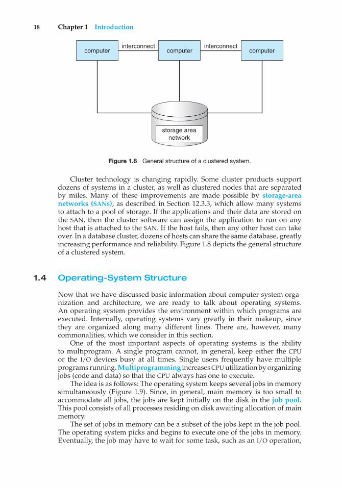
18 Chapter 1 Introduction
computerinterconnect
computerinterconnect
computer
storage areanetwork
Figure 1.8 General structure of a clustered system.
Cluster technology is changing rapidly. Some cluster products supportdozens of systems in a cluster, as well as clustered nodes that are separatedby miles. Many of these improvements are made possible by storage-areanetworks (SANs), as described in Section 12.3.3, which allow many systemsto attach to a pool of storage. If the applications and their data are stored onthe SAN, then the cluster software can assign the application to run on anyhost that is attached to the SAN. If the host fails, then any other host can takeover. In a database cluster, dozens of hosts can share the same database, greatlyincreasing performance and reliability. Figure 1.8 depicts the general structureof a clustered system.
1.4 Operating-System Structure
Now that we have discussed basic information about computer-system orga-nization and architecture, we are ready to talk about operating systems.An operating system provides the environment within which programs areexecuted. Internally, operating systems vary greatly in their makeup, sincethey are organized along many different lines. There are, however, manycommonalities, which we consider in this section.
One of the most important aspects of operating systems is the abilityto multiprogram. A single program cannot, in general, keep either the CPUor the I/O devices busy at all times. Single users frequently have multipleprograms running. Multiprogramming increases CPU utilization by organizingjobs (code and data) so that the CPU always has one to execute.
The idea is as follows: The operating system keeps several jobs in memorysimultaneously (Figure 1.9). Since, in general, main memory is too small toaccommodate all jobs, the jobs are kept initially on the disk in the job pool.This pool consists of all processes residing on disk awaiting allocation of mainmemory.
The set of jobs in memory can be a subset of the jobs kept in the job pool.The operating system picks and begins to execute one of the jobs in memory.Eventually, the job may have to wait for some task, such as an I/O operation,
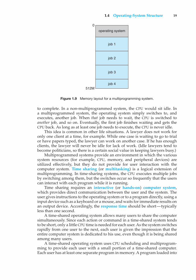
1.4 Operating-System Structure 19
job 1
0
512M
operating system
job 2
job 3
job 4
Figure 1.9 Memory layout for a multiprogramming system.
to complete. In a non-multiprogrammed system, the CPU would sit idle. Ina multiprogrammed system, the operating system simply switches to, andexecutes, another job. When that job needs to wait, the CPU is switched toanother job, and so on. Eventually, the first job finishes waiting and gets theCPU back. As long as at least one job needs to execute, the CPU is never idle.
This idea is common in other life situations. A lawyer does not work foronly one client at a time, for example. While one case is waiting to go to trialor have papers typed, the lawyer can work on another case. If he has enoughclients, the lawyer will never be idle for lack of work. (Idle lawyers tend tobecome politicians, so there is a certain social value in keeping lawyers busy.)
Multiprogrammed systems provide an environment in which the varioussystem resources (for example, CPU, memory, and peripheral devices) areutilized effectively, but they do not provide for user interaction with thecomputer system. Time sharing (or multitasking) is a logical extension ofmultiprogramming. In time-sharing systems, the CPU executes multiple jobsby switching among them, but the switches occur so frequently that the userscan interact with each program while it is running.
Time sharing requires an interactive (or hands-on) computer system,which provides direct communication between the user and the system. Theuser gives instructions to the operating system or to a program directly, using ainput device such as a keyboard or a mouse, and waits for immediate results onan output device. Accordingly, the response time should be short—typicallyless than one second.
A time-shared operating system allows many users to share the computersimultaneously. Since each action or command in a time-shared system tendsto be short, only a little CPU time is needed for each user. As the system switchesrapidly from one user to the next, each user is given the impression that theentire computer system is dedicated to his use, even though it is being sharedamong many users.
A time-shared operating system uses CPU scheduling and multiprogram-ming to provide each user with a small portion of a time-shared computer.Each user has at least one separate program in memory. A program loaded into
20 Chapter 1 Introduction
memory and executing is called a process. When a process executes, it typicallyexecutes for only a short time before it either finishes or needs to perform I/O.I/O may be interactive; that is, output goes to a display for the user, and inputcomes from a user keyboard, mouse, or other device. Since interactive I/Otypically runs at “people speeds,” it may take a long time to complete. Input,for example, may be bounded by the user’s typing speed; seven characters persecond is fast for people but incredibly slow for computers. Rather than letthe CPU sit idle as this interactive input takes place, the operating system willrapidly switch the CPU to the program of some other user.
Time sharing and multiprogramming require that several jobs be keptsimultaneously in memory. If several jobs are ready to be brought into memory,and if there is not enough room for all of them, then the system must chooseamong them. Making this decision is job scheduling, which is discussed inChapter 5. When the operating system selects a job from the job pool, it loadsthat job into memory for execution. Having several programs in memory at thesame time requires some form of memory management, which is covered inChapters 8 and 9. In addition, if several jobs are ready to run at the same time,the system must choose among them. Making this decision is CPU scheduling,which is discussed in Chapter 5. Finally, running multiple jobs concurrentlyrequires that their ability to affect one another be limited in all phases of theoperating system, including process scheduling, disk storage, and memorymanagement. These considerations are discussed throughout the text.
In a time-sharing system, the operating system must ensure reasonableresponse time, which is sometimes accomplished through swapping, whereprocesses are swapped in and out of main memory to the disk. A more commonmethod for achieving this goal is virtual memory, a technique that allowsthe execution of a process that is not completely in memory (Chapter 9).The main advantage of the virtual-memory scheme is that it enables usersto run programs that are larger than actual physical memory. Further, itabstracts main memory into a large, uniform array of storage, separating logicalmemory as viewed by the user from physical memory. This arrangement freesprogrammers from concern over memory-storage limitations.
Time-sharing systems must also provide a file system (Chapters 10 and 11).The file system resides on a collection of disks; hence, disk management mustbe provided (Chapter 12). Also, time-sharing systems provide a mechanism forprotecting resources from inappropriate use (Chapter 14). To ensure orderlyexecution, the system must provide mechanisms for job synchronization andcommunication (Chapter 6), and it may ensure that jobs do not get stuck in adeadlock, forever waiting for one another (Chapter 7).
1.5 Operating-System Operations
As mentioned earlier, modern operating systems are interrupt driven. If thereare no processes to execute, no I/O devices to service, and no users to whomto respond, an operating system will sit quietly, waiting for something tohappen. Events are almost always signaled by the occurrence of an interruptor a trap. A trap (or an exception) is a software-generated interrupt causedeither by an error (for example, division by zero or invalid memory access)or by a specific request from a user program that an operating-system service
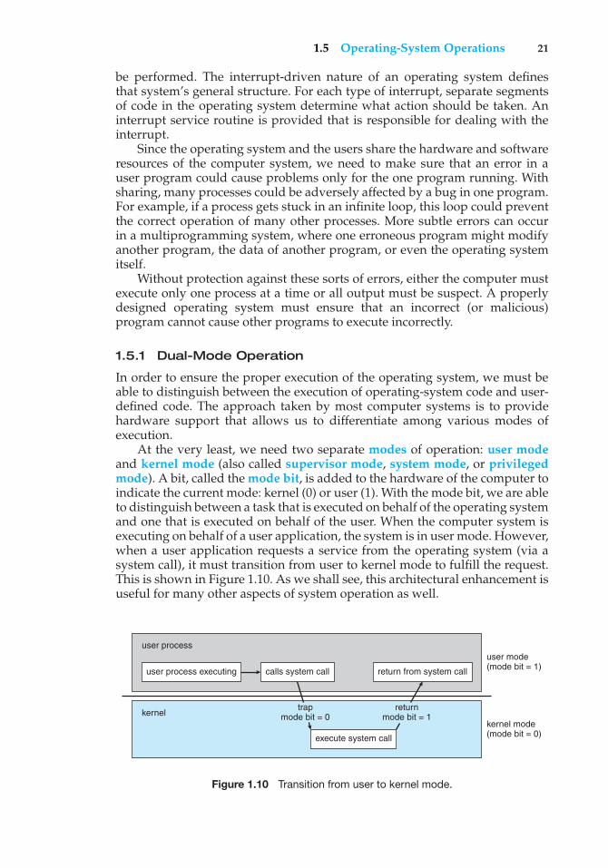
1.5 Operating-System Operations 21
be performed. The interrupt-driven nature of an operating system definesthat system’s general structure. For each type of interrupt, separate segmentsof code in the operating system determine what action should be taken. Aninterrupt service routine is provided that is responsible for dealing with theinterrupt.
Since the operating system and the users share the hardware and softwareresources of the computer system, we need to make sure that an error in auser program could cause problems only for the one program running. Withsharing, many processes could be adversely affected by a bug in one program.For example, if a process gets stuck in an infinite loop, this loop could preventthe correct operation of many other processes. More subtle errors can occurin a multiprogramming system, where one erroneous program might modifyanother program, the data of another program, or even the operating systemitself.
Without protection against these sorts of errors, either the computer mustexecute only one process at a time or all output must be suspect. A properlydesigned operating system must ensure that an incorrect (or malicious)program cannot cause other programs to execute incorrectly.
1.5.1 Dual-Mode Operation
In order to ensure the proper execution of the operating system, we must beable to distinguish between the execution of operating-system code and user-defined code. The approach taken by most computer systems is to providehardware support that allows us to differentiate among various modes ofexecution.
At the very least, we need two separate modes of operation: user modeand kernel mode (also called supervisor mode, system mode, or privilegedmode). A bit, called the mode bit, is added to the hardware of the computer toindicate the current mode: kernel (0) or user (1). With the mode bit, we are ableto distinguish between a task that is executed on behalf of the operating systemand one that is executed on behalf of the user. When the computer system isexecuting on behalf of a user application, the system is in user mode. However,when a user application requests a service from the operating system (via asystem call), it must transition from user to kernel mode to fulfill the request.This is shown in Figure 1.10. As we shall see, this architectural enhancement isuseful for many other aspects of system operation as well.
user process executing
user process
kernel
calls system call return from system call
user mode(mode bit = 1)
trapmode bit = 0
returnmode bit = 1
kernel mode(mode bit = 0)execute system call
Figure 1.10 Transition from user to kernel mode.
22 Chapter 1 Introduction
At system boot time, the hardware starts in kernel mode. The operatingsystem is then loaded and starts user applications in user mode. Whenever atrap or interrupt occurs, the hardware switches from user mode to kernel mode(that is, changes the state of the mode bit to 0). Thus, whenever the operatingsystem gains control of the computer, it is in kernel mode. The system alwaysswitches to user mode (by setting the mode bit to 1) before passing control toa user program.
The dual mode of operation provides us with the means for protecting theoperating system from errant users—and errant users from one another. Weaccomplish this protection by designating some of the machine instructions thatmay cause harm as privileged instructions. The hardware allows privilegedinstructions to be executed only in kernel mode. If an attempt is made toexecute a privileged instruction in user mode, the hardware does not executethe instruction but rather treats it as illegal and traps it to the operating system.
The instruction to switch to kernel mode is an example of a privilegedinstruction. Some other examples include I/O control, timer management, andinterrupt management. As we shall see throughout the text, there are manyadditional privileged instructions.
We can now see the life cycle of instruction execution in a computer system.Initial control resides in the operating system, where instructions are executedin kernel mode. When control is given to a user application, the mode is set touser mode. Eventually, control is switched back to the operating system via aninterrupt, a trap, or a system call.
System calls provide the means for a user program to ask the operatingsystem to perform tasks reserved for the operating system on the userprogram’s behalf. A system call is invoked in a variety of ways, dependingon the functionality provided by the underlying processor. In all forms, it is themethod used by a process to request action by the operating system. A systemcall usually takes the form of a trap to a specific location in the interrupt vector.This trap can be executed by a generic trap instruction, although some systems(such as the MIPS R2000 family) have a specific syscall instruction.
When a system call is executed, it is treated by the hardware as a softwareinterrupt. Control passes through the interrupt vector to a service routine inthe operating system, and the mode bit is set to kernel mode. The system-call service routine is a part of the operating system. The kernel examinesthe interrupting instruction to determine what system call has occurred; aparameter indicates what type of service the user program is requesting.Additional information needed for the request may be passed in registers,on the stack, or in memory (with pointers to the memory locations passed inregisters). The kernel verifies that the parameters are correct and legal, executesthe request, and returns control to the instruction following the system call. Wedescribe system calls more fully in Section 2.3.
The lack of a hardware-supported dual mode can cause serious shortcom-ings in an operating system. For instance, MS-DOS was written for the Intel8088 architecture, which has no mode bit and therefore no dual mode. A userprogram running awry can wipe out the operating system by writing over itwith data; and multiple programs are able to write to a device at the same time,with potentially disastrous results. Recent versions of the Intel CPU do providedual-mode operation. Accordingly, most contemporary operating systems—such as Microsoft Vista and Windows XP, as well as Unix, Linux, and Solaris
1.6 Process Management 23
—take advantage of this dual-mode feature and provide greater protection forthe operating system.
Once hardware protection is in place, it detects errors that violate modes.These errors are normally handled by the operating system. If a user programfails in some way—such as by making an attempt either to execute an illegalinstruction or to access memory that is not in the user’s address space—thenthe hardware traps to the operating system. The trap transfers control throughthe interrupt vector to the operating system, just as an interrupt does. Whena program error occurs, the operating system must terminate the programabnormally. This situation is handled by the same code as a user-requestedabnormal termination. An appropriate error message is given, and the memoryof the program may be dumped. The memory dump is usually written to afile so that the user or programmer can examine it and perhaps correct it andrestart the program.
1.5.2 Timer
We must ensure that the operating system maintains control over the CPU.We cannot allow a user program to get stuck in an infinite loop or to failto call system services and never return control to the operating system. Toaccomplish this goal, we can use a timer. A timer can be set to interruptthe computer after a specified period. The period may be fixed (for example,1/60 second) or variable (for example, from 1 millisecond to 1 second). Avariable timer is generally implemented by a fixed-rate clock and a counter.The operating system sets the counter. Every time the clock ticks, the counteris decremented. When the counter reaches 0, an interrupt occurs. For instance,a 10-bit counter with a 1-millisecond clock allows interrupts at intervals from1 millisecond to 1,024 milliseconds, in steps of 1 millisecond.
Before turning over control to the user, the operating system ensuresthat the timer is set to interrupt. If the timer interrupts, control transfersautomatically to the operating system, which may treat the interrupt as a fatalerror or may give the program more time. Clearly, instructions that modify thecontent of the timer are privileged.
Thus, we can use the timer to prevent a user program from running toolong. A simple technique is to initialize a counter with the amount of time that aprogram is allowed to run. A program with a 7-minute time limit, for example,would have its counter initialized to 420. Every second, the timer interruptsand the counter is decremented by 1. As long as the counter is positive, controlis returned to the user program. When the counter becomes negative, theoperating system terminates the program for exceeding the assigned timelimit.
1.6 Process Management
A program does nothing unless its instructions are executed by a CPU. Aprogram in execution, as mentioned, is a process. A time-shared user programsuch as a compiler is a process. A word-processing program being run by anindividual user on a PC is a process. A system task, such as sending outputto a printer, can also be a process (or at least part of one). For now, you canconsider a process to be a job or a time-shared program, but later you will learn
24 Chapter 1 Introduction
that the concept is more general. As we shall see in Chapter 3, it is possibleto provide system calls that allow processes to create subprocesses to executeconcurrently.
A process needs certain resources—including CPU time, memory, files,and I/O devices—to accomplish its task. These resources are either given tothe process when it is created or allocated to it while it is running. In additionto the various physical and logical resources that a process obtains when it iscreated, various initialization data (input) may be passed along. For example,consider a process whose function is to display the status of a file on the screenof a terminal. The process will be given as an input the name of the file and willexecute the appropriate instructions and system calls to obtain and displayon the terminal the desired information. When the process terminates, theoperating system will reclaim any reusable resources.
We emphasize that a program by itself is not a process; a program is apassive entity, like the contents of a file stored on disk, whereas a process is anactive entity. A single-threaded process has one program counter specifying thenext instruction to execute. (Threads are covered in Chapter 4.) The executionof such a process must be sequential. The CPU executes one instruction of theprocess after another, until the process completes. Further, at any time, oneinstruction at most is executed on behalf of the process. Thus, although twoprocesses may be associated with the same program, they are neverthelessconsidered two separate execution sequences. A multithreaded process hasmultiple program counters, each pointing to the next instruction to execute fora given thread.
A process is the unit of work in a system. Such a system consists of acollection of processes, some of which are operating-system processes (thosethat execute system code) and the rest of which are user processes (those thatexecute user code). All these processes can potentially execute concurrently—by multiplexing on a single CPU, for example.
The operating system is responsible for the following activities in connec-tion with process management:
• Scheduling processes and threads on the CPUs
• Creating and deleting both user and system processes
• Suspending and resuming processes
• Providing mechanisms for process synchronization
• Providing mechanisms for process communication
We discuss process-management techniques in Chapters 3 through 6.
1.7 Memory Management
As we discussed in Section 1.2.2, the main memory is central to the operationof a modern computer system. Main memory is a large array of words or bytes,ranging in size from hundreds of thousands to billions. Each word or byte hasits own address. Main memory is a repository of quickly accessible data sharedby the CPU and I/O devices. The central processor reads instructions from main
1.8 Storage Management 25
memory during the instruction-fetch cycle and both reads and writes data frommain memory during the data-fetch cycle (on a von Neumann architecture).As noted earlier, the main memory is generally the only large storage devicethat the CPU is able to address and access directly. For example, for the CPU toprocess data from disk, those data must first be transferred to main memoryby CPU-generated I/O calls. In the same way, instructions must be in memoryfor the CPU to execute them.
For a program to be executed, it must be mapped to absolute addresses andloaded into memory. As the program executes, it accesses program instructionsand data from memory by generating these absolute addresses. Eventually,the program terminates, its memory space is declared available, and the nextprogram can be loaded and executed.
To improve both the utilization of the CPU and the speed of the computer’sresponse to its users, general-purpose computers must keep several programsin memory, creating a need for memory management. Many different memory-management schemes are used. These schemes reflect various approaches, andthe effectiveness of any given algorithm depends on the situation. In selecting amemory-management scheme for a specific system, we must take into accountmany factors—especially the hardware design of the system. Each algorithmrequires its own hardware support.
The operating system is responsible for the following activities in connec-tion with memory management:
• Keeping track of which parts of memory are currently being used and bywhom
• Deciding which processes (or parts thereof) and data to move into and outof memory
• Allocating and deallocating memory space as needed
Memory-management techniques are discussed in Chapters 8 and 9.
1.8 Storage Management
To make the computer system convenient for users, the operating systemprovides a uniform, logical view of information storage. The operating systemabstracts from the physical properties of its storage devices to define a logicalstorage unit, the file. The operating system maps files onto physical media andaccesses these files via the storage devices.
1.8.1 File-System Management
File management is one of the most visible components of an operating system.Computers can store information on several different types of physical media.Magnetic disk, optical disk, and magnetic tape are the most common. Eachof these media has its own characteristics and physical organization. Eachmedium is controlled by a device, such as a disk drive or tape drive, thatalso has its own unique characteristics. These properties include access speed,capacity, data-transfer rate, and access method (sequential or random).
26 Chapter 1 Introduction
A file is a collection of related information defined by its creator. Commonly,files represent programs (both source and object forms) and data. Data files maybe numeric, alphabetic, alphanumeric, or binary. Files may be free-form (forexample, text files), or they may be formatted rigidly (for example, fixed fields).Clearly, the concept of a file is an extremely general one.
The operating system implements the abstract concept of a file by managingmass-storage media, such as tapes and disks, and the devices that control them.Also, files are normally organized into directories to make them easier to use.Finally, when multiple users have access to files, it may be desirable to controlby whom and in what ways (for example, read, write, append) files may beaccessed.
The operating system is responsible for the following activities in connec-tion with file management:
• Creating and deleting files
• Creating and deleting directories to organize files
• Supporting primitives for manipulating files and directories
• Mapping files onto secondary storage
• Backing up files on stable (nonvolatile) storage media
File-management techniques are discussed in Chapters 10 and 11.
1.8.2 Mass-Storage Management
As we have already seen, because main memory is too small to accommodateall data and programs, and because the data that it holds are lost when poweris lost, the computer system must provide secondary storage to back up mainmemory. Most modern computer systems use disks as the principal on-linestorage medium for both programs and data. Most programs—includingcompilers, assemblers, word processors, editors, and formatters—are storedon a disk until loaded into memory and then use the disk as both the sourceand destination of their processing. Hence, the proper management of diskstorage is of central importance to a computer system. The operating system isresponsible for the following activities in connection with disk management:
• Free-space management
• Storage allocation
• Disk scheduling
Because secondary storage is used frequently, it must be used efficiently. Theentire speed of operation of a computer may hinge on the speeds of the disksubsystem and the algorithms that manipulate that subsystem.
There are, however, many uses for storage that is slower and lower in cost(and sometimes of higher capacity) than secondary storage. Backups of diskdata, seldom-used data, and long-term archival storage are some examples.Magnetic tape drives and their tapes and CD and DVD drives and platters aretypical tertiary storage devices. The media (tapes and optical platters) varybetween WORM (write-once, read-many-times) and RW (read–write) formats.
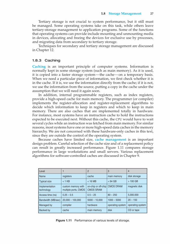
1.8 Storage Management 27
Tertiary storage is not crucial to system performance, but it still mustbe managed. Some operating systems take on this task, while others leavetertiary-storage management to application programs. Some of the functionsthat operating systems can provide include mounting and unmounting mediain devices, allocating and freeing the devices for exclusive use by processes,and migrating data from secondary to tertiary storage.
Techniques for secondary and tertiary storage management are discussedin Chapter 12.
1.8.3 Caching
Caching is an important principle of computer systems. Information isnormally kept in some storage system (such as main memory). As it is used,it is copied into a faster storage system—the cache—on a temporary basis.When we need a particular piece of information, we first check whether it isin the cache. If it is, we use the information directly from the cache; if it is not,we use the information from the source, putting a copy in the cache under theassumption that we will need it again soon.
In addition, internal programmable registers, such as index registers,provide a high-speed cache for main memory. The programmer (or compiler)implements the register-allocation and register-replacement algorithms todecide which information to keep in registers and which to keep in mainmemory. There are also caches that are implemented totally in hardware.For instance, most systems have an instruction cache to hold the instructionsexpected to be executed next. Without this cache, the CPU would have to waitseveral cycles while an instruction was fetched from main memory. For similarreasons, most systems have one or more high-speed data caches in the memoryhierarchy. We are not concerned with these hardware-only caches in this text,since they are outside the control of the operating system.
Because caches have limited size, cache management is an importantdesign problem. Careful selection of the cache size and of a replacement policycan result in greatly increased performance. Figure 1.11 compares storageperformance in large workstations and small servers. Various replacementalgorithms for software-controlled caches are discussed in Chapter 9.
Level
Name
Typical size
Implementation technology
Access time (ns)
Bandwidth (MB/sec)
Managed by
Backed by
1
registers
< 1 KB
custom memory with multiple ports, CMOS
0.25 – 0.5
20,000 – 100,000
compiler
cache
2
cache
< 16 MB
on-chip or off-chip CMOS SRAM
0.5 – 25
5000 – 10,000
hardware
main memory
3
main memory
< 64 GB
CMOS DRAM
80 – 250
1000 – 5000
operating system
disk
4
disk storage
> 100 GB
magnetic disk
5,000.000
20 – 150
operating system
CD or tape
Figure 1.11 Performance of various levels of storage.
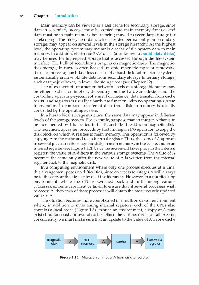
28 Chapter 1 Introduction
Main memory can be viewed as a fast cache for secondary storage, sincedata in secondary storage must be copied into main memory for use, anddata must be in main memory before being moved to secondary storage forsafekeeping. The file-system data, which resides permanently on secondarystorage, may appear on several levels in the storage hierarchy. At the highestlevel, the operating system may maintain a cache of file-system data in mainmemory. In addition, electronic RAM disks (also known as solid-state disks)may be used for high-speed storage that is accessed through the file-systeminterface. The bulk of secondary storage is on magnetic disks. The magnetic-disk storage, in turn, is often backed up onto magnetic tapes or removabledisks to protect against data loss in case of a hard-disk failure. Some systemsautomatically archive old file data from secondary storage to tertiary storage,such as tape jukeboxes, to lower the storage cost (see Chapter 12).
The movement of information between levels of a storage hierarchy maybe either explicit or implicit, depending on the hardware design and thecontrolling operating-system software. For instance, data transfer from cacheto CPU and registers is usually a hardware function, with no operating-systemintervention. In contrast, transfer of data from disk to memory is usuallycontrolled by the operating system.
In a hierarchical storage structure, the same data may appear in differentlevels of the storage system. For example, suppose that an integer A that is tobe incremented by 1 is located in file B, and file B resides on magnetic disk.The increment operation proceeds by first issuing an I/O operation to copy thedisk block on which A resides to main memory. This operation is followed bycopying A to the cache and to an internal register. Thus, the copy of A appearsin several places: on the magnetic disk, in main memory, in the cache, and in aninternal register (see Figure 1.12). Once the increment takes place in the internalregister, the value of A differs in the various storage systems. The value of Abecomes the same only after the new value of A is written from the internalregister back to the magnetic disk.
In a computing environment where only one process executes at a time,this arrangement poses no difficulties, since an access to integer A will alwaysbe to the copy at the highest level of the hierarchy. However, in a multitaskingenvironment, where the CPU is switched back and forth among variousprocesses, extreme care must be taken to ensure that, if several processes wishto access A, then each of these processes will obtain the most recently updatedvalue of A.
The situation becomes more complicated in a multiprocessor environmentwhere, in addition to maintaining internal registers, each of the CPUs alsocontains a local cache (Figure 1.6). In such an environment, a copy of A mayexist simultaneously in several caches. Since the various CPUs can all executeconcurrently, we must make sure that an update to the value of A in one cache
A A Amagneticdisk
mainmemory
hardwareregistercache
Figure 1.12 Migration of integer A from disk to register.
1.9 Protection and Security 29
is immediately reflected in all other caches where A resides. This situation iscalled cache coherency, and it is usually a hardware problem (handled belowthe operating-system level).
In a distributed environment, the situation becomes even more complex.In this environment, several copies (or replicas) of the same file can be kepton different computers that are distributed in space. Since the various replicasmay be accessed and updated concurrently, some distributed systems ensurethat, when a replica is updated in one place, all other replicas are brought upto date as soon as possible. There are various ways to achieve this guarantee,as we discuss in Chapter 17.
1.8.4 I/O Systems
One of the purposes of an operating system is to hide the peculiarities of specifichardware devices from the user. For example, in UNIX, the peculiarities of I/Odevices are hidden from the bulk of the operating system itself by the I/Osubsystem. The I/O subsystem consists of several components:
• A memory-management component that includes buffering, caching, andspooling
• A general device-driver interface
• Drivers for specific hardware devices
Only the device driver knows the peculiarities of the specific device to whichit is assigned.
We discussed in Section 1.2.3 how interrupt handlers and device drivers areused in the construction of efficient I/O subsystems. In Chapter 13, we discusshow the I/O subsystem interfaces to the other system components, managesdevices, transfers data, and detects I/O completion.
1.9 Protection and Security
If a computer system has multiple users and allows the concurrent executionof multiple processes, then access to data must be regulated. For that purpose,mechanisms ensure that files, memory segments, CPU, and other resources canbe operated on by only those processes that have gained proper authoriza-tion from the operating system. For example, memory-addressing hardwareensures that a process can execute only within its own address space. Thetimer ensures that no process can gain control of the CPU without eventuallyrelinquishing control. Device-control registers are not accessible to users, sothe integrity of the various peripheral devices is protected.
Protection, then, is any mechanism for controlling the access of processesor users to the resources defined by a computer system. This mechanism mustprovide means to specify the controls to be imposed and means to enforce thecontrols.
Protection can improve reliability by detecting latent errors at the interfacesbetween component subsystems. Early detection of interface errors can oftenprevent contamination of a healthy subsystem by another subsystem that is
30 Chapter 1 Introduction
malfunctioning. Furthermore, an unprotected resource cannot defend againstuse (or misuse) by an unauthorized or incompetent user. A protection-orientedsystem provides a means to distinguish between authorized and unauthorizedusage, as we discuss in Chapter 14.
A system can have adequate protection but still be prone to failure andallow inappropriate access. Consider a user whose authentication information(her means of identifying herself to the system) is stolen. Her data could becopied or deleted, even though file and memory protection are working. It isthe job of security to defend a system from external and internal attacks. Suchattacks spread across a huge range and include viruses and worms, denial-of-service attacks (which use all of a system’s resources and so keep legitimateusers out of the system), identity theft, and theft of service (unauthorized useof a system). Prevention of some of these attacks is considered an operating-system function on some systems, while other systems leave the prevention topolicy or additional software. Due to the alarming rise in security incidents,operating-system security features represent a fast-growing area of researchand implementation. Security is discussed in Chapter 15.
Protection and security require the system to be able to distinguish amongall its users. Most operating systems maintain a list of user names andassociated user identifiers (user IDs). In Windows Vista parlance, this is asecurity ID (SID). These numerical IDs are unique, one per user. When a userlogs in to the system, the authentication stage determines the appropriate userID for the user. That user ID is associated with all of the user’s processes andthreads. When an ID needs to be user readable, it is translated back to the username via the user name list.
In some circumstances, we wish to distinguish among sets of users ratherthan individual users. For example, the owner of a file on a UNIX system may beallowed to issue all operations on that file, whereas a selected set of users mayonly be allowed to read the file. To accomplish this, we need to define a groupname and the set of users belonging to that group. Group functionality canbe implemented as a system-wide list of group names and group identifiers.A user can be in one or more groups, depending on operating-system designdecisions. The user’s group IDs are also included in every associated processand thread.
In the course of normal use of a system, the user ID and group ID for a userare sufficient. However, a user sometimes needs to escalate privileges to gainextra permissions for an activity. The user may need access to a device that isrestricted, for example. Operating systems provide various methods to allowprivilege escalation. On UNIX, for example, the setuid attribute on a programcauses that program to run with the user ID of the owner of the file, rather thanthe current user’s ID. The process runs with this effective UID until it turns offthe extra privileges or terminates.
1.10 Distributed Systems
A distributed system is a collection of physically separate, possibly heteroge-neous, computer systems that are networked to provide the users with accessto the various resources that the system maintains. Access to a shared resource
1.10 Distributed Systems 31
increases computation speed, functionality, data availability, and reliability.Some operating systems generalize network access as a form of file access, withthe details of networking contained in the network interface’s device driver.Others make users specifically invoke network functions. Generally, systemscontain a mix of the two modes—for example FTP and NFS. The protocolsthat create a distributed system can greatly affect that system’s utility andpopularity.
A network, in the simplest terms, is a communication path betweentwo or more systems. Distributed systems depend on networking for theirfunctionality. Networks vary by the protocols used, the distances betweennodes, and the transport media. TCP/IP is the most common network protocol,although ATM and other protocols are in widespread use. Likewise, operating-system support of protocols varies. Most operating systems support TCP/IP,including the Windows and UNIX operating systems. Some systems supportproprietary protocols to suit their needs. To an operating system, a networkprotocol simply needs an interface device—a network adapter, for example—with a device driver to manage it, as well as software to handle data. Theseconcepts are discussed throughout this book.
Networks are characterized based on the distances between their nodes.A local-area network (LAN) connects computers within a room, a floor,or a building. A wide-area network (WAN) usually links buildings, cities,or countries. A global company may have a WAN to connect its officesworldwide. These networks may run one protocol or several protocols. Thecontinuing advent of new technologies brings about new forms of networks.For example, a metropolitan-area network (MAN) could link buildings withina city. BlueTooth and 802.11 devices use wireless technology to communicateover a distance of several feet, in essence creating a small-area network suchas might be found in a home.
The media to carry networks are equally varied. They include copper wires,fiber strands, and wireless transmissions between satellites, microwave dishes,and radios. When computing devices are connected to cellular phones, theycreate a network. Even very short-range infrared communication can be usedfor networking. At a rudimentary level, whenever computers communicate,they use or create a network. These networks also vary in their performanceand reliability.
Some operating systems have taken the concept of networks and dis-tributed systems further than the notion of providing network connectivity. Anetwork operating system is an operating system that provides features suchas file sharing across the network and that includes a communication schemethat allows different processes on different computers to exchange messages.A computer running a network operating system acts autonomously from allother computers on the network, although it is aware of the network and isable to communicate with other networked computers. A distributed operat-ing system provides a less autonomous environment: The different operatingsystems communicate closely enough to provide the illusion that only a singleoperating system controls the network.
We cover computer networks and distributed systems in Chapters 16through 18.
32 Chapter 1 Introduction
1.11 Special-Purpose Systems
The discussion thus far has focused on the general-purpose computer systemsthat we are all familiar with. There are, however, other classes of computersystems whose functions are more limited and whose objective is to deal withlimited computation domains.
1.11.1 Real-Time Embedded Systems
Embedded computers are the most prevalent form of computers in existence.These devices are found everywhere, from car engines and manufacturingrobots to DVDs and microwave ovens. They tend to have very specific tasks.The systems they run on are usually primitive, and so the operating systemsprovide limited features. Usually, they have little or no user interface, preferringto spend their time monitoring and managing hardware devices, such asautomobile engines and robotic arms.
These embedded systems vary considerably. Some are general-purposecomputers, running standard operating systems—such as UNIX—withspecial-purpose applications to implement the functionality. Others arehardware devices with a special-purpose embedded operating systemproviding just the functionality desired. Yet others are hardware deviceswith application-specific integrated circuits (ASICs) that perform their taskswithout an operating system.
The use of embedded systems continues to expand. The power of thesedevices, both as standalone units and as elements of networks and the Web,is sure to increase as well. Even now, entire houses can be computerized, sothat a central computer—either a general-purpose computer or an embeddedsystem—can control heating and lighting, alarm systems, and even coffeemakers. Web access can enable a home owner to tell the house to heat upbefore she arrives home. Someday, the refrigerator may call the grocery storewhen it notices the milk is gone.
Embedded systems almost always run real-time operating systems. Areal-time system is used when rigid time requirements have been placed onthe operation of a processor or the flow of data; thus, it is often used as acontrol device in a dedicated application. Sensors bring data to the computer.The computer must analyze the data and possibly adjust controls to modifythe sensor inputs. Systems that control scientific experiments, medical imagingsystems, industrial control systems, and certain display systems are real-time systems. Some automobile-engine fuel-injection systems, home-appliancecontrollers, and weapon systems are also real-time systems.
A real-time system has well-defined, fixed time constraints. Processingmust be done within the defined constraints, or the system will fail. For instance,it would not do for a robot arm to be instructed to halt after it had smashedinto the car it was building. A real-time system functions correctly only if itreturns the correct result within its time constraints. Contrast this system witha time-sharing system, where it is desirable (but not mandatory) to respondquickly, or a batch system, which may have no time constraints at all.
In Chapter 19, we cover real-time embedded systems in great detail. InChapter 5, we consider the scheduling facility needed to implement real-timefunctionality in an operating system. In Chapter 9, we describe the design
1.11 Special-Purpose Systems 33
of memory management for real-time computing. Finally, in Chapter 22, wedescribe the real-time components of the Windows XP operating system.
1.11.2 Multimedia Systems
Most operating systems are designed to handle conventional data such astext files, programs, word-processing documents, and spreadsheets. However,a recent trend in technology is the incorporation of multimedia data intocomputer systems. Multimedia data consist of audio and video files as well asconventional files. These data differ from conventional data in that multimediadata—such as frames of video—must be delivered (streamed) according tocertain time restrictions (for example, 30 frames per second).
Multimedia describes a wide range of applications in popular use today.These include audio files such as MP3, DVD movies, video conferencing, andshort video clips of movie previews or news stories downloaded over theInternet. Multimedia applications may also include live webcasts (broadcastingover the World Wide Web) of speeches or sporting events and even livewebcams that allow a viewer in Manhattan to observe customers at a cafein Paris. Multimedia applications need not be either audio or video; rather, amultimedia application often includes a combination of both. For example, amovie may consist of separate audio and video tracks. Nor must multimediaapplications be delivered only to desktop personal computers. Increasingly,they are being directed toward smaller devices, including PDAs and cellulartelephones. For example, a stock trader may have stock quotes deliveredwirelessly and in real time to his PDA.
In Chapter 20, we explore the demands of multimedia applications,describe how multimedia data differ from conventional data, and explain howthe nature of these data affects the design of operating systems that supportthe requirements of multimedia systems.
1.11.3 Handheld Systems
Handheld systems include personal digital assistants (PDAs), such as Palmand Pocket-PCs, and cellular telephones, many of which use special-purposeembedded operating systems. Developers of handheld systems and applica-tions face many challenges, most of which are due to the limited size of suchdevices. For example, a PDA is typically about 5 inches in height and 3 inchesin width, and it weighs less than one-half pound. Because of their size, mosthandheld devices have small amounts of memory, slow processors, and smalldisplay screens. We take a look now at each of these limitations.
The amount of physical memory in a handheld depends on the device, buttypically it is somewhere between 1 MB and 1 GB. (Contrast this with a typicalPC or workstation, which may have several gigabytes of memory.) As a result,the operating system and applications must manage memory efficiently. Thisincludes returning all allocated memory to the memory manager when thememory is not being used. In Chapter 9, we explore virtual memory, whichallows developers to write programs that behave as if the system has morememory than is physically available. Currently, not many handheld devicesuse virtual memory techniques, so program developers must work within theconfines of limited physical memory.
34 Chapter 1 Introduction
A second issue of concern to developers of handheld devices is the speedof the processor used in the devices. Processors for most handheld devicesrun at a fraction of the speed of a processor in a PC. Faster processors requiremore power. To include a faster processor in a handheld device would requirea larger battery, which would take up more space and would have to bereplaced (or recharged) more frequently. Most handheld devices use smaller,slower processors that consume less power. Therefore, the operating systemand applications must be designed not to tax the processor.
The last issue confronting program designers for handheld devices is I/O.A lack of physical space limits input methods to small keyboards, handwritingrecognition, or small screen-based keyboards. The small display screens limitoutput options. Whereas a monitor for a home computer may measure up to30 inches, the display for a handheld device is often no more than 3 inchessquare. Familiar tasks, such as reading e-mail and browsing Web pages, mustbe condensed into smaller displays. One approach for displaying the contentin Web pages is Web clipping, where only a small subset of a Web page isdelivered and displayed on the handheld device.
Some handheld devices use wireless technology, such as BlueTooth or802.11, allowing remote access to e-mail and Web browsing. Cellular telephoneswith connectivity to the Internet fall into this category. However, for PDAs thatdo not provide wireless access, downloading data typically requires the userfirst to download the data to a PC or workstation and then download the datato the PDA. Some PDAs allow data to be directly copied from one device toanother using an infrared link.
Generally, the limitations in the functionality of PDAs are balanced bytheir convenience and portability. Their use continues to expand as networkconnections become more available and other options, such as digital camerasand MP3 players, expand their utility.
1.12 Computing Environments
So far, we have provided an overview of computer-system organization andmajor operating-system components. We conclude with a brief overview ofhow these are used in a variety of computing environments.
1.12.1 Traditional Computing
As computing matures, the lines separating many of the traditional computingenvironments are blurring. Consider the “typical office environment.” Just afew years ago, this environment consisted of PCs connected to a network,with servers providing file and print services. Remote access was awkward,and portability was achieved by use of laptop computers. Terminals attachedto mainframes were prevalent at many companies as well, with even fewerremote access and portability options.
The current trend is toward providing more ways to access these computingenvironments. Web technologies are stretching the boundaries of traditionalcomputing. Companies establish portals, which provide Web accessibilityto their internal servers. Network computers are essentially terminals thatunderstand Web-based computing. Handheld computers can synchronize with
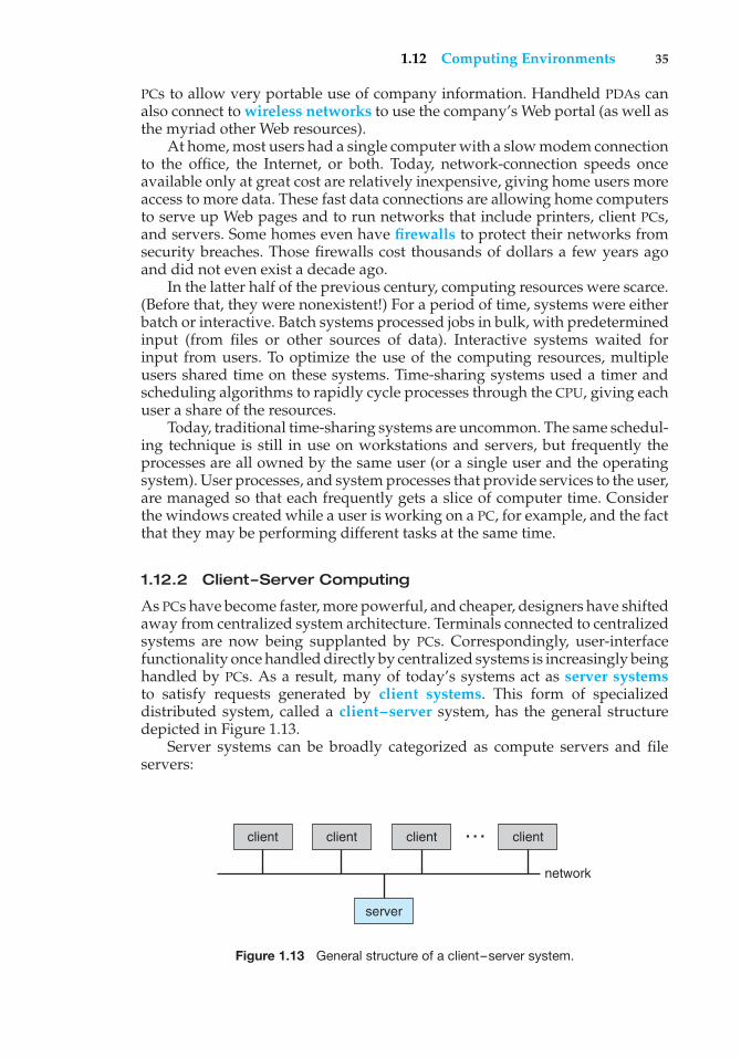
1.12 Computing Environments 35
PCs to allow very portable use of company information. Handheld PDAs canalso connect to wireless networks to use the company’s Web portal (as well asthe myriad other Web resources).
At home, most users had a single computer with a slow modem connectionto the office, the Internet, or both. Today, network-connection speeds onceavailable only at great cost are relatively inexpensive, giving home users moreaccess to more data. These fast data connections are allowing home computersto serve up Web pages and to run networks that include printers, client PCs,and servers. Some homes even have firewalls to protect their networks fromsecurity breaches. Those firewalls cost thousands of dollars a few years agoand did not even exist a decade ago.
In the latter half of the previous century, computing resources were scarce.(Before that, they were nonexistent!) For a period of time, systems were eitherbatch or interactive. Batch systems processed jobs in bulk, with predeterminedinput (from files or other sources of data). Interactive systems waited forinput from users. To optimize the use of the computing resources, multipleusers shared time on these systems. Time-sharing systems used a timer andscheduling algorithms to rapidly cycle processes through the CPU, giving eachuser a share of the resources.
Today, traditional time-sharing systems are uncommon. The same schedul-ing technique is still in use on workstations and servers, but frequently theprocesses are all owned by the same user (or a single user and the operatingsystem). User processes, and system processes that provide services to the user,are managed so that each frequently gets a slice of computer time. Considerthe windows created while a user is working on a PC, for example, and the factthat they may be performing different tasks at the same time.
1.12.2 Client–Server Computing
As PCs have become faster, more powerful, and cheaper, designers have shiftedaway from centralized system architecture. Terminals connected to centralizedsystems are now being supplanted by PCs. Correspondingly, user-interfacefunctionality once handled directly by centralized systems is increasingly beinghandled by PCs. As a result, many of today’s systems act as server systemsto satisfy requests generated by client systems. This form of specializeddistributed system, called a client–server system, has the general structuredepicted in Figure 1.13.
Server systems can be broadly categorized as compute servers and fileservers:
client client client client
server
network
…
Figure 1.13 General structure of a client–server system.
36 Chapter 1 Introduction
• The compute-server system provides an interface to which a client cansend a request to perform an action (for example, read data); in response,the server executes the action and sends back results to the client. A serverrunning a database that responds to client requests for data is an exampleof such a system.
• The file-server system provides a file-system interface where clients cancreate, update, read, and delete files. An example of such a system is a Webserver that delivers files to clients running Web browsers.
1.12.3 Peer-to-Peer Computing
Another structure for a distributed system is the peer-to-peer (P2P) systemmodel. In this model, clients and servers are not distinguished from oneanother; instead, all nodes within the system are considered peers, and eachmay act as either a client or a server, depending on whether it is requesting orproviding a service. Peer-to-peer systems offer an advantage over traditionalclient-server systems. In a client-server system, the server is a bottleneck; butin a peer-to-peer system, services can be provided by several nodes distributedthroughout the network.
To participate in a peer-to-peer system, a node must first join the networkof peers. Once a node has joined the network, it can begin providing servicesto—and requesting services from—other nodes in the network. Determiningwhat services are available is accomplished in one of two general ways:
• When a node joins a network, it registers its service with a centralizedlookup service on the network. Any node desiring a specific service firstcontacts this centralized lookup service to determine which node providesthe service. The remainder of the communication takes place between theclient and the service provider.
• A peer acting as a client must first discover what node provides a desiredservice by broadcasting a request for the service to all other nodes in thenetwork. The node (or nodes) providing that service responds to the peermaking the request. To support this approach, a discovery protocol must beprovided that allows peers to discover services provided by other peers inthe network.
Peer-to-peer networks gained widespread popularity in the late 1990s withseveral file-sharing services, such as Napster and Gnutella, that enable peersto exchange files with one another. The Napster system uses an approachsimilar to the first type described above: a centralized server maintains anindex of all files stored on peer nodes in the Napster network, and the actualexchanging of files takes place between the peer nodes. The Gnutella systemuses a technique similar to the second type: a client broadcasts file requeststo other nodes in the system, and nodes that can service the request responddirectly to the client. The future of exchanging files remains uncertain becausemany of the files are copyrighted (music, for example), and there are lawsgoverning the distribution of copyrighted material. In any case, though, peer-to-peer technology undoubtedly will play a role in the future of many services,such as searching, file exchange, and e-mail.
1.13 Open-Source Operating Systems 37
1.12.4 Web-Based Computing
The Web has become ubiquitous, leading to more access by a wider variety ofdevices than was dreamt of a few years ago. PCs are still the most prevalentaccess devices, with workstations, handheld PDAs, and even cell phones alsoproviding access.
Web computing has increased the emphasis on networking. Devices thatwere not previously networked now include wired or wireless access. Devicesthat were networked now have faster network connectivity, provided by eitherimproved networking technology, optimized network implementation code,or both.
The implementation of Web-based computing has given rise to newcategories of devices, such as load balancers, which distribute networkconnections among a pool of similar servers. Operating systems like Windows95, which acted as Web clients, have evolved into Linux and Windows XP, whichcan act as Web servers as well as clients. Generally, the Web has increased thecomplexity of devices because their users require them to be Web-enabled.
1.13 Open-Source Operating Systems
The study of operating systems, as noted earlier, is made easier by theavailability of a vast number of open-source releases. Open-source operatingsystems are those made available in source-code format rather than ascompiled binary code. Linux is the most famous open- source operating system,while Microsoft Windows is a well-known example of the opposite closed-source approach. Starting with the source code allows the programmer toproduce binary code that can be executed on a system. Doing the opposite—reverse engineering the source code from the binaries—is quite a lot of work,and useful items such as comments are never recovered. Learning operatingsystems by examining the actual source code, rather than reading summaries ofthat code, can be extremely useful. With the source code in hand, a student canmodify the operating system and then compile and run the code to try out thosechanges, which is another excellent learning tool. This text includes projectsthat involve modifying operating system source code, while also describingalgorithms at a high level to be sure all important operating system topics arecovered. Throughout the text, we provide pointers to examples of open-sourcecode for deeper study.
There are many benefits to open-source operating systems, including acommunity of interested (and usually unpaid) programmers who contributeto the code by helping to debug it, analyze it, provide support, and suggestchanges. Arguably, open-source code is more secure than closed-source codebecause many more eyes are viewing the code. Certainly open-source code hasbugs, but open-source advocates argue that bugs tend to be found and fixedfaster owing to the number of people using and viewing the code. Companiesthat earn revenue from selling their programs tend to be hesitant to open-sourcetheir code, but Red Hat, SUSE, Sun, and a myriad of other companies are doingjust that and showing that commercial companies benefit, rather than suffer,when they open-source their code. Revenue can be generated through supportcontracts and the sale of hardware on which the software runs, for example.
38 Chapter 1 Introduction
1.13.1 History
In the early days of modern computing (that is, the 1950s), a great deal ofsoftware was available in open-source format. The original hackers (computerenthusiasts) at MIT’s Tech Model Railroad Club left their programs in drawersfor others to work on. “Homebrew” user groups exchanged code during theirmeetings. Later, company-specific user groups, such as Digital EquipmentCorporation’s DEC, accepted contributions of source-code programs, collectedthem onto tapes, and distributed the tapes to interested members.
Computer and software companies eventually sought to limit the useof their software to authorized computers and paying customers. Releasingonly the binary files compiled from the source code, rather than the sourcecode itself, helped them to achieve this goal, as well as protecting their codeand their ideas from their competitors. Another issue involved copyrightedmaterial. Operating systems and other programs can limit the ability to playback movies and music or display electronic books to authorized computers.Such copy protection or Digital Rights Management (DRM) would not beeffective if the source code that implemented these limits were published.Laws in many countries, including the U.S. Digital Millennium CopyrightAct (DMCA), make it illegal to reverse-engineer DRM code or otherwise try tocircumvent copy protection.
To counter the move to limit software use and redistribution, RichardStallman in 1983 started the GNU project to create a free, open-source UNIX-compatible operating system. In 1985, he published the GNU Manifesto, whichargues that all software should be free and open-sourced. He also formedthe Free Software Foundation (FSF) with the goal of encouraging the freeexchange of software source code and the free use of that software. Rather thancopyright its software, the FSF “copylefts” the software to encourage sharingand improvement. The GNU General Public License (GPL) codifies copyleftingand is a common license under which free software is released. Fundamentally,GPL requires that the source code be distributed with any binaries and that anychanges made to the source code be released under the same GPL license.
1.13.2 Linux
As an example of an open-source operating system, consider GNU/Linux.The GNU project produced many UNIX-compatible tools, including compilers,editors, and utilities, but never released a kernel. In 1991, a student inFinland, Linus Torvalds, released a rudimentary UNIX-like kernel using theGNU compilers and tools and invited contributions worldwide. The advent ofthe Internet meant that anyone interested could download the source code,modify it, and submit changes to Torvalds. Releasing updates once a weekallowed this so-called Linux operating system to grow rapidly, enhanced byseveral thousand programmers.
The resulting GNU/Linux operating system has spawned hundreds ofunique distributions, or custom builds, of the system. Major distributionsinclude RedHat, SUSE, Fedora, Debian, Slackware, and Ubuntu. Distributionsvary in function, utility, installed applications, hardware support, user inter-face, and purpose. For example, RedHat Enterprise Linux is geared to largecommercial use. PCLinuxOS is a LiveCD—an operating system that can bebooted and run from a CD-ROM without being installed on a system’s hard
1.13 Open-Source Operating Systems 39
disk. One variant of PCLinuxOS, “PCLinuxOS Supergamer DVD,” is a LiveDVDthat includes graphics drivers and games. A gamer can run it on any compatiblesystem simply by booting from the DVD. When the gamer is finished, a rebootof the system resets it to its installed operating system.
Access to the Linux source code varies by release. Here, we considerUbuntu Linux. Ubuntu is a popular Linux distribution that comes in a varietyof types, including those tuned for desktops, servers, and students. Its founderpays for the printing and mailing of DVDs containing the binary and sourcecode (which helps to make it popular). The following steps outline a wayto explore the Ubuntu kernel source code on systems that support the free“VMware Player” tool:
• Download the player from http://www.vmware.com/download/player/and install it on your system.
• Download a virtual machine containing Ubuntu. Hundreds of“appliances”, or virtual machine images, pre-installed with oper-ating systems and applications, are available from VMware athttp://www.vmware.com/appliances/.
• Boot the virtual machine within VMware Player.
• Get the source code of the kernel release of interest, such as 2.6, by executingwget http://www.kernel.org/pub/linux/kernel/v2.6/linux-2.6.18.1.tar.bz2 within the Ubuntu virtual machine.
• Uncompress and untar the downloaded file via tar xjf linux-2.6.18.1.tar.bz2.
• Explore the source code of the Ubuntu kernel, which is now in ./linux-2.6.18.1.
For more about Linux, see Chapter 21. For more about virtual machines, seeSection 2.8.
1.13.3 BSD UNIX
BSD UNIX has a longer and more complicated history than Linux. It started in1978 as a derivative of AT&T’s UNIX. Releases from the University of Californiaat Berkeley (UCB) came in source and binary form, but they were not open-source because a license from AT&T was required. BSD UNIX’s development wasslowed by a lawsuit by AT&T, but eventually a fully functional, open-sourceversion, 4.4BSD-lite, was released in 1994.
Just as with Linux, there are many distributions of BSD UNIX, includingFreeBSD, NetBSD, OpenBSD, and DragonflyBSD. To explore the source codeof FreeBSD, simply download the virtual machine image of the version ofinterest and boot it within VMware, as described above for Ubuntu Linux. Thesource code comes with the distribution and is stored in /usr/src/. The kernelsource code is in /usr/src/sys. For example, to examine the virtual-memoryimplementation code in the FreeBSD kernel, see the files in /usr/src/sys/vm.
Darwin, the core kernel component of MAC, is based on BSDUNIX and is open-sourced as well. That source code is available fromhttp://www.opensource.apple.com/darwinsource/. Every MAC release
40 Chapter 1 Introduction
has its open-source components posted at that site. The name of thepackage that contains the kernel is “xnu.” The source code for MACkernel revision 1228 (the source code to MAC Leopard) can be found atwww.opensource.apple.com/darwinsource/tarballs/apsl/xnu-1228.tar.gz.Apple also provides extensive developer tools, documentation, and supportat http://connect.apple.com. For more information, see Appendix A.
1.13.4 Solaris
Solaris is the commercial UNIX-based operating system of Sun Microsystems.Originally, Sun’s SunOS operating system was based on BSD UNIX. Sun movedto AT&T’s System V UNIX as its base in 1991. In 2005, Sun open-sourced someof the Solaris code, and over time, the company has added more and more tothat open-source code base. Unfortunately, not all of Solaris is open-sourced,because some of the code is still owned by AT&T and other companies. However,Solaris can be compiled from the open source and linked with binaries of theclose-sourced components, so it can still be explored, modified, compiled, andtested.
The source code is available from http://opensolaris.org/os/downloads/.Also available there are pre-compiled distributions based on the source code,documentation, and discussion groups. It is not necessary to download theentire source-code bundle from the site, because Sun allows visitors to explorethe source code on-line via a source code browser.
1.13.5 Utility
The free software movement is driving legions of programmers to createthousands of open-source projects, including operating systems. Sites likehttp://freshmeat.net/ and http://distrowatch.com/ provide portals tomany of these projects. Open-source projects enable students to use sourcecode as a learning tool. They can modify programs and test them, help findand fix bugs, and otherwise explore mature, full-featured operating systems,compilers, tools, user interfaces, and other types of programs. The availabilityof source code for historic projects, such as Multics, can help students tounderstand those projects and to build knowledge that will help in theimplementation of new projects.
GNU/Linux, BSD UNIX, and Solaris are all open-source operating sys-tems, but each has its own goals, utility, licensing, and purpose. Sometimeslicenses are not mutually exclusive and cross-pollination occurs, allowingrapid improvements in operating-system projects. For example, several majorcomponents of Solaris have been ported to BSD UNIX. The advantages of freesoftware and open sourcing are likely to increase the number and quality ofopen-source projects, leading to an increase in the number of individuals andcompanies that use these projects.
1.14 Summary
An operating system is software that manages the computer hardware, as wellas providing an environment for application programs to run. Perhaps the
1.14 Summary 41
most visible aspect of an operating system is the interface to the computersystem it provides to the human user.
For a computer to do its job of executing programs, the programs must bein main memory. Main memory is the only large storage area that the processorcan access directly. It is an array of words or bytes, ranging in size from millionsto billions. Each word in memory has its own address. The main memory isusually a volatile storage device that loses its contents when power is turnedoff or lost. Most computer systems provide secondary storage as an extensionof main memory. Secondary storage provides a form of nonvolatile storage thatis capable of holding large quantities of data permanently. The most commonsecondary-storage device is a magnetic disk, which provides storage of bothprograms and data.
The wide variety of storage systems in a computer system can be organizedin a hierarchy according to speed and cost. The higher levels are expensive,but they are fast. As we move down the hierarchy, the cost per bit generallydecreases, whereas the access time generally increases.
There are several different strategies for designing a computer system.Uniprocessor systems have only a single processor, while multiprocessorsystems contain two or more processors that share physical memory andperipheral devices. The most common multiprocessor design is symmetricmultiprocessing (or SMP), where all processors are considered peers and runindependently of one another. Clustered systems are a specialized form ofmultiprocessor systems and consist of multiple computer systems connectedby a local area network.
To best utilize the CPU, modern operating systems employ multiprogram-ming, which allows several jobs to be in memory at the same time, thus ensuringthat the CPU always has a job to execute. Time-sharing systems are an exten-sion of multiprogramming wherein CPU scheduling algorithms rapidly switchbetween jobs, thus providing the illusion that each job is running concurrently.
The operating system must ensure correct operation of the computersystem. To prevent user programs from interfering with the proper operation ofthe system, the hardware has two modes: user mode and kernel mode. Variousinstructions (such as I/O instructions and halt instructions) are privileged andcan be executed only in kernel mode. The memory in which the operatingsystem resides must also be protected from modification by the user. A timerprevents infinite loops. These facilities (dual mode, privileged instructions,memory protection, and timer interrupt) are basic building blocks used byoperating systems to achieve correct operation.
A process (or job) is the fundamental unit of work in an operating system.Process management includes creating and deleting processes and providingmechanisms for processes to communicate and synchronize with each other.An operating system manages memory by keeping track of what parts ofmemory are being used and by whom. The operating system is also responsiblefor dynamically allocating and freeing memory space. Storage space is alsomanaged by the operating system; this includes providing file systems forrepresenting files and directories and managing space on mass-storage devices.
Operating systems must also be concerned with protecting and securingthe operating system and users. Protection measures are mechanisms thatcontrol the access of processes or users to the resources made available by the
42 Chapter 1 Introduction
computer system. Security measures are responsible for defending a computersystem from external or internal attacks.
Distributed systems allow users to share resources on geographicallydispersed hosts connected via a computer network. Services may be providedthrough either the client–server model or the peer-to-peer model. In a clusteredsystem, multiple machines can perform computations on data residing onshared storage, and computing can continue even when some subset of clustermembers fails.
LANs and WANs are the two basic types of networks. LANs enableprocessors distributed over a small geographical area to communicate, whereasWANs allow processors distributed over a larger area to communicate. LANstypically are faster than WANs.
There are several computer systems that serve specific purposes. Theseinclude real-time operating systems designed for embedded environmentssuch as consumer devices, automobiles, and robotics. Real-time operatingsystems have well-defined, fixed-time constraints. Processing must be donewithin the defined constraints, or the system will fail. Multimedia systemsinvolve the delivery of multimedia data and often have special requirements ofdisplaying or playing audio, video, or synchronized audio and video streams.
Recently, the influence of the Internet and the World Wide Web hasencouraged the development of operating systems that include Web browsersand networking and communication software as integral features.
The free software movement has created thousands of open-source projects,including operating systems. Because of these projects, students are able to usesource code as a learning tool. They can modify programs and test them,help find and fix bugs, and otherwise explore mature, full-featured operatingsystems, compilers, tools, user interfaces, and other types of programs.
GNU/Linux, BSD UNIX, and Solaris are all open-source operating systems.The advantages of free software and open sourcing are likely to increase thenumber and quality of open-source projects, leading to an increase in thenumber of individuals and companies that use these projects.
Practice Exercises
1.1 What are the three main purposes of an operating system?
1.2 What are the main differences between operating systems for mainframecomputers and personal computers?
1.3 List the four steps that are necessary to run a program on a completelydedicated machine—a computer that is running only that program.
1.4 We have stressed the need for an operating system to make efficient useof the computing hardware. When is it appropriate for the operatingsystem to forsake this principle and to “waste” resources? Why is sucha system not really wasteful?
1.5 What is the main difficulty that a programmer must overcome in writingan operating system for a real-time environment?
1.6 Consider the various definitions of operating system. Consider whetherthe operating system should include applications such as Web browsers
Exercises 43
and mail programs. Argue both that it should and that it should not, andsupport your answers.
1.7 How does the distinction between kernel mode and user mode functionas a rudimentary form of protection (security) system?
1.8 Which of the following instructions should be privileged?
a. Set value of timer.
b. Read the clock.
c. Clear memory.
d. Issue a trap instruction.
e. Turn off interrupts.
f. Modify entries in device-status table.
g. Switch from user to kernel mode.
h. Access I/O device.
1.9 Some early computers protected the operating system by placing it ina memory partition that could not be modified by either the user jobor the operating system itself. Describe two difficulties that you thinkcould arise with such a scheme.
1.10 Some CPUs provide for more than two modes of operation. What aretwo possible uses of these multiple modes?
1.11 Timers could be used to compute the current time. Provide a shortdescription of how this could be accomplished.
1.12 Is the Internet a LAN or a WAN?
Exercises
1.13 In a multiprogramming and time-sharing environment, several usersshare the system simultaneously. This situation can result in varioussecurity problems.
a. What are two such problems?
b. Can we ensure the same degree of security in a time-sharedmachine as in a dedicated machine? Explain your answer.
1.14 The issue of resource utilization shows up in different forms in differenttypes of operating systems. List what resources must be managedcarefully in the following settings:
a. Mainframe or minicomputer systems
b. Workstations connected to servers
c. Handheld computers
44 Chapter 1 Introduction
1.15 Under what circumstances would a user be better off using a time-sharing system rather than a PC or a single-user workstation?
1.16 Identify which of the functionalities listed below need to be supported bythe operating system for (a) handheld devices and (b) real-time systems.
a. Batch programming
b. Virtual memory
c. Time sharing
1.17 Describe the differences between symmetric and asymmetric multipro-cessing. What are three advantages and one disadvantage of multipro-cessor systems?
1.18 How do clustered systems differ from multiprocessor systems? What isrequired for two machines belonging to a cluster to cooperate to providea highly available service?
1.19 Distinguish between the client–server and peer-to-peer models ofdistributed systems.
1.20 Consider a computing cluster consisting of two nodes running adatabase. Describe two ways in which the cluster software can manageaccess to the data on the disk. Discuss the benefits and disadvantages ofeach.
1.21 How are network computers different from traditional personal com-puters? Describe some usage scenarios in which it is advantageous touse network computers.
1.22 What is the purpose of interrupts? What are the differences between atrap and an interrupt? Can traps be generated intentionally by a userprogram? If so, for what purpose?
1.23 Direct memory access is used for high-speed I/O devices in order toavoid increasing the CPU’s execution load.
a. How does the CPU interface with the device to coordinate thetransfer?
b. How does the CPU know when the memory operations are com-plete?
c. The CPU is allowed to execute other programs while the DMAcontroller is transferring data. Does this process interfere withthe execution of the user programs? If so, describe what formsof interference are caused.
1.24 Some computer systems do not provide a privileged mode of operationin hardware. Is it possible to construct a secure operating system forthese computer systems? Give arguments both that it is and that it is notpossible.
1.25 Give two reasons why caches are useful. What problems do they solve?What problems do they cause? If a cache can be made as large as the
Exercises 45
device for which it is caching (for instance, a cache as large as a disk),why not make it that large and eliminate the device?
1.26 Consider an SMP system similar to what is shown in Figure 1.6. Illustratewith an example how data residing in memory could in fact have twodifferent values in each of the local caches.
1.27 Discuss, with examples, how the problem of maintaining coherence ofcached data manifests itself in the following processing environments:
a. Single-processor systems
b. Multiprocessor systems
c. Distributed systems
1.28 Describe a mechanism for enforcing memory protection in order toprevent a program from modifying the memory associated with otherprograms.
1.29 What network configuration would best suit the following environ-ments?
a. A dormitory floor
b. A university campus
c. A state
d. A nation
1.30 Define the essential properties of the following types of operatingsystems:
a. Batch
b. Interactive
c. Time sharing
d. Real time
e. Network
f. Parallel
g. Distributed
h. Clustered
i. Handheld
1.31 What are the tradeoffs inherent in handheld computers?
1.32 Identify several advantages and several disadvantages of open-sourceoperating systems. Include the types of people who would find eachaspect to be an advantage or a disadvantage.
46 Chapter 1 Introduction
Wiley Plus
Visit Wiley Plus for
• Source code
• Solutions to practice exercises
• Additional programming problems and exercises
• Labs using an operating system simulator
Bibliographical Notes
Brookshear [2003] provides an overview of computer science in general.An overview of the Linux operating system is presented in Bovet and
Cesati [2006]. Solomon and Russinovich [2000] give an overview of MicrosoftWindows and considerable technical detail about the system internals andcomponents. Russinovich and Solomon [2005] update this information toWindows Server 2003 and Windows XP. McDougall and Mauro [2007] coverthe internals of the Solaris operating system. Mac OS X is presented athttp://www.apple.com/macosx. Mac OS X internals are discussed in Singh[2007].
Coverage of peer-to-peer systems includes Parameswaran et al. [2001],Gong [2002], Ripeanu et al. [2002], Agre [2003], Balakrishnan et al. [2003], andLoo [2003]. A discussion of peer-to-peer file-sharing systems can be found inLee [2003]. Good coverage of cluster computing is provided by Buyya [1999].Recent advances in cluster computing are described by Ahmed [2000]. A surveyof issues relating to operating-system support for distributed systems can befound in Tanenbaum and Van Renesse [1985].
Many general textbooks cover operating systems, including Stallings[2000b], Nutt [2004], and Tanenbaum [2001].
Hamacher et al. [2002] describe computer organization, and McDougalland Laudon [2006] discuss multicore processors. Hennessy and Patterson[2007] provide coverage of I/O systems and buses, and of system architecturein general. Blaauw and Brooks [1997] describe details of the architecture ofmany computer systems, including several from IBM. Stokes [2007] providesan illustrated introduction to microprocessors and computer architecture.
Cache memories, including associative memory, are described and ana-lyzed by Smith [1982]. That paper also includes an extensive bibliography onthe subject.
Discussions concerning magnetic-disk technology are presented by Freed-man [1983] and by Harker et al. [1981]. Optical disks are covered by Kenville[1982], Fujitani [1984], O’Leary and Kitts [1985], Gait [1988], and Olsen andKenley [1989]. Discussions of floppy disks are offered by Pechura and Schoeffler[1983] and by Sarisky [1983]. General discussions concerning mass-storagetechnology are offered by Chi [1982] and by Hoagland [1985].
Kurose and Ross [2005] and Tanenbaum [2003] provides general overviewsof computer networks. Fortier [1989] presents a detailed discussion of network-ing hardware and software. Kozierok [2005] discuss TCP in detail. Mullender[1993] provides an overview of distributed systems. Wolf [2003] discusses
Bibliographical Notes 47
recent developments in developing embedded systems. Issues related to hand-held devices can be found in Myers and Beigl [2003] and Di Pietro and Mancini[2003].
A full discussion of the history of open sourcing and its benefits and chal-lenges is found in Raymond [1999]. The history of hacking is discussed in Levy[1994]. The Free Software Foundation has published its philosophy on its Website: http://www.gnu.org/philosophy/free-software-for-freedom.html.Detailed instructions on how to build the Ubuntu Linux kernel are onhttp://www.howtoforge.com/kernel compilation ubuntu. The open-sourcecomponents of MAC are available from http://developer.apple.com/open-source/index.html.
Wikipedia (http://en.wikipedia.org/wiki/Richard Stallman) has aninformative entry about Richard Stallman.
The source code of Multics is available at http://web.mit.edu/multics-history/source/Multics Internet Server/Multics sources.html.

This page intentionally left blank
2C H A P T E ROperating -SystemStructures
An operating system provides the environment within which programs areexecuted. Internally, operating systems vary greatly in their makeup, sincethey are organized along many different lines. The design of a new operatingsystem is a major task. It is important that the goals of the system be welldefined before the design begins. These goals form the basis for choices amongvarious algorithms and strategies.
We can view an operating system from several vantage points. One viewfocuses on the services that the system provides; another, on the interface thatit makes available to users and programmers; a third, on its components andtheir interconnections. In this chapter, we explore all three aspects of operatingsystems, showing the viewpoints of users, programmers, and operating-systemdesigners. We consider what services an operating system provides, how theyare provided, how they are debugged, and what the various methodologiesare for designing such systems. Finally, we describe how operating systemsare created and how a computer starts its operating system.
CHAPTER OBJECTIVES
• To describe the services an operating system provides to users, processes,and other systems.
• To discuss the various ways of structuring an operating system.
• To explain how operating systems are installed and customized and howthey boot.
2.1 Operating-System Services
An operating system provides an environment for the execution of programs.It provides certain services to programs and to the users of those programs.The specific services provided, of course, differ from one operating system toanother, but we can identify common classes. These operating-system servicesare provided for the convenience of the programmer, to make the programming
49
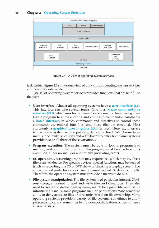
50 Chapter 2 Operating-System Structures
user and other system programs
services
operating system
hardware
system calls
GUI batch
user interfaces
command line
programexecution
I/Ooperations
filesystems communication resource
allocation accounting
protectionand
security
errordetection
Figure 2.1 A view of operating system services.
task easier. Figure 2.1 shows one view of the various operating-system servicesand how they interrelate.
One set of operating-system services provides functions that are helpful tothe user.
• User interface. Almost all operating systems have a user interface (UI).This interface can take several forms. One is a DTrace command-lineinterface (CLI), which uses text commands and a method for entering them(say, a program to allow entering and editing of commands). Another isa batch interface, in which commands and directives to control thosecommands are entered into files, and those files are executed. Mostcommonly, a graphical user interface (GUI) is used. Here, the interfaceis a window system with a pointing device to direct I/O, choose frommenus, and make selections and a keyboard to enter text. Some systemsprovide two or all three of these variations.
• Program execution. The system must be able to load a program intomemory and to run that program. The program must be able to end itsexecution, either normally or abnormally (indicating error).
• I/O operations. A running program may require I/O, which may involve afile or an I/O device. For specific devices, special functions may be desired(such as recording to a CD or DVD drive or blanking a display screen). Forefficiency and protection, users usually cannot control I/O devices directly.Therefore, the operating system must provide a means to do I/O.
• File-system manipulation. The file system is of particular interest. Obvi-ously, programs need to read and write files and directories. They alsoneed to create and delete them by name, search for a given file, and list fileinformation. Finally, some programs include permissions management toallow or deny access to files or directories based on file ownership. Manyoperating systems provide a variety of file systems, sometimes to allowpersonal choice, and sometimes to provide specific features or performancecharacteristics.
2.1 Operating-System Services 51
• Communications. There are many circumstances in which one processneeds to exchange information with another process. Such communicationmay occur between processes that are executing on the same computeror between processes that are executing on different computer systemstied together by a computer network. Communications may be imple-mented via shared memory or through message passing, in which packets ofinformation are moved between processes by the operating system.
• Error detection. The operating system needs to be constantly aware ofpossible errors. Errors may occur in the CPU and memory hardware (suchas a memory error or a power failure), in I/O devices (such as a parity erroron tape, a connection failure on a network, or lack of paper in the printer),and in the user program (such as an arithmetic overflow, an attempt toaccess an illegal memory location, or a too-great use of CPU time). For eachtype of error, the operating system should take the appropriate action toensure correct and consistent computing. Of course, there is variation inhow operating systems react to and correct errors. Debugging facilities cangreatly enhance the user’s and programmer’s abilities to use the systemefficiently.
Another set of operating-system functions exists not for helping the userbut rather for ensuring the efficient operation of the system itself. Systems withmultiple users can gain efficiency by sharing the computer resources amongthe users.
• Resource allocation. When there are multiple users or multiple jobsrunning at the same time, resources must be allocated to each of them.Many different types of resources are managed by the operating system.Some (such as CPU cycles, main memory, and file storage) may have specialallocation code, whereas others (such as I/O devices) may have much moregeneral request and release code. For instance, in determining how best touse the CPU, operating systems have CPU-scheduling routines that take intoaccount the speed of the CPU, the jobs that must be executed, the number ofregisters available, and other factors. There may also be routines to allocateprinters, modems, USB storage drives, and other peripheral devices.
• Accounting. We want to keep track of which users use how much andwhat kinds of computer resources. This record keeping may be used foraccounting (so that users can be billed) or simply for accumulating usagestatistics. Usage statistics may be a valuable tool for researchers who wishto reconfigure the system to improve computing services.
• Protection and security. The owners of information stored in a multiuser ornetworked computer system may want to control use of that information.When several separate processes execute concurrently, it should not bepossible for one process to interfere with the others or with the operatingsystem itself. Protection involves ensuring that all access to systemresources is controlled. Security of the system from outsiders is alsoimportant. Such security starts with requiring each user to authenticatehimself or herself to the system, usually by means of a password, to gainaccess to system resources. It extends to defending external I/O devices,
52 Chapter 2 Operating-System Structures
including modems and network adapters, from invalid access attemptsand to recording all such connections for detection of break-ins. If a systemis to be protected and secure, precautions must be instituted throughoutit. A chain is only as strong as its weakest link.
2.2 User Operating-System Interface
We mentioned earlier that there are several ways for users to interface withthe operating system. Here, we discuss two fundamental approaches. Oneprovides a command-line interface, or command interpreter, that allows usersto directly enter commands to be performed by the operating system. Theother allows users to interface with the operating system via a graphical userinterface, or GUI.
2.2.1 Command Interpreter
Some operating systems include the command interpreter in the kernel. Others,such as Windows XP and UNIX, treat the command interpreter as a specialprogram that is running when a job is initiated or when a user first logs on(on interactive systems). On systems with multiple command interpreters tochoose from, the interpreters are known as shells. For example, on UNIX andLinux systems, a user may choose among several different shells, includingthe Bourne shell, C shell, Bourne-Again shell, Korn shell, and others. Third-partyshells and free user-written shells are also available. Most shells provide similarfunctionality, and a user’s choice of which shell to use is generally based onpersonal preference. Figure 2.2 shows the Bourne shell command interpreterbeing used on Solaris 10.
The main function of the command interpreter is to get and execute the nextuser-specified command. Many of the commands given at this level manipulatefiles: create, delete, list, print, copy, execute, and so on. The MS-DOS and UNIXshells operate in this way. These commands can be implemented in two generalways.
In one approach, the command interpreter itself contains the code toexecute the command. For example, a command to delete a file may causethe command interpreter to jump to a section of its code that sets up theparameters and makes the appropriate system call. In this case, the number ofcommands that can be given determines the size of the command interpreter,since each command requires its own implementing code.
An alternative approach—used by UNIX, among other operating systems—implements most commands through system programs. In this case, thecommand interpreter does not understand the command in any way; it merelyuses the command to identify a file to be loaded into memory and executed.Thus, the UNIX command to delete a file
rm file.txt
would search for a file called rm, load the file into memory, and execute it withthe parameter file.txt. The function associated with the rm command wouldbe defined completely by the code in the file rm. In this way, programmers canadd new commands to the system easily by creating new files with the proper
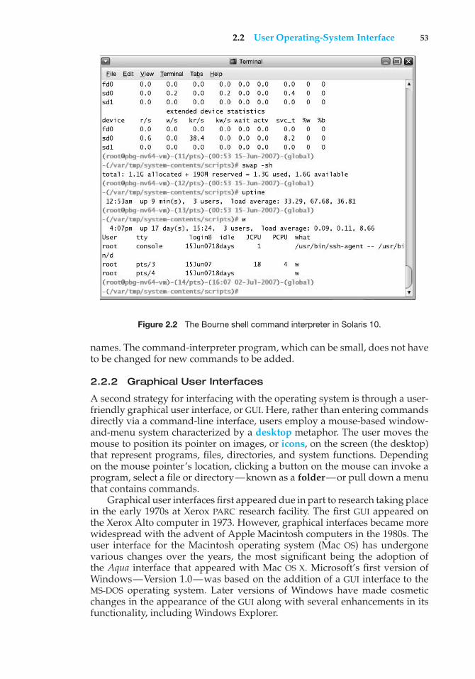
2.2 User Operating-System Interface 53
Figure 2.2 The Bourne shell command interpreter in Solaris 10.
names. The command-interpreter program, which can be small, does not haveto be changed for new commands to be added.
2.2.2 Graphical User Interfaces
A second strategy for interfacing with the operating system is through a user-friendly graphical user interface, or GUI. Here, rather than entering commandsdirectly via a command-line interface, users employ a mouse-based window-and-menu system characterized by a desktop metaphor. The user moves themouse to position its pointer on images, or icons, on the screen (the desktop)that represent programs, files, directories, and system functions. Dependingon the mouse pointer’s location, clicking a button on the mouse can invoke aprogram, select a file or directory—known as a folder—or pull down a menuthat contains commands.
Graphical user interfaces first appeared due in part to research taking placein the early 1970s at Xerox PARC research facility. The first GUI appeared onthe Xerox Alto computer in 1973. However, graphical interfaces became morewidespread with the advent of Apple Macintosh computers in the 1980s. Theuser interface for the Macintosh operating system (Mac OS) has undergonevarious changes over the years, the most significant being the adoption ofthe Aqua interface that appeared with Mac OS X. Microsoft’s first version ofWindows—Version 1.0—was based on the addition of a GUI interface to theMS-DOS operating system. Later versions of Windows have made cosmeticchanges in the appearance of the GUI along with several enhancements in itsfunctionality, including Windows Explorer.
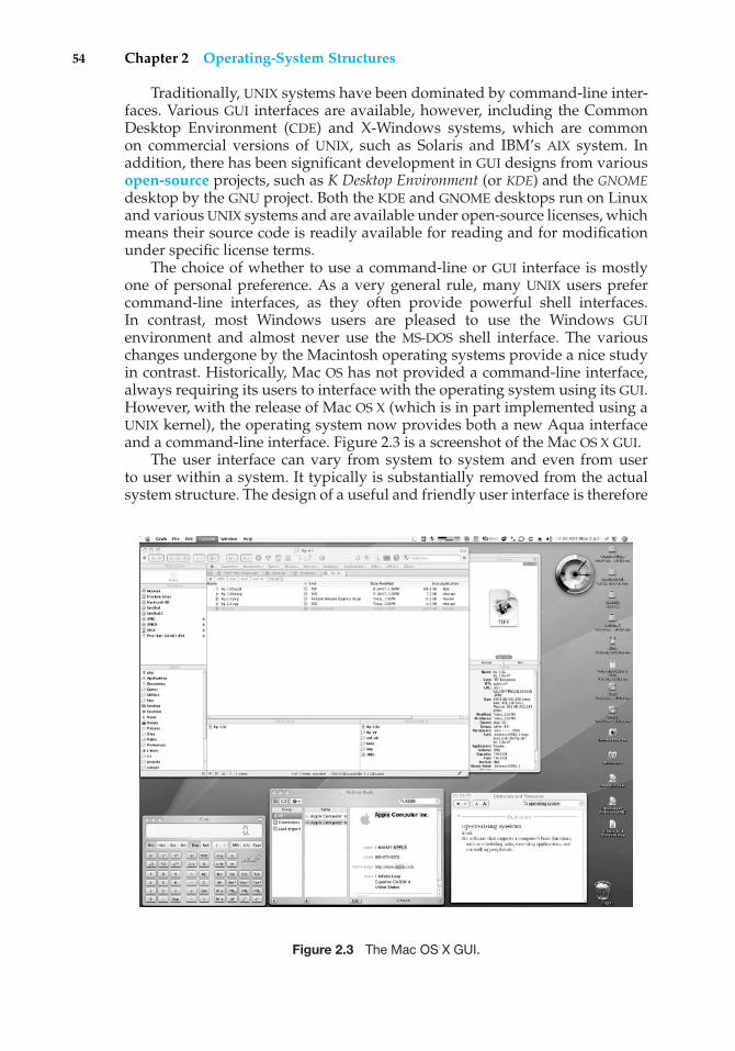
54 Chapter 2 Operating-System Structures
Traditionally, UNIX systems have been dominated by command-line inter-faces. Various GUI interfaces are available, however, including the CommonDesktop Environment (CDE) and X-Windows systems, which are commonon commercial versions of UNIX, such as Solaris and IBM’s AIX system. Inaddition, there has been significant development in GUI designs from variousopen-source projects, such as K Desktop Environment (or KDE) and the GNOMEdesktop by the GNU project. Both the KDE and GNOME desktops run on Linuxand various UNIX systems and are available under open-source licenses, whichmeans their source code is readily available for reading and for modificationunder specific license terms.
The choice of whether to use a command-line or GUI interface is mostlyone of personal preference. As a very general rule, many UNIX users prefercommand-line interfaces, as they often provide powerful shell interfaces.In contrast, most Windows users are pleased to use the Windows GUIenvironment and almost never use the MS-DOS shell interface. The variouschanges undergone by the Macintosh operating systems provide a nice studyin contrast. Historically, Mac OS has not provided a command-line interface,always requiring its users to interface with the operating system using its GUI.However, with the release of Mac OS X (which is in part implemented using aUNIX kernel), the operating system now provides both a new Aqua interfaceand a command-line interface. Figure 2.3 is a screenshot of the Mac OS X GUI.
The user interface can vary from system to system and even from userto user within a system. It typically is substantially removed from the actualsystem structure. The design of a useful and friendly user interface is therefore
Figure 2.3 The Mac OS X GUI.
2.3 System Calls 55
not a direct function of the operating system. In this book, we concentrate onthe fundamental problems of providing adequate service to user programs.From the point of view of the operating system, we do not distinguish betweenuser programs and system programs.
2.3 System Calls
System calls provide an interface to the services made available by an operatingsystem. These calls are generally available as routines written in C andC++, although certain low-level tasks (for example, tasks where hardwaremust be accessed directly), may need to be written using assembly-languageinstructions.
Before we discuss how an operating system makes system calls available,let’s first use an example to illustrate how system calls are used: writing asimple program to read data from one file and copy them to another file. Thefirst input that the program will need is the names of the two files: the input fileand the output file. These names can be specified in many ways, dependingon the operating-system design. One approach is for the program to ask theuser for the names of the two files. In an interactive system, this approach willrequire a sequence of system calls, first to write a prompting message on thescreen and then to read from the keyboard the characters that define the twofiles. On mouse-based and icon-based systems, a menu of file names is usuallydisplayed in a window. The user can then use the mouse to select the sourcename, and a window can be opened for the destination name to be specified.This sequence requires many I/O system calls.
Once the two file names are obtained, the program must open the input fileand create the output file. Each of these operations requires another system call.There are also possible error conditions for each operation. When the programtries to open the input file, it may find that there is no file of that name or thatthe file is protected against access. In these cases, the program should print amessage on the console (another sequence of system calls) and then terminateabnormally (another system call). If the input file exists, then we must create anew output file. We may find that there is already an output file with the samename. This situation may cause the program to abort (a system call), or wemay delete the existing file (another system call) and create a new one (anothersystem call). Another option, in an interactive system, is to ask the user (viaa sequence of system calls to output the prompting message and to read theresponse from the terminal) whether to replace the existing file or to abort theprogram.
Now that both files are set up, we enter a loop that reads from the inputfile (a system call) and writes to the output file (another system call). Each readand write must return status information regarding various possible errorconditions. On input, the program may find that the end of the file has beenreached or that there was a hardware failure in the read (such as a parity error).The write operation may encounter various errors, depending on the outputdevice (no more disk space, printer out of paper, and so on).
Finally, after the entire file is copied, the program may close both files(another system call), write a message to the console or window (moresystem calls), and finally terminate normally (the final system call). As we
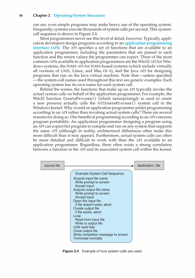
56 Chapter 2 Operating-System Structures
can see, even simple programs may make heavy use of the operating system.Frequently, systems execute thousands of system calls per second. This system-call sequence is shown in Figure 2.4.
Most programmers never see this level of detail, however. Typically, appli-cation developers design programs according to an application programminginterface (API). The API specifies a set of functions that are available to anapplication programmer, including the parameters that are passed to eachfunction and the return values the programmer can expect. Three of the mostcommon APIs available to application programmers are the Win32 API for Win-dows systems, the POSIX API for POSIX-based systems (which include virtuallyall versions of UNIX, Linux, and Mac OS X), and the Java API for designingprograms that run on the Java virtual machine. Note that—unless specified—the system-call names used throughout this text are generic examples. Eachoperating system has its own name for each system call.
Behind the scenes, the functions that make up an API typically invoke theactual system calls on behalf of the application programmer. For example, theWin32 function CreateProcess() (which unsurprisingly is used to createa new process) actually calls the NTCreateProcess() system call in theWindows kernel. Why would an application programmer prefer programmingaccording to an API rather than invoking actual system calls? There are severalreasons for doing so. One benefit of programming according to an API concernsprogram portability: An application programmer designing a program usingan API can expect her program to compile and run on any system that supportsthe same API (although in reality, architectural differences often make thismore difficult than it may appear). Furthermore, actual system calls can oftenbe more detailed and difficult to work with than the API available to anapplication programmer. Regardless, there often exists a strong correlationbetween a function in the API and its associated system call within the kernel.
source file destination file
Example System Call Sequence
Acquire input file name Write prompt to screen Accept inputAcquire output file name Write prompt to screen Accept input Open the input file if file doesn't exist, abort Create output file if file exists, abort Loop Read from input file Write to output file Until read fails Close output fileWrite completion message to screen Terminate normally
Figure 2.4 Example of how system calls are used.
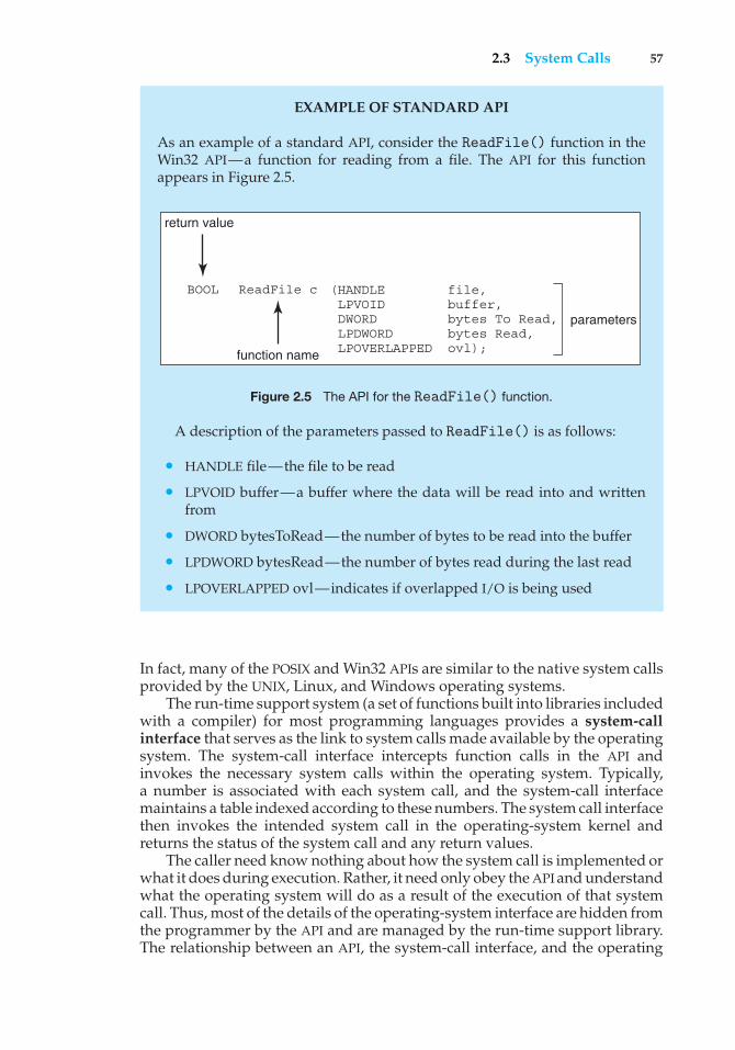
2.3 System Calls 57
EXAMPLE OF STANDARD API
As an example of a standard API, consider the ReadFile() function in theWin32 API—a function for reading from a file. The API for this functionappears in Figure 2.5.
(HANDLE file, LPVOID buffer, DWORD bytes To Read, LPDWORD bytes Read, LPOVERLAPPED ovl);
return value
ReadFile c
function name
BOOL
parameters
Figure 2.5 The API for the ReadFile() function.
A description of the parameters passed to ReadFile() is as follows:
• HANDLE file—the file to be read
• LPVOID buffer—a buffer where the data will be read into and writtenfrom
• DWORD bytesToRead—the number of bytes to be read into the buffer
• LPDWORD bytesRead—the number of bytes read during the last read
• LPOVERLAPPED ovl—indicates if overlapped I/O is being used
In fact, many of the POSIX and Win32 APIs are similar to the native system callsprovided by the UNIX, Linux, and Windows operating systems.
The run-time support system (a set of functions built into libraries includedwith a compiler) for most programming languages provides a system-callinterface that serves as the link to system calls made available by the operatingsystem. The system-call interface intercepts function calls in the API andinvokes the necessary system calls within the operating system. Typically,a number is associated with each system call, and the system-call interfacemaintains a table indexed according to these numbers. The system call interfacethen invokes the intended system call in the operating-system kernel andreturns the status of the system call and any return values.
The caller need know nothing about how the system call is implemented orwhat it does during execution. Rather, it need only obey the API and understandwhat the operating system will do as a result of the execution of that systemcall. Thus, most of the details of the operating-system interface are hidden fromthe programmer by the API and are managed by the run-time support library.The relationship between an API, the system-call interface, and the operating
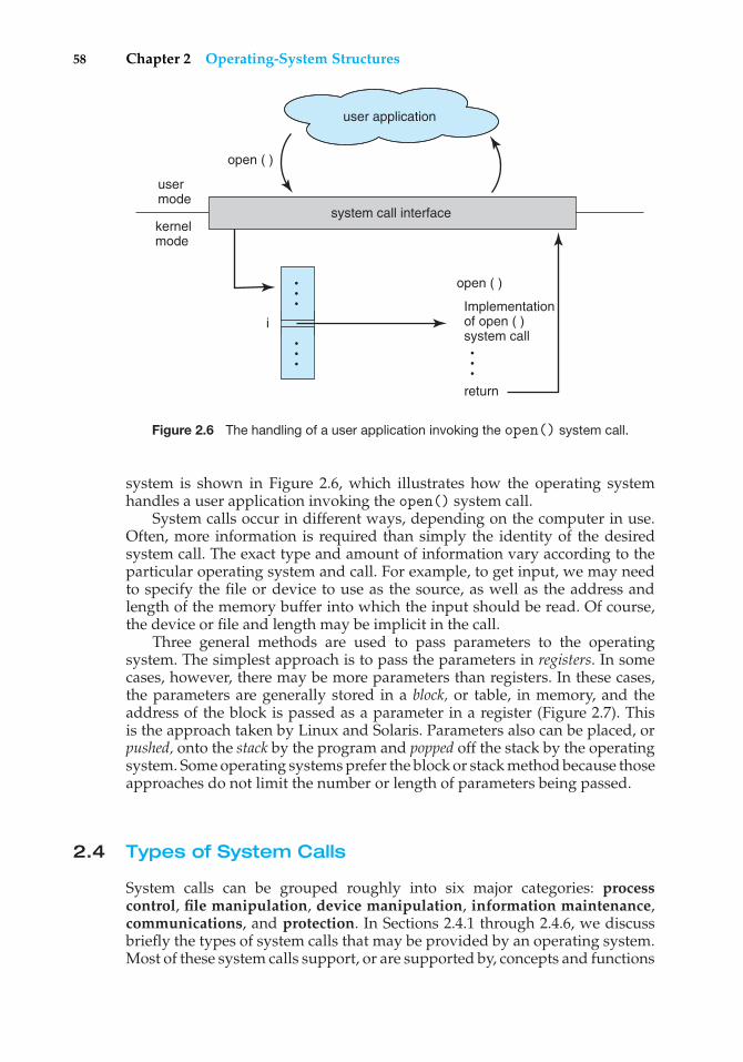
58 Chapter 2 Operating-System Structures
Implementationof open ( )system call
open ( )
user mode
return
user application
system call interfacekernelmode
i
open ( )
Figure 2.6 The handling of a user application invoking the open() system call.
system is shown in Figure 2.6, which illustrates how the operating systemhandles a user application invoking the open() system call.
System calls occur in different ways, depending on the computer in use.Often, more information is required than simply the identity of the desiredsystem call. The exact type and amount of information vary according to theparticular operating system and call. For example, to get input, we may needto specify the file or device to use as the source, as well as the address andlength of the memory buffer into which the input should be read. Of course,the device or file and length may be implicit in the call.
Three general methods are used to pass parameters to the operatingsystem. The simplest approach is to pass the parameters in registers. In somecases, however, there may be more parameters than registers. In these cases,the parameters are generally stored in a block, or table, in memory, and theaddress of the block is passed as a parameter in a register (Figure 2.7). Thisis the approach taken by Linux and Solaris. Parameters also can be placed, orpushed, onto the stack by the program and popped off the stack by the operatingsystem. Some operating systems prefer the block or stack method because thoseapproaches do not limit the number or length of parameters being passed.
2.4 Types of System Calls
System calls can be grouped roughly into six major categories: processcontrol, file manipulation, device manipulation, information maintenance,communications, and protection. In Sections 2.4.1 through 2.4.6, we discussbriefly the types of system calls that may be provided by an operating system.Most of these system calls support, or are supported by, concepts and functions
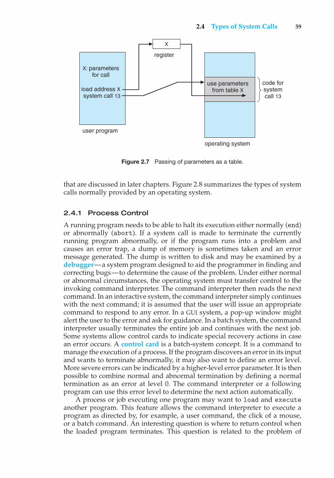
2.4 Types of System Calls 59
code for system call 13
operating system
user program
use parametersfrom table X
register
X
X: parametersfor call
load address Xsystem call 13
Figure 2.7 Passing of parameters as a table.
that are discussed in later chapters. Figure 2.8 summarizes the types of systemcalls normally provided by an operating system.
2.4.1 Process Control
A running program needs to be able to halt its execution either normally (end)or abnormally (abort). If a system call is made to terminate the currentlyrunning program abnormally, or if the program runs into a problem andcauses an error trap, a dump of memory is sometimes taken and an errormessage generated. The dump is written to disk and may be examined by adebugger—a system program designed to aid the programmer in finding andcorrecting bugs—to determine the cause of the problem. Under either normalor abnormal circumstances, the operating system must transfer control to theinvoking command interpreter. The command interpreter then reads the nextcommand. In an interactive system, the command interpreter simply continueswith the next command; it is assumed that the user will issue an appropriatecommand to respond to any error. In a GUI system, a pop-up window mightalert the user to the error and ask for guidance. In a batch system, the commandinterpreter usually terminates the entire job and continues with the next job.Some systems allow control cards to indicate special recovery actions in casean error occurs. A control card is a batch-system concept. It is a command tomanage the execution of a process. If the program discovers an error in its inputand wants to terminate abnormally, it may also want to define an error level.More severe errors can be indicated by a higher-level error parameter. It is thenpossible to combine normal and abnormal termination by defining a normaltermination as an error at level 0. The command interpreter or a followingprogram can use this error level to determine the next action automatically.
A process or job executing one program may want to load and executeanother program. This feature allows the command interpreter to execute aprogram as directed by, for example, a user command, the click of a mouse,or a batch command. An interesting question is where to return control whenthe loaded program terminates. This question is related to the problem of
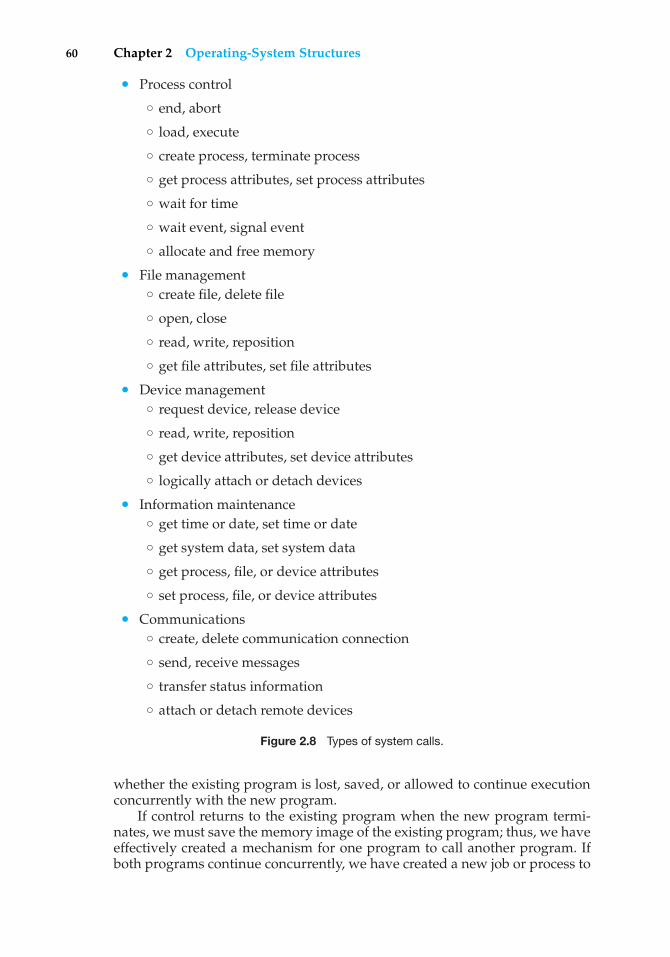
60 Chapter 2 Operating-System Structures
• Process control
◦ end, abort
◦ load, execute
◦ create process, terminate process
◦ get process attributes, set process attributes
◦ wait for time
◦ wait event, signal event
◦ allocate and free memory
• File management◦ create file, delete file
◦ open, close
◦ read, write, reposition
◦ get file attributes, set file attributes
• Device management◦ request device, release device
◦ read, write, reposition
◦ get device attributes, set device attributes
◦ logically attach or detach devices
• Information maintenance◦ get time or date, set time or date
◦ get system data, set system data
◦ get process, file, or device attributes
◦ set process, file, or device attributes
• Communications◦ create, delete communication connection
◦ send, receive messages
◦ transfer status information
◦ attach or detach remote devices
Figure 2.8 Types of system calls.
whether the existing program is lost, saved, or allowed to continue executionconcurrently with the new program.
If control returns to the existing program when the new program termi-nates, we must save the memory image of the existing program; thus, we haveeffectively created a mechanism for one program to call another program. Ifboth programs continue concurrently, we have created a new job or process to
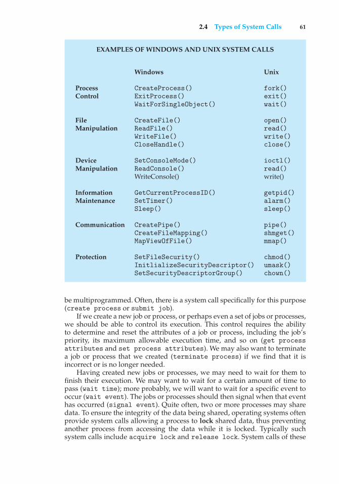
2.4 Types of System Calls 61
EXAMPLES OF WINDOWS AND UNIX SYSTEM CALLS
Windows Unix
Process CreateProcess() fork()Control ExitProcess() exit()
WaitForSingleObject() wait()
File CreateFile() open()Manipulation ReadFile() read()
WriteFile() write()CloseHandle() close()
Device SetConsoleMode() ioctl()Manipulation ReadConsole() read()
WriteConsole() write()
Information GetCurrentProcessID() getpid()Maintenance SetTimer() alarm()
Sleep() sleep()
Communication CreatePipe() pipe()CreateFileMapping() shmget()MapViewOfFile() mmap()
Protection SetFileSecurity() chmod()InitlializeSecurityDescriptor() umask()SetSecurityDescriptorGroup() chown()
be multiprogrammed. Often, there is a system call specifically for this purpose(create process or submit job).
If we create a new job or process, or perhaps even a set of jobs or processes,we should be able to control its execution. This control requires the abilityto determine and reset the attributes of a job or process, including the job’spriority, its maximum allowable execution time, and so on (get processattributes and set process attributes). We may also want to terminatea job or process that we created (terminate process) if we find that it isincorrect or is no longer needed.
Having created new jobs or processes, we may need to wait for them tofinish their execution. We may want to wait for a certain amount of time topass (wait time); more probably, we will want to wait for a specific event tooccur (wait event). The jobs or processes should then signal when that eventhas occurred (signal event). Quite often, two or more processes may sharedata. To ensure the integrity of the data being shared, operating systems oftenprovide system calls allowing a process to lock shared data, thus preventinganother process from accessing the data while it is locked. Typically suchsystem calls include acquire lock and release lock. System calls of these
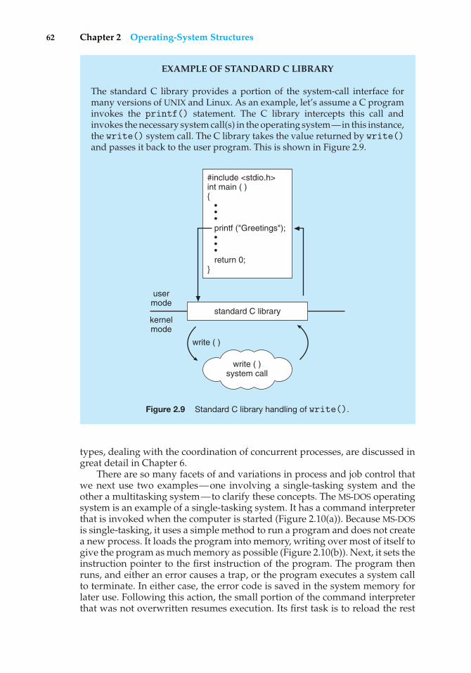
62 Chapter 2 Operating-System Structures
EXAMPLE OF STANDARD C LIBRARY
The standard C library provides a portion of the system-call interface formany versions of UNIX and Linux. As an example, let’s assume a C programinvokes the printf() statement. The C library intercepts this call andinvokes the necessary system call(s) in the operating system—in this instance,the write() system call. The C library takes the value returned by write()and passes it back to the user program. This is shown in Figure 2.9.
write ( )system call
usermode
kernelmode
#include <stdio.h>int main ( ){ • • • printf ("Greetings"); • • • return 0;}
standard C library
write ( )
Figure 2.9 Standard C library handling of write().
types, dealing with the coordination of concurrent processes, are discussed ingreat detail in Chapter 6.
There are so many facets of and variations in process and job control thatwe next use two examples—one involving a single-tasking system and theother a multitasking system—to clarify these concepts. The MS-DOS operatingsystem is an example of a single-tasking system. It has a command interpreterthat is invoked when the computer is started (Figure 2.10(a)). Because MS-DOSis single-tasking, it uses a simple method to run a program and does not createa new process. It loads the program into memory, writing over most of itself togive the program as much memory as possible (Figure 2.10(b)). Next, it sets theinstruction pointer to the first instruction of the program. The program thenruns, and either an error causes a trap, or the program executes a system callto terminate. In either case, the error code is saved in the system memory forlater use. Following this action, the small portion of the command interpreterthat was not overwritten resumes execution. Its first task is to reload the rest
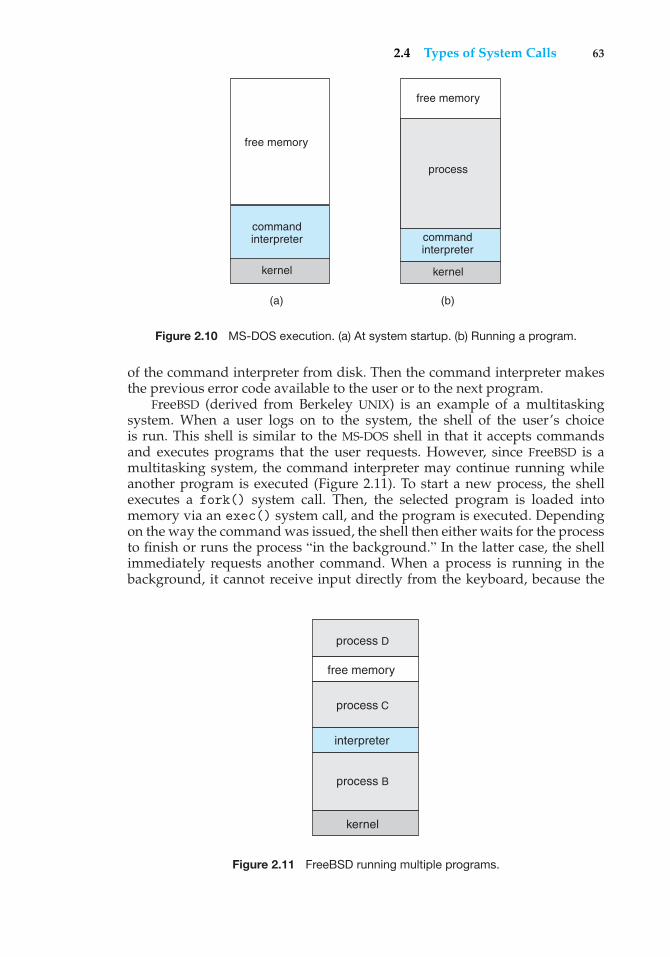
2.4 Types of System Calls 63
(a) (b)
free memory
command interpreter
kernel
process
free memory
command interpreter
kernel
Figure 2.10 MS-DOS execution. (a) At system startup. (b) Running a program.
of the command interpreter from disk. Then the command interpreter makesthe previous error code available to the user or to the next program.
FreeBSD (derived from Berkeley UNIX) is an example of a multitaskingsystem. When a user logs on to the system, the shell of the user’s choiceis run. This shell is similar to the MS-DOS shell in that it accepts commandsand executes programs that the user requests. However, since FreeBSD is amultitasking system, the command interpreter may continue running whileanother program is executed (Figure 2.11). To start a new process, the shellexecutes a fork() system call. Then, the selected program is loaded intomemory via an exec() system call, and the program is executed. Dependingon the way the command was issued, the shell then either waits for the processto finish or runs the process “in the background.” In the latter case, the shellimmediately requests another command. When a process is running in thebackground, it cannot receive input directly from the keyboard, because the
free memory
interpreter
kernel
process D
process C
process B
Figure 2.11 FreeBSD running multiple programs.
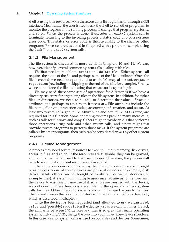
64 Chapter 2 Operating-System Structures
shell is using this resource. I/O is therefore done through files or through a GUIinterface. Meanwhile, the user is free to ask the shell to run other programs, tomonitor the progress of the running process, to change that program’s priority,and so on. When the process is done, it executes an exit() system call toterminate, returning to the invoking process a status code of 0 or a nonzeroerror code. This status or error code is then available to the shell or otherprograms. Processes are discussed in Chapter 3 with a program example usingthe fork() and exec() system calls.
2.4.2 File Management
The file system is discussed in more detail in Chapters 10 and 11. We can,however, identify several common system calls dealing with files.
We first need to be able to create and delete files. Either system callrequires the name of the file and perhaps some of the file’s attributes. Once thefile is created, we need to open it and to use it. We may also read, write, orreposition (rewinding or skipping to the end of the file, for example). Finally,we need to close the file, indicating that we are no longer using it.
We may need these same sets of operations for directories if we have adirectory structure for organizing files in the file system. In addition, for eitherfiles or directories, we need to be able to determine the values of variousattributes and perhaps to reset them if necessary. File attributes include thefile name, file type, protection codes, accounting information, and so on. Atleast two system calls, get file attribute and set file attribute, arerequired for this function. Some operating systems provide many more calls,such as calls for file move and copy. Others might provide an API that performsthose operations using code and other system calls, and others might justprovide system programs to perform those tasks. If the system programs arecallable by other programs, then each can be considered an API by other systemprograms.
2.4.3 Device Management
A process may need several resources to execute—main memory, disk drives,access to files, and so on. If the resources are available, they can be granted,and control can be returned to the user process. Otherwise, the process willhave to wait until sufficient resources are available.
The various resources controlled by the operating system can be thoughtof as devices. Some of these devices are physical devices (for example, diskdrives), while others can be thought of as abstract or virtual devices (forexample, files). A system with multiple users may require us to first requestthe device, to ensure exclusive use of it. After we are finished with the device,we release it. These functions are similar to the open and close systemcalls for files. Other operating systems allow unmanaged access to devices.The hazard then is the potential for device contention and perhaps deadlock,which is described in Chapter 7.
Once the device has been requested (and allocated to us), we can read,write, and (possibly) reposition the device, just as we can with files. In fact,the similarity between I/O devices and files is so great that many operatingsystems, including UNIX, merge the two into a combined file–device structure.In this case, a set of system calls is used on both files and devices. Sometimes,
2.4 Types of System Calls 65
I/O devices are identified by special file names, directory placement, or fileattributes.
The user interface can also make files and devices appear to be similar, eventhough the underlying system calls are dissimilar. This is another example ofthe many design decisions that go into building an operating system and userinterface.
2.4.4 Information Maintenance
Many system calls exist simply for the purpose of transferring informationbetween the user program and the operating system. For example, mostsystems have a system call to return the current time and date. Other systemcalls may return information about the system, such as the number of currentusers, the version number of the operating system, the amount of free memoryor disk space, and so on.
Another set of system calls is helpful in debugging a program. Manysystems provide system calls to dump memory. This provision is useful fordebugging. A program trace lists each system call as it is executed. Evenmicroprocessors provide a CPU mode known as single step, in which a trap isexecuted by the CPU after every instruction. The trap is usually caught by adebugger.
Many operating systems provide a time profile of a program to indicatethe amount of time that the program executes at a particular location or setof locations. A time profile requires either a tracing facility or regular timerinterrupts. At every occurrence of the timer interrupt, the value of the programcounter is recorded. With sufficiently frequent timer interrupts, a statisticalpicture of the time spent on various parts of the program can be obtained.
In addition, the operating system keeps information about all its processes,and system calls are used to access this information. Generally, calls arealso used to reset the process information (get process attributes andset process attributes). In Section 3.1.3, we discuss what information isnormally kept.
2.4.5 Communication
There are two common models of interprocess communication: the message-passing model and the shared-memory model. In the message-passing model,the communicating processes exchange messages with one another to transferinformation. Messages can be exchanged between the processes either directlyor indirectly through a common mailbox. Before communication can takeplace, a connection must be opened. The name of the other communicatormust be known, be it another process on the same system or a process onanother computer connected by a communications network. Each computerin a network has a host name by which it is commonly known. A host alsohas a network identifier, such as an IP address. Similarly, each process hasa process name, and this name is translated into an identifier by which theoperating system can refer to the process. Theget hostidandget processidsystem calls do this translation. The identifiers are then passed to the general-purpose open and close calls provided by the file system or to specificopen connection and close connection system calls, depending on thesystem’s model of communication. The recipient process usually must give its
66 Chapter 2 Operating-System Structures
permission for communication to take place with an accept connection call.Most processes that will be receiving connections are special-purpose daemons,which are systems programs provided for that purpose. They execute a waitfor connection call and are awakened when a connection is made. The sourceof the communication, known as the client, and the receiving daemon, known asa server, then exchange messages by using read message and write messagesystem calls. The close connection call terminates the communication.
In the shared-memory model, processes use shared memory create andshared memory attach system calls to create and gain access to regions ofmemory owned by other processes. Recall that, normally, the operating systemtries to prevent one process from accessing another process’s memory. Sharedmemory requires that two or more processes agree to remove this restriction.They can then exchange information by reading and writing data in the sharedareas. The form of the data is determined by the processes and are not underthe operating system’s control. The processes are also responsible for ensuringthat they are not writing to the same location simultaneously. Such mechanismsare discussed in Chapter 6. In Chapter 4, we look at a variation of the processscheme—threads—in which memory is shared by default.
Both of the models just discussed are common in operating systems,and most systems implement both. Message passing is useful for exchangingsmaller amounts of data, because no conflicts need be avoided. It is also easier toimplement than is shared memory for intercomputer communication. Sharedmemory allows maximum speed and convenience of communication, since itcan be done at memory transfer speeds when it takes place within a computer.Problems exist, however, in the areas of protection and synchronizationbetween the processes sharing memory.
2.4.6 Protection
Protection provides a mechanism for controlling access to the resourcesprovided by a computer system. Historically, protection was a concern only onmultiprogrammed computer systems with several users. However, with theadvent of networking and the Internet, all computer systems, from servers toPDAs, must be concerned with protection.
Typically, system calls providing protection include set permission andget permission, which manipulate the permission settings of resourcessuch as files and disks. The allow user and deny user system calls spec-ify whether particular users can—or cannot—be allowed access to certainresources.
We cover protection in Chapter 14 and the much larger issue of security inChapter 15.
2.5 System Programs
Another aspect of a modern system is the collection of system programs. RecallFigure 1.1, which depicted the logical computer hierarchy. At the lowest level ishardware. Next is the operating system, then the system programs, and finallythe application programs. System programs, also known as system utilities,provide a convenient environment for program development and execution.
2.5 System Programs 67
Some of them are simply user interfaces to system calls; others are considerablymore complex. They can be divided into these categories:
• File management. These programs create, delete, copy, rename, print,dump, list, and generally manipulate files and directories.
• Status information. Some programs simply ask the system for the date,time, amount of available memory or disk space, number of users, orsimilar status information. Others are more complex, providing detailedperformance, logging, and debugging information. Typically, these pro-grams format and print the output to the terminal or other output devicesor files or display it in a window of the GUI. Some systems also support aregistry, which is used to store and retrieve configuration information.
• File modification. Several text editors may be available to create andmodify the content of files stored on disk or other storage devices. Theremay also be special commands to search contents of files or performtransformations of the text.
• Programming-language support. Compilers, assemblers, debuggers, andinterpreters for common programming languages (such as C, C++, Java,Visual Basic, and PERL) are often provided to the user with the operatingsystem.
• Program loading and execution. Once a program is assembled or com-piled, it must be loaded into memory to be executed. The system mayprovide absolute loaders, relocatable loaders, linkage editors, and overlayloaders. Debugging systems for either higher-level languages or machinelanguage are needed as well.
• Communications. These programs provide the mechanism for creatingvirtual connections among processes, users, and computer systems. Theyallow users to send messages to one another’s screens, to browse Webpages, to send electronic-mail messages, to log in remotely, or to transferfiles from one machine to another.
In addition to systems programs, most operating systems are suppliedwith programs that are useful in solving common problems or performingcommon operations. Such application programs include Web browsers, wordprocessors and text formatters, spreadsheets, database systems, compilers,plotting and statistical-analysis packages, and games.
The view of the operating system seen by most users is defined by theapplication and system programs, rather than by the actual system calls.Consider a user’s PC. When a user’s computer is running the Mac OS Xoperating system, the user might see the GUI, featuring a mouse-and-windowsinterface. Alternatively, or even in one of the windows, the user might havea command-line UNIX shell. Both use the same set of system calls, but thesystem calls look different and act in different ways. Further confusing theuser view, consider the user dual-booting from Mac OS X into Windows Vista.Now the same user on the same hardware has two entirely different interfacesand two sets of applications using the same physical resources. On the same
68 Chapter 2 Operating-System Structures
hardware, then, a user can be exposed to multiple user interfaces sequentiallyor concurrently.
2.6 Operating-System Design and Implementation
In this section, we discuss problems we face in designing and implementing anoperating system. There are, of course, no complete solutions to such problems,but there are approaches that have proved successful.
2.6.1 Design Goals
The first problem in designing a system is to define goals and specifications.At the highest level, the design of the system will be affected by the choice ofhardware and the type of system: batch, time shared, single user, multiuser,distributed, real time, or general purpose.
Beyond this highest design level, the requirements may be much harder tospecify. The requirements can, however, be divided into two basic groups: usergoals and system goals.
Users desire certain obvious properties in a system. The system should beconvenient to use, easy to learn and to use, reliable, safe, and fast. Of course,these specifications are not particularly useful in the system design, since thereis no general agreement on how to achieve them.
A similar set of requirements can be defined by those people who mustdesign, create, maintain, and operate the system. The system should be easy todesign, implement, and maintain; and it should be flexible, reliable, error free,and efficient. Again, these requirements are vague and may be interpreted invarious ways.
There is, in short, no unique solution to the problem of defining therequirements for an operating system. The wide range of systems in existenceshows that different requirements can result in a large variety of solutions fordifferent environments. For example, the requirements for VxWorks, a real-time operating system for embedded systems, must have been substantiallydifferent from those for MVS, a large multiuser, multiaccess operating systemfor IBM mainframes.
Specifying and designing an operating system is a highly creative task.Although no textbook can tell you how to do it, general principles havebeen developed in the field of software engineering, and we turn now toa discussion of some of these principles.
2.6.2 Mechanisms and Policies
One important principle is the separation of policy from mechanism. Mecha-nisms determine how to do something; policies determine what will be done.For example, the timer construct (see Section 1.5.2) is a mechanism for ensuringCPU protection, but deciding how long the timer is to be set for a particularuser is a policy decision.
The separation of policy and mechanism is important for flexibility. Policiesare likely to change across places or over time. In the worst case, each changein policy would require a change in the underlying mechanism. A generalmechanism insensitive to changes in policy would be more desirable. A change
2.6 Operating-System Design and Implementation 69
in policy would then require redefinition of only certain parameters of thesystem. For instance, consider a mechanism for giving priority to certain typesof programs over others. If the mechanism is properly separated from policy,it can be used either to support a policy decision that I/O-intensive programsshould have priority over CPU-intensive ones or to support the opposite policy.
Microkernel-based operating systems (Section 2.7.3) take the separation ofmechanism and policy to one extreme by implementing a basic set of primitivebuilding blocks. These blocks are almost policy free, allowing more advancedmechanisms and policies to be added via user-created kernel modules or viauser programs themselves. As an example, consider the history of UNIX. Atfirst, it had a time-sharing scheduler. In the latest version of Solaris, schedulingis controlled by loadable tables. Depending on the table currently loaded,the system can be time shared, batch processing, real time, fair share, orany combination. Making the scheduling mechanism general purpose allowsvast policy changes to be made with a single load-new-table command. Atthe other extreme is a system such as Windows, in which both mechanismand policy are encoded in the system to enforce a global look and feel. Allapplications have similar interfaces, because the interface itself is built intothe kernel and system libraries. The Mac OS X operating system has similarfunctionality.
Policy decisions are important for all resource allocation. Whenever it isnecessary to decide whether or not to allocate a resource, a policy decision mustbe made. Whenever the question is how rather than what, it is a mechanism thatmust be determined.
2.6.3 Implementation
Once an operating system is designed, it must be implemented. Traditionally,operating systems have been written in assembly language. Now, however,they are most commonly written in higher-level languages such as C or C++.
The first system that was not written in assembly language was probablythe Master Control Program (MCP) for Burroughs computers. MCP was writtenin a variant of ALGOL. MULTICS, developed at MIT, was written mainly inPL/1. The Linux and Windows XP operating systems are written mostly in C,although there are some small sections of assembly code for device drivers andfor saving and restoring the state of registers.
The advantages of using a higher-level language, or at least a systems-implementation language, for implementing operating systems are the sameas those accrued when the language is used for application programs: thecode can be written faster, is more compact, and is easier to understand anddebug. In addition, improvements in compiler technology will improve thegenerated code for the entire operating system by simple recompilation. Finally,an operating system is far easier to port—to move to some other hardware—ifit is written in a higher-level language. For example, MS-DOS was written in Intel8088 assembly language. Consequently, it runs natively only on the Intel X86family of CPUs. (Although MS-DOS runs natively only on Intel X86, emulatorsof the X86 instruction set allow the operating system to run non-natively—slower, with more resource use—on other CPUs. Emulators are programs thatduplicate the functionality of one system with another system.) The Linux
70 Chapter 2 Operating-System Structures
operating system, in contrast, is written mostly in C and is available natively ona number of different CPUs, including Intel X86, Sun SPARC, and IBMPowerPC.
The only possible disadvantages of implementing an operating system in ahigher-level language are reduced speed and increased storage requirements.This, however, is no longer a major issue in today’s systems. Although anexpert assembly-language programmer can produce efficient small routines,for large programs a modern compiler can perform complex analysis and applysophisticated optimizations that produce excellent code. Modern processorshave deep pipelining and multiple functional units that can handle the detailsof complex dependencies much more easily than can the human mind.
As is true in other systems, major performance improvements in operatingsystems are more likely to be the result of better data structures and algorithmsthan of excellent assembly-language code. In addition, although operating sys-tems are large, only a small amount of the code is critical to high performance;the memory manager and the CPU scheduler are probably the most critical rou-tines. After the system is written and is working correctly, bottleneck routinescan be identified and can be replaced with assembly-language equivalents.
2.7 Operating-System Structure
A system as large and complex as a modern operating system must beengineered carefully if it is to function properly and be modified easily. Acommon approach is to partition the task into small components rather thanhave one monolithic system. Each of these modules should be a well-definedportion of the system, with carefully defined inputs, outputs, and functions.We have already discussed briefly in Chapter 1 the common componentsof operating systems. In this section, we discuss how these components areinterconnected and melded into a kernel.
2.7.1 Simple Structure
Many commercial operating systems do not have well-defined structures.Frequently, such systems started as small, simple, and limited systems andthen grew beyond their original scope. MS-DOS is an example of such a system.It was originally designed and implemented by a few people who had noidea that it would become so popular. It was written to provide the mostfunctionality in the least space, so it was not divided into modules carefully.Figure 2.12 shows its structure.
In MS-DOS, the interfaces and levels of functionality are not well separated.For instance, application programs are able to access the basic I/O routinesto write directly to the display and disk drives. Such freedom leaves MS-DOSvulnerable to errant (or malicious) programs, causing entire system crasheswhen user programs fail. Of course, MS-DOS was also limited by the hardwareof its era. Because the Intel 8088 for which it was written provides no dualmode and no hardware protection, the designers of MS-DOS had no choice butto leave the base hardware accessible.
Another example of limited structuring is the original UNIX operatingsystem. Like MS-DOS, UNIX initially was limited by hardware functionality. Itconsists of two separable parts: the kernel and the system programs. The kernel
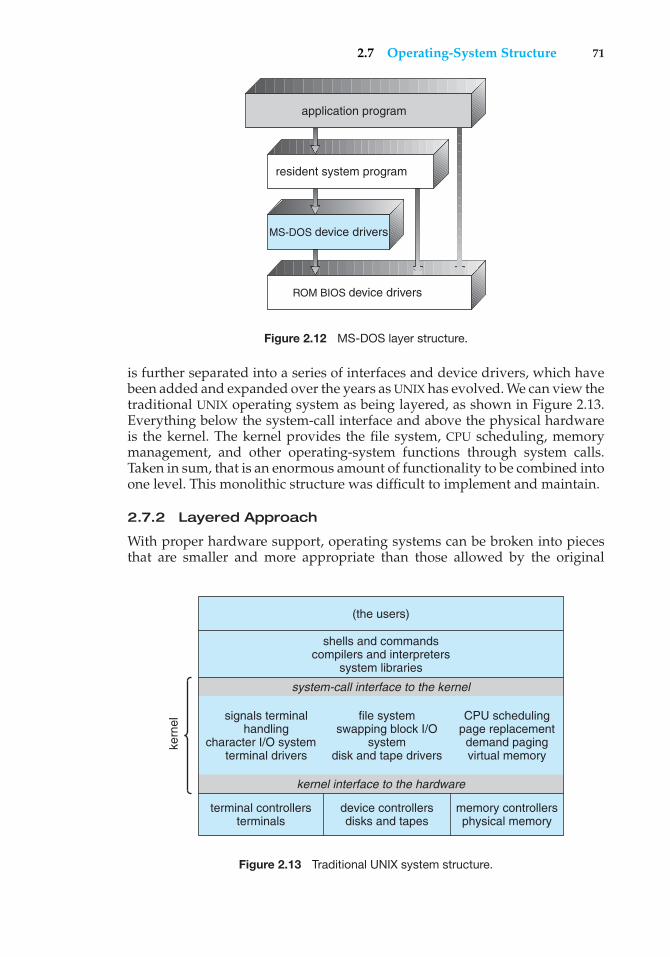
2.7 Operating-System Structure 71
ROM BIOS device drivers
application program
MS-DOS device drivers
resident system program
Figure 2.12 MS-DOS layer structure.
is further separated into a series of interfaces and device drivers, which havebeen added and expanded over the years as UNIX has evolved. We can view thetraditional UNIX operating system as being layered, as shown in Figure 2.13.Everything below the system-call interface and above the physical hardwareis the kernel. The kernel provides the file system, CPU scheduling, memorymanagement, and other operating-system functions through system calls.Taken in sum, that is an enormous amount of functionality to be combined intoone level. This monolithic structure was difficult to implement and maintain.
2.7.2 Layered Approach
With proper hardware support, operating systems can be broken into piecesthat are smaller and more appropriate than those allowed by the original
kern
el
(the users)
shells and commandscompilers and interpreters
system libraries
system-call interface to the kernel
signals terminalhandling
character I/O systemterminal drivers
file systemswapping block I/O
systemdisk and tape drivers
CPU schedulingpage replacementdemand pagingvirtual memory
kernel interface to the hardware
terminal controllersterminals
device controllersdisks and tapes
memory controllersphysical memory
Figure 2.13 Traditional UNIX system structure.
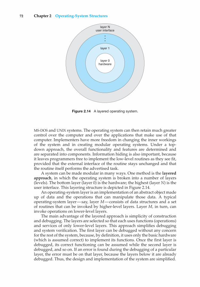
72 Chapter 2 Operating-System Structures
layer Nuser interface
•••
layer 1
layer 0hardware
Figure 2.14 A layered operating system.
MS-DOS and UNIX systems. The operating system can then retain much greatercontrol over the computer and over the applications that make use of thatcomputer. Implementers have more freedom in changing the inner workingsof the system and in creating modular operating systems. Under a top-down approach, the overall functionality and features are determined andare separated into components. Information hiding is also important, becauseit leaves programmers free to implement the low-level routines as they see fit,provided that the external interface of the routine stays unchanged and thatthe routine itself performs the advertised task.
A system can be made modular in many ways. One method is the layeredapproach, in which the operating system is broken into a number of layers(levels). The bottom layer (layer 0) is the hardware; the highest (layer N) is theuser interface. This layering structure is depicted in Figure 2.14.
An operating-system layer is an implementation of an abstract object madeup of data and the operations that can manipulate those data. A typicaloperating-system layer—say, layer M—consists of data structures and a setof routines that can be invoked by higher-level layers. Layer M, in turn, caninvoke operations on lower-level layers.
The main advantage of the layered approach is simplicity of constructionand debugging. The layers are selected so that each uses functions (operations)and services of only lower-level layers. This approach simplifies debuggingand system verification. The first layer can be debugged without any concernfor the rest of the system, because, by definition, it uses only the basic hardware(which is assumed correct) to implement its functions. Once the first layer isdebugged, its correct functioning can be assumed while the second layer isdebugged, and so on. If an error is found during the debugging of a particularlayer, the error must be on that layer, because the layers below it are alreadydebugged. Thus, the design and implementation of the system are simplified.
2.7 Operating-System Structure 73
Each layer is implemented with only those operations provided by lower-level layers. A layer does not need to know how these operations areimplemented; it needs to know only what these operations do. Hence, eachlayer hides the existence of certain data structures, operations, and hardwarefrom higher-level layers.
The major difficulty with the layered approach involves appropriatelydefining the various layers. Because a layer can use only lower-level layers,careful planning is necessary. For example, the device driver for the backingstore (disk space used by virtual-memory algorithms) must be at a lowerlevel than the memory-management routines, because memory managementrequires the ability to use the backing store.
Other requirements may not be so obvious. The backing-store driver wouldnormally be above the CPU scheduler, because the driver may need to wait forI/O and the CPU can be rescheduled during this time. However, on a largesystem, the CPU scheduler may have more information about all the activeprocesses than can fit in memory. Therefore, this information may need to beswapped in and out of memory, requiring the backing-store driver routine tobe below the CPU scheduler.
A final problem with layered implementations is that they tend to be lessefficient than other types. For instance, when a user program executes an I/Ooperation, it executes a system call that is trapped to the I/O layer, which callsthe memory-management layer, which in turn calls the CPU-scheduling layer,which is then passed to the hardware. At each layer, the parameters may bemodified, data may need to be passed, and so on. Each layer adds overhead tothe system call; the net result is a system call that takes longer than does oneon a nonlayered system.
These limitations have caused a small backlash against layering in recentyears. Fewer layers with more functionality are being designed, providing mostof the advantages of modularized code while avoiding the difficult problemsof layer definition and interaction.
2.7.3 Microkernels
We have already seen that as UNIX expanded, the kernel became largeand difficult to manage. In the mid-1980s, researchers at Carnegie MellonUniversity developed an operating system called Mach that modularizedthe kernel using the microkernel approach. This method structures theoperating system by removing all nonessential components from the kernel andimplementing them as system and user-level programs. The result is a smallerkernel. There is little consensus regarding which services should remain in thekernel and which should be implemented in user space. Typically, however,microkernels provide minimal process and memory management, in additionto a communication facility.
The main function of the microkernel is to provide a communication facilitybetween the client program and the various services that are also runningin user space. Communication is provided by message passing, which wasdescribed in Section 2.4.5. For example, if the client program wishes to accessa file, it must interact with the file server. The client program and service neverinteract directly. Rather, they communicate indirectly by exchanging messageswith the microkernel.
74 Chapter 2 Operating-System Structures
One benefit of the microkernel approach is ease of extending the operatingsystem. All new services are added to user space and consequently do notrequire modification of the kernel. When the kernel does have to be modified,the changes tend to be fewer, because the microkernel is a smaller kernel.The resulting operating system is easier to port from one hardware designto another. The microkernel also provides more security and reliability, sincemost services are running as user—rather than kernel—processes. If a servicefails, the rest of the operating system remains untouched.
Several contemporary operating systems have used the microkernelapproach. Tru64 UNIX (formerly Digital UNIX) provides a UNIX interface to theuser, but it is implemented with a Mach kernel. The Mach kernel maps UNIXsystem calls into messages to the appropriate user-level services. The Mac OSX kernel (also known as Darwin) is also based on the Mach microkernel.
Another example is QNX, a real-time operating system. The QNX micro-kernel provides services for message passing and process scheduling. It alsohandles low-level network communication and hardware interrupts. All otherservices in QNX are provided by standard processes that run outside the kernelin user mode.
Unfortunately, microkernels can suffer from performance decreases dueto increased system function overhead. Consider the history of Windows NT.The first release had a layered microkernel organization. However, this versiondelivered low performance compared with that of Windows 95. Windows NT4.0 partially redressed the performance problem by moving layers from userspace to kernel space and integrating them more closely. By the time WindowsXP was designed, its architecture was more monolithic than microkernel.
2.7.4 Modules
Perhaps the best current methodology for operating-system design involvesusing object-oriented programming techniques to create a modular kernel.Here, the kernel has a set of core components and links in additional serviceseither during boot time or during run time. Such a strategy uses dynamicallyloadable modules and is common in modern implementations of UNIX, suchas Solaris, Linux, and Mac OS X. For example, the Solaris operating systemstructure, shown in Figure 2.15, is organized around a core kernel with seventypes of loadable kernel modules:
1. Scheduling classes
2. File systems
3. Loadable system calls
4. Executable formats
5. STREAMS modules
6. Miscellaneous
7. Device and bus drivers
Such a design allows the kernel to provide core services yet also allowscertain features to be implemented dynamically. For example, device and
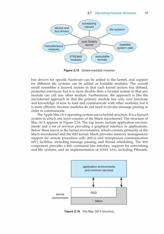
2.7 Operating-System Structure 75
core Solariskernel
file systems
loadablesystem calls
executableformats
STREAMSmodules
miscellaneousmodules
device andbus drivers
schedulingclasses
Figure 2.15 Solaris loadable modules.
bus drivers for specific hardware can be added to the kernel, and supportfor different file systems can be added as loadable modules. The overallresult resembles a layered system in that each kernel section has defined,protected interfaces; but it is more flexible than a layered system in that anymodule can call any other module. Furthermore, the approach is like themicrokernel approach in that the primary module has only core functionsand knowledge of how to load and communicate with other modules; but itis more efficient, because modules do not need to invoke message passing inorder to communicate.
The Apple Mac OS X operating system uses a hybrid structure. It is a layeredsystem in which one layer consists of the Mach microkernel. The structure ofMac OS X appears in Figure 2.16. The top layers include application environ-ments and a set of services providing a graphical interface to applications.Below these layers is the kernel environment, which consists primarily of theMach microkernel and the BSD kernel. Mach provides memory management;support for remote procedure calls (RPCs) and interprocess communication(IPC) facilities, including message passing; and thread scheduling. The BSDcomponent provides a BSD command line interface, support for networkingand file systems, and an implementation of POSIX APIs, including Pthreads.
application environmentsand common services
BSDkernelenvironment
Mach
Figure 2.16 The Mac OS X structure.
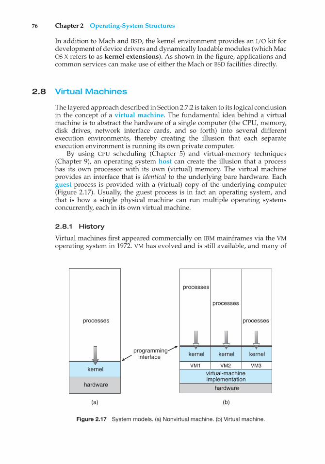
76 Chapter 2 Operating-System Structures
In addition to Mach and BSD, the kernel environment provides an I/O kit fordevelopment of device drivers and dynamically loadable modules (which MacOS X refers to as kernel extensions). As shown in the figure, applications andcommon services can make use of either the Mach or BSD facilities directly.
2.8 Virtual Machines
The layered approach described in Section 2.7.2 is taken to its logical conclusionin the concept of a virtual machine. The fundamental idea behind a virtualmachine is to abstract the hardware of a single computer (the CPU, memory,disk drives, network interface cards, and so forth) into several differentexecution environments, thereby creating the illusion that each separateexecution environment is running its own private computer.
By using CPU scheduling (Chapter 5) and virtual-memory techniques(Chapter 9), an operating system host can create the illusion that a processhas its own processor with its own (virtual) memory. The virtual machineprovides an interface that is identical to the underlying bare hardware. Eachguest process is provided with a (virtual) copy of the underlying computer(Figure 2.17). Usually, the guest process is in fact an operating system, andthat is how a single physical machine can run multiple operating systemsconcurrently, each in its own virtual machine.
2.8.1 History
Virtual machines first appeared commercially on IBM mainframes via the VMoperating system in 1972. VM has evolved and is still available, and many of
(a)
processes
hardware
kernel
(b)
programminginterface
processes
processes
processes
kernelkernel kernel
VM2VM1 VM3
implementation
hardware
virtual-machine
Figure 2.17 System models. (a) Nonvirtual machine. (b) Virtual machine.
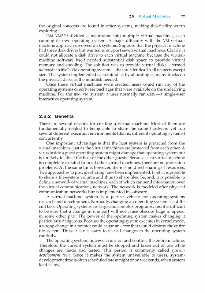
2.8 Virtual Machines 77
the original concepts are found in other systems, making this facility worthexploring.
IBM VM370 divided a mainframe into multiple virtual machines, eachrunning its own operating system. A major difficulty with the VM virtual-machine approach involved disk systems. Suppose that the physical machinehad three disk drives but wanted to support seven virtual machines. Clearly, itcould not allocate a disk drive to each virtual machine, because the virtual-machine software itself needed substantial disk space to provide virtualmemory and spooling. The solution was to provide virtual disks—termedminidisks in IBM’s VM operating system—that are identical in all respects exceptsize. The system implemented each minidisk by allocating as many tracks onthe physical disks as the minidisk needed.
Once these virtual machines were created, users could run any of theoperating systems or software packages that were available on the underlyingmachine. For the IBM VM system, a user normally ran CMS—a single-userinteractive operating system.
2.8.2 Benefits
There are several reasons for creating a virtual machine. Most of them arefundamentally related to being able to share the same hardware yet runseveral different execution environments (that is, different operating systems)concurrently.
One important advantage is that the host system is protected from thevirtual machines, just as the virtual machines are protected from each other. Avirus inside a guest operating system might damage that operating system butis unlikely to affect the host or the other guests. Because each virtual machineis completely isolated from all other virtual machines, there are no protectionproblems. At the same time, however, there is no direct sharing of resources.Two approaches to provide sharing have been implemented. First, it is possibleto share a file-system volume and thus to share files. Second, it is possible todefine a network of virtual machines, each of which can send information overthe virtual communications network. The network is modeled after physicalcommunication networks but is implemented in software.
A virtual-machine system is a perfect vehicle for operating-systemsresearch and development. Normally, changing an operating system is a diffi-cult task. Operating systems are large and complex programs, and it is difficultto be sure that a change in one part will not cause obscure bugs to appearin some other part. The power of the operating system makes changing itparticularly dangerous. Because the operating system executes in kernel mode,a wrong change in a pointer could cause an error that would destroy the entirefile system. Thus, it is necessary to test all changes to the operating systemcarefully.
The operating system, however, runs on and controls the entire machine.Therefore, the current system must be stopped and taken out of use whilechanges are made and tested. This period is commonly called system-development time. Since it makes the system unavailable to users, system-development time is often scheduled late at night or on weekends, when systemload is low.
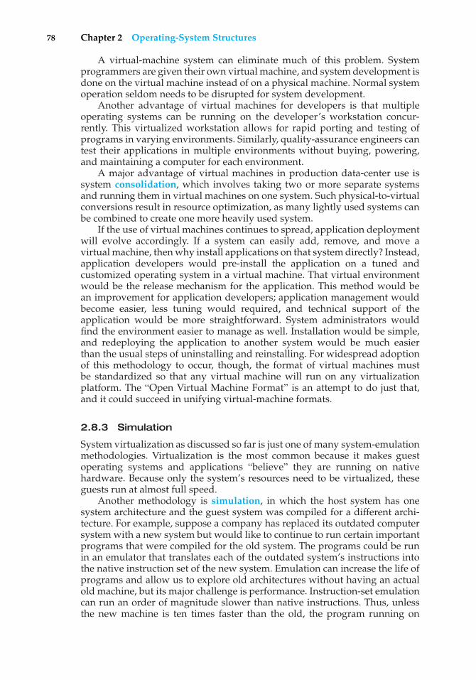
78 Chapter 2 Operating-System Structures
A virtual-machine system can eliminate much of this problem. Systemprogrammers are given their own virtual machine, and system development isdone on the virtual machine instead of on a physical machine. Normal systemoperation seldom needs to be disrupted for system development.
Another advantage of virtual machines for developers is that multipleoperating systems can be running on the developer’s workstation concur-rently. This virtualized workstation allows for rapid porting and testing ofprograms in varying environments. Similarly, quality-assurance engineers cantest their applications in multiple environments without buying, powering,and maintaining a computer for each environment.
A major advantage of virtual machines in production data-center use issystem consolidation, which involves taking two or more separate systemsand running them in virtual machines on one system. Such physical-to-virtualconversions result in resource optimization, as many lightly used systems canbe combined to create one more heavily used system.
If the use of virtual machines continues to spread, application deploymentwill evolve accordingly. If a system can easily add, remove, and move avirtual machine, then why install applications on that system directly? Instead,application developers would pre-install the application on a tuned andcustomized operating system in a virtual machine. That virtual environmentwould be the release mechanism for the application. This method would bean improvement for application developers; application management wouldbecome easier, less tuning would required, and technical support of theapplication would be more straightforward. System administrators wouldfind the environment easier to manage as well. Installation would be simple,and redeploying the application to another system would be much easierthan the usual steps of uninstalling and reinstalling. For widespread adoptionof this methodology to occur, though, the format of virtual machines mustbe standardized so that any virtual machine will run on any virtualizationplatform. The “Open Virtual Machine Format” is an attempt to do just that,and it could succeed in unifying virtual-machine formats.
2.8.3 Simulation
System virtualization as discussed so far is just one of many system-emulationmethodologies. Virtualization is the most common because it makes guestoperating systems and applications “believe” they are running on nativehardware. Because only the system’s resources need to be virtualized, theseguests run at almost full speed.
Another methodology is simulation, in which the host system has onesystem architecture and the guest system was compiled for a different archi-tecture. For example, suppose a company has replaced its outdated computersystem with a new system but would like to continue to run certain importantprograms that were compiled for the old system. The programs could be runin an emulator that translates each of the outdated system’s instructions intothe native instruction set of the new system. Emulation can increase the life ofprograms and allow us to explore old architectures without having an actualold machine, but its major challenge is performance. Instruction-set emulationcan run an order of magnitude slower than native instructions. Thus, unlessthe new machine is ten times faster than the old, the program running on
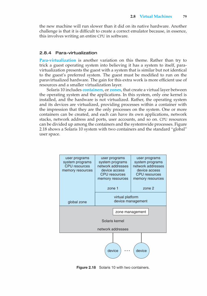
2.8 Virtual Machines 79
the new machine will run slower than it did on its native hardware. Anotherchallenge is that it is difficult to create a correct emulator because, in essence,this involves writing an entire CPU in software.
2.8.4 Para-virtualization
Para-virtualization is another variation on this theme. Rather than try totrick a guest operating system into believing it has a system to itself, para-virtualization presents the guest with a system that is similar but not identicalto the guest’s preferred system. The guest must be modified to run on theparavirtualized hardware. The gain for this extra work is more efficient use ofresources and a smaller virtualization layer.
Solaris 10 includes containers, or zones, that create a virtual layer betweenthe operating system and the applications. In this system, only one kernel isinstalled, and the hardware is not virtualized. Rather, the operating systemand its devices are virtualized, providing processes within a container withthe impression that they are the only processes on the system. One or morecontainers can be created, and each can have its own applications, networkstacks, network address and ports, user accounts, and so on. CPU resourcescan be divided up among the containers and the systemwide processes. Figure2.18 shows a Solaris 10 system with two containers and the standard “global”user space.
virtual platformdevice management
zone 1
global zone
Solaris kernel
network addresses
zone 2
zone management
user programssystem programsCPU resources
memory resources
user programssystem programs
network addressesdevice accessCPU resources
memory resources
user programssystem programs
network addressesdevice accessCPU resources
memory resources
device device…
Figure 2.18 Solaris 10 with two containers.
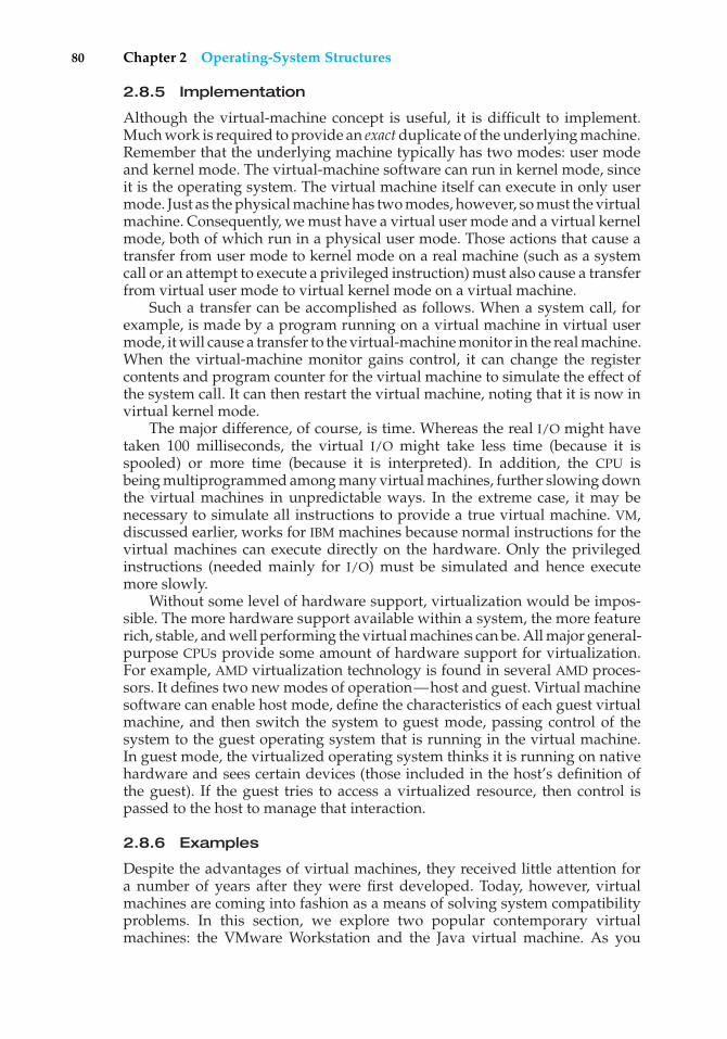
80 Chapter 2 Operating-System Structures
2.8.5 Implementation
Although the virtual-machine concept is useful, it is difficult to implement.Much work is required to provide an exact duplicate of the underlying machine.Remember that the underlying machine typically has two modes: user modeand kernel mode. The virtual-machine software can run in kernel mode, sinceit is the operating system. The virtual machine itself can execute in only usermode. Just as the physical machine has two modes, however, so must the virtualmachine. Consequently, we must have a virtual user mode and a virtual kernelmode, both of which run in a physical user mode. Those actions that cause atransfer from user mode to kernel mode on a real machine (such as a systemcall or an attempt to execute a privileged instruction) must also cause a transferfrom virtual user mode to virtual kernel mode on a virtual machine.
Such a transfer can be accomplished as follows. When a system call, forexample, is made by a program running on a virtual machine in virtual usermode, it will cause a transfer to the virtual-machine monitor in the real machine.When the virtual-machine monitor gains control, it can change the registercontents and program counter for the virtual machine to simulate the effect ofthe system call. It can then restart the virtual machine, noting that it is now invirtual kernel mode.
The major difference, of course, is time. Whereas the real I/O might havetaken 100 milliseconds, the virtual I/O might take less time (because it isspooled) or more time (because it is interpreted). In addition, the CPU isbeing multiprogrammed among many virtual machines, further slowing downthe virtual machines in unpredictable ways. In the extreme case, it may benecessary to simulate all instructions to provide a true virtual machine. VM,discussed earlier, works for IBM machines because normal instructions for thevirtual machines can execute directly on the hardware. Only the privilegedinstructions (needed mainly for I/O) must be simulated and hence executemore slowly.
Without some level of hardware support, virtualization would be impos-sible. The more hardware support available within a system, the more featurerich, stable, and well performing the virtual machines can be. All major general-purpose CPUs provide some amount of hardware support for virtualization.For example, AMD virtualization technology is found in several AMD proces-sors. It defines two new modes of operation—host and guest. Virtual machinesoftware can enable host mode, define the characteristics of each guest virtualmachine, and then switch the system to guest mode, passing control of thesystem to the guest operating system that is running in the virtual machine.In guest mode, the virtualized operating system thinks it is running on nativehardware and sees certain devices (those included in the host’s definition ofthe guest). If the guest tries to access a virtualized resource, then control ispassed to the host to manage that interaction.
2.8.6 Examples
Despite the advantages of virtual machines, they received little attention fora number of years after they were first developed. Today, however, virtualmachines are coming into fashion as a means of solving system compatibilityproblems. In this section, we explore two popular contemporary virtualmachines: the VMware Workstation and the Java virtual machine. As you
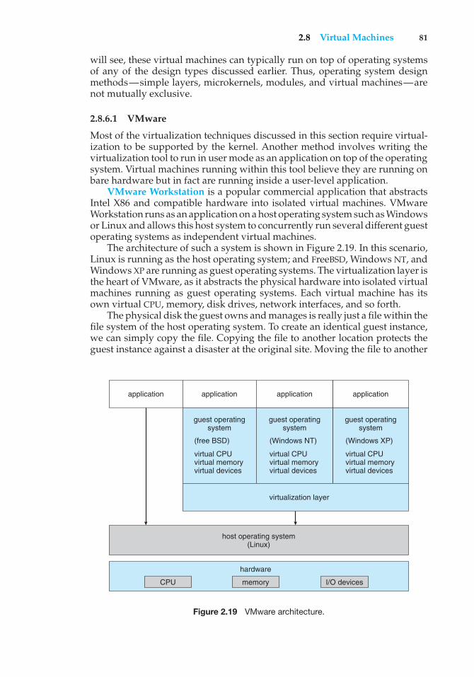
2.8 Virtual Machines 81
will see, these virtual machines can typically run on top of operating systemsof any of the design types discussed earlier. Thus, operating system designmethods—simple layers, microkernels, modules, and virtual machines—arenot mutually exclusive.
2.8.6.1 VMware
Most of the virtualization techniques discussed in this section require virtual-ization to be supported by the kernel. Another method involves writing thevirtualization tool to run in user mode as an application on top of the operatingsystem. Virtual machines running within this tool believe they are running onbare hardware but in fact are running inside a user-level application.
VMware Workstation is a popular commercial application that abstractsIntel X86 and compatible hardware into isolated virtual machines. VMwareWorkstation runs as an application on a host operating system such as Windowsor Linux and allows this host system to concurrently run several different guestoperating systems as independent virtual machines.
The architecture of such a system is shown in Figure 2.19. In this scenario,Linux is running as the host operating system; and FreeBSD, Windows NT, andWindows XP are running as guest operating systems. The virtualization layer isthe heart of VMware, as it abstracts the physical hardware into isolated virtualmachines running as guest operating systems. Each virtual machine has itsown virtual CPU, memory, disk drives, network interfaces, and so forth.
The physical disk the guest owns and manages is really just a file within thefile system of the host operating system. To create an identical guest instance,we can simply copy the file. Copying the file to another location protects theguest instance against a disaster at the original site. Moving the file to another
virtualization layer
host operating system(Linux)
CPU memory
hardware
I/O devices
application application application application
guest operatingsystem
(free BSD)
virtual CPUvirtual memory virtual devices
guest operatingsystem
(Windows NT)
virtual CPUvirtual memoryvirtual devices
guest operatingsystem
(Windows XP)
virtual CPUvirtual memoryvirtual devices
Figure 2.19 VMware architecture.
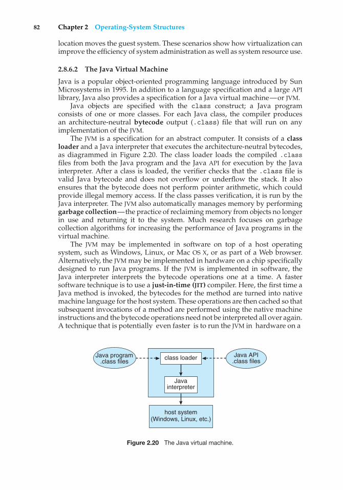
82 Chapter 2 Operating-System Structures
location moves the guest system. These scenarios show how virtualization canimprove the efficiency of system administration as well as system resource use.
2.8.6.2 The Java Virtual Machine
Java is a popular object-oriented programming language introduced by SunMicrosystems in 1995. In addition to a language specification and a large APIlibrary, Java also provides a specification for a Java virtual machine—or JVM.
Java objects are specified with the class construct; a Java programconsists of one or more classes. For each Java class, the compiler producesan architecture-neutral bytecode output (.class) file that will run on anyimplementation of the JVM.
The JVM is a specification for an abstract computer. It consists of a classloader and a Java interpreter that executes the architecture-neutral bytecodes,as diagrammed in Figure 2.20. The class loader loads the compiled .classfiles from both the Java program and the Java API for execution by the Javainterpreter. After a class is loaded, the verifier checks that the .class file isvalid Java bytecode and does not overflow or underflow the stack. It alsoensures that the bytecode does not perform pointer arithmetic, which couldprovide illegal memory access. If the class passes verification, it is run by theJava interpreter. The JVM also automatically manages memory by performinggarbage collection—the practice of reclaiming memory from objects no longerin use and returning it to the system. Much research focuses on garbagecollection algorithms for increasing the performance of Java programs in thevirtual machine.
The JVM may be implemented in software on top of a host operatingsystem, such as Windows, Linux, or Mac OS X, or as part of a Web browser.Alternatively, the JVM may be implemented in hardware on a chip specificallydesigned to run Java programs. If the JVM is implemented in software, theJava interpreter interprets the bytecode operations one at a time. A fastersoftware technique is to use a just-in-time (JIT) compiler. Here, the first time aJava method is invoked, the bytecodes for the method are turned into nativemachine language for the host system. These operations are then cached so thatsubsequent invocations of a method are performed using the native machineinstructions and the bytecode operations need not be interpreted all over again.A technique that is potentially even faster is to run the JVM in hardware on a
host system (Windows, Linux, etc.)
class loader
Javainterpreter
Java program.class files
Java API.class files
Figure 2.20 The Java virtual machine.
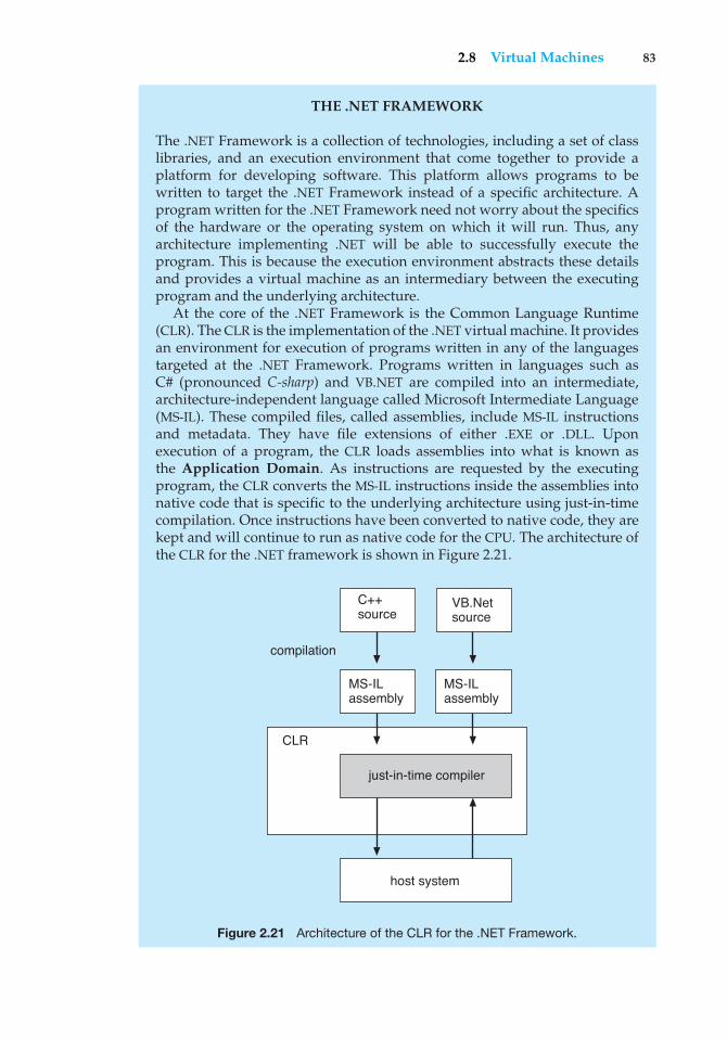
2.8 Virtual Machines 83
THE .NET FRAMEWORK
The .NET Framework is a collection of technologies, including a set of classlibraries, and an execution environment that come together to provide aplatform for developing software. This platform allows programs to bewritten to target the .NET Framework instead of a specific architecture. Aprogram written for the .NET Framework need not worry about the specificsof the hardware or the operating system on which it will run. Thus, anyarchitecture implementing .NET will be able to successfully execute theprogram. This is because the execution environment abstracts these detailsand provides a virtual machine as an intermediary between the executingprogram and the underlying architecture.
At the core of the .NET Framework is the Common Language Runtime(CLR). The CLR is the implementation of the .NET virtual machine. It providesan environment for execution of programs written in any of the languagestargeted at the .NET Framework. Programs written in languages such asC# (pronounced C-sharp) and VB.NET are compiled into an intermediate,architecture-independent language called Microsoft Intermediate Language(MS-IL). These compiled files, called assemblies, include MS-IL instructionsand metadata. They have file extensions of either .EXE or .DLL. Uponexecution of a program, the CLR loads assemblies into what is known asthe Application Domain. As instructions are requested by the executingprogram, the CLR converts the MS-IL instructions inside the assemblies intonative code that is specific to the underlying architecture using just-in-timecompilation. Once instructions have been converted to native code, they arekept and will continue to run as native code for the CPU. The architecture ofthe CLR for the .NET framework is shown in Figure 2.21.
CLR
compilation
host system
just-in-time compiler
C++ source
MS-IL assembly
MS-IL assembly
VB.Net source
Figure 2.21 Architecture of the CLR for the .NET Framework.
84 Chapter 2 Operating-System Structures
special Java chip that executes the Java bytecode operations as native code, thusbypassing the need for either a software interpreter or a just-in-time compiler.
2.9 Operating-System Debugging
Broadly, debugging is the activity of finding and fixing errors, or bugs, in asystem. Debugging seeks to find and fix errors in both hardware and software.Performance problems are considered bugs, so debugging can also includeperformance tuning, which seeks to improve performance by removingbottlenecks in the processing taking place within a system. A discussion ofhardware debugging is outside of the scope of this text. In this section, weexplore debugging kernel and process errors and performance problems.
2.9.1 Failure Analysis
If a process fails, most operating systems write the error information to a logfile to alert system operators or users that the problem occurred. The operatingsystem can also take a core dump—a capture of the memory (referred to as the“core” in the early days of computing) of the process. This core image is storedin a file for later analysis. Running programs and core dumps can be probedby a debugger, a tool designed to allow a programmer to explore the code andmemory of a process.
Debugging user-level process code is a challenge. Operating system kerneldebugging even more complex because of the size and complexity of the kernel,its control of the hardware, and the lack of user-level debugging tools. A kernelfailure is called a crash. As with a process failure, error information is saved toa log file, and the memory state is saved to a crash dump.
Operating system debugging frequently uses different tools and techniquesthan process debugging due to the very different nature of these two tasks.Consider that a kernel failure in the file-system code would make it risky forthe kernel to try to save its state to a file on the file system before rebooting.A common technique is to save the kernel’s memory state to a section of diskset aside for this purpose that contains no file system. If the kernel detectsan unrecoverable error, it writes the entire contents of memory, or at least thekernel-owned parts of the system memory, to the disk area. When the systemreboots, a process runs to gather the data from that area and write it to a crashdump file within a file system for analysis.
2.9.2 Performance Tuning
To identify bottlenecks, we must be able to monitor system performance. Codemust be added to compute and display measures of system behavior. In anumber of systems, the operating system does this task by producing tracelistings of system behavior. All interesting events are logged with their time andimportant parameters and are written to a file. Later, an analysis program canprocess the log file to determine system performance and to identify bottlenecksand inefficiencies. These same traces can be run as input for a simulation ofa suggested improved system. Traces also can help people to find errors inoperating-system behavior.
2.9 Operating-System Debugging 85
Kernighan’s Law
“Debugging is twice as hard as writing the code in the first place. Therefore,if you write the code as cleverly as possible, you are, by definition, not smartenough to debug it.”
Another approach to performance tuning is to include interactive toolswith the system that allow users and administrators to question the state ofvarious components of the system to look for bottlenecks. The UNIX commandtop displays resources used on the system, as well as a sorted list of the “top”resource-using processes. Other tools display the state of disk I/O, memoryallocation, and network traffic. The authors of these single-purpose tools try toguess what a user would want to see while analyzing a system and to providethat information.
Making running operating systems easier to understand, debug, and tuneis an active area of operating system research and implementation. The cycleof enabling tracing as system problems occur and analyzing the traces lateris being broken by a new generation of kernel-enabled performance analysistools. Further, these tools are not single-purpose or merely for sections of codethat were written to emit debugging data. The Solaris 10 DTrace dynamictracing facility is a leading example of such a tool.
2.9.3 DTrace
DTrace is a facility that dynamically adds probes to a running system, bothin user processes and in the kernel. These probes can be queried via the Dprogramming language to determine an astonishing amount about the kernel,the system state, and process activities. For example, Figure 2.22 follows anapplication as it executes a system call (ioctl) and further shows the functionalcalls within the kernel as they execute to perform the system call. Lines endingwith “U” are executed in user mode, and lines ending in “K” in kernel mode.
Debugging the interactions between user-level and kernel code is nearlyimpossible without a toolset that understands both sets of code and caninstrument the interactions. For that toolset to be truly useful, it must be ableto debug any area of a system, including areas that were not written withdebugging in mind, and do so without affecting system reliability. This toolmust also have a minimum performance impact—ideally it should have noimpact when not in use and a proportional impact during use. The DTrace toolmeets these requirements and provides a dynamic, safe, low-impact debuggingenvironment.
Until the DTrace framework and tools became available with Solaris 10,kernel debugging was usually shrouded in mystery and accomplished viahappenstance and archaic code and tools. For example, CPUs have a breakpointfeature that will halt execution and allow a debugger to examine the state of thesystem. Then execution can continue until the next breakpoint or termination.This method cannot be used in a multiuser operating-system kernel withoutnegatively affecting all of the users on the system. Profiling, which periodicallysamples the instruction pointer to determine which code is being executed, canshow statistical trends but not individual activities. Code can be included inthe kernel to emit specific data under specific circumstances, but that code
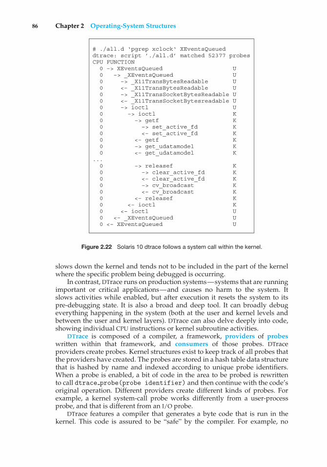
86 Chapter 2 Operating-System Structures
# ./all.d ‘pgrep xclock‘ XEventsQueueddtrace: script ’./all.d’ matched 52377 probesCPU FUNCTION 0 –> XEventsQueued U 0 –> _XEventsQueued U 0 –> _X11TransBytesReadable U 0 <– _X11TransBytesReadable U 0 –> _X11TransSocketBytesReadable U 0 <– _X11TransSocketBytesreadable U 0 –> ioctl U 0 –> ioctl K 0 –> getf K 0 –> set_active_fd K 0 <– set_active_fd K 0 <– getf K 0 –> get_udatamodel K 0 <– get_udatamodel K... 0 –> releasef K 0 –> clear_active_fd K 0 <– clear_active_fd K 0 –> cv_broadcast K 0 <– cv_broadcast K 0 <– releasef K 0 <– ioctl K 0 <– ioctl U 0 <– _XEventsQueued U 0 <– XEventsQueued U
Figure 2.22 Solaris 10 dtrace follows a system call within the kernel.
slows down the kernel and tends not to be included in the part of the kernelwhere the specific problem being debugged is occurring.
In contrast, DTrace runs on production systems—systems that are runningimportant or critical applications—and causes no harm to the system. Itslows activities while enabled, but after execution it resets the system to itspre-debugging state. It is also a broad and deep tool. It can broadly debugeverything happening in the system (both at the user and kernel levels andbetween the user and kernel layers). DTrace can also delve deeply into code,showing individual CPU instructions or kernel subroutine activities.
DTrace is composed of a compiler, a framework, providers of probeswritten within that framework, and consumers of those probes. DTraceproviders create probes. Kernel structures exist to keep track of all probes thatthe providers have created. The probes are stored in a hash table data structurethat is hashed by name and indexed according to unique probe identifiers.When a probe is enabled, a bit of code in the area to be probed is rewrittento call dtrace probe(probe identifier) and then continue with the code’soriginal operation. Different providers create different kinds of probes. Forexample, a kernel system-call probe works differently from a user-processprobe, and that is different from an I/O probe.
DTrace features a compiler that generates a byte code that is run in thekernel. This code is assured to be “safe” by the compiler. For example, no
2.9 Operating-System Debugging 87
loops are allowed, and only specific kernel state modifications are allowedwhen specifically requested. Only users with the DTrace “privileges” (or “root”users) are allowed to use DTrace, as it can retrieve private kernel data (andmodify data if requested). The generated code runs in the kernel and enablesprobes. It also enables consumers in user mode and enables communicationsbetween the two.
A DTrace consumer is code that is interested in a probe and its results.A consumer requests that the provider create one or more probes. When aprobe fires, it emits data that are managed by the kernel. Within the kernel,actions called enabling control blocks, or ECBs, are performed when probesfire. One probe can cause multiple ECBs to execute if more than one consumeris interested in that probe. Each ECB contains a predicate (“if statement”) thatcan filter out that ECB. Otherwise, the list of actions in the ECB is executed. Themost usual action is to capture some bit of data, such as a variable’s value atthat point of the probe execution. By gathering such data, a complete picture ofa user or kernel action can be built. Further, probes firing from both user spaceand the kernel can show how a user-level action caused kernel-level reactions.Such data are invaluable for performance monitoring and code optimization.
Once the probe consumer terminates, its ECBs are removed. If there are noECBs consuming a probe, the probe is removed. That involves rewriting thecode to remove the dtrace probe call and put back the original code. Thus,before a probe is created and after it is destroyed, the system is exactly thesame, as if no probing occurred.
DTrace takes care to assure that probes do not use too much memory orCPU capacity, which could harm the running system. The buffers used to holdthe probe results are monitored for exceeding default and maximum limits.CPU time for probe execution is monitored as well. If limits are exceeded, theconsumer is terminated, along with the offending probes. Buffers are allocatedper CPU to avoid contention and data loss.
An example of D code and its output shows some of its utility. The followingprogram shows the DTrace code to enable scheduler probes and record theamount of CPU time of each process running with user ID 101 while thoseprobes are enabled (that is, while the program runs):
sched:::on-cpuuid == 101{
self->ts = timestamp;}
sched:::off-cpuself->ts{
@time[execname] = sum(timestamp - self->ts);self->ts = 0;
}
The output of the program, showing the processes and how much time (innanoseconds) they spend running on the CPUs, is shown in Figure 2.23.
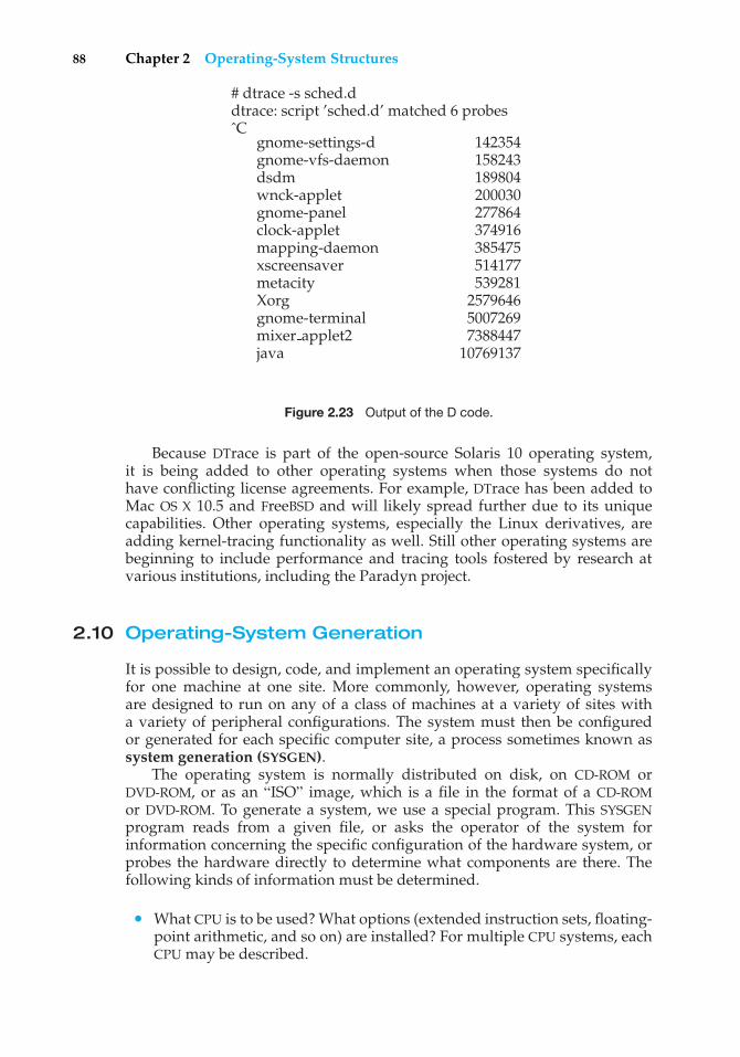
88 Chapter 2 Operating-System Structures
# dtrace -s sched.ddtrace: script ’sched.d’ matched 6 probesˆC
gnome-settings-d 142354gnome-vfs-daemon 158243dsdm 189804wnck-applet 200030gnome-panel 277864clock-applet 374916mapping-daemon 385475xscreensaver 514177metacity 539281Xorg 2579646gnome-terminal 5007269mixer applet2 7388447java 10769137
Figure 2.23 Output of the D code.
Because DTrace is part of the open-source Solaris 10 operating system,it is being added to other operating systems when those systems do nothave conflicting license agreements. For example, DTrace has been added toMac OS X 10.5 and FreeBSD and will likely spread further due to its uniquecapabilities. Other operating systems, especially the Linux derivatives, areadding kernel-tracing functionality as well. Still other operating systems arebeginning to include performance and tracing tools fostered by research atvarious institutions, including the Paradyn project.
2.10 Operating-System Generation
It is possible to design, code, and implement an operating system specificallyfor one machine at one site. More commonly, however, operating systemsare designed to run on any of a class of machines at a variety of sites witha variety of peripheral configurations. The system must then be configuredor generated for each specific computer site, a process sometimes known assystem generation (SYSGEN).
The operating system is normally distributed on disk, on CD-ROM orDVD-ROM, or as an “ISO” image, which is a file in the format of a CD-ROMor DVD-ROM. To generate a system, we use a special program. This SYSGENprogram reads from a given file, or asks the operator of the system forinformation concerning the specific configuration of the hardware system, orprobes the hardware directly to determine what components are there. Thefollowing kinds of information must be determined.
• What CPU is to be used? What options (extended instruction sets, floating-point arithmetic, and so on) are installed? For multiple CPU systems, eachCPU may be described.
2.11 System Boot 89
• How will the boot disk be formatted? How many sections, or “partitions,”will it be separated into, and what will go into each partition?
• How much memory is available? Some systems will determine this valuethemselves by referencing memory location after memory location until an“illegal address” fault is generated. This procedure defines the final legaladdress and hence the amount of available memory.
• What devices are available? The system will need to know how to addresseach device (the device number), the device interrupt number, the device’stype and model, and any special device characteristics.
• What operating-system options are desired, or what parameter values areto be used? These options or values might include how many buffers ofwhich sizes should be used, what type of CPU-scheduling algorithm isdesired, what the maximum number of processes to be supported is, andso on.
Once this information is determined, it can be used in several ways. At oneextreme, a system administrator can use it to modify a copy of the source code ofthe operating system. The operating system then is completely compiled. Datadeclarations, initializations, and constants, along with conditional compilation,produce an output-object version of the operating system that is tailored to thesystem described.
At a slightly less tailored level, the system description can lead to thecreation of tables and the selection of modules from a precompiled library.These modules are linked together to form the generated operating system.Selection allows the library to contain the device drivers for all supported I/Odevices, but only those needed are linked into the operating system. Becausethe system is not recompiled, system generation is faster, but the resultingsystem may be overly general.
At the other extreme, it is possible to construct a system that is completelytable driven. All the code is always part of the system, and selection occurs atexecution time, rather than at compile or link time. System generation involvessimply creating the appropriate tables to describe the system.
The major differences among these approaches are the size and generalityof the generated system and the ease of modifying it as the hardwareconfiguration changes. Consider the cost of modifying the system to support anewly acquired graphics terminal or another disk drive. Balanced against thatcost, of course, is the frequency (or infrequency) of such changes.
2.11 System Boot
After an operating system is generated, it must be made available for use bythe hardware. But how does the hardware know where the kernel is or how toload that kernel? The procedure of starting a computer by loading the kernelis known as booting the system. On most computer systems, a small piece ofcode known as the bootstrap program or bootstrap loader locates the kernel,loads it into main memory, and starts its execution. Some computer systems,such as PCs, use a two-step process in which a simple bootstrap loader fetchesa more complex boot program from disk, which in turn loads the kernel.
90 Chapter 2 Operating-System Structures
When a CPU receives a reset event—for instance, when it is powered upor rebooted—the instruction register is loaded with a predefined memorylocation, and execution starts there. At that location is the initial bootstrapprogram. This program is in the form of read-only memory (ROM), becausethe RAM is in an unknown state at system startup. ROM is convenient becauseit needs no initialization and cannot easily be infected by a computer virus.
The bootstrap program can perform a variety of tasks. Usually, one taskis to run diagnostics to determine the state of the machine. If the diagnosticspass, the program can continue with the booting steps. It can also initialize allaspects of the system, from CPU registers to device controllers and the contentsof main memory. Sooner or later, it starts the operating system.
Some systems—such as cellular phones, PDAs, and game consoles—storethe entire operating system in ROM. Storing the operating system in ROM issuitable for small operating systems, simple supporting hardware, and ruggedoperation. A problem with this approach is that changing the bootstrap coderequires changing the ROM hardware chips. Some systems resolve this problemby using erasable programmable read-only memory (EPROM), which is read-only except when explicitly given a command to become writable. All formsof ROM are also known as firmware, since their characteristics fall somewherebetween those of hardware and those of software. A problem with firmwarein general is that executing code there is slower than executing code in RAM.Some systems store the operating system in firmware and copy it to RAM forfast execution. A final issue with firmware is that it is relatively expensive, sousually only small amounts are available.
For large operating systems (including most general-purpose operatingsystems like Windows, Mac OS X, and UNIX) or for systems that changefrequently, the bootstrap loader is stored in firmware, and the operating systemis on disk. In this case, the bootstrap runs diagnostics and has a bit of codethat can read a single block at a fixed location (say block zero) from disk intomemory and execute the code from that boot block. The program stored in theboot block may be sophisticated enough to load the entire operating systeminto memory and begin its execution. More typically, it is simple code (as it fitsin a single disk block) and knows only the address on disk and length of theremainder of the bootstrap program. GRUB is an example of an open-sourcebootstrap program for Linux systems. All of the disk-bound bootstrap, and theoperating system itself, can be easily changed by writing new versions to disk.A disk that has a boot partition (more on that in Section 12.5.1) is called a bootdisk or system disk.
Now that the full bootstrap program has been loaded, it can traverse thefile system to find the operating system kernel, load it into memory, and startits execution. It is only at this point that the system is said to be running.
2.12 Summary
Operating systems provide a number of services. At the lowest level, systemcalls allow a running program to make requests from the operating systemdirectly. At a higher level, the command interpreter or shell provides amechanism for a user to issue a request without writing a program. Commandsmay come from files during batch-mode execution or directly from a terminal
Practice Exercises 91
when in an interactive or time-shared mode. System programs are provided tosatisfy many common user requests.
The types of requests vary according to level. The system-call level mustprovide the basic functions, such as process control and file and devicemanipulation. Higher-level requests, satisfied by the command interpreter orsystem programs, are translated into a sequence of system calls. System servicescan be classified into several categories: program control, status requests, andI/O requests. Program errors can be considered implicit requests for service.
Once the system services are defined, the structure of the operating systemcan be developed. Various tables are needed to record the information thatdefines the state of the computer system and the status of the system’s jobs.
The design of a new operating system is a major task. It is important thatthe goals of the system be well defined before the design begins. The type ofsystem desired is the foundation for choices among various algorithms andstrategies that will be needed.
Since an operating system is large, modularity is important. Designing asystem as a sequence of layers or using a microkernel is considered a goodtechnique. The virtual-machine concept takes the layered approach and treatsboth the kernel of the operating system and the hardware as though they werehardware. Even other operating systems may be loaded on top of this virtualmachine.
Throughout the entire operating-system design cycle, we must be carefulto separate policy decisions from implementation details (mechanisms). Thisseparation allows maximum flexibility if policy decisions are to be changedlater.
Operating systems are now almost always written in a systems-implementation language or in a higher-level language. This feature improvestheir implementation, maintenance, and portability. To create an operatingsystem for a particular machine configuration, we must perform systemgeneration.
Debugging process and kernel failures can be accomplished through theuse of debuggers and other tools that analyze core dumps. Tools such as DTraceanalyze production systems to find bottlenecks and understand other systembehavior.
For a computer system to begin running, the CPU must initialize and startexecuting the bootstrap program in firmware. The bootstrap can execute theoperating system directly if the operating system is also in the firmware, orit can complete a sequence in which it loads progressively smarter programsfrom firmware and disk until the operating system itself is loaded into memoryand executed.
Practice Exercises
2.1 What is the purpose of system calls?
2.2 What are the five major activities of an operating system with regard toprocess management?
2.3 What are the three major activities of an operating system with regardto memory management?
92 Chapter 2 Operating-System Structures
2.4 What are the three major activities of an operating system with regardto secondary-storage management?
2.5 What is the purpose of the command interpreter? Why is it usuallyseparate from the kernel?
2.6 What system calls have to be executed by a command interpreter or shellin order to start a new process?
2.7 What is the purpose of system programs?
2.8 What is the main advantage of the layered approach to system design?What are the disadvantages of using the layered approach?
2.9 List five services provided by an operating system, and explain how eachcreates convenience for users. In which cases would it be impossible foruser-level programs to provide these services? Explain your answer.
2.10 Why do some systems store the operating system in firmware, whileothers store it on disk?
2.11 How could a system be designed to allow a choice of operating systemsfrom which to boot? What would the bootstrap program need to do?
Exercises
2.12 The services and functions provided by an operating system can bedivided into two main categories. Briefly describe the two categoriesand discuss how they differ.
2.13 Describe three general methods for passing parameters to the operatingsystem.
2.14 Describe how you could obtain a statistical profile of the amount of timespent by a program executing different sections of its code. Discuss theimportance of obtaining such a statistical profile.
2.15 What are the five major activities of an operating system with regard tofile management?
2.16 What are the advantages and disadvantages of using the same system-call interface for manipulating both files and devices?
2.17 Would it be possible for the user to develop a new command interpreterusing the system-call interface provided by the operating system?
2.18 What are the two models of interprocess communication? What are thestrengths and weaknesses of the two approaches?
2.19 Why is the separation of mechanism and policy desirable?
2.20 It is sometimes difficult to achieve a layered approach if two componentsof the operating system are dependent on each other. Identify a scenarioin which it is unclear how to layer two system components that requiretight coupling of their functionalities.
Programming Projects 93
2.21 What is the main advantage of the microkernel approach to systemdesign? How do user programs and system services interact in amicrokernel architecture? What are the disadvantages of using themicrokernel approach?
2.22 In what ways is the modular kernel approach similar to the layeredapproach? In what ways does it differ from the layered approach?
2.23 What is the main advantage for an operating-system designer of usinga virtual-machine architecture? What is the main advantage for a user?
2.24 Why is a just-in-time compiler useful for executing Java programs?
2.25 What is the relationship between a guest operating system and a hostoperating system in a system like VMware? What factors need to beconsidered in choosing the host operating system?
2.26 The experimental Synthesis operating system has an assembler incor-porated in the kernel. To optimize system-call performance, the kernelassembles routines within kernel space to minimize the path that thesystem call must take through the kernel. This approach is the antithesisof the layered approach, in which the path through the kernel is extendedto make building the operating system easier. Discuss the pros and consof the Synthesis approach to kernel design and system-performanceoptimization.
Programming Problems
2.27 In Section 2.3, we described a program that copies the contents of one fileto a destination file. This program works by first prompting the user forthe name of the source and destination files. Write this program usingeither the Win32 or POSIX API. Be sure to include all necessary errorchecking, including ensuring that the source file exists.
Once you have correctly designed and tested the program, ifyou used a system that supports it, run the program using a utilitythat traces system calls. Linux systems provide the ptrace utility, andSolaris systems use the truss or dtrace command. On Mac OS X, thektrace facility provides similar functionality. As Windows systems donot provide such features, you will have to trace through the Win32version of this program using a debugger.
Programming Projects
2.28 Adding a system call to the Linux Kernel.
In this project, you will study the system-call interface provided by theLinux operating system and learn how user programs communicate withthe operating system kernel via this interface. Your task is to incorporatea new system call into the kernel, thereby expanding the functionalityof the operating system.
94 Chapter 2 Operating-System Structures
Part 1: Getting Started
A user-mode procedure call is performed by passing arguments to thecalled procedure either on the stack or through registers, saving thecurrent state and the value of the program counter, and jumping tothe beginning of the code corresponding to the called procedure. Theprocess continues to have the same privileges as before.
System calls appear as procedure calls to user programs but result ina change in execution context and privileges. In Linux on the Intel 386architecture, a system call is accomplished by storing the system-callnumber into the EAX register, storing arguments to the system call inother hardware registers, and executing a trap instruction (which is theINT 0x80 assembly instruction). After the trap is executed, the system-call number is used to index into a table of code pointers to obtain thestarting address for the handler code implementing the system call. Theprocess then jumps to this address, and the privileges of the processare switched from user to kernel mode. With the expanded privileges,the process can now execute kernel code, which may include privilegedinstructions that cannot be executed in user mode. The kernel codecan then carry out the requested services, such as interacting with I/Odevices, and can perform process management and other activities thatcannot be performed in user mode.
The system call numbers for recent versions of the Linux ker-nel are listed in /usr/src/linux-2.x/include/asm-i386/unistd.h.(For instance, NR close corresponds to the system call close(), whichis invoked for closing a file descriptor, and is defined as value 6.) Thelist of pointers to system-call handlers is typically stored in the file/usr/src/linux-2.x/arch/i386/kernel/entry.S under the head-ing ENTRY(sys call table). Notice that sys close is stored at entrynumber 6 in the table to be consistent with the system-call numberdefined in the unistd.h file. (The keyword .long denotes that the entrywill occupy the same number of bytes as a data value of type long.)
Part 2: Building a New Kernel
Before adding a system call to the kernel, you must familiarize yourselfwith the task of building the binary for a kernel from its source code andbooting the machine with the newly built kernel. This activity comprisesthe following tasks, some of which depend on the particular installationof the Linux operating system in use.
• Obtain the kernel source code for the Linux distribution. If thesource code package has already been installed on your machine,the corresponding files might be available under /usr/src/linuxor /usr/src/linux-2.x (where the suffix corresponds to the kernelversion number). If the package has not yet been installed, it can bedownloaded from the provider of your Linux distribution or fromhttp://www.kernel.org.
• Learn how to configure, compile, and install the kernel binary. Thiswill vary among the different kernel distributions, but some typical
Programming Projects 95
commands for building the kernel (after entering the directorywhere the kernel source code is stored) include:
◦ make xconfig
◦ make dep
◦ make bzImage
• Add a new entry to the set of bootable kernels supported by thesystem. The Linux operating system typically uses utilities such aslilo and grub to maintain a list of bootable kernels from which theuser can choose during machine boot-up. If your system supportslilo, add an entry to lilo.conf, such as:
image=/boot/bzImage.mykernellabel=mykernelroot=/dev/hda5read-only
where/boot/bzImage.mykernel is the kernel image andmykernelis the label associated with the new kernel. This step will allowyou to choose the new kernel during the boot-up process. You willthen have the option of either booting the new kernel or bootingthe unmodified kernel if the newly built kernel does not functionproperly.
Part 3: Extending the Kernel Source
You can now experiment with adding a new file to the set of sourcefiles used for compiling the kernel. Typically, the source code is storedin the /usr/src/linux-2.x/kernel directory, although that locationmay differ in your Linux distribution. There are two options for addingthe system call. The first is to add the system call to an existing source filein this directory. The second is to create a new file in the source directoryand modify /usr/src/linux-2.x/kernel/Makefile to include thenewly created file in the compilation process. The advantage of the firstapproach is that when you modify an existing file that is already part ofthe compilation process, the Makefile need not be modified.
Part 4: Adding a System Call to the Kernel
Now that you are familiar with the various background tasks corre-sponding to building and booting Linux kernels, you can begin theprocess of adding a new system call to the Linux kernel. In this project,the system call will have limited functionality; it will simply transitionfrom user mode to kernel mode, print a message that is logged with thekernel messages, and transition back to user mode. We will call this thehelloworld system call. While it has only limited functionality, it illustratesthe system-call mechanism and sheds light on the interaction betweenuser programs and the kernel.
96 Chapter 2 Operating-System Structures
• Create a new file called helloworld.c to define your system call.Include the header files linux/linkage.h and linux/kernel.h.Add the following code to this file:
#include <linux/linkage.h>#include <linux/kernel.h>asmlinkage int sys helloworld() {
printk(KERN EMERG "hello world!");
return 1;}
This creates a system call with the name sys helloworld(). If youchoose to add this system call to an existing file in the sourcedirectory, all that is necessary is to add the sys helloworld()function to the file you choose. In the code, asmlinkage isa remnant from the days when Linux used both C++ and Ccode and is used to indicate that the code is written in C. Theprintk() function is used to print messages to a kernel log fileand therefore may be called only from the kernel. The kernel mes-sages specified in the parameter to printk() are logged in thefile /var/log/kernel/warnings. The function prototype for theprintk() call is defined in /usr/include/linux/kernel.h.
• Define a new system call number for NR helloworld in/usr/src/linux-2.x/include/asm-i386/unistd.h. A userprogram can use this number to identify the newly added systemcall. Also be sure to increment the value for NR syscalls, whichis stored in the same file. This constant tracks the number of systemcalls currently defined in the kernel.
• Add an entry .long sys helloworld to the sys call tabledefined in the/usr/src/linux-2.x/arch/i386/kernel/entry.Sfile. As discussed earlier, the system-call number is used to indexinto this table to find the position of the handler code for theinvoked system call.
• Add your file helloworld.c to the Makefile (if you created a newfile for your system call.) Save a copy of your old kernel binaryimage (in case there are problems with your newly created kernel).You can now build the new kernel, rename it to distinguish it fromthe unmodified kernel, and add an entry to the loader configurationfiles (such as lilo.conf). After completing these steps, you can booteither the old kernel or the new kernel that contains your systemcall.
Part 5: Using the System Call from a User Program
When you boot with the new kernel, it will support the newly definedsystem call; you now simply need to invoke this system call from auser program. Ordinarily, the standard C library supports an interface
Wiley Plus 97
for system calls defined for the Linux operating system. As your newsystem call is not linked into the standard C library, however, invokingyour system call will require manual intervention.
As noted earlier, a system call is invoked by storing the appropriatevalue in a hardware register and performing a trap instruction. Unfortu-nately, these low-level operations cannot be performed using C languagestatements and instead require assembly instructions. Fortunately, Linuxprovides macros for instantiating wrapper functions that contain theappropriate assembly instructions. For instance, the following C pro-gram uses the syscall0() macro to invoke the newly defined systemcall:
#include <linux/errno.h>#include <sys/syscall.h>#include <linux/unistd.h>
syscall0(int, helloworld);
main(){
helloworld();}
• The syscall0 macro takes two arguments. The first specifies thetype of the value returned by the system call; the second is thename of the system call. The name is used to identify the system-call number that is stored in the hardware register before the trapinstruction is executed. If your system call requires arguments, thena different macro (such as syscall0, where the suffix indicates thenumber of arguments) could be used to instantiate the assemblycode required for performing the system call.
• Compile and execute the program with the newly built kernel.There should be a message “hello world!” in the kernel log file/var/log/kernel/warnings to indicate that the system call hasexecuted.
As a next step, consider expanding the functionality of your system call.How would you pass an integer value or a character string to the systemcall and have it printed into the kernel log file? What are the implicationsof passing pointers to data stored in the user program’s address spaceas opposed to simply passing an integer value from the user program tothe kernel using hardware registers?
Wiley Plus
Visit Wiley Plus for
• Source code
• Solutions to practice exercises
98 Chapter 2 Operating-System Structures
• Additional programming problems and exercises
• Labs using an operating system simulator
Bibliographical Notes
Dijkstra [1968] advocated the layered approach to operating-system design.Brinch-Hansen [1970] was an early proponent of constructing an operatingsystem as a kernel (or nucleus) on which more complete systems can be built.
System instrumentation and dynamic tracing are described in Tamches andMiller [1999]. DTrace is discussed in Cantrill et al. [2004]. The DTrace sourcecode is available at http://src.opensolaris.org/source/. Cheung andLoong [1995] explore issues of operating-system structure from microkernelto extensible systems.
MS-DOS, Version 3.1, is described in Microsoft [1986]. Windows NT andWindows 2000 are described by Solomon [1998] and Solomon and Russinovich[2000]. Windows 2003 and Windows XP internals are described in Russinovichand Solomon [2005]. Hart [2005] covers Windows systems programming indetail. BSD UNIX is described in McKusick et al. [1996]. Bovet and Cesati[2006] thoroughly discuss the Linux kernel. Several UNIX systems—includingMach—are treated in detail in Vahalia [1996]. Mac OS X is presented athttp://www.apple.com/macosx and in Singh [2007]. Solaris is fully describedin McDougall and Mauro [2007].
The first operating system to provide a virtual machine was the CP/67 onan IBM 360/67. The commercially available IBM VM/370 operating system wasderived from CP/67. Details regarding Mach, a microkernel-based operatingsystem, can be found in Young et al. [1987]. Kaashoek et al. [1997] present detailsregarding exokernel operating systems, wherein the architecture separatesmanagement issues from protection, thereby giving untrusted software theability to exercise control over hardware and software resources.
The specifications for the Java language and the Java virtual machine arepresented by Gosling et al. [1996] and by Lindholm and Yellin [1999], respec-tively. The internal workings of the Java virtual machine are fully describedby Venners [1998]. Golm et al. [2002] highlight the JX operating system; Backet al. [2000] cover several issues in the design of Java operating systems. Moreinformation on Java is available on the Web at http://www.javasoft.com.Details about the implementation of VMware can be found in Sugerman et al.[2001]. Information about the Open Virtual Machine Format can be found athttp://www.vmware.com/appliances/learn/ovf.html.
Part Two
ProcessManagement
A process can be thought of as a program in execution. A process willneed certain resources—such as CPU time, memory, files, and I/O devices—to accomplish its task. These resources are allocated to the processeither when it is created or while it is executing.
A process is the unit of work in most systems. Systems consist ofa collection of processes: Operating-system processes execute systemcode, and user processes execute user code. All these processes mayexecute concurrently.
Although traditionally a process contained only a single thread ofcontrol as it ran, most modern operating systems now support processesthat have multiple threads.
The operating system is responsible for the following activities inconnection with process and thread management: the creation anddeletion of both user and system processes; the scheduling of processes;and the provision of mechanisms for synchronization, communication,and deadlock handling for processes.

This page intentionally left blank
3C H A P T E R
Processes
Early computer systems allowed only one program to be executed at atime. This program had complete control of the system and had access toall the system’s resources. In contrast, current-day computer systems allowmultiple programs to be loaded into memory and executed concurrently.This evolution required firmer control and more compartmentalization of thevarious programs; and these needs resulted in the notion of a process, which isa program in execution. A process is the unit of work in a modern time-sharingsystem.
The more complex the operating system is, the more it is expected to do onbehalf of its users. Although its main concern is the execution of user programs,it also needs to take care of various system tasks that are better left outside thekernel itself. A system therefore consists of a collection of processes: operating-system processes executing system code and user processes executing usercode. Potentially, all these processes can execute concurrently, with the CPU (orCPUs) multiplexed among them. By switching the CPU between processes, theoperating system can make the computer more productive. In this chapter, youwill read about what processes are and how they work.
CHAPTER OBJECTIVES
• To introduce the notion of a process—a program in execution, which formsthe basis of all computation.
• To describe the various features of processes, including scheduling,creation and termination, and communication.
• To describe communication in client–server systems.
3.1 Process Concept
A question that arises in discussing operating systems involves what to call allthe CPU activities. A batch system executes jobs,whereas a time-shared systemhas user programs, or tasks. Even on a single-user system such as Microsoft
101
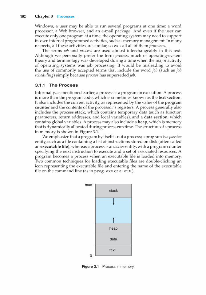
102 Chapter 3 Processes
Windows, a user may be able to run several programs at one time: a wordprocessor, a Web browser, and an e-mail package. And even if the user canexecute only one program at a time, the operating system may need to supportits own internal programmed activities, such as memory management. In manyrespects, all these activities are similar, so we call all of them processes.
The terms job and process are used almost interchangeably in this text.Although we personally prefer the term process, much of operating-systemtheory and terminology was developed during a time when the major activityof operating systems was job processing. It would be misleading to avoidthe use of commonly accepted terms that include the word job (such as jobscheduling) simply because process has superseded job.
3.1.1 The Process
Informally, as mentioned earlier, a process is a program in execution. A processis more than the program code, which is sometimes known as the text section.It also includes the current activity, as represented by the value of the programcounter and the contents of the processor’s registers. A process generally alsoincludes the process stack, which contains temporary data (such as functionparameters, return addresses, and local variables), and a data section, whichcontains global variables. A process may also include a heap, which is memorythat is dynamically allocated during process run time. The structure of a processin memory is shown in Figure 3.1.
We emphasize that a program by itself is not a process; a program is a passiveentity, such as a file containing a list of instructions stored on disk (often calledan executable file), whereas a process is an active entity, with a program counterspecifying the next instruction to execute and a set of associated resources. Aprogram becomes a process when an executable file is loaded into memory.Two common techniques for loading executable files are double-clicking anicon representing the executable file and entering the name of the executablefile on the command line (as in prog.exe or a.out.)
text
0
max
data
heap
stack
Figure 3.1 Process in memory.
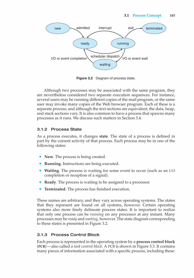
3.1 Process Concept 103
new terminated
runningready
admitted interrupt
scheduler dispatchI/O or event completion I/O or event wait
exit
waiting
Figure 3.2 Diagram of process state.
Although two processes may be associated with the same program, theyare nevertheless considered two separate execution sequences. For instance,several users may be running different copies of the mail program, or the sameuser may invoke many copies of the Web browser program. Each of these is aseparate process; and although the text sections are equivalent, the data, heap,and stack sections vary. It is also common to have a process that spawns manyprocesses as it runs. We discuss such matters in Section 3.4.
3.1.2 Process State
As a process executes, it changes state. The state of a process is defined inpart by the current activity of that process. Each process may be in one of thefollowing states:
• New. The process is being created.
• Running. Instructions are being executed.
• Waiting. The process is waiting for some event to occur (such as an I/Ocompletion or reception of a signal).
• Ready. The process is waiting to be assigned to a processor.
• Terminated. The process has finished execution.
These names are arbitrary, and they vary across operating systems. The statesthat they represent are found on all systems, however. Certain operatingsystems also more finely delineate process states. It is important to realizethat only one process can be running on any processor at any instant. Manyprocesses may be ready andwaiting, however. The state diagram correspondingto these states is presented in Figure 3.2.
3.1.3 Process Control Block
Each process is represented in the operating system by a process control block(PCB)—also called a task control block. A PCB is shown in Figure 3.3. It containsmany pieces of information associated with a specific process, including these:
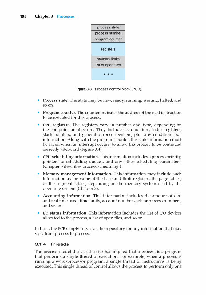
104 Chapter 3 Processes
process state
process number
program counter
memory limits
list of open files
registers
• • •
Figure 3.3 Process control block (PCB).
• Process state. The state may be new, ready, running, waiting, halted, andso on.
• Program counter. The counter indicates the address of the next instructionto be executed for this process.
• CPU registers. The registers vary in number and type, depending onthe computer architecture. They include accumulators, index registers,stack pointers, and general-purpose registers, plus any condition-codeinformation. Along with the program counter, this state information mustbe saved when an interrupt occurs, to allow the process to be continuedcorrectly afterward (Figure 3.4).
• CPU-scheduling information. This information includes a process priority,pointers to scheduling queues, and any other scheduling parameters.(Chapter 5 describes process scheduling.)
• Memory-management information. This information may include suchinformation as the value of the base and limit registers, the page tables,or the segment tables, depending on the memory system used by theoperating system (Chapter 8).
• Accounting information. This information includes the amount of CPUand real time used, time limits, account numbers, job or process numbers,and so on.
• I/O status information. This information includes the list of I/O devicesallocated to the process, a list of open files, and so on.
In brief, the PCB simply serves as the repository for any information that mayvary from process to process.
3.1.4 Threads
The process model discussed so far has implied that a process is a programthat performs a single thread of execution. For example, when a process isrunning a word-processor program, a single thread of instructions is beingexecuted. This single thread of control allows the process to perform only one
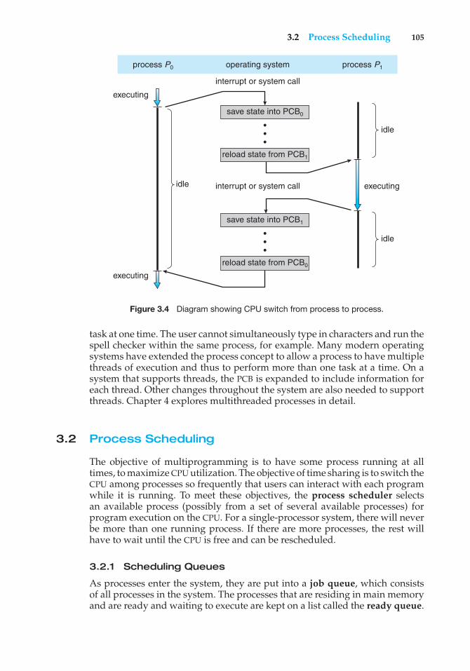
3.2 Process Scheduling 105
process P0 process P1
save state into PCB0
save state into PCB1
reload state from PCB1
reload state from PCB0
operating system
idle
idle
executingidle
executing
executing
interrupt or system call
interrupt or system call
•••
•••
Figure 3.4 Diagram showing CPU switch from process to process.
task at one time. The user cannot simultaneously type in characters and run thespell checker within the same process, for example. Many modern operatingsystems have extended the process concept to allow a process to have multiplethreads of execution and thus to perform more than one task at a time. On asystem that supports threads, the PCB is expanded to include information foreach thread. Other changes throughout the system are also needed to supportthreads. Chapter 4 explores multithreaded processes in detail.
3.2 Process Scheduling
The objective of multiprogramming is to have some process running at alltimes, to maximize CPU utilization. The objective of time sharing is to switch theCPU among processes so frequently that users can interact with each programwhile it is running. To meet these objectives, the process scheduler selectsan available process (possibly from a set of several available processes) forprogram execution on the CPU. For a single-processor system, there will neverbe more than one running process. If there are more processes, the rest willhave to wait until the CPU is free and can be rescheduled.
3.2.1 Scheduling Queues
As processes enter the system, they are put into a job queue, which consistsof all processes in the system. The processes that are residing in main memoryand are ready and waiting to execute are kept on a list called the ready queue.
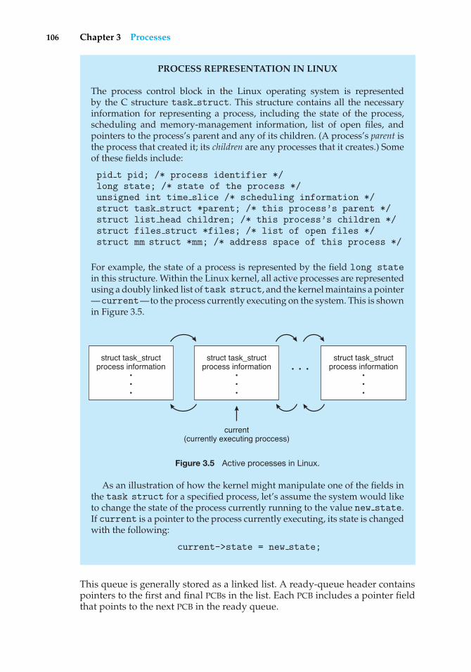
106 Chapter 3 Processes
PROCESS REPRESENTATION IN LINUX
The process control block in the Linux operating system is representedby the C structure task struct. This structure contains all the necessaryinformation for representing a process, including the state of the process,scheduling and memory-management information, list of open files, andpointers to the process’s parent and any of its children. (A process’s parent isthe process that created it; its children are any processes that it creates.) Someof these fields include:
pid t pid; /* process identifier */long state; /* state of the process */unsigned int time slice /* scheduling information */struct task struct *parent; /* this process’s parent */struct list head children; /* this process’s children */struct files struct *files; /* list of open files */struct mm struct *mm; /* address space of this process */
For example, the state of a process is represented by the field long statein this structure. Within the Linux kernel, all active processes are representedusing a doubly linked list oftask struct, and the kernel maintains a pointer—current—to the process currently executing on the system. This is shownin Figure 3.5.
struct task_structprocess information
• • •
struct task_structprocess information
•••
current(currently executing proccess)
struct task_structprocess information
•••
• • •
Figure 3.5 Active processes in Linux.
As an illustration of how the kernel might manipulate one of the fields inthe task struct for a specified process, let’s assume the system would liketo change the state of the process currently running to the value new state.If current is a pointer to the process currently executing, its state is changedwith the following:
current->state = new state;
This queue is generally stored as a linked list. A ready-queue header containspointers to the first and final PCBs in the list. Each PCB includes a pointer fieldthat points to the next PCB in the ready queue.
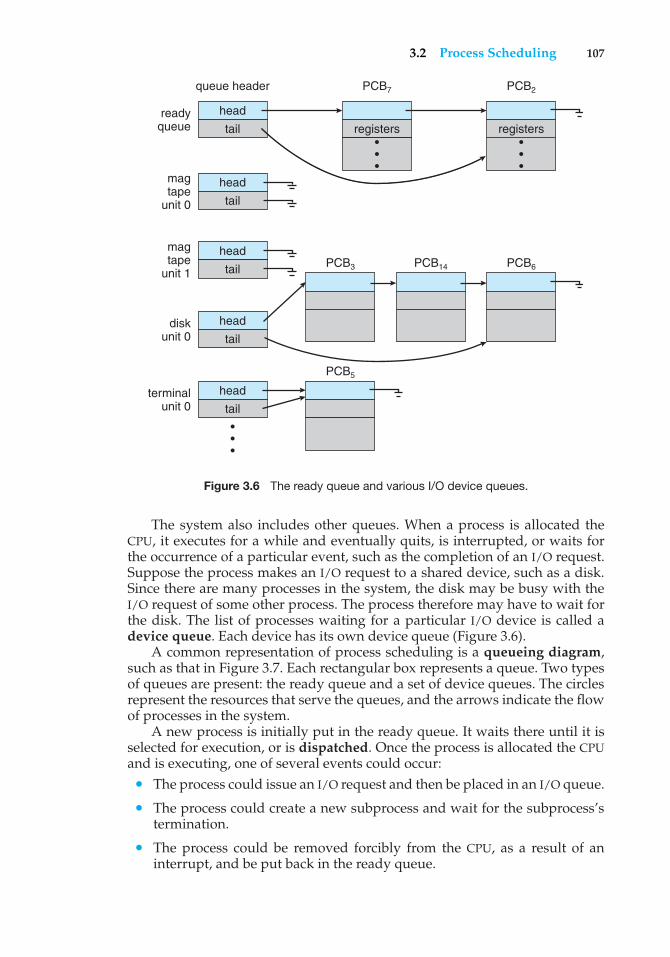
3.2 Process Scheduling 107
queue header PCB7
PCB3
PCB5
PCB14 PCB6
PCB2
head
head
head
head
head
readyqueue
disk unit 0
terminal unit 0
magtape
unit 0
magtape
unit 1
tail registers registers
tail
tail
tail
tail
•••
•••
•••
Figure 3.6 The ready queue and various I/O device queues.
The system also includes other queues. When a process is allocated theCPU, it executes for a while and eventually quits, is interrupted, or waits forthe occurrence of a particular event, such as the completion of an I/O request.Suppose the process makes an I/O request to a shared device, such as a disk.Since there are many processes in the system, the disk may be busy with theI/O request of some other process. The process therefore may have to wait forthe disk. The list of processes waiting for a particular I/O device is called adevice queue. Each device has its own device queue (Figure 3.6).
A common representation of process scheduling is a queueing diagram,such as that in Figure 3.7. Each rectangular box represents a queue. Two typesof queues are present: the ready queue and a set of device queues. The circlesrepresent the resources that serve the queues, and the arrows indicate the flowof processes in the system.
A new process is initially put in the ready queue. It waits there until it isselected for execution, or is dispatched. Once the process is allocated the CPUand is executing, one of several events could occur:
• The process could issue an I/O request and then be placed in an I/O queue.
• The process could create a new subprocess and wait for the subprocess’stermination.
• The process could be removed forcibly from the CPU, as a result of aninterrupt, and be put back in the ready queue.
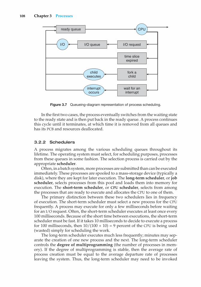
108 Chapter 3 Processes
ready queue CPU
I/O I/O queue I/O request
time sliceexpired
fork achild
wait for aninterrupt
interruptoccurs
childexecutes
Figure 3.7 Queueing-diagram representation of process scheduling.
In the first two cases, the process eventually switches from the waiting stateto the ready state and is then put back in the ready queue. A process continuesthis cycle until it terminates, at which time it is removed from all queues andhas its PCB and resources deallocated.
3.2.2 Schedulers
A process migrates among the various scheduling queues throughout itslifetime. The operating system must select, for scheduling purposes, processesfrom these queues in some fashion. The selection process is carried out by theappropriate scheduler.
Often, in a batch system, more processes are submitted than can be executedimmediately. These processes are spooled to a mass-storage device (typically adisk), where they are kept for later execution. The long-term scheduler, or jobscheduler, selects processes from this pool and loads them into memory forexecution. The short-term scheduler, or CPU scheduler, selects from amongthe processes that are ready to execute and allocates the CPU to one of them.
The primary distinction between these two schedulers lies in frequencyof execution. The short-term scheduler must select a new process for the CPUfrequently. A process may execute for only a few milliseconds before waitingfor an I/O request. Often, the short-term scheduler executes at least once every100 milliseconds. Because of the short time between executions, the short-termscheduler must be fast. If it takes 10 milliseconds to decide to execute a processfor 100 milliseconds, then 10/(100 + 10) = 9 percent of the CPU is being used(wasted) simply for scheduling the work.
The long-term scheduler executes much less frequently; minutes may sep-arate the creation of one new process and the next. The long-term schedulercontrols the degree of multiprogramming (the number of processes in mem-ory). If the degree of multiprogramming is stable, then the average rate ofprocess creation must be equal to the average departure rate of processesleaving the system. Thus, the long-term scheduler may need to be invoked
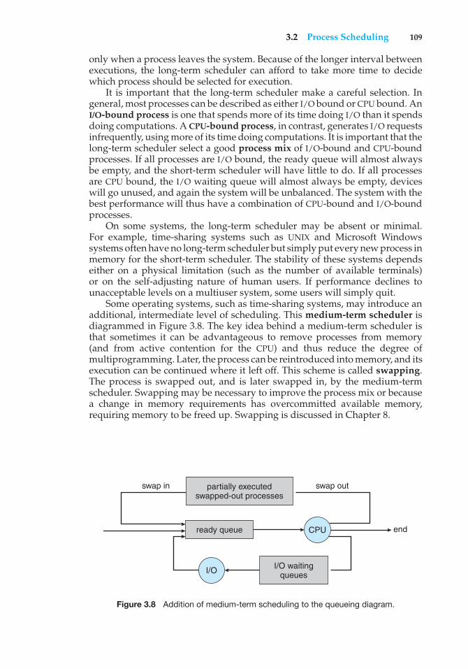
3.2 Process Scheduling 109
only when a process leaves the system. Because of the longer interval betweenexecutions, the long-term scheduler can afford to take more time to decidewhich process should be selected for execution.
It is important that the long-term scheduler make a careful selection. Ingeneral, most processes can be described as either I/O bound or CPU bound. AnI/O-bound process is one that spends more of its time doing I/O than it spendsdoing computations. A CPU-bound process, in contrast, generates I/O requestsinfrequently, using more of its time doing computations. It is important that thelong-term scheduler select a good process mix of I/O-bound and CPU-boundprocesses. If all processes are I/O bound, the ready queue will almost alwaysbe empty, and the short-term scheduler will have little to do. If all processesare CPU bound, the I/O waiting queue will almost always be empty, deviceswill go unused, and again the system will be unbalanced. The system with thebest performance will thus have a combination of CPU-bound and I/O-boundprocesses.
On some systems, the long-term scheduler may be absent or minimal.For example, time-sharing systems such as UNIX and Microsoft Windowssystems often have no long-term scheduler but simply put every new process inmemory for the short-term scheduler. The stability of these systems dependseither on a physical limitation (such as the number of available terminals)or on the self-adjusting nature of human users. If performance declines tounacceptable levels on a multiuser system, some users will simply quit.
Some operating systems, such as time-sharing systems, may introduce anadditional, intermediate level of scheduling. This medium-term scheduler isdiagrammed in Figure 3.8. The key idea behind a medium-term scheduler isthat sometimes it can be advantageous to remove processes from memory(and from active contention for the CPU) and thus reduce the degree ofmultiprogramming. Later, the process can be reintroduced into memory, and itsexecution can be continued where it left off. This scheme is called swapping.The process is swapped out, and is later swapped in, by the medium-termscheduler. Swapping may be necessary to improve the process mix or becausea change in memory requirements has overcommitted available memory,requiring memory to be freed up. Swapping is discussed in Chapter 8.
swap in swap out
endCPU
I/O I/O waitingqueues
ready queue
partially executedswapped-out processes
Figure 3.8 Addition of medium-term scheduling to the queueing diagram.
110 Chapter 3 Processes
3.2.3 Context Switch
As mentioned in Section 1.2.1, interrupts cause the operating system to changea CPU from its current task and to run a kernel routine. Such operations happenfrequently on general-purpose systems. When an interrupt occurs, the systemneeds to save the current context of the process running on the CPU so thatit can restore that context when its processing is done, essentially suspendingthe process and then resuming it. The context is represented in the PCB of theprocess; it includes the value of the CPU registers, the process state (see Figure3.2), and memory-management information. Generically, we perform a statesave of the current state of the CPU, be it in kernel or user mode, and then astate restore to resume operations.
Switching the CPU to another process requires performing a state saveof the current process and a state restore of a different process. This task isknown as a context switch. When a context switch occurs, the kernel saves thecontext of the old process in its PCB and loads the saved context of the newprocess scheduled to run. Context-switch time is pure overhead, because thesystem does no useful work while switching. Its speed varies from machine tomachine, depending on the memory speed, the number of registers that mustbe copied, and the existence of special instructions (such as a single instructionto load or store all registers). Typical speeds are a few milliseconds.
Context-switch times are highly dependent on hardware support. Forinstance, some processors (such as the Sun UltraSPARC) provide multiple setsof registers. A context switch here simply requires changing the pointer to thecurrent register set. Of course, if there are more active processes than there areregister sets, the system resorts to copying register data to and from memory,as before. Also, the more complex the operating system, the more work mustbe done during a context switch. As we will see in Chapter 8, advancedmemory-management techniques may require extra data to be switched witheach context. For instance, the address space of the current process must bepreserved as the space of the next task is prepared for use. How the addressspace is preserved, and what amount of work is needed to preserve it, dependon the memory-management method of the operating system.
3.3 Operations on Processes
The processes in most systems can execute concurrently, and they maybe created and deleted dynamically. Thus, these systems must provide amechanism for process creation and termination. In this section, we explorethe mechanisms involved in creating processes and illustrate process creationon UNIX and Windows systems.
3.3.1 Process Creation
A process may create several new processes, via a create-process system call,during the course of execution. The creating process is called a parent process,and the new processes are called the children of that process. Each of thesenew processes may in turn create other processes, forming a tree of processes.
Most operating systems (including UNIX and the Windows family ofoperating systems) identify processes according to a unique process identifier
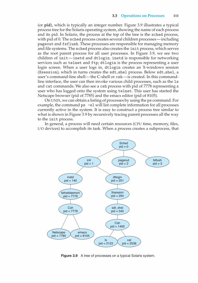
3.3 Operations on Processes 111
(or pid), which is typically an integer number. Figure 3.9 illustrates a typicalprocess tree for the Solaris operating system, showing the name of each processand its pid. In Solaris, the process at the top of the tree is the sched process,with pid of 0. The sched process creates several children processes—includingpageout and fsflush. These processes are responsible for managing memoryand file systems. The sched process also creates the init process, which servesas the root parent process for all user processes. In Figure 3.9, we see twochildren of init—inetd and dtlogin. inetd is responsible for networkingservices such as telnet and ftp; dtlogin is the process representing a userlogin screen. When a user logs in, dtlogin creates an X-windows session(Xsession), which in turns creates the sdt shel process. Below sdt shel, auser’s command-line shell—the C-shell or csh—is created. In this command-line interface, the user can then invoke various child processes, such as the lsand cat commands. We also see a csh process with pid of 7778 representing auser who has logged onto the system using telnet. This user has started theNetscape browser (pid of 7785) and the emacs editor (pid of 8105).
On UNIX, we can obtain a listing of processes by using the ps command. Forexample, the command ps -el will list complete information for all processescurrently active in the system. It is easy to construct a process tree similar towhat is shown in Figure 3.9 by recursively tracing parent processes all the wayto the init process.
In general, a process will need certain resources (CPU time, memory, files,I/O devices) to accomplish its task. When a process creates a subprocess, that
dtloginpid = 251
Schedpid = 0
fsflushpid = 3
pageoutpid = 2
initpid = 1
catpid = 2536
lspid = 2123
emacspid = 8105
Netscapepid = 7785
Xsessionpid = 294
sdt_shelpid = 340
Cshpid = 1400
Cshpid = 7778
telnetdaemonpid = 7776
inetdpid = 140
Figure 3.9 A tree of processes on a typical Solaris system.
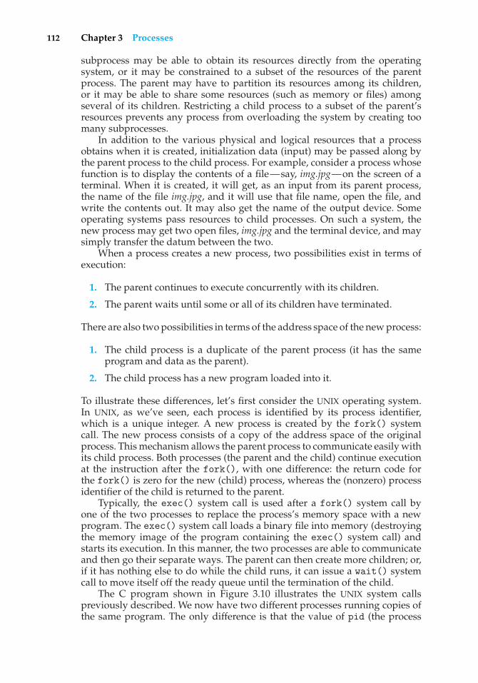
112 Chapter 3 Processes
subprocess may be able to obtain its resources directly from the operatingsystem, or it may be constrained to a subset of the resources of the parentprocess. The parent may have to partition its resources among its children,or it may be able to share some resources (such as memory or files) amongseveral of its children. Restricting a child process to a subset of the parent’sresources prevents any process from overloading the system by creating toomany subprocesses.
In addition to the various physical and logical resources that a processobtains when it is created, initialization data (input) may be passed along bythe parent process to the child process. For example, consider a process whosefunction is to display the contents of a file—say, img.jpg—on the screen of aterminal. When it is created, it will get, as an input from its parent process,the name of the file img.jpg, and it will use that file name, open the file, andwrite the contents out. It may also get the name of the output device. Someoperating systems pass resources to child processes. On such a system, thenew process may get two open files, img.jpg and the terminal device, and maysimply transfer the datum between the two.
When a process creates a new process, two possibilities exist in terms ofexecution:
1. The parent continues to execute concurrently with its children.
2. The parent waits until some or all of its children have terminated.
There are also two possibilities in terms of the address space of the new process:
1. The child process is a duplicate of the parent process (it has the sameprogram and data as the parent).
2. The child process has a new program loaded into it.
To illustrate these differences, let’s first consider the UNIX operating system.In UNIX, as we’ve seen, each process is identified by its process identifier,which is a unique integer. A new process is created by the fork() systemcall. The new process consists of a copy of the address space of the originalprocess. This mechanism allows the parent process to communicate easily withits child process. Both processes (the parent and the child) continue executionat the instruction after the fork(), with one difference: the return code forthe fork() is zero for the new (child) process, whereas the (nonzero) processidentifier of the child is returned to the parent.
Typically, the exec() system call is used after a fork() system call byone of the two processes to replace the process’s memory space with a newprogram. The exec() system call loads a binary file into memory (destroyingthe memory image of the program containing the exec() system call) andstarts its execution. In this manner, the two processes are able to communicateand then go their separate ways. The parent can then create more children; or,if it has nothing else to do while the child runs, it can issue a wait() systemcall to move itself off the ready queue until the termination of the child.
The C program shown in Figure 3.10 illustrates the UNIX system callspreviously described. We now have two different processes running copies ofthe same program. The only difference is that the value of pid (the process
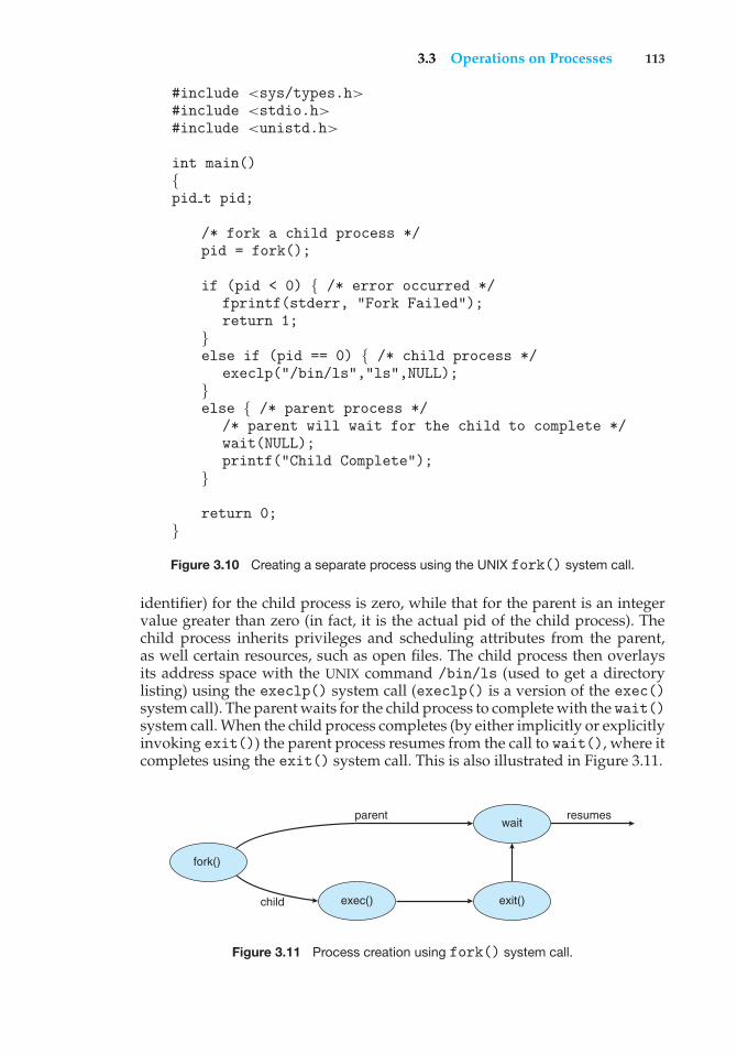
3.3 Operations on Processes 113
#include <sys/types.h>#include <stdio.h>#include <unistd.h>
int main(){pid t pid;
/* fork a child process */pid = fork();
if (pid < 0) { /* error occurred */fprintf(stderr, "Fork Failed");return 1;
}else if (pid == 0) { /* child process */
execlp("/bin/ls","ls",NULL);}else { /* parent process */
/* parent will wait for the child to complete */wait(NULL);printf("Child Complete");
}
return 0;}
Figure 3.10 Creating a separate process using the UNIX fork() system call.
identifier) for the child process is zero, while that for the parent is an integervalue greater than zero (in fact, it is the actual pid of the child process). Thechild process inherits privileges and scheduling attributes from the parent,as well certain resources, such as open files. The child process then overlaysits address space with the UNIX command /bin/ls (used to get a directorylisting) using the execlp() system call (execlp() is a version of the exec()system call). The parent waits for the child process to complete with the wait()system call. When the child process completes (by either implicitly or explicitlyinvoking exit()) the parent process resumes from the call to wait(), where itcompletes using the exit() system call. This is also illustrated in Figure 3.11.
fork()
exec()
waitresumesparent
child exit()
Figure 3.11 Process creation using fork() system call.
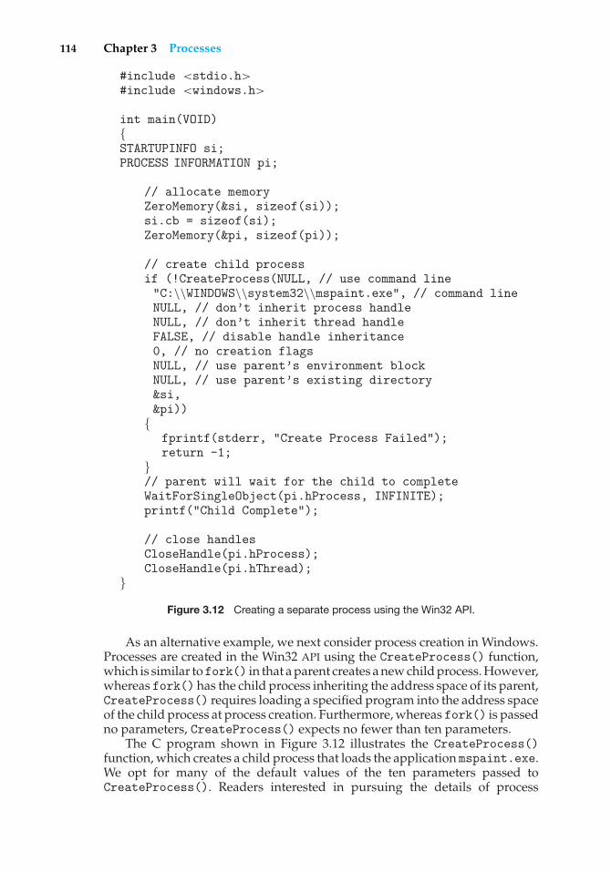
114 Chapter 3 Processes
#include <stdio.h>#include <windows.h>
int main(VOID){STARTUPINFO si;PROCESS INFORMATION pi;
// allocate memoryZeroMemory(&si, sizeof(si));si.cb = sizeof(si);ZeroMemory(&pi, sizeof(pi));
// create child processif (!CreateProcess(NULL, // use command line"C:\\WINDOWS\\system32\\mspaint.exe", // command lineNULL, // don’t inherit process handleNULL, // don’t inherit thread handleFALSE, // disable handle inheritance0, // no creation flagsNULL, // use parent’s environment blockNULL, // use parent’s existing directory&si,&pi))
{fprintf(stderr, "Create Process Failed");return -1;
}// parent will wait for the child to completeWaitForSingleObject(pi.hProcess, INFINITE);printf("Child Complete");
// close handlesCloseHandle(pi.hProcess);CloseHandle(pi.hThread);
}Figure 3.12 Creating a separate process using the Win32 API.
As an alternative example, we next consider process creation in Windows.Processes are created in the Win32 API using the CreateProcess() function,which is similar tofork() in that a parent creates a new child process. However,whereas fork() has the child process inheriting the address space of its parent,CreateProcess() requires loading a specified program into the address spaceof the child process at process creation. Furthermore, whereas fork() is passedno parameters, CreateProcess() expects no fewer than ten parameters.
The C program shown in Figure 3.12 illustrates the CreateProcess()function, which creates a child process that loads the application mspaint.exe.We opt for many of the default values of the ten parameters passed toCreateProcess(). Readers interested in pursuing the details of process
3.3 Operations on Processes 115
creation and management in the Win32 API are encouraged to consult thebibliographical notes at the end of this chapter.
Two parameters passed to CreateProcess() are instances of the START-UPINFO and PROCESS INFORMATION structures. STARTUPINFO specifies manyproperties of the new process, such as window size and appearance and han-dles to standard input and output files. The PROCESS INFORMATION structurecontains a handle and the identifiers to the newly created process and its thread.We invoke the ZeroMemory() function to allocate memory for each of thesestructures before proceeding with CreateProcess().
The first two parameters passed to CreateProcess() are the applicationname and command-line parameters. If the application name is NULL (asit is in this case), the command-line parameter specifies the application toload. In this instance, we are loading the Microsoft Windows mspaint.exeapplication. Beyond these two initial parameters, we use the default parametersfor inheriting process and thread handles as well as specifying no creation flags.We also use the parent’s existing environment block and starting directory.Last, we provide two pointers to the STARTUPINFO and PROCESS INFORMATIONstructures created at the beginning of the program. In Figure 3.10, the parentprocess waits for the child to complete by invoking the wait() systemcall. The equivalent of this in Win32 is WaitForSingleObject(), which ispassed a handle of the child process—pi.hProcess—and waits for thisprocess to complete. Once the child process exits, control returns from theWaitForSingleObject() function in the parent process.
3.3.2 Process Termination
A process terminates when it finishes executing its final statement and asks theoperating system to delete it by using the exit() system call. At that point, theprocess may return a status value (typically an integer) to its parent process(via the wait() system call). All the resources of the process—includingphysical and virtual memory, open files, and I/O buffers—are deallocatedby the operating system.
Termination can occur in other circumstances as well. A process can causethe termination of another process via an appropriate system call (for example,TerminateProcess() in Win32). Usually, such a system call can be invokedonly by the parent of the process that is to be terminated. Otherwise, userscould arbitrarily kill each other’s jobs. Note that a parent needs to know theidentities of its children. Thus, when one process creates a new process, theidentity of the newly created process is passed to the parent.
A parent may terminate the execution of one of its children for a variety ofreasons, such as these:
• The child has exceeded its usage of some of the resources that it has beenallocated. (To determine whether this has occurred, the parent must havea mechanism to inspect the state of its children.)
• The task assigned to the child is no longer required.
• The parent is exiting, and the operating system does not allow a child tocontinue if its parent terminates.
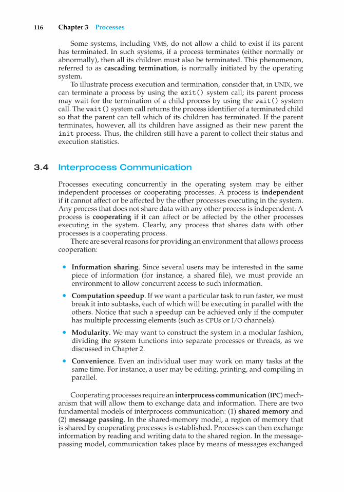
116 Chapter 3 Processes
Some systems, including VMS, do not allow a child to exist if its parenthas terminated. In such systems, if a process terminates (either normally orabnormally), then all its children must also be terminated. This phenomenon,referred to as cascading termination, is normally initiated by the operatingsystem.
To illustrate process execution and termination, consider that, in UNIX, wecan terminate a process by using the exit() system call; its parent processmay wait for the termination of a child process by using the wait() systemcall. The wait() system call returns the process identifier of a terminated childso that the parent can tell which of its children has terminated. If the parentterminates, however, all its children have assigned as their new parent theinit process. Thus, the children still have a parent to collect their status andexecution statistics.
3.4 Interprocess Communication
Processes executing concurrently in the operating system may be eitherindependent processes or cooperating processes. A process is independentif it cannot affect or be affected by the other processes executing in the system.Any process that does not share data with any other process is independent. Aprocess is cooperating if it can affect or be affected by the other processesexecuting in the system. Clearly, any process that shares data with otherprocesses is a cooperating process.
There are several reasons for providing an environment that allows processcooperation:
• Information sharing. Since several users may be interested in the samepiece of information (for instance, a shared file), we must provide anenvironment to allow concurrent access to such information.
• Computation speedup. If we want a particular task to run faster, we mustbreak it into subtasks, each of which will be executing in parallel with theothers. Notice that such a speedup can be achieved only if the computerhas multiple processing elements (such as CPUs or I/O channels).
• Modularity. We may want to construct the system in a modular fashion,dividing the system functions into separate processes or threads, as wediscussed in Chapter 2.
• Convenience. Even an individual user may work on many tasks at thesame time. For instance, a user may be editing, printing, and compiling inparallel.
Cooperating processes require an interprocess communication (IPC) mech-anism that will allow them to exchange data and information. There are twofundamental models of interprocess communication: (1) shared memory and(2) message passing. In the shared-memory model, a region of memory thatis shared by cooperating processes is established. Processes can then exchangeinformation by reading and writing data to the shared region. In the message-passing model, communication takes place by means of messages exchanged
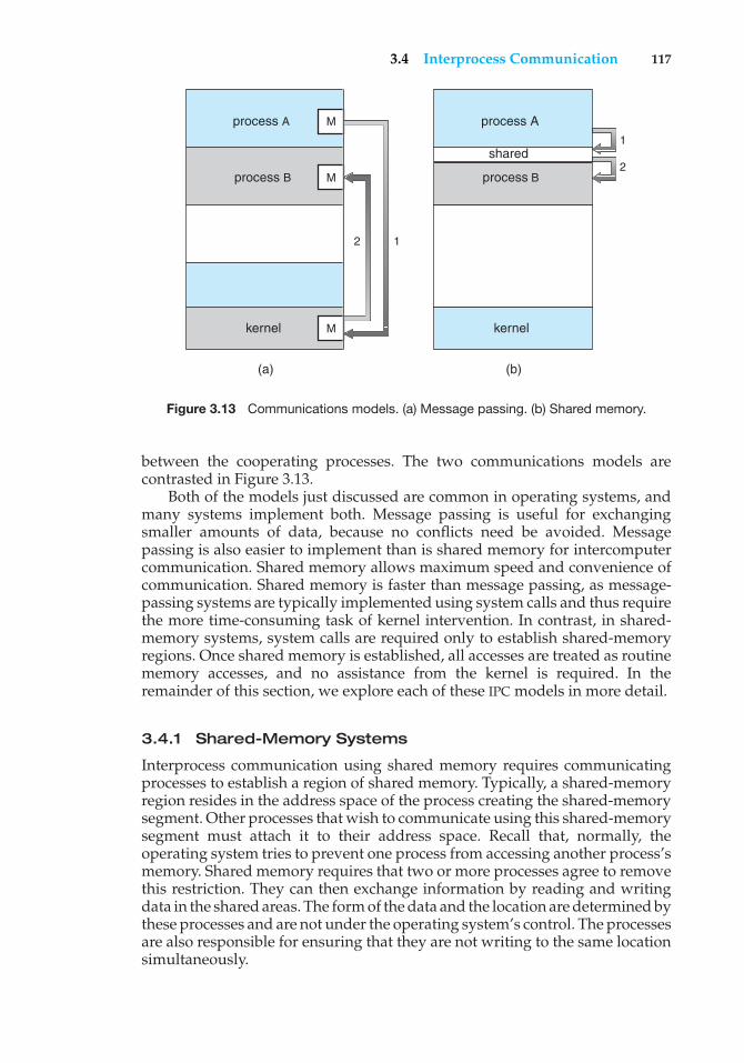
3.4 Interprocess Communication 117
process A
(a)
M
process B M
kernel M
(b)
12
1
2
process A
shared
process B
kernel
Figure 3.13 Communications models. (a) Message passing. (b) Shared memory.
between the cooperating processes. The two communications models arecontrasted in Figure 3.13.
Both of the models just discussed are common in operating systems, andmany systems implement both. Message passing is useful for exchangingsmaller amounts of data, because no conflicts need be avoided. Messagepassing is also easier to implement than is shared memory for intercomputercommunication. Shared memory allows maximum speed and convenience ofcommunication. Shared memory is faster than message passing, as message-passing systems are typically implemented using system calls and thus requirethe more time-consuming task of kernel intervention. In contrast, in shared-memory systems, system calls are required only to establish shared-memoryregions. Once shared memory is established, all accesses are treated as routinememory accesses, and no assistance from the kernel is required. In theremainder of this section, we explore each of these IPC models in more detail.
3.4.1 Shared-Memory Systems
Interprocess communication using shared memory requires communicatingprocesses to establish a region of shared memory. Typically, a shared-memoryregion resides in the address space of the process creating the shared-memorysegment. Other processes that wish to communicate using this shared-memorysegment must attach it to their address space. Recall that, normally, theoperating system tries to prevent one process from accessing another process’smemory. Shared memory requires that two or more processes agree to removethis restriction. They can then exchange information by reading and writingdata in the shared areas. The form of the data and the location are determined bythese processes and are not under the operating system’s control. The processesare also responsible for ensuring that they are not writing to the same locationsimultaneously.
118 Chapter 3 Processes
To illustrate the concept of cooperating processes, let’s consider theproducer–consumer problem, which is a common paradigm for cooperatingprocesses. A producer process produces information that is consumed by aconsumer process. For example, a compiler may produce assembly code,which is consumed by an assembler. The assembler, in turn, may produceobject modules, which are consumed by the loader. The producer–consumerproblem also provides a useful metaphor for the client–server paradigm. Wegenerally think of a server as a producer and a client as a consumer. Forexample, a Web server produces (that is, provides) HTML files and images,which are consumed (that is, read) by the client Web browser requesting theresource.
One solution to the producer–consumer problem uses shared memory. Toallow producer and consumer processes to run concurrently, we must haveavailable a buffer of items that can be filled by the producer and emptied bythe consumer. This buffer will reside in a region of memory that is shared bythe producer and consumer processes. A producer can produce one item whilethe consumer is consuming another item. The producer and consumer mustbe synchronized, so that the consumer does not try to consume an item thathas not yet been produced.
Two types of buffers can be used. The unbounded buffer places no practicallimit on the size of the buffer. The consumer may have to wait for new items,but the producer can always produce new items. The bounded buffer assumesa fixed buffer size. In this case, the consumer must wait if the buffer is empty,and the producer must wait if the buffer is full.
Let’s look more closely at how the bounded buffer can be used to enableprocesses to share memory. The following variables reside in a region ofmemory shared by the producer and consumer processes:
#define BUFFER SIZE 10
typedef struct {. . .
}item;
item buffer[BUFFER SIZE];int in = 0;int out = 0;
The shared buffer is implemented as a circular array with two logicalpointers: in and out. The variable in points to the next free position in thebuffer; out points to the first full position in the buffer. The buffer is emptywhen in == out; the buffer is full when ((in + 1) % BUFFER SIZE) == out.
The code for the producer and consumer processes is shown in Figures 3.14and 3.15, respectively. The producer process has a local variable nextProducedin which the new item to be produced is stored. The consumer process has alocal variable nextConsumed in which the item to be consumed is stored.
This scheme allows at most BUFFER SIZE − 1 items in the buffer at the sametime. We leave it as an exercise for you to provide a solution where BUFFER SIZEitems can be in the buffer at the same time. In Section 3.5.1, we illustrate thePOSIX API for shared memory.
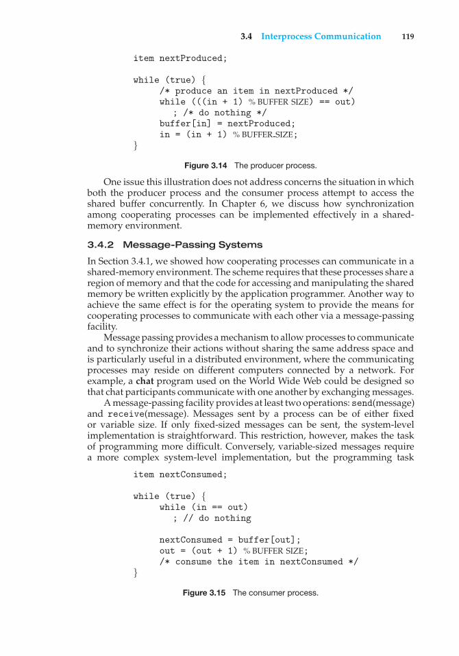
3.4 Interprocess Communication 119
item nextProduced;
while (true) {/* produce an item in nextProduced */while (((in + 1) % BUFFER SIZE) == out)
; /* do nothing */buffer[in] = nextProduced;in = (in + 1) % BUFFER SIZE;
}Figure 3.14 The producer process.
One issue this illustration does not address concerns the situation in whichboth the producer process and the consumer process attempt to access theshared buffer concurrently. In Chapter 6, we discuss how synchronizationamong cooperating processes can be implemented effectively in a shared-memory environment.
3.4.2 Message-Passing Systems
In Section 3.4.1, we showed how cooperating processes can communicate in ashared-memory environment. The scheme requires that these processes share aregion of memory and that the code for accessing and manipulating the sharedmemory be written explicitly by the application programmer. Another way toachieve the same effect is for the operating system to provide the means forcooperating processes to communicate with each other via a message-passingfacility.
Message passing provides a mechanism to allow processes to communicateand to synchronize their actions without sharing the same address space andis particularly useful in a distributed environment, where the communicatingprocesses may reside on different computers connected by a network. Forexample, a chat program used on the World Wide Web could be designed sothat chat participants communicate with one another by exchanging messages.
A message-passing facility provides at least two operations: send(message)and receive(message). Messages sent by a process can be of either fixedor variable size. If only fixed-sized messages can be sent, the system-levelimplementation is straightforward. This restriction, however, makes the taskof programming more difficult. Conversely, variable-sized messages requirea more complex system-level implementation, but the programming task
item nextConsumed;
while (true) {while (in == out)
; // do nothing
nextConsumed = buffer[out];out = (out + 1) % BUFFER SIZE;/* consume the item in nextConsumed */
}Figure 3.15 The consumer process.
120 Chapter 3 Processes
becomes simpler. This is a common kind of tradeoff seen throughout operating-system design.
If processesP andQwant to communicate, they must send messages to andreceive messages from each other; a communication link must exist betweenthem. This link can be implemented in a variety of ways. We are concerned herenot with the link’s physical implementation (such as shared memory, hardwarebus, or network, which are covered in Chapter 16) but rather with its logicalimplementation. Here are several methods for logically implementing a linkand the send()/receive() operations:
• Direct or indirect communication
• Synchronous or asynchronous communication
• Automatic or explicit bufferingWe look at issues related to each of these features next.
3.4.2.1 Naming
Processes that want to communicate must have a way to refer to each other.They can use either direct or indirect communication.
Under direct communication, each process that wants to communicatemust explicitly name the recipient or sender of the communication. In thisscheme, the send() and receive() primitives are defined as:
• send(P, message)—Send a message to process P.
• receive(Q, message)—Receive a message from process Q.
A communication link in this scheme has the following properties:
• A link is established automatically between every pair of processes thatwant to communicate. The processes need to know only each other’sidentity to communicate.
• A link is associated with exactly two processes.
• Between each pair of processes, there exists exactly one link.
This scheme exhibits symmetry in addressing; that is, both the senderprocess and the receiver process must name the other to communicate. Avariant of this scheme employs asymmetry in addressing. Here, only the sendernames the recipient; the recipient is not required to name the sender. In thisscheme, the send() and receive() primitives are defined as follows:
• send(P, message)—Send a message to process P.
• receive(id, message)—Receive a message from any process; the vari-able id is set to the name of the process with which communication hastaken place.
The disadvantage in both of these schemes (symmetric and asymmetric)is the limited modularity of the resulting process definitions. Changing theidentifier of a process may necessitate examining all other process definitions.All references to the old identifier must be found, so that they can be modifiedto the new identifier. In general, any such hard-coding techniques, where
3.4 Interprocess Communication 121
identifiers must be explicitly stated, are less desirable than techniques involvingindirection, as described next.
With indirect communication, the messages are sent to and received frommailboxes, or ports. A mailbox can be viewed abstractly as an object into whichmessages can be placed by processes and from which messages can be removed.Each mailbox has a unique identification. For example, POSIX message queuesuse an integer value to identify a mailbox. In this scheme, a process cancommunicate with some other process via a number of different mailboxes.Two processes can communicate only if the processes have a shared mailbox,however. The send() and receive() primitives are defined as follows:
• send(A, message)—Send a message to mailbox A.
• receive(A, message)—Receive a message from mailbox A.
In this scheme, a communication link has the following properties:
• A link is established between a pair of processes only if both members ofthe pair have a shared mailbox.
• A link may be associated with more than two processes.
• Between each pair of communicating processes, there may be a number ofdifferent links, with each link corresponding to one mailbox.
Now suppose that processes P1, P2, and P3 all share mailbox A. ProcessP1 sends a message to A, while both P2 and P3 execute a receive() from A.Which process will receive the message sent by P1? The answer depends onwhich of the following methods we choose:
• Allow a link to be associated with two processes at most.
• Allow at most one process at a time to execute a receive() operation.
• Allow the system to select arbitrarily which process will receive themessage (that is, either P2 or P3, but not both, will receive the message).The system also may define an algorithm for selecting which processwill receive the message (that is, round robin, where processes take turnsreceiving messages). The system may identify the receiver to the sender.
A mailbox may be owned either by a process or by the operating system.If the mailbox is owned by a process (that is, the mailbox is part of the addressspace of the process), then we distinguish between the owner (which canonly receive messages through this mailbox) and the user (which can onlysend messages to the mailbox). Since each mailbox has a unique owner, therecan be no confusion about which process should receive a message sent tothis mailbox. When a process that owns a mailbox terminates, the mailboxdisappears. Any process that subsequently sends a message to this mailboxmust be notified that the mailbox no longer exists.
In contrast, a mailbox that is owned by the operating system has anexistence of its own. It is independent and is not attached to any particularprocess. The operating system then must provide a mechanism that allows aprocess to do the following:
122 Chapter 3 Processes
• Create a new mailbox.
• Send and receive messages through the mailbox.
• Delete a mailbox.
The process that creates a new mailbox is that mailbox’s owner by default.Initially, the owner is the only process that can receive messages through thismailbox. However, the ownership and receiving privilege may be passed toother processes through appropriate system calls. Of course, this provisioncould result in multiple receivers for each mailbox.
3.4.2.2 Synchronization
Communication between processes takes place through calls to send() andreceive() primitives. There are different design options for implementingeach primitive. Message passing may be either blocking or nonblocking—also known as synchronous and asynchronous.
• Blocking send. The sending process is blocked until the message isreceived by the receiving process or by the mailbox.
• Nonblocking send. The sending process sends the message and resumesoperation.
• Blocking receive. The receiver blocks until a message is available.
• Nonblocking receive. The receiver retrieves either a valid message or anull.
Different combinations of send() and receive() are possible. When bothsend() and receive() are blocking, we have a rendezvous between thesender and the receiver. The solution to the producer–consumer problembecomes trivial when we use blocking send() and receive() statements.The producer merely invokes the blocking send() call and waits until themessage is delivered to either the receiver or the mailbox. Likewise, when theconsumer invokes receive(), it blocks until a message is available.
Note that the concepts of synchronous and asynchronous occur frequentlyin operating-system I/O algorithms, as you will see throughout this text.
3.4.2.3 Buffering
Whether communication is direct or indirect, messages exchanged by commu-nicating processes reside in a temporary queue. Basically, such queues can beimplemented in three ways:
• Zero capacity. The queue has a maximum length of zero; thus, the linkcannot have any messages waiting in it. In this case, the sender must blockuntil the recipient receives the message.
• Bounded capacity. The queue has finite length n; thus, at most nmessagescan reside in it. If the queue is not full when a new message is sent, themessage is placed in the queue (either the message is copied or a pointerto the message is kept), and the sender can continue execution without
3.5 Examples of IPC Systems 123
waiting. The link’s capacity is finite, however. If the link is full, the sendermust block until space is available in the queue.
• Unbounded capacity. The queue’s length is potentially infinite; thus, anynumber of messages can wait in it. The sender never blocks.
The zero-capacity case is sometimes referred to as a message system with nobuffering; the other cases are referred to as systems with automatic buffering.
3.5 Examples of IPC Systems
In this section, we explore three different IPC systems. We first cover thePOSIX API for shared memory and then discuss message passing in the Machoperating system. We conclude with Windows XP, which interestingly usesshared memory as a mechanism for providing certain types of message passing.
3.5.1 An Example: POSIX Shared Memory
Several IPC mechanisms are available for POSIX systems, including sharedmemory and message passing. Here, we explore the POSIX API for sharedmemory.
A process must first create a shared memory segment using the shmget()system call (shmget() is derived from SHared Memory GET). The followingexample illustrates the use of shmget():
segment id = shmget(IPC PRIVATE, size, S IRUSR | S IWUSR);
This first parameter specifies the key (or identifier) of the shared-memorysegment. If this is set to IPC PRIVATE, a new shared-memory segment is created.The second parameter specifies the size (in bytes) of the shared-memorysegment. Finally, the third parameter identifies the mode, which indicateshow the shared-memory segment is to be used—that is, for reading, writing,or both. By setting the mode to S IRUSR | S IWUSR, we are indicating that theowner may read or write to the shared-memory segment. A successful call toshmget() returns an integer identifier for the shared-memory segment. Otherprocesses that want to use this region of shared memory must specify thisidentifier.
Processes that wish to access a shared-memory segment must attach it totheir address space using the shmat() (SHared Memory ATtach) system call.The call to shmat() expects three parameters as well. The first is the integeridentifier of the shared-memory segment being attached, and the second isa pointer location in memory indicating where the shared memory will beattached. If we pass a value of NULL, the operating system selects the locationon the user’s behalf. The third parameter identifies a flag that allows the shared-memory region to be attached in read-only or read-write mode; by passing aparameter of 0, we allow both reads and writes to the shared region. We attacha region of shared memory using shmat() as follows:
shared memory = (char *) shmat(id, NULL, 0);
If successful, shmat() returns a pointer to the beginning location in memorywhere the shared-memory region has been attached.
124 Chapter 3 Processes
Once the region of shared memory is attached to a process’s address space,the process can access the shared memory as a routine memory access usingthe pointer returned from shmat(). In this example, shmat() returns a pointerto a character string. Thus, we could write to the shared-memory region asfollows:
sprintf(shared memory, "Writing to shared memory");
Other processes sharing this segment would see the updates to the shared-memory segment.
Typically, a process using an existing shared-memory segment first attachesthe shared-memory region to its address space and then accesses (and possiblyupdates) the region of shared memory. When a process no longer requiresaccess to the shared-memory segment, it detaches the segment from its addressspace. To detach a region of shared memory, the process can pass the pointerof the shared-memory region to the shmdt() system call, as follows:
shmdt(shared memory);
Finally, a shared-memory segment can be removed from the system with theshmctl() system call, which is passed the identifier of the shared segmentalong with the flag IPC RMID.
The program shown in Figure 3.16 illustrates the POSIX shared-memoryAPI just discussed. This program creates a 4,096-byte shared-memory segment.Once the region of shared memory is attached, the process writes the messageHi There! to shared memory. After outputting the contents of the updatedmemory, it detaches and removes the shared-memory region. We providefurther exercises using the POSIX shared-memory API in the programmingexercises at the end of this chapter.
3.5.2 An Example: Mach
As an example of a message-based operating system, we next considerthe Mach operating system, developed at Carnegie Mellon University. Weintroduced Mach in Chapter 2 as part of the Mac OS X operating system. TheMach kernel supports the creation and destruction of multiple tasks, which aresimilar to processes but have multiple threads of control. Most communicationin Mach—including most of the system calls and all intertask information—is carried out by messages. Messages are sent to and received from mailboxes,called ports in Mach.
Even system calls are made by messages. When a task is created, two specialmailboxes—the Kernel mailbox and the Notify mailbox—are also created. TheKernel mailbox is used by the kernel to communicate with the task. The kernelsends notification of event occurrences to the Notify port. Only three systemcalls are needed for message transfer. The msg send() call sends a messageto a mailbox. A message is received via msg receive(). Remote procedurecalls (RPCs) are executed via msg rpc(), which sends a message and waits forexactly one return message from the sender. In this way, the RPC models atypical subroutine procedure call but can work between systems—hence theterm remote.
The port allocate() system call creates a new mailbox and allocatesspace for its queue of messages. The maximum size of the message queue
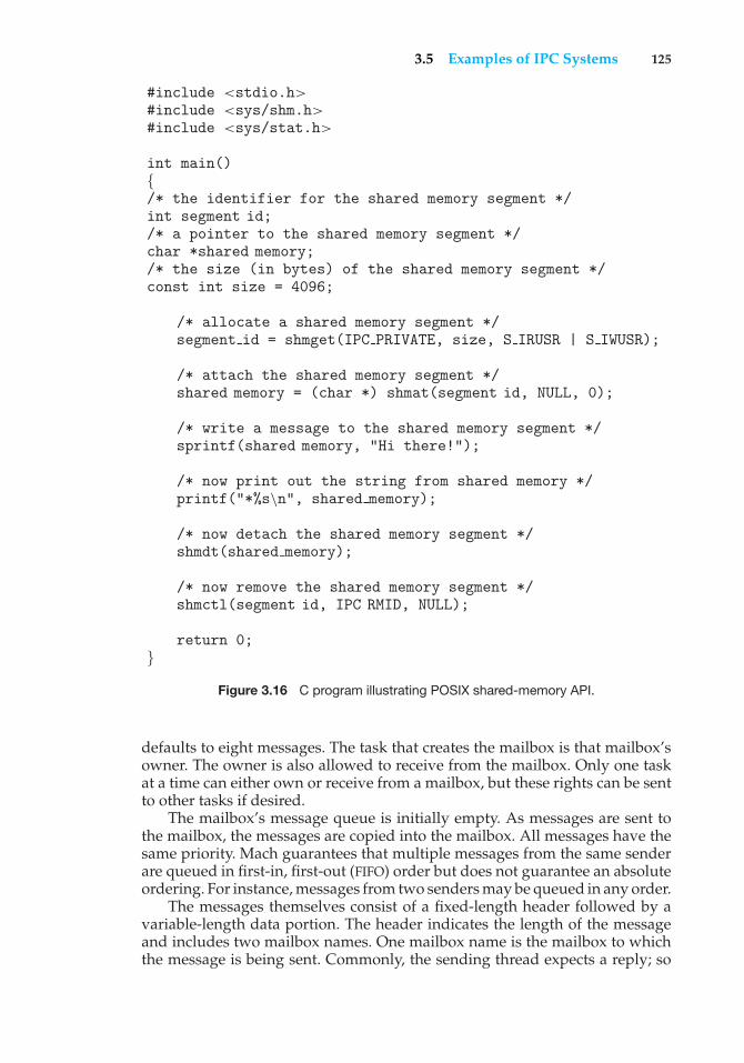
3.5 Examples of IPC Systems 125
#include <stdio.h>#include <sys/shm.h>#include <sys/stat.h>
int main(){/* the identifier for the shared memory segment */int segment id;/* a pointer to the shared memory segment */char *shared memory;/* the size (in bytes) of the shared memory segment */const int size = 4096;
/* allocate a shared memory segment */segment id = shmget(IPC PRIVATE, size, S IRUSR | S IWUSR);
/* attach the shared memory segment */shared memory = (char *) shmat(segment id, NULL, 0);
/* write a message to the shared memory segment */sprintf(shared memory, "Hi there!");
/* now print out the string from shared memory */printf("*%s\n", shared memory);
/* now detach the shared memory segment */shmdt(shared memory);
/* now remove the shared memory segment */shmctl(segment id, IPC RMID, NULL);
return 0;}
Figure 3.16 C program illustrating POSIX shared-memory API.
defaults to eight messages. The task that creates the mailbox is that mailbox’sowner. The owner is also allowed to receive from the mailbox. Only one taskat a time can either own or receive from a mailbox, but these rights can be sentto other tasks if desired.
The mailbox’s message queue is initially empty. As messages are sent tothe mailbox, the messages are copied into the mailbox. All messages have thesame priority. Mach guarantees that multiple messages from the same senderare queued in first-in, first-out (FIFO) order but does not guarantee an absoluteordering. For instance, messages from two senders may be queued in any order.
The messages themselves consist of a fixed-length header followed by avariable-length data portion. The header indicates the length of the messageand includes two mailbox names. One mailbox name is the mailbox to whichthe message is being sent. Commonly, the sending thread expects a reply; so
126 Chapter 3 Processes
the mailbox name of the sender is passed on to the receiving task, which canuse it as a “return address.”
The variable part of a message is a list of typed data items. Each entryin the list has a type, size, and value. The type of the objects specified in themessage is important, since objects defined by the operating system—such asownership or receive access rights, task states, and memory segments—maybe sent in messages.
The send and receive operations themselves are flexible. For instance, whena message is sent to a mailbox, the mailbox may be full. If the mailbox is notfull, the message is copied to the mailbox, and the sending thread continues. Ifthe mailbox is full, the sending thread has four options:
1. Wait indefinitely until there is room in the mailbox.
2. Wait at most nmilliseconds.
3. Do not wait at all but rather return immediately.
4. Temporarily cache a message. One message can be given to the operatingsystem to keep, even though the mailbox to which that message is beingsent is full. When the message can be put in the mailbox, a message issent back to the sender; only one such message to a full mailbox can bepending at any time for a given sending thread.
The final option is meant for server tasks, such as a line-printer driver. Afterfinishing a request, such tasks may need to send a one-time reply to the taskthat had requested service; but they must also continue with other servicerequests, even if the reply mailbox for a client is full.
The receive operation must specify the mailbox or mailbox set from which amessage is to be received. A mailbox set is a collection of mailboxes, as declaredby the task, which can be grouped together and treated as one mailbox for thepurposes of the task. Threads in a task can receive only from a mailbox ormailbox set for which the task has receive access. A port status() systemcall returns the number of messages in a given mailbox. The receive operationattempts to receive from (1) any mailbox in a mailbox set or (2) a specific(named) mailbox. If no message is waiting to be received, the receiving threadcan either wait at most nmilliseconds or not wait at all.
The Mach system was especially designed for distributed systems, whichwe discuss in Chapters 16 through 18, but Mach is also suitable for single-processor systems, as evidenced by its inclusion in the Mac OS X system. Themajor problem with message systems has generally been poor performancecaused by double copying of messages; the message is copied first fromthe sender to the mailbox and then from the mailbox to the receiver. TheMach message system attempts to avoid double-copy operations by usingvirtual-memory-management techniques (Chapter 9). Essentially, Mach mapsthe address space containing the sender’s message into the receiver’s addressspace. The message itself is never actually copied. This message-managementtechnique provides a large performance boost but works for only intrasystemmessages. The Mach operating system is discussed in an extra chapter postedon our website.
3.5 Examples of IPC Systems 127
3.5.3 An Example: Windows XP
The Windows XP operating system is an example of modern design thatemploys modularity to increase functionality and decrease the time neededto implement new features. Windows XP provides support for multipleoperating environments, or subsystems, with which application programscommunicate via a message-passing mechanism. The application programscan be considered clients of the Windows XP subsystem server.
The message-passing facility in Windows XP is called the local procedure-call (LPC) facility. The LPC in Windows XP communicates between twoprocesses on the same machine. It is similar to the standard RPC mechanism thatis widely used, but it is optimized for and specific to Windows XP. Like Mach,Windows XP uses a port object to establish and maintain a connection betweentwo processes. Every client that calls a subsystem needs a communicationchannel, which is provided by a port object and is never inherited. WindowsXP uses two types of ports: connection ports and communication ports. Theyare really the same but are given different names according to how they areused.
Connection ports are named objects and are visible to all processes; theygive applications a way to set up communication channels (Chapter 22). Thecommunication works as follows:
• The client opens a handle to the subsystem’s connection port object.
• The client sends a connection request.
• The server creates two private communication ports and returns the handleto one of them to the client.
• The client and server use the corresponding port handle to send messagesor callbacks and to listen for replies.
Windows XP uses two types of message-passing techniques over a port thatthe client specifies when it establishes the channel. The simplest, which is usedfor small messages, uses the port’s message queue as intermediate storage andcopies the message from one process to the other. Under this method, messagesof up to 256 bytes can be sent.
If a client needs to send a larger message, it passes the message througha section object, which sets up a region of shared memory. The client has todecide when it sets up the channel whether or not it will need to send a largemessage. If the client determines that it does want to send large messages, itasks for a section object to be created. Similarly, if the server decides that replieswill be large, it creates a section object. So that the section object can be used,a small message is sent that contains a pointer and size information about thesection object. This method is more complicated than the first method, but itavoids data copying. In both cases, a callback mechanism can be used wheneither the client or the server cannot respond immediately to a request. Thecallback mechanism allows them to perform asynchronous message handling.The structure of local procedure calls in Windows XP is shown in Figure 3.17.
It is important to note that the LPC facility in Windows XP is not part ofthe Win32 API and hence is not visible to the application programmer. Rather,applications using the Win32 API invoke standard remote procedure calls.
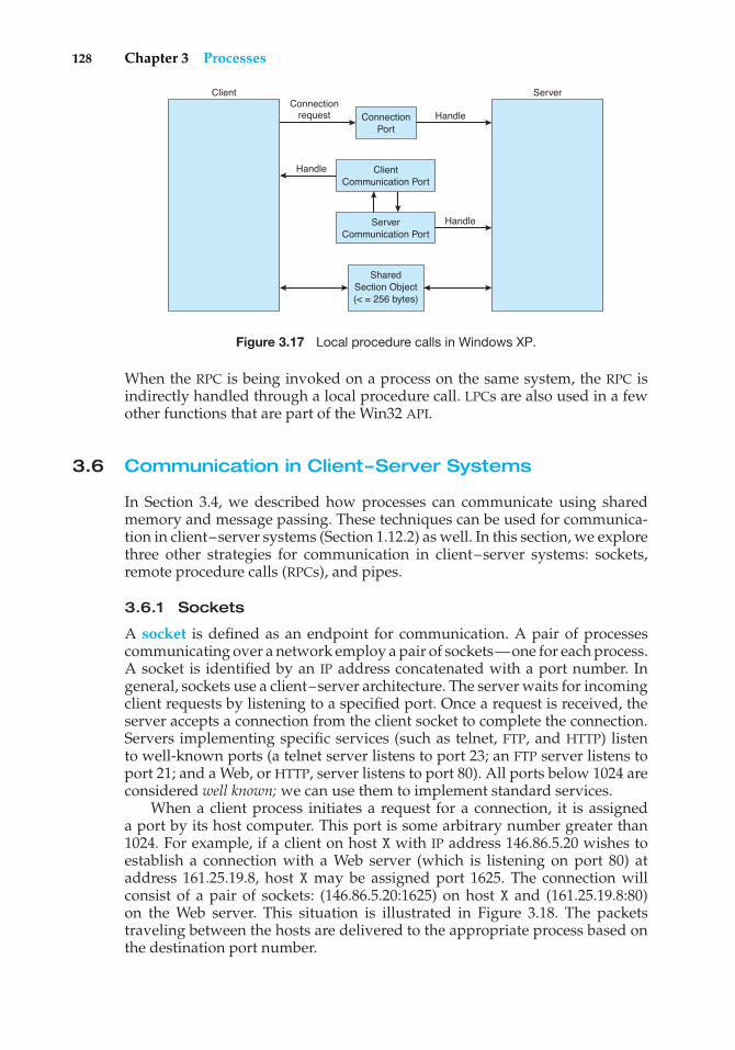
128 Chapter 3 Processes
ConnectionPort
Connectionrequest Handle
Handle
Handle
ClientCommunication Port
ServerCommunication Port
SharedSection Object(< = 256 bytes)
ServerClient
Figure 3.17 Local procedure calls in Windows XP.
When the RPC is being invoked on a process on the same system, the RPC isindirectly handled through a local procedure call. LPCs are also used in a fewother functions that are part of the Win32 API.
3.6 Communication in Client–Server Systems
In Section 3.4, we described how processes can communicate using sharedmemory and message passing. These techniques can be used for communica-tion in client–server systems (Section 1.12.2) as well. In this section, we explorethree other strategies for communication in client–server systems: sockets,remote procedure calls (RPCs), and pipes.
3.6.1 Sockets
A socket is defined as an endpoint for communication. A pair of processescommunicating over a network employ a pair of sockets—one for each process.A socket is identified by an IP address concatenated with a port number. Ingeneral, sockets use a client–server architecture. The server waits for incomingclient requests by listening to a specified port. Once a request is received, theserver accepts a connection from the client socket to complete the connection.Servers implementing specific services (such as telnet, FTP, and HTTP) listento well-known ports (a telnet server listens to port 23; an FTP server listens toport 21; and a Web, or HTTP, server listens to port 80). All ports below 1024 areconsidered well known; we can use them to implement standard services.
When a client process initiates a request for a connection, it is assigneda port by its host computer. This port is some arbitrary number greater than1024. For example, if a client on host X with IP address 146.86.5.20 wishes toestablish a connection with a Web server (which is listening on port 80) ataddress 161.25.19.8, host X may be assigned port 1625. The connection willconsist of a pair of sockets: (146.86.5.20:1625) on host X and (161.25.19.8:80)on the Web server. This situation is illustrated in Figure 3.18. The packetstraveling between the hosts are delivered to the appropriate process based onthe destination port number.
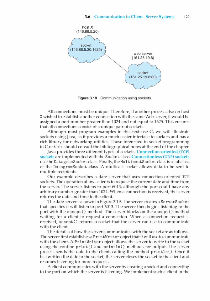
3.6 Communication in Client–Server Systems 129
socket(146.86.5.20:1625)
host X(146.86.5.20)
socket(161.25.19.8:80)
web server(161.25.19.8)
Figure 3.18 Communication using sockets.
All connections must be unique. Therefore, if another process also on hostXwished to establish another connection with the same Web server, it would beassigned a port number greater than 1024 and not equal to 1625. This ensuresthat all connections consist of a unique pair of sockets.
Although most program examples in this text use C, we will illustratesockets using Java, as it provides a much easier interface to sockets and has arich library for networking utilities. Those interested in socket programmingin C or C++ should consult the bibliographical notes at the end of the chapter.
Java provides three different types of sockets. Connection-oriented (TCP)sockets are implemented with the Socket class. Connectionless (UDP) socketsuse theDatagramSocket class. Finally, theMulticastSocket class is a subclassof the DatagramSocket class. A multicast socket allows data to be sent tomultiple recipients.
Our example describes a date server that uses connection-oriented TCPsockets. The operation allows clients to request the current date and time fromthe server. The server listens to port 6013, although the port could have anyarbitrary number greater than 1024. When a connection is received, the serverreturns the date and time to the client.
The date server is shown in Figure 3.19. The server creates a ServerSocketthat specifies it will listen to port 6013. The server then begins listening to theport with the accept() method. The server blocks on the accept() methodwaiting for a client to request a connection. When a connection request isreceived, accept() returns a socket that the server can use to communicatewith the client.
The details of how the server communicates with the socket are as follows.The server first establishes aPrintWriterobject that it will use to communicatewith the client. A PrintWriter object allows the server to write to the socketusing the routine print() and println() methods for output. The serverprocess sends the date to the client, calling the method println(). Once ithas written the date to the socket, the server closes the socket to the client andresumes listening for more requests.
A client communicates with the server by creating a socket and connectingto the port on which the server is listening. We implement such a client in the
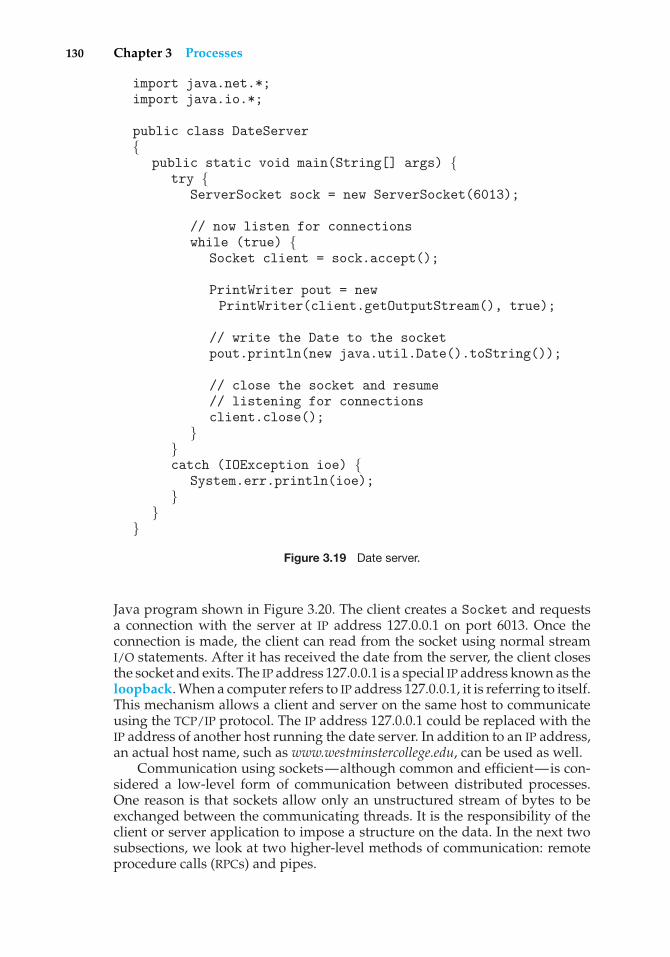
130 Chapter 3 Processes
import java.net.*;import java.io.*;
public class DateServer{
public static void main(String[] args) {try {
ServerSocket sock = new ServerSocket(6013);
// now listen for connectionswhile (true) {
Socket client = sock.accept();
PrintWriter pout = newPrintWriter(client.getOutputStream(), true);
// write the Date to the socketpout.println(new java.util.Date().toString());
// close the socket and resume// listening for connectionsclient.close();
}}catch (IOException ioe) {
System.err.println(ioe);}
}}
Figure 3.19 Date server.
Java program shown in Figure 3.20. The client creates a Socket and requestsa connection with the server at IP address 127.0.0.1 on port 6013. Once theconnection is made, the client can read from the socket using normal streamI/O statements. After it has received the date from the server, the client closesthe socket and exits. The IP address 127.0.0.1 is a special IP address known as theloopback. When a computer refers to IP address 127.0.0.1, it is referring to itself.This mechanism allows a client and server on the same host to communicateusing the TCP/IP protocol. The IP address 127.0.0.1 could be replaced with theIP address of another host running the date server. In addition to an IP address,an actual host name, such as www.westminstercollege.edu, can be used as well.
Communication using sockets—although common and efficient—is con-sidered a low-level form of communication between distributed processes.One reason is that sockets allow only an unstructured stream of bytes to beexchanged between the communicating threads. It is the responsibility of theclient or server application to impose a structure on the data. In the next twosubsections, we look at two higher-level methods of communication: remoteprocedure calls (RPCs) and pipes.
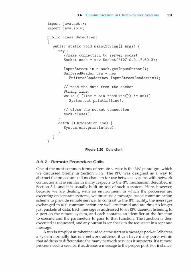
3.6 Communication in Client–Server Systems 131
import java.net.*;import java.io.*;
public class DateClient{
public static void main(String[] args) {try {
//make connection to server socketSocket sock = new Socket("127.0.0.1",6013);
InputStream in = sock.getInputStream();BufferedReader bin = new
BufferedReader(new InputStreamReader(in));
// read the date from the socketString line;while ( (line = bin.readLine()) != null)
System.out.println(line);
// close the socket connectionsock.close();
}catch (IOException ioe) {
System.err.println(ioe);}
}}
Figure 3.20 Date client.
3.6.2 Remote Procedure Calls
One of the most common forms of remote service is the RPC paradigm, whichwe discussed briefly in Section 3.5.2. The RPC was designed as a way toabstract the procedure-call mechanism for use between systems with networkconnections. It is similar in many respects to the IPC mechanism described inSection 3.4, and it is usually built on top of such a system. Here, however,because we are dealing with an environment in which the processes areexecuting on separate systems, we must use a message-based communicationscheme to provide remote service. In contrast to the IPC facility, the messagesexchanged in RPC communication are well structured and are thus no longerjust packets of data. Each message is addressed to an RPC daemon listening toa port on the remote system, and each contains an identifier of the functionto execute and the parameters to pass to that function. The function is thenexecuted as requested, and any output is sent back to the requester in a separatemessage.
A port is simply a number included at the start of a message packet. Whereasa system normally has one network address, it can have many ports withinthat address to differentiate the many network services it supports. If a remoteprocess needs a service, it addresses a message to the proper port. For instance,
132 Chapter 3 Processes
if a system wished to allow other systems to be able to list its current users, itwould have a daemon supporting such an RPC attached to a port—say, port3027. Any remote system could obtain the needed information (that is, the listof current users) by sending an RPC message to port 3027 on the server; thedata would be received in a reply message.
The semantics of RPCs allow a client to invoke a procedure on a remotehost as it would invoke a procedure locally. The RPC system hides the detailsthat allow communication to take place by providing a stub on the client side.Typically, a separate stub exists for each separate remote procedure. When theclient invokes a remote procedure, the RPC system calls the appropriate stub,passing it the parameters provided to the remote procedure. This stub locatesthe port on the server and marshals the parameters. Parameter marshallinginvolves packaging the parameters into a form that can be transmitted overa network. The stub then transmits a message to the server using messagepassing. A similar stub on the server side receives this message and invokesthe procedure on the server. If necessary, return values are passed back to theclient using the same technique.
One issue that must be dealt with concerns differences in data representa-tion on the client and server machines. Consider the representation of 32-bitintegers. Some systems (known as big-endian) store the most significant bytefirst, while other systems (known as little-endian) store the least significantbyte first. Neither order is “better” per se; rather, the choice is arbitrary withina computer architecture. To resolve differences like this, many RPC systemsdefine a machine-independent representation of data. One such representationis known as external data representation (XDR). On the client side, parametermarshalling involves converting the machine-dependent data into XDR beforethey are sent to the server. On the server side, the XDR data are unmarshalledand converted to the machine-dependent representation for the server.
Another important issue involves the semantics of a call. Whereas localprocedure calls fail only under extreme circumstances, RPCs can fail, or beduplicated and executed more than once, as a result of common networkerrors. One way to address this problem is for the operating system to ensurethat messages are acted on exactly once, rather than at most once. Most localprocedure calls have the “exactly once” functionality, but it is more difficult toimplement.
First, consider “at most once”. This semantic can be implemented byattaching a timestamp to each message. The server must keep a history ofall the timestamps of messages it has already processed or a history largeenough to ensure that repeated messages are detected. Incoming messagesthat have a timestamp already in the history are ignored. The client can thensend a message one or more times and be assured that it only executes once.(Generation of these timestamps is discussed in Section 18.1.)
For “exactly once,” we need to remove the risk that the server will neverreceive the request. To accomplish this, the server must implement the “atmost once” protocol described above but must also acknowledge to the clientthat the RPC call was received and executed. These ACK messages are commonthroughout networking. The client must resend each RPC call periodically untilit receives the ACK for that call.
Another important issue concerns the communication between a serverand a client. With standard procedure calls, some form of binding takes place
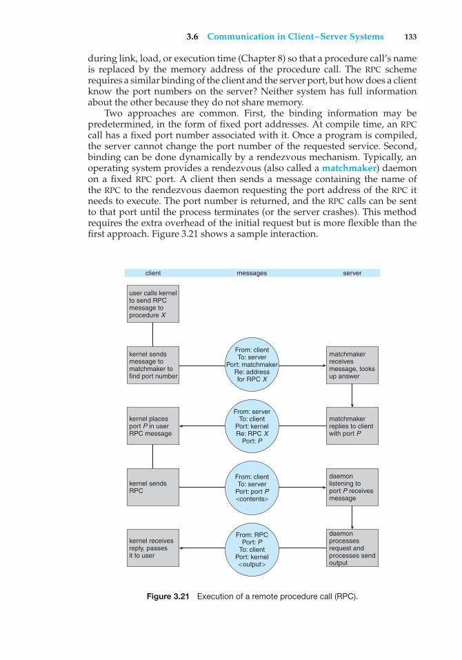
3.6 Communication in Client–Server Systems 133
during link, load, or execution time (Chapter 8) so that a procedure call’s nameis replaced by the memory address of the procedure call. The RPC schemerequires a similar binding of the client and the server port, but how does a clientknow the port numbers on the server? Neither system has full informationabout the other because they do not share memory.
Two approaches are common. First, the binding information may bepredetermined, in the form of fixed port addresses. At compile time, an RPCcall has a fixed port number associated with it. Once a program is compiled,the server cannot change the port number of the requested service. Second,binding can be done dynamically by a rendezvous mechanism. Typically, anoperating system provides a rendezvous (also called a matchmaker) daemonon a fixed RPC port. A client then sends a message containing the name ofthe RPC to the rendezvous daemon requesting the port address of the RPC itneeds to execute. The port number is returned, and the RPC calls can be sentto that port until the process terminates (or the server crashes). This methodrequires the extra overhead of the initial request but is more flexible than thefirst approach. Figure 3.21 shows a sample interaction.
client
user calls kernelto send RPCmessage toprocedure X
matchmakerreceivesmessage, looksup answer
matchmakerreplies to clientwith port P
daemonlistening toport P receivesmessage
daemonprocessesrequest andprocesses sendoutput
kernel sendsmessage tomatchmaker tofind port number
From: clientTo: server
Port: matchmakerRe: addressfor RPC X
From: clientTo: server
Port: port P<contents>
From: RPCPort: P
To: clientPort: kernel<output>
From: serverTo: client
Port: kernelRe: RPC X
Port: P
kernel placesport P in userRPC message
kernel sendsRPC
kernel receivesreply, passesit to user
messages server
Figure 3.21 Execution of a remote procedure call (RPC).
134 Chapter 3 Processes
The RPC scheme is useful in implementing a distributed file system(Chapter 17). Such a system can be implemented as a set of RPC daemonsand clients. The messages are addressed to the distributed file system port on aserver on which a file operation is to take place. The message contains the diskoperation to be performed. The disk operation might be read, write, rename,delete, or status, corresponding to the usual file-related system calls. Thereturn message contains any data resulting from that call, which is executed bythe DFS daemon on behalf of the client. For instance, a message might containa request to transfer a whole file to a client or be limited to a simple blockrequest. In the latter case, several such requests may be needed if a whole fileis to be transferred.
3.6.3 Pipes
A pipe acts as a conduit allowing two processes to communicate. Pipes wereone of the first IPC mechanisms in early UNIX systems and typically provide oneof the simpler ways for processes to communicate with one another, althoughthey also have some limitations. In implementing a pipe, four issues must beconsidered:
1. Does the pipe allow unidirectional communication or bidirectional com-munication?
2. If two-way communication is allowed, is it half duplex (data can travelonly one way at a time) or full duplex (data can travel in both directionsat the same time)?
3. Must a relationship (such as parent–child) exist between the communicat-ing processes?
4. Can the pipes communicate over a network, or must the communicatingprocesses reside on the same machine?
In the following sections, we explore two common types of pipes used on bothUNIX and Windows systems.
3.6.3.1 Ordinary Pipes
Ordinary pipes allow two processes to communicate in standard producer–consumer fashion; the producer writes to one end of the pipe (the write-end),and the consumer reads from the other end (the read-end). As a result, ordinarypipes are unidirectional, allowing only one-way communication. If two-waycommunication is required, two pipes must be used, with each pipe sendingdata in a different direction. We next illustrate constructing ordinary pipeson both UNIX and Windows systems. In both program examples, one processwrites the message Greetings to the pipe, while the other process reads thismessage from the pipe.
On UNIX systems, ordinary pipes are constructed using the function
pipe(int fd[])
This function creates a pipe that is accessed through the int fd[] filedescriptors: fd[0] is the read-end of the pipe, and fd[1] is the write end.
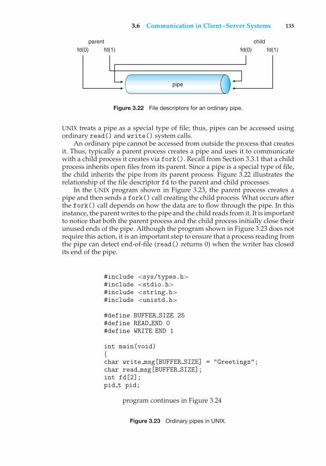
3.6 Communication in Client–Server Systems 135
parent
fd(0) fd(1)
child
fd(0) fd(1)
pipe
Figure 3.22 File descriptors for an ordinary pipe.
UNIX treats a pipe as a special type of file; thus, pipes can be accessed usingordinary read() and write() system calls.
An ordinary pipe cannot be accessed from outside the process that createsit. Thus, typically a parent process creates a pipe and uses it to communicatewith a child process it creates via fork(). Recall from Section 3.3.1 that a childprocess inherits open files from its parent. Since a pipe is a special type of file,the child inherits the pipe from its parent process. Figure 3.22 illustrates therelationship of the file descriptor fd to the parent and child processes.
In the UNIX program shown in Figure 3.23, the parent process creates apipe and then sends a fork() call creating the child process. What occurs afterthe fork() call depends on how the data are to flow through the pipe. In thisinstance, the parent writes to the pipe and the child reads from it. It is importantto notice that both the parent process and the child process initially close theirunused ends of the pipe. Although the program shown in Figure 3.23 does notrequire this action, it is an important step to ensure that a process reading fromthe pipe can detect end-of-file (read() returns 0) when the writer has closedits end of the pipe.
#include <sys/types.h>#include <stdio.h>#include <string.h>#include <unistd.h>
#define BUFFER SIZE 25#define READ END 0#define WRITE END 1
int main(void){char write msg[BUFFER SIZE] = "Greetings";char read msg[BUFFER SIZE];int fd[2];pid t pid;
program continues in Figure 3.24
Figure 3.23 Ordinary pipes in UNIX.
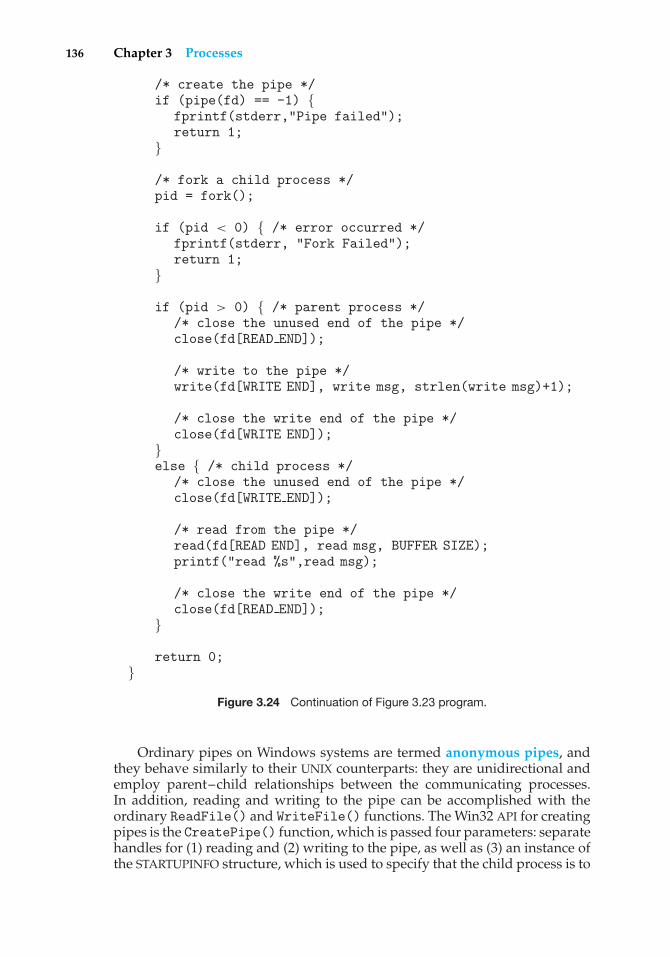
136 Chapter 3 Processes
/* create the pipe */if (pipe(fd) == -1) {
fprintf(stderr,"Pipe failed");return 1;
}
/* fork a child process */pid = fork();
if (pid < 0) { /* error occurred */fprintf(stderr, "Fork Failed");return 1;
}
if (pid > 0) { /* parent process *//* close the unused end of the pipe */close(fd[READ END]);
/* write to the pipe */write(fd[WRITE END], write msg, strlen(write msg)+1);
/* close the write end of the pipe */close(fd[WRITE END]);
}else { /* child process */
/* close the unused end of the pipe */close(fd[WRITE END]);
/* read from the pipe */read(fd[READ END], read msg, BUFFER SIZE);printf("read %s",read msg);
/* close the write end of the pipe */close(fd[READ END]);
}
return 0;}
Figure 3.24 Continuation of Figure 3.23 program.
Ordinary pipes on Windows systems are termed anonymous pipes, andthey behave similarly to their UNIX counterparts: they are unidirectional andemploy parent–child relationships between the communicating processes.In addition, reading and writing to the pipe can be accomplished with theordinary ReadFile() and WriteFile() functions. The Win32 API for creatingpipes is the CreatePipe() function, which is passed four parameters: separatehandles for (1) reading and (2) writing to the pipe, as well as (3) an instance ofthe STARTUPINFO structure, which is used to specify that the child process is to
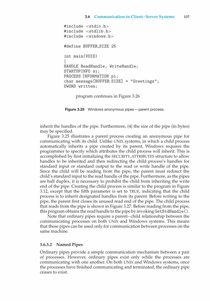
3.6 Communication in Client–Server Systems 137
#include <stdio.h>#include <stdlib.h>#include <windows.h>
#define BUFFER SIZE 25
int main(VOID){HANDLE ReadHandle, WriteHandle;STARTUPINFO si;PROCESS INFORMATION pi;char message[BUFFER SIZE] = "Greetings";DWORD written;
program continues in Figure 3.26
Figure 3.25 Windows anonymous pipes—parent process.
inherit the handles of the pipe. Furthermore, (4) the size of the pipe (in bytes)may be specified.
Figure 3.25 illustrates a parent process creating an anonymous pipe forcommunicating with its child. Unlike UNIX systems, in which a child processautomatically inherits a pipe created by its parent, Windows requires theprogrammer to specify which attributes the child process will inherit. This isaccomplished by first initializing the SECURITY ATTRIBUTES structure to allowhandles to be inherited and then redirecting the child process’s handles forstandard input or standard output to the read or write handle of the pipe.Since the child will be reading from the pipe, the parent must redirect thechild’s standard input to the read handle of the pipe. Furthermore, as the pipesare half duplex, it is necessary to prohibit the child from inheriting the writeend of the pipe. Creating the child process is similar to the program in Figure3.12, except that the fifth parameter is set to TRUE, indicating that the childprocess is to inherit designated handles from its parent. Before writing to thepipe, the parent first closes its unused read end of the pipe. The child processthat reads from the pipe is shown in Figure 3.27. Before reading from the pipe,this program obtains the read handle to the pipe by invoking GetStdHandle().
Note that ordinary pipes require a parent–child relationship between thecommunicating processes on both UNIX and Windows systems. This meansthat these pipes can be used only for communication between processes on thesame machine.
3.6.3.2 Named Pipes
Ordinary pipes provide a simple communication mechanism between a pairof processes. However, ordinary pipes exist only while the processes arecommunicating with one another. On both UNIX and Windows systems, oncethe processes have finished communicating and terminated, the ordinary pipeceases to exist.
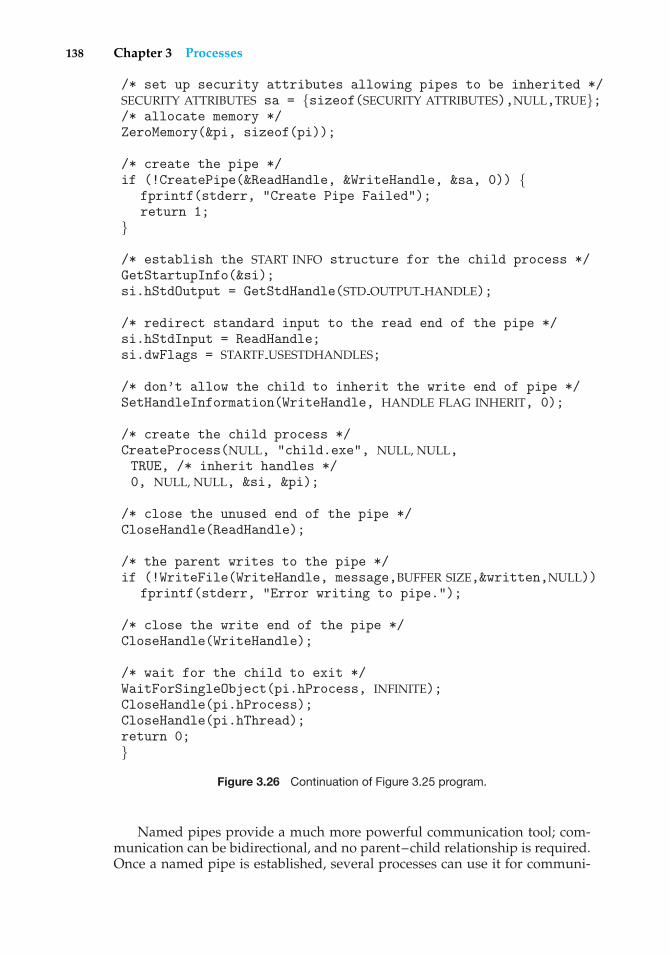
138 Chapter 3 Processes
/* set up security attributes allowing pipes to be inherited */SECURITY ATTRIBUTES sa = {sizeof(SECURITY ATTRIBUTES),NULL,TRUE};/* allocate memory */ZeroMemory(&pi, sizeof(pi));
/* create the pipe */if (!CreatePipe(&ReadHandle, &WriteHandle, &sa, 0)) {
fprintf(stderr, "Create Pipe Failed");return 1;
}
/* establish the START INFO structure for the child process */GetStartupInfo(&si);si.hStdOutput = GetStdHandle(STD OUTPUT HANDLE);
/* redirect standard input to the read end of the pipe */si.hStdInput = ReadHandle;si.dwFlags = STARTF USESTDHANDLES;
/* don’t allow the child to inherit the write end of pipe */SetHandleInformation(WriteHandle, HANDLE FLAG INHERIT, 0);
/* create the child process */CreateProcess(NULL, "child.exe", NULL, NULL,TRUE, /* inherit handles */0, NULL, NULL, &si, &pi);
/* close the unused end of the pipe */CloseHandle(ReadHandle);
/* the parent writes to the pipe */if (!WriteFile(WriteHandle, message,BUFFER SIZE,&written,NULL))
fprintf(stderr, "Error writing to pipe.");
/* close the write end of the pipe */CloseHandle(WriteHandle);
/* wait for the child to exit */WaitForSingleObject(pi.hProcess, INFINITE);CloseHandle(pi.hProcess);CloseHandle(pi.hThread);return 0;}
Figure 3.26 Continuation of Figure 3.25 program.
Named pipes provide a much more powerful communication tool; com-munication can be bidirectional, and no parent–child relationship is required.Once a named pipe is established, several processes can use it for communi-
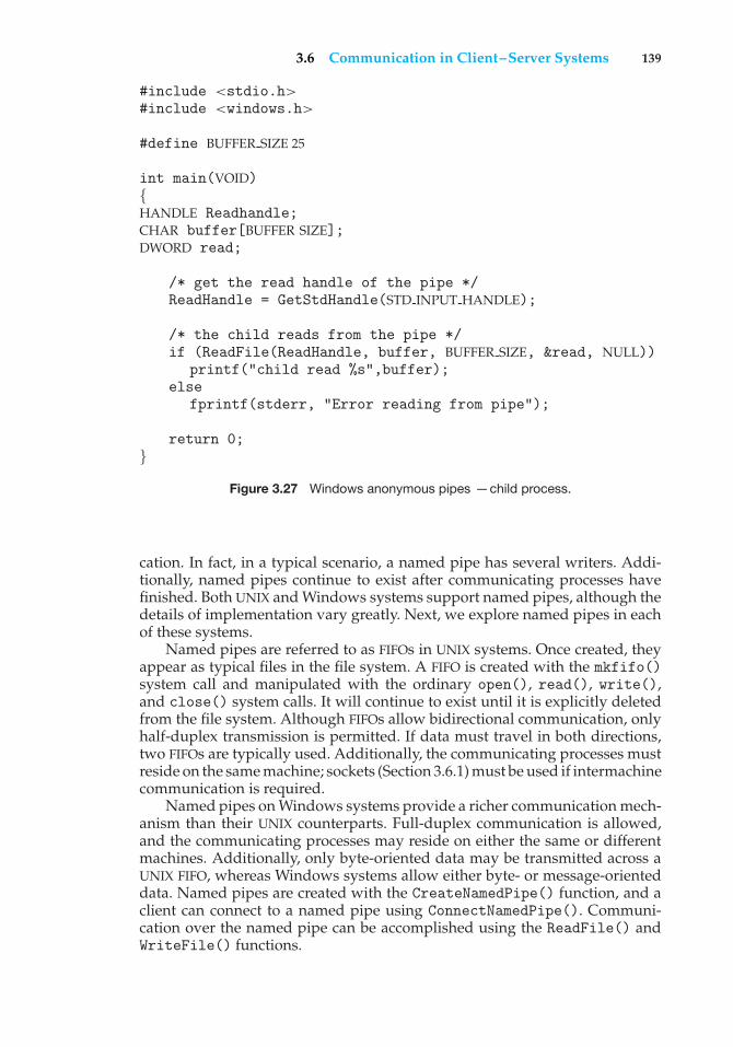
3.6 Communication in Client–Server Systems 139
#include <stdio.h>#include <windows.h>
#define BUFFER SIZE 25
int main(VOID){HANDLE Readhandle;CHAR buffer[BUFFER SIZE];DWORD read;
/* get the read handle of the pipe */ReadHandle = GetStdHandle(STD INPUT HANDLE);
/* the child reads from the pipe */if (ReadFile(ReadHandle, buffer, BUFFER SIZE, &read, NULL))
printf("child read %s",buffer);else
fprintf(stderr, "Error reading from pipe");
return 0;}
Figure 3.27 Windows anonymous pipes —child process.
cation. In fact, in a typical scenario, a named pipe has several writers. Addi-tionally, named pipes continue to exist after communicating processes havefinished. Both UNIX and Windows systems support named pipes, although thedetails of implementation vary greatly. Next, we explore named pipes in eachof these systems.
Named pipes are referred to as FIFOs in UNIX systems. Once created, theyappear as typical files in the file system. A FIFO is created with the mkfifo()system call and manipulated with the ordinary open(), read(), write(),and close() system calls. It will continue to exist until it is explicitly deletedfrom the file system. Although FIFOs allow bidirectional communication, onlyhalf-duplex transmission is permitted. If data must travel in both directions,two FIFOs are typically used. Additionally, the communicating processes mustreside on the same machine; sockets (Section 3.6.1) must be used if intermachinecommunication is required.
Named pipes on Windows systems provide a richer communication mech-anism than their UNIX counterparts. Full-duplex communication is allowed,and the communicating processes may reside on either the same or differentmachines. Additionally, only byte-oriented data may be transmitted across aUNIX FIFO, whereas Windows systems allow either byte- or message-orienteddata. Named pipes are created with the CreateNamedPipe() function, and aclient can connect to a named pipe using ConnectNamedPipe(). Communi-cation over the named pipe can be accomplished using the ReadFile() andWriteFile() functions.
140 Chapter 3 Processes
PIPES IN PRACTICE
Pipes are used quite often in the UNIX command-line environment forsituations in which the output of one command serves as input to thesecond. For example, the UNIX ls command produces a directory listing.For especially long directory listings, the output may scroll through severalscreens. The command more manages output by displaying only one screenof output at a time; the user must press the space bar to move from one screento the next. Setting up a pipe between the ls and more commands (whichare running as individual processes) allows the output of ls to be deliveredas the input to more, enabling the user to display a large directory listing ascreen at a time. A pipe can be constructed on the command line using the |character. The complete command is
ls | more
In this scenario, the ls command serves as the producer, and its output isconsumed by the more command.
Windows systems provide a more command for the DOS shell withfunctionality similar to that of its UNIX counterpart. The DOS shell also usesthe | character for establishing a pipe. The only difference is that to get adirectory listing, DOS uses the dir command rather than ls. The equivalentcommand in DOS to what is shown above is
dir | more
3.7 Summary
A process is a program in execution. As a process executes, it changes state. Thestate of a process is defined by that process’s current activity. Each process maybe in one of the following states: new, ready, running, waiting, or terminated.Each process is represented in the operating system by its own process controlblock (PCB).
A process, when it is not executing, is placed in some waiting queue. Thereare two major classes of queues in an operating system: I/O request queuesand the ready queue. The ready queue contains all the processes that are readyto execute and are waiting for the CPU. Each process is represented by a PCB,and the PCBs can be linked together to form a ready queue. Long-term (job)scheduling is the selection of processes that will be allowed to contend forthe CPU. Normally, long-term scheduling is heavily influenced by resource-allocation considerations, especially memory management. Short-term (CPU)scheduling is the selection of one process from the ready queue.
Operating systems must provide a mechanism for parent processes tocreate new child processes. The parent may wait for its children to terminatebefore proceeding, or the parent and children may execute concurrently. Thereare several reasons for allowing concurrent execution: information sharing,computation speedup, modularity, and convenience.
Practice Exercises 141
The processes executing in the operating system may be either independentprocesses or cooperating processes. Cooperating processes require an interpro-cess communication mechanism to communicate with each other. Principally,communication is achieved through two schemes: shared memory and mes-sage passing. The shared-memory method requires communicating processesto share some variables. The processes are expected to exchange informationthrough the use of these shared variables. In a shared-memory system, theresponsibility for providing communication rests with the application pro-grammers; the operating system needs to provide only the shared memory.The message-passing method allows the processes to exchange messages.The responsibility for providing communication may rest with the operatingsystem itself. These two schemes are not mutually exclusive and can be usedsimultaneously within a single operating system.
Communication in client–server systems may use (1) sockets, (2) remoteprocedure calls (RPCs), or (3) pipes. A socket is defined as an endpoint forcommunication. A connection between a pair of applications consists of apair of sockets, one at each end of the communication channel. RPCs areanother form of distributed communication. An RPC occurs when a process(or thread) calls a procedure on a remote application. Ordinary pipes allowcommunication between parent and child processes, while named pipes permitunrelated processes to communicate with one another.
Practice Exercises
3.1 Palm OS provides no means of concurrent processing. Discuss threemajor complications that concurrent processing adds to an operatingsystem.
3.2 The Sun UltraSPARC processor has multiple register sets. Describe whathappens when a context switch occurs if the new context is alreadyloaded into one of the register sets. What happens if the new context isin memory rather than in a register set and all the register sets are inuse?
3.3 When a process creates a new process using the fork() operation, whichof the following states is shared between the parent process and the childprocess?
a. Stack
b. Heap
c. Shared memory segments
3.4 With respect to the RPC mechanism, consider the “exactly once” semantic.Does the algorithm for implementing this semantic execute correctlyeven if the ACK message back to the client is lost due to a networkproblem? Describe the sequence of messages and discuss whether“exactly once” is still preserved.
3.5 Assume that a distributed system is susceptible to server failure. Whatmechanisms would be required to guarantee the “exactly once” semanticfor execution of RPCs?
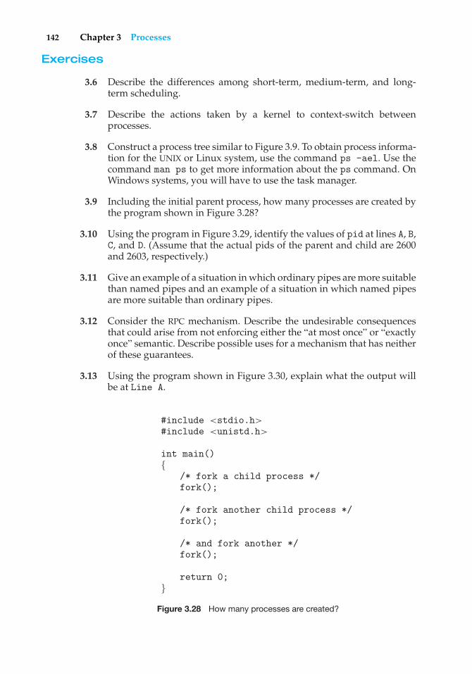
142 Chapter 3 Processes
Exercises
3.6 Describe the differences among short-term, medium-term, and long-term scheduling.
3.7 Describe the actions taken by a kernel to context-switch betweenprocesses.
3.8 Construct a process tree similar to Figure 3.9. To obtain process informa-tion for the UNIX or Linux system, use the command ps -ael. Use thecommand man ps to get more information about the ps command. OnWindows systems, you will have to use the task manager.
3.9 Including the initial parent process, how many processes are created bythe program shown in Figure 3.28?
3.10 Using the program in Figure 3.29, identify the values of pid at lines A, B,C, and D. (Assume that the actual pids of the parent and child are 2600and 2603, respectively.)
3.11 Give an example of a situation in which ordinary pipes are more suitablethan named pipes and an example of a situation in which named pipesare more suitable than ordinary pipes.
3.12 Consider the RPC mechanism. Describe the undesirable consequencesthat could arise from not enforcing either the “at most once” or “exactlyonce” semantic. Describe possible uses for a mechanism that has neitherof these guarantees.
3.13 Using the program shown in Figure 3.30, explain what the output willbe at Line A.
#include <stdio.h>#include <unistd.h>
int main(){
/* fork a child process */fork();
/* fork another child process */fork();
/* and fork another */fork();
return 0;}
Figure 3.28 How many processes are created?
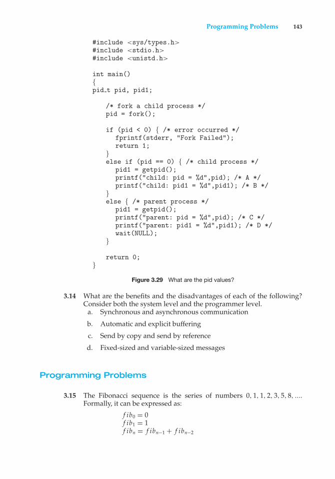
Programming Problems 143
#include <sys/types.h>#include <stdio.h>#include <unistd.h>
int main(){pid t pid, pid1;
/* fork a child process */pid = fork();
if (pid < 0) { /* error occurred */fprintf(stderr, "Fork Failed");return 1;
}else if (pid == 0) { /* child process */
pid1 = getpid();printf("child: pid = %d",pid); /* A */printf("child: pid1 = %d",pid1); /* B */
}else { /* parent process */
pid1 = getpid();printf("parent: pid = %d",pid); /* C */printf("parent: pid1 = %d",pid1); /* D */wait(NULL);
}
return 0;}
Figure 3.29 What are the pid values?
3.14 What are the benefits and the disadvantages of each of the following?Consider both the system level and the programmer level.
a. Synchronous and asynchronous communication
b. Automatic and explicit buffering
c. Send by copy and send by reference
d. Fixed-sized and variable-sized messages
Programming Problems
3.15 The Fibonacci sequence is the series of numbers 0, 1, 1, 2, 3, 5, 8, ....Formally, it can be expressed as:
f ib0 = 0f ib1 = 1f ibn = f ibn−1 + f ibn−2
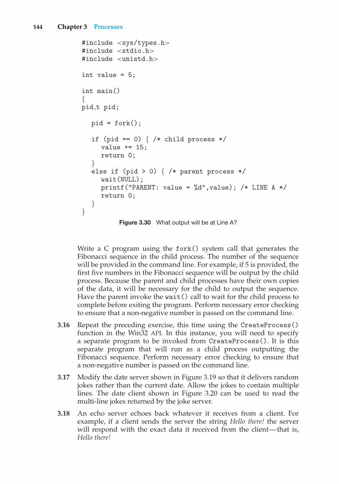
144 Chapter 3 Processes
#include <sys/types.h>#include <stdio.h>#include <unistd.h>
int value = 5;
int main(){pid t pid;
pid = fork();
if (pid == 0) { /* child process */value += 15;return 0;
}else if (pid > 0) { /* parent process */
wait(NULL);printf("PARENT: value = %d",value); /* LINE A */return 0;
}}
Figure 3.30 What output will be at Line A?
Write a C program using the fork() system call that generates theFibonacci sequence in the child process. The number of the sequencewill be provided in the command line. For example, if 5 is provided, thefirst five numbers in the Fibonacci sequence will be output by the childprocess. Because the parent and child processes have their own copiesof the data, it will be necessary for the child to output the sequence.Have the parent invoke the wait() call to wait for the child process tocomplete before exiting the program. Perform necessary error checkingto ensure that a non-negative number is passed on the command line.
3.16 Repeat the preceding exercise, this time using the CreateProcess()function in the Win32 API. In this instance, you will need to specifya separate program to be invoked from CreateProcess(). It is thisseparate program that will run as a child process outputting theFibonacci sequence. Perform necessary error checking to ensure thata non-negative number is passed on the command line.
3.17 Modify the date server shown in Figure 3.19 so that it delivers randomjokes rather than the current date. Allow the jokes to contain multiplelines. The date client shown in Figure 3.20 can be used to read themulti-line jokes returned by the joke server.
3.18 An echo server echoes back whatever it receives from a client. Forexample, if a client sends the server the string Hello there! the serverwill respond with the exact data it received from the client—that is,Hello there!
Programming Problems 145
Write an echo server using the Java networking API described inSection 3.6.1. This server will wait for a client connection using theaccept() method. When a client connection is received, the server willloop, performing the following steps:
• Read data from the socket into a buffer.
• Write the contents of the buffer back to the client.
The server will break out of the loop only when it has determined thatthe client has closed the connection.
The server shown in Figure 3.19 uses the java.io.BufferedReaderclass. BufferedReader extends the java.io.Reader class, which isused for reading character streams. However, the echo server cannotguarantee that it will read characters from clients; it may receive binarydata as well. The class java.io.InputStreamdeals with data at the bytelevel rather than the character level. Thus, this echo server must use anobject that extends java.io.InputStream. The read() method in thejava.io.InputStream class returns −1 when the client has closed itsend of the socket connection.
3.19 In Exercise 3.15, the child process must output the Fibonacci sequence,since the parent and child have their own copies of the data. Anotherapproach to designing this program is to establish a shared-memorysegment between the parent and child processes. This technique allowsthe child to write the contents of the Fibonacci sequence to the shared-memory segment and has the parent output the sequence when the childcompletes. Because the memory is shared, any changes the child makeswill be reflected in the parent process as well.
This program will be structured using POSIX shared memoryas described in Section 3.5.1. The program first requires creating thedata structure for the shared-memory segment. This is most easilyaccomplished using a struct. This data structure will contain two items:(1) a fixed-sized array of size MAX SEQUENCE that will hold the Fibonaccivalues and (2) the size of the sequence the child process is to generate—sequence size, where sequence size ≤ MAX SEQUENCE. These itemscan be represented in a struct as follows:
#define MAX SEQUENCE 10
typedef struct {long fib sequence[MAX SEQUENCE];int sequence size;
} shared data;
The parent process will progress through the following steps:
a. Accept the parameter passed on the command line and performerror checking to ensure that the parameter is ≤ MAX SEQUENCE.
b. Create a shared-memory segment of size shared data.
c. Attach the shared-memory segment to its address space.
146 Chapter 3 Processes
d. Set the value of sequence size to the parameter on the commandline.
e. Fork the child process and invoke the wait() system call to waitfor the child to finish.
f. Output the value of the Fibonacci sequence in the shared-memorysegment.
g. Detach and remove the shared-memory segment.
Because the child process is a copy of the parent, the shared-memoryregion will be attached to the child’s address space as well as theparent’s. The child process will then write the Fibonacci sequence toshared memory and finally will detach the segment.
One issue of concern with cooperating processes involves synchro-nization issues. In this exercise, the parent and child processes must besynchronized so that the parent does not output the Fibonacci sequenceuntil the child finishes generating the sequence. These two processeswill be synchronized using the wait() system call; the parent processwill invoke wait(), which will cause it to be suspended until the childprocess exits.
3.20 Design a program using ordinary pipes in which one process sends astring message to a second process, and the second process reversesthe case of each character in the message and sends it back to the firstprocess. For example, if the first process sends the message Hi There,the second process will return hI tHERE. This will require using twopipes, one for sending the original message from the first to the secondprocess, and the other for sending the modified message from the secondback to the first process. You may write this program using either UNIXor Windows pipes.
3.21 Design a file-copying program named FileCopy using ordinary pipes.This program will be passed two parameters: the first is the name ofthe file to be copied, and the second is the name of the copied file. Theprogram will then create an ordinary pipe and write the contents of thefile to be copied to the pipe. The child process will read this file from thepipe and write it to the destination file. For example, if we invoke theprogram as follows:
FileCopy input.txt copy.txt
the file input.txt will be written to the pipe. The child process willread the contents of this file and write it to the destination file copy.txt.You may write this program using either UNIX or Windows pipes.
3.22 Most UNIX and Linux systems provide the ipcs command. This com-mand lists the status of various POSIX interprocess communicationmechanisms, including shared-memory segments. Much of the informa-tion for the command comes from the data structure struct shmid ds,which is available in the /usr/include/sys/shm.h file. Some of thefields in this structure include:
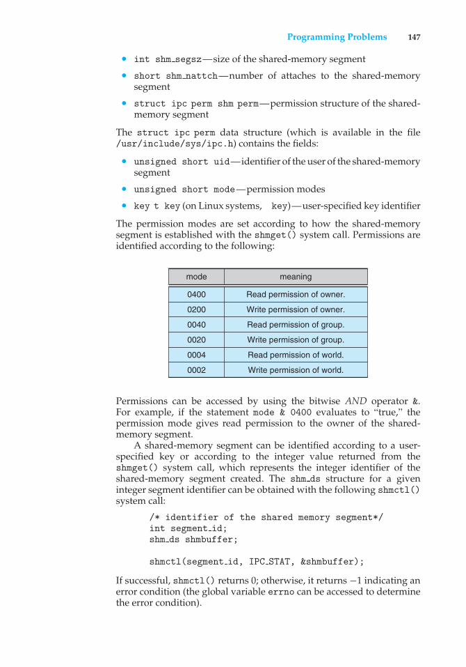
Programming Problems 147
• int shm segsz—size of the shared-memory segment
• short shm nattch—number of attaches to the shared-memorysegment
• struct ipc perm shm perm—permission structure of the shared-memory segment
The struct ipc perm data structure (which is available in the file/usr/include/sys/ipc.h) contains the fields:
• unsigned short uid—identifier of the user of the shared-memorysegment
• unsigned short mode—permission modes
• key t key (on Linux systems, key)—user-specified key identifier
The permission modes are set according to how the shared-memorysegment is established with the shmget() system call. Permissions areidentified according to the following:
mode meaning
0400
0200
0040
0020
0004
0002
Read permission of owner.
Write permission of owner.
Read permission of group.
Write permission of group.
Read permission of world.
Write permission of world.
Permissions can be accessed by using the bitwise AND operator &.For example, if the statement mode & 0400 evaluates to “true,” thepermission mode gives read permission to the owner of the shared-memory segment.
A shared-memory segment can be identified according to a user-specified key or according to the integer value returned from theshmget() system call, which represents the integer identifier of theshared-memory segment created. The shm ds structure for a giveninteger segment identifier can be obtained with the following shmctl()system call:
/* identifier of the shared memory segment*/int segment id;shm ds shmbuffer;
shmctl(segment id, IPC STAT, &shmbuffer);
If successful, shmctl() returns 0; otherwise, it returns −1 indicating anerror condition (the global variable errno can be accessed to determinethe error condition).
148 Chapter 3 Processes
Write a C program that is passed an identifier for a shared-memorysegment. This program will invoke the shmctl() function to obtainits shm ds structure. It will then output the following values of theshared-memory segment:
• Segment ID
• Key
• Mode
• Owner UID
• Size
• Number of attaches
Programming Projects
3.23 POSIX Message Passing.
This project consists of using POSIX message queues for communicatingtemperatures between each of four external processes and a centralprocess. The project can be completed on systems that support POSIXmessage passing, such as UNIX, Linux, and Mac OS X.
Part 1: Overview
Four external processes will communicate temperatures to a centralprocess, which in turn will reply with its own temperature and willindicate whether the entire system has stabilized. Each process willreceive its initial temperature upon creation and will recalculate a newtemperature according to two formulas:
new external temp =(myTemp * 3 + 2 * centralTemp) / 5;
new central temp =(2 * centralTemp + four temps received from external processes) / 6;
Initially, each external process will send its temperature to the mailboxfor the central process. If all four temperatures are exactly the same asthose sent by the four processes during the last iteration, the systemhas stabilized. In this case, the central process will notify each externalprocess that it is now finished (along with the central process itself),and each process will output the final stabilized temperature. If thesystem has not yet become stable, the central process will send its newtemperature to the mailbox for each of the outer processes and awaittheir replies. The processes will continue to run until the temperaturehas stabilized.
Programming Projects 149
Part 2: The Message Passing System
Processes can exchange messages by using four system calls: msgget(),msgsnd(), msgrcv(), and msgctl(). The msgget() function convertsa mailbox name to a message queue id, msqid. (A mailbox nameis an externally known message queue name that is shared amongthe cooperating processes.) msqid, the internal identifier returned bymsgget(), must be passed to all subsequent system calls using thismessage queue to facilitate interprocess communication. A typicalinvocation of msgget()is seen below:
msqid = msgget(1234, 0600 | IPC CREAT);
The first parameter is the name of the mailbox, and the second parameterinstructs the operating system to create the message queue if it does notalready exist, with read and write privileges only for processes with thesame user id as this process. If a message queue already exists for thismailbox name, msgget() returns the msqid of the existing mailbox. Toavoid attaching to an existing message queue, a process can first attemptto attach to the mailbox by omitting IPC CREAT and then checking thereturn value from msgget(). If msqid is negative, an error has occurredduring the system call, and the globally accessible variable errno can beconsulted to determine whether the error occurred because the messagequeue already exists or for some other reason. If the process determinesthat the mailbox does not currently exist, it can then create it by includingIPC CREAT. (For the current project, this strategy should not be necessaryif students are using standalone PCs or are assigned unique ranges ofmailbox names by the instructor.)
Once a valid msqid has been established, a process can begin touse msgsnd() to send messages and msgrcv() to receive messages.The messages being sent and received are similar in format to thosedescribed in Section 3.5.2, as they include a fixed-length portion at thebeginning followed by a variable-length portion. Obviously, the sendersand receivers must agree on the format of the messages being exchanged.Since the operating system specifies one field in the fixed-length portionof every message format, and at least one piece of information willbe sent to the receiving process, it is logical to create a data aggregatefor each type of message using a struct. The first field of any suchstruct must be a long, and it will contain the priority of the message.(This project does not use this functionality; we recommend that yousimply make the first field in every message equal to the same integralvalue, such as 2.) Other fields in the messages contain the informationto be shared between the communicating processes. Three additionalfields are recommended: (1) the temperature being sent, (2) the processnumber of the external process sending the message (0 for the centralprocess), and (3) a flag that is set to 0 but that the central process willset to 1 when it notices stability. A recommended struct appears asfollows:
150 Chapter 3 Processes
struct {long priority;int temp;int pid;int stable;
} msgp;
Assuming the msqid has been established, examples of msgsnd() andmsgrcv() appear as such:
int stat, msqid;
stat = msgsnd(msqid, &msgp,sizeof(msgp)−sizeof(long), 0);
stat = msgrcv(msqid, &msgp,sizeof(msgp)−sizeof(long), 2, 0);
The first parameter in both system calls must be a valid msqid; otherwisea negative value is returned. (Both functions return the number ofbytes sent or received upon successful completion of the operation.)The second parameter is the address of where to find or store themessage to be sent or received, followed by the number of informationbytes to be sent or received. The final parameter of 0 indicates that theoperations will be synchronous and that the sender will block if themessage queue is full. (IPC NOWAIT would be used if asynchronous, ornonblocking, operations were desired. Each individual message queuecan hold a maximum number of messages—or bytes—so it is possiblefor the queue to become filled, which is one reason a sender may blockwhen attempting to transmit a message.) The 2 that appears before thisfinal parameter in msgrcv() indicates the minimum priority level ofthe messages the process wishes to receive; the receiver will wait untila message of that priority (or higher) is sent to the msqid if this is asynchronous operation.
Once a process is finished using a message queue, it must beremoved so that the mailbox can be reused by other processes. Unlessit is removed, the message queue—and any messages that have not yetbeen received—will remain in the storage space that has been providedfor this mailbox by the kernel. To remove the message queue, and deleteany unread messages therein, it is necessary to invoke msgctl(), asfollows:
struct msgid ds dummyParam;status = msgctl(msqid, IPC RMID, &dummyParam);
The third parameter is necessary because this function requires it, but itis used only if it the programmer wishes to collect some statistics aboutthe usage of the message queue. This is accomplished by substitutingIPC STAT as the second parameter.
All programs should include the following three header files, whichare found in /usr/include/sys: ipc.h, types.h, and msg.h. Onepossibly confusing artifact of the message queue implementation bears
Programming Projects 151
mentioning at this point. After a mailbox is removed via msgctl(), anysubsequent attempts to create another mailbox with that same nameusing msgget() will typically generate a different msqid.
Part 3: Creating the Processes
Each external process, as well as the central server, will create its ownmailbox with the name X + i , where i is a numeric identifier of theexternal process 1..4 or zero for the central process. Thus, if X were 70,then the central process would receive messages in the mailbox named70, and it would send its replies to mailboxes 71–74. Outer process 2would receive in mailbox 72 and would send to mailbox 70, and so forth.Thus, each external process will attach to two mailboxes, and the centralprocess will attach to five. If each process specifies IPC CREAT wheninvoking msgget(), the first process that invokes msgget() actuallycreates the mailbox; subsequent calls to msgget() attach to the existingmailbox. The protocol for removal should be that the mailbox/messagequeue that each process is listening to should be the only one it removes—via msgctl().)
Each external process will be uniquely identified by a command-lineparameter. The first parameter to each external process will be its initialtemperature, and the second parameter will be its unique number: 1,2, 3, or 4. The central server will be passed one parameter—its initialtemperature. Assuming the executable name of the external process isexternal and the central server is central, invoking all five processeswill be done as follows:
./external 100 1 &
./external 22 2 &
./external 50 3 &
./external 40 4 &
./central 60 &
Part 4: Implementation Hints
It might be best to start by sending one message successfully fromthe central process to a single outer process, and vice versa, beforetrying to write all the code to solve this problem. It is also wise tocheck all the return values from the four message queue system callsfor possible failed requests and to output a message to the screen aftereach one successfully completes. The message should indicate what wasaccomplished and by whom—for instance, “mailbox 71 has been createdby outer process 1,” “message received by central process from externalprocess 2,” and so forth. These messages can be removed or commentedout after the problem is solved. Processes should also verify that theywere passed the correct number of command-line parameters (via theargc parameter in main()). Finally, extraneous messages residing ina queue can cause a collection of cooperating processes that functioncorrectly to appear erroneous. For that reason, it is wise to remove allmailboxes relevant to this project to ensure that mailboxes are emptybefore the processes begin. The easiest way to do this is to use the
152 Chapter 3 Processes
ipcs command to list all message queues and the ipcrm command toremove existing message queues. The ipcs command lists the msqid ofall message queues on the system. Use ipcrm to remove message queuesaccording to their msqid. For example, if msqid 163845 appears with theoutput of ipcs, it can be deleted with the following command:
ipcrm -q 163845
Wiley Plus
Visit Wiley Plus for
• Source code
• Solutions to practice exercises
• Additional programming problems and exercises
• Labs using an operating system simulator
Bibliographical Notes
Interprocess communication in the RC 4000 system is discussed by Brinch-Hansen [1970]. Schlichting and Schneider [1982] discuss asynchronousmessage-passing primitives. The IPC facility implemented at the user level isdescribed by Bershad et al. [1990].
Details of interprocess communication in UNIX systems are presented byGray [1997]. Barrera [1991] and Vahalia [1996] describe interprocess commu-nication in the Mach system. Russinovich and Solomon [2005], Solomon andRussinovich [2000], and Stevens [1999] outline interprocess communicationin Windows 2003, Windows 2000 and UNIX respectively. Hart [2005] coversWindows systems programming in detail.
The implementation of RPCs is discussed by Birrell and Nelson [1984]. Shri-vastava and Panzieri [1982] describes the design of a reliable RPC mechanism,and Tay and Ananda [1990] presents a survey of RPCs. Stankovic [1982] andStaunstrup [1982] discuss procedure calls versus message-passing communi-cation. Harold [2005] provides coverage of socket programming in Java. Hart[2005] and Robbins and Robbins [2003] cover pipes in Windows and UNIXsystems, respectively.
4C H A P T E R
Threads
The process model introduced in Chapter 3 assumed that a process was anexecuting program with a single thread of control. Most modern operatingsystems now provide features enabling a process to contain multiple threads ofcontrol. This chapter introduces many concepts associated with multithreadedcomputer systems, including a discussion of the APIs for the Pthreads, Win32,and Java thread libraries. We look at many issues related to multithreadedprogramming and its effect on the design of operating systems. Finally, weexplore how the Windows XP and Linux operating systems support threads atthe kernel level.
CHAPTER OBJECTIVES
• To introduce the notion of a thread—a fundamental unit of CPU utilizationthat forms the basis of multithreaded computer systems.
• To discuss the APIs for the Pthreads, Win32, and Java thread libraries.
• To examine issues related to multithreaded programming.
4.1 Overview
A thread is a basic unit of CPU utilization; it comprises a thread ID, a programcounter, a register set, and a stack. It shares with other threads belongingto the same process its code section, data section, and other operating-systemresources, such as open files and signals. A traditional (or heavyweight) processhas a single thread of control. If a process has multiple threads of control, itcan perform more than one task at a time. Figure 4.1 illustrates the differencebetween a traditional single-threaded process and a multithreaded process.
4.1.1 Motivation
Many software packages that run on modern desktop PCs are multithreaded.An application typically is implemented as a separate process with severalthreads of control. A Web browser might have one thread display images or
153
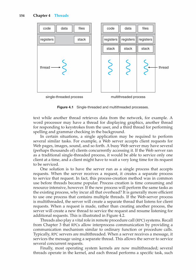
154 Chapter 4 Threads
registers
code data files
stack registers registers registers
code data files
stackstackstack
thread thread
single-threaded process multithreaded process
Figure 4.1 Single-threaded and multithreaded processes.
text while another thread retrieves data from the network, for example. Aword processor may have a thread for displaying graphics, another threadfor responding to keystrokes from the user, and a third thread for performingspelling and grammar checking in the background.
In certain situations, a single application may be required to performseveral similar tasks. For example, a Web server accepts client requests forWeb pages, images, sound, and so forth. A busy Web server may have several(perhaps thousands of) clients concurrently accessing it. If the Web server ranas a traditional single-threaded process, it would be able to service only oneclient at a time, and a client might have to wait a very long time for its requestto be serviced.
One solution is to have the server run as a single process that acceptsrequests. When the server receives a request, it creates a separate processto service that request. In fact, this process-creation method was in commonuse before threads became popular. Process creation is time consuming andresource intensive, however. If the new process will perform the same tasks asthe existing process, why incur all that overhead? It is generally more efficientto use one process that contains multiple threads. If the Web-server processis multithreaded, the server will create a separate thread that listens for clientrequests. When a request is made, rather than creating another process, theserver will create a new thread to service the request and resume listening foradditional requests. This is illustrated in Figure 4.2.
Threads also play a vital role in remote procedure call (RPC) systems. Recallfrom Chapter 3 that RPCs allow interprocess communication by providing acommunication mechanism similar to ordinary function or procedure calls.Typically, RPC servers are multithreaded. When a server receives a message, itservices the message using a separate thread. This allows the server to serviceseveral concurrent requests.
Finally, most operating system kernels are now multithreaded; severalthreads operate in the kernel, and each thread performs a specific task, such
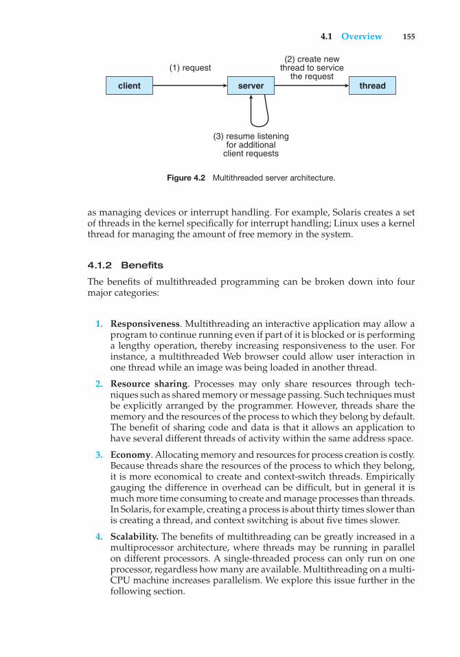
4.1 Overview 155
client
(1) request(2) create new
thread to servicethe request
(3) resume listeningfor additional
client requests
server thread
Figure 4.2 Multithreaded server architecture.
as managing devices or interrupt handling. For example, Solaris creates a setof threads in the kernel specifically for interrupt handling; Linux uses a kernelthread for managing the amount of free memory in the system.
4.1.2 Benefits
The benefits of multithreaded programming can be broken down into fourmajor categories:
1. Responsiveness. Multithreading an interactive application may allow aprogram to continue running even if part of it is blocked or is performinga lengthy operation, thereby increasing responsiveness to the user. Forinstance, a multithreaded Web browser could allow user interaction inone thread while an image was being loaded in another thread.
2. Resource sharing. Processes may only share resources through tech-niques such as shared memory or message passing. Such techniques mustbe explicitly arranged by the programmer. However, threads share thememory and the resources of the process to which they belong by default.The benefit of sharing code and data is that it allows an application tohave several different threads of activity within the same address space.
3. Economy. Allocating memory and resources for process creation is costly.Because threads share the resources of the process to which they belong,it is more economical to create and context-switch threads. Empiricallygauging the difference in overhead can be difficult, but in general it ismuch more time consuming to create and manage processes than threads.In Solaris, for example, creating a process is about thirty times slower thanis creating a thread, and context switching is about five times slower.
4. Scalability. The benefits of multithreading can be greatly increased in amultiprocessor architecture, where threads may be running in parallelon different processors. A single-threaded process can only run on oneprocessor, regardless how many are available. Multithreading on a multi-CPU machine increases parallelism. We explore this issue further in thefollowing section.
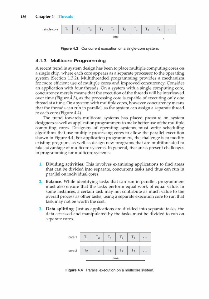
156 Chapter 4 Threads
T1 T2 T3 T4 T1 T2 T3 T4 T1single core
time
…
Figure 4.3 Concurrent execution on a single-core system.
4.1.3 Multicore Programming
A recent trend in system design has been to place multiple computing cores ona single chip, where each core appears as a separate processor to the operatingsystem (Section 1.3.2). Multithreaded programming provides a mechanismfor more efficient use of multiple cores and improved concurrency. Consideran application with four threads. On a system with a single computing core,concurrency merely means that the execution of the threads will be interleavedover time (Figure 4.3), as the processing core is capable of executing only onethread at a time. On a system with multiple cores, however, concurrency meansthat the threads can run in parallel, as the system can assign a separate threadto each core (Figure 4.4).
The trend towards multicore systems has placed pressure on systemdesigners as well as application programmers to make better use of the multiplecomputing cores. Designers of operating systems must write schedulingalgorithms that use multiple processing cores to allow the parallel executionshown in Figure 4.4. For application programmers, the challenge is to modifyexisting programs as well as design new programs that are multithreaded totake advantage of multicore systems. In general, five areas present challengesin programming for multicore systems:
1. Dividing activities. This involves examining applications to find areasthat can be divided into separate, concurrent tasks and thus can run inparallel on individual cores.
2. Balance. While identifying tasks that can run in parallel, programmersmust also ensure that the tasks perform equal work of equal value. Insome instances, a certain task may not contribute as much value to theoverall process as other tasks; using a separate execution core to run thattask may not be worth the cost.
3. Data splitting. Just as applications are divided into separate tasks, thedata accessed and manipulated by the tasks must be divided to run onseparate cores.
T1 T3 T1 T3 T1core 1
T2 T4 T2 T4 T2core 2
time
…
…
Figure 4.4 Parallel execution on a multicore system.
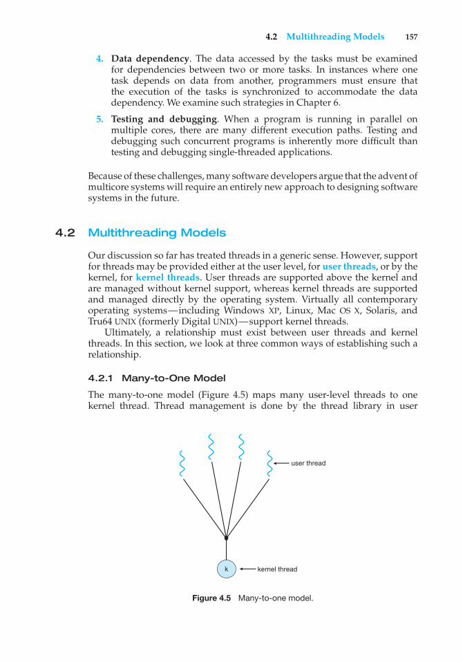
4.2 Multithreading Models 157
4. Data dependency. The data accessed by the tasks must be examinedfor dependencies between two or more tasks. In instances where onetask depends on data from another, programmers must ensure thatthe execution of the tasks is synchronized to accommodate the datadependency. We examine such strategies in Chapter 6.
5. Testing and debugging. When a program is running in parallel onmultiple cores, there are many different execution paths. Testing anddebugging such concurrent programs is inherently more difficult thantesting and debugging single-threaded applications.
Because of these challenges, many software developers argue that the advent ofmulticore systems will require an entirely new approach to designing softwaresystems in the future.
4.2 Multithreading Models
Our discussion so far has treated threads in a generic sense. However, supportfor threads may be provided either at the user level, for user threads, or by thekernel, for kernel threads. User threads are supported above the kernel andare managed without kernel support, whereas kernel threads are supportedand managed directly by the operating system. Virtually all contemporaryoperating systems—including Windows XP, Linux, Mac OS X, Solaris, andTru64 UNIX (formerly Digital UNIX)—support kernel threads.
Ultimately, a relationship must exist between user threads and kernelthreads. In this section, we look at three common ways of establishing such arelationship.
4.2.1 Many-to-One Model
The many-to-one model (Figure 4.5) maps many user-level threads to onekernel thread. Thread management is done by the thread library in user
user thread
kernel threadk
Figure 4.5 Many-to-one model.
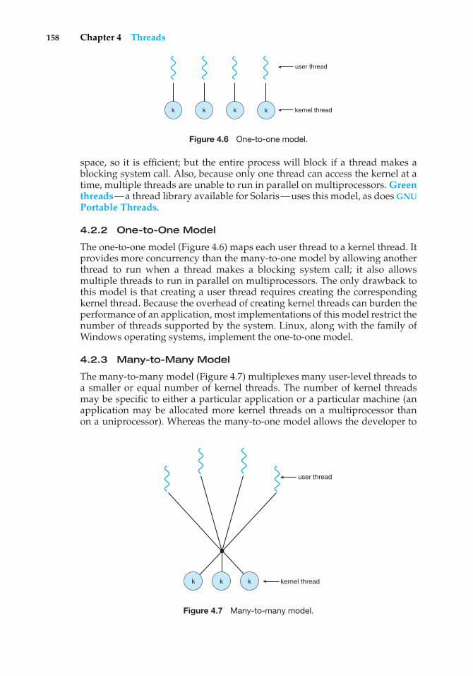
158 Chapter 4 Threads
user thread
kernel threadkkkk
Figure 4.6 One-to-one model.
space, so it is efficient; but the entire process will block if a thread makes ablocking system call. Also, because only one thread can access the kernel at atime, multiple threads are unable to run in parallel on multiprocessors. Greenthreads—a thread library available for Solaris—uses this model, as does GNUPortable Threads.
4.2.2 One-to-One Model
The one-to-one model (Figure 4.6) maps each user thread to a kernel thread. Itprovides more concurrency than the many-to-one model by allowing anotherthread to run when a thread makes a blocking system call; it also allowsmultiple threads to run in parallel on multiprocessors. The only drawback tothis model is that creating a user thread requires creating the correspondingkernel thread. Because the overhead of creating kernel threads can burden theperformance of an application, most implementations of this model restrict thenumber of threads supported by the system. Linux, along with the family ofWindows operating systems, implement the one-to-one model.
4.2.3 Many-to-Many Model
The many-to-many model (Figure 4.7) multiplexes many user-level threads toa smaller or equal number of kernel threads. The number of kernel threadsmay be specific to either a particular application or a particular machine (anapplication may be allocated more kernel threads on a multiprocessor thanon a uniprocessor). Whereas the many-to-one model allows the developer to
user thread
kernel threadkkk
Figure 4.7 Many-to-many model.
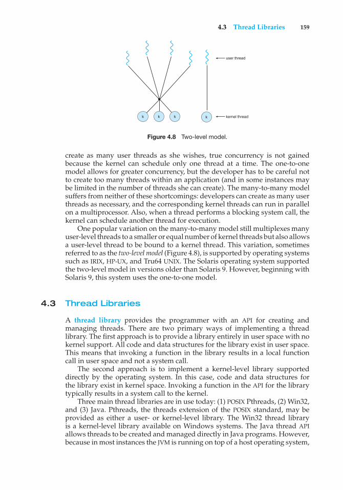
4.3 Thread Libraries 159
user thread
kernel threadkkk k
Figure 4.8 Two-level model.
create as many user threads as she wishes, true concurrency is not gainedbecause the kernel can schedule only one thread at a time. The one-to-onemodel allows for greater concurrency, but the developer has to be careful notto create too many threads within an application (and in some instances maybe limited in the number of threads she can create). The many-to-many modelsuffers from neither of these shortcomings: developers can create as many userthreads as necessary, and the corresponding kernel threads can run in parallelon a multiprocessor. Also, when a thread performs a blocking system call, thekernel can schedule another thread for execution.
One popular variation on the many-to-many model still multiplexes manyuser-level threads to a smaller or equal number of kernel threads but also allowsa user-level thread to be bound to a kernel thread. This variation, sometimesreferred to as the two-level model (Figure 4.8), is supported by operating systemssuch as IRIX, HP-UX, and Tru64 UNIX. The Solaris operating system supportedthe two-level model in versions older than Solaris 9. However, beginning withSolaris 9, this system uses the one-to-one model.
4.3 Thread Libraries
A thread library provides the programmer with an API for creating andmanaging threads. There are two primary ways of implementing a threadlibrary. The first approach is to provide a library entirely in user space with nokernel support. All code and data structures for the library exist in user space.This means that invoking a function in the library results in a local functioncall in user space and not a system call.
The second approach is to implement a kernel-level library supporteddirectly by the operating system. In this case, code and data structures forthe library exist in kernel space. Invoking a function in the API for the librarytypically results in a system call to the kernel.
Three main thread libraries are in use today: (1) POSIX Pthreads, (2) Win32,and (3) Java. Pthreads, the threads extension of the POSIX standard, may beprovided as either a user- or kernel-level library. The Win32 thread libraryis a kernel-level library available on Windows systems. The Java thread APIallows threads to be created and managed directly in Java programs. However,because in most instances the JVM is running on top of a host operating system,
160 Chapter 4 Threads
the Java thread API is generally implemented using a thread library availableon the host system. This means that on Windows systems, Java threads aretypically implemented using the Win32 API; UNIX and Linux systems often usePthreads.
In the remainder of this section, we describe basic thread creation usingthese three thread libraries. As an illustrative example, we design a multi-threaded program that performs the summation of a non-negative integer in aseparate thread using the well-known summation function:
sum =N∑
i=0
i
For example, if N were 5, this function would represent the summation ofintegers from 0 to 5, which is 15. Each of the three programs will be run withthe upper bounds of the summation entered on the command line; thus, if theuser enters 8, the summation of the integer values from 0 to 8 will be output.
4.3.1 Pthreads
Pthreads refers to the POSIX standard (IEEE 1003.1c) defining an API for threadcreation and synchronization. This is a specification for thread behavior, not animplementation. Operating system designers may implement the specification inany way they wish. Numerous systems implement the Pthreads specification,including Solaris, Linux, Mac OS X, and Tru64 UNIX. Shareware implementationsare available in the public domain for the various Windows operating systemsas well.
The C program shown in Figure 4.9 demonstrates the basic Pthreads API forconstructing a multithreaded program that calculates the summation of a non-negative integer in a separate thread. In a Pthreads program, separate threadsbegin execution in a specified function. In Figure 4.9, this is the runner()function. When this program begins, a single thread of control begins inmain(). After some initialization, main() creates a second thread that beginscontrol in the runner() function. Both threads share the global data sum.
Let’s look more closely at this program. All Pthreads programs mustinclude the pthread.h header file. The statement pthread t tid declaresthe identifier for the thread we will create. Each thread has a set of attributes,including stack size and scheduling information. The pthread attr t attrdeclaration represents the attributes for the thread. We set the attributes in thefunction call pthread attr init(&attr). Because we did not explicitly setany attributes, we use the default attributes provided. (In Chapter 5, we discusssome of the scheduling attributes provided by the Pthreads API.) A separatethread is created with the pthread create() function call. In addition topassing the thread identifier and the attributes for the thread, we also pass thename of the function where the new thread will begin execution—in this case,the runner() function. Last, we pass the integer parameter that was providedon the command line, argv[1].
At this point, the program has two threads: the initial (or parent) threadin main() and the summation (or child) thread performing the summation
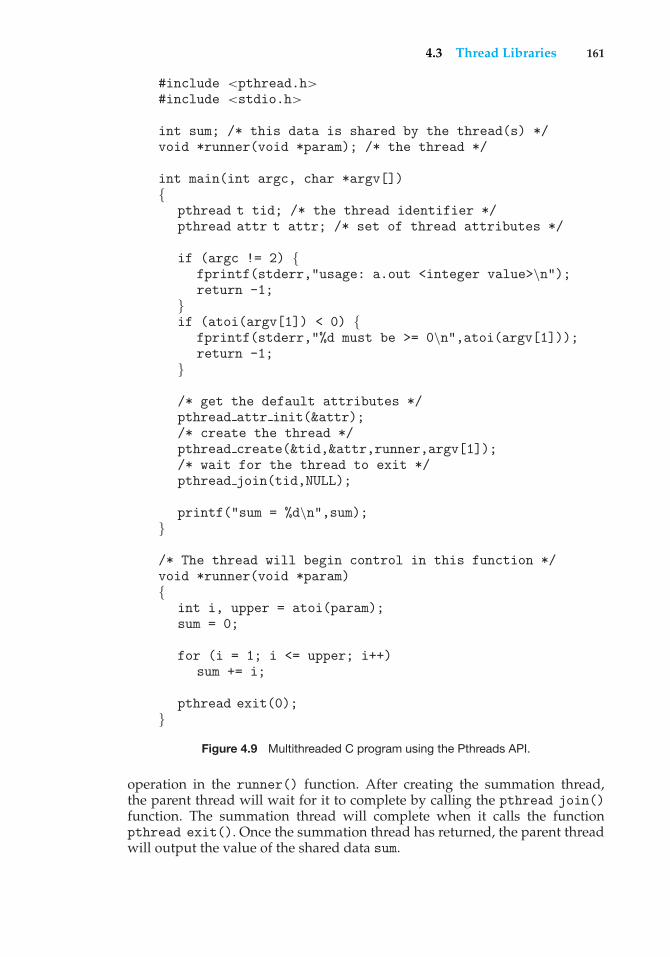
4.3 Thread Libraries 161
#include <pthread.h>#include <stdio.h>
int sum; /* this data is shared by the thread(s) */void *runner(void *param); /* the thread */
int main(int argc, char *argv[]){
pthread t tid; /* the thread identifier */pthread attr t attr; /* set of thread attributes */
if (argc != 2) {fprintf(stderr,"usage: a.out <integer value>\n");return -1;
}if (atoi(argv[1]) < 0) {
fprintf(stderr,"%d must be >= 0\n",atoi(argv[1]));return -1;
}
/* get the default attributes */pthread attr init(&attr);/* create the thread */pthread create(&tid,&attr,runner,argv[1]);/* wait for the thread to exit */pthread join(tid,NULL);
printf("sum = %d\n",sum);}
/* The thread will begin control in this function */void *runner(void *param){
int i, upper = atoi(param);sum = 0;
for (i = 1; i <= upper; i++)sum += i;
pthread exit(0);}
Figure 4.9 Multithreaded C program using the Pthreads API.
operation in the runner() function. After creating the summation thread,the parent thread will wait for it to complete by calling the pthread join()function. The summation thread will complete when it calls the functionpthread exit(). Once the summation thread has returned, the parent threadwill output the value of the shared data sum.
162 Chapter 4 Threads
4.3.2 Win32 Threads
The technique for creating threads using the Win32 thread library is similarto the Pthreads technique in several ways. We illustrate the Win32 threadAPI in the C program shown in Figure 4.10. Notice that we must include thewindows.h header file when using the Win32 API.
Just as in the Pthreads version shown in Figure 4.9, data shared by theseparate threads—in this case, Sum—are declared globally (the DWORD datatype is an unsigned 32-bit integer). We also define the Summation() functionthat is to be performed in a separate thread. This function is passed a pointer toa void, which Win32 defines as LPVOID. The thread performing this functionsets the global data Sum to the value of the summation from 0 to the parameterpassed to Summation().
Threads are created in the Win32 API using the CreateThread() function,and—just as in Pthreads—a set of attributes for the thread is passed to thisfunction. These attributes include security information, the size of the stack,and a flag that can be set to indicate if the thread is to start in a suspendedstate. In this program, we use the default values for these attributes (which donot initially set the thread to a suspended state and instead make it eligibleto be run by the CPU scheduler). Once the summation thread is created, theparent must wait for it to complete before outputting the value of Sum, asthe value is set by the summation thread. Recall that the Pthread program(Figure 4.9) had the parent thread wait for the summation thread using thepthread join() statement. We perform the equivalent of this in the Win32 APIusing the WaitForSingleObject() function, which causes the creating threadto block until the summation thread has exited. (We cover synchronizationobjects in more detail in Chapter 6.)
4.3.3 Java Threads
Threads are the fundamental model of program execution in a Java program,and the Java language and its API provide a rich set of features for the creationand management of threads. All Java programs comprise at least a single threadof control—even a simple Java program consisting of only a main() methodruns as a single thread in the JVM.
There are two techniques for creating threads in a Java program. Oneapproach is to create a new class that is derived from the Thread class andto override its run() method. An alternative—and more commonly used—technique is to define a class that implements the Runnable interface. TheRunnable interface is defined as follows:
public interface Runnable{
public abstract void run();}
When a class implements Runnable, it must define a run() method. The codeimplementing the run() method is what runs as a separate thread.
Figure 4.11 shows the Java version of a multithreaded program thatdetermines the summation of a non-negative integer. The Summation classimplements the Runnable interface. Thread creation is performed by creating
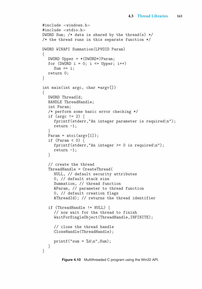
4.3 Thread Libraries 163
#include <windows.h>#include <stdio.h>DWORD Sum; /* data is shared by the thread(s) *//* the thread runs in this separate function */
DWORD WINAPI Summation(LPVOID Param){
DWORD Upper = *(DWORD*)Param;for (DWORD i = 0; i <= Upper; i++)
Sum += i;return 0;
}
int main(int argc, char *argv[]){
DWORD ThreadId;HANDLE ThreadHandle;int Param;/* perform some basic error checking */if (argc != 2) {
fprintf(stderr,"An integer parameter is required\n");return -1;
}Param = atoi(argv[1]);if (Param < 0) {
fprintf(stderr,"An integer >= 0 is required\n");return -1;
}
// create the threadThreadHandle = CreateThread(
NULL, // default security attributes0, // default stack sizeSummation, // thread function&Param, // parameter to thread function0, // default creation flags&ThreadId); // returns the thread identifier
if (ThreadHandle != NULL) {// now wait for the thread to finishWaitForSingleObject(ThreadHandle,INFINITE);
// close the thread handleCloseHandle(ThreadHandle);
printf("sum = %d\n",Sum);}
}Figure 4.10 Multithreaded C program using the Win32 API.
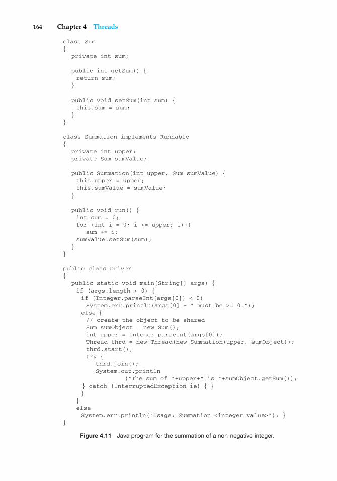
164 Chapter 4 Threads
class Sum{
private int sum;
public int getSum() {return sum;
}
public void setSum(int sum) {this.sum = sum;
}}
class Summation implements Runnable{
private int upper;private Sum sumValue;
public Summation(int upper, Sum sumValue) {this.upper = upper;this.sumValue = sumValue;
}
public void run() {int sum = 0;for (int i = 0; i <= upper; i++)
sum += i;sumValue.setSum(sum);
}}
public class Driver{
public static void main(String[] args) {if (args.length > 0) {if (Integer.parseInt(args[0]) < 0)System.err.println(args[0] + " must be >= 0.");
else {// create the object to be sharedSum sumObject = new Sum();int upper = Integer.parseInt(args[0]);Thread thrd = new Thread(new Summation(upper, sumObject));thrd.start();try {
thrd.join();System.out.println
("The sum of "+upper+" is "+sumObject.getSum());} catch (InterruptedException ie) { }}
}elseSystem.err.println("Usage: Summation <integer value>"); }
}
Figure 4.11 Java program for the summation of a non-negative integer.
4.4 Threading Issues 165
an object instance of the Thread class and passing the constructor a Runnableobject.
Creating a Thread object does not specifically create the new thread; rather,it is the start() method that creates the new thread. Calling the start()method for the new object does two things:
1. It allocates memory and initializes a new thread in the JVM.
2. It calls the run() method, making the thread eligible to be run by theJVM. (Note that we never call the run() method directly. Rather, we callthe start() method, and it calls the run() method on our behalf.)
When the summation program runs, two threads are created by the JVM.The first is the parent thread, which starts execution in the main() method.The second thread is created when the start() method on the Thread objectis invoked. This child thread begins execution in the run() method of theSummation class. After outputting the value of the summation, this threadterminates when it exits from its run() method.
Sharing of data between threads occurs easily in Win32 and Pthreads, sinceshared data are simply declared globally. As a pure object-oriented language,Java has no such notion of global data; if two or more threads are to sharedata in a Java program, the sharing occurs by passing references to the sharedobject to the appropriate threads. In the Java program shown in Figure 4.11,the main thread and the summation thread share the object instance of the Sumclass. This shared object is referenced through the appropriate getSum() andsetSum() methods. (You might wonder why we don’t use an Integer objectrather than designing a new sum class. The reason is that the Integer class isimmutable—that is, once its value is set, it cannot change.)
Recall that the parent threads in the Pthreads and Win32 libraries usepthread join() and WaitForSingleObject() (respectively) to wait forthe summation threads to finish before proceeding. The join() methodin Java provides similar functionality. (Notice that join() can throw anInterruptedException, which we choose to ignore.)
4.4 Threading Issues
In this section, we discuss some of the issues to consider with multithreadedprograms.
4.4.1 The fork() and exec() System Calls
In Chapter 3, we described how the fork() system call is used to create aseparate, duplicate process. The semantics of the fork() and exec() systemcalls change in a multithreaded program.
If one thread in a program calls fork(), does the new process duplicateall threads, or is the new process single-threaded? Some UNIX systems havechosen to have two versions of fork(), one that duplicates all threads andanother that duplicates only the thread that invoked the fork() system call.
The exec() system call typically works in the same way as describedin Chapter 3. That is, if a thread invokes the exec() system call, the program
166 Chapter 4 Threads
The JVM and the Host Operating System
The JVM is typically implemented on top of a host operating system (seeFigure 2.20). This setup allows the JVM to hide the implementation detailsof the underlying operating system and to provide a consistent, abstractenvironment that allows Java programs to operate on any platform thatsupports a JVM. The specification for the JVM does not indicate how Javathreads are to be mapped to the underlying operating system, instead leavingthat decision to the particular implementation of the JVM. For example, theWindows XP operating system uses the one-to-one model; therefore, eachJava thread for a JVM running on such a system maps to a kernel thread. Onoperating systems that use the many-to-many model (such as Tru64 UNIX), aJava thread is mapped according to the many-to-many model. Solaris initiallyimplemented the JVM using the many-to-one model (the green threads library,mentioned earlier). Later releases of the JVM were implemented using themany-to-many model. Beginning with Solaris 9, Java threads were mappedusing the one-to-one model. In addition, there may be a relationship betweenthe Java thread library and the thread library on the host operating system.For example, implementations of a JVM for the Windows family of operatingsystems might use the Win32 API when creating Java threads; Linux, Solaris,and Mac OS X systems might use the Pthreads API.
specified in the parameter to exec()will replace the entire process—includingall threads.
Which of the two versions of fork() to use depends on the application.If exec() is called immediately after forking, then duplicating all threads isunnecessary, as the program specified in the parameters to exec() will replacethe process. In this instance, duplicating only the calling thread is appropriate.If, however, the separate process does not callexec() after forking, the separateprocess should duplicate all threads.
4.4.2 Cancellation
Thread cancellation is the task of terminating a thread before it has completed.For example, if multiple threads are concurrently searching through a databaseand one thread returns the result, the remaining threads might be canceled.Another situation might occur when a user presses a button on a Web browserthat stops a Web page from loading any further. Often, a Web page is loadedusing several threads—each image is loaded in a separate thread. When auser presses the stop button on the browser, all threads loading the page arecanceled.
A thread that is to be canceled is often referred to as the target thread.Cancellation of a target thread may occur in two different scenarios:
1. Asynchronous cancellation. One thread immediately terminates thetarget thread.
4.4 Threading Issues 167
2. Deferred cancellation. The target thread periodically checks whether itshould terminate, allowing it an opportunity to terminate itself in anorderly fashion.
The difficulty with cancellation occurs in situations where resources havebeen allocated to a canceled thread or where a thread is canceled while inthe midst of updating data it is sharing with other threads. This becomesespecially troublesome with asynchronous cancellation. Often, the operatingsystem will reclaim system resources from a canceled thread but will notreclaim all resources. Therefore, canceling a thread asynchronously may notfree a necessary system-wide resource.
With deferred cancellation, in contrast, one thread indicates that a targetthread is to be canceled, but cancellation occurs only after the target thread haschecked a flag to determine whether or not it should be canceled. The threadcan perform this check at a point at which it can be canceled safely. Pthreadsrefers to such points as cancellation points.
4.4.3 Signal Handling
A signal is used in UNIX systems to notify a process that a particular event hasoccurred. A signal may be received either synchronously or asynchronously,depending on the source of and the reason for the event being signaled. Allsignals, whether synchronous or asynchronous, follow the same pattern:
1. A signal is generated by the occurrence of a particular event.
2. A generated signal is delivered to a process.
3. Once delivered, the signal must be handled.
Examples of synchronous signals include illegal memory access anddivision by 0. If a running program performs either of these actions, a signalis generated. Synchronous signals are delivered to the same process thatperformed the operation that caused the signal (that is the reason they areconsidered synchronous).
When a signal is generated by an event external to a running process, thatprocess receives the signal asynchronously. Examples of such signals includeterminating a process with specific keystrokes (such as <control><C>) andhaving a timer expire. Typically, an asynchronous signal is sent to anotherprocess.
A signal may be handled by one of two possible handlers:
1. A default signal handler
2. A user-defined signal handler
Every signal has a default signal handler that is run by the kernel whenhandling that signal. This default action can be overridden by a user-definedsignal handler that is called to handle the signal. Signals are handled indifferent ways. Some signals (such as changing the size of a window) aresimply ignored; others (such as an illegal memory access) are handled byterminating the program.
168 Chapter 4 Threads
Handling signals in single-threaded programs is straightforward: signalsare always delivered to a process. However, delivering signals is morecomplicated in multithreaded programs, where a process may have severalthreads. Where, then, should a signal be delivered?
In general, the following options exist:
1. Deliver the signal to the thread to which the signal applies.
2. Deliver the signal to every thread in the process.
3. Deliver the signal to certain threads in the process.
4. Assign a specific thread to receive all signals for the process.
The method for delivering a signal depends on the type of signal generated.For example, synchronous signals need to be delivered to the thread causingthe signal and not to other threads in the process. However, the situation withasynchronous signals is not as clear. Some asynchronous signals—such as asignal that terminates a process (<control><C>, for example)—should besent to all threads.
Most multithreaded versions of UNIX allow a thread to specify whichsignals it will accept and which it will block. Therefore, in some cases, anasynchronous signal may be delivered only to those threads that are notblocking it. However, because signals need to be handled only once, a signalis typically delivered only to the first thread found that is not blocking it.The standard UNIX function for delivering a signal is kill(pid t pid, intsignal), which specifies the process (pid) to which a particular signal is to bedelivered. POSIX Pthreads provides the pthread kill(pthread t tid, intsignal) function, which allows a signal to be delivered to a specified thread(tid).
Although Windows does not explicitly provide support for signals, theycan be emulated using asynchronous procedure calls (APCs). The APC facilityallows a user thread to specify a function that is to be called when the userthread receives notification of a particular event. As indicated by its name,an APC is roughly equivalent to an asynchronous signal in UNIX. However,whereas UNIX must contend with how to deal with signals in a multithreadedenvironment, the APC facility is more straightforward, since an APC is deliveredto a particular thread rather than a process.
4.4.4 Thread Pools
In Section 4.1, we mentioned multithreading in a Web server. In this situation,whenever the server receives a request, it creates a separate thread to servicethe request. Whereas creating a separate thread is certainly superior to creatinga separate process, a multithreaded server nonetheless has potential problems.The first issue concerns the amount of time required to create the thread priorto servicing the request, together with the fact that this thread will be discardedonce it has completed its work. The second issue is more troublesome: if weallow all concurrent requests to be serviced in a new thread, we have not placeda bound on the number of threads concurrently active in the system. Unlimitedthreads could exhaust system resources, such as CPU time or memory. Onesolution to this problem is to use a thread pool.
4.4 Threading Issues 169
The general idea behind a thread pool is to create a number of threads atprocess startup and place them into a pool, where they sit and wait for work.When a server receives a request, it awakens a thread from this pool—if oneis available—and passes it the request for service. Once the thread completesits service, it returns to the pool and awaits more work. If the pool contains noavailable thread, the server waits until one becomes free.
Thread pools offer these benefits:
1. Servicing a request with an existing thread is usually faster than waitingto create a thread.
2. A thread pool limits the number of threads that exist at any one point.This is particularly important on systems that cannot support a largenumber of concurrent threads.
The number of threads in the pool can be set heuristically based on factorssuch as the number of CPUs in the system, the amount of physical memory,and the expected number of concurrent client requests. More sophisticatedthread-pool architectures can dynamically adjust the number of threads in thepool according to usage patterns. Such architectures provide the further benefitof having a smaller pool—thereby consuming less memory—when the loadon the system is low.
The Win32 API provides several functions related to thread pools. Usingthe thread pool API is similar to creating a thread with the Thread Create()function, as described in Section 4.3.2. Here, a function that is to run as aseparate thread is defined. Such a function may appear as follows:
DWORD WINAPI PoolFunction(AVOID Param) {/*** this function runs as a separate thread.**/
}
A pointer to PoolFunction() is passed to one of the functions in the threadpool API, and a thread from the pool executes this function. One such memberin the thread pool API is the QueueUserWorkItem() function, which is passedthree parameters:
• LPTHREAD START ROUTINE Function—a pointer to the function that is torun as a separate thread
• PVOID Param—the parameter passed to Function
• ULONG Flags—flags indicating how the thread pool is to create andmanage execution of the thread
An example of invoking a function is:
QueueUserWorkItem(&PoolFunction, NULL, 0);
This causes a thread from the thread pool to invoke PoolFunction() on behalfof the programmer. In this instance, we pass no parameters to PoolFunc-
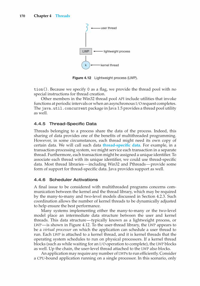
170 Chapter 4 Threads
LWP
user thread
kernel threadk
lightweight process
Figure 4.12 Lightweight process (LWP).
tion(). Because we specify 0 as a flag, we provide the thread pool with nospecial instructions for thread creation.
Other members in the Win32 thread pool API include utilities that invokefunctions at periodic intervals or when an asynchronous I/O request completes.The java.util.concurrent package in Java 1.5 provides a thread pool utilityas well.
4.4.5 Thread-Specific Data
Threads belonging to a process share the data of the process. Indeed, thissharing of data provides one of the benefits of multithreaded programming.However, in some circumstances, each thread might need its own copy ofcertain data. We will call such data thread-specific data. For example, in atransaction-processing system, we might service each transaction in a separatethread. Furthermore, each transaction might be assigned a unique identifier. Toassociate each thread with its unique identifier, we could use thread-specificdata. Most thread libraries—including Win32 and Pthreads—provide someform of support for thread-specific data. Java provides support as well.
4.4.6 Scheduler Activations
A final issue to be considered with multithreaded programs concerns com-munication between the kernel and the thread library, which may be requiredby the many-to-many and two-level models discussed in Section 4.2.3. Suchcoordination allows the number of kernel threads to be dynamically adjustedto help ensure the best performance.
Many systems implementing either the many-to-many or the two-levelmodel place an intermediate data structure between the user and kernelthreads. This data structure—typically known as a lightweight process, orLWP—is shown in Figure 4.12. To the user-thread library, the LWP appears tobe a virtual processor on which the application can schedule a user thread torun. Each LWP is attached to a kernel thread, and it is kernel threads that theoperating system schedules to run on physical processors. If a kernel threadblocks (such as while waiting for an I/O operation to complete), the LWP blocksas well. Up the chain, the user-level thread attached to the LWP also blocks.
An application may require any number of LWPs to run efficiently. Considera CPU-bound application running on a single processor. In this scenario, only
4.5 Operating-System Examples 171
one thread can run at once, so one LWP is sufficient. An application that is I/O-intensive may require multiple LWPs to execute, however. Typically, an LWP isrequired for each concurrent blocking system call. Suppose, for example, thatfive different file-read requests occur simultaneously. Five LWPs are needed,because all could be waiting for I/O completion in the kernel. If a process hasonly four LWPs, then the fifth request must wait for one of the LWPs to returnfrom the kernel.
One scheme for communication between the user-thread library and thekernel is known as scheduler activation. It works as follows: The kernelprovides an application with a set of virtual processors (LWPs), and theapplication can schedule user threads onto an available virtual processor.Furthermore, the kernel must inform an application about certain events. Thisprocedure is known as an upcall. Upcalls are handled by the thread librarywith an upcall handler, and upcall handlers must run on a virtual processor.One event that triggers an upcall occurs when an application thread is about toblock. In this scenario, the kernel makes an upcall to the application informingit that a thread is about to block and identifying the specific thread. The kernelthen allocates a new virtual processor to the application. The application runsan upcall handler on this new virtual processor, which saves the state of theblocking thread and relinquishes the virtual processor on which the blockingthread is running. The upcall handler then schedules another thread that iseligible to run on the new virtual processor. When the event that the blockingthread was waiting for occurs, the kernel makes another upcall to the threadlibrary informing it that the previously blocked thread is now eligible to run.The upcall handler for this event also requires a virtual processor, and the kernelmay allocate a new virtual processor or preempt one of the user threads andrun the upcall handler on its virtual processor. After marking the unblockedthread as eligible to run, the application schedules an eligible thread to run onan available virtual processor.
4.5 Operating-System Examples
In this section, we explore how threads are implemented in Windows XP andLinux systems.
4.5.1 Windows XP Threads
Windows XP implements the Win32 API, which is the primary API for thefamily of Microsoft operating systems (Windows 95, 98, NT, 2000, and XP).Indeed, much of what is mentioned in this section applies to this entire familyof operating systems.
A Windows XP application runs as a separate process, and each processmay contain one or more threads. The Win32 API for creating threads iscovered in Section 4.3.2. Windows XP uses the one-to-one mapping describedin Section 4.2.2, where each user-level thread maps to an associated kernelthread. However, Windows XP also provides support for a fiber library, whichprovides the functionality of the many-to-many model (Section 4.2.3). By usingthe thread library, any thread belonging to a process can access the addressspace of the process.
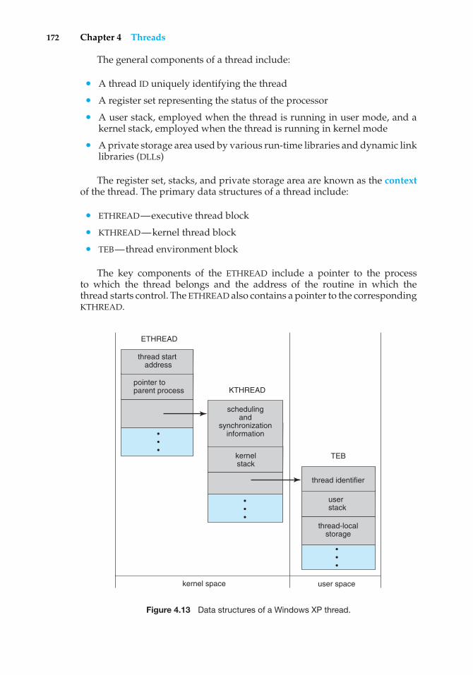
172 Chapter 4 Threads
The general components of a thread include:
• A thread ID uniquely identifying the thread
• A register set representing the status of the processor
• A user stack, employed when the thread is running in user mode, and akernel stack, employed when the thread is running in kernel mode
• A private storage area used by various run-time libraries and dynamic linklibraries (DLLs)
The register set, stacks, and private storage area are known as the contextof the thread. The primary data structures of a thread include:
• ETHREAD—executive thread block
• KTHREAD—kernel thread block
• TEB—thread environment block
The key components of the ETHREAD include a pointer to the processto which the thread belongs and the address of the routine in which thethread starts control. The ETHREAD also contains a pointer to the correspondingKTHREAD.
user spacekernel space
pointer to parent process
thread start address
ETHREAD
KTHREAD
• • •
kernel stack
scheduling and
synchronizationinformation
• • •
user stack
thread-local storage
thread identifier
TEB
• • •
Figure 4.13 Data structures of a Windows XP thread.
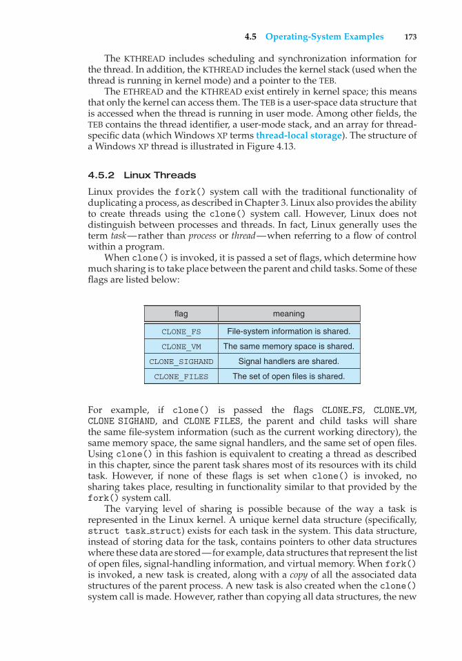
4.5 Operating-System Examples 173
The KTHREAD includes scheduling and synchronization information forthe thread. In addition, the KTHREAD includes the kernel stack (used when thethread is running in kernel mode) and a pointer to the TEB.
The ETHREAD and the KTHREAD exist entirely in kernel space; this meansthat only the kernel can access them. The TEB is a user-space data structure thatis accessed when the thread is running in user mode. Among other fields, theTEB contains the thread identifier, a user-mode stack, and an array for thread-specific data (which Windows XP terms thread-local storage). The structure ofa Windows XP thread is illustrated in Figure 4.13.
4.5.2 Linux Threads
Linux provides the fork() system call with the traditional functionality ofduplicating a process, as described in Chapter 3. Linux also provides the abilityto create threads using the clone() system call. However, Linux does notdistinguish between processes and threads. In fact, Linux generally uses theterm task—rather than process or thread—when referring to a flow of controlwithin a program.
When clone() is invoked, it is passed a set of flags, which determine howmuch sharing is to take place between the parent and child tasks. Some of theseflags are listed below:
flag meaning
CLONE_FS
CLONE_VM
CLONE_SIGHAND
CLONE_FILES
File-system information is shared.
The same memory space is shared.
Signal handlers are shared.
The set of open files is shared.
For example, if clone() is passed the flags CLONE FS, CLONE VM,CLONE SIGHAND, and CLONE FILES, the parent and child tasks will sharethe same file-system information (such as the current working directory), thesame memory space, the same signal handlers, and the same set of open files.Using clone() in this fashion is equivalent to creating a thread as describedin this chapter, since the parent task shares most of its resources with its childtask. However, if none of these flags is set when clone() is invoked, nosharing takes place, resulting in functionality similar to that provided by thefork() system call.
The varying level of sharing is possible because of the way a task isrepresented in the Linux kernel. A unique kernel data structure (specifically,struct task struct) exists for each task in the system. This data structure,instead of storing data for the task, contains pointers to other data structureswhere these data are stored—for example, data structures that represent the listof open files, signal-handling information, and virtual memory. When fork()is invoked, a new task is created, along with a copy of all the associated datastructures of the parent process. A new task is also created when the clone()system call is made. However, rather than copying all data structures, the new
174 Chapter 4 Threads
task points to the data structures of the parent task, depending on the set offlags passed to clone().
Several distributions of the Linux kernel now include the NPTL threadlibrary. NPTL (which stands for Native POSIX Thread Library) provides a POSIX-compliant thread model for Linux systems along with several other features,such as better support for SMP systems, as well as taking advantage of NUMAsupport. In addition, the start-up cost for creating a thread is lower with NPTLthan with traditional Linux threads. Finally, with NPTL, the system has thepotential to support hundreds of thousands of threads. Such support becomesmore important with the growth of multicore and other SMP systems.
4.6 Summary
A thread is a flow of control within a process. A multithreaded process containsseveral different flows of control within the same address space. The benefits ofmultithreading include increased responsiveness to the user, resource sharingwithin the process, economy, and scalability issues such as more efficient useof multiple cores.
User-level threads are threads that are visible to the programmer and areunknown to the kernel. The operating-system kernel supports and manageskernel-level threads. In general, user-level threads are faster to create andmanage than are kernel threads, as no intervention from the kernel is required.Three different types of models relate user and kernel threads: The many-to-onemodel maps many user threads to a single kernel thread. The one-to-one modelmaps each user thread to a corresponding kernel thread. The many-to-manymodel multiplexes many user threads to a smaller or equal number of kernelthreads.
Most modern operating systems provide kernel support for threads; amongthese are Windows 98, NT, 2000, and XP, as well as Solaris and Linux.
Thread libraries provide the application programmer with an API forcreating and managing threads. Three primary thread libraries are in commonuse: POSIX Pthreads, Win32 threads for Windows systems, and Java threads.
Multithreaded programs introduce many challenges for the programmer,including the semantics of the fork() and exec() system calls. Other issuesinclude thread cancellation, signal handling, and thread-specific data.
Practice Exercises
4.1 Provide two programming examples in which multithreading providesbetter performance than a single-threaded solution.
4.2 What are two differences between user-level threads and kernel-levelthreads? Under what circumstances is one type better than the other?
4.3 Describe the actions taken by a kernel to context-switch between kernel-level threads.
4.4 What resources are used when a thread is created? How do they differfrom those used when a process is created?
Exercises 175
4.5 Assume that an operating system maps user-level threads to the kernelusing the many-to-many model and that the mapping is done throughLWPs. Furthermore, the system allows developers to create real-timethreads for use in real-time systems. Is it necessary to bind a real-timethread to an LWP? Explain.
4.6 A Pthread program that performs the summation function was providedin Section 4.3.1. Rewrite this program in Java.
Exercises
4.7 Provide two programming examples in which multithreading does notprovide better performance than a single-threaded solution.
4.8 Describe the actions taken by a thread library to context-switch betweenuser-level threads.
4.9 Under what circumstances does a multithreaded solution using multi-ple kernel threads provide better performance than a single-threadedsolution on a single-processor system?
4.10 Which of the following components of program state are shared acrossthreads in a multithreaded process?
a. Register values
b. Heap memory
c. Global variables
d. Stack memory
4.11 Can a multithreaded solution using multiple user-level threads achievebetter performance on a multiprocessor system than on a single-processor system? Explain.
4.12 As described in Section 4.5.2, Linux does not distinguish betweenprocesses and threads. Instead, Linux treats both in the same way,allowing a task to be more akin to a process or a thread dependingon the set of flags passed to the clone() system call. However, manyoperating systems—such as Windows XP and Solaris—treat processesand threads differently. Typically, such systems use a notation whereinthe data structure for a process contains pointers to the separate threadsbelonging to the process. Contrast these two approaches for modelingprocesses and threads within the kernel.
4.13 The program shown in Figure 4.14 uses the Pthreads API. What wouldbe the output from the program at LINE C and LINE P?
4.14 Consider a multiprocessor system and a multithreaded program writtenusing the many-to-many threading model. Let the number of user-level
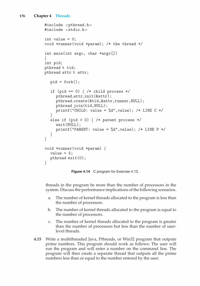
176 Chapter 4 Threads
#include <pthread.h>#include <stdio.h>
int value = 0;void *runner(void *param); /* the thread */
int main(int argc, char *argv[]){int pid;pthread t tid;pthread attr t attr;
pid = fork();
if (pid == 0) { /* child process */pthread attr init(&attr);pthread create(&tid,&attr,runner,NULL);pthread join(tid,NULL);printf("CHILD: value = %d",value); /* LINE C */
}else if (pid > 0) { /* parent process */
wait(NULL);printf("PARENT: value = %d",value); /* LINE P */
}}
void *runner(void *param) {value = 5;pthread exit(0);
}Figure 4.14 C program for Exercise 4.13.
threads in the program be more than the number of processors in thesystem. Discuss the performance implications of the following scenarios.
a. The number of kernel threads allocated to the program is less thanthe number of processors.
b. The number of kernel threads allocated to the program is equal tothe number of processors.
c. The number of kernel threads allocated to the program is greaterthan the number of processors but less than the number of user-level threads.
4.15 Write a multithreaded Java, Pthreads, or Win32 program that outputsprime numbers. This program should work as follows: The user willrun the program and will enter a number on the command line. Theprogram will then create a separate thread that outputs all the primenumbers less than or equal to the number entered by the user.
Projects 177
4.16 Modify the socket-based date server (Figure 3.19) in Chapter 3 so thatthe server services each client request in a separate thread.
4.17 The Fibonacci sequence is the series of numbers 0, 1, 1, 2, 3, 5, 8, ....Formally, it can be expressed as:
f ib0 = 0f ib1 = 1f ibn = f ibn−1 + f ibn−2
Write a multithreaded program that generates the Fibonacci sequenceusing either the Java, Pthreads, or Win32 thread library. This programshould work as follows: The user will enter on the command linethe number of Fibonacci numbers that the program is to generate.The program will then create a separate thread that will generate theFibonacci numbers, placing the sequence in data that can be shared bythe threads (an array is probably the most convenient data structure).When the thread finishes execution, the parent thread will output thesequence generated by the child thread. Because the parent thread cannotbegin outputting the Fibonacci sequence until the child thread finishes,this will require having the parent thread wait for the child thread tofinish, using the techniques described in Section 4.3.
4.18 Exercise 3.18 in Chapter 3 involves designing an echo server using theJava threading API. However, this server is single-threaded, meaningthat the server cannot respond to concurrent echo clients until the currentclient exits. Modify the solution to Exercise 3.18 so that the echo serverservices each client in a separate request.
Projects
The set of projects below deal with two distinct topics—naming service andmatrix muliplication.
Project 1: Naming Service Project
A naming service such as DNS (for domain name system) can be used toresolve IP names to IP addresses. For example, when someone accesses the hostwww.westminstercollege.edu, a naming service is used to determine theIP address that is mapped to the IP name www.westminstercollege.edu.This assignment consists of writing a multithreaded naming service in Javausing sockets (see Section 3.6.1).
The java.net API provides the following mechanism for resolving IP names:
InetAddress hostAddress =InetAddress.getByName("www.westminstercollege.edu");
String IPaddress = hostAddress.getHostAddress();
where getByName() throws an UnknownHostException if it is unable toresolve the host name.
178 Chapter 4 Threads
The Server
The server will listen to port 6052 waiting for client connections. Whena client connection is made, the server will service the connection in a separatethread and will resume listening for additional client connections. Once aclient makes a connection to the server, the client will write the IP name itwishes the server to resolve—such as www.westminstercollege.edu—to the socket. The server thread will read this IP name from the socket andeither resolve its IP address or, if it cannot locate the host address, catch anUnknownHostException. The server will write the IP address back to theclient or, in the case of an UnknownHostException, will write the message“Unable to resolve host <host name>.” Once the server has writtento the client, it will close its socket connection.
The Client
Initially, write just the server application and connect to it via telnet.For example, assuming the server is running on the localhost, a telnet sessionwould appear as follows. (Client responses appear in blue.)
telnet localhost 6052Connected to localhost.Escape character is ’ˆ]’.www.westminstercollege.edu146.86.1.17Connection closed by foreign host.
By initially having telnet act as a client, you can more easily debug any problemsyou may have with your server. Once you are convinced your server is workingproperly, you can write a client application. The client will be passed the IPname that is to be resolved as a parameter. The client will open a socketconnection to the server and then write the IP name that is to be resolved. Itwill then read the response sent back by the server. As an example, if the clientis named NSClient, it is invoked as follows:
java NSClient www.westminstercollege.edu
and the server will respond with the corresponding IP address or “unknownhost” message. Once the client has output the IP address, it will close its socketconnection.
Project 2: Matrix Multiplication Project
Given two matrices, Aand B, where matrix Acontains M rows and K columnsand matrix B contains K rows and N columns, the matrix product of A and Bis matrix C , where C contains M rows and N columns. The entry in matrix Cfor row i , column j (Ci, j ) is the sum of the products of the elements for row iin matrix A and column j in matrix B. That is,
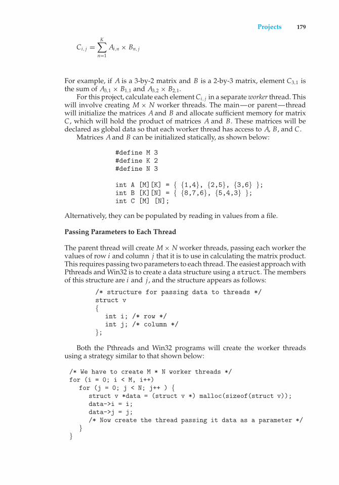
Projects 179
Ci, j =K∑
n=1
Ai,n × Bn, j
For example, if A is a 3-by-2 matrix and B is a 2-by-3 matrix, element C3,1 isthe sum of A3,1 × B1,1 and A3,2 × B2,1.
For this project, calculate each element Ci, j in a separate worker thread. Thiswill involve creating M × N worker threads. The main—or parent—threadwill initialize the matrices A and B and allocate sufficient memory for matrixC , which will hold the product of matrices A and B. These matrices will bedeclared as global data so that each worker thread has access to A, B, and C .
Matrices A and B can be initialized statically, as shown below:
#define M 3#define K 2#define N 3
int A [M][K] = { {1,4}, {2,5}, {3,6} };int B [K][N] = { {8,7,6}, {5,4,3} };int C [M] [N];
Alternatively, they can be populated by reading in values from a file.
Passing Parameters to Each Thread
The parent thread will create M × N worker threads, passing each worker thevalues of row i and column j that it is to use in calculating the matrix product.This requires passing two parameters to each thread. The easiest approach withPthreads and Win32 is to create a data structure using a struct. The membersof this structure are i and j , and the structure appears as follows:
/* structure for passing data to threads */struct v{
int i; /* row */int j; /* column */
};
Both the Pthreads and Win32 programs will create the worker threadsusing a strategy similar to that shown below:
/* We have to create M * N worker threads */for (i = 0; i < M, i++)
for (j = 0; j < N; j++ ) {struct v *data = (struct v *) malloc(sizeof(struct v));data->i = i;data->j = j;/* Now create the thread passing it data as a parameter */
}}
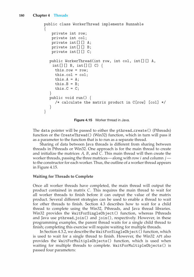
180 Chapter 4 Threads
public class WorkerThread implements Runnable{
private int row;private int col;private int[][] A;private int[][] B;private int[][] C;
public WorkerThread(int row, int col, int[][] A,int[][] B, int[][] C) {this.row = row;this.col = col;this.A = A;this.B = B;this.C = C;
}public void run() {
/* calculate the matrix product in C[row] [col] */}
}Figure 4.15 Worker thread in Java.
The data pointer will be passed to either the pthread create() (Pthreads)function or the CreateThread() (Win32) function, which in turn will pass itas a parameter to the function that is to run as a separate thread.
Sharing of data between Java threads is different from sharing betweenthreads in Pthreads or Win32. One approach is for the main thread to createand initialize the matrices A, B, and C . This main thread will then create theworker threads, passing the three matrices—along with row i and column j —to the constructor for each worker. Thus, the outline of a worker thread appearsin Figure 4.15.
Waiting for Threads to Complete
Once all worker threads have completed, the main thread will output theproduct contained in matrix C . This requires the main thread to wait forall worker threads to finish before it can output the value of the matrixproduct. Several different strategies can be used to enable a thread to waitfor other threads to finish. Section 4.3 describes how to wait for a childthread to complete using the Win32, Pthreads, and Java thread libraries.Win32 provides the WaitForSingleObject() function, whereas Pthreadsand Java use pthread join() and join(), respectively. However, in theseprogramming examples, the parent thread waits for a single child thread tofinish; completing this exercise will require waiting for multiple threads.
In Section 4.3.2, we describe the WaitForSingleObject() function, whichis used to wait for a single thread to finish. However, the Win32 API alsoprovides the WaitForMultipleObjects() function, which is used whenwaiting for multiple threads to complete. WaitForMultipleObjects() ispassed four parameters:
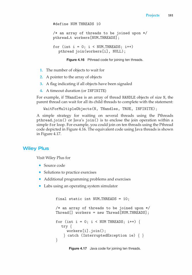
Projects 181
#define NUM THREADS 10
/* an array of threads to be joined upon */pthread t workers[NUM THREADS];
for (int i = 0; i < NUM THREADS; i++)pthread join(workers[i], NULL);
Figure 4.16 Pthread code for joining ten threads.
1. The number of objects to wait for
2. A pointer to the array of objects
3. A flag indicating if all objects have been signaled
4. A timeout duration (or INFINITE)
For example, if THandles is an array of thread HANDLE objects of size N, theparent thread can wait for all its child threads to complete with the statement:
WaitForMultipleObjects(N, THandles, TRUE, INFINITE);
A simple strategy for waiting on several threads using the Pthreadspthread join() or Java’s join() is to enclose the join operation within asimple for loop. For example, you could join on ten threads using the Pthreadcode depicted in Figure 4.16. The equivalent code using Java threads is shownin Figure 4.17.
Wiley Plus
Visit Wiley Plus for
• Source code
• Solutions to practice exercises
• Additional programming problems and exercises
• Labs using an operating system simulator
final static int NUM THREADS = 10;
/* an array of threads to be joined upon */Thread[] workers = new Thread[NUM THREADS];
for (int i = 0; i < NUM THREADS; i++) {try {
workers[i].join();} catch (InterruptedException ie) { }
}Figure 4.17 Java code for joining ten threads.
182 Chapter 4 Threads
Bibliographical Notes
Threads have had a long evolution, starting as “cheap concurrency” inprogramming languages and moving to “lightweight processes”, with earlyexamples that included the Thoth system (Cheriton et al. [1979]) and the Pilotsystem (Redell et al. [1980]). Binding [1985] described moving threads intothe UNIX kernel. Mach (Accetta et al. [1986], Tevanian et al. [1987a]) and V(Cheriton [1988]) made extensive use of threads, and eventually almost allmajor operating systems implemented them in some form or another.
Thread performance issues were discussed by Anderson et al. [1989], whocontinued their work in Anderson et al. [1991] by evaluating the performanceof user-level threads with kernel support. Bershad et al. [1990] describecombining threads with RPC. Engelschall [2000] discusses a technique forsupporting user-level threads. An analysis of an optimal thread-pool size canbe found in Ling et al. [2000]. Scheduler activations were first presented inAnderson et al. [1991], and Williams [2002] discusses scheduler activations inthe NetBSD system. Other mechanisms by which the user-level thread libraryand the kernel cooperate with each other are discussed in Marsh et al. [1991],Govindan and Anderson [1991], Draves et al. [1991], and Black [1990]. Zabattaand Young [1998] compare Windows NT and Solaris threads on a symmetricmultiprocessor. Pinilla and Gill [2003] compare Java thread performance onLinux, Windows, and Solaris.
Vahalia [1996] covers threading in several versions of UNIX. McDougalland Mauro [2007] describe recent developments in threading the Solaris kernel.Russinovich and Solomon [2005] discuss threading in the Windows operatingsystem family. Bovet and Cesati [2006] and Love [2004] explain how Linuxhandles threading and Singh [2007] covers threads in Mac OS X.
Information on Pthreads programming is given in Lewis and Berg [1998]and Butenhof [1997]. Oaks and Wong [1999], Lewis and Berg [2000], and Holub[2000] discuss multithreading in Java. Goetz et al. [2006] present a detaileddiscussion of concurrent programming in Java. Beveridge and Wiener [1997]and Cohen and Woodring [1997] describe multithreading using Win32.
5C H A P T E R
CPUScheduling
CPU scheduling is the basis of multiprogrammed operating systems. Byswitching the CPU among processes, the operating system can make thecomputer more productive. In this chapter, we introduce basic CPU-schedulingconcepts and present several CPU-scheduling algorithms. We also consider theproblem of selecting an algorithm for a particular system.
In Chapter 4, we introduced threads to the process model. On operatingsystems that support them, it is kernel-level threads—not processes—that arein fact being scheduled by the operating system. However, the terms processscheduling and thread scheduling are often used interchangeably. In thischapter, we use process scheduling when discussing general scheduling conceptsand thread scheduling to refer to thread-specific ideas.
CHAPTER OBJECTIVES
• To introduce CPU scheduling, which is the basis for multiprogrammedoperating systems.
• To describe various CPU-scheduling algorithms.
• To discuss evaluation criteria for selecting a CPU-scheduling algorithm fora particular system.
5.1 Basic Concepts
In a single-processor system, only one process can run at a time; any othersmust wait until the CPU is free and can be rescheduled. The objective ofmultiprogramming is to have some process running at all times, to maximizeCPU utilization. The idea is relatively simple. A process is executed untilit must wait, typically for the completion of some I/O request. In a simplecomputer system, the CPU then just sits idle. All this waiting time is wasted;no useful work is accomplished. With multiprogramming, we try to use thistime productively. Several processes are kept in memory at one time. Whenone process has to wait, the operating system takes the CPU away from that
183
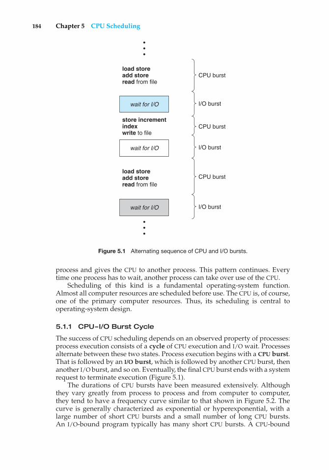
184 Chapter 5 CPU Scheduling
CPU burstload storeadd storeread from file
store incrementindexwrite to file
load storeadd storeread from file
wait for I/O
wait for I/O
wait for I/O
I/O burst
I/O burst
I/O burst
CPU burst
CPU burst
•••
•••
Figure 5.1 Alternating sequence of CPU and I/O bursts.
process and gives the CPU to another process. This pattern continues. Everytime one process has to wait, another process can take over use of the CPU.
Scheduling of this kind is a fundamental operating-system function.Almost all computer resources are scheduled before use. The CPU is, of course,one of the primary computer resources. Thus, its scheduling is central tooperating-system design.
5.1.1 CPU–I/O Burst Cycle
The success of CPU scheduling depends on an observed property of processes:process execution consists of a cycle of CPU execution and I/O wait. Processesalternate between these two states. Process execution begins with a CPU burst.That is followed by an I/O burst, which is followed by another CPU burst, thenanother I/O burst, and so on. Eventually, the final CPU burst ends with a systemrequest to terminate execution (Figure 5.1).
The durations of CPU bursts have been measured extensively. Althoughthey vary greatly from process to process and from computer to computer,they tend to have a frequency curve similar to that shown in Figure 5.2. Thecurve is generally characterized as exponential or hyperexponential, with alarge number of short CPU bursts and a small number of long CPU bursts.An I/O-bound program typically has many short CPU bursts. A CPU-bound
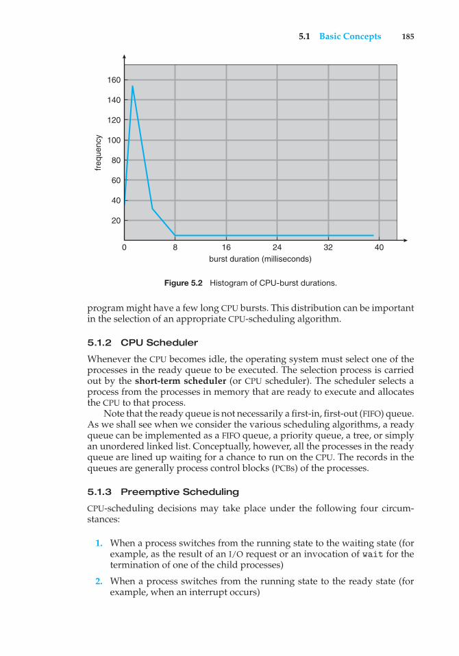
5.1 Basic Concepts 185
freq
uenc
y
160
140
120
100
80
60
40
20
0 8 16 24 32 40burst duration (milliseconds)
Figure 5.2 Histogram of CPU-burst durations.
program might have a few long CPU bursts. This distribution can be importantin the selection of an appropriate CPU-scheduling algorithm.
5.1.2 CPU Scheduler
Whenever the CPU becomes idle, the operating system must select one of theprocesses in the ready queue to be executed. The selection process is carriedout by the short-term scheduler (or CPU scheduler). The scheduler selects aprocess from the processes in memory that are ready to execute and allocatesthe CPU to that process.
Note that the ready queue is not necessarily a first-in, first-out (FIFO) queue.As we shall see when we consider the various scheduling algorithms, a readyqueue can be implemented as a FIFO queue, a priority queue, a tree, or simplyan unordered linked list. Conceptually, however, all the processes in the readyqueue are lined up waiting for a chance to run on the CPU. The records in thequeues are generally process control blocks (PCBs) of the processes.
5.1.3 Preemptive Scheduling
CPU-scheduling decisions may take place under the following four circum-stances:
1. When a process switches from the running state to the waiting state (forexample, as the result of an I/O request or an invocation of wait for thetermination of one of the child processes)
2. When a process switches from the running state to the ready state (forexample, when an interrupt occurs)
186 Chapter 5 CPU Scheduling
3. When a process switches from the waiting state to the ready state (forexample, at completion of I/O)
4. When a process terminates
For situations 1 and 4, there is no choice in terms of scheduling. A new process(if one exists in the ready queue) must be selected for execution. There is achoice, however, for situations 2 and 3.
When scheduling takes place only under circumstances 1 and 4, we saythat the scheduling scheme is nonpreemptive or cooperative; otherwise, itis preemptive. Under nonpreemptive scheduling, once the CPU has beenallocated to a process, the process keeps the CPU until it releases the CPU eitherby terminating or by switching to the waiting state. This scheduling methodwas used by Microsoft Windows 3.x; Windows 95 introduced preemptivescheduling, and all subsequent versions of Windows operating systems haveused preemptive scheduling. The Mac OS X operating system for the Macintoshalso uses preemptive scheduling; previous versions of the Macintosh operatingsystem relied on cooperative scheduling. Cooperative scheduling is the onlymethod that can be used on certain hardware platforms, because it does notrequire the special hardware (for example, a timer) needed for preemptivescheduling.
Unfortunately, preemptive scheduling incurs a cost associated with accessto shared data. Consider the case of two processes that share data. While oneis updating the data, it is preempted so that the second process can run. Thesecond process then tries to read the data, which are in an inconsistent state. Insuch situations, we need new mechanisms to coordinate access to shared data;we discuss this topic in Chapter 6.
Preemption also affects the design of the operating-system kernel. Duringthe processing of a system call, the kernel may be busy with an activity onbehalf of a process. Such activities may involve changing important kerneldata (for instance, I/O queues). What happens if the process is preempted inthe middle of these changes and the kernel (or the device driver) needs toread or modify the same structure? Chaos ensues. Certain operating systems,including most versions of UNIX, deal with this problem by waiting eitherfor a system call to complete or for an I/O block to take place before doing acontext switch. This scheme ensures that the kernel structure is simple, sincethe kernel will not preempt a process while the kernel data structures are inan inconsistent state. Unfortunately, this kernel-execution model is a poor onefor supporting real-time computing and multiprocessing. These problems, andtheir solutions, are described in Sections 5.5 and 19.5.
Because interrupts can, by definition, occur at any time, and becausethey cannot always be ignored by the kernel, the sections of code affectedby interrupts must be guarded from simultaneous use. The operating systemneeds to accept interrupts at almost all times; otherwise, input might be lost oroutput overwritten. So that these sections of code are not accessed concurrentlyby several processes, they disable interrupts at entry and reenable interruptsat exit. It is important to note that sections of code that disable interrupts donot occur very often and typically contain few instructions.
5.2 Scheduling Criteria 187
5.1.4 Dispatcher
Another component involved in the CPU-scheduling function is the dispatcher.The dispatcher is the module that gives control of the CPU to the process selectedby the short-term scheduler. This function involves the following:
• Switching context
• Switching to user mode
• Jumping to the proper location in the user program to restart that program
The dispatcher should be as fast as possible, since it is invoked during everyprocess switch. The time it takes for the dispatcher to stop one process andstart another running is known as the dispatch latency.
5.2 Scheduling Criteria
Different CPU-scheduling algorithms have different properties, and the choiceof a particular algorithm may favor one class of processes over another. Inchoosing which algorithm to use in a particular situation, we must considerthe properties of the various algorithms.
Many criteria have been suggested for comparing CPU-scheduling algo-rithms. Which characteristics are used for comparison can make a substantialdifference in which algorithm is judged to be best. The criteria include thefollowing:
• CPU utilization. We want to keep the CPU as busy as possible. Concep-tually, CPU utilization can range from 0 to 100 percent. In a real system, itshould range from 40 percent (for a lightly loaded system) to 90 percent(for a heavily used system).
• Throughput. If the CPU is busy executing processes, then work is beingdone. One measure of work is the number of processes that are completedper time unit, called throughput. For long processes, this rate may be oneprocess per hour; for short transactions, it may be ten processes per second.
• Turnaround time. From the point of view of a particular process, theimportant criterion is how long it takes to execute that process. The intervalfrom the time of submission of a process to the time of completion is theturnaround time. Turnaround time is the sum of the periods spent waitingto get into memory, waiting in the ready queue, executing on the CPU, anddoing I/O.
• Waiting time. The CPU-scheduling algorithm does not affect the amountof time during which a process executes or does I/O; it affects only theamount of time that a process spends waiting in the ready queue. Waitingtime is the sum of the periods spent waiting in the ready queue.
• Response time. In an interactive system, turnaround time may not bethe best criterion. Often, a process can produce some output fairly earlyand can continue computing new results while previous results are being
188 Chapter 5 CPU Scheduling
output to the user. Thus, another measure is the time from the submissionof a request until the first response is produced. This measure, calledresponse time, is the time it takes to start responding, not the time it takesto output the response. The turnaround time is generally limited by thespeed of the output device.
It is desirable to maximize CPU utilization and throughput and to minimizeturnaround time, waiting time, and response time. In most cases, we optimizethe average measure. However, under some circumstances, it is desirableto optimize the minimum or maximum values rather than the average. Forexample, to guarantee that all users get good service, we may want to minimizethe maximum response time.
Investigators have suggested that, for interactive systems (such as time-sharing systems), it is more important to minimize the variance in the responsetime than to minimize the average response time. A system with reasonableand predictable response time may be considered more desirable than a systemthat is faster on the average but is highly variable. However, little work hasbeen done on CPU-scheduling algorithms that minimize variance.
As we discuss various CPU-scheduling algorithms in the following section,we illustrate their operation. An accurate illustration should involve manyprocesses, each a sequence of several hundred CPU bursts and I/O bursts.For simplicity, though, we consider only one CPU burst (in milliseconds) perprocess in our examples. Our measure of comparison is the average waitingtime. More elaborate evaluation mechanisms are discussed in Section 5.7.
5.3 Scheduling Algorithms
CPU scheduling deals with the problem of deciding which of the processes in theready queue is to be allocated the CPU. There are many different CPU-schedulingalgorithms. In this section, we describe several of them.
5.3.1 First-Come, First-Served Scheduling
By far the simplest CPU-scheduling algorithm is the first-come, first-served(FCFS) scheduling algorithm. With this scheme, the process that requests theCPU first is allocated the CPU first. The implementation of the FCFS policy iseasily managed with a FIFO queue. When a process enters the ready queue, itsPCB is linked onto the tail of the queue. When the CPU is free, it is allocated tothe process at the head of the queue. The running process is then removed fromthe queue. The code for FCFS scheduling is simple to write and understand.
On the negative side, the average waiting time under the FCFS policy isoften quite long. Consider the following set of processes that arrive at time 0,with the length of the CPU burst given in milliseconds:
Process Burst Time
P1 24P2 3P3 3
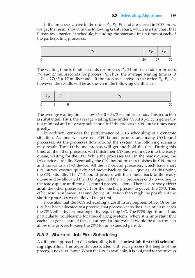
5.3 Scheduling Algorithms 189
If the processes arrive in the order P1, P2, P3, and are served in FCFS order,we get the result shown in the following Gantt chart, which is a bar chart thatillustrates a particular schedule, including the start and finish times of each ofthe participating processes:
P1 P2 P3
3027240
The waiting time is 0 milliseconds for process P1, 24 milliseconds for processP2, and 27 milliseconds for process P3. Thus, the average waiting time is (0+ 24 + 27)/3 = 17 milliseconds. If the processes arrive in the order P2, P3, P1,however, the results will be as shown in the following Gantt chart:
P1P2 P3
300 3 6
The average waiting time is now (6 + 0 + 3)/3 = 3 milliseconds. This reductionis substantial. Thus, the average waiting time under an FCFS policy is generallynot minimal and may vary substantially if the processes CPU burst times varygreatly.
In addition, consider the performance of FCFS scheduling in a dynamicsituation. Assume we have one CPU-bound process and many I/O-boundprocesses. As the processes flow around the system, the following scenariomay result. The CPU-bound process will get and hold the CPU. During thistime, all the other processes will finish their I/O and will move into the readyqueue, waiting for the CPU. While the processes wait in the ready queue, theI/O devices are idle. Eventually, the CPU-bound process finishes its CPU burstand moves to an I/O device. All the I/O-bound processes, which have shortCPU bursts, execute quickly and move back to the I/O queues. At this point,the CPU sits idle. The CPU-bound process will then move back to the readyqueue and be allocated the CPU. Again, all the I/O processes end up waiting inthe ready queue until the CPU-bound process is done. There is a convoy effectas all the other processes wait for the one big process to get off the CPU. Thiseffect results in lower CPU and device utilization than might be possible if theshorter processes were allowed to go first.
Note also that the FCFS scheduling algorithm is nonpreemptive. Once theCPU has been allocated to a process, that process keeps the CPU until it releasesthe CPU, either by terminating or by requesting I/O. The FCFS algorithm is thusparticularly troublesome for time-sharing systems, where it is important thateach user get a share of the CPU at regular intervals. It would be disastrous toallow one process to keep the CPU for an extended period.
5.3.2 Shortest-Job-First Scheduling
A different approach to CPU scheduling is the shortest-job-first (SJF) schedul-ing algorithm. This algorithm associates with each process the length of theprocess’s next CPU burst. When the CPU is available, it is assigned to the process
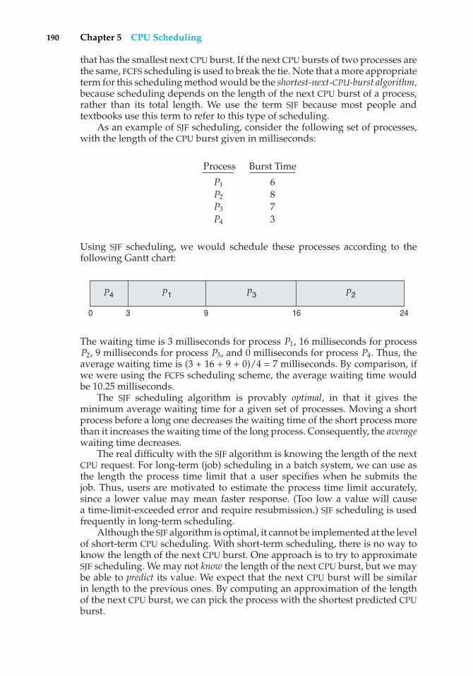
190 Chapter 5 CPU Scheduling
that has the smallest next CPU burst. If the next CPU bursts of two processes arethe same, FCFS scheduling is used to break the tie. Note that a more appropriateterm for this scheduling method would be the shortest-next-CPU-burst algorithm,because scheduling depends on the length of the next CPU burst of a process,rather than its total length. We use the term SJF because most people andtextbooks use this term to refer to this type of scheduling.
As an example of SJF scheduling, consider the following set of processes,with the length of the CPU burst given in milliseconds:
Process Burst Time
P1 6P2 8P3 7P4 3
Using SJF scheduling, we would schedule these processes according to thefollowing Gantt chart:
P3 P2P4 P1
241690 3
The waiting time is 3 milliseconds for process P1, 16 milliseconds for processP2, 9 milliseconds for process P3, and 0 milliseconds for process P4. Thus, theaverage waiting time is (3 + 16 + 9 + 0)/4 = 7 milliseconds. By comparison, ifwe were using the FCFS scheduling scheme, the average waiting time wouldbe 10.25 milliseconds.
The SJF scheduling algorithm is provably optimal, in that it gives theminimum average waiting time for a given set of processes. Moving a shortprocess before a long one decreases the waiting time of the short process morethan it increases the waiting time of the long process. Consequently, the averagewaiting time decreases.
The real difficulty with the SJF algorithm is knowing the length of the nextCPU request. For long-term (job) scheduling in a batch system, we can use asthe length the process time limit that a user specifies when he submits thejob. Thus, users are motivated to estimate the process time limit accurately,since a lower value may mean faster response. (Too low a value will causea time-limit-exceeded error and require resubmission.) SJF scheduling is usedfrequently in long-term scheduling.
Although the SJF algorithm is optimal, it cannot be implemented at the levelof short-term CPU scheduling. With short-term scheduling, there is no way toknow the length of the next CPU burst. One approach is to try to approximateSJF scheduling. We may not know the length of the next CPU burst, but we maybe able to predict its value. We expect that the next CPU burst will be similarin length to the previous ones. By computing an approximation of the lengthof the next CPU burst, we can pick the process with the shortest predicted CPUburst.
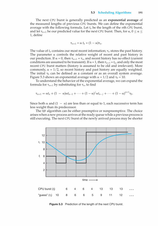
5.3 Scheduling Algorithms 191
The next CPU burst is generally predicted as an exponential average ofthe measured lengths of previous CPU bursts. We can define the exponentialaverage with the following formula. Let tn be the length of the nth CPU burst,and let �n+1 be our predicted value for the next CPU burst. Then, for �, 0 ≤ � ≤1, define
�n+1 = � tn + (1 − �)�n.
The value of tn contains our most recent information; �n stores the past history.The parameter � controls the relative weight of recent and past history inour prediction. If � = 0, then �n+1 = �n, and recent history has no effect (currentconditions are assumed to be transient). If � = 1, then �n+1 = tn, and only the mostrecent CPU burst matters (history is assumed to be old and irrelevant). Morecommonly, � = 1/2, so recent history and past history are equally weighted.The initial �0 can be defined as a constant or as an overall system average.Figure 5.3 shows an exponential average with � = 1/2 and �0 = 10.
To understand the behavior of the exponential average, we can expand theformula for �n+1 by substituting for �n, to find
�n+1 = �tn + (1 − �)�tn−1 + · · · + (1 − �) j �tn− j + · · · + (1 − �)n+1�0.
Since both � and (1 − �) are less than or equal to 1, each successive term hasless weight than its predecessor.
The SJF algorithm can be either preemptive or nonpreemptive. The choicearises when a new process arrives at the ready queue while a previous process isstill executing. The next CPU burst of the newly arrived process may be shorter
6 4 6 4 13 13 13 …810 6 6 5 9 11 12 …
CPU burst (ti)
"guess" (τi)
ti
τi
2
time
4
6
8
10
12
Figure 5.3 Prediction of the length of the next CPU burst.
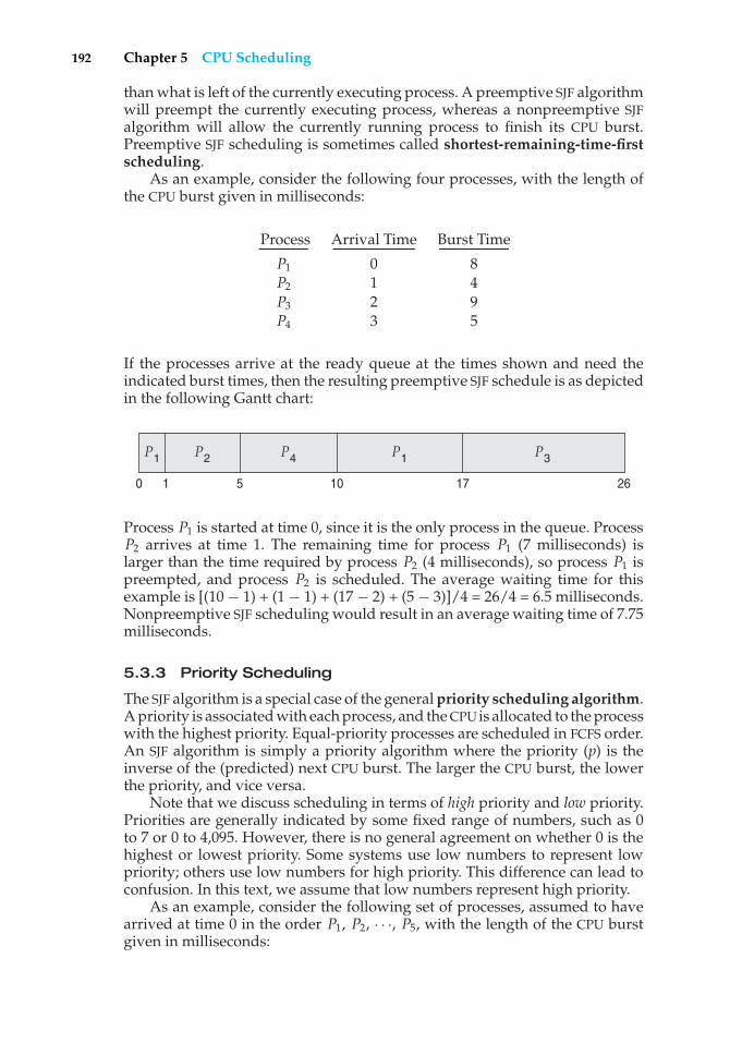
192 Chapter 5 CPU Scheduling
than what is left of the currently executing process. A preemptive SJF algorithmwill preempt the currently executing process, whereas a nonpreemptive SJFalgorithm will allow the currently running process to finish its CPU burst.Preemptive SJF scheduling is sometimes called shortest-remaining-time-firstscheduling.
As an example, consider the following four processes, with the length ofthe CPU burst given in milliseconds:
Process Arrival Time Burst Time
P1 0 8P2 1 4P3 2 9P4 3 5
If the processes arrive at the ready queue at the times shown and need theindicated burst times, then the resulting preemptive SJF schedule is as depictedin the following Gantt chart:
P1 P3P1 P2 P4
2617100 1 5
Process P1 is started at time 0, since it is the only process in the queue. ProcessP2 arrives at time 1. The remaining time for process P1 (7 milliseconds) islarger than the time required by process P2 (4 milliseconds), so process P1 ispreempted, and process P2 is scheduled. The average waiting time for thisexample is [(10 − 1) + (1 − 1) + (17 − 2) + (5 − 3)]/4 = 26/4 = 6.5 milliseconds.Nonpreemptive SJF scheduling would result in an average waiting time of 7.75milliseconds.
5.3.3 Priority Scheduling
The SJF algorithm is a special case of the general priority scheduling algorithm.A priority is associated with each process, and the CPU is allocated to the processwith the highest priority. Equal-priority processes are scheduled in FCFS order.An SJF algorithm is simply a priority algorithm where the priority (p) is theinverse of the (predicted) next CPU burst. The larger the CPU burst, the lowerthe priority, and vice versa.
Note that we discuss scheduling in terms of high priority and low priority.Priorities are generally indicated by some fixed range of numbers, such as 0to 7 or 0 to 4,095. However, there is no general agreement on whether 0 is thehighest or lowest priority. Some systems use low numbers to represent lowpriority; others use low numbers for high priority. This difference can lead toconfusion. In this text, we assume that low numbers represent high priority.
As an example, consider the following set of processes, assumed to havearrived at time 0 in the order P1, P2, · · ·, P5, with the length of the CPU burstgiven in milliseconds:
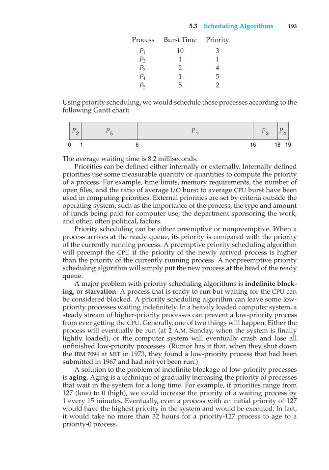
5.3 Scheduling Algorithms 193
Process Burst Time Priority
P1 10 3P2 1 1P3 2 4P4 1 5P5 5 2
Using priority scheduling, we would schedule these processes according to thefollowing Gantt chart:
P1 P4P3P2 P5
19181660 1
The average waiting time is 8.2 milliseconds.Priorities can be defined either internally or externally. Internally defined
priorities use some measurable quantity or quantities to compute the priorityof a process. For example, time limits, memory requirements, the number ofopen files, and the ratio of average I/O burst to average CPU burst have beenused in computing priorities. External priorities are set by criteria outside theoperating system, such as the importance of the process, the type and amountof funds being paid for computer use, the department sponsoring the work,and other, often political, factors.
Priority scheduling can be either preemptive or nonpreemptive. When aprocess arrives at the ready queue, its priority is compared with the priorityof the currently running process. A preemptive priority scheduling algorithmwill preempt the CPU if the priority of the newly arrived process is higherthan the priority of the currently running process. A nonpreemptive priorityscheduling algorithm will simply put the new process at the head of the readyqueue.
A major problem with priority scheduling algorithms is indefinite block-ing, or starvation. A process that is ready to run but waiting for the CPU canbe considered blocked. A priority scheduling algorithm can leave some low-priority processes waiting indefinitely. In a heavily loaded computer system, asteady stream of higher-priority processes can prevent a low-priority processfrom ever getting the CPU. Generally, one of two things will happen. Either theprocess will eventually be run (at 2 A.M. Sunday, when the system is finallylightly loaded), or the computer system will eventually crash and lose allunfinished low-priority processes. (Rumor has it that, when they shut downthe IBM 7094 at MIT in 1973, they found a low-priority process that had beensubmitted in 1967 and had not yet been run.)
A solution to the problem of indefinite blockage of low-priority processesis aging. Aging is a technique of gradually increasing the priority of processesthat wait in the system for a long time. For example, if priorities range from127 (low) to 0 (high), we could increase the priority of a waiting process by1 every 15 minutes. Eventually, even a process with an initial priority of 127would have the highest priority in the system and would be executed. In fact,it would take no more than 32 hours for a priority-127 process to age to apriority-0 process.
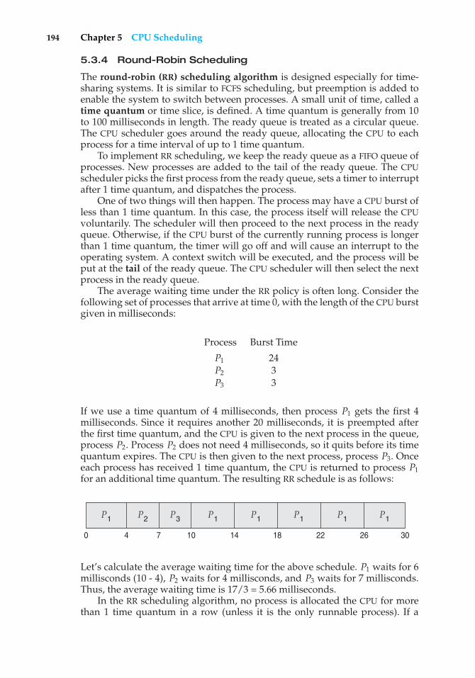
194 Chapter 5 CPU Scheduling
5.3.4 Round-Robin Scheduling
The round-robin (RR) scheduling algorithm is designed especially for time-sharing systems. It is similar to FCFS scheduling, but preemption is added toenable the system to switch between processes. A small unit of time, called atime quantum or time slice, is defined. A time quantum is generally from 10to 100 milliseconds in length. The ready queue is treated as a circular queue.The CPU scheduler goes around the ready queue, allocating the CPU to eachprocess for a time interval of up to 1 time quantum.
To implement RR scheduling, we keep the ready queue as a FIFO queue ofprocesses. New processes are added to the tail of the ready queue. The CPUscheduler picks the first process from the ready queue, sets a timer to interruptafter 1 time quantum, and dispatches the process.
One of two things will then happen. The process may have a CPU burst ofless than 1 time quantum. In this case, the process itself will release the CPUvoluntarily. The scheduler will then proceed to the next process in the readyqueue. Otherwise, if the CPU burst of the currently running process is longerthan 1 time quantum, the timer will go off and will cause an interrupt to theoperating system. A context switch will be executed, and the process will beput at the tail of the ready queue. The CPU scheduler will then select the nextprocess in the ready queue.
The average waiting time under the RR policy is often long. Consider thefollowing set of processes that arrive at time 0, with the length of the CPU burstgiven in milliseconds:
Process Burst Time
P1 24P2 3P3 3
If we use a time quantum of 4 milliseconds, then process P1 gets the first 4milliseconds. Since it requires another 20 milliseconds, it is preempted afterthe first time quantum, and the CPU is given to the next process in the queue,process P2. Process P2 does not need 4 milliseconds, so it quits before its timequantum expires. The CPU is then given to the next process, process P3. Onceeach process has received 1 time quantum, the CPU is returned to process P1for an additional time quantum. The resulting RR schedule is as follows:
P1P1 P1P1P1P1 P2
301814 26221070 4
P3
Let’s calculate the average waiting time for the above schedule. P1 waits for 6millisconds (10 - 4), P2 waits for 4 millisconds, and P3 waits for 7 millisconds.Thus, the average waiting time is 17/3 = 5.66 milliseconds.
In the RR scheduling algorithm, no process is allocated the CPU for morethan 1 time quantum in a row (unless it is the only runnable process). If a
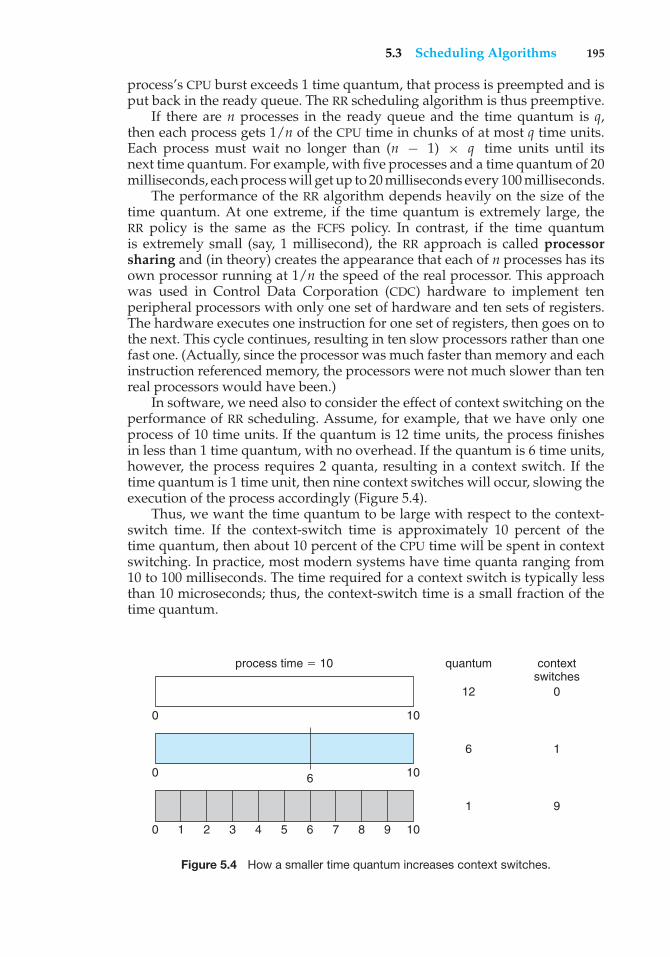
5.3 Scheduling Algorithms 195
process’s CPU burst exceeds 1 time quantum, that process is preempted and isput back in the ready queue. The RR scheduling algorithm is thus preemptive.
If there are n processes in the ready queue and the time quantum is q,then each process gets 1/n of the CPU time in chunks of at most q time units.Each process must wait no longer than (n − 1) × q time units until itsnext time quantum. For example, with five processes and a time quantum of 20milliseconds, each process will get up to 20 milliseconds every 100 milliseconds.
The performance of the RR algorithm depends heavily on the size of thetime quantum. At one extreme, if the time quantum is extremely large, theRR policy is the same as the FCFS policy. In contrast, if the time quantumis extremely small (say, 1 millisecond), the RR approach is called processorsharing and (in theory) creates the appearance that each of n processes has itsown processor running at 1/n the speed of the real processor. This approachwas used in Control Data Corporation (CDC) hardware to implement tenperipheral processors with only one set of hardware and ten sets of registers.The hardware executes one instruction for one set of registers, then goes on tothe next. This cycle continues, resulting in ten slow processors rather than onefast one. (Actually, since the processor was much faster than memory and eachinstruction referenced memory, the processors were not much slower than tenreal processors would have been.)
In software, we need also to consider the effect of context switching on theperformance of RR scheduling. Assume, for example, that we have only oneprocess of 10 time units. If the quantum is 12 time units, the process finishesin less than 1 time quantum, with no overhead. If the quantum is 6 time units,however, the process requires 2 quanta, resulting in a context switch. If thetime quantum is 1 time unit, then nine context switches will occur, slowing theexecution of the process accordingly (Figure 5.4).
Thus, we want the time quantum to be large with respect to the context-switch time. If the context-switch time is approximately 10 percent of thetime quantum, then about 10 percent of the CPU time will be spent in contextswitching. In practice, most modern systems have time quanta ranging from10 to 100 milliseconds. The time required for a context switch is typically lessthan 10 microseconds; thus, the context-switch time is a small fraction of thetime quantum.
process time � 10 quantum contextswitches
12 0
6 1
1 9
0 10
0 10
0 1 2 3 4 5 6 7 8 9 10
6
Figure 5.4 How a smaller time quantum increases context switches.
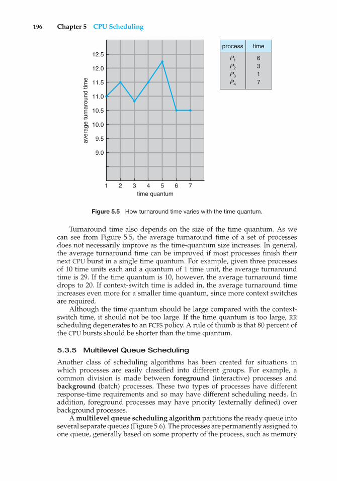
196 Chapter 5 CPU Scheduling
aver
age
turn
arou
nd ti
me
1
12.5
12.0
11.5
11.0
10.5
10.0
9.5
9.0
2 3 4time quantum
5 6 7
P1
P2
P3
P4
6 3 1 7
process time
Figure 5.5 How turnaround time varies with the time quantum.
Turnaround time also depends on the size of the time quantum. As wecan see from Figure 5.5, the average turnaround time of a set of processesdoes not necessarily improve as the time-quantum size increases. In general,the average turnaround time can be improved if most processes finish theirnext CPU burst in a single time quantum. For example, given three processesof 10 time units each and a quantum of 1 time unit, the average turnaroundtime is 29. If the time quantum is 10, however, the average turnaround timedrops to 20. If context-switch time is added in, the average turnaround timeincreases even more for a smaller time quantum, since more context switchesare required.
Although the time quantum should be large compared with the context-switch time, it should not be too large. If the time quantum is too large, RRscheduling degenerates to an FCFS policy. A rule of thumb is that 80 percent ofthe CPU bursts should be shorter than the time quantum.
5.3.5 Multilevel Queue Scheduling
Another class of scheduling algorithms has been created for situations inwhich processes are easily classified into different groups. For example, acommon division is made between foreground (interactive) processes andbackground (batch) processes. These two types of processes have differentresponse-time requirements and so may have different scheduling needs. Inaddition, foreground processes may have priority (externally defined) overbackground processes.
A multilevel queue scheduling algorithm partitions the ready queue intoseveral separate queues (Figure 5.6). The processes are permanently assigned toone queue, generally based on some property of the process, such as memory
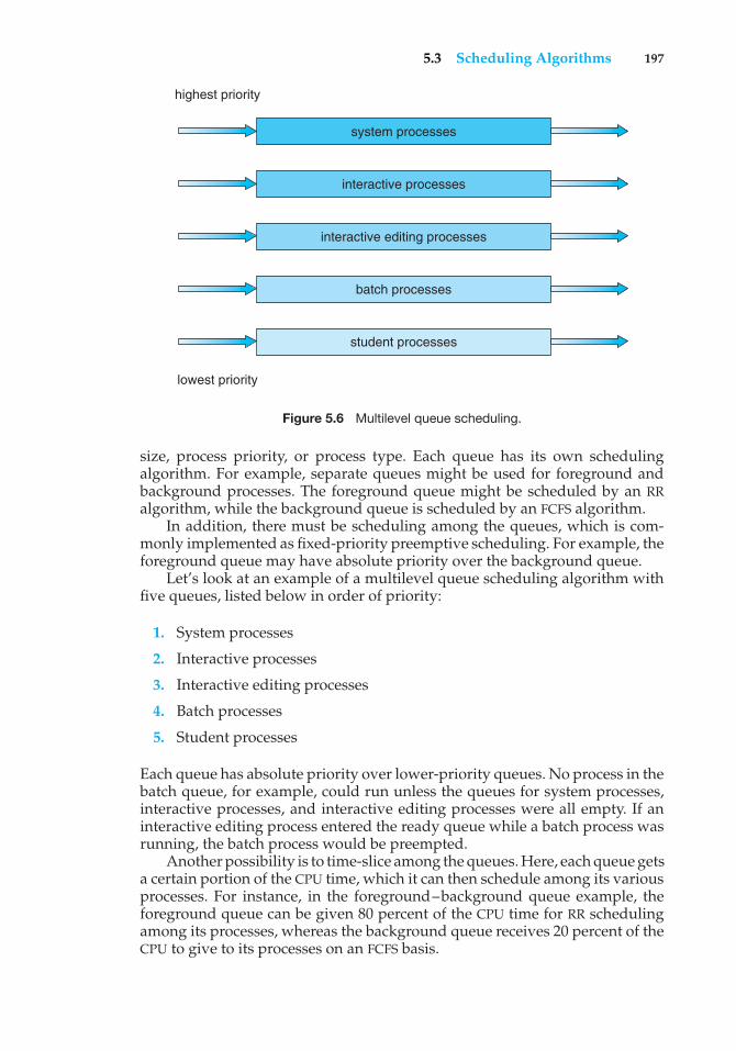
5.3 Scheduling Algorithms 197
system processes
highest priority
lowest priority
interactive processes
interactive editing processes
batch processes
student processes
Figure 5.6 Multilevel queue scheduling.
size, process priority, or process type. Each queue has its own schedulingalgorithm. For example, separate queues might be used for foreground andbackground processes. The foreground queue might be scheduled by an RRalgorithm, while the background queue is scheduled by an FCFS algorithm.
In addition, there must be scheduling among the queues, which is com-monly implemented as fixed-priority preemptive scheduling. For example, theforeground queue may have absolute priority over the background queue.
Let’s look at an example of a multilevel queue scheduling algorithm withfive queues, listed below in order of priority:
1. System processes
2. Interactive processes
3. Interactive editing processes
4. Batch processes
5. Student processes
Each queue has absolute priority over lower-priority queues. No process in thebatch queue, for example, could run unless the queues for system processes,interactive processes, and interactive editing processes were all empty. If aninteractive editing process entered the ready queue while a batch process wasrunning, the batch process would be preempted.
Another possibility is to time-slice among the queues. Here, each queue getsa certain portion of the CPU time, which it can then schedule among its variousprocesses. For instance, in the foreground–background queue example, theforeground queue can be given 80 percent of the CPU time for RR schedulingamong its processes, whereas the background queue receives 20 percent of theCPU to give to its processes on an FCFS basis.
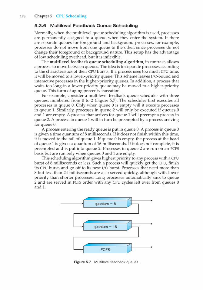
198 Chapter 5 CPU Scheduling
5.3.6 Multilevel Feedback Queue Scheduling
Normally, when the multilevel queue scheduling algorithm is used, processesare permanently assigned to a queue when they enter the system. If thereare separate queues for foreground and background processes, for example,processes do not move from one queue to the other, since processes do notchange their foreground or background nature. This setup has the advantageof low scheduling overhead, but it is inflexible.
The multilevel feedback queue scheduling algorithm, in contrast, allowsa process to move between queues. The idea is to separate processes accordingto the characteristics of their CPU bursts. If a process uses too much CPU time,it will be moved to a lower-priority queue. This scheme leaves I/O-bound andinteractive processes in the higher-priority queues. In addition, a process thatwaits too long in a lower-priority queue may be moved to a higher-priorityqueue. This form of aging prevents starvation.
For example, consider a multilevel feedback queue scheduler with threequeues, numbered from 0 to 2 (Figure 5.7). The scheduler first executes allprocesses in queue 0. Only when queue 0 is empty will it execute processesin queue 1. Similarly, processes in queue 2 will only be executed if queues 0and 1 are empty. A process that arrives for queue 1 will preempt a process inqueue 2. A process in queue 1 will in turn be preempted by a process arrivingfor queue 0.
A process entering the ready queue is put in queue 0. A process in queue 0is given a time quantum of 8 milliseconds. If it does not finish within this time,it is moved to the tail of queue 1. If queue 0 is empty, the process at the headof queue 1 is given a quantum of 16 milliseconds. If it does not complete, it ispreempted and is put into queue 2. Processes in queue 2 are run on an FCFSbasis but are run only when queues 0 and 1 are empty.
This scheduling algorithm gives highest priority to any process with a CPUburst of 8 milliseconds or less. Such a process will quickly get the CPU, finishits CPU burst, and go off to its next I/O burst. Processes that need more than8 but less than 24 milliseconds are also served quickly, although with lowerpriority than shorter processes. Long processes automatically sink to queue2 and are served in FCFS order with any CPU cycles left over from queues 0and 1.
quantum � 8
quantum � 16
FCFS
Figure 5.7 Multilevel feedback queues.
5.4 Thread Scheduling 199
In general, a multilevel feedback queue scheduler is defined by thefollowing parameters:
• The number of queues
• The scheduling algorithm for each queue
• The method used to determine when to upgrade a process to a higher-priority queue
• The method used to determine when to demote a process to a lower-priority queue
• The method used to determine which queue a process will enter when thatprocess needs service
The definition of a multilevel feedback queue scheduler makes it the mostgeneral CPU-scheduling algorithm. It can be configured to match a specificsystem under design. Unfortunately, it is also the most complex algorithm,since defining the best scheduler requires some means by which to selectvalues for all the parameters.
5.4 Thread Scheduling
In Chapter 4, we introduced threads to the process model, distinguishingbetween user-level and kernel-level threads. On operating systems that supportthem, it is kernel-level threads—not processes—that are being scheduled bythe operating system. User-level threads are managed by a thread library,and the kernel is unaware of them. To run on a CPU, user-level threadsmust ultimately be mapped to an associated kernel-level thread, althoughthis mapping may be indirect and may use a lightweight process (LWP). In thissection, we explore scheduling issues involving user-level and kernel-levelthreads and offer specific examples of scheduling for Pthreads.
5.4.1 Contention Scope
One distinction between user-level and kernel-level threads lies in how theyare scheduled. On systems implementing the many-to-one (Section 4.2.1) andmany-to-many (Section 4.2.3) models, the thread library schedules user-levelthreads to run on an available LWP, a scheme known as process-contentionscope (PCS), since competition for the CPU takes place among threads belongingto the same process. When we say the thread library schedules user threads ontoavailable LWPs, we do not mean that the thread is actually running on a CPU;this would require the operating system to schedule the kernel thread ontoa physical CPU. To decide which kernel thread to schedule onto a CPU, thekernel uses system-contention scope (SCS). Competition for the CPU with SCSscheduling takes place among all threads in the system. Systems using theone-to-one model (Section 4.2.2), such as Windows XP, Solaris, and Linux,schedule threads using only SCS.
Typically, PCS is done according to priority—the scheduler selects therunnable thread with the highest priority to run. User-level thread priorities
200 Chapter 5 CPU Scheduling
are set by the programmer and are not adjusted by the thread library, althoughsome thread libraries may allow the programmer to change the priority ofa thread. It is important to note that PCS will typically preempt the threadcurrently running in favor of a higher-priority thread; however, there is noguarantee of time slicing (Section 5.3.4) among threads of equal priority.
5.4.2 Pthread Scheduling
We provided a sample POSIX Pthread program in Section 4.3.1, along with anintroduction to thread creation with Pthreads. Now, we highlight the POSIXPthread API that allows specifying either PCS or SCS during thread creation.Pthreads identifies the following contention scope values:
• PTHREAD SCOPE PROCESS schedules threads using PCS scheduling.
• PTHREAD SCOPE SYSTEM schedules threads using SCS scheduling.
On systems implementing the many-to-many model, thePTHREAD SCOPE PROCESS policy schedules user-level threads onto availableLWPs. The number of LWPs is maintained by the thread library, perhaps usingscheduler activations (Section 4.4.6). The PTHREAD SCOPE SYSTEM schedulingpolicy will create and bind an LWP for each user-level thread on many-to-manysystems, effectively mapping threads using the one-to-one policy.
The Pthread IPC provides two functions for getting—and setting—thecontention scope policy:
• pthread attr setscope(pthread attr t *attr, int scope)
• pthread attr getscope(pthread attr t *attr, int *scope)
The first parameter for both functions contains a pointer to the attribute set forthe thread. The second parameter for the pthread attr setscope() functionis passed either the PTHREAD SCOPE SYSTEM or the PTHREAD SCOPE PROCESSvalue, indicating how the contention scope is to be set. In the case ofpthread attr getscope(), this second parameter contains a pointer to anint value that is set to the current value of the contention scope. If an erroroccurs, each of these functions returns a non-zero value.
In Figure 5.8, we illustrate a Pthread scheduling API. The pro-gram first determines the existing contention scope and sets it toPTHREAD SCOPE PROCESS. It then creates five separate threads that willrun using the SCS scheduling policy. Note that on some systems, only certaincontention scope values are allowed. For example, Linux and Mac OS Xsystems allow only PTHREAD SCOPE SYSTEM.
5.5 Multiple-Processor Scheduling
Our discussion thus far has focused on the problems of scheduling the CPU ina system with a single processor. If multiple CPUs are available, load sharingbecomes possible; however, the scheduling problem becomes correspondingly
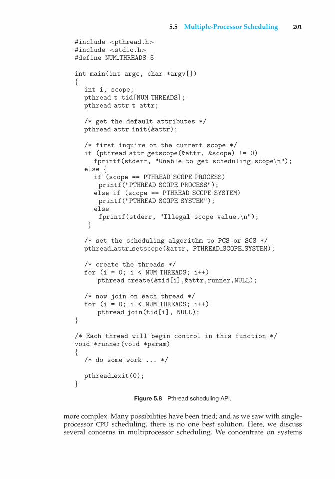
5.5 Multiple-Processor Scheduling 201
#include <pthread.h>#include <stdio.h>#define NUM THREADS 5
int main(int argc, char *argv[]){
int i, scope;pthread t tid[NUM THREADS];pthread attr t attr;
/* get the default attributes */pthread attr init(&attr);
/* first inquire on the current scope */if (pthread attr getscope(&attr, &scope) != 0)
fprintf(stderr, "Unable to get scheduling scope\n");else {
if (scope == PTHREAD SCOPE PROCESS)printf("PTHREAD SCOPE PROCESS");
else if (scope == PTHREAD SCOPE SYSTEM)printf("PTHREAD SCOPE SYSTEM");
elsefprintf(stderr, "Illegal scope value.\n");
}
/* set the scheduling algorithm to PCS or SCS */pthread attr setscope(&attr, PTHREAD SCOPE SYSTEM);
/* create the threads */for (i = 0; i < NUM THREADS; i++)
pthread create(&tid[i],&attr,runner,NULL);
/* now join on each thread */for (i = 0; i < NUM THREADS; i++)
pthread join(tid[i], NULL);}
/* Each thread will begin control in this function */void *runner(void *param){
/* do some work ... */
pthread exit(0);}
Figure 5.8 Pthread scheduling API.
more complex. Many possibilities have been tried; and as we saw with single-processor CPU scheduling, there is no one best solution. Here, we discussseveral concerns in multiprocessor scheduling. We concentrate on systems
202 Chapter 5 CPU Scheduling
in which the processors are identical—homogeneous—in terms of theirfunctionality; we can then use any available processor to run any processin the queue. (Note, however, that even with homogeneous multiprocessors,there are sometimes limitations on scheduling. Consider a system with an I/Odevice attached to a private bus of one processor. Processes that wish to usethat device must be scheduled to run on that processor.)
5.5.1 Approaches to Multiple-Processor Scheduling
One approach to CPU scheduling in a multiprocessor system has all schedulingdecisions, I/O processing, and other system activities handled by a singleprocessor—the master server. The other processors execute only user code.This asymmetric multiprocessing is simple because only one processoraccesses the system data structures, reducing the need for data sharing.
A second approach uses symmetric multiprocessing (SMP), where eachprocessor is self-scheduling. All processes may be in a common ready queue, oreach processor may have its own private queue of ready processes. Regardless,scheduling proceeds by having the scheduler for each processor examine theready queue and select a process to execute. As we shall see in Chapter 6,if we have multiple processors trying to access and update a common datastructure, the scheduler must be programmed carefully. We must ensure thattwo processors do not choose the same process and that processes are not lostfrom the queue. Virtually all modern operating systems support SMP, includingWindows XP, Windows 2000, Solaris, Linux, and Mac OS X. In the remainder ofthis section, we discuss issues concerning SMP systems.
5.5.2 Processor Affinity
Consider what happens to cache memory when a process has been running ona specific processor. The data most recently accessed by the process populatethe cache for the processor; and as a result, successive memory accesses bythe process are often satisfied in cache memory. Now consider what happensif the process migrates to another processor. The contents of cache memorymust be invalidated for the first processor, and the cache for the secondprocessor must be repopulated. Because of the high cost of invalidating andrepopulating caches, most SMP systems try to avoid migration of processesfrom one processor to another and instead attempt to keep a process runningon the same processor. This is known as processor affinity—that is, a processhas an affinity for the processor on which it is currently running.
Processor affinity takes several forms. When an operating system has apolicy of attempting to keep a process running on the same processor—butnot guaranteeing that it will do so—we have a situation known as soft affinity.Here, it is possible for a process to migrate between processors. Some systems—such as Linux—also provide system calls that support hard affinity, therebyallowing a process to specify that it is not to migrate to other processors. Solarisallows processes to be assigned to processor sets, limiting which processes canrun on which CPUs. It also implements soft affinity.
The main-memory architecture of a system can affect processor affinityissues. Figure 5.9 illustrates an architecture featuring non-uniform memoryaccess (NUMA), in which a CPU has faster access to some parts of main memorythan to other parts. Typically, this occurs in systems containing combined CPU
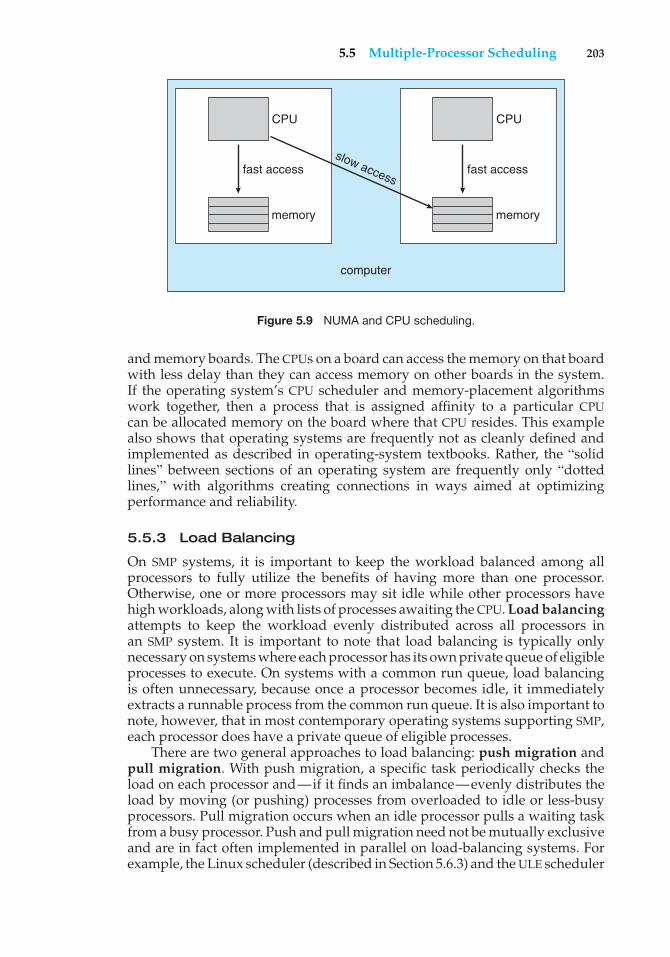
5.5 Multiple-Processor Scheduling 203
CPU
fast access
memory
CPU
fast accessslow access
memory
computer
Figure 5.9 NUMA and CPU scheduling.
and memory boards. The CPUs on a board can access the memory on that boardwith less delay than they can access memory on other boards in the system.If the operating system’s CPU scheduler and memory-placement algorithmswork together, then a process that is assigned affinity to a particular CPUcan be allocated memory on the board where that CPU resides. This examplealso shows that operating systems are frequently not as cleanly defined andimplemented as described in operating-system textbooks. Rather, the “solidlines” between sections of an operating system are frequently only “dottedlines,” with algorithms creating connections in ways aimed at optimizingperformance and reliability.
5.5.3 Load Balancing
On SMP systems, it is important to keep the workload balanced among allprocessors to fully utilize the benefits of having more than one processor.Otherwise, one or more processors may sit idle while other processors havehigh workloads, along with lists of processes awaiting the CPU. Load balancingattempts to keep the workload evenly distributed across all processors inan SMP system. It is important to note that load balancing is typically onlynecessary on systems where each processor has its own private queue of eligibleprocesses to execute. On systems with a common run queue, load balancingis often unnecessary, because once a processor becomes idle, it immediatelyextracts a runnable process from the common run queue. It is also important tonote, however, that in most contemporary operating systems supporting SMP,each processor does have a private queue of eligible processes.
There are two general approaches to load balancing: push migration andpull migration. With push migration, a specific task periodically checks theload on each processor and—if it finds an imbalance—evenly distributes theload by moving (or pushing) processes from overloaded to idle or less-busyprocessors. Pull migration occurs when an idle processor pulls a waiting taskfrom a busy processor. Push and pull migration need not be mutually exclusiveand are in fact often implemented in parallel on load-balancing systems. Forexample, the Linux scheduler (described in Section 5.6.3) and the ULE scheduler
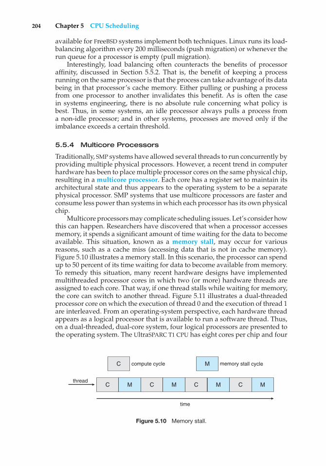
204 Chapter 5 CPU Scheduling
available for FreeBSD systems implement both techniques. Linux runs its load-balancing algorithm every 200 milliseconds (push migration) or whenever therun queue for a processor is empty (pull migration).
Interestingly, load balancing often counteracts the benefits of processoraffinity, discussed in Section 5.5.2. That is, the benefit of keeping a processrunning on the same processor is that the process can take advantage of its databeing in that processor’s cache memory. Either pulling or pushing a processfrom one processor to another invalidates this benefit. As is often the casein systems engineering, there is no absolute rule concerning what policy isbest. Thus, in some systems, an idle processor always pulls a process froma non-idle processor; and in other systems, processes are moved only if theimbalance exceeds a certain threshold.
5.5.4 Multicore Processors
Traditionally, SMP systems have allowed several threads to run concurrently byproviding multiple physical processors. However, a recent trend in computerhardware has been to place multiple processor cores on the same physical chip,resulting in a multicore processor. Each core has a register set to maintain itsarchitectural state and thus appears to the operating system to be a separatephysical processor. SMP systems that use multicore processors are faster andconsume less power than systems in which each processor has its own physicalchip.
Multicore processors may complicate scheduling issues. Let’s consider howthis can happen. Researchers have discovered that when a processor accessesmemory, it spends a significant amount of time waiting for the data to becomeavailable. This situation, known as a memory stall, may occur for variousreasons, such as a cache miss (accessing data that is not in cache memory).Figure 5.10 illustrates a memory stall. In this scenario, the processor can spendup to 50 percent of its time waiting for data to become available from memory.To remedy this situation, many recent hardware designs have implementedmultithreaded processor cores in which two (or more) hardware threads areassigned to each core. That way, if one thread stalls while waiting for memory,the core can switch to another thread. Figure 5.11 illustrates a dual-threadedprocessor core on which the execution of thread 0 and the execution of thread 1are interleaved. From an operating-system perspective, each hardware threadappears as a logical processor that is available to run a software thread. Thus,on a dual-threaded, dual-core system, four logical processors are presented tothe operating system. The UltraSPARC T1 CPU has eight cores per chip and four
time
compute cycle memory stall cycle
threadC
C
M C M C M
M
C M
Figure 5.10 Memory stall.
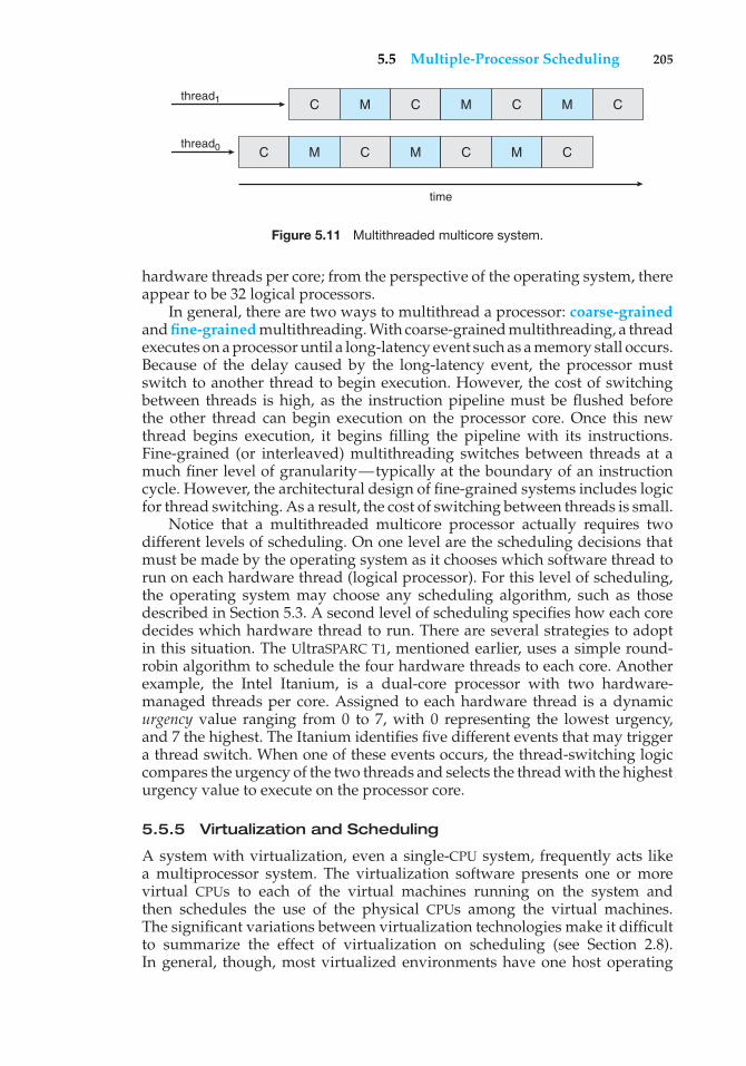
5.5 Multiple-Processor Scheduling 205
time
thread0
thread1
C M C M C M C
C M C M C M C
Figure 5.11 Multithreaded multicore system.
hardware threads per core; from the perspective of the operating system, thereappear to be 32 logical processors.
In general, there are two ways to multithread a processor: coarse-grainedand fine-grained multithreading. With coarse-grained multithreading, a threadexecutes on a processor until a long-latency event such as a memory stall occurs.Because of the delay caused by the long-latency event, the processor mustswitch to another thread to begin execution. However, the cost of switchingbetween threads is high, as the instruction pipeline must be flushed beforethe other thread can begin execution on the processor core. Once this newthread begins execution, it begins filling the pipeline with its instructions.Fine-grained (or interleaved) multithreading switches between threads at amuch finer level of granularity—typically at the boundary of an instructioncycle. However, the architectural design of fine-grained systems includes logicfor thread switching. As a result, the cost of switching between threads is small.
Notice that a multithreaded multicore processor actually requires twodifferent levels of scheduling. On one level are the scheduling decisions thatmust be made by the operating system as it chooses which software thread torun on each hardware thread (logical processor). For this level of scheduling,the operating system may choose any scheduling algorithm, such as thosedescribed in Section 5.3. A second level of scheduling specifies how each coredecides which hardware thread to run. There are several strategies to adoptin this situation. The UltraSPARC T1, mentioned earlier, uses a simple round-robin algorithm to schedule the four hardware threads to each core. Anotherexample, the Intel Itanium, is a dual-core processor with two hardware-managed threads per core. Assigned to each hardware thread is a dynamicurgency value ranging from 0 to 7, with 0 representing the lowest urgency,and 7 the highest. The Itanium identifies five different events that may triggera thread switch. When one of these events occurs, the thread-switching logiccompares the urgency of the two threads and selects the thread with the highesturgency value to execute on the processor core.
5.5.5 Virtualization and Scheduling
A system with virtualization, even a single-CPU system, frequently acts likea multiprocessor system. The virtualization software presents one or morevirtual CPUs to each of the virtual machines running on the system andthen schedules the use of the physical CPUs among the virtual machines.The significant variations between virtualization technologies make it difficultto summarize the effect of virtualization on scheduling (see Section 2.8).In general, though, most virtualized environments have one host operating
206 Chapter 5 CPU Scheduling
system and many guest operating systems. The host operating system createsand manages the virtual machines, and each virtual machine has a guestoperating system installed and applications running within that guest. Eachguest operating system may be fine-tuned for specific use cases, applications,and users, including time sharing or even real-time operation.
Any guest operating-system scheduling algorithm that assumes a certainamount of progress in a given amount of time will be negatively impacted byvirtualization. Consider a time-sharing operating system that tries to allot 100milliseconds to each time slice to give users a reasonable response time. Withina virtual machine, this operating system is at the mercy of the virtualizationsystem as to what CPU resources it actually receives. A given 100-millisecondtime slice may take much more than 100 milliseconds of virtual CPU time.Depending on how busy the system is, the time slice may take a second or more,resulting in very poor response times for users logged into that virtual machine.The effect on a real-time operating system would be even more catastrophic.
The net effect of such scheduling layering is that individual virtualizedoperating systems receive only a portion of the available CPU cycles, eventhough they believe they are receiving all of the cycles and indeed that theyare scheduling all of those cycles. Commonly, the time-of-day clocks in virtualmachines are incorrect because timers take longer to trigger than they would ondedicated CPUs. Virtualization can thus undo the good scheduling-algorithmefforts of the operating systems within virtual machines.
5.6 Operating System Examples
We turn next to a description of the scheduling policies of the Solaris, WindowsXP, and Linux operating systems. It is important to remember that we aredescribing the scheduling of kernel threads with Solaris and Windows XP.Recall that Linux does not distinguish between processes and threads; thus,we use the term task when discussing the Linux scheduler.
5.6.1 Example: Solaris Scheduling
Solaris uses priority-based thread scheduling where each thread belongs toone of six classes:
1. Time sharing (TS)
2. Interactive (IA)
3. Real time (RT)
4. System (SYS)
5. Fair share (FSS)
6. Fixed priority (FP)
Within each class there are different priorities and different scheduling algo-rithms.
The default scheduling class for a process is time sharing. The schedulingpolicy for the time-sharing class dynamically alters priorities and assigns time
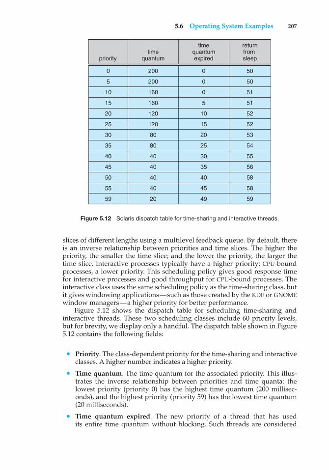
5.6 Operating System Examples 207
timequantumpriority
returnfrom sleep
timequantumexpired
0
5
10
15
20
25
30
35
40
45
50
55
59
200
200
160
160
120
120
80
80
40
40
40
40
20
0
0
0
5
10
15
20
25
30
35
40
45
49
50
50
51
51
52
52
53
54
55
56
58
58
59
Figure 5.12 Solaris dispatch table for time-sharing and interactive threads.
slices of different lengths using a multilevel feedback queue. By default, thereis an inverse relationship between priorities and time slices. The higher thepriority, the smaller the time slice; and the lower the priority, the larger thetime slice. Interactive processes typically have a higher priority; CPU-boundprocesses, a lower priority. This scheduling policy gives good response timefor interactive processes and good throughput for CPU-bound processes. Theinteractive class uses the same scheduling policy as the time-sharing class, butit gives windowing applications—such as those created by the KDE or GNOMEwindow managers—a higher priority for better performance.
Figure 5.12 shows the dispatch table for scheduling time-sharing andinteractive threads. These two scheduling classes include 60 priority levels,but for brevity, we display only a handful. The dispatch table shown in Figure5.12 contains the following fields:
• Priority. The class-dependent priority for the time-sharing and interactiveclasses. A higher number indicates a higher priority.
• Time quantum. The time quantum for the associated priority. This illus-trates the inverse relationship between priorities and time quanta: thelowest priority (priority 0) has the highest time quantum (200 millisec-onds), and the highest priority (priority 59) has the lowest time quantum(20 milliseconds).
• Time quantum expired. The new priority of a thread that has usedits entire time quantum without blocking. Such threads are considered
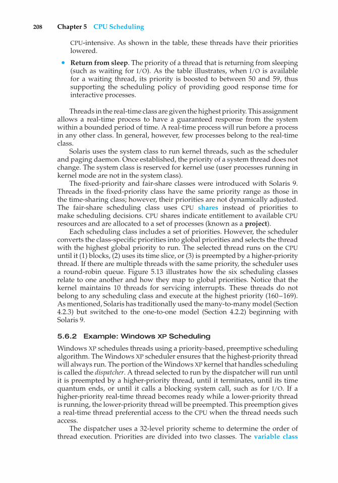
208 Chapter 5 CPU Scheduling
CPU-intensive. As shown in the table, these threads have their prioritieslowered.
• Return from sleep. The priority of a thread that is returning from sleeping(such as waiting for I/O). As the table illustrates, when I/O is availablefor a waiting thread, its priority is boosted to between 50 and 59, thussupporting the scheduling policy of providing good response time forinteractive processes.
Threads in the real-time class are given the highest priority. This assignmentallows a real-time process to have a guaranteed response from the systemwithin a bounded period of time. A real-time process will run before a processin any other class. In general, however, few processes belong to the real-timeclass.
Solaris uses the system class to run kernel threads, such as the schedulerand paging daemon. Once established, the priority of a system thread does notchange. The system class is reserved for kernel use (user processes running inkernel mode are not in the system class).
The fixed-priority and fair-share classes were introduced with Solaris 9.Threads in the fixed-priority class have the same priority range as those inthe time-sharing class; however, their priorities are not dynamically adjusted.The fair-share scheduling class uses CPU shares instead of priorities tomake scheduling decisions. CPU shares indicate entitlement to available CPUresources and are allocated to a set of processes (known as a project).
Each scheduling class includes a set of priorities. However, the schedulerconverts the class-specific priorities into global priorities and selects the threadwith the highest global priority to run. The selected thread runs on the CPUuntil it (1) blocks, (2) uses its time slice, or (3) is preempted by a higher-prioritythread. If there are multiple threads with the same priority, the scheduler usesa round-robin queue. Figure 5.13 illustrates how the six scheduling classesrelate to one another and how they map to global priorities. Notice that thekernel maintains 10 threads for servicing interrupts. These threads do notbelong to any scheduling class and execute at the highest priority (160–169).As mentioned, Solaris has traditionally used the many-to-many model (Section4.2.3) but switched to the one-to-one model (Section 4.2.2) beginning withSolaris 9.
5.6.2 Example: Windows XP Scheduling
Windows XP schedules threads using a priority-based, preemptive schedulingalgorithm. The Windows XP scheduler ensures that the highest-priority threadwill always run. The portion of the Windows XP kernel that handles schedulingis called the dispatcher. A thread selected to run by the dispatcher will run untilit is preempted by a higher-priority thread, until it terminates, until its timequantum ends, or until it calls a blocking system call, such as for I/O. If ahigher-priority real-time thread becomes ready while a lower-priority threadis running, the lower-priority thread will be preempted. This preemption givesa real-time thread preferential access to the CPU when the thread needs suchaccess.
The dispatcher uses a 32-level priority scheme to determine the order ofthread execution. Priorities are divided into two classes. The variable class
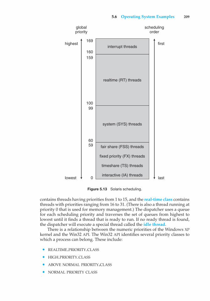
5.6 Operating System Examples 209
interrupt threads
169highest
lowest
first
schedulingorder
globalpriority
last
160159
100
6059
0
99
realtime (RT) threads
system (SYS) threads
fair share (FSS) threads
fixed priority (FX) threads
timeshare (TS) threads
interactive (IA) threads
Figure 5.13 Solaris scheduling.
contains threads having priorities from 1 to 15, and the real-time class containsthreads with priorities ranging from 16 to 31. (There is also a thread running atpriority 0 that is used for memory management.) The dispatcher uses a queuefor each scheduling priority and traverses the set of queues from highest tolowest until it finds a thread that is ready to run. If no ready thread is found,the dispatcher will execute a special thread called the idle thread.
There is a relationship between the numeric priorities of the Windows XPkernel and the Win32 API. The Win32 API identifies several priority classes towhich a process can belong. These include:
• REALTIME PRIORITY CLASS
• HIGH PRIORITY CLASS
• ABOVE NORMAL PRIORITY CLASS
• NORMAL PRIORITY CLASS
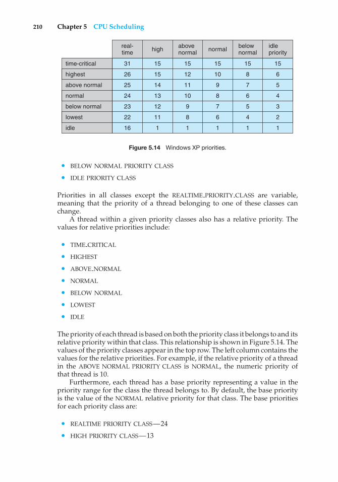
210 Chapter 5 CPU Scheduling
high abovenormal normal below
normalidlepriority
time-critical
real-time
31
26
25
24
23
22
16
15
15
14
13
12
11
1
15
12
11
10
9
8
1
15
10
9
8
7
6
1
15
8
7
6
5
4
1
15
6
5
4
3
2
1
highest
above normal
normal
lowest
idle
below normal
Figure 5.14 Windows XP priorities.
• BELOW NORMAL PRIORITY CLASS
• IDLE PRIORITY CLASS
Priorities in all classes except the REALTIME PRIORITY CLASS are variable,meaning that the priority of a thread belonging to one of these classes canchange.
A thread within a given priority classes also has a relative priority. Thevalues for relative priorities include:
• TIME CRITICAL
• HIGHEST
• ABOVE NORMAL
• NORMAL
• BELOW NORMAL
• LOWEST
• IDLE
The priority of each thread is based on both the priority class it belongs to and itsrelative priority within that class. This relationship is shown in Figure 5.14. Thevalues of the priority classes appear in the top row. The left column contains thevalues for the relative priorities. For example, if the relative priority of a threadin the ABOVE NORMAL PRIORITY CLASS is NORMAL, the numeric priority ofthat thread is 10.
Furthermore, each thread has a base priority representing a value in thepriority range for the class the thread belongs to. By default, the base priorityis the value of the NORMAL relative priority for that class. The base prioritiesfor each priority class are:
• REALTIME PRIORITY CLASS—24
• HIGH PRIORITY CLASS—13
5.6 Operating System Examples 211
• ABOVE NORMAL PRIORITY CLASS—10
• NORMAL PRIORITY CLASS—8
• BELOW NORMAL PRIORITY CLASS—6
• IDLE PRIORITY CLASS—4
Processes are typically members of the NORMAL PRIORITY CLASS. A pro-cess belongs to this class unless the parent of the process was of theIDLE PRIORITY CLASS or unless another class was specified when the processwas created. The initial priority of a thread is typically the base priority of theprocess the thread belongs to.
When a thread’s time quantum runs out, that thread is interrupted; if thethread is in the variable-priority class, its priority is lowered. The priority isnever lowered below the base priority, however. Lowering the priority tendsto limit the CPU consumption of compute-bound threads. When a variable-priority thread is released from a wait operation, the dispatcher boosts thepriority. The amount of the boost depends on what the thread was waitingfor; for example, a thread that was waiting for keyboard I/O would get a largeincrease, whereas a thread waiting for a disk operation would get a moderateone. This strategy tends to give good response times to interactive threads thatare using the mouse and windows. It also enables I/O-bound threads to keepthe I/O devices busy while permitting compute-bound threads to use spareCPU cycles in the background. This strategy is used by several time-sharingoperating systems, including UNIX. In addition, the window with which theuser is currently interacting receives a priority boost to enhance its responsetime.
When a user is running an interactive program, the system needs to provideespecially good performance. For this reason, Windows XP has a specialscheduling rule for processes in the NORMAL PRIORITY CLASS. Windows XPdistinguishes between the foreground process that is currently selected on thescreen and the background processes that are not currently selected. When aprocess moves into the foreground, Windows XP increases the schedulingquantum by some factor—typically by 3. This increase gives the foregroundprocess three times longer to run before a time-sharing preemption occurs.
5.6.3 Example: Linux Scheduling
Prior to Version 2.5, the Linux kernel ran a variation of the traditional UNIXscheduling algorithm. Two problems with the traditional UNIX scheduler arethat it does not provide adequate support for SMP systems and that it doesnot scale well as the number of tasks on the system grows. With Version 2.5,the scheduler was overhauled, and the kernel now provides a schedulingalgorithm that runs in constant time—known as O(1)—regardless of thenumber of tasks on the system. The new scheduler also provides increasedsupport for SMP, including processor affinity and load balancing, as well asproviding fairness and support for interactive tasks.
The Linux scheduler is a preemptive, priority-based algorithm with twoseparate priority ranges: a real-time range from 0 to 99 and a nice value rangingfrom 100 to 140. These two ranges map into a global priority scheme whereinnumerically lower values indicate higher priorities.
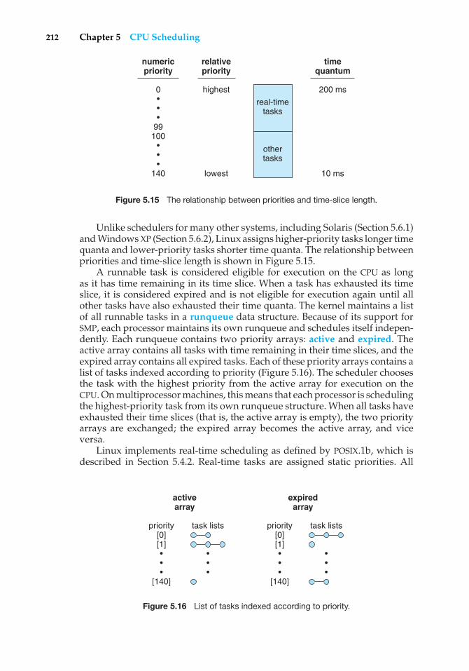
212 Chapter 5 CPU Scheduling
numericpriority
relativepriority
timequantum
0•••
99100
•••
140
highest
lowest
200 ms
10 ms
real-timetasks
othertasks
Figure 5.15 The relationship between priorities and time-slice length.
Unlike schedulers for many other systems, including Solaris (Section 5.6.1)and Windows XP (Section 5.6.2), Linux assigns higher-priority tasks longer timequanta and lower-priority tasks shorter time quanta. The relationship betweenpriorities and time-slice length is shown in Figure 5.15.
A runnable task is considered eligible for execution on the CPU as longas it has time remaining in its time slice. When a task has exhausted its timeslice, it is considered expired and is not eligible for execution again until allother tasks have also exhausted their time quanta. The kernel maintains a listof all runnable tasks in a runqueue data structure. Because of its support forSMP, each processor maintains its own runqueue and schedules itself indepen-dently. Each runqueue contains two priority arrays: active and expired. Theactive array contains all tasks with time remaining in their time slices, and theexpired array contains all expired tasks. Each of these priority arrays contains alist of tasks indexed according to priority (Figure 5.16). The scheduler choosesthe task with the highest priority from the active array for execution on theCPU. On multiprocessor machines, this means that each processor is schedulingthe highest-priority task from its own runqueue structure. When all tasks haveexhausted their time slices (that is, the active array is empty), the two priorityarrays are exchanged; the expired array becomes the active array, and viceversa.
Linux implements real-time scheduling as defined by POSIX.1b, which isdescribed in Section 5.4.2. Real-time tasks are assigned static priorities. All
activearray
priority[0][1]•••
[140]
task lists
•••
expiredarray
priority[0][1]•••
[140]
task lists
•••
Figure 5.16 List of tasks indexed according to priority.
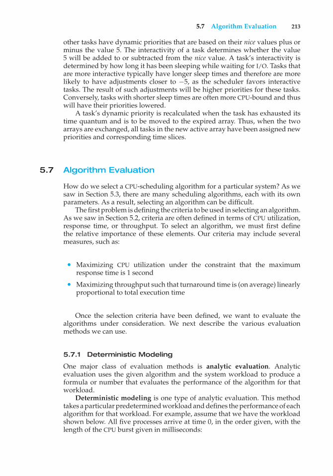
5.7 Algorithm Evaluation 213
other tasks have dynamic priorities that are based on their nice values plus orminus the value 5. The interactivity of a task determines whether the value5 will be added to or subtracted from the nice value. A task’s interactivity isdetermined by how long it has been sleeping while waiting for I/O. Tasks thatare more interactive typically have longer sleep times and therefore are morelikely to have adjustments closer to −5, as the scheduler favors interactivetasks. The result of such adjustments will be higher priorities for these tasks.Conversely, tasks with shorter sleep times are often more CPU-bound and thuswill have their priorities lowered.
A task’s dynamic priority is recalculated when the task has exhausted itstime quantum and is to be moved to the expired array. Thus, when the twoarrays are exchanged, all tasks in the new active array have been assigned newpriorities and corresponding time slices.
5.7 Algorithm Evaluation
How do we select a CPU-scheduling algorithm for a particular system? As wesaw in Section 5.3, there are many scheduling algorithms, each with its ownparameters. As a result, selecting an algorithm can be difficult.
The first problem is defining the criteria to be used in selecting an algorithm.As we saw in Section 5.2, criteria are often defined in terms of CPU utilization,response time, or throughput. To select an algorithm, we must first definethe relative importance of these elements. Our criteria may include severalmeasures, such as:
• Maximizing CPU utilization under the constraint that the maximumresponse time is 1 second
• Maximizing throughput such that turnaround time is (on average) linearlyproportional to total execution time
Once the selection criteria have been defined, we want to evaluate thealgorithms under consideration. We next describe the various evaluationmethods we can use.
5.7.1 Deterministic Modeling
One major class of evaluation methods is analytic evaluation. Analyticevaluation uses the given algorithm and the system workload to produce aformula or number that evaluates the performance of the algorithm for thatworkload.
Deterministic modeling is one type of analytic evaluation. This methodtakes a particular predetermined workload and defines the performance of eachalgorithm for that workload. For example, assume that we have the workloadshown below. All five processes arrive at time 0, in the order given, with thelength of the CPU burst given in milliseconds:
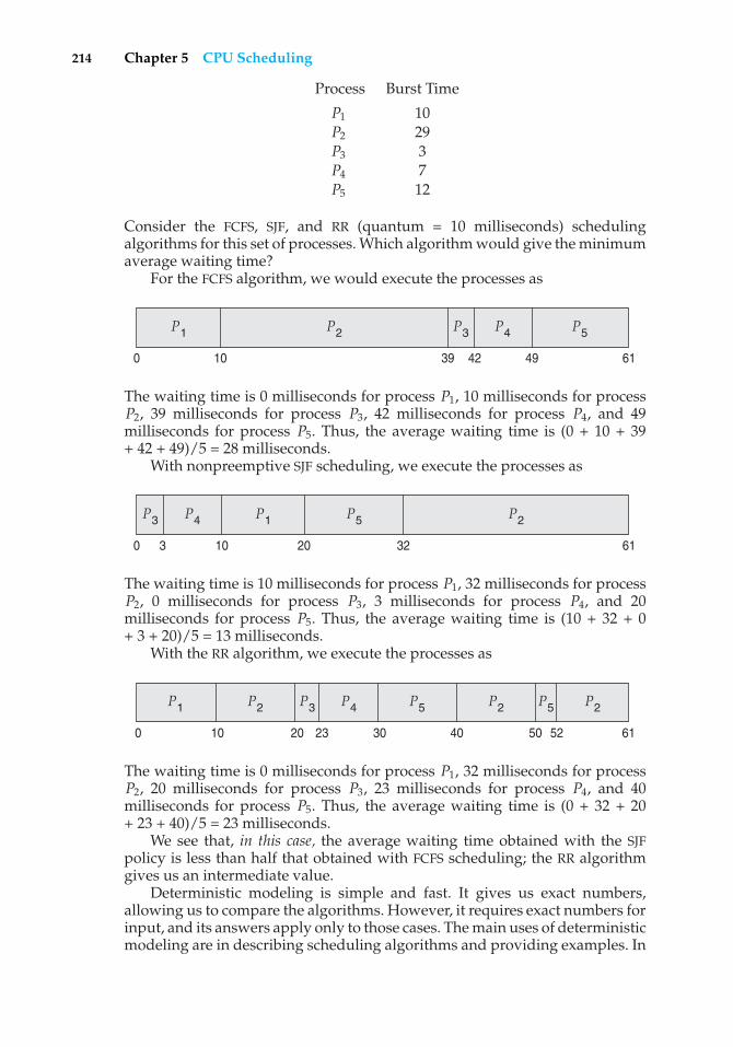
214 Chapter 5 CPU Scheduling
Process Burst Time
P1 10P2 29P3 3P4 7P5 12
Consider the FCFS, SJF, and RR (quantum = 10 milliseconds) schedulingalgorithms for this set of processes. Which algorithm would give the minimumaverage waiting time?
For the FCFS algorithm, we would execute the processes as
P2 P5P3 P4P1
6139 49420 10
The waiting time is 0 milliseconds for process P1, 10 milliseconds for processP2, 39 milliseconds for process P3, 42 milliseconds for process P4, and 49milliseconds for process P5. Thus, the average waiting time is (0 + 10 + 39+ 42 + 49)/5 = 28 milliseconds.
With nonpreemptive SJF scheduling, we execute the processes as
P5 P2P3 P4
613220100 3
P1
The waiting time is 10 milliseconds for process P1, 32 milliseconds for processP2, 0 milliseconds for process P3, 3 milliseconds for process P4, and 20milliseconds for process P5. Thus, the average waiting time is (10 + 32 + 0+ 3 + 20)/5 = 13 milliseconds.
With the RR algorithm, we execute the processes as
P5 P5 P2P2 P2P3 P4
6130 40 50 5220 23100
P1
The waiting time is 0 milliseconds for process P1, 32 milliseconds for processP2, 20 milliseconds for process P3, 23 milliseconds for process P4, and 40milliseconds for process P5. Thus, the average waiting time is (0 + 32 + 20+ 23 + 40)/5 = 23 milliseconds.
We see that, in this case, the average waiting time obtained with the SJFpolicy is less than half that obtained with FCFS scheduling; the RR algorithmgives us an intermediate value.
Deterministic modeling is simple and fast. It gives us exact numbers,allowing us to compare the algorithms. However, it requires exact numbers forinput, and its answers apply only to those cases. The main uses of deterministicmodeling are in describing scheduling algorithms and providing examples. In
5.7 Algorithm Evaluation 215
cases where we are running the same program over and over again and canmeasure the program’s processing requirements exactly, we may be able to usedeterministic modeling to select a scheduling algorithm. Furthermore, over aset of examples, deterministic modeling may indicate trends that can then beanalyzed and proved separately. For example, it can be shown that, for theenvironment described (all processes and their times available at time 0), theSJF policy will always result in the minimum waiting time.
5.7.2 Queueing Models
On many systems, the processes that are run vary from day to day, so thereis no static set of processes (or times) to use for deterministic modeling. Whatcan be determined, however, is the distribution of CPU and I/O bursts. Thesedistributions can be measured and then approximated or simply estimated. Theresult is a mathematical formula describing the probability of a particular CPUburst. Commonly, this distribution is exponential and is described by its mean.Similarly, we can describe the distribution of times when processes arrive inthe system (the arrival-time distribution). From these two distributions, it ispossible to compute the average throughput, utilization, waiting time, and soon for most algorithms.
The computer system is described as a network of servers. Each server hasa queue of waiting processes. The CPU is a server with its ready queue, as isthe I/O system with its device queues. Knowing arrival rates and service rates,we can compute utilization, average queue length, average wait time, and soon. This area of study is called queueing-network analysis.
As an example, let n be the average queue length (excluding the processbeing serviced), let W be the average waiting time in the queue, and let � bethe average arrival rate for new processes in the queue (such as three processesper second). We expect that during the time W that a process waits, � × Wnew processes will arrive in the queue. If the system is in a steady state, thenthe number of processes leaving the queue must be equal to the number ofprocesses that arrive. Thus,
n = � × W.
This equation, known as Little’s formula, is particularly useful because it isvalid for any scheduling algorithm and arrival distribution.
We can use Little’s formula to compute one of the three variables if weknow the other two. For example, if we know that 7 processes arrive everysecond (on average), and that there are normally 14 processes in the queue,then we can compute the average waiting time per process as 2 seconds.
Queueing analysis can be useful in comparing scheduling algorithms,but it also has limitations. At the moment, the classes of algorithms anddistributions that can be handled are fairly limited. The mathematics ofcomplicated algorithms and distributions can be difficult to work with. Thus,arrival and service distributions are often defined in mathematically tractable—but unrealistic—ways. It is also generally necessary to make a number ofindependent assumptions, which may not be accurate. As a result of thesedifficulties, queueing models are often only approximations of real systems,and the accuracy of the computed results may be questionable.
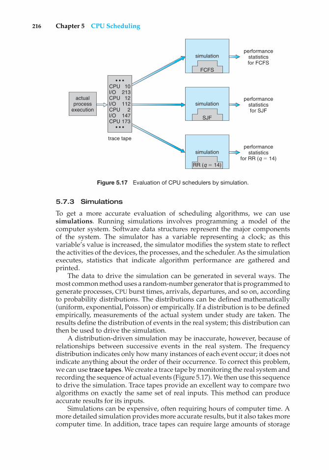
216 Chapter 5 CPU Scheduling
actualprocess
execution
performancestatisticsfor FCFS
simulation
FCFS
performancestatisticsfor SJF
performancestatistics
for RR (q � 14)
trace tape
simulation
SJF
simulation
RR (q � 14)
• • •CPU 10I/O 213 CPU 12 I/O 112 CPU 2 I/O 147 CPU 173
• • •
Figure 5.17 Evaluation of CPU schedulers by simulation.
5.7.3 Simulations
To get a more accurate evaluation of scheduling algorithms, we can usesimulations. Running simulations involves programming a model of thecomputer system. Software data structures represent the major componentsof the system. The simulator has a variable representing a clock; as thisvariable’s value is increased, the simulator modifies the system state to reflectthe activities of the devices, the processes, and the scheduler. As the simulationexecutes, statistics that indicate algorithm performance are gathered andprinted.
The data to drive the simulation can be generated in several ways. Themost common method uses a random-number generator that is programmed togenerate processes, CPU burst times, arrivals, departures, and so on, accordingto probability distributions. The distributions can be defined mathematically(uniform, exponential, Poisson) or empirically. If a distribution is to be definedempirically, measurements of the actual system under study are taken. Theresults define the distribution of events in the real system; this distribution canthen be used to drive the simulation.
A distribution-driven simulation may be inaccurate, however, because ofrelationships between successive events in the real system. The frequencydistribution indicates only how many instances of each event occur; it does notindicate anything about the order of their occurrence. To correct this problem,we can use trace tapes. We create a trace tape by monitoring the real system andrecording the sequence of actual events (Figure 5.17). We then use this sequenceto drive the simulation. Trace tapes provide an excellent way to compare twoalgorithms on exactly the same set of real inputs. This method can produceaccurate results for its inputs.
Simulations can be expensive, often requiring hours of computer time. Amore detailed simulation provides more accurate results, but it also takes morecomputer time. In addition, trace tapes can require large amounts of storage
5.8 Summary 217
space. Finally, the design, coding, and debugging of the simulator can be amajor task.
5.7.4 Implementation
Even a simulation is of limited accuracy. The only completely accurate wayto evaluate a scheduling algorithm is to code it up, put it in the operatingsystem, and see how it works. This approach puts the actual algorithm in thereal system for evaluation under real operating conditions.
The major difficulty with this approach is the high cost. The expense isincurred not only in coding the algorithm and modifying the operating systemto support it (along with its required data structures) but also in the reactionof the users to a constantly changing operating system. Most users are notinterested in building a better operating system; they merely want to get theirprocesses executed and use their results. A constantly changing operatingsystem does not help the users to get their work done.
Another difficulty is that the environment in which the algorithm is usedwill change. The environment will change not only in the usual way, as newprograms are written and the types of problems change, but also as a resultof the performance of the scheduler. If short processes are given priority, thenusers may break larger processes into sets of smaller processes. If interactiveprocesses are given priority over noninteractive processes, then users mayswitch to interactive use.
For example, researchers designed one system that classified interactiveand noninteractive processes automatically by looking at the amount ofterminal I/O. If a process did not input or output to the terminal in a 1-secondinterval, the process was classified as noninteractive and was moved to alower-priority queue. In response to this policy, one programmer modified hisprograms to write an arbitrary character to the terminal at regular intervals ofless than 1 second. The system gave his programs a high priority, even thoughthe terminal output was completely meaningless.
The most flexible scheduling algorithms are those that can be alteredby the system managers or by the users so that they can be tuned fora specific application or set of applications. A workstation that performshigh-end graphical applications, for instance, may have scheduling needsdifferent from those of a Web server or file server. Some operating systems—particularly several versions of UNIX—allow the system manager to fine-tunethe scheduling parameters for a particular system configuration. For example,Solaris provides the dispadmin command to allow the system administratorto modify the parameters of the scheduling classes described in Section 5.6.1.
Another approach is to use APIs that modify the priority of a process orthread. The Java, /POSIX, and /WinAPI/ provide such functions. The downfallof this approach is that performance-tuning a system or application most oftendoes not result in improved performance in more general situations.
5.8 Summary
CPU scheduling is the task of selecting a waiting process from the ready queueand allocating the CPU to it. The CPU is allocated to the selected process by thedispatcher.
218 Chapter 5 CPU Scheduling
First-come, first-served (FCFS) scheduling is the simplest scheduling algo-rithm, but it can cause short processes to wait for very long processes. Shortest-job-first (SJF) scheduling is provably optimal, providing the shortest averagewaiting time. Implementing SJF scheduling is difficult, however, because pre-dicting the length of the next CPU burst is difficult. The SJF algorithm is a specialcase of the general priority scheduling algorithm, which simply allocates theCPU to the highest-priority process. Both priority and SJF scheduling may sufferfrom starvation. Aging is a technique to prevent starvation.
Round-robin (RR) scheduling is more appropriate for a time-shared (inter-active) system. RR scheduling allocates the CPU to the first process in the readyqueue for q time units, where q is the time quantum. After q time units, ifthe process has not relinquished the CPU, it is preempted, and the process isput at the tail of the ready queue. The major problem is the selection of thetime quantum. If the quantum is too large, RR scheduling degenerates to FCFSscheduling; if the quantum is too small, scheduling overhead in the form ofcontext-switch time becomes excessive.
The FCFS algorithm is nonpreemptive; the RR algorithm is preemptive. TheSJF and priority algorithms may be either preemptive or nonpreemptive.
Multilevel queue algorithms allow different algorithms to be used fordifferent classes of processes. The most common model includes a foregroundinteractive queue that uses RR scheduling and a background batch queue thatuses FCFS scheduling. Multilevel feedback queues allow processes to movefrom one queue to another.
Many contemporary computer systems support multiple processors andallow each processor to schedule itself independently. Typically, each processormaintains its own private queue of processes (or threads), all of whichare available to run. Additional issues related to multiprocessor schedulinginclude processor affinity, load balancing, and multicore processing as well asscheduling on virtualization systems.
Operating systems supporting threads at the kernel level must schedulethreads—not processes—for execution. This is the case with Solaris andWindows XP. Both of these systems schedule threads using preemptive,priority-based scheduling algorithms, including support for real-time threads.The Linux process scheduler uses a priority-based algorithm with real-timesupport as well. The scheduling algorithms for these three operating systemstypically favor interactive over batch and CPU-bound processes.
The wide variety of scheduling algorithms demands that we have methodsto select among algorithms. Analytic methods use mathematical analysis todetermine the performance of an algorithm. Simulation methods determineperformance by imitating the scheduling algorithm on a “representative”sample of processes and computing the resulting performance. However, sim-ulation can at best provide an approximation of actual system performance;the only reliable technique for evaluating a scheduling algorithm is to imple-ment the algorithm on an actual system and monitor its performance in a“real-world” environment.
Practice Exercises
5.1 A CPU-scheduling algorithm determines an order for the executionof its scheduled processes. Given n processes to be scheduled on one
Practice Exercises 219
processor, how many different schedules are possible? Give a formulain terms of n.
5.2 Explain the difference between preemptive and nonpreemptive schedul-ing.
5.3 Suppose that the following processes arrive for execution at the timesindicated. Each process will run for the amount of time listed. Inanswering the questions, use nonpreemptive scheduling, and base alldecisions on the information you have at the time the decision must bemade.
Process Arrival Time Burst Time
P1 0.0 8P2 0.4 4P3 1.0 1
a. What is the average turnaround time for these processes with theFCFS scheduling algorithm?
b. What is the average turnaround time for these processes with theSJF scheduling algorithm?
c. The SJF algorithm is supposed to improve performance, but noticethat we chose to run process P1 at time 0 because we did not knowthat two shorter processes would arrive soon. Compute what theaverage turnaround time will be if the CPU is left idle for the first1 unit and then SJF scheduling is used. Remember that processesP1 and P2 are waiting during this idle time, so their waiting timemay increase. This algorithm could be known as future-knowledgescheduling.
5.4 What advantage is there in having different time-quantum sizes atdifferent levels of a multilevel queueing system?
5.5 Many CPU-scheduling algorithms are parameterized. For example, theRR algorithm requires a parameter to indicate the time slice. Multilevelfeedback queues require parameters to define the number of queues, thescheduling algorithm for each queue, the criteria used to move processesbetween queues, and so on.
These algorithms are thus really sets of algorithms (for example, theset of RR algorithms for all time slices, and so on). One set of algorithmsmay include another (for example, the FCFS algorithm is the RR algorithmwith an infinite time quantum). What (if any) relation holds between thefollowing pairs of algorithm sets?
a. Priority and SJF
b. Multilevel feedback queues and FCFS
c. Priority and FCFS
d. RR and SJF
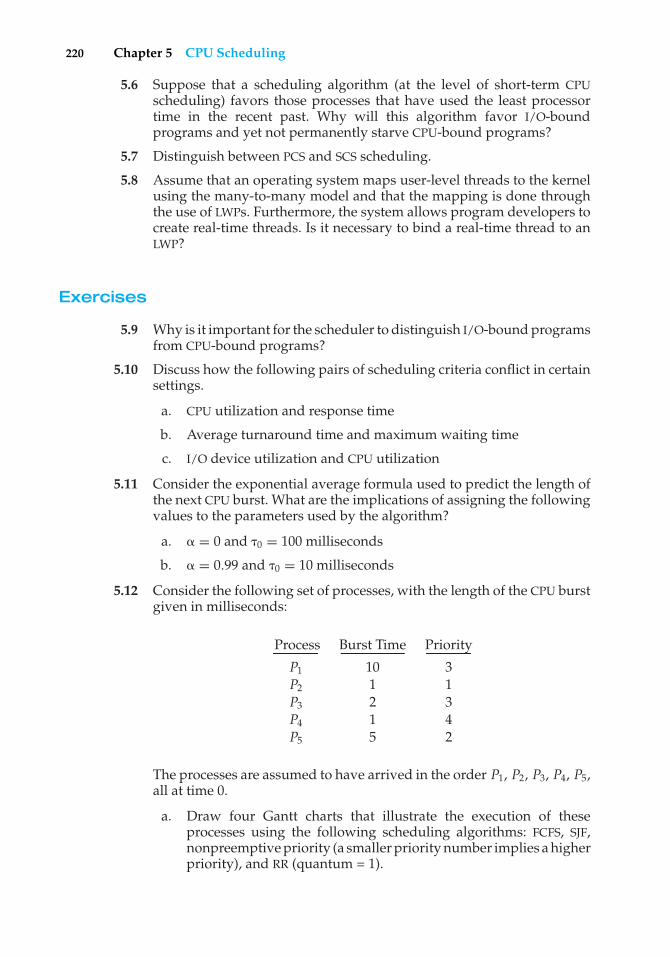
220 Chapter 5 CPU Scheduling
5.6 Suppose that a scheduling algorithm (at the level of short-term CPUscheduling) favors those processes that have used the least processortime in the recent past. Why will this algorithm favor I/O-boundprograms and yet not permanently starve CPU-bound programs?
5.7 Distinguish between PCS and SCS scheduling.
5.8 Assume that an operating system maps user-level threads to the kernelusing the many-to-many model and that the mapping is done throughthe use of LWPs. Furthermore, the system allows program developers tocreate real-time threads. Is it necessary to bind a real-time thread to anLWP?
Exercises
5.9 Why is it important for the scheduler to distinguish I/O-bound programsfrom CPU-bound programs?
5.10 Discuss how the following pairs of scheduling criteria conflict in certainsettings.
a. CPU utilization and response time
b. Average turnaround time and maximum waiting time
c. I/O device utilization and CPU utilization
5.11 Consider the exponential average formula used to predict the length ofthe next CPU burst. What are the implications of assigning the followingvalues to the parameters used by the algorithm?
a. � = 0 and �0 = 100 milliseconds
b. � = 0.99 and �0 = 10 milliseconds
5.12 Consider the following set of processes, with the length of the CPU burstgiven in milliseconds:
Process Burst Time Priority
P1 10 3P2 1 1P3 2 3P4 1 4P5 5 2
The processes are assumed to have arrived in the order P1, P2, P3, P4, P5,all at time 0.
a. Draw four Gantt charts that illustrate the execution of theseprocesses using the following scheduling algorithms: FCFS, SJF,nonpreemptive priority (a smaller priority number implies a higherpriority), and RR (quantum = 1).
Exercises 221
b. What is the turnaround time of each process for each of thescheduling algorithms in part a?
c. What is the waiting time of each process for each of these schedul-ing algorithms?
d. Which of the algorithms results in the minimum average waitingtime (over all processes)?
5.13 Which of the following scheduling algorithms could result in starvation?
a. First-come, first-served
b. Shortest job first
c. Round robin
d. Priority
5.14 Consider a variant of the RR scheduling algorithm in which the entriesin the ready queue are pointers to the PCBs.
a. What would be the effect of putting two pointers to the sameprocess in the ready queue?
b. What would be two major advantages and two disadvantages ofthis scheme?
c. How would you modify the basic RR algorithm to achieve the sameeffect without the duplicate pointers?
5.15 Consider a system running ten I/O-bound tasks and one CPU-boundtask. Assume that the I/O-bound tasks issue an I/O operation once forevery millisecond of CPU computing and that each I/O operation takes10 milliseconds to complete. Also assume that the context-switchingoverhead is 0.1 millisecond and that all processes are long-running tasks.Describe the CPU utilization for a round-robin scheduler when:
a. The time quantum is 1 millisecond
b. The time quantum is 10 milliseconds
5.16 Consider a system implementing multilevel queue scheduling. Whatstrategy can a computer user employ to maximize the amount of CPUtime allocated to the user’s process?
5.17 Consider a preemptive priority scheduling algorithm based on dynami-cally changing priorities. Larger priority numbers imply higher priority.When a process is waiting for the CPU (in the ready queue, but notrunning), its priority changes at a rate �; when it is running, its prioritychanges at a rate �. All processes are given a priority of 0 when theyenter the ready queue. The parameters � and � can be set to give manydifferent scheduling algorithms.
a. What is the algorithm that results from � > � > 0?
b. What is the algorithm that results from � < � < 0?
222 Chapter 5 CPU Scheduling
5.18 Explain the differences in how much the following scheduling algo-rithms discriminate in favor of short processes:
a. FCFS
b. RR
c. Multilevel feedback queues
5.19 Using the Windows XP scheduling algorithm, determine the numericpriority of each of the following threads.
a. A thread in the REALTIME PRIORITY CLASS with a relative priorityof HIGHEST
b. A thread in the NORMAL PRIORITY CLASS with a relative priorityof NORMAL
c. A thread in the HIGH PRIORITY CLASS with a relative priority ofABOVE NORMAL
5.20 Consider the scheduling algorithm in the Solaris operating system fortime-sharing threads.
a. What is the time quantum (in milliseconds) for a thread withpriority 10? With priority 55?
b. Assume that a thread with priority 35 has used its entire timequantum without blocking. What new priority will the schedulerassign this thread?
c. Assume that a thread with priority 35 blocks for I/O before its timequantum has expired. What new priority will the scheduler assignthis thread?
5.21 The traditional UNIX scheduler enforces an inverse relationship betweenpriority numbers and priorities: the higher the number, the lower thepriority. The scheduler recalculates process priorities once per secondusing the following function:
Priority = (recent CPU usage / 2) + base
where base = 60 and recent CPU usage refers to a value indicating howoften a process has used the CPU since priorities were last recalculated.
Assume that recent CPU usage for process P1 is 40, for process P2 is 18,and for process P3 is 10. What will be the new priorities for these threeprocesses when priorities are recalculated? Based on this information,does the traditional UNIX scheduler raise or lower the relative priorityof a CPU-bound process?
Wiley Plus
Visit Wiley Plus for
• Source code
Bibliographical Notes 223
• Solutions to practice exercises
• Additional programming problems and exercises
• Labs using an operating system simulator
Bibliographical Notes
Feedback queues were originally implemented on the CTSS system describedin Corbato et al. [1962]. This feedback queue scheduling system was analyzedby Schrage [1967]. The preemptive priority scheduling algorithm of Exercise5.17 was suggested by Kleinrock [1975].
Anderson et al. [1989], Lewis and Berg [1998], and Philbin et al. [1996]discuss thread scheduling. Multicore scheduling is examined in McNairy andBhatia [2005] and Kongetira et al. [2005].
Scheduling techniques that take into account information regarding pro-cess execution times from previous runs are described in Fisher [1981], Hallet al. [1996], and Lowney et al. [1993].
Fair-share schedulers are covered by Henry [1984], Woodside [1986], andKay and Lauder [1988].
Scheduling policies used in the UNIX V operating system are describedby Bach [1987]; those for UNIX FreeBSD 5.2 are presented by McKusick andNeville-Neil [2005]; and those for the Mach operating system are discussedby Black [1990]. Love [2005] covers scheduling in Linux. Details of the ULEscheduler can be found in Roberson [2003]. Solaris scheduling is describedby Mauro and McDougall [2007]. Solomon [1998], Solomon and Russinovich[2000], and Russinovich and Solomon [2005] discuss scheduling in Windowsinternals. Butenhof [1997] and Lewis and Berg [1998] describe schedulingin Pthreads systems. Siddha et al. [2007] discuss scheduling challenges onmulticore systems.

This page intentionally left blank
6C H A P T E R
ProcessSynchronization
A cooperating process is one that can affect or be affected by other processesexecuting in the system. Cooperating processes can either directly share alogical address space (that is, both code and data) or be allowed to share dataonly through files or messages. The former case is achieved through the use ofthreads, discussed in Chapter 4. Concurrent access to shared data may result indata inconsistency, however. In this chapter, we discuss various mechanismsto ensure the orderly execution of cooperating processes that share a logicaladdress space, so that data consistency is maintained.
CHAPTER OBJECTIVES
• To introduce the critical-section problem, whose solutions can be used toensure the consistency of shared data.
• To present both software and hardware solutions of the critical-sectionproblem.
• To introduce the concept of an atomic transaction and describe mecha-nisms to ensure atomicity.
6.1 Background
In Chapter 3, we developed a model of a system consisting of cooperatingsequential processes or threads, all running asynchronously and possiblysharing data. We illustrated this model with the producer–consumer problem,which is representative of operating systems. Specifically, in Section 3.4.1, wedescribed how a bounded buffer could be used to enable processes to sharememory.
Let’s return to our consideration of the bounded buffer. As we pointedout, our original solution allowed at most BUFFER SIZE − 1 items in the bufferat the same time. Suppose we want to modify the algorithm to remedy thisdeficiency. One possibility is to add an integer variable counter, initialized to0. counter is incremented every time we add a new item to the buffer and is
225
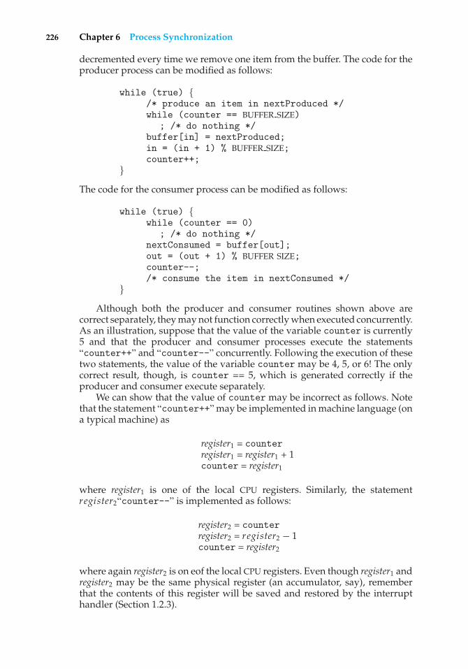
226 Chapter 6 Process Synchronization
decremented every time we remove one item from the buffer. The code for theproducer process can be modified as follows:
while (true) {/* produce an item in nextProduced */while (counter == BUFFER SIZE)
; /* do nothing */buffer[in] = nextProduced;in = (in + 1) % BUFFER SIZE;counter++;
}The code for the consumer process can be modified as follows:
while (true) {while (counter == 0)
; /* do nothing */nextConsumed = buffer[out];out = (out + 1) % BUFFER SIZE;counter--;/* consume the item in nextConsumed */
}Although both the producer and consumer routines shown above are
correct separately, they may not function correctly when executed concurrently.As an illustration, suppose that the value of the variable counter is currently5 and that the producer and consumer processes execute the statements“counter++” and “counter--” concurrently. Following the execution of thesetwo statements, the value of the variable counter may be 4, 5, or 6! The onlycorrect result, though, is counter == 5, which is generated correctly if theproducer and consumer execute separately.
We can show that the value of counter may be incorrect as follows. Notethat the statement “counter++” may be implemented in machine language (ona typical machine) as
register1 = counterregister1 = register1 + 1counter = register1
where register1 is one of the local CPU registers. Similarly, the statementregister2“counter--” is implemented as follows:
register2 = counterregister2 = register2 − 1counter = register2
where again register2 is on eof the local CPU registers. Even though register1 andregister2 may be the same physical register (an accumulator, say), rememberthat the contents of this register will be saved and restored by the interrupthandler (Section 1.2.3).
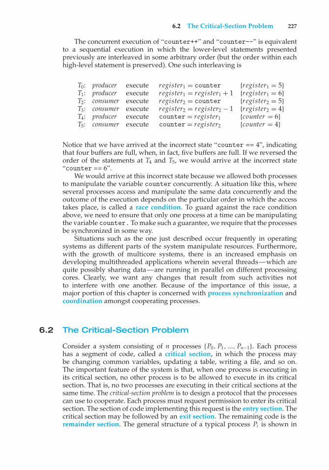
6.2 The Critical-Section Problem 227
The concurrent execution of “counter++” and “counter--” is equivalentto a sequential execution in which the lower-level statements presentedpreviously are interleaved in some arbitrary order (but the order within eachhigh-level statement is preserved). One such interleaving is
T0: producer execute register1 = counter {register1 = 5}T1: producer execute register1 = register1 + 1 {register1 = 6}T2: consumer execute register2 = counter {register2 = 5}T3: consumer execute register2 = register2 − 1 {register2 = 4}T4: producer execute counter = register1 {counter = 6}T5: consumer execute counter = register2 {counter = 4}
Notice that we have arrived at the incorrect state “counter == 4”, indicatingthat four buffers are full, when, in fact, five buffers are full. If we reversed theorder of the statements at T4 and T5, we would arrive at the incorrect state“counter == 6”.
We would arrive at this incorrect state because we allowed both processesto manipulate the variable counter concurrently. A situation like this, whereseveral processes access and manipulate the same data concurrently and theoutcome of the execution depends on the particular order in which the accesstakes place, is called a race condition. To guard against the race conditionabove, we need to ensure that only one process at a time can be manipulatingthe variable counter. To make such a guarantee, we require that the processesbe synchronized in some way.
Situations such as the one just described occur frequently in operatingsystems as different parts of the system manipulate resources. Furthermore,with the growth of multicore systems, there is an increased emphasis ondeveloping multithreaded applications wherein several threads—which arequite possibly sharing data—are running in parallel on different processingcores. Clearly, we want any changes that result from such activities notto interfere with one another. Because of the importance of this issue, amajor portion of this chapter is concerned with process synchronization andcoordination amongst cooperating processes.
6.2 The Critical-Section Problem
Consider a system consisting of n processes {P0, P1, ..., Pn−1}. Each processhas a segment of code, called a critical section, in which the process maybe changing common variables, updating a table, writing a file, and so on.The important feature of the system is that, when one process is executing inits critical section, no other process is to be allowed to execute in its criticalsection. That is, no two processes are executing in their critical sections at thesame time. The critical-section problem is to design a protocol that the processescan use to cooperate. Each process must request permission to enter its criticalsection. The section of code implementing this request is the entry section. Thecritical section may be followed by an exit section. The remaining code is theremainder section. The general structure of a typical process Pi is shown in
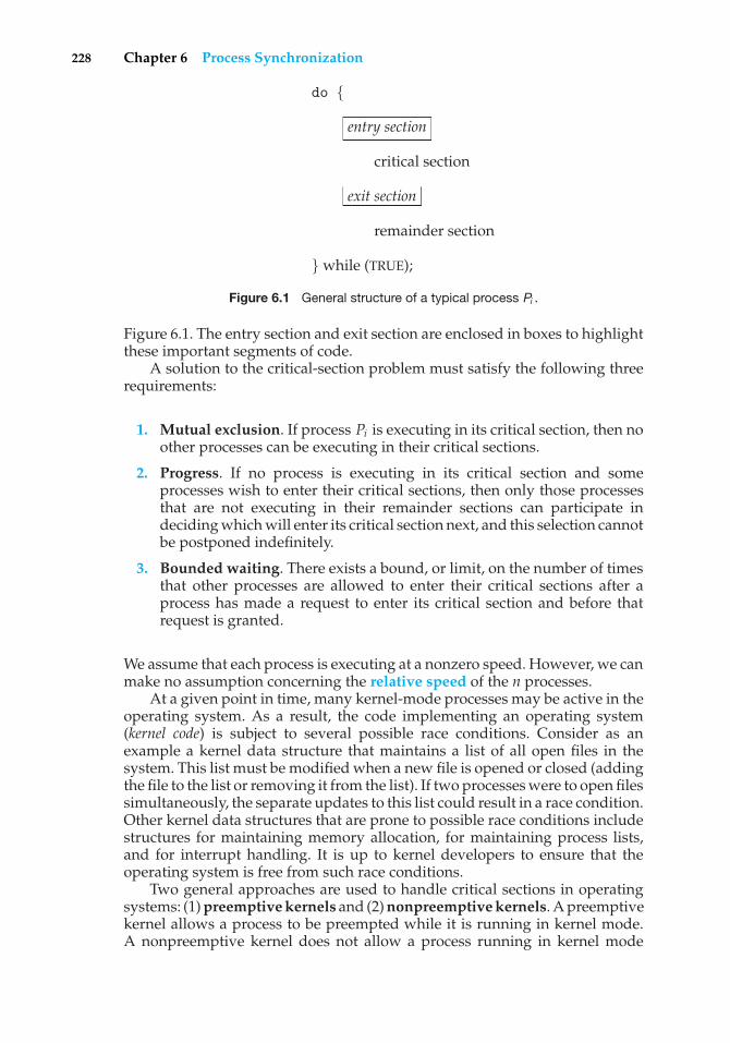
228 Chapter 6 Process Synchronization
do {
entry section
critical section
exit section
remainder section
} while (TRUE);
Figure 6.1 General structure of a typical process Pi .
Figure 6.1. The entry section and exit section are enclosed in boxes to highlightthese important segments of code.
A solution to the critical-section problem must satisfy the following threerequirements:
1. Mutual exclusion. If process Pi is executing in its critical section, then noother processes can be executing in their critical sections.
2. Progress. If no process is executing in its critical section and someprocesses wish to enter their critical sections, then only those processesthat are not executing in their remainder sections can participate indeciding which will enter its critical section next, and this selection cannotbe postponed indefinitely.
3. Bounded waiting. There exists a bound, or limit, on the number of timesthat other processes are allowed to enter their critical sections after aprocess has made a request to enter its critical section and before thatrequest is granted.
We assume that each process is executing at a nonzero speed. However, we canmake no assumption concerning the relative speed of the n processes.
At a given point in time, many kernel-mode processes may be active in theoperating system. As a result, the code implementing an operating system(kernel code) is subject to several possible race conditions. Consider as anexample a kernel data structure that maintains a list of all open files in thesystem. This list must be modified when a new file is opened or closed (addingthe file to the list or removing it from the list). If two processes were to open filessimultaneously, the separate updates to this list could result in a race condition.Other kernel data structures that are prone to possible race conditions includestructures for maintaining memory allocation, for maintaining process lists,and for interrupt handling. It is up to kernel developers to ensure that theoperating system is free from such race conditions.
Two general approaches are used to handle critical sections in operatingsystems: (1) preemptive kernels and (2) nonpreemptive kernels. A preemptivekernel allows a process to be preempted while it is running in kernel mode.A nonpreemptive kernel does not allow a process running in kernel mode
6.3 Peterson’s Solution 229
to be preempted; a kernel-mode process will run until it exits kernel mode,blocks, or voluntarily yields control of the CPU. Obviously, a nonpreemptivekernel is essentially free from race conditions on kernel data structures, as onlyone process is active in the kernel at a time. We cannot say the same aboutpreemptive kernels, so they must be carefully designed to ensure that sharedkernel data are free from race conditions. Preemptive kernels are especiallydifficult to design for SMP architectures, since in these environments it ispossible for two kernel-mode processes to run simultaneously on differentprocessors.
Why, then, would anyone favor a preemptive kernel over a nonpreemptiveone? A preemptive kernel is more suitable for real-time programming, as it willallow a real-time process to preempt a process currently running in the kernel.Furthermore, a preemptive kernel may be more responsive, since there is lessrisk that a kernel-mode process will run for an arbitrarily long period beforerelinquishing the processor to waiting processes. Of course, this effect can beminimized by designing kernel code that does not behave in this way. Later inthis chapter, we explore how various operating systems manage preemptionwithin the kernel.
6.3 Peterson’s Solution
Next, we illustrate a classic software-based solution to the critical-sectionproblem known as Peterson’s solution. Because of the way modern computerarchitectures perform basic machine-language instructions, such as load andstore, there are no guarantees that Peterson’s solution will work correctly onsuch architectures. However, we present the solution because it provides a goodalgorithmic description of solving the critical-section problem and illustratessome of the complexities involved in designing software that addresses therequirements of mutual exclusion, progress, and bounded waiting.
Peterson’s solution is restricted to two processes that alternate executionbetween their critical sections and remainder sections. The processes arenumbered P0 and P1. For convenience, when presenting Pi , we use Pj todenote the other process; that is, j equals 1 − i.
Peterson’s solution requires the two processes to share two data items:
int turn;boolean flag[2];
The variable turn indicates whose turn it is to enter its critical section. That is,if turn == i, then process Pi is allowed to execute in its critical section. Theflag array is used to indicate if a process is ready to enter its critical section.For example, if flag[i] is true, this value indicates that Pi is ready to enterits critical section. With an explanation of these data structures complete, weare now ready to describe the algorithm shown in Figure 6.2.
To enter the critical section, process Pi first sets flag[i] to be true andthen sets turn to the value j, thereby asserting that if the other process wishesto enter the critical section, it can do so. If both processes try to enter at the sametime, turnwill be set to bothi and j at roughly the same time. Only one of theseassignments will last; the other will occur but will be overwritten immediately.
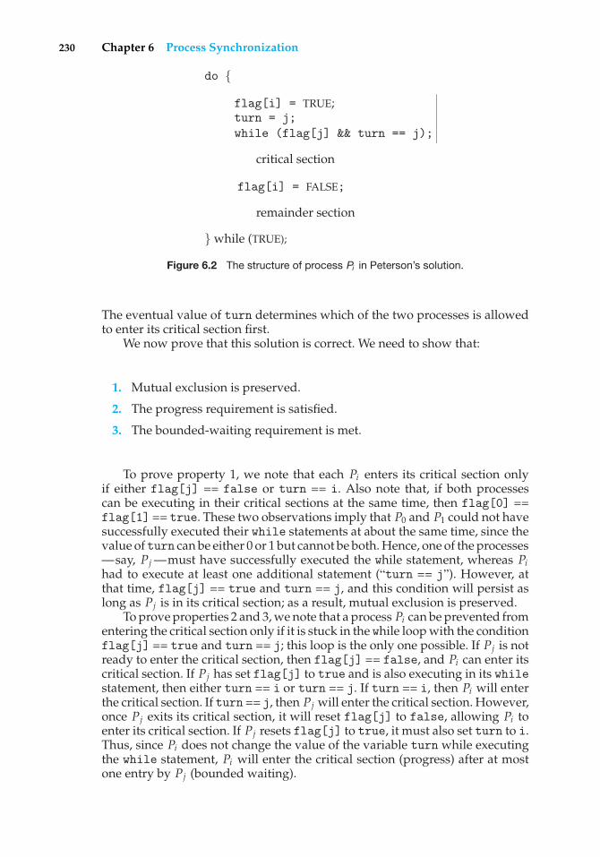
230 Chapter 6 Process Synchronization
do {
flag[i] = TRUE;turn = j;while (flag[j] && turn == j);
critical section
flag[i] = FALSE;
remainder section
} while (TRUE);
Figure 6.2 The structure of process Pi in Peterson’s solution.
The eventual value of turn determines which of the two processes is allowedto enter its critical section first.
We now prove that this solution is correct. We need to show that:
1. Mutual exclusion is preserved.
2. The progress requirement is satisfied.
3. The bounded-waiting requirement is met.
To prove property 1, we note that each Pi enters its critical section onlyif either flag[j] == false or turn == i. Also note that, if both processescan be executing in their critical sections at the same time, then flag[0] ==flag[1] == true. These two observations imply that P0 and P1 could not havesuccessfully executed their while statements at about the same time, since thevalue of turn can be either 0 or 1 but cannot be both. Hence, one of the processes—say, Pj —must have successfully executed the while statement, whereas Pihad to execute at least one additional statement (“turn == j”). However, atthat time, flag[j] == true and turn == j, and this condition will persist aslong as Pj is in its critical section; as a result, mutual exclusion is preserved.
To prove properties 2 and 3, we note that a process Pi can be prevented fromentering the critical section only if it is stuck in the while loop with the conditionflag[j] == true and turn == j; this loop is the only one possible. If Pj is notready to enter the critical section, then flag[j] == false, and Pi can enter itscritical section. If Pj has set flag[j] to true and is also executing in its whilestatement, then either turn == i or turn == j. If turn == i, then Pi will enterthe critical section. If turn == j, then Pj will enter the critical section. However,once Pj exits its critical section, it will reset flag[j] to false, allowing Pi toenter its critical section. If Pj resets flag[j] to true, it must also set turn to i.Thus, since Pi does not change the value of the variable turn while executingthe while statement, Pi will enter the critical section (progress) after at mostone entry by Pj (bounded waiting).
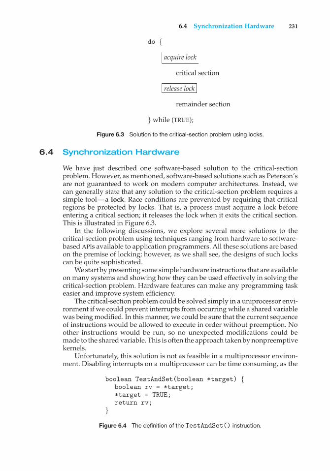
6.4 Synchronization Hardware 231
do {
acquire lock
critical section
release lock
remainder section
} while (TRUE);
Figure 6.3 Solution to the critical-section problem using locks.
6.4 Synchronization Hardware
We have just described one software-based solution to the critical-sectionproblem. However, as mentioned, software-based solutions such as Peterson’sare not guaranteed to work on modern computer architectures. Instead, wecan generally state that any solution to the critical-section problem requires asimple tool—a lock. Race conditions are prevented by requiring that criticalregions be protected by locks. That is, a process must acquire a lock beforeentering a critical section; it releases the lock when it exits the critical section.This is illustrated in Figure 6.3.
In the following discussions, we explore several more solutions to thecritical-section problem using techniques ranging from hardware to software-based APIs available to application programmers. All these solutions are basedon the premise of locking; however, as we shall see, the designs of such lockscan be quite sophisticated.
We start by presenting some simple hardware instructions that are availableon many systems and showing how they can be used effectively in solving thecritical-section problem. Hardware features can make any programming taskeasier and improve system efficiency.
The critical-section problem could be solved simply in a uniprocessor envi-ronment if we could prevent interrupts from occurring while a shared variablewas being modified. In this manner, we could be sure that the current sequenceof instructions would be allowed to execute in order without preemption. Noother instructions would be run, so no unexpected modifications could bemade to the shared variable. This is often the approach taken by nonpreemptivekernels.
Unfortunately, this solution is not as feasible in a multiprocessor environ-ment. Disabling interrupts on a multiprocessor can be time consuming, as the
boolean TestAndSet(boolean *target) {boolean rv = *target;*target = TRUE;return rv;
}
Figure 6.4 The definition of the TestAndSet() instruction.
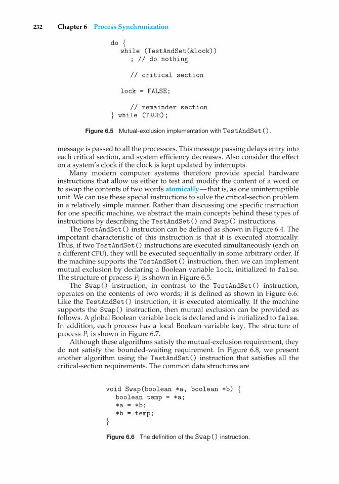
232 Chapter 6 Process Synchronization
do {while (TestAndSet(&lock))
; // do nothing
// critical section
lock = FALSE;
// remainder section} while (TRUE);
Figure 6.5 Mutual-exclusion implementation with TestAndSet().
message is passed to all the processors. This message passing delays entry intoeach critical section, and system efficiency decreases. Also consider the effecton a system’s clock if the clock is kept updated by interrupts.
Many modern computer systems therefore provide special hardwareinstructions that allow us either to test and modify the content of a word orto swap the contents of two words atomically—that is, as one uninterruptibleunit. We can use these special instructions to solve the critical-section problemin a relatively simple manner. Rather than discussing one specific instructionfor one specific machine, we abstract the main concepts behind these types ofinstructions by describing the TestAndSet() and Swap() instructions.
The TestAndSet() instruction can be defined as shown in Figure 6.4. Theimportant characteristic of this instruction is that it is executed atomically.Thus, if two TestAndSet() instructions are executed simultaneously (each ona different CPU), they will be executed sequentially in some arbitrary order. Ifthe machine supports the TestAndSet() instruction, then we can implementmutual exclusion by declaring a Boolean variable lock, initialized to false.The structure of process Pi is shown in Figure 6.5.
The Swap() instruction, in contrast to the TestAndSet() instruction,operates on the contents of two words; it is defined as shown in Figure 6.6.Like the TestAndSet() instruction, it is executed atomically. If the machinesupports the Swap() instruction, then mutual exclusion can be provided asfollows. A global Boolean variable lock is declared and is initialized to false.In addition, each process has a local Boolean variable key. The structure ofprocess Pi is shown in Figure 6.7.
Although these algorithms satisfy the mutual-exclusion requirement, theydo not satisfy the bounded-waiting requirement. In Figure 6.8, we presentanother algorithm using the TestAndSet() instruction that satisfies all thecritical-section requirements. The common data structures are
void Swap(boolean *a, boolean *b) {boolean temp = *a;*a = *b;*b = temp;
}
Figure 6.6 The definition of the Swap() instruction.
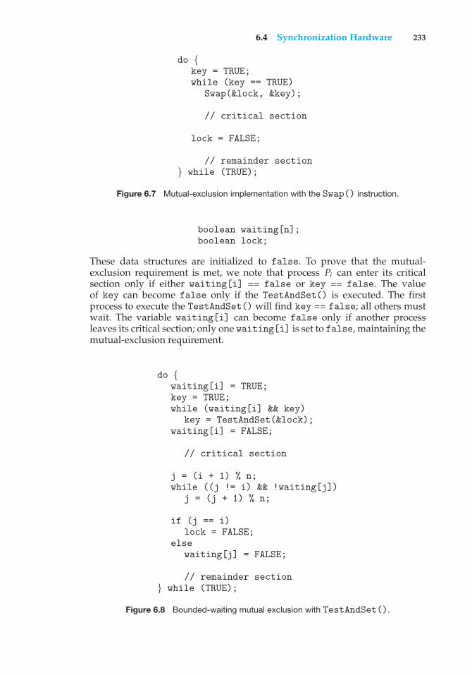
6.4 Synchronization Hardware 233
do {key = TRUE;while (key == TRUE)
Swap(&lock, &key);
// critical section
lock = FALSE;
// remainder section} while (TRUE);
Figure 6.7 Mutual-exclusion implementation with the Swap() instruction.
boolean waiting[n];boolean lock;
These data structures are initialized to false. To prove that the mutual-exclusion requirement is met, we note that process Pi can enter its criticalsection only if either waiting[i] == false or key == false. The valueof key can become false only if the TestAndSet() is executed. The firstprocess to execute the TestAndSet() will find key == false; all others mustwait. The variable waiting[i] can become false only if another processleaves its critical section; only one waiting[i] is set to false, maintaining themutual-exclusion requirement.
do {waiting[i] = TRUE;key = TRUE;while (waiting[i] && key)
key = TestAndSet(&lock);waiting[i] = FALSE;
// critical section
j = (i + 1) % n;while ((j != i) && !waiting[j])
j = (j + 1) % n;
if (j == i)lock = FALSE;
elsewaiting[j] = FALSE;
// remainder section} while (TRUE);
Figure 6.8 Bounded-waiting mutual exclusion with TestAndSet().
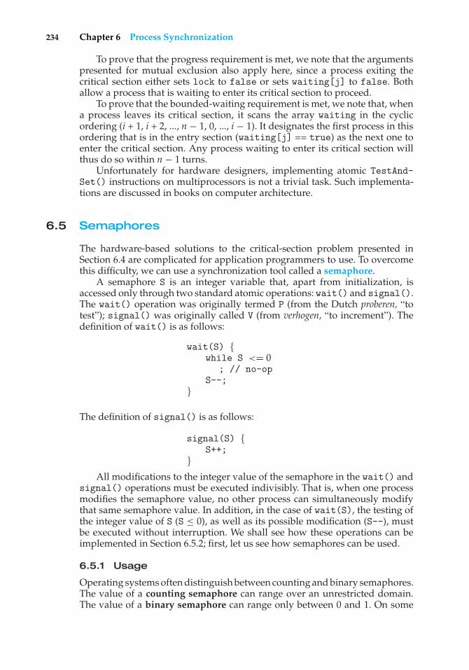
234 Chapter 6 Process Synchronization
To prove that the progress requirement is met, we note that the argumentspresented for mutual exclusion also apply here, since a process exiting thecritical section either sets lock to false or sets waiting[j] to false. Bothallow a process that is waiting to enter its critical section to proceed.
To prove that the bounded-waiting requirement is met, we note that, whena process leaves its critical section, it scans the array waiting in the cyclicordering (i + 1, i + 2, ..., n − 1, 0, ..., i − 1). It designates the first process in thisordering that is in the entry section (waiting[j] == true) as the next one toenter the critical section. Any process waiting to enter its critical section willthus do so within n − 1 turns.
Unfortunately for hardware designers, implementing atomic TestAnd-Set() instructions on multiprocessors is not a trivial task. Such implementa-tions are discussed in books on computer architecture.
6.5 Semaphores
The hardware-based solutions to the critical-section problem presented inSection 6.4 are complicated for application programmers to use. To overcomethis difficulty, we can use a synchronization tool called a semaphore.
A semaphore S is an integer variable that, apart from initialization, isaccessed only through two standard atomic operations: wait() and signal().The wait() operation was originally termed P (from the Dutch proberen, “totest”); signal() was originally called V (from verhogen, “to increment”). Thedefinition of wait() is as follows:
wait(S) {while S <= 0
; // no-opS--;
}
The definition of signal() is as follows:
signal(S) {S++;
}All modifications to the integer value of the semaphore in the wait() and
signal() operations must be executed indivisibly. That is, when one processmodifies the semaphore value, no other process can simultaneously modifythat same semaphore value. In addition, in the case of wait(S), the testing ofthe integer value of S (S ≤ 0), as well as its possible modification (S--), mustbe executed without interruption. We shall see how these operations can beimplemented in Section 6.5.2; first, let us see how semaphores can be used.
6.5.1 Usage
Operating systems often distinguish between counting and binary semaphores.The value of a counting semaphore can range over an unrestricted domain.The value of a binary semaphore can range only between 0 and 1. On some
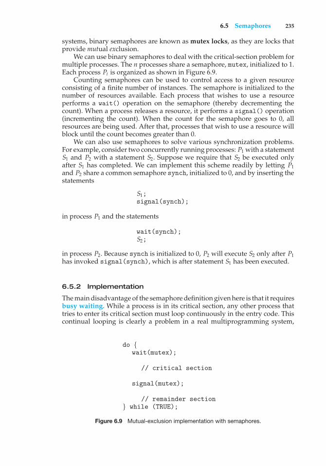
6.5 Semaphores 235
systems, binary semaphores are known as mutex locks, as they are locks thatprovide mutual exclusion.
We can use binary semaphores to deal with the critical-section problem formultiple processes. The n processes share a semaphore, mutex, initialized to 1.Each process Pi is organized as shown in Figure 6.9.
Counting semaphores can be used to control access to a given resourceconsisting of a finite number of instances. The semaphore is initialized to thenumber of resources available. Each process that wishes to use a resourceperforms a wait() operation on the semaphore (thereby decrementing thecount). When a process releases a resource, it performs a signal() operation(incrementing the count). When the count for the semaphore goes to 0, allresources are being used. After that, processes that wish to use a resource willblock until the count becomes greater than 0.
We can also use semaphores to solve various synchronization problems.For example, consider two concurrently running processes: P1 with a statementS1 and P2 with a statement S2. Suppose we require that S2 be executed onlyafter S1 has completed. We can implement this scheme readily by letting P1and P2 share a common semaphore synch, initialized to 0, and by inserting thestatements
S1;signal(synch);
in process P1 and the statements
wait(synch);S2;
in process P2. Because synch is initialized to 0, P2 will execute S2 only after P1has invoked signal(synch), which is after statement S1 has been executed.
6.5.2 Implementation
The main disadvantage of the semaphore definition given here is that it requiresbusy waiting. While a process is in its critical section, any other process thattries to enter its critical section must loop continuously in the entry code. Thiscontinual looping is clearly a problem in a real multiprogramming system,
do {wait(mutex);
// critical section
signal(mutex);
// remainder section} while (TRUE);
Figure 6.9 Mutual-exclusion implementation with semaphores.
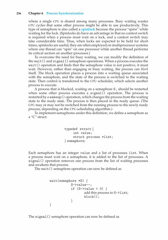
236 Chapter 6 Process Synchronization
where a single CPU is shared among many processes. Busy waiting wastesCPU cycles that some other process might be able to use productively. Thistype of semaphore is also called a spinlock because the process “spins” whilewaiting for the lock. (Spinlocks do have an advantage in that no context switchis required when a process must wait on a lock, and a context switch maytake considerable time. Thus, when locks are expected to be held for shorttimes, spinlocks are useful; they are often employed on multiprocessor systemswhere one thread can “spin” on one processor while another thread performsits critical section on another processor.)
To overcome the need for busy waiting, we can modify the definition ofthe wait() and signal() semaphore operations. When a process executes thewait() operation and finds that the semaphore value is not positive, it mustwait. However, rather than engaging in busy waiting, the process can blockitself. The block operation places a process into a waiting queue associatedwith the semaphore, and the state of the process is switched to the waitingstate. Then control is transferred to the CPU scheduler, which selects anotherprocess to execute.
A process that is blocked, waiting on a semaphore S, should be restartedwhen some other process executes a signal() operation. The process isrestarted by a wakeup() operation, which changes the process from the waitingstate to the ready state. The process is then placed in the ready queue. (TheCPU may or may not be switched from the running process to the newly readyprocess, depending on the CPU-scheduling algorithm.)
To implement semaphores under this definition, we define a semaphore asa “C” struct:
typedef struct {int value;struct process *list;
} semaphore;
Each semaphore has an integer value and a list of processes list. Whena process must wait on a semaphore, it is added to the list of processes. Asignal() operation removes one process from the list of waiting processesand awakens that process.
The wait() semaphore operation can now be defined as
wait(semaphore *S) {S->value--;if (S->value < 0) {
add this process to S->list;block();
}}
The signal() semaphore operation can now be defined as
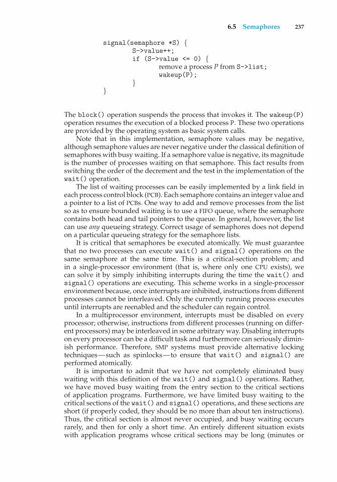
6.5 Semaphores 237
signal(semaphore *S) {S->value++;if (S->value <= 0) {
remove a process P from S->list;wakeup(P);
}}
The block() operation suspends the process that invokes it. The wakeup(P)operation resumes the execution of a blocked process P. These two operationsare provided by the operating system as basic system calls.
Note that in this implementation, semaphore values may be negative,although semaphore values are never negative under the classical definition ofsemaphores with busy waiting. If a semaphore value is negative, its magnitudeis the number of processes waiting on that semaphore. This fact results fromswitching the order of the decrement and the test in the implementation of thewait() operation.
The list of waiting processes can be easily implemented by a link field ineach process control block (PCB). Each semaphore contains an integer value anda pointer to a list of PCBs. One way to add and remove processes from the listso as to ensure bounded waiting is to use a FIFO queue, where the semaphorecontains both head and tail pointers to the queue. In general, however, the listcan use any queueing strategy. Correct usage of semaphores does not dependon a particular queueing strategy for the semaphore lists.
It is critical that semaphores be executed atomically. We must guaranteethat no two processes can execute wait() and signal() operations on thesame semaphore at the same time. This is a critical-section problem; andin a single-processor environment (that is, where only one CPU exists), wecan solve it by simply inhibiting interrupts during the time the wait() andsignal() operations are executing. This scheme works in a single-processorenvironment because, once interrupts are inhibited, instructions from differentprocesses cannot be interleaved. Only the currently running process executesuntil interrupts are reenabled and the scheduler can regain control.
In a multiprocessor environment, interrupts must be disabled on everyprocessor; otherwise, instructions from different processes (running on differ-ent processors) may be interleaved in some arbitrary way. Disabling interruptson every processor can be a difficult task and furthermore can seriously dimin-ish performance. Therefore, SMP systems must provide alternative lockingtechniques—such as spinlocks—to ensure that wait() and signal() areperformed atomically.
It is important to admit that we have not completely eliminated busywaiting with this definition of the wait() and signal() operations. Rather,we have moved busy waiting from the entry section to the critical sectionsof application programs. Furthermore, we have limited busy waiting to thecritical sections of the wait() and signal() operations, and these sections areshort (if properly coded, they should be no more than about ten instructions).Thus, the critical section is almost never occupied, and busy waiting occursrarely, and then for only a short time. An entirely different situation existswith application programs whose critical sections may be long (minutes or
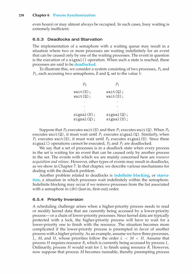
238 Chapter 6 Process Synchronization
even hours) or may almost always be occupied. In such cases, busy waiting isextremely inefficient.
6.5.3 Deadlocks and Starvation
The implementation of a semaphore with a waiting queue may result in asituation where two or more processes are waiting indefinitely for an eventthat can be caused only by one of the waiting processes. The event in questionis the execution of a signal() operation. When such a state is reached, theseprocesses are said to be deadlocked.
To illustrate this, we consider a system consisting of two processes, P0 andP1, each accessing two semaphores, S and Q, set to the value 1:
P0 P1
wait(S); wait(Q);wait(Q); wait(S);
. .
. .
. .signal(S); signal(Q);signal(Q); signal(S);
Suppose that P0 executes wait(S) and then P1 executes wait(Q). When P0executes wait(Q), it must wait until P1 executes signal(Q). Similarly, whenP1 executes wait(S), it must wait until P0 executes signal(S). Since thesesignal() operations cannot be executed, P0 and P1 are deadlocked.
We say that a set of processes is in a deadlock state when every processin the set is waiting for an event that can be caused only by another processin the set. The events with which we are mainly concerned here are resourceacquisition and release. However, other types of events may result in deadlocks,as we show in Chapter 7. In that chapter, we describe various mechanisms fordealing with the deadlock problem.
Another problem related to deadlocks is indefinite blocking, or starva-tion, a situation in which processes wait indefinitely within the semaphore.Indefinite blocking may occur if we remove processes from the list associatedwith a semaphore in LIFO (last-in, first-out) order.
6.5.4 Priority Inversion
A scheduling challenge arises when a higher-priority process needs to reador modify kernel data that are currently being accessed by a lower-priorityprocess—or a chain of lower-priority processes. Since kernel data are typicallyprotected with a lock, the higher-priority process will have to wait for alower-priority one to finish with the resource. The situation becomes morecomplicated if the lower-priority process is preempted in favor of anotherprocess with a higher priority. As an example, assume we have three processes,L, M, and H, whose priorities follow the order L < M < H. Assume thatprocess H requires resource R, which is currently being accessed by process L.Ordinarily, process H would wait for L to finish using resource R. However,now suppose that process M becomes runnable, thereby preempting process
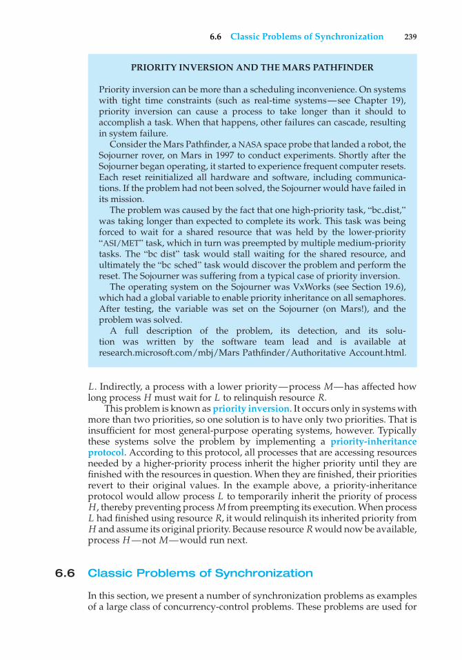
6.6 Classic Problems of Synchronization 239
PRIORITY INVERSION AND THE MARS PATHFINDER
Priority inversion can be more than a scheduling inconvenience. On systemswith tight time constraints (such as real-time systems—see Chapter 19),priority inversion can cause a process to take longer than it should toaccomplish a task. When that happens, other failures can cascade, resultingin system failure.
Consider the Mars Pathfinder, a NASA space probe that landed a robot, theSojourner rover, on Mars in 1997 to conduct experiments. Shortly after theSojourner began operating, it started to experience frequent computer resets.Each reset reinitialized all hardware and software, including communica-tions. If the problem had not been solved, the Sojourner would have failed inits mission.
The problem was caused by the fact that one high-priority task, “bc dist,”was taking longer than expected to complete its work. This task was beingforced to wait for a shared resource that was held by the lower-priority“ASI/MET” task, which in turn was preempted by multiple medium-prioritytasks. The “bc dist” task would stall waiting for the shared resource, andultimately the “bc sched” task would discover the problem and perform thereset. The Sojourner was suffering from a typical case of priority inversion.
The operating system on the Sojourner was VxWorks (see Section 19.6),which had a global variable to enable priority inheritance on all semaphores.After testing, the variable was set on the Sojourner (on Mars!), and theproblem was solved.
A full description of the problem, its detection, and its solu-tion was written by the software team lead and is available atresearch.microsoft.com/mbj/Mars Pathfinder/Authoritative Account.html.
L. Indirectly, a process with a lower priority—process M—has affected howlong process H must wait for L to relinquish resource R.
This problem is known as priority inversion. It occurs only in systems withmore than two priorities, so one solution is to have only two priorities. That isinsufficient for most general-purpose operating systems, however. Typicallythese systems solve the problem by implementing a priority-inheritanceprotocol. According to this protocol, all processes that are accessing resourcesneeded by a higher-priority process inherit the higher priority until they arefinished with the resources in question. When they are finished, their prioritiesrevert to their original values. In the example above, a priority-inheritanceprotocol would allow process L to temporarily inherit the priority of processH, thereby preventing process M from preempting its execution. When processL had finished using resource R, it would relinquish its inherited priority fromH and assume its original priority. Because resource R would now be available,process H —not M—would run next.
6.6 Classic Problems of Synchronization
In this section, we present a number of synchronization problems as examplesof a large class of concurrency-control problems. These problems are used for
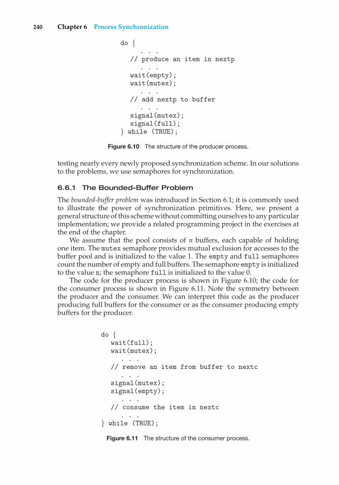
240 Chapter 6 Process Synchronization
do {. . .
// produce an item in nextp. . .
wait(empty);wait(mutex);
. . .// add nextp to buffer
. . .signal(mutex);signal(full);
} while (TRUE);
Figure 6.10 The structure of the producer process.
testing nearly every newly proposed synchronization scheme. In our solutionsto the problems, we use semaphores for synchronization.
6.6.1 The Bounded-Buffer Problem
The bounded-buffer problem was introduced in Section 6.1; it is commonly usedto illustrate the power of synchronization primitives. Here, we present ageneral structure of this scheme without committing ourselves to any particularimplementation; we provide a related programming project in the exercises atthe end of the chapter.
We assume that the pool consists of n buffers, each capable of holdingone item. The mutex semaphore provides mutual exclusion for accesses to thebuffer pool and is initialized to the value 1. The empty and full semaphorescount the number of empty and full buffers. The semaphore empty is initializedto the value n; the semaphore full is initialized to the value 0.
The code for the producer process is shown in Figure 6.10; the code forthe consumer process is shown in Figure 6.11. Note the symmetry betweenthe producer and the consumer. We can interpret this code as the producerproducing full buffers for the consumer or as the consumer producing emptybuffers for the producer.
do {wait(full);wait(mutex);
. . .// remove an item from buffer to nextc
. . .signal(mutex);signal(empty);
. . .// consume the item in nextc
. . .} while (TRUE);
Figure 6.11 The structure of the consumer process.
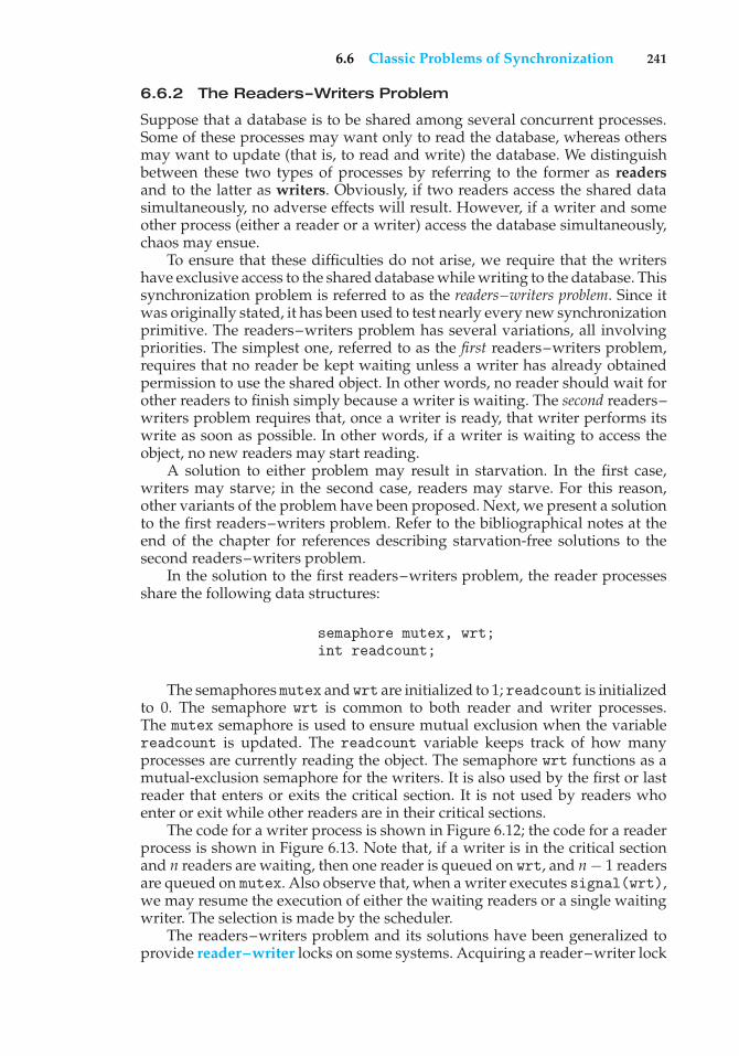
6.6 Classic Problems of Synchronization 241
6.6.2 The Readers–Writers Problem
Suppose that a database is to be shared among several concurrent processes.Some of these processes may want only to read the database, whereas othersmay want to update (that is, to read and write) the database. We distinguishbetween these two types of processes by referring to the former as readersand to the latter as writers. Obviously, if two readers access the shared datasimultaneously, no adverse effects will result. However, if a writer and someother process (either a reader or a writer) access the database simultaneously,chaos may ensue.
To ensure that these difficulties do not arise, we require that the writershave exclusive access to the shared database while writing to the database. Thissynchronization problem is referred to as the readers–writers problem. Since itwas originally stated, it has been used to test nearly every new synchronizationprimitive. The readers–writers problem has several variations, all involvingpriorities. The simplest one, referred to as the first readers–writers problem,requires that no reader be kept waiting unless a writer has already obtainedpermission to use the shared object. In other words, no reader should wait forother readers to finish simply because a writer is waiting. The second readers–writers problem requires that, once a writer is ready, that writer performs itswrite as soon as possible. In other words, if a writer is waiting to access theobject, no new readers may start reading.
A solution to either problem may result in starvation. In the first case,writers may starve; in the second case, readers may starve. For this reason,other variants of the problem have been proposed. Next, we present a solutionto the first readers–writers problem. Refer to the bibliographical notes at theend of the chapter for references describing starvation-free solutions to thesecond readers–writers problem.
In the solution to the first readers–writers problem, the reader processesshare the following data structures:
semaphore mutex, wrt;int readcount;
The semaphores mutex and wrt are initialized to 1; readcount is initializedto 0. The semaphore wrt is common to both reader and writer processes.The mutex semaphore is used to ensure mutual exclusion when the variablereadcount is updated. The readcount variable keeps track of how manyprocesses are currently reading the object. The semaphore wrt functions as amutual-exclusion semaphore for the writers. It is also used by the first or lastreader that enters or exits the critical section. It is not used by readers whoenter or exit while other readers are in their critical sections.
The code for a writer process is shown in Figure 6.12; the code for a readerprocess is shown in Figure 6.13. Note that, if a writer is in the critical sectionand n readers are waiting, then one reader is queued on wrt, and n − 1 readersare queued on mutex. Also observe that, when a writer executes signal(wrt),we may resume the execution of either the waiting readers or a single waitingwriter. The selection is made by the scheduler.
The readers–writers problem and its solutions have been generalized toprovide reader–writer locks on some systems. Acquiring a reader–writer lock
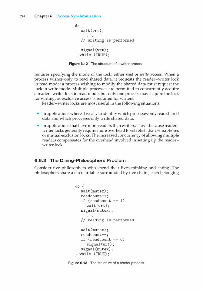
242 Chapter 6 Process Synchronization
do {wait(wrt);
. . .// writing is performed
. . .signal(wrt);
} while (TRUE);
Figure 6.12 The structure of a writer process.
requires specifying the mode of the lock: either read or write access. When aprocess wishes only to read shared data, it requests the reader–writer lockin read mode; a process wishing to modify the shared data must request thelock in write mode. Multiple processes are permitted to concurrently acquirea reader–writer lock in read mode, but only one process may acquire the lockfor writing, as exclusive access is required for writers.
Reader–writer locks are most useful in the following situations:
• In applications where it is easy to identify which processes only read shareddata and which processes only write shared data.
• In applications that have more readers than writers. This is because reader–writer locks generally require more overhead to establish than semaphoresor mutual-exclusion locks. The increased concurrency of allowing multiplereaders compensates for the overhead involved in setting up the reader–writer lock.
6.6.3 The Dining-Philosophers Problem
Consider five philosophers who spend their lives thinking and eating. Thephilosophers share a circular table surrounded by five chairs, each belonging
do {wait(mutex);readcount++;if (readcount == 1)
wait(wrt);signal(mutex);
. . .// reading is performed
. . .wait(mutex);readcount--;if (readcount == 0)
signal(wrt);signal(mutex);
} while (TRUE);
Figure 6.13 The structure of a reader process.
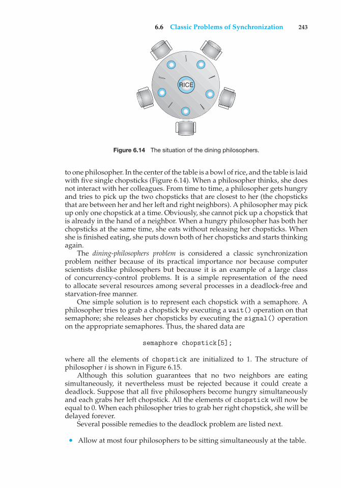
6.6 Classic Problems of Synchronization 243
RICE
Figure 6.14 The situation of the dining philosophers.
to one philosopher. In the center of the table is a bowl of rice, and the table is laidwith five single chopsticks (Figure 6.14). When a philosopher thinks, she doesnot interact with her colleagues. From time to time, a philosopher gets hungryand tries to pick up the two chopsticks that are closest to her (the chopsticksthat are between her and her left and right neighbors). A philosopher may pickup only one chopstick at a time. Obviously, she cannot pick up a chopstick thatis already in the hand of a neighbor. When a hungry philosopher has both herchopsticks at the same time, she eats without releasing her chopsticks. Whenshe is finished eating, she puts down both of her chopsticks and starts thinkingagain.
The dining-philosophers problem is considered a classic synchronizationproblem neither because of its practical importance nor because computerscientists dislike philosophers but because it is an example of a large classof concurrency-control problems. It is a simple representation of the needto allocate several resources among several processes in a deadlock-free andstarvation-free manner.
One simple solution is to represent each chopstick with a semaphore. Aphilosopher tries to grab a chopstick by executing a wait() operation on thatsemaphore; she releases her chopsticks by executing the signal() operationon the appropriate semaphores. Thus, the shared data are
semaphore chopstick[5];
where all the elements of chopstick are initialized to 1. The structure ofphilosopher i is shown in Figure 6.15.
Although this solution guarantees that no two neighbors are eatingsimultaneously, it nevertheless must be rejected because it could create adeadlock. Suppose that all five philosophers become hungry simultaneouslyand each grabs her left chopstick. All the elements of chopstick will now beequal to 0. When each philosopher tries to grab her right chopstick, she will bedelayed forever.
Several possible remedies to the deadlock problem are listed next.
• Allow at most four philosophers to be sitting simultaneously at the table.
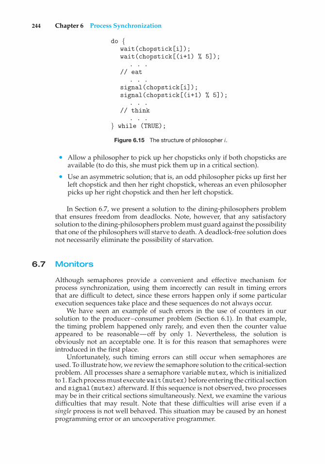
244 Chapter 6 Process Synchronization
do {wait(chopstick[i]);wait(chopstick[(i+1) % 5]);
. . .// eat
. . .signal(chopstick[i]);signal(chopstick[(i+1) % 5]);
. . .// think
. . .} while (TRUE);
Figure 6.15 The structure of philosopher i.
• Allow a philosopher to pick up her chopsticks only if both chopsticks areavailable (to do this, she must pick them up in a critical section).
• Use an asymmetric solution; that is, an odd philosopher picks up first herleft chopstick and then her right chopstick, whereas an even philosopherpicks up her right chopstick and then her left chopstick.
In Section 6.7, we present a solution to the dining-philosophers problemthat ensures freedom from deadlocks. Note, however, that any satisfactorysolution to the dining-philosophers problem must guard against the possibilitythat one of the philosophers will starve to death. A deadlock-free solution doesnot necessarily eliminate the possibility of starvation.
6.7 Monitors
Although semaphores provide a convenient and effective mechanism forprocess synchronization, using them incorrectly can result in timing errorsthat are difficult to detect, since these errors happen only if some particularexecution sequences take place and these sequences do not always occur.
We have seen an example of such errors in the use of counters in oursolution to the producer–consumer problem (Section 6.1). In that example,the timing problem happened only rarely, and even then the counter valueappeared to be reasonable—off by only 1. Nevertheless, the solution isobviously not an acceptable one. It is for this reason that semaphores wereintroduced in the first place.
Unfortunately, such timing errors can still occur when semaphores areused. To illustrate how, we review the semaphore solution to the critical-sectionproblem. All processes share a semaphore variable mutex, which is initializedto 1. Each process must executewait(mutex)before entering the critical sectionand signal(mutex) afterward. If this sequence is not observed, two processesmay be in their critical sections simultaneously. Next, we examine the variousdifficulties that may result. Note that these difficulties will arise even if asingle process is not well behaved. This situation may be caused by an honestprogramming error or an uncooperative programmer.
6.7 Monitors 245
• Suppose that a process interchanges the order in which the wait() andsignal() operations on the semaphore mutex are executed, resulting inthe following execution:
signal(mutex);...
critical section...
wait(mutex);
In this situation, several processes may be executing in their critical sectionssimultaneously, violating the mutual-exclusion requirement. This errormay be discovered only if several processes are simultaneously activein their critical sections. Note that this situation may not always bereproducible.
• Suppose that a process replaces signal(mutex) with wait(mutex). Thatis, it executes
wait(mutex);...
critical section...
wait(mutex);
In this case, a deadlock will occur.
• Suppose that a process omits the wait(mutex), or the signal(mutex), orboth. In this case, either mutual exclusion is violated or a deadlock willoccur.
These examples illustrate that various types of errors can be generated easilywhen programmers use semaphores incorrectly to solve the critical-sectionproblem. Similar problems may arise in the other synchronization modelsdiscussed in Section 6.6.
To deal with such errors, researchers have developed high-level languageconstructs. In this section, we describe one fundamental high-level synchro-nization construct—the monitor type.
6.7.1 Usage
A abstract data type — or ADT — encapsulates private data with public methodsto operate on that data. A monitor type is an ADT which presents a set ofprogrammer-defined operations that are provided mutual exclusion withinthe monitor. The monitor type also contains the declaration of variables whosevalues define the state of an instance of that type, along with the bodies ofprocedures or functions that operate on those variables. The syntax of a monitortype is shown in Figure 6.16. The representation of a monitor type cannot beused directly by the various processes. Thus, a procedure defined within amonitor can access only those variables declared locally within the monitorand its formal parameters. Similarly, the local variables of a monitor can beaccessed by only the local procedures.
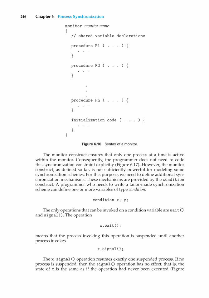
246 Chapter 6 Process Synchronization
monitor monitor name{
// shared variable declarations
procedure P1 ( . . . ) {. . .
}
procedure P2 ( . . . ) {. . .
}
.
.
.procedure Pn ( . . . ) {
. . .}
initialization code ( . . . ) {. . .
}}
Figure 6.16 Syntax of a monitor.
The monitor construct ensures that only one process at a time is activewithin the monitor. Consequently, the programmer does not need to codethis synchronization constraint explicitly (Figure 6.17). However, the monitorconstruct, as defined so far, is not sufficiently powerful for modeling somesynchronization schemes. For this purpose, we need to define additional syn-chronization mechanisms. These mechanisms are provided by the conditionconstruct. A programmer who needs to write a tailor-made synchronizationscheme can define one or more variables of type condition:
condition x, y;
The only operations that can be invoked on a condition variable are wait()and signal(). The operation
x.wait();
means that the process invoking this operation is suspended until anotherprocess invokes
x.signal();
The x.signal() operation resumes exactly one suspended process. If noprocess is suspended, then the signal() operation has no effect; that is, thestate of x is the same as if the operation had never been executed (Figure
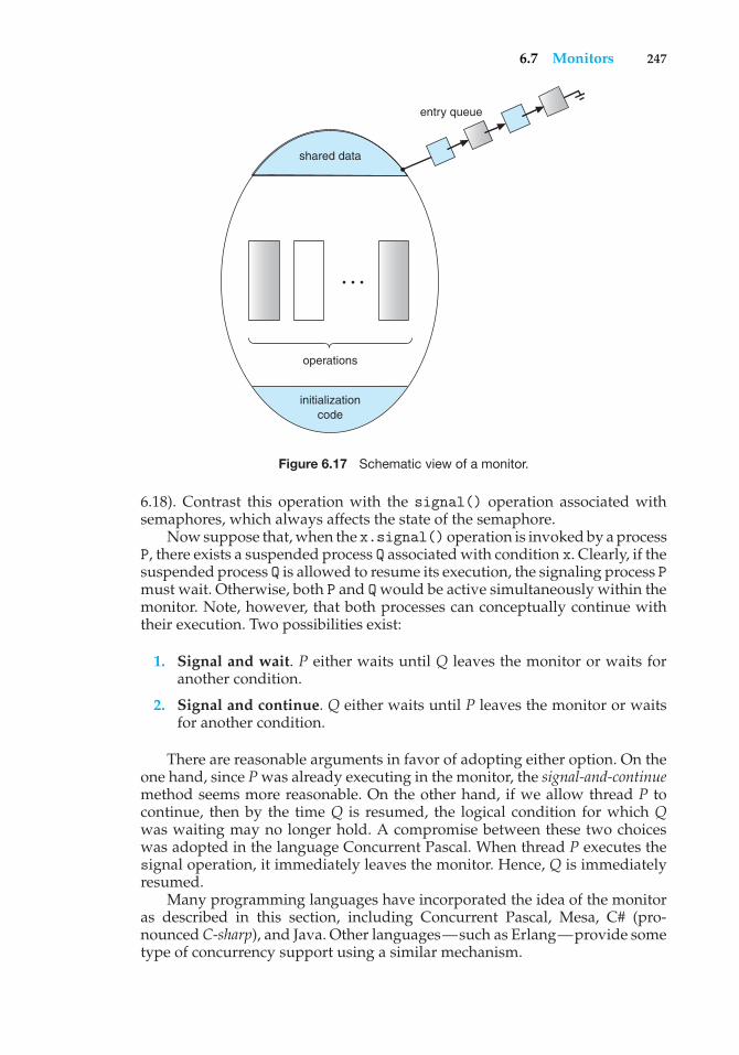
6.7 Monitors 247
entry queue
shared data
operations
initializationcode
. . .
Figure 6.17 Schematic view of a monitor.
6.18). Contrast this operation with the signal() operation associated withsemaphores, which always affects the state of the semaphore.
Now suppose that, when the x.signal() operation is invoked by a processP, there exists a suspended process Q associated with condition x. Clearly, if thesuspended process Q is allowed to resume its execution, the signaling process Pmust wait. Otherwise, both P and Q would be active simultaneously within themonitor. Note, however, that both processes can conceptually continue withtheir execution. Two possibilities exist:
1. Signal and wait. P either waits until Q leaves the monitor or waits foranother condition.
2. Signal and continue. Q either waits until P leaves the monitor or waitsfor another condition.
There are reasonable arguments in favor of adopting either option. On theone hand, since P was already executing in the monitor, the signal-and-continuemethod seems more reasonable. On the other hand, if we allow thread P tocontinue, then by the time Q is resumed, the logical condition for which Qwas waiting may no longer hold. A compromise between these two choiceswas adopted in the language Concurrent Pascal. When thread P executes thesignal operation, it immediately leaves the monitor. Hence, Q is immediatelyresumed.
Many programming languages have incorporated the idea of the monitoras described in this section, including Concurrent Pascal, Mesa, C# (pro-nounced C-sharp), and Java. Other languages—such as Erlang—provide sometype of concurrency support using a similar mechanism.
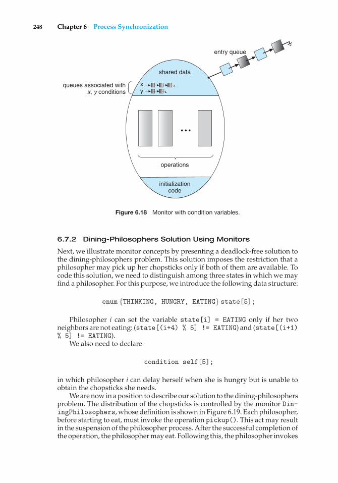
248 Chapter 6 Process Synchronization
operations
queues associated withx, y conditions
entry queue
shared data
x y
initializationcode
• • •
Figure 6.18 Monitor with condition variables.
6.7.2 Dining-Philosophers Solution Using Monitors
Next, we illustrate monitor concepts by presenting a deadlock-free solution tothe dining-philosophers problem. This solution imposes the restriction that aphilosopher may pick up her chopsticks only if both of them are available. Tocode this solution, we need to distinguish among three states in which we mayfind a philosopher. For this purpose, we introduce the following data structure:
enum {THINKING, HUNGRY, EATING} state[5];
Philosopher i can set the variable state[i] = EATING only if her twoneighbors are not eating: (state[(i+4) % 5] != EATING) and (state[(i+1)% 5] != EATING).
We also need to declare
condition self[5];
in which philosopher i can delay herself when she is hungry but is unable toobtain the chopsticks she needs.
We are now in a position to describe our solution to the dining-philosophersproblem. The distribution of the chopsticks is controlled by the monitor Din-ingPhilosophers, whose definition is shown in Figure 6.19. Each philosopher,before starting to eat, must invoke the operation pickup(). This act may resultin the suspension of the philosopher process. After the successful completion ofthe operation, the philosopher may eat. Following this, the philosopher invokes
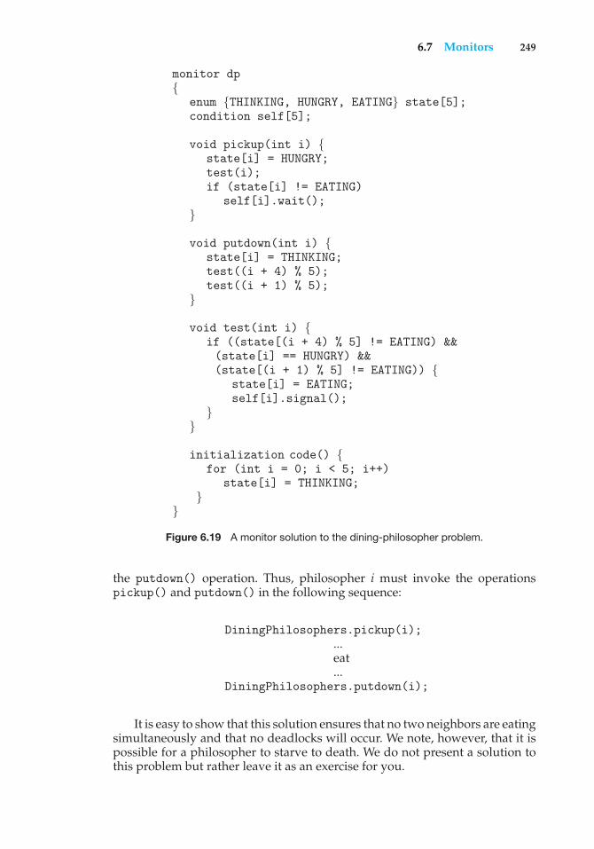
6.7 Monitors 249
monitor dp{
enum {THINKING, HUNGRY, EATING} state[5];condition self[5];
void pickup(int i) {state[i] = HUNGRY;test(i);if (state[i] != EATING)
self[i].wait();}
void putdown(int i) {state[i] = THINKING;test((i + 4) % 5);test((i + 1) % 5);
}
void test(int i) {if ((state[(i + 4) % 5] != EATING) &&(state[i] == HUNGRY) &&(state[(i + 1) % 5] != EATING)) {
state[i] = EATING;self[i].signal();
}}
initialization code() {for (int i = 0; i < 5; i++)
state[i] = THINKING;}
}Figure 6.19 A monitor solution to the dining-philosopher problem.
the putdown() operation. Thus, philosopher i must invoke the operationspickup() and putdown() in the following sequence:
DiningPhilosophers.pickup(i);...eat...
DiningPhilosophers.putdown(i);
It is easy to show that this solution ensures that no two neighbors are eatingsimultaneously and that no deadlocks will occur. We note, however, that it ispossible for a philosopher to starve to death. We do not present a solution tothis problem but rather leave it as an exercise for you.
250 Chapter 6 Process Synchronization
6.7.3 Implementing a Monitor Using Semaphores
We now consider a possible implementation of the monitor mechanism usingsemaphores. For each monitor, a semaphore mutex (initialized to 1) is provided.A process must execute wait(mutex) before entering the monitor and mustexecute signal(mutex) after leaving the monitor.
Since a signaling process must wait until the resumed process either leavesor waits, an additional semaphore, next, is introduced, initialized to 0. Thesignaling processes can use next to suspend themselves. An integer variablenext count is also provided to count the number of processes suspended onnext. Thus, each external procedure F is replaced by
wait(mutex);...
body of F...
if (next count > 0)signal(next);
elsesignal(mutex);
Mutual exclusion within a monitor is ensured.We can now describe how condition variables are implemented as well.
For each condition x, we introduce a semaphore x sem and an integervariable x count, both initialized to 0. The operation x.wait() can now beimplemented as
x count++;if (next count > 0)
signal(next);else
signal(mutex);wait(x sem);x count--;
The operation x.signal() can be implemented as
if (x count > 0) {next count++;signal(x sem);wait(next);next count--;
}This implementation is applicable to the definitions of monitors given by
both Hoare and Brinch-Hansen. In some cases, however, the generality of theimplementation is unnecessary, and a significant improvement in efficiency ispossible. We leave this problem to you in Exercise 6.27.
6.7.4 Resuming Processes within a Monitor
We turn now to the subject of process-resumption order within a monitor. Ifseveral processes are suspended on condition x, and an x.signal() operation
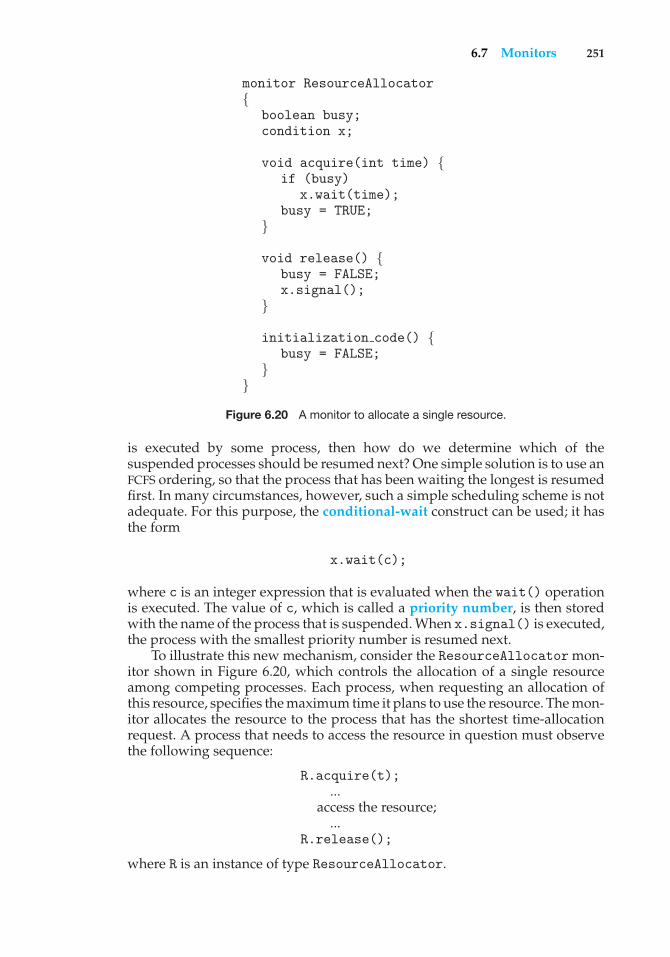
6.7 Monitors 251
monitor ResourceAllocator{
boolean busy;condition x;
void acquire(int time) {if (busy)
x.wait(time);busy = TRUE;
}
void release() {busy = FALSE;x.signal();
}
initialization code() {busy = FALSE;
}}
Figure 6.20 A monitor to allocate a single resource.
is executed by some process, then how do we determine which of thesuspended processes should be resumed next? One simple solution is to use anFCFS ordering, so that the process that has been waiting the longest is resumedfirst. In many circumstances, however, such a simple scheduling scheme is notadequate. For this purpose, the conditional-wait construct can be used; it hasthe form
x.wait(c);
where c is an integer expression that is evaluated when the wait() operationis executed. The value of c, which is called a priority number, is then storedwith the name of the process that is suspended. When x.signal() is executed,the process with the smallest priority number is resumed next.
To illustrate this new mechanism, consider the ResourceAllocator mon-itor shown in Figure 6.20, which controls the allocation of a single resourceamong competing processes. Each process, when requesting an allocation ofthis resource, specifies the maximum time it plans to use the resource. The mon-itor allocates the resource to the process that has the shortest time-allocationrequest. A process that needs to access the resource in question must observethe following sequence:
R.acquire(t);...
access the resource;...
R.release();
where R is an instance of type ResourceAllocator.
252 Chapter 6 Process Synchronization
Unfortunately, the monitor concept cannot guarantee that the precedingaccess sequence will be observed. In particular, the following problems canoccur:
• A process might access a resource without first gaining access permissionto the resource.
• A process might never release a resource once it has been granted accessto the resource.
• A process might attempt to release a resource that it never requested.
• A process might request the same resource twice (without first releasingthe resource).
The same difficulties are encountered with the use of semaphores, andthese difficulties are similar in nature to those that encouraged us to developthe monitor constructs in the first place. Previously, we had to worry aboutthe correct use of semaphores. Now, we have to worry about the correct use ofhigher-level programmer-defined operations, with which the compiler can nolonger assist us.
One possible solution to the current problem is to include the resource-access operations within the ResourceAllocator monitor. However, usingthis solution will mean that scheduling is done according to the built-inmonitor-scheduling algorithm rather than the one we have coded.
To ensure that the processes observe the appropriate sequences, we mustinspect all the programs that make use of the ResourceAllocator monitorand its managed resource. We must check two conditions to establish thecorrectness of this system. First, user processes must always make their callson the monitor in a correct sequence. Second, we must be sure that anuncooperative process does not simply ignore the mutual-exclusion gatewayprovided by the monitor and try to access the shared resource directly, withoutusing the access protocols. Only if these two conditions can be ensured can weguarantee that no time-dependent errors will occur and that the schedulingalgorithm will not be defeated.
Although this inspection may be possible for a small, static system, it isnot reasonable for a large system or a dynamic system. This access-controlproblem can be solved only through the use of additional mechanisms that aredescribed in Chapter 14.
Many programming languages have incorporated the idea of the monitoras described in this section, including Concurrent Pascal, Mesa, C# (pro-nounced C-sharp), and Java. Other languages—such as Erlang—provide sometype of concurrency support using a similar mechanism.
6.8 Synchronization Examples
We next describe the synchronization mechanisms provided by the Solaris,Windows XP, and Linux operating systems, as well as the Pthreads API. We havechosen these three operating systems because they provide good examples ofdifferent approaches for synchronizing the kernel, and we have included the
6.8 Synchronization Examples 253
JAVA MONITORS
Java provides a monitor-like concurrency mechanism for thread synchro-nization. Every object in Java has associated with it a single lock. When amethod is declared to be synchronized, calling the method requires owningthe lock for the object. We declare a synchronized method by placing thesynchronized keyword in the method definition. The following defines thesafeMethod() as synchronized, for example:
public class SimpleClass {. . .public synchronized void safeMethod() {/* Implementation of safeMethod() */. . .
}}
Next, assume we create an object instance of SimpleClass, such as:
SimpleClass sc = new SimpleClass();
Invoking the sc.safeMethod() method requires owning the lock on theobject instance sc. If the lock is already owned by another thread, the threadcalling the synchronizedmethod blocks and is placed in the entry set for theobject’s lock. The entry set represents the set of threads waiting for the lockto become available. If the lock is available when a synchronized methodis called, the calling thread becomes the owner of the object’s lock and canenter the method. The lock is released when the thread exits the method; athread from the entry set is then selected as the new owner of the lock.
Java also provides wait() and notify() methods, which are similarin function to the wait() and signal() statements for a monitor. Release1.5 of the Java language provides API support for semaphores, conditionvariables, and mutex locks (among other concurrency mechanisms) in thejava.util.concurrent package.
Pthreads API because it is widely used for thread creation and synchronizationby developers on UNIX and Linux systems. As you will see in this section, thesynchronization methods available in these differing systems vary in subtleand significant ways.
6.8.1 Synchronization in Solaris
To control access to critical sections, Solaris provides adaptive mutexes, condi-tion variables, semaphores, reader–writer locks, and turnstiles. Solaris imple-ments semaphores and condition variables essentially as they are presentedin Sections 6.5 and 6.7. In this section, we describe adaptive mutexes, reader–writer locks, and turnstiles.
254 Chapter 6 Process Synchronization
An adaptive mutex protects access to every critical data item. On amultiprocessor system, an adaptive mutex starts as a standard semaphoreimplemented as a spinlock. If the data are locked and therefore already in use,the adaptive mutex does one of two things. If the lock is held by a thread thatis currently running on another CPU, the thread spins while waiting for thelock to become available, because the thread holding the lock is likely to finishsoon. If the thread holding the lock is not currently in run state, the threadblocks, going to sleep until it is awakened by the release of the lock. It is putto sleep so that it will not spin while waiting, since the lock will not be freedvery soon. A lock held by a sleeping thread is likely to be in this category. Ona single-processor system, the thread holding the lock is never running if thelock is being tested by another thread, because only one thread can run at atime. Therefore, on this type of system, threads always sleep rather than spinif they encounter a lock.
Solaris uses the adaptive-mutex method to protect only data that areaccessed by short code segments. That is, a mutex is used if a lock will beheld for less than a few hundred instructions. If the code segment is longerthan that, the spin-waiting method is exceedingly inefficient. For these longercode segments, condition variables and semaphores are used. If the desiredlock is already held, the thread issues a wait and sleeps. When a thread freesthe lock, it issues a signal to the next sleeping thread in the queue. The extracost of putting a thread to sleep and waking it, and of the associated contextswitches, is less than the cost of wasting several hundred instructions waitingin a spinlock.
Reader–writer locks are used to protect data that are accessed frequentlybut are usually accessed in a read-only manner. In these circumstances,reader–writer locks are more efficient than semaphores, because multiplethreads can read data concurrently, whereas semaphores always serialize accessto the data. Reader–writer locks are relatively expensive to implement, so againthey are used only on long sections of code.
Solaris uses turnstiles to order the list of threads waiting to acquire eitheran adaptive mutex or a reader–writer lock. A turnstile is a queue structurecontaining threads blocked on a lock. For example, if one thread currentlyowns the lock for a synchronized object, all other threads trying to acquire thelock will block and enter the turnstile for that lock. When the lock is released,the kernel selects a thread from the turnstile as the next owner of the lock.Each synchronized object with at least one thread blocked on the object’s lockrequires a separate turnstile. However, rather than associating a turnstile witheach synchronized object, Solaris gives each kernel thread its own turnstile.Because a thread can be blocked only on one object at a time, this is moreefficient than having a turnstile for each object.
The turnstile for the first thread to block on a synchronized object becomesthe turnstile for the object itself. Threads subsequently blocking on the lock willbe added to this turnstile. When the initial thread ultimately releases the lock,it gains a new turnstile from a list of free turnstiles maintained by the kernel. Toprevent a priority inversion, turnstiles are organized according to a priority-inheritance protocol. This means that if a lower-priority thread currently holdsa lock on which a higher-priority thread is blocked, the thread with the lowerpriority will temporarily inherit the priority of the higher-priority thread. Uponreleasing the lock, the thread will revert to its original priority.
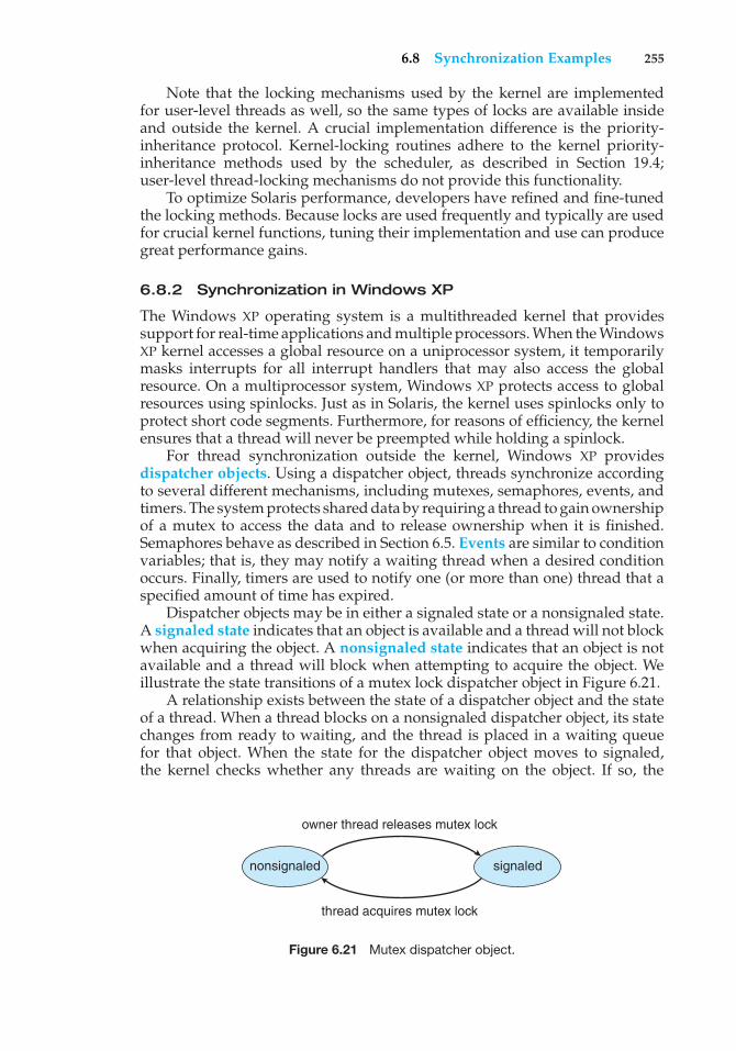
6.8 Synchronization Examples 255
Note that the locking mechanisms used by the kernel are implementedfor user-level threads as well, so the same types of locks are available insideand outside the kernel. A crucial implementation difference is the priority-inheritance protocol. Kernel-locking routines adhere to the kernel priority-inheritance methods used by the scheduler, as described in Section 19.4;user-level thread-locking mechanisms do not provide this functionality.
To optimize Solaris performance, developers have refined and fine-tunedthe locking methods. Because locks are used frequently and typically are usedfor crucial kernel functions, tuning their implementation and use can producegreat performance gains.
6.8.2 Synchronization in Windows XP
The Windows XP operating system is a multithreaded kernel that providessupport for real-time applications and multiple processors. When the WindowsXP kernel accesses a global resource on a uniprocessor system, it temporarilymasks interrupts for all interrupt handlers that may also access the globalresource. On a multiprocessor system, Windows XP protects access to globalresources using spinlocks. Just as in Solaris, the kernel uses spinlocks only toprotect short code segments. Furthermore, for reasons of efficiency, the kernelensures that a thread will never be preempted while holding a spinlock.
For thread synchronization outside the kernel, Windows XP providesdispatcher objects. Using a dispatcher object, threads synchronize accordingto several different mechanisms, including mutexes, semaphores, events, andtimers. The system protects shared data by requiring a thread to gain ownershipof a mutex to access the data and to release ownership when it is finished.Semaphores behave as described in Section 6.5. Events are similar to conditionvariables; that is, they may notify a waiting thread when a desired conditionoccurs. Finally, timers are used to notify one (or more than one) thread that aspecified amount of time has expired.
Dispatcher objects may be in either a signaled state or a nonsignaled state.A signaled state indicates that an object is available and a thread will not blockwhen acquiring the object. A nonsignaled state indicates that an object is notavailable and a thread will block when attempting to acquire the object. Weillustrate the state transitions of a mutex lock dispatcher object in Figure 6.21.
A relationship exists between the state of a dispatcher object and the stateof a thread. When a thread blocks on a nonsignaled dispatcher object, its statechanges from ready to waiting, and the thread is placed in a waiting queuefor that object. When the state for the dispatcher object moves to signaled,the kernel checks whether any threads are waiting on the object. If so, the
nonsignaled signaled
owner thread releases mutex lock
thread acquires mutex lock
Figure 6.21 Mutex dispatcher object.
256 Chapter 6 Process Synchronization
kernel moves one thread—or possibly more threads—from the waiting stateto the ready state, where they can resume executing. The number of threadsthe kernel selects from the waiting queue depends on the type of dispatcherobject for which it is waiting. The kernel will select only one thread from thewaiting queue for a mutex, since a mutex object may be “owned” by only asingle thread. For an event object, the kernel will select all threads that arewaiting for the event.
We can use a mutex lock as an illustration of dispatcher objects andthread states. If a thread tries to acquire a mutex dispatcher object that is in anonsignaled state, that thread will be suspended and placed in a waiting queuefor the mutex object. When the mutex moves to the signaled state (becauseanother thread has released the lock on the mutex), the thread waiting at thefront of the queue will be moved from the waiting state to the ready state andwill acquire the mutex lock.
We provide a programming project at the end of this chapter that usesmutex locks and semaphores in the Win32 API.
6.8.3 Synchronization in Linux
Prior to Version 2.6, Linux was a nonpreemptive kernel, meaning that a processrunning in kernel mode could not be preempted—even if a higher-priorityprocess became available to run. Now, however, the Linux kernel is fullypreemptive, so a task can be preempted when it is running in the kernel.
The Linux kernel provides spinlocks and semaphores (as well as reader–writer versions of these two locks) for locking in the kernel. On SMP machines,the fundamental locking mechanism is a spinlock, and the kernel is designed sothat the spinlock is held only for short durations. On single-processor machines,spinlocks are inappropriate for use and are replaced by enabling and disablingkernel preemption. That is, on single-processor machines, rather than holdinga spinlock, the kernel disables kernel preemption; and rather than releasingthe spinlock, it enables kernel preemption. This is summarized below:
single processor multiple processors
Acquire spin lock.
Release spin lock.
Disable kernel preemption.
Enable kernel preemption.
Linux uses an interesting approach to disable and enable kernel preemp-tion. It provides two simple system calls—preempt disable() and pre-empt enable()—for disabling and enabling kernel preemption. In addition,however, the kernel is not preemptible if a kernel-mode task is holding a lock.To enforce this rule, each task in the system has a thread-info structurecontaining a counter, preempt count, to indicate the number of locks beingheld by the task. When a lock is acquired, preempt count is incremented. Itis decremented when a lock is released. If the value of preempt count for thetask currently running is greater than zero, it is not safe to preempt the kernel,as this task currently holds a lock. If the count is zero, the kernel can safely beinterrupted (assuming there are no outstanding calls to preempt disable()).
6.9 Atomic Transactions 257
Spinlocks—along with enabling and disabling kernel preemption—areused in the kernel only when a lock (or disabling kernel preemption) is heldfor a short duration. When a lock must be held for a longer period, semaphoresare appropriate for use.
6.8.4 Synchronization in Pthreads
The Pthreads API provides mutex locks, condition variables, and read–writelocks for thread synchronization. This API is available for programmers andis not part of any particular kernel. Mutex locks represent the fundamentalsynchronization technique used with Pthreads. A mutex lock is used to protectcritical sections of code—that is, a thread acquires the lock before enteringa critical section and releases it upon exiting the critical section. Conditionvariables in Pthreads behave much as described in Section 6.7. Read–writelocks behave similarly to the locking mechanism described in Section 6.6.2.Many systems that implement Pthreads also provide semaphores, althoughthey are not part of the Pthreads standard and instead belong to the POSIX SEMextension. Other extensions to the Pthreads API include spinlocks, but not allextensions are considered portable from one implementation to another. Weprovide a programming project at the end of this chapter that uses Pthreadsmutex locks and semaphores.
6.9 Atomic Transactions
The mutual exclusion of critical sections ensures that the critical sections areexecuted atomically—that is, as one uninterruptible unit. If two critical sectionsare instead executed concurrently, the result is equivalent to their sequentialexecution in some unknown order. Although this property is useful in manyapplication domains, in many cases we would like to make sure that a criticalsection forms a single logical unit of work that either is performed in its entiretyor is not performed at all. An example is funds transfer, in which one accountis debited and another is credited. Clearly, it is essential for data consistencyeither that both the credit and debit occur or that neither occurs.
Consistency of data, along with storage and retrieval of data, is a concernoften associated with database systems. Recently, there has been an upsurge ofinterest in using database-systems techniques in operating systems. Operatingsystems can be viewed as manipulators of data; as such, they can benefit fromthe advanced techniques and models available from database research. Forinstance, many of the ad hoc techniques used in operating systems to managefiles could be more flexible and powerful if more formal database methodswere used in their place. In Sections 6.9.2 to 6.9.4, we describe some of thesedatabase techniques and explain how they can be used by operating systems.First, however, we deal with the general issue of transaction atomicity. It is thisproperty that the database techniques are meant to address.
6.9.1 System Model
A collection of instructions (or operations) that performs a single logicalfunction is called a transaction. A major issue in processing transactions is the
258 Chapter 6 Process Synchronization
preservation of atomicity despite the possibility of failures within the computersystem.
We can think of a transaction as a program unit that accesses and perhapsupdates various data items that reside on a disk within some files. From ourpoint of view, such a transaction is simply a sequence of read and writeoperations terminated by either a commit operation or an abort operation.A commit operation signifies that the transaction has terminated its executionsuccessfully, whereas an abort operation signifies that the transaction has
TRANSACTIONAL MEMORY
With the emergence of multicore systems has come increased pressure todevelop multithreaded applications that take advantage of multiple process-ing cores. However, multithreaded applications present an increased riskof race conditions and deadlocks. Traditionally, techniques such as locks,semaphores, and monitors have been used to address these issues. How-ever, transactional memory provides an alternative strategy for developingthread-safe concurrent applications.
A memory transaction is a sequence of memory read–write operationsthat are atomic. If all operations in a transaction are completed, the memorytransaction is committed; otherwise, the operations must be aborted androlled back. The benefits of transactional memory can be obtained throughfeatures added to a programming language.
Consider an example. Suppose we have a function update() thatmodifies shared data. Traditionally, this function would be written usinglocks such as the following:
update () {acquire();/* modify shared data */release();
}However, using synchronization mechanisms such as locks and semaphoresinvolves many potential problems, including deadlocks. Additionally, as thenumber of threads increases, traditional locking does not scale well.
As an alternative to traditional methods, new features that take advantageof transactional memory can be added to a programming language. In ourexample, suppose we add the construct atomic{S}, which ensures thatthe operations in S execute as a transaction. This allows us to rewrite theupdate() method as follows:
update () {atomic {
/* modify shared data */}
}
Continued on following page.
6.9 Atomic Transactions 259
TRANSACTIONAL MEMORY (Continued)
The advantage of using such a mechanism rather than locks is that thetransactional memory system—not the developer—is responsible for guar-anteeing atomicity. Additionally, the system can identify which statements inatomic blocks can be executed concurrently, such as concurrent read access toa shared variable. It is, of course, possible for a programmer to identify thesesituations and use reader–writer locks, but the task becomes increasinglydifficult as the number of threads within an application grows.
Transactional memory can be implemented in either software or hard-ware. Software transactional memory (STM), as the name suggests, imple-ments transactional memory exclusively in software—no special hardwareis needed. STM works by inserting instrumentation code inside transactionblocks. The code is inserted by a compiler and manages each transaction byexamining where statements may run concurrently and where specific low-level locking is required. Hardware transactional memory (small HTM) useshardware cache hierarchies and cache coherency protocols to manage andresolve conflicts involving shared data residing in separate processors caches.HTM requires no special code instrumentation and thus has less overheadthan STM. However, HTM does require that existing cache hierarchies andcache coherency protocols be modified to support transactional memory.
Transactional memory has existed for several years without widespreadimplementation. However, the growth of multicore systems and the asso-ciated emphasis on concurrent programming have prompted a significantamount of research in this area on the part of both academics and hardwarevendors, including Intel and Sun Microsystems.
ended its normal execution due to some logical error or a system failure.If a terminated transaction has completed its execution successfully, it iscommitted; otherwise, it is aborted.
Since an aborted transaction may already have modified the data that ithas accessed, the state of these data may not be the same as it would havebeen if the transaction had executed atomically. So that atomicity is ensured,an aborted transaction must have no effect on the state of the data that it hasalready modified. Thus, the state of the data accessed by an aborted transactionmust be restored to what it was just before the transaction started executing. Wesay that such a transaction has been rolled back. It is part of the responsibilityof the system to ensure this property.
To determine how the system should ensure atomicity, we need first toidentify the properties of devices used for storing the various data accessedby the transactions. Various types of storage media are distinguished by theirrelative speed, capacity, and resilience to failure.
• Volatile storage. Information residing in volatile storage does not usuallysurvive system crashes. Examples of such storage are main and cachememory. Access to volatile storage is extremely fast, both because of thespeed of the memory access itself and because it is possible to accessdirectly any data item in volatile storage.
260 Chapter 6 Process Synchronization
• Nonvolatile storage. Information residing in nonvolatile storage usuallysurvives system crashes. Examples of media for such storage are disks andmagnetic tapes. Disks are more reliable than main memory but less reliablethan magnetic tapes. Both disks and tapes, however, are subject to failure,which may result in loss of information. Currently, nonvolatile storage isslower than volatile storage by several orders of magnitude, because diskand tape devices are electromechanical and require physical motion toaccess data.
• Stable storage. Information residing in stable storage is never lost (nevershould be taken with a grain of salt, since theoretically such absolutescannot be guaranteed). To implement an approximation of such storage, weneed to replicate information in several nonvolatile storage caches (usuallydisk) with independent failure modes and to update the information in acontrolled manner (Section 12.8).
Here, we are concerned only with ensuring transaction atomicity in anenvironment where failures result in the loss of information on volatile storage.
6.9.2 Log-Based Recovery
One way to ensure atomicity is to record, on stable storage, informationdescribing all the modifications made by the transaction to the various data itaccesses. The most widely used method for achieving this form of recordingis write-ahead logging. Here, the system maintains, on stable storage, a datastructure called the log. Each log record describes a single operation of atransaction write and has the following fields:
• Transaction name. The unique name of the transaction that performed thewrite operation
• Data item name. The unique name of the data item written
• Old value. The value of the data item prior to the write operation
• New value. The value that the data item will have after the write
Other special log records exist to record significant events during transac-tion processing, such as the start of a transaction and the commit or abort of atransaction.
Before a transaction Ti starts its execution, the record < Ti starts> iswritten to the log. During its execution, any write operation by Ti is precededby the writing of the appropriate new record to the log. When Ti commits, therecord < Ti commits> is written to the log.
Because the information in the log is used in reconstructing the state of thedata items accessed by the various transactions, we cannot allow the actualupdate to a data item to take place before the corresponding log record iswritten out to stable storage. We therefore require that, prior to execution of awrite(X) operation, the log records corresponding to X be written onto stablestorage.
Note the performance penalty inherent in this system. Two physical writesare required for every logical write requested. Also, more storage is needed,both for the data themselves and for the log recording the changes. In cases
6.9 Atomic Transactions 261
where the data are extremely important and fast failure recovery is necessary,however, the functionality is worth the price.
Using the log, the system can handle any failure that does not result in theloss of information on nonvolatile storage. The recovery algorithm uses twoprocedures:
• undo(Ti ), which restores the value of all data updated by transaction Ti tothe old values
• redo(Ti ), which sets the value of all data updated by transaction Ti to thenew values
The set of data updated by Ti and the appropriate old and new values can befound in the log. Note that the undo and redo operations must be idempotent(that is, multiple executions must have the same result as does one execution) toguarantee correct behavior even if a failure occurs during the recovery process.
If a transaction Ti aborts, then we can restore the state of the data thatit has updated by simply executing undo(Ti ). If a system failure occurs, werestore the state of all updated data by consulting the log to determine whichtransactions need to be redone and which need to be undone. This classificationof transactions is accomplished as follows:
• Transaction Ti needs to be undone if the log contains the < Ti starts>record but does not contain the < Ti commits> record.
• Transaction Ti needs to be redone if the log contains both the < Ti starts>and the < Ti commits> records.
6.9.3 Checkpoints
When a system failure occurs, we must consult the log to determine whichtransactions need to be redone and which need to be undone. In principle, weneed to search the entire log to make these determinations. There are two majordrawbacks to this approach:
1. The searching process is time consuming.
2. Most of the transactions that, according to our algorithm, need to beredone have already actually updated the data that the log says theyneed to modify. Although redoing the data modifications will cause noharm (due to idempotency), it will nevertheless cause recovery to takelonger.
To reduce these types of overhead, we introduce the concept of check-points. During execution, the system maintains the write-ahead log. In addi-tion, the system periodically performs checkpoints that require the followingsequence of actions to take place:
1. Output all log records currently residing in volatile storage (usually mainmemory) onto stable storage.
2. Output all modified data residing in volatile storage to the stable storage.
3. Output a log record <checkpoint> onto stable storage.
262 Chapter 6 Process Synchronization
The presence of a <checkpoint> record in the log allows the systemto streamline its recovery procedure. Consider a transaction Ti that committedprior to the checkpoint. The < Ti commits> record appears in the log before the<checkpoint> record. Any modifications made by Ti must have been writtento stable storage either prior to the checkpoint or as part of the checkpointitself. Thus, at recovery time, there is no need to perform a redo operation onTi .
This observation allows us to refine our previous recovery algorithm. Aftera failure has occurred, the recovery routine examines the log to determinethe most recent transaction Ti that started executing before the most recentcheckpoint took place. It finds such a transaction by searching the log backwardto find the first <checkpoint> record and then finding the subsequent< Ti start> record.
Once transaction Ti has been identified, the redo and undo operations needbe applied only to transaction Ti and all transactions Tj that started executingafter transaction Ti . We’ll call these transactions set T. The remainder of the logcan be ignored. The recovery operations that are required are as follows:
• For all transactions Tk in T for which the record < Tk commits> appears inthe log, execute redo(Tk).
• For all transactions Tk in T that have no < Tk commits> record in the log,execute undo(Tk).
6.9.4 Concurrent Atomic Transactions
We have been considering an environment in which only one transaction canbe executing at a time. We now turn to the case where multiple transactionsare active simultaneously. Because each transaction is atomic, the concurrentexecution of transactions must be equivalent to the case where these trans-actions are executed serially in some arbitrary order. This property, calledserializability, can be maintained by simply executing each transaction withina critical section. That is, all transactions share a common semaphore mutex,which is initialized to 1. When a transaction starts executing, its first action is toexecute wait(mutex). After the transaction either commits or aborts, it executessignal(mutex).
Although this scheme ensures the atomicity of all concurrently executingtransactions, it is nevertheless too restrictive. As we shall see, in manycases we can allow transactions to overlap their execution while maintainingserializability. A number of different concurrency-control algorithms ensureserializability, and we describe these algorithms next.
6.9.4.1 Serializability
Consider a system with two data items, A and B, that are both read and writtenby two transactions, T0 and T1. Suppose that these transactions are executedatomically in the order T0 followed by T1. This execution sequence, which iscalled a schedule, is represented in Figure 6.22. In schedule 1 of Figure 6.22, thesequence of instruction steps is in chronological order from top to bottom, withinstructions of T0 appearing in the left column and instructions of T1 appearingin the right column.
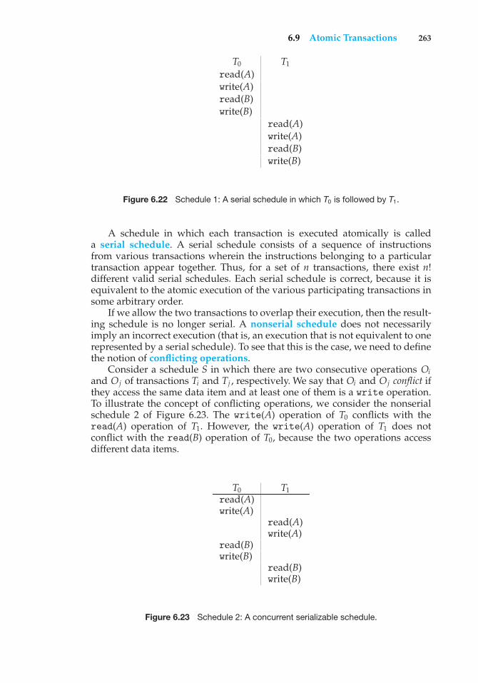
6.9 Atomic Transactions 263
T0 T1
read(A)write(A)read(B)write(B)
read(A)write(A)read(B)write(B)
Figure 6.22 Schedule 1: A serial schedule in which T0 is followed by T1.
A schedule in which each transaction is executed atomically is calleda serial schedule. A serial schedule consists of a sequence of instructionsfrom various transactions wherein the instructions belonging to a particulartransaction appear together. Thus, for a set of n transactions, there exist n!different valid serial schedules. Each serial schedule is correct, because it isequivalent to the atomic execution of the various participating transactions insome arbitrary order.
If we allow the two transactions to overlap their execution, then the result-ing schedule is no longer serial. A nonserial schedule does not necessarilyimply an incorrect execution (that is, an execution that is not equivalent to onerepresented by a serial schedule). To see that this is the case, we need to definethe notion of conflicting operations.
Consider a schedule S in which there are two consecutive operations Oiand Oj of transactions Ti and Tj , respectively. We say that Oi and Oj conflict ifthey access the same data item and at least one of them is a write operation.To illustrate the concept of conflicting operations, we consider the nonserialschedule 2 of Figure 6.23. The write(A) operation of T0 conflicts with theread(A) operation of T1. However, the write(A) operation of T1 does notconflict with the read(B) operation of T0, because the two operations accessdifferent data items.
T0 T1read(A)write(A)
read(A)write(A)
read(B)write(B)
read(B)write(B)
Figure 6.23 Schedule 2: A concurrent serializable schedule.
264 Chapter 6 Process Synchronization
Let Oi and Oj be consecutive operations of a schedule S. If Oi and Oj areoperations of different transactions and Oi and Oj do not conflict, then we canswap the order of Oi and Oj to produce a new schedule S’. We expect S to beequivalent to S’, as all operations appear in the same order in both schedules,except for Oi and Oj , whose order does not matter.
We can illustrate the swapping idea by considering again schedule 2 ofFigure 6.23. As the write(A) operation of T1 does not conflict with the read(B)operation of T0, we can swap these operations to generate an equivalentschedule. Regardless of the initial system state, both schedules producethe same final system state. Continuing with this procedure of swappingnonconflicting operations, we get:
• Swap the read(B) operation of T0 with the read(A) operation of T1.
• Swap the write(B) operation of T0 with the write(A) operation of T1.
• Swap the write(B) operation of T0 with the read(A) operation of T1.
The final result of these swaps is schedule 1 in Figure 6.22, which is aserial schedule. Thus, we have shown that schedule 2 is equivalent to a serialschedule. This result implies that, regardless of the initial system state, schedule2 will produce the same final state as will some serial schedule.
If a schedule S can be transformed into a serial schedule S’ by a series ofswaps of nonconflicting operations, we say that a schedule S is conflict serial-izable. Thus, schedule 2 is conflict serializable, because it can be transformedinto the serial schedule 1.
6.9.4.2 Locking Protocol
One way to ensure serializability is to associate a lock with each data item andto require that each transaction follow a locking protocol that governs howlocks are acquired and released. There are various modes in which a data itemcan be locked. In this section, we restrict our attention to two modes:
• Shared. If a transaction Ti has obtained a shared-mode lock (denoted byS) on data item Q, then Ti can read this item but cannot write Q.
• Exclusive. If a transaction Ti has obtained an exclusive-mode lock (denotedby X) on data item Q, then Ti can both read and write Q.
We require that every transaction request a lock in an appropriate mode ondata item Q, depending on the type of operations it will perform on Q.
To access data item Q, transaction Ti must first lock Q in the appropriatemode. If Q is not currently locked, then the lock is granted, and Ti can nowaccess it. However, if the data item Q is currently locked by some othertransaction, then Ti may have to wait. More specifically, suppose that Ti requestsan exclusive lock on Q. In this case, Ti must wait until the lock on Q is released.If Ti requests a shared lock on Q, then Ti must wait if Q is locked in exclusivemode. Otherwise, it can obtain the lock and access Q. Notice that this schemeis quite similar to the readers–writers algorithm discussed in Section 6.6.2.
A transaction may unlock a data item that it locked at an earlier point.It must, however, hold a lock on a data item as long as it accesses that item.
6.9 Atomic Transactions 265
Moreover, it is not always desirable for a transaction to unlock a data itemimmediately after its last access of that data item, because serializability maynot be ensured.
One protocol that ensures serializability is the two-phase locking protocol.This protocol requires that each transaction issue lock and unlock requests intwo phases:
• Growing phase. A transaction may obtain locks but may not release anylocks.
• Shrinking phase. A transaction may release locks but may not obtain anynew locks.
Initially, a transaction is in the growing phase. The transaction acquires locksas needed. Once the transaction releases a lock, it enters the shrinking phase,and no more lock requests can be issued.
The two-phase locking protocol ensures conflict serializability (Exercise6.35). It does not, however, ensure freedom from deadlock. In addition, itis possible that, for a given set of transactions, there are conflict-serializableschedules that cannot be obtained by use of the two-phase locking protocol.To improve performance over two-phase locking, we need either to haveadditional information about the transactions or to impose some structureor ordering on the set of data.
6.9.4.3 Timestamp-Based Protocols
In the locking protocols described above, the order followed by pairs ofconflicting transactions is determined at execution time. Another method fordetermining the serializability order is to select an order in advance. The mostcommon method for doing so is to use a timestamp ordering scheme.
With each transaction Ti in the system, we associate a unique fixedtimestamp, denoted by TS(Ti ). This timestamp is assigned by the systembefore the transaction Ti starts execution. If a transaction Ti has been assignedtimestamp TS(Ti ), and later a new transaction Tj enters the system, then TS(Ti )< TS(Tj ). There are two simple methods for implementing this scheme:
• Use the value of the system clock as the timestamp; that is, a transaction’stimestamp is equal to the value of the clock when the transaction enters thesystem. This method will not work for transactions that occur on separatesystems or for processors that do not share a clock.
• Use a logical counter as the timestamp; that is, a transaction’s timestampis equal to the value of the counter when the transaction enters the system.The counter is incremented after a new timestamp is assigned.
The timestamps of the transactions determine the serializability order.Thus, if TS(Ti ) < TS(Tj ), then the system must ensure that the scheduleproduced is equivalent to a serial schedule in which transaction Ti appearsbefore transaction Tj .
To implement this scheme, we associate with each data item Q twotimestamp values:
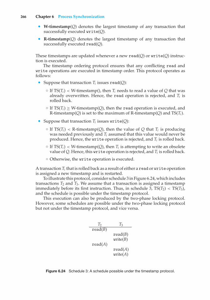
266 Chapter 6 Process Synchronization
• W-timestamp(Q) denotes the largest timestamp of any transaction thatsuccessfully executed write(Q).
• R-timestamp(Q) denotes the largest timestamp of any transaction thatsuccessfully executed read(Q).
These timestamps are updated whenever a new read(Q) or write(Q) instruc-tion is executed.
The timestamp ordering protocol ensures that any conflicting read andwrite operations are executed in timestamp order. This protocol operates asfollows:
• Suppose that transaction Ti issues read(Q):
◦ If TS(Ti ) < W-timestamp(), then Ti needs to read a value of Q that wasalready overwritten. Hence, the read operation is rejected, and Ti isrolled back.
◦ If TS(Ti ) ≥ W-timestamp(Q), then the read operation is executed, andR-timestamp(Q) is set to the maximum of R-timestamp(Q) and TS(Ti ).
• Suppose that transaction Ti issues write(Q):
◦ If TS(Ti ) < R-timestamp(Q), then the value of Q that Ti is producingwas needed previously and Ti assumed that this value would never beproduced. Hence, the write operation is rejected, and Ti is rolled back.
◦ If TS(Ti ) < W-timestamp(Q), then Ti is attempting to write an obsoletevalue of Q. Hence, this write operation is rejected, and Ti is rolled back.
◦ Otherwise, the write operation is executed.
A transaction Ti that is rolled back as a result of either a read or write operationis assigned a new timestamp and is restarted.
To illustrate this protocol, consider schedule 3 in Figure 6.24, which includestransactions T2 and T3. We assume that a transaction is assigned a timestampimmediately before its first instruction. Thus, in schedule 3, TS(T2) < TS(T3),and the schedule is possible under the timestamp protocol.
This execution can also be produced by the two-phase locking protocol.However, some schedules are possible under the two-phase locking protocolbut not under the timestamp protocol, and vice versa.
T2 T3read(B)
read(B)write(B)
read(A)read(A)write(A)
Figure 6.24 Schedule 3: A schedule possible under the timestamp protocol.
Practice Exercises 267
The timestamp protocol ensures conflict serializability. This capabilityfollows from the fact that conflicting operations are processed in timestamporder. The protocol also ensures freedom from deadlock, because no transactionever waits.
6.10 Summary
Given a collection of cooperating sequential processes that share data, mutualexclusion must be provided to ensure that a critical section of code is usedby only one process or thread at a time. Typically, computer hardwareprovides several operations that ensure mutual exclusion. However, suchhardware-based solutions are too complicated for most developers to use.Semaphores overcome this obstacle. Semaphores can be used to solve varioussynchronization problems and can be implemented efficiently, especially ifhardware support for atomic operations is available.
Various synchronization problems (such as the bounded-buffer problem,the readers–writers problem, and the dining-philosophers problem) are impor-tant mainly because they are examples of a large class of concurrency-controlproblems. These problems are used to test nearly every newly proposedsynchronization scheme.
The operating system must provide the means to guard against timingerrors. Several language constructs have been proposed to deal with these prob-lems. Monitors provide the synchronization mechanism for sharing abstractdata types. A condition variable provides a method by which a monitorprocedure can block its execution until it is signaled to continue.
Operating systems also provide support for synchronization. For example,Solaris, Windows XP, and Linux provide mechanisms such as semaphores,mutexes, spinlocks, and condition variables to control access to shared data.The Pthreads API provides support for mutexes and condition variables.
A transaction is a program unit that must be executed atomically; thatis, either all the operations associated with it are executed to completion, ornone are performed. To ensure atomicity despite system failure, we can use awrite-ahead log. All updates are recorded on the log, which is kept in stablestorage. If a system crash occurs, the information in the log is used in restoringthe state of the updated data items, which is accomplished by use of the undoand redo operations. To reduce the overhead in searching the log after a systemfailure has occurred, we can use a checkpoint scheme.
To ensure serializability when the execution of several transactions over-laps, we must use a concurrency-control scheme. Various concurrency-controlschemes ensure serializability by delaying an operation or aborting the trans-action that issued the operation. The most common ones are locking protocolsand timestamp ordering schemes.
Practice Exercises
6.1 In Section 6.4, we mentioned that disabling interrupts frequently canaffect the system’s clock. Explain why this can occur and how sucheffects can be minimized.
268 Chapter 6 Process Synchronization
6.2 The Cigarette-Smokers Problem. Consider a system with three smokerprocesses and one agent process. Each smoker continuously rolls acigarette and then smokes it. But to roll and smoke a cigarette, thesmoker needs three ingredients: tobacco, paper, and matches. One ofthe smoker processes has paper, another has tobacco, and the third hasmatches. The agent has an infinite supply of all three materials. Theagent places two of the ingredients on the table. The smoker who hasthe remaining ingredient then makes and smokes a cigarette, signalingthe agent on completion. The agent then puts out another two of thethree ingredients, and the cycle repeats. Write a program to synchronizethe agent and the smokers using Java synchronization.
6.3 Explain why Solaris, Windows XP, and Linux implement multiplelocking mechanisms. Describe the circumstances under which theyuse spinlocks, mutexes, semaphores, adaptive mutexes, and conditionvariables. In each case, explain why the mechanism is needed.
6.4 Describe how volatile, nonvolatile, and stable storage differ in cost.
6.5 Explain the purpose of the checkpoint mechanism. How often shouldcheckpoints be performed? Describe how the frequency of checkpointsaffects:
• System performance when no failure occurs
• The time it takes to recover from a system crash
• The time it takes to recover from a disk crash
6.6 Explain the concept of transaction atomicity.
6.7 Show that some schedules are possible under the two-phase lockingprotocol but not possible under the timestamp protocol, and vice versa.
Exercises
6.8 Race conditions are possible in many computer systems. Considera banking system with two functions: deposit(amount) and with-draw(amount). These two functions are passed the amount that is tobe deposited or withdrawn from a bank account. Assume a sharedbank account exists between a husband and wife and concurrently thehusband calls the withdraw() function and the wife calls deposit().Describe how a race condition is possible and what might be done toprevent the race condition from occurring.
6.9 The first known correct software solution to the critical-section problemfor two processes was developed by Dekker. The two processes, P0 andP1, share the following variables:
boolean flag[2]; /* initially false */int turn;
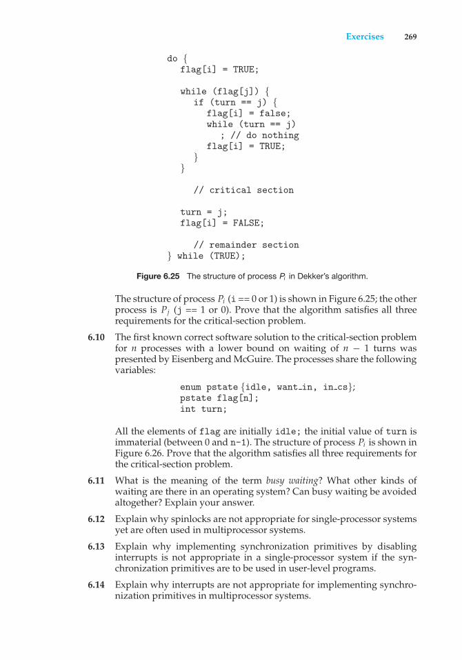
Exercises 269
do {flag[i] = TRUE;
while (flag[j]) {if (turn == j) {
flag[i] = false;while (turn == j)
; // do nothingflag[i] = TRUE;
}}
// critical section
turn = j;flag[i] = FALSE;
// remainder section} while (TRUE);
Figure 6.25 The structure of process Pi in Dekker’s algorithm.
The structure of process Pi (i == 0 or 1) is shown in Figure 6.25; the otherprocess is Pj (j == 1 or 0). Prove that the algorithm satisfies all threerequirements for the critical-section problem.
6.10 The first known correct software solution to the critical-section problemfor n processes with a lower bound on waiting of n − 1 turns waspresented by Eisenberg and McGuire. The processes share the followingvariables:
enum pstate {idle, want in, in cs};pstate flag[n];int turn;
All the elements of flag are initially idle; the initial value of turn isimmaterial (between 0 and n-1). The structure of process Pi is shown inFigure 6.26. Prove that the algorithm satisfies all three requirements forthe critical-section problem.
6.11 What is the meaning of the term busy waiting? What other kinds ofwaiting are there in an operating system? Can busy waiting be avoidedaltogether? Explain your answer.
6.12 Explain why spinlocks are not appropriate for single-processor systemsyet are often used in multiprocessor systems.
6.13 Explain why implementing synchronization primitives by disablinginterrupts is not appropriate in a single-processor system if the syn-chronization primitives are to be used in user-level programs.
6.14 Explain why interrupts are not appropriate for implementing synchro-nization primitives in multiprocessor systems.
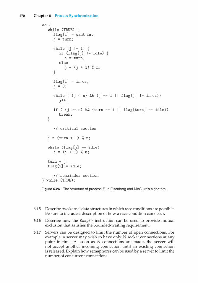
270 Chapter 6 Process Synchronization
do {while (TRUE) {
flag[i] = want in;j = turn;
while (j != i) {if (flag[j] != idle) {
j = turn;else
j = (j + 1) % n;}
flag[i] = in cs;j = 0;
while ( (j < n) && (j == i || flag[j] != in cs))j++;
if ( (j >= n) && (turn == i || flag[turn] == idle))break;
}
// critical section
j = (turn + 1) % n;
while (flag[j] == idle)j = (j + 1) % n;
turn = j;flag[i] = idle;
// remainder section} while (TRUE);
Figure 6.26 The structure of process Pi in Eisenberg and McGuire’s algorithm.
6.15 Describe two kernel data structures in which race conditions are possible.Be sure to include a description of how a race condition can occur.
6.16 Describe how the Swap() instruction can be used to provide mutualexclusion that satisfies the bounded-waiting requirement.
6.17 Servers can be designed to limit the number of open connections. Forexample, a server may wish to have only N socket connections at anypoint in time. As soon as N connections are made, the server willnot accept another incoming connection until an existing connectionis released. Explain how semaphores can be used by a server to limit thenumber of concurrent connections.
Exercises 271
6.18 Show that, if the wait() and signal() semaphore operations are notexecuted atomically, then mutual exclusion may be violated.
6.19 Windows Vista provides a new lightweight synchronization tool calledslim reader–writer locks. Whereas most implementations of reader–writer locks favor either readers or writers, or perhaps order waitingthreads using a FIFO policy, slim reader–writer locks favor neitherreaders nor writers, nor are waiting threads ordered in a FIFO queue.Explain the benefits of providing such a synchronization tool.
6.20 Show how to implement the wait() and signal() semaphore opera-tions in multiprocessor environments using the TestAndSet() instruc-tion. The solution should exhibit minimal busy waiting.
6.21 Exercise 4.17 requires the parent thread to wait for the child thread tofinish its execution before printing out the computed values. If we letthe parent thread access the Fibonacci numbers as soon as they havebeen computed by the child thread — rather than waiting for the childthread to terminate — Explain what changes would be necessary to thesolution for this exercise? Implement your modified solution.
6.22 Demonstrate that monitors and semaphores are equivalent insofar asthey can be used to implement the same types of synchronizationproblems.
6.23 Write a bounded-buffer monitor in which the buffers (portions) areembedded within the monitor itself.
6.24 The strict mutual exclusion within a monitor makes the bounded-buffermonitor of Exercise 6.23 mainly suitable for small portions.
a. Explain why this is true.
b. Design a new scheme that is suitable for larger portions.
6.25 Discuss the tradeoff between fairness and throughput of operationsin the readers–writers problem. Propose a method for solving thereaders–writers problem without causing starvation.
6.26 How does the signal() operation associated with monitors differ fromthe corresponding operation defined for semaphores?
6.27 Suppose the signal() statement can appear only as the last statementin a monitor procedure. Suggest how the implementation described inSection 6.7 can be simplified in this situation.
6.28 Consider a system consisting of processes P1, P2, ..., Pn, each of which hasa unique priority number. Write a monitor that allocates three identicalline printers to these processes, using the priority numbers for decidingthe order of allocation.
6.29 A file is to be shared among different processes, each of which hasa unique number. The file can be accessed simultaneously by severalprocesses, subject to the following constraint: The sum of all uniquenumbers associated with all the processes currently accessing the filemust be less than n. Write a monitor to coordinate access to the file.
272 Chapter 6 Process Synchronization
6.30 When a signal is performed on a condition inside a monitor, the signalingprocess can either continue its execution or transfer control to the processthat is signaled. How would the solution to the preceding exercise differwith these two different ways in which signaling can be performed?
6.31 Suppose we replace the wait() and signal() operations of moni-tors with a single construct await(B), where B is a general Booleanexpression that causes the process executing it to wait until B becomestrue.
a. Write a monitor using this scheme to implement the readers–writers problem.
b. Explain why, in general, this construct cannot be implementedefficiently.
c. What restrictions need to be put on the await statement so that itcan be implemented efficiently? (Hint: Restrict the generality of B;see Kessels [1977].)
6.32 Write a monitor that implements an alarm clock that enables a callingprogram to delay itself for a specified number of time units (ticks).You may assume the existence of a real hardware clock that invokesa procedure tick in your monitor at regular intervals.
6.33 Why do Solaris, Linux, and Windows XP use spinlocks as a syn-chronization mechanism only on multiprocessor systems and not onsingle-processor systems?
6.34 In log-based systems that provide support for transactions, updates todata items cannot be performed before the corresponding entries arelogged. Why is this restriction necessary?
6.35 Show that the two-phase locking protocol ensures conflict serializability.
6.36 What are the implications of assigning a new timestamp to a transactionthat is rolled back? How does the system process transactions that wereissued after the rolled-back transaction but that have timestamps smallerthan the new timestamp of the rolled-back transaction?
6.37 Assume that a finite number of resources of a single resource type mustbe managed. Processes may ask for a number of these resources and—once finished—will return them. As an example, many commercialsoftware packages provide a given number of licenses, indicating thenumber of applications that may run concurrently. When the applicationis started, the license count is decremented. When the application isterminated, the license count is incremented. If all licenses are in use,requests to start the application are denied. Such requests will only begranted when an existing license holder terminates the application anda license is returned.
The following program segment is used to manage a finite number ofinstances of an available resource. The maximum number of resourcesand the number of available resources are declared as follows:
#define MAX RESOURCES 5int available resources = MAX RESOURCES;
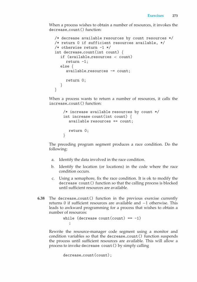
Exercises 273
When a process wishes to obtain a number of resources, it invokes thedecrease count() function:
/* decrease available resources by count resources *//* return 0 if sufficient resources available, *//* otherwise return -1 */int decrease count(int count) {
if (available resources < count)return -1;
else {available resources -= count;
return 0;}
}
When a process wants to return a number of resources, it calls theincrease count() function:
/* increase available resources by count */int increase count(int count) {
available resources += count;
return 0;}
The preceding program segment produces a race condition. Do thefollowing:
a. Identify the data involved in the race condition.
b. Identify the location (or locations) in the code where the racecondition occurs.
c. Using a semaphore, fix the race condition. It is ok to modify thedecrease count() function so that the calling process is blockeduntil sufficient resources are available.
6.38 The decrease count() function in the previous exercise currentlyreturns 0 if sufficient resources are available and −1 otherwise. Thisleads to awkward programming for a process that wishes to obtain anumber of resources:
while (decrease count(count) == -1);
Rewrite the resource-manager code segment using a monitor andcondition variables so that the decrease count() function suspendsthe process until sufficient resources are available. This will allow aprocess to invoke decrease count() by simply calling
decrease count(count);
274 Chapter 6 Process Synchronization
The process will return from this function call only when sufficientresources are available.
Programming Problems
6.39 The Sleeping-Barber Problem. A barbershop consists of a waiting roomwith n chairs and a barber room with one barber chair. If there are nocustomers to be served, the barber goes to sleep. If a customer entersthe barbershop and all chairs are occupied, then the customer leaves theshop. If the barber is busy but chairs are available, then the customer sitsin one of the free chairs. If the barber is asleep, the customer wakes upthe barber. Write a program to coordinate the barber and the customers.
Programming Projects
6.40 Producer–Consumer ProblemIn Section 6.6.1, we had presented a semaphore-based solution to theproducer–consumer problem using a bounded buffer. In this project,we will design a programming solution to the bounded-buffer problemusing the producer and consumer processes shown in Figures 6.10 and6.11. The solution presented in Section 6.6.1 uses three semaphores:empty and full, which count the number of empty and full slots in thebuffer, and mutex, which is a binary (or mutual-exclusion) semaphorethat protects the actual insertion or removal of items in the buffer. Forthis project, standard counting semaphores will be used for empty andfull, and a mutex lock, rather than a binary semaphore, will be usedto represent mutex. The producer and consumer—running as separatethreads—will move items to and from a buffer that is synchronized withthese empty, full, and mutex structures. You can solve this problemusing either Pthreads or the Win32 API.
The Buffer
Internally, the buffer will consist of a fixed-size array of typebuffer item (which will be defined using a typedef). The array ofbuffer item objects will be manipulated as a circular queue. Thedefinition of buffer item, along with the size of the buffer, can bestored in a header file such as the following:
/* buffer.h */typedef int buffer item;#define BUFFER SIZE 5
The buffer will be manipulated with two functions, insert item() andremove item(), which are called by the producer and consumer threads,respectively. A skeleton outlining these functions appears in Figure 6.27.
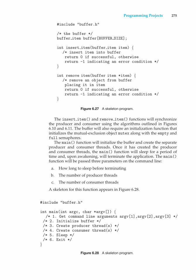
Programming Projects 275
#include "buffer.h"
/* the buffer */buffer item buffer[BUFFER SIZE];
int insert item(buffer item item) {/* insert item into bufferreturn 0 if successful, otherwisereturn -1 indicating an error condition */
}
int remove item(buffer item *item) {/* remove an object from bufferplacing it in itemreturn 0 if successful, otherwisereturn -1 indicating an error condition */
}
Figure 6.27 A skeleton program.
The insert item() and remove item() functions will synchronizethe producer and consumer using the algorithms outlined in Figures6.10 and 6.11. The buffer will also require an initialization function thatinitializes the mutual-exclusion object mutex along with the empty andfull semaphores.
The main() function will initialize the buffer and create the separateproducer and consumer threads. Once it has created the producerand consumer threads, the main() function will sleep for a period oftime and, upon awakening, will terminate the application. The main()function will be passed three parameters on the command line:
a. How long to sleep before terminating
b. The number of producer threads
c. The number of consumer threads
A skeleton for this function appears in Figure 6.28.
#include "buffer.h"
int main(int argc, char *argv[]) {/* 1. Get command line arguments argv[1],argv[2],argv[3] */
/* 2. Initialize buffer *//* 3. Create producer thread(s) *//* 4. Create consumer thread(s) *//* 5. Sleep *//* 6. Exit */
}Figure 6.28 A skeleton program.
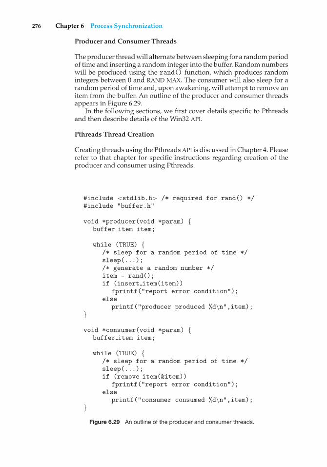
276 Chapter 6 Process Synchronization
Producer and Consumer Threads
The producer thread will alternate between sleeping for a random periodof time and inserting a random integer into the buffer. Random numberswill be produced using the rand() function, which produces randomintegers between 0 and RAND MAX. The consumer will also sleep for arandom period of time and, upon awakening, will attempt to remove anitem from the buffer. An outline of the producer and consumer threadsappears in Figure 6.29.
In the following sections, we first cover details specific to Pthreadsand then describe details of the Win32 API.
Pthreads Thread Creation
Creating threads using the Pthreads API is discussed in Chapter 4. Pleaserefer to that chapter for specific instructions regarding creation of theproducer and consumer using Pthreads.
#include <stdlib.h> /* required for rand() */#include "buffer.h"
void *producer(void *param) {buffer item item;
while (TRUE) {/* sleep for a random period of time */sleep(...);/* generate a random number */item = rand();if (insert item(item))
fprintf("report error condition");else
printf("producer produced %d\n",item);}
void *consumer(void *param) {buffer item item;
while (TRUE) {/* sleep for a random period of time */sleep(...);if (remove item(&item))
fprintf("report error condition");else
printf("consumer consumed %d\n",item);}
Figure 6.29 An outline of the producer and consumer threads.
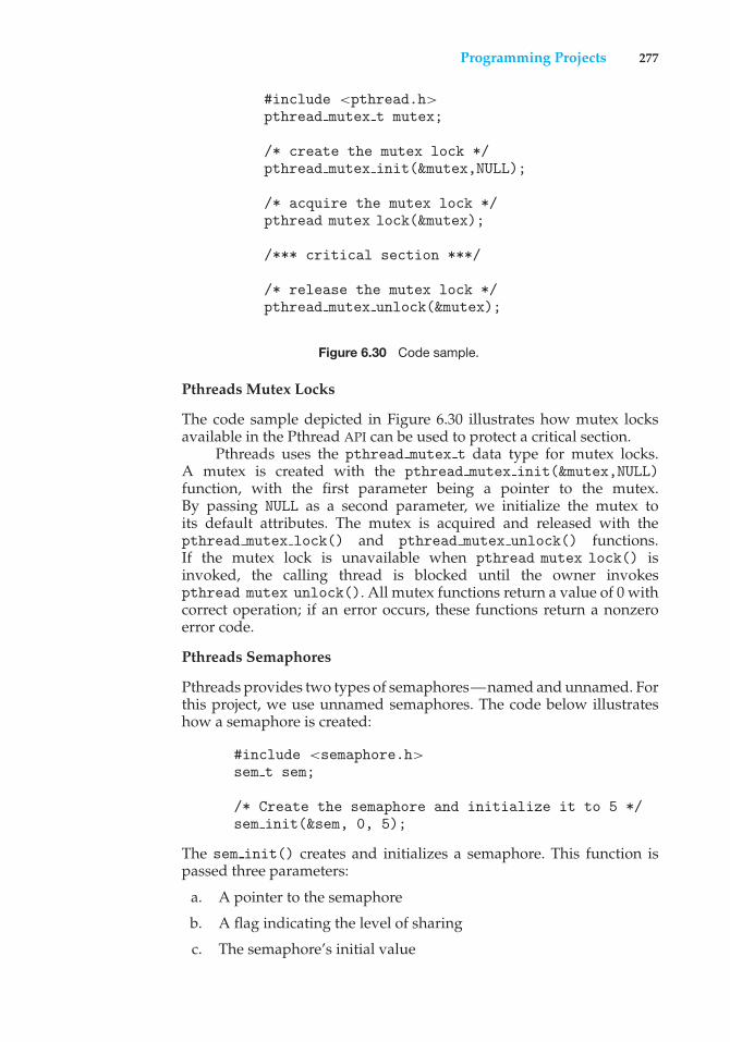
Programming Projects 277
#include <pthread.h>pthread mutex t mutex;
/* create the mutex lock */pthread mutex init(&mutex,NULL);
/* acquire the mutex lock */pthread mutex lock(&mutex);
/*** critical section ***/
/* release the mutex lock */pthread mutex unlock(&mutex);
Figure 6.30 Code sample.
Pthreads Mutex Locks
The code sample depicted in Figure 6.30 illustrates how mutex locksavailable in the Pthread API can be used to protect a critical section.
Pthreads uses the pthread mutex t data type for mutex locks.A mutex is created with the pthread mutex init(&mutex,NULL)function, with the first parameter being a pointer to the mutex.By passing NULL as a second parameter, we initialize the mutex toits default attributes. The mutex is acquired and released with thepthread mutex lock() and pthread mutex unlock() functions.If the mutex lock is unavailable when pthread mutex lock() isinvoked, the calling thread is blocked until the owner invokespthread mutex unlock(). All mutex functions return a value of 0 withcorrect operation; if an error occurs, these functions return a nonzeroerror code.
Pthreads Semaphores
Pthreads provides two types of semaphores—named and unnamed. Forthis project, we use unnamed semaphores. The code below illustrateshow a semaphore is created:
#include <semaphore.h>sem t sem;
/* Create the semaphore and initialize it to 5 */sem init(&sem, 0, 5);
The sem init() creates and initializes a semaphore. This function ispassed three parameters:
a. A pointer to the semaphore
b. A flag indicating the level of sharing
c. The semaphore’s initial value
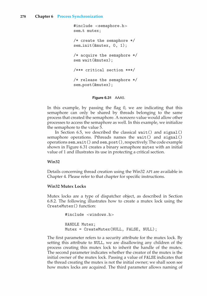
278 Chapter 6 Process Synchronization
#include <semaphore.h>sem t mutex;
/* create the semaphore */sem init(&mutex, 0, 1);
/* acquire the semaphore */sem wait(&mutex);
/*** critical section ***/
/* release the semaphore */sem post(&mutex);
Figure 6.31 AAA5.
In this example, by passing the flag 0, we are indicating that thissemaphore can only be shared by threads belonging to the sameprocess that created the semaphore. A nonzero value would allow otherprocesses to access the semaphore as well. In this example, we initializethe semaphore to the value 5.
In Section 6.5, we described the classical wait() and signal()semaphore operations. Pthreads names the wait() and signal()operations sem wait() and sem post(), respectively. The code exampleshown in Figure 6.31 creates a binary semaphore mutex with an initialvalue of 1 and illustrates its use in protecting a critical section.
Win32
Details concerning thread creation using the Win32 API are available inChapter 4. Please refer to that chapter for specific instructions.
Win32 Mutex Locks
Mutex locks are a type of dispatcher object, as described in Section6.8.2. The following illustrates how to create a mutex lock using theCreateMutex() function:
#include <windows.h>
HANDLE Mutex;Mutex = CreateMutex(NULL, FALSE, NULL);
The first parameter refers to a security attribute for the mutex lock. Bysetting this attribute to NULL, we are disallowing any children of theprocess creating this mutex lock to inherit the handle of the mutex.The second parameter indicates whether the creator of the mutex is theinitial owner of the mutex lock. Passing a value of FALSE indicates thatthe thread creating the mutex is not the initial owner; we shall soon seehow mutex locks are acquired. The third parameter allows naming of
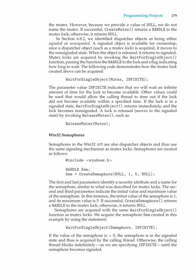
Programming Projects 279
the mutex. However, because we provide a value of NULL, we do notname the mutex. If successful, CreateMutex() returns a HANDLE to themutex lock; otherwise, it returns NULL.
In Section 6.8.2, we identified dispatcher objects as being eithersignaled or nonsignaled. A signaled object is available for ownership;once a dispatcher object (such as a mutex lock) is acquired, it moves tothe nonsignaled state. When the object is released, it returns to signaled.Mutex locks are acquired by invoking the WaitForSingleObject()function, passing the function the HANDLE to the lock and a flag indicatinghow long to wait. The following code demonstrates how the mutex lockcreated above can be acquired:
WaitForSingleObject(Mutex, INFINITE);
The parameter value INFINITE indicates that we will wait an infiniteamount of time for the lock to become available. Other values couldbe used that would allow the calling thread to time out if the lockdid not become available within a specified time. If the lock is in asignaled state, WaitForSingleObject() returns immediately, and thelock becomes nonsignaled. A lock is released (moves to the signaledstate) by invoking ReleaseMutex(), such as:
ReleaseMutex(Mutex);
Win32 Semaphores
Semaphores in the Win32 API are also dispatcher objects and thus usethe same signaling mechanism as mutex locks. Semaphores are createdas follows:
#include <windows.h>
HANDLE Sem;Sem = CreateSemaphore(NULL, 1, 5, NULL);
The first and last parameters identify a security attribute and a name forthe semaphore, similar to what was described for mutex locks. The sec-ond and third parameters indicate the initial value and maximum valueof the semaphore. In this instance, the initial value of the semaphore is 1,and its maximum value is 5. If successful, CreateSemaphore() returnsa HANDLE to the mutex lock; otherwise, it returns NULL.
Semaphores are acquired with the same WaitForSingleObject()function as mutex locks. We acquire the semaphore Sem created in thisexample by using the statement:
WaitForSingleObject(Semaphore, INFINITE);
If the value of the semaphore is > 0, the semaphore is in the signaledstate and thus is acquired by the calling thread. Otherwise, the callingthread blocks indefinitely—as we are specifying INFINITE—until thesemaphore becomes signaled.
280 Chapter 6 Process Synchronization
The equivalent of the signal() operation on Win32 semaphores is theReleaseSemaphore() function. This function is passed three parame-ters:
a. The HANDLE of the semaphore
b. The amount by which to increase the value of the semaphore
c. A pointer to the previous value of the semaphore
We can increase Sem by 1 using the following statement:
ReleaseSemaphore(Sem, 1, NULL);
Both ReleaseSemaphore() and ReleaseMutex() return nonzero ifsuccessful and zero otherwise.
Wiley Plus
Visit Wiley Plus for
• Source code
• Solutions to practice exercises
• Additional programming problems and exercises
• Labs using an operating system simulator
Bibliographical Notes
The mutual-exclusion problem was first discussed in a classic paper by Dijkstra[1965a]. Dekker’s algorithm (Exercise 6.9)—the first correct software solutionto the two-process mutual-exclusion problem—was developed by the Dutchmathematician T. Dekker. This algorithm also was discussed by Dijkstra[1965a]. A simpler solution to the two-process mutual-exclusion problem hassince been presented by Peterson [1981] (Figure 6.2).
Dijkstra [1965b] presented the first solution to the mutual-exclusion prob-lem for n processes. This solution, however, does not have an upper bound onthe amount of time a process must wait before it is allowed to enter the criticalsection. Knuth [1966] presented the first algorithm with a bound; his boundwas 2n turns. A refinement of Knuth’s algorithm by deBruijn [1967] reduced thewaiting time to n2 turns, after which Eisenberg and McGuire [1972] succeededin reducing the time to the lower bound of n−1 turns. Another algorithmthat also requires n−1 turns but is easier to program and to understand isthe bakery algorithm, which was developed by Lamport [1974]. Burns [1978]developed the hardware-solution algorithm that satisfies the bounded-waitingrequirement.
General discussions concerning the mutual-exclusion problem wereoffered by Lamport [1986] and Lamport [1991]. A collection of algorithms formutual exclusion was given by Raynal [1986].
Bibliographical Notes 281
The semaphore concept was suggested by Dijkstra [1965a]. Patil [1971]examined the question of whether semaphores can solve all possible syn-chronization problems. Parnas [1975] discussed some of the flaws in Patil’sarguments. Kosaraju [1973] followed up on Patil’s work to produce a problemthat cannot be solved by wait() and signal() operations. Lipton [1974]discussed the limitations of various synchronization primitives.
The classic process-coordination problems that we have described areparadigms for a large class of concurrency-control problems. The bounded-buffer problem, the dining-philosophers problem, and the sleeping-barberproblem (Exercise 6.39) were suggested by Dijkstra [1965a] and Dijkstra [1971].The cigarette-smokers problem (Exercise 6.2 was developed by Patil [1971]. Thereaders–writers problem was suggested by Courtois et al. [1971]. The issue ofconcurrent reading and writing was discussed by Lamport [1977]. The problemof synchronization of independent processes was discussed by Lamport [1976].
The critical-region concept was suggested by Hoare [1972] and by Brinch-Hansen [1972]. The monitor concept was developed by Brinch-Hansen [1973].A complete description of the monitor was given by Hoare [1974]. Kessels[1977] proposed an extension to the monitor to allow automatic signaling.Experience obtained from the use of monitors in concurrent programs wasdiscussed by Lampson and Redell [1979]. They also examined the priorityinversion problem. General discussions concerning concurrent programmingwere offered by Ben-Ari [1990] and Birrell [1989].
Optimizing the performance of locking primitives has been discussed inmany works, such as Lamport [1987], Mellor-Crummey and Scott [1991], andAnderson [1990]. The use of shared objects that do not require the use of criticalsections was discussed in Herlihy [1993], Bershad [1993], and Kopetz andReisinger [1993]. Novel hardware instructions and their utility in implementingsynchronization primitives have been described in works such as Culler et al.[1998], Goodman et al. [1989], Barnes [1993], and Herlihy and Moss [1993].
Some details of the locking mechanisms used in Solaris were presentedin Mauro and McDougall [2007]. Note that the locking mechanisms used bythe kernel are implemented for user-level threads as well, so the same typesof locks are available inside and outside the kernel. Details of Windows 2000synchronization can be found in Solomon and Russinovich [2000]. Goetz et al.[2006] presents a detailed discussion of concurrent programming in Java aswell as the java.util.concurrent package.
The write-ahead log scheme was first introduced in System R by Gray et al.[1981]. The concept of serializability was formulated by Eswaran et al. [1976] inconnection with their work on concurrency control for System R. The two-phaselocking protocol was introduced by Eswaran et al. [1976]. The timestamp-based concurrency-control scheme was provided by Reed [1983]. Varioustimestamp-based concurrency-control algorithms were explained by Bernsteinand Goodman [1980]. Adl-Tabatabai et al. [2007] discusses transactionalmemory.

This page intentionally left blank
7C H A P T E R
Deadlocks
In a multiprogramming environment, several processes may compete for afinite number of resources. A process requests resources; if the resources arenot available at that time, the process enters a waiting state. Sometimes, awaiting process is never again able to change state, because the resources ithas requested are held by other waiting processes. This situation is calleda deadlock. We discussed this issue briefly in Chapter 6 in connection withsemaphores.
Perhaps the best illustration of a deadlock can be drawn from a law passedby the Kansas legislature early in the 20th century. It said, in part: “When twotrains approach each other at a crossing, both shall come to a full stop andneither shall start up again until the other has gone.”
In this chapter, we describe methods that an operating system can useto prevent or deal with deadlocks. Although some applications can identifyprograms that may deadlock, operating systems typically do not providedeadlock-prevention facilities, and it remains the responsibility of program-mers to ensure that they design deadlock-free programs. Deadlock problemscan only become more common, given current trends, including larger num-bers of processes, multithreaded programs, many more resources within asystem, and an emphasis on long-lived file and database servers rather thanbatch systems.
CHAPTER OBJECTIVES
• To develop a description of deadlocks, which prevent sets of concurrentprocesses from completing their tasks.
• To present a number of different methods for preventing or avoidingdeadlocks in a computer system.
7.1 System Model
A system consists of a finite number of resources to be distributed amonga number of competing processes. The resources are partitioned into several
283
284 Chapter 7 Deadlocks
types, each consisting of some number of identical instances. Memory space,CPU cycles, files, and I/O devices (such as printers and DVD drives) are examplesof resource types. If a system has two CPUs, then the resource type CPU hastwo instances. Similarly, the resource type printer may have five instances.
If a process requests an instance of a resource type, the allocation of anyinstance of the type will satisfy the request. If it will not, then the instances arenot identical, and the resource type classes have not been defined properly. Forexample, a system may have two printers. These two printers may be defined tobe in the same resource class if no one cares which printer prints which output.However, if one printer is on the ninth floor and the other is in the basement,then people on the ninth floor may not see both printers as equivalent, andseparate resource classes may need to be defined for each printer.
A process must request a resource before using it and must release theresource after using it. A process may request as many resources as it requiresto carry out its designated task. Obviously, the number of resources requestedmay not exceed the total number of resources available in the system. In otherwords, a process cannot request three printers if the system has only two.
Under the normal mode of operation, a process may utilize a resource inonly the following sequence:
1. Request. The process requests the resource. If the request cannot begranted immediately (for example, if the resource is being used by anotherprocess), then the requesting process must wait until it can acquire theresource.
2. Use. The process can operate on the resource (for example, if the resourceis a printer, the process can print on the printer).
3. Release. The process releases the resource.
The request and release of resources are system calls, as explained inChapter 2. Examples are the request() and release() device, open() andclose() file, and allocate() and free() memory system calls. Request andrelease of resources that are not managed by the operating system can beaccomplished through the wait() and signal() operations on semaphoresor through acquisition and release of a mutex lock. For each use of a kernel-managed resource by a process or thread, the operating system checks tomake sure that the process has requested and has been allocated the resource.A system table records whether each resource is free or allocated; for eachresource that is allocated, the table also records the process to which it isallocated. If a process requests a resource that is currently allocated to anotherprocess, it can be added to a queue of processes waiting for this resource.
A set of processes is in a deadlocked state when every process in the set iswaiting for an event that can be caused only by another process in the set. Theevents with which we are mainly concerned here are resource acquisition andrelease. The resources may be either physical resources (for example, printers,tape drives, memory space, and CPU cycles) or logical resources (for example,files, semaphores, and monitors). However, other types of events may result indeadlocks (for example, the IPC facilities discussed in Chapter 3).
To illustrate a deadlocked state, consider a system with three CD RW drives.Suppose each of three processes holds one of these CD RW drives. If each process
7.2 Deadlock Characterization 285
now requests another drive, the three processes will be in a deadlocked state.Each is waiting for the event “CD RW is released,” which can be caused onlyby one of the other waiting processes. This example illustrates a deadlockinvolving the same resource type.
Deadlocks may also involve different resource types. For example, considera system with one printer and one DVD drive. Suppose that process Pi is holdingthe DVD and process Pj is holding the printer. If Pi requests the printer and Pjrequests the DVD drive, a deadlock occurs.
A programmer who is developing multithreaded applications must payparticular attention to this problem. Multithreaded programs are good candi-dates for deadlock because multiple threads can compete for shared resources.
7.2 Deadlock Characterization
In a deadlock, processes never finish executing, and system resources are tiedup, preventing other jobs from starting. Before we discuss the various methodsfor dealing with the deadlock problem, we look more closely at features thatcharacterize deadlocks.
7.2.1 Necessary Conditions
A deadlock situation can arise if the following four conditions hold simultane-ously in a system:
1. Mutual exclusion. At least one resource must be held in a nonsharablemode; that is, only one process at a time can use the resource. If another
DEADLOCK WITH MUTEX LOCKS
Let’s see how deadlock can occur in a multithreaded Pthread programusing mutex locks. The pthread mutex init() function initializesan unlocked mutex. Mutex locks are acquired and released usingpthread mutex lock() and pthread mutex unlock(), respec-tively. If a thread attempts to acquire a locked mutex, the call topthread mutex lock() blocks the thread until the owner of the mutexlock invokes pthread mutex unlock().
Two mutex locks are created in the following code example:
/* Create and initialize the mutex locks */pthread mutex t first mutex;pthread mutex t second mutex;
pthread mutex init(&first mutex,NULL);pthread mutex init(&second mutex,NULL);
Next, two threads—thread one and thread two—are created, and boththese threads have access to both mutex locks. thread one and thread tworun in the functions do work one() and do work two(), respectively, asshown in Figure 7.1.
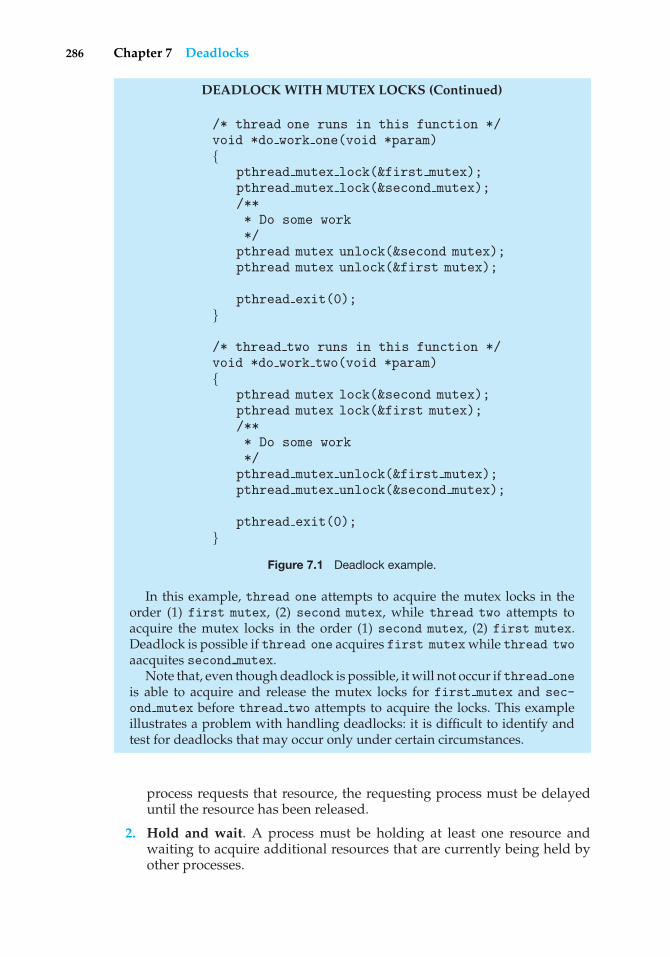
286 Chapter 7 Deadlocks
DEADLOCK WITH MUTEX LOCKS (Continued)
/* thread one runs in this function */void *do work one(void *param){
pthread mutex lock(&first mutex);pthread mutex lock(&second mutex);/*** Do some work*/
pthread mutex unlock(&second mutex);pthread mutex unlock(&first mutex);
pthread exit(0);}
/* thread two runs in this function */void *do work two(void *param){
pthread mutex lock(&second mutex);pthread mutex lock(&first mutex);/*** Do some work*/
pthread mutex unlock(&first mutex);pthread mutex unlock(&second mutex);
pthread exit(0);}
Figure 7.1 Deadlock example.
In this example, thread one attempts to acquire the mutex locks in theorder (1) first mutex, (2) second mutex, while thread two attempts toacquire the mutex locks in the order (1) second mutex, (2) first mutex.Deadlock is possible if thread one acquires first mutex while thread twoaacquites second mutex.
Note that, even though deadlock is possible, it will not occur if thread oneis able to acquire and release the mutex locks for first mutex and sec-ond mutex before thread two attempts to acquire the locks. This exampleillustrates a problem with handling deadlocks: it is difficult to identify andtest for deadlocks that may occur only under certain circumstances.
process requests that resource, the requesting process must be delayeduntil the resource has been released.
2. Hold and wait. A process must be holding at least one resource andwaiting to acquire additional resources that are currently being held byother processes.
7.2 Deadlock Characterization 287
3. No preemption. Resources cannot be preempted; that is, a resource canbe released only voluntarily by the process holding it, after that processhas completed its task.
4. Circular wait. A set {P0, P1, ..., Pn} of waiting processes must exist suchthat P0 is waiting for a resource held by P1, P1 is waiting for a resourceheld by P2, ..., Pn−1 is waiting for a resource held by Pn, and Pn is waitingfor a resource held by P0.
We emphasize that all four conditions must hold for a deadlock tooccur. The circular-wait condition implies the hold-and-wait condition, so thefour conditions are not completely independent. We shall see in Section 7.4,however, that it is useful to consider each condition separately.
7.2.2 Resource-Allocation Graph
Deadlocks can be described more precisely in terms of a directed graph calleda system resource-allocation graph. This graph consists of a set of vertices Vand a set of edges E. The set of verticesV is partitioned into two different typesof nodes: P = {P1, P2, ..., Pn}, the set consisting of all the active processes in thesystem, and R = {R1, R2, ..., Rm}, the set consisting of all resource types in thesystem.
A directed edge from process Pi to resource type Rj is denoted by Pi → Rj ;it signifies that process Pi has requested an instance of resource type Rj andis currently waiting for that resource. A directed edge from resource type Rjto process Pi is denoted by Rj → Pi ; it signifies that an instance of resourcetype Rj has been allocated to process Pi . A directed edge Pi → Rj is called arequest edge; a directed edge Rj → Pi is called an assignment edge.
Pictorially, we represent each process Pi as a circle and each resource typeRj as a rectangle. Since resource type Rj may have more than one instance, werepresent each such instance as a dot within the rectangle. Note that a requestedge points to only the rectangle Rj , whereas an assignment edge must alsodesignate one of the dots in the rectangle.
When process Pi requests an instance of resource type Rj , a request edgeis inserted in the resource-allocation graph. When this request can be fulfilled,the request edge is instantaneously transformed to an assignment edge. Whenthe process no longer needs access to the resource, it releases the resource; as aresult, the assignment edge is deleted.
The resource-allocation graph shown in Figure 7.2 depicts the followingsituation.
• The sets P, R, and E:
◦ P = {P1, P2, P3}◦ R = {R1, R2, R3, R4}◦ E = {P1 → R1, P2 → R3, R1 → P2, R2 → P2, R2 → P1, R3 → P3}
• Resource instances:
◦ One instance of resource type R1
◦ Two instances of resource type R2
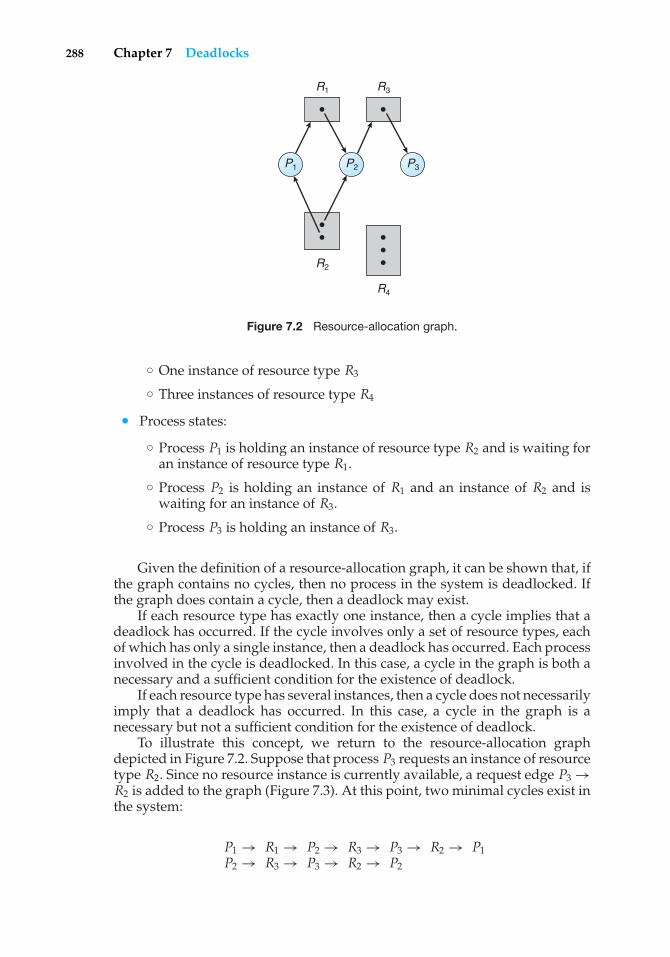
288 Chapter 7 Deadlocks
R1 R3
R2
R4
P3P2P1
Figure 7.2 Resource-allocation graph.
◦ One instance of resource type R3
◦ Three instances of resource type R4
• Process states:
◦ Process P1 is holding an instance of resource type R2 and is waiting foran instance of resource type R1.
◦ Process P2 is holding an instance of R1 and an instance of R2 and iswaiting for an instance of R3.
◦ Process P3 is holding an instance of R3.
Given the definition of a resource-allocation graph, it can be shown that, ifthe graph contains no cycles, then no process in the system is deadlocked. Ifthe graph does contain a cycle, then a deadlock may exist.
If each resource type has exactly one instance, then a cycle implies that adeadlock has occurred. If the cycle involves only a set of resource types, eachof which has only a single instance, then a deadlock has occurred. Each processinvolved in the cycle is deadlocked. In this case, a cycle in the graph is both anecessary and a sufficient condition for the existence of deadlock.
If each resource type has several instances, then a cycle does not necessarilyimply that a deadlock has occurred. In this case, a cycle in the graph is anecessary but not a sufficient condition for the existence of deadlock.
To illustrate this concept, we return to the resource-allocation graphdepicted in Figure 7.2. Suppose that process P3 requests an instance of resourcetype R2. Since no resource instance is currently available, a request edge P3 →R2 is added to the graph (Figure 7.3). At this point, two minimal cycles exist inthe system:
P1 → R1 → P2 → R3 → P3 → R2 → P1P2 → R3 → P3 → R2 → P2
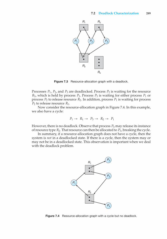
7.2 Deadlock Characterization 289
R1 R3
R2
R4
P3P2P1
Figure 7.3 Resource-allocation graph with a deadlock.
Processes P1, P2, and P3 are deadlocked. Process P2 is waiting for the resourceR3, which is held by process P3. Process P3 is waiting for either process P1 orprocess P2 to release resource R2. In addition, process P1 is waiting for processP2 to release resource R1.
Now consider the resource-allocation graph in Figure 7.4. In this example,we also have a cycle:
P1 → R1 → P3 → R2 → P1
However, there is no deadlock. Observe that process P4 may release its instanceof resource type R2. That resource can then be allocated to P3, breaking the cycle.
In summary, if a resource-allocation graph does not have a cycle, then thesystem is not in a deadlocked state. If there is a cycle, then the system may ormay not be in a deadlocked state. This observation is important when we dealwith the deadlock problem.
R2
R1
P3
P4
P2
P1
Figure 7.4 Resource-allocation graph with a cycle but no deadlock.
290 Chapter 7 Deadlocks
7.3 Methods for Handling Deadlocks
Generally speaking, we can deal with the deadlock problem in one of threeways:
• We can use a protocol to prevent or avoid deadlocks, ensuring that thesystem will never enter a deadlocked state.
• We can allow the system to enter a deadlocked state, detect it, and recover.
• We can ignore the problem altogether and pretend that deadlocks neveroccur in the system.
The third solution is the one used by most operating systems, including UNIXand Windows; it is then up to the application developer to write programs thathandle deadlocks.
Next, we elaborate briefly on each of the three methods for handlingdeadlocks. Then, in Sections 7.4 through 7.7, we present detailed algorithms.Before proceeding, we should mention that some researchers have argued thatnone of the basic approaches alone is appropriate for the entire spectrum ofresource-allocation problems in operating systems. The basic approaches canbe combined, however, allowing us to select an optimal approach for each classof resources in a system.
To ensure that deadlocks never occur, the system can use either a deadlock-prevention or a deadlock-avoidance scheme. Deadlock prevention providesa set of methods for ensuring that at least one of the necessary conditions(Section 7.2.1) cannot hold. These methods prevent deadlocks by constraininghow requests for resources can be made. We discuss these methods in Section7.4.
Deadlock avoidance requires that the operating system be given inadvance additional information concerning which resources a process willrequest and use during its lifetime. With this additional knowledge, it candecide for each request whether or not the process should wait. To decidewhether the current request can be satisfied or must be delayed, the systemmust consider the resources currently available, the resources currently allo-cated to each process, and the future requests and releases of each process. Wediscuss these schemes in Section 7.5.
If a system does not employ either a deadlock-prevention or a deadlock-avoidance algorithm, then a deadlock situation may arise. In this environment,the system can provide an algorithm that examines the state of the system todetermine whether a deadlock has occurred and an algorithm to recover fromthe deadlock (if a deadlock has indeed occurred). We discuss these issues inSection 7.6 and Section 7.7.
In the absence of algorithms to detect and recover from deadlocks, we mayarrive at a situation in which the system is in a deadlock state yet has no wayof recognizing what has happened. In this case, the undetected deadlock willresult in deterioration of the system’s performance, because resources are beingheld by processes that cannot run and because more and more processes, asthey make requests for resources, will enter a deadlocked state. Eventually, thesystem will stop functioning and will need to be restarted manually.
7.4 Deadlock Prevention 291
Although this method may not seem to be a viable approach to the deadlockproblem, it is nevertheless used in most operating systems, as mentionedearlier. In many systems, deadlocks occur infrequently (say, once per year);thus, this method is cheaper than the prevention, avoidance, or detection andrecovery methods, which must be used constantly. Also, in some circumstances,a system is in a frozen state but not in a deadlocked state. We see this situation,for example, with a real-time process running at the highest priority (or anyprocess running on a nonpreemptive scheduler) and never returning controlto the operating system. The system must have manual recovery methods forsuch conditions and may simply use those techniques for deadlock recovery.
7.4 Deadlock Prevention
As we noted in Section 7.2.1, for a deadlock to occur, each of the four necessaryconditions must hold. By ensuring that at least one of these conditions cannothold, we can prevent the occurrence of a deadlock. We elaborate on thisapproach by examining each of the four necessary conditions separately.
7.4.1 Mutual Exclusion
The mutual-exclusion condition must hold for nonsharable resources. Forexample, a printer cannot be simultaneously shared by several processes.Sharable resources, in contrast, do not require mutually exclusive access andthus cannot be involved in a deadlock. Read-only files are a good example ofa sharable resource. If several processes attempt to open a read-only file at thesame time, they can be granted simultaneous access to the file. A process neverneeds to wait for a sharable resource. In general, however, we cannot preventdeadlocks by denying the mutual-exclusion condition, because some resourcesare intrinsically nonsharable.
7.4.2 Hold and Wait
To ensure that the hold-and-wait condition never occurs in the system, we mustguarantee that, whenever a process requests a resource, it does not hold anyother resources. One protocol that can be used requires each process to requestand be allocated all its resources before it begins execution. We can implementthis provision by requiring that system calls requesting resources for a processprecede all other system calls.
An alternative protocol allows a process to request resources only when ithas none. A process may request some resources and use them. Before it canrequest any additional resources, however, it must release all the resources thatit is currently allocated.
To illustrate the difference between these two protocols, we consider aprocess that copies data from a DVD drive to a file on disk, sorts the file, andthen prints the results to a printer. If all resources must be requested at thebeginning of the process, then the process must initially request the DVD drive,disk file, and printer. It will hold the printer for its entire execution, even thoughit needs the printer only at the end.
The second method allows the process to request initially only the DVDdrive and disk file. It copies from the DVD drive to the disk and then releases
292 Chapter 7 Deadlocks
both the DVD drive and the disk file. The process must then again request thedisk file and the printer. After copying the disk file to the printer, it releasesthese two resources and terminates.
Both these protocols have two main disadvantages. First, resource utiliza-tion may be low, since resources may be allocated but unused for a long period.In the example given, for instance, we can release the DVD drive and disk file,and then again request the disk file and printer, only if we can be sure that ourdata will remain on the disk file. Otherwise, we must request all resources atthe beginning for both protocols.
Second, starvation is possible. A process that needs several popularresources may have to wait indefinitely, because at least one of the resourcesthat it needs is always allocated to some other process.
7.4.3 No Preemption
The third necessary condition for deadlocks is that there be no preemptionof resources that have already been allocated. To ensure that this conditiondoes not hold, we can use the following protocol. If a process is holdingsome resources and requests another resource that cannot be immediatelyallocated to it (that is, the process must wait), then all resources the process iscurrently holding are preempted. In other words, these resources are implicitlyreleased. The preempted resources are added to the list of resources for whichthe process is waiting. The process will be restarted only when it can regain itsold resources, as well as the new ones that it is requesting.
Alternatively, if a process requests some resources, we first check whetherthey are available. If they are, we allocate them. If they are not, we checkwhether they are allocated to some other process that is waiting for additionalresources. If so, we preempt the desired resources from the waiting process andallocate them to the requesting process. If the resources are neither availablenor held by a waiting process, the requesting process must wait. While it iswaiting, some of its resources may be preempted, but only if another processrequests them. A process can be restarted only when it is allocated the newresources it is requesting and recovers any resources that were preemptedwhile it was waiting.
This protocol is often applied to resources whose state can be easily savedand restored later, such as CPU registers and memory space. It cannot generallybe applied to such resources as printers and tape drives.
7.4.4 Circular Wait
The fourth and final condition for deadlocks is the circular-wait condition. Oneway to ensure that this condition never holds is to impose a total ordering ofall resource types and to require that each process requests resources in anincreasing order of enumeration.
To illustrate, we let R = {R1, R2, ..., Rm} be the set of resource types. Weassign to each resource type a unique integer number, which allows us tocompare two resources and to determine whether one precedes another in ourordering. Formally, we define a one-to-one function F: R→ N, where N is theset of natural numbers. For example, if the set of resource types R includestape drives, disk drives, and printers, then the function F might be defined asfollows:
7.4 Deadlock Prevention 293
F (tape drive) = 1F (disk drive) = 5F (printer) = 12
We can now consider the following protocol to prevent deadlocks: Eachprocess can request resources only in an increasing order of enumeration. Thatis, a process can initially request any number of instances of a resource type—say, Ri . After that, the process can request instances of resource type Rj ifand only if F(Rj ) > F(Ri ). For example, using the function defined previously,a process that wants to use the tape drive and printer at the same time mustfirst request the tape drive and then request the printer. Alternatively, we canrequire that a process requesting an instance of resource type Rj must havereleased any resources Ri such that F(Ri ) ≥ F(Rj ). It must also be noted that ifseveral instances of the same resource type are needed, a single request for allof them must be issued.
If these two protocols are used, then the circular-wait condition cannothold. We can demonstrate this fact by assuming that a circular wait exists(proof by contradiction). Let the set of processes involved in the circular wait be{P0, P1, ..., Pn}, where Pi is waiting for a resource Ri , which is held by processPi+1. (Modulo arithmetic is used on the indexes, so that Pn is waiting fora resource Rn held by P0.) Then, since process Pi+1 is holding resource Riwhile requesting resource Ri+1, we must have F(Ri ) < F(Ri+1) for all i. Butthis condition means that F(R0) < F(R1) < ... < F(Rn) < F (R0). By transitivity,F(R0) < F(R0), which is impossible. Therefore, there can be no circular wait.
We can accomplish this scheme in an application program by developingan ordering among all synchronization objects in the system. All requests forsynchronization objects must be made in increasing order. For example, if thelock ordering in the Pthread program shown in Figure 7.1 was
F (first mutex) = 1F (second mutex) = 5
then thread two could not request the locks out of order.Keep in mind that developing an ordering, or hierarchy, does not in itself
prevent deadlock. It is up to application developers to write programs thatfollow the ordering. Also note that the function F should be defined accordingto the normal order of usage of the resources in a system. For example, becausethe tape drive is usually needed before the printer, it would be reasonable todefine F(tape drive) <F(printer).
Although ensuring that resources are acquired in the proper order is theresponsibility of application developers, certain software can be used to verifythat locks are acquired in the proper order and to give appropriate warningswhen locks are acquired out of order and deadlock is possible. One lock-orderverifier, which works on BSD versions of UNIX such as FreeBSD, is known aswitness. Witness uses mutual-exclusion locks to protect critical sections, asdescribed in Chapter 6; it works by dynamically maintaining the relationshipof lock orders in a system. Let’s use the program shown in Figure 7.1 as anexample. Assume that thread one is the first to acquire the locks and does so inthe order (1) first mutex, (2) second mutex. Witness records the relationshipthat first mutex must be acquired before second mutex. If thread two later
294 Chapter 7 Deadlocks
acquires the locks out of order, witness generates a warning message on thesystem console.
It is also important to note that imposing a lock ordering does not guaranteedeadlock prevention if locks can be acquired dynamically. For example, assumewe have a function that transfers funds between two accounts. To prevent arace condition, each account has an associated semaphore that is obtained froma getLock() function such as the following:
void transaction(Account from, Account to, double amount){
Semaphore lock1, lock2;lock1 = getLock(from);lock2 = getLock(to);
wait(lock1);wait(lock2);
withdraw(from, amount);deposit(to, amount);
signal(lock2);signal(lock1);
}Deadlock is possible if two threads simultaneously invoke the transaction()function, transposing different accounts. That is, one thread might invoke
transaction(checkingAccount, savingsAccount, 25);
and another might invoke
transaction(savingsAccount, checkingAccount, 50);
We leave it as an exercise for students to fix this situation.
7.5 Deadlock Avoidance
Deadlock-prevention algorithms, as discussed in Section 7.4, prevent deadlocksby restraining how requests can be made. The restraints ensure that at leastone of the necessary conditions for deadlock cannot occur and, hence, thatdeadlocks cannot hold. Possible side effects of preventing deadlocks by thismethod, however, are low device utilization and reduced system throughput.
An alternative method for avoiding deadlocks is to require additionalinformation about how resources are to be requested. For example, in a systemwith one tape drive and one printer, the system might need to know thatprocess Pwill request first the tape drive and then the printer before releasingboth resources, whereas process Q will request first the printer and then thetape drive. With this knowledge of the complete sequence of requests andreleases for each process, the system can decide for each request whether ornot the process should wait in order to avoid a possible future deadlock. Eachrequest requires that in making this decision the system consider the resources
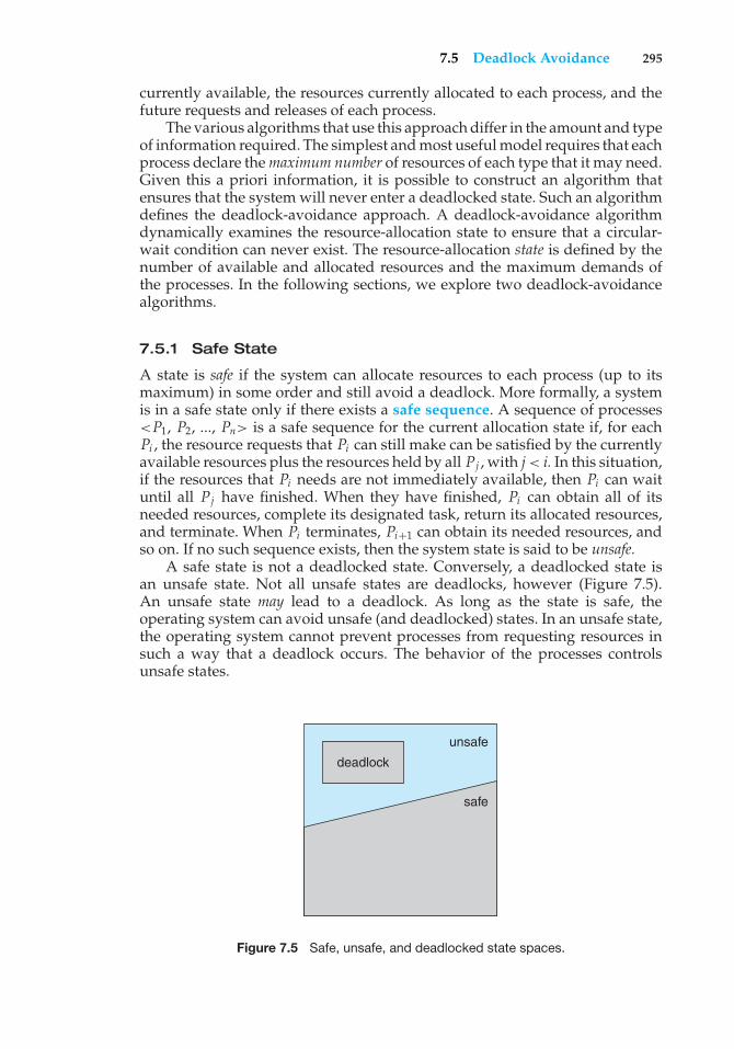
7.5 Deadlock Avoidance 295
currently available, the resources currently allocated to each process, and thefuture requests and releases of each process.
The various algorithms that use this approach differ in the amount and typeof information required. The simplest and most useful model requires that eachprocess declare themaximum number of resources of each type that it may need.Given this a priori information, it is possible to construct an algorithm thatensures that the system will never enter a deadlocked state. Such an algorithmdefines the deadlock-avoidance approach. A deadlock-avoidance algorithmdynamically examines the resource-allocation state to ensure that a circular-wait condition can never exist. The resource-allocation state is defined by thenumber of available and allocated resources and the maximum demands ofthe processes. In the following sections, we explore two deadlock-avoidancealgorithms.
7.5.1 Safe State
A state is safe if the system can allocate resources to each process (up to itsmaximum) in some order and still avoid a deadlock. More formally, a systemis in a safe state only if there exists a safe sequence. A sequence of processes<P1, P2, ..., Pn> is a safe sequence for the current allocation state if, for eachPi , the resource requests that Pi can still make can be satisfied by the currentlyavailable resources plus the resources held by all Pj , with j< i. In this situation,if the resources that Pi needs are not immediately available, then Pi can waituntil all Pj have finished. When they have finished, Pi can obtain all of itsneeded resources, complete its designated task, return its allocated resources,and terminate. When Pi terminates, Pi+1 can obtain its needed resources, andso on. If no such sequence exists, then the system state is said to be unsafe.
A safe state is not a deadlocked state. Conversely, a deadlocked state isan unsafe state. Not all unsafe states are deadlocks, however (Figure 7.5).An unsafe state may lead to a deadlock. As long as the state is safe, theoperating system can avoid unsafe (and deadlocked) states. In an unsafe state,the operating system cannot prevent processes from requesting resources insuch a way that a deadlock occurs. The behavior of the processes controlsunsafe states.
deadlock
unsafe
safe
Figure 7.5 Safe, unsafe, and deadlocked state spaces.
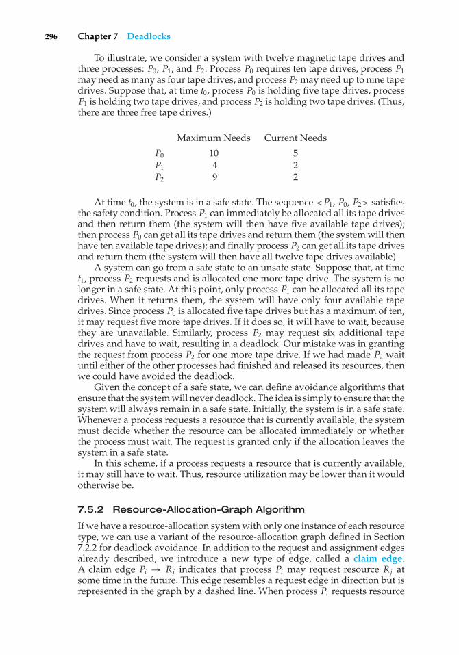
296 Chapter 7 Deadlocks
To illustrate, we consider a system with twelve magnetic tape drives andthree processes: P0, P1, and P2. Process P0 requires ten tape drives, process P1may need as many as four tape drives, and process P2 may need up to nine tapedrives. Suppose that, at time t0, process P0 is holding five tape drives, processP1 is holding two tape drives, and process P2 is holding two tape drives. (Thus,there are three free tape drives.)
Maximum Needs Current Needs
P0 10 5P1 4 2P2 9 2
At time t0, the system is in a safe state. The sequence <P1, P0, P2> satisfiesthe safety condition. Process P1 can immediately be allocated all its tape drivesand then return them (the system will then have five available tape drives);then process P0 can get all its tape drives and return them (the system will thenhave ten available tape drives); and finally process P2 can get all its tape drivesand return them (the system will then have all twelve tape drives available).
A system can go from a safe state to an unsafe state. Suppose that, at timet1, process P2 requests and is allocated one more tape drive. The system is nolonger in a safe state. At this point, only process P1 can be allocated all its tapedrives. When it returns them, the system will have only four available tapedrives. Since process P0 is allocated five tape drives but has a maximum of ten,it may request five more tape drives. If it does so, it will have to wait, becausethey are unavailable. Similarly, process P2 may request six additional tapedrives and have to wait, resulting in a deadlock. Our mistake was in grantingthe request from process P2 for one more tape drive. If we had made P2 waituntil either of the other processes had finished and released its resources, thenwe could have avoided the deadlock.
Given the concept of a safe state, we can define avoidance algorithms thatensure that the system will never deadlock. The idea is simply to ensure that thesystem will always remain in a safe state. Initially, the system is in a safe state.Whenever a process requests a resource that is currently available, the systemmust decide whether the resource can be allocated immediately or whetherthe process must wait. The request is granted only if the allocation leaves thesystem in a safe state.
In this scheme, if a process requests a resource that is currently available,it may still have to wait. Thus, resource utilization may be lower than it wouldotherwise be.
7.5.2 Resource-Allocation-Graph Algorithm
If we have a resource-allocation system with only one instance of each resourcetype, we can use a variant of the resource-allocation graph defined in Section7.2.2 for deadlock avoidance. In addition to the request and assignment edgesalready described, we introduce a new type of edge, called a claim edge.A claim edge Pi → Rj indicates that process Pi may request resource Rj atsome time in the future. This edge resembles a request edge in direction but isrepresented in the graph by a dashed line. When process Pi requests resource
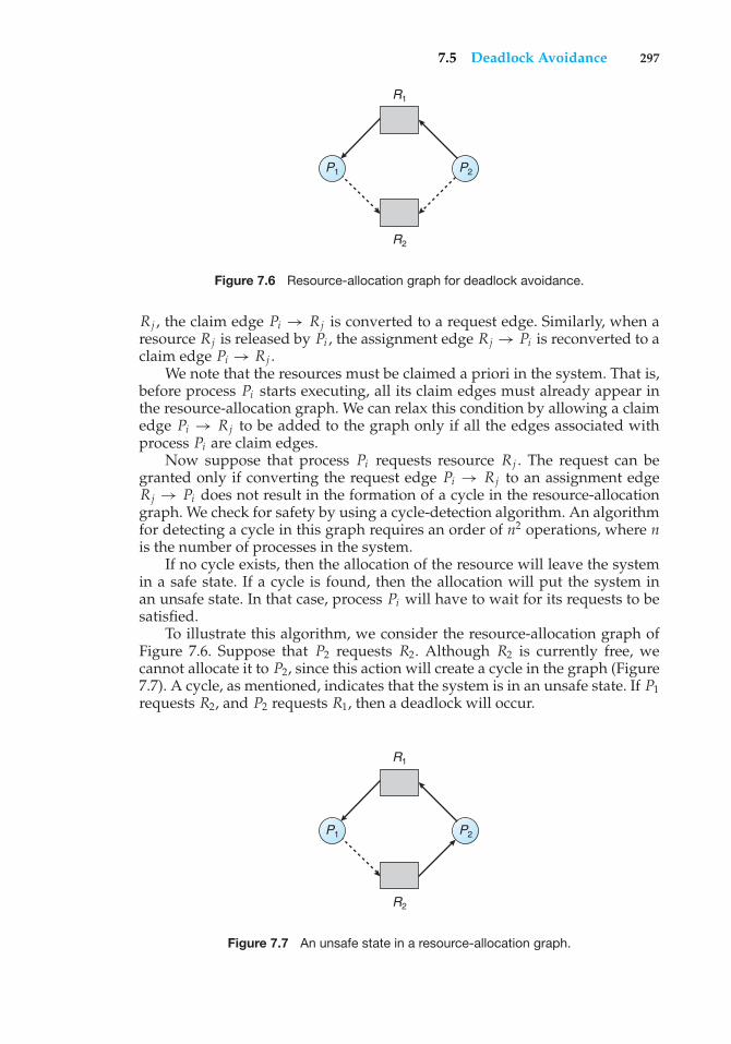
7.5 Deadlock Avoidance 297
R1
R2
P2P1
Figure 7.6 Resource-allocation graph for deadlock avoidance.
Rj , the claim edge Pi → Rj is converted to a request edge. Similarly, when aresource Rj is released by Pi , the assignment edge Rj → Pi is reconverted to aclaim edge Pi → Rj .
We note that the resources must be claimed a priori in the system. That is,before process Pi starts executing, all its claim edges must already appear inthe resource-allocation graph. We can relax this condition by allowing a claimedge Pi → Rj to be added to the graph only if all the edges associated withprocess Pi are claim edges.
Now suppose that process Pi requests resource Rj . The request can begranted only if converting the request edge Pi → Rj to an assignment edgeRj → Pi does not result in the formation of a cycle in the resource-allocationgraph. We check for safety by using a cycle-detection algorithm. An algorithmfor detecting a cycle in this graph requires an order of n2 operations, where nis the number of processes in the system.
If no cycle exists, then the allocation of the resource will leave the systemin a safe state. If a cycle is found, then the allocation will put the system inan unsafe state. In that case, process Pi will have to wait for its requests to besatisfied.
To illustrate this algorithm, we consider the resource-allocation graph ofFigure 7.6. Suppose that P2 requests R2. Although R2 is currently free, wecannot allocate it to P2, since this action will create a cycle in the graph (Figure7.7). A cycle, as mentioned, indicates that the system is in an unsafe state. If P1requests R2, and P2 requests R1, then a deadlock will occur.
R1
R2
P2P1
Figure 7.7 An unsafe state in a resource-allocation graph.
298 Chapter 7 Deadlocks
7.5.3 Banker’s Algorithm
The resource-allocation-graph algorithm is not applicable to a resource-allocation system with multiple instances of each resource type. The deadlock-avoidance algorithm that we describe next is applicable to such a system butis less efficient than the resource-allocation graph scheme. This algorithm iscommonly known as the banker’s algorithm. The name was chosen because thealgorithm could be used in a banking system to ensure that the bank neverallocated its available cash in such a way that it could no longer satisfy theneeds of all its customers.
When a new process enters the system, it must declare the maximumnumber of instances of each resource type that it may need. This number maynot exceed the total number of resources in the system. When a user requestsa set of resources, the system must determine whether the allocation of theseresources will leave the system in a safe state. If it will, the resources areallocated; otherwise, the process must wait until some other process releasesenough resources.
Several data structures must be maintained to implement the banker’salgorithm. These data structures encode the state of the resource-allocationsystem. We need the following data structures, where n is the number ofprocesses in the system and m is the number of resource types:
• Available. A vector of lengthm indicates the number of available resourcesof each type. If Available[j] equals k, then k instances of resource type Rjare available.
• Max. An n × m matrix defines the maximum demand of each process.If Max[i][j] equals k, then process Pi may request at most k instances ofresource type Rj .
• Allocation. An n× mmatrix defines the number of resources of each typecurrently allocated to each process. If Allocation[i][j] equals k, then processPi is currently allocated k instances of resource type Rj .
• Need. An n × m matrix indicates the remaining resource need of eachprocess. IfNeed[i][j] equals k, then process Pi may need kmore instances ofresource type Rj to complete its task. Note that Need[i][j] equals Max[i][j]− Allocation[i][j].
These data structures vary over time in both size and value.To simplify the presentation of the banker’s algorithm, we next establish
some notation. Let X and Y be vectors of length n. We say that X ≤ Y if andonly if X[i] ≤ Y[i] for all i = 1, 2, ..., n. For example, if X = (1,7,3,2) and Y =(0,3,2,1), then Y ≤ X. In addition, Y < X if Y ≤ X and Y �= X.
We can treat each row in the matrices Allocation and Need as vectorsand refer to them as Allocationi and Needi . The vector Allocationi specifiesthe resources currently allocated to process Pi ; the vector Needi specifies theadditional resources that process Pi may still request to complete its task.
7.5.3.1 Safety Algorithm
We can now present the algorithm for finding out whether or not a system isin a safe state. This algorithm can be described as follows:
7.5 Deadlock Avoidance 299
1. Let Work and Finish be vectors of length m and n, respectively. InitializeWork = Available and Finish[i] = false for i = 0, 1, ..., n − 1.
2. Find an index i such that both
a. Finish[i] == false
b. Needi ≤WorkIf no such i exists, go to step 4.
3. Work =Work + AllocationiFinish[i] = trueGo to step 2.
4. If Finish[i] == true for all i, then the system is in a safe state.
This algorithm may require an order ofm× n2 operations to determine whethera state is safe.
7.5.3.2 Resource-Request Algorithm
Next, we describe the algorithm for determining whether requests can be safelygranted.
Let Requesti be the request vector for process Pi . If Requesti [ j] == k, thenprocess Pi wants k instances of resource type Rj . When a request for resourcesis made by process Pi , the following actions are taken:
1. If Requesti ≤Needi , go to step 2. Otherwise, raise an error condition, sincethe process has exceeded its maximum claim.
2. If Requesti ≤ Available, go to step 3. Otherwise, Pi must wait, since theresources are not available.
3. Have the system pretend to have allocated the requested resources toprocess Pi by modifying the state as follows:
Available = Available - Requesti ;Allocationi = Allocationi + Requesti ;Needi = Needi - Requesti ;
If the resulting resource-allocation state is safe, the transaction is com-pleted, and process Pi is allocated its resources. However, if the new stateis unsafe, then Pi must wait for Requesti , and the old resource-allocationstate is restored.
7.5.3.3 An Illustrative Example
To illustrate the use of the banker’s algorithm, consider a system with fiveprocesses P0 through P4 and three resource types A, B, and C. Resource type Ahas ten instances, resource type B has five instances, and resource type C hasseven instances. Suppose that, at time T0, the following snapshot of the systemhas been taken:
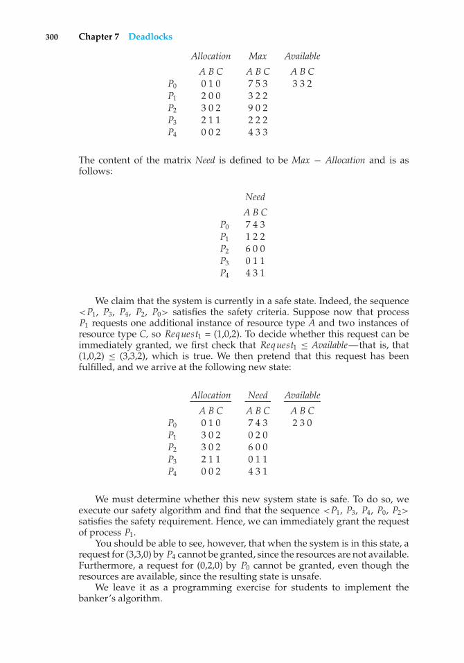
300 Chapter 7 Deadlocks
Allocation Max Available
A B C A B C A B CP0 0 1 0 7 5 3 3 3 2P1 2 0 0 3 2 2P2 3 0 2 9 0 2P3 2 1 1 2 2 2P4 0 0 2 4 3 3
The content of the matrix Need is defined to be Max − Allocation and is asfollows:
Need
A B CP0 7 4 3P1 1 2 2P2 6 0 0P3 0 1 1P4 4 3 1
We claim that the system is currently in a safe state. Indeed, the sequence<P1, P3, P4, P2, P0> satisfies the safety criteria. Suppose now that processP1 requests one additional instance of resource type A and two instances ofresource type C, so Request1 = (1,0,2). To decide whether this request can beimmediately granted, we first check that Request1 ≤ Available—that is, that(1,0,2) ≤ (3,3,2), which is true. We then pretend that this request has beenfulfilled, and we arrive at the following new state:
Allocation Need Available
A B C A B C A B CP0 0 1 0 7 4 3 2 3 0P1 3 0 2 0 2 0P2 3 0 2 6 0 0P3 2 1 1 0 1 1P4 0 0 2 4 3 1
We must determine whether this new system state is safe. To do so, weexecute our safety algorithm and find that the sequence <P1, P3, P4, P0, P2>
satisfies the safety requirement. Hence, we can immediately grant the requestof process P1.
You should be able to see, however, that when the system is in this state, arequest for (3,3,0) by P4 cannot be granted, since the resources are not available.Furthermore, a request for (0,2,0) by P0 cannot be granted, even though theresources are available, since the resulting state is unsafe.
We leave it as a programming exercise for students to implement thebanker’s algorithm.
7.6 Deadlock Detection 301
7.6 Deadlock Detection
If a system does not employ either a deadlock-prevention or a deadlock-avoidance algorithm, then a deadlock situation may occur. In this environment,the system may provide:
• An algorithm that examines the state of the system to determine whethera deadlock has occurred
• An algorithm to recover from the deadlock
In the following discussion, we elaborate on these two requirements as theypertain to systems with only a single instance of each resource type, as well as tosystems with several instances of each resource type. At this point, however, wenote that a detection-and-recovery scheme requires overhead that includes notonly the run-time costs of maintaining the necessary information and executingthe detection algorithm but also the potential losses inherent in recovering froma deadlock.
7.6.1 Single Instance of Each Resource Type
If all resources have only a single instance, then we can define a deadlock-detection algorithm that uses a variant of the resource-allocation graph, calleda wait-for graph. We obtain this graph from the resource-allocation graph byremoving the resource nodes and collapsing the appropriate edges.
More precisely, an edge from Pi to Pj in a wait-for graph implies thatprocess Pi is waiting for process Pj to release a resource that Pi needs. An edgePi → Pj exists in a wait-for graph if and only if the corresponding resource-allocation graph contains two edges Pi → Rq and Rq → Pj for some resourceRq . For example, in Figure 7.8, we present a resource-allocation graph and thecorresponding wait-for graph.
As before, a deadlock exists in the system if and only if the wait-for graphcontains a cycle. To detect deadlocks, the system needs tomaintain the wait-forgraph and periodically invoke an algorithm that searches for a cycle in the graph.An algorithm to detect a cycle in a graph requires an order of n2 operations,where n is the number of vertices in the graph.
7.6.2 Several Instances of a Resource Type
The wait-for graph scheme is not applicable to a resource-allocation systemwith multiple instances of each resource type. We turn now to a deadlock-detection algorithm that is applicable to such a system. The algorithm employsseveral time-varying data structures that are similar to those used in thebanker’s algorithm (Section 7.5.3):
• Available. A vector of lengthm indicates the number of available resourcesof each type.
• Allocation. An n× mmatrix defines the number of resources of each typecurrently allocated to each process.
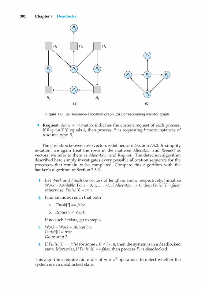
302 Chapter 7 Deadlocks
P3
P5
P4
P2P1
R2
R1 R3 R4
R5
P3
P5
P4
P2P1
(b)(a)
Figure 7.8 (a) Resource-allocation graph. (b) Corresponding wait-for graph.
• Request. An n × m matrix indicates the current request of each process.If Request[i][j] equals k, then process Pi is requesting k more instances ofresource type Rj .
The ≤ relation between two vectors is defined as in Section 7.5.3. To simplifynotation, we again treat the rows in the matrices Allocation and Request asvectors; we refer to them as Allocationi and Requesti . The detection algorithmdescribed here simply investigates every possible allocation sequence for theprocesses that remain to be completed. Compare this algorithm with thebanker’s algorithm of Section 7.5.3.
1. Let Work and Finish be vectors of length m and n, respectively. InitializeWork = Available. For i = 0, 1, ..., n-1, if Allocationi �= 0, then Finish[i] = false;otherwise, Finish[i] = true.
2. Find an index i such that both
a. Finish[i] == false
b. Requesti ≤WorkIf no such i exists, go to step 4.
3. Work =Work + AllocationiFinish[i] = trueGo to step 2.
4. If Finish[i] == false for some i, 0 ≤ i< n, then the system is in a deadlockedstate. Moreover, if Finish[i] == false, then process Pi is deadlocked.
This algorithm requires an order of m × n2 operations to detect whether thesystem is in a deadlocked state.
7.6 Deadlock Detection 303
You may wonder why we reclaim the resources of process Pi (in step 3)as soon as we determine that Requesti ≤ Work (in step 2b). We know that Piis currently not involved in a deadlock (since Requesti ≤ Work). Thus, we takean optimistic attitude and assume that Pi will require no more resources tocomplete its task; it will thus soon return all currently allocated resources tothe system. If our assumption is incorrect, a deadlock may occur later. Thatdeadlock will be detected the next time the deadlock-detection algorithm isinvoked.
To illustrate this algorithm, we consider a system with five processes P0through P4 and three resource types A, B, and C. Resource type A has seveninstances, resource type B has two instances, and resource type C has sixinstances. Suppose that, at time T0, we have the following resource-allocationstate:
Allocation Request Available
A B C A B C A B CP0 0 1 0 0 0 0 0 0 0P1 2 0 0 2 0 2P2 3 0 3 0 0 0P3 2 1 1 1 0 0P4 0 0 2 0 0 2
We claim that the system is not in a deadlocked state. Indeed, if we executeour algorithm, we will find that the sequence <P0, P2, P3, P1, P4> results inFinish[i] == true for all i.
Suppose now that process P2 makes one additional request for an instanceof type C. The Requestmatrix is modified as follows:
Request
A B CP0 0 0 0P1 2 0 2P2 0 0 1P3 1 0 0P4 0 0 2
We claim that the system is now deadlocked. Although we can reclaim theresources held by process P0, the number of available resources is not sufficientto fulfill the requests of the other processes. Thus, a deadlock exists, consistingof processes P1, P2, P3, and P4.
7.6.3 Detection-Algorithm Usage
When should we invoke the detection algorithm? The answer depends on twofactors:
1. How often is a deadlock likely to occur?
2. How many processes will be affected by deadlock when it happens?
304 Chapter 7 Deadlocks
If deadlocks occur frequently, then the detection algorithm should be invokedfrequently. Resources allocated to deadlocked processes will be idle until thedeadlock can be broken. In addition, the number of processes involved in thedeadlock cycle may grow.
Deadlocks occur only when some process makes a request that cannot begranted immediately. This request may be the final request that completes achain of waiting processes. In the extreme, then, we can invoke the deadlock-detection algorithm every time a request for allocation cannot be grantedimmediately. In this case, we can identify not only the deadlocked set ofprocesses but also the specific process that “caused” the deadlock. (In reality,each of the deadlocked processes is a link in the cycle in the resource graph, soall of them, jointly, caused the deadlock.) If there are many different resourcetypes, one request may create many cycles in the resource graph, each cyclecompleted by the most recent request and “caused” by the one identifiableprocess.
Of course, invoking the deadlock-detection algorithm for every resourcerequest will incur considerable overhead in computation time. A less expensivealternative is simply to invoke the algorithm at defined intervals—for example,once per hour or whenever CPU utilization drops below 40 percent. (A deadlockeventually cripples system throughput and causes CPU utilization to drop.) Ifthe detection algorithm is invoked at arbitrary points in time, the resourcegraph may contain many cycles. In this case, we generally cannot tell which ofthe many deadlocked processes “caused” the deadlock.
7.7 Recovery from Deadlock
When a detection algorithm determines that a deadlock exists, several alter-natives are available. One possibility is to inform the operator that a deadlockhas occurred and to let the operator deal with the deadlock manually. Anotherpossibility is to let the system recover from the deadlock automatically. Thereare two options for breaking a deadlock. One is simply to abort one or moreprocesses to break the circular wait. The other is to preempt some resourcesfrom one or more of the deadlocked processes.
7.7.1 Process Termination
To eliminate deadlocks by aborting a process, we use one of two methods. Inboth methods, the system reclaims all resources allocated to the terminatedprocesses.
• Abort all deadlocked processes. This method clearly will break thedeadlock cycle, but at great expense; the deadlocked processes may havecomputed for a long time, and the results of these partial computationsmust be discarded and probably will have to be recomputed later.
• Abort one process at a time until the deadlock cycle is eliminated. Thismethod incurs considerable overhead, since after each process is aborted, adeadlock-detection algorithm must be invoked to determine whether anyprocesses are still deadlocked.
7.7 Recovery from Deadlock 305
Aborting a process may not be easy. If the process was in the midst ofupdating a file, terminating it will leave that file in an incorrect state. Similarly,if the process was in the midst of printing data on a printer, the system mustreset the printer to a correct state before printing the next job.
If the partial termination method is used, then we must determine whichdeadlocked process (or processes) should be terminated. This determination isa policy decision, similar to CPU-scheduling decisions. The question is basicallyan economic one; we should abort those processes whose termination will incurthe minimum cost. Unfortunately, the term minimum cost is not a precise one.Many factors may affect which process is chosen, including:
1. What the priority of the process is
2. How long the process has computed and how much longer the processwill compute before completing its designated task
3. How many and what types of resources the process has used (for example,whether the resources are simple to preempt)
4. How many more resources the process needs in order to complete
5. How many processes will need to be terminated
6. Whether the process is interactive or batch
7.7.2 Resource Preemption
To eliminate deadlocks using resource preemption, we successively preemptsome resources from processes and give these resources to other processes untilthe deadlock cycle is broken.
If preemption is required to deal with deadlocks, then three issues need tobe addressed:
1. Selecting a victim. Which resources and which processes are to bepreempted? As in process termination, we must determine the order ofpreemption to minimize cost. Cost factors may include such parametersas the number of resources a deadlocked process is holding and theamount of time the process has thus far consumed during its execution.
2. Rollback. If we preempt a resource from a process, what should be donewith that process? Clearly, it cannot continue with its normal execution; itis missing some needed resource. We must roll back the process to somesafe state and restart it from that state.
Since, in general, it is difficult to determine what a safe state is, thesimplest solution is a total rollback: abort the process and then restartit. Although it is more effective to roll back the process only as far asnecessary to break the deadlock, this method requires the system to keepmore information about the state of all running processes.
3. Starvation. How do we ensure that starvation will not occur? That is,how can we guarantee that resources will not always be preempted fromthe same process?
306 Chapter 7 Deadlocks
In a system where victim selection is based primarily on cost factors,it may happen that the same process is always picked as a victim. Asa result, this process never completes its designated task, a starvationsituation that must be dealt with in any practical system. Clearly, wemust ensure that a process can be picked as a victim only a (small) finitenumber of times. The most common solution is to include the number ofrollbacks in the cost factor.
7.8 Summary
A deadlocked state occurs when two or more processes are waiting indefinitelyfor an event that can be caused only by one of the waiting processes. There arethree principal methods for dealing with deadlocks:
• Use some protocol to prevent or avoid deadlocks, ensuring that the systemwill never enter a deadlocked state.
• Allow the system to enter a deadlocked state, detect it, and then recover.
• Ignore the problem altogether and pretend that deadlocks never occur inthe system.
The third solution is the one used by most operating systems, including UNIXand Windows.
A deadlock can occur only if four necessary conditions hold simultaneouslyin the system: mutual exclusion, hold and wait, no preemption, and circularwait. To prevent deadlocks, we can ensure that at least one of the necessaryconditions never holds.
A method for avoiding deadlocks, rather than preventing them, requiresthat the operating system have a priori information about how each processwill utilize system resources. The banker’s algorithm, for example, requiresa priori information about the maximum number of each resource class thateach process may request. Using this information, we can define a deadlock-avoidance algorithm.
If a system does not employ a protocol to ensure that deadlocks will neveroccur, then a detection-and-recovery scheme may be employed. A deadlock-detection algorithm must be invoked to determine whether a deadlockhas occurred. If a deadlock is detected, the system must recover either byterminating some of the deadlocked processes or by preempting resourcesfrom some of the deadlocked processes.
Where preemption is used to deal with deadlocks, three issues must beaddressed: selecting a victim, rollback, and starvation. In a system that selectsvictims for rollback primarily on the basis of cost factors, starvation may occur,and the selected process can never complete its designated task.
Researchers have argued that none of the basic approaches alone is appro-priate for the entire spectrum of resource-allocation problems in operatingsystems. The basic approaches can be combined, however, allowing us to selectan optimal approach for each class of resources in a system.
Practice Exercises 307
Practice Exercises
7.1 List three examples of deadlocks that are not related to a computer-system environment.
7.2 Suppose that a system is in an unsafe state. Show that it is possible forthe processes to complete their execution without entering a deadlockedstate.
7.3 A possible method for preventing deadlocks is to have a single, higher-order resource that must be requested before any other resource. Forexample, if multiple threads attempt to access the synchronizationobjects A · · · E , deadlock is possible. (Such synchronization objects mayinclude mutexes, semaphores, condition variables, and the like.) We canprevent the deadlock by adding a sixth object F . Whenever a threadwants to acquire the synchronization lock for any object A · · · E , it mustfirst acquire the lock for object F . This solution is known as containment:the locks for objects A · · · E are contained within the lock for object F .Compare this scheme with the circular-wait scheme of Section 7.4.4.
7.4 Prove that the safety algorithm presented in Section 7.5.3 requires anorder of m × n2 operations.
7.5 Consider a computer system that runs 5,000 jobs per month and has nodeadlock-prevention or deadlock-avoidance scheme. Deadlocks occurabout twice per month, and the operator must terminate and rerun about10 jobs per deadlock. Each job is worth about $2 (in CPU time), and thejobs terminated tend to be about half-done when they are aborted.
A systems programmer has estimated that a deadlock-avoidancealgorithm (like the banker’s algorithm) could be installed in the systemwith an increase in the average execution time per job of about 10 percent.Since the machine currently has 30 percent idle time, all 5,000 jobs permonth could still be run, although turnaround time would increase byabout 20 percent on average.
a. What are the arguments for installing the deadlock-avoidancealgorithm?
b. What are the arguments against installing the deadlock-avoidancealgorithm?
7.6 Can a system detect that some of its processes are starving? If you answer“yes,” explain how it can. If you answer “no,” explain how the systemcan deal with the starvation problem.
7.7 Consider the following resource-allocation policy. Requests for andreleases of resources are allowed at any time. If a request for resourcescannot be satisfied because the resources are not available, then we checkany processes that are blocked waiting for resources. If a blocked processhas the desired resources, then these resources are taken away from itand are given to the requesting process. The vector of resources for whichthe blocked process is waiting is increased to include the resources thatwere taken away.
308 Chapter 7 Deadlocks
For example, consider a system with three resource types and thevector Available initialized to (4,2,2). If process P0 asks for (2,2,1), it getsthem. If P1 asks for (1,0,1), it gets them. Then, if P0 asks for (0,0,1), itis blocked (resource not available). If P2 now asks for (2,0,0), it gets theavailable one (1,0,0) and one that was allocated to P0 (since P0 is blocked).P0’s Allocation vector goes down to (1,2,1), and its Need vector goes upto (1,0,1).
a. Can deadlock occur? If you answer “yes,” give an example. If youanswer “no,” specify which necessary condition cannot occur.
b. Can indefinite blocking occur? Explain your answer.
7.8 Suppose that you have coded the deadlock-avoidance safety algorithmand now have been asked to implement the deadlock-detection algo-rithm. Can you do so by simply using the safety algorithm code andredefining Maxi = Waitingi + Allocationi , where Waitingi is a vectorspecifying the resources for which process i is waiting and Allocationiis as defined in Section 7.5? Explain your answer.
7.9 Is it possible to have a deadlock involving only a single process? Explainyour answer.
Exercises
7.10 Consider the traffic deadlock depicted in Figure 7.9.
a. Show that the four necessary conditions for deadlock hold in thisexample.
b. State a simple rule for avoiding deadlocks in this system.
7.11 Consider the deadlock situation that can occur in the dining-philosophers problem when the philosophers obtain the chopsticks oneat a time. Discuss how the four necessary conditions for deadlock holdin this setting. Discuss how deadlocks could be avoided by eliminatingany one of the four necessary conditions.
7.12 In Section 7.4.4, we describe a situation in which we prevent deadlockby ensuring that all locks are acquired in a certain order. However,we also point out that deadlock is possible in this situation if twothreads simultaneously invoke the transaction() function. Fix thetransaction() function to prevent deadlocks.
7.13 Compare the circular-wait scheme with the various deadlock-avoidanceschemes (like the banker’s algorithm) with respect to the followingissues:
a. Runtime overheads
b. System throughput
7.14 In a real computer system, neither the resources available nor thedemands of processes for resources are consistent over long periods
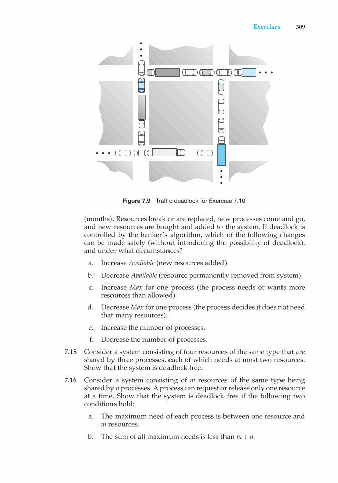
Exercises 309
•••
•••
• • •
• • •
Figure 7.9 Traffic deadlock for Exercise 7.10.
(months). Resources break or are replaced, new processes come and go,and new resources are bought and added to the system. If deadlock iscontrolled by the banker’s algorithm, which of the following changescan be made safely (without introducing the possibility of deadlock),and under what circumstances?
a. Increase Available (new resources added).
b. Decrease Available (resource permanently removed from system).
c. Increase Max for one process (the process needs or wants moreresources than allowed).
d. DecreaseMax for one process (the process decides it does not needthat many resources).
e. Increase the number of processes.
f. Decrease the number of processes.
7.15 Consider a system consisting of four resources of the same type that areshared by three processes, each of which needs at most two resources.Show that the system is deadlock free.
7.16 Consider a system consisting of m resources of the same type beingshared by n processes. A process can request or release only one resourceat a time. Show that the system is deadlock free if the following twoconditions hold:
a. The maximum need of each process is between one resource andm resources.
b. The sum of all maximum needs is less than m + n.
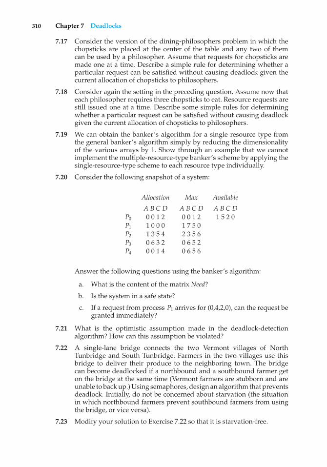
310 Chapter 7 Deadlocks
7.17 Consider the version of the dining-philosophers problem in which thechopsticks are placed at the center of the table and any two of themcan be used by a philosopher. Assume that requests for chopsticks aremade one at a time. Describe a simple rule for determining whether aparticular request can be satisfied without causing deadlock given thecurrent allocation of chopsticks to philosophers.
7.18 Consider again the setting in the preceding question. Assume now thateach philosopher requires three chopsticks to eat. Resource requests arestill issued one at a time. Describe some simple rules for determiningwhether a particular request can be satisfied without causing deadlockgiven the current allocation of chopsticks to philosophers.
7.19 We can obtain the banker’s algorithm for a single resource type fromthe general banker’s algorithm simply by reducing the dimensionalityof the various arrays by 1. Show through an example that we cannotimplement the multiple-resource-type banker’s scheme by applying thesingle-resource-type scheme to each resource type individually.
7.20 Consider the following snapshot of a system:
Allocation Max Available
A B C D A B C D A B C DP0 0 0 1 2 0 0 1 2 1 5 2 0P1 1 0 0 0 1 7 5 0P2 1 3 5 4 2 3 5 6P3 0 6 3 2 0 6 5 2P4 0 0 1 4 0 6 5 6
Answer the following questions using the banker’s algorithm:
a. What is the content of the matrix Need?
b. Is the system in a safe state?
c. If a request from process P1 arrives for (0,4,2,0), can the request begranted immediately?
7.21 What is the optimistic assumption made in the deadlock-detectionalgorithm? How can this assumption be violated?
7.22 A single-lane bridge connects the two Vermont villages of NorthTunbridge and South Tunbridge. Farmers in the two villages use thisbridge to deliver their produce to the neighboring town. The bridgecan become deadlocked if a northbound and a southbound farmer geton the bridge at the same time (Vermont farmers are stubborn and areunable to back up.) Using semaphores, design an algorithm that preventsdeadlock. Initially, do not be concerned about starvation (the situationin which northbound farmers prevent southbound farmers from usingthe bridge, or vice versa).
7.23 Modify your solution to Exercise 7.22 so that it is starvation-free.
Bibliographical Notes 311
Programming Problems
7.24 Write a multithreaded program that implements the banker’s algorithmdiscussed in Section 7.5.3. Create n threads that request and releaseresources from the bank. The banker will grant the request only if itleaves the system in a safe state. You may write this program usingeither Pthreads or Win32 threads. It is important that shared data be safefrom concurrent access. To ensure safe access to shared data, you canuse mutex locks, which are available in both the Pthreads and Win32APIs. The use of mutex locks in both of these libraries is described in theproject entitled “Producer–Consumer Problem” at the end of Chapter 6.
Wiley Plus
Visit Wiley Plus for
• Source code
• Solutions to practice exercises
• Additional programming problems and exercises
• Labs using an operating system simulator
Bibliographical Notes
Dijkstra [1965a] was one of the first and most influential contributors in thedeadlock area. Holt [1972] was the first person to formalize the notion ofdeadlocks in terms of an allocation-graph model similar to the one presentedin this chapter. Starvation was also covered by Holt [1972]. Hyman [1985]provided the deadlock example from the Kansas legislature. A recent study ofdeadlock handling is provided in Levine [2003].
The various prevention algorithms were suggested by Havender [1968],who devised the resource-ordering scheme for the IBM OS/360 system.
The banker’s algorithm for avoiding deadlocks was developed for a singleresource type by Dijkstra [1965a] and was extended to multiple resource typesby Habermann [1969]. Exercises 7.15 and 7.16 are from Holt [1971].
The deadlock-detection algorithm for multiple instances of a resource type,which is described in Section 7.6.2, was presented by Coffman et al. [1971].
Bach [1987] describes how many of the algorithms in the traditional UNIXkernel handle deadlock. Solutions to deadlock problems in networks arediscussed in works such as Culler et al. [1998] and Rodeheffer and Schroeder[1991].
The witness lock-order verifier is presented in Baldwin [2002].

This page intentionally left blank
Part Three
MemoryManagement
The main purpose of a computer system is to execute programs. Theseprograms, together with the data they access, must be at least partiallyin main memory during execution.
To improve both the utilization of the CPU and the speed of itsresponse to users, a general-purpose computer must keep several pro-cesses in memory. Many memory-management schemes exist, reflect-ing various approaches, and the effectiveness of each algorithm dependson the situation. Selection of a memory-management scheme for a sys-tem depends on many factors, especially on the hardware design of thesystem. Most algorithms require hardware support.

This page intentionally left blank
8C H A P T E R
Main Memory
In Chapter 5, we showed how the CPU can be shared by a set of processes. Asa result of CPU scheduling, we can improve both the utilization of the CPU andthe speed of the computer’s response to its users. To realize this increase inperformance, however, we must keep several processes in memory; that is, wemust share memory.
In this chapter, we discuss various ways to manage memory. The memory-management algorithms vary from a primitive bare-machine approach topaging and segmentation strategies. Each approach has its own advantagesand disadvantages. Selection of a memory-management method for a specificsystem depends on many factors, especially on the hardware design of thesystem. As we shall see, many algorithms require hardware support, althoughrecent designs have closely integrated the hardware and operating system.
CHAPTER OBJECTIVES
• To provide a detailed description of various ways of organizing memoryhardware.
• To discuss various memory-management techniques, including pagingand segmentation.
• To provide a detailed description of the Intel Pentium, which supports bothpure segmentation and segmentation with paging.
8.1 Background
As we saw in Chapter 1, memory is central to the operation of a moderncomputer system. Memory consists of a large array of words or bytes, eachwith its own address. The CPU fetches instructions from memory accordingto the value of the program counter. These instructions may cause additionalloading from and storing to specific memory addresses.
A typical instruction-execution cycle, for example, first fetches an instruc-tion from memory. The instruction is then decoded and may cause operandsto be fetched from memory. After the instruction has been executed on the
315
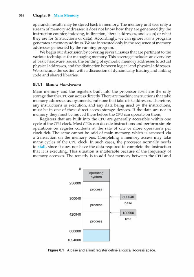
316 Chapter 8 Main Memory
operands, results may be stored back in memory. The memory unit sees only astream of memory addresses; it does not know how they are generated (by theinstruction counter, indexing, indirection, literal addresses, and so on) or whatthey are for (instructions or data). Accordingly, we can ignore how a programgenerates a memory address. We are interested only in the sequence of memoryaddresses generated by the running program.
We begin our discussion by covering several issues that are pertinent to thevarious techniques for managing memory. This coverage includes an overviewof basic hardware issues, the binding of symbolic memory addresses to actualphysical addresses, and the distinction between logical and physical addresses.We conclude the section with a discussion of dynamically loading and linkingcode and shared libraries.
8.1.1 Basic Hardware
Main memory and the registers built into the processor itself are the onlystorage that the CPU can access directly. There are machine instructions that takememory addresses as arguments, but none that take disk addresses. Therefore,any instructions in execution, and any data being used by the instructions,must be in one of these direct-access storage devices. If the data are not inmemory, they must be moved there before the CPU can operate on them.
Registers that are built into the CPU are generally accessible within onecycle of the CPU clock. Most CPUs can decode instructions and perform simpleoperations on register contents at the rate of one or more operations perclock tick. The same cannot be said of main memory, which is accessed viaa transaction on the memory bus. Completing a memory access may takemany cycles of the CPU clock. In such cases, the processor normally needsto stall, since it does not have the data required to complete the instructionthat it is executing. This situation is intolerable because of the frequency ofmemory accesses. The remedy is to add fast memory between the CPU and
operatingsystem
0
256000
300040 300040
base
120900
limit420940
880000
1024000
process
process
process
Figure 8.1 A base and a limit register define a logical address space.
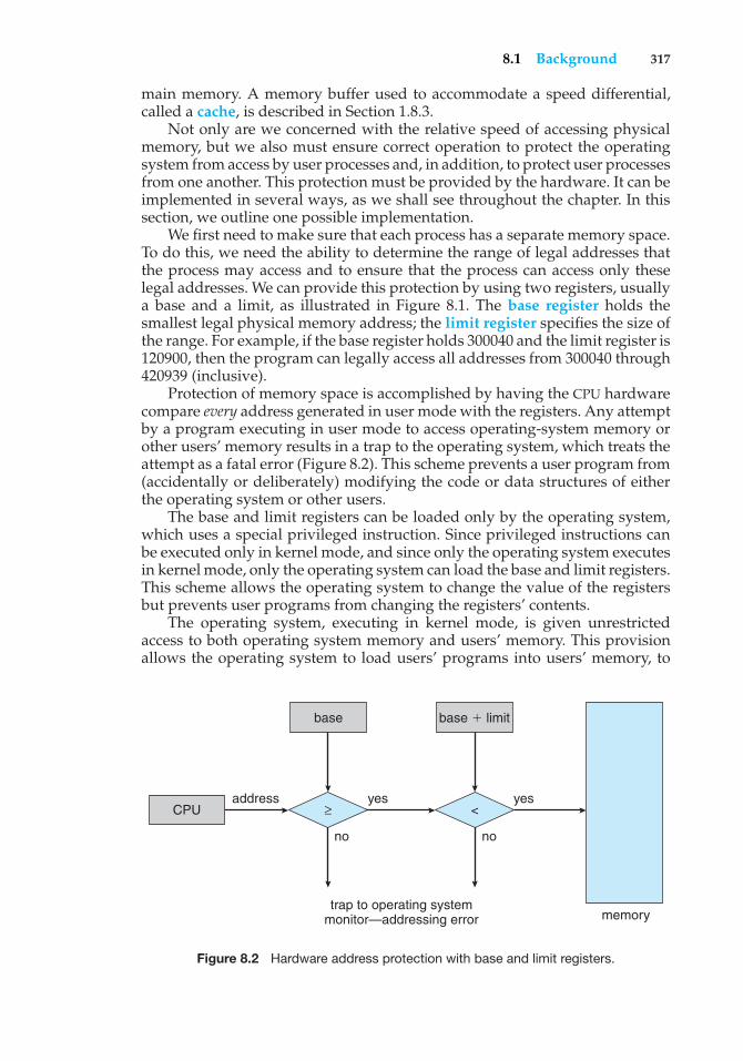
8.1 Background 317
main memory. A memory buffer used to accommodate a speed differential,called a cache, is described in Section 1.8.3.
Not only are we concerned with the relative speed of accessing physicalmemory, but we also must ensure correct operation to protect the operatingsystem from access by user processes and, in addition, to protect user processesfrom one another. This protection must be provided by the hardware. It can beimplemented in several ways, as we shall see throughout the chapter. In thissection, we outline one possible implementation.
We first need to make sure that each process has a separate memory space.To do this, we need the ability to determine the range of legal addresses thatthe process may access and to ensure that the process can access only theselegal addresses. We can provide this protection by using two registers, usuallya base and a limit, as illustrated in Figure 8.1. The base register holds thesmallest legal physical memory address; the limit register specifies the size ofthe range. For example, if the base register holds 300040 and the limit register is120900, then the program can legally access all addresses from 300040 through420939 (inclusive).
Protection of memory space is accomplished by having the CPU hardwarecompare every address generated in user mode with the registers. Any attemptby a program executing in user mode to access operating-system memory orother users’ memory results in a trap to the operating system, which treats theattempt as a fatal error (Figure 8.2). This scheme prevents a user program from(accidentally or deliberately) modifying the code or data structures of eitherthe operating system or other users.
The base and limit registers can be loaded only by the operating system,which uses a special privileged instruction. Since privileged instructions canbe executed only in kernel mode, and since only the operating system executesin kernel mode, only the operating system can load the base and limit registers.This scheme allows the operating system to change the value of the registersbut prevents user programs from changing the registers’ contents.
The operating system, executing in kernel mode, is given unrestrictedaccess to both operating system memory and users’ memory. This provisionallows the operating system to load users’ programs into users’ memory, to
base
memorytrap to operating system
monitor—addressing error
address yesyes
nono
CPU
base � limit
≥ <
Figure 8.2 Hardware address protection with base and limit registers.
318 Chapter 8 Main Memory
dump out those programs in case of errors, to access and modify parametersof system calls, and so on.
8.1.2 Address Binding
Usually, a program resides on a disk as a binary executable file. To be executed,the program must be brought into memory and placed within a process.Depending on the memory management in use, the process may be movedbetween disk and memory during its execution. The processes on the disk thatare waiting to be brought into memory for execution form the input queue.
The normal procedure is to select one of the processes in the input queueand to load that process into memory. As the process is executed, it accessesinstructions and data from memory. Eventually, the process terminates, and itsmemory space is declared available.
Most systems allow a user process to reside in any part of the physicalmemory. Thus, although the address space of the computer starts at 00000,the first address of the user process need not be 00000. This approach affectsthe addresses that the user program can use. In most cases, a user programwill go through several steps—some of which may be optional—before beingexecuted (Figure 8.3). Addresses may be represented in different ways duringthese steps. Addresses in the source program are generally symbolic (such ascount). A compiler will typically bind these symbolic addresses to relocatableaddresses (such as “14 bytes from the beginning of this module”). The linkageeditor or loader will in turn bind the relocatable addresses to absolute addresses(such as 74014). Each binding is a mapping from one address space to another.
Classically, the binding of instructions and data to memory addresses canbe done at any step along the way:
• Compile time. If you know at compile time where the process will residein memory, then absolute code can be generated. For example, if you knowthat a user process will reside starting at location R, then the generatedcompiler code will start at that location and extend up from there. If, atsome later time, the starting location changes, then it will be necessaryto recompile this code. The MS-DOS .COM-format programs are bound atcompile time.
• Load time. If it is not known at compile time where the process will residein memory, then the compiler must generate relocatable code. In this case,final binding is delayed until load time. If the starting address changes, weneed only reload the user code to incorporate this changed value.
• Execution time. If the process can be moved during its execution fromone memory segment to another, then binding must be delayed until runtime. Special hardware must be available for this scheme to work, as willbe discussed in Section 8.1.3. Most general-purpose operating systems usethis method.
A major portion of this chapter is devoted to showing how these vari-ous bindings can be implemented effectively in a computer system and todiscussing appropriate hardware support.

8.1 Background 319
dynamiclinking
sourceprogram
objectmodule
linkageeditor
loadmodule
loader
in-memorybinary
memoryimage
otherobject
modules
compiletime
loadtime
executiontime (runtime)
compiler orassembler
systemlibrary
dynamicallyloadedsystemlibrary
Figure 8.3 Multistep processing of a user program.
8.1.3 Logical versus Physical Address Space
An address generated by the CPU is commonly referred to as a logical address,whereas an address seen by the memory unit—that is, the one loaded intothe memory-address register of the memory—is commonly referred to as aphysical address.
The compile-time and load-time address-binding methods generate iden-tical logical and physical addresses. However, the execution-time address-binding scheme results in differing logical and physical addresses. In this case,we usually refer to the logical address as a virtual address. We use logical addressand virtual address interchangeably in this text. The set of all logical addressesgenerated by a program is a logical address space; the set of all physicaladdresses corresponding to these logical addresses is a physical address space.Thus, in the execution-time address-binding scheme, the logical and physicaladdress spaces differ.
The run-time mapping from virtual to physical addresses is done by ahardware device called the memory-management unit (MMU). We can choosefrom many different methods to accomplish such mapping, as we discuss in
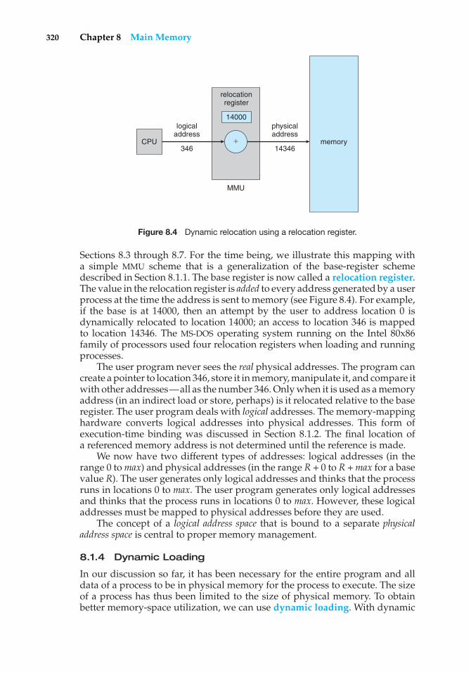
320 Chapter 8 Main Memory
�
MMU
CPU memory14346
14000
relocationregister
346
logicaladdress
physicaladdress
Figure 8.4 Dynamic relocation using a relocation register.
Sections 8.3 through 8.7. For the time being, we illustrate this mapping witha simple MMU scheme that is a generalization of the base-register schemedescribed in Section 8.1.1. The base register is now called a relocation register.The value in the relocation register is added to every address generated by a userprocess at the time the address is sent to memory (see Figure 8.4). For example,if the base is at 14000, then an attempt by the user to address location 0 isdynamically relocated to location 14000; an access to location 346 is mappedto location 14346. The MS-DOS operating system running on the Intel 80x86family of processors used four relocation registers when loading and runningprocesses.
The user program never sees the real physical addresses. The program cancreate a pointer to location 346, store it in memory, manipulate it, and compare itwith other addresses—all as the number 346. Only when it is used as a memoryaddress (in an indirect load or store, perhaps) is it relocated relative to the baseregister. The user program deals with logical addresses. The memory-mappinghardware converts logical addresses into physical addresses. This form ofexecution-time binding was discussed in Section 8.1.2. The final location ofa referenced memory address is not determined until the reference is made.
We now have two different types of addresses: logical addresses (in therange 0 to max) and physical addresses (in the range R + 0 to R + max for a basevalue R). The user generates only logical addresses and thinks that the processruns in locations 0 to max. The user program generates only logical addressesand thinks that the process runs in locations 0 to max. However, these logicaladdresses must be mapped to physical addresses before they are used.
The concept of a logical address space that is bound to a separate physicaladdress space is central to proper memory management.
8.1.4 Dynamic Loading
In our discussion so far, it has been necessary for the entire program and alldata of a process to be in physical memory for the process to execute. The sizeof a process has thus been limited to the size of physical memory. To obtainbetter memory-space utilization, we can use dynamic loading. With dynamic
8.1 Background 321
loading, a routine is not loaded until it is called. All routines are kept on diskin a relocatable load format. The main program is loaded into memory andis executed. When a routine needs to call another routine, the calling routinefirst checks to see whether the other routine has been loaded. If it has not, therelocatable linking loader is called to load the desired routine into memory andto update the program’s address tables to reflect this change. Then control ispassed to the newly loaded routine.
The advantage of dynamic loading is that an unused routine is neverloaded. This method is particularly useful when large amounts of code areneeded to handle infrequently occurring cases, such as error routines. In thiscase, although the total program size may be large, the portion that is used(and hence loaded) may be much smaller.
Dynamic loading does not require special support from the operatingsystem. It is the responsibility of the users to design their programs to takeadvantage of such a method. Operating systems may help the programmer,however, by providing library routines to implement dynamic loading.
8.1.5 Dynamic Linking and Shared Libraries
Figure 8.3 also shows dynamically linked libraries. Some operating systemssupport only static linking, in which system language libraries are treatedlike any other object module and are combined by the loader into the binaryprogram image. Dynamic linking, in contrast, is similar to dynamic loading.Here, though, linking, rather than loading, is postponed until execution time.This feature is usually used with system libraries, such as language subroutinelibraries. Without this facility, each program on a system must include a copyof its language library (or at least the routines referenced by the program) in theexecutable image. This requirement wastes both disk space and main memory.
With dynamic linking, a stub is included in the image for each library-routine reference. The stub is a small piece of code that indicates how to locatethe appropriate memory-resident library routine or how to load the library ifthe routine is not already present. When the stub is executed, it checks to seewhether the needed routine is already in memory. If it is not, the program loadsthe routine into memory. Either way, the stub replaces itself with the addressof the routine and executes the routine. Thus, the next time that particularcode segment is reached, the library routine is executed directly, incurring nocost for dynamic linking. Under this scheme, all processes that use a languagelibrary execute only one copy of the library code.
This feature can be extended to library updates (such as bug fixes). A librarymay be replaced by a new version, and all programs that reference the librarywill automatically use the new version. Without dynamic linking, all suchprograms would need to be relinked to gain access to the new library. So thatprograms will not accidentally execute new, incompatible versions of libraries,version information is included in both the program and the library. More thanone version of a library may be loaded into memory, and each program uses itsversion information to decide which copy of the library to use. Versions withminor changes retain the same version number, whereas versions with majorchanges increment the number. Thus, only programs that are compiled withthe new library version are affected by any incompatible changes incorporated
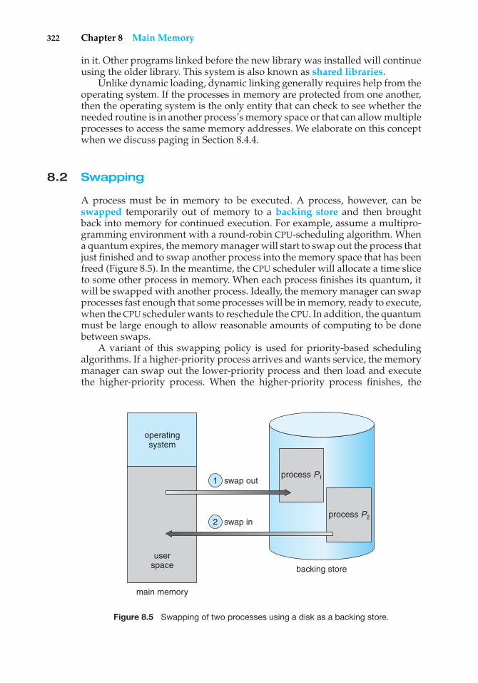
322 Chapter 8 Main Memory
in it. Other programs linked before the new library was installed will continueusing the older library. This system is also known as shared libraries.
Unlike dynamic loading, dynamic linking generally requires help from theoperating system. If the processes in memory are protected from one another,then the operating system is the only entity that can check to see whether theneeded routine is in another process’s memory space or that can allow multipleprocesses to access the same memory addresses. We elaborate on this conceptwhen we discuss paging in Section 8.4.4.
8.2 Swapping
A process must be in memory to be executed. A process, however, can beswapped temporarily out of memory to a backing store and then broughtback into memory for continued execution. For example, assume a multipro-gramming environment with a round-robin CPU-scheduling algorithm. Whena quantum expires, the memory manager will start to swap out the process thatjust finished and to swap another process into the memory space that has beenfreed (Figure 8.5). In the meantime, the CPU scheduler will allocate a time sliceto some other process in memory. When each process finishes its quantum, itwill be swapped with another process. Ideally, the memory manager can swapprocesses fast enough that some processes will be in memory, ready to execute,when the CPU scheduler wants to reschedule the CPU. In addition, the quantummust be large enough to allow reasonable amounts of computing to be donebetween swaps.
A variant of this swapping policy is used for priority-based schedulingalgorithms. If a higher-priority process arrives and wants service, the memorymanager can swap out the lower-priority process and then load and executethe higher-priority process. When the higher-priority process finishes, the
operatingsystem
swap out
swap in
userspace
main memory
backing store
process P2
process P11
2
Figure 8.5 Swapping of two processes using a disk as a backing store.
8.2 Swapping 323
lower-priority process can be swapped back in and continued. This variantof swapping is sometimes called roll out, roll in.
Normally, a process that is swapped out will be swapped back into thesame memory space it occupied previously. This restriction is dictated by themethod of address binding. If binding is done at assembly or load time, thenthe process cannot be easily moved to a different location. If execution-timebinding is being used, however, then a process can be swapped into a differentmemory space, because the physical addresses are computed during executiontime.
Swapping requires a backing store. The backing store is commonly a fastdisk. It must be large enough to accommodate copies of all memory imagesfor all users, and it must provide direct access to these memory images. Thesystem maintains a ready queue consisting of all processes whose memoryimages are on the backing store or in memory and are ready to run. Wheneverthe CPU scheduler decides to execute a process, it calls the dispatcher. Thedispatcher checks to see whether the next process in the queue is in memory.If it is not, and if there is no free memory region, the dispatcher swaps out aprocess currently in memory and swaps in the desired process. It then reloadsregisters and transfers control to the selected process.
The context-switch time in such a swapping system is fairly high. To getan idea of the context-switch time, let us assume that the user process is 100MB in size and the backing store is a standard hard disk with a transfer rate of50 MB per second. The actual transfer of the 100-MB process to or from mainmemory takes
100 MB/50 MB per second = 2 seconds.
Assuming an average latency of 8 milliseconds, the swap time is 2008milliseconds. Since we must both swap out and swap in, the total swap time isabout 4016 milliseconds.
Notice that the major part of the swap time is transfer time. The totaltransfer time is directly proportional to the amount of memory swapped. If wehave a computer system with 4 GB of main memory and a resident operatingsystem taking 1 GB, the maximum size of the user process is 3 GB. However,many user processes may be much smaller than this—say, 100 MB. A 100-MBprocess could be swapped out in 2 seconds, compared with the 60 secondsrequired for swapping 3 GB. Clearly, it would be useful to know exactly howmuch memory a user process is using, not simply how much it might be using.Then we would need to swap only what is actually used, reducing swap time.For this method to be effective, the user must keep the system informed ofany changes in memory requirements. Thus, a process with dynamic memoryrequirements will need to issue system calls (request memory and releasememory) to inform the operating system of its changing memory needs.
Swapping is constrained by other factors as well. If we want to swapa process, we must be sure that it is completely idle. Of particular concernis any pending I/O. A process may be waiting for an I/O operation whenwe want to swap that process to free up memory. However, if the I/O isasynchronously accessing the user memory for I/O buffers, then the processcannot be swapped. Assume that the I/O operation is queued because thedevice is busy. If we were to swap out process P1 and swap in process P2, the
324 Chapter 8 Main Memory
I/O operation might then attempt to use memory that now belongs to processP2. There are two main solutions to this problem: never swap a process withpending I/O, or execute I/O operations only into operating-system buffers.Transfers between operating-system buffers and process memory then occuronly when the process is swapped in.
The assumption, mentioned earlier, that swapping requires few, if any,head seeks needs further explanation. We postpone discussing this issue untilChapter 12, where secondary-storage structure is covered. Generally, swapspace is allocated as a chunk of disk, separate from the file system, so that itsuse is as fast as possible.
Currently, standard swapping is used in few systems. It requires toomuch swapping time and provides too little execution time to be a reasonablememory-management solution. Modified versions of swapping, however, arefound on many systems.
A modification of swapping is used in many versions of UNIX. Swapping isnormally disabled but will start if many processes are running and are using athreshold amount of memory. Swapping is again halted when the load on thesystem is reduced. Memory management in UNIX is described fully in Sections21.7 and A.6.
Early PCs—which lacked the sophistication to implement more advancedmemory-management methods—ran multiple large processes by using amodified version of swapping. A prime example is the Microsoft Windows3.1 operating system, which supports concurrent execution of processes inmemory. If a new process is loaded and there is insufficient main memory,an old process is swapped to disk. This operating system does not providefull swapping, however, because the user, rather than the scheduler, decideswhen it is time to preempt one process for another. Any swapped-out processremains swapped out (and not executing) until the user selects that process torun. Subsequent versions of Microsoft operating systems take advantage of theadvanced MMU features now found in PCs. We explore such features in Section8.4 and in Chapter 9, where we cover virtual memory.
8.3 Contiguous Memory Allocation
The main memory must accommodate both the operating system and thevarious user processes. We therefore need to allocate main memory in the mostefficient way possible. This section explains one common method, contiguousmemory allocation.
The memory is usually divided into two partitions: one for the residentoperating system and one for the user processes. We can place the operatingsystem in either low memory or high memory. The major factor affecting thisdecision is the location of the interrupt vector. Since the interrupt vector isoften in low memory, programmers usually place the operating system in lowmemory as well. Thus, in this text, we discuss only the situation in whichthe operating system resides in low memory. The development of the othersituation is similar.
We usually want several user processes to reside in memory at the sametime. We therefore need to consider how to allocate available memory to theprocesses that are in the input queue waiting to be brought into memory.
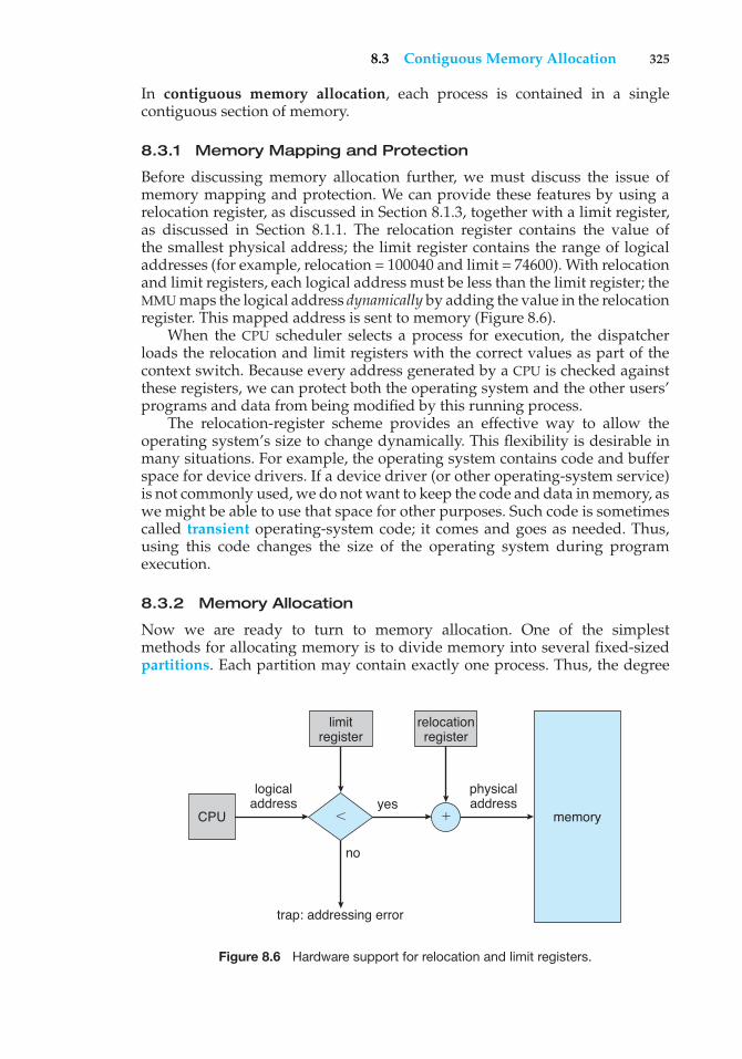
8.3 Contiguous Memory Allocation 325
In contiguous memory allocation, each process is contained in a singlecontiguous section of memory.
8.3.1 Memory Mapping and Protection
Before discussing memory allocation further, we must discuss the issue ofmemory mapping and protection. We can provide these features by using arelocation register, as discussed in Section 8.1.3, together with a limit register,as discussed in Section 8.1.1. The relocation register contains the value ofthe smallest physical address; the limit register contains the range of logicaladdresses (for example, relocation = 100040 and limit = 74600). With relocationand limit registers, each logical address must be less than the limit register; theMMU maps the logical address dynamically by adding the value in the relocationregister. This mapped address is sent to memory (Figure 8.6).
When the CPU scheduler selects a process for execution, the dispatcherloads the relocation and limit registers with the correct values as part of thecontext switch. Because every address generated by a CPU is checked againstthese registers, we can protect both the operating system and the other users’programs and data from being modified by this running process.
The relocation-register scheme provides an effective way to allow theoperating system’s size to change dynamically. This flexibility is desirable inmany situations. For example, the operating system contains code and bufferspace for device drivers. If a device driver (or other operating-system service)is not commonly used, we do not want to keep the code and data in memory, aswe might be able to use that space for other purposes. Such code is sometimescalled transient operating-system code; it comes and goes as needed. Thus,using this code changes the size of the operating system during programexecution.
8.3.2 Memory Allocation
Now we are ready to turn to memory allocation. One of the simplestmethods for allocating memory is to divide memory into several fixed-sizedpartitions. Each partition may contain exactly one process. Thus, the degree
CPU memory
logicaladdress
trap: addressing error
no
yesphysicaladdress
relocationregister
�
limitregister
Figure 8.6 Hardware support for relocation and limit registers.

326 Chapter 8 Main Memory
of multiprogramming is bound by the number of partitions. In this multiple-partition method, when a partition is free, a process is selected from the inputqueue and is loaded into the free partition. When the process terminates, thepartition becomes available for another process. This method was originallyused by the IBM OS/360 operating system (called MFT); it is no longer in use.The method described next is a generalization of the fixed-partition scheme(called MVT); it is used primarily in batch environments. Many of the ideaspresented here are also applicable to a time-sharing environment in whichpure segmentation is used for memory management (Section 8.6).
In the variable-partition scheme, the operating system keeps a tableindicating which parts of memory are available and which are occupied.Initially, all memory is available for user processes and is considered onelarge block of available memory, a hole. Eventually, as you will see, memorycontains a set of holes of various sizes.
As processes enter the system, they are put into an input queue. Theoperating system takes into account the memory requirements of each processand the amount of available memory space in determining which processes areallocated memory. When a process is allocated space, it is loaded into memory,and it can then compete for CPU time. When a process terminates, it releases itsmemory, which the operating system may then fill with another process fromthe input queue.
At any given time, then, we have a list of available block sizes and aninput queue. The operating system can order the input queue according toa scheduling algorithm. Memory is allocated to processes until, finally, thememory requirements of the next process cannot be satisfied—that is, noavailable block of memory (or hole) is large enough to hold that process. Theoperating system can then wait until a large enough block is available, or it canskip down the input queue to see whether the smaller memory requirementsof some other process can be met.
In general, as mentioned, the memory blocks available comprise a set ofholes of various sizes scattered throughout memory. When a process arrivesand needs memory, the system searches the set for a hole that is large enoughfor this process. If the hole is too large, it is split into two parts. One part isallocated to the arriving process; the other is returned to the set of holes. Whena process terminates, it releases its block of memory, which is then placed backin the set of holes. If the new hole is adjacent to other holes, these adjacent holesare merged to form one larger hole. At this point, the system may need to checkwhether there are processes waiting for memory and whether this newly freedand recombined memory could satisfy the demands of any of these waitingprocesses.
This procedure is a particular instance of the general dynamic storage-allocation problem, which concerns how to satisfy a request of size n from alist of free holes. There are many solutions to this problem. The first-fit, best-fit,and worst-fit strategies are the ones most commonly used to select a free holefrom the set of available holes.
• First fit. Allocate the first hole that is big enough. Searching can start eitherat the beginning of the set of holes or at the location where the previousfirst-fit search ended. We can stop searching as soon as we find a free holethat is large enough.
8.3 Contiguous Memory Allocation 327
• Best fit. Allocate the smallest hole that is big enough. We must search theentire list, unless the list is ordered by size. This strategy produces thesmallest leftover hole.
• Worst fit. Allocate the largest hole. Again, we must search the entire list,unless it is sorted by size. This strategy produces the largest leftover hole,which may be more useful than the smaller leftover hole from a best-fitapproach.
Simulations have shown that both first fit and best fit are better than worstfit in terms of decreasing time and storage utilization. Neither first fit nor bestfit is clearly better than the other in terms of storage utilization, but first fit isgenerally faster.
8.3.3 Fragmentation
Both the first-fit and best-fit strategies for memory allocation suffer fromexternal fragmentation. As processes are loaded and removed from memory,the free memory space is broken into little pieces. External fragmentation existswhen there is enough total memory space to satisfy a request but the availablespaces are not contiguous; storage is fragmented into a large number of smallholes. This fragmentation problem can be severe. In the worst case, we couldhave a block of free (or wasted) memory between every two processes. If allthese small pieces of memory were in one big free block instead, we might beable to run several more processes.
Whether we are using the first-fit or best-fit strategy can affect the amountof fragmentation. (First fit is better for some systems, whereas best fit is betterfor others.) Another factor is which end of a free block is allocated. (Which isthe leftover piece—the one on the top or the one on the bottom?) No matterwhich algorithm is used, however, external fragmentation will be a problem.
Depending on the total amount of memory storage and the average processsize, external fragmentation may be a minor or a major problem. Statisticalanalysis of first fit, for instance, reveals that, even with some optimization,given N allocated blocks, another 0.5 N blocks will be lost to fragmentation.That is, one-third of memory may be unusable! This property is known as the50-percent rule.
Memory fragmentation can be internal as well as external. Consider amultiple-partition allocation scheme with a hole of 18,464 bytes. Suppose thatthe next process requests 18,462 bytes. If we allocate exactly the requested block,we are left with a hole of 2 bytes. The overhead to keep track of this hole will besubstantially larger than the hole itself. The general approach to avoiding thisproblem is to break the physical memory into fixed-sized blocks and allocatememory in units based on block size. With this approach, the memory allocatedto a process may be slightly larger than the requested memory. The differencebetween these two numbers is internal fragmentation—unused memory thatis internal to a partition.
One solution to the problem of external fragmentation is compaction. Thegoal is to shuffle the memory contents so as to place all free memory togetherin one large block. Compaction is not always possible, however. If relocationis static and is done at assembly or load time, compaction cannot be done;compaction is possible only if relocation is dynamic and is done at execution
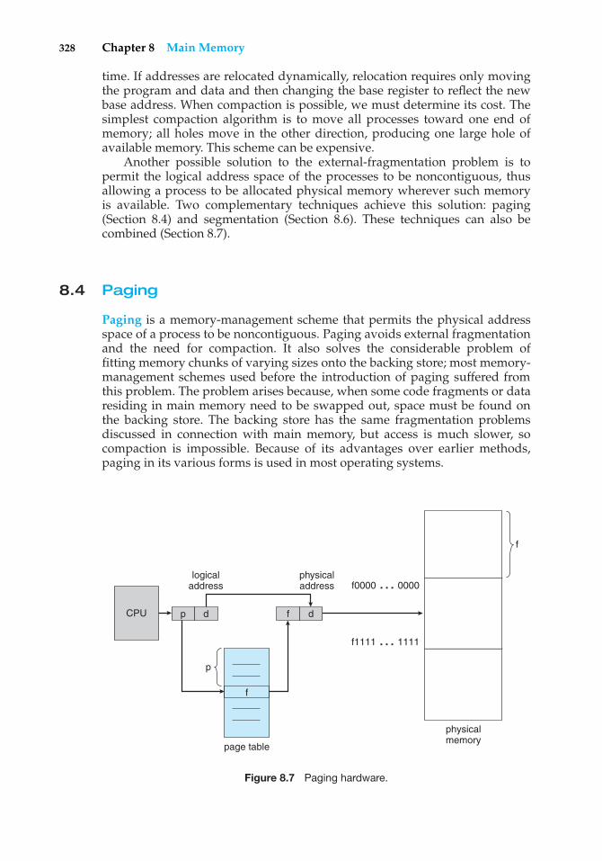
328 Chapter 8 Main Memory
time. If addresses are relocated dynamically, relocation requires only movingthe program and data and then changing the base register to reflect the newbase address. When compaction is possible, we must determine its cost. Thesimplest compaction algorithm is to move all processes toward one end ofmemory; all holes move in the other direction, producing one large hole ofavailable memory. This scheme can be expensive.
Another possible solution to the external-fragmentation problem is topermit the logical address space of the processes to be noncontiguous, thusallowing a process to be allocated physical memory wherever such memoryis available. Two complementary techniques achieve this solution: paging(Section 8.4) and segmentation (Section 8.6). These techniques can also becombined (Section 8.7).
8.4 Paging
Paging is a memory-management scheme that permits the physical addressspace of a process to be noncontiguous. Paging avoids external fragmentationand the need for compaction. It also solves the considerable problem offitting memory chunks of varying sizes onto the backing store; most memory-management schemes used before the introduction of paging suffered fromthis problem. The problem arises because, when some code fragments or dataresiding in main memory need to be swapped out, space must be found onthe backing store. The backing store has the same fragmentation problemsdiscussed in connection with main memory, but access is much slower, socompaction is impossible. Because of its advantages over earlier methods,paging in its various forms is used in most operating systems.
physicalmemory
f
logicaladdress
page table
physicaladdress
CPU p
p
f
d df
f0000 … 0000
f1111 … 1111
Figure 8.7 Paging hardware.
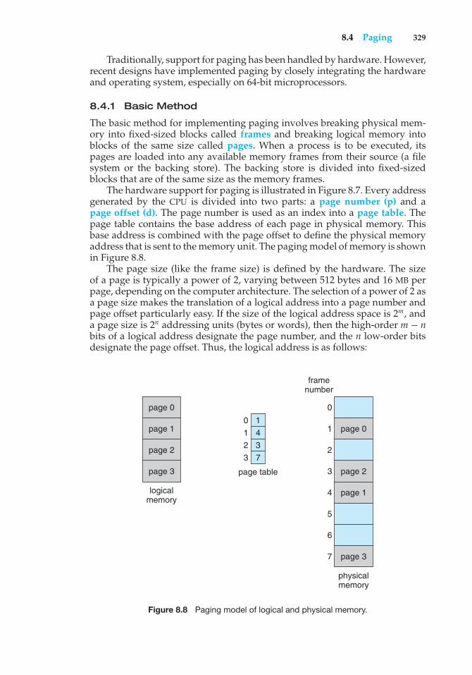
8.4 Paging 329
Traditionally, support for paging has been handled by hardware. However,recent designs have implemented paging by closely integrating the hardwareand operating system, especially on 64-bit microprocessors.
8.4.1 Basic Method
The basic method for implementing paging involves breaking physical mem-ory into fixed-sized blocks called frames and breaking logical memory intoblocks of the same size called pages. When a process is to be executed, itspages are loaded into any available memory frames from their source (a filesystem or the backing store). The backing store is divided into fixed-sizedblocks that are of the same size as the memory frames.
The hardware support for paging is illustrated in Figure 8.7. Every addressgenerated by the CPU is divided into two parts: a page number (p) and apage offset (d). The page number is used as an index into a page table. Thepage table contains the base address of each page in physical memory. Thisbase address is combined with the page offset to define the physical memoryaddress that is sent to the memory unit. The paging model of memory is shownin Figure 8.8.
The page size (like the frame size) is defined by the hardware. The sizeof a page is typically a power of 2, varying between 512 bytes and 16 MB perpage, depending on the computer architecture. The selection of a power of 2 asa page size makes the translation of a logical address into a page number andpage offset particularly easy. If the size of the logical address space is 2m, anda page size is 2n addressing units (bytes or words), then the high-order m − nbits of a logical address designate the page number, and the n low-order bitsdesignate the page offset. Thus, the logical address is as follows:
page 0
page 1
page 2
page 3
logicalmemory
page 1
page 3
page 0
page 2
physicalmemory
page table
framenumber
1
4
3
7
0
1
2
3
0
1
2
3
4
5
6
7
Figure 8.8 Paging model of logical and physical memory.
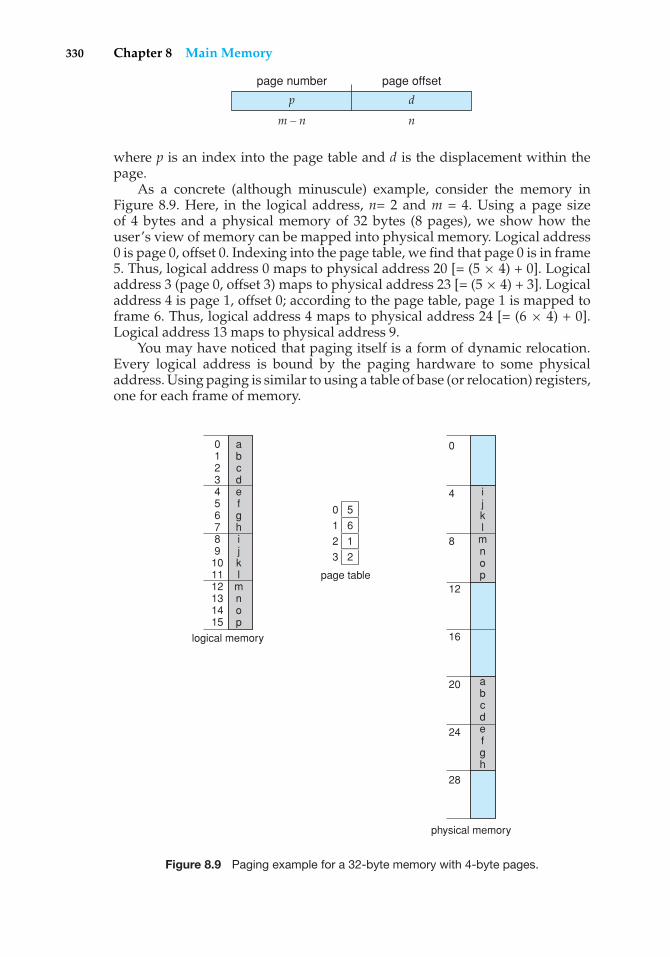
330 Chapter 8 Main Memory
p d
page number page offset
m – n n
where p is an index into the page table and d is the displacement within thepage.
As a concrete (although minuscule) example, consider the memory inFigure 8.9. Here, in the logical address, n= 2 and m = 4. Using a page sizeof 4 bytes and a physical memory of 32 bytes (8 pages), we show how theuser’s view of memory can be mapped into physical memory. Logical address0 is page 0, offset 0. Indexing into the page table, we find that page 0 is in frame5. Thus, logical address 0 maps to physical address 20 [= (5 × 4) + 0]. Logicaladdress 3 (page 0, offset 3) maps to physical address 23 [= (5 × 4) + 3]. Logicaladdress 4 is page 1, offset 0; according to the page table, page 1 is mapped toframe 6. Thus, logical address 4 maps to physical address 24 [= (6 × 4) + 0].Logical address 13 maps to physical address 9.
You may have noticed that paging itself is a form of dynamic relocation.Every logical address is bound by the paging hardware to some physicaladdress. Using paging is similar to using a table of base (or relocation) registers,one for each frame of memory.
logical memory
physical memory
page table
ijkl
mnop
abcdefgh
abcdefghijkl
mnop
0123456789
101112131415
0
0
4
8
12
16
20
24
28
1
2
3
5
6
1
2
Figure 8.9 Paging example for a 32-byte memory with 4-byte pages.
8.4 Paging 331
When we use a paging scheme, we have no external fragmentation: any freeframe can be allocated to a process that needs it. However, we may have someinternal fragmentation. Notice that frames are allocated as units. If the memoryrequirements of a process do not happen to coincide with page boundaries,the last frame allocated may not be completely full. For example, if page sizeis 2,048 bytes, a process of 72,766 bytes will need 35 pages plus 1,086 bytes. Itwill be allocated 36 frames, resulting in internal fragmentation of 2,048 − 1,086= 962 bytes. In the worst case, a process would need n pages plus 1 byte. Itwould be allocated n + 1 frames, resulting in internal fragmentation of almostan entire frame.
If process size is independent of page size, we expect internal fragmentationto average one-half page per process. This consideration suggests that smallpage sizes are desirable. However, overhead is involved in each page-tableentry, and this overhead is reduced as the size of the pages increases. Also,disk I/O is more efficient when the amount data being transferred is larger(Chapter 12). Generally, page sizes have grown over time as processes, datasets, and main memory have become larger. Today, pages typically are between4 KB and 8 KB in size, and some systems support even larger page sizes. SomeCPUs and kernels even support multiple page sizes. For instance, Solaris usespage sizes of 8 KB and 4 MB, depending on the data stored by the pages.Researchers are now developing support for variable on-the-fly page size.
Usually, each page-table entry is 4 bytes long, but that size can vary as well.A 32-bit entry can point to one of 232 physical page frames. If frame size is 4 KB,then a system with 4-byte entries can address 244 bytes (or 16 TB) of physicalmemory.
When a process arrives in the system to be executed, its size, expressedin pages, is examined. Each page of the process needs one frame. Thus, if theprocess requires n pages, at least n frames must be available in memory. If nframes are available, they are allocated to this arriving process. The first pageof the process is loaded into one of the allocated frames, and the frame numberis put in the page table for this process. The next page is loaded into anotherframe, its frame number is put into the page table, and so on (Figure 8.10).
An important aspect of paging is the clear separation between the user’sview of memory and the actual physical memory. The user program viewsmemory as one single space, containing only this one program. In fact, the userprogram is scattered throughout physical memory, which also holds otherprograms. The difference between the user’s view of memory and the actualphysical memory is reconciled by the address-translation hardware. The logicaladdresses are translated into physical addresses. This mapping is hidden fromthe user and is controlled by the operating system. Notice that the user processby definition is unable to access memory it does not own. It has no way ofaddressing memory outside of its page table, and the table includes only thosepages that the process owns.
Since the operating system is managing physical memory, it must be awareof the allocation details of physical memory—which frames are allocated,which frames are available, how many total frames there are, and so on. Thisinformation is generally kept in a data structure called a frame table. The frametable has one entry for each physical page frame, indicating whether the latteris free or allocated and, if it is allocated, to which page of which process orprocesses.
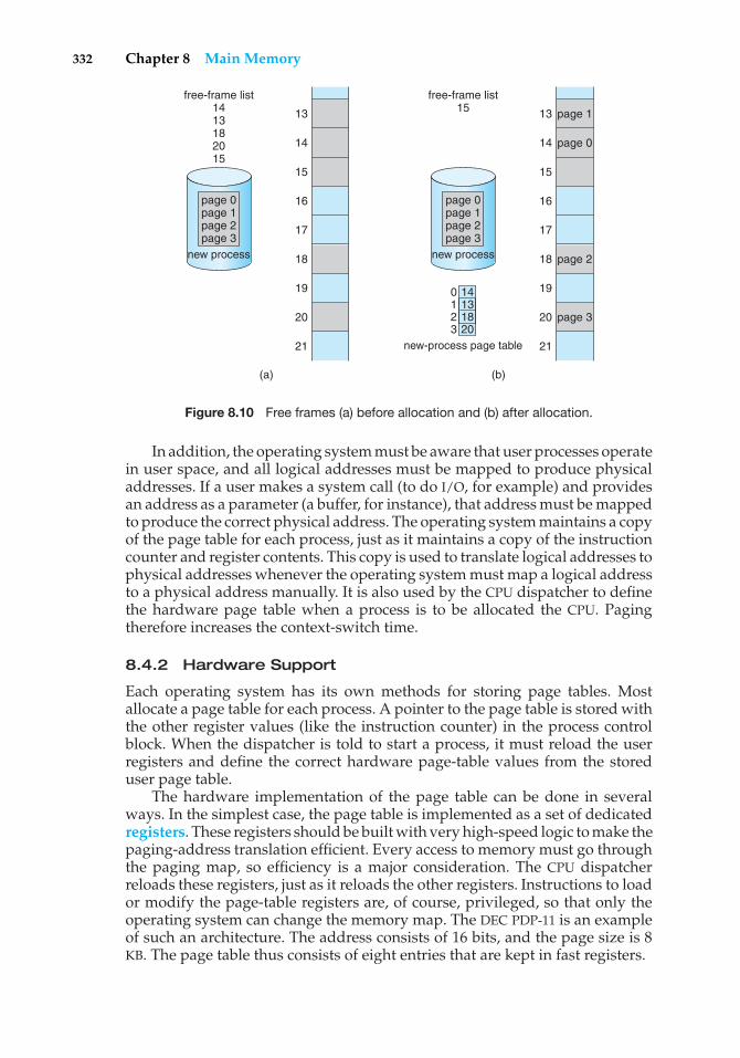
332 Chapter 8 Main Memory
(a)
free-frame list1413182015
13
14
15
16
17
18
19
20
21
page 0 page 1 page 2 page 3
new process
(b)
free-frame list15 13 page 1
page 0
page 2
page 3
14
15
16
17
18
19
20
21
page 0 page 1 page 2 page 3
new process
new-process page table
140123
131820
Figure 8.10 Free frames (a) before allocation and (b) after allocation.
In addition, the operating system must be aware that user processes operatein user space, and all logical addresses must be mapped to produce physicaladdresses. If a user makes a system call (to do I/O, for example) and providesan address as a parameter (a buffer, for instance), that address must be mappedto produce the correct physical address. The operating system maintains a copyof the page table for each process, just as it maintains a copy of the instructioncounter and register contents. This copy is used to translate logical addresses tophysical addresses whenever the operating system must map a logical addressto a physical address manually. It is also used by the CPU dispatcher to definethe hardware page table when a process is to be allocated the CPU. Pagingtherefore increases the context-switch time.
8.4.2 Hardware Support
Each operating system has its own methods for storing page tables. Mostallocate a page table for each process. A pointer to the page table is stored withthe other register values (like the instruction counter) in the process controlblock. When the dispatcher is told to start a process, it must reload the userregisters and define the correct hardware page-table values from the storeduser page table.
The hardware implementation of the page table can be done in severalways. In the simplest case, the page table is implemented as a set of dedicatedregisters. These registers should be built with very high-speed logic to make thepaging-address translation efficient. Every access to memory must go throughthe paging map, so efficiency is a major consideration. The CPU dispatcherreloads these registers, just as it reloads the other registers. Instructions to loador modify the page-table registers are, of course, privileged, so that only theoperating system can change the memory map. The DEC PDP-11 is an exampleof such an architecture. The address consists of 16 bits, and the page size is 8KB. The page table thus consists of eight entries that are kept in fast registers.
8.4 Paging 333
The use of registers for the page table is satisfactory if the page table isreasonably small (for example, 256 entries). Most contemporary computers,however, allow the page table to be very large (for example, 1 million entries).For these machines, the use of fast registers to implement the page table isnot feasible. Rather, the page table is kept in main memory, and a page-tablebase register (PTBR) points to the page table. Changing page tables requireschanging only this one register, substantially reducing context-switch time.
The problem with this approach is the time required to access a usermemory location. If we want to access location i, we must first index intothe page table, using the value in the PTBR offset by the page number for i. Thistask requires a memory access. It provides us with the frame number, whichis combined with the page offset to produce the actual address. We can thenaccess the desired place in memory. With this scheme, two memory accesses areneeded to access a byte (one for the page-table entry, one for the byte). Thus,memory access is slowed by a factor of 2. This delay would be intolerable undermost circumstances. We might as well resort to swapping!
The standard solution to this problem is to use a special, small, fast-lookup hardware cache, called a translation look-aside buffer (TLB). The TLBis associative, high-speed memory. Each entry in the TLB consists of two parts:a key (or tag) and a value. When the associative memory is presented with anitem, the item is compared with all keys simultaneously. If the item is found,the corresponding value field is returned. The search is fast; the hardware,however, is expensive. Typically, the number of entries in a TLB is small, oftennumbering between 64 and 1,024.
The TLB is used with page tables in the following way. The TLB containsonly a few of the page-table entries. When a logical address is generated bythe CPU, its page number is presented to the TLB. If the page number is found,its frame number is immediately available and is used to access memory. Thewhole task may take less than 10 percent longer than it would if an unmappedmemory reference were used.
If the page number is not in the TLB (known as a TLB miss), a memoryreference to the page table must be made. When the frame number is obtained,we can use it to access memory (Figure 8.11). In addition, we add the pagenumber and frame number to the TLB, so that they will be found quickly on thenext reference. If the TLB is already full of entries, the operating system mustselect one for replacement. Replacement policies range from least recentlyused (LRU) to random. Furthermore, some TLBs allow certain entries to bewired down, meaning that they cannot be removed from the TLB. Typically,TLB entries for kernel code are wired down.
Some TLBs store address-space identifiers (ASIDs) in each TLB entry. AnASID uniquely identifies each process and is used to provide address-spaceprotection for that process. When the TLB attempts to resolve virtual pagenumbers, it ensures that the ASID for the currently running process matches theASID associated with the virtual page. If the ASIDs do not match, the attempt istreated as a TLB miss. In addition to providing address-space protection, an ASIDallows the TLB to contain entries for several different processes simultaneously.If the TLB does not support separate ASIDs, then every time a new page tableis selected (for instance, with each context switch), the TLB must be flushed(or erased) to ensure that the next executing process does not use the wrongtranslation information. Otherwise, the TLB could include old entries that
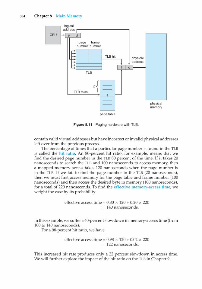
334 Chapter 8 Main Memory
page table
f
CPU
logicaladdress
p d
f d
physicaladdress
physicalmemory
p
TLB miss
pagenumber
framenumber
TLB hit
TLB
Figure 8.11 Paging hardware with TLB.
contain valid virtual addresses but have incorrect or invalid physical addressesleft over from the previous process.
The percentage of times that a particular page number is found in the TLBis called the hit ratio. An 80-percent hit ratio, for example, means that wefind the desired page number in the TLB 80 percent of the time. If it takes 20nanoseconds to search the TLB and 100 nanoseconds to access memory, thena mapped-memory access takes 120 nanoseconds when the page number isin the TLB. If we fail to find the page number in the TLB (20 nanoseconds),then we must first access memory for the page table and frame number (100nanoseconds) and then access the desired byte in memory (100 nanoseconds),for a total of 220 nanoseconds. To find the effective memory-access time, weweight the case by its probability:
effective access time = 0.80 × 120 + 0.20 × 220= 140 nanoseconds.
In this example, we suffer a 40-percent slowdown in memory-access time (from100 to 140 nanoseconds).
For a 98-percent hit ratio, we have
effective access time = 0.98 × 120 + 0.02 × 220= 122 nanoseconds.
This increased hit rate produces only a 22 percent slowdown in access time.We will further explore the impact of the hit ratio on the TLB in Chapter 9.
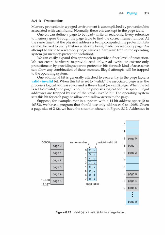
8.4 Paging 335
8.4.3 Protection
Memory protection in a paged environment is accomplished by protection bitsassociated with each frame. Normally, these bits are kept in the page table.
One bit can define a page to be read–write or read-only. Every referenceto memory goes through the page table to find the correct frame number. Atthe same time that the physical address is being computed, the protection bitscan be checked to verify that no writes are being made to a read-only page. Anattempt to write to a read-only page causes a hardware trap to the operatingsystem (or memory-protection violation).
We can easily expand this approach to provide a finer level of protection.We can create hardware to provide read-only, read–write, or execute-onlyprotection; or, by providing separate protection bits for each kind of access, wecan allow any combination of these accesses. Illegal attempts will be trappedto the operating system.
One additional bit is generally attached to each entry in the page table: avalid–invalid bit. When this bit is set to “valid,” the associated page is in theprocess’s logical address space and is thus a legal (or valid) page. When the bitis set to“invalid,” the page is not in the process’s logical address space. Illegaladdresses are trapped by use of the valid–invalid bit. The operating systemsets this bit for each page to allow or disallow access to the page.
Suppose, for example, that in a system with a 14-bit address space (0 to16383), we have a program that should use only addresses 0 to 10468. Givena page size of 2 KB, we have the situation shown in Figure 8.12. Addresses in
page 0
page 0
page 1
page 2
page 3
page 4
page 5
page n
•••
00000
0
1
2
3
4
5
6
7
8
9
frame number
0
1
2
3
4
5
6
7
2
3
4
7
8
9
0
0
v
v
v
v
v
v
i
i
page table
valid–invalid bit
10,468
12,287
page 1
page 2
page 3
page 4
page 5
Figure 8.12 Valid (v) or invalid (i) bit in a page table.
336 Chapter 8 Main Memory
pages 0, 1, 2, 3, 4, and 5 are mapped normally through the page table. Anyattempt to generate an address in pages 6 or 7, however, will find that thevalid–invalid bit is set to invalid, and the computer will trap to the operatingsystem (invalid page reference).
Notice that this scheme has created a problem. Because the programextends only to address 10468, any reference beyond that address is illegal.However, references to page 5 are classified as valid, so accesses to addressesup to 12287 are valid. Only the addresses from 12288 to 16383 are invalid. Thisproblem is a result of the 2-KB page size and reflects the internal fragmentationof paging.
Rarely does a process use all its address range. In fact, many processesuse only a small fraction of the address space available to them. It would bewasteful in these cases to create a page table with entries for every page in theaddress range. Most of this table would be unused but would take up valuablememory space. Some systems provide hardware, in the form of a page-tablelength register (PTLR), to indicate the size of the page table. This value ischecked against every logical address to verify that the address is in the validrange for the process. Failure of this test causes an error trap to the operatingsystem.
8.4.4 Shared Pages
An advantage of paging is the possibility of sharing common code. This con-sideration is particularly important in a time-sharing environment. Consider asystem that supports 40 users, each of whom executes a text editor. If the texteditor consists of 150 KB of code and 50 KB of data space, we need 8,000 KB tosupport the 40 users. If the code is reentrant code (or pure code), however, itcan be shared, as shown in Figure 8.13. Here we see a three-page editor—eachpage 50 KB in size (the large page size is used to simplify the figure)—beingshared among three processes. Each process has its own data page.
Reentrant code is non-self-modifying code: it never changes during execu-tion. Thus, two or more processes can execute the same code at the same time.Each process has its own copy of registers and data storage to hold the data forthe process’s execution. The data for two different processes will, of course, bedifferent.
Only one copy of the editor need be kept in physical memory. Each user’spage table maps onto the same physical copy of the editor, but data pages aremapped onto different frames. Thus, to support 40 users, we need only onecopy of the editor (150 KB), plus 40 copies of the 50 KB of data space per user.The total space required is now 2,150 KB instead of 8,000 KB—a significantsavings.
Other heavily used programs can also be shared—compilers, windowsystems, run-time libraries, database systems, and so on. To be sharable, thecode must be reentrant. The read-only nature of shared code should not beleft to the correctness of the code; the operating system should enforce thisproperty.
The sharing of memory among processes on a system is similar to thesharing of the address space of a task by threads, described in Chapter 4.Furthermore, recall that in Chapter 3 we described shared memory as a method
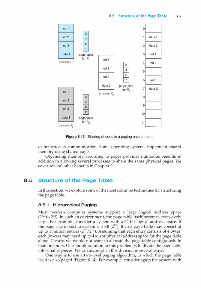
8.5 Structure of the Page Table 337
7
6
5
ed 24
ed 13
2
data 11
0
3
4
6
1
page tablefor P1
process P1
data 1
ed 2
ed 3
ed 1
3
4
6
2
page tablefor P3
process P3
data 3
ed 2
ed 3
ed 1
3
4
6
7
page tablefor P2
process P2
data 2
ed 2
ed 3
ed 1
8
9
10
11
data 3
2data
ed 3
Figure 8.13 Sharing of code in a paging environment.
of interprocess communication. Some operating systems implement sharedmemory using shared pages.
Organizing memory according to pages provides numerous benefits inaddition to allowing several processes to share the same physical pages. Wecover several other benefits in Chapter 9.
8.5 Structure of the Page Table
In this section, we explore some of the most common techniques for structuringthe page table.
8.5.1 Hierarchical Paging
Most modern computer systems support a large logical address space(232 to 264). In such an environment, the page table itself becomes excessivelylarge. For example, consider a system with a 32-bit logical address space. Ifthe page size in such a system is 4 KB (212), then a page table may consist ofup to 1 million entries (232/212). Assuming that each entry consists of 4 bytes,each process may need up to 4 MB of physical address space for the page tablealone. Clearly, we would not want to allocate the page table contiguously inmain memory. One simple solution to this problem is to divide the page tableinto smaller pieces. We can accomplish this division in several ways.
One way is to use a two-level paging algorithm, in which the page tableitself is also paged (Figure 8.14). For example, consider again the system with
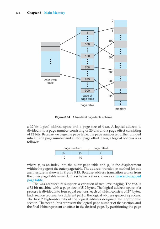
338 Chapter 8 Main Memory
•••
•••
outer pagetable
page ofpage table
page tablememory
929
900
929
900
708
500
100
1
0
•••
100
708
•••
•••
•••
•••
•••
•••
•••
•••
•••
1
500
Figure 8.14 A two-level page-table scheme.
a 32-bit logical address space and a page size of 4 KB. A logical address isdivided into a page number consisting of 20 bits and a page offset consistingof 12 bits. Because we page the page table, the page number is further dividedinto a 10-bit page number and a 10-bit page offset. Thus, a logical address is asfollows:
p1 p2 d
page number page offset
10 10 12
where p1 is an index into the outer page table and p2 is the displacementwithin the page of the outer page table. The address-translation method for thisarchitecture is shown in Figure 8.15. Because address translation works fromthe outer page table inward, this scheme is also known as a forward-mappedpage table.
The VAX architecture supports a variation of two-level paging. The VAX isa 32-bit machine with a page size of 512 bytes. The logical address space of aprocess is divided into four equal sections, each of which consists of 230 bytes.Each section represents a different part of the logical address space of a process.The first 2 high-order bits of the logical address designate the appropriatesection. The next 21 bits represent the logical page number of that section, andthe final 9 bits represent an offset in the desired page. By partitioning the page
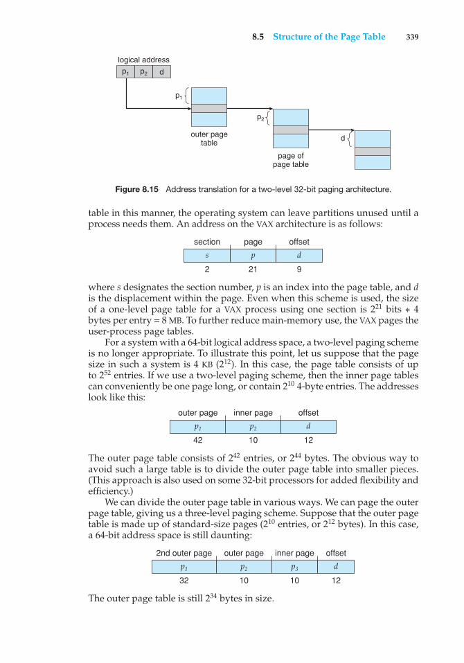
8.5 Structure of the Page Table 339
logical address
outer pagetable
p1 p2
p1
page ofpage table
p2
d
d
Figure 8.15 Address translation for a two-level 32-bit paging architecture.
table in this manner, the operating system can leave partitions unused until aprocess needs them. An address on the VAX architecture is as follows:
s p d
section page offset
2 21 9
where s designates the section number, p is an index into the page table, and dis the displacement within the page. Even when this scheme is used, the sizeof a one-level page table for a VAX process using one section is 221 bits ∗ 4bytes per entry = 8 MB. To further reduce main-memory use, the VAX pages theuser-process page tables.
For a system with a 64-bit logical address space, a two-level paging schemeis no longer appropriate. To illustrate this point, let us suppose that the pagesize in such a system is 4 KB (212). In this case, the page table consists of upto 252 entries. If we use a two-level paging scheme, then the inner page tablescan conveniently be one page long, or contain 210 4-byte entries. The addresseslook like this:
p1 p2 d
outer page inner page offset
42 10 12
The outer page table consists of 242 entries, or 244 bytes. The obvious way toavoid such a large table is to divide the outer page table into smaller pieces.(This approach is also used on some 32-bit processors for added flexibility andefficiency.)
We can divide the outer page table in various ways. We can page the outerpage table, giving us a three-level paging scheme. Suppose that the outer pagetable is made up of standard-size pages (210 entries, or 212 bytes). In this case,a 64-bit address space is still daunting:
p1 p2 p3
2nd outer page outer page inner page
32 10 10
d
offset
12
The outer page table is still 234 bytes in size.
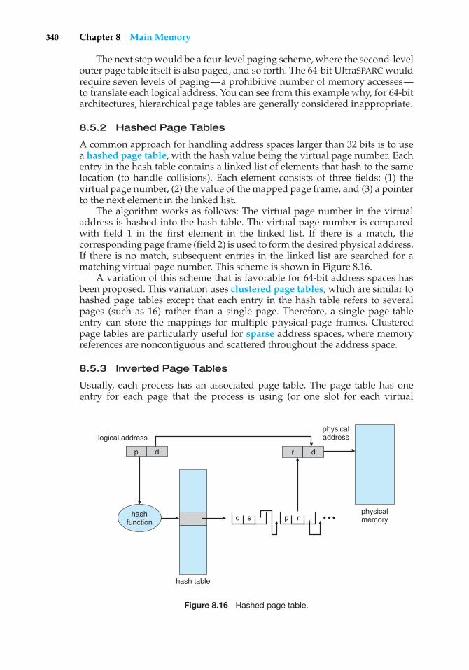
340 Chapter 8 Main Memory
The next step would be a four-level paging scheme, where the second-levelouter page table itself is also paged, and so forth. The 64-bit UltraSPARC wouldrequire seven levels of paging—a prohibitive number of memory accesses—to translate each logical address. You can see from this example why, for 64-bitarchitectures, hierarchical page tables are generally considered inappropriate.
8.5.2 Hashed Page Tables
A common approach for handling address spaces larger than 32 bits is to usea hashed page table, with the hash value being the virtual page number. Eachentry in the hash table contains a linked list of elements that hash to the samelocation (to handle collisions). Each element consists of three fields: (1) thevirtual page number, (2) the value of the mapped page frame, and (3) a pointerto the next element in the linked list.
The algorithm works as follows: The virtual page number in the virtualaddress is hashed into the hash table. The virtual page number is comparedwith field 1 in the first element in the linked list. If there is a match, thecorresponding page frame (field 2) is used to form the desired physical address.If there is no match, subsequent entries in the linked list are searched for amatching virtual page number. This scheme is shown in Figure 8.16.
A variation of this scheme that is favorable for 64-bit address spaces hasbeen proposed. This variation uses clustered page tables, which are similar tohashed page tables except that each entry in the hash table refers to severalpages (such as 16) rather than a single page. Therefore, a single page-tableentry can store the mappings for multiple physical-page frames. Clusteredpage tables are particularly useful for sparse address spaces, where memoryreferences are noncontiguous and scattered throughout the address space.
8.5.3 Inverted Page Tables
Usually, each process has an associated page table. The page table has oneentry for each page that the process is using (or one slot for each virtual
hash table
q s
logical addressphysicaladdress
physicalmemory
p d r d
p rhashfunction
• • •
Figure 8.16 Hashed page table.
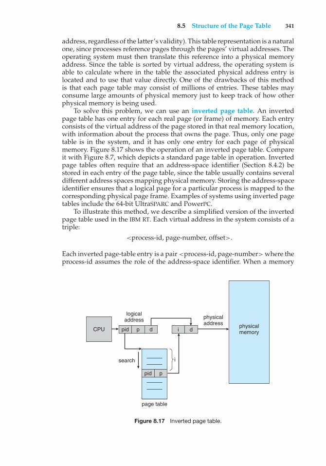
8.5 Structure of the Page Table 341
address, regardless of the latter’s validity). This table representation is a naturalone, since processes reference pages through the pages’ virtual addresses. Theoperating system must then translate this reference into a physical memoryaddress. Since the table is sorted by virtual address, the operating system isable to calculate where in the table the associated physical address entry islocated and to use that value directly. One of the drawbacks of this methodis that each page table may consist of millions of entries. These tables mayconsume large amounts of physical memory just to keep track of how otherphysical memory is being used.
To solve this problem, we can use an inverted page table. An invertedpage table has one entry for each real page (or frame) of memory. Each entryconsists of the virtual address of the page stored in that real memory location,with information about the process that owns the page. Thus, only one pagetable is in the system, and it has only one entry for each page of physicalmemory. Figure 8.17 shows the operation of an inverted page table. Compareit with Figure 8.7, which depicts a standard page table in operation. Invertedpage tables often require that an address-space identifier (Section 8.4.2) bestored in each entry of the page table, since the table usually contains severaldifferent address spaces mapping physical memory. Storing the address-spaceidentifier ensures that a logical page for a particular process is mapped to thecorresponding physical page frame. Examples of systems using inverted pagetables include the 64-bit UltraSPARC and PowerPC.
To illustrate this method, we describe a simplified version of the invertedpage table used in the IBM RT. Each virtual address in the system consists of atriple:
<process-id, page-number, offset>.
Each inverted page-table entry is a pair <process-id, page-number> where theprocess-id assumes the role of the address-space identifier. When a memory
page table
CPU
logicaladdress physical
address physicalmemory
i
pid p
pid
search
p
d i d
Figure 8.17 Inverted page table.
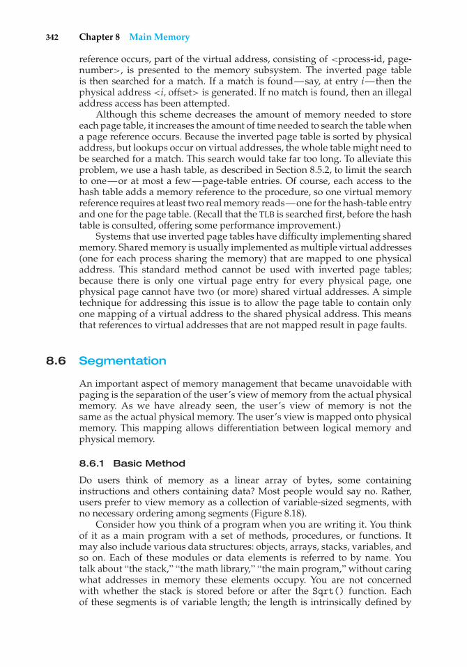
342 Chapter 8 Main Memory
reference occurs, part of the virtual address, consisting of <process-id, page-number>, is presented to the memory subsystem. The inverted page tableis then searched for a match. If a match is found—say, at entry i—then thephysical address <i, offset> is generated. If no match is found, then an illegaladdress access has been attempted.
Although this scheme decreases the amount of memory needed to storeeach page table, it increases the amount of time needed to search the table whena page reference occurs. Because the inverted page table is sorted by physicaladdress, but lookups occur on virtual addresses, the whole table might need tobe searched for a match. This search would take far too long. To alleviate thisproblem, we use a hash table, as described in Section 8.5.2, to limit the searchto one—or at most a few—page-table entries. Of course, each access to thehash table adds a memory reference to the procedure, so one virtual memoryreference requires at least two real memory reads—one for the hash-table entryand one for the page table. (Recall that the TLB is searched first, before the hashtable is consulted, offering some performance improvement.)
Systems that use inverted page tables have difficulty implementing sharedmemory. Shared memory is usually implemented as multiple virtual addresses(one for each process sharing the memory) that are mapped to one physicaladdress. This standard method cannot be used with inverted page tables;because there is only one virtual page entry for every physical page, onephysical page cannot have two (or more) shared virtual addresses. A simpletechnique for addressing this issue is to allow the page table to contain onlyone mapping of a virtual address to the shared physical address. This meansthat references to virtual addresses that are not mapped result in page faults.
8.6 Segmentation
An important aspect of memory management that became unavoidable withpaging is the separation of the user’s view of memory from the actual physicalmemory. As we have already seen, the user’s view of memory is not thesame as the actual physical memory. The user’s view is mapped onto physicalmemory. This mapping allows differentiation between logical memory andphysical memory.
8.6.1 Basic Method
Do users think of memory as a linear array of bytes, some containinginstructions and others containing data? Most people would say no. Rather,users prefer to view memory as a collection of variable-sized segments, withno necessary ordering among segments (Figure 8.18).
Consider how you think of a program when you are writing it. You thinkof it as a main program with a set of methods, procedures, or functions. Itmay also include various data structures: objects, arrays, stacks, variables, andso on. Each of these modules or data elements is referred to by name. Youtalk about “the stack,” “the math library,” “the main program,” without caringwhat addresses in memory these elements occupy. You are not concernedwith whether the stack is stored before or after the Sqrt() function. Eachof these segments is of variable length; the length is intrinsically defined by
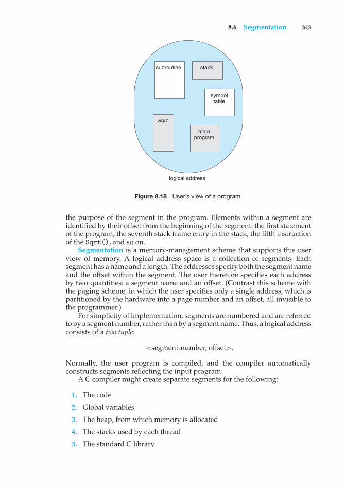
8.6 Segmentation 343
logical address
subroutine stack
symbol table
main program
Sqrt
Figure 8.18 User’s view of a program.
the purpose of the segment in the program. Elements within a segment areidentified by their offset from the beginning of the segment: the first statementof the program, the seventh stack frame entry in the stack, the fifth instructionof the Sqrt(), and so on.
Segmentation is a memory-management scheme that supports this userview of memory. A logical address space is a collection of segments. Eachsegment has a name and a length. The addresses specify both the segment nameand the offset within the segment. The user therefore specifies each addressby two quantities: a segment name and an offset. (Contrast this scheme withthe paging scheme, in which the user specifies only a single address, which ispartitioned by the hardware into a page number and an offset, all invisible tothe programmer.)
For simplicity of implementation, segments are numbered and are referredto by a segment number, rather than by a segment name. Thus, a logical addressconsists of a two tuple:
<segment-number, offset>.
Normally, the user program is compiled, and the compiler automaticallyconstructs segments reflecting the input program.
A C compiler might create separate segments for the following:
1. The code
2. Global variables
3. The heap, from which memory is allocated
4. The stacks used by each thread
5. The standard C library
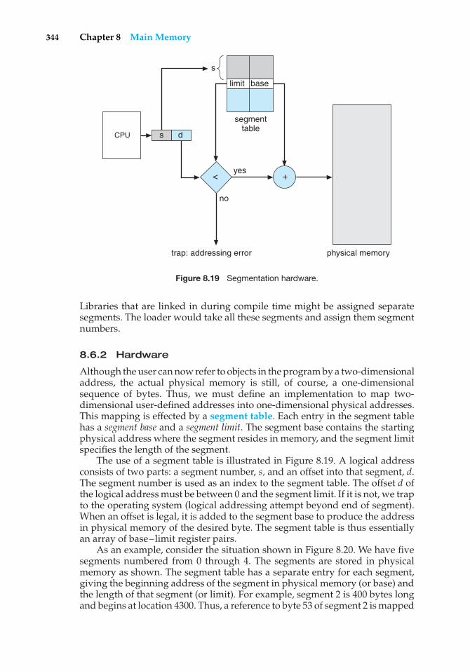
344 Chapter 8 Main Memory
CPU
physical memory
s d
< +
trap: addressing error
no
yes
segment table
limit base
s
Figure 8.19 Segmentation hardware.
Libraries that are linked in during compile time might be assigned separatesegments. The loader would take all these segments and assign them segmentnumbers.
8.6.2 Hardware
Although the user can now refer to objects in the program by a two-dimensionaladdress, the actual physical memory is still, of course, a one-dimensionalsequence of bytes. Thus, we must define an implementation to map two-dimensional user-defined addresses into one-dimensional physical addresses.This mapping is effected by a segment table. Each entry in the segment tablehas a segment base and a segment limit. The segment base contains the startingphysical address where the segment resides in memory, and the segment limitspecifies the length of the segment.
The use of a segment table is illustrated in Figure 8.19. A logical addressconsists of two parts: a segment number, s, and an offset into that segment, d.The segment number is used as an index to the segment table. The offset d ofthe logical address must be between 0 and the segment limit. If it is not, we trapto the operating system (logical addressing attempt beyond end of segment).When an offset is legal, it is added to the segment base to produce the addressin physical memory of the desired byte. The segment table is thus essentiallyan array of base–limit register pairs.
As an example, consider the situation shown in Figure 8.20. We have fivesegments numbered from 0 through 4. The segments are stored in physicalmemory as shown. The segment table has a separate entry for each segment,giving the beginning address of the segment in physical memory (or base) andthe length of that segment (or limit). For example, segment 2 is 400 bytes longand begins at location 4300. Thus, a reference to byte 53 of segment 2 is mapped
8.7 Example: The Intel Pentium 345
logical address space
subroutine stack
symbol table
main program
Sqrt
1400
physical memory
2400
3200
segment 24300
4700
5700
6300
6700
segment table
limit0 1 2 3 4
1000 400 400
1100 1000
base1400 6300 4300 3200 4700
segment 0
segment 3
segment 4
segment 2segment 1
segment 0
segment 3
segment 4
segment 1
Figure 8.20 Example of segmentation.
onto location 4300 + 53 = 4353. A reference to segment 3, byte 852, is mapped to3200 (the base of segment 3) + 852 = 4052. A reference to byte 1222 of segment0 would result in a trap to the operating system, as this segment is only 1,000bytes long.
8.7 Example: The Intel Pentium
Both paging and segmentation have advantages and disadvantages. In fact,some architectures provide both. In this section, we discuss the Intel Pentiumarchitecture, which supports both pure segmentation and segmentation withpaging. We do not give a complete description of the memory-managementstructure of the Pentium in this text. Rather, we present the major ideas onwhich it is based. We conclude our discussion with an overview of Linuxaddress translation on Pentium systems.
In Pentium systems, the CPU generates logical addresses, which are givento the segmentation unit. The segmentation unit produces a linear address foreach logical address. The linear address is then given to the paging unit, whichin turn generates the physical address in main memory. Thus, the segmentationand paging units form the equivalent of the memory-management unit (MMU).This scheme is shown in Figure 8.21.
8.7.1 Pentium Segmentation
The Pentium architecture allows a segment to be as large as 4 GB, and themaximum number of segments per process is 16 K. The logical-address space
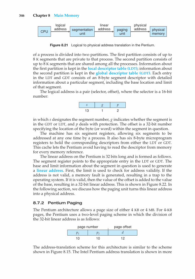
346 Chapter 8 Main Memory
CPU
logicaladdress segmentation
unit
linearaddress paging
unit
physicaladdress physical
memory
Figure 8.21 Logical to physical address translation in the Pentium.
of a process is divided into two partitions. The first partition consists of up to8 K segments that are private to that process. The second partition consists ofup to 8 K segments that are shared among all the processes. Information aboutthe first partition is kept in the local descriptor table (LDT); information aboutthe second partition is kept in the global descriptor table (GDT). Each entryin the LDT and GDT consists of an 8-byte segment descriptor with detailedinformation about a particular segment, including the base location and limitof that segment.
The logical address is a pair (selector, offset), where the selector is a 16-bitnumber:
p
2
g
1
s
13
in which s designates the segment number, g indicates whether the segment isin the GDT or LDT, and p deals with protection. The offset is a 32-bit numberspecifying the location of the byte (or word) within the segment in question.
The machine has six segment registers, allowing six segments to beaddressed at any one time by a process. It also has six 8-byte microprogramregisters to hold the corresponding descriptors from either the LDT or GDT.This cache lets the Pentium avoid having to read the descriptor from memoryfor every memory reference.
The linear address on the Pentium is 32 bits long and is formed as follows.The segment register points to the appropriate entry in the LDT or GDT. Thebase and limit information about the segment in question is used to generatea linear address. First, the limit is used to check for address validity. If theaddress is not valid, a memory fault is generated, resulting in a trap to theoperating system. If it is valid, then the value of the offset is added to the valueof the base, resulting in a 32-bit linear address. This is shown in Figure 8.22. Inthe following section, we discuss how the paging unit turns this linear addressinto a physical address.
8.7.2 Pentium Paging
The Pentium architecture allows a page size of either 4 KB or 4 MB. For 4-KBpages, the Pentium uses a two-level paging scheme in which the division ofthe 32-bit linear address is as follows:
p1 p2 d
page number page offset
10 10 12
The address-translation scheme for this architecture is similar to the schemeshown in Figure 8.15. The Intel Pentium address translation is shown in more
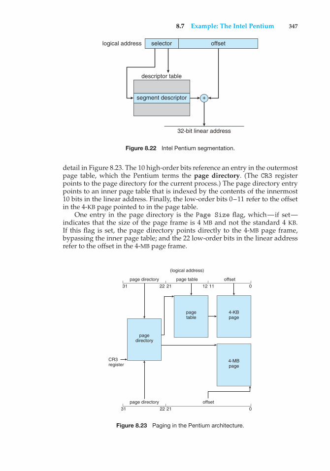
8.7 Example: The Intel Pentium 347
logical address selector
descriptor table
segment descriptor +
32-bit linear address
offset
Figure 8.22 Intel Pentium segmentation.
detail in Figure 8.23. The 10 high-order bits reference an entry in the outermostpage table, which the Pentium terms the page directory. (The CR3 registerpoints to the page directory for the current process.) The page directory entrypoints to an inner page table that is indexed by the contents of the innermost10 bits in the linear address. Finally, the low-order bits 0–11 refer to the offsetin the 4-KB page pointed to in the page table.
One entry in the page directory is the Page Size flag, which—if set—indicates that the size of the page frame is 4 MB and not the standard 4 KB.If this flag is set, the page directory points directly to the 4-MB page frame,bypassing the inner page table; and the 22 low-order bits in the linear addressrefer to the offset in the 4-MB page frame.
page directory
page directory
CR3register
pagedirectory
pagetable
4-KBpage
4-MBpage
page table
offset
offset
(logical address)
31 22 21 12 11 0
2131 22 0
Figure 8.23 Paging in the Pentium architecture.
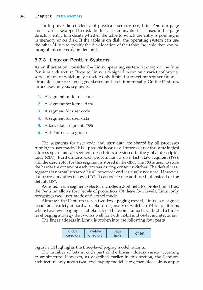
348 Chapter 8 Main Memory
To improve the efficiency of physical memory use, Intel Pentium pagetables can be swapped to disk. In this case, an invalid bit is used in the pagedirectory entry to indicate whether the table to which the entry is pointing isin memory or on disk. If the table is on disk, the operating system can usethe other 31 bits to specify the disk location of the table; the table then can bebrought into memory on demand.
8.7.3 Linux on Pentium Systems
As an illustration, consider the Linux operating system running on the IntelPentium architecture. Because Linux is designed to run on a variety of proces-sors—many of which may provide only limited support for segmentation—Linux does not rely on segmentation and uses it minimally. On the Pentium,Linux uses only six segments:
1. A segment for kernel code
2. A segment for kernel data
3. A segment for user code
4. A segment for user data
5. A task-state segment (TSS)
6. A default LDT segment
The segments for user code and user data are shared by all processesrunning in user mode. This is possible because all processes use the same logicaladdress space and all segment descriptors are stored in the global descriptortable (GDT). Furthermore, each process has its own task-state segment (TSS),and the descriptor for this segment is stored in the GDT. The TSS is used to storethe hardware context of each process during context switches. The default LDTsegment is normally shared by all processes and is usually not used. However,if a process requires its own LDT, it can create one and use that instead of thedefault LDT.
As noted, each segment selector includes a 2-bit field for protection. Thus,the Pentium allows four levels of protection. Of these four levels, Linux onlyrecognizes two: user mode and kernel mode.
Although the Pentium uses a two-level paging model, Linux is designedto run on a variety of hardware platforms, many of which are 64-bit platformswhere two-level paging is not plausible. Therefore, Linux has adopted a three-level paging strategy that works well for both 32-bit and 64-bit architectures.
The linear address in Linux is broken into the following four parts:
globaldirectory
middledirectory
pagetable offset
Figure 8.24 highlights the three-level paging model in Linux.The number of bits in each part of the linear address varies according
to architecture. However, as described earlier in this section, the Pentiumarchitecture only uses a two-level paging model. How, then, does Linux apply
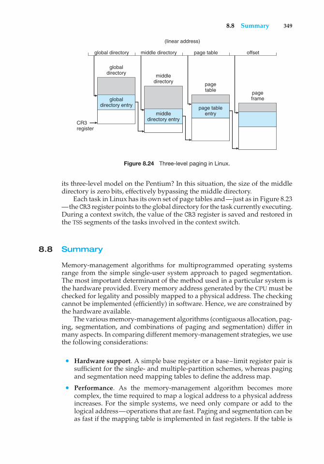
8.8 Summary 349
global directory
globaldirectory
CR3register
middledirectory page
table pageframeglobal
directory entry
middledirectory entry
page tableentry
middle directory page table
(linear address)
offset
Figure 8.24 Three-level paging in Linux.
its three-level model on the Pentium? In this situation, the size of the middledirectory is zero bits, effectively bypassing the middle directory.
Each task in Linux has its own set of page tables and—just as in Figure 8.23—the CR3 register points to the global directory for the task currently executing.During a context switch, the value of the CR3 register is saved and restored inthe TSS segments of the tasks involved in the context switch.
8.8 Summary
Memory-management algorithms for multiprogrammed operating systemsrange from the simple single-user system approach to paged segmentation.The most important determinant of the method used in a particular system isthe hardware provided. Every memory address generated by the CPU must bechecked for legality and possibly mapped to a physical address. The checkingcannot be implemented (efficiently) in software. Hence, we are constrained bythe hardware available.
The various memory-management algorithms (contiguous allocation, pag-ing, segmentation, and combinations of paging and segmentation) differ inmany aspects. In comparing different memory-management strategies, we usethe following considerations:
• Hardware support. A simple base register or a base–limit register pair issufficient for the single- and multiple-partition schemes, whereas pagingand segmentation need mapping tables to define the address map.
• Performance. As the memory-management algorithm becomes morecomplex, the time required to map a logical address to a physical addressincreases. For the simple systems, we need only compare or add to thelogical address—operations that are fast. Paging and segmentation can beas fast if the mapping table is implemented in fast registers. If the table is
350 Chapter 8 Main Memory
in memory, however, user memory accesses can be degraded substantially.A TLB can reduce the performance degradation to an acceptable level.
• Fragmentation. A multiprogrammed system will generally perform moreefficiently if it has a higher level of multiprogramming. For a givenset of processes, we can increase the multiprogramming level only bypacking more processes into memory. To accomplish this task, we mustreduce memory waste, or fragmentation. Systems with fixed-sized allo-cation units, such as the single-partition scheme and paging, suffer frominternal fragmentation. Systems with variable-sized allocation units, suchas the multiple-partition scheme and segmentation, suffer from externalfragmentation.
• Relocation. One solution to the external-fragmentation problem is com-paction. Compaction involves shifting a program in memory in such away that the program does not notice the change. This considerationrequires that logical addresses be relocated dynamically, at execution time.If addresses are relocated only at load time, we cannot compact storage.
• Swapping. Swapping can be added to any algorithm. At intervals deter-mined by the operating system, usually dictated by CPU-scheduling poli-cies, processes are copied from main memory to a backing store and laterare copied back to main memory. This scheme allows more processes to berun than can be fit into memory at one time.
• Sharing. Another means of increasing the multiprogramming level is toshare code and data among different users. Sharing generally requiresthat either paging or segmentation be used to provide small packets ofinformation (pages or segments) that can be shared. Sharing is a meansof running many processes with a limited amount of memory, but sharedprograms and data must be designed carefully.
• Protection. If paging or segmentation is provided, different sections of auser program can be declared execute-only, read-only, or read–write. Thisrestriction is necessary with shared code or data and is generally usefulin any case to provide simple run-time checks for common programmingerrors.
Practice Exercises
8.1 Name two differences between logical and physical addresses.
8.2 Consider a system in which a program can be separated into twoparts: code and data. The CPU knows whether it wants an instruction(instruction fetch) or data (data fetch or store). Therefore, two base–limit register pairs are provided: one for instructions and one for data.The instruction base–limit register pair is automatically read-only, soprograms can be shared among different users. Discuss the advantagesand disadvantages of this scheme.
8.3 Why are page sizes always powers of 2?
Exercises 351
8.4 Consider a logical address space of 64 pages of 1,024 words each, mappedonto a physical memory of 32 frames.
a. How many bits are there in the logical address?
b. How many bits are there in the physical address?
8.5 What is the effect of allowing two entries in a page table to point to thesame page frame in memory? Explain how this effect could be used todecrease the amount of time needed to copy a large amount of memoryfrom one place to another. What effect would updating some byte on theone page have on the other page?
8.6 Describe a mechanism by which one segment could belong to the addressspace of two different processes.
8.7 Sharing segments among processes without requiring that they have thesame segment number is possible in a dynamically linked segmentationsystem.
a. Define a system that allows static linking and sharing of segmentswithout requiring that the segment numbers be the same.
b. Describe a paging scheme that allows pages to be shared withoutrequiring that the page numbers be the same.
8.8 In the IBM/370, memory protection is provided through the use of keys. Akey is a 4-bit quantity. Each 2-K block of memory has a key (the storagekey) associated with it. The CPU also has a key (the protection key)associated with it. A store operation is allowed only if both keys areequal or if either is zero. Which of the following memory-managementschemes could be used successfully with this hardware?
a. Bare machine
b. Single-user system
c. Multiprogramming with a fixed number of processes
d. Multiprogramming with a variable number of processes
e. Paging
f. Segmentation
Exercises
8.9 Explain the difference between internal and external fragmentation.
8.10 Consider the following process for generating binaries. A compiler isused to generate the object code for individual modules, and a linkageeditor is used to combine multiple object modules into a single programbinary. How does the linkage editor change the binding of instructionsand data to memory addresses? What information needs to be passedfrom the compiler to the linkage editor to facilitate the memory-bindingtasks of the linkage editor?
352 Chapter 8 Main Memory
8.11 Given five memory partitions of 100 KB, 500 KB, 200 KB, 300 KB, and 600KB (in order), how would the first-fit, best-fit, and worst-fit algorithmsplace processes of 212 KB, 417 KB, 112 KB, and 426 KB (in order)? Whichalgorithm makes the most efficient use of memory?
8.12 Most systems allow a program to allocate more memory to its addressspace during execution. Allocation of data in the heap segments ofprograms is an example of such allocated memory. What is requiredto support dynamic memory allocation in the following schemes?
a. Contiguous memory allocation
b. Pure segmentation
c. Pure paging
8.13 Compare the memory organization schemes of contiguous memoryallocation, pure segmentation, and pure paging with respect to thefollowing issues:
a. External fragmentation
b. Internal fragmentation
c. Ability to share code across processes
8.14 On a system with paging, a process cannot access memory that it doesnot own. Why? How could the operating system allow access to othermemory? Why should it or should it not?
8.15 Compare paging with segmentation with respect to the amount ofmemory required by the address translation structures in order toconvert virtual addresses to physical addresses.
8.16 Program binaries in many systems are typically structured as follows.Code is stored starting with a small, fixed virtual address, such as 0. Thecode segment is followed by the data segment that is used for storingthe program variables. When the program starts executing, the stack isallocated at the other end of the virtual address space and is allowedto grow toward lower virtual addresses. What is the significance of thisstructure for the following schemes?
a. Contiguous memory allocation
b. Pure segmentation
c. Pure paging
8.17 Assuming a 1-KB page size, what are the page numbers and offsets forthe following address references (provided as decimal numbers):
a. 2375
b. 19366
c. 30000
d. 256
e. 16385
Exercises 353
8.18 Consider a logical address space of 32 pages with 1,024 words per page,mapped onto a physical memory of 16 frames.
a. How many bits are required in the logical address?
b. How many bits are required in the physical address?
8.19 Consider a computer system with a 32-bit logical address and 4-KB pagesize. The system supports up to 512 MB of physical memory. How manyentries are there in each of the following?
a. A conventional single-level page table
b. An inverted page table
8.20 Consider a paging system with the page table stored in memory.
a. If a memory reference takes 200 nanoseconds, how long does apaged memory reference take?
b. If we add TLBs, and 75 percent of all page-table references are foundin the TLBs, what is the effective memory reference time? (Assumethat finding a page-table entry in the TLBs takes zero time, if theentry is there.)
8.21 Why are segmentation and paging sometimes combined into onescheme?
8.22 Explain why sharing a reentrant module is easier when segmentation isused than when pure paging is used.
8.23 Consider the following segment table:
Segment Base Length
0 219 6001 2300 14290 1003 1327 5804 1952 96
What are the physical addresses for the following logical addresses?
a. 0,430
b. 1,10
c. 2,500
d. 3,400
e. 4,112
8.24 What is the purpose of paging the page tables?
8.25 Consider the hierarchical paging scheme used by the VAX architecture.How many memory operations are performed when a user programexecutes a memory-load operation?
354 Chapter 8 Main Memory
8.26 Compare the segmented paging scheme with the hashed page tablescheme for handling large address spaces. Under what circumstances isone scheme preferable to the other?
8.27 Consider the Intel address-translation scheme shown in Figure 8.22.
a. Describe all the steps taken by the Intel Pentium in translating alogical address into a physical address.
b. What are the advantages to the operating system of hardware thatprovides such complicated memory translation?
c. Are there any disadvantages to this address-translation system? Ifso, what are they? If not, why is this scheme not used by everymanufacturer?
Programming Problems
8.28 Assume that a system has a 32-bit virtual address with a 4-KB page size.Write a C program that is passed a virtual address (in decimal) on thecommand line and have it output the page number and offset for thegiven address. As an example, your program would run as follows:
./a.out 19986
Your program would output:
The address 19986 contains:page number = 4offset = 3602
Writing this program will require using the appropriate data type tostore 32 bits. We encourage you to use unsigned data types as well.
Wiley Plus
Visit Wiley Plus for
• Source code
• Solutions to practice exercises
• Additional programming problems and exercises
• Labs using an operating system simulator
Bibliographical Notes
Dynamic storage allocation was discussed by Knuth [1973] (Section 2.5), whofound through simulation results that first fit is generally superior to best fit.Knuth [1973] also discussed the 50-percent rule.
The concept of paging can be credited to the designers of the Atlas system,which has been described by Kilburn et al. [1961] and by Howarth et al.
Bibliographical Notes 355
[1961]. The concept of segmentation was first discussed by Dennis [1965].Paged segmentation was first supported in the GE 645, on which MULTICS wasoriginally implemented (Organick [1972] and Daley and Dennis [1967]).
Inverted page tables are discussed in an article about the IBM RT storagemanager by Chang and Mergen [1988].
Address translation in software is covered in Jacob and Mudge [1997].Hennessy and Patterson [2002] explains the hardware aspects of TLBs,
caches, and MMUs. Talluri et al. [1995] discusses page tables for 64-bit addressspaces. Alternative approaches to enforcing memory protection are proposedand studied in Wahbe et al. [1993a], Chase et al. [1994], Bershad et al. [1995],and Thorn [1997]. Dougan et al. [1999] and Jacob and Mudge [2001] discusstechniques for managing the TLB. Fang et al. [2001] evaluate support for largepages.
Tanenbaum [2001] discusses Intel 80386 paging. Memory management forseveral architectures—such as the Pentium II, PowerPC, and UltraSPARC—are described by Jacob and Mudge [1998a]. Segmentation on Linux systems ispresented in Bovet and Cesati [2002].

This page intentionally left blank
9C H A P T E R
VirtualMemory
In Chapter 8, we discussed various memory-management strategies used incomputer systems. All these strategies have the same goal: to keep manyprocesses in memory simultaneously to allow multiprogramming. However,they tend to require that an entire process be in memory before it can execute.
Virtual memory is a technique that allows the execution of processesthat are not completely in memory. One major advantage of this scheme isthat programs can be larger than physical memory. Further, virtual memoryabstracts main memory into an extremely large, uniform array of storage,separating logical memory as viewed by the user from physical memory.This technique frees programmers from the concerns of memory-storagelimitations. Virtual memory also allows processes to share files easily andto implement shared memory. In addition, it provides an efficient mechanismfor process creation. Virtual memory is not easy to implement, however, andmay substantially decrease performance if it is used carelessly. In this chapter,we discuss virtual memory in the form of demand paging and examine itscomplexity and cost.
CHAPTER OBJECTIVES
• To describe the benefits of a virtual memory system.
• To explain the concepts of demand paging, page-replacement algorithms,and allocation of page frames.
• To discuss the principles of the working-set model.
9.1 Background
The memory-management algorithms outlined in Chapter 8 are necessarybecause of one basic requirement: The instructions being executed must bein physical memory. The first approach to meeting this requirement is to placethe entire logical address space in physical memory. Dynamic loading can helpto ease this restriction, but it generally requires special precautions and extrawork by the programmer.
357
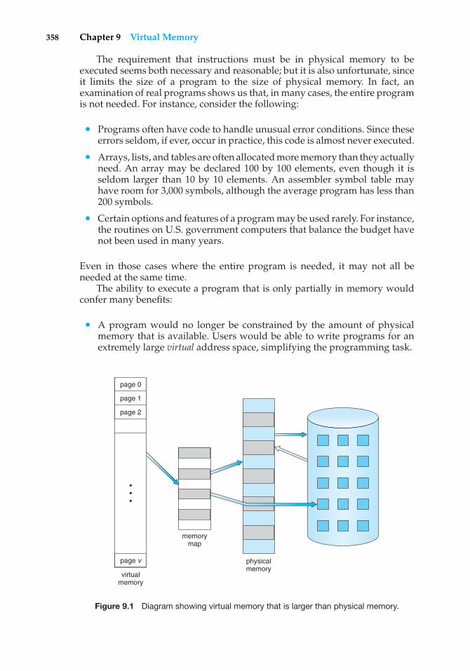
358 Chapter 9 Virtual Memory
The requirement that instructions must be in physical memory to beexecuted seems both necessary and reasonable; but it is also unfortunate, sinceit limits the size of a program to the size of physical memory. In fact, anexamination of real programs shows us that, in many cases, the entire programis not needed. For instance, consider the following:
• Programs often have code to handle unusual error conditions. Since theseerrors seldom, if ever, occur in practice, this code is almost never executed.
• Arrays, lists, and tables are often allocated more memory than they actuallyneed. An array may be declared 100 by 100 elements, even though it isseldom larger than 10 by 10 elements. An assembler symbol table mayhave room for 3,000 symbols, although the average program has less than200 symbols.
• Certain options and features of a program may be used rarely. For instance,the routines on U.S. government computers that balance the budget havenot been used in many years.
Even in those cases where the entire program is needed, it may not all beneeded at the same time.
The ability to execute a program that is only partially in memory wouldconfer many benefits:
• A program would no longer be constrained by the amount of physicalmemory that is available. Users would be able to write programs for anextremely large virtual address space, simplifying the programming task.
virtualmemory
memorymap
physicalmemory
•••
page 0
page 1
page 2
page v
Figure 9.1 Diagram showing virtual memory that is larger than physical memory.
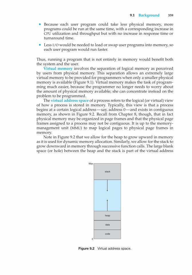
9.1 Background 359
• Because each user program could take less physical memory, moreprograms could be run at the same time, with a corresponding increase inCPU utilization and throughput but with no increase in response time orturnaround time.
• Less I/O would be needed to load or swap user programs into memory, soeach user program would run faster.
Thus, running a program that is not entirely in memory would benefit boththe system and the user.
Virtual memory involves the separation of logical memory as perceivedby users from physical memory. This separation allows an extremely largevirtual memory to be provided for programmers when only a smaller physicalmemory is available (Figure 9.1). Virtual memory makes the task of program-ming much easier, because the programmer no longer needs to worry aboutthe amount of physical memory available; she can concentrate instead on theproblem to be programmed.
The virtual address space of a process refers to the logical (or virtual) viewof how a process is stored in memory. Typically, this view is that a processbegins at a certain logical address—say, address 0—and exists in contiguousmemory, as shown in Figure 9.2. Recall from Chapter 8, though, that in factphysical memory may be organized in page frames and that the physical pageframes assigned to a process may not be contiguous. It is up to the memory-management unit (MMU) to map logical pages to physical page frames inmemory.
Note in Figure 9.2 that we allow for the heap to grow upward in memoryas it is used for dynamic memory allocation. Similarly, we allow for the stack togrow downward in memory through successive function calls. The large blankspace (or hole) between the heap and the stack is part of the virtual address
code
0
Max
data
heap
stack
Figure 9.2 Virtual address space.
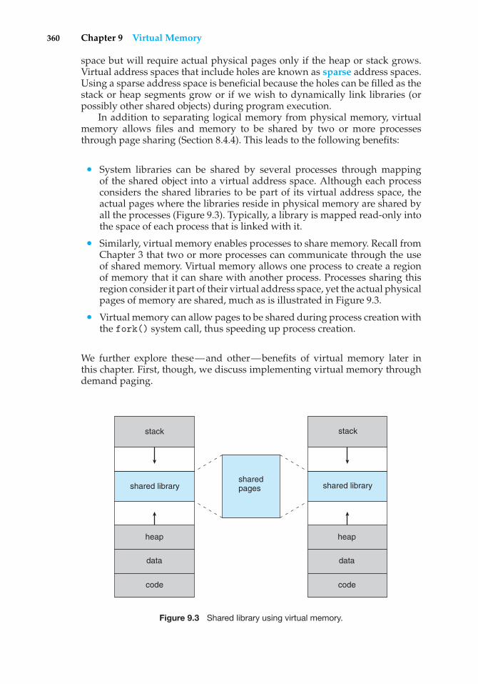
360 Chapter 9 Virtual Memory
space but will require actual physical pages only if the heap or stack grows.Virtual address spaces that include holes are known as sparse address spaces.Using a sparse address space is beneficial because the holes can be filled as thestack or heap segments grow or if we wish to dynamically link libraries (orpossibly other shared objects) during program execution.
In addition to separating logical memory from physical memory, virtualmemory allows files and memory to be shared by two or more processesthrough page sharing (Section 8.4.4). This leads to the following benefits:
• System libraries can be shared by several processes through mappingof the shared object into a virtual address space. Although each processconsiders the shared libraries to be part of its virtual address space, theactual pages where the libraries reside in physical memory are shared byall the processes (Figure 9.3). Typically, a library is mapped read-only intothe space of each process that is linked with it.
• Similarly, virtual memory enables processes to share memory. Recall fromChapter 3 that two or more processes can communicate through the useof shared memory. Virtual memory allows one process to create a regionof memory that it can share with another process. Processes sharing thisregion consider it part of their virtual address space, yet the actual physicalpages of memory are shared, much as is illustrated in Figure 9.3.
• Virtual memory can allow pages to be shared during process creation withthe fork() system call, thus speeding up process creation.
We further explore these—and other—benefits of virtual memory later inthis chapter. First, though, we discuss implementing virtual memory throughdemand paging.
shared library
stack
shared pages
code
data
heap
code
data
heap
shared library
stack
Figure 9.3 Shared library using virtual memory.
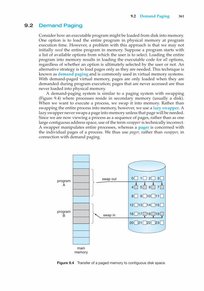
9.2 Demand Paging 361
9.2 Demand Paging
Consider how an executable program might be loaded from disk into memory.One option is to load the entire program in physical memory at programexecution time. However, a problem with this approach is that we may notinitially need the entire program in memory. Suppose a program starts witha list of available options from which the user is to select. Loading the entireprogram into memory results in loading the executable code for all options,regardless of whether an option is ultimately selected by the user or not. Analternative strategy is to load pages only as they are needed. This technique isknown as demand paging and is commonly used in virtual memory systems.With demand-paged virtual memory, pages are only loaded when they aredemanded during program execution; pages that are never accessed are thusnever loaded into physical memory.
A demand-paging system is similar to a paging system with swapping(Figure 9.4) where processes reside in secondary memory (usually a disk).When we want to execute a process, we swap it into memory. Rather thanswapping the entire process into memory, however, we use a lazy swapper. Alazy swapper never swaps a page into memory unless that page will be needed.Since we are now viewing a process as a sequence of pages, rather than as onelarge contiguous address space, use of the term swapper is technically incorrect.A swapper manipulates entire processes, whereas a pager is concerned withthe individual pages of a process. We thus use pager, rather than swapper, inconnection with demand paging.
programA
swap out 0 1 2 3
4 5 6 7
8 9 10 11
12 13 14 15
16 17 18 19
20 21 22 23
swap inprogram
B
mainmemory
Figure 9.4 Transfer of a paged memory to contiguous disk space.
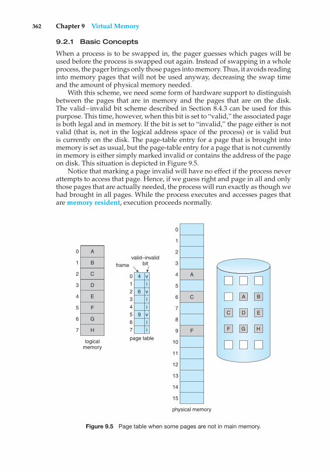
362 Chapter 9 Virtual Memory
9.2.1 Basic Concepts
When a process is to be swapped in, the pager guesses which pages will beused before the process is swapped out again. Instead of swapping in a wholeprocess, the pager brings only those pages into memory. Thus, it avoids readinginto memory pages that will not be used anyway, decreasing the swap timeand the amount of physical memory needed.
With this scheme, we need some form of hardware support to distinguishbetween the pages that are in memory and the pages that are on the disk.The valid–invalid bit scheme described in Section 8.4.3 can be used for thispurpose. This time, however, when this bit is set to “valid,” the associated pageis both legal and in memory. If the bit is set to “invalid,” the page either is notvalid (that is, not in the logical address space of the process) or is valid butis currently on the disk. The page-table entry for a page that is brought intomemory is set as usual, but the page-table entry for a page that is not currentlyin memory is either simply marked invalid or contains the address of the pageon disk. This situation is depicted in Figure 9.5.
Notice that marking a page invalid will have no effect if the process neverattempts to access that page. Hence, if we guess right and page in all and onlythose pages that are actually needed, the process will run exactly as though wehad brought in all pages. While the process executes and accesses pages thatare memory resident, execution proceeds normally.
B
D
D EF
H
logicalmemory
valid–invalidbitframe
page table
1
0 4
62
3
4
5 9
6
7
1
0
2
3
4
5
6
7
i
v
v
i
i
v
i
i
physical memory
A
A BC
C
F G HF
1
0
2
3
4
5
6
7
9
8
10
11
12
13
14
15
A
C
E
G
Figure 9.5 Page table when some pages are not in main memory.
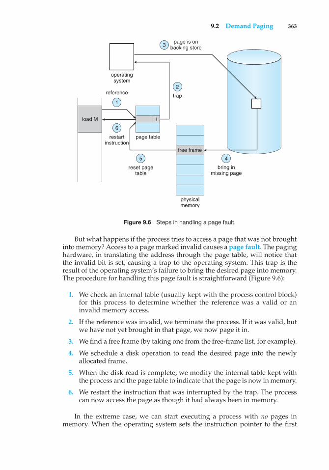
9.2 Demand Paging 363
load M
referencetrap
i
page is onbacking store
operatingsystem
restartinstruction
reset pagetable
page table
physicalmemory
bring inmissing page
free frame
1
2
3
6
5 4
Figure 9.6 Steps in handling a page fault.
But what happens if the process tries to access a page that was not broughtinto memory? Access to a page marked invalid causes a page fault. The paginghardware, in translating the address through the page table, will notice thatthe invalid bit is set, causing a trap to the operating system. This trap is theresult of the operating system’s failure to bring the desired page into memory.The procedure for handling this page fault is straightforward (Figure 9.6):
1. We check an internal table (usually kept with the process control block)for this process to determine whether the reference was a valid or aninvalid memory access.
2. If the reference was invalid, we terminate the process. If it was valid, butwe have not yet brought in that page, we now page it in.
3. We find a free frame (by taking one from the free-frame list, for example).
4. We schedule a disk operation to read the desired page into the newlyallocated frame.
5. When the disk read is complete, we modify the internal table kept withthe process and the page table to indicate that the page is now in memory.
6. We restart the instruction that was interrupted by the trap. The processcan now access the page as though it had always been in memory.
In the extreme case, we can start executing a process with no pages inmemory. When the operating system sets the instruction pointer to the first
364 Chapter 9 Virtual Memory
instruction of the process, which is on a non-memory-resident page, the processimmediately faults for the page. After this page is brought into memory, theprocess continues to execute, faulting as necessary until every page that itneeds is in memory. At that point, it can execute with no more faults. Thisscheme is pure demand paging: never bring a page into memory until it isrequired.
Theoretically, some programs could access several new pages of memorywith each instruction execution (one page for the instruction and many fordata), possibly causing multiple page faults per instruction. This situationwould result in unacceptable system performance. Fortunately, analysis ofrunning processes shows that this behavior is exceedingly unlikely. Programstend to have locality of reference, described in Section 9.6.1, which results inreasonable performance from demand paging.
The hardware to support demand paging is the same as the hardware forpaging and swapping:
• Page table. This table has the ability to mark an entry invalid through avalid–invalid bit or a special value of protection bits.
• Secondary memory. This memory holds those pages that are not presentin main memory. The secondary memory is usually a high-speed disk. It isknown as the swap device, and the section of disk used for this purpose isknown as swap space. Swap-space allocation is discussed in Chapter 12.
A crucial requirement for demand paging is the ability to restart anyinstruction after a page fault. Because we save the state (registers, conditioncode, instruction counter) of the interrupted process when the page faultoccurs, we must be able to restart the process in exactly the same place andstate, except that the desired page is now in memory and is accessible. In mostcases, this requirement is easy to meet. A page fault may occur at any memoryreference. If the page fault occurs on the instruction fetch, we can restart byfetching the instruction again. If a page fault occurs while we are fetching anoperand, we must fetch and decode the instruction again and then fetch theoperand.
As a worst-case example, consider a three-address instruction such as ADDthe content of A to B, placing the result in C. These are the steps to execute thisinstruction:
1. Fetch and decode the instruction (ADD).
2. Fetch A.
3. Fetch B.
4. Add A and B.
5. Store the sum in C.
If we fault when we try to store in C (because C is in a page not currentlyin memory), we will have to get the desired page, bring it in, correct thepage table, and restart the instruction. The restart will require fetching theinstruction again, decoding it again, fetching the two operands again, and
9.2 Demand Paging 365
then adding again. However, there is not much repeated work (less than onecomplete instruction), and the repetition is necessary only when a page faultoccurs.
The major difficulty arises when one instruction may modify severaldifferent locations. For example, consider the IBM System 360/370 MVC (movecharacter) instruction, which can move up to 256 bytes from one location toanother (possibly overlapping) location. If either block (source or destination)straddles a page boundary, a page fault might occur after the move is partiallydone. In addition, if the source and destination blocks overlap, the sourceblock may have been modified, in which case we cannot simply restart theinstruction.
This problem can be solved in two different ways. In one solution, themicrocode computes and attempts to access both ends of both blocks. If a pagefault is going to occur, it will happen at this step, before anything is modified.The move can then take place; we know that no page fault can occur, since allthe relevant pages are in memory. The other solution uses temporary registersto hold the values of overwritten locations. If there is a page fault, all the oldvalues are written back into memory before the trap occurs. This action restoresmemory to its state before the instruction was started, so that the instructioncan be repeated.
This is by no means the only architectural problem resulting from addingpaging to an existing architecture to allow demand paging, but it illustratessome of the difficulties involved. Paging is added between the CPU and thememory in a computer system. It should be entirely transparent to the userprocess. Thus, people often assume that paging can be added to any system.Although this assumption is true for a non-demand-paging environment,where a page fault represents a fatal error, it is not true where a page faultmeans only that an additional page must be brought into memory and theprocess restarted.
9.2.2 Performance of Demand Paging
Demand paging can significantly affect the performance of a computer system.To see why, let’s compute the effective access time for a demand-pagedmemory. For most computer systems, the memory-access time, denoted ma,ranges from 10 to 200 nanoseconds. As long as we have no page faults, theeffective access time is equal to the memory access time. If, however, a pagefault occurs, we must first read the relevant page from disk and then access thedesired word.
Let p be the probability of a page fault (0 ≤ p ≤ 1). We would expect p tobe close to zero—that is, we would expect to have only a few page faults. Theeffective access time is then
effective access time = (1 − p) × ma + p × page fault time.
To compute the effective access time, we must know how much time isneeded to service a page fault. A page fault causes the following sequence tooccur:
1. Trap to the operating system.
2. Save the user registers and process state.
366 Chapter 9 Virtual Memory
3. Determine that the interrupt was a page fault.
4. Check that the page reference was legal and determine the location of thepage on the disk.
5. Issue a read from the disk to a free frame:
a. Wait in a queue for this device until the read request is serviced.
b. Wait for the device seek and/or latency time.
c. Begin the transfer of the page to a free frame.
6. While waiting, allocate the CPU to some other user (CPU scheduling,optional).
7. Receive an interrupt from the disk I/O subsystem (I/O completed).
8. Save the registers and process state for the other user (if step 6 is executed).
9. Determine that the interrupt was from the disk.
10. Correct the page table and other tables to show that the desired page isnow in memory.
11. Wait for the CPU to be allocated to this process again.
12. Restore the user registers, process state, and new page table, and thenresume the interrupted instruction.
Not all of these steps are necessary in every case. For example, we are assumingthat, in step 6, the CPU is allocated to another process while the I/O occurs.This arrangement allows multiprogramming to maintain CPU utilization butrequires additional time to resume the page-fault service routine when the I/Otransfer is complete.
In any case, we are faced with three major components of the page-faultservice time:
1. Service the page-fault interrupt.
2. Read in the page.
3. Restart the process.
The first and third tasks can be reduced, with careful coding, to severalhundred instructions. These tasks may take from 1 to 100 microseconds each.The page-switch time, however, will probably be close to 8 milliseconds.(A typical hard disk has an average latency of 3 milliseconds, a seek of5 milliseconds, and a transfer time of 0.05 milliseconds. Thus, the totalpaging time is about 8 milliseconds, including hardware and software time.)Remember also that we are looking at only the device-service time. If a queueof processes is waiting for the device, we have to add device-queueing time aswe wait for the paging device to be free to service our request, increasing evenmore the time to swap.
With an average page-fault service time of 8 milliseconds and a memory-access time of 200 nanoseconds, the effective access time in nanosecondsis
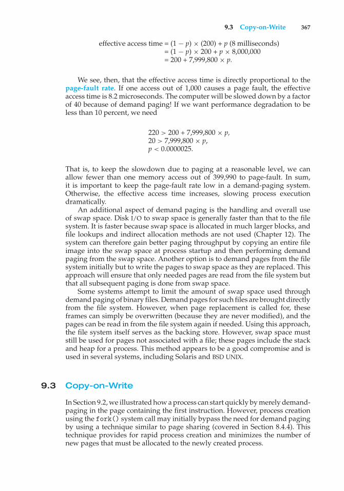
9.3 Copy-on-Write 367
effective access time = (1 − p) × (200) + p (8 milliseconds)= (1 − p) × 200 + p × 8,000,000= 200 + 7,999,800 × p.
We see, then, that the effective access time is directly proportional to thepage-fault rate. If one access out of 1,000 causes a page fault, the effectiveaccess time is 8.2 microseconds. The computer will be slowed down by a factorof 40 because of demand paging! If we want performance degradation to beless than 10 percent, we need
220 > 200 + 7,999,800 × p,20 > 7,999,800 × p,p < 0.0000025.
That is, to keep the slowdown due to paging at a reasonable level, we canallow fewer than one memory access out of 399,990 to page-fault. In sum,it is important to keep the page-fault rate low in a demand-paging system.Otherwise, the effective access time increases, slowing process executiondramatically.
An additional aspect of demand paging is the handling and overall useof swap space. Disk I/O to swap space is generally faster than that to the filesystem. It is faster because swap space is allocated in much larger blocks, andfile lookups and indirect allocation methods are not used (Chapter 12). Thesystem can therefore gain better paging throughput by copying an entire fileimage into the swap space at process startup and then performing demandpaging from the swap space. Another option is to demand pages from the filesystem initially but to write the pages to swap space as they are replaced. Thisapproach will ensure that only needed pages are read from the file system butthat all subsequent paging is done from swap space.
Some systems attempt to limit the amount of swap space used throughdemand paging of binary files. Demand pages for such files are brought directlyfrom the file system. However, when page replacement is called for, theseframes can simply be overwritten (because they are never modified), and thepages can be read in from the file system again if needed. Using this approach,the file system itself serves as the backing store. However, swap space muststill be used for pages not associated with a file; these pages include the stackand heap for a process. This method appears to be a good compromise and isused in several systems, including Solaris and BSD UNIX.
9.3 Copy-on-Write
In Section 9.2, we illustrated how a process can start quickly by merely demand-paging in the page containing the first instruction. However, process creationusing the fork() system call may initially bypass the need for demand pagingby using a technique similar to page sharing (covered in Section 8.4.4). Thistechnique provides for rapid process creation and minimizes the number ofnew pages that must be allocated to the newly created process.
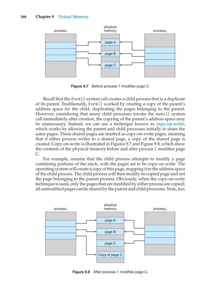
368 Chapter 9 Virtual Memory
process1
physicalmemory
page A
page B
page C
process2
Figure 9.7 Before process 1 modifies page C.
Recall that the fork() system call creates a child process that is a duplicateof its parent. Traditionally, fork() worked by creating a copy of the parent’saddress space for the child, duplicating the pages belonging to the parent.However, considering that many child processes invoke the exec() systemcall immediately after creation, the copying of the parent’s address space maybe unnecessary. Instead, we can use a technique known as copy-on-write,which works by allowing the parent and child processes initially to share thesame pages. These shared pages are marked as copy-on-write pages, meaningthat if either process writes to a shared page, a copy of the shared page iscreated. Copy-on-write is illustrated in Figures 9.7 and Figure 9.8, which showthe contents of the physical memory before and after process 1 modifies pageC.
For example, assume that the child process attempts to modify a pagecontaining portions of the stack, with the pages set to be copy-on-write. Theoperating system will create a copy of this page, mapping it to the address spaceof the child process. The child process will then modify its copied page and notthe page belonging to the parent process. Obviously, when the copy-on-writetechnique is used, only the pages that are modified by either process are copied;all unmodified pages can be shared by the parent and child processes. Note, too,
process1
physicalmemory
page A
page B
page C
Copy of page C
process2
Figure 9.8 After process 1 modifies page C.
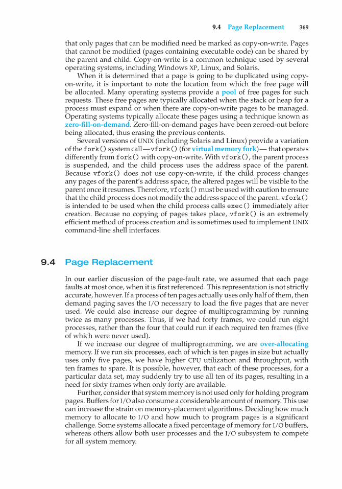
9.4 Page Replacement 369
that only pages that can be modified need be marked as copy-on-write. Pagesthat cannot be modified (pages containing executable code) can be shared bythe parent and child. Copy-on-write is a common technique used by severaloperating systems, including Windows XP, Linux, and Solaris.
When it is determined that a page is going to be duplicated using copy-on-write, it is important to note the location from which the free page willbe allocated. Many operating systems provide a pool of free pages for suchrequests. These free pages are typically allocated when the stack or heap for aprocess must expand or when there are copy-on-write pages to be managed.Operating systems typically allocate these pages using a technique known aszero-fill-on-demand. Zero-fill-on-demand pages have been zeroed-out beforebeing allocated, thus erasing the previous contents.
Several versions of UNIX (including Solaris and Linux) provide a variationof the fork() system call—vfork() (for virtual memory fork)— that operatesdifferently from fork() with copy-on-write. With vfork(), the parent processis suspended, and the child process uses the address space of the parent.Because vfork() does not use copy-on-write, if the child process changesany pages of the parent’s address space, the altered pages will be visible to theparent once it resumes. Therefore, vfork()must be used with caution to ensurethat the child process does not modify the address space of the parent. vfork()is intended to be used when the child process calls exec() immediately aftercreation. Because no copying of pages takes place, vfork() is an extremelyefficient method of process creation and is sometimes used to implement UNIXcommand-line shell interfaces.
9.4 Page Replacement
In our earlier discussion of the page-fault rate, we assumed that each pagefaults at most once, when it is first referenced. This representation is not strictlyaccurate, however. If a process of ten pages actually uses only half of them, thendemand paging saves the I/O necessary to load the five pages that are neverused. We could also increase our degree of multiprogramming by runningtwice as many processes. Thus, if we had forty frames, we could run eightprocesses, rather than the four that could run if each required ten frames (fiveof which were never used).
If we increase our degree of multiprogramming, we are over-allocatingmemory. If we run six processes, each of which is ten pages in size but actuallyuses only five pages, we have higher CPU utilization and throughput, withten frames to spare. It is possible, however, that each of these processes, for aparticular data set, may suddenly try to use all ten of its pages, resulting in aneed for sixty frames when only forty are available.
Further, consider that system memory is not used only for holding programpages. Buffers for I/O also consume a considerable amount of memory. This usecan increase the strain on memory-placement algorithms. Deciding how muchmemory to allocate to I/O and how much to program pages is a significantchallenge. Some systems allocate a fixed percentage of memory for I/O buffers,whereas others allow both user processes and the I/O subsystem to competefor all system memory.
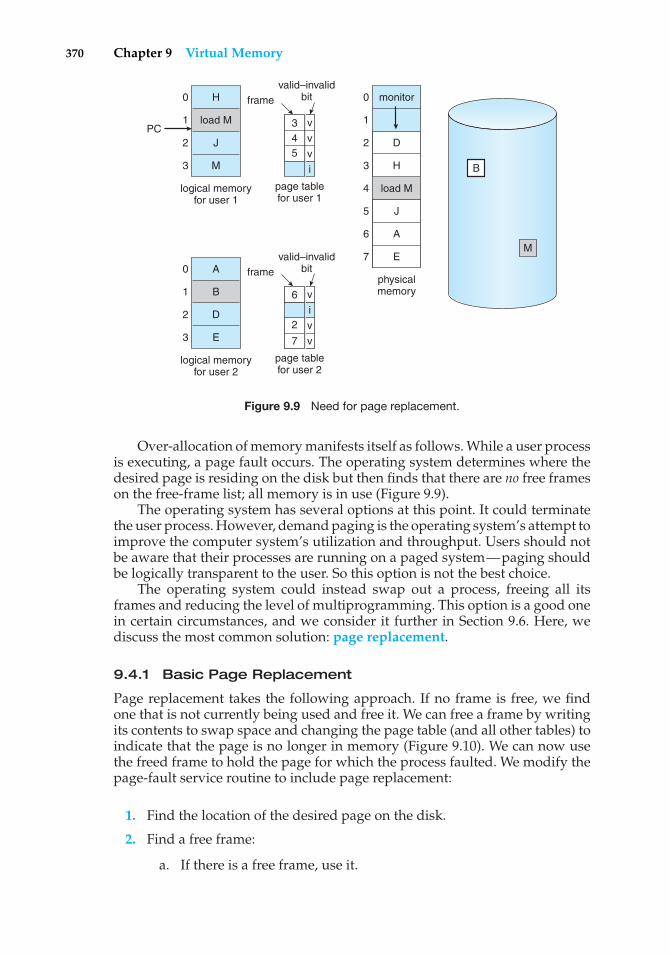
370 Chapter 9 Virtual Memory
monitor
load M
physicalmemory
1
0
2
3
4
5
6
7
H
load M
J
M
logical memoryfor user 1
0
PC1
2
3 B
M
valid–invalidbitframe
page tablefor user 1
i
A
B
D
E
logical memoryfor user 2
0
1
2
3
valid–invalidbitframe
page tablefor user 2
i
43
5
v
v
v
7
2 v
v
6 v
D
H
J
A
E
Figure 9.9 Need for page replacement.
Over-allocation of memory manifests itself as follows. While a user processis executing, a page fault occurs. The operating system determines where thedesired page is residing on the disk but then finds that there are no free frameson the free-frame list; all memory is in use (Figure 9.9).
The operating system has several options at this point. It could terminatethe user process. However, demand paging is the operating system’s attempt toimprove the computer system’s utilization and throughput. Users should notbe aware that their processes are running on a paged system—paging shouldbe logically transparent to the user. So this option is not the best choice.
The operating system could instead swap out a process, freeing all itsframes and reducing the level of multiprogramming. This option is a good onein certain circumstances, and we consider it further in Section 9.6. Here, wediscuss the most common solution: page replacement.
9.4.1 Basic Page Replacement
Page replacement takes the following approach. If no frame is free, we findone that is not currently being used and free it. We can free a frame by writingits contents to swap space and changing the page table (and all other tables) toindicate that the page is no longer in memory (Figure 9.10). We can now usethe freed frame to hold the page for which the process faulted. We modify thepage-fault service routine to include page replacement:
1. Find the location of the desired page on the disk.
2. Find a free frame:
a. If there is a free frame, use it.
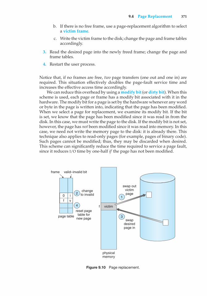
9.4 Page Replacement 371
b. If there is no free frame, use a page-replacement algorithm to selecta victim frame.
c. Write the victim frame to the disk; change the page and frame tablesaccordingly.
3. Read the desired page into the newly freed frame; change the page andframe tables.
4. Restart the user process.
Notice that, if no frames are free, two page transfers (one out and one in) arerequired. This situation effectively doubles the page-fault service time andincreases the effective access time accordingly.
We can reduce this overhead by using a modify bit (or dirty bit). When thisscheme is used, each page or frame has a modify bit associated with it in thehardware. The modify bit for a page is set by the hardware whenever any wordor byte in the page is written into, indicating that the page has been modified.When we select a page for replacement, we examine its modify bit. If the bitis set, we know that the page has been modified since it was read in from thedisk. In this case, we must write the page to the disk. If the modify bit is not set,however, the page has not been modified since it was read into memory. In thiscase, we need not write the memory page to the disk: it is already there. Thistechnique also applies to read-only pages (for example, pages of binary code).Such pages cannot be modified; thus, they may be discarded when desired.This scheme can significantly reduce the time required to service a page fault,since it reduces I/O time by one-half if the page has not been modified.
valid–invalid bitframe
f
page table
victim
changeto invalid
swap outvictimpage
swapdesiredpage in
reset pagetable for
new page
physicalmemory
2
4
1
3
f
0 i
v
Figure 9.10 Page replacement.
372 Chapter 9 Virtual Memory
Page replacement is basic to demand paging. It completes the separationbetween logical memory and physical memory. With this mechanism, anenormous virtual memory can be provided for programmers on a smallerphysical memory. With no demand paging, user addresses are mapped intophysical addresses, so the two sets of addresses can be different. All the pages ofa process still must be in physical memory, however. With demand paging, thesize of the logical address space is no longer constrained by physical memory.If we have a user process of twenty pages, we can execute it in ten framessimply by using demand paging and using a replacement algorithm to finda free frame whenever necessary. If a page that has been modified is to bereplaced, its contents are copied to the disk. A later reference to that page willcause a page fault. At that time, the page will be brought back into memory,perhaps replacing some other page in the process.
We must solve two major problems to implement demand paging: we mustdevelop a frame-allocation algorithm and a page-replacement algorithm.That is, if we have multiple processes in memory, we must decide how manyframes to allocate to each process; and when page replacement is required,we must select the frames that are to be replaced. Designing appropriatealgorithms to solve these problems is an important task, because disk I/Ois so expensive. Even slight improvements in demand-paging methods yieldlarge gains in system performance.
There are many different page-replacement algorithms. Every operatingsystem probably has its own replacement scheme. How do we select aparticular replacement algorithm? In general, we want the one with the lowestpage-fault rate.
We evaluate an algorithm by running it on a particular string of memoryreferences and computing the number of page faults. The string of memoryreferences is called a reference string. We can generate reference stringsartificially (by using a random-number generator, for example), or we can tracea given system and record the address of each memory reference. The latterchoice produces a large number of data (on the order of 1 million addressesper second). To reduce the number of data, we use two facts.
First, for a given page size (and the page size is generally fixed by thehardware or system), we need to consider only the page number, rather thanthe entire address. Second, if we have a reference to a page p, then any referencesto page p that immediately follow will never cause a page fault. Page pwill be inmemory after the first reference, so the immediately following references willnot fault.
For example, if we trace a particular process, we might record the followingaddress sequence:
0100, 0432, 0101, 0612, 0102, 0103, 0104, 0101, 0611, 0102, 0103,0104, 0101, 0610, 0102, 0103, 0104, 0101, 0609, 0102, 0105
At 100 bytes per page, this sequence is reduced to the following referencestring:
1, 4, 1, 6, 1, 6, 1, 6, 1, 6, 1
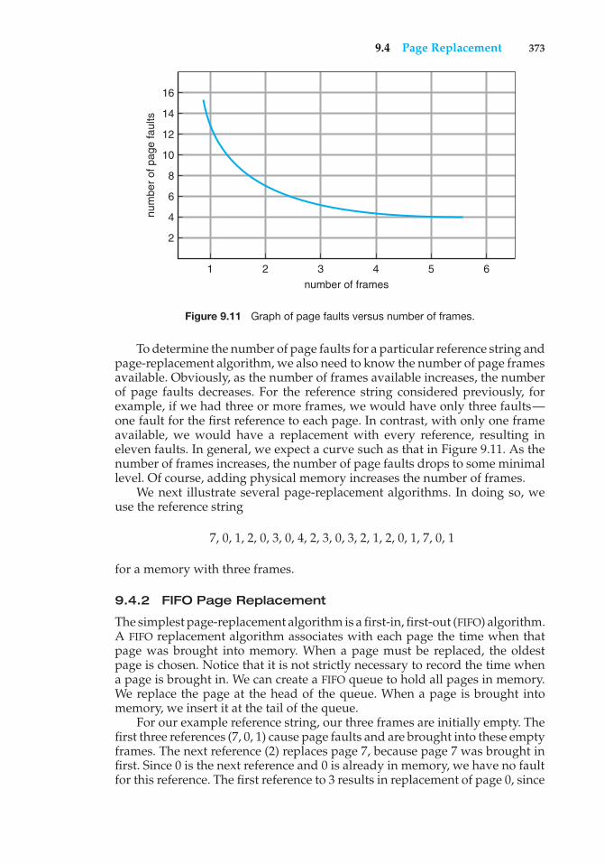
9.4 Page Replacement 373
num
ber
of p
age
faul
ts
16
14
12
10
8
6
4
2
1 2 3
number of frames
4 5 6
Figure 9.11 Graph of page faults versus number of frames.
To determine the number of page faults for a particular reference string andpage-replacement algorithm, we also need to know the number of page framesavailable. Obviously, as the number of frames available increases, the numberof page faults decreases. For the reference string considered previously, forexample, if we had three or more frames, we would have only three faults—one fault for the first reference to each page. In contrast, with only one frameavailable, we would have a replacement with every reference, resulting ineleven faults. In general, we expect a curve such as that in Figure 9.11. As thenumber of frames increases, the number of page faults drops to some minimallevel. Of course, adding physical memory increases the number of frames.
We next illustrate several page-replacement algorithms. In doing so, weuse the reference string
7, 0, 1, 2, 0, 3, 0, 4, 2, 3, 0, 3, 2, 1, 2, 0, 1, 7, 0, 1
for a memory with three frames.
9.4.2 FIFO Page Replacement
The simplest page-replacement algorithm is a first-in, first-out (FIFO) algorithm.A FIFO replacement algorithm associates with each page the time when thatpage was brought into memory. When a page must be replaced, the oldestpage is chosen. Notice that it is not strictly necessary to record the time whena page is brought in. We can create a FIFO queue to hold all pages in memory.We replace the page at the head of the queue. When a page is brought intomemory, we insert it at the tail of the queue.
For our example reference string, our three frames are initially empty. Thefirst three references (7, 0, 1) cause page faults and are brought into these emptyframes. The next reference (2) replaces page 7, because page 7 was brought infirst. Since 0 is the next reference and 0 is already in memory, we have no faultfor this reference. The first reference to 3 results in replacement of page 0, since
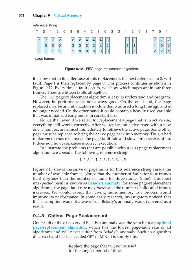
374 Chapter 9 Virtual Memory
7 7
0
7
0
1
page frames
reference string
2
0
1
2
3
1
2
3
0
4
3
0
4
2
0
4
2
3
0
2
3
7
1
2
7
0
2
7
0
1
0
1
3
0
7 0 1 2 0 3 0 4 2 3 0 7 11 02 1 20 3
1
2
Figure 9.12 FIFO page-replacement algorithm.
it is now first in line. Because of this replacement, the next reference, to 0, willfault. Page 1 is then replaced by page 0. This process continues as shown inFigure 9.12. Every time a fault occurs, we show which pages are in our threeframes. There are fifteen faults altogether.
The FIFO page-replacement algorithm is easy to understand and program.However, its performance is not always good. On the one hand, the pagereplaced may be an initialization module that was used a long time ago and isno longer needed. On the other hand, it could contain a heavily used variablethat was initialized early and is in constant use.
Notice that, even if we select for replacement a page that is in active use,everything still works correctly. After we replace an active page with a newone, a fault occurs almost immediately to retrieve the active page. Some otherpage must be replaced to bring the active page back into memory. Thus, a badreplacement choice increases the page-fault rate and slows process execution.It does not, however, cause incorrect execution.
To illustrate the problems that are possible with a FIFO page-replacementalgorithm, we consider the following reference string:
1, 2, 3, 4, 1, 2, 5, 1, 2, 3, 4, 5
Figure 9.13 shows the curve of page faults for this reference string versus thenumber of available frames. Notice that the number of faults for four frames(ten) is greater than the number of faults for three frames (nine)! This mostunexpected result is known as Belady’s anomaly: for some page-replacementalgorithms, the page-fault rate may increase as the number of allocated framesincreases. We would expect that giving more memory to a process wouldimprove its performance. In some early research, investigators noticed thatthis assumption was not always true. Belady’s anomaly was discovered as aresult.
9.4.3 Optimal Page Replacement
One result of the discovery of Belady’s anomaly was the search for an optimalpage-replacement algorithm, which has the lowest page-fault rate of allalgorithms and will never suffer from Belady’s anomaly. Such an algorithmdoes exist and has been called OPT or MIN. It is simply this:
Replace the page that will not be usedfor the longest period of time.
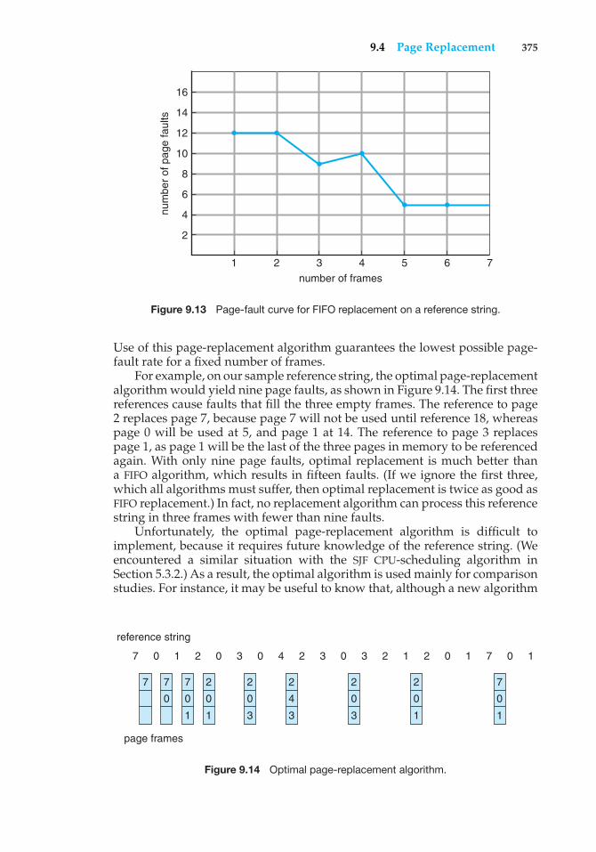
9.4 Page Replacement 375
num
ber
of p
age
faul
ts
16
14
12
10
8
6
4
2
1 2 3
number of frames
4 5 6 7
Figure 9.13 Page-fault curve for FIFO replacement on a reference string.
Use of this page-replacement algorithm guarantees the lowest possible page-fault rate for a fixed number of frames.
For example, on our sample reference string, the optimal page-replacementalgorithm would yield nine page faults, as shown in Figure 9.14. The first threereferences cause faults that fill the three empty frames. The reference to page2 replaces page 7, because page 7 will not be used until reference 18, whereaspage 0 will be used at 5, and page 1 at 14. The reference to page 3 replacespage 1, as page 1 will be the last of the three pages in memory to be referencedagain. With only nine page faults, optimal replacement is much better thana FIFO algorithm, which results in fifteen faults. (If we ignore the first three,which all algorithms must suffer, then optimal replacement is twice as good asFIFO replacement.) In fact, no replacement algorithm can process this referencestring in three frames with fewer than nine faults.
Unfortunately, the optimal page-replacement algorithm is difficult toimplement, because it requires future knowledge of the reference string. (Weencountered a similar situation with the SJF CPU-scheduling algorithm inSection 5.3.2.) As a result, the optimal algorithm is used mainly for comparisonstudies. For instance, it may be useful to know that, although a new algorithm
page frames
reference string
7 7
0
7
0
1
2
0
1
2
0
3
2
4
3
2
0
3
7
0
1
2
0
1
7 0 1 2 0 3 0 4 2 3 0 7 11 02 1 20 3
Figure 9.14 Optimal page-replacement algorithm.
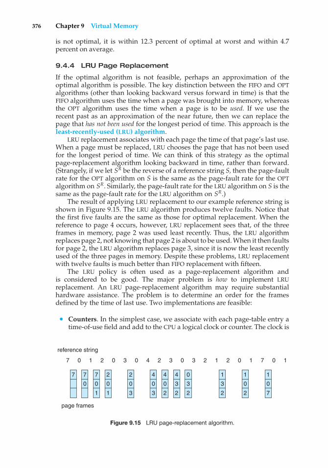
376 Chapter 9 Virtual Memory
is not optimal, it is within 12.3 percent of optimal at worst and within 4.7percent on average.
9.4.4 LRU Page Replacement
If the optimal algorithm is not feasible, perhaps an approximation of theoptimal algorithm is possible. The key distinction between the FIFO and OPTalgorithms (other than looking backward versus forward in time) is that theFIFO algorithm uses the time when a page was brought into memory, whereasthe OPT algorithm uses the time when a page is to be used. If we use therecent past as an approximation of the near future, then we can replace thepage that has not been used for the longest period of time. This approach is theleast-recently-used (LRU) algorithm.
LRU replacement associates with each page the time of that page’s last use.When a page must be replaced, LRU chooses the page that has not been usedfor the longest period of time. We can think of this strategy as the optimalpage-replacement algorithm looking backward in time, rather than forward.(Strangely, if we let SR be the reverse of a reference string S, then the page-faultrate for the OPT algorithm on S is the same as the page-fault rate for the OPTalgorithm on SR. Similarly, the page-fault rate for the LRU algorithm on S is thesame as the page-fault rate for the LRU algorithm on SR.)
The result of applying LRU replacement to our example reference string isshown in Figure 9.15. The LRU algorithm produces twelve faults. Notice thatthe first five faults are the same as those for optimal replacement. When thereference to page 4 occurs, however, LRU replacement sees that, of the threeframes in memory, page 2 was used least recently. Thus, the LRU algorithmreplaces page 2, not knowing that page 2 is about to be used. When it then faultsfor page 2, the LRU algorithm replaces page 3, since it is now the least recentlyused of the three pages in memory. Despite these problems, LRU replacementwith twelve faults is much better than FIFO replacement with fifteen.
The LRU policy is often used as a page-replacement algorithm andis considered to be good. The major problem is how to implement LRUreplacement. An LRU page-replacement algorithm may require substantialhardware assistance. The problem is to determine an order for the framesdefined by the time of last use. Two implementations are feasible:
• Counters. In the simplest case, we associate with each page-table entry atime-of-use field and add to the CPU a logical clock or counter. The clock is
page frames
reference string
7 7
0
7
0
1
2
0
1
2
0
3
4
0
3
4
0
2
4
3
2
0
3
2
1
3
2
1
0
2
1
0
7
7 0 1 2 0 3 0 4 2 3 0 7 11 02 1 20 3
Figure 9.15 LRU page-replacement algorithm.
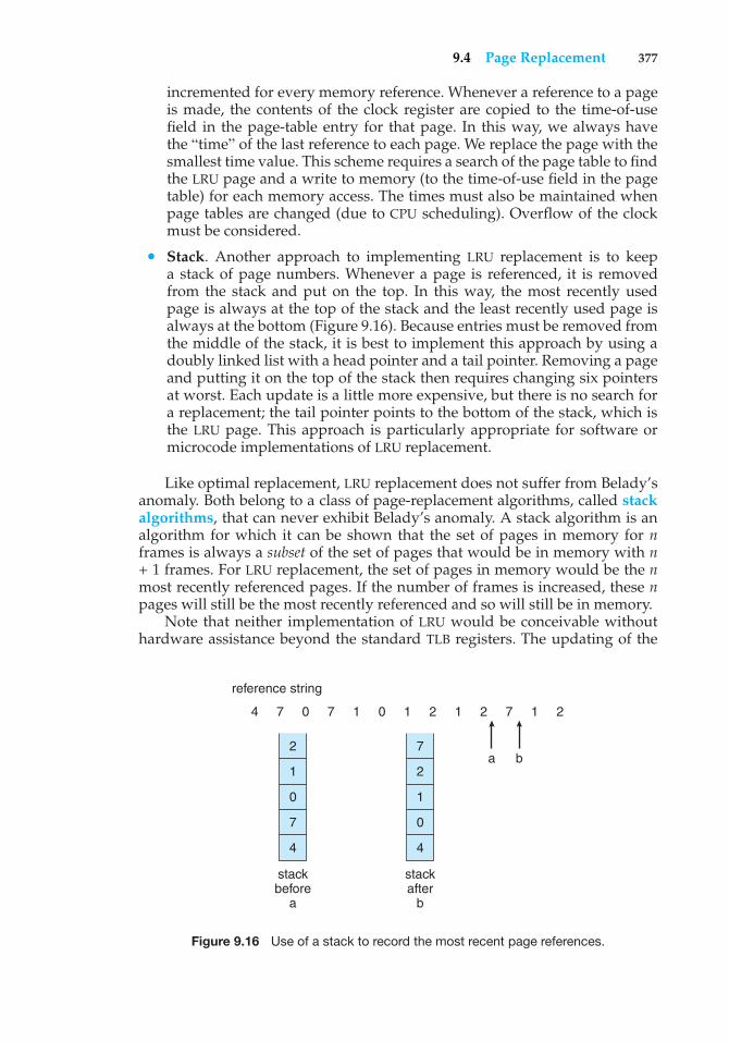
9.4 Page Replacement 377
incremented for every memory reference. Whenever a reference to a pageis made, the contents of the clock register are copied to the time-of-usefield in the page-table entry for that page. In this way, we always havethe “time” of the last reference to each page. We replace the page with thesmallest time value. This scheme requires a search of the page table to findthe LRU page and a write to memory (to the time-of-use field in the pagetable) for each memory access. The times must also be maintained whenpage tables are changed (due to CPU scheduling). Overflow of the clockmust be considered.
• Stack. Another approach to implementing LRU replacement is to keepa stack of page numbers. Whenever a page is referenced, it is removedfrom the stack and put on the top. In this way, the most recently usedpage is always at the top of the stack and the least recently used page isalways at the bottom (Figure 9.16). Because entries must be removed fromthe middle of the stack, it is best to implement this approach by using adoubly linked list with a head pointer and a tail pointer. Removing a pageand putting it on the top of the stack then requires changing six pointersat worst. Each update is a little more expensive, but there is no search fora replacement; the tail pointer points to the bottom of the stack, which isthe LRU page. This approach is particularly appropriate for software ormicrocode implementations of LRU replacement.
Like optimal replacement, LRU replacement does not suffer from Belady’sanomaly. Both belong to a class of page-replacement algorithms, called stackalgorithms, that can never exhibit Belady’s anomaly. A stack algorithm is analgorithm for which it can be shown that the set of pages in memory for nframes is always a subset of the set of pages that would be in memory with n+ 1 frames. For LRU replacement, the set of pages in memory would be the nmost recently referenced pages. If the number of frames is increased, these npages will still be the most recently referenced and so will still be in memory.
Note that neither implementation of LRU would be conceivable withouthardware assistance beyond the standard TLB registers. The updating of the
2
1
0
4
7
stackbefore
a
7
2
1
4
0
stackafter
b
reference string
4 7 0 7 1 0 1 2 1 2 27
a b
1
Figure 9.16 Use of a stack to record the most recent page references.
378 Chapter 9 Virtual Memory
clock fields or stack must be done for every memory reference. If we were touse an interrupt for every reference to allow software to update such datastructures, it would slow every memory reference by a factor of at least ten,hence slowing every user process by a factor of ten. Few systems could toleratethat level of overhead for memory management.
9.4.5 LRU-Approximation Page Replacement
Few computer systems provide sufficient hardware support for true LRU pagereplacement. Some systems provide no hardware support, and other page-replacement algorithms (such as a FIFO algorithm) must be used. Many systemsprovide some help, however, in the form of a reference bit. The reference bitfor a page is set by the hardware whenever that page is referenced (either aread or a write to any byte in the page). Reference bits are associated with eachentry in the page table.
Initially, all bits are cleared (to 0) by the operating system. As a user processexecutes, the bit associated with each page referenced is set (to 1) by thehardware. After some time, we can determine which pages have been used andwhich have not been used by examining the reference bits, although we do notknow the order of use. This information is the basis for many page-replacementalgorithms that approximate LRU replacement.
9.4.5.1 Additional-Reference-Bits Algorithm
We can gain additional ordering information by recording the reference bits atregular intervals. We can keep an 8-bit byte for each page in a table in memory.At regular intervals (say, every 100 milliseconds), a timer interrupt transferscontrol to the operating system. The operating system shifts the reference bitfor each page into the high-order bit of its 8-bit byte, shifting the other bits rightby 1 bit and discarding the low-order bit. These 8-bit shift registers contain thehistory of page use for the last eight time periods. If the shift register contains00000000, for example, then the page has not been used for eight time periods;a page that is used at least once in each period has a shift register value of11111111. A page with a history register value of 11000100 has been used morerecently than one with a value of 01110111. If we interpret these 8-bit bytesas unsigned integers, the page with the lowest number is the LRU page, andit can be replaced. Notice that the numbers are not guaranteed to be unique,however. We can either replace (swap out) all pages with the smallest value oruse the FIFO method to choose among them.
The number of bits of history included in the shift register can be varied,of course, and is selected (depending on the hardware available) to makethe updating as fast as possible. In the extreme case, the number can bereduced to zero, leaving only the reference bit itself. This algorithm is calledthe second-chance page-replacement algorithm.
9.4.5.2 Second-Chance Algorithm
The basic algorithm of second-chance replacement is a FIFO replacementalgorithm. When a page has been selected, however, we inspect its referencebit. If the value is 0, we proceed to replace this page; but if the reference bitis set to 1, we give the page a second chance and move on to select the next
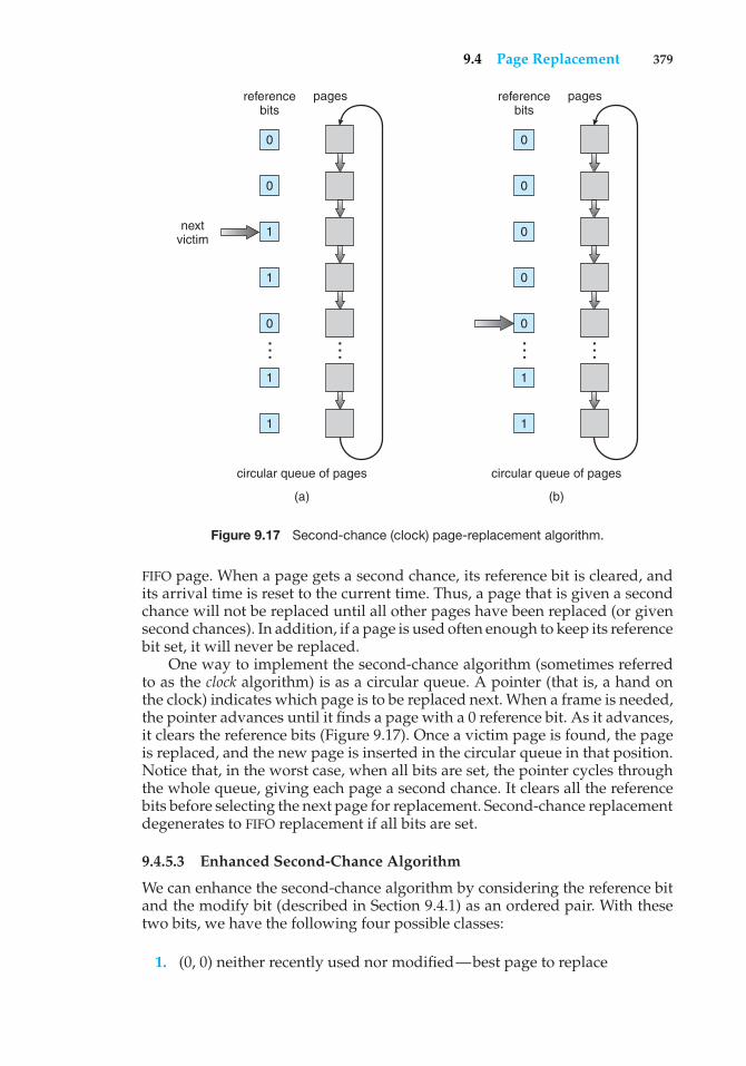
9.4 Page Replacement 379
circular queue of pages
(a)
nextvictim
0
referencebits
pages
0
1
1
0
1
1
……
circular queue of pages
(b)
0
referencebits
pages
0
0
0
0
1
1
……Figure 9.17 Second-chance (clock) page-replacement algorithm.
FIFO page. When a page gets a second chance, its reference bit is cleared, andits arrival time is reset to the current time. Thus, a page that is given a secondchance will not be replaced until all other pages have been replaced (or givensecond chances). In addition, if a page is used often enough to keep its referencebit set, it will never be replaced.
One way to implement the second-chance algorithm (sometimes referredto as the clock algorithm) is as a circular queue. A pointer (that is, a hand onthe clock) indicates which page is to be replaced next. When a frame is needed,the pointer advances until it finds a page with a 0 reference bit. As it advances,it clears the reference bits (Figure 9.17). Once a victim page is found, the pageis replaced, and the new page is inserted in the circular queue in that position.Notice that, in the worst case, when all bits are set, the pointer cycles throughthe whole queue, giving each page a second chance. It clears all the referencebits before selecting the next page for replacement. Second-chance replacementdegenerates to FIFO replacement if all bits are set.
9.4.5.3 Enhanced Second-Chance Algorithm
We can enhance the second-chance algorithm by considering the reference bitand the modify bit (described in Section 9.4.1) as an ordered pair. With thesetwo bits, we have the following four possible classes:
1. (0, 0) neither recently used nor modified—best page to replace
380 Chapter 9 Virtual Memory
2. (0, 1) not recently used but modified—not quite as good, because thepage will need to be written out before replacement
3. (1, 0) recently used but clean—probably will be used again soon
4. (1, 1) recently used and modified—probably will be used again soon, andthe page will be need to be written out to disk before it can be replaced
Each page is in one of these four classes. When page replacement is called for,we use the same scheme as in the clock algorithm; but instead of examiningwhether the page to which we are pointing has the reference bit set to 1,we examine the class to which that page belongs. We replace the first pageencountered in the lowest nonempty class. Notice that we may have to scanthe circular queue several times before we find a page to be replaced.
The major difference between this algorithm and the simpler clock algo-rithm is that here we give preference to those pages that have been modifiedto reduce the number of I/Os required.
9.4.6 Counting-Based Page Replacement
There are many other algorithms that can be used for page replacement. Forexample, we can keep a counter of the number of references that have beenmade to each page and develop the following two schemes.
• The least frequently used (LFU) page-replacement algorithm requiresthat the page with the smallest count be replaced. The reason for thisselection is that an actively used page should have a large reference count.A problem arises, however, when a page is used heavily during the initialphase of a process but then is never used again. Since it was used heavily,it has a large count and remains in memory even though it is no longerneeded. One solution is to shift the counts right by 1 bit at regular intervals,forming an exponentially decaying average usage count.
• The most frequently used (MFU) page-replacement algorithm is basedon the argument that the page with the smallest count was probably justbrought in and has yet to be used.
As you might expect, neither MFU nor LFU replacement is common. Theimplementation of these algorithms is expensive, and they do not approximateOPT replacement well.
9.4.7 Page-Buffering Algorithms
Other procedures are often used in addition to a specific page-replacementalgorithm. For example, systems commonly keep a pool of free frames. Whena page fault occurs, a victim frame is chosen as before. However, the desiredpage is read into a free frame from the pool before the victim is written out. Thisprocedure allows the process to restart as soon as possible, without waitingfor the victim page to be written out. When the victim is later written out, itsframe is added to the free-frame pool.
9.4 Page Replacement 381
An expansion of this idea is to maintain a list of modified pages. Wheneverthe paging device is idle, a modified page is selected and is written to the disk.Its modify bit is then reset. This scheme increases the probability that a pagewill be clean when it is selected for replacement and will not need to be writtenout.
Another modification is to keep a pool of free frames but to rememberwhich page was in each frame. Since the frame contents are not modified whena frame is written to the disk, the old page can be reused directly from thefree-frame pool if it is needed before that frame is reused. No I/O is needed inthis case. When a page fault occurs, we first check whether the desired page isin the free-frame pool. If it is not, we must select a free frame and read into it.
This technique is used in the VAX/VMS system along with a FIFO replace-ment algorithm. When the FIFO replacement algorithm mistakenly replaces apage that is still in active use, that page is quickly retrieved from the free-framepool, and no I/O is necessary. The free-frame buffer provides protection againstthe relatively poor, but simple, FIFO replacement algorithm. This method isnecessary because the early versions of VAX did not implement the referencebit correctly.
Some versions of the UNIX system use this method in conjunction withthe second-chance algorithm. It can be a useful augmentation to any page-replacement algorithm, to reduce the penalty incurred if the wrong victimpage is selected.
9.4.8 Applications and Page Replacement
In certain cases, applications accessing data through the operating system’svirtual memory perform worse than if the operating system provided nobuffering at all. A typical example is a database, which provides its ownmemory management and I/O buffering. Applications like this understandtheir memory use and disk use better than does an operating system that isimplementing algorithms for general-purpose use. If the operating system isbuffering I/O, and the application is doing so as well, then twice the memoryis being used for a set of I/O.
In another example, data warehouses frequently perform massive sequen-tial disk reads, followed by computations and writes. The LRU algorithm wouldbe removing old pages and preserving new ones, while the application wouldmore likely be reading older pages than newer ones (as it starts its sequentialreads again). Here, MFU would actually be more efficient than LRU.
Because of such problems, some operating systems give special programsthe ability to use a disk partition as a large sequential array of logical blocks,without any file-system data structures. This array is sometimes called the rawdisk, and I/O to this array is termed raw I/O. Raw I/O bypasses all the file-system services, such as file I/O demand paging, file locking, prefetching, spaceallocation, file names, and directories. Note that although certain applicationsare more efficient when implementing their own special-purpose storageservices on a raw partition, most applications perform better when they usethe regular file-system services.
382 Chapter 9 Virtual Memory
9.5 Allocation of Frames
We turn next to the issue of allocation. How do we allocate the fixed amountof free memory among the various processes? If we have 93 free frames andtwo processes, how many frames does each process get?
The simplest case is the single-user system. Consider a single-user systemwith 128 KB of memory composed of pages 1 KB in size. This system has 128frames. The operating system may take 35 KB, leaving 93 frames for the userprocess. Under pure demand paging, all 93 frames would initially be put onthe free-frame list. When a user process started execution, it would generate asequence of page faults. The first 93 page faults would all get free frames fromthe free-frame list. When the free-frame list was exhausted, a page-replacementalgorithm would be used to select one of the 93 in-memory pages to be replacedwith the 94th, and so on. When the process terminated, the 93 frames wouldonce again be placed on the free-frame list.
There are many variations on this simple strategy. We can require that theoperating system allocate all its buffer and table space from the free-frame list.When this space is not in use by the operating system, it can be used to supportuser paging. We can try to keep three free frames reserved on the free-frame listat all times. Thus, when a page fault occurs, there is a free frame available topage into. While the page swap is taking place, a replacement can be selected,which is then written to the disk as the user process continues to execute.Other variants are also possible, but the basic strategy is clear: the user processis allocated any free frame.
9.5.1 Minimum Number of Frames
Our strategies for the allocation of frames are constrained in various ways. Wecannot, for example, allocate more than the total number of available frames(unless there is page sharing). We must also allocate at least a minimum numberof frames. Here, we look more closely at the latter requirement.
One reason for allocating at least a minimum number of frames involvesperformance. Obviously, as the number of frames allocated to each processdecreases, the page-fault rate increases, slowing process execution. In addition,remember that, when a page fault occurs before an executing instructionis complete, the instruction must be restarted. Consequently, we must haveenough frames to hold all the different pages that any single instruction canreference.
For example, consider a machine in which all memory-reference instruc-tions may reference only one memory address. In this case, we need at least oneframe for the instruction and one frame for the memory reference. In addition,if one-level indirect addressing is allowed (for example, a load instruction onpage 16 can refer to an address on page 0, which is an indirect reference to page23), then paging requires at least three frames per process. Think about whatmight happen if a process had only two frames.
The minimum number of frames is defined by the computer architecture.For example, the move instruction for the PDP-11 includes more than one wordfor some addressing modes, and thus the instruction itself may straddle twopages. In addition, each of its two operands may be indirect references, for atotal of six frames. Another example is the IBM 370 MVC instruction. Since the
9.5 Allocation of Frames 383
instruction is from storage location to storage location, it takes 6 bytes and canstraddle two pages. The block of characters to move and the area to which itis to be moved can each also straddle two pages. This situation would requiresix frames. The worst case occurs when the MVC instruction is the operand ofan EXECUTE instruction that straddles a page boundary; in this case, we needeight frames.
The worst-case scenario occurs in computer architectures that allowmultiple levels of indirection (for example, each 16-bit word could containa 15-bit address plus a 1-bit indirect indicator). Theoretically, a simple loadinstruction could reference an indirect address that could reference an indirectaddress (on another page) that could also reference an indirect address (on yetanother page), and so on, until every page in virtual memory had been touched.Thus, in the worst case, the entire virtual memory must be in physical memory.To overcome this difficulty, we must place a limit on the levels of indirection (forexample, limit an instruction to at most 16 levels of indirection). When the firstindirection occurs, a counter is set to 16; the counter is then decremented foreach successive indirection for this instruction. If the counter is decremented to0, a trap occurs (excessive indirection). This limitation reduces the maximumnumber of memory references per instruction to 17, requiring the same numberof frames.
Whereas the minimum number of frames per process is defined by thearchitecture, the maximum number is defined by the amount of availablephysical memory. In between, we are still left with significant choice in frameallocation.
9.5.2 Allocation Algorithms
The easiest way to split m frames among n processes is to give everyone anequal share,m/n frames. For instance, if there are 93 frames and five processes,each process will get 18 frames. The three leftover frames can be used as afree-frame buffer pool. This scheme is called equal allocation.
An alternative is to recognize that various processes will need differingamounts of memory. Consider a system with a 1-KB frame size. If a smallstudent process of 10 KB and an interactive database of 127 KB are the onlytwo processes running in a system with 62 free frames, it does not make muchsense to give each process 31 frames. The student process does not need morethan 10 frames, so the other 21 are, strictly speaking, wasted.
To solve this problem, we can use proportional allocation, in which weallocate available memory to each process according to its size. Let the size ofthe virtual memory for process pi be si , and define
S =∑si .
Then, if the total number of available frames is m, we allocate ai frames toprocess pi , where ai is approximately
ai = si/S× m.
384 Chapter 9 Virtual Memory
Of course, we must adjust each ai to be an integer that is greater than theminimum number of frames required by the instruction set, with a sum notexceeding m.
With proportional allocation, we would split 62 frames between twoprocesses, one of 10 pages and one of 127 pages, by allocating 4 frames and 57frames, respectively, since
10/137 × 62 ≈ 4, and127/137 × 62 ≈ 57.
In this way, both processes share the available frames according to their“needs,” rather than equally.
In both equal and proportional allocation, of course, the allocation mayvary according to the multiprogramming level. If the multiprogramming levelis increased, each process will lose some frames to provide the memory neededfor the new process. Conversely, if the multiprogramming level decreases, theframes that were allocated to the departed process can be spread over theremaining processes.
Notice that, with either equal or proportional allocation, a high-priorityprocess is treated the same as a low-priority process. By its definition, however,we may want to give the high-priority process more memory to speed itsexecution, to the detriment of low-priority processes. One solution is to usea proportional allocation scheme wherein the ratio of frames depends not onthe relative sizes of processes but rather on the priorities of processes or on acombination of size and priority.
9.5.3 Global versus Local Allocation
Another important factor in the way frames are allocated to the variousprocesses is page replacement. With multiple processes competing for frames,we can classify page-replacement algorithms into two broad categories: globalreplacement and local replacement. Global replacement allows a process toselect a replacement frame from the set of all frames, even if that frame iscurrently allocated to some other process; that is, one process can take a framefrom another. Local replacement requires that each process select from only itsown set of allocated frames.
For example, consider an allocation scheme wherein we allow high-priorityprocesses to select frames from low-priority processes for replacement. Aprocess can select a replacement from among its own frames or the framesof any lower-priority process. This approach allows a high-priority process toincrease its frame allocation at the expense of a low-priority process. With alocal replacement strategy, the number of frames allocated to a process does notchange. With global replacement, a process may happen to select only framesallocated to other processes, thus increasing the number of frames allocated toit (assuming that other processes do not choose its frames for replacement).
One problem with a global replacement algorithm is that a process cannotcontrol its own page-fault rate. The set of pages in memory for a processdepends not only on the paging behavior of that process but also on the pagingbehavior of other processes. Therefore, the same process may perform quite
9.5 Allocation of Frames 385
differently (for example, taking 0.5 seconds for one execution and 10.3 secondsfor the next execution) because of totally external circumstances. Such is notthe case with a local replacement algorithm. Under local replacement, theset of pages in memory for a process is affected by the paging behavior ofonly that process. Local replacement might hinder a process, however, bynot making available to it other, less used pages of memory. Thus, globalreplacement generally results in greater system throughput and is thereforethe more common method.
9.5.4 Non-Uniform Memory Access
Thus far in our coverage of virtual memory, we have assumed that all mainmemory is created equal—or at least that it is accessed equally. On manycomputer systems, that is not the case. Often, in systems with multiple CPUs(Section 1.3.2), a given CPU can access some sections of main memory fasterthan it can access others. These performance differences are caused by howCPUs and memory are interconnected in the system. Frequently, such a systemis made up of several system boards, each containing multiple CPUs and somememory. The system boards are interconnected in various ways, ranging fromsystem busses to high-speed network connections like InfiniBand. As youmight expect, the CPUs on a particular board can access the memory on thatboard with less delay than they can access memory on other boards in thesystem. Systems in which memory access times vary significantly are knowncollectively as non-uniform memory access (NUMA) systems, and withoutexception, they are slower than systems in which memory and CPUs are locatedon the same motherboard.
Managing which page frames are stored at which locations can significantlyaffect performance in NUMA systems. If we treat memory as uniform in sucha system, CPUs may wait significantly longer for memory access than if wemodify memory allocation algorithms to take NUMA into account. Similarchanges must be made to the scheduling system. The goal of these changes isto have memory frames allocated “as close as possible” to the CPU on whichthe process is running. The definition of “close” is “with minimum latency,”which typically means on the same system board as the CPU.
The algorithmic changes consist of having the scheduler track the last CPUon which each process ran. If the scheduler tries to schedule each process ontoits previous CPU, and the memory-management system tries to allocate framesfor the process close to the CPU on which it is being scheduled, then improvedcache hits and decreased memory access times will result.
The picture is more complicated once threads are added. For example, aprocess with many running threads may end up with those threads scheduledon many different system boards. How is the memory to be allocated in thiscase? Solaris solves the problem by creating an lgroup entity in the kernel. Eachlgroup gathers together close CPUs and memory. In fact, there is a hierarchyof lgroups based on the amount of latency between the groups. Solaris tries toschedule all threads of a process and allocate all memory of a process withinan lgroup. If that is not possible, it picks nearby lgroups for the rest of theresources needed. In this manner, overall memory latency is minimized, andCPU cache hit rates are maximized.
386 Chapter 9 Virtual Memory
9.6 Thrashing
If the number of frames allocated to a low-priority process falls below theminimum number required by the computer architecture, we must suspendthat process’s execution. We should then page out its remaining pages, freeingall its allocated frames. This provision introduces a swap-in, swap-out level ofintermediate CPU scheduling.
In fact, look at any process that does not have “enough” frames. If theprocess does not have the number of frames it needs to support pages inactive use, it will quickly page-fault. At this point, it must replace some page.However, since all its pages are in active use, it must replace a page that willbe needed again right away. Consequently, it quickly faults again, and again,and again, replacing pages that it must bring back in immediately.
This high paging activity is called thrashing. A process is thrashing if it isspending more time paging than executing.
9.6.1 Cause of Thrashing
Thrashing results in severe performance problems. Consider the followingscenario, which is based on the actual behavior of early paging systems.
The operating system monitors CPU utilization. If CPU utilization is too low,we increase the degree of multiprogramming by introducing a new processto the system. A global page-replacement algorithm is used; it replaces pageswithout regard to the process to which they belong. Now suppose that a processenters a new phase in its execution and needs more frames. It starts faulting andtaking frames away from other processes. These processes need those pages,however, and so they also fault, taking frames from other processes. Thesefaulting processes must use the paging device to swap pages in and out. Asthey queue up for the paging device, the ready queue empties. As processeswait for the paging device, CPU utilization decreases.
The CPU scheduler sees the decreasing CPU utilization and increases thedegree of multiprogramming as a result. The new process tries to get startedby taking frames from running processes, causing more page faults and a longerqueue for the paging device. As a result, CPU utilization drops even further,and the CPU scheduler tries to increase the degree of multiprogramming evenmore. Thrashing has occurred, and system throughput plunges. The page-fault rate increases tremendously. As a result, the effective memory-accesstime increases. No work is getting done, because the processes are spendingall their time paging.
This phenomenon is illustrated in Figure 9.18, in which CPU utilizationis plotted against the degree of multiprogramming. As the degree of multi-programming increases, CPU utilization also increases, although more slowly,until a maximum is reached. If the degree of multiprogramming is increasedeven further, thrashing sets in, and CPU utilization drops sharply. At this point,to increase CPU utilization and stop thrashing, we must decrease the degree ofmultiprogramming.
We can limit the effects of thrashing by using a local replacement algorithm(or priority replacement algorithm). With local replacement, if one processstarts thrashing, it cannot steal frames from another process and cause the latterto thrash as well. However, the problem is not entirely solved. If processes are
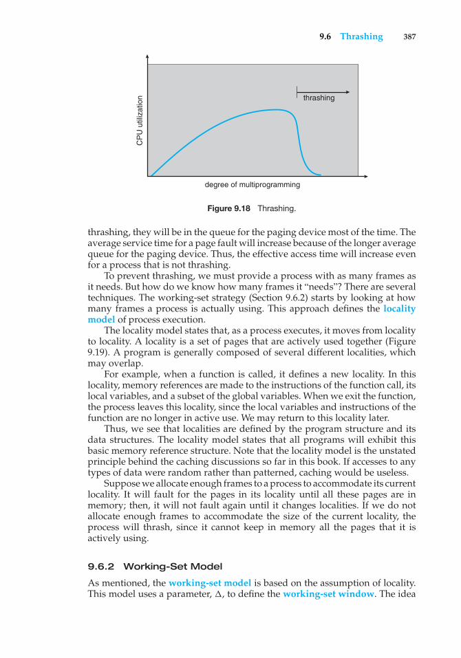
9.6 Thrashing 387
thrashing
degree of multiprogramming
CP
U u
tiliz
atio
n
Figure 9.18 Thrashing.
thrashing, they will be in the queue for the paging device most of the time. Theaverage service time for a page fault will increase because of the longer averagequeue for the paging device. Thus, the effective access time will increase evenfor a process that is not thrashing.
To prevent thrashing, we must provide a process with as many frames asit needs. But how do we know how many frames it “needs”? There are severaltechniques. The working-set strategy (Section 9.6.2) starts by looking at howmany frames a process is actually using. This approach defines the localitymodel of process execution.
The locality model states that, as a process executes, it moves from localityto locality. A locality is a set of pages that are actively used together (Figure9.19). A program is generally composed of several different localities, whichmay overlap.
For example, when a function is called, it defines a new locality. In thislocality, memory references are made to the instructions of the function call, itslocal variables, and a subset of the global variables. When we exit the function,the process leaves this locality, since the local variables and instructions of thefunction are no longer in active use. We may return to this locality later.
Thus, we see that localities are defined by the program structure and itsdata structures. The locality model states that all programs will exhibit thisbasic memory reference structure. Note that the locality model is the unstatedprinciple behind the caching discussions so far in this book. If accesses to anytypes of data were random rather than patterned, caching would be useless.
Suppose we allocate enough frames to a process to accommodate its currentlocality. It will fault for the pages in its locality until all these pages are inmemory; then, it will not fault again until it changes localities. If we do notallocate enough frames to accommodate the size of the current locality, theprocess will thrash, since it cannot keep in memory all the pages that it isactively using.
9.6.2 Working-Set Model
As mentioned, the working-set model is based on the assumption of locality.This model uses a parameter, �, to define the working-set window. The idea
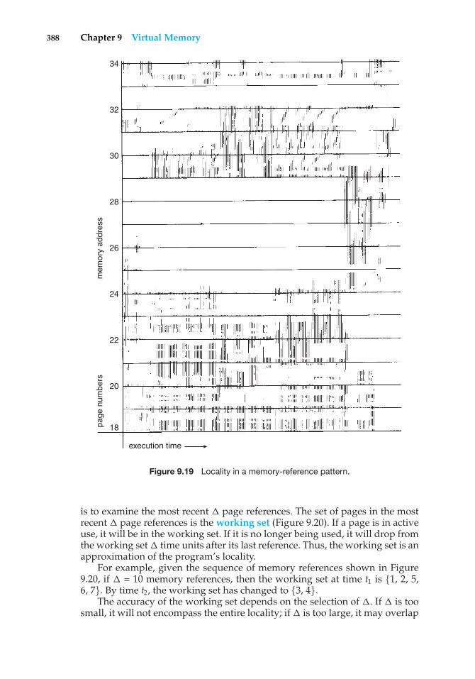
388 Chapter 9 Virtual Memory
18
20
22
24
26
28
30
32
34
page
num
bers
mem
ory
addr
ess
execution time
Figure 9.19 Locality in a memory-reference pattern.
is to examine the most recent � page references. The set of pages in the mostrecent � page references is the working set (Figure 9.20). If a page is in activeuse, it will be in the working set. If it is no longer being used, it will drop fromthe working set � time units after its last reference. Thus, the working set is anapproximation of the program’s locality.
For example, given the sequence of memory references shown in Figure9.20, if � = 10 memory references, then the working set at time t1 is {1, 2, 5,6, 7}. By time t2, the working set has changed to {3, 4}.
The accuracy of the working set depends on the selection of �. If � is toosmall, it will not encompass the entire locality; if � is too large, it may overlap
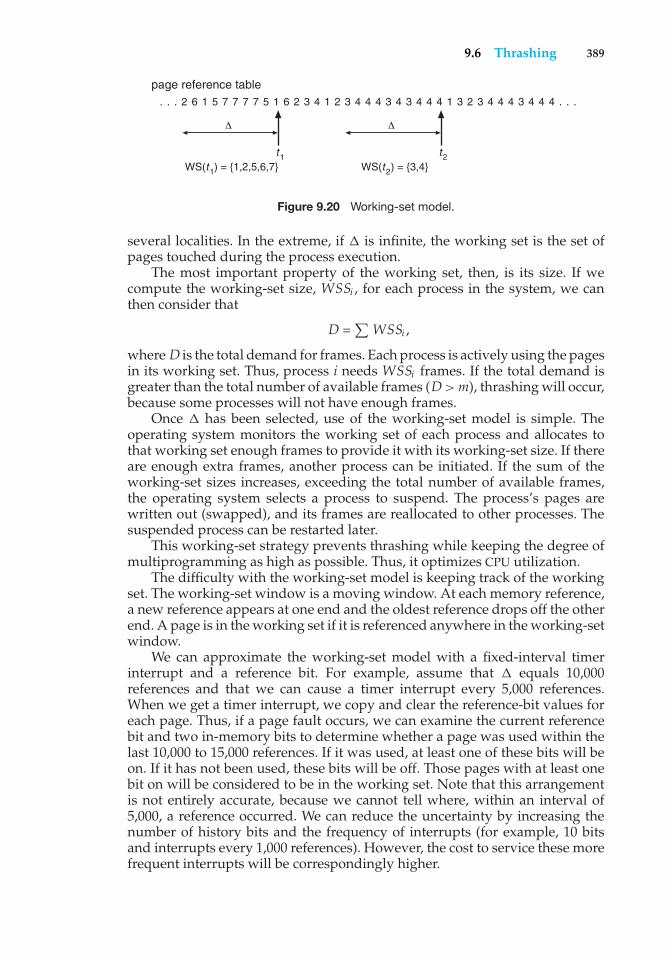
9.6 Thrashing 389
page reference table. . . 2 6 1 5 7 7 7 7 5 1 6 2 3 4 1 2 3 4 4 4 3 4 3 4 4 4 1 3 2 3 4 4 4 3 4 4 4 . . .
�
t1WS(t1) = {1,2,5,6,7}
�
t2WS(t2) = {3,4}
Figure 9.20 Working-set model.
several localities. In the extreme, if � is infinite, the working set is the set ofpages touched during the process execution.
The most important property of the working set, then, is its size. If wecompute the working-set size, WSSi , for each process in the system, we canthen consider that
D =∑WSSi ,
where D is the total demand for frames. Each process is actively using the pagesin its working set. Thus, process i needs WSSi frames. If the total demand isgreater than the total number of available frames (D>m), thrashing will occur,because some processes will not have enough frames.
Once � has been selected, use of the working-set model is simple. Theoperating system monitors the working set of each process and allocates tothat working set enough frames to provide it with its working-set size. If thereare enough extra frames, another process can be initiated. If the sum of theworking-set sizes increases, exceeding the total number of available frames,the operating system selects a process to suspend. The process’s pages arewritten out (swapped), and its frames are reallocated to other processes. Thesuspended process can be restarted later.
This working-set strategy prevents thrashing while keeping the degree ofmultiprogramming as high as possible. Thus, it optimizes CPU utilization.
The difficulty with the working-set model is keeping track of the workingset. The working-set window is a moving window. At each memory reference,a new reference appears at one end and the oldest reference drops off the otherend. A page is in the working set if it is referenced anywhere in the working-setwindow.
We can approximate the working-set model with a fixed-interval timerinterrupt and a reference bit. For example, assume that � equals 10,000references and that we can cause a timer interrupt every 5,000 references.When we get a timer interrupt, we copy and clear the reference-bit values foreach page. Thus, if a page fault occurs, we can examine the current referencebit and two in-memory bits to determine whether a page was used within thelast 10,000 to 15,000 references. If it was used, at least one of these bits will beon. If it has not been used, these bits will be off. Those pages with at least onebit on will be considered to be in the working set. Note that this arrangementis not entirely accurate, because we cannot tell where, within an interval of5,000, a reference occurred. We can reduce the uncertainty by increasing thenumber of history bits and the frequency of interrupts (for example, 10 bitsand interrupts every 1,000 references). However, the cost to service these morefrequent interrupts will be correspondingly higher.
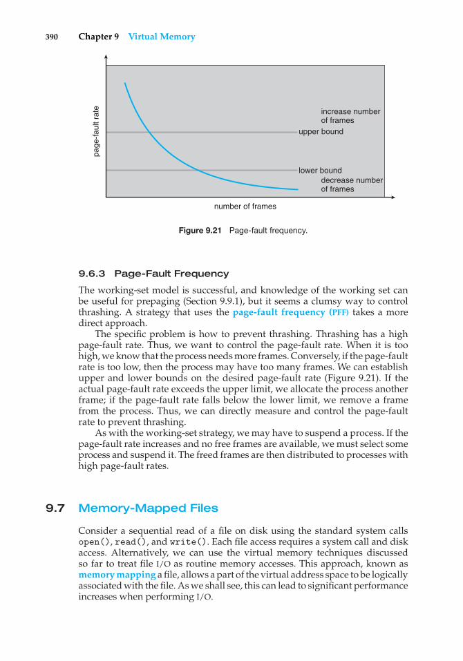
390 Chapter 9 Virtual Memory
number of frames
increase numberof frames
upper bound
lower bounddecrease numberof frames
page
-fau
lt ra
te
Figure 9.21 Page-fault frequency.
9.6.3 Page-Fault Frequency
The working-set model is successful, and knowledge of the working set canbe useful for prepaging (Section 9.9.1), but it seems a clumsy way to controlthrashing. A strategy that uses the page-fault frequency (PFF) takes a moredirect approach.
The specific problem is how to prevent thrashing. Thrashing has a highpage-fault rate. Thus, we want to control the page-fault rate. When it is toohigh, we know that the process needs more frames. Conversely, if the page-faultrate is too low, then the process may have too many frames. We can establishupper and lower bounds on the desired page-fault rate (Figure 9.21). If theactual page-fault rate exceeds the upper limit, we allocate the process anotherframe; if the page-fault rate falls below the lower limit, we remove a framefrom the process. Thus, we can directly measure and control the page-faultrate to prevent thrashing.
As with the working-set strategy, we may have to suspend a process. If thepage-fault rate increases and no free frames are available, we must select someprocess and suspend it. The freed frames are then distributed to processes withhigh page-fault rates.
9.7 Memory-Mapped Files
Consider a sequential read of a file on disk using the standard system callsopen(), read(), and write(). Each file access requires a system call and diskaccess. Alternatively, we can use the virtual memory techniques discussedso far to treat file I/O as routine memory accesses. This approach, known asmemory mapping a file, allows a part of the virtual address space to be logicallyassociated with the file. As we shall see, this can lead to significant performanceincreases when performing I/O.
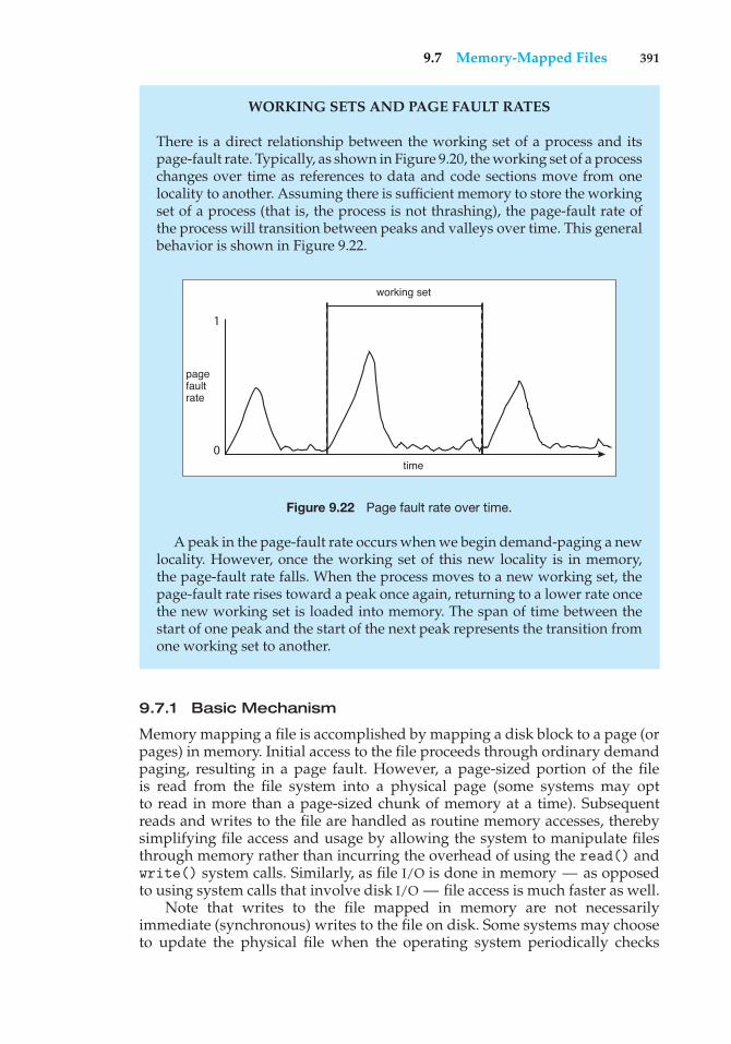
9.7 Memory-Mapped Files 391
WORKING SETS AND PAGE FAULT RATES
There is a direct relationship between the working set of a process and itspage-fault rate. Typically, as shown in Figure 9.20, the working set of a processchanges over time as references to data and code sections move from onelocality to another. Assuming there is sufficient memory to store the workingset of a process (that is, the process is not thrashing), the page-fault rate ofthe process will transition between peaks and valleys over time. This generalbehavior is shown in Figure 9.22.
1
0time
working set
page fault rate
Figure 9.22 Page fault rate over time.
A peak in the page-fault rate occurs when we begin demand-paging a newlocality. However, once the working set of this new locality is in memory,the page-fault rate falls. When the process moves to a new working set, thepage-fault rate rises toward a peak once again, returning to a lower rate oncethe new working set is loaded into memory. The span of time between thestart of one peak and the start of the next peak represents the transition fromone working set to another.
9.7.1 Basic Mechanism
Memory mapping a file is accomplished by mapping a disk block to a page (orpages) in memory. Initial access to the file proceeds through ordinary demandpaging, resulting in a page fault. However, a page-sized portion of the fileis read from the file system into a physical page (some systems may optto read in more than a page-sized chunk of memory at a time). Subsequentreads and writes to the file are handled as routine memory accesses, therebysimplifying file access and usage by allowing the system to manipulate filesthrough memory rather than incurring the overhead of using the read() andwrite() system calls. Similarly, as file I/O is done in memory — as opposedto using system calls that involve disk I/O — file access is much faster as well.
Note that writes to the file mapped in memory are not necessarilyimmediate (synchronous) writes to the file on disk. Some systems may chooseto update the physical file when the operating system periodically checks
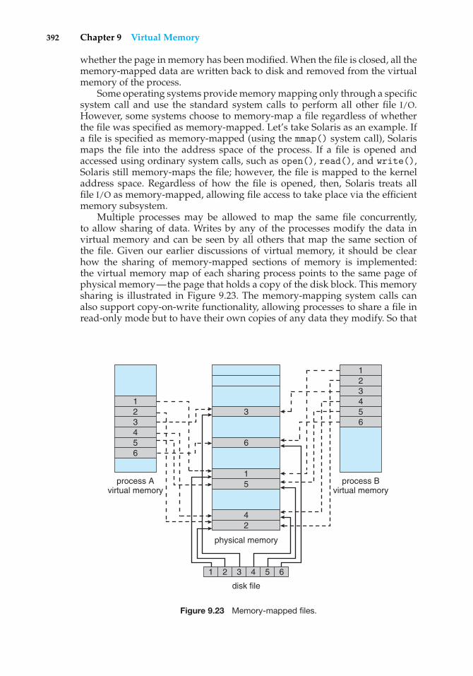
392 Chapter 9 Virtual Memory
whether the page in memory has been modified. When the file is closed, all thememory-mapped data are written back to disk and removed from the virtualmemory of the process.
Some operating systems provide memory mapping only through a specificsystem call and use the standard system calls to perform all other file I/O.However, some systems choose to memory-map a file regardless of whetherthe file was specified as memory-mapped. Let’s take Solaris as an example. Ifa file is specified as memory-mapped (using the mmap() system call), Solarismaps the file into the address space of the process. If a file is opened andaccessed using ordinary system calls, such as open(), read(), and write(),Solaris still memory-maps the file; however, the file is mapped to the kerneladdress space. Regardless of how the file is opened, then, Solaris treats allfile I/O as memory-mapped, allowing file access to take place via the efficientmemory subsystem.
Multiple processes may be allowed to map the same file concurrently,to allow sharing of data. Writes by any of the processes modify the data invirtual memory and can be seen by all others that map the same section ofthe file. Given our earlier discussions of virtual memory, it should be clearhow the sharing of memory-mapped sections of memory is implemented:the virtual memory map of each sharing process points to the same page ofphysical memory—the page that holds a copy of the disk block. This memorysharing is illustrated in Figure 9.23. The memory-mapping system calls canalso support copy-on-write functionality, allowing processes to share a file inread-only mode but to have their own copies of any data they modify. So that
process Avirtual memory
1
1
1 2 3 4 5 6
23
3
45
5
42
66
123456
process Bvirtual memory
physical memory
disk file
Figure 9.23 Memory-mapped files.
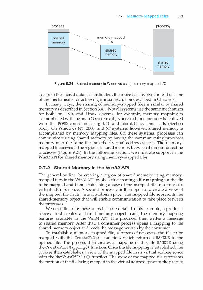
9.7 Memory-Mapped Files 393
process1
memory-mappedfile
sharedmemory
sharedmemory
sharedmemory
process2
Figure 9.24 Shared memory in Windows using memory-mapped I/O.
access to the shared data is coordinated, the processes involved might use oneof the mechanisms for achieving mutual exclusion described in Chapter 6.
In many ways, the sharing of memory-mapped files is similar to sharedmemory as described in Section 3.4.1. Not all systems use the same mechanismfor both; on UNIX and Linux systems, for example, memory mapping isaccomplished with themmap() system call, whereas shared memory is achievedwith the POSIX-compliant shmget() and shmat() systems calls (Section3.5.1). On Windows NT, 2000, and XP systems, however, shared memory isaccomplished by memory mapping files. On these systems, processes cancommunicate using shared memory by having the communicating processesmemory-map the same file into their virtual address spaces. The memory-mapped file serves as the region of shared memory between the communicatingprocesses (Figure 9.24). In the following section, we illustrate support in theWin32 API for shared memory using memory-mapped files.
9.7.2 Shared Memory in the Win32 API
The general outline for creating a region of shared memory using memory-mapped files in the Win32 API involves first creating a file mapping for the fileto be mapped and then establishing a view of the mapped file in a process’svirtual address space. A second process can then open and create a view ofthe mapped file in its virtual address space. The mapped file represents theshared-memory object that will enable communication to take place betweenthe processes.
We next illustrate these steps in more detail. In this example, a producerprocess first creates a shared-memory object using the memory-mappingfeatures available in the Win32 API. The producer then writes a messageto shared memory. After that, a consumer process opens a mapping to theshared-memory object and reads the message written by the consumer.
To establish a memory-mapped file, a process first opens the file to bemapped with the CreateFile() function, which returns a HANDLE to theopened file. The process then creates a mapping of this file HANDLE usingthe CreateFileMapping() function. Once the file mapping is established, theprocess then establishes a view of the mapped file in its virtual address spacewith the MapViewOfFile() function. The view of the mapped file representsthe portion of the file being mapped in the virtual address space of the process
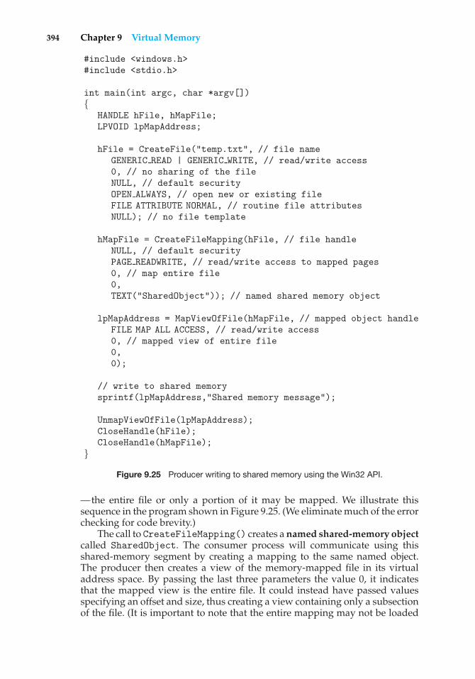
394 Chapter 9 Virtual Memory
#include <windows.h>#include <stdio.h>
int main(int argc, char *argv[]){
HANDLE hFile, hMapFile;LPVOID lpMapAddress;
hFile = CreateFile("temp.txt", // file nameGENERIC READ | GENERIC WRITE, // read/write access0, // no sharing of the fileNULL, // default securityOPEN ALWAYS, // open new or existing fileFILE ATTRIBUTE NORMAL, // routine file attributesNULL); // no file template
hMapFile = CreateFileMapping(hFile, // file handleNULL, // default securityPAGE READWRITE, // read/write access to mapped pages0, // map entire file0,TEXT("SharedObject")); // named shared memory object
lpMapAddress = MapViewOfFile(hMapFile, // mapped object handleFILE MAP ALL ACCESS, // read/write access0, // mapped view of entire file0,0);
// write to shared memorysprintf(lpMapAddress,"Shared memory message");
UnmapViewOfFile(lpMapAddress);CloseHandle(hFile);CloseHandle(hMapFile);
}Figure 9.25 Producer writing to shared memory using the Win32 API.
—the entire file or only a portion of it may be mapped. We illustrate thissequence in the program shown in Figure 9.25. (We eliminate much of the errorchecking for code brevity.)
The call to CreateFileMapping() creates a named shared-memory objectcalled SharedObject. The consumer process will communicate using thisshared-memory segment by creating a mapping to the same named object.The producer then creates a view of the memory-mapped file in its virtualaddress space. By passing the last three parameters the value 0, it indicatesthat the mapped view is the entire file. It could instead have passed valuesspecifying an offset and size, thus creating a view containing only a subsectionof the file. (It is important to note that the entire mapping may not be loaded
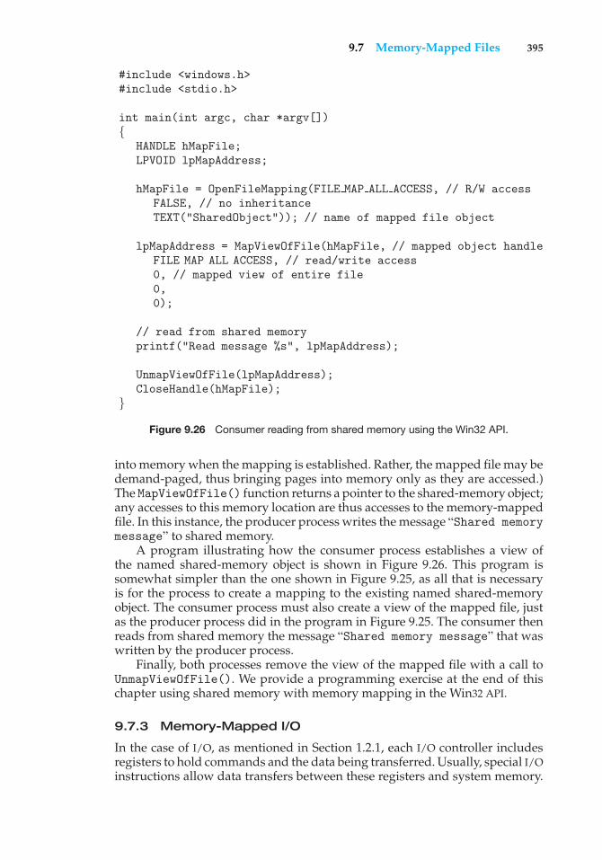
9.7 Memory-Mapped Files 395
#include <windows.h>#include <stdio.h>
int main(int argc, char *argv[]){
HANDLE hMapFile;LPVOID lpMapAddress;
hMapFile = OpenFileMapping(FILE MAP ALL ACCESS, // R/W accessFALSE, // no inheritanceTEXT("SharedObject")); // name of mapped file object
lpMapAddress = MapViewOfFile(hMapFile, // mapped object handleFILE MAP ALL ACCESS, // read/write access0, // mapped view of entire file0,0);
// read from shared memoryprintf("Read message %s", lpMapAddress);
UnmapViewOfFile(lpMapAddress);CloseHandle(hMapFile);
}Figure 9.26 Consumer reading from shared memory using the Win32 API.
into memory when the mapping is established. Rather, the mapped file may bedemand-paged, thus bringing pages into memory only as they are accessed.)The MapViewOfFile() function returns a pointer to the shared-memory object;any accesses to this memory location are thus accesses to the memory-mappedfile. In this instance, the producer process writes the message “Shared memorymessage” to shared memory.
A program illustrating how the consumer process establishes a view ofthe named shared-memory object is shown in Figure 9.26. This program issomewhat simpler than the one shown in Figure 9.25, as all that is necessaryis for the process to create a mapping to the existing named shared-memoryobject. The consumer process must also create a view of the mapped file, justas the producer process did in the program in Figure 9.25. The consumer thenreads from shared memory the message “Shared memory message” that waswritten by the producer process.
Finally, both processes remove the view of the mapped file with a call toUnmapViewOfFile(). We provide a programming exercise at the end of thischapter using shared memory with memory mapping in the Win32 API.
9.7.3 Memory-Mapped I/O
In the case of I/O, as mentioned in Section 1.2.1, each I/O controller includesregisters to hold commands and the data being transferred. Usually, special I/Oinstructions allow data transfers between these registers and system memory.
396 Chapter 9 Virtual Memory
To allow more convenient access to I/O devices, many computer architecturesprovide memory-mapped I/O. In this case, ranges of memory addresses areset aside and are mapped to the device registers. Reads and writes to thesememory addresses cause the data to be transferred to and from the deviceregisters. This method is appropriate for devices that have fast response times,such as video controllers. In the IBM PC, each location on the screen is mappedto a memory location. Displaying text on the screen is almost as easy as writingthe text into the appropriate memory-mapped locations.
Memory-mapped I/O is also convenient for other devices, such as the serialand parallel ports used to connect modems and printers to a computer. TheCPU transfers data through these kinds of devices by reading and writing a fewdevice registers, called an I/O port. To send out a long string of bytes through amemory-mapped serial port, the CPU writes one data byte to the data registerand sets a bit in the control register to signal that the byte is available. The devicetakes the data byte and then clears the bit in the control register to signal thatit is ready for the next byte. Then the CPU can transfer the next byte. If theCPU uses polling to watch the control bit, constantly looping to see whetherthe device is ready, this method of operation is called programmed I/O (PIO).If the CPU does not poll the control bit, but instead receives an interrupt whenthe device is ready for the next byte, the data transfer is said to be interruptdriven.
9.8 Allocating Kernel Memory
When a process running in user mode requests additional memory, pagesare allocated from the list of free page frames maintained by the kernel.This list is typically populated using a page-replacement algorithm such asthose discussed in Section 9.4 and most likely contains free pages scatteredthroughout physical memory, as explained earlier. Remember, too, that if auser process requests a single byte of memory, internal fragmentation willresult, as the process will be granted an entire page frame.
Kernel memory, however, is often allocated from a free-memory pooldifferent from the list used to satisfy ordinary user-mode processes. Thereare two primary reasons for this:
1. The kernel requests memory for data structures of varying sizes, some ofwhich are less than a page in size. As a result, the kernel must use memoryconservatively and attempt to minimize waste due to fragmentation. Thisis especially important because many operating systems do not subjectkernel code or data to the paging system.
2. Pages allocated to user-mode processes do not necessarily have to be incontiguous physical memory. However, certain hardware devices interactdirectly with physical memory—without the benefit of a virtual memoryinterface—and consequently may require memory residing in physicallycontiguous pages.
In the following sections, we examine two strategies for managing free memorythat is assigned to kernel processes: the “buddy system” and slab allocation.
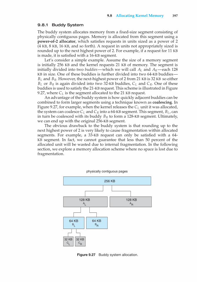
9.8 Allocating Kernel Memory 397
9.8.1 Buddy System
The buddy system allocates memory from a fixed-size segment consisting ofphysically contiguous pages. Memory is allocated from this segment using apower-of-2 allocator, which satisfies requests in units sized as a power of 2(4 KB, 8 KB, 16 KB, and so forth). A request in units not appropriately sized isrounded up to the next highest power of 2. For example, if a request for 11 KBis made, it is satisfied with a 16-KB segment.
Let’s consider a simple example. Assume the size of a memory segmentis initially 256 KB and the kernel requests 21 KB of memory. The segment isinitially divided into two buddies—which we will call AL and AR—each 128KB in size. One of these buddies is further divided into two 64-KB buddies—BL and BR. However, the next-highest power of 2 from 21 KB is 32 KB so eitherBL or BR is again divided into two 32-KB buddies, CL and CR. One of thesebuddies is used to satisfy the 21-KB request. This scheme is illustrated in Figure9.27, where CL is the segment allocated to the 21 KB request.
An advantage of the buddy system is how quickly adjacent buddies can becombined to form larger segments using a technique known as coalescing. InFigure 9.27, for example, when the kernel releases the CL unit it was allocated,the system can coalesceCL and CR into a 64-KB segment. This segment, BL , canin turn be coalesced with its buddy BR to form a 128-KB segment. Ultimately,we can end up with the original 256-KB segment.
The obvious drawback to the buddy system is that rounding up to thenext highest power of 2 is very likely to cause fragmentation within allocatedsegments. For example, a 33-KB request can only be satisfied with a 64-KB segment. In fact, we cannot guarantee that less than 50 percent of theallocated unit will be wasted due to internal fragmentation. In the followingsection, we explore a memory allocation scheme where no space is lost due tofragmentation.
physically contiguous pages
256 KB
128 KB AL
64 KB BR
64 KB BL
32 KB CL
32 KB CR
128 KB AR
Figure 9.27 Buddy system allocation.
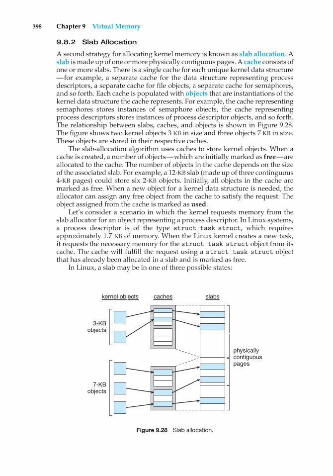
398 Chapter 9 Virtual Memory
9.8.2 Slab Allocation
A second strategy for allocating kernel memory is known as slab allocation. Aslab is made up of one or more physically contiguous pages. A cache consists ofone or more slabs. There is a single cache for each unique kernel data structure—for example, a separate cache for the data structure representing processdescriptors, a separate cache for file objects, a separate cache for semaphores,and so forth. Each cache is populated with objects that are instantiations of thekernel data structure the cache represents. For example, the cache representingsemaphores stores instances of semaphore objects, the cache representingprocess descriptors stores instances of process descriptor objects, and so forth.The relationship between slabs, caches, and objects is shown in Figure 9.28.The figure shows two kernel objects 3 KB in size and three objects 7 KB in size.These objects are stored in their respective caches.
The slab-allocation algorithm uses caches to store kernel objects. When acache is created, a number of objects—which are initially marked as free—areallocated to the cache. The number of objects in the cache depends on the sizeof the associated slab. For example, a 12-KB slab (made up of three continguous4-KB pages) could store six 2-KB objects. Initially, all objects in the cache aremarked as free. When a new object for a kernel data structure is needed, theallocator can assign any free object from the cache to satisfy the request. Theobject assigned from the cache is marked as used.
Let’s consider a scenario in which the kernel requests memory from theslab allocator for an object representing a process descriptor. In Linux systems,a process descriptor is of the type struct task struct, which requiresapproximately 1.7 KB of memory. When the Linux kernel creates a new task,it requests the necessary memory for the struct task struct object from itscache. The cache will fulfill the request using a struct task struct objectthat has already been allocated in a slab and is marked as free.
In Linux, a slab may be in one of three possible states:
3-KBobjects
7-KBobjects
kernel objects caches slabs
physicallycontiguouspages
Figure 9.28 Slab allocation.
9.9 Other Considerations 399
1. Full. All objects in the slab are marked as used.
2. Empty. All objects in the slab are marked as free.
3. Partial. The slab consists of both used and free objects.
The slab allocator first attempts to satisfy the request with a free object in apartial slab. If none exist, a free object is assigned from an empty slab. If noempty slabs are available, a new slab is allocated from contiguous physicalpages and assigned to a cache; memory for the object is allocated from thisslab.
The slab allocator provides two main benefits:
1. No memory is wasted due to fragmentation. Fragmentation is not anissue because each unique kernel data structure has an associated cache,and each cache is made up of one or more slabs that are divided intochunks the size of the objects being represented. Thus, when the kernelrequests memory for an object, the slab allocator returns the exact amountof memory required to represent the object.
2. Memory requests can be satisfied quickly. The slab allocation schemeis thus particularly effective for managing memory when objects arefrequently allocated and deallocated, as is often the case with requestsfrom the kernel. The act of allocating—and releasing—memory can bea time-consuming process. However, objects are created in advance andthus can be quickly allocated from the cache. Furthermore, when thekernel has finished with an object and releases it, it is marked as free andreturned to its cache, thus making it immediately available for subsequentrequests from the kernel.
The slab allocator first appeared in the Solaris 2.4 kernel. Because of itsgeneral-purpose nature, this allocator is now also used for certain user-modememory requests in Solaris. Linux originally used the buddy system; however,beginning with Version 2.2, the Linux kernel adopted the slab allocator.
9.9 Other Considerations
The major decisions that we make for a paging system are the selections ofa replacement algorithm and an allocation policy, which we discussed earlierin this chapter. There are many other considerations as well, and we discussseveral of them here.
9.9.1 Prepaging
An obvious property of pure demand paging is the large number of page faultsthat occur when a process is started. This situation results from trying to get theinitial locality into memory. The same situation may arise at other times. Forinstance, when a swapped-out process is restarted, all its pages are on the disk,and each must be brought in by its own page fault. Prepaging is an attempt toprevent this high level of initial paging. The strategy is to bring into memory at
400 Chapter 9 Virtual Memory
one time all the pages that will be needed. Some operating systems—notablySolaris—prepage the page frames for small files.
In a system using the working-set model, for example, we keep with eachprocess a list of the pages in its working set. If we must suspend a process(due to an I/O wait or a lack of free frames), we remember the working set forthat process. When the process is to be resumed (because I/O has finished orenough free frames have become available), we automatically bring back intomemory its entire working set before restarting the process.
Prepaging may offer an advantage in some cases. The question is simplywhether the cost of using prepaging is less than the cost of servicing thecorresponding page faults. It may well be the case that many of the pagesbrought back into memory by prepaging will not be used.
Assume that s pages are prepaged and a fraction � of these s pages isactually used (0 ≤ � ≤ 1). The question is whether the cost of the s * � savedpage faults is greater or less than the cost of prepaging s * (1 − �) unnecessarypages. If � is close to 0, prepaging loses; if � is close to 1, prepaging wins.
9.9.2 Page Size
The designers of an operating system for an existing machine seldom havea choice concerning the page size. However, when new machines are beingdesigned, a decision regarding the best page size must be made. As you mightexpect, there is no single best page size. Rather, there is a set of factors thatsupport various sizes. Page sizes are invariably powers of 2, generally rangingfrom 4,096 (212) to 4,194,304 (222) bytes.
How do we select a page size? One concern is the size of the page table. Fora given virtual memory space, decreasing the page size increases the numberof pages and hence the size of the page table. For a virtual memory of 4 MB(222), for example, there would be 4,096 pages of 1,024 bytes but only 512 pagesof 8,192 bytes. Because each active process must have its own copy of the pagetable, a large page size is desirable.
Memory is better utilized with smaller pages, however. If a process isallocated memory starting at location 00000 and continuing until it has as muchas it needs, it probably will not end exactly on a page boundary. Thus, a partof the final page must be allocated (because pages are the units of allocation)but will be unused (creating internal fragmentation). Assuming independenceof process size and page size, we can expect that, on the average, half of thefinal page of each process will be wasted. This loss is only 256 bytes for a pageof 512 bytes but is 4,096 bytes for a page of 8,192 bytes. To minimize internalfragmentation, then, we need a small page size.
Another problem is the time required to read or write a page. I/O time iscomposed of seek, latency, and transfer times. Transfer time is proportionalto the amount transferred (that is, the page size)—a fact that would seemto argue for a small page size. However, as we shall see in Section 12.1.1,latency and seek time normally dwarf transfer time. At a transfer rate of 2MB per second, it takes only 0.2 milliseconds to transfer 512 bytes. Latencytime, though, is perhaps 8 milliseconds and seek time 20 milliseconds. Ofthe total I/O time (28.2 milliseconds), therefore, only 1 percent is attributableto the actual transfer. Doubling the page size increases I/O time to only 28.4milliseconds. It takes 28.4 milliseconds to read a single page of 1,024 bytes but
9.9 Other Considerations 401
56.4 milliseconds to read the same amount as two pages of 512 bytes each.Thus, a desire to minimize I/O time argues for a larger page size.
With a smaller page size, though, total I/O should be reduced, since localitywill be improved. A smaller page size allows each page to match programlocality more accurately. For example, consider a process 200 KB in size, ofwhich only half (100 KB) is actually used in an execution. If we have only onelarge page, we must bring in the entire page, a total of 200 KB transferred andallocated. If instead we had pages of only 1 byte, then we could bring in onlythe 100 KB that are actually used, resulting in only 100 KB transferred andallocated. With a smaller page size, we have better resolution, allowing us toisolate only the memory that is actually needed. With a larger page size, wemust allocate and transfer not only what is needed but also anything else thathappens to be in the page, whether it is needed or not. Thus, a smaller pagesize should result in less I/O and less total allocated memory.
But did you notice that with a page size of 1 byte, we would have a pagefault for each byte? A process of 200 KB that used only half of that memorywould generate only one page fault with a page size of 200 KB but 102,400 pagefaults with a page size of 1 byte. Each page fault generates the large amountof overhead needed for processing the interrupt, saving registers, replacing apage, queueing for the paging device, and updating tables. To minimize thenumber of page faults, we need to have a large page size.
Other factors must be considered as well (such as the relationship betweenpage size and sector size on the paging device). The problem has no bestanswer. As we have seen, some factors (internal fragmentation, locality) arguefor a small page size, whereas others (table size, I/O time) argue for a largepage size. However, the historical trend is toward larger page sizes. Indeed, thefirst edition of Operating System Concepts (1983) used 4,096 bytes as the upperbound on page sizes, and this value was the most common page size in 1990.Modern systems may now use much larger page sizes, as we will see in thefollowing section.
9.9.3 TLB Reach
In Chapter 8, we introduced the hit ratio of the TLB. Recall that the hit ratiofor the TLB refers to the percentage of virtual address translations that areresolved in the TLB rather than the page table. Clearly, the hit ratio is relatedto the number of entries in the TLB, and the way to increase the hit ratio isby increasing the number of entries in the TLB. This, however, does not comecheaply, as the associative memory used to construct the TLB is both expensiveand power hungry.
Related to the hit ratio is a similar metric: the TLB reach. The TLB reach refersto the amount of memory accessible from the TLB and is simply the numberof entries multiplied by the page size. Ideally, the working set for a process isstored in the TLB. If it is not, the process will spend a considerable amount oftime resolving memory references in the page table rather than the TLB. If wedouble the number of entries in the TLB, we double the TLB reach. However,for some memory-intensive applications, this may still prove insufficient forstoring the working set.
Another approach for increasing the TLB reach is to either increase the sizeof the page or provide multiple page sizes. If we increase the page size—say,
402 Chapter 9 Virtual Memory
from 8 KB to 32 KB—we quadruple the TLB reach. However, this may lead toan increase in fragmentation for some applications that do not require sucha large page size as 32 KB. Alternatively, an operating system may provideseveral different page sizes. For example, the UltraSPARC supports page sizesof 8 KB, 64 KB, 512 KB, and 4 MB. Of these available pages sizes, Solaris usesboth 8-KB and 4-MB page sizes. And with a 64-entry TLB, the TLB reach forSolaris ranges from 512 KB with 8-KB pages to 256 MB with 4-MB pages. For themajority of applications, the 8-KB page size is sufficient, although Solaris mapsthe first 4 MB of kernel code and data with two 4-MB pages. Solaris also allowsapplications—such as databases—to take advantage of the large 4-MB pagesize.
Providing support for multiple page sizes requires the operating system—not hardware—to manage the TLB. For example, one of the fields in aTLB entry must indicate the size of the page frame corresponding to theTLB entry. Managing the TLB in software and not hardware comes at a costin performance. However, the increased hit ratio and TLB reach offset theperformance costs. Indeed, recent trends indicate a move toward software-managed TLBs and operating-system support for multiple page sizes. TheUltraSPARC, MIPS, and Alpha architectures employ software-managed TLBs.The PowerPC and Pentium manage the TLB in hardware.
9.9.4 Inverted Page Tables
Section 8.5.3 introduced the concept of the inverted page table. The purposeof this form of page management is to reduce the amount of physical memoryneeded to track virtual-to-physical address translations. We accomplish thissavings by creating a table that has one entry per page of physical memory,indexed by the pair <process-id, page-number>.
Because they keep information about which virtual memory page is storedin each physical frame, inverted page tables reduce the amount of physicalmemory needed to store this information. However, the inverted page tableno longer contains complete information about the logical address space of aprocess, and that information is required if a referenced page is not currentlyin memory. Demand paging requires this information to process page faults.For the information to be available, an external page table (one per process)must be kept. Each such table looks like the traditional per-process page tableand contains information on where each virtual page is located.
But do external page tables negate the utility of inverted page tables? Sincethese tables are referenced only when a page fault occurs, they do not need tobe available quickly. Instead, they are themselves paged in and out of memoryas necessary. Unfortunately, a page fault may now cause the virtual memorymanager to generate another page fault as it pages in the external page table itneeds to locate the virtual page on the backing store. This special case requirescareful handling in the kernel and a delay in the page-lookup processing.
9.9.5 Program Structure
Demand paging is designed to be transparent to the user program. In manycases, the user is completely unaware of the paged nature of memory. In othercases, however, system performance can be improved if the user (or compiler)has an awareness of the underlying demand paging.
9.9 Other Considerations 403
Let’s look at a contrived but informative example. Assume that pages are128 words in size. Consider a C program whose function is to initialize to 0each element of a 128-by-128 array. The following code is typical:
int i, j;int[128][128] data;
for (j = 0; j < 128; j++)for (i = 0; i < 128; i++)
data[i][j] = 0;
Notice that the array is stored row major; that is, the array is storeddata[0][0], data[0][1], · · ·, data[0][127], data[1][0], data[1][1], · · ·,data[127][127]. For pages of 128 words, each row takes one page. Thus,the preceding code zeros one word in each page, then another word in eachpage, and so on. If the operating system allocates fewer than 128 frames to theentire program, then its execution will result in 128 × 128 = 16,384 page faults.In contrast, suppose we change the code to
int i, j;int[128][128] data;
for (i = 0; i < 128; i++)for (j = 0; j < 128; j++)
data[i][j] = 0;
This code zeros all the words on one page before starting the next page,reducing the number of page faults to 128.
Careful selection of data structures and programming structures canincrease locality and hence lower the page-fault rate and the number of pages inthe working set. For example, a stack has good locality, since access is alwaysmade to the top. A hash table, in contrast, is designed to scatter references,producing bad locality. Of course, locality of reference is just one measure ofthe efficiency of the use of a data structure. Other heavily weighted factorsinclude search speed, total number of memory references, and total number ofpages touched.
At a later stage, the compiler and loader can have a significant effect onpaging. Separating code and data and generating reentrant code means thatcode pages can be read-only and hence will never be modified. Clean pagesdo not have to be paged out to be replaced. The loader can avoid placingroutines across page boundaries, keeping each routine completely in one page.Routines that call each other many times can be packed into the same page.This packaging is a variant of the bin-packing problem of operations research:try to pack the variable-sized load segments into the fixed-sized pages so thatinterpage references are minimized. Such an approach is particularly usefulfor large page sizes.
The choice of programming language can affect paging as well. Forexample, C and C++ use pointers frequently, and pointers tend to randomizeaccess to memory, thereby potentially diminishing a process’s locality. Somestudies have shown that object-oriented programs also tend to have a poorlocality of reference.
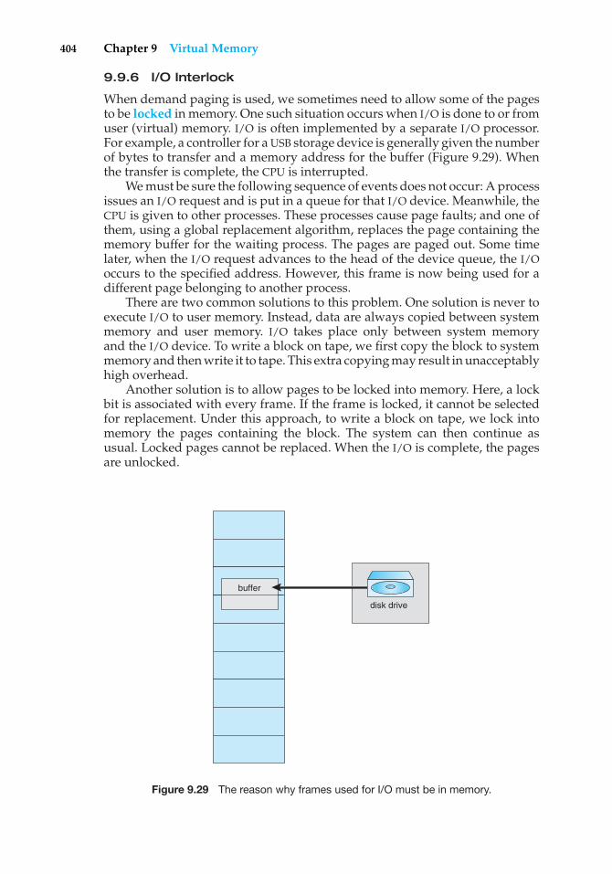
404 Chapter 9 Virtual Memory
9.9.6 I/O Interlock
When demand paging is used, we sometimes need to allow some of the pagesto be locked in memory. One such situation occurs when I/O is done to or fromuser (virtual) memory. I/O is often implemented by a separate I/O processor.For example, a controller for a USB storage device is generally given the numberof bytes to transfer and a memory address for the buffer (Figure 9.29). Whenthe transfer is complete, the CPU is interrupted.
We must be sure the following sequence of events does not occur: A processissues an I/O request and is put in a queue for that I/O device. Meanwhile, theCPU is given to other processes. These processes cause page faults; and one ofthem, using a global replacement algorithm, replaces the page containing thememory buffer for the waiting process. The pages are paged out. Some timelater, when the I/O request advances to the head of the device queue, the I/Ooccurs to the specified address. However, this frame is now being used for adifferent page belonging to another process.
There are two common solutions to this problem. One solution is never toexecute I/O to user memory. Instead, data are always copied between systemmemory and user memory. I/O takes place only between system memoryand the I/O device. To write a block on tape, we first copy the block to systemmemory and then write it to tape. This extra copying may result in unacceptablyhigh overhead.
Another solution is to allow pages to be locked into memory. Here, a lockbit is associated with every frame. If the frame is locked, it cannot be selectedfor replacement. Under this approach, to write a block on tape, we lock intomemory the pages containing the block. The system can then continue asusual. Locked pages cannot be replaced. When the I/O is complete, the pagesare unlocked.
buffer
disk drive
Figure 9.29 The reason why frames used for I/O must be in memory.
9.10 Operating-System Examples 405
Lock bits are used in various situations. Frequently, some or all of theoperating-system kernel is locked into memory, as many operating systemscannot tolerate a page fault caused by the kernel.
Another use for a lock bit involves normal page replacement. Considerthe following sequence of events: A low-priority process faults. Selecting areplacement frame, the paging system reads the necessary page into memory.Ready to continue, the low-priority process enters the ready queue and waitsfor the CPU. Since it is a low-priority process, it may not be selected by theCPU scheduler for a time. While the low-priority process waits, a high-priorityprocess faults. Looking for a replacement, the paging system sees a page thatis in memory but has not been referenced or modified: it is the page that thelow-priority process just brought in. This page looks like a perfect replacement:it is clean and will not need to be written out, and it apparently has not beenused for a long time.
Whether the high-priority process should be able to replace the low-priorityprocess is a policy decision. After all, we are simply delaying the low-priorityprocess for the benefit of the high-priority process. However, we are wastingthe effort spent to bring in the page for the low-priority process. If we decideto prevent replacement of a newly brought-in page until it can be used at leastonce, then we can use the lock bit to implement this mechanism. When a pageis selected for replacement, its lock bit is turned on; it remains on until thefaulting process is again dispatched.
Using a lock bit can be dangerous: The lock bit may get turned on butnever turned off. Should this situation occur (because of a bug in the operatingsystem, for example), the locked frame becomes unusable. On a single-usersystem, the overuse of locking would hurt only the user doing the locking.Multiuser systems must be less trusting of users. For instance, Solaris allowslocking “hints,” but it is free to disregard these hints if the free-frame poolbecomes too small or if an individual process requests that too many pages belocked in memory.
9.10 Operating-System Examples
In this section, we describe how Windows XP and Solaris implement virtualmemory.
9.10.1 Windows XP
Windows XP implements virtual memory using demand paging with clus-tering. Clustering handles page faults by bringing in not only the faultingpage but also several pages following the faulting page. When a process is firstcreated, it is assigned a working-set minimum and maximum. The working-setminimum is the minimum number of pages the process is guaranteed to havein memory. If sufficient memory is available, a process may be assigned asmany pages as its working-set maximum. For most applications, the valueof working-set minimum and working-set maximum is 50 and 345 pages,respectively. (In some circumstances, a process may be allowed to exceed itsworking-set maximum.) The virtual memory manager maintains a list of freepage frames. Associated with this list is a threshold value that is used to
406 Chapter 9 Virtual Memory
indicate whether sufficient free memory is available. If a page fault occurs for aprocess that is below its working-set maximum, the virtual memory managerallocates a page from this list of free pages. If a process that is at its working-setmaximum incurs a page fault, it must select a page for replacement using alocal page-replacement policy.
When the amount of free memory falls below the threshold, the virtualmemory manager uses a tactic known as automatic working-set trimming torestore the value above the threshold. Automatic working-set trimming worksby evaluating the number of pages allocated to processes. If a process hasbeen allocated more pages than its working-set minimum, the virtual memorymanager removes pages until the process reaches its working-set minimum. Aprocess that is at its working-set minimum may be allocated pages from thefree-page-frame list once sufficient free memory is available.
The algorithm used to determine which page to remove from a working setdepends on the type of processor. On single-processor 80x86 systems, WindowsXP uses a variation of the clock algorithm discussed in Section 9.4.5.2. OnAlpha and multiprocessor x86 systems, clearing the reference bit may requireinvalidating the entry in the translation look-aside buffer on other processors.Rather than incurring this overhead, Windows XP uses a variation on the FIFOalgorithm discussed in Section 9.4.2.
9.10.2 Solaris
In Solaris, when a thread incurs a page fault, the kernel assigns a page tothe faulting thread from the list of free pages it maintains. Therefore, it isimperative that the kernel keep a sufficient amount of free memory available.Associated with this list of free pages is a parameter— lotsfree—that representsa threshold to begin paging. The lotsfree parameter is typically set to 1/64 thesize of the physical memory. Four times per second, the kernel checks whetherthe amount of free memory is less than lotsfree. If the number of free pages fallsbelow lotsfree, a process known as a pageout starts up. The pageout process issimilar to the second-chance algorithm described in Section 9.4.5.2, except thatit uses two hands while scanning pages, rather than one. The pageout processworks as follows: The front hand of the clock scans all pages in memory, settingthe reference bit to 0. Later, the back hand of the clock examines the referencebit for the pages in memory, appending each page whose reference bit is still setto 0 to the free list and writing to disk its contents if modified. Solaris maintainsa cache list of pages that have been “freed” but have not yet been overwritten.The free list contains frames that have invalid contents. Pages can be reclaimedfrom the cache list if they are accessed before being moved to the free list.
The pageout algorithm uses several parameters to control the rate at whichpages are scanned (known as the scanrate). The scanrate is expressed in pagesper second and ranges from slowscan to fastscan. When free memory fallsbelow lotsfree, scanning occurs at slowscan pages per second and progressesto fastscan, depending on the amount of free memory available. The defaultvalue of slowscan is 100 pages per second; fastscan is typically set to the value(total physical pages)/2 pages per second, with a maximum of 8,192 pages persecond. This is shown in Figure 9.30 (with fastscan set to the maximum).
The distance (in pages) between the hands of the clock is determined bya system parameter, handspread. The amount of time between the front hand’s
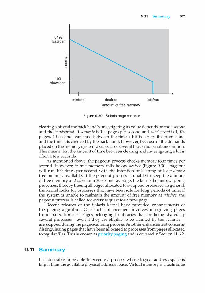
9.11 Summary 407
minfree
scan
rat
e
100 slowscan
8192 fastscan
desfree
amount of free memory
lotsfree
Figure 9.30 Solaris page scanner.
clearing a bit and the back hand’s investigating its value depends on the scanrateand the handspread. If scanrate is 100 pages per second and handspread is 1,024pages, 10 seconds can pass between the time a bit is set by the front handand the time it is checked by the back hand. However, because of the demandsplaced on the memory system, a scanrate of several thousand is not uncommon.This means that the amount of time between clearing and investigating a bit isoften a few seconds.
As mentioned above, the pageout process checks memory four times persecond. However, if free memory falls below desfree (Figure 9.30), pageoutwill run 100 times per second with the intention of keeping at least desfreefree memory available. If the pageout process is unable to keep the amountof free memory at desfree for a 30-second average, the kernel begins swappingprocesses, thereby freeing all pages allocated to swapped processes. In general,the kernel looks for processes that have been idle for long periods of time. Ifthe system is unable to maintain the amount of free memory at minfree, thepageout process is called for every request for a new page.
Recent releases of the Solaris kernel have provided enhancements ofthe paging algorithm. One such enhancement involves recognizing pagesfrom shared libraries. Pages belonging to libraries that are being shared byseveral processes—even if they are eligible to be claimed by the scanner—are skipped during the page-scanning process. Another enhancement concernsdistinguishing pages that have been allocated to processes from pages allocatedto regular files. This is known as priority paging and is covered in Section 11.6.2.
9.11 Summary
It is desirable to be able to execute a process whose logical address space islarger than the available physical address space. Virtual memory is a technique
408 Chapter 9 Virtual Memory
that enables us to map a large logical address space onto a smaller physicalmemory. Virtual memory allows us to run extremely large processes and toraise the degree of multiprogramming, increasing CPU utilization. Further, itfrees application programmers from worrying about memory availability. Inaddition, with virtual memory, several processes can share system librariesand memory. Virtual memory also enables us to use an efficient type of processcreation known as copy-on-write, wherein parent and child processes shareactual pages of memory.
Virtual memory is commonly implemented by demand paging. Puredemand paging never brings in a page until that page is referenced. The firstreference causes a page fault to the operating system. The operating-systemkernel consults an internal table to determine where the page is located on thebacking store. It then finds a free frame and reads the page in from the backingstore. The page table is updated to reflect this change, and the instruction thatcaused the page fault is restarted. This approach allows a process to run eventhough its entire memory image is not in main memory at once. As long as thepage-fault rate is reasonably low, performance is acceptable.
We can use demand paging to reduce the number of frames allocated toa process. This arrangement can increase the degree of multiprogramming(allowing more processes to be available for execution at one time) and—intheory, at least—the CPU utilization of the system. It also allows processesto be run even though their memory requirements exceed the total availablephysical memory. Such processes run in virtual memory.
If total memory requirements exceed the capacity of physical memory,then it may be necessary to replace pages from memory to free frames fornew pages. Various page-replacement algorithms are used. FIFO page replace-ment is easy to program but suffers from Belady’s anomaly. Optimal pagereplacement requires future knowledge. LRU replacement is an approxima-tion of optimal page replacement, but even it may be difficult to implement.Most page-replacement algorithms, such as the second-chance algorithm, areapproximations of LRU replacement.
In addition to a page-replacement algorithm, a frame-allocation policyis needed. Allocation can be fixed, suggesting local page replacement, ordynamic, suggesting global replacement. The working-set model assumes thatprocesses execute in localities. The working set is the set of pages in the currentlocality. Accordingly, each process should be allocated enough frames for itscurrent working set. If a process does not have enough memory for its workingset, it will thrash. Providing enough frames to each process to avoid thrashingmay require process swapping and scheduling.
Most operating systems provide features for memory mapping files, thusallowing file I/O to be treated as routine memory access. The Win32 APIimplements shared memory through memory mapping files.
Kernel processes typically require memory to be allocated using pagesthat are physically contiguous. The buddy system allocates memory to kernelprocesses in units sized according to a power of 2, which often results infragmentation. Slab allocators assign kernel data structures to caches associatedwith slabs, which are made up of one or more physically contiguous pages.With slab allocation, no memory is wasted due to fragmentation, and memoryrequests can be satisfied quickly.
Practice Exercises 409
In addition to requiring that we solve the major problems of pagereplacement and frame allocation, the proper design of a paging systemrequires that we consider prepaging, page size, TLB reach, inverted page tables,program structure, I/O interlock, and other issues.
Practice Exercises
9.1 Under what circumstances do page faults occur? Describe the actionstaken by the operating system when a page fault occurs.
9.2 Assume that you have a page-reference string for a process with mframes (initially all empty). The page-reference string has length p;n distinct page numbers occur in it. Answer these questions for anypage-replacement algorithms:
a. What is a lower bound on the number of page faults?
b. What is an upper bound on the number of page faults?
9.3 Which of the following programming techniques and structures are“good” for a demand-paged environment ? Which are “not good”?Explain your answers.
a. Stack
b. Hashed symbol table
c. Sequential search
d. Binary search
e. Pure code
f. Vector operations
g. Indirection
9.4 Consider the following page-replacement algorithms. Rank these algo-rithms on a five-point scale from “bad” to “perfect” according to theirpage-fault rate. Separate those algorithms that suffer from Belady’sanomaly from those that do not.
a. LRU replacement
b. FIFO replacement
c. Optimal replacement
d. Second-chance replacement
9.5 When virtual memory is implemented in a computing system, there arecertain costs associated with the technique and certain benefits. List thecosts and the benefits. Is it possible for the costs to exceed the benefits?If it is, what measures can be taken to ensure that this does not happen?
9.6 An operating system supports a paged virtual memory, using a centralprocessor with a cycle time of 1 microsecond. It costs an additional 1microsecond to access a page other than the current one. Pages have 1,000
410 Chapter 9 Virtual Memory
words, and the paging device is a drum that rotates at 3,000 revolutionsper minute and transfers 1 million words per second. The followingstatistical measurements were obtained from the system:
• One percent of all instructions executed accessed a page other thanthe current page.
• Of the instructions that accessed another page, 80 percent accesseda page already in memory.
• When a new page was required, the replaced page was modified 50percent of the time.
Calculate the effective instruction time on this system, assuming that thesystem is running one process only and that the processor is idle duringdrum transfers.
9.7 Consider the two-dimensional array A:
int A[][] = new int[100][100];
where A[0][0] is at location 200 in a paged memory system with pagesof size 200. A small process that manipulates the matrix resides in page0 (locations 0 to 199). Thus, every instruction fetch will be from page 0.
For three page frames, how many page faults are generated bythe following array-initialization loops, using LRU replacement andassuming that page frame 1 contains the process and the other twoare initially empty?
a. for (int j = 0; j < 100; j++)for (int i = 0; i < 100; i++)
A[i][j] = 0;
b. for (int i = 0; i < 100; i++)for (int j = 0; j < 100; j++)
A[i][j] = 0;
9.8 Consider the following page reference string:
1, 2, 3, 4, 2, 1, 5, 6, 2, 1, 2, 3, 7, 6, 3, 2, 1, 2, 3, 6.
How many page faults would occur for the following replacementalgorithms, assuming one, two, three, four, five, six, and seven frames?Remember that all frames are initially empty, so your first unique pageswill cost one fault each.
• LRU replacement
• FIFO replacement
• Optimal replacement
9.9 Suppose that you want to use a paging algorithm that requires a referencebit (such as second-chance replacement or working-set model), butthe hardware does not provide one. Sketch how you could simulate areference bit even if one were not provided by the hardware, or explain
Exercises 411
why it is not possible to do so. If it is possible, calculate what the costwould be.
9.10 You have devised a new page-replacement algorithm that you think maybe optimal. In some contorted test cases, Belady’s anomaly occurs. Is thenew algorithm optimal? Explain your answer.
9.11 Segmentation is similar to paging but uses variable-sized “pages.”Definetwo segment-replacement algorithms based on FIFO and LRU page-replacement schemes. Remember that since segments are not the samesize, the segment that is chosen to be replaced may not be big enoughto leave enough consecutive locations for the needed segment. Considerstrategies for systems where segments cannot be relocated and strategiesfor systems where they can.
9.12 Consider a demand-paged computer system where the degree of mul-tiprogramming is currently fixed at four. The system was recentlymeasured to determine utilization of the CPU and the paging disk.The results are one of the following alternatives. For each case, whatis happening? Can the degree of multiprogramming be increased toincrease the CPU utilization? Is the paging helping?
a. CPU utilization 13 percent; disk utilization 97 percent
b. CPU utilization 87 percent; disk utilization 3 percent
c. CPU utilization 13 percent; disk utilization 3 percent
9.13 We have an operating system for a machine that uses base and limitregisters, but we have modified the machine to provide a page table.Can the page tables be set up to simulate base and limit registers? Howcan they be, or why can they not be?
Exercises
9.14 Assume that a program has just referenced an address in virtual memory.Describe a scenario in which each of the following can occur. (If no suchscenario can occur, explain why.)
• TLB miss with no page fault
• TLB miss and page fault
• TLB hit and no page fault
• TLB hit and page fault
9.15 A simplified view of thread states is Ready, Running, and Blocked,where a thread is either ready and waiting to be scheduled, is runningon the processor, or is blocked (i.e. is waiting for I/O.) This is illustratedin Figure 9.31. Assuming a thread is in the Running state, answer thefollowing questions: (Be sure to explain your answer.)
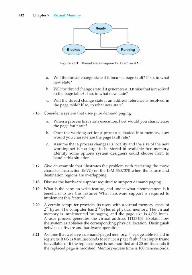
412 Chapter 9 Virtual Memory
Ready
Blocked Running
Figure 9.31 Thread state diagram for Exercise 9.15.
a. Will the thread change state if it incurs a page fault? If so, to whatnew state?
b. Will the thread change state if it generates a TLB miss that is resolvedin the page table? If so, to what new state?
c. Will the thread change state if an address reference is resolved inthe page table? If so, to what new state?
9.16 Consider a system that uses pure demand paging.
a. When a process first starts execution, how would you characterizethe page fault rate?
b. Once the working set for a process is loaded into memory, howwould you characterize the page fault rate?
c. Assume that a process changes its locality and the size of the newworking set is too large to be stored in available free memory.Identify some options system designers could choose from tohandle this situation.
9.17 Give an example that illustrates the problem with restarting the movecharacter instruction (MVC) on the IBM 360/370 when the source anddestination regions are overlapping.
9.18 Discuss the hardware support required to support demand paging.
9.19 What is the copy-on-write feature, and under what circumstances is itbeneficial to use this feature? What hardware support is required toimplement this feature?
9.20 A certain computer provides its users with a virtual memory space of232 bytes. The computer has 218 bytes of physical memory. The virtualmemory is implemented by paging, and the page size is 4,096 bytes.A user process generates the virtual address 11123456. Explain howthe system establishes the corresponding physical location. Distinguishbetween software and hardware operations.
9.21 Assume that we have a demand-paged memory. The page table is held inregisters. It takes 8 milliseconds to service a page fault if an empty frameis available or if the replaced page is not modified and 20 milliseconds ifthe replaced page is modified. Memory-access time is 100 nanoseconds.
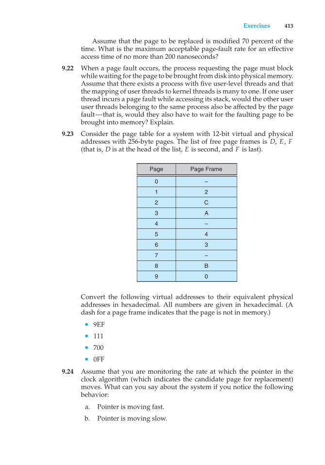
Exercises 413
Assume that the page to be replaced is modified 70 percent of thetime. What is the maximum acceptable page-fault rate for an effectiveaccess time of no more than 200 nanoseconds?
9.22 When a page fault occurs, the process requesting the page must blockwhile waiting for the page to be brought from disk into physical memory.Assume that there exists a process with five user-level threads and thatthe mapping of user threads to kernel threads is many to one. If one userthread incurs a page fault while accessing its stack, would the other useruser threads belonging to the same process also be affected by the pagefault—that is, would they also have to wait for the faulting page to bebrought into memory? Explain.
9.23 Consider the page table for a system with 12-bit virtual and physicaladdresses with 256-byte pages. The list of free page frames is D, E , F(that is, D is at the head of the list, E is second, and F is last).
Page Page Frame
0
1
2
3
4
5
–
2
C
A
–
4
6 3
7 –
8 B
9 0
Convert the following virtual addresses to their equivalent physicaladdresses in hexadecimal. All numbers are given in hexadecimal. (Adash for a page frame indicates that the page is not in memory.)
• 9EF
• 111
• 700
• 0FF
9.24 Assume that you are monitoring the rate at which the pointer in theclock algorithm (which indicates the candidate page for replacement)moves. What can you say about the system if you notice the followingbehavior:
a. Pointer is moving fast.
b. Pointer is moving slow.
414 Chapter 9 Virtual Memory
9.25 Discuss situations in which the least frequently used page-replacementalgorithm generates fewer page faults than the least recently usedpage-replacement algorithm. Also discuss under what circumstancesthe opposite holds.
9.26 Discuss situations in which the most frequently used page-replacementalgorithm generates fewer page faults than the least recently usedpage-replacement algorithm. Also discuss under what circumstancesthe opposite holds.
9.27 The VAX/VMS system uses a FIFO replacement algorithm for residentpages and a free-frame pool of recently used pages. Assume that thefree-frame pool is managed using the least recently used replacementpolicy. Answer the following questions:
a. If a page fault occurs and if the page does not exist in the free-framepool, how is free space generated for the newly requested page?
b. If a page fault occurs and if the page exists in the free-frame pool,how is the resident page set and the free-frame pool managed tomake space for the requested page?
c. What does the system degenerate to if the number of resident pagesis set to one?
d. What does the system degenerate to if the number of pages in thefree-frame pool is zero?
9.28 Consider a demand-paging system with the following time-measuredutilizations:
CPU utilization 20%Paging disk 97.7%Other I/O devices 5%
For each of the following, say whether it will (or is likely to) improveCPU utilization. Explain your answers.
a. Install a faster CPU.
b. Install a bigger paging disk.
c. Increase the degree of multiprogramming.
d. Decrease the degree of multiprogramming.
e. Install more main memory.
f. Install a faster hard disk or multiple controllers with multiple harddisks.
g. Add prepaging to the page-fetch algorithms.
h. Increase the page size.
9.29 Suppose that a machine provides instructions that can access memorylocations using the one-level indirect addressing scheme. What sequenceof page faults is incurred when all of the pages of a program are
Exercises 415
currently nonresident and the first instruction of the program is anindirect memory-load operation? What happens when the operatingsystem is using a per-process frame allocation technique and only twopages are allocated to this process?
9.30 Suppose that your replacement policy (in a paged system) is to examineeach page regularly and to discard that page if it has not been used sincethe last examination. What would you gain and what would you loseby using this policy rather than LRU or second-chance replacement?
9.31 A page-replacement algorithm should minimize the number of pagefaults. We can achieve this minimization by distributing heavily usedpages evenly over all of memory, rather than having them compete fora small number of page frames. We can associate with each page framea counter of the number of pages associated with that frame. Then,to replace a page, we can search for the page frame with the smallestcounter.
a. Define a page-replacement algorithm using this basic idea. Specif-ically address these problems:i. What is the initial value of the counters?
ii. When are counters increased?iii. When are counters decreased?iv. How is the page to be replaced selected?
b. How many page faults occur for your algorithm for the followingreference string with four page frames?
1, 2, 3, 4, 5, 3, 4, 1, 6, 7, 8, 7, 8, 9, 7, 8, 9, 5, 4, 5, 4, 2.
c. What is the minimum number of page faults for an optimal page-replacement strategy for the reference string in part b with fourpage frames?
9.32 Consider a demand-paging system with a paging disk that has anaverage access and transfer time of 20 milliseconds. Addresses aretranslated through a page table in main memory, with an access time of 1microsecond per memory access. Thus, each memory reference throughthe page table takes two accesses. To improve this time, we have addedan associative memory that reduces access time to one memory referenceif the page-table entry is in the associative memory.
Assume that 80 percent of the accesses are in the associative memoryand that, of those remaining, 10 percent (or 2 percent of the total) causepage faults. What is the effective memory access time?
9.33 What is the cause of thrashing? How does the system detect thrashing?Once it detects thrashing, what can the system do to eliminate thisproblem?
9.34 Is it possible for a process to have two working sets, one representingdata and another representing code? Explain.
9.35 Consider the parameter � used to define the working-set window inthe working-set model. What is the effect of setting � to a small value
416 Chapter 9 Virtual Memory
on the page-fault frequency and the number of active (nonsuspended)processes currently executing in the system? What is the effect when �
is set to a very high value?
9.36 Assume there is a 1,024-KB segment where memory is allocated usingthe buddy system. Using Figure 9.27 as a guide, draw a tree illustratinghow the following memory requests are allocated:
• Request 240 bytes
• Request 120 bytes
• Request 60 bytes
• Request 130 bytes
Next, modify the tree for the following releases of memory. Performcoalescing whenever possible:
• Release 240 bytes
• Release 60 bytes
• Release 120 bytes
9.37 Consider a system that provides support for user-level and kernel-level threads. The mapping in this system is one to one (there is acorresponding kernel thread for each user thread). Does a multithreadedprocess consist of (a) a working set for the entire process or (b) a workingset for each thread? Explain
9.38 The slab-allocation algorithm uses a separate cache for each differentobject type. Assuming there is one cache per object type, explain whythis scheme doesn’t scale well with multiple CPUs. What could be doneto address this scalability issue?
9.39 Consider a system that allocates pages of different sizes to its processes.What are the advantages of such a paging scheme? What modificationsto the virtual memory system provide this functionality?
Programming Problems
9.40 Write a program that implements the FIFO and LRU page-replacementalgorithms presented in this chapter. First, generate a random page-reference string where page numbers range from 0 to 9. Apply therandom page-reference string to each algorithm, and record the numberof page faults incurred by each algorithm. Implement the replacementalgorithms so that the number of page frames can vary from 1 to 7.Assume that demand paging is used.
9.41 The Catalan numbers are an integer sequence Cn that appear in tree-enumeration problems. The first Catalan numbers for n = 1, 2, 3, ... are1, 2, 5, 14, 42, 132, .... A formula generating Cn is
Bibliographical Notes 417
Cn = 1(n+ 1)
(2nn
)= (2n)!
(n+ 1)!n!
Design two programs that communicate with shared memory usingthe Win32 API as outlined in Section 9.7.2. The producer process willgenerate the Catalan sequence and write it to a shared memory object.The consumer process will then read and output the sequence fromshared memory.
In this instance, the producer process will be passed an integerparameter on the command line specifying how many Catalan numbersto produce (for example, providing 5 on the command line means theproducer process will generate the first five Catalan numbers).
Wiley Plus
Visit Wiley Plus for
• Source code
• Solutions to practice exercises
• Additional programming problems and exercises
• Labs using an operating system simulator
Bibliographical Notes
Demand paging was first used in the Atlas system, implemented on theManchester University MUSE computer around 1960 (Kilburn et al. [1961]).Another early demand-paging system was MULTICS, implemented on the GE645 system (Organick [1972]).
Belady et al. [1969] were the first researchers to observe that the FIFOreplacement strategy may produce the anomaly that bears Belady’s name.Mattson et al. [1970] demonstrated that stack algorithms are not subject toBelady’s anomaly.
The optimal replacement algorithm was presented by Belady [1966] andwas proved to be optimal by Mattson et al. [1970]. Belady’s optimal algorithm isfor a fixed allocation; Prieve and Fabry [1976] presented an optimal algorithmfor situations in which the allocation can vary.
The enhanced clock algorithm was discussed by Carr and Hennessy [1981].The working-set model was developed by Denning [1968]. Discussions
concerning the working-set model were presented by Denning [1980].The scheme for monitoring the page-fault rate was developed by Wulf
[1969], who successfully applied this technique to the Burroughs B5500 com-puter system.
Wilson et al. [1995] presented several algorithms for dynamic memory allo-cation. Johnstone and Wilson [1998] described various memory-fragmentationissues. Buddy system memory allocators were described in Knowlton [1965],Peterson and Norman [1977], and Purdom, Jr. and Stigler [1970]. Bonwick[1994] discussed the slab allocator, and Bonwick and Adams [2001] extended
418 Chapter 9 Virtual Memory
the discussion to multiple processors. Other memory-fitting algorithms canbe found in Stephenson [1983], Bays [1977], and Brent [1989]. A survey ofmemory-allocation strategies can be found in Wilson et al. [1995].
Solomon and Russinovich [2000] and Russinovich and Solomon [2005]described how Windows implements virtual memory. McDougall and Mauro[2007] discussed virtual memory in Solaris. Virtual memory techniques inLinux and BSD were described by Bovet and Cesati [2002] and McKusicket al. [1996], respectively. Ganapathy and Schimmel [1998] and Navarro et al.[2002] discussed operating system support for multiple page sizes. Ortiz [2001]described virtual memory used in a real-time embedded operating system.
Jacob and Mudge [1998b] compared implementations of virtual memory inthe MIPS, PowerPC, and Pentium architectures. A companion article (Jacob andMudge [1998a]) described the hardware support necessary for implementationof virtual memory in six different architectures, including the UltraSPARC.
Part Four
StorageManagement
Since main memory is usually too small to accommodate all the data andprograms permanently, the computer system must provide secondarystorage to back up main memory. Modern computer systems use disksas the primary on-line storage medium for information (both programsand data). The file system provides the mechanism for on-line storageof and access to both data and programs residing on the disks. A fileis a collection of related information defined by its creator. The files aremapped by the operating system onto physical devices. Files are normallyorganized into directories for ease of use.
The devices that attach to a computer vary in many aspects. Somedevices transfer a character or a block of characters at a time. Somecan be accessed only sequentially, others randomly. Some transferdata synchronously, others asynchronously. Some are dedicated, someshared. They can be read-only or read–write. They vary greatly in speed.In many ways, they are also the slowest major component of thecomputer.
Because of all this device variation, the operating system needs toprovide a wide range of functionality to applications, to allow them tocontrol all aspects of the devices. One key goal of an operating system’sI/O subsystem is to provide the simplest interface possible to the rest ofthe system. Because devices are a performance bottleneck, another keyis to optimize I/O for maximum concurrency.

This page intentionally left blank
10C H A P T E R
File -SystemInterface
For most users, the file system is the most visible aspect of an operating system.It provides the mechanism for on-line storage of and access to both data andprograms of the operating system and all the users of the computer system. Thefile system consists of two distinct parts: a collection of files, each storing relateddata, and a directory structure, which organizes and provides information aboutall the files in the system. File systems live on devices, which we explore fullyin the following chapters but touch upon here. In this chapter, we considerthe various aspects of files and the major directory structures. We also discussthe semantics of sharing files among multiple processes, users, and computers.Finally, we discuss ways to handle file protection, necessary when we havemultiple users and we want to control who may access files and how files maybe accessed.
CHAPTER OBJECTIVES
• To explain the function of file systems.
• To describe the interfaces to file systems.
• To discuss file-system design tradeoffs, including access methods, filesharing, file locking, and directory structures.
• To explore file-system protection.
10.1 File Concept
Computers can store information on various storage media, such as magneticdisks, magnetic tapes, and optical disks. So that the computer system willbe convenient to use, the operating system provides a uniform logical viewof information storage. The operating system abstracts from the physicalproperties of its storage devices to define a logical storage unit, the file. Files aremapped by the operating system onto physical devices. These storage devicesare usually nonvolatile, so the contents are persistent through power failuresand system reboots.
421
422 Chapter 10 File-System Interface
A file is a named collection of related information that is recorded onsecondary storage. From a user’s perspective, a file is the smallest allotmentof logical secondary storage; that is, data cannot be written to secondarystorage unless they are within a file. Commonly, files represent programs (bothsource and object forms) and data. Data files may be numeric, alphabetic,alphanumeric, or binary. Files may be free form, such as text files, or may beformatted rigidly. In general, a file is a sequence of bits, bytes, lines, or records,the meaning of which is defined by the file’s creator and user. The concept ofa file is thus extremely general.
The information in a file is defined by its creator. Many different typesof information may be stored in a file—source programs, object programs,executable programs, numeric data, text, payroll records, graphic images,sound recordings, and so on. A file has a certain defined structure, whichdepends on its type. A text file is a sequence of characters organized intolines (and possibly pages). A source file is a sequence of subroutines andfunctions, each of which is further organized as declarations followed byexecutable statements. An object file is a sequence of bytes organized intoblocks understandable by the system’s linker. An executable file is a series ofcode sections that the loader can bring into memory and execute.
10.1.1 File Attributes
A file is named, for the convenience of its human users, and is referred to byits name. A name is usually a string of characters, such as example.c. Somesystems differentiate between uppercase and lowercase characters in names,whereas other systems do not. When a file is named, it becomes independentof the process, the user, and even the system that created it. For instance, oneuser might create the file example.c, and another user might edit that file byspecifying its name. The file’s owner might write the file to a floppy disk, sendit in an e-mail, or copy it across a network, and it could still be called example.con the destination system.
A file’s attributes vary from one operating system to another but typicallyconsist of these:
• Name. The symbolic file name is the only information kept in human-readable form.
• Identifier. This unique tag, usually a number, identifies the file within thefile system; it is the non-human-readable name for the file.
• Type. This information is needed for systems that support different typesof files.
• Location. This information is a pointer to a device and to the location ofthe file on that device.
• Size. The current size of the file (in bytes, words, or blocks) and possiblythe maximum allowed size are included in this attribute.
• Protection. Access-control information determines who can do reading,writing, executing, and so on.
10.1 File Concept 423
• Time, date, and user identification. This information may be kept forcreation, last modification, and last use. These data can be useful forprotection, security, and usage monitoring.
The information about all files is kept in the directory structure, which alsoresides on secondary storage. Typically, a directory entry consists of the file’sname and its unique identifier. The identifier in turn locates the other fileattributes. It may take more than a kilobyte to record this information foreach file. In a system with many files, the size of the directory itself may bemegabytes. Because directories, like files, must be nonvolatile, they must bestored on the device and brought into memory piecemeal, as needed.
10.1.2 File Operations
A file is an abstract data type. To define a file properly, we need to consider theoperations that can be performed on files. The operating system can providesystem calls to create, write, read, reposition, delete, and truncate files. Let’sexamine what the operating system must do to perform each of these six basicfile operations. It should then be easy to see how other similar operations, suchas renaming a file, can be implemented.
• Creating a file. Two steps are necessary to create a file. First, space in thefile system must be found for the file. We discuss how to allocate space forthe file in Chapter 11. Second, an entry for the new file must be made inthe directory.
• Writing a file. To write a file, we make a system call specifying both thename of the file and the information to be written to the file. Given thename of the file, the system searches the directory to find the file’s location.The system must keep a write pointer to the location in the file where thenext write is to take place. The write pointer must be updated whenever awrite occurs.
• Reading a file. To read from a file, we use a system call that specifies thename of the file and where (in memory) the next block of the file shouldbe put. Again, the directory is searched for the associated entry, and thesystem needs to keep a read pointer to the location in the file where thenext read is to take place. Once the read has taken place, the read pointeris updated. Because a process is usually either reading from or writing toa file, the current operation location can be kept as a per-process current-file-position pointer. Both the read and write operations use this samepointer, saving space and reducing system complexity.
• Repositioning within a file. The directory is searched for the appropriateentry, and the current-file-position pointer is repositioned to a given value.Repositioning within a file need not involve any actual I/O. This fileoperation is also known as a file seek.
• Deleting a file. To delete a file, we search the directory for the named file.Having found the associated directory entry, we release all file space, sothat it can be reused by other files, and erase the directory entry.
424 Chapter 10 File-System Interface
• Truncating a file. The user may want to erase the contents of a file butkeep its attributes. Rather than forcing the user to delete the file and thenrecreate it, this function allows all attributes to remain unchanged—exceptfor file length—but lets the file be reset to length zero and its file spacereleased.
These six basic operations comprise the minimal set of required fileoperations. Other common operations include appending new informationto the end of an existing file and renaming an existing file. These primitiveoperations can then be combined to perform other file operations. For instance,we can create a copy of a file, or copy the file to another I/O device, such asa printer or a display, by creating a new file and then reading from the oldand writing to the new. We also want to have operations that allow a user toget and set the various attributes of a file. For example, we may want to haveoperations that allow a user to determine the status of a file, such as the file’slength, and to set file attributes, such as the file’s owner.
Most of the file operations mentioned involve searching the directory forthe entry associated with the named file. To avoid this constant searching, manysystems require that an open() system call be made before a file is first usedactively. The operating system keeps a small table, called the open-file table,containing information about all open files. When a file operation is requested,the file is specified via an index into this table, so no searching is required.When the file is no longer being actively used, it is closed by the process, andthe operating system removes its entry from the open-file table. create anddelete are system calls that work with closed rather than open files.
Some systems implicitly open a file when the first reference to it is made.The file is automatically closed when the job or program that opened thefile terminates. Most systems, however, require that the programmer open afile explicitly with the open() system call before that file can be used. Theopen() operation takes a file name and searches the directory, copying thedirectory entry into the open-file table. The open() call can also accept access-mode information—create, read-only, read–write, append-only, and so on.This mode is checked against the file’s permissions. If the request mode isallowed, the file is opened for the process. The open() system call typicallyreturns a pointer to the entry in the open-file table. This pointer, not the actualfile name, is used in all I/O operations, avoiding any further searching andsimplifying the system-call interface.
The implementation of the open() and close() operations is morecomplicated in an environment where several processes may open the filesimultaneously. This may occur in a system where several different applicationsopen the same file at the same time. Typically, the operating system uses twolevels of internal tables: a per-process table and a system-wide table. The per-process table tracks all files that a process has open. Stored in this table isinformation regarding the use of the file by the process. For instance, thecurrent file pointer for each file is found here. Access rights to the file andaccounting information can also be included.
Each entry in the per-process table in turn points to a system-wide open-filetable. The system-wide table contains process-independent information, suchas the location of the file on disk, access dates, and file size. Once a file has beenopened by one process, the system-wide table includes an entry for the file.
10.1 File Concept 425
When another process executes an open() call, a new entry is simply addedto the process’s open-file table pointing to the appropriate entry in the system-wide table. Typically, the open-file table also has an open count associated witheach file to indicate how many processes have the file open. Each close()decreases this open count, and when the open count reaches zero, the file is nolonger in use, and the file’s entry is removed from the open-file table.
In summary, several pieces of information are associated with an open file.
• File pointer. On systems that do not include a file offset as part of theread() and write() system calls, the system must track the last read–write location as a current-file-position pointer. This pointer is unique toeach process operating on the file and therefore must be kept separate fromthe on-disk file attributes.
• File-open count. As files are closed, the operating system must reuse itsopen-file table entries, or it could run out of space in the table. Becausemultiple processes may have opened a file, the system must wait for thelast file to close before removing the open-file table entry. The file-opencounter tracks the number of opens and closes and reaches zero on the lastclose. The system can then remove the entry.
• Disk location of the file. Most file operations require the system to modifydata within the file. The information needed to locate the file on disk iskept in memory so that the system does not have to read it from disk foreach operation.
• Access rights. Each process opens a file in an access mode. This informationis stored on the per-process table so the operating system can allow or denysubsequent I/O requests.
Some operating systems provide facilities for locking an open file (orsections of a file). File locks allow one process to lock a file and prevent otherprocesses from gaining access to it. File locks are useful for files that are sharedby several processes—for example, a system log file that can be accessed andmodified by a number of processes in the system.
FILE LOCKING IN JAVA
In the Java API, acquiring a lock requires first obtaining the FileChannelfor the file to be locked. The lock() method of the FileChannel is used toacquire the lock. The API of the lock() method is
FileLock lock(long begin, long end, boolean shared)
where begin and end are the beginning and ending positions of the regionbeing locked. Setting shared to true is for shared locks; setting sharedto false acquires the lock exclusively. The lock is released by invoking therelease() of the FileLock returned by the lock() operation.
The program in Figure 10.1 illustrates file locking in Java. This programacquires two locks on the file file.txt. The first half of the file is acquired as anexclusive lock; the lock for the second half is a shared lock.
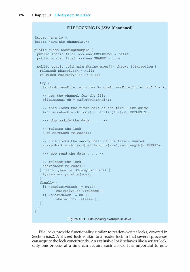
426 Chapter 10 File-System Interface
FILE LOCKING IN JAVA (Continued)
import java.io.*;import java.nio.channels.*;
public class LockingExample {public static final boolean EXCLUSIVE = false;public static final boolean SHARED = true;
public static void main(String args[]) throws IOException {FileLock sharedLock = null;FileLock exclusiveLock = null;
try {RandomAccessFile raf = new RandomAccessFile("file.txt","rw");
// get the channel for the fileFileChannel ch = raf.getChannel();
// this locks the first half of the file - exclusiveexclusiveLock = ch.lock(0, raf.length()/2, EXCLUSIVE);
/** Now modify the data . . . */
// release the lockexclusiveLock.release();
// this locks the second half of the file - sharedsharedLock = ch.lock(raf.length()/2+1,raf.length(),SHARED);
/** Now read the data . . . */
// release the locksharedLock.release();
} catch (java.io.IOException ioe) {System.err.println(ioe);
}finally {if (exclusiveLock != null)
exclusiveLock.release();if (sharedLock != null)
sharedLock.release();}
}}
Figure 10.1 File-locking example in Java.
File locks provide functionality similar to reader–writer locks, covered inSection 6.6.2. A shared lock is akin to a reader lock in that several processescan acquire the lock concurrently. An exclusive lock behaves like a writer lock;only one process at a time can acquire such a lock. It is important to note
10.1 File Concept 427
that not all operating systems provide both types of locks; some systems onlyprovide exclusive file locking.
Furthermore, operating systems may provide either mandatory or advi-sory file-locking mechanisms. If a lock is mandatory, then once a processacquires an exclusive lock, the operating system will prevent any other processfrom accessing the locked file. For example, assume a process acquires anexclusive lock on the file system.log. If we attempt to open system.logfrom another process—for example, a text editor—the operating system willprevent access until the exclusive lock is released. This occurs even if the texteditor is not written explicitly to acquire the lock. Alternatively, if the lockis advisory, then the operating system will not prevent the text editor fromacquiring access to system.log. Rather, the text editor must be written so thatit manually acquires the lock before accessing the file. In other words, if thelocking scheme is mandatory, the operating system ensures locking integrity.For advisory locking, it is up to software developers to ensure that locks areappropriately acquired and released. As a general rule, Windows operatingsystems adopt mandatory locking, and UNIX systems employ advisory locks.
The use of file locks requires the same precautions as ordinary processsynchronization. For example, programmers developing on systems withmandatory locking must be careful to hold exclusive file locks only whilethey are accessing the file; otherwise, they will prevent other processes fromaccessing the file as well. Furthermore, some measures must be taken to ensurethat two or more processes do not become involved in a deadlock while tryingto acquire file locks.
10.1.3 File Types
When we design a file system—indeed, an entire operating system—wealways consider whether the operating system should recognize and supportfile types. If an operating system recognizes the type of a file, it can then operateon the file in reasonable ways. For example, a common mistake occurs when auser tries to print the binary-object form of a program. This attempt normallyproduces garbage; however, the attempt can succeed if the operating systemhas been told that the file is a binary-object program.
A common technique for implementing file types is to include the type aspart of the file name. The name is split into two parts—a name and an extension,usually separated by a period character (Figure 10.2). In this way, the user andthe operating system can tell from the name alone what the type of a file is.For example, most operating systems allow users to specify a file name as asequence of characters followed by a period and terminated by an extension ofadditional characters. File name examples include resume.doc, Server.java, andReaderThread.c.
The system uses the extension to indicate the type of the file and the typeof operations that can be done on that file. Only a file with a .com, .exe, or .batextension can be executed, for instance. The .com and .exe files are two forms ofbinary executable files, whereas a .bat file is a batch file containing, in ASCIIformat, commands to the operating system. MS-DOS recognizes only a fewextensions, but application programs also use extensions to indicate file typesin which they are interested. For example, assemblers expect source files to havean .asm extension, and the Microsoft Word word processor expects its files to
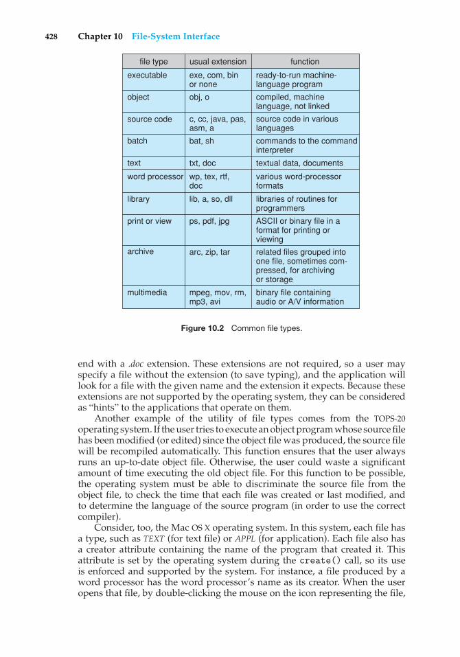
428 Chapter 10 File-System Interface
file type usual extension function
ready-to-run machine-language program
executable exe, com, binor none
compiled, machinelanguage, not linked
object obj, o
binary file containingaudio or A/V information
multimedia mpeg, mov, rm,mp3, avi
related files grouped intoone file, sometimes com-pressed, for archivingor storage
archive arc, zip, tar
ASCII or binary file in aformat for printing orviewing
print or view ps, pdf, jpg
libraries of routines forprogrammers
library lib, a, so, dll
various word-processorformats
word processor wp, tex, rtf,doc
commands to the commandinterpreter
batch bat, sh
textual data, documentstext txt, doc
source code in variouslanguages
source code c, cc, java, pas,asm, a
Figure 10.2 Common file types.
end with a .doc extension. These extensions are not required, so a user mayspecify a file without the extension (to save typing), and the application willlook for a file with the given name and the extension it expects. Because theseextensions are not supported by the operating system, they can be consideredas “hints” to the applications that operate on them.
Another example of the utility of file types comes from the TOPS-20operating system. If the user tries to execute an object program whose source filehas been modified (or edited) since the object file was produced, the source filewill be recompiled automatically. This function ensures that the user alwaysruns an up-to-date object file. Otherwise, the user could waste a significantamount of time executing the old object file. For this function to be possible,the operating system must be able to discriminate the source file from theobject file, to check the time that each file was created or last modified, andto determine the language of the source program (in order to use the correctcompiler).
Consider, too, the Mac OS X operating system. In this system, each file hasa type, such as TEXT (for text file) or APPL (for application). Each file also hasa creator attribute containing the name of the program that created it. Thisattribute is set by the operating system during the create() call, so its useis enforced and supported by the system. For instance, a file produced by aword processor has the word processor’s name as its creator. When the useropens that file, by double-clicking the mouse on the icon representing the file,
10.1 File Concept 429
the word processor is invoked automatically, and the file is loaded, ready to beedited.
The UNIX system uses a crude magic number stored at the beginning ofsome files to indicate roughly the type of the file—executable program, batchfile (or shell script), PostScript file, and so on. Not all files have magic numbers,so system features cannot be based solely on this information. UNIX does notrecord the name of the creating program, either. UNIX does allow file-name-extension hints, but these extensions are neither enforced nor depended on bythe operating system; they are meant mostly to aid users in determining whattype of contents the file contains. Extensions can be used or ignored by a givenapplication, but that is up to the application’s programmer.
10.1.4 File Structure
File types also can be used to indicate the internal structure of the file. Asmentioned in Section 10.1.3, source and object files have structures that matchthe expectations of the programs that read them. Further, certain files mustconform to a required structure that is understood by the operating system. Forexample, the operating system requires that an executable file have a specificstructure so that it can determine where in memory to load the file and whatthe location of the first instruction is. Some operating systems extend this ideainto a set of system-supported file structures, with sets of special operationsfor manipulating files with those structures. For instance, DEC’s VMS operatingsystem has a file system that supports three defined file structures.
This point brings us to one of the disadvantages of having the operatingsystem support multiple file structures: the resulting size of the operatingsystem is cumbersome. If the operating system defines five different filestructures, it needs to contain the code to support these file structures.In addition, it may be necessary to define every file as one of the filetypes supported by the operating system. When new applications requireinformation structured in ways not supported by the operating system, severeproblems may result.
For example, assume that a system supports two types of files: text files(composed of ASCII characters separated by a carriage return and line feed)and executable binary files. Now, if we (as users) want to define an encryptedfile to protect the contents from being read by unauthorized people, we mayfind neither file type to be appropriate. The encrypted file is not ASCII text linesbut rather is (apparently) random bits. Although it may appear to be a binaryfile, it is not executable. As a result, we may have to circumvent or misuse theoperating system’s file-type mechanism or abandon our encryption scheme.
Some operating systems impose (and support) a minimal number of filestructures. This approach has been adopted in UNIX, MS-DOS, and others. UNIXconsiders each file to be a sequence of 8-bit bytes; no interpretation of these bitsis made by the operating system. This scheme provides maximum flexibilitybut little support. Each application program must include its own code tointerpret an input file as to the appropriate structure. However, all operatingsystems must support at least one structure—that of an executable file—sothat the system is able to load and run programs.
The Macintosh operating system also supports a minimal number offile structures. It expects files to contain two parts: a resource fork and a
430 Chapter 10 File-System Interface
data fork. The resource fork contains information of interest to the user.For instance, it holds the labels of any buttons displayed by the program.A foreign user may want to re-label these buttons in his own language, andthe Macintosh operating system provides tools to allow modification of thedata in the resource fork. The data fork contains program code or data—thetraditional file contents. To accomplish the same task on a UNIX or MS-DOSsystem, the programmer would need to change and recompile the source code,unless she created her own user-changeable data file. Clearly, it is useful foran operating system to support structures that will be used frequently andthat will save the programmer substantial effort. Too few structures makeprogramming inconvenient, whereas too many cause operating-system bloatand programmer confusion.
10.1.5 Internal File Structure
Internally, locating an offset within a file can be complicated for the operatingsystem. Disk systems typically have a well-defined block size determined bythe size of a sector. All disk I/O is performed in units of one block (physicalrecord), and all blocks are the same size. It is unlikely that the physical recordsize will exactly match the length of the desired logical record. Logical recordsmay even vary in length. Packing a number of logical records into physicalblocks is a common solution to this problem.
For example, the UNIX operating system defines all files to be simplystreams of bytes. Each byte is individually addressable by its offset from thebeginning (or end) of the file. In this case, the logical record size is 1 byte. Thefile system automatically packs and unpacks bytes into physical disk blocks—say, 512 bytes per block—as necessary.
The logical record size, physical block size, and packing technique deter-mine how many logical records are in each physical block. The packing can bedone either by the user’s application program or by the operating system. Ineither case, the file may be considered a sequence of blocks. All the basic I/Ofunctions operate in terms of blocks. The conversion from logical records tophysical blocks is a relatively simple software problem.
Because disk space is always allocated in blocks, some portion of the lastblock of each file is generally wasted. If each block were 512 bytes, for example,then a file of 1,949 bytes would be allocated four blocks (2,048 bytes); the last99 bytes would be wasted. The waste incurred to keep everything in unitsof blocks (instead of bytes) is internal fragmentation. All file systems sufferfrom internal fragmentation; the larger the block size, the greater the internalfragmentation.
10.2 Access Methods
Files store information. When it is used, this information must be accessed andread into computer memory. The information in the file can be accessed inseveral ways. Some systems provide only one access method for files. Othersystems, such as those of IBM, support many access methods, and choosing theright one for a particular application is a major design problem.
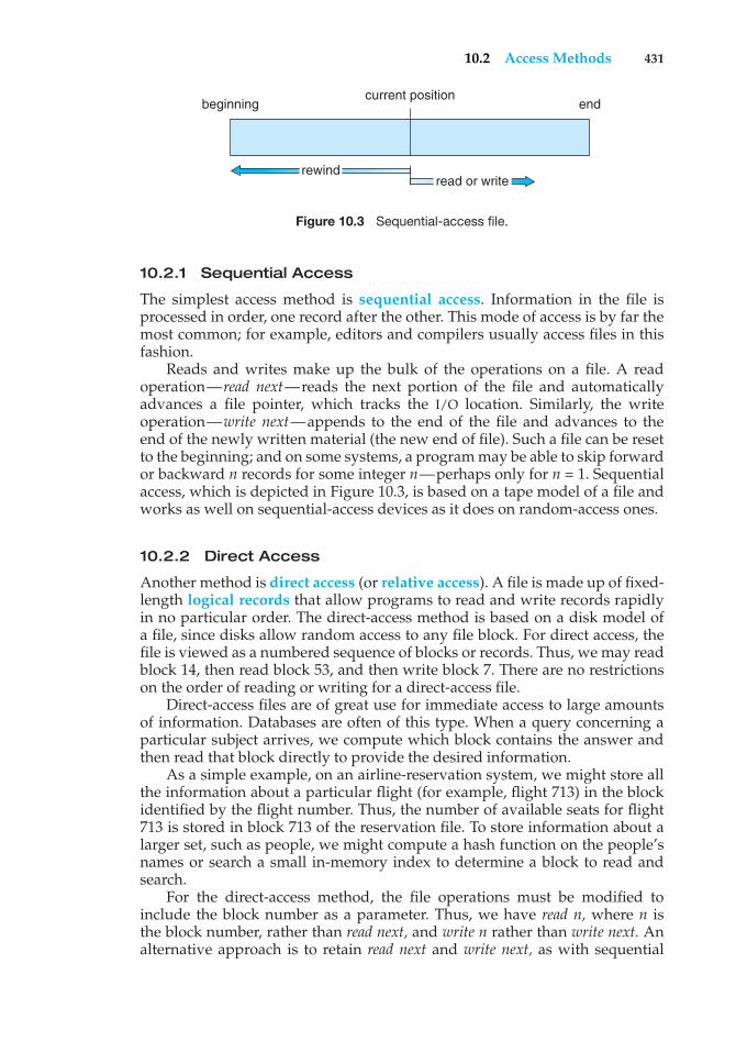
10.2 Access Methods 431
beginning endcurrent position
rewindread or write
Figure 10.3 Sequential-access file.
10.2.1 Sequential Access
The simplest access method is sequential access. Information in the file isprocessed in order, one record after the other. This mode of access is by far themost common; for example, editors and compilers usually access files in thisfashion.
Reads and writes make up the bulk of the operations on a file. A readoperation—read next—reads the next portion of the file and automaticallyadvances a file pointer, which tracks the I/O location. Similarly, the writeoperation—write next—appends to the end of the file and advances to theend of the newly written material (the new end of file). Such a file can be resetto the beginning; and on some systems, a program may be able to skip forwardor backward n records for some integer n—perhaps only for n = 1. Sequentialaccess, which is depicted in Figure 10.3, is based on a tape model of a file andworks as well on sequential-access devices as it does on random-access ones.
10.2.2 Direct Access
Another method is direct access (or relative access). A file is made up of fixed-length logical records that allow programs to read and write records rapidlyin no particular order. The direct-access method is based on a disk model ofa file, since disks allow random access to any file block. For direct access, thefile is viewed as a numbered sequence of blocks or records. Thus, we may readblock 14, then read block 53, and then write block 7. There are no restrictionson the order of reading or writing for a direct-access file.
Direct-access files are of great use for immediate access to large amountsof information. Databases are often of this type. When a query concerning aparticular subject arrives, we compute which block contains the answer andthen read that block directly to provide the desired information.
As a simple example, on an airline-reservation system, we might store allthe information about a particular flight (for example, flight 713) in the blockidentified by the flight number. Thus, the number of available seats for flight713 is stored in block 713 of the reservation file. To store information about alarger set, such as people, we might compute a hash function on the people’snames or search a small in-memory index to determine a block to read andsearch.
For the direct-access method, the file operations must be modified toinclude the block number as a parameter. Thus, we have read n, where n isthe block number, rather than read next, and write n rather than write next. Analternative approach is to retain read next and write next, as with sequential
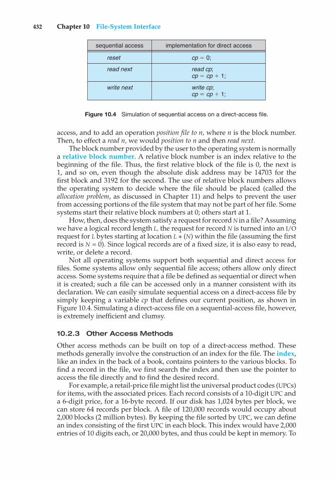
432 Chapter 10 File-System Interface
sequential access
reset
read next
write next
cp � 0;
read cp;cp � cp � 1;
write cp;cp � cp � 1;
implementation for direct access
Figure 10.4 Simulation of sequential access on a direct-access file.
access, and to add an operation position file to n, where n is the block number.Then, to effect a read n, we would position to n and then read next.
The block number provided by the user to the operating system is normallya relative block number. A relative block number is an index relative to thebeginning of the file. Thus, the first relative block of the file is 0, the next is1, and so on, even though the absolute disk address may be 14703 for thefirst block and 3192 for the second. The use of relative block numbers allowsthe operating system to decide where the file should be placed (called theallocation problem, as discussed in Chapter 11) and helps to prevent the userfrom accessing portions of the file system that may not be part of her file. Somesystems start their relative block numbers at 0; others start at 1.
How, then, does the system satisfy a request for record N in a file? Assumingwe have a logical record length L, the request for record N is turned into an I/Orequest for L bytes starting at location L ∗ (N) within the file (assuming the firstrecord is N = 0). Since logical records are of a fixed size, it is also easy to read,write, or delete a record.
Not all operating systems support both sequential and direct access forfiles. Some systems allow only sequential file access; others allow only directaccess. Some systems require that a file be defined as sequential or direct whenit is created; such a file can be accessed only in a manner consistent with itsdeclaration. We can easily simulate sequential access on a direct-access file bysimply keeping a variable cp that defines our current position, as shown inFigure 10.4. Simulating a direct-access file on a sequential-access file, however,is extremely inefficient and clumsy.
10.2.3 Other Access Methods
Other access methods can be built on top of a direct-access method. Thesemethods generally involve the construction of an index for the file. The index,like an index in the back of a book, contains pointers to the various blocks. Tofind a record in the file, we first search the index and then use the pointer toaccess the file directly and to find the desired record.
For example, a retail-price file might list the universal product codes (UPCs)for items, with the associated prices. Each record consists of a 10-digit UPC anda 6-digit price, for a 16-byte record. If our disk has 1,024 bytes per block, wecan store 64 records per block. A file of 120,000 records would occupy about2,000 blocks (2 million bytes). By keeping the file sorted by UPC, we can definean index consisting of the first UPC in each block. This index would have 2,000entries of 10 digits each, or 20,000 bytes, and thus could be kept in memory. To
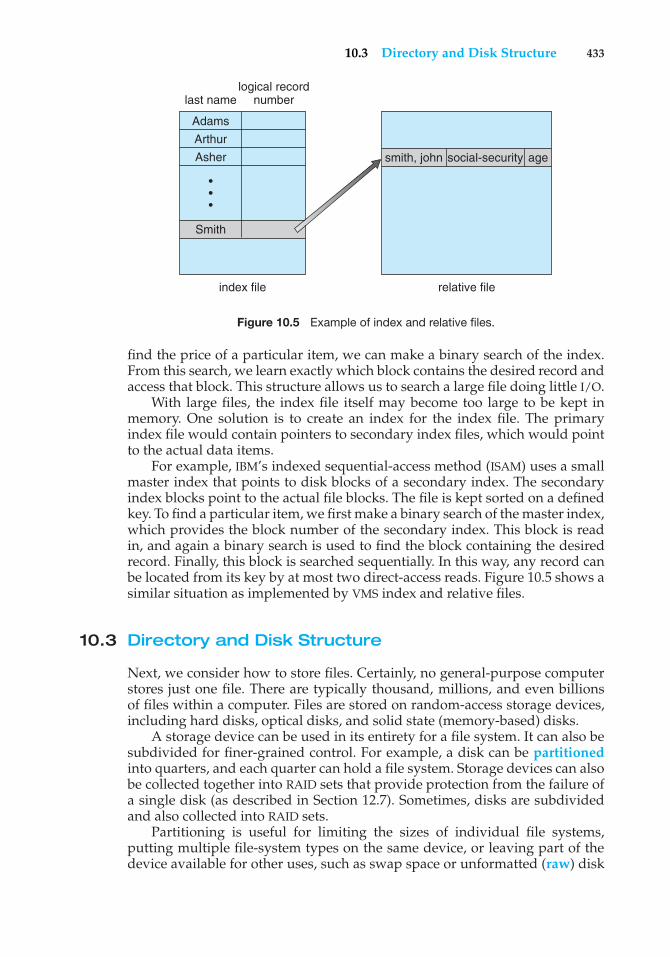
10.3 Directory and Disk Structure 433
index file relative file
Smith
last name
smith, john social-security age
logical recordnumber
Adams
Arthur
Asher
•••
Figure 10.5 Example of index and relative files.
find the price of a particular item, we can make a binary search of the index.From this search, we learn exactly which block contains the desired record andaccess that block. This structure allows us to search a large file doing little I/O.
With large files, the index file itself may become too large to be kept inmemory. One solution is to create an index for the index file. The primaryindex file would contain pointers to secondary index files, which would pointto the actual data items.
For example, IBM’s indexed sequential-access method (ISAM) uses a smallmaster index that points to disk blocks of a secondary index. The secondaryindex blocks point to the actual file blocks. The file is kept sorted on a definedkey. To find a particular item, we first make a binary search of the master index,which provides the block number of the secondary index. This block is readin, and again a binary search is used to find the block containing the desiredrecord. Finally, this block is searched sequentially. In this way, any record canbe located from its key by at most two direct-access reads. Figure 10.5 shows asimilar situation as implemented by VMS index and relative files.
10.3 Directory and Disk Structure
Next, we consider how to store files. Certainly, no general-purpose computerstores just one file. There are typically thousand, millions, and even billionsof files within a computer. Files are stored on random-access storage devices,including hard disks, optical disks, and solid state (memory-based) disks.
A storage device can be used in its entirety for a file system. It can also besubdivided for finer-grained control. For example, a disk can be partitionedinto quarters, and each quarter can hold a file system. Storage devices can alsobe collected together into RAID sets that provide protection from the failure ofa single disk (as described in Section 12.7). Sometimes, disks are subdividedand also collected into RAID sets.
Partitioning is useful for limiting the sizes of individual file systems,putting multiple file-system types on the same device, or leaving part of thedevice available for other uses, such as swap space or unformatted (raw) disk
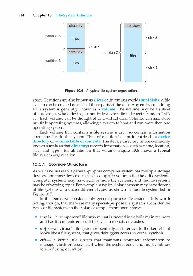
434 Chapter 10 File-System Interface
directory directory
directory
filespartition A
partition B
partition C
files
disk 1
disk 2
disk 3
files
Figure 10.6 A typical file-system organization.
space. Partitions are also known as slices or (in the IBM world) minidisks. A filesystem can be created on each of these parts of the disk. Any entity containinga file system is generally known as a volume. The volume may be a subsetof a device, a whole device, or multiple devices linked together into a RAIDset. Each volume can be thought of as a virtual disk. Volumes can also storemultiple operating systems, allowing a system to boot and run more than oneoperating system.
Each volume that contains a file system must also contain informationabout the files in the system. This information is kept in entries in a devicedirectory or volume table of contents. The device directory (more commonlyknown simply as that directory) records information—such as name, location,size, and type—for all files on that volume. Figure 10.6 shows a typicalfile-system organization.
10.3.1 Storage Structure
As we have just seen, a general-purpose computer system has multiple storagedevices, and those devices can be sliced up into volumes that hold file systems.Computer systems may have zero or more file systems, and the file systemsmay be of varying types. For example, a typical Solaris system may have dozensof file systems of a dozen different types, as shown in the file system list inFigure 10.7.
In this book, we consider only general-purpose file systems. It is worthnoting, though, that there are many special-purpose file systems. Consider thetypes of file systems in the Solaris example mentioned above:
• tmpfs—a “temporary” file system that is created in volatile main memoryand has its contents erased if the system reboots or crashes
• objfs—a “virtual” file system (essentially an interface to the kernel thatlooks like a file system) that gives debuggers access to kernel symbols
• ctfs— a virtual file system that maintains “contract” information tomanage which processes start when the system boots and must continueto run during operation
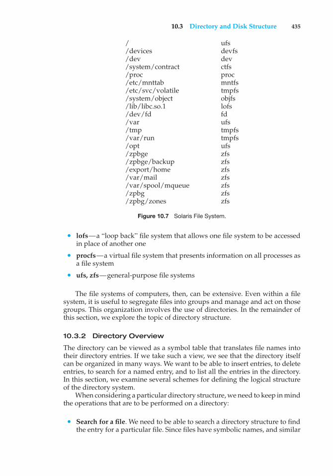
10.3 Directory and Disk Structure 435
/ ufs/devices devfs/dev dev/system/contract ctfs/proc proc/etc/mnttab mntfs/etc/svc/volatile tmpfs/system/object objfs/lib/libc.so.1 lofs/dev/fd fd/var ufs/tmp tmpfs/var/run tmpfs/opt ufs/zpbge zfs/zpbge/backup zfs/export/home zfs/var/mail zfs/var/spool/mqueue zfs/zpbg zfs/zpbg/zones zfs
Figure 10.7 Solaris File System.
• lofs—a “loop back” file system that allows one file system to be accessedin place of another one
• procfs—a virtual file system that presents information on all processes asa file system
• ufs, zfs—general-purpose file systems
The file systems of computers, then, can be extensive. Even within a filesystem, it is useful to segregate files into groups and manage and act on thosegroups. This organization involves the use of directories. In the remainder ofthis section, we explore the topic of directory structure.
10.3.2 Directory Overview
The directory can be viewed as a symbol table that translates file names intotheir directory entries. If we take such a view, we see that the directory itselfcan be organized in many ways. We want to be able to insert entries, to deleteentries, to search for a named entry, and to list all the entries in the directory.In this section, we examine several schemes for defining the logical structureof the directory system.
When considering a particular directory structure, we need to keep in mindthe operations that are to be performed on a directory:
• Search for a file. We need to be able to search a directory structure to findthe entry for a particular file. Since files have symbolic names, and similar
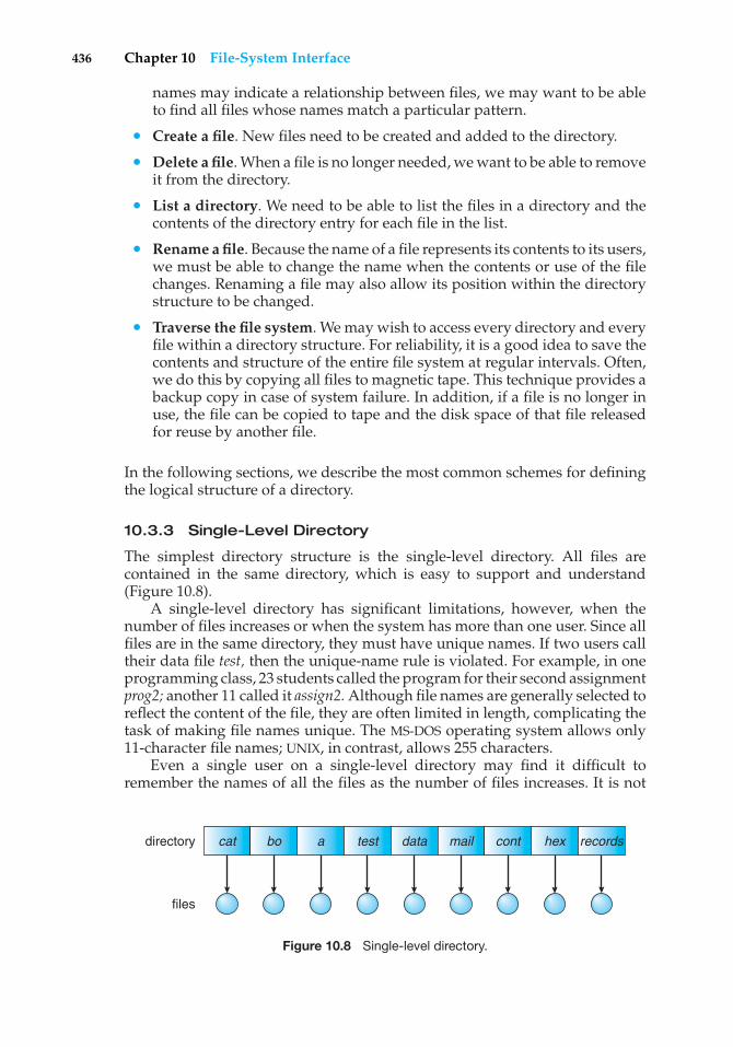
436 Chapter 10 File-System Interface
names may indicate a relationship between files, we may want to be ableto find all files whose names match a particular pattern.
• Create a file. New files need to be created and added to the directory.
• Delete a file. When a file is no longer needed, we want to be able to removeit from the directory.
• List a directory. We need to be able to list the files in a directory and thecontents of the directory entry for each file in the list.
• Rename a file. Because the name of a file represents its contents to its users,we must be able to change the name when the contents or use of the filechanges. Renaming a file may also allow its position within the directorystructure to be changed.
• Traverse the file system. We may wish to access every directory and everyfile within a directory structure. For reliability, it is a good idea to save thecontents and structure of the entire file system at regular intervals. Often,we do this by copying all files to magnetic tape. This technique provides abackup copy in case of system failure. In addition, if a file is no longer inuse, the file can be copied to tape and the disk space of that file releasedfor reuse by another file.
In the following sections, we describe the most common schemes for definingthe logical structure of a directory.
10.3.3 Single-Level Directory
The simplest directory structure is the single-level directory. All files arecontained in the same directory, which is easy to support and understand(Figure 10.8).
A single-level directory has significant limitations, however, when thenumber of files increases or when the system has more than one user. Since allfiles are in the same directory, they must have unique names. If two users calltheir data file test, then the unique-name rule is violated. For example, in oneprogramming class, 23 students called the program for their second assignmentprog2; another 11 called it assign2. Although file names are generally selected toreflect the content of the file, they are often limited in length, complicating thetask of making file names unique. The MS-DOS operating system allows only11-character file names; UNIX, in contrast, allows 255 characters.
Even a single user on a single-level directory may find it difficult toremember the names of all the files as the number of files increases. It is not
cat
files
directory bo a test data mail cont hex records
Figure 10.8 Single-level directory.
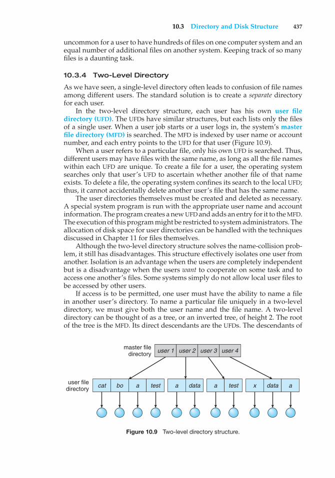
10.3 Directory and Disk Structure 437
uncommon for a user to have hundreds of files on one computer system and anequal number of additional files on another system. Keeping track of so manyfiles is a daunting task.
10.3.4 Two-Level Directory
As we have seen, a single-level directory often leads to confusion of file namesamong different users. The standard solution is to create a separate directoryfor each user.
In the two-level directory structure, each user has his own user filedirectory (UFD). The UFDs have similar structures, but each lists only the filesof a single user. When a user job starts or a user logs in, the system’s masterfile directory (MFD) is searched. The MFD is indexed by user name or accountnumber, and each entry points to the UFD for that user (Figure 10.9).
When a user refers to a particular file, only his own UFD is searched. Thus,different users may have files with the same name, as long as all the file nameswithin each UFD are unique. To create a file for a user, the operating systemsearches only that user’s UFD to ascertain whether another file of that nameexists. To delete a file, the operating system confines its search to the local UFD;thus, it cannot accidentally delete another user’s file that has the same name.
The user directories themselves must be created and deleted as necessary.A special system program is run with the appropriate user name and accountinformation. The program creates a new UFD and adds an entry for it to the MFD.The execution of this program might be restricted to system administrators. Theallocation of disk space for user directories can be handled with the techniquesdiscussed in Chapter 11 for files themselves.
Although the two-level directory structure solves the name-collision prob-lem, it still has disadvantages. This structure effectively isolates one user fromanother. Isolation is an advantage when the users are completely independentbut is a disadvantage when the users want to cooperate on some task and toaccess one another’s files. Some systems simply do not allow local user files tobe accessed by other users.
If access is to be permitted, one user must have the ability to name a filein another user’s directory. To name a particular file uniquely in a two-leveldirectory, we must give both the user name and the file name. A two-leveldirectory can be thought of as a tree, or an inverted tree, of height 2. The rootof the tree is the MFD. Its direct descendants are the UFDs. The descendants of
cat bo a test x data aa
user 1 user 2 user 3 user 4
data a testuser filedirectory
master filedirectory
Figure 10.9 Two-level directory structure.
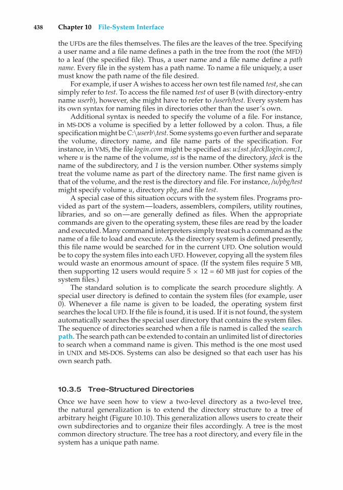
438 Chapter 10 File-System Interface
the UFDs are the files themselves. The files are the leaves of the tree. Specifyinga user name and a file name defines a path in the tree from the root (the MFD)to a leaf (the specified file). Thus, a user name and a file name define a pathname. Every file in the system has a path name. To name a file uniquely, a usermust know the path name of the file desired.
For example, if user A wishes to access her own test file named test, she cansimply refer to test. To access the file named test of user B (with directory-entryname userb), however, she might have to refer to /userb/test. Every system hasits own syntax for naming files in directories other than the user’s own.
Additional syntax is needed to specify the volume of a file. For instance,in MS-DOS a volume is specified by a letter followed by a colon. Thus, a filespecification might be C:\userb\test. Some systems go even further and separatethe volume, directory name, and file name parts of the specification. Forinstance, in VMS, the file login.com might be specified as: u:[sst.jdeck]login.com;1,where u is the name of the volume, sst is the name of the directory, jdeck is thename of the subdirectory, and 1 is the version number. Other systems simplytreat the volume name as part of the directory name. The first name given isthat of the volume, and the rest is the directory and file. For instance, /u/pbg/testmight specify volume u, directory pbg, and file test.
A special case of this situation occurs with the system files. Programs pro-vided as part of the system—loaders, assemblers, compilers, utility routines,libraries, and so on—are generally defined as files. When the appropriatecommands are given to the operating system, these files are read by the loaderand executed. Many command interpreters simply treat such a command as thename of a file to load and execute. As the directory system is defined presently,this file name would be searched for in the current UFD. One solution wouldbe to copy the system files into each UFD. However, copying all the system fileswould waste an enormous amount of space. (If the system files require 5 MB,then supporting 12 users would require 5 × 12 = 60 MB just for copies of thesystem files.)
The standard solution is to complicate the search procedure slightly. Aspecial user directory is defined to contain the system files (for example, user0). Whenever a file name is given to be loaded, the operating system firstsearches the local UFD. If the file is found, it is used. If it is not found, the systemautomatically searches the special user directory that contains the system files.The sequence of directories searched when a file is named is called the searchpath. The search path can be extended to contain an unlimited list of directoriesto search when a command name is given. This method is the one most usedin UNIX and MS-DOS. Systems can also be designed so that each user has hisown search path.
10.3.5 Tree-Structured Directories
Once we have seen how to view a two-level directory as a two-level tree,the natural generalization is to extend the directory structure to a tree ofarbitrary height (Figure 10.10). This generalization allows users to create theirown subdirectories and to organize their files accordingly. A tree is the mostcommon directory structure. The tree has a root directory, and every file in thesystem has a unique path name.
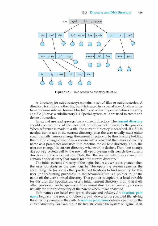
10.3 Directory and Disk Structure 439
list obj spell
find count hex reorderstat mail dist
root spell bin programs
p e mail
reorder list findprog copy prt exp
last first
hex count
all
Figure 10.10 Tree-structured directory structure.
A directory (or subdirectory) contains a set of files or subdirectories. Adirectory is simply another file, but it is treated in a special way. All directorieshave the same internal format. One bit in each directory entry defines the entryas a file (0) or as a subdirectory (1). Special system calls are used to create anddelete directories.
In normal use, each process has a current directory. The current directoryshould contain most of the files that are of current interest to the process.When reference is made to a file, the current directory is searched. If a file isneeded that is not in the current directory, then the user usually must eitherspecify a path name or change the current directory to be the directory holdingthat file. To change directories, a system call is provided that takes a directoryname as a parameter and uses it to redefine the current directory. Thus, theuser can change his current directory whenever he desires. From one changedirectory system call to the next, all open system calls search the currentdirectory for the specified file. Note that the search path may or may notcontain a special entry that stands for “the current directory.”
The initial current directory of the login shell of a user is designated whenthe user job starts or the user logs in. The operating system searches theaccounting file (or some other predefined location) to find an entry for thisuser (for accounting purposes). In the accounting file is a pointer to (or thename of) the user’s initial directory. This pointer is copied to a local variablefor this user that specifies the user’s initial current directory. From that shell,other processes can be spawned. The current directory of any subprocess isusually the current directory of the parent when it was spawned.
Path names can be of two types: absolute and relative. An absolute pathname begins at the root and follows a path down to the specified file, givingthe directory names on the path. A relative path name defines a path from thecurrent directory. For example, in the tree-structured file system of Figure 10.10,
440 Chapter 10 File-System Interface
if the current directory is root/spell/mail, then the relative path name prt/firstrefers to the same file as does the absolute path name root/spell/mail/prt/first.
Allowing a user to define her own subdirectories permits her to imposea structure on her files. This structure might result in separate directories forfiles associated with different topics (for example, a subdirectory was createdto hold the text of this book) or different forms of information (for example, thedirectory programs may contain source programs; the directory bin may storeall the binaries).
An interesting policy decision in a tree-structured directory concerns howto handle the deletion of a directory. If a directory is empty, its entry in thedirectory that contains it can simply be deleted. However, suppose the directoryto be deleted is not empty but contains several files or subdirectories. One oftwo approaches can be taken. Some systems, such as MS-DOS, will not delete adirectory unless it is empty. Thus, to delete a directory, the user must first deleteall the files in that directory. If any subdirectories exist, this procedure mustbe applied recursively to them, so that they can be deleted also. This approachcan result in a substantial amount of work. An alternative approach, such asthat taken by the UNIX rm command, is to provide an option: when a request ismade to delete a directory, all that directory’s files and subdirectories are alsoto be deleted. Either approach is fairly easy to implement; the choice is oneof policy. The latter policy is more convenient, but it is also more dangerous,because an entire directory structure can be removed with one command. Ifthat command is issued in error, a large number of files and directories willneed to be restored (assuming a backup exists).
With a tree-structured directory system, users can be allowed to access, inaddition to their files, the files of other users. For example, user B can access afile of user A by specifying its path names. User B can specify either an absoluteor a relative path name. Alternatively, user B can change her current directoryto be user A’s directory and access the file by its file names.
A path to a file in a tree-structured directory can be longer than a pathin a two-level directory. To allow users to access programs without having toremember these long paths, the Macintosh operating system automates thesearch for executable programs. One method it uses is to maintain a file, calledthe Desktop File, containing the metadata code and the name and locationof all executable programs it has seen. When a new hard disk is added to thesystem, or the network is accessed, the operating system traverses the directorystructure, searching for executable programs on the device and recording thepertinent information. This mechanism supports the double-click executionfunctionality described previously. A double-click on a file causes its creator-attribute data to be read and the Desktop File to be searched for a match. Oncethe match is found, the appropriate executable program is started with theclicked-on file as its input.
10.3.6 Acyclic-Graph Directories
Consider two programmers who are working on a joint project. The files asso-ciated with that project can be stored in a subdirectory, separating them fromother projects and files of the two programmers. But since both programmersare equally responsible for the project, both want the subdirectory to be in
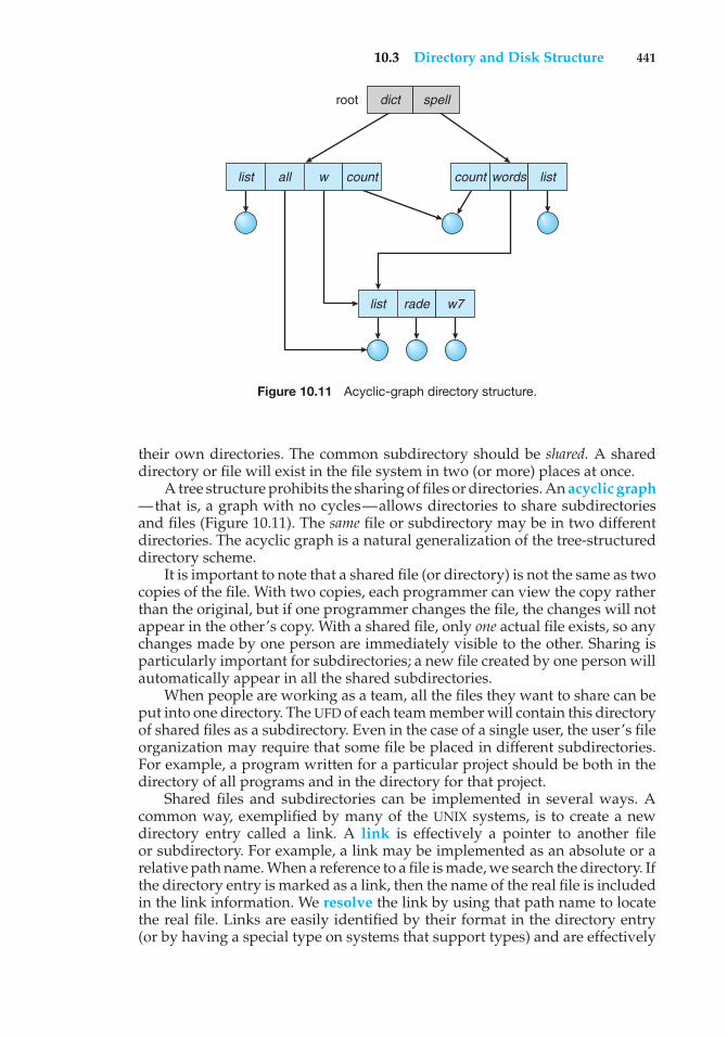
10.3 Directory and Disk Structure 441
list all w count words list
list rade w7
count
root dict spell
Figure 10.11 Acyclic-graph directory structure.
their own directories. The common subdirectory should be shared. A shareddirectory or file will exist in the file system in two (or more) places at once.
A tree structure prohibits the sharing of files or directories. An acyclic graph—that is, a graph with no cycles—allows directories to share subdirectoriesand files (Figure 10.11). The same file or subdirectory may be in two differentdirectories. The acyclic graph is a natural generalization of the tree-structureddirectory scheme.
It is important to note that a shared file (or directory) is not the same as twocopies of the file. With two copies, each programmer can view the copy ratherthan the original, but if one programmer changes the file, the changes will notappear in the other’s copy. With a shared file, only one actual file exists, so anychanges made by one person are immediately visible to the other. Sharing isparticularly important for subdirectories; a new file created by one person willautomatically appear in all the shared subdirectories.
When people are working as a team, all the files they want to share can beput into one directory. The UFD of each team member will contain this directoryof shared files as a subdirectory. Even in the case of a single user, the user’s fileorganization may require that some file be placed in different subdirectories.For example, a program written for a particular project should be both in thedirectory of all programs and in the directory for that project.
Shared files and subdirectories can be implemented in several ways. Acommon way, exemplified by many of the UNIX systems, is to create a newdirectory entry called a link. A link is effectively a pointer to another fileor subdirectory. For example, a link may be implemented as an absolute or arelative path name. When a reference to a file is made, we search the directory. Ifthe directory entry is marked as a link, then the name of the real file is includedin the link information. We resolve the link by using that path name to locatethe real file. Links are easily identified by their format in the directory entry(or by having a special type on systems that support types) and are effectively
442 Chapter 10 File-System Interface
indirect pointers. The operating system ignores these links when traversingdirectory trees to preserve the acyclic structure of the system.
Another common approach to implementing shared files is simply toduplicate all information about them in both sharing directories. Thus, bothentries are identical and equal. Consider the difference between this approachand the creation of a link. The link is clearly different from the original directoryentry; thus, the two are not equal. Duplicate directory entries, however, makethe original and the copy indistinguishable. A major problem with duplicatedirectory entries is maintaining consistency when a file is modified.
An acyclic-graph directory structure is more flexible than is a simple treestructure, but it is also more complex. Several problems must be consideredcarefully. A file may now have multiple absolute path names. Consequently,distinct file names may refer to the same file. This situation is similar to thealiasing problem for programming languages. If we are trying to traverse theentire file system—to find a file, to accumulate statistics on all files, or to copyall files to backup storage—this problem becomes significant, since we do notwant to traverse shared structures more than once.
Another problem involves deletion. When can the space allocated to ashared file be deallocated and reused? One possibility is to remove the filewhenever anyone deletes it, but this action may leave dangling pointers to thenow-nonexistent file. Worse, if the remaining file pointers contain actual diskaddresses, and the space is subsequently reused for other files, these danglingpointers may point into the middle of other files.
In a system where sharing is implemented by symbolic links, this situationis somewhat easier to handle. The deletion of a link need not affect the originalfile; only the link is removed. If the file entry itself is deleted, the space forthe file is deallocated, leaving the links dangling. We can search for these linksand remove them as well, but unless a list of the associated links is kept witheach file, this search can be expensive. Alternatively, we can leave the linksuntil an attempt is made to use them. At that time, we can determine that thefile of the name given by the link does not exist and can fail to resolve thelink name; the access is treated just as with any other illegal file name. (In thiscase, the system designer should consider carefully what to do when a file isdeleted and another file of the same name is created, before a symbolic link tothe original file is used.) In the case of UNIX, symbolic links are left when a fileis deleted, and it is up to the user to realize that the original file is gone or hasbeen replaced. Microsoft Windows (all flavors) uses the same approach.
Another approach to deletion is to preserve the file until all references toit are deleted. To implement this approach, we must have some mechanismfor determining that the last reference to the file has been deleted. We couldkeep a list of all references to a file (directory entries or symbolic links). Whena link or a copy of the directory entry is established, a new entry is added tothe file-reference list. When a link or directory entry is deleted, we remove itsentry on the list. The file is deleted when its file-reference list is empty.
The trouble with this approach is the variable and potentially large size ofthe file-reference list. However, we really do not need to keep the entire list—we need to keep only a count of the number of references. Adding a newlink or directory entry increments the reference count; deleting a link or entrydecrements the count. When the count is 0, the file can be deleted; there areno remaining references to it. The UNIX operating system uses this approach
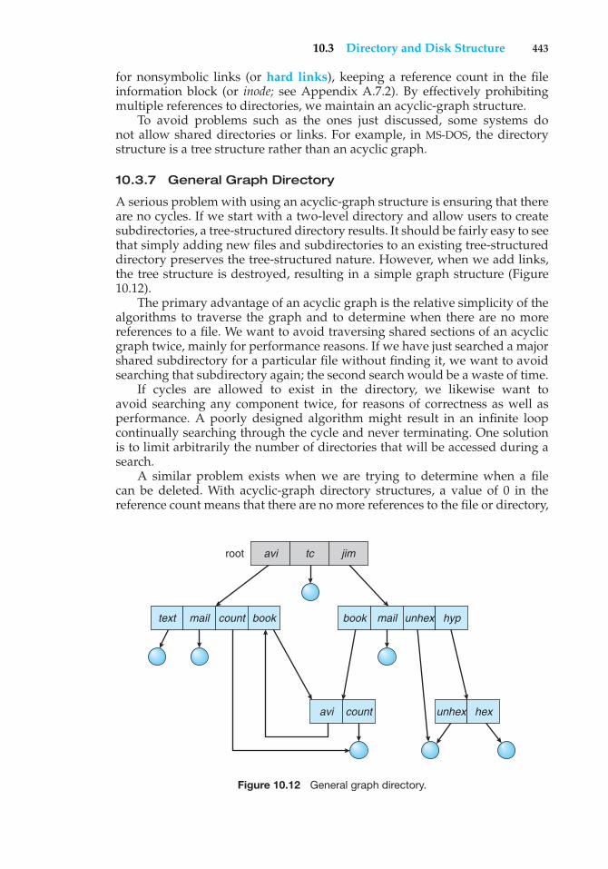
10.3 Directory and Disk Structure 443
for nonsymbolic links (or hard links), keeping a reference count in the fileinformation block (or inode; see Appendix A.7.2). By effectively prohibitingmultiple references to directories, we maintain an acyclic-graph structure.
To avoid problems such as the ones just discussed, some systems donot allow shared directories or links. For example, in MS-DOS, the directorystructure is a tree structure rather than an acyclic graph.
10.3.7 General Graph Directory
A serious problem with using an acyclic-graph structure is ensuring that thereare no cycles. If we start with a two-level directory and allow users to createsubdirectories, a tree-structured directory results. It should be fairly easy to seethat simply adding new files and subdirectories to an existing tree-structureddirectory preserves the tree-structured nature. However, when we add links,the tree structure is destroyed, resulting in a simple graph structure (Figure10.12).
The primary advantage of an acyclic graph is the relative simplicity of thealgorithms to traverse the graph and to determine when there are no morereferences to a file. We want to avoid traversing shared sections of an acyclicgraph twice, mainly for performance reasons. If we have just searched a majorshared subdirectory for a particular file without finding it, we want to avoidsearching that subdirectory again; the second search would be a waste of time.
If cycles are allowed to exist in the directory, we likewise want toavoid searching any component twice, for reasons of correctness as well asperformance. A poorly designed algorithm might result in an infinite loopcontinually searching through the cycle and never terminating. One solutionis to limit arbitrarily the number of directories that will be accessed during asearch.
A similar problem exists when we are trying to determine when a filecan be deleted. With acyclic-graph directory structures, a value of 0 in thereference count means that there are no more references to the file or directory,
text mail
avi count unhex hex
count book book mail unhex hyp
root avi tc jim
Figure 10.12 General graph directory.
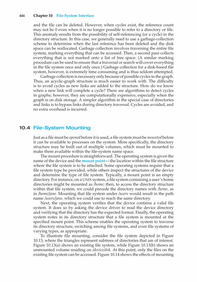
444 Chapter 10 File-System Interface
and the file can be deleted. However, when cycles exist, the reference countmay not be 0 even when it is no longer possible to refer to a directory or file.This anomaly results from the possibility of self-referencing (or a cycle) in thedirectory structure. In this case, we generally need to use a garbage-collectionscheme to determine when the last reference has been deleted and the diskspace can be reallocated. Garbage collection involves traversing the entire filesystem, marking everything that can be accessed. Then, a second pass collectseverything that is not marked onto a list of free space. (A similar markingprocedure can be used to ensure that a traversal or search will cover everythingin the file system once and only once.) Garbage collection for a disk-based filesystem, however, is extremely time consuming and is thus seldom attempted.
Garbage collection is necessary only because of possible cycles in the graph.Thus, an acyclic-graph structure is much easier to work with. The difficultyis to avoid cycles as new links are added to the structure. How do we knowwhen a new link will complete a cycle? There are algorithms to detect cyclesin graphs; however, they are computationally expensive, especially when thegraph is on disk storage. A simpler algorithm in the special case of directoriesand links is to bypass links during directory traversal. Cycles are avoided, andno extra overhead is incurred.
10.4 File-System Mounting
Just as a file must be opened before it is used, a file system must be mounted beforeit can be available to processes on the system. More specifically, the directorystructure may be built out of multiple volumes, which must be mounted tomake them available within the file-system name space.
The mount procedure is straightforward. The operating system is given thename of the device and the mount point—the location within the file structurewhere the file system is to be attached. Some operating systems require that afile system type be provided, while others inspect the structures of the deviceand determine the type of file system. Typically, a mount point is an emptydirectory. For instance, on a UNIX system, a file system containing a user’s homedirectories might be mounted as /home; then, to access the directory structurewithin that file system, we could precede the directory names with /home, asin /home/jane. Mounting that file system under /users would result in the pathname /users/jane, which we could use to reach the same directory.
Next, the operating system verifies that the device contains a valid filesystem. It does so by asking the device driver to read the device directoryand verifying that the directory has the expected format. Finally, the operatingsystem notes in its directory structure that a file system is mounted at thespecified mount point. This scheme enables the operating system to traverseits directory structure, switching among file systems, and even file systems ofvarying types, as appropriate.
To illustrate file mounting, consider the file system depicted in Figure10.13, where the triangles represent subtrees of directories that are of interest.Figure 10.13(a) shows an existing file system, while Figure 10.13(b) shows anunmounted volume residing on /device/dsk. At this point, only the files on theexisting file system can be accessed. Figure 10.14 shows the effects of mounting
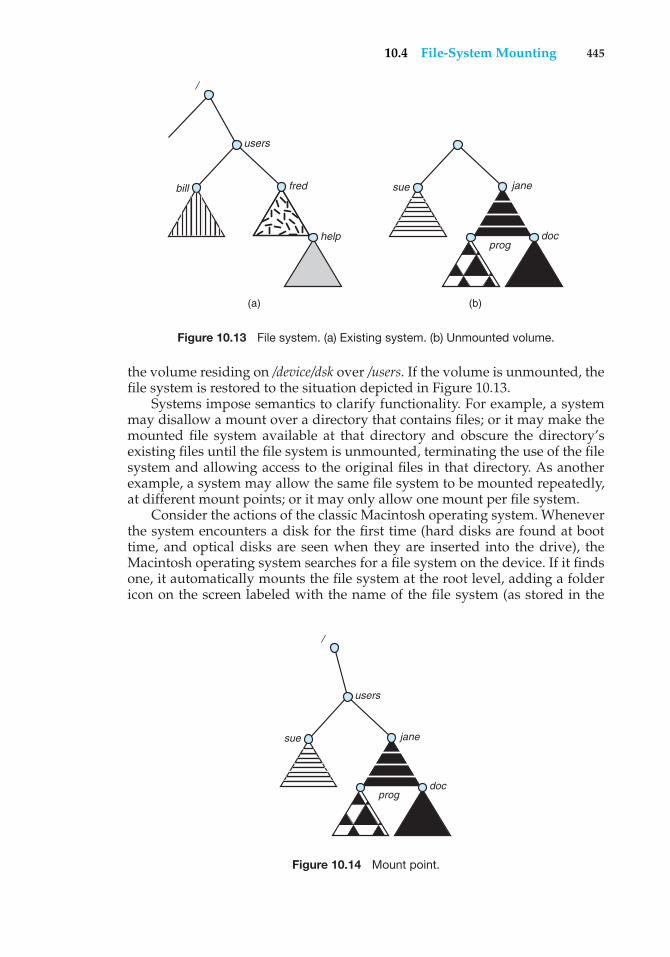
10.4 File-System Mounting 445
users
/
bill fred
help
sue jane
progdoc
(a) (b)
Figure 10.13 File system. (a) Existing system. (b) Unmounted volume.
the volume residing on /device/dsk over /users. If the volume is unmounted, thefile system is restored to the situation depicted in Figure 10.13.
Systems impose semantics to clarify functionality. For example, a systemmay disallow a mount over a directory that contains files; or it may make themounted file system available at that directory and obscure the directory’sexisting files until the file system is unmounted, terminating the use of the filesystem and allowing access to the original files in that directory. As anotherexample, a system may allow the same file system to be mounted repeatedly,at different mount points; or it may only allow one mount per file system.
Consider the actions of the classic Macintosh operating system. Wheneverthe system encounters a disk for the first time (hard disks are found at boottime, and optical disks are seen when they are inserted into the drive), theMacintosh operating system searches for a file system on the device. If it findsone, it automatically mounts the file system at the root level, adding a foldericon on the screen labeled with the name of the file system (as stored in the
/
users
sue jane
progdoc
Figure 10.14 Mount point.
446 Chapter 10 File-System Interface
device directory). The user is then able to click on the icon and thus display thenewly mounted file system. Mac OS X behaves much like BSD UNIX, on which itis based. All file systems are mounted under the /Volumes directory. The MacOS X GUI hides this fact and shows the file systems as if they were all mountedat the root level.
The Microsoft Windows family of operating systems (95, 98, NT, small2000, 2003, XP, Vista) maintains an extended two-level directory structure,with devices and volumes assigned drive letters. Volumes have a general graphdirectory structure associated with the drive letter. The path to a specific filetakes the form of drive-letter:\path\to\file. The more recent versions of Windowsallow a file system to be mounted anywhere in the directory tree, just asUNIX does. Windows operating systems automatically discover all devices andmount all located file systems at boot time. In some systems, like UNIX, themount commands are explicit. A system configuration file contains a list ofdevices and mount points for automatic mounting at boot time, but othermounts may be executed manually.
Issues concerning file system mounting are further discussed in Section11.2.2 and in Appendix A.7.5.
10.5 File Sharing
In the previous sections, we explored the motivation for file sharing and some ofthe difficulties involved in allowing users to share files. Such file sharing is verydesirable for users who want to collaborate and to reduce the effort requiredto achieve a computing goal. Therefore, user-oriented operating systems mustaccommodate the need to share files in spite of the inherent difficulties.
In this section, we examine more aspects of file sharing. We begin bydiscussing general issues that arise when multiple users share files. Oncemultiple users are allowed to share files, the challenge is to extend sharing tomultiple file systems, including remote file systems; we discuss that challengeas well. Finally, we consider what to do about conflicting actions occurring onshared files. For instance, if multiple users are writing to a file, should all thewrites be allowed to occur, or should the operating system protect the users’actions from one another?
10.5.1 Multiple Users
When an operating system accommodates multiple users, the issues of filesharing, file naming, and file protection become preeminent. Given a directorystructure that allows files to be shared by users, the system must mediate thefile sharing. The system can either allow a user to access the files of other usersby default or require that a user specifically grant access to the files. These arethe issues of access control and protection, which are covered in Section 10.6.
To implement sharing and protection, the system must maintain more fileand directory attributes than are needed on a single-user system. Althoughmany approaches have been taken to meet this requirement, most systemshave evolved to use the concepts of file (or directory) owner (or user) and group.The owner is the user who can change attributes and grant access and who hasthe most control over the file. The group attribute defines a subset of users who
10.5 File Sharing 447
can share access to the file. For example, the owner of a file on a UNIX systemcan issue all operations on a file, while members of the file’s group can executeone subset of those operations, and all other users can execute another subsetof operations. Exactly which operations can be executed by group membersand other users is definable by the file’s owner. More details on permissionattributes are included in the next section.
The owner and group IDs of a given file (or directory) are stored with theother file attributes. When a user requests an operation on a file, the user ID canbe compared with the owner attribute to determine if the requesting user is theowner of the file. Likewise, the group IDs can be compared. The result indicateswhich permissions are applicable. The system then applies those permissionsto the requested operation and allows or denies it.
Many systems have multiple local file systems, including volumes of asingle disk or multiple volumes on multiple attached disks. In these cases,the ID checking and permission matching are straightforward, once the filesystems are mounted.
10.5.2 Remote File Systems
With the advent of networks (Chapter 16), communication among remotecomputers became possible. Networking allows the sharing of resources spreadacross a campus or even around the world. One obvious resource to share isdata in the form of files.
Through the evolution of network and file technology, remote file-sharingmethods have changed. The first implemented method involves manuallytransferring files between machines via programs like ftp. The second majormethod uses a distributed file system (DFS) in which remote directories arevisible from a local machine. In some ways, the third method, the World WideWeb, is a reversion to the first. A browser is needed to gain access to theremote files, and separate operations (essentially a wrapper for ftp) are usedto transfer files.
ftp is used for both anonymous and authenticated access. Anonymousaccess allows a user to transfer files without having an account on the remotesystem. The World Wide Web uses anonymous file exchange almost exclusively.DFS involves a much tighter integration between the machine that is accessingthe remote files and the machine providing the files. This integration addscomplexity, which we describe in this section.
10.5.2.1 The Client–Server Model
Remote file systems allow a computer to mount one or more file systemsfrom one or more remote machines. In this case, the machine containing thefiles is the server, and the machine seeking access to the files is the client. Theclient–server relationship is common with networked machines. Generally,the server declares that a resource is available to clients and specifies exactlywhich resource (in this case, which files) and exactly which clients. A servercan serve multiple clients, and a client can use multiple servers, depending onthe implementation details of a given client–server facility.
The server usually specifies the available files on a volume or directorylevel. Client identification is more difficult. A client can be specified by anetwork name or other identifier, such as an IP address, but these can be spoofed,
448 Chapter 10 File-System Interface
or imitated. As a result of spoofing, an unauthorized client could be allowedaccess to the server. More secure solutions include secure authentication of theclient via encrypted keys. Unfortunately, with security come many challenges,including ensuring compatibility of the client and server (they must use thesame encryption algorithms) and security of key exchanges (intercepted keyscould again allow unauthorized access). Because of the difficulty of solvingthese problems, unsecure authentication methods are most commonly used.
In the case of UNIX and its network file system (NFS), authentication takesplace via the client networking information, by default. In this scheme, theuser’s IDs on the client and server must match. If they do not, the server willbe unable to determine access rights to files. Consider the example of a userwho has an ID of 1000 on the client and 2000 on the server. A request fromthe client to the server for a specific file will not be handled appropriately, asthe server will determine if user 1000 has access to the file rather than basingthe determination on the real user ID of 2000. Access is thus granted or deniedbased on incorrect authentication information. The server must trust the clientto present the correct user ID. Note that the NFS protocols allow many-to-manyrelationships. That is, many servers can provide files to many clients. In fact,a given machine can be both a server to some NFS clients and a client of otherNFS servers.
Once the remote file system is mounted, file operation requests are senton behalf of the user across the network to the server via the DFS protocol.Typically, a file-open request is sent along with the ID of the requesting user.The server then applies the standard access checks to determine if the user hascredentials to access the file in the mode requested. The request is either allowedor denied. If it is allowed, a file handle is returned to the client application,and the application then can perform read, write, and other operations on thefile. The client closes the file when access is completed. The operating systemmay apply semantics similar to those for a local file-system mount or may usedifferent semantics.
10.5.2.2 Distributed Information Systems
To make client–server systems easier to manage, distributed informationsystems, also known as distributed naming services, provide unified accessto the information needed for remote computing. The domain name sys-tem (DNS) provides host-name-to-network-address translations for the entireInternet (including the World Wide Web). Before DNS became widespread,files containing the same information were sent via e-mail or ftp between allnetworked hosts. This methodology was not scalable. DNS is further discussedin Section 16.5.1.
Other distributed information systems provide user name/password/userID/group ID space for a distributed facility. UNIX systems have employed a widevariety of distributed-information methods. Sun Microsystems introducedyellow pages (since renamed network information service, or NIS), and most ofthe industry adopted its use. It centralizes storage of user names, host names,printer information, and the like. Unfortunately, it uses unsecure authenticationmethods, including sending user passwords unencrypted (in clear text) andidentifying hosts by IP address. Sun’s NIS+ is a much more secure replacementfor NIS but is also much more complicated and has not been widely adopted.
10.5 File Sharing 449
In the case of Microsoft’s common Internet file system (CIFS), networkinformation is used in conjunction with user authentication (user name andpassword) to create a network login that the server uses to decide whetherto allow or deny access to a requested file system. For this authenticationto be valid, the user names must match from machine to machine (as withNFS). Microsoft uses two distributed naming structures to provide a singlename space for users. The older naming technology is domains. The newertechnology, available in Windows XP and Windows 2000, is active directory.Once established, the distributed naming facility is used by all clients andservers to authenticate users.
The industry is moving toward use of the lightweight directory-accessprotocol (LDAP) as a secure distributed naming mechanism. In fact, activedirectory is based on LDAP. Sun Microsystems includes LDAP with theoperating system and allows it to be employed for user authentication aswell as system-wide retrieval of information, such as availability of printers.Conceivably, one distributed LDAP directory could be used by an organizationto store all user and resource information for all the organization’s computers.The result would be secure single sign-on for users, who would entertheir authentication information once for access to all computers within theorganization. It would also ease system-administration efforts by combining,in one location, information that is currently scattered in various files on eachsystem or in different distributed information services.
10.5.2.3 Failure Modes
Local file systems can fail for a variety of reasons, including failure of thedisk containing the file system, corruption of the directory structure or otherdisk-management information (collectively called metadata), disk-controllerfailure, cable failure, and host-adapter failure. User or system-administratorfailure can also cause files to be lost or entire directories or volumes to bedeleted. Many of these failures will cause a host to crash and an error conditionto be displayed, and human intervention will be required to repair the damage.
Remote file systems have even more failure modes. Because of thecomplexity of network systems and the required interactions between remotemachines, many more problems can interfere with the proper operation ofremote file systems. In the case of networks, the network can be interruptedbetween two hosts. Such interruptions can result from hardware failure, poorhardware configuration, or networking implementation issues. Although somenetworks have built-in resiliency, including multiple paths between hosts,many do not. Any single failure can thus interrupt the flow of DFS commands.
Consider a client in the midst of using a remote file system. It has files openfrom the remote host; among other activities, it may be performing directorylookups to open files, reading or writing data to files, and closing files. Nowconsider a partitioning of the network, a crash of the server, or even a scheduledshutdown of the server. Suddenly, the remote file system is no longer reachable.This scenario is rather common, so it would not be appropriate for the clientsystem to act as it would if a local file system were lost. Rather, the system caneither terminate all operations to the lost server or delay operations until theserver is again reachable. These failure semantics are defined and implementedas part of the remote-file-system protocol. Termination of all operations can
450 Chapter 10 File-System Interface
result in users’ losing data—and patience. Thus, most DFS protocols eitherenforce or allow delaying of file-system operations to remote hosts, with thehope that the remote host will become available again.
To implement this kind of recovery from failure, some kind of stateinformation may be maintained on both the client and the server. If both serverand client maintain knowledge of their current activities and open files, thenthey can seamlessly recover from a failure. In the situation where the servercrashes but must recognize that it has remotely mounted exported file systemsand opened files, NFS takes a simple approach, implementing a stateless DFS.In essence, it assumes that a client request for a file read or write would nothave occurred unless the file system had been remotely mounted and the filehad been previously open. The NFS protocol carries all the information neededto locate the appropriate file and perform the requested operation. Similarly,it does not track which clients have the exported volumes mounted, againassuming that if a request comes in, it must be legitimate. While this statelessapproach makes NFS resilient and rather easy to implement, it also makes itunsecure. For example, forged read or write requests could be allowed by anNFS server even though the requisite mount request and permission checkhad not taken place. These issues are addressed in the industry standard NFSVersion 4, in which NFS is made stateful to improve its security, performance,and functionality.
10.5.3 Consistency Semantics
Consistency semantics represent an important criterion for evaluating anyfile system that supports file sharing. These semantics specify how multipleusers of a system are to access a shared file simultaneously. In particular, theyspecify when modifications of data by one user will be observable by otherusers. These semantics are typically implemented as code with the file system.
Consistency semantics are directly related to the process-synchronizationalgorithms of Chapter 6. However, the complex algorithms of that chapter tendnot to be implemented in the case of file I/O because of the great latencies andslow transfer rates of disks and networks. For example, performing an atomictransaction to a remote disk could involve several network communications,several disk reads and writes, or both. Systems that attempt such a full set offunctionalities tend to perform poorly. A successful implementation of complexsharing semantics can be found in the Andrew file system.
For the following discussion, we assume that a series of file accesses (thatis, reads and writes) attempted by a user to the same file is always enclosedbetween the open() and close() operations. The series of accesses betweenthe open() and close() operations makes up a file session. To illustrate theconcept, we sketch several prominent examples of consistency semantics.
10.5.3.1 UNIX Semantics
The UNIX file system (Chapter 17) uses the following consistency semantics:
• Writes to an open file by a user are visible immediately to other users whohave this file open.
• One mode of sharing allows users to share the pointer of current locationinto the file. Thus, the advancing of the pointer by one user affects all
10.6 Protection 451
sharing users. Here, a file has a single image that interleaves all accesses,regardless of their origin.
In the UNIX semantics, a file is associated with a single physical image thatis accessed as an exclusive resource. Contention for this single image causesdelays in user processes.
10.5.3.2 Session Semantics
The Andrew file system (AFS) (Chapter 17) uses the following consistencysemantics:
• Writes to an open file by a user are not visible immediately to other usersthat have the same file open.
• Once a file is closed, the changes made to it are visible only in sessionsstarting later. Already open instances of the file do not reflect these changes.
According to these semantics, a file may be associated temporarily with several(possibly different) images at the same time. Consequently, multiple users areallowed to perform both read and write accesses concurrently on their imagesof the file, without delay. Almost no constraints are enforced on schedulingaccesses.
10.5.3.3 Immutable-Shared-Files Semantics
A unique approach is that of immutable shared files. Once a file is declaredas shared by its creator, it cannot be modified. An immutable file has two keyproperties: its name may not be reused, and its contents may not be altered.Thus, the name of an immutable file signifies that the contents of the file arefixed. The implementation of these semantics in a distributed system (Chapter17) is simple, because the sharing is disciplined (read-only).
10.6 Protection
When information is stored in a computer system, we want to keep it safefrom physical damage (the issue of reliability) and improper access (the issueof protection).
Reliability is generally provided by duplicate copies of files. Many comput-ers have systems programs that automatically (or through computer-operatorintervention) copy disk files to tape at regular intervals (once per day or weekor month) to maintain a copy should a file system be accidentally destroyed.File systems can be damaged by hardware problems (such as errors in readingor writing), power surges or failures, head crashes, dirt, temperature extremes,and vandalism. Files may be deleted accidentally. Bugs in the file-system soft-ware can also cause file contents to be lost. Reliability is covered in more detailin Chapter 12.
Protection can be provided in many ways. For a small single-user system,we might provide protection by physically removing the floppy disks andlocking them in a desk drawer or file cabinet. In a multiuser system, however,other mechanisms are needed.
452 Chapter 10 File-System Interface
10.6.1 Types of Access
The need to protect files is a direct result of the ability to access files. Systemsthat do not permit access to the files of other users do not need protection. Thus,we could provide complete protection by prohibiting access. Alternatively, wecould provide free access with no protection. Both approaches are too extremefor general use. What is needed is controlled access.
Protection mechanisms provide controlled access by limiting the types offile access that can be made. Access is permitted or denied depending onseveral factors, one of which is the type of access requested. Several differenttypes of operations may be controlled:
• Read. Read from the file.
• Write. Write or rewrite the file.
• Execute. Load the file into memory and execute it.
• Append. Write new information at the end of the file.
• Delete. Delete the file and free its space for possible reuse.
• List. List the name and attributes of the file.
Other operations, such as renaming, copying, and editing the file, may alsobe controlled. For many systems, however, these higher-level functions maybe implemented by a system program that makes lower-level system calls.Protection is provided at only the lower level. For instance, copying a file maybe implemented simply by a sequence of read requests. In this case, a user withread access can also cause the file to be copied, printed, and so on.
Many protection mechanisms have been proposed. Each has advantagesand disadvantages and must be appropriate for its intended application. Asmall computer system that is used by only a few members of a research group,for example, may not need the same types of protection as a large corporatecomputer that is used for research, finance, and personnel operations. Wediscuss some approaches to protection in the following sections and present amore complete treatment in Chapter 14.
10.6.2 Access Control
The most common approach to the protection problem is to make accessdependent on the identity of the user. Different users may need different typesof access to a file or directory. The most general scheme to implement identity-dependent access is to associate with each file and directory an access-controllist (ACL) specifying user names and the types of access allowed for each user.When a user requests access to a particular file, the operating system checksthe access list associated with that file. If that user is listed for the requestedaccess, the access is allowed. Otherwise, a protection violation occurs, and theuser job is denied access to the file.
This approach has the advantage of enabling complex access methodolo-gies. The main problem with access lists is their length. If we want to alloweveryone to read a file, we must list all users with read access. This techniquehas two undesirable consequences:
10.6 Protection 453
• Constructing such a list may be a tedious and unrewarding task, especiallyif we do not know in advance the list of users in the system.
• The directory entry, previously of fixed size, now must be of variable size,resulting in more complicated space management.
These problems can be resolved by use of a condensed version of the accesslist.
To condense the length of the access-control list, many systems recognizethree classifications of users in connection with each file:
• Owner. The user who created the file is the owner.
• Group. A set of users who are sharing the file and need similar access is agroup, or work group.
• Universe. All other users in the system constitute the universe.
The most common recent approach is to combine access-control lists withthe more general (and easier to implement) owner, group, and universe access-control scheme just described. For example, Solaris 2.6 and beyond use thethree categories of access by default but allow access-control lists to be addedto specific files and directories when more fine-grained access control is desired.
To illustrate, consider a person, Sara, who is writing a new book. She hashired three graduate students (Jim, Dawn, and Jill) to help with the project.The text of the book is kept in a file named book. The protection associated withthis file is as follows:
• Sara should be able to invoke all operations on the file.
• Jim, Dawn, and Jill should be able only to read and write the file; theyshould not be allowed to delete the file.
• All other users should be able to read, but not write, the file. (Sara isinterested in letting as many people as possible read the text so that shecan obtain feedback.)
To achieve such protection, we must create a new group—say, text—with members Jim, Dawn, and Jill. The name of the group, text, must thenbe associated with the file book, and the access rights must be set in accordancewith the policy we have outlined.
Now consider a visitor to whom Sara would like to grant temporary accessto Chapter 1. The visitor cannot be added to the text group because that wouldgive him access to all chapters. Because a file can only be in one group, Saracannot add another group to Chapter 1. With the addition of access-control-listfunctionality, though, the visitor can be added to the access control list ofChapter 1.
For this scheme to work properly, permissions and access lists must becontrolled tightly. This control can be accomplished in several ways. Forexample, in the UNIX system, groups can be created and modified only bythe manager of the facility (or by any superuser). Thus, control is achievedthrough human interaction. In the VMS system, the owner of the file can create
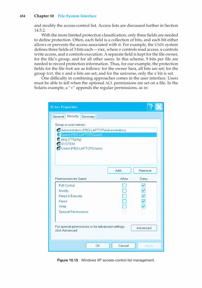
454 Chapter 10 File-System Interface
and modify the access-control list. Access lists are discussed further in Section14.5.2.
With the more limited protection classification, only three fields are neededto define protection. Often, each field is a collection of bits, and each bit eitherallows or prevents the access associated with it. For example, the UNIX systemdefines three fields of 3 bits each—rwx, where r controls read access, w controlswrite access, and x controls execution. A separate field is kept for the file owner,for the file’s group, and for all other users. In this scheme, 9 bits per file areneeded to record protection information. Thus, for our example, the protectionfields for the file book are as follows: for the owner Sara, all bits are set; for thegroup text, the r and w bits are set; and for the universe, only the r bit is set.
One difficulty in combining approaches comes in the user interface. Usersmust be able to tell when the optional ACL permissions are set on a file. In theSolaris example, a “+” appends the regular permissions, as in:
Figure 10.15 Windows XP access-control list management.
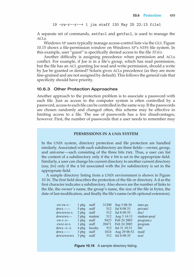
10.6 Protection 455
19 -rw-r--r--+ 1 jim staff 130 May 25 22:13 file1
A separate set of commands, setfacl and getfacl, is used to manage theACLs.
Windows XP users typically manage access-control lists via the GUI. Figure10.15 shows a file-permission window on Windows XP’s NTFS file system. Inthis example, user “guest” is specifically denied access to the file 10.tex.
Another difficulty is assigning precedence when permission and ACLsconflict. For example, if Joe is in a file’s group, which has read permission,but the file has an ACL granting Joe read and write permission, should a writeby Joe be granted or denied? Solaris gives ACLs precedence (as they are morefine-grained and are not assigned by default). This follows the general rule thatspecificity should have priority.
10.6.3 Other Protection Approaches
Another approach to the protection problem is to associate a password witheach file. Just as access to the computer system is often controlled by apassword, access to each file can be controlled in the same way. If the passwordsare chosen randomly and changed often, this scheme may be effective inlimiting access to a file. The use of passwords has a few disadvantages,however. First, the number of passwords that a user needs to remember may
PERMISSIONS IN A UNIX SYSTEM
In the UNIX system, directory protection and file protection are handledsimilarly. Associated with each subdirectory are three fields—owner, group,and universe—each consisting of the three bits rwx. Thus, a user can listthe content of a subdirectory only if the r bit is set in the appropriate field.Similarly, a user can change his current directory to another current directory(say, foo) only if the x bit associated with the foo subdirectory is set in theappropriate field.
A sample directory listing from a UNIX environment is shown in Figure10.16. The first field describes the protection of the file or directory. A d as thefirst character indicates a subdirectory. Also shown are the number of links tothe file, the owner’s name, the group’s name, the size of the file in bytes, thedate of last modification, and finally the file’s name (with optional extension).
-rw-rw-r--drwx------drwxrwxr-xdrwxrwx----rw-r--r---rwxr-xr-xdrwx--x--xdrwx------drwxrwxrwx
1 pbg5 pbg2 pbg 2 pbg 1 pbg 1 pbg 4 pbg 3 pbg 3 pbg
staffstaffstaffstudentstaffstafffacultystaffstaff
intro.psprivate/doc/student-proj/program.cprogramlib/mail/test/
Sep 3 08:30Jul 8 09.33Jul 8 09:35Aug 3 14:13Feb 24 2003Feb 24 2003Jul 31 10:31Aug 29 06:52Jul 8 09:35
31200512512512
942320471
512 1024 512
Figure 10.16 A sample directory listing.
456 Chapter 10 File-System Interface
become large, making the scheme impractical. Second, if only one password isused for all the files, then once it is discovered, all files are accessible; protectionis on an all-or-none basis. Some systems (for example, TOPS-20) allow a userto associate a password with a subdirectory, rather than with an individualfile, to deal with this problem. The IBMVM/CMS operating system allows threepasswords for a minidisk—one each for read, write, and multiwrite access.
Some single-user operating systems—such as MS-DOS and versions of theMacintosh operating system prior to Mac OS X—provide little in terms of fileprotection. In scenarios where these older systems are now being placed onnetworks requiring file sharing and communication, protection mechanismsmust be retrofitted into them. Designing a feature for a new operating systemis almost always easier than adding a feature to an existing one. Such updatesare usually less effective and are not seamless.
In a multilevel directory structure, we need to protect not only individualfiles but also collections of files in subdirectories; that is, we need to providea mechanism for directory protection. The directory operations that must beprotected are somewhat different from the file operations. We want to controlthe creation and deletion of files in a directory. In addition, we probably wantto control whether a user can determine the existence of a file in a directory.Sometimes, knowledge of the existence and name of a file is significant in itself.Thus, listing the contents of a directory must be a protected operation. Similarly,if a path name refers to a file in a directory, the user must be allowed accessto both the directory and the file. In systems where files may have numerouspath names (such as acyclic or general graphs), a given user may have differentaccess rights to a particular file, depending on the path name used.
10.7 Summary
A file is an abstract data type defined and implemented by the operatingsystem. It is a sequence of logical records. A logical record may be a byte, a line(of fixed or variable length), or a more complex data item. The operating systemmay specifically support various record types or may leave that support to theapplication program.
The major task for the operating system is to map the logical file conceptonto physical storage devices such as magnetic tape or disk. Since the physicalrecord size of the device may not be the same as the logical record size, it maybe necessary to order logical records into physical records. Again, this task maybe supported by the operating system or left for the application program.
Each device in a file system keeps a volume table of contents or a devicedirectory listing the location of the files on the device. In addition, it is usefulto create directories to allow files to be organized. A single-level directoryin a multiuser system causes naming problems, since each file must have aunique name. A two-level directory solves this problem by creating a separatedirectory for each users files. The directory lists the files by name and includesthe file’s location on the disk, length, type, owner, time of creation, time of lastuse, and so on.
The natural generalization of a two-level directory is a tree-structureddirectory. A tree-structured directory allows a user to create subdirectoriesto organize files. Acyclic-graph directory structures enable users to share
Practice Exercises 457
subdirectories and files but complicate searching and deletion. A general graphstructure allows complete flexibility in the sharing of files and directories butsometimes requires garbage collection to recover unused disk space.
Disks are segmented into one or more volumes, each containing a filesystem or left “raw.” File systems may be mounted into the system’s namingstructures to make them available. The naming scheme varies by operatingsystem. Once mounted, the files within the volume are available for use. Filesystems may be unmounted to disable access or for maintenance.
File sharing depends on the semantics provided by the system. Files mayhave multiple readers, multiple writers, or limits on sharing. Distributed filesystems allow client hosts to mount volumes or directories from servers, as longas they can access each other across a network. Remote file systems presentchallenges in reliability, performance, and security. Distributed informationsystems maintain user, host, and access information so that clients and serverscan share state information to manage use and access.
Since files are the main information-storage mechanism in most computersystems, file protection is needed. Access to files can be controlled separatelyfor each type of access—read, write, execute, append, delete, list directory,and so on. File protection can be provided by access lists, passwords, or othertechniques.
Practice Exercises
10.1 Some systems automatically delete all user files when a user logs off ora job terminates, unless the user explicitly requests that they be kept;other systems keep all files unless the user explicitly deletes them.Discuss the relative merits of each approach.
10.2 Why do some systems keep track of the type of a file, while others leaveit to the user and others simply do not implement multiple file types?Which system is “better?”
10.3 Similarly, some systems support many types of structures for a file’sdata, while others simply support a stream of bytes. What are theadvantages and disadvantages of each approach?
10.4 Could you simulate a multilevel directory structure with a single-leveldirectory structure in which arbitrarily long names can be used? If youranswer is yes, explain how you can do so, and contrast this scheme withthe multilevel directory scheme. If your answer is no, explain whatprevents your simulation’s success. How would your answer changeif file names were limited to seven characters?
10.5 Explain the purpose of the open() and close() operations.
10.6 Give an example of an application in which data in a file should beaccessed in the following order:
a. Sequentially
b. Randomly
458 Chapter 10 File-System Interface
10.7 In some systems, a subdirectory can be read and written by anauthorized user, just as ordinary files can be.
a. Describe the protection problems that could arise.
b. Suggest a scheme for dealing with each of these protectionproblems.
10.8 Consider a system that supports 5,000 users. Suppose that you want toallow 4,990 of these users to be able to access one file.
a. How would you specify this protection scheme in UNIX?
b. Can you suggest another protection scheme that can be used moreeffectively for this purpose than the scheme provided by UNIX?
10.9 Researchers have suggested that, instead of having an access listassociated with each file (specifying which users can access the file,and how), we should have a user control list associated with each user(specifying which files a user can access, and how). Discuss the relativemerits of these two schemes.
Exercises
10.10 Consider a file system in which a file can be deleted and its disk spacereclaimed while links to that file still exist. What problems may occur ifa new file is created in the same storage area or with the same absolutepath name? How can these problems be avoided?
10.11 The open-file table is used to maintain information about files that arecurrently open. Should the operating system maintain a separate tablefor each user or just maintain one table that contains references to filesthat are currently being accessed by all users? If the same file is beingaccessed by two different programs or users, should there be separateentries in the open-file table?
10.12 What are the advantages and disadvantages of providing mandatorylocks instead of advisory locks whose usage is left to users’ discretion?
10.13 What are the advantages and disadvantages of recording the nameof the creating program with the file’s attributes (as is done in theMacintosh operating system)?
10.14 Some systems automatically open a file when it is referenced for the firsttime and close the file when the job terminates. Discuss the advantagesand disadvantages of this scheme compared with the more traditionalone, where the user has to open and close the file explicitly.
10.15 If the operating system knew that a certain application was goingto access file data in a sequential manner, how could it exploit thisinformation to improve performance?
10.16 Give an example of an application that could benefit from operating-system support for random access to indexed files.
Bibliographical Notes 459
10.17 Discuss the advantages and disadvantages of supporting links to filesthat cross mount points (that is, the file link refers to a file that is storedin a different volume).
10.18 Some systems provide file sharing by maintaining a single copy of afile; other systems maintain several copies, one for each of the userssharing the file. Discuss the relative merits of each approach.
10.19 Discuss the advantages and disadvantages of associating with remotefile systems (stored on file servers) a set of failure semantics differentfrom that associated with local file systems.
10.20 What are the implications of supporting UNIX consistency semanticsfor shared access for files stored on remote file systems?
Wiley Plus
Visit Wiley Plus for
• Source code
• Solutions to practice exercises
• Additional programming problems and exercises
• Labs using an operating system simulator
Bibliographical Notes
General discussions concerning file systems are offered by Grosshans [1986].Golden and Pechura [1986] describe the structure of microcomputer filesystems. Database systems and their file structures are described in full inSilberschatz et al. [2001].
A multilevel directory structure was first implemented on the MULTICSsystem (Organick [1972]). Most operating systems now implement multileveldirectory structures. These include Linux (Bovet and Cesati [2002]), Mac OSX (http://www.apple.com/macosx/), Solaris (McDougall and Mauro [2007]),and all versions of Windows (Russinovich and Solomon [2005]).
The network file system (NFS), designed by Sun Microsystems, allowsdirectory structures to be spread across networked computer systems. NFSis fully described in Chapter 17. NFS Version 4 is described in RFC3505(http://www.ietf.org/rfc/rfc3530.txt). General discussion of Solaris file sys-tems is found in the Sun System Administration Guide: Devices and File Systems(http://docs.sun.com/app/docs/doc/817-5093).
DNS was first proposed by Su [1982] and has gone through several revisionssince, with Mockapetris [1987] adding several major features. Eastlake [1999]has proposed security extensions to let DNS hold security keys.
LDAP, also known as X.509, is a derivative subset of the X.500 distributeddirectory protocol. It was defined by Yeong et al. [1995] and has beenimplemented on many operating systems.
460 Chapter 10 File-System Interface
Interesting research is ongoing in the area of file-system interfaces—inparticular, on issues relating to file naming and attributes. For example, thePlan 9 operating system from Bell Laboratories (Lucent Technology) makes allobjects look like file systems. Thus, to display a list of processes on a system,a user simply lists the contents of the /proc directory. Similarly, to display thetime of day, a user need only type the file /dev/time.
11C H A P T E R
File -SystemImplementation
As we saw in Chapter 10, the file system provides the mechanism for on-linestorage and access to file contents, including data and programs. The file systemresides permanently on secondary storage, which is designed to hold a largeamount of data permanently. This chapter is primarily concerned with issuessurrounding file storage and access on the most common secondary-storagemedium, the disk. We explore ways to structure file use, to allocate disk space,to recover freed space, to track the locations of data, and to interface otherparts of the operating system to secondary storage. Performance issues areconsidered throughout the chapter.
CHAPTER OBJECTIVES
• To describe the details of implementing local file systems and directorystructures.
• To describe the implementation of remote file systems.
• To discuss block allocation and free-block algorithms and trade-offs.
11.1 File-System Structure
Disks provide the bulk of secondary storage on which a file system ismaintained. They have two characteristics that make them a convenientmedium for storing multiple files:
1. A disk can be rewritten in place; it is possible to read a block from thedisk, modify the block, and write it back into the same place.
2. A disk can access directly any block of information it contains. Thus, it issimple to access any file either sequentially or randomly, and switchingfrom one file to another requires only moving the read–write heads andwaiting for the disk to rotate.
We discuss disk structure in great detail in Chapter 12.
461
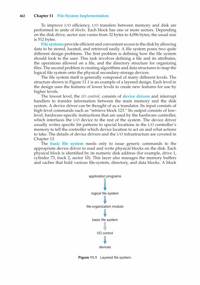
462 Chapter 11 File-System Implementation
To improve I/O efficiency, I/O transfers between memory and disk areperformed in units of blocks. Each block has one or more sectors. Dependingon the disk drive, sector size varies from 32 bytes to 4,096 bytes; the usual sizeis 512 bytes.
File systems provide efficient and convenient access to the disk by allowingdata to be stored, located, and retrieved easily. A file system poses two quitedifferent design problems. The first problem is defining how the file systemshould look to the user. This task involves defining a file and its attributes,the operations allowed on a file, and the directory structure for organizingfiles. The second problem is creating algorithms and data structures to map thelogical file system onto the physical secondary-storage devices.
The file system itself is generally composed of many different levels. Thestructure shown in Figure 11.1 is an example of a layered design. Each level inthe design uses the features of lower levels to create new features for use byhigher levels.
The lowest level, the I/O control, consists of device drivers and interrupthandlers to transfer information between the main memory and the disksystem. A device driver can be thought of as a translator. Its input consists ofhigh-level commands such as “retrieve block 123.” Its output consists of low-level, hardware-specific instructions that are used by the hardware controller,which interfaces the I/O device to the rest of the system. The device driverusually writes specific bit patterns to special locations in the I/O controller’smemory to tell the controller which device location to act on and what actionsto take. The details of device drivers and the I/O infrastructure are covered inChapter 13.
The basic file system needs only to issue generic commands to theappropriate device driver to read and write physical blocks on the disk. Eachphysical block is identified by its numeric disk address (for example, drive 1,cylinder 73, track 2, sector 10). This layer also manages the memory buffersand caches that hold various file-system, directory, and data blocks. A block
application programs
file-organization module
basic file system
I/O control
devices
logical file system
Figure 11.1 Layered file system.
11.1 File-System Structure 463
in the buffer is allocated before the transfer of a disk block can occur. Whenthe buffer is full, the buffer manager must find more buffer memory or freeup buffer space to allow a requested I/O to complete. Caches are used to holdfrequently used file-system metadata to improve performance, so managingtheir contents is critical for optimum system performance.
The file-organization module knows about files and their logical blocks,as well as physical blocks. By knowing the type of file allocation used andthe location of the file, the file-organization module can translate logical blockaddresses to physical block addresses for the basic file system to transfer.Each file’s logical blocks are numbered from 0 (or 1) through N. Since thephysical blocks containing the data usually do not match the logical numbers,a translation is needed to locate each block. The file-organization module alsoincludes the free-space manager, which tracks unallocated blocks and providesthese blocks to the file-organization module when requested.
Finally, the logical file system manages metadata information. Metadataincludes all of the file-system structure except the actual data (or contents of thefiles). The logical file system manages the directory structure to provide the file-organization module with the information the latter needs, given a symbolicfile name. It maintains file structure via file-control blocks. A file-control block(FCB) (an inode in most UNIX file systems) contains information about thefile, including ownership, permissions, and location of the file contents. Thelogical file system is also responsible for protection and security, as discussedin Chapters 10 and 14.
When a layered structure is used for file-system implementation, duplica-tion of code is minimized. The I/O control and sometimes the basic file-systemcode can be used by multiple file systems. Each file system can then have itsown logical file-system and file-organization modules. Unfortunately, layeringcan introduce more operating system overhead, which may result in decreasedperformance. The use of layering, including the decision about how manylayers to use and what each layer should do, is a major challenge in designingnew systems.
Many file systems are in use today. Most operating systems supportmore than one. For example, most CD-ROMs are written in the ISO 9660format, a standard format agreed on by CD-ROM manufacturers. In additionto removable-media file systems, each operating system has one or more disk-based file systems. UNIX uses the UNIX file system (UFS), which is based onthe Berkeley Fast File System (FFS). Windows NT, 2000, and XP support diskfile-system formats of FAT, FAT32, and NTFS (or Windows NT File System), aswell as CD-ROM, DVD, and floppy-disk file-system formats. Although Linuxsupports over forty different file systems, the standard Linux file system isknown as the extended file system, with the most common versions beingext2 and ext3. There are also distributed file systems in which a file system ona server is mounted by one or more client computers across a network.
File-system research continues to be an active area of operating-systemdesign and implementation. Google created its own file system to meet thecompany’s specific storage and retrieval needs. Another interesting projectis the FUSE file-system, which provides flexibility in file-system use byimplementing and executing file systems as user-level rather than kernel-levelcode. Using FUSE, a user can add a new file system to a variety of operatingsystems and can use that file system to manage her files.
464 Chapter 11 File-System Implementation
11.2 File-System Implementation
As was described in Section 10.1.2, operating systems implement open()and close() systems calls for processes to request access to file contents.In this section, we delve into the structures and operations used to implementfile-system operations.
11.2.1 Overview
Several on-disk and in-memory structures are used to implement a file system.These structures vary depending on the operating system and the file system,but some general principles apply.
On disk, the file system may contain information about how to boot anoperating system stored there, the total number of blocks, the number andlocation of free blocks, the directory structure, and individual files. Many ofthese structures are detailed throughout the remainder of this chapter; here,we describe them briefly:
• A boot control block (per volume) can contain information needed by thesystem to boot an operating system from that volume. If the disk does notcontain an operating system, this block can be empty. It is typically thefirst block of a volume. In UFS, it is called the boot block; in NTFS, it is thepartition boot sector.
• A volume control block (per volume) contains volume (or partition)details, such as the number of blocks in the partition, the size of the blocks,a free-block count and free-block pointers, and a free-FCB count and FCBpointers. In UFS, this is called a superblock; in NTFS, it is stored in themaster file table.
• A directory structure (per file system) is used to organize the files. In UFS,this includes file names and associated inode numbers. In NTFS, it is storedin the master file table.
• A per-file FCB contains many details about the file. It has a uniqueidentifier number to allow association with a directory entry. In NTFS,this information is actually stored within the master file table, which usesa relational database structure, with a row per file.
The in-memory information is used for both file-system management andperformance improvement via caching. The data are loaded at mount time,updated during file-system operations, and discarded at dismount. Severaltypes of structures may be included.
• An in-memory mount table contains information about each mountedvolume.
• An in-memory directory-structure cache holds the directory informationof recently accessed directories. (For directories at which volumes aremounted, it can contain a pointer to the volume table.)
• The system-wide open-file table contains a copy of the FCB of each openfile, as well as other information.
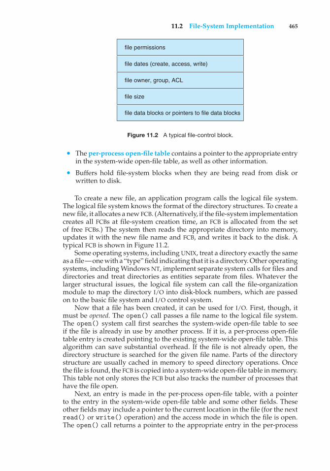
11.2 File-System Implementation 465
file permissions
file dates (create, access, write)
file owner, group, ACL
file size
file data blocks or pointers to file data blocks
Figure 11.2 A typical file-control block.
• The per-process open-file table contains a pointer to the appropriate entryin the system-wide open-file table, as well as other information.
• Buffers hold file-system blocks when they are being read from disk orwritten to disk.
To create a new file, an application program calls the logical file system.The logical file system knows the format of the directory structures. To create anew file, it allocates a new FCB. (Alternatively, if the file-system implementationcreates all FCBs at file-system creation time, an FCB is allocated from the setof free FCBs.) The system then reads the appropriate directory into memory,updates it with the new file name and FCB, and writes it back to the disk. Atypical FCB is shown in Figure 11.2.
Some operating systems, including UNIX, treat a directory exactly the sameas a file—one with a “type”field indicating that it is a directory. Other operatingsystems, including Windows NT, implement separate system calls for files anddirectories and treat directories as entities separate from files. Whatever thelarger structural issues, the logical file system can call the file-organizationmodule to map the directory I/O into disk-block numbers, which are passedon to the basic file system and I/O control system.
Now that a file has been created, it can be used for I/O. First, though, itmust be opened. The open() call passes a file name to the logical file system.The open() system call first searches the system-wide open-file table to seeif the file is already in use by another process. If it is, a per-process open-filetable entry is created pointing to the existing system-wide open-file table. Thisalgorithm can save substantial overhead. If the file is not already open, thedirectory structure is searched for the given file name. Parts of the directorystructure are usually cached in memory to speed directory operations. Oncethe file is found, the FCB is copied into a system-wide open-file table in memory.This table not only stores the FCB but also tracks the number of processes thathave the file open.
Next, an entry is made in the per-process open-file table, with a pointerto the entry in the system-wide open-file table and some other fields. Theseother fields may include a pointer to the current location in the file (for the nextread() or write() operation) and the access mode in which the file is open.The open() call returns a pointer to the appropriate entry in the per-process
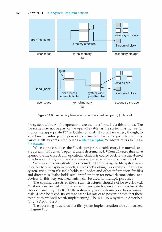
466 Chapter 11 File-System Implementation
directory structure
directory structureopen (file name)
kernel memoryuser space
index
(a)
file-control block
secondary storage
data blocks
per-processopen-file table
system-wideopen-file table
read (index)
kernel memoryuser space
(b)
file-control block
secondary storage
Figure 11.3 In-memory file-system structures. (a) File open. (b) File read.
file-system table. All file operations are then performed via this pointer. Thefile name may not be part of the open-file table, as the system has no use forit once the appropriate FCB is located on disk. It could be cached, though, tosave time on subsequent opens of the same file. The name given to the entryvaries. UNIX systems refer to it as a file descriptor; Windows refers to it as afile handle.
When a process closes the file, the per-process table entry is removed, andthe system-wide entry’s open count is decremented. When all users that haveopened the file close it, any updated metadata is copied back to the disk-baseddirectory structure, and the system-wide open-file table entry is removed.
Some systems complicate this scheme further by using the file system as aninterface to other system aspects, such as networking. For example, in UFS, thesystem-wide open-file table holds the inodes and other information for filesand directories. It also holds similar information for network connections anddevices. In this way, one mechanism can be used for multiple purposes.
The caching aspects of file-system structures should not be overlooked.Most systems keep all information about an open file, except for its actual datablocks, in memory. The BSD UNIX system is typical in its use of caches whereverdisk I/O can be saved. Its average cache hit rate of 85 percent shows that thesetechniques are well worth implementing. The BSD UNIX system is describedfully in Appendix A.
The operating structures of a file-system implementation are summarizedin Figure 11.3.
11.2 File-System Implementation 467
11.2.2 Partitions and Mounting
The layout of a disk can have many variations, depending on the operatingsystem. A disk can be sliced into multiple partitions, or a volume can spanmultiple partitions on multiple disks. The former layout is discussed here,while the latter, which is more appropriately considered a form of RAID, iscovered in Section 12.7.
Each partition can be either “raw,” containing no file system, or “cooked,”containing a file system. Raw disk is used where no file system is appropriate.UNIX swap space can use a raw partition, for example, as it uses its own formaton disk and does not use a file system. Likewise, some databases use raw diskand format the data to suit their needs. Raw disk can also hold informationneeded by disk RAID systems, such as bit maps indicating which blocks aremirrored and which have changed and need to be mirrored. Similarly, raw diskcan contain a miniature database holding RAID configuration information, suchas which disks are members of each RAID set. Raw disk use is further discussedin Section 12.5.1.
Boot information can be stored in a separate partition. Again, it has itsown format, because at boot time the system does not have the file-systemcode loaded and therefore cannot interpret the file-system format. Rather, bootinformation is usually a sequential series of blocks, loaded as an image intomemory. Execution of the image starts at a predefined location, such as the firstbyte. This boot loader in turn knows enough about the file-system structure tobe able to find and load the kernel and start it executing. It can contain morethan the instructions for how to boot a specific operating system. For instance,PCs and other systems can be dual-booted. Multiple operating systems can beinstalled on such a system. How does the system know which one to boot?A boot loader that understands multiple file systems and multiple operatingsystems can occupy the boot space. Once loaded, it can boot one of the operatingsystems available on the disk. The disk can have multiple partitions, eachcontaining a different type of file system and a different operating system.
The root partition, which contains the operating-system kernel and some-times other system files, is mounted at boot time. Other volumes can beautomatically mounted at boot or manually mounted later, depending onthe operating system. As part of a successful mount operation, the operatingsystem verifies that the device contains a valid file system. It does so by askingthe device driver to read the device directory and verifying that the directoryhas the expected format. If the format is invalid, the partition must haveits consistency checked and possibly corrected, either with or without userintervention. Finally, the operating system notes in its in-memory mount tablethat a file system is mounted, along with the type of the file system. The detailsof this function depend on the operating system. Microsoft Windows–basedsystems mount each volume in a separate name space, denoted by a letterand a colon. To record that a file system is mounted at F:, for example, theoperating system places a pointer to the file system in a field of the devicestructure corresponding to F:. When a process specifies the driver letter, theoperating system finds the appropriate file-system pointer and traverses thedirectory structures on that device to find the specified file or directory. Laterversions of Windows can mount a file system at any point within the existingdirectory structure.
468 Chapter 11 File-System Implementation
On UNIX, file systems can be mounted at any directory. Mounting isimplemented by setting a flag in the in-memory copy of the inode for thatdirectory. The flag indicates that the directory is a mount point. A field thenpoints to an entry in the mount table, indicating which device is mounted there.The mount table entry contains a pointer to the superblock of the file system onthat device. This scheme enables the operating system to traverse its directorystructure, switching seamlessly among file systems of varying types.
11.2.3 Virtual File Systems
The previous section makes it clear that modern operating systems mustconcurrently support multiple types of file systems. But how does an operatingsystem allow multiple types of file systems to be integrated into a directorystructure? And how can users seamlessly move between file-system typesas they navigate the file-system space? We now discuss some of theseimplementation details.
An obvious but suboptimal method of implementing multiple types of filesystems is to write directory and file routines for each type. Instead, however,most operating systems, including UNIX, use object-oriented techniques tosimplify, organize, and modularize the implementation. The use of thesemethods allows very dissimilar file-system types to be implemented withinthe same structure, including network file systems, such as NFS. Users canaccess files that are contained within multiple file systems on the local disk oreven on file systems available across the network.
Data structures and procedures are used to isolate the basic system-call functionality from the implementation details. Thus, the file-systemimplementation consists of three major layers, as depicted schematically inFigure 11.4. The first layer is the file-system interface, based on the open(),read(), write(), and close() calls and on file descriptors.
The second layer is called the virtual file system (VFS) layer. The VFS layerserves two important functions:
1. It separates file-system-generic operations from their implementationby defining a clean VFS interface. Several implementations for the VFSinterface may coexist on the same machine, allowing transparent accessto different types of file systems mounted locally.
2. It provides a mechanism for uniquely representing a file throughout anetwork. The VFS is based on a file-representation structure, called avnode, that contains a numerical designator for a network-wide uniquefile. (UNIX inodes are unique within only a single file system.) Thisnetwork-wide uniqueness is required for support of network file systems.The kernel maintains one vnode structure for each active node (file ordirectory).
Thus, the VFS distinguishes local files from remote ones, and local files arefurther distinguished according to their file-system types.
The VFS activates file-system-specific operations to handle local requestsaccording to their file-system types and calls the NFS protocol procedures forremote requests. File handles are constructed from the relevant vnodes andare passed as arguments to these procedures. The layer implementing the
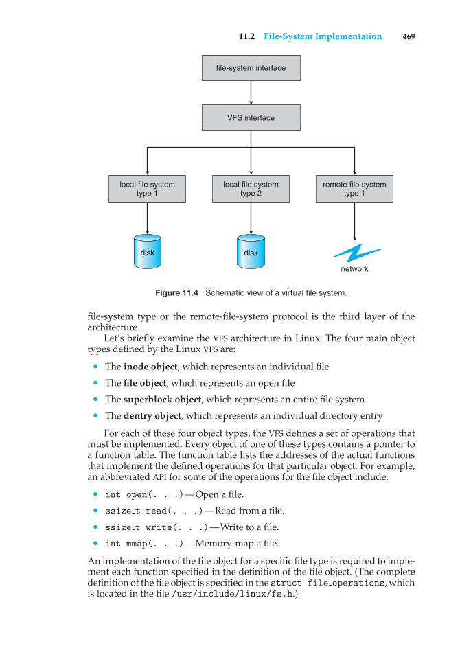
11.2 File-System Implementation 469
local file systemtype 1
disk
local file systemtype 2
disk
remote file systemtype 1
network
file-system interface
VFS interface
Figure 11.4 Schematic view of a virtual file system.
file-system type or the remote-file-system protocol is the third layer of thearchitecture.
Let’s briefly examine the VFS architecture in Linux. The four main objecttypes defined by the Linux VFS are:
• The inode object, which represents an individual file
• The file object, which represents an open file
• The superblock object, which represents an entire file system
• The dentry object, which represents an individual directory entry
For each of these four object types, the VFS defines a set of operations thatmust be implemented. Every object of one of these types contains a pointer toa function table. The function table lists the addresses of the actual functionsthat implement the defined operations for that particular object. For example,an abbreviated API for some of the operations for the file object include:
• int open(. . .)—Open a file.
• ssize t read(. . .)—Read from a file.
• ssize t write(. . .)—Write to a file.
• int mmap(. . .)—Memory-map a file.
An implementation of the file object for a specific file type is required to imple-ment each function specified in the definition of the file object. (The completedefinition of the file object is specified in the struct file operations, whichis located in the file /usr/include/linux/fs.h.)
470 Chapter 11 File-System Implementation
Thus, the VFS software layer can perform an operation on one of theseobjects by calling the appropriate function from the object’s function table,without having to know in advance exactly what kind of object it is dealingwith. The VFS does not know, or care, whether an inode represents a disk file,a directory file, or a remote file. The appropriate function for that file’s read()operation will always be at the same place in its function table, and the VFSsoftware layer will call that function without caring how the data are actuallyread.
11.3 Directory Implementation
The selection of directory-allocation and directory-management algorithmssignificantly affects the efficiency, performance, and reliability of the filesystem. In this section, we discuss the trade-offs involved in choosing oneof these algorithms.
11.3.1 Linear List
The simplest method of implementing a directory is to use a linear list of filenames with pointers to the data blocks. This method is simple to programbut time-consuming to execute. To create a new file, we must first search thedirectory to be sure that no existing file has the same name. Then, we add anew entry at the end of the directory. To delete a file, we search the directory forthe named file and then release the space allocated to it. To reuse the directoryentry, we can do one of several things. We can mark the entry as unused (byassigning it a special name, such as an all-blank name, or with a used–unusedbit in each entry), or we can attach it to a list of free directory entries. A thirdalternative is to copy the last entry in the directory into the freed location andto decrease the length of the directory. A linked list can also be used to decreasethe time required to delete a file.
The real disadvantage of a linear list of directory entries is that finding afile requires a linear search. Directory information is used frequently, and userswill notice if access to it is slow. In fact, many operating systems implement asoftware cache to store the most recently used directory information. A cachehit avoids the need to constantly reread the information from disk. A sortedlist allows a binary search and decreases the average search time. However, therequirement that the list be kept sorted may complicate creating and deletingfiles, since we may have to move substantial amounts of directory informationto maintain a sorted directory. A more sophisticated tree data structure, suchas a B-tree, might help here. An advantage of the sorted list is that a sorteddirectory listing can be produced without a separate sort step.
11.3.2 Hash Table
Another data structure used for a file directory is a hash table. With thismethod, a linear list stores the directory entries, but a hash data structure isalso used. The hash table takes a value computed from the file name and returnsa pointer to the file name in the linear list. Therefore, it can greatly decrease thedirectory search time. Insertion and deletion are also fairly straightforward,although some provision must be made for collisions—situations in whichtwo file names hash to the same location.
11.4 Allocation Methods 471
The major difficulties with a hash table are its generally fixed size and thedependence of the hash function on that size. For example, assume that wemake a linear-probing hash table that holds 64 entries. The hash functionconverts file names into integers from 0 to 63, for instance, by using theremainder of a division by 64. If we later try to create a 65th file, we mustenlarge the directory hash table—say, to 128 entries. As a result, we needa new hash function that must map file names to the range 0 to 127, and wemust reorganize the existing directory entries to reflect their new hash-functionvalues.
Alternatively, a chained-overflow hash table can be used. Each hash entrycan be a linked list instead of an individual value, and we can resolve collisionsby adding the new entry to the linked list. Lookups may be somewhat slowed,because searching for a name might require stepping through a linked list ofcolliding table entries. Still, this method is likely to be much faster than a linearsearch through the entire directory.
11.4 Allocation Methods
The direct-access nature of disks allows us flexibility in the implementation offiles. In almost every case, many files are stored on the same disk. The mainproblem is how to allocate space to these files so that disk space is utilizedeffectively and files can be accessed quickly. Three major methods of allocatingdisk space are in wide use: contiguous, linked, and indexed. Each method hasadvantages and disadvantages. Some systems (such as Data General’s RDOSfor its Nova line of computers) support all three. More commonly, a systemuses one method for all files within a file-system type.
11.4.1 Contiguous Allocation
Contiguous allocation requires that each file occupy a set of contiguous blockson the disk. Disk addresses define a linear ordering on the disk. With thisordering, assuming that only one job is accessing the disk, accessing block b +1 after block b normally requires no head movement. When head movementis needed (from the last sector of one cylinder to the first sector of the nextcylinder), the head need only move from one track to the next. Thus, the numberof disk seeks required for accessing contiguously allocated files is minimal, asis seek time when a seek is finally needed. The IBM VM/CMS operating systemuses contiguous allocation because it provides such good performance.
Contiguous allocation of a file is defined by the disk address and length (inblock units) of the first block. If the file is n blocks long and starts at locationb, then it occupies blocks b, b + 1, b + 2, ..., b + n − 1. The directory entry foreach file indicates the address of the starting block and the length of the areaallocated for this file (Figure 11.5).
Accessing a file that has been allocated contiguously is easy. For sequentialaccess, the file system remembers the disk address of the last block referencedand, when necessary, reads the next block. For direct access to block i of afile that starts at block b, we can immediately access block b + i. Thus, bothsequential and direct access can be supported by contiguous allocation.
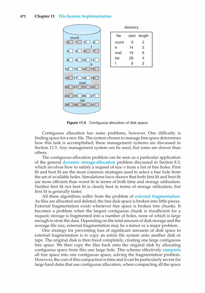
472 Chapter 11 File-System Implementation
directory
0 1 2 3
4 5 6 7
8 9 10 11
12 13 14 15
16 17 18 19
20 21 22 23
24 25 26 27
28 29 30 31
count
f
tr
list
start
0 14 19 28 6
length
2 3 6 4 2
file
count tr mail list f
Figure 11.5 Contiguous allocation of disk space.
Contiguous allocation has some problems, however. One difficulty isfinding space for a new file. The system chosen to manage free space determineshow this task is accomplished; these management systems are discussed inSection 11.5. Any management system can be used, but some are slower thanothers.
The contiguous-allocation problem can be seen as a particular applicationof the general dynamic storage-allocation problem discussed in Section 8.3,which involves how to satisfy a request of size n from a list of free holes. Firstfit and best fit are the most common strategies used to select a free hole fromthe set of available holes. Simulations have shown that both first fit and best fitare more efficient than worst fit in terms of both time and storage utilization.Neither first fit nor best fit is clearly best in terms of storage utilization, butfirst fit is generally faster.
All these algorithms suffer from the problem of external fragmentation.As files are allocated and deleted, the free disk space is broken into little pieces.External fragmentation exists whenever free space is broken into chunks. Itbecomes a problem when the largest contiguous chunk is insufficient for arequest; storage is fragmented into a number of holes, none of which is largeenough to store the data. Depending on the total amount of disk storage and theaverage file size, external fragmentation may be a minor or a major problem.
One strategy for preventing loss of significant amounts of disk space toexternal fragmentation is to copy an entire file system onto another disk ortape. The original disk is then freed completely, creating one large contiguousfree space. We then copy the files back onto the original disk by allocatingcontiguous space from this one large hole. This scheme effectively compactsall free space into one contiguous space, solving the fragmentation problem.However, the cost of this compaction is time and it can be particularly severe forlarge hard disks that use contiguous allocation, where compacting all the space
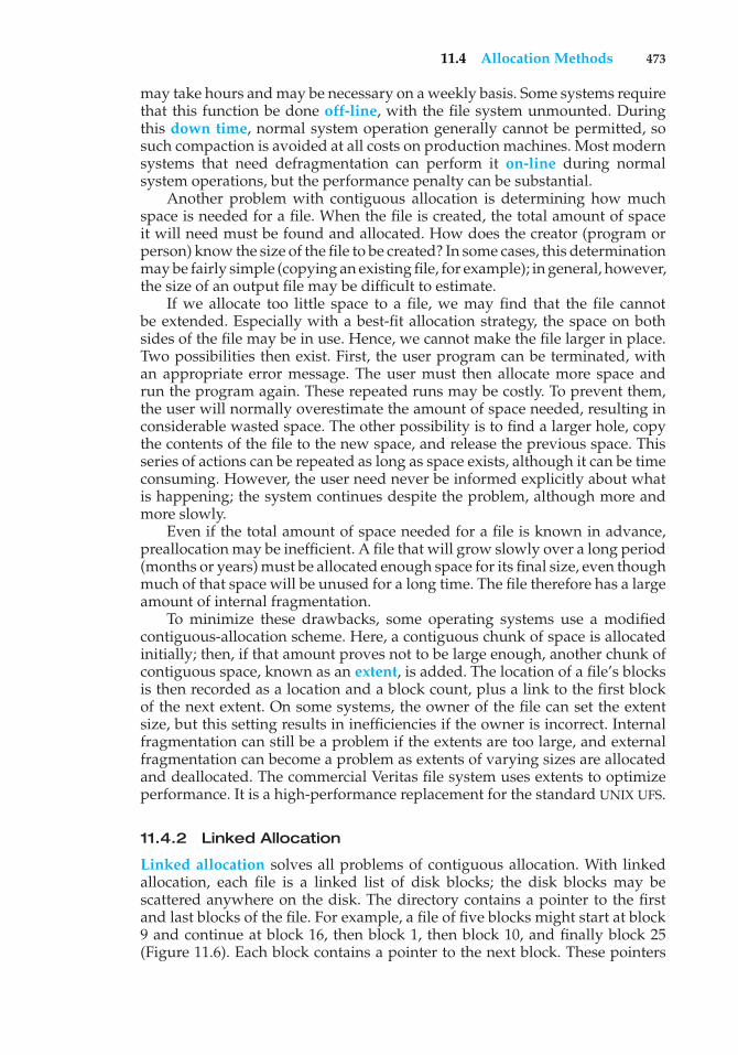
11.4 Allocation Methods 473
may take hours and may be necessary on a weekly basis. Some systems requirethat this function be done off-line, with the file system unmounted. Duringthis down time, normal system operation generally cannot be permitted, sosuch compaction is avoided at all costs on production machines. Most modernsystems that need defragmentation can perform it on-line during normalsystem operations, but the performance penalty can be substantial.
Another problem with contiguous allocation is determining how muchspace is needed for a file. When the file is created, the total amount of spaceit will need must be found and allocated. How does the creator (program orperson) know the size of the file to be created? In some cases, this determinationmay be fairly simple (copying an existing file, for example); in general, however,the size of an output file may be difficult to estimate.
If we allocate too little space to a file, we may find that the file cannotbe extended. Especially with a best-fit allocation strategy, the space on bothsides of the file may be in use. Hence, we cannot make the file larger in place.Two possibilities then exist. First, the user program can be terminated, withan appropriate error message. The user must then allocate more space andrun the program again. These repeated runs may be costly. To prevent them,the user will normally overestimate the amount of space needed, resulting inconsiderable wasted space. The other possibility is to find a larger hole, copythe contents of the file to the new space, and release the previous space. Thisseries of actions can be repeated as long as space exists, although it can be timeconsuming. However, the user need never be informed explicitly about whatis happening; the system continues despite the problem, although more andmore slowly.
Even if the total amount of space needed for a file is known in advance,preallocation may be inefficient. A file that will grow slowly over a long period(months or years) must be allocated enough space for its final size, even thoughmuch of that space will be unused for a long time. The file therefore has a largeamount of internal fragmentation.
To minimize these drawbacks, some operating systems use a modifiedcontiguous-allocation scheme. Here, a contiguous chunk of space is allocatedinitially; then, if that amount proves not to be large enough, another chunk ofcontiguous space, known as an extent, is added. The location of a file’s blocksis then recorded as a location and a block count, plus a link to the first blockof the next extent. On some systems, the owner of the file can set the extentsize, but this setting results in inefficiencies if the owner is incorrect. Internalfragmentation can still be a problem if the extents are too large, and externalfragmentation can become a problem as extents of varying sizes are allocatedand deallocated. The commercial Veritas file system uses extents to optimizeperformance. It is a high-performance replacement for the standard UNIX UFS.
11.4.2 Linked Allocation
Linked allocation solves all problems of contiguous allocation. With linkedallocation, each file is a linked list of disk blocks; the disk blocks may bescattered anywhere on the disk. The directory contains a pointer to the firstand last blocks of the file. For example, a file of five blocks might start at block9 and continue at block 16, then block 1, then block 10, and finally block 25(Figure 11.6). Each block contains a pointer to the next block. These pointers
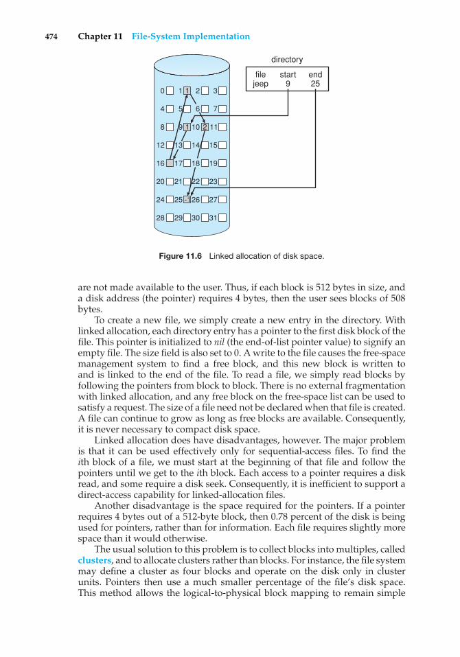
474 Chapter 11 File-System Implementation
0 1 2 3
4 5 7
8 9 10 11
12 13 14
16 17 18 19
20 21 22 23
24 25 26 27
28 29 30 31
15
6
filejeep
start9
directory
end25
1
1
-1
2
Figure 11.6 Linked allocation of disk space.
are not made available to the user. Thus, if each block is 512 bytes in size, anda disk address (the pointer) requires 4 bytes, then the user sees blocks of 508bytes.
To create a new file, we simply create a new entry in the directory. Withlinked allocation, each directory entry has a pointer to the first disk block of thefile. This pointer is initialized to nil (the end-of-list pointer value) to signify anempty file. The size field is also set to 0. A write to the file causes the free-spacemanagement system to find a free block, and this new block is written toand is linked to the end of the file. To read a file, we simply read blocks byfollowing the pointers from block to block. There is no external fragmentationwith linked allocation, and any free block on the free-space list can be used tosatisfy a request. The size of a file need not be declared when that file is created.A file can continue to grow as long as free blocks are available. Consequently,it is never necessary to compact disk space.
Linked allocation does have disadvantages, however. The major problemis that it can be used effectively only for sequential-access files. To find theith block of a file, we must start at the beginning of that file and follow thepointers until we get to the ith block. Each access to a pointer requires a diskread, and some require a disk seek. Consequently, it is inefficient to support adirect-access capability for linked-allocation files.
Another disadvantage is the space required for the pointers. If a pointerrequires 4 bytes out of a 512-byte block, then 0.78 percent of the disk is beingused for pointers, rather than for information. Each file requires slightly morespace than it would otherwise.
The usual solution to this problem is to collect blocks into multiples, calledclusters, and to allocate clusters rather than blocks. For instance, the file systemmay define a cluster as four blocks and operate on the disk only in clusterunits. Pointers then use a much smaller percentage of the file’s disk space.This method allows the logical-to-physical block mapping to remain simple
11.4 Allocation Methods 475
but improves disk throughput (because fewer disk-head seeks are required)and decreases the space needed for block allocation and free-list management.The cost of this approach is an increase in internal fragmentation, becausemore space is wasted when a cluster is partially full than when a block ispartially full. Clusters can be used to improve the disk-access time for manyother algorithms as well, so they are used in most file systems.
Yet another problem of linked allocation is reliability. Recall that the filesare linked together by pointers scattered all over the disk, and consider whatwould happen if a pointer were lost or damaged. A bug in the operating-systemsoftware or a disk hardware failure might result in picking up the wrongpointer. This error could in turn result in linking into the free-space list or intoanother file. One partial solution is to use doubly linked lists, and another isto store the file name and relative block number in each block; however, theseschemes require even more overhead for each file.
An important variation on linked allocation is the use of a file-allocationtable (FAT). This simple but efficient method of disk-space allocation is usedby the MS-DOS and OS/2 operating systems. A section of disk at the beginningof each volume is set aside to contain the table. The table has one entry foreach disk block and is indexed by block number. The FAT is used in much thesame way as a linked list. The directory entry contains the block number of thefirst block of the file. The table entry indexed by that block number containsthe block number of the next block in the file. This chain continues until itreaches the last block, which has a special end-of-file value as the table entry.An unused block is indicated by a table value of 0. Allocating a new block toa file is a simple matter of finding the first 0-valued table entry and replacingthe previous end-of-file value with the address of the new block. The 0 is thenreplaced with the end-of-file value. An illustrative example is the FAT structureshown in Figure 11.7 for a file consisting of disk blocks 217, 618, and 339.
• • •
directory entry
test 217
start blockname0
217 618
339
618 339
number of disk blocks –1
FAT
Figure 11.7 File-allocation table.
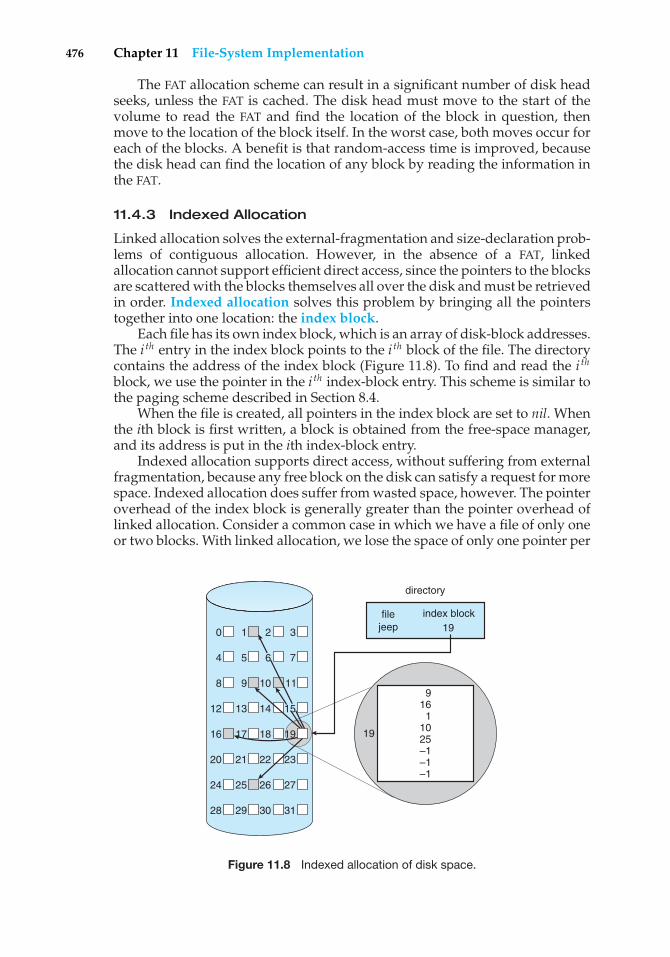
476 Chapter 11 File-System Implementation
The FAT allocation scheme can result in a significant number of disk headseeks, unless the FAT is cached. The disk head must move to the start of thevolume to read the FAT and find the location of the block in question, thenmove to the location of the block itself. In the worst case, both moves occur foreach of the blocks. A benefit is that random-access time is improved, becausethe disk head can find the location of any block by reading the information inthe FAT.
11.4.3 Indexed Allocation
Linked allocation solves the external-fragmentation and size-declaration prob-lems of contiguous allocation. However, in the absence of a FAT, linkedallocation cannot support efficient direct access, since the pointers to the blocksare scattered with the blocks themselves all over the disk and must be retrievedin order. Indexed allocation solves this problem by bringing all the pointerstogether into one location: the index block.
Each file has its own index block, which is an array of disk-block addresses.The i th entry in the index block points to the i th block of the file. The directorycontains the address of the index block (Figure 11.8). To find and read the i thblock, we use the pointer in the i th index-block entry. This scheme is similar tothe paging scheme described in Section 8.4.
When the file is created, all pointers in the index block are set to nil. Whenthe ith block is first written, a block is obtained from the free-space manager,and its address is put in the ith index-block entry.
Indexed allocation supports direct access, without suffering from externalfragmentation, because any free block on the disk can satisfy a request for morespace. Indexed allocation does suffer from wasted space, however. The pointeroverhead of the index block is generally greater than the pointer overhead oflinked allocation. Consider a common case in which we have a file of only oneor two blocks. With linked allocation, we lose the space of only one pointer per
directory
0 1 2 3
4 5 7
8 9 10 11
12 13 14
16 17 18 19
20 21 22 23
24 25 26 27
28 29 30 31
15
6
9 161
10 25 –1 –1–1
filejeep
index block19
19
Figure 11.8 Indexed allocation of disk space.
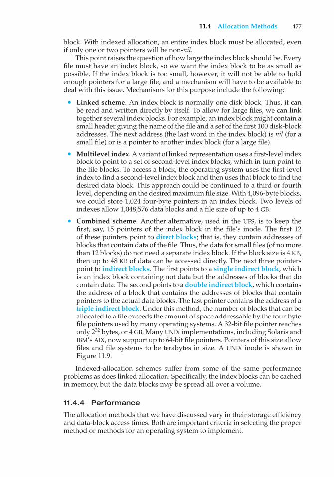
11.4 Allocation Methods 477
block. With indexed allocation, an entire index block must be allocated, evenif only one or two pointers will be non-nil.
This point raises the question of how large the index block should be. Everyfile must have an index block, so we want the index block to be as small aspossible. If the index block is too small, however, it will not be able to holdenough pointers for a large file, and a mechanism will have to be available todeal with this issue. Mechanisms for this purpose include the following:
• Linked scheme. An index block is normally one disk block. Thus, it canbe read and written directly by itself. To allow for large files, we can linktogether several index blocks. For example, an index block might contain asmall header giving the name of the file and a set of the first 100 disk-blockaddresses. The next address (the last word in the index block) is nil (for asmall file) or is a pointer to another index block (for a large file).
• Multilevel index. A variant of linked representation uses a first-level indexblock to point to a set of second-level index blocks, which in turn point tothe file blocks. To access a block, the operating system uses the first-levelindex to find a second-level index block and then uses that block to find thedesired data block. This approach could be continued to a third or fourthlevel, depending on the desired maximum file size. With 4,096-byte blocks,we could store 1,024 four-byte pointers in an index block. Two levels ofindexes allow 1,048,576 data blocks and a file size of up to 4 GB.
• Combined scheme. Another alternative, used in the UFS, is to keep thefirst, say, 15 pointers of the index block in the file’s inode. The first 12of these pointers point to direct blocks; that is, they contain addresses ofblocks that contain data of the file. Thus, the data for small files (of no morethan 12 blocks) do not need a separate index block. If the block size is 4 KB,then up to 48 KB of data can be accessed directly. The next three pointerspoint to indirect blocks. The first points to a single indirect block, whichis an index block containing not data but the addresses of blocks that docontain data. The second points to a double indirect block, which containsthe address of a block that contains the addresses of blocks that containpointers to the actual data blocks. The last pointer contains the address of atriple indirect block. Under this method, the number of blocks that can beallocated to a file exceeds the amount of space addressable by the four-bytefile pointers used by many operating systems. A 32-bit file pointer reachesonly 232 bytes, or 4 GB. Many UNIX implementations, including Solaris andIBM’s AIX, now support up to 64-bit file pointers. Pointers of this size allowfiles and file systems to be terabytes in size. A UNIX inode is shown inFigure 11.9.
Indexed-allocation schemes suffer from some of the same performanceproblems as does linked allocation. Specifically, the index blocks can be cachedin memory, but the data blocks may be spread all over a volume.
11.4.4 Performance
The allocation methods that we have discussed vary in their storage efficiencyand data-block access times. Both are important criteria in selecting the propermethod or methods for an operating system to implement.
478 Chapter 11 File-System Implementation
direct blocks
data
data
data
data
data
data
data
data
data
data
• • ••
• •
• • •
• • •
• • •
• • •
mode
owners (2)
timestamps (3)
size block count
single indirect
double indirect
triple indirect
Figure 11.9 The UNIX inode.
Before selecting an allocation method, we need to determine how thesystems will be used. A system with mostly sequential access should not usethe same method as a system with mostly random access.
For any type of access, contiguous allocation requires only one access to geta disk block. Since we can easily keep the initial address of the file in memory,we can calculate immediately the disk address of the ith block (or the nextblock) and read it directly.
For linked allocation, we can also keep the address of the next block inmemory and read it directly. This method is fine for sequential access; fordirect access, however, an access to the ith block might require idisk reads. Thisproblem indicates why linked allocation should not be used for an applicationrequiring direct access.
As a result, some systems support direct-access files by using contiguousallocation and sequential-access files by using linked allocation. For thesesystems, the type of access to be made must be declared when the file iscreated. A file created for sequential access will be linked and cannot be usedfor direct access. A file created for direct access will be contiguous and cansupport both direct access and sequential access, but its maximum length mustbe declared when it is created. In this case, the operating system must haveappropriate data structures and algorithms to support both allocation methods.Files can be converted from one type to another by the creation of a new file ofthe desired type, into which the contents of the old file are copied. The old filemay then be deleted and the new file renamed.
Indexed allocation is more complex. If the index block is already in memory,then the access can be made directly. However, keeping the index block inmemory requires considerable space. If this memory space is not available,then we may have to read first the index block and then the desired datablock. For a two-level index, two index-block reads might be necessary. For an
11.5 Free-Space Management 479
extremely large file, accessing a block near the end of the file would requirereading in all the index blocks before the needed data block finally couldbe read. Thus, the performance of indexed allocation depends on the indexstructure, on the size of the file, and on the position of the block desired.
Some systems combine contiguous allocation with indexed allocation byusing contiguous allocation for small files (up to three or four blocks) andautomatically switching to an indexed allocation if the file grows large. Sincemost files are small, and contiguous allocation is efficient for small files, averageperformance can be quite good.
For instance, the version of the UNIX operating system from Sun Microsys-tems was changed in 1991 to improve performance in the file-system allocationalgorithm. The performance measurements indicated that the maximum diskthroughput on a typical workstation (a 12-MIPS SPARCstation1) took 50 percentof the CPU and produced a disk bandwidth of only 1.5 MB per second. Toimprove performance, Sun made changes to allocate space in clusters of 56 KBwhenever possible (56 KB was the maximum size of a DMA transfer on Sunsystems at that time). This allocation reduced external fragmentation, and thusseek and latency times. In addition, the disk-reading routines were optimizedto read in these large clusters. The inode structure was left unchanged. As aresult of these changes, plus the use of read-ahead and free-behind (discussedin Section 11.6.2), 25 percent less CPU was used, and throughput substantiallyimproved.
Many other optimizations are in use. Given the disparity between CPUspeed and disk speed, it is not unreasonable to add thousands of extrainstructions to the operating system to save just a few disk-head movements.Furthermore, this disparity is increasing over time, to the point where hundredsof thousands of instructions reasonably could be used to optimize headmovements.
11.5 Free-Space Management
Since disk space is limited, we need to reuse the space from deleted files for newfiles, if possible. (Write-once optical disks only allow one write to any givensector, and thus such reuse is not physically possible.) To keep track of free diskspace, the system maintains a free-space list. The free-space list records all freedisk blocks—those not allocated to some file or directory. To create a file, wesearch the free-space list for the required amount of space and allocate thatspace to the new file. This space is then removed from the free-space list. Whena file is deleted, its disk space is added to the free-space list. The free-space list,despite its name, might not be implemented as a list, as we discuss next.
11.5.1 Bit Vector
Frequently, the free-space list is implemented as a bit map or bit vector. Eachblock is represented by 1 bit. If the block is free, the bit is 1; if the block isallocated, the bit is 0.
For example, consider a disk where blocks 2, 3, 4, 5, 8, 9, 10, 11, 12, 13, 17,18, 25, 26, and 27 are free and the rest of the blocks are allocated. The free-spacebit map would be
480 Chapter 11 File-System Implementation
001111001111110001100000011100000 ...
The main advantage of this approach is its relative simplicity and itsefficiency in finding the first free block or n consecutive free blocks on thedisk. Indeed, many computers supply bit-manipulation instructions that canbe used effectively for that purpose. For example, the Intel family starting withthe 80386 and the Motorola family starting with the 68020 have instructionsthat return the offset in a word of the first bit with the value 1 (these processorshave powered PCs and Macintosh systems, respectively). One technique forfinding the first free block on a system that uses a bit-vector to allocate diskspace is to sequentially check each word in the bit map to see whether thatvalue is not 0, since a 0-valued word contains only 0 bits and represents a setof allocated blocks. The first non-0 word is scanned for the first 1 bit, which isthe location of the first free block. The calculation of the block number is
(number of bits per word) × (number of 0-value words) + offset of first 1 bit.
Again, we see hardware features driving software functionality. Unfor-tunately, bit vectors are inefficient unless the entire vector is kept in mainmemory (and is written to disk occasionally for recovery needs). Keeping it inmain memory is possible for smaller disks but not necessarily for larger ones.A 1.3-GB disk with 512-byte blocks would need a bit map of over 332 KB totrack its free blocks, although clustering the blocks in groups of four reducesthis number to around 83 KB per disk. A 1-TB disk with 4-KB blocks requires 32MB to store its bit map. Given that disk size constantly increases, the problemwith bit vectors will continue to escalate. A 1-PB file system would take a 32-GBbitmap just to manage its free space.
11.5.2 Linked List
Another approach to free-space management is to link together all the freedisk blocks, keeping a pointer to the first free block in a special location on thedisk and caching it in memory. This first block contains a pointer to the nextfree disk block, and so on. Recall our earlier example (Section 11.5.1), in whichblocks 2, 3, 4, 5, 8, 9, 10, 11, 12, 13, 17, 18, 25, 26, and 27 were free and therest of the blocks were allocated. In this situation, we would keep a pointer toblock 2 as the first free block. Block 2 would contain a pointer to block 3, whichwould point to block 4, which would point to block 5, which would point toblock 8, and so on (Figure 11.10). This scheme is not efficient; to traverse thelist, we must read each block, which requires substantial I/O time. Fortunately,however, traversing the free list is not a frequent action. Usually, the operatingsystem simply needs a free block so that it can allocate that block to a file, sothe first block in the free list is used. The FAT method incorporates free-blockaccounting into the allocation data structure. No separate method is needed.
11.5.3 Grouping
A modification of the free-list approach stores the addresses of n free blocksin the first free block. The first n−1 of these blocks are actually free. The lastblock contains the addresses of another n free blocks, and so on. The addresses
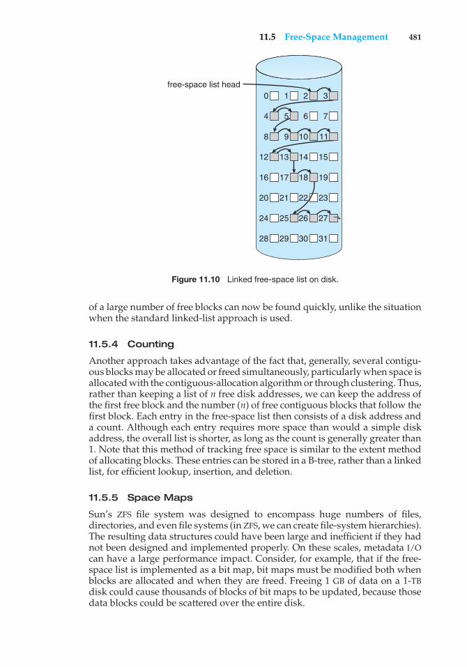
11.5 Free-Space Management 481
0 1 2 3
4 5 7
8 9 10 11
12 13 14
16 17 18 19
20 21 22 23
24 25 26 27
28 29 30 31
15
6
free-space list head
Figure 11.10 Linked free-space list on disk.
of a large number of free blocks can now be found quickly, unlike the situationwhen the standard linked-list approach is used.
11.5.4 Counting
Another approach takes advantage of the fact that, generally, several contigu-ous blocks may be allocated or freed simultaneously, particularly when space isallocated with the contiguous-allocation algorithm or through clustering. Thus,rather than keeping a list of n free disk addresses, we can keep the address ofthe first free block and the number (n) of free contiguous blocks that follow thefirst block. Each entry in the free-space list then consists of a disk address anda count. Although each entry requires more space than would a simple diskaddress, the overall list is shorter, as long as the count is generally greater than1. Note that this method of tracking free space is similar to the extent methodof allocating blocks. These entries can be stored in a B-tree, rather than a linkedlist, for efficient lookup, insertion, and deletion.
11.5.5 Space Maps
Sun’s ZFS file system was designed to encompass huge numbers of files,directories, and even file systems (in ZFS, we can create file-system hierarchies).The resulting data structures could have been large and inefficient if they hadnot been designed and implemented properly. On these scales, metadata I/Ocan have a large performance impact. Consider, for example, that if the free-space list is implemented as a bit map, bit maps must be modified both whenblocks are allocated and when they are freed. Freeing 1 GB of data on a 1-TBdisk could cause thousands of blocks of bit maps to be updated, because thosedata blocks could be scattered over the entire disk.
482 Chapter 11 File-System Implementation
ZFS uses a combination of techniques in its free-space managementalgorithm to control the size of data structures and minimize the I/O neededto manage those structures. First, ZFS creates metaslabs to divide the spaceon the device into chucks of manageable size. A given volume may containhundreds of metaslabs. Each metaslab has an associated space map. ZFS usesthe counting algorithm to store information about free blocks. Rather thanwrite count structures to disk, it uses log-structured file- system techniquesto record them. The space map is a log of all block activity (allocating andfreeing), in time order, in counting format. When ZFS decides to allocate orfree space from a metaslab, it loads the associated space map into memoryin a balanced-tree structure (for very efficient operation), indexed by offset,and replays the log into that structure. The in-memory space map is then anaccurate representation of the allocated and free space in the metaslab. ZFS alsocondenses the map as much as possible by combining contiguous free blocksinto a single entry. Finally, the free-space list is updated on disk as part ofthe transaction-oriented operations of ZFS. During the collection and sortingphase, block requests can still occur, and ZFS satisfies these requests from thelog. In essence, the log plus the balanced tree is the free list.
11.6 Efficiency and Performance
Now that we have discussed various block-allocation and directory-management options, we can further consider their effect on performanceand efficient disk use. Disks tend to represent a major bottleneck in systemperformance, since they are the slowest main computer component. In thissection, we discuss a variety of techniques used to improve the efficiency andperformance of secondary storage.
11.6.1 Efficiency
The efficient use of disk space depends heavily on the disk allocation anddirectory algorithms in use. For instance, UNIX inodes are preallocated on avolume. Even an “empty” disk has a percentage of its space lost to inodes.However, by preallocating the inodes and spreading them across the volume,we improve the file system’s performance. This improved performance resultsfrom the UNIX allocation and free-space algorithms, which try to keep a file’sdata blocks near that file’s inode block to reduce seek time.
As another example, let’s reconsider the clustering scheme discussed inSection 11.4, which aids in file-seek and file-transfer performance at the costof internal fragmentation. To reduce this fragmentation, BSD UNIX varies thecluster size as a file grows. Large clusters are used where they can be filled, andsmall clusters are used for small files and the last cluster of a file. This systemis described in Appendix A.
The types of data normally kept in a file’s directory (or inode) entry alsorequire consideration. Commonly, a “last write date” is recorded to supplyinformation to the user and to determine whether the file needs to be backedup. Some systems also keep a “last access date,” so that a user can determinewhen the file was last read. The result of keeping this information is that,whenever the file is read, a field in the directory structure must be written
11.6 Efficiency and Performance 483
to. That means the block must be read into memory, a section changed, andthe block written back out to disk, because operations on disks occur only inblock (or cluster) chunks. So any time a file is opened for reading, its directoryentry must be read and written as well. This requirement can be inefficient forfrequently accessed files, so we must weigh its benefit against its performancecost when designing a file system. Generally, every data item associated with afile needs to be considered for its effect on efficiency and performance.
As an example, consider how efficiency is affected by the size of the pointersused to access data. Most systems use either 16- or 32-bit pointers throughoutthe operating system. These pointer sizes limit the length of a file to either216 (64 KB) or 232 bytes (4 GB). Some systems implement 64-bit pointers toincrease this limit to 264 bytes, which is a very large number indeed. However,64-bit pointers take more space to store and in turn make the allocation andfree-space-management methods (linked lists, indexes, and so on) use moredisk space.
One of the difficulties in choosing a pointer size, or indeed any fixedallocation size within an operating system, is planning for the effects ofchanging technology. Consider that the IBM PC XT had a 10-MB hard driveand an MS-DOS file system that could support only 32 MB. (Each FAT entrywas 12 bits, pointing to an 8-KB cluster.) As disk capacities increased, largerdisks had to be split into 32-MB partitions, because the file system could nottrack blocks beyond 32 MB. As hard disks with capacities of over 100 MB becamecommon, the disk data structures and algorithms in MS-DOS had to be modifiedto allow larger file systems. (Each FAT entry was expanded to 16 bits and laterto 32 bits.) The initial file-system decisions were made for efficiency reasons;however, with the advent of MS-DOS Version 4, millions of computer users wereinconvenienced when they had to switch to the new, larger file system. Sun’sZFS file system uses 128-bit pointers, which theoretically should never needto be extended. (The minimum mass of a device capable of storing 2128 bytesusing atomic-level storage would be about 272 trillion kilograms.)
As another example, consider the evolution of Sun’s Solaris operatingsystem. Originally, many data structures were of fixed length, allocated atsystem startup. These structures included the process table and the open-filetable. When the process table became full, no more processes could be created.When the file table became full, no more files could be opened. The systemwould fail to provide services to users. Table sizes could be increased only byrecompiling the kernel and rebooting the system. Since the release of Solaris2, almost all kernel structures have been allocated dynamically, eliminatingthese artificial limits on system performance. Of course, the algorithms thatmanipulate these tables are more complicated, and the operating system is alittle slower because it must dynamically allocate and deallocate table entries;but that price is the usual one for more general functionality.
11.6.2 Performance
Even after the basic file-system algorithms have been selected, we can stillimprove performance in several ways. As will be discussed in Chapter 13,most disk controllers include local memory to form an on-board cache that islarge enough to store entire tracks at a time. Once a seek is performed, thetrack is read into the disk cache starting at the sector under the disk head
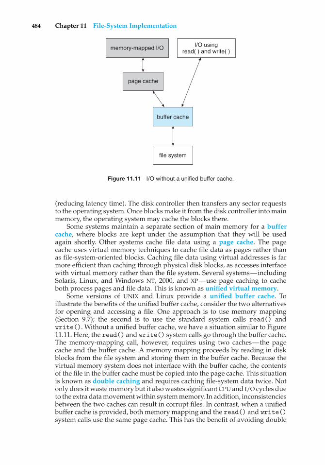
484 Chapter 11 File-System Implementation
memory-mapped I/O I/O usingread( ) and write( )
page cache
buffer cache
file system
Figure 11.11 I/O without a unified buffer cache.
(reducing latency time). The disk controller then transfers any sector requeststo the operating system. Once blocks make it from the disk controller into mainmemory, the operating system may cache the blocks there.
Some systems maintain a separate section of main memory for a buffercache, where blocks are kept under the assumption that they will be usedagain shortly. Other systems cache file data using a page cache. The pagecache uses virtual memory techniques to cache file data as pages rather thanas file-system-oriented blocks. Caching file data using virtual addresses is farmore efficient than caching through physical disk blocks, as accesses interfacewith virtual memory rather than the file system. Several systems—includingSolaris, Linux, and Windows NT, 2000, and XP—use page caching to cacheboth process pages and file data. This is known as unified virtual memory.
Some versions of UNIX and Linux provide a unified buffer cache. Toillustrate the benefits of the unified buffer cache, consider the two alternativesfor opening and accessing a file. One approach is to use memory mapping(Section 9.7); the second is to use the standard system calls read() andwrite(). Without a unified buffer cache, we have a situation similar to Figure11.11. Here, the read() and write() system calls go through the buffer cache.The memory-mapping call, however, requires using two caches—the pagecache and the buffer cache. A memory mapping proceeds by reading in diskblocks from the file system and storing them in the buffer cache. Because thevirtual memory system does not interface with the buffer cache, the contentsof the file in the buffer cache must be copied into the page cache. This situationis known as double caching and requires caching file-system data twice. Notonly does it waste memory but it also wastes significant CPU and I/O cycles dueto the extra data movement within system memory. In addition, inconsistenciesbetween the two caches can result in corrupt files. In contrast, when a unifiedbuffer cache is provided, both memory mapping and the read() and write()system calls use the same page cache. This has the benefit of avoiding double
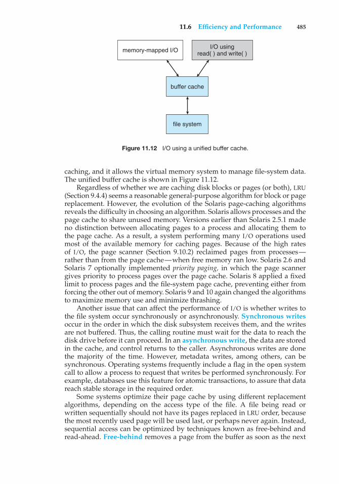
11.6 Efficiency and Performance 485
memory-mapped I/O I/O usingread( ) and write( )
buffer cache
file system
Figure 11.12 I/O using a unified buffer cache.
caching, and it allows the virtual memory system to manage file-system data.The unified buffer cache is shown in Figure 11.12.
Regardless of whether we are caching disk blocks or pages (or both), LRU(Section 9.4.4) seems a reasonable general-purpose algorithm for block or pagereplacement. However, the evolution of the Solaris page-caching algorithmsreveals the difficulty in choosing an algorithm. Solaris allows processes and thepage cache to share unused memory. Versions earlier than Solaris 2.5.1 madeno distinction between allocating pages to a process and allocating them tothe page cache. As a result, a system performing many I/O operations usedmost of the available memory for caching pages. Because of the high ratesof I/O, the page scanner (Section 9.10.2) reclaimed pages from processes—rather than from the page cache—when free memory ran low. Solaris 2.6 andSolaris 7 optionally implemented priority paging, in which the page scannergives priority to process pages over the page cache. Solaris 8 applied a fixedlimit to process pages and the file-system page cache, preventing either fromforcing the other out of memory. Solaris 9 and 10 again changed the algorithmsto maximize memory use and minimize thrashing.
Another issue that can affect the performance of I/O is whether writes tothe file system occur synchronously or asynchronously. Synchronous writesoccur in the order in which the disk subsystem receives them, and the writesare not buffered. Thus, the calling routine must wait for the data to reach thedisk drive before it can proceed. In an asynchronous write, the data are storedin the cache, and control returns to the caller. Asynchronous writes are donethe majority of the time. However, metadata writes, among others, can besynchronous. Operating systems frequently include a flag in the open systemcall to allow a process to request that writes be performed synchronously. Forexample, databases use this feature for atomic transactions, to assure that datareach stable storage in the required order.
Some systems optimize their page cache by using different replacementalgorithms, depending on the access type of the file. A file being read orwritten sequentially should not have its pages replaced in LRU order, becausethe most recently used page will be used last, or perhaps never again. Instead,sequential access can be optimized by techniques known as free-behind andread-ahead. Free-behind removes a page from the buffer as soon as the next
486 Chapter 11 File-System Implementation
page is requested. The previous pages are not likely to be used again andwaste buffer space. With read-ahead, a requested page and several subsequentpages are read and cached. These pages are likely to be requested after thecurrent page is processed. Retrieving these data from the disk in one transferand caching them saves a considerable amount of time. One might think thata track cache on the controller would eliminate the need for read-ahead on amultiprogrammed system. However, because of the high latency and overheadinvolved in making many small transfers from the track cache to main memory,performing a read-ahead remains beneficial.
The page cache, the file system, and the disk drivers have some interestinginteractions. When data are written to a disk file, the pages are buffered in thecache, and the disk driver sorts its output queue according to disk address.These two actions allow the disk driver to minimize disk-head seeks and towrite data at times optimized for disk rotation. Unless synchronous writes arerequired, a process writing to disk simply writes into the cache, and the systemasynchronously writes the data to disk when convenient. The user process seesvery fast writes. When data are read from a disk file, the block I/O system doessome read-ahead; however, writes are much more nearly asynchronous thanare reads. Thus, output to the disk through the file system is often faster thanis input for large transfers, counter to intuition.
11.7 Recovery
Files and directories are kept both in main memory and on disk, and care mustbe taken to ensure that a system failure does not result in loss of data or in datainconsistency. We deal with these issues in this section as well as how a systemcan recover from such a failure.
A system crash can cause inconsistencies among on-disk file-system datastructures, such as directory structures, free-block pointers, and free FCBpointers. Many file systems apply changes to these structures in place. Atypical operation, such as creating a file, can involve many structural changeswithin the file system on the disk. Directory structures are modified, FCBs areallocated, data blocks are allocated, and the free counts for all of these blocksare decreased. These changes can be interrupted by a crash, and inconsistenciesamong the structures can result. For example, the free FCB count might indicatethat an FCB had been allocated, but the directory structure might not point tothe FCB. Compounding this problem is the caching that operating systems doto optimize I/O performance. Some changes may go directly to disk, whileothers may be cached. If the cached changes do not reach disk before a crashoccurs, more corruption is possible.
In addition to crashes, bugs in file-system implementation, disk controllers,and even user applications can corrupt a file system. File systems have varyingmethods to deal with corruption, depending on the file-system data structuresand algorithms. We deal with these issues next.
11.7.1 Consistency Checking
Whatever the cause of corruption, a file system must first detect the problemsand then correct them. For detection, a scan of all the metadata on each file
11.7 Recovery 487
system can confirm or deny the consistency of the system. Unfortunately, thisscan can take minutes or hours and should occur every time the system boots.Alternatively, a file system can record its state within the file-system metadata.At the start of any metadata change, a status bit is set to indicate that themetadata is in flux. If all updates to the metadata complete successfully, the filesystem can clear that bit. If, however, the status bit remains set, a consistencychecker is run.
The consistency checker—a systems program such as fsck in UNIX orchkdsk in Windows—compares the data in the directory structure with thedata blocks on disk and tries to fix any inconsistencies it finds. The allocationand free-space-management algorithms dictate what types of problems thechecker can find and how successful it will be in fixing them. For instance, iflinked allocation is used and there is a link from any block to its next block,then the entire file can be reconstructed from the data blocks, and the directorystructure can be recreated. In contrast, the loss of a directory entry on anindexed allocation system can be disastrous, because the data blocks have noknowledge of one another. For this reason, UNIX caches directory entries forreads; but any write that results in space allocation, or other metadata changes,is done synchronously, before the corresponding data blocks are written. Ofcourse, problems can still occur if a synchronous write is interrupted by a crash.
11.7.2 Log-Structured File Systems
Computer scientists often find that algorithms and technologies originally usedin one area are equally useful in other areas. Such is the case with the databaselog-based recovery algorithms described in Section 6.9.2. These logging algo-rithms have been applied successfully to the problem of consistency checking.The resulting implementations are known as log-based transaction-oriented(or journaling) file systems.
Note that with the consistency-checking approach discussed in the pre-ceding section, we essentially allow structures to break and repair them onrecovery. However, there are several problems with this approach. One is thatthe inconsistency may be irreparable. The consistency check may not be able torecover the structures, resulting in loss of files and even entire directories.Consistency checking can require human intervention to resolve conflicts,and that is inconvenient if no human is available. The system can remainunavailable until the human tells it how to proceed. Consistency checking alsotakes system and clock time. To check terabytes of data, hours of clock timemay be required.
The solution to this problem is to apply log-based recovery techniques tofile-system metadata updates. Both NTFS and the Veritas file system use thismethod, and it is included in recent versions of UFS on Solaris. In fact, it isbecoming common on many operating systems.
Fundamentally, all metadata changes are written sequentially to a log.Each set of operations for performing a specific task is a transaction. Oncethe changes are written to this log, they are considered to be committed,and the system call can return to the user process, allowing it to continueexecution. Meanwhile, these log entries are replayed across the actual file-system structures. As the changes are made, a pointer is updated to indicate
488 Chapter 11 File-System Implementation
which actions have completed and which are still incomplete. When an entirecommitted transaction is completed, it is removed from the log file, which isactually a circular buffer. A circular buffer writes to the end of its space andthen continues at the beginning, overwriting older values as it goes. We wouldnot want the buffer to write over data that had not yet been saved, so thatscenario is avoided. The log may be in a separate section of the file system oreven on a separate disk spindle. It is more efficient, but more complex, to haveit under separate read and write heads, thereby decreasing head contentionand seek times.
If the system crashes, the log file will contain zero or more transactions.Any transactions it contains were not completed to the file system, even thoughthey were committed by the operating system, so they must now be completed.The transactions can be executed from the pointer until the work is completeso that the file-system structures remain consistent. The only problem occurswhen a transaction was aborted—that is, was not committed before the systemcrashed. Any changes from such a transaction that were applied to the filesystem must be undone, again preserving the consistency of the file system.This recovery is all that is needed after a crash, eliminating any problems withconsistency checking.
A side benefit of using logging on disk metadata updates is that thoseupdates proceed much faster than when they are applied directly to the on-diskdata structures. The reason for this improvement is found in the performanceadvantage of sequential I/O over random I/O. The costly synchronous randommetadata writes are turned into much less costly synchronous sequential writesto the log-structured file system’s logging area. Those changes in turn arereplayed asynchronously via random writes to the appropriate structures.The overall result is a significant gain in performance of metadata-orientedoperations, such as file creation and deletion.
11.7.3 Other Solutions
Another alternative to consistency checking is employed by Network Appli-ance’s WAFL file system and Sun’s ZFS file system. These systems neveroverwrite blocks with new data. Rather, a transaction writes all data and meta-data changes to new blocks. When the transaction is complete, the metadatastructures that pointed to the old versions of these blocks are updated to pointto the new blocks. The file system can then remove the old pointers and the oldblocks and make them available for reuse. If the old pointers and blocks arekept, a snapshot is created; the snapshot is a view of the file system before thelast update took place. This solution should require no consistency checking ifthe pointer update is done atomically. WAFL does have a consistency checker,however, so some failure scenarios can still cause metadata corruption. (See11.9 for details of the WAFL file system.)
Sun’s ZFS takes an even more innovative approach to disk consistency.It never overwrites blocks, just as is the case with WAFL. However, ZFS goesfurther and provides check-summing of all metadata and data blocks. Thissolution (when combined with RAID) assures that data are always correct. ZFStherefore has no consistency checker. (More details on ZFS are found in Section12.7.6.)
11.7 Recovery 489
11.7.4 Backup and Restore
Magnetic disks sometimes fail, and care must be taken to ensure that the datalost in such a failure are not lost forever. To this end, system programs can beused to back up data from disk to another storage device, such as a floppydisk, magnetic tape, optical disk, or other hard disk. Recovery from the loss ofan individual file, or of an entire disk, may then be a matter of restoring thedata from backup.
To minimize the copying needed, we can use information from each file’sdirectory entry. For instance, if the backup program knows when the lastbackup of a file was done, and the file’s last write date in the directory indicatesthat the file has not changed since that date, then the file does not need to becopied again. A typical backup schedule may then be as follows:
• Day 1. Copy to a backup medium all files from the disk. This is called afull backup.
• Day 2. Copy to another medium all files changed since day 1. This is anincremental backup.
• Day 3. Copy to another medium all files changed since day 2.
.
.
.
• Day N. Copy to another medium all files changed since day N− 1. Thengo back to Day 1.
The new cycle can have its backup written over the previous set or ontoa new set of backup media. In this manner, we can restore an entire diskby starting restores with the full backup and continuing through each of theincremental backups. Of course, the larger the value of N, the greater thenumber of media that must be read for a complete restore. An added advantageof this backup cycle is that we can restore any file accidentally deleted duringthe cycle by retrieving the deleted file from the backup of the previous day. Thelength of the cycle is a compromise between the amount of backup mediumneeded and the number of days back from which a restore can be done. Todecrease the number of tapes that must be read to do a restore, an option is toperform a full backup and then each day back up all files that have changedsince the full backup. In this way, a restore can be done via the most recentincremental backup and the full backup, with no other incremental backupsneeded. The trade-off is that more files will be modified each day, so eachsuccessive incremental backup involves more files and more backup media.
A user may notice that a particular file is missing or corrupted long afterthe damage was done. For this reason, we usually plan to take a full backupfrom time to time that will be saved “forever.” It is a good idea to store thesepermanent backups far away from the regular backups to protect againsthazard, such as a fire that destroys the computer and all the backups too.And if the backup cycle reuses media, we must take care not to reuse the
490 Chapter 11 File-System Implementation
media too many times—if the media wear out, it might not be possible torestore any data from the backups.
11.8 NFS
Network file systems are commonplace. They are typically integrated withthe overall directory structure and interface of the client system. NFS is agood example of a widely used, well-implemented client–server network filesystem. Here, we use it as an example to explore the implementation details ofnetwork file systems.
NFS is both an implementation and a specification of a software system foraccessing remote files across LANs (or even WANs). NFS is part of ONC+, whichmost UNIX vendors and some PC operating systems support. The implementa-tion described here is part of the Solaris operating system, which is a modifiedversion of UNIX SVR4 running on Sun workstations and other hardware. It useseither the TCP or UDP/IP protocol (depending on the interconnecting network).The specification and the implementation are intertwined in our description ofNFS. Whenever detail is needed, we refer to the Sun implementation; wheneverthe description is general, it applies to the specification also.
There are multiple versions of NFS, with the latest being Version 4. Here,we describe Version 3, as that is the one most commonly deployed.
11.8.1 Overview
NFS views a set of interconnected workstations as a set of independent machineswith independent file systems. The goal is to allow some degree of sharingamong these file systems (on explicit request) in a transparent manner. Sharingis based on a client–server relationship. A machine may be, and often is, both aclient and a server. Sharing is allowed between any pair of machines. To ensuremachine independence, sharing of a remote file system affects only the clientmachine and no other machine.
So that a remote directory will be accessible in a transparent mannerfrom a particular machine—say, from M1—a client of that machine mustfirst carry out a mount operation. The semantics of the operation involvemounting a remote directory over a directory of a local file system. Once themount operation is completed, the mounted directory looks like an integralsubtree of the local file system, replacing the subtree descending from thelocal directory. The local directory becomes the name of the root of the newlymounted directory. Specification of the remote directory as an argument for themount operation is not done transparently; the location (or host name) of theremote directory has to be provided. However, from then on, users on machineM1 can access files in the remote directory in a totally transparent manner.
To illustrate file mounting, consider the file system depicted in Figure 11.13,where the triangles represent subtrees of directories that are of interest. Thefigure shows three independent file systems of machines named U, S1, andS2. At this point, on each machine, only the local files can be accessed. Figure11.14(a) shows the effects of mounting S1:/usr/shared over U:/usr/local.This figure depicts the view users on U have of their file system. Notice thatafter the mount is complete, they can access any file within the dir1 directory
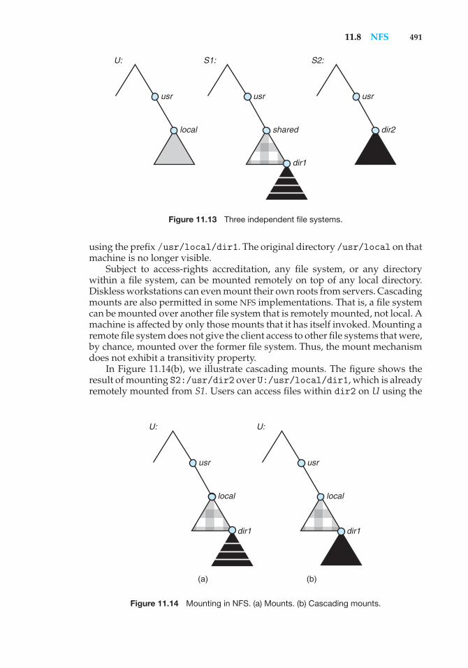
11.8 NFS 491
local
usr
shared
dir1
usr
U: S1: S2:
dir2
usr
Figure 11.13 Three independent file systems.
using the prefix /usr/local/dir1. The original directory /usr/local on thatmachine is no longer visible.
Subject to access-rights accreditation, any file system, or any directorywithin a file system, can be mounted remotely on top of any local directory.Diskless workstations can even mount their own roots from servers. Cascadingmounts are also permitted in some NFS implementations. That is, a file systemcan be mounted over another file system that is remotely mounted, not local. Amachine is affected by only those mounts that it has itself invoked. Mounting aremote file system does not give the client access to other file systems that were,by chance, mounted over the former file system. Thus, the mount mechanismdoes not exhibit a transitivity property.
In Figure 11.14(b), we illustrate cascading mounts. The figure shows theresult of mounting S2:/usr/dir2 over U:/usr/local/dir1, which is alreadyremotely mounted from S1. Users can access files within dir2 on U using the
local
dir1 dir1
usr
U: U:
(a) (b)
local
usr
Figure 11.14 Mounting in NFS. (a) Mounts. (b) Cascading mounts.
492 Chapter 11 File-System Implementation
prefix /usr/local/dir1. If a shared file system is mounted over a user’s homedirectories on all machines in a network, the user can log into any workstationand get his home environment. This property permits user mobility.
One of the design goals of NFS was to operate in a heterogeneous environ-ment of different machines, operating systems, and network architectures.The NFS specification is independent of these media and thus encouragesother implementations. This independence is achieved through the use ofRPC primitives built on top of an external data representation (XDR) proto-col used between two implementation-independent interfaces. Hence, if thesystem consists of heterogeneous machines and file systems that are properlyinterfaced to NFS, file systems of different types can be mounted both locallyand remotely.
The NFS specification distinguishes between the services provided by amount mechanism and the actual remote-file-access services. Accordingly, twoseparate protocols are specified for these services: a mount protocol and aprotocol for remote file accesses, the NFS protocol. The protocols are specified assets of RPCs. These RPCs are the building blocks used to implement transparentremote file access.
11.8.2 The Mount Protocol
The mount protocol establishes the initial logical connection between a serverand a client. In Sun’s implementation, each machine has a server process,outside the kernel, performing the protocol functions.
A mount operation includes the name of the remote directory to bemounted and the name of the server machine storing it. The mount requestis mapped to the corresponding RPC and is forwarded to the mount serverrunning on the specific server machine. The server maintains an export listthat specifies local file systems that it exports for mounting, along with namesof machines that are permitted to mount them. (In Solaris, this list is the/etc/dfs/dfstab, which can be edited only by a superuser.) The specificationcan also include access rights, such as read only. To simplify the maintenanceof export lists and mount tables, a distributed naming scheme can be used tohold this information and make it available to appropriate clients.
Recall that any directory within an exported file system can be mountedremotely by an accredited machine. A component unit is such a directory. Whenthe server receives a mount request that conforms to its export list, it returns tothe client a file handle that serves as the key for further accesses to files withinthe mounted file system. The file handle contains all the information that theserver needs to distinguish an individual file it stores. In UNIX terms, the filehandle consists of a file-system identifier and an inode number to identify theexact mounted directory within the exported file system.
The server also maintains a list of the client machines and the correspondingcurrently mounted directories. This list is used mainly for administrativepurposes—for instance, for notifying all clients that the server is going down.Only through addition and deletion of entries in this list can the server statebe affected by the mount protocol.
Usually, a system has a static mounting preconfiguration that is establishedat boot time (/etc/vfstab in Solaris); however, this layout can be modified. In
11.8 NFS 493
addition to the actual mount procedure, the mount protocol includes severalother procedures, such as unmount and return export list.
11.8.3 The NFS Protocol
The NFS protocol provides a set of RPCs for remote file operations. Theprocedures support the following operations:
• Searching for a file within a directory
• Reading a set of directory entries
• Manipulating links and directories
• Accessing file attributes
• Reading and writing files
These procedures can be invoked only after a file handle for the remotelymounted directory has been established.
The omission of open() and close() operations is intentional. A promi-nent feature of NFS servers is that they are stateless. Servers do not maintaininformation about their clients from one access to another. No parallels toUNIX’s open-files table or file structures exist on the server side. Consequently,each request has to provide a full set of arguments, including a unique fileidentifier and an absolute offset inside the file for the appropriate operations.The resulting design is robust; no special measures need be taken to recovera server after a crash. File operations must be idempotent for this purpose.Every NFS request has a sequence number, allowing the server to determine ifa request is duplicated or if any are missing.
Maintaining the list of clients that we mentioned seems to violate thestatelessness of the server. However, this list is not essential for the correctoperation of the client or the server, and hence it does not need to be restoredafter a server crash. Consequently, it might include inconsistent data and istreated as only a hint.
A further implication of the stateless-server philosophy and a result of thesynchrony of an RPC is that modified data (including indirection and statusblocks) must be committed to the server’s disk before results are returned tothe client. That is, a client can cache write blocks, but when it flushes themto the server, it assumes that they have reached the server’s disks. The servermust write all NFS data synchronously. Thus, a server crash and recoverywill be invisible to a client; all blocks that the server is managing for theclient will be intact. The consequent performance penalty can be large, becausethe advantages of caching are lost. Performance can be increased by usingstorage with its own nonvolatile cache (usually battery-backed-up memory).The disk controller acknowledges the disk write when the write is stored inthe nonvolatile cache. In essence, the host sees a very fast synchronous write.These blocks remain intact even after system crash and are written from thisstable storage to disk periodically.
A single NFS write procedure call is guaranteed to be atomic and is notintermixed with other write calls to the same file. The NFS protocol, however,does not provide concurrency-control mechanisms. A write() system call may
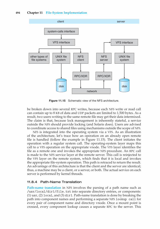
494 Chapter 11 File-System Implementation
disk disk
system-calls interface
client server
other types offile systems
UNIX filesystem
UNIX filesystem
NFSclient
RPC/XDR
network
RPC/XDR
NFSserver
VFS interface VFS interface
Figure 11.15 Schematic view of the NFS architecture.
be broken down into several RPC writes, because each NFS write or read callcan contain up to 8 KB of data and UDP packets are limited to 1,500 bytes. As aresult, two users writing to the same remote file may get their data intermixed.The claim is that, because lock management is inherently stateful, a serviceoutside the NFS should provide locking (and Solaris does). Users are advisedto coordinate access to shared files using mechanisms outside the scope of NFS.
NFS is integrated into the operating system via a VFS. As an illustrationof the architecture, let’s trace how an operation on an already open remotefile is handled (follow the example in Figure 11.15). The client initiates theoperation with a regular system call. The operating-system layer maps thiscall to a VFS operation on the appropriate vnode. The VFS layer identifies thefile as a remote one and invokes the appropriate NFS procedure. An RPC callis made to the NFS service layer at the remote server. This call is reinjected tothe VFS layer on the remote system, which finds that it is local and invokesthe appropriate file-system operation. This path is retraced to return the result.An advantage of this architecture is that the client and the server are identical;thus, a machine may be a client, or a server, or both. The actual service on eachserver is performed by kernel threads.
11.8.4 Path-Name Translation
Path-name translation in NFS involves the parsing of a path name such as/usr/local/dir1/file.txt into separate directory entries, or components:(1) usr, (2) local, and (3) dir1. Path-name translation is done by breaking thepath into component names and performing a separate NFS lookup call forevery pair of component name and directory vnode. Once a mount point iscrossed, every component lookup causes a separate RPC to the server. This
11.8 NFS 495
expensive path-name-traversal scheme is needed, since the layout of eachclient’s logical name space is unique, dictated by the mounts the client hasperformed. It would be much more efficient to hand a server a path nameand receive a target vnode once a mount point is encountered. At any point,however, there might be another mount point for the particular client of whichthe stateless server is unaware.
So that lookup is fast, a directory-name-lookup cache on the client sideholds the vnodes for remote directory names. This cache speeds up referencesto files with the same initial path name. The directory cache is discarded whenattributes returned from the server do not match the attributes of the cachedvnode.
Recall that mounting a remote file system on top of another alreadymounted remote file system (a cascading mount) is allowed in some imple-mentations of NFS. However, a server cannot act as an intermediary between aclient and another server. Instead, a client must establish a direct client–serverconnection with the second server by directly mounting the desired directory.When a client has a cascading mount, more than one server can be involved in apath-name traversal. However, each component lookup is performed betweenthe original client and some server. Therefore, when a client does a lookup ona directory on which the server has mounted a file system, the client sees theunderlying directory instead of the mounted directory.
11.8.5 Remote Operations
With the exception of opening and closing files, there is almost a one-to-onecorrespondence between the regular UNIX system calls for file operations andthe NFS protocol RPCs. Thus, a remote file operation can be translated directlyto the corresponding RPC. Conceptually, NFS adheres to the remote-serviceparadigm; but in practice, buffering and caching techniques are employed forthe sake of performance. No direct correspondence exists between a remoteoperation and an RPC. Instead, file blocks and file attributes are fetched by theRPCs and are cached locally. Future remote operations use the cached data,subject to consistency constraints.
There are two caches: the file-attribute (inode-information) cache and thefile-blocks cache. When a file is opened, the kernel checks with the remoteserver to determine whether to fetch or revalidate the cached attributes. Thecached file blocks are used only if the corresponding cached attributes are upto date. The attribute cache is updated whenever new attributes arrive fromthe server. Cached attributes are, by default, discarded after 60 seconds. Bothread-ahead and delayed-write techniques are used between the server and theclient. Clients do not free delayed-write blocks until the server confirms thatthe data have been written to disk. Delayed-write is retained even when a fileis opened concurrently, in conflicting modes. Hence, UNIX semantics (Section10.5.3.1) are not preserved.
Tuning the system for performance makes it difficult to characterize theconsistency semantics of NFS. New files created on a machine may not bevisible elsewhere for 30 seconds. Furthermore, writes to a file at one site mayor may not be visible at other sites that have this file open for reading. Newopens of a file observe only the changes that have already been flushed to theserver. Thus, NFS provides neither strict emulation of UNIX semantics nor the
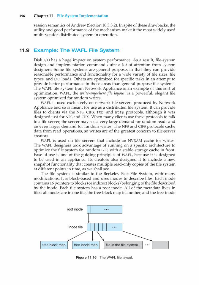
496 Chapter 11 File-System Implementation
session semantics of Andrew (Section 10.5.3.2). In spite of these drawbacks, theutility and good performance of the mechanism make it the most widely usedmulti-vendor-distributed system in operation.
11.9 Example: The WAFL File System
Disk I/O has a huge impact on system performance. As a result, file-systemdesign and implementation command quite a lot of attention from systemdesigners. Some file systems are general purpose, in that they can providereasonable performance and functionality for a wide variety of file sizes, filetypes, and I/O loads. Others are optimized for specific tasks in an attempt toprovide better performance in those areas than general-purpose file systems.The WAFL file system from Network Appliance is an example of this sort ofoptimization. WAFL, the write-anywhere �le layout, is a powerful, elegant filesystem optimized for random writes.
WAFL is used exclusively on network file servers produced by NetworkAppliance and so is meant for use as a distributed file system. It can providefiles to clients via the NFS, CIFS, ftp, and http protocols, although it wasdesigned just for NFS and CIFS. When many clients use these protocols to talkto a file server, the server may see a very large demand for random reads andan even larger demand for random writes. The NFS and CIFS protocols cachedata from read operations, so writes are of the greatest concern to file-servercreators.
WAFL is used on file servers that include an NVRAM cache for writes.The WAFL designers took advantage of running on a specific architecture tooptimize the file system for random I/O, with a stable-storage cache in front.Ease of use is one of the guiding principles of WAFL, because it is designedto be used in an appliance. Its creators also designed it to include a newsnapshot functionality that creates multiple read-only copies of the file systemat different points in time, as we shall see.
The file system is similar to the Berkeley Fast File System, with manymodifications. It is block-based and uses inodes to describe files. Each inodecontains 16 pointers to blocks (or indirect blocks) belonging to the file describedby the inode. Each file system has a root inode. All of the metadata lives infiles: all inodes are in one file, the free-block map in another, and the free-inode
free block map free inode map file in the file system...
root inode
inode file
•••
•••
•••
Figure 11.16 The WAFL file layout.
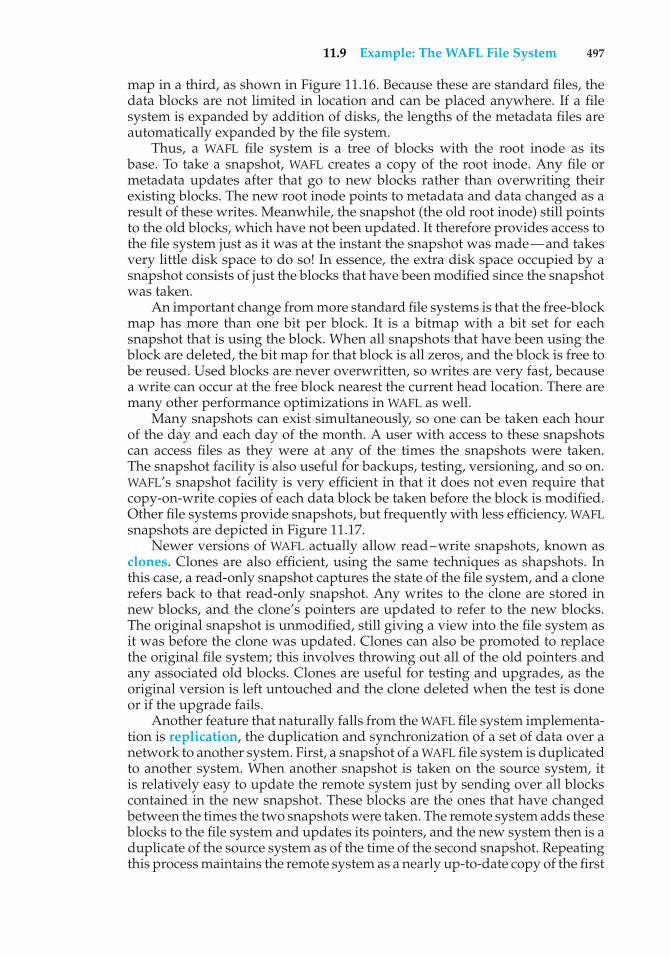
11.9 Example: The WAFL File System 497
map in a third, as shown in Figure 11.16. Because these are standard files, thedata blocks are not limited in location and can be placed anywhere. If a filesystem is expanded by addition of disks, the lengths of the metadata files areautomatically expanded by the file system.
Thus, a WAFL file system is a tree of blocks with the root inode as itsbase. To take a snapshot, WAFL creates a copy of the root inode. Any file ormetadata updates after that go to new blocks rather than overwriting theirexisting blocks. The new root inode points to metadata and data changed as aresult of these writes. Meanwhile, the snapshot (the old root inode) still pointsto the old blocks, which have not been updated. It therefore provides access tothe file system just as it was at the instant the snapshot was made—and takesvery little disk space to do so! In essence, the extra disk space occupied by asnapshot consists of just the blocks that have been modified since the snapshotwas taken.
An important change from more standard file systems is that the free-blockmap has more than one bit per block. It is a bitmap with a bit set for eachsnapshot that is using the block. When all snapshots that have been using theblock are deleted, the bit map for that block is all zeros, and the block is free tobe reused. Used blocks are never overwritten, so writes are very fast, becausea write can occur at the free block nearest the current head location. There aremany other performance optimizations in WAFL as well.
Many snapshots can exist simultaneously, so one can be taken each hourof the day and each day of the month. A user with access to these snapshotscan access files as they were at any of the times the snapshots were taken.The snapshot facility is also useful for backups, testing, versioning, and so on.WAFL’s snapshot facility is very efficient in that it does not even require thatcopy-on-write copies of each data block be taken before the block is modified.Other file systems provide snapshots, but frequently with less efficiency. WAFLsnapshots are depicted in Figure 11.17.
Newer versions of WAFL actually allow read–write snapshots, known asclones. Clones are also efficient, using the same techniques as shapshots. Inthis case, a read-only snapshot captures the state of the file system, and a clonerefers back to that read-only snapshot. Any writes to the clone are stored innew blocks, and the clone’s pointers are updated to refer to the new blocks.The original snapshot is unmodified, still giving a view into the file system asit was before the clone was updated. Clones can also be promoted to replacethe original file system; this involves throwing out all of the old pointers andany associated old blocks. Clones are useful for testing and upgrades, as theoriginal version is left untouched and the clone deleted when the test is doneor if the upgrade fails.
Another feature that naturally falls from the WAFL file system implementa-tion is replication, the duplication and synchronization of a set of data over anetwork to another system. First, a snapshot of a WAFL file system is duplicatedto another system. When another snapshot is taken on the source system, itis relatively easy to update the remote system just by sending over all blockscontained in the new snapshot. These blocks are the ones that have changedbetween the times the two snapshots were taken. The remote system adds theseblocks to the file system and updates its pointers, and the new system then is aduplicate of the source system as of the time of the second snapshot. Repeatingthis process maintains the remote system as a nearly up-to-date copy of the first
498 Chapter 11 File-System Implementation
block A B C D E
root inode
(a) Before a snapshot.
block A B C D E
root inode
(b) After a snapshot, before any blocks change.
new snapshot
block A B C D D´E
root inode
(c) After block D has changed to D´.
new snapshot
Figure 11.17 Snapshots in WAFL.
system. Such replication is used for disaster recovery. Should the first systembe destroyed, most of its data are available for use on the remote system.
Finally, we should note that Sun’s ZFS file system supports similarlyefficient snapshots, clones, and replication.
11.10 Summary
The file system resides permanently on secondary storage, which is designed tohold a large amount of data permanently. The most common secondary-storagemedium is the disk.
Physical disks may be segmented into partitions to control media useand to allow multiple, possibly varying, file systems on a single spindle.These file systems are mounted onto a logical file system architecture to makethem available for use. File systems are often implemented in a layered ormodular structure. The lower levels deal with the physical properties of storagedevices. Upper levels deal with symbolic file names and logical properties offiles. Intermediate levels map the logical file concepts into physical deviceproperties.
Any file-system type can have different structures and algorithms. A VFSlayer allows the upper layers to deal with each file-system type uniformly. Even
Practice Exercises 499
remote file systems can be integrated into the system’s directory structure andacted on by standard system calls via the VFS interface.
The various files can be allocated space on the disk in three ways: throughcontiguous, linked, or indexed allocation. Contiguous allocation can sufferfrom external fragmentation. Direct access is very inefficient with linkedallocation. Indexed allocation may require substantial overhead for its indexblock. These algorithms can be optimized in many ways. Contiguous spacecan be enlarged through extents to increase flexibility and to decrease externalfragmentation. Indexed allocation can be done in clusters of multiple blocksto increase throughput and to reduce the number of index entries needed.Indexing in large clusters is similar to contiguous allocation with extents.
Free-space allocation methods also influence the efficiency of disk-spaceuse, the performance of the file system, and the reliability of secondary storage.The methods used include bit vectors and linked lists. Optimizations includegrouping, counting, and the FAT, which places the linked list in one contiguousarea.
Directory-management routines must consider efficiency, performance,and reliability. A hash table is a commonly used method, as it is fast andefficient. Unfortunately, damage to the table or a system crash can resultin inconsistency between the directory information and the disk’s contents.A consistency checker can be used to repair the damage. Operating-systembackup tools allow disk data to be copied to tape, enabling the user to recoverfrom data or even disk loss due to hardware failure, operating system bug, oruser error.
Network file systems, such as NFS, use client–server methodology toallow users to access files and directories from remote machines as if theywere on local file systems. System calls on the client are translated intonetwork protocols and retranslated into file-system operations on the server.Networking and multiple-client access create challenges in the areas of dataconsistency and performance.
Due to the fundamental role that file systems play in system operation,their performance and reliability are crucial. Techniques such as log structuresand caching help improve performance, while log structures and RAID improvereliability. The WAFL file system is an example of optimization of performanceto match a specific I/O load.
Practice Exercises
11.1 Consider a file currently consisting of 100 blocks. Assume that the file-control block (and the index block, in the case of indexed allocation)is already in memory. Calculate how many disk I/O operations arerequired for contiguous, linked, and indexed (single-level) allocationstrategies, if, for one block, the following conditions hold. In thecontiguous-allocation case, assume that there is no room to grow atthe beginning but there is room to grow at the end. Also assume thatthe block information to be added is stored in memory.
a. The block is added at the beginning.
b. The block is added in the middle.
500 Chapter 11 File-System Implementation
c. The block is added at the end.
d. The block is removed from the beginning.
e. The block is removed from the middle.
f. The block is removed from the end.
11.2 What problems could occur if a system allowed a file system to bemounted simultaneously at more than one location?
11.3 Why must the bit map for file allocation be kept on mass storage, ratherthan in main memory?
11.4 Consider a system that supports the strategies of contiguous, linked,and indexed allocation. What criteria should be used in deciding whichstrategy is best utilized for a particular file?
11.5 One problem with contiguous allocation is that the user must preallo-cate enough space for each file. If the file grows to be larger than thespace allocated for it, special actions must be taken. One solution to thisproblem is to define a file structure consisting of an initial contiguousarea (of a specified size). If this area is filled, the operating systemautomatically defines an overflow area that is linked to the initialcontiguous area. If the overflow area is filled, another overflow areais allocated. Compare this implementation of a file with the standardcontiguous and linked implementations.
11.6 How do caches help improve performance? Why do systems not usemore or larger caches if they are so useful?
11.7 Why is it advantageous to the user for an operating system to dynami-cally allocate its internal tables? What are the penalties to the operatingsystem for doing so?
11.8 Explain how the VFS layer allows an operating system to supportmultiple types of file systems easily.
Exercises
11.9 Consider a file system that uses a modifed contiguous-allocationscheme with support for extents. A file is a collection of extents, witheach extent corresponding to a contiguous set of blocks. A key issue insuch systems is the degree of variability in the size of the extents. Whatare the advantages and disadvantages of the following schemes?
a. All extents are of the same size, and the size is predetermined.
b. Extents can be of any size and are allocated dynamically.
c. Extents can be of a few fixed sizes, and these sizes are predeter-mined.
11.10 What are the advantages of the variant of linked allocation that uses aFAT to chain together the blocks of a file?
Exercises 501
11.11 Consider a system where free space is kept in a free-space list.
a. Suppose that the pointer to the free-space list is lost. Can thesystem reconstruct the free-space list? Explain your answer.
b. Consider a file system similar to the one used by UNIX withindexed allocation. How many disk I/O operations might berequired to read the contents of a small local file at /a/b/c? Assumethat none of the disk blocks is currently being cached.
c. Suggest a scheme to ensure that the pointer is never lost as a resultof memory failure.
11.12 Some file systems allow disk storage to be allocated at different levelsof granularity. For instance, a file system could allocate 4 KB of diskspace as a single 4-KB block or as eight 512-byte blocks. How couldwe take advantage of this flexibility to improve performance? Whatmodifications would have to be made to the free-space managementscheme in order to support this feature?
11.13 Discuss how performance optimizations for file systems might resultin difficulties in maintaining the consistency of the systems in the eventof computer crashes.
11.14 Consider a file system on a disk that has both logical and physicalblock sizes of 512 bytes. Assume that the information about eachfile is already in memory. For each of the three allocation strategies(contiguous, linked, and indexed), answer these questions:
a. How is the logical-to-physical address mapping accomplishedin this system? (For the indexed allocation, assume that a file isalways less than 512 blocks long.)
b. If we are currently at logical block 10 (the last block accessed wasblock 10) and want to access logical block 4, how many physicalblocks must be read from the disk?
11.15 Consider a file system that uses inodes to represent files. Disk blocksare 8 KB in size, and a pointer to a disk block requires 4 bytes. This filesystem has 12 direct disk blocks, as well as single, double, and tripleindirect disk blocks. What is the maximum size of a file that can bestored in this file system?
11.16 Fragmentation on a storage device can be eliminated by recompactionof the information. Typical disk devices do not have relocation or baseregisters (such as those used when memory is to be compacted), sohow can we relocate files? Give three reasons why recompacting andrelocation of files are often avoided.
11.17 In what situations would using memory as a RAM disk be more usefulthan using it as a disk cache?
11.18 Assume that in a particular augmentation of a remote-file-accessprotocol, each client maintains a name cache that caches translationsfrom file names to corresponding file handles. What issues should wetake into account in implementing the name cache?
502 Chapter 11 File-System Implementation
11.19 Explain why logging metadata updates ensures recovery of a filesystem after a file-system crash.
11.20 Consider the following backup scheme:
• Day 1. Copy to a backup medium all files from the disk.
• Day 2. Copy to another medium all files changed since day 1.
• Day 3. Copy to another medium all files changed since day 1.
This differs from the schedule given in Section 11.7.4 by having allsubsequent backups copy all files modified since the first full backup.What are the benefits of this system over the one in Section 11.7.4?What are the drawbacks? Are restore operations made easier or moredifficult? Explain your answer.
Wiley Plus
Visit Wiley Plus for
• Source code
• Solutions to practice exercises
• Additional programming problems and exercises
• Labs using an operating system simulator
Bibliographical Notes
The MS-DOS FAT system is explained in Norton and Wilton [1988], and the OS/2description can be found in Iacobucci [1988]. These operating systems usethe Intel 8086 CPUs(Intel [1985b], Intel [1985a], Intel [1986], and Intel [1990]).IBM allocation methods are described in Deitel [1990]. The internals of theBSD UNIX system are covered in full in McKusick et al. [1996]. McVoy andKleiman [1991] discusses optimizations of these methods made in Solaris. TheGoogle file system is described in Ghemawat et al. [2003]. FUSE can be foundat http://fuse.sourceforge.net/.
Disk file allocation based on the buddy system is covered in Koch[1987]. A file-organization scheme that guarantees retrieval in one accessis described by Larson and Kajla [1984]. Log-structured file organiza-tions for enhancing both performance and consistency are discussed inRosenblum and Ousterhout [1991], Seltzer et al. [1993], and Seltzer et al.[1995]. Algorithms such as balanced trees (and much more) are coveredby Knuth [1998] and Cormen et al. [2001]. The ZFS source code for spacemaps can be found at http://src.opensolaris.org/source/xref/onnv/onnv-gate/usr/src/uts/common/fs/zfs/space map.c.
Disk caching is discussed by McKeon [1985] and Smith [1985]. Caching inthe experimental Sprite operating system is described in Nelson et al. [1988].General discussions concerning mass-storage technology are offered by Chi[1982] and Hoagland [1985]. Folk and Zoellick [1987] covers the gamut of file
Bibliographical Notes 503
structures. Silvers [2000] discusses implementing the page cache in the NetBSDoperating system.
The network file system (NFS) is discussed in Sandberg et al. [1985],Sandberg [1987], Sun [1990], and Callaghan [2000]. NFS Version 4 is a stan-dard described at http://www.ietf.org/rfc/rfc3530.txt. The characteristics ofworkloads in distributed file systems are examined in Baker et al. [1991].Ousterhout [1991] discusses the role of distributed state in networked filesystems. Log-structured designs for networked file systems are proposed inHartman and Ousterhout [1995] and Thekkath et al. [1997]. NFS and the UNIXfile system (UFS) are described in Vahalia [1996] and Mauro and McDougall[2007]. The Windows NT file system, NTFS, is explained in Solomon [1998]. TheExt2 file system used in Linux is described in Bovet and Cesati [2002] andthe WAFL file system in Hitz et al. [1995]. ZFS documentation can be found athttp://www.opensolaris.org/os/community/ZFS/docs.

This page intentionally left blank
12C H A P T E R
Mass -StorageStructure
The file system can be viewed logically as consisting of three parts. In Chapter10, we examined the user and programmer interface to the file system. InChapter 11, we described the internal data structures and algorithms usedby the operating system to implement this interface. In this chapter, wediscuss the lowest level of the file system: the secondary and tertiary storagestructures. We first describe the physical structure of magenetic disks andmagnetic tapes. We then describe disk-scheduling algorithms, which schedulethe order of disk I/Os to improve performance. Next, we discuss disk formattingand management of boot blocks, damaged blocks, and swap space. We thenexamine secondary storage structure, covering disk reliability and stable-storage implementation. We conclude with a brief description of tertiarystorage devices and the problems that arise when an operating system usestertiary storage.
CHAPTER OBJECTIVES
• To describe the physical structure of secondary and tertiary storagedevices and its effects on the uses of the devices.
• To explain the performance characteristics of mass-storage devices.
• To discuss operating-system services provided for mass storage, includingRAID and HSM.
12.1 Overview of Mass-Storage Structure
In this section, we present a general overview of the physical structure ofsecondary and tertiary storage devices.
12.1.1 Magnetic Disks
Magnetic disks provide the bulk of secondary storage for modern computersystems. Conceptually, disks are relatively simple (Figure 12.1). Each diskplatter has a flat circular shape, like a CD. Common platter diameters range
505
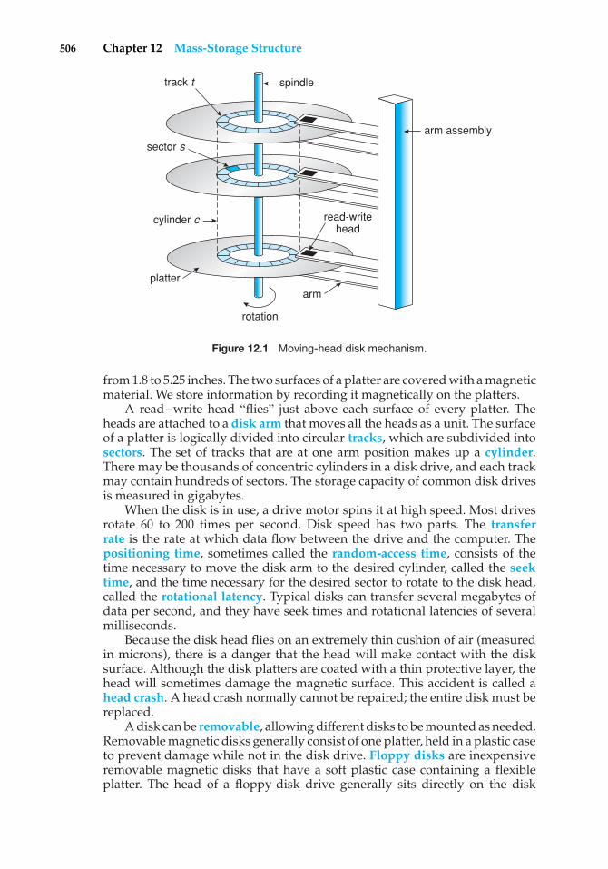
506 Chapter 12 Mass-Storage Structure
track t
sector s
spindle
cylinder c
platter
arm
read-writehead
arm assembly
rotation
Figure 12.1 Moving-head disk mechanism.
from 1.8 to 5.25 inches. The two surfaces of a platter are covered with a magneticmaterial. We store information by recording it magnetically on the platters.
A read–write head “flies” just above each surface of every platter. Theheads are attached to a disk arm that moves all the heads as a unit. The surfaceof a platter is logically divided into circular tracks, which are subdivided intosectors. The set of tracks that are at one arm position makes up a cylinder.There may be thousands of concentric cylinders in a disk drive, and each trackmay contain hundreds of sectors. The storage capacity of common disk drivesis measured in gigabytes.
When the disk is in use, a drive motor spins it at high speed. Most drivesrotate 60 to 200 times per second. Disk speed has two parts. The transferrate is the rate at which data flow between the drive and the computer. Thepositioning time, sometimes called the random-access time, consists of thetime necessary to move the disk arm to the desired cylinder, called the seektime, and the time necessary for the desired sector to rotate to the disk head,called the rotational latency. Typical disks can transfer several megabytes ofdata per second, and they have seek times and rotational latencies of severalmilliseconds.
Because the disk head flies on an extremely thin cushion of air (measuredin microns), there is a danger that the head will make contact with the disksurface. Although the disk platters are coated with a thin protective layer, thehead will sometimes damage the magnetic surface. This accident is called ahead crash. A head crash normally cannot be repaired; the entire disk must bereplaced.
A disk can be removable, allowing different disks to be mounted as needed.Removable magnetic disks generally consist of one platter, held in a plastic caseto prevent damage while not in the disk drive. Floppy disks are inexpensiveremovable magnetic disks that have a soft plastic case containing a flexibleplatter. The head of a floppy-disk drive generally sits directly on the disk
12.1 Overview of Mass-Storage Structure 507
DISK TRANSFER RATES
As with many aspects of computing, published performance numbers fordisks are not the same as real-world performance numbers. Stated transferrates are always lower than effective transfer rates, for example. The transferrate may be the rate at which bits can be read from the magnetic media bythe disk head, but that is different from the rate at which blocks are deliveredto the operating system.
surface, so the drive is designed to rotate more slowly than a hard-disk driveto reduce the wear on the disk surface. The storage capacity of a floppy diskis typically only 1.44 MB or so. Removable disks are available that work muchlike normal hard disks and have capacities measured in gigabytes.
A disk drive is attached to a computer by a set of wires called an I/Obus. Several kinds of buses are available, including enhanced integrated driveelectronics (EIDE), advanced technology attachment (ATA), serial ATA (SATA),universal serial bus (USB), fiber channel (FC), and small computer-systemsinterface (SCSI) buses. The data transfers on a bus are carried out by specialelectronic processors called controllers. The host controller is the controller atthe computer end of the bus. A disk controller is built into each disk drive. Toperform a disk I/O operation, the computer places a command into the hostcontroller, typically using memory-mapped I/O ports, as described in Section9.7.3. The host controller then sends the command via messages to the diskcontroller, and the disk controller operates the disk-drive hardware to carryout the command. Disk controllers usually have a built-in cache. Data transferat the disk drive happens between the cache and the disk surface, and datatransfer to the host, at fast electronic speeds, occurs between the cache and thehost controller.
12.1.2 Magnetic Tapes
Magnetic tape was used as an early secondary-storage medium. Although itis relatively permanent and can hold large quantities of data, its access timeis slow compared with that of main memory and magnetic disk. In addition,random access to magnetic tape is about a thousand times slower than randomaccess to magnetic disk, so tapes are not very useful for secondary storage.Tapes are used mainly for backup, for storage of infrequently used information,and as a medium for transferring information from one system to another.
A tape is kept in a spool and is wound or rewound past a read–write head.Moving to the correct spot on a tape can take minutes, but once positioned,tape drives can write data at speeds comparable to disk drives. Tape capacitiesvary greatly, depending on the particular kind of tape drive. Typically, theystore from 20 GB to 200 GB. Some have built-in compression that can more thandouble the effective storage. Tapes and their drivers are usually categorizedby width, including 4, 8, and 19 millimeters and 1/4 and 1/2 inch. Some arenamed according to technology, such as LTO-2 and SDLT. Tape storage is furtherdescribed in Section 12.9.
508 Chapter 12 Mass-Storage Structure
FIREWIRE
FireWire refers to an interface designed for connecting peripheral devicessuch as hard drives, DVD drives, and digital video cameras to a computersystem. FireWire was first developed by Apple Computer and becamethe IEEE 1394 standard in 1995. The original FireWire standard providedbandwidth up to 400 megabits per second. Recently, a new standard—FireWire 2—has emerged and is identified by the IEEE 1394b standard.FireWire 2 provides double the data rate of the original FireWire—800megabits per second.
12.2 Disk Structure
Modern disk drives are addressed as large one-dimensional arrays of logicalblocks, where the logical block is the smallest unit of transfer. The size ofa logical block is usually 512 bytes, although some disks can be low-levelformatted to have a different logical block size, such as 1,024 bytes. This optionis described in Section 12.5.1. The one-dimensional array of logical blocks ismapped onto the sectors of the disk sequentially. Sector 0 is the first sectorof the first track on the outermost cylinder. The mapping proceeds in orderthrough that track, then through the rest of the tracks in that cylinder, and thenthrough the rest of the cylinders from outermost to innermost.
By using this mapping, we can—at least in theory—convert a logical blocknumber into an old-style disk address that consists of a cylinder number, a tracknumber within that cylinder, and a sector number within that track. In practice,it is difficult to perform this translation, for two reasons. First, most disks havesome defective sectors, but the mapping hides this by substituting spare sectorsfrom elsewhere on the disk. Second, the number of sectors per track is not aconstant on some drives.
Let’s look more closely at the second reason. On media that use constantlinear velocity (CLV), the density of bits per track is uniform. The farther a trackis from the center of the disk, the greater its length, so the more sectors it canhold. As we move from outer zones to inner zones, the number of sectors pertrack decreases. Tracks in the outermost zone typically hold 40 percent moresectors than do tracks in the innermost zone. The drive increases its rotationspeed as the head moves from the outer to the inner tracks to keep the same rateof data moving under the head. This method is used in CD-ROM and DVD-ROMdrives. Alternatively, the disk rotation speed can stay constant; in this case, thedensity of bits decreases from inner tracks to outer tracks to keep the data rateconstant. This method is used in hard disks and is known as constant angularvelocity (CAV).
The number of sectors per track has been increasing as disk technologyimproves, and the outer zone of a disk usually has several hundred sectors pertrack. Similarly, the number of cylinders per disk has been increasing; largedisks have tens of thousands of cylinders.
12.3 Disk Attachment 509
12.3 Disk Attachment
Computers access disk storage in two ways. One way is via I/O ports (orhost-attached storage); this is common on small systems. The other way is viaa remote host in a distributed file system; this is referred to as network-attachedstorage.
12.3.1 Host-Attached Storage
Host-attached storage is storage accessed through local I/O ports. These portsuse several technologies. The typical desktop PC uses an I/O bus architecturecalled IDE or ATA. This architecture supports a maximum of two drives per I/Obus. A newer, similar protocol that has simplified cabling is SATA. High-endworkstations and servers generally use more sophisticated I/O architectures,such as SCSI and fiber channel (FC).
SCSI is a bus architecture. Its physical medium is usually a ribbon cable witha large number of conductors (typically 50 or 68). The SCSI protocol supports amaximum of 16 devices per bus. Generally, the devices include one controllercard in the host (the SCSI initiator) and up to 15 storage devices (the SCSItargets). A SCSI disk is a common SCSI target, but the protocol provides theability to address up to 8 logical units in each SCSI target. A typical use oflogical unit addressing is to direct commands to components of a RAID arrayor components of a removable media library (such as a CD jukebox sendingcommands to the media-changer mechanism or to one of the drives).
FC is a high-speed serial architecture that can operate over optical fiber orover a four-conductor copper cable. It has two variants. One is a large switchedfabric having a 24-bit address space. This variant is expected to dominatein the future and is the basis of storage-area networks (SANs), discussed inSection 12.3.3. Because of the large address space and the switched nature ofthe communication, multiple hosts and storage devices can attach to the fabric,allowing great flexibility in I/O communication. The other FC variant is anarbitrated loop (FC-AL) that can address 126 devices (drives and controllers).
A wide variety of storage devices are suitable for use as host-attachedstorage. Among these are hard disk drives, RAID arrays, and CD, DVD, andtape drives. The I/O commands that initiate data transfers to a host-attachedstorage device are reads and writes of logical data blocks directed to specificallyidentified storage units (such as bus ID, SCSI ID, and target logical unit).
12.3.2 Network-Attached Storage
A network-attached storage (NAS) device is a special-purpose storage systemthat is accessed remotely over a data network (Figure 12.2). Clients accessnetwork-attached storage via a remote-procedure-call interface such as NFSfor UNIX systems or CIFS for Windows machines. The remote procedure calls(RPCs) are carried via TCP or UDP over an IP network—usually the samelocal-area network (LAN) that carries all data traffic to the clients. The network-attached storage unit is usually implemented as a RAID array with software thatimplements the RPC interface. It is easiest to think of NAS as simply anotherstorage-access protocol. For example, rather than using a SCSI device driverand SCSI protocols to access storage, a system using NAS would use RPC overTCP/IP.
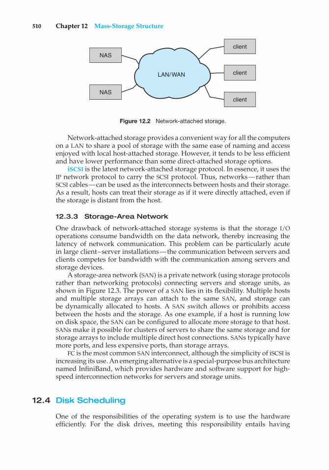
510 Chapter 12 Mass-Storage Structure
NAS
client
NASclient
clientLAN/WAN
Figure 12.2 Network-attached storage.
Network-attached storage provides a convenient way for all the computerson a LAN to share a pool of storage with the same ease of naming and accessenjoyed with local host-attached storage. However, it tends to be less efficientand have lower performance than some direct-attached storage options.
iSCSI is the latest network-attached storage protocol. In essence, it uses theIP network protocol to carry the SCSI protocol. Thus, networks—rather thanSCSI cables—can be used as the interconnects between hosts and their storage.As a result, hosts can treat their storage as if it were directly attached, even ifthe storage is distant from the host.
12.3.3 Storage-Area Network
One drawback of network-attached storage systems is that the storage I/Ooperations consume bandwidth on the data network, thereby increasing thelatency of network communication. This problem can be particularly acutein large client–server installations—the communication between servers andclients competes for bandwidth with the communication among servers andstorage devices.
A storage-area network (SAN) is a private network (using storage protocolsrather than networking protocols) connecting servers and storage units, asshown in Figure 12.3. The power of a SAN lies in its flexibility. Multiple hostsand multiple storage arrays can attach to the same SAN, and storage canbe dynamically allocated to hosts. A SAN switch allows or prohibits accessbetween the hosts and the storage. As one example, if a host is running lowon disk space, the SAN can be configured to allocate more storage to that host.SANs make it possible for clusters of servers to share the same storage and forstorage arrays to include multiple direct host connections. SANs typically havemore ports, and less expensive ports, than storage arrays.
FC is the most common SAN interconnect, although the simplicity of iSCSI isincreasing its use. An emerging alternative is a special-purpose bus architecturenamed InfiniBand, which provides hardware and software support for high-speed interconnection networks for servers and storage units.
12.4 Disk Scheduling
One of the responsibilities of the operating system is to use the hardwareefficiently. For the disk drives, meeting this responsibility entails having
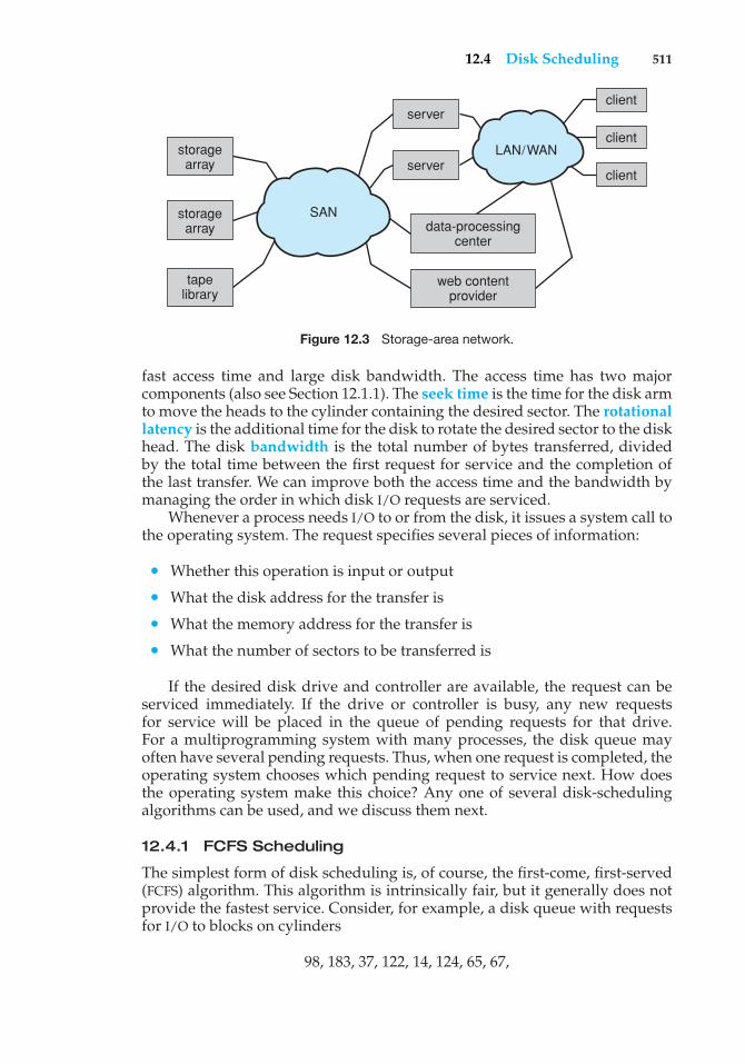
12.4 Disk Scheduling 511
LAN/WAN
storagearray
storagearray
data-processingcenter
web contentprovider
serverclient
client
clientserver
tapelibrary
SAN
Figure 12.3 Storage-area network.
fast access time and large disk bandwidth. The access time has two majorcomponents (also see Section 12.1.1). The seek time is the time for the disk armto move the heads to the cylinder containing the desired sector. The rotationallatency is the additional time for the disk to rotate the desired sector to the diskhead. The disk bandwidth is the total number of bytes transferred, dividedby the total time between the first request for service and the completion ofthe last transfer. We can improve both the access time and the bandwidth bymanaging the order in which disk I/O requests are serviced.
Whenever a process needs I/O to or from the disk, it issues a system call tothe operating system. The request specifies several pieces of information:
• Whether this operation is input or output
• What the disk address for the transfer is
• What the memory address for the transfer is
• What the number of sectors to be transferred is
If the desired disk drive and controller are available, the request can beserviced immediately. If the drive or controller is busy, any new requestsfor service will be placed in the queue of pending requests for that drive.For a multiprogramming system with many processes, the disk queue mayoften have several pending requests. Thus, when one request is completed, theoperating system chooses which pending request to service next. How doesthe operating system make this choice? Any one of several disk-schedulingalgorithms can be used, and we discuss them next.
12.4.1 FCFS Scheduling
The simplest form of disk scheduling is, of course, the first-come, first-served(FCFS) algorithm. This algorithm is intrinsically fair, but it generally does notprovide the fastest service. Consider, for example, a disk queue with requestsfor I/O to blocks on cylinders
98, 183, 37, 122, 14, 124, 65, 67,
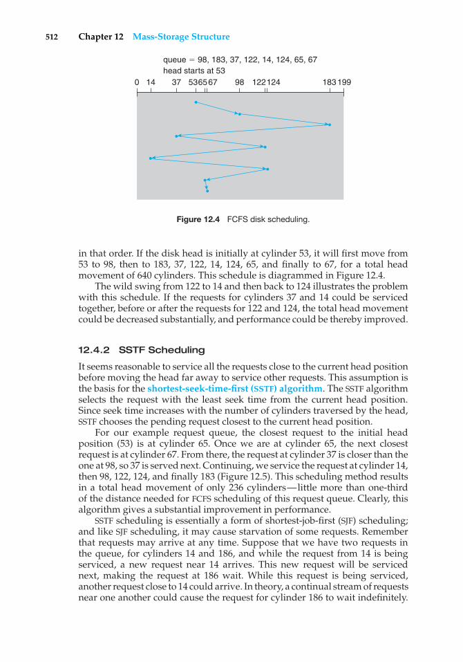
512 Chapter 12 Mass-Storage Structure
0 14 37 536567 98 122124 183199
queue � 98, 183, 37, 122, 14, 124, 65, 67head starts at 53
Figure 12.4 FCFS disk scheduling.
in that order. If the disk head is initially at cylinder 53, it will first move from53 to 98, then to 183, 37, 122, 14, 124, 65, and finally to 67, for a total headmovement of 640 cylinders. This schedule is diagrammed in Figure 12.4.
The wild swing from 122 to 14 and then back to 124 illustrates the problemwith this schedule. If the requests for cylinders 37 and 14 could be servicedtogether, before or after the requests for 122 and 124, the total head movementcould be decreased substantially, and performance could be thereby improved.
12.4.2 SSTF Scheduling
It seems reasonable to service all the requests close to the current head positionbefore moving the head far away to service other requests. This assumption isthe basis for the shortest-seek-time-first (SSTF) algorithm. The SSTF algorithmselects the request with the least seek time from the current head position.Since seek time increases with the number of cylinders traversed by the head,SSTF chooses the pending request closest to the current head position.
For our example request queue, the closest request to the initial headposition (53) is at cylinder 65. Once we are at cylinder 65, the next closestrequest is at cylinder 67. From there, the request at cylinder 37 is closer than theone at 98, so 37 is served next. Continuing, we service the request at cylinder 14,then 98, 122, 124, and finally 183 (Figure 12.5). This scheduling method resultsin a total head movement of only 236 cylinders—little more than one-thirdof the distance needed for FCFS scheduling of this request queue. Clearly, thisalgorithm gives a substantial improvement in performance.
SSTF scheduling is essentially a form of shortest-job-first (SJF) scheduling;and like SJF scheduling, it may cause starvation of some requests. Rememberthat requests may arrive at any time. Suppose that we have two requests inthe queue, for cylinders 14 and 186, and while the request from 14 is beingserviced, a new request near 14 arrives. This new request will be servicednext, making the request at 186 wait. While this request is being serviced,another request close to 14 could arrive. In theory, a continual stream of requestsnear one another could cause the request for cylinder 186 to wait indefinitely.
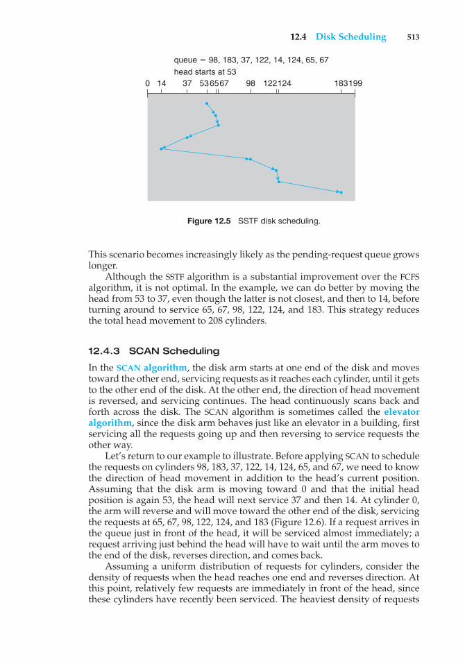
12.4 Disk Scheduling 513
0 14 37 536567 98 122124 183199
queue � 98, 183, 37, 122, 14, 124, 65, 67head starts at 53
Figure 12.5 SSTF disk scheduling.
This scenario becomes increasingly likely as the pending-request queue growslonger.
Although the SSTF algorithm is a substantial improvement over the FCFSalgorithm, it is not optimal. In the example, we can do better by moving thehead from 53 to 37, even though the latter is not closest, and then to 14, beforeturning around to service 65, 67, 98, 122, 124, and 183. This strategy reducesthe total head movement to 208 cylinders.
12.4.3 SCAN Scheduling
In the SCAN algorithm, the disk arm starts at one end of the disk and movestoward the other end, servicing requests as it reaches each cylinder, until it getsto the other end of the disk. At the other end, the direction of head movementis reversed, and servicing continues. The head continuously scans back andforth across the disk. The SCAN algorithm is sometimes called the elevatoralgorithm, since the disk arm behaves just like an elevator in a building, firstservicing all the requests going up and then reversing to service requests theother way.
Let’s return to our example to illustrate. Before applying SCAN to schedulethe requests on cylinders 98, 183, 37, 122, 14, 124, 65, and 67, we need to knowthe direction of head movement in addition to the head’s current position.Assuming that the disk arm is moving toward 0 and that the initial headposition is again 53, the head will next service 37 and then 14. At cylinder 0,the arm will reverse and will move toward the other end of the disk, servicingthe requests at 65, 67, 98, 122, 124, and 183 (Figure 12.6). If a request arrives inthe queue just in front of the head, it will be serviced almost immediately; arequest arriving just behind the head will have to wait until the arm moves tothe end of the disk, reverses direction, and comes back.
Assuming a uniform distribution of requests for cylinders, consider thedensity of requests when the head reaches one end and reverses direction. Atthis point, relatively few requests are immediately in front of the head, sincethese cylinders have recently been serviced. The heaviest density of requests
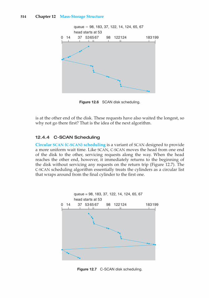
514 Chapter 12 Mass-Storage Structure
0 14 37 536567 98 122124 183199
queue � 98, 183, 37, 122, 14, 124, 65, 67head starts at 53
Figure 12.6 SCAN disk scheduling.
is at the other end of the disk. These requests have also waited the longest, sowhy not go there first? That is the idea of the next algorithm.
12.4.4 C-SCAN Scheduling
Circular SCAN (C-SCAN) scheduling is a variant of SCAN designed to providea more uniform wait time. Like SCAN, C-SCAN moves the head from one endof the disk to the other, servicing requests along the way. When the headreaches the other end, however, it immediately returns to the beginning ofthe disk without servicing any requests on the return trip (Figure 12.7). TheC-SCAN scheduling algorithm essentially treats the cylinders as a circular listthat wraps around from the final cylinder to the first one.
0 14 37 53 65 67 98 122124 183199
queue = 98, 183, 37, 122, 14, 124, 65, 67head starts at 53
Figure 12.7 C-SCAN disk scheduling.
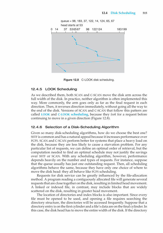
12.4 Disk Scheduling 515
0 14 37 536567 98 122124 183199
queue = 98, 183, 37, 122, 14, 124, 65, 67head starts at 53
Figure 12.8 C-LOOK disk scheduling.
12.4.5 LOOK Scheduling
As we described them, both SCAN and C-SCAN move the disk arm across thefull width of the disk. In practice, neither algorithm is often implemented thisway. More commonly, the arm goes only as far as the final request in eachdirection. Then, it reverses direction immediately, without going all the way tothe end of the disk. Versions of SCAN and C-SCAN that follow this pattern arecalled LOOK and C-LOOK scheduling, because they look for a request beforecontinuing to move in a given direction (Figure 12.8).
12.4.6 Selection of a Disk-Scheduling Algorithm
Given so many disk-scheduling algorithms, how do we choose the best one?SSTF is common and has a natural appeal because it increases performance overFCFS. SCAN and C-SCAN perform better for systems that place a heavy load onthe disk, because they are less likely to cause a starvation problem. For anyparticular list of requests, we can define an optimal order of retrieval, but thecomputation needed to find an optimal schedule may not justify the savingsover SSTF or SCAN. With any scheduling algorithm, however, performancedepends heavily on the number and types of requests. For instance, supposethat the queue usually has just one outstanding request. Then, all schedulingalgorithms behave the same, because they have only one choice of where tomove the disk head: they all behave like FCFS scheduling.
Requests for disk service can be greatly influenced by the file-allocationmethod. A program reading a contiguously allocated file will generate severalrequests that are close together on the disk, resulting in limited head movement.A linked or indexed file, in contrast, may include blocks that are widelyscattered on the disk, resulting in greater head movement.
The location of directories and index blocks is also important. Since everyfile must be opened to be used, and opening a file requires searching thedirectory structure, the directories will be accessed frequently. Suppose that adirectory entry is on the first cylinder and a file’s data are on the final cylinder. Inthis case, the disk head has to move the entire width of the disk. If the directory
516 Chapter 12 Mass-Storage Structure
entry were on the middle cylinder, the head would have to move only one-halfthe width. Caching the directories and index blocks in main memory can alsohelp to reduce disk-arm movement, particularly for read requests.
Because of these complexities, the disk-scheduling algorithm should bewritten as a separate module of the operating system, so that it can be replacedwith a different algorithm if necessary. Either SSTF or LOOK is a reasonablechoice for the default algorithm.
The scheduling algorithms described here consider only the seek distances.For modern disks, the rotational latency can be nearly as large as theaverage seek time. It is difficult for the operating system to schedule forimproved rotational latency, though, because modern disks do not disclose thephysical location of logical blocks. Disk manufacturers have been alleviatingthis problem by implementing disk-scheduling algorithms in the controllerhardware built into the disk drive. If the operating system sends a batch ofrequests to the controller, the controller can queue them and then schedulethem to improve both the seek time and the rotational latency.
If I/O performance were the only consideration, the operating systemwould gladly turn over the responsibility of disk scheduling to the disk hard-ware. In practice, however, the operating system may have other constraints onthe service order for requests. For instance, demand paging may take priorityover application I/O, and writes are more urgent than reads if the cache isrunning out of free pages. Also, it may be desirable to guarantee the order of aset of disk writes to make the file system robust in the face of system crashes.Consider what could happen if the operating system allocated a disk page to afile and the application wrote data into that page before the operating systemhad a chance to flush the modified inode and free-space list back to disk. Toaccommodate such requirements, an operating system may choose to do itsown disk scheduling and to spoon-feed the requests to the disk controller, oneby one, for some types of I/O.
12.5 Disk Management
The operating system is responsible for several other aspects of disk manage-ment, too. Here we discuss disk initialization, booting from disk, and bad-blockrecovery.
12.5.1 Disk Formatting
A new magnetic disk is a blank slate: it is just a platter of a magnetic recordingmaterial. Before a disk can store data, it must be divided into sectors that thedisk controller can read and write. This process is called low-level formatting,or physical formatting. Low-level formatting fills the disk with a special datastructure for each sector. The data structure for a sector typically consists of aheader, a data area (usually 512 bytes in size), and a trailer. The header andtrailer contain information used by the disk controller, such as a sector numberand an error-correcting code (ECC). When the controller writes a sector of dataduring normal I/O, the ECC is updated with a value calculated from all the bytesin the data area. When the sector is read, the ECC is recalculated and comparedwith the stored value. If the stored and calculated numbers are different, this
12.5 Disk Management 517
mismatch indicates that the data area of the sector has become corrupted andthat the disk sector may be bad (Section 12.5.3). The ECC is an error-correctingcode because it contains enough information, if only a few bits of data havebeen corrupted, to enable the controller to identify which bits have changedand calculate what their correct values should be. It then reports a recoverablesoft error. The controller automatically does the ECC processing whenever asector is read or written.
Most hard disks are low-level-formatted at the factory as a part of themanufacturing process. This formatting enables the manufacturer to test thedisk and to initialize the mapping from logical block numbers to defect-freesectors on the disk. For many hard disks, when the disk controller is instructedto low-level-format the disk, it can also be told how many bytes of data spaceto leave between the header and trailer of all sectors. It is usually possible tochoose among a few sizes, such as 256, 512, and 1,024 bytes. Formatting a diskwith a larger sector size means that fewer sectors can fit on each track; but italso means that fewer headers and trailers are written on each track and morespace is available for user data. Some operating systems can handle only asector size of 512 bytes.
Before it can use a disk to hold files, the operating system still needs torecord its own data structures on the disk. It does so in two steps. The first stepis to partition the disk into one or more groups of cylinders. The operatingsystem can treat each partition as though it were a separate disk. For instance,one partition can hold a copy of the operating system’s executable code, whileanother holds user files. The second step is logical formatting, or creation of afile system. In this step, the operating system stores the initial file-system datastructures onto the disk. These data structures may include maps of free andallocated space (a FAT or inodes) and an initial empty directory.
To increase efficiency, most file systems group blocks together into largerchunks, frequently called clusters. Disk I/O is done via blocks, but file systemI/O is done via clusters, effectively assuring that I/O has more sequential-accessand fewer random-access characteristics.
Some operating systems give special programs the ability to use a diskpartition as a large sequential array of logical blocks, without any file-systemdata structures. This array is sometimes called the raw disk, and I/O to this arrayis termed raw I/O. For example, some database systems prefer raw I/O becauseit enables them to control the exact disk location where each database record isstored. Raw I/O bypasses all the file-system services, such as the buffer cache,file locking, prefetching, space allocation, file names, and directories. We canmake certain applications more efficient by allowing them to implement theirown special-purpose storage services on a raw partition, but most applicationsperform better when they use the regular file-system services.
12.5.2 Boot Block
For a computer to start running—for instance, when it is powered up orrebooted—it must have an initial program to run. This initial bootstrapprogramtends to be simple. It initializes all aspects of the system, from CPU registersto device controllers and the contents of main memory, and then starts theoperating system. To do its job, the bootstrap program finds the operating-
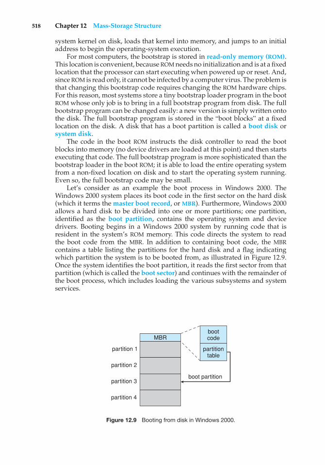
518 Chapter 12 Mass-Storage Structure
system kernel on disk, loads that kernel into memory, and jumps to an initialaddress to begin the operating-system execution.
For most computers, the bootstrap is stored in read-only memory (ROM).This location is convenient, because ROM needs no initialization and is at a fixedlocation that the processor can start executing when powered up or reset. And,since ROM is read only, it cannot be infected by a computer virus. The problem isthat changing this bootstrap code requires changing the ROM hardware chips.For this reason, most systems store a tiny bootstrap loader program in the bootROM whose only job is to bring in a full bootstrap program from disk. The fullbootstrap program can be changed easily: a new version is simply written ontothe disk. The full bootstrap program is stored in the “boot blocks” at a fixedlocation on the disk. A disk that has a boot partition is called a boot disk orsystem disk.
The code in the boot ROM instructs the disk controller to read the bootblocks into memory (no device drivers are loaded at this point) and then startsexecuting that code. The full bootstrap program is more sophisticated than thebootstrap loader in the boot ROM; it is able to load the entire operating systemfrom a non-fixed location on disk and to start the operating system running.Even so, the full bootstrap code may be small.
Let’s consider as an example the boot process in Windows 2000. TheWindows 2000 system places its boot code in the first sector on the hard disk(which it terms the master boot record, or MBR). Furthermore, Windows 2000allows a hard disk to be divided into one or more partitions; one partition,identified as the boot partition, contains the operating system and devicedrivers. Booting begins in a Windows 2000 system by running code that isresident in the system’s ROM memory. This code directs the system to readthe boot code from the MBR. In addition to containing boot code, the MBRcontains a table listing the partitions for the hard disk and a flag indicatingwhich partition the system is to be booted from, as illustrated in Figure 12.9.Once the system identifies the boot partition, it reads the first sector from thatpartition (which is called the boot sector) and continues with the remainder ofthe boot process, which includes loading the various subsystems and systemservices.
MBR
partition 1
partition 2
partition 3
partition 4
bootcode
partitiontable
boot partition
Figure 12.9 Booting from disk in Windows 2000.
12.5 Disk Management 519
12.5.3 Bad Blocks
Because disks have moving parts and small tolerances (recall that the diskhead flies just above the disk surface), they are prone to failure. Sometimes thefailure is complete; in this case, the disk needs to be replaced and its contentsrestored from backup media to the new disk. More frequently, one or moresectors become defective. Most disks even come from the factory with badblocks. Depending on the disk and controller in use, these blocks are handledin a variety of ways.
On simple disks, such as some disks with IDE controllers, bad blocks arehandled manually. For instance, the MS-DOS format command performs logicalformatting and, as a part of the process, scans the disk to find bad blocks. Ifformat finds a bad block, it writes a special value into the corresponding FATentry to tell the allocation routines not to use that block. If blocks go bad duringnormal operation, a special program (such as chkdsk) must be run manuallyto search for the bad blocks and to lock them away. Data that resided on thebad blocks usually are lost.
More sophisticated disks, such as the SCSI disks used in high-end PCsand most workstations and servers, are smarter about bad-block recovery. Thecontroller maintains a list of bad blocks on the disk. The list is initialized duringthe low-level formatting at the factory and is updated over the life of the disk.Low-level formatting also sets aside spare sectors not visible to the operatingsystem. The controller can be told to replace each bad sector logically with oneof the spare sectors. This scheme is known as sector sparing or forwarding.
A typical bad-sector transaction might be as follows:
• The operating system tries to read logical block 87.
• The controller calculates the ECC and finds that the sector is bad. It reportsthis finding to the operating system.
• The next time the system is rebooted, a special command is run to tell theSCSI controller to replace the bad sector with a spare.
• After that, whenever the system requests logical block 87, the request istranslated into the replacement sector’s address by the controller.
Note that such a redirection by the controller could invalidate any opti-mization by the operating system’s disk-scheduling algorithm! For this reason,most disks are formatted to provide a few spare sectors in each cylinder anda spare cylinder as well. When a bad block is remapped, the controller uses aspare sector from the same cylinder, if possible.
As an alternative to sector sparing, some controllers can be instructed toreplace a bad block by sector slipping. Here is an example: Suppose thatlogical block 17 becomes defective and the first available spare follows sector202. Then, sector slipping remaps all the sectors from 17 to 202, moving themall down one spot. That is, sector 202 is copied into the spare, then sector 201into 202, then 200 into 201, and so on, until sector 18 is copied into sector 19.Slipping the sectors in this way frees up the space of sector 18, so sector 17 canbe mapped to it.
The replacement of a bad block generally is not totally automatic becausethe data in the bad block are usually lost. Soft errors may trigger a process in
520 Chapter 12 Mass-Storage Structure
which a copy of the block data is made and the block is spared or slipped.An unrecoverable hard error, however, results in lost data. Whatever file wasusing that block must be repaired (for instance, by restoration from a backuptape), and that requires manual intervention.
12.6 Swap-Space Management
Swapping was first presented in Section 8.2, where we discussed movingentire processes between disk and main memory. Swapping in that settingoccurs when the amount of physical memory reaches a critically low point andprocesses are moved from memory to swap space to free available memory.In practice, very few modern operating systems implement swapping inthis fashion. Rather, systems now combine swapping with virtual memorytechniques (Chapter 9) and swap pages, not necessarily entire processes. Infact, some systems now use the terms swapping and paging interchangeably,reflecting the merging of these two concepts.
Swap-space management is another low-level task of the operatingsystem. Virtual memory uses disk space as an extension of main memory.Since disk access is much slower than memory access, using swap spacesignificantly decreases system performance. The main goal for the design andimplementation of swap space is to provide the best throughput for the virtualmemory system. In this section, we discuss how swap space is used, whereswap space is located on disk, and how swap space is managed.
12.6.1 Swap-Space Use
Swap space is used in various ways by different operating systems, dependingon the memory-management algorithms in use. For instance, systems thatimplement swapping may use swap space to hold an entire process image,including the code and data segments. Paging systems may simply store pagesthat have been pushed out of main memory. The amount of swap space neededon a system can therefore vary from a few megabytes of disk space to gigabytes,depending on the amount of physical memory, the amount of virtual memoryit is backing, and the way in which the virtual memory is used.
Note that it may be safer to overestimate than to underestimate the amountof swap space required, because if a system runs out of swap space it may beforced to abort processes or may crash entirely. Overestimation wastes diskspace that could otherwise be used for files, but it does no other harm. Somesystems recommend the amount to be set aside for swap space. Solaris, forexample, suggests setting swap space equal to the amount by which virtualmemory exceeds pageable physical memory. In the past, Linux has suggestedsetting swap space to double the amount of physical memory, although mostLinux systems now use considerably less swap space. In fact, there is currentlymuch debate in the Linux community about whether to set aside swap spaceat all!
Some operating systems—including Linux—allow the use of multipleswap spaces. These swap spaces are usually put on separate disks so that theload placed on the I/O system by paging and swapping can be spread over thesystem’s I/O devices.
12.6 Swap-Space Management 521
12.6.2 Swap-Space Location
A swap space can reside in one of two places: it can be carved out of thenormal file system, or it can be in a separate disk partition. If the swap spaceis simply a large file within the file system, normal file-system routines can beused to create it, name it, and allocate its space. This approach, though easyto implement, is inefficient. Navigating the directory structure and the disk-allocation data structures takes time and (possibly) extra disk accesses. Externalfragmentation can greatly increase swapping times by forcing multiple seeksduring reading or writing of a process image. We can improve performanceby caching the block location information in physical memory and by usingspecial tools to allocate physically contiguous blocks for the swap file, but thecost of traversing the file-system data structures remains.
Alternatively, swap space can be created in a separate raw partition. Nofile system or directory structure is placed in this space. Rather, a separateswap-space storage manager is used to allocate and deallocate the blocksfrom the raw partition. This manager uses algorithms optimized for speedrather than for storage efficiency, because swap space is accessed much morefrequently than file systems (when it is used). Internal fragmentation mayincrease, but this trade-off is acceptable because the life of data in the swapspace generally is much shorter than that of files in the file system. Sinceswap space is reinitialized at boot time, any fragmentation is short-lived. Theraw-partition approach creates a fixed amount of swap space during diskpartitioning. Adding more swap space requires either repartitioning the disk(which involves moving the other file-system partitions or destroying themand restoring them from backup) or adding another swap space elsewhere.
Some operating systems are flexible and can swap both in raw partitionsand in file-system space. Linux is an example: the policy and implementationare separate, allowing the machine’s administrator to decide which type ofswapping to use. The trade-off is between the convenience of allocation andmanagement in the file system and the performance of swapping in rawpartitions.
12.6.3 Swap-Space Management: An Example
We can illustrate how swap space is used by following the evolution ofswapping and paging in various UNIX systems. The traditional UNIX kernelstarted with an implementation of swapping that copied entire processesbetween contiguous disk regions and memory. UNIX later evolved to acombination of swapping and paging as paging hardware became available.
In Solaris 1 (SunOS), the designers changed standard UNIX methods toimprove efficiency and reflect technological developments. When a processexecutes, text-segment pages containing code are brought in from the filesystem, accessed in main memory, and thrown away if selected for pageout. Itis more efficient to reread a page from the file system than to write it to swapspace and then reread it from there. Swap space is only used as a backing storefor pages of anonymous memory, which includes memory allocated for thestack, heap, and uninitialized data of a process.
More changes were made in later versions of Solaris. The biggest changeis that Solaris now allocates swap space only when a page is forced out ofphysical memory, rather than when the virtual memory page is first created.
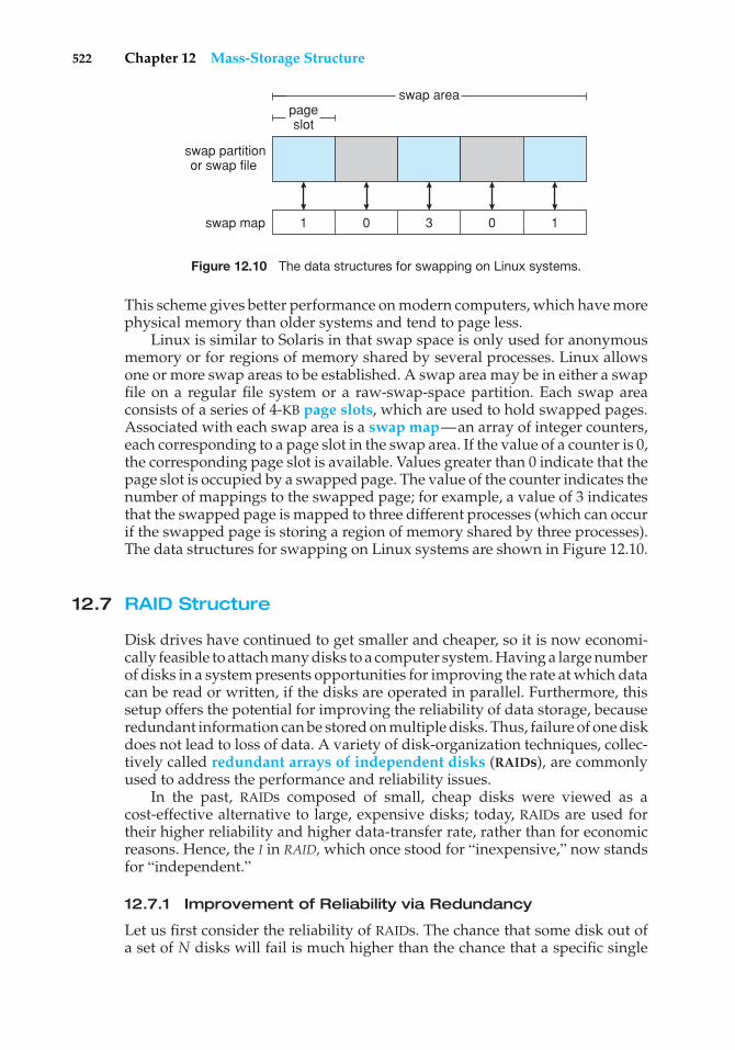
522 Chapter 12 Mass-Storage Structure
swap areapageslot
swap partitionor swap file
swap map 1 0 3 0 1
Figure 12.10 The data structures for swapping on Linux systems.
This scheme gives better performance on modern computers, which have morephysical memory than older systems and tend to page less.
Linux is similar to Solaris in that swap space is only used for anonymousmemory or for regions of memory shared by several processes. Linux allowsone or more swap areas to be established. A swap area may be in either a swapfile on a regular file system or a raw-swap-space partition. Each swap areaconsists of a series of 4-KB page slots, which are used to hold swapped pages.Associated with each swap area is a swap map—an array of integer counters,each corresponding to a page slot in the swap area. If the value of a counter is 0,the corresponding page slot is available. Values greater than 0 indicate that thepage slot is occupied by a swapped page. The value of the counter indicates thenumber of mappings to the swapped page; for example, a value of 3 indicatesthat the swapped page is mapped to three different processes (which can occurif the swapped page is storing a region of memory shared by three processes).The data structures for swapping on Linux systems are shown in Figure 12.10.
12.7 RAID Structure
Disk drives have continued to get smaller and cheaper, so it is now economi-cally feasible to attach many disks to a computer system. Having a large numberof disks in a system presents opportunities for improving the rate at which datacan be read or written, if the disks are operated in parallel. Furthermore, thissetup offers the potential for improving the reliability of data storage, becauseredundant information can be stored on multiple disks. Thus, failure of one diskdoes not lead to loss of data. A variety of disk-organization techniques, collec-tively called redundant arrays of independent disks (RAIDs), are commonlyused to address the performance and reliability issues.
In the past, RAIDs composed of small, cheap disks were viewed as acost-effective alternative to large, expensive disks; today, RAIDs are used fortheir higher reliability and higher data-transfer rate, rather than for economicreasons. Hence, the I in RAID,which once stood for “inexpensive,” now standsfor “independent.”
12.7.1 Improvement of Reliability via Redundancy
Let us first consider the reliability of RAIDs. The chance that some disk out ofa set of N disks will fail is much higher than the chance that a specific single
12.7 RAID Structure 523
STRUCTURING RAID
RAID storage can be structured in a variety of ways. For example, a systemcan have disks directly attached to its buses. In this case, the operatingsystem or system software can implement RAID functionality. Alternatively,an intelligent host controller can control multiple attached disks and canimplement RAID on those disks in hardware. Finally, a storage array, or RAIDarray, can be used. A RAID array is a standalone unit with its own controller,cache (usually), and disks. It is attached to the host via one or more standardATA SCSI or FC controllers. This common setup allows any operating systemand software without RAID functionality to have RAID-protected disks. Itis even used on systems that do have RAID software layers because of itssimplicity and flexibility.
disk will fail. Suppose that the mean time to failure of a single disk is 100,000hours. Then the mean time to failure of some disk in an array of 100 diskswill be 100,000/100 = 1,000 hours, or 41.66 days, which is not long at all! If westore only one copy of the data, then each disk failure will result in loss of asignificant amount of data—and such a high rate of data loss is unacceptable.
The solution to the problem of reliability is to introduce redundancy; westore extra information that is not normally needed but that can be used in theevent of failure of a disk to rebuild the lost information. Thus, even if a diskfails, data are not lost.
The simplest (but most expensive) approach to introducing redundancyis to duplicate every disk. This technique is called mirroring. With mirroring,a logical disk consists of two physical disks, and every write is carried outon both disks. The result is called a mirrored volume. If one of the disks in thevolume fails, the data can be read from the other. Data will be lost only if thesecond disk fails before the first failed disk is replaced.
The mean time to failure of a mirrored volume—where failure is the lossof data— depends on two factors. One is the mean time to failure of theindividual disks. The other is the mean time to repair, which is the time ittakes (on average) to replace a failed disk and to restore the data on it. Supposethat the failures of the two disks are independent; that is, the failure of one diskis not connected to the failure of the other. Then, if the mean time to failure of asingle disk is 100,000 hours and the mean time to repair is 10 hours, the meantime to data loss of a mirrored disk system is 100, 0002/(2 ∗ 10) = 500 ∗ 106
hours, or 57,000 years!You should be aware that the assumption of independence of disk failures
is not valid. Power failures and natural disasters, such as earthquakes, fires,and floods, may result in damage to both disks at the same time. Also,manufacturing defects in a batch of disks can cause correlated failures. Asdisks age, the probability of failure grows, increasing the chance that a seconddisk will fail while the first is being repaired. In spite of all these considerations,however, mirrored-disk systems offer much higher reliability than do single-disk systems.
Power failures are a particular source of concern, since they occur far morefrequently than do natural disasters. Even with mirroring of disks, if writes are
524 Chapter 12 Mass-Storage Structure
in progress to the same block in both disks, and power fails before both blocksare fully written, the two blocks can be in an inconsistent state. One solutionto this problem is to write one copy first, then the next. Another is to add anonvolatile RAM (NVRAM) cache to the RAID array. This write-back cache isprotected from data loss during power failures, so the write can be consideredcomplete at that point, assuming the NVRAM has some kind of error protectionand correction, such as ECC or mirroring.
12.7.2 Improvement in Performance via Parallelism
Now let’s consider how parallel access to multiple disks improves perfor-mance. With disk mirroring, the rate at which read requests can be handled isdoubled, since read requests can be sent to either disk (as long as both disksin a pair are functional, as is almost always the case). The transfer rate of eachread is the same as in a single-disk system, but the number of reads per unittime has doubled.
With multiple disks, we can improve the transfer rate as well (or instead)by striping data across the disks. In its simplest form, data striping consistsof splitting the bits of each byte across multiple disks; such striping is calledbit-level striping. For example, if we have an array of eight disks, we write biti of each byte to disk i. The array of eight disks can be treated as a single diskwith sectors that are eight times the normal size and, more important, that haveeight times the access rate. In such an organization, every disk participates inevery access (read or write); so the number of accesses that can be processedper second is about the same as on a single disk, but each access can read eighttimes as many data in the same time as on a single disk.
Bit-level striping can be generalized to include a number of disks that eitheris a multiple of 8 or divides 8. For example, if we use an array of four disks,bits i and 4 + i of each byte go to disk i. Further, striping need not occur atthe bit level. In block-level striping, for instance, blocks of a file are stripedacross multiple disks; with n disks, block i of a file goes to disk (i mod n) + 1.Other levels of striping, such as bytes of a sector or sectors of a block, also arepossible. Block-level striping is the most common.
Parallelism in a disk system, as achieved through striping, has two maingoals:
1. Increase the throughput of multiple small accesses (that is, page accesses)by load balancing.
2. Reduce the response time of large accesses.
12.7.3 RAID Levels
Mirroring provides high reliability, but it is expensive. Striping provides highdata-transfer rates, but it does not improve reliability. Numerous schemesto provide redundancy at lower cost by using disk striping combined with“parity” bits (which we describe next) have been proposed. These schemeshave different cost–performance trade-offs and are classified according tolevels called RAID levels. We describe the various levels here; Figure 12.11shows them pictorially (in the figure, P indicates error-correcting bits, and C
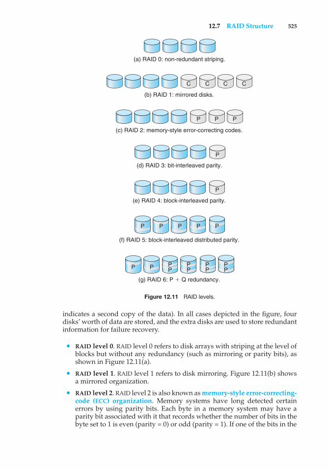
12.7 RAID Structure 525
(a) RAID 0: non-redundant striping.
(b) RAID 1: mirrored disks.
C C C C
(c) RAID 2: memory-style error-correcting codes.
(d) RAID 3: bit-interleaved parity.
(e) RAID 4: block-interleaved parity.
(f) RAID 5: block-interleaved distributed parity.
P P
P
P
P P P
(g) RAID 6: P � Q redundancy.
PP P
PPPP P
PPP
PP
Figure 12.11 RAID levels.
indicates a second copy of the data). In all cases depicted in the figure, fourdisks’ worth of data are stored, and the extra disks are used to store redundantinformation for failure recovery.
• RAID level 0. RAID level 0 refers to disk arrays with striping at the level ofblocks but without any redundancy (such as mirroring or parity bits), asshown in Figure 12.11(a).
• RAID level 1. RAID level 1 refers to disk mirroring. Figure 12.11(b) showsa mirrored organization.
• RAID level 2. RAID level 2 is also known as memory-style error-correcting-code (ECC) organization. Memory systems have long detected certainerrors by using parity bits. Each byte in a memory system may have aparity bit associated with it that records whether the number of bits in thebyte set to 1 is even (parity = 0) or odd (parity = 1). If one of the bits in the
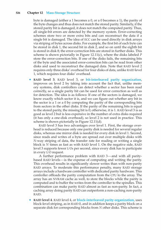
526 Chapter 12 Mass-Storage Structure
byte is damaged (either a 1 becomes a 0, or a 0 becomes a 1), the parity ofthe byte changes and thus does not match the stored parity. Similarly, if thestored parity bit is damaged, it does not match the computed parity. Thus,all single-bit errors are detected by the memory system. Error-correctingschemes store two or more extra bits and can reconstruct the data if asingle bit is damaged. The idea of ECC can be used directly in disk arraysvia striping of bytes across disks. For example, the first bit of each byte canbe stored in disk 1, the second bit in disk 2, and so on until the eighth bitis stored in disk 8; the error-correction bits are stored in further disks. Thisscheme is shown pictorially in Figure 12.11(c), where the disks labeled Pstore the error-correction bits. If one of the disks fails, the remaining bitsof the byte and the associated error-correction bits can be read from otherdisks and used to reconstruct the damaged data. Note that RAID level 2requires only three disks’ overhead for four disks of data, unlike RAID level1, which requires four disks’ overhead.
• RAID level 3. RAID level 3, or bit-interleaved parity organization,improves on level 2 by taking into account the fact that, unlike mem-ory systems, disk controllers can detect whether a sector has been readcorrectly, so a single parity bit can be used for error correction as well asfor detection. The idea is as follows: If one of the sectors is damaged, weknow exactly which sector it is, and we can figure out whether any bit inthe sector is a 1 or a 0 by computing the parity of the corresponding bitsfrom sectors in the other disks. If the parity of the remaining bits is equalto the stored parity, the missing bit is 0; otherwise, it is 1. RAID level 3 is asgood as level 2 but is less expensive in the number of extra disks required(it has only a one-disk overhead), so level 2 is not used in practice. Thisscheme is shown pictorially in Figure 12.11(d).
RAID level 3 has two advantages over level 1. First, the storage over-head is reduced because only one parity disk is needed for several regulardisks, whereas one mirror disk is needed for every disk in level 1. Second,since reads and writes of a byte are spread out over multiple disks withN-way striping of data, the transfer rate for reading or writing a singleblock is N times as fast as with RAID level 1. On the negative side, RAIDlevel 3 supports fewer I/Os per second, since every disk has to participatein every I/O request.
A further performance problem with RAID 3—and with all parity-based RAID levels—is the expense of computing and writing the parity.This overhead results in significantly slower writes than with non-parityRAID arrays. To moderate this performance penalty, many RAID storagearrays include a hardware controller with dedicated parity hardware. Thiscontroller offloads the parity computation from the CPU to the array. Thearray has an NVRAM cache as well, to store the blocks while the parity iscomputed and to buffer the writes from the controller to the spindles. Thiscombination can make parity RAID almost as fast as non-parity. In fact, acaching array doing parity RAID can outperform a non-caching non-parityRAID.
• RAID level 4. RAID level 4, or block-interleaved parity organization, usesblock-level striping, as in RAID 0, and in addition keeps a parity block on aseparate disk for corresponding blocks from N other disks. This scheme is
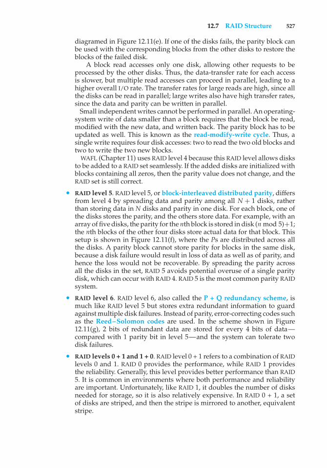
12.7 RAID Structure 527
diagramed in Figure 12.11(e). If one of the disks fails, the parity block canbe used with the corresponding blocks from the other disks to restore theblocks of the failed disk.
A block read accesses only one disk, allowing other requests to beprocessed by the other disks. Thus, the data-transfer rate for each accessis slower, but multiple read accesses can proceed in parallel, leading to ahigher overall I/O rate. The transfer rates for large reads are high, since allthe disks can be read in parallel; large writes also have high transfer rates,since the data and parity can be written in parallel.
Small independent writes cannot be performed in parallel. An operating-system write of data smaller than a block requires that the block be read,modified with the new data, and written back. The parity block has to beupdated as well. This is known as the read-modify-write cycle. Thus, asingle write requires four disk accesses: two to read the two old blocks andtwo to write the two new blocks.
WAFL (Chapter 11) uses RAID level 4 because this RAID level allows disksto be added to a RAID set seamlessly. If the added disks are initialized withblocks containing all zeros, then the parity value does not change, and theRAID set is still correct.
• RAID level 5. RAID level 5, or block-interleaved distributed parity, differsfrom level 4 by spreading data and parity among all N + 1 disks, ratherthan storing data in N disks and parity in one disk. For each block, one ofthe disks stores the parity, and the others store data. For example, with anarray of five disks, the parity for the nth block is stored in disk (nmod 5)+1;the nth blocks of the other four disks store actual data for that block. Thissetup is shown in Figure 12.11(f), where the Ps are distributed across allthe disks. A parity block cannot store parity for blocks in the same disk,because a disk failure would result in loss of data as well as of parity, andhence the loss would not be recoverable. By spreading the parity acrossall the disks in the set, RAID 5 avoids potential overuse of a single paritydisk, which can occur with RAID 4. RAID 5 is the most common parity RAIDsystem.
• RAID level 6. RAID level 6, also called the P + Q redundancy scheme, ismuch like RAID level 5 but stores extra redundant information to guardagainst multiple disk failures. Instead of parity, error-correcting codes suchas the Reed–Solomon codes are used. In the scheme shown in Figure12.11(g), 2 bits of redundant data are stored for every 4 bits of data—compared with 1 parity bit in level 5—and the system can tolerate twodisk failures.
• RAID levels 0 + 1 and 1 + 0. RAID level 0 + 1 refers to a combination of RAIDlevels 0 and 1. RAID 0 provides the performance, while RAID 1 providesthe reliability. Generally, this level provides better performance than RAID5. It is common in environments where both performance and reliabilityare important. Unfortunately, like RAID 1, it doubles the number of disksneeded for storage, so it is also relatively expensive. In RAID 0 + 1, a setof disks are striped, and then the stripe is mirrored to another, equivalentstripe.
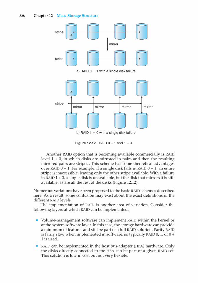
528 Chapter 12 Mass-Storage Structure
x
x
mirror
a) RAID 0 � 1 with a single disk failure.
stripe
stripe
mirror
b) RAID 1 � 0 with a single disk failure.
stripemirror mirror mirror
Figure 12.12 RAID 0 + 1 and 1 + 0.
Another RAID option that is becoming available commercially is RAIDlevel 1 + 0, in which disks are mirrored in pairs and then the resultingmirrored pairs are striped. This scheme has some theoretical advantagesover RAID 0 + 1. For example, if a single disk fails in RAID 0 + 1, an entirestripe is inaccessible, leaving only the other stripe available. With a failurein RAID 1 + 0, a single disk is unavailable, but the disk that mirrors it is stillavailable, as are all the rest of the disks (Figure 12.12).
Numerous variations have been proposed to the basic RAID schemes describedhere. As a result, some confusion may exist about the exact definitions of thedifferent RAID levels.
The implementation of RAID is another area of variation. Consider thefollowing layers at which RAID can be implemented.
• Volume-management software can implement RAID within the kernel orat the system software layer. In this case, the storage hardware can providea minimum of features and still be part of a full RAID solution. Parity RAIDis fairly slow when implemented in software, so typically RAID 0, 1, or 0 +1 is used.
• RAID can be implemented in the host bus-adapter (HBA) hardware. Onlythe disks directly connected to the HBA can be part of a given RAID set.This solution is low in cost but not very flexible.
12.7 RAID Structure 529
• RAID can be implemented in the hardware of the storage array. The storagearray can create RAID sets of various levels and can even slice these setsinto smaller volumes, which are then presented to the operating system.The operating system need only implement the file system on each of thevolumes. Arrays can have multiple connections available or can be part ofa SAN, allowing multiple hosts to take advantage of the array’s features.
• RAID can be implemented in the SAN interconnect layer by disk virtualiza-tion devices. In this case, a device sits between the hosts and the storage.It accepts commands from the servers and manages access to the storage.It could provide mirroring, for example, by writing each block to twoseparate storage devices.
Other features, such as snapshots and replication, can be implemented ateach of these levels as well. Replication involves the automatic duplication ofwrites between separate sites for redundancy and disaster recovery. Replicationcan be synchronous or asynchronous. In synchronous replication, each blockmust be written locally and remotely before the write is considered complete,whereas in asynchronous replication, the writes are grouped together andwritten periodically. Asynchronous replication can result in data loss if theprimary site fails, but it is faster and has no distance limitations.
The implementation of these features differs depending on the layer atwhich RAID is implemented. For example, if RAID is implemented in software,then each host may need to carry out and manage its own replication. Ifreplication is implemented in the storage array or in the SAN interconnect,however, then whatever the host operating system or its features, the host’sdata can be replicated.
One other aspect of most RAID implementations is a hot spare disk or disks.A hot spare is not used for data but is configured to be used as a replacement incase of disk failure. For instance, a hot spare can be used to rebuild a mirroredpair should one of the disks in the pair fail. In this way, the RAID level can bereestablished automatically, without waiting for the failed disk to be replaced.Allocating more than one hot spare allows more than one failure to be repairedwithout human intervention.
12.7.4 Selecting a RAID Level
Given the many choices they have, how do system designers choose a RAIDlevel? One consideration is rebuild performance. If a disk fails, the time neededto rebuild its data can be significant. This may be an important factor if acontinuous supply of data is required, as it is in high-performance or interactivedatabase systems. Furthermore, rebuild performance influences the mean timeto failure.
Rebuild performance varies with the RAID level used. Rebuilding is easiestfor RAID level 1, since data can be copied from another disk; for the other levels,we need to access all the other disks in the array to rebuild data in a failed disk.Rebuild times can be hours for RAID 5 rebuilds of large disk sets.
RAID level 0 is used in high-performance applications where data loss isnot critical. RAID level 1 is popular for applications that require high reliabilitywith fast recovery. RAID 0 + 1 and 1 + 0 are used where both performance andreliability are important—for example, for small databases. Due to RAID 1’s
530 Chapter 12 Mass-Storage Structure
THE InServ STORAGE ARRAY
Innovation, in an effort to provide better, faster, and less expensive solutions,frequently blurs the lines that separated previous technologies. Consider theInServ storage array from 3Par. Unlike most other storage arrays, InServdoes not require that a set of disks be configured at a specific RAID level.Rather, each disk is broken into 256-MB “chunklets.” RAID is then applied atthe chunklet level. A disk can thus participate in multiple and various RAIDlevels as its chunklets are used for multiple volumes.
InServ also provides snapshots similar to those created by the WAFL filesystem. The format of InServ snapshots can be read–write as well as read-only, allowing multiple hosts to mount copies of a given file system withoutneeding their own copies of the entire file system. Any changes a host makesin its own copy are copy-on-write and so are not reflected in the other copies.
A further innovation is utility storage. Some file systems do not expandor shrink. On these systems, the original size is the only size, and any changerequires copying data. An administrator can configure InServ to provide ahost with a large amount of logical storage that initially occupies only a smallamount of physical storage. As the host starts using the storage, unused disksare allocated to the host, up to the original logical level. The host thus canbelieve that it has a large fixed storage space, create its file systems there, andso on. Disks can be added or removed from the file system by InServ withoutthe file systems noticing the change. This feature can reduce the number ofdrives needed by hosts, or at least delay the purchase of disks until they arereally needed.
high space overhead, RAID level 5 is often preferred for storing large volumesof data. Level 6 is not supported currently by many RAID implementations, butit should offer better reliability than level 5.
RAID system designers and administrators of storage have to make severalother decisions as well. For example, how many disks should be in a givenRAID set? How many bits should be protected by each parity bit? If more disksare in an array, data-transfer rates are higher, but the system is more expensive.If more bits are protected by a parity bit, the space overhead due to parity bitsis lower, but the chance that a second disk will fail before the first failed disk isrepaired is greater, and that will result in data loss.
12.7.5 Extensions
The concepts of RAID have been generalized to other storage devices, includingarrays of tapes, and even to the broadcast of data over wireless systems. Whenapplied to arrays of tapes, RAID structures are able to recover data even if oneof the tapes in an array is damaged. When applied to broadcast of data, a blockof data is split into short units and is broadcast along with a parity unit; if oneof the units is not received for any reason, it can be reconstructed from theother units. Commonly, tape-drive robots containing multiple tape drives willstripe data across all the drives to increase throughput and decrease backuptime.
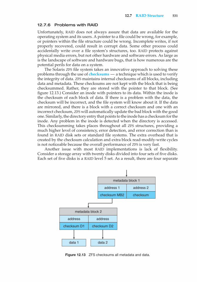
12.7 RAID Structure 531
12.7.6 Problems with RAID
Unfortunately, RAID does not always assure that data are available for theoperating system and its users. A pointer to a file could be wrong, for example,or pointers within the file structure could be wrong. Incomplete writes, if notproperly recovered, could result in corrupt data. Some other process couldaccidentally write over a file system’s structures, too. RAID protects againstphysical media errors, but not other hardware and software errors. As large asis the landscape of software and hardware bugs, that is how numerous are thepotential perils for data on a system.
The Solaris ZFS file system takes an innovative approach to solving theseproblems through the use of checksums — a technique which is used to verifythe integrity of data. ZFS maintains internal checksums of all blocks, includingdata and metadata. These checksums are not kept with the block that is beingchecksummed. Rather, they are stored with the pointer to that block. (Seefigure 12.13.) Consider an inode with pointers to its data. Within the inode isthe checksum of each block of data. If there is a problem with the data, thechecksum will be incorrect, and the file system will know about it. If the dataare mirrored, and there is a block with a correct checksum and one with anincorrect checksum, ZFS will automatically update the bad block with the goodone. Similarly, the directory entry that points to the inode has a checksum for theinode. Any problem in the inode is detected when the directory is accessed.This checksumming takes places throughout all ZFS structures, providing amuch higher level of consistency, error detection, and error correction than isfound in RAID disk sets or standard file systems. The extra overhead that iscreated by the checksum calculation and extra block read-modify-write cyclesis not noticeable because the overall performance of ZFS is very fast.
Another issue with most RAID implementations is lack of flexibility.Consider a storage array with twenty disks divided into four sets of five disks.Each set of five disks is a RAID level 5 set. As a result, there are four separate
metadata block 1
address 1
checksum MB2 checksum
address 2
metadata block 2
address
checksum D1 checksum D2
data 1 data 2
address
Figure 12.13 ZFS checksums all metadata and data.
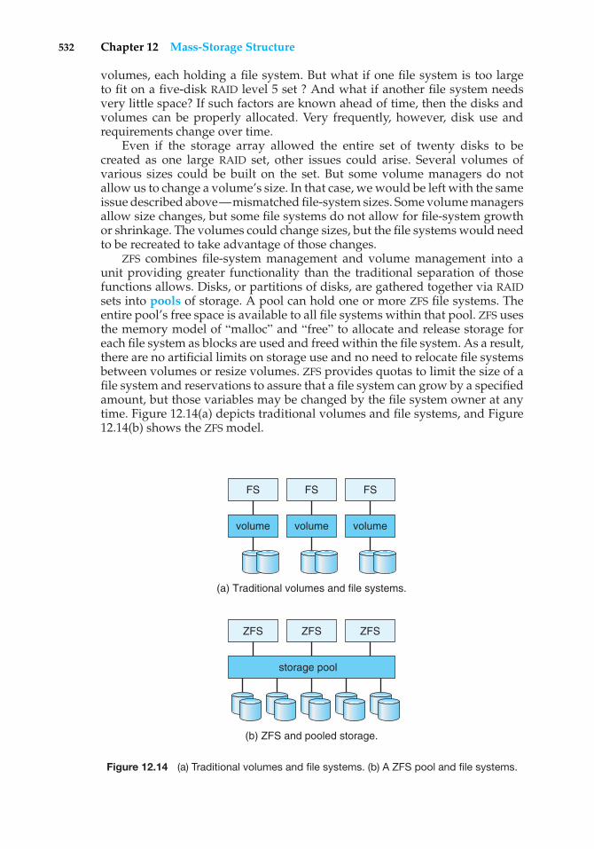
532 Chapter 12 Mass-Storage Structure
volumes, each holding a file system. But what if one file system is too largeto fit on a five-disk RAID level 5 set ? And what if another file system needsvery little space? If such factors are known ahead of time, then the disks andvolumes can be properly allocated. Very frequently, however, disk use andrequirements change over time.
Even if the storage array allowed the entire set of twenty disks to becreated as one large RAID set, other issues could arise. Several volumes ofvarious sizes could be built on the set. But some volume managers do notallow us to change a volume’s size. In that case, we would be left with the sameissue described above—mismatched file-system sizes. Some volume managersallow size changes, but some file systems do not allow for file-system growthor shrinkage. The volumes could change sizes, but the file systems would needto be recreated to take advantage of those changes.
ZFS combines file-system management and volume management into aunit providing greater functionality than the traditional separation of thosefunctions allows. Disks, or partitions of disks, are gathered together via RAIDsets into pools of storage. A pool can hold one or more ZFS file systems. Theentire pool’s free space is available to all file systems within that pool. ZFS usesthe memory model of “malloc” and “free” to allocate and release storage foreach file system as blocks are used and freed within the file system. As a result,there are no artificial limits on storage use and no need to relocate file systemsbetween volumes or resize volumes. ZFS provides quotas to limit the size of afile system and reservations to assure that a file system can grow by a specifiedamount, but those variables may be changed by the file system owner at anytime. Figure 12.14(a) depicts traditional volumes and file systems, and Figure12.14(b) shows the ZFS model.
FS
volume
ZFS ZFS
storage pool
ZFS
volume volume
FS FS
(a) Traditional volumes and file systems.
(b) ZFS and pooled storage.
Figure 12.14 (a) Traditional volumes and file systems. (b) A ZFS pool and file systems.
12.8 Stable-Storage Implementation 533
12.8 Stable-Storage Implementation
In Chapter 6, we introduced the write-ahead log, which requires the availabilityof stable storage. By definition, information residing in stable storage is neverlost. To implement such storage, we need to replicate the required informationon multiple storage devices (usually disks) with independent failure modes.We also need to coordinate the writing of updates in a way that guaranteesthat a failure during an update will not leave all the copies in a damaged stateand that, when we are recovering from a failure, we can force all copies to aconsistent and correct value, even if another failure occurs during the recovery.In this section, we discuss how to meet these needs.
A disk write results in one of three outcomes:
1. Successful completion. The data were written correctly on disk.
2. Partial failure. A failure occurred in the midst of transfer, so only some ofthe sectors were written with the new data, and the sector being writtenduring the failure may have been corrupted.
3. Total failure. The failure occurred before the disk write started, so theprevious data values on the disk remain intact.
Whenever a failure occurs during writing of a block, the system needs todetect it and invoke a recovery procedure to restore the block to a consistentstate. To do that, the system must maintain two physical blocks for each logicalblock. An output operation is executed as follows:
1. Write the information onto the first physical block.
2. When the first write completes successfully, write the same informationonto the second physical block.
3. Declare the operation complete only after the second write completessuccessfully.
During recovery from a failure, each pair of physical blocks is examined.If both are the same and no detectable error exists, then no further action isnecessary. If one block contains a detectable error, then we replace its contentswith the value of the other block. If neither block contains a detectable error,but the blocks differ in content, then we replace the content of the first blockwith that of the second. This recovery procedure ensures that a write to stablestorage either succeeds completely or results in no change.
We can extend this procedure easily to allow the use of an arbitrarily largenumber of copies of each block of stable storage. Although having a largenumber of copies further reduces the probability of a failure, it is usuallyreasonable to simulate stable storage with only two copies. The data in stablestorage are guaranteed to be safe unless a failure destroys all the copies.
Because waiting for disk writes to complete (synchronous I/O) is timeconsuming, many storage arrays add NVRAM as a cache. Since the memory isnonvolatile (it usually has battery power to back up the unit’s power), it canbe trusted to store the data en route to the disks. It is thus considered part of
534 Chapter 12 Mass-Storage Structure
the stable storage. Writes to it are much faster than to disk, so performance isgreatly improved.
12.9 Tertiary-Storage Structure
Would you buy a DVD or CD player that had one disk sealed inside? Of coursenot. You expect to use a DVD or CD player with many relatively inexpensivedisks. On a computer as well, using many inexpensive cartridges with onedrive lowers the overall cost. Low cost is the defining characteristic of tertiarystorage, which we discuss in this section.
12.9.1 Tertiary-Storage Devices
Because cost is so important, in practice, tertiary storage is built with removablemedia. The most common examples are floppy disks, tapes, and read-only,write-once, and rewritable CDs and DVDs. Many any other kinds of tertiary-storage devices are available as well, including removable devices that storedata in flash memory and interact with the computer system via a USB interface.
12.9.1.1 Removable Disks
Removable disks are one kind of tertiary storage. Floppy disks are an exampleof removable magnetic disks. They are made from a thin, flexible disk coatedwith magnetic material and enclosed in a protective plastic case. Althoughcommon floppy disks can hold only about 1 MB, similar technology is usedfor removable magnetic disks that hold more than 1 GB. Removable magneticdisks can be nearly as fast as hard disks, although the recording surface is atgreater risk of damage from scratches.
A magneto-optic disk is another kind of removable disk. It records dataon a rigid platter coated with magnetic material, but the recording technologyis quite different from that for a magnetic disk. The magneto-optic head fliesmuch farther from the disk surface than a magnetic disk head does, and themagnetic material is covered with a thick protective layer of plastic or glass.This arrangement makes the disk much more resistant to head crashes.
The magneto-optic disk drive has a coil that produces a magnetic field; atroom temperature, the field is too large and too weak to magnetize a bit on thedisk. To write a bit, the disk head flashes a laser beam at the disk surface. Thelaser is aimed at a tiny spot where a bit is to be written. The laser heats thisspot, which makes the spot susceptible to the magnetic field. Now the large,weak magnetic field can record a tiny bit.
The magneto-optic head is too far from the disk surface to read the data bydetecting the tiny magnetic fields in the way that the head of a hard disk does.Instead, the drive reads a bit using a property of laser light called the Kerreffect. When a laser beam is bounced off of a magnetic spot, the polarizationof the laser beam is rotated clockwise or counterclockwise, depending on theorientation of the magnetic field. This rotation is what the head detects to reada bit.
Another category of removable disk is the optical disk. Optical disks do notuse magnetism at all. Instead, they use special materials that can be altered bylaser light to have relatively dark or bright spots. One example of optical-disk
12.9 Tertiary-Storage Structure 535
technology is the phase-change disk, which is coated with a material that canfreeze into either a crystalline or an amorphous state. The crystalline state ismore transparent, and hence a laser beam is brighter when it passes throughthe material and bounces off the reflective layer. The phase-change drive useslaser light at three different powers: low power to read data, medium powerto erase the disk by melting and refreezing the recording medium into thecrystalline state, and high power to melt the medium into the amorphous stateto write to the disk. The most common examples of this technology are there-recordable CD-RW and DVD-RW.
The kinds of disks just described can be used over and over. They are calledread–write disks. In contrast, write-once, read-many-times (WORM) disks canbe written only once. An old way to make a WORM disk is to manufacture a thinaluminum film sandwiched between two glass or plastic platters. To write abit, the drive uses a laser light to burn a small hole through the aluminum. Thisburning cannot be reversed. Although it is possible to destroy the informationon a WORM disk by burning holes everywhere, it is virtually impossible to alterdata on the disk, because holes can only be added, and the ECC code associatedwith each sector is likely to detect such additions. WORM disks are considereddurable and reliable because the metal layer is safely encapsulated betweenthe protective glass or plastic platters and magnetic fields cannot damage therecording. A newer write-once technology records on an organic polymer dyeinstead of an aluminum layer; the dye absorbs laser light to form marks. Thistechnology is used in the recordable CD-R and DVD-R.
Read-only disks, such as CD-ROM and DVD-ROM, come from the factorywith the data prerecorded. They use technology similar to that of WORM disks(although the bits are pressed, not burned), and they are very durable.
Most removable disks are slower than their nonremovable counterparts.The writing process is slower, as are rotation and sometimes seek time.
12.9.1.2 Tapes
Magnetic tape is another type of removable medium. As a general rule, a tapeholds more data than an optical or magnetic disk cartridge. Tape drives anddisk drives have similar transfer rates. But random access to tape is muchslower than a disk seek, because it requires a fast-forward or rewind operationthat takes tens of seconds or even minutes.
Although a typical tape drive is more expensive than a typical disk drive,the price of a tape cartridge is lower than the price of the equivalent capacityof magnetic disks. So tape is an economical medium for purposes that do notrequire fast random access. Tapes are commonly used to hold backup copiesof disk data. They are also used in large supercomputer centers to hold theenormous volumes of data used in scientific research and by large commercialenterprises.
Large tape installations typically use robotic tape changers that move tapesbetween tape drives and storage slots in a tape library. These mechanisms givethe computer automated access to many tape cartridges.
A robotic tape library can lower the overall cost of data storage. A disk-resident file that will not be needed for a while can be archived to tape, wherethe cost per gigabyte is lower; if the file is needed in the future, the computercan stage it back into disk storage for active use. A robotic tape library is
536 Chapter 12 Mass-Storage Structure
sometimes called near-line storage, since it is between the high performanceof on-line magnetic disks and the low cost of off-line tapes sitting on shelvesin a storage room.
12.9.1.3 Future Technology
In the future, other storage technologies may become important. Sometimes oldtechnologies are used in new ways, as economics change or the technologiesevolve. For example, solid-state disks, or SSDs, are growing in importance andbecoming more common. Simply described, an SSD is a disk that is used likea hard drive. Depending on the memory technology used, it can be volatileor nonvolatile. The memory technology also affects performance. NonvolatileSSDs have the same characteristics as traditional hard disks but can be morereliable because they have no moving parts and faster because they have noseek time or latency. In addition, they use less energy. However, they are moreexpensive per megabyte than traditional hard disks, have lower capacity thanthe larger hard disks, and may have shorter life-spans than hard disks; so theiruses are limited. In one example, SSDs are being used in storage arrays to holdmetadata which requires high-performance such as the journal of a journalingfile system. SSDs are also being added to notebook computers to make themsmaller, faster, and more energy efficient.
Another promising storage technology, holographic storage, uses laserlight to record holographic photographs on special media. We can think of ahologram as a three-dimensional array of pixels. Each pixel represents one bit:0 for black or 1 for white. And all the pixels in a hologram are transferred in oneflash of laser light, so the data transfer rate is extremely high. With continueddevelopment, holographic storage may become commercially viable.
Another storage technology under active research is based on micro-electronic mechanical systems (MEMS). The idea is to apply the fabricationtechnologies that produce electronic chips to the manufacture of small data-storage machines. One proposal calls for the fabrication of an array of 10,000tiny disk heads, with a square centimeter of magnetic storage material sus-pended above the array. When the storage material is moved lengthwise overthe heads, each head accesses its own linear track of data on the material. Thestorage material can be shifted sideways slightly to enable all the heads toaccess their next track. Although it remains to be seen whether this technologycan be successful, it may provide a nonvolatile data-storage technology that isfaster than magnetic disk and cheaper than semiconductor DRAM.
Whether the storage medium is a removable magnetic disk, a DVD, or amagnetic tape, the operating system needs to provide several capabilities to useremovable media for data storage. These capabilities are discussed in Section12.9.2.
12.9.2 Operating-System Support
Two major jobs of an operating system are to manage physical devices andto present a virtual machine abstraction to applications. In this chapter, wehave seen that, for hard disks, the operating system provides two abstractions.One is the raw device, which is just an array of data blocks. The other is a filesystem. For a file system on a magnetic disk, the operating system queues and
12.9 Tertiary-Storage Structure 537
schedules the interleaved requests from several applications. Now, we shall seehow the operating system does its job when the storage media are removable.
12.9.2.1 Application Interface
Most operating systems can handle removable disks almost exactly as they dofixed disks. When a blank cartridge is inserted into the drive (or mounted), thecartridge must be formatted, and then an empty file system is generated on thedisk. This file system is used just like a file system on a hard disk.
Tapes are often handled differently. The operating system usually presentsa tape as a raw storage medium. An application does not open a file on thetape; it opens the whole tape drive as a raw device. Usually, the tape driveis then reserved for the exclusive use of that application until the applicationexits or closes the tape device. This exclusivity makes sense, because randomaccess on a tape can take tens of seconds, or even a few minutes, so interleavingrandom accesses to tapes from more than one application would be likely tocause thrashing.
When the tape drive is presented as a raw device, the operating systemdoes not provide file-system services. The application must decide how to usethe array of blocks. For instance, a program that backs up a hard disk to tapemight store a list of file names and sizes at the beginning of the tape and thencopy the data of the files to the tape in that order.
It is easy to see the problems that can arise from this way of using tape.Since every application makes up its own rules for how to organize a tape,a tape full of data can generally be used only by the program that created it.For instance, even if we know that a backup tape contains a list of file namesand file sizes followed by the file data, we will still find it difficult to use thetape. How exactly are the file names stored? Are the file sizes in binary or ASCIIform? Are the files written one per block, or are they all concatenated in onetremendously long string of bytes? We do not even know the block size on thetape, because this variable is generally one that can be chosen separately foreach block written.
For a disk drive, the basic operations are read(), write(), and seek().Tape drives have a different set of basic operations. Instead of seek(), a tapedrive uses the locate() operation. The tape locate() operation is moreprecise than the disk seek() operation, because it positions the tape to aspecific logical block, rather than an entire track. Locating to block 0 is thesame as rewinding the tape.
For most kinds of tape drives, it is possible to locate to any block that hasbeen written on a tape. In a partly filled tape, however, it is not possible tolocate into the empty space beyond the written area, because most tape drivesdo not manage their physical space in the same way disk drives do. For a diskdrive, the sectors have a fixed size, and the formatting process must be used toplace empty sectors in their final positions before any data can be written. Mosttape drives have a variable block size, and the size of each block is determinedon the fly, when that block is written. If an area of defective tape is encounteredduring writing, the bad area is skipped and the block is written again. Thisoperation explains why it is not possible to locate into the empty space beyondthe written area—the positions and numbers of the logical blocks have not yetbeen determined.

538 Chapter 12 Mass-Storage Structure
Most tape drives have a read position() operation that returns thelogical block number where the tape head is currently located. Many tapedrives also support a space() operation for relative motion. So, for example,the operation space(-2) would locate backward over two logical blocks.
For most kinds of tape drives, writing a block has the side effect of logicallyerasing everything beyond the position of the write. In practice, this side effectmeans that most tape drives are append-only devices, because updating ablock in the middle of the tape also effectively erases everything beyond thatblock. The tape drive implements this appending by placing an end-of-tape(EOT) mark after a block that is written. The drive refuses to locate past the EOTmark, but it is possible to locate to the EOT and then start writing. Doing sooverwrites the old EOT mark and places a new one at the end of the new blocksjust written.
In principle, a file system can be implemented on a tape. But many of thefile-system data structures and algorithms would be different from those usedfor disks, because of the append-only property of tape.
12.9.2.2 File Naming
Another question that the operating system needs to handle is how to namefiles on removable media. For a fixed disk, naming is not difficult. On a PC, thefile name consists of a drive letter followed by a path name. In UNIX, the filename does not contain a drive letter, but the mount table enables the operatingsystem to discover on what drive the file is located. If the disk is removable,however, knowing what drive contained the cartridge at some time in the pastdoes not mean knowing how to find the file. If every removable cartridge inthe world had a different serial number, the name of a file on a removabledevice could be prefixed with the serial number, but to ensure that no twoserial numbers are the same would require each one to be about 12 digits inlength. Who could remember the names of her files if she had to memorize a12-digit serial number for each one?
The problem becomes even more difficult when we want to write dataon a removable cartridge on one computer and then use the cartridge inanother computer. If both machines are of the same type and have the samekind of removable drive, the only difficulty is knowing the contents and datalayout on the cartridge. But if the machines or drives are different, manyadditional problems can arise. Even if the drives are compatible, differentcomputers may store bytes in different orders and may use different encodingsfor binary numbers and even for letters (such as ASCII on PCs versus EBCDICon mainframes).
Today’s operating systems generally leave the name-space problemunsolved for removable media and depend on applications and users to figureout how to access and interpret the data. Fortunately, a few kinds of removablemedia are so well standardized that all computers use them the same way. Oneexample is the CD. Music CDs use a universal format that is understood by anyCD drive. Data CDs are available in only a few different formats, so it is usualfor a CD drive and the operating-system device driver to be programmed tohandle all the common formats. DVD formats are also well standardized.
12.9 Tertiary-Storage Structure 539
12.9.2.3 Hierarchical Storage Management
A robotic jukebox enables the computer to change the removable cartridge in atape or disk drive without human assistance. Two major uses of this technologyare for backups and hierarchical storage systems. The use of a jukebox forbackups is simple: When one cartridge becomes full, the computer instructsthe jukebox to switch to the next cartridge. Some jukeboxes hold tens of drivesand thousands of cartridges, with robotic arms managing the movement oftapes to the drives.
A hierarchical storage system extends the storage hierarchy beyondprimary memory and secondary storage (that is, magnetic disk) to incorporatetertiary storage. Tertiary storage is usually implemented as a jukebox of tapesor removable disks. This level of the storage hierarchy is larger, cheaper, andslower.
Although the virtual memory system can be extended in a straightforwardmanner to tertiary storage, this extension is rarely carried out in practice. Thereason is that a retrieval from a jukebox can take tens of seconds or evenminutes, and such a long delay is intolerable for demand paging and for otherforms of virtual memory use.
The usual way to incorporate tertiary storage is to extend the file system.Small and frequently used files remain on magnetic disk, while large and oldfiles that are not actively used are archived to the jukebox. In some file-archivingsystems, the directory entry for the file continues to exist, but the contents ofthe file no longer occupy space in secondary storage. If an application tries toopen the file, the open() system call is suspended until the file contents canbe staged in from tertiary storage. When the contents are again available frommagnetic disk, the open() operation returns control to the application, whichproceeds to use the disk-resident copy of the data.
Today, hierarchical storage management (HSM) is usually found in instal-lations that have large volumes of data that are used seldom, sporadically,or periodically. Current work in HSM includes extending it to provide fullinformation life-cycle management (ILM). Here, data move from disk to tapeand back to disk, as needed, but are deleted on a schedule or according topolicy. For example, some sites save e-mail for seven years but want to be surethat at the end of seven years it is destroyed. At that point, the data might beon disk, HSM tape, and backup tape. ILM centralizes knowledge of where thedata are so that policies can be applied across all these locations.
12.9.3 Performance Issues
As with any component of the operating system, the three most importantaspects of tertiary-storage performance are speed, reliability, and cost.
12.9.3.1 Speed
The speed of tertiary storage has two aspects: bandwidth and latency. Wemeasure the bandwidth in bytes per second. The sustained bandwidth isthe average data rate during a large transfer—that is, the number of bytesdivided by the transfer time. The effective bandwidth calculates the averageover the entire I/O time, including the time for seek() or locate() and any
540 Chapter 12 Mass-Storage Structure
cartridge-switching time in a jukebox. In essence, the sustained bandwidth isthe rate at which the data stream actually flows, and the effective bandwidth isthe overall data rate provided by the drive. The bandwidth of a drive is generallyunderstood to mean the sustained bandwidth.
For removable disks, the bandwidth ranges from a few megabytes persecond for the slowest to over 40 MB per second for the fastest. Tapes have asimilar range of bandwidths, from a few megabytes per second to over 30 MBper second.
The second aspect of speed is the access latency. By this performancemeasure, disks are much faster than tapes. Disk storage is essentially two-dimensional—all the bits are out in the open. A disk access simply moves thearm to the selected cylinder and waits for the rotational latency, which maytake less than 5 milliseconds. By contrast, tape storage is three-dimensional.At any time, a small portion of the tape is accessible to the head, whereas mostof the bits are buried below hundreds or thousands of layers of tape woundon the reel. A random access on tape requires winding the tape reels untilthe selected block reaches the tape head, which can take tens or hundreds ofseconds. So we can generally say that random access within a tape cartridge ismore than a thousand times slower than random access on disk.
If a jukebox is involved, the access latency can be significantly higher. Fora removable disk to be changed, the drive must stop spinning, then the roboticarm must switch the disk cartridges, and then the drive must spin up the newcartridge. This operation takes several seconds—about a hundred times longerthan the random-access time within one disk. So switching disks in a jukeboxincurs a relatively high performance penalty.
For tapes, the robotic-arm time is about the same as for disks. But for tapesto be switched, the old tape generally must rewind before it can be ejected, andthat operation can take as long as 4 minutes. And, after a new tape is loadedinto the drive, many seconds can be required for the drive to calibrate itselfto the tape and to prepare for I/O. Although a slow tape jukebox can have atape-switch time of 1 or 2 minutes, this time is not enormously greater than therandom-access time within one tape.
To generalize, we can say that random access in a disk jukebox has alatency of tens of seconds, whereas random access in a tape jukebox has alatency of hundreds of seconds; switching tapes is expensive, but switchingdisks is not. We must be careful not to overgeneralize, though. Some expensivetape jukeboxes can rewind, eject, load a new tape, and fast-forward to a randomitem of data all in less than 30 seconds.
If we pay attention to only the performance of the drives in a jukebox,the bandwidth and latency seem reasonable. But if we focus our attentionon the cartridges instead, we find a terrible bottleneck. Consider first thebandwidth. The bandwidth-to-storage-capacity ratio of a robotic library ismuch less favorable than that of a fixed disk. To read all the data stored ona large hard disk could take about an hour. To read all the data stored in alarge tape library could take years. The situation with respect to access latencyis nearly as bad. To illustrate, if 100 requests are queued for a disk drive,the average waiting time will be about a second. If 100 requests are queuedfor a tape library, the average waiting time could be over an hour. The lowcost of tertiary storage results from having many cheap cartridges share a fewexpensive drives. But a removable library is best devoted to the storage of
12.9 Tertiary-Storage Structure 541
infrequently used data, because the library can satisfy only a relatively smallnumber of I/O requests per hour.
12.9.3.2 Reliability
Although we often think good performancemeans high speed, another importantaspect of performance is reliability. If we try to read some data and are unableto do so because of a drive or media failure, for all practical purposes the accesstime is infinitely long and the bandwidth is infinitely small. So it is importantto understand the reliability of removable media.
Removable magnetic disks are somewhat less reliable than are fixed harddisks, because they are more likely to be exposed to harmful environmentalconditions such as dust, large changes in temperature and humidity, andmechanical forces such as shock and bending. Optical disks are consideredvery reliable, because the layer that stores the bits is protected by a transparentplastic or glass layer. The reliability of magnetic tape varies widely, dependingon the kind of drive. Some inexpensive drives wear out tapes after a few dozenuses; other drives are gentle enough to allow millions of reuses. By comparisonwith a magnetic-disk head, the head in a magnetic-tape drive is a weak spot.A disk head flies above the media, but a tape head is in close contact withthe tape. The scrubbing action of the tape can wear out the head after a fewthousands or tens of thousands of hours.
In summary, we can say that a fixed-disk drive is likely to be more reliablethan a removable-disk or tape drive, and an optical disk is likely to be morereliable than a magnetic disk or tape. But a fixed magnetic disk has oneweakness. A head crash in a hard disk generally destroys the data, whereasthe failure of a tape drive or optical-disk drive often leaves the data cartridgeunharmed.
12.9.3.3 Cost
Storage cost is another important factor. Here is a concrete example of howremovable media may lower the overall storage cost. Suppose that a hard diskthat holds X GB has a price of $200; of this amount, $190 is for the housing,motor, and controller, and $10 is for the magnetic platters. The storage costfor this disk is $200/X per gigabyte. Now, suppose that we can manufacturethe platters in a removable cartridge. For one drive and 10 cartridges, the totalprice is $190 + $100, and the capacity is 10X GB, so the storage cost is $29/X pergigabyte. Even if it is a little more expensive to make a removable cartridge,the cost per gigabyte of removable storage may well be lower than the cost pergigabyte of a hard disk, because the expense of one drive is averaged with thelow price of many removable cartridges.
Figures 12.15, 12.16, and 12.17 show cost trends per megabyte for DRAMmemory, magnetic hard disks, and tape drives. The prices in the graphs arethe lowest prices found in advertisements in various computer magazines andon the World Wide Web at the end of each year. These prices reflect the small-computer marketplace of the readership of these magazines, where prices arelow by comparison with the mainframe and minicomputer markets. In thecase of tape, the price is for a drive with one tape. The overall cost of tapestorage becomes much lower as more tapes are purchased for use with the
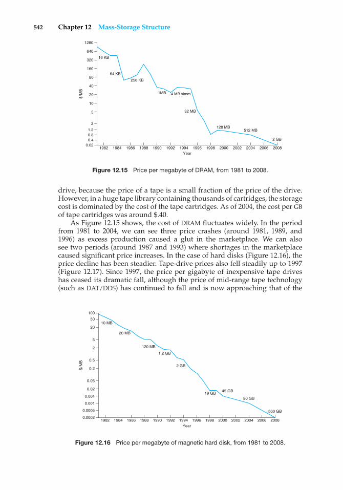
542 Chapter 12 Mass-Storage Structure
0.80.4
0.02
1.2
2
5
10
20
40
80
160
320
640
1280
1982 1984 1986 1988 1990 1992 1994 1996 1998 2000 2002 2004 2006 2008
$/M
B
Year
16 KB
64 KB
256 KB
1MB 4 MB simm
32 MB
128 MB512 MB
2 GB
Figure 12.15 Price per megabyte of DRAM, from 1981 to 2008.
drive, because the price of a tape is a small fraction of the price of the drive.However, in a huge tape library containing thousands of cartridges, the storagecost is dominated by the cost of the tape cartridges. As of 2004, the cost per GBof tape cartridges was around $.40.
As Figure 12.15 shows, the cost of DRAM fluctuates widely. In the periodfrom 1981 to 2004, we can see three price crashes (around 1981, 1989, and1996) as excess production caused a glut in the marketplace. We can alsosee two periods (around 1987 and 1993) where shortages in the marketplacecaused significant price increases. In the case of hard disks (Figure 12.16), theprice decline has been steadier. Tape-drive prices also fell steadily up to 1997(Figure 12.17). Since 1997, the price per gigabyte of inexpensive tape driveshas ceased its dramatic fall, although the price of mid-range tape technology(such as DAT/DDS) has continued to fall and is now approaching that of the
0.001
0.0002
0.0005
0.02
0.05
0.004
0.2
0.5
2
5
20
50
100
1982 1984 1986 1988 1990 1992 1994 1996 1998 2000 2002 2004 2006 2008
$/M
B
Year
10 MB
20 MB
120 MB
1.2 GB
2 GB
19 GB45 GB
80 GB
500 GB
Figure 12.16 Price per megabyte of magnetic hard disk, from 1981 to 2008.
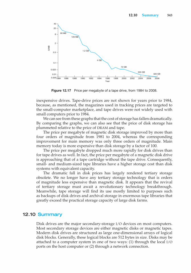
12.10 Summary 543
0.01
0.005
0.1
0.025
0.5
2
8
20
40
1984 1986 1988 1990 1992 1994 1996 1998 2000
$/M
B
Year
60 MB
120 MB
1.2 GB
4 GB
72 GB
320 GB 320 GB
2002 2004 2006 2008
Figure 12.17 Price per megabyte of a tape drive, from 1984 to 2008.
inexpensive drives. Tape-drive prices are not shown for years prior to 1984,because, as mentioned, the magazines used in tracking prices are targeted tothe small-computer marketplace, and tape drives were not widely used withsmall computers prior to 1984.
We can see from these graphs that the cost of storage has fallen dramatically.By comparing the graphs, we can also see that the price of disk storage hasplummeted relative to the price of DRAM and tape.
The price per megabyte of magnetic disk storage improved by more thanfour orders of magnitude from 1981 to 2004, whereas the correspondingimprovement for main memory was only three orders of magnitude. Mainmemory today is more expensive than disk storage by a factor of 100.
The price per megabyte dropped much more rapidly for disk drives thanfor tape drives as well. In fact, the price per megabyte of a magnetic disk driveis approaching that of a tape cartridge without the tape drive. Consequently,small- and medium-sized tape libraries have a higher storage cost than disksystems with equivalent capacity.
The dramatic fall in disk prices has largely rendered tertiary storageobsolete. We no longer have any tertiary storage technology that is ordersof magnitude less expensive than magnetic disk. It appears that the revivalof tertiary storage must await a revolutionary technology breakthrough.Meanwhile, tape storage will find its use mostly limited to purposes suchas backups of disk drives and archival storage in enormous tape libraries thatgreatly exceed the practical storage capacity of large disk farms.
12.10 Summary
Disk drives are the major secondary-storage I/O devices on most computers.Most secondary storage devices are either magnetic disks or magnetic tapes.Modern disk drives are structured as large one-dimensional arrays of logicaldisk blocks. Generally, these logical blocks are 512 bytes in size. Disks may beattached to a computer system in one of two ways: (1) through the local I/Oports on the host computer or (2) through a network connection.
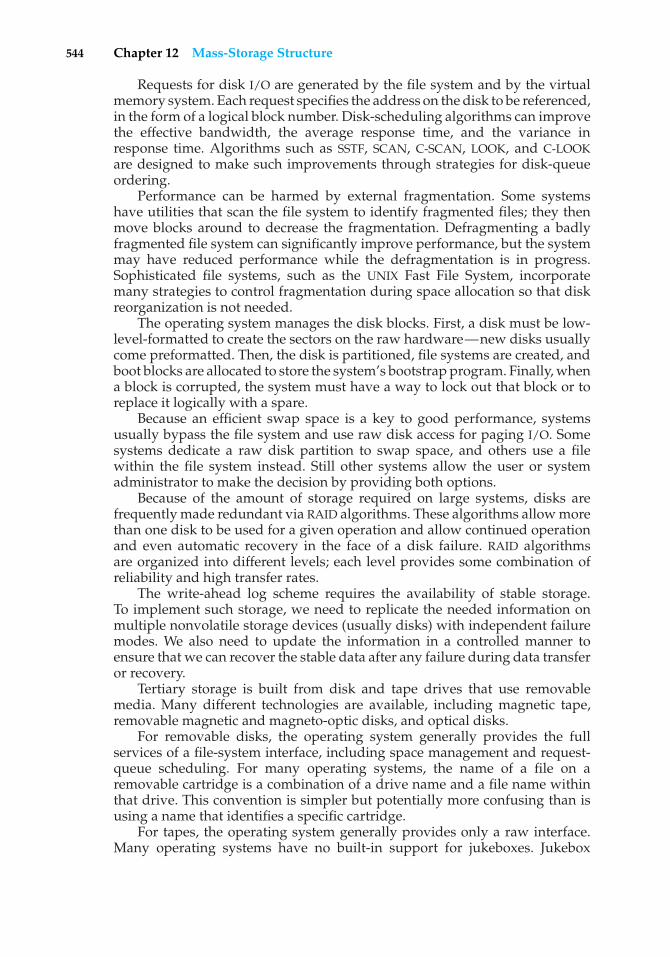
544 Chapter 12 Mass-Storage Structure
Requests for disk I/O are generated by the file system and by the virtualmemory system. Each request specifies the address on the disk to be referenced,in the form of a logical block number. Disk-scheduling algorithms can improvethe effective bandwidth, the average response time, and the variance inresponse time. Algorithms such as SSTF, SCAN, C-SCAN, LOOK, and C-LOOKare designed to make such improvements through strategies for disk-queueordering.
Performance can be harmed by external fragmentation. Some systemshave utilities that scan the file system to identify fragmented files; they thenmove blocks around to decrease the fragmentation. Defragmenting a badlyfragmented file system can significantly improve performance, but the systemmay have reduced performance while the defragmentation is in progress.Sophisticated file systems, such as the UNIX Fast File System, incorporatemany strategies to control fragmentation during space allocation so that diskreorganization is not needed.
The operating system manages the disk blocks. First, a disk must be low-level-formatted to create the sectors on the raw hardware—new disks usuallycome preformatted. Then, the disk is partitioned, file systems are created, andboot blocks are allocated to store the system’s bootstrap program. Finally, whena block is corrupted, the system must have a way to lock out that block or toreplace it logically with a spare.
Because an efficient swap space is a key to good performance, systemsusually bypass the file system and use raw disk access for paging I/O. Somesystems dedicate a raw disk partition to swap space, and others use a filewithin the file system instead. Still other systems allow the user or systemadministrator to make the decision by providing both options.
Because of the amount of storage required on large systems, disks arefrequently made redundant via RAID algorithms. These algorithms allow morethan one disk to be used for a given operation and allow continued operationand even automatic recovery in the face of a disk failure. RAID algorithmsare organized into different levels; each level provides some combination ofreliability and high transfer rates.
The write-ahead log scheme requires the availability of stable storage.To implement such storage, we need to replicate the needed information onmultiple nonvolatile storage devices (usually disks) with independent failuremodes. We also need to update the information in a controlled manner toensure that we can recover the stable data after any failure during data transferor recovery.
Tertiary storage is built from disk and tape drives that use removablemedia. Many different technologies are available, including magnetic tape,removable magnetic and magneto-optic disks, and optical disks.
For removable disks, the operating system generally provides the fullservices of a file-system interface, including space management and request-queue scheduling. For many operating systems, the name of a file on aremovable cartridge is a combination of a drive name and a file name withinthat drive. This convention is simpler but potentially more confusing than isusing a name that identifies a specific cartridge.
For tapes, the operating system generally provides only a raw interface.Many operating systems have no built-in support for jukeboxes. Jukebox
Practice Exercises 545
support can be provided by a device driver or by a privileged applicationdesigned for backups or for HSM.
Three important aspects of performance are bandwidth, latency, andreliability. Many bandwidths are available for both disks and tapes, but therandom-access latency for a tape is generally much greater than that for a disk.Switching cartridges in a jukebox is also relatively slow. Because a jukeboxhas a low ratio of drives to cartridges, reading a large fraction of the data in ajukebox can take a long time. Optical media, which protect the sensitive layerwith a transparent coating, are generally more robust than magnetic media,which are more likely to expose the magnetic material to physical damage.Lastly, the cost of storage has decreased greatly in the past two decades, mostnotably for disk storage.
Practice Exercises
12.1 Is disk scheduling, other than FCFS scheduling, useful in a single-userenvironment? Explain your answer.
12.2 Explain why SSTF scheduling tends to favor middle cylinders over theinnermost and outermost cylinders.
12.3 Why is rotational latency usually not considered in disk scheduling?How would you modify SSTF, SCAN, and C-SCAN to include latencyoptimization?
12.4 How would use of a RAM disk affect your selection of a disk-schedulingalgorithm? What factors would you need to consider? Do the sameconsiderations apply to hard-disk scheduling, given that the file systemstores recently used blocks in a buffer cache in main memory?
12.5 Why is it important to balance file system I/O among the disks andcontrollers on a system in a multitasking environment?
12.6 What are the tradeoffs involved in rereading code pages from the filesystem versus using swap space to store them?
12.7 Is there any way to implement truly stable storage? Explain youranswer.
12.8 The term “Fast Wide SCSI-II” denotes a SCSI bus that operates at adata rate of 20 megabytes per second when it moves a packet of bytesbetween the host and a device. Suppose that a Fast Wide SCSI-II diskdrive spins at 7,200 RPM, has a sector size of 512 bytes, and holds 160sectors per track.
a. Estimate the sustained transfer rate of this drive in megabytes persecond.
b. Suppose that the drive has 7,000 cylinders, 20 tracks per cylinder,a head-switch time (from one platter to another) of 0.5 millisec-ond, and an adjacent-cylinder seek time of 2 milliseconds. Usethis additional information to give an accurate estimate of thesustained transfer rate for a huge transfer.
546 Chapter 12 Mass-Storage Structure
c. Suppose that the average seek time for the drive is 8 milliseconds.Estimate the I/O operations per second and the effective transferrate for a random-access workload that reads individual sectorsthat are scattered across the disk.
d. Calculate the random-access I/O operations per second andtransfer rate for I/O sizes of 4 kilobytes, 8 kilobytes, and 64kilobytes.
e. If multiple requests are in the queue, a scheduling algorithm suchas SCAN should be able to reduce the average seek distance. Sup-pose that a random-access workload is reading 8-kilobyte pages,the average queue length is 10, and the scheduling algorithmreduces the average seek time to 3 milliseconds. Now calculatethe I/O operations per second and the effective transfer rate of thedrive.
12.9 More than one disk drive can be attached to a SCSI bus. In particular,a Fast Wide SCSI-II bus (see Exercise 12.8) can be connected to at most15 disk drives. Recall that this bus has a bandwidth of 20 megabytesper second. At any time, only one packet can be transferred on the busbetween some disk’s internal cache and the host. However, a disk canbe moving its disk arm while some other disk is transferring a packeton the bus. Also, a disk can be transferring data between its magneticplatters and its internal cache while some other disk is transferring apacket on the bus. Considering the transfer rates that you calculatedfor the various workloads in Exercise 12.8, discuss how many disks canbe used effectively by one Fast Wide SCSI-II bus.
12.10 Remapping bad blocks by sector sparing or sector slipping can influ-ence performance. Suppose that the drive in Exercise 12.8 has a totalof 100 bad sectors at random locations and that each bad sector ismapped to a spare that is located on a different track within the samecylinder. Estimate the number of I/O operations per second and theeffective transfer rate for a random-access workload consisting of 8-kilobyte reads, assuming a queue length of 1 (that is, the choice ofscheduling algorithm is not a factor). What is the effect of a bad sectoron performance?
12.11 In a disk jukebox, what would be the effect of having more open filesthan the number of drives in the jukebox?
12.12 If magnetic hard disks eventually have the same cost per gigabyte as dotapes, will tapes become obsolete, or will they still be needed? Explainyour answer.
12.13 It is sometimes said that tape is a sequential-access medium, whereasa magnetic disk is a random-access medium. In fact, the suitabilityof a storage device for random access depends on the transfer size.The term streaming transfer rate denotes the rate for a data transferthat is underway, excluding the effect of access latency. By contrast, theeffective transfer rate is the ratio of total bytes per total seconds, includingoverhead time such as access latency.
Practice Exercises 547
Suppose that, in a computer, the level-2 cache has an access latencyof 8 nanoseconds and a streaming transfer rate of 800 megabytes persecond, the main memory has an access latency of 60 nanoseconds anda streaming transfer rate of 80 megabytes per second, the magnetic diskhas an access latency of 15 milliseconds and a streaming transfer rateof 5 megabytes per second, and a tape drive has an access latency of 60seconds and a streaming transfer rate of 2 megabytes per seconds.
a. Random access causes the effective transfer rate of a device todecrease, because no data are transferred during the access time.For the disk described, what is the effective transfer rate if anaverage access is followed by a streaming transfer of (1) 512 bytes,(2) 8 kilobytes, (3) 1 megabyte, and (4) 16 megabytes?
b. The utilization of a device is the ratio of effective transfer rate tostreaming transfer rate. Calculate the utilization of the disk drivefor each of the four transfer sizes given in part a.
c. Suppose that a utilization of 25 percent (or higher) is consideredacceptable. Using the performance figures given, compute thesmallest transfer size for disk that gives acceptable utilization.
d. Complete the following sentence: A disk is a random-accessdevice for transfers larger than bytes and is a sequential-access device for smaller transfers.
e. Compute the minimum transfer sizes that give acceptable utiliza-tion for cache, memory, and tape.
f. When is a tape a random-access device, and when is it asequential-access device?
12.14 Suppose that we agree that 1 kilobyte is 1,024 bytes, 1 megabyte is1,0242 bytes, and 1 gigabyte is 1,0243 bytes. This progression continuesthrough terabytes, petabytes, and exabytes (1,0246). Several proposedscientific projects plan to record and store a few exabytes of data duringthe next decade. To answer the following questions, you will need tomake a few reasonable assumptions; state the assumptions that youmake.
a. How many disk drives would be required to hold 4 exabytes ofdata?
b. How many magnetic tapes would be required to hold 4 exabytesof data?
c. How many optical tapes would be required to hold 4 exabytes ofdata (see Exercise 12.35)?
d. How many holographic storage cartridges would be required tohold 4 exabytes of data (see Exercise 12.34)?
e. How many cubic feet of storage space would each option require?
548 Chapter 12 Mass-Storage Structure
Exercises
12.15 None of the disk-scheduling disciplines, except FCFS, is truly fair(starvation may occur).
a. Explain why this assertion is true.
b. Describe a way to modify algorithms such as SCAN to ensurefairness.
c. Explain why fairness is an important goal in a time-sharingsystem.
d. Give three or more examples of circumstances in which it isimportant that the operating system be unfair in serving I/Orequests.
12.16 Suppose that a disk drive has 5,000 cylinders, numbered 0 to 4999. Thedrive is currently serving a request at cylinder 143, and the previousrequest was at cylinder 125. The queue of pending requests, in FIFOorder, is:
86, 1470, 913, 1774, 948, 1509, 1022, 1750, 130
Starting from the current head position, what is the total distance (incylinders) that the disk arm moves to satisfy all the pending requestsfor each of the following disk-scheduling algorithms?
a. FCFS
b. SSTF
c. SCAN
d. LOOK
e. C-SCAN
f. C-LOOK
12.17 Elementary physics states that when an object is subjected to a constantacceleration a, the relationship between distance d and time t is givenby d = 1
2at2. Suppose that, during a seek, the disk in Exercise 12.16
accelerates the disk arm at a constant rate for the first half of the seek,then decelerates the disk arm at the same rate for the second half of theseek. Assume that the disk can perform a seek to an adjacent cylinderin 1 millisecond and a full-stroke seek over all 5,000 cylinders in 18milliseconds.
a. The distance of a seek is the number of cylinders that the headmoves. Explain why the seek time is proportional to the squareroot of the seek distance.
b. Write an equation for the seek time as a function of the seekdistance. This equation should be of the form t = x+ y√L, wheret is the time in milliseconds and L is the seek distance in cylinders.
Exercises 549
c. Calculate the total seek time for each of the schedules in Exercise12.16. Determine which schedule is the fastest (has the smallesttotal seek time).
d. The percentage speedup is the time saved divided by the originaltime. What is the percentage speedup of the fastest schedule overFCFS?
12.18 Suppose that the disk in Exercise 12.17 rotates at 7,200 RPM.
a. What is the average rotational latency of this disk drive?
b. What seek distance can be covered in the time that you found forpart a?
12.19 The accelerating seek described in Exercise 12.17 is typical of hard-diskdrives. By contrast, floppy disks (and many hard disks manufacturedbefore the mid-1980s) typically seek at a fixed rate. Suppose that thedisk in Exercise 12.17 has a constant-rate seek rather than a constant-acceleration seek, so the seek time is of the form t = x + yL , where tis the time in milliseconds and L is the seek distance. Suppose that thetime to seek to an adjacent cylinder is 1 millisecond, as before, and thetime to seek to each additional cylinder is 0.5 milliseconds.
a. Write an equation for this seek time as a function of the seekdistance.
b. Using this seek-time function, calculate the total seek time foreach of the schedules in Exercise 12.16. Is your answer the sameas the one for Exercise 12.17(c)?
c. What is the percentage speedup of the fastest schedule over FCFSin this case?
12.20 Write a program that simulates the disk-scheduling algorithms dis-cussed in Section 12.4.
12.21 Compare the performance of C-SCAN and SCAN scheduling, assuminga uniform distribution of requests. Consider the average response time(the time between the arrival of a request and the completion of thatrequest’s service), the variation in response time, and the effectivebandwidth. How does performance depend on the relative sizes ofseek time and rotational latency?
12.22 Requests are not usually uniformly distributed. For example, we canexpect a cylinder containing the file-system FAT or inodes to be accessedmore frequently than a cylinder containing only files. Suppose youknow that 50 percent of the requests are for a small, fixed number ofcylinders.
a. Would any of the scheduling algorithms discussed in this chapterbe particularly good for this case? Explain your answer.
b. Propose a disk-scheduling algorithm that gives even better per-formance by taking advantage of this “hot spot” on the disk.
550 Chapter 12 Mass-Storage Structure
c. File systems typically find data blocks via an indirection table,such as a FAT in DOS or inodes in UNIX. Describe one or more waysto take advantage of this indirection to improve disk performance.
12.23 Could a RAID level 1 organization achieve better performance for readrequests than a RAID level 0 organization (with nonredundant stripingof data)? If so, how?
12.24 Consider a RAID level 5 organization comprising five disks, with theparity for sets of four blocks on four disks stored on the fifth disk. Howmany blocks are accessed in order to perform the following?
a. A write of one block of data
b. A write of seven continuous blocks of data
12.25 Compare the throughput achieved by a RAID level 5 organization withthat achieved by a RAID level 1 organization for the following:
a. Read operations on single blocks
b. Read operations on multiple contiguous blocks
12.26 Compare the performance of write operations achieved by a RAID level5 organization with that achieved by a RAID level 1 organization.
12.27 Assume that you have a mixed configuration comprising disks orga-nized as RAID level 1 and RAID level 5 disks. Assume that the systemhas flexibility in deciding which disk organization to use for storing aparticular file. Which files should be stored in the RAID level 1 disksand which in the RAID level 5 disks in order to optimize performance?
12.28 The reliability of a hard-disk drive is typically described in terms of aquantity calledmean time between failures (MTBF). Although this quantityis called a “time,” the MTBF actually is measured in drive-hours perfailure.
a. If a system contains 1,000 disk drives, each of which has a 750,000-hour MTBF, which of the following best describes how often adrive failure will occur in that disk farm: once per thousand years,once per century, once per decade, once per year, once per month,once per week, once per day, once per hour, once per minute, oronce per second?
b. Mortality statistics indicate that, on the average, a U.S. residenthas about 1 chance in 1,000 of dying between the ages of 20 and 21.Deduce the MTBF hours for 20-year-olds. Convert this figure fromhours to years. What does this MTBF tell you about the expectedlifetime of a 20-year-old?
c. The manufacturer guarantees a 1-million-hour MTBF for a certainmodel of disk drive. What can you conclude about the number ofyears for which one of these drives is under warranty?
12.29 Discuss the relative advantages and disadvantages of sector sparingand sector slipping.
Exercises 551
12.30 Discuss the reasons why the operating system might require accurateinformation on how blocks are stored on a disk. How could the oper-ating system improve file system performance with this knowledge?
12.31 The operating system generally treats removable disks as shared filesystems but assigns a tape drive to only one application at a time. Givethree reasons that could explain this difference in treatment of disks andtapes. Describe the additional features that an operating system wouldneed to support shared file-system access to a tape jukebox. Would theapplications sharing the tape jukebox need any special properties, orcould they use the files as though the files were disk-resident? Explainyour answer.
12.32 What would be the effects on cost and performance if tape storage hadthe same areal density as disk storage? (Areal density is the number ofgigabits per square inch.)
12.33 You can use simple estimates to compare the cost and performanceof a terabyte storage system made entirely from disks with one thatincorporates tertiary storage. Suppose that each magnetic disk holds10 GB, costs $1,000, transfers 5 MB per second, and has an average accesslatency of 15 milliseconds. Also suppose that a tape library costs $10per gigabyte, transfers 10 MB per second, and has an average accesslatency of 20 seconds. Compute the total cost, the maximum total datarate, and the average waiting time for a pure disk system. If you makeany assumptions about the workload, describe and justify them. Now,suppose that 5 percent of the data are frequently used, so they mustreside on disk, but the other 95 percent are archived in the tape library.Further suppose that the disk system handles 95 percent of the requestsand the library handles the other 5 percent. What are the total cost,the maximum total data rate, and the average waiting time for thishierarchical storage system?
12.34 Imagine that a holographic storage drive has been invented. The drivecosts $10,000 and has an average access time of 40 milliseconds. It usesa $100 cartridge the size of a CD. This cartridge holds 40,000 images,and each image is a square black-and-white picture with a resolutionof 6, 000 × 6, 000 pixels (each pixel stores 1 bit). The drive can read orwrite one picture in 1 millisecond. Answer the following questions.
a. What would be some good uses for this device?
b. How would this device affect the I/O performance of a computingsystem?
c. What kinds of storage devices, if any, would become obsolete asa result of the invention of this device?
12.35 Suppose that a one-sided 5.25-inch optical-disk cartridge has an arealdensity of 1 gigabit per square inch. Further suppose that a magnetictape has an areal density of 20 megabits per square inch and is 1/2inch wide and 1,800 feet long. Calculate an estimate of the storagecapacities of these two kinds of storage media. Suppose that an opticaltape exists that has the same physical size as the magnetic tape but the
552 Chapter 12 Mass-Storage Structure
same storage density as the optical disk. What volume of data couldthe optical tape hold? What would be a marketable price for the opticaltape if the magnetic tape cost $25?
12.36 Discuss how an operating system could maintain a free-space listfor a tape-resident file system. Assume that the tape technology isappend-only and that it uses EOT marks and locate, space, and readposition commands as described in Section 12.9.2.1.
Wiley Plus
Visit Wiley Plus for
• Source code
• Solutions to practice exercises
• Additional programming problems and exercises
• Labs using an operating system simulator
Bibliographical Notes
Discussions of redundant arrays of independent disks (RAIDs) are presentedby Patterson et al. [1988] and in the detailed survey of Chen et al. [1994].Disk-system architectures for high-performance computing are discussed byKatz et al. [1989]. Enhancements to RAID systems are discussed in Wilkeset al. [1996] and Yu et al. [2000]. Teorey and Pinkerton [1972] present an earlycomparative analysis of disk-scheduling algorithms. They use simulations thatmodel a disk for which seek time is linear in the number of cylinders crossed.For this disk, LOOK is a good choice for queue lengths below 140, and C-LOOKis good for queue lengths above 100. King [1990] describes ways to improve theseek time by moving the disk arm when the disk is otherwise idle. Seltzer et al.[1990] and Jacobson and Wilkes [1991] describe disk-scheduling algorithms thatconsider rotational latency in addition to seek time. Scheduling optimizationsthat exploit disk idle times are discussed in Lumb et al. [2000]. Worthingtonet al. [1994] discuss disk performance and show the negligible performanceimpact of defect management. The placement of hot data to improve seektimes has been considered by Ruemmler and Wilkes [1991] and Akyurek andSalem [1993]. Ruemmler and Wilkes [1994] describe an accurate performancemodel for a modern disk drive. Worthington et al. [1995] tell how to determinelow-level disk properties such as the zone structure, and this work is furtheradvanced by Schindler and Gregory [1999]. Disk power management issuesare discussed in Douglis et al. [1994], Douglis et al. [1995], Greenawalt [1994],and Golding et al. [1995].
The I/O size and randomness of the workload has a considerable influenceon disk performance. Ousterhout et al. [1985] and Ruemmler and Wilkes[1993] report numerous interesting workload characteristics, including thatmost files are small, most newly created files are deleted soon thereafter, mostfiles that are opened for reading are read sequentially in their entirety, and most
Bibliographical Notes 553
seeks are short. McKusick et al. [1984] describe the Berkeley Fast File System(FFS), which uses many sophisticated techniques to obtain good performancefor a wide variety of workloads. McVoy and Kleiman [1991] discuss furtherimprovements to the basic FFS. Quinlan [1991] describes how to implementa file system on WORM storage with a magnetic disk cache; Richards [1990]discusses a file-system approach to tertiary storage. Maher et al. [1994] give anoverview of the integration of distributed file systems and tertiary storage.
The concept of a storage hierarchy has been studied for more thanthirty years. For instance, a 1970 paper by Mattson et al. [1970] describes amathematical approach to predicting the performance of a storage hierarchy.Alt [1993] describes the accommodation of removable storage in a commercialoperating system, and Miller and Katz [1993] describe the characteristics oftertiary-storage access in a supercomputing environment. Benjamin [1990]gives an overview of the massive storage requirements for the EOSDIS projectat NASA. Management and use of network-attached disks and programmabledisks are discussed in Gibson et al. [1997b], Gibson et al. [1997a], Riedel et al.[1998], and Lee and Thekkath [1996].
Holographic storage technology is the subject of an article by Psaltis andMok [1995]; a collection of papers on this topic dating from 1963 has beenassembled by Sincerbox [1994]. Asthana and Finkelstein [1995] describe severalemerging storage technologies, including holographic storage, optical tape,and electron trapping. Toigo [2000] gives an in-depth description of moderndisk technology and several potential future storage technologies.

This page intentionally left blank
13C H A P T E R
I/O Systems
The two main jobs of a computer are I/O and processing. In many cases, themain job is I/O, and the processing is merely incidental. For instance, whenwe browse a Web page or edit a file, our immediate interest is to read or entersome information, not to compute an answer.
The role of the operating system in computer I/O is to manage andcontrol I/O operations and I/O devices. Although related topics appear inother chapters, here we bring together the pieces to paint a complete pictureof I/O. First, we describe the basics of I/O hardware, because the nature of thehardware interface places constraints on the internal facilities of the operatingsystem. Next, we discuss the I/O services provided by the operating systemand the embodiment of these services in the application I/O interface. Then,we explain how the operating system bridges the gap between the hardwareinterface and the application interface. We also discuss the UNIX System VSTREAMS mechanism, which enables an application to assemble pipelines ofdriver code dynamically. Finally, we discuss the performance aspects of I/Oand the principles of operating-system design that improve I/O performance.
CHAPTER OBJECTIVES
• To explore the structure of an operating system’s I/O subsystem.
• To discuss the principles and complexities of I/O hardware.
• To explain the performance aspects of I/O hardware and software.
13.1 Overview
The control of devices connected to the computer is a major concern ofoperating-system designers. Because I/O devices vary so widely in theirfunction and speed (consider a mouse, a hard disk, and a CD-ROM jukebox),varied methods are needed to control them. These methods form the I/Osubsystem of the kernel, which separates the rest of the kernel from thecomplexities of managing I/O devices.
555
556 Chapter 13 I/O Systems
I/O-device technology exhibits two conflicting trends. On the one hand, wesee increasing standardization of software and hardware interfaces. This trendhelps us to incorporate improved device generations into existing computersand operating systems. On the other hand, we see an increasingly broad varietyof I/O devices. Some new devices are so unlike previous devices that it is achallenge to incorporate them into our computers and operating systems. Thischallenge is met by a combination of hardware and software techniques. Thebasic I/O hardware elements, such as ports, buses, and device controllers,accommodate a wide variety of I/O devices. To encapsulate the details andoddities of different devices, the kernel of an operating system is structuredto use device-driver modules. The device drivers present a uniform device-access interface to the I/O subsystem, much as system calls provide a standardinterface between the application and the operating system.
13.2 I/O Hardware
Computers operate a great many kinds of devices. Most fit into the generalcategories of storage devices (disks, tapes), transmission devices (networkcards, modems), and human-interface devices (screen, keyboard, mouse).Other devices are more specialized, such as those involved in the steeringof a military fighter jet or a space shuttle. In these aircraft, a human gives inputto the flight computer via a joystick and foot pedals, and the computer sendsoutput commands that cause motors to move rudders, flaps, and thrusters.Despite the incredible variety of I/O devices, though, we need only a fewconcepts to understand how the devices are attached and how the softwarecan control the hardware.
A device communicates with a computer system by sending signals over acable or even through the air. The device communicates with the machine via aconnection point, or port—for example, a serial port. If devices use a commonset of wires, the connection is called a bus. A bus is a set of wires and a rigidlydefined protocol that specifies a set of messages that can be sent on the wires.In terms of the electronics, the messages are conveyed by patterns of electricalvoltages applied to the wires with defined timings. When device A has a cablethat plugs into device B, and device B has a cable that plugs into device C, anddevice C plugs into a port on the computer, this arrangement is called a daisychain. A daisy chain usually operates as a bus.
Buses are used widely in computer architecture and vary in their signalingmethods, speed, throughput, and connection methods. A typical PC busstructure appears in Figure 13.1. This figure shows a PCI bus (the commonPC system bus) that connects the processor–memory subsystem to the fastdevices and an expansion bus that connects relatively slow devices, such asthe keyboard and serial and USB ports. In the upper-right portion of the figure,four disks are connected together on a SCSI bus plugged into a SCSI controller.Other common buses used to interconnect main parts of a computer includePCI-X, with throughput up to 4.3 GB; PCI Express (PCIe), with throughput upto 16 GB; and HyperTransport, with throughput up to 20 GB.
A controller is a collection of electronics that can operate a port, a bus,or a device. A serial-port controller is a simple device controller. It is a singlechip (or portion of a chip) in the computer that controls the signals on the
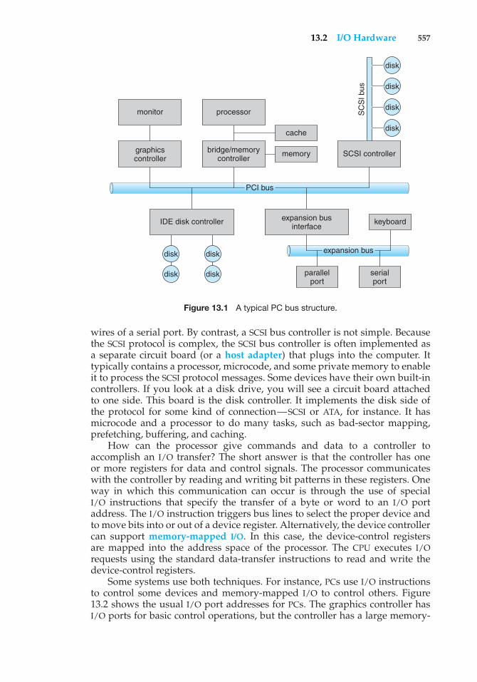
13.2 I/O Hardware 557
expansion bus
PCI bus
disk
disk
disk
disk
disk
disk
disk
disk
SCSI controller
SC
SI b
us
cache
memory
processor
bridge/memorycontroller
monitor
IDE disk controller expansion businterface
graphicscontroller
keyboard
parallelport
serialport
Figure 13.1 A typical PC bus structure.
wires of a serial port. By contrast, a SCSI bus controller is not simple. Becausethe SCSI protocol is complex, the SCSI bus controller is often implemented asa separate circuit board (or a host adapter) that plugs into the computer. Ittypically contains a processor, microcode, and some private memory to enableit to process the SCSI protocol messages. Some devices have their own built-incontrollers. If you look at a disk drive, you will see a circuit board attachedto one side. This board is the disk controller. It implements the disk side ofthe protocol for some kind of connection—SCSI or ATA, for instance. It hasmicrocode and a processor to do many tasks, such as bad-sector mapping,prefetching, buffering, and caching.
How can the processor give commands and data to a controller toaccomplish an I/O transfer? The short answer is that the controller has oneor more registers for data and control signals. The processor communicateswith the controller by reading and writing bit patterns in these registers. Oneway in which this communication can occur is through the use of specialI/O instructions that specify the transfer of a byte or word to an I/O portaddress. The I/O instruction triggers bus lines to select the proper device andto move bits into or out of a device register. Alternatively, the device controllercan support memory-mapped I/O. In this case, the device-control registersare mapped into the address space of the processor. The CPU executes I/Orequests using the standard data-transfer instructions to read and write thedevice-control registers.
Some systems use both techniques. For instance, PCs use I/O instructionsto control some devices and memory-mapped I/O to control others. Figure13.2 shows the usual I/O port addresses for PCs. The graphics controller hasI/O ports for basic control operations, but the controller has a large memory-
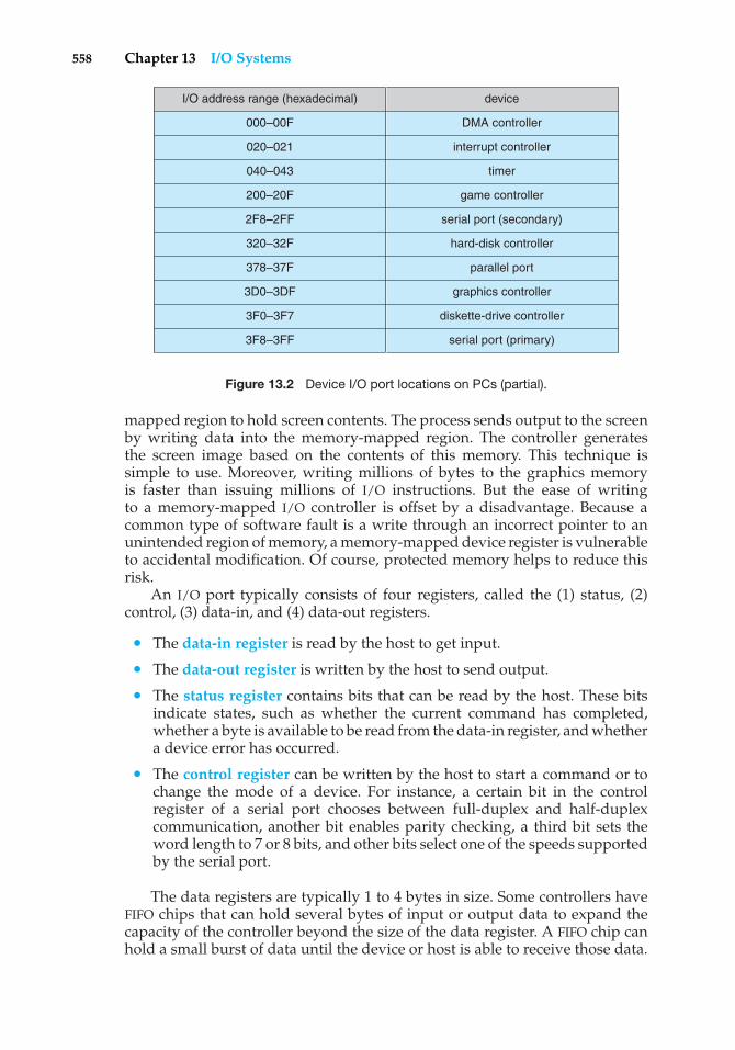
558 Chapter 13 I/O Systems
I/O address range (hexadecimal)
000–00F
020–021
040–043
200–20F
2F8–2FF
320–32F
378–37F
3D0–3DF
3F0–3F7
3F8–3FF
device
DMA controller
interrupt controller
timer
game controller
serial port (secondary)
hard-disk controller
parallel port
graphics controller
diskette-drive controller
serial port (primary)
Figure 13.2 Device I/O port locations on PCs (partial).
mapped region to hold screen contents. The process sends output to the screenby writing data into the memory-mapped region. The controller generatesthe screen image based on the contents of this memory. This technique issimple to use. Moreover, writing millions of bytes to the graphics memoryis faster than issuing millions of I/O instructions. But the ease of writingto a memory-mapped I/O controller is offset by a disadvantage. Because acommon type of software fault is a write through an incorrect pointer to anunintended region of memory, a memory-mapped device register is vulnerableto accidental modification. Of course, protected memory helps to reduce thisrisk.
An I/O port typically consists of four registers, called the (1) status, (2)control, (3) data-in, and (4) data-out registers.
• The data-in register is read by the host to get input.
• The data-out register is written by the host to send output.
• The status register contains bits that can be read by the host. These bitsindicate states, such as whether the current command has completed,whether a byte is available to be read from the data-in register, and whethera device error has occurred.
• The control register can be written by the host to start a command or tochange the mode of a device. For instance, a certain bit in the controlregister of a serial port chooses between full-duplex and half-duplexcommunication, another bit enables parity checking, a third bit sets theword length to 7 or 8 bits, and other bits select one of the speeds supportedby the serial port.
The data registers are typically 1 to 4 bytes in size. Some controllers haveFIFO chips that can hold several bytes of input or output data to expand thecapacity of the controller beyond the size of the data register. A FIFO chip canhold a small burst of data until the device or host is able to receive those data.
13.2 I/O Hardware 559
13.2.1 Polling
The complete protocol for interaction between the host and a controllercan be intricate, but the basic handshaking notion is simple. We explainhandshaking with an example. Assume that 2 bits are used to coordinatethe producer–consumer relationship between the controller and the host. Thecontroller indicates its state through the busy bit in the status register. (Recallthat to set a bit means to write a 1 into the bit and to clear a bit means to writea 0 into it.) The controller sets the busy bit when it is busy working and clearsthe busy bit when it is ready to accept the next command. The host signalsits wishes via the command-ready bit in the command register. The host sets thecommand-ready bit when a command is available for the controller to execute.For this example, the host writes output through a port, coordinating with thecontroller by handshaking as follows.
1. The host repeatedly reads the busy bit until that bit becomes clear.
2. The host sets the write bit in the command register and writes a byte intothe data-out register.
3. The host sets the command-ready bit.
4. When the controller notices that the command-ready bit is set, it sets thebusy bit.
5. The controller reads the command register and sees the write command.It reads the data-out register to get the byte and does the I/O to the device.
6. The controller clears the command-ready bit, clears the error bit in the statusregister to indicate that the device I/O succeeded, and clears the busy bitto indicate that it is finished.
This loop is repeated for each byte.In step 1, the host is busy-waiting or polling: it is in a loop, reading the
status register over and over until the busy bit becomes clear. If the controllerand device are fast, this method is a reasonable one. But if the wait may belong, the host should probably switch to another task. How, then, does thehost know when the controller has become idle? For some devices, the hostmust service the device quickly, or data will be lost. For instance, when dataare streaming in on a serial port or from a keyboard, the small buffer on thecontroller will overflow and data will be lost if the host waits too long beforereturning to read the bytes.
In many computer architectures, three CPU-instruction cycles are sufficientto poll a device: read a device register, logical–and to extract a status bit, andbranch if not zero. Clearly, the basic polling operation is efficient. But pollingbecomes inefficient when it is attempted repeatedly yet rarely finds a deviceto be ready for service, while other useful CPU processing remains undone. Insuch instances, it may be more efficient to arrange for the hardware controller tonotify the CPU when the device becomes ready for service, rather than to requirethe CPU to poll repeatedly for an I/O completion. The hardware mechanismthat enables a device to notify the CPU is called an interrupt.
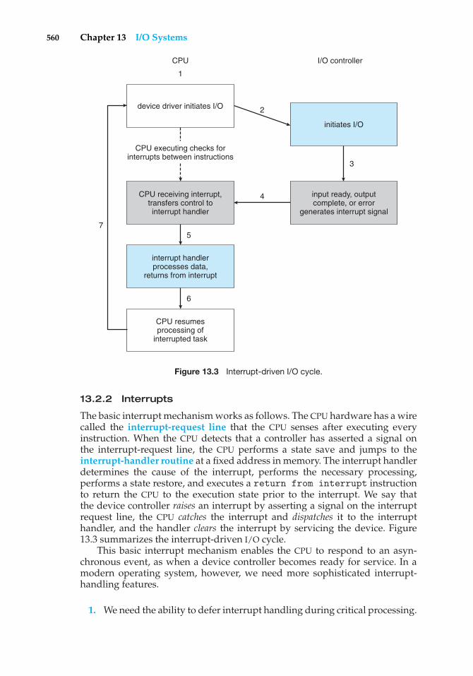
560 Chapter 13 I/O Systems
device driver initiates I/O
CPU receiving interrupt,transfers control tointerrupt handler
CPU resumesprocessing of
interrupted task
CPU
1
I/O controller
CPU executing checks forinterrupts between instructions
5
interrupt handlerprocesses data,
returns from interrupt
initiates I/O
3
2
4
7
input ready, outputcomplete, or error
generates interrupt signal
6
Figure 13.3 Interrupt-driven I/O cycle.
13.2.2 Interrupts
The basic interrupt mechanism works as follows. The CPU hardware has a wirecalled the interrupt-request line that the CPU senses after executing everyinstruction. When the CPU detects that a controller has asserted a signal onthe interrupt-request line, the CPU performs a state save and jumps to theinterrupt-handler routine at a fixed address in memory. The interrupt handlerdetermines the cause of the interrupt, performs the necessary processing,performs a state restore, and executes a return from interrupt instructionto return the CPU to the execution state prior to the interrupt. We say thatthe device controller raises an interrupt by asserting a signal on the interruptrequest line, the CPU catches the interrupt and dispatches it to the interrupthandler, and the handler clears the interrupt by servicing the device. Figure13.3 summarizes the interrupt-driven I/O cycle.
This basic interrupt mechanism enables the CPU to respond to an asyn-chronous event, as when a device controller becomes ready for service. In amodern operating system, however, we need more sophisticated interrupt-handling features.
1. We need the ability to defer interrupt handling during critical processing.
13.2 I/O Hardware 561
2. We need an efficient way to dispatch to the proper interrupt handler fora device without first polling all the devices to see which one raised theinterrupt.
3. We need multilevel interrupts, so that the operating system can distin-guish between high- and low-priority interrupts and can respond withthe appropriate degree of urgency.
In modern computer hardware, these three features are provided by the CPUand by the interrupt-controller hardware.
Most CPUs have two interrupt request lines. One is the nonmaskableinterrupt, which is reserved for events such as unrecoverable memory errors.The second interrupt line is maskable: it can be turned off by the CPU beforethe execution of critical instruction sequences that must not be interrupted.The maskable interrupt is used by device controllers to request service.
The interrupt mechanism accepts an address—a number that selects aspecific interrupt-handling routine from a small set. In most architectures, thisaddress is an offset in a table called the interrupt vector. This vector containsthe memory addresses of specialized interrupt handlers. The purpose of avectored interrupt mechanism is to reduce the need for a single interrupthandler to search all possible sources of interrupts to determine which oneneeds service. In practice, however, computers have more devices (and, hence,interrupt handlers) than they have address elements in the interrupt vector.A common way to solve this problem is to use the technique of interruptchaining, in which each element in the interrupt vector points to the head ofa list of interrupt handlers. When an interrupt is raised, the handlers on thecorresponding list are called one by one, until one is found that can servicethe request. This structure is a compromise between the overhead of a hugeinterrupt table and the inefficiency of dispatching to a single interrupt handler.
Figure 13.4 illustrates the design of the interrupt vector for the Intel Pentiumprocessor. The events from 0 to 31, which are nonmaskable, are used to signalvarious error conditions. The events from 32 to 255, which are maskable, areused for purposes such as device-generated interrupts.
The interrupt mechanism also implements a system of interrupt prioritylevels. This mechanism enables the CPU to defer the handling of low-priorityinterrupts without masking off all interrupts and makes it possible for ahigh-priority interrupt to preempt the execution of a low-priority interrupt.
A modern operating system interacts with the interrupt mechanism inseveral ways. At boot time, the operating system probes the hardware busesto determine what devices are present and installs the corresponding interrupthandlers into the interrupt vector. During I/O, the various device controllersraise interrupts when they are ready for service. These interrupts signify thatoutput has completed, or that input data are available, or that a failure hasbeen detected. The interrupt mechanism is also used to handle a wide varietyof exceptions, such as dividing by zero, accessing a protected or nonexistentmemory address, or attempting to execute a privileged instruction from usermode. The events that trigger interrupts have a common property: they areoccurrences that induce the CPU to execute an urgent, self-contained routine.
An operating system has other good uses for an efficient hardware andsoftware mechanism that saves a small amount of processor state and then
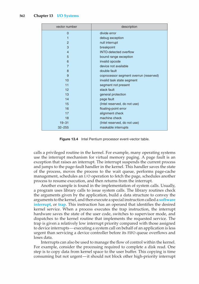
562 Chapter 13 I/O Systems
descriptionvector number
0123456789
101112131415161718
19–3132–255
divide errordebug exceptionnull interruptbreakpointINTO-detected overflowbound range exceptioninvalid opcodedevice not availabledouble faultcoprocessor segment overrun (reserved)invalid task state segmentsegment not presentstack faultgeneral protectionpage fault(Intel reserved, do not use)floating-point erroralignment checkmachine check(Intel reserved, do not use)maskable interrupts
Figure 13.4 Intel Pentium processor event-vector table.
calls a privileged routine in the kernel. For example, many operating systemsuse the interrupt mechanism for virtual memory paging. A page fault is anexception that raises an interrupt. The interrupt suspends the current processand jumps to the page-fault handler in the kernel. This handler saves the stateof the process, moves the process to the wait queue, performs page-cachemanagement, schedules an I/O operation to fetch the page, schedules anotherprocess to resume execution, and then returns from the interrupt.
Another example is found in the implementation of system calls. Usually,a program uses library calls to issue system calls. The library routines checkthe arguments given by the application, build a data structure to convey thearguments to the kernel, and then execute a special instruction called a softwareinterrupt, or trap. This instruction has an operand that identifies the desiredkernel service. When a process executes the trap instruction, the interrupthardware saves the state of the user code, switches to supervisor mode, anddispatches to the kernel routine that implements the requested service. Thetrap is given a relatively low interrupt priority compared with those assignedto device interrupts—executing a system call on behalf of an application is lessurgent than servicing a device controller before its FIFO queue overflows andloses data.
Interrupts can also be used to manage the flow of control within the kernel.For example, consider the processing required to complete a disk read. Onestep is to copy data from kernel space to the user buffer. This copying is timeconsuming but not urgent—it should not block other high-priority interrupt

13.2 I/O Hardware 563
handling. Another step is to start the next pending I/O for that disk drive. Thisstep has higher priority. If the disks are to be used efficiently, we need to startthe next I/O as soon as the previous one completes. Consequently, a pair ofinterrupt handlers implements the kernel code that completes a disk read. Thehigh-priority handler records the I/O status, clears the device interrupt, startsthe next pending I/O, and raises a low-priority interrupt to complete the work.Later, when the CPU is not occupied with high-priority work, the low-priorityinterrupt will be dispatched. The corresponding handler completes the user-level I/O by copying data from kernel buffers to the application space and thencalling the scheduler to place the application on the ready queue.
A threaded kernel architecture is well suited to implement multipleinterrupt priorities and to enforce the precedence of interrupt handling overbackground processing in kernel and application routines. We illustrate thispoint with the Solaris kernel. In Solaris, interrupt handlers are executedas kernel threads. A range of high priorities is reserved for these threads.These priorities give interrupt handlers precedence over application code andkernel housekeeping and implement the priority relationships among interrupthandlers. The priorities cause the Solaris thread scheduler to preempt low-priority interrupt handlers in favor of higher-priority ones, and the threadedimplementation enables multiprocessor hardware to run several interrupthandlers concurrently. We describe the interrupt architecture of Windows XPand UNIX in Chapter 22 and Appendix A, respectively.
In summary, interrupts are used throughout modern operating systems tohandle asynchronous events and to trap to supervisor-mode routines in thekernel. To enable the most urgent work to be done first, modern computersuse a system of interrupt priorities. Device controllers, hardware faults, andsystem calls all raise interrupts to trigger kernel routines. Because interruptsare used so heavily for time-sensitive processing, efficient interrupt handlingis required for good system performance.
13.2.3 Direct Memory Access
For a device that does large transfers, such as a disk drive, it seems wastefulto use an expensive general-purpose processor to watch status bits and tofeed data into a controller register one byte at a time—a process termedprogrammed I/O (PIO). Many computers avoid burdening the main CPU withPIO by offloading some of this work to a special-purpose processor called adirect-memory-access (DMA) controller. To initiate a DMA transfer, the hostwrites a DMA command block into memory. This block contains a pointer tothe source of a transfer, a pointer to the destination of the transfer, and a countof the number of bytes to be transferred. The CPU writes the address of thiscommand block to the DMA controller, then goes on with other work. The DMAcontroller proceeds to operate the memory bus directly, placing addresses onthe bus to perform transfers without the help of the main CPU. A simple DMAcontroller is a standard component in PCs, and bus-mastering I/O boards forthe PC usually contain their own high-speed DMA hardware.
Handshaking between the DMA controller and the device controller isperformed via a pair of wires called DMA-request and DMA-acknowledge.The device controller places a signal on the DMA-request wire when a wordof data is available for transfer. This signal causes the DMA controller to seize
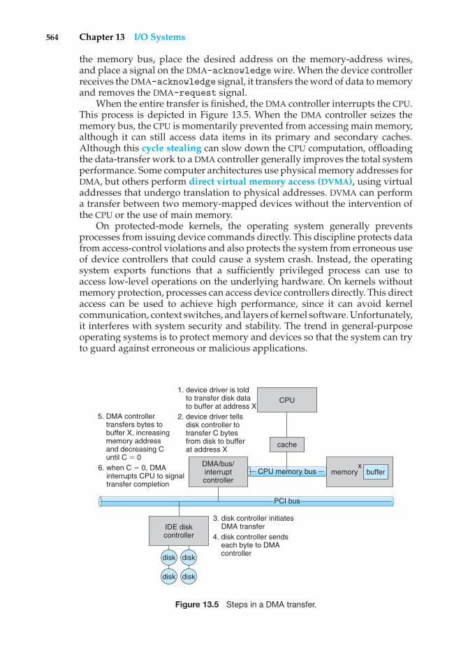
564 Chapter 13 I/O Systems
the memory bus, place the desired address on the memory-address wires,and place a signal on the DMA-acknowledge wire. When the device controllerreceives the DMA-acknowledge signal, it transfers the word of data to memoryand removes the DMA-request signal.
When the entire transfer is finished, the DMA controller interrupts the CPU.This process is depicted in Figure 13.5. When the DMA controller seizes thememory bus, the CPU is momentarily prevented from accessing main memory,although it can still access data items in its primary and secondary caches.Although this cycle stealing can slow down the CPU computation, offloadingthe data-transfer work to a DMA controller generally improves the total systemperformance. Some computer architectures use physical memory addresses forDMA, but others perform direct virtual memory access (DVMA), using virtualaddresses that undergo translation to physical addresses. DVMA can performa transfer between two memory-mapped devices without the intervention ofthe CPU or the use of main memory.
On protected-mode kernels, the operating system generally preventsprocesses from issuing device commands directly. This discipline protects datafrom access-control violations and also protects the system from erroneous useof device controllers that could cause a system crash. Instead, the operatingsystem exports functions that a sufficiently privileged process can use toaccess low-level operations on the underlying hardware. On kernels withoutmemory protection, processes can access device controllers directly. This directaccess can be used to achieve high performance, since it can avoid kernelcommunication, context switches, and layers of kernel software. Unfortunately,it interferes with system security and stability. The trend in general-purposeoperating systems is to protect memory and devices so that the system can tryto guard against erroneous or malicious applications.
IDE diskcontroller
xDMA/bus/interruptcontroller
bufferx
memoryCPU memory bus
PCI bus
cache
CPU
5. DMA controller transfers bytes to buffer X, increasing memory address and decreasing C until C � 0
1. device driver is told to transfer disk data to buffer at address X 2. device driver tells disk controller to transfer C bytes from disk to buffer at address X
6. when C � 0, DMA interrupts CPU to signal transfer completion
3. disk controller initiates DMA transfer4. disk controller sends each byte to DMA controller
disk
disk
disk
disk
Figure 13.5 Steps in a DMA transfer.
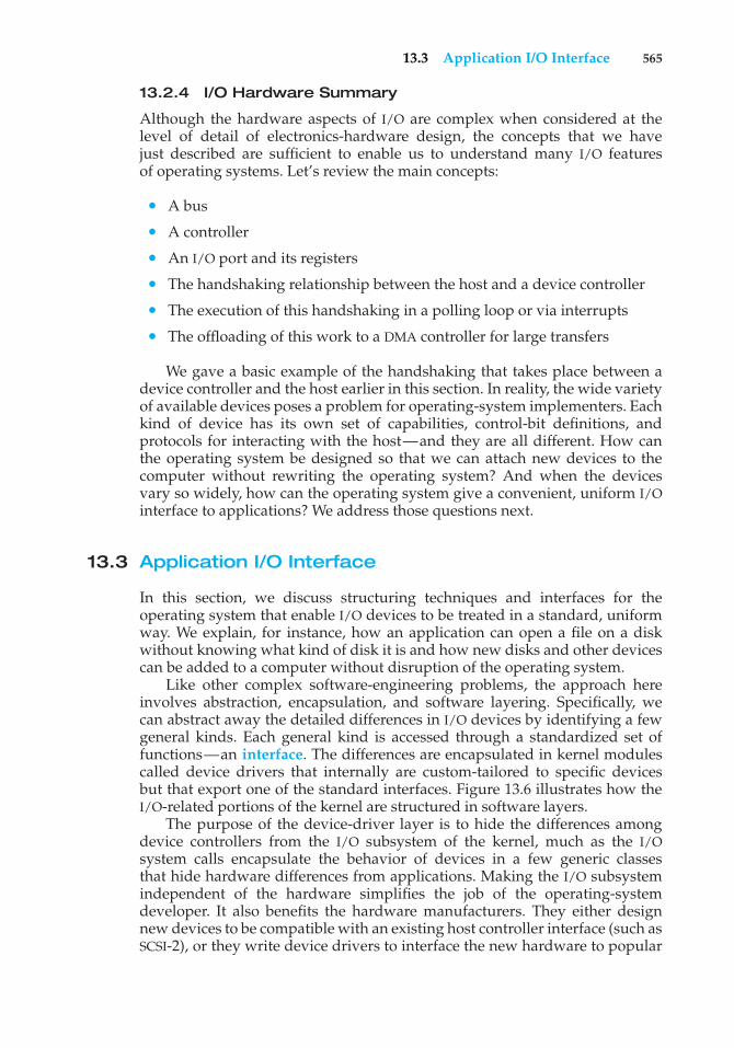
13.3 Application I/O Interface 565
13.2.4 I/O Hardware Summary
Although the hardware aspects of I/O are complex when considered at thelevel of detail of electronics-hardware design, the concepts that we havejust described are sufficient to enable us to understand many I/O featuresof operating systems. Let’s review the main concepts:
• A bus
• A controller
• An I/O port and its registers
• The handshaking relationship between the host and a device controller
• The execution of this handshaking in a polling loop or via interrupts
• The offloading of this work to a DMA controller for large transfers
We gave a basic example of the handshaking that takes place between adevice controller and the host earlier in this section. In reality, the wide varietyof available devices poses a problem for operating-system implementers. Eachkind of device has its own set of capabilities, control-bit definitions, andprotocols for interacting with the host—and they are all different. How canthe operating system be designed so that we can attach new devices to thecomputer without rewriting the operating system? And when the devicesvary so widely, how can the operating system give a convenient, uniform I/Ointerface to applications? We address those questions next.
13.3 Application I/O Interface
In this section, we discuss structuring techniques and interfaces for theoperating system that enable I/O devices to be treated in a standard, uniformway. We explain, for instance, how an application can open a file on a diskwithout knowing what kind of disk it is and how new disks and other devicescan be added to a computer without disruption of the operating system.
Like other complex software-engineering problems, the approach hereinvolves abstraction, encapsulation, and software layering. Specifically, wecan abstract away the detailed differences in I/O devices by identifying a fewgeneral kinds. Each general kind is accessed through a standardized set offunctions—an interface. The differences are encapsulated in kernel modulescalled device drivers that internally are custom-tailored to specific devicesbut that export one of the standard interfaces. Figure 13.6 illustrates how theI/O-related portions of the kernel are structured in software layers.
The purpose of the device-driver layer is to hide the differences amongdevice controllers from the I/O subsystem of the kernel, much as the I/Osystem calls encapsulate the behavior of devices in a few generic classesthat hide hardware differences from applications. Making the I/O subsystemindependent of the hardware simplifies the job of the operating-systemdeveloper. It also benefits the hardware manufacturers. They either designnew devices to be compatible with an existing host controller interface (such asSCSI-2), or they write device drivers to interface the new hardware to popular
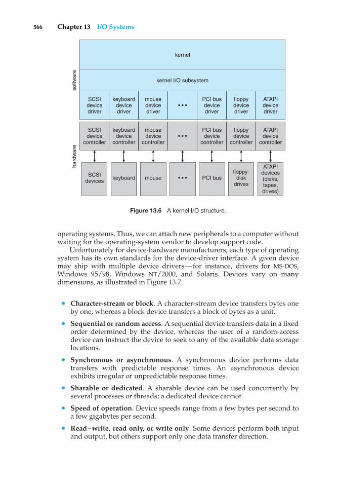
566 Chapter 13 I/O Systems
kernel
hard
war
eso
ftwar
e
SCSIdevicedriver
keyboarddevicedriver
mousedevicedriver
• • •
• • •
• • •
PCI busdevicedriver
floppydevicedriver
ATAPIdevicedriver
SCSIdevice
controller
keyboarddevice
controller
mousedevice
controller
PCI busdevice
controller
floppydevice
controller
ATAPIdevice
controller
SCSIdevices keyboard mouse PCI bus
floppy-disk
drives
ATAPIdevices(disks,tapes,drives)
kernel I/O subsystem
Figure 13.6 A kernel I/O structure.
operating systems. Thus, we can attach new peripherals to a computer withoutwaiting for the operating-system vendor to develop support code.
Unfortunately for device-hardware manufacturers, each type of operatingsystem has its own standards for the device-driver interface. A given devicemay ship with multiple device drivers—for instance, drivers for MS-DOS,Windows 95/98, Windows NT/2000, and Solaris. Devices vary on manydimensions, as illustrated in Figure 13.7.
• Character-stream or block. A character-stream device transfers bytes oneby one, whereas a block device transfers a block of bytes as a unit.
• Sequential or random access. A sequential device transfers data in a fixedorder determined by the device, whereas the user of a random-accessdevice can instruct the device to seek to any of the available data storagelocations.
• Synchronous or asynchronous. A synchronous device performs datatransfers with predictable response times. An asynchronous deviceexhibits irregular or unpredictable response times.
• Sharable or dedicated. A sharable device can be used concurrently byseveral processes or threads; a dedicated device cannot.
• Speed of operation. Device speeds range from a few bytes per second toa few gigabytes per second.
• Read–write, read only, or write only. Some devices perform both inputand output, but others support only one data transfer direction.
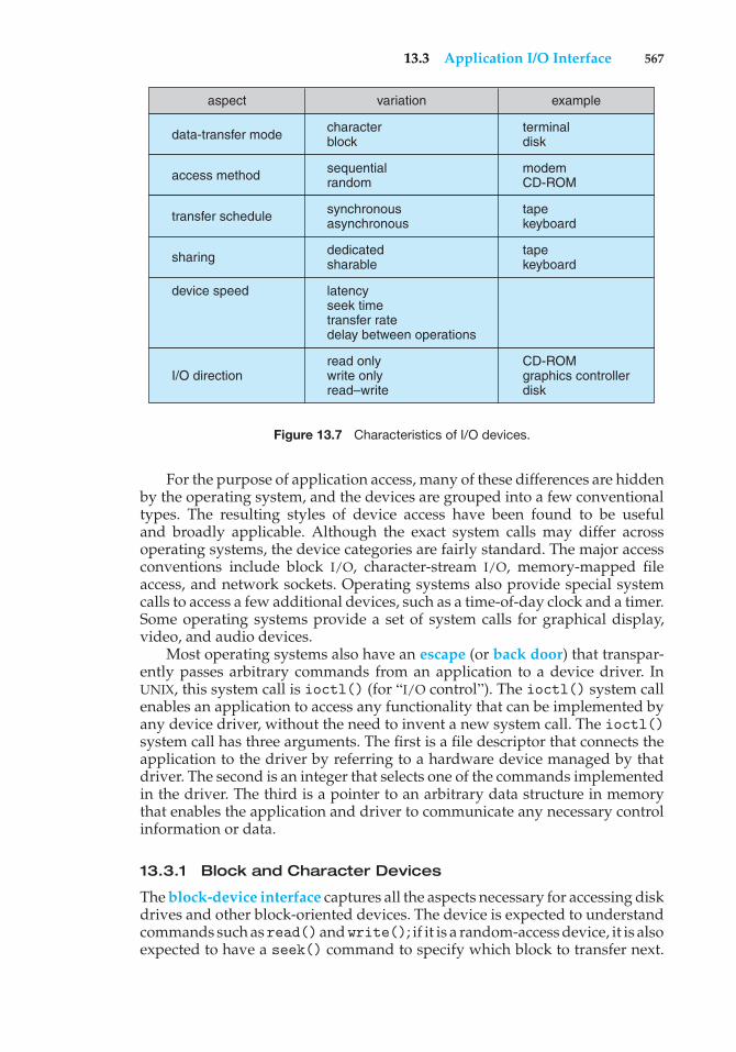
13.3 Application I/O Interface 567
aspect variation example
terminaldisk
modemCD-ROM
tapekeyboard
tapekeyboard
CD-ROMgraphics controllerdisk
data-transfer mode
access method
transfer schedule
sharing
I/O direction
characterblock
sequentialrandom
synchronousasynchronous
dedicatedsharable
read onlywrite onlyread–write
latencyseek timetransfer ratedelay between operations
device speed
Figure 13.7 Characteristics of I/O devices.
For the purpose of application access, many of these differences are hiddenby the operating system, and the devices are grouped into a few conventionaltypes. The resulting styles of device access have been found to be usefuland broadly applicable. Although the exact system calls may differ acrossoperating systems, the device categories are fairly standard. The major accessconventions include block I/O, character-stream I/O, memory-mapped fileaccess, and network sockets. Operating systems also provide special systemcalls to access a few additional devices, such as a time-of-day clock and a timer.Some operating systems provide a set of system calls for graphical display,video, and audio devices.
Most operating systems also have an escape (or back door) that transpar-ently passes arbitrary commands from an application to a device driver. InUNIX, this system call is ioctl() (for “I/O control”). The ioctl() system callenables an application to access any functionality that can be implemented byany device driver, without the need to invent a new system call. The ioctl()system call has three arguments. The first is a file descriptor that connects theapplication to the driver by referring to a hardware device managed by thatdriver. The second is an integer that selects one of the commands implementedin the driver. The third is a pointer to an arbitrary data structure in memorythat enables the application and driver to communicate any necessary controlinformation or data.
13.3.1 Block and Character Devices
The block-device interface captures all the aspects necessary for accessing diskdrives and other block-oriented devices. The device is expected to understandcommands such asread()andwrite(); if it is a random-access device, it is alsoexpected to have a seek() command to specify which block to transfer next.
568 Chapter 13 I/O Systems
Applications normally access such a device through a file-system interface.We can see that read(), write(), and seek() capture the essential behaviorsof block-storage devices, so that applications are insulated from the low-leveldifferences among those devices.
The operating system itself, as well as special applications such as database-management systems, may prefer to access a block device as a simple lineararray of blocks. This mode of access is sometimes called raw I/O. If theapplication performs its own buffering, then using a file system would causeextra, unneeded buffering. Likewise, if an application provides its own lockingof file blocks or regions, then any operating-system locking services would beredundant at the least and contradictory at the worst. To avoid these conflicts,raw-device access passes control of the device directly to the application, lettingthe operating system step out of the way. Unfortunately, no operating-systemservices are then performed on this device. A compromise that is becomingcommon is for the operating system to allow a mode of operation on a file thatdisables buffering and locking. In the UNIX world, this is called direct I/O.
Memory-mapped file access can be layered on top of block-device drivers.Rather than offering read and write operations, a memory-mapped interfaceprovides access to disk storage via an array of bytes in main memory. Thesystem call that maps a file into memory returns the virtual memory addressthat contains a copy of the file. The actual data transfers are performed onlywhen needed to satisfy access to the memory image. Because the transfersare handled by the same mechanism as that used for demand-paged virtualmemory access, memory-mapped I/O is efficient. Memory mapping is alsoconvenient for programmers—access to a memory-mapped file is as simpleas reading from and writing to memory. Operating systems that offer virtualmemory commonly use the mapping interface for kernel services. For instance,to execute a program, the operating system maps the executable into memoryand then transfers control to the entry address of the executable. The mappinginterface is also commonly used for kernel access to swap space on disk.
A keyboard is an example of a device that is accessed through a character-stream interface. The basic system calls in this interface enable an applicationto get() or put() one character. On top of this interface, libraries can bebuilt that offer line-at-a-time access, with buffering and editing services (forexample, when a user types a backspace, the preceding character is removedfrom the input stream). This style of access is convenient for input devices suchas keyboards, mice, and modems that produce data for input “spontaneously”—that is, at times that cannot necessarily be predicted by the application. Thisaccess style is also good for output devices such as printers and audio boards,which naturally fit the concept of a linear stream of bytes.
13.3.2 Network Devices
Because the performance and addressing characteristics of network I/O differsignificantly from those of disk I/O, most operating systems provide a networkI/O interface that is different from theread()–write()–seek() interface usedfor disks. One interface available in many operating systems, including UNIXand Windows NT, is the network socket interface.
Think of a wall socket for electricity: any electrical appliance can be pluggedin. By analogy, the system calls in the socket interface enable an application
13.3 Application I/O Interface 569
to create a socket, to connect a local socket to a remote address (which plugsthis application into a socket created by another application), to listen forany remote application to plug into the local socket, and to send and receivepackets over the connection. To support the implementation of servers, thesocket interface also provides a function called select() that manages a setof sockets. A call to select() returns information about which sockets have apacket waiting to be received and which sockets have room to accept a packetto be sent. The use of select() eliminates the polling and busy waiting thatwould otherwise be necessary for network I/O. These functions encapsulate theessential behaviors of networks, greatly facilitating the creation of distributedapplications that can use any underlying network hardware and protocol stack.
Many other approaches to interprocess communication and networkcommunication have been implemented. For instance, Windows NT providesone interface to the network interface card and a second interface to thenetwork protocols (Appendix C.6). In UNIX, which has a long history as aproving ground for network technology, we find half-duplex pipes, full-duplexFIFOs, full-duplex STREAMS, message queues, and sockets. Information on UNIXnetworking is given in Appendix A.9.
13.3.3 Clocks and Timers
Most computers have hardware clocks and timers that provide three basicfunctions:
• Give the current time.
• Give the elapsed time.
• Set a timer to trigger operation X at time T.
These functions are used heavily by the operating system, as well as by time-sensitive applications. Unfortunately, the system calls that implement thesefunctions are not standardized across operating systems.
The hardware to measure elapsed time and to trigger operations is calleda programmable interval timer. It can be set to wait a certain amount of timeand then generate an interrupt, and it can be set to do this once or to repeat theprocess to generate periodic interrupts. The scheduler uses this mechanism togenerate an interrupt that will preempt a process at the end of its time slice.The disk I/O subsystem uses it to invoke the periodic flushing of dirty cachebuffers to disk, and the network subsystem uses it to cancel operations that areproceeding too slowly because of network congestion or failures. The operatingsystem may also provide an interface for user processes to use timers. Theoperating system can support more timer requests than the number of timerhardware channels by simulating virtual clocks. To do so, the kernel (or thetimer device driver) maintains a list of interrupts wanted by its own routinesand by user requests, sorted in earliest-time-first order. It sets the timer for theearliest time. When the timer interrupts, the kernel signals the requester andreloads the timer with the next earliest time.
On many computers, the interrupt rate generated by the hardware clock isbetween 18 and 60 ticks per second. This resolution is coarse, since a moderncomputer can execute hundreds of millions of instructions per second. The
570 Chapter 13 I/O Systems
precision of triggers is limited by the coarse resolution of the timer, togetherwith the overhead of maintaining virtual clocks. Furthermore, if the timerticks are used to maintain the system time-of-day clock, the system clockcan drift. In most computers, the hardware clock is constructed from a high-frequency counter. In some computers, the value of this counter can be readfrom a device register, in which case the counter can be considered a high-resolution clock. Although this clock does not generate interrupts, it offersaccurate measurements of time intervals.
13.3.4 Blocking and Nonblocking I/O
Another aspect of the system-call interface relates to the choice betweenblocking I/O and nonblocking I/O. When an application issues a blockingsystem call, the execution of the application is suspended. The applicationis moved from the operating system’s run queue to a wait queue. After thesystem call completes, the application is moved back to the run queue, whereit is eligible to resume execution. When it resumes execution, it will receivethe values returned by the system call. The physical actions performed byI/O devices are generally asynchronous—they take a varying or unpredictableamount of time. Nevertheless, most operating systems use blocking systemcalls for the application interface, because blocking application code is easierto understand than nonblocking application code.
Some user-level processes need nonblocking I/O. One example is a userinterface that receives keyboard and mouse input while processing anddisplaying data on the screen. Another example is a video application thatreads frames from a file on disk while simultaneously decompressing anddisplaying the output on the display.
One way an application writer can overlap execution with I/O is to writea multithreaded application. Some threads can perform blocking system calls,while others continue executing. The Solaris developers used this technique toimplement a user-level library for asynchronous I/O, freeing the applicationwriter from that task. Some operating systems provide nonblocking I/O systemcalls. A nonblocking call does not halt the execution of the application for anextended time. Instead, it returns quickly, with a return value that indicateshow many bytes were transferred.
An alternative to a nonblocking system call is an asynchronous systemcall. An asynchronous call returns immediately, without waiting for the I/O tocomplete. The application continues to execute its code. The completion of theI/O at some future time is communicated to the application, either through thesetting of some variable in the address space of the application or through thetriggering of a signal or software interrupt or a call-back routine that is executedoutside the linear control flow of the application. The difference betweennonblocking and asynchronous system calls is that a nonblocking read()returns immediately with whatever data are available—the full number ofbytes requested, fewer, or none at all. An asynchronous read() call requests atransfer that will be performed in its entirety but will complete at some futuretime. These two I/O methods are shown in Figure 13.8.
A good example of nonblocking behavior is the select() system call fornetwork sockets. This system call takes an argument that specifies a maximumwaiting time. By setting it to 0, an application can poll for network activity
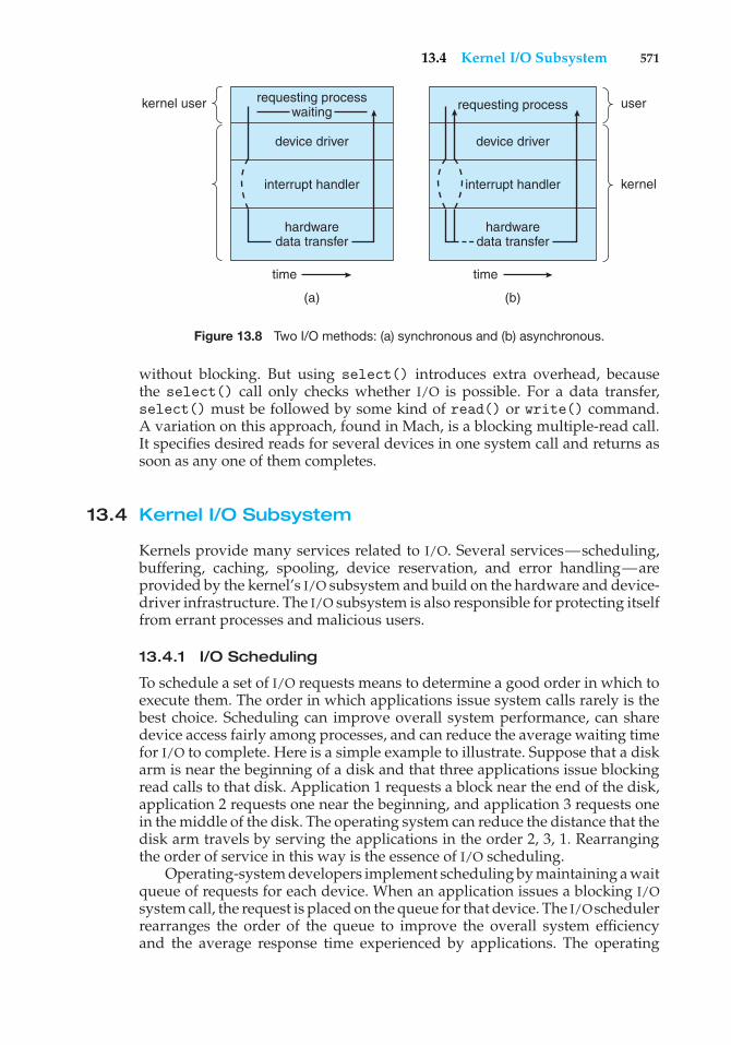
13.4 Kernel I/O Subsystem 571
requesting processwaiting
hardwaredata transfer
hardwaredata transfer
device driver device driver
interrupt handler
requesting processkernel user
(a) (b)
time time
user
kernelinterrupt handler
Figure 13.8 Two I/O methods: (a) synchronous and (b) asynchronous.
without blocking. But using select() introduces extra overhead, becausethe select() call only checks whether I/O is possible. For a data transfer,select() must be followed by some kind of read() or write() command.A variation on this approach, found in Mach, is a blocking multiple-read call.It specifies desired reads for several devices in one system call and returns assoon as any one of them completes.
13.4 Kernel I/O Subsystem
Kernels provide many services related to I/O. Several services—scheduling,buffering, caching, spooling, device reservation, and error handling—areprovided by the kernel’s I/O subsystem and build on the hardware and device-driver infrastructure. The I/O subsystem is also responsible for protecting itselffrom errant processes and malicious users.
13.4.1 I/O Scheduling
To schedule a set of I/O requests means to determine a good order in which toexecute them. The order in which applications issue system calls rarely is thebest choice. Scheduling can improve overall system performance, can sharedevice access fairly among processes, and can reduce the average waiting timefor I/O to complete. Here is a simple example to illustrate. Suppose that a diskarm is near the beginning of a disk and that three applications issue blockingread calls to that disk. Application 1 requests a block near the end of the disk,application 2 requests one near the beginning, and application 3 requests onein the middle of the disk. The operating system can reduce the distance that thedisk arm travels by serving the applications in the order 2, 3, 1. Rearrangingthe order of service in this way is the essence of I/O scheduling.
Operating-system developers implement scheduling by maintaining a waitqueue of requests for each device. When an application issues a blocking I/Osystem call, the request is placed on the queue for that device. The I/Oschedulerrearranges the order of the queue to improve the overall system efficiencyand the average response time experienced by applications. The operating
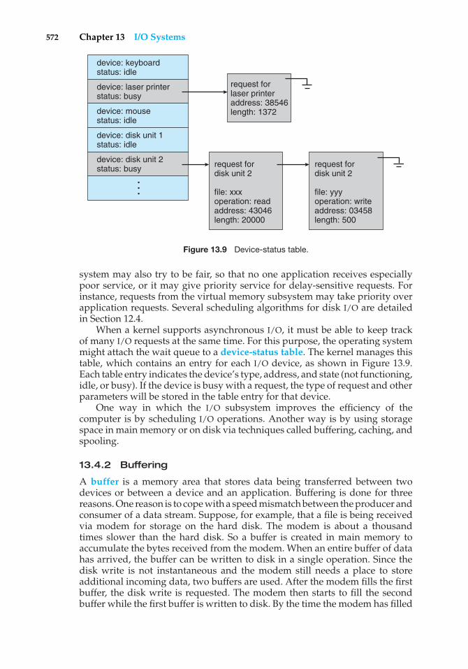
572 Chapter 13 I/O Systems
device: keyboardstatus: idle
device: laser printerstatus: busy
device: mousestatus: idle
device: disk unit 1status: idle
device: disk unit 2 status: busy
...
request forlaser printeraddress: 38546length: 1372
request fordisk unit 2
file: xxxoperation: readaddress: 43046length: 20000
request fordisk unit 2
file: yyyoperation: writeaddress: 03458length: 500
Figure 13.9 Device-status table.
system may also try to be fair, so that no one application receives especiallypoor service, or it may give priority service for delay-sensitive requests. Forinstance, requests from the virtual memory subsystem may take priority overapplication requests. Several scheduling algorithms for disk I/O are detailedin Section 12.4.
When a kernel supports asynchronous I/O, it must be able to keep trackof many I/O requests at the same time. For this purpose, the operating systemmight attach the wait queue to a device-status table. The kernel manages thistable, which contains an entry for each I/O device, as shown in Figure 13.9.Each table entry indicates the device’s type, address, and state (not functioning,idle, or busy). If the device is busy with a request, the type of request and otherparameters will be stored in the table entry for that device.
One way in which the I/O subsystem improves the efficiency of thecomputer is by scheduling I/O operations. Another way is by using storagespace in main memory or on disk via techniques called buffering, caching, andspooling.
13.4.2 Buffering
A buffer is a memory area that stores data being transferred between twodevices or between a device and an application. Buffering is done for threereasons. One reason is to cope with a speed mismatch between the producer andconsumer of a data stream. Suppose, for example, that a file is being receivedvia modem for storage on the hard disk. The modem is about a thousandtimes slower than the hard disk. So a buffer is created in main memory toaccumulate the bytes received from the modem. When an entire buffer of datahas arrived, the buffer can be written to disk in a single operation. Since thedisk write is not instantaneous and the modem still needs a place to storeadditional incoming data, two buffers are used. After the modem fills the firstbuffer, the disk write is requested. The modem then starts to fill the secondbuffer while the first buffer is written to disk. By the time the modem has filled
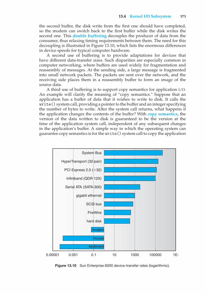
13.4 Kernel I/O Subsystem 573
the second buffer, the disk write from the first one should have completed,so the modem can switch back to the first buffer while the disk writes thesecond one. This double buffering decouples the producer of data from theconsumer, thus relaxing timing requirements between them. The need for thisdecoupling is illustrated in Figure 13.10, which lists the enormous differencesin device speeds for typical computer hardware.
A second use of buffering is to provide adaptations for devices thathave different data-transfer sizes. Such disparities are especially common incomputer networking, where buffers are used widely for fragmentation andreassembly of messages. At the sending side, a large message is fragmentedinto small network packets. The packets are sent over the network, and thereceiving side places them in a reassembly buffer to form an image of thesource data.
A third use of buffering is to support copy semantics for application I/O.An example will clarify the meaning of “copy semantics.” Suppose that anapplication has a buffer of data that it wishes to write to disk. It calls thewrite() system call, providing a pointer to the buffer and an integer specifyingthe number of bytes to write. After the system call returns, what happens ifthe application changes the contents of the buffer? With copy semantics, theversion of the data written to disk is guaranteed to be the version at thetime of the application system call, independent of any subsequent changesin the application’s buffer. A simple way in which the operating system canguarantee copy semantics is for the write() system call to copy the application
hard disk
0.1 100.0010.00001 1000 100000 1E-
modem
mouse
keyboard
FireWire
SCSI bus
gigabit ethernet
Serial ATA (SATA-300)
Infiniband (QDR 12X)
PCI Express 2.0 (32)
HyperTransport (32-pair)
System Bus
Figure 13.10 Sun Enterprise 6000 device-transfer rates (logarithmic).
574 Chapter 13 I/O Systems
data into a kernel buffer before returning control to the application. The diskwrite is performed from the kernel buffer, so that subsequent changes to theapplication buffer have no effect. Copying of data between kernel buffers andapplication data space is common in operating systems, despite the overheadthat this operation introduces, because of the clean semantics. The same effectcan be obtained more efficiently by clever use of virtual memory mapping andcopy-on-write page protection.
13.4.3 Caching
A cache is a region of fast memory that holds copies of data. Access to the cachedcopy is more efficient than access to the original. For instance, the instructionsof the currently running process are stored on disk, cached in physical memory,and copied again in the CPU’s secondary and primary caches. The differencebetween a buffer and a cache is that a buffer may hold the only existing copyof a data item, whereas a cache, by definition, holds a copy on faster storage ofan item that resides elsewhere.
Caching and buffering are distinct functions, but sometimes a regionof memory can be used for both purposes. For instance, to preserve copysemantics and to enable efficient scheduling of disk I/O, the operating systemuses buffers in main memory to hold disk data. These buffers are also used asa cache, to improve the I/O efficiency for files that are shared by applicationsor that are being written and reread rapidly. When the kernel receives a fileI/O request, the kernel first accesses the buffer cache to see whether that regionof the file is already available in main memory. If it is, a physical disk I/Ocan be avoided or deferred. Also, disk writes are accumulated in the buffercache for several seconds, so that large transfers are gathered to allow efficientwrite schedules. This strategy of delaying writes to improve I/O efficiency isdiscussed, in the context of remote file access, in Section 17.3.
13.4.4 Spooling and Device Reservation
A spool is a buffer that holds output for a device, such as a printer, that cannotaccept interleaved data streams. Although a printer can serve only one jobat a time, several applications may wish to print their output concurrently,without having their output mixed together. The operating system solves thisproblem by intercepting all output to the printer. Each application’s outputis spooled to a separate disk file. When an application finishes printing, thespooling system queues the corresponding spool file for output to the printer.The spooling system copies the queued spool files to the printer one at a time. Insome operating systems, spooling is managed by a system daemon process. Inothers, it is handled by an in-kernel thread. In either case, the operating systemprovides a control interface that enables users and system administrators todisplay the queue, remove unwanted jobs before those jobs print, suspendprinting while the printer is serviced, and so on.
Some devices, such as tape drives and printers, cannot usefully multiplexthe I/O requests of multiple concurrent applications. Spooling is one wayoperating systems can coordinate concurrent output. Another way to deal withconcurrent device access is to provide explicit facilities for coordination. Someoperating systems (including VMS) provide support for exclusive device accessby enabling a process to allocate an idle device and to deallocate that device
13.4 Kernel I/O Subsystem 575
when it is no longer needed. Other operating systems enforce a limit of oneopen file handle to such a device. Many operating systems provide functionsthat enable processes to coordinate exclusive access among themselves. Forinstance, Windows NT provides system calls to wait until a device objectbecomes available. It also has a parameter to the open() system call thatdeclares the types of access to be permitted to other concurrent threads. Onthese systems, it is up to the applications to avoid deadlock.
13.4.5 Error Handling
An operating system that uses protected memory can guard against manykinds of hardware and application errors, so that a complete system failure isnot the usual result of each minor mechanical glitch. Devices and I/O transferscan fail in many ways, either for transient reasons, as when a network becomesoverloaded, or for “permanent” reasons, as when a disk controller becomesdefective. Operating systems can often compensate effectively for transientfailures. For instance, a disk read() failure results in a read() retry, anda network send() error results in a resend(), if the protocol so specifies.Unfortunately, if an important component experiences a permanent failure,the operating system is unlikely to recover.
As a general rule, an I/O system call will return one bit of informationabout the status of the call, signifying either success or failure. In the UNIXoperating system, an additional integer variable named errno is used toreturn an error code—one of about a hundred values—indicating the generalnature of the failure (for example, argument out of range, bad pointer, orfile not open). By contrast, some hardware can provide highly detailed errorinformation, although many current operating systems are not designed toconvey this information to the application. For instance, a failure of a SCSIdevice is reported by the SCSI protocol in three levels of detail: a sense key thatidentifies the general nature of the failure, such as a hardware error or an illegalrequest; an additional sense code that states the category of failure, such as abad command parameter or a self-test failure; and an additional sense-codequalifier that gives even more detail, such as which command parameter wasin error or which hardware subsystem failed its self-test. Further, many SCSIdevices maintain internal pages of error-log information that can be requestedby the host—but seldom are.
13.4.6 I/O Protection
Errors are closely related to the issue of protection. A user process mayaccidentally or purposely attempt to disrupt the normal operation of a systemby attempting to issue illegal I/O instructions. We can use various mechanismsto ensure that such disruptions cannot take place in the system.
To prevent users from performing illegal I/O, we define all I/O instructionsto be privileged instructions. Thus, users cannot issue I/O instructions directly;they must do it through the operating system. To do I/O, a user programexecutes a system call to request that the operating system perform I/O on itsbehalf (Figure 13.11). The operating system, executing in monitor mode, checksthat the request is valid and, if it is, does the I/O requested. The operatingsystem then returns to the user.
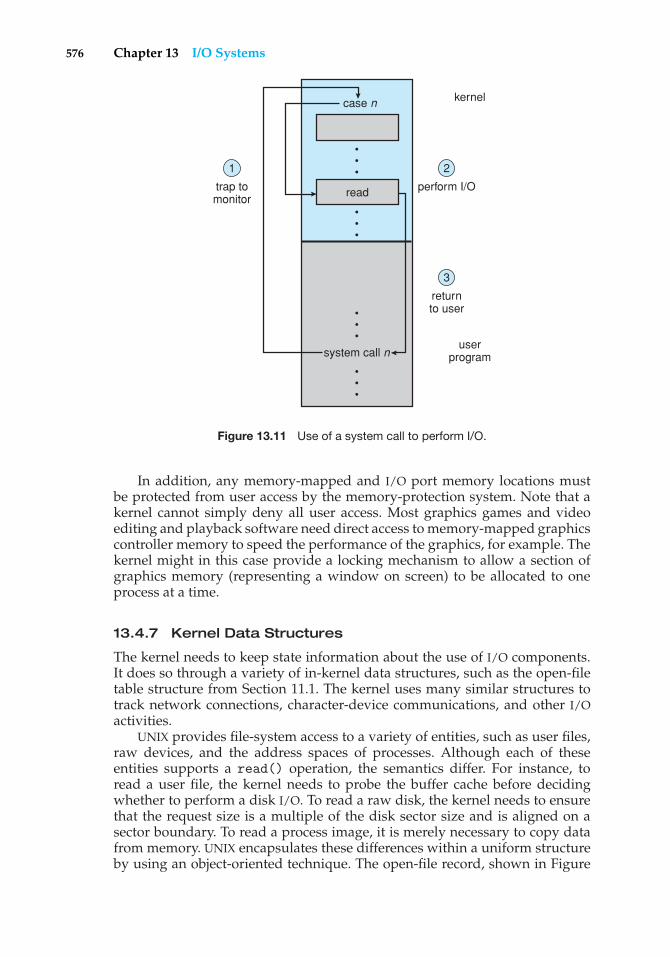
576 Chapter 13 I/O Systems
kernel
2
perform I/O
case n
system call n
read
3
returnto user
1
trap tomonitor
userprogram
• • •
• • •
• • •
• • •
Figure 13.11 Use of a system call to perform I/O.
In addition, any memory-mapped and I/O port memory locations mustbe protected from user access by the memory-protection system. Note that akernel cannot simply deny all user access. Most graphics games and videoediting and playback software need direct access to memory-mapped graphicscontroller memory to speed the performance of the graphics, for example. Thekernel might in this case provide a locking mechanism to allow a section ofgraphics memory (representing a window on screen) to be allocated to oneprocess at a time.
13.4.7 Kernel Data Structures
The kernel needs to keep state information about the use of I/O components.It does so through a variety of in-kernel data structures, such as the open-filetable structure from Section 11.1. The kernel uses many similar structures totrack network connections, character-device communications, and other I/Oactivities.
UNIX provides file-system access to a variety of entities, such as user files,raw devices, and the address spaces of processes. Although each of theseentities supports a read() operation, the semantics differ. For instance, toread a user file, the kernel needs to probe the buffer cache before decidingwhether to perform a disk I/O. To read a raw disk, the kernel needs to ensurethat the request size is a multiple of the disk sector size and is aligned on asector boundary. To read a process image, it is merely necessary to copy datafrom memory. UNIX encapsulates these differences within a uniform structureby using an object-oriented technique. The open-file record, shown in Figure
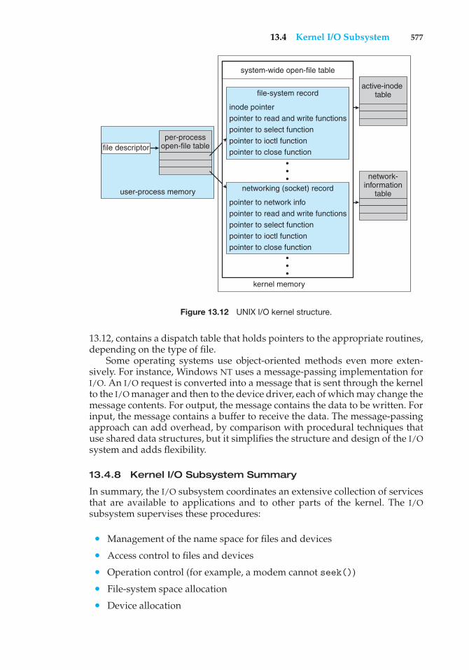
13.4 Kernel I/O Subsystem 577
active-inode table
network-information
table
per-processopen-file table
user-process memory
system-wide open-file table
kernel memory
•••
•••
file-system record
inode pointerpointer to read and write functionspointer to select functionpointer to ioctl functionpointer to close function
networking (socket) record
pointer to network infopointer to read and write functionspointer to select functionpointer to ioctl functionpointer to close function
file descriptor
Figure 13.12 UNIX I/O kernel structure.
13.12, contains a dispatch table that holds pointers to the appropriate routines,depending on the type of file.
Some operating systems use object-oriented methods even more exten-sively. For instance, Windows NT uses a message-passing implementation forI/O. An I/O request is converted into a message that is sent through the kernelto the I/O manager and then to the device driver, each of which may change themessage contents. For output, the message contains the data to be written. Forinput, the message contains a buffer to receive the data. The message-passingapproach can add overhead, by comparison with procedural techniques thatuse shared data structures, but it simplifies the structure and design of the I/Osystem and adds flexibility.
13.4.8 Kernel I/O Subsystem Summary
In summary, the I/O subsystem coordinates an extensive collection of servicesthat are available to applications and to other parts of the kernel. The I/Osubsystem supervises these procedures:
• Management of the name space for files and devices
• Access control to files and devices
• Operation control (for example, a modem cannot seek())
• File-system space allocation
• Device allocation
578 Chapter 13 I/O Systems
• Buffering, caching, and spooling
• I/O scheduling
• Device-status monitoring, error handling, and failure recovery
• Device-driver configuration and initialization
The upper levels of the I/O subsystem access devices via the uniforminterface provided by the device drivers.
13.5 Transforming I/O Requests to Hardware Operations
Earlier, we described the handshaking between a device driver and a devicecontroller, but we did not explain how the operating system connects anapplication request to a set of network wires or to a specific disk sector.Consider, for example, reading a file from disk. The application refers to thedata by a file name. Within a disk, the file system maps from the file namethrough the file-system directories to obtain the space allocation of the file. Forinstance, in MS-DOS, the name maps to a number that indicates an entry in thefile-access table, and that table entry tells which disk blocks are allocated tothe file. In UNIX, the name maps to an inode number, and the correspondinginode contains the space-allocation information. But how is the connectionmade from the file name to the disk controller (the hardware port address orthe memory-mapped controller registers)?
One method is that used by MS-DOS, a relatively simple operating system.The first part of an MS-DOS file name, preceding the colon, is a string thatidentifies a specific hardware device. For example, c: is the first part of everyfile name on the primary hard disk. The fact that c: represents the primary harddisk is built into the operating system; c: is mapped to a specific port addressthrough a device table. Because of the colon separator, the device name spaceis separate from the file-system name space. This separation makes it easyfor the operating system to associate extra functionality with each device. Forinstance, it is easy to invoke spooling on any files written to the printer.
If, instead, the device name space is incorporated in the regular file-systemname space, as it is in UNIX, the normal file-system name services are providedautomatically. If the file system provides ownership and access control to allfile names, then devices have owners and access control. Since files are storedon devices, such an interface provides access to the I/O system at two levels.Names can be used to access the devices themselves or to access the files storedon the devices.
UNIX represents device names in the regular file-system name space. Unlikean MS-DOS file name, which has a colon separator, a UNIX path name has noclear separation of the device portion. In fact, no part of the path name is thename of a device. UNIX has a mount table that associates prefixes of path nameswith specific device names. To resolve a path name, UNIX looks up the name inthe mount table to find the longest matching prefix; the corresponding entryin the mount table gives the device name. This device name also has the formof a name in the file-system name space. When UNIX looks up this name inthe file-system directory structures, it finds not an inode number but a <major,
13.5 Transforming I/O Requests to Hardware Operations 579
minor> device number. The major device number identifies a device driverthat should be called to handle I/O to this device. The minor device numberis passed to the device driver to index into a device table. The correspondingdevice-table entry gives the port address or the memory-mapped address ofthe device controller.
Modern operating systems obtain significant flexibility from the multiplestages of lookup tables in the path between a request and a physical devicecontroller. The mechanisms that pass requests between applications anddrivers are general. Thus, we can introduce new devices and drivers into acomputer without recompiling the kernel. In fact, some operating systemshave the ability to load device drivers on demand. At boot time, the systemfirst probes the hardware buses to determine what devices are present; it thenloads in the necessary drivers, either immediately or when first required by anI/O request.
We next describe the typical life cycle of a blocking read request, as depictedin Figure 13.13. The figure suggests that an I/O operation requires a great manysteps that together consume a tremendous number of CPU cycles.
1. A process issues a blocking read() system call to a file descriptor of a filethat has been opened previously.
2. The system-call code in the kernel checks the parameters for correctness.In the case of input, if the data are already available in the buffer cache,the data are returned to the process, and the I/O request is completed.
3. Otherwise, a physical I/O must be performed. The process is removedfrom the run queue and is placed on the wait queue for the device, andthe I/O request is scheduled. Eventually, the I/O subsystem sends therequest to the device driver. Depending on the operating system, therequest is sent via a subroutine call or an in-kernel message.
4. The device driver allocates kernel buffer space to receive the data andschedules the I/O. Eventually, the driver sends commands to the devicecontroller by writing into the device-control registers.
5. The device controller operates the device hardware to perform the datatransfer.
6. The driver may poll for status and data, or it may have set up a DMAtransfer into kernel memory. We assume that the transfer is managedby a DMA controller, which generates an interrupt when the transfercompletes.
7. The correct interrupt handler receives the interrupt via the interrupt-vector table, stores any necessary data, signals the device driver, andreturns from the interrupt.
8. The device driver receives the signal, determines which I/O request hascompleted, determines the request’s status, and signals the kernel I/Osubsystem that the request has been completed.
9. The kernel transfers data or return codes to the address space of therequesting process and moves the process from the wait queue back tothe ready queue.
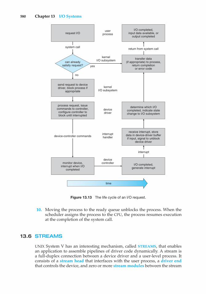
580 Chapter 13 I/O Systems
send request to devicedriver, block process if
appropriate
monitor device,interrupt when I/O
completed
process request, issuecommands to controller,configure controller toblock until interrupted
request I/O
system call
no
yes
I/O completed,input data available, or
output completed
userprocess
kernelI/O subsystem
kernelI/O subsystem
devicedriver
devicecontroller
time
interrupthandler
transfer data(if appropriate) to process,
return completionor error code
determine which I/Ocompleted, indicate statechange to I/O subsystem
receive interrupt, storedata in device-driver bufferif input, signal to unblock
device driver
I/O completed,generate interrupt
return from system call
interrupt
device-controller commands
can alreadysatisfy request?
Figure 13.13 The life cycle of an I/O request.
10. Moving the process to the ready queue unblocks the process. When thescheduler assigns the process to the CPU, the process resumes executionat the completion of the system call.
13.6 STREAMS
UNIX System V has an interesting mechanism, called STREAMS, that enablesan application to assemble pipelines of driver code dynamically. A stream isa full-duplex connection between a device driver and a user-level process. Itconsists of a stream head that interfaces with the user process, a driver endthat controls the device, and zero or more stream modules between the stream
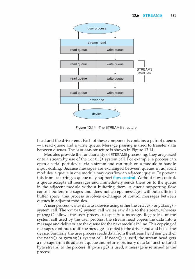
13.6 STREAMS 581
user process
device
stream head
driver end
read queue write queue
STREAMSmodules
read queue
read queue
read queue
write queue
write queue
write queue
Figure 13.14 The STREAMS structure.
head and the driver end. Each of these components contains a pair of queues—a read queue and a write queue. Message passing is used to transfer databetween queues. The STREAMS structure is shown in Figure 13.14.
Modules provide the functionality of STREAMS processing; they are pushedonto a stream by use of the ioctl() system call. For example, a process canopen a serial-port device via a stream and can push on a module to handleinput editing. Because messages are exchanged between queues in adjacentmodules, a queue in one module may overflow an adjacent queue. To preventthis from occurring, a queue may support flow control. Without flow control,a queue accepts all messages and immediately sends them on to the queuein the adjacent module without buffering them. A queue supporting flowcontrol buffers messages and does not accept messages without sufficientbuffer space; this process involves exchanges of control messages betweenqueues in adjacent modules.
A user process writes data to a device using either the write()orputmsg()system call. The write() system call writes raw data to the stream, whereasputmsg() allows the user process to specify a message. Regardless of thesystem call used by the user process, the stream head copies the data into amessage and delivers it to the queue for the next module in line. This copying ofmessages continues until the message is copied to the driver end and hence thedevice. Similarly, the user process reads data from the stream head using eitherthe read() or getmsg() system call. If read() is used, the stream head getsa message from its adjacent queue and returns ordinary data (an unstructuredbyte stream) to the process. If getmsg() is used, a message is returned to theprocess.
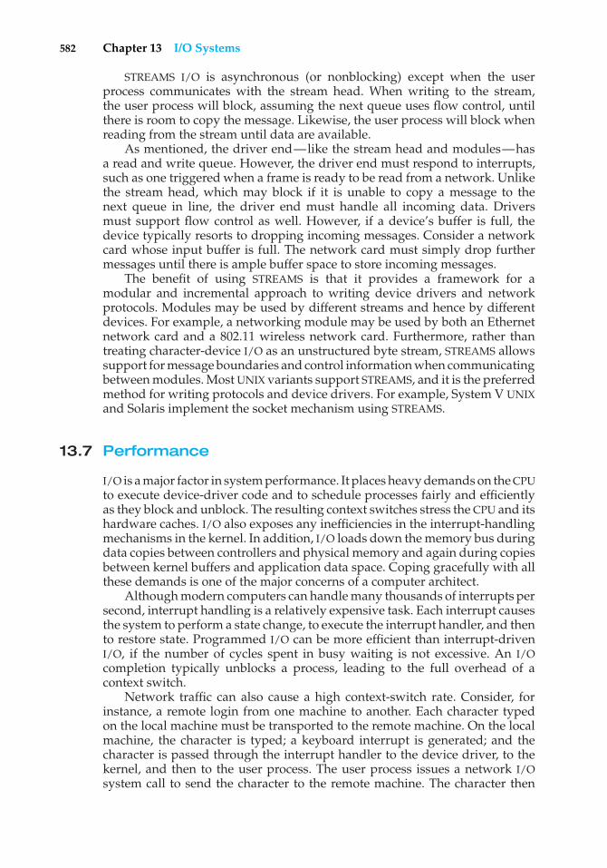
582 Chapter 13 I/O Systems
STREAMS I/O is asynchronous (or nonblocking) except when the userprocess communicates with the stream head. When writing to the stream,the user process will block, assuming the next queue uses flow control, untilthere is room to copy the message. Likewise, the user process will block whenreading from the stream until data are available.
As mentioned, the driver end—like the stream head and modules—hasa read and write queue. However, the driver end must respond to interrupts,such as one triggered when a frame is ready to be read from a network. Unlikethe stream head, which may block if it is unable to copy a message to thenext queue in line, the driver end must handle all incoming data. Driversmust support flow control as well. However, if a device’s buffer is full, thedevice typically resorts to dropping incoming messages. Consider a networkcard whose input buffer is full. The network card must simply drop furthermessages until there is ample buffer space to store incoming messages.
The benefit of using STREAMS is that it provides a framework for amodular and incremental approach to writing device drivers and networkprotocols. Modules may be used by different streams and hence by differentdevices. For example, a networking module may be used by both an Ethernetnetwork card and a 802.11 wireless network card. Furthermore, rather thantreating character-device I/O as an unstructured byte stream, STREAMS allowssupport for message boundaries and control information when communicatingbetween modules. Most UNIX variants support STREAMS, and it is the preferredmethod for writing protocols and device drivers. For example, System V UNIXand Solaris implement the socket mechanism using STREAMS.
13.7 Performance
I/O is a major factor in system performance. It places heavy demands on the CPUto execute device-driver code and to schedule processes fairly and efficientlyas they block and unblock. The resulting context switches stress the CPU and itshardware caches. I/O also exposes any inefficiencies in the interrupt-handlingmechanisms in the kernel. In addition, I/O loads down the memory bus duringdata copies between controllers and physical memory and again during copiesbetween kernel buffers and application data space. Coping gracefully with allthese demands is one of the major concerns of a computer architect.
Although modern computers can handle many thousands of interrupts persecond, interrupt handling is a relatively expensive task. Each interrupt causesthe system to perform a state change, to execute the interrupt handler, and thento restore state. Programmed I/O can be more efficient than interrupt-drivenI/O, if the number of cycles spent in busy waiting is not excessive. An I/Ocompletion typically unblocks a process, leading to the full overhead of acontext switch.
Network traffic can also cause a high context-switch rate. Consider, forinstance, a remote login from one machine to another. Each character typedon the local machine must be transported to the remote machine. On the localmachine, the character is typed; a keyboard interrupt is generated; and thecharacter is passed through the interrupt handler to the device driver, to thekernel, and then to the user process. The user process issues a network I/Osystem call to send the character to the remote machine. The character then
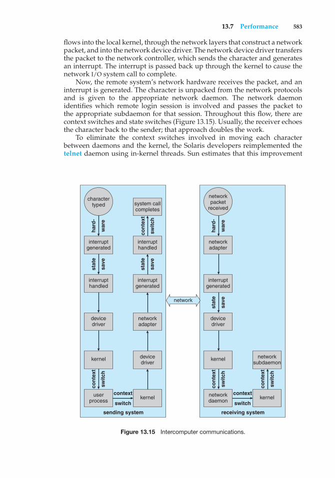
13.7 Performance 583
flows into the local kernel, through the network layers that construct a networkpacket, and into the network device driver. The network device driver transfersthe packet to the network controller, which sends the character and generatesan interrupt. The interrupt is passed back up through the kernel to cause thenetwork I/O system call to complete.
Now, the remote system’s network hardware receives the packet, and aninterrupt is generated. The character is unpacked from the network protocolsand is given to the appropriate network daemon. The network daemonidentifies which remote login session is involved and passes the packet tothe appropriate subdaemon for that session. Throughout this flow, there arecontext switches and state switches (Figure 13.15). Usually, the receiver echoesthe character back to the sender; that approach doubles the work.
To eliminate the context switches involved in moving each characterbetween daemons and the kernel, the Solaris developers reimplemented thetelnet daemon using in-kernel threads. Sun estimates that this improvement
network
kerneluserprocess
kernel
devicedriver
interrupthandled
devicedriver
networkadapter
interruptgenerated
interrupthandled
interruptgenerated
system callcompletes
sending system
stat
e
save
stat
e
save
stat
e
save
con
text
swit
ch
con
text
swit
ch
har
d-
war
e
har
d-
war
e
receiving system
charactertyped
context
switch
context
switch
con
text
swit
ch
con
text
swit
ch
kernelnetworkdaemon
networksubdaemon
kernel
devicedriver
interruptgenerated
networkadapter
networkpacket
received
Figure 13.15 Intercomputer communications.
584 Chapter 13 I/O Systems
increased the maximum number of network logins from a few hundred to afew thousand on a large server.
Other systems use separate front-end processors for terminal I/O to reducethe interrupt burden on the main CPU. For instance, a terminal concentratorcan multiplex the traffic from hundreds of remote terminals into one port on alarge computer. An I/O channel is a dedicated, special-purpose CPU found inmainframes and in other high-end systems. The job of a channel is to offloadI/O work from the main CPU. The idea is that the channels keep the data flowingsmoothly, while the main CPU remains free to process the data. Like the devicecontrollers and DMA controllers found in smaller computers, a channel canprocess more general and sophisticated programs, so channels can be tunedfor particular workloads.
We can employ several principles to improve the efficiency of I/O:
• Reduce the number of context switches.
• Reduce the number of times that data must be copied in memory whilepassing between device and application.
• Reduce the frequency of interrupts by using large transfers, smart con-trollers, and polling (if busy waiting can be minimized).
• Increase concurrency by using DMA-knowledgeable controllers or chan-nels to offload simple data copying from the CPU.
• Move processing primitives into hardware, to allow their operation indevice controllers to be concurrent with CPU and bus operation.
• Balance CPU, memory subsystem, bus, and I/O performance, because anoverload in any one area will cause idleness in others.
I/O devices vary greatly in complexity. For instance, a mouse is simple. Themouse movements and button clicks are converted into numeric values that arepassed from hardware, through the mouse device driver, to the application. Bycontrast, the functionality provided by the Windows NT disk device driver iscomplex. It not only manages individual disks but also implements RAID arrays(Section 12.7). To do so, it converts an application’s read or write request into acoordinated set of disk I/O operations. Moreover, it implements sophisticatederror-handling and data-recovery algorithms and takes many steps to optimizedisk performance.
Where should the I/O functionality be implemented—in the device hard-ware, in the device driver, or in application software? Sometimes we observethe progression depicted in Figure 13.16.
• Initially, we implement experimental I/O algorithms at the applicationlevel, because application code is flexible and application bugs are unlikelyto cause system crashes. Furthermore, by developing code at the applica-tion level, we avoid the need to reboot or reload device drivers after everychange to the code. An application-level implementation can be inefficient,however, because of the overhead of context switches and because theapplication cannot take advantage of internal kernel data structures and
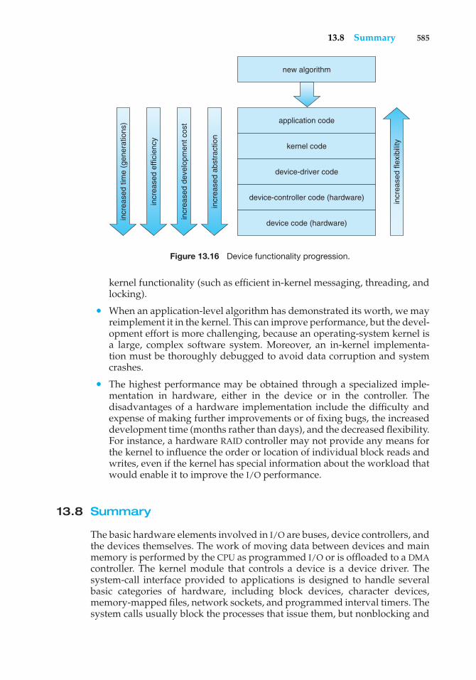
13.8 Summary 585
application code
kernel code
device-driver code
device-controller code (hardware)
device code (hardware)
new algorithm
incr
ease
d fle
xibi
lity
incr
ease
d ab
stra
ctio
n
incr
ease
d de
velo
pmen
t cos
t
incr
ease
d ef
ficie
ncy
incr
ease
d tim
e (g
ener
atio
ns)
Figure 13.16 Device functionality progression.
kernel functionality (such as efficient in-kernel messaging, threading, andlocking).
• When an application-level algorithm has demonstrated its worth, we mayreimplement it in the kernel. This can improve performance, but the devel-opment effort is more challenging, because an operating-system kernel isa large, complex software system. Moreover, an in-kernel implementa-tion must be thoroughly debugged to avoid data corruption and systemcrashes.
• The highest performance may be obtained through a specialized imple-mentation in hardware, either in the device or in the controller. Thedisadvantages of a hardware implementation include the difficulty andexpense of making further improvements or of fixing bugs, the increaseddevelopment time (months rather than days), and the decreased flexibility.For instance, a hardware RAID controller may not provide any means forthe kernel to influence the order or location of individual block reads andwrites, even if the kernel has special information about the workload thatwould enable it to improve the I/O performance.
13.8 Summary
The basic hardware elements involved in I/O are buses, device controllers, andthe devices themselves. The work of moving data between devices and mainmemory is performed by the CPU as programmed I/O or is offloaded to a DMAcontroller. The kernel module that controls a device is a device driver. Thesystem-call interface provided to applications is designed to handle severalbasic categories of hardware, including block devices, character devices,memory-mapped files, network sockets, and programmed interval timers. Thesystem calls usually block the processes that issue them, but nonblocking and
586 Chapter 13 I/O Systems
asynchronous calls are used by the kernel itself and by applications that mustnot sleep while waiting for an I/O operation to complete.
The kernel’s I/O subsystem provides numerous services. Among theseare I/O scheduling, buffering, caching, spooling, device reservation, and errorhandling. Another service, name translation, makes the connections betweenhardware devices and the symbolic file names used by applications. It involvesseveral levels of mapping that translate from character-string names, to specificdevice drivers and device addresses, and then to physical addresses of I/Oportsor bus controllers. This mapping may occur within the file-system name space,as it does in UNIX, or in a separate device name space, as it does in MS-DOS.
STREAMS is an implementation and methodology that provides a frame-work for a modular and incremental approach to writing device drivers andnetwork protocols. Through streams, drivers can be stacked, with data passingthrough them sequentially and bidirectionally for processing.
I/O system calls are costly in terms of CPU consumption because of themany layers of software between a physical device and an application. Theselayers imply overhead from several sources: context switching to cross thekernel’s protection boundary, signal and interrupt handling to service the I/Odevices, and the load on the CPU and memory system to copy data betweenkernel buffers and application space.
Practice Exercises
13.1 State three advantages of placing functionality in a device controller,rather than in the kernel. State three disadvantages.
13.2 The example of handshaking in Section 13.2 used 2 bits: a busy bit and acommand-ready bit. Is it possible to implement this handshaking withonly 1 bit? If it is, describe the protocol. If it is not, explain why 1 bit isinsufficient.
13.3 Why might a system use interrupt-driven I/O to manage a single serialport and polling I/O to manage a front-end processor, such as a terminalconcentrator?
13.4 Polling for an I/O completion can waste a large number of CPU cyclesif the processor iterates a busy-waiting loop many times before the I/Ocompletes. But if the I/O device is ready for service, polling can be muchmore efficient than is catching and dispatching an interrupt. Describea hybrid strategy that combines polling, sleeping, and interrupts forI/O device service. For each of these three strategies (pure polling, pureinterrupts, hybrid), describe a computing environment in which thatstrategy is more efficient than is either of the others.
13.5 How does DMA increase system concurrency? How does it complicatehardware design?
13.6 Why is it important to scale up system-bus and device speeds as CPUspeed increases?
13.7 Distinguish between a STREAMS driver and a STREAMS module.
Exercises 587
Exercises
13.8 When multiple interrupts from different devices appear at about thesame time, a priority scheme could be used to determine the order inwhich the interrupts would be serviced. Discuss what issues need tobe considered in assigning priorities to different interrupts.
13.9 What are the advantages and disadvantages of supporting memory-mapped I/O to device control registers?
13.10 Consider the following I/O scenarios on a single-user PC:
a. A mouse used with a graphical user interface
b. A tape drive on a multitasking operating system (with no devicepreallocation available)
c. A disk drive containing user files
d. A graphics card with direct bus connection, accessible throughmemory-mapped I/O
For each of these scenarios, would you design the operating systemto use buffering, spooling, caching, or a combination? Would you usepolled I/O or interrupt-driven I/O? Give reasons for your choices.
13.11 In most multiprogrammed systems, user programs access memorythrough virtual addresses, while the operating system uses raw phys-ical addresses to access memory. What are the implications of thisdesign for the initiation of I/O operations by the user program andtheir execution by the operating system?
13.12 What are the various kinds of performance overhead associated withservicing an interrupt?
13.13 Describe three circumstances under which blocking I/O should be used.Describe three circumstances under which nonblocking I/O should beused. Why not just implement nonblocking I/O and have processesbusy-wait until their devices are ready?
13.14 Typically, at the completion of a device I/O, a single interrupt is raisedand appropriately handled by the host processor. In certain settings,however, the code that is to be executed at the completion of theI/O can be broken into two separate pieces. The first piece executesimmediately after the I/O completes and schedules a second interruptfor the remaining piece of code to be executed at a later time. What isthe purpose of using this strategy in the design of interrupt handlers?
13.15 Some DMA controllers support direct virtual memory access, wherethe targets of I/O operations are specified as virtual addresses anda translation from virtual to physical address is performed duringthe DMA. How does this design complicate the design of the DMAcontroller? What are the advantages of providing such functionality?
13.16 UNIX coordinates the activities of the kernel I/O components bymanipulating shared in-kernel data structures, whereas Windows NT
588 Chapter 13 I/O Systems
uses object-oriented message passing between kernel I/O components.Discuss three pros and three cons of each approach.
13.17 Write (in pseudocode) an implementation of virtual clocks, includingthe queueing and management of timer requests for the kernel andapplications. Assume that the hardware provides three timer channels.
13.18 Discuss the advantages and disadvantages of guaranteeing reliabletransfer of data between modules in the STREAMS abstraction.
Wiley Plus
Visit Wiley Plus for
• Source code
• Solutions to practice exercises
• Additional programming problems and exercises
• Labs using an operating system simulator
Bibliographical Notes
Vahalia [1996] provides a good overview of I/O and networking in UNIX.Leffler et al. [1989] detail the I/O structures and methods employed inBSD UNIX. Milenkovic [1987] discusses the complexity of I/O methods andimplementation. The use and programming of the various interprocess-communication and network protocols in UNIX are explored in Stevens[1992]. Brain [1996] documents the Windows NT application interface. TheI/O implementation in the sample MINIX operating system is described inTanenbaum and Woodhull [1997]. Custer [1994] includes detailed informationon the NT message-passing implementation of I/O.
For details of hardware-level I/O handling and memory-mapping function-ality, processor reference manuals (Motorola [1993] and Intel [1993]) are amongthe best sources. Hennessy and Patterson [2002] describe multiprocessor sys-tems and cache-consistency issues. Tanenbaum [1990] describes hardware I/Odesign at a low level, and Sargent and Shoemaker [1995] provide a program-mer’s guide to low-level PC hardware and software. The IBM PC device I/Oaddress map is given in IBM [1983]. The March 1994 issue of IEEE Computer isdevoted to I/O hardware and software. Rago [1993] provides a good discussionof STREAMS.
Part Five
Protection andSecurity
Protection mechanisms control access to a system by limiting the typesof file access permitted to users. In addition, protection must ensurethat only processes that have gained proper authorization from theoperating system can operate on memory segments, the CPU, and otherresources.
Protection is provided by a mechanism that controls the access ofprograms, processes, or users to the resources defined by a computersystem. This mechanism must provide a means for specifying the controlsto be imposed, together with a means of enforcing them.
Security ensures the authentication of system users to protect theintegrity of the information stored in the system (both data and code),as well as the physical resources of the computer system. The securitysystem prevents unauthorized access, malicious destruction or alterationof data, and accidental introduction of inconsistency.

This page intentionally left blank
14C H A P T E R
Protection
The processes in an operating system must be protected from one another’sactivities. To provide such protection, we can use various mechanisms to ensurethat only processes that have gained proper authorization from the operatingsystem can operate on the files, memory segments, CPU, and other resourcesof a system.
Protection refers to a mechanism for controlling the access of programs,processes, or users to the resources defined by a computer system. Thismechanism must provide a means for specifying the controls to be imposed,together with a means of enforcement. We distinguish between protection andsecurity, which is a measure of confidence that the integrity of a system andits data will be preserved. In this chapter, we focus on protection. Securityassurance is a much broader topic, and we address it in Chapter 15.
CHAPTER OBJECTIVES
• To discuss the goals and principles of protection in a modern computersystem.
• To explain how protection domains, combined with an access matrix, areused to specify the resources a process may access.
• To examine capability- and language-based protection systems.
14.1 Goals of Protection
As computer systems have become more sophisticated and pervasive in theirapplications, the need to protect their integrity has also grown. Protection wasoriginally conceived as an adjunct to multiprogramming operating systems,so that untrustworthy users might safely share a common logical name space,such as a directory of files, or share a common physical name space, such asmemory. Modern protection concepts have evolved to increase the reliabilityof any complex system that makes use of shared resources.
We need to provide protection for several reasons. The most obvious is theneed to prevent the mischievous, intentional violation of an access restriction
591
592 Chapter 14 Protection
by a user. Of more general importance, however, is the need to ensure thateach program component active in a system uses system resources only inways consistent with stated policies. This requirement is an absolute one for areliable system.
Protection can improve reliability by detecting latent errors at the interfacesbetween component subsystems. Early detection of interface errors can oftenprevent contamination of a healthy subsystem by a malfunctioning subsystem.Also, an unprotected resource cannot defend against use (or misuse) by anunauthorized or incompetent user. A protection-oriented system providesmeans to distinguish between authorized and unauthorized usage.
The role of protection in a computer system is to provide a mechanism forthe enforcement of the policies governing resource use. These policies can beestablished in a variety of ways. Some are fixed in the design of the system,while others are formulated by the management of a system. Still others aredefined by the individual users to protect their own files and programs. Aprotection system must have the flexibility to enforce a variety of policies.
Policies for resource use may vary by application, and they may changeover time. For these reasons, protection is no longer the concern solely ofthe designer of an operating system. The application programmer needs touse protection mechanisms as well, to guard resources created and supportedby an application subsystem against misuse. In this chapter, we describe theprotection mechanisms the operating system should provide, but applicationdesigners can use them as well in designing their own protection software.
Note thatmechanisms are distinct from policies.Mechanisms determine howsomething will be done; policies decide what will be done. The separationof policy and mechanism is important for flexibility. Policies are likely tochange from place to place or time to time. In the worst case, every changein policy would require a change in the underlying mechanism. Using generalmechanisms enables us to avoid such a situation.
14.2 Principles of Protection
Frequently, a guiding principle can be used throughout a project, such asthe design of an operating system. Following this principle simplifies designdecisions and keeps the system consistent and easy to understand. A key,time-tested guiding principle for protection is the principle of least privilege. Itdictates that programs, users, and even systems be given just enough privilegesto perform their tasks.
Consider the analogy of a security guard with a passkey. If this key allowsthe guard into just the public areas that she guards, then misuse of the keywill result in minimal damage. If, however, the passkey allows access to allareas, then damage from its being lost, stolen, misused, copied, or otherwisecompromised will be much greater.
An operating system following the principle of least privilege implementsits features, programs, system calls, and data structures so that failure orcompromise of a component does the minimum damage and allows theminimum damage to be done. The overflow of a buffer in a system daemonmight cause the daemon process to fail, for example, but should not allow theexecution of code from the daemon process’s stack that would enable a remote
14.3 Domain of Protection 593
user to gain maximum privileges and access to the entire system (as happenstoo often today).
Such an operating system also provides system calls and services thatallow applications to be written with fine-grained access controls. It providesmechanisms to enable privileges when they are needed and to disable themwhen they are not needed. Also beneficial is the creation of audit trails forall privileged function access. The audit trail allows the programmer, systemsadministrator, or law-enforcement officer to trace all protection and securityactivities on the system.
Managing users with the principle of least privilege entails creating aseparate account for each user, with just the privileges that the user needs. Anoperator who needs to mount tapes and back up files on the system has accessto just those commands and files needed to accomplish the job. Some systemsimplement role-based access control (RBAC) to provide this functionality.
Computers implemented in a computing facility under the principle of leastprivilege can be limited to running specific services, accessing specific remotehosts via specific services, and doing so during specific times. Typically, theserestrictions are implemented through enabling or disabling each service andthrough using access control lists, as described in Sections 10.6.2 and 14.6.
The principle of least privilege can help produce a more secure computingenvironment. Unfortunately, it frequently does not. For example, Windows2000 has a complex protection scheme at its core and yet has many securityholes. By comparison, Solaris is considered relatively secure, even though itis a variant of UNIX, which historically was designed with little protectionin mind. One reason for the difference may be that Windows 2000 has morelines of code and more services than Solaris and thus has more to secure andprotect. Another reason could be that the protection scheme in Windows 2000is incomplete or protects the wrong aspects of the operating system, leavingother areas vulnerable.
14.3 Domain of Protection
A computer system is a collection of processes and objects. By objects,we meanboth hardware objects (such as the CPU, memory segments, printers, disks, andtape drives) and software objects (such as files, programs, and semaphores).Each object has a unique name that differentiates it from all other objects in thesystem, and each can be accessed only through well-defined and meaningfuloperations. Objects are essentially abstract data types.
The operations that are possible may depend on the object. For example,on a CPU, we can only execute. Memory segments can be read and written,whereas a CD-ROM or DVD-ROM can only be read. Tape drives can be read,written, and rewound. Data files can be created, opened, read, written, closed,and deleted; program files can be read, written, executed, and deleted.
A process should be allowed to access only those resources for which ithas authorization. Furthermore, at any time, a process should be able to accessonly those resources that it currently requires to complete its task. This secondrequirement, commonly referred to as the need-to-know principle, is useful inlimiting the amount of damage a faulty process can cause in the system. Forexample, when process p invokes procedure A(), the procedure should be
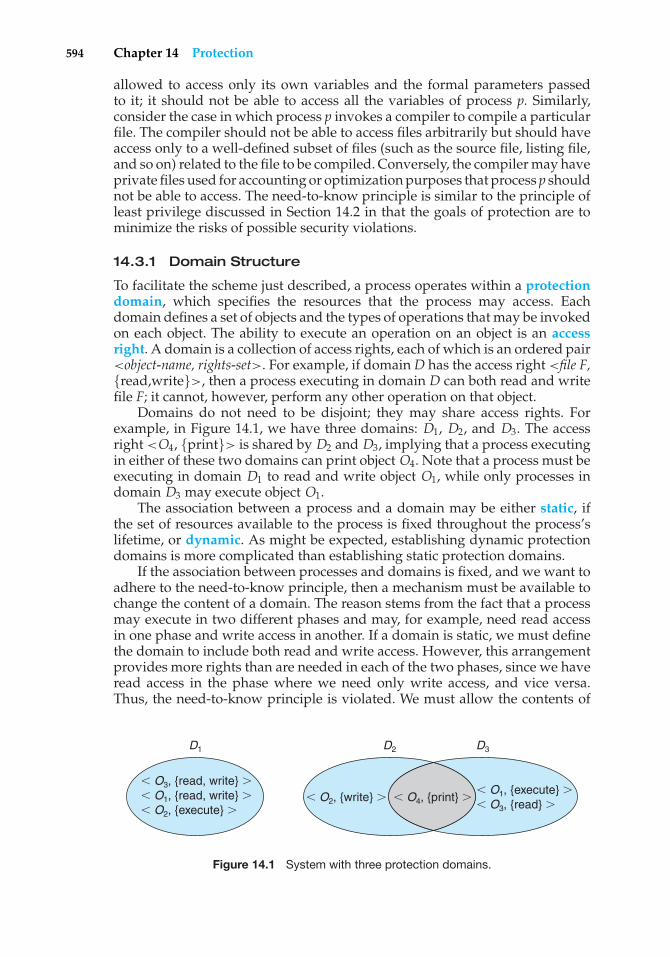
594 Chapter 14 Protection
allowed to access only its own variables and the formal parameters passedto it; it should not be able to access all the variables of process p. Similarly,consider the case in which process p invokes a compiler to compile a particularfile. The compiler should not be able to access files arbitrarily but should haveaccess only to a well-defined subset of files (such as the source file, listing file,and so on) related to the file to be compiled. Conversely, the compiler may haveprivate files used for accounting or optimization purposes that process p shouldnot be able to access. The need-to-know principle is similar to the principle ofleast privilege discussed in Section 14.2 in that the goals of protection are tominimize the risks of possible security violations.
14.3.1 Domain Structure
To facilitate the scheme just described, a process operates within a protectiondomain, which specifies the resources that the process may access. Eachdomain defines a set of objects and the types of operations that may be invokedon each object. The ability to execute an operation on an object is an accessright. A domain is a collection of access rights, each of which is an ordered pair<object-name, rights-set>. For example, if domainD has the access right <�le F,{read,write}>, then a process executing in domain D can both read and writefile F; it cannot, however, perform any other operation on that object.
Domains do not need to be disjoint; they may share access rights. Forexample, in Figure 14.1, we have three domains: D1, D2, and D3. The accessright <O4, {print}> is shared by D2 and D3, implying that a process executingin either of these two domains can print object O4. Note that a process must beexecuting in domain D1 to read and write object O1, while only processes indomain D3 may execute object O1.
The association between a process and a domain may be either static, ifthe set of resources available to the process is fixed throughout the process’slifetime, or dynamic. As might be expected, establishing dynamic protectiondomains is more complicated than establishing static protection domains.
If the association between processes and domains is fixed, and we want toadhere to the need-to-know principle, then a mechanism must be available tochange the content of a domain. The reason stems from the fact that a processmay execute in two different phases and may, for example, need read accessin one phase and write access in another. If a domain is static, we must definethe domain to include both read and write access. However, this arrangementprovides more rights than are needed in each of the two phases, since we haveread access in the phase where we need only write access, and vice versa.Thus, the need-to-know principle is violated. We must allow the contents of
D1
O3, {read, write} � O1, {read, write} � O2, {execute} �
O1, {execute} � O3, {read} �
O2, {write} � O4, {print} �
D2 D3
Figure 14.1 System with three protection domains.
14.3 Domain of Protection 595
a domain to be modified so that the domain always reflects the minimumnecessary access rights.
If the association is dynamic, a mechanism is available to allow domainswitching, enabling the process to switch from one domain to another. We mayalso want to allow the content of a domain to be changed. If we cannot changethe content of a domain, we can provide the same effect by creating a newdomain with the changed content and switching to that new domain when wewant to change the domain content.
A domain can be realized in a variety of ways:
• Each user may be a domain. In this case, the set of objects that can beaccessed depends on the identity of the user. Domain switching occurswhen the user is changed—generally when one user logs out and anotheruser logs in.
• Each process may be a domain. In this case, the set of objects that can beaccessed depends on the identity of the process. Domain switching occurswhen one process sends a message to another process and then waits fora response.
• Each procedure may be a domain. In this case, the set of objects that can beaccessed corresponds to the local variables defined within the procedure.Domain switching occurs when a procedure call is made.
We discuss domain switching in greater detail in Section 14.4.Consider the standard dual-mode (monitor–user mode) model of
operating-system execution. When a process executes in monitor mode, itcan execute privileged instructions and thus gain complete control of thecomputer system. In contrast, when a process executes in user mode, it caninvoke only nonprivileged instructions. Consequently, it can execute onlywithin its predefined memory space. These two modes protect the operatingsystem (executing in monitor domain) from the user processes (executingin user domain). In a multiprogrammed operating system, two protectiondomains are insufficient, since users also want to be protected from oneanother. Therefore, a more elaborate scheme is needed. We illustrate such ascheme by examining two influential operating systems—UNIX and MULTICS—to see how they implement these concepts.
14.3.2 An Example: UNIX
In the UNIX operating system, a domain is associated with the user. Switchingthe domain corresponds to changing the user identification temporarily.This change is accomplished through the file system as follows. An owneridentification and a domain bit (known as the setuid bit) are associated witheach file. When the setuid bit is on, and a user executes that file, the user ID isset to that of the owner of the file; when the bit is off, however, the user ID doesnot change. For example, when a user A (that is, a user with userID = A) startsexecuting a file owned by B, whose associated domain bit is off, the userID ofthe process is set to A. When the setuid bit is on, the userID is set to that ofthe owner of the file: B. When the process exits, this temporary userID changeends.
596 Chapter 14 Protection
Other methods are used to change domains in operating systems in whichuser IDs are used for domain definition, because almost all systems needto provide such a mechanism. This mechanism is used when an otherwiseprivileged facility needs to be made available to the general user population.For instance, it might be desirable to allow users to access a network withoutletting them write their own networking programs. In such a case, on a UNIXsystem, the setuid bit on a networking program would be set, causing the userID to change when the program was run. The user ID would change to thatof a user with network access privilege (such as root, the most powerful userID). One problem with this method is that if a user manages to create a filewith user ID root and with its setuid bit on, that user can become root and doanything and everything on the system. The setuid mechanism is discussedfurther in Appendix A.
An alternative to this method used in other operating systems is to placeprivileged programs in a special directory. The operating system would bedesigned to change the user ID of any program run from this directory, eitherto the equivalent of root or to the user ID of the owner of the directory. Thiseliminates one security problem with setuid programs in which crackers createand hide such programs for later use (using obscure file or directory names).This method is less flexible than that used in UNIX, however.
Even more restrictive, and thus more protective, are systems that simplydo not allow a change of user ID. In these instances, special techniques mustbe used to allow users access to privileged facilities. For instance, a daemonprocess may be started at boot time and run as a special user ID. Users thenrun a separate program, which sends requests to this process whenever theyneed to use the facility. This method is used by the TOPS-20 operating system.
In any of these systems, great care must be taken in writing privilegedprograms. Any oversight can result in a total lack of protection on the system.Generally, these programs are the first to be attacked by people trying tobreak into a system; unfortunately, the attackers are frequently successful.For example, security has been breached on many UNIX systems because of thesetuid feature. We discuss security in Chapter 15.
14.3.3 An Example: MULTICS
In the MULTICS system, the protection domains are organized hierarchicallyinto a ring structure. Each ring corresponds to a single domain (Figure 14.2).The rings are numbered from 0 to 7. Let Di and Dj be any two domain rings.If j < i, then Di is a subset of Dj . That is, a process executing in domain Djhas more privileges than does a process executing in domain Di . A processexecuting in domain D0 has the most privileges. If only two rings exist, thisscheme is equivalent to the monitor–user mode of execution, where monitormode corresponds to D0 and user mode corresponds to D1.
MULTICS has a segmented address space; each segment is a file, and eachsegment is associated with one of the rings. A segment description includes anentry that identifies the ring number. In addition, it includes three access bitsto control reading, writing, and execution. The association between segmentsand rings is a policy decision with which we are not concerned here.
A current-ring-number counter is associated with each process, identifyingthe ring in which the process is executing currently. When a process is executing
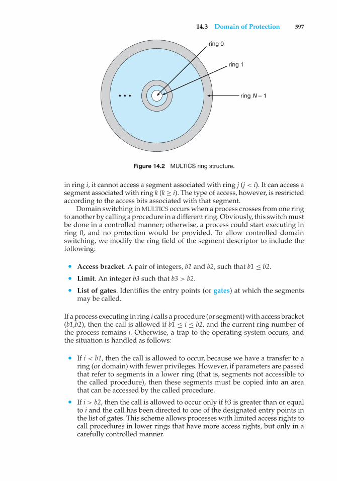
14.3 Domain of Protection 597
ring 0
ring 1
ring N – 1• • •
Figure 14.2 MULTICS ring structure.
in ring i, it cannot access a segment associated with ring j (j< i). It can access asegment associated with ring k (k≥ i). The type of access, however, is restrictedaccording to the access bits associated with that segment.
Domain switching in MULTICS occurs when a process crosses from one ringto another by calling a procedure in a different ring. Obviously, this switch mustbe done in a controlled manner; otherwise, a process could start executing inring 0, and no protection would be provided. To allow controlled domainswitching, we modify the ring field of the segment descriptor to include thefollowing:
• Access bracket. A pair of integers, b1 and b2, such that b1 ≤ b2.• Limit. An integer b3 such that b3 > b2.
• List of gates. Identifies the entry points (or gates) at which the segmentsmay be called.
If a process executing in ring i calls a procedure (or segment) with access bracket(b1,b2), then the call is allowed if b1 ≤ i ≤ b2, and the current ring number ofthe process remains i. Otherwise, a trap to the operating system occurs, andthe situation is handled as follows:
• If i < b1, then the call is allowed to occur, because we have a transfer to aring (or domain) with fewer privileges. However, if parameters are passedthat refer to segments in a lower ring (that is, segments not accessible tothe called procedure), then these segments must be copied into an areathat can be accessed by the called procedure.
• If i > b2, then the call is allowed to occur only if b3 is greater than or equalto i and the call has been directed to one of the designated entry points inthe list of gates. This scheme allows processes with limited access rights tocall procedures in lower rings that have more access rights, but only in acarefully controlled manner.
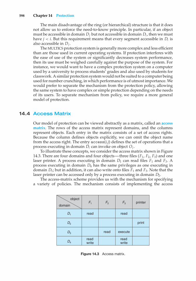
598 Chapter 14 Protection
The main disadvantage of the ring (or hierarchical) structure is that it doesnot allow us to enforce the need-to-know principle. In particular, if an objectmust be accessible in domain Dj but not accessible in domain Di , then we musthave j < i. But this requirement means that every segment accessible in Di isalso accessible in Dj .
The MULTICS protection system is generally more complex and less efficientthan are those used in current operating systems. If protection interferes withthe ease of use of the system or significantly decreases system performance,then its use must be weighed carefully against the purpose of the system. Forinstance, we would want to have a complex protection system on a computerused by a university to process students’ grades and also used by students forclasswork. A similar protection system would not be suited to a computer beingused for number crunching, in which performance is of utmost importance. Wewould prefer to separate the mechanism from the protection policy, allowingthe same system to have complex or simple protection depending on the needsof its users. To separate mechanism from policy, we require a more generalmodel of protection.
14.4 Access Matrix
Our model of protection can be viewed abstractly as a matrix, called an accessmatrix. The rows of the access matrix represent domains, and the columnsrepresent objects. Each entry in the matrix consists of a set of access rights.Because the column defines objects explicitly, we can omit the object namefrom the access right. The entry access(i,j) defines the set of operations that aprocess executing in domain Di can invoke on object Oj .
To illustrate these concepts, we consider the access matrix shown in Figure14.3. There are four domains and four objects—three files (F1, F2, F3) and onelaser printer. A process executing in domain D1 can read files F1 and F3. Aprocess executing in domain D4 has the same privileges as one executing indomain D1; but in addition, it can also write onto files F1 and F3. Note that thelaser printer can be accessed only by a process executing in domain D2.
The access-matrix scheme provides us with the mechanism for specifyinga variety of policies. The mechanism consists of implementing the access
objectprinter
read
read execute
readwrite
readwrite
read
F1
D1
D2
D3
D4
F2 F3domain
Figure 14.3 Access matrix.
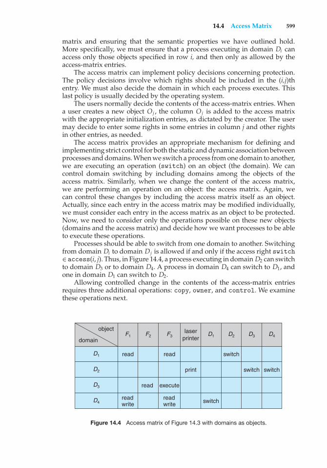
14.4 Access Matrix 599
matrix and ensuring that the semantic properties we have outlined hold.More specifically, we must ensure that a process executing in domain Di canaccess only those objects specified in row i, and then only as allowed by theaccess-matrix entries.
The access matrix can implement policy decisions concerning protection.The policy decisions involve which rights should be included in the (i,j)thentry. We must also decide the domain in which each process executes. Thislast policy is usually decided by the operating system.
The users normally decide the contents of the access-matrix entries. Whena user creates a new object Oj , the column Oj is added to the access matrixwith the appropriate initialization entries, as dictated by the creator. The usermay decide to enter some rights in some entries in column j and other rightsin other entries, as needed.
The access matrix provides an appropriate mechanism for defining andimplementing strict control for both the static and dynamic association betweenprocesses and domains. When we switch a process from one domain to another,we are executing an operation (switch) on an object (the domain). We cancontrol domain switching by including domains among the objects of theaccess matrix. Similarly, when we change the content of the access matrix,we are performing an operation on an object: the access matrix. Again, wecan control these changes by including the access matrix itself as an object.Actually, since each entry in the access matrix may be modified individually,we must consider each entry in the access matrix as an object to be protected.Now, we need to consider only the operations possible on these new objects(domains and the access matrix) and decide how we want processes to be ableto execute these operations.
Processes should be able to switch from one domain to another. Switchingfrom domain Di to domain Dj is allowed if and only if the access right switch∈ access(i, j). Thus, in Figure 14.4, a process executing in domain D2 can switchto domain D3 or to domain D4. A process in domain D4 can switch to D1, andone in domain D1 can switch to D2.
Allowing controlled change in the contents of the access-matrix entriesrequires three additional operations: copy, owner, and control. We examinethese operations next.
laserprinter
read
read execute
readwrite
readwrite
read
switch
switch
switch switch
F1
D1
D1
D2
D2
D3
D3
D4
D4F2 F3
object
domain
Figure 14.4 Access matrix of Figure 14.3 with domains as objects.
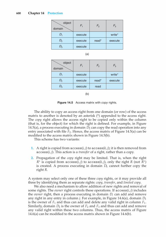
600 Chapter 14 Protection
object
read*
write*execute
execute execute
execute
F1
D1
D2
D3
F2 F3domain
(a)
object
read*
write*execute
execute execute
execute read
F1
D1
D2
D3
F2 F3domain
(b)
Figure 14.5 Access matrix with copy rights.
The ability to copy an access right from one domain (or row) of the accessmatrix to another is denoted by an asterisk (*) appended to the access right.The copy right allows the access right to be copied only within the column(that is, for the object) for which the right is defined. For example, in Figure14.5(a), a process executing in domain D2 can copy the read operation into anyentry associated with file F2. Hence, the access matrix of Figure 14.5(a) can bemodified to the access matrix shown in Figure 14.5(b).
This scheme has two variants:
1. A right is copied from access(i, j) to access(k, j); it is then removed fromaccess(i, j). This action is a transfer of a right, rather than a copy.
2. Propagation of the copy right may be limited. That is, when the rightR∗ is copied from access(i, j) to access(k, j), only the right R (not R∗)is created. A process executing in domain Dk cannot further copy theright R.
A system may select only one of these three copy rights, or it may provide allthree by identifying them as separate rights: copy, transfer, and limited copy.
We also need a mechanism to allow addition of new rights and removal ofsome rights. The owner right controls these operations. If access(i, j) includesthe owner right, then a process executing in domain Di can add and removeany right in any entry in column j. For example, in Figure 14.6(a), domain D1is the owner of F1 and thus can add and delete any valid right in column F1.Similarly, domain D2 is the owner of F2 and F3 and thus can add and removeany valid right within these two columns. Thus, the access matrix of Figure14.6(a) can be modified to the access matrix shown in Figure 14.6(b).
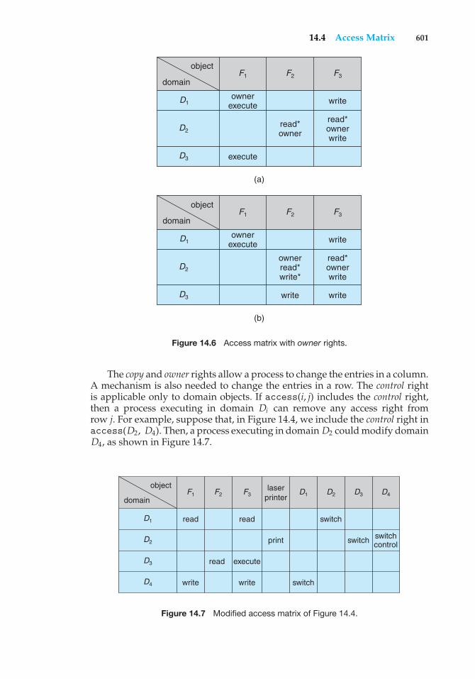
14.4 Access Matrix 601
object
read*owner
writeownerexecute
read*ownerwrite
execute
F1
D1
D2
D3
F2 F3domain
(a)
object
ownerread*write*
writeownerexecute
read*ownerwrite
F1
D1
D2
D3
F2 F3domain
(b)
writewrite
Figure 14.6 Access matrix with owner rights.
The copy and owner rights allow a process to change the entries in a column.A mechanism is also needed to change the entries in a row. The control rightis applicable only to domain objects. If access(i, j) includes the control right,then a process executing in domain Di can remove any access right fromrow j. For example, suppose that, in Figure 14.4, we include the control right inaccess(D2, D4). Then, a process executing in domain D2 could modify domainD4, as shown in Figure 14.7.
laserprinter
read
read execute
write write
read
switch
switch
switch switchcontrol
F1
D1
D1
D2
D2
D3
D3
D4
D4F2 F3
object
domain
Figure 14.7 Modified access matrix of Figure 14.4.
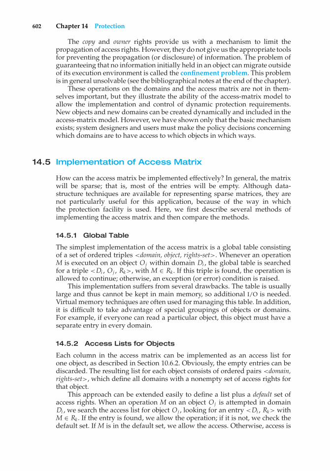
602 Chapter 14 Protection
The copy and owner rights provide us with a mechanism to limit thepropagation of access rights. However, they do not give us the appropriate toolsfor preventing the propagation (or disclosure) of information. The problem ofguaranteeing that no information initially held in an object can migrate outsideof its execution environment is called the confinement problem. This problemis in general unsolvable (see the bibliographical notes at the end of the chapter).
These operations on the domains and the access matrix are not in them-selves important, but they illustrate the ability of the access-matrix model toallow the implementation and control of dynamic protection requirements.New objects and new domains can be created dynamically and included in theaccess-matrix model. However, we have shown only that the basic mechanismexists; system designers and users must make the policy decisions concerningwhich domains are to have access to which objects in which ways.
14.5 Implementation of Access Matrix
How can the access matrix be implemented effectively? In general, the matrixwill be sparse; that is, most of the entries will be empty. Although data-structure techniques are available for representing sparse matrices, they arenot particularly useful for this application, because of the way in whichthe protection facility is used. Here, we first describe several methods ofimplementing the access matrix and then compare the methods.
14.5.1 Global Table
The simplest implementation of the access matrix is a global table consistingof a set of ordered triples <domain, object, rights-set>. Whenever an operationM is executed on an object Oj within domain Di , the global table is searchedfor a triple <Di , Oj , Rk>, with M ∈ Rk . If this triple is found, the operation isallowed to continue; otherwise, an exception (or error) condition is raised.
This implementation suffers from several drawbacks. The table is usuallylarge and thus cannot be kept in main memory, so additional I/O is needed.Virtual memory techniques are often used for managing this table. In addition,it is difficult to take advantage of special groupings of objects or domains.For example, if everyone can read a particular object, this object must have aseparate entry in every domain.
14.5.2 Access Lists for Objects
Each column in the access matrix can be implemented as an access list forone object, as described in Section 10.6.2. Obviously, the empty entries can bediscarded. The resulting list for each object consists of ordered pairs <domain,rights-set>, which define all domains with a nonempty set of access rights forthat object.
This approach can be extended easily to define a list plus a default set ofaccess rights. When an operation M on an object Oj is attempted in domainDi , we search the access list for object Oj , looking for an entry <Di , Rk> withM ∈ Rk . If the entry is found, we allow the operation; if it is not, we check thedefault set. If M is in the default set, we allow the access. Otherwise, access is
14.5 Implementation of Access Matrix 603
denied, and an exception condition occurs. For efficiency, we may check thedefault set first and then search the access list.
14.5.3 Capability Lists for Domains
Rather than associating the columns of the access matrix with the objects asaccess lists, we can associate each row with its domain. A capability list fora domain is a list of objects together with the operations allowed on thoseobjects. An object is often represented by its physical name or address, calleda capability. To execute operation M on object Oj , the process executes theoperationM, specifying the capability (or pointer) for object Oj as a parameter.Simple possession of the capability means that access is allowed.
The capability list is associated with a domain, but it is never directlyaccessible to a process executing in that domain. Rather, the capability listis itself a protected object, maintained by the operating system and accessedby the user only indirectly. Capability-based protection relies on the fact thatthe capabilities are never allowed to migrate into any address space directlyaccessible by a user process (where they could be modified). If all capabilitiesare secure, the object they protect is also secure against unauthorized access.
Capabilities were originally proposed as a kind of secure pointer, tomeet the need for resource protection that was foreseen as multiprogrammedcomputer systems came of age. The idea of an inherently protected pointerprovides a foundation for protection that can be extended up to the applicationslevel.
To provide inherent protection, we must distinguish capabilities from otherkinds of objects, and they must be interpreted by an abstract machine on whichhigher-level programs run. Capabilities are usually distinguished from otherdata in one of two ways:
• Each object has a tag to denote whether it is a capability or accessibledata. The tags themselves must not be directly accessible by an applicationprogram. Hardware or firmware support may be used to enforce thisrestriction. Although only one bit is necessary to distinguish betweencapabilities and other objects, more bits are often used. This extensionallows all objects to be tagged with their types by the hardware. Thus,the hardware can distinguish integers, floating-point numbers, pointers,Booleans, characters, instructions, capabilities, and uninitialized values bytheir tags.
• Alternatively, the address space associated with a program can be split intotwo parts. One part is accessible to the program and contains the program’snormal data and instructions. The other part, containing the capability list,is accessible only by the operating system. A segmented memory space(Section 8.6) is useful to support this approach.
Several capability-based protection systems have been developed; we describethem briefly in Section 14.8. The Mach operating system also uses a version ofcapability-based protection; it is described in Appendix B.
604 Chapter 14 Protection
14.5.4 A Lock–Key Mechanism
The lock–key scheme is a compromise between access lists and capabilitylists. Each object has a list of unique bit patterns, called locks. Similarly, eachdomain has a list of unique bit patterns, called keys. A process executing in adomain can access an object only if that domain has a key that matches one ofthe locks of the object.
As with capability lists, the list of keys for a domain must be managedby the operating system on behalf of the domain. Users are not allowed toexamine or modify the list of keys (or locks) directly.
14.5.5 Comparison
As you might expect, choosing a technique for implementing an access matrixinvolves various trade-offs. Using a global table is simple; however, the tablecan be quite large and often cannot take advantage of special groupings ofobjects or domains. Access lists correspond directly to the needs of users.When a user creates an object, he can specify which domains can access theobject, as well as what operations are allowed. However, because access-rightsinformation for a particular domain is not localized, determining the set ofaccess rights for each domain is difficult. In addition, every access to the objectmust be checked, requiring a search of the access list. In a large system withlong access lists, this search can be time consuming.
Capability lists do not correspond directly to the needs of users; theyare useful, however, for localizing information for a given process. Theprocess attempting access must present a capability for that access. Then, theprotection system needs only to verify that the capability is valid. Revocationof capabilities, however, may be inefficient (Section 14.7).
The lock–key mechanism, as mentioned, is a compromise between accesslists and capability lists. The mechanism can be both effective and flexible,depending on the length of the keys. The keys can be passed freely fromdomain to domain. In addition, access privileges can be effectively revoked bythe simple technique of changing some of the locks associated with the object(Section 14.7).
Most systems use a combination of access lists and capabilities. When aprocess first tries to access an object, the access list is searched. If access isdenied, an exception condition occurs. Otherwise, a capability is created andattached to the process. Additional references use the capability to demonstrateswiftly that access is allowed. After the last access, the capability is destroyed.This strategy is used in the MULTICS system and in the CAL system.
As an example of how such a strategy works, consider a file system inwhich each file has an associated access list. When a process opens a file, thedirectory structure is searched to find the file, access permission is checked, andbuffers are allocated. All this information is recorded in a new entry in a filetable associated with the process. The operation returns an index into this tablefor the newly opened file. All operations on the file are made by specificationof the index into the file table. The entry in the file table then points to the fileand its buffers. When the file is closed, the file-table entry is deleted. Since thefile table is maintained by the operating system, the user cannot accidentallycorrupt it. Thus, the user can access only those files that have been opened.
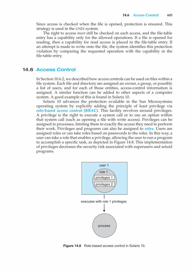
14.6 Access Control 605
Since access is checked when the file is opened, protection is ensured. Thisstrategy is used in the UNIX system.
The right to access must still be checked on each access, and the file-tableentry has a capability only for the allowed operations. If a file is opened forreading, then a capability for read access is placed in the file-table entry. Ifan attempt is made to write onto the file, the system identifies this protectionviolation by comparing the requested operation with the capability in thefile-table entry.
14.6 Access Control
In Section 10.6.2, we described how access controls can be used on files within afile system. Each file and directory are assigned an owner, a group, or possiblya list of users, and for each of those entities, access-control information isassigned. A similar function can be added to other aspects of a computersystem. A good example of this is found in Solaris 10.
Solaris 10 advances the protection available in the Sun Microsystemsoperating system by explicitly adding the principle of least privilege viarole-based access control (RBAC). This facility revolves around privileges.A privilege is the right to execute a system call or to use an option withinthat system call (such as opening a file with write access). Privileges can beassigned to processes, limiting them to exactly the access they need to performtheir work. Privileges and programs can also be assigned to roles. Users areassigned roles or can take roles based on passwords to the roles. In this way, auser can take a role that enables a privilege, allowing the user to run a programto accomplish a specific task, as depicted in Figure 14.8. This implementationof privileges decreases the security risk associated with superusers and setuidprograms.
user 1
role 1
privileges 1
executes with role 1 privileges
privileges 2
process
Figure 14.8 Role-based access control in Solaris 10.
606 Chapter 14 Protection
Notice that this facility is similar to the access matrix described in Section14.4. This relationship is further explored in the exercises at the end of thechapter.
14.7 Revocation of Access Rights
In a dynamic protection system, we may sometimes need to revoke accessrights to objects shared by different users. Various questions about revocationmay arise:
• Immediate versus delayed. Does revocation occur immediately, or is itdelayed? If revocation is delayed, can we find out when it will take place?
• Selective versus general. When an access right to an object is revoked,does it affect all the users who have an access right to that object, or canwe specify a select group of users whose access rights should be revoked?
• Partial versus total. Can a subset of the rights associated with an object berevoked, or must we revoke all access rights for this object?
• Temporary versus permanent. Can access be revoked permanently (thatis, the revoked access right will never again be available), or can access berevoked and later be obtained again?
With an access-list scheme, revocation is easy. The access list is searched forany access rights to be revoked, and they are deleted from the list. Revocationis immediate and can be general or selective, total or partial, and permanentor temporary.
Capabilities, however, present a much more difficult revocation problem,as mentioned earlier. Since the capabilities are distributed throughout thesystem, we must find them before we can revoke them. Schemes that implementrevocation for capabilities include the following:
• Reacquisition. Periodically, capabilities are deleted from each domain. Ifa process wants to use a capability, it may find that that capability has beendeleted. The process may then try to reacquire the capability. If access hasbeen revoked, the process will not be able to reacquire the capability.
• Back-pointers. A list of pointers is maintained with each object, pointingto all capabilities associated with that object. When revocation is required,we can follow these pointers, changing the capabilities as necessary. Thisscheme was adopted in the MULTICS system. It is quite general, but itsimplementation is costly.
• Indirection. The capabilities point indirectly, not directly, to the objects.Each capability points to a unique entry in a global table, which in turnpoints to the object. We implement revocation by searching the global tablefor the desired entry and deleting it. Then, when an access is attempted,the capability is found to point to an illegal table entry. Table entries canbe reused for other capabilities without difficulty, since both the capabilityand the table entry contain the unique name of the object. The object for a
14.8 Capability-Based Systems 607
capability and its table entry must match. This scheme was adopted in theCAL system. It does not allow selective revocation.
• Keys. A key is a unique bit pattern that can be associated with a capability.This key is defined when the capability is created, and it can be neithermodified nor inspected by the process that owns the capability. A masterkey is associated with each object; it can be defined or replaced withthe set-key operation. When a capability is created, the current valueof the master key is associated with the capability. When the capabilityis exercised, its key is compared with the master key. If the keys match,the operation is allowed to continue; otherwise, an exception conditionis raised. Revocation replaces the master key with a new value via theset-key operation, invalidating all previous capabilities for this object.
This scheme does not allow selective revocation, since only one masterkey is associated with each object. If we associate a list of keys with eachobject, then selective revocation can be implemented. Finally, we can groupall keys into one global table of keys. A capability is valid only if itskey matches some key in the global table. We implement revocation byremoving the matching key from the table. With this scheme, a key can beassociated with several objects, and several keys can be associated witheach object, providing maximum flexibility.
In key-based schemes, the operations of defining keys, inserting theminto lists, and deleting them from lists should not be available to all users.In particular, it would be reasonable to allow only the owner of an objectto set the keys for that object. This choice, however, is a policy decisionthat the protection system can implement but should not define.
14.8 Capability-Based Systems
In this section, we survey two capability-based protection systems. Thesesystems differ in their complexity and in the types of policies that can beimplemented on them. Neither system is widely used, but both provideinteresting proving grounds for protection theories.
14.8.1 An Example: Hydra
Hydra is a capability-based protection system that provides considerableflexibility. The system implements a fixed set of possible access rights, includingsuch basic forms of access as the right to read, write, or execute a memorysegment. In addition, a user (of the protection system) can declare other rights.The interpretation of user-defined rights is performed solely by the user’sprogram, but the system provides access protection for the use of these rights,as well as for the use of system-defined rights. These facilities constitute asignificant development in protection technology.
Operations on objects are defined procedurally. The procedures thatimplement such operations are themselves a form of object, and they areaccessed indirectly by capabilities. The names of user-defined procedures mustbe identified to the protection system if it is to deal with objects of the user-defined type. When the definition of an object is made known to Hydra, thenames of operations on the type become auxiliary rights. Auxiliary rights
608 Chapter 14 Protection
can be described in a capability for an instance of the type. For a process toperform an operation on a typed object, the capability it holds for that objectmust contain the name of the operation being invoked among its auxiliaryrights. This restriction enables discrimination of access rights to be made on aninstance-by-instance and process-by-process basis.
Hydra also provides rights amplification. This scheme allows a procedureto be certified as trustworthy to act on a formal parameter of a specified typeon behalf of any process that holds a right to execute the procedure. The rightsheld by a trustworthy procedure are independent of, and may exceed, therights held by the calling process. However, such a procedure must not beregarded as universally trustworthy (the procedure is not allowed to act onother types, for instance), and the trustworthiness must not be extended to anyother procedures or program segments that might be executed by a process.
Amplification allows implementation procedures access to the representa-tion variables of an abstract data type. If a process holds a capability to a typedobject A, for instance, this capability may include an auxiliary right to invokesome operation P but does not include any of the so-called kernel rights, suchas read, write, or execute, on the segment that represents A. Such a capabilitygives a process a means of indirect access (through the operation P) to therepresentation of A, but only for specific purposes.
When a process invokes the operation P on an object A, however, thecapability for access to A may be amplified as control passes to the code bodyof P. This amplification may be necessary to allow P the right to access thestorage segment representingA so as to implement the operation that P defineson the abstract data type. The code body of P may be allowed to read or towrite to the segment of A directly, even though the calling process cannot.On return from P, the capability for A is restored to its original, unamplifiedstate. This case is a typical one in which the rights held by a process for accessto a protected segment must change dynamically, depending on the task tobe performed. The dynamic adjustment of rights is performed to guaranteeconsistency of a programmer-defined abstraction. Amplification of rights canbe stated explicitly in the declaration of an abstract type to the Hydra operatingsystem.
When a user passes an object as an argument to a procedure, we may needto ensure that the procedure cannot modify the object. We can implement thisrestriction readily by passing an access right that does not have the modification(write) right. However, if amplification may occur, the right to modify maybe reinstated. Thus, the user-protection requirement can be circumvented.In general, of course, a user may trust that a procedure performs its taskcorrectly. This assumption is not always correct, however, because of hardwareor software errors. Hydra solves this problem by restricting amplifications.
The procedure-call mechanism of Hydra was designed as a direct solutionto the problem of mutually suspicious subsystems. This problem is defined asfollows. Suppose that a program is provided that can be invoked as a serviceby a number of different users (for example, a sort routine, a compiler, agame). When users invoke this service program, they take the risk that theprogram will malfunction and will either damage the given data or retainsome access right to the data to be used (without authority) later. Similarly,the service program may have some private files (for accounting purposes,
14.8 Capability-Based Systems 609
for example) that should not be accessed directly by the calling user program.Hydra provides mechanisms for directly dealing with this problem.
A Hydra subsystem is built on top of its protection kernel and may requireprotection of its own components. A subsystem interacts with the kernelthrough calls on a set of kernel-defined primitives that define access rights toresources defined by the subsystem. The subsystem designer can define policiesfor use of these resources by user processes, but the policies are enforceable byuse of the standard access protection afforded by the capability system.
Programmers can make direct use of the protection system after acquaint-ing themselves with its features in the appropriate reference manual. Hydraprovides a large library of system-defined procedures that can be called byuser programs. Programmers can explicitly incorporate calls on these systemprocedures into their program code or can use a program translator that hasbeen interfaced to Hydra.
14.8.2 An Example: Cambridge CAP System
A different approach to capability-based protection has been taken in thedesign of the Cambridge CAP system. CAP’s capability system is simpler andsuperficially less powerful than that of Hydra. However, closer examinationshows that it, too, can be used to provide secure protection of user-definedobjects. CAP has two kinds of capabilities. The ordinary kind is called adata capability. It can be used to provide access to objects, but the onlyrights provided are the standard read, write, and execute of the individualstorage segments associated with the object. Data capabilities are interpretedby microcode in the CAP machine.
The second kind of capability is the so-called software capability, whichis protected, but not interpreted, by the CAP microcode. It is interpreted by aprotected (that is, privileged) procedure, which may be written by an applicationprogrammer as part of a subsystem. A particular kind of rights amplificationis associated with a protected procedure. When executing the code body ofsuch a procedure, a process temporarily acquires the right to read or write thecontents of a software capability itself. This specific kind of rights amplificationcorresponds to an implementation of the seal and unseal primitives oncapabilities. Of course, this privilege is still subject to type verification to ensurethat only software capabilities for a specified abstract type are passed to anysuch procedure. Universal trust is not placed in any code other than the CAPmachine’s microcode. (See Bibliographical Notes for references.)
The interpretation of a software capability is left completely to the sub-system, through the protected procedures it contains. This scheme allows avariety of protection policies to be implemented. Although programmers candefine their own protected procedures (any of which might be incorrect), thesecurity of the overall system cannot be compromised. The basic protectionsystem will not allow an unverified, user-defined, protected procedure accessto any storage segments (or capabilities) that do not belong to the protectionenvironment in which it resides. The most serious consequence of an insecureprotected procedure is a protection breakdown of the subsystem for which thatprocedure has responsibility.
610 Chapter 14 Protection
The designers of the CAP system have noted that the use of softwarecapabilities allowed them to realize considerable economies in formulatingand implementing protection policies commensurate with the requirements ofabstract resources. However, subsystem designers who want to make use ofthis facility cannot simply study a reference manual, as is the case with Hydra.Instead, they must learn the principles and techniques of protection, since thesystem provides them with no library of procedures.
14.9 Language-Based Protection
To the degree that protection is provided in existing computer systems, it isusually achieved through an operating-system kernel, which acts as a securityagent to inspect and validate each attempt to access a protected resource. Sincecomprehensive access validation may be a source of considerable overhead,either we must give it hardware support to reduce the cost of each validationor we must allow the system designer to compromise the goals of protection.Satisfying all these goals is difficult if the flexibility to implement protectionpolicies is restricted by the support mechanisms provided or if protectionenvironments are made larger than necessary to secure greater operationalefficiency.
As operating systems have become more complex, and particularly as theyhave attempted to provide higher-level user interfaces, the goals of protectionhave become much more refined. The designers of protection systems havedrawn heavily on ideas that originated in programming languages andespecially on the concepts of abstract data types and objects. Protection systemsare now concerned not only with the identity of a resource to which access isattempted but also with the functional nature of that access. In the newestprotection systems, concern for the function to be invoked extends beyonda set of system-defined functions, such as standard file-access methods, toinclude functions that may be user-defined as well.
Policies for resource use may also vary, depending on the application,and they may be subject to change over time. For these reasons, protectioncan no longer be considered a matter of concern only to the designer of anoperating system. It should also be available as a tool for use by the applicationdesigner, so that resources of an applications subsystem can be guarded againsttampering or the influence of an error.
14.9.1 Compiler-Based Enforcement
At this point, programming languages enter the picture. Specifying the desiredcontrol of access to a shared resource in a system is making a declarativestatement about the resource. This kind of statement can be integrated into alanguage by an extension of its typing facility. When protection is declaredalong with data typing, the designer of each subsystem can specify itsrequirements for protection, as well as its need for use of other resources in asystem. Such a specification should be given directly as a program is composed,and in the language in which the program itself is stated. This approach hasseveral significant advantages:
14.9 Language-Based Protection 611
1. Protection needs are simply declared, rather than programmed as asequence of calls on procedures of an operating system.
2. Protection requirements can be stated independently of the facilitiesprovided by a particular operating system.
3. The means for enforcement need not be provided by the designer of asubsystem.
4. A declarative notation is natural because access privileges are closelyrelated to the linguistic concept of data type.
A variety of techniques can be provided by a programming-languageimplementation to enforce protection, but any of these must depend on somedegree of support from an underlying machine and its operating system. Forexample, suppose a language is used to generate code to run on the CambridgeCAP system. On this system, every storage reference made on the underlyinghardware occurs indirectly through a capability. This restriction prevents anyprocess from accessing a resource outside of its protection environment atany time. However, a program may impose arbitrary restrictions on howa resource can be used during execution of a particular code segment.We can implement such restrictions most readily by using the softwarecapabilities provided by CAP. A language implementation might providestandard protected procedures to interpret software capabilities that wouldrealize the protection policies that could be specified in the language. Thisscheme puts policy specification at the disposal of the programmers, whilefreeing them from implementing its enforcement.
Even if a system does not provide a protection kernel as powerful as thoseof Hydra or CAP, mechanisms are still available for implementing protectionspecifications given in a programming language. The principal distinction isthat the security of this protection will not be as great as that supported bya protection kernel, because the mechanism must rely on more assumptionsabout the operational state of the system. A compiler can separate referencesfor which it can certify that no protection violation could occur from thosefor which a violation might be possible, and it can treat them differently. Thesecurity provided by this form of protection rests on the assumption that thecode generated by the compiler will not be modified prior to or during itsexecution.
What, then, are the relative merits of enforcement based solely on a kernel,as opposed to enforcement provided largely by a compiler?
• Security. Enforcement by a kernel provides a greater degree of securityof the protection system itself than does the generation of protection-checking code by a compiler. In a compiler-supported scheme, securityrests on correctness of the translator, on some underlying mechanism ofstorage management that protects the segments from which compiledcode is executed, and, ultimately, on the security of files from which aprogram is loaded. Some of these considerations also apply to a software-supported protection kernel, but to a lesser degree, since the kernel mayreside in fixed physical storage segments and may be loaded only froma designated file. With a tagged-capability system, in which all address
612 Chapter 14 Protection
computation is performed either by hardware or by a fixed microprogram,even greater security is possible. Hardware-supported protection is alsorelatively immune to protection violations that might occur as a result ofeither hardware or system software malfunction.
• Flexibility. There are limits to the flexibility of a protection kernel inimplementing a user-defined policy, although it may supply adequatefacilities for the system to provide enforcement of its own policies.With a programming language, protection policy can be declared andenforcement provided as needed by an implementation. If a languagedoes not provide sufficient flexibility, it can be extended or replaced withless disturbance of a system in service than would be caused by themodification of an operating-system kernel.
• Efficiency. The greatest efficiency is obtained when enforcement of protec-tion is supported directly by hardware (or microcode). Insofar as softwaresupport is required, language-based enforcement has the advantage thatstatic access enforcement can be verified off-line at compile time. Also,since an intelligent compiler can tailor the enforcement mechanism tomeet the specified need, the fixed overhead of kernel calls can often beavoided.
In summary, the specification of protection in a programming languageallows the high-level description of policies for the allocation and use ofresources. A language implementation can provide software for protectionenforcement when automatic hardware-supported checking is unavailable. Inaddition, it can interpret protection specifications to generate calls on whateverprotection system is provided by the hardware and the operating system.
One way of making protection available to the application program isthrough the use of a software capability that could be used as an objectof computation. Inherent in this concept is the idea that certain programcomponents might have the privilege of creating or examining these softwarecapabilities. A capability-creating program would be able to execute a primitiveoperation that would seal a data structure, rendering the latter’s contentsinaccessible to any program components that did not hold either the seal orthe unseal privilege. Such components might copy the data structure or passits address to other program components, but they could not gain access toits contents. The reason for introducing such software capabilities is to bring aprotection mechanism into the programming language. The only problem withthe concept as proposed is that the use of the seal and unseal operations takesa procedural approach to specifying protection. A nonprocedural or declarativenotation seems a preferable way to make protection available to the applicationprogrammer.
What is needed is a safe, dynamic access-control mechanism for distribut-ing capabilities to system resources among user processes. To contribute to theoverall reliability of a system, the access-control mechanism should be safeto use. To be useful in practice, it should also be reasonably efficient. Thisrequirement has led to the development of a number of language constructsthat allow the programmer to declare various restrictions on the use of a specificmanaged resource. (See the Bibliographical Notes for appropriate references.)These constructs provide mechanisms for three functions:
14.9 Language-Based Protection 613
1. Distributing capabilities safely and efficiently among customer processes.In particular, mechanisms ensure that a user process will use the managedresource only if it was granted a capability to that resource.
2. Specifying the type of operations that a particular process may invoke onan allocated resource (for example, a reader of a file should be allowedonly to read the file, whereas a writer should be able both to read andto write). It should not be necessary to grant the same set of rights toevery user process, and it should be impossible for a process to enlargeits set of access rights, except with the authorization of the access-controlmechanism.
3. Specifying the order in which a particular process may invoke the variousoperations of a resource (for example, a file must be opened before it canbe read). It should be possible to give two processes different restrictionson the order in which they can invoke the operations of the allocatedresource.
The incorporation of protection concepts into programming languages, asa practical tool for system design, is in its infancy. Protection will likely becomea matter of greater concern to the designers of new systems with distributedarchitectures and increasingly stringent requirements on data security. Thenthe importance of suitable language notations in which to express protectionrequirements will be recognized more widely.
14.9.2 Protection in Java
Because Java was designed to run in a distributed environment, the Javavirtual machine—or JVM—has many built-in protection mechanisms. Javaprograms are composed of classes, each of which is a collection of data fieldsand functions (called methods) that operate on those fields. The JVM loads aclass in response to a request to create instances (or objects) of that class. One ofthe most novel and useful features of Java is its support for dynamically loadinguntrusted classes over a network and for executing mutually distrusting classeswithin the same JVM.
Because of these capabilities of Java, protection is a paramount concern.Classes running in the same JVM may be from different sources and may notbe equally trusted. As a result, enforcing protection at the granularity of theJVM process is insufficient. Intuitively, whether a request to open a file shouldbe allowed will generally depend on which class has requested the open. Theoperating system lacks this knowledge.
Thus, such protection decisions are handled within the JVM. When theJVM loads a class, it assigns the class to a protection domain that givesthe permissions of that class. The protection domain to which the class isassigned depends on the URL from which the class was loaded and any digitalsignatures on the class file. (Digital signatures are covered in Section 15.4.1.3.)A configurable policy file determines the permissions granted to the domain(and its classes). For example, classes loaded from a trusted server might beplaced in a protection domain that allows them to access files in the user’shome directory, whereas classes loaded from an untrusted server might haveno file access permissions at all.
614 Chapter 14 Protection
It can be complicated for the JVM to determine what class is responsible for arequest to access a protected resource. Accesses are often performed indirectly,through system libraries or other classes. For example, consider a class thatis not allowed to open network connections. It could call a system library torequest the load of the contents of a URL. The JVM must decide whether or notto open a network connection for this request. But which class should be usedto determine if the connection should be allowed, the application or the systemlibrary?
The philosophy adopted in Java is to require the library class to explicitlypermit a network connection. More generally, in order to access a protectedresource, some method in the calling sequence that resulted in the request mustexplicitly assert the privilege to access the resource. By doing so, this methodtakes responsibility for the request; presumably, it will also perform whateverchecks are necessary to ensure the safety of the request. Of course, not everymethod is allowed to assert a privilege; a method can assert a privilege only ifits class is in a protection domain that is itself allowed to exercise the privilege.
This implementation approach is called stack inspection. Every threadin the JVM has an associated stack of its ongoing method invocations. Whena caller may not be trusted, a method executes an access request within adoPrivileged block to perform the access to a protected resource directly orindirectly. doPrivileged() is a static method in the AccessController classthat is passed a class with a run() method to invoke. When the doPrivilegedblock is entered, the stack frame for this method is annotated to indicate thisfact. Then, the contents of the block are executed. When an access to a protectedresource is subsequently requested, either by this method or a method itcalls, a call to checkPermissions() is used to invoke stack inspection todetermine if the request should be allowed. The inspection examines stackframes on the calling thread’s stack, starting from the most recently addedframe and working toward the oldest. If a stack frame is first found that has thedoPrivileged() annotation, then checkPermissions() returns immediatelyand silently, allowing the access. If a stack frame is first found for whichaccess is disallowed based on the protection domain of the method’s class,then checkPermissions() throws an AccessControlException. If the stackinspection exhausts the stack without finding either type of frame, thenwhether access is allowed depends on the implementation (for example, someimplementations of the JVM may allow access, while other implementationsmay disallow it).
Stack inspection is illustrated in Figure 14.9. Here, the gui() method ofa class in the untrusted applet protection domain performs two operations,first a get() and then an open(). The former is an invocation of theget() method of a class in the URL loader protection domain, which ispermitted to open() sessions to sites in the lucent.com domain, in particulara proxy server proxy.lucent.com for retrieving URLs. For this reason, theuntrusted applet’s get() invocation will succeed: the checkPermissions()call in the networking library encounters the stack frame of the get()method, which performed its open() in a doPrivileged block. However,the untrusted applet’s open() invocation will result in an exception, becausethe checkPermissions() call finds no doPrivileged annotation beforeencountering the stack frame of the gui() method.
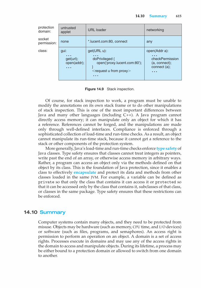
14.10 Summary 615
untrustedapplet
protectiondomain:
socketpermission:
class:
none
gui: … get(url); open(addr); …
networking
any
open(Addr a): … checkPermission (a, connect); connect (a); …
get(URL u): … doPrivileged { open(‘proxy.lucent.com:80’); } request u from proxy� …
*.lucent.com:80, connect
URL loader
Figure 14.9 Stack inspection.
Of course, for stack inspection to work, a program must be unable tomodify the annotations on its own stack frame or to do other manipulationsof stack inspection. This is one of the most important differences betweenJava and many other languages (including C++). A Java program cannotdirectly access memory; it can manipulate only an object for which it hasa reference. References cannot be forged, and the manipulations are madeonly through well-defined interfaces. Compliance is enforced through asophisticated collection of load-time and run-time checks. As a result, an objectcannot manipulate its run-time stack, because it cannot get a reference to thestack or other components of the protection system.
More generally, Java’s load-time and run-time checks enforce type safety ofJava classes. Type safety ensures that classes cannot treat integers as pointers,write past the end of an array, or otherwise access memory in arbitrary ways.Rather, a program can access an object only via the methods defined on thatobject by its class. This is the foundation of Java protection, since it enables aclass to effectively encapsulate and protect its data and methods from otherclasses loaded in the same JVM. For example, a variable can be defined asprivate so that only the class that contains it can access it or protected sothat it can be accessed only by the class that contains it, subclasses of that class,or classes in the same package. Type safety ensures that these restrictions canbe enforced.
14.10 Summary
Computer systems contain many objects, and they need to be protected frommisuse. Objects may be hardware (such as memory, CPU time, and I/O devices)or software (such as files, programs, and semaphores). An access right ispermission to perform an operation on an object. A domain is a set of accessrights. Processes execute in domains and may use any of the access rights inthe domain to access and manipulate objects. During its lifetime, a process maybe either bound to a protection domain or allowed to switch from one domainto another.
616 Chapter 14 Protection
The access matrix is a general model of protection that provides amechanism for protection without imposing a particular protection policy onthe system or its users. The separation of policy and mechanism is an importantdesign property.
The access matrix is sparse. It is normally implemented either as access listsassociated with each object or as capability lists associated with each domain.We can include dynamic protection in the access-matrix model by consideringdomains and the access matrix itself as objects. Revocation of access rights in adynamic protection model is typically easier to implement with an access-listscheme than with a capability list.
Real systems are much more limited than the general model and tend toprovide protection only for files. UNIX is representative, providing read, write,and execution protection separately for the owner, group, and general publicfor each file. MULTICS uses a ring structure in addition to file access. Hydra, theCambridge CAP system, and Mach are capability systems that extend protectionto user-defined software objects. Solaris 10 implements the principle of leastprivilege via role-based access control, a form of the access matrix.
Language-based protection provides finer-grained arbitration of requestsand privileges than the operating system is able to provide. For example, asingle Java JVM can run several threads, each in a different protection class. Itenforces the resource requests through sophisticated stack inspection and viathe type safety of the language.
Practice Exercises
14.1 What are the main differences between capability lists and access lists?
14.2 A Burroughs B7000/B6000 MCP file can be tagged as sensitive data.When such a file is deleted, its storage area is overwritten by somerandom bits. For what purpose would such a scheme be useful?
14.3 In a ring-protection system, level 0 has the greatest access to objects,and level n (where n > 0) has fewer access rights. The access rights ofa program at a particular level in the ring structure are considered aset of capabilities. What is the relationship between the capabilities ofa domain at level j and a domain at level i to an object (for j > i)?
14.4 The RC 4000 system, among others, has defined a tree of processes (calleda process tree) such that all the descendants of a process can be givenresources (objects) and access rights by their ancestors only. Thus, adescendant can never have the ability to do anything that its ancestorscannot do. The root of the tree is the operating system, which has theability to do anything. Assume the set of access rights is representedby an access matrix, A. A(x,y) defines the access rights of process x toobject y. If x is a descendant of z,what is the relationship betweenA(x,y)and A(z,y) for an arbitrary object y?
14.5 What protection problems may arise if a shared stack is used forparameter passing?
Exercises 617
14.6 Consider a computing environment where a unique number is associ-ated with each process and each object in the system. Suppose that weallow a process with number n to access an object with number m onlyif n > m. What type of protection structure do we have?
14.7 Consider a computing environment where a process is given theprivilege of accessing an object only n times. Suggest a scheme forimplementing this policy.
14.8 If all the access rights to an object are deleted, the object can no longerbe accessed. At this point, the object should also be deleted, and thespace it occupies should be returned to the system. Suggest an efficientimplementation of this scheme.
14.9 Why is it difficult to protect a system in which users are allowed to dotheir own I/O?
14.10 Capability lists are usually kept within the address space of the user.How does the system ensure that the user cannot modify the contentsof the list?
Exercises
14.11 Consider the ring-protection scheme in MULTICS. If we were to imple-ment the system calls of a typical operating system and store them in asegment associated with ring 0, what should be the values stored in thering field of the segment descriptor? What happens during a systemcall when a process executing in a higher-numbered ring invokes aprocedure in ring 0?
14.12 The access-control matrix can be used to determine whether a processcan switch from, say, domain A to domain B and enjoy the accessprivileges of domain B. Is this approach equivalent to including theaccess privileges of domain B in those of domain A?
14.13 Consider a computer system in which “computer games” can be playedby students only between 10 P.M. and 6 A.M., by faculty membersbetween 5 P.M. and 8 A.M., and by the computer center staff at alltimes. Suggest a scheme for implementing this policy efficiently.
14.14 What hardware features does a computer system need for efficientcapability manipulation? Can these features be used for memoryprotection?
14.15 Discuss the strengths and weaknesses of implementing an access matrixusing access lists that are associated with objects.
14.16 Discuss the strengths and weaknesses of implementing an access matrixusing capabilities that are associated with domains.
14.17 Explain why a capability-based system such as Hydra provides greaterflexibility than the ring-protection scheme in enforcing protectionpolicies.
618 Chapter 14 Protection
14.18 Discuss the need for rights amplification in Hydra. How does thispractice compare with the cross-ring calls in a ring-protection scheme?
14.19 What is the need-to-know principle? Why is it important for a protec-tion system to adhere to this principle?
14.20 Discuss which of the following systems allow module designers toenforce the need-to-know principle.
a. The MULTICS ring-protection scheme
b. Hydra’s capabilities
c. JVM’s stack-inspection scheme
14.21 Describe how the Java protection model would be compromised if aJava program were allowed to directly alter the annotations of its stackframe.
14.22 How are the access-matrix facility and the role-based access-controlfacility similar? How do they differ?
14.23 How does the principle of least privilege aid in the creation of protectionsystems?
14.24 How can systems that implement the principle of least privilege stillhave protection failures that lead to security violations?
Wiley Plus
Visit Wiley Plus for
• Source code
• Solutions to practice exercises
• Additional programming problems and exercises
• Labs using an operating system simulator
Bibliographical Notes
The access-matrix model of protection between domains and objects wasdeveloped by Lampson [1969] and Lampson [1971]. Popek [1974] and Saltzerand Schroeder [1975] provided excellent surveys on the subject of protection.Harrison et al. [1976] used a formal version of this model to enable them toprove properties of a protection system mathematically.
The concept of a capability evolved from Iliffe’s and Jodeit’s codewords,which were implemented in the Rice University computer (Iliffe and Jodeit[1962]). The term capability was introduced by Dennis and Horn [1966].
The Hydra system was described by Wulf et al. [1981]. The CAP systemwas described by Needham and Walker [1977]. Organick [1972] discussed theMULTICS ring-protection system.
Bibliographical Notes 619
Revocation was discussed by Redell and Fabry [1974], Cohen and Jefferson[1975], and Ekanadham and Bernstein [1979]. The principle of separation ofpolicy and mechanism was advocated by the designer of Hydra (Levin et al.[1975]). The confinement problem was first discussed by Lampson [1973] andwas further examined by Lipner [1975].
The use of higher-level languages for specifying access control wassuggested first by Morris [1973], who proposed the use of the seal and unsealoperations discussed in Section 14.9. Kieburtz and Silberschatz [1978], Kieburtzand Silberschatz [1983], and McGraw and Andrews [1979] proposed variouslanguage constructs for dealing with general dynamic-resource-managementschemes. Jones and Liskov [1978] considered how a static access-control schemecan be incorporated in a programming language that supports abstract datatypes. The use of minimal operating-system support to enforce protection wasadvocated by the Exokernel Project (Ganger et al. [2002], Kaashoek et al. [1997]).Extensibility of system code through language-based protection mechanismswas discussed in Bershad et al. [1995]. Other techniques for enforcing protectioninclude sandboxing (Goldberg et al. [1996]) and software fault isolation (Wahbeet al. [1993b]). The issues of lowering the overhead associated with protectioncosts and enabling user-level access to networking devices were discussed inMcCanne and Jacobson [1993] and Basu et al. [1995].
More detailed analyses of stack inspection, including comparisons withother approaches to Java security, can be found in Wallach et al. [1997] andGong et al. [1997].

This page intentionally left blank
15C H A P T E R
Security
Protection, as we discussed in Chapter 14, is strictly an internal problem: Howdo we provide controlled access to programs and data stored in a computersystem? Security, on the other hand, requires not only an adequate protectionsystem but also consideration of the external environment within which thesystem operates. A protection system is ineffective if user authentication iscompromised or a program is run by an unauthorized user.
Computer resources must be guarded against unauthorized access, mali-cious destruction or alteration, and accidental introduction of inconsistency.These resources include information stored in the system (both data and code),as well as the CPU, memory, disks, tapes, and networking that are the com-puter. In this chapter, we start by examining ways in which resources maybe accidentally or purposely misused. We then explore a key security enabler—cryptography. Finally, we look at mechanisms to guard against or detectattacks.
CHAPTER OBJECTIVES
• To discuss security threats and attacks.
• To explain the fundamentals of encryption, authentication, and hashing.
• To examine the uses of cryptography in computing.
• To describe various countermeasures to security attacks.
15.1 The Security Problem
In many applications, ensuring the security of the computer system is worthconsiderable effort. Large commercial systems containing payroll or otherfinancial data are inviting targets to thieves. Systems that contain data pertain-ing to corporate operations may be of interest to unscrupulous competitors.Furthermore, loss of such data, whether by accident or fraud, can seriouslyimpair the ability of the corporation to function.
In Chapter 14, we discussed mechanisms that the operating system canprovide (with appropriate aid from the hardware) that allow users to protect
621
622 Chapter 15 Security
their resources, including programs and data. These mechanisms work wellonly as long as the users conform to the intended use of and access to theseresources. We say that a system is secure if its resources are used and accessedas intended under all circumstances. Unfortunately, total security cannot beachieved. Nonetheless, we must have mechanisms to make security breachesa rare occurrence, rather than the norm.
Security violations (or misuse) of the system can be categorized as inten-tional (malicious) or accidental. It is easier to protect against accidental misusethan against malicious misuse. For the most part, protection mechanisms arethe core of protection from accidents. The following list includes several formsof accidental and malicious security violations. We should note that in ourdiscussion of security, we use the terms intruder and cracker for those attemptingto breach security. In addition, a threat is the potential for a security violation,such as the discovery of a vulnerability, whereas an attack is the attempt tobreak security.
• Breach of confidentiality. This type of violation involves unauthorizedreading of data (or theft of information). Typically, a breach of confiden-tiality is the goal of an intruder. Capturing secret data from a system ora data stream, such as credit-card information or identity information foridentity theft, can result directly in money for the intruder.
• Breach of integrity. This violation involves unauthorized modificationof data. Such attacks can, for example, result in passing of liability toan innocent party or modification of the source code of an importantcommercial application.
• Breach of availability. This violation involves unauthorized destruction ofdata. Some crackers would rather wreak havoc and gain status or braggingrights than gain financially. Web-site defacement is a common example ofthis type of security breach.
• Theft of service. This violation involves unauthorized use of resources.For example, an intruder (or intrusion program) may install a daemon ona system that acts as a file server.
• Denial of service. This violation involves preventing legitimate use of thesystem. Denial-of-service, or DOS, attacks are sometimes accidental. Theoriginal Internet worm turned into a DOS attack when a bug failed to delayits rapid spread. We discuss DOS attacks further in Section 15.3.3.
Attackers use several standard methods in their attempts to breachsecurity. The most common is masquerading, in which one participant ina communication pretends to be someone else (another host or anotherperson). By masquerading, attackers breach authentication, the correctnessof identification; they can then gain access that they would not normally beallowed or escalate their privileges—obtain privileges to which they would notnormally be entitled. Another common attack is to replay a captured exchangeof data. A replay attack consists of the malicious or fraudulent repeat of avalid data transmission. Sometimes the replay comprises the entire attack—for example, in a repeat of a request to transfer money. But frequently it isdone along with message modification, again to escalate privileges. Consider
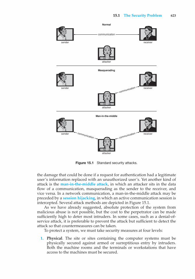
15.1 The Security Problem 623
communication
communication
communicationcommunication
sender receiver
attacker
sender receiver
attacker
sender receiver
attacker
Masquerading
Man-in-the-middle
Normal
Figure 15.1 Standard security attacks.
the damage that could be done if a request for authentication had a legitimateuser’s information replaced with an unauthorized user’s. Yet another kind ofattack is the man-in-the-middle attack, in which an attacker sits in the dataflow of a communication, masquerading as the sender to the receiver, andvice versa. In a network communication, a man-in-the-middle attack may bepreceded by a session hijacking, in which an active communication session isintercepted. Several attack methods are depicted in Figure 15.1.
As we have already suggested, absolute protection of the system frommalicious abuse is not possible, but the cost to the perpetrator can be madesufficiently high to deter most intruders. In some cases, such as a denial-of-service attack, it is preferable to prevent the attack but sufficient to detect theattack so that countermeasures can be taken.
To protect a system, we must take security measures at four levels:
1. Physical. The site or sites containing the computer systems must bephysically secured against armed or surreptitious entry by intruders.Both the machine rooms and the terminals or workstations that haveaccess to the machines must be secured.
624 Chapter 15 Security
2. Human. Authorization must be done carefully to assure that onlyappropriate users have access to the system. Even authorized users,however, may be “encouraged” to let others use their access (in exchangefor a bribe, for example). They may also be tricked into allowingaccess via social engineering. One type of social-engineering attackis phishing. Here, a legitimate-looking e-mail or Web page misleadsa user into entering confidential information. Another technique isdumpster diving, a general term for attempting to gather information inorder to gain unauthorized access to the computer (by looking throughtrash, finding phone books, or finding notes containing passwords, forexample). These security problems are management and personnel issues,not problems pertaining to operating systems.
3. Operating system. The system must protect itself from accidental orpurposeful security breaches. A runaway process could constitute anaccidental denial-of-service attack. A query to a service could reveal pass-words. A stack overflow could allow the launching of an unauthorizedprocess. The list of possible breaches is almost endless.
4. Network. Much computer data in modern systems travels over privateleased lines, shared lines like the Internet, wireless connections, or dial-uplines. Intercepting these data could be just as harmful as breaking into acomputer; and interruption of communications could constitute a remotedenial-of-service attack, diminishing users’ use of and trust in the system.
Security at the first two levels must be maintained if operating-systemsecurity is to be ensured. A weakness at a high level of security (physical orhuman) allows circumvention of strict low-level (operating-system) securitymeasures. Thus, the old adage that a chain is as weak as its weakest link isespecially true of system security. All of these aspects must be addressed forsecurity to be maintained.
Furthermore, the system must provide protection (Chapter 14) to allow theimplementation of security features. Without the ability to authorize usersand processes, to control their access, and to log their activities, it wouldbe impossible for an operating system to implement security measures orto run securely. Hardware protection features are needed to support an overallprotection scheme. For example, a system without memory protection cannotbe secure. New hardware features are allowing systems to be made moresecure, as we shall discuss.
Unfortunately, little in security is straightforward. As intruders exploitsecurity vulnerabilities, security countermeasures are created and deployed.This causes intruders to become more sophisticated in their attacks. Forexample, recent security incidents include the use of spyware to providea conduit for spam through innocent systems (we discuss this practice inSection 15.2). This cat-and-mouse game is likely to continue, with more securitytools needed to block the escalating intruder techniques and activities.
In the remainder of this chapter, we address security at the network andoperating-system levels. Security at the physical and human levels, althoughimportant, is for the most part beyond the scope of this text. Security within theoperating system and between operating systems is implemented in several
15.2 Program Threats 625
ways, ranging from passwords for authentication through guarding againstviruses to detecting intrusions. We start with an exploration of security threats.
15.2 Program Threats
Processes, along with the kernel, are the only means of accomplishing workon a computer. Therefore, writing a program that creates a breach of security,or causing a normal process to change its behavior and create a breach, is acommon goal of crackers. In fact, even most nonprogram security events haveas their goal causing a program threat. For example, while it is useful to log into a system without authorization, it is quite a lot more useful to leave behinda back-door daemon that provides information or allows easy access even ifthe original exploit is blocked. In this section, we describe common methodsby which programs cause security breaches. Note that there is considerablevariation in the naming conventions of security holes and that we use the mostcommon or descriptive terms.
15.2.1 Trojan Horse
Many systems have mechanisms for allowing programs written by users tobe executed by other users. If these programs are executed in a domain thatprovides the access rights of the executing user, the other users may misusethese rights. A text-editor program, for example, may include code to searchthe file to be edited for certain keywords. If any are found, the entire filemay be copied to a special area accessible to the creator of the text editor.A code segment that misuses its environment is called a Trojan horse. Longsearch paths, such as are common on UNIX systems, exacerbate the Trojan-horse problem. The search path lists the set of directories to search when anambiguous program name is given. The path is searched for a file of thatname, and the file is executed. All the directories in such a search path mustbe secure, or a Trojan horse could be slipped into the user’s path and executedaccidentally.
For instance, consider the use of the “.” character in a search path. The “.”tells the shell to include the current directory in the search. Thus, if a user has“.” in her search path, has set her current directory to a friend’s directory, andenters the name of a normal system command, the command may be executedfrom the friend’s directory instead. The program would run within the user’sdomain, allowing the program to do anything that the user is allowed to do,including deleting the user’s files, for instance.
A variation of the Trojan horse is a program that emulates a login program.An unsuspecting user starts to log in at a terminal and notices that he hasapparently mistyped his password. He tries again and is successful. Whathas happened is that his authentication key and password have been stolenby the login emulator, which was left running on the terminal by the thief.The emulator stored away the password, printed out a login error message,and exited; the user was then provided with a genuine login prompt. Thistype of attack can be defeated by having the operating system print a usagemessage at the end of an interactive session or by a non-trappable key sequence,
626 Chapter 15 Security
such as the control-alt-delete combination used by all modern Windowsoperating systems.
Another variation on the Trojan horse is spyware. Spyware sometimesaccompanies a program that the user has chosen to install. Most frequently, itcomes along with freeware or shareware programs, but sometimes it is includedwith commercial software. The goal of spyware is to download ads to displayon the user’s system, create pop-up browser windows when certain sites arevisited, or capture information from the user’s system and return it to a centralsite. This latter practice is an example of a general category of attacks known ascovert channels, in which surreptitious communication occurs. For example,the installation of an innocuous-seeming program on a Windows system couldresult in the loading of a spyware daemon. The spyware could contact a centralsite, be given a message and a list of recipient addresses, and deliver the spammessage to those users from the Windows machine. This process continuesuntil the user discovers the spyware. Frequently, the spyware is not discovered.In 2004, it was estimated that 80 percent of spam was being delivered by thismethod. This theft of service is not even considered a crime in most countries!
Spyware is a micro example of a macro problem: violation of the principleof least privilege. Under most circumstances, a user of an operating systemdoes not need to install network daemons. Such daemons are installed viatwo mistakes. First, a user may run with more privileges than necessary (forexample, as the administrator), allowing programs that she runs to have moreaccess to the system than is necessary. This is a case of human error—a commonsecurity weakness. Second, an operating system may allow by default moreprivileges than a normal user needs. This is a case of poor operating-systemdesign decisions. An operating system (and, indeed, software in general)should allow fine-grained control of access and security, but it must also be easyto manage and understand. Inconvenient or inadequate security measures arebound to be circumvented, causing an overall weakening of the security theywere designed to implement.
15.2.2 Trap Door
The designer of a program or system might leave a hole in the software that onlyhe is capable of using. This type of security breach (or trap door) was shown inthe movie War Games. For instance, the code might check for a specific user ID orpassword, and it might circumvent normal security procedures. Programmershave been arrested for embezzling from banks by including rounding errorsin their code and having the occasional half-cent credited to their accounts.This account crediting can add up to a large amount of money, considering thenumber of transactions that a large bank executes.
A clever trap door could be included in a compiler. The compiler couldgenerate standard object code as well as a trap door, regardless of the sourcecode being compiled. This activity is particularly nefarious, since a search ofthe source code of the program will not reveal any problems. Only the sourcecode of the compiler would contain the information.
Trap doors pose a difficult problem because, to detect them, we have toanalyze all the source code for all components of a system. Given that softwaresystems may consist of millions of lines of code, this analysis is not donefrequently, and frequently it is not done at all!
15.2 Program Threats 627
15.2.3 Logic Bomb
Consider a program that initiates a security incident only under certaincircumstances. It would be hard to detect because under normal operations,there would be no security hole. However, when a predefined set of parameterswere met, the security hole would be created. This scenario is known as a logicbomb. A programmer, for example, might write code to detect whether shewas still employed; if that check failed, a daemon could be spawned to allowremote access, or code could be launched to cause damage to the site.
15.2.4 Stack and Buffer Overflow
The stack- or buffer-overflow attack is the most common way for an attackeroutside the system, on a network or dial-up connection, to gain unauthorizedaccess to the target system. An authorized user of the system may also use thisexploit for privilege escalation.
Essentially, the attack exploits a bug in a program. The bug can be a simplecase of poor programming, in which the programmer neglected to code boundschecking on an input field. In this case, the attacker sends more data than theprogram was expecting. By using trial and error, or by examining the sourcecode of the attacked program if it is available, the attacker determines thevulnerability and writes a program to do the following:
1. Overflow an input field, command-line argument, or input buffer—forexample, on a network daemon—until it writes into the stack.
2. Overwrite the current return address on the stack with the address of theexploit code loaded in step 3.
3. Write a simple set of code for the next space in the stack that includesthe commands that the attacker wishes to execute—for instance, spawna shell.
The result of this attack program’s execution will be a root shell or otherprivileged command execution.
For instance, if a Web-page form expects a user name to be entered into afield, the attacker could send the user name, plus extra characters to overflowthe buffer and reach the stack, plus a new return address to load onto the stack,plus the code the attacker wants to run. When the buffer-reading subroutinereturns from execution, the return address is the exploit code, and the code isrun.
Let’s look at a buffer-overflow exploit in more detail. Consider the simpleC program shown in Figure 15.2. This program creates a character array ofsize BUFFER SIZE and copies the contents of the parameter provided on thecommand line—argv[1]. As long as the size of this parameter is less thanBUFFER SIZE (we need one byte to store the null terminator), this programworks properly. But consider what happens if the parameter provided on thecommand line is longer than BUFFER SIZE. In this scenario, the strcpy()function will begin copying from argv[1] until it encounters a null terminator(\0) or until the program crashes. Thus, this program suffers from a potentialbuffer-overflow problem in which copied data overflow the buffer array.
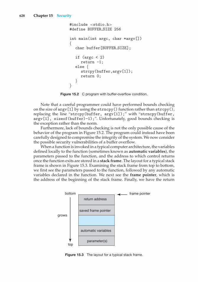
628 Chapter 15 Security
#include <stdio.h>#define BUFFER SIZE 256
int main(int argc, char *argv[]){
char buffer[BUFFER SIZE];
if (argc < 2)return -1;
else {strcpy(buffer,argv[1]);return 0;
}}
Figure 15.2 C program with buffer-overflow condition.
Note that a careful programmer could have performed bounds checkingon the size of argv[1] by using the strncpy() function rather than strcpy(),replacing the line “strcpy(buffer, argv[1]);” with “strncpy(buffer,argv[1], sizeof(buffer)-1);”. Unfortunately, good bounds checking isthe exception rather than the norm.
Furthermore, lack of bounds checking is not the only possible cause of thebehavior of the program in Figure 15.2. The program could instead have beencarefully designed to compromise the integrity of the system. We now considerthe possible security vulnerabilities of a buffer overflow.
When a function is invoked in a typical computer architecture, the variablesdefined locally to the function (sometimes known as automatic variables), theparameters passed to the function, and the address to which control returnsonce the function exits are stored in a stack frame. The layout for a typical stackframe is shown in Figure 15.3. Examining the stack frame from top to bottom,we first see the parameters passed to the function, followed by any automaticvariables declared in the function. We next see the frame pointer, which isthe address of the beginning of the stack frame. Finally, we have the return
parameter(s)
bottom
grows
top
automatic variables
saved frame pointer
frame pointer
return address
Figure 15.3 The layout for a typical stack frame.
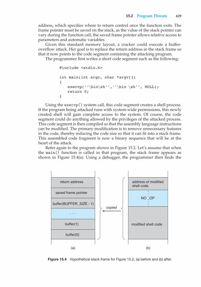
15.2 Program Threats 629
address, which specifies where to return control once the function exits. Theframe pointer must be saved on the stack, as the value of the stack pointer canvary during the function call; the saved frame pointer allows relative access toparameters and automatic variables.
Given this standard memory layout, a cracker could execute a buffer-overflow attack. Her goal is to replace the return address in the stack frame sothat it now points to the code segment containing the attacking program.
The programmer first writes a short code segment such as the following:
#include <stdio.h>
int main(int argc, char *argv[]){
execvp(‘‘\bin\sh’’,‘‘\bin \sh’’, NULL);return 0;
}
Using the execvp() system call, this code segment creates a shell process.If the program being attacked runs with system-wide permissions, this newlycreated shell will gain complete access to the system. Of course, the codesegment could do anything allowed by the privileges of the attacked process.This code segment is then compiled so that the assembly language instructionscan be modified. The primary modification is to remove unnecessary featuresin the code, thereby reducing the code size so that it can fit into a stack frame.This assembled code fragment is now a binary sequence that will be at theheart of the attack.
Refer again to the program shown in Figure 15.2. Let’s assume that whenthe main() function is called in that program, the stack frame appears asshown in Figure 15.4(a). Using a debugger, the programmer then finds the
buffer(0)
buffer(1)
buffer(BUFFER_SIZE - 1)
saved frame pointer
copied
return address
modified shell code
NO _OP
address of modified shell code
• ••
• ••
• ••
(a) (b)
Figure 15.4 Hypothetical stack frame for Figure 15.2, (a) before and (b) after.
630 Chapter 15 Security
address of buffer[0] in the stack. That address is the location of the code theattacker wants executed. The binary sequence is appended with the necessaryamount of NO-OP instructions (for NO-OPeration) to fill the stack frame upto the location of the return address; and the location of buffer[0], the newreturn address, is added. The attack is complete when the attacker gives thisconstructed binary sequence as input to the process. The process then copiesthe binary sequence from argv[1] to position buffer[0] in the stack frame.Now, when control returns from main(), instead of returning to the locationspecified by the old value of the return address, we return to the modified shellcode, which runs with the access rights of the attacked process! Figure 15.4(b)contains the modified shell code.
There are many ways to exploit potential buffer-overflow problems. Inthis example, we considered the possibility that the program being attacked—the code shown in Figure 15.2—ran with system-wide permissions. However,the code segment that runs once the value of the return address has beenmodified might perform any type of malicious act, such as deleting files,opening network ports for further exploitation, and so on.
This example buffer-overflow attack reveals that considerable knowledgeand programming skill are needed to recognize exploitable code and thento exploit it. Unfortunately, it does not take great programmers to launchsecurity attacks. Rather, one cracker can determine the bug and then write anexploit. Anyone with rudimentary computer skills and access to the exploit—a so-called script kiddie—can then try to launch the attack at target systems.
The buffer-overflow attack is especially pernicious because it can be runbetween systems and can travel over allowed communication channels. Suchattacks can occur within protocols that are expected to be used to communicatewith the target machine, and they can therefore be hard to detect and prevent.They can even bypass the security added by firewalls (Section 15.7).
One solution to this problem is for the CPU to have a feature that disallowsexecution of code in a stack section of memory. Recent versions of Sun’s SPARCchip include this setting, and recent versions of Solaris enable it. The returnaddress of the overflowed routine can still be modified; but when the returnaddress is within the stack and the code there attempts to execute, an exceptionis generated, and the program is halted with an error.
Recent versions of AMD and Intel x86 chips include the NX feature to preventthis type of attack. The use of the feature is supported in several x86 operatingsystems, including Linux and Windows XP SP2. The hardware implementationinvolves the use of a new bit in the page tables of the CPUs. This bit marksthe associated page as nonexecutable, so that instructions cannot be read fromit and executed. As this feature becomes prevalent, buffer-overflow attacksshould greatly diminish.
15.2.5 Viruses
Another form of program threat is a virus. A virus is a fragment of code embed-ded in a legitimate program. Viruses are self-replicating and are designed to“infect” other programs. They can wreak havoc in a system by modifying ordestroying files and causing system crashes and program malfunctions. Aswith most penetration attacks, viruses are very specific to architectures, oper-ating systems, and applications. Viruses are a particular problem for users of
15.2 Program Threats 631
PCs. UNIX and other multiuser operating systems generally are not susceptibleto viruses because the executable programs are protected from writing by theoperating system. Even if a virus does infect such a program, its powers usuallyare limited because other aspects of the system are protected.
Viruses are usually borne via e-mail, with spam the most common vector.They can also spread when users download viral programs from Internetfile-sharing services or exchange infected disks.
Another common form of virus transmission uses Microsoft Office files,such as Microsoft Word documents. These documents can contain macros (orVisual Basic programs) that programs in the Office suite (Word, PowerPoint,and Excel) will execute automatically. Because these programs run under theuser’s own account, the macros can run largely unconstrained (for example,deleting user files at will). Commonly, the virus will also e-mail itself to othersin the user’s contact list. Here is a code sample that shows the simplicity ofwriting a Visual Basic macro that a virus could use to format the hard drive ofa Windows computer as soon as the file containing the macro was opened:
Sub AutoOpen()Dim oFS
Set oFS = CreateObject(’’Scripting.FileSystemObject’’)vs = Shell(’’c: command.com /k format c:’’,vbHide)
End Sub
How do viruses work? Once a virus reaches a target machine, a programknown as a virus dropper inserts the virus into the system. The virus dropperis usually a Trojan horse, executed for other reasons but installing the virusas its core activity. Once installed, the virus may do any one of a number ofthings. There are literally thousands of viruses, but they fall into several maincategories. Note that many viruses belong to more than one category.
• File. A standard file virus infects a system by appending itself to a file.It changes the start of the program so that execution jumps to its code.After it executes, it returns control to the program so that its execution isnot noticed. File viruses are sometimes known as parasitic viruses, as theyleave no full files behind and leave the host program still functional.
• Boot. A boot virus infects the boot sector of the system, executing everytime the system is booted and before the operating system is loaded. Itwatches for other bootable media (that is, floppy disks) and infects them.These viruses are also known as memory viruses, because they do notappear in the file system. Figure 15.5 shows how a boot virus works.
• Macro. Most viruses are written in a low-level language, such as assemblyor C. Macro viruses are written in a high-level language, such as VisualBasic. These viruses are triggered when a program capable of executingthe macro is run. For example, a macro virus could be contained in aspreadsheet file.
• Source code. A source code virus looks for source code and modifies it toinclude the virus and to help spread the virus.
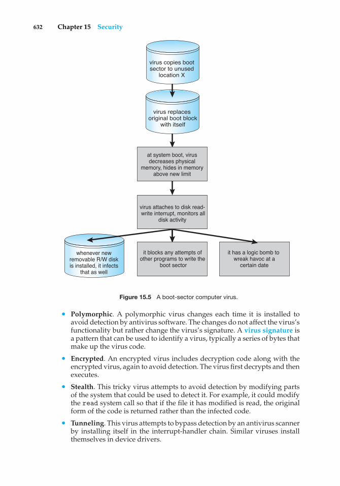
632 Chapter 15 Security
whenever new removable R/W disk is installed, it infects
that as well
it has a logic bomb to wreak havoc at a
certain date
virus replaces original boot block
with itself
at system boot, virus decreases physical
memory, hides in memory above new limit
virus attaches to disk read- write interrupt, monitors all
disk activity
it blocks any attempts of other programs to write the
boot sector
virus copies boot sector to unused
location X
Figure 15.5 A boot-sector computer virus.
• Polymorphic. A polymorphic virus changes each time it is installed toavoid detection by antivirus software. The changes do not affect the virus’sfunctionality but rather change the virus’s signature. A virus signature isa pattern that can be used to identify a virus, typically a series of bytes thatmake up the virus code.
• Encrypted. An encrypted virus includes decryption code along with theencrypted virus, again to avoid detection. The virus first decrypts and thenexecutes.
• Stealth. This tricky virus attempts to avoid detection by modifying partsof the system that could be used to detect it. For example, it could modifythe read system call so that if the file it has modified is read, the originalform of the code is returned rather than the infected code.
• Tunneling. This virus attempts to bypass detection by an antivirus scannerby installing itself in the interrupt-handler chain. Similar viruses installthemselves in device drivers.
15.3 System and Network Threats 633
• Multipartite. A virus of this type is able to infect multiple parts of a system,including boot sectors, memory, and files. This makes it difficult to detectand contain.
• Armored. An armored virus is coded to make it hard for antivirusresearchers to unravel and understand. It can also be compressed to avoiddetection and disinfection. In addition, virus droppers and other full filesthat are part of a virus infestation are frequently hidden via file attributesor unviewable file names.
This vast variety of viruses is likely to continue to grow. In fact, in 2004a new and widespread virus was detected. It exploited three separate bugsfor its operation. This virus started by infecting hundreds of Windows servers(including many trusted sites) running Microsoft Internet Information Server(IIS). Any vulnerable Microsoft Explorer Web browser visiting those sitesreceived a browser virus with any download. The browser virus installedseveral back-door programs, including a keystroke logger, which recordsall things entered on the keyboard (including passwords and credit-cardnumbers). It also installed a daemon to allow unlimited remote access byan intruder and another that allowed an intruder to route spam through theinfected desktop computer.
Generally, viruses are the most disruptive security attacks; and becausethey are effective, they will continue to be written and to spread. Among theactive debates within the computing community is whether a monoculture,in which many systems run the same hardware, operating system, and/orapplication software, is increasing the threat of and damage caused by securityintrusions. This monoculture supposedly consists of Microsoft products, andpart of the debate concerns whether such a monoculture even exists today.
15.3 System and Network Threats
Program threats typically use a breakdown in the protection mechanisms of asystem to attack programs. In contrast, system and network threats involve theabuse of services and network connections. System and network threats createa situation in which operating-system resources and user files are misused.Sometimes a system and network attack is used to launch a program attack,and vice versa.
The more open an operating system is—the more services it has enabledand the more functions it allows—the more likely it is that a bug is availableto exploit. Increasingly, operating systems strive to be secure by default.For example, Solaris 10 moved from a model in which many services (FTP,telnet, and others) were enabled by default when the system was installedto a model in which almost all services are disabled at installation time andmust specifically be enabled by system administrators. Such changes reducethe system’s attack surface—the set of ways in which an attacker can try tobreak into the system.
In the remainder of this section, we discuss some examples of systemand network threats, including worms, port scanning, and denial-of-serviceattacks. It is important to note that masquerading and replay attacks are also
634 Chapter 15 Security
commonly launched over networks between systems. In fact, these attacksare more effective and harder to counter when multiple systems are involved.For example, within a computer, the operating system usually can determinethe sender and receiver of a message. Even if the sender changes to the ID ofsomeone else, there may be a record of that ID change. When multiple systemsare involved, especially systems controlled by attackers, then such tracing ismuch more difficult.
In general, we can say that sharing secrets (to prove identity and as keys toencryption) is required for authentication and encryption, and sharing secretsis easier in environments (such as a single operating system) in which securesharing methods exist. These methods include shared memory and interpro-cess communications. Creating secure communication and authentication isdiscussed in Sections 15.4 and 15.5.
15.3.1 Worms
A worm is a process that uses the spawn mechanism to ravage systemperformance. The worm spawns copies of itself, using up system resourcesand perhaps locking out all other processes. On computer networks, wormsare particularly potent, since they may reproduce themselves among systemsand thus shut down an entire network. Such an event occurred in 1988 to UNIXsystems on the Internet, causing the loss of system and system-administratortime worth millions of dollars.
At the close of the workday on November 2, 1988, Robert Tappan Morris,Jr., a first-year Cornell graduate student, unleashed a worm program on oneor more hosts connected to the Internet. Targeting Sun Microsystems’ Sun 3workstations and VAX computers running variants of Version 4 BSD UNIX, theworm quickly spread over great distances; within a few hours of its release,it had consumed system resources to the point of bringing down the infectedmachines.
Although Robert Morris designed the self-replicating program for rapidreproduction and distribution, some of the features of the UNIX networkingenvironment provided the means to propagate the worm throughout the sys-tem. It is likely that Morris chose for initial infection an Internet host left openfor and accessible to outside users. From there, the worm program exploitedflaws in the UNIX operating system’s security routines and took advantageof UNIX utilities that simplify resource sharing in local-area networks to gainunauthorized access to thousands of other connected sites. Morris’s methodsof attack are outlined next.
The worm was made up of two programs, a grappling hook (also called abootstrap or vector) program and the main program. Named l1.c, the grapplinghook consisted of 99 lines of C code compiled and run on each machine itaccessed. Once established on the computer system under attack, the grapplinghook connected to the machine where it originated and uploaded a copy of themain worm onto the hooked system (Figure 15.6). The main program proceededto search for other machines to which the newly infected system could connecteasily. In these actions, Morris exploited the UNIX networking utility rsh foreasy remote task execution. By setting up special files that list host–loginname pairs, users can omit entering a password each time they access a remoteaccount on the paired list. The worm searched these special files for site names
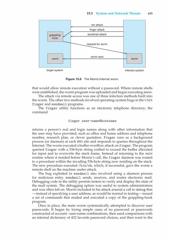
15.3 System and Network Threats 635
grappling hook
worm
target system
worm
infected system
rsh attack
finger attack
sendmail attack
request for worm
worm sent
Figure 15.6 The Morris Internet worm.
that would allow remote execution without a password. Where remote shellswere established, the worm program was uploaded and began executing anew.
The attack via remote access was one of three infection methods built intothe worm. The other two methods involved operating-system bugs in the UNIXfinger and sendmail programs.
The finger utility functions as an electronic telephone directory; thecommand
finger user-name@hostname
returns a person’s real and login names along with other information thatthe user may have provided, such as office and home address and telephonenumber, research plan, or clever quotation. Finger runs as a backgroundprocess (or daemon) at each BSD site and responds to queries throughout theInternet. The worm executed a buffer-overflow attack on finger. The programqueried finger with a 536-byte string crafted to exceed the buffer allocatedfor input and to overwrite the stack frame. Instead of returning to the mainroutine where it resided before Morris’s call, the finger daemon was routedto a procedure within the invading 536-byte string now residing on the stack.The new procedure executed /bin/sh, which, if successful, gave the worm aremote shell on the machine under attack.
The bug exploited in sendmail also involved using a daemon processfor malicious entry. sendmail sends, receives, and routes electronic mail.Debugging code in the utility permits testers to verify and display the state ofthe mail system. The debugging option was useful to system administratorsand was often left on. Morris included in his attack arsenal a call to debug that—instead of specifying a user address, as would be normal in testing—issueda set of commands that mailed and executed a copy of the grappling-hookprogram.
Once in place, the main worm systematically attempted to discover userpasswords. It began by trying simple cases of no password or passwordsconstructed of account–user-name combinations, then used comparisons withan internal dictionary of 432 favorite password choices, and then went to the
636 Chapter 15 Security
final stage of trying each word in the standard UNIX on-line dictionary as apossible password. This elaborate and efficient three-stage password-crackingalgorithm enabled the worm to gain access to other user accounts on theinfected system. The worm then searched for rsh data files in these newlybroken accounts and used them as described previously to gain access to useraccounts on remote systems.
With each new access, the worm program searched for already activecopies of itself. If it found one, the new copy exited, except in every seventhinstance. Had the worm exited on all duplicate sightings, it might haveremained undetected. Allowing every seventh duplicate to proceed (possiblyto confound efforts to stop its spread by baiting with fake worms) created awholesale infestation of Sun and VAX systems on the Internet.
The very features of the UNIX network environment that assisted in theworm’s propagation also helped to stop its advance. Ease of electronic commu-nication, mechanisms to copy source and binary files to remote machines, andaccess to both source code and human expertise allowed cooperative efforts todevelop solutions quickly. By the evening of the next day, November 3, methodsof halting the invading program were circulated to system administrators viathe Internet. Within days, specific software patches for the exploited securityflaws were available.
Why did Morris unleash the worm? The action has been characterizedas both a harmless prank gone awry and a serious criminal offense. Basedon the complexity of the attack, it is unlikely that the worm’s release or thescope of its spread was unintentional. The worm program took elaborate stepsto cover its tracks and to repel efforts to stop its spread. Yet the programcontained no code aimed at damaging or destroying the systems on which itran. The author clearly had the expertise to include such commands; in fact,data structures were present in the bootstrap code that could have been used totransfer Trojan-horse or virus programs. The behavior of the program may leadto interesting observations, but it does not provide a sound basis for inferringmotive. What is not open to speculation, however, is the legal outcome: Afederal court convicted Morris and handed down a sentence of three years’probation, 400 hours of community service, and a $10,000 fine. Morris’s legalcosts probably exceeded $100,000.
Security experts continue to evaluate methods to decrease or eliminateworms. A more recent event, though, shows that worms are still a fact oflife on the Internet. It also shows that as the Internet grows, the damagethat even “harmless” worms can do also grows and can be significant. Thisexample occurred during August 2003. The fifth version of the “Sobig” worm,more properly known as “W32.Sobig.F@mm,” was released by persons at thistime unknown. It was the fastest-spreading worm released to date, at its peakinfecting hundreds of thousands of computers and one in seventeen e-mailmessages on the Internet. It clogged e-mail inboxes, slowed networks, andtook a huge number of hours to clean up.
Sobig.F was launched by being uploaded to a pornography newsgroup viaan account created with a stolen credit card. It was disguised as a photo. Thevirus targeted Microsoft Windows systems and used its own SMTP engine toe-mail itself to all the addresses found on an infected system. It used a varietyof subject lines to help avoid detection, including “Thank You!” “Your details,”and “Re: Approved.” It also used a random address on the host as the “From:”
15.3 System and Network Threats 637
address, making it difficult to determine from the message which machine wasthe infected source. Sobig.F included an attachment for the target e-mail readerto click on, again with a variety of names. If this payload was executed, it storeda program called WINPPR32.EXE in the default Windows directory, along witha text file. It also modified the Windows registry.
The code included in the attachment was also programmed to periodicallyattempt to connect to one of twenty servers and download and execute aprogram from them. Fortunately, the servers were disabled before the codecould be downloaded. The content of the program from these servers has notyet been determined. If the code was malevolent, untold damage to a vastnumber of machines could have resulted.
15.3.2 Port Scanning
Port scanning is not an attack but rather a means for a cracker to detecta system’s vulnerabilities to attack. Port scanning typically is automated,involving a tool that attempts to create a TCP/IP connection to a specific portor a range of ports. For example, suppose there is a known vulnerability (orbug) in sendmail. A cracker could launch a port scanner to try to connect, say,to port 25 of a particular system or to a range of systems. If the connectionwas successful, the cracker (or tool) could attempt to communicate with theanswering service to determine if the service was indeed sendmail and, if so,if it was the version with the bug.
Now imagine a tool in which each bug of every service of every operatingsystem was encoded. The tool could attempt to connect to every port of oneor more systems. For every service that answered, it could try to use eachknown bug. Frequently, the bugs are buffer overflows, allowing the creation ofa privileged command shell on the system. From there, of course, the crackercould install Trojan horses, back-door programs, and so on.
There is no such tool, but there are tools that perform subsets of thatfunctionality. For example, nmap (from http://www.insecure.org/nmap/) isa very versatile open-source utility for network exploration and securityauditing. When pointed at a target, it will determine what services are running,including application names and versions. It can identify the host operatingsystem. It can also provide information about defenses, such as what firewallsare defending the target. It does not exploit any known bugs.
Nessus (from http://www.nessus.org/) performs a similar function, butit has a database of bugs and their exploits. It can scan a range of systems,determine the services running on those systems, and attempt to attack allappropriate bugs. It generates reports about the results. It does not performthe final step of exploiting the found bugs, but a knowledgeable cracker or ascript kiddie could.
Because port scans are detectable (Section 15.6.3), they frequently arelaunched from zombie systems. Such systems are previously compromised,independent systems that are serving their owners while being used for nefar-ious purposes, including denial-of-service attacks and spam relay. Zombiesmake crackers particularly difficult to prosecute because determining thesource of the attack and the person that launched it is challenging. This isone of many reasons for securing “inconsequential” systems, not just systemscontaining “valuable” information or services.
638 Chapter 15 Security
15.3.3 Denial of Service
As mentioned earlier, denial-of-service attacks are aimed not at gaininginformation or stealing resources but rather at disrupting legitimate use ofa system or facility. Most such attacks involve systems that the attacker hasnot penetrated. Indeed, launching an attack that prevents legitimate use isfrequently easier than breaking into a machine or facility.
Denial-of-service attacks are generally network based. They fall into twocategories. Attacks in the first category use so many facility resources that,in essence, no useful work can be done. For example, a Web-site click coulddownload a Java applet that proceeds to use all available CPU time or to pop upwindows infinitely. The second category involves disrupting the network ofthe facility. There have been several successful denial-of-service attacks of thiskind against major Web sites. These attacks result from abuse of some of thefundamental functionality of TCP/IP. For instance, if the attacker sends the partof the protocol that says “I want to start a TCP connection,” but never followswith the standard “The connection is now complete,” the result can be partiallystarted TCP sessions. If enough of these sessions are launched, they can eat upall the network resources of the system, disabling any further legitimate TCPconnections. Such attacks, which can last hours or days, have caused partial orfull failure of attempts to use the target facility. The attacks are usually stoppedat the network level until the operating systems can be updated to reduce theirvulnerability.
Generally, it is impossible to prevent denial-of-service attacks. The attacksuse the same mechanisms as normal operation. Even more difficult to preventand resolve are distributed denial-of-service attacks (DDOS). These attacksare launched from multiple sites at once, toward a common target, typicallyby zombies. DDOS attacks have become more common and are sometimesassociated with blackmail attempts. A site comes under attack, and theattackers offer to halt the attack in exchange for money.
Sometimes a site does not even know it is under attack. It can be difficultto determine whether a system slowdown is an attack or just a surge in systemuse. Consider that a successful advertising campaign that greatly increasestraffic to a site could be considered a DDOS.
There are other interesting aspects of DOS attacks. For example, if anauthentication algorithm locks an account for a period of time after severalincorrect attempts to access the account, then an attacker could cause allauthentication to be blocked by purposely making incorrect attempts to accessall accounts. Similarly, a firewall that automatically blocks certain kinds oftraffic could be induced to block that traffic when it should not. These examplessuggest that programmers and systems managers need to fully understand thealgorithms and technologies they are deploying. Finally, computer scienceclasses are notorious sources of accidental system DOS attacks. Consider thefirst programming exercises in which students learn to create subprocessesor threads. A common bug involves spawning subprocesses infinitely. Thesystem’s free memory and CPU resources don’t stand a chance.
15.4 Cryptography as a Security Tool
There are many defenses against computer attacks, running the gamut frommethodology to technology. The broadest tool available to system designers
15.4 Cryptography as a Security Tool 639
and users is cryptography. In this section, we discuss the details of cryptogra-phy and its use in computer security.
In an isolated computer, the operating system can reliably determine thesender and recipient of all interprocess communication, since it controls allcommunication channels in the computer. In a network of computers, thesituation is quite different. A networked computer receives bits from thewire with no immediate and reliable way of determining what machine orapplication sent those bits. Similarly, the computer sends bits onto the networkwith no way of knowing who might eventually receive them.
Commonly, network addresses are used to infer the potential sendersand receivers of network messages. Network packets arrive with a sourceaddress, such as an IP address. And when a computer sends a message, itnames the intended receiver by specifying a destination address. However, forapplications where security matters, we are asking for trouble if we assumethat the source or destination address of a packet reliably determines who sentor received that packet. A rogue computer can send a message with a falsifiedsource address, and numerous computers other than the one specified by thedestination address can (and typically do) receive a packet. For example, all ofthe routers on the way to the destination will receive the packet, too. How, then,is an operating system to decide whether to grant a request when it cannot trustthe named source of the request? And how is it supposed to provide protectionfor a request or data when it cannot determine who will receive the responseor message contents it sends over the network?
It is generally considered infeasible to build a network of any scale inwhich the source and destination addresses of packets can be trusted in thissense. Therefore, the only alternative is somehow to eliminate the need totrust the network. This is the job of cryptography. Abstractly, cryptography isused to constrain the potential senders and/or receivers of a message. Moderncryptography is based on secrets called keys that are selectively distributed tocomputers in a network and used to process messages. Cryptography enables arecipient of a message to verify that the message was created by some computerpossessing a certain key—the key is the source of the message. Similarly, asender can encode its message so that only a computer with a certain key candecode the message, so that the key becomes the destination. Unlike networkaddresses, however, keys are designed so that it is not computationally feasibleto derive them from the messages they were used to generate or from anyother public information. Thus, they provide a much more trustworthy meansof constraining senders and receivers of messages. Note that cryptography isa field of study unto itself, with large and small complexities and subtleties.Here, we explore the most important aspects of the parts of cryptography thatpertain to operating systems.
15.4.1 Encryption
Because it solves a wide variety of communication security problems, encryp-tion is used frequently in many aspects of modern computing. Encryption isa means for constraining the possible receivers of a message. An encryptionalgorithm enables the sender of a message to ensure that only a computerpossessing a certain key can read the message. Encryption of messages is anancient practice, of course, and there have been many encryption algorithms,
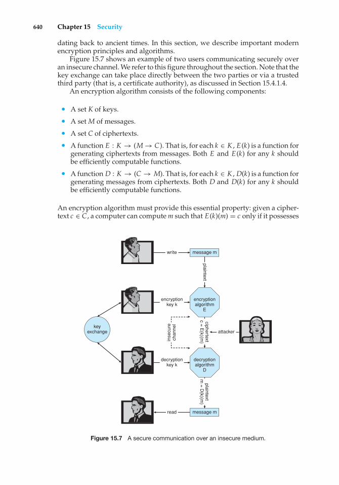
640 Chapter 15 Security
dating back to ancient times. In this section, we describe important modernencryption principles and algorithms.
Figure 15.7 shows an example of two users communicating securely overan insecure channel. We refer to this figure throughout the section. Note that thekey exchange can take place directly between the two parties or via a trustedthird party (that is, a certificate authority), as discussed in Section 15.4.1.4.
An encryption algorithm consists of the following components:
• A set K of keys.
• A set M of messages.
• A set C of ciphertexts.
• A function E : K → (M → C). That is, for each k ∈ K , E(k) is a function forgenerating ciphertexts from messages. Both E and E(k) for any k shouldbe efficiently computable functions.
• A function D : K → (C → M). That is, for each k ∈ K , D(k) is a function forgenerating messages from ciphertexts. Both D and D(k) for any k shouldbe efficiently computable functions.
An encryption algorithm must provide this essential property: given a cipher-text c ∈ C , a computer can compute m such that E(k)(m) = c only if it possesses
keyexchange
message m
message m
encryptionalgorithm
E
decryptionalgorithm
D
write
encryptionkey k
decryptionkey k
read
inse
cure
chan
nel
plaintextciphertext
c = E
(k)(m)
plaintextm
= D
(k)(m)
attacker
Figure 15.7 A secure communication over an insecure medium.
15.4 Cryptography as a Security Tool 641
D(k). Thus, a computer holding D(k) can decrypt ciphertexts to the plaintextsused to produce them, but a computer not holding D(k) cannot decrypt cipher-texts. Since ciphertexts are generally exposed (for example, sent on a network),it is important that it be infeasible to derive D(k) from the ciphertexts.
There are two main types of encryption algorithms: symmetric andasymmetric. We discuss both types in the following sections.
15.4.1.1 Symmetric Encryption
In a symmetric encryption algorithm, the same key is used to encrypt and todecrypt. That is, E(k) can be derived from D(k), and vice versa. Therefore, thesecrecy of E(k) must be protected to the same extent as that of D(k).
For the past several decades, the most commonly used symmetric encryp-tion algorithm in the United States for civilian applications has been thedata-encryption standard (DES) adopted by the National Institute of Stan-dards and Technology (NIST). DES works by taking a 64-bit value and a 56-bitkey and performing a series of transformations. These transformations arebased on substitution and permutation operations, as is generally the casefor symmetric encryption transformations. Some of the transformations areblack-box transformations, in that their algorithms are hidden. In fact, theseso-called “S-boxes” are classified by the United States government. Messageslonger than 64 bits are broken into 64-bit chunks. Because DES works on achunk of bits at a time, is known as a block cipher. If the same key is usedfor encrypting an extended amount of data, it becomes vulnerable to attack.Consider, for example, that the same source block would result in the sameciphertext if the same key and encryption algorithm were used. Therefore,the chunks are not just encrypted but also exclusive-or’ed (XORed) with theprevious ciphertext block before encryption. This is known as cipher-blockchaining.
DES is now considered insecure for many applications because its keys canbe exhaustively searched with moderate computing resources. Rather thangiving up on DES, though, NIST created a modification called triple DES, inwhich the DES algorithm is repeated three times (two encryptions and onedecryption) on the same plaintext using two or three keys—for example,c = E(k3)(D(k2)(E(K1)(m))). When three keys are used, the effective key lengthis 168 bits. Triple DES is in widespread use today.
In 2001, NIST adopted a new encryption algorithm, called the advancedencryption standard (AES), to replace DES. AES is another symmetric blockcipher. It can use key lengths of 128, 192, and 256 bits and works on 128-bitblocks. It works by performing 10 to 14 rounds of transformations on a matrixformed from a block. Generally, the algorithm is compact and efficient.
Several other symmetric block encryption algorithms in use today bearmentioning. The twofish algorithm is fast, compact, and easy to implement. Itcan use a variable key length of up to 256 bits and works on 128-bit blocks. RC5can vary in key length, number of transformations, and block size. Because ituses only basic computational operations, it can run on a wide variety of CPUs.
RC4 is perhaps the most common stream cipher. A stream cipher isdesigned to encrypt and decrypt a stream of bytes or bits rather than a block.This is useful when the length of a communication would make a block ciphertoo slow. The key is input into a pseudo–random-bit generator, which is an
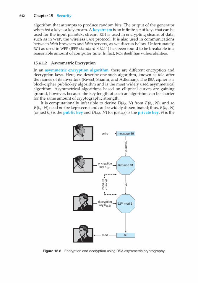
642 Chapter 15 Security
algorithm that attempts to produce random bits. The output of the generatorwhen fed a key is a keystream. A keystream is an infinite set of keys that can beused for the input plaintext stream. RC4 is used in encrypting steams of data,such as in WEP, the wireless LAN protocol. It is also used in communicationsbetween Web browsers and Web servers, as we discuss below. Unfortunately,RC4 as used in WEP (IEEE standard 802.11) has been found to be breakable in areasonable amount of computer time. In fact, RC4 itself has vulnerabilities.
15.4.1.2 Asymmetric Encryption
In an asymmetric encryption algorithm, there are different encryption anddecryption keys. Here, we describe one such algorithm, known as RSA afterthe names of its inventors (Rivest, Shamir, and Adleman). The RSA cipher is ablock-cipher public-key algorithm and is the most widely used asymmetricalalgorithm. Asymmetrical algorithms based on elliptical curves are gainingground, however, because the key length of such an algorithm can be shorterfor the same amount of cryptographic strength.
It is computationally infeasible to derive D(kd, N) from E(ke , N), and soE(ke, N) need not be kept secret and can be widely disseminated; thus, E(ke, N)(or just ke ) is the public key and D(kd , N) (or just kd ) is the private key. N is the
message 69
69
695 mod 91
6229 mod 91
write
encryptionkey k5,91
decryptionkey k29,91
read
inse
cure
chan
nel
plaintext62
Figure 15.8 Encryption and decryption using RSA asymmetric cryptography.
15.4 Cryptography as a Security Tool 643
product of two large, randomly chosen prime numbers p and q (for example, pand q are 512 bits each). The encryption algorithm is E(ke, N)(m) = mke mod N,where ke satisfies kekd mod (p −1)(q −1) = 1. The decryption algorithm is thenD(kd , N)(c) = ckd mod N.
An example using small values is shown in Figure 15.8. In this example, wemake p = 7 and q = 13. We then calculate N = 7∗13 = 91 and (p−1)(q−1) = 72.We next select ke relatively prime to 72 and < 72, yielding 5. Finally, we calculatekd such that kekd mod 72 = 1, yielding 29. We now have our keys: the publickey, ke , N = 5, 91, and the private key, kd, N = 29, 91. Encrypting the message69 with the public key results in the message 62, which is then decoded by thereceiver via the private key.
The use of asymmetric encryption begins with the publication of the publickey of the destination. For bidirectional communication, the source also mustpublish its public key. “Publication” can be as simple as handing over anelectronic copy of the key, or it can be more complex. The private key (or “secretkey”) must be jealously guarded, as anyone holding that key can decrypt anymessage created by the matching public key.
We should note that the seemingly small difference in key use betweenasymmetric and symmetric cryptography is quite large in practice. Asymmetriccryptography is based on mathematical functions rather than transformations,making it much more computationally expensive to execute. It is muchfaster for a computer to encode and decode ciphertext by using the usualsymmetric algorithms than by using asymmetric algorithms. Why, then, usean asymmetric algorithm? In truth, these algorithms are not used for general-purpose encryption of large amounts of data. However, they are used notonly for encryption of small amounts of data but also for authentication,confidentiality, and key distribution, as we show in the following sections.
15.4.1.3 Authentication
We have seen that encryption offers a way of constraining the set of possiblereceivers of a message. Constraining the set of potential senders of a message iscalled authentication. Authentication is thus complementary to encryption. Infact, sometimes their functions overlap. Consider that an encrypted messagecan also prove the identity of the sender. For example, if D(kd , N)(E(ke, N)(m))produces a valid message, then we know that the creator of the message musthold ke . Authentication is also useful for proving that a message has not beenmodified. In this section, we discuss authentication as a constraint on possiblereceivers of a message. Note that this sort of authentication is similar to butdistinct from user authentication, which we discuss in Section 15.5.
An authentication algorithm consists of the following components:
• A set K of keys.
• A set M of messages.
• A set A of authenticators.
• A function S : K → (M → A). That is, for each k ∈ K , S(k) is a function forgenerating authenticators from messages. Both S and S(k) for any k shouldbe efficiently computable functions.
644 Chapter 15 Security
• A function V : K → (M × A → {true, false}). That is, for each k ∈ K ,V(k) is a function for verifying authenticators on messages. Both V andV(k) for any k should be efficiently computable functions.
The critical property that an authentication algorithm must possess is this: for amessage m, a computer can generate an authenticator a ∈ Asuch that V(k)(m, a )= true only if it possesses S(k). Thus, a computer holding S(k) can generateauthenticators on messages so that any computer possessing V(k) can verifythem. However, a computer not holding S(k) cannot generate authenticatorson messages that can be verified using V(k). Since authenticators are generallyexposed (for example, sent on a network with the messages themselves), itmust not be feasible to derive S(k) from the authenticators.
Just as there are two types of encryption algorithms, there are two mainvarieties of authentication algorithms. The first step in understanding thesealgorithms is to explore hash functions. A hash function H(m) creates a small,fixed-sized block of data, known as a message digest or hash value, froma message m. Hash functions work by taking a message in n-bit blocks andprocessing the blocks to produce an n-bit hash. H must be collision resistanton m—that is, it must be infeasible to find an m′ �= m such that H(m) = H(m′).Now, if H(m) = H(m′), we know that m = m′ —that is, we know that themessage has not been modified. Common message-digest functions includeMD5, which produces a 128-bit hash, and SHA-1, which outputs a 160-bit hash.Message digests are useful for detecting changed messages but are not useful asauthenticators. For example, H(m) can be sent along with a message; but if H isknown, then someone could modify m and recompute H(m), and the messagemodification would not be detected. Therefore, an authentication algorithmtakes the message digest and encrypts it.
The first main type of authentication algorithm uses symmetric encryption.In a message-authentication code (MAC), a cryptographic checksum is gener-ated from the message using a secret key. Knowledge of V(k) and knowledgeof S(k) are equivalent: one can be derived from the other, so k must be keptsecret. A simple example of a MAC defines S(k)(m) = f (k, H(m)), where f isa function that is one-way on its first argument (that is, k cannot be derivedfrom f (k, H(m))). Because of the collision resistance in the hash function, weare reasonably assured that no other message could create the same MAC. Asuitable verification algorithm is then V(k)(m, a ) ≡ ( f (k, m) = a ). Note that kis needed to compute both S(k) and V(k), so anyone able to compute one cancompute the other.
The second main type of authentication algorithm is a digital-signaturealgorithm, and the authenticators thus produced are called digital signatures.In a digital-signature algorithm, it is computationally infeasible to derive S(ks)from V(kv); in particular, V is a one-way function. Thus, kv is the public keyand ks is the private key.
Consider as an example the RSA digital-signature algorithm. It is similarto the RSA encryption algorithm, but the key use is reversed. The digitalsignature of a message is derived by computing S(ks)(m) = H(m)ks mod N.The key ks again is a pair 〈d, N〉, where N is the product of two large, randomlychosen prime numbers p and q . The verification algorithm is then V(kv)(m, a ) ≡(a kv mod N = H(m)), where kv satisfies kvks mod (p − 1)(q − 1) = 1.
15.4 Cryptography as a Security Tool 645
If encryption can prove the identity of the sender of a message, then why dowe need separate authentication algorithms? There are three primary reasons.
• Authentication algorithms generally require fewer computations (withthe notable exception of RSA digital signatures). Over large amounts ofplaintext, this efficiency can make a huge difference in resource use andthe time needed to authenticate a message.
• The authenticator of a message is almost always shorter than the mes-sage and its ciphertext. This improves space use and transmission timeefficiency.
• Sometimes, we want authentication but not confidentiality. For example,a company could provide a software patch and could “sign” that patch toprove that it came from the company and that it hasn’t been modified.
Authentication is a component of many aspects of security. For example, itis the core of nonrepudiation, which supplies proof that an entity performed anaction. A typical example of nonrepudiation involves the filling out of electronicforms as an alternative to the signing of paper contracts. Nonrepudiationassures that a person filling out an electronic form cannot deny that he didso.
15.4.1.4 Key Distribution
Certainly, a good part of the battle between cryptographers (those inventingciphers) and cryptanalysts (those trying to break them) involves keys. Withsymmetric algorithms, both parties need the key, and no one else shouldhave it. The delivery of the symmetric key is a huge challenge. Sometimesit is performed out-of-band—say, via a paper document or a conversation.These methods do not scale well, however. Also consider the key-managementchallenge. Suppose a user wanted to communicate with N other users privately.That user would need N keys and, for more security, would need to changethose keys frequently.
These are the very reasons for efforts to create asymmetric key algorithms.Not only can the keys be exchanged in public, but a given user needs onlyone private key, no matter how many other people she wants to communicatewith. There is still the matter of managing a public key for each party to becommunicated with, but since public keys need not be secured, simple storagecan be used for that key ring.
Unfortunately, even the distribution of public keys requires some care.Consider the man-in-the-middle attack shown in Figure 15.9. Here, the personwho wants to receive an encrypted message sends out his public key, but anattacker also sends her “bad” public key (which matches her private key). Theperson who wants to send the encrypted message knows no better and so usesthe bad key to encrypt the message. The attacker then happily decrypts it.
The problem is one of authentication—what we need is proof of who (orwhat) owns a public key. One way to solve that problem involves the useof digital certificates. A digital certificate is a public key digitally signed by atrusted party. The trusted party receives proof of identification from some entity
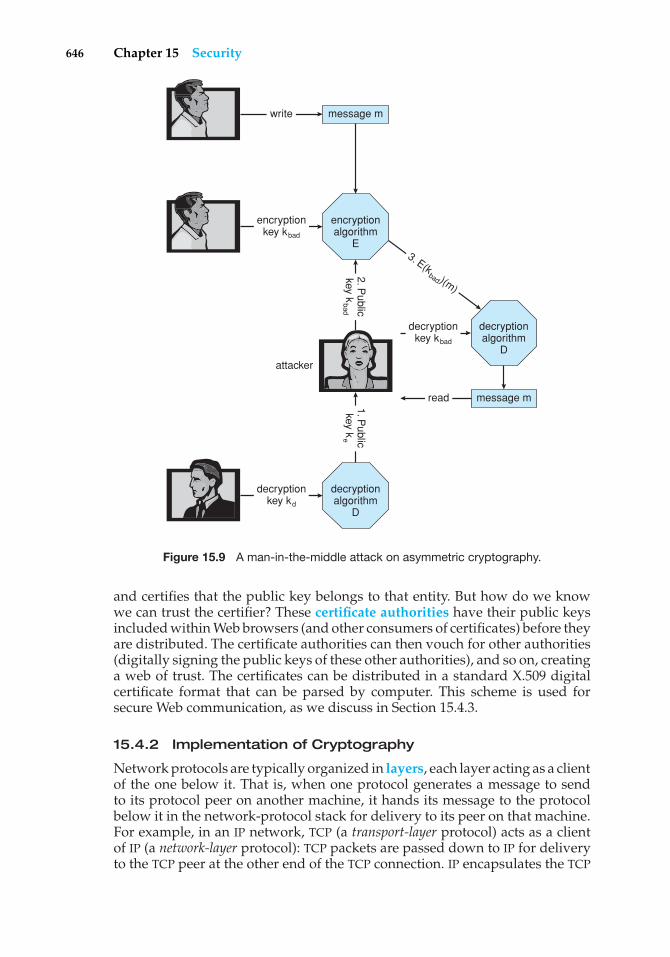
646 Chapter 15 Security
message m
encryptionalgorithm
E
decryptionalgorithm
D
write
3. E(kbad )(m)
message mread
encryptionkey kbad
decryptionkey kd
decryptionalgorithm
D
decryptionkey kbad
2. Public
key kbad
1. Public
key ke
attacker
Figure 15.9 A man-in-the-middle attack on asymmetric cryptography.
and certifies that the public key belongs to that entity. But how do we knowwe can trust the certifier? These certificate authorities have their public keysincluded within Web browsers (and other consumers of certificates) before theyare distributed. The certificate authorities can then vouch for other authorities(digitally signing the public keys of these other authorities), and so on, creatinga web of trust. The certificates can be distributed in a standard X.509 digitalcertificate format that can be parsed by computer. This scheme is used forsecure Web communication, as we discuss in Section 15.4.3.
15.4.2 Implementation of Cryptography
Network protocols are typically organized in layers, each layer acting as a clientof the one below it. That is, when one protocol generates a message to sendto its protocol peer on another machine, it hands its message to the protocolbelow it in the network-protocol stack for delivery to its peer on that machine.For example, in an IP network, TCP (a transport-layer protocol) acts as a clientof IP (a network-layer protocol): TCP packets are passed down to IP for deliveryto the TCP peer at the other end of the TCP connection. IP encapsulates the TCP
15.4 Cryptography as a Security Tool 647
packet in an IP packet, which it similarly passes down to the data-link layer to betransmitted across the network to its IP peer on the destination computer. ThisIP peer then delivers the TCP packet up to the TCP peer on that machine. All inall, the ISO Reference Model, which has been almost universally adopted as amodel for data networking, defines seven such protocol layers. (You will readmore about the ISO model of networking in Chapter 16; Figure 16.6 shows adiagram of the model.)
Cryptography can be inserted at almost any layer in the ISO model. SSL(Section 15.4.3), for example, provides security at the transport layer. Network-layer security generally has been standardized on IPSec, which defines IPpacket formats that allow the insertion of authenticators and the encryptionof packet contents. It uses symmetric encryption and uses the IKE protocolfor key exchange. IPSec is becoming widely used as the basis for virtualprivate networks (VPNs), in which all traffic between two IPSec endpointsis encrypted to make a private network out of one that may otherwise bepublic. Numerous protocols also have been developed for use by applications,but then the applications themselves must be coded to implement security.
Where is cryptographic protection best placed in a protocol stack? Ingeneral, there is no definitive answer. On the one hand, more protocols benefitfrom protections placed lower in the stack. For example, since IP packetsencapsulate TCP packets, encryption of IP packets (using IPSec, for example) alsohides the contents of the encapsulated TCP packets. Similarly, authenticatorson IP packets detect the modification of contained TCP header information.
On the other hand, protection at lower layers in the protocol stack may giveinsufficient protection to higher-layer protocols. For example, an applicationserver that runs over IPSec might be able to authenticate the client computersfrom which requests are received. However, to authenticate a user at a clientcomputer, the server may need to use an application-level protocol—forexample, the user may be required to type a password. Also consider theproblem of e-mail. E-mail delivered via the industry standard SMTP protocol isstored and forwarded, frequently multiple times, before it is delivered. Each ofthese transmissions could go over a secure or an insecure network. For e-mailto be secure, the e-mail message needs to be encrypted so that its security isindependent of the transports that carry it.
15.4.3 An Example: SSL
SSL 3.0 is a cryptographic protocol that enables two computers to communicatesecurely—that is, so that each can limit the sender and receiver of messagesto the other. It is perhaps the most commonly used cryptographic protocolon the Internet today, since it is the standard protocol by which Web browserscommunicate securely with Web servers. For completeness, we should note thatSSL was designed by Netscape and that it evolved into the industry standardTLS protocol. In this discussion, we use SSL to mean both SSL and TLS.
SSL is a complex protocol with many options. Here, we present only asingle variation of it, and even then in a very simplified and abstract form,so as to maintain focus on its use of cryptographic primitives. What we areabout to see is a complex dance in which asymmetric cryptography is used sothat a client and a server can establish a secure session key that can be usedfor symmetric encryption of the session between the two—all of this while
648 Chapter 15 Security
avoiding man-in-the-middle and replay attacks. For added cryptographicstrength, the session keys are forgotten once a session is completed. Anothercommunication between the two will require generation of new session keys.
The SSL protocol is initiated by a client c to communicate securely with aserver. Prior to the protocol’s use, the server s is assumed to have obtained acertificate, denoted certs , from certification authority CA. This certificate is astructure containing the following:
• Various attributes attrs of the server, such as its unique distinguished nameand its common (DNS) name
• The identity of a public encryption algorithm E () for the server
• The public key ke of this server
• A validity interval interval during which the certificate should be consid-ered valid
• A digital signature a on the above information made by the CA—that is,a = S(kC A)(〈 attrs, E(ke), interval 〉)
In addition, prior to the protocol’s use, the client is presumed to have obtainedthe public verification algorithm V(kC A) for CA. In the case of the Web, the user’sbrowser is shipped from its vendor containing the verification algorithms andpublic keys of certain certification authorities. The user can add or delete thesefor certification authorities as she chooses.
When c connects to s, it sends a 28-byte random value nc to the server, whichresponds with a random value ns of its own, plus its certificate certs . The clientverifies that V(kC A)(〈 attrs, E(ke ), interval〉, a) = true and that the current timeis in the validity interval interval. If both of these tests are satisfied, the serverhas proved its identity. Then the client generates a random 46-byte premastersecret pms and sends cpms = E(ks)(pms) to the server. The server recoverspms = D(kd )(cpms). Now both the client and the server are in possession ofnc , ns , and pms, and each can compute a shared 48-byte master secret ms =f (nc, ns , pms), where f is a one-way and collision-resistant function. Only theserver and client can compute ms, since only they know pms. Moreover, thedependence of ms on nc and ns ensures that ms is a fresh value—that is, asession key that has not been used in a previous communication. At this point,the client and the server both compute the following keys from the ms:
• A symmetric encryption key kcryptcs for encrypting messages from the client
to the server
• A symmetric encryption key kcryptsc for encrypting messages from the server
to the client
• A MAC generation key kmaccs for generating authenticators on messages
from the client to the server
• A MAC generation key kmacsc for generating authenticators on messages
from the server to the client
To send a message m to the server, the client sends
15.5 User Authentication 649
c = E(kcryptcs )(〈m, S(kmac
cs )(m)〉).Upon receiving c, the server recovers
〈m, a〉 = D(kcryptcs )(c)
and accepts m if V(kmaccs )(m, a ) = true. Similarly, to send a message m to the
client, the server sends
c = E(kcryptsc )(〈m, S(kmac
sc )(m)〉)and the client recovers
〈m, a〉 = D(kcryptsc )(c)
and accepts m if V(kmacsc )(m, a ) = true.
This protocol enables the server to limit the recipients of its messages to theclient that generated pms and to limit the senders of the messages it acceptsto that same client. Similarly, the client can limit the recipients of the messagesit sends and the senders of the messages it accepts to the party that knowsS(kd ) (that is, the party that can decrypt cpms). In many applications, suchas Web transactions, the client needs to verify the identity of the party thatknows S(kd ). This is one purpose of the certificate certs ; in particular, the attrsfield contains information that the client can use to determine the identity—for example, the domain name—of the server with which it is communicating.For applications in which the server also needs information about the client,SSL supports an option by which a client can send a certificate to the server.
In addition to its use on the Internet, SSL is being used for a wide varietyof tasks. For example, IPSec VPNs now have a competitor in SSL VPNs. IPSecis good for point-to-point encryption of traffic—say, between two companyoffices. SSL VPNs are more flexible but not as efficient, so they might be usedbetween an individual employee working remotely and the corporate office.
15.5 User Authentication
Our earlier discussion of authentication involves messages and sessions. Butwhat about users? If a system cannot authenticate a user, then authenticatingthat a message came from that user is pointless. Thus, a major security problemfor operating systems is user authentication. The protection system dependson the ability to identify the programs and processes currently executing,which in turn depends on the ability to identify each user of the system. Usersnormally identify themselves. How do we determine whether a user’s identityis authentic? Generally, user authentication is based on one or more of threethings: the user’s possession of something (a key or card), the user’s knowledgeof something (a user identifier and password), and/or an attribute of the user(fingerprint, retina pattern, or signature).
15.5.1 Passwords
The most common approach to authenticating a user identity is the use ofpasswords. When the user identifies herself by user ID or account name, she
650 Chapter 15 Security
is asked for a password. If the user-supplied password matches the passwordstored in the system, the system assumes that the account is being accessed bythe owner of that account.
Passwords are often used to protect objects in the computer system, inthe absence of more complete protection schemes. They can be considered aspecial case of either keys or capabilities. For instance, a password may beassociated with each resource (such as a file). Whenever a request is made touse the resource, the password must be given. If the password is correct, accessis granted. Different passwords may be associated with different access rights.For example, different passwords may be used for reading files, appendingfiles, and updating files.
In practice, most systems require only one password for a user to gainfull rights. Although more passwords theoretically would be more secure,such systems tend not to be implemented due to the classic trade-off betweensecurity and convenience. If security makes something inconvenient, then thesecurity is frequently bypassed or otherwise circumvented.
15.5.2 Password Vulnerabilities
Passwords are extremely common because they are easy to understand and use.Unfortunately, passwords can often be guessed, accidentally exposed, sniffed,or illegally transferred from an authorized user to an unauthorized one, as weshow next.
There are two common ways to guess a password. One way is for theintruder (either human or program) to know the user or to have informationabout the user. All too frequently, people use obvious information (such as thenames of their cats or spouses) as their passwords. The other way is to use bruteforce, trying enumeration—or all possible combinations of valid passwordcharacters (letters, numbers, and punctuation on some systems)—until thepassword is found. Short passwords are especially vulnerable to this method.For example, a four-character password provides only 10,000 variations. Onaverage, guessing 5,000 times would produce a correct hit. A program thatcould try a password every millisecond would take only about 5 seconds toguess a four-character password. Enumeration is less successful where systemsallow longer passwords that include both uppercase and lowercase letters,along with numbers and all punctuation characters. Of course, users must takeadvantage of the large password space and must not, for example, use onlylowercase letters.
In addition to being guessed, passwords can be exposed as a result ofvisual or electronic monitoring. An intruder can look over the shoulder of auser (shoulder surfing) when the user is logging in and can learn the passwordeasily by watching the keyboard. Alternatively, anyone with access to thenetwork on which a computer resides can seamlessly add a network monitor,allowing him to watch all data being transferred on the network (sniffing),including user IDs and passwords. Encrypting the data stream containing thepassword solves this problem. Even such a system could have passwordsstolen, however. For example, if a file is used to contain the passwords, itcould be copied for off-system analysis. Or consider a Trojan-horse programinstalled on the system that captures every keystroke before sending it on tothe application.
15.5 User Authentication 651
Exposure is a particularly severe problem if the password is written downwhere it can be read or lost. As we shall see, some systems force users to selecthard-to-remember or long passwords, which may cause a user to record thepassword or to reuse it. As a result, such systems provide much less securitythan systems that allow users to select easy passwords!
The final type of password compromise, illegal transfer, is the result ofhuman nature. Most computer installations have a rule that forbids users toshare accounts. This rule is sometimes implemented for accounting reasons butis often aimed at improving security. For instance, suppose one user ID is sharedby several users, and a security breach occurs from that user ID. It is impossibleto know who was using the ID at the time the break occurred or even whetherthe user was an authorized one. With one user per user ID, any user can bequestioned directly about use of the account; in addition, the user might noticesomething different about the account and detect the break-in. Sometimes,users break account-sharing rules to help friends or to circumvent accounting,and this behavior can result in a system’s being accessed by unauthorized users—possibly harmful ones.
Passwords can be either generated by the system or selected by a user.System-generated passwords may be difficult to remember, and thus users maywrite them down. As mentioned, however, user-selected passwords are ofteneasy to guess (the user’s name or favorite car, for example). Some systems willcheck a proposed password for ease of guessing or cracking before accepting it.At some sites, administrators occasionally check user passwords and notify auser if his password is easy to guess. Some systems also age passwords, forcingusers to change their passwords at regular intervals (every three months, forinstance). This method is not foolproof either, because users can easily togglebetween two passwords. The solution, as implemented on some systems, is torecord a password history for each user. For instance, the system could recordthe last N passwords and not allow their reuse.
Several variants on these simple password schemes can be used. Forexample, the password can be changed more frequently. In the extreme, thepassword is changed from session to session. A new password is selected(either by the system or by the user) at the end of each session, and that passwordmust be used for the next session. In such a case, even if a password is misused,it can be used only once. When the legitimate user tries to use a now-invalidpassword at the next session, he discovers the security violation. Steps can thenbe taken to repair the breached security.
15.5.3 Encrypted Passwords
One problem with all these approaches is the difficulty of keeping the passwordsecret within the computer. How can the system store a password securely yetallow its use for authentication when the user presents her password? TheUNIX system uses encryption to avoid the necessity of keeping its passwordlist secret. Each user has a password. The system contains a function that isextremely difficult—the designers hope impossible—to invert but is simpleto compute. That is, given a value x, it is easy to compute the function valuef (x). Given a function value f (x), however, it is impossible to compute x. Thisfunction is used to encode all passwords. Only encoded passwords are stored.When a user presents a password, it is encoded and compared against the
652 Chapter 15 Security
stored encoded password. Even if the stored encoded password is seen, itcannot be decoded, so the password cannot be determined. Thus, the passwordfile does not need to be kept secret. The function f (x) is typically an encryptionalgorithm that has been designed and tested rigorously.
The flaw in this method is that the system no longer has control overthe passwords. Although the passwords are encrypted, anyone with a copyof the password file can run fast encryption routines against it—encryptingeach word in a dictionary, for instance, and comparing the results againstthe passwords. If the user has selected a password that is also a word in thedictionary, the password is cracked. On sufficiently fast computers, or evenon clusters of slow computers, such a comparison may take only a few hours.Furthermore, because UNIX systems use a well-known encryption algorithm,a cracker might keep a cache of passwords that have been cracked previously.For these reasons, new versions of UNIX store the encrypted password entries ina file readable only by the superuser. The programs that compare a presentedpassword to the stored password run setuid to root; so they can read this file,but other users cannot. They also include a “salt,” or recorded random number,in the encryption algorithm. The salt is added to the password to ensure thatif two plaintext passwords are the same, they result in different ciphertexts.
Another weakness in the UNIX password methods is that many UNIXsystems treat only the first eight characters as significant. It is thereforeextremely important for users to take advantage of the available passwordspace. To avoid the dictionary encryption method, some systems disallow theuse of dictionary words as passwords. A good technique is to generate yourpassword by using the first letter of each word of an easily remembered phraseusing both upper and lower characters with a number or punctuation markthrown in for good measure. For example, the phrase “My mother’s name isKatherine” might yield the password “Mmn.isK!”. The password is hard tocrack but easy for the user to remember.
15.5.4 One-Time Passwords
To avoid the problems of password sniffing and shoulder surfing, a systemcould use a set of paired passwords. When a session begins, the systemrandomly selects and presents one part of a password pair; the user mustsupply the other part. In this system, the user is challenged and must respondwith the correct answer to that challenge.
This approach can be generalized to the use of an algorithm as a password.The algorithm might be an integer function, for example. The system selectsa random integer and presents it to the user. The user applies a function andreplies with the correct result. The system also applies the function. If the tworesults match, access is allowed.
Such algorithmic passwords are not susceptible to reuse; that is, a user cantype in a password, and no entity intercepting that password will be able toreuse it. In this scheme, the system and the user share a secret. The secret isnever transmitted over a medium that allows exposure. Rather, the secret isused as input to the function, along with a shared seed. A seed is a randomnumber or alphanumeric sequence. The seed is the authentication challengefrom the computer. The secret and the seed are used as input to the functionf (secret, seed). The result of this function is transmitted as the password to the
15.5 User Authentication 653
computer. Because the computer also knows the secret and the seed, it canperform the same computation. If the results match, the user is authenticated.The next time the user needs to be authenticated, another seed is generated,and the same steps ensue. This time, the password is different.
In this one-time password system, the password is different in eachinstance. Anyone capturing the password from one session and trying to reuseit in another session will fail. One-time passwords are among the only ways toprevent improper authentication due to password exposure.
One-time password systems are implemented in various ways. Commer-cial implementations, such as SecurID, use hardware calculators. Most of thesecalculators are shaped like a credit card, a key-chain dangle, or a USB device;they include a display and may or may not also have a keypad. Some usethe current time as the random seed. Others require the user to enter theshared secret, also known as a personal identification number or PIN, on thekeypad. The display then shows the one-time password. The use of both aone-time password generator and a PIN is one form of two-factor authentica-tion. Two different types of components are needed in this case. Two-factorauthentication offers far better authentication protection than single-factorauthentication.
Another variation on one-time passwords uses a code book, or one-timepad, which is a list of single-use passwords. Each password on the list is usedonce and then is crossed out or erased. The commonly used S/Key systemuses either a software calculator or a code book based on these calculationsas a source of one-time passwords. Of course, the user must protect his codebook.
15.5.5 Biometrics
Yet another variation on the use of passwords for authentication involvesthe use of biometric measures. Palm- or hand-readers are commonly used tosecure physical access—for example, access to a data center. These readersmatch stored parameters against what is being read from hand-reader pads.The parameters can include a temperature map, as well as finger length, fingerwidth, and line patterns. These devices are currently too large and expensiveto be used for normal computer authentication.
Fingerprint readers have become accurate and cost-effective and shouldbecome more common in the future. These devices read finger ridge patternsand convert them into a sequence of numbers. Over time, they can store a set ofsequences to adjust for the location of the finger on the reading pad and otherfactors. Software can then scan a finger on the pad and compare its featureswith these stored sequences to determine if they match. Of course, multipleusers can have profiles stored, and the scanner can differentiate among them.A very accurate two-factor authentication scheme can result from requiringa password as well as a user name and fingerprint scan. If this informationis encrypted in transit, the system can be very resistant to spoofing or replayattack.
Multifactor authentication is better still. Consider how strong authentica-tion can be with a USB device that must be plugged into the system, a PIN, anda fingerprint scan. Except for the user’s having to place her finger on a pad andplug the USB into the system, this authentication method is no less convenient
654 Chapter 15 Security
that using normal passwords. Recall, though, that strong authentication byitself is not sufficient to guarantee the ID of the user. An authenticated sessioncan still be hijacked if it is not encrypted.
15.6 Implementing Security Defenses
Just as there are myriad threats to system and network security, there are manysecurity solutions. The solutions run the gamut from improved user education,through technology, to writing bug-free software. Most security professionalssubscribe to the theory of defense in depth, which states that more layersof defense are better than fewer layers. Of course, this theory applies to anykind of security. Consider the security of a house without a door lock, witha door lock, and with a lock and an alarm. In this section, we look at themajor methods, tools, and techniques that can be used to improve resistanceto threats.
15.6.1 Security Policy
The first step toward improving the security of any aspect of computing is tohave a security policy. Policies vary widely but generally include a statementof what is being secured. For example, a policy might state that all outside-accessible applications must have a code review before being deployed, or thatusers should not share their passwords, or that all connection points between acompany and the outside must have port scans run every six months. Withouta policy in place, it is impossible for users and administrators to know whatis permissible, what is required, and what is not allowed. The policy is a roadmap to security, and if a site is trying to move from less secure to more secure,it needs a map to know how to get there.
Once the security policy is in place, the people it affects should know itwell. It should be their guide. The policy should also be a living documentthat is reviewed and updated periodically to ensure that it is still pertinent andstill followed.
15.6.2 Vulnerability Assessment
How can we determine whether a security policy has been correctly imple-mented? The best way is to execute a vulnerability assessment. Such assess-ments can cover broad ground, from social engineering through risk assess-ment to port scans. Risk assessment, for example, endeavors to value theassets of the entity in question (a program, a management team, a system, ora facility) and determine the odds that a security incident will affect the entityand decrease its value. When the odds of suffering a loss and the amount of thepotential loss are known, a value can be placed on trying to secure the entity.
The core activity of most vulnerability assessments is a penetration test,in which the entity is scanned for known vulnerabilities. Because this bookis concerned with operating systems and the software that runs on them, weconcentrate on those aspects of vulnerability assessment.
Vulnerability scans typically are done at times when computer use isrelatively low, to minimize their impact. When appropriate, they are done on
15.6 Implementing Security Defenses 655
test systems rather than production systems, because they can induce unhappybehavior from the target systems or network devices.
A scan within an individual system can check a variety of aspects of thesystem:
• Short or easy-to-guess passwords
• Unauthorized privileged programs, such as setuid programs
• Unauthorized programs in system directories
• Unexpectedly long-running processes
• Improper directory protections on user and system directories
• Improper protections on system data files, such as the password file, devicedrivers, or the operating-system kernel itself
• Dangerous entries in the program search path (for example, the Trojanhorse discussed in Section 15.2.1)
• Changes to system programs detected with checksum values
• Unexpected or hidden network daemons
Any problems found by a security scan can be either fixed automatically orreported to the managers of the system.
Networked computers are much more susceptible to security attacks thanare standalone systems. Rather than attacks from a known set of accesspoints, such as directly connected terminals, we face attacks from an unknownand large set of access points—a potentially severe security problem. To alesser extent, systems connected to telephone lines via modems are also moreexposed.
In fact, the U.S. government considers a system to be only as secure as itsmost far-reaching connection. For instance, a top-secret system may be accessedonly from within a building also considered top-secret. The system loses its top-secret rating if any form of communication can occur outside that environment.Some government facilities take extreme security precautions. The connectorsthat plug a terminal into the secure computer are locked in a safe in the officewhen the terminal is not in use. A person must have proper ID to gain access tothe building and her office, must know a physical lock combination, and mustknow authentication information for the computer itself to gain access to thecomputer—an example of multifactor authentication.
Unfortunately for systems administrators and computer-security profes-sionals, it is frequently impossible to lock a machine in a room and disallow allremote access. For instance, the Internet network currently connects millions ofcomputers. It is becoming a mission-critical, indispensable resource for manycompanies and individuals. If you consider the Internet a club, then, as in anyclub with millions of members, there are many good members and some badmembers. The bad members have many tools they can use to attempt to gainaccess to the interconnected computers, just as Morris did with his worm.
Vulnerability scans can be applied to networks to address some of theproblems with network security. The scans search a network for ports thatrespond to a request. If services are enabled that should not be, access to themcan be blocked, or they can be disabled. The scans then determine the details of
656 Chapter 15 Security
the application listening on that port and try to determine if it has any knownvulnerabilities. Testing those vulnerabilities can determine if the system ismisconfigured or lacks needed patches.
Finally, though, consider the use of port scanners in the hands of a crackerrather than someone trying to improve security. These tools could help crackersfind vulnerabilities to attack. (Fortunately, it is possible to detect port scansthrough anomaly detection, as we discuss next.) It is a general challenge tosecurity that the same tools can be used for good and for harm. In fact, somepeople advocate security through obscurity, stating that no tools should bewritten to test security, because such tools can be used to find (and exploit)security holes. Others believe that this approach to security is not a valid one,pointing out, for example, that crackers could write their own tools. It seemsreasonable that security through obscurity be considered one of the layersof security only so long as it is not the only layer. For example, a companycould publish its entire network configuration; but keeping that informationsecret makes it harder for intruders to know what to attack or to determinewhat might be detected. Even here, though, a company assuming that suchinformation will remain a secret has a false sense of security.
15.6.3 Intrusion Detection
Securing systems and facilities is intimately linked to intrusion detection. Intru-sion detection, as its name suggests, strives to detect attempted or successfulintrusions into computer systems and to initiate appropriate responses to theintrusions. Intrusion detection encompasses a wide array of techniques thatvary on a number of axes, including the following:
• The time at which detection occurs. Detection can occur in real time (whilethe intrusion is occurring) or after the fact.
• The types of inputs examined to detect intrusive activity. These mayinclude user-shell commands, process system calls, and network packetheaders or contents. Some forms of intrusion might be detected only bycorrelating information from several such sources.
• The range of response capabilities. Simple forms of response includealerting an administrator to the potential intrusion or somehow haltingthe potentially intrusive activity—for example, killing a process engagedin such activity. In a sophisticated form of response, a system mighttransparently divert an intruder’s activity to a honeypot—a false resourceexposed to the attacker. The resource appears real to the attacker andenables the system to monitor and gain information about the attack.
These degrees of freedom in the design space for detecting intrusions haveyielded a wide range of solutions, known as intrusion-detection systems(IDSs) and intrusion-prevention systems (IDPs). IDS systems raise an alarmwhen an intrusion is detected, while IDP systems act as routers, passing trafficunless an intrusion is detected (at which point that traffic is blocked).
But just what constitutes an intrusion? Defining a suitable specification ofintrusion turns out to be quite difficult, and thus automatic IDSs and IDPs todaytypically settle for one of two less ambitious approaches. In the first, calledsignature-based detection, system input or network traffic is examined for
15.6 Implementing Security Defenses 657
specific behavior patterns (or signatures) known to indicate attacks. A simpleexample of signature-based detection is scanning network packets for the string/etc/passwd/ targeted for a UNIX system. Another example is virus-detectionsoftware, which scans binaries or network packets for known viruses.
The second approach, typically called anomaly detection, attemptsthrough various techniques to detect anomalous behavior within computersystems. Of course, not all anomalous system activity indicates an intrusion,but the presumption is that intrusions often induce anomalous behavior. Anexample of anomaly detection is monitoring system calls of a daemon processto detect whether the system-call behavior deviates from normal patterns,possibly indicating that a buffer overflow has been exploited in the daemonto corrupt its behavior. Another example is monitoring shell commands todetect anomalous commands for a given user or detecting an anomalous logintime for a user, either of which may indicate that an attacker has succeeded ingaining access to that user’s account.
Signature-based detection and anomaly detection can be viewed as twosides of the same coin: Signature-based detection attempts to characterizedangerous behaviors and to detect when one of these behaviors occurs,whereas anomaly detection attempts to characterize normal (or nondangerous)behaviors and to detect when something other than these behaviors occurs.
These different approaches yield IDSs and IDPs with very different proper-ties, however. In particular, anomaly detection can find previously unknownmethods of intrusion (so-called zero-day attacks). Signature-based detection,in contrast, will identify only known attacks that can be codified in a rec-ognizable pattern. Thus, new attacks that were not contemplated when thesignatures were generated will evade signature-based detection. This problemis well known to vendors of virus-detection software, who must release newsignatures with great frequency as new viruses are detected manually.
Anomaly detection is not necessarily superior to signature-based detection,however. Indeed, a significant challenge for systems that attempt anomalydetection is to benchmark “normal” system behavior accurately. If the systemhas already been penetrated when it is benchmarked, then the intrusive activitymay be included in the “normal” benchmark. Even if the system is bench-marked cleanly, without influence from intrusive behavior, the benchmarkmust give a fairly complete picture of normal behavior. Otherwise, the numberof false positives (false alarms) or, worse, false negatives (missed intrusions)will be excessive.
To illustrate the impact of even a marginally high rate of false alarms,consider an installation consisting of a hundred UNIX workstations from whichsecurity-relevant events are recorded for purposes of intrusion detection. Asmall installation such as this could easily generate a million audit records perday. Only one or two might be worthy of an administrator’s investigation. If wesuppose, optimistically, that each actual attack is reflected in ten audit records,we can roughly compute the rate of occurrence of audit records reflecting trulyintrusive activity as follows:
2 intrusionsday · 10 records
intrusion
106 recordsday
= 0.00002.
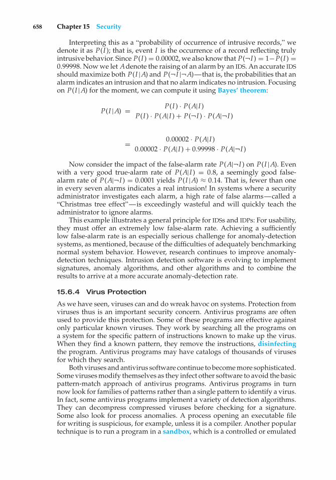
658 Chapter 15 Security
Interpreting this as a “probability of occurrence of intrusive records,” wedenote it as P(I ); that is, event I is the occurrence of a record reflecting trulyintrusive behavior. Since P(I ) = 0.00002, we also know that P(¬I ) = 1−P(I ) =0.99998. Now we let Adenote the raising of an alarm by an IDS. An accurate IDSshould maximize both P(I |A) and P(¬I |¬A)—that is, the probabilities that analarm indicates an intrusion and that no alarm indicates no intrusion. Focusingon P(I |A) for the moment, we can compute it using Bayes’ theorem:
P(I |A) = P(I ) · P(A|I )P(I ) · P(A|I ) + P(¬I ) · P(A|¬I )
= 0.00002 · P(A|I )0.00002 · P(A|I ) + 0.99998 · P(A|¬I )
Now consider the impact of the false-alarm rate P(A|¬I ) on P(I |A). Evenwith a very good true-alarm rate of P(A|I ) = 0.8, a seemingly good false-alarm rate of P(A|¬I ) = 0.0001 yields P(I |A) ≈ 0.14. That is, fewer than onein every seven alarms indicates a real intrusion! In systems where a securityadministrator investigates each alarm, a high rate of false alarms—called a“Christmas tree effect”—is exceedingly wasteful and will quickly teach theadministrator to ignore alarms.
This example illustrates a general principle for IDSs and IDPs: For usability,they must offer an extremely low false-alarm rate. Achieving a sufficientlylow false-alarm rate is an especially serious challenge for anomaly-detectionsystems, as mentioned, because of the difficulties of adequately benchmarkingnormal system behavior. However, research continues to improve anomaly-detection techniques. Intrusion detection software is evolving to implementsignatures, anomaly algorithms, and other algorithms and to combine theresults to arrive at a more accurate anomaly-detection rate.
15.6.4 Virus Protection
As we have seen, viruses can and do wreak havoc on systems. Protection fromviruses thus is an important security concern. Antivirus programs are oftenused to provide this protection. Some of these programs are effective againstonly particular known viruses. They work by searching all the programs ona system for the specific pattern of instructions known to make up the virus.When they find a known pattern, they remove the instructions, disinfectingthe program. Antivirus programs may have catalogs of thousands of virusesfor which they search.
Both viruses and antivirus software continue to become more sophisticated.Some viruses modify themselves as they infect other software to avoid the basicpattern-match approach of antivirus programs. Antivirus programs in turnnow look for families of patterns rather than a single pattern to identify a virus.In fact, some antivirus programs implement a variety of detection algorithms.They can decompress compressed viruses before checking for a signature.Some also look for process anomalies. A process opening an executable filefor writing is suspicious, for example, unless it is a compiler. Another populartechnique is to run a program in a sandbox, which is a controlled or emulated
15.6 Implementing Security Defenses 659
THE TRIPWIRE FILE SYSTEM
An example of an anomaly-detection tool is the Tripwire file system integrity-checking tool for UNIX, developed at Purdue University. Tripwire operates onthe premise that many intrusions result in modification of system directoriesand files. For example, an attacker might modify the system programs,perhaps inserting copies with Trojan horses, or might insert new programsinto directories commonly found in user-shell search paths. Or an intrudermight remove system log files to cover his tracks. Tripwire is a tool tomonitor file systems for added, deleted, or changed files and to alert systemadministrators to these modifications.
The operation of Tripwire is controlled by a configuration file tw.configthat enumerates the directories and files to be monitored for changes,deletions, or additions. Each entry in this configuration file includes aselection mask to specify the file attributes (inode attributes) that will bemonitored for changes. For example, the selection mask might specify that afile’s permissions be monitored but its access time be ignored. In addition, theselection mask can instruct that the file be monitored for changes. Monitoringthe hash of a file for changes is as good as monitoring the file itself, but storinghashes of files requires far less room than copying the files themselves.
When run initially, Tripwire takes as input the tw.config file andcomputes a signature for each file or directory consisting of its monitoredattributes (inode attributes and hash values). These signatures are stored in adatabase. When run subsequently, Tripwire inputs both tw.config and thepreviously stored database, recomputes the signature for each file or directorynamed in tw.config, and compares this signature with the signature (if any)in the previously computed database. Events reported to an administratorinclude any monitored file or directory whose signature differs from that inthe database (a changed file), any file or directory in a monitored directoryfor which a signature does not exist in the database (an added file), and anysignature in the database for which the corresponding file or directory nolonger exists (a deleted file).
Although effective for a wide class of attacks, Tripwire does have limita-tions. Perhaps the most obvious is the need to protect the Tripwire programand its associated files, especially the database file, from unauthorized mod-ification. For this reason, Tripwire and its associated files should be storedon some tamper-proof medium, such as a write-protected disk or a secureserver where logins can be tightly controlled. Unfortunately, this makes itless convenient to update the database after authorized updates to moni-tored directories and files. A second limitation is that some security-relevantfiles—for example, system log files—are supposed to change over time, andTripwire does not provide a way to distinguish between an authorized andan unauthorized change. So, for example, an attack that modifies (withoutdeleting) a system log that would normally change anyway would escapeTripwire’s detection capabilities. The best Tripwire can do in this case is todetect certain obvious inconsistencies (for example, a shrinking log file). Freeand commercial versions of Tripwire are available from http://tripwire.organd http://tripwire.com.
660 Chapter 15 Security
section of the system. The antivirus software analyzes the behavior of the codein the sandbox before letting it run unmonitored. Some antivirus programs alsoput up a complete shield rather than just scanning files within a file system.They search boot sectors, memory, inbound and outbound e-mail, files as theyare downloaded, files on removable devices or media, and so on.
The best protection against computer viruses is prevention, or the practiceof safe computing. Purchasing unopened software from vendors and avoidingfree or pirated copies from public sources or disk exchange offer the safestroute to preventing infection. However, even new copies of legitimate softwareapplications are not immune to virus infection: in a few cases, disgruntledemployees of a software company have infected the master copies of softwareprograms to do economic harm to the company. For macro viruses, one defenseis to exchange Microsoft Word documents in an alternative file format calledrich text format (RTF). Unlike the native Word format, RTF does not include thecapability to attach macros.
Another defense is to avoid opening any e-mail attachments from unknownusers. Unfortunately, history has shown that e-mail vulnerabilities appear asfast as they are fixed. For example, in 2000, the love bug virus became verywidespread by traveling in e-mail messages that pretended to be love notessent by friends of the receivers. Once a receiver opened the attached VisualBasic script, the virus propagated by sending itself to the first addresses in thereceiver’s e-mail contact list. Fortunately, except for clogging e-mail systemsand users’ inboxes, it was relatively harmless. It did, however, effectivelynegate the defensive strategy of opening attachments only from people knownto the receiver. A more effective defense method is to avoid opening any e-mailattachment that contains executable code. Some companies now enforce thisas policy by removing all incoming attachments to e-mail messages.
Another safeguard, although it does not prevent infection, does permitearly detection. A user must begin by completely reformatting the hard disk,especially the boot sector, which is often targeted for viral attack. Only securesoftware is uploaded, and a signature of each program is taken via a securemessage-digest computation. The resulting filename and associated message-digest list must then be kept free from unauthorized access. Periodically, oreach time a program is run, the operating system recomputes the signature andcompares it with the signature on the original list; any differences serve as awarning of possible infection. This technique can be combined with others. Forexample, a high-overhead antivirus scan, such as a sandbox, can be used; andif a program passes the test, a signature can be created for it. If the signaturesmatch the next time the program is run, it does not need to be virus-scannedagain.
15.6.5 Auditing, Accounting, and Logging
Auditing, accounting, and logging can decrease system performance, but theyare useful in several areas, including security. Logging can be general orspecific. All system-call executions can be logged for analysis of programbehavior (or misbehavior). More typically, suspicious events are logged.Authentication failures and authorization failures can tell us quite a lot aboutbreak-in attempts.
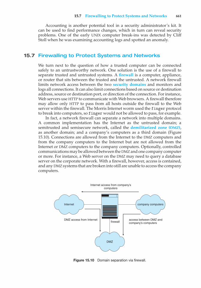
15.7 Firewalling to Protect Systems and Networks 661
Accounting is another potential tool in a security administrator’s kit. Itcan be used to find performance changes, which in turn can reveal securityproblems. One of the early UNIX computer break-ins was detected by CliffStoll when he was examining accounting logs and spotted an anomaly.
15.7 Firewalling to Protect Systems and Networks
We turn next to the question of how a trusted computer can be connectedsafely to an untrustworthy network. One solution is the use of a firewall toseparate trusted and untrusted systems. A firewall is a computer, appliance,or router that sits between the trusted and the untrusted. A network firewalllimits network access between the two security domains and monitors andlogs all connections. It can also limit connections based on source or destinationaddress, source or destination port, or direction of the connection. For instance,Web servers use HTTP to communicate with Web browsers. A firewall thereforemay allow only HTTP to pass from all hosts outside the firewall to the Webserver within the firewall. The Morris Internet worm used the finger protocolto break into computers, so finger would not be allowed to pass, for example.
In fact, a network firewall can separate a network into multiple domains.A common implementation has the Internet as the untrusted domain; asemitrusted and semisecure network, called the demilitarized zone (DMZ),as another domain; and a company’s computers as a third domain (Figure15.10). Connections are allowed from the Internet to the DMZ computers andfrom the company computers to the Internet but are not allowed from theInternet or DMZ computers to the company computers. Optionally, controlledcommunications may be allowed between the DMZ and one company computeror more. For instance, a Web server on the DMZ may need to query a databaseserver on the corporate network. With a firewall, however, access is contained,and any DMZ systems that are broken into still are unable to access the companycomputers.
Internet access from company’scomputers
company computers
DMZ access from Internetfirewall
DMZ
access between DMZ andcompany’s computers
Internet
Figure 15.10 Domain separation via firewall.
662 Chapter 15 Security
Of course, a firewall itself must be secure and attack-proof; otherwise,its ability to secure connections can be compromised. Furthermore, firewallsdo not prevent attacks that tunnel, or travel within protocols or connectionsthat the firewall allows. A buffer-overflow attack to a Web server will not bestopped by the firewall, for example, because the HTTP connection is allowed;it is the contents of the HTTP connection that house the attack. Likewise, denial-of-service attacks can affect firewalls as much as any other machines. Anothervulnerability of firewalls is spoofing, in which an unauthorized host pretendsto be an authorized host by meeting some authorization criterion. For example,if a firewall rule allows a connection from a host and identifies that host by itsIP address, then another host could send packets using that same address andbe allowed through the firewall.
In addition to the most common network firewalls, there are other, newerkinds of firewalls, each with its pros and cons. A personal firewall is asoftware layer either included with the operating system or added as anapplication. Rather than limiting communication between security domains, itlimits communication to (and possibly from) a given host. A user could adda personal firewall to her PC so that a Trojan horse would be denied access tothe network to which the PC is connected, for example. An application proxyfirewall understands the protocols that applications speak across the network.For example, SMTP is used for mail transfer. An application proxy accepts aconnection just as an SMTP server would and then initiates a connection tothe original destination SMTP server. It can monitor the traffic as it forwardsthe message, watching for and disabling illegal commands, attempts to exploitbugs, and so on. Some firewalls are designed for one specific protocol. AnXML firewall, for example, has the specific purpose of analyzing XML trafficand blocking disallowed or malformed XML. System-call firewalls sit betweenapplications and the kernel, monitoring system-call execution. For example,in Solaris 10, the “least privilege” feature implements a list of more than fiftysystem calls that processes may or may not be allowed to make. A process thatdoes not need to spawn other processes can have that ability taken away, forinstance.
15.8 Computer-Security Classifications
The U.S. Department of Defense Trusted Computer System Evaluation Criteriaspecify four security classifications in systems: A, B, C, and D. This specificationis widely used to determine the security of a facility and to model securitysolutions, so we explore it here. The lowest-level classification is division D, orminimal protection. Division D includes only one class and is used for systemsthat have failed to meet the requirements of any of the other security classes.For instance, MS-DOS and Windows 3.1 are in division D.
Division C, the next level of security, provides discretionary protection andaccountability of users and their actions through the use of audit capabilities.Division C has two levels: C1 and C2. A C1-class system incorporates someform of controls that allow users to protect private information and tokeep other users from accidentally reading or destroying their data. A C1environment is one in which cooperating users access data at the same levelsof sensitivity. Most versions of UNIX are C1 class.
15.8 Computer-Security Classifications 663
The total of all protection systems within a computer system (hardware,software, firmware) that correctly enforce a security policy is known as atrusted computer base (TCB). The TCB of a C1 system controls access betweenusers and files by allowing the user to specify and control sharing of objectsby named individuals or defined groups. In addition, the TCB requires that theusers identify themselves before they start any activities that the TCB is expectedto mediate. This identification is accomplished via a protected mechanism orpassword; the TCB protects the authentication data so that they are inaccessibleto unauthorized users.
A C2-class system adds an individual-level access control to the require-ments of a C1 system. For example, access rights of a file can be specifiedto the level of a single individual. In addition, the system administrator canselectively audit the actions of any one or more users based on individualidentity. The TCB also protects itself from modification of its code or datastructures. In addition, no information produced by a prior user is availableto another user who accesses a storage object that has been released back tothe system. Some special, secure versions of UNIX have been certified at the C2level.
Division-B mandatory-protection systems have all the properties of a class-C2 system; in addition, they attach a sensitivity label to each object. The B1-classTCB maintains the security label of each object in the system; the label is usedfor decisions pertaining to mandatory access control. For example, a userat the confidential level could not access a file at the more sensitive secretlevel. The TCB also denotes the sensitivity level at the top and bottom of eachpage of any human-readable output. In addition to the normal user-name–password authentication information, the TCB also maintains the clearanceand authorizations of individual users and will support at least two levels ofsecurity. These levels are hierarchical, so that a user may access any objectsthat carry sensitivity labels equal to or lower than his security clearance. Forexample, a secret-level user could access a file at the confidential level in theabsence of other access controls. Processes are also isolated through the use ofdistinct address spaces.
A B2-class system extends the sensitivity labels to each system resource,such as storage objects. Physical devices are assigned minimum and maximumsecurity levels that the system uses to enforce constraints imposed by thephysical environments in which the devices are located. In addition, a B2system supports covert channels and the auditing of events that could lead tothe exploitation of a covert channel.
A B3-class system allows the creation of access-control lists that denoteusers or groups not granted access to a given named object. The TCB alsocontains a mechanism to monitor events that may indicate a violation ofsecurity policy. The mechanism notifies the security administrator and, ifnecessary, terminates the event in the least disruptive manner.
The highest-level classification is division A. Architecturally, a class-A1system is functionally equivalent to a B3 system, but it uses formal designspecifications and verification techniques, granting a high degree of assurancethat the TCB has been implemented correctly. A system beyond class A1 mightbe designed and developed in a trusted facility by trusted personnel.
The use of a TCB merely ensures that the system can enforce aspects of asecurity policy; the TCB does not specify what the policy should be. Typically,
664 Chapter 15 Security
a given computing environment develops a security policy for certificationand has the plan accredited by a security agency, such as the NationalComputer Security Center. Certain computing environments may require othercertification, such as that supplied by TEMPEST, which guards against electroniceavesdropping. For example, a TEMPEST-certified system has terminals thatare shielded to prevent electromagnetic fields from escaping. This shieldingensures that equipment outside the room or building where the terminal ishoused cannot detect what information is being displayed by the terminal.
15.9 An Example: Windows XP
Microsoft Windows XP is a general-purpose operating system designed tosupport a variety of security features and methods. In this section, we examinefeatures that Windows XP uses to perform security functions. For moreinformation and background on Windows XP, see Chapter 22.
The Windows XP security model is based on the notion of user accounts.Windows XP allows the creation of any number of user accounts, which canbe grouped in any manner. Access to system objects can then be permitted ordenied as desired. Users are identified to the system by a unique security ID.When a user logs on, Windows XP creates a security access token that includesthe security ID for the user, security IDs for any groups of which the user isa member, and a list of any special privileges that the user has. Examplesof special privileges include backing up files and directories, shutting downthe computer, logging on interactively, and changing the system clock. Everyprocess that Windows XP runs on behalf of a user will receive a copy of theaccess token. The system uses the security IDs in the access token to permit ordeny access to system objects whenever the user, or a process on behalf of theuser, attempts to access the object. Authentication of a user account is typicallyaccomplished via a user name and password, although the modular design ofWindows XP allows the development of custom authentication packages. Forexample, a retinal (or eye) scanner might be used to verify that the user is whoshe says she is.
Windows XP uses the idea of a subject to ensure that programs run by auser do not get greater access to the system than the user is authorized to have.A subject is used to track and manage permissions for each program that auser runs; it is composed of the user’s access token and the program actingon behalf of the user. Since Windows XP operates with a client–server model,two classes of subjects are used to control access: simple subjects and serversubjects. An example of a simple subject is the typical application programthat a user executes after she logs on. The simple subject is assigned a securitycontext based on the security access token of the user. A server subject is aprocess implemented as a protected server that uses the security context of theclient when acting on the client’s behalf.
As mentioned in Section 15.7, auditing is a useful security technique.Windows XP has built-in auditing that allows many common security threatsto be monitored. Examples include failure auditing for login and logoff eventsto detect random password break-ins, success auditing for login and logoffevents to detect login activity at strange hours, success and failure write-accessauditing for executable files to track a virus outbreak, and success and failureauditing for file access to detect access to sensitive files.
15.10 Summary 665
Security attributes of an object in Windows XP are described by a securitydescriptor. The security descriptor contains the security ID of the owner ofthe object (who can change the access permissions), a group security ID usedonly by the POSIX subsystem, a discretionary access-control list that identifieswhich users or groups are allowed (and which are not allowed) access, anda system access-control list that controls which auditing messages the systemwill generate. For example, the security descriptor of the file foo.bar might haveowner avi and this discretionary access-control list:
• avi—all access
• group cs—read–write access
• user cliff—no access
In addition, it might have a system access-control list of audit writes byeveryone.
An access-control list is composed of access-control entries that containthe security ID of the individual and an access mask that defines all possibleactions on the object, with a value of AccessAllowed or AccessDenied foreach action. Files in Windows XP may have the following access types: Read-Data, WriteData, AppendData, Execute, ReadExtendedAttribute, Write-ExtendedAttribute, ReadAttributes, and WriteAttributes. We can seehow this allows a fine degree of control over access to objects.
Windows XP classifies objects as either container objects or noncontainerobjects. Container objects, such as directories, can logically contain otherobjects. By default, when an object is created within a container object, the newobject inherits permissions from the parent object. Similarly, if the user copies afile from one directory to a new directory, the file will inherit the permissions ofthe destination directory. Noncontainer objects inherit no other permissions.Furthermore, if a permission is changed on a directory, the new permissionsdo not automatically apply to existing files and subdirectories; the user mayexplicitly apply them if she so desires.
The system administrator can prohibit printing to a printer on the systemfor all or part of a day and can use the Windows XP Performance Monitor tohelp her spot approaching problems. In general, Windows XP does a good jobof providing features to help ensure a secure computing environment. Many ofthese features are not enabled by default, however, which may be one reasonfor the myriad security breaches on Windows XP systems. Another reason isthe vast number of services Windows XP starts at system boot time and thenumber of applications that typically are installed on a Windows XP system.For a real multiuser environment, the system administrator should formulatea security plan and implement it, using the features that Windows XP providesand other security tools.
15.10 Summary
Protection is an internal problem. Security, in contrast, must consider boththe computer system and the environment—people, buildings, businesses,valuable objects, and threats—within which the system is used.
666 Chapter 15 Security
The data stored in the computer system must be protected from unautho-rized access, malicious destruction or alteration, and accidental introduction ofinconsistency. It is easier to protect against accidental loss of data consistencythan to protect against malicious access to the data. Absolute protection of theinformation stored in a computer system from malicious abuse is not possible;but the cost to the perpetrator can be made sufficiently high to deter most, ifnot all, attempts to access that information without proper authority.
Several types of attacks can be launched against programs and againstindividual computers or the masses. Stack- and buffer-overflow techniquesallow successful attackers to change their level of system access. Viruses andworms are self-perpetuating, sometimes infecting thousands of computers.Denial-of-service attacks prevent legitimate use of target systems.
Encryption limits the domain of receivers of data, while authenticationlimits the domain of senders. Encryption is used to provide confidentialityof data being stored or transferred. Symmetric encryption requires a sharedkey, while asymmetric encryption provides a public key and a private key.Authentication, when combined with hashing, can prove that data have notbeen changed.
User authentication methods are used to identify legitimate users of asystem. In addition to standard user-name and password protection, severalauthentication methods are used. One-time passwords, for example, changefrom session to session to avoid replay attacks. Two-factor authenticationrequires two forms of authentication, such as a hardware calculator with anactivation PIN. Multifactor authentication uses three or more forms. Thesemethods greatly decrease the chance of authentication forgery.
Methods of preventing or detecting security incidents include intrusion-detection systems, antivirus software, auditing and logging of system events,monitoring of system software changes, system-call monitoring, and firewalls.
Exercises
15.1 Buffer-overflow attacks can be avoided by adopting a better program-ming methodology or by using special hardware support. Discuss thesesolutions.
15.2 A password may become known to other users in a variety of ways. Isthere a simple method for detecting that such an event has occurred?Explain your answer.
15.3 What is the purpose of using a “salt” along with the user-providedpassword? Where should the “salt” be stored, and how should it beused?
15.4 The list of all passwords is kept within the operating system. Thus,if a user manages to read this list, password protection is no longerprovided. Suggest a scheme that will avoid this problem. (Hint: Usedifferent internal and external representations.)
15.5 An experimental addition to UNIX allows a user to connect a watchdogprogram to a file. The watchdog is invoked whenever a program
Exercises 667
requests access to the file. The watchdog then either grants or deniesaccess to the file. Discuss two pros and two cons of using watchdogsfor security.
15.6 The UNIX program COPS scans a given system for possible securityholes and alerts the user to possible problems. What are two potentialhazards of using such a system for security? How can these problemsbe limited or eliminated?
15.7 Discuss a means by which managers of systems connected to theInternet could design their systems to limit or eliminate the damagedone by worms. What are the drawbacks of making the change thatyou suggest?
15.8 Argue for or against the judicial sentence handed down against RobertMorris, Jr., for his creation and execution of the Internet worm discussedin Section 15.3.1.
15.9 Make a list of six security concerns for a bank’s computer system. Foreach item on your list, state whether this concern relates to physical,human, or operating-system security.
15.10 What are two advantages of encrypting data stored in the computersystem?
15.11 What commonly used computer programs are prone to man-in-the-middle attacks? Discuss solutions for preventing this form of attack.
15.12 Compare symmetric and asymmetric encryption schemes, and discussunder what circumstances a distributed system would use one or theother.
15.13 Why doesn’t D(ke , N)(E(kd, N)(m)) provide authentication of thesender? To what uses can such an encryption be put?
15.14 Discuss how the asymmetric encryption algorithm can be used toachieve the following goals.
a. Authentication: the receiver knows that only the sender couldhave generated the message.
b. Secrecy: only the receiver can decrypt the message.
c. Authentication and secrecy: only the receiver can decrypt themessage, and the receiver knows that only the sender could havegenerated the message.
15.15 Consider a system that generates 10 million audit records per day. Alsoassume that there are on average 10 attacks per day on this system andthat each such attack is reflected in 20 records. If the intrusion-detectionsystem has a true-alarm rate of 0.6 and a false-alarm rate of 0.0005,what percentage of alarms generated by the system correspond to realintrusions?
668 Chapter 15 Security
Wiley Plus
Visit Wiley Plus for
• Source code
• Solutions to practice exercises
• Additional programming problems and exercises
• Labs using an operating system simulator
Bibliographical Notes
General discussions concerning security are given by Hsiao et al. [1979],Landwehr [1981], Denning [1982], Pfleeger and Pfleeger [2003], Tanenbaum2003, and Russell and Gangemi [1991]. Also of general interest is the text byLobel [1986]. Computer networking is discussed in Kurose and Ross [2005].
Issues concerning the design and verification of secure systems are dis-cussed by Rushby [1981] and by Silverman [1983]. A security kernel for amultiprocessor microcomputer is described by Schell [1983]. A distributedsecure system is described by Rushby and Randell [1983].
Morris and Thompson [1979] discuss password security. Morshedian[1986] presents methods to fight password pirates. Password authenticationwith insecure communications is considered by Lamport [1981]. The issueof password cracking is examined by Seely [1989]. Computer break-ins arediscussed by Lehmann [1987] and by Reid [1987]. Issues related to trustingcomputer programs are discussed in Thompson [1984].
Discussions concerning UNIX security are offered by Grampp and Morris[1984], Wood and Kochan [1985], Farrow [1986b], Farrow [1986a], Filipski andHanko [1986], Hecht et al. [1988], Kramer [1988], and Garfinkel et al. [2003].Bershad and Pinkerton [1988] present the watchdog extension to BSD UNIX. TheCOPS security-scanning package for UNIX was written by Farmer at PurdueUniversity. It is available to users on the Internet via the FTP program fromhost ftp.uu.net in directory /pub/security/cops.
Spafford [1989] presents a detailed technical discussion of the Internetworm. The Spafford article appears with three others in a special section onthe Morris Internet worm in Communications of the ACM (Volume 32, Number6, June 1989).
Security problems associated with the TCP/IP protocol suite are describedin Bellovin [1989]. The mechanisms commonly used to prevent such attacks arediscussed in Cheswick et al. [2003]. Another approach to protecting networksfrom insider attacks is to secure topology or route discovery. Kent et al. [2000],Hu et al. [2002], Zapata and Asokan [2002], and Hu and Perrig [2004] presentsolutions for secure routing. Savage et al. [2000] examine the distributed denial-of-service attack and propose IP trace-back solutions to address the problem.Perlman [1988] proposes an approach to diagnose faults when the networkcontains malicious routers.
Information about viruses and worms can be found athttp://www.viruslist.com, as well as in Ludwig [1998] and Ludwig[2002]. Other Web sites containing up-to-date security information
Bibliographical Notes 669
include http://www.trusecure.com and httpd://www.eeye.com. Apaper on the dangers of a computer monoculture can be found athttp://www.ccianet.org/papers/cyberinsecurity.pdf.
Diffie and Hellman [1976] and Diffie and Hellman [1979] were the firstresearchers to propose the use of the public-key encryption scheme. The algo-rithm presented in Section 15.4.1 is based on the public-key encryption scheme;it was developed by Rivest et al. [1978]. Lempel [1979], Simmons [1979],Denning and Denning [1979], Gifford [1982], Denning [1982], Ahituv et al.[1987], Schneier [1996], and Stallings [2003] explore the use of cryptography incomputer systems. Discussions concerning protection of digital signatures areoffered by Akl [1983], Davies [1983], Denning [1983], and Denning [1984].
The U.S. government is, of course, concerned about security. The Depart-ment of Defense Trusted Computer System Evaluation Criteria (DoD [1985]), knownalso as the Orange Book, describes a set of security levels and the features thatan operating system must have to qualify for each security rating. Readingit is a good starting point for understanding security concerns. The MicrosoftWindows NT Workstation Resource Kit (Microsoft [1996]) describes the securitymodel of NT and how to use that model.
The RSA algorithm is presented in Rivest et al. [1978]. Information aboutNIST’s AES activities can be found at http://www.nist.gov/aes/; informa-tion about other cryptographic standards for the United States can alsobe found at that site. More complete coverage of SSL 3.0 can be found athttp://home.netscape.com/eng/ssl3/. In 1999, SSL 3.0 was modified slightlyand presented in an IETF Request for Comments (RFC) under the name TLS.
The example in Section 15.6.3 illustrating the impact of false-alarm rateon the effectiveness of IDSs is based on Axelsson [1999]. The description ofTripwire in Section 15.6.5 is based on Kim and Spafford [1993]. Research intosystem-call-based anomaly detection is described in Forrest et al. [1996].

This page intentionally left blank
Part Six
DistributedSystems
A distributed system is a collection of processors that do not share mem-ory or a clock. Instead, each processor has its own local memory, and theprocessors communicate with one another through communication linessuch as local-area or wide-area networks. The processors in a distributedsystem vary in size and function. Such systems may include small hand-held or real-time devices, personal computers, workstations, and largemainframe computer systems.
A distributed file system is a file-service system whose users, servers,and storage devices are dispersed among the sites of a distributedsystem. Accordingly, service activity has to be carried out across thenetwork; instead of a single centralized data repository, there are multipleindependent storage devices.
The benefits of a distributed system include giving users access tothe resources maintained by the system and thereby speeding up com-putation and improving data availability and reliability. Because a system isdistributed, however, it must provide mechanisms for process synchro-nization and communication, for dealing with the deadlock problem, andfor handling failures that are not encountered in a centralized system.

This page intentionally left blank
16C H A P T E RDistributedSystemStructures
A distributed system is a collection of processors that do not share memoryor a clock. Instead, each processor has its own local memory. The processorscommunicate with one another through various communication networks,such as high-speed buses or telephone lines. In this chapter, we discuss thegeneral structure of distributed systems and the networks that interconnectthem. We contrast the main differences in operating-system design betweenthese systems and centralized systems. In Chapter 17, we go on to discussdistributed file systems. Then, in Chapter 18, we describe the methodsnecessary for distributed operating systems to coordinate their actions.
CHAPTER OBJECTIVES
• To provide a high-level overview of distributed systems and the networksthat interconnect them.
• To discuss the general structure of distributed operating systems.
16.1 Motivation
A distributed system is a collection of loosely coupled processors intercon-nected by a communication network. From the point of view of a specificprocessor in a distributed system, the rest of the processors and their respectiveresources are remote, whereas its own resources are local.
The processors in a distributed system may vary in size and function.They may include small microprocessors, workstations, minicomputers, andlarge general-purpose computer systems. These processors are referred to by anumber of names, such as sites, nodes, computers, machines, and hosts, dependingon the context in which they are mentioned. We mainly use site to indicate thelocation of a machine and host to refer to a specific system at a site. Generally,one host at one site, the server, has a resource that another host at anothersite, the client (or user), would like to use. A general structure of a distributedsystem is shown in Figure 16.1.
673
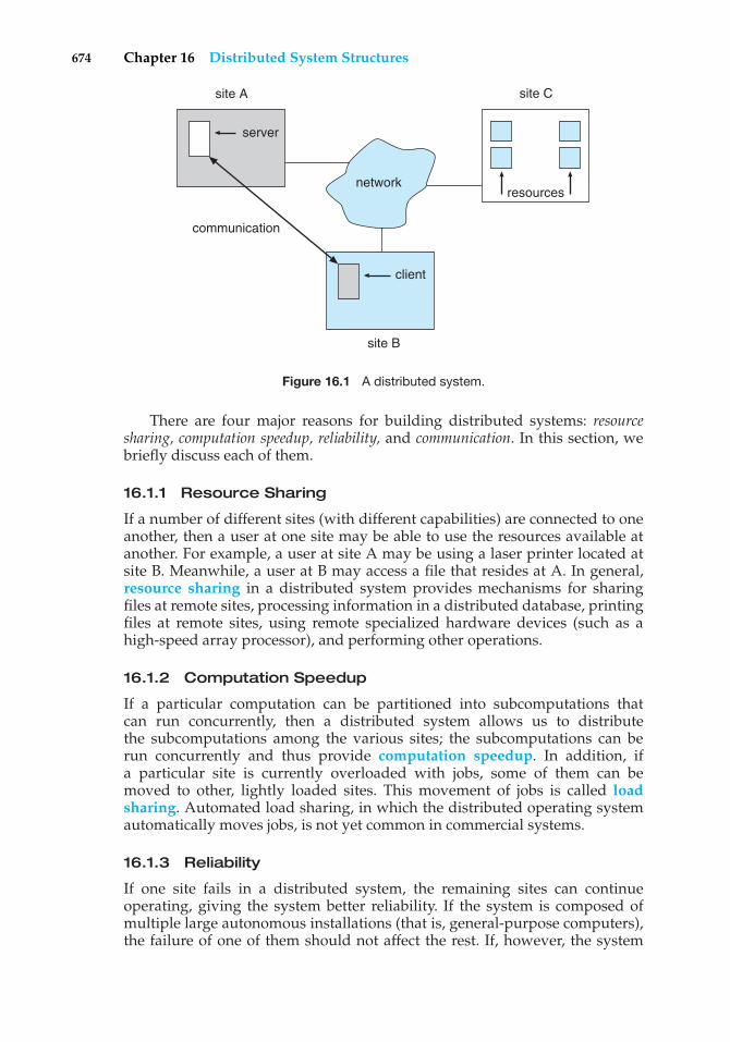
674 Chapter 16 Distributed System Structures
site C
resources
site B
client
communication
site A
server
network
Figure 16.1 A distributed system.
There are four major reasons for building distributed systems: resourcesharing, computation speedup, reliability, and communication. In this section, webriefly discuss each of them.
16.1.1 Resource Sharing
If a number of different sites (with different capabilities) are connected to oneanother, then a user at one site may be able to use the resources available atanother. For example, a user at site A may be using a laser printer located atsite B. Meanwhile, a user at B may access a file that resides at A. In general,resource sharing in a distributed system provides mechanisms for sharingfiles at remote sites, processing information in a distributed database, printingfiles at remote sites, using remote specialized hardware devices (such as ahigh-speed array processor), and performing other operations.
16.1.2 Computation Speedup
If a particular computation can be partitioned into subcomputations thatcan run concurrently, then a distributed system allows us to distributethe subcomputations among the various sites; the subcomputations can berun concurrently and thus provide computation speedup. In addition, ifa particular site is currently overloaded with jobs, some of them can bemoved to other, lightly loaded sites. This movement of jobs is called loadsharing. Automated load sharing, in which the distributed operating systemautomatically moves jobs, is not yet common in commercial systems.
16.1.3 Reliability
If one site fails in a distributed system, the remaining sites can continueoperating, giving the system better reliability. If the system is composed ofmultiple large autonomous installations (that is, general-purpose computers),the failure of one of them should not affect the rest. If, however, the system
16.2 Types of Network-based Operating Systems 675
is composed of small machines, each of which is responsible for some crucialsystem function (such as terminal character I/O or the file system), then a singlefailure may halt the operation of the whole system. In general, with enoughredundancy (in both hardware and data), the system can continue operation,even if some of its sites have failed.
The failure of a site must be detected by the system, and appropriate actionmay be needed to recover from the failure. The system must no longer use theservices of that site. In addition, if the function of the failed site can be takenover by another site, the system must ensure that the transfer of function occurscorrectly. Finally, when the failed site recovers or is repaired, mechanisms mustbe available to integrate it back into the system smoothly. As we shall see inChapters 17 and 18, these actions present difficult problems that have manypossible solutions.
16.1.4 Communication
When several sites are connected to one another by a communication network,users at the various sites have the opportunity to exchange information. Ata low level, messages are passed between systems, much as messages arepassed between processes in the single-computer message system discussedin Section 3.4. Given message passing, all the higher-level functionality foundin standalone systems can be expanded to encompass the distributed system.Such functions include file transfer, login, mail, and remote procedure calls(RPCs).
The advantage of a distributed system is that these functions can becarried out over great distances. Two people at geographically distant sites cancollaborate on a project, for example. By transferring the files of the project,logging in to each other’s remote systems to run programs, and exchangingmail to coordinate the work, users minimize the limitations inherent in long-distance work. We wrote this book by collaborating in such a manner.
The advantages of distributed systems have resulted in an industry-widetrend toward downsizing. Many companies are replacing their mainframeswith networks of workstations or personal computers. Companies get a biggerbang for the buck (that is, better functionality for the cost), more flexibility inlocating resources and expanding facilities, better user interfaces, and easiermaintenance.
16.2 Types of Network-based Operating Systems
In this section, we describe the two general categories of network-orientedoperating systems: network operating systems and distributed operatingsystems. Network operating systems are simpler to implement but generallymore difficult for users to access and utilize than are distributed operatingsystems, which provide more features.
16.2.1 Network Operating Systems
A network operating system provides an environment in which users, who areaware of the multiplicity of machines, can access remote resources by either
676 Chapter 16 Distributed System Structures
logging in to the appropriate remote machine or transferring data from theremote machine to their own machines.
16.2.1.1 Remote Login
An important function of a network operating system is to allow users to log inremotely. The Internet provides the telnet facility for this purpose. To illustratethis facility, lets suppose that a user at Westminster College wishes to computeon “cs.yale.edu,” a computer that is located at Yale University. To do so, theuser must have a valid account on that machine. To log in remotely, the userissues the command
telnet cs.yale.edu
This command results in the formation of a socket connection between thelocal machine at Westminster College and the “cs.yale.edu” computer. After thisconnection has been established, the networking software creates a transparent,bidirectional link so that all characters entered by the user are sent to a processon “cs.yale.edu” and all the output from that process is sent back to the user. Theprocess on the remote machine asks the user for a login name and a password.Once the correct information has been received, the process acts as a proxy forthe user, who can compute on the remote machine just as any local user can.
16.2.1.2 Remote File Transfer
Another major function of a network operating system is to provide amechanism for remote file transfer from one machine to another. In suchan environment, each computer maintains its own local file system. If a user atone site (say, “cs.uvm.edu”) wants to access a file located on another computer(say, “cs.yale.edu”), then the file must be copied explicitly from the computerat Yale to the computer at the University of Vermont.
The Internet provides a mechanism for such a transfer with the file transferprotocol (FTP) program. Suppose that a user on “cs.uvm.edu” wants to copy aJava program Server.java that resides on “cs.yale.edu.” The user must firstinvoke the FTP program by executing
ftp cs.yale.edu
The program then asks the user for a login name and a password. Oncethe correct information has been received, the user must connect to thesubdirectory where the file Server.java resides and then copy the file byexecuting
get Server.java
In this scheme, the file location is not transparent to the user; users must knowexactly where each file is. Moreover, there is no real file sharing, because a usercan only copy a file from one site to another. Thus, several copies of the samefile may exist, resulting in a waste of space. In addition, if these copies aremodified, the various copies will be inconsistent.
16.2 Types of Network-based Operating Systems 677
Notice that, in our example, the user at the University of Vermont musthave login permission on “cs.yale.edu.” FTP also provides a way to allow a userwho does not have an account on the Yale computer to copy files remotely. Thisremote copying is accomplished through the “anonymous FTP” method, whichworks as follows. The file to be copied (that is, Server.java) must be placedin a special subdirectory (say, ftp) with the protection set to allow the publicto read the file. A user who wishes to copy the file uses the ftp command asbefore. When the user is asked for the login name, the user supplies the name“anonymous” and an arbitrary password.
Once anonymous login is accomplished, care must be taken by the systemto ensure that this partially authorized user does not access inappropriatefiles. Generally, the user is allowed to access only those files that are in thedirectory tree of user “anonymous.” Any files placed here are accessible toany anonymous users, subject to the usual file-protection scheme used onthat machine. Anonymous users, however, cannot access files outside of thisdirectory tree.
Implementation of the FTP mechanism is similar to telnet implementation.A daemon on the remote site watches for requests to connect to the system’s FTPport. Login authentication is accomplished, and the user is allowed to executecommands remotely. Unlike the telnet daemon, which executes any commandfor the user, the FTP daemon responds only to a predefined set of file-relatedcommands. These include the following:
• get—Transfer a file from the remote machine to the local machine.
• put—Transfer from the local machine to the remote machine.
• ls or dir—List files in the current directory on the remote machine.
• cd—Change the current directory on the remote machine.
There are also various commands to change transfer modes (for binary or ASCIIfiles) and to determine connection status.
An important point about telnet and FTP is that they require the user tochange paradigms. FTP requires the user to know a command set entirelydifferent from the normal operating-system commands. Telnet requires asmaller shift: the user must know appropriate commands on the remote system.For instance, a user on a Windows machine who telnets to a UNIX machinemust switch to UNIX commands for the duration of the telnet session. Facilitiesare more convenient for users if they do not require the use of a differentset of commands. Distributed operating systems are designed to address thisproblem.
16.2.2 Distributed Operating Systems
In a distributed operating system, users access remote resources in the sameway they access local resources. Data and process migration from one site toanother is under the control of the distributed operating system.
16.2.2.1 Data Migration
Suppose a user on site A wants to access data (such as a file) that reside at siteB. The system can transfer the data by one of two basic methods. One approach
678 Chapter 16 Distributed System Structures
to data migration is to transfer the entire file to site A. From that point on, allaccess to the file is local. When the user no longer needs access to the file, acopy of the file (if it has been modified) is sent back to site B. Even if only amodest change has been made to a large file, all the data must be transferred.This mechanism can be thought of as an automated FTP system. This approachwas used in the Andrew file system, as we discuss in Chapter 17, but it wasfound to be too inefficient.
The other approach is to transfer to site A only those portions of the filethat are actually necessary for the immediate task. If another portion is requiredlater, another transfer will take place. When the user no longer wants to accessthe file, any part of it that has been modified must be sent back to site B. (Notethe similarity to demand paging.) The Sun Microsystems network file system(NFS) protocol uses this method (Chapter 17), as do newer versions of Andrew.The Microsoft SMB protocol (running on top of either TCP/IP or the MicrosoftNetBEUI protocol) also allows file sharing over a network. SMB is described inAppendix C.6.1.
Clearly, if only a small part of a large file is being accessed, the latterapproach is preferable. If significant portions of the file are being accessed,however, it is more efficient to copy the entire file. In both methods, datamigration includes more than the mere transfer of data from one site to another.The system must also perform various data translations if the two sites involvedare not directly compatible (for instance, if they use different character-coderepresentations or represent integers with a different number or order of bits).
16.2.2.2 Computation Migration
In some circumstances, we may want to transfer the computation, rather thanthe data, across the system; this approach is called computation migration. Forexample, consider a job that needs to access various large files that reside atdifferent sites, to obtain a summary of those files. It would be more efficient toaccess the files at the sites where they reside and return the desired results tothe site that initiated the computation. Generally, if the time to transfer the datais longer than the time to execute the remote command, the remote commandshould be used.
Such a computation can be carried out in different ways. Suppose thatprocess P wants to access a file at site A. Access to the file is carried out atsite A and could be initiated by an RPC. An RPC uses a datagram protocol(UDP on the Internet) to execute a routine on a remote system (Section 3.6.2).Process P invokes a predefined procedure at site A. The procedure executesappropriately and then returns the results to P.
Alternatively, process P can send a message to site A. The operating systemat site A then creates a new process Q whose function is to carry out thedesignated task. When process Q completes its execution, it sends the neededresult back to P via the message system. In this scheme, process P may executeconcurrently with process Q; in fact, it may have several processes runningconcurrently on several sites.
Either method could be used to access several files residing at various sites.One RPC might result in the invocation of another RPC or even in the transferof messages to another site. Similarly, process Q could, during the course of its
16.3 Network Structure 679
execution, send a message to another site, which in turn would create anotherprocess. This process might either send a message back to Q or repeat the cycle.
16.2.2.3 Process Migration
A logical extension of computation migration is process migration. When aprocess is submitted for execution, it is not always executed at the site at whichit is initiated. The entire process, or parts of it, may be executed at differentsites. This scheme may be used for several reasons:
• Load balancing. The processes (or subprocesses) may be distributed acrossthe network to even the workload.
• Computation speedup. If a single process can be divided into a numberof subprocesses that can run concurrently on different sites, then the totalprocess turnaround time can be reduced.
• Hardware preference. The process may have characteristics that make itmore suitable for execution on some specialized processor (such as matrixinversion on an array processor) rather than on a microprocessor.
• Software preference. The process may require software that is availableat only a particular site, and either the software cannot be moved, or it isless expensive to move the process.
• Data access. Just as in computation migration, if the data being used in thecomputation are numerous, it may be more efficient to have a process runremotely than to transfer all the data.
We use two complementary techniques to move processes in a computernetwork. In the first, the system can attempt to hide the fact that the process hasmigrated from the client. This scheme has the advantage that the user does notneed to code her program explicitly to accomplish the migration. This methodis usually employed for achieving load balancing and computation speedupamong homogeneous systems, as they do not need user input to help themexecute programs remotely.
The other approach is to allow (or require) the user to specify explicitlyhow the process should migrate. This method is usually employed when theprocess must be moved to satisfy a hardware or software preference.
You have probably realized that the Web has many aspects of a distributed-computing environment. Certainly it provides data migration (between a Webserver and a Web client). It also provides computation migration. For instance,a Web client could trigger a database operation on a Web server. Finally, withJava, it provides a form of process migration: Java applets are sent from theserver to the client, where they are executed. A network operating systemprovides most of these features, but a distributed operating system makesthem seamless and easily accessible. The result is a powerful and easy-to-usefacility—one of the reasons for the huge growth of the World Wide Web.
16.3 Network Structure
There are basically two types of networks: local-area networks (LAN) andwide-area networks (WAN). The main difference between the two is the way in
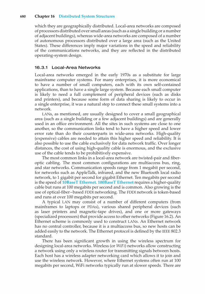
680 Chapter 16 Distributed System Structures
which they are geographically distributed. Local-area networks are composedof processors distributed over small areas (such as a single building or a numberof adjacent buildings), whereas wide-area networks are composed of a numberof autonomous processors distributed over a large area (such as the UnitedStates). These differences imply major variations in the speed and reliabilityof the communications networks, and they are reflected in the distributedoperating-system design.
16.3.1 Local-Area Networks
Local-area networks emerged in the early 1970s as a substitute for largemainframe computer systems. For many enterprises, it is more economicalto have a number of small computers, each with its own self-containedapplications, than to have a single large system. Because each small computeris likely to need a full complement of peripheral devices (such as disksand printers), and because some form of data sharing is likely to occur ina single enterprise, it was a natural step to connect these small systems into anetwork.
LANs, as mentioned, are usually designed to cover a small geographicalarea (such as a single building or a few adjacent buildings) and are generallyused in an office environment. All the sites in such systems are close to oneanother, so the communication links tend to have a higher speed and lowererror rate than do their counterparts in wide-area networks. High-quality(expensive) cables are needed to attain this higher speed and reliability. It isalso possible to use the cable exclusively for data network traffic. Over longerdistances, the cost of using high-quality cable is enormous, and the exclusiveuse of the cable tends to be prohibitively expensive.
The most common links in a local-area network are twisted-pair and fiber-optic cabling. The most common configurations are multiaccess bus, ring,and star networks. Communication speeds range from 1 megabit per second,for networks such as AppleTalk, infrared, and the new Bluetooth local radionetwork, to 1 gigabit per second for gigabit Ethernet. Ten megabits per secondis the speed of 10BaseT Ethernet. 100BaseT Ethernet requires a higher-qualitycable but runs at 100 megabits per second and is common. Also growing is theuse of optical-fiber–based FDDI networking. The FDDI network is token-basedand runs at over 100 megabits per second.
A typical LAN may consist of a number of different computers (frommainframes to laptops or PDAs), various shared peripheral devices (suchas laser printers and magnetic-tape drives), and one or more gateways(specialized processors) that provide access to other networks (Figure 16.2). AnEthernet scheme is commonly used to construct LANs. An Ethernet networkhas no central controller, because it is a multiaccess bus, so new hosts can beadded easily to the network. The Ethernet protocol is defined by the IEEE 802.3standard.
There has been significant growth in using the wireless spectrum fordesigning local-area networks. Wireless (or WiFi) networks allow constructinga network using only a wireless router for transmitting signals between hosts.Each host has a wireless adapter networking card which allows it to join anduse the wireless network. However, where Ethernet systems often run at 100megabits per second, WiFi networks typically run at slower speeds. There are
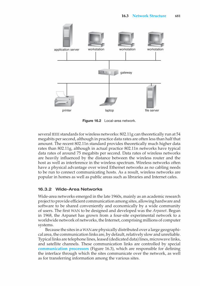
16.3 Network Structure 681
printer laptop file server
workstation workstation workstation
gateway
application server
Figure 16.2 Local-area network.
several IEEE standards for wireless networks: 802.11g can theoretically run at 54megabits per second, although in practice data rates are often less than half thatamount. The recent 802.11n standard provides theoretically much higher datarates than 802.11g, although in actual practice 802.11n networks have typicaldata rates of around 75 megabits per second. Data rates of wireless networksare heavily influenced by the distance between the wireless router and thehost as well as interference in the wireless spectrum. Wireless networks oftenhave a physical advantage over wired Ethernet networks as no cabling needsto be run to connect communicating hosts. As a result, wireless networks arepopular in homes as well as public areas such as libraries and Internet cafes.
16.3.2 Wide-Area Networks
Wide-area networks emerged in the late 1960s, mainly as an academic researchproject to provide efficient communication among sites, allowing hardware andsoftware to be shared conveniently and economically by a wide communityof users. The first WAN to be designed and developed was the Arpanet. Begunin 1968, the Arpanet has grown from a four-site experimental network to aworldwide network of networks, the Internet, comprising millions of computersystems.
Because the sites in a WAN are physically distributed over a large geographi-cal area, the communication links are, by default, relatively slow and unreliable.Typical links are telephone lines, leased (dedicated data) lines, microwave links,and satellite channels. These communication links are controlled by specialcommunication processors (Figure 16.3), which are responsible for definingthe interface through which the sites communicate over the network, as wellas for transferring information among the various sites.
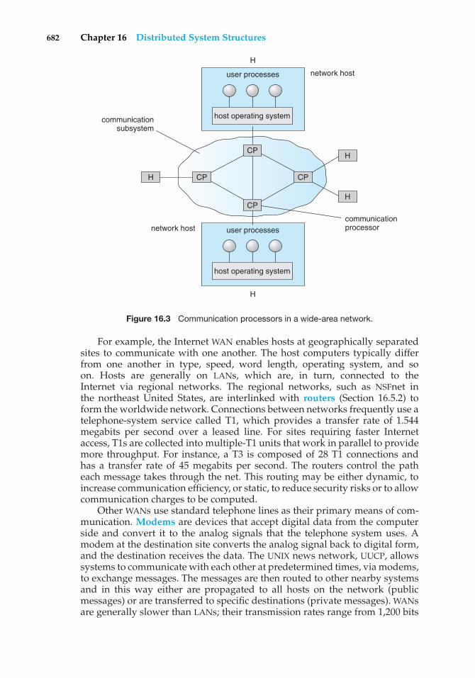
682 Chapter 16 Distributed System Structures
communicationprocessor
communicationsubsystem
H
H
H
H
H
user processes
user processes
network host
network host
host operating system
host operating system
CP
CP
CPCP
Figure 16.3 Communication processors in a wide-area network.
For example, the Internet WAN enables hosts at geographically separatedsites to communicate with one another. The host computers typically differfrom one another in type, speed, word length, operating system, and soon. Hosts are generally on LANs, which are, in turn, connected to theInternet via regional networks. The regional networks, such as NSFnet inthe northeast United States, are interlinked with routers (Section 16.5.2) toform the worldwide network. Connections between networks frequently use atelephone-system service called T1, which provides a transfer rate of 1.544megabits per second over a leased line. For sites requiring faster Internetaccess, T1s are collected into multiple-T1 units that work in parallel to providemore throughput. For instance, a T3 is composed of 28 T1 connections andhas a transfer rate of 45 megabits per second. The routers control the patheach message takes through the net. This routing may be either dynamic, toincrease communication efficiency, or static, to reduce security risks or to allowcommunication charges to be computed.
Other WANs use standard telephone lines as their primary means of com-munication. Modems are devices that accept digital data from the computerside and convert it to the analog signals that the telephone system uses. Amodem at the destination site converts the analog signal back to digital form,and the destination receives the data. The UNIX news network, UUCP, allowssystems to communicate with each other at predetermined times, via modems,to exchange messages. The messages are then routed to other nearby systemsand in this way either are propagated to all hosts on the network (publicmessages) or are transferred to specific destinations (private messages). WANsare generally slower than LANs; their transmission rates range from 1,200 bits
16.4 Network Topology 683
per second to over 1 megabit per second. UUCP has been superseded by PPP,the point-to-point protocol. PPP functions over modem connections, allowinghome computers to be fully connected to the Internet.
16.4 Network Topology
The sites in a distributed system can be connected physically in a variety ofways. Each configuration has advantages and disadvantages. We can comparethe configurations by using the following criteria:
• Installation cost. The cost of physically linking the sites in the system
• Communication cost. The cost in time and money to send a message fromsite A to site B
• Availability. The extent to which data can be accessed despite the failureof some links or sites
The various topologies are depicted in Figure 16.4 as graphs whose nodescorrespond to sites. An edge from node A to node B corresponds to a directcommunication link between the two sites. In a fully connected network, eachsite is directly connected to every other site. However, the number of linksgrows as the square of the number of sites, resulting in a huge installation cost.Therefore, fully connected networks are impractical in any large system.
In a partially connected network, direct links exist between some—butnot all—pairs of sites. Hence, the installation cost of such a configuration islower than that of the fully connected network. However, if two sites A andB are not directly connected, messages from one to the other must be routedthrough a sequence of communication links. This requirement results in ahigher communication cost.
If a communication link fails, messages that would have been transmittedacross the link must be rerouted. In some cases, another route through thenetwork may be found, so that the messages are able to reach their destination.In other cases, a failure may mean that no connection exists between somepair (or pairs) of sites. When a system is split into two (or more) unconnectedsubsystems, it is partitioned. Under this definition, a subsystem (or partition)may consist of a single node.
The various partially connected network types include tree-structurednetworks, ring networks, and star networks, as shown in Figure 16.4. Thesetypes have different failure characteristics and installation and communicationcosts. Installation and communication costs are relatively low for a tree-structured network. However, the failure of a single link in such a networkcan result in the network’s becoming partitioned. In a ring network, at leasttwo links must fail for partition to occur. Thus, the ring network has a higherdegree of availability than does a tree-structured network. However, thecommunication cost is high, since a message may have to cross a large numberof links. In a star network, the failure of a single link results in a networkpartition, but one of the partitions has only a single site. Such a partition can betreated as a single-site failure. The star network also has a low communicationcost, since each site is at most two links away from every other site. However,
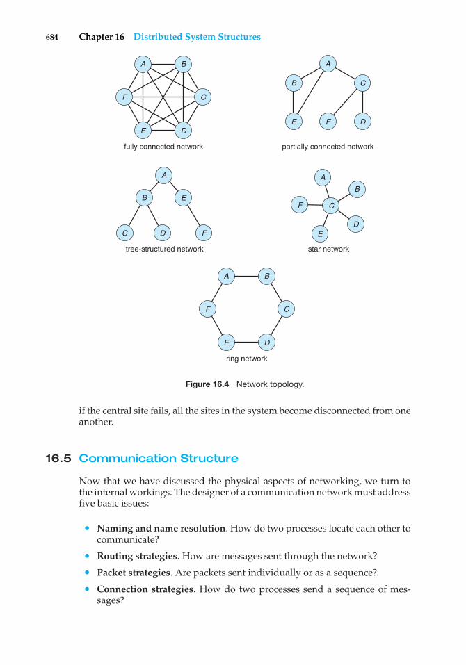
684 Chapter 16 Distributed System Structures
A A
A
B
B
B
E
F C
C
C
DE
E
D
D
F
F
A
B E
C FD
fully connected network
A B
E
F C
D
ring network
tree-structured network star network
partially connected network
Figure 16.4 Network topology.
if the central site fails, all the sites in the system become disconnected from oneanother.
16.5 Communication Structure
Now that we have discussed the physical aspects of networking, we turn tothe internal workings. The designer of a communication network must addressfive basic issues:
• Naming and name resolution. How do two processes locate each other tocommunicate?
• Routing strategies. How are messages sent through the network?
• Packet strategies. Are packets sent individually or as a sequence?
• Connection strategies. How do two processes send a sequence of mes-sages?
16.5 Communication Structure 685
• Contention. How do we resolve conflicting demands for the network’suse, given that it is a shared resource?
In the following sections, we elaborate on each of these issues.
16.5.1 Naming and Name Resolution
The first component of network communication is the naming of the systemsin the network. For a process at site A to exchange information with a processat site B, each must be able to specify the other. Within a computer system,each process has a process identifier, and messages may be addressed with theprocess identifier. Because networked systems share no memory, however, ahost within the system initially has no knowledge about the processes on otherhosts.
To solve this problem, processes on remote systems are generally identifiedby the pair <host name, identifier>, where host name is a name unique withinthe network and identifier may be a process identifier or other unique numberwithin that host. A host name is usually an alphanumeric identifier, rather thana number, to make it easier for users to specify. For instance, site A might havehosts named homer, marge, bart, and lisa. Bart is certainly easier to rememberthan is 12814831100.
Names are convenient for humans to use, but computers prefer numbers forspeed and simplicity. For this reason, there must be a mechanism to resolve thehost name into a host-id that describes the destination system to the networkinghardware. This mechanism is similar to the name-to-address binding thatoccurs during program compilation, linking, loading, and execution (Chapter8). In the case of host names, two possibilities exist. First, every host may have adata file containing the names and addresses of all the other hosts reachable onthe network (similar to binding at compile time). The problem with this modelis that adding or removing a host from the network requires updating the datafiles on all the hosts. The alternative is to distribute the information amongsystems on the network. The network must then use a protocol to distributeand retrieve the information. This scheme is like execution-time binding. Thefirst method was the one originally used on the Internet; as the Internet grew,however, it became untenable, so the second method, the domain-name system(DNS), is now in use.
DNS specifies the naming structure of the hosts, as well as name-to-addressresolution. Hosts on the Internet are logically addressed with multipart namesknown as IP addresses. The parts of an IP address progress from the mostspecific to the most general part, with periods separating the fields. Forinstance, bob.cs.brown.edu refers to host bob in the Department of ComputerScience at Brown University within the top-level domain edu. (Other top-leveldomains include com for commercial sites and org for organizations, as well asa domain for each country connected to the network, for systems specifiedby country rather than organization type.) Generally, the system resolvesaddresses by examining the host-name components in reverse order. Eachcomponent has a name server—simply a process on a system—that acceptsa name and returns the address of the name server responsible for that name.As the final step, the name server for the host in question is contacted, and ahost-id is returned. For example, a request made by a process on system A tocommunicate with bob.cs.brown.edu would result in the following steps:
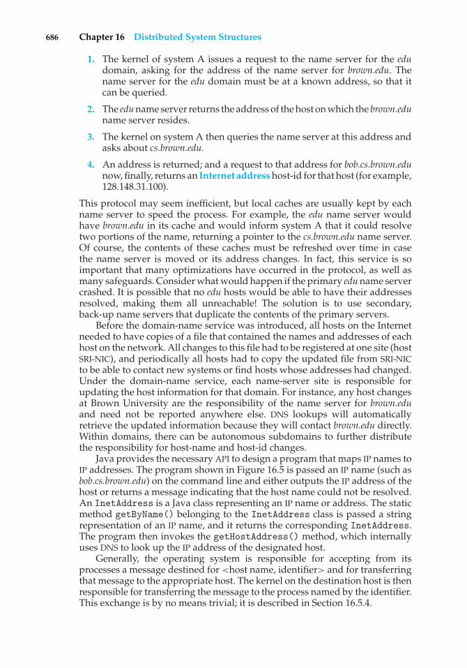
686 Chapter 16 Distributed System Structures
1. The kernel of system A issues a request to the name server for the edudomain, asking for the address of the name server for brown.edu. Thename server for the edu domain must be at a known address, so that itcan be queried.
2. The edu name server returns the address of the host on which the brown.eduname server resides.
3. The kernel on system A then queries the name server at this address andasks about cs.brown.edu.
4. An address is returned; and a request to that address for bob.cs.brown.edunow, finally, returns an Internet address host-id for that host (for example,128.148.31.100).
This protocol may seem inefficient, but local caches are usually kept by eachname server to speed the process. For example, the edu name server wouldhave brown.edu in its cache and would inform system A that it could resolvetwo portions of the name, returning a pointer to the cs.brown.edu name server.Of course, the contents of these caches must be refreshed over time in casethe name server is moved or its address changes. In fact, this service is soimportant that many optimizations have occurred in the protocol, as well asmany safeguards. Consider what would happen if the primary edu name servercrashed. It is possible that no edu hosts would be able to have their addressesresolved, making them all unreachable! The solution is to use secondary,back-up name servers that duplicate the contents of the primary servers.
Before the domain-name service was introduced, all hosts on the Internetneeded to have copies of a file that contained the names and addresses of eachhost on the network. All changes to this file had to be registered at one site (hostSRI-NIC), and periodically all hosts had to copy the updated file from SRI-NICto be able to contact new systems or find hosts whose addresses had changed.Under the domain-name service, each name-server site is responsible forupdating the host information for that domain. For instance, any host changesat Brown University are the responsibility of the name server for brown.eduand need not be reported anywhere else. DNS lookups will automaticallyretrieve the updated information because they will contact brown.edu directly.Within domains, there can be autonomous subdomains to further distributethe responsibility for host-name and host-id changes.
Java provides the necessary API to design a program that maps IP names toIP addresses. The program shown in Figure 16.5 is passed an IP name (such asbob.cs.brown.edu) on the command line and either outputs the IP address of thehost or returns a message indicating that the host name could not be resolved.An InetAddress is a Java class representing an IP name or address. The staticmethod getByName() belonging to the InetAddress class is passed a stringrepresentation of an IP name, and it returns the corresponding InetAddress.The program then invokes the getHostAddress() method, which internallyuses DNS to look up the IP address of the designated host.
Generally, the operating system is responsible for accepting from itsprocesses a message destined for <host name, identifier> and for transferringthat message to the appropriate host. The kernel on the destination host is thenresponsible for transferring the message to the process named by the identifier.This exchange is by no means trivial; it is described in Section 16.5.4.
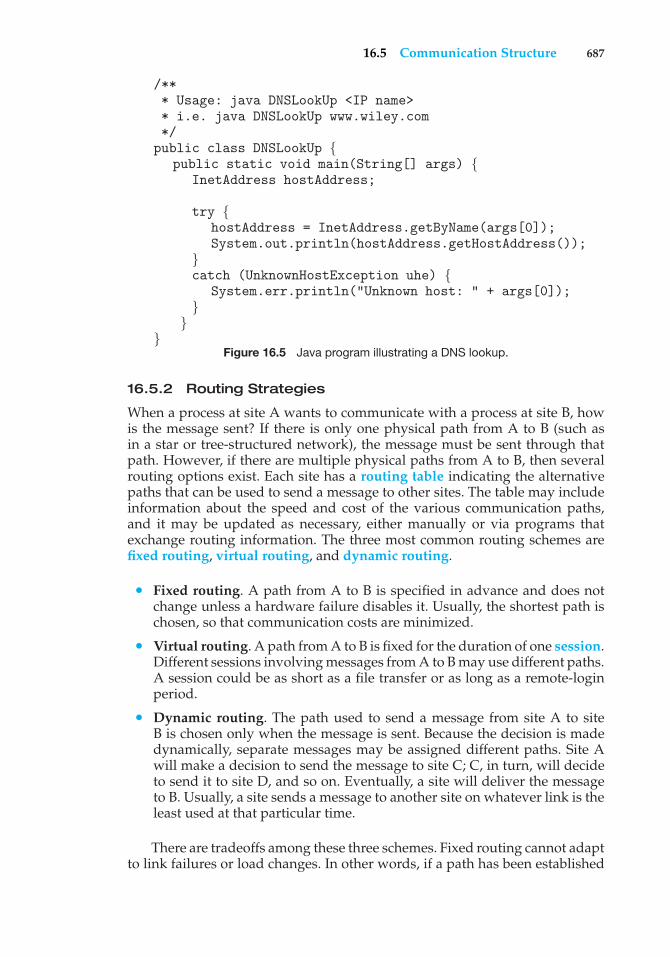
16.5 Communication Structure 687
/*** Usage: java DNSLookUp <IP name>* i.e. java DNSLookUp www.wiley.com*/public class DNSLookUp {
public static void main(String[] args) {InetAddress hostAddress;
try {hostAddress = InetAddress.getByName(args[0]);System.out.println(hostAddress.getHostAddress());
}catch (UnknownHostException uhe) {
System.err.println("Unknown host: " + args[0]);}
}}
Figure 16.5 Java program illustrating a DNS lookup.
16.5.2 Routing Strategies
When a process at site A wants to communicate with a process at site B, howis the message sent? If there is only one physical path from A to B (such asin a star or tree-structured network), the message must be sent through thatpath. However, if there are multiple physical paths from A to B, then severalrouting options exist. Each site has a routing table indicating the alternativepaths that can be used to send a message to other sites. The table may includeinformation about the speed and cost of the various communication paths,and it may be updated as necessary, either manually or via programs thatexchange routing information. The three most common routing schemes arefixed routing, virtual routing, and dynamic routing.
• Fixed routing. A path from A to B is specified in advance and does notchange unless a hardware failure disables it. Usually, the shortest path ischosen, so that communication costs are minimized.
• Virtual routing. A path from A to B is fixed for the duration of one session.Different sessions involving messages from A to B may use different paths.A session could be as short as a file transfer or as long as a remote-loginperiod.
• Dynamic routing. The path used to send a message from site A to siteB is chosen only when the message is sent. Because the decision is madedynamically, separate messages may be assigned different paths. Site Awill make a decision to send the message to site C; C, in turn, will decideto send it to site D, and so on. Eventually, a site will deliver the messageto B. Usually, a site sends a message to another site on whatever link is theleast used at that particular time.
There are tradeoffs among these three schemes. Fixed routing cannot adaptto link failures or load changes. In other words, if a path has been established
688 Chapter 16 Distributed System Structures
between A and B, the messages must be sent along this path, even if the pathis down or is used more heavily than another possible path. We can partiallyremedy this problem by using virtual routing and can avoid it completely byusing dynamic routing. Fixed routing and virtual routing ensure that messagesfrom A to B will be delivered in the order in which they were sent. In dynamicrouting, messages may arrive out of order. We can remedy this problem byappending a sequence number to each message.
Dynamic routing is the most complicated to set up and run; however, it isthe best way to manage routing in complicated environments. UNIX providesboth fixed routing for use on hosts within simple networks and dynamicrouting for complicated network environments. It is also possible to mix thetwo. Within a site, the hosts may just need to know how to reach the system thatconnects the local network to other networks (such as company-wide networksor the Internet). Such a node is known as a gateway. Each individual host hasa static route to the gateway, although the gateway itself uses dynamic routingto reach any host on the rest of the network.
A router is the entity within the computer network responsible for routingmessages. A router can be a host computer with routing software or aspecial-purpose device. Either way, a router must have at least two networkconnections, or else it would have nowhere to route messages. A router decideswhether any given message needs to be passed from the network on whichit is received to any other network connected to the router. It makes thisdetermination by examining the destination Internet address of the message.The router checks its tables to determine the location of the destination host, orat least of the network to which it will send the message toward the destinationhost. In the case of static routing, this table is changed only by manual update(a new file is loaded onto the router). With dynamic routing, a routing protocolis used between routers to inform them of network changes and to allow themto update their routing tables automatically. Gateways and routers typicallyare dedicated hardware devices that run code out of firmware.
16.5.3 Packet Strategies
Messages generally vary in length. To simplify the system design, we com-monly implement communication with fixed-length messages called packets,frames, or datagrams. A communication implemented in one packet can besent to its destination in a connectionless message. A connectionless messagecan be unreliable, in which case the sender has no guarantee that, and cannottell whether, the packet reached its destination. Alternatively, the packet canbe reliable; usually, in this case, a packet is returned from the destinationindicating that the packet arrived. (Of course, the return packet could be lostalong the way.) If a message is too long to fit within one packet, or if the packetsneed to flow back and forth between the two communicators, a connection isestablished to allow the reliable exchange of multiple packets.
16.5.4 Connection Strategies
Once messages are able to reach their destinations, processes can institutecommunications sessions to exchange information. Pairs of processes thatwant to communicate over the network can be connected in a number of ways.
16.5 Communication Structure 689
The three most common schemes are circuit switching, message switching,and packet switching.
• Circuit switching. If two processes want to communicate, a permanentphysical link is established between them. This link is allocated for theduration of the communication session, and no other process can usethat link during this period (even if the two processes are not activelycommunicating for a while). This scheme is similar to that used in thetelephone system. Once a communication line has been opened betweentwo parties (that is, party A calls party B), no one else can use this circuituntil the communication is terminated explicitly (for example, when theparties hang up).
• Message switching. If two processes want to communicate, a temporarylink is established for the duration of one message transfer. Physicallinks are allocated dynamically among correspondents as needed andare allocated for only short periods. Each message is a block of datawith system information—such as the source, the destination, and error-correction codes (ECC)—that allows the communication network to deliverthe message to the destination correctly. This scheme is similar to thepost-office mailing system. Each letter is a message that contains both thedestination address and source (return) address. Many messages (fromdifferent users) can be shipped over the same link.
• Packet switching. One logical message may have to be divided into anumber of packets. Each packet may be sent to its destination separately,and each therefore must include a source and a destination address with itsdata. Furthermore, the various packets may take different paths throughthe network. The packets must be reassembled into messages as theyarrive. Note that it is not harmful for data to be broken into packets,possibly routed separately, and reassembled at the destination. Breakingup an audio signal (say, a telephone communication), in contrast, couldcause great confusion if it was not done carefully.
There are obvious tradeoffs among these schemes. Circuit switching requiressubstantial set-up time and may waste network bandwidth, but it incursless overhead for shipping each message. Conversely, message and packetswitching require less set-up time but incur more overhead per message. Also,in packet switching, each message must be divided into packets and laterreassembled. Packet switching is the method most commonly used on datanetworks because it makes the best use of network bandwidth.
16.5.5 Contention
Depending on the network topology, a link may connect more than two sitesin the computer network, and several of these sites may want to transmitinformation over a link simultaneously. This situation occurs mainly in a ring ormultiaccess bus network. In this case, the transmitted information may becomescrambled. If it does, it must be discarded; and the sites must be notified aboutthe problem so that they can retransmit the information. If no special provisionsare made, this situation may be repeated, resulting in degraded performance.
690 Chapter 16 Distributed System Structures
Several techniques have been developed to avoid repeated collisions, includingcollision detection and token passing.
• CSMA/CD. Before transmitting a message over a link, a site must listento determine whether another message is currently being transmittedover that link; this technique is called carrier sense with multiple access(CSMA). If the link is free, the site can start transmitting. Otherwise, it mustwait (and continue to listen) until the link is free. If two or more sites begintransmitting at exactly the same time (each thinking that no other site isusing the link), then they will register a collision detection (CD) and willstop transmitting. Each site will try again after some random time interval.The main problem with this approach is that, when the system is verybusy, many collisions may occur, and thus performance may be degraded.Nevertheless, CSMA/CD has been used successfully in the Ethernet system,the most common local area network system. One strategy for limiting thenumber of collisions is to limit the number of hosts per Ethernet network.Adding more hosts to a congested network could result in poor networkthroughput. As systems get faster, they are able to send more packets pertime segment. As a result, the number of systems per Ethernet networkgenerally is decreasing so that networking performance is kept reasonable.
• Token passing. A unique message type, known as a token, continuouslycirculates in the system (usually a ring structure). A site that wants totransmit information must wait until the token arrives. It then removesthe token from the ring and begins to transmit its messages. When thesite completes its round of message passing, it retransmits the token. Thisaction, in turn, allows another site to receive and remove the token andto start its message transmission. If the token gets lost, the system mustdetect the loss and generate a new token. It usually does that by declaringan election to choose a unique site where a new token will be generated.Later, in Section 18.6, we present one election algorithm. A token-passingscheme has been adopted by the IBM and HP/Apollo systems. The benefitof a token-passing network is that performance is constant. Adding newsites to a network may lengthen the waiting time for a token, but it will notcause a large performance decrease, as may happen on Ethernet. On lightlyloaded networks, however, Ethernet is more efficient, because systems cansend messages at any time.
16.6 Communication Protocols
When we are designing a communication network, we must deal with theinherent complexity of coordinating asynchronous operations communicatingin a potentially slow and error-prone environment. In addition, the systems onthe network must agree on a protocol or a set of protocols for determininghost names, locating hosts on the network, establishing connections, andso on. We can simplify the design problem (and related implementation)by partitioning the problem into multiple layers. Each layer on one systemcommunicates with the equivalent layer on other systems. Typically, each layerhas its own protocols, and communication takes place between peer layers
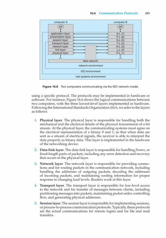
16.6 Communication Protocols 691
real systems environment
ISO environment
network environment
data network
computer A
application layerpresentation layer
session layertransport layernetwork layer
link layerphysical layer
AP
computer B
A-L (7) P-L (6) S-L (5) T-L (4) N-L (3) L-L (2) P-L (1)
AP
Figure 16.6 Two computers communicating via the ISO network model.
using a specific protocol. The protocols may be implemented in hardware orsoftware. For instance, Figure 16.6 shows the logical communications betweentwo computers, with the three lowest-level layers implemented in hardware.Following the International Standards Organization (ISO), we refer to the layersas follows:
1. Physical layer. The physical layer is responsible for handling both themechanical and the electrical details of the physical transmission of a bitstream. At the physical layer, the communicating systems must agree onthe electrical representation of a binary 0 and 1, so that when data aresent as a stream of electrical signals, the receiver is able to interpret thedata properly as binary data. This layer is implemented in the hardwareof the networking device.
2. Data-link layer. The data-link layer is responsible for handling frames, orfixed-length parts of packets, including any error detection and recoverythat occurs in the physical layer.
3. Network layer. The network layer is responsible for providing connec-tions and for routing packets in the communication network, includinghandling the addresses of outgoing packets, decoding the addressesof incoming packets, and maintaining routing information for properresponse to changing load levels. Routers work at this layer.
4. Transport layer. The transport layer is responsible for low-level accessto the network and for transfer of messages between clients, includingpartitioning messages into packets, maintaining packet order, controllingflow, and generating physical addresses.
5. Session layer. The session layer is responsible for implementing sessions,or process-to-process communication protocols. Typically, these protocolsare the actual communications for remote logins and for file and mailtransfers.
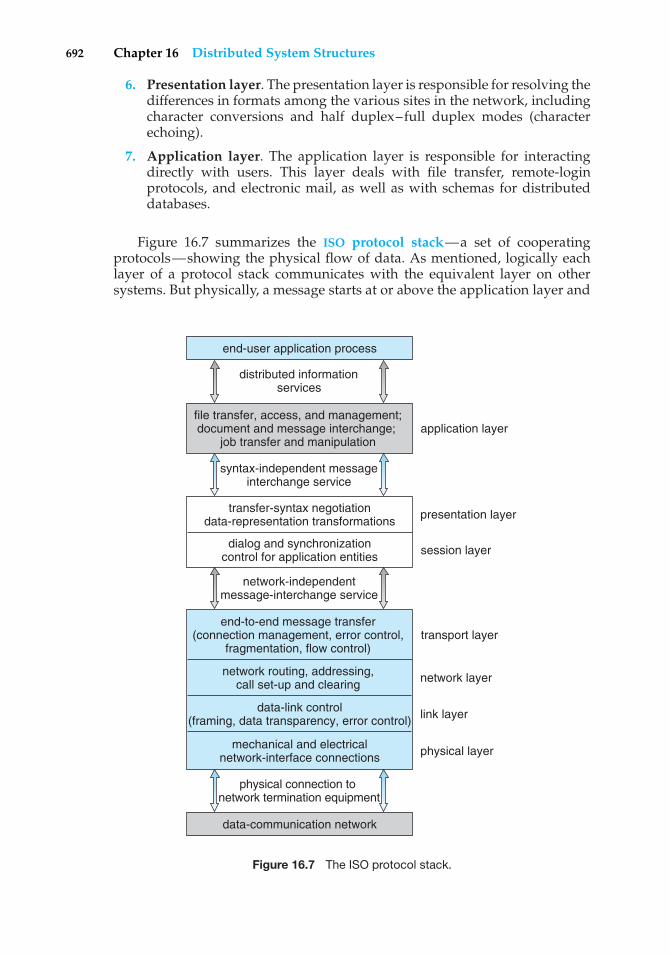
692 Chapter 16 Distributed System Structures
6. Presentation layer. The presentation layer is responsible for resolving thedifferences in formats among the various sites in the network, includingcharacter conversions and half duplex–full duplex modes (characterechoing).
7. Application layer. The application layer is responsible for interactingdirectly with users. This layer deals with file transfer, remote-loginprotocols, and electronic mail, as well as with schemas for distributeddatabases.
Figure 16.7 summarizes the ISO protocol stack—a set of cooperatingprotocols—showing the physical flow of data. As mentioned, logically eachlayer of a protocol stack communicates with the equivalent layer on othersystems. But physically, a message starts at or above the application layer and
data-communication network
end-to-end message transfer(connection management, error control,
fragmentation, flow control)
physical connection to network termination equipment
transport layer
network routing, addressing,call set-up and clearing
transfer-syntax negotiationdata-representation transformations
network-independentmessage-interchange service
presentation layer
file transfer, access, and management; document and message interchange;
job transfer and manipulation
syntax-independent messageinterchange service
end-user application process
distributed information services
application layer
dialog and synchronizationcontrol for application entities session layer
network layer
link layer
physical layer
data-link control(framing, data transparency, error control)
mechanical and electricalnetwork-interface connections
Figure 16.7 The ISO protocol stack.
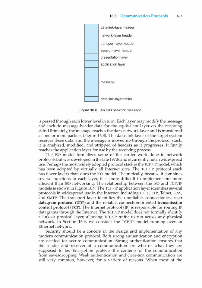
16.6 Communication Protocols 693
data-link-layer header
network-layer header
transport-layer header
session-layer header
presentation layer
application layer
message
data-link-layer trailer
Figure 16.8 An ISO network message.
is passed through each lower level in turn. Each layer may modify the messageand include message-header data for the equivalent layer on the receivingside. Ultimately, the message reaches the data-network layer and is transferredas one or more packets (Figure 16.8). The data-link layer of the target systemreceives these data, and the message is moved up through the protocol stack;it is analyzed, modified, and stripped of headers as it progresses. It finallyreaches the application layer for use by the receiving process.
The ISO model formalizes some of the earlier work done in networkprotocols but was developed in the late 1970s and is currently not in widespreaduse. Perhaps the most widely adopted protocol stack is the TCP/IP model, whichhas been adopted by virtually all Internet sites. The TCP/IP protocol stackhas fewer layers than does the ISO model. Theoretically, because it combinesseveral functions in each layer, it is more difficult to implement but moreefficient than ISO networking. The relationship between the ISO and TCP/IPmodels is shown in Figure 16.9. The TCP/IP application layer identifies severalprotocols in widespread use in the Internet, including HTTP, FTP, Telnet, DNS,and SMTP. The transport layer identifies the unreliable, connectionless userdatagram protocol (UDP) and the reliable, connection-oriented transmissioncontrol protocol (TCP). The Internet protocol (IP) is responsible for routing IPdatagrams through the Internet. The TCP/IP model does not formally identifya link or physical layer, allowing TCP/IP traffic to run across any physicalnetwork. In Section 16.9, we consider the TCP/IP model running over anEthernet network.
Security should be a concern in the design and implementation of anymodern communication protocol. Both strong authentication and encryptionare needed for secure communication. Strong authentication ensures thatthe sender and receiver of a communication are who or what they aresupposed to be. Encryption protects the contents of the communicationfrom eavesdropping. Weak authentication and clear-text communication arestill very common, however, for a variety of reasons. When most of the
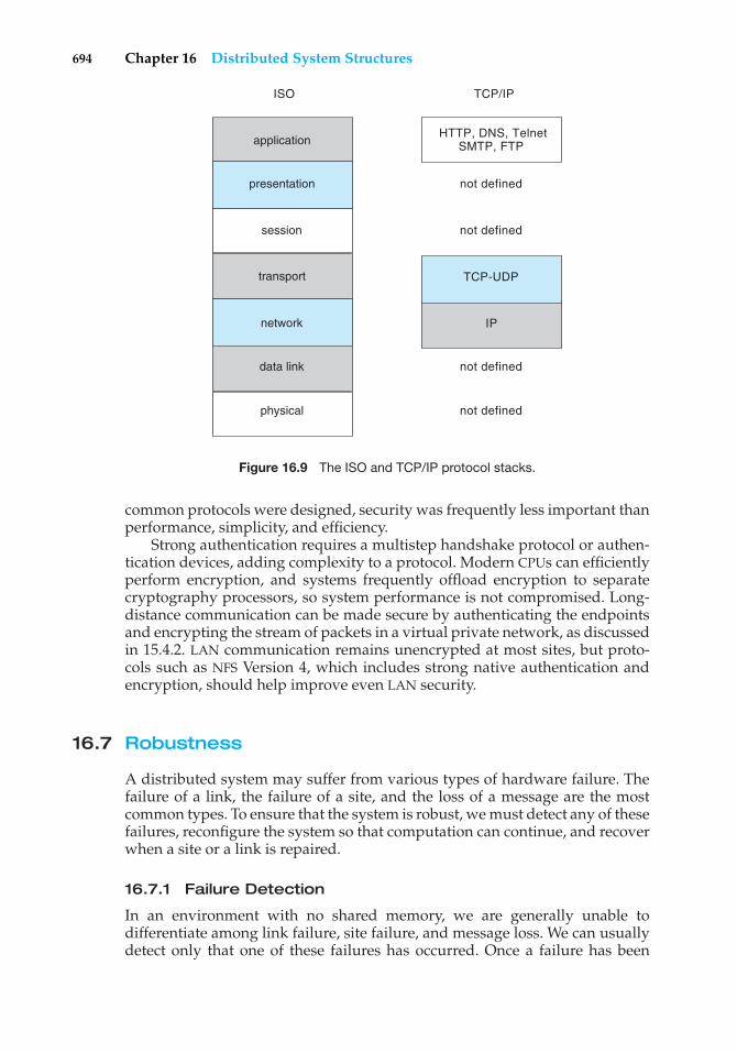
694 Chapter 16 Distributed System Structures
data link
transport
applicationHTTP, DNS, Telnet
SMTP, FTP
not defined
not defined
not defined
ISO TCP/IP
not defined
IP
TCP-UDP
physical
network
session
presentation
Figure 16.9 The ISO and TCP/IP protocol stacks.
common protocols were designed, security was frequently less important thanperformance, simplicity, and efficiency.
Strong authentication requires a multistep handshake protocol or authen-tication devices, adding complexity to a protocol. Modern CPUs can efficientlyperform encryption, and systems frequently offload encryption to separatecryptography processors, so system performance is not compromised. Long-distance communication can be made secure by authenticating the endpointsand encrypting the stream of packets in a virtual private network, as discussedin 15.4.2. LAN communication remains unencrypted at most sites, but proto-cols such as NFS Version 4, which includes strong native authentication andencryption, should help improve even LAN security.
16.7 Robustness
A distributed system may suffer from various types of hardware failure. Thefailure of a link, the failure of a site, and the loss of a message are the mostcommon types. To ensure that the system is robust, we must detect any of thesefailures, reconfigure the system so that computation can continue, and recoverwhen a site or a link is repaired.
16.7.1 Failure Detection
In an environment with no shared memory, we are generally unable todifferentiate among link failure, site failure, and message loss. We can usuallydetect only that one of these failures has occurred. Once a failure has been

16.7 Robustness 695
detected, appropriate action must be taken. What action is appropriate dependson the particular application.
To detect link and site failure, we use a handshaking procedure. Supposethat sites A and B have a direct physical link between them. At fixed intervals,the sites send each other an I-am-up message. If site A does not receive thismessage within a predetermined time period, it can assume that site B hasfailed, that the link between A and B has failed, or that the message from Bhas been lost. At this point, site A has two choices. It can wait for another timeperiod to receive an I-am-up message from B, or it can send an Are-you-up?message to B.
If time goes by and site A still has not received an I-am-up message, or if siteA has sent an Are-you-up? message and has not received a reply, the procedurecan be repeated. Again, the only conclusion that site A can draw safely is thatsome type of failure has occurred.
Site A can try to differentiate between link failure and site failure by sendingan Are-you-up? message to B by another route (if one exists). If and when Breceives this message, it immediately replies positively. This positive reply tellsA that B is up and that the failure is in the direct link between them. Since wedo not know in advance how long it will take the message to travel from A to Band back, we must use a time-out scheme. At the time A sends the Are-you-up?message, it specifies a time interval during which it is willing to wait for thereply from B. If A receives the reply message within that time interval, then itcan safely conclude that B is up. If not, however (that is, if a time-out occurs),then A may conclude only that one or more of the following situations hasoccurred:
• Site B is down.
• The direct link (if one exists) from A to B is down.
• The alternative path from A to B is down.
• The message has been lost.
Site A cannot, however, determine which of these events has occurred.
16.7.2 Reconfiguration
Suppose that site A has discovered, through the mechanism described in theprevious section, that a failure has occurred. It must then initiate a procedurethat will allow the system to reconfigure and to continue its normal mode ofoperation.
• If a direct link from A to B has failed, this information must be broadcast toevery site in the system, so that the various routing tables can be updatedaccordingly.
• If the system believes that a site has failed (because that site can be reachedno longer), then all sites in the system must be so notified, so that theywill no longer attempt to use the services of the failed site. The failure of asite that serves as a central coordinator for some activity (such as deadlockdetection) requires the election of a new coordinator. Similarly, if the failed
696 Chapter 16 Distributed System Structures
site is part of a logical ring, then a new logical ring must be constructed.Note that, if the site has not failed (that is, if it is up but cannot be reached),then we may have the undesirable situation in which two sites serve as thecoordinator. When the network is partitioned, the two coordinators (eachfor its own partition) may initiate conflicting actions. For example, if thecoordinators are responsible for implementing mutual exclusion, we mayhave a situation in which two processes are executing simultaneously intheir critical sections.
16.7.3 Recovery from Failure
When a failed link or site is repaired, it must be integrated into the systemgracefully and smoothly.
• Suppose that a link between A and B has failed. When it is repaired,both A and B must be notified. We can accomplish this notification bycontinuously repeating the handshaking procedure described in Section16.7.1.
• Suppose that site B has failed. When it recovers, it must notify all other sitesthat it is up again. Site B then may have to receive information from theother sites to update its local tables; for example, it may need routing-tableinformation, a list of sites that are down, or undelivered messages andmail. If the site has not failed but simply could not be reached, then thisinformation is still required.
16.7.4 Fault Tolerance
A distributed system must tolerate a certain level of failure and continue tofunction normally when faced with various types of failures. Making a facilityfault tolerant starts at the protocol level, as described above, but continuesthrough all aspects of the system. We use the term fault tolerance in a broadsense. Communication faults, machine failures (of type fail-stop where themachine stops before performing an erroneous operation that is visible to otherprocessors), storage-device crashes, and decays of storage media should all betolerated to some extent. A fault-tolerant system should continue to function,perhaps in a degraded form, when faced with such failures. The degradationcan be in performance, in functionality, or in both. It should be proportional,however, to the failures that caused it. A system that grinds to a halt when onlyone of its components fails is certainly not fault tolerant.
Unfortunately, fault tolerance can be difficult and expensive to implement.At the network layer, multiple redundant communication paths and networkdevices such as switches and routers are needed to avoid a communicationfailure. A storage failure can cause loss of the operating system, applications,or data. Storage units can include redundant hardware components thatautomatically take over from each other in case of failure. In addition, RAIDsystems can ensure continued access to the data even in the event of one ormore disk failures (Section 12.7).
A system failure without redundancy can cause an application or an entirefacility to stop operation. The most simple system failure involves a systemrunning only stateless applications. These applications can be restarted without
16.8 Design Issues 697
compromising the operation; so as long as the applications can run on morethan one computer (node), operation can continue. Such a facility is commonlyknown as a compute cluster because it is computation-centric.
In contrast, data-centric systems involve running applications that accessand modify shared data. As a result, data-centric computing facilities are moredifficult to make fault tolerant. They require failure-monitoring software andspecial infrastructure. For instance, high-availability clusters such as VeritasCluster and Sun Cluster include two or more computers and a set of shareddisks. Any given application can be stored on the computers or on the shareddisk, but the data must be stored on the shared disk. The running application’snode has exclusive access to the application’s data on disk. The application ismonitored by the cluster software, and if it fails it is automatically restarted.If it cannot be restarted, or if the entire computer fails, the node’s exclusiveaccess to the application’s data is terminated and is granted to another nodein the cluster. The application is restarted on that new node. The applicationloses whatever state information was in the failed system’s memory but cancontinue based on whatever state it last wrote to the shared disk. From a user’spoint of view, a service was interrupted and then restarted, possibly with somedata missing.
Specific applications may improve on this functionality by implementinglock management along with clustering. With lock management (Section18.4.1), the application can run on multiple nodes and can use the same dataon shared disks concurrently. Clustered databases frequently implement thisfunctionality. If a node fails, transactions can continue on other nodes, and usersnotice no interruption of service, as long as the client is able to automaticallylocate the other nodes in the cluster. Any noncommitted transactions on thefailed node are lost, but again, client applications can be designed to retrynoncommitted transactions if they detect a failure of their database node.
16.8 Design Issues
Making the multiplicity of processors and storage devices transparent to theusers has been a key challenge to many designers. Ideally, a distributed systemshould look to its users like a conventional, centralized system. The userinterface of a transparent distributed system should not distinguish betweenlocal and remote resources. That is, users should be able to access remoteresources as though these resources were local, and the distributed systemshould be responsible for locating the resources and for arranging for theappropriate interaction.
Another aspect of transparency is user mobility. It would be convenientto allow users to log into any machine in the system rather than forcingthem to use a specific machine. A transparent distributed system facilitatesuser mobility by bringing over the user’s environment (for example, homedirectory) to wherever he logs in. Both the Andrew file system from CMU andProject Athena from MIT provide this functionality on a large scale; NFS canprovide it on a smaller scale.
Still another issue is scalability—the capability of a system to adapt toincreased service load. Systems have bounded resources and can becomecompletely saturated under increased load. For example, with respect to a file
698 Chapter 16 Distributed System Structures
system, saturation occurs either when a server’s CPU runs at a high utilizationrate or when disks are almost full. Scalability is a relative property, but it can bemeasured accurately. A scalable system reacts more gracefully to increased loadthan does a nonscalable one. First, its performance degrades more moderately;and second, its resources reach a saturated state later. Even perfect designcannot accommodate an ever-growing load. Adding new resources might solvethe problem, but it might generate additional indirect load on other resources(for example, adding machines to a distributed system can clog the networkand increase service loads). Even worse, expanding the system can call forexpensive design modifications. A scalable system should have the potentialto grow without these problems. In a distributed system, the ability to scaleup gracefully is of special importance, since expanding the network by addingnew machines or interconnecting two networks is commonplace. In short, ascalable design should withstand high service load, accommodate growth ofthe user community, and enable simple integration of added resources.
Scalability is related to fault tolerance, discussed earlier. A heavily loadedcomponent can become paralyzed and behave like a faulty component. Also,shifting the load from a faulty component to that component’s backup cansaturate the latter. Generally, having spare resources is essential for ensuringreliability as well as for handling peak loads gracefully. An inherent advantageof a distributed system is a potential for fault tolerance and scalability becauseof the multiplicity of resources. However, inappropriate design can obscurethis potential. Fault-tolerance and scalability considerations call for a designdemonstrating distribution of control and data.
Very large-scale distributed systems, to a great extent, are still onlytheoretical. No magic guidelines ensure the scalability of a system. It is easierto point out why current designs are not scalable. We next discuss severaldesigns that pose problems and propose possible solutions, all in the contextof scalability.
One principle for designing very large-scale systems is that the servicedemand from any component of the system should be bounded by a constantthat is independent of the number of nodes in the system. Any servicemechanism whose load demand is proportional to the size of the system isdestined to become clogged once the system grows beyond a certain size.Adding more resources will not alleviate such a problem. The capacity of thismechanism simply limits the growth of the system.
Another principle concerns centralization. Central control schemes andcentral resources should not be used to build scalable (and fault-tolerant)systems. Examples of centralized entities are central authentication servers,central naming servers, and central file servers. Centralization is a form offunctional asymmetry among machines constituting the system. The idealalternative is a functionally symmetric configuration; that is, all the componentmachines have an equal role in the operation of the system, and hence eachmachine has some degree of autonomy. Practically, it is virtually impossible tocomply with such a principle. For instance, incorporating diskless machinesviolates functional symmetry, since the workstations depend on a central disk.However, autonomy and symmetry are important goals to which we shouldaspire.
Deciding on the process structure of the server is a major problem inthe design of any service. Servers are supposed to operate efficiently in peak
16.9 An Example: Networking 699
periods, when hundreds of active clients need to be served simultaneously. Asingle-process server is certainly not a good choice, since whenever a requestnecessitates disk I/O, the whole service will be blocked. Assigning a process foreach client is a better choice; however, the expense of frequent context switchesbetween the processes must be considered. A related problem occurs becauseall the server processes need to share information.
One of the best solutions for the server architecture is the use of lightweightprocesses, or threads, which we discuss in Chapter 4. We can think of a groupof lightweight processes as multiple threads of control associated with someshared resources. Usually, a lightweight process is not bound to a particularclient. Instead, it serves single requests of different clients. Scheduling ofthreads can be preemptive or nonpreemptive. If threads are allowed to runto completion (nonpreemptive), then their shared data do not need to beprotected explicitly. Otherwise, some explicit locking mechanism must be used.Clearly, some form of lightweight-process scheme is essential if servers are tobe scalable.
16.9 An Example: Networking
We now return to the name-resolution issue raised in Section 16.5.1 andexamine its operation with respect to the TCP/IP protocol stack on the Internet.We consider the processing needed to transfer a packet between hosts ondifferent Ethernet networks.
In a TCP/IP network, every host has a name and an associated IP address(or host-id). Both of these strings must be unique; and so that the name spacecan be managed, they are segmented. The name is hierarchical (as explainedin Section 16.5.1), describing the host name and then the organization withwhich the host is associated. The host-id is split into a network number and ahost number. The proportion of the split varies, depending on the size of thenetwork. Once the Internet administrators assign a network number, the sitewith that number is free to assign host-ids.
The sending system checks its routing tables to locate a router to send theframe on its way. The routers use the network part of the host-id to transferthe packet from its source network to the destination network. The destinationsystem then receives the packet. The packet may be a complete message, or itmay just be a component of a message, with more packets needed before themessage can be reassembled and passed to the TCP/UDP layer for transmissionto the destination process.
Now we know how a packet moves from its source network to itsdestination. Within a network, how does a packet move from sender (hostor router) to receiver? Every Ethernet device has a unique byte number, calledthe medium access control (MAC) address, assigned to it for addressing. Twodevices on a LAN communicate with each other only with this number. Ifa system needs to send data to another system, the networking softwaregenerates an address resolution protocol (ARP) packet containing the IPaddress of the destination system. This packet is broadcast to all other systemson that Ethernet network.
A broadcast uses a special network address (usually, the maximumaddress) to signal that all hosts should receive and process the packet. The
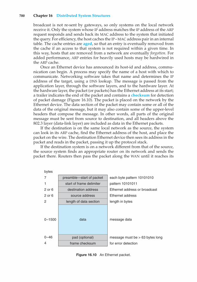
700 Chapter 16 Distributed System Structures
broadcast is not re-sent by gateways, so only systems on the local networkreceive it. Only the system whose IP address matches the IP address of the ARPrequest responds and sends back its MAC address to the system that initiatedthe query. For efficiency, the host caches the IP–MAC address pair in an internaltable. The cache entries are aged, so that an entry is eventually removed fromthe cache if an access to that system is not required within a given time. Inthis way, hosts that are removed from a network are eventually forgotten. Foradded performance, ARP entries for heavily used hosts may be hardwired inthe ARP cache.
Once an Ethernet device has announced its host-id and address, commu-nication can begin. A process may specify the name of a host with which tocommunicate. Networking software takes that name and determines the IPaddress of the target, using a DNS lookup. The message is passed from theapplication layer, through the software layers, and to the hardware layer. Atthe hardware layer, the packet (or packets) has the Ethernet address at its start;a trailer indicates the end of the packet and contains a checksum for detectionof packet damage (Figure 16.10). The packet is placed on the network by theEthernet device. The data section of the packet may contain some or all of thedata of the original message, but it may also contain some of the upper-levelheaders that compose the message. In other words, all parts of the originalmessage must be sent from source to destination, and all headers above the802.3 layer (data-link layer) are included as data in the Ethernet packets.
If the destination is on the same local network as the source, the systemcan look in its ARP cache, find the Ethernet address of the host, and place thepacket on the wire. The destination Ethernet device then sees its address in thepacket and reads in the packet, passing it up the protocol stack.
If the destination system is on a network different from that of the source,the source system finds an appropriate router on its network and sends thepacket there. Routers then pass the packet along the WAN until it reaches its
preamble—start of packet
start of frame delimiter
destination address
source address
length of data section
pad (optional)
frame checksum
bytes
7
1
2 or 6
2 or 6
2
each byte pattern 10101010
pattern 10101011
Ethernet address or broadcast
Ethernet address
length in bytes
message data
message must be > 63 bytes long
for error detection
0–1500
0–46
4
data
Figure 16.10 An Ethernet packet.
Practice Exercises 701
destination network. The router that connects the destination network checksits ARP cache, finds the Ethernet number of the destination, and sends thepacket to that host. Through all of these transfers, the data-link-layer headermay change as the Ethernet address of the next router in the chain is used, butthe other headers of the packet remain the same until the packet is receivedand processed by the protocol stack and finally passed to the receiving processby the kernel.
16.10 Summary
A distributed system is a collection of processors that do not share memory ora clock. Instead, each processor has its own local memory, and the processorscommunicate with one another through various communication lines, suchas high-speed buses and telephone lines. The processors in a distributedsystem vary in size and function. They may include small microprocessors,workstations, minicomputers, and large general-purpose computer systems.
The processors in the system are connected through a communicationnetwork, which can be configured in a number of ways. The network maybe fully or partially connected. It may be a tree, a star, a ring, or a multiaccessbus. The communication-network design must include routing and connectionstrategies, and it must solve the problems of contention and security.
A distributed system provides the user with access to the resourcesthe system provides. Access to a shared resource can be provided by datamigration, computation migration, or process migration.
Protocol stacks, as specified by network layering models, “massage” themessage, adding information to it to ensure that it reaches its destination. Anaming system (such as DNS) must be used to translate from a host nameto a network address, and another protocol (such as ARP) may be neededto translate the network number to a network device address (an Ethernetaddress, for instance). If systems are located on separate networks, routers areneeded to pass packets from source network to destination network.
A distributed system may suffer from various types of hardware failure.For a distributed system to be fault tolerant, it must detect hardware failuresand reconfigure the system. When the failure is repaired, the system must bereconfigured again.
Practice Exercises
16.1 Most WANs employ only a partially connected topology. Why is thisso?
16.2 Under what circumstances is a token-passing network more effectivethan an Ethernet network?
16.3 Why would it be a bad idea for gateways to pass broadcast packetsbetween networks? What would be the advantages of doing so?
16.4 Discuss the advantages and disadvantages of caching name transla-tions for computers located in remote domains.
702 Chapter 16 Distributed System Structures
16.5 What are the advantages and disadvantages of using circuit switching?For what kinds of applications is circuit switching a viable strategy?
16.6 What are two formidable problems that designers must solve toimplement a network-transparent system?
16.7 Process migration within a heterogeneous network is usually impos-sible, given the differences in architectures and operating systems.Describe a method for process migration across different architecturesrunning:
a. The same operating system
b. Different operating systems
16.8 To build a robust distributed system, you must know what kinds offailures can occur.
a. List three possible types of failure in a distributed system.
b. Specify which of the entries in your list also are applicable to acentralized system.
16.9 Is it always crucial to know that the message you have sent has arrivedat its destination safely? If your answer is yes, explain why. If youranswer is no, give appropriate examples.
16.10 Present an algorithm for reconstructing a logical ring after a process inthe ring fails.
16.11 Consider a distributed system with two sites, A and B. Considerwhether site A can distinguish among the following:
a. B goes down.
b. The link between A and B goes down.
c. B is extremely overloaded, and its response time is 100 timeslonger than normal.
What implications does your answer have for recovery in distributedsystems?
Exercises
16.12 What is the difference between computation migration and processmigration? Which is easier to implement, and why?
16.13 Contrast the various network topologies in terms of the followingattributes:
a. Reliability
b. Available bandwidth for concurrent communications
c. Installation cost
d. Load balance in routing responsibilities
Exercises 703
16.14 Even though the ISO model of networking specifies seven layers offunctionality, most computer systems use fewer layers to implement anetwork. Why do they use fewer layers? What problems could the useof fewer layers cause?
16.15 Explain why doubling the speed of the systems on an Ethernet segmentmay result in decreased network performance. What changes couldhelp solve this problem?
16.16 What are the advantages of using dedicated hardware devices forrouters and gateways? What are the disadvantages of using thesedevices compared with using general-purpose computers?
16.17 In what ways is using a name server better than using static host tables?What problems or complications are associated with name servers?What methods could you use to decrease the amount of traffic nameservers generate to satisfy translation requests?
16.18 Name servers are organized in a hierarchical manner. What is thepurpose of using a hierarchical organization?
16.19 Consider a network layer that senses collisions and retransmits imme-diately on detection of a collision. What problems could arise with thisstrategy? How could they be rectified?
16.20 The lower layers of the ISO network model provide datagram service,with no delivery guarantees for messages. A transport-layer protocolsuch as TCP is used to provide reliability. Discuss the advantages anddisadvantages of supporting reliable message delivery at the lowestpossible layer.
16.21 How does using a dynamic routing strategy affect application behav-ior? For what type of applications is it beneficial to use virtual routinginstead of dynamic routing?
16.22 Run the program shown in Figure 16.5 and determine the IP addressesof the following host names:
• www.wiley.com
• www.cs.yale.edu
• www.apple.com
• www.westminstercollege.edu
• www.ietf.org
16.23 The original HTTP protocol used TCP/IP as the underlying networkprotocol. For each page, graphic, or applet, a separate TCP session wasconstructed, used, and torn down. Because of the overhead of buildingand destroying TCP/IP connections, performance problems resultedfrom this implementation method. Would using UDP rather than TCPbe a good alternative? What other changes could you make to improveHTTP performance?
704 Chapter 16 Distributed System Structures
16.24 Of what use is an address-resolution protocol? Why is it better to usesuch a protocol than to make each host read each packet to determinethat packet’s destination? Does a token-passing network need such aprotocol? Explain your answer.
16.25 What are the advantages and the disadvantages of making the com-puter network transparent to the user?
Wiley Plus
Visit Wiley Plus for
• Source code
• Solutions to practice exercises
• Additional programming problems and exercises
• Labs using an operating system simulator
Bibliographical Notes
Tanenbaum [2003], Stallings [2000a], and Kurose and Ross [2005] providegeneral overviews of computer networks. Williams [2001] covers computernetworking from a computer-architecture viewpoint.
The Internet and its protocols are described in Comer [1999] and Comer[2000]. Coverage of TCP/IP can be found in Stevens [1994] and Stevens [1995].UNIX network programming is described thoroughly in Stevens [1997] andStevens [1998].
Discussions concerning distributed operating-system structures have beenoffered by Coulouris et al. [2001] and Tanenbaum and van Steen [2002].
Load balancing and load sharing are discussed by Harchol-Balter andDowney [1997] and Vee and Hsu [2000]. Harish and Owens [1999] describesload-balancing DNS servers. Process migration is discussed by Jul et al. [1988],Douglis and Ousterhout [1991], Han and Ghosh [1998], and Milojicic et al.[2000]. Issues relating to a distributed virtual machine for distributed systemsare examined in Sirer et al. [1999].
1 7C H A P T E RDistributedFileSystems
In the previous chapter, we discussed network construction and the low-levelprotocols needed to transfer messages between systems. Now we examineone use of this infrastructure. A distributed file system (DFS) is a distributedimplementation of the classical time-sharing model of a file system, wheremultiple users share files and storage resources (Chapter 11). The purpose ofa DFS is to support the same kind of sharing when the files are physicallydispersed among the sites of a distributed system.
In this chapter, we describe how a DFS can be designed and implemented.First, we discuss common concepts on which DFSs are based. Then, we illustrateour concepts by examining one influential DFS—the Andrew file system (AFS).
CHAPTER OBJECTIVES
• To explain the naming mechanism that provides location transparency andindependence.
• To describe the various methods for accessing distributed files.
• To contrast stateful and stateless distributed file servers.
• To show how replication of files on different machines in a distributed filesystem is a useful redundancy for improving availability.
• To introduce the Andrew file system (AFS) as an example of a distributedfile system.
17.1 Background
As we noted in the preceding chapter, a distributed system is a collectionof loosely coupled computers interconnected by a communication network.These computers can share physically dispersed files by using a distributedfile system (DFS). In this chapter, we use the term DFS to mean distributed filesystems in general, not the commercial Transarc DFS product; we refer to thelatter as Transarc DFS. Also, NFS refers to NFS Version 3, unless otherwise noted.
705
706 Chapter 17 Distributed File Systems
To explain the structure of a DFS, we need to define the terms service, server,and client. A service is a software entity running on one or more machinesand providing a particular type of function to clients. A server is the servicesoftware running on a single machine. A client is a process that can invokea service using a set of operations that form its client interface. Sometimes alower-level interface is defined for the actual cross-machine interaction; it isthe intermachine interface.
Using this terminology, we say that a file system provides file services toclients. A client interface for a file service is formed by a set of primitive fileoperations, such as create a file, delete a file, read from a file, and write to a file.The primary hardware component that a file server controls is a set of localsecondary-storage devices (usually, magnetic disks) on which files are storedand from which they are retrieved according to the clients’ requests.
A DFS is a file system whose clients, servers, and storage devices aredispersed among the machines of a distributed system. Accordingly, serviceactivity has to be carried out across the network. Instead of a single centralizeddata repository, the system frequently has multiple and independent storagedevices. As you will see, the concrete configuration and implementation of aDFS may vary from system to system. In some configurations, servers run ondedicated machines; in others, a machine can be both a server and a client. A DFScan be implemented as part of a distributed operating system or, alternatively,by a software layer whose task is to manage the communication betweenconventional operating systems and file systems. The distinctive features of aDFS are the multiplicity and autonomy of clients and servers in the system.
Ideally, a DFS should appear to its clients to be a conventional, centralizedfile system. The multiplicity and dispersion of its servers and storage devicesshould be made invisible. That is, the client interface of a DFS should notdistinguish between local and remote files. It is up to the DFS to locate thefiles and to arrange for the transport of the data. A transparent DFS facilitatesuser mobility by bringing a user’s environment (that is, home directory) towherever the user logs in.
The most important performance measure of a DFS is the amount of timeneeded to satisfy service requests. In conventional systems, this time consists ofdisk-access time and a small amount of CPU-processing time. In a DFS, however,a remote access has the additional overhead attributed to the distributedstructure. This overhead includes the time to deliver the request to a server, aswell as the time to get the response across the network back to the client. Foreach direction, in addition to the transfer of the information, there is the CPUoverhead of running the communication protocol software. The performanceof a DFS can be viewed as another dimension of the DFS’s transparency. That is,the performance of an ideal DFS would be comparable to that of a conventionalfile system.
The fact that a DFS manages a set of dispersed storage devices is the DFS’skey distinguishing feature. The overall storage space managed by a DFS iscomposed of different and remotely located smaller storage spaces. Usually,these constituent storage spaces correspond to sets of files. A component unitis the smallest set of files that can be stored on a single machine, independentlyfrom other units. All files belonging to the same component unit must residein the same location.
17.2 Naming and Transparency 707
17.2 Naming and Transparency
Naming is a mapping between logical and physical objects. For instance,users deal with logical data objects represented by file names, whereas thesystem manipulates physical blocks of data stored on disk tracks. Usually, auser refers to a file by a textual name. The latter is mapped to a lower-levelnumerical identifier that in turn is mapped to disk blocks. This multilevelmapping provides users with an abstraction of a file that hides the details ofhow and where on the disk the file is stored.
In a transparent DFS, a new dimension is added to the abstraction: that ofhiding where in the network the file is located. In a conventional file system, therange of the naming mapping is an address within a disk. In a DFS, this rangeis expanded to include the specific machine on whose disk the file is stored.Going one step further with the concept of treating files as abstractions leadsto the possibility of file replication. Given a file name, the mapping returns aset of the locations of this file’s replicas. In this abstraction, both the existenceof multiple copies and their locations are hidden.
17.2.1 Naming Structures
We need to differentiate two related notions regarding name mappings in aDFS:
1. Location transparency. The name of a file does not reveal any hint of thefile’s physical storage location.
2. Location independence. The name of a file does not need to be changedwhen the file’s physical storage location changes.
Both definitions relate to the level of naming discussed previously,since files have different names at different levels (that is, user-level textualnames and system-level numerical identifiers). A location-independent nam-ing scheme is a dynamic mapping, since it can map the same file name todifferent locations at two different times. Therefore, location independence isa stronger property than is location transparency.
In practice, most of the current DFSs provide a static, location-transparentmapping for user-level names. These systems, however, do not support filemigration; that is, changing the location of a file automatically is impossible.Hence, the notion of location independence is irrelevant for these systems.Files are associated permanently with a specific set of disk blocks. Files anddisks can be moved between machines manually, but file migration implies anautomatic, operating-system-initiated action. Only AFS and a few experimentalfile systems support location independence and file mobility. AFS supports filemobility mainly for administrative purposes. A protocol provides migrationof AFS component units to satisfy high-level user requests, without changingeither the user-level names or the low-level names of the corresponding files.
A few aspects can further differentiate location independence and staticlocation transparency:
• Divorce of data from location, as exhibited by location independence,provides a better abstraction for files. A file name should denote the file’s
708 Chapter 17 Distributed File Systems
most significant attributes, which are its contents rather than its location.Location-independent files can be viewed as logical data containers thatare not attached to a specific storage location. If only static locationtransparency is supported, the file name still denotes a specific, althoughhidden, set of physical disk blocks.
• Static location transparency provides users with a convenient way to sharedata. Users can share remote files by simply naming the files in a location-transparent manner, as though the files were local. Nevertheless, sharingthe storage space is cumbersome, because logical names are still staticallyattached to physical storage devices. Location independence promotessharing the storage space itself, as well as the data objects. When files canbe mobilized, the overall, system-wide storage space looks like a singlevirtual resource. A possible benefit of such a view is the ability to balancethe utilization of disks across the system.
• Location independence separates the naming hierarchy from the storage-devices hierarchy and from the intercomputer structure. By contrast, ifstatic location transparency is used (although names are transparent),we can easily expose the correspondence between component units andmachines. The machines are configured in a pattern similar to the namingstructure. This configuration may restrict the architecture of the systemunnecessarily and conflict with other considerations. A server in charge ofa root directory is an example of a structure that is dictated by the naminghierarchy and contradicts decentralization guidelines.
Once the separation of name and location has been completed, clientscan access files residing on remote server systems. In fact, these clients maybe diskless and rely on servers to provide all files, including the operating-system kernel. Special protocols are needed for the boot sequence, however.Consider the problem of getting the kernel to a diskless workstation. Thediskless workstation has no kernel, so it cannot use the DFS code to retrievethe kernel. Instead, a special boot protocol, stored in read-only memory (ROM)on the client, is invoked. It enables networking and retrieves only one specialfile (the kernel or boot code) from a fixed location. Once the kernel is copiedover the network and loaded, its DFS makes all the other operating-system filesavailable. The advantages of diskless clients are many, including lower cost(because the client machines require no disks) and greater convenience (whenan operating-system upgrade occurs, only the server needs to be modified).The disadvantages are the added complexity of the boot protocols and theperformance loss resulting from the use of a network rather than a local disk.
The current trend is for clients to use both local disks and remote file servers.Operating systems and networking software are stored locally; file systemscontaining user data—and possibly applications—are stored on remote filesystems. Some client systems may store commonly used applications, such asword processors and Web browsers, on the local file system as well. Other, lesscommonly used applications may be pushed from the remote file server to theclient on demand. The main reason for providing clients with local file systemsrather than pure diskless systems is that disk drives are rapidly increasing incapacity and decreasing in cost, with new generations appearing every yearor so. The same cannot be said for networks, which evolve every few years.
17.2 Naming and Transparency 709
Overall, systems are growing more quickly than are networks, so extra workis needed to limit network access to improve system throughput.
17.2.2 Naming Schemes
There are three main approaches to naming schemes in a DFS. In the simplestapproach, a file is identified by some combination of its host name and localname, which guarantees a unique system-wide name. In Ibis, for instance,a file is identified uniquely by the name host:local-name, where local-name is aUNIX-like path. This naming scheme is neither location transparent nor locationindependent. Nevertheless, the same file operations can be used for both localand remote files. The DFS is structured as a collection of isolated componentunits, each of which is an entire conventional file system. In this first approach,component units remain isolated, although means are provided to refer to aremote file. We do not consider this scheme any further in this text.
The second approach was popularized by Sun’s network file system, NFS.NFS is the file-system component of ONC+, a networking package supportedby many UNIX vendors. NFS provides a means to attach remote directoriesto local directories, thus giving the appearance of a coherent directory tree.Early NFS versions allowed only previously mounted remote directories tobe accessed transparently. With the advent of the automount feature, mountsare done on demand, based on a table of mount points and file-structurenames. Components are integrated to support transparent sharing, althoughthis integration is limited and is not uniform, because each machine may attachdifferent remote directories to its tree. The resulting structure is versatile.
We can achieve total integration of the component file systems by using thethird approach. Here, a single global name structure spans all the files in thesystem. Ideally, the composed file-system structure is the same as the structureof a conventional file system. In practice, however, the many special files (forexample, UNIX device files and machine-specific binary directories) make thisgoal difficult to attain.
To evaluate naming structures, we look at their administrative complexity.The most complex and most difficult-to-maintain structure is the NFS structure.Because any remote directory can be attached anywhere onto the local directorytree, the resulting hierarchy can be highly unstructured. If a server becomesunavailable, some arbitrary set of directories on different machines becomesunavailable. In addition, a separate accreditation mechanism controls whichmachine is allowed to attach which directory to its tree. Thus, a user mightbe able to access a remote directory tree on one client but be denied access onanother client.
17.2.3 Implementation Techniques
Implementation of transparent naming requires a provision for the mappingof a file name to the associated location. To keep this mapping manageable,we must aggregate sets of files into component units and provide the mappingon a component-unit basis rather than on a single-file basis. This aggregationserves administrative purposes as well. UNIX-like systems use the hierarchicaldirectory tree to provide name-to-location mapping and to aggregate filesrecursively into directories.
710 Chapter 17 Distributed File Systems
To enhance the availability of the crucial mapping information, we can usereplication, local caching, or both. As we noted, location independence meansthat the mapping changes over time; hence, replicating the mapping makesa simple yet consistent update of this information impossible. A techniqueto overcome this obstacle is to introduce low-level location-independent fileidentifiers. Textual file names are mapped to lower-level file identifiers thatindicate to which component unit the file belongs. These identifiers are stilllocation independent. They can be replicated and cached freely without beinginvalidated by migration of component units. The inevitable price is the needfor a second level of mapping, which maps component units to locations andneeds a simple yet consistent update mechanism. Implementing UNIX-likedirectory trees using these low-level, location-independent identifiers makesthe whole hierarchy invariant under component-unit migration. The onlyaspect that does change is the component-unit location mapping.
A common way to implement low-level identifiers is to use structurednames. These names are bit strings that usually have two parts. The firstpart identifies the component unit to which the file belongs; the second partidentifies the particular file within the unit. Variants with more parts arepossible. The invariant of structured names, however, is that individual partsof the name are unique at all times only within the context of the rest of theparts. We can obtain uniqueness at all times by taking care not to reuse a namethat is still in use, by adding sufficiently more bits (this method is used in AFS),or by using a timestamp as one part of the name (as done in Apollo Domain).Another way to view this process is that we are taking a location-transparentsystem, such as Ibis, and adding another level of abstraction to produce alocation-independent naming scheme.
Aggregating files into component units and using lower-level location-independent file identifiers are techniques exemplified in AFS.
17.3 Remote File Access
Consider a user who requests access to a remote file. The server storing the filehas been located by the naming scheme, and now the actual data transfer musttake place.
One way to achieve this transfer is through a remote-service mechanism,whereby requests for accesses are delivered to the server, the server machineperforms the accesses, and their results are forwarded back to the user. Oneof the most common ways of implementing remote service is the remoteprocedure call (RPC) paradigm, which we discussed in Chapter 3. A directanalogy exists between disk-access methods in conventional file systems andthe remote-service method in a DFS: using the remote-service method isanalogous to performing a disk access for each access request.
To ensure reasonable performance of a remote-service mechanism, we canuse a form of caching. In conventional file systems, the rationale for caching isto reduce disk I/O (thereby increasing performance), whereas in DFSs, the goalis to reduce both network traffic and disk I/O. In the following discussion, wedescribe the implementation of caching in a DFS and contrast it with the basicremote-service paradigm.
17.3 Remote File Access 711
17.3.1 Basic Caching Scheme
The concept of caching is simple. If the data needed to satisfy the access requestare not already cached, then a copy of those data is brought from the server tothe client system. Accesses are performed on the cached copy. The idea is toretain recently accessed disk blocks in the cache, so that repeated accesses to thesame information can be handled locally, without additional network traffic.A replacement policy (for example, the least-recently-used algorithm) keepsthe cache size bounded. No direct correspondence exists between accesses andtraffic to the server. Files are still identified with one master copy residing at theserver machine, but copies (or parts) of the file are scattered in different caches.When a cached copy is modified, the changes need to be reflected on the mastercopy to preserve the relevant consistency semantics. The problem of keepingthe cached copies consistent with the master file is the cache-consistencyproblem, which we discuss in Section 17.3.4. DFS caching could just as easilybe called network virtual memory; it acts similarly to demand-paged virtualmemory, except that the backing store usually is not a local disk but rather aremote server. NFS allows the swap space to be mounted remotely, so it actuallycan implement virtual memory over a network, notwithstanding the resultingperformance penalty.
The granularity of the cached data in a DFS can vary from blocks of a file toan entire file. Usually, more data are cached than are needed to satisfy a singleaccess, so that many accesses can be served by the cached data. This procedureis much like disk read-ahead (Section 11.6.2). AFS caches files in large chunks (64KB). The other systems discussed in this chapter support caching of individualblocks driven by client demand. Increasing the caching unit increases the hitratio, but it also increases the miss penalty, because each miss requires moredata to be transferred. It increases the potential for consistency problems aswell. Selecting the unit of caching involves considering parameters such as thenetwork transfer unit and the RPC protocol service unit (if an RPC protocol isused). The network transfer unit (for Ethernet, a packet) is about 1.5 KB, so largerunits of cached data need to be disassembled for delivery and reassembled onreception.
Block size and total cache size are obviously of importance for block-caching schemes. In UNIX-like systems, common block sizes are 4 KB and 8KB. For large caches (over 1 MB), large block sizes (over 8 KB) are beneficial. Forsmaller caches, large block sizes are less beneficial because they result in fewerblocks in the cache and a lower hit ratio.
17.3.2 Cache Location
Where should the cached data be stored—on disk or in main memory? Diskcaches have one clear advantage over main-memory caches: they are reliable.Modifications to cached data are lost in a crash if the cache is kept in volatilememory. Moreover, if the cached data are kept on disk, they are still there duringrecovery, and there is no need to fetch them again. Main-memory caches haveseveral advantages of their own, however:
• Main-memory caches permit workstations to be diskless.
• Data can be accessed more quickly from a cache in main memory thanfrom one on a disk.
712 Chapter 17 Distributed File Systems
• Technology is moving toward larger and less expensive memory. Theresulting performance speedup is predicted to outweigh the advantagesof disk caches.
• The server caches (used to speed up disk I/O) will be in main memoryregardless of where user caches are located; if we use main-memory cacheson the user machine, too, we can build a single caching mechanism for useby both servers and users.
Many remote-access implementations can be thought of as hybrids ofcaching and remote service. In NFS, for instance, the implementation is based onremote service but is augmented with client- and server-side memory cachingfor performance. Similarly, Sprite’s implementation is based on caching; butunder certain circumstances, a remote-service method is adopted. Thus, toevaluate the two methods, we must evaluate the degree to which either methodis emphasized.
The NFS protocol and most implementations do not provide disk caching.Recent Solaris implementations of NFS (Solaris 2.6 and beyond) include a client-side disk-caching option, the cachefs file system. Once the NFS client readsblocks of a file from the server, it caches them in memory as well as on disk.If the memory copy is flushed, or even if the system reboots, the disk cacheis referenced. If a needed block is neither in memory nor in the cachefs diskcache, an RPC is sent to the server to retrieve the block, and the block is writteninto the disk cache as well as stored in the memory cache for client use.
17.3.3 Cache-Update Policy
The policy used to write modified data blocks back to the server’s master copyhas a critical effect on the system’s performance and reliability. The simplestpolicy is to write data through to disk as soon as they are placed in any cache.The advantage of a write-through policy is reliability: little information islost when a client system crashes. However, this policy requires each writeaccess to wait until the information is sent to the server, so it causes poor writeperformance. Caching with write-through is equivalent to using remote servicefor write accesses and exploiting caching only for read accesses.
An alternative is the delayed-write policy, also known as write-backcaching, where we delay updates to the master copy. Modifications are writtento the cache and then are written through to the server at a later time. Thispolicy has two advantages over write-through. First, because writes are madeto the cache, write accesses complete much more quickly. Second, data may beoverwritten before they are written back, in which case only the last updateneeds to be written at all. Unfortunately, delayed-write schemes introducereliability problems, since unwritten data are lost whenever a user machinecrashes.
Variations of the delayed-write policy differ in when modified data blocksare flushed to the server. One alternative is to flush a block when it is about tobe ejected from the client’s cache. This option can result in good performance,but some blocks can reside in the client’s cache a long time before they arewritten back to the server. A compromise between this alternative and thewrite-through policy is to scan the cache at regular intervals and to flushblocks that have been modified since the most recent scan, just as UNIX scans
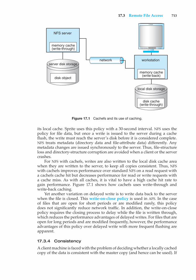
17.3 Remote File Access 713
memory cache (write-through)
disk object
server disk storage
NFS server
network
disk cache (write-through)
local disk storage
memory cache (write-back)
workstation
SUN
Figure 17.1 Cachefs and its use of caching.
its local cache. Sprite uses this policy with a 30-second interval. NFS uses thepolicy for file data, but once a write is issued to the server during a cacheflush, the write must reach the server’s disk before it is considered complete.NFS treats metadata (directory data and file-attribute data) differently. Anymetadata changes are issued synchronously to the server. Thus, file-structureloss and directory-structure corruption are avoided when a client or the servercrashes.
For NFS with cachefs, writes are also written to the local disk cache areawhen they are written to the server, to keep all copies consistent. Thus, NFSwith cachefs improves performance over standard NFS on a read request witha cachefs cache hit but decreases performance for read or write requests witha cache miss. As with all caches, it is vital to have a high cache hit rate togain performance. Figure 17.1 shows how cachefs uses write-through andwrite-back caching.
Yet another variation on delayed write is to write data back to the serverwhen the file is closed. This write-on-close policy is used in AFS. In the caseof files that are open for short periods or are modified rarely, this policydoes not significantly reduce network traffic. In addition, the write-on-closepolicy requires the closing process to delay while the file is written through,which reduces the performance advantages of delayed writes. For files that areopen for long periods and are modified frequently, however, the performanceadvantages of this policy over delayed write with more frequent flushing areapparent.
17.3.4 Consistency
A client machine is faced with the problem of deciding whether a locally cachedcopy of the data is consistent with the master copy (and hence can be used). If
714 Chapter 17 Distributed File Systems
the client machine determines that its cached data are out of date, accesses canno longer be served by those cached data. An up-to-date copy of the data needsto be cached. There are two approaches to verifying the validity of cached data:
1. Client-initiated approach. The client initiates a validity check, in which itcontacts the server and checks whether the local data are consistent withthe master copy. The frequency of the validity checking is the crux ofthis approach and determines the resulting consistency semantics. It canrange from a check before every access to a check only on first access toa file (on file open, basically). Every access coupled with a validity checkis delayed, compared with an access served immediately by the cache.Alternatively, checks can be initiated at fixed time intervals. Dependingon its frequency, the validity check can load both the network and theserver.
2. Server-initiated approach. The server records, for each client, the files(or parts of files) that it caches. When the server detects a potentialinconsistency, it must react. A potential for inconsistency occurs whentwo different clients in conflicting modes cache a file. If UNIX semantics(Section 10.5.3) is implemented, we can resolve the potential inconsistencyby having the server play an active role. The server must be notifiedwhenever a file is opened, and the intended mode (read or write) mustbe indicated for every open. The server can then act when it detects thata file has been opened simultaneously in conflicting modes by disablingcaching for that particular file. Actually, disabling caching results inswitching to a remote-service mode of operation.
17.3.5 AComparisonofCachingandRemoteService
Essentially, the choice between caching and remote service trades off poten-tially increased performance with decreased simplicity. We evaluate thistradeoff by listing the advantages and disadvantages of the two methods:
• When caching is used, the local cache can handle a substantial numberof the remote accesses efficiently. Capitalizing on locality in file-accesspatterns makes caching even more attractive. Thus, most of the remoteaccesses will be served as fast as will local ones. Moreover, servers arecontacted only occasionally, rather than for each access. Consequently,server load and network traffic are reduced, and the potential for scalabilityis enhanced. By contrast, when the remote-service method is used, everyremote access is handled across the network. The penalty in network traffic,server load, and performance is obvious.
• Total network overhead is lower for transmitting big chunks of data (asis done in caching) than for transmitting series of responses to specificrequests (as in the remote-service method). Furthermore, disk-accessroutines on the server may be better optimized if it is known that requestswill always be for large, contiguous segments of data rather than forrandom disk blocks.
• The cache-consistency problem is the major drawback of caching. Whenaccess patterns exhibit infrequent writes, caching is superior. However,
17.4 Stateful Versus Stateless Service 715
when writes are frequent, the mechanisms employed to overcome theconsistency problem incur substantial overhead in terms of performance,network traffic, and server load.
• So that caching will confer a benefit, execution should be carried out onmachines that have either local disks or large main memories. Remoteaccess on diskless, small-memory-capacity machines should be donethrough the remote-service method.
• In caching, since data are transferred en masse between the server and theclient, rather than in response to the specific needs of a file operation, thelower-level intermachine interface is different from the upper-level userinterface. The remote-service paradigm, in contrast, is just an extension ofthe local file-system interface across the network. Thus, the intermachineinterface mirrors the user interface.
17.4 Stateful Versus Stateless Service
There are two approaches for storing server-side information when a clientaccesses remote files: either the server tracks each file being accessed by eachclient, or it simply provides blocks as they are requested by the client withoutknowledge of how those blocks are used. In the former case, the serviceprovided is stateful; in the latter case, it is stateless.
The typical scenario involving a stateful file service is as follows: A clientmust perform anopen()operation on a file before accessing that file. The serverfetches information about the file from its disk, stores it in its memory, and givesthe client a connection identifier that is unique to the client and the open file.(In UNIX terms, the server fetches the inode and gives the client a file descriptor,which serves as an index to an in-core table of inodes.) This identifier is used forsubsequent accesses until the session ends. A stateful service is characterizedas a connection between the client and the server during a session. Either onclosing the file or through a garbage-collection mechanism, the server mustreclaim the main-memory space used by clients that are no longer active. Thekey point regarding fault tolerance in a stateful service approach is that theserver keeps main-memory information about its clients. AFS is a stateful fileservice.
A stateless file service avoids state information by making each requestself-contained. That is, each request identifies the file and the position in thefile (for read and write accesses) in full. The server does not need to keep atable of open files in main memory, although it usually does so for efficiencyreasons. Moreover, there is no need to establish and terminate a connectionthrough open() and close() operations. They are totally redundant, sinceeach file operation stands on its own and is not considered part of a session. Aclient process would open a file, and that open would not result in the sendingof a remote message. Reads and writes would take place as remote messages(or cache lookups). The final close by the client would again result in only alocal operation. NFS is a stateless file service.
The advantage of a stateful over a stateless service is increased perfor-mance. File information is cached in main memory and can be accessed easilyvia the connection identifier, thereby saving disk accesses. In addition, a stateful
716 Chapter 17 Distributed File Systems
server knows whether a file is open for sequential access and can thereforeread ahead the next blocks. Stateless servers cannot do so, since they have noknowledge of the purpose of the client’s requests.
The distinction between stateful and stateless service becomes moreevident when we consider the effects of a crash that occurs during a serviceactivity. A stateful server loses all its volatile state in a crash. Ensuring thegraceful recovery of such a server involves restoring this state, usually by arecovery protocol based on a dialog with clients. Less graceful recovery requiresthat the operations that were underway when the crash occurred be aborted.A different problem is caused by client failures. The server needs to becomeaware of such failures so that it can reclaim space allocated to record the state ofcrashed client processes. This phenomenon is sometimes referred to as orphandetection and elimination.
A stateless computer server avoids these problems, since a newly reincar-nated server can respond to a self-contained request without any difficulty.Therefore, the effects of server failures and recovery are almost unnoticeable.There is no difference between a slow server and a recovering server from aclient’s point of view. The client keeps retransmitting its request if it receivesno response.
The penalty for using the robust stateless service is longer request messagesand slower processing of requests, since there is no in-core information to speedthe processing. In addition, stateless service imposes additional constraintson the design of the DFS. First, since each request identifies the target file, auniform, system-wide, low-level naming scheme should be used. Translatingremote to local names for each request would cause even slower processingof the requests. Second, since clients retransmit requests for file operations,these operations must be idempotent; that is, each operation must have thesame effect and return the same output if executed several times consecutively.Self-contained read and write accesses are idempotent, as long as they use anabsolute byte count to indicate the position within the file they access and donot rely on an incremental offset (as is done in UNIX read() and write()system calls). However, we must be careful when implementing destructiveoperations (such as deleting a file) to make them idempotent, too.
In some environments, a stateful service is a necessity. If the server employsthe server-initiated method for cache validation, it cannot provide statelessservice, since it maintains a record of which files are cached by which clients.
The way UNIX uses file descriptors and implicit offsets is inherently stateful.Servers must maintain tables to map the file descriptors to inodes and muststore the current offset within a file. This requirement is why NFS, whichemploys a stateless service, does not use file descriptors and does includean explicit offset in every access.
17.5 File Replication
Replication of files on different machines in a distributed file system is a usefulredundancy for improving availability. Multimachine replication can benefitperformance too: selecting a nearby replica to serve an access request resultsin shorter service time.
The basic requirement of a replication scheme is that different replicas ofthe same file reside on failure-independent machines. That is, the availability
17.5 File Replication 717
NFS V4
Our coverage of NFS thus far has only considered Version 3 (or V3) NFS. Themost recent NFS standard is Version 4 (V4), and it differs fundamentally fromprevious versions. The most significant change is that the protocol is nowstateful, meaning that the server maintains the state of the client session fromthe time the remote file is opened until it is closed. Thus, the NFS protocol nowprovides open() and close() operations; previous versions of NFS (whichare stateless) provide no such operations. Furthermore, previous versionsspecify separate protocols for mounting remote file systems and for lockingremote files. V4 provides all of these features under a single protocol. Inparticular, the mount protocol was eliminated, allowing NFS to work withnetwork firewalls. The mount protocol was a notorious security hole in NFSimplementations.
Additionally, V4 has enhanced the ability of clients to cache file datalocally. This feature improves the performance of the distributed file system,as clients are able to resolve more file accesses from the local cache ratherthan having to go through the server. V4 allows clients to request file locksfrom servers as well. If the server grants the request, the client maintainsthe lock until it is released or its lease expires. (Clients are also permitted torenew existing leases.) Traditionally, UNIX-based systems provide advisoryfile locking, whereas Windows operating systems use mandatory locking. Toallow NFS to work well with non-UNIX systems, V4 now provides mandatorylocking as well. The new locking and caching mechanisms are based on theconcept of delegation, whereby the server delegates responsibilities for afile’s lock and contents to the client that requested the lock. That delegatedclient maintains in cache the current version of the file, and other clients canask that delegated client for lock access and file contents until the delegatedclient relinquishes the lock and delegation.
Finally, whereas previous versions of NFS are based on the UDP networkprotocol, V4 is based on TCP, which allows it to better adjust to varying trafficloads on the network. Delegating these responsibilities to clients reduces theload on the server and improves cache coherency.
of one replica is not affected by the availability of the rest of the replicas.This obvious requirement implies that replication management is inherentlya location-opaque activity. Provisions for placing a replica on a particularmachine must be available.
It is desirable to hide the details of replication from users. Mapping areplicated file name to a particular replica is the task of the naming scheme.The existence of replicas should be invisible to higher levels. At lowerlevels, however, the replicas must be distinguished from one another bydifferent lower-level names. Another transparency requirement is providingreplication control at higher levels. Replication control includes determinationof the degree of replication and of the placement of replicas. Under certaincircumstances, we may want to expose these details to users. Locus, forinstance, provides users and system administrators with mechanisms to controlthe replication scheme.
718 Chapter 17 Distributed File Systems
The main problem associated with replicas is updating. From a user’spoint of view, replicas of a file denote the same logical entity, and thus anupdate to any replica must be reflected on all other replicas. More precisely,the relevant consistency semantics must be preserved when accesses to replicasare viewed as virtual accesses to the replicas’ logical files. If consistency is notof primary importance, it can be sacrificed for availability and performance. Inthis fundamental tradeoff in the area of fault tolerance, the choice is betweenpreserving consistency at all costs, thereby creating a potential for indefiniteblocking, and sacrificing consistency under some (we hope, rare) circumstancesfor the sake of guaranteed progress. Locus, for example, employs replicationextensively and sacrifices consistency in the case of network partition for thesake of availability of files for read and write accesses.
Ibis uses a variation of the primary-copy approach. The domain of thename mapping is a pair <primary-replica-identifier, local-replica-identifier>. If nolocal replica exists, a special value is used. Thus, the mapping is relative to amachine. If the local replica is the primary one, the pair contains two identicalidentifiers. Ibis supports demand replication, an automatic replication-controlpolicy similar to whole-file caching. Under demand replication, reading ofa nonlocal replica causes it to be cached locally, thereby generating a newnonprimary replica. Updates are performed only on the primary copy andcause all other replicas to be invalidated through the sending of appropriatemessages. Atomic and serialized invalidation of all nonprimary replicas is notguaranteed. Hence, a stale replica may be considered valid. To satisfy remotewrite accesses, we migrate the primary copy to the requesting machine.
17.6 An Example: AFS
Andrew is a distributed computing environment designed and implementedat Carnegie Mellon University. The Andrew file system (AFS) constitutes theunderlying information-sharing mechanism among clients of the environment.The Transarc Corporation took over development of AFS and then was pur-chased by IBM. IBM has since produced several commercial implementationsof AFS. AFS was subsequently chosen as the DFS for an industry coalition; theresult was Transarc DFS, part of the distributed computing environment (DCE)from the OSF organization.
In 2000, IBM’s Transarc Lab announced that AFS would be an open-sourceproduct (termed OpenAFS) available under the IBM public license, and TransarcDFS was canceled as a commercial product. OpenAFS is available under mostcommercial versions of UNIX as well as Linux and Microsoft Windows systems.Many UNIX vendors, as well as Microsoft, support the DCE system and its DFS,which is based on AFS, and work is ongoing to make DCE a cross-platform,universally accepted DFS. As AFS and Transarc DFS are very similar, we describeAFS throughout this section, unless Transarc DFS is named specifically.
AFS seeks to solve many of the problems of the simpler DFSs, such asNFS, and is arguably the most feature-rich nonexperimental DFS. It featuresa uniform name space, location-independent file sharing, client-side cachingwith cache consistency, and secure authentication via Kerberos. It also includesserver-side caching in the form of replicas, with high availability throughautomatic switchover to a replica if the source server is unavailable. One of the
17.6 An Example: AFS 719
most formidable attributes of AFS is scalability: the Andrew system is targetedto span over 5,000 workstations. Between AFS and Transarc DFS, there arehundreds of implementations worldwide.
17.6.1 Overview
AFS distinguishes between client machines (sometimes referred to as worksta-tions) and dedicated server machines. Servers and clients originally ran only 4.2BSD UNIX, but AFS has been ported to many operating systems. The clients andservers are interconnected by a network of LANs or WANs.
Clients are presented with a partitioned space of file names: a local namespace and a shared name space. Dedicated servers, collectively called Viceafter the name of the software they run, present the shared name space to theclients as a homogeneous, identical, and location-transparent file hierarchy.The local name space is the root file system of a workstation, from whichthe shared name space descends. Workstations run the Virtue protocol tocommunicate with Vice, and each is required to have a local disk where itstores its local name space. Servers collectively are responsible for the storageand management of the shared name space. The local name space is small,is distinct for each workstation, and contains system programs essential forautonomous operation and better performance. Also local are temporary filesand files that the workstation owner, for privacy reasons, explicitly wants tostore locally.
Viewed at a finer granularity, clients and servers are structured in clustersinterconnected by a WAN. Each cluster consists of a collection of workstationson a LAN and a representative of Vice called a cluster server, and each clusteris connected to the WAN by a router. The decomposition into clusters isdone primarily to address the problem of scale. For optimal performance,workstations should use the server on their own cluster most of the time,thereby making cross-cluster file references relatively infrequent.
The file-system architecture is also based on considerations of scale. Thebasic heuristic is to offload work from the servers to the clients, in lightof experience indicating that server CPU speed is the system’s bottleneck.Following this heuristic, the key mechanism for remote file operations is tocache files in large chunks (64 KB). This feature reduces file-open latency andallows reads and writes to be directed to the cached copy without frequentlyinvolving the servers.
Briefly, here are a few additional issues in the design of AFS:
• Client mobility. Clients are able to access any file in the shared namespace from any workstation. A client may notice some initial performancedegradation due to the caching of files when accessing files from aworkstation other than the usual one.
• Security. The Vice interface is considered the boundary of trustworthiness,because no client programs are executed on Vice machines. Authenticationand secure-transmission functions are provided as part of a connection-based communication package based on the RPC paradigm. After mutualauthentication, a Vice server and a client communicate via encryptedmessages. Encryption is performed by hardware devices or (more slowly)
720 Chapter 17 Distributed File Systems
in software. Information about clients and groups is stored in a protectiondatabase replicated at each server.
• Protection. AFS provides access lists for protecting directories and theregular UNIX bits for file protection. The access list may contain informationabout those users allowed to access a directory, as well as informationabout those users not allowed to access it. Thus, it is simple to specify thateveryone except, say, Jim can access a directory. AFS supports the accesstypes read, write, lookup, insert, administer, lock, and delete.
• Heterogeneity. Defining a clear interface to Vice is a key for integration ofdiverse workstation hardware and operating systems. So that heterogene-ity is facilitated, some files in the local /bin directory are symbolic linkspointing to machine-specific executable files residing in Vice.
17.6.2 The Shared Name Space
AFS’s shared name space is made up of component units called volumes. Thevolumes are unusually small component units. Typically, they are associatedwith the files of a single client. Few volumes reside within a single diskpartition, and they may grow (up to a quota) and shrink in size. Conceptually,volumes are glued together by a mechanism similar to the UNIX mountmechanism. However, the granularity difference is significant, since in UNIXonly an entire disk partition (containing a file system) can be mounted. Volumesare a key administrative unit and play a vital role in identifying and locatingan individual file.
A Vice file or directory is identified by a low-level identifier called a fid.Each AFS directory entry maps a path-name component to a fid. A fid is 96 bitslong and has three equal-length components: a volume number, a vnode number,and a uniquifier. The vnode number is used as an index into an array containingthe inodes of files in a single volume. The uniquifier allows reuse of vnodenumbers, thereby keeping certain data structures compact. Fids are locationtransparent; therefore, file movements from server to server do not invalidatecached directory contents.
Location information is kept on a volume basis in a volume-locationdatabase replicated on each server. A client can identify the location of everyvolume in the system by querying this database. The aggregation of files intovolumes makes it possible to keep the location database at a manageable size.
To balance the available disk space and utilization of servers, volumesneed to be migrated among disk partitions and servers. When a volume isshipped to its new location, its original server is left with temporary forwardinginformation, so that the location database need not be updated synchronously.While the volume is being transferred, the original server can still handleupdates, which are shipped later to the new server. At some point, the volumeis briefly disabled so that the recent modifications can be processed; then, thenew volume becomes available again at the new site. The volume-movementoperation is atomic; if either server crashes, the operation is aborted.
Read-only replication at the granularity of an entire volume is supportedfor system-executable files and for seldom-updated files in the upper levelsof the Vice name space. The volume-location database specifies the server
17.6 An Example: AFS 721
containing the only read–write copy of a volume and a list of read-onlyreplication sites.
17.6.3 File Operations and Consistency Semantics
The fundamental architectural principle in AFS is the caching of entire filesfrom servers. Accordingly, a client workstation interacts with Vice serversonly during opening and closing of files, and even this interaction is notalways necessary. Reading and writing files do not cause remote interaction (incontrast to the remote-service method). This key distinction has far-reachingramifications for performance, as well as for semantics of file operations.
The operating system on each workstation intercepts file-system calls andforwards them to a client-level process on that workstation. This process, calledVenus, caches files from Vice when they are opened and stores modified copiesof files back on the servers from which they came when they are closed. Venusmay contact Vice only when a file is opened or closed; reading and writing ofindividual bytes of a file are performed directly on the cached copy and bypassVenus. As a result, writes at some sites are not visible immediately at othersites.
Caching is further exploited for future opens of the cached file. Venusassumes that cached entries (files or directories) are valid unless notifiedotherwise. Therefore, Venus does not need to contact Vice on a file open tovalidate the cached copy. The mechanism to support this policy, called callback,dramatically reduces the number of cache-validation requests received byservers. It works as follows. When a client caches a file or a directory, theserver updates its state information to record this caching. We say that theclient has a callback on that file. The server notifies the client before allowinganother client to modify the file. In such a case, we say that the server removesthe callback on the file for the former client. A client can use a cached file foropen purposes only when the file has a callback. If a client closes a file aftermodifying it, all other clients caching this file lose their callbacks. Therefore,when these clients open the file later, they have to get the new version fromthe server.
Reading and writing bytes of a file are done directly by the kernel withoutVenus’s intervention on the cached copy. Venus regains control when the file isclosed. If the file has been modified locally, it updates the file on the appropriateserver. Thus, the only occasions on which Venus contacts Vice servers are onopens of files that either are not in the cache or have had their callback revokedand on closes of locally modified files.
Basically, AFS implements session semantics. The only exceptions arefile operations other than the primitive read and write (such as protectionchanges at the directory level), which are visible everywhere on the networkimmediately after the operation completes.
In spite of the callback mechanism, a small amount of cached validationtraffic is still present, usually to replace callbacks lost because of machine ornetwork failures. When a workstation is rebooted, Venus considers all cachedfiles and directories suspect, and it generates a cache-validation request for thefirst use of each such entry.
The callback mechanism forces each server to maintain callback informa-tion and each client to maintain validity information. If the amount of callback
722 Chapter 17 Distributed File Systems
information maintained by a server is excessive, the server can break callbacksand reclaim some storage by unilaterally notifying clients and revoking thevalidity of their cached files. If the callback state maintained by Venus getsout of sync with the corresponding state maintained by the servers, someinconsistency may result.
Venus also caches contents of directories and symbolic links, for path-name translation. Each component in the path name is fetched, and a callbackis established for it if it is not already cached or if the client does not havea callback on it. Venus does lookups on the fetched directories locally, usingfids. No requests are forwarded from one server to another. At the end of apath-name traversal, all the intermediate directories and the target file are inthe cache with callbacks on them. Future open calls to this file will involve nonetwork communication at all, unless a callback is broken on a component ofthe path name.
The only exception to the caching policy is a modification to a directorythat is made directly on the server responsible for that directory for reasonsof integrity. The Vice interface has well-defined operations for such purposes.Venus reflects the changes in its cached copy to avoid re-fetching the directory.
17.6.4 Implementation
Client processes are interfaced to a UNIX kernel with the usual set of systemcalls. The kernel is modified slightly to detect references to Vice files in therelevant operations and to forward the requests to the client-level Venus processat the workstation.
Venus carries out path-name translation component by component, asdescribed above. It has a mapping cache that associates volumes to serverlocations in order to avoid server interrogation for an already known volumelocation. If a volume is not present in this cache, Venus contacts any serverto which it already has a connection, requests the location information, andenters that information into the mapping cache. Unless Venus already hasa connection to the server, it establishes a new connection. It then uses thisconnection to fetch the file or directory. Connection establishment is needed forauthentication and security purposes. When a target file is found and cached, acopy is created on the local disk. Venus then returns to the kernel, which opensthe cached copy and returns its handle to the client process.
The UNIX file system is used as a low-level storage system for both AFSservers and clients. The client cache is a local directory on the workstation’sdisk. Within this directory are files whose names are placeholders for cacheentries. Both Venus and server processes access UNIX files directly by the latter’sinodes to avoid the expensive path-name-to-inode translation routine (namei).Because the internal inode interface is not visible to client-level processes (bothVenus and server processes are client-level processes), an appropriate set ofadditional system calls was added. DFS uses its own journaling file system toimprove performance and reliability over UFS.
Venus manages two separate caches: one for status and the other for data.It uses a simple least-recently-used (LRU) algorithm to keep each of thembounded in size. When a file is flushed from the cache, Venus notifies theappropriate server to remove the callback for this file. The status cache is keptin virtual memory to allow rapid servicing of stat() (file-status-returning)
17.7 Summary 723
system calls. The data cache is resident on the local disk, but the UNIX I/Obuffering mechanism does some caching of disk blocks in memory that istransparent to Venus.
A single client-level process on each file server services all file requests fromclients. This process uses a lightweight-process package with non-preemptiblescheduling to service many client requests concurrently. The RPC packageis integrated with the lightweight-process package, thereby allowing the fileserver to concurrently make or service one RPC per lightweight process. TheRPC package is built on top of a low-level datagram abstraction. Whole-filetransfer is implemented as a side effect of the RPC calls. One RPC connectionexists per client, but there is no a priori binding of lightweight processes to theseconnections. Instead, a pool of lightweight processes services client requestson all connections. The use of a single multithreaded server process allows thecaching of data structures needed to service requests. On the negative side,a crash of a single server process has the disastrous effect of paralyzing thisparticular server.
17.7 Summary
A DFS is a file-service system whose clients, servers, and storage devices aredispersed among the sites of a distributed system. Accordingly, service activityhas to be carried out across the network; instead of a single centralized datarepository, there are multiple independent storage devices.
Ideally, a DFS should look to its clients like a conventional, centralizedfile system. The multiplicity and dispersion of its servers and storage devicesshould be made transparent. That is, the client interface of a DFS should notdistinguish between local and remote files. It is up to the DFS to locate the filesand to arrange for the transport of the data. A transparent DFS facilitates clientmobility by bringing the client’s environment to the site where the client logsin.
There are several approaches to naming schemes in a DFS. In the simplestapproach, files are named by some combination of their host name and localname, which guarantees a unique system-wide name. Another approach,popularized by NFS, provides a means to attach remote directories to localdirectories, thus giving the appearance of a coherent directory tree.
Requests to access a remote file are usually handled by two complementarymethods. With remote service, requests for accesses are delivered to the server.The server machine performs the accesses, and their results are forwardedback to the client. With caching, if the data needed to satisfy the access requestare not already cached, then a copy of the data is brought from the serverto the client. Accesses are performed on the cached copy. The idea is toretain recently accessed disk blocks in the cache, so that repeated accessesto the same information can be handled locally, without additional networktraffic. A replacement policy is used to keep the cache size bounded. Theproblem of keeping the cached copies consistent with the master file is thecache-consistency problem.
There are two approaches to server-side information. Either the servertracks each file the client accesses, or it simply provides blocks as the clientrequests them without knowledge of their use. These approaches are thestateful versus stateless service paradigms.
724 Chapter 17 Distributed File Systems
Replication of files on different machines is a useful redundancy forimproving availability. Multimachine replication can benefit performance, too,since selecting a nearby replica to serve an access request results in shorterservice time.
AFS is a feature-rich DFS characterized by location independence and loca-tion transparency. It also imposes significant consistency semantics. Cachingand replication are used to improve performance.
Exercises
17.1 What are the benefits of a DFS compared with a file system in acentralized system?
17.2 Which of the example DFSs discussed in this chapter would handle alarge, multiclient database application most efficiently? Explain youranswer.
17.3 Discuss whether AFS and NFS provide the following: (a) locationtransparency and (b) location independence.
17.4 Under what circumstances would a client prefer a location-transparent DFS? Under what circumstances would she prefer alocation-independent DFS? Discuss the reasons for these preferences.
17.5 What aspects of a distributed system would you select for a systemrunning on a totally reliable network?
17.6 Consider AFS, which is a stateful distributed file system. What actionsneed to be performed to recover from a server crash in order to preservethe consistency guaranteed by the system?
17.7 Compare and contrast the techniques of caching disk blocks locally, ona client system, and remotely, on a server.
17.8 AFS is designed to support a large number of clients. Discuss threetechniques used to make AFS a scalable system.
17.9 Discuss the advantages and disadvantages of path-name translationin which the client ships the entire path to the server requesting atranslation for the entire path name of the file.
17.10 What are the benefits of mapping objects into virtual memory, as ApolloDomain does? What are the drawbacks?
17.11 Describe some of the fundamental differences between AFS and NFS(see Chapter 11).
17.12 Discuss whether clients in the following systems can obtain inconsistentor stale data from the file server and, if so, under what scenarios thiscould occur.
a. AFS
b. Sprite
c. NFS
Bibliographical Notes 725
Wiley Plus
Visit Wiley Plus for
• Source code
• Solutions to practice exercises
• Additional programming problems and exercises
• Labs using an operating system simulator
Bibliographical Notes
Consistency and recovery control for replicated files are examined by Davcevand Burkhard [1985]. Management of replicated files in a UNIX environment iscovered by Brereton [1986] and Purdin et al. [1987]. Wah [1984] discusses theissue of file placement on distributed computer systems. A detailed survey ofmainly centralized file servers appears in Svobodova [1984].
Sun’s network file system (NFS) is described by Callaghan [2000] andSandberg et al. [1985]. The AFS system is discussed by Morris et al. [1986],Howard et al. [1988], and Satyanarayanan [1990]. Information about OpenAFSis available from http://www.openafs.org
Many different and interesting DFSs are not covered in detail in thistext, including UNIX United, Sprite, and Locus. UNIX United is described byBrownbridge et al. [1982]. The Locus system is discussed by Popek and Walker[1985]. The Sprite system is described by Ousterhout et al. [1988] and Nelsonet al. [1988]. Distributed file systems for mobile storage devices are discussed inKistler and Satyanarayanan [1992] and Sobti et al. [2004]. Considerable researchhas also been performed on cluster-based distributed file systems (Andersonet al. [1995], Lee and Thekkath [1996], Thekkath et al. [1997], and Andersonet al. [2000]). Distributed storage systems for large-scale, wide-area settings arepresented in Dabek et al. [2001] and Kubiatowicz et al. [2000].

This page intentionally left blank
18C H A P T E R
DistributedCoordination
In Chapter 6, we described various mechanisms that allow processes tosynchronize their actions. We also discussed a number of schemes to ensurethe atomicity of a transaction that executes either in isolation or concurrentlywith other transactions. In Chapter 7, we described various methods that anoperating system can use to deal with the deadlock problem. In this chapter,we examine how centralized synchronization mechanisms can be extended toa distributed environment. We also discuss methods for handling deadlocks ina distributed system.
CHAPTER OBJECTIVES
• To describe various methods for achieving mutual exclusion in a distributedsystem.
• To explain how atomic transactions can be implemented in a distributedsystem.
• To show how some of the concurrency-control schemes discussed inChapter 6 can be modified for use in a distributed environment.
• To present schemes for handling deadlock prevention, deadlock avoid-ance, and deadlock detection in a distributed system.
18.1 Event Ordering
In a centralized system, we can always determine the order in which twoevents occurred, since the system has a single common memory and clock.Many applications may require us to determine order. For example, in aresource-allocation scheme, we specify that a resource can be used only afterthe resource has been granted. A distributed system, however, has no commonmemory and no common clock. Therefore, it is sometimes impossible to saywhich of two events occurred first. The happened-before relation, discussednext, is only a partial ordering of the events in distributed systems. Since
727
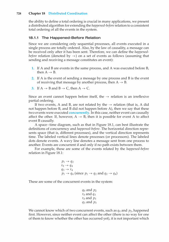
728 Chapter 18 Distributed Coordination
the ability to define a total ordering is crucial in many applications, we presenta distributed algorithm for extending the happened-before relation to a consistenttotal ordering of all the events in the system.
18.1.1 The Happened-Before Relation
Since we are considering only sequential processes, all events executed in asingle process are totally ordered. Also, by the law of causality, a message canbe received only after it has been sent. Therefore, we can define the happened-before relation (denoted by →) on a set of events as follows (assuming thatsending and receiving a message constitutes an event):
1. If A and B are events in the same process, and A was executed before B,then A → B.
2. If A is the event of sending a message by one process and B is the eventof receiving that message by another process, then A → B.
3. If A → B and B → C, then A → C.
Since an event cannot happen before itself, the → relation is an irreflexivepartial ordering.
If two events, A and B, are not related by the → relation (that is, A didnot happen before B, and B did not happen before A), then we say that thesetwo events were executed concurrently. In this case, neither event can causallyaffect the other. If, however, A → B, then it is possible for event A to affectevent B causally.
A space–time diagram, such as that in Figure 18.1, can best illustrate thedefinitions of concurrency and happened-before. The horizontal direction repre-sents space (that is, different processes), and the vertical direction representstime. The labeled vertical lines denote processes (or processors). The labeleddots denote events. A wavy line denotes a message sent from one process toanother. Events are concurrent if and only if no path exists between them.
For example, these are some of the events related by the happened-beforerelation in Figure 18.1:
p1 → q2r0 → q4q3 → r4p1 → q4 (since p1 → q2 and q2 → q4)
These are some of the concurrent events in the system:
q0 and p2r0 and q3r0 and p3q3 and p3
We cannot know which of two concurrent events, such as q0 and p2, happenedfirst. However, since neither event can affect the other (there is no way for oneof them to know whether the other has occurred yet), it is not important which
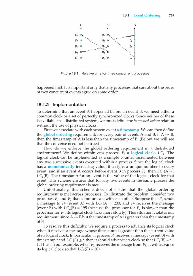
18.1 Event Ordering 729
P
p4
p3
p2
p1
p0
q4
q3
q2
q1
q0
r4
r3
r2
r1
r0
Q R
Figure 18.1 Relative time for three concurrent processes.
happened first. It is important only that any processes that care about the orderof two concurrent events agree on some order.
18.1.2 Implementation
To determine that an event A happened before an event B, we need either acommon clock or a set of perfectly synchronized clocks. Since neither of theseis available in a distributed system, we must define the happened-before relationwithout the use of physical clocks.
First we associate with each system event a timestamp. We can then definethe global ordering requirement: for every pair of events A and B, if A → B,then the timestamp of A is less than the timestamp of B. (Below, we will seethat the converse need not be true.)
How do we enforce the global ordering requirement in a distributedenvironment? We define within each process Pi a logical clock, LCi . Thelogical clock can be implemented as a simple counter incremented betweenany two successive events executed within a process. Since the logical clockhas a monotonically increasing value, it assigns a unique number to everyevent, and if an event A occurs before event B in process Pi , then LCi (A) <
LCi (B). The timestamp for an event is the value of the logical clock for thatevent. This scheme ensures that for any two events in the same process theglobal ordering requirement is met.
Unfortunately, this scheme does not ensure that the global orderingrequirement is met across processes. To illustrate the problem, consider twoprocesses P1 and P2 that communicate with each other. Suppose that P1 sendsa message to P2 (event A) with LC1(A) = 200, and P2 receives the message(event B) with LC2(B) = 195 (because the processor for P2 is slower than theprocessor for P1, its logical clock ticks more slowly). This situation violates ourrequirement, since A → B but the timestamp of A is greater than the timestampof B.
To resolve this difficulty, we require a process to advance its logical clockwhen it receives a message whose timestamp is greater than the current valueof its logical clock. In particular, if process Pi receives a message (event B) withtimestamp t and LCi (B) ≤ t, then it should advance its clock so that LCi (B) = t +1. Thus, in our example, when P2 receives the message from P1, it will advanceits logical clock so that LC2(B) = 201.
730 Chapter 18 Distributed Coordination
Finally, to realize a total ordering, we need only observe that, with ourtimestamp-ordering scheme, if the timestamps of two events, A and B, are thesame, then the events are concurrent. In this case, we may use process identitynumbers to break ties and to create a total ordering. The use of timestamps isfurther discussed in Section 18.4.2.
18.2 Mutual Exclusion
In this section, we present a number of different algorithms for implementingmutual exclusion in a distributed environment. We assume that the systemconsists of n processes, each of which resides at a different processor. To simplifyour discussion, we assume that processes are numbered uniquely from 1 to nand that a one-to-one mapping exists between processes and processors (thatis, each process has its own processor).
18.2.1 Centralized Approach
In a centralized approach to providing mutual exclusion, one of the processesin the system is chosen to coordinate the entry to the critical section. Eachprocess that wants to invoke mutual exclusion sends a request message to thecoordinator. When the process receives a reply message from the coordinator, itcan enter its critical section. After exiting its critical section, the process sendsa release message to the coordinator and proceeds with its execution.
On receiving a request message, the coordinator checks to see whether someother process is in its critical section. If no process is in its critical section, thecoordinator immediately sends back a reply message. Otherwise, the requestis queued. When the coordinator receives a release message, it removes oneof the request messages from the queue (in accordance with some schedulingalgorithm) and sends a reply message to the requesting process.
It should be clear that this algorithm ensures mutual exclusion. In addition,if the scheduling policy within the coordinator is fair—such as first-come, first-served (FCFS) scheduling—no starvation can occur. This scheme requires threemessages per critical-section entry: a request, a reply, and a release.
If the coordinator process fails, then a new process must take its place.In Section 18.6, we describe some algorithms for electing a unique newcoordinator. Once a new coordinator has been elected, it must poll all theprocesses in the system to reconstruct its request queue. Once the queue hasbeen constructed, the computation can resume.
18.2.2 Fully Distributed Approach
If we want to distribute the decision making across the entire system, thenthe solution is far more complicated. One approach, described next, uses analgorithm based on the event-ordering scheme described in Section 18.1.
When a process Pi wants to enter its critical section, it generates a newtimestamp, TS, and sends the message request(Pi , TS) to all processes in thesystem (including itself). On receiving a request message, a process may replyimmediately (that is, send a reply message back to Pi ), or it may defer sendinga reply back (because it is already in its critical section, for example). A processthat has received a reply message from all other processes in the system can
18.2 Mutual Exclusion 731
enter its critical section, queueing incoming requests and deferring them. Afterexiting its critical section, the process sends reply messages to all its deferredrequests.
The decision whether process Pi replies immediately to a request(Pj , TS)message or defers its reply is based on three factors:
1. If process Pi is in its critical section, then it defers its reply to Pj .
2. If process Pi does not want to enter its critical section, then it sends a replyimmediately to Pj .
3. If process Pi wants to enter its critical section but has not yet enteredit, then it compares its own request timestamp with the timestamp ofthe incoming request made by process Pj . If its own request timestampis greater than that of the incoming request, then it sends a replyimmediately to Pj (Pj asked first). Otherwise, the reply is deferred.
This algorithm exhibits the following desirable behavior:
• Mutual exclusion is obtained.
• Freedom from deadlock is ensured.
• Freedom from starvation is ensured, since entry to the critical section isscheduled according to the timestamp ordering. The timestamp orderingensures that processes are served in FCFS order.
• The number of messages per critical-section entry is 2 × (n−1). This numberrepresents the minimum number of required messages per critical-sectionentry when processes act independently and concurrently.
To illustrate how the algorithm functions, we consider a system consistingof processes P1, P2, and P3. Suppose that processes P1 and P3 want to entertheir critical sections. Process P1 then sends a message request (P1, timestamp= 10) to processes P2 and P3, while process P3 sends a message request (P3,timestamp = 4) to processes P1 and P2. (The timestamps 4 and 10 were obtainedfrom the logical clocks described in Section 18.1.) When process P2 receivesthese request messages, it replies immediately. When process P1 receives therequest from process P3, it replies immediately, since the timestamp (10) on itsown request message is greater than the timestamp (4) for process P3. Whenprocess P3 receives the request message from process P1, it defers its reply,since the timestamp (4) on its request message is less than the timestamp (10)for the message from process P1. On receiving replies from both process P1and process P2, process P3 can enter its critical section. After exiting its criticalsection, process P3 sends a reply to process P1, which can then enter its criticalsection.
Because this scheme requires the participation of all the processes in thesystem, it has three undesirable consequences:
1. The processes need to know the identity of all other processes in thesystem. When a new process joins the group of processes participating inthe mutual-exclusion algorithm, the following actions need to be taken:
732 Chapter 18 Distributed Coordination
a. The process must receive the names of all the other processes in thegroup.
b. The name of the new process must be distributed to all the otherprocesses in the group.
This task is not as trivial as it may seem, since some request and replymessages may be circulating in the system when the new process joinsthe group. The interested reader is referred to the bibliographical notesat the end of the chapter.
2. If one process fails, then the entire scheme collapses. We can resolve thisdifficulty by continuously monitoring the state of all processes in thesystem. If one process fails, then all other processes are notified, so thatthey will no longer send request messages to the failed process. When aprocess recovers, it must initiate the procedure that allows it to rejoin thegroup.
3. Processes that have not entered their critical section must pause fre-quently to assure other processes that they intend to enter the criticalsection.
Because of these difficulties, this protocol is best suited for small, stable sets ofcooperating processes.
18.2.3 Token-Passing Approach
Another method of providing mutual exclusion is to circulate a token amongthe processes in the system. A token is a special type of message that is passedfrom process to process. Possession of the token entitles the holder to enter thecritical section. Since there is only a single token, only one process can be in itscritical section at a time.
We assume that the processes in the system are logically organized in a ringstructure. The physical communication network need not be a ring. As long asthe processes are connected to one another, it is possible to implement a logicalring. To implement mutual exclusion, we pass the token around the ring. Whena process receives the token, it may enter its critical section, keeping the token.After the process exits its critical section, the token is passed around again.If the process receiving the token does not want to enter its critical section,it passes the token to its neighbor. This scheme is similar to algorithm 1 inChapter 6, but a token is substituted for a shared variable.
If the ring is unidirectional, freedom from starvation is ensured. Thenumber of messages required to implement mutual exclusion may vary fromone message per entry, in the case of high contention (that is, every processwants to enter its critical section), to an infinite number of messages, in the caseof low contention (that is, no process wants to enter its critical section).
Two types of failure must be considered. First, if the token is lost, an electionmust be called to generate a new token. Second, if a process fails, a new logicalring must be established. In Section 18.6, we present an election algorithm;others are possible. The development of an algorithm for reconstructing thering is left to you in Exercise 18.9.
18.3 Atomicity 733
18.3 Atomicity
In Chapter 6, we introduced the concept of an atomic transaction, which is aprogram unit that must be executed atomically. That is, either all the operationsassociated with it are executed to completion, or none are performed. When weare dealing with a distributed system, ensuring the atomicity of a transactionbecomes much more complicated than in a centralized system. This difficultyoccurs because several sites may be participating in the execution of a singletransaction. The failure of one of these sites, or the failure of a communicationlink connecting the sites, may result in erroneous computations.
Ensuring that the execution of transactions in the distributed systempreserves atomicity is the function of the transaction coordinator. Each site hasits own local transaction coordinator, which is responsible for coordinating theexecution of all the transactions initiated at that site. For each such transaction,the coordinator is responsible for the following:
• Starting the execution of the transaction
• Breaking the transaction into a number of subtransactions and distributingthese subtransactions to the appropriate sites for execution
• Coordinating the termination of the transaction, which may result in thetransactions being committed at all sites or aborted at all sites
We assume that each local site maintains a log for recovery purposes.
18.3.1 The Two-Phase Commit Protocol
For atomicity to be ensured, all the sites in which a transaction T has executedmust agree on the final outcome of the execution. T must either commit atall sites, or it must abort at all sites. To ensure this property, the transactioncoordinator of T must execute a commit protocol. Among the simplest andmost widely used commit protocols is the two-phase commit (2PC) protocol,which we discuss next.
Assume that T is a transaction initiated at site Si and that the transactioncoordinator at Si is Ci . When T completes its execution—that is, when all thesites at which T has executed inform Ci that T has completed—then Ci startsthe 2PC protocol.
• Phase 1. Ci adds the record <prepare T> to the log and forces the recordonto stable storage. It then sends a prepare (T) message to all the sites atwhich T has executed. On receiving the message, the transaction managerat each of these sites determines whether it is willing to commit its portionof T. If the answer is no, it adds a record <no T> to the log, and then itresponds by sending an abort (T) message to Ci . If the answer is yes, it addsa record <ready T> to the log and forces all the log records correspondingto T onto stable storage. The transaction manager then replies with a ready(T) message to Ci .
• Phase 2. When Ci has received responses to the prepare (T) message fromall the sites, or when a pre-specified interval of time has elapsed since theprepare (T) message was sent out, Ci can determine whether the transaction
734 Chapter 18 Distributed Coordination
T can be committed or aborted. Transaction T can be committed if Ci hasreceived a ready (T) message from all the participating sites. Otherwise,transaction T must be aborted. Depending on the verdict, either a record<commit T> or a record <abort T> is added to the log and forced ontostable storage. At this point, the fate of the transaction has been sealed.Following this, the coordinator sends either a commit (T) or an abort (T)message to all participating sites. When a site receives that message, itrecords the message in the log.
A site at which T has executed can unconditionally abort T at any time priorto its sending the message ready (T) to the coordinator. The ready (T) messageis, in effect, a promise by a site to follow the coordinator’s order to commit T orto abort T. A site can make such a promise only when the needed informationis stored in stable storage. Otherwise, if the site crashes after sending ready (T),it may be unable to make good on its promise.
Since unanimity is required to commit a transaction, the fate of T is sealedas soon as at least one site responds with abort (T). Note that the coordinatorsite Si can decide unilaterally to abort T, as it is one of the sites at whichT has executed. The final verdict regarding T is determined at the time thecoordinator writes that verdict (commit or abort) to the log and forces it tostable storage.
In some implementations of the 2PC protocol, a site sends an acknowledge(T) message to the coordinator at the end of the second phase of the protocol.When the coordinator has received the acknowledge (T) message from all thesites, it adds the record <complete T> to the log.
18.3.2 Failure Handling in 2PC
We now examine in detail how 2PC responds to various types of failures. Aswe shall see, one major disadvantage of the 2PC protocol is that coordinatorfailure may result in blocking, and a decision either to commit or to abort Tmay have to be postponed until the coordinator recovers.
18.3.2.1 Failure of a Participating Site
When a participating site Sk recovers from a failure, it must examine its logto determine the fate of those transactions that were in the midst of executionwhen the failure occurred. Suppose that T is one such transaction. How will Skdeal with T? We consider each of the possible alternatives:
• The log contains a <commit T> record. In this case, the site executesredo(T).
• The log contains an <abort T> record. In this case, the site executesundo(T).
• The log contains a <ready T> record. In this case, the site must consultCi to determine the fate of T. If Ci is up, it tells Sk whether T committedor aborted. In the former case, it executes redo(T); in the latter case, itexecutes undo(T). If Ci is down, Sk must try to find out the fate of Tfrom other sites. It does so by sending a query-status (T) message to allthe sites in the system. On receiving such a message, a site must consult
18.3 Atomicity 735
its log to determine whether T has executed there and, if so, whether Tcommitted or aborted. It then notifies Sk about this outcome. If no site hasthe appropriate information (that is, whether T committed or aborted), thenSk can neither abort nor commit T. The decision concerning T is postponeduntil Sk can obtain the needed information. Thus, Sk must periodicallyresend the query-status (T) message to the other sites. It does so until a siteresponds with the needed information. The site at which Ci resides alwayshas this information.
• The log contains no control records (abort, commit, ready) concerning T.The absence of control records implies that Sk failed before responding tothe prepare (T) message from Ci . Since the failure of Sk means that it couldnot have sent such a response, by our algorithm, Ci must have aborted T.Hence, Sk must execute undo(T).
18.3.2.2 Failure of the Coordinator
If the coordinator fails in the midst of the execution of the commit protocol fortransaction T, then the participating sites must decide the fate of T. We shall seethat, in certain cases, the participating sites cannot decide whether to commitor abort T, and therefore these sites must wait for the recovery of the failedcoordinator.
• If an active site contains a <commit T> record in its log, then T must becommitted.
• If an active site contains an <abort T> record in its log, then T must beaborted.
• If some active site does not contain a <ready T> record in its log, then thefailed coordinator Ci cannot have decided to commit T. We can draw thisconclusion because a site that does not have a <ready T> record in its logcannot have sent a ready (T) message to Ci . However, the coordinator mayhave decided to abort T. Rather than wait for Ci to recover, it is preferableto abort T in this case.
• If none of the preceding cases holds, then all the active sites must have a<ready T> record in their logs, but no additional control records (suchas <abort T> or <commit T>). Since the coordinator has failed, it isimpossible to determine whether a decision has been made—or, if so,what that decision is—until the coordinator recovers. Thus, the activesites must wait for Ci to recover. As long as the fate of T remains in doubt,T may continue to hold system resources. For example, if locking is used,T may hold locks on data at active sites. Such a situation is undesirablebecause hours or days may pass before Ci is again active. During thistime, other transactions may be forced to wait for T. As a result, data areunavailable not only on the failed site (Ci ) but on active sites as well. Theamount of unavailable data increases as the downtime of Ci grows. Thissituation is called the blocking problem, because T is blocked pending therecovery of site Ci .
736 Chapter 18 Distributed Coordination
18.3.2.3 Failure of the Network
When a link fails, the messages in the process of being routed through thelink do not arrive at their destinations intact. From the viewpoint of the sitesconnected throughout that link, the other sites appear to have failed. Thus, ourprevious schemes apply here as well.
When a number of links fail, the network may partition. In this case,two possibilities exist. The coordinator and all its participants may remain inone partition; in this case, the failure has no effect on the commit protocol.Alternatively, the coordinator and its participants may belong to severalpartitions; in this case, messages between the participant and the coordinatorare lost, reducing the case to a link failure.
18.4 Concurrency Control
We move next to the issue of concurrency control. In this section, we showhow certain of the concurrency-control schemes discussed in Chapter 6 can bemodified for use in a distributed environment.
The transaction manager of a distributed database system manages theexecution of those transactions (or subtransactions) that access data storedin a local site. Each such transaction may be either a local transaction(that is, a transaction that executes only at that site) or part of a globaltransaction (that is, a transaction that executes at several sites). Each transactionmanager is responsible for maintaining a log for recovery purposes and forparticipating in an appropriate concurrency-control scheme to coordinate theconcurrent execution of the transactions executing at that site. As we shallsee, the concurrency schemes described in Chapter 6 need to be modified toaccommodate the distribution of transactions.
18.4.1 Locking Protocols
The two-phase locking protocols described in Chapter 6 can be used in adistributed environment. The only change needed is in the way the lockmanager is implemented. Here, we present several possible schemes. The firstdeals with the case where no data replication is allowed. The others applyto the more general case where data can be replicated in several sites. As inChapter 6, we assume the existence of the shared and exclusive lock modes.
18.4.1.1 Nonreplicated Scheme
If no data are replicated in the system, then the locking schemes described inSection 6.9 can be applied as follows: Each site maintains a local lock managerwhose function is to administer the lock and unlock requests for those dataitems stored in that site. When a transaction wishes to lock data item Q at siteSi , it simply sends a message to the lock manager at site Si requesting a lock(in a particular lock mode). If data item Q is locked in an incompatible mode,then the request is delayed until that request can be granted. Once it has beendetermined that the lock request can be granted, the lock manager sends amessage back to the initiator indicating that the lock request has been granted.
18.4 Concurrency Control 737
This scheme has the advantage of simple implementation. It requires twomessage transfers for handling lock requests and one message transfer forhandling unlock requests. However, deadlock handling is more complex. Sincethe lock and unlock requests are no longer made at a single site, the variousdeadlock-handling algorithms discussed in Chapter 7 must be modified; thesemodifications are discussed in Section 18.5.
18.4.1.2 Single-Coordinator Approach
Several concurrency-control schemes can be used in systems that allow datareplication. Under the single-coordinator approach, the system maintains asingle lock manager that resides in a single chosen site—say, Si . All lock andunlock requests are made at site Si . When a transaction needs to lock a dataitem, it sends a lock request to Si . The lock manager determines whether thelock can be granted immediately. If so, it sends a message to that effect to thesite at which the lock request was initiated. Otherwise, the request is delayeduntil it can be granted; and at that time, a message is sent to the site at whichthe lock request was initiated. The transaction can read the data item from anyone of the sites at which a replica of the data item resides. In the case of awrite operation, all the sites where a replica of the data item resides must beinvolved in the writing.
The scheme has the following advantages:
• Simple implementation. This scheme requires two messages for handlinglock requests and one message for handling unlock requests.
• Simple deadlock handling. Since all lock and unlock requests are madeat one site, the deadlock-handling algorithms discussed in Chapter 7 canbe applied directly to this environment.
The disadvantages of the scheme include the following:
• Bottleneck. The site Si becomes a bottleneck, since all requests must beprocessed there.
• Vulnerability. If the site Si fails, the concurrency controller is lost. Eitherprocessing must stop or a recovery scheme must be used.
A compromise between these advantages and disadvantages can beachieved through a multiple-coordinator approach, in which the lock-manager function is distributed over several sites. Each lock manager adminis-ters the lock and unlock requests for a subset of the data items. This distributionreduces the degree to which the coordinator is a bottleneck, but it complicatesdeadlock handling, since the lock and unlock requests are not made at a singlesite.
18.4.1.3 Majority Protocol
The majority protocol is a modification of the nonreplicated data schemepresented earlier. The system maintains a lock manager at each site. Eachmanager controls the locks for all the data or replicas of data stored at that site.When a transaction wishes to lock a data item Q that is replicated in n different
738 Chapter 18 Distributed Coordination
sites, it must send a lock request to more than one-half of the n sites in whichQ is stored. Each lock manager determines whether the lock can be grantedimmediately (as far as it is concerned). As before, the response is delayed untilthe request can be granted. The transaction does not operate on Q until it hassuccessfully obtained a lock on a majority of the replicas of Q
This scheme deals with replicated data in a decentralized manner, thusavoiding the drawbacks of central control. However, it suffers from its owndisadvantages:
• Implementation. The majority protocol is more complicated to implementthan the previous schemes. It requires 2(n/2 + 1) messages for handlinglock requests and (n/2 + 1) messages for handling unlock requests.
• Deadlock handling. Since the lock and unlock requests are not madeat one site, the deadlock-handling algorithms must be modified (Section18.5). In addition, a deadlock can occur even if only one data item is beinglocked. To illustrate, consider a system with four sites and full replication.Suppose that transactions T1 and T2 wish to lock data item Q in exclusivemode. Transaction T1 may succeed in locking Q at sites S1 and S3, whiletransaction T2 may succeed in locking Q at sites S2 and S4. Each then mustwait to acquire the third lock, and hence a deadlock has occurred.
18.4.1.4 Biased Protocol
The biased protocol is similar to the majority protocol. The difference is thatrequests for shared locks are given more favorable treatment than are requestsfor exclusive locks. The system maintains a lock manager at each site. Eachmanager manages the locks for all the data items stored at that site. Shared andexclusive locks are handled differently.
• Shared locks. When a transaction needs to lock data item Q, it simplyrequests a lock on Q from the lock manager at one site containing a replicaof Q
• Exclusive locks. When a transaction needs to lock data item Q, it requestsa lock on Q from the lock manager at each site containing a replica of Q
As before, the response to the request is delayed until the request can begranted.
The scheme has the advantage of imposing less overhead on read opera-tions than does the majority protocol. This advantage is especially significantin common cases in which the frequency of reads is much greater than thefrequency of writes. However, the additional overhead on writes is a dis-advantage. Furthermore, the biased protocol shares the majority protocol’sdisadvantage of complexity in handling deadlock.
18.4.1.5 Primary Copy
Yet another alternative is to choose one of the replicas as the primary copy.Thus, for each data item Q, the primary copy of Q must reside in precisely onesite, which we call the primary site of Q. When a transaction needs to lock a data
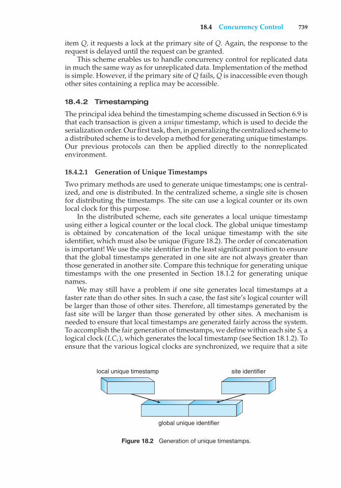
18.4 Concurrency Control 739
item Q, it requests a lock at the primary site of Q. Again, the response to therequest is delayed until the request can be granted.
This scheme enables us to handle concurrency control for replicated datain much the same way as for unreplicated data. Implementation of the methodis simple. However, if the primary site of Q fails, Q is inaccessible even thoughother sites containing a replica may be accessible.
18.4.2 Timestamping
The principal idea behind the timestamping scheme discussed in Section 6.9 isthat each transaction is given a unique timestamp, which is used to decide theserialization order. Our first task, then, in generalizing the centralized scheme toa distributed scheme is to develop a method for generating unique timestamps.Our previous protocols can then be applied directly to the nonreplicatedenvironment.
18.4.2.1 Generation of Unique Timestamps
Two primary methods are used to generate unique timestamps; one is central-ized, and one is distributed. In the centralized scheme, a single site is chosenfor distributing the timestamps. The site can use a logical counter or its ownlocal clock for this purpose.
In the distributed scheme, each site generates a local unique timestampusing either a logical counter or the local clock. The global unique timestampis obtained by concatenation of the local unique timestamp with the siteidentifier, which must also be unique (Figure 18.2). The order of concatenationis important! We use the site identifier in the least significant position to ensurethat the global timestamps generated in one site are not always greater thanthose generated in another site. Compare this technique for generating uniquetimestamps with the one presented in Section 18.1.2 for generating uniquenames.
We may still have a problem if one site generates local timestamps at afaster rate than do other sites. In such a case, the fast site’s logical counter willbe larger than those of other sites. Therefore, all timestamps generated by thefast site will be larger than those generated by other sites. A mechanism isneeded to ensure that local timestamps are generated fairly across the system.To accomplish the fair generation of timestamps, we define within each site Si alogical clock (LCi ), which generates the local timestamp (see Section 18.1.2). Toensure that the various logical clocks are synchronized, we require that a site
local unique timestamp
global unique identifier
site identifier
Figure 18.2 Generation of unique timestamps.
740 Chapter 18 Distributed Coordination
Si advance its logical clock whenever a transaction Ti with timestamp <x,y>
visits that site and x is greater than the current value of LCi . In this case, site Siadvances its logical clock to the value x + 1.
If the system clock is used to generate timestamps, then timestamps areassigned fairly, provided that no site has a system clock that runs fast or slow.Since clocks may not be perfectly accurate, a technique similar to that used forlogical clocks must be used to ensure that no clock gets far ahead or far behindanother clock.
18.4.2.2 Timestamp-Ordering Scheme
The basic timestamp scheme introduced in Section 6.9.4.3 can be extended ina straightforward manner to a distributed system. As in the centralized case,cascading rollbacks may result if no mechanism is used to prevent a transactionfrom reading a data item value that is not yet committed. To eliminate cascadingrollbacks, we can combine the basic timestamp scheme of Section 6.9 with the2PC protocol of Section 18.3 to obtain a protocol that ensures serializabilitywith no cascading rollbacks. We leave the development of such an algorithmto you.
The basic timestamp scheme just described suffers from the undesirableproperty that conflicts between transactions are resolved through rollbacks,rather than through waits. To alleviate this problem, we can buffer the variousread and write operations (that is, delay them) until a time when we areassured that these operations can take place without causing aborts. A read(x)operation by Ti must be delayed if there exists a transaction Tj that will performa write(x) operation but has not yet done so and TS(Tj ) < TS(Ti ). Similarly, awrite(x) operation by Ti must be delayed if there exists a transaction Tj that willperform either a read(x) or a write(x) operation and TS(Tj ) < TS(Ti ). Variousmethods are available for ensuring this property. One such method, calledthe conservative timestamp-ordering scheme, requires each site to maintaina read queue and a write queue consisting of all the read and write requeststhat are to be executed at the site and that must be delayed to preserve theproperty just described. We shall not present the scheme here. Again, we leavethe development of the algorithm to you.
18.5 Deadlock Handling
The deadlock-prevention, deadlock-avoidance, and deadlock-detection algo-rithms presented in Chapter 7 can be extended so that they can be used ina distributed system. In this section, we describe several of these distributedalgorithms.
18.5.1 Deadlock Prevention and Avoidance
The deadlock-prevention and deadlock-avoidance algorithms presented inChapter 7 can be used in a distributed system, provided that appropriatemodifications are made. For example, we can use the resource-orderingdeadlock-prevention technique by simply defining a global ordering amongthe system resources. That is, all resources in the entire system are assignedunique numbers, and a process may request a resource (at any processor) with
18.5 Deadlock Handling 741
unique number i only if it is not holding a resource with a unique numbergreater than i. Similarly, we can use the banker’s algorithm in a distributedsystem by designating one of the processes in the system (the banker) as theprocess that maintains the information necessary to carry out the banker’salgorithm. Every resource request must be channeled through the banker.
The global resource-ordering deadlock-prevention scheme is simple toimplement in a distributed environment and requires little overhead. Thebanker’s algorithm can also be implemented easily, but it may require toomuch overhead. The banker may become a bottleneck, since the number ofmessages to and from the banker may be large. Thus, the banker’s schemedoes not seem to be of practical use in a distributed system.
We turn next to a new deadlock-prevention scheme based on a timestamp-ordering approach with resource preemption. Although this approach canhandle any deadlock situation that may arise in a distributed system, forsimplicity we consider only the case of a single instance of each resource type.
To control the preemption, we assign a unique priority number to eachprocess. These numbers are used to decide whether a process Pi should waitfor a process Pj . For example, we can let Pi wait for Pj if Pi has a priority higherthan that of Pj ; otherwise, Pi is rolled back. This scheme prevents deadlocksbecause, for every edge Pi → Pj in the wait-for graph, Pi has a higher prioritythan Pj . Thus, a cycle cannot exist.
One difficulty with this scheme is the possibility of starvation. Someprocesses with extremely low priorities may always be rolled back. Thisdifficulty can be avoided through the use of timestamps. Each process in thesystem is assigned a unique timestamp when it is created. Two complementarydeadlock-prevention schemes using timestamps have been proposed:
1. The wait–die scheme. This approach is based on a nonpreemptivetechnique. When process Pi requests a resource currently held by Pj , Pi isallowed to wait only if it has a smaller timestamp than does Pj (that is, Piis older than Pj ). Otherwise, Pi is rolled back (dies). For example, supposethat processes P1, P2, and P3 have timestamps 5, 10, and 15, respectively.If P1 requests a resource held by P2, P1 will wait. If P3 requests a resourceheld by P2, P3 will be rolled back.
2. The wound–wait scheme. This approach is based on a preemptivetechnique and is a counterpart to the wait–die approach. When processPi requests a resource currently held by Pj , Pi is allowed to wait onlyif it has a larger timestamp than does Pj (that is, Pi is younger thanPj ). Otherwise, Pj is rolled back (Pj is wounded by Pi ). Returning to ourprevious example, with processes P1, P2, and P3, if P1 requests a resourceheld by P2, then the resource will be preempted from P2, and P2 will berolled back. If P3 requests a resource held by P2, then P3 will wait.
Both schemes can avoid starvation provided that, when a process is rolledback, it is not assigned a new timestamp. Since timestamps always increase, aprocess that is rolled back will eventually have the smallest timestamp. Thus,it will not be rolled back again. There are, however, significant differences inthe way the two schemes operate.
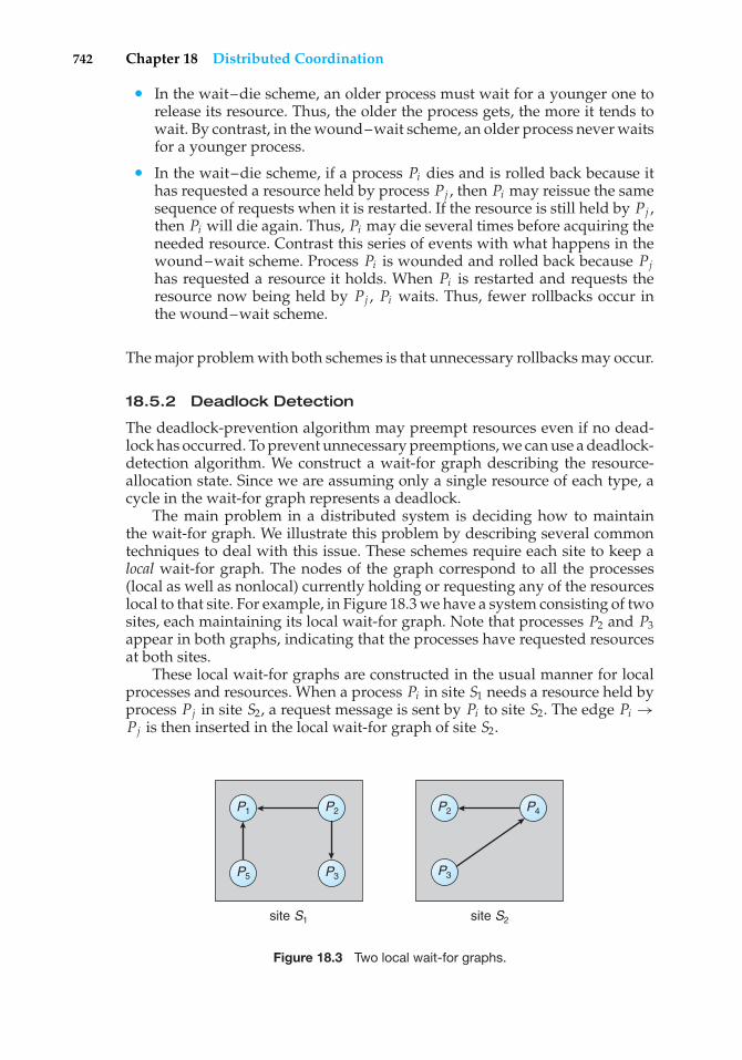
742 Chapter 18 Distributed Coordination
• In the wait–die scheme, an older process must wait for a younger one torelease its resource. Thus, the older the process gets, the more it tends towait. By contrast, in the wound–wait scheme, an older process never waitsfor a younger process.
• In the wait–die scheme, if a process Pi dies and is rolled back because ithas requested a resource held by process Pj , then Pi may reissue the samesequence of requests when it is restarted. If the resource is still held by Pj ,then Pi will die again. Thus, Pi may die several times before acquiring theneeded resource. Contrast this series of events with what happens in thewound–wait scheme. Process Pi is wounded and rolled back because Pjhas requested a resource it holds. When Pi is restarted and requests theresource now being held by Pj , Pi waits. Thus, fewer rollbacks occur inthe wound–wait scheme.
The major problem with both schemes is that unnecessary rollbacks may occur.
18.5.2 Deadlock Detection
The deadlock-prevention algorithm may preempt resources even if no dead-lock has occurred. To prevent unnecessary preemptions, we can use a deadlock-detection algorithm. We construct a wait-for graph describing the resource-allocation state. Since we are assuming only a single resource of each type, acycle in the wait-for graph represents a deadlock.
The main problem in a distributed system is deciding how to maintainthe wait-for graph. We illustrate this problem by describing several commontechniques to deal with this issue. These schemes require each site to keep alocal wait-for graph. The nodes of the graph correspond to all the processes(local as well as nonlocal) currently holding or requesting any of the resourceslocal to that site. For example, in Figure 18.3 we have a system consisting of twosites, each maintaining its local wait-for graph. Note that processes P2 and P3appear in both graphs, indicating that the processes have requested resourcesat both sites.
These local wait-for graphs are constructed in the usual manner for localprocesses and resources. When a process Pi in site S1 needs a resource held byprocess Pj in site S2, a request message is sent by Pi to site S2. The edge Pi →Pj is then inserted in the local wait-for graph of site S2.
P1 P2 P2
P3
P4
P5 P3
site S1 site S2
Figure 18.3 Two local wait-for graphs.
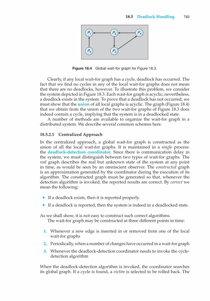
18.5 Deadlock Handling 743
P1
P5
P2 P4
P3
Figure 18.4 Global wait-for graph for Figure 18.3.
Clearly, if any local wait-for graph has a cycle, deadlock has occurred. Thefact that we find no cycles in any of the local wait-for graphs does not meanthat there are no deadlocks, however. To illustrate this problem, we considerthe system depicted in Figure 18.3. Each wait-for graph is acyclic; nevertheless,a deadlock exists in the system. To prove that a deadlock has not occurred, wemust show that the union of all local graphs is acyclic. The graph (Figure 18.4)that we obtain from the union of the two wait-for graphs of Figure 18.3 doesindeed contain a cycle, implying that the system is in a deadlocked state.
A number of methods are available to organize the wait-for graph in adistributed system. We describe several common schemes here.
18.5.2.1 Centralized Approach
In the centralized approach, a global wait-for graph is constructed as theunion of all the local wait-for graphs. It is maintained in a single process:the deadlock-detection coordinator. Since there is communication delay inthe system, we must distinguish between two types of wait-for graphs. Thereal graph describes the real but unknown state of the system at any pointin time, as would be seen by an omniscient observer. The constructed graphis an approximation generated by the coordinator during the execution of itsalgorithm. The constructed graph must be generated so that, whenever thedetection algorithm is invoked, the reported results are correct. By correct wemean the following:
• If a deadlock exists, then it is reported properly.
• If a deadlock is reported, then the system is indeed in a deadlocked state.
As we shall show, it is not easy to construct such correct algorithms.The wait-for graph may be constructed at three different points in time:
1. Whenever a new edge is inserted in or removed from one of the localwait-for graphs
2. Periodically, when a number of changes have occurred in a wait-for graph
3. Whenever the deadlock-detection coordinator needs to invoke the cycle-detection algorithm
When the deadlock-detection algorithm is invoked, the coordinator searchesits global graph. If a cycle is found, a victim is selected to be rolled back. The
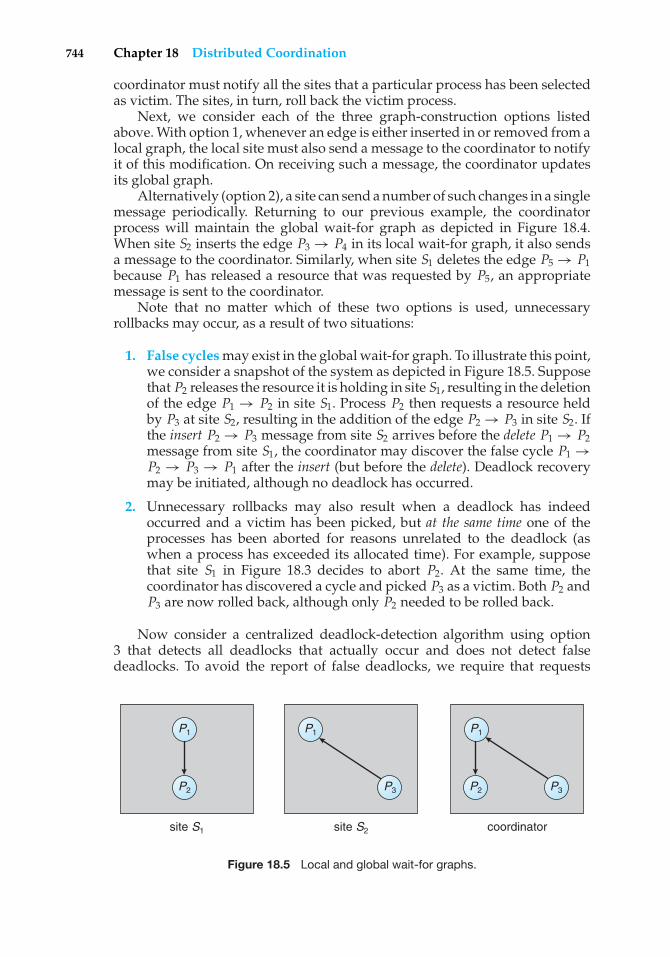
744 Chapter 18 Distributed Coordination
coordinator must notify all the sites that a particular process has been selectedas victim. The sites, in turn, roll back the victim process.
Next, we consider each of the three graph-construction options listedabove. With option 1, whenever an edge is either inserted in or removed from alocal graph, the local site must also send a message to the coordinator to notifyit of this modification. On receiving such a message, the coordinator updatesits global graph.
Alternatively (option 2), a site can send a number of such changes in a singlemessage periodically. Returning to our previous example, the coordinatorprocess will maintain the global wait-for graph as depicted in Figure 18.4.When site S2 inserts the edge P3 → P4 in its local wait-for graph, it also sendsa message to the coordinator. Similarly, when site S1 deletes the edge P5 → P1because P1 has released a resource that was requested by P5, an appropriatemessage is sent to the coordinator.
Note that no matter which of these two options is used, unnecessaryrollbacks may occur, as a result of two situations:
1. False cycles may exist in the global wait-for graph. To illustrate this point,we consider a snapshot of the system as depicted in Figure 18.5. Supposethat P2 releases the resource it is holding in site S1, resulting in the deletionof the edge P1 → P2 in site S1. Process P2 then requests a resource heldby P3 at site S2, resulting in the addition of the edge P2 → P3 in site S2. Ifthe insert P2 → P3 message from site S2 arrives before the delete P1 → P2message from site S1, the coordinator may discover the false cycle P1 →P2 → P3 → P1 after the insert (but before the delete). Deadlock recoverymay be initiated, although no deadlock has occurred.
2. Unnecessary rollbacks may also result when a deadlock has indeedoccurred and a victim has been picked, but at the same time one of theprocesses has been aborted for reasons unrelated to the deadlock (aswhen a process has exceeded its allocated time). For example, supposethat site S1 in Figure 18.3 decides to abort P2. At the same time, thecoordinator has discovered a cycle and picked P3 as a victim. Both P2 andP3 are now rolled back, although only P2 needed to be rolled back.
Now consider a centralized deadlock-detection algorithm using option3 that detects all deadlocks that actually occur and does not detect falsedeadlocks. To avoid the report of false deadlocks, we require that requests
P1 P1 P1
P2 P3 P3P2
site S1 site S2 coordinator
Figure 18.5 Local and global wait-for graphs.
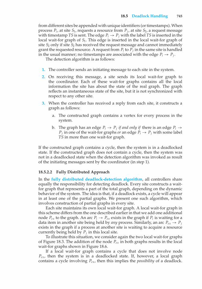
18.5 Deadlock Handling 745
from different sites be appended with unique identifiers (or timestamps). Whenprocess Pi , at site S1, requests a resource from Pj , at site S2, a request messagewith timestamp TS is sent. The edge Pi → Pj with the label TS is inserted in thelocal wait-for graph of S1. This edge is inserted in the local wait-for graph ofsite S2 only if site S2 has received the request message and cannot immediatelygrant the requested resource. A request from Pi to Pj in the same site is handledin the usual manner; no timestamps are associated with the edge Pi → Pj .
The detection algorithm is as follows:
1. The controller sends an initiating message to each site in the system.
2. On receiving this message, a site sends its local wait-for graph tothe coordinator. Each of these wait-for graphs contains all the localinformation the site has about the state of the real graph. The graphreflects an instantaneous state of the site, but it is not synchronized withrespect to any other site.
3. When the controller has received a reply from each site, it constructs agraph as follows:
a. The constructed graph contains a vertex for every process in thesystem.
b. The graph has an edge Pi → Pj if and only if there is an edge Pi →Pj in one of the wait-for graphs or an edge Pi → Pj with some labelTS in more than one wait-for graph.
If the constructed graph contains a cycle, then the system is in a deadlockedstate. If the constructed graph does not contain a cycle, then the system wasnot in a deadlocked state when the detection algorithm was invoked as resultof the initiating messages sent by the coordinator (in step 1).
18.5.2.2 Fully Distributed Approach
In the fully distributed deadlock-detection algorithm, all controllers shareequally the responsibility for detecting deadlock. Every site constructs a wait-for graph that represents a part of the total graph, depending on the dynamicbehavior of the system. The idea is that, if a deadlock exists, a cycle will appearin at least one of the partial graphs. We present one such algorithm, whichinvolves construction of partial graphs in every site.
Each site maintains its own local wait-for graph. A local wait-for graph inthis scheme differs from the one described earlier in that we add one additionalnode Pex to the graph. An arc Pi → Pex exists in the graph if Pi is waiting for adata item in another site being held by any process. Similarly, an arc Pex → Pjexists in the graph if a process at another site is waiting to acquire a resourcecurrently being held by Pj in this local site.
To illustrate this situation, we consider again the two local wait-for graphsof Figure 18.3. The addition of the node Pex in both graphs results in the localwait-for graphs shown in Figure 18.6.
If a local wait-for graph contains a cycle that does not involve nodePex , then the system is in a deadlocked state. If, however, a local graphcontains a cycle involving Pex, then this implies the possibility of a deadlock.
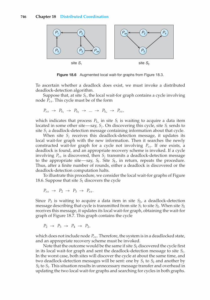
746 Chapter 18 Distributed Coordination
site S1 site S2
P1
P5
P2 P2
P3
P4
P3 Pex
Pex
Figure 18.6 Augmented local wait-for graphs from Figure 18.3.
To ascertain whether a deadlock does exist, we must invoke a distributeddeadlock-detection algorithm.
Suppose that, at site Si , the local wait-for graph contains a cycle involvingnode Pex. This cycle must be of the form
Pex → Pk1 → Pk2 → ... → Pkn → Pex,
which indicates that process Pkn in site Si is waiting to acquire a data itemlocated in some other site—say, Sj . On discovering this cycle, site Si sends tosite Sj a deadlock-detection message containing information about that cycle.
When site Sj receives this deadlock-detection message, it updates itslocal wait-for graph with the new information. Then it searches the newlyconstructed wait-for graph for a cycle not involving Pex. If one exists, adeadlock is found, and an appropriate recovery scheme is invoked. If a cycleinvolving Pex is discovered, then Sj transmits a deadlock-detection messageto the appropriate site—say, Sk . Site Sk , in return, repeats the procedure.Thus, after a finite number of rounds, either a deadlock is discovered or thedeadlock-detection computation halts.
To illustrate this procedure, we consider the local wait-for graphs of Figure18.6. Suppose that site S1 discovers the cycle
Pex → P2 → P3 → Pex.
Since P3 is waiting to acquire a data item in site S2, a deadlock-detectionmessage describing that cycle is transmitted from site S1 to site S2. When site S2receives this message, it updates its local wait-for graph, obtaining the wait-forgraph of Figure 18.7. This graph contains the cycle
P2 → P3 → P4 → P2,
which does not include node Pex . Therefore, the system is in a deadlocked state,and an appropriate recovery scheme must be invoked.
Note that the outcome would be the same if site S2 discovered the cycle firstin its local wait-for graph and sent the deadlock-detection message to site S1.In the worst case, both sites will discover the cycle at about the same time, andtwo deadlock-detection messages will be sent: one by S1 to S2 and another byS2 to S1. This situation results in unnecessary message transfer and overhead inupdating the two local wait-for graphs and searching for cycles in both graphs.

18.6 Election Algorithms 747
P2
P3
Pex P4
site S2
Figure 18.7 Augmented local wait-for graph in site S2 of Figure 18.6.
To reduce message traffic, we assign to each process Pi a unique identifier,which we denote ID(Pi ). When site Sk discovers that its local wait-for graphcontains a cycle involving node Pex of the form
Pex → PK1 → PK2 → ... → PKn → Pex,
it sends a deadlock-detection message to another site only if
ID(PKn) < ID(PK1 ).
Otherwise, site Sk continues its normal execution, leaving the burden ofinitiating the deadlock-detection algorithm to some other site.
To illustrate this scheme, we consider again the wait-for graphs maintainedat sites S1 and S2 as shown in Figure 18.6. Suppose that
I D(P1) < I D(P2) < I D(P3) < I D(P4).
Suppose both sites discover these local cycles at about the same time. The cyclein site S1 is of the form
Pex → P2 → P3 → Pex.
Since ID(P3) > ID(P2), site S1 does not send a deadlock-detection message tosite S2.
The cycle in site S2 is of the form
Pex → P3 → P4 → P2 → Pex.
Since ID(P2) < ID(P3), site S2 does send a deadlock-detection message to siteS1, which, on receiving the message, updates its local wait-for graph. Site S1then searches for a cycle in the graph and discovers that the system is in adeadlocked state.
18.6 Election Algorithms
As we pointed out in Section 18.3, many distributed algorithms employ acoordinator process that performs functions needed by the other processes in
748 Chapter 18 Distributed Coordination
the system. These functions include enforcing mutual exclusion, maintaininga global wait-for graph for deadlock detection, replacing a lost token, andcontrolling an input or output device in the system. If the coordinator processfails due to the failure of the site at which it resides, the system can continueexecution only by restarting a new copy of the coordinator on some other site.The algorithms that determine where a new copy of the coordinator should berestarted are called election algorithms.
Election algorithms assume that a unique priority number is associatedwith each active process in the system. For ease of notation, we assume thatthe priority number of process Pi is i. To simplify our discussion, we assumea one-to-one correspondence between processes and sites and thus refer toboth as processes. The coordinator is always the process with the largestpriority number. Hence, when a coordinator fails, the algorithm must electthat active process with the largest priority number. This number must be sentto each active process in the system. In addition, the algorithm must provide amechanism for a recovered process to identify the current coordinator.
In this section, we present examples of election algorithms for two differentconfigurations of distributed systems. The first algorithm applies to systemswhere every process can send a message to every other process in the system.The second algorithm applies to systems organized as a ring (logically orphysically). Both algorithms require n2 messages for an election, where n is thenumber of processes in the system. We assume that a process that has failedknows on recovery that it has indeed failed and thus takes appropriate actionsto rejoin the set of active processes.
18.6.1 The Bully Algorithm
Suppose that process Pi sends a request that is not answered by the coordinatorwithin a time interval T. In this situation, it is assumed that the coordinator hasfailed, and Pi tries to elect itself as the new coordinator. This task is completedthrough the following algorithm.
Process Pi sends an election message to every process with a higher prioritynumber. Process Pi then waits for a time interval T for an answer from any oneof these processes.
If no response is received within time T, Pi assumes that all processes withnumbers greater than i have failed and elects itself the new coordinator. ProcessPi restarts a new copy of the coordinator and sends a message to inform allactive processes with priority numbers less than i that Pi is the new coordinator.
However, if an answer is received, Pi begins a time interval T ′, waiting toreceive a message informing it that a process with a higher priority numberhas been elected. (That is, some other process is electing itself coordinator andshould report the results within time T ′.) If no message is received within T ′,then the process with a higher number is assumed to have failed, and processPi should restart the algorithm.
If Pi is not the coordinator, then, at any time during execution, Pi mayreceive one of the following two messages from process Pj :
1. Pj is the new coordinator (j > i). Process Pi , in turn, records thisinformation.
18.6 Election Algorithms 749
2. Pj has started an election (j < i). Process Pi sends a response to Pjand begins its own election algorithm, provided that Pi has not alreadyinitiated such an election.
The process that completes its algorithm has the highest number and is electedas the coordinator. It has sent its number to all active processes with lowernumbers. After a failed process recovers, it immediately begins execution ofthe same algorithm. If there are no active processes with higher numbers, therecovered process forces all processes with lower numbers to let it become thecoordinator process, even if there is a currently active coordinator with a lowernumber. For this reason, the algorithm is termed the bully algorithm.
We can demonstrate the operation of the algorithm with a simple exampleof a system consisting of processes P1 through P4. The operations are as follows:
1. All processes are active; P4 is the coordinator process.
2. P1 and P4 fail. P2 determines that P4 has failed by sending a request thatis not answered within time T. P2 then begins its election algorithm bysending a request to P3.
3. P3 receives the request, responds to P2, and begins its own algorithm bysending an election request to P4.
4. P2 receives P3’s response and begins waiting for an interval T ′.
5. P4 does not respond within an interval T, so P3 elects itself the newcoordinator and sends the number 3 to P2 and P1. (P1 does not receivethe number, since it has failed.)
6. Later, when P1 recovers, it sends an election request to P2, P3, and P4.
7. P2 and P3 respond to P1 and begin their own election algorithms. P3 willagain be elected, through the same events as before.
8. Finally, P4 recovers and notifies P1, P2, and P3 that it is the currentcoordinator. (P4 sends no election requests, since it is the process withthe highest number in the system.)
18.6.2 The Ring Algorithm
The ring algorithm assumes that the links between processes are unidirectionaland that each process sends its messages to the neighbor on the right. The maindata structure used by the algorithm is the active list, a list that contains thepriority numbers of all active processes in the system when the algorithm ends;each process maintains its own active list. The algorithm works as follows:
1. If process Pi detects a coordinator failure, it creates a new active list thatis initially empty. It then sends a message elect(i) to its neighbor on theright and adds the number i to its active list.
750 Chapter 18 Distributed Coordination
2. If Pi receives a message elect(j) from the process on the left, it must respondin one of three ways:
a. If this is the first elect message it has seen or sent, Pi creates a newactive list with the numbers i and j. It then sends the message elect(i),followed by the message elect(j).
b. If i �= j—that is, if the message received does not contain Pi ’s number—then Pi adds j to its active list and forwards the message to itsneighbor on the right.
c. If i = j—that is, if Pi receives the message elect(i)—then the activelist for Pi now contains the numbers of all the active processes inthe system. Process Pi can now determine the largest number in theactive list to identify the new coordinator process.
This algorithm does not specify how a recovering process determines thenumber of the current coordinator process. One solution requires a recoveringprocess to send an inquiry message. This message is forwarded around the ringto the current coordinator, which in turn sends a reply containing its number.
18.7 Reaching Agreement
For a system to be reliable, we need a mechanism that allows a set of processesto agree on a common value. Such an agreement may not take place, for severalreasons. First, the communication medium may be faulty, resulting in lost orgarbled messages. Second, the processes themselves may be faulty, resultingin unpredictable process behavior. The best we can hope for in this case is thatprocesses fail in a clean way, stopping their execution without deviating fromtheir normal execution pattern. In the worst case, processes may send garbledor incorrect messages to other processes or even collaborate with other failedprocesses in an attempt to destroy the integrity of the system.
The Byzantine generals problem provides an analogy for this situation.Several divisions of the Byzantine army, each commanded by its own general,surround an enemy camp. The Byzantine generals must reach agreement onwhether or not to attack the enemy at dawn. It is crucial that all generals agree,since an attack by only some of the divisions would result in defeat. The variousdivisions are geographically dispersed, and the generals can communicate withone another only via messengers who run from camp to camp. The generalsmay not be able to reach agreement for at least two major reasons:
1. Messengers may get caught by the enemy and thus may be unable todeliver their messages. This situation corresponds to unreliable com-munication in a computer system and is discussed further in Section18.7.1.
2. Generals may be traitors, trying to prevent the loyal generals fromreaching an agreement. This situation corresponds to faulty processesin a computer system and is discussed further in Section 18.7.2.
18.7 Reaching Agreement 751
18.7.1 Unreliable Communications
Let us first assume that, if processes fail, they do so in a clean way and thatthe communication medium is unreliable. Suppose that process Pi at site S1,which has sent a message to process Pj at site S2, needs to know whetherPj has received the message so that it can decide how to proceed with itscomputation. For example, Pi may decide to compute a function foo if Pj hasreceived its message or to compute a function boo if Pj has not received themessage (because of some hardware failure).
To detect failures, we can use a time-out scheme similar to the onedescribed in Section 16.7.1. When Pi sends out a message, it also specifiesa time interval during which it is willing to wait for an acknowledgmentmessage from Pj . When Pj receives the message, it immediately sends anacknowledgment to Pi . If Pi receives the acknowledgment message within thespecified time interval, it can safely conclude that Pj has received its message.If, however, a time-out occurs, then Pi needs to retransmit its message andwait for an acknowledgment. This procedure continues until Pi either gets theacknowledgment message back or is notified by the system that site S2 is down.In the first case, it will compute foo; in the latter case, it will compute boo. Notethat, if these are the only two viable alternatives, Pi must wait until it has beennotified that one of the situations has occurred.
Suppose now that Pj also needs to know that Pi has received its acknowl-edgment message, so that it can decide how to proceed with its computation.For example, Pj may want to compute foo only if it is assured that Pi gotits acknowledgment. In other words, Pi and Pj will compute foo if and onlyif both have agreed on it. It turns out that, in the presence of failure, it isnot possible to accomplish this task. More precisely, it is not possible in adistributed environment for processes Pi and Pj to agree completely on theirrespective states.
To prove this claim, let us suppose that a minimal sequence of messagetransfers exists such that, after the messages have been delivered, bothprocesses agree to compute foo. Let m′ be the last message sent by Pi toPj . Since Pi does not know whether its message will arrive at Pj (since themessage may be lost due to a failure), Pi will execute foo regardless of theoutcome of the message delivery. Thus, m′ could be removed from the sequencewithout affecting the decision procedure. Hence, the original sequence was notminimal, contradicting our assumption and showing that there is no sequence.The processes can never be sure that both will compute foo.
18.7.2 Faulty Processes
Now let us assume that the communication medium is reliable but thatprocesses can fail in unpredictable ways. Consider a system of n processes,of which no more than m are faulty. Suppose that each process Pi has someprivate value of Vi . We wish to devise an algorithm that allows each nonfaultyprocess Pi to construct a vector Xi = (Ai,1, Ai,2, ..., Ai,n) such that the followingconditions exist:
1. If Pj is a nonfaulty process, then Ai, j = Vj .
2. If Pi and Pj are both nonfaulty processes, then Xi = Xj .
752 Chapter 18 Distributed Coordination
There are many solutions to this problem, and they share the followingproperties:
1. A correct algorithm can be devised only if n ≥ 3 × m + 1.
2. The worst-case delay for reaching agreement is proportionate to m + 1message-passing delays.
3. The number of messages required for reaching agreement is large. Nosingle process is trustworthy, so all processes must collect all informationand make their own decisions.
Rather than presenting a general solution, which would be complicated, wepresent an algorithm for the simple case where m = 1 and n = 4. The algorithmrequires two rounds of information exchange:
1. Each process sends its private value to the other three processes.
2. Each process sends the information it has obtained in the first round toall other processes.
A faulty process obviously may refuse to send messages. In this case, anonfaulty process can choose an arbitrary value and pretend that the valuewas sent by the faulty process.
Once these two rounds are completed, a nonfaulty process Pi can constructits vector Xi = (Ai,1, Ai,2, Ai,3, Ai,4) as follows:
1. Ai,i = Vi .
2. For j �= i, if at least two of the three values reported for process Pj (inthe two rounds of exchange) agree, then the majority value is used to setthe value of Ai, j . Otherwise, a default value—say, nil—is used to set thevalue of Ai, j .
18.8 Summary
In a distributed system with no common memory and no common clock, itis sometimes impossible to determine the exact order in which two eventsoccur. The happened-before relation is only a partial ordering of the events ina distributed system. Timestamps can be used to provide a consistent eventordering.
Mutual exclusion in a distributed environment can be implemented in avariety of ways. In a centralized approach, one of the processes in the systemis chosen to coordinate the entry to the critical section. In the fully distributedapproach, the decision making is distributed across the entire system. Adistributed algorithm, which is applicable to ring-structured networks, is thetoken-passing approach.
For atomicity to be ensured, all the sites in which a transaction T hasexecuted must agree on the final outcome of the execution. T either commits atall sites or aborts at all sites. To ensure this property, the transaction coordinator
Exercises 753
of T must execute a commit protocol. The most widely used commit protocolis the 2PC protocol.
The various concurrency-control schemes that can be used in a centralizedsystem can be modified for use in a distributed environment. In the caseof locking protocols, we need only change the way the lock manager isimplemented. In the case of timestamping and validation schemes, the onlychange needed is the development of a mechanism for generating uniqueglobal timestamps. The mechanism can either concatenate a local timestampwith the site identification or advance local clocks whenever a message arrivesthat has a larger timestamp.
The primary method for dealing with deadlocks in a distributed environ-ment is deadlock detection. The main problem is deciding how to maintain thewait-for graph. Methods for organizing the wait-for graph include a centralizedapproach and a fully distributed approach.
Some distributed algorithms require the use of a coordinator. If thecoordinator fails because of the failure of the site at which it resides, the systemcan continue execution only by restarting a new copy of the coordinator onsome other site. It can do so by maintaining a backup coordinator that isready to assume responsibility if the coordinator fails. Another approach is tochoose the new coordinator after the coordinator has failed. The algorithmsthat determine where a new copy of the coordinator should be restarted arecalled election algorithms. Two algorithms, the bully algorithm and the ringalgorithm, can be used to elect a new coordinator in case of failures.
Exercises
18.1 Discuss the advantages and disadvantages of the two methods pre-sented in the chapter for generating globally unique timestamps.
18.2 The logical clock timestamp scheme presented in this chapter providesthe following guarantee: if event A happens before event B, then thetimestamp of A is smaller than the timestamp of B. Note, however, thatwe cannot order two events based only on their timestamps. The factthat an event C has a timestamp that is smaller than the timestampof event D does not necessarily mean that event C happened beforeevent D; C and D could be concurrent events in the system. Discussways in which the logical clock timestamp scheme could be extendedto distinguish concurrent events from events that can be ordered by thehappened-before relation.
18.3 Your company is building a computer network, and you are asked towrite an algorithm for achieving distributed mutual exclusion. Whichscheme will you use? Explain your choice.
18.4 Why is deadlock detection much more expensive in a distributedenvironment than in a centralized environment?
18.5 Your company is building a computer network, and you are asked todevelop a scheme for dealing with the deadlock problem.
a. Would you use a deadlock-detection scheme or a deadlock-prevention scheme?
754 Chapter 18 Distributed Coordination
b. If you used a deadlock-prevention scheme, which one would youuse? Explain your choice.
c. If you used a deadlock-detection scheme, which one would youuse? Explain your choice.
18.6 Under what circumstances does the wait–die scheme perform betterthan the wound–wait scheme for granting resources to concurrentlyexecuting transactions?
18.7 Consider the centralized and the fully distributed approaches todeadlock detection. Compare the two algorithms in terms of messagecomplexity.
18.8 Consider a hierarchical deadlock-detection algorithm in which theglobal wait-for graph is distributed over a number of different con-trollers, which are organized in a tree. Each non-leaf controller maintainsa wait-for graph that contains relevant information from the graphs ofthe controllers in the subtree below it. In particular, let SA, SB , and SCbe controllers such that SC is the lowest common ancestor of SA andSB (SC must be unique, since we are dealing with a tree). Suppose thatnode Ti appears in the local wait-for graph of controllers SA and SB .Then Ti must also appear in the local wait-for graph of
• Controller SC
• Every controller in the path from SC to SA
• Every controller in the path from SC to SB
In addition, if Ti and Tj appear in the wait-for graph of controller SDand there exists a path from Ti to Tj in the wait-for graph of one of thechildren of SD, then an edge Ti → Tj must be in the wait-for graph ofSD.
Show that, if a cycle exists in any of the wait-for graphs, then thesystem is deadlocked.
18.9 Derive an election algorithm for bidirectional rings that is more efficientthan the one presented in this chapter. How many messages are neededfor n processes?
18.10 Consider a setting where processors are not associated with uniqueidentifiers but the total number of processors is known and theprocessors are organized along a bidirectional ring. Is it possible toderive an election algorithm for such a setting?
18.11 Consider a failure that occurs during 2PC for a transaction. For eachpossible failure, explain how 2PC ensures transaction atomicity despitethe failure.
18.12 Consider the following failure model for faulty processors. Processorsfollow the prescribed protocol but may fail at unexpected points intime. When processors fail, they simply stop functioning and do notcontinue to participate in the distributed system. Given such a failuremodel, design an algorithm for reaching agreement among a set of
Bibliographical Notes 755
processors. Discuss the conditions under which agreement could bereached.
Wiley Plus
Visit Wiley Plus for
• Source code
• Solutions to practice exercises
• Additional programming problems and exercises
• Labs using an operating system simulator
Bibliographical Notes
The distributed algorithm for extending the happened-before relation to aconsistent total ordering of all the events in the system was developed byLamport [1978b]. Further discussions of using logical time to characterize thebehavior of distributed systems can be found in Fidge [1991], Raynal andSinghal [1996], Babaoglu and Marzullo [1993], Schwarz and Mattern [1994],and Mattern [1988].
The first general algorithm for implementing mutual exclusion in adistributed environment was also developed by Lamport [1978b]. Lamport’sscheme requires 3 × (n − 1) messages per critical-section entry. Subsequently,Ricart and Agrawala [1981] proposed a distributed algorithm that requires only2 × (n − 1) messages. Their algorithm is presented in Section 18.2.2. A square-root algorithm for distributed mutual exclusion is described by Maekawa[1985]. The token-passing algorithm for ring-structured systems presented inSection 18.2.3 was developed by Lann [1977]. Carvalho and Roucairol [1983]discusses mutual exclusion in computer networks, and Agrawal and Abbadi[1991] describes an efficient and fault-tolerant solution of distributed mutualexclusion. A simple taxonomy for distributed mutual-exclusion algorithms ispresented by Raynal [1991].
The issue of distributed synchronization is discussed by Reed and Kanodia[1979] (shared-memory environment), Lamport [1978b], Lamport [1978a], andSchneider [1982] (totally disjoint processes). A distributed solution to thedining-philosophers problem is presented by Chang [1980].
The 2PC protocol was developed by Lampson and Sturgis [1976] and Gray[1978]. Two modified versions of 2PC, called presume commit and presumeabort, reduce the overhead of 2PC by defining default assumptions regardingthe fate of transactions (Mohan and Lindsay [1983]).
Papers dealing with the problems of implementing the transaction conceptin a distributed database were presented by Gray [1981], Traiger et al. [1982],and Spector and Schwarz [1983]. Bernstein et al. [1987] offer comprehensivediscussions of distributed concurrency control. Rosenkrantz et al. [1978]report on the timestamp distributed deadlock-prevention algorithm. Thefully distributed deadlock-detection scheme presented in Section 18.5.2 wasdeveloped by Obermarck [1982]. The hierarchical deadlock-detection scheme
756 Chapter 18 Distributed Coordination
of Exercise 18.4 appears in Menasce and Muntz [1979]. Knapp [1987] andSinghal [1989] offer surveys of deadlock detection in distributed systems.Deadlocks can also be detected by taking global snapshots of a distributedsystem, as discussed in Chandy and Lamport [1985].
The Byzantine generals problem is discussed by Lamport et al. [1982] andPease et al. [1980]. The bully algorithm is presented by Garcia-Molina [1982],and the election algorithm for a ring-structured system was written by Lann[1977].
Part Seven
Special -PurposeSystems
Our coverage of operating-system issues thus far has focused mainlyon general-purpose computing systems. There are, however, special-purpose systems with requirements different from those of many of thesystems we have described.
A real-time system is a computer system that requires not onlythat computed results be correct but also that the results be producedwithin a specified deadline period. Results produced after the deadlinehas passed—even if correct—may be of no real value. For such sys-tems, many traditional operating-system scheduling algorithms must bemodified to meet the stringent timing deadlines.
A multimedia system must be able to handle not only conventionaldata, such as text files, programs, and word-processing documents,but also multimedia data. Multimedia data consist of continuous-mediadata (audio and video) as well as conventional data. Continuous-mediadata—such as frames of video—must be delivered according to certaintime restrictions (for example, 30 frames per second). The demands ofhandling continuous-media data require significant changes in operating-system structure, most notably in memory, disk, and network manage-ment.

This page intentionally left blank
19C H A P T E R
Real -TimeSystems
Our coverage of operating-system issues thus far has focused mainly ongeneral-purpose computing systems (for example, desktop and server sys-tems). We now turn our attention to real-time computing systems. The require-ments of real-time systems differ from those of many of the systems we havedescribed, largely because real-time systems must produce results within cer-tain time limits. In this chapter, we provide an overview of real-time computersystems and describe how real-time operating systems must be constructed tomeet the stringent timing requirements of these systems.
CHAPTER OBJECTIVES
• To explain the timing requirements of real-time systems.
• To distinguish between hard and soft real-time systems.
• To discuss the defining characteristics of real-time systems.
• To describe scheduling algorithms for hard real-time systems.
19.1 Overview
A real-time system is a computer system that requires not only that thecomputing results be “correct” but also that the results be produced withina specified deadline period. Results produced after the deadline has passed—even if correct—may be of no real value. To illustrate, consider an autonomousrobot that delivers mail in an office complex. If its vision-control systemidentifies a wall after the robot has walked into it, despite correctly identifyingthe wall, the system has not met its requirement. Contrast this timingrequirement with the much less strict demands of other systems. In aninteractive desktop computer system, it is desirable to provide a quick responsetime to the interactive user, but it is not mandatory to do so. Some systems— such as a batch-processing system— may have no timing requirementswhatsoever.
Real-time systems executing on traditional computer hardware are usedin a wide range of applications. In addition, many real-time systems are
759
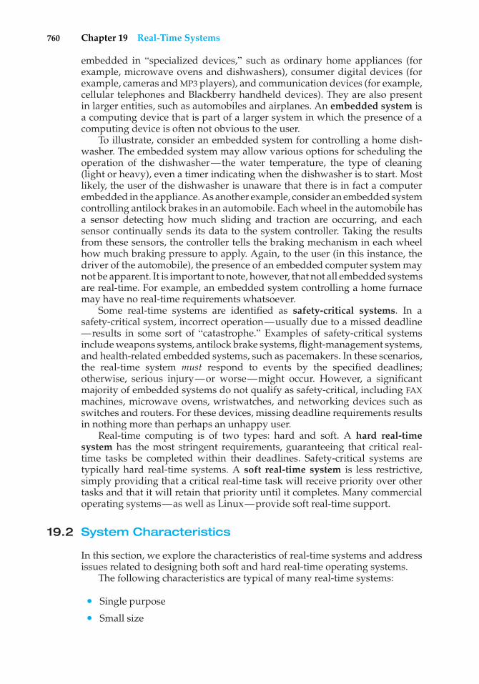
760 Chapter 19 Real-Time Systems
embedded in “specialized devices,” such as ordinary home appliances (forexample, microwave ovens and dishwashers), consumer digital devices (forexample, cameras and MP3 players), and communication devices (for example,cellular telephones and Blackberry handheld devices). They are also presentin larger entities, such as automobiles and airplanes. An embedded system isa computing device that is part of a larger system in which the presence of acomputing device is often not obvious to the user.
To illustrate, consider an embedded system for controlling a home dish-washer. The embedded system may allow various options for scheduling theoperation of the dishwasher—the water temperature, the type of cleaning(light or heavy), even a timer indicating when the dishwasher is to start. Mostlikely, the user of the dishwasher is unaware that there is in fact a computerembedded in the appliance. As another example, consider an embedded systemcontrolling antilock brakes in an automobile. Each wheel in the automobile hasa sensor detecting how much sliding and traction are occurring, and eachsensor continually sends its data to the system controller. Taking the resultsfrom these sensors, the controller tells the braking mechanism in each wheelhow much braking pressure to apply. Again, to the user (in this instance, thedriver of the automobile), the presence of an embedded computer system maynot be apparent. It is important to note, however, that not all embedded systemsare real-time. For example, an embedded system controlling a home furnacemay have no real-time requirements whatsoever.
Some real-time systems are identified as safety-critical systems. In asafety-critical system, incorrect operation—usually due to a missed deadline—results in some sort of “catastrophe.” Examples of safety-critical systemsinclude weapons systems, antilock brake systems, flight-management systems,and health-related embedded systems, such as pacemakers. In these scenarios,the real-time system must respond to events by the specified deadlines;otherwise, serious injury—or worse—might occur. However, a significantmajority of embedded systems do not qualify as safety-critical, including FAXmachines, microwave ovens, wristwatches, and networking devices such asswitches and routers. For these devices, missing deadline requirements resultsin nothing more than perhaps an unhappy user.
Real-time computing is of two types: hard and soft. A hard real-timesystem has the most stringent requirements, guaranteeing that critical real-time tasks be completed within their deadlines. Safety-critical systems aretypically hard real-time systems. A soft real-time system is less restrictive,simply providing that a critical real-time task will receive priority over othertasks and that it will retain that priority until it completes. Many commercialoperating systems—as well as Linux—provide soft real-time support.
19.2 System Characteristics
In this section, we explore the characteristics of real-time systems and addressissues related to designing both soft and hard real-time operating systems.
The following characteristics are typical of many real-time systems:
• Single purpose
• Small size
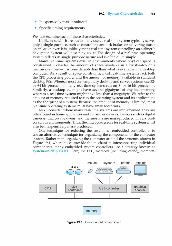
19.2 System Characteristics 761
• Inexpensively mass-produced
• Specific timing requirements
We next examine each of these characteristics.Unlike PCs, which are put to many uses, a real-time system typically serves
only a single purpose, such as controlling antilock brakes or delivering musicon an MP3 player. It is unlikely that a real-time system controlling an airliner’snavigation system will also play DVDs! The design of a real-time operatingsystem reflects its single-purpose nature and is often quite simple.
Many real-time systems exist in environments where physical space isconstrained. Consider the amount of space available in a wristwatch or amicrowave oven—it is considerably less than what is available in a desktopcomputer. As a result of space constraints, most real-time systems lack boththe CPU processing power and the amount of memory available in standarddesktop PCs. Whereas most contemporary desktop and server systems use 32-or 64-bit processors, many real-time systems run on 8- or 16-bit processors.Similarly, a desktop PC might have several gigabytes of physical memory,whereas a real-time system might have less than a megabyte. We refer to theamount of memory required to run the operating system and its applicationsas the footprint of a system. Because the amount of memory is limited, mostreal-time operating systems must have small footprints.
Next, consider where many real-time systems are implemented: they areoften found in home appliances and consumer devices. Devices such as digitalcameras, microwave ovens, and thermostats are mass-produced in very cost-conscious environments. Thus, the microprocessors for real-time systems mustalso be inexpensively mass-produced.
One technique for reducing the cost of an embedded controller is touse an alternative technique for organizing the components of the computersystem. Rather than organizing the computer around the structure shown inFigure 19.1, where buses provide the mechanism interconnecting individualcomponents, many embedded system controllers use a strategy known assystem-on-chip (SOC). Here, the CPU, memory (including cache), memory-
USB controller
keyboard printermouse monitordisks
graphicsadapter
diskcontroller
memory
CPU
on-line
Figure 19.1 Bus-oriented organization.
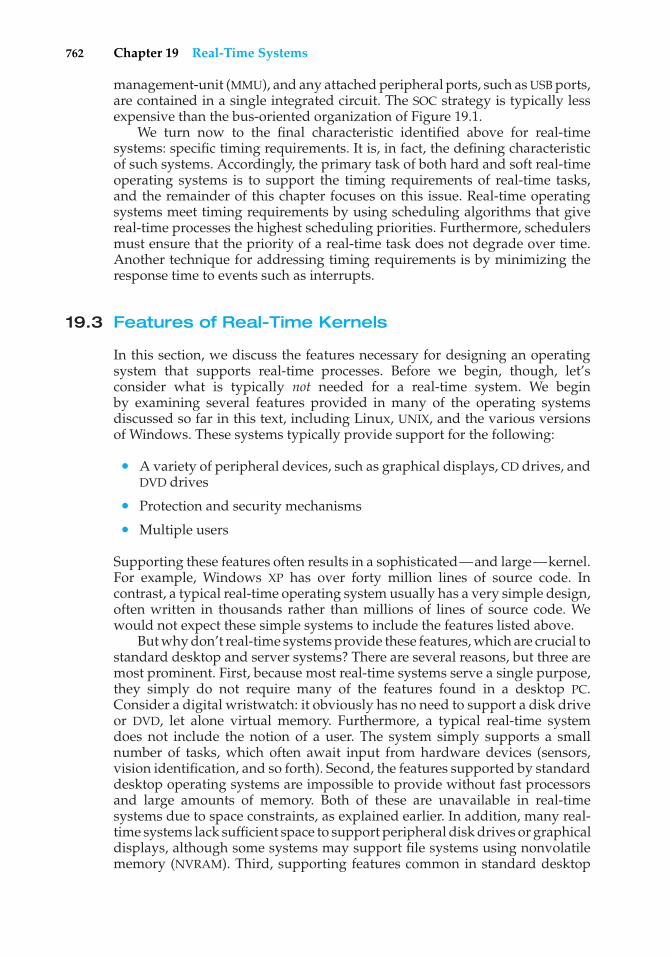
762 Chapter 19 Real-Time Systems
management-unit (MMU), and any attached peripheral ports, such as USB ports,are contained in a single integrated circuit. The SOC strategy is typically lessexpensive than the bus-oriented organization of Figure 19.1.
We turn now to the final characteristic identified above for real-timesystems: specific timing requirements. It is, in fact, the defining characteristicof such systems. Accordingly, the primary task of both hard and soft real-timeoperating systems is to support the timing requirements of real-time tasks,and the remainder of this chapter focuses on this issue. Real-time operatingsystems meet timing requirements by using scheduling algorithms that givereal-time processes the highest scheduling priorities. Furthermore, schedulersmust ensure that the priority of a real-time task does not degrade over time.Another technique for addressing timing requirements is by minimizing theresponse time to events such as interrupts.
19.3 Features of Real-Time Kernels
In this section, we discuss the features necessary for designing an operatingsystem that supports real-time processes. Before we begin, though, let’sconsider what is typically not needed for a real-time system. We beginby examining several features provided in many of the operating systemsdiscussed so far in this text, including Linux, UNIX, and the various versionsof Windows. These systems typically provide support for the following:
• A variety of peripheral devices, such as graphical displays, CD drives, andDVD drives
• Protection and security mechanisms
• Multiple users
Supporting these features often results in a sophisticated—and large—kernel.For example, Windows XP has over forty million lines of source code. Incontrast, a typical real-time operating system usually has a very simple design,often written in thousands rather than millions of lines of source code. Wewould not expect these simple systems to include the features listed above.
But why don’t real-time systems provide these features, which are crucial tostandard desktop and server systems? There are several reasons, but three aremost prominent. First, because most real-time systems serve a single purpose,they simply do not require many of the features found in a desktop PC.Consider a digital wristwatch: it obviously has no need to support a disk driveor DVD, let alone virtual memory. Furthermore, a typical real-time systemdoes not include the notion of a user. The system simply supports a smallnumber of tasks, which often await input from hardware devices (sensors,vision identification, and so forth). Second, the features supported by standarddesktop operating systems are impossible to provide without fast processorsand large amounts of memory. Both of these are unavailable in real-timesystems due to space constraints, as explained earlier. In addition, many real-time systems lack sufficient space to support peripheral disk drives or graphicaldisplays, although some systems may support file systems using nonvolatilememory (NVRAM). Third, supporting features common in standard desktop
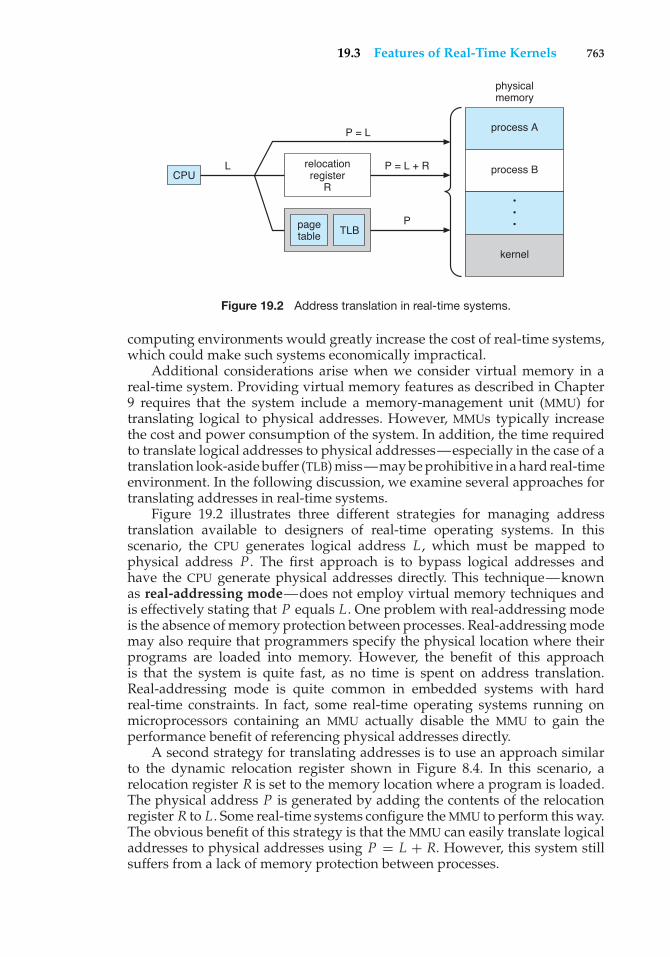
19.3 Features of Real-Time Kernels 763
CPU
TLB
relocationregister
R
pagetable
P = L
P = L + R
P
L
physicalmemory
process A
process B
•••
kernel
Figure 19.2 Address translation in real-time systems.
computing environments would greatly increase the cost of real-time systems,which could make such systems economically impractical.
Additional considerations arise when we consider virtual memory in areal-time system. Providing virtual memory features as described in Chapter9 requires that the system include a memory-management unit (MMU) fortranslating logical to physical addresses. However, MMUs typically increasethe cost and power consumption of the system. In addition, the time requiredto translate logical addresses to physical addresses—especially in the case of atranslation look-aside buffer (TLB) miss—may be prohibitive in a hard real-timeenvironment. In the following discussion, we examine several approaches fortranslating addresses in real-time systems.
Figure 19.2 illustrates three different strategies for managing addresstranslation available to designers of real-time operating systems. In thisscenario, the CPU generates logical address L , which must be mapped tophysical address P . The first approach is to bypass logical addresses andhave the CPU generate physical addresses directly. This technique—knownas real-addressing mode—does not employ virtual memory techniques andis effectively stating that P equals L . One problem with real-addressing modeis the absence of memory protection between processes. Real-addressing modemay also require that programmers specify the physical location where theirprograms are loaded into memory. However, the benefit of this approachis that the system is quite fast, as no time is spent on address translation.Real-addressing mode is quite common in embedded systems with hardreal-time constraints. In fact, some real-time operating systems running onmicroprocessors containing an MMU actually disable the MMU to gain theperformance benefit of referencing physical addresses directly.
A second strategy for translating addresses is to use an approach similarto the dynamic relocation register shown in Figure 8.4. In this scenario, arelocation register R is set to the memory location where a program is loaded.The physical address P is generated by adding the contents of the relocationregister R to L. Some real-time systems configure the MMU to perform this way.The obvious benefit of this strategy is that the MMU can easily translate logicaladdresses to physical addresses using P = L + R. However, this system stillsuffers from a lack of memory protection between processes.
764 Chapter 19 Real-Time Systems
The last approach is for the real-time system to provide full virtual memoryfunctionality as described in Chapter 9. In this instance, address translationtakes place via page tables and a translation look-aside buffer, or TLB. Inaddition to allowing a program to be loaded at any memory location, thisstrategy also provides memory protection between processes. For systemswithout attached disk drives, demand paging and swapping may not bepossible. However, systems may provide such features using NVRAM flashmemory. The LynxOS and OnCore Systems are examples of real-time operatingsystems providing full support for virtual memory.
19.4 Implementing Real-Time Operating Systems
Keeping in mind the many possible variations, we now identify the featuresnecessary for implementing a real-time operating system. This list is by nomeans absolute; some systems provide more features than we list below, whileother systems provide fewer.
• Preemptive, priority-based scheduling
• Preemptive kernel
• Minimized latency
One notable feature we omit from this list is networking support. How-ever, deciding whether to support networking protocols such as TCP/IP issimple: if the real-time system must be connected to a network, the operatingsystem must provide networking capabilities. For example, a system thatgathers real-time data and transmits it to a server must obviously includenetworking features. Alternatively, a self-contained embedded system requir-ing no interaction with other computer systems has no obvious networkingrequirement.
In the remainder of this section, we examine the basic requirements listedabove and identify how they can be implemented in a real-time operatingsystem.
19.4.1 Priority-Based Scheduling
The most important feature of a real-time operating system is to respondimmediately to a real-time process as soon as that process requires the CPU.As a result, the scheduler for a real-time operating system must support apriority-based algorithm with preemption. Recall that priority-based schedul-ing algorithms assign each process a priority based on its importance; moreimportant tasks are assigned higher priorities than those deemed less impor-tant. If the scheduler also supports preemption, a process currently runningon the CPU will be preempted if a higher-priority process becomes available torun.
Preemptive, priority-based scheduling algorithms are discussed in detailin Chapter 5, where we also present examples of the soft real-time schedulingfeatures of the Solaris, Windows XP, and Linux operating systems. Each ofthese systems assigns real-time processes the highest scheduling priority. For
19.4 Implementing Real-Time Operating Systems 765
example, Windows XP has 32 different priority levels; the highest levels—priority values 16 to 31—are reserved for real-time processes. Solaris andLinux have similar prioritization schemes.
Note, however, that providing a preemptive, priority-based scheduler onlyguarantees soft real-time functionality. Hard real-time systems must furtherguarantee that real-time tasks will be serviced in accord with their deadlinerequirements, and making such guarantees may require additional schedulingfeatures. In Section 19.5, we cover scheduling algorithms appropriate for hardreal-time systems.
19.4.2 Preemptive Kernels
Nonpreemptive kernels disallow preemption of a process running in kernelmode; a kernel-mode process will run until it exits kernel mode, blocks, orvoluntarily yields control of the CPU. In contrast, a preemptive kernel allowsthe preemption of a task running in kernel mode. Designing preemptivekernels can be quite difficult, and traditional user-oriented applications suchas spreadsheets, word processors, and Web browsers typically do not requiresuch quick response times. As a result, some commercial desktop operatingsystems—such as Windows XP—are nonpreemptive.
However, to meet the timing requirements of real-time systems—in partic-ular, hard real-time systems—preemptive kernels are mandatory. Otherwise,a real-time task might have to wait an arbitrarily long period of time whileanother task was active in the kernel.
There are various strategies for making a kernel preemptible. One approachis to insert preemption points in long-duration system calls. A preemptionpoint checks to see whether a high-priority process needs to be run. If so, acontext switch takes place. Then, when the high-priority process terminates,the interrupted process continues with the system call. Preemption pointscan be placed only at safe locations in the kernel—that is, only where kerneldata structures are not being modified. A second strategy for making a kernelpreemptible is through the use of synchronization mechanisms, discussed inChapter 6. With this method, the kernel can always be preemptible, because anykernel data being updated are protected from modification by the high-priorityprocess.
19.4.3 Minimizing Latency
Consider the event-driven nature of a real-time system. The system is typicallywaiting for an event in real time to occur. Events may arise either in software—as when a timer expires—or in hardware—as when a remote-controlledvehicle detects that it is approaching an obstruction. When an event occurs, thesystem must respond to and service it as quickly as possible. We refer to eventlatency as the amount of time that elapses from when an event occurs to whenit is serviced (Figure 19.3).
Usually, different events have different latency requirements. For example,the latency requirement for an antilock brake system might be three to fivemilliseconds, meaning that from the time a wheel first detects that it is sliding,the system controlling the antilock brakes has three to five milliseconds torespond to and control the situation. Any response that takes longer mightresult in the automobile’s veering out of control. In contrast, an embedded
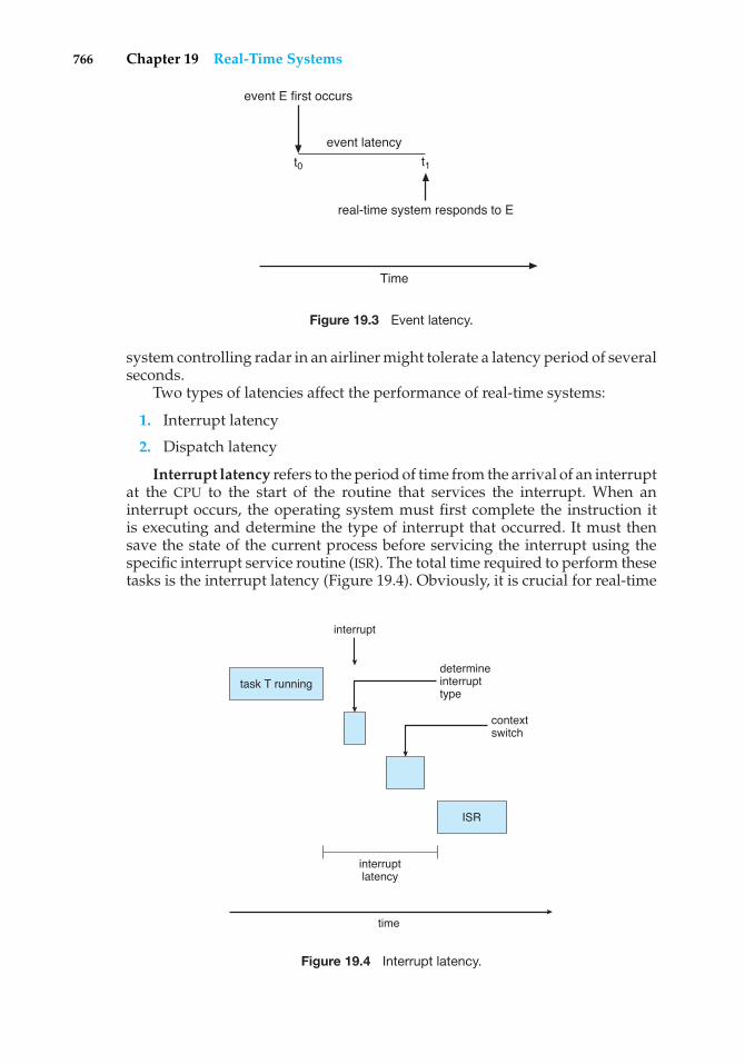
766 Chapter 19 Real-Time Systems
t1t0
event latency
event E first occurs
real-time system responds to E
Time
Figure 19.3 Event latency.
system controlling radar in an airliner might tolerate a latency period of severalseconds.
Two types of latencies affect the performance of real-time systems:
1. Interrupt latency
2. Dispatch latency
Interrupt latency refers to the period of time from the arrival of an interruptat the CPU to the start of the routine that services the interrupt. When aninterrupt occurs, the operating system must first complete the instruction itis executing and determine the type of interrupt that occurred. It must thensave the state of the current process before servicing the interrupt using thespecific interrupt service routine (ISR). The total time required to perform thesetasks is the interrupt latency (Figure 19.4). Obviously, it is crucial for real-time
task T running
ISR
determineinterrupttype
interrupt
interruptlatency
contextswitch
time
Figure 19.4 Interrupt latency.
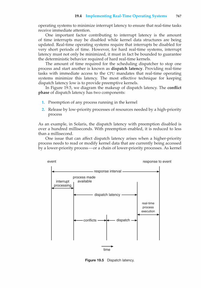
19.4 Implementing Real-Time Operating Systems 767
operating systems to minimize interrupt latency to ensure that real-time tasksreceive immediate attention.
One important factor contributing to interrupt latency is the amountof time interrupts may be disabled while kernel data structures are beingupdated. Real-time operating systems require that interrupts be disabled forvery short periods of time. However, for hard real-time systems, interruptlatency must not only be minimized, it must in fact be bounded to guaranteethe deterministic behavior required of hard real-time kernels.
The amount of time required for the scheduling dispatcher to stop oneprocess and start another is known as dispatch latency. Providing real-timetasks with immediate access to the CPU mandates that real-time operatingsystems minimize this latency. The most effective technique for keepingdispatch latency low is to provide preemptive kernels.
In Figure 19.5, we diagram the makeup of dispatch latency. The conflictphase of dispatch latency has two components:
1. Preemption of any process running in the kernel
2. Release by low-priority processes of resources needed by a high-priorityprocess
As an example, in Solaris, the dispatch latency with preemption disabled isover a hundred milliseconds. With preemption enabled, it is reduced to lessthan a millisecond.
One issue that can affect dispatch latency arises when a higher-priorityprocess needs to read or modify kernel data that are currently being accessedby a lower-priority process—or a chain of lower-priority processes. As kernel
response to event
real-time process
execution
event
conflicts
time
dispatch
response interval
dispatch latency
process made availableinterrupt
processing
Figure 19.5 Dispatch latency.
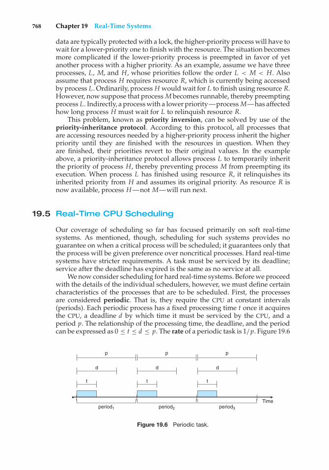
768 Chapter 19 Real-Time Systems
data are typically protected with a lock, the higher-priority process will have towait for a lower-priority one to finish with the resource. The situation becomesmore complicated if the lower-priority process is preempted in favor of yetanother process with a higher priority. As an example, assume we have threeprocesses, L, M, and H, whose priorities follow the order L < M < H. Alsoassume that process H requires resource R, which is currently being accessedby process L. Ordinarily, process Hwould wait for L to finish using resource R.However, now suppose that process M becomes runnable, thereby preemptingprocess L. Indirectly, a process with a lower priority—processM—has affectedhow long process H must wait for L to relinquish resource R.
This problem, known as priority inversion, can be solved by use of thepriority-inheritance protocol. According to this protocol, all processes thatare accessing resources needed by a higher-priority process inherit the higherpriority until they are finished with the resources in question. When theyare finished, their priorities revert to their original values. In the exampleabove, a priority-inheritance protocol allows process L to temporarily inheritthe priority of process H, thereby preventing process M from preempting itsexecution. When process L has finished using resource R, it relinquishes itsinherited priority from H and assumes its original priority. As resource R isnow available, process H—not M—will run next.
19.5 Real-Time CPU Scheduling
Our coverage of scheduling so far has focused primarily on soft real-timesystems. As mentioned, though, scheduling for such systems provides noguarantee on when a critical process will be scheduled; it guarantees only thatthe process will be given preference over noncritical processes. Hard real-timesystems have stricter requirements. A task must be serviced by its deadline;service after the deadline has expired is the same as no service at all.
We now consider scheduling for hard real-time systems. Before we proceedwith the details of the individual schedulers, however, we must define certaincharacteristics of the processes that are to be scheduled. First, the processesare considered periodic. That is, they require the CPU at constant intervals(periods). Each periodic process has a fixed processing time t once it acquiresthe CPU, a deadline d by which time it must be serviced by the CPU, and aperiod p. The relationship of the processing time, the deadline, and the periodcan be expressed as 0 ≤ t ≤ d ≤ p. The rate of a periodic task is 1/p. Figure 19.6
period1 period2 period3
Time
p p p
ddd
t tt
Figure 19.6 Periodic task.
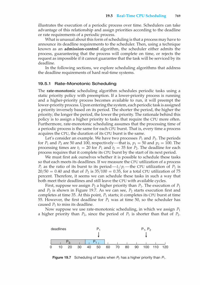
19.5 Real-Time CPU Scheduling 769
illustrates the execution of a periodic process over time. Schedulers can takeadvantage of this relationship and assign priorities according to the deadlineor rate requirements of a periodic process.
What is unusual about this form of scheduling is that a process may have toannounce its deadline requirements to the scheduler. Then, using a techniqueknown as an admission-control algorithm, the scheduler either admits theprocess, guaranteeing that the process will complete on time, or rejects therequest as impossible if it cannot guarantee that the task will be serviced by itsdeadline.
In the following sections, we explore scheduling algorithms that addressthe deadline requirements of hard real-time systems.
19.5.1 Rate-Monotonic Scheduling
The rate-monotonic scheduling algorithm schedules periodic tasks using astatic priority policy with preemption. If a lower-priority process is runningand a higher-priority process becomes available to run, it will preempt thelower-priority process. Upon entering the system, each periodic task is assigneda priority inversely based on its period. The shorter the period, the higher thepriority; the longer the period, the lower the priority. The rationale behind thispolicy is to assign a higher priority to tasks that require the CPU more often.Furthermore, rate-monotonic scheduling assumes that the processing time ofa periodic process is the same for each CPU burst. That is, every time a processacquires the CPU, the duration of its CPU burst is the same.
Let’s consider an example. We have two processes P1 and P2. The periodsfor P1 and P2 are 50 and 100, respectively—that is, p1 = 50 and p2 = 100. Theprocessing times are t1 = 20 for P1 and t2 = 35 for P2. The deadline for eachprocess requires that it complete its CPU burst by the start of its next period.
We must first ask ourselves whether it is possible to schedule these tasksso that each meets its deadlines. If we measure the CPU utilization of a processPi as the ratio of its burst to its period—ti/pi —the CPU utilization of P1 is20/50 = 0.40 and that of P2 is 35/100 = 0.35, for a total CPU utilization of 75percent. Therefore, it seems we can schedule these tasks in such a way thatboth meet their deadlines and still leave the CPU with available cycles.
First, suppose we assign P2 a higher priority than P1. The execution of P1and P2 is shown in Figure 19.7. As we can see, P2 starts execution first andcompletes at time 35. At this point, P1 starts; it completes its CPU burst at time55. However, the first deadline for P1 was at time 50, so the scheduler hascaused P1 to miss its deadline.
Now suppose we use rate-monotonic scheduling, in which we assign P1a higher priority than P2, since the period of P1 is shorter than that of P2.
0 10 20 30 40 50 60 70 80 12090 100 110
P1
P1
P1, P2
P2
deadlines
Figure 19.7 Scheduling of tasks when P2 has a higher priority than P1.