Embed Size (px)
Citation preview
OPTICAL MARK READER
OPERATING MANUALSR-1800
SR-1800
�
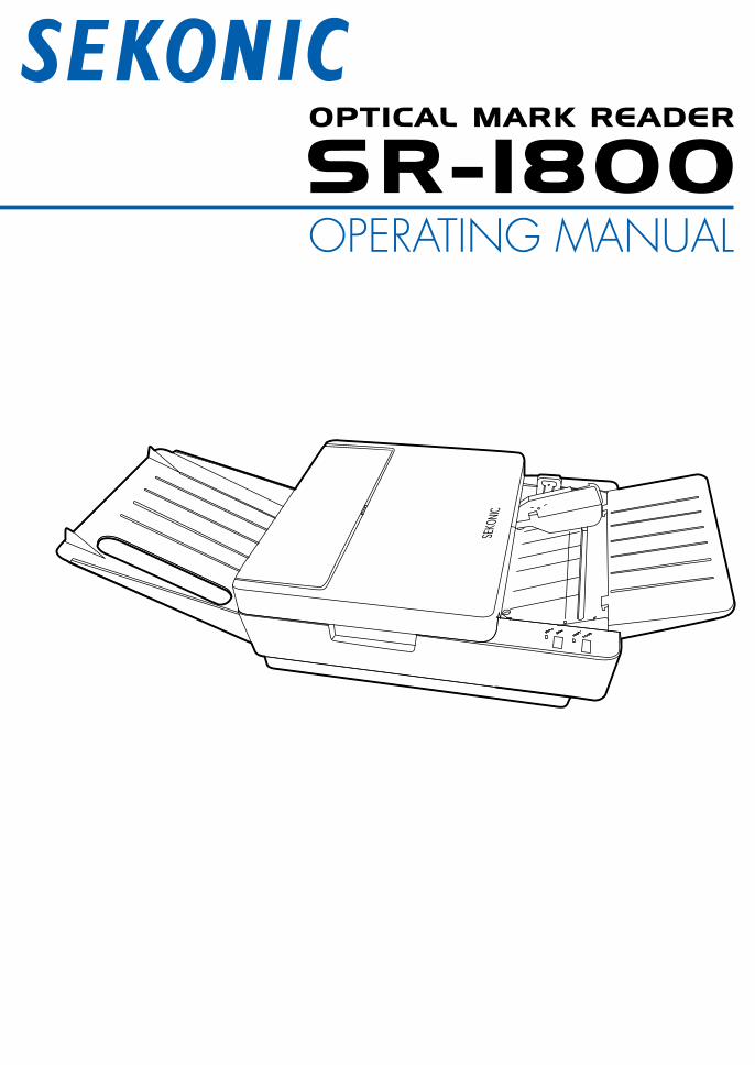
IntroductionThank you very much for purchasing our product.Please read the operating manual before using this product, and be sure to use it properly.After reading this operating manual, be sure to keep it in a place that you can access at any time.
NOTICES
1.Apartorallofcontentsofthismanualmaynotbereproducedinanyformwithoutthepriorwrittenpermissionofthepublisher.
2.Thecontentsofthismanualaresubjecttochangewithoutnotice.3.If you have anydoubt or question about theproduct or thecontentsof thismanual,
pleasemakecontactwithoursalesdivisionorservicedivision.
©2009SEKONICCorporationAllRightsReserved.
�
SR-1800
SafetyPrecautions...................................................................................................................... 4
Warranty...................................................................................................................................... 7
PrecautionsforUse.................................................................................................................... 8Precautionsregardinginstallation..................................................................................... 8Handlingprecautions......................................................................................................... 8
BeforeUsing................................................................................................................................ 9BeforeUsingtheDevice..................................................................................................... 9UnpackingtheDevice....................................................................................................... 10
NamesandFunctionsofParts................................................................................................. 11MainBodyUnit.................................................................................................................. 11OperationPanel................................................................................................................ 11BuzzerSound.................................................................................................................... 13
PreparationforUse................................................................................................................... 14AttachingtheSheetFeedTrayandStacker.................................................................... 14ConnectingtheACAdopter............................................................................................. 15InstallingtheUSBDriver.................................................................................................. 15InstallingtheDiagnosticUtilities..................................................................................... 15ConnectingtheCommunicationCable........................................................................... 16ConnectingtotheComputer............................................................................................ 16RotaryandDIPSwitchSettings...................................................................................... 171 AccessingtheRotaryandDIPSwitches..................................................................... 172 RotarySwitchRSW1Settings...................................................................................... 173 DIPSwitchSW1Settings.............................................................................................. 184 DIPSwitchSW2Settings.............................................................................................. 195 DIPSwitchSW3Settings.............................................................................................. 216 RotarySwitchRSW2Settings...................................................................................... 22
InspectingSheets..................................................................................................................... 23
HandlingandStoringSheets................................................................................................... 25Handlingsheets................................................................................................................ 25Storageofsheets.............................................................................................................. 25
MarkingInstructions................................................................................................................. 26
AboutReadingSensitivityLevel.............................................................................................. 26
Operation................................................................................................................................... 27OperationFlow.................................................................................................................. 27TurningPowerOn/Off....................................................................................................... 271 TurningPowerOn.......................................................................................................... 272 TurningPowerOff......................................................................................................... 27
■■
■■
■■■
■■■■■■■
■■
■■
Table of Contents
SR-1800
�
3 PowerSavingModes.................................................................................................... 28SettingSheets................................................................................................................... 29ReadingSheets................................................................................................................. 32Whenanerroroccurs:...................................................................................................... 32ChecksheetReadingTest................................................................................................ 32
Troubleshooting........................................................................................................................ 34Troubleshooting................................................................................................................ 34ErrorIndicator................................................................................................................... 35FixingSheetJams............................................................................................................. 37
Cleaning..................................................................................................................................... 39RegularMaintenance........................................................................................................ 39CleaningProcedures........................................................................................................ 40
ServiceSchedule...................................................................................................................... 42
ProductSpecifications............................................................................................................. 43
ExternalDimensionsDiagram.................................................................................................. 44
OMRGlossary........................................................................................................................... 45
Appendix...................................................................................................................................... iSheetcreationreference..................................................................................................... i
■■
■
■■■
■■
■
�
SR-1800
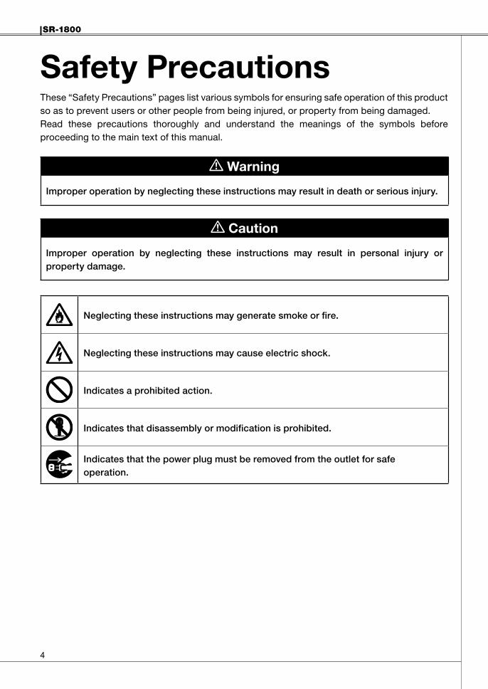
Safety PrecautionsThese “Safety Precautions” pages list various symbols for ensuring safe operation of this product so as to prevent users or other people from being injured, or property from being damaged.Read these precautions thoroughly and understand the meanings of the symbols before proceeding to the main text of this manual.
Warning
Improperoperationbyneglectingtheseinstructionsmayresultindeathorseriousinjury.
Caution
Improper operation by neglecting these instructions may result in personal injury orpropertydamage.
Neglectingtheseinstructionsmaygeneratesmokeorfire.
Neglectingtheseinstructionsmaycauseelectricshock.
Indicatesaprohibitedaction.
Indicatesthatdisassemblyormodificationisprohibited.
Indicatesthatthepowerplugmustberemovedfromtheoutletforsafeoperation.
SR-1800
�
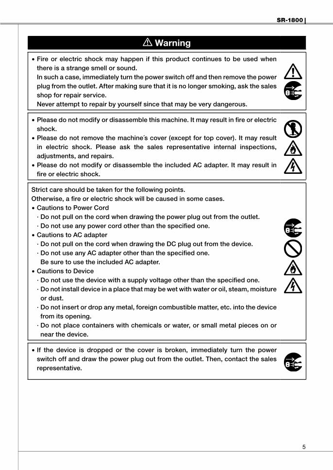
Warning
Fireorelectricshockmayhappen if thisproductcontinues tobeusedwhenthereisastrangesmellorsound.Insuchacase,immediatelyturnthepowerswitchoffandthenremovethepowerplugfromtheoutlet.Aftermakingsurethatitisnolongersmoking,askthesalesshopforrepairservice.Neverattempttorepairbyyourselfsincethatmaybeverydangerous.
•
Pleasedonotmodifyordisassemblethismachine.Itmayresultinfireorelectricshock.Pleasedonotremovethemachine´scover(exceptfortopcover).Itmayresultin electric shock. Please ask the sales representative internal inspections,adjustments,andrepairs.PleasedonotmodifyordisassembletheincludedACadapter.Itmayresultinfireorelectricshock.
•
•
•
Strictcareshouldbetakenforthefollowingpoints.Otherwise,afireorelectricshockwillbecausedinsomecases.
CautionstoPowerCord·Donotpullonthecordwhendrawingthepowerplugoutfromtheoutlet.·Donotuseanypowercordotherthanthespecifiedone.CautionstoACadapter·DonotpullonthecordwhendrawingtheDCplugoutfromthedevice.·DonotuseanyACadapterotherthanthespecifiedone.BesuretousetheincludedACadapter.CautionstoDevice·Donotusethedevicewithasupplyvoltageotherthanthespecifiedone.·Donotinstalldeviceinaplacethatmaybewetwithwateroroil,steam,moistureordust.
·Donotinsertordropanymetal,foreigncombustiblematter,etc.intothedevicefromitsopening.
·Donotplacecontainerswithchemicalsorwater,orsmallmetalpiecesonornearthedevice.
•
•
•
If the device is dropped or the cover is broken, immediately turn the powerswitchoffanddrawthepowerplugoutfromtheoutlet.Then,contactthesalesrepresentative.
•

�
SR-1800
Warning
Ifanyforeignmattershouldenterinside,immediatelyturnthepowerswitchoffandremovethepowerplugfromtheoutlet.Then,contactthesalesrepresentativeorSekonic.Ifthedevicecontinuestobeusedwithforeignmatterinside,fireorelectricshockmayoccur.If water or other substances penetrate the unit, immediately turn the powerswitchoffandremovethepowerplugfromtheoutlet.Then,contactthesalesrepresentativeorSekonic.Ifthedevicecontinuestobeusedwithwaterorotherforeignmatterinside,fireorelectricshockmayoccur.
•
Beforemovingthedevice,besuretoremovethepowerplugfromtheoutlet.Ifthecableisdamaged,fireorelectricshockmayoccur.
•
Donotconnectordisconnectthepowerplugifyourhandsarewet.Otherwise,anelectricshockmayoccur.
•
Caution
Donotplacethedeviceinanunstablelocation.Otherwise,itmayfallorcollapse,resultingininjury.
•
Whenopeningorclosing theupperpartof themainbody,donotplaceyourhandonthesheet-feedingsurface.Otherwise,fingersmaybecaught,resultingininjury.Ifyoumusttouchthesheet-feedingsurfaceofthemainbody,becarefulnottoallowyourfingerstobecaughtorhit.
•
•
Whendoingmaintenanceonthedevice,foryourownsafety,besuretoremovethepowerplugfromtheoutlet.Whenthedeviceisnotinuseforlongperiods,forsafety,removethepowerplugfromtheoutlet.
•
•
Donotputheavythingsonthedevice.Otherwise,itmayfallorcollapse,resultingininjury.
•
SR-1800
�
WarrantyThe cost-free warranty period for this product extends for one year after delivery.The company will repair malfunctions arising during this period free of charge if they are determined to be the company's responsibility. In the event repairs are necessary, as a general rule the company will keep the product temporarily to carry out such repair work.Problems arising after the warranty period has expired, problems not covered by the warranty even if the warranty period has not expired, problems that do not have the seal of the retailer, malfunctions and other failures caused by customer misuse or by wear and tear of parts due to repeated use will not be covered by the warranty.This warranty covers only this product and included accessories, and the company does not assume any responsibility for monetary damages, lost profits or any claims from third parties resulting from the use of this device.
�
SR-1800
Precautions for UseHandle the device with the following points in mind to enable full use of its functions.
PrecautionsregardinginstallationDo not place the device in the following places. Otherwise, failures could result such as sheet jams, reading errors, or the unit could stop operating.(1) In direct sunlight or near a heating device.(2) Outdoors where the main body may not perform satisfactorily due to rain or strong wind.(3) Places where the machine may not perform satisfactorily, such as unstable or inclined
surfaces, or other locations where the machine may shake while it is operating.(4) Places subject to sudden temperature changes, excessive moisture and dust.
Recommended temperature: 10 - 30°C (50°F - 86°F)Guaranteed operating temperature range: 5 - 35°C (41°F - 95°F)Humidity: 30-80% (no condensation) Avoid environments outside the above ranges as much as possible.
Handlingprecautions(1) Do not connect or disconnect the power plug or DC plug of AC adapter when the device is
in operation or the power switch is on.(2) Do not move the device while it is operating. Also, do not touch, pull, or push the sheet.(3) Do not put objects on the device, or sit or lean on it.(4) Do not give the device a strong vibration and shock etc.(5) Allow an interval of at least 5 seconds between turning the power switch on and off.(6) Do not insert foreign objects other than the sheet.(7) Do not apply force that deforms the sheet while it is being loaded.(8) Since the sheet reader is equipped with an optical lens, never insert a screwdriver or other
such objects. (Otherwise, reading may be disabled.)If sheet feeding is disabled due to dust or the like in the sheet feeder, open the top cover to remove it. See “Cleaning” (P.39).
(9) If the roller becomes soiled with powder from sheets or pencil lead, the roller and the sheet may slip. In order to prevent slippage, clean the roller at proper intervals. See "Cleaning" (P.39).
(10) If the exterior of the device is soiled, lightly wipe with a soft cloth wetted with water or a neutral detergent. Note that wiping with a cloth wetted with volatile chemicals like benzene or paint thinner may cause deformation or discoloring.
(11) Do not place excessive load on the sheet feed tray and stacker. Doing so may result in deformation or damage.
(12) When the machine is not used for a prolonged period of time, remove the power cord from the outlet.
(13) When the machine is not used for a prolonged period of time, keep the hopper set in the down position.
SR-1800
�
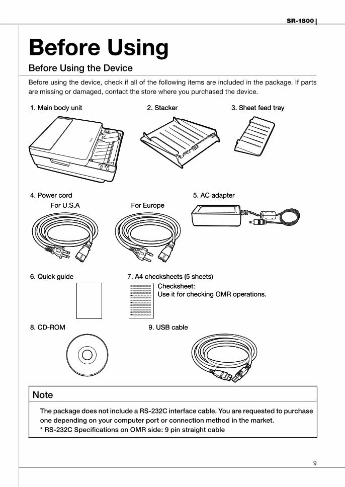
Before UsingBeforeUsingtheDeviceBefore using the device, check if all of the following items are included in the package. If parts are missing or damaged, contact the store where you purchased the device.
Note
ThepackagedoesnotincludeaRS-232Cinterfacecable.Youarerequestedtopurchaseonedependingonyourcomputerportorconnectionmethodinthemarket.*RS-232CSpecificationsonOMRside:9pinstraightcable
1. Main body unit
4. Power cord
For U.S.A
6. Quick guide
8. CD-ROM 9. USB cable
7. A4 checksheets (5 sheets)Checksheet:Use it for checking OMR operations.
For Europe
5. AC adapter
2. Stacker 3. Sheet feed tray1. Main body unit
4. Power cord
For U.S.A
6. Quick guide
8. CD-ROM 9. USB cable
7. A4 checksheets (5 sheets)Checksheet:Use it for checking OMR operations.
For Europe
5. AC adapter
2. Stacker 3. Sheet feed tray
�0
SR-1800
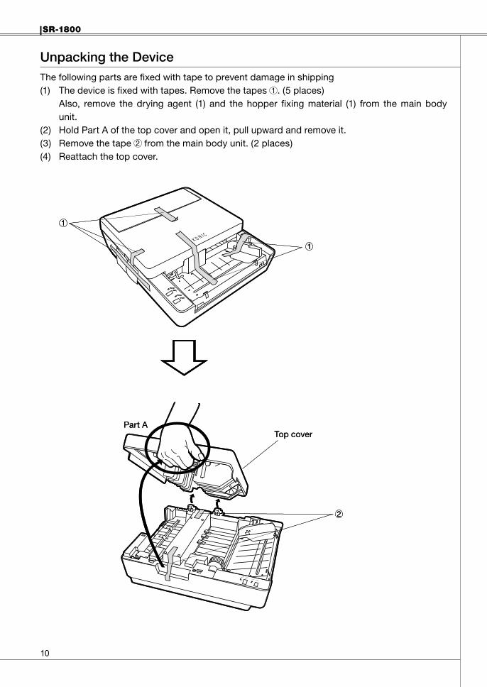
UnpackingtheDeviceThe following parts are fixed with tape to prevent damage in shipping(1) The device is fixed with tapes. Remove the tapes 1 . (5 places)
Also, remove the drying agent (1) and the hopper fixing material (1) from the main body unit.
(2) Hold Part A of the top cover and open it, pull upward and remove it.(3) Remove the tape 2 from the main body unit. (2 places)(4) Reattach the top cover.
1
1
1
1
Part ATop cover
2
Part ATop cover
2
SR-1800
��
Names and Functions of PartsMainBodyUnit
Number Name Explanation
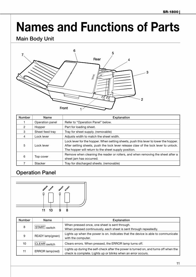
1 Operation panel Refer to “Operation Panel” below.
2 Hopper Part for loading sheet.
3 Sheet feed tray Tray for sheet supply. (removable)
4 Lock lever Adjusts width to match the sheet width.
5 Lock leverLock lever for the hopper. When setting sheets, push this lever to lower the hopper. After setting sheets, push the lock lever release claw of the lock lever to unlock. The hopper will return to the sheet supply position.
6 Top coverRemove when cleaning the reader or rollers, and when removing the sheet after a sheet jam has occurred.
7 Stacker Tray for discharged sheets. (removable)
OperationPanel
Number Name Explanation
8 START switchWhen pressed once, one sheet is sent through.When pressed continuously, each sheet is sent through repeatedly.
9 READY lamp(green)Lights up when the power is on. Indicates that the device is able to communicate with the computer.
10 CLEAR switch Clears errors. When pressed, the ERROR lamp turns off.
11 ERROR lamp(red)Lights up during the self-check after the power is turned on, and turns off when the check is complete. Lights up or blinks when an error occurs.
1
2
3
4
657
Front
Rear
1
2
3
4
657
Front
Rear
891011 891011

��
SR-1800
Number Name Explanation
12 USB connector Port for communication via USB cable.
13 RS-232C connector Port for communication via RS-232C.
14 DC jack DC plug (AC adapter) connection terminal.
15 Power switch Turns the device ON/OFF.
16 DIP Switch cover Cover for the DIP switch. Bend the cover to remove it.
17 DIP/Rotary switchesSwitches for setting device specifications. Before using the device, the switches must be set.(Reference: “Rotary and DIP Switch Settings” (P.17))
12 13 1415
16
17
Front
Rear
12 13 1415
16
17
Front
Rear

SR-1800
��
BuzzerSoundThis device has a built-in buzzer that indicates operating conditions and errors.
BuzzerSound Meaning Explanation
Pip! Confirmation
When the power is on, the buzzer sounds after the self-check is completed normally.(Sounds at the same time the ERROR lamp turns off.)
Sounds when the START switch is pressed and one sheet is loaded.
Sounds when the CLEAR switch is pressed and the ERROR lamp turns off.
Pip! Pip! Pip! Caution
Sounds when no sheet is in the hopper and the START switch is pressed.
Sounds when an abnormality occurs during the checksheet reading test.
Peep! Peep! Peep! Error Sounds when an error occurs .
ON
OFF
50 ms
ON
OFF
ON
OFF
200 ms 50 ms
50 ms 100 ms
Pip!
Pip! Pip! Pip!
Peep! Peep! Peep!
ON
OFF
50 ms
ON
OFF
ON
OFF
200 ms 50 ms
50 ms 100 ms
Pip!
Pip! Pip! Pip!
Peep! Peep! Peep!
��
SR-1800
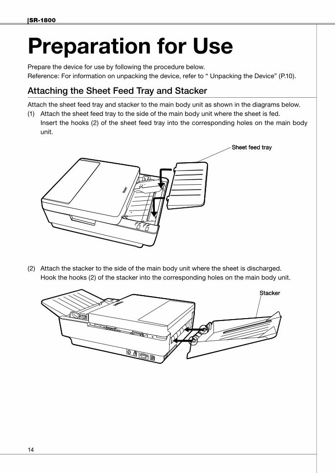
Preparation for UsePrepare the device for use by following the procedure below.Reference: For information on unpacking the device, refer to “ Unpacking the Device” (P.10).
AttachingtheSheetFeedTrayandStackerAttach the sheet feed tray and stacker to the main body unit as shown in the diagrams below.(1) Attach the sheet feed tray to the side of the main body unit where the sheet is fed.
Insert the hooks (2) of the sheet feed tray into the corresponding holes on the main body unit.
(2) Attach the stacker to the side of the main body unit where the sheet is discharged.Hook the hooks (2) of the stacker into the corresponding holes on the main body unit.
Sheet feed traySheet feed tray
StackerStacker

SR-1800
��
ConnectingtheACAdopterAttach the AC adapter (included) to the device.
BesuretousetheincludedACadapter,otherwiseafiremayresult.•
WARNING
(1) Insert the DC plug of the AC adapter into the main body unit's DC jack(2) Connect the power cord to the AC adapter and the outlet.
InstallingtheUSBDriverInstall the driver on the included CD-ROM.· For details on how to install the driver, refer to ¥Driver¥Install.txt in the CD-ROM.
InstallingtheDiagnosticUtilitiesInstall the diagnostic utilities on the included CD-ROM.· For details on how to install and use the diagnostic utilities, refer to ¥Diagonistic Utility
¥setup.exe in the CD-ROM.
AC adapter Power cord
DC plug
AC adapter Power cord
DC plug
��
SR-1800
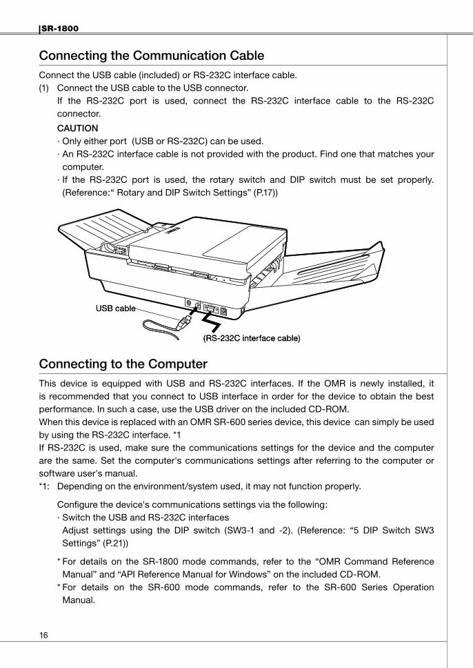
ConnectingtheCommunicationCableConnect the USB cable (included) or RS-232C interface cable.(1) Connect the USB cable to the USB connector.
If the RS-232C port is used, connect the RS-232C interface cable to the RS-232C connector.
CAUTION · Only either port (USB or RS-232C) can be used.· An RS-232C interface cable is not provided with the product. Find one that matches your
computer.· If the RS-232C port is used, the rotary switch and DIP switch must be set properly.
(Reference:“ Rotary and DIP Switch Settings” (P.17))
ConnectingtotheComputerThis device is equipped with USB and RS-232C interfaces. If the OMR is newly installed, it is recommended that you connect to USB interface in order for the device to obtain the best performance. In such a case, use the USB driver on the included CD-ROM.When this device is replaced with an OMR SR-600 series device, this device can simply be used by using the RS-232C interface. *1If RS-232C is used, make sure the communications settings for the device and the computer are the same. Set the computer's communications settings after referring to the computer or software user's manual.*1: Depending on the environment/system used, it may not function properly.
Configure the device's communications settings via the following:· Switch the USB and RS-232C interfaces Adjust settings using the DIP switch (SW3-1 and -2). (Reference: “5 DIP Switch SW3
Settings” (P.21))
* For details on the SR-1800 mode commands, refer to the “OMR Command Reference Manual” and “API Reference Manual for Windows” on the included CD-ROM.
* For details on the SR-600 mode commands, refer to the SR-600 Series Operation Manual.
USB cable
(RS-232C interface cable)
USB cable
(RS-232C interface cable)
SR-1800
��
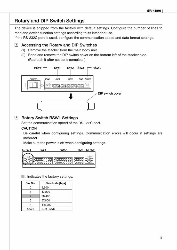
RotaryandDIPSwitchSettingsThe device is shipped from the factory with default settings. Configure the number of lines to read and device function settings according to its intended use.If the RS-232C port is used, configure the communication speed and data format settings.
1 AccessingtheRotaryandDIPSwitches(1) Remove the stacker from the main body unit.(2) Bend and remove the DIP switch cover on the bottom left of the stacker side. (Reattach it after set up is complete.)
2 RotarySwitchRSW1SettingsSet the communication speed of the RS-232C port.
CAUTION· Be careful when configuring settings. Communication errors will occur if settings are
incorrect.· Make sure the power is off when configuring settings.
: Indicates the factory settings.
SWNo. Baudrate[bps]
0 9,600
1 19,200
2 38,400
3 57,600
4 115,200
5 to 9 (Not used)
RSW1 SW1 SW2 SW3 RSW2
DIP switch cover
RSW1 SW1 SW2 SW3 RSW2
DIP switch cover
��
SR-1800
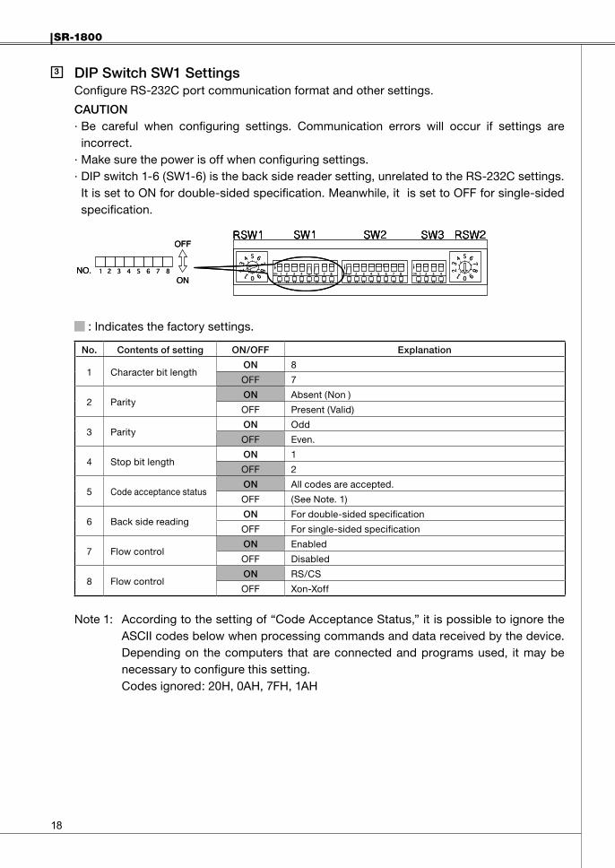
3 DIPSwitchSW1SettingsConfigure RS-232C port communication format and other settings.
CAUTION· Be careful when configuring settings. Communication errors will occur if settings are
incorrect.· Make sure the power is off when configuring settings.· DIP switch 1-6 (SW1-6) is the back side reader setting, unrelated to the RS-232C settings.
It is set to ON for double-sided specification. Meanwhile, it is set to OFF for single-sided specification.
: Indicates the factory settings.
No. Contentsofsetting ON/OFF Explanation
1 Character bit lengthON 8
OFF 7
2 ParityON Absent (Non )
OFF Present (Valid)
3 ParityON Odd
OFF Even.
4 Stop bit lengthON 1
OFF 2
5 Code acceptance statusON All codes are accepted.
OFF (See Note. 1)
6 Back side readingON For double-sided specification
OFF For single-sided specification
7 Flow controlON Enabled
OFF Disabled
8 Flow controlON RS/CS
OFF Xon-Xoff
Note 1: According to the setting of “Code Acceptance Status,” it is possible to ignore the ASCII codes below when processing commands and data received by the device. Depending on the computers that are connected and programs used, it may be necessary to configure this setting.
Codes ignored: 20H, 0AH, 7FH, 1AH
NO.
OFF
ONNO.
OFF
ON

SR-1800
��
4 DIPSwitchSW2SettingsCAUTION· Be careful when configuring settings. Marks will be misread if the settings are incorrect.· Make sure the power is off when configuring settings.
: Indicates the factory settings.
Contentsofsetting SW2
No.oflines Timingtype 1 2 3 4 5 6 7 8
12 lines
Control type ON ON ON OFF
Direct-under type OFF OFF OFF ON
Mark-to-mark type OFF OFF ON ON
24 lines
Control type OFF OFF ON OFF
Direct-under type ON OFF ON OFF
Mark-to-mark type ON ON OFF OFF
32 lines
Control type OFF ON OFF OFF
Direct-under type ON ON OFF ON
Mark-to-mark type OFF ON OFF ON
38 linesControl type OFF ON ON ON
Direct-under type ON ON ON ON
40 lines
Control type OFF OFF OFF OFF
Mark-to-mark type ON OFF OFF OFF
Direct-under type ON OFF OFF ON
48 lines Direct-under type ON OFF ON ON
Automatic sheet dischargeON ON
OFF OFF
Sheet empty detectionON ON
OFF OFF
Timing mark error detectionON ON
OFF OFF
(Not used) - ON
- OFF
SW2-1 to 4: Select the number of lines to read and the timing mark type according to the sheet used. Mark-to-mark type is set for “Without top-end margin reading.”(Reference: “OMR Glossary” (P.45) - Timing control type, Direct under type, Mark to mark type)
Priority is given to the settings from the computer side.
NO.
OFF
ONNO.
OFF
ON
�0
SR-1800
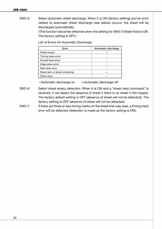
SW2-5: Select automatic sheet discharge. When it is ON (factory setting) and an error related to automatic sheet discharge (see below) occurs, the sheet will be discharged automatically.
(This function becomes effective when the setting for SW3-3 Sheet Hold is ON. The factory setting is OFF.)
List of Errors for Automatic Discharge:
Error Automaticdischarge
Sheet empty ×
Timing mark error ○Double feed error ○Edge skew error ○Mark skew error ○Sheet jam or sheet remaining ×
Other error ○
○:Automatic discharge on ×:Automatic discharge off
SW2-6: Select sheet empty detection. When it is ON and a “sheet read command” is received, it will detect the absence of sheet if there is no sheet in the hopper. The factory default setting is OFF (absence of sheet will not be detected). The factory setting is OFF (absence of sheet will not be detected).
SW2-7: If there are three or less timing marks on the sheet that was read, a timing mark error will be detected (detection is made as the factory setting is ON).
SR-1800
��
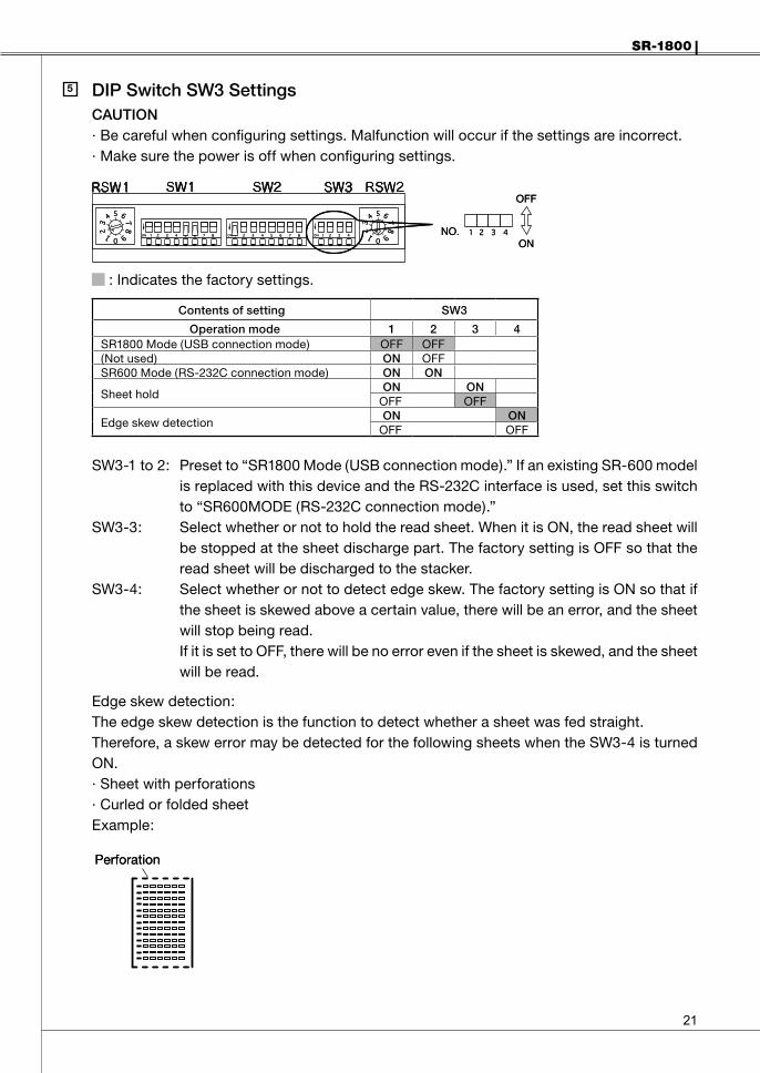
5 DIPSwitchSW3SettingsCAUTION· Be careful when configuring settings. Malfunction will occur if the settings are incorrect.· Make sure the power is off when configuring settings.
: Indicates the factory settings.
Contentsofsetting SW3
Operationmode 1 2 3 4SR1800 Mode (USB connection mode) OFF OFF(Not used) ON OFFSR600 Mode (RS-232C connection mode) ON ON
Sheet holdON ON
OFF OFF
Edge skew detectionON ON
OFF OFF
SW3-1 to 2: Preset to “SR1800 Mode (USB connection mode).” If an existing SR-600 model is replaced with this device and the RS-232C interface is used, set this switch to “SR600MODE (RS-232C connection mode).”
SW3-3: Select whether or not to hold the read sheet. When it is ON, the read sheet will be stopped at the sheet discharge part. The factory setting is OFF so that the read sheet will be discharged to the stacker.
SW3-4: Select whether or not to detect edge skew. The factory setting is ON so that if the sheet is skewed above a certain value, there will be an error, and the sheet will stop being read.
If it is set to OFF, there will be no error even if the sheet is skewed, and the sheet will be read.
Edge skew detection:The edge skew detection is the function to detect whether a sheet was fed straight.Therefore, a skew error may be detected for the following sheets when the SW3-4 is turned ON.· Sheet with perforations· Curled or folded sheetExample:
NO.
OFF
ONNO.
OFF
ON
PerforationPerforation
��
SR-1800
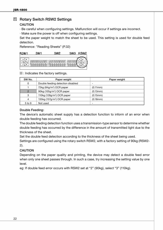
6 RotarySwitchRSW2SettingsCAUTION· Be careful when configuring settings. Malfunction will occur if settings are incorrect.· Make sure the power is off when configuring settings.Set the paper weight to match the sheet to be used. This setting is used for double feed detection.Reference: ”Reading Sheets” (P.32)
: Indicates the factory settings.
SWNo. Paperweight Paperweight
0 Double feeding detection disabled -
1 72kg (84g/m2) OCR paper (0.11mm)
2 90kg (105g/m2) OCR paper (0.13mm)
3 110kg (128g/m2) OCR paper (0.15mm)
4 135kg (157g/m2) OCR paper (0.18mm)
5 to 9 Not used -
DoubleFeeding:The device’s automatic sheet supply has a detection function to inform of an error when double feeding has occurred.The double feeding detection function uses a transmission-type sensor to determine whether double feeding has occurred by the difference in the amount of transmitted light due to the thickness of the sheet.Set the double feed detection according to the thickness of the sheet being used.Settings are configured using the rotary switch RSW2, with a factory setting of 90kg (RSW2-2).
CAUTIONDepending on the paper quality and printing, the device may detect a double feed error when only one sheet passes through. In such a case, try increasing the setting value by one level.eg: If double feed error occurs with RSW2 set at “2” (90kg), select “3” (110kg).
SR-1800
��
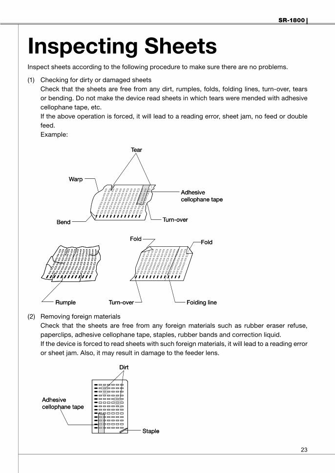
Inspecting SheetsInspect sheets according to the following procedure to make sure there are no problems.
(1) Checking for dirty or damaged sheetsCheck that the sheets are free from any dirt, rumples, folds, folding lines, turn-over, tears or bending. Do not make the device read sheets in which tears were mended with adhesive cellophane tape, etc.If the above operation is forced, it will lead to a reading error, sheet jam, no feed or double feed.Example:
(2) Removing foreign materials Check that the sheets are free from any foreign materials such as rubber eraser refuse, paperclips, adhesive cellophane tape, staples, rubber bands and correction liquid. If the device is forced to read sheets with such foreign materials, it will lead to a reading error or sheet jam. Also, it may result in damage to the feeder lens.
Tear
Warp
Adhesivecellophane tape
Turn-over
Fold Fold
Rumple Turn-over Folding line
Bend
Tear
Warp
Adhesivecellophane tape
Turn-over
Fold Fold
Rumple Turn-over Folding line
Bend
Dirt
Adhesivecellophane tape
Staple
Dirt
Adhesivecellophane tape
Staple
��
SR-1800
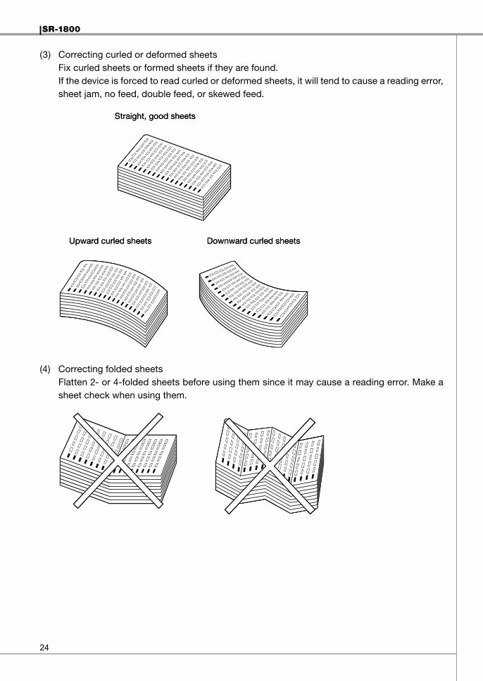
(3) Correcting curled or deformed sheetsFix curled sheets or formed sheets if they are found.If the device is forced to read curled or deformed sheets, it will tend to cause a reading error, sheet jam, no feed, double feed, or skewed feed.
(4) Correcting folded sheetsFlatten 2- or 4-folded sheets before using them since it may cause a reading error. Make a sheet check when using them.
Straight, good sheets
Upward curled sheets Downward curled sheets
Straight, good sheets
Upward curled sheets Downward curled sheets
SR-1800
��
Handling and Storing SheetsSheets are affected by their handling and ambient conditions (especially temperature and humidity) and their characteristics may change, resulting in a reading error.
CAUTION:Handle and store sheets with extreme care.
Handlingsheets(1) Do not fold or blemish sheets, as a reading error may occur.(2) Keep sheets free from foreign materials such as oil and dust.(3) Do not use dirty sheets or those with torn edges since they will affect reading or cause a
sheet jam.(4) If the temperature or humidity suddenly changes, keep sheets in the new conditions for
about an hour, allowing them to adjust to the new conditions.(5) Do not expose sheets to direct sunlight for a long period of time.
Storageofsheets(1) Avoid storing sheets in a place where ambient conditions can suddenly change.(2) Store sheets in a cabinet, etc. to protect them from humidity.(3) Avoid storing sheets near windows or other locations where they may become dusty.(4) Store sheets on a flat surface so that they do not bend.
��
SR-1800
Marking InstructionsMarks readable by this device are as follows.(1) Mark size: 0.5 × 3mm or more (recommended mark)(2) Readable writing instruments: pencils (black, HB or darker), [Option: ballpoint pens (black or
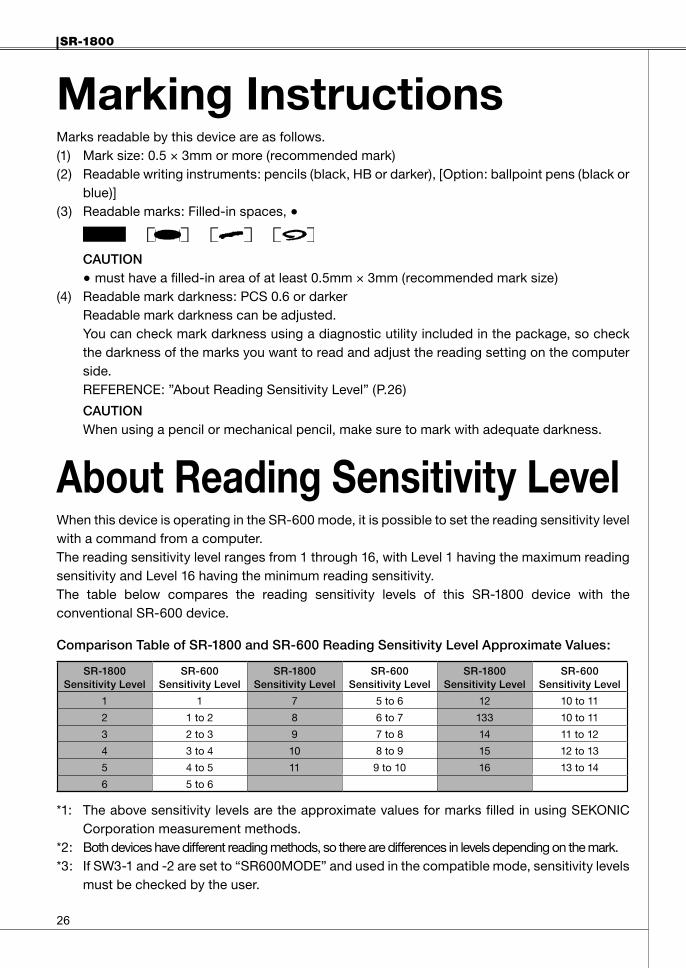
blue)](3) Readable marks: Filled-in spaces, ●
CAUTION●must have a filled-in area of at least 0.5mm × 3mm (recommended mark size)
(4) Readable mark darkness: PCS 0.6 or darkerReadable mark darkness can be adjusted.You can check mark darkness using a diagnostic utility included in the package, so check the darkness of the marks you want to read and adjust the reading setting on the computer side.REFERENCE: ”About Reading Sensitivity Level” (P.26)
CAUTIONWhen using a pencil or mechanical pencil, make sure to mark with adequate darkness.
About Reading Sensitivity LevelWhen this device is operating in the SR-600 mode, it is possible to set the reading sensitivity level with a command from a computer.The reading sensitivity level ranges from 1 through 16, with Level 1 having the maximum reading sensitivity and Level 16 having the minimum reading sensitivity.The table below compares the reading sensitivity levels of this SR-1800 device with the conventional SR-600 device.
ComparisonTableofSR-1800andSR-600ReadingSensitivityLevelApproximateValues:
SR-1800SensitivityLevel
SR-600SensitivityLevel
SR-1800SensitivityLevel
SR-600SensitivityLevel
SR-1800SensitivityLevel
SR-600SensitivityLevel
1 1 7 5 to 6 12 10 to 11
2 1 to 2 8 6 to 7 133 10 to 11
3 2 to 3 9 7 to 8 14 11 to 12
4 3 to 4 10 8 to 9 15 12 to 13
5 4 to 5 11 9 to 10 16 13 to 14
6 5 to 6
*1: The above sensitivity levels are the approximate values for marks filled in using SEKONIC Corporation measurement methods.
*2: Both devices have different reading methods, so there are differences in levels depending on the mark.*3: If SW3-1 and -2 are set to “SR600MODE” and used in the compatible mode, sensitivity levels
must be checked by the user.

SR-1800
��
OperationOperationFlow
TurningPowerOn/Off1 TurningPowerOn
(1) Turn the power switch to ON position.Power is turned on and the self-check begins. Then the READY lamp (green) and ERROR lamp (red) light up.When the self-check is completed normally, the buzzer sounds “Pip!” and the ERROR lamp turns off. Only the READY lamp turns on, indicating that the device is able to communicate with the computer.
2 TurningPowerOff(1) Turn the power switch to OFF position.
Power on
Set sheets
Reading sheets
Power off
Reading Checksheets
Reference: “Checksheet Reading Test” (P.32)
If necessary, read the checksheet and make sure there are no errors. (After the test, make sure to turn the power off.)
Power on
Set sheets
Reading sheets
Power off
Reading Checksheets
Reference: “Checksheet Reading Test” (P.32)
If necessary, read the checksheet and make sure there are no errors. (After the test, make sure to turn the power off.)
Power Switch
ON OFF
Power Switch
ON OFF

��
SR-1800
3 PowerSavingModesAfter turning the power on, if the device is not operated for a certain period of time, the device will automatically enter power saving mode and power consumption will be minimized. The following are two types of power saving modes:
PowersavingsleepmodeIf device is not operated for 5 minutes, it will enter power saving sleep mode, and the READY lamp will blink repeatedly at fast intervals. Power consumption will be reduced.
Powersavingstandbymode
After entering the power saving sleep mode, if the device is not operated for another 5 minutes, it will enter power saving standby mode.The READY lamp will blink repeatedly at slow intervals and power consumption will be minimized.
DeactivatingSleep/StandbyModes:The sleep/standby modes will be deactivated when the following occur:· Operation is performed using the operating panel.· Operating command is received from the computer.· Top cover is open.· Sheet is set in the hopper.
CasesWhenDeviceCannotEnterSleep/StandbyMode:· There is an error.
0.2 sec.0.8 sec.
0.2 sec.1.8 sec.
Power Saving Sleep Mode (Fast blinking)
READY lamp
READY lamp
Power Saving Standby Mode (Slow blinking)
0.2 sec.0.8 sec.
0.2 sec.1.8 sec.
Power Saving Sleep Mode (Fast blinking)
READY lamp
READY lamp
Power Saving Standby Mode (Slow blinking)

SR-1800
��
SettingSheets(1) Push the lock lever down.
When the hopper is lowered to the position where the sheets are set, there will be a clicking sound and it will lock.
(2) Set sheets straight so that their timing marks are on the left side viewing from the sheet feed direction.
CAUTIONIf the front edge and side edge of the sheets are not aligned, it will result in a sheet feeding error or skewed sheets.
(3) Slide the sheet guide so that there is no space between it and the sheets.
CAUTION· When there is space between the sheets and the sheet guide, it may result in a skewed
sheets.· Refer to “Sheet Setting Example” (P.31) and check that the sheets are set properly.
(4) Push the lock lever release claw on the inside of the lock lever in the direction of the arrow(toward the operation panel side) to unlock the hopper.The hopper will move upward and return to the sheet feeding position.
Lock lever release claw
Lock lever
Sheet guide
Lock lever release claw
Lock lever
Sheet guide
�0
SR-1800
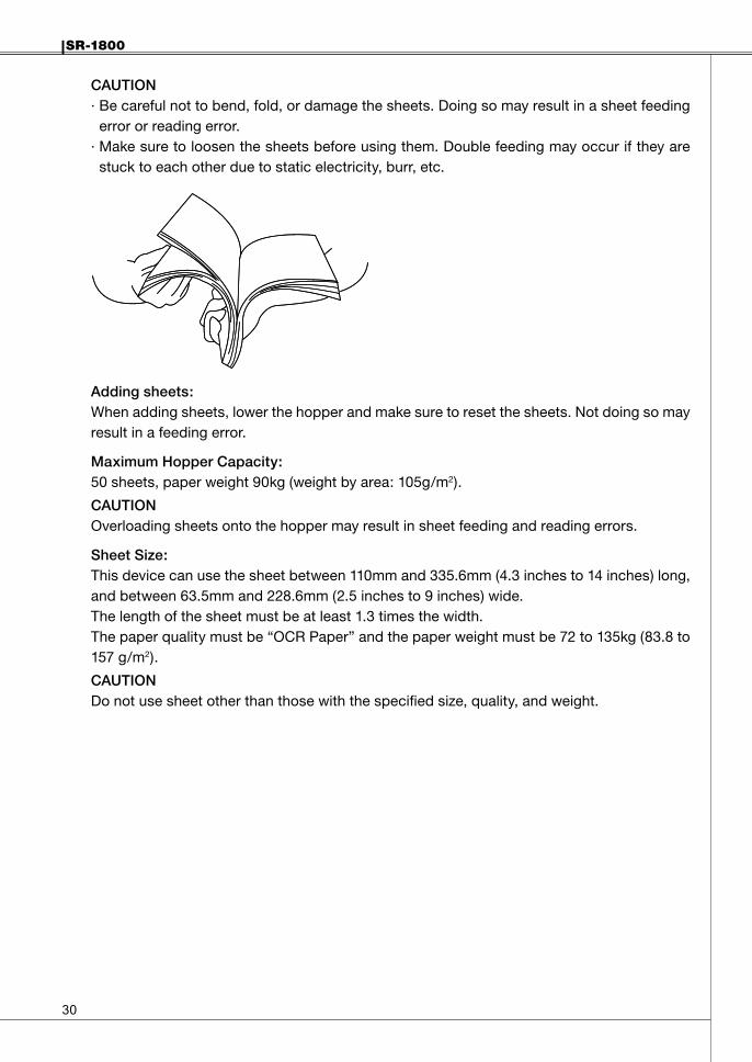
CAUTION· Be careful not to bend, fold, or damage the sheets. Doing so may result in a sheet feeding
error or reading error.· Make sure to loosen the sheets before using them. Double feeding may occur if they are
stuck to each other due to static electricity, burr, etc.
Addingsheets:When adding sheets, lower the hopper and make sure to reset the sheets. Not doing so may result in a feeding error.
MaximumHopperCapacity:50 sheets, paper weight 90kg (weight by area: 105g/m2).
CAUTIONOverloading sheets onto the hopper may result in sheet feeding and reading errors.
SheetSize:This device can use the sheet between 110mm and 335.6mm (4.3 inches to 14 inches) long, and between 63.5mm and 228.6mm (2.5 inches to 9 inches) wide.The length of the sheet must be at least 1.3 times the width.The paper quality must be “OCR Paper” and the paper weight must be 72 to 135kg (83.8 to 157 g/m2).
CAUTIONDo not use sheet other than those with the specified size, quality, and weight.
SR-1800
��
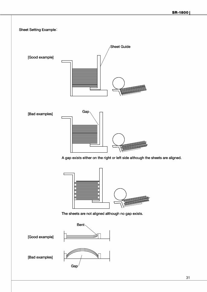
[Good example]
[Good example]
Sheet Setting Example:
Sheet Guide
[Bad examples]
[Bad examples]
A gap exists either on the right or left side although the sheets are aligned.
The sheets are not aligned although no gap exists.
Gap
Bent
Gap
[Good example]
[Good example]
Sheet Setting Example:
Sheet Guide
[Bad examples]
[Bad examples]
A gap exists either on the right or left side although the sheets are aligned.
The sheets are not aligned although no gap exists.
Gap
Bent
Gap
��
SR-1800
ReadingSheetsThis section explains the procedure for reading sheets.(If you perform the checksheet reading test, please refer to “Checksheet Reading Test” (P.32))
(1) Turn the power switch on.The power turns on and the self-check begins. The READY lamp (green) and the ERROR lamp (red) both light up. When the self-check is completed normally, the buzzer sounds “Pip!” and the ERROR lamp turns off.
(2) Set the sheets in the hopper.Align the sheets so that the timing mark is on the left side viewing from the feed direction.
(3) Press the START switch, or send a command from the computer to read the sheet.One sheet will be fed to device.If the START switch is held down, the sheet will be fed continuously to the device.If you want to obtain mark data of the sheet that was fed, send the “Get Mark Density” command. (Reference: For details on commands, please refer to the “Command Reference Manual.”)
(4) When finished, turn the power off.
Whenanerroroccurs:The buzzer sounds and the ERROR lamp (red) turns on or blinks. (Reference: “Troubleshooting” (P.34))When the CLEAR switch is pressed, the ERROR lamp turns off.
ChecksheetReadingTestThe included checksheets (with printed data marks) can be used to test the device’s reading function.
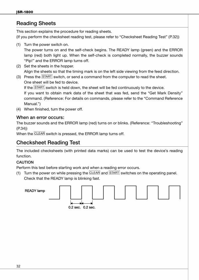
CAUTIONPerform this test before starting work and when a reading error occurs.(1) Turn the power on while pressing the CLEAR and START switches on the operating panel.
Check that the READY lamp is blinking fast.
0.2 sec.0.2 sec.
READY lamp
0.2 sec.0.2 sec.
READY lamp
SR-1800
��
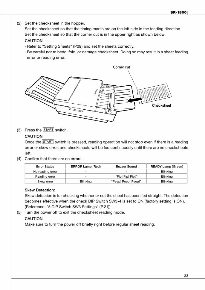
(2) Set the checksheet in the hopper.Set the checksheet so that the timing marks are on the left side in the feeding direction.Set the checksheet so that the corner cut is in the upper right as shown below.
CAUTION· Refer to “Setting Sheets” (P29) and set the sheets correctly.· Be careful not to bend, fold, or damage checksheet. Doing so may result in a sheet feeding
error or reading error.
(3) Press the START switch.
CAUTIONOnce the START switch is pressed, reading operation will not stop even if there is a reading error or skew error, and checksheets will be fed continuously until there are no checksheets left.
(4) Confirm that there are no errors.
ErrorStatus ERRORLamp(Red) BuzzerSound READYLamp(Green)
No reading error - - Blinking
Reading error - “Pip! Pip! Pip!” Blinking
Skew error Blinking “Peep! Peep! Peep!” Blinking
SkewDetection:Skew detection is for checking whether or not the sheet has been fed straight. The detection becomes effective when the check DIP Switch SW3-4 is set to ON (factory setting is ON).(Reference: ”5 DIP Switch SW3 Settings” (P.21))
(5) Turn the power off to exit the checksheet reading mode.
CAUTIONMake sure to turn the power off briefly right before regular sheet reading.
Corner cut
Checksheet
Corner cut
Checksheet
��
SR-1800
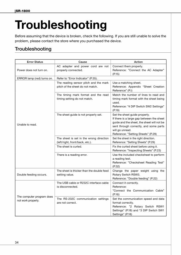
TroubleshootingBefore assuming that the device is broken, check the following. If you are still unable to solve the problem, please contact the store where you purchased the device.
Troubleshooting
ErrorStatus Cause Action
Power does not turn on.AC adapter and power cord are not properly connected.
Connect them properly.Reference: ”Connect the AC Adapter” (P.15)
ERROR lamp (red) turns on. Refer to “Error Indicator” (P.35).
Unable to read.
The reading sensor pitch and the mark pitch of the sheet do not match.
Use a matching sheet.Reference: Appendix “Sheet Creation Reference” (P.i)
The timing mark format and the read timing setting do not match.
Match the number of lines to read and timing mark format with the sheet being used.Reference: ”4 DIP Switch SW2 Settings” (P.19)
The sheet guide is not properly set. Set the sheet guide properly.If there is a large gap between the sheet guide and the sheet, the sheet will not be sent through correctly, and some parts will go unread.Reference: ”Setting Sheets” (P.29)
The sheet is set in the wrong direction (left/right, front/back, etc.).
Set the sheet in the right direction.Reference: ”Setting Sheets” (P.29)
The sheet is curled. Fix the curled sheet before using it.Reference: ”Inspecting Sheets” (P.23)
There is a reading error. Use the included checksheet to perform a reading test.Reference: ”Checksheet Reading Test” (P.32)
Double feeding occurs.The sheet is thicker than the double feed setting value.
Change the paper weight using the Rotary Switch RSW3.Reference: ”Double feeding” (P.22)
The computer program does not work properly.
The USB cable or R232C interface cable is disconnected.
Connect it correctly.Reference: ”Connect the Communication Cable” (P.16)
The RS-232C communication settings are not correct.
Set the communication speed and data format correctly.Reference: ”2 Rotary Switch RSW1 Settings” (P.18) and “3 DIP Switch SW1 Settings” (P.18)
SR-1800
��
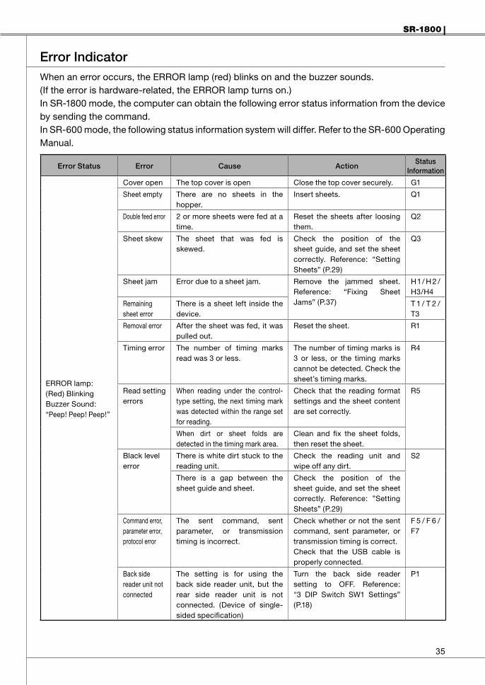
ErrorIndicatorWhen an error occurs, the ERROR lamp (red) blinks on and the buzzer sounds.(If the error is hardware-related, the ERROR lamp turns on.)In SR-1800 mode, the computer can obtain the following error status information from the device by sending the command.In SR-600 mode, the following status information system will differ. Refer to the SR-600 Operating Manual.
ErrorStatus Error Cause ActionStatus
Information
ERROR lamp:(Red) BlinkingBuzzer Sound:“Peep! Peep! Peep!”
Cover open The top cover is open Close the top cover securely. G1
Sheet empty There are no sheets in the hopper.
Insert sheets. Q1
Double feed error 2 or more sheets were fed at a time.
Reset the sheets after loosing them.
Q2
Sheet skew The sheet that was fed is skewed.
Check the position of the sheet guide, and set the sheet correctly. Reference: “Setting Sheets” (P.29)
Q3
Sheet jam Error due to a sheet jam. Remove the jammed sheet. Reference: “Fixing Sheet Jams” (P.37)
H1/ H 2 /H3/H4
Remaining sheet error
There is a sheet left inside the device.
T 1 / T 2 /T3
Removal error After the sheet was fed, it was pulled out.
Reset the sheet. R1
Timing error The number of timing marks read was 3 or less.
The number of timing marks is 3 or less, or the timing marks cannot be detected. Check the sheet’s timing marks.
R4
Read setting errors
When reading under the control-type setting, the next timing mark was detected within the range set for reading.
Check that the reading format settings and the sheet content are set correctly.
R5
When dirt or sheet folds are detected in the timing mark area.
Clean and fix the sheet folds, then reset the sheet.
Black level error
There is white dirt stuck to the reading unit.
Check the reading unit and wipe off any dirt.
S2
There is a gap between the sheet guide and sheet.
Check the position of the sheet guide, and set the sheet correctly. Reference: ”Setting Sheets” (P.29)
Command error, parameter error, protocol error
The sent command, sent parameter, or transmission timing is incorrect.
Check whether or not the sent command, sent parameter, or transmission timing is correct.Check that the USB cable is properly connected.
F 5 / F 6 /F7
Back side reader unit not connected
The setting is for using the back side reader unit, but the rear side reader unit is not connected. (Device of single-sided specification)
Turn the back side reader setting to OFF. Reference: "3 DIP Switch SW1 Settings” (P.18)
P1

��
SR-1800
ErrorStatus Error Cause ActionStatus
Information
ERROR lamp(Red) Lights up.Buzzer Sound:“Peep! Peep! Peep!”
Hardware error
Internal error Turn off the power briefly, then turn the power back on. Check whether or not the same error occurs. If the same error occurs, request for maintenance service.
A1 / A 2 /A4/A5/A6B1/ B 2 /B3 / B4 /B5 / B6 /B7
SR-1800
��
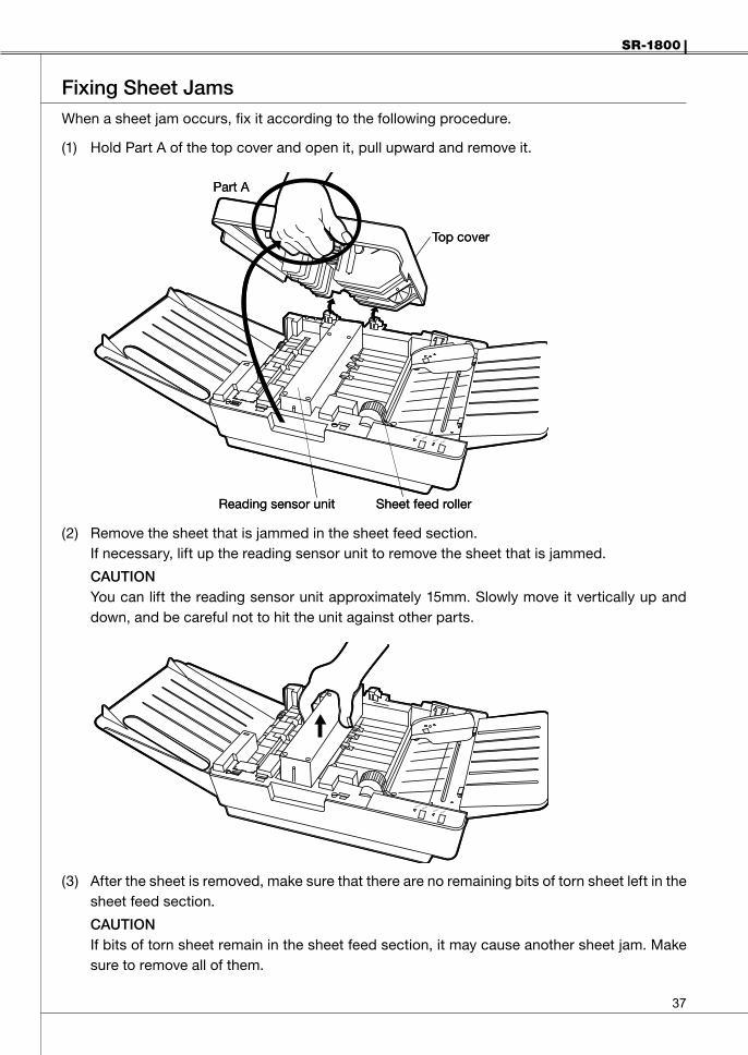
FixingSheetJamsWhen a sheet jam occurs, fix it according to the following procedure.
(1) Hold Part A of the top cover and open it, pull upward and remove it.
(2) Remove the sheet that is jammed in the sheet feed section.If necessary, lift up the reading sensor unit to remove the sheet that is jammed.
CAUTIONYou can lift the reading sensor unit approximately 15mm. Slowly move it vertically up and down, and be careful not to hit the unit against other parts.
(3) After the sheet is removed, make sure that there are no remaining bits of torn sheet left in the sheet feed section.
CAUTIONIf bits of torn sheet remain in the sheet feed section, it may cause another sheet jam. Make sure to remove all of them.
Part A
Top cover
Reading sensor unit Sheet feed roller
Part A
Top cover
Reading sensor unit Sheet feed roller

��
SR-1800
(4) Reattach the top cover.Close the top cover securely. Otherwise, it may cause poor sheet feeding.
(5) If the ERROR lamp (red) is on, check (3) and (4) again.(6) The following are possible causes of the sheet jam.
Check each item and take the necessary action if there is a problem.
Cause Action
Sheetdeformation,rippedsheet,foreignobjectstucktosheet
Inspect the sheet.(Reference: ”Inspecting Sheets” (P.23)
Dirtysheetfeedroller,transferrollerClean the roller.(Reference: ”Cleaning Procedures” (P.40)
SR-1800
��
CleaningMakesuretoturnthepoweroffandremovethepowerplugfromtheoutletbeforecleaning.Failuretodosomayresultinelectricshock.
WARNING
Externalpartsaremadeofplastic.Donotusebenzene,paintthinner,oranyothervolatilesubstancesandchemicalsolvents.Doingsomayresultindiscoloringordeformation.
Caution
RegularMaintenanceWhen the rollers and reading sensors become dirty, various types of malfunction problems may occur. Maintain the device regularly as discussed below. Maintenance frequency will depend on usage (frequency of use, quality of sheet used, etc.) When you become aware of dirt or other foreign objects, clean them off.
(1) Cleaning the device and its external partsWet a soft cloth with thinned neutral detergent, squeeze it hard and clean the device lightly with it. At this time, prepare a dry cloth as well and wipe the device so as not to leave moisture on it.
(2) Cleaning the rollers· Clean the rollers according to the frequency of use and the stained conditions since stains
on them may be transferred to sheets and may cause a malfunction when sheets are fed (once every a few days).
· Clean the rollers, in particular, after a large number of sheets or sheets fitted with copy carbon are fed.
· Use antiseptic alcohol (ethanol) to clean the rollers.· Use a soft cloth slightly wetted with antiseptic alcohol (ethanol) to lightly wipe off stains.
(3) Cleaning the Read SensorSince the read sensor is covered with optical lens, clean it with a soft cloth or cleaning paper wetted with a small amount of antiseptic alcohol (ethanol) so as not to damage the glass.
CAUTION:Handle the sensor with extreme care since the reading level will be degraded and a reading error may occur if it is flawed.
(4) Maintaining the sheet feed pathWipe off dirt such as bits of torn sheet with a soft cloth or cleaning paper wetted with a small amount of antiseptic alcohol (ethanol).
�0
SR-1800
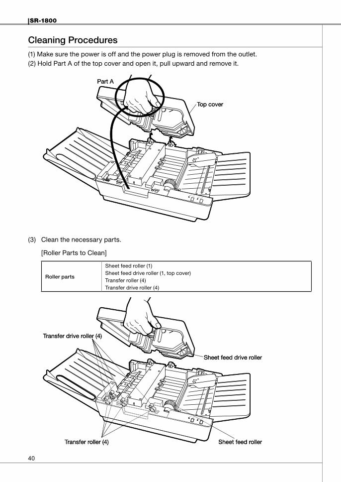
CleaningProcedures(1) Make sure the power is off and the power plug is removed from the outlet.(2) Hold Part A of the top cover and open it, pull upward and remove it.
(3) Clean the necessary parts.
[Roller Parts to Clean]
Rollerparts
Sheet feed roller (1)Sheet feed drive roller (1, top cover)Transfer roller (4)Transfer drive roller (4)
Part A
Top cover
Part A
Top cover
Transfer drive roller (4)
Transfer roller (4) Sheet feed roller
Sheet feed drive roller
Transfer drive roller (4)
Transfer roller (4) Sheet feed roller
Sheet feed drive roller
SR-1800
��
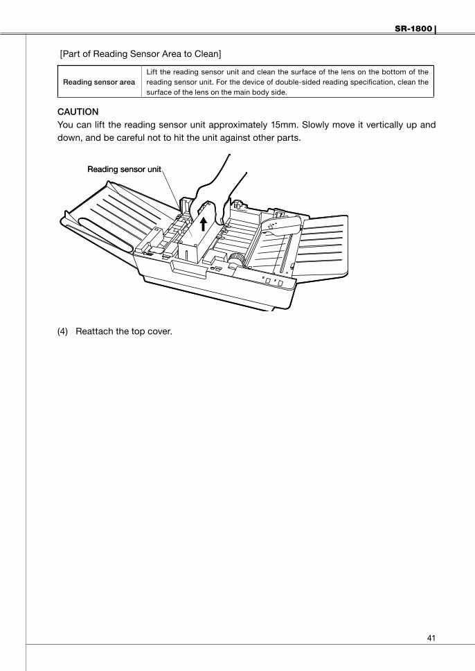
[Part of Reading Sensor Area to Clean]
ReadingsensorareaLift the reading sensor unit and clean the surface of the lens on the bottom of the reading sensor unit. For the device of double-sided reading specification, clean the surface of the lens on the main body side.
CAUTIONYou can lift the reading sensor unit approximately 15mm. Slowly move it vertically up and down, and be careful not to hit the unit against other parts.
(4) Reattach the top cover.
Reading sensor unitReading sensor unit

��
SR-1800
Service ScheduleFor stable operation of this device, regular replacement of components is required.See the following table, and contact us, or the store where you purchased the device, when requiring component replacement.
Componentname Number Replacementreference Remarks
Sheet feed roller 1 3 years or 150,000 sheets
Separator pad(located under the sheet feed roller)
1 3 years or 150,000 sheetsReplace at the same time as the sheet feed roller
CAUTION· The above number of years and sheets should be considered as a guide.· Depending on the device’s usage and environment, the number of years and sheets may
differ.· For details on when to replace parts, contact the store where you purchased the device.· Check the number of sheets read using the diagnostic utilities. For details on how to install the diagnostic utilities, refer to “Installing the Diagnostic Utilities”
(P.15).
SR-1800
��
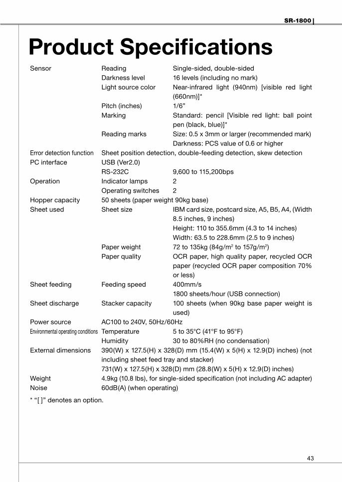
Product SpecificationsSensor Reading Single-sided, double-sided
Darkness level 16 levels (including no mark)Light source color Near-infrared light (940nm) [visible red light
(660nm)]*Pitch (inches) 1/6”Marking Standard: pencil [Visible red light: ball point
pen (black, blue)]*Reading marks Size: 0.5 x 3mm or larger (recommended mark)
Darkness: PCS value of 0.6 or higherError detection function Sheet position detection, double-feeding detection, skew detectionPC interface USB (Ver2.0)
RS-232C 9,600 to 115,200bpsOperation Indicator lamps 2
Operating switches 2Hopper capacity 50 sheets (paper weight 90kg base)Sheet used Sheet size IBM card size, postcard size, A5, B5, A4, (Width
8.5 inches, 9 inches)Height: 110 to 355.6mm (4.3 to 14 inches) Width: 63.5 to 228.6mm (2.5 to 9 inches)
Paper weight 72 to 135kg (84g/m2 to 157g/m2)Paper quality OCR paper, high quality paper, recycled OCR
paper (recycled OCR paper composition 70% or less)
Sheet feeding Feeding speed 400mm/s1800 sheets/hour (USB connection)
Sheet discharge Stacker capacity 100 sheets (when 90kg base paper weight is used)
Power source AC100 to 240V, 50Hz/60HzEnvironmental operating conditions Temperature 5 to 35°C (41°F to 95°F)
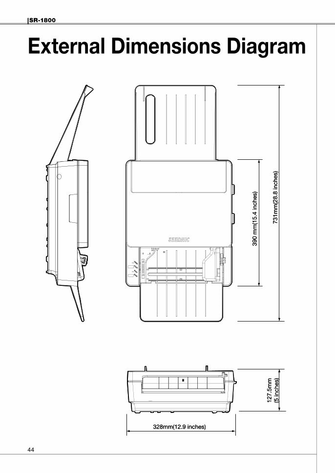
Humidity 30 to 80%RH (no condensation)External dimensions 390(W) x 127.5(H) x 328(D) mm (15.4(W) x 5(H) x 12.9(D) inches) (not
including sheet feed tray and stacker)731(W) x 127.5(H) x 328(D) mm (28.8(W) x 5(H) x 12.9(D) inches)
Weight 4.9kg (10.8 lbs), for single-sided specification (not including AC adapter)Noise 60dB(A) (when operating)
* “[ ]” denotes an option.
��
SR-1800
External Dimensions Diagram
731m
m(2
8.8
inch
es)
127.
5mm
(5 in
ches
)
328mm(12.9 inches)
390
mm
(15.
4 in
ches
)
731m
m(2
8.8
inch
es)
127.
5mm
(5 in
ches
)
328mm(12.9 inches)
390
mm
(15.
4 in
ches
)
SR-1800
��
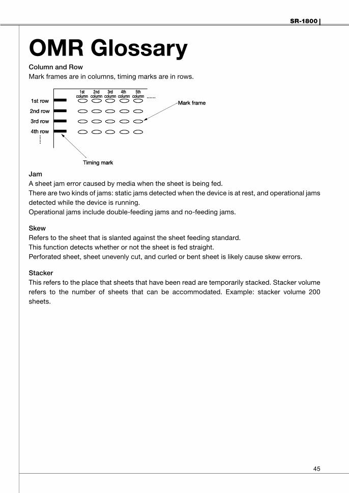
OMR GlossaryColumnandRowMark frames are in columns, timing marks are in rows.
JamA sheet jam error caused by media when the sheet is being fed.There are two kinds of jams: static jams detected when the device is at rest, and operational jams detected while the device is running.Operational jams include double-feeding jams and no-feeding jams.
SkewRefers to the sheet that is slanted against the sheet feeding standard.This function detects whether or not the sheet is fed straight.Perforated sheet, sheet unevenly cut, and curled or bent sheet is likely cause skew errors.
StackerThis refers to the place that sheets that have been read are temporarily stacked. Stacker volume refers to the number of sheets that can be accommodated. Example: stacker volume 200 sheets.
1stcolumn
2ndcolumn
3rdcolumn
4thcolumn
5thcolumn
1st row
2nd row
3rd row
4th row......
Timing mark
Mark frame......
1stcolumn
2ndcolumn
3rdcolumn
4thcolumn
5thcolumn
1st row
2nd row
3rd row
4th row......
Timing mark
Mark frame......
��
SR-1800
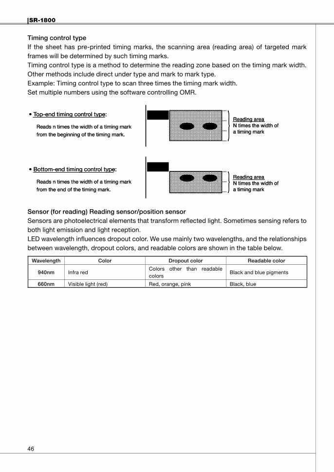
TimingcontroltypeIf the sheet has pre-printed timing marks, the scanning area (reading area) of targeted mark frames will be determined by such timing marks.Timing control type is a method to determine the reading zone based on the timing mark width. Other methods include direct under type and mark to mark type.Example: Timing control type to scan three times the timing mark width.Set multiple numbers using the software controlling OMR.
Sensor(forreading)Readingsensor/positionsensorSensors are photoelectrical elements that transform reflected light. Sometimes sensing refers to both light emission and light reception.LED wavelength influences dropout color. We use mainly two wavelengths, and the relationships between wavelength, dropout colors, and readable colors are shown in the table below.
Wavelength Color Dropoutcolor Readablecolor
940nm Infra redColors other than readable colors
Black and blue pigments
660nm Visible light (red) Red, orange, pink Black, blue
...
...
...
...
Reading areaN times the width ofa timing mark
Reading areaN times the width ofa timing mark
• Top-end timing control type:
Reads n times the width of a timing mark
from the beginning of the timing mark.
• Bottom-end timing control type:
Reads n times the width of a timing mark
from the end of the timing mark.
...
...
...
...
...
...
...
Reading areaN times the width ofa timing mark
Reading areaN times the width ofa timing mark
• Top-end timing control type:
Reads n times the width of a timing mark
from the beginning of the timing mark.
• Bottom-end timing control type:
Reads n times the width of a timing mark
from the end of the timing mark.
...
...
...
SR-1800
��
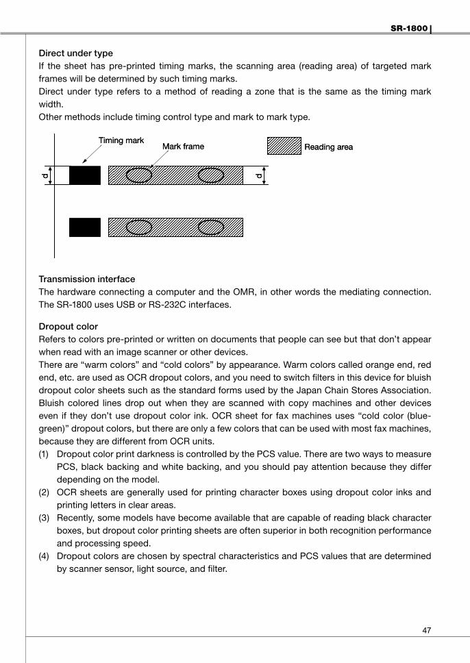
DirectundertypeIf the sheet has pre-printed timing marks, the scanning area (reading area) of targeted mark frames will be determined by such timing marks.Direct under type refers to a method of reading a zone that is the same as the timing mark width.Other methods include timing control type and mark to mark type.
TransmissioninterfaceThe hardware connecting a computer and the OMR, in other words the mediating connection. The SR-1800 uses USB or RS-232C interfaces.
DropoutcolorRefers to colors pre-printed or written on documents that people can see but that don’t appear when read with an image scanner or other devices.There are “warm colors” and “cold colors” by appearance. Warm colors called orange end, red end, etc. are used as OCR dropout colors, and you need to switch filters in this device for bluish dropout color sheets such as the standard forms used by the Japan Chain Stores Association. Bluish colored lines drop out when they are scanned with copy machines and other devices even if they don’t use dropout color ink. OCR sheet for fax machines uses “cold color (blue-green)” dropout colors, but there are only a few colors that can be used with most fax machines, because they are different from OCR units.(1) Dropout color print darkness is controlled by the PCS value. There are two ways to measure
PCS, black backing and white backing, and you should pay attention because they differ depending on the model.
(2) OCR sheets are generally used for printing character boxes using dropout color inks and printing letters in clear areas.
(3) Recently, some models have become available that are capable of reading black character boxes, but dropout color printing sheets are often superior in both recognition performance and processing speed.
(4) Dropout colors are chosen by spectral characteristics and PCS values that are determined by scanner sensor, light source, and filter.
Timing markMark frame Reading area
d d
Timing markMark frame Reading area
d d
��
SR-1800
(5) Colors that can be used as dropout colors differ depending on the model, but with some models, even regular ballpoint pen ink drops out and cannot be used. In such cases, you need special OCR ballpoint pens that are rarely available today. See table below for relationships between wavelengths and colors.
Peaksensitivitywavelength Color Remarks
740(nm)
SepiaMagentaPurpleBrown
Abundant dropout colorsSome ballpoint pens cannot be used.
Bluish tonesGreenish tones
660
RosePinkRedOrange
For red end colors only, rose aniline, purplish red, deep redRegular ballpoint pens can be used.
570 YellowAs in fax scanners, it’s difficult to see with human eyes→should be avoided.Regular ballpoint pens can be used.
530Blue Regular ballpoint pens can be used for blue-end colors
only. GreenGreen
a) It is important to control the PCS value to print dropout colors. (You need to choose a printer equipped with devices that can measure PCS values.)
b) If you want to use an abundance of colors, we recommend printing in ink other than dropout colors as a “black frame sheet.”
NofeedRefers to the sheet doesn’t get fed during sheet feeding operations.If such an error occurs, the device assesses it as a sheet feeding error, and notifies user of the error.
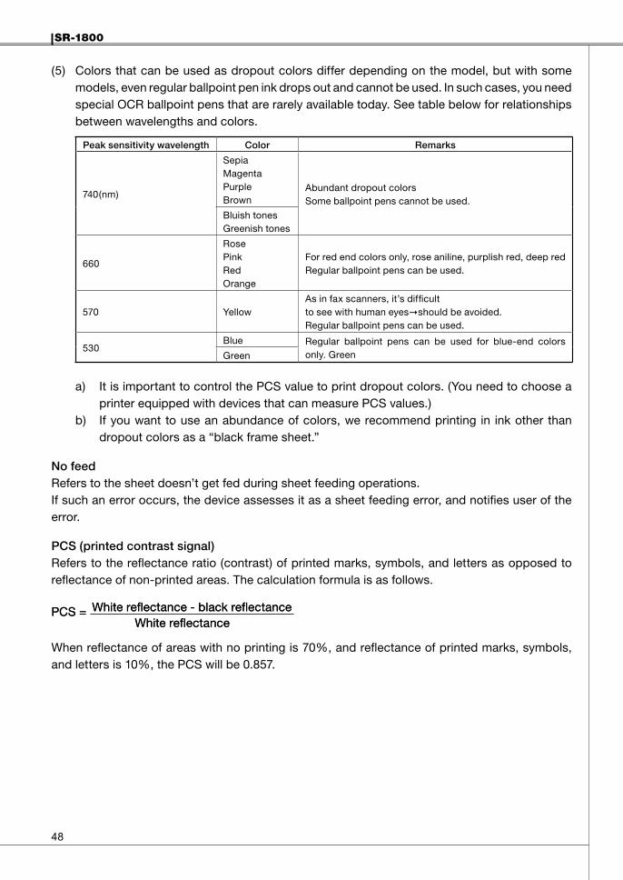
PCS(printedcontrastsignal)Refers to the reflectance ratio (contrast) of printed marks, symbols, and letters as opposed to reflectance of non-printed areas. The calculation formula is as follows.
When reflectance of areas with no printing is 70%, and reflectance of printed marks, symbols, and letters is 10%, the PCS will be 0.857.
PCS = White reflectance - black reflectanceWhite reflectance
PCS = White reflectance - black reflectanceWhite reflectance
SR-1800
��
WritingimplementsReadable marks and unreadable marks depend on the writing instruments used. This can also differ according to the light source that the reading sensor uses.Relationships between sensors used for OMR (light source) and writing implements
Light sourcewavelength
Color toneReadable mark colorsand writing implement
Unreadable mark colorsand writing implement
940nm(standard)
Infra redColor: black (pigment)Writing implement: pencil
Color: other than blackWriting implement: other than pencil
660nm(*Option)
Visible light(red)
Color: black, brown, blue, green, purpleWriting implement: pencil, fountain pen, water/oil base ballpoint pen, water/oil base marker
Color: red, orange, yellowWriting implement: items in above colors
HopperPlace where readable sheets are set.
�0
SR-1800
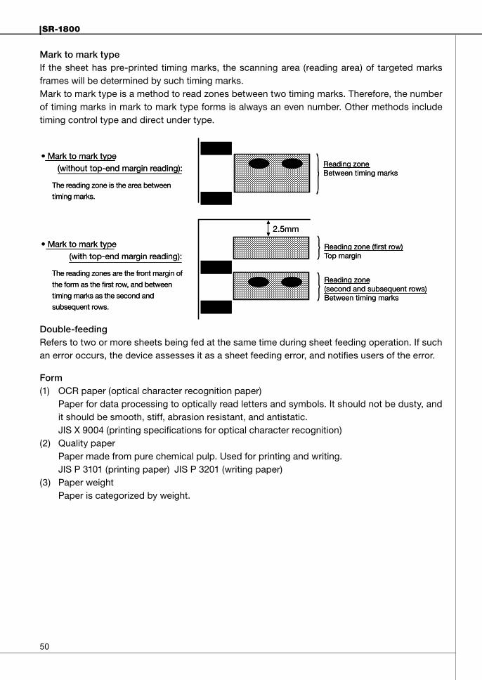
MarktomarktypeIf the sheet has pre-printed timing marks, the scanning area (reading area) of targeted marks frames will be determined by such timing marks.Mark to mark type is a method to read zones between two timing marks. Therefore, the number of timing marks in mark to mark type forms is always an even number. Other methods include timing control type and direct under type.
Double-feedingRefers to two or more sheets being fed at the same time during sheet feeding operation. If such an error occurs, the device assesses it as a sheet feeding error, and notifies users of the error.
Form(1) OCR paper (optical character recognition paper)
Paper for data processing to optically read letters and symbols. It should not be dusty, and it should be smooth, stiff, abrasion resistant, and antistatic.JIS X 9004 (printing specifications for optical character recognition)
(2) Quality paperPaper made from pure chemical pulp. Used for printing and writing.JIS P 3101 (printing paper) JIS P 3201 (writing paper)
(3) Paper weightPaper is categorized by weight.
Reading zoneBetween timing marks
Reading zone (first row)Top margin
Reading zone(second and subsequent rows)Between timing marks
• Mark to mark type (without top-end margin reading):
The reading zone is the area between
timing marks.
• Mark to mark type (with top-end margin reading):
The reading zones are the front margin of
the form as the first row, and between
timing marks as the second and
subsequent rows.
2.5mm
SR-1800
�
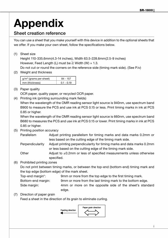
AppendixSheetcreationreferenceYou can use a sheet that you make yourself with this device in addition to the optional sheets that we offer. If you make your own sheet, follow the specifications below.
(1) Sheet sizeHeight 110-335.6mm(4.3-14 inches), Width 63.5-228.6mm(2.5-9 inches)However, Feed Length (L) must be Width (W) × 1.3.Do not cut or round the corners on the reference side (timing mark side). (See P.iv)
(2) Weight and thickness
g/m2 (grams per sheet) 84 - 157
mm (thickness) 0.1 - 0.19
(3) Paper qualityOCR paper, quality paper, or recycled OCR paper.
(4) Printing ink (printing surrounding mark fields)When the wavelength of the OMR reading sensor light source is 940nm, use spectrum band B900 to measure the PCS and use ink at PCS 0.15 or less. Print timing marks in ink at PCS 0.85 or higher.When the wavelength of the OMR reading sensor light source is 660nm, use spectrum band B680 to measures the PCS and use ink at PCS 0.15 or lower. Print timing marks in ink at PCS 0.85 or higher.
(5) Printing position accuracyParallelism Adjust printing parallelism for timing marks and data marks 0.2mm or
less based on the cutting edge of the timing mark side.Perpendicularity Adjust printing perpendicularity for timing marks and data marks 0.2mm
or less based on the cutting edge of the timing mark side.Other Adjust to ±0.2mm or less of specified measurements unless otherwise
specified.(6) Prohibited printing zones
Do not print between timing marks, or between the top-end (bottom-end) timing mark and the top edge (bottom edge) of the mark sheet.Top-end margin*: 9mm or more from the top edge to the first timing mark.Bottom-end margin: 9mm or more from the last timing mark to the bottom edge.Side margin: 4mm or more on the opposite side of the sheet’s standard
edge.(7) Direction of paper grain
Feed a sheet in the direction of its grain to eliminate curling.
Feeding directionPaper grain direction
Feeding directionPaper grain direction
��
SR-1800
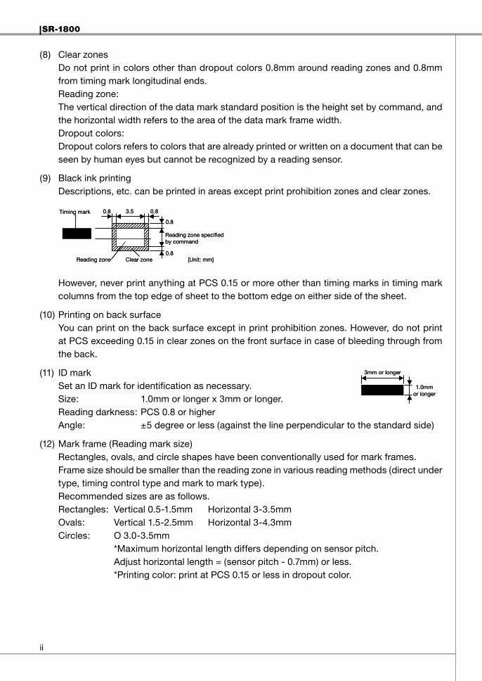
(8) Clear zonesDo not print in colors other than dropout colors 0.8mm around reading zones and 0.8mm from timing mark longitudinal ends.Reading zone:The vertical direction of the data mark standard position is the height set by command, and the horizontal width refers to the area of the data mark frame width.Dropout colors:Dropout colors refers to colors that are already printed or written on a document that can be seen by human eyes but cannot be recognized by a reading sensor.
(9) Black ink printingDescriptions, etc. can be printed in areas except print prohibition zones and clear zones.
However, never print anything at PCS 0.15 or more other than timing marks in timing mark columns from the top edge of sheet to the bottom edge on either side of the sheet.
(10) Printing on back surfaceYou can print on the back surface except in print prohibition zones. However, do not print at PCS exceeding 0.15 in clear zones on the front surface in case of bleeding through from the back.
(11) ID markSet an ID mark for identification as necessary. Size: 1.0mm or longer x 3mm or longer.Reading darkness: PCS 0.8 or higherAngle: ±5 degree or less (against the line perpendicular to the standard side)
(12) Mark frame (Reading mark size)Rectangles, ovals, and circle shapes have been conventionally used for mark frames.Frame size should be smaller than the reading zone in various reading methods (direct under type, timing control type and mark to mark type).Recommended sizes are as follows.Rectangles: Vertical 0.5-1.5mm Horizontal 3-3.5mmOvals: Vertical 1.5-2.5mm Horizontal 3-4.3mmCircles: O 3.0-3.5mm *Maximum horizontal length differs depending on sensor pitch. Adjust horizontal length = (sensor pitch - 0.7mm) or less. *Printing color: print at PCS 0.15 or less in dropout color.
0.8
0.83.50.8
0.8
Reading zone specifiedby command
Timing mark
Reading zone Clear zone [Unit: mm]
0.8
0.83.50.8
0.8
Reading zone specifiedby command
Timing mark
Reading zone Clear zone [Unit: mm]
3mm or longer
1.0mmor longer
3mm or longer
1.0mmor longer

SR-1800
���
(13) Sheet dimensions[Direct under type sheet]
Size WxL(mm)Maximumnumberofcolumns
Maximumnumberofrows1/6
IBM* 82.55 x 187.3 16 40
Postcard 100 x 148 20 31
1/6 A5 148 x 210 31 46
a 3.81 B5 182 x 257 39 57
b 6.99 A4 210 x 297 46 66
c 1.27 8.5" 216 x 279 47 62
d 11.43 9" 228.6 x 355.6 48 80
Note 1) Timing mark width: maximum width of c is 12mm.Note 2) Maximum number of rows indicates the number of timing marks.Note 3) Printing specifications for IBM card size are described on the next page.
Mark frame
She
et v
ertic
al le
ngth
(L
1.
3xW
)
0.3 A
0.3 A
0.2
0.2
0.3 A
4 or more
Sheet horizontal length (W)
Pitch (P) x (row-1)Do not aggregate tolerancesP
d
b
a
4.23
min
imum
Timing mark
9 or
mor
ec
1.5
or m
ore
9 or
mor
e4.
23m
inim
um
General tolerance ±0.2[Unit: mm]
A
0.1 0.2 A
Mark frame
She
et v
ertic
al le
ngth
(L
1.
3xW
)
0.3 A
0.3 A
0.2
0.2
0.3 A
4 or more
Sheet horizontal length (W)
Pitch (P) x (row-1)Do not aggregate tolerancesP
d
b
a
4.23
min
imum
Timing mark
9 or
mor
ec
1.5
or m
ore
9 or
mor
e4.
23m
inim
um
General tolerance ±0.2[Unit: mm]
A
0.1 0.2 A
�v
SR-1800
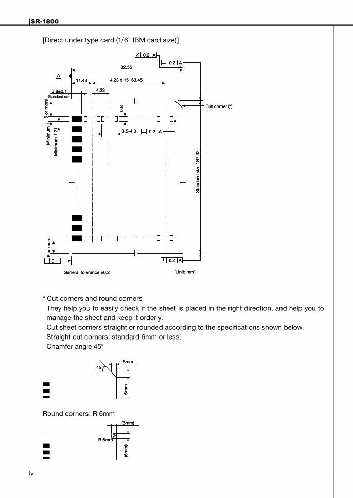
[Direct under type card (1/6” IBM card size)]
* Cut corners and round corners They help you to easily check if the sheet is placed in the right direction, and help you to
manage the sheet and keep it orderly. Cut sheet corners straight or rounded according to the specifications shown below. Straight cut corners: standard 6mm or less. Chamfer angle 45°
Round corners: R 6mm
Sta
ndar
d s
ize
187.
32
0.2 A
0.2 A
0.2 A82.55
0.8
6 or
mor
eM
inim
um 1
5 or
mor
e
3.8±0.1Standard size
General tolerance ±0.2 [Unit: mm]
A4.23 x 15=63.45
Min
imum
1.2
1
3.5-4.3
4.23
11.43
Cut corner (*)
0.2 A
0.1
Sta
ndar
d s
ize
187.
32
0.2 A
0.2 A
0.2 A82.55
0.8
6 or
mor
eM
inim
um 1
5 or
mor
e
3.8±0.1Standard size
General tolerance ±0.2 [Unit: mm]
A4.23 x 15=63.45
Min
imum
1.2
1
3.5-4.3
4.23
11.43
Cut corner (*)
0.2 A
0.1
6mm45
6mm
6mm45
6mm
(6mm)
R 6mm
(6m
m)
(6mm)
R 6mm
(6m
m)
SR-1800
v
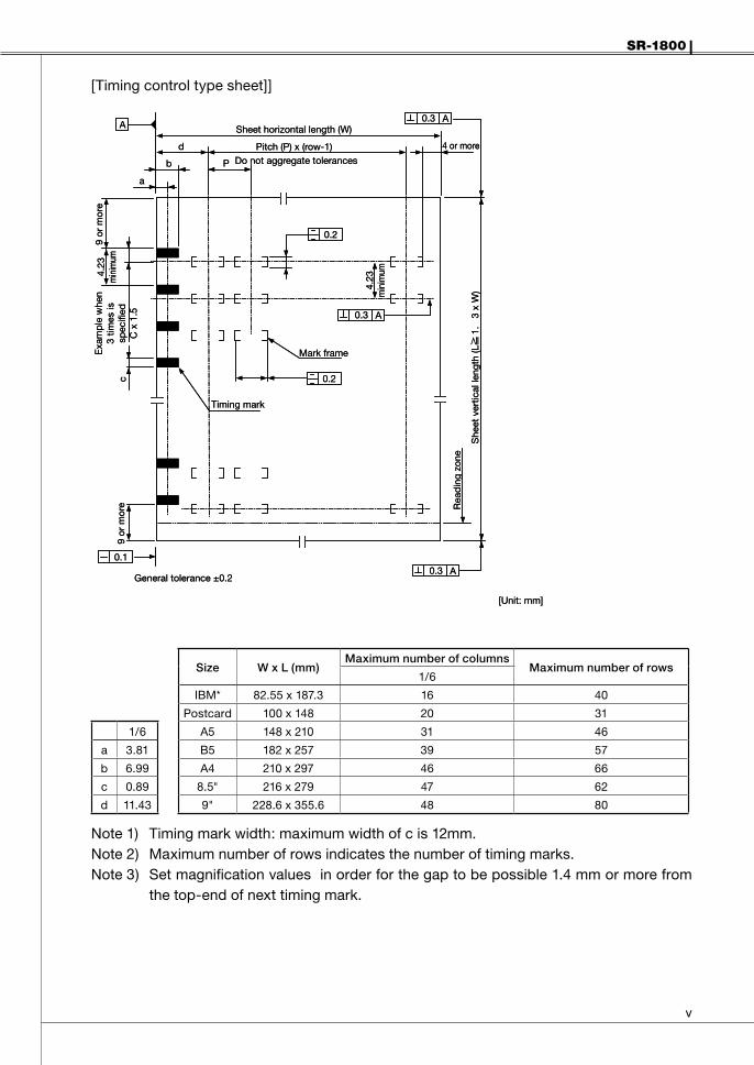
[Timing control type sheet]]
Size WxL(mm)Maximumnumberofcolumns
Maximumnumberofrows1/6
IBM* 82.55 x 187.3 16 40
Postcard 100 x 148 20 31
1/6 A5 148 x 210 31 46
a 3.81 B5 182 x 257 39 57
b 6.99 A4 210 x 297 46 66
c 0.89 8.5" 216 x 279 47 62
d 11.43 9" 228.6 x 355.6 48 80
Note 1) Timing mark width: maximum width of c is 12mm.Note 2) Maximum number of rows indicates the number of timing marks.Note 3) Set magnification values in order for the gap to be possible 1.4 mm or more from
the top-end of next timing mark.
Mark frame
She
et v
ertic
al le
ngth
(L
1.
3 x
W)
0.3 A
0.3 A
0.2
0.2
0.3 A
4 or more
Sheet horizontal length (W)
Pitch (P) x (row-1)Do not aggregate tolerancesP
d
b
a
4.23
min
imum
Timing mark
9 or
mor
ec
Exa
mp
le w
hen
3 tim
es is
spec
ified
C x
1.5
9 or
mor
e4.
23m
inim
um
General tolerance ±0.2
[Unit: mm]
A
0.1
Rea
din
g zo
ne

v�
SR-1800
[Mark to mark type sheet]
Size WxL(mm)Maximumnumberofcolumns
Maximumnumberofrows1/6
IBM* 82.55 x 187.3 16 40
Postcard 100 x 148 20 31
1/6 A5 148 x 210 31 46
a 3.81 B5 182 x 257 39 57
b 6.99 A4 210 x 297 46 66
c 1.0 8.5" 216 x 279 47 62
d 11.43 9" 228.6 x 355.6 48 80
Note 1) Timing mark width: maximum width of c is 12mm.Note 2) Maximum number of rows indicates the number of timing marks.Note 3) Printing specifications for IBM card size are described on the next page.
Mark frame
She
et v
ertic
al le
ngth
(L
1.
3xW
)
0.3 A
0.3 A
0.3 A
4 or more
Sheet horizontal length (W)
Pitch (P) x (row-1)Do not aggregate tolerancesP
d
b
a
4.23
min
imum
Timing mark
9 or
mor
ec
9 or
mor
e
4. 2
3m
inim
um
General tolerance ±0.2
[Unit: mm]
A
Sheet-feeding pitch E
E/2
2.5
Should be in the centerbetween timing marks
Rea
ding
zon
eof
sec
ond
row
Read
ing
zone
of fi
rst r
ow
Rea
din
g zo
neof
last
row
SR-1800
v��
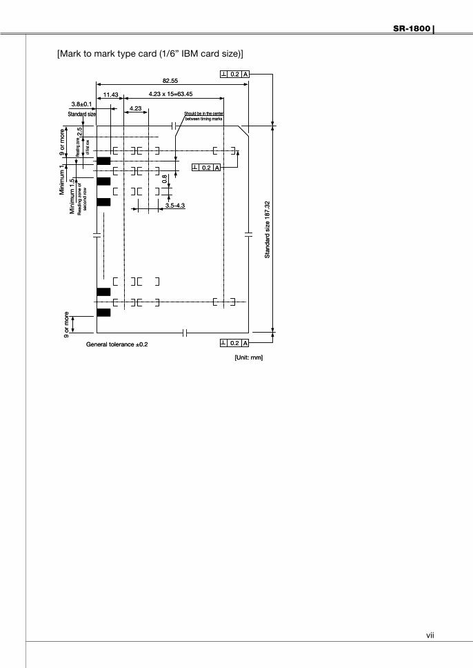
[Mark to mark type card (1/6” IBM card size)]
Sta
ndar
d s
ize
187.
32
0.2 A
0.2 A
0.2 A82.55
0.8
9 or
mor
eM
inim
um 1
9 or
mor
e
3.8±0.1
Standard size
General tolerance ±0.2
[Unit: mm]
4.23 x 15=63.45
Min
imum
1.5
3.5-4.3
4.23
11.43
Should be in the centerbetween timing marks
Rea
din
g zo
ne o
fse
cond
row
Read
ing zo
ne
of fir
st ro
w
2.5
Sta
ndar
d s
ize
187.
32
0.2 A
0.2 A
0.2 A82.55
0.8
9 or
mor
eM
inim
um 1
9 or
mor
e
3.8±0.1
Standard size
General tolerance ±0.2
[Unit: mm]
4.23 x 15=63.45
Min
imum
1.5
3.5-4.3
4.23
11.43
Should be in the centerbetween timing marks
Rea
din
g zo
ne o
fse
cond
row
Read
ing zo
ne
of fir
st ro
w
2.5

CG0097120
7-24-14, Oizumi Gakuen-cho, Nerima-ku, Tokyo 178-8686, JapanTelephone: +81-3-3978-2375 Facsimile: +81-3-3978-5229