Embed Size (px)
Citation preview

Operating Instructions Matchbox PFM 1500 AItem No.: B 08-0023-00.BEN-001-05
07.08.2006
Operating Instructions Matchbox PFM 1500 A
Notice!This operating manual is required for the safe operation of the PFM 1500 A Matchboxes. Therefore, you should keep the operating manu-al close to the unit.

07.08.2006 Operating Instructions Matchbox PFM 1500 AItem No.: B 08-0023-00.BEN-001-05
Who are these operat-ing instructions for?
This manual is intended for all persons who are working with and onthe PFM 1500 A Matchboxes, and especially for the operating person-nel.
Copyright The PFM 1500 A Matchboxes and this manual are protected by copy-right. Any reproduction of these devices will be prosecuted.
This document was produced by the Technical Documentation De-partment of HÜTTINGER Elektronik GmbH + Co. KG.
All rights reserved by HÜTTINGER Elektronik GmbH + Co. KG, in par-ticular the rights of reproduction and distribution as well as translation,including issues relating to copyright claims. No part of this documen-tation may be reproduced or processed, duplicated or distributedthrough the use of electronic systems in any way without the priorwritten permission from HÜTTINGER Elektronik GmbH + Co. KG. Sub-ject to errors and technical changes.
© HÜTTINGER Elektronik GmbH + Co. KG
Hüttinger Elektronik GmbH + Co. KG assumes no responsibility for anypossible errors in this documentation. Liability is excluded for damages,either direct or consequential, which occur in association with the de-livery or use of this documentation, as permitted by law.
This manual contains the most precise description of the product pos-sible. However, this does not guarantee particular features or applica-tion results. We are always grateful for criticism or hints regardingimperfections, and suggestions for possible improvements.
Unless otherwise stated, the relevant State of Engineering is that at thetime of combined delivery of the product and the manual by HÜTTING-ER Elektronik GmbH & Co. KG. The product is subject to technicalchanges without prior notice. Previous manuals are no longer valid.
Do you have any questions? Or problems with installation and opera-tion? - Call us! We will be glad to help you.

Operating Instructions Matchbox PFM 1500 AItem No.: B 08-0023-00.BEN-001-05
07.08.2006
HÜTTINGER Elektronik GmbH + Co. KG
Bötzinger Straße 8079111 FreiburgGermany
Tel.: +49 (0)7 61/89 71-0Fax: +49 (0)7 61/89 71-1150E-mail: [email protected]: www.huettinger.com
HUETTINGER Electronic, Inc.
111 Hyde RoadFarmington, CT 06032USA
Tel.: +1.860.255.6555Fax: +1.860.255.6423E-mail: [email protected]
[email protected]: www.huettinger.com
HUETTINGER Electronic K.K.
3-22-13 Shin Yokohama, Kohoku-KuYokohama, 222-0033Japan
Tel: +81-45-470-3761Fax: +81-45-470-3510E-mail: [email protected]: www.huettinger.com
TRUMPF Korea Co., Ltd.
14th Fl., CBS Bd.917-1 Mok-dong, Yangcheon-guSeoul 158-701Korea
Tel: +82-2-67392500 Fax: +82-2-67392525 E-mail: [email protected] Internet: www.trumpf.co.kr

07.08.2006 Operating Instructions Matchbox PFM 1500 AItem No.: B 08-0023-00.BEN-001-05
This operating manual concerns the devices of the PFM 1500 A line of products listed below, as well as devices with the same code for the wiring diagram (B 82-…), even though their Item number is not listed here.
461490 (B 82-0176-00.S)
461746 (B 82-0221-00.S)
461765 (B 82-0226-00.S)
910492 (B 82-0240-00.S)
941164 (B 82-0253-00.S)
943440 (B 82-0254-00.S)
944455 (B 82-0258-00.S)
952756 (B 82-0259-00.S)
964526 (B 82-0261-00.S)
967318 (B 82-0176-00.S)
1212719 (B 82-0268-00.S)

Operating Instructions Matchbox PFM 1500 AChapter : Table of contentsB 08-0023-00.BEN-001-05 Page 5
TABLE OF CONTENTS
TABLE OF CONTENTS ............................................................5
INDEX OF FIGURES ...............................................................7
INDEX OF TABLES ................................................................9
1 GENERAL INFORMATION ...................................................111.1 GENERAL DETAILS OF THE PRODUCT ....................................... 111.2 WARRANTY ................................................................................ 111.3 STRUCTURE OF THE DOCUMENTATION ................................... 121.4 TECHNICAL EXPRESSIONS AND ABBREVIATIONS .................... 14
2 SAFETY ...............................................................................152.1 INTENDED USE ........................................................................... 152.2 GENERAL WARNING NOTICES .................................................. 162.3 SAFETY DEVICES ........................................................................ 172.4 EMERGENCY MEASURES ........................................................... 18
3 DESCRIPTION, TECHNOLOGY .............................................193.1 CLASSIFICATION ACCORDING TO EN 55011 ............................ 193.2 DESCRIPTION OF FUNCTIONS .................................................... 193.3 OVERVIEW OF THE DEVICE ....................................................... 223.4 FIELDS OF APPLICATION ............................................................ 243.5 TECHNICAL DATA ...................................................................... 25
4 VERSIONS, ACCESSORIES ..................................................274.1 RF OUTPUTS ............................................................................... 274.2 FIBER OPTIC CABLE .................................................................... 284.3 MATCHBOX MODEL VERSIONS ................................................ 29
5 INSTALLATION ....................................................................335.1 TRANSPORT, STORAGE .............................................................. 335.2 POSITIONING .............................................................................. 345.3 MOUNTING ................................................................................ 365.4 COIL MATCHING FOR THE INDUCTIVE MATCHBOX ................ 375.5 CONNECTION ............................................................................. 395.6 DISMANTLING, PACKING .......................................................... 45
6 OPERATION, CONTROL .......................................................476.1 MATCHBOX OPERATION ........................................................... 476.2 OPERATION MODES .................................................................. 486.3 TROUBLESHOOTING, RECTIFICATION OF FAILURES ................ 49
7 MAINTENANCE ...................................................................517.1 GENERAL MAINTENANCE NOTICES .......................................... 517.2 IGNITION SETTING ..................................................................... 527.3 INCREASING THE CAPACITANCE ............................................... 547.4 CHANGING THE TAP ON THE LOAD COIL ................................ 567.5 MEASUREMENT VALUE ADJUSTMENT ..................................... 57
8 INTERFACES ........................................................................598.1 DESCRIPTION OF THE INTERFACES ........................................... 59

Operating Instructions Matchbox PFM 1500 AChapter : Table of contentsB 08-0023-00.BEN-001-05Page 6
8.2 SIGNAL DESCRIPTION OF X3 ..................................................... 608.3 OPTICAL DATA INTERFACES ...................................................... 628.4 GROUNDING SWITCH INTERFACE ............................................. 62

Operating Instructions Matchbox PFM 1500 AChapter : Index of FiguresB 08-0023-00.BEN-001-05 Page 7
INDEX OF FIGURES
Fig.3.1 Matchbox PFM 1500 A, front view ................................................... 22Fig.3.2 PFM 1500 A Matchbox, rear view ..................................................... 23Fig.4.1 13/30 chassis socket ......................................................................... 27Fig.4.2 7/16 chassis socket ........................................................................... 27Fig.4.3 "N" chassis socket ........................................................................... 27Fig.4.4 Bushing insulator .............................................................................. 28Fig.5.1 Position of L1, C8 and W5 ................................................................ 38Fig.5.2 Ground connection .......................................................................... 39Fig.5.3 A/D interface X3 ............................................................................... 39Fig.5.4 Fiber optic cable interface ................................................................. 40Fig.5.5 RF input X1, securing bar removed ................................................... 40Fig.5.6 Bushing insulator .............................................................................. 41Fig.5.7 Ground return via the shield housing ................................................ 42Fig.5.8 Ground return via the shielded and connection housing ................... 43Fig.5.9 Ground return via the RF cable ......................................................... 43Fig.5.10 Ground return via the connection point ............................................ 43Fig.5.11 Mains connection ............................................................................. 45Fig.7.1 PFM 1500 A Matchbox, opened ....................................................... 55Fig.7.2 Ceramic capacitors ........................................................................... 55Fig.7.3 Installing the ceramic capacitors ....................................................... 55Fig.7.4 Load-coil clamp ................................................................................ 56Fig.7.5 Access openings for trimming potentiometer ................................... 57

Page 8
Operating Instructions Matchbox PFM 1500 AChapter : Index of Figures
B 08-0023-00.BEN-001-05

Operating Instructions Matchbox PFM 1500 AChapter : Index of TablesB 08-0023-00.BEN-001-05 Page 9
INDEX OF TABLES
Tab.3.1 Technical data .................................................................................. 25Tab.4.1 Model variations ............................................................................... 29Tab.5.1 Technical data for coil matching ....................................................... 37Tab.6.1 Error messages ................................................................................. 50Tab.8.1 Pin assignments A/D interface X3 ..................................................... 59Tab.8.2 Pin assignment of the grounding switch interface ............................. 62

Page 10
Operating Instructions Matchbox PFM 1500 AChapter : Index of Tables
B 08-0023-00.BEN-001-05

Operating Instructions Matchbox PFM 1500 AChapter 1: General InformationB 08-0023-00.BEN-001-05 Page 11
1 GENERAL INFORMATION
Chapter Outline:
Who is this chapter directed at?
This chapter is intended for all persons who install, operate, and main-tain PFM 1500 A Matchboxes on the basis of this operating manual.
Chapter contents This chapter contains the principal details of the product and the op-erating manual.
1.1 GENERAL DETAILS OF THE PRODUCT
The present operating manual applies to the following units:
• PFM 1500 A Matchboxes
Manufacturer:
HÜTTINGER Elektronik GmbH + Co. KGBötzinger Str. 80D-79111 FreiburgTel.: +49 7 61 / 89 71 - 0Fax: +49 7 61 / 89 71 - 1150
E-mail: [email protected]:http://www.huettinger.com
1.2 WARRANTY
The duration of the warranty is specified in the order confirmation and in the general terms and conditions of sale and delivery of HÜTTINGER Elektronik GmbH + Co. KG .
Damage caused by improper use or unauthorized modification of the device does not constitute grounds for a warranty claim.

Operating Instructions Matchbox PFM 1500 AChapter 1: General Information
B 08-0023-00.BEN-001-05Page 12
1.3 STRUCTURE OF THE DOCUMENTATION
GENERAL
There are two types of accompanying documents for Hüttinger prod-ucts:
• Operating manual
- The operating manual provides all necessary details for the installation, operation and maintenance of the respective systems.
Technical documents regarding the unit
- The technical documents regarding the unit provide detailed plans, drawings and lists for the unit. This information is not meant for op-erating personnel. Service, maintenance and repair guided by these documents must be carried out by specially trained skilled personnel only.
This document is the operating manual.
STRUCTURE OF THE OPERATING MANUAL
The present operating manual consists of eight chapters which contain all necessary information for the operation of the system:
• Chapter 1: "STRUCTURE OF THE DOCUMENT"
• Chapter 2: "SAFETY"
• Chapter 3: "DESCRIPTION, TECHNOLOGY"
• Chapter 4: "VERSIONS, ACCESSORIES"
• Chapter 5: "INSTALLATION"
• Chapter 6: "OPERATION, CONTROL"
• Chapter 7: "MAINTENANCE"
• Chapter 8: "INTERFACES"
STRUCTURE OF THE INDIVIDUAL PAGES
Header A product symbol is located at the top outside corner of the page so that it is straight-forward to recognize the product to which the oper-ating manual applies.
Footer The footer contains information about the actual chapter:
• chapter number and name,

Operating Instructions Matchbox PFM 1500 AChapter 1: General InformationB 08-0023-00.BEN-001-05 Page 13
• document name
The current chapter is indicated by a pictograph above the page num-ber which contains the chapter number and corresponding symbol.
EXPLANATION OF PICTOGRAMS AND SYMBOLS
Danger !This sign warns of possible personal injury. Serious and even fatal inju-ries could result if this sign is not heeded.
Life Threatening Voltage !This sign warns of danger from electrical voltage. If not heeded, elec-trical shocks and their known, even fatal, consequences could result.
Warning !This sign warns of dangers for the product. Damage and even com-plete destruction of the product and adjoining parts can result if this sign is not heeded.
Warning: Electromagnetic fields !This symbol warns of electromagnetic fields.
Danger: High frequency !These signs warn of danger from high frequency radiation. Personswith pacemakers or implants may not enter areas where this sign isposted as pacemaker operation can be disturbed by the presence ofhigh frequency radiation and implats can heat-up.
Notice !This sign draws attention to important information.
Symbol of work step instructions This symbol calls your attention to tasks which are to be carried out.
!

Operating Instructions Matchbox PFM 1500 AChapter 1: General Information
B 08-0023-00.BEN-001-05Page 14
1.4 TECHNICAL EXPRESSIONS AND ABBREVIA-TIONS
DESCRIPTION OF ABBREVIATIONS USED
CL nominal/actual value of the load capacitor
CT nominal/actual value of the tuning capacitor
PHI phase angle of the load power vector
PI RF power (incident power)
PR reflected RF power
Td dew point temperature
TW cooling water temperature
UHF Peak RF peak voltage at the output of the matchbox
Z size of the load power vector
EXPLANATION OF TERMS USED
DC bias voltage DC voltage, created by spontaneous gas discharge in plasma processes
Matchbox adjustable tuning network for the optimum adjustment of the load to the RF generator
Controller controlling device for the matchbox, allows for manual and automatic tuning of the matchbox
FOC fiber-optic cable
Reflectometer device for measuring the forward and reflected RF power
Magnitude / phase detector
device for measuring the differential magnitude and the phase of the transmitted RF power at the input of the matchbox
Reactive current compensation
rough adjustment of the matchbox for different loads can be carried out using an additional coil in the tuning circuit with a variable tap. This improves the tuning performance.

Operating Instructions Matchbox PFM 1500 AChapter 2: SafetyB 08-0023-00.BEN-001-05 Page 15
2 SAFETY
Chapter Outline:
Who is this chapter directed at?
This chapter is intended for all persons who install, operate, and main-tain PFM 1500 A Matchboxes on the basis of this operating manual.
Chapter contents The chapter contains the principal details for the safe operation of the product.
2.1 INTENDED USE
Danger!The protection of operating personnel and the device is not guaran-teed if the device is not operated in compliance with its intended use.
! The matchbox may only be operated by qualified personnel in compliance with these operating instructions.
FUNCTIONS AND OPERATION OF THE EQUIPMENT
Tuning network with variable impedance matching
The matchbox automatically compensates for RF impedance-varying loads. It provides the source RF generator with a regulated, impedance matched 50 Ω load.
The functions of the matchbox can be controlled either through the RF generator (in "internal" operating mode) or by using the optional PFC controller (in "internal" operating mode).
Full information about this can be found in chapter 3: “Description, technology”.
INTENDED USE
The PFM series matchbox was conceived as an impedance matching device which can be directly mounted to systems producing varying RF loads.

Operating Instructions Matchbox PFM 1500 AChapter 2: Safety
B 08-0023-00.BEN-001-05Page 16
The PFC controller is suited to the operation of PFM Matchboxes plus accessories (e.g. RF selectors) and data transfer for customer remote control systems.
Unauthorized operation
The PFM matchbox and the PFC controller may be used only within the scope of their intended use.
2.2 GENERAL WARNING NOTICES
DANGER DURING OPERATION OF THE MATCHBOX
Danger: high frequency!
Alternating electromagnetic fields can have an unwanted, damaging effect on active and passive health aids (pacemakers, implants …). Per-sons with active and passive health aids must stay outside of areas af-fected by the matchbox.
Due to the intensity of the electromagnetic field, magnetic materials can heat up and possibly melt.
! Use only nonmagnetic materials (brass, stainless steel, copper) for mounting the matchbox and for attaching other devices to it.
! Place the warning signs included with the shipment at all en-trances to the room where the matchbox is operating.
DANGERS DUE TO HIGH VOLTAGES
Life-threatening voltages!The matchbox provides impedance matching for RF generators. The high voltages present at the RF output of the RF generator and match-box during undisturbed operation are absolutely life-threatening.
Life-threatening voltages!Even after switching off and disconnecting the mains, residual voltages can be present in the matchbox.

Operating Instructions Matchbox PFM 1500 AChapter 2: SafetyB 08-0023-00.BEN-001-05 Page 17
! Never open the matchbox or the PFC controller. The device may only be opened by properly instructed qualified personnel after being disconnected from the mains.
! Before opening the RF unit, disconnect the PFM matchbox from the RF generator, any application and further supply units which may be connected.
Danger!In order to provide protection against electromagnetic fields and elec-tric shock, the connection between matchbox and application must be made according to the instructions given in chapter 5: “Installation”. Bringing a high-frequency system into operation whose application has not been connected as described above can lead to the following dangers:
• Electrical shock and / or burns when touching uncovered parts.
• Exposure of persons to electromagnetic fields.
• Faulty functioning or damage to other devices due to electromag-netic fields.
Contact HÜTTINGER for any questions concerning use with your appli-cation.
2.3 SAFETY DEVICES
MONITORING AND SAFETY DEVICES
Warning!No interlocking devices are provided with the PFM Matchbox. It is the operator's responsibility to ensure that the input RF power, as well as the output RF current and voltage do not exceed the maximum allow-able values (see document "Technical Specification") and that the re-quired cooling water amount for the device is maintained at all times during operation. Failure to operate the device as described in these operating instructions may result in damage to or destruction of the device.

Operating Instructions Matchbox PFM 1500 AChapter 2: Safety
B 08-0023-00.BEN-001-05Page 18
Notice!As the operator, you are responsible for the safe operation of the PFM matchbox. It is your responsibility to know the applicable legal regula-tions and to apply them.
2.4 EMERGENCY MEASURES
! In an emergency, carry out the following steps in the given or-der:
1. Switch off the external mains separation device for the RFgenerator as well as for matchbox and controller.
2. Turn off the cooling water supply for the generator andmatchbox.
3. Put out any fires with a suitable extinguisher.
Life-threatening voltages!Due to the high voltages, never extinguish the fire with water.

Page 19Operating Instructions Matchbox PFM 1500 AChapter 3: Description, technologyB 08-0023-00.BEN-001-05
3 DESCRIPTION, TECHNOLOGY
Chapter Outline:
Who is this chapter directed at?
This chapter is intended for all persons who install, operate, and main-tain PFM 1500 A Matchboxes on the basis of this operating manual.
Chapter contents The chapter contains information about the functionality and techno-logy of the PFM 1500 A Matchboxes, their use, fields of application, and technical data.
3.1 CLASSIFICATION ACCORDING TO EN 55011
The EN 55011 standard groups ISM devices (industrial, scientific and medical high-frequency devices) into various groups and classes.
The PFM 1500 A Matchboxes are devices of Group 2 / Class A.
Group 2 includes all ISM devices, where HF energy is purposely gener-ated and / or used as electromagnetic radiation for the treatment of material.
Devices of Class A are intended for operation in an industrial environ-ment. The electromagnetic compatibility in other environments (resi-dential areas) may not be guaranteed due to the conductor-bound interference factors that occur.
3.2 DESCRIPTION OF FUNCTIONS
PLASMA PROCESS REQUIREMENTS
A plasma process can be regarded electrically as a parallel connection of a variable capacitor with a variable resistor, hence it is a variable complex load.

Operating Instructions Matchbox PFM 1500 AChapter 3: Description, technology
B 08-0023-00.BEN-001-05Page 20
The RF power is transmitted most efficiently to a non-reactive load: HÜTTINGER RF generators are designed for 50 Ω loads. A Matchbox (tuning network) directly connected to the application is used to trans-form the complex load of the plasma process to a stable 50 Ω resistive load.
At its input, the Matchbox measures magnitude and phase of the RF power transmitted to the Matchbox + plasma chamber combination, and, by means of an internal microcontroller, provides a stable "opti-mum load".

Page 21Operating Instructions Matchbox PFM 1500 AChapter 3: Description, technologyB 08-0023-00.BEN-001-05
THE MATCHBOX
The PFM 1500 A Matchbox is an active tuning network which ensures "optimum loading" of the RF power source under variable load condi-tions. The Matchbox can be controlled either via fiber optic cables (PFG RF or PFC device series) or via the A/D interface. The optional PFC Con-troller can be connected via optical data interfaces for controlling up to ten Matchboxes and as a data source for a process control system. Contrary to many other systems, the PFM 1500 A Matchbox measures the process-related DC bias voltage. This value is transmitted via the in-terfaces and can be displayed or used as control parameter.
Further details about Matchbox operation with the PFC Controller can be found in Chapter 6 of the "PFC Controller" operating instructions.
OPERATION MODES
The PFM 1500 A Matchbox can be operated in two modes:
External mode • "External" operation mode:This is the operation mode of the Matchbox after switching on the power. In the "external" operating mode, a control device must be connected to the A/D interface X3 in order for the necessary control signals to be sent to the Matchbox.
Internal • "Internal" operation mode:"Internal" operation mode requires that a PFC Controller or a PFG RF Generator be connected via a fiber optic cable. In the "internal" operating mode, the Matchbox can be operated manually or auto-matically via the PFC Controller or PFG RF unit, or remotely con-trolled by means of another source. Further details about Matchbox operation with the Controller can be found in Chapter 6 of the "PFC Controller" operating instructions.
CONTROL
Reflected RF power PR
To optimize the RF power output to the plasma system, the PFM 1500 A Matchbox uses an adjustable load coil and two variable air capacitors. These compensate for impedance variations in the plas-ma-system process by minimizing the reflected RF power. Impedance variations can arise through, for example, temperature and pressure fluctuations, changes in the gas composition, etc. In addition, ceramic capacitors can be connected in parallel to increase the capacitance range of the air capacitors.

Operating Instructions Matchbox PFM 1500 AChapter 3: Description, technology
B 08-0023-00.BEN-001-05Page 22
3.3 OVERVIEW OF THE DEVICE
The PFM 1500 A Matchbox is a single unit which is designed to be mounted directly to systems producing varying RF loads. Figure 3.1 shows the front side of the Matchbox. The connection to the plasma and thin-film process system is by means of a socket installed at the front.
Front view
Fig.3.1 Matchbox PFM 1500 A, front view

Page 23Operating Instructions Matchbox PFM 1500 AChapter 3: Description, technologyB 08-0023-00.BEN-001-05
Rear view
Fig.3.2 PFM 1500 A Matchbox, rear view
The following connections are located on the rear of the Matchbox:
1. Mains voltage
2. Miniature fuse3. Ground connection4. RF input with securing bar5. Fiber optic cable connectors (in and out)6. A/D interface, 25-pin Sub-D connector7. Manual trimming of the magnitude and phase detector8. Ventilation

Operating Instructions Matchbox PFM 1500 AChapter 3: Description, technology
B 08-0023-00.BEN-001-05Page 24
3.4 FIELDS OF APPLICATION
TYPICAL FIELDS OF APPLICATION
Plasma and thin-film processes
The PFM 1500 A Matchbox is designed as an active impedance match-ing device for use with plasma systems. Typical fields of application are:
• magnetron-sputtering,
• sputter-etching,
• reactive ion etching,
• CVD plasma processes,
• RF bias applications.
• inductive plasma excitation,
• induction heating.
ADAPTABILITY
Adapting to different process requirements
The PFM 1500 A Matchbox is optimally suited for plasma and thin-film processes due to its ability to perform impedance matching for a wide range of applications. In particular, Matchboxes are specifically de-signed to conveniently handle impedance variations due to changes in process temperature, pressure and gas composition.
When using a PFC Controller, up to 10 Matchboxes can be controlled and monitored from a single Controller. The Controller can also be used for analyzing and recording process data by connecting it to a PC.

Page 25Operating Instructions Matchbox PFM 1500 AChapter 3: Description, technologyB 08-0023-00.BEN-001-05
3.5 TECHNICAL DATA
TECHNICAL SPECIFICATIONS
Technical dataPFM 1500 A B 82-
0176-00.SB 82-
0221-00.SB 82-0226-
00.S
Item No. 461490 461746 461765
RF power
Nominal RF power 1000 W
Frequency 13.56 MHz
Load current (see Chap. 4) max. 18 A rms max. 22 A rms
Load voltage max. 2 kVs
Input impedance 50 Ω, coaxial socket, type N
Mains connection
Mains voltage 230 V 115 V 230 V
Mains voltage tolerance -15% / +10%
Mains frequency 50 - 60 Hz
Mains power 100 VA
Connection Inlet connector for non-heating appliances
Interfaces
Analog/digital (A/D)(for separate control)
25-pin Sub-D socket connector
Optical data interface (LWL)
IN: TOR x 170 (Toshiba)OUT: TOT x 170 A (Toshiba)
Cooling
Ventilation air cooling of capacitors and inductances
Ambient temperature max. 35°C
Miscellaneous Data
Dimensions (WxHxD) 230 x 180 x 400 mm, excluding connectors
Weight approx. 7.5 kg
Housing chromated aluminum
Protection class IP 21
Tab.3.1 Technical data

Operating Instructions Matchbox PFM 1500 AChapter 3: Description, technology
B 08-0023-00.BEN-001-05Page 26
Features • 2 variable air capacitors, 2 tuning inductive coils
• Ceramic capacitor for configuration
• Motor drive at capacitors
Special feature in version for inductive load
The RF power unit for the B 82-0226-00.S can be alternatively con-nected for three load ranges: j30 … j60 Ω / j50 … j170 Ω / j160 … j600 Ω
Measuring sensor • Adjustment magnitude and phase measurement
• RF peak voltage 0 - 2040 Vs (B 82 - 0226-00.S)
• DC bias voltage 0 - 2040 VDC (B 82 - 0176-00.S, - 0221-00.S)
Controller • Microcontroller for motor control and
• automatic tuning and fiber optic cable data transmission
Operation • via control panel on PFG RF generator
• via separate PFC Controller
Regulations • CE-conforming
• Interference protection and EMC in accordance with
- EN 55011 Group 2 Class A
- EN 50082 Part 2 and IEC 1000-4 -2, -3, -4, -5.
• Low-voltage directives 73/23/EEC for internal wiring
• Power unit VDE 0110, 0160
INSTALLATION SITE
Environmental conditions
The PFM 1500 A Matchbox is mounted directly to the vacuum cham-ber of the plasma system. The location should be free from excessive dust or humidity and have a suitable ambient temperature (see Table 3.1).
Space requirement In order to establish the supply connections and to allow for later ser-vice and maintenance work, the following minimum spacing should be kept around the system:
• 20 cm at the rear of the Matchbox for installation and removal.
• Enough space behind the device so that the RF power cable can be connected to the RF input.
• The Matchboxes should never interfere with any required safety functions of the plasma system, escape routes or any other local regulations concerning safety.
Page 27Operating Instructions Matchbox PFM 1500 AChapter 4: Versions, accessoriesB 08-0023-00.BEN-001-05
4 VERSIONS, ACCESSORIES
Chapter Outline:
Who is this chapter directed at?
This chapter is intended for all persons who install and operate special variants of the basic model of the PFM 1500 A Matchboxes or acces-sories for them.
Chapter contents The chapter contains information about the functionality and technol-ogy of model variants and accessories of the PFM 1500 A Matchboxes, their use, fields of application, and technical data.
4.1 RF OUTPUTS
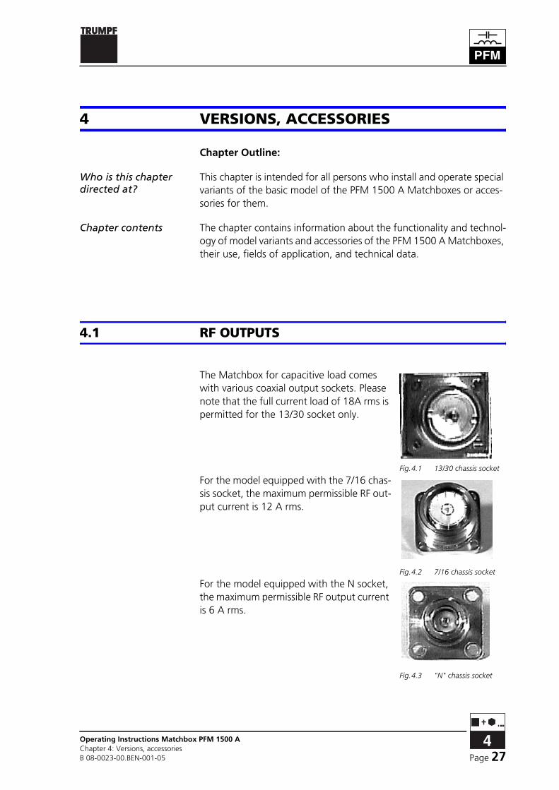
The Matchbox for capacitive load comes with various coaxial output sockets. Please note that the full current load of 18A rms is permitted for the 13/30 socket only.
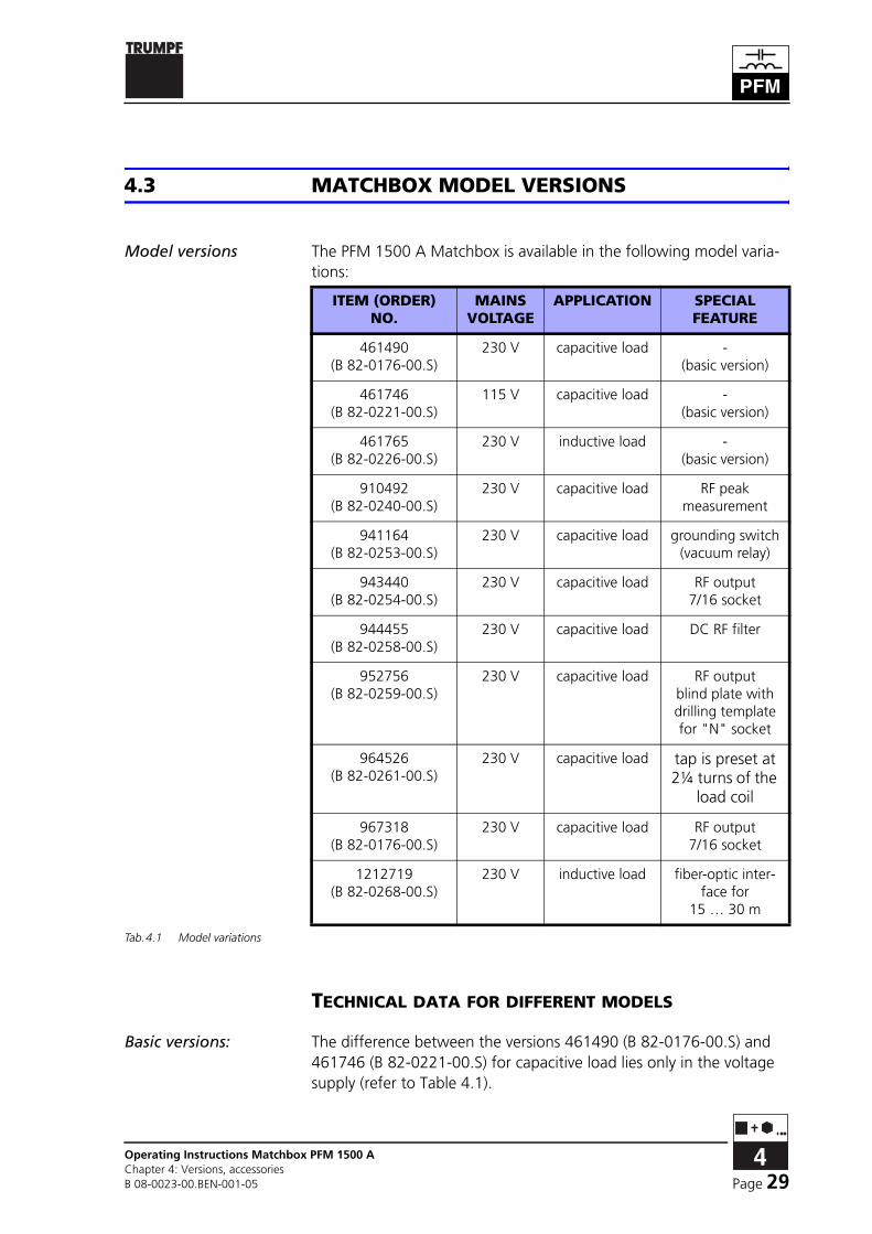
For the model equipped with the 7/16 chas-sis socket, the maximum permissible RF out-put current is 12 A rms.
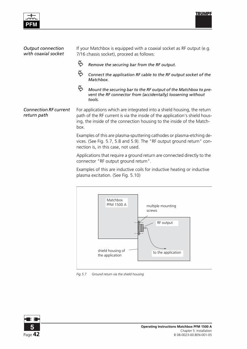
For the model equipped with the N socket, the maximum permissible RF output current is 6 A rms.
Fig.4.1 13/30 chassis socket
Fig.4.2 7/16 chassis socket
Fig.4.3 "N" chassis socket

Operating Instructions Matchbox PFM 1500 AChapter 4: Versions, accessories
B 08-0023-00.BEN-001-05Page 28
The standard Matchbox for inductive load is fitted with an M6 threaded neck on a ce-ramic insulator (bushing insulator, see Fig. 4.4).
4.2 FIBER OPTIC CABLE
The standard length range for the fiber optic cable is 0.5 … 15 m. However, devices for the ranges 15 … 30 m and 30 … 50 m are avail-able upon request. All members in an optical data system have to be specified for the same length range. The lengths of the fiber optic ca-bles used have to lie within this range although the individual lengths of the fiber optic cables may vary.
On the device, the length range is marked beside the fiber optic cable connectors. Devices without information on length are specified for the standard length of 0.5 … 15 m.
Notice!Devices of the same model but specified for different length ranges have different item numbers.
Fig.4.4 Bushing insulator
Page 29Operating Instructions Matchbox PFM 1500 AChapter 4: Versions, accessoriesB 08-0023-00.BEN-001-05
4.3 MATCHBOX MODEL VERSIONS
Model versions The PFM 1500 A Matchbox is available in the following model varia-tions:
TECHNICAL DATA FOR DIFFERENT MODELS
Basic versions: The difference between the versions 461490 (B 82-0176-00.S) and 461746 (B 82-0221-00.S) for capacitive load lies only in the voltage supply (refer to Table 4.1).
ITEM (ORDER) NO.
MAINS VOLTAGE
APPLICATION SPECIALFEATURE
461490 (B 82-0176-00.S)
230 V capacitive load -(basic version)
461746 (B 82-0221-00.S)
115 V capacitive load -(basic version)
461765 (B 82-0226-00.S)
230 V inductive load -(basic version)
910492 (B 82-0240-00.S)
230 V capacitive load RF peakmeasurement
941164 (B 82-0253-00.S)
230 V capacitive load grounding switch(vacuum relay)
943440 (B 82-0254-00.S)
230 V capacitive load RF output7/16 socket
944455 (B 82-0258-00.S)
230 V capacitive load DC RF filter
952756 (B 82-0259-00.S)
230 V capacitive load RF outputblind plate with drilling template for "N" socket
964526 (B 82-0261-00.S)
230 V capacitive load tap is preset at 2¼ turns of the
load coil
967318 (B 82-0176-00.S)
230 V capacitive load RF output7/16 socket
1212719 (B 82-0268-00.S)
230 V inductive load fiber-optic inter-face for
15 … 30 m
Tab.4.1 Model variations

Operating Instructions Matchbox PFM 1500 AChapter 4: Versions, accessories
B 08-0023-00.BEN-001-05Page 30
Model 461765 (B 82-0226-00.S) is designed for operating on induc-tive loads and therefore measures the RF peak voltage providing a 2nd control parameter and automatic tuning enabling.

Page 31Operating Instructions Matchbox PFM 1500 AChapter 4: Versions, accessoriesB 08-0023-00.BEN-001-05
Model 910492(B 82-0240-00.S):
This Matchbox is intended for the operation on capacitive loads, the load range corresponds to the 461490 (B 82-0176-00.S) model. For an optimum operation of plasma loads without DC bias voltage output, an RF peak measuring device (0-2040 Vs) is installed. The measure-ment serves to enable automatic tuning and as control or limit param-eter.
Model 941164(B 82- 0253-00.S):
A grounding switch (vacuum relay) is installed in the Matchbox con-necting the RF output to ground. In thin-film processes operating on several RF electrodes with capacitive (geometric) connection between each, the grounding switch makes it possible to avoid undesirable plas-ma effects at "turned off" electrodes.
Grounding switch: technical data
Grounding switch control:
- 9-pin Sub-D connector
- 24 V / 0.1 A; 1000 µF internal back-up capacitor
- on and off switching only under load-free conditions.
Rating:
- max. 1.4 KV rms / 11 A rms (DC - 15 MHz)
The grounding switch may be used for operational grounding only. The type of switch selected does not allow safety applications.
Model 943440(B 82-0254-00.S):
This Matchbox corresponds to a large extent to the basic model 461490 (B 82-0176-00.S). It also features the standard RF output as 7/16 socket; and also four M5 screw threads for attaching the Match-box to a chassis. For the model with 7/16 chassis socket, the maximum permissible RF output current is 12 A rms.The dimensions are indicated in the drawing B 82- 0254-00.Y.
Model 944455(B 82-0258-00.S):
In order to connect additional DC power to an electrode, a DC/RF su-perposition filter is attached to this Matchbox. The filter superposes DC and RF at the load side and filters the RF voltage off the DC input. DC and RF can be supplied to the load electrode individually or together. Furthermore, there are decoupling diodes preventing the return of the DC bias voltage (RF operation) to the DC supply device.
Technical data DC/RF filter
DC input:
- coaxial socket type 7/16
load rating:
- max. 6.25 A / 1000 V DC
The DC supply voltage must have a negative polarization against GND.

Operating Instructions Matchbox PFM 1500 AChapter 4: Versions, accessories
B 08-0023-00.BEN-001-05Page 32
Model 952756(B 82-0259-00.S):
This Matchbox corresponds to a large extent to the basic model 461490 (B 82-0176). Instead of the RF output, a blind plate with drill-ing template for an "N" chassis socket is mounted. The user can there-fore either directly screw the Matchbox to the plasma system or mount an N socket on the Matchbox.
Model 964526(B 82-0261-00.S):
This Matchbox corresponds to a large extent to the basic model 461490 (B 82-0176). The RF output is of the 7/16 chassis socket type. The tap is preset at 2¼ turns of the load coil. For the model with 7/16 chassis socket, the maximum permissible RF output current is 12 A rms.
Model 967318(B 82-0176-00.S):
This Matchbox corresponds to a large extent to the basic model 461490 (B 82-0176). The RF output is of the 7/16 chassis socket type. For the model with 7/16 chassis socket, the maximum permissible RF output current is 12 A rms.
Model 1212719(B 82-0268-00.S)
This matchbox corresponds to a large extent to the model 461765 (B 82-0226-00.S) for inductive loads. However, the fiber-optic inter-face here is designed for the length range of 15 … 30 m. The dimen-sions of the RF output are shown in drawing B 82-0268-00.y.

Page 33Operating Instructions Matchbox PFM 1500 AChapter 5: InstallationB 08-0023-00.BEN-001-05
5 INSTALLATION
Chapter Outline:
Who is this chapter directed at?
This chapter is intended for all persons who install PFM 1500 A Match-boxes on the basis of this operating manual.
Chapter contents The chapter contains advice regarding the correct mechanical and electrical installation of the PFM 1500 A Matchboxes.
5.1 TRANSPORT, STORAGE
GENERAL NOTICES
After receiving the equipment:
! Check the device immediately as soon as it is delivered for com-pleteness in accordance with the delivery note and also for visi-ble damages incurred during transport.
! Report any damages incurred during transport immediately in writing to the forwarding agency, the insurance company, and HÜTTINGER.
TRANSPORTATION
Individually packed The Matchbox is delivered in appropriate packaging such that it reach-es its destination without damage.
! The device should be protected against collision and jarring at all times. Always transport the device in its original packaging.
Attention !Transporting and storing the device under inappropriate conditions may cause permanent damage. Such damage might not be detectable from the outside. Hüttinger accepts no liability for consequential dam-ages to the device or any other connected equipment due to improper handling.

Operating Instructions Matchbox PFM 1500 AChapter 5: Installation
B 08-0023-00.BEN-001-05Page 34
STORAGE
The PFM 1500 A Matchbox must be stored in the original packaging under the following environmental conditions:
Environmental conditions
• Temperature range: 5°C … 40°C
• Air humidity range: 20 % … 80 %
5.2 POSITIONING
REMOVING THE DEVICE FROM ITS PACKAGING
Attention !The PFM 1500 A Matchbox contains sensitive components and must be handled carefully.
The PFM 1500 A Matchbox is delivered in a special packaging.
! While unpacking the PFM 1500 A Matchbox, carefully check for any visible damage. Pay particular attention to:
• damage to the housing
• damage to the interfaces
! Place the shipping box on a flat surface.
! Open the box and pull all four flaps open
! Remove the test certificate

Page 35Operating Instructions Matchbox PFM 1500 AChapter 5: InstallationB 08-0023-00.BEN-001-05
Notice !If there is no test certificate: Check to see if the lid to the inner Styrofoam box is located on this side. If it is not, then the box is upside down. Close the flaps, secure with tape and carefully turn the box over and open the other side.
! Lift out the lid of the inner Styrofoam box.
! Remove the two fiber optic cables.
! Replace the Styrofoam lid
! While holding down one of the box flaps on a long side, careful-ly turn the box onto the side with the folded back flap.
! While holding the other three flaps open, turn the box the rest of the way onto its top (no flaps should be under the box).
! Lift the cardboard box off the inner Styrofoam box and set aside
! The Styrofoam inner box should now be upside down with the lid on the bottom
! Carefully lift off the Styrofoam box leaving the Matchbox up side down on top of the lid
! Carefully turn the Matchbox over on the lid so that it is right side up
! Check that the information on the nameplate matches that on the shipping note and your order.
PACKAGING MATERIAL
What should be kept The following packaging material should be kept for possible future transport:
• inner polyethylene packaging container
• shipping carton
Disposal Any remaining packaging material should be disposed of properly. The following materials are used depending on the method of transport:
• Polyethylene (PE) for the protection of the equipment
• corrugated cardboard for internal and external packaging
All packaging materials must be disposed off according to the applica-ble regulations of the delivery area.

Operating Instructions Matchbox PFM 1500 AChapter 5: Installation
B 08-0023-00.BEN-001-05Page 36
5.3 MOUNTING
Danger: high frequency !Alternating electromagnetic fields can have an undesired, damaging effect on active and passive medical devices (pacemakers, implants…). Persons wearing active and passive medical devices must stay outside of areas affected by the Matchbox.
Due to the intensity of the electromagnetic field, magnetic materials can heat up and possibly melt.
! Use a Matchbox with coaxial RF output or install the Matchbox together with a metal housing fabricated by the user. The hous-ing serves to shield the area between the Matchbox and applica-tion.
Four internal screw threads are provided in the Matchbox housing for installation purposes. The hole dimensions can be found in the Appen-dix.
! Use only nonmagnetic materials (brass, stainless steel, copper) for mounting the Matchbox and for attaching other devices to it.

Page 37Operating Instructions Matchbox PFM 1500 AChapter 5: InstallationB 08-0023-00.BEN-001-05
5.4 COIL MATCHING FOR THE INDUCTIVE MATCH-BOX
The magnetic field generated by the coil of your application can excite a plasma or heat up a metallic work piece. In addition, there are various coils with different inductances and different reactances. The PFM 1500 A Matchbox must be adjusted to each coil type.
! Refer to the technical data of your coil and compare these data to those listed in Table 5.1.
Your coil type belongs to one of the three categories:
• Low-Z,
• Medium-Z,
• High-Z,
to which the Matchbox must then be adjusted.
! If you perform coil matching after the first installation:
• Make sure that the RF supply is switched off!
• Disconnect the mains power.
• As a precaution, discharge the RF input and output of the network with a grounding rod.
! Open the cover of the Matchbox RF section with a suitable screwdriver.
OUTPUT IMPEDANCE
LOW-Z MEDIUM-Z HIGH-Z
Load range j30 … j60 Ω j50 … j170 Ω j160 … j600 Ω
equivalent to approx. µH
0.35 … 0.7 µH 0.6 … 2 µH 1.9 … 7 µH
max. load current 22 A rms 15 A rms 8 A rms
max. load voltage 1.4 kV rms
Tab.5.1 Technical data for coil matching

Operating Instructions Matchbox PFM 1500 AChapter 5: Installation
B 08-0023-00.BEN-001-05Page 38
Notice !Coil L1, capacitor C8 and the copper connection strap W5 are labeled in the Matchbox and in the circuit diagram (see Appendix).
Fig.5.1 Position of L1, C8 and W5
! Perform one of the following adjustments:
High-Z The Matchbox is delivered in the High-Z state. If you would like to set the High-Z state:
! Install coil L1 and connect it as specified in the circuit diagram.
! Capacitor C8 is not connected. The copper connection strap W5 is disconnected or removed.
Medium-Z ! Remove coil L1.
! Do not connect capacitor C8, i.e. disconnect and remove copper connection strap W5.
Low-Z ! Remove coil L1.
! Connect capacitor C8 with the copper connection strap W5.

Page 39Operating Instructions Matchbox PFM 1500 AChapter 5: InstallationB 08-0023-00.BEN-001-05
5.5 CONNECTION
SAFETY
Life-threatening voltages!The PFM 1500 A Matchbox is connected to 230 V mains voltage (or 115 V in the USA). Observe the applicable safety precautions for work-ing with mains power.
Qualified personnel The electrical connection of PFM 1500 A Matchboxes may only be car-ried out by personnel who are qualified and trained for work with elec-trical equipment and the Matchbox. These personnel must be accustomed with and abide by the relevant safety regulations of the installation site for the erection of electrical equipment.
Danger !The following dangers can arise due to improper installation of the Matchboxes:
• danger of fire
• danger to life due to the high voltages
CONNECTION OF THE CONTROL CIRCUITS
Ground connection If necessary, establish a ground connection between the Matchbox, your application and the RF generator via the grounding ter-minal at the rear of the Matchbox.
! Connect the Matchbox to the ground-ing bar of your application with a suit-able cable.
Analog/digital interface
For external control purposes the Matchbox is connected to the RF power generator via the analog/digital interface X3.
! If necessary, connect the control cable with the 25-pin Sub-D connector to the Matchbox.
Fig.5.2 Ground connection
Fig.5.3 A/D interface X3

Operating Instructions Matchbox PFM 1500 AChapter 5: Installation
B 08-0023-00.BEN-001-05Page 40
Optical data interface The PFM 1500 A Matchbox is provided with two fiber optic cable interfaces through which up to ten Matchboxes can be con-nected to a PFC Controller.
! To connect the PFC Controller, careful-ly remove the protective covers of con-nections U1 and U2 on the Controller and Matchbox. Insert the fiber optic cable connector. Connect the output of the Matchbox (Matchbox U1) to the input of the Controller (Controller U2) and the Controller output (U1) to the Matchbox input (U2).Proceed as described above if you would like to control the Matchbox from a PFG RF series generator.
! If more than one Matchbox are to be connected in series to the Controller, connect the Controller output (U1) to the input of the first Matchbox (U2 Matchbox 1), then the output of the first Matchbox (U1) to the input of the second Matchbox (U2 Match-box 2), etc., up to ten Matchboxes. Finally, connect the output of the last Matchbox (U1) to the input of the Controller (Controller U2). The fiber optic circuit must make a complete loop through all Matchboxes for it to work properly.
Notice!Please note that all connected members have to be adjusted to the same length range of the transmission line. The length of the fiber optic cable used has to correspond to this range.
MAKING THE ELECTRICAL CONNECTIONS
Making the RF connection
! Remove the securing bar from the RF input.
! Connect the RF generator cable to the RF input X1 (socket-type N) of the Matchbox.
! Mount the securing bar to the RF input to prevent the RF connector from (accidentally) loosening with-out tools.
Fig.5.4 Fiber optic cable in-terface
Fig.5.5 RF input X1, securing bar removed

Page 41Operating Instructions Matchbox PFM 1500 AChapter 5: InstallationB 08-0023-00.BEN-001-05
Make the connection to the DC input
Only for devices with DC/RF superposition filter:
! Remove the securing bar from the DC input.
! Connect the cable of the DC supply unit to the socket marked "DC input" (type 7/16) of the DC RF filter (housing mounted on top of the Matchbox).
! Mount the securing bar to the DC input to prevent the DC con-nector from (accidentally) loosening without tools.
! Make sure that the RF and DC cables are connected to the same side as the corresponding supply units.
Danger!If a Matchbox with DC RF superposition filter is powered by a DC or RF generator, both input cables (DC and RF) have to be connected at all times and coupled with the corresponding supply unit, the connectors have to be locked with the securing bar.
Output connection(version for inductive load)
! Connect the connector of your appli-cation to the RF output of the Match-box.
The standard RF output is installed in the factory as a bushing insulator with M6 threaded neck. The connection to the appli-cation can be made, for example, with flat copper 20 x 0.5 mm or cop-per tubing Ø 8 mm. The length of the connection should be less than 20 cm. If you require another RF output socket, read Chapter 4.1: "RF outputs".
The connection between the Matchbox output and the application must be completely shielded with metal. To accomplish this, the Matchbox must be bolted to the shield housing of the application at several locations. If this is not possible, place a connection housing be-tween the Matchbox and the application.
Both the Matchbox housing and the shield housing of the application must be tightly connected to the connection housing in several places.
Fig.5.6 Bushing insulator
Operating Instructions Matchbox PFM 1500 AChapter 5: Installation
B 08-0023-00.BEN-001-05Page 42
Output connection with coaxial socket
If your Matchbox is equipped with a coaxial socket as RF output (e.g. 7/16 chassis socket), proceed as follows:
! Remove the securing bar from the RF output.
! Connect the application RF cable to the RF output socket of the Matchbox.
! Mount the securing bar to the RF output of the Matchbox to pre-vent the RF connector from (accidentally) loosening without tools.
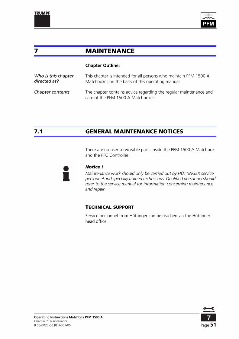
Connection RF current return path
For applications which are integrated into a shield housing, the return path of the RF current is via the inside of the application's shield hous-ing, the inside of the connection housing to the inside of the Match-box.
Examples of this are plasma-sputtering cathodes or plasma-etching de-vices. (See Fig. 5.7, 5.8 and 5.9). The "RF output ground return" con-nection is, in this case, not used.
Applications that require a ground return are connected directly to the connector "RF output ground return".
Examples of this are inductive coils for inductive heating or inductive plasma excitation. (See Fig. 5.10)
Fig.5.7 Ground return via the shield housing
RF output
shield housing of the application
to the application
multiple mounting screws
Matchbox PFM 1500 A

Page 43Operating Instructions Matchbox PFM 1500 AChapter 5: InstallationB 08-0023-00.BEN-001-05
Fig.5.8 Ground return via the shielded and connection housing
Fig.5.9 Ground return via the RF cable
Fig.5.10 Ground return via the connection point
to the application
each mounted with multiple screws
shield housing of the application
RF output
connection housing
Matchbox PFM 1500 A
to the application
shield housing of the application
chassis sockettype 7/16
RF cable with 2x 7/16 plugrecommended length max. 1 m
Matchbox PFM 1500 A
application,e.g. inductive coils
shield housing of the application
RF output
multiple mounting screws
connection point RF output ground returnMatchbox
PFM 1500 A

Operating Instructions Matchbox PFM 1500 AChapter 5: Installation
B 08-0023-00.BEN-001-05Page 44
Danger !In order to ensure protection against electrical shock and electromag-netic fields, the connection between the Matchbox and the application must be carried out as described. Bringing a high-frequency system into operation whose application has not been connected as described above can lead to the following dangers:
• Electrical shock and / or burns when touching uncovered parts.
• Exposure to electromagnetic fields.
• Faulty functioning or damage to other devices due to electromag-netic fields.
Contact Hüttinger with any questions concerning use of your applica-tion.
Notice !According to DIN EN 61010-1 / VDE 0411 Part 1, a mains separation device must be installed in the electrical supply of the PFM 1500 A Matchbox. This has to be:
• designed as a switch or power switch,
• installed near the RF generator and easily accessible by the user,
• labeled as a separation device for the Matchbox.
Life-threatening voltages !As soon as the mains cable is connected, voltage is immediately present in the Matchbox.
! Never open the housing when the Matchbox is connected to the voltage supply.
! Check whether the mains voltage indicated on the nameplate of the Matchbox corresponds to the mains voltage available at the installation site. Contact HÜTTINGER Service if the supply volt-age is different.

Page 45Operating Instructions Matchbox PFM 1500 AChapter 5: InstallationB 08-0023-00.BEN-001-05
Mains connection ! Connect the mains cable with the in-let connector for non-heating appli-ances to the Matchbox.
! Connect the socket end of the cable to the device and plug the other end into a mains socket.
If you want to use a mains cable different from the one included in the delivery or if you want to mount a different mains con-nector on the cable that comes with the Matchbox:
! Check whether the resistance between Matchbox housing and PE connection of the mains plug is within the limits set by the regulations valid for the installation site.
This work may be performed by trained and qualified personnel only.
After all electrical connections have been made:
Checking electrical connections
! Check all connectors and cables for a stable connection.
! Check the functioning of the servo drives using the Controller.
5.6 DISMANTLING, PACKING
REMOVE CONNECTIONS
! Please make sure that the RF power and any other supply units which may be connected are switched off!
! Disconnect the mains power.
! Disconnect the RF power cables from the front and the rear of the Matchbox.
! Disconnect the fiber optic communication cables.
! Remove the connector at the analog/digital interface.
Life-threatening voltages !Even after switching off and disconnecting the mains, residual voltages can be present in the Matchbox.
Fig.5.11 Mains connection

Operating Instructions Matchbox PFM 1500 AChapter 5: Installation
B 08-0023-00.BEN-001-05Page 46
! Observe the safety information in Chapter 2: "Safety".
PACKAGING
! Pack the Matchbox either in its original packaging or another appropriate packaging which will protect it from humidity and jarring.
DISPOSAL
Materials Old pieces of equipment that have no further use must be specially disposed of. The Matchbox consists of the following materials:
• Metals
- aluminum
- copper
- steel
- brass
- sheet iron
- galvanized sheet steel
• Plastics
- Teflon
- PA and others
• Other
- cardboard, ceramic
- printed circuit boards, mounted with electronic components

Page 47Operating Instructions Matchbox PFM 1500 AChapter 6: Operation, controlB 08-0023-00.BEN-001-05
6 OPERATION, CONTROL
Chapter Outline:
Who is this chapter directed at?
This chapter is intended for all persons who operate PFM 1500 A Matchboxes on the basis of this operating manual.
Chapter contents The chapter contains a description of the modes and states of opera-tion as well as operating instructions for PFM 1500 A Matchboxes.
6.1 MATCHBOX OPERATION
SAFETY INSPECTION
! Before operating the Matchbox, check all RF cables for a stable connection.
PREPARING FOR OPERATION
! Switch on the external mains separator.
The A/D interface is activated and the Matchbox is in "external" oper-ation mode.
With water-cooled devices:
! Switch on the cooling water supply.
The Matchbox is now ready for power operation.

Operating Instructions Matchbox PFM 1500 AChapter 6: Operation, control
B 08-0023-00.BEN-001-05Page 48
POWER OPERATION
! Switch on RF power.
The equipment is now in power operation. The capacitor settings of the Matchbox and hence the reflected RF power are controlled either by the PFG RF Generator or the PFC Controller.
SWITCHING OFF THE MATCHBOX
Make sure that all RF sources are deactivated.
! Switch off the external mains separator.
SWITCHING OFF IN AN EMERGENCY
! Carry out the emergency measures for the equipment to which the Matchbox is connected.
Life-threatening voltages !Even after switching off, the Matchbox still may contain residual volt-age.
6.2 OPERATION MODES
"EXTERNAL" OPERATION MODE
In external operation mode, a control device must be connected to the Matchbox at interface X3 (see Chapter 8, "Interfaces") that will pro-vide the required control signals. After switching on the power, the Matchbox is automatically in "external" operation mode.
The operation mode can be changed to "Internal" operation mode us-ing menu functions of the optional PFC Controller.

Page 49Operating Instructions Matchbox PFM 1500 AChapter 6: Operation, controlB 08-0023-00.BEN-001-05
"INTERNAL" OPERATION MODE
If the Matchbox is to be controlled using a PFC Controller:
! Connect the PFC Controller to the Matchbox. (see Chapter 5 of the PFC Controller operating instructions)
This has the following consequences:
• The Matchbox can be controlled either with the Controller or from the interface X3, depending on the selected mode of the Controller (see Chapter 6 of the PFC Controller operating Manual).
• Actual values of the Matchbox parameters can be monitored at the Controller.
6.3 TROUBLESHOOTING, RECTIFICATION OF FAIL-URES
INDICATIONS OF FAILURE
On the Controller There are no external indicators on the Matchbox for the operating status of the device.
Failure of the Matchbox is indicated by a HIGH state at pin 16 of the X3 interface (see Chapter 8: "Interfaces").

Operating Instructions Matchbox PFM 1500 AChapter 6: Operation, control
B 08-0023-00.BEN-001-05Page 50
The following table describes various conditions which lead to a "fail-ure" state of the Matchbox and the necessary steps to correct the problem.
RECTIFICATION OF FAILURES
If the cause of a failure cannot be located or corrected:
! Call HÜTTINGER Service.
SYMPTOM CAUSE REMEDY
Matchbox cannot be accessed via the Controller.
Fuse F1 blown Replace the blown fuse.
Improper connection of the fiber optic cables.
Correct the connection. Check that the fiber optic cable is not damaged, kinked or squeezed.
Matchbox and Controller (or another optical data ring member) are not specified for the same length range.
Please use matching compo-nents.The length of the fiber optic
cable does not correspond to the length range in the marking.
Tab.6.1 Error messages
Page 51Operating Instructions Matchbox PFM 1500 AChapter 7: MaintenanceB 08-0023-00.BEN-001-05
7 MAINTENANCE
Chapter Outline:
Who is this chapter directed at?
This chapter is intended for all persons who maintain PFM 1500 A Matchboxes on the basis of this operating manual.
Chapter contents The chapter contains advice regarding the regular maintenance and care of the PFM 1500 A Matchboxes.
7.1 GENERAL MAINTENANCE NOTICES
There are no user serviceable parts inside the PFM 1500 A Matchbox and the PFC Controller.
Notice !Maintenance work should only be carried out by HÜTTINGER service personnel and specially trained technicians. Qualified personnel should refer to the service manual for information concerning maintenance and repair.
TECHNICAL SUPPORT
Service personnel from Hüttinger can be reached via the Hüttinger head office.

Operating Instructions Matchbox PFM 1500 AChapter 7: Maintenance
B 08-0023-00.BEN-001-05Page 52
7.2 IGNITION SETTING
To ignite the gas discharge in the plasma chamber, CT and CL must be set on the Controller. Proceed as follows:
! Connect your application to the system.
! Set an RF output power between 5% and 20%.
! Set the operation mode on the Controller to "Manual".
! Set the CT on the Controller display to a value between 800 and 1000.
! Set CL to 0.
! Start up the system.
! Slowly adjust the value of CL from 0 to 1000.
! Observe at which CL value the plasma ignites and leave CL at this setting.
The value for CL should be greater than 500.
Life-threatening voltages !If the value of CL is very small (< 150), a very high voltage may be present at the RF output. There is a risk of flashover!
Notice !If you have passed through the entire CL value range and no gas dis-charge was observed or if the value of CL is smaller than 500, please carry out the adjustment instructions in Chapter 7.4: "Changing the tap on the load coil" now. Afterwards, begin the ignition setting again.
Tuning A good "plasma-on" position means maintaining the lowest possible reflected power PR. If PR is less than 5% (with reference to PI), accept-able tuning has been achieved. Proper tuning is achieved, if PR is less than 1% of PI.
! Alternately make small adjustments to the settings for CL and CT. Read the Controller display to determine with which setting the lowest reflected power PR is achieved.

Page 53Operating Instructions Matchbox PFM 1500 AChapter 7: MaintenanceB 08-0023-00.BEN-001-05
Notice !If the tuning behavior (matching) is very sharp, i.e. a slight change in the value of CL or CT results in a disproportionately large change in the value of PR, please install additional ceramic capacitors in the Match-box as described in Chapter 7.3: "Increasing the capacitance".
The ignition maximum can also be exactly determined with the aid of an oscilloscope and a probe:
Ignition setting with the aid of an oscilloscope
! Set the deflection on the oscilloscope to approx. 1 ms/div.
! Hold the tip of the probe in the shield housing made by the sys-tem operator (without making physical contact!),
or
! Hold the probe close to your application (without making phys-ical contact!).
! Set the sensitivity of the oscilloscope so that the measured (very small) RF voltage is displayed as a band on the screen (and not as an individual sinusoidal oscillation).
! Alternately make small adjustments to the settings for CL and CT on the Controller. Read the oscilloscope screen to determine at which setting the band is widest. This setting indicates the igni-tion maximum.
Teach-in Plasma-on
You carried out plasma ignition and successful tuning in the "Manual" operation mode. To save the set values of CT and CL as a "plasma-on" position, you must first switch the Matchbox to the "Automatic" op-eration mode as in the previously described setting (PR < 5% PI; DC bias or RF peak > 5V).
The previously determined values of the ignition position for CT and CL should subsequently be set on the Controller. This can be carried out with the power switched either off or on.

Operating Instructions Matchbox PFM 1500 AChapter 7: Maintenance
B 08-0023-00.BEN-001-05Page 54
Function description "Automatic tuning"
The Matchbox is switched to "Automatic" with the Controller. With the RF power switched off, the Matchbox returns to the set ignition positions of CT and CL. The criterion for setting the ignition position is: DC bias voltage and RF peak voltage < 5V. If the DC bias voltage (or RF peak voltage) > 5V condition is fulfilled, the Matchbox moves the capacitors CT and CL to the previously stored (teach-in) "plasma-on" position. Once CT and CL have reached the "plasma-on" position, the automatic matching is activated with the measured values of the mag-nitude/phase detectors. In the operation mode DC AUTO, only the DC bias voltage is queried as an enable criterion. In this way, the best pos-sible matching is ensured, even under changing load conditions.
Notice !The "plasma-on" positions stored under "teach-in" are not displayed. To change these, the procedure is to be completed again as described.
The function "plasma-on position teach-in" is not available with Con-troller PFC 100 M.
7.3 INCREASING THE CAPACITANCE
As the set values CT and CL for matching are dependent on the load, it may be necessary to increase the capacitance CL of the Matchbox. Also, in the case of an excessively sharp tuning behavior (see Chapter 7.2: "Ignition setting"), please carry out the following modification to the Matchbox.
Life-threatening voltages !The following steps should only be carried out by qualified personnel trained to work with electrical equipment who have read and under-stood all safety instructions in this manual.
! Switch off the complete system including RF generator, Match-box and Controller.
! As a precaution, discharge the RF inputs and outputs of the Matchbox with a grounding hook.
! Open the housing cover of the RF part of the Matchbox with a suitable screwdriver.

Page 55Operating Instructions Matchbox PFM 1500 AChapter 7: MaintenanceB 08-0023-00.BEN-001-05
The following components will be visible:
Fig.7.1 PFM 1500 A Matchbox, opened
1. Two variable air capacitors one behind the other (front: CT)
2. Parallel additional capacitors3. Tuning coil4. Load coil with variable tap (with capacitive load), or coil L1
(in versions for inductive load).5. DC-bias voltage measurement parallel to RF output (or RF
peak voltage measurement in versions for inductive load)
With matching networks for capacitive loads, 3 ceramic capacitors are included in the scope of delivery. These can be wired in parallel with the air capacitor CL.
Holes are provided on the side for installa-tion purposes.
! Connect one to three ceramic capaci-tors in parallel with the CL air capaci-tor in order to increase the capacitance.
! Close the Matchbox and reconnect it to your system.
! Carry out the ignition setting de-scribed in Chapter 7.2: "Ignition setting".
Fig.7.2 Ceramic capacitors
Fig.7.3 Installing the ceramic capacitors
Operating Instructions Matchbox PFM 1500 AChapter 7: Maintenance
B 08-0023-00.BEN-001-05Page 56
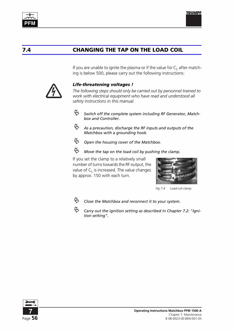
7.4 CHANGING THE TAP ON THE LOAD COIL
If you are unable to ignite the plasma or if the value for CL after match-ing is below 500, please carry out the following instructions:
Life-threatening voltages !The following steps should only be carried out by personnel trained to work with electrical equipment who have read and understood all safety instructions in this manual.
! Switch off the complete system including RF Generator, Match-box and Controller.
! As a precaution, discharge the RF inputs and outputs of the Matchbox with a grounding hook.
! Open the housing cover of the Matchbox.
! Move the tap on the load coil by pushing the clamp.
If you set the clamp to a relatively small number of turns towards the RF output, the value of CL is increased. The value changes by approx. 150 with each turn.
! Close the Matchbox and reconnect it to your system.
! Carry out the ignition setting as described in Chapter 7.2: "Igni-tion setting".
Fig.7.4 Load-coil clamp

Page 57Operating Instructions Matchbox PFM 1500 AChapter 7: MaintenanceB 08-0023-00.BEN-001-05
7.5 MEASUREMENT VALUE ADJUSTMENT
Adjusting magnitude and phase
If the reflected power PR in automatic oper-ation should move outside of the accept-able limit values and you are unable to bring about an improvement with the pre-vious settings (Chapter 7.2 through Chap-ter 7.4), a screwdriver can be used on the adjustment potentiometer to carry out a measured-value adjustment for magnitude (Z) and phase (j). Z and j are displayed on the Controller.
! Contact HÜTTINGER before carrying out the adjustment.
Fig.7.5 Access openings for trimming potentiometer

Operating Instructions Matchbox PFM 1500 AChapter 7: Maintenance
B 08-0023-00.BEN-001-05Page 58

Page 59Operating Instructions Matchbox PFM 1500 AChapter 8: InterfacesB 08-0023-00.BEN-001-05
8 INTERFACES
Chapter Outline:
Who is this chapter directed at?
This chapter is intended for all persons who operate PFM 1500 A Matchboxes on the basis of this operating manual.
Chapter contents This chapter contains detail information about the interfaces of the PFM 1500 A Matchboxes.
8.1 DESCRIPTION OF THE INTERFACES
The PFM 1500 A Matchbox has the following interface connections:
- 25-pin Sub-D device socket (X3)
- Fiber optic cable connectors
- 9-pin Sub-D connector in devices with grounding switch
A/D interface X3PIN NO. ASSIGNMENT
1 + 24 V DC
2 COM IN
3 AUTO IN
4 reset/freeze
5 not used
6 CT set value
7 CL set value
8 PR option
9 PI option
10 CT actual value
11 CL actual value
12 RF peak voltage option
13 DC bias voltage option
Tab.8.1 Pin assignments A/D interface X3

Operating Instructions Matchbox PFM 1500 AChapter 8: Interfaces
B 08-0023-00.BEN-001-05Page 60
8.2 SIGNAL DESCRIPTION OF X3
ANALOG SIGNALS
Outputs
DC bias voltage (13) The actual value of the process voltage. (0 … 10 V ⇒ 0 … 2040 V), in-stalled in Matchboxes for capacitive loads
CL actual value 0 … 10 V (+) (11) and CT actual value 0 … 10 V (+) (10)
Actual position of the load and tuning capacitors:
• 0 V equals minimum capacitance
• 10 V equals maximum capacitance
RF peak voltage Actual value of the load voltage (peak value) 0 … 10 V ⇒ 0 … 2040 V, installed in Matchboxes for inductive loads
14 ground
15 AUTO OUT
16 fault
17 not used
18 not used
19 ground
20 ground
21 ground
22 ground
23 ground
24 ground
25 ground
PIN NO. ASSIGNMENT
Tab.8.1 Pin assignments A/D interface X3

Page 61Operating Instructions Matchbox PFM 1500 AChapter 8: InterfacesB 08-0023-00.BEN-001-05
Inputs
CL set value 0 … 10 V (+) (7) and CT set value 0 … 10 V (+) (6)
Set value position of the load and tuning capacitors:
• The application of 0 … 10 V DC causes the capacitor to tune through its entire range.
• Adjustment of the capacitor positions through this interface is only possible in the "Manual" operation mode (PFC Controller).
DIGITAL SIGNALS
Outputs
Error (16) Error status of the Matchbox:
• HIGH = error
• LOW = no error
AUTO OUT (15) Acknowledgment of automatic operation:
• HIGH = automatic operation
• LOW = manual operation
Inputs
RESET (4) / FREEZE (4) Reset the Matchbox:
• HIGH = clearing of an error message
• Selection of the "External" operation mode when operating with-out fiber optic cable
• Blocks the CL / CT capacitors at their current positions as long as the HIGH signal is active; overrides all other inputs
AUTO IN (3) Switches the Matchbox between automatic and manual operation:
• HIGH switches the Matchbox to automatic operation
• LOW = switches the Matchbox to manual operation
COM IN (2) Digital common:
• Connect either to an external common or internal common at pin 14.
+ 24 V (1) and ground (14;19 - 25)
Reference voltage for the digital output signals:
• Bridging W1 on the PCB supplies the interface with the internal +24 V DC.
• If W1 is not used, +24 V DC must be supplied externally at pin 1.

Operating Instructions Matchbox PFM 1500 AChapter 8: Interfaces
B 08-0023-00.BEN-001-05Page 62
8.3 OPTICAL DATA INTERFACES
The optical data interfaces U1 and U2 are used to connect up to ten PFM 1500 A Matchboxes to one PFC Controller. The fiber optic system provides a complete data and control network. All parameter actual values for each Matchbox can be accessed. All control functions, such as setting the capacitor positions and switching between operation modes, can all be carried out from a single PFC Controller.
The Controller transmits control commands via the output U1 and re-ceives data via the input U2. The fiber optic cable has to be connected from the Controller output U1 to the input U2 of the first Matchbox. Output U1 of the first Matchbox is connected either back to input U2 of the Controller or with input U2 of the next Matchbox (max. 10). The last Matchbox must be connected back to the Controller (U2 of the Controller).
Instead of the PFC Controller, a PFG RF series Generator can also be used to control one or more Matchboxes.
Fiber optic transmitters and receivers are designed for certain length ranges of the fiber optic cables. The length ranges of the transmitters, receivers and fiber optic cables used have to match (refer to Chapter 4: "Versions, accessories"").
8.4 GROUNDING SWITCH INTERFACE
A 9-pin Sub-D connector is mounted on the device.
PIN NO. ASSIGNMENT
2 0V (device isolated)
3 +24 V / 0.1 A (control of the grounding switch; internally connected with 1000µF back-up capacitor)
Tab.8.2 Pin assignment of the grounding switch interface