Embed Size (px)
Citation preview
Operating Instructions and Maintenance Specifications for the DCA WEIGHTMASTER
Trailer Axle Systems
Dai
mle
rChr
ysle
r AG
, Kas
sel A
.02.
03.1
105.
EN P
rinte
d in
Ger
man
y
DaimlerChrysler AGTrailer Axle SystemsHPC 990AMercedesplatz 134127 Kassel, GermanyTel. +49 (0)561 802-2078Fax +49 (0)561 802-2164E-mail [email protected]
Region BeneluxDaimlerChrysler AGTrailer Axle SystemsMasterode 25709HX, Helmond, The NetherlandsTel. +31 (0) 6-20 100 354E-mail [email protected]
Region Eastern EuropeDaimlerChrysler AGTrailer Axle Systems
02-793 Warszawa, PolandTel. +48 (0) 228 59 12-60Fax +48 (0) 228 59 12-59E-mail [email protected]
Sales Office Northern EuropeDaimlerChrysler AGTrailer Axle Systems4, Chantry Court, Sovereign WayCH1 4QN Chester, EnglandTel. +44 (0)1244 394-220Fax +44 (0)1244 394-224E-mail [email protected]
Sales Office Southern EuropeDiscos Southern Europe SASUne société du Groupe DaimlerChrysler Immeuble Le Rio11 Font de la Banquière34970 Lattes, FranceTel. +33 (0)499 1337-37Fax +33 (0)499 1337-30E-mail [email protected]
DaimlerChrysler AGTrailer Axle SystemsVia Sommacampagna 61Cassetta Postale 1537137 Verona, ItalyTel. +39 045 8623-077Fax +39 045 8646-325E-mail [email protected]
DaimlerChrysler AGTrailer Axle SystemsApartado de correos: 11428500 Madrid, SpainTel. +34 (0)918 732-719Fax +34 (0)918 732-941E-mail [email protected]
www.traileraxlesystems.daimlerchrysler.com
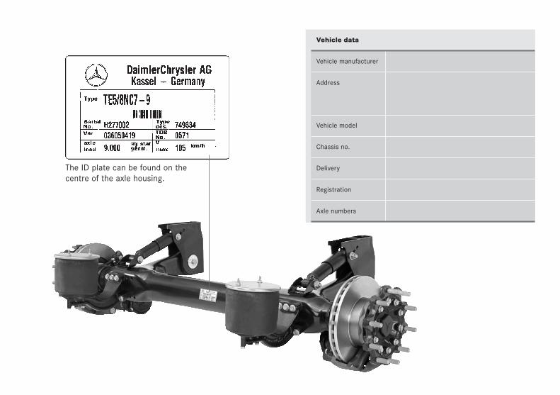
Vehicle data
Vehicle manufacturer
Address
Vehicle model
Chassis no.
Delivery
Registration
Axle numbers
The ID plate can be found on thecentre of the axle housing.
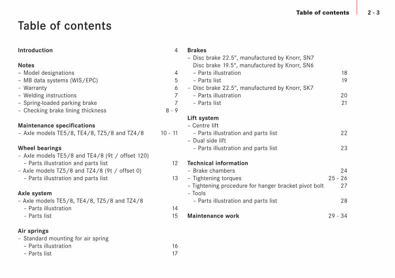
2 - 3Table of contents
Introduction 4
Notes– Model designations 4– MB data systems (WIS/EPC) 5– Warranty 6– Welding instructions 7– Spring-loaded parking brake 7– Checking brake lining thickness 8 - 9
Maintenance specifications– Axle models TE5/8, TE4/8, TZ5/8 and TZ4/8 10 - 11
Wheel bearings– Axle models TE5/8 and TE4/8 (9t / offset 120)
– Parts illustration and parts list 12– Axle models TZ5/8 and TZ4/8 (9t / offset 0)
– Parts illustration and parts list 13
Axle system– Axle models TE5/8, TE4/8, TZ5/8 and TZ4/8
– Parts illustration 14– Parts list 15
Air springs– Standard mounting for air spring
– Parts illustration 16– Parts list 17
Brakes– Disc brake 22.5", manufactured by Knorr, SN7
Disc brake 19.5", manufactured by Knorr, SN6– Parts illustration 18– Parts list 19
– Disc brake 22.5", manufactured by Knorr, SK7– Parts illustration 20– Parts list 21
Lift system– Centre lift
– Parts illustration and parts list 22– Dual side lift
– Parts illustration and parts list 23
Technical information– Brake chambers 24– Tightening torques 25 - 26– Tightening procedure for hanger bracket pivot bolt 27– Tools
– Parts illustration and parts list 28
Maintenance work 29 - 34
Table of contents
This maintenance booklet is intended to serve as a guidelinefor performing maintenance work on your axle.
Always perform the work specified by us when it is due tomaintain operating reliability.
Our axles are subject to continuous development. Pleaseappreciate that the maintenance scopes may change due totechnical modifications.Any maintenance work due and inspections prescribed at cer-tain intervals by law (in Germany, for example, Section 29 ofthe StVZO Road Transport Licensing Regulations) can be per-formed individually or together, depending on what is betterfor the individual company.
In order to offer the most favourable scope of work, it is pos-sible to select between:– Complete maintenance– Maintenance excluding those items which are covered bythe intermediate and main inspections.
The "daily vehicle check" before starting a journey is one ofthe driver’s obligations and is described in the vehicleOperating Instructions.
Introduction
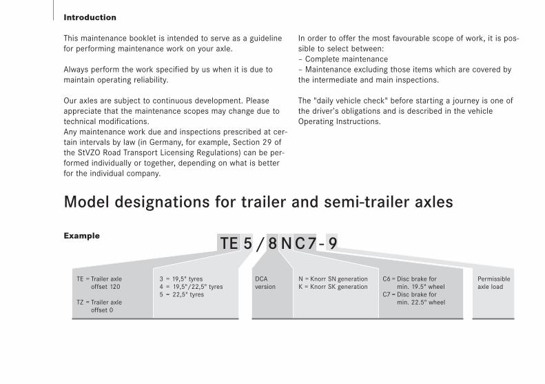
Model designations for trailer and semi-trailer axles
Example
TE = Trailer axleoffset 120
TZ = Trailer axleoffset 0
TE 5 / 8 N C 7 - 9
3 = 19,5" tyres4 = 19,5"/22,5" tyres5 = 22,5" tyres
DCAversion
C6 = Disc brake formin. 19.5" wheel
C7 = Disc brake formin. 22.5" wheel
N = Knorr SN generationK = Knorr SK generation
Permissibleaxle load
4 - 5
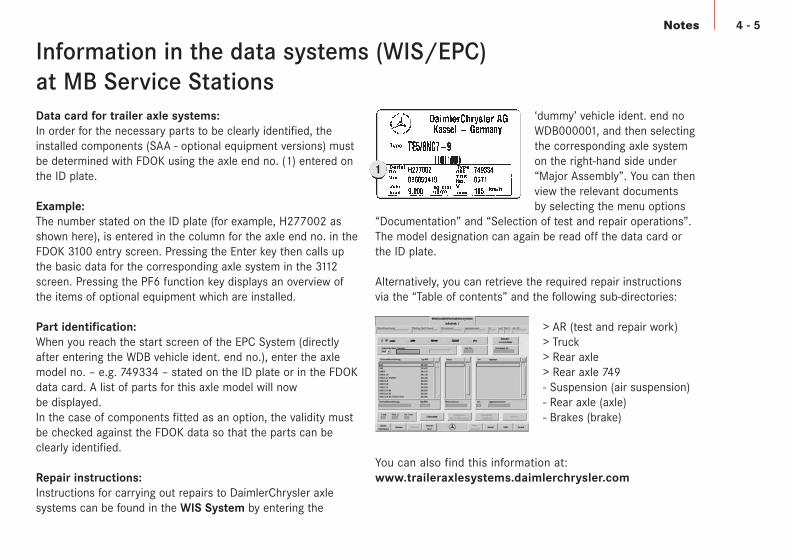
Information in the data systems (WIS/EPC)at MB Service StationsData card for trailer axle systems:In order for the necessary parts to be clearly identified, theinstalled components (SAA - optional equipment versions) mustbe determined with FDOK using the axle end no. (1) entered onthe ID plate.
Example: The number stated on the ID plate (for example, H277002 asshown here), is entered in the column for the axle end no. in theFDOK 3100 entry screen. Pressing the Enter key then calls upthe basic data for the corresponding axle system in the 3112screen. Pressing the PF6 function key displays an overview ofthe items of optional equipment which are installed.
Part identification:When you reach the start screen of the EPC System (directlyafter entering the WDB vehicle ident. end no.), enter the axlemodel no. – e.g. 749334 – stated on the ID plate or in the FDOKdata card. A list of parts for this axle model will nowbe displayed. In the case of components fitted as an option, the validity mustbe checked against the FDOK data so that the parts can beclearly identified.
Repair instructions:Instructions for carrying out repairs to DaimlerChrysler axle systems can be found in the WIS System by entering the
‘dummy’ vehicle ident. end noWDB000001, and then selectingthe corresponding axle systemon the right-hand side under“Major Assembly”. You can thenview the relevant documents by selecting the menu options
“Documentation” and “Selection of test and repair operations”.The model designation can again be read off the data card orthe ID plate.
Alternatively, you can retrieve the required repair instructionsvia the “Table of contents” and the following sub-directories:
> AR (test and repair work)> Truck> Rear axle> Rear axle 749- Suspension (air suspension)- Rear axle (axle)- Brakes (brake)
You can also find this information at:www.traileraxlesystems.daimlerchrysler.com
Notes
1
Warranty
An extensive network of Mercedes-Benz Service Stations isavailable to perform the maintenance work for you. Thanks totheir equipment, tools, specially trained personnel, experi-ence and regular technical training by the plant, all of theseworkshops ensure that your axle will be checked and servicedproperly, thoroughly and in line with the latest practices.Warranty claims for DaimlerChrysler products can be filedwith any authorised Mercedes-Benz Service Station.
If you have any questions concerning the warranty, pleasecontact the service department at:
D, B, NL, A, CH– Tel. +49 (0)561 802-2078– Fax +49 (0)561 802-2164
UK– Tel. +44 (0)1244 394-220– Fax +44 (0)1244 394-224
F, E, P, I– Tel. +33 (0)499 1337-37– Fax +33 (0)499 1337-30
Please follow the instructions in this maintenance bookletand ensure that they are also observed when a third party isresponsible for use and care of the vehicle. Only in this man-ner can you ensure that your warranty remains valid. If main-tenance services during the warranty period are not per-formed regularly or when they are due, or are not performedby an authorised workshop, a decision can only be maderegarding warranty claims once an analysis report from themanufacturer is available.
Special lubricant additives are not required. The use of spe-cial additives and non-approved spare parts may limit thescope of the warranty.
No legal rights can be derived from the contents of theseOperating Instructions.
Notes
6 - 7Notes
Welding instructions
Brake system
Axle parts and parts of the wheel brakes are safety parts.For this reason, the following work is in principle not permis-sible:– Welding– Build-up welding– Heating and straightening– Hard chrome plating– Other similar work.
Such work can result in tension cracks which cannot bedetected externally, but which can lead to fractures and acci-dent damage. Any welding work required is subject toapproval and must be agreed with DaimlerChrysler AG first.
Release of the spring-loaded parking brake withinsufficient supply pressure in the brake system
In emergencies or in the workshop, the spring-loaded parkingbrake can be released mechanically or pneumatically.
Caution! Risk of accident.
– Before releasing the spring-loaded parking brake:Ensure that the vehicle cannot roll away.
– Before starting up vehicle:Ensure that spring-loaded parking brake is in a proper operational state.Apply parking brake.
Mechanical release– Screw release screws out to stop (released position).
Caution! Release torque max. 70 Nm(do not use an impact screwdriver)
To return spring-loaded parking brake to an operational state:– Fill the brake system up to switch-off pressure– Move the lever on the parking brake valve to the released
position– Completely screw in and tighten release screws (braked
position)Tightening torque 40-50 Nm
Notes
Checking brake lining thickness
H
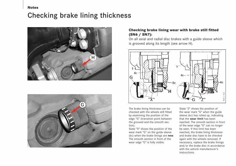
The brake lining thickness can bechecked with the wheels still fittedby examining the position of theedge “G” (transition point betweenthe grooved and the smooth sec-tion).State "X" shows the position of thewear mark "G" on the guide sleeve(6c) when the brake linings are new.The smooth section in front of thewear edge "G" is fully visible.
State "Z" shows the position of the wear mark "G" when the guidesleeve (6c) has rolled up, indicatingthat the wear limit has beenreached. The smooth section in frontof the wear edge "G" can no longerbe seen. If this limit has beenreached, the brake lining thicknessand brake disc have to be checkedagain with the wheels removed. Ifnecessary, replace the brake liningsand/or the brake disc in accordancewith the vehicle manufacturer’sinstructions.
Checking brake lining wear with brake still fitted(SN6 / SN7):On all axial and radial disc brakes with a guide sleeve whichis grooved along its length (see arrow H).
G
8 - 9Notes
R
P
C D
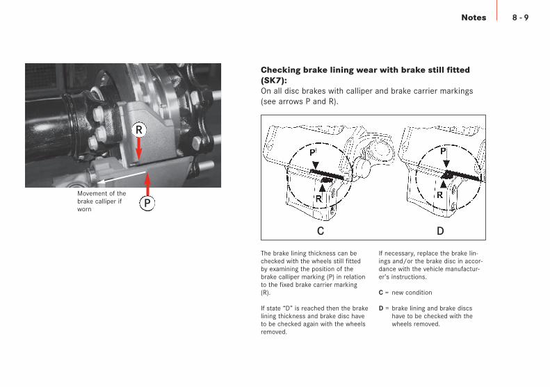
The brake lining thickness can bechecked with the wheels still fittedby examining the position of thebrake calliper marking (P) in relationto the fixed brake carrier marking(R).
If state “D” is reached then the brakelining thickness and brake disc haveto be checked again with the wheelsremoved.
Movement of thebrake calliper ifworn
If necessary, replace the brake lin-ings and/or the brake disc in accor-dance with the vehicle manufactur-er’s instructions.
C = new condition
D = brake lining and brake discs have to be checked with the wheels removed.
Checking brake lining wear with brake still fitted(SK7):On all disc brakes with calliper and brake carrier markings(see arrows P and R).
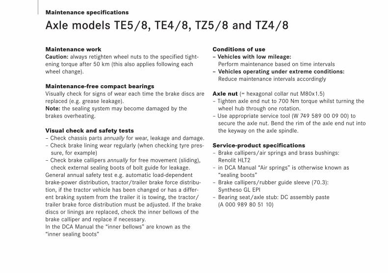
Axle models TE5/8, TE4/8, TZ5/8 and TZ4/8
Maintenance workCaution: always retighten wheel nuts to the specified tight-ening torque after 50 km (this also applies following eachwheel change).
Maintenance-free compact bearingsVisually check for signs of wear each time the brake discs arereplaced (e.g. grease leakage).Note: the sealing system may become damaged by thebrakes overheating.
Visual check and safety tests– Check chassis parts annually for wear, leakage and damage.– Check brake lining wear regularly (when checking tyre pres-
sure, for example)– Check brake callipers annually for free movement (sliding),
check external sealing boots of bolt guide for leakage.General annual safety test e.g. automatic load-dependentbrake-power distribution, tractor/trailer brake force distribu-tion, if the tractor vehicle has been changed or has a differ-ent braking system from the trailer it is towing, the tractor/trailer brake force distribution must be adjusted. If the brakediscs or linings are replaced, check the inner bellows of thebrake calliper and replace if necessary.In the DCA Manual the “inner bellows” are known as the“inner sealing boots”
Conditions of use– Vehicles with low mileage:
Perform maintenance based on time intervals– Vehicles operating under extreme conditions:
Reduce maintenance intervals accordingly
Axle nut (= hexagonal collar nut M80x1.5)– Tighten axle end nut to 700 Nm torque whilst turning the
wheel hub through one rotation.– Use appropriate service tool (W 749 589 00 09 00) to
secure the axle nut. Bend the rim of the axle end nut into the keyway on the axle spindle.
Service-product specifications– Brake callipers/air springs and brass bushings:
Renolit HLT2– in DCA Manual “Air springs” is otherwise known as
“sealing boots”– Brake callipers/rubber guide sleeve (70.3):
Syntheso GL EPI– Bearing seat/axle stub: DC assembly paste
(A 000 989 80 51 10)
Maintenance specifications
10 - 11Maintenance specifications
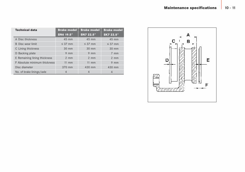
Technical data
A Disc thickness
B Disc wear limit
C Lining thickness
D Backing plate
E Remaining lining thickness
F Absolute minimum thickness
Disc diameter
No. of brake linings/axle
Brake model
SN7 22.5"
45 mm
≤ 37 mm
30 mm
9 mm
2 mm
11 mm
430 mm
4
Brake model
SK7 22.5"
45 mm
≤ 37 mm
30 mm
7 mm
2 mm
9 mm
430 mm
4
Brake model
SN6 19.5"
45 mm
≤ 37 mm
30 mm
9 mm
2 mm
11 mm
370 mm
4
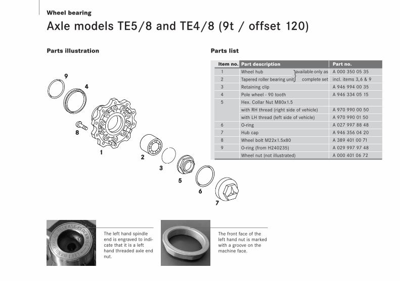
Axle models TE5/8 and TE4/8 (9t / offset 120)
Parts illustration
Item no.
1
2
3
4
5
6
7
8
9
Part no.
A 000 350 05 35
incl. items 3,6 & 9
A 946 994 00 35
A 946 334 05 15
A 970 990 00 50
A 970 990 01 50
A 027 997 88 48
A 946 356 04 20
A 389 401 00 71
A 029 997 97 48
A 000 401 06 72
Parts list
available only as
complete set
Part description
Wheel hub
Tapered roller bearing unit
Retaining clip
Pole wheel - 90 tooth
Hex. Collar Nut M80x1.5
with RH thread (right side of vehicle)
with LH thread (left side of vehicle)
O-ring
Hub cap
Wheel bolt M22x1.5x80
O-ring (from H240235)
Wheel nut (not illustrated)
Wheel bearing
The front face of theleft hand nut is markedwith a groove on themachine face.
The left hand spindleend is engraved to indi-cate that it is a lefthand threaded axle endnut.
12 - 13Wheel bearing
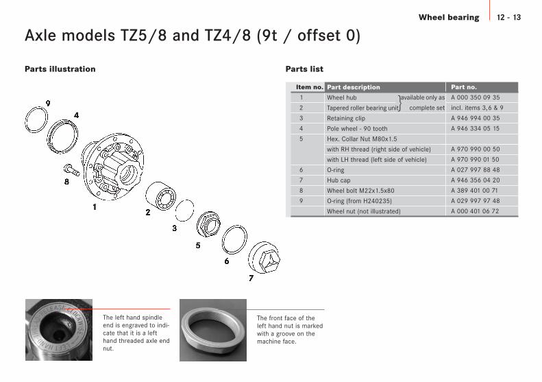
Axle models TZ5/8 and TZ4/8 (9t / offset 0)
Parts illustration Parts list
Item no.
1
2
3
4
5
6
7
8
9
Part no.
A 000 350 09 35
incl. items 3,6 & 9
A 946 994 00 35
A 946 334 05 15
A 970 990 00 50
A 970 990 01 50
A 027 997 88 48
A 946 356 04 20
A 389 401 00 71
A 029 997 97 48
A 000 401 06 72
available only as
complete set
Part description
Wheel hub
Tapered roller bearing unit
Retaining clip
Pole wheel - 90 tooth
Hex. Collar Nut M80x1.5
with RH thread (right side of vehicle)
with LH thread (left side of vehicle)
O-ring
Hub cap
Wheel bolt M22x1.5x80
O-ring (from H240235)
Wheel nut (not illustrated)
The front face of theleft hand nut is markedwith a groove on themachine face.
The left hand spindleend is engraved to indi-cate that it is a lefthand threaded axle endnut.
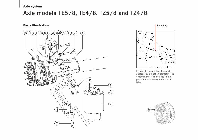
Axle system
Axle models TE5/8, TE4/8, TZ5/8 and TZ4/8
Parts illustration
10 11 5 5 1 12 4 11 9 63
13
7
2
14
8
15
16
In order to ensure that the shockabsorber can function correctly, it isessential that it is installed in theposition indicated by the attachedlabel.
Labelling
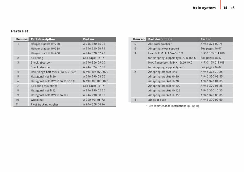
Axle system 14 - 15
Item no.
1
2
3
4
5
6
7
8
9
10
11
Part no.
A 946 320 65 78
A 946 320 66 78
A 946 320 67 78
See pages 16-17
A 946 326 05 00
A 946 326 07 00
N 910 105 020 020
A 946 990 08 50
N 910 105 020 027
See pages 16-17
A 946 990 02 50
A 946 990 00 00
A 000 401 06 72
A 946 328 04 76
Parts list
Part description
Hanger bracket H=250
Hanger bracket H=325
Hanger bracket H=400
Air spring
Shock absorber
Shock absorber
Hex. flange bolt M20x1,5x130-10.9
Hexagonal nut M20
Hexagonal bolt M20x1.5x100-10.9
Air spring mountings
Hexagonal nut M12
Hexagonal bolt M22x1.5x195
Wheel nut
Pivot tracking washer
Item no.
12
13
14
15
16
Part no.
A 946 328 00 76
See pages 16-17
N 910 105 014 010
See pages 16-17
N 910 105 014 019
See pages 16-17
A 946 328 70 35
A 946 320 03 35
A 946 320 04 35
A 946 320 06 35
A 946 320 10 35
A 946 320 08 35
A 946 390 02 50
Part description
Anti-wear washer*
Air spring lower support
Hex. bolt M14x1.5x45-10.9
for air spring support type A, B and C
Hex. flange bolt M14x1.5x60-10.9
for air spring support type D
Air spring bracket H=5
Air spring bracket H=50
Air spring bracket H=70
Air spring bracket H=100
Air spring bracket H=125
Air spring bracket H=155
3D pivot bush
* See maintenance instructions (p. 10-11)
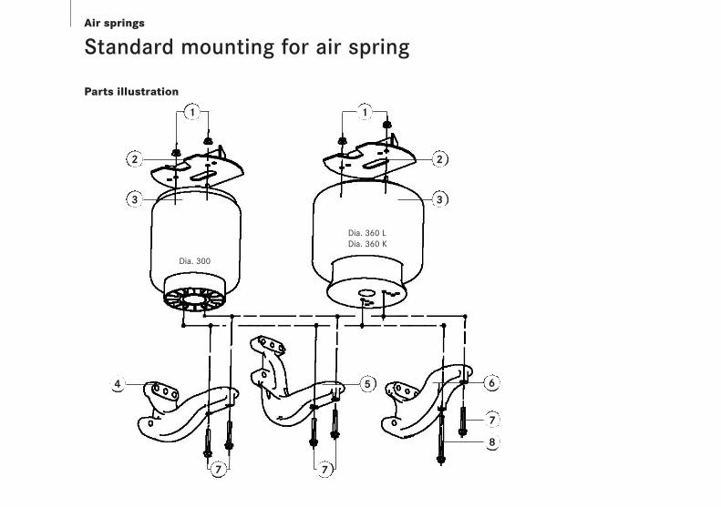
Air springs
Standard mounting for air spring
2
3
6
8
54
Dia. 300
Dia. 360 LDia. 360 K
7
2
3
Parts illustration
7 7
11
16 - 17Air springs
Item no.
1
2
3
4
5
6
7
8
Parts list
Part description Part no.
Hexagonal nut M12 A 946 990 02 50
Air spring pedestal See page 15
Air spring, dia. 300 A 946 328 14 01
Air spring, dia. 360 L A 946 328 15 01
Air spring, dia. 360 K A 946 328 19 01
Air spring support, type A, medium L2=385 A 946 328 12 41
Air spring support, type B, low L2=385 A 946 328 11 41
Air spring support, type D, mega L2=385 A 946 328 14 41
Air spring support, type C, high L2=340 A 946 328 13 41
Hex. bolt M12x80-10.9 N 910 105 012 022
Hex. bolt M12x150-10.9 N 000 000 003 493
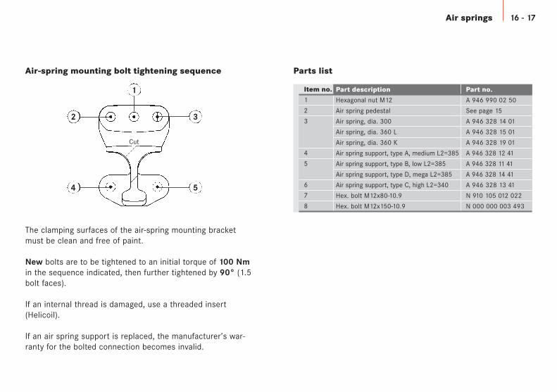
Cut
2 3
54
1
Air-spring mounting bolt tightening sequence
The clamping surfaces of the air-spring mounting bracketmust be clean and free of paint.
New bolts are to be tightened to an initial torque of 100 Nmin the sequence indicated, then further tightened by 90° (1.5bolt faces).
If an internal thread is damaged, use a threaded insert(Helicoil).
If an air spring support is replaced, the manufacturer’s war-ranty for the bolted connection becomes invalid.
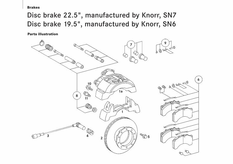
Disc brake 22.5", manufactured by Knorr, SN7Disc brake 19.5", manufactured by Knorr, SN6Parts illustration
Brakes
6
97
811
10
1a
1
2 543
18 - 19Brakes
Item no.
1
1a
2
3
4
5
6
7
8
9
10
11
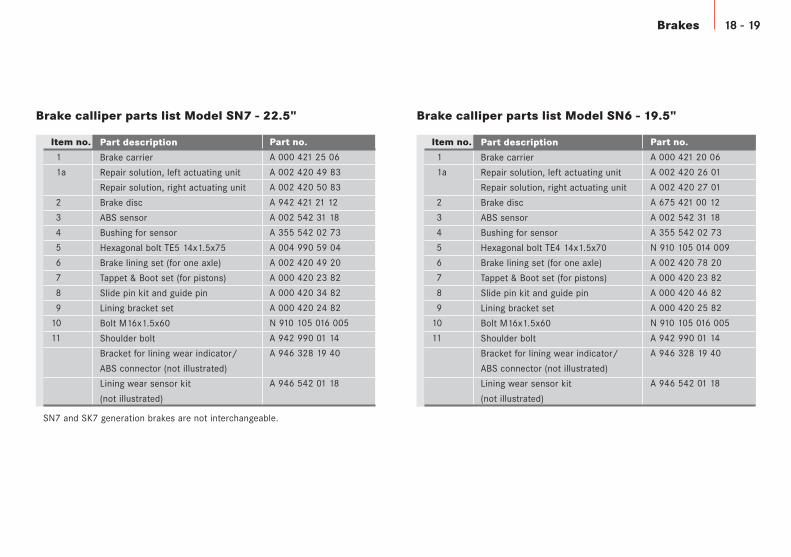
Brake calliper parts list Model SN7 - 22.5" Brake calliper parts list Model SN6 - 19.5"
Item no.
1
1a
2
3
4
5
6
7
8
9
10
11
Part no.
A 000 421 20 06
A 002 420 26 01
A 002 420 27 01
A 675 421 00 12
A 002 542 31 18
A 355 542 02 73
N 910 105 014 009
A 002 420 78 20
A 000 420 23 82
A 000 420 46 82
A 000 420 25 82
N 910 105 016 005
A 942 990 01 14
A 946 328 19 40
A 946 542 01 18
Part description
Brake carrier
Repair solution, left actuating unit
Repair solution, right actuating unit
Brake disc
ABS sensor
Bushing for sensor
Hexagonal bolt TE4 14x1.5x70
Brake lining set (for one axle)
Tappet & Boot set (for pistons)
Slide pin kit and guide pin
Lining bracket set
Bolt M16x1.5x60
Shoulder bolt
Bracket for lining wear indicator/
ABS connector (not illustrated)
Lining wear sensor kit
(not illustrated)
Part description
Brake carrier
Repair solution, left actuating unit
Repair solution, right actuating unit
Brake disc
ABS sensor
Bushing for sensor
Hexagonal bolt TE5 14x1.5x75
Brake lining set (for one axle)
Tappet & Boot set (for pistons)
Slide pin kit and guide pin
Lining bracket set
Bolt M16x1.5x60
Shoulder bolt
Bracket for lining wear indicator/
ABS connector (not illustrated)
Lining wear sensor kit
(not illustrated)
Part no.
A 000 421 25 06
A 002 420 49 83
A 002 420 50 83
A 942 421 21 12
A 002 542 31 18
A 355 542 02 73
A 004 990 59 04
A 002 420 49 20
A 000 420 23 82
A 000 420 34 82
A 000 420 24 82
N 910 105 016 005
A 942 990 01 14
A 946 328 19 40
A 946 542 01 18
SN7 and SK7 generation brakes are not interchangeable.
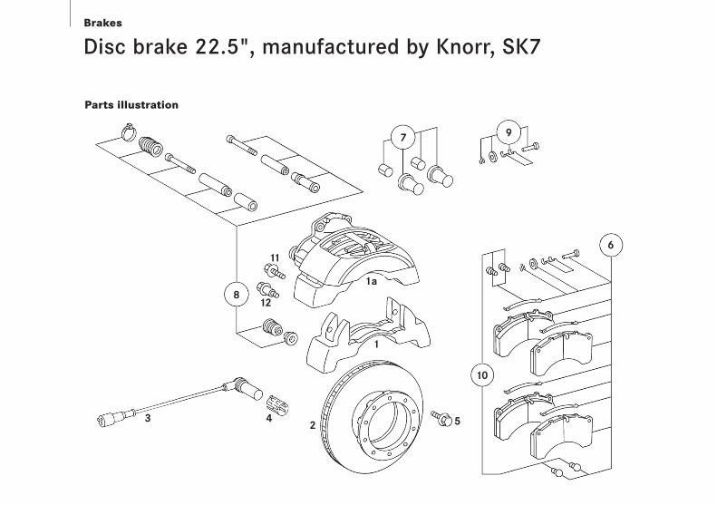
Disc brake 22.5", manufactured by Knorr, SK7
Parts illustration
Brakes
6
10
97
812
11
1a
1
2 543
20 - 21Brakes
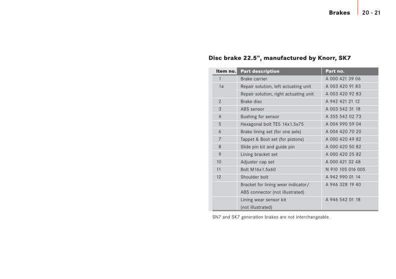
Disc brake 22.5", manufactured by Knorr, SK7
Item no.
1
1a
2
3
4
5
6
7
8
9
10
11
12
Part no.
A 000 421 39 06
A 003 420 91 83
A 003 420 92 83
A 942 421 21 12
A 003 542 31 18
A 355 542 02 73
A 004 990 59 04
A 004 420 70 20
A 000 420 49 82
A 000 420 50 82
A 000 420 25 82
A 000 421 32 48
N 910 105 016 005
A 942 990 01 14
A 946 328 19 40
A 946 542 01 18
Part description
Brake carrier
Repair solution, left actuating unit
Repair solution, right actuating unit
Brake disc
ABS sensor
Bushing for sensor
Hexagonal bolt TE5 14x1.5x75
Brake lining set (for one axle)
Tappet & Boot set (for pistons)
Slide pin kit and guide pin
Lining bracket set
Adjuster cap set
Bolt M16x1.5x60
Shoulder bolt
Bracket for lining wear indicator/
ABS connector (not illustrated)
Lining wear sensor kit
(not illustrated)
SN7 and SK7 generation brakes are not interchangeable.
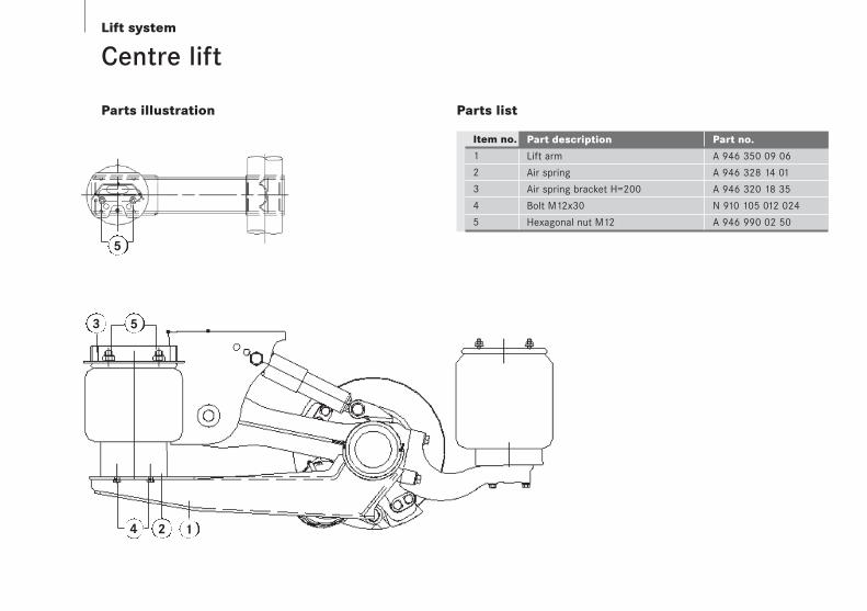
Lift system
Centre lift
Parts illustration
Item no.
1
2
3
4
5
Parts list
Part description Part no.
Lift arm A 946 350 09 06
Air spring A 946 328 14 01
Air spring bracket H=200 A 946 320 18 35
Bolt M12x30 N 910 105 012 024
Hexagonal nut M12 A 946 990 02 50
2 1
3 5
5
4

Lift system 22 - 23
Dual side lift
Parts illustration
Item no.
1
2
3
4
5
6
7
8
9
10
11
12
Parts list
Part description Part no.
Half bracket, left A 946 328 28 40
(air spring fixed mounting)
Half bracket, right A 946 328 29 40
(air spring fixed mounting)
Half bracket, left A 946 328 30 40
(air spring rotating mounting)
Half bracket, right A 946 328 31 40
(air spring rotating mounting)
Lift air spring A 946 328 16 01
Hexagonal bolt M10x20-8.8 A 946 990 08 01
Adapter G1/4" to M14x1.5 A 946 328 02 64
Locating hook plate A 946 328 32 40
Hexagonal bolt M10x25-8.8 A 946 990 04 01
Rubber lift pad A 946 325 00 44
Hexagonal bolt M10x160-8.8 A 946 990 02 01
Hexagonal nut M10 A 946 990 09 50
1 67
3
6
5
11
2
8
10
12
4
6
9
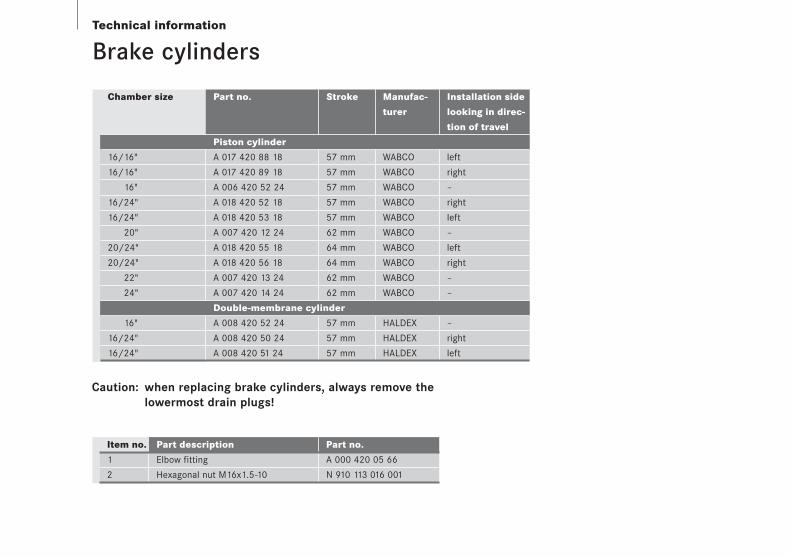
Technical information
Caution: when replacing brake cylinders, always remove the lowermost drain plugs!
Part description Part no.
Elbow fitting A 000 420 05 66
Hexagonal nut M16x1.5-10 N 910 113 016 001
Item no.
1
2
Brake cylinders
Chamber size
16/16"
16/16"
16"
16/24"
16/24"
20"
20/24"
20/24"
22"
24"
16"
16/24"
16/24"
Stroke
57 mm
57 mm
57 mm
57 mm
57 mm
62 mm
64 mm
64 mm
62 mm
62 mm
57 mm
57 mm
57 mm
Manufac-
turer
WABCO
WABCO
WABCO
WABCO
WABCO
WABCO
WABCO
WABCO
WABCO
WABCO
HALDEX
HALDEX
HALDEX
Installation side
looking in direc-
tion of travel
left
right
–
right
left
–
left
right
–
–
–
right
left
Part no.
Piston cylinder
A 017 420 88 18
A 017 420 89 18
A 006 420 52 24
A 018 420 52 18
A 018 420 53 18
A 007 420 12 24
A 018 420 55 18
A 018 420 56 18
A 007 420 13 24
A 007 420 14 24
Double-membrane cylinder
A 008 420 52 24
A 008 420 50 24
A 008 420 51 24
24 - 25Technical information
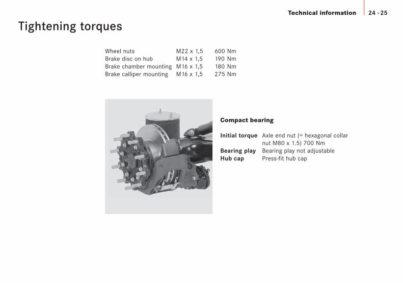
Tightening torques
Compact bearing
Initial torque Axle end nut (= hexagonal collar nut M80 x 1.5) 700 Nm
Bearing play Bearing play not adjustableHub cap Press-fit hub cap
Wheel nuts M22 x 1,5 600 NmBrake disc on hub M14 x 1,5 190 NmBrake chamber mounting M16 x 1,5 180 NmBrake calliper mounting M16 x 1,5 275 Nm
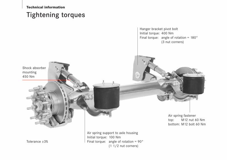
Technical information
Tightening torques
Air spring fastener top: M12 nut 60 Nmbottom: M12 bolt 60 Nm
Hanger bracket pivot boltInitial torque: 400 NmFinal torque: angle of rotation = 180°
(3 nut corners)
Air spring support to axle housingInitial torque: 100 NmFinal torque: angle of rotation = 90°
(1 1/2 nut corners)
Shock absorbermounting450 Nm
Tolerance +3%
Technical information 26 - 27
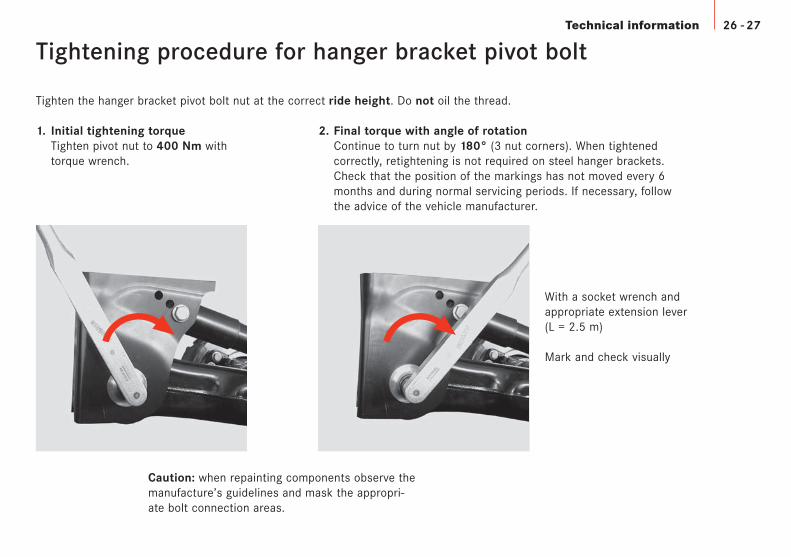
Tightening procedure for hanger bracket pivot bolt
Tighten the hanger bracket pivot bolt nut at the correct ride height. Do not oil the thread.
1. Initial tightening torqueTighten pivot nut to 400 Nm withtorque wrench.
2. Final torque with angle of rotationContinue to turn nut by 180° (3 nut corners). When tightened correctly, retightening is not required on steel hanger brackets. Check that the position of the markings has not moved every 6 months and during normal servicing periods. If necessary, follow the advice of the vehicle manufacturer.
With a socket wrench andappropriate extension lever(L = 2.5 m)
Mark and check visually
Caution: when repainting components observe themanufacture’s guidelines and mask the appropri-ate bolt connection areas.
Technical information
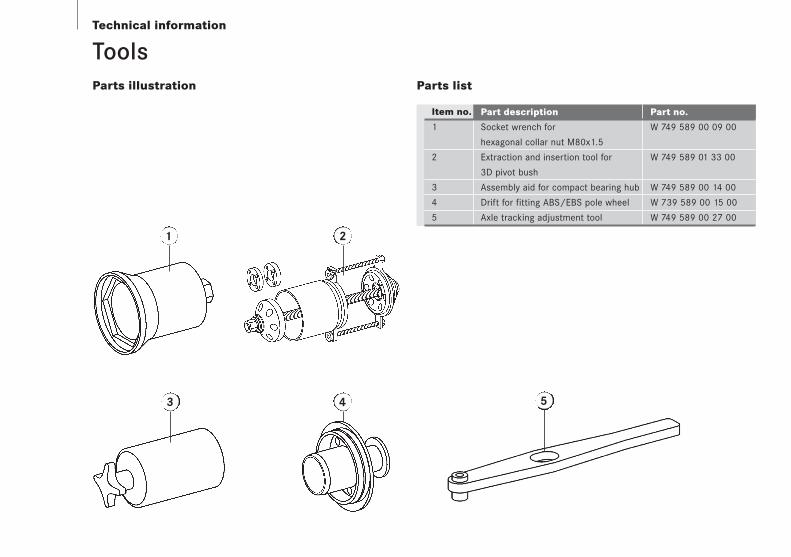
Item no.
1
2
3
4
5
Parts list
Part description Part no.
Socket wrench for W 749 589 00 09 00
hexagonal collar nut M80x1.5
Extraction and insertion tool for W 749 589 01 33 00
3D pivot bush
Assembly aid for compact bearing hub W 749 589 00 14 00
Drift for fitting ABS/EBS pole wheel W 739 589 00 15 00
Axle tracking adjustment tool W 749 589 00 27 00
1 2
3 4 5
Parts illustration
Tools

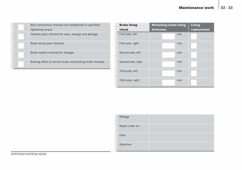
28 - 29Maintenance work
Bolt connections checked and retightened to specified
tightening torque
Chassis parts checked for wear, leakage and damage
Brake lining wear checked
Brake system checked for leakage
Braking effect of service brake and parking brake checked
Mileage
Repair order no.
Date
Signature
Authorised workshop stamp
Brake lining
check
First axle, left
First axle, right
Second axle, left
Second axle, right
Third axle, left
Third axle, right
Remaining brake lining
thickness
mm
mm
mm
mm
mm
mm
Lining
replacement

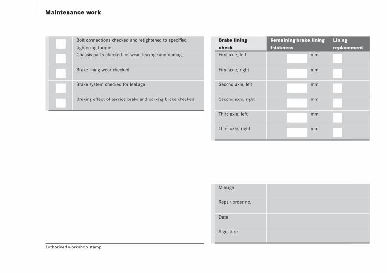
Maintenance work
Bolt connections checked and retightened to specified
tightening torque
Chassis parts checked for wear, leakage and damage
Brake lining wear checked
Brake system checked for leakage
Braking effect of service brake and parking brake checked
Mileage
Repair order no.
Date
Signature
Authorised workshop stamp
Brake lining
check
First axle, left
First axle, right
Second axle, left
Second axle, right
Third axle, left
Third axle, right
Remaining brake lining
thickness
mm
mm
mm
mm
mm
mm
Lining
replacement

30 - 31Maintenance work
Bolt connections checked and retightened to specified
tightening torque
Chassis parts checked for wear, leakage and damage
Brake lining wear checked
Brake system checked for leakage
Braking effect of service brake and parking brake checked
Mileage
Repair order no.
Date
Signature
Authorised workshop stamp
Brake lining
check
First axle, left
First axle, right
Second axle, left
Second axle, right
Third axle, left
Third axle, right
Remaining brake lining
thickness
mm
mm
mm
mm
mm
mm
Lining
replacement

Maintenance work
Bolt connections checked and retightened to specified
tightening torque
Chassis parts checked for wear, leakage and damage
Brake lining wear checked
Brake system checked for leakage
Braking effect of service brake and parking brake checked
Mileage
Repair order no.
Date
Signature
Authorised workshop stamp
Brake lining
check
First axle, left
First axle, right
Second axle, left
Second axle, right
Third axle, left
Third axle, right
Remaining brake lining
thickness
mm
mm
mm
mm
mm
mm
Lining
replacement
Maintenance work 32 - 33
Bolt connections checked and retightened to specified
tightening torque
Chassis parts checked for wear, leakage and damage
Brake lining wear checked
Brake system checked for leakage
Braking effect of service brake and parking brake checked
Mileage
Repair order no.
Date
Signature
Authorised workshop stamp
Brake lining
check
First axle, left
First axle, right
Second axle, left
Second axle, right
Third axle, left
Third axle, right
Remaining brake lining
thickness
mm
mm
mm
mm
mm
mm
Lining
replacement
Maintenance work
Bolt connections checked and retightened to specified
tightening torque
Chassis parts checked for wear, leakage and damage
Brake lining wear checked
Brake system checked for leakage
Braking effect of service brake and parking brake checked
Mileage
Repair order no.
Date
Signature
Authorised workshop stamp
Brake lining
check
First axle, left
First axle, right
Second axle, left
Second axle, right
Third axle, left
Third axle, right
Remaining brake lining
thickness
mm
mm
mm
mm
mm
mm
Lining
replacement
34 - 35
Please note: modifications may have been made to the products since this brochure went to print. The information in this brochure is to be regarded as approxi-mate. The illustrations may contain accessories and items of optional equipment which are not part of standard specification. This brochure may also containmodels and services which are not offered in certain countries. Please consult your DaimlerChrysler dealer for current details.