Embed Size (px)
Citation preview
1
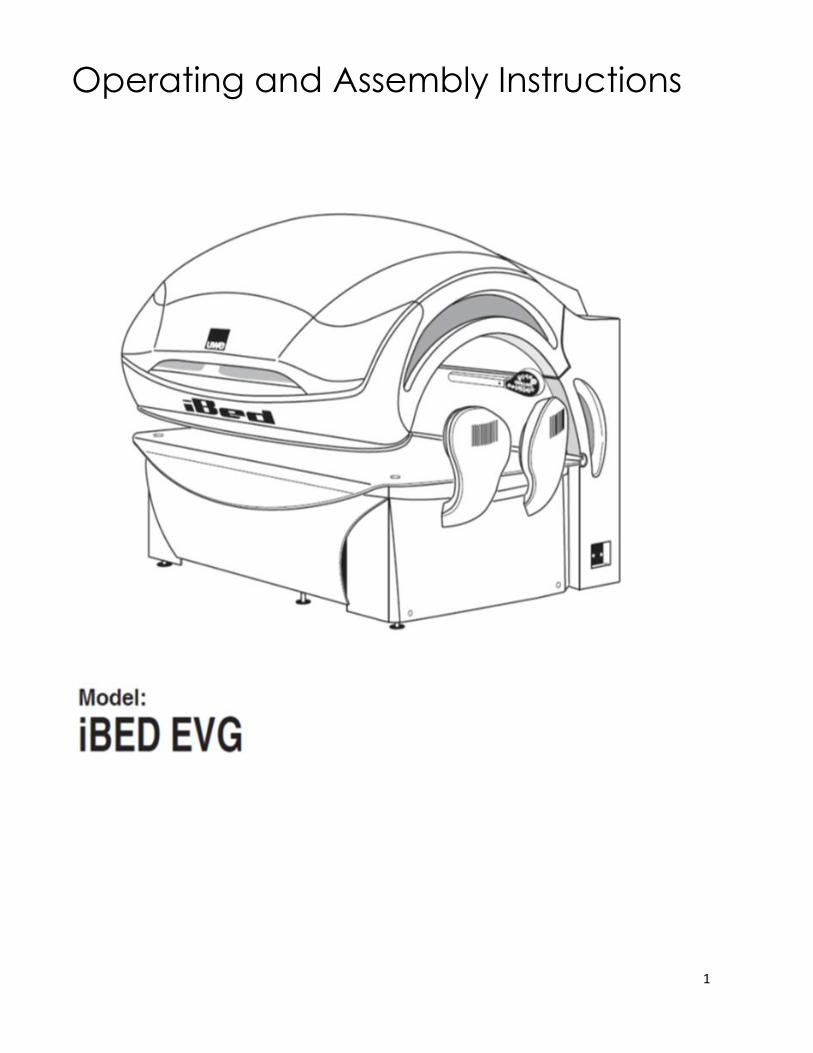
Operating and Assembly Instructions
2
Copyright and Trademark
© Copyright 2015 uwe Light GmbH
This documentation only covers products manufactured by uwe Light GmbH. It must not be
duplicated, photocopied, translated or stored without prior special consent by uwe Light
GmbH. Duplication on electronic media or in a machine-readable form, either in whole or in
part, is also prohibited.
is a registered trademark of uwe Light GmbH
DISCLAIMER
All information given in this document corresponds to the status quo at the date of publication
but may be subject to changes. Therefore, we do not accept any liability for, nor do we
guarantee the accuracy and/or completeness of the information.
EXPORT
Technical equipment and versions of the devices are in accordance with the legal prescriptions
of the respective country of destination. Export to the European Union of the uwe products,
listed in this guide, or operation of the systems in these countries, are not permitted. uwe does
not accept any manufacturers’ liability in case this direction is not adhered to. It is expressly
pointed out that any violation of the export/operation prohibition will involve substantial risks of
liability for the exporter and/or operator.
MANUFACTURER
uwe Light GmbH
Buchstraße 82
73525 Schwäbisch Gmünd
Germany
CONTACT
PC Tan
1040 Wilt Avenue
Ridgefield, NJ 07657 USA
1-800-FAST TAN (327-8826)
Document version date: December, 2015
3
Contents 1. General information
1.1 About these instructions
1.2 Safety signs
1.3 Transport by forklift truck
1.4 Other modes of transport
1.5 Environmental regulations
1.6 Service
1.7 Updating system software
2. Safety notes
2.1 General safety notes
2.2 Duties of the operator
2.3 Intended use
2.4 Indications for use
2.5 Contraindications
2.6 Warnings
2.7 Remote timer controlled operation
2.8 Guidelines for the use of protective eyewear
3. Description of the tanning device
3.1 Standards
3.2 Components
3.3 Functionality
4. Connections
4.1 Class I ME equipment
4.2 Overview - supply connections
4.3 Connecting the mains voltage
4.4 Connecting an external audio source
4.5 Studio music signal
4.6 Operation using different audio sources
4.7 Remote control timer operation
4.8 T-Max Connection (External and internal timer)
4.9 Aroma connections
4.10 Breeze connections
5. Start-up
5.1 Operating modes
6. Tanning instructions
6.1 Instructions for the user
6.2 Exposure schedule
4
7. Tanning mode
7.1 Starting the tanning session in remote control timer mode
7.2 Basic functions
8. Service menu
8.1 Service module
8.2 Operating the service module
8.3 Service module menu
8.4 Pre-set service intervals
8.5 Overview of possible setting
8.6 Service menu diagram
8.7 Set decorative lighting
9. Maintenance and cleaning
9.1 Instructions for cleaning and care
9.2 Maintenance intervals
9.3 Acrylic panes
9.4 Facial tanners
9.5 Sunlamps
9.6 Filter mats
9.7 Breeze
9.8 Aroma
10. Assembly Instructions
10.1 Delivery condition
10.2 Disassembly of the unit
11. System messages
11.1 System messages
11.2 Tips for Troubleshooting
12. Technical data
12.1 Views
12.2 Labels attached to the tanning device (examples)
13. uwe EQUIPMENT WARRANTY
14. WARRANTY CARD
15. EMC Information
5
1. General information
1.1 About these instructions
This operating manual is intended for use by
- Operator and staff > Persons responsible for the operation, disinfecting, cleaning and
maintenance work and instructs the user in the operation of the device.
- User > A person who uses the tanning device at a commercial facility.
- Service provider > Qualified outside service company authorized
by the manufacturer for assembly, maintenance and repair work.
Any person dealing with this uwe Sunlamp Product (hereafter referred to as tanning device)
must have read and understand these instructions.
This manual describes tanning devices equipped with the maximum number of features.
Keep this manual readily available at all times.
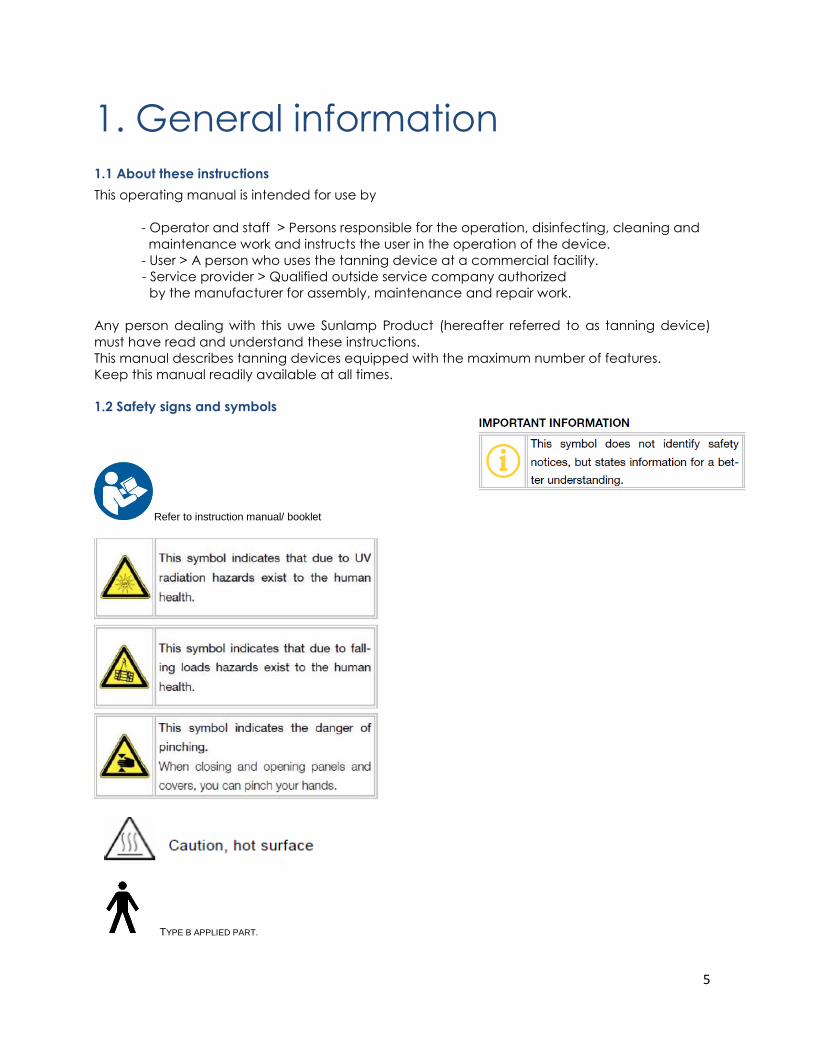
1.2 Safety signs and symbols
Refer to instruction manual/ booklet
TYPE B APPLIED PART.
6
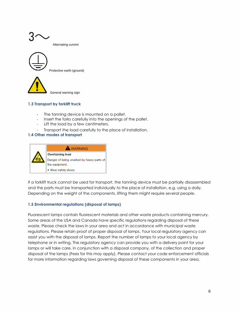
Alternating current
Protective earth (ground)
General warning sign
1.3 Transport by forklift truck
- The tanning device is mounted on a pallet.
- Insert the forks carefully into the openings of the pallet.
- Lift the load by a few centimeters.
- Transport the load carefully to the place of installation.
1.4 Other modes of transport
If a forklift truck cannot be used for transport, the tanning device must be partially disassembled
and the parts must be transported individually to the place of installation, e.g. using a dolly.
Depending on the weight of the components, lifting them might require several people.
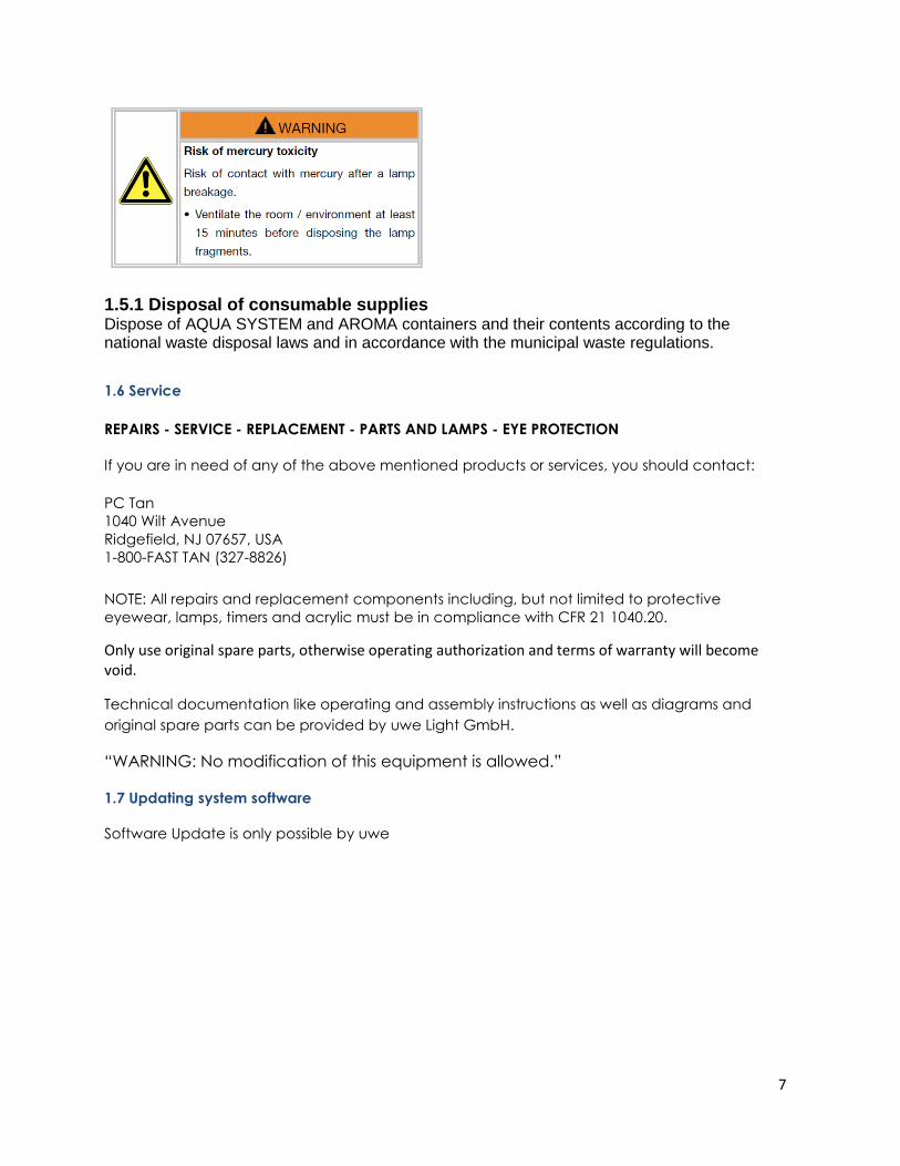
1.5 Environmental regulations (disposal of lamps)
Fluorescent lamps contain fluorescent materials and other waste products containing mercury.
Some areas of the USA and Canada have specific regulations regarding disposal of these
waste. Please check the laws in your area and act in accordance with municipal waste
regulations. Please retain proof of proper disposal of lamps. Your local regulatory agency can
assist you with the disposal of lamps. Report the number of lamps to your local agency by
telephone or in writing. The regulatory agency can provide you with a delivery point for your
lamps or will take care, in conjunction with a disposal company, of the collection and proper
disposal of the lamps (Fees for this may apply). Please contact your code enforcement officials
for more information regarding laws governing disposal of these components in your area.
7
1.5.1 Disposal of consumable supplies Dispose of AQUA SYSTEM and AROMA containers and their contents according to the national waste disposal laws and in accordance with the municipal waste regulations.
1.6 Service
REPAIRS - SERVICE - REPLACEMENT - PARTS AND LAMPS - EYE PROTECTION
If you are in need of any of the above mentioned products or services, you should contact:
PC Tan
1040 Wilt Avenue
Ridgefield, NJ 07657, USA
1-800-FAST TAN (327-8826)
NOTE: All repairs and replacement components including, but not limited to protective
eyewear, lamps, timers and acrylic must be in compliance with CFR 21 1040.20.
Only use original spare parts, otherwise operating authorization and terms of warranty will become void.
Technical documentation like operating and assembly instructions as well as diagrams and
original spare parts can be provided by uwe Light GmbH.
“WARNING: No modification of this equipment is allowed.”
1.7 Updating system software
Software Update is only possible by uwe
8
This product is in conformity with performance standards for sunlamp products under
21 CFR 1040.20
DANGER--Ultraviolet radiation. Follow instructions. Avoid overexposure. As with natural sunlight,
overexposure can cause eye and skin injury and allergic reactions. Repeated exposure may
cause premature aging of the skin and skin cancer. WEAR PROTECTIVE EYEWEAR; FAILURE TO
MAY RESULT IN SEVERE BURNS OR LONG-TERM INJURY TO THE EYES. Medications or cosmetics
may increase your sensitivity to the ultraviolet radiation. Consult physician before using sunlamp
if you are using medications or have a history of skin problems or believe yourself especially
sensitive to sunlight. If you do not tan in the sun, you are unlikely to tan from the use of this
product.
Product meets requirements of UL standard 482, CSA C22.2 No. 224 and EMC standard IEC
60601-1-2: 2007
2. Safety notes
2.1 General safety notes
Read the operating instructions before using the tanning device.
This tanning device must be operated with an external timer as specified in chapter 2.7 Remote
timer controlled operation.
When the device is in use no other people may remain in the room. This includes both children
and adults.
NOTE: This tanning device is intended to be used by only one adult person at a time. Therefore,
only one (1) pair of protective eyewear is provided with each uwe tanning device. Use
protective eyewear whenever the tanning device is operated. Read related operating
instructions in chapter 2.8 Guidelines for the use of protective eyewear.
Do not tan more than once in a 24 hour period. Tanning results normally occur after a few
sessions and increase after four (4) weeks of regular exposure. Follow the exposure schedule in
accordance with your skin type as specified in chapter 6.2 Exposure schedule. Failure to do so
may result in overexposure. However, regardless of how dark an individual may tan on this
tanning device, it will not provide adequate protection against overexposure to natural sunlight
or UVB tanning devices.
9
SKIN TYPE II - This is the individual that usually burns easily and severely, tans minimally or lightly
and peels.
SKIN TYPE III - Often referred to as “AVERAGE” complexion. Burns moderately and tans about
average.
SKIN TYPE IV - This individual burns minimally, tans easily and above average with each
exposure.
SKIN TYPE V - This individual rarely burns, tans easily and substantially.
Follow all instructions given in this manual. In addition to that, observe all applicable statutory
provisions and regulations, also those applicable in the country of operation.
The tanning device may only be installed and assembled by a trained service provider.
Observe all danger signals and safety signs attached to the equipment.
Safety signs must not be removed, and safety appliances must not be disabled.
The tanning device may only be operated when in perfect working condition.
Never operate the tanning device with the outer covering removed or with the acrylic panes
removed.
Pay attention to the load limit of the bed pane (tanning devices only).
The canopy is not designed to carry additional loads. In particular, during installation the
canopy must not be charged with additional loads.
Caution – Use of controls or adjustments or performance of procedures other than those
specified herein may result in hazardous radiation exposure
Equipment not suitable for use in the presence of a flammable anesthetic mixture with air,
oxygen, or nitrous oxide. The solvents of adhesives and flammable solutions used for cleaning
and disinfecting should be allowed to evaporate before the unit is used
2.2 Duties of the operator
- Inform users of the possible risks of tanning.
- Responsible to ensure the tanning device is handled properly
and may only be used when in complete operational condition.
- Ensure no safety component is removed or bypassed to impair the safe operation of
the device.
- Obligated to train your personnel and ensure your staff understands and observes the
operating instructions, including intended use, safety and cleaning/disinfection and
maintenance instructions.
- Please make all instructions available to your staff at their workplace.
10
The manufacturer cannot be held liable for damages or injuries resulting from improper use of
the equipment or non-observance of these operating instructions.
2.3 Intended use
This tanning device is intended for the cosmetic tanning of the human skin.
This tanning device is designed for use by one adult person at a time who is in full command of
her physical, sensorial and mental faculties. Moreover, sufficient knowledge and experience
are required.
Wear protective eyewear to block UV radiation during tanning.
Lie down on the bench in a straight position and with physical contact to the bench. Choose a
suitable position to reach the interior control panel at all times during the tanning.
During the operation no other person shall be in the radiation range of the tanning device.
2.4 Indications for use
Any adult person that is not listed under chapter 2.5 Contraindications may use this tanning
device for the purpose of cosmetic tanning. In doubt consult a physician.
2.5 Contraindications
This sunlamp product is contraindicated for use on persons under the age of 18 years.
UV radiation
Danger of skin and eye injuries or skin diseases!
Please observe the following instructions.
This sunlamp product must not be used
- if skin lesions or open wounds are present.
- by persons wearing heart pacemakers.
- by persons prone to sunburn (skin type I).
- by persons already suffering from sunburn.
- by persons taking medicines.
- by persons taking photosensitive medications.
- by persons, who had several severe sunburns as children.
- by persons, who are being treated by a physician for conditions associated with
photosensitivity.
- by persons, who are prone to freckles.
- by persons with atypical discolored skin areas or/and with more than five atypical
moles with a diameter of 5 millimeters or more and persons with more than 16 moles
with a diameter greater than or equal to 2 millimeters. If in doubt, consult a physician!
- by persons with naturally red hair color.
- by persons, who do not tan at all or cannot tan without getting sunburn.
11
2.6 Warnings
- This sunlamp product should not be used on individuals who have had skin cancer or
have a family history of skin cancer.
- Persons repeatedly exposed to ultraviolet sunlamp products should be regularly
evaluated for skin cancer.
- The unit incorporates special preventive measures with regard to the electromagnetic
compatibility and must be installed and commissioned according to the EMC
instructions obtained from the assembly instructions.
2.7 Remote timer controlled operation
This tanning device must be operated with an external timer that is listed in compliance with UL
917.
If the external timer fails, the tanning device is automatically switched off by an internal timer
after the TE-time of the respective type of tanning device.
The maximum tanning time must not be exceeded.
2.8 Guidelines for the use of protective eyewear
Before use, the length of the elastic strap must be adjusted to the required head size. For
maximum protection to alleviate stray light, the eye protection must fit securely and
comfortably on the eyelids. If there is any stray light from the sides or under the rim of the lens,
DO NOT USE this eye protection. Ask the studio staff to recommend an alternative eye
protection.
Never use eye protection lenses that are broken, cracked, bleached out, or otherwise
damaged.
3. Description of the tanning device 3.1 Standards
This product is in conformity with performance standards for sunlamp products under
No. 21 CFR 1040.20, UL 482, CSA C22.2 No. 224 and EMC standard IEC 60601-1-2: Ed. 3, 2007
3.2 Components
Applied parts are: Handle, acrylic patient support, shoulder tannerr, control panel. The tanning device basically consists of the following components:
Not every model is equipped with all of the options described here and therefore:
1. Please observe the instructions for the features which apply to your unit.
2. Please pass on all information to the user.
12
INTERACTIVE OPERATION
You can regulate the tanning intensity and cooling for your body and face separately.
AFTER BRONZER
Facial tanning continues for a certain time after your regular tanning time is over.
AIR JET
An air vent is provided in the canopy which allows cool air to be directed over the upper part
of the body.
FAN
The fans continue to run for about 4 minutes (factory setting) after switching off the unit in order
to cool it down.
BREAKSAFE (unit type XTT)
The filter discs above the high pressure lamps are protected by a BREAKSAFE device. If one of
these filter discs breaks, the power is cut off and the unit can only be restarted after the filter
disc has been replaced.
POWERSPOT
There is one POWERSPOT each in the canopy and in the side tanner for a focused tanning (unit
type XTT)
BREEZE
There are two nozzles in the canopy from which a fine atomized spray of distilled, sterilized
water can be sprayed into the tanning area on demand.
AROMA
There is an aroma module in the base of the unit. When tanning starts, a fragrance is sprayed
into the tanning area together with the cooling air for the body.
SERVICE MODULE
The service module allows you to monitor the operating hours according to the total operating
hours of the tanning device, the operating time of the High pressure lamps and POWERSPOT.
The service module facilitates maintenance and inspections of parts for wear (see Ch. 5).
AUDIO SYSTEM (T-MAX AUDIO amplifier optional)
The unit may be connected to an external sound system.
CONNECTION TO MP3 PLAYER, iPod AND CELL PHONE
13
The tanning bed has a connection for your MP3 Player, iPod and your cell phone with which
you can hear your own music.
LOUDSPEAKER
The tanning bed has two speakers allowing you to enjoy the music played on the central sound
system while you tan.
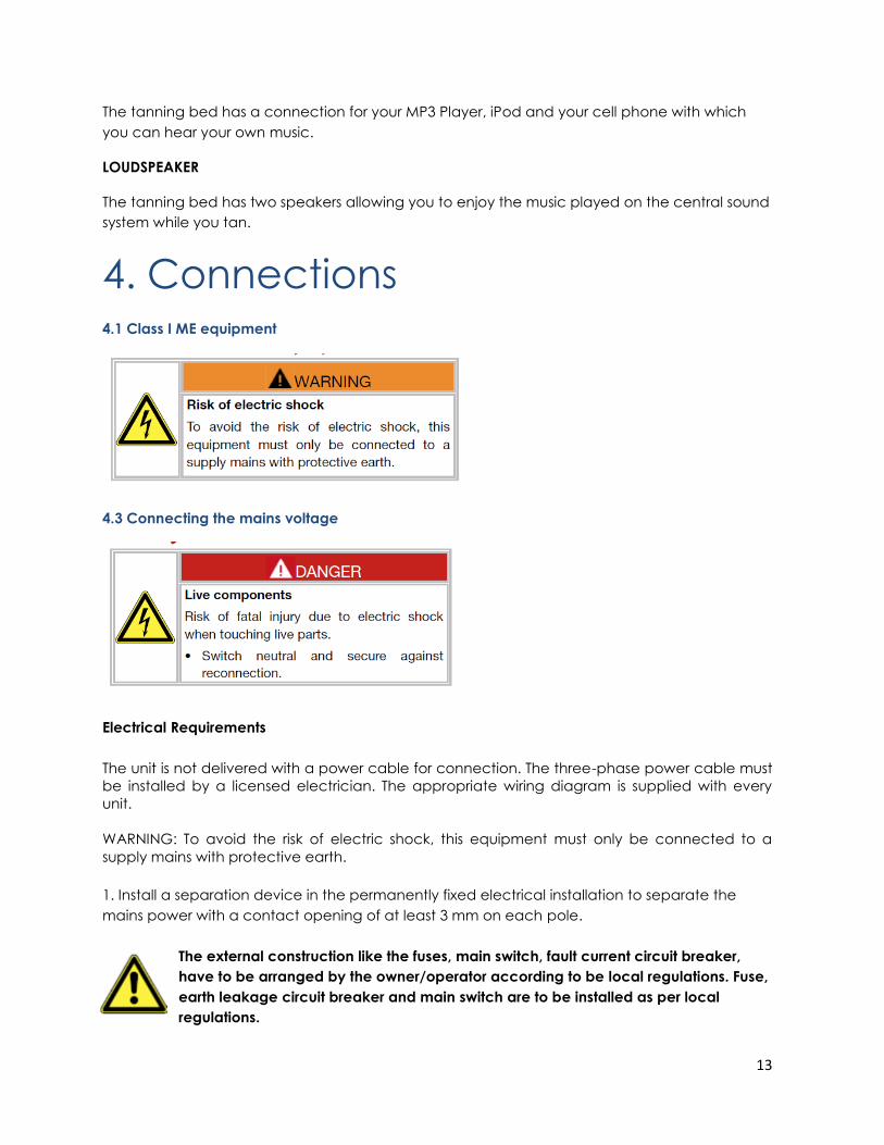
4. Connections 4.1 Class I ME equipment
4.3 Connecting the mains voltage
Electrical Requirements
The unit is not delivered with a power cable for connection. The three-phase power cable must
be installed by a licensed electrician. The appropriate wiring diagram is supplied with every
unit.
WARNING: To avoid the risk of electric shock, this equipment must only be connected to a
supply mains with protective earth.
1. Install a separation device in the permanently fixed electrical installation to separate the
mains power with a contact opening of at least 3 mm on each pole.
The external construction like the fuses, main switch, fault current circuit breaker,
have to be arranged by the owner/operator according to be local regulations. Fuse,
earth leakage circuit breaker and main switch are to be installed as per local
regulations.
14
The means provided to isolate its circuits electrically from the SUPPLY MAINS shall be capable of
being locked in the off position if:
– any OPERATOR including SERVICE PERSONNEL is unable to view the means of isolation from
their intended position.
The locking mechanism may be in a SUPPLY MAINS switch provided by the RESPONSIBLE
ORGANIZATION.
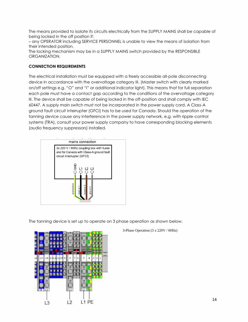
CONNECTION REQUIREMENTS
The electrical installation must be equipped with a freely accessible all-pole disconnecting
device in accordance with the overvoltage category III. (Master switch with clearly marked
on/off settings e.g. “O” and “I” or additional indicator light). This means that for full separation
each pole must have a contact gap according to the conditions of the overvoltage category
III. The device shall be capable of being locked in the off-position and shall comply with IEC
60447. A supply main switch must not be incorporated in the power supply cord. A Class-A
ground fault circuit interrupter (GFCI) has to be used for Canada. Should the operation of the
tanning device cause any interference in the power supply network, e.g. with ripple-control
systems (TRA), consult your power supply company to have corresponding blocking elements
(audio frequency suppressors) installed.
The tanning device is set up to operate on 3 phase operation as shown below.
3-Phase Operation (3 x 220V / 60Hz)
15
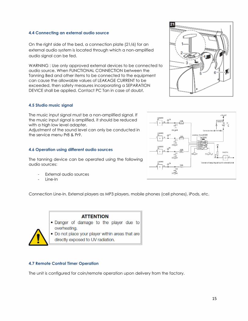
4.4 Connecting an external audio source
On the right side of the bed, a connection plate (21/6) for an
external audio system is located through which a non-amplified
audio signal can be fed.
WARNING : Use only approved external devices to be connected to
audio source. When FUNCTIONAL CONNECTION between the
Tanning Bed and other items to be connected to the equipment
can cause the allowable values of LEAKAGE CURRENT to be
exceeded, then safety measures incorporating a SEPARATION
DEVICE shall be applied. Contact PC Tan in case of doubt.
4.5 Studio music signal
The music input signal must be a non-amplified signal. If
the music input signal is amplified, it should be reduced
with a high low level adapter.
Adjustment of the sound level can only be conducted in
the service menu Pr8 & Pr9.
4.6 Operation using different audio sources
The tanning device can be operated using the following
audio sources:
- External audio sources
- Line-In
Connection Line-In. External players as MP3 players, mobile phones (cell phones), iPods, etc.
4.7 Remote Control Timer Operation
The unit is configured for coin/remote operation upon delivery from the factory.
16
Danger to life!
Power down the unit and protect against accidentally being switched back on!
4.8 T-Max Timer (External Timer)
The unit may only be connected by a qualified electrician in accordance with the appropriate
national norm.
Power down the unit.
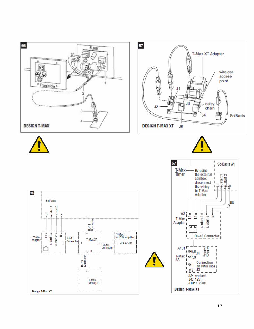
The T-Max CAT 5 Cable (66/2, 10 meters long) is supplied with every unit. Plug the plug (66/3) of
the T-Max cable into the T-Max adapter (66/4) of the control board. Feed the cable through
the recess (65/1) of the base outside and connect the cables at the T-Max Timer (66/1). Refer to
the connections of the table in picture 66. Information about T-Max operation can be found
within T-Max guide, which is supplied every T-Max Timer.
4.8.1 T-Max XT Timer (Internal Timer) optional
T-Max XT Board: Setting address & wiring:
1- Press and hold start & up buttons together until P1 appears
2- Press stop button to enter the P1 address parameter
3- Press the up button to enter the room number
4- Press the stop button until P1 appears
5- To exit hold the up and down buttons together till display goes to zero.
Refer to the connections of the table in picture 67 & 68.
17
18
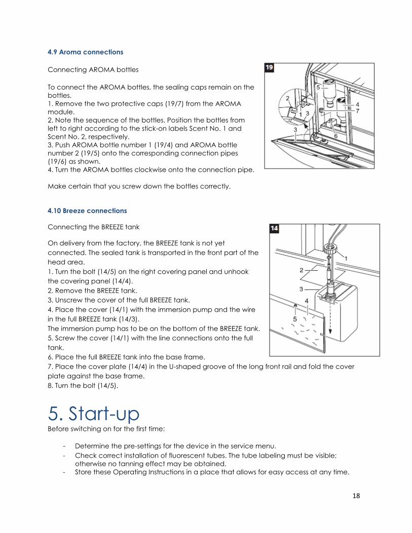
4.9 Aroma connections
Connecting AROMA bottles
To connect the AROMA bottles, the sealing caps remain on the
bottles.
1. Remove the two protective caps (19/7) from the AROMA
module.
2. Note the sequence of the bottles. Position the bottles from
left to right according to the stick-on labels Scent No. 1 and
Scent No. 2, respectively.
3. Push AROMA bottle number 1 (19/4) and AROMA bottle
number 2 (19/5) onto the corresponding connection pipes
(19/6) as shown.
4. Turn the AROMA bottles clockwise onto the connection pipe.
Make certain that you screw down the bottles correctly.
4.10 Breeze connections
Connecting the BREEZE tank
On delivery from the factory, the BREEZE tank is not yet
connected. The sealed tank is transported in the front part of the
head area.
1. Turn the bolt (14/5) on the right covering panel and unhook
the covering panel (14/4).
2. Remove the BREEZE tank.
3. Unscrew the cover of the full BREEZE tank.
4. Place the cover (14/1) with the immersion pump and the wire
in the full BREEZE tank (14/3).
The immersion pump has to be on the bottom of the BREEZE tank.
5. Screw the cover (14/1) with the line connections onto the full
tank.
6. Place the full BREEZE tank into the base frame.
7. Place the cover plate (14/4) in the U-shaped groove of the long front rail and fold the cover
plate against the base frame.
8. Turn the bolt (14/5).
5. Start-up Before switching on for the first time:
- Determine the pre-settings for the device in the service menu.
- Check correct installation of fluorescent tubes. The tube labeling must be visible;
otherwise no tanning effect may be obtained.
- Store these Operating Instructions in a place that allows for easy access at any time.
19
5.1 Operating modes
The three different operating modes are explained below:
STANDBY MODE
The tanning device is in an idle state, i.e. it is connected to the mains but is currently not being
used. The tubes and the tanning lamps are switched off. From the standby mode you can
access the service menu.
TANNING MODE
The tubes and the tanning lamps are switched on and a tanning session is in progress. While the
tanning device is in tanning mode, the settings for the ongoing tanning session can be
changed via the interior control panel.
FAN RUN-ON
After the tanning session, the fan runs on for 4 minutes in order to cool down the device.
6. Tanning instructions Tanning normally begins after one to two exposures and maximizes after one to four (1-4) weeks
of exposure following the recommended schedule for your skin type.
NO SUNSCREEN WITH PROTECTION FACTOR
Sunscreens with sun protection factors are unsuitable for use in a tanning salon. For tanning, the
skin should have been thoroughly cleaned and be dry. For optimum skin care, we recommend
using our line of body care products after tanning.
6.1 Instructions for the user
Observe the following tanning instructions.
GENERAL
- Only the individuals described in the chapter 2.4 Indications for use may use the
tanning device.
- The different skin types tolerate the sun and hence tanning times to a different degree.
Please observe the specifications in the skin-type table (supplied with the tanning
device) and the tanning times. After having reached the maximum tan, further tanning
can only be achieved by substantially exceeding the allowed tanning times. This must
absolutely be avoided.
- The UV radiation of the sun or of UV appliances can cause damage to the skin or to
the eyes. These biological effects depend on the type and amount of radiation as well
as on the individual sensitivity of the skin.
20
- After excessive exposure to radiation, the skin may exhibit sunburn. Excessively
repeated exposure to UV radiation of sunlight or UV appliances can result in premature
ageing of the skin and in a higher risk of skin cancer.
- The unprotected eye can suffer from surface inflammation and in certain cases, e.g.
after a cataract operation, excessive radiation can damage the retina. After many
repeated sessions a cataract might form.
- Do not expose yourself to UV radiation if you take medicine that increases the
sensitivity to ultraviolet radiation. When in doubt, seek medical advice.
- It cannot generally be assumed that the use of a tanning device reduces the risk of
getting a sunburn.
- Seek medical advice if persistent swellings or skin sores develop or pigmented moles
change in appearance.
6.1.1 Application tips
When describing the operation, the tanning device is often shown with the canopy open.
During tanning the canopy must always be closed.
Proper operation is not possible with the canopy open.
– Lie down and place your head on the headrest or as indicated by the ergonomic base panel
to maintain the proper distance between skin and lamps.
Preparation time
Before the UV lamps turn on, you have a few minutes to prepare yourself. During the
preparation time you can switch on the UV lamps at any time by pressing the START button.
*Remove your clothes and all jewelry.
*Remove make-up and other cosmetics.
*Remove glasses. Contact lenses can be worn under the protective goggles.
*Put on the protective goggles.
*Lie down on the bed surface.
*Close the canopy.
*Press the START button.
FOR EACH TANNING SESSION
- Always wear the supplied protective goggles.
- Remove cosmetics before the session and do not use any sunscreen.
- Allow for at least 24 hours to pass between sessions.
- After a tanning session in a studio, do not take another sunbath outdoors on the same
day.
21
6.1.2 How to stop
The tanning session ends automatically after the preset time has run down.
The internal body cooling fan continues to run for approx. four (4) minutes to
sufficiently cool the device.
– To interrupt a tanning session, press the button STOP anytime during a session.
– Press START again to restart the lamps.
6.2 Exposure schedule
It may take some time before the expected results appear.
- Follow instructions.
- The time between the first two tanning sessions must be at least 24 hours.
- Increasing tanning also requires an extension of the exposure time (= radiation time) or
after a certain degree of tanning has been achieved, a further intensification is not
possible. However, the radiation time may not be extended as desired within the
scope of the permissible radiation doses! Therefore, only a certain degree of final
tanning dependent on the skin type can be achieved without endangering your
health.
- Inform users about proper tanning.
For the precise definition of the skin types, please refer to the supplied skin-type table.
If the tanning-session sequence is interrupted for 4 weeks or more, you will have to start with the
first session again.
The times mentioned in the tanning schedules are only valid for tubes and facial tanners that
are replaced according to the maintenance intervals.
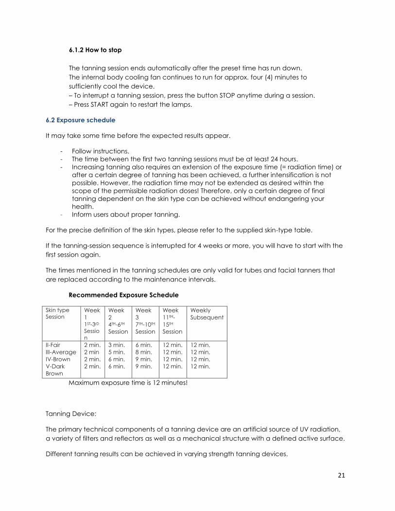
Recommended Exposure Schedule
Skin type
Session Week
1 1ST-3rD
Sessio
n
Week
2
4tH-6tH
Session
Week
3
7tH-10tH
Session
Week
11tH-
15tH
Session
Weekly
Subsequent
II-Fair
III-Average
IV-Brown
V-Dark
Brown
2 min.
2 min
2 min.
2 min.
3 min.
5 min.
6 min.
6 min.
6 min.
8 min.
9 min.
9 min.
12 min.
12 min.
12 min.
12 min.
12 min.
12 min.
12 min.
12 min.
Maximum exposure time is 12 minutes!
Tanning Device:
The primary technical components of a tanning device are an artificial source of UV radiation,
a variety of filters and reflectors as well as a mechanical structure with a defined active surface.
Different tanning results can be achieved in varying strength tanning devices.
22
This is due to the different strength UV lamps and the different UV-A and UVB proportions of the
UV radiation. The UV-A proportion primarily generates a superficial tan, which appears rapidly
and is intensive but also fades more rapidly, the UV-B radiation is primarily responsible for more
long-term tanning results. The disadvantage of the UV-B radiation is that the tan does not
become visible until one or two days after visiting the tanning salon. Therefore, the appropriate
tanning device is to be selected depending on the desired tanning goal.
The tanning devices described here primarily emit UV-A radiation.
REPLACE ONLY WITH ORIGINAL LAMPS OR FDA APPROVED EQUIVALENT
7. Tanning mode
The following explanations and functions refer to a tanning device that is fully equipped with all
features.
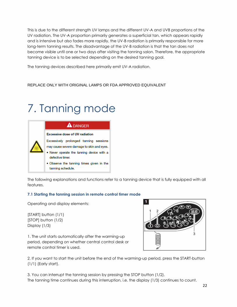
7.1 Starting the tanning session in remote control timer mode
Operating and display elements:
[START] button (1/1)
[STOP] button (1/2)
Display (1/3)
1. The unit starts automatically after the warming-up
period, depending on whether central control desk or
remote control timer is used.
2. If you want to start the unit before the end of the warming-up period, press the START-button
(1/1) (Early start).
3. You can interrupt the tanning session by pressing the STOP button (1/2).
The tanning time continues during this interruption, i.e. the display (1/3) continues to count.
23
7.2 Basic functions
1. Lie down on the bed.
Do not rest any part of the body on the edge of the bed to avoid bruising!
2. Pull down the canopy using the handle provided as far as it will go. The distance between
your body and the lamps is determined by the design of the unit.
3. You can control the functions of the tanning device via the interior control panel during the
tanning session. It is particularly easy for you to access the basic functions.
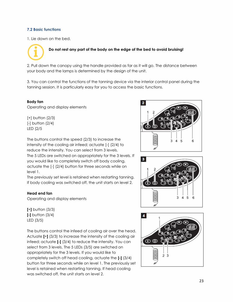
Body fan
Operating and display elements
[+] button (2/3)
[-] button (2/4)
LED (2/5
The buttons control the speed (2/3) to increase the
intensity of the cooling air infeed; actuate [-] (2/4) to
reduce the intensity. You can select from 3 levels.
The 5 LEDs are switched on appropriately for the 3 levels. If
you would like to completely switch off body cooling,
actuate the [-] (2/4) button for three seconds while on
level 1.
The previously set level is retained when restarting tanning.
If body cooling was switched off, the unit starts on level 2.
Head end fan
Operating and display elements
[+] button (3/3)
[-] button (3/4)
LED (3/5)
The buttons control the infeed of cooling air over the head.
Actuate [+] (3/3) to increase the intensity of the cooling air
infeed; actuate [-] (3/4) to reduce the intensity. You can
select from 3 levels. The 5 LEDs (3/5) are switched on
appropriately for the 3 levels. If you would like to
completely switch off head cooling, actuate the [-] (3/4)
button for three seconds while on level 1. The previously set
level is retained when restarting tanning. If head cooling
was switched off, the unit starts on level 2.
24
Body tanning
Operating and display elements
[+] button (4/1)
[-] button (4/2)
LED (4/3)
The buttons control the intensity of body tanning. Actuate [+] (4/1) to increase the intensity of
body tanning; actuate [-]
4/2) to decrease the intensity. You can select from 3 levels.
The 5 LEDs are switched on appropriately for the 3 levels. The previously set level is retained
when re-starting tanning. If the body tanning was previously switched off, the unit starts on level
3 (highest level).
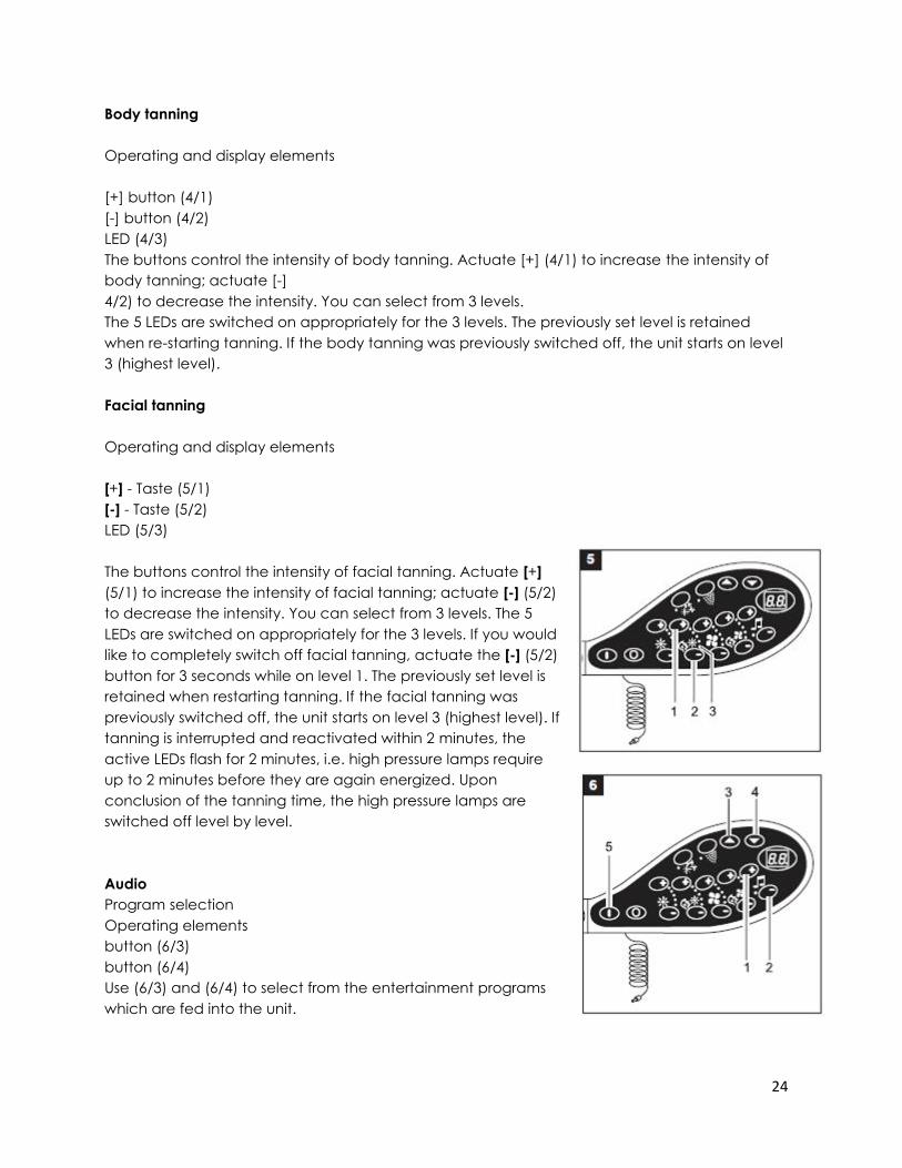
Facial tanning
Operating and display elements
[+] - Taste (5/1)
[-] - Taste (5/2)
LED (5/3)
The buttons control the intensity of facial tanning. Actuate [+]
(5/1) to increase the intensity of facial tanning; actuate [-] (5/2)
to decrease the intensity. You can select from 3 levels. The 5
LEDs are switched on appropriately for the 3 levels. If you would
like to completely switch off facial tanning, actuate the [-] (5/2)
button for 3 seconds while on level 1. The previously set level is
retained when restarting tanning. If the facial tanning was
previously switched off, the unit starts on level 3 (highest level). If
tanning is interrupted and reactivated within 2 minutes, the
active LEDs flash for 2 minutes, i.e. high pressure lamps require
up to 2 minutes before they are again energized. Upon
conclusion of the tanning time, the high pressure lamps are
switched off level by level.
Audio
Program selection
Operating elements
button (6/3)
button (6/4)
Use (6/3) and (6/4) to select from the entertainment programs
which are fed into the unit.
25
T-Max XT (optional)
Program selection
Operating elements
button (6/3)
button (6/4)
button (6/5)
To parametrize T-Max XT push the up (6/3) and start button (6/5).
Please refer to the T-Max XT instructions sections 4.8.1.
Volume
Operating elements
[+] button (6/1)
[-] button (6/2)
With the two buttons, you can control the volume of the entertainment being fed into the unit.
Actuate [+] (6/1) to increase the volume; actuate [-] (6/2) to decrease the volume.
T-MAX AUDIO amplifier (optional)
Precondition to be able to operate the T-MAX XT AUDIO is the uwe Control Software Variation V
1.10.0 or updated version T-Max Manager Version 4.18 or updated version T-Max XT Audio.
Function
Please use the following operation elements to operate the T-MAX XT AUDIO:
Operating and display elements:
[+] button volume regulation
[-] button volume regulation
[6/3] button channel selection
[6/4] button channel selection
Channel selection:
C0 Salon Stereo
C1 Customer Input (MP3)
C2 FM1
C3 FM2
C4 FM3
C5 FM4
C6 DMX1
C7 DMX2
C8 DMX3
C9 DMX4
26
The operating elements volume regulation is out of function after tanning. The parameter of the
T-MAX XT AUDIO can be changed by operating the operating elements arrow [6/3] up and
[6/4] down and Start button [6/5].
Please refer to the operating instruction of the T-MAX XT AUDIO amplifier.
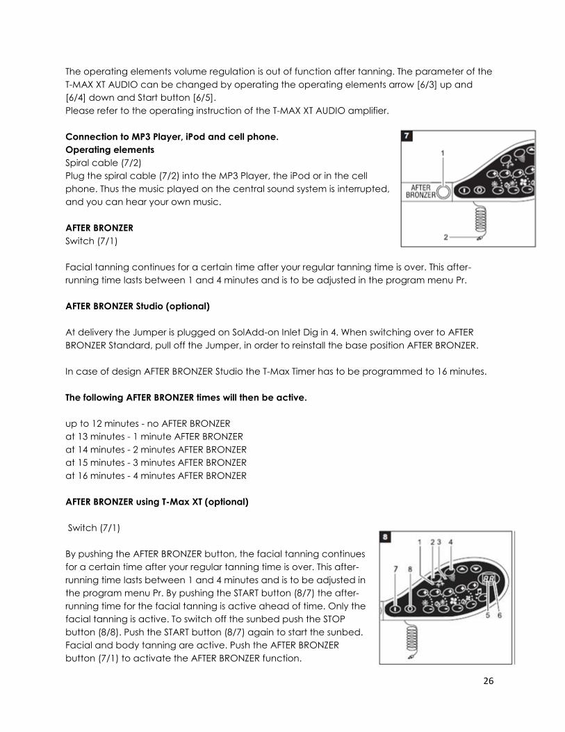
Connection to MP3 Player, iPod and cell phone.
Operating elements
Spiral cable (7/2)
Plug the spiral cable (7/2) into the MP3 Player, the iPod or in the cell
phone. Thus the music played on the central sound system is interrupted,
and you can hear your own music.
AFTER BRONZER
Switch (7/1)
Facial tanning continues for a certain time after your regular tanning time is over. This after-
running time lasts between 1 and 4 minutes and is to be adjusted in the program menu Pr.
AFTER BRONZER Studio (optional)
At delivery the Jumper is plugged on SolAdd-on Inlet Dig in 4. When switching over to AFTER
BRONZER Standard, pull off the Jumper, in order to reinstall the base position AFTER BRONZER.
In case of design AFTER BRONZER Studio the T-Max Timer has to be programmed to 16 minutes.
The following AFTER BRONZER times will then be active.
up to 12 minutes - no AFTER BRONZER
at 13 minutes - 1 minute AFTER BRONZER
at 14 minutes - 2 minutes AFTER BRONZER
at 15 minutes - 3 minutes AFTER BRONZER
at 16 minutes - 4 minutes AFTER BRONZER
AFTER BRONZER using T-Max XT (optional)
Switch (7/1)
By pushing the AFTER BRONZER button, the facial tanning continues
for a certain time after your regular tanning time is over. This after-
running time lasts between 1 and 4 minutes and is to be adjusted in
the program menu Pr. By pushing the START button (8/7) the after-
running time for the facial tanning is active ahead of time. Only the
facial tanning is active. To switch off the sunbed push the STOP
button (8/8). Push the START button (8/7) again to start the sunbed.
Facial and body tanning are active. Push the AFTER BRONZER
button (7/1) to activate the AFTER BRONZER function.
27
AROMA
Operating- and display elements
Button AROMA (8/2)
LED (8/1)
The AROMA program starts automatically when tanning commences. You do not have to press
any button. You can stop the AROMA program by pressing the AROMA button (8/2) and restart
it again by pressing the AROMA button. The red LED lights (8/1) up while the AROMA program is
running. During the AROMA program, the cooling air circulation for the body is set to the lowest
level; cooling of the face is switched on according to the setting.
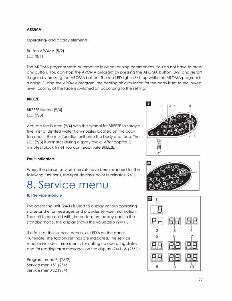
BREEZE
BREEZE button (9/4)
LED (9/3)
Actuate the button (9/4) with the symbol for BREEZE to spray a
fine mist of distilled water from nozzles located on the body
fan and in the multifunction unit onto the body and face. The
LED (9/3) illuminates during a spray cycle. After approx. 2
minutes (block time) you can reactivate BREEZE.
Fault indicators
When the pre-set service intervals have been reached for the
following functions, the right decimal point illuminates (9/6).
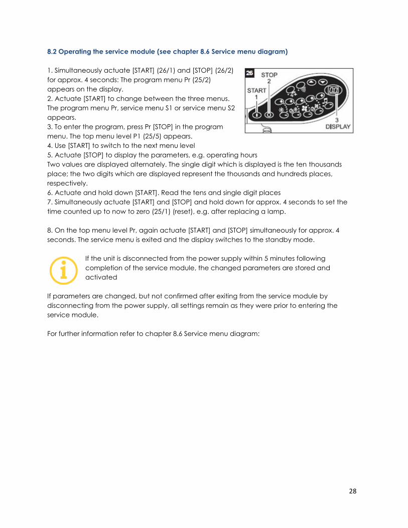
8. Service menu 8.1 Service module
The operating unit (24/1) is used to display various operating
states and error messages and provides service information.
The unit is operated with the buttons on the key pad. In the
standby mode, the display shows the value zero (24/1).
If a fault at the sol base occurs, all LED´s on the panel
illuminate. The factory settings are indicated. The service
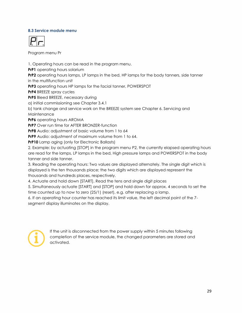
module includes three menus for calling up operating states
and for reading error messages on the display (24/1) & (25/1):
Program menu Pr (25/2)
Service menu S1 (25/3)
Service menu S2 (25/4)
28
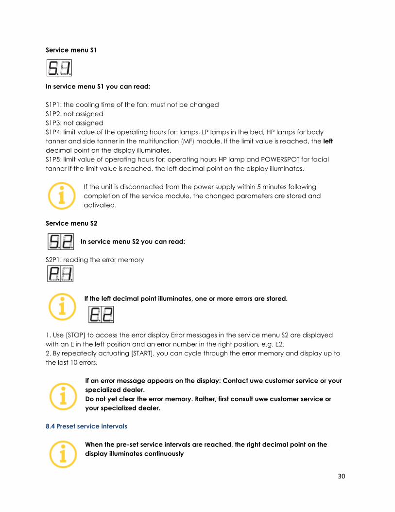
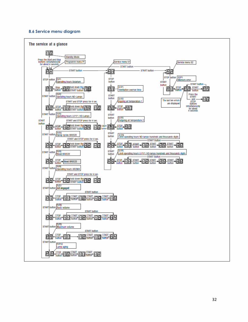
8.2 Operating the service module (see chapter 8.6 Service menu diagram)
1. Simultaneously actuate [START] (26/1) and [STOP] (26/2)
for approx. 4 seconds: The program menu Pr (25/2)
appears on the display.
2. Actuate [START] to change between the three menus.
The program menu Pr, service menu S1 or service menu S2
appears.
3. To enter the program, press Pr [STOP] in the program
menu. The top menu level P1 (25/5) appears.
4. Use [START] to switch to the next menu level
5. Actuate [STOP] to display the parameters, e.g. operating hours
Two values are displayed alternately. The single digit which is displayed is the ten thousands
place; the two digits which are displayed represent the thousands and hundreds places,
respectively.
6. Actuate and hold down [START]. Read the tens and single digit places
7. Simultaneously actuate [START] and [STOP] and hold down for approx. 4 seconds to set the
time counted up to now to zero (25/1) (reset), e.g. after replacing a lamp.
8. On the top menu level Pr, again actuate [START] and [STOP] simultaneously for approx. 4
seconds. The service menu is exited and the display switches to the standby mode.
If the unit is disconnected from the power supply within 5 minutes following
completion of the service module, the changed parameters are stored and
activated
If parameters are changed, but not confirmed after exiting from the service module by
disconnecting from the power supply, all settings remain as they were prior to entering the
service module.
For further information refer to chapter 8.6 Service menu diagram:
29
8.3 Service module menu
Program menu Pr
1. Operating hours can be read in the program menu.
PrP1 operating hours solarium
PrP2 operating hours lamps, LP lamps in the bed, HP lamps for the body tanners, side tanner
in the multifunction unit
PrP3 operating hours HP lamps for the facial tanner, POWERSPOT
PrP4 BREEZE spray cycles
PrP5 Bleed BREEZE, necessary during
a) initial commissioning see Chapter 3.4.1
b) tank change and service work on the BREEZE system see Chapter 6. Servicing and
Maintenance
PrP6 operating hours AROMA
PrP7 Over run time for AFTER BRONZER-function
PrP8 Audio: adjustment of basic volume from 1 to 64
PrP9 Audio: adjustment of maximum volume from 1 to 64.
PrP10 Lamp aging (only for Electronic Ballasts)
2. Example: by actuating [STOP] in the program menu P2, the currently elapsed operating hours
are read for the lamps, LP lamps in the bed, High pressure lamps and POWERSPOT in the body
tanner and side tanner.
3. Reading the operating hours: Two values are displayed alternately. The single digit which is
displayed is the ten thousands place; the two digits which are displayed represent the
thousands and hundreds places, respectively.
4. Actuate and hold down [START]. Read the tens and single digit places
5. Simultaneously actuate [START] and [STOP] and hold down for approx. 4 seconds to set the
time counted up to now to zero (25/1) (reset), e.g. after replacing a lamp.
6. If an operating hour counter has reached its limit value, the left decimal point of the 7-
segment display illuminates on the display.
If the unit is disconnected from the power supply within 5 minutes following
completion of the service module, the changed parameters are stored and
activated.
30
Service menu S1
In service menu S1 you can read:
S1P1: the cooling time of the fan: must not be changed
S1P2: not assigned
S1P3: not assigned
S1P4: limit value of the operating hours for: lamps, LP lamps in the bed, HP lamps for body
tanner and side tanner in the multifunction (MF) module. If the limit value is reached, the left
decimal point on the display illuminates.
S1P5: limit value of operating hours for: operating hours HP lamp and POWERSPOT for facial
tanner If the limit value is reached, the left decimal point on the display illuminates.
If the unit is disconnected from the power supply within 5 minutes following
completion of the service module, the changed parameters are stored and
activated.
Service menu S2
In service menu S2 you can read:
S2P1: reading the error memory
If the left decimal point illuminates, one or more errors are stored.
1. Use [STOP] to access the error display Error messages in the service menu S2 are displayed
with an E in the left position and an error number in the right position, e.g. E2.
2. By repeatedly actuating [START], you can cycle through the error memory and display up to
the last 10 errors.
If an error message appears on the display: Contact uwe customer service or your
specialized dealer.
Do not yet clear the error memory. Rather, first consult uwe customer service or
your specialized dealer.
8.4 Preset service intervals
When the pre-set service intervals are reached, the right decimal point on the
display illuminates continuously
31
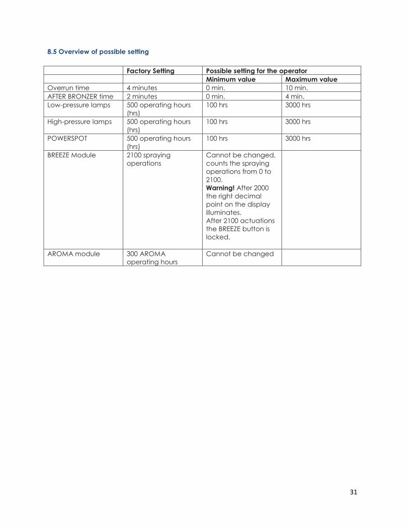
8.5 Overview of possible setting
Factory Setting Possible setting for the operator
Minimum value Maximum value
Overrun time 4 minutes 0 min. 10 min.
AFTER BRONZER time 2 minutes 0 min. 4 min.
Low-pressure lamps 500 operating hours
(hrs)
100 hrs 3000 hrs
High-pressure lamps 500 operating hours
(hrs)
100 hrs 3000 hrs
POWERSPOT 500 operating hours
(hrs)
100 hrs 3000 hrs
BREEZE Module 2100 spraying
operations
Cannot be changed,
counts the spraying
operations from 0 to
2100.
Warning! After 2000
the right decimal
point on the display
illuminates.
After 2100 actuations
the BREEZE button is
locked.
AROMA module 300 AROMA
operating hours
Cannot be changed
32
8.6 Service menu diagram
33
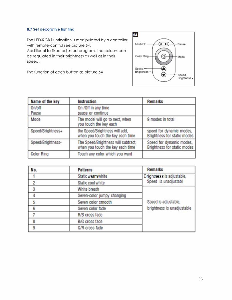
8.7 Set decorative lighting
The LED-RGB illumination is manipulated by a controller
with remote-control see picture 64.
Additional to fixed adjusted programs the colours can
be regulated in their brightness as well as in their
speed.
The function of each button as picture 64
34
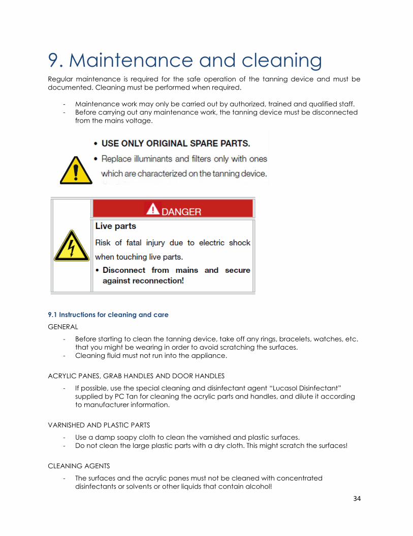
9. Maintenance and cleaning Regular maintenance is required for the safe operation of the tanning device and must be
documented. Cleaning must be performed when required.
- Maintenance work may only be carried out by authorized, trained and qualified staff.
- Before carrying out any maintenance work, the tanning device must be disconnected
from the mains voltage.
9.1 Instructions for cleaning and care
GENERAL
- Before starting to clean the tanning device, take off any rings, bracelets, watches, etc.
that you might be wearing in order to avoid scratching the surfaces.
- Cleaning fluid must not run into the appliance.
ACRYLIC PANES, GRAB HANDLES AND DOOR HANDLES
- If possible, use the special cleaning and disinfectant agent “Lucasol Disinfectant”
supplied by PC Tan for cleaning the acrylic parts and handles, and dilute it according
to manufacturer information.
VARNISHED AND PLASTIC PARTS
- Use a damp soapy cloth to clean the varnished and plastic surfaces.
- Do not clean the large plastic parts with a dry cloth. This might scratch the surfaces!
CLEANING AGENTS
- The surfaces and the acrylic panes must not be cleaned with concentrated
disinfectants or solvents or other liquids that contain alcohol!
35
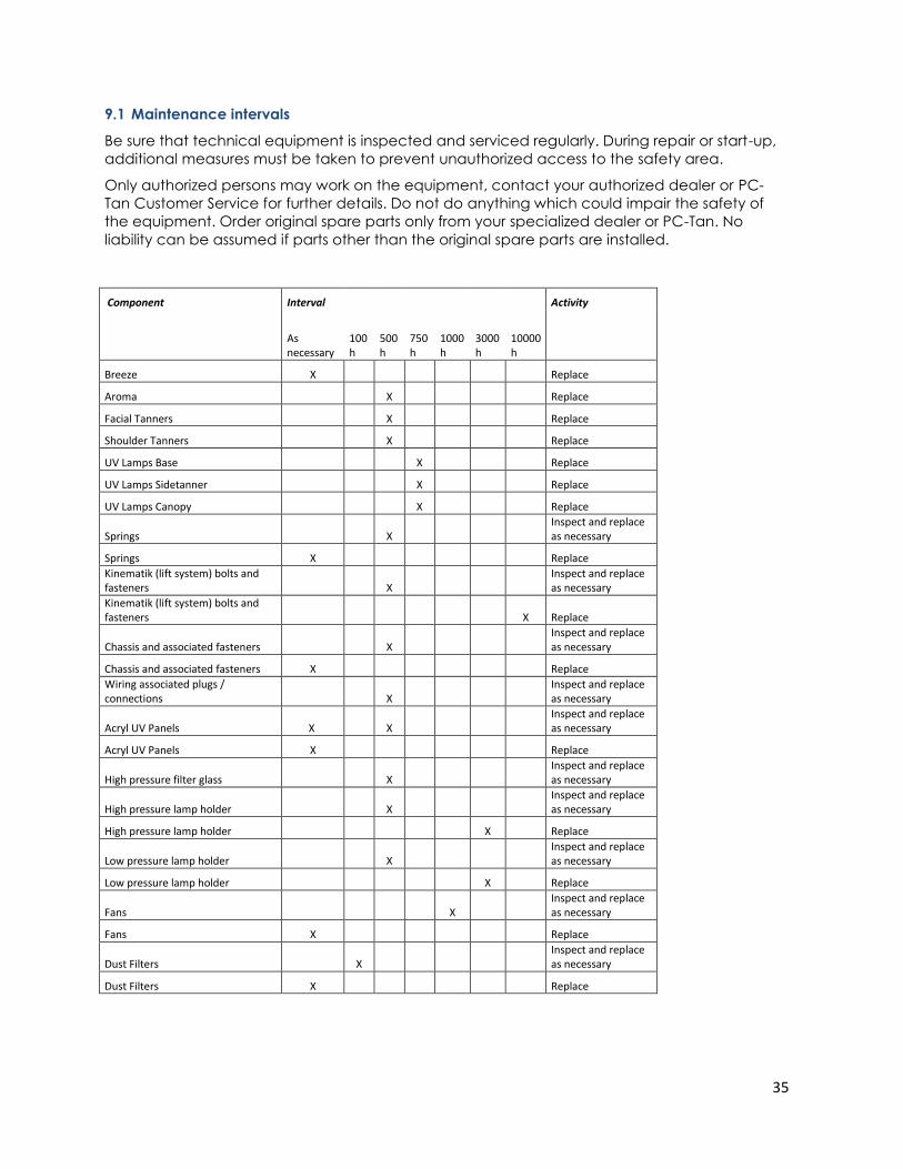
9.1 Maintenance intervals
Be sure that technical equipment is inspected and serviced regularly. During repair or start-up,
additional measures must be taken to prevent unauthorized access to the safety area.
Only authorized persons may work on the equipment, contact your authorized dealer or PC-
Tan Customer Service for further details. Do not do anything which could impair the safety of
the equipment. Order original spare parts only from your specialized dealer or PC-Tan. No
liability can be assumed if parts other than the original spare parts are installed.
Component Interval Activity
As necessary
100h
500h
750h
1000h
3000h
10000h
Breeze X Replace
Aroma X Replace
Facial Tanners X Replace
Shoulder Tanners X Replace
UV Lamps Base X Replace
UV Lamps Sidetanner X Replace
UV Lamps Canopy X Replace
Springs X Inspect and replace as necessary
Springs X Replace
Kinematik (lift system) bolts and fasteners X
Inspect and replace as necessary
Kinematik (lift system) bolts and fasteners X Replace
Chassis and associated fasteners X Inspect and replace as necessary
Chassis and associated fasteners X Replace
Wiring associated plugs / connections X
Inspect and replace as necessary
Acryl UV Panels X X Inspect and replace as necessary
Acryl UV Panels X Replace
High pressure filter glass X Inspect and replace as necessary
High pressure lamp holder X Inspect and replace as necessary
High pressure lamp holder X Replace
Low pressure lamp holder X Inspect and replace as necessary
Low pressure lamp holder X Replace
Fans X Inspect and replace as necessary
Fans X Replace
Dust Filters X Inspect and replace as necessary
Dust Filters X Replace
36
9.2 Acrylic panes
Do not operate the unit without the acrylic sheets
Replacing the acrylic sheets
The acrylic sheets are made of special plastic with high UV penetrability. Therefore, when
replacing, never use window glass or standard acrylic, as these filter the UV radiation either
partially or completely.
Always order the original acrylic sheets from your specialized dealer or unit manufacturer. Upon
delivery of replacements, the acrylic sheets are covered on both sides with a protective foil.
Remove the foil before installing in the tanning unit.
Do not operate the unit without acrylic sheets, as cooling of the unit cannot otherwise be
ensured.
In the event of damages, the manufacturer assumes no liability.
LIGHTGLASS
The acrylic panels of the canopy and bed (upper) are frosted on the backside.
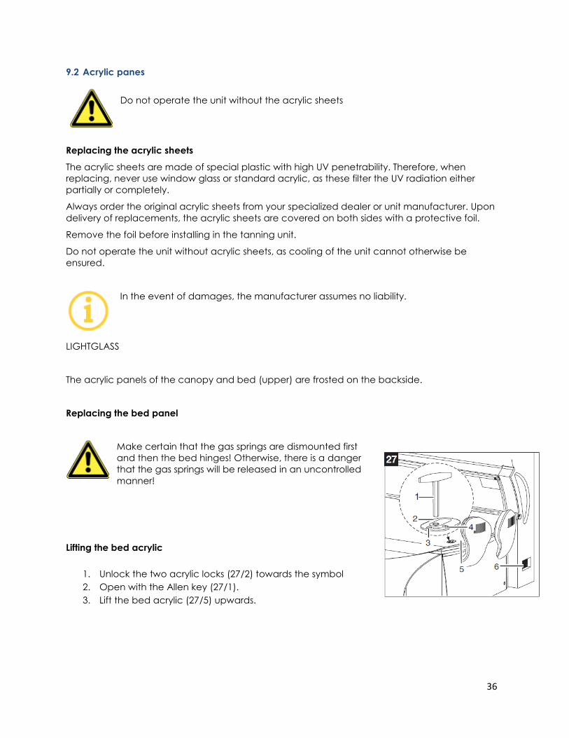
Replacing the bed panel
Make certain that the gas springs are dismounted first
and then the bed hinges! Otherwise, there is a danger
that the gas springs will be released in an uncontrolled
manner!
Lifting the bed acrylic
1. Unlock the two acrylic locks (27/2) towards the symbol
2. Open with the Allen key (27/1).
3. Lift the bed acrylic (27/5) upwards.
37
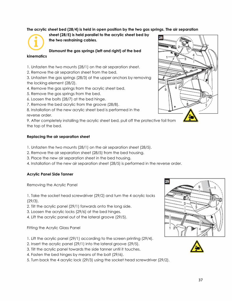
The acrylic sheet bed (28/4) is held in open position by the two gas springs. The air separation
sheet (28/5) is held parallel to the acrylic sheet bed by
the two restraining cables.
Dismount the gas springs (left and right) of the bed
kinematics
1. Unfasten the two mounts (28/1) on the air separation sheet.
2. Remove the air separation sheet from the bed.
3. Unfasten the gas springs (28/3) at the upper anchors by removing
the locking element (28/2).
4. Remove the gas springs from the acrylic sheet bed.
5. Remove the gas springs from the bed.
6. Loosen the bolts (28/7) at the bed hinge.
7. Remove the bed acrylic from the groove (28/8).
8. Installation of the new acrylic sheet bed is performed in the
reverse order.
9. After completely installing the acrylic sheet bed, pull off the protective foil from
the top of the bed.
Replacing the air separation sheet
1. Unfasten the two mounts (28/1) on the air separation sheet (28/5).
2. Remove the air separation sheet (28/5) from the bed housing.
3. Place the new air separation sheet in the bed housing.
4. Installation of the new air separation sheet (28/5) is performed in the reverse order.
Acrylic Panel Side Tanner
Removing the Acrylic Panel
1. Take the socket head screwdriver (29/2) and turn the 4 acrylic locks
(29/3).
2. Tilt the acrylic panel (29/1) forwards onto the long side.
3. Loosen the acrylic locks (29/6) at the bed hinges.
4. Lift the acrylic panel out of the lateral groove (29/5).
Fitting the Acrylic Glass Panel
1. Lift the acrylic panel (29/1) according to the screen printing (29/4).
2. Insert the acrylic panel (29/1) into the lateral groove (29/5).
3. Tilt the acrylic panel towards the side tanner until it touches.
4. Fasten the bed hinges by means of the bolt (29/6).
5. Turn back the 4 acrylic lock (29/3) using the socket head screwdriver (29/2).
38
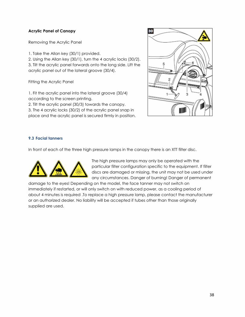
Acrylic Panel of Canopy
Removing the Acrylic Panel
1. Take the Allan key (30/1) provided.
2. Using the Allan key (30/1), turn the 4 acrylic locks (30/2).
3. Tilt the acrylic panel forwards onto the long side. Lift the
acrylic panel out of the lateral groove (30/4).
Fitting the Acrylic Panel
1. Fit the acrylic panel into the lateral groove (30/4)
according to the screen printing.
2. Tilt the acrylic panel (30/3) towards the canopy.
3. The 4 acrylic locks (30/2) of the acrylic panel snap in
place and the acrylic panel is secured firmly in position.
9.3 Facial tanners
In front of each of the three high pressure lamps in the canopy there is an XTT filter disc.
The high pressure lamps may only be operated with the
particular filter configuration specific to the equipment. If filter
discs are damaged or missing, the unit may not be used under
any circumstances. Danger of burning! Danger of permanent
damage to the eyes! Depending on the model, the face tanner may not switch on
immediately if restarted, or will only switch on with reduced power, as a cooling period of
about 4 minutes is required .To replace a high pressure lamp, please contact the manufacturer
or an authorized dealer. No liability will be accepted if tubes other than those originally
supplied are used.
39
BREAKSAFE unit XTT
Each XTT filter disc above the high pressure lamp in the canopy is equipped with a BREAKSAFE
device. If one of these filter discs breaks, the power supply is cut off and the unit can only be
restarted after the XTT filter disc has been replaced.
Changing the high pressure lamp iBED XTT
Attention! Transport the sunlamp in its packing to the place of
installation. Wear gloves when replacing the sunlamp.Never
touch the sunlamp with your fingers, as fingerprints will damage
the sunlamp. Remove possible soling with a clean cloth soaked
in rubbing alcohol.
Never install a damaged sunlamp. Before installing the sunlamp check, if it shows mechanical
damage. Before opening the device to replace a sunlamp, always disconnect all poles of the
device from the mains and wait until the tube has cooled completely. Wear goggles to protect
yourself against exploding lamps.
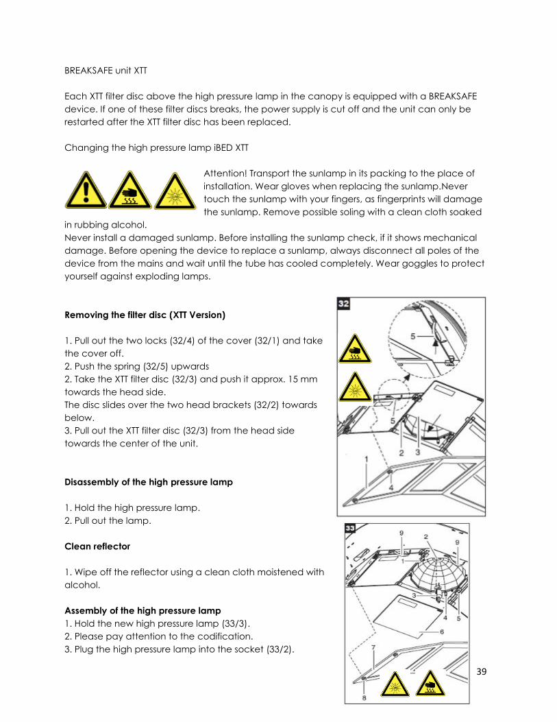
Removing the filter disc (XTT Version)
1. Pull out the two locks (32/4) of the cover (32/1) and take
the cover off.
2. Push the spring (32/5) upwards
2. Take the XTT filter disc (32/3) and push it approx. 15 mm
towards the head side.
The disc slides over the two head brackets (32/2) towards
below.
3. Pull out the XTT filter disc (32/3) from the head side
towards the center of the unit.
Disassembly of the high pressure lamp
1. Hold the high pressure lamp.
2. Pull out the lamp.
Clean reflector
1. Wipe off the reflector using a clean cloth moistened with
alcohol.
Assembly of the high pressure lamp
1. Hold the new high pressure lamp (33/3).
2. Please pay attention to the codification.
3. Plug the high pressure lamp into the socket (33/2).
40
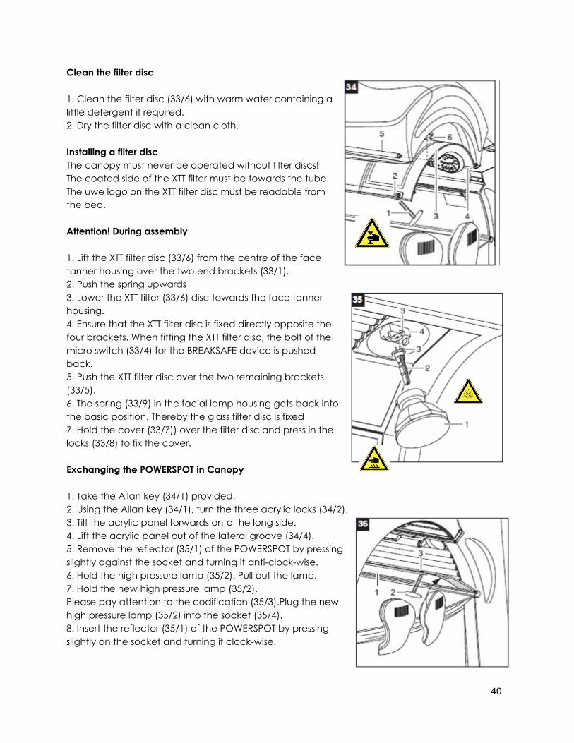
Clean the filter disc
1. Clean the filter disc (33/6) with warm water containing a
little detergent if required.
2. Dry the filter disc with a clean cloth.
Installing a filter disc
The canopy must never be operated without filter discs!
The coated side of the XTT filter must be towards the tube.
The uwe logo on the XTT filter disc must be readable from
the bed.
Attention! During assembly
1. Lift the XTT filter disc (33/6) from the centre of the face
tanner housing over the two end brackets (33/1).
2. Push the spring upwards
3. Lower the XTT filter (33/6) disc towards the face tanner
housing.
4. Ensure that the XTT filter disc is fixed directly opposite the
four brackets. When fitting the XTT filter disc, the bolt of the
micro switch (33/4) for the BREAKSAFE device is pushed
back.
5. Push the XTT filter disc over the two remaining brackets
(33/5).
6. The spring (33/9) in the facial lamp housing gets back into
the basic position. Thereby the glass filter disc is fixed
7. Hold the cover (33/7)) over the filter disc and press in the
locks (33/8) to fix the cover.
Exchanging the POWERSPOT in Canopy
1. Take the Allan key (34/1) provided.
2. Using the Allan key (34/1), turn the three acrylic locks (34/2).
3. Tilt the acrylic panel forwards onto the long side.
4. Lift the acrylic panel out of the lateral groove (34/4).
5. Remove the reflector (35/1) of the POWERSPOT by pressing
slightly against the socket and turning it anti-clock-wise.
6. Hold the high pressure lamp (35/2). Pull out the lamp.
7. Hold the new high pressure lamp (35/2).
Please pay attention to the codification (35/3).Plug the new
high pressure lamp (35/2) into the socket (35/4).
8. Insert the reflector (35/1) of the POWERSPOT by pressing
slightly on the socket and turning it clock-wise.
41
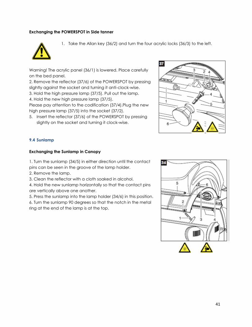
Exchanging the POWERSPOT in Side tanner
1. Take the Allan key (36/2) and turn the four acrylic locks (36/3) to the left.
Warning! The acrylic panel (36/1) is lowered. Place carefully
on the bed panel.
2. Remove the reflector (37/6) of the POWERSPOT by pressing
slightly against the socket and turning it anti-clock-wise.
3. Hold the high pressure lamp (37/5). Pull out the lamp.
4. Hold the new high pressure lamp (37/5).
Please pay attention to the codification (37/4).Plug the new
high pressure lamp (37/5) into the socket (37/2).
5. Insert the reflector (37/6) of the POWERSPOT by pressing
slightly on the socket and turning it clock-wise.
9.4 Sunlamp
Exchanging the Sunlamp in Canopy
1. Turn the sunlamp (34/5) in either direction until the contact
pins can be seen in the groove of the lamp holder.
2. Remove the lamp.
3. Clean the reflector with a cloth soaked in alcohol.
4. Hold the new sunlamp horizontally so that the contact pins
are vertically above one another.
5. Press the sunlamp into the lamp holder (34/6) in this position.
6. Turn the sunlamp 90 degrees so that the notch in the metal
ring at the end of the lamp is at the top.
42
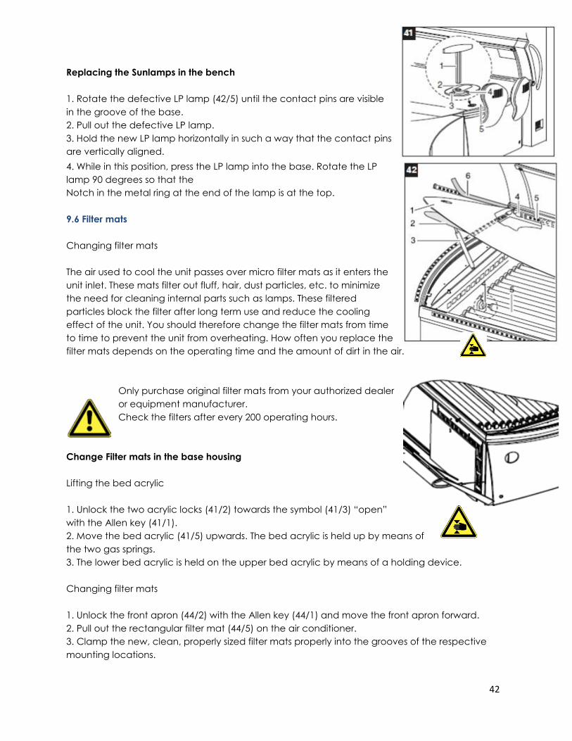
Replacing the Sunlamps in the bench
1. Rotate the defective LP lamp (42/5) until the contact pins are visible
in the groove of the base.
2. Pull out the defective LP lamp.
3. Hold the new LP lamp horizontally in such a way that the contact pins
are vertically aligned.
4. While in this position, press the LP lamp into the base. Rotate the LP
lamp 90 degrees so that the
Notch in the metal ring at the end of the lamp is at the top.
9.6 Filter mats
Changing filter mats
The air used to cool the unit passes over micro filter mats as it enters the
unit inlet. These mats filter out fluff, hair, dust particles, etc. to minimize
the need for cleaning internal parts such as lamps. These filtered
particles block the filter after long term use and reduce the cooling
effect of the unit. You should therefore change the filter mats from time
to time to prevent the unit from overheating. How often you replace the
filter mats depends on the operating time and the amount of dirt in the air.
Only purchase original filter mats from your authorized dealer
or equipment manufacturer.
Check the filters after every 200 operating hours.
Change Filter mats in the base housing
Lifting the bed acrylic
1. Unlock the two acrylic locks (41/2) towards the symbol (41/3) “open”
with the Allen key (41/1).
2. Move the bed acrylic (41/5) upwards. The bed acrylic is held up by means of
the two gas springs.
3. The lower bed acrylic is held on the upper bed acrylic by means of a holding device.
Changing filter mats
1. Unlock the front apron (44/2) with the Allen key (44/1) and move the front apron forward.
2. Pull out the rectangular filter mat (44/5) on the air conditioner.
3. Clamp the new, clean, properly sized filter mats properly into the grooves of the respective
mounting locations.
43
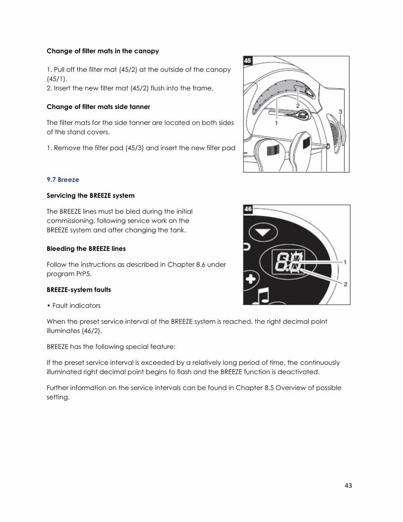
Change of filter mats in the canopy
1. Pull off the filter mat (45/2) at the outside of the canopy
(45/1).
2. Insert the new filter mat (45/2) flush into the frame.
Change of filter mats side tanner
The filter mats for the side tanner are located on both sides
of the stand covers.
1. Remove the filter pad (45/3) and insert the new filter pad
9.7 Breeze
Servicing the BREEZE system
The BREEZE lines must be bled during the initial
commissioning, following service work on the
BREEZE system and after changing the tank.
Bleeding the BREEZE lines
Follow the instructions as described in Chapter 8.6 under
program PrP5.
BREEZE-system faults
• Fault indicators
When the preset service interval of the BREEZE system is reached, the right decimal point
illuminates (46/2).
BREEZE has the following special feature:
If the preset service interval is exceeded by a relatively long period of time, the continuously
illuminated right decimal point begins to flash and the BREEZE function is deactivated.
Further information on the service intervals can be found in Chapter 8.5 Overview of possible
setting.
44
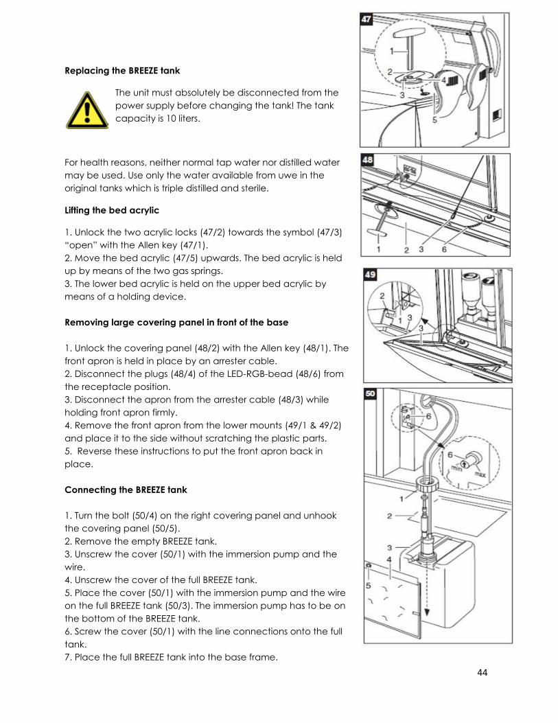
Replacing the BREEZE tank
The unit must absolutely be disconnected from the
power supply before changing the tank! The tank
capacity is 10 liters.
For health reasons, neither normal tap water nor distilled water
may be used. Use only the water available from uwe in the
original tanks which is triple distilled and sterile.
Lifting the bed acrylic
1. Unlock the two acrylic locks (47/2) towards the symbol (47/3)
“open” with the Allen key (47/1).
2. Move the bed acrylic (47/5) upwards. The bed acrylic is held
up by means of the two gas springs.
3. The lower bed acrylic is held on the upper bed acrylic by
means of a holding device.
Removing large covering panel in front of the base
1. Unlock the covering panel (48/2) with the Allen key (48/1). The
front apron is held in place by an arrester cable.
2. Disconnect the plugs (48/4) of the LED-RGB-bead (48/6) from
the receptacle position.
3. Disconnect the apron from the arrester cable (48/3) while
holding front apron firmly.
4. Remove the front apron from the lower mounts (49/1 & 49/2)
and place it to the side without scratching the plastic parts.
5. Reverse these instructions to put the front apron back in
place.
Connecting the BREEZE tank
1. Turn the bolt (50/4) on the right covering panel and unhook
the covering panel (50/5).
2. Remove the empty BREEZE tank.
3. Unscrew the cover (50/1) with the immersion pump and the
wire.
4. Unscrew the cover of the full BREEZE tank.
5. Place the cover (50/1) with the immersion pump and the wire
on the full BREEZE tank (50/3). The immersion pump has to be on
the bottom of the BREEZE tank.
6. Screw the cover (50/1) with the line connections onto the full
tank.
7. Place the full BREEZE tank into the base frame.

45
The BREEZE lines must be de-ventilated during the initial commissioning, following service work
on the BREEZE system, after changing the tank and the BREEZE nozzles.
After changing the BREEZE tank, the number of spray cycles must be in chapter 8.6
set to zero in program menu PrP4.
Controlling the Breeze water amount
To adjust the water mass, turn the knob between the min and max-
level.
Min. stands for minimum and max. for maximum water quantity. The
delivery status is adjusted to OPT. (optimum).
1. Adjust the knob (50/6) with the arrow between min and max to
your preferred water quantity.
2. Insert the right covering (50/4) and turn the bolt (50/5).
Set the BREEZE spray cycles to zero,
Bleed BREEZE Setting BREEZE spray cycles to zero
1. Actuate [START] and [STOP] simultaneously for 4 seconds. The
program menu Pr (54/2) appears on the display.
2. Actuate [STOP]. The program menu P1 (54/5) appears.
3. Actuate [START] until program menu P4 (54/8) BREEZE spray cycles
appears.
4. Actuate [STOP] and then [START] and [STOP] simultaneously for 4
seconds. The number of BREEZE spray cycles counted up to now is
set to zero (54/1).
Bleeding the BREEZE system
1. Actuate [START] and the program menu P5 (54/9) Bleed BREEZE appears.
2. In program menu P5, press [STOP] for up to 1 minute until the emission pattern of the nozzle jet
is a finely atomized cone.
3. Disconnect the unit from the power supply within 5 minutes to save and activate the
changed parameters
Wait 1 minute before triggering another spray cycle.
46
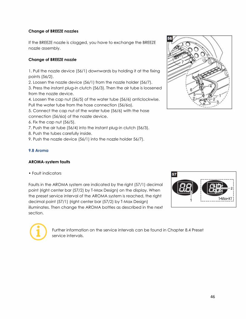
Change of BREEZE nozzles
If the BREEZE nozzle is clogged, you have to exchange the BREEZE
nozzle assembly.
Change of BREEZE nozzle
1. Pull the nozzle device (56/1) downwards by holding it at the fixing
points (56/2).
2. Loosen the nozzle device (56/1) from the nozzle holder (56/7).
3. Press the instant plug-in clutch (56/3). Then the air tube is loosened
from the nozzle device.
4. Loosen the cap nut (56/5) of the water tube (56/6) anticlockwise.
Pull the water tube from the hose connection (56/6a).
5. Connect the cap nut of the water tube (56/6) with the hose
connection (56/6a) of the nozzle device.
6. Fix the cap nut (56/5).
7. Push the air tube (56/4) into the instant plug-in clutch (56/3).
8. Push the tubes carefully inside.
9. Push the nozzle device (56/1) into the nozzle holder 56/7).
9.8 Aroma
AROMA-system faults
• Fault indicators
Faults in the AROMA system are indicated by the right (57/1) decimal
point (right center bar (57/2) by T-Max Design) on the display. When
the preset service interval of the AROMA system is reached, the right
decimal point (57/1) (right center bar (57/2) by T-Max Design)
illuminates. Then change the AROMA bottles as described in the next
section.
Further information on the service intervals can be found in Chapter 8.4 Preset
service intervals.
47
Changing AROMA bottles
Disconnect the unit from the power supply before change the bottles.
Always wear gloves when working on the AROMA module. Pay
attention to the edges of the housing. Work with care! Each AROMA
bottle contains 250 ml.
Changing AROMA bottles
1. Unscrew the aroma bottle (60/4) anticlockwise.
2. Do the same with the second bottle (60/5)
3. Take the new aroma bottle and press it onto the level controller
(60/6).
4. Screw the bottle to the level controller clockwise. Ensure that the
bottle is firmly tightened.
Attention! Observe the order of the bottles!
Arrange bottle No. 1 and bottle No. 2 from left to right. The AROMA set consists of:
Bottle No. 1: Fragrance 1 Bottle No. 2: Fragrance 2
After changing the AROMA bottles, the AROMA operating hours must be set to
zero in program menu PrP6. See chapter 8.6 for details.
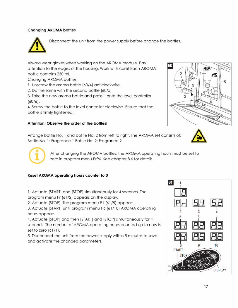
Reset AROMA operating hours counter to 0
1. Actuate [START] and [STOP] simultaneously for 4 seconds. The
program menu Pr (61/2) appears on the display.
2. Actuate [STOP]. The program menu P1 (61/5) appears.
3. Actuate [START] until program menu P6 (61/10) AROMA operating
hours appears.
4. Actuate [STOP] and then [START] and [STOP] simultaneously for 4
seconds. The number of AROMA operating hours counted up to now is
set to zero (61/1).
5. Disconnect the unit from the power supply within 5 minutes to save
and activate the changed parameters.
48
10. Assembly Instructions
10.1 Delivery condition
The equipment is transported and delivered preassembled on a pallet. It is fastened to the
pallet with straps and covered with a protective sheet. The pallet with the unit must be
unloaded on-site using a hydraulic ramp or fork-lift truck. For the installation at the operating
site the unit must first be disassembled on the pallet and then reassembled on site.
10.2 Disassembling of the unit
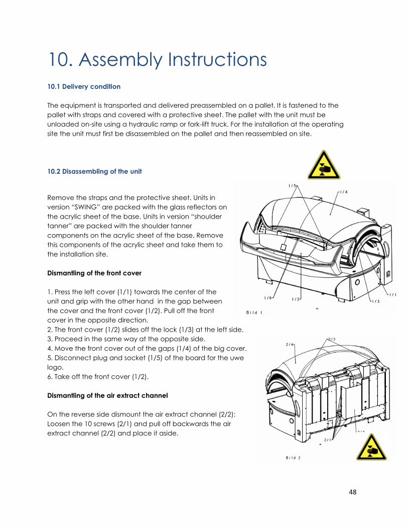
Remove the straps and the protective sheet. Units in
version “SWING” are packed with the glass reflectors on
the acrylic sheet of the base. Units in version “shoulder
tanner” are packed with the shoulder tanner
components on the acrylic sheet of the base, Remove
this components of the acrylic sheet and take them to
the installation site.
Dismantling of the front cover
1. Press the left cover (1/1) towards the center of the
unit and grip with the other hand in the gap between
the cover and the front cover (1/2). Pull off the front
cover in the opposite direction.
2. The front cover (1/2) slides off the lock (1/3) at the left side.
3. Proceed in the same way at the opposite side.
4. Move the front cover out of the gaps (1/4) of the big cover.
5. Disconnect plug and socket (1/5) of the board for the uwe
logo.
6. Take off the front cover (1/2).
Dismantling of the air extract channel
On the reverse side dismount the air extract channel (2/2):
Loosen the 10 screws (2/1) and pull off backwards the air
extract channel (2/2) and place it aside.
49
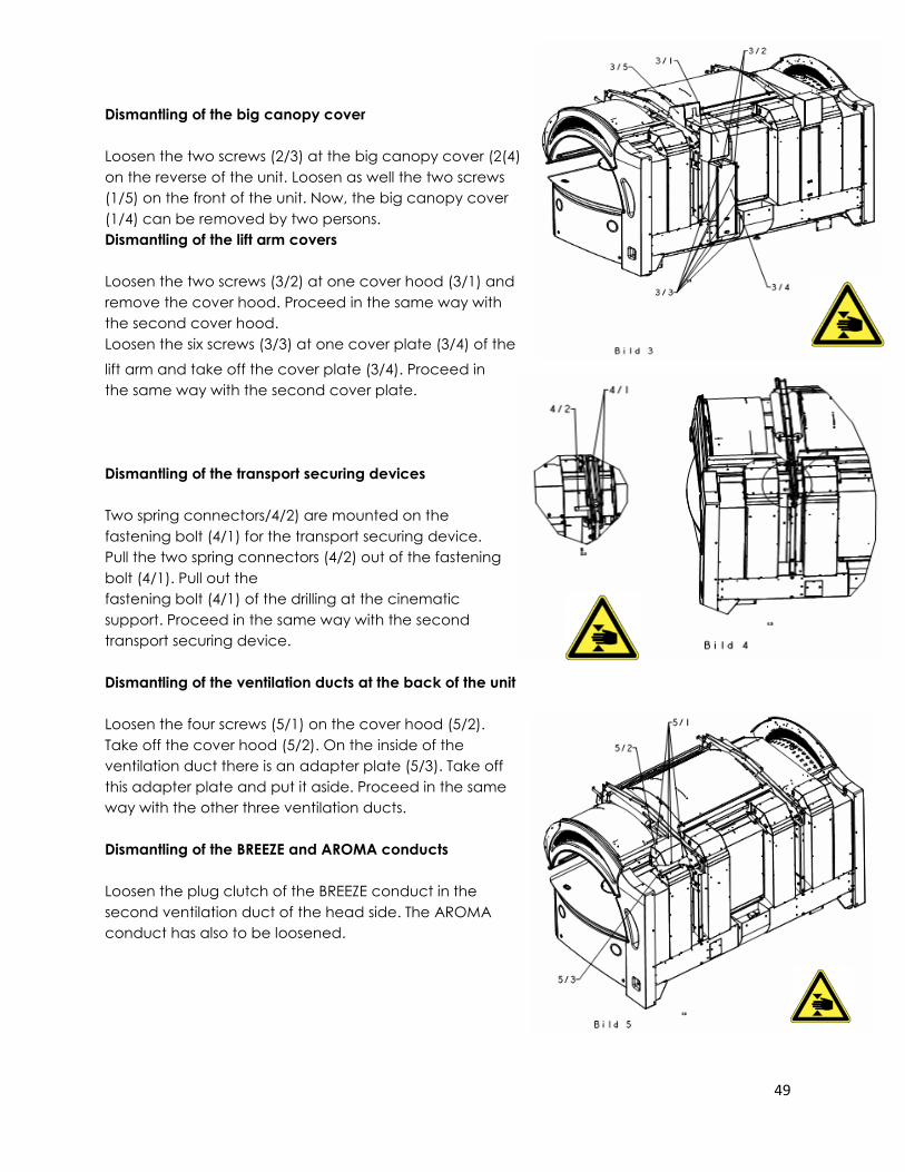
Dismantling of the big canopy cover
Loosen the two screws (2/3) at the big canopy cover (2(4)
on the reverse of the unit. Loosen as well the two screws
(1/5) on the front of the unit. Now, the big canopy cover
(1/4) can be removed by two persons.
Dismantling of the lift arm covers
Loosen the two screws (3/2) at one cover hood (3/1) and
remove the cover hood. Proceed in the same way with
the second cover hood.
Loosen the six screws (3/3) at one cover plate (3/4) of the
lift arm and take off the cover plate (3/4). Proceed in
the same way with the second cover plate.
Dismantling of the transport securing devices
Two spring connectors/4/2) are mounted on the
fastening bolt (4/1) for the transport securing device.
Pull the two spring connectors (4/2) out of the fastening
bolt (4/1). Pull out the
fastening bolt (4/1) of the drilling at the cinematic
support. Proceed in the same way with the second
transport securing device.
Dismantling of the ventilation ducts at the back of the unit
Loosen the four screws (5/1) on the cover hood (5/2).
Take off the cover hood (5/2). On the inside of the
ventilation duct there is an adapter plate (5/3). Take off
this adapter plate and put it aside. Proceed in the same
way with the other three ventilation ducts.
Dismantling of the BREEZE and AROMA conducts
Loosen the plug clutch of the BREEZE conduct in the
second ventilation duct of the head side. The AROMA
conduct has also to be loosened.
50
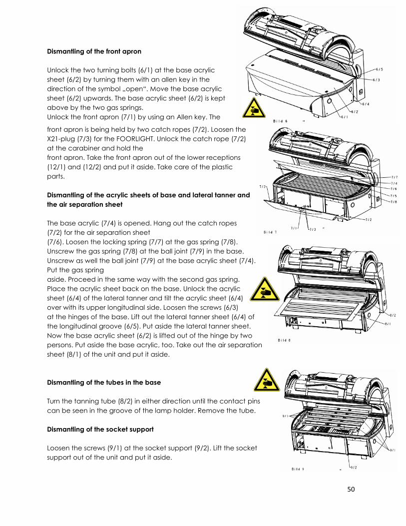
Dismantling of the front apron
Unlock the two turning bolts (6/1) at the base acrylic
sheet (6/2) by turning them with an allen key in the
direction of the symbol „open“. Move the base acrylic
sheet (6/2) upwards. The base acrylic sheet (6/2) is kept
above by the two gas springs.
Unlock the front apron (7/1) by using an Allen key. The
front apron is being held by two catch ropes (7/2). Loosen the
X21-plug (7/3) for the FOORLIGHT. Unlock the catch rope (7/2)
at the carabiner and hold the
front apron. Take the front apron out of the lower receptions
(12/1) and (12/2) and put it aside. Take care of the plastic
parts.
Dismantling of the acrylic sheets of base and lateral tanner and
the air separation sheet
The base acrylic (7/4) is opened. Hang out the catch ropes
(7/2) for the air separation sheet
(7/6). Loosen the locking spring (7/7) at the gas spring (7/8).
Unscrew the gas spring (7/8) at the ball joint (7/9) in the base.
Unscrew as well the ball joint (7/9) at the base acrylic sheet (7/4).
Put the gas spring
aside. Proceed in the same way with the second gas spring.
Place the acrylic sheet back on the base. Unlock the acrylic
sheet (6/4) of the lateral tanner and tilt the acrylic sheet (6/4)
over with its upper longitudinal side. Loosen the screws (6/3)
at the hinges of the base. Lift out the lateral tanner sheet (6/4) of
the longitudinal groove (6/5). Put aside the lateral tanner sheet.
Now the base acrylic sheet (6/2) is lifted out of the hinge by two
persons. Put aside the base acrylic, too. Take out the air separation
sheet (8/1) of the unit and put it aside.
Dismantling of the tubes in the base
Turn the tanning tube (8/2) in either direction until the contact pins
can be seen in the groove of the lamp holder. Remove the tube.
Dismantling of the socket support
Loosen the screws (9/1) at the socket support (9/2). Lift the socket
support out of the unit and put it aside.
51
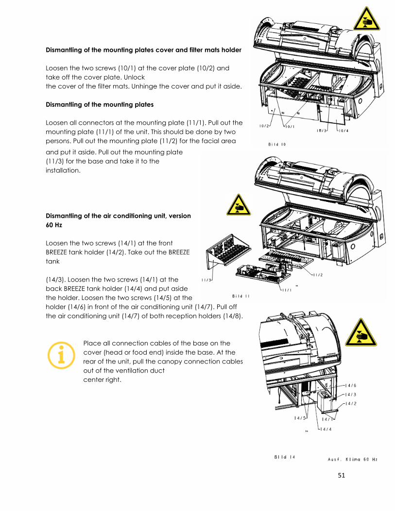
Dismantling of the mounting plates cover and filter mats holder
Loosen the two screws (10/1) at the cover plate (10/2) and
take off the cover plate. Unlock
the cover of the filter mats. Unhinge the cover and put it aside.
Dismantling of the mounting plates
Loosen all connectors at the mounting plate (11/1). Pull out the
mounting plate (11/1) of the unit. This should be done by two
persons. Pull out the mounting plate (11/2) for the facial area
and put it aside. Pull out the mounting plate
(11/3) for the base and take it to the
installation.
Dismantling of the air conditioning unit, version
60 Hz
Loosen the two screws (14/1) at the front
BREEZE tank holder (14/2). Take out the BREEZE
tank
(14/3). Loosen the two screws (14/1) at the
back BREEZE tank holder (14/4) and put aside
the holder. Loosen the two screws (14/5) at the
holder (14/6) in front of the air conditioning unit (14/7). Pull off
the air conditioning unit (14/7) of both reception holders (14/8).
Place all connection cables of the base on the
cover (head or food end) inside the base. At the
rear of the unit, pull the canopy connection cables
out of the ventilation duct
center right.
52
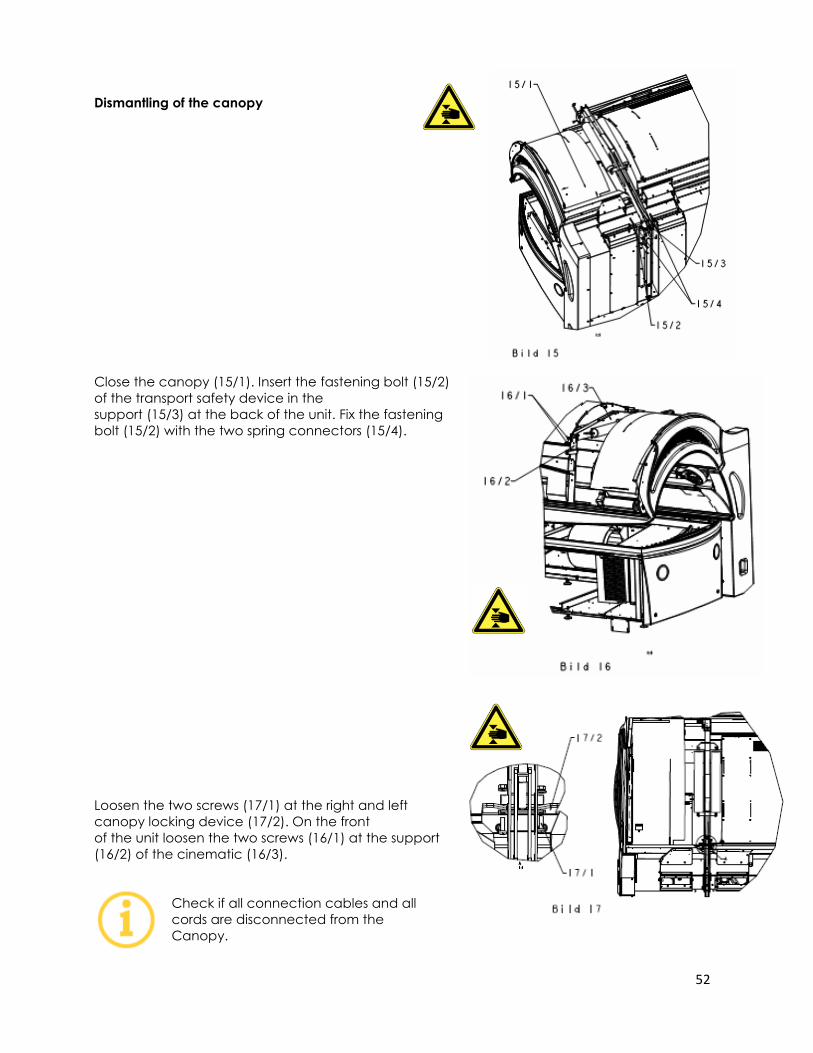
Dismantling of the canopy
Close the canopy (15/1). Insert the fastening bolt (15/2)
of the transport safety device in the
support (15/3) at the back of the unit. Fix the fastening
bolt (15/2) with the two spring connectors (15/4).
Loosen the two screws (17/1) at the right and left
canopy locking device (17/2). On the front
of the unit loosen the two screws (16/1) at the support
(16/2) of the cinematic (16/3).
Check if all connection cables and all
cords are disconnected from the
Canopy.
53
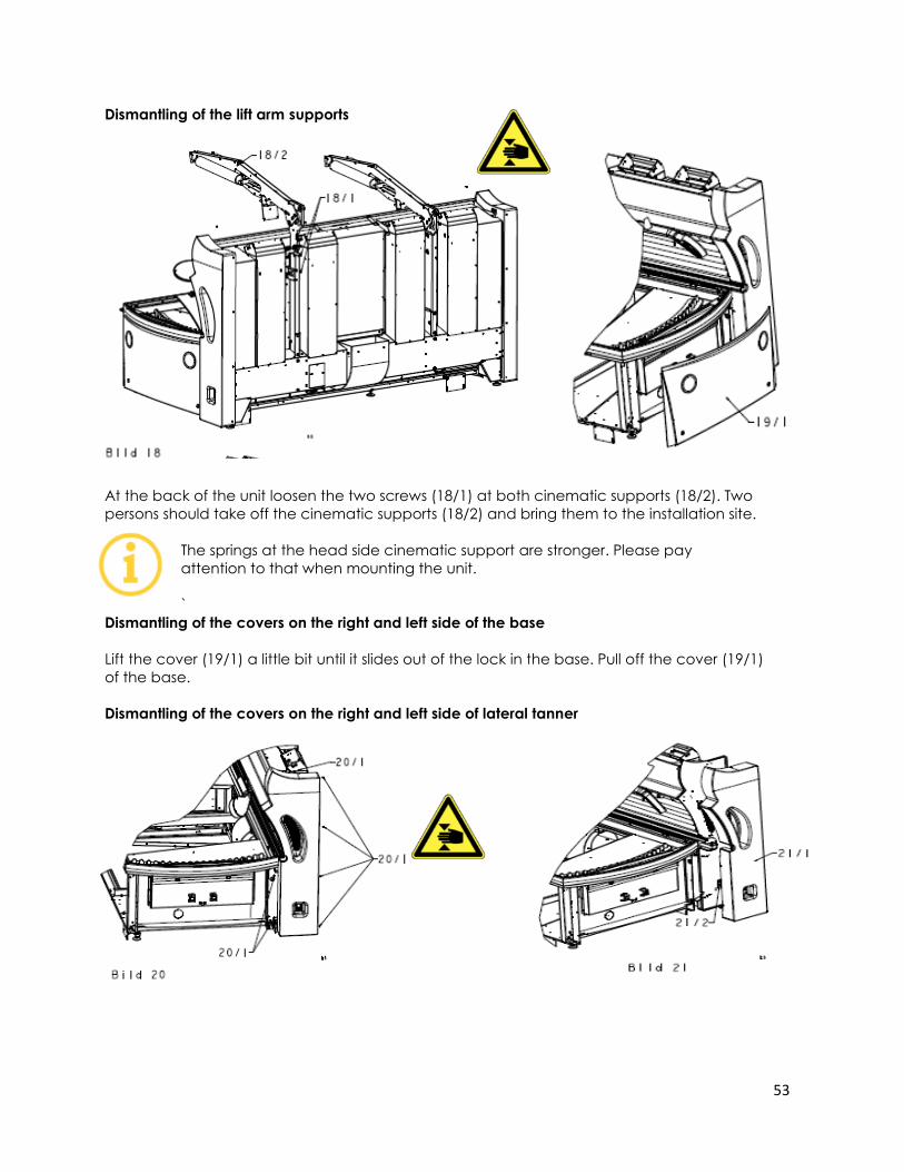
Dismantling of the lift arm supports
At the back of the unit loosen the two screws (18/1) at both cinematic supports (18/2). Two
persons should take off the cinematic supports (18/2) and bring them to the installation site.
The springs at the head side cinematic support are stronger. Please pay
attention to that when mounting the unit.
`
Dismantling of the covers on the right and left side of the base
Lift the cover (19/1) a little bit until it slides out of the lock in the base. Pull off the cover (19/1)
of the base.
Dismantling of the covers on the right and left side of lateral tanner
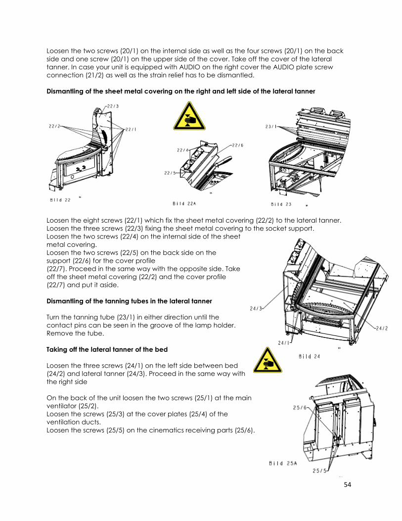
54
Loosen the two screws (20/1) on the internal side as well as the four screws (20/1) on the back
side and one screw (20/1) on the upper side of the cover. Take off the cover of the lateral
tanner. In case your unit is equipped with AUDIO on the right cover the AUDIO plate screw
connection (21/2) as well as the strain relief has to be dismantled.
Dismantling of the sheet metal covering on the right and left side of the lateral tanner
Loosen the eight screws (22/1) which fix the sheet metal covering (22/2) to the lateral tanner.
Loosen the three screws (22/3) fixing the sheet metal covering to the socket support.
Loosen the two screws (22/4) on the internal side of the sheet
metal covering.
Loosen the two screws (22/5) on the back side on the
support (22/6) for the cover profile
(22/7). Proceed in the same way with the opposite side. Take
off the sheet metal covering (22/2) and the cover profile
(22/7) and put it aside.
Dismantling of the tanning tubes in the lateral tanner
Turn the tanning tube (23/1) in either direction until the
contact pins can be seen in the groove of the lamp holder.
Remove the tube.
Taking off the lateral tanner of the bed
Loosen the three screws (24/1) on the left side between bed
(24/2) and lateral tanner (24/3). Proceed in the same way with
the right side
On the back of the unit loosen the two screws (25/1) at the main
ventilator (25/2).
Loosen the screws (25/3) at the cover plates (25/4) of the
ventilation ducts.
Loosen the screws (25/5) on the cinematics receiving parts (25/6).
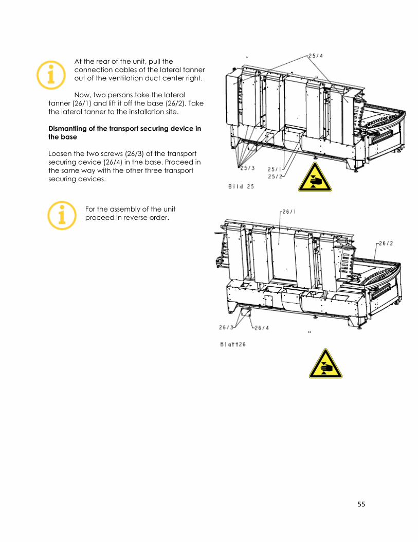
55
At the rear of the unit, pull the
connection cables of the lateral tanner
out of the ventilation duct center right.
Now, two persons take the lateral
tanner (26/1) and lift it off the base (26/2). Take
the lateral tanner to the installation site.
Dismantling of the transport securing device in
the base
Loosen the two screws (26/3) of the transport
securing device (26/4) in the base. Proceed in
the same way with the other three transport
securing devices.
For the assembly of the unit
proceed in reverse order.
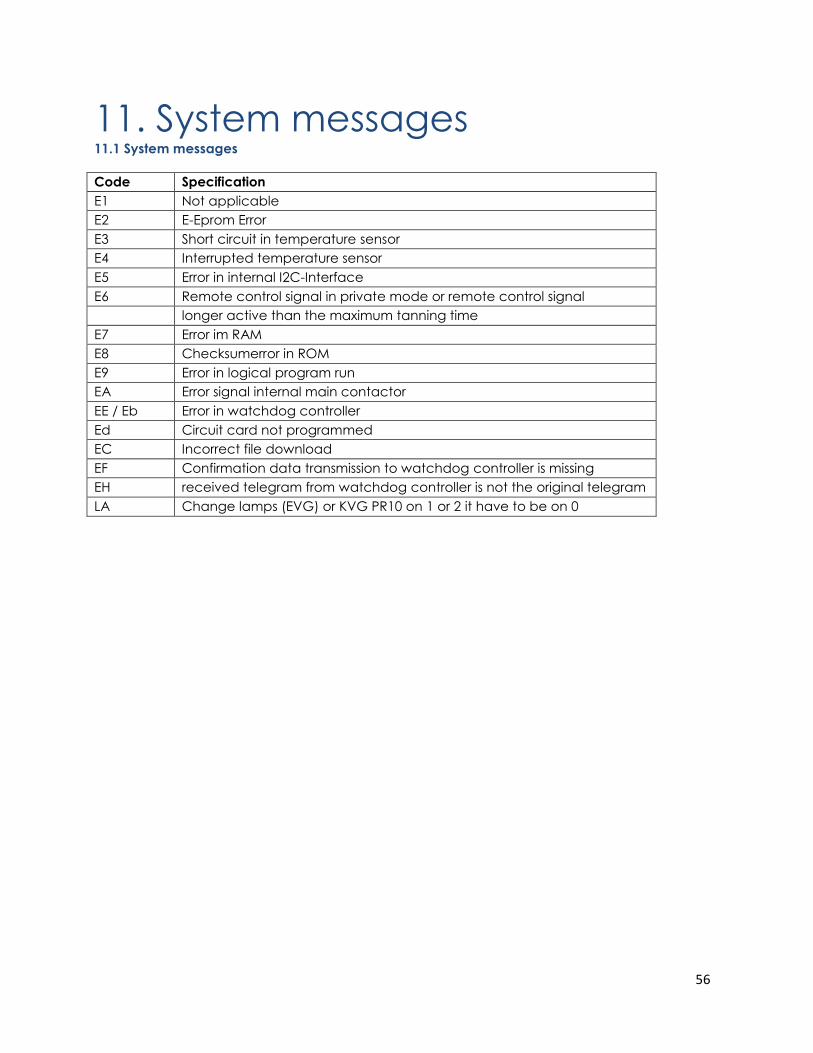
56
11. System messages 11.1 System messages
Code Specification
E1 Not applicable
E2 E-Eprom Error
E3 Short circuit in temperature sensor
E4 Interrupted temperature sensor
E5 Error in internal I2C-Interface
E6 Remote control signal in private mode or remote control signal
longer active than the maximum tanning time
E7 Error im RAM
E8 Checksumerror in ROM
E9 Error in logical program run
EA Error signal internal main contactor
EE / Eb Error in watchdog controller
Ed Circuit card not programmed
EC Incorrect file download
EF Confirmation data transmission to watchdog controller is missing
EH received telegram from watchdog controller is not the original telegram
LA Change lamps (EVG) or KVG PR10 on 1 or 2 it have to be on 0
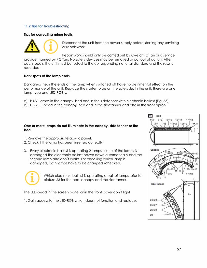
57
11.2 Tips for Troubleshooting
Tips for correcting minor faults
Disconnect the unit from the power supply before starting any servicing
or repair work.
Repair work should only be carried out by uwe or PC Tan or a service
provider named by PC Tan. No safety devices may be removed or put out of action. After
each repair, the unit must be tested to the corresponding national standard and the results
recorded.
Dark spots at the lamp ends
Dark areas near the ends of the lamp when switched off have no detrimental effect on the
performance of the unit. Replace the starter to be on the safe side. In the unit, there are one
lamp type and LED-RGB’s:
a) LP UV- lamps in the canopy, bed and in the sidetanner with electronic ballast (Fig. 63).
b) LED-RGB-bead in the canopy, bed and in the sidetanner and also in the front apron.
One or more lamps do not illuminate in the canopy, side tanner or the
bed.
1. Remove the appropriate acrylic panel.
2. Check if the lamp has been inserted correctly.
3. Every electronic ballast is operating 2 lamps. If one of the lamps is
damaged the electronic ballast power down automatically and the
second lamp also don´t works. For checking which lamp is
damaged, both lamps have to be changed /checked.
Which electronic ballast is operating a pair of lamps refer to
picture 63 for the bed, canopy and the sidetanner.
The LED-bead in the screen panel or in the front cover don´t light
1. Gain access to the LED-RGB which does not function and replace.
58
Arrange for an inspection by PC Tan or a service provider named by PC Tan.
The canopy or bed becomes too warm
1. Check whether the air intake filters (filter mats) are clogged.
2. Ensure that the exhaust air can be discharged unobstructed. Airflow must not be obstructed
at either the exhaust hose or in the ventilation duct, as this will lead to overheating of the unit.
For information on effective ventilation, ask your dealer.
Arrange for an inspection by PC Tan or a service provider named by PC Tan.
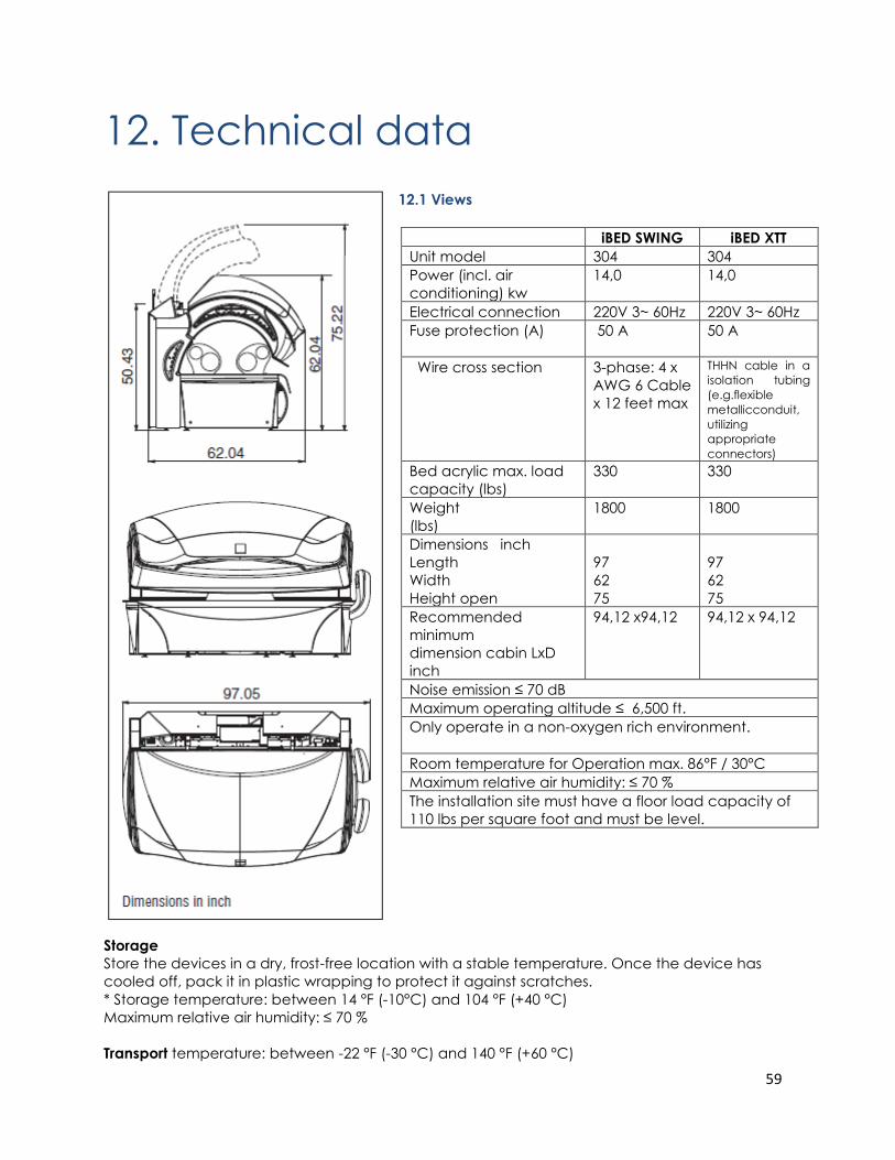
59
12. Technical data
12.1 Views
Storage
Store the devices in a dry, frost-free location with a stable temperature. Once the device has
cooled off, pack it in plastic wrapping to protect it against scratches.
* Storage temperature: between 14 °F (-10°C) and 104 °F (+40 °C)
Maximum relative air humidity: ≤ 70 %
Transport temperature: between -22 °F (-30 °C) and 140 °F (+60 °C)
iBED SWING iBED XTT
Unit model 304 304
Power (incl. air
conditioning) kw
14,0 14,0
Electrical connection 220V 3~ 60Hz 220V 3~ 60Hz
Fuse protection (A) 50 A 50 A
Wire cross section
3-phase: 4 x
AWG 6 Cable
x 12 feet max
THHN cable in a
isolation tubing
(e.g.flexible
metallicconduit,
utilizing
appropriate
connectors)
Bed acrylic max. load
capacity (lbs)
330 330
Weight
(lbs)
1800 1800
Dimensions inch
Length
Width
Height open
97
62
75
97
62
75
Recommended
minimum
dimension cabin LxD
inch
94,12 x94,12 94,12 x 94,12
Noise emission ≤ 70 dB
Maximum operating altitude ≤ 6,500 ft.
Only operate in a non-oxygen rich environment.
Room temperature for Operation max. 86°F / 30°C
Maximum relative air humidity: ≤ 70 %
The installation site must have a floor load capacity of
110 lbs per square foot and must be level.
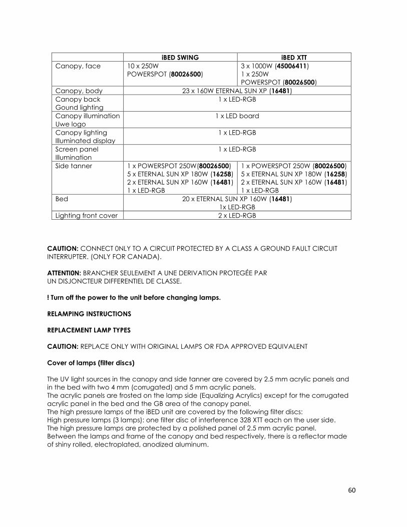
60
CAUTION: CONNECT 0NLY TO A CIRCUIT PROTECTED BY A CLASS A GROUND FAULT CIRCUIT
INTERRUPTER. (ONLY FOR CANADA).
ATTENTI0N: BRANCHER SEULEMENT A UNE DERIVATION PROTEGÉE PAR
UN DISJONCTEUR DIFFERENTIEL DE CLASSE.
! Turn off the power to the unit before changing lamps.
RELAMPING INSTRUCTIONS
REPLACEMENT LAMP TYPES
CAUTION: REPLACE ONLY WITH ORIGINAL LAMPS OR FDA APPROVED EQUIVALENT
Cover of lamps (filter discs)
The UV light sources in the canopy and side tanner are covered by 2.5 mm acrylic panels and
in the bed with two 4 mm (corrugated) and 5 mm acrylic panels.
The acrylic panels are frosted on the lamp side (Equalizing Acrylics) except for the corrugated
acrylic panel in the bed and the GB area of the canopy panel.
The high pressure lamps of the iBED unit are covered by the following filter discs:
High pressure lamps (3 lamps): one filter disc of interference 328 XTT each on the user side.
The high pressure lamps are protected by a polished panel of 2.5 mm acrylic panel.
Between the lamps and frame of the canopy and bed respectively, there is a reflector made
of shiny rolled, electroplated, anodized aluminum.
iBED SWING iBED XTT
Canopy, face 10 x 250W
POWERSPOT (80026500)
3 x 1000W (45006411)
1 x 250W
POWERSPOT (80026500)
Canopy, body 23 x 160W ETERNAL SUN XP (16481)
Canopy back
Gound lighting
1 x LED-RGB
Canopy illumination
Uwe logo
1 x LED board
Canopy lighting
Illuminated display
1 x LED-RGB
Screen panel
Illumination
1 x LED-RGB
Side tanner 1 x POWERSPOT 250W(80026500)
5 x ETERNAL SUN XP 180W (16258)
2 x ETERNAL SUN XP 160W (16481)
1 x LED-RGB
1 x POWERSPOT 250W (80026500)
5 x ETERNAL SUN XP 180W (16258)
2 x ETERNAL SUN XP 160W (16481)
1 x LED-RGB
Bed 20 x ETERNAL SUN XP 160W (16481)
1x LED-RGB
Lighting front cover 2 x LED-RGB
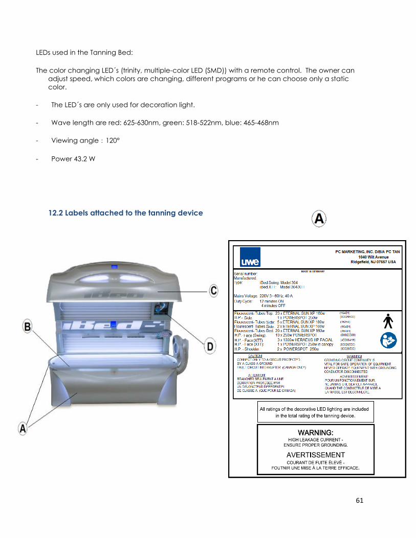
61
LEDs used in the Tanning Bed:
The color changing LED´s (trinity, multiple-color LED (SMD)) with a remote control. The owner can
adjust speed, which colors are changing, different programs or he can choose only a static
color.
- The LED´s are only used for decoration light.
- Wave length are red: 625-630nm, green: 518-522nm, blue: 465-468nm
- Viewing angle:120°
- Power 43.2 W
12.2 Labels attached to the tanning device
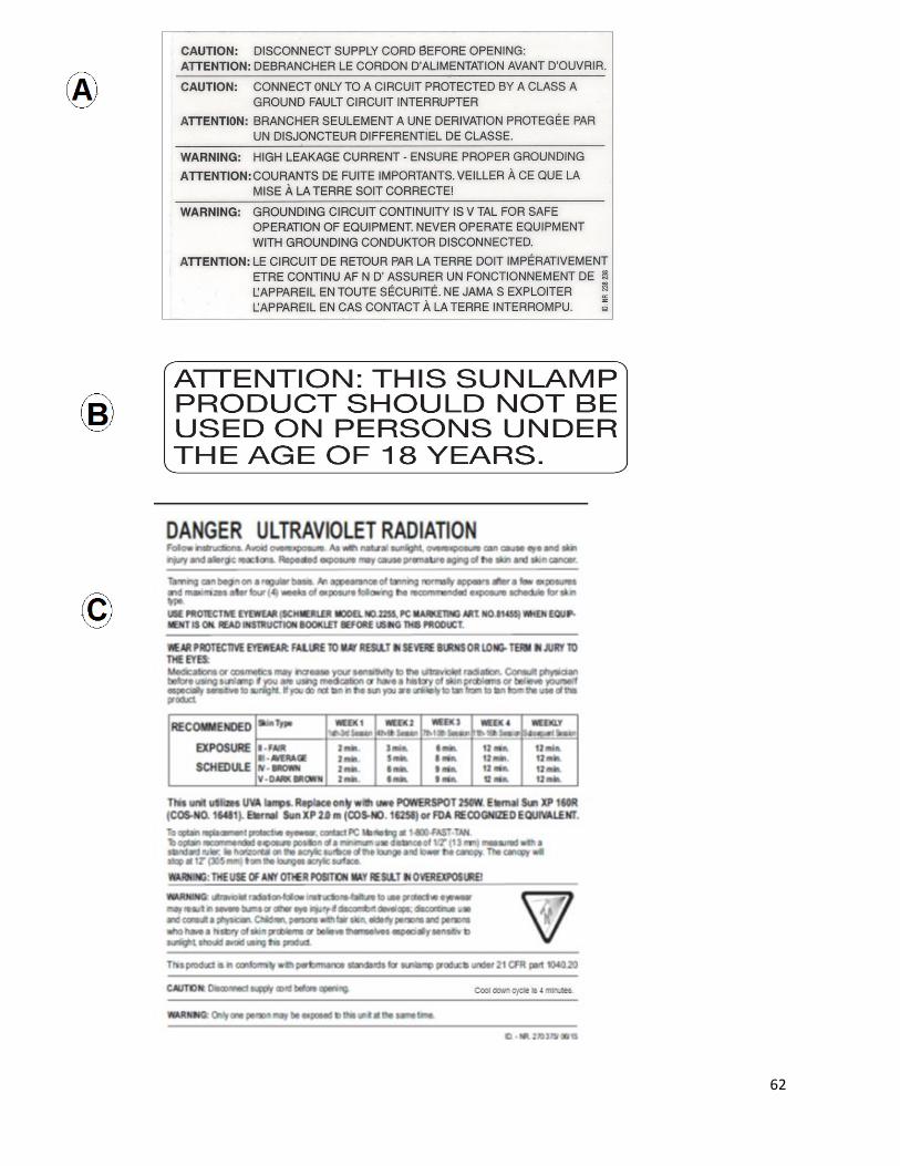
62
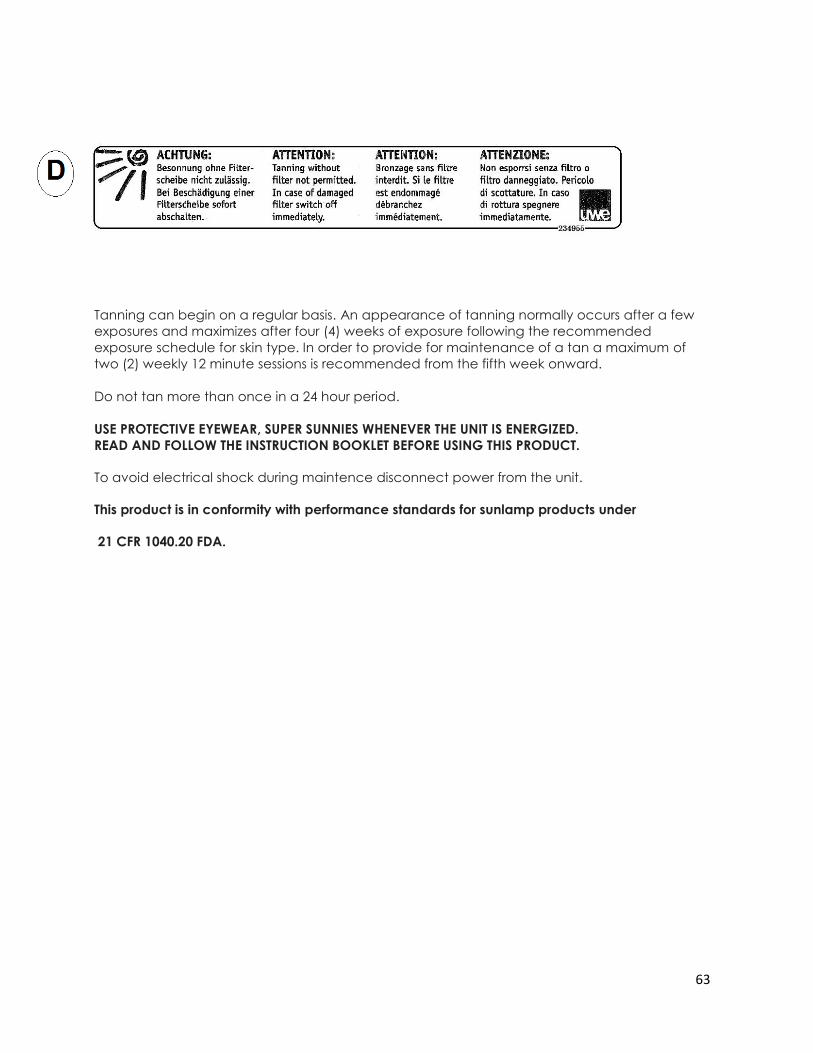
63
Tanning can begin on a regular basis. An appearance of tanning normally occurs after a few
exposures and maximizes after four (4) weeks of exposure following the recommended
exposure schedule for skin type. In order to provide for maintenance of a tan a maximum of
two (2) weekly 12 minute sessions is recommended from the fifth week onward.
Do not tan more than once in a 24 hour period.
USE PROTECTIVE EYEWEAR, SUPER SUNNIES WHENEVER THE UNIT IS ENERGIZED.
READ AND FOLLOW THE INSTRUCTION BOOKLET BEFORE USING THIS PRODUCT.
To avoid electrical shock during maintence disconnect power from the unit.
This product is in conformity with performance standards for sunlamp products under
21 CFR 1040.20 FDA.
64
13. uwe EQUIPMENT WARRANTY
1. WARRANTY - PC Marketing, Inc. d/b/a PC Tan (the “Company”) warrants that electrical
components are free from defects in its materials and workmanship, under normal use,
for one year (“Warranty Period”) beginning from the purchase invoice date of the uwe
indoor tanning equipment (“Product”) is purchased from the Company or an authorized
Distributor of the Company or from an authorized Dealer or Representative of such
Distributor or Dealer (collectively the “Distributor”), if you, the original purchaser
(“Purchaser”), retain ownership during the Warranty Period. This Warranty is
nontransferable. THE WARRANTY CONTAINED IN THIS SECTION 1 IS SUBJECT TO VOIDANCE
IN ACCORDANCE WITH SECTION 3.
2. WARRANTY FOR ITEMS NOT COVERED BY THE ONE YEAR WARRANTY SET FORTH IN SECTION
1; ACRYLIC SURFACES. Lamps, lamp starters, filter glass plates; metal structure, plastic
covers and air filters are not covered under this warranty. THE WARRANTY CONTAINED IN
THIS SECTION 2 IS SUBJECT TO VOIDANCE IN ACCORDANCE WITH SECTION 3.
3. VOIDANCE OF THE WARRANTY. THE WARRANTIES SET FORTH IN SECTIONS 1 AND 2 HEREIN
ABOVE ARE VOID IF YOU: TRANSFER THE PRODUCT TO A THIRD PARTY, MODIFY THE
PRODUCT, MISUSE THE PRODUCT, SUBJECT THE PRODUCT TO ABNORMAL CONDITIONS OF
OPERATION, ATTEMPT UNAUTHORIZED REPAIRS TO THE PRODUCT, DO NOT USE ORIGINAL
EQUIPMENT MANUFACTURER (OEM) REPLACEMENT PARTS, DO NOT FOLLOW THE CARE
AND USE INSTRUCTION MANUAL CONCERNING SPACE, ELECTRICAL AND ENVIRONMENTAL
REQUIREMENTS, SUBJECT THE PRODUCT TO ACCIDENT, MISUSE OR MISAPPLICATION; OR
SERVICE THE PRODUCT BY ANYONE OTHER THAN THE COMPANY OR AN AUTHORIZED
SERVICE REPRESENTATIVE OF THE COMPANY OR DISTRIBUTOR
4. WARRANTY RETURNS. All warranty claims can be handled through the Company or
Distributor. If you do not know the phone number of the Distributor, you can contact the
Company at 1-800-FAST-TAN, Monday through Friday from 9:00 AM to 5:00 PM EST.
Warranty covered items are to be returned on a part for part replacement. All freight
charges are the sole responsibility of the Purchaser.
5. DISTRIBUTOR WARRANTIES. To the extent representations, warranties or commitments are
extended to the Purchaser by a Distributor, such representations, warranties and
commitments will be those of the Distributor alone, and will not be attributed to the
Company and the Company shall not be responsible for same.
6. DISCLAIMER OF WARRANTIES. EXCEPT AS EXPRESSLY STATED IN SECTION 1 AND 2 HEREIN
ABOVE, THERE ARE NO OTHER WARRANTIES BY THE COMPANY OR DISTRIBUTOR, EXPRESSED
OR IMPLIED, BY OPERATION OF LAW OR OTHERWISE. THE COMPANY AND DISTRIBUTOR
DISCLAIM ALL IMPLIED AND EXPRESS WARRANTIES, INCLUDING BUT NOT LIMITED TO ANY
IMPLIED WARRANTY OF MERCHANTABILITY OR FITNESS FOR A PARTICULAR PURPOSE.
65
7. LIMITATION OF LIABILITY. THE COMPANY OR DISTRIBUTOR SHALL NOT BE LIABLE, WHETHER IN
CONTRACT OR TORT, FOR ANY LOSS OR DAMAGE, INCLUDING BUT NOT LIMITED TO
SPECIAL, INDIRECT, CONSEQUENTIAL, PROPERTY, ECONOMIC OR PERSONAL DAMAGES
OF THE END USER, OR THIRD PARTIES, EVEN IF ADVISED OF THE POSSIBILITIES OF SUCH
DAMAGES, ABOVE OR BEYOND THE REPAIR, REPLACEMENT OR REFUND OF ANY
DEFECTIVE PRODUCT, WHICH SHALL BE THE PURCHASER’S SOLE REMEDY. THE PURCHASE
PRICE OF THE PRODUCT IS A CONSIDERATION IN LIMITING THE COMPANY’S AND
DISTRIBUTOR’S LIABILITY.
8. LOCAL LAWS. Laws pertaining to the rights and limitations of the Warranty vary from state
to state. The limitations set forth herein may not be applicable to the Purchaser, or
Purchaser may have other legal rights not referenced herein.
9. MISCELLANEOUS
10. VALIDATION. To validate that you are the original purchaser of the Product from the
Company or a Distributor and to ensure that you receive the above-recited benefits
under the Warranty, please provide the information on the warranty card, sign the card
and mail it within (30) days of purchase to:
11. SPARE AND REPLACEMENT PARTS. Original Equipment Manufacturers (OEM) lamps and
replacement parts are available by direct order. To order, call 1-800-FAST-TAN. Please
have Credit Card information available when calling or write:
GOVERNING LAW. This Warranty shall be governed by, interpreted by and enforced in
accordance with the substantive and procedural laws of the State of New Jersey, and
the United States of America, conflict of laws notwithstanding. This Warranty and any
such claims, disputes or actions is domiciled. The Company, Distributor and Purchaser
hereby agree to submit to the subject matter and personal jurisdiction and venue of
said courts to resolve any disputes. If any term or provision of this Warranty is
adjudicated to be invalid by any Court have jurisdiction, such provision shall be
inoperable and deemed omitted and shall not invalidate the remaining provisions
hereof.
ENTIRE AGREEMENT. This Warranty constitutes the entire agreement of the Purchaser, the
Distributor and the Company as to the subject matter and there are no other
understandings, agreements or terms, whether oral or written, between the Company
and the Purchaser.
READ AND UNDERSTAND THIS WARRANTY. Before signing and returning this warranty, the
Purchaser acknowledges that Purchaser has read and understands the terms herein, or
has had the opportunity to have them read and explained to the Purchaser by an
authorized representative.
Warranty Department
PC Tan
1040 Wilt Avenue
Ridgefield, NJ 07657
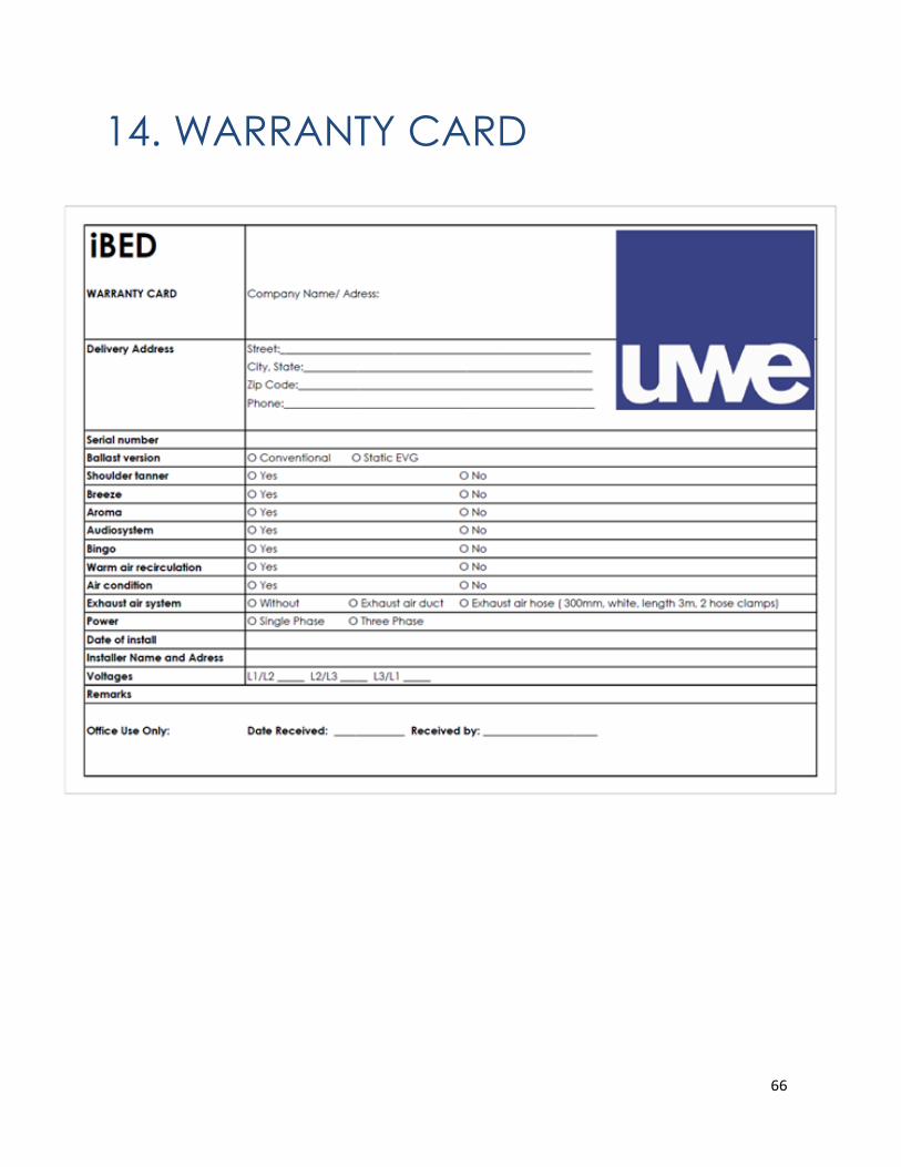
66
14. WARRANTY CARD

67
15. EMC information - iBed
Warnings: Medical Electrical Equipment needs special precautions regarding EMC and needs to be
installed and put into service according to the EMC information provided in the Accompanying
Documents.
Portable and Mobile RF Communications Equipment can affect Medical Electrical Equipment The use of accessories and cables other than those specified, with the exception of those sold
by the manufacturer as replacement parts for internal components, may result in increased
emissions or decreased immunity of the equipment or system.
The Tanning device should not be used adjacent to or stacked with other equipment and that
if adjacent or stacked use is necessary, the Tanning device should be observed to verify normal
operation in the configuration in which it will be used. 15.1.1 Table 1: Guidelines and manufacturer's
declaration – Electromagnetic emissions
The tanning device has been designed for use in the electromagnetic environment
specified below. The device operator must ensure that it is used in such an
environment
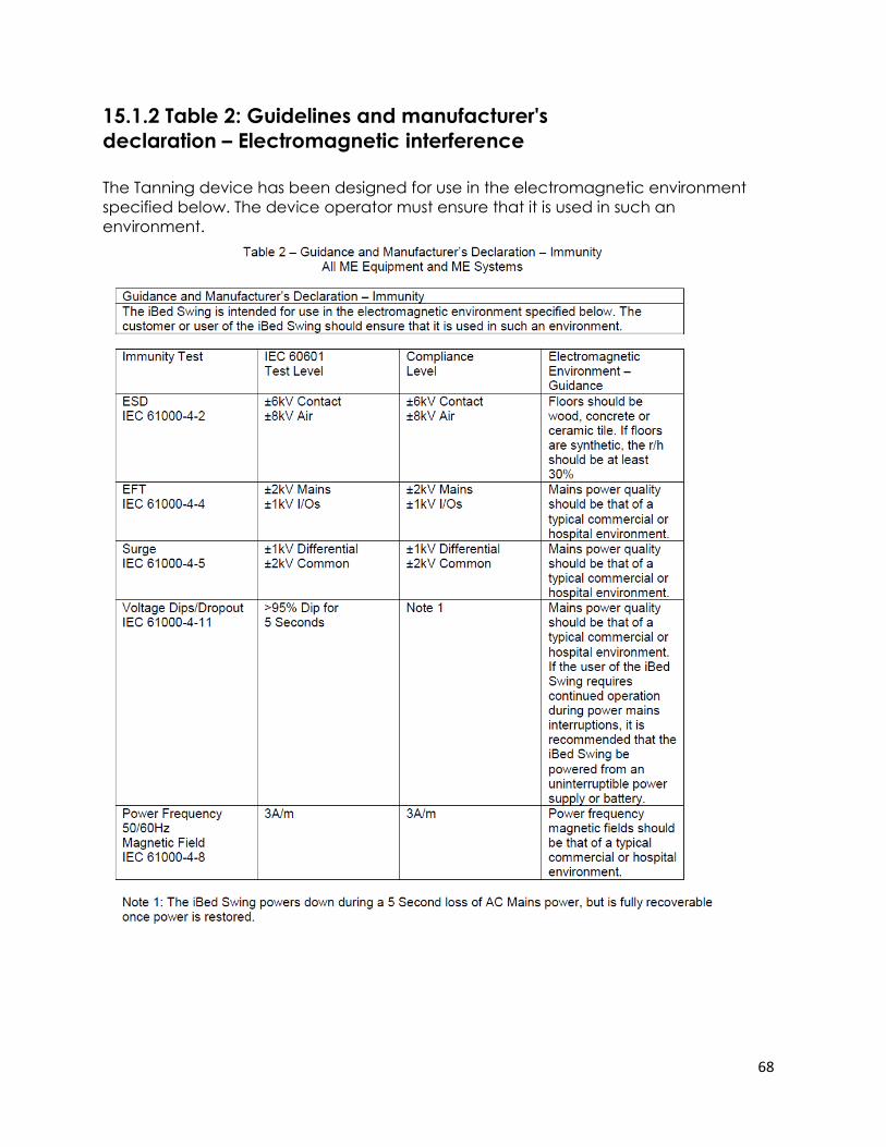
68
15.1.2 Table 2: Guidelines and manufacturer's
declaration – Electromagnetic interference
The Tanning device has been designed for use in the electromagnetic environment
specified below. The device operator must ensure that it is used in such an
environment.
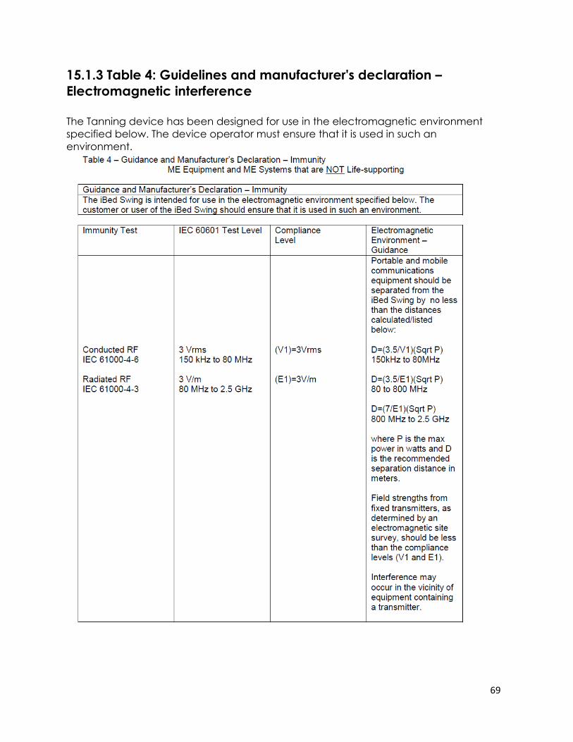
69
15.1.3 Table 4: Guidelines and manufacturer's declaration –
Electromagnetic interference
The Tanning device has been designed for use in the electromagnetic environment
specified below. The device operator must ensure that it is used in such an
environment.
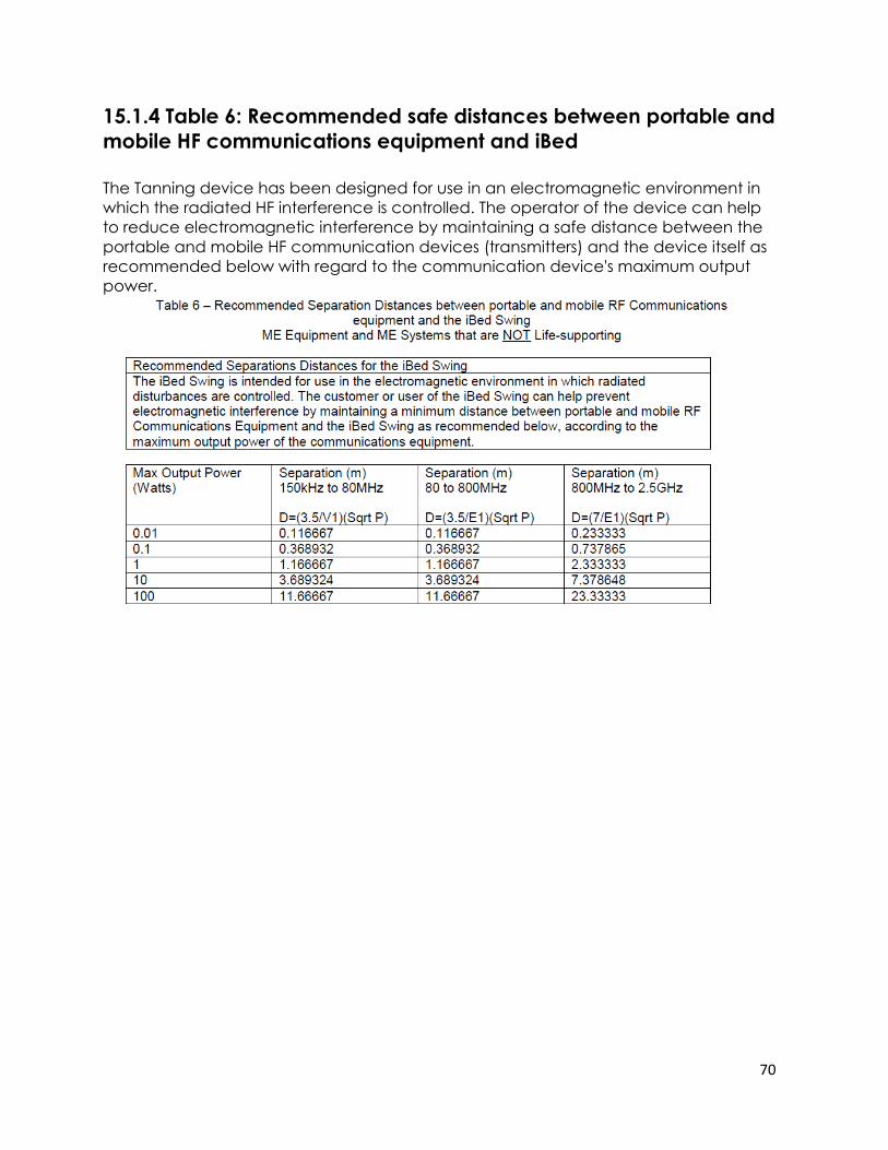
70
15.1.4 Table 6: Recommended safe distances between portable and
mobile HF communications equipment and iBed
The Tanning device has been designed for use in an electromagnetic environment in
which the radiated HF interference is controlled. The operator of the device can help
to reduce electromagnetic interference by maintaining a safe distance between the
portable and mobile HF communication devices (transmitters) and the device itself as
recommended below with regard to the communication device's maximum output
power.

71
Made in Germany
ID.-NR. 292 016 / 12/ 15