Embed Size (px)
Citation preview

1
OP20 Software User manual
Xinje Electronic Co., Ltd.
Data no. HOC02 20110705 8.0

2
Catalog 1 INTRODUCTION ............................................................................................................................... 3
1-1.SUMMARIZATION ................................................................................................................................................ 3 1-2.INSTALL AND UNINSTALL .................................................................................................................................... 3 1-3.USING PROCESS .................................................................................................................................................. 5
2 EDIT SCREEN.................................................................................................................................... 6
3 MENU.............................................................................................................................................. 8
3-1. FILE ...................................................................................................................................................................... 8 3-2. EDIT.................................................................................................................................................................... 10 3-3. TOOL .................................................................................................................................................................. 10 3-4. HELP ................................................................................................................................................................... 17
4 PART ............................................................................................................................................. 18
4-1. TEXT AND TRUE TYPE TEXT ................................................................................................................................ 18 4-2.DYNAMIC TEXT AND DYNAMIC TRUE TYPE TEXT .............................................................................................. 18 4-3. FUNCTION KEY ................................................................................................................................................... 19 4-4.DISPLAY AND SET THE DATA ............................................................................................................................. 21 4-5.LAMP ................................................................................................................................................................ 23 4-6.BAR .................................................................................................................................................................. 25 4-7.TREND MAP ...................................................................................................................................................... 26 4-8.PICTURE ........................................................................................................................................................... 27 4-9.STRING ............................................................................................................................................................. 27 4-10.TOUCH KEY .................................................................................................................................................... 28
5 MAKE A PROJECT .......................................................................................................................... 29
5-1.MAKE A NEW PROJECT ...................................................................................................................................... 29 5-2.MAKE A SCREEN ............................................................................................................................................... 29 5-3.DOWNLOAD THE PROJECT ................................................................................................................................ 30 5-5.PROJECT PROTECTION ...................................................................................................................................... 30
6 Q&A .............................................................................................................................................. 32

3
1 Introduction
1-1.Summarization
OP20 software is fit for OP operate panel, MP touch panel and XP HMI&PLC controller. The software running OS: Windows98/XP/Win7. The software is fit for the follow models:
OP OP320, OP320-S OP320-A, OP320-A-N, OP320-A-S OP325-A, OP325-A-S OP330, OP330-S
MP MP330, MP330-S MP325-A, MP325-A-S
XP
XP1-18R\T\RT XP2-18R\T\RT XP3-18R\T\RT XP3-16R\T\RT
The software is easy to learn and use. All the parts including lamp, text, buttons, trend map, data settings, etc. can be put into the OP screen. The OP project includes many screens; each screen can switch to another by jump screen button.
1-2.Install and uninstall
1.Get the OP20 software from www.xinje.com
2.OS requirements: Windows98/2000/XP/Win7.
3.Installation steps (1) Double click “setup.exe” to enter the installation guide.

4
(2) click next and “accept the agreement”. Click next to enter the serial number. Open
“serial_no.txt” to know the serial number.

5
(3) Click next until finish the installation. Note: 1. If there is other version of OP20 in the PC, please choose different installation location. If the two versions are installed at the same location, the software cannot run normally. 2. Higher version of OP20 is compatible with lower version. But lower version isn’t compatible with higher version.
4.Uninstall Double click “Thinget/OP20/unins000.exe” in the installation folder and continue as the uninstall guide.
1-3.Using process The using process of OP20 software: Open OP20 software build a new project choose panel type choose PLC type make the screen save the project download project run the OP product

6
2 Edit screen
It will show the follow edit screen after running OP20 software:
Screen: display the screen no Description: simple description for the screen function New: build a new screen Delete: delete the current screen The buttons in the tool bar:
Button Function
Build a new project
Open a project
Save the project
Cut the contents in the text
Copy the contents in the text
Paste the contents in the text
Build a new screen
The attribute of current screen
Copy screen
Delete screen
Alarm list, each alarm message is related to an auxiliary relay
The original screen. Press ESC on the panel to return to original screen. It can set the password and interactive register.

7
Set the general function key. (for MP325/OP330/MP330)
Download the program into the OP panel The buttons on the right side of screen:
Button Function
For text input
Dynamic text
Text, support different fonts
Dynamic text, support different fonts
Set the register data
Lamp, to display the status of PLC auxiliary relay
Function button. The function includes coil setting, screen jump, data setting
Trend map. To show the trend of parameters
Bar map. To show the flow, pressure, level and so on.
Insert bmp file.
String. To show the contents in PLC register.
Function button for touch operation (only for MP series panel)

8
3 Menu
3-1. File File menu:
1. New project
Click or file/new project to build a new project. Choose the OP model and PLC model in the
list. The PLC will communicate with OP.

9
2. Open project
Click or File/open to open the project.
3. Save project
Click or file/save project to save the project. The current file will cover the former one.
4. Save project as… Save the current file in another location but not cover the former file.
5. Import data… and export data… Protect the program. Please refer to chapter 5. 6. Select model Choose the OP model.
7. Select PLC Choose the PLC model and set the PLC communication parameters.
8. Comm port Choose the PC COM port to download the program. The default port is COM1. The port range is from COM1 to COM8.

10
9. Download
Download program from PC to OP panel. Click for same function.
10. Exit Exit OP20 software. 3-2. Edit Cut, Copy, paste and delete are for text operation.
3-3. Tool
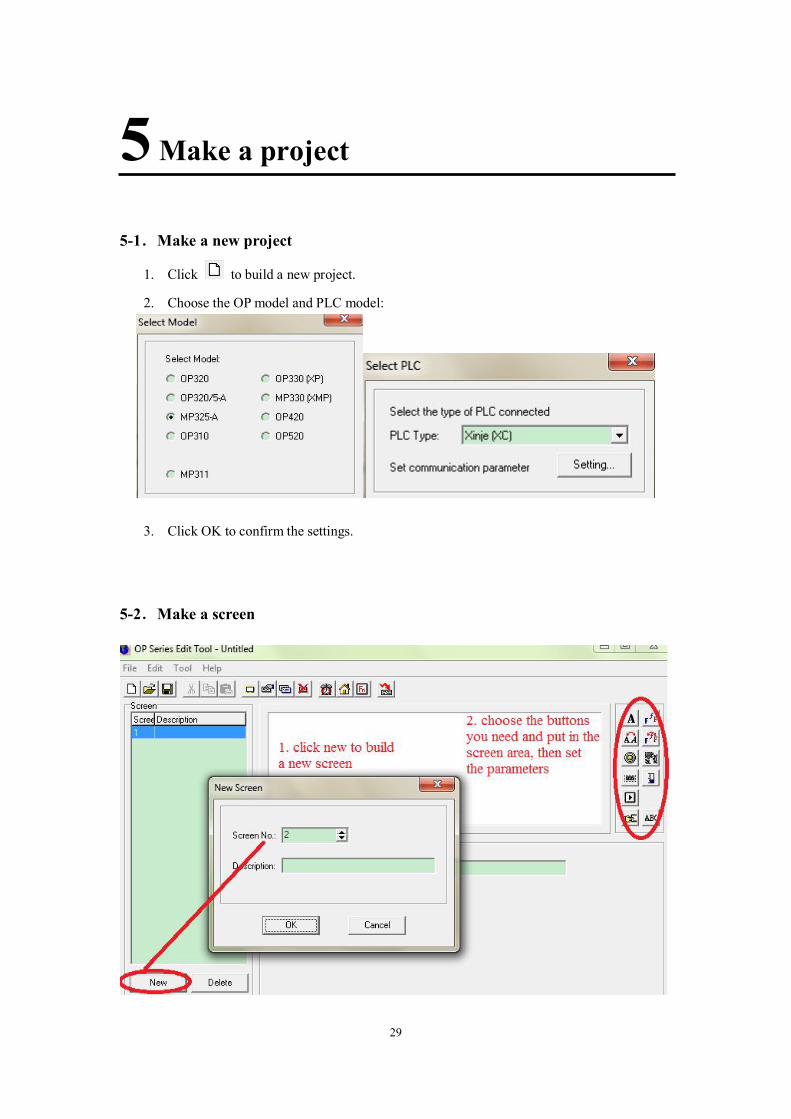
1. New screen… Build a new screen. Note: please see the follow picture, suppose there are two screens in the project. Click screen2 and new button, it will build a new screen3. But click screen1 and new button, it still builds screen2 and the former screen2 will be covered.
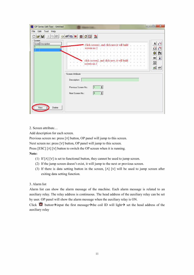
11
2. Screen attribute… Add description for each screen. Previous screen no: press [∧] button, OP panel will jump to this screen. Next screen no: press [∨] button, OP panel will jump to this screen. Press [ESC] [∧] [∨] button to switch the OP screen when it is running. Note:
(1) If [∧] [∨] is set to functional button, they cannot be used to jump screen. (2) If the jump screen doesn’t exist, it will jump to the next or previous screen. (3) If there is data setting button in the screen, [∧] [∨] will be used to jump screen after
exiting data setting function.
3. Alarm list Alarm list can show the alarm message of the machine. Each alarm message is related to an auxiliary relay. The relay address is continuous. The head address of the auxiliary relay can be set by user. OP panel will show the alarm message when the auxiliary relay is ON. Click buttoninput the first messagethe coil ID will light set the head address of the auxiliary relay

12
User can take some action to solve the alarm problem. Press [ESC] to return to monitor screen. Note: for software version 8.0h and higher, please press ENT to return to main screen. Press ESC
to return to the former screen.
If user wants to see the entire message in the alarm list, please put a function button on the screen, and set as the following picture. So you can press the function button and press UP DOWN button to check the alarm message.
4. Set OP series
Click button or Tool/set OP series…

13
Master screen: the screen after OP panel electrified. Please choose the main menu or most frequently used screen for master screen. Press ESC button to jump to master screen.
Password: one project can have one password. For example, when choose encrypt
function of register button , this button can be used after inputting the password.
Password is also applied to function key, jump screen, coil settings and so on. Screen save: show certain screen or turn off the backlight if OP panel has no operation for
long time. The default backlight time is 3 minutes. Power beep: choose this item to decrease the volume of beep. Exchange word: exchange the high byte and low byte of register. For example, Schneider
PLC have to choose this item, otherwise, double-word displaying will be the messy code. Interactive control: generally, switch the screen by pressing the OP button. This item can
switch the screen by PLC register. For example, D0=3, OP panel will jump to screen no.3. then D0 will be zero again. If D0≥32768, beep will always tweet.
Report current screen: save the current screen no. in PLC register. Peripheral control/use date time module: OP320 doesn’t have this item. This item is to
save the OP time in PLC register.

14
For example, set register ID = D3. D5= Year and month, D6=date and hour, D7= minute and second.
Then use a function key to enter the RTC. Click , and set it as the following picture:
If OP shows this screen, it means this OP model doesn’t have RTC module. Press SET to set the RTC in the sequence of year/month/date/hour/minute/second. Press ENT to confirm the settings. Please note that don’t set the RTC by PLC register.

15
5. Set general function key This key can be used for all the screens. Only OP330, MP330 and MP325-A has this key.
Click it will show below window:
Function key includes eight keys (F1~F8). Each key has 4 functions(not setted/set coil/screen jump/set data) which can be used together with encrypt function. If function key is displayed on the screen, it can realize these functions. If not, it is the same to normal keys (UP/DOWN/LEFT…). After setting the function key, it can be operated in every screen of the OP project.
(1) Set coil
Force ON Turn ON auxiliary relay after pressing the button Force OFF Turn OFF auxiliary relay after pressing the button Reverse Get the NOT of auxiliary relay after pressing the button Momentary
ON Turn ON auxiliary relay when pressing the button, turn OFF the auxiliary relay when releasing the button
Encrypt: choose this item to protect the button. You can operate the button after inputting the password
(2) Screen jump

16
Screen Choose the screen no. to jump when pressing the button Password Jump to the screen of password input when pressing the button Alarm list Jump to the screen of alarm list when pressing the button Date/time Jump to the screen of date/time when pressing the button Encrypt: choose this item to protect the button. You can operate the
button after inputting the password. (3) Set data
Set D0 to the value when pressing the button. Encrypt: choose this item to protect the button. You can operate the button after inputting the password. Click OK to confirm the settings for general function key. After downloading project to OP panel, press Fn to realize set function. 6. Display grid dot Display the grid dot in the screen if ticked this item. The OP panel will not display the dot whether tick this item. This item is only effective for the OP20 software.

17
3-4. Help Check the OP20 software version in this item.

18
4 Part
4-1. Text and true type text
Click button, it will show a rectangle, put it in the suitable place on the screen. Input words in the message frame.
Coordinate Show the coordinate of the text. The original point is the top left corner.
Special Double: zoom in the text 2-time Inverse: exchange the color of text and background
Text Message: in the text, support copy, cut, delete
true type text: the text which can change the font.
4-2.Dynamic text and dynamic true type text
dynamic text can display different text according to register value. For example: D0=0, it
19
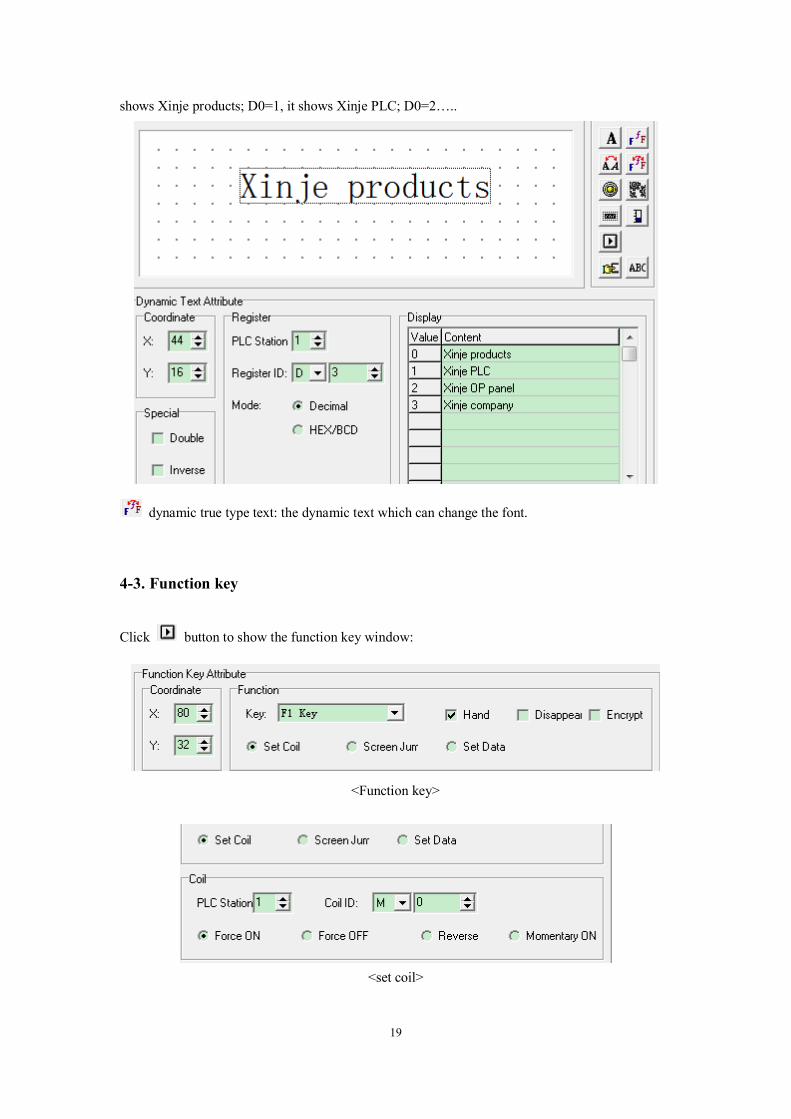
shows Xinje products; D0=1, it shows Xinje PLC; D0=2…..
dynamic true type text: the dynamic text which can change the font.
4-3. Function key
Click button to show the function key window:
<Function key>
<set coil>

20
<screen jump>
<set data>
<function key> Key Choose function key during the buttons Hand Add hand beside the key Disappear The function key will not display on the screen Encrypt <set coil>
The function key will be available after input the correct password
Set coil Set the auxiliary relay Force ON Set ON the auxiliary relay
Force OFF Set OFF the auxiliary relay Reverse Set NOT the auxiliary relay
Momentary ON
Set ON the auxiliary relay when pressing the button, set OFF it when releasing the button
<screen jump> Screen jump
Jump to set screen
Screen The jump screen no. Password Jump to the password input screen Alarm list Jump to the alarm screen Date/time
Jump to RTC screen to set the date and time
<set data> Set data
Set value for the register
21
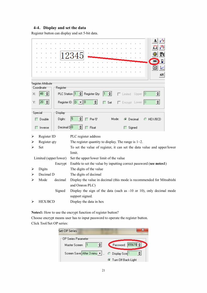
4-4.Display and set the data Register button can display and set 5-bit data.
Register ID PLC register address Register qty The register quantity to display. The range is 1~2. Set To set the value of register, it can set the data value and upper/lower
limit. Limited (upper/lower) Set the upper/lower limit of the value
Encrypt Enable to set the value by inputting correct password (see notes1) Digits The digits of the value Decimal D The digits of decimal Mode decimal Display the value in decimal (this mode is recommended for Mitsubishi
and Omron PLC) Signed Display the sign of the data (such as -10 or 10), only decimal mode
support signed. HEX/BCD Display the data in hex Notes1: How to use the encrypt function of register button? Choose encrypt means user has to input password to operate the register button. Click Tool/Set OP series:
22
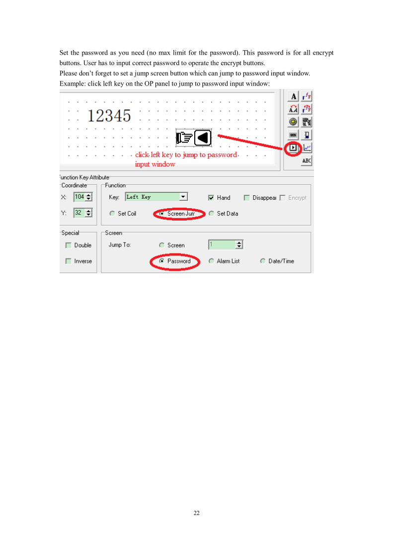
Set the password as you need (no max limit for the password). This password is for all encrypt buttons. User has to input correct password to operate the encrypt buttons. Please don’t forget to set a jump screen button which can jump to password input window. Example: click left key on the OP panel to jump to password input window:
23
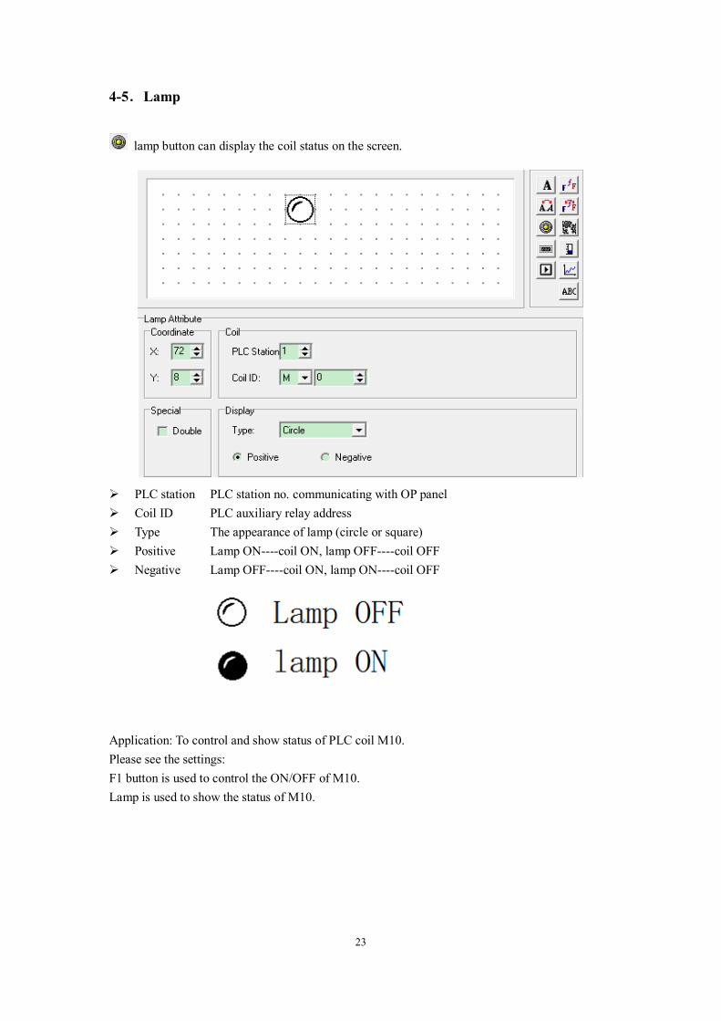
4-5.Lamp
lamp button can display the coil status on the screen.
PLC station Coil ID
PLC station no. communicating with OP panel PLC auxiliary relay address
Type The appearance of lamp (circle or square) Positive Lamp ON----coil ON, lamp OFF----coil OFF Negative Lamp OFF----coil ON, lamp ON----coil OFF
Application: To control and show status of PLC coil M10. Please see the settings: F1 button is used to control the ON/OFF of M10. Lamp is used to show the status of M10.

24

25
4-6.Bar Bar is used to show the analog parameters, such as flow, pressure, level and so on. The width, height and direction can be set.
Register ID PLC register address related to the bar Full value The register value related to the full scale value Zero value The register value related to the zero scale value Direct The display direction of bar Range W: width of the bar H:height of the bar

26
This application will monitor the value of register D300. For example: when D300=100, the bar shows the full scale, D300=50, the bar shows the half scale. 4-7.Trend map Trend map can show the changing trend of data.
Register ID The PLC register related to the trend Full value The register value related to the full scale value Zero value The register value related to the zero scale value Sample data The sample points of the trend. Sample cycle The time between two sample points Range The width and height of the trend Note: one trend only can show one curve.

27
4-8.Picture
picture button can show the picture of bmp format in the OP project.
Note: the max pixel of the picture is 192*64. The part which exceeds the range will be cut.
4-9.String String button can show the register value in character. Note: one register can show two characters. The ASCII of one character is a 2-bit hex number. for
example: D0=4142 (hex), it will show AB.

28
4-10.Touch key This key is only useful for MP series products. The function of touch key is the same to function key. MP series has touch area. This key can be operated in touch area.
29
5 Make a project
5-1.Make a new project
1. Click to build a new project.
2. Choose the OP model and PLC model:
3. Click OK to confirm the settings. 5-2.Make a screen

30
5-3.Download the project
First make sure the project has been saved in the PC. Click to save the project.
Then connect OP panel and PC serial port with OP cable. Turn on the +24V DC power supply of
OP panel. Click to start download. At last it will show the message of “download succeed”.
Note:
1. Do not cut the power supply during downloading. Otherwise OP will not start normally next time.
2. If the software show the message of “timeout, please check the cable”. Please confirm: (a) The software version is compatible with the OP hardware version (see the label at the
back of OP product). OP hardware version OP software version V3.6 V3.6 V4.0~V7.0(not include V7.0) V6.5 V7.0~V8.0 (not include V8.0) V6.5/V7.0/V8.0 and higher version ≥V8.0 ≥V8.0 (b) Check the port of OP and PLC and cable.
3. OP software cannot upload the project from OP panel to the PC. Please save the project in your PC before downloading.
Next is to connect OP panel with the PLC. Please turn off all the power supply for OP and PLC. Connect them with PLC cable. Then turn ON the power. If the communication is normal, it will not show any message. If OP shows the message of “communicating…”, please check the reason as the following items. 1. PLC model is correct 2. The cable is good 3. The port of PLC and OP is good 4.Contact us for help 5-5.Project protection If the user doesn’t want other person to see the project contents, please use this function. Click File/outport data…, save the project in odp format. Now the file.odp is protected. Click File/import data…. to open the odp format file. All the screens and buttons are not applicable except download button. That mean you only can download the file.odp to OP panel.

31
32
6 Q&A
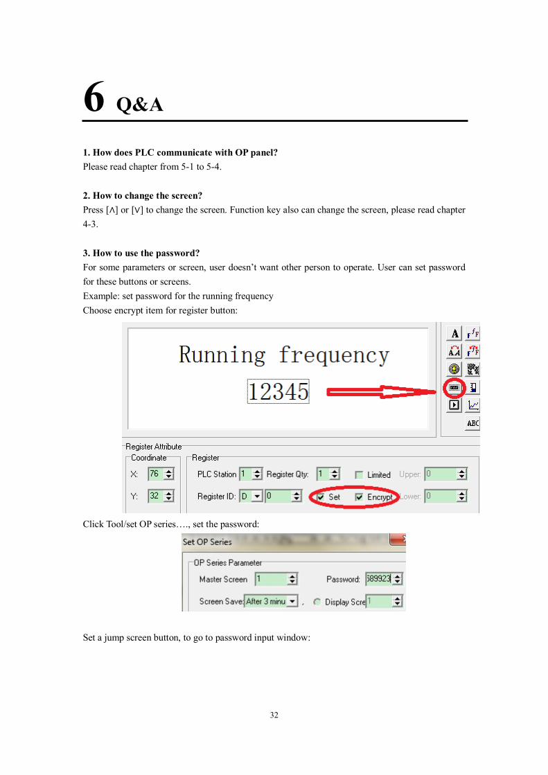
1. How does PLC communicate with OP panel? Please read chapter from 5-1 to 5-4. 2. How to change the screen? Press [∧] or [∨] to change the screen. Function key also can change the screen, please read chapter 4-3. 3. How to use the password? For some parameters or screen, user doesn’t want other person to operate. User can set password for these buttons or screens. Example: set password for the running frequency Choose encrypt item for register button:
Click Tool/set OP series…., set the password:
Set a jump screen button, to go to password input window:

33
When user press SET button on the OP panel, the register cannot be operated. User has to press left key to enter password window. After inputting the correct password, the register can be operated again.
4. How to set the value?
In OP20 software: Choose “set” item of register button. And set the register address (register ID). OP panel: User can press SET button on the OP panel to set the register value. Press UP/DOWN button to increase or decrease the value. Press left/right button to change the set bit of register. Press ENT button to confirm the settings.

34
5. How to set the auxiliary relay? Please refer to chapter 4-3 function key (set coil). In OP20 software: Choose set coil item of function key, set the coil address (coil ID) and the coil action (force ON/force off/reverse/momentary on).
Force ON: set ON the auxiliary relay Force OFF: set OFF the auxiliary relay Reverse: if coil is ON, set to OFF; if coil is OFF, set to ON Momentary ON: set ON the auxiliary relay when pressing the button, set OFF it when releasing the button OP panel: Press left key(for example) on OP panel to control the auxiliary relay M0. 6. How to set the RTC of OP panel? Set the function key in OP20 software: Choose screen jump and date/time item. OP panel: Press left key (for example) to jump to RTC screen. Then user can set the date and time on that screen.

35

无锡信捷电气有限公司
江苏省无锡市蠡园开发区滴翠路 100 号
创意产业园 7 号楼四楼
邮编: 214072
电话: (0510) 85134136
传真: (0510) 85111290
Xinje Electronic Co., Ltd.
4th Floor Building 7,Originality Industry park, Liyuan
Development Zone, Wuxi City, Jiangsu Province
214072
Tel: (510) 85134136
Fax: (510) 85111290


![PLC Software MANUAL - Xinje-support-centre-listo. · PDF filePLC Software Manual Page 3 of 365 LMAN021_R2V2 3-14 [NOP], [END] 76 3-15 [GROUP], [GROUPE] 77 3-16 Programming Notes 78](https://img.dokumen.tips/doc/110x75/5a8231be7f8b9ada388dafc2/plc-software-manual-xinje-support-centre-listo-software-manual-page-3-of-365.jpg)