Embed Size (px)
Citation preview
ONONDAGA COUNTY WATER ENVIRONMENT PROTECTION
METRO WWTP SYRACUSE, NY
DIGESTER #4 STEEL COVER ASSESSMENT
September 11, 2015 Prepared by: Ghaith Makhlouf, PE C&S Engineers, Inc. 499 Col. Eileen Collins Blvd. Syracuse, NY 13212 (315) 455-2000 www.cscos.com
F:\Project\125A - ONONDAGA COUNTY\125400014 - On-Call Electrical and Mechanical Engineering\125SPR130 - Digester No. 4 Structural Repairs\Design\Reports\parts\Digester 4 Assessment (9-11-2015) .docx
ONONDAGA COUNTY DEPARTMENT OF WATER ENVIRONMENT PROTECTION
METRO WWTP-SYRACUSE
DIGESTER #4 STEEL COVER ASSESSMENT C&S Project #125.SPR.130
September 10, 2015
TABLE OF CONTENTS SECTION 1- INTRODUCTION/OBJECTIVES/SCOPE SECTION 2- SCANNING/MEASURING/OBSERVATIONS SECTION 3- FINDINGS & RECOMMENDATIONS SECTION 4- CONSTRUCTION COST DATA FIGURES – Figure 1 through 7. APPENDICES
1. Digester #4, Scans, Elevation Tabulations, And Drawings, by C&S (2015) 2. EIMCO Water Technologies-digester cover guide system article. 3. Record Drawings, dated 02/2013, Drawing G5, Existing Digester #4 Plan and Section by
GHD, Gas Holder Tank Asbuilt drawing dated 10/21/1955, Concrete wall section and miscellaneous tank cover details, dated 1977.
DOCUMENTS PROVIDED BY COUNTY -REFERENCES:
1. Interim Inspection Report, Digester No. 4, (Revised February 4, 2013)-Metro Syracuse WWTP Digester Cleaning and Miscellaneous Repairs.
2. Interim Inspection Report, Digester No. 4, Addendum No. 1, (January 3, 2011)- Metro Syracuse WWTP Digester Cleaning and Miscellaneous Repairs.
3. Inspection and Testing Report, 100-ft Diameter Gas Holder Digester Cover, Dated March 23, 2011.
4. Interim Inspection Report, Digester No. 4, Addendum No. 2, (April 7, 2011)- Metro Syracuse WWTP Digester Cleaning and Miscellaneous Repairs.
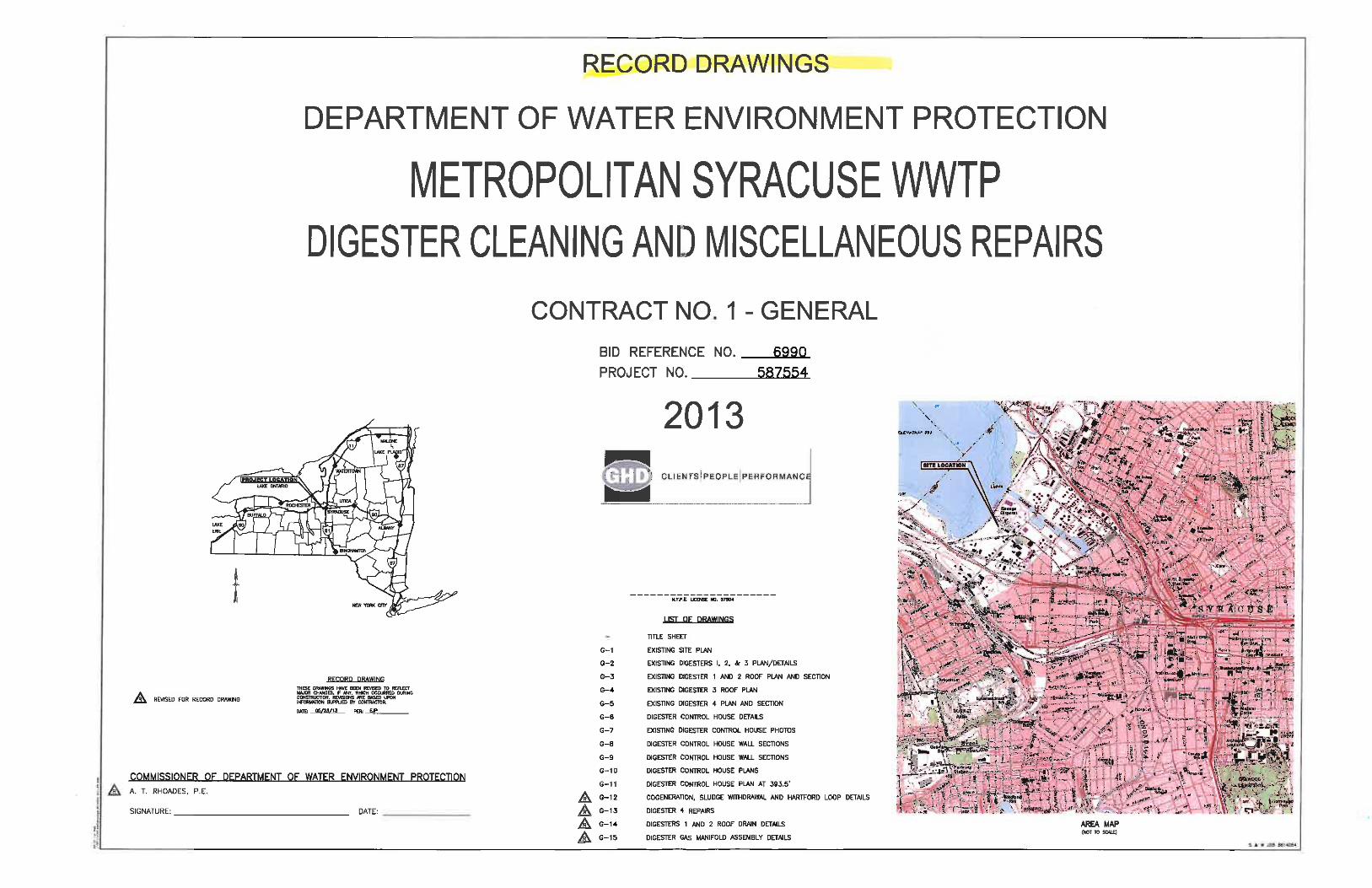
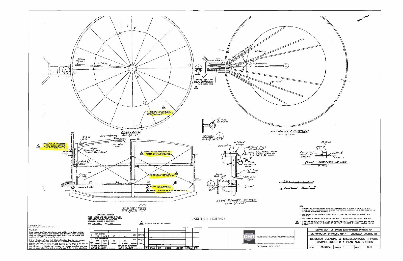
5. Drawing G5, Existing Digester #4 Plan And Section by GHD, Record Drawings, dated 02/2013.
6. Digester Cleaning And Miscellaneous Repairs, Contract No. 1 – General, 2013. 7. Digester No. 4 Inspection Photograph Albums, Book #1, #2, and #3, dated October 1999. 8. Miscellaneous drawings of modifications made to Digester #4 tank and cover, dated 1977
and 1999. 9. Gas Holder Tank, Asbuilt Drawing, dated October 21, 1955.
ONONDAGA COUNTY DEPARTMENT OF WATER ENVIRONMENT PROTECTION DIGESTER TANK #4 STEEL COVER ASSESSMENT
Page 2 of 15
SECTION 1- INTRODUCTION/OBJECTIVES/SCOPE This Memorandum is to document the Digester Tank #4 floating cover condition and provide the County with our assessment. The digester floating cover is no longer gliding along the four tracks attached to the concrete walls of the 100’ diameter circular digester tank. It was discovered the floating cover being out of balance and the cover is no longer engaged at three of the four guide tracks. Last winter (2014/2015) while clearing the snow off the tank cover, the staff noticed snow and ice falling and becoming wedged in the gap between the concrete wall and the skirt, which may have affected the cover balance and disengaged the fins from the guide angle. It was also reported that the cover was bound and did not float with the gas volume changes. The County is concerned about further damaging the digester cover and/or damaging the concrete tank. The County is planning to replace the existing floating cover within five (5) years. If the gas holder cannot operate, the County will lose all gas storage capacity. Objectives: The overall objective is to determine if the tank cover is suitable for operation in its current condition. Additionally, the County is interested in recommendations for short term and long term options related to the following:
1. Consider options for resetting the cover back in its guides without taking the tank out of service.
2. Requirements to repair damaged steel and concrete elements related to the skirt fins and guide angles and approximate construction cost.
3. Document distortion (out of round) of the cover. 4. Document the position of the cover as it travels from the highest to the lowest position. 5. Document the top of the concrete wall elevations.
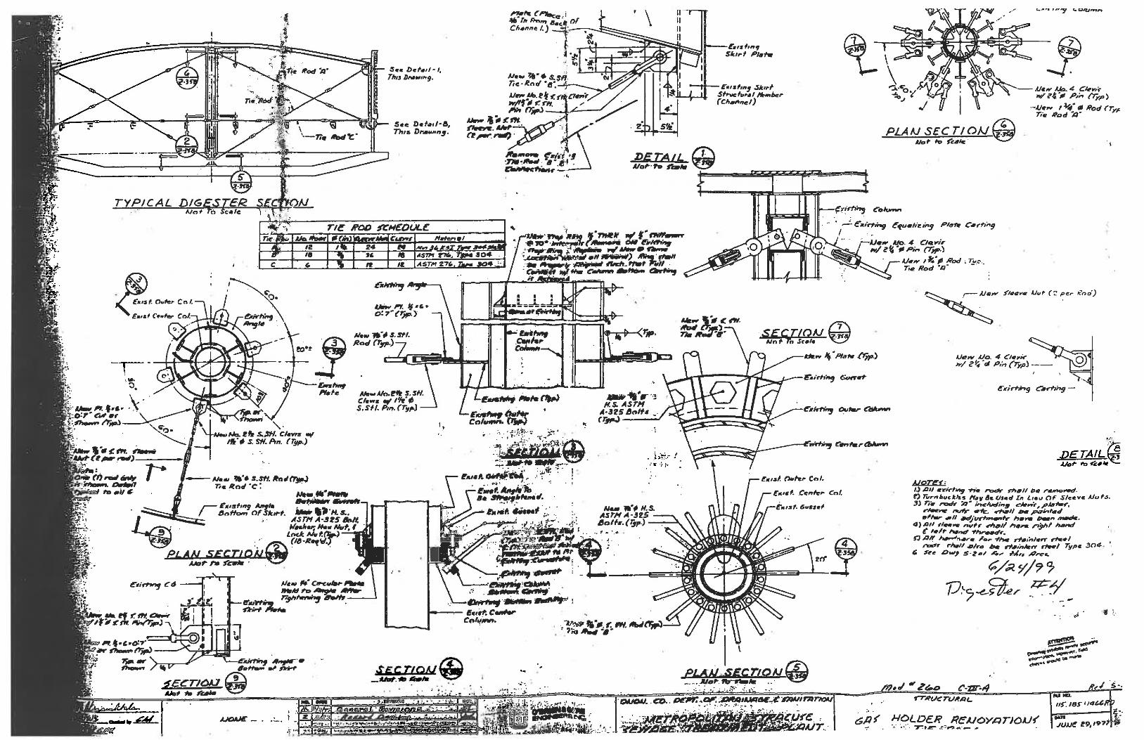
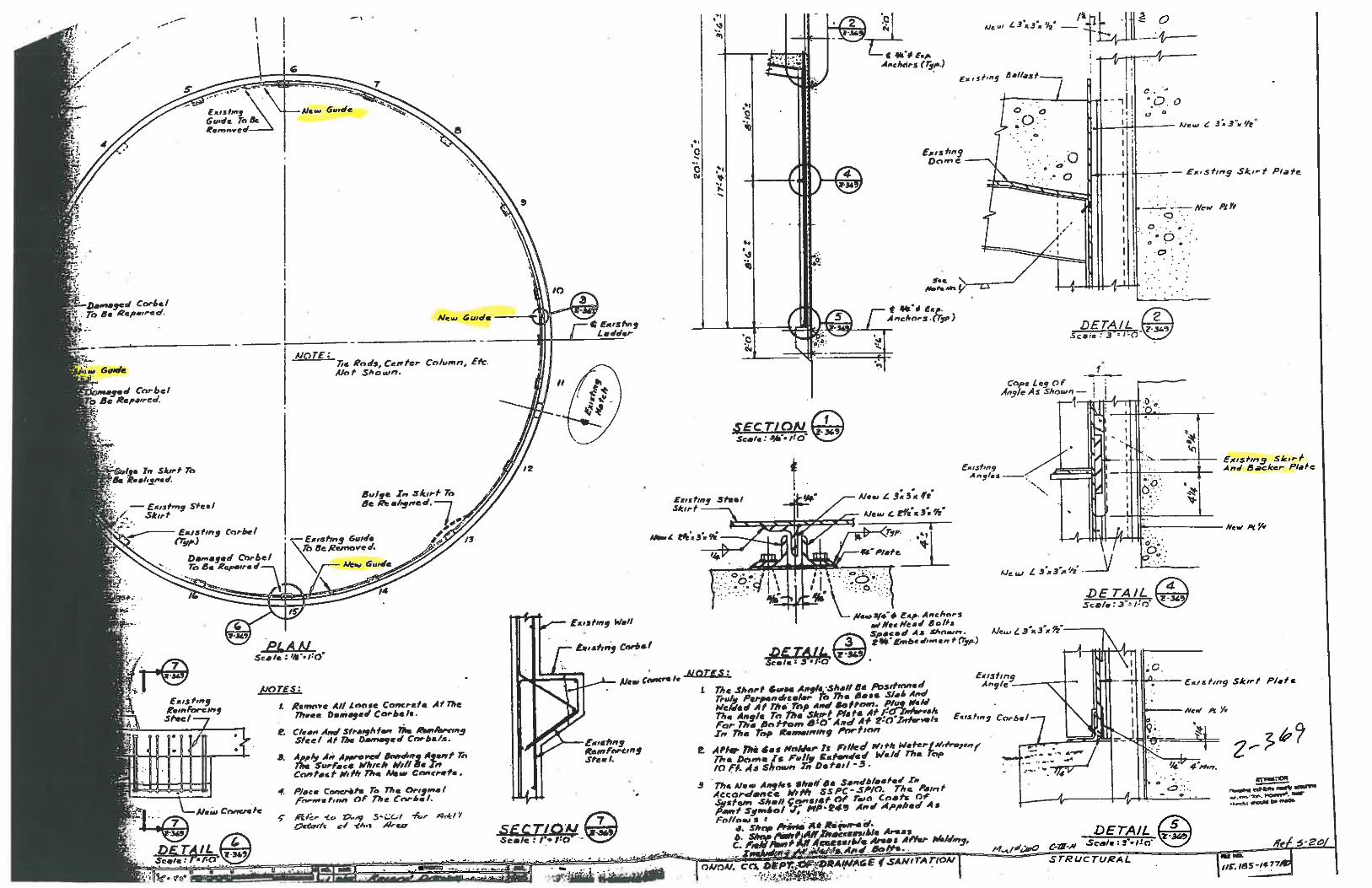
Background: We understand that the 100’ diameter concrete digester tank is supported by a concrete mat foundation, which appears to have differentially settled as previously reported. Digester tank #4 is the only digester tank that is not supported by deep foundation. The tank consists of a pre-stressed concrete wall, based on drawings found in our 1999 modification design files. This digester is the only tank with a floating cover. The steel floating cover consists of a dome shaped roof and a 17’ high skirt. The center mast of the floating cover is braced by steel tie rods attached to the concrete wall. The cover has internal steel tie rods and stiffeners to maintain its shape. The following background information related to Digester #4 was obtained from the above referenced documents and record documents found in our files.
1. The tank and cover are believed to have been in service for 60 years. 2. During the 1977 plant upgrade, the interior tie rods of the cover were all replaced,
concrete corbels were repaired, the additional skirt and counterweight sidewalk were added, and the angle guides were installed. The steel frame and grating access walkway and handrails anchored to the tank cover were added in 2000.
ONONDAGA COUNTY DEPARTMENT OF WATER ENVIRONMENT PROTECTION DIGESTER TANK #4 STEEL COVER ASSESSMENT
Page 3 of 15
3. Documentation exists in Digester No. 4 Inspection Photograph Albums, Book #1, #2, and #3, dated October 1999.
4. In 2010 the County performed an inspection of the cover and discovered the following: a. The cover was tilted. b. Many tie rods were loose and/or disconnected. c. Deformation along the vertical wide flange section welded to the center column. d. The concrete wall at the north side of tank is 6” lower than the south side. GHD
recommended checking the tank elevation in 5 years. e. There are variations in the skirt gap around the digester. GHD recommended to
check the clearances during balancing and initial operation of the cover. f. Deterioration at the tank concrete pilasters and tank top surface. GHD
recommended repairing the cracks. 5. In the 2013 project “Digester Cleaning and Misc. Repairs”, the County performed the
following digester repairs: a. Provided new tie rods to replace the damaged tie rods and re-tensioned all rods. b. Reinforced the areas of “indentation”/bent skirt plate at the fin attachments using
(16) ¼” 12”x12” steel plates. c. Repaired tie rod connections at the center column. d. Repaired tie rod connections at the concrete wall. e. Repaired Concrete corbels. f. Provided additional concrete counterweights to balance the cover.
ONONDAGA COUNTY DEPARTMENT OF WATER ENVIRONMENT PROTECTION DIGESTER TANK #4 STEEL COVER ASSESSMENT
Page 4 of 15
SECTION 2- SCANNING/MEASURING/OBSERVATIONS: C&S performed the following tasks and field measurement to document the existing conditions.
1. C&S retained the services of Paul James Olszewski, PLS, PLLC (PJO) to perform base mapping and 3-dimensional scanning of the digester cover and concrete tank along with installing targets on the concrete tank to monitor any future movement or settlement of the concrete tank. The 3D scans and field measurements accomplished the following:
a. Top of the concrete wall elevations along the perimeter of the tank. b. The roundness of the digester concrete wall. c. The roundness of the digester floating cover. d. Document any out of plumb (tilting) of the concrete tank and floating cover. e. Measure the gaps between the floating cover skirt wall and the concrete wall. f. Check for irregularities along the skirt wall of the floating cover. g. Provide four (4) survey targets to be installed on the concrete pilasters located
along the circumference of the tank.
2. On May 14, 2015, a meeting was held with the County to review with the inspection and scanning program. The meeting was attended by the following:
a. Adam George -Onondaga County-Water Environmental Protection (OCWEP) b. James Jones (OCWEP) c. Jeff Shelby (OCWEP) d. Paul Olszewski (PJO) e. Bob Hamlin (C&S) f. Ghaith Makhlouf (C&S)
Upon conclusion of the meeting, PJO started setting up surveying/scanning equipment for base mapping and setting controls and finished on the following day. Additionally, PJO installed the four (4) survey targets on the concrete pilasters located along the circumference of the tank. The targets were set approximately 10’ above finish grade.
3. On May 19, 2015, a meeting was held with OCWEP to review the completed base mapping work. The meeting was attended by the following:
a. Adam George (OCWEP) b. James Jones (OCWEP) c. Jim Renk (OCWEP) d. Daniel Jean (OCWEP) e. Jeff Shelby (OCWEP) f. Paul Olszewski (PJO) g. John Camp (C&S) h. Bob Hamlin (C&S) i. Ghaith Makhlouf (C&S)
4. On May 28, and May 29, 2015, Paul Olszewski, Bob Hamlin and Ghaith Makhlouf
(partial time) conducted the work associated with the digital scanning and measuring of
ONONDAGA COUNTY DEPARTMENT OF WATER ENVIRONMENT PROTECTION DIGESTER TANK #4 STEEL COVER ASSESSMENT
Page 5 of 15
Digester #4 floating cover and concrete tank. Mr. Hamlin performed manual field measurements of the cover height and gaps between the skirt and concrete tank using a rented boom-lift operated by Edward Fisher of C&S. The work was conducted while the tank was in service and was limited to the exterior of the tank.
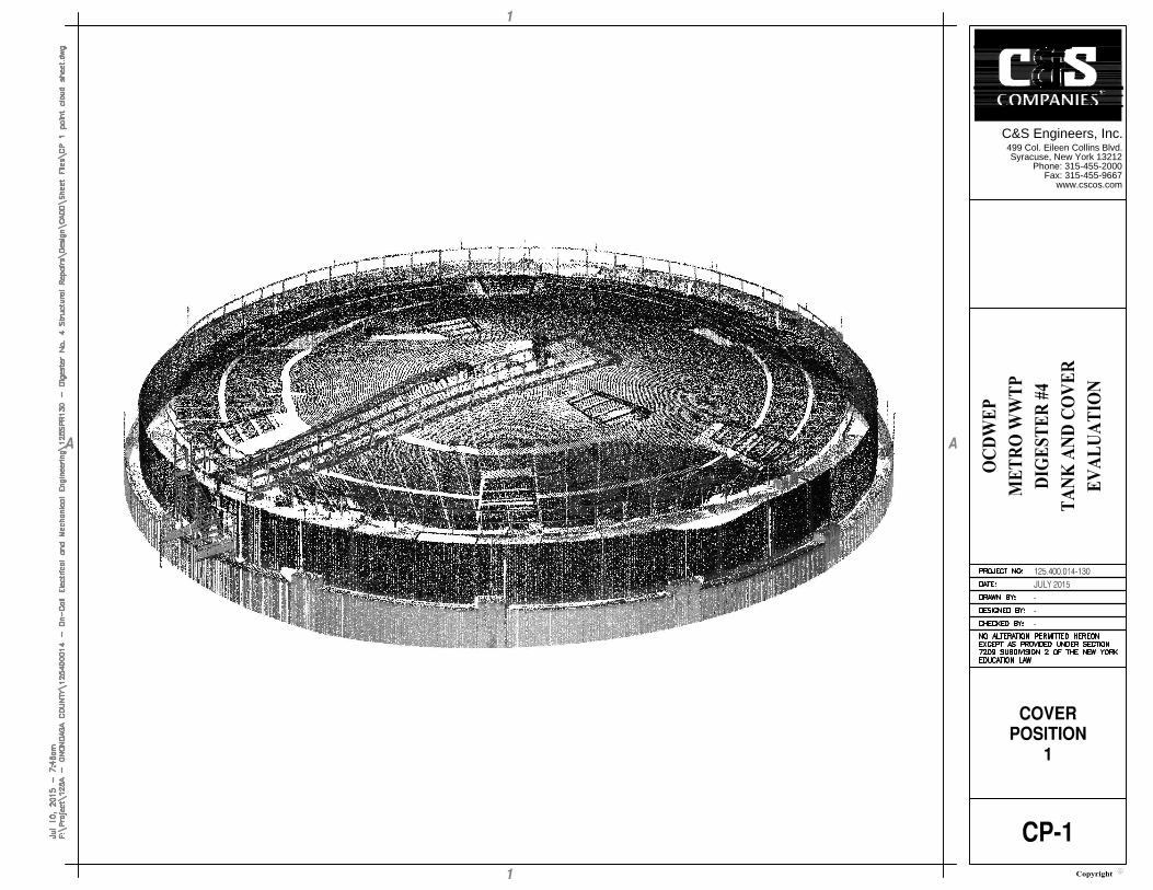
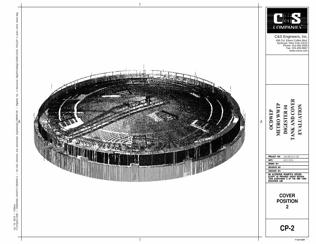
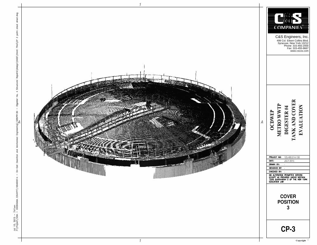
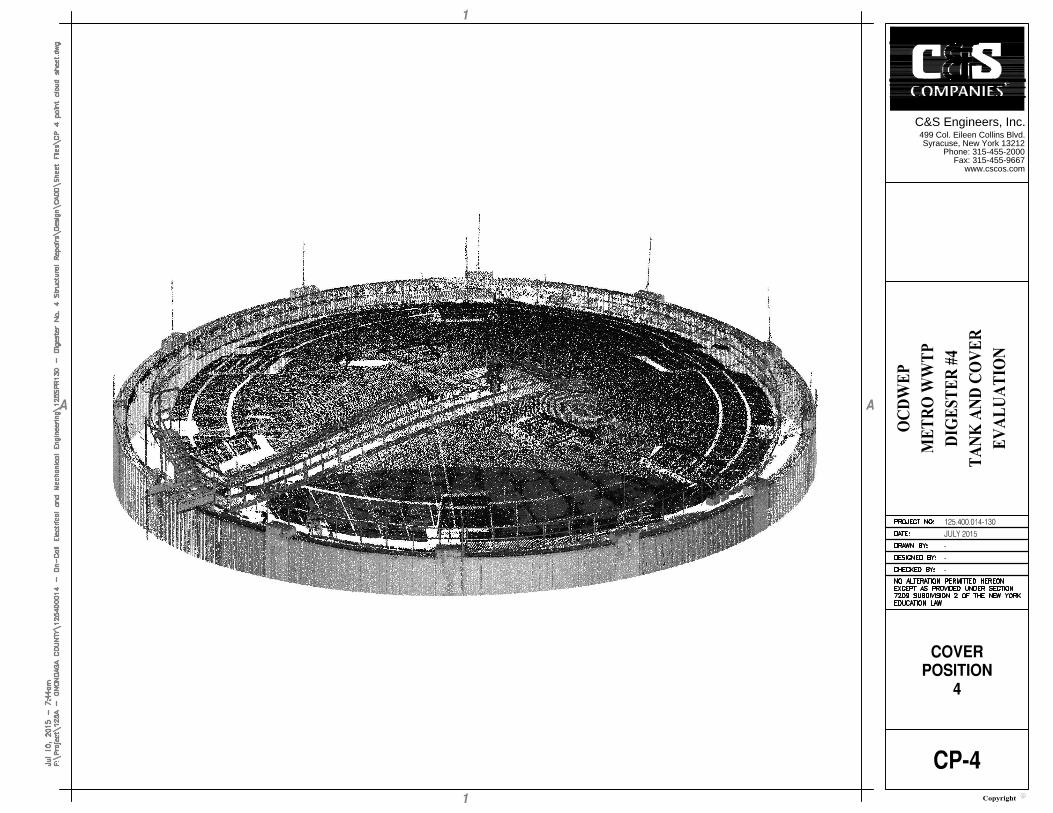
5. In preparation and prior to performing the scans, on May 28, 2015 the County raised the floating cover to the maximum height, which the County’s operators were comfortable with, and held it at that position to start the scanning. The floating cover and tank were scanned at five (5) levels with the County’s operators lowering the cover height by approximately 2.5’ intervals.
a. Cover position 1 - skirt rim approximately 8 feet above top-of-tank (max height) b. Cover position 2 - skirt rim approximately 5.8 feet above top-of-tank c. Cover position 3 - skirt rim approximately 3.4 feet above top-of-tank d. Cover position 4 - skirt rim approximately 1.2 feet below top-of-tank e. Cover position 5 - skirt rim approximately 3.7 feet below top-of-tank (min height)
6. The final position is limited by the interior concrete corbels located along the
circumference of the concrete wall. Per the existing drawings, we understand the top of corbels are located at approximate elevation of 375’+/- and the top of concrete wall was set at elevation 395.83’.
7. The cover height experienced some movement due to fluctuation in the gas volume during the base mapping and scanning operation.
ONONDAGA COUNTY DEPARTMENT OF WATER ENVIRONMENT PROTECTION DIGESTER TANK #4 STEEL COVER ASSESSMENT
Page 6 of 15
SECTION 3- FINDINGS & RECOMMENDATIONS:
1. Overall, the method of maintaining the position of the cover at several elevations during the data gathering process worked as intended.
2. During the data gathering with the cover in position 2, some movement of the cover occurred. This could be seen in the results of the 3D scans and is reflected in the manual measurements as well. The 3D scan data of position 2 was adjusted to remove the anomaly created by the uncontrolled drop of the digester cover. The 3D scans were less effective for positions 4 and 5 (cover below top of concrete). Interference by the cover’s railing obscured some of the data.
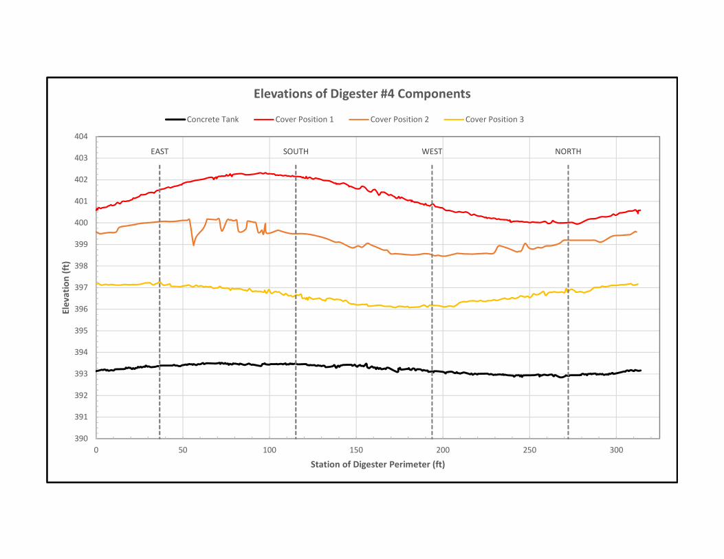
3. The elevation of the concrete wall was as follows: a. The elevation of the top of the concrete wall varied with the north side of the tank
0.56 ft (6.7 inches) lower than the south side. The report issued as Addendum No. 1 by GHD, dated January 3, 2011 indicated that this differential measurement obtained in November 19, 2010 was 0.53 ft (6.4 inches).
b. This may indicate that the tank could be continuing to settle differentially, with an additional movement of 0.03’ during the last approximately 5 years. However, this variation, though well within the detectable limits of surveying equipment, could in part be attributable to variations in the concrete surface of the top of the tank.
c. Upon examining the scan data for the pilasters located at the south and north sides of the tank, we determined that the walls have deflected (out of plumb) an average distance of 1 ½” in the north direction over the exposed height of the concrete pilasters.
4. The elevations of the top of the cover along the skirt varied along the perimeter at all five
cover positions. A graphic showing these variations is included in Appendix 1. a. Cover position 1 - skirt rim approximately 8 feet above top-of-tank (max height)
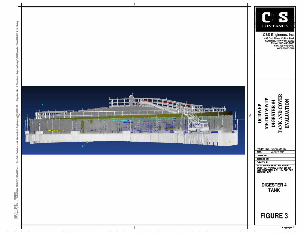
i. 28 inch elevation variation, refer to Figure 3 in Appendix 2. ii. South-Southeast quadrant “high side”
b. Cover position 2 - skirt rim approximately 5.8 feet above top-of-tank i. 18 inch elevation variation
ii. East-Southeast quadrant “high side” c. Cover position 3 - skirt rim approximately 3.4 feet above top-of-tank
i. 12 inch elevation variation ii. Northeast quadrant “high side”
d. Cover position 4 - skirt rim approximately 1.2 feet below top-of-tank i. 9 inch elevation variation
ii. East-Southeast quadrant “high side” e. Cover position 5 - skirt rim approximately 3.7 feet below top-of-tank (min height)
i. 7.7 inch elevation variation ii. East-Southeast quadrant “high side”
(Note: The elevation data of digester cover positions 4 and 5 are based on field measurements.)
ONONDAGA COUNTY DEPARTMENT OF WATER ENVIRONMENT PROTECTION DIGESTER TANK #4 STEEL COVER ASSESSMENT
Page 7 of 15
5. The horizontal positioning of the cover varied between each of the five (5) positions. a. The averages of the gap measurements did not change substantially in the east
west direction, indicating that active horizontal movement of the cover is more pronounced in the north south direction.
b. Generally the gap measurements did not show a uniform pattern of increasing and decreasing around the circumference of the cover.
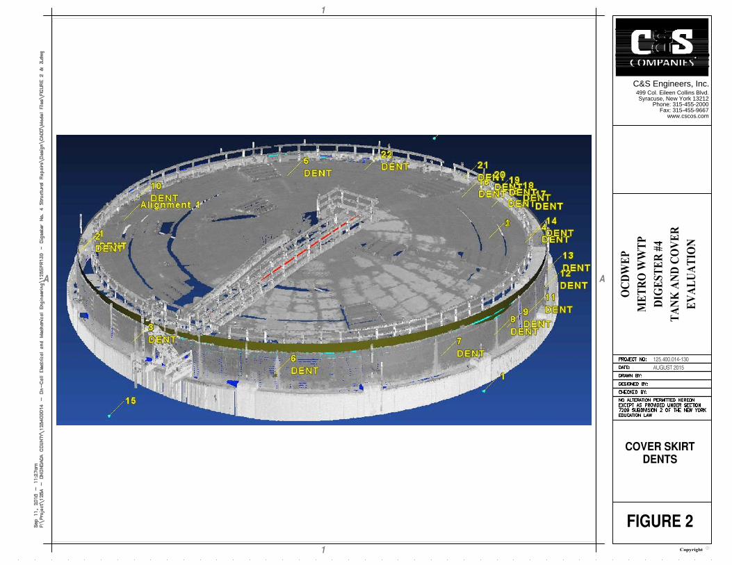
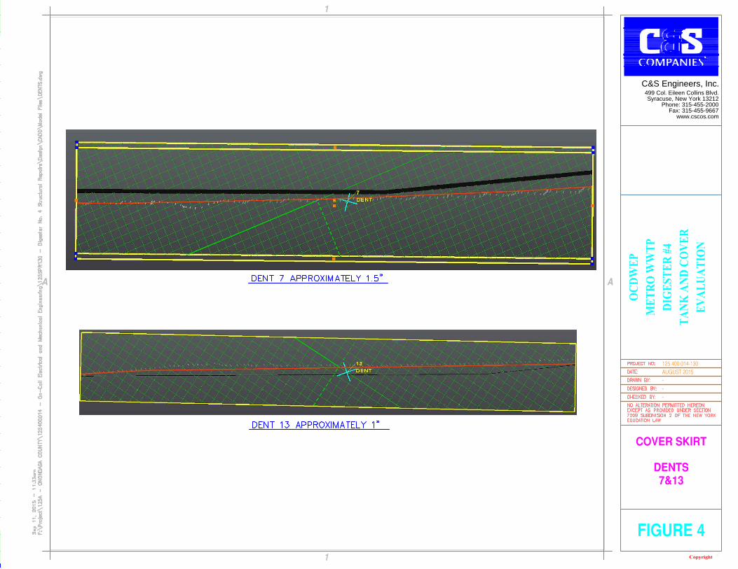
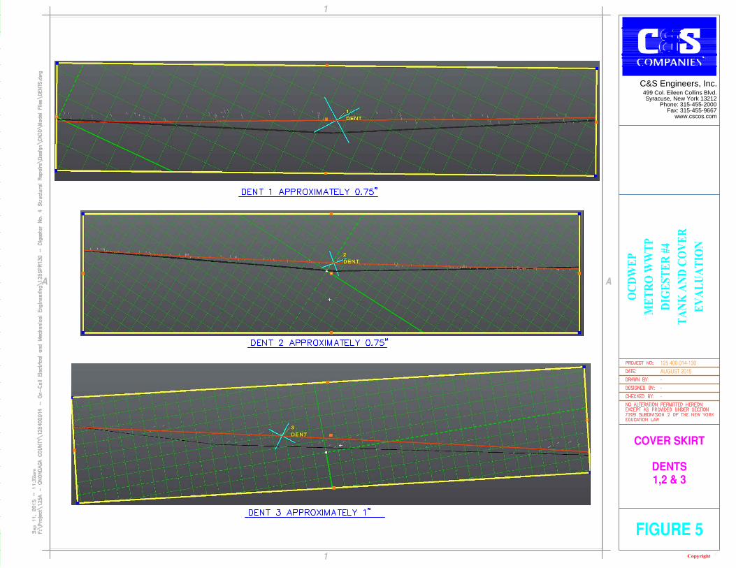
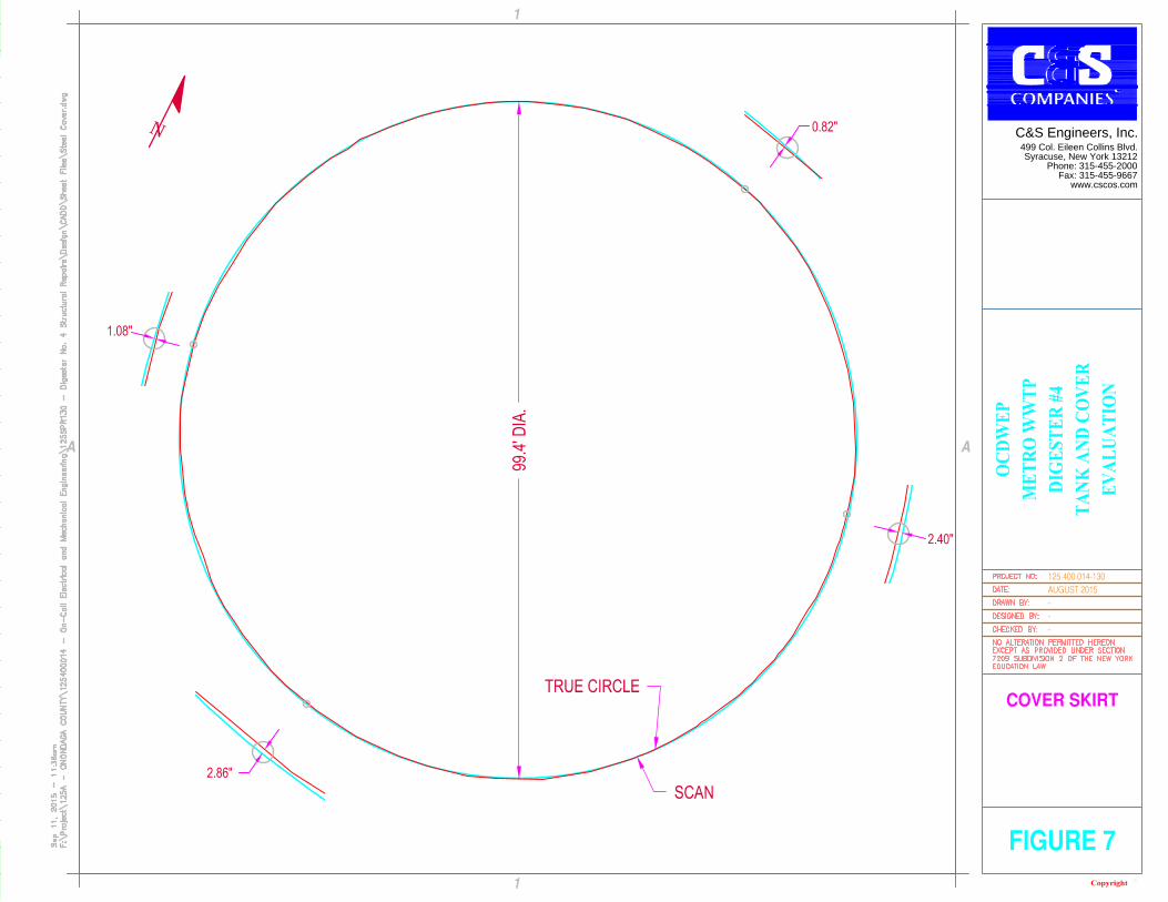
c. The skirt contains several localized inward and outward indentations of up to 1 ½” that may have contributed to the non-uniformity of the gap measurements. Refer to the Figures 2, 4, and 5. These irregularities in the skirt surface indicate that the skirt is not perfectly round. However, we believe that overall the skirt is reasonably round when compared to best-fit circle with a maximum out of round deviation of up to 2”. Note that we don’t have access to accurate as-built information relating to the tank cover and concrete tank to compare to the present conditions.
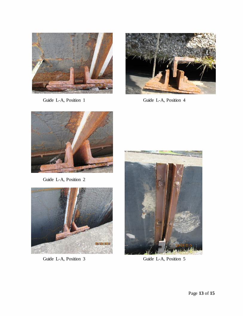
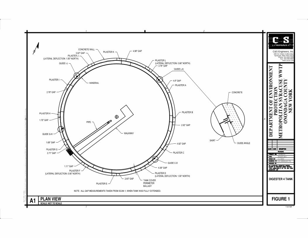
d. Our measurements show the gaps between the skirt and the concrete walls varied from 0” to 7 1/8”. While dropping from position 1 to position 3 the cover appeared to shift laterally in the north south direction resulting in a wider gap at the north side versus the south side. In general the gaps became smaller along the perimeter at the two lower positions, which we believe is due to the irregular shape of the ballast trough along the perimeter of the cover. The largest gap between the skirt and concrete wall of 7 1/8” was recorded at guide angle LA. Refer to Figure 1 and tabulations in Appendix 1.
e. The gaps measured by Stearns and Wheeler provided in their report, dated December 2010, appeared to be non-uniform and varied from 1/4” to 5 3/8”. These measurements are assumed to have been taken while the cover resting on the concrete corbels. These measurements are relatively close to the measurements we obtained while the cover was in position 5.
f. At position 5 the cover at the location between pilasters G and F near the access walkway, the ballast trough scraped against the concrete wall. The Stearns and Wheeler’s December 2010 report did not indicate any areas of cover in contact with the concrete wall.
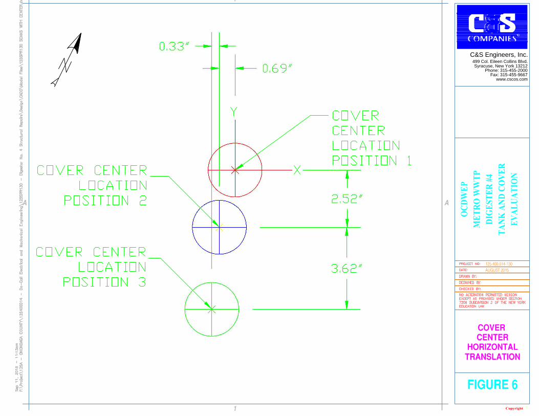
g. In summary, the cover appears to undergo non-uniform possibly lateral transition and tilting movements as it was lowered from its maximum height to the lowest point. By examining the scan of the center of the cover and the position of the guide angles while the cover being lowered (from position 1 to position 3), it is not clear if the detected horizontally movement is primarily related to pure horizontal movement versus tilting of the cover or a combination of the two. Refer to Figure 6. The change in gaps was more significant mainly in the north south direction. We believe that the detected/apparent change in the position of the center of the cover and the guide angles is mainly related to the uneven/tilting during vertical decent of the cover.
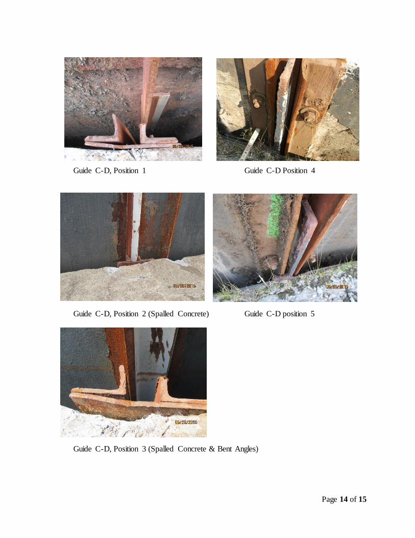
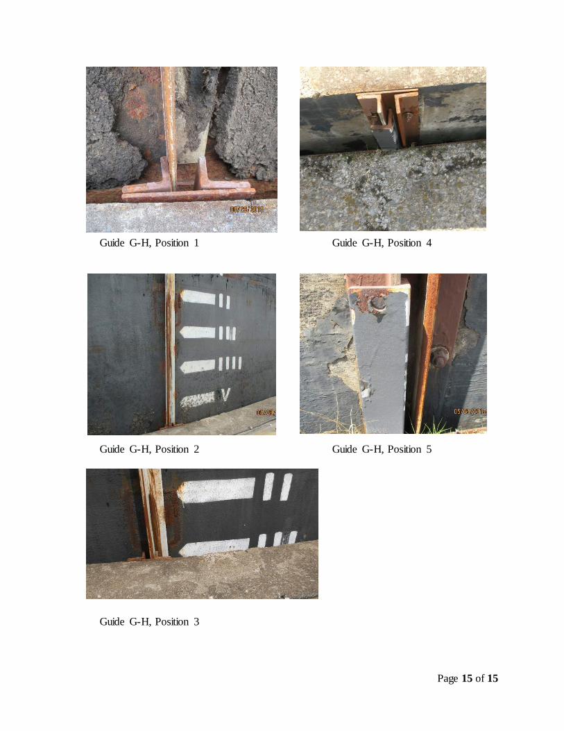
6. Several observations were made regarding the angle guides system: a. Three out of the four angles welded to the cover, other than the fin at the north
side of the tank, appeared to rub against the guide angles attached to the concrete wall at all five positions. Refer to the attached photos. The guides at the northwest and northeast quadrants changed position and realigned with the tracks upon lowering the tank to position 2 and position3. The guide at the southwest quadrant (next to the catwalk) remained engaged in the track throughout the five positions.
ONONDAGA COUNTY DEPARTMENT OF WATER ENVIRONMENT PROTECTION DIGESTER TANK #4 STEEL COVER ASSESSMENT
Page 8 of 15
However, the guide shifted from one side to other side within the track. The guide located at the southeast quadrant stayed outside the track however, appeared to shift slightly separating from the track after lowering the cover to position 2 and 3 then returned towards the track at position 4 and 5, which is similar to the previous location at position 1.
b. At position 5, three (3) of the four (4) cover guides were inside their respective tracks.
c. According to the County, the tracking fins did not remain in position upon raising the cover during normal operations following the measurements, resulting in three (3) guides out of the tracks.
7. There is some minor cracking in the concrete wall adjacent to the guide angles located at
east quadrant. This concrete cracking should be repaired when the tank is taken out of service.
8. There are some loose anchor bolts and nuts and bent guide angles along with gaps between the back of the guide angles and the concrete wall. These damaged guides require repair when the tank is taken out of service. We note that the existing guides are not part of the original design. According to some existing drawings, we believe these surface mounted angle guides and fins were added/modified in 1977 and 1999.
9. Under current operation the cover tilting exceeds the 10-inch tolerance recommended in
Inspection & Testing Report by Ovivo USA, LLC, dated March 23, 2011. We believe the documented variations in gaps and cover heights as the cover travels can be attributed to the following factors or combinations of factors.
a. The cover is out of balance as evidence by the tilting. b. Friction and binding between the guides, cover and walls. c. The center support column may be out of plumb. d. The skirt of the steel cover is out of round. e. The tilting and out of round could be the result of failure or deformation of
internal tie rods. The condition of the tie rods is unknown. f. The concrete tank walls are slightly out of round and not plumb. g. Lateral loads from wind pressure, which can exceed 8000#. Additionally, wind
can impart downward and uplift loads on the cover.
10. The potential hazards related to methane gas make it unfeasible to perform significant repairs while the digester is operational. Any major repair work to remove, replace or attach new guides will require the tank to be taken out of service, emptied, and cleaned.
11. In our opinion the tank cover is not suitable for operation under the present condition and should be repaired or replaced as soon as possible. Based upon communications with Avivo, we understand that to continue operating the floating cover under the existing conditions will run the risk of collapsing the cover and/or explosion if the cover becomes wedged/stuck. Under the scenario where the cover is stuck while discharging gas or lowering the liquid level, the created vacuum inside the tank could collapse the cover. The same scenario may result in damaging the concrete wall from unintended concentrated loads from the heavy weight of the steel cover. It is critical that the system has pressure relief valve to prevent vacuum or over pressurization of the tank. We recommend reviewing the existing safety systems and installing a monitoring system and
ONONDAGA COUNTY DEPARTMENT OF WATER ENVIRONMENT PROTECTION DIGESTER TANK #4 STEEL COVER ASSESSMENT
Page 9 of 15
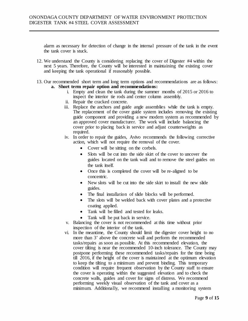
alarm as necessary for detection of change in the internal pressure of the tank in the event the tank cover is stuck.
12. We understand the County is considering replacing the cover of Digester #4 within the next 5 years. Therefore, the County will be interested in maintaining the existing cover and keeping the tank operational if reasonably possible.
13. Our recommended short term and long term options and recommendations are as follows: a. Short term repair option and recommendations:
i. Empty and clean the tank during the summer months of 2015 or 2016 to inspect the interior tie rods and center column assembly.
ii. Repair the cracked concrete. iii. Replace the anchors and guide angle assemblies while the tank is empty.
The replacement of the cover guide system includes removing the existing guide component and providing a new modern system as recommended by an approved cover manufacturer. The work will include balancing the cover prior to placing back in service and adjust counterweights as required.
iv. In order to repair the guides, Avivo recommends the following corrective action, which will not require the removal of the cover.
• Cover will be sitting on the corbels. • Slots will be cut into the side skirt of the cover to uncover the
guides located on the tank wall and to remove the steel guides on the tank itself.
• Once this is completed the cover will be re-aligned to be concentric.
• New slots will be cut into the side skirt to install the new slide guides.
• The final installation of slide blocks will be performed. • The slots will be welded back with cover plates and a protective
coating applied. • Tank will be filled and tested for leaks. • Tank will be put back in service.
v. Balancing the cover is not recommended at this time without prior inspection of the interior of the tank.
vi. In the meantime, the County should limit the digester cover height to no more than 3’ above the concrete wall and perform the recommended tasks/repairs as soon as possible. At this recommended elevation, the cover tilting is near the recommended 10-inch tolerance. The County may postpone performing these recommended tasks/repairs for the time being till 2016, if the height of the cover is maintained at the optimum elevation to keep the tilting to a minimum and prevent binding. This temporary condition will require frequent observation by the County staff to ensure the cover is operating within the suggested elevation and to check the concrete walls, guides and cover for signs of distress. We recommend performing weekly visual observation of the tank and cover as a minimum. Additionally, we recommend installing a monitoring system
ONONDAGA COUNTY DEPARTMENT OF WATER ENVIRONMENT PROTECTION DIGESTER TANK #4 STEEL COVER ASSESSMENT
Page 10 of 15
with alarm to detect change in the internal pressure in the event the cover gets stuck.
b. Long term repair option and recommendations:
i. Perform annual observation of the cover and tank to document changes in elevations and compare with the survey data provided in the 2015 scans. This will help to determine the behavior of the cover and any potential settlement of the concrete tank.
ii. There are no other recommendations that are considered as Long Term repairs short of total replacement of the cover and possibly the entire digester. The concrete tank will require testing and complete evaluation to determine the feasibility of replacing the cover and any required structural upgrades. We note that the concrete tank is at least 60 years old and near the end of its life expectancy.
iii. There are areas of freeze/thaw damage which will require repair. The freeze/thaw damage was noted at the top of all pilasters and the concrete ballast (counter weight) in the troughs located along the perimeter of the floating cover.
iv. At the time of cover replacement, we recommend performing a comprehensive inspection and material testing of the concrete tank to determine its structural integrity and determine the status of the reported tank settlement. The existing concrete may not be durable enough to extend its service life through the life of a new cover. Therefore, our recommendation is to consider the option of replacing the digester at the end of the existing cover’s service life.
SECTION 4- CONSTRUCTION COST DATA: The following is a preliminary construction cost that was developed with assistance from Avivo for the recommended short term option repairs of the damaged steel guide system and miscellaneous items.
1. Empty and clean tank: (TBD by County based on existing cost data) 2. Replace cover guide system: $475,000 3. Repair concrete wall: $20,000 4. Miscellaneous repairs to tie rods, etc.: TBD 5. Design/bidding/construction phase services: TBD
Page 11 of 15
ONONDAGA COUNTY DEPARTMENT OF WATER ENVIRONMENT PROTECTION DIGESTER TANK #4 STEEL COVER ASSESSMENT
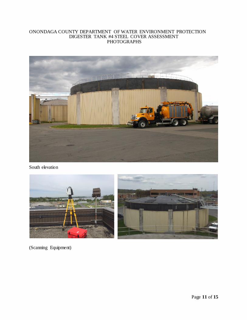
PHOTOGRAPHS
South elevation
(Scanning Equipment)
Page 12 of 15
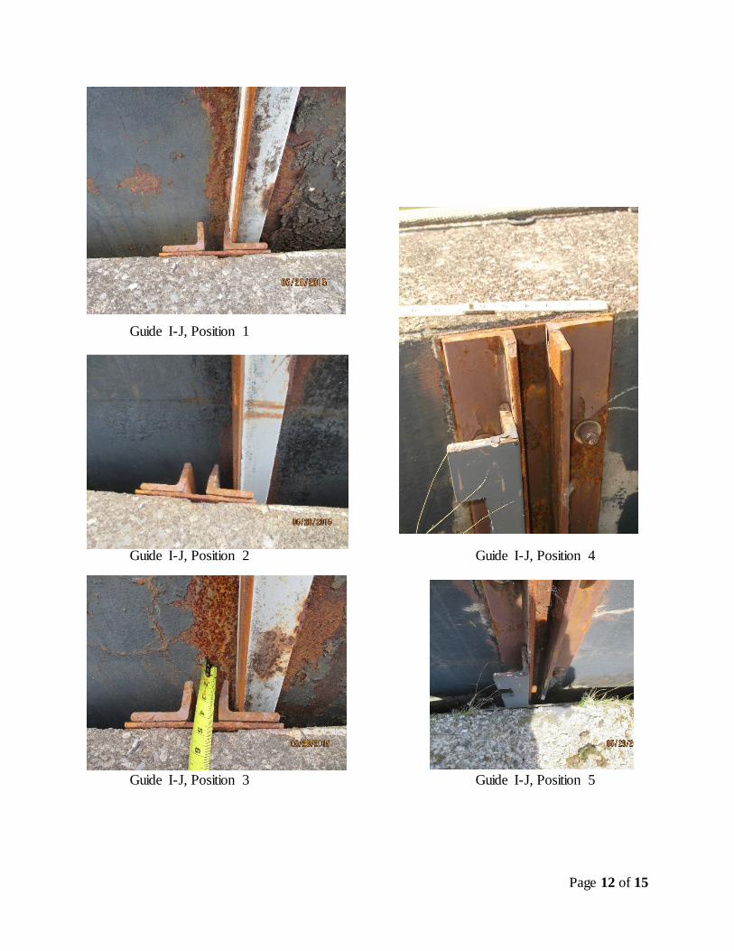
Guide I-J, Position 1
Guide I-J, Position 2 Guide I-J, Position 4
Guide I-J, Position 3 Guide I-J, Position 5
Page 13 of 15
Guide L-A, Position 1 Guide L-A, Position 4
Guide L-A, Position 2
Guide L-A, Position 3 Guide L-A, Position 5
Page 14 of 15
Guide C-D, Position 1 Guide C-D Position 4
Guide C-D, Position 2 (Spalled Concrete) Guide C-D position 5
Guide C-D, Position 3 (Spalled Concrete & Bent Angles)
Page 15 of 15
Guide G-H, Position 1 Guide G-H, Position 4
Guide G-H, Position 2 Guide G-H, Position 5
Guide G-H, Position 3
499 Col. Eileen Collins Blvd.
Syracuse, New York 13212
Phone: 315-455-2000
Fax: 315-455-9667
www.cscos.com
C&S Engineers, Inc.
N
499 Col. Eileen Collins Blvd.
Syracuse, New York 13212
Phone: 315-455-2000
Fax: 315-455-9667
www.cscos.com
C&S Engineers, Inc.
499 Col. Eileen Collins Blvd.
Syracuse, New York 13212
Phone: 315-455-2000
Fax: 315-455-9667
www.cscos.com
C&S Engineers, Inc.
499 Col. Eileen Collins Blvd.
Syracuse, New York 13212
Phone: 315-455-2000
Fax: 315-455-9667
www.cscos.com
C&S Engineers, Inc.
499 Col. Eileen Collins Blvd.
Syracuse, New York 13212
Phone: 315-455-2000
Fax: 315-455-9667
www.cscos.com
C&S Engineers, Inc.
499 Col. Eileen Collins Blvd.
Syracuse, New York 13212
Phone: 315-455-2000
Fax: 315-455-9667
www.cscos.com
C&S Engineers, Inc.
499 Col. Eileen Collins Blvd.
Syracuse, New York 13212
Phone: 315-455-2000
Fax: 315-455-9667
www.cscos.com
C&S Engineers, Inc.
499 Col. Eileen Collins Blvd.
Syracuse, New York 13212
Phone: 315-455-2000
Fax: 315-455-9667
www.cscos.com
C&S Engineers, Inc.
N

www.cscos.com (877) CS-SOLVE
Appendix 1
499 Col. Eileen Collins Blvd.
Syracuse, New York 13212
Phone: 315-455-2000
Fax: 315-455-9667
www.cscos.com
C&S Engineers, Inc.
499 Col. Eileen Collins Blvd.
Syracuse, New York 13212
Phone: 315-455-2000
Fax: 315-455-9667
www.cscos.com
C&S Engineers, Inc.
499 Col. Eileen Collins Blvd.
Syracuse, New York 13212
Phone: 315-455-2000
Fax: 315-455-9667
www.cscos.com
C&S Engineers, Inc.
499 Col. Eileen Collins Blvd.
Syracuse, New York 13212
Phone: 315-455-2000
Fax: 315-455-9667
www.cscos.com
C&S Engineers, Inc.

499 Col. Eileen Collins Blvd.
Syracuse, New York 13212
Phone: 315-455-2000
Fax: 315-455-9667
www.cscos.com
C&S Engineers, Inc.
EAST SOUTH WEST NORTH
390
391
392
393
394
395
396
397
398
399
400
401
402
403
404
0 50 100 150 200 250 300
Elevation (ft)
Station of Digester Perimeter (ft)
Elevations of Digester #4 Components
Concrete Tank Cover Position 1 Cover Position 2 Cover Position 3
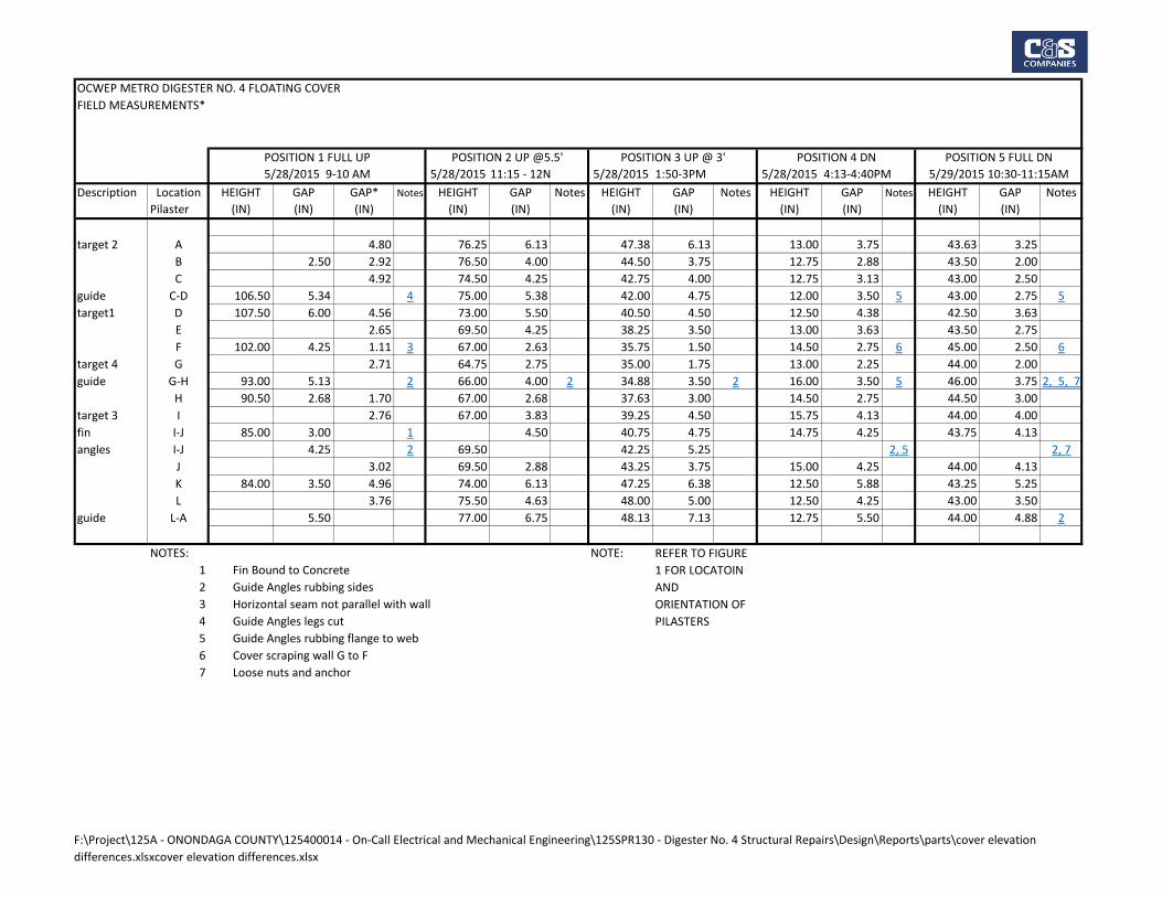
OCWEP METRO DIGESTER NO. 4 FLOATING COVER
FIELD MEASUREMENTS*
5/28/2015 11:15 - 12N 5/28/2015 1:50-3PM 5/28/2015 4:13-4:40PM
Description Location HEIGHT GAP GAP* Notes HEIGHT GAP Notes HEIGHT GAP Notes HEIGHT GAP Notes HEIGHT GAP Notes
Pilaster (IN) (IN) (IN) (IN) (IN) (IN) (IN) (IN) (IN) (IN) (IN)
target 2 A 4.80 76.25 6.13 47.38 6.13 13.00 3.75 43.63 3.25
B 2.50 2.92 76.50 4.00 44.50 3.75 12.75 2.88 43.50 2.00
C 4.92 74.50 4.25 42.75 4.00 12.75 3.13 43.00 2.50
guide C-D 106.50 5.34 4 75.00 5.38 42.00 4.75 12.00 3.50 5 43.00 2.75 5
target1 D 107.50 6.00 4.56 73.00 5.50 40.50 4.50 12.50 4.38 42.50 3.63
E 2.65 69.50 4.25 38.25 3.50 13.00 3.63 43.50 2.75
F 102.00 4.25 1.11 3 67.00 2.63 35.75 1.50 14.50 2.75 6 45.00 2.50 6
target 4 G 2.71 64.75 2.75 35.00 1.75 13.00 2.25 44.00 2.00
guide G-H 93.00 5.13 2 66.00 4.00 2 34.88 3.50 2 16.00 3.50 5 46.00 3.75 2, 5, 7
H 90.50 2.68 1.70 67.00 2.68 37.63 3.00 14.50 2.75 44.50 3.00
target 3 I 2.76 67.00 3.83 39.25 4.50 15.75 4.13 44.00 4.00
fin I-J 85.00 3.00 1 4.50 40.75 4.75 14.75 4.25 43.75 4.13
angles I-J 4.25 2 69.50 42.25 5.25 2, 5 2, 7
J 3.02 69.50 2.88 43.25 3.75 15.00 4.25 44.00 4.13
K 84.00 3.50 4.96 74.00 6.13 47.25 6.38 12.50 5.88 43.25 5.25
L 3.76 75.50 4.63 48.00 5.00 12.50 4.25 43.00 3.50
guide L-A 5.50 77.00 6.75 48.13 7.13 12.75 5.50 44.00 4.88 2
NOTES: NOTE:
1 Fin Bound to Concrete
2 Guide Angles rubbing sides
3 Horizontal seam not parallel with wall
4 Guide Angles legs cut
5 Guide Angles rubbing flange to web
6 Cover scraping wall G to F
7 Loose nuts and anchor
5/29/2015 10:30-11:15AM
POSITION 5 FULL DN
REFER TO FIGURE
1 FOR LOCATOIN
AND
ORIENTATION OF
PILASTERS
POSITION 1 FULL UP POSITION 2 UP @5.5' POSITION 3 UP @ 3' POSITION 4 DN
5/28/2015 9-10 AM
F:\Project\125A - ONONDAGA COUNTY\125400014 - On-Call Electrical and Mechanical Engineering\125SPR130 - Digester No. 4 Structural Repairs\Design\Reports\parts\cover elevation
differences.xlsxcover elevation differences.xlsx
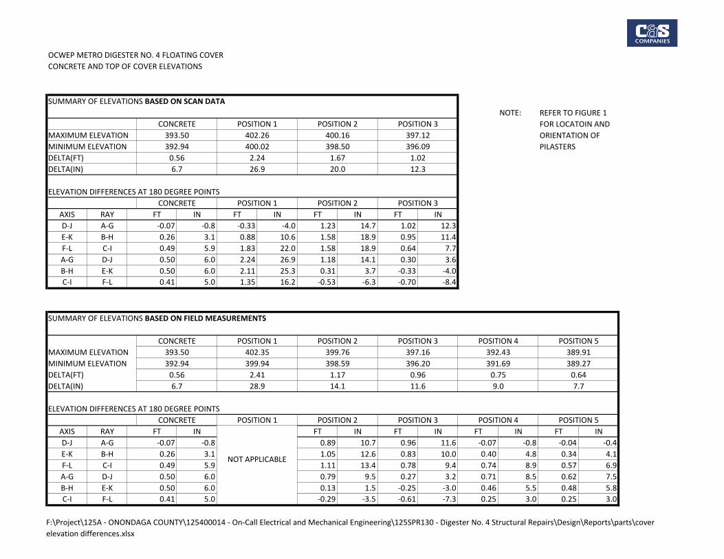
OCWEP METRO DIGESTER NO. 4 FLOATING COVER
CONCRETE AND TOP OF COVER ELEVATIONS
SUMMARY OF ELEVATIONS BASED ON SCAN DATA
NOTE:
MAXIMUM ELEVATION
MINIMUM ELEVATION
DELTA(FT)
DELTA(IN)
ELEVATION DIFFERENCES AT 180 DEGREE POINTS
AXIS RAY FT IN FT IN FT IN FT IN
D-J A-G -0.07 -0.8 -0.33 -4.0 1.23 14.7 1.02 12.3
E-K B-H 0.26 3.1 0.88 10.6 1.58 18.9 0.95 11.4
F-L C-I 0.49 5.9 1.83 22.0 1.58 18.9 0.64 7.7
A-G D-J 0.50 6.0 2.24 26.9 1.18 14.1 0.30 3.6
B-H E-K 0.50 6.0 2.11 25.3 0.31 3.7 -0.33 -4.0
C-I F-L 0.41 5.0 1.35 16.2 -0.53 -6.3 -0.70 -8.4
SUMMARY OF ELEVATIONS BASED ON FIELD MEASUREMENTS
MAXIMUM ELEVATION
MINIMUM ELEVATION
DELTA(FT)
DELTA(IN)
ELEVATION DIFFERENCES AT 180 DEGREE POINTS
AXIS RAY FT IN FT IN FT IN FT IN FT IN
D-J A-G -0.07 -0.8 0.89 10.7 0.96 11.6 -0.07 -0.8 -0.04 -0.4
E-K B-H 0.26 3.1 1.05 12.6 0.83 10.0 0.40 4.8 0.34 4.1
F-L C-I 0.49 5.9 1.11 13.4 0.78 9.4 0.74 8.9 0.57 6.9
A-G D-J 0.50 6.0 0.79 9.5 0.27 3.2 0.71 8.5 0.62 7.5
B-H E-K 0.50 6.0 0.13 1.5 -0.25 -3.0 0.46 5.5 0.48 5.8
C-I F-L 0.41 5.0 -0.29 -3.5 -0.61 -7.3 0.25 3.0 0.25 3.0
CONCRETE POSITION 1 POSITION 2 POSITION 3
CONCRETE POSITION 1 POSITION 2 POSITION 3
393.50
392.94
0.56
6.7
402.26
400.02
2.24
26.9
REFER TO FIGURE 1
FOR LOCATOIN AND
ORIENTATION OF
PILASTERS
POSITION 5POSITION 4
400.16
398.50
1.67
20.0
397.12
396.09
1.02
12.3
0.64
7.7
392.43
391.69
0.75
9.0
389.27
389.91
0.96
11.6
399.76
398.59
1.17
14.1
396.20
397.16
2.41
28.9
393.50
392.94
0.56
6.7
402.35
CONCRETE POSITION 1 POSITION 2 POSITION 3
399.94
POSITION 4 POSITION 5
NOT APPLICABLE
CONCRETE POSITION 1 POSITION 2 POSITION 3
F:\Project\125A - ONONDAGA COUNTY\125400014 - On-Call Electrical and Mechanical Engineering\125SPR130 - Digester No. 4 Structural Repairs\Design\Reports\parts\cover
elevation differences.xlsx

www.cscos.com (877) CS-SOLVE
Appendix 2
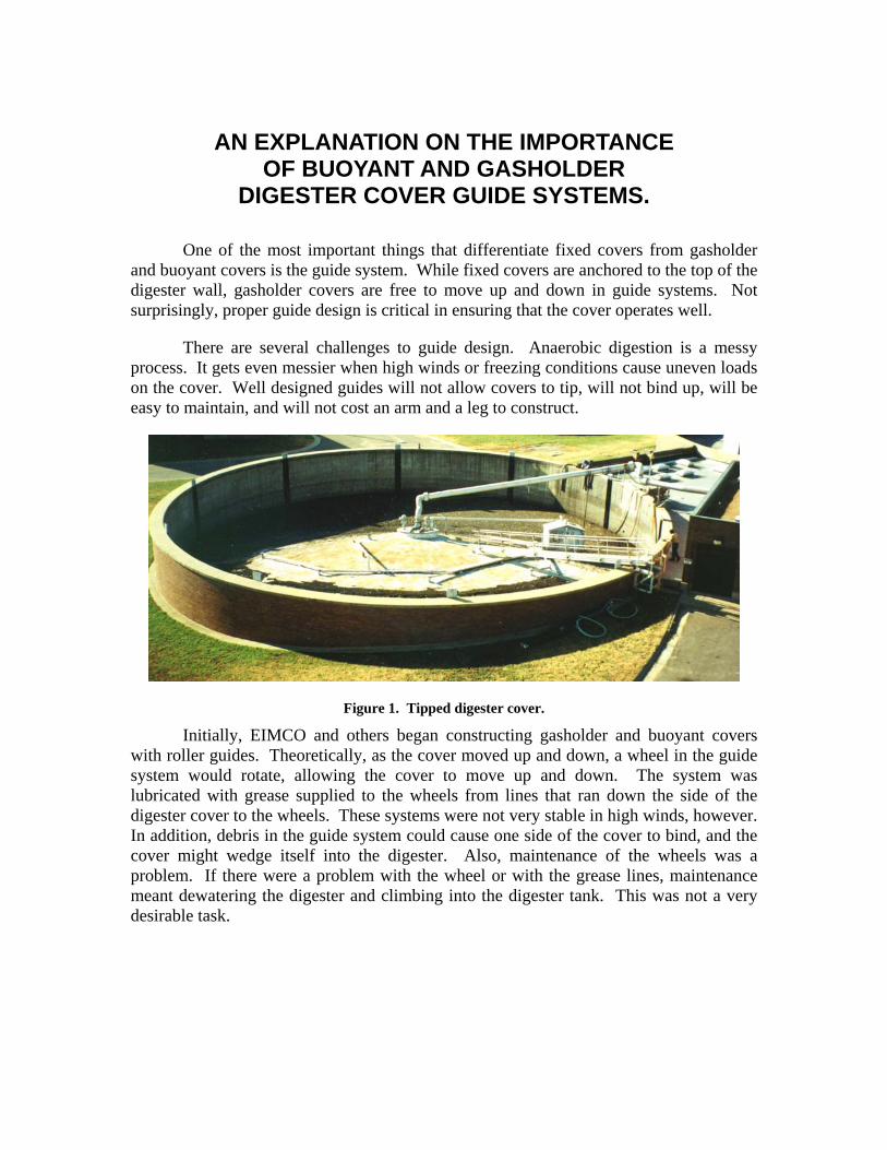
AN EXPLANATION ON THE IMPORTANCE OF BUOYANT AND GASHOLDER
DIGESTER COVER GUIDE SYSTEMS.
One of the most important things that differentiate fixed covers from gasholder and buoyant covers is the guide system. While fixed covers are anchored to the top of the digester wall, gasholder covers are free to move up and down in guide systems. Not surprisingly, proper guide design is critical in ensuring that the cover operates well.
There are several challenges to guide design. Anaerobic digestion is a messy process. It gets even messier when high winds or freezing conditions cause uneven loads on the cover. Well designed guides will not allow covers to tip, will not bind up, will be easy to maintain, and will not cost an arm and a leg to construct.
Figure 1. Tipped digester cover.
Initially, EIMCO and others began constructing gasholder and buoyant covers with roller guides. Theoretically, as the cover moved up and down, a wheel in the guide system would rotate, allowing the cover to move up and down. The system was lubricated with grease supplied to the wheels from lines that ran down the side of the digester cover to the wheels. These systems were not very stable in high winds, however. In addition, debris in the guide system could cause one side of the cover to bind, and the cover might wedge itself into the digester. Also, maintenance of the wheels was a problem. If there were a problem with the wheel or with the grease lines, maintenance meant dewatering the digester and climbing into the digester tank. This was not a very desirable task.
- 1 -
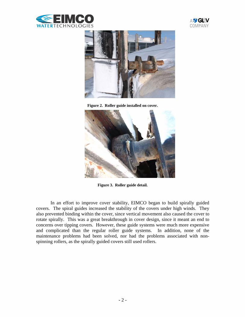
Figure 2. Roller guide installed on cover.
Figure 3. Roller guide detail.
In an effort to improve cover stability, EIMCO began to build spirally guided covers. The spiral guides increased the stability of the covers under high winds. They also prevented binding within the cover, since vertical movement also caused the cover to rotate spirally. This was a great breakthrough in cover design, since it meant an end to concerns over tipping covers. However, these guide systems were much more expensive and complicated than the regular roller guide systems. In addition, none of the maintenance problems had been solved, nor had the problems associated with non-spinning rollers, as the spirally guided covers still used rollers.
- 2 -
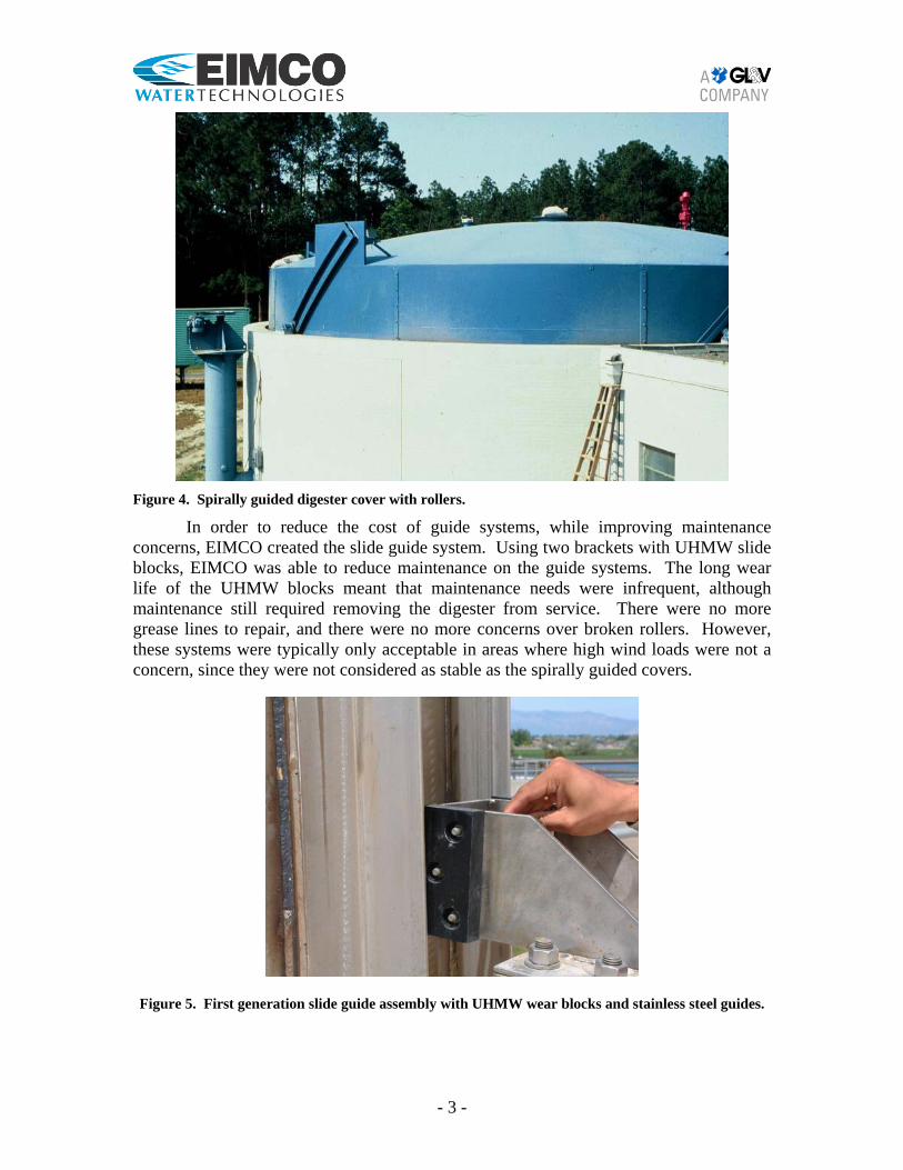
Figure 4. Spirally guided digester cover with rollers.
In order to reduce the cost of guide systems, while improving maintenance concerns, EIMCO created the slide guide system. Using two brackets with UHMW slide blocks, EIMCO was able to reduce maintenance on the guide systems. The long wear life of the UHMW blocks meant that maintenance needs were infrequent, although maintenance still required removing the digester from service. There were no more grease lines to repair, and there were no more concerns over broken rollers. However, these systems were typically only acceptable in areas where high wind loads were not a concern, since they were not considered as stable as the spirally guided covers.
Figure 5. First generation slide guide assembly with UHMW wear blocks and stainless steel guides.
- 3 -
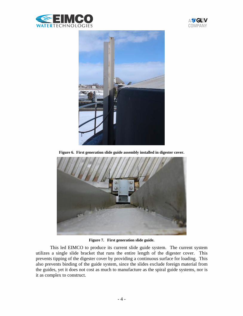
Figure 6. First generation slide guide assembly installed in digester cover.
Figure 7. First generation slide guide.
This led EIMCO to produce its current slide guide system. The current system utilizes a single slide bracket that runs the entire length of the digester cover. This prevents tipping of the digester cover by providing a continuous surface for loading. This also prevents binding of the guide system, since the slides exclude foreign material from the guides, yet it does not cost as much to manufacture as the spiral guide systems, nor is it as complex to construct.
- 4 -
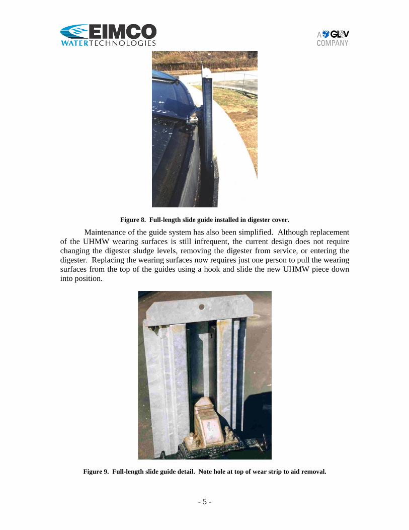
Figure 8. Full-length slide guide installed in digester cover.
Maintenance of the guide system has also been simplified. Although replacement of the UHMW wearing surfaces is still infrequent, the current design does not require changing the digester sludge levels, removing the digester from service, or entering the digester. Replacing the wearing surfaces now requires just one person to pull the wearing surfaces from the top of the guides using a hook and slide the new UHMW piece down into position.
Figure 9. Full-length slide guide detail. Note hole at top of wear strip to aid removal.
- 5 -
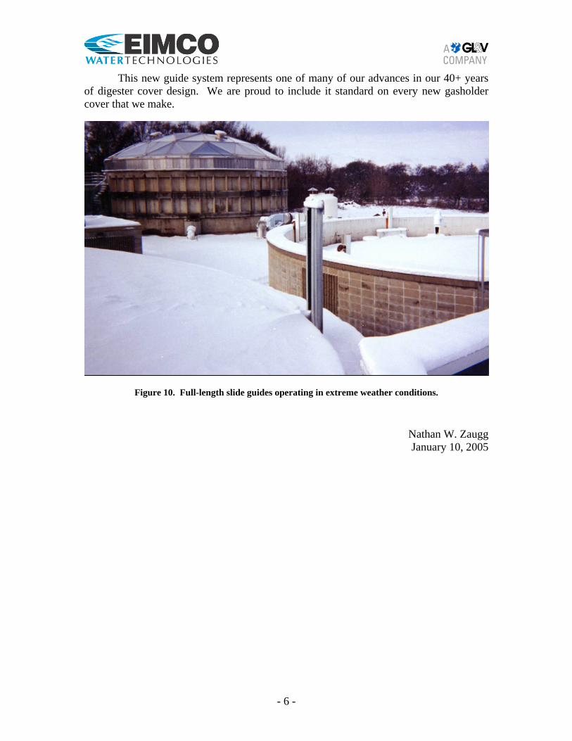
This new guide system represents one of many of our advances in our 40+ years
of digester cover design. We are proud to include it standard on every new gasholder cover that we make.
Figure 10. Full-length slide guides operating in extreme weather conditions.
Nathan W. Zaugg January 10, 2005
- 6 -

www.cscos.com (877) CS-SOLVE
Appendix 3