Embed Size (px)
Citation preview
Technical Data
OneGear™ MV SMC™ Flex Solid-State Motor Controller (10…15 kV)Bulletins 7760, 7761, 7762, and 7763

OneGear™ MV SMC™ Flex Solid-State Motor Controller (10…15 kV)
Additional Resources
These documents contain additional information concerning related products from Rockwell Automation.
You can view or download publications at http://www.rockwellautomation.com/literature/. To order paper copies of technical documentation, contact your local Allen-Bradley distributor or Rockwell Automation sales representative.
Topic Page
Additional Resources 2
Introduction 3
Equipment Design and Selection 5
Structure and Controller 6
OneGear MV SMC Control Module 10
Enclosure Types 12
Ground Bus 13
Vacuum Contactor Specifications 13
Vacuum Circuit Breaker Specifications 14
Three-Phase Power Stack Unit 15
Low Voltage Wireway 15
Low Voltage Control Panel 16
Power Fuses and Fuse Holders (Contactor Based) 16
Control Circuit Power Supply 16
Current Transformer 16
Load Terminations 17
Control Module 17
Current Loop Gate Driver (GLCD Board) 18
Voltage Sensing Module 19
Fiber Optic Expansion Board 19
Basic Data Sheets 20
Resource Description
Industrial Automation Wiring and Grounding Guidelines, publication 1770-4.1 Provides general guidelines for installing a Rockwell Automation industrial system.
Product Certifications website, http://www.ab.com Provides declarations of conformity, certificates, and other certification details.
150-WP003_-EN-P SMC Flex Controller with Pump Control White Paper
1560E-WP023_-EN-E How to Successfully Apply Medium Voltage Soft Starters
7760-SR001_-EN-P Specification Guide
150-AT002_-EN-P Bulletin 150 SMC Flex Application Guide
www.ab.com/mvb Medium Voltage Motor Control website
2 Rockwell Automation Publication 7760-TD001D-EN-P - October 2014
OneGear™ MV SMC™ Flex Solid-State Motor Controller (10…15 kV)
Introduction
Rockwell Automation has produced quality medium voltage products to meet the requirements of all types of industries for well over seven decades.
From the original oil-immersed contactor, to air break and vacuum contactors, to solid-state controllers such as Smart Motor Controllers and AC Variable Frequency Drives, Rockwell Automation has developed and built a medium voltage product line that satisfies those industries demanding increased safety, less maintenance, longer life and reliability in motor control equipment.
This Technical Data Guide supplies all the technical features and functions of the OneGear™ MV SMC™ Flex, a solid-state motor controller for motor starting applications between 10…14.4 kV.
Benefits of Solid-State Motor Controllers
1. Minimize Downtime/Operating Costs• Belts, gears and machinery can be damaged by across-the-line starting.• Increased life of mechanical equipment.• Materials can be damaged or destroyed by sudden starts and stops
2. Cost Savings by Minimizing Inrush Currents• Power company restrictions on incoming line current.• Weak power lines cannot handle high inrush currents, causing brown outs or excessive line disturbances.
OneGear MV SMC Flex Solid-State Motor Controllers
Rockwell Automation meets industry demands with the OneGear MV SMC Flex line of solid-state, reduced-voltage motor controllers. The OneGear MV SMC Flex is used to control industrial motors rated up to 580 A full load current,10…14.4 kV AC, 50/60 Hz and up to 50 °C. Under certain conditions, higher motor full load current may be possible but conditions should be reviewed by Rockwell Automation for confirmation.
The OneGear MV SMC Flex is a solid-state reduced voltage controller utilizing the SMC Flex digital control module. This is the same control module used in the low voltage Bulletin 150 SMC Flex controller.
Rockwell Automation Publication 7760-TD001D-EN-P - October 2014 3
OneGear™ MV SMC™ Flex Solid-State Motor Controller (10…15 kV)
OneGear MV SMC Flex Control Capabilities
The OneGear MV SMC Flex provides closed-loop microprocessor control to start and stop three-phase motors. Several standard modes of operation are available within a single controller:
• Soft Start with Selectable Kickstart• Current Limit Start with Selectable Kickstart • Linear Acceleration with Selectable Kickstart (requires motor tachometer)• Linear Deceleration (requires motor tachometer)• Soft Stop• Dual Ramp Start• Full Voltage Start• Pump Control (optional control module), including start and stop control
Refer to Publication 150-UM008_-EN-P, for complete details of control features.
Additional Features• Solid-state motor protection• Metering• DPI (Drive Programming Interface) communication• LCD display• Keypad programming• Fiber optic control of medium voltage SCRs (for isolation)• Current loop gate driver boards• Removable PowerBrick™ SCR assemblies• Compartmentalized construction• Power Bus (optional)
Available Switching Technologies• Drawout Vacuum Contactors (VC) for 10…12 kV (to 160 A)• Drawout Vacuum Circuit Breakers (VB) 10…15 kV
Bulletin Number ExplanationRetrofit Controller 7760
OEM Controller 7761
Complete Controller (Vacuum Contactor) 7762
Complete Controller (Vacuum Breaker) 7763
4 Rockwell Automation Publication 7760-TD001D-EN-P - October 2014

OneGear™ MV SMC™ Flex Solid-State Motor Controller (10…15 kV)
Equipment Design and Selection
The OneGear MV SMC Flex consists of free-standing, dead front, vertical steel structures.
Each structure is suitable for future expansion at each end. Each structure will be supplied with removable lifting means for ease of handling and installation.
The controller is a modular design to provide for ease and speed of maintenance. The modules are manufactured and designed to allow ease of maintenance, including removal of medium voltage components and power electronic components.
The complete controller is divided into isolated compartments as follows:• Main power bus compartment• Power cell compartment• Cable termination compartment(s)• Low voltage compartment
Grounded metal barriers are provided between the low voltage compartment, power cell, main power bus compartment, and cable termination compartment. Personnel will have access to the low voltage compartment, with the controller energized, without being exposed to any medium voltage.
Rockwell Automation Publication 7760-TD001D-EN-P - October 2014 5

OneGear™ MV SMC™ Flex Solid-State Motor Controller (10…15 kV)
Structure and Controller
Each structure will contain the following items:
Retrofit Controller (Bulletin 7760) (No Main Isolation Contactor/Breaker)• Drawout bypass vacuum breaker• Removable ‘PowerBrick’ SCR assemblies • Voltage sensing board• Fiber optic connection from SMC Flex control module to gate driver boards on ‘PowerBricks’• Tin-plated insulated horizontal copper power bus • A continuous bare copper ground bus • LV control panel with SMC Flex control module and associated interface board and terminations.• Provisions for bottom fed line and load connections.• Earthing switch (optional)
Figure 1 - Bulletin 7760 Typical Single-Line Drawing (Bottom Cable Entry)
Power Converter Bypass unit
Motor cables
SMCFlexControl Module
CT inputFromexisting unit
FromExistingController
Optional EarthingSwitch
Line Cable Compartment
SeparateControl Power
x
6 Rockwell Automation Publication 7760-TD001D-EN-P - October 2014
OneGear™ MV SMC™ Flex Solid-State Motor Controller (10…15 kV)
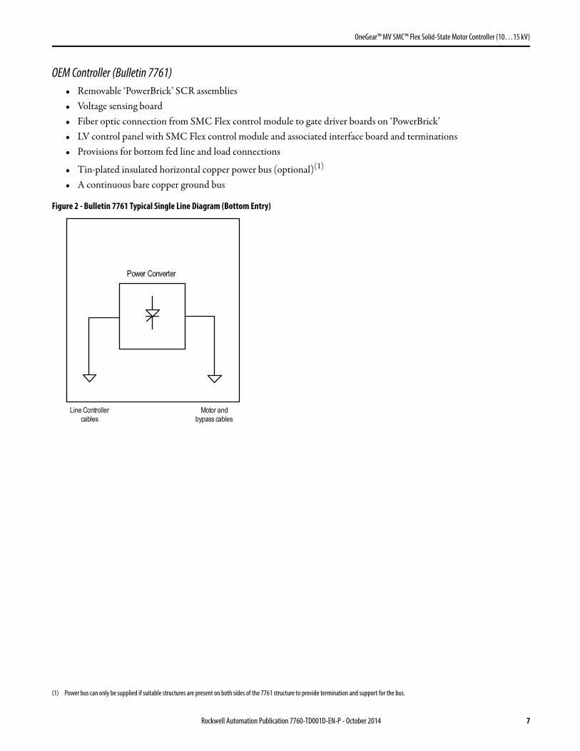
OEM Controller (Bulletin 7761)• Removable ‘PowerBrick’ SCR assemblies• Voltage sensing board• Fiber optic connection from SMC Flex control module to gate driver boards on ‘PowerBrick’• LV control panel with SMC Flex control module and associated interface board and terminations• Provisions for bottom fed line and load connections
• Tin-plated insulated horizontal copper power bus (optional)(1)
• A continuous bare copper ground bus
Figure 2 - Bulletin 7761 Typical Single Line Diagram (Bottom Entry)
(1) Power bus can only be supplied if suitable structures are present on both sides of the 7761 structure to provide termination and support for the bus.
Power Converter
Motor andbypass cables
Line Controllercables
Rockwell Automation Publication 7760-TD001D-EN-P - October 2014 7

OneGear™ MV SMC™ Flex Solid-State Motor Controller (10…15 kV)
Complete Controller (VC) (Bulletin 7762) (12kV Max)• Drawout main isolation (Start) vacuum contactor • Drawout bypass (Run) vacuum contactor • Removable ‘PowerBrick’ SCR assemblies• Three current limiting power fuses each for main and bypass contactors• Six current transformers• Tin-plated insulated horizontal copper power bus• A continuous bare copper ground bus • Voltage sensing board• Fiber optic connection from SMC Flex control module to gate driver boards on ‘PowerBrick’• LV control panel with SMC Flex control module and associated interface board and terminations• Provisions for bottom load connections• Earthing switch (optional)
Figure 3 - Bulletin 7762 Typical Single Line Diagram (Bottom Cable Entry)
Power converter
SMC Bypass unit
Motor cables
Start unit
SMC FlexControl Module
Optional EarthingSwitch
8 Rockwell Automation Publication 7760-TD001D-EN-P - October 2014
OneGear™ MV SMC™ Flex Solid-State Motor Controller (10…15 kV)
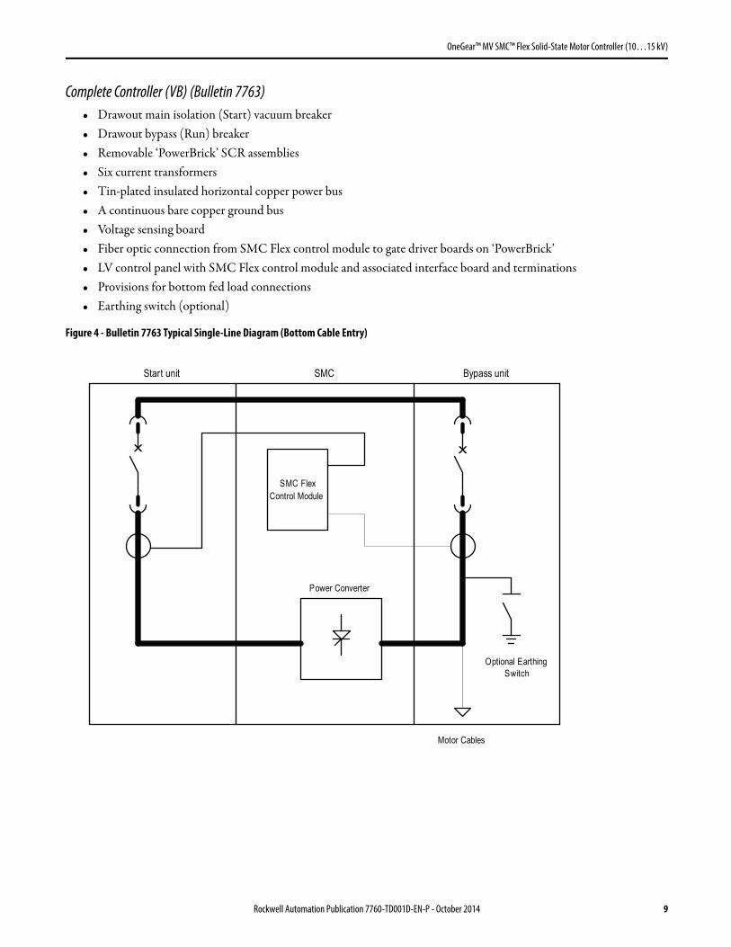
Complete Controller (VB) (Bulletin 7763) • Drawout main isolation (Start) vacuum breaker• Drawout bypass (Run) breaker• Removable ‘PowerBrick’ SCR assemblies• Six current transformers• Tin-plated insulated horizontal copper power bus • A continuous bare copper ground bus • Voltage sensing board• Fiber optic connection from SMC Flex control module to gate driver boards on ‘PowerBrick’• LV control panel with SMC Flex control module and associated interface board and terminations• Provisions for bottom fed load connections• Earthing switch (optional)
Figure 4 - Bulletin 7763 Typical Single-Line Diagram (Bottom Cable Entry)
Power Converter
SMC Bypass unit
Motor Cables
Start unit
SMC FlexControl Module
Optional EarthingSwitch
x x
Rockwell Automation Publication 7760-TD001D-EN-P - October 2014 9

OneGear™ MV SMC™ Flex Solid-State Motor Controller (10…15 kV)
OneGear MV SMC Flex Control Module
Electrical
The SMC Flex control module provides closed-loop digital microprocessor control and supervision of all controller operations, including SCR pulse firing control. The control module used in the OneGear MV SMC Flex is the exact same unit that is used in low voltage applications.
The SMC Flex control module is capable of providing the following control functions:• Soft Start – with Selectable Kickstart• Soft Stop• Current Limit Start – with Selectable Kickstart
• Linear Speed Acceleration(1) – with Selectable Kickstart
• Linear Speed Deceleration(1)
• Dual Ramp – with Selectable Kickstart• Full Voltage• Preset Slow Speed• Pump Control (Optional module)
The standard start time can be programmed from 0…30 seconds.
The standard stop time can be programmed from 0…30 seconds. Extended start or stop times may be made available, but a Rockwell Automation technical specialist should be consulted on the application.
Kick-start, selectable with soft start, current limit and linear acceleration, can provide an adjustable time pulse of current prior to the normal start mode. The current can also be controlled to provide 0…90% of locked rotor torque for a time between 0.0…2.0 seconds. This feature is entirely field-selectable.
Pump Control (Optional)• The Pump Control option with the SMC Flex control module can be implemented to provide closed loop control of
a motor to match the specific torque requirements of centrifugal pumps for both starting and stopping. This patented feature aids in eliminating the phenomena commonly referred to as "water hammer". The standard start time is between 0…30 seconds but can be expanded, but a Rockwell Automation technical specialist should be consulted on the application.
• Closed loop control is achieved without using external sensors or feedback devices.• Pump Stop is initiated by a dedicated Pump Stop input. A coast-to-rest stop is still possible with a separate stop
input.
• The Pump Stop time is user adjustable from 0…120 seconds.
(1) Requires motor tachometer
10 Rockwell Automation Publication 7760-TD001D-EN-P - October 2014

OneGear™ MV SMC™ Flex Solid-State Motor Controller (10…15 kV)
Monitoring
The SMC Flex control module provides the following monitoring functions indicated though the built-in LCD display; or remotely via the communication port:
• Phase-to-phase supply voltage• Three-phase line current• Three-phase power (MW, MWh, power factor)• Elapsed time• Motor thermal capacity usage• Motor speed (with optional use of tachometer input and Linear ramp function)
Protection and Diagnostics
The following protection and diagnostics is provided as standard with the SMC Flex control module. Protection and Diagnostics features can be utilized with contactor based controllers.(1)
• Power loss (with phase indication; pre-start)• Line fault (with phase indication; pre-start) advising:
– Shorted SCR– Missing load connection
• Line fault (running protection) advising:– Power loss– Shorted SCR– Missing load connection
• Voltage unbalance(2)
• Phase reversal(2)
• Undervoltage(2)
• Overvoltage(2)
• Stall(2)
• Jam(2)
• Overload(2)
• Underload(2)
• Excessive starts/hour u• Open gate (with phase indication)• Overtemperature (power stack, with phase indication)• Communication loss• Motor temperature (via PTC input)• Ground fault (with GFCT option)
(1) Breaker-based units will require overcurrent protection that is not included in the SMC Flex control module, and may therefore require a separate protection relay.
(2) These protective features can be disabled.
Rockwell Automation Publication 7760-TD001D-EN-P - October 2014 11

OneGear™ MV SMC™ Flex Solid-State Motor Controller (10…15 kV)
Overload Protection• Three-phase current sensing is utilized.• Overload trip classes are user-programmable.• Electronic thermal memory is provided for enhanced motor protection.• Protection is available through the controller while in bypass configuration.
Enclosure Types
The OneGear MV SMC Flex is available in an IEC IP4X enclosure as standard. Optional enclosures are:• IEC IP41 • IEC IP42
Arc Resistant Enclosure
The medium voltage motor controller(s) is designed as an arc resistant enclosure.
The arc resistant units will meet the requirements per IEC 62271-200 Annex A, and provide the following benefits: • Reinforced structure, to contain arc flash material • Arc vent to exhaust arc flash material• Plenum or chimney to redirect arc flash material• Reinforced low voltage panel, sealed to prevent entry of arc flash material
Structure Finish
As standard, all exterior doors and lineup end plates shall be painted RAL 7035, textured finish. All metal back plates in the low voltage compartments shall be painted high gloss white for high visibility. The enclosure frame, internal structural metal and metallic barriers will be zinc coated galvanized steel or similar.
Notes:
When optional custom paint color is specified, all doors and lineup end plates shall be painted to the custom color requirement, except for the external handle assemblies, lifting angles and lifting brackets.
All unpainted steel parts, not listed above, shall be zinc coated galvanized steel, or zinc chromate plated.
Description Hybrid epoxy powder paint.
Standard Color RAL 7035 textured finish.
Procedure Continuous paint line. All base steel parts are painted before assembly.
Preparation Alkaline wash/rinse/iron phosphate rinse/iron-chrome sealer rinse/recirculated de-ionized water rinse and virgin de-ionized water rinse.
Painting Air-atomized electrostatic spray.Total paint thickness is 0.002 in. (0.051 mm) minimum
Baking Natural gas oven at 179 °C (355 °F) minimum.
12 Rockwell Automation Publication 7760-TD001D-EN-P - October 2014

OneGear™ MV SMC™ Flex Solid-State Motor Controller (10…15 kV)
Main Power Bus (Optional)
The power bus will be made of solid copper conductor(s) and tin plated to resist corrosive elements. Heat shrink insulation is standard where applicable. The material used for the power bus is common from the main power bus through to the line side connection to the power cell. The same material is also used from the load side terminal of the power cell to the load cable connections.
The main power bus will be located in the power bus compartment located at the top and back of the controller.
Bus Ratings
The main bus is braced for 31.5 kA for one second. Higher ratings are available options.
Access is provided to the bus compartment from the top, rear or side of the structure to allow for installation and regular maintenance of the power bus splice connections. (Access is possible from the front of the switchgear sections, but requires some degree of disassembly.)
Ground Bus
A continuous copper ground bus will be provided along the entire length of the controller line-up. The ground bus is also available with optional tin plating to improve corrosion resistance in certain environmental conditions. A mechanical lug for 10 mm2 to 50 mm2 (#8 to #1/0 AWG) or 16 mm2 to 120 mm2 (#6 to 250 MCM) cable is supplied at the incoming end of the line-up. The ground bus will withstand a short time current level of 31.5 kA for three seconds.
Bus Linking
Bus linking system will be available to enable power and ground bus connection of adjacent units in the field by customers or their agents.
Vacuum Contactor Specifications (Input and Bypass: 10…12 kV)
The medium voltage drawout contactor is a magnetic drive vacuum type, rated 400 A from 10…12 kV.
Each vacuum contactor provides the following safety features:• Prevent apparatus racking in or out with the apparatus closed.• Prevent the closing of the apparatus when the truck is in an undefined position (neither service nor test position).• Prevent apparatus racking in if the multi-contact plug is unplugged.• Prevent unplugging the multi-contact plug if the truck is in the service or undefined position.• Prevent the closing of the Earthing switch if the truck is in the service or undefined position.• Prevent apparatus racking in if the Earthing switch is closed.
When the contactor is withdrawn, automatic shutters provide isolation from the main power bus and load terminals. The electrical life of the contactor is up to 100,000 operations (AC3). The mechanical life of the contactor is up to one million operations. The contactor will come with an ‘Emergency Manual Operating Device’.
Rockwell Automation Publication 7760-TD001D-EN-P - October 2014 13

OneGear™ MV SMC™ Flex Solid-State Motor Controller (10…15 kV)
Interlocks• Prevent the apparatus compartment door from opening if the truck is in the service or undefined position.• Prevent the apparatus racking in if the apparatus compartment door is open.• Prevent the feeder compartment door from opening if the Earthing switch is open.• Prevent the Earthing switch from opening if the feeder compartment door is open.
Other Interlocks
Key Type• Apparatus racking in.• Earthing switch closing.• Earthing switch opening• Insertion of the apparatus racking lever.• Insertion of the Earthing switch operating lever.
Padlock Type• Compartment door opening.• Insertion of operating or racking levers• Shutters opening or closing.
A bypass contactor is provided to connect the motor to the main bus voltage once the motor is up to full speed. When a stop option is selected, the bypass contactor will open, bringing the SCRs in the three phase power stack circuit (PowerBrick) back into the power circuit.
The bypass contactor is fully rated and is capable of providing a full voltage start in case of emergency bypass.
Vacuum Circuit Breaker Specifications (Input and Bypass: 10…15 kV)
The medium voltage vacuum drawout circuit breaker is a vacuum type, rated 12…17.5 kV. The vacuum circuit breaker is rated for 1250 A.
Two different types of medium voltage circuit breakers are available: spring actuated or magnetically actuated.
The vacuum circuit breaker provides the following safety features:• Prevent apparatus (contactor or breaker) racking in or out with the apparatus closed.• Prevent the closing of the apparatus when the truck is an undefined position (neither service nor test position).• Prevent apparatus racking in if the multi-contact plug is unplugged.• Prevent unplugging the multi-contact plug if the truck is in the service or undefined position.• Prevent the closing of the Earthing switch if the truck is in the service or undefined position.• Prevent apparatus racking in if the Earthing switch is closed.
14 Rockwell Automation Publication 7760-TD001D-EN-P - October 2014

OneGear™ MV SMC™ Flex Solid-State Motor Controller (10…15 kV)
Interlocks• Prevent the apparatus compartment door from opening if the truck is in the service or undefined position.• Prevent the apparatus racking in if the apparatus compartment door is open.• Prevent the feeder compartment door from opening if the Earthing switch is open.• Prevent the Earthing switch from opening if the feeder compartment door is open.
Other Interlocks
Key Type• Apparatus racking in.• Earthing switch closing.• Earthing switch opening• Insertion of the apparatus racking lever.• Insertion of the Earthing switch operating lever.
Padlock Type• Compartment door opening.• Insertion of operating or racking levers• Shutters opening or closing.
A bypass breaker is provided to connect the motor to the main bus voltage once the motor is up to full speed. When a stop option is selected, the bypass breaker will open, bringing the SCRs in the three phase power stack circuit back into the power circuit.
The bypass breaker is fully rated and is capable of providing a full voltage start in case of emergency bypass.
Three-Phase Power Stack Circuit
The power stacks are comprised of simple “building-block” components (i.e. a two-device power circuit using “PowerBrick” technology), to minimize the number of assemblies. The number of PowerBricks used is a function of the system voltage and will increase to provide the required PIV withstand.
The PowerBrick assemblies are capable of the ratings listed in the specifications section.
Each phase of the PowerBrick assemblies will be mounted on a removable cart or ‘truck’ for ease of maintenance.
Low Voltage Wireway
A standard low voltage wireway can be available across the top of the structure. • 153 mm x 100 mm (6 in. x 4 in.)
The low voltage wireway allows a convenient method of interconnecting control wire from one controller to another, when interfacing with a master panel or with programmable controller circuits.
Rockwell Automation Publication 7760-TD001D-EN-P - October 2014 15

OneGear™ MV SMC™ Flex Solid-State Motor Controller (10…15 kV)
Low Voltage Control Panel
Each controller has a separate, front accessible, low voltage control compartment. The compartment is completely isolated, using grounded metal barriers between the low voltage compartment and the power cell and/or main power bus compartments for utmost safety, providing LSC2B service continuity protection.
Optional meters, motor protection relays, selector switches, operators, indicating lights, etc., are mounted on the front of the low voltage door in the contactor or breaker units, and arranged in a logical and symmetrical manner.
The low voltage panel provides the following features:• Space for low voltage control devices, transducers and metering.• Necessary terminal blocks. Extra terminal blocks can be supplied as an option.• Low voltage control panel access from the front, without turning the controller “OFF”. • All remote low voltage cables are able to enter the low voltage control panel from the top or bottom of the structure.
Access is by means of removable metal entry plates on the top and bottom of the structure.• Pilot control relays used to operate the vacuum contactor or breaker. • The control panel supply voltage is rated 110/120V AC or 220/240V AC, 50/60 Hz. • The low voltage control panel door has a viewing window, allowing the user to monitor the MV SMC Flex controller
operation via the built-in display.
Power Fuses and Fuse Holders (Contactor Based)
Current limiting power fuses will be provided. DIN style Backup fuses will be used for the short circuit protection of medium voltage motors and motor controllers.
The medium voltage controller will have DIN power fuse holders and be located to allow easy inspection and replacement without any disassembly. The power fuses will be supplied with an open fuse indicator. The power fuse size will be selected when motor data and the protective device characteristics are known.
Control Circuit Power Supply
User supplied control power must be provided for operation of the drawout contactor or circuit breaker, and other control and protection devices within the controller.
The minimum requirements are: 110/120 or 220/240V AC, 250 VA.
Current Transformer
The medium voltage feeder compartment will include three current transformers of sufficient VA capacity to meet the requirements of all the devices connected to them.
Each current transformer will have the primary rating sized appropriately in relation to the full load current rating of the motor or feeder. The secondary of the current transformers will have a five amp output plus the accuracy suitable for the type and quantity of protection or metering devices connected to it. All current transformer control wiring will be terminated on the current transformer with locking type, fork tongue lugs.
16 Rockwell Automation Publication 7760-TD001D-EN-P - October 2014

OneGear™ MV SMC™ Flex Solid-State Motor Controller (10…15 kV)
Load Terminations
An appropriate load termination location is provided to accommodate lugs with single hole mounting for connection of the load cables.
As a standard solution, it is possible to connect up to three single-pole cables per phase, with stress cones (maximum cross-sectional area of 185 mm2), or two cables per phase, with stress cones (maximum cross-sectional area of 300 mm2). The connection height of the cables in relation to the floor is a minimum of 530 mm.
There are provisions to locate a toroid (donut) style, ground fault sensing current transformer, when the zero sequence ground fault protection feature is required. (7760, 7762 or 7763).
Earthing Switch (optional)
The OneGear MV SMC Flex can be equipped with a snap action manually operated earthing switch for high speed positive closing. The unit is also sized to conduct the short circuit rated current. The switch comes with an earthing blade that connects all three phases by earthing pins. The earthing switch is rated per IEC 62271-102. Short circuit rating of the earthing switch will match the rating of the bypass and/or input section.
Tachometer Signal Conditioner (Optional)• A panel-mounted tachometer signal conditioner (TSC) is available for use with linear acceleration/deceleration
applications.• A suitable power supply will be provided with the TSC. • The TSC is used to convert the motor speed feedback signal (in pulse format) to a 0…4.5V DC level.
Control Module
The control module is designed for mounting within the low voltage panel (for safety reasons) of the OneGear MV SMC Flex and is compatible with the full range of current and voltage ratings.
The control module consists of a power supply, logic control circuitry, silicon controlled rectifier (SCR) firing circuitry, I/O circuitry, a digital programming keypad, a backlit LCD display, and a DPI port.
Control Module Programming and Display
Digital parameter adjustment is provided through a standard built-in keypad. A built-in backlit LCD display is provided for controller set-up, diagnostics, status, and monitoring. The display has three lines of 16 characters.
The display can depict alphanumeric characters in any of the following languages, by adjustment of a single parameter:• English• French • Spanish• German• Portuguese• Mandarin
Rockwell Automation Publication 7760-TD001D-EN-P - October 2014 17

OneGear™ MV SMC™ Flex Solid-State Motor Controller (10…15 kV)
Control Module Communications
A serial communications port DPI (Drive Programming Interface), is provided as standard. Optional communications protocol interface modules are available for connection to Remote I/O, DeviceNet™, ControlNet™, Ethernet, RS-485, Modbus RTU, Profibus-DP and Modbus/HCP.
Control Module Interface Boards
The interface board provides all the necessary feedback and control signals to operate the OneGear MV SMC Flex up to 14.4 kV. The following features are incorporated:
• Gate drive signals, sufficient for up to 12 devices per phase in conjunction with the Fiber Optic expansion board • Current feedback• Voltage feedback• Power stack heatsink temperature feedback• Power supply input requirements
– 110…240V AC (-15/+10%), 50/60 Hz– 15 VA – Auto-sensing (no jumpers required)
The interface board provides for set-up and troubleshooting aids, as follows:• Diagnostic LEDs• Manual gate firing pulse enable/disable (only for use without MV applied to the unit)• Heatsink temperature feedback enable/disable
Current Loop Gate Driver (GLCD) Board
This board provides the turn-on capability for SCR devices. The board provides optical fiber isolation between itself and the gating source logic. It is powered by recovering energy from the snubber circuit, so it is fully isolated from the control and logic circuits. The board also receives short-term power from the current loop power supply.
18 Rockwell Automation Publication 7760-TD001D-EN-P - October 2014

OneGear™ MV SMC™ Flex Solid-State Motor Controller (10…15 kV)
Voltage Sensing Module
The voltage sensing board has six independent channels, with different sized resistors based on pre-defined voltage ranges, which convert voltages ranging between 10…14.4 kV down to lower voltages that can used by the SMC Flex control module logic.
The table above shows the required MV ratio for each version of voltage sensing module. The MV ratios maybe fine tuned to achieve better accuracy on the display of the SMC Flex control module. While running the motor in bypass mode, compare the voltage displayed on the control module to a known accurate meter connected to the same source voltage as the motor the OneGear MV SMC Flex is controlling.
Fiber Optic Expansion Board
The Fiber Optic Expansion Board accepts fiber gate drive signals from the Control Module Interface Board and splits them into the required fiber optic gate drive signals for 10…15 kV for the OneGear PowerBrick. The expansion board can control up to 36 MV SCRs.
Power supply input requirements:• 110…240V AC (-15/+10%), 50/60 Hz• 25 VA maximum• Universal input
Line Voltage (3 phase, 50/60 Hz) MV Ratio (Parameter 106)
10,000…12,000V 126
12,001…14,400V 97
Rockwell Automation Publication 7760-TD001D-EN-P - October 2014 19

OneGear™ MV SMC™ Flex Solid-State Motor Controller (10…15 kV)
Basic Data SheetsTable 1 - Electrical Ratings (Bulletin 7761)
Electrical Ratings IEC
Power Circuit
Method of Connection Motor in delta or star; SCRs between windings and supply
Number of Poles Equipment designed for three phase loads only
Rated Voltage (Ur) 12 kV / 15 kV
Rated Insulation Voltage (Ui) 12 kV / 15 kV
Rated Impulse Voltage (Uimp) 75 kV / 95 kV
Dielectric Withstand 28 kV / 36 kV
Repetitive Peak Inverse Voltage Rating 32500 / 39000
Output Rating 100…15,000 hp75…11,000 kW
Semi-Conductor Isolation Fiber optic
Operating Frequency 50/60 Hz
dv/dt Protection RC Snubber Network
Transient Protection Integrated overvoltage trigger circuit
Rated Current 160 A340 A580 A
dv/dt 1000V/μs
di/dt 100 A/μs
Voltage Drop (Line to Output Terminals)
2.5V per SCR without bypass;Less than 1.0V with bypass, total
Overall Efficiency 99.95% with bypass
Initial Torque 0….90% of motor locked rotor torque
Thermal Capacity 600%, 10 s450%, 30 s
Ramp Time 0…30 s (Consult Factory for Longer Time)
Kickstart 0…90% of motor locked rotor torque for 0.0…2.0 s
Approvals Safety: 92/59/EEC (Directive)Ref: BSEN 61010-1 :1993, BSEN 60204-1 :1997, IEC 62271-1, IEC 62271-100,IEC 60146-1-1, IEC 60947-4-2
Short Circuit Protection
The power electronics within the converter section must be protected by current-limiting fuses or a fast-acting circuit breaker. The standard 12 kV combination controller, with power fuses and vacuum contactor, includes appropriately coordinated fusing. When circuit breakers are used, a suitably coordinated protection system must be employed to open the breaker under short circuit conditions; limiting the available short circuit current, to the converter section, to the fault limit shown below.
Fault Level Withstand(1) 31.5 kA 100 ms
Control Circuit
Rated Operation Voltage 120/240V AC (-15%, +10%)
Dielectric Withstand 1600V AC / 2000V ~
Operating Frequency 50/60 Hz
Enclosure
Enclosure Type IP4X, IP41 and IP42
20 Rockwell Automation Publication 7760-TD001D-EN-P - October 2014
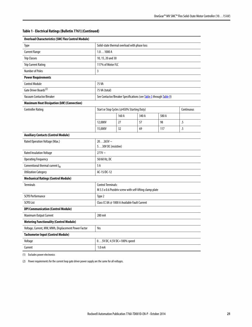
OneGear™ MV SMC™ Flex Solid-State Motor Controller (10…15 kV)
Overload Characteristics (SMC Flex Control Module)
Type Solid-state thermal overload with phase loss
Current Range 1.0…1000 A
Trip Classes 10, 15, 20 and 30
Trip Current Rating 117% of Motor FLC
Number of Poles 3
Power Requirements
Control Module 75 VA
Gate Driver Boards(2) 75 VA (total)
Vacuum Contactor/Breaker See Contactor/Breaker Specifications (see Table 5 through Table 9)
Maximum Heat Dissipation (kW) (Convection)
Controller Rating Start or Stop Cycles (@450% Starting Duty) Continuous
160 A 340 A 580 A
12,000V 27 57 98 .5
15,000V 32 69 117 .5
Auxiliary Contacts (Control Module)
Rated Operation Voltage (Max.) 20…265V ~5…30V DC (resistive)
Rated Insulation Voltage 277V ~
Operating Frequency 50/60 Hz, DC
Conventional thermal current Ith 5 A
Utilization Category AC-15/DC-12
Mechanical Ratings (Control Module)
Terminals Control Terminals:M 3.5 x 0.6 Pozidriv screw with self-lifting clamp plate
SCPD Performance Type 2
SCPD List Class CC 8A @ 1000 A Available Fault Current
DPI Communication (Control Module)
Maximum Output Current 280 mA
Metering Functionality (Control Module)
Voltage, Current, MW, MWh, Displacement Power Factor Yes
Tachometer Input (Control Module)
Voltage 0…5V DC; 4.5V DC=100% speed
Current 1.0 mA
(1) Excludes power electronics
(2) Power requirements for the current loop gate driver power supply are the same for all voltages.
Table 1 - Electrical Ratings (Bulletin 7761) (Continued)
Rockwell Automation Publication 7760-TD001D-EN-P - October 2014 21
OneGear™ MV SMC™ Flex Solid-State Motor Controller (10…15 kV)
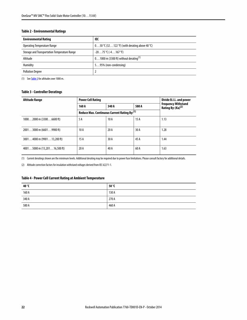
Table 2 - Environmental Ratings
Environmental Rating IEC
Operating Temperature Range 0…50 °C (32…122 °F) (with derating above 40 °C)
Storage and Transportation Temperature Range -20…75 °C (-4…167 °F)
Altitude 0…1000 m (3300 ft) without derating(1)
(1) See Table 3 for altitudes over 1000 m.
Humidity 5…95% (non-condensing)
Pollution Degree 2
Table 3 - Controller Deratings
Altitude Range Power Cell Rating Divide B.I.L. and power frequency Withstand Rating By: (Ka)(2)
(2) Altitude correction factors for insulation withstand voltages derived from IEC 62271-1.
160 A 340 A 580 A
Reduce Max. Continuous Current Rating By:(1)
(1) Current deratings shown are the minimum levels. Additional derating may be required due to power fuse limitations. Please consult factory for additional details.
1000…2000 m (3300…6600 ft) 5 A 10 A 15 A 1.13
2001…3000 m (6601…9900 ft) 10 A 20 A 30 A 1.28
3001…4000 m (9901…13,200 ft) 15 A 30 A 45 A 1.44
4001…5000 m (13,201…16,500 ft) 20 A 40 A 60 A 1.63
Table 4 - Power Cell Current Rating at Ambient Temperature
40 °C 50 °C
160 A 130 A
340 A 270 A
580 A 460 A
22 Rockwell Automation Publication 7760-TD001D-EN-P - October 2014

OneGear™ MV SMC™ Flex Solid-State Motor Controller (10…15 kV)
Table 5 - Shipping Weights and Dimensions(1)
(1) Weights and dimensions are approximate. Certain options (such as top entry or PFCC) will change weight and dimensions. Contact factory for certified dimensions and weights.
Current Rating kW (Hp)(2)
(2) Power Ratings are given for reference only. The capability of the Soft Starter is dependent on the starting current of the motor and operational time. Therefore, application ratings may be greater or less than values in this table.
Dimensions in mm (in.) Shipping Weight
10 kV 11 kV 13.8 kV Width Depth Height kg (lb)
10…12 kV SMC Flex Complete Controller (Vacuum Contactor) – Bulletin 7762
160 A 2200 (3000) 2500 (3250) – 2800 (110) 1340 (53) 2200 (86) 2728 (6000)
10…15 kV SMC Flex Complete Controller (Vacuum Circuit Breakers) – Bulletin 7763
160 A 2200 (3000) 2500 (3250) 3150 (4000) 2800 (110) 1340 (53) 2200 (86) 2728 (6000)
340 A 4750 (6500) 5300 (7000) 6700 (9000)
580 A 8000 (11,000) 9000 (12,000) 11000 (15,000)
10…15 kV SMC Flex OEM Controller – Bulletin 7761
160 A 2200 (3000) 2500 (3250) 3150 (4000) 1500 (59) 1340 (53) 2200 (86) 2728 (6000)
340 A 4750 (6500) 5300 (7000) 6700 (9000)
580 A 8000 (11,000) 9000 (12,000) 11,000 (15,000)
10…15 kV SMC Flex Retrofit Controller (Vacuum Circuit Breaker) – Bulletin 7760
160 A 2200 (3000) 2500 (3250) 3150 (4000) 2800 (110) 1340 (53) 2200 (86) 2728 (6000)
340 A 4750 (6500) 5300 (7000) 6700 (9000)
580 A 8000 (11,000) 9000 (12,000) 11,000 (15,000)
Table 6 - Power Bus Specifications
Description Specifications
Main Power Bus
Bus Bar Material Tin-plated insulated copper
Optional Power Bus Plating Silver
Continuous Current Rating at 40 °C (104 °F) 1250, 2000 A
Maximum Full Load Temperature Rise 65 °C (149 °F)
Maximum Full Load Temperature 105 °C (221 °F) @ 40 °C ambient
Fault Withstand Current Rating (3 s) 31.5 kA RMS SYM
Type of Bus Bracing Epoxy cast, glass polyester
Dimensions per Phase 1250 A2000 A
Qty 1 – 10 x 80 mm (3/8 x 3 in.)Qty 2 – 10x 80 mm (3/8 x 3 in.)
Cross Sectional Area per Phase 1250 A2000 A
800 mm2 (1.125 in.2) total1600 mm2 (2.25 in.2) total
Insulating Material Between Phases and Ground Type : Sleeve, heat shrink
Material : Polyolefin
Thickness : 3.0 mm (0.12 in./120 mils)
Anti-hygroscopic : 0.25%
Electrical Strength : 500V/mil (20 kV/mm)
Rockwell Automation Publication 7760-TD001D-EN-P - October 2014 23
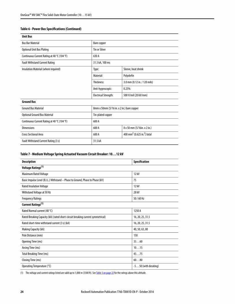
OneGear™ MV SMC™ Flex Solid-State Motor Controller (10…15 kV)
Unit Bus
Bus Bar Material Bare copper
Optional Unit Bus Plating Tin or Silver
Continuous Current Rating at 40 °C (104 °F) 630 A
Fault Withstand Current Rating 31.5 kA, 100 ms
Insulation Material (where required) Type: Sleeve, heat shrink
Material: Polyolefin
Thickness: 3.0 mm (0.12 in. / 120 mils)
Anti-hygroscopic: 0.25%
Electrical Strength: 500 V/mil (20 kV/mm)
Ground Bus
Ground Bus Material 8mm x 50mm (5/16 in. x 2 in.) bare copper
Optional Ground Bus Material Tin-plated copper
Continuous Current Rating at 40 °C (104 °F) 600 A
Dimensions 600 A 8 x 50 mm (5/16in. x 2 in.)
Cross Sectional Area 600 A 400 mm2 (0.625 in.2) total
Fault Withstand Current Rating (3 s) 31.5 kA
Table 7 - Medium Voltage Spring Actuated Vacuum Circuit Breaker: 10…12 kV
Description Specification
Voltage Ratings(1)
(1) The voltage and current ratings listed are valid up to 1,000 m (3300 ft). See Table 3 on page 22 for the ratings above this altitude.
Maximum Rated Voltage 12 kV
Basic Impulse Level (B.I.L.) Withstand – Phase to Ground, Phase to Phase (kV) 75
Rated Insulation Voltage 12 kV
Withstand Voltage at 50 Hz 28 kV
Frequency Ratings 50 / 60 Hz
Current Ratings(1)
Rated Normal current (40 °C) 1250 A
Rated Breaking Capacity (kA) (rated short-circuit breaking current symmetrical) 16, 20, 25, 31.5
Rated short-time withstand current (3 s) (kA) 16, 20, 25, 31.5
Making Capacity (kA) 40, 50, 63, 80
Pole Distance (mm) 150
Opening Time (ms) 33…60
Arcing Time (ms) 10…15
Total Breaking Time (ms) 43…75
Closing Time (ms) 60…80
Operating Temperature (°C) -5…50 (with derating)
Table 6 - Power Bus Specifications (Continued)
24 Rockwell Automation Publication 7760-TD001D-EN-P - October 2014

OneGear™ MV SMC™ Flex Solid-State Motor Controller (10…15 kV)
Table 8 - Medium Voltage Spring Actuated Vacuum Circuit Breaker: 12.5…15 kV
Description Specification
Voltage Ratings(1)
(1) The voltage and current ratings listed are valid up to 1000 m (3300 ft). See Table 3 on page 22 for the ratings above this altitude.
Maximum Rated Voltage 17.5 kV
Basic Impulse Level (B.I.L.) Withstand – Phase to Ground, Phase to Phase (kV) 95
Rated Insulation Voltage 17.5 kV
Withstand Voltage at 50 Hz 38 kV
Frequency Ratings 50 / 60 Hz
Current Ratings(1)
Rated Normal current (40 °C) 1250 A
Rated Breaking Capacity (rated short-circuit breaking current symmetrical) (A) 16, 20, 25, 31.5
Rated short-time withstand current (3 s) (kA) 16, 20, 25, 31.5
Making Capacity (kA) 40, 50, 63, 80
Pole Distance (mm) 150
Opening Time (ms) 33…60
Arcing Time (ms) 10…15
Total Breaking Time (ms) 43…75
Closing Time (ms) 60…80
Operating Temperature (°C) -5…50 (with Derating)
Table 9 - Medium Voltage Magnetically Actuated Vacuum Circuit Breaker: 10…12 kV
Description Specification
Voltage Ratings(1)
(1) The voltage and current ratings listed are valid up to 1000 m (3300 ft). See Table 3 on page 22 for the ratings above this altitude.itude.
Maximum Rated Voltage 12 kV
Basic Impulse Level (B.I.L.) Withstand – Phase to Ground, Phase to Phase (kV) 75
Rated Insulation Voltage 12 kV
Withstand Voltage at 50 Hz 28 kV
Frequency Ratings 50 / 60 Hz
Current Ratings(1)
Rated Normal current (40 °C) 1250 A
Rated Breaking Capacity (kA) (rated short-circuit breaking current symmetrical) 16, 20, 25, 31.5
Rated short-time withstand current (3 s) 16, 20, 25, 31.5
Making Capacity (kA) 40, 50, 63, 80
Pole Distance (mm) 150
Opening Time (ms) 35…45
Arcing Time (ms) 10…15
Total Breaking Time (ms) 45…60
Closing Time (ms) 50…60
Operating Temperature (°C) -25…50 (with derating)
Mechanical Operations (Actuator) (cycles) 100,000
Electrical Operations (Rated Current) (cycles) 30,000
Rockwell Automation Publication 7760-TD001D-EN-P - October 2014 25
OneGear™ MV SMC™ Flex Solid-State Motor Controller (10…15 kV)
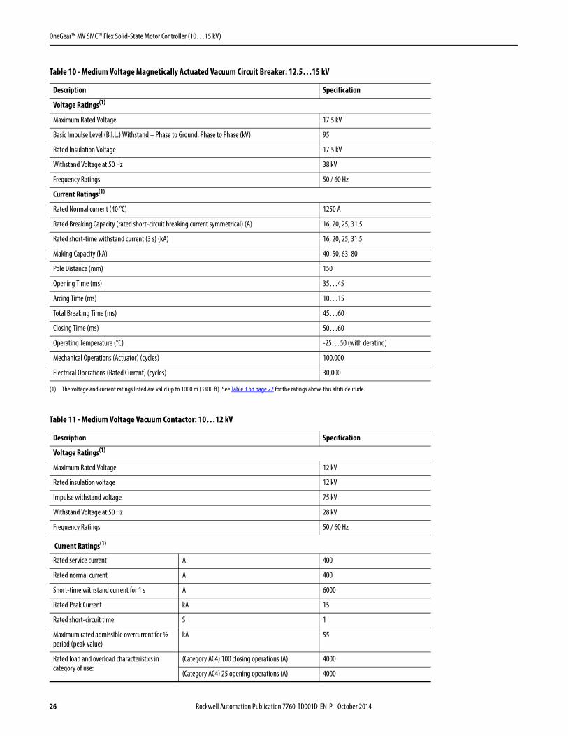
Table 10 - Medium Voltage Magnetically Actuated Vacuum Circuit Breaker: 12.5…15 kV
Description Specification
Voltage Ratings(1)
(1) The voltage and current ratings listed are valid up to 1000 m (3300 ft). See Table 3 on page 22 for the ratings above this altitude.itude.
Maximum Rated Voltage 17.5 kV
Basic Impulse Level (B.I.L.) Withstand – Phase to Ground, Phase to Phase (kV) 95
Rated Insulation Voltage 17.5 kV
Withstand Voltage at 50 Hz 38 kV
Frequency Ratings 50 / 60 Hz
Current Ratings(1)
Rated Normal current (40 °C) 1250 A
Rated Breaking Capacity (rated short-circuit breaking current symmetrical) (A) 16, 20, 25, 31.5
Rated short-time withstand current (3 s) (kA) 16, 20, 25, 31.5
Making Capacity (kA) 40, 50, 63, 80
Pole Distance (mm) 150
Opening Time (ms) 35…45
Arcing Time (ms) 10…15
Total Breaking Time (ms) 45…60
Closing Time (ms) 50…60
Operating Temperature (°C) -25…50 (with derating)
Mechanical Operations (Actuator) (cycles) 100,000
Electrical Operations (Rated Current) (cycles) 30,000
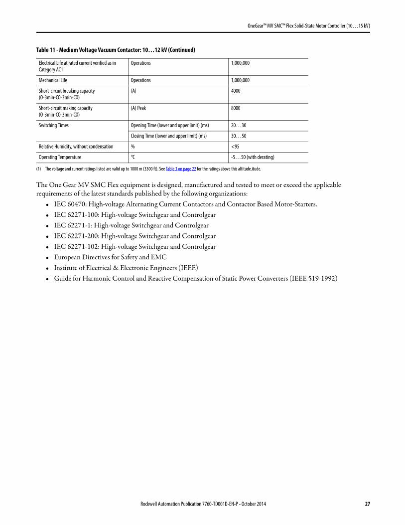
Table 11 - Medium Voltage Vacuum Contactor: 10…12 kV
Description Specification
Voltage Ratings(1)
Maximum Rated Voltage 12 kV
Rated insulation voltage 12 kV
Impulse withstand voltage 75 kV
Withstand Voltage at 50 Hz 28 kV
Frequency Ratings 50 / 60 Hz
Current Ratings(1)
Rated service current A 400
Rated normal current A 400
Short-time withstand current for 1 s A 6000
Rated Peak Current kA 15
Rated short-circuit time S 1
Maximum rated admissible overcurrent for ½ period (peak value)
kA 55
Rated load and overload characteristics in category of use:
(Category AC4) 100 closing operations (A) 4000
(Category AC4) 25 opening operations (A) 4000
26 Rockwell Automation Publication 7760-TD001D-EN-P - October 2014
OneGear™ MV SMC™ Flex Solid-State Motor Controller (10…15 kV)
The One Gear MV SMC Flex equipment is designed, manufactured and tested to meet or exceed the applicable requirements of the latest standards published by the following organizations:
• IEC 60470: High-voltage Alternating Current Contactors and Contactor Based Motor-Starters.• IEC 62271-100: High-voltage Switchgear and Controlgear• IEC 62271-1: High-voltage Switchgear and Controlgear• IEC 62271-200: High-voltage Switchgear and Controlgear• IEC 62271-102: High-voltage Switchgear and Controlgear• European Directives for Safety and EMC• Institute of Electrical & Electronic Engineers (IEEE)• Guide for Harmonic Control and Reactive Compensation of Static Power Converters (IEEE 519-1992)
Electrical Life at rated current verified as in Category AC1
Operations 1,000,000
Mechanical Life Operations 1,000,000
Short-circuit breaking capacity (O-3min-CO-3min-CO)
(A) 4000
Short-circuit making capacity (O-3min-CO-3min-CO)
(A) Peak 8000
Switching Times Opening Time (lower and upper limit) (ms) 20…30
Closing Time (lower and upper limit) (ms) 30…50
Relative Humidity, without condensation % <95
Operating Temperature °C -5…50 (with derating)
(1) The voltage and current ratings listed are valid up to 1000 m (3300 ft). See Table 3 on page 22 for the ratings above this altitude.itude.
Table 11 - Medium Voltage Vacuum Contactor: 10…12 kV (Continued)
Rockwell Automation Publication 7760-TD001D-EN-P - October 2014 27

OneGear™ MV SMC™ Flex Solid-State Motor Controller (10…15 kV)
Notes:
28 Rockwell Automation Publication 7760-TD001D-EN-P - October 2014

Publication 7760-TD001D-EN-P - October 2014 Supersedes Publication 7760-TD001C-EN-P - August 2012 Copyright © 2014 Rockwell Automation, Inc. All rights reserved. Printed in Canada.
Rockwell Automation Support
Rockwell Automation provides technical information on the Web to assist you in using its products. At http://www.rockwellautomation.com/support, you can find technical manuals, technical and application notes, sample code and links to software service packs, and a MySupport feature that you can customize to make the best use of these tools. You can also visit our Knowledgebase at http://www.rockwellautomation.com/knowledgebase for FAQs, technical information, support chat and forums, software updates, and to sign up for product notification updates.
For an additional level of technical phone support for installation, configuration, and troubleshooting, we offer TechConnectSM support programs. For more information, contact your local distributor or Rockwell Automation representative, or visit http://www.rockwellautomation.com/support/.
Installation Assistance
If you experience a problem within the first 24 hours of installation, review the information that is contained in this manual. You can contact Customer Support for initial help in getting your product up and running.
New Product Satisfaction Return
Rockwell Automation tests all of its products to ensure that they are fully operational when shipped from the manufacturing facility. However, if your product is not functioning and needs to be returned, follow these procedures.
Documentation Feedback
Your comments will help us serve your documentation needs better. If you have any suggestions on how to improve this document, complete this form, publication RA-DU002, available at http://www.rockwellautomation.com/literature/.
United States or Canada 1.440.646.3434
Outside United States or Canada Use the Worldwide Locator at http://www.rockwellautomation.com/support/americas/phone_en.html, or contact your local Rockwell Automation representative.
United States Contact your distributor. You must provide a Customer Support case number (call the phone number above to obtain one) to your distributor to complete the return process.
Outside United States Please contact your local Rockwell Automation representative for the return procedure.
Medium Voltage Products, 135 Dundas Street, Cambridge, ON, N1R 5X1 Canada, Tel: (1) 519.740.4100, Fax: (1) 519.623.8930Online: www.ab.com/mvb
Allen-Bradley, Rockwell Software, Rockwell Automation, and TechConnect are trademarks of Rockwell Automation, Inc.
Trademarks not belonging to Rockwell Automation are property of their respective companies.