Embed Size (px)
Citation preview
IEEE TRA.TNSACTIONS ON I-NSTRUMENTATION AND MEASUREMENT. VOL. IM-20, NO. 3, AUGUST 1971 147
One-Way Time Synchronization via GeostationarySatel ites at UHF
D. WAYNE HANSON, MEMBER, IEEE, AND WALLACE F. HAMILTON
Abstract-This paper describes an experiment designed to One-way synchronization of clocks using satellites canevaluate the accuracy of one-way clock synchronization using be accomplished by either sending the information nec-geostationary satellites with the propagation delays calculated from essary to calculate path delay along with the timing sig-the satellite's orbital elements. Propagation delays from a ground nalssaryisodonlculatepath delayalong ellitthe t1mor bytransmitter via satellite to each of five locations in the North and as is done with the TRANSIT satellites [51 or bySouth American continents were measured and compared with the publishing satellite positions, projected ahead in timecalculated values. Three months of data are presented along with from the satellite orbital elements. Orbital elements de-descriptions of the equipment, timing signal format, and methods scribe the satellite's orbit and position in that orbit at afor delay calculation and time recovery. given instant of time usually referred to as its epoch.The results show that within two weeks of epoch for the orbital
elements, clocks can be synchronized to 150 Mus using the Tactical This paper describe's experiments conducted by the Na-Communications Satellite (TACSAT). If one of the observers of tional Bureau of Standards (NBS) to evaluate the ac-the timing signals was already synchronized to the master clock, curacy of a one-way time dissemination system usinghis delay measurement could improve the results for TACSAT to earth synchronous satellites and path delays derived75 Ms. By the same method and within 12 hours of epoch, the results from orbital elements. Additional objectives of the ex-for the Lincoln Experimental Satellite-6 (LES-6) indicated that * usynchronization to 25 Ms was possible. periments included the evaluation of user equipment re-
quirements and determining the utility of certain timingI. INTRODUCTION signal formats. Constraints on the system design were
accuracy in the 0.5-ims 10-pis region, low cost, and sim-A NNUMBER of time dissemination systems exist
that permit remote clocks to be synchronized to piiyi h iercvr rcdrs
a pasterm clostonbe s.e.,honedwy Observations were carried out in North and Southa master clock by a listen-only, i.e., one-way, Amrc by litnn tth tingsasreydmode of opleration. Systerns such as, WWV, WWVH
Aeiab itnn otetmn in1 eae
orithrough two Air Force experimental satellites, theLoran-C, and Omega are examples. In each case, the Lincoln Experimental Sa,tellite-6 (LES-6) and the Tac-propaga,tion time froim the transmitter to the observer tical Communications Satellite (TACSAT). The pathmust be known. The VLF and LF propagation delays delays measured during these observations were com-can be established to an accuracy of a few microseconds. pared with the computed values obtained from theThe MF and HF regions allow only millisecond accuracy satellite's orbital elements and are presented in the re-in delay calibration. Delay calibration is usually a one- sults. Descriptions of the equipment used, signal format,time requirement since the transmitter and observer are and the method by which the delay computations werenormally fixed in position and the delay remains con- made are included.stant.
Satellites have been used to transpond timing signals II. MEASUREMENTbetween a master clock and remote clocks. The majordifficulty associated with this use of satellites is the The major technical problem with one-way satellitevariability in delay caused by satellite motion. The re- time synchronization is the signal delay calculation. Thequirement of computing or measuring the delay has been path delay via, the satellite cannot be calibrated in theavoided by a two-way exchange of time information be- normal sienst pointse the satellite is in continuous mo-tween the master clock and remote clocks [l]-[4]. This tion relative to points on the earth's surface. Satellitesexchange effectively eliminates the delay time from con- are observed, however, resulting in descriptions of theirsideration but also limits the usefulness of the time dis- orbit and position at a given time in that orbit. T'hissemination system. Since only one user can be serviced information, issued approximately monthly, is in theat a, time, there is system saturation. Also, each user form of six constants of motion called orbital elements.mUSt have a greater investment in equipment, i.e., a From these constants the position of the satellite, at anytransmitter as well as a receiver, time, can be calculated.
The accuracy of these delay calculations can bechecked by simply measuring the delay fromn a number
Manuscript received January 8, 1971. This work was supported Of poiin ntegrud nodrtom,ete0etby the Office of Aerospace Research, USAF Cambridge Researchsionontegud.IorrtomkthefcsLaboratories under Contract PR-CRL-90858 and PR-CRL-01703. of cross-track, in-track, and radial calculation errorsThe authors are with the Frequency-Time. .Dissemin.ation most readily appjarent, the observing sites were dispersed
Research Section, Time and Frequency Division, NationalBureau of Standards, Boulder, Colo. 80302. around the subsatellite point as much as possible. Micro-
148 IEEE TRANSACTIONS ON INSTRUMENTATION AND MEASUREIMENT, AUGUST 1971
second synchronization of the transmitter and all ob- isI ~~~~~~~~~~~~~~~~~~~~~~~~~~~lI pps ticks
servers' clocks would allow an accurate m-neasuremnent of clockdelay. A signal from the ground transmitter would be t
initiated, for example, on the I-pps tick and its arrival i 2sHz sqsarerelative to the I-pps tick of the observer's clock would wave
be a measure of the path and equipment delay.The straightforward approach would have been to use lOHz square
IjLJLiLI LJ u LiLi wave
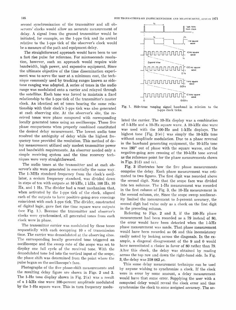
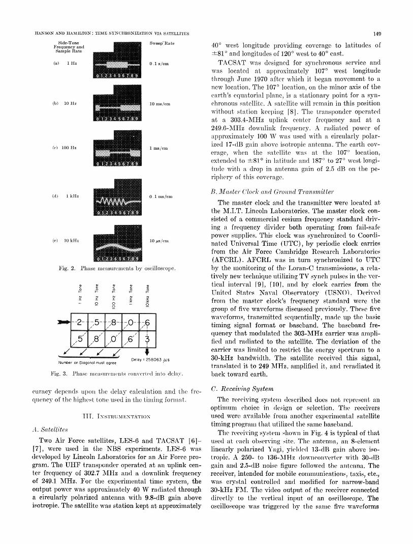
a fast rise pulse for reference. For microseconds resolu- IIstion, however, such an approach would require wide Expand View ~bandwidth, high power, and expensive equipment. Since nro Hz squorethe ultimate objective of the time dissemination experi- t waveOl1sment was to serve the user at a minimum cost, the tech-nique commonly used by tracking ranges known as side- inf kfhHzsquareLFLFLFLFLFtwavetone ranging was adopted. A series of tones in the audio k __ O.Olsrange was modulated onto a carrier and relayed through sqathe satellites. Each tone was forced to maintain a fixed LLzKLL wuavrerelationship to the I-pps tick of the transmitter's master Iooolsclock. An identical set of tones bearing the salme rela-tionship witithircalock' 1-pps tick was sal enerat Fig. 1. Side-tone ranging signal baseband in relation to thetionship with their clock's I-pps tick was also generated 1-pps clock ticks.at each observing site. At the observer's site, the re-ceived tones were phase compared with corresponding lated the carrier. The 10-Hz display was a combinationlocally generated tones using an oscilloscope. Those five of 1-kHz and a 10-Hz square wave. A 10-klz sine wavephase comnparisons when properly combined constituted was used with the 100-Hz and 1-kHz displays. Thethe desired delay measurement. The lowest audio tone highest tone [Fig. 2(e) was simply the 10-kHz toneresolved the ambiguity of delay while the highest fre-zn~ ~ ~ E 1 without amplitude modulation. Due to. a phase reversalquency tone provided. the resolution. This method of de- in the baseband generating equipment, the 10-kHz tonelay measurement utilized only modest transmitter power oand bandwidth requirements. An observer needed only a native-goin zerphase with the square waves, and the
. . . , ~~~~~~~~negative-going zero crossing of the 10-kHz tone servedsimple receiving system and the time recovery tdeeh- as the reference point for the phase measurements shownniques were very straightforward. in Figs. 2 (d) and (e).The audio tones at the transmitter and at each ob- F
server's site were generated in essentially the same way. cprisamew thedl.a phase measurementestT'he 1-MIHz standard frequency from the clock's oscil-
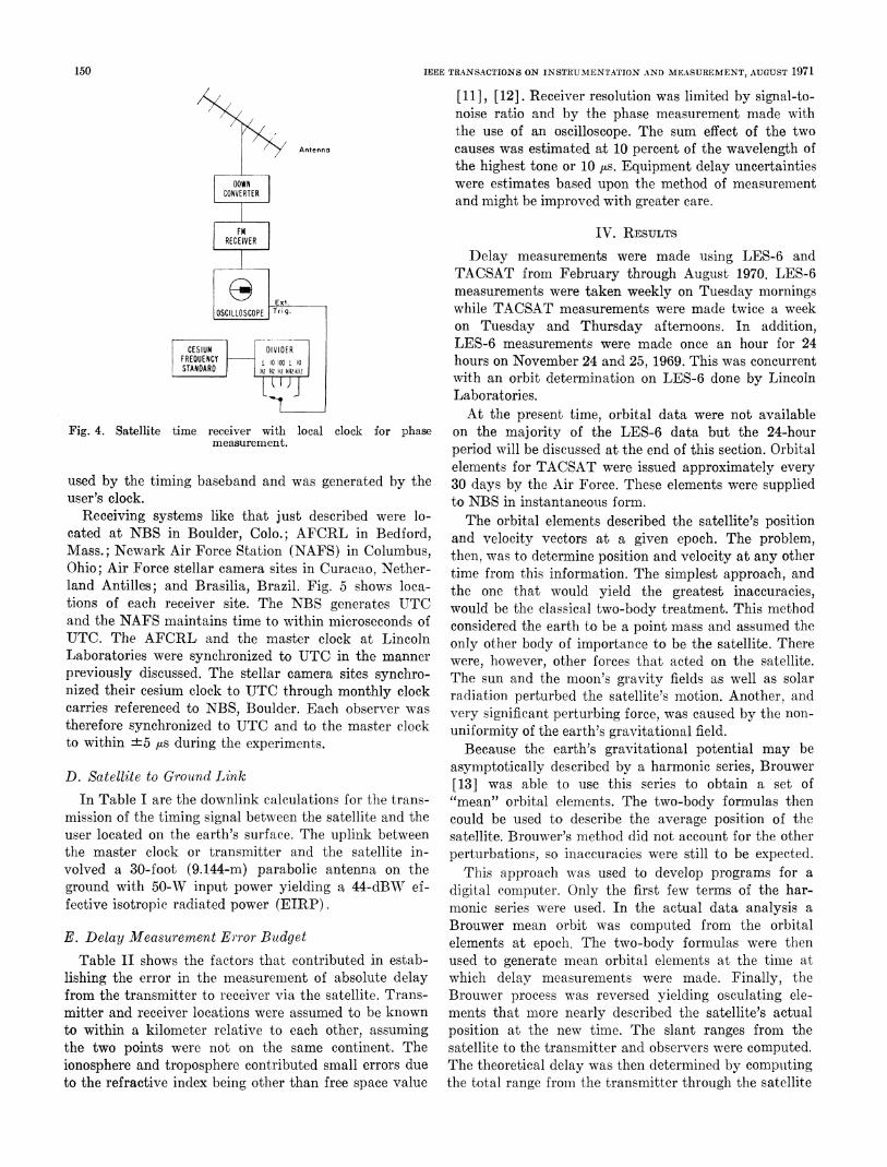
cmrs h ea.Ec hs esrmn a si
mated to two figures. The first digit was recorded abovelator, a cesium frequency standard, was divided down the second digit. Note that the scope face was dividedin steps of ten with outputs at 10, kHz, 1 kHz, 100 Hz, 10 into ten columns. The 1-Hz measurement was recordedHz, and 1 Hz. The divider had a reset mechanism that, in the first column of Fig. 3, the 10-Hz measurement inwhen activated by the 1-pps tick of the clock, alignedeach of the outputs to have positive-oing-zero crossings
the second eolumn, etc. Snce the scope sweepnonlanear-coincident with each 1-pps tick. The divider constructed scn digite tha valureon a check on thefof digital logic, gave fast rise time square wave outputs in the preceding column.(see Fig. 1.). Because the transmitter and observer's Referring to Figs. 2 and 3, if the 100-Hz phaseclocks were synchronized, all generated tones from-l each measurement had been recorded as a 79 instead of 80,
clock~~~ ~ ~ ~ ~ ~ ~~~maurmnwere bee reorehase. isea fclock were in phase. the error would have been detected when the 1-kHzThe transmitter carrier was modulated by these tones phase measurement was made. That phase measurementsequentially with each occupying 10 s of transmission would have been recorded as 06 and this inconsistencytime. The carrier was demodulated at the observing sites. easily noted by looking across the diagonals. In the ex-The corresponding locally generated tone triggered an ample, a diagonal disagreement of the 9' and 0 wouldoscilloscope and the sweep rate of the scope was set to have necessitated a choice in favor of 80 rather than 79.display one full cycle of the received tone. With the After this check, the delay was obtained by readingdemiiodulated tone fed into the vertical input of the scope, across the top row and down the right-hand side. In Fig.the phase shift was determined from the point w _ere the 3, the delay was 258 063 ,s.pulse began on the oscilloscope's face. This samae delay mleasurement technique can be usedPhotographs of the five phase-shift measuremlenlts and by anyone wishing to synchronize a clock. If the clock
the resulting delay figure are shown in Figs. 2 and 3. were in error by some amount, a delay measurementThe: 1-Hz tone: display shown in Fig. 2(a) was a result would have that same error. Supplying the user withl aof a 1-kHz sine wave 100-percent amplitude mnodulated colmputed delay would reveal the clock error and thusby the 1-Hz square wave. This in turn frequency modu- synchronize the clock to some assigned accuracy. The ac-
HANSON AND HAMILTON: TIME SYNCHRONIZATION VIA SATELLITES 149
Side-Tone 400wetepovdigRcveagFrequennc and SweepRate longitude providing coverage to latitudes ofSample ate ±810 and longitudes of 1200 west to 400 east.
(a) 1 Hz 0.1 s/cm TACSAT was designed for synchronous service andwas located at approximately 1070 west longitudethrough June 1970 after which it began movement to anew location. The 1070 location, on the minor axis of theearth's equatorial plane, is a stationary point for a syn-
(b) 10 llz 10 ms/cm chronous satellite. A satellite will remain in this positionwithout station keeping [8]. The transponder operatedat a 303.4-MHz uplink center frequency and at a249.6-MHz downlink frequency. A radiated power ofapproximately 100 W was used with a circularly polar-
(e) 100 llz 1 ms/cm ized 17-dB gain above isotropic antenna. The earth cov-erage, when the satellite was at the 1070 location,extended to ±810 in latitude and 187° to 270 west longi-tude with a drop in antenna gain of 2.5 dB on the pe-ripherv of this coverage.
B. Master Clock and Grozund Transmitter(d) I1kHz 0.1 Ms/cm
The master clock and the transmitter were located atthe M.I.T. Lincoln Laboratories. The master clock con-sisted of a commercial cesium frequency standard driv-ing a frequency divider both operating from fail-safe
(e) 10 kHz 10 gs/enipower supplies. This clock was synchronized to Coordi-
(e) 10OkHz 10 ps/cfls nated Universal Time (UTC), by periodic clock carriesfrom the Air Force Cambridge Research Laboratories(AFCRL). AFCRL was in turn synchronized to UTC
Fig. 2. Phase measurements by oscilloscope. by the monitoring of the Loran-C transmissions, a rela-tively new technique utilizing TV synch pulses in the ver-tical interval r9], [10], and by clock carries from the
12 9 @° '° 0United States Naval Observatory (USNO). DerivedI I O I o from the master clock's frequency standard were the
0 - group of five waveforms discussed previously. These fivewaveforms, transmitted sequentially, made up the basic
--2- ;,, 0, O- timing signal format or baseband. The baseband fre-quency that modulated the 303-MHz carrier was ampli-
,5 ,8 ,, ,6 3 fied and radiated to the satellite. The deviation of the___7__ 7__ 7-__ * carrier was limited to restrict the energy spectrum to a
Number on Diagonal must agree Delay 258063jUs 30-kHz bandwidth. The satellite received this signal,translated it to 249 MHz, amplified it, and reradiated it
Fig. 3. Phase nleasuremnnts converted into delay. back toward earth.
curacy depends UpOnl the delay calculation and the fre- C. Receiving Systemquenev of the highest tone used in the timing forimat. The receiving system described does not represeit an
optimumi ehoice in design or selection. The receivers111. INSTRIUXIENTATION used were available fromii another experimental satellite
A. Satellites timing program that utilized the same baseband.
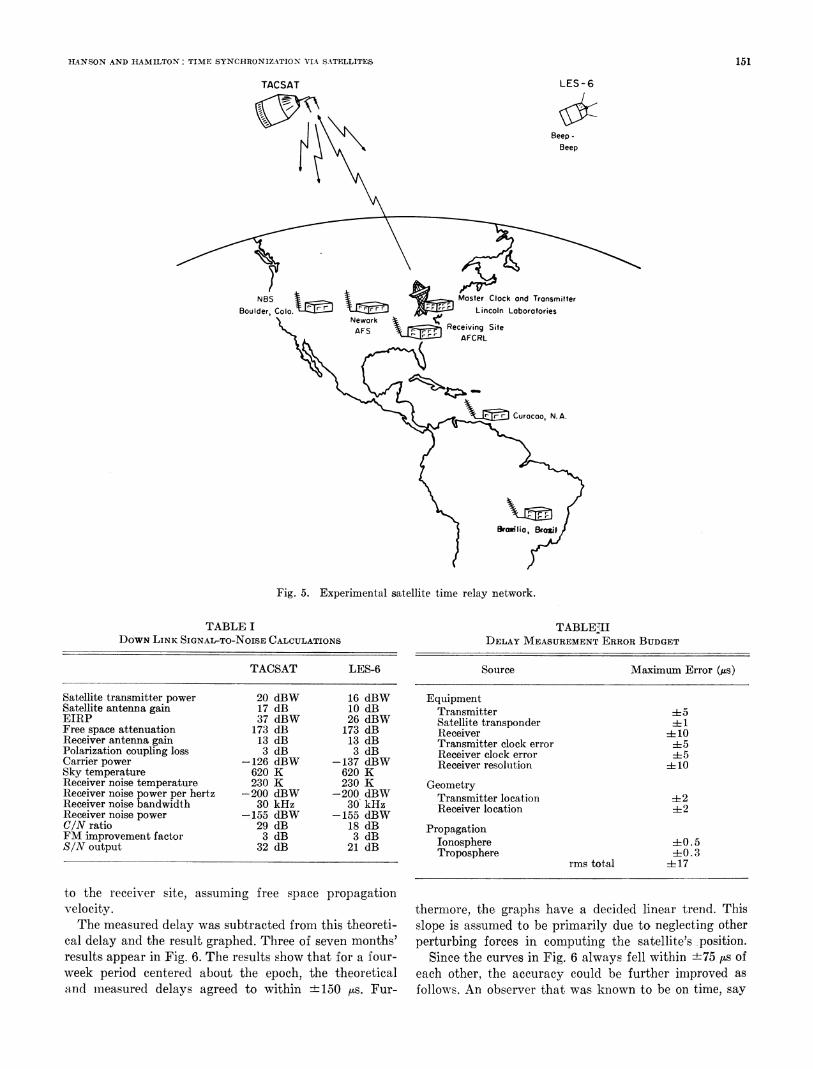
The receiving system shown in Fig. 4 is typical of thatTwo Air Force satellites, LES-6 and TACSAT [6]- used at eachi observing site. The antenna, an 8-element
[71, were used in the NBS experiments. LES-6 was linearly polarized Yagi, yielde(d 13-dB gain above iso-developed by Lincoln Laboratories for an Air Force pro- tropic. A 250- to 136-MlHz downionverter with 30-dBgram. The UHF transponder operated at an uplink cen- gain and 2.5-dB noise figure followed the antenna. Theter frequency of 302.7 MHz and a downlink frequency receiver, intended for mobile communications, taxis, etc.,of 249.1 MHz. For the experimental time system, the was crystal controlled and modified for narrow-bandoutput power was approximately 40 W radiated through 30-kHz FM. The video output of the receiver connecteda circularly polarized antenna with 9.8-dB gain above directly to the vertical input of an oscilloscope. Theisotropic. The satellite was station kept at approximately oscilloscope was triggered by the same five waveforms
150 IEEE TRANSACTIONS ON INSTRUMENTATION AND MEASUREMENT, AUGUST 1971
/ [11], [12]. Receiver resolution was limited by signal-to-noise ratio and by the phase measurement made withthe use of an oscilloscope. The sum effect of the two
Antenna causes was estimated at 10 percent of the wavelength ofthe highest tone or 10 jus. Equipment delay uncertainties
DOWN were estimates based upon the method of measurementCONVERTER and might be improved with greater care.
FM IV. RESULTSRECEIVER
Delay measurements were made using LES-6 andTACSAT from February through August 1970. LES-6measurements were taken weekly on Tuesday mornings
OSCILLOSCOPE Trig. while TACSAT measurements were made twice a weekon Tuesday and Thursday afternoons. In addition,
CESIUM DIVIDER LES-6 measurements were made once an hour for 24FREQUENCY i 1l0 1 l0 hours on November 24 and 25, 1969. This was concurrentSTANDARD HZ HZ HHzk with an orbit determination on LES-6 done by Lincoln
Laboratories.At the present time, orbital data were not available
Fig. 4. Satellite time receiver with local clock for phase on the majority of the LES-6 data but the 24-hourmeasurement. period will be discussed at the end of this section. Orbital
elements for TACSAT were issued approximately everyused by the timing baseband and was generated by the 30 days by the Air Force. These elements were supplieduser's clock. to NBS in instantaneous form.
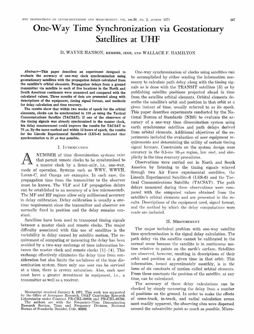
Receiving systems, like that just described were lo- The orbital elements described the satellite's positioncated at NBS in Boulder, Colo.; AFCRL in Bedford, and velocity vectors at a given epoch. The problem,Mass.; Newark Air Force Station (NAFS) in Columbus, then, was to determine position and velocity at any otherOhio; Air Force stellar camera sites in Curacao, Nether- time from this information. The simplest approach, andland Antilles; and Brasilia, Brazil. Fig. 5 shows loca- the one that would yield the greatest inaccuracies,tions of each receiver site. The NBS generates UTC would be the classical two-body treatment. This methodand the NAFS maintains time to within microseconds of considered the earth to be a point mass and assumed theUTC. The AFCRL and the master clock at Lincoln only other body of importance to be the satellite. ThereLaboratories were synchronized to UTC in the manner were, however, other forces that acted on the satellite.previously discussed. The stellar camera sites synchro- The sun and the moon's gravity fields as well as solarnized their cesium clock to UTC through monthly clock radiation perturbed the satellite's motion. Another, andcarries referenced to NBS, Boulder. Each observer was very significant perturbing force, was caused by the non-therefore synchronized to UTC and to the master clock uniformity of the earth's gravitational field.to within ±5 ,as during the experiments. Because the earth's gravitational potential may be
asymptotically described by a harmonic series, Brouwer[13] was able to use this series to obtain al set of
In Table I are the downlink calculations for the trans- "mean" orbital elements. The two-body formulas thenmission of the timing signal between the satellite and the could be used to describe the average position of theuser located on the earth's surface. The uplink between satellite. Brouwer's method did not account for the otherthe master clock or transmitter and the satellite in- perturbations, so inaccuracies were still to be expected.volved a 30-foot (9.144-m) parabolic antenna on the This approach was used to develop programs for aground with 50-W input power yielding a 44-dBW ef- digital computer. Only the first few terms of the har-fective isotropic radiated power (EIRP). monic series were used. In the actual data analysis a
E. Delay Measurement Error Budget Brouwer mean orbit was computed from the orbitalelements at epoch. The two-body formulas were then
Table II shows the factors that contributed in estab- used to generate mean orbital elements at the time atlishing the error in the measuremaent of abslolute delay which delay measurements were made. Finallly, thefrom the transmitter to receiver via the satellite. Trans- Brouwer process was reversed yielding osculating ele-mnitter and receiver locations were assumed to be known ments that more nearly described the satellite's actualto within a kilometer relative to each other, assuming position at the new time. The slant ranges from thethe two points were not on the same continent. The satellite to the transmitter and observers were computed.ionosphere and troposphere contributed small errors due The theoretical delay was then determined by computingto the refractive index being other than free space value the total range fromn the transmitter through the satellite
HANSON AND HAMILTON: TIME SYNCHRONIZATION VIA SATELLITES 151
TACSAT LES-6
Beep-Beep
NBS Master Clock ond TransmitterBoulder, Colo. Lincoln Laborotories
\ ~~~Nework > 1>~~~~~F eevn Site
\Juc Curacao, N. A.
railiao,Bazil
Fig. 5. Experimental satellite time relay network.
TABLE I TABLE-IIDOWN LINK SIGNAITO-NOISE CALCULATIONS DELAY MEASUREMENT ERROR BUDGET
TACSAT LES-6 Source Maximum Error (,us)
Satellite transmitter power 20 dBW 16 dBW EquipmentSatellite antenna gain 17 dB 10 dB Transmitter +5EJRP 37 dBW 26 dBW Satellite transponder 4+1Free space attenuation 173 dB 173 dB Receiver + 10Receiver antenna gain 13 dB 13 dB Transmitter clock error 45Polarization coupling loss 3 dB 3 dB Receiver clock error 45Carrier power -126 dBW -137 dBW Receiver resolution + 10Sky temperature 620 K 620 KReceiver noise temperature 230 K 230 K GeometryReceiver noise power per hertz -200 dBW -200 dBW Transmitter location ±t2Receiver noise bandwidth 30 kHz 30' kHz Receiver location i2Receiver noise power -155 dBW -155 dBWC/N ratio 29 dB 18 dB PropagationFM improvement factor 3 dB 3 dB Ionosphere +0.5S/N output 32 dB 21 dB Troposphere +0.3
rms total +17
to the receiver site, assuming free space propagationvelocity. thermaore, the graphs have a decided linear trend. ThisThe measured delay was subtracted from this theoreti- slope is assumed to be primarily due to neglecting other
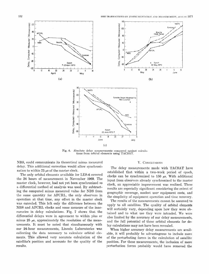
cal delay and the result graphed. Tihree of seven months' perturbing forces in computing the satellite's position.results appear in Fig. 6. The results show that for a four- Since the curves in Fig. 6 always fell within ±75 ,.c. ofweek period centered about the epoch, the theoretical each other, the accuracy could be further improved asa.nd mneasured delays agreed to wvithin ±150 ,us. Fur- follows. An observer that wals known to be on time, say
152 IEEE TRANSACTIONS ON INSTRUMENT!ATION AND MEASUREMENT, AlU(GiUST 1971
-T 20ff
16L iNAFS0: ,,; ;Curaca/ /.
-120~~~~~~~~~~~~~~~~~~~~~~~~~~~~~o 2
80 120 7R Broz1liaAprlClock Failed n~80 r. .
40~~~~ ~ ~ ~ ~ ~ ~ ~ ~ ~ ~ ~ .
:NBS Brazilia - I 40
E 80 New Locotion X~~~~0 ,
-~~~~~ D 0 ~~~~~~~~~~~ A AFC~~~~~~~~~RLD 40 NBSN.E 0"Curocoo C 40 /
-80 >Epoch C) t ~~~~~~~~~~~~~~~~~~Epoch
t23Apr1 1970 0)22 May 1970
20 12 16 20 24 28 2I 8 12 16 20 24 285 9April May May June
(a) (b)
160~~~~~C
167\.NAFSc K8u120
tion s from o a Satellite Began Movement todelay. New Location
~8040 AFC40
Epocha' 80 - ~~~~22June 1970 t
3 7 II 15 19 23 27 5June July
(c)
Fig. 6. Absolute delay measurements compared against calcula-
tionis from orbital elements using TACSAT.
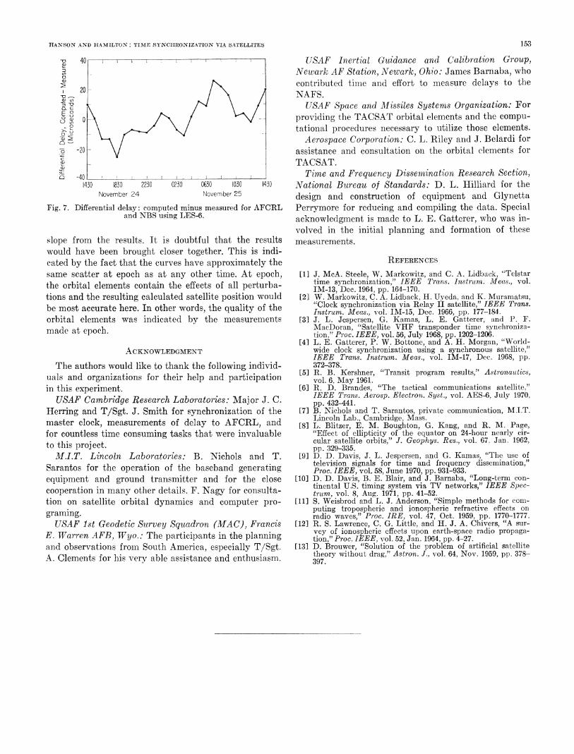
NBS, could communicate its theoretical minus m-easured V. CONCLUSIONSdelay. This additional correction would allow synchroni- The delay measurements made with TACSAT havezation to within 75 /i.s of the master clock, established that within a two-week period of epoch,The only orbital elements available for LES-6 covered clocks can be synchronized to. 150 s. With additional
the 24 hours of measurement in November 19*69. The input from observers, already synchronized to the mastermaster clock, however, had not yet been synchronized so clock an appreciable improvement was realized. Thesea differential method of analyslis was used. By subtract- results are especially significant considering the extent ofing the computed minus measured value for NBS from geographic coverage, modest user equipment costs, andthe same quantity for AFCRL, the only observers inoperation at that time, any offset in the mast-er clock The results of the measurements cannot be assumed towas canceled. This left only the difference between the apl tosall s l The quality of bitalslments
NBS,and F'CRcloks ad sme masur of he iac-apply to all satellites. The quality of orbital elementsNBScanACl clcks andsom suof the tac will certainly vary, depending upon how they were ob-curacies in delay calculations. Fig. 7 shows that the tained and to what use they were intended. We weredifferential delays were in agreement to within plus or also limited by the accuracy of our delay measurements,minus 25M,s, approximately the resolution of the meas- and the full potential of these orbital elements for de-urements. It must be noted that simultaneously with lay calculations may not have been revealed.Our 24-hour measurements, Lincoln Laboratories was When higher accuracy delay measurements are avail-collecting the data necessary tdo calculate orbital ele- able, it will probably ble advantageous to include morements. This allowed very accurate calculation of the of the perturbating forces in the calculation of satellitesatellite's position and accountSs for the quality of the position. For these mneasurements, the inclusion of moreresults. perturbation forces probably would have removed the
HANSON AND HAMILTON: TIME SYNCHRONIZ\ATION VIA SATELLITES 153
D 40 USAF Inertial Guidance and Calibration Group,3 Newark AF Station, Newark, Ohio: James Barnaba, who0
contributed timie and effort to measure delays to theNAFS.
a ° t\ /9 \ t lJUSAF Space and Missiles Systems Organization: For,,a) o \ /\N / ~ providing the TACSAT orbital elements and the compu-
o3 0 L \ ' V I tational procedures necessary to utilize those elements.C) > \ /Aerospace Corporation: C. L. Riley and J. Belardi for
,-O-20- \/ | assistance and consultation on the orbital elements forTACSAT.
a) -40 ____________I_________________________________ Time and Frequency Dissemination Research Section,1430 1830 2230 0230 0630 1030 1430 NVational Bureau of Standards: D. L. Hilliard for the
November 24 November 25 design and construction of equipment and GlynettaFig. 7. Differential delay: computed minus measured for AFCRL Perrymore for reducing and compiling the data. Special
and NBS using LES-6. acknowledgnent is made to L. E. Gatterer, who was in-volved in the initial planning and formation of these
slope from the results. It is doubtful that the results measurements.would have been brought closer together. This is indi-cated by the fact that the curves have approximately the REFERENCESsame scatter at epoch as at any other time. At epoch, [1] J. McA. Steele, W. Markowitz, and C. A. Lidback, "Telstarthe orbital elements contain the effects of all perturba- time synchronization," IEEE Tra.s. Instrum. Meas., Vol.
IM-13, Dec. 1964, pp. 164-170.tions and the resulting, calculated satellite position would [2] W. Markowitz, C. A. Lidback, H. Uyeda, and K. Muramatsu,be most accurate here. In other words, the quality of the "Clock synchronization via Relay II satellite," IEEE Trans.Instrum. Meas., vol. IM-15, Dec. 1966, pp. 177-184.orbital elements was indicated by the measurements [3] J. L. Jespersen, G. Kamas, L. E. Gatterer, and P. F.made at epoch. MacDoran, "Satellite VHF transponder time synchroniza-
tion," Proc. IEEE, vol. 56, July 1968, pp. 1202-1206.[4] L. E. Gatterer, P. W. Bottone, and A. H. Morgan, "World-
ACKNOWLEDGMENT wide clock synchronization using a synchronous satellite,"IEEE Trans. Instrum. Meas., vol. IM-17, Dec. 1968, pp.
The authors would like to thank the following individ- 372-378.uals and organizations for their help and participation [5] R. B. Kershner, "Transit program results," Astronautics,vol. 6, May 1961.in this experiment. [6] R. D. Brandes "The tactical communications satellite."USAF Cambridge Research Laboratories: Major J. C. IEEE Trans. Aerosp. Electron. Syst., vol. AES-6, July 1970,pp. 432-441.
Herring and T/Sgt. J. Smith for synchronization of the [7] B. Nichols and T. Sarantos, private communication, M.I.T.
master clock, measurements of delay to AFCRL, and [ Lincoln Lab., Cambridge, Mass.y [81 ~~~~~~~~~~L.Blitzer, E. M. Boughton, G. Kang, and R. M. Page,
for countless time consuming tasks that were invaluable "Effect of ellipticity of the equator on 24-hour nearly cir-to this project. cular satellite olbits," J. Geophys. Res., vol. 67. Jan. 1962,
pp. 329-335.M.I.T. Lincoln Laboratories: B. Nichols and T. [9] D. D. Davis, J. L. Jespersen, and G. Kamas, "The, use of
Sarantos for the operation of the baseband generating television signals for time and frequency dissemination,"Proc. IEEE, vol. 58, June 1970, pp. 931-933.
equipment and ground transmitter and for the close [10] D. D. Davis, B. E. Blair, and J. Barnaba, "Long-term con-
cooperation in many other details. F. Nagy for consulta- tinental U.S. timing system via TV networks," IEEE Spec-cooperation ~~~~~~~~~~~~~trum,vol. 8, Aug. 1971, pp. 41-52.tion on satellite orbital dynamics and computer pro- [11] S. Weisbrod and L. J. Anderson, "Simple methods for com-
graming. puting tropospheric and ionospheric refractive effects onradio waves," Proc. IRE, vol. 47, Oct. 1959, pp. 1770-1777.USAF 1st Geodetic Survey Squadron (MAC), Francis [12] R. S. Lawrence, C. G. Little, and H. J. A. Chivers, "A sur-
E. Warren AFB, Wyo.: The participants in the planning vey of ionospheric effects upon earth-space radio propaga-tion," Proc. IEEE, vol. 52, Jan. 1964, pp. 4-27.and observations from South America, especially T/Sgt. [13] D. Brouwer, "Solution of the prohlem of artificial satelliteA. Clements for his very able assistance and enthusiasm. theory without drag," Astron. J., vol. 64, Nov. 1959, pp. 378-397.