Embed Size (px)
Citation preview
USER GUIDE
wwwoncentercom
Table of Contents
SECTION 1 - INTRODUCTION 1 Welcome to On-Screen Takeoff2 About this Guide 3 Extrashelliphellip 4
Instruction Jargon4 Typographic Conventions 5
Help File 5 Contents Tab 6 Index Tab6 Search Tab 7
SECTION 2 - SETUP 8 Minimum System Requirements 9 Recommended Components 9 Compatible File Formats 9
Convert To TIF 10 Installing Your Digitizer 10 SECTION 3 - TOOLBARS AND MENUS 11 Toolbars 12
Viewing Toolbars 12 Moving Toolbars 13 Docking Toolbars 13 Hiding Toolbars13 Resizing Toolbars13 Customizing Toolbars 13
Menushellip 14 Filehellip14 Edit 14 View hellip15 Tools 15 Image 15 Help 15 Digitizer15
SECTION 4 - FEATURES 16 Start On-Screen Takeoff 17
Quick Start Video 18 On-ScreenTakeoff Environment 18
Image View 19 Takeoff View 19 Worksheet View20
Navigating On-Screen Takeoff 20
Auto Scrolling 20 Changing Pages 20 Hot Links 21
SECTION 5 - PROJECTS 22 Project Template Files 23
Saving a Project as a Template 23 Modifying a Template23
Opening an Existing Project 24 Creating a New Project24 Project Properties25 Adding Pages to Projects 25
Individual Electronic Plans 25 Group of Electronic Plans26 Paper Plans 26
Setting Up Drawing Template 27 Setting Takeoff Area 27 Setting Scale for Specific Pages28 Calculating Scale28 SECTION 6 - CONDITIONS AND TAKEOFF 29 Creating Conditions 30 Condition Attributes 31 Linear Conditions 31
General 31 Advanced 31
Area Conditions 32 General 32 Advanced 32
Count Conditions33 General 33 Advanced 33
Zone Conditions 33 Condition Notes 34 Condition Results 35 Copying Conditions 35 Editing Conditions 35 Deleting Conditions 36 Organizing Project Conditions 36
Creating Folders and Sub-Folders36 Copying Folders 36 Renaming Folders 36 Changing Condition Order 36
Drawing with Conditions37 Snap Angles 37
Drawing a Linear Object 37 Continuous Mode 38 Drawing a Curve 38
Drawing an Area Object 39 Grid Options 40 Grid Calculation 40 Backout Mode41
Drawing a Count Object 41 Drawing a Zone 41 Selecting Objects 42 Moving and Resizing Objects 42
Linear42 Area and Zone 42 Count 42
Layers 43 Default Layers 43 Creating Layers43 Assigning a Layers to a Condition44 View and Hide Layers44 Assigning Text to a Layers45
SECTION 7 - PRINTING AND EXPORTING 46 Print Setup 47 Printing Images 47 Printing Takeoff Lists and Worksheets 48 Print Preview 49 Exporting49
Using Copy Paste Feature49 Using Export Feature50 Exporting Worksheet to Excel 52 Exporting Takeoff to CVS52
SECTION 8 - ADVANCED FEATURES 53 Features to Use With Objects54
Roping Feature 54 Applying a Drop Run Count 55 Edit Drop Run Count 55 Adding Text in Image View55 Formatting Text 56
Object Properties 56 Linear Objects 56 Area Objects57 Count Objects57
Advanced Features of Conditions 57 The Round Feature 57
Pitch 57 Advanced Features of Project Properties58
Selecting Multiple Pages 58 Changing Image Assigned to a Drawing 59 Changing Image File Path59 Delete Page from Project Propertiesl 59
Advanced Features of Tool Options 60 Calculation Method60 Configuration Tab 60 Font Tab 61
Renaming the Current Page61 SECTION 9 - SAVING AND EXITING 62 Saving Your Project63
The Auto-Save Feature63 Exiting63 APPENDIX I - INSTALLING YOUR DIGITIZER 65 APPENDIX II - TOOLBAR ITEM DETAILS 67 APPENDIX III - LOADING PLANS FROM A DODGE CD 72 APPENDIX IV -USING THE PLAN VIEWER 73 APPENDIX V - FREQUENTLY ASKED QUESTIONS 75 INDEX 78
Section 1
1
Introduction
This section will
Help you become familiar with On-Screen Takeoff and the User Guide
Give Full Mode users information on how the product works with a digitizer
Section 1 Introduction
2
Welcome to On-Screen Takeoff This extraordinary software gives you bidding advantage in less time with greater accuracy by allowing you to perform complex takeoffs right on your computer screen
On-Screen Takeoff can be used with a digitizer and paper plans or a mouse and electronic plan files On-Screen Takeoff enables the user to create live drawings with resizable conditions linear conditions such as walls pipes and electrical lines area conditions such as floors and ceilings count conditions such as sprinkler heads corner beads doors and windows and zone conditions that assess quantities for any part of an area you specify As you record conditions using your plans the program provides reports on quantities and can recalculate instantly for any adjustment to the conditions of your project
New and experienced users will enjoy the power of this estimating system that is very easy to use As with all products from On Center Software this program works well for most construction trades and is ready to use the day you receive it So start bidding jobs more quickly and accurately today with On-Screen Takeoff This program is equipped with three modes View Mode allows the user to perform quick takeoffs view previously created files and drawing zoom to view plans better and print drawings (see Appendix IV Using the Plan Viewer for more details) Lite Mode adds the use of zones Full Mode allows the user to perform more advanced takeoff options including layers and working with a digitizer The mode is referenced in the lower left corner of the program screen
If you currently have View or Lite Mode and are interested in performing more advanced takeoffs a
purchase request button has been provided on the main toolbar Clicking will take you to a webpage purchase form You can also call an On-Center Software Account Representative 1-800-880-8254 or visit us on the web at wwwoncentercom for more details
Section 1 Introduction
3
About this Guide This guide is intended to be a compliment to On-Screen Takeoff software The sections are presented in an order intended to help new users understand the software The User Guide provides detailed information about On-Screen Takeoff tools and commands It is designed to assist you in applying program features to your estimating projects Use it as a reference tool along with the online help system in your day to day work with On-Screen Takeoff
Table of Contents outlines the sections and topics covered in each section
Section 1 Introduction explains the user guide and helpful resources
Section 2 Setup lists system requirements and recommended components
Section 3 Toolbars and Menus explains the toolbars and menus used in On-Screen Takeoff
Section 4 Features gives you a tour of the On-Screen Takeoff environment and shows you how to navigate through your projects
Section 5 Projects leads you through your first time with the program or if yoursquore an old hand at On-Screen Takeoff reacquainting yourself with the software
Section 6 Conditions and Takeoff shows you features of working with condition objects zones and backouts in the takeoff area
Section 7 Printing and Exporting explains the step-by-step of printing images and reports copying and pasting data from On-Screen Takeoff and exporting quantity results to an Excel spreadsheet
Section 8 Advanced Features discusses special and advanced features of On-Screen Takeoff conditions and options
Section 9 Saving and Exiting explains how to save projects and safely exit the program Appendixes gives you additional information on installing a digitizer toolbar item details loading files using the plan viewer and frequently asked questions Index provides key words or phrases the program application and references the page(s) in the user guide where they can be found
Section 1 Introduction
4
Extras Along the way yoursquoll encounter bits of information that make the User Guide not only more readable but more personal and relevant The signs and signals placed throughout the guide will better help you understand On-Screen Takeoff and On Center Software We think yoursquoll find these bits and pieces interesting Herersquos what to look for
NOTE
To make special notice of specific information
Caution Warning This symbol is there to insure that you are following the information to minimize risk
This symbol represents information that also appears on the Quick Start Video
In this manual some information is specific to using a digitizer The icon appears alongside this information (Must be in Full Mode to use a digitizer)
A reminder is there to keep the information in mind for future consideration
For Your Informationhellip
Instruction Jargon
In this guide click or double-click refers to clicking on the left mouse button A right-click clicking on the right mouse button will be specifically stated
Click the digitizer refers to clicking down once with the stylus pen
NOTE When using a digitizer a click or double-click refers to pressing the ball tip of the stylus pen right on the digitizer (usually in the takeoff area) A right-click can be accomplished by using the digitizer mouse template and the first button on the stylus pen See Appendix I Installing You Digitizer for more information
Drag and drop is holding down the left mouse button after clicking on an object You may simply drag the object to the desired location and release the mouse button
Section 1 Introduction
5
Typographic Conventions
The following are typographical conventions to be aware of when reading this guide
Menu items you are instructed to choose appear in a different typeface with the greater than (gt) symbol separating each menu level For example if you are instructed to select the Open command in the File menu it appears as File gt Open If you are instructed to select the Save As command from the File menu it appears as File gt Save As
Helpful hints or information about the topic are provided throughout the document They will be labeled lsquoNOTErsquo (all caps and bold font to catch your attention)
Several topics will have more detailed steps outlined in either another section of the user guide or in the Appendix They will always be referenced and italicized For example ldquoSee Editing Conditions for more informationrdquo
Help File In combination with this User Guide and the Quick Start video (Help gt Watch Quick Start Video) the Help File will also be a great resource for product information and application There are additional resources available on the website at wwwoncentercom or Help gt Visit our Website Follow these instructions to open the Help file
1 Select Help gt Help Topics
2 This will open the On-Screen Help File
Hide and Show Buttons
The Hide and Show buttons will either remove or display the Topics panel in the Help dialog
Back Button
The Back button takes you back to the last help page you viewed It will be available only if you have navigated through multiple pages in the help file
Print Button
Clicking will print the topic displayed This is helpful if the instructions to follow are long and you prefer to work on a full screen
Options Button
The Options button will allow you to pick from a list of commands to help you navigate the Help file
Section 1 Introduction
6
Contents Tab This tab provides a quick breakout of the Contents of the help file It should be used like the Table of Contents of a book Simply double-click on the book icon to open the chapter Then click the desired page icon to display the relevant information
Index Tab This tab allows you to locate a specifically indexed topic This should be used as you would a book index Begin typing a word in the index entry field and the system will automatically move within the list to the entries closest in spelling to your word(s) Begin typing the topic word to access it in the list quickly
Section 1 Introduction
7
Search Tab This tab works like a word find It allows you to search for any word contained in the Help file Type the
word you are looking for in the lsquoType in the keyword to findrsquo field Click A list of topics containing that word will appear Scroll through the list and double click on the topic you want displayed
Section 2
8
Setup
This section will
Let you know what system requirements you will need to have in place
Recommend components that work well with the software
Help Full Mode users install a digitizer
Section 2 Setup
9
Minimum System Requirements To use On-Screen Takeoff your computer must meet the following minimum system requirements
An IBM PC or 100 compatible computer with a Pentium II or faster Intel processor
Memory Requirements 200 MB of available hard-disk space and256 MB RAM (128 MB preferred)
Windows 2000 SP4 and Windows XP SP2 256 color video card Super VGA display card Mouse 15-inch monitor
While these are the minimum system requirements Windows places heavy demands on your systems resources The more available memory in your computer the faster and more efficient On-Screen Takeoff will operate
Recommended Components
For the best performance we recommend the following components
Pentium III or faster processor
512 or more of RAM
12X speed CD-ROM or better
17-inch monitor or dual monitors Graphic adapter with 128 MB or more VRAM Sound card and speakers installed
NOTE In order to utilize the Training Videos you must have a sound card and speakers installed
Compatible File Formats The resolution in electronic plans does not need to be more that 200 DPI (Dots per Inch) The preferred file format is a black and white TIF (Group4) On-Screen Takeoff recognizes image files with the following extensions
File Extensions View Mode Lite Mode Full Mode TIF X X X PDF X X X OSE X X X JPG X X X CPC X X X CAL X DGN X DWG X DXF X OSP X PLN X PLT X
Section 2 Setup
10
NOTE Use the following image types for best results
Convert to TIF
The converted files will be stored in a folder with the name of the current On-Screen Takeoff project Since the conversion can be very time consuming you should only select this option if you really intend to convert vector files to TIF
1 Select File gt Project Properties
2 In the Pages Field add your image See Section 5 Establishing Project Setting Adding Pages
3 Click
4 Then select the page with the drawing you wish to convert
5 Click
Installing Your Digitizer The following instructions are a quick start to installing your digitizer For more specific information please reference Appendix I Installing Your Digitizer at the end of this guide
Connecting Your Digitizer
Upon receiving your digitizer (either a GTCO or another brand) you will need to connect it to your computer
1 Lay the digitizer out flat
2 Connect the Stylus to the digitizer
3 Plug in the power supply
4 Plug the interface cable into the digitizer
5 Plug the other end of the interface cable into the computer
NOTE On-Screen Takeoff is compatible with any tablet that is WinTab compatible
Digitizer options are only available in Full Mode If you are in View or Lite Mode and would like
to use this feature click from the main toolbar to purchase the upgrade
Section 3
11
Toolbars and Menus
This section will
Introduce the program toolbars
Familiarize you with On-Screen Take Offtrade Menu options
Section 3 Toolbars and Menus
12
Toolbars On-Screen Takeoff is equipped with several helpful toolbars for application efficiency See Appendix II Toolbar Item` Details for a detailed description of each toolbar item Individually the toolbars may be displayed moved docked reshaped or hidden from view You can also create costume toolbars to fit your needs
Main Toolbar
Tool Toolbar
Zoom Toolbar
View Toolbar
Navigate Toolbar
Takeoff Toolbar
Image Toolbar Viewing Toolbars Toolbars are displayed on the screen and will be consistent on each tab or page (Some toolbars or toolbar items will be in an inactive state if they donrsquot have a supporting element in the application)
1 Select View gt Toolbars and select the appropriate toolbar name
OR
2 Right-click on a toolbar region of the screen
3 Check the toolbars you want to display
Section 3 Toolbars and Menus
13
Moving Toolbars The toolbars may be positioned anywhere on the screen you wish This feature is provided to allow the flexibility for positioning the toolbars so they are out of your way yet handy for use
1 Click on an edge of the toolbar holding down the mouse button drag it to its new position
2 Release the mouse button to set it in place
NOTE If the toolbar is dropped anywhere other than a screen edge it will become free floating This feature is especially handy when using multiple monitors
Docking Toolbars The toolbars can be docked to any of the screen edges
1 Click on the title bar of an undocked toolbar
2 Drag the toolbar to any location on the screen
Hiding Toolbars
1 Select View gt Toolbars and select the toolbar you wish to remove from the screen
2 Right-click on the toolbar or dock bar areas
3 A floating toolbar can be closed by clicking on the in the upper right corner of the toolbar
Resizing Toolbars Only undocked (floating) toolbars may be resized
1 Position the mouse pointer over an edge
2 Click and drag
3 The toolbar can be resized as desired
Customizing the Toolbars You may rearrange or delete buttons within a toolbarrsquos display or you may move buttons from one toolbar to another If you find that you use a few tools over and over you may want to group them within a single toolbar for convenience On-Screen Takeoff gives you the flexibility to customize your takeoff environment
1 Select Tools gt Customize The Customize dialog will open
2 With the dialog open click on a toolbar button and drag buttons from one toolbar to another or a new location within the same toolbar
3 To add a button without altering another toolbar click on the Commands tab of the Customize dialog and drag the appropriate symbol from the Buttons section to a toolbar
4 To remove a button drag it to within the takeoff area of the application
Section 3 Toolbars and Menus
14
Menus
Section 3 Toolbars and Menus
15
Digitizer Menu
Section 4
16
Features
This section will
Show you how open On-Screen Takeoff
Describe the On-Screen Takeoff environment
Teach you how to navigate pages
Section 4 Features
17
Start On-Screen Takeoff
1 On your desktop double-click your On-Screen Takeoff icon
2 The application will open
OR
3 Left-click on the Start button on your computerrsquos toolbar
4 Scroll up to Programs gt On Center Software
5 Highlight On-Screen Takeoff and click On-Screen Takeoff will open On-Screen Takeoff opens to an untitled blank project The Image view of the screen will be a blank page
Two blank dock bars the Pan dock bar and the Takeoff dock bar appear at the left side of the screen Along the bottom the Status bar displays user status or context-sensitive messages as well as paper size and current zoom percentage of the plan sheet on screen The menu bar and several task specific toolbars are located at the top of the screen
NOTE All toolbars and dock bars may be accessed to view or hide through View gt Toolbars on the menu bar
Section 4 Features
18
Quick Start Video When On-Screen Takeoff opens you will be given an option to watch the Quick Start video (recommended) or start the program without watching the video
The 20 minute video will demonstrate key program functionality and allow you to view application instruction for enhanced learning
If you would like to watch the video click If you prefer to get started without
the video click If you have already viewed the video click the lsquoDo not show this message againrsquo box to prevent this dialog from appearing each time you open the program
NOTE If you decide later that you would like to watch the Quick Start video go to Help gt Watch
Quick Start Videos
On-Screen Takeoff Environment The On-Screen Takeoff environment acts like your drafting table allowing you to work on several sheets of plans at once and to reference at a glance the entire drawing and your position on that drawing while giving you the power of a computer to track analyze print and export your takeoff quantities and plans
The screen is bordered at the top by the Menu bar with pull-down menus and at the bottom by the Status bar which indicates current user status plan page size and current zoom percentage of page The largest portion of the application screen will be your takeoff area bounded on the left (by default) by two dock bars and on the top by several toolbars
In the takeoff area you may view your project plans (images) andor takeoff objects the takeoff list with quantities the worksheet or a legend of your condition list
The main window of On-Screen Takeoff has three tabs located at the bottom left allowing for quick change between Image Takeoff or Worksheet views Select the desired view option on the toolbar and it will automatically open on your screen
Section 4 Features
19
Image View
This view shows the plan file andor takeoff conditions drawn from your plans
Takeoff View This view displays the height if applicable and quantity breakdowns of your conditions according to result types indicated (eg linear feet square feet or count of items) for zones pages and the project as a whole It also displays notes per condition
Section 4 Features
20
Worksheet View This view displays the condition and quantity in units of measure specified in the first results field of the Results tab in the Condition dialog and allows the user to enter amounts for material labor and subcontractor takeoffs
NOTE When in the Worksheet view tab out the field then save This is keep all the values saved
Navigating On-Screen Takeoff
Auto Scrolling When creating linear areas or zones On-Screen Takeoff will automatically scroll the image view when necessary It will move as your mouse or digitizer moves beyond the edge of the current view
Changing Pages
1 Select View gt Next Page Previous Page or Go To Page (specify page number for the Go to Page option)
2 You may also select the corresponding arrows for these options from the Navigate Toolbar The
drop down arrow in the Page field will list the pages The and arrows will take you to the
previous or next page The and arrows will take you to the first or last page
OR
Section 4 Features
21
3 Or press Ctrl G for the Go To Page dialog
Hot Links Hot links allow you to move quickly from one drawing to the pertinent area of another drawing A hot link is handy when viewing enlarged areas of a page and needing the ability to jump back to a reference page
1 Select Tools gt Hot Link
OR
2 Click from the Tools Toolbar
3 Click on the page where you want to set the link The Hot Link dialog will open
4 Using the current page display on the Navigate Toolbar access the pull-down menu of pages by
clicking on the arrow at the right
5 Select the page for your link (You may also choose View gt Go to Page and select by page number)
6 Manipulate the view using the zoom tool and the scroll bars
7 Click
8 After joining a hot link to another page the hot link arrows in the Navigation Toolbar will become active
9 Move a hot link to another location on the page by clicking then click and drag the hot link image anywhere on the page
Section 5
22
Projects
This section will
Help you create settings important to your projects
Explain how On-Screen Takeoff works with your electronic or paper plans
Section 5 Projects
23
Project Template Files You can begin your project with a template Templates allow you to take advantage of conditions and settings used with previous projects
On-Screen Takeoff templates contain condition lists and established layer separations from previous projects you have created You may also use the sample templates provided with On-Screen Takeoff as a great starting point All aspects of the templates may be adjusted for a new project
1 Select File gt New and click the OK button
2 From the New dialog box choose the template that best fits your project
3 The conditions for this template will appear in the Takeoff Dock bar and the Project Properties dialog will open asking for further information
4 Use File gt Save or File gt Save As to rename and save your new project
Saving a Project as a Template File You can save your condition properties and layers as a template for future projects
1 Select File gt Save As
2 Enter a name for your template and select On-Screen Takeoff Template Files (tpo) from the Save As type field of the dialog (click on the down arrow to select)
3 Click the OK button to accept and close the dialog Modifying a Template File Follow these steps to modify an existing template file if you need to change or add conditions andor layers
1 Select File gt Open
2 Navigate to your Projects directory
3 In the File Type drop-down select On-Screen Takeoff Template files (tpo)
4 Choose the On-Screen Takeoff template file you would like to modify and click the OK button
5 Make appropriate changes
6 Save and close file
The On-Screen Takeoff template files cannot save takeoff information
Section 5 Projects
24
Opening an Existing Project File 1 Select File gt Open
2 Navigate to the desired file location
3 Click the Open button
NOTE If your latest changes to a project file have not been saved On-Screen Takeoff will ask
you whether you would like to save the file and gives you the option of canceling the operation
Creating a New Project
1 Select File gt New
2 For a blank untitled project click
3 At this point the Project Properties dialog will pop-up for more information about your takeoff
NOTE The following are important to keep in mind when beginning a new project
At the start of your project fill out the Project Properties settings to establish the name for all printed output from your project set the default page size and scale for your plans number and names of different pages within the project and locations of electronic drawings
Scale settings can significantly affect quantity outcomes Be sure to set the scale for each page of drawings before beginning condition takeoffs
When using a digitizer remember to make a mark with a pen or pencil in the upper left and lower right corners of the first sheet of the paper plans to delineate the takeoff area for that sheet You can then set the takeoff area on On-Screen Takeoff using your marks
Save your project before you begin taking off any conditions On-Screen Takeoff will write a back-up file using the same file name
Remember the Undo feature If you make a mistake select Edit gt Undo and reverse the process step by step
Section 5 Projects
25
Project Properties
You can either set your Project Properties when you create a new takeoff or once your project file is saved under the appropriate name
1 Select File gt Project Properties the Project Properties dialog box will appear
2 Type in the name of your project to appear on printouts Use the backspace andor delete keys to edit the name as necessary
3 Press the Tab key to move to the Default Image Size option or click within the Image Size box You may click on the arrow at the right for the pull-down menu of page size options or you can use the down-arrow key on your keyboard to scroll through the list to the appropriate selection
4 Press the Tab key to move to the Default Scale option Select a scale by using the drop down arrow If your scale is metric you will need to click in the box next to Metric to convert to that measurement
5 Establish the number of pages for your project plans And load image files See Adding Pages to
Your Project
Adding Pages to Projects Individual Electronic Plans
1 Click on in the Project Properties dialog
2 In the Add Images dialog use the drop down arrow to navigate to the appropriate directory and folder containing your image
3 Select the file so that it displays in the File name field then click The file will display by name and path in the Image File field in Project Properties dialog
4 Click to accept and your project will automatically open
5 Save your project with the new settings by selecting File gt Save
Section 5 Projects
26
Electronic plans scanned from blueprints (as opposed to blue lines) will display as white lines on a black background and are difficult to read on your computer screen Select Image gt Invert and the colors will invert to black on white
You may have noticed the Page column in the Project Properties dialog Generally plan images occupy one page and 1 will be listed in the column indicating Page 1 of your plan file If you import a multi-page TIF a plan file containing more than one page of plans they will import as separate pages and each successive page will be indicated under the Page column as 1 2 3 etc of the plan file
Group of Electronic Plans You may add all the electronic plan files from a particular source (for example from a CD) by using the Auto Add feature
1 Click the button in the Project Properties dialog
2 Browse until you find the appropriate directory and folder containing your plan images
3 Click on any file displayed within your target folder so that the file name appears in the File name box of the Auto Add dialog
4 Click The image paths and file names will be recorded into the project properties arranged alphabetically
5 Click to accept your choices and your project will automatically open
6 Save your project with the new settings by selecting File gt Save
To load Dodge Plans into your Project Properties see Appendix IIi Loading Plans from a Dodge CD
Paper Plans On-Screen Takeoff makes it easy for Full Mode users to perform quantity takeoffs from paper plans using a digitizer
1 Add pages by clicking until you have the number of pages initially in the project
2 Name each page by clicking within the Title area and typing the name
3 Click to accept your choices and close the Project Properties dialog
4 Save your project with the new project properties settings by selecting File gt Save
Section 5 Projects
27
Setting Up a Drawing Template On-Screen Takeoff provides the convenience of using the same work surface for both digitizer and mouse to allow the user to draw conditions and then edit settings of the project or add or change conditions without breaking stride A mouse pad template included with the program defines the area of the digitizer in which use of the stylus or cursor will be recognized as mouse movement as opposed to drawing movement
1 Place your stylus on On-Screen Takeoff
2 Placing the template identifies the location mouse movements will be recognized by the program
Before placing the template the template must be applied to the digitizer surface This may have been done during the installation of your digitizer We suggest attaching the template to the lower right corner of the digitizer surface about one inch inside the grid area
3 Select Digitizer gt Place Template
4 Follow the instruction prompts on the screen clicking first on the target symbol at the left of the On-Screen Takeoff box on the template then on the target at the right
Setting Takeoff Area Before you can begin taking off a drawing you must define the drawing area on the digitizer This requires defining an area that will include all objects on each drawing of your plans As you add pages to your takeoff the same area of the digitizer will be active
1 Secure the plans to the digitizer with tape or a set of clamps
2 With a pen or a pencil mark the upper left corner and the lower right corner of the first page in your set of plans
3 Select Digitizer gt Set Takeoff Area
4 Click each mark with the stylus pen as prompted
5 Verify the active area of the digitizer by looking at the image size located in the lower right corner of your screen
If you close the program before the takeoff is complete you will need to reestablish the takeoff area before you can add additional condition quantities
Electronic plans appear on your computer screen eliminating the need to set a takeoff area You simply drag your mouse across the conditions you wish to takeoff The conditions will be highlighted and quantities will be totaled instantly Electronic plans are available through a variety of services For information contact an On Center Software account manager
Section 5 Projects
28
Setting Scale for Specific Pages You may set the scale in each page view separately This will override the default scale setting in Project Properties for that page Setting the correct scale for the drawing before taking off quantities ensures accurate calculations Be careful to check the scale for each drawing in your project before doing takeoffs
1 Display the page you want to set select Edit gt Set Scale
2 Use the drop down arrow to select a scale that will be applied to that page
3 Click
OR
4 Access the pull-down scale settings on the Navigate toolbar
NOTE As you draw objects notice that the drawn object is similar in width to the object on your plans If it is not the scale set may not be correct
Calculating Scale You may calculate scale according to a known measurement between two points either with a digitizer or on electronic plans
1 Select Edit gt Calculate Scale using Image or Edit gt Calculate Scale using Digitizer
2 Follow the instructions in the related Calculate Scale dialog box You will be asked to click on the first and second points then to enter the dimension for that distance
3 The scale will be recalculated for the displayed page and the Scale display on the Navigate toolbar will show the new scale
Section 6
29
Conditions and Takeoff
This section will Draw Conditions to Takeoff Plan Quantities
What Zones will do to help your takeoff process
Discuss the ins and outs of Takeoffs
Section 6 Conditions and Takeoff
30
Creating Conditions
If you are starting a new project from scratch you will need to create conditions to takeoff quantities such as floor areas wall lengths and corner bead counts If you are using a template you will have several pre-designed conditions already listed on the Takeoff dock bar However you may want to change the characteristics of some conditions or create additional conditions for a particular project
1 Right Click within the Takeoff dock bar Select New gt Condition
Or
2 From the Takeoff dock bar Click (if the buttons are not showing right-click in the Takeoff dock bar area and select Show Buttons from the pop-up menu) The New Condition dialog appears
3 Select the condition type (Linear Area Count or Zone) from the pull-down menu accessed by the
down arrow next to the Type option
4 Press Tab or use the mouse (or stylus) to move to Name and enter a name for your condition
5 Specify the desired condition attributes See Condition Attributes for more detail
6 Click for condition to apply
Section 6 Conditions and Takeoff
31
Condition Attributes Each condition type will have related attributes to select or specify within the General and Advanced tabs of the New Condition dialog Once a condition has been used to takeoff a quantity from your plans certain attributes cannot be changed
All conditions allow the user to specify color and fill pattern for the object drawn
Linear Conditions
General Specify width and height by feet and inches Specify pitch in inches up to the nearest thousandth of an inch if applicable
Advanced Specify rounding for object quantities and droprun default length for electrical or plumbing drops at the ends of lines Select Connect to have lines connect at the corners where one line of the condition ends and another begins (and indicate Tolerance for the featurersquos activation as distance between the ends of two lines) Choose Trim to have lines automatically trim to a line being crossed Choose Curve to draw a curved line
Follow these examples for inputting feet and inches For 7 feet 6 inches type 706 for 13 feet 7 inches type 1307 For 20 feet type 2000
Section 6 Conditions and Takeoff
32
Area Conditions
General If needed you can specify the thickness (in inches) andor pitch (in inches)
Advanced Specify rounding for object quantities Choose to display an adjustable grid within the area and indicate matrix cell dimensions
Section 6 Conditions and Takeoff
33
Count Conditions
General
Specify height and indicate the size (in inches) and shape (square circle triangle rectangle or opening) of the count object as it will appear on screen
Advanced Count conditions have advanced attributes These options are available for all shapes except for openings
Zone Conditions Zones allow you to subdivide condition quantities making it easier to modify and complete jobs in phases They can be used at the end of a takeoff to isolate a group of condition quantities that are in different areas of the takeoff
Zones can also be used to break a takeoff into multi-phases and can even be used to isolate quantities while a job is in progress to group the amount of work that has been completed to date They can be applied to one or multiple pages in your plans automatically calculating the takeoff quantities for each zoned area
Section 6 Conditions and Takeoff
34
The zone feature is only available in Lite and Full Mode If you are in View Mode and would like
to use this feature click from the main toolbar to purchase the upgrade
Condition Notes A Note tab is provided for comments regarding the condition These notes will display on the Takeoff List report and will import into Quick Bid
Section 6 Conditions and Takeoff
35
Condition Results The Results tab of the New Condition is based on condition type Initial settings default to linear feet (LF) for linear conditions square feet (SF) for area conditions and count of items (EA) for count conditions and zones The first of the results fields will display for the condition items in the Takeoff dock bar area All results will display in worksheets and Takeoff List reports as well as in an Excel spreadsheet after being exported
Copying Conditions You may use the condition attributes from a condition yoursquove already created for any future conditions of the same type
1 Click on a condition to select it
2 Click the Copy button from the toolbar
OR
3 Right-click in the Takeoff dock bar area and select copy
4 A new condition will appear in the list with the same condition attributes as the previous condition but with the quantities zeroed
Editing Conditions Once you have copied a condition you might want to change several attributes You can also edit an existing condition to fit any updated needs
1 Highlight the desired condition on the Takeoff dock bar
2 Click the Change button
OR
3 Double-click on the condition you wish to edit to bring up the Change Condition dialog
NOTE The Change Condition dialog differs from the New Condition dialog only in that if takeoffs
Section 6 Conditions and Takeoff
36
have been performed in your project with this condition you will not be able to change the type of condition or certain properties under the advanced tab of the dialog box
Deleting Conditions 1 Click on the condition in the Takeoff Dock bar area
2 Click the Delete button on the toolbar
OR
3 Right-click and select Delete from the pop-up menu
All takeoff associated with the deleted condition will be deleted immediately and permanently
Organizing Project Conditions Within your project you can create folders andor sub-folders for different types of conditions You may even want to create a folder containing conditions with reset values
To get started organizing your conditions make sure you are viewing the condition tree (right-click in the Takeoff dock bar area and select Show Tree)
Creating Folders and Sub-Folders 1 Right-click in the Takeoff Dock bar area
2 Select New gt Folder from the pop-up menu
Copying Folders
1 Click on the folder and click Copy on the toolbar
2 All copied conditions within the new folder will have values reset to zero
Renaming Folders
1 Click on the folder
2 Right-click and select Rename from the pop-up menu
3 Enter a name for your folder and click the Enter button
Changing Condition Order
You may move conditions up or down in the condition list of the Takeoff dock bar to suit your project needs
1 Select the condition you would like to move by clicking to highlight it
NOTE When you are ready to move the highlighted conditions be sure that you start
moving using the last condition chosen That condition will have a highlighted boarder
Section 6 Conditions and Takeoff
37
2 Drag and drop any the condition from one place to another in the list You may also move a condition to another folder on the list in this way
Drawing with Conditions Snap Angles Set up snap angles to prevent lines from appearing jagged Snap angles are commonly set at 15deg and shift snap angles at 0deg
1 Go to Tools gt Options Options dialog appears
2 Under the General tab make the desired settings
3 Click to save the settings As they are drawn lines will snap to the set degree
Drawing a Linear Object 1 Select a condition from the Condition List in the Takeoff dock bar
2 Move the cursor into the Image takeoff area of the screen you will see the cursor display as crosshairs
3 Click and hold left mouse button then drag mouse to draw a line
4 Release mouse button to set line
Section 6 Conditions and Takeoff
38
5 Repeat steps for further lines
Continuous Mode This feature allows you to draw an object that has connected lines
1 Click the icon from the Takeoff toolbar
OR
2 Go to Tools gt Continuous Mode
3 Follow steps 1-3 from Draw a Linear Object
4 Click at each point of intersection The object will be connected
5 Double-click after making the final point to set the lines
Drawing a Curve To draw a curved line the Curve option must be checked under the Advanced tab of the Condition dialog
1 Click where you want to begin the curve and drag in a straight line to the position for the other endpoint of the curve
2 Click on the line to select it Handles in the shapes of small squares will appear at either end of
Section 6 Conditions and Takeoff
39
the line and in the center of the line
3 Move the cursor over the center handles until the cursor becomes a two-way arrow
4 Click and drag in the direction of the curve bending the line as you move the cursor Release to set the curve (The line you began with will disappear)
Draw a circle by drawing two curved lines connected
Drawing an Area Object Area conditions are drawn similarly to continuous mode lines You may trace any number of adjoining walls at different angles to complete your area takeoff
NOTE When drawing an area do not intersect the perimeter or line of the object you are drawing
1 Click at each point
2 Double-click when yoursquove returned to your starting point
3 The area will be filled with the pattern set for that condition
NOTE The simulated circle will be good enough for you to be able to make a bid
To create a circular area click from point to point with very short distances in between points simulating a circlersquos perimeter Double-click after setting the last point to set the area
Section 6 Conditions and Takeoff
40
Grid Options Grids give you an added advantage when installing materials such as tiles Use this feature to get a count for how many tiles are needed for an area
1 Double-click on an area condition in the Takeoff dock bar to open its Condition dialog
2 Click on the Advanced tab to show its options
3 Check the box next to Grid by clicking in it
4 Indicate the dimensions of the cell matrix in inches (For example 200 x 400)
5 Under Results tab choose each (EA) for one of the results fields This will tabulate a number of grid cells (including partial grid cells) in area
6 Click to save your settings
7 Use the Move Grid and Rotate Grid features in the Tools menu to manipulate the grid as desired
Grid Calculation
1 Go to Tools gt Options menu
1 Specify if On-Screen Takeoff automatically should Calculate Grid Position
2 If AreaGrid Size is selected On-Screen Takeoff will calculate the number of items needed to fill the grid based on grid demintions
3 Click to accept and close the dialog
To move a line at any angle (regardless of default setting) press the Shift key while moving the mouse
Section 6 Conditions and Takeoff
41
Backout Mode This feature allows you to take out part of an area and deduct that amount of square footage
1 Select Tools gt Backout Mode
2 Outline the are you want backed out as you would when drawing a regular area object (see Drawing an Area Object)
3 The outlined area will clear and quantities will be recalculated
NOTE The perimeter of the backout area will be added to the LF quantity for that condition
Drawing a Count Object Square triangle rectangle and circle shaped count objects can easily be placed on images
1 Select the condition
2 Click in the location where you want the object to appear
3 To place an opening-shaped count item like a door or window you must click over an existing linear object such as a wall
4 On the Results tab you can change the height properties to give you the result you need
5 If Backout is checked on the advanced tab for each count opening the opening-shaped count item will back out a corresponding section of the linear object
Opening shaped count items are sized at 3rsquo0rdquo by default
Drawing a Zone Zones are drawn in the same way as area objects and may be any polygonal shape You may trace any number of adjoining walls at different angles to complete the zone perimeter
1 Click at each point
2 Double-click when yoursquove returned to your starting point
Section 6 Conditions and Takeoff
42
Selecting Objects
1 Use the Select Tool to select objects
You can also select all objects that correspond to a condition
1 Click on a condition to select it
2 Right-click and choose Select All
3 All objects with this condition will be highlighted with squares as an outline
Moving and Resizing Objects Linear
1 To move or resize a linear object click anywhere on the line to select it
2 To move the line position your pointer over the center handles When the mouse is positioned over the handles you will see a two-way arrow You will only be able to move the line in the direction of the arrows
3 Drag the line to a new position
4 Clicking and dragging the handles on the ends of the line will allow you to lengthen or shorten your line
Area and Zone
1 To move an area object or zone in its entirety click and drag it to its new position
2 Grabbing a handle at a corner or intersection of the object will allow you to adjust and change its perimeter
Section 6 Conditions and Takeoff
43
Count 1 To move a square circle rectangle or triangle shaped count object click and drag
2 Click and drag an opening shaped count object along the length of the linear object to the desired position then release
NOTE An opening shaped count object may not be moved from its associated linear condition object however it may be moved up and down the length of the linear object
Layers On-Screen Takeoff allows you to sort and separate your takeoff objects within the same job and on the same page On-Screen Takeoff gives you this flexibility through the use of layers
By assigning different conditions to different layers (for example differentiating between floors ceilings and walls) you can choose to view all layers or turn off certain layers to display and print the remaining groups of conditions only You may also remove the background image of electronic plans add text and hot link symbols or print only your condition takeoffs
Layers are only available in Full Mode If you are in View or Lite Mode and would like to use this
feature click from the main toolbar to purchase the upgrade Default Layers
On-Screen Takeoff begins every project with three default layers Image Annotation and Default The Image layer holds the electronic plan files you may have in your project The Annotation layer possesses all text notations highlighting and hot links in the project The Default layer will appear in the Condition dialog when creating or editing a condition (listed in the takeoff dock bar) Conditions are assigned to the Default layer unless otherwise specified by the user
Creating Layers To assign a condition to a layer other than the default layer you must first create additional layers for your project
1 Select View gt Layers to open the Layers dialog
2 Click An unnamed layer will be added
3 Click within the empty box and type a name for your layer (for example Wall)
4 New layers are added as active layers The adjacent box under the Show column will be checked
Section 6 Conditions and Takeoff
44
Assigning a Layer to a Condition 1 Open the Condition dialog box by creating a new condition or editing an existing condition
2 Under the General tab click on the down arrow in the Layer field to display optional layers
3 Select the desired layer for the condition Only the Default layer and layers you have added will be displayed
4 Click
View and Hide Layers
1 Select View gt Layers
2 Under the Show column check the box to view or remove the check (by clicking on it) to hide the specific layer
3 Click to accept and close the Layers dialog
Section 6 Conditions and Takeoff
45
Assigning Text to a Layer When adding text to an image On-Screen Takeoff has the capability to assign the text to a specified layer
1 Select the Text Tool
2 Click at the point you want to place your text
3 Type in your text using the Enter key for line breaks
4 Click the drop down arrow next to the Layer field and select the desired layer
Section 7
46
Printing and Exporting
This section will
Printing options and procedures
Exporting data by copying and pasting
Exporting quantity results to Excel spreadsheets
Section 7 Printing and Exporting
47
Print Setup On-Screen Takeoff allows the user to print the image takeoff list and worksheet
1 Select File gt Print Setup The Print Setup dialog will open
2 Select a printer or leave the default selection listed (change from the default printer displayed by clicking on the down arrow at the right of the field)
3 Indicate page size and printer tray option (Source) Access page size options by clicking on the
down arrow at the right of the field
4 Choose Portrait or Landscape orientation
5 Click to accept and close the dialog
Printing Images The image area can include the electronic plans the takeoff objects added text and hot links To print a subset of these (for example just the takeoffs without the plans or the added text and hot link symbols) hide layers that you do not want to print (see Section 6 View and Hide Layers) When you are printing your images every page will show the scale of the takeoff you are printing
1 Click on the Image tab to display the area of your project
2 Select File gt Print (or Ctrl + P)
Section 7 Printing and Exporting
48
3 Select the desired view (What to print) and the Image Range
4 Click The second Print dialog will open
5 Change settings accordingly or click if you accept the default settings
Printing Takeoff Lists and Worksheets In Takeoff Lists and Worksheets you may hide columns to print only certain results or adjust column widths to fit the report within the page size selected
1 In Takeoff List or Worksheet view move your cursor to the right side of the columnrsquos title bar the cursor will display as a two-way arrow
Section 7 Printing and Exporting
49
2 Click and drag to adjust the width of the column Holding the mouse button you may
slide the title bar under the title bar to its left to hide the column completely
3 Select File gt Print or press Ctrl + P to access the Print dialog
4 Indicate desired printer and choose the number of copies
5 Click to print and close the dialog
When printing the condition list we suggest printing in landscape
To reset to the default column widths double-click on the right border of a column heading will reset the column to its right (or previously to its right before being hidden)
Print Preview 1 Select File gt Print Preview
2 Use and to vary your view 3 If viewing an image choose current full or scale view to see how it displays
4 For printed outputs that cover more than one page use and to view adjacent pages or click on the down arrow next to Page field and select the page you want displayed
Exporting Using the CopyPaste Feature You may copy all the data or sections from the worksheet and the takeoff list view in On-Screen Takeoff and paste it into another application When pasting into Excel the cell layout will be maintained
1 Highlight the areas you wish to paste Click and hold the left mouse button down as you drag the cursor over the area to be selected then releasing the mouse button
OR
2 Select the entire takeoff list quickly click on the left On-Screen Takeoff column header and hold and drag the cursor across the remaining column headings
The number of pages for the view selected will display in the lower left-hand corner The zoom percentage that applies to the view will be displayed in the lower right-hand corner next to page size of the drawing
Section 7 Printing and Exporting
50
3 In the worksheet view you may highlight rows by clicking on the numbered buttons to the left of each row clicking and dragging across column headings or clicking and dragging over individual cells in the worksheet
Click anywhere in the appropriate view to deselect the area
4 Once your selection is highlighted you may select Edit gt Copy or Ctrl C from the keyboard 5 On your monitor switch to the application into which you want to paste your selection 6 Select Edit gt Paste in the new application or simply press Ctrl + V to paste
The colored keys for conditions cannot be pasted
Using the Export Feature You may export condition quantities to specified cell location within an Excel worksheet file Cell target locations are assigned in the Results tab of the condition dialogs on the Export line relating to each quantity measurement type
On-Screen Takeoff will export takeoff quantity results for up to three different quantity types that you specify For instance you may want to know the number of square feet in a ceiling area as well as the number of linear feet in its perimeter
Section 7 Printing and Exporting
51
1 Bring up the Condition dialog by double-clicking on a condition in the takeoff dock bar or by
selecting the condition and clicking
2 Click on the Results tab to access its fields The default quantities for the condition type will display
3 For each results field click on the arrow to access the pull-down menu and select the appropriate quantity (for example SF LF EA etchellip)
4 Have your Excel spreadsheet opened and saved in a file
5 Specify the Excel spreadsheet cell locations where you want the results to go
6 For a cell in the first sheet of your spreadsheet type in the cell address (eg a1) Case is not important
7 For a cell on a successive sheet of your spreadsheet type in sheet the number followed by a comma and the cell address without any spaces (eg sheet2a1) Case is not important
8 Click
9 Select File gt Export gt Condition Qty to Excel
Section 7 Printing and Exporting
52
10 Browse to the location of the Excel spreadsheet file click file to select it
11 Click to export On-Screen Takeoff results to specified cell locations in the Excel file When you return to the Excel application you will see the values have been added to the specified cell locations in your spreadsheet
12 Save your Excel file
Exporting Worksheet to Excel
1 Assign condition quantities you want to export
2 Open saved Excel spreadsheet file to which you will be exporting
3 From On-Screen Takeoff Select File gt Export gt Worksheet to Excel
4 Browse to the location of the Excel spreadsheet file click file to select it
5 Click When you return to the Excel application you will see the values from the Worksheet Tab have been added to your spreadsheet
6 Save your Excel file
Exporting Takeoff to CVS 1 Assign condition quantities you want to export
2 Open saved Excel spreadsheet file to which you will be exporting
3 Click the Takeoff Tab in the project you want to export the information
4 Select File gt Export gt Takeoff to CSV
5 Browse to the location of the CSV spreadsheet file click file to select it
6 Click the Save
NOTE CSV files can be opened in Excel Lotus Access etc One may consider this option more of a ldquodumprdquo into a file
The Excel application must be active (it may be minimized on the application bar) with the target spreadsheet open in the application Otherwise an error will occur with the export operation that will affect both the On-Screen Takeofftrade file and the Excel spreadsheet
Section 8
53
Advanced Features
This section will
Some special features of working with condition objects in the takeoff area
Details of advanced options for conditions
Advanced features of the Project Properties dialog
Section 8 Advanced Features
54
Features to Use with Objects Roping Feature You can move copy or delete using this feature Using the Select tool (the pointer) you may select several objects at once by clicking and dragging an outline around the objects then releasing the mouse button Roping may select either objects completely within the outlined area (inclusive) or objects both within and touched by the outlined area (touching) Specify your roping preference under Tools gt Options
1 Click and hold the mouse button at a point on the screen near the objects to be selected and drag to surround the objects with an outline
2 Release the mouse button The objects will be selected
3 You may now
Move the group around on the page by clicking within the group dragging the mouse and releasing the button to place the objects
Delete the group of objects by clicking the Delete key or
Copy and paste by pressing Ctrl C to copy the group then Ctrl V to paste it The pasted copy of the grouped objects will appear slightly offset from the original objects
Section 8 Advanced Features
55
Applying a DropRun Count
Use the droprun feature when calculating quantities to take into account the drop or run of a linear condition such as electrical lines or plumbing pipes Drop or run lengths may be added separately to any linear condition on screen while a default droprun length may be indicated for a condition as a whole
1 Select the desired linear condition from the Condition List in the Takeoff Dock bar
2 Click the Change button in the toolbar to open the Change Condition dialog
3 Click the Advanced tab to access the advanced options and click inside the DropRun check box
4 Enter a default length to be applied to all of this condition Entering 800 will be interpreted as 8 0 (You must enter both place markers for inches) You can leave the length blank and manually enter drop run on each segment drawn
5 Click the OK button to accept and close the dialog
Edit DropRun Count
1 With the related linear condition in the Takeoff Dock bar highlighted or with the pointer tool selected
2 click on the desired linear object in the image takeoff area The Count button will become active
3 Click on the Count button (alternatively select Tools gt Count) The default droprun amount will show in the pop-up Count dialog (Default length will be zero if droprun has not been selected in this conditionrsquos properties)
4 Type in the desired length Entering 800 will be interpreted as 8 0 (You must enter both place markers for inches)
5 Click the OK button The additional amount will be reflected in the corresponding quantity The new DropRun count will apply only to the object edited
Adding Text in Image View
On-Screen Takeoff allows you to place text comments around your quantity takeoffs that may be printed along with plan images and objects Text is automatically placed within the Annotation Layer (that includes text and hot links)
1 To place text on the image select the Text Tool and click at the point you want to place your text opening a text box
2 Type in your information clicking Enter for line breaks
3 When you are finished click the OK button to exit the text box
4 To reposition text simply click on the text (with the Text Tool active) to select it
5 Move the cursor over the text the cursor will now display as a four-way arrow
6 Click and drag the mouse to position the text as desired
Section 8 Advanced Features
56
1 To edit existing text use the Text Tool to double-click on the text to open the editing box
2 Enter additional text or use the Backspace key to delete text as necessary
Formatting Text Once created you may format the font size type style and color of your text
1 Click on the text to select it and select Tools gt Font or click on the Font button in the Takeoff Toolbar
2 Select the desired features (color options are disabled) and click the OK button
3 Click on the text to select it and select Tools gt Color or click on the Color button in the Takeoff Toolbar The Color dialog will open
4 Click on a color in the Basic Color palette or create a color and add to the Custom Colors palette (Be sure to click on the color in the Custom Colors palette to select it)
5 Click the OK button
Object Properties
Linear Objects
Linear objects may be set to connect at corners
A linear object may be set to trim automatically when crossing another linear object (Check the trim option under the advanced tab of the Condition dialog)
When you move a connected linear object objects automatically move and resize connected lines accordingly (quantities are then recalculated)
This feature requires that the connected linear object be moved using the center handles (does not apply when resizing the line from the ends)
Objects constrain to snap increments defined in the Tools gt Options menu (with the mouse 15deg by default incremental when shift key is held down)
Objects are measured from centerline to centerline
Section 8 Advanced Features
57
Area Objects When drawing an area use your escape key to undo the last line drawn You may reverse your
drawing of an area using the escape key
The area will not fill with color and pattern until the user double-clicks after the last line is set
Lines drawn to delineate an area object constrain to snap increments defined in the Tools gt Options menu (with the mouse 15deg by default incremental when shift key is held down)
After selecting an area to move or adjust position the mouse in the center to move the entire area position the mouse at the sides or corners to adjust the perimeter
Count Objects
All count objects are quantified by the physical number of objects per page and reported as EA for the UOM The quantity for the current Image View is (displayed in the Condition List) and the total quantity in your project is displayed in the Takeoff View and Worksheet View)
Square circle rectangle and triangle shaped count objects do not displace or subtract from other object quantities when placed on top of them However on the Advanced Tab for the count condition a connect property can be set (this is a check box) so that when a count object of this shape is put on top of a Linear type takeoff object it will move with the linear if said linear is moved
An opened-shaped count object must be placed within a linear object Opening shaped count objects may also be measured by linear foot or linear yard (EA SF and SY are also options) Opening shaped count items default to a width of 3rsquo 0rdquo at the time of creation This size can be changed The small medium and large size are not options on this type of condition anymore Check Backout on the Advanced tab for each Count object back out the footage (or yardage) of opening-shaped count objects in which they are placed
NOTE In order to see this Backout functionality (in quantity) for SY or SF deductions at least one of the
results for the Linear(s) this object will be placed on must be set to SY or SF and the count object must have a height quantity
Advanced Features of Conditions The Round Feature Under the Advanced tab of the linear and area Condition dialogues you may specify quantity rounding (in inches) For linear objects rounding applies to each linear object drawn For area objects rounding will apply to each segment of the area perimeter adjusting the perimeter and area calculations For example With a linear condition entering 12 in the Round field will round up each related linear object to the nearest 12 inches or one foot With this setting two walls of 1 4 would each round to 2 0 totaling 4 0
NOTE In the Takeoff Dock bar condition list and in the On-Screen Takeoff reports quantities will be displayed in whole numbers rounded up to the nearest foot However calculations are based on true quantities without rounding unless the Round Feature is engaged
Pitch Pitch may apply either to linear or area conditions It is measured in rise per linear foot Entering 12 indicates a 12 rise per 12 of linear distance (a pitch of 12 over 12) or an angle of 45deg
Section 8 Advanced Features
58
Advanced Features of Project Properties Selecting Multiple Pages
1 Select a single page entry by clicking on the numbered gray button to the left of the entry
2 Drag the cursor down the column of numbers to select consecutive pages
3 Click on the blank button at the top of this column to select all pages in the Properties dialog
Section 8 Advanced Features
59
Changing Image Assigned to a Drawing 1 Select the page entry by clicking on the numbered gray button to the left of the entry 2 Click the Change Image button The Change Image dialog box will appear
3 Navigate to the desired file and select by clicking on it
4 Click the Open button The electronic file assigned to the page will have been changed to reflect the new file choice
Changing Image File Path 1 Select pages as described above
2 Choose Change Folder
3 In the Change Folder dialog navigate to the appropriate folder
4 Click the OK button The file path will have been changed for the selected page entries
Delete a Page from Project Properties 1 Select the page you want to delete by clicking on its associated number (in the gray box at the
left of the entry)
2 Choose Delete Page
All Takeoff on the page will be deleted immediately and permanently
Section 8 Advanced Features
60
Advanced Features of Tool Options
Calculation Method On-Screen Takeoff has built-in calculation options to allow for faster work and faster saves until your takeoff is complete Calculation options are found by selecting Tools gt Options then clicking on the Calculation tab
Calculation method can be set to Automatic Automatic except Grids and Manual Manual will allow the program to operate more quickly while Automatic or Automatic except Grids allows the user to see quantity changes as takeoffs are made
In any mode you may press F9 to recalculate quantities for the On-Screen Takeoff current totals
Configuration Tab
When the ldquoPage Label (A01)rdquo radial button is chosen On-Screen Takeoff puts the numbered label on all the pages of in your current page indicator in your Navigate Toolbar If the Page Descriptionrdquo radial button is chosen then a description of what takeoff is on that specific page will be shown in your current page indicator in your Navigate Toolbar
This section of the configuration tab gives you options on how you want to export your information When the ldquoFolderSubfolder Namesrdquo radial button is chosen than on your file that you are exporting to will have all the conditions folders and subfolders In the Delimiter box you can choose the symbol that is needed to separate the information you are exporting Some files need semicolons () or colons () to make sure the information comes exported in is separated it the appropriate places
Section 8 Advanced Features
61
In previous versions of On-Screen Takeoff there are views that users need to have in order for them to display their information By either choosing ldquoOST 1xrdquo or ldquoOST 2xrdquo it will let the program know you want your columns of information exported in that specific format
When you have the Confirm Deletions radial button of ldquoYesrdquo chosen than every time you delete anything you will get a dialog box confirming your intentions of deletion
While working with your takeoff you have a choice to either view the legend of your conditions or hide it Choose whichever radial button that suits your needs
For those who prefer to use the Enter key to navigate in dialog boxes this option is just for that
Font Tab The Font tab is designed for you to make your own look and feel for the application At the bottom of this tab it will show you sample of the fonts and colors you have chosen
Renaming the Current Page You may change the name of the current page in the takeoff area of On-Screen Takeoff by selecting Edit gt Rename Page
This opens the Name Page dialog and you may simply type in a new name and click the Enter button The new name for the file will be reflected on the title bar for the page and in Project Properties
You also may access the Rename Page function by right-clicking in the takeoff area while in Image View and selecting the option from the pop-up menu that appears
Section 9
62
Saving and Exiting
This section will
Explain how to save projects
Show you how to safely exit the program
Section 9 Saving and Exiting
63
Saving Your Project
1 Select File gt Save 2 If your project has not previously been saved a Save dialog box will open to allow you to name
the file and choose the directory and folder in which to save your file 3 Once saved File gt Save will simply save the current version of the file
OR
4 Select File gt Save As then type in a new name for the file and save to the desired file path
The Auto-save Feature With the Auto-save feature On-Screen Takeoff automatically backs up your open project You may choose to have more than one level of backup files The first backup copy will have the extension b00 and successive files will be b01 b02 and so on If you have designated four levels of backup files after the fourth backup copy has been created (b03) the next file will be saved over the file with extension b00 Further backup saves will then rotate through the four backup files in the same way
1 Select Tools gt Options 2 In the Auto-save area (under the General tab) select the frequency of backup file creation (in
minutes) and the number of levels for the feature 3 You also may disengage the feature by clicking in the check box to clear it
The Auto-save feature automatically saves backup copies to the directory of the current project If you are working from a write-protected area such as a CD-ROM On-Screen Takeoff will place backup files in the On-Screen Takeoff folder
Exiting When you are finished using On-Screen Takeoff it is very easy to exit Exiting is very important because of security reasons If someone were to use your computer they could enter the application and view and manipulate information
Section 9 Saving and Exiting
64
On-Screen Takeoff closes the open project when you open another or create a new project or when you exit the program
1 Select File gt Exit
OR
2 You also may click at the upper right-hand corner of the application to exit
NOTE If your latest changes to a project file have not been saved On-Screen Takeoff will ask you whether you would like to save the file and gives you the option of canceling the operation
Appendix I Installing Your Digitizer
65
Appendix I Installing Your Digitizer When you get your digitizer from GTCO you will need to connect it to your computer Follow the instructions outlined below to do this
Note For rollup digitizers the metal bar must be oriented to the top or right hand side
Connecting the Digitizer 1 Lay the digitizer out flat 2 Connect the Stylus to the digitizer 3 Plug in the power adapter 4 Plug the interface (IO) cable into the digitizer 5 Plug the other end of the interface cable into an open serial port on computer
Note GTCO Technical support phone number is 410-381-6688 The electronic manual (on diskette) from GTCO contains more detailed installation and operation instructions for the GTCO digitizer model you have
Installing other Digitizer Drivers If you are using a GTCO Digitizer you will need to install the GTCO TabletWorks Drivers
If you are using a Digitizer not supported by GTCO Tablet Works 10 please contact the manufacturer of your digitizer for assistance with installation
Installing GTCO TabletWorks Drivers 1 Insert the On Center CD into the CD-ROM drive The CD Startup screen will open 2 Click on Install Software 3 Select Additional Software and Drivers 4 Select Digitizer Driver 5 Follow the instructions for installing TabletWorks 10
Adhering the Template The template is a small plastic sticker used to enable mouse function when using the digitizer with On-Screen Takeoff Place your template on your digitizer We suggest placing it in the bottom right corner of the digitizer about one inch inside the takeoff area
Note You may either peel off the back of the template and use the adhesive surface or you can tape the template down
Appendix I Installing Your Digitizer
66
Testing the Digitizer Drivers Before running OST you may test the digitizer by moving the stylus around on the digitizer pad it should move the mouse cursor (if mouse emulation is enabled)
If the digitizer does not move the mouse cursor on the screen
The superset codes may need to be reset Reset the superset codes by touching on the border of the digitizer with the stylus The digitizer should beep several times
The digitizer may not be communicating with the computer Be sure the COM port selected is correct Be sure the COM port selected is correct If you are not able to get the digitizer to move the mouse cursor you need to call GTCO technical support for help
Note The Mouse Emulation is not required for On-Screen Takeoff to work properly It is used only for the Template functionality if the digitizer is moving the cursor the wrong direction (up instead of sideways or vice-versa)
Click the L-shaped arrow symbol on the digitizer with the stylus
Appendix II Toolbar Item Details
67
Appendix II Toolbar Items Main Toolbar
Appendix II Toolbar Item Details
68
Tool Toolbar
Appendix II Toolbar Item Details
69
Zoom Toolbar
View Toolbar
Navigate Toolbar
Appendix II Toolbar Item Details
70
Navigate Toolbar (Continued)
Takeoff Toolbar
Appendix II Toolbar Item Details
71
Takeoff Toolbar (Continued)
Image Toolbar
Appendix III Loading Plans from a Dodge CD
72
Appendix III Loading Plans from a Dodge CD
This section will detail how to load plans from a F W Dodge CD-ROM into an On-Screen Takeoff project file ready for takeoffs
Dodge files may be added to the Project Properties dialog However loading the files in that way will load the files by number rather than name description If you want to load one page only from your Dodge CD You will have to rename the page to display the name rather than number of the file
To load plan files from a Dodge CD so that the files load sequentially by file number but are displayed by name rather than by number within your project follow the instructions below
Opening a Dodge project from a CD-ROM 1 Insert the CD into the drive 2 Choose File gt Custom 3 Choose Dodge Plans Project (plansdat) as the file type 4 Select the appropriate file type by clicking on the down arrow at the right of the Files of type
field 5 In the Look in field access your drive paths by clicking on the down arrow at the right of the
field then
Navigate to your CD-ROM drive Open the data folder and Open the Projects folder
6 Select the desired project and open its folder 7 Open the plansdat file 8 All the images will come in sequenced correctly for that job along with the full descriptions
(names) of each page If there is not a plans folder in the project folder then plans do not exist for that project on the CD Opening the plansdat file will yield an empty project
Appendix IV Using the Plan Viewer
73
Appendix IV Using On-Screen Takeoff Plan Viewer The On-Screen Takeoff Plan Viewer is a limited version of On Center Softwarersquos commercial takeoff software If your status bar located at the very bottom of the main window says View Mode in the lower left-hand corner then you are using the Plan Viewer You can use the plan viewer to
View CD-based amp converted CAD drawings
View a previously created OST file and associated drawings
Download electronic plans online
Navigate through drawings
Quickly Takeoff linearsareas and counts
Zoom in to view the plan better
Print drawings directly from the viewer
Viewing an On-Screen Takeoff Project File
1 To open an OST file that was previously created with of On-Screen Takeoff 2 Select File gt Open 3 An Open dialog will appear if you do not see the OST file you are looking for select the
Look In drop down arrow 4 A drop down menu will appear listing the various folders drives and mapped drives located
on your computer select the correct drive or folder location and continue to browse to the location of your OST file
5 When you see your OST file double-click it to open it 6 Any takeoff and drawings should appear on the Image tab view
If you do not see the drawings but do see the colored takeoff layer the drawings may
not be located in the same place they were originally saved at Go to File gt Project Properties and check the Image File path for each listed page If the image file path is pointing to a CD drive make sure the CD is inside the CR-ROM
Downloading Electronic Plans If your Online Plan Service provides a special file format (OSX) required to use this feature of our plan viewer you can immediately downloaded all electronic plans of a project directly from our viewer
Most Plan Room web sites will automatically open On-Screen Takeoff when a request to download plans is made Your particular Plan Room may differ in operation so please contact the provider directly with questions on using the site
Appendix IV Using the Plan Viewer
74
When you request to download or open a project file from a Plan Room you will usually have the open to open or save an OSX file Choosing open will automatically open On-Screen Takeoff Alternately you may choose to save the file to a local hard drive After you have saved the file either double-click it to launch On-Screen Takeoff or open the OSX file using On-Screen Takeoff by clicking File then Open and locating the file on your hard drive You will need to change the file type to OSX
After the OSX file is opened you will see an additional tab appear in the Conditions List window called Pages
The Pages tab shows the hierarchy of your project Gray file icons represent pages that have not been downloaded and blue icons represents pages that have been downloaded
To download a page simply double-click the page icon
If you wish to select a group of pages to download you can use the Ctrl or Shift key to multiple select them then click the Download button
If you wish to download all pages at once click the Download All button
Downloaded pages will now appear in the Project Properties dialog in the same order in which they appear in the Pages tab
Creating Quick Takeoffs With On-Screen Takeoff you can create quick takeoffs to measure quantities even if you dont have the full version of our program However using the Quick Takeoff functionality shows you just a fraction of what the full version can do
The Quick Takeoff Toolbar is located at the top of the image view It has three buttons designated for three types of takeoffs Linear Area and Count The Quantity drop down list will show secondary quantities for Linears and Areas The Units drop down allows you to select how you want your quantities displayed Feet Inches Yards Millimeters and Meters
NOTE Every time change the type of takeoff you are performing (switching from Area to Linear for example) the previous quantities and takeoff objects will disappear They will also disappear when you changes pages
NOTE You can use the Dimension Tool to basically measure the distance between two points or linears The distance will display on the status bar at the bottom of the application
The Quick Takeoff Toolbar
Appendix V Frequently Asked Questions
75
Appendix V Frequently Asked Questions General
Where is On-Screen Takeoff installed on my computer
Typically it is installed in CProgram FilesOn-Screen Takeoff
In Explorer how do I recognize On-Screen Takeoff file types
On-Screen Takeoff data is stored in a single file per job lsquojob name OSTrsquo On-Screen Takeoff templates are stored as lsquotemplate nameTPOrsquo
Can only one project at a time be open
Yes For that reason opening another project automatically closes the project on screen You will be asked to save any changes
Is only one scale allowed per page What about on drawings that have multiple detail sections on a page and each of those drawings have different scales
Yes For pages with drawings of different scales copy the drawing to another project page and set the appropriate scale
I cannot perform backout on an area that is along a linear
As a workaround use the On-Screen Takeoff layers feature to help you with this issue Electronic Images
How do I start a project from drawings that have been scanned and written to a CD-ROM
Open a new project Select File gt Project Properties and select Auto Add Navigate to your CD and the appropriate folder and select any image file in that location Click Open All files in the location will load into your project Recommended that images are copied from CD to hard drive for performance
If I get a disk of drawings in AutoCAD format (R13 or R14) can I read them in On-Screen Takeoff
Yes On-Screen Takeoff now reads DWG DXF and many other format that are saved with AutoCAD
Appendix V Frequently Asked Questions
76
When I click on the all pages button what is supposed to happen Currently nothing seems to change when I click on that button
The All Pages button is used to apply the Darken and Enhance Plans feature to all pages in the project (as opposed to only the current page on screen)
Is there a way to deduct a large skylight from an area condition
Yes with the related area condition selected in the Takeoff Dock bar unselect the Backout button on the Takeoff Toolbar then draw the Backout area The area quantity will be deducted from the related condition object and the linear measurement of the Backout perimeter will be added
Digitizer Issues
How do I connect a Digitizer to the computer
See Appendix I Connecting a Digitizer
The Place Template menu choice is disabled
On-Screen Takeoff may need to be authorized or the digitizer or the digitzer drivers are not installed
It wonrsquot let me select the Set Takeoff Area menu choice
On-Screen Takeoff may need to be authorized or no job is open a digitizer is not installed or the drivers are not installed
The digitizer stylus is not moving the cursor or crosshairs
Click S-0-1 superset on the digitizer
How do I convert my old GTCO Digitizer to work with On- Screen Takeofftrade
Call GTCO and they may be able to reconfigure your digitizer to be compatible with On-Screen Takeoff
Printing Issues Which Printers work with On-Screen Takeoff
Compatible printers include On-Screen Takeoff Hewlett Packard Epson and Canon printers If you are having printer difficulties please contact support and specify the type of printer along with other pertinent information Contact support at wwwoncentercomsupport or email supportoncentercom
Which Plotters work with On-Screen Takeoff
Compatible Plotters include Hewlett Packard DesignJet plotters and the EnCAD Cadjet II If you are having plotter difficulties please contact support and specify the type of plotter concerned
ViewingDisplay I can no longer see my condition list How do I get it back
The toolbars and Dock bars can be turned on and off through the View gt Toolbars menu options
Appendix V Frequently Asked Questions
77
This is also accessible by right-clicking in the toolbar area and selecting (or deselecting) a toolbar listed
I cannot view my folders in the condition list
Right-click in the Takeoff Dock barcondition list area and select Show Tree to display your folders
My Status Bar reads Viewer Mode and I am unable to draw conditions
On-Screen Takeoff needs to be Authorized Or you need to purchase an upgrade Click the Perform Advanced Takeoff button on the main toolbar
I hid a Dock bar and when I selected to view it again it appeared alongside the other Dock
bar instead of stacked on top of it How do I fix it
Pick up the Dock bar by clicking on the bar at the top and continuing to hold down the mouse button drag the Dock bar over the other one It will resize and appear stacked with the other
When I open image files from a CD the images are all upside down How do I get them right
side up
To flip pages from top to bottom follow the steps below 1 Click the All Pages button on the Image Toolbar (All Pages is engaged when the button
is not clicked) 2 Click the Flip Horizontal button on the Image Toolbar 3 Click the All Pages button again to disengage
Templates How do I create a Template
Follow the steps below 1 Create a typical project 2 Choose File gt Save As 3 Choose On-Screen Takeoff Template Files as the file type to save 4 Name the file This will save all of the condition setups as well as the layers for the
project
How do I create a new project from a template
Follow the steps below 1 Choose File gt New 2 Select a template from those listed in the New dialog This will open a new project with
conditions and layers saved from a previous project but no pages or takeoff
78
INDEX
Area Conditions 32
Area Objects 57
Auto Scrolling 20
Auto-save 63
Backout Mode 41
Calculation Method 60
Conditions 29
Configuration 60
Contents Tab 6
Continuous Mode 38
Count Conditions 33
Count Objects 57
Digitizer 10 65 76
Docking Toolbars 13
Dodge CD 72
Drawing 27 37
DropRun Count 55
Environment 18
Exiting 63
Exporting 49
Features 16
Font 61
Frequently Asked Questions 75
Grid 40
Help File 5
Hiding Toolbars 13
Hot Links 21
Image 19 59
Image files 9
Image Toolbar 12 71
Images 75
Index Tab 6
Layers 43
Linear Conditions 31
Linear Objects 56
Main Toolbar 12 67
Menus 14
Moving Toolbars 13
Navigate Toolbar 12 69
Navigating 20
On-Screen Takeofftrade 2
Page 59 61
Pages 20 25 28
Plan Viewer 73
Plans 26
Printing 47 76
Project Properties 25
Projects 22
Quick Start Video 18
Resizing Toolbars 13
Roping 54
Saving 63
Scale 28
Search Tab 7
Selecting Objects 42
Setup 8
Start On-Screen Takeofftrade 17
System Requirements 9
Takeoff 19 27
Takeoff Toolbar 70 71
Takeoff Toolbar 12
Template Files 23
TIF (Group4) 9
Tool Toolbar 12 68
Toolbar 67
Toolbars 12
View Toolbar 12 69
Viewing Toolbars 12
Worksheet 20
Zone Conditions 33
Zoom Toolbar 12 69
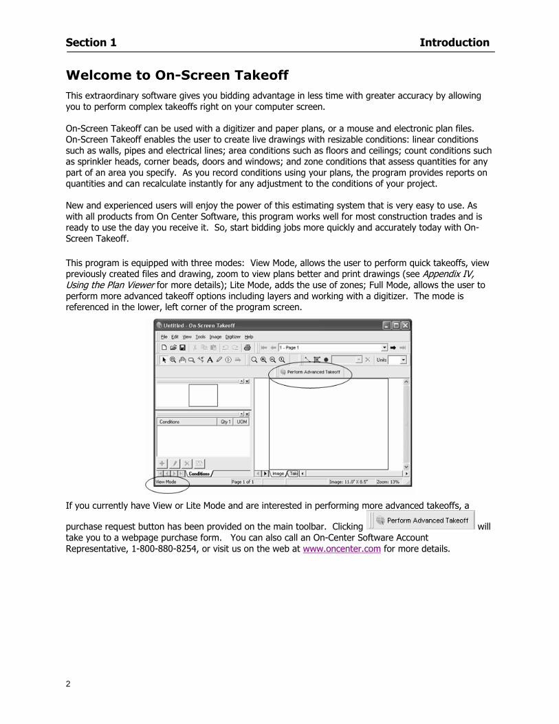
Section 1 Introduction
2
Welcome to On-Screen Takeoff This extraordinary software gives you bidding advantage in less time with greater accuracy by allowing you to perform complex takeoffs right on your computer screen
On-Screen Takeoff can be used with a digitizer and paper plans or a mouse and electronic plan files On-Screen Takeoff enables the user to create live drawings with resizable conditions linear conditions such as walls pipes and electrical lines area conditions such as floors and ceilings count conditions such as sprinkler heads corner beads doors and windows and zone conditions that assess quantities for any part of an area you specify As you record conditions using your plans the program provides reports on quantities and can recalculate instantly for any adjustment to the conditions of your project
New and experienced users will enjoy the power of this estimating system that is very easy to use As with all products from On Center Software this program works well for most construction trades and is ready to use the day you receive it So start bidding jobs more quickly and accurately today with On-Screen Takeoff This program is equipped with three modes View Mode allows the user to perform quick takeoffs view previously created files and drawing zoom to view plans better and print drawings (see Appendix IV Using the Plan Viewer for more details) Lite Mode adds the use of zones Full Mode allows the user to perform more advanced takeoff options including layers and working with a digitizer The mode is referenced in the lower left corner of the program screen
If you currently have View or Lite Mode and are interested in performing more advanced takeoffs a
purchase request button has been provided on the main toolbar Clicking will take you to a webpage purchase form You can also call an On-Center Software Account Representative 1-800-880-8254 or visit us on the web at wwwoncentercom for more details
Section 1 Introduction
3
About this Guide This guide is intended to be a compliment to On-Screen Takeoff software The sections are presented in an order intended to help new users understand the software The User Guide provides detailed information about On-Screen Takeoff tools and commands It is designed to assist you in applying program features to your estimating projects Use it as a reference tool along with the online help system in your day to day work with On-Screen Takeoff
Table of Contents outlines the sections and topics covered in each section
Section 1 Introduction explains the user guide and helpful resources
Section 2 Setup lists system requirements and recommended components
Section 3 Toolbars and Menus explains the toolbars and menus used in On-Screen Takeoff
Section 4 Features gives you a tour of the On-Screen Takeoff environment and shows you how to navigate through your projects
Section 5 Projects leads you through your first time with the program or if yoursquore an old hand at On-Screen Takeoff reacquainting yourself with the software
Section 6 Conditions and Takeoff shows you features of working with condition objects zones and backouts in the takeoff area
Section 7 Printing and Exporting explains the step-by-step of printing images and reports copying and pasting data from On-Screen Takeoff and exporting quantity results to an Excel spreadsheet
Section 8 Advanced Features discusses special and advanced features of On-Screen Takeoff conditions and options
Section 9 Saving and Exiting explains how to save projects and safely exit the program Appendixes gives you additional information on installing a digitizer toolbar item details loading files using the plan viewer and frequently asked questions Index provides key words or phrases the program application and references the page(s) in the user guide where they can be found
Section 1 Introduction
4
Extras Along the way yoursquoll encounter bits of information that make the User Guide not only more readable but more personal and relevant The signs and signals placed throughout the guide will better help you understand On-Screen Takeoff and On Center Software We think yoursquoll find these bits and pieces interesting Herersquos what to look for
NOTE
To make special notice of specific information
Caution Warning This symbol is there to insure that you are following the information to minimize risk
This symbol represents information that also appears on the Quick Start Video
In this manual some information is specific to using a digitizer The icon appears alongside this information (Must be in Full Mode to use a digitizer)
A reminder is there to keep the information in mind for future consideration
For Your Informationhellip
Instruction Jargon
In this guide click or double-click refers to clicking on the left mouse button A right-click clicking on the right mouse button will be specifically stated
Click the digitizer refers to clicking down once with the stylus pen
NOTE When using a digitizer a click or double-click refers to pressing the ball tip of the stylus pen right on the digitizer (usually in the takeoff area) A right-click can be accomplished by using the digitizer mouse template and the first button on the stylus pen See Appendix I Installing You Digitizer for more information
Drag and drop is holding down the left mouse button after clicking on an object You may simply drag the object to the desired location and release the mouse button
Section 1 Introduction
5
Typographic Conventions
The following are typographical conventions to be aware of when reading this guide
Menu items you are instructed to choose appear in a different typeface with the greater than (gt) symbol separating each menu level For example if you are instructed to select the Open command in the File menu it appears as File gt Open If you are instructed to select the Save As command from the File menu it appears as File gt Save As
Helpful hints or information about the topic are provided throughout the document They will be labeled lsquoNOTErsquo (all caps and bold font to catch your attention)
Several topics will have more detailed steps outlined in either another section of the user guide or in the Appendix They will always be referenced and italicized For example ldquoSee Editing Conditions for more informationrdquo
Help File In combination with this User Guide and the Quick Start video (Help gt Watch Quick Start Video) the Help File will also be a great resource for product information and application There are additional resources available on the website at wwwoncentercom or Help gt Visit our Website Follow these instructions to open the Help file
1 Select Help gt Help Topics
2 This will open the On-Screen Help File
Hide and Show Buttons
The Hide and Show buttons will either remove or display the Topics panel in the Help dialog
Back Button
The Back button takes you back to the last help page you viewed It will be available only if you have navigated through multiple pages in the help file
Print Button
Clicking will print the topic displayed This is helpful if the instructions to follow are long and you prefer to work on a full screen
Options Button
The Options button will allow you to pick from a list of commands to help you navigate the Help file
Section 1 Introduction
6
Contents Tab This tab provides a quick breakout of the Contents of the help file It should be used like the Table of Contents of a book Simply double-click on the book icon to open the chapter Then click the desired page icon to display the relevant information
Index Tab This tab allows you to locate a specifically indexed topic This should be used as you would a book index Begin typing a word in the index entry field and the system will automatically move within the list to the entries closest in spelling to your word(s) Begin typing the topic word to access it in the list quickly
Section 1 Introduction
7
Search Tab This tab works like a word find It allows you to search for any word contained in the Help file Type the
word you are looking for in the lsquoType in the keyword to findrsquo field Click A list of topics containing that word will appear Scroll through the list and double click on the topic you want displayed
Section 2
8
Setup
This section will
Let you know what system requirements you will need to have in place
Recommend components that work well with the software
Help Full Mode users install a digitizer
Section 2 Setup
9
Minimum System Requirements To use On-Screen Takeoff your computer must meet the following minimum system requirements
An IBM PC or 100 compatible computer with a Pentium II or faster Intel processor
Memory Requirements 200 MB of available hard-disk space and256 MB RAM (128 MB preferred)
Windows 2000 SP4 and Windows XP SP2 256 color video card Super VGA display card Mouse 15-inch monitor
While these are the minimum system requirements Windows places heavy demands on your systems resources The more available memory in your computer the faster and more efficient On-Screen Takeoff will operate
Recommended Components
For the best performance we recommend the following components
Pentium III or faster processor
512 or more of RAM
12X speed CD-ROM or better
17-inch monitor or dual monitors Graphic adapter with 128 MB or more VRAM Sound card and speakers installed
NOTE In order to utilize the Training Videos you must have a sound card and speakers installed
Compatible File Formats The resolution in electronic plans does not need to be more that 200 DPI (Dots per Inch) The preferred file format is a black and white TIF (Group4) On-Screen Takeoff recognizes image files with the following extensions
File Extensions View Mode Lite Mode Full Mode TIF X X X PDF X X X OSE X X X JPG X X X CPC X X X CAL X DGN X DWG X DXF X OSP X PLN X PLT X
Section 2 Setup
10
NOTE Use the following image types for best results
Convert to TIF
The converted files will be stored in a folder with the name of the current On-Screen Takeoff project Since the conversion can be very time consuming you should only select this option if you really intend to convert vector files to TIF
1 Select File gt Project Properties
2 In the Pages Field add your image See Section 5 Establishing Project Setting Adding Pages
3 Click
4 Then select the page with the drawing you wish to convert
5 Click
Installing Your Digitizer The following instructions are a quick start to installing your digitizer For more specific information please reference Appendix I Installing Your Digitizer at the end of this guide
Connecting Your Digitizer
Upon receiving your digitizer (either a GTCO or another brand) you will need to connect it to your computer
1 Lay the digitizer out flat
2 Connect the Stylus to the digitizer
3 Plug in the power supply
4 Plug the interface cable into the digitizer
5 Plug the other end of the interface cable into the computer
NOTE On-Screen Takeoff is compatible with any tablet that is WinTab compatible
Digitizer options are only available in Full Mode If you are in View or Lite Mode and would like
to use this feature click from the main toolbar to purchase the upgrade
Section 3
11
Toolbars and Menus
This section will
Introduce the program toolbars
Familiarize you with On-Screen Take Offtrade Menu options
Section 3 Toolbars and Menus
12
Toolbars On-Screen Takeoff is equipped with several helpful toolbars for application efficiency See Appendix II Toolbar Item` Details for a detailed description of each toolbar item Individually the toolbars may be displayed moved docked reshaped or hidden from view You can also create costume toolbars to fit your needs
Main Toolbar
Tool Toolbar
Zoom Toolbar
View Toolbar
Navigate Toolbar
Takeoff Toolbar
Image Toolbar Viewing Toolbars Toolbars are displayed on the screen and will be consistent on each tab or page (Some toolbars or toolbar items will be in an inactive state if they donrsquot have a supporting element in the application)
1 Select View gt Toolbars and select the appropriate toolbar name
OR
2 Right-click on a toolbar region of the screen
3 Check the toolbars you want to display
Section 3 Toolbars and Menus
13
Moving Toolbars The toolbars may be positioned anywhere on the screen you wish This feature is provided to allow the flexibility for positioning the toolbars so they are out of your way yet handy for use
1 Click on an edge of the toolbar holding down the mouse button drag it to its new position
2 Release the mouse button to set it in place
NOTE If the toolbar is dropped anywhere other than a screen edge it will become free floating This feature is especially handy when using multiple monitors
Docking Toolbars The toolbars can be docked to any of the screen edges
1 Click on the title bar of an undocked toolbar
2 Drag the toolbar to any location on the screen
Hiding Toolbars
1 Select View gt Toolbars and select the toolbar you wish to remove from the screen
2 Right-click on the toolbar or dock bar areas
3 A floating toolbar can be closed by clicking on the in the upper right corner of the toolbar
Resizing Toolbars Only undocked (floating) toolbars may be resized
1 Position the mouse pointer over an edge
2 Click and drag
3 The toolbar can be resized as desired
Customizing the Toolbars You may rearrange or delete buttons within a toolbarrsquos display or you may move buttons from one toolbar to another If you find that you use a few tools over and over you may want to group them within a single toolbar for convenience On-Screen Takeoff gives you the flexibility to customize your takeoff environment
1 Select Tools gt Customize The Customize dialog will open
2 With the dialog open click on a toolbar button and drag buttons from one toolbar to another or a new location within the same toolbar
3 To add a button without altering another toolbar click on the Commands tab of the Customize dialog and drag the appropriate symbol from the Buttons section to a toolbar
4 To remove a button drag it to within the takeoff area of the application
Section 3 Toolbars and Menus
14
Menus
Section 3 Toolbars and Menus
15
Digitizer Menu
Section 4
16
Features
This section will
Show you how open On-Screen Takeoff
Describe the On-Screen Takeoff environment
Teach you how to navigate pages
Section 4 Features
17
Start On-Screen Takeoff
1 On your desktop double-click your On-Screen Takeoff icon
2 The application will open
OR
3 Left-click on the Start button on your computerrsquos toolbar
4 Scroll up to Programs gt On Center Software
5 Highlight On-Screen Takeoff and click On-Screen Takeoff will open On-Screen Takeoff opens to an untitled blank project The Image view of the screen will be a blank page
Two blank dock bars the Pan dock bar and the Takeoff dock bar appear at the left side of the screen Along the bottom the Status bar displays user status or context-sensitive messages as well as paper size and current zoom percentage of the plan sheet on screen The menu bar and several task specific toolbars are located at the top of the screen
NOTE All toolbars and dock bars may be accessed to view or hide through View gt Toolbars on the menu bar
Section 4 Features
18
Quick Start Video When On-Screen Takeoff opens you will be given an option to watch the Quick Start video (recommended) or start the program without watching the video
The 20 minute video will demonstrate key program functionality and allow you to view application instruction for enhanced learning
If you would like to watch the video click If you prefer to get started without
the video click If you have already viewed the video click the lsquoDo not show this message againrsquo box to prevent this dialog from appearing each time you open the program
NOTE If you decide later that you would like to watch the Quick Start video go to Help gt Watch
Quick Start Videos
On-Screen Takeoff Environment The On-Screen Takeoff environment acts like your drafting table allowing you to work on several sheets of plans at once and to reference at a glance the entire drawing and your position on that drawing while giving you the power of a computer to track analyze print and export your takeoff quantities and plans
The screen is bordered at the top by the Menu bar with pull-down menus and at the bottom by the Status bar which indicates current user status plan page size and current zoom percentage of page The largest portion of the application screen will be your takeoff area bounded on the left (by default) by two dock bars and on the top by several toolbars
In the takeoff area you may view your project plans (images) andor takeoff objects the takeoff list with quantities the worksheet or a legend of your condition list
The main window of On-Screen Takeoff has three tabs located at the bottom left allowing for quick change between Image Takeoff or Worksheet views Select the desired view option on the toolbar and it will automatically open on your screen
Section 4 Features
19
Image View
This view shows the plan file andor takeoff conditions drawn from your plans
Takeoff View This view displays the height if applicable and quantity breakdowns of your conditions according to result types indicated (eg linear feet square feet or count of items) for zones pages and the project as a whole It also displays notes per condition
Section 4 Features
20
Worksheet View This view displays the condition and quantity in units of measure specified in the first results field of the Results tab in the Condition dialog and allows the user to enter amounts for material labor and subcontractor takeoffs
NOTE When in the Worksheet view tab out the field then save This is keep all the values saved
Navigating On-Screen Takeoff
Auto Scrolling When creating linear areas or zones On-Screen Takeoff will automatically scroll the image view when necessary It will move as your mouse or digitizer moves beyond the edge of the current view
Changing Pages
1 Select View gt Next Page Previous Page or Go To Page (specify page number for the Go to Page option)
2 You may also select the corresponding arrows for these options from the Navigate Toolbar The
drop down arrow in the Page field will list the pages The and arrows will take you to the
previous or next page The and arrows will take you to the first or last page
OR
Section 4 Features
21
3 Or press Ctrl G for the Go To Page dialog
Hot Links Hot links allow you to move quickly from one drawing to the pertinent area of another drawing A hot link is handy when viewing enlarged areas of a page and needing the ability to jump back to a reference page
1 Select Tools gt Hot Link
OR
2 Click from the Tools Toolbar
3 Click on the page where you want to set the link The Hot Link dialog will open
4 Using the current page display on the Navigate Toolbar access the pull-down menu of pages by
clicking on the arrow at the right
5 Select the page for your link (You may also choose View gt Go to Page and select by page number)
6 Manipulate the view using the zoom tool and the scroll bars
7 Click
8 After joining a hot link to another page the hot link arrows in the Navigation Toolbar will become active
9 Move a hot link to another location on the page by clicking then click and drag the hot link image anywhere on the page
Section 5
22
Projects
This section will
Help you create settings important to your projects
Explain how On-Screen Takeoff works with your electronic or paper plans
Section 5 Projects
23
Project Template Files You can begin your project with a template Templates allow you to take advantage of conditions and settings used with previous projects
On-Screen Takeoff templates contain condition lists and established layer separations from previous projects you have created You may also use the sample templates provided with On-Screen Takeoff as a great starting point All aspects of the templates may be adjusted for a new project
1 Select File gt New and click the OK button
2 From the New dialog box choose the template that best fits your project
3 The conditions for this template will appear in the Takeoff Dock bar and the Project Properties dialog will open asking for further information
4 Use File gt Save or File gt Save As to rename and save your new project
Saving a Project as a Template File You can save your condition properties and layers as a template for future projects
1 Select File gt Save As
2 Enter a name for your template and select On-Screen Takeoff Template Files (tpo) from the Save As type field of the dialog (click on the down arrow to select)
3 Click the OK button to accept and close the dialog Modifying a Template File Follow these steps to modify an existing template file if you need to change or add conditions andor layers
1 Select File gt Open
2 Navigate to your Projects directory
3 In the File Type drop-down select On-Screen Takeoff Template files (tpo)
4 Choose the On-Screen Takeoff template file you would like to modify and click the OK button
5 Make appropriate changes
6 Save and close file
The On-Screen Takeoff template files cannot save takeoff information
Section 5 Projects
24
Opening an Existing Project File 1 Select File gt Open
2 Navigate to the desired file location
3 Click the Open button
NOTE If your latest changes to a project file have not been saved On-Screen Takeoff will ask
you whether you would like to save the file and gives you the option of canceling the operation
Creating a New Project
1 Select File gt New
2 For a blank untitled project click
3 At this point the Project Properties dialog will pop-up for more information about your takeoff
NOTE The following are important to keep in mind when beginning a new project
At the start of your project fill out the Project Properties settings to establish the name for all printed output from your project set the default page size and scale for your plans number and names of different pages within the project and locations of electronic drawings
Scale settings can significantly affect quantity outcomes Be sure to set the scale for each page of drawings before beginning condition takeoffs
When using a digitizer remember to make a mark with a pen or pencil in the upper left and lower right corners of the first sheet of the paper plans to delineate the takeoff area for that sheet You can then set the takeoff area on On-Screen Takeoff using your marks
Save your project before you begin taking off any conditions On-Screen Takeoff will write a back-up file using the same file name
Remember the Undo feature If you make a mistake select Edit gt Undo and reverse the process step by step
Section 5 Projects
25
Project Properties
You can either set your Project Properties when you create a new takeoff or once your project file is saved under the appropriate name
1 Select File gt Project Properties the Project Properties dialog box will appear
2 Type in the name of your project to appear on printouts Use the backspace andor delete keys to edit the name as necessary
3 Press the Tab key to move to the Default Image Size option or click within the Image Size box You may click on the arrow at the right for the pull-down menu of page size options or you can use the down-arrow key on your keyboard to scroll through the list to the appropriate selection
4 Press the Tab key to move to the Default Scale option Select a scale by using the drop down arrow If your scale is metric you will need to click in the box next to Metric to convert to that measurement
5 Establish the number of pages for your project plans And load image files See Adding Pages to
Your Project
Adding Pages to Projects Individual Electronic Plans
1 Click on in the Project Properties dialog
2 In the Add Images dialog use the drop down arrow to navigate to the appropriate directory and folder containing your image
3 Select the file so that it displays in the File name field then click The file will display by name and path in the Image File field in Project Properties dialog
4 Click to accept and your project will automatically open
5 Save your project with the new settings by selecting File gt Save
Section 5 Projects
26
Electronic plans scanned from blueprints (as opposed to blue lines) will display as white lines on a black background and are difficult to read on your computer screen Select Image gt Invert and the colors will invert to black on white
You may have noticed the Page column in the Project Properties dialog Generally plan images occupy one page and 1 will be listed in the column indicating Page 1 of your plan file If you import a multi-page TIF a plan file containing more than one page of plans they will import as separate pages and each successive page will be indicated under the Page column as 1 2 3 etc of the plan file
Group of Electronic Plans You may add all the electronic plan files from a particular source (for example from a CD) by using the Auto Add feature
1 Click the button in the Project Properties dialog
2 Browse until you find the appropriate directory and folder containing your plan images
3 Click on any file displayed within your target folder so that the file name appears in the File name box of the Auto Add dialog
4 Click The image paths and file names will be recorded into the project properties arranged alphabetically
5 Click to accept your choices and your project will automatically open
6 Save your project with the new settings by selecting File gt Save
To load Dodge Plans into your Project Properties see Appendix IIi Loading Plans from a Dodge CD
Paper Plans On-Screen Takeoff makes it easy for Full Mode users to perform quantity takeoffs from paper plans using a digitizer
1 Add pages by clicking until you have the number of pages initially in the project
2 Name each page by clicking within the Title area and typing the name
3 Click to accept your choices and close the Project Properties dialog
4 Save your project with the new project properties settings by selecting File gt Save
Section 5 Projects
27
Setting Up a Drawing Template On-Screen Takeoff provides the convenience of using the same work surface for both digitizer and mouse to allow the user to draw conditions and then edit settings of the project or add or change conditions without breaking stride A mouse pad template included with the program defines the area of the digitizer in which use of the stylus or cursor will be recognized as mouse movement as opposed to drawing movement
1 Place your stylus on On-Screen Takeoff
2 Placing the template identifies the location mouse movements will be recognized by the program
Before placing the template the template must be applied to the digitizer surface This may have been done during the installation of your digitizer We suggest attaching the template to the lower right corner of the digitizer surface about one inch inside the grid area
3 Select Digitizer gt Place Template
4 Follow the instruction prompts on the screen clicking first on the target symbol at the left of the On-Screen Takeoff box on the template then on the target at the right
Setting Takeoff Area Before you can begin taking off a drawing you must define the drawing area on the digitizer This requires defining an area that will include all objects on each drawing of your plans As you add pages to your takeoff the same area of the digitizer will be active
1 Secure the plans to the digitizer with tape or a set of clamps
2 With a pen or a pencil mark the upper left corner and the lower right corner of the first page in your set of plans
3 Select Digitizer gt Set Takeoff Area
4 Click each mark with the stylus pen as prompted
5 Verify the active area of the digitizer by looking at the image size located in the lower right corner of your screen
If you close the program before the takeoff is complete you will need to reestablish the takeoff area before you can add additional condition quantities
Electronic plans appear on your computer screen eliminating the need to set a takeoff area You simply drag your mouse across the conditions you wish to takeoff The conditions will be highlighted and quantities will be totaled instantly Electronic plans are available through a variety of services For information contact an On Center Software account manager
Section 5 Projects
28
Setting Scale for Specific Pages You may set the scale in each page view separately This will override the default scale setting in Project Properties for that page Setting the correct scale for the drawing before taking off quantities ensures accurate calculations Be careful to check the scale for each drawing in your project before doing takeoffs
1 Display the page you want to set select Edit gt Set Scale
2 Use the drop down arrow to select a scale that will be applied to that page
3 Click
OR
4 Access the pull-down scale settings on the Navigate toolbar
NOTE As you draw objects notice that the drawn object is similar in width to the object on your plans If it is not the scale set may not be correct
Calculating Scale You may calculate scale according to a known measurement between two points either with a digitizer or on electronic plans
1 Select Edit gt Calculate Scale using Image or Edit gt Calculate Scale using Digitizer
2 Follow the instructions in the related Calculate Scale dialog box You will be asked to click on the first and second points then to enter the dimension for that distance
3 The scale will be recalculated for the displayed page and the Scale display on the Navigate toolbar will show the new scale
Section 6
29
Conditions and Takeoff
This section will Draw Conditions to Takeoff Plan Quantities
What Zones will do to help your takeoff process
Discuss the ins and outs of Takeoffs
Section 6 Conditions and Takeoff
30
Creating Conditions
If you are starting a new project from scratch you will need to create conditions to takeoff quantities such as floor areas wall lengths and corner bead counts If you are using a template you will have several pre-designed conditions already listed on the Takeoff dock bar However you may want to change the characteristics of some conditions or create additional conditions for a particular project
1 Right Click within the Takeoff dock bar Select New gt Condition
Or
2 From the Takeoff dock bar Click (if the buttons are not showing right-click in the Takeoff dock bar area and select Show Buttons from the pop-up menu) The New Condition dialog appears
3 Select the condition type (Linear Area Count or Zone) from the pull-down menu accessed by the
down arrow next to the Type option
4 Press Tab or use the mouse (or stylus) to move to Name and enter a name for your condition
5 Specify the desired condition attributes See Condition Attributes for more detail
6 Click for condition to apply
Section 6 Conditions and Takeoff
31
Condition Attributes Each condition type will have related attributes to select or specify within the General and Advanced tabs of the New Condition dialog Once a condition has been used to takeoff a quantity from your plans certain attributes cannot be changed
All conditions allow the user to specify color and fill pattern for the object drawn
Linear Conditions
General Specify width and height by feet and inches Specify pitch in inches up to the nearest thousandth of an inch if applicable
Advanced Specify rounding for object quantities and droprun default length for electrical or plumbing drops at the ends of lines Select Connect to have lines connect at the corners where one line of the condition ends and another begins (and indicate Tolerance for the featurersquos activation as distance between the ends of two lines) Choose Trim to have lines automatically trim to a line being crossed Choose Curve to draw a curved line
Follow these examples for inputting feet and inches For 7 feet 6 inches type 706 for 13 feet 7 inches type 1307 For 20 feet type 2000
Section 6 Conditions and Takeoff
32
Area Conditions
General If needed you can specify the thickness (in inches) andor pitch (in inches)
Advanced Specify rounding for object quantities Choose to display an adjustable grid within the area and indicate matrix cell dimensions
Section 6 Conditions and Takeoff
33
Count Conditions
General
Specify height and indicate the size (in inches) and shape (square circle triangle rectangle or opening) of the count object as it will appear on screen
Advanced Count conditions have advanced attributes These options are available for all shapes except for openings
Zone Conditions Zones allow you to subdivide condition quantities making it easier to modify and complete jobs in phases They can be used at the end of a takeoff to isolate a group of condition quantities that are in different areas of the takeoff
Zones can also be used to break a takeoff into multi-phases and can even be used to isolate quantities while a job is in progress to group the amount of work that has been completed to date They can be applied to one or multiple pages in your plans automatically calculating the takeoff quantities for each zoned area
Section 6 Conditions and Takeoff
34
The zone feature is only available in Lite and Full Mode If you are in View Mode and would like
to use this feature click from the main toolbar to purchase the upgrade
Condition Notes A Note tab is provided for comments regarding the condition These notes will display on the Takeoff List report and will import into Quick Bid
Section 6 Conditions and Takeoff
35
Condition Results The Results tab of the New Condition is based on condition type Initial settings default to linear feet (LF) for linear conditions square feet (SF) for area conditions and count of items (EA) for count conditions and zones The first of the results fields will display for the condition items in the Takeoff dock bar area All results will display in worksheets and Takeoff List reports as well as in an Excel spreadsheet after being exported
Copying Conditions You may use the condition attributes from a condition yoursquove already created for any future conditions of the same type
1 Click on a condition to select it
2 Click the Copy button from the toolbar
OR
3 Right-click in the Takeoff dock bar area and select copy
4 A new condition will appear in the list with the same condition attributes as the previous condition but with the quantities zeroed
Editing Conditions Once you have copied a condition you might want to change several attributes You can also edit an existing condition to fit any updated needs
1 Highlight the desired condition on the Takeoff dock bar
2 Click the Change button
OR
3 Double-click on the condition you wish to edit to bring up the Change Condition dialog
NOTE The Change Condition dialog differs from the New Condition dialog only in that if takeoffs
Section 6 Conditions and Takeoff
36
have been performed in your project with this condition you will not be able to change the type of condition or certain properties under the advanced tab of the dialog box
Deleting Conditions 1 Click on the condition in the Takeoff Dock bar area
2 Click the Delete button on the toolbar
OR
3 Right-click and select Delete from the pop-up menu
All takeoff associated with the deleted condition will be deleted immediately and permanently
Organizing Project Conditions Within your project you can create folders andor sub-folders for different types of conditions You may even want to create a folder containing conditions with reset values
To get started organizing your conditions make sure you are viewing the condition tree (right-click in the Takeoff dock bar area and select Show Tree)
Creating Folders and Sub-Folders 1 Right-click in the Takeoff Dock bar area
2 Select New gt Folder from the pop-up menu
Copying Folders
1 Click on the folder and click Copy on the toolbar
2 All copied conditions within the new folder will have values reset to zero
Renaming Folders
1 Click on the folder
2 Right-click and select Rename from the pop-up menu
3 Enter a name for your folder and click the Enter button
Changing Condition Order
You may move conditions up or down in the condition list of the Takeoff dock bar to suit your project needs
1 Select the condition you would like to move by clicking to highlight it
NOTE When you are ready to move the highlighted conditions be sure that you start
moving using the last condition chosen That condition will have a highlighted boarder
Section 6 Conditions and Takeoff
37
2 Drag and drop any the condition from one place to another in the list You may also move a condition to another folder on the list in this way
Drawing with Conditions Snap Angles Set up snap angles to prevent lines from appearing jagged Snap angles are commonly set at 15deg and shift snap angles at 0deg
1 Go to Tools gt Options Options dialog appears
2 Under the General tab make the desired settings
3 Click to save the settings As they are drawn lines will snap to the set degree
Drawing a Linear Object 1 Select a condition from the Condition List in the Takeoff dock bar
2 Move the cursor into the Image takeoff area of the screen you will see the cursor display as crosshairs
3 Click and hold left mouse button then drag mouse to draw a line
4 Release mouse button to set line
Section 6 Conditions and Takeoff
38
5 Repeat steps for further lines
Continuous Mode This feature allows you to draw an object that has connected lines
1 Click the icon from the Takeoff toolbar
OR
2 Go to Tools gt Continuous Mode
3 Follow steps 1-3 from Draw a Linear Object
4 Click at each point of intersection The object will be connected
5 Double-click after making the final point to set the lines
Drawing a Curve To draw a curved line the Curve option must be checked under the Advanced tab of the Condition dialog
1 Click where you want to begin the curve and drag in a straight line to the position for the other endpoint of the curve
2 Click on the line to select it Handles in the shapes of small squares will appear at either end of
Section 6 Conditions and Takeoff
39
the line and in the center of the line
3 Move the cursor over the center handles until the cursor becomes a two-way arrow
4 Click and drag in the direction of the curve bending the line as you move the cursor Release to set the curve (The line you began with will disappear)
Draw a circle by drawing two curved lines connected
Drawing an Area Object Area conditions are drawn similarly to continuous mode lines You may trace any number of adjoining walls at different angles to complete your area takeoff
NOTE When drawing an area do not intersect the perimeter or line of the object you are drawing
1 Click at each point
2 Double-click when yoursquove returned to your starting point
3 The area will be filled with the pattern set for that condition
NOTE The simulated circle will be good enough for you to be able to make a bid
To create a circular area click from point to point with very short distances in between points simulating a circlersquos perimeter Double-click after setting the last point to set the area
Section 6 Conditions and Takeoff
40
Grid Options Grids give you an added advantage when installing materials such as tiles Use this feature to get a count for how many tiles are needed for an area
1 Double-click on an area condition in the Takeoff dock bar to open its Condition dialog
2 Click on the Advanced tab to show its options
3 Check the box next to Grid by clicking in it
4 Indicate the dimensions of the cell matrix in inches (For example 200 x 400)
5 Under Results tab choose each (EA) for one of the results fields This will tabulate a number of grid cells (including partial grid cells) in area
6 Click to save your settings
7 Use the Move Grid and Rotate Grid features in the Tools menu to manipulate the grid as desired
Grid Calculation
1 Go to Tools gt Options menu
1 Specify if On-Screen Takeoff automatically should Calculate Grid Position
2 If AreaGrid Size is selected On-Screen Takeoff will calculate the number of items needed to fill the grid based on grid demintions
3 Click to accept and close the dialog
To move a line at any angle (regardless of default setting) press the Shift key while moving the mouse
Section 6 Conditions and Takeoff
41
Backout Mode This feature allows you to take out part of an area and deduct that amount of square footage
1 Select Tools gt Backout Mode
2 Outline the are you want backed out as you would when drawing a regular area object (see Drawing an Area Object)
3 The outlined area will clear and quantities will be recalculated
NOTE The perimeter of the backout area will be added to the LF quantity for that condition
Drawing a Count Object Square triangle rectangle and circle shaped count objects can easily be placed on images
1 Select the condition
2 Click in the location where you want the object to appear
3 To place an opening-shaped count item like a door or window you must click over an existing linear object such as a wall
4 On the Results tab you can change the height properties to give you the result you need
5 If Backout is checked on the advanced tab for each count opening the opening-shaped count item will back out a corresponding section of the linear object
Opening shaped count items are sized at 3rsquo0rdquo by default
Drawing a Zone Zones are drawn in the same way as area objects and may be any polygonal shape You may trace any number of adjoining walls at different angles to complete the zone perimeter
1 Click at each point
2 Double-click when yoursquove returned to your starting point
Section 6 Conditions and Takeoff
42
Selecting Objects
1 Use the Select Tool to select objects
You can also select all objects that correspond to a condition
1 Click on a condition to select it
2 Right-click and choose Select All
3 All objects with this condition will be highlighted with squares as an outline
Moving and Resizing Objects Linear
1 To move or resize a linear object click anywhere on the line to select it
2 To move the line position your pointer over the center handles When the mouse is positioned over the handles you will see a two-way arrow You will only be able to move the line in the direction of the arrows
3 Drag the line to a new position
4 Clicking and dragging the handles on the ends of the line will allow you to lengthen or shorten your line
Area and Zone
1 To move an area object or zone in its entirety click and drag it to its new position
2 Grabbing a handle at a corner or intersection of the object will allow you to adjust and change its perimeter
Section 6 Conditions and Takeoff
43
Count 1 To move a square circle rectangle or triangle shaped count object click and drag
2 Click and drag an opening shaped count object along the length of the linear object to the desired position then release
NOTE An opening shaped count object may not be moved from its associated linear condition object however it may be moved up and down the length of the linear object
Layers On-Screen Takeoff allows you to sort and separate your takeoff objects within the same job and on the same page On-Screen Takeoff gives you this flexibility through the use of layers
By assigning different conditions to different layers (for example differentiating between floors ceilings and walls) you can choose to view all layers or turn off certain layers to display and print the remaining groups of conditions only You may also remove the background image of electronic plans add text and hot link symbols or print only your condition takeoffs
Layers are only available in Full Mode If you are in View or Lite Mode and would like to use this
feature click from the main toolbar to purchase the upgrade Default Layers
On-Screen Takeoff begins every project with three default layers Image Annotation and Default The Image layer holds the electronic plan files you may have in your project The Annotation layer possesses all text notations highlighting and hot links in the project The Default layer will appear in the Condition dialog when creating or editing a condition (listed in the takeoff dock bar) Conditions are assigned to the Default layer unless otherwise specified by the user
Creating Layers To assign a condition to a layer other than the default layer you must first create additional layers for your project
1 Select View gt Layers to open the Layers dialog
2 Click An unnamed layer will be added
3 Click within the empty box and type a name for your layer (for example Wall)
4 New layers are added as active layers The adjacent box under the Show column will be checked
Section 6 Conditions and Takeoff
44
Assigning a Layer to a Condition 1 Open the Condition dialog box by creating a new condition or editing an existing condition
2 Under the General tab click on the down arrow in the Layer field to display optional layers
3 Select the desired layer for the condition Only the Default layer and layers you have added will be displayed
4 Click
View and Hide Layers
1 Select View gt Layers
2 Under the Show column check the box to view or remove the check (by clicking on it) to hide the specific layer
3 Click to accept and close the Layers dialog
Section 6 Conditions and Takeoff
45
Assigning Text to a Layer When adding text to an image On-Screen Takeoff has the capability to assign the text to a specified layer
1 Select the Text Tool
2 Click at the point you want to place your text
3 Type in your text using the Enter key for line breaks
4 Click the drop down arrow next to the Layer field and select the desired layer
Section 7
46
Printing and Exporting
This section will
Printing options and procedures
Exporting data by copying and pasting
Exporting quantity results to Excel spreadsheets
Section 7 Printing and Exporting
47
Print Setup On-Screen Takeoff allows the user to print the image takeoff list and worksheet
1 Select File gt Print Setup The Print Setup dialog will open
2 Select a printer or leave the default selection listed (change from the default printer displayed by clicking on the down arrow at the right of the field)
3 Indicate page size and printer tray option (Source) Access page size options by clicking on the
down arrow at the right of the field
4 Choose Portrait or Landscape orientation
5 Click to accept and close the dialog
Printing Images The image area can include the electronic plans the takeoff objects added text and hot links To print a subset of these (for example just the takeoffs without the plans or the added text and hot link symbols) hide layers that you do not want to print (see Section 6 View and Hide Layers) When you are printing your images every page will show the scale of the takeoff you are printing
1 Click on the Image tab to display the area of your project
2 Select File gt Print (or Ctrl + P)
Section 7 Printing and Exporting
48
3 Select the desired view (What to print) and the Image Range
4 Click The second Print dialog will open
5 Change settings accordingly or click if you accept the default settings
Printing Takeoff Lists and Worksheets In Takeoff Lists and Worksheets you may hide columns to print only certain results or adjust column widths to fit the report within the page size selected
1 In Takeoff List or Worksheet view move your cursor to the right side of the columnrsquos title bar the cursor will display as a two-way arrow
Section 7 Printing and Exporting
49
2 Click and drag to adjust the width of the column Holding the mouse button you may
slide the title bar under the title bar to its left to hide the column completely
3 Select File gt Print or press Ctrl + P to access the Print dialog
4 Indicate desired printer and choose the number of copies
5 Click to print and close the dialog
When printing the condition list we suggest printing in landscape
To reset to the default column widths double-click on the right border of a column heading will reset the column to its right (or previously to its right before being hidden)
Print Preview 1 Select File gt Print Preview
2 Use and to vary your view 3 If viewing an image choose current full or scale view to see how it displays
4 For printed outputs that cover more than one page use and to view adjacent pages or click on the down arrow next to Page field and select the page you want displayed
Exporting Using the CopyPaste Feature You may copy all the data or sections from the worksheet and the takeoff list view in On-Screen Takeoff and paste it into another application When pasting into Excel the cell layout will be maintained
1 Highlight the areas you wish to paste Click and hold the left mouse button down as you drag the cursor over the area to be selected then releasing the mouse button
OR
2 Select the entire takeoff list quickly click on the left On-Screen Takeoff column header and hold and drag the cursor across the remaining column headings
The number of pages for the view selected will display in the lower left-hand corner The zoom percentage that applies to the view will be displayed in the lower right-hand corner next to page size of the drawing
Section 7 Printing and Exporting
50
3 In the worksheet view you may highlight rows by clicking on the numbered buttons to the left of each row clicking and dragging across column headings or clicking and dragging over individual cells in the worksheet
Click anywhere in the appropriate view to deselect the area
4 Once your selection is highlighted you may select Edit gt Copy or Ctrl C from the keyboard 5 On your monitor switch to the application into which you want to paste your selection 6 Select Edit gt Paste in the new application or simply press Ctrl + V to paste
The colored keys for conditions cannot be pasted
Using the Export Feature You may export condition quantities to specified cell location within an Excel worksheet file Cell target locations are assigned in the Results tab of the condition dialogs on the Export line relating to each quantity measurement type
On-Screen Takeoff will export takeoff quantity results for up to three different quantity types that you specify For instance you may want to know the number of square feet in a ceiling area as well as the number of linear feet in its perimeter
Section 7 Printing and Exporting
51
1 Bring up the Condition dialog by double-clicking on a condition in the takeoff dock bar or by
selecting the condition and clicking
2 Click on the Results tab to access its fields The default quantities for the condition type will display
3 For each results field click on the arrow to access the pull-down menu and select the appropriate quantity (for example SF LF EA etchellip)
4 Have your Excel spreadsheet opened and saved in a file
5 Specify the Excel spreadsheet cell locations where you want the results to go
6 For a cell in the first sheet of your spreadsheet type in the cell address (eg a1) Case is not important
7 For a cell on a successive sheet of your spreadsheet type in sheet the number followed by a comma and the cell address without any spaces (eg sheet2a1) Case is not important
8 Click
9 Select File gt Export gt Condition Qty to Excel
Section 7 Printing and Exporting
52
10 Browse to the location of the Excel spreadsheet file click file to select it
11 Click to export On-Screen Takeoff results to specified cell locations in the Excel file When you return to the Excel application you will see the values have been added to the specified cell locations in your spreadsheet
12 Save your Excel file
Exporting Worksheet to Excel
1 Assign condition quantities you want to export
2 Open saved Excel spreadsheet file to which you will be exporting
3 From On-Screen Takeoff Select File gt Export gt Worksheet to Excel
4 Browse to the location of the Excel spreadsheet file click file to select it
5 Click When you return to the Excel application you will see the values from the Worksheet Tab have been added to your spreadsheet
6 Save your Excel file
Exporting Takeoff to CVS 1 Assign condition quantities you want to export
2 Open saved Excel spreadsheet file to which you will be exporting
3 Click the Takeoff Tab in the project you want to export the information
4 Select File gt Export gt Takeoff to CSV
5 Browse to the location of the CSV spreadsheet file click file to select it
6 Click the Save
NOTE CSV files can be opened in Excel Lotus Access etc One may consider this option more of a ldquodumprdquo into a file
The Excel application must be active (it may be minimized on the application bar) with the target spreadsheet open in the application Otherwise an error will occur with the export operation that will affect both the On-Screen Takeofftrade file and the Excel spreadsheet
Section 8
53
Advanced Features
This section will
Some special features of working with condition objects in the takeoff area
Details of advanced options for conditions
Advanced features of the Project Properties dialog
Section 8 Advanced Features
54
Features to Use with Objects Roping Feature You can move copy or delete using this feature Using the Select tool (the pointer) you may select several objects at once by clicking and dragging an outline around the objects then releasing the mouse button Roping may select either objects completely within the outlined area (inclusive) or objects both within and touched by the outlined area (touching) Specify your roping preference under Tools gt Options
1 Click and hold the mouse button at a point on the screen near the objects to be selected and drag to surround the objects with an outline
2 Release the mouse button The objects will be selected
3 You may now
Move the group around on the page by clicking within the group dragging the mouse and releasing the button to place the objects
Delete the group of objects by clicking the Delete key or
Copy and paste by pressing Ctrl C to copy the group then Ctrl V to paste it The pasted copy of the grouped objects will appear slightly offset from the original objects
Section 8 Advanced Features
55
Applying a DropRun Count
Use the droprun feature when calculating quantities to take into account the drop or run of a linear condition such as electrical lines or plumbing pipes Drop or run lengths may be added separately to any linear condition on screen while a default droprun length may be indicated for a condition as a whole
1 Select the desired linear condition from the Condition List in the Takeoff Dock bar
2 Click the Change button in the toolbar to open the Change Condition dialog
3 Click the Advanced tab to access the advanced options and click inside the DropRun check box
4 Enter a default length to be applied to all of this condition Entering 800 will be interpreted as 8 0 (You must enter both place markers for inches) You can leave the length blank and manually enter drop run on each segment drawn
5 Click the OK button to accept and close the dialog
Edit DropRun Count
1 With the related linear condition in the Takeoff Dock bar highlighted or with the pointer tool selected
2 click on the desired linear object in the image takeoff area The Count button will become active
3 Click on the Count button (alternatively select Tools gt Count) The default droprun amount will show in the pop-up Count dialog (Default length will be zero if droprun has not been selected in this conditionrsquos properties)
4 Type in the desired length Entering 800 will be interpreted as 8 0 (You must enter both place markers for inches)
5 Click the OK button The additional amount will be reflected in the corresponding quantity The new DropRun count will apply only to the object edited
Adding Text in Image View
On-Screen Takeoff allows you to place text comments around your quantity takeoffs that may be printed along with plan images and objects Text is automatically placed within the Annotation Layer (that includes text and hot links)
1 To place text on the image select the Text Tool and click at the point you want to place your text opening a text box
2 Type in your information clicking Enter for line breaks
3 When you are finished click the OK button to exit the text box
4 To reposition text simply click on the text (with the Text Tool active) to select it
5 Move the cursor over the text the cursor will now display as a four-way arrow
6 Click and drag the mouse to position the text as desired
Section 8 Advanced Features
56
1 To edit existing text use the Text Tool to double-click on the text to open the editing box
2 Enter additional text or use the Backspace key to delete text as necessary
Formatting Text Once created you may format the font size type style and color of your text
1 Click on the text to select it and select Tools gt Font or click on the Font button in the Takeoff Toolbar
2 Select the desired features (color options are disabled) and click the OK button
3 Click on the text to select it and select Tools gt Color or click on the Color button in the Takeoff Toolbar The Color dialog will open
4 Click on a color in the Basic Color palette or create a color and add to the Custom Colors palette (Be sure to click on the color in the Custom Colors palette to select it)
5 Click the OK button
Object Properties
Linear Objects
Linear objects may be set to connect at corners
A linear object may be set to trim automatically when crossing another linear object (Check the trim option under the advanced tab of the Condition dialog)
When you move a connected linear object objects automatically move and resize connected lines accordingly (quantities are then recalculated)
This feature requires that the connected linear object be moved using the center handles (does not apply when resizing the line from the ends)
Objects constrain to snap increments defined in the Tools gt Options menu (with the mouse 15deg by default incremental when shift key is held down)
Objects are measured from centerline to centerline
Section 8 Advanced Features
57
Area Objects When drawing an area use your escape key to undo the last line drawn You may reverse your
drawing of an area using the escape key
The area will not fill with color and pattern until the user double-clicks after the last line is set
Lines drawn to delineate an area object constrain to snap increments defined in the Tools gt Options menu (with the mouse 15deg by default incremental when shift key is held down)
After selecting an area to move or adjust position the mouse in the center to move the entire area position the mouse at the sides or corners to adjust the perimeter
Count Objects
All count objects are quantified by the physical number of objects per page and reported as EA for the UOM The quantity for the current Image View is (displayed in the Condition List) and the total quantity in your project is displayed in the Takeoff View and Worksheet View)
Square circle rectangle and triangle shaped count objects do not displace or subtract from other object quantities when placed on top of them However on the Advanced Tab for the count condition a connect property can be set (this is a check box) so that when a count object of this shape is put on top of a Linear type takeoff object it will move with the linear if said linear is moved
An opened-shaped count object must be placed within a linear object Opening shaped count objects may also be measured by linear foot or linear yard (EA SF and SY are also options) Opening shaped count items default to a width of 3rsquo 0rdquo at the time of creation This size can be changed The small medium and large size are not options on this type of condition anymore Check Backout on the Advanced tab for each Count object back out the footage (or yardage) of opening-shaped count objects in which they are placed
NOTE In order to see this Backout functionality (in quantity) for SY or SF deductions at least one of the
results for the Linear(s) this object will be placed on must be set to SY or SF and the count object must have a height quantity
Advanced Features of Conditions The Round Feature Under the Advanced tab of the linear and area Condition dialogues you may specify quantity rounding (in inches) For linear objects rounding applies to each linear object drawn For area objects rounding will apply to each segment of the area perimeter adjusting the perimeter and area calculations For example With a linear condition entering 12 in the Round field will round up each related linear object to the nearest 12 inches or one foot With this setting two walls of 1 4 would each round to 2 0 totaling 4 0
NOTE In the Takeoff Dock bar condition list and in the On-Screen Takeoff reports quantities will be displayed in whole numbers rounded up to the nearest foot However calculations are based on true quantities without rounding unless the Round Feature is engaged
Pitch Pitch may apply either to linear or area conditions It is measured in rise per linear foot Entering 12 indicates a 12 rise per 12 of linear distance (a pitch of 12 over 12) or an angle of 45deg
Section 8 Advanced Features
58
Advanced Features of Project Properties Selecting Multiple Pages
1 Select a single page entry by clicking on the numbered gray button to the left of the entry
2 Drag the cursor down the column of numbers to select consecutive pages
3 Click on the blank button at the top of this column to select all pages in the Properties dialog
Section 8 Advanced Features
59
Changing Image Assigned to a Drawing 1 Select the page entry by clicking on the numbered gray button to the left of the entry 2 Click the Change Image button The Change Image dialog box will appear
3 Navigate to the desired file and select by clicking on it
4 Click the Open button The electronic file assigned to the page will have been changed to reflect the new file choice
Changing Image File Path 1 Select pages as described above
2 Choose Change Folder
3 In the Change Folder dialog navigate to the appropriate folder
4 Click the OK button The file path will have been changed for the selected page entries
Delete a Page from Project Properties 1 Select the page you want to delete by clicking on its associated number (in the gray box at the
left of the entry)
2 Choose Delete Page
All Takeoff on the page will be deleted immediately and permanently
Section 8 Advanced Features
60
Advanced Features of Tool Options
Calculation Method On-Screen Takeoff has built-in calculation options to allow for faster work and faster saves until your takeoff is complete Calculation options are found by selecting Tools gt Options then clicking on the Calculation tab
Calculation method can be set to Automatic Automatic except Grids and Manual Manual will allow the program to operate more quickly while Automatic or Automatic except Grids allows the user to see quantity changes as takeoffs are made
In any mode you may press F9 to recalculate quantities for the On-Screen Takeoff current totals
Configuration Tab
When the ldquoPage Label (A01)rdquo radial button is chosen On-Screen Takeoff puts the numbered label on all the pages of in your current page indicator in your Navigate Toolbar If the Page Descriptionrdquo radial button is chosen then a description of what takeoff is on that specific page will be shown in your current page indicator in your Navigate Toolbar
This section of the configuration tab gives you options on how you want to export your information When the ldquoFolderSubfolder Namesrdquo radial button is chosen than on your file that you are exporting to will have all the conditions folders and subfolders In the Delimiter box you can choose the symbol that is needed to separate the information you are exporting Some files need semicolons () or colons () to make sure the information comes exported in is separated it the appropriate places
Section 8 Advanced Features
61
In previous versions of On-Screen Takeoff there are views that users need to have in order for them to display their information By either choosing ldquoOST 1xrdquo or ldquoOST 2xrdquo it will let the program know you want your columns of information exported in that specific format
When you have the Confirm Deletions radial button of ldquoYesrdquo chosen than every time you delete anything you will get a dialog box confirming your intentions of deletion
While working with your takeoff you have a choice to either view the legend of your conditions or hide it Choose whichever radial button that suits your needs
For those who prefer to use the Enter key to navigate in dialog boxes this option is just for that
Font Tab The Font tab is designed for you to make your own look and feel for the application At the bottom of this tab it will show you sample of the fonts and colors you have chosen
Renaming the Current Page You may change the name of the current page in the takeoff area of On-Screen Takeoff by selecting Edit gt Rename Page
This opens the Name Page dialog and you may simply type in a new name and click the Enter button The new name for the file will be reflected on the title bar for the page and in Project Properties
You also may access the Rename Page function by right-clicking in the takeoff area while in Image View and selecting the option from the pop-up menu that appears
Section 9
62
Saving and Exiting
This section will
Explain how to save projects
Show you how to safely exit the program
Section 9 Saving and Exiting
63
Saving Your Project
1 Select File gt Save 2 If your project has not previously been saved a Save dialog box will open to allow you to name
the file and choose the directory and folder in which to save your file 3 Once saved File gt Save will simply save the current version of the file
OR
4 Select File gt Save As then type in a new name for the file and save to the desired file path
The Auto-save Feature With the Auto-save feature On-Screen Takeoff automatically backs up your open project You may choose to have more than one level of backup files The first backup copy will have the extension b00 and successive files will be b01 b02 and so on If you have designated four levels of backup files after the fourth backup copy has been created (b03) the next file will be saved over the file with extension b00 Further backup saves will then rotate through the four backup files in the same way
1 Select Tools gt Options 2 In the Auto-save area (under the General tab) select the frequency of backup file creation (in
minutes) and the number of levels for the feature 3 You also may disengage the feature by clicking in the check box to clear it
The Auto-save feature automatically saves backup copies to the directory of the current project If you are working from a write-protected area such as a CD-ROM On-Screen Takeoff will place backup files in the On-Screen Takeoff folder
Exiting When you are finished using On-Screen Takeoff it is very easy to exit Exiting is very important because of security reasons If someone were to use your computer they could enter the application and view and manipulate information
Section 9 Saving and Exiting
64
On-Screen Takeoff closes the open project when you open another or create a new project or when you exit the program
1 Select File gt Exit
OR
2 You also may click at the upper right-hand corner of the application to exit
NOTE If your latest changes to a project file have not been saved On-Screen Takeoff will ask you whether you would like to save the file and gives you the option of canceling the operation
Appendix I Installing Your Digitizer
65
Appendix I Installing Your Digitizer When you get your digitizer from GTCO you will need to connect it to your computer Follow the instructions outlined below to do this
Note For rollup digitizers the metal bar must be oriented to the top or right hand side
Connecting the Digitizer 1 Lay the digitizer out flat 2 Connect the Stylus to the digitizer 3 Plug in the power adapter 4 Plug the interface (IO) cable into the digitizer 5 Plug the other end of the interface cable into an open serial port on computer
Note GTCO Technical support phone number is 410-381-6688 The electronic manual (on diskette) from GTCO contains more detailed installation and operation instructions for the GTCO digitizer model you have
Installing other Digitizer Drivers If you are using a GTCO Digitizer you will need to install the GTCO TabletWorks Drivers
If you are using a Digitizer not supported by GTCO Tablet Works 10 please contact the manufacturer of your digitizer for assistance with installation
Installing GTCO TabletWorks Drivers 1 Insert the On Center CD into the CD-ROM drive The CD Startup screen will open 2 Click on Install Software 3 Select Additional Software and Drivers 4 Select Digitizer Driver 5 Follow the instructions for installing TabletWorks 10
Adhering the Template The template is a small plastic sticker used to enable mouse function when using the digitizer with On-Screen Takeoff Place your template on your digitizer We suggest placing it in the bottom right corner of the digitizer about one inch inside the takeoff area
Note You may either peel off the back of the template and use the adhesive surface or you can tape the template down
Appendix I Installing Your Digitizer
66
Testing the Digitizer Drivers Before running OST you may test the digitizer by moving the stylus around on the digitizer pad it should move the mouse cursor (if mouse emulation is enabled)
If the digitizer does not move the mouse cursor on the screen
The superset codes may need to be reset Reset the superset codes by touching on the border of the digitizer with the stylus The digitizer should beep several times
The digitizer may not be communicating with the computer Be sure the COM port selected is correct Be sure the COM port selected is correct If you are not able to get the digitizer to move the mouse cursor you need to call GTCO technical support for help
Note The Mouse Emulation is not required for On-Screen Takeoff to work properly It is used only for the Template functionality if the digitizer is moving the cursor the wrong direction (up instead of sideways or vice-versa)
Click the L-shaped arrow symbol on the digitizer with the stylus
Appendix II Toolbar Item Details
67
Appendix II Toolbar Items Main Toolbar
Appendix II Toolbar Item Details
68
Tool Toolbar
Appendix II Toolbar Item Details
69
Zoom Toolbar
View Toolbar
Navigate Toolbar
Appendix II Toolbar Item Details
70
Navigate Toolbar (Continued)
Takeoff Toolbar
Appendix II Toolbar Item Details
71
Takeoff Toolbar (Continued)
Image Toolbar
Appendix III Loading Plans from a Dodge CD
72
Appendix III Loading Plans from a Dodge CD
This section will detail how to load plans from a F W Dodge CD-ROM into an On-Screen Takeoff project file ready for takeoffs
Dodge files may be added to the Project Properties dialog However loading the files in that way will load the files by number rather than name description If you want to load one page only from your Dodge CD You will have to rename the page to display the name rather than number of the file
To load plan files from a Dodge CD so that the files load sequentially by file number but are displayed by name rather than by number within your project follow the instructions below
Opening a Dodge project from a CD-ROM 1 Insert the CD into the drive 2 Choose File gt Custom 3 Choose Dodge Plans Project (plansdat) as the file type 4 Select the appropriate file type by clicking on the down arrow at the right of the Files of type
field 5 In the Look in field access your drive paths by clicking on the down arrow at the right of the
field then
Navigate to your CD-ROM drive Open the data folder and Open the Projects folder
6 Select the desired project and open its folder 7 Open the plansdat file 8 All the images will come in sequenced correctly for that job along with the full descriptions
(names) of each page If there is not a plans folder in the project folder then plans do not exist for that project on the CD Opening the plansdat file will yield an empty project
Appendix IV Using the Plan Viewer
73
Appendix IV Using On-Screen Takeoff Plan Viewer The On-Screen Takeoff Plan Viewer is a limited version of On Center Softwarersquos commercial takeoff software If your status bar located at the very bottom of the main window says View Mode in the lower left-hand corner then you are using the Plan Viewer You can use the plan viewer to
View CD-based amp converted CAD drawings
View a previously created OST file and associated drawings
Download electronic plans online
Navigate through drawings
Quickly Takeoff linearsareas and counts
Zoom in to view the plan better
Print drawings directly from the viewer
Viewing an On-Screen Takeoff Project File
1 To open an OST file that was previously created with of On-Screen Takeoff 2 Select File gt Open 3 An Open dialog will appear if you do not see the OST file you are looking for select the
Look In drop down arrow 4 A drop down menu will appear listing the various folders drives and mapped drives located
on your computer select the correct drive or folder location and continue to browse to the location of your OST file
5 When you see your OST file double-click it to open it 6 Any takeoff and drawings should appear on the Image tab view
If you do not see the drawings but do see the colored takeoff layer the drawings may
not be located in the same place they were originally saved at Go to File gt Project Properties and check the Image File path for each listed page If the image file path is pointing to a CD drive make sure the CD is inside the CR-ROM
Downloading Electronic Plans If your Online Plan Service provides a special file format (OSX) required to use this feature of our plan viewer you can immediately downloaded all electronic plans of a project directly from our viewer
Most Plan Room web sites will automatically open On-Screen Takeoff when a request to download plans is made Your particular Plan Room may differ in operation so please contact the provider directly with questions on using the site
Appendix IV Using the Plan Viewer
74
When you request to download or open a project file from a Plan Room you will usually have the open to open or save an OSX file Choosing open will automatically open On-Screen Takeoff Alternately you may choose to save the file to a local hard drive After you have saved the file either double-click it to launch On-Screen Takeoff or open the OSX file using On-Screen Takeoff by clicking File then Open and locating the file on your hard drive You will need to change the file type to OSX
After the OSX file is opened you will see an additional tab appear in the Conditions List window called Pages
The Pages tab shows the hierarchy of your project Gray file icons represent pages that have not been downloaded and blue icons represents pages that have been downloaded
To download a page simply double-click the page icon
If you wish to select a group of pages to download you can use the Ctrl or Shift key to multiple select them then click the Download button
If you wish to download all pages at once click the Download All button
Downloaded pages will now appear in the Project Properties dialog in the same order in which they appear in the Pages tab
Creating Quick Takeoffs With On-Screen Takeoff you can create quick takeoffs to measure quantities even if you dont have the full version of our program However using the Quick Takeoff functionality shows you just a fraction of what the full version can do
The Quick Takeoff Toolbar is located at the top of the image view It has three buttons designated for three types of takeoffs Linear Area and Count The Quantity drop down list will show secondary quantities for Linears and Areas The Units drop down allows you to select how you want your quantities displayed Feet Inches Yards Millimeters and Meters
NOTE Every time change the type of takeoff you are performing (switching from Area to Linear for example) the previous quantities and takeoff objects will disappear They will also disappear when you changes pages
NOTE You can use the Dimension Tool to basically measure the distance between two points or linears The distance will display on the status bar at the bottom of the application
The Quick Takeoff Toolbar
Appendix V Frequently Asked Questions
75
Appendix V Frequently Asked Questions General
Where is On-Screen Takeoff installed on my computer
Typically it is installed in CProgram FilesOn-Screen Takeoff
In Explorer how do I recognize On-Screen Takeoff file types
On-Screen Takeoff data is stored in a single file per job lsquojob name OSTrsquo On-Screen Takeoff templates are stored as lsquotemplate nameTPOrsquo
Can only one project at a time be open
Yes For that reason opening another project automatically closes the project on screen You will be asked to save any changes
Is only one scale allowed per page What about on drawings that have multiple detail sections on a page and each of those drawings have different scales
Yes For pages with drawings of different scales copy the drawing to another project page and set the appropriate scale
I cannot perform backout on an area that is along a linear
As a workaround use the On-Screen Takeoff layers feature to help you with this issue Electronic Images
How do I start a project from drawings that have been scanned and written to a CD-ROM
Open a new project Select File gt Project Properties and select Auto Add Navigate to your CD and the appropriate folder and select any image file in that location Click Open All files in the location will load into your project Recommended that images are copied from CD to hard drive for performance
If I get a disk of drawings in AutoCAD format (R13 or R14) can I read them in On-Screen Takeoff
Yes On-Screen Takeoff now reads DWG DXF and many other format that are saved with AutoCAD
Appendix V Frequently Asked Questions
76
When I click on the all pages button what is supposed to happen Currently nothing seems to change when I click on that button
The All Pages button is used to apply the Darken and Enhance Plans feature to all pages in the project (as opposed to only the current page on screen)
Is there a way to deduct a large skylight from an area condition
Yes with the related area condition selected in the Takeoff Dock bar unselect the Backout button on the Takeoff Toolbar then draw the Backout area The area quantity will be deducted from the related condition object and the linear measurement of the Backout perimeter will be added
Digitizer Issues
How do I connect a Digitizer to the computer
See Appendix I Connecting a Digitizer
The Place Template menu choice is disabled
On-Screen Takeoff may need to be authorized or the digitizer or the digitzer drivers are not installed
It wonrsquot let me select the Set Takeoff Area menu choice
On-Screen Takeoff may need to be authorized or no job is open a digitizer is not installed or the drivers are not installed
The digitizer stylus is not moving the cursor or crosshairs
Click S-0-1 superset on the digitizer
How do I convert my old GTCO Digitizer to work with On- Screen Takeofftrade
Call GTCO and they may be able to reconfigure your digitizer to be compatible with On-Screen Takeoff
Printing Issues Which Printers work with On-Screen Takeoff
Compatible printers include On-Screen Takeoff Hewlett Packard Epson and Canon printers If you are having printer difficulties please contact support and specify the type of printer along with other pertinent information Contact support at wwwoncentercomsupport or email supportoncentercom
Which Plotters work with On-Screen Takeoff
Compatible Plotters include Hewlett Packard DesignJet plotters and the EnCAD Cadjet II If you are having plotter difficulties please contact support and specify the type of plotter concerned
ViewingDisplay I can no longer see my condition list How do I get it back
The toolbars and Dock bars can be turned on and off through the View gt Toolbars menu options
Appendix V Frequently Asked Questions
77
This is also accessible by right-clicking in the toolbar area and selecting (or deselecting) a toolbar listed
I cannot view my folders in the condition list
Right-click in the Takeoff Dock barcondition list area and select Show Tree to display your folders
My Status Bar reads Viewer Mode and I am unable to draw conditions
On-Screen Takeoff needs to be Authorized Or you need to purchase an upgrade Click the Perform Advanced Takeoff button on the main toolbar
I hid a Dock bar and when I selected to view it again it appeared alongside the other Dock
bar instead of stacked on top of it How do I fix it
Pick up the Dock bar by clicking on the bar at the top and continuing to hold down the mouse button drag the Dock bar over the other one It will resize and appear stacked with the other
When I open image files from a CD the images are all upside down How do I get them right
side up
To flip pages from top to bottom follow the steps below 1 Click the All Pages button on the Image Toolbar (All Pages is engaged when the button
is not clicked) 2 Click the Flip Horizontal button on the Image Toolbar 3 Click the All Pages button again to disengage
Templates How do I create a Template
Follow the steps below 1 Create a typical project 2 Choose File gt Save As 3 Choose On-Screen Takeoff Template Files as the file type to save 4 Name the file This will save all of the condition setups as well as the layers for the
project
How do I create a new project from a template
Follow the steps below 1 Choose File gt New 2 Select a template from those listed in the New dialog This will open a new project with
conditions and layers saved from a previous project but no pages or takeoff
78
INDEX
Area Conditions 32
Area Objects 57
Auto Scrolling 20
Auto-save 63
Backout Mode 41
Calculation Method 60
Conditions 29
Configuration 60
Contents Tab 6
Continuous Mode 38
Count Conditions 33
Count Objects 57
Digitizer 10 65 76
Docking Toolbars 13
Dodge CD 72
Drawing 27 37
DropRun Count 55
Environment 18
Exiting 63
Exporting 49
Features 16
Font 61
Frequently Asked Questions 75
Grid 40
Help File 5
Hiding Toolbars 13
Hot Links 21
Image 19 59
Image files 9
Image Toolbar 12 71
Images 75
Index Tab 6
Layers 43
Linear Conditions 31
Linear Objects 56
Main Toolbar 12 67
Menus 14
Moving Toolbars 13
Navigate Toolbar 12 69
Navigating 20
On-Screen Takeofftrade 2
Page 59 61
Pages 20 25 28
Plan Viewer 73
Plans 26
Printing 47 76
Project Properties 25
Projects 22
Quick Start Video 18
Resizing Toolbars 13
Roping 54
Saving 63
Scale 28
Search Tab 7
Selecting Objects 42
Setup 8
Start On-Screen Takeofftrade 17
System Requirements 9
Takeoff 19 27
Takeoff Toolbar 70 71
Takeoff Toolbar 12
Template Files 23
TIF (Group4) 9
Tool Toolbar 12 68
Toolbar 67
Toolbars 12
View Toolbar 12 69
Viewing Toolbars 12
Worksheet 20
Zone Conditions 33
Zoom Toolbar 12 69
Section 1 Introduction
3
About this Guide This guide is intended to be a compliment to On-Screen Takeoff software The sections are presented in an order intended to help new users understand the software The User Guide provides detailed information about On-Screen Takeoff tools and commands It is designed to assist you in applying program features to your estimating projects Use it as a reference tool along with the online help system in your day to day work with On-Screen Takeoff
Table of Contents outlines the sections and topics covered in each section
Section 1 Introduction explains the user guide and helpful resources
Section 2 Setup lists system requirements and recommended components
Section 3 Toolbars and Menus explains the toolbars and menus used in On-Screen Takeoff
Section 4 Features gives you a tour of the On-Screen Takeoff environment and shows you how to navigate through your projects
Section 5 Projects leads you through your first time with the program or if yoursquore an old hand at On-Screen Takeoff reacquainting yourself with the software
Section 6 Conditions and Takeoff shows you features of working with condition objects zones and backouts in the takeoff area
Section 7 Printing and Exporting explains the step-by-step of printing images and reports copying and pasting data from On-Screen Takeoff and exporting quantity results to an Excel spreadsheet
Section 8 Advanced Features discusses special and advanced features of On-Screen Takeoff conditions and options
Section 9 Saving and Exiting explains how to save projects and safely exit the program Appendixes gives you additional information on installing a digitizer toolbar item details loading files using the plan viewer and frequently asked questions Index provides key words or phrases the program application and references the page(s) in the user guide where they can be found
Section 1 Introduction
4
Extras Along the way yoursquoll encounter bits of information that make the User Guide not only more readable but more personal and relevant The signs and signals placed throughout the guide will better help you understand On-Screen Takeoff and On Center Software We think yoursquoll find these bits and pieces interesting Herersquos what to look for
NOTE
To make special notice of specific information
Caution Warning This symbol is there to insure that you are following the information to minimize risk
This symbol represents information that also appears on the Quick Start Video
In this manual some information is specific to using a digitizer The icon appears alongside this information (Must be in Full Mode to use a digitizer)
A reminder is there to keep the information in mind for future consideration
For Your Informationhellip
Instruction Jargon
In this guide click or double-click refers to clicking on the left mouse button A right-click clicking on the right mouse button will be specifically stated
Click the digitizer refers to clicking down once with the stylus pen
NOTE When using a digitizer a click or double-click refers to pressing the ball tip of the stylus pen right on the digitizer (usually in the takeoff area) A right-click can be accomplished by using the digitizer mouse template and the first button on the stylus pen See Appendix I Installing You Digitizer for more information
Drag and drop is holding down the left mouse button after clicking on an object You may simply drag the object to the desired location and release the mouse button
Section 1 Introduction
5
Typographic Conventions
The following are typographical conventions to be aware of when reading this guide
Menu items you are instructed to choose appear in a different typeface with the greater than (gt) symbol separating each menu level For example if you are instructed to select the Open command in the File menu it appears as File gt Open If you are instructed to select the Save As command from the File menu it appears as File gt Save As
Helpful hints or information about the topic are provided throughout the document They will be labeled lsquoNOTErsquo (all caps and bold font to catch your attention)
Several topics will have more detailed steps outlined in either another section of the user guide or in the Appendix They will always be referenced and italicized For example ldquoSee Editing Conditions for more informationrdquo
Help File In combination with this User Guide and the Quick Start video (Help gt Watch Quick Start Video) the Help File will also be a great resource for product information and application There are additional resources available on the website at wwwoncentercom or Help gt Visit our Website Follow these instructions to open the Help file
1 Select Help gt Help Topics
2 This will open the On-Screen Help File
Hide and Show Buttons
The Hide and Show buttons will either remove or display the Topics panel in the Help dialog
Back Button
The Back button takes you back to the last help page you viewed It will be available only if you have navigated through multiple pages in the help file
Print Button
Clicking will print the topic displayed This is helpful if the instructions to follow are long and you prefer to work on a full screen
Options Button
The Options button will allow you to pick from a list of commands to help you navigate the Help file
Section 1 Introduction
6
Contents Tab This tab provides a quick breakout of the Contents of the help file It should be used like the Table of Contents of a book Simply double-click on the book icon to open the chapter Then click the desired page icon to display the relevant information
Index Tab This tab allows you to locate a specifically indexed topic This should be used as you would a book index Begin typing a word in the index entry field and the system will automatically move within the list to the entries closest in spelling to your word(s) Begin typing the topic word to access it in the list quickly
Section 1 Introduction
7
Search Tab This tab works like a word find It allows you to search for any word contained in the Help file Type the
word you are looking for in the lsquoType in the keyword to findrsquo field Click A list of topics containing that word will appear Scroll through the list and double click on the topic you want displayed
Section 2
8
Setup
This section will
Let you know what system requirements you will need to have in place
Recommend components that work well with the software
Help Full Mode users install a digitizer
Section 2 Setup
9
Minimum System Requirements To use On-Screen Takeoff your computer must meet the following minimum system requirements
An IBM PC or 100 compatible computer with a Pentium II or faster Intel processor
Memory Requirements 200 MB of available hard-disk space and256 MB RAM (128 MB preferred)
Windows 2000 SP4 and Windows XP SP2 256 color video card Super VGA display card Mouse 15-inch monitor
While these are the minimum system requirements Windows places heavy demands on your systems resources The more available memory in your computer the faster and more efficient On-Screen Takeoff will operate
Recommended Components
For the best performance we recommend the following components
Pentium III or faster processor
512 or more of RAM
12X speed CD-ROM or better
17-inch monitor or dual monitors Graphic adapter with 128 MB or more VRAM Sound card and speakers installed
NOTE In order to utilize the Training Videos you must have a sound card and speakers installed
Compatible File Formats The resolution in electronic plans does not need to be more that 200 DPI (Dots per Inch) The preferred file format is a black and white TIF (Group4) On-Screen Takeoff recognizes image files with the following extensions
File Extensions View Mode Lite Mode Full Mode TIF X X X PDF X X X OSE X X X JPG X X X CPC X X X CAL X DGN X DWG X DXF X OSP X PLN X PLT X
Section 2 Setup
10
NOTE Use the following image types for best results
Convert to TIF
The converted files will be stored in a folder with the name of the current On-Screen Takeoff project Since the conversion can be very time consuming you should only select this option if you really intend to convert vector files to TIF
1 Select File gt Project Properties
2 In the Pages Field add your image See Section 5 Establishing Project Setting Adding Pages
3 Click
4 Then select the page with the drawing you wish to convert
5 Click
Installing Your Digitizer The following instructions are a quick start to installing your digitizer For more specific information please reference Appendix I Installing Your Digitizer at the end of this guide
Connecting Your Digitizer
Upon receiving your digitizer (either a GTCO or another brand) you will need to connect it to your computer
1 Lay the digitizer out flat
2 Connect the Stylus to the digitizer
3 Plug in the power supply
4 Plug the interface cable into the digitizer
5 Plug the other end of the interface cable into the computer
NOTE On-Screen Takeoff is compatible with any tablet that is WinTab compatible
Digitizer options are only available in Full Mode If you are in View or Lite Mode and would like
to use this feature click from the main toolbar to purchase the upgrade
Section 3
11
Toolbars and Menus
This section will
Introduce the program toolbars
Familiarize you with On-Screen Take Offtrade Menu options
Section 3 Toolbars and Menus
12
Toolbars On-Screen Takeoff is equipped with several helpful toolbars for application efficiency See Appendix II Toolbar Item` Details for a detailed description of each toolbar item Individually the toolbars may be displayed moved docked reshaped or hidden from view You can also create costume toolbars to fit your needs
Main Toolbar
Tool Toolbar
Zoom Toolbar
View Toolbar
Navigate Toolbar
Takeoff Toolbar
Image Toolbar Viewing Toolbars Toolbars are displayed on the screen and will be consistent on each tab or page (Some toolbars or toolbar items will be in an inactive state if they donrsquot have a supporting element in the application)
1 Select View gt Toolbars and select the appropriate toolbar name
OR
2 Right-click on a toolbar region of the screen
3 Check the toolbars you want to display
Section 3 Toolbars and Menus
13
Moving Toolbars The toolbars may be positioned anywhere on the screen you wish This feature is provided to allow the flexibility for positioning the toolbars so they are out of your way yet handy for use
1 Click on an edge of the toolbar holding down the mouse button drag it to its new position
2 Release the mouse button to set it in place
NOTE If the toolbar is dropped anywhere other than a screen edge it will become free floating This feature is especially handy when using multiple monitors
Docking Toolbars The toolbars can be docked to any of the screen edges
1 Click on the title bar of an undocked toolbar
2 Drag the toolbar to any location on the screen
Hiding Toolbars
1 Select View gt Toolbars and select the toolbar you wish to remove from the screen
2 Right-click on the toolbar or dock bar areas
3 A floating toolbar can be closed by clicking on the in the upper right corner of the toolbar
Resizing Toolbars Only undocked (floating) toolbars may be resized
1 Position the mouse pointer over an edge
2 Click and drag
3 The toolbar can be resized as desired
Customizing the Toolbars You may rearrange or delete buttons within a toolbarrsquos display or you may move buttons from one toolbar to another If you find that you use a few tools over and over you may want to group them within a single toolbar for convenience On-Screen Takeoff gives you the flexibility to customize your takeoff environment
1 Select Tools gt Customize The Customize dialog will open
2 With the dialog open click on a toolbar button and drag buttons from one toolbar to another or a new location within the same toolbar
3 To add a button without altering another toolbar click on the Commands tab of the Customize dialog and drag the appropriate symbol from the Buttons section to a toolbar
4 To remove a button drag it to within the takeoff area of the application
Section 3 Toolbars and Menus
14
Menus
Section 3 Toolbars and Menus
15
Digitizer Menu
Section 4
16
Features
This section will
Show you how open On-Screen Takeoff
Describe the On-Screen Takeoff environment
Teach you how to navigate pages
Section 4 Features
17
Start On-Screen Takeoff
1 On your desktop double-click your On-Screen Takeoff icon
2 The application will open
OR
3 Left-click on the Start button on your computerrsquos toolbar
4 Scroll up to Programs gt On Center Software
5 Highlight On-Screen Takeoff and click On-Screen Takeoff will open On-Screen Takeoff opens to an untitled blank project The Image view of the screen will be a blank page
Two blank dock bars the Pan dock bar and the Takeoff dock bar appear at the left side of the screen Along the bottom the Status bar displays user status or context-sensitive messages as well as paper size and current zoom percentage of the plan sheet on screen The menu bar and several task specific toolbars are located at the top of the screen
NOTE All toolbars and dock bars may be accessed to view or hide through View gt Toolbars on the menu bar
Section 4 Features
18
Quick Start Video When On-Screen Takeoff opens you will be given an option to watch the Quick Start video (recommended) or start the program without watching the video
The 20 minute video will demonstrate key program functionality and allow you to view application instruction for enhanced learning
If you would like to watch the video click If you prefer to get started without
the video click If you have already viewed the video click the lsquoDo not show this message againrsquo box to prevent this dialog from appearing each time you open the program
NOTE If you decide later that you would like to watch the Quick Start video go to Help gt Watch
Quick Start Videos
On-Screen Takeoff Environment The On-Screen Takeoff environment acts like your drafting table allowing you to work on several sheets of plans at once and to reference at a glance the entire drawing and your position on that drawing while giving you the power of a computer to track analyze print and export your takeoff quantities and plans
The screen is bordered at the top by the Menu bar with pull-down menus and at the bottom by the Status bar which indicates current user status plan page size and current zoom percentage of page The largest portion of the application screen will be your takeoff area bounded on the left (by default) by two dock bars and on the top by several toolbars
In the takeoff area you may view your project plans (images) andor takeoff objects the takeoff list with quantities the worksheet or a legend of your condition list
The main window of On-Screen Takeoff has three tabs located at the bottom left allowing for quick change between Image Takeoff or Worksheet views Select the desired view option on the toolbar and it will automatically open on your screen
Section 4 Features
19
Image View
This view shows the plan file andor takeoff conditions drawn from your plans
Takeoff View This view displays the height if applicable and quantity breakdowns of your conditions according to result types indicated (eg linear feet square feet or count of items) for zones pages and the project as a whole It also displays notes per condition
Section 4 Features
20
Worksheet View This view displays the condition and quantity in units of measure specified in the first results field of the Results tab in the Condition dialog and allows the user to enter amounts for material labor and subcontractor takeoffs
NOTE When in the Worksheet view tab out the field then save This is keep all the values saved
Navigating On-Screen Takeoff
Auto Scrolling When creating linear areas or zones On-Screen Takeoff will automatically scroll the image view when necessary It will move as your mouse or digitizer moves beyond the edge of the current view
Changing Pages
1 Select View gt Next Page Previous Page or Go To Page (specify page number for the Go to Page option)
2 You may also select the corresponding arrows for these options from the Navigate Toolbar The
drop down arrow in the Page field will list the pages The and arrows will take you to the
previous or next page The and arrows will take you to the first or last page
OR
Section 4 Features
21
3 Or press Ctrl G for the Go To Page dialog
Hot Links Hot links allow you to move quickly from one drawing to the pertinent area of another drawing A hot link is handy when viewing enlarged areas of a page and needing the ability to jump back to a reference page
1 Select Tools gt Hot Link
OR
2 Click from the Tools Toolbar
3 Click on the page where you want to set the link The Hot Link dialog will open
4 Using the current page display on the Navigate Toolbar access the pull-down menu of pages by
clicking on the arrow at the right
5 Select the page for your link (You may also choose View gt Go to Page and select by page number)
6 Manipulate the view using the zoom tool and the scroll bars
7 Click
8 After joining a hot link to another page the hot link arrows in the Navigation Toolbar will become active
9 Move a hot link to another location on the page by clicking then click and drag the hot link image anywhere on the page
Section 5
22
Projects
This section will
Help you create settings important to your projects
Explain how On-Screen Takeoff works with your electronic or paper plans
Section 5 Projects
23
Project Template Files You can begin your project with a template Templates allow you to take advantage of conditions and settings used with previous projects
On-Screen Takeoff templates contain condition lists and established layer separations from previous projects you have created You may also use the sample templates provided with On-Screen Takeoff as a great starting point All aspects of the templates may be adjusted for a new project
1 Select File gt New and click the OK button
2 From the New dialog box choose the template that best fits your project
3 The conditions for this template will appear in the Takeoff Dock bar and the Project Properties dialog will open asking for further information
4 Use File gt Save or File gt Save As to rename and save your new project
Saving a Project as a Template File You can save your condition properties and layers as a template for future projects
1 Select File gt Save As
2 Enter a name for your template and select On-Screen Takeoff Template Files (tpo) from the Save As type field of the dialog (click on the down arrow to select)
3 Click the OK button to accept and close the dialog Modifying a Template File Follow these steps to modify an existing template file if you need to change or add conditions andor layers
1 Select File gt Open
2 Navigate to your Projects directory
3 In the File Type drop-down select On-Screen Takeoff Template files (tpo)
4 Choose the On-Screen Takeoff template file you would like to modify and click the OK button
5 Make appropriate changes
6 Save and close file
The On-Screen Takeoff template files cannot save takeoff information
Section 5 Projects
24
Opening an Existing Project File 1 Select File gt Open
2 Navigate to the desired file location
3 Click the Open button
NOTE If your latest changes to a project file have not been saved On-Screen Takeoff will ask
you whether you would like to save the file and gives you the option of canceling the operation
Creating a New Project
1 Select File gt New
2 For a blank untitled project click
3 At this point the Project Properties dialog will pop-up for more information about your takeoff
NOTE The following are important to keep in mind when beginning a new project
At the start of your project fill out the Project Properties settings to establish the name for all printed output from your project set the default page size and scale for your plans number and names of different pages within the project and locations of electronic drawings
Scale settings can significantly affect quantity outcomes Be sure to set the scale for each page of drawings before beginning condition takeoffs
When using a digitizer remember to make a mark with a pen or pencil in the upper left and lower right corners of the first sheet of the paper plans to delineate the takeoff area for that sheet You can then set the takeoff area on On-Screen Takeoff using your marks
Save your project before you begin taking off any conditions On-Screen Takeoff will write a back-up file using the same file name
Remember the Undo feature If you make a mistake select Edit gt Undo and reverse the process step by step
Section 5 Projects
25
Project Properties
You can either set your Project Properties when you create a new takeoff or once your project file is saved under the appropriate name
1 Select File gt Project Properties the Project Properties dialog box will appear
2 Type in the name of your project to appear on printouts Use the backspace andor delete keys to edit the name as necessary
3 Press the Tab key to move to the Default Image Size option or click within the Image Size box You may click on the arrow at the right for the pull-down menu of page size options or you can use the down-arrow key on your keyboard to scroll through the list to the appropriate selection
4 Press the Tab key to move to the Default Scale option Select a scale by using the drop down arrow If your scale is metric you will need to click in the box next to Metric to convert to that measurement
5 Establish the number of pages for your project plans And load image files See Adding Pages to
Your Project
Adding Pages to Projects Individual Electronic Plans
1 Click on in the Project Properties dialog
2 In the Add Images dialog use the drop down arrow to navigate to the appropriate directory and folder containing your image
3 Select the file so that it displays in the File name field then click The file will display by name and path in the Image File field in Project Properties dialog
4 Click to accept and your project will automatically open
5 Save your project with the new settings by selecting File gt Save
Section 5 Projects
26
Electronic plans scanned from blueprints (as opposed to blue lines) will display as white lines on a black background and are difficult to read on your computer screen Select Image gt Invert and the colors will invert to black on white
You may have noticed the Page column in the Project Properties dialog Generally plan images occupy one page and 1 will be listed in the column indicating Page 1 of your plan file If you import a multi-page TIF a plan file containing more than one page of plans they will import as separate pages and each successive page will be indicated under the Page column as 1 2 3 etc of the plan file
Group of Electronic Plans You may add all the electronic plan files from a particular source (for example from a CD) by using the Auto Add feature
1 Click the button in the Project Properties dialog
2 Browse until you find the appropriate directory and folder containing your plan images
3 Click on any file displayed within your target folder so that the file name appears in the File name box of the Auto Add dialog
4 Click The image paths and file names will be recorded into the project properties arranged alphabetically
5 Click to accept your choices and your project will automatically open
6 Save your project with the new settings by selecting File gt Save
To load Dodge Plans into your Project Properties see Appendix IIi Loading Plans from a Dodge CD
Paper Plans On-Screen Takeoff makes it easy for Full Mode users to perform quantity takeoffs from paper plans using a digitizer
1 Add pages by clicking until you have the number of pages initially in the project
2 Name each page by clicking within the Title area and typing the name
3 Click to accept your choices and close the Project Properties dialog
4 Save your project with the new project properties settings by selecting File gt Save
Section 5 Projects
27
Setting Up a Drawing Template On-Screen Takeoff provides the convenience of using the same work surface for both digitizer and mouse to allow the user to draw conditions and then edit settings of the project or add or change conditions without breaking stride A mouse pad template included with the program defines the area of the digitizer in which use of the stylus or cursor will be recognized as mouse movement as opposed to drawing movement
1 Place your stylus on On-Screen Takeoff
2 Placing the template identifies the location mouse movements will be recognized by the program
Before placing the template the template must be applied to the digitizer surface This may have been done during the installation of your digitizer We suggest attaching the template to the lower right corner of the digitizer surface about one inch inside the grid area
3 Select Digitizer gt Place Template
4 Follow the instruction prompts on the screen clicking first on the target symbol at the left of the On-Screen Takeoff box on the template then on the target at the right
Setting Takeoff Area Before you can begin taking off a drawing you must define the drawing area on the digitizer This requires defining an area that will include all objects on each drawing of your plans As you add pages to your takeoff the same area of the digitizer will be active
1 Secure the plans to the digitizer with tape or a set of clamps
2 With a pen or a pencil mark the upper left corner and the lower right corner of the first page in your set of plans
3 Select Digitizer gt Set Takeoff Area
4 Click each mark with the stylus pen as prompted
5 Verify the active area of the digitizer by looking at the image size located in the lower right corner of your screen
If you close the program before the takeoff is complete you will need to reestablish the takeoff area before you can add additional condition quantities
Electronic plans appear on your computer screen eliminating the need to set a takeoff area You simply drag your mouse across the conditions you wish to takeoff The conditions will be highlighted and quantities will be totaled instantly Electronic plans are available through a variety of services For information contact an On Center Software account manager
Section 5 Projects
28
Setting Scale for Specific Pages You may set the scale in each page view separately This will override the default scale setting in Project Properties for that page Setting the correct scale for the drawing before taking off quantities ensures accurate calculations Be careful to check the scale for each drawing in your project before doing takeoffs
1 Display the page you want to set select Edit gt Set Scale
2 Use the drop down arrow to select a scale that will be applied to that page
3 Click
OR
4 Access the pull-down scale settings on the Navigate toolbar
NOTE As you draw objects notice that the drawn object is similar in width to the object on your plans If it is not the scale set may not be correct
Calculating Scale You may calculate scale according to a known measurement between two points either with a digitizer or on electronic plans
1 Select Edit gt Calculate Scale using Image or Edit gt Calculate Scale using Digitizer
2 Follow the instructions in the related Calculate Scale dialog box You will be asked to click on the first and second points then to enter the dimension for that distance
3 The scale will be recalculated for the displayed page and the Scale display on the Navigate toolbar will show the new scale
Section 6
29
Conditions and Takeoff
This section will Draw Conditions to Takeoff Plan Quantities
What Zones will do to help your takeoff process
Discuss the ins and outs of Takeoffs
Section 6 Conditions and Takeoff
30
Creating Conditions
If you are starting a new project from scratch you will need to create conditions to takeoff quantities such as floor areas wall lengths and corner bead counts If you are using a template you will have several pre-designed conditions already listed on the Takeoff dock bar However you may want to change the characteristics of some conditions or create additional conditions for a particular project
1 Right Click within the Takeoff dock bar Select New gt Condition
Or
2 From the Takeoff dock bar Click (if the buttons are not showing right-click in the Takeoff dock bar area and select Show Buttons from the pop-up menu) The New Condition dialog appears
3 Select the condition type (Linear Area Count or Zone) from the pull-down menu accessed by the
down arrow next to the Type option
4 Press Tab or use the mouse (or stylus) to move to Name and enter a name for your condition
5 Specify the desired condition attributes See Condition Attributes for more detail
6 Click for condition to apply
Section 6 Conditions and Takeoff
31
Condition Attributes Each condition type will have related attributes to select or specify within the General and Advanced tabs of the New Condition dialog Once a condition has been used to takeoff a quantity from your plans certain attributes cannot be changed
All conditions allow the user to specify color and fill pattern for the object drawn
Linear Conditions
General Specify width and height by feet and inches Specify pitch in inches up to the nearest thousandth of an inch if applicable
Advanced Specify rounding for object quantities and droprun default length for electrical or plumbing drops at the ends of lines Select Connect to have lines connect at the corners where one line of the condition ends and another begins (and indicate Tolerance for the featurersquos activation as distance between the ends of two lines) Choose Trim to have lines automatically trim to a line being crossed Choose Curve to draw a curved line
Follow these examples for inputting feet and inches For 7 feet 6 inches type 706 for 13 feet 7 inches type 1307 For 20 feet type 2000
Section 6 Conditions and Takeoff
32
Area Conditions
General If needed you can specify the thickness (in inches) andor pitch (in inches)
Advanced Specify rounding for object quantities Choose to display an adjustable grid within the area and indicate matrix cell dimensions
Section 6 Conditions and Takeoff
33
Count Conditions
General
Specify height and indicate the size (in inches) and shape (square circle triangle rectangle or opening) of the count object as it will appear on screen
Advanced Count conditions have advanced attributes These options are available for all shapes except for openings
Zone Conditions Zones allow you to subdivide condition quantities making it easier to modify and complete jobs in phases They can be used at the end of a takeoff to isolate a group of condition quantities that are in different areas of the takeoff
Zones can also be used to break a takeoff into multi-phases and can even be used to isolate quantities while a job is in progress to group the amount of work that has been completed to date They can be applied to one or multiple pages in your plans automatically calculating the takeoff quantities for each zoned area
Section 6 Conditions and Takeoff
34
The zone feature is only available in Lite and Full Mode If you are in View Mode and would like
to use this feature click from the main toolbar to purchase the upgrade
Condition Notes A Note tab is provided for comments regarding the condition These notes will display on the Takeoff List report and will import into Quick Bid
Section 6 Conditions and Takeoff
35
Condition Results The Results tab of the New Condition is based on condition type Initial settings default to linear feet (LF) for linear conditions square feet (SF) for area conditions and count of items (EA) for count conditions and zones The first of the results fields will display for the condition items in the Takeoff dock bar area All results will display in worksheets and Takeoff List reports as well as in an Excel spreadsheet after being exported
Copying Conditions You may use the condition attributes from a condition yoursquove already created for any future conditions of the same type
1 Click on a condition to select it
2 Click the Copy button from the toolbar
OR
3 Right-click in the Takeoff dock bar area and select copy
4 A new condition will appear in the list with the same condition attributes as the previous condition but with the quantities zeroed
Editing Conditions Once you have copied a condition you might want to change several attributes You can also edit an existing condition to fit any updated needs
1 Highlight the desired condition on the Takeoff dock bar
2 Click the Change button
OR
3 Double-click on the condition you wish to edit to bring up the Change Condition dialog
NOTE The Change Condition dialog differs from the New Condition dialog only in that if takeoffs
Section 6 Conditions and Takeoff
36
have been performed in your project with this condition you will not be able to change the type of condition or certain properties under the advanced tab of the dialog box
Deleting Conditions 1 Click on the condition in the Takeoff Dock bar area
2 Click the Delete button on the toolbar
OR
3 Right-click and select Delete from the pop-up menu
All takeoff associated with the deleted condition will be deleted immediately and permanently
Organizing Project Conditions Within your project you can create folders andor sub-folders for different types of conditions You may even want to create a folder containing conditions with reset values
To get started organizing your conditions make sure you are viewing the condition tree (right-click in the Takeoff dock bar area and select Show Tree)
Creating Folders and Sub-Folders 1 Right-click in the Takeoff Dock bar area
2 Select New gt Folder from the pop-up menu
Copying Folders
1 Click on the folder and click Copy on the toolbar
2 All copied conditions within the new folder will have values reset to zero
Renaming Folders
1 Click on the folder
2 Right-click and select Rename from the pop-up menu
3 Enter a name for your folder and click the Enter button
Changing Condition Order
You may move conditions up or down in the condition list of the Takeoff dock bar to suit your project needs
1 Select the condition you would like to move by clicking to highlight it
NOTE When you are ready to move the highlighted conditions be sure that you start
moving using the last condition chosen That condition will have a highlighted boarder
Section 6 Conditions and Takeoff
37
2 Drag and drop any the condition from one place to another in the list You may also move a condition to another folder on the list in this way
Drawing with Conditions Snap Angles Set up snap angles to prevent lines from appearing jagged Snap angles are commonly set at 15deg and shift snap angles at 0deg
1 Go to Tools gt Options Options dialog appears
2 Under the General tab make the desired settings
3 Click to save the settings As they are drawn lines will snap to the set degree
Drawing a Linear Object 1 Select a condition from the Condition List in the Takeoff dock bar
2 Move the cursor into the Image takeoff area of the screen you will see the cursor display as crosshairs
3 Click and hold left mouse button then drag mouse to draw a line
4 Release mouse button to set line
Section 6 Conditions and Takeoff
38
5 Repeat steps for further lines
Continuous Mode This feature allows you to draw an object that has connected lines
1 Click the icon from the Takeoff toolbar
OR
2 Go to Tools gt Continuous Mode
3 Follow steps 1-3 from Draw a Linear Object
4 Click at each point of intersection The object will be connected
5 Double-click after making the final point to set the lines
Drawing a Curve To draw a curved line the Curve option must be checked under the Advanced tab of the Condition dialog
1 Click where you want to begin the curve and drag in a straight line to the position for the other endpoint of the curve
2 Click on the line to select it Handles in the shapes of small squares will appear at either end of
Section 6 Conditions and Takeoff
39
the line and in the center of the line
3 Move the cursor over the center handles until the cursor becomes a two-way arrow
4 Click and drag in the direction of the curve bending the line as you move the cursor Release to set the curve (The line you began with will disappear)
Draw a circle by drawing two curved lines connected
Drawing an Area Object Area conditions are drawn similarly to continuous mode lines You may trace any number of adjoining walls at different angles to complete your area takeoff
NOTE When drawing an area do not intersect the perimeter or line of the object you are drawing
1 Click at each point
2 Double-click when yoursquove returned to your starting point
3 The area will be filled with the pattern set for that condition
NOTE The simulated circle will be good enough for you to be able to make a bid
To create a circular area click from point to point with very short distances in between points simulating a circlersquos perimeter Double-click after setting the last point to set the area
Section 6 Conditions and Takeoff
40
Grid Options Grids give you an added advantage when installing materials such as tiles Use this feature to get a count for how many tiles are needed for an area
1 Double-click on an area condition in the Takeoff dock bar to open its Condition dialog
2 Click on the Advanced tab to show its options
3 Check the box next to Grid by clicking in it
4 Indicate the dimensions of the cell matrix in inches (For example 200 x 400)
5 Under Results tab choose each (EA) for one of the results fields This will tabulate a number of grid cells (including partial grid cells) in area
6 Click to save your settings
7 Use the Move Grid and Rotate Grid features in the Tools menu to manipulate the grid as desired
Grid Calculation
1 Go to Tools gt Options menu
1 Specify if On-Screen Takeoff automatically should Calculate Grid Position
2 If AreaGrid Size is selected On-Screen Takeoff will calculate the number of items needed to fill the grid based on grid demintions
3 Click to accept and close the dialog
To move a line at any angle (regardless of default setting) press the Shift key while moving the mouse
Section 6 Conditions and Takeoff
41
Backout Mode This feature allows you to take out part of an area and deduct that amount of square footage
1 Select Tools gt Backout Mode
2 Outline the are you want backed out as you would when drawing a regular area object (see Drawing an Area Object)
3 The outlined area will clear and quantities will be recalculated
NOTE The perimeter of the backout area will be added to the LF quantity for that condition
Drawing a Count Object Square triangle rectangle and circle shaped count objects can easily be placed on images
1 Select the condition
2 Click in the location where you want the object to appear
3 To place an opening-shaped count item like a door or window you must click over an existing linear object such as a wall
4 On the Results tab you can change the height properties to give you the result you need
5 If Backout is checked on the advanced tab for each count opening the opening-shaped count item will back out a corresponding section of the linear object
Opening shaped count items are sized at 3rsquo0rdquo by default
Drawing a Zone Zones are drawn in the same way as area objects and may be any polygonal shape You may trace any number of adjoining walls at different angles to complete the zone perimeter
1 Click at each point
2 Double-click when yoursquove returned to your starting point
Section 6 Conditions and Takeoff
42
Selecting Objects
1 Use the Select Tool to select objects
You can also select all objects that correspond to a condition
1 Click on a condition to select it
2 Right-click and choose Select All
3 All objects with this condition will be highlighted with squares as an outline
Moving and Resizing Objects Linear
1 To move or resize a linear object click anywhere on the line to select it
2 To move the line position your pointer over the center handles When the mouse is positioned over the handles you will see a two-way arrow You will only be able to move the line in the direction of the arrows
3 Drag the line to a new position
4 Clicking and dragging the handles on the ends of the line will allow you to lengthen or shorten your line
Area and Zone
1 To move an area object or zone in its entirety click and drag it to its new position
2 Grabbing a handle at a corner or intersection of the object will allow you to adjust and change its perimeter
Section 6 Conditions and Takeoff
43
Count 1 To move a square circle rectangle or triangle shaped count object click and drag
2 Click and drag an opening shaped count object along the length of the linear object to the desired position then release
NOTE An opening shaped count object may not be moved from its associated linear condition object however it may be moved up and down the length of the linear object
Layers On-Screen Takeoff allows you to sort and separate your takeoff objects within the same job and on the same page On-Screen Takeoff gives you this flexibility through the use of layers
By assigning different conditions to different layers (for example differentiating between floors ceilings and walls) you can choose to view all layers or turn off certain layers to display and print the remaining groups of conditions only You may also remove the background image of electronic plans add text and hot link symbols or print only your condition takeoffs
Layers are only available in Full Mode If you are in View or Lite Mode and would like to use this
feature click from the main toolbar to purchase the upgrade Default Layers
On-Screen Takeoff begins every project with three default layers Image Annotation and Default The Image layer holds the electronic plan files you may have in your project The Annotation layer possesses all text notations highlighting and hot links in the project The Default layer will appear in the Condition dialog when creating or editing a condition (listed in the takeoff dock bar) Conditions are assigned to the Default layer unless otherwise specified by the user
Creating Layers To assign a condition to a layer other than the default layer you must first create additional layers for your project
1 Select View gt Layers to open the Layers dialog
2 Click An unnamed layer will be added
3 Click within the empty box and type a name for your layer (for example Wall)
4 New layers are added as active layers The adjacent box under the Show column will be checked
Section 6 Conditions and Takeoff
44
Assigning a Layer to a Condition 1 Open the Condition dialog box by creating a new condition or editing an existing condition
2 Under the General tab click on the down arrow in the Layer field to display optional layers
3 Select the desired layer for the condition Only the Default layer and layers you have added will be displayed
4 Click
View and Hide Layers
1 Select View gt Layers
2 Under the Show column check the box to view or remove the check (by clicking on it) to hide the specific layer
3 Click to accept and close the Layers dialog
Section 6 Conditions and Takeoff
45
Assigning Text to a Layer When adding text to an image On-Screen Takeoff has the capability to assign the text to a specified layer
1 Select the Text Tool
2 Click at the point you want to place your text
3 Type in your text using the Enter key for line breaks
4 Click the drop down arrow next to the Layer field and select the desired layer
Section 7
46
Printing and Exporting
This section will
Printing options and procedures
Exporting data by copying and pasting
Exporting quantity results to Excel spreadsheets
Section 7 Printing and Exporting
47
Print Setup On-Screen Takeoff allows the user to print the image takeoff list and worksheet
1 Select File gt Print Setup The Print Setup dialog will open
2 Select a printer or leave the default selection listed (change from the default printer displayed by clicking on the down arrow at the right of the field)
3 Indicate page size and printer tray option (Source) Access page size options by clicking on the
down arrow at the right of the field
4 Choose Portrait or Landscape orientation
5 Click to accept and close the dialog
Printing Images The image area can include the electronic plans the takeoff objects added text and hot links To print a subset of these (for example just the takeoffs without the plans or the added text and hot link symbols) hide layers that you do not want to print (see Section 6 View and Hide Layers) When you are printing your images every page will show the scale of the takeoff you are printing
1 Click on the Image tab to display the area of your project
2 Select File gt Print (or Ctrl + P)
Section 7 Printing and Exporting
48
3 Select the desired view (What to print) and the Image Range
4 Click The second Print dialog will open
5 Change settings accordingly or click if you accept the default settings
Printing Takeoff Lists and Worksheets In Takeoff Lists and Worksheets you may hide columns to print only certain results or adjust column widths to fit the report within the page size selected
1 In Takeoff List or Worksheet view move your cursor to the right side of the columnrsquos title bar the cursor will display as a two-way arrow
Section 7 Printing and Exporting
49
2 Click and drag to adjust the width of the column Holding the mouse button you may
slide the title bar under the title bar to its left to hide the column completely
3 Select File gt Print or press Ctrl + P to access the Print dialog
4 Indicate desired printer and choose the number of copies
5 Click to print and close the dialog
When printing the condition list we suggest printing in landscape
To reset to the default column widths double-click on the right border of a column heading will reset the column to its right (or previously to its right before being hidden)
Print Preview 1 Select File gt Print Preview
2 Use and to vary your view 3 If viewing an image choose current full or scale view to see how it displays
4 For printed outputs that cover more than one page use and to view adjacent pages or click on the down arrow next to Page field and select the page you want displayed
Exporting Using the CopyPaste Feature You may copy all the data or sections from the worksheet and the takeoff list view in On-Screen Takeoff and paste it into another application When pasting into Excel the cell layout will be maintained
1 Highlight the areas you wish to paste Click and hold the left mouse button down as you drag the cursor over the area to be selected then releasing the mouse button
OR
2 Select the entire takeoff list quickly click on the left On-Screen Takeoff column header and hold and drag the cursor across the remaining column headings
The number of pages for the view selected will display in the lower left-hand corner The zoom percentage that applies to the view will be displayed in the lower right-hand corner next to page size of the drawing
Section 7 Printing and Exporting
50
3 In the worksheet view you may highlight rows by clicking on the numbered buttons to the left of each row clicking and dragging across column headings or clicking and dragging over individual cells in the worksheet
Click anywhere in the appropriate view to deselect the area
4 Once your selection is highlighted you may select Edit gt Copy or Ctrl C from the keyboard 5 On your monitor switch to the application into which you want to paste your selection 6 Select Edit gt Paste in the new application or simply press Ctrl + V to paste
The colored keys for conditions cannot be pasted
Using the Export Feature You may export condition quantities to specified cell location within an Excel worksheet file Cell target locations are assigned in the Results tab of the condition dialogs on the Export line relating to each quantity measurement type
On-Screen Takeoff will export takeoff quantity results for up to three different quantity types that you specify For instance you may want to know the number of square feet in a ceiling area as well as the number of linear feet in its perimeter
Section 7 Printing and Exporting
51
1 Bring up the Condition dialog by double-clicking on a condition in the takeoff dock bar or by
selecting the condition and clicking
2 Click on the Results tab to access its fields The default quantities for the condition type will display
3 For each results field click on the arrow to access the pull-down menu and select the appropriate quantity (for example SF LF EA etchellip)
4 Have your Excel spreadsheet opened and saved in a file
5 Specify the Excel spreadsheet cell locations where you want the results to go
6 For a cell in the first sheet of your spreadsheet type in the cell address (eg a1) Case is not important
7 For a cell on a successive sheet of your spreadsheet type in sheet the number followed by a comma and the cell address without any spaces (eg sheet2a1) Case is not important
8 Click
9 Select File gt Export gt Condition Qty to Excel
Section 7 Printing and Exporting
52
10 Browse to the location of the Excel spreadsheet file click file to select it
11 Click to export On-Screen Takeoff results to specified cell locations in the Excel file When you return to the Excel application you will see the values have been added to the specified cell locations in your spreadsheet
12 Save your Excel file
Exporting Worksheet to Excel
1 Assign condition quantities you want to export
2 Open saved Excel spreadsheet file to which you will be exporting
3 From On-Screen Takeoff Select File gt Export gt Worksheet to Excel
4 Browse to the location of the Excel spreadsheet file click file to select it
5 Click When you return to the Excel application you will see the values from the Worksheet Tab have been added to your spreadsheet
6 Save your Excel file
Exporting Takeoff to CVS 1 Assign condition quantities you want to export
2 Open saved Excel spreadsheet file to which you will be exporting
3 Click the Takeoff Tab in the project you want to export the information
4 Select File gt Export gt Takeoff to CSV
5 Browse to the location of the CSV spreadsheet file click file to select it
6 Click the Save
NOTE CSV files can be opened in Excel Lotus Access etc One may consider this option more of a ldquodumprdquo into a file
The Excel application must be active (it may be minimized on the application bar) with the target spreadsheet open in the application Otherwise an error will occur with the export operation that will affect both the On-Screen Takeofftrade file and the Excel spreadsheet
Section 8
53
Advanced Features
This section will
Some special features of working with condition objects in the takeoff area
Details of advanced options for conditions
Advanced features of the Project Properties dialog
Section 8 Advanced Features
54
Features to Use with Objects Roping Feature You can move copy or delete using this feature Using the Select tool (the pointer) you may select several objects at once by clicking and dragging an outline around the objects then releasing the mouse button Roping may select either objects completely within the outlined area (inclusive) or objects both within and touched by the outlined area (touching) Specify your roping preference under Tools gt Options
1 Click and hold the mouse button at a point on the screen near the objects to be selected and drag to surround the objects with an outline
2 Release the mouse button The objects will be selected
3 You may now
Move the group around on the page by clicking within the group dragging the mouse and releasing the button to place the objects
Delete the group of objects by clicking the Delete key or
Copy and paste by pressing Ctrl C to copy the group then Ctrl V to paste it The pasted copy of the grouped objects will appear slightly offset from the original objects
Section 8 Advanced Features
55
Applying a DropRun Count
Use the droprun feature when calculating quantities to take into account the drop or run of a linear condition such as electrical lines or plumbing pipes Drop or run lengths may be added separately to any linear condition on screen while a default droprun length may be indicated for a condition as a whole
1 Select the desired linear condition from the Condition List in the Takeoff Dock bar
2 Click the Change button in the toolbar to open the Change Condition dialog
3 Click the Advanced tab to access the advanced options and click inside the DropRun check box
4 Enter a default length to be applied to all of this condition Entering 800 will be interpreted as 8 0 (You must enter both place markers for inches) You can leave the length blank and manually enter drop run on each segment drawn
5 Click the OK button to accept and close the dialog
Edit DropRun Count
1 With the related linear condition in the Takeoff Dock bar highlighted or with the pointer tool selected
2 click on the desired linear object in the image takeoff area The Count button will become active
3 Click on the Count button (alternatively select Tools gt Count) The default droprun amount will show in the pop-up Count dialog (Default length will be zero if droprun has not been selected in this conditionrsquos properties)
4 Type in the desired length Entering 800 will be interpreted as 8 0 (You must enter both place markers for inches)
5 Click the OK button The additional amount will be reflected in the corresponding quantity The new DropRun count will apply only to the object edited
Adding Text in Image View
On-Screen Takeoff allows you to place text comments around your quantity takeoffs that may be printed along with plan images and objects Text is automatically placed within the Annotation Layer (that includes text and hot links)
1 To place text on the image select the Text Tool and click at the point you want to place your text opening a text box
2 Type in your information clicking Enter for line breaks
3 When you are finished click the OK button to exit the text box
4 To reposition text simply click on the text (with the Text Tool active) to select it
5 Move the cursor over the text the cursor will now display as a four-way arrow
6 Click and drag the mouse to position the text as desired
Section 8 Advanced Features
56
1 To edit existing text use the Text Tool to double-click on the text to open the editing box
2 Enter additional text or use the Backspace key to delete text as necessary
Formatting Text Once created you may format the font size type style and color of your text
1 Click on the text to select it and select Tools gt Font or click on the Font button in the Takeoff Toolbar
2 Select the desired features (color options are disabled) and click the OK button
3 Click on the text to select it and select Tools gt Color or click on the Color button in the Takeoff Toolbar The Color dialog will open
4 Click on a color in the Basic Color palette or create a color and add to the Custom Colors palette (Be sure to click on the color in the Custom Colors palette to select it)
5 Click the OK button
Object Properties
Linear Objects
Linear objects may be set to connect at corners
A linear object may be set to trim automatically when crossing another linear object (Check the trim option under the advanced tab of the Condition dialog)
When you move a connected linear object objects automatically move and resize connected lines accordingly (quantities are then recalculated)
This feature requires that the connected linear object be moved using the center handles (does not apply when resizing the line from the ends)
Objects constrain to snap increments defined in the Tools gt Options menu (with the mouse 15deg by default incremental when shift key is held down)
Objects are measured from centerline to centerline
Section 8 Advanced Features
57
Area Objects When drawing an area use your escape key to undo the last line drawn You may reverse your
drawing of an area using the escape key
The area will not fill with color and pattern until the user double-clicks after the last line is set
Lines drawn to delineate an area object constrain to snap increments defined in the Tools gt Options menu (with the mouse 15deg by default incremental when shift key is held down)
After selecting an area to move or adjust position the mouse in the center to move the entire area position the mouse at the sides or corners to adjust the perimeter
Count Objects
All count objects are quantified by the physical number of objects per page and reported as EA for the UOM The quantity for the current Image View is (displayed in the Condition List) and the total quantity in your project is displayed in the Takeoff View and Worksheet View)
Square circle rectangle and triangle shaped count objects do not displace or subtract from other object quantities when placed on top of them However on the Advanced Tab for the count condition a connect property can be set (this is a check box) so that when a count object of this shape is put on top of a Linear type takeoff object it will move with the linear if said linear is moved
An opened-shaped count object must be placed within a linear object Opening shaped count objects may also be measured by linear foot or linear yard (EA SF and SY are also options) Opening shaped count items default to a width of 3rsquo 0rdquo at the time of creation This size can be changed The small medium and large size are not options on this type of condition anymore Check Backout on the Advanced tab for each Count object back out the footage (or yardage) of opening-shaped count objects in which they are placed
NOTE In order to see this Backout functionality (in quantity) for SY or SF deductions at least one of the
results for the Linear(s) this object will be placed on must be set to SY or SF and the count object must have a height quantity
Advanced Features of Conditions The Round Feature Under the Advanced tab of the linear and area Condition dialogues you may specify quantity rounding (in inches) For linear objects rounding applies to each linear object drawn For area objects rounding will apply to each segment of the area perimeter adjusting the perimeter and area calculations For example With a linear condition entering 12 in the Round field will round up each related linear object to the nearest 12 inches or one foot With this setting two walls of 1 4 would each round to 2 0 totaling 4 0
NOTE In the Takeoff Dock bar condition list and in the On-Screen Takeoff reports quantities will be displayed in whole numbers rounded up to the nearest foot However calculations are based on true quantities without rounding unless the Round Feature is engaged
Pitch Pitch may apply either to linear or area conditions It is measured in rise per linear foot Entering 12 indicates a 12 rise per 12 of linear distance (a pitch of 12 over 12) or an angle of 45deg
Section 8 Advanced Features
58
Advanced Features of Project Properties Selecting Multiple Pages
1 Select a single page entry by clicking on the numbered gray button to the left of the entry
2 Drag the cursor down the column of numbers to select consecutive pages
3 Click on the blank button at the top of this column to select all pages in the Properties dialog
Section 8 Advanced Features
59
Changing Image Assigned to a Drawing 1 Select the page entry by clicking on the numbered gray button to the left of the entry 2 Click the Change Image button The Change Image dialog box will appear
3 Navigate to the desired file and select by clicking on it
4 Click the Open button The electronic file assigned to the page will have been changed to reflect the new file choice
Changing Image File Path 1 Select pages as described above
2 Choose Change Folder
3 In the Change Folder dialog navigate to the appropriate folder
4 Click the OK button The file path will have been changed for the selected page entries
Delete a Page from Project Properties 1 Select the page you want to delete by clicking on its associated number (in the gray box at the
left of the entry)
2 Choose Delete Page
All Takeoff on the page will be deleted immediately and permanently
Section 8 Advanced Features
60
Advanced Features of Tool Options
Calculation Method On-Screen Takeoff has built-in calculation options to allow for faster work and faster saves until your takeoff is complete Calculation options are found by selecting Tools gt Options then clicking on the Calculation tab
Calculation method can be set to Automatic Automatic except Grids and Manual Manual will allow the program to operate more quickly while Automatic or Automatic except Grids allows the user to see quantity changes as takeoffs are made
In any mode you may press F9 to recalculate quantities for the On-Screen Takeoff current totals
Configuration Tab
When the ldquoPage Label (A01)rdquo radial button is chosen On-Screen Takeoff puts the numbered label on all the pages of in your current page indicator in your Navigate Toolbar If the Page Descriptionrdquo radial button is chosen then a description of what takeoff is on that specific page will be shown in your current page indicator in your Navigate Toolbar
This section of the configuration tab gives you options on how you want to export your information When the ldquoFolderSubfolder Namesrdquo radial button is chosen than on your file that you are exporting to will have all the conditions folders and subfolders In the Delimiter box you can choose the symbol that is needed to separate the information you are exporting Some files need semicolons () or colons () to make sure the information comes exported in is separated it the appropriate places
Section 8 Advanced Features
61
In previous versions of On-Screen Takeoff there are views that users need to have in order for them to display their information By either choosing ldquoOST 1xrdquo or ldquoOST 2xrdquo it will let the program know you want your columns of information exported in that specific format
When you have the Confirm Deletions radial button of ldquoYesrdquo chosen than every time you delete anything you will get a dialog box confirming your intentions of deletion
While working with your takeoff you have a choice to either view the legend of your conditions or hide it Choose whichever radial button that suits your needs
For those who prefer to use the Enter key to navigate in dialog boxes this option is just for that
Font Tab The Font tab is designed for you to make your own look and feel for the application At the bottom of this tab it will show you sample of the fonts and colors you have chosen
Renaming the Current Page You may change the name of the current page in the takeoff area of On-Screen Takeoff by selecting Edit gt Rename Page
This opens the Name Page dialog and you may simply type in a new name and click the Enter button The new name for the file will be reflected on the title bar for the page and in Project Properties
You also may access the Rename Page function by right-clicking in the takeoff area while in Image View and selecting the option from the pop-up menu that appears
Section 9
62
Saving and Exiting
This section will
Explain how to save projects
Show you how to safely exit the program
Section 9 Saving and Exiting
63
Saving Your Project
1 Select File gt Save 2 If your project has not previously been saved a Save dialog box will open to allow you to name
the file and choose the directory and folder in which to save your file 3 Once saved File gt Save will simply save the current version of the file
OR
4 Select File gt Save As then type in a new name for the file and save to the desired file path
The Auto-save Feature With the Auto-save feature On-Screen Takeoff automatically backs up your open project You may choose to have more than one level of backup files The first backup copy will have the extension b00 and successive files will be b01 b02 and so on If you have designated four levels of backup files after the fourth backup copy has been created (b03) the next file will be saved over the file with extension b00 Further backup saves will then rotate through the four backup files in the same way
1 Select Tools gt Options 2 In the Auto-save area (under the General tab) select the frequency of backup file creation (in
minutes) and the number of levels for the feature 3 You also may disengage the feature by clicking in the check box to clear it
The Auto-save feature automatically saves backup copies to the directory of the current project If you are working from a write-protected area such as a CD-ROM On-Screen Takeoff will place backup files in the On-Screen Takeoff folder
Exiting When you are finished using On-Screen Takeoff it is very easy to exit Exiting is very important because of security reasons If someone were to use your computer they could enter the application and view and manipulate information
Section 9 Saving and Exiting
64
On-Screen Takeoff closes the open project when you open another or create a new project or when you exit the program
1 Select File gt Exit
OR
2 You also may click at the upper right-hand corner of the application to exit
NOTE If your latest changes to a project file have not been saved On-Screen Takeoff will ask you whether you would like to save the file and gives you the option of canceling the operation
Appendix I Installing Your Digitizer
65
Appendix I Installing Your Digitizer When you get your digitizer from GTCO you will need to connect it to your computer Follow the instructions outlined below to do this
Note For rollup digitizers the metal bar must be oriented to the top or right hand side
Connecting the Digitizer 1 Lay the digitizer out flat 2 Connect the Stylus to the digitizer 3 Plug in the power adapter 4 Plug the interface (IO) cable into the digitizer 5 Plug the other end of the interface cable into an open serial port on computer
Note GTCO Technical support phone number is 410-381-6688 The electronic manual (on diskette) from GTCO contains more detailed installation and operation instructions for the GTCO digitizer model you have
Installing other Digitizer Drivers If you are using a GTCO Digitizer you will need to install the GTCO TabletWorks Drivers
If you are using a Digitizer not supported by GTCO Tablet Works 10 please contact the manufacturer of your digitizer for assistance with installation
Installing GTCO TabletWorks Drivers 1 Insert the On Center CD into the CD-ROM drive The CD Startup screen will open 2 Click on Install Software 3 Select Additional Software and Drivers 4 Select Digitizer Driver 5 Follow the instructions for installing TabletWorks 10
Adhering the Template The template is a small plastic sticker used to enable mouse function when using the digitizer with On-Screen Takeoff Place your template on your digitizer We suggest placing it in the bottom right corner of the digitizer about one inch inside the takeoff area
Note You may either peel off the back of the template and use the adhesive surface or you can tape the template down
Appendix I Installing Your Digitizer
66
Testing the Digitizer Drivers Before running OST you may test the digitizer by moving the stylus around on the digitizer pad it should move the mouse cursor (if mouse emulation is enabled)
If the digitizer does not move the mouse cursor on the screen
The superset codes may need to be reset Reset the superset codes by touching on the border of the digitizer with the stylus The digitizer should beep several times
The digitizer may not be communicating with the computer Be sure the COM port selected is correct Be sure the COM port selected is correct If you are not able to get the digitizer to move the mouse cursor you need to call GTCO technical support for help
Note The Mouse Emulation is not required for On-Screen Takeoff to work properly It is used only for the Template functionality if the digitizer is moving the cursor the wrong direction (up instead of sideways or vice-versa)
Click the L-shaped arrow symbol on the digitizer with the stylus
Appendix II Toolbar Item Details
67
Appendix II Toolbar Items Main Toolbar
Appendix II Toolbar Item Details
68
Tool Toolbar
Appendix II Toolbar Item Details
69
Zoom Toolbar
View Toolbar
Navigate Toolbar
Appendix II Toolbar Item Details
70
Navigate Toolbar (Continued)
Takeoff Toolbar
Appendix II Toolbar Item Details
71
Takeoff Toolbar (Continued)
Image Toolbar
Appendix III Loading Plans from a Dodge CD
72
Appendix III Loading Plans from a Dodge CD
This section will detail how to load plans from a F W Dodge CD-ROM into an On-Screen Takeoff project file ready for takeoffs
Dodge files may be added to the Project Properties dialog However loading the files in that way will load the files by number rather than name description If you want to load one page only from your Dodge CD You will have to rename the page to display the name rather than number of the file
To load plan files from a Dodge CD so that the files load sequentially by file number but are displayed by name rather than by number within your project follow the instructions below
Opening a Dodge project from a CD-ROM 1 Insert the CD into the drive 2 Choose File gt Custom 3 Choose Dodge Plans Project (plansdat) as the file type 4 Select the appropriate file type by clicking on the down arrow at the right of the Files of type
field 5 In the Look in field access your drive paths by clicking on the down arrow at the right of the
field then
Navigate to your CD-ROM drive Open the data folder and Open the Projects folder
6 Select the desired project and open its folder 7 Open the plansdat file 8 All the images will come in sequenced correctly for that job along with the full descriptions
(names) of each page If there is not a plans folder in the project folder then plans do not exist for that project on the CD Opening the plansdat file will yield an empty project
Appendix IV Using the Plan Viewer
73
Appendix IV Using On-Screen Takeoff Plan Viewer The On-Screen Takeoff Plan Viewer is a limited version of On Center Softwarersquos commercial takeoff software If your status bar located at the very bottom of the main window says View Mode in the lower left-hand corner then you are using the Plan Viewer You can use the plan viewer to
View CD-based amp converted CAD drawings
View a previously created OST file and associated drawings
Download electronic plans online
Navigate through drawings
Quickly Takeoff linearsareas and counts
Zoom in to view the plan better
Print drawings directly from the viewer
Viewing an On-Screen Takeoff Project File
1 To open an OST file that was previously created with of On-Screen Takeoff 2 Select File gt Open 3 An Open dialog will appear if you do not see the OST file you are looking for select the
Look In drop down arrow 4 A drop down menu will appear listing the various folders drives and mapped drives located
on your computer select the correct drive or folder location and continue to browse to the location of your OST file
5 When you see your OST file double-click it to open it 6 Any takeoff and drawings should appear on the Image tab view
If you do not see the drawings but do see the colored takeoff layer the drawings may
not be located in the same place they were originally saved at Go to File gt Project Properties and check the Image File path for each listed page If the image file path is pointing to a CD drive make sure the CD is inside the CR-ROM
Downloading Electronic Plans If your Online Plan Service provides a special file format (OSX) required to use this feature of our plan viewer you can immediately downloaded all electronic plans of a project directly from our viewer
Most Plan Room web sites will automatically open On-Screen Takeoff when a request to download plans is made Your particular Plan Room may differ in operation so please contact the provider directly with questions on using the site
Appendix IV Using the Plan Viewer
74
When you request to download or open a project file from a Plan Room you will usually have the open to open or save an OSX file Choosing open will automatically open On-Screen Takeoff Alternately you may choose to save the file to a local hard drive After you have saved the file either double-click it to launch On-Screen Takeoff or open the OSX file using On-Screen Takeoff by clicking File then Open and locating the file on your hard drive You will need to change the file type to OSX
After the OSX file is opened you will see an additional tab appear in the Conditions List window called Pages
The Pages tab shows the hierarchy of your project Gray file icons represent pages that have not been downloaded and blue icons represents pages that have been downloaded
To download a page simply double-click the page icon
If you wish to select a group of pages to download you can use the Ctrl or Shift key to multiple select them then click the Download button
If you wish to download all pages at once click the Download All button
Downloaded pages will now appear in the Project Properties dialog in the same order in which they appear in the Pages tab
Creating Quick Takeoffs With On-Screen Takeoff you can create quick takeoffs to measure quantities even if you dont have the full version of our program However using the Quick Takeoff functionality shows you just a fraction of what the full version can do
The Quick Takeoff Toolbar is located at the top of the image view It has three buttons designated for three types of takeoffs Linear Area and Count The Quantity drop down list will show secondary quantities for Linears and Areas The Units drop down allows you to select how you want your quantities displayed Feet Inches Yards Millimeters and Meters
NOTE Every time change the type of takeoff you are performing (switching from Area to Linear for example) the previous quantities and takeoff objects will disappear They will also disappear when you changes pages
NOTE You can use the Dimension Tool to basically measure the distance between two points or linears The distance will display on the status bar at the bottom of the application
The Quick Takeoff Toolbar
Appendix V Frequently Asked Questions
75
Appendix V Frequently Asked Questions General
Where is On-Screen Takeoff installed on my computer
Typically it is installed in CProgram FilesOn-Screen Takeoff
In Explorer how do I recognize On-Screen Takeoff file types
On-Screen Takeoff data is stored in a single file per job lsquojob name OSTrsquo On-Screen Takeoff templates are stored as lsquotemplate nameTPOrsquo
Can only one project at a time be open
Yes For that reason opening another project automatically closes the project on screen You will be asked to save any changes
Is only one scale allowed per page What about on drawings that have multiple detail sections on a page and each of those drawings have different scales
Yes For pages with drawings of different scales copy the drawing to another project page and set the appropriate scale
I cannot perform backout on an area that is along a linear
As a workaround use the On-Screen Takeoff layers feature to help you with this issue Electronic Images
How do I start a project from drawings that have been scanned and written to a CD-ROM
Open a new project Select File gt Project Properties and select Auto Add Navigate to your CD and the appropriate folder and select any image file in that location Click Open All files in the location will load into your project Recommended that images are copied from CD to hard drive for performance
If I get a disk of drawings in AutoCAD format (R13 or R14) can I read them in On-Screen Takeoff
Yes On-Screen Takeoff now reads DWG DXF and many other format that are saved with AutoCAD
Appendix V Frequently Asked Questions
76
When I click on the all pages button what is supposed to happen Currently nothing seems to change when I click on that button
The All Pages button is used to apply the Darken and Enhance Plans feature to all pages in the project (as opposed to only the current page on screen)
Is there a way to deduct a large skylight from an area condition
Yes with the related area condition selected in the Takeoff Dock bar unselect the Backout button on the Takeoff Toolbar then draw the Backout area The area quantity will be deducted from the related condition object and the linear measurement of the Backout perimeter will be added
Digitizer Issues
How do I connect a Digitizer to the computer
See Appendix I Connecting a Digitizer
The Place Template menu choice is disabled
On-Screen Takeoff may need to be authorized or the digitizer or the digitzer drivers are not installed
It wonrsquot let me select the Set Takeoff Area menu choice
On-Screen Takeoff may need to be authorized or no job is open a digitizer is not installed or the drivers are not installed
The digitizer stylus is not moving the cursor or crosshairs
Click S-0-1 superset on the digitizer
How do I convert my old GTCO Digitizer to work with On- Screen Takeofftrade
Call GTCO and they may be able to reconfigure your digitizer to be compatible with On-Screen Takeoff
Printing Issues Which Printers work with On-Screen Takeoff
Compatible printers include On-Screen Takeoff Hewlett Packard Epson and Canon printers If you are having printer difficulties please contact support and specify the type of printer along with other pertinent information Contact support at wwwoncentercomsupport or email supportoncentercom
Which Plotters work with On-Screen Takeoff
Compatible Plotters include Hewlett Packard DesignJet plotters and the EnCAD Cadjet II If you are having plotter difficulties please contact support and specify the type of plotter concerned
ViewingDisplay I can no longer see my condition list How do I get it back
The toolbars and Dock bars can be turned on and off through the View gt Toolbars menu options
Appendix V Frequently Asked Questions
77
This is also accessible by right-clicking in the toolbar area and selecting (or deselecting) a toolbar listed
I cannot view my folders in the condition list
Right-click in the Takeoff Dock barcondition list area and select Show Tree to display your folders
My Status Bar reads Viewer Mode and I am unable to draw conditions
On-Screen Takeoff needs to be Authorized Or you need to purchase an upgrade Click the Perform Advanced Takeoff button on the main toolbar
I hid a Dock bar and when I selected to view it again it appeared alongside the other Dock
bar instead of stacked on top of it How do I fix it
Pick up the Dock bar by clicking on the bar at the top and continuing to hold down the mouse button drag the Dock bar over the other one It will resize and appear stacked with the other
When I open image files from a CD the images are all upside down How do I get them right
side up
To flip pages from top to bottom follow the steps below 1 Click the All Pages button on the Image Toolbar (All Pages is engaged when the button
is not clicked) 2 Click the Flip Horizontal button on the Image Toolbar 3 Click the All Pages button again to disengage
Templates How do I create a Template
Follow the steps below 1 Create a typical project 2 Choose File gt Save As 3 Choose On-Screen Takeoff Template Files as the file type to save 4 Name the file This will save all of the condition setups as well as the layers for the
project
How do I create a new project from a template
Follow the steps below 1 Choose File gt New 2 Select a template from those listed in the New dialog This will open a new project with
conditions and layers saved from a previous project but no pages or takeoff
78
INDEX
Area Conditions 32
Area Objects 57
Auto Scrolling 20
Auto-save 63
Backout Mode 41
Calculation Method 60
Conditions 29
Configuration 60
Contents Tab 6
Continuous Mode 38
Count Conditions 33
Count Objects 57
Digitizer 10 65 76
Docking Toolbars 13
Dodge CD 72
Drawing 27 37
DropRun Count 55
Environment 18
Exiting 63
Exporting 49
Features 16
Font 61
Frequently Asked Questions 75
Grid 40
Help File 5
Hiding Toolbars 13
Hot Links 21
Image 19 59
Image files 9
Image Toolbar 12 71
Images 75
Index Tab 6
Layers 43
Linear Conditions 31
Linear Objects 56
Main Toolbar 12 67
Menus 14
Moving Toolbars 13
Navigate Toolbar 12 69
Navigating 20
On-Screen Takeofftrade 2
Page 59 61
Pages 20 25 28
Plan Viewer 73
Plans 26
Printing 47 76
Project Properties 25
Projects 22
Quick Start Video 18
Resizing Toolbars 13
Roping 54
Saving 63
Scale 28
Search Tab 7
Selecting Objects 42
Setup 8
Start On-Screen Takeofftrade 17
System Requirements 9
Takeoff 19 27
Takeoff Toolbar 70 71
Takeoff Toolbar 12
Template Files 23
TIF (Group4) 9
Tool Toolbar 12 68
Toolbar 67
Toolbars 12
View Toolbar 12 69
Viewing Toolbars 12
Worksheet 20
Zone Conditions 33
Zoom Toolbar 12 69
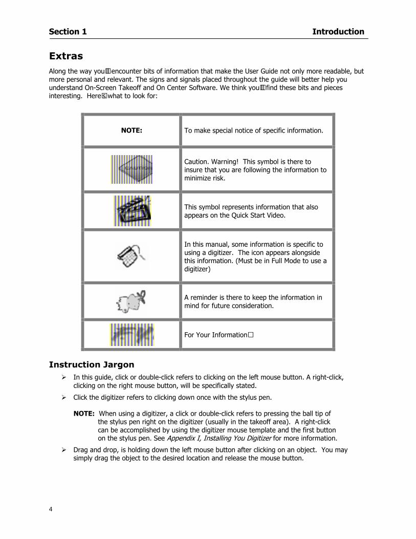
Section 1 Introduction
4
Extras Along the way yoursquoll encounter bits of information that make the User Guide not only more readable but more personal and relevant The signs and signals placed throughout the guide will better help you understand On-Screen Takeoff and On Center Software We think yoursquoll find these bits and pieces interesting Herersquos what to look for
NOTE
To make special notice of specific information
Caution Warning This symbol is there to insure that you are following the information to minimize risk
This symbol represents information that also appears on the Quick Start Video
In this manual some information is specific to using a digitizer The icon appears alongside this information (Must be in Full Mode to use a digitizer)
A reminder is there to keep the information in mind for future consideration
For Your Informationhellip
Instruction Jargon
In this guide click or double-click refers to clicking on the left mouse button A right-click clicking on the right mouse button will be specifically stated
Click the digitizer refers to clicking down once with the stylus pen
NOTE When using a digitizer a click or double-click refers to pressing the ball tip of the stylus pen right on the digitizer (usually in the takeoff area) A right-click can be accomplished by using the digitizer mouse template and the first button on the stylus pen See Appendix I Installing You Digitizer for more information
Drag and drop is holding down the left mouse button after clicking on an object You may simply drag the object to the desired location and release the mouse button
Section 1 Introduction
5
Typographic Conventions
The following are typographical conventions to be aware of when reading this guide
Menu items you are instructed to choose appear in a different typeface with the greater than (gt) symbol separating each menu level For example if you are instructed to select the Open command in the File menu it appears as File gt Open If you are instructed to select the Save As command from the File menu it appears as File gt Save As
Helpful hints or information about the topic are provided throughout the document They will be labeled lsquoNOTErsquo (all caps and bold font to catch your attention)
Several topics will have more detailed steps outlined in either another section of the user guide or in the Appendix They will always be referenced and italicized For example ldquoSee Editing Conditions for more informationrdquo
Help File In combination with this User Guide and the Quick Start video (Help gt Watch Quick Start Video) the Help File will also be a great resource for product information and application There are additional resources available on the website at wwwoncentercom or Help gt Visit our Website Follow these instructions to open the Help file
1 Select Help gt Help Topics
2 This will open the On-Screen Help File
Hide and Show Buttons
The Hide and Show buttons will either remove or display the Topics panel in the Help dialog
Back Button
The Back button takes you back to the last help page you viewed It will be available only if you have navigated through multiple pages in the help file
Print Button
Clicking will print the topic displayed This is helpful if the instructions to follow are long and you prefer to work on a full screen
Options Button
The Options button will allow you to pick from a list of commands to help you navigate the Help file
Section 1 Introduction
6
Contents Tab This tab provides a quick breakout of the Contents of the help file It should be used like the Table of Contents of a book Simply double-click on the book icon to open the chapter Then click the desired page icon to display the relevant information
Index Tab This tab allows you to locate a specifically indexed topic This should be used as you would a book index Begin typing a word in the index entry field and the system will automatically move within the list to the entries closest in spelling to your word(s) Begin typing the topic word to access it in the list quickly
Section 1 Introduction
7
Search Tab This tab works like a word find It allows you to search for any word contained in the Help file Type the
word you are looking for in the lsquoType in the keyword to findrsquo field Click A list of topics containing that word will appear Scroll through the list and double click on the topic you want displayed
Section 2
8
Setup
This section will
Let you know what system requirements you will need to have in place
Recommend components that work well with the software
Help Full Mode users install a digitizer
Section 2 Setup
9
Minimum System Requirements To use On-Screen Takeoff your computer must meet the following minimum system requirements
An IBM PC or 100 compatible computer with a Pentium II or faster Intel processor
Memory Requirements 200 MB of available hard-disk space and256 MB RAM (128 MB preferred)
Windows 2000 SP4 and Windows XP SP2 256 color video card Super VGA display card Mouse 15-inch monitor
While these are the minimum system requirements Windows places heavy demands on your systems resources The more available memory in your computer the faster and more efficient On-Screen Takeoff will operate
Recommended Components
For the best performance we recommend the following components
Pentium III or faster processor
512 or more of RAM
12X speed CD-ROM or better
17-inch monitor or dual monitors Graphic adapter with 128 MB or more VRAM Sound card and speakers installed
NOTE In order to utilize the Training Videos you must have a sound card and speakers installed
Compatible File Formats The resolution in electronic plans does not need to be more that 200 DPI (Dots per Inch) The preferred file format is a black and white TIF (Group4) On-Screen Takeoff recognizes image files with the following extensions
File Extensions View Mode Lite Mode Full Mode TIF X X X PDF X X X OSE X X X JPG X X X CPC X X X CAL X DGN X DWG X DXF X OSP X PLN X PLT X
Section 2 Setup
10
NOTE Use the following image types for best results
Convert to TIF
The converted files will be stored in a folder with the name of the current On-Screen Takeoff project Since the conversion can be very time consuming you should only select this option if you really intend to convert vector files to TIF
1 Select File gt Project Properties
2 In the Pages Field add your image See Section 5 Establishing Project Setting Adding Pages
3 Click
4 Then select the page with the drawing you wish to convert
5 Click
Installing Your Digitizer The following instructions are a quick start to installing your digitizer For more specific information please reference Appendix I Installing Your Digitizer at the end of this guide
Connecting Your Digitizer
Upon receiving your digitizer (either a GTCO or another brand) you will need to connect it to your computer
1 Lay the digitizer out flat
2 Connect the Stylus to the digitizer
3 Plug in the power supply
4 Plug the interface cable into the digitizer
5 Plug the other end of the interface cable into the computer
NOTE On-Screen Takeoff is compatible with any tablet that is WinTab compatible
Digitizer options are only available in Full Mode If you are in View or Lite Mode and would like
to use this feature click from the main toolbar to purchase the upgrade
Section 3
11
Toolbars and Menus
This section will
Introduce the program toolbars
Familiarize you with On-Screen Take Offtrade Menu options
Section 3 Toolbars and Menus
12
Toolbars On-Screen Takeoff is equipped with several helpful toolbars for application efficiency See Appendix II Toolbar Item` Details for a detailed description of each toolbar item Individually the toolbars may be displayed moved docked reshaped or hidden from view You can also create costume toolbars to fit your needs
Main Toolbar
Tool Toolbar
Zoom Toolbar
View Toolbar
Navigate Toolbar
Takeoff Toolbar
Image Toolbar Viewing Toolbars Toolbars are displayed on the screen and will be consistent on each tab or page (Some toolbars or toolbar items will be in an inactive state if they donrsquot have a supporting element in the application)
1 Select View gt Toolbars and select the appropriate toolbar name
OR
2 Right-click on a toolbar region of the screen
3 Check the toolbars you want to display
Section 3 Toolbars and Menus
13
Moving Toolbars The toolbars may be positioned anywhere on the screen you wish This feature is provided to allow the flexibility for positioning the toolbars so they are out of your way yet handy for use
1 Click on an edge of the toolbar holding down the mouse button drag it to its new position
2 Release the mouse button to set it in place
NOTE If the toolbar is dropped anywhere other than a screen edge it will become free floating This feature is especially handy when using multiple monitors
Docking Toolbars The toolbars can be docked to any of the screen edges
1 Click on the title bar of an undocked toolbar
2 Drag the toolbar to any location on the screen
Hiding Toolbars
1 Select View gt Toolbars and select the toolbar you wish to remove from the screen
2 Right-click on the toolbar or dock bar areas
3 A floating toolbar can be closed by clicking on the in the upper right corner of the toolbar
Resizing Toolbars Only undocked (floating) toolbars may be resized
1 Position the mouse pointer over an edge
2 Click and drag
3 The toolbar can be resized as desired
Customizing the Toolbars You may rearrange or delete buttons within a toolbarrsquos display or you may move buttons from one toolbar to another If you find that you use a few tools over and over you may want to group them within a single toolbar for convenience On-Screen Takeoff gives you the flexibility to customize your takeoff environment
1 Select Tools gt Customize The Customize dialog will open
2 With the dialog open click on a toolbar button and drag buttons from one toolbar to another or a new location within the same toolbar
3 To add a button without altering another toolbar click on the Commands tab of the Customize dialog and drag the appropriate symbol from the Buttons section to a toolbar
4 To remove a button drag it to within the takeoff area of the application
Section 3 Toolbars and Menus
14
Menus
Section 3 Toolbars and Menus
15
Digitizer Menu
Section 4
16
Features
This section will
Show you how open On-Screen Takeoff
Describe the On-Screen Takeoff environment
Teach you how to navigate pages
Section 4 Features
17
Start On-Screen Takeoff
1 On your desktop double-click your On-Screen Takeoff icon
2 The application will open
OR
3 Left-click on the Start button on your computerrsquos toolbar
4 Scroll up to Programs gt On Center Software
5 Highlight On-Screen Takeoff and click On-Screen Takeoff will open On-Screen Takeoff opens to an untitled blank project The Image view of the screen will be a blank page
Two blank dock bars the Pan dock bar and the Takeoff dock bar appear at the left side of the screen Along the bottom the Status bar displays user status or context-sensitive messages as well as paper size and current zoom percentage of the plan sheet on screen The menu bar and several task specific toolbars are located at the top of the screen
NOTE All toolbars and dock bars may be accessed to view or hide through View gt Toolbars on the menu bar
Section 4 Features
18
Quick Start Video When On-Screen Takeoff opens you will be given an option to watch the Quick Start video (recommended) or start the program without watching the video
The 20 minute video will demonstrate key program functionality and allow you to view application instruction for enhanced learning
If you would like to watch the video click If you prefer to get started without
the video click If you have already viewed the video click the lsquoDo not show this message againrsquo box to prevent this dialog from appearing each time you open the program
NOTE If you decide later that you would like to watch the Quick Start video go to Help gt Watch
Quick Start Videos
On-Screen Takeoff Environment The On-Screen Takeoff environment acts like your drafting table allowing you to work on several sheets of plans at once and to reference at a glance the entire drawing and your position on that drawing while giving you the power of a computer to track analyze print and export your takeoff quantities and plans
The screen is bordered at the top by the Menu bar with pull-down menus and at the bottom by the Status bar which indicates current user status plan page size and current zoom percentage of page The largest portion of the application screen will be your takeoff area bounded on the left (by default) by two dock bars and on the top by several toolbars
In the takeoff area you may view your project plans (images) andor takeoff objects the takeoff list with quantities the worksheet or a legend of your condition list
The main window of On-Screen Takeoff has three tabs located at the bottom left allowing for quick change between Image Takeoff or Worksheet views Select the desired view option on the toolbar and it will automatically open on your screen
Section 4 Features
19
Image View
This view shows the plan file andor takeoff conditions drawn from your plans
Takeoff View This view displays the height if applicable and quantity breakdowns of your conditions according to result types indicated (eg linear feet square feet or count of items) for zones pages and the project as a whole It also displays notes per condition
Section 4 Features
20
Worksheet View This view displays the condition and quantity in units of measure specified in the first results field of the Results tab in the Condition dialog and allows the user to enter amounts for material labor and subcontractor takeoffs
NOTE When in the Worksheet view tab out the field then save This is keep all the values saved
Navigating On-Screen Takeoff
Auto Scrolling When creating linear areas or zones On-Screen Takeoff will automatically scroll the image view when necessary It will move as your mouse or digitizer moves beyond the edge of the current view
Changing Pages
1 Select View gt Next Page Previous Page or Go To Page (specify page number for the Go to Page option)
2 You may also select the corresponding arrows for these options from the Navigate Toolbar The
drop down arrow in the Page field will list the pages The and arrows will take you to the
previous or next page The and arrows will take you to the first or last page
OR
Section 4 Features
21
3 Or press Ctrl G for the Go To Page dialog
Hot Links Hot links allow you to move quickly from one drawing to the pertinent area of another drawing A hot link is handy when viewing enlarged areas of a page and needing the ability to jump back to a reference page
1 Select Tools gt Hot Link
OR
2 Click from the Tools Toolbar
3 Click on the page where you want to set the link The Hot Link dialog will open
4 Using the current page display on the Navigate Toolbar access the pull-down menu of pages by
clicking on the arrow at the right
5 Select the page for your link (You may also choose View gt Go to Page and select by page number)
6 Manipulate the view using the zoom tool and the scroll bars
7 Click
8 After joining a hot link to another page the hot link arrows in the Navigation Toolbar will become active
9 Move a hot link to another location on the page by clicking then click and drag the hot link image anywhere on the page
Section 5
22
Projects
This section will
Help you create settings important to your projects
Explain how On-Screen Takeoff works with your electronic or paper plans
Section 5 Projects
23
Project Template Files You can begin your project with a template Templates allow you to take advantage of conditions and settings used with previous projects
On-Screen Takeoff templates contain condition lists and established layer separations from previous projects you have created You may also use the sample templates provided with On-Screen Takeoff as a great starting point All aspects of the templates may be adjusted for a new project
1 Select File gt New and click the OK button
2 From the New dialog box choose the template that best fits your project
3 The conditions for this template will appear in the Takeoff Dock bar and the Project Properties dialog will open asking for further information
4 Use File gt Save or File gt Save As to rename and save your new project
Saving a Project as a Template File You can save your condition properties and layers as a template for future projects
1 Select File gt Save As
2 Enter a name for your template and select On-Screen Takeoff Template Files (tpo) from the Save As type field of the dialog (click on the down arrow to select)
3 Click the OK button to accept and close the dialog Modifying a Template File Follow these steps to modify an existing template file if you need to change or add conditions andor layers
1 Select File gt Open
2 Navigate to your Projects directory
3 In the File Type drop-down select On-Screen Takeoff Template files (tpo)
4 Choose the On-Screen Takeoff template file you would like to modify and click the OK button
5 Make appropriate changes
6 Save and close file
The On-Screen Takeoff template files cannot save takeoff information
Section 5 Projects
24
Opening an Existing Project File 1 Select File gt Open
2 Navigate to the desired file location
3 Click the Open button
NOTE If your latest changes to a project file have not been saved On-Screen Takeoff will ask
you whether you would like to save the file and gives you the option of canceling the operation
Creating a New Project
1 Select File gt New
2 For a blank untitled project click
3 At this point the Project Properties dialog will pop-up for more information about your takeoff
NOTE The following are important to keep in mind when beginning a new project
At the start of your project fill out the Project Properties settings to establish the name for all printed output from your project set the default page size and scale for your plans number and names of different pages within the project and locations of electronic drawings
Scale settings can significantly affect quantity outcomes Be sure to set the scale for each page of drawings before beginning condition takeoffs
When using a digitizer remember to make a mark with a pen or pencil in the upper left and lower right corners of the first sheet of the paper plans to delineate the takeoff area for that sheet You can then set the takeoff area on On-Screen Takeoff using your marks
Save your project before you begin taking off any conditions On-Screen Takeoff will write a back-up file using the same file name
Remember the Undo feature If you make a mistake select Edit gt Undo and reverse the process step by step
Section 5 Projects
25
Project Properties
You can either set your Project Properties when you create a new takeoff or once your project file is saved under the appropriate name
1 Select File gt Project Properties the Project Properties dialog box will appear
2 Type in the name of your project to appear on printouts Use the backspace andor delete keys to edit the name as necessary
3 Press the Tab key to move to the Default Image Size option or click within the Image Size box You may click on the arrow at the right for the pull-down menu of page size options or you can use the down-arrow key on your keyboard to scroll through the list to the appropriate selection
4 Press the Tab key to move to the Default Scale option Select a scale by using the drop down arrow If your scale is metric you will need to click in the box next to Metric to convert to that measurement
5 Establish the number of pages for your project plans And load image files See Adding Pages to
Your Project
Adding Pages to Projects Individual Electronic Plans
1 Click on in the Project Properties dialog
2 In the Add Images dialog use the drop down arrow to navigate to the appropriate directory and folder containing your image
3 Select the file so that it displays in the File name field then click The file will display by name and path in the Image File field in Project Properties dialog
4 Click to accept and your project will automatically open
5 Save your project with the new settings by selecting File gt Save
Section 5 Projects
26
Electronic plans scanned from blueprints (as opposed to blue lines) will display as white lines on a black background and are difficult to read on your computer screen Select Image gt Invert and the colors will invert to black on white
You may have noticed the Page column in the Project Properties dialog Generally plan images occupy one page and 1 will be listed in the column indicating Page 1 of your plan file If you import a multi-page TIF a plan file containing more than one page of plans they will import as separate pages and each successive page will be indicated under the Page column as 1 2 3 etc of the plan file
Group of Electronic Plans You may add all the electronic plan files from a particular source (for example from a CD) by using the Auto Add feature
1 Click the button in the Project Properties dialog
2 Browse until you find the appropriate directory and folder containing your plan images
3 Click on any file displayed within your target folder so that the file name appears in the File name box of the Auto Add dialog
4 Click The image paths and file names will be recorded into the project properties arranged alphabetically
5 Click to accept your choices and your project will automatically open
6 Save your project with the new settings by selecting File gt Save
To load Dodge Plans into your Project Properties see Appendix IIi Loading Plans from a Dodge CD
Paper Plans On-Screen Takeoff makes it easy for Full Mode users to perform quantity takeoffs from paper plans using a digitizer
1 Add pages by clicking until you have the number of pages initially in the project
2 Name each page by clicking within the Title area and typing the name
3 Click to accept your choices and close the Project Properties dialog
4 Save your project with the new project properties settings by selecting File gt Save
Section 5 Projects
27
Setting Up a Drawing Template On-Screen Takeoff provides the convenience of using the same work surface for both digitizer and mouse to allow the user to draw conditions and then edit settings of the project or add or change conditions without breaking stride A mouse pad template included with the program defines the area of the digitizer in which use of the stylus or cursor will be recognized as mouse movement as opposed to drawing movement
1 Place your stylus on On-Screen Takeoff
2 Placing the template identifies the location mouse movements will be recognized by the program
Before placing the template the template must be applied to the digitizer surface This may have been done during the installation of your digitizer We suggest attaching the template to the lower right corner of the digitizer surface about one inch inside the grid area
3 Select Digitizer gt Place Template
4 Follow the instruction prompts on the screen clicking first on the target symbol at the left of the On-Screen Takeoff box on the template then on the target at the right
Setting Takeoff Area Before you can begin taking off a drawing you must define the drawing area on the digitizer This requires defining an area that will include all objects on each drawing of your plans As you add pages to your takeoff the same area of the digitizer will be active
1 Secure the plans to the digitizer with tape or a set of clamps
2 With a pen or a pencil mark the upper left corner and the lower right corner of the first page in your set of plans
3 Select Digitizer gt Set Takeoff Area
4 Click each mark with the stylus pen as prompted
5 Verify the active area of the digitizer by looking at the image size located in the lower right corner of your screen
If you close the program before the takeoff is complete you will need to reestablish the takeoff area before you can add additional condition quantities
Electronic plans appear on your computer screen eliminating the need to set a takeoff area You simply drag your mouse across the conditions you wish to takeoff The conditions will be highlighted and quantities will be totaled instantly Electronic plans are available through a variety of services For information contact an On Center Software account manager
Section 5 Projects
28
Setting Scale for Specific Pages You may set the scale in each page view separately This will override the default scale setting in Project Properties for that page Setting the correct scale for the drawing before taking off quantities ensures accurate calculations Be careful to check the scale for each drawing in your project before doing takeoffs
1 Display the page you want to set select Edit gt Set Scale
2 Use the drop down arrow to select a scale that will be applied to that page
3 Click
OR
4 Access the pull-down scale settings on the Navigate toolbar
NOTE As you draw objects notice that the drawn object is similar in width to the object on your plans If it is not the scale set may not be correct
Calculating Scale You may calculate scale according to a known measurement between two points either with a digitizer or on electronic plans
1 Select Edit gt Calculate Scale using Image or Edit gt Calculate Scale using Digitizer
2 Follow the instructions in the related Calculate Scale dialog box You will be asked to click on the first and second points then to enter the dimension for that distance
3 The scale will be recalculated for the displayed page and the Scale display on the Navigate toolbar will show the new scale
Section 6
29
Conditions and Takeoff
This section will Draw Conditions to Takeoff Plan Quantities
What Zones will do to help your takeoff process
Discuss the ins and outs of Takeoffs
Section 6 Conditions and Takeoff
30
Creating Conditions
If you are starting a new project from scratch you will need to create conditions to takeoff quantities such as floor areas wall lengths and corner bead counts If you are using a template you will have several pre-designed conditions already listed on the Takeoff dock bar However you may want to change the characteristics of some conditions or create additional conditions for a particular project
1 Right Click within the Takeoff dock bar Select New gt Condition
Or
2 From the Takeoff dock bar Click (if the buttons are not showing right-click in the Takeoff dock bar area and select Show Buttons from the pop-up menu) The New Condition dialog appears
3 Select the condition type (Linear Area Count or Zone) from the pull-down menu accessed by the
down arrow next to the Type option
4 Press Tab or use the mouse (or stylus) to move to Name and enter a name for your condition
5 Specify the desired condition attributes See Condition Attributes for more detail
6 Click for condition to apply
Section 6 Conditions and Takeoff
31
Condition Attributes Each condition type will have related attributes to select or specify within the General and Advanced tabs of the New Condition dialog Once a condition has been used to takeoff a quantity from your plans certain attributes cannot be changed
All conditions allow the user to specify color and fill pattern for the object drawn
Linear Conditions
General Specify width and height by feet and inches Specify pitch in inches up to the nearest thousandth of an inch if applicable
Advanced Specify rounding for object quantities and droprun default length for electrical or plumbing drops at the ends of lines Select Connect to have lines connect at the corners where one line of the condition ends and another begins (and indicate Tolerance for the featurersquos activation as distance between the ends of two lines) Choose Trim to have lines automatically trim to a line being crossed Choose Curve to draw a curved line
Follow these examples for inputting feet and inches For 7 feet 6 inches type 706 for 13 feet 7 inches type 1307 For 20 feet type 2000
Section 6 Conditions and Takeoff
32
Area Conditions
General If needed you can specify the thickness (in inches) andor pitch (in inches)
Advanced Specify rounding for object quantities Choose to display an adjustable grid within the area and indicate matrix cell dimensions
Section 6 Conditions and Takeoff
33
Count Conditions
General
Specify height and indicate the size (in inches) and shape (square circle triangle rectangle or opening) of the count object as it will appear on screen
Advanced Count conditions have advanced attributes These options are available for all shapes except for openings
Zone Conditions Zones allow you to subdivide condition quantities making it easier to modify and complete jobs in phases They can be used at the end of a takeoff to isolate a group of condition quantities that are in different areas of the takeoff
Zones can also be used to break a takeoff into multi-phases and can even be used to isolate quantities while a job is in progress to group the amount of work that has been completed to date They can be applied to one or multiple pages in your plans automatically calculating the takeoff quantities for each zoned area
Section 6 Conditions and Takeoff
34
The zone feature is only available in Lite and Full Mode If you are in View Mode and would like
to use this feature click from the main toolbar to purchase the upgrade
Condition Notes A Note tab is provided for comments regarding the condition These notes will display on the Takeoff List report and will import into Quick Bid
Section 6 Conditions and Takeoff
35
Condition Results The Results tab of the New Condition is based on condition type Initial settings default to linear feet (LF) for linear conditions square feet (SF) for area conditions and count of items (EA) for count conditions and zones The first of the results fields will display for the condition items in the Takeoff dock bar area All results will display in worksheets and Takeoff List reports as well as in an Excel spreadsheet after being exported
Copying Conditions You may use the condition attributes from a condition yoursquove already created for any future conditions of the same type
1 Click on a condition to select it
2 Click the Copy button from the toolbar
OR
3 Right-click in the Takeoff dock bar area and select copy
4 A new condition will appear in the list with the same condition attributes as the previous condition but with the quantities zeroed
Editing Conditions Once you have copied a condition you might want to change several attributes You can also edit an existing condition to fit any updated needs
1 Highlight the desired condition on the Takeoff dock bar
2 Click the Change button
OR
3 Double-click on the condition you wish to edit to bring up the Change Condition dialog
NOTE The Change Condition dialog differs from the New Condition dialog only in that if takeoffs
Section 6 Conditions and Takeoff
36
have been performed in your project with this condition you will not be able to change the type of condition or certain properties under the advanced tab of the dialog box
Deleting Conditions 1 Click on the condition in the Takeoff Dock bar area
2 Click the Delete button on the toolbar
OR
3 Right-click and select Delete from the pop-up menu
All takeoff associated with the deleted condition will be deleted immediately and permanently
Organizing Project Conditions Within your project you can create folders andor sub-folders for different types of conditions You may even want to create a folder containing conditions with reset values
To get started organizing your conditions make sure you are viewing the condition tree (right-click in the Takeoff dock bar area and select Show Tree)
Creating Folders and Sub-Folders 1 Right-click in the Takeoff Dock bar area
2 Select New gt Folder from the pop-up menu
Copying Folders
1 Click on the folder and click Copy on the toolbar
2 All copied conditions within the new folder will have values reset to zero
Renaming Folders
1 Click on the folder
2 Right-click and select Rename from the pop-up menu
3 Enter a name for your folder and click the Enter button
Changing Condition Order
You may move conditions up or down in the condition list of the Takeoff dock bar to suit your project needs
1 Select the condition you would like to move by clicking to highlight it
NOTE When you are ready to move the highlighted conditions be sure that you start
moving using the last condition chosen That condition will have a highlighted boarder
Section 6 Conditions and Takeoff
37
2 Drag and drop any the condition from one place to another in the list You may also move a condition to another folder on the list in this way
Drawing with Conditions Snap Angles Set up snap angles to prevent lines from appearing jagged Snap angles are commonly set at 15deg and shift snap angles at 0deg
1 Go to Tools gt Options Options dialog appears
2 Under the General tab make the desired settings
3 Click to save the settings As they are drawn lines will snap to the set degree
Drawing a Linear Object 1 Select a condition from the Condition List in the Takeoff dock bar
2 Move the cursor into the Image takeoff area of the screen you will see the cursor display as crosshairs
3 Click and hold left mouse button then drag mouse to draw a line
4 Release mouse button to set line
Section 6 Conditions and Takeoff
38
5 Repeat steps for further lines
Continuous Mode This feature allows you to draw an object that has connected lines
1 Click the icon from the Takeoff toolbar
OR
2 Go to Tools gt Continuous Mode
3 Follow steps 1-3 from Draw a Linear Object
4 Click at each point of intersection The object will be connected
5 Double-click after making the final point to set the lines
Drawing a Curve To draw a curved line the Curve option must be checked under the Advanced tab of the Condition dialog
1 Click where you want to begin the curve and drag in a straight line to the position for the other endpoint of the curve
2 Click on the line to select it Handles in the shapes of small squares will appear at either end of
Section 6 Conditions and Takeoff
39
the line and in the center of the line
3 Move the cursor over the center handles until the cursor becomes a two-way arrow
4 Click and drag in the direction of the curve bending the line as you move the cursor Release to set the curve (The line you began with will disappear)
Draw a circle by drawing two curved lines connected
Drawing an Area Object Area conditions are drawn similarly to continuous mode lines You may trace any number of adjoining walls at different angles to complete your area takeoff
NOTE When drawing an area do not intersect the perimeter or line of the object you are drawing
1 Click at each point
2 Double-click when yoursquove returned to your starting point
3 The area will be filled with the pattern set for that condition
NOTE The simulated circle will be good enough for you to be able to make a bid
To create a circular area click from point to point with very short distances in between points simulating a circlersquos perimeter Double-click after setting the last point to set the area
Section 6 Conditions and Takeoff
40
Grid Options Grids give you an added advantage when installing materials such as tiles Use this feature to get a count for how many tiles are needed for an area
1 Double-click on an area condition in the Takeoff dock bar to open its Condition dialog
2 Click on the Advanced tab to show its options
3 Check the box next to Grid by clicking in it
4 Indicate the dimensions of the cell matrix in inches (For example 200 x 400)
5 Under Results tab choose each (EA) for one of the results fields This will tabulate a number of grid cells (including partial grid cells) in area
6 Click to save your settings
7 Use the Move Grid and Rotate Grid features in the Tools menu to manipulate the grid as desired
Grid Calculation
1 Go to Tools gt Options menu
1 Specify if On-Screen Takeoff automatically should Calculate Grid Position
2 If AreaGrid Size is selected On-Screen Takeoff will calculate the number of items needed to fill the grid based on grid demintions
3 Click to accept and close the dialog
To move a line at any angle (regardless of default setting) press the Shift key while moving the mouse
Section 6 Conditions and Takeoff
41
Backout Mode This feature allows you to take out part of an area and deduct that amount of square footage
1 Select Tools gt Backout Mode
2 Outline the are you want backed out as you would when drawing a regular area object (see Drawing an Area Object)
3 The outlined area will clear and quantities will be recalculated
NOTE The perimeter of the backout area will be added to the LF quantity for that condition
Drawing a Count Object Square triangle rectangle and circle shaped count objects can easily be placed on images
1 Select the condition
2 Click in the location where you want the object to appear
3 To place an opening-shaped count item like a door or window you must click over an existing linear object such as a wall
4 On the Results tab you can change the height properties to give you the result you need
5 If Backout is checked on the advanced tab for each count opening the opening-shaped count item will back out a corresponding section of the linear object
Opening shaped count items are sized at 3rsquo0rdquo by default
Drawing a Zone Zones are drawn in the same way as area objects and may be any polygonal shape You may trace any number of adjoining walls at different angles to complete the zone perimeter
1 Click at each point
2 Double-click when yoursquove returned to your starting point
Section 6 Conditions and Takeoff
42
Selecting Objects
1 Use the Select Tool to select objects
You can also select all objects that correspond to a condition
1 Click on a condition to select it
2 Right-click and choose Select All
3 All objects with this condition will be highlighted with squares as an outline
Moving and Resizing Objects Linear
1 To move or resize a linear object click anywhere on the line to select it
2 To move the line position your pointer over the center handles When the mouse is positioned over the handles you will see a two-way arrow You will only be able to move the line in the direction of the arrows
3 Drag the line to a new position
4 Clicking and dragging the handles on the ends of the line will allow you to lengthen or shorten your line
Area and Zone
1 To move an area object or zone in its entirety click and drag it to its new position
2 Grabbing a handle at a corner or intersection of the object will allow you to adjust and change its perimeter
Section 6 Conditions and Takeoff
43
Count 1 To move a square circle rectangle or triangle shaped count object click and drag
2 Click and drag an opening shaped count object along the length of the linear object to the desired position then release
NOTE An opening shaped count object may not be moved from its associated linear condition object however it may be moved up and down the length of the linear object
Layers On-Screen Takeoff allows you to sort and separate your takeoff objects within the same job and on the same page On-Screen Takeoff gives you this flexibility through the use of layers
By assigning different conditions to different layers (for example differentiating between floors ceilings and walls) you can choose to view all layers or turn off certain layers to display and print the remaining groups of conditions only You may also remove the background image of electronic plans add text and hot link symbols or print only your condition takeoffs
Layers are only available in Full Mode If you are in View or Lite Mode and would like to use this
feature click from the main toolbar to purchase the upgrade Default Layers
On-Screen Takeoff begins every project with three default layers Image Annotation and Default The Image layer holds the electronic plan files you may have in your project The Annotation layer possesses all text notations highlighting and hot links in the project The Default layer will appear in the Condition dialog when creating or editing a condition (listed in the takeoff dock bar) Conditions are assigned to the Default layer unless otherwise specified by the user
Creating Layers To assign a condition to a layer other than the default layer you must first create additional layers for your project
1 Select View gt Layers to open the Layers dialog
2 Click An unnamed layer will be added
3 Click within the empty box and type a name for your layer (for example Wall)
4 New layers are added as active layers The adjacent box under the Show column will be checked
Section 6 Conditions and Takeoff
44
Assigning a Layer to a Condition 1 Open the Condition dialog box by creating a new condition or editing an existing condition
2 Under the General tab click on the down arrow in the Layer field to display optional layers
3 Select the desired layer for the condition Only the Default layer and layers you have added will be displayed
4 Click
View and Hide Layers
1 Select View gt Layers
2 Under the Show column check the box to view or remove the check (by clicking on it) to hide the specific layer
3 Click to accept and close the Layers dialog
Section 6 Conditions and Takeoff
45
Assigning Text to a Layer When adding text to an image On-Screen Takeoff has the capability to assign the text to a specified layer
1 Select the Text Tool
2 Click at the point you want to place your text
3 Type in your text using the Enter key for line breaks
4 Click the drop down arrow next to the Layer field and select the desired layer
Section 7
46
Printing and Exporting
This section will
Printing options and procedures
Exporting data by copying and pasting
Exporting quantity results to Excel spreadsheets
Section 7 Printing and Exporting
47
Print Setup On-Screen Takeoff allows the user to print the image takeoff list and worksheet
1 Select File gt Print Setup The Print Setup dialog will open
2 Select a printer or leave the default selection listed (change from the default printer displayed by clicking on the down arrow at the right of the field)
3 Indicate page size and printer tray option (Source) Access page size options by clicking on the
down arrow at the right of the field
4 Choose Portrait or Landscape orientation
5 Click to accept and close the dialog
Printing Images The image area can include the electronic plans the takeoff objects added text and hot links To print a subset of these (for example just the takeoffs without the plans or the added text and hot link symbols) hide layers that you do not want to print (see Section 6 View and Hide Layers) When you are printing your images every page will show the scale of the takeoff you are printing
1 Click on the Image tab to display the area of your project
2 Select File gt Print (or Ctrl + P)
Section 7 Printing and Exporting
48
3 Select the desired view (What to print) and the Image Range
4 Click The second Print dialog will open
5 Change settings accordingly or click if you accept the default settings
Printing Takeoff Lists and Worksheets In Takeoff Lists and Worksheets you may hide columns to print only certain results or adjust column widths to fit the report within the page size selected
1 In Takeoff List or Worksheet view move your cursor to the right side of the columnrsquos title bar the cursor will display as a two-way arrow
Section 7 Printing and Exporting
49
2 Click and drag to adjust the width of the column Holding the mouse button you may
slide the title bar under the title bar to its left to hide the column completely
3 Select File gt Print or press Ctrl + P to access the Print dialog
4 Indicate desired printer and choose the number of copies
5 Click to print and close the dialog
When printing the condition list we suggest printing in landscape
To reset to the default column widths double-click on the right border of a column heading will reset the column to its right (or previously to its right before being hidden)
Print Preview 1 Select File gt Print Preview
2 Use and to vary your view 3 If viewing an image choose current full or scale view to see how it displays
4 For printed outputs that cover more than one page use and to view adjacent pages or click on the down arrow next to Page field and select the page you want displayed
Exporting Using the CopyPaste Feature You may copy all the data or sections from the worksheet and the takeoff list view in On-Screen Takeoff and paste it into another application When pasting into Excel the cell layout will be maintained
1 Highlight the areas you wish to paste Click and hold the left mouse button down as you drag the cursor over the area to be selected then releasing the mouse button
OR
2 Select the entire takeoff list quickly click on the left On-Screen Takeoff column header and hold and drag the cursor across the remaining column headings
The number of pages for the view selected will display in the lower left-hand corner The zoom percentage that applies to the view will be displayed in the lower right-hand corner next to page size of the drawing
Section 7 Printing and Exporting
50
3 In the worksheet view you may highlight rows by clicking on the numbered buttons to the left of each row clicking and dragging across column headings or clicking and dragging over individual cells in the worksheet
Click anywhere in the appropriate view to deselect the area
4 Once your selection is highlighted you may select Edit gt Copy or Ctrl C from the keyboard 5 On your monitor switch to the application into which you want to paste your selection 6 Select Edit gt Paste in the new application or simply press Ctrl + V to paste
The colored keys for conditions cannot be pasted
Using the Export Feature You may export condition quantities to specified cell location within an Excel worksheet file Cell target locations are assigned in the Results tab of the condition dialogs on the Export line relating to each quantity measurement type
On-Screen Takeoff will export takeoff quantity results for up to three different quantity types that you specify For instance you may want to know the number of square feet in a ceiling area as well as the number of linear feet in its perimeter
Section 7 Printing and Exporting
51
1 Bring up the Condition dialog by double-clicking on a condition in the takeoff dock bar or by
selecting the condition and clicking
2 Click on the Results tab to access its fields The default quantities for the condition type will display
3 For each results field click on the arrow to access the pull-down menu and select the appropriate quantity (for example SF LF EA etchellip)
4 Have your Excel spreadsheet opened and saved in a file
5 Specify the Excel spreadsheet cell locations where you want the results to go
6 For a cell in the first sheet of your spreadsheet type in the cell address (eg a1) Case is not important
7 For a cell on a successive sheet of your spreadsheet type in sheet the number followed by a comma and the cell address without any spaces (eg sheet2a1) Case is not important
8 Click
9 Select File gt Export gt Condition Qty to Excel
Section 7 Printing and Exporting
52
10 Browse to the location of the Excel spreadsheet file click file to select it
11 Click to export On-Screen Takeoff results to specified cell locations in the Excel file When you return to the Excel application you will see the values have been added to the specified cell locations in your spreadsheet
12 Save your Excel file
Exporting Worksheet to Excel
1 Assign condition quantities you want to export
2 Open saved Excel spreadsheet file to which you will be exporting
3 From On-Screen Takeoff Select File gt Export gt Worksheet to Excel
4 Browse to the location of the Excel spreadsheet file click file to select it
5 Click When you return to the Excel application you will see the values from the Worksheet Tab have been added to your spreadsheet
6 Save your Excel file
Exporting Takeoff to CVS 1 Assign condition quantities you want to export
2 Open saved Excel spreadsheet file to which you will be exporting
3 Click the Takeoff Tab in the project you want to export the information
4 Select File gt Export gt Takeoff to CSV
5 Browse to the location of the CSV spreadsheet file click file to select it
6 Click the Save
NOTE CSV files can be opened in Excel Lotus Access etc One may consider this option more of a ldquodumprdquo into a file
The Excel application must be active (it may be minimized on the application bar) with the target spreadsheet open in the application Otherwise an error will occur with the export operation that will affect both the On-Screen Takeofftrade file and the Excel spreadsheet
Section 8
53
Advanced Features
This section will
Some special features of working with condition objects in the takeoff area
Details of advanced options for conditions
Advanced features of the Project Properties dialog
Section 8 Advanced Features
54
Features to Use with Objects Roping Feature You can move copy or delete using this feature Using the Select tool (the pointer) you may select several objects at once by clicking and dragging an outline around the objects then releasing the mouse button Roping may select either objects completely within the outlined area (inclusive) or objects both within and touched by the outlined area (touching) Specify your roping preference under Tools gt Options
1 Click and hold the mouse button at a point on the screen near the objects to be selected and drag to surround the objects with an outline
2 Release the mouse button The objects will be selected
3 You may now
Move the group around on the page by clicking within the group dragging the mouse and releasing the button to place the objects
Delete the group of objects by clicking the Delete key or
Copy and paste by pressing Ctrl C to copy the group then Ctrl V to paste it The pasted copy of the grouped objects will appear slightly offset from the original objects
Section 8 Advanced Features
55
Applying a DropRun Count
Use the droprun feature when calculating quantities to take into account the drop or run of a linear condition such as electrical lines or plumbing pipes Drop or run lengths may be added separately to any linear condition on screen while a default droprun length may be indicated for a condition as a whole
1 Select the desired linear condition from the Condition List in the Takeoff Dock bar
2 Click the Change button in the toolbar to open the Change Condition dialog
3 Click the Advanced tab to access the advanced options and click inside the DropRun check box
4 Enter a default length to be applied to all of this condition Entering 800 will be interpreted as 8 0 (You must enter both place markers for inches) You can leave the length blank and manually enter drop run on each segment drawn
5 Click the OK button to accept and close the dialog
Edit DropRun Count
1 With the related linear condition in the Takeoff Dock bar highlighted or with the pointer tool selected
2 click on the desired linear object in the image takeoff area The Count button will become active
3 Click on the Count button (alternatively select Tools gt Count) The default droprun amount will show in the pop-up Count dialog (Default length will be zero if droprun has not been selected in this conditionrsquos properties)
4 Type in the desired length Entering 800 will be interpreted as 8 0 (You must enter both place markers for inches)
5 Click the OK button The additional amount will be reflected in the corresponding quantity The new DropRun count will apply only to the object edited
Adding Text in Image View
On-Screen Takeoff allows you to place text comments around your quantity takeoffs that may be printed along with plan images and objects Text is automatically placed within the Annotation Layer (that includes text and hot links)
1 To place text on the image select the Text Tool and click at the point you want to place your text opening a text box
2 Type in your information clicking Enter for line breaks
3 When you are finished click the OK button to exit the text box
4 To reposition text simply click on the text (with the Text Tool active) to select it
5 Move the cursor over the text the cursor will now display as a four-way arrow
6 Click and drag the mouse to position the text as desired
Section 8 Advanced Features
56
1 To edit existing text use the Text Tool to double-click on the text to open the editing box
2 Enter additional text or use the Backspace key to delete text as necessary
Formatting Text Once created you may format the font size type style and color of your text
1 Click on the text to select it and select Tools gt Font or click on the Font button in the Takeoff Toolbar
2 Select the desired features (color options are disabled) and click the OK button
3 Click on the text to select it and select Tools gt Color or click on the Color button in the Takeoff Toolbar The Color dialog will open
4 Click on a color in the Basic Color palette or create a color and add to the Custom Colors palette (Be sure to click on the color in the Custom Colors palette to select it)
5 Click the OK button
Object Properties
Linear Objects
Linear objects may be set to connect at corners
A linear object may be set to trim automatically when crossing another linear object (Check the trim option under the advanced tab of the Condition dialog)
When you move a connected linear object objects automatically move and resize connected lines accordingly (quantities are then recalculated)
This feature requires that the connected linear object be moved using the center handles (does not apply when resizing the line from the ends)
Objects constrain to snap increments defined in the Tools gt Options menu (with the mouse 15deg by default incremental when shift key is held down)
Objects are measured from centerline to centerline
Section 8 Advanced Features
57
Area Objects When drawing an area use your escape key to undo the last line drawn You may reverse your
drawing of an area using the escape key
The area will not fill with color and pattern until the user double-clicks after the last line is set
Lines drawn to delineate an area object constrain to snap increments defined in the Tools gt Options menu (with the mouse 15deg by default incremental when shift key is held down)
After selecting an area to move or adjust position the mouse in the center to move the entire area position the mouse at the sides or corners to adjust the perimeter
Count Objects
All count objects are quantified by the physical number of objects per page and reported as EA for the UOM The quantity for the current Image View is (displayed in the Condition List) and the total quantity in your project is displayed in the Takeoff View and Worksheet View)
Square circle rectangle and triangle shaped count objects do not displace or subtract from other object quantities when placed on top of them However on the Advanced Tab for the count condition a connect property can be set (this is a check box) so that when a count object of this shape is put on top of a Linear type takeoff object it will move with the linear if said linear is moved
An opened-shaped count object must be placed within a linear object Opening shaped count objects may also be measured by linear foot or linear yard (EA SF and SY are also options) Opening shaped count items default to a width of 3rsquo 0rdquo at the time of creation This size can be changed The small medium and large size are not options on this type of condition anymore Check Backout on the Advanced tab for each Count object back out the footage (or yardage) of opening-shaped count objects in which they are placed
NOTE In order to see this Backout functionality (in quantity) for SY or SF deductions at least one of the
results for the Linear(s) this object will be placed on must be set to SY or SF and the count object must have a height quantity
Advanced Features of Conditions The Round Feature Under the Advanced tab of the linear and area Condition dialogues you may specify quantity rounding (in inches) For linear objects rounding applies to each linear object drawn For area objects rounding will apply to each segment of the area perimeter adjusting the perimeter and area calculations For example With a linear condition entering 12 in the Round field will round up each related linear object to the nearest 12 inches or one foot With this setting two walls of 1 4 would each round to 2 0 totaling 4 0
NOTE In the Takeoff Dock bar condition list and in the On-Screen Takeoff reports quantities will be displayed in whole numbers rounded up to the nearest foot However calculations are based on true quantities without rounding unless the Round Feature is engaged
Pitch Pitch may apply either to linear or area conditions It is measured in rise per linear foot Entering 12 indicates a 12 rise per 12 of linear distance (a pitch of 12 over 12) or an angle of 45deg
Section 8 Advanced Features
58
Advanced Features of Project Properties Selecting Multiple Pages
1 Select a single page entry by clicking on the numbered gray button to the left of the entry
2 Drag the cursor down the column of numbers to select consecutive pages
3 Click on the blank button at the top of this column to select all pages in the Properties dialog
Section 8 Advanced Features
59
Changing Image Assigned to a Drawing 1 Select the page entry by clicking on the numbered gray button to the left of the entry 2 Click the Change Image button The Change Image dialog box will appear
3 Navigate to the desired file and select by clicking on it
4 Click the Open button The electronic file assigned to the page will have been changed to reflect the new file choice
Changing Image File Path 1 Select pages as described above
2 Choose Change Folder
3 In the Change Folder dialog navigate to the appropriate folder
4 Click the OK button The file path will have been changed for the selected page entries
Delete a Page from Project Properties 1 Select the page you want to delete by clicking on its associated number (in the gray box at the
left of the entry)
2 Choose Delete Page
All Takeoff on the page will be deleted immediately and permanently
Section 8 Advanced Features
60
Advanced Features of Tool Options
Calculation Method On-Screen Takeoff has built-in calculation options to allow for faster work and faster saves until your takeoff is complete Calculation options are found by selecting Tools gt Options then clicking on the Calculation tab
Calculation method can be set to Automatic Automatic except Grids and Manual Manual will allow the program to operate more quickly while Automatic or Automatic except Grids allows the user to see quantity changes as takeoffs are made
In any mode you may press F9 to recalculate quantities for the On-Screen Takeoff current totals
Configuration Tab
When the ldquoPage Label (A01)rdquo radial button is chosen On-Screen Takeoff puts the numbered label on all the pages of in your current page indicator in your Navigate Toolbar If the Page Descriptionrdquo radial button is chosen then a description of what takeoff is on that specific page will be shown in your current page indicator in your Navigate Toolbar
This section of the configuration tab gives you options on how you want to export your information When the ldquoFolderSubfolder Namesrdquo radial button is chosen than on your file that you are exporting to will have all the conditions folders and subfolders In the Delimiter box you can choose the symbol that is needed to separate the information you are exporting Some files need semicolons () or colons () to make sure the information comes exported in is separated it the appropriate places
Section 8 Advanced Features
61
In previous versions of On-Screen Takeoff there are views that users need to have in order for them to display their information By either choosing ldquoOST 1xrdquo or ldquoOST 2xrdquo it will let the program know you want your columns of information exported in that specific format
When you have the Confirm Deletions radial button of ldquoYesrdquo chosen than every time you delete anything you will get a dialog box confirming your intentions of deletion
While working with your takeoff you have a choice to either view the legend of your conditions or hide it Choose whichever radial button that suits your needs
For those who prefer to use the Enter key to navigate in dialog boxes this option is just for that
Font Tab The Font tab is designed for you to make your own look and feel for the application At the bottom of this tab it will show you sample of the fonts and colors you have chosen
Renaming the Current Page You may change the name of the current page in the takeoff area of On-Screen Takeoff by selecting Edit gt Rename Page
This opens the Name Page dialog and you may simply type in a new name and click the Enter button The new name for the file will be reflected on the title bar for the page and in Project Properties
You also may access the Rename Page function by right-clicking in the takeoff area while in Image View and selecting the option from the pop-up menu that appears
Section 9
62
Saving and Exiting
This section will
Explain how to save projects
Show you how to safely exit the program
Section 9 Saving and Exiting
63
Saving Your Project
1 Select File gt Save 2 If your project has not previously been saved a Save dialog box will open to allow you to name
the file and choose the directory and folder in which to save your file 3 Once saved File gt Save will simply save the current version of the file
OR
4 Select File gt Save As then type in a new name for the file and save to the desired file path
The Auto-save Feature With the Auto-save feature On-Screen Takeoff automatically backs up your open project You may choose to have more than one level of backup files The first backup copy will have the extension b00 and successive files will be b01 b02 and so on If you have designated four levels of backup files after the fourth backup copy has been created (b03) the next file will be saved over the file with extension b00 Further backup saves will then rotate through the four backup files in the same way
1 Select Tools gt Options 2 In the Auto-save area (under the General tab) select the frequency of backup file creation (in
minutes) and the number of levels for the feature 3 You also may disengage the feature by clicking in the check box to clear it
The Auto-save feature automatically saves backup copies to the directory of the current project If you are working from a write-protected area such as a CD-ROM On-Screen Takeoff will place backup files in the On-Screen Takeoff folder
Exiting When you are finished using On-Screen Takeoff it is very easy to exit Exiting is very important because of security reasons If someone were to use your computer they could enter the application and view and manipulate information
Section 9 Saving and Exiting
64
On-Screen Takeoff closes the open project when you open another or create a new project or when you exit the program
1 Select File gt Exit
OR
2 You also may click at the upper right-hand corner of the application to exit
NOTE If your latest changes to a project file have not been saved On-Screen Takeoff will ask you whether you would like to save the file and gives you the option of canceling the operation
Appendix I Installing Your Digitizer
65
Appendix I Installing Your Digitizer When you get your digitizer from GTCO you will need to connect it to your computer Follow the instructions outlined below to do this
Note For rollup digitizers the metal bar must be oriented to the top or right hand side
Connecting the Digitizer 1 Lay the digitizer out flat 2 Connect the Stylus to the digitizer 3 Plug in the power adapter 4 Plug the interface (IO) cable into the digitizer 5 Plug the other end of the interface cable into an open serial port on computer
Note GTCO Technical support phone number is 410-381-6688 The electronic manual (on diskette) from GTCO contains more detailed installation and operation instructions for the GTCO digitizer model you have
Installing other Digitizer Drivers If you are using a GTCO Digitizer you will need to install the GTCO TabletWorks Drivers
If you are using a Digitizer not supported by GTCO Tablet Works 10 please contact the manufacturer of your digitizer for assistance with installation
Installing GTCO TabletWorks Drivers 1 Insert the On Center CD into the CD-ROM drive The CD Startup screen will open 2 Click on Install Software 3 Select Additional Software and Drivers 4 Select Digitizer Driver 5 Follow the instructions for installing TabletWorks 10
Adhering the Template The template is a small plastic sticker used to enable mouse function when using the digitizer with On-Screen Takeoff Place your template on your digitizer We suggest placing it in the bottom right corner of the digitizer about one inch inside the takeoff area
Note You may either peel off the back of the template and use the adhesive surface or you can tape the template down
Appendix I Installing Your Digitizer
66
Testing the Digitizer Drivers Before running OST you may test the digitizer by moving the stylus around on the digitizer pad it should move the mouse cursor (if mouse emulation is enabled)
If the digitizer does not move the mouse cursor on the screen
The superset codes may need to be reset Reset the superset codes by touching on the border of the digitizer with the stylus The digitizer should beep several times
The digitizer may not be communicating with the computer Be sure the COM port selected is correct Be sure the COM port selected is correct If you are not able to get the digitizer to move the mouse cursor you need to call GTCO technical support for help
Note The Mouse Emulation is not required for On-Screen Takeoff to work properly It is used only for the Template functionality if the digitizer is moving the cursor the wrong direction (up instead of sideways or vice-versa)
Click the L-shaped arrow symbol on the digitizer with the stylus
Appendix II Toolbar Item Details
67
Appendix II Toolbar Items Main Toolbar
Appendix II Toolbar Item Details
68
Tool Toolbar
Appendix II Toolbar Item Details
69
Zoom Toolbar
View Toolbar
Navigate Toolbar
Appendix II Toolbar Item Details
70
Navigate Toolbar (Continued)
Takeoff Toolbar
Appendix II Toolbar Item Details
71
Takeoff Toolbar (Continued)
Image Toolbar
Appendix III Loading Plans from a Dodge CD
72
Appendix III Loading Plans from a Dodge CD
This section will detail how to load plans from a F W Dodge CD-ROM into an On-Screen Takeoff project file ready for takeoffs
Dodge files may be added to the Project Properties dialog However loading the files in that way will load the files by number rather than name description If you want to load one page only from your Dodge CD You will have to rename the page to display the name rather than number of the file
To load plan files from a Dodge CD so that the files load sequentially by file number but are displayed by name rather than by number within your project follow the instructions below
Opening a Dodge project from a CD-ROM 1 Insert the CD into the drive 2 Choose File gt Custom 3 Choose Dodge Plans Project (plansdat) as the file type 4 Select the appropriate file type by clicking on the down arrow at the right of the Files of type
field 5 In the Look in field access your drive paths by clicking on the down arrow at the right of the
field then
Navigate to your CD-ROM drive Open the data folder and Open the Projects folder
6 Select the desired project and open its folder 7 Open the plansdat file 8 All the images will come in sequenced correctly for that job along with the full descriptions
(names) of each page If there is not a plans folder in the project folder then plans do not exist for that project on the CD Opening the plansdat file will yield an empty project
Appendix IV Using the Plan Viewer
73
Appendix IV Using On-Screen Takeoff Plan Viewer The On-Screen Takeoff Plan Viewer is a limited version of On Center Softwarersquos commercial takeoff software If your status bar located at the very bottom of the main window says View Mode in the lower left-hand corner then you are using the Plan Viewer You can use the plan viewer to
View CD-based amp converted CAD drawings
View a previously created OST file and associated drawings
Download electronic plans online
Navigate through drawings
Quickly Takeoff linearsareas and counts
Zoom in to view the plan better
Print drawings directly from the viewer
Viewing an On-Screen Takeoff Project File
1 To open an OST file that was previously created with of On-Screen Takeoff 2 Select File gt Open 3 An Open dialog will appear if you do not see the OST file you are looking for select the
Look In drop down arrow 4 A drop down menu will appear listing the various folders drives and mapped drives located
on your computer select the correct drive or folder location and continue to browse to the location of your OST file
5 When you see your OST file double-click it to open it 6 Any takeoff and drawings should appear on the Image tab view
If you do not see the drawings but do see the colored takeoff layer the drawings may
not be located in the same place they were originally saved at Go to File gt Project Properties and check the Image File path for each listed page If the image file path is pointing to a CD drive make sure the CD is inside the CR-ROM
Downloading Electronic Plans If your Online Plan Service provides a special file format (OSX) required to use this feature of our plan viewer you can immediately downloaded all electronic plans of a project directly from our viewer
Most Plan Room web sites will automatically open On-Screen Takeoff when a request to download plans is made Your particular Plan Room may differ in operation so please contact the provider directly with questions on using the site
Appendix IV Using the Plan Viewer
74
When you request to download or open a project file from a Plan Room you will usually have the open to open or save an OSX file Choosing open will automatically open On-Screen Takeoff Alternately you may choose to save the file to a local hard drive After you have saved the file either double-click it to launch On-Screen Takeoff or open the OSX file using On-Screen Takeoff by clicking File then Open and locating the file on your hard drive You will need to change the file type to OSX
After the OSX file is opened you will see an additional tab appear in the Conditions List window called Pages
The Pages tab shows the hierarchy of your project Gray file icons represent pages that have not been downloaded and blue icons represents pages that have been downloaded
To download a page simply double-click the page icon
If you wish to select a group of pages to download you can use the Ctrl or Shift key to multiple select them then click the Download button
If you wish to download all pages at once click the Download All button
Downloaded pages will now appear in the Project Properties dialog in the same order in which they appear in the Pages tab
Creating Quick Takeoffs With On-Screen Takeoff you can create quick takeoffs to measure quantities even if you dont have the full version of our program However using the Quick Takeoff functionality shows you just a fraction of what the full version can do
The Quick Takeoff Toolbar is located at the top of the image view It has three buttons designated for three types of takeoffs Linear Area and Count The Quantity drop down list will show secondary quantities for Linears and Areas The Units drop down allows you to select how you want your quantities displayed Feet Inches Yards Millimeters and Meters
NOTE Every time change the type of takeoff you are performing (switching from Area to Linear for example) the previous quantities and takeoff objects will disappear They will also disappear when you changes pages
NOTE You can use the Dimension Tool to basically measure the distance between two points or linears The distance will display on the status bar at the bottom of the application
The Quick Takeoff Toolbar
Appendix V Frequently Asked Questions
75
Appendix V Frequently Asked Questions General
Where is On-Screen Takeoff installed on my computer
Typically it is installed in CProgram FilesOn-Screen Takeoff
In Explorer how do I recognize On-Screen Takeoff file types
On-Screen Takeoff data is stored in a single file per job lsquojob name OSTrsquo On-Screen Takeoff templates are stored as lsquotemplate nameTPOrsquo
Can only one project at a time be open
Yes For that reason opening another project automatically closes the project on screen You will be asked to save any changes
Is only one scale allowed per page What about on drawings that have multiple detail sections on a page and each of those drawings have different scales
Yes For pages with drawings of different scales copy the drawing to another project page and set the appropriate scale
I cannot perform backout on an area that is along a linear
As a workaround use the On-Screen Takeoff layers feature to help you with this issue Electronic Images
How do I start a project from drawings that have been scanned and written to a CD-ROM
Open a new project Select File gt Project Properties and select Auto Add Navigate to your CD and the appropriate folder and select any image file in that location Click Open All files in the location will load into your project Recommended that images are copied from CD to hard drive for performance
If I get a disk of drawings in AutoCAD format (R13 or R14) can I read them in On-Screen Takeoff
Yes On-Screen Takeoff now reads DWG DXF and many other format that are saved with AutoCAD
Appendix V Frequently Asked Questions
76
When I click on the all pages button what is supposed to happen Currently nothing seems to change when I click on that button
The All Pages button is used to apply the Darken and Enhance Plans feature to all pages in the project (as opposed to only the current page on screen)
Is there a way to deduct a large skylight from an area condition
Yes with the related area condition selected in the Takeoff Dock bar unselect the Backout button on the Takeoff Toolbar then draw the Backout area The area quantity will be deducted from the related condition object and the linear measurement of the Backout perimeter will be added
Digitizer Issues
How do I connect a Digitizer to the computer
See Appendix I Connecting a Digitizer
The Place Template menu choice is disabled
On-Screen Takeoff may need to be authorized or the digitizer or the digitzer drivers are not installed
It wonrsquot let me select the Set Takeoff Area menu choice
On-Screen Takeoff may need to be authorized or no job is open a digitizer is not installed or the drivers are not installed
The digitizer stylus is not moving the cursor or crosshairs
Click S-0-1 superset on the digitizer
How do I convert my old GTCO Digitizer to work with On- Screen Takeofftrade
Call GTCO and they may be able to reconfigure your digitizer to be compatible with On-Screen Takeoff
Printing Issues Which Printers work with On-Screen Takeoff
Compatible printers include On-Screen Takeoff Hewlett Packard Epson and Canon printers If you are having printer difficulties please contact support and specify the type of printer along with other pertinent information Contact support at wwwoncentercomsupport or email supportoncentercom
Which Plotters work with On-Screen Takeoff
Compatible Plotters include Hewlett Packard DesignJet plotters and the EnCAD Cadjet II If you are having plotter difficulties please contact support and specify the type of plotter concerned
ViewingDisplay I can no longer see my condition list How do I get it back
The toolbars and Dock bars can be turned on and off through the View gt Toolbars menu options
Appendix V Frequently Asked Questions
77
This is also accessible by right-clicking in the toolbar area and selecting (or deselecting) a toolbar listed
I cannot view my folders in the condition list
Right-click in the Takeoff Dock barcondition list area and select Show Tree to display your folders
My Status Bar reads Viewer Mode and I am unable to draw conditions
On-Screen Takeoff needs to be Authorized Or you need to purchase an upgrade Click the Perform Advanced Takeoff button on the main toolbar
I hid a Dock bar and when I selected to view it again it appeared alongside the other Dock
bar instead of stacked on top of it How do I fix it
Pick up the Dock bar by clicking on the bar at the top and continuing to hold down the mouse button drag the Dock bar over the other one It will resize and appear stacked with the other
When I open image files from a CD the images are all upside down How do I get them right
side up
To flip pages from top to bottom follow the steps below 1 Click the All Pages button on the Image Toolbar (All Pages is engaged when the button
is not clicked) 2 Click the Flip Horizontal button on the Image Toolbar 3 Click the All Pages button again to disengage
Templates How do I create a Template
Follow the steps below 1 Create a typical project 2 Choose File gt Save As 3 Choose On-Screen Takeoff Template Files as the file type to save 4 Name the file This will save all of the condition setups as well as the layers for the
project
How do I create a new project from a template
Follow the steps below 1 Choose File gt New 2 Select a template from those listed in the New dialog This will open a new project with
conditions and layers saved from a previous project but no pages or takeoff
78
INDEX
Area Conditions 32
Area Objects 57
Auto Scrolling 20
Auto-save 63
Backout Mode 41
Calculation Method 60
Conditions 29
Configuration 60
Contents Tab 6
Continuous Mode 38
Count Conditions 33
Count Objects 57
Digitizer 10 65 76
Docking Toolbars 13
Dodge CD 72
Drawing 27 37
DropRun Count 55
Environment 18
Exiting 63
Exporting 49
Features 16
Font 61
Frequently Asked Questions 75
Grid 40
Help File 5
Hiding Toolbars 13
Hot Links 21
Image 19 59
Image files 9
Image Toolbar 12 71
Images 75
Index Tab 6
Layers 43
Linear Conditions 31
Linear Objects 56
Main Toolbar 12 67
Menus 14
Moving Toolbars 13
Navigate Toolbar 12 69
Navigating 20
On-Screen Takeofftrade 2
Page 59 61
Pages 20 25 28
Plan Viewer 73
Plans 26
Printing 47 76
Project Properties 25
Projects 22
Quick Start Video 18
Resizing Toolbars 13
Roping 54
Saving 63
Scale 28
Search Tab 7
Selecting Objects 42
Setup 8
Start On-Screen Takeofftrade 17
System Requirements 9
Takeoff 19 27
Takeoff Toolbar 70 71
Takeoff Toolbar 12
Template Files 23
TIF (Group4) 9
Tool Toolbar 12 68
Toolbar 67
Toolbars 12
View Toolbar 12 69
Viewing Toolbars 12
Worksheet 20
Zone Conditions 33
Zoom Toolbar 12 69
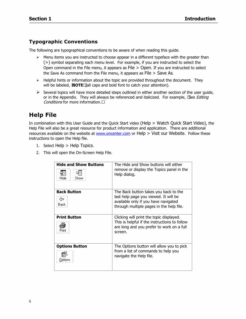
Section 1 Introduction
5
Typographic Conventions
The following are typographical conventions to be aware of when reading this guide
Menu items you are instructed to choose appear in a different typeface with the greater than (gt) symbol separating each menu level For example if you are instructed to select the Open command in the File menu it appears as File gt Open If you are instructed to select the Save As command from the File menu it appears as File gt Save As
Helpful hints or information about the topic are provided throughout the document They will be labeled lsquoNOTErsquo (all caps and bold font to catch your attention)
Several topics will have more detailed steps outlined in either another section of the user guide or in the Appendix They will always be referenced and italicized For example ldquoSee Editing Conditions for more informationrdquo
Help File In combination with this User Guide and the Quick Start video (Help gt Watch Quick Start Video) the Help File will also be a great resource for product information and application There are additional resources available on the website at wwwoncentercom or Help gt Visit our Website Follow these instructions to open the Help file
1 Select Help gt Help Topics
2 This will open the On-Screen Help File
Hide and Show Buttons
The Hide and Show buttons will either remove or display the Topics panel in the Help dialog
Back Button
The Back button takes you back to the last help page you viewed It will be available only if you have navigated through multiple pages in the help file
Print Button
Clicking will print the topic displayed This is helpful if the instructions to follow are long and you prefer to work on a full screen
Options Button
The Options button will allow you to pick from a list of commands to help you navigate the Help file
Section 1 Introduction
6
Contents Tab This tab provides a quick breakout of the Contents of the help file It should be used like the Table of Contents of a book Simply double-click on the book icon to open the chapter Then click the desired page icon to display the relevant information
Index Tab This tab allows you to locate a specifically indexed topic This should be used as you would a book index Begin typing a word in the index entry field and the system will automatically move within the list to the entries closest in spelling to your word(s) Begin typing the topic word to access it in the list quickly
Section 1 Introduction
7
Search Tab This tab works like a word find It allows you to search for any word contained in the Help file Type the
word you are looking for in the lsquoType in the keyword to findrsquo field Click A list of topics containing that word will appear Scroll through the list and double click on the topic you want displayed
Section 2
8
Setup
This section will
Let you know what system requirements you will need to have in place
Recommend components that work well with the software
Help Full Mode users install a digitizer
Section 2 Setup
9
Minimum System Requirements To use On-Screen Takeoff your computer must meet the following minimum system requirements
An IBM PC or 100 compatible computer with a Pentium II or faster Intel processor
Memory Requirements 200 MB of available hard-disk space and256 MB RAM (128 MB preferred)
Windows 2000 SP4 and Windows XP SP2 256 color video card Super VGA display card Mouse 15-inch monitor
While these are the minimum system requirements Windows places heavy demands on your systems resources The more available memory in your computer the faster and more efficient On-Screen Takeoff will operate
Recommended Components
For the best performance we recommend the following components
Pentium III or faster processor
512 or more of RAM
12X speed CD-ROM or better
17-inch monitor or dual monitors Graphic adapter with 128 MB or more VRAM Sound card and speakers installed
NOTE In order to utilize the Training Videos you must have a sound card and speakers installed
Compatible File Formats The resolution in electronic plans does not need to be more that 200 DPI (Dots per Inch) The preferred file format is a black and white TIF (Group4) On-Screen Takeoff recognizes image files with the following extensions
File Extensions View Mode Lite Mode Full Mode TIF X X X PDF X X X OSE X X X JPG X X X CPC X X X CAL X DGN X DWG X DXF X OSP X PLN X PLT X
Section 2 Setup
10
NOTE Use the following image types for best results
Convert to TIF
The converted files will be stored in a folder with the name of the current On-Screen Takeoff project Since the conversion can be very time consuming you should only select this option if you really intend to convert vector files to TIF
1 Select File gt Project Properties
2 In the Pages Field add your image See Section 5 Establishing Project Setting Adding Pages
3 Click
4 Then select the page with the drawing you wish to convert
5 Click
Installing Your Digitizer The following instructions are a quick start to installing your digitizer For more specific information please reference Appendix I Installing Your Digitizer at the end of this guide
Connecting Your Digitizer
Upon receiving your digitizer (either a GTCO or another brand) you will need to connect it to your computer
1 Lay the digitizer out flat
2 Connect the Stylus to the digitizer
3 Plug in the power supply
4 Plug the interface cable into the digitizer
5 Plug the other end of the interface cable into the computer
NOTE On-Screen Takeoff is compatible with any tablet that is WinTab compatible
Digitizer options are only available in Full Mode If you are in View or Lite Mode and would like
to use this feature click from the main toolbar to purchase the upgrade
Section 3
11
Toolbars and Menus
This section will
Introduce the program toolbars
Familiarize you with On-Screen Take Offtrade Menu options
Section 3 Toolbars and Menus
12
Toolbars On-Screen Takeoff is equipped with several helpful toolbars for application efficiency See Appendix II Toolbar Item` Details for a detailed description of each toolbar item Individually the toolbars may be displayed moved docked reshaped or hidden from view You can also create costume toolbars to fit your needs
Main Toolbar
Tool Toolbar
Zoom Toolbar
View Toolbar
Navigate Toolbar
Takeoff Toolbar
Image Toolbar Viewing Toolbars Toolbars are displayed on the screen and will be consistent on each tab or page (Some toolbars or toolbar items will be in an inactive state if they donrsquot have a supporting element in the application)
1 Select View gt Toolbars and select the appropriate toolbar name
OR
2 Right-click on a toolbar region of the screen
3 Check the toolbars you want to display
Section 3 Toolbars and Menus
13
Moving Toolbars The toolbars may be positioned anywhere on the screen you wish This feature is provided to allow the flexibility for positioning the toolbars so they are out of your way yet handy for use
1 Click on an edge of the toolbar holding down the mouse button drag it to its new position
2 Release the mouse button to set it in place
NOTE If the toolbar is dropped anywhere other than a screen edge it will become free floating This feature is especially handy when using multiple monitors
Docking Toolbars The toolbars can be docked to any of the screen edges
1 Click on the title bar of an undocked toolbar
2 Drag the toolbar to any location on the screen
Hiding Toolbars
1 Select View gt Toolbars and select the toolbar you wish to remove from the screen
2 Right-click on the toolbar or dock bar areas
3 A floating toolbar can be closed by clicking on the in the upper right corner of the toolbar
Resizing Toolbars Only undocked (floating) toolbars may be resized
1 Position the mouse pointer over an edge
2 Click and drag
3 The toolbar can be resized as desired
Customizing the Toolbars You may rearrange or delete buttons within a toolbarrsquos display or you may move buttons from one toolbar to another If you find that you use a few tools over and over you may want to group them within a single toolbar for convenience On-Screen Takeoff gives you the flexibility to customize your takeoff environment
1 Select Tools gt Customize The Customize dialog will open
2 With the dialog open click on a toolbar button and drag buttons from one toolbar to another or a new location within the same toolbar
3 To add a button without altering another toolbar click on the Commands tab of the Customize dialog and drag the appropriate symbol from the Buttons section to a toolbar
4 To remove a button drag it to within the takeoff area of the application
Section 3 Toolbars and Menus
14
Menus
Section 3 Toolbars and Menus
15
Digitizer Menu
Section 4
16
Features
This section will
Show you how open On-Screen Takeoff
Describe the On-Screen Takeoff environment
Teach you how to navigate pages
Section 4 Features
17
Start On-Screen Takeoff
1 On your desktop double-click your On-Screen Takeoff icon
2 The application will open
OR
3 Left-click on the Start button on your computerrsquos toolbar
4 Scroll up to Programs gt On Center Software
5 Highlight On-Screen Takeoff and click On-Screen Takeoff will open On-Screen Takeoff opens to an untitled blank project The Image view of the screen will be a blank page
Two blank dock bars the Pan dock bar and the Takeoff dock bar appear at the left side of the screen Along the bottom the Status bar displays user status or context-sensitive messages as well as paper size and current zoom percentage of the plan sheet on screen The menu bar and several task specific toolbars are located at the top of the screen
NOTE All toolbars and dock bars may be accessed to view or hide through View gt Toolbars on the menu bar
Section 4 Features
18
Quick Start Video When On-Screen Takeoff opens you will be given an option to watch the Quick Start video (recommended) or start the program without watching the video
The 20 minute video will demonstrate key program functionality and allow you to view application instruction for enhanced learning
If you would like to watch the video click If you prefer to get started without
the video click If you have already viewed the video click the lsquoDo not show this message againrsquo box to prevent this dialog from appearing each time you open the program
NOTE If you decide later that you would like to watch the Quick Start video go to Help gt Watch
Quick Start Videos
On-Screen Takeoff Environment The On-Screen Takeoff environment acts like your drafting table allowing you to work on several sheets of plans at once and to reference at a glance the entire drawing and your position on that drawing while giving you the power of a computer to track analyze print and export your takeoff quantities and plans
The screen is bordered at the top by the Menu bar with pull-down menus and at the bottom by the Status bar which indicates current user status plan page size and current zoom percentage of page The largest portion of the application screen will be your takeoff area bounded on the left (by default) by two dock bars and on the top by several toolbars
In the takeoff area you may view your project plans (images) andor takeoff objects the takeoff list with quantities the worksheet or a legend of your condition list
The main window of On-Screen Takeoff has three tabs located at the bottom left allowing for quick change between Image Takeoff or Worksheet views Select the desired view option on the toolbar and it will automatically open on your screen
Section 4 Features
19
Image View
This view shows the plan file andor takeoff conditions drawn from your plans
Takeoff View This view displays the height if applicable and quantity breakdowns of your conditions according to result types indicated (eg linear feet square feet or count of items) for zones pages and the project as a whole It also displays notes per condition
Section 4 Features
20
Worksheet View This view displays the condition and quantity in units of measure specified in the first results field of the Results tab in the Condition dialog and allows the user to enter amounts for material labor and subcontractor takeoffs
NOTE When in the Worksheet view tab out the field then save This is keep all the values saved
Navigating On-Screen Takeoff
Auto Scrolling When creating linear areas or zones On-Screen Takeoff will automatically scroll the image view when necessary It will move as your mouse or digitizer moves beyond the edge of the current view
Changing Pages
1 Select View gt Next Page Previous Page or Go To Page (specify page number for the Go to Page option)
2 You may also select the corresponding arrows for these options from the Navigate Toolbar The
drop down arrow in the Page field will list the pages The and arrows will take you to the
previous or next page The and arrows will take you to the first or last page
OR
Section 4 Features
21
3 Or press Ctrl G for the Go To Page dialog
Hot Links Hot links allow you to move quickly from one drawing to the pertinent area of another drawing A hot link is handy when viewing enlarged areas of a page and needing the ability to jump back to a reference page
1 Select Tools gt Hot Link
OR
2 Click from the Tools Toolbar
3 Click on the page where you want to set the link The Hot Link dialog will open
4 Using the current page display on the Navigate Toolbar access the pull-down menu of pages by
clicking on the arrow at the right
5 Select the page for your link (You may also choose View gt Go to Page and select by page number)
6 Manipulate the view using the zoom tool and the scroll bars
7 Click
8 After joining a hot link to another page the hot link arrows in the Navigation Toolbar will become active
9 Move a hot link to another location on the page by clicking then click and drag the hot link image anywhere on the page
Section 5
22
Projects
This section will
Help you create settings important to your projects
Explain how On-Screen Takeoff works with your electronic or paper plans
Section 5 Projects
23
Project Template Files You can begin your project with a template Templates allow you to take advantage of conditions and settings used with previous projects
On-Screen Takeoff templates contain condition lists and established layer separations from previous projects you have created You may also use the sample templates provided with On-Screen Takeoff as a great starting point All aspects of the templates may be adjusted for a new project
1 Select File gt New and click the OK button
2 From the New dialog box choose the template that best fits your project
3 The conditions for this template will appear in the Takeoff Dock bar and the Project Properties dialog will open asking for further information
4 Use File gt Save or File gt Save As to rename and save your new project
Saving a Project as a Template File You can save your condition properties and layers as a template for future projects
1 Select File gt Save As
2 Enter a name for your template and select On-Screen Takeoff Template Files (tpo) from the Save As type field of the dialog (click on the down arrow to select)
3 Click the OK button to accept and close the dialog Modifying a Template File Follow these steps to modify an existing template file if you need to change or add conditions andor layers
1 Select File gt Open
2 Navigate to your Projects directory
3 In the File Type drop-down select On-Screen Takeoff Template files (tpo)
4 Choose the On-Screen Takeoff template file you would like to modify and click the OK button
5 Make appropriate changes
6 Save and close file
The On-Screen Takeoff template files cannot save takeoff information
Section 5 Projects
24
Opening an Existing Project File 1 Select File gt Open
2 Navigate to the desired file location
3 Click the Open button
NOTE If your latest changes to a project file have not been saved On-Screen Takeoff will ask
you whether you would like to save the file and gives you the option of canceling the operation
Creating a New Project
1 Select File gt New
2 For a blank untitled project click
3 At this point the Project Properties dialog will pop-up for more information about your takeoff
NOTE The following are important to keep in mind when beginning a new project
At the start of your project fill out the Project Properties settings to establish the name for all printed output from your project set the default page size and scale for your plans number and names of different pages within the project and locations of electronic drawings
Scale settings can significantly affect quantity outcomes Be sure to set the scale for each page of drawings before beginning condition takeoffs
When using a digitizer remember to make a mark with a pen or pencil in the upper left and lower right corners of the first sheet of the paper plans to delineate the takeoff area for that sheet You can then set the takeoff area on On-Screen Takeoff using your marks
Save your project before you begin taking off any conditions On-Screen Takeoff will write a back-up file using the same file name
Remember the Undo feature If you make a mistake select Edit gt Undo and reverse the process step by step
Section 5 Projects
25
Project Properties
You can either set your Project Properties when you create a new takeoff or once your project file is saved under the appropriate name
1 Select File gt Project Properties the Project Properties dialog box will appear
2 Type in the name of your project to appear on printouts Use the backspace andor delete keys to edit the name as necessary
3 Press the Tab key to move to the Default Image Size option or click within the Image Size box You may click on the arrow at the right for the pull-down menu of page size options or you can use the down-arrow key on your keyboard to scroll through the list to the appropriate selection
4 Press the Tab key to move to the Default Scale option Select a scale by using the drop down arrow If your scale is metric you will need to click in the box next to Metric to convert to that measurement
5 Establish the number of pages for your project plans And load image files See Adding Pages to
Your Project
Adding Pages to Projects Individual Electronic Plans
1 Click on in the Project Properties dialog
2 In the Add Images dialog use the drop down arrow to navigate to the appropriate directory and folder containing your image
3 Select the file so that it displays in the File name field then click The file will display by name and path in the Image File field in Project Properties dialog
4 Click to accept and your project will automatically open
5 Save your project with the new settings by selecting File gt Save
Section 5 Projects
26
Electronic plans scanned from blueprints (as opposed to blue lines) will display as white lines on a black background and are difficult to read on your computer screen Select Image gt Invert and the colors will invert to black on white
You may have noticed the Page column in the Project Properties dialog Generally plan images occupy one page and 1 will be listed in the column indicating Page 1 of your plan file If you import a multi-page TIF a plan file containing more than one page of plans they will import as separate pages and each successive page will be indicated under the Page column as 1 2 3 etc of the plan file
Group of Electronic Plans You may add all the electronic plan files from a particular source (for example from a CD) by using the Auto Add feature
1 Click the button in the Project Properties dialog
2 Browse until you find the appropriate directory and folder containing your plan images
3 Click on any file displayed within your target folder so that the file name appears in the File name box of the Auto Add dialog
4 Click The image paths and file names will be recorded into the project properties arranged alphabetically
5 Click to accept your choices and your project will automatically open
6 Save your project with the new settings by selecting File gt Save
To load Dodge Plans into your Project Properties see Appendix IIi Loading Plans from a Dodge CD
Paper Plans On-Screen Takeoff makes it easy for Full Mode users to perform quantity takeoffs from paper plans using a digitizer
1 Add pages by clicking until you have the number of pages initially in the project
2 Name each page by clicking within the Title area and typing the name
3 Click to accept your choices and close the Project Properties dialog
4 Save your project with the new project properties settings by selecting File gt Save
Section 5 Projects
27
Setting Up a Drawing Template On-Screen Takeoff provides the convenience of using the same work surface for both digitizer and mouse to allow the user to draw conditions and then edit settings of the project or add or change conditions without breaking stride A mouse pad template included with the program defines the area of the digitizer in which use of the stylus or cursor will be recognized as mouse movement as opposed to drawing movement
1 Place your stylus on On-Screen Takeoff
2 Placing the template identifies the location mouse movements will be recognized by the program
Before placing the template the template must be applied to the digitizer surface This may have been done during the installation of your digitizer We suggest attaching the template to the lower right corner of the digitizer surface about one inch inside the grid area
3 Select Digitizer gt Place Template
4 Follow the instruction prompts on the screen clicking first on the target symbol at the left of the On-Screen Takeoff box on the template then on the target at the right
Setting Takeoff Area Before you can begin taking off a drawing you must define the drawing area on the digitizer This requires defining an area that will include all objects on each drawing of your plans As you add pages to your takeoff the same area of the digitizer will be active
1 Secure the plans to the digitizer with tape or a set of clamps
2 With a pen or a pencil mark the upper left corner and the lower right corner of the first page in your set of plans
3 Select Digitizer gt Set Takeoff Area
4 Click each mark with the stylus pen as prompted
5 Verify the active area of the digitizer by looking at the image size located in the lower right corner of your screen
If you close the program before the takeoff is complete you will need to reestablish the takeoff area before you can add additional condition quantities
Electronic plans appear on your computer screen eliminating the need to set a takeoff area You simply drag your mouse across the conditions you wish to takeoff The conditions will be highlighted and quantities will be totaled instantly Electronic plans are available through a variety of services For information contact an On Center Software account manager
Section 5 Projects
28
Setting Scale for Specific Pages You may set the scale in each page view separately This will override the default scale setting in Project Properties for that page Setting the correct scale for the drawing before taking off quantities ensures accurate calculations Be careful to check the scale for each drawing in your project before doing takeoffs
1 Display the page you want to set select Edit gt Set Scale
2 Use the drop down arrow to select a scale that will be applied to that page
3 Click
OR
4 Access the pull-down scale settings on the Navigate toolbar
NOTE As you draw objects notice that the drawn object is similar in width to the object on your plans If it is not the scale set may not be correct
Calculating Scale You may calculate scale according to a known measurement between two points either with a digitizer or on electronic plans
1 Select Edit gt Calculate Scale using Image or Edit gt Calculate Scale using Digitizer
2 Follow the instructions in the related Calculate Scale dialog box You will be asked to click on the first and second points then to enter the dimension for that distance
3 The scale will be recalculated for the displayed page and the Scale display on the Navigate toolbar will show the new scale
Section 6
29
Conditions and Takeoff
This section will Draw Conditions to Takeoff Plan Quantities
What Zones will do to help your takeoff process
Discuss the ins and outs of Takeoffs
Section 6 Conditions and Takeoff
30
Creating Conditions
If you are starting a new project from scratch you will need to create conditions to takeoff quantities such as floor areas wall lengths and corner bead counts If you are using a template you will have several pre-designed conditions already listed on the Takeoff dock bar However you may want to change the characteristics of some conditions or create additional conditions for a particular project
1 Right Click within the Takeoff dock bar Select New gt Condition
Or
2 From the Takeoff dock bar Click (if the buttons are not showing right-click in the Takeoff dock bar area and select Show Buttons from the pop-up menu) The New Condition dialog appears
3 Select the condition type (Linear Area Count or Zone) from the pull-down menu accessed by the
down arrow next to the Type option
4 Press Tab or use the mouse (or stylus) to move to Name and enter a name for your condition
5 Specify the desired condition attributes See Condition Attributes for more detail
6 Click for condition to apply
Section 6 Conditions and Takeoff
31
Condition Attributes Each condition type will have related attributes to select or specify within the General and Advanced tabs of the New Condition dialog Once a condition has been used to takeoff a quantity from your plans certain attributes cannot be changed
All conditions allow the user to specify color and fill pattern for the object drawn
Linear Conditions
General Specify width and height by feet and inches Specify pitch in inches up to the nearest thousandth of an inch if applicable
Advanced Specify rounding for object quantities and droprun default length for electrical or plumbing drops at the ends of lines Select Connect to have lines connect at the corners where one line of the condition ends and another begins (and indicate Tolerance for the featurersquos activation as distance between the ends of two lines) Choose Trim to have lines automatically trim to a line being crossed Choose Curve to draw a curved line
Follow these examples for inputting feet and inches For 7 feet 6 inches type 706 for 13 feet 7 inches type 1307 For 20 feet type 2000
Section 6 Conditions and Takeoff
32
Area Conditions
General If needed you can specify the thickness (in inches) andor pitch (in inches)
Advanced Specify rounding for object quantities Choose to display an adjustable grid within the area and indicate matrix cell dimensions
Section 6 Conditions and Takeoff
33
Count Conditions
General
Specify height and indicate the size (in inches) and shape (square circle triangle rectangle or opening) of the count object as it will appear on screen
Advanced Count conditions have advanced attributes These options are available for all shapes except for openings
Zone Conditions Zones allow you to subdivide condition quantities making it easier to modify and complete jobs in phases They can be used at the end of a takeoff to isolate a group of condition quantities that are in different areas of the takeoff
Zones can also be used to break a takeoff into multi-phases and can even be used to isolate quantities while a job is in progress to group the amount of work that has been completed to date They can be applied to one or multiple pages in your plans automatically calculating the takeoff quantities for each zoned area
Section 6 Conditions and Takeoff
34
The zone feature is only available in Lite and Full Mode If you are in View Mode and would like
to use this feature click from the main toolbar to purchase the upgrade
Condition Notes A Note tab is provided for comments regarding the condition These notes will display on the Takeoff List report and will import into Quick Bid
Section 6 Conditions and Takeoff
35
Condition Results The Results tab of the New Condition is based on condition type Initial settings default to linear feet (LF) for linear conditions square feet (SF) for area conditions and count of items (EA) for count conditions and zones The first of the results fields will display for the condition items in the Takeoff dock bar area All results will display in worksheets and Takeoff List reports as well as in an Excel spreadsheet after being exported
Copying Conditions You may use the condition attributes from a condition yoursquove already created for any future conditions of the same type
1 Click on a condition to select it
2 Click the Copy button from the toolbar
OR
3 Right-click in the Takeoff dock bar area and select copy
4 A new condition will appear in the list with the same condition attributes as the previous condition but with the quantities zeroed
Editing Conditions Once you have copied a condition you might want to change several attributes You can also edit an existing condition to fit any updated needs
1 Highlight the desired condition on the Takeoff dock bar
2 Click the Change button
OR
3 Double-click on the condition you wish to edit to bring up the Change Condition dialog
NOTE The Change Condition dialog differs from the New Condition dialog only in that if takeoffs
Section 6 Conditions and Takeoff
36
have been performed in your project with this condition you will not be able to change the type of condition or certain properties under the advanced tab of the dialog box
Deleting Conditions 1 Click on the condition in the Takeoff Dock bar area
2 Click the Delete button on the toolbar
OR
3 Right-click and select Delete from the pop-up menu
All takeoff associated with the deleted condition will be deleted immediately and permanently
Organizing Project Conditions Within your project you can create folders andor sub-folders for different types of conditions You may even want to create a folder containing conditions with reset values
To get started organizing your conditions make sure you are viewing the condition tree (right-click in the Takeoff dock bar area and select Show Tree)
Creating Folders and Sub-Folders 1 Right-click in the Takeoff Dock bar area
2 Select New gt Folder from the pop-up menu
Copying Folders
1 Click on the folder and click Copy on the toolbar
2 All copied conditions within the new folder will have values reset to zero
Renaming Folders
1 Click on the folder
2 Right-click and select Rename from the pop-up menu
3 Enter a name for your folder and click the Enter button
Changing Condition Order
You may move conditions up or down in the condition list of the Takeoff dock bar to suit your project needs
1 Select the condition you would like to move by clicking to highlight it
NOTE When you are ready to move the highlighted conditions be sure that you start
moving using the last condition chosen That condition will have a highlighted boarder
Section 6 Conditions and Takeoff
37
2 Drag and drop any the condition from one place to another in the list You may also move a condition to another folder on the list in this way
Drawing with Conditions Snap Angles Set up snap angles to prevent lines from appearing jagged Snap angles are commonly set at 15deg and shift snap angles at 0deg
1 Go to Tools gt Options Options dialog appears
2 Under the General tab make the desired settings
3 Click to save the settings As they are drawn lines will snap to the set degree
Drawing a Linear Object 1 Select a condition from the Condition List in the Takeoff dock bar
2 Move the cursor into the Image takeoff area of the screen you will see the cursor display as crosshairs
3 Click and hold left mouse button then drag mouse to draw a line
4 Release mouse button to set line
Section 6 Conditions and Takeoff
38
5 Repeat steps for further lines
Continuous Mode This feature allows you to draw an object that has connected lines
1 Click the icon from the Takeoff toolbar
OR
2 Go to Tools gt Continuous Mode
3 Follow steps 1-3 from Draw a Linear Object
4 Click at each point of intersection The object will be connected
5 Double-click after making the final point to set the lines
Drawing a Curve To draw a curved line the Curve option must be checked under the Advanced tab of the Condition dialog
1 Click where you want to begin the curve and drag in a straight line to the position for the other endpoint of the curve
2 Click on the line to select it Handles in the shapes of small squares will appear at either end of
Section 6 Conditions and Takeoff
39
the line and in the center of the line
3 Move the cursor over the center handles until the cursor becomes a two-way arrow
4 Click and drag in the direction of the curve bending the line as you move the cursor Release to set the curve (The line you began with will disappear)
Draw a circle by drawing two curved lines connected
Drawing an Area Object Area conditions are drawn similarly to continuous mode lines You may trace any number of adjoining walls at different angles to complete your area takeoff
NOTE When drawing an area do not intersect the perimeter or line of the object you are drawing
1 Click at each point
2 Double-click when yoursquove returned to your starting point
3 The area will be filled with the pattern set for that condition
NOTE The simulated circle will be good enough for you to be able to make a bid
To create a circular area click from point to point with very short distances in between points simulating a circlersquos perimeter Double-click after setting the last point to set the area
Section 6 Conditions and Takeoff
40
Grid Options Grids give you an added advantage when installing materials such as tiles Use this feature to get a count for how many tiles are needed for an area
1 Double-click on an area condition in the Takeoff dock bar to open its Condition dialog
2 Click on the Advanced tab to show its options
3 Check the box next to Grid by clicking in it
4 Indicate the dimensions of the cell matrix in inches (For example 200 x 400)
5 Under Results tab choose each (EA) for one of the results fields This will tabulate a number of grid cells (including partial grid cells) in area
6 Click to save your settings
7 Use the Move Grid and Rotate Grid features in the Tools menu to manipulate the grid as desired
Grid Calculation
1 Go to Tools gt Options menu
1 Specify if On-Screen Takeoff automatically should Calculate Grid Position
2 If AreaGrid Size is selected On-Screen Takeoff will calculate the number of items needed to fill the grid based on grid demintions
3 Click to accept and close the dialog
To move a line at any angle (regardless of default setting) press the Shift key while moving the mouse
Section 6 Conditions and Takeoff
41
Backout Mode This feature allows you to take out part of an area and deduct that amount of square footage
1 Select Tools gt Backout Mode
2 Outline the are you want backed out as you would when drawing a regular area object (see Drawing an Area Object)
3 The outlined area will clear and quantities will be recalculated
NOTE The perimeter of the backout area will be added to the LF quantity for that condition
Drawing a Count Object Square triangle rectangle and circle shaped count objects can easily be placed on images
1 Select the condition
2 Click in the location where you want the object to appear
3 To place an opening-shaped count item like a door or window you must click over an existing linear object such as a wall
4 On the Results tab you can change the height properties to give you the result you need
5 If Backout is checked on the advanced tab for each count opening the opening-shaped count item will back out a corresponding section of the linear object
Opening shaped count items are sized at 3rsquo0rdquo by default
Drawing a Zone Zones are drawn in the same way as area objects and may be any polygonal shape You may trace any number of adjoining walls at different angles to complete the zone perimeter
1 Click at each point
2 Double-click when yoursquove returned to your starting point
Section 6 Conditions and Takeoff
42
Selecting Objects
1 Use the Select Tool to select objects
You can also select all objects that correspond to a condition
1 Click on a condition to select it
2 Right-click and choose Select All
3 All objects with this condition will be highlighted with squares as an outline
Moving and Resizing Objects Linear
1 To move or resize a linear object click anywhere on the line to select it
2 To move the line position your pointer over the center handles When the mouse is positioned over the handles you will see a two-way arrow You will only be able to move the line in the direction of the arrows
3 Drag the line to a new position
4 Clicking and dragging the handles on the ends of the line will allow you to lengthen or shorten your line
Area and Zone
1 To move an area object or zone in its entirety click and drag it to its new position
2 Grabbing a handle at a corner or intersection of the object will allow you to adjust and change its perimeter
Section 6 Conditions and Takeoff
43
Count 1 To move a square circle rectangle or triangle shaped count object click and drag
2 Click and drag an opening shaped count object along the length of the linear object to the desired position then release
NOTE An opening shaped count object may not be moved from its associated linear condition object however it may be moved up and down the length of the linear object
Layers On-Screen Takeoff allows you to sort and separate your takeoff objects within the same job and on the same page On-Screen Takeoff gives you this flexibility through the use of layers
By assigning different conditions to different layers (for example differentiating between floors ceilings and walls) you can choose to view all layers or turn off certain layers to display and print the remaining groups of conditions only You may also remove the background image of electronic plans add text and hot link symbols or print only your condition takeoffs
Layers are only available in Full Mode If you are in View or Lite Mode and would like to use this
feature click from the main toolbar to purchase the upgrade Default Layers
On-Screen Takeoff begins every project with three default layers Image Annotation and Default The Image layer holds the electronic plan files you may have in your project The Annotation layer possesses all text notations highlighting and hot links in the project The Default layer will appear in the Condition dialog when creating or editing a condition (listed in the takeoff dock bar) Conditions are assigned to the Default layer unless otherwise specified by the user
Creating Layers To assign a condition to a layer other than the default layer you must first create additional layers for your project
1 Select View gt Layers to open the Layers dialog
2 Click An unnamed layer will be added
3 Click within the empty box and type a name for your layer (for example Wall)
4 New layers are added as active layers The adjacent box under the Show column will be checked
Section 6 Conditions and Takeoff
44
Assigning a Layer to a Condition 1 Open the Condition dialog box by creating a new condition or editing an existing condition
2 Under the General tab click on the down arrow in the Layer field to display optional layers
3 Select the desired layer for the condition Only the Default layer and layers you have added will be displayed
4 Click
View and Hide Layers
1 Select View gt Layers
2 Under the Show column check the box to view or remove the check (by clicking on it) to hide the specific layer
3 Click to accept and close the Layers dialog
Section 6 Conditions and Takeoff
45
Assigning Text to a Layer When adding text to an image On-Screen Takeoff has the capability to assign the text to a specified layer
1 Select the Text Tool
2 Click at the point you want to place your text
3 Type in your text using the Enter key for line breaks
4 Click the drop down arrow next to the Layer field and select the desired layer
Section 7
46
Printing and Exporting
This section will
Printing options and procedures
Exporting data by copying and pasting
Exporting quantity results to Excel spreadsheets
Section 7 Printing and Exporting
47
Print Setup On-Screen Takeoff allows the user to print the image takeoff list and worksheet
1 Select File gt Print Setup The Print Setup dialog will open
2 Select a printer or leave the default selection listed (change from the default printer displayed by clicking on the down arrow at the right of the field)
3 Indicate page size and printer tray option (Source) Access page size options by clicking on the
down arrow at the right of the field
4 Choose Portrait or Landscape orientation
5 Click to accept and close the dialog
Printing Images The image area can include the electronic plans the takeoff objects added text and hot links To print a subset of these (for example just the takeoffs without the plans or the added text and hot link symbols) hide layers that you do not want to print (see Section 6 View and Hide Layers) When you are printing your images every page will show the scale of the takeoff you are printing
1 Click on the Image tab to display the area of your project
2 Select File gt Print (or Ctrl + P)
Section 7 Printing and Exporting
48
3 Select the desired view (What to print) and the Image Range
4 Click The second Print dialog will open
5 Change settings accordingly or click if you accept the default settings
Printing Takeoff Lists and Worksheets In Takeoff Lists and Worksheets you may hide columns to print only certain results or adjust column widths to fit the report within the page size selected
1 In Takeoff List or Worksheet view move your cursor to the right side of the columnrsquos title bar the cursor will display as a two-way arrow
Section 7 Printing and Exporting
49
2 Click and drag to adjust the width of the column Holding the mouse button you may
slide the title bar under the title bar to its left to hide the column completely
3 Select File gt Print or press Ctrl + P to access the Print dialog
4 Indicate desired printer and choose the number of copies
5 Click to print and close the dialog
When printing the condition list we suggest printing in landscape
To reset to the default column widths double-click on the right border of a column heading will reset the column to its right (or previously to its right before being hidden)
Print Preview 1 Select File gt Print Preview
2 Use and to vary your view 3 If viewing an image choose current full or scale view to see how it displays
4 For printed outputs that cover more than one page use and to view adjacent pages or click on the down arrow next to Page field and select the page you want displayed
Exporting Using the CopyPaste Feature You may copy all the data or sections from the worksheet and the takeoff list view in On-Screen Takeoff and paste it into another application When pasting into Excel the cell layout will be maintained
1 Highlight the areas you wish to paste Click and hold the left mouse button down as you drag the cursor over the area to be selected then releasing the mouse button
OR
2 Select the entire takeoff list quickly click on the left On-Screen Takeoff column header and hold and drag the cursor across the remaining column headings
The number of pages for the view selected will display in the lower left-hand corner The zoom percentage that applies to the view will be displayed in the lower right-hand corner next to page size of the drawing
Section 7 Printing and Exporting
50
3 In the worksheet view you may highlight rows by clicking on the numbered buttons to the left of each row clicking and dragging across column headings or clicking and dragging over individual cells in the worksheet
Click anywhere in the appropriate view to deselect the area
4 Once your selection is highlighted you may select Edit gt Copy or Ctrl C from the keyboard 5 On your monitor switch to the application into which you want to paste your selection 6 Select Edit gt Paste in the new application or simply press Ctrl + V to paste
The colored keys for conditions cannot be pasted
Using the Export Feature You may export condition quantities to specified cell location within an Excel worksheet file Cell target locations are assigned in the Results tab of the condition dialogs on the Export line relating to each quantity measurement type
On-Screen Takeoff will export takeoff quantity results for up to three different quantity types that you specify For instance you may want to know the number of square feet in a ceiling area as well as the number of linear feet in its perimeter
Section 7 Printing and Exporting
51
1 Bring up the Condition dialog by double-clicking on a condition in the takeoff dock bar or by
selecting the condition and clicking
2 Click on the Results tab to access its fields The default quantities for the condition type will display
3 For each results field click on the arrow to access the pull-down menu and select the appropriate quantity (for example SF LF EA etchellip)
4 Have your Excel spreadsheet opened and saved in a file
5 Specify the Excel spreadsheet cell locations where you want the results to go
6 For a cell in the first sheet of your spreadsheet type in the cell address (eg a1) Case is not important
7 For a cell on a successive sheet of your spreadsheet type in sheet the number followed by a comma and the cell address without any spaces (eg sheet2a1) Case is not important
8 Click
9 Select File gt Export gt Condition Qty to Excel
Section 7 Printing and Exporting
52
10 Browse to the location of the Excel spreadsheet file click file to select it
11 Click to export On-Screen Takeoff results to specified cell locations in the Excel file When you return to the Excel application you will see the values have been added to the specified cell locations in your spreadsheet
12 Save your Excel file
Exporting Worksheet to Excel
1 Assign condition quantities you want to export
2 Open saved Excel spreadsheet file to which you will be exporting
3 From On-Screen Takeoff Select File gt Export gt Worksheet to Excel
4 Browse to the location of the Excel spreadsheet file click file to select it
5 Click When you return to the Excel application you will see the values from the Worksheet Tab have been added to your spreadsheet
6 Save your Excel file
Exporting Takeoff to CVS 1 Assign condition quantities you want to export
2 Open saved Excel spreadsheet file to which you will be exporting
3 Click the Takeoff Tab in the project you want to export the information
4 Select File gt Export gt Takeoff to CSV
5 Browse to the location of the CSV spreadsheet file click file to select it
6 Click the Save
NOTE CSV files can be opened in Excel Lotus Access etc One may consider this option more of a ldquodumprdquo into a file
The Excel application must be active (it may be minimized on the application bar) with the target spreadsheet open in the application Otherwise an error will occur with the export operation that will affect both the On-Screen Takeofftrade file and the Excel spreadsheet
Section 8
53
Advanced Features
This section will
Some special features of working with condition objects in the takeoff area
Details of advanced options for conditions
Advanced features of the Project Properties dialog
Section 8 Advanced Features
54
Features to Use with Objects Roping Feature You can move copy or delete using this feature Using the Select tool (the pointer) you may select several objects at once by clicking and dragging an outline around the objects then releasing the mouse button Roping may select either objects completely within the outlined area (inclusive) or objects both within and touched by the outlined area (touching) Specify your roping preference under Tools gt Options
1 Click and hold the mouse button at a point on the screen near the objects to be selected and drag to surround the objects with an outline
2 Release the mouse button The objects will be selected
3 You may now
Move the group around on the page by clicking within the group dragging the mouse and releasing the button to place the objects
Delete the group of objects by clicking the Delete key or
Copy and paste by pressing Ctrl C to copy the group then Ctrl V to paste it The pasted copy of the grouped objects will appear slightly offset from the original objects
Section 8 Advanced Features
55
Applying a DropRun Count
Use the droprun feature when calculating quantities to take into account the drop or run of a linear condition such as electrical lines or plumbing pipes Drop or run lengths may be added separately to any linear condition on screen while a default droprun length may be indicated for a condition as a whole
1 Select the desired linear condition from the Condition List in the Takeoff Dock bar
2 Click the Change button in the toolbar to open the Change Condition dialog
3 Click the Advanced tab to access the advanced options and click inside the DropRun check box
4 Enter a default length to be applied to all of this condition Entering 800 will be interpreted as 8 0 (You must enter both place markers for inches) You can leave the length blank and manually enter drop run on each segment drawn
5 Click the OK button to accept and close the dialog
Edit DropRun Count
1 With the related linear condition in the Takeoff Dock bar highlighted or with the pointer tool selected
2 click on the desired linear object in the image takeoff area The Count button will become active
3 Click on the Count button (alternatively select Tools gt Count) The default droprun amount will show in the pop-up Count dialog (Default length will be zero if droprun has not been selected in this conditionrsquos properties)
4 Type in the desired length Entering 800 will be interpreted as 8 0 (You must enter both place markers for inches)
5 Click the OK button The additional amount will be reflected in the corresponding quantity The new DropRun count will apply only to the object edited
Adding Text in Image View
On-Screen Takeoff allows you to place text comments around your quantity takeoffs that may be printed along with plan images and objects Text is automatically placed within the Annotation Layer (that includes text and hot links)
1 To place text on the image select the Text Tool and click at the point you want to place your text opening a text box
2 Type in your information clicking Enter for line breaks
3 When you are finished click the OK button to exit the text box
4 To reposition text simply click on the text (with the Text Tool active) to select it
5 Move the cursor over the text the cursor will now display as a four-way arrow
6 Click and drag the mouse to position the text as desired
Section 8 Advanced Features
56
1 To edit existing text use the Text Tool to double-click on the text to open the editing box
2 Enter additional text or use the Backspace key to delete text as necessary
Formatting Text Once created you may format the font size type style and color of your text
1 Click on the text to select it and select Tools gt Font or click on the Font button in the Takeoff Toolbar
2 Select the desired features (color options are disabled) and click the OK button
3 Click on the text to select it and select Tools gt Color or click on the Color button in the Takeoff Toolbar The Color dialog will open
4 Click on a color in the Basic Color palette or create a color and add to the Custom Colors palette (Be sure to click on the color in the Custom Colors palette to select it)
5 Click the OK button
Object Properties
Linear Objects
Linear objects may be set to connect at corners
A linear object may be set to trim automatically when crossing another linear object (Check the trim option under the advanced tab of the Condition dialog)
When you move a connected linear object objects automatically move and resize connected lines accordingly (quantities are then recalculated)
This feature requires that the connected linear object be moved using the center handles (does not apply when resizing the line from the ends)
Objects constrain to snap increments defined in the Tools gt Options menu (with the mouse 15deg by default incremental when shift key is held down)
Objects are measured from centerline to centerline
Section 8 Advanced Features
57
Area Objects When drawing an area use your escape key to undo the last line drawn You may reverse your
drawing of an area using the escape key
The area will not fill with color and pattern until the user double-clicks after the last line is set
Lines drawn to delineate an area object constrain to snap increments defined in the Tools gt Options menu (with the mouse 15deg by default incremental when shift key is held down)
After selecting an area to move or adjust position the mouse in the center to move the entire area position the mouse at the sides or corners to adjust the perimeter
Count Objects
All count objects are quantified by the physical number of objects per page and reported as EA for the UOM The quantity for the current Image View is (displayed in the Condition List) and the total quantity in your project is displayed in the Takeoff View and Worksheet View)
Square circle rectangle and triangle shaped count objects do not displace or subtract from other object quantities when placed on top of them However on the Advanced Tab for the count condition a connect property can be set (this is a check box) so that when a count object of this shape is put on top of a Linear type takeoff object it will move with the linear if said linear is moved
An opened-shaped count object must be placed within a linear object Opening shaped count objects may also be measured by linear foot or linear yard (EA SF and SY are also options) Opening shaped count items default to a width of 3rsquo 0rdquo at the time of creation This size can be changed The small medium and large size are not options on this type of condition anymore Check Backout on the Advanced tab for each Count object back out the footage (or yardage) of opening-shaped count objects in which they are placed
NOTE In order to see this Backout functionality (in quantity) for SY or SF deductions at least one of the
results for the Linear(s) this object will be placed on must be set to SY or SF and the count object must have a height quantity
Advanced Features of Conditions The Round Feature Under the Advanced tab of the linear and area Condition dialogues you may specify quantity rounding (in inches) For linear objects rounding applies to each linear object drawn For area objects rounding will apply to each segment of the area perimeter adjusting the perimeter and area calculations For example With a linear condition entering 12 in the Round field will round up each related linear object to the nearest 12 inches or one foot With this setting two walls of 1 4 would each round to 2 0 totaling 4 0
NOTE In the Takeoff Dock bar condition list and in the On-Screen Takeoff reports quantities will be displayed in whole numbers rounded up to the nearest foot However calculations are based on true quantities without rounding unless the Round Feature is engaged
Pitch Pitch may apply either to linear or area conditions It is measured in rise per linear foot Entering 12 indicates a 12 rise per 12 of linear distance (a pitch of 12 over 12) or an angle of 45deg
Section 8 Advanced Features
58
Advanced Features of Project Properties Selecting Multiple Pages
1 Select a single page entry by clicking on the numbered gray button to the left of the entry
2 Drag the cursor down the column of numbers to select consecutive pages
3 Click on the blank button at the top of this column to select all pages in the Properties dialog
Section 8 Advanced Features
59
Changing Image Assigned to a Drawing 1 Select the page entry by clicking on the numbered gray button to the left of the entry 2 Click the Change Image button The Change Image dialog box will appear
3 Navigate to the desired file and select by clicking on it
4 Click the Open button The electronic file assigned to the page will have been changed to reflect the new file choice
Changing Image File Path 1 Select pages as described above
2 Choose Change Folder
3 In the Change Folder dialog navigate to the appropriate folder
4 Click the OK button The file path will have been changed for the selected page entries
Delete a Page from Project Properties 1 Select the page you want to delete by clicking on its associated number (in the gray box at the
left of the entry)
2 Choose Delete Page
All Takeoff on the page will be deleted immediately and permanently
Section 8 Advanced Features
60
Advanced Features of Tool Options
Calculation Method On-Screen Takeoff has built-in calculation options to allow for faster work and faster saves until your takeoff is complete Calculation options are found by selecting Tools gt Options then clicking on the Calculation tab
Calculation method can be set to Automatic Automatic except Grids and Manual Manual will allow the program to operate more quickly while Automatic or Automatic except Grids allows the user to see quantity changes as takeoffs are made
In any mode you may press F9 to recalculate quantities for the On-Screen Takeoff current totals
Configuration Tab
When the ldquoPage Label (A01)rdquo radial button is chosen On-Screen Takeoff puts the numbered label on all the pages of in your current page indicator in your Navigate Toolbar If the Page Descriptionrdquo radial button is chosen then a description of what takeoff is on that specific page will be shown in your current page indicator in your Navigate Toolbar
This section of the configuration tab gives you options on how you want to export your information When the ldquoFolderSubfolder Namesrdquo radial button is chosen than on your file that you are exporting to will have all the conditions folders and subfolders In the Delimiter box you can choose the symbol that is needed to separate the information you are exporting Some files need semicolons () or colons () to make sure the information comes exported in is separated it the appropriate places
Section 8 Advanced Features
61
In previous versions of On-Screen Takeoff there are views that users need to have in order for them to display their information By either choosing ldquoOST 1xrdquo or ldquoOST 2xrdquo it will let the program know you want your columns of information exported in that specific format
When you have the Confirm Deletions radial button of ldquoYesrdquo chosen than every time you delete anything you will get a dialog box confirming your intentions of deletion
While working with your takeoff you have a choice to either view the legend of your conditions or hide it Choose whichever radial button that suits your needs
For those who prefer to use the Enter key to navigate in dialog boxes this option is just for that
Font Tab The Font tab is designed for you to make your own look and feel for the application At the bottom of this tab it will show you sample of the fonts and colors you have chosen
Renaming the Current Page You may change the name of the current page in the takeoff area of On-Screen Takeoff by selecting Edit gt Rename Page
This opens the Name Page dialog and you may simply type in a new name and click the Enter button The new name for the file will be reflected on the title bar for the page and in Project Properties
You also may access the Rename Page function by right-clicking in the takeoff area while in Image View and selecting the option from the pop-up menu that appears
Section 9
62
Saving and Exiting
This section will
Explain how to save projects
Show you how to safely exit the program
Section 9 Saving and Exiting
63
Saving Your Project
1 Select File gt Save 2 If your project has not previously been saved a Save dialog box will open to allow you to name
the file and choose the directory and folder in which to save your file 3 Once saved File gt Save will simply save the current version of the file
OR
4 Select File gt Save As then type in a new name for the file and save to the desired file path
The Auto-save Feature With the Auto-save feature On-Screen Takeoff automatically backs up your open project You may choose to have more than one level of backup files The first backup copy will have the extension b00 and successive files will be b01 b02 and so on If you have designated four levels of backup files after the fourth backup copy has been created (b03) the next file will be saved over the file with extension b00 Further backup saves will then rotate through the four backup files in the same way
1 Select Tools gt Options 2 In the Auto-save area (under the General tab) select the frequency of backup file creation (in
minutes) and the number of levels for the feature 3 You also may disengage the feature by clicking in the check box to clear it
The Auto-save feature automatically saves backup copies to the directory of the current project If you are working from a write-protected area such as a CD-ROM On-Screen Takeoff will place backup files in the On-Screen Takeoff folder
Exiting When you are finished using On-Screen Takeoff it is very easy to exit Exiting is very important because of security reasons If someone were to use your computer they could enter the application and view and manipulate information
Section 9 Saving and Exiting
64
On-Screen Takeoff closes the open project when you open another or create a new project or when you exit the program
1 Select File gt Exit
OR
2 You also may click at the upper right-hand corner of the application to exit
NOTE If your latest changes to a project file have not been saved On-Screen Takeoff will ask you whether you would like to save the file and gives you the option of canceling the operation
Appendix I Installing Your Digitizer
65
Appendix I Installing Your Digitizer When you get your digitizer from GTCO you will need to connect it to your computer Follow the instructions outlined below to do this
Note For rollup digitizers the metal bar must be oriented to the top or right hand side
Connecting the Digitizer 1 Lay the digitizer out flat 2 Connect the Stylus to the digitizer 3 Plug in the power adapter 4 Plug the interface (IO) cable into the digitizer 5 Plug the other end of the interface cable into an open serial port on computer
Note GTCO Technical support phone number is 410-381-6688 The electronic manual (on diskette) from GTCO contains more detailed installation and operation instructions for the GTCO digitizer model you have
Installing other Digitizer Drivers If you are using a GTCO Digitizer you will need to install the GTCO TabletWorks Drivers
If you are using a Digitizer not supported by GTCO Tablet Works 10 please contact the manufacturer of your digitizer for assistance with installation
Installing GTCO TabletWorks Drivers 1 Insert the On Center CD into the CD-ROM drive The CD Startup screen will open 2 Click on Install Software 3 Select Additional Software and Drivers 4 Select Digitizer Driver 5 Follow the instructions for installing TabletWorks 10
Adhering the Template The template is a small plastic sticker used to enable mouse function when using the digitizer with On-Screen Takeoff Place your template on your digitizer We suggest placing it in the bottom right corner of the digitizer about one inch inside the takeoff area
Note You may either peel off the back of the template and use the adhesive surface or you can tape the template down
Appendix I Installing Your Digitizer
66
Testing the Digitizer Drivers Before running OST you may test the digitizer by moving the stylus around on the digitizer pad it should move the mouse cursor (if mouse emulation is enabled)
If the digitizer does not move the mouse cursor on the screen
The superset codes may need to be reset Reset the superset codes by touching on the border of the digitizer with the stylus The digitizer should beep several times
The digitizer may not be communicating with the computer Be sure the COM port selected is correct Be sure the COM port selected is correct If you are not able to get the digitizer to move the mouse cursor you need to call GTCO technical support for help
Note The Mouse Emulation is not required for On-Screen Takeoff to work properly It is used only for the Template functionality if the digitizer is moving the cursor the wrong direction (up instead of sideways or vice-versa)
Click the L-shaped arrow symbol on the digitizer with the stylus
Appendix II Toolbar Item Details
67
Appendix II Toolbar Items Main Toolbar
Appendix II Toolbar Item Details
68
Tool Toolbar
Appendix II Toolbar Item Details
69
Zoom Toolbar
View Toolbar
Navigate Toolbar
Appendix II Toolbar Item Details
70
Navigate Toolbar (Continued)
Takeoff Toolbar
Appendix II Toolbar Item Details
71
Takeoff Toolbar (Continued)
Image Toolbar
Appendix III Loading Plans from a Dodge CD
72
Appendix III Loading Plans from a Dodge CD
This section will detail how to load plans from a F W Dodge CD-ROM into an On-Screen Takeoff project file ready for takeoffs
Dodge files may be added to the Project Properties dialog However loading the files in that way will load the files by number rather than name description If you want to load one page only from your Dodge CD You will have to rename the page to display the name rather than number of the file
To load plan files from a Dodge CD so that the files load sequentially by file number but are displayed by name rather than by number within your project follow the instructions below
Opening a Dodge project from a CD-ROM 1 Insert the CD into the drive 2 Choose File gt Custom 3 Choose Dodge Plans Project (plansdat) as the file type 4 Select the appropriate file type by clicking on the down arrow at the right of the Files of type
field 5 In the Look in field access your drive paths by clicking on the down arrow at the right of the
field then
Navigate to your CD-ROM drive Open the data folder and Open the Projects folder
6 Select the desired project and open its folder 7 Open the plansdat file 8 All the images will come in sequenced correctly for that job along with the full descriptions
(names) of each page If there is not a plans folder in the project folder then plans do not exist for that project on the CD Opening the plansdat file will yield an empty project
Appendix IV Using the Plan Viewer
73
Appendix IV Using On-Screen Takeoff Plan Viewer The On-Screen Takeoff Plan Viewer is a limited version of On Center Softwarersquos commercial takeoff software If your status bar located at the very bottom of the main window says View Mode in the lower left-hand corner then you are using the Plan Viewer You can use the plan viewer to
View CD-based amp converted CAD drawings
View a previously created OST file and associated drawings
Download electronic plans online
Navigate through drawings
Quickly Takeoff linearsareas and counts
Zoom in to view the plan better
Print drawings directly from the viewer
Viewing an On-Screen Takeoff Project File
1 To open an OST file that was previously created with of On-Screen Takeoff 2 Select File gt Open 3 An Open dialog will appear if you do not see the OST file you are looking for select the
Look In drop down arrow 4 A drop down menu will appear listing the various folders drives and mapped drives located
on your computer select the correct drive or folder location and continue to browse to the location of your OST file
5 When you see your OST file double-click it to open it 6 Any takeoff and drawings should appear on the Image tab view
If you do not see the drawings but do see the colored takeoff layer the drawings may
not be located in the same place they were originally saved at Go to File gt Project Properties and check the Image File path for each listed page If the image file path is pointing to a CD drive make sure the CD is inside the CR-ROM
Downloading Electronic Plans If your Online Plan Service provides a special file format (OSX) required to use this feature of our plan viewer you can immediately downloaded all electronic plans of a project directly from our viewer
Most Plan Room web sites will automatically open On-Screen Takeoff when a request to download plans is made Your particular Plan Room may differ in operation so please contact the provider directly with questions on using the site
Appendix IV Using the Plan Viewer
74
When you request to download or open a project file from a Plan Room you will usually have the open to open or save an OSX file Choosing open will automatically open On-Screen Takeoff Alternately you may choose to save the file to a local hard drive After you have saved the file either double-click it to launch On-Screen Takeoff or open the OSX file using On-Screen Takeoff by clicking File then Open and locating the file on your hard drive You will need to change the file type to OSX
After the OSX file is opened you will see an additional tab appear in the Conditions List window called Pages
The Pages tab shows the hierarchy of your project Gray file icons represent pages that have not been downloaded and blue icons represents pages that have been downloaded
To download a page simply double-click the page icon
If you wish to select a group of pages to download you can use the Ctrl or Shift key to multiple select them then click the Download button
If you wish to download all pages at once click the Download All button
Downloaded pages will now appear in the Project Properties dialog in the same order in which they appear in the Pages tab
Creating Quick Takeoffs With On-Screen Takeoff you can create quick takeoffs to measure quantities even if you dont have the full version of our program However using the Quick Takeoff functionality shows you just a fraction of what the full version can do
The Quick Takeoff Toolbar is located at the top of the image view It has three buttons designated for three types of takeoffs Linear Area and Count The Quantity drop down list will show secondary quantities for Linears and Areas The Units drop down allows you to select how you want your quantities displayed Feet Inches Yards Millimeters and Meters
NOTE Every time change the type of takeoff you are performing (switching from Area to Linear for example) the previous quantities and takeoff objects will disappear They will also disappear when you changes pages
NOTE You can use the Dimension Tool to basically measure the distance between two points or linears The distance will display on the status bar at the bottom of the application
The Quick Takeoff Toolbar
Appendix V Frequently Asked Questions
75
Appendix V Frequently Asked Questions General
Where is On-Screen Takeoff installed on my computer
Typically it is installed in CProgram FilesOn-Screen Takeoff
In Explorer how do I recognize On-Screen Takeoff file types
On-Screen Takeoff data is stored in a single file per job lsquojob name OSTrsquo On-Screen Takeoff templates are stored as lsquotemplate nameTPOrsquo
Can only one project at a time be open
Yes For that reason opening another project automatically closes the project on screen You will be asked to save any changes
Is only one scale allowed per page What about on drawings that have multiple detail sections on a page and each of those drawings have different scales
Yes For pages with drawings of different scales copy the drawing to another project page and set the appropriate scale
I cannot perform backout on an area that is along a linear
As a workaround use the On-Screen Takeoff layers feature to help you with this issue Electronic Images
How do I start a project from drawings that have been scanned and written to a CD-ROM
Open a new project Select File gt Project Properties and select Auto Add Navigate to your CD and the appropriate folder and select any image file in that location Click Open All files in the location will load into your project Recommended that images are copied from CD to hard drive for performance
If I get a disk of drawings in AutoCAD format (R13 or R14) can I read them in On-Screen Takeoff
Yes On-Screen Takeoff now reads DWG DXF and many other format that are saved with AutoCAD
Appendix V Frequently Asked Questions
76
When I click on the all pages button what is supposed to happen Currently nothing seems to change when I click on that button
The All Pages button is used to apply the Darken and Enhance Plans feature to all pages in the project (as opposed to only the current page on screen)
Is there a way to deduct a large skylight from an area condition
Yes with the related area condition selected in the Takeoff Dock bar unselect the Backout button on the Takeoff Toolbar then draw the Backout area The area quantity will be deducted from the related condition object and the linear measurement of the Backout perimeter will be added
Digitizer Issues
How do I connect a Digitizer to the computer
See Appendix I Connecting a Digitizer
The Place Template menu choice is disabled
On-Screen Takeoff may need to be authorized or the digitizer or the digitzer drivers are not installed
It wonrsquot let me select the Set Takeoff Area menu choice
On-Screen Takeoff may need to be authorized or no job is open a digitizer is not installed or the drivers are not installed
The digitizer stylus is not moving the cursor or crosshairs
Click S-0-1 superset on the digitizer
How do I convert my old GTCO Digitizer to work with On- Screen Takeofftrade
Call GTCO and they may be able to reconfigure your digitizer to be compatible with On-Screen Takeoff
Printing Issues Which Printers work with On-Screen Takeoff
Compatible printers include On-Screen Takeoff Hewlett Packard Epson and Canon printers If you are having printer difficulties please contact support and specify the type of printer along with other pertinent information Contact support at wwwoncentercomsupport or email supportoncentercom
Which Plotters work with On-Screen Takeoff
Compatible Plotters include Hewlett Packard DesignJet plotters and the EnCAD Cadjet II If you are having plotter difficulties please contact support and specify the type of plotter concerned
ViewingDisplay I can no longer see my condition list How do I get it back
The toolbars and Dock bars can be turned on and off through the View gt Toolbars menu options
Appendix V Frequently Asked Questions
77
This is also accessible by right-clicking in the toolbar area and selecting (or deselecting) a toolbar listed
I cannot view my folders in the condition list
Right-click in the Takeoff Dock barcondition list area and select Show Tree to display your folders
My Status Bar reads Viewer Mode and I am unable to draw conditions
On-Screen Takeoff needs to be Authorized Or you need to purchase an upgrade Click the Perform Advanced Takeoff button on the main toolbar
I hid a Dock bar and when I selected to view it again it appeared alongside the other Dock
bar instead of stacked on top of it How do I fix it
Pick up the Dock bar by clicking on the bar at the top and continuing to hold down the mouse button drag the Dock bar over the other one It will resize and appear stacked with the other
When I open image files from a CD the images are all upside down How do I get them right
side up
To flip pages from top to bottom follow the steps below 1 Click the All Pages button on the Image Toolbar (All Pages is engaged when the button
is not clicked) 2 Click the Flip Horizontal button on the Image Toolbar 3 Click the All Pages button again to disengage
Templates How do I create a Template
Follow the steps below 1 Create a typical project 2 Choose File gt Save As 3 Choose On-Screen Takeoff Template Files as the file type to save 4 Name the file This will save all of the condition setups as well as the layers for the
project
How do I create a new project from a template
Follow the steps below 1 Choose File gt New 2 Select a template from those listed in the New dialog This will open a new project with
conditions and layers saved from a previous project but no pages or takeoff
78
INDEX
Area Conditions 32
Area Objects 57
Auto Scrolling 20
Auto-save 63
Backout Mode 41
Calculation Method 60
Conditions 29
Configuration 60
Contents Tab 6
Continuous Mode 38
Count Conditions 33
Count Objects 57
Digitizer 10 65 76
Docking Toolbars 13
Dodge CD 72
Drawing 27 37
DropRun Count 55
Environment 18
Exiting 63
Exporting 49
Features 16
Font 61
Frequently Asked Questions 75
Grid 40
Help File 5
Hiding Toolbars 13
Hot Links 21
Image 19 59
Image files 9
Image Toolbar 12 71
Images 75
Index Tab 6
Layers 43
Linear Conditions 31
Linear Objects 56
Main Toolbar 12 67
Menus 14
Moving Toolbars 13
Navigate Toolbar 12 69
Navigating 20
On-Screen Takeofftrade 2
Page 59 61
Pages 20 25 28
Plan Viewer 73
Plans 26
Printing 47 76
Project Properties 25
Projects 22
Quick Start Video 18
Resizing Toolbars 13
Roping 54
Saving 63
Scale 28
Search Tab 7
Selecting Objects 42
Setup 8
Start On-Screen Takeofftrade 17
System Requirements 9
Takeoff 19 27
Takeoff Toolbar 70 71
Takeoff Toolbar 12
Template Files 23
TIF (Group4) 9
Tool Toolbar 12 68
Toolbar 67
Toolbars 12
View Toolbar 12 69
Viewing Toolbars 12
Worksheet 20
Zone Conditions 33
Zoom Toolbar 12 69
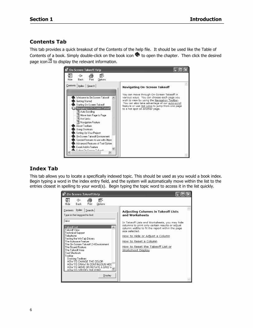
Section 1 Introduction
6
Contents Tab This tab provides a quick breakout of the Contents of the help file It should be used like the Table of Contents of a book Simply double-click on the book icon to open the chapter Then click the desired page icon to display the relevant information
Index Tab This tab allows you to locate a specifically indexed topic This should be used as you would a book index Begin typing a word in the index entry field and the system will automatically move within the list to the entries closest in spelling to your word(s) Begin typing the topic word to access it in the list quickly
Section 1 Introduction
7
Search Tab This tab works like a word find It allows you to search for any word contained in the Help file Type the
word you are looking for in the lsquoType in the keyword to findrsquo field Click A list of topics containing that word will appear Scroll through the list and double click on the topic you want displayed
Section 2
8
Setup
This section will
Let you know what system requirements you will need to have in place
Recommend components that work well with the software
Help Full Mode users install a digitizer
Section 2 Setup
9
Minimum System Requirements To use On-Screen Takeoff your computer must meet the following minimum system requirements
An IBM PC or 100 compatible computer with a Pentium II or faster Intel processor
Memory Requirements 200 MB of available hard-disk space and256 MB RAM (128 MB preferred)
Windows 2000 SP4 and Windows XP SP2 256 color video card Super VGA display card Mouse 15-inch monitor
While these are the minimum system requirements Windows places heavy demands on your systems resources The more available memory in your computer the faster and more efficient On-Screen Takeoff will operate
Recommended Components
For the best performance we recommend the following components
Pentium III or faster processor
512 or more of RAM
12X speed CD-ROM or better
17-inch monitor or dual monitors Graphic adapter with 128 MB or more VRAM Sound card and speakers installed
NOTE In order to utilize the Training Videos you must have a sound card and speakers installed
Compatible File Formats The resolution in electronic plans does not need to be more that 200 DPI (Dots per Inch) The preferred file format is a black and white TIF (Group4) On-Screen Takeoff recognizes image files with the following extensions
File Extensions View Mode Lite Mode Full Mode TIF X X X PDF X X X OSE X X X JPG X X X CPC X X X CAL X DGN X DWG X DXF X OSP X PLN X PLT X
Section 2 Setup
10
NOTE Use the following image types for best results
Convert to TIF
The converted files will be stored in a folder with the name of the current On-Screen Takeoff project Since the conversion can be very time consuming you should only select this option if you really intend to convert vector files to TIF
1 Select File gt Project Properties
2 In the Pages Field add your image See Section 5 Establishing Project Setting Adding Pages
3 Click
4 Then select the page with the drawing you wish to convert
5 Click
Installing Your Digitizer The following instructions are a quick start to installing your digitizer For more specific information please reference Appendix I Installing Your Digitizer at the end of this guide
Connecting Your Digitizer
Upon receiving your digitizer (either a GTCO or another brand) you will need to connect it to your computer
1 Lay the digitizer out flat
2 Connect the Stylus to the digitizer
3 Plug in the power supply
4 Plug the interface cable into the digitizer
5 Plug the other end of the interface cable into the computer
NOTE On-Screen Takeoff is compatible with any tablet that is WinTab compatible
Digitizer options are only available in Full Mode If you are in View or Lite Mode and would like
to use this feature click from the main toolbar to purchase the upgrade
Section 3
11
Toolbars and Menus
This section will
Introduce the program toolbars
Familiarize you with On-Screen Take Offtrade Menu options
Section 3 Toolbars and Menus
12
Toolbars On-Screen Takeoff is equipped with several helpful toolbars for application efficiency See Appendix II Toolbar Item` Details for a detailed description of each toolbar item Individually the toolbars may be displayed moved docked reshaped or hidden from view You can also create costume toolbars to fit your needs
Main Toolbar
Tool Toolbar
Zoom Toolbar
View Toolbar
Navigate Toolbar
Takeoff Toolbar
Image Toolbar Viewing Toolbars Toolbars are displayed on the screen and will be consistent on each tab or page (Some toolbars or toolbar items will be in an inactive state if they donrsquot have a supporting element in the application)
1 Select View gt Toolbars and select the appropriate toolbar name
OR
2 Right-click on a toolbar region of the screen
3 Check the toolbars you want to display
Section 3 Toolbars and Menus
13
Moving Toolbars The toolbars may be positioned anywhere on the screen you wish This feature is provided to allow the flexibility for positioning the toolbars so they are out of your way yet handy for use
1 Click on an edge of the toolbar holding down the mouse button drag it to its new position
2 Release the mouse button to set it in place
NOTE If the toolbar is dropped anywhere other than a screen edge it will become free floating This feature is especially handy when using multiple monitors
Docking Toolbars The toolbars can be docked to any of the screen edges
1 Click on the title bar of an undocked toolbar
2 Drag the toolbar to any location on the screen
Hiding Toolbars
1 Select View gt Toolbars and select the toolbar you wish to remove from the screen
2 Right-click on the toolbar or dock bar areas
3 A floating toolbar can be closed by clicking on the in the upper right corner of the toolbar
Resizing Toolbars Only undocked (floating) toolbars may be resized
1 Position the mouse pointer over an edge
2 Click and drag
3 The toolbar can be resized as desired
Customizing the Toolbars You may rearrange or delete buttons within a toolbarrsquos display or you may move buttons from one toolbar to another If you find that you use a few tools over and over you may want to group them within a single toolbar for convenience On-Screen Takeoff gives you the flexibility to customize your takeoff environment
1 Select Tools gt Customize The Customize dialog will open
2 With the dialog open click on a toolbar button and drag buttons from one toolbar to another or a new location within the same toolbar
3 To add a button without altering another toolbar click on the Commands tab of the Customize dialog and drag the appropriate symbol from the Buttons section to a toolbar
4 To remove a button drag it to within the takeoff area of the application
Section 3 Toolbars and Menus
14
Menus
Section 3 Toolbars and Menus
15
Digitizer Menu
Section 4
16
Features
This section will
Show you how open On-Screen Takeoff
Describe the On-Screen Takeoff environment
Teach you how to navigate pages
Section 4 Features
17
Start On-Screen Takeoff
1 On your desktop double-click your On-Screen Takeoff icon
2 The application will open
OR
3 Left-click on the Start button on your computerrsquos toolbar
4 Scroll up to Programs gt On Center Software
5 Highlight On-Screen Takeoff and click On-Screen Takeoff will open On-Screen Takeoff opens to an untitled blank project The Image view of the screen will be a blank page
Two blank dock bars the Pan dock bar and the Takeoff dock bar appear at the left side of the screen Along the bottom the Status bar displays user status or context-sensitive messages as well as paper size and current zoom percentage of the plan sheet on screen The menu bar and several task specific toolbars are located at the top of the screen
NOTE All toolbars and dock bars may be accessed to view or hide through View gt Toolbars on the menu bar
Section 4 Features
18
Quick Start Video When On-Screen Takeoff opens you will be given an option to watch the Quick Start video (recommended) or start the program without watching the video
The 20 minute video will demonstrate key program functionality and allow you to view application instruction for enhanced learning
If you would like to watch the video click If you prefer to get started without
the video click If you have already viewed the video click the lsquoDo not show this message againrsquo box to prevent this dialog from appearing each time you open the program
NOTE If you decide later that you would like to watch the Quick Start video go to Help gt Watch
Quick Start Videos
On-Screen Takeoff Environment The On-Screen Takeoff environment acts like your drafting table allowing you to work on several sheets of plans at once and to reference at a glance the entire drawing and your position on that drawing while giving you the power of a computer to track analyze print and export your takeoff quantities and plans
The screen is bordered at the top by the Menu bar with pull-down menus and at the bottom by the Status bar which indicates current user status plan page size and current zoom percentage of page The largest portion of the application screen will be your takeoff area bounded on the left (by default) by two dock bars and on the top by several toolbars
In the takeoff area you may view your project plans (images) andor takeoff objects the takeoff list with quantities the worksheet or a legend of your condition list
The main window of On-Screen Takeoff has three tabs located at the bottom left allowing for quick change between Image Takeoff or Worksheet views Select the desired view option on the toolbar and it will automatically open on your screen
Section 4 Features
19
Image View
This view shows the plan file andor takeoff conditions drawn from your plans
Takeoff View This view displays the height if applicable and quantity breakdowns of your conditions according to result types indicated (eg linear feet square feet or count of items) for zones pages and the project as a whole It also displays notes per condition
Section 4 Features
20
Worksheet View This view displays the condition and quantity in units of measure specified in the first results field of the Results tab in the Condition dialog and allows the user to enter amounts for material labor and subcontractor takeoffs
NOTE When in the Worksheet view tab out the field then save This is keep all the values saved
Navigating On-Screen Takeoff
Auto Scrolling When creating linear areas or zones On-Screen Takeoff will automatically scroll the image view when necessary It will move as your mouse or digitizer moves beyond the edge of the current view
Changing Pages
1 Select View gt Next Page Previous Page or Go To Page (specify page number for the Go to Page option)
2 You may also select the corresponding arrows for these options from the Navigate Toolbar The
drop down arrow in the Page field will list the pages The and arrows will take you to the
previous or next page The and arrows will take you to the first or last page
OR
Section 4 Features
21
3 Or press Ctrl G for the Go To Page dialog
Hot Links Hot links allow you to move quickly from one drawing to the pertinent area of another drawing A hot link is handy when viewing enlarged areas of a page and needing the ability to jump back to a reference page
1 Select Tools gt Hot Link
OR
2 Click from the Tools Toolbar
3 Click on the page where you want to set the link The Hot Link dialog will open
4 Using the current page display on the Navigate Toolbar access the pull-down menu of pages by
clicking on the arrow at the right
5 Select the page for your link (You may also choose View gt Go to Page and select by page number)
6 Manipulate the view using the zoom tool and the scroll bars
7 Click
8 After joining a hot link to another page the hot link arrows in the Navigation Toolbar will become active
9 Move a hot link to another location on the page by clicking then click and drag the hot link image anywhere on the page
Section 5
22
Projects
This section will
Help you create settings important to your projects
Explain how On-Screen Takeoff works with your electronic or paper plans
Section 5 Projects
23
Project Template Files You can begin your project with a template Templates allow you to take advantage of conditions and settings used with previous projects
On-Screen Takeoff templates contain condition lists and established layer separations from previous projects you have created You may also use the sample templates provided with On-Screen Takeoff as a great starting point All aspects of the templates may be adjusted for a new project
1 Select File gt New and click the OK button
2 From the New dialog box choose the template that best fits your project
3 The conditions for this template will appear in the Takeoff Dock bar and the Project Properties dialog will open asking for further information
4 Use File gt Save or File gt Save As to rename and save your new project
Saving a Project as a Template File You can save your condition properties and layers as a template for future projects
1 Select File gt Save As
2 Enter a name for your template and select On-Screen Takeoff Template Files (tpo) from the Save As type field of the dialog (click on the down arrow to select)
3 Click the OK button to accept and close the dialog Modifying a Template File Follow these steps to modify an existing template file if you need to change or add conditions andor layers
1 Select File gt Open
2 Navigate to your Projects directory
3 In the File Type drop-down select On-Screen Takeoff Template files (tpo)
4 Choose the On-Screen Takeoff template file you would like to modify and click the OK button
5 Make appropriate changes
6 Save and close file
The On-Screen Takeoff template files cannot save takeoff information
Section 5 Projects
24
Opening an Existing Project File 1 Select File gt Open
2 Navigate to the desired file location
3 Click the Open button
NOTE If your latest changes to a project file have not been saved On-Screen Takeoff will ask
you whether you would like to save the file and gives you the option of canceling the operation
Creating a New Project
1 Select File gt New
2 For a blank untitled project click
3 At this point the Project Properties dialog will pop-up for more information about your takeoff
NOTE The following are important to keep in mind when beginning a new project
At the start of your project fill out the Project Properties settings to establish the name for all printed output from your project set the default page size and scale for your plans number and names of different pages within the project and locations of electronic drawings
Scale settings can significantly affect quantity outcomes Be sure to set the scale for each page of drawings before beginning condition takeoffs
When using a digitizer remember to make a mark with a pen or pencil in the upper left and lower right corners of the first sheet of the paper plans to delineate the takeoff area for that sheet You can then set the takeoff area on On-Screen Takeoff using your marks
Save your project before you begin taking off any conditions On-Screen Takeoff will write a back-up file using the same file name
Remember the Undo feature If you make a mistake select Edit gt Undo and reverse the process step by step
Section 5 Projects
25
Project Properties
You can either set your Project Properties when you create a new takeoff or once your project file is saved under the appropriate name
1 Select File gt Project Properties the Project Properties dialog box will appear
2 Type in the name of your project to appear on printouts Use the backspace andor delete keys to edit the name as necessary
3 Press the Tab key to move to the Default Image Size option or click within the Image Size box You may click on the arrow at the right for the pull-down menu of page size options or you can use the down-arrow key on your keyboard to scroll through the list to the appropriate selection
4 Press the Tab key to move to the Default Scale option Select a scale by using the drop down arrow If your scale is metric you will need to click in the box next to Metric to convert to that measurement
5 Establish the number of pages for your project plans And load image files See Adding Pages to
Your Project
Adding Pages to Projects Individual Electronic Plans
1 Click on in the Project Properties dialog
2 In the Add Images dialog use the drop down arrow to navigate to the appropriate directory and folder containing your image
3 Select the file so that it displays in the File name field then click The file will display by name and path in the Image File field in Project Properties dialog
4 Click to accept and your project will automatically open
5 Save your project with the new settings by selecting File gt Save
Section 5 Projects
26
Electronic plans scanned from blueprints (as opposed to blue lines) will display as white lines on a black background and are difficult to read on your computer screen Select Image gt Invert and the colors will invert to black on white
You may have noticed the Page column in the Project Properties dialog Generally plan images occupy one page and 1 will be listed in the column indicating Page 1 of your plan file If you import a multi-page TIF a plan file containing more than one page of plans they will import as separate pages and each successive page will be indicated under the Page column as 1 2 3 etc of the plan file
Group of Electronic Plans You may add all the electronic plan files from a particular source (for example from a CD) by using the Auto Add feature
1 Click the button in the Project Properties dialog
2 Browse until you find the appropriate directory and folder containing your plan images
3 Click on any file displayed within your target folder so that the file name appears in the File name box of the Auto Add dialog
4 Click The image paths and file names will be recorded into the project properties arranged alphabetically
5 Click to accept your choices and your project will automatically open
6 Save your project with the new settings by selecting File gt Save
To load Dodge Plans into your Project Properties see Appendix IIi Loading Plans from a Dodge CD
Paper Plans On-Screen Takeoff makes it easy for Full Mode users to perform quantity takeoffs from paper plans using a digitizer
1 Add pages by clicking until you have the number of pages initially in the project
2 Name each page by clicking within the Title area and typing the name
3 Click to accept your choices and close the Project Properties dialog
4 Save your project with the new project properties settings by selecting File gt Save
Section 5 Projects
27
Setting Up a Drawing Template On-Screen Takeoff provides the convenience of using the same work surface for both digitizer and mouse to allow the user to draw conditions and then edit settings of the project or add or change conditions without breaking stride A mouse pad template included with the program defines the area of the digitizer in which use of the stylus or cursor will be recognized as mouse movement as opposed to drawing movement
1 Place your stylus on On-Screen Takeoff
2 Placing the template identifies the location mouse movements will be recognized by the program
Before placing the template the template must be applied to the digitizer surface This may have been done during the installation of your digitizer We suggest attaching the template to the lower right corner of the digitizer surface about one inch inside the grid area
3 Select Digitizer gt Place Template
4 Follow the instruction prompts on the screen clicking first on the target symbol at the left of the On-Screen Takeoff box on the template then on the target at the right
Setting Takeoff Area Before you can begin taking off a drawing you must define the drawing area on the digitizer This requires defining an area that will include all objects on each drawing of your plans As you add pages to your takeoff the same area of the digitizer will be active
1 Secure the plans to the digitizer with tape or a set of clamps
2 With a pen or a pencil mark the upper left corner and the lower right corner of the first page in your set of plans
3 Select Digitizer gt Set Takeoff Area
4 Click each mark with the stylus pen as prompted
5 Verify the active area of the digitizer by looking at the image size located in the lower right corner of your screen
If you close the program before the takeoff is complete you will need to reestablish the takeoff area before you can add additional condition quantities
Electronic plans appear on your computer screen eliminating the need to set a takeoff area You simply drag your mouse across the conditions you wish to takeoff The conditions will be highlighted and quantities will be totaled instantly Electronic plans are available through a variety of services For information contact an On Center Software account manager
Section 5 Projects
28
Setting Scale for Specific Pages You may set the scale in each page view separately This will override the default scale setting in Project Properties for that page Setting the correct scale for the drawing before taking off quantities ensures accurate calculations Be careful to check the scale for each drawing in your project before doing takeoffs
1 Display the page you want to set select Edit gt Set Scale
2 Use the drop down arrow to select a scale that will be applied to that page
3 Click
OR
4 Access the pull-down scale settings on the Navigate toolbar
NOTE As you draw objects notice that the drawn object is similar in width to the object on your plans If it is not the scale set may not be correct
Calculating Scale You may calculate scale according to a known measurement between two points either with a digitizer or on electronic plans
1 Select Edit gt Calculate Scale using Image or Edit gt Calculate Scale using Digitizer
2 Follow the instructions in the related Calculate Scale dialog box You will be asked to click on the first and second points then to enter the dimension for that distance
3 The scale will be recalculated for the displayed page and the Scale display on the Navigate toolbar will show the new scale
Section 6
29
Conditions and Takeoff
This section will Draw Conditions to Takeoff Plan Quantities
What Zones will do to help your takeoff process
Discuss the ins and outs of Takeoffs
Section 6 Conditions and Takeoff
30
Creating Conditions
If you are starting a new project from scratch you will need to create conditions to takeoff quantities such as floor areas wall lengths and corner bead counts If you are using a template you will have several pre-designed conditions already listed on the Takeoff dock bar However you may want to change the characteristics of some conditions or create additional conditions for a particular project
1 Right Click within the Takeoff dock bar Select New gt Condition
Or
2 From the Takeoff dock bar Click (if the buttons are not showing right-click in the Takeoff dock bar area and select Show Buttons from the pop-up menu) The New Condition dialog appears
3 Select the condition type (Linear Area Count or Zone) from the pull-down menu accessed by the
down arrow next to the Type option
4 Press Tab or use the mouse (or stylus) to move to Name and enter a name for your condition
5 Specify the desired condition attributes See Condition Attributes for more detail
6 Click for condition to apply
Section 6 Conditions and Takeoff
31
Condition Attributes Each condition type will have related attributes to select or specify within the General and Advanced tabs of the New Condition dialog Once a condition has been used to takeoff a quantity from your plans certain attributes cannot be changed
All conditions allow the user to specify color and fill pattern for the object drawn
Linear Conditions
General Specify width and height by feet and inches Specify pitch in inches up to the nearest thousandth of an inch if applicable
Advanced Specify rounding for object quantities and droprun default length for electrical or plumbing drops at the ends of lines Select Connect to have lines connect at the corners where one line of the condition ends and another begins (and indicate Tolerance for the featurersquos activation as distance between the ends of two lines) Choose Trim to have lines automatically trim to a line being crossed Choose Curve to draw a curved line
Follow these examples for inputting feet and inches For 7 feet 6 inches type 706 for 13 feet 7 inches type 1307 For 20 feet type 2000
Section 6 Conditions and Takeoff
32
Area Conditions
General If needed you can specify the thickness (in inches) andor pitch (in inches)
Advanced Specify rounding for object quantities Choose to display an adjustable grid within the area and indicate matrix cell dimensions
Section 6 Conditions and Takeoff
33
Count Conditions
General
Specify height and indicate the size (in inches) and shape (square circle triangle rectangle or opening) of the count object as it will appear on screen
Advanced Count conditions have advanced attributes These options are available for all shapes except for openings
Zone Conditions Zones allow you to subdivide condition quantities making it easier to modify and complete jobs in phases They can be used at the end of a takeoff to isolate a group of condition quantities that are in different areas of the takeoff
Zones can also be used to break a takeoff into multi-phases and can even be used to isolate quantities while a job is in progress to group the amount of work that has been completed to date They can be applied to one or multiple pages in your plans automatically calculating the takeoff quantities for each zoned area
Section 6 Conditions and Takeoff
34
The zone feature is only available in Lite and Full Mode If you are in View Mode and would like
to use this feature click from the main toolbar to purchase the upgrade
Condition Notes A Note tab is provided for comments regarding the condition These notes will display on the Takeoff List report and will import into Quick Bid
Section 6 Conditions and Takeoff
35
Condition Results The Results tab of the New Condition is based on condition type Initial settings default to linear feet (LF) for linear conditions square feet (SF) for area conditions and count of items (EA) for count conditions and zones The first of the results fields will display for the condition items in the Takeoff dock bar area All results will display in worksheets and Takeoff List reports as well as in an Excel spreadsheet after being exported
Copying Conditions You may use the condition attributes from a condition yoursquove already created for any future conditions of the same type
1 Click on a condition to select it
2 Click the Copy button from the toolbar
OR
3 Right-click in the Takeoff dock bar area and select copy
4 A new condition will appear in the list with the same condition attributes as the previous condition but with the quantities zeroed
Editing Conditions Once you have copied a condition you might want to change several attributes You can also edit an existing condition to fit any updated needs
1 Highlight the desired condition on the Takeoff dock bar
2 Click the Change button
OR
3 Double-click on the condition you wish to edit to bring up the Change Condition dialog
NOTE The Change Condition dialog differs from the New Condition dialog only in that if takeoffs
Section 6 Conditions and Takeoff
36
have been performed in your project with this condition you will not be able to change the type of condition or certain properties under the advanced tab of the dialog box
Deleting Conditions 1 Click on the condition in the Takeoff Dock bar area
2 Click the Delete button on the toolbar
OR
3 Right-click and select Delete from the pop-up menu
All takeoff associated with the deleted condition will be deleted immediately and permanently
Organizing Project Conditions Within your project you can create folders andor sub-folders for different types of conditions You may even want to create a folder containing conditions with reset values
To get started organizing your conditions make sure you are viewing the condition tree (right-click in the Takeoff dock bar area and select Show Tree)
Creating Folders and Sub-Folders 1 Right-click in the Takeoff Dock bar area
2 Select New gt Folder from the pop-up menu
Copying Folders
1 Click on the folder and click Copy on the toolbar
2 All copied conditions within the new folder will have values reset to zero
Renaming Folders
1 Click on the folder
2 Right-click and select Rename from the pop-up menu
3 Enter a name for your folder and click the Enter button
Changing Condition Order
You may move conditions up or down in the condition list of the Takeoff dock bar to suit your project needs
1 Select the condition you would like to move by clicking to highlight it
NOTE When you are ready to move the highlighted conditions be sure that you start
moving using the last condition chosen That condition will have a highlighted boarder
Section 6 Conditions and Takeoff
37
2 Drag and drop any the condition from one place to another in the list You may also move a condition to another folder on the list in this way
Drawing with Conditions Snap Angles Set up snap angles to prevent lines from appearing jagged Snap angles are commonly set at 15deg and shift snap angles at 0deg
1 Go to Tools gt Options Options dialog appears
2 Under the General tab make the desired settings
3 Click to save the settings As they are drawn lines will snap to the set degree
Drawing a Linear Object 1 Select a condition from the Condition List in the Takeoff dock bar
2 Move the cursor into the Image takeoff area of the screen you will see the cursor display as crosshairs
3 Click and hold left mouse button then drag mouse to draw a line
4 Release mouse button to set line
Section 6 Conditions and Takeoff
38
5 Repeat steps for further lines
Continuous Mode This feature allows you to draw an object that has connected lines
1 Click the icon from the Takeoff toolbar
OR
2 Go to Tools gt Continuous Mode
3 Follow steps 1-3 from Draw a Linear Object
4 Click at each point of intersection The object will be connected
5 Double-click after making the final point to set the lines
Drawing a Curve To draw a curved line the Curve option must be checked under the Advanced tab of the Condition dialog
1 Click where you want to begin the curve and drag in a straight line to the position for the other endpoint of the curve
2 Click on the line to select it Handles in the shapes of small squares will appear at either end of
Section 6 Conditions and Takeoff
39
the line and in the center of the line
3 Move the cursor over the center handles until the cursor becomes a two-way arrow
4 Click and drag in the direction of the curve bending the line as you move the cursor Release to set the curve (The line you began with will disappear)
Draw a circle by drawing two curved lines connected
Drawing an Area Object Area conditions are drawn similarly to continuous mode lines You may trace any number of adjoining walls at different angles to complete your area takeoff
NOTE When drawing an area do not intersect the perimeter or line of the object you are drawing
1 Click at each point
2 Double-click when yoursquove returned to your starting point
3 The area will be filled with the pattern set for that condition
NOTE The simulated circle will be good enough for you to be able to make a bid
To create a circular area click from point to point with very short distances in between points simulating a circlersquos perimeter Double-click after setting the last point to set the area
Section 6 Conditions and Takeoff
40
Grid Options Grids give you an added advantage when installing materials such as tiles Use this feature to get a count for how many tiles are needed for an area
1 Double-click on an area condition in the Takeoff dock bar to open its Condition dialog
2 Click on the Advanced tab to show its options
3 Check the box next to Grid by clicking in it
4 Indicate the dimensions of the cell matrix in inches (For example 200 x 400)
5 Under Results tab choose each (EA) for one of the results fields This will tabulate a number of grid cells (including partial grid cells) in area
6 Click to save your settings
7 Use the Move Grid and Rotate Grid features in the Tools menu to manipulate the grid as desired
Grid Calculation
1 Go to Tools gt Options menu
1 Specify if On-Screen Takeoff automatically should Calculate Grid Position
2 If AreaGrid Size is selected On-Screen Takeoff will calculate the number of items needed to fill the grid based on grid demintions
3 Click to accept and close the dialog
To move a line at any angle (regardless of default setting) press the Shift key while moving the mouse
Section 6 Conditions and Takeoff
41
Backout Mode This feature allows you to take out part of an area and deduct that amount of square footage
1 Select Tools gt Backout Mode
2 Outline the are you want backed out as you would when drawing a regular area object (see Drawing an Area Object)
3 The outlined area will clear and quantities will be recalculated
NOTE The perimeter of the backout area will be added to the LF quantity for that condition
Drawing a Count Object Square triangle rectangle and circle shaped count objects can easily be placed on images
1 Select the condition
2 Click in the location where you want the object to appear
3 To place an opening-shaped count item like a door or window you must click over an existing linear object such as a wall
4 On the Results tab you can change the height properties to give you the result you need
5 If Backout is checked on the advanced tab for each count opening the opening-shaped count item will back out a corresponding section of the linear object
Opening shaped count items are sized at 3rsquo0rdquo by default
Drawing a Zone Zones are drawn in the same way as area objects and may be any polygonal shape You may trace any number of adjoining walls at different angles to complete the zone perimeter
1 Click at each point
2 Double-click when yoursquove returned to your starting point
Section 6 Conditions and Takeoff
42
Selecting Objects
1 Use the Select Tool to select objects
You can also select all objects that correspond to a condition
1 Click on a condition to select it
2 Right-click and choose Select All
3 All objects with this condition will be highlighted with squares as an outline
Moving and Resizing Objects Linear
1 To move or resize a linear object click anywhere on the line to select it
2 To move the line position your pointer over the center handles When the mouse is positioned over the handles you will see a two-way arrow You will only be able to move the line in the direction of the arrows
3 Drag the line to a new position
4 Clicking and dragging the handles on the ends of the line will allow you to lengthen or shorten your line
Area and Zone
1 To move an area object or zone in its entirety click and drag it to its new position
2 Grabbing a handle at a corner or intersection of the object will allow you to adjust and change its perimeter
Section 6 Conditions and Takeoff
43
Count 1 To move a square circle rectangle or triangle shaped count object click and drag
2 Click and drag an opening shaped count object along the length of the linear object to the desired position then release
NOTE An opening shaped count object may not be moved from its associated linear condition object however it may be moved up and down the length of the linear object
Layers On-Screen Takeoff allows you to sort and separate your takeoff objects within the same job and on the same page On-Screen Takeoff gives you this flexibility through the use of layers
By assigning different conditions to different layers (for example differentiating between floors ceilings and walls) you can choose to view all layers or turn off certain layers to display and print the remaining groups of conditions only You may also remove the background image of electronic plans add text and hot link symbols or print only your condition takeoffs
Layers are only available in Full Mode If you are in View or Lite Mode and would like to use this
feature click from the main toolbar to purchase the upgrade Default Layers
On-Screen Takeoff begins every project with three default layers Image Annotation and Default The Image layer holds the electronic plan files you may have in your project The Annotation layer possesses all text notations highlighting and hot links in the project The Default layer will appear in the Condition dialog when creating or editing a condition (listed in the takeoff dock bar) Conditions are assigned to the Default layer unless otherwise specified by the user
Creating Layers To assign a condition to a layer other than the default layer you must first create additional layers for your project
1 Select View gt Layers to open the Layers dialog
2 Click An unnamed layer will be added
3 Click within the empty box and type a name for your layer (for example Wall)
4 New layers are added as active layers The adjacent box under the Show column will be checked
Section 6 Conditions and Takeoff
44
Assigning a Layer to a Condition 1 Open the Condition dialog box by creating a new condition or editing an existing condition
2 Under the General tab click on the down arrow in the Layer field to display optional layers
3 Select the desired layer for the condition Only the Default layer and layers you have added will be displayed
4 Click
View and Hide Layers
1 Select View gt Layers
2 Under the Show column check the box to view or remove the check (by clicking on it) to hide the specific layer
3 Click to accept and close the Layers dialog
Section 6 Conditions and Takeoff
45
Assigning Text to a Layer When adding text to an image On-Screen Takeoff has the capability to assign the text to a specified layer
1 Select the Text Tool
2 Click at the point you want to place your text
3 Type in your text using the Enter key for line breaks
4 Click the drop down arrow next to the Layer field and select the desired layer
Section 7
46
Printing and Exporting
This section will
Printing options and procedures
Exporting data by copying and pasting
Exporting quantity results to Excel spreadsheets
Section 7 Printing and Exporting
47
Print Setup On-Screen Takeoff allows the user to print the image takeoff list and worksheet
1 Select File gt Print Setup The Print Setup dialog will open
2 Select a printer or leave the default selection listed (change from the default printer displayed by clicking on the down arrow at the right of the field)
3 Indicate page size and printer tray option (Source) Access page size options by clicking on the
down arrow at the right of the field
4 Choose Portrait or Landscape orientation
5 Click to accept and close the dialog
Printing Images The image area can include the electronic plans the takeoff objects added text and hot links To print a subset of these (for example just the takeoffs without the plans or the added text and hot link symbols) hide layers that you do not want to print (see Section 6 View and Hide Layers) When you are printing your images every page will show the scale of the takeoff you are printing
1 Click on the Image tab to display the area of your project
2 Select File gt Print (or Ctrl + P)
Section 7 Printing and Exporting
48
3 Select the desired view (What to print) and the Image Range
4 Click The second Print dialog will open
5 Change settings accordingly or click if you accept the default settings
Printing Takeoff Lists and Worksheets In Takeoff Lists and Worksheets you may hide columns to print only certain results or adjust column widths to fit the report within the page size selected
1 In Takeoff List or Worksheet view move your cursor to the right side of the columnrsquos title bar the cursor will display as a two-way arrow
Section 7 Printing and Exporting
49
2 Click and drag to adjust the width of the column Holding the mouse button you may
slide the title bar under the title bar to its left to hide the column completely
3 Select File gt Print or press Ctrl + P to access the Print dialog
4 Indicate desired printer and choose the number of copies
5 Click to print and close the dialog
When printing the condition list we suggest printing in landscape
To reset to the default column widths double-click on the right border of a column heading will reset the column to its right (or previously to its right before being hidden)
Print Preview 1 Select File gt Print Preview
2 Use and to vary your view 3 If viewing an image choose current full or scale view to see how it displays
4 For printed outputs that cover more than one page use and to view adjacent pages or click on the down arrow next to Page field and select the page you want displayed
Exporting Using the CopyPaste Feature You may copy all the data or sections from the worksheet and the takeoff list view in On-Screen Takeoff and paste it into another application When pasting into Excel the cell layout will be maintained
1 Highlight the areas you wish to paste Click and hold the left mouse button down as you drag the cursor over the area to be selected then releasing the mouse button
OR
2 Select the entire takeoff list quickly click on the left On-Screen Takeoff column header and hold and drag the cursor across the remaining column headings
The number of pages for the view selected will display in the lower left-hand corner The zoom percentage that applies to the view will be displayed in the lower right-hand corner next to page size of the drawing
Section 7 Printing and Exporting
50
3 In the worksheet view you may highlight rows by clicking on the numbered buttons to the left of each row clicking and dragging across column headings or clicking and dragging over individual cells in the worksheet
Click anywhere in the appropriate view to deselect the area
4 Once your selection is highlighted you may select Edit gt Copy or Ctrl C from the keyboard 5 On your monitor switch to the application into which you want to paste your selection 6 Select Edit gt Paste in the new application or simply press Ctrl + V to paste
The colored keys for conditions cannot be pasted
Using the Export Feature You may export condition quantities to specified cell location within an Excel worksheet file Cell target locations are assigned in the Results tab of the condition dialogs on the Export line relating to each quantity measurement type
On-Screen Takeoff will export takeoff quantity results for up to three different quantity types that you specify For instance you may want to know the number of square feet in a ceiling area as well as the number of linear feet in its perimeter
Section 7 Printing and Exporting
51
1 Bring up the Condition dialog by double-clicking on a condition in the takeoff dock bar or by
selecting the condition and clicking
2 Click on the Results tab to access its fields The default quantities for the condition type will display
3 For each results field click on the arrow to access the pull-down menu and select the appropriate quantity (for example SF LF EA etchellip)
4 Have your Excel spreadsheet opened and saved in a file
5 Specify the Excel spreadsheet cell locations where you want the results to go
6 For a cell in the first sheet of your spreadsheet type in the cell address (eg a1) Case is not important
7 For a cell on a successive sheet of your spreadsheet type in sheet the number followed by a comma and the cell address without any spaces (eg sheet2a1) Case is not important
8 Click
9 Select File gt Export gt Condition Qty to Excel
Section 7 Printing and Exporting
52
10 Browse to the location of the Excel spreadsheet file click file to select it
11 Click to export On-Screen Takeoff results to specified cell locations in the Excel file When you return to the Excel application you will see the values have been added to the specified cell locations in your spreadsheet
12 Save your Excel file
Exporting Worksheet to Excel
1 Assign condition quantities you want to export
2 Open saved Excel spreadsheet file to which you will be exporting
3 From On-Screen Takeoff Select File gt Export gt Worksheet to Excel
4 Browse to the location of the Excel spreadsheet file click file to select it
5 Click When you return to the Excel application you will see the values from the Worksheet Tab have been added to your spreadsheet
6 Save your Excel file
Exporting Takeoff to CVS 1 Assign condition quantities you want to export
2 Open saved Excel spreadsheet file to which you will be exporting
3 Click the Takeoff Tab in the project you want to export the information
4 Select File gt Export gt Takeoff to CSV
5 Browse to the location of the CSV spreadsheet file click file to select it
6 Click the Save
NOTE CSV files can be opened in Excel Lotus Access etc One may consider this option more of a ldquodumprdquo into a file
The Excel application must be active (it may be minimized on the application bar) with the target spreadsheet open in the application Otherwise an error will occur with the export operation that will affect both the On-Screen Takeofftrade file and the Excel spreadsheet
Section 8
53
Advanced Features
This section will
Some special features of working with condition objects in the takeoff area
Details of advanced options for conditions
Advanced features of the Project Properties dialog
Section 8 Advanced Features
54
Features to Use with Objects Roping Feature You can move copy or delete using this feature Using the Select tool (the pointer) you may select several objects at once by clicking and dragging an outline around the objects then releasing the mouse button Roping may select either objects completely within the outlined area (inclusive) or objects both within and touched by the outlined area (touching) Specify your roping preference under Tools gt Options
1 Click and hold the mouse button at a point on the screen near the objects to be selected and drag to surround the objects with an outline
2 Release the mouse button The objects will be selected
3 You may now
Move the group around on the page by clicking within the group dragging the mouse and releasing the button to place the objects
Delete the group of objects by clicking the Delete key or
Copy and paste by pressing Ctrl C to copy the group then Ctrl V to paste it The pasted copy of the grouped objects will appear slightly offset from the original objects
Section 8 Advanced Features
55
Applying a DropRun Count
Use the droprun feature when calculating quantities to take into account the drop or run of a linear condition such as electrical lines or plumbing pipes Drop or run lengths may be added separately to any linear condition on screen while a default droprun length may be indicated for a condition as a whole
1 Select the desired linear condition from the Condition List in the Takeoff Dock bar
2 Click the Change button in the toolbar to open the Change Condition dialog
3 Click the Advanced tab to access the advanced options and click inside the DropRun check box
4 Enter a default length to be applied to all of this condition Entering 800 will be interpreted as 8 0 (You must enter both place markers for inches) You can leave the length blank and manually enter drop run on each segment drawn
5 Click the OK button to accept and close the dialog
Edit DropRun Count
1 With the related linear condition in the Takeoff Dock bar highlighted or with the pointer tool selected
2 click on the desired linear object in the image takeoff area The Count button will become active
3 Click on the Count button (alternatively select Tools gt Count) The default droprun amount will show in the pop-up Count dialog (Default length will be zero if droprun has not been selected in this conditionrsquos properties)
4 Type in the desired length Entering 800 will be interpreted as 8 0 (You must enter both place markers for inches)
5 Click the OK button The additional amount will be reflected in the corresponding quantity The new DropRun count will apply only to the object edited
Adding Text in Image View
On-Screen Takeoff allows you to place text comments around your quantity takeoffs that may be printed along with plan images and objects Text is automatically placed within the Annotation Layer (that includes text and hot links)
1 To place text on the image select the Text Tool and click at the point you want to place your text opening a text box
2 Type in your information clicking Enter for line breaks
3 When you are finished click the OK button to exit the text box
4 To reposition text simply click on the text (with the Text Tool active) to select it
5 Move the cursor over the text the cursor will now display as a four-way arrow
6 Click and drag the mouse to position the text as desired
Section 8 Advanced Features
56
1 To edit existing text use the Text Tool to double-click on the text to open the editing box
2 Enter additional text or use the Backspace key to delete text as necessary
Formatting Text Once created you may format the font size type style and color of your text
1 Click on the text to select it and select Tools gt Font or click on the Font button in the Takeoff Toolbar
2 Select the desired features (color options are disabled) and click the OK button
3 Click on the text to select it and select Tools gt Color or click on the Color button in the Takeoff Toolbar The Color dialog will open
4 Click on a color in the Basic Color palette or create a color and add to the Custom Colors palette (Be sure to click on the color in the Custom Colors palette to select it)
5 Click the OK button
Object Properties
Linear Objects
Linear objects may be set to connect at corners
A linear object may be set to trim automatically when crossing another linear object (Check the trim option under the advanced tab of the Condition dialog)
When you move a connected linear object objects automatically move and resize connected lines accordingly (quantities are then recalculated)
This feature requires that the connected linear object be moved using the center handles (does not apply when resizing the line from the ends)
Objects constrain to snap increments defined in the Tools gt Options menu (with the mouse 15deg by default incremental when shift key is held down)
Objects are measured from centerline to centerline
Section 8 Advanced Features
57
Area Objects When drawing an area use your escape key to undo the last line drawn You may reverse your
drawing of an area using the escape key
The area will not fill with color and pattern until the user double-clicks after the last line is set
Lines drawn to delineate an area object constrain to snap increments defined in the Tools gt Options menu (with the mouse 15deg by default incremental when shift key is held down)
After selecting an area to move or adjust position the mouse in the center to move the entire area position the mouse at the sides or corners to adjust the perimeter
Count Objects
All count objects are quantified by the physical number of objects per page and reported as EA for the UOM The quantity for the current Image View is (displayed in the Condition List) and the total quantity in your project is displayed in the Takeoff View and Worksheet View)
Square circle rectangle and triangle shaped count objects do not displace or subtract from other object quantities when placed on top of them However on the Advanced Tab for the count condition a connect property can be set (this is a check box) so that when a count object of this shape is put on top of a Linear type takeoff object it will move with the linear if said linear is moved
An opened-shaped count object must be placed within a linear object Opening shaped count objects may also be measured by linear foot or linear yard (EA SF and SY are also options) Opening shaped count items default to a width of 3rsquo 0rdquo at the time of creation This size can be changed The small medium and large size are not options on this type of condition anymore Check Backout on the Advanced tab for each Count object back out the footage (or yardage) of opening-shaped count objects in which they are placed
NOTE In order to see this Backout functionality (in quantity) for SY or SF deductions at least one of the
results for the Linear(s) this object will be placed on must be set to SY or SF and the count object must have a height quantity
Advanced Features of Conditions The Round Feature Under the Advanced tab of the linear and area Condition dialogues you may specify quantity rounding (in inches) For linear objects rounding applies to each linear object drawn For area objects rounding will apply to each segment of the area perimeter adjusting the perimeter and area calculations For example With a linear condition entering 12 in the Round field will round up each related linear object to the nearest 12 inches or one foot With this setting two walls of 1 4 would each round to 2 0 totaling 4 0
NOTE In the Takeoff Dock bar condition list and in the On-Screen Takeoff reports quantities will be displayed in whole numbers rounded up to the nearest foot However calculations are based on true quantities without rounding unless the Round Feature is engaged
Pitch Pitch may apply either to linear or area conditions It is measured in rise per linear foot Entering 12 indicates a 12 rise per 12 of linear distance (a pitch of 12 over 12) or an angle of 45deg
Section 8 Advanced Features
58
Advanced Features of Project Properties Selecting Multiple Pages
1 Select a single page entry by clicking on the numbered gray button to the left of the entry
2 Drag the cursor down the column of numbers to select consecutive pages
3 Click on the blank button at the top of this column to select all pages in the Properties dialog
Section 8 Advanced Features
59
Changing Image Assigned to a Drawing 1 Select the page entry by clicking on the numbered gray button to the left of the entry 2 Click the Change Image button The Change Image dialog box will appear
3 Navigate to the desired file and select by clicking on it
4 Click the Open button The electronic file assigned to the page will have been changed to reflect the new file choice
Changing Image File Path 1 Select pages as described above
2 Choose Change Folder
3 In the Change Folder dialog navigate to the appropriate folder
4 Click the OK button The file path will have been changed for the selected page entries
Delete a Page from Project Properties 1 Select the page you want to delete by clicking on its associated number (in the gray box at the
left of the entry)
2 Choose Delete Page
All Takeoff on the page will be deleted immediately and permanently
Section 8 Advanced Features
60
Advanced Features of Tool Options
Calculation Method On-Screen Takeoff has built-in calculation options to allow for faster work and faster saves until your takeoff is complete Calculation options are found by selecting Tools gt Options then clicking on the Calculation tab
Calculation method can be set to Automatic Automatic except Grids and Manual Manual will allow the program to operate more quickly while Automatic or Automatic except Grids allows the user to see quantity changes as takeoffs are made
In any mode you may press F9 to recalculate quantities for the On-Screen Takeoff current totals
Configuration Tab
When the ldquoPage Label (A01)rdquo radial button is chosen On-Screen Takeoff puts the numbered label on all the pages of in your current page indicator in your Navigate Toolbar If the Page Descriptionrdquo radial button is chosen then a description of what takeoff is on that specific page will be shown in your current page indicator in your Navigate Toolbar
This section of the configuration tab gives you options on how you want to export your information When the ldquoFolderSubfolder Namesrdquo radial button is chosen than on your file that you are exporting to will have all the conditions folders and subfolders In the Delimiter box you can choose the symbol that is needed to separate the information you are exporting Some files need semicolons () or colons () to make sure the information comes exported in is separated it the appropriate places
Section 8 Advanced Features
61
In previous versions of On-Screen Takeoff there are views that users need to have in order for them to display their information By either choosing ldquoOST 1xrdquo or ldquoOST 2xrdquo it will let the program know you want your columns of information exported in that specific format
When you have the Confirm Deletions radial button of ldquoYesrdquo chosen than every time you delete anything you will get a dialog box confirming your intentions of deletion
While working with your takeoff you have a choice to either view the legend of your conditions or hide it Choose whichever radial button that suits your needs
For those who prefer to use the Enter key to navigate in dialog boxes this option is just for that
Font Tab The Font tab is designed for you to make your own look and feel for the application At the bottom of this tab it will show you sample of the fonts and colors you have chosen
Renaming the Current Page You may change the name of the current page in the takeoff area of On-Screen Takeoff by selecting Edit gt Rename Page
This opens the Name Page dialog and you may simply type in a new name and click the Enter button The new name for the file will be reflected on the title bar for the page and in Project Properties
You also may access the Rename Page function by right-clicking in the takeoff area while in Image View and selecting the option from the pop-up menu that appears
Section 9
62
Saving and Exiting
This section will
Explain how to save projects
Show you how to safely exit the program
Section 9 Saving and Exiting
63
Saving Your Project
1 Select File gt Save 2 If your project has not previously been saved a Save dialog box will open to allow you to name
the file and choose the directory and folder in which to save your file 3 Once saved File gt Save will simply save the current version of the file
OR
4 Select File gt Save As then type in a new name for the file and save to the desired file path
The Auto-save Feature With the Auto-save feature On-Screen Takeoff automatically backs up your open project You may choose to have more than one level of backup files The first backup copy will have the extension b00 and successive files will be b01 b02 and so on If you have designated four levels of backup files after the fourth backup copy has been created (b03) the next file will be saved over the file with extension b00 Further backup saves will then rotate through the four backup files in the same way
1 Select Tools gt Options 2 In the Auto-save area (under the General tab) select the frequency of backup file creation (in
minutes) and the number of levels for the feature 3 You also may disengage the feature by clicking in the check box to clear it
The Auto-save feature automatically saves backup copies to the directory of the current project If you are working from a write-protected area such as a CD-ROM On-Screen Takeoff will place backup files in the On-Screen Takeoff folder
Exiting When you are finished using On-Screen Takeoff it is very easy to exit Exiting is very important because of security reasons If someone were to use your computer they could enter the application and view and manipulate information
Section 9 Saving and Exiting
64
On-Screen Takeoff closes the open project when you open another or create a new project or when you exit the program
1 Select File gt Exit
OR
2 You also may click at the upper right-hand corner of the application to exit
NOTE If your latest changes to a project file have not been saved On-Screen Takeoff will ask you whether you would like to save the file and gives you the option of canceling the operation
Appendix I Installing Your Digitizer
65
Appendix I Installing Your Digitizer When you get your digitizer from GTCO you will need to connect it to your computer Follow the instructions outlined below to do this
Note For rollup digitizers the metal bar must be oriented to the top or right hand side
Connecting the Digitizer 1 Lay the digitizer out flat 2 Connect the Stylus to the digitizer 3 Plug in the power adapter 4 Plug the interface (IO) cable into the digitizer 5 Plug the other end of the interface cable into an open serial port on computer
Note GTCO Technical support phone number is 410-381-6688 The electronic manual (on diskette) from GTCO contains more detailed installation and operation instructions for the GTCO digitizer model you have
Installing other Digitizer Drivers If you are using a GTCO Digitizer you will need to install the GTCO TabletWorks Drivers
If you are using a Digitizer not supported by GTCO Tablet Works 10 please contact the manufacturer of your digitizer for assistance with installation
Installing GTCO TabletWorks Drivers 1 Insert the On Center CD into the CD-ROM drive The CD Startup screen will open 2 Click on Install Software 3 Select Additional Software and Drivers 4 Select Digitizer Driver 5 Follow the instructions for installing TabletWorks 10
Adhering the Template The template is a small plastic sticker used to enable mouse function when using the digitizer with On-Screen Takeoff Place your template on your digitizer We suggest placing it in the bottom right corner of the digitizer about one inch inside the takeoff area
Note You may either peel off the back of the template and use the adhesive surface or you can tape the template down
Appendix I Installing Your Digitizer
66
Testing the Digitizer Drivers Before running OST you may test the digitizer by moving the stylus around on the digitizer pad it should move the mouse cursor (if mouse emulation is enabled)
If the digitizer does not move the mouse cursor on the screen
The superset codes may need to be reset Reset the superset codes by touching on the border of the digitizer with the stylus The digitizer should beep several times
The digitizer may not be communicating with the computer Be sure the COM port selected is correct Be sure the COM port selected is correct If you are not able to get the digitizer to move the mouse cursor you need to call GTCO technical support for help
Note The Mouse Emulation is not required for On-Screen Takeoff to work properly It is used only for the Template functionality if the digitizer is moving the cursor the wrong direction (up instead of sideways or vice-versa)
Click the L-shaped arrow symbol on the digitizer with the stylus
Appendix II Toolbar Item Details
67
Appendix II Toolbar Items Main Toolbar
Appendix II Toolbar Item Details
68
Tool Toolbar
Appendix II Toolbar Item Details
69
Zoom Toolbar
View Toolbar
Navigate Toolbar
Appendix II Toolbar Item Details
70
Navigate Toolbar (Continued)
Takeoff Toolbar
Appendix II Toolbar Item Details
71
Takeoff Toolbar (Continued)
Image Toolbar
Appendix III Loading Plans from a Dodge CD
72
Appendix III Loading Plans from a Dodge CD
This section will detail how to load plans from a F W Dodge CD-ROM into an On-Screen Takeoff project file ready for takeoffs
Dodge files may be added to the Project Properties dialog However loading the files in that way will load the files by number rather than name description If you want to load one page only from your Dodge CD You will have to rename the page to display the name rather than number of the file
To load plan files from a Dodge CD so that the files load sequentially by file number but are displayed by name rather than by number within your project follow the instructions below
Opening a Dodge project from a CD-ROM 1 Insert the CD into the drive 2 Choose File gt Custom 3 Choose Dodge Plans Project (plansdat) as the file type 4 Select the appropriate file type by clicking on the down arrow at the right of the Files of type
field 5 In the Look in field access your drive paths by clicking on the down arrow at the right of the
field then
Navigate to your CD-ROM drive Open the data folder and Open the Projects folder
6 Select the desired project and open its folder 7 Open the plansdat file 8 All the images will come in sequenced correctly for that job along with the full descriptions
(names) of each page If there is not a plans folder in the project folder then plans do not exist for that project on the CD Opening the plansdat file will yield an empty project
Appendix IV Using the Plan Viewer
73
Appendix IV Using On-Screen Takeoff Plan Viewer The On-Screen Takeoff Plan Viewer is a limited version of On Center Softwarersquos commercial takeoff software If your status bar located at the very bottom of the main window says View Mode in the lower left-hand corner then you are using the Plan Viewer You can use the plan viewer to
View CD-based amp converted CAD drawings
View a previously created OST file and associated drawings
Download electronic plans online
Navigate through drawings
Quickly Takeoff linearsareas and counts
Zoom in to view the plan better
Print drawings directly from the viewer
Viewing an On-Screen Takeoff Project File
1 To open an OST file that was previously created with of On-Screen Takeoff 2 Select File gt Open 3 An Open dialog will appear if you do not see the OST file you are looking for select the
Look In drop down arrow 4 A drop down menu will appear listing the various folders drives and mapped drives located
on your computer select the correct drive or folder location and continue to browse to the location of your OST file
5 When you see your OST file double-click it to open it 6 Any takeoff and drawings should appear on the Image tab view
If you do not see the drawings but do see the colored takeoff layer the drawings may
not be located in the same place they were originally saved at Go to File gt Project Properties and check the Image File path for each listed page If the image file path is pointing to a CD drive make sure the CD is inside the CR-ROM
Downloading Electronic Plans If your Online Plan Service provides a special file format (OSX) required to use this feature of our plan viewer you can immediately downloaded all electronic plans of a project directly from our viewer
Most Plan Room web sites will automatically open On-Screen Takeoff when a request to download plans is made Your particular Plan Room may differ in operation so please contact the provider directly with questions on using the site
Appendix IV Using the Plan Viewer
74
When you request to download or open a project file from a Plan Room you will usually have the open to open or save an OSX file Choosing open will automatically open On-Screen Takeoff Alternately you may choose to save the file to a local hard drive After you have saved the file either double-click it to launch On-Screen Takeoff or open the OSX file using On-Screen Takeoff by clicking File then Open and locating the file on your hard drive You will need to change the file type to OSX
After the OSX file is opened you will see an additional tab appear in the Conditions List window called Pages
The Pages tab shows the hierarchy of your project Gray file icons represent pages that have not been downloaded and blue icons represents pages that have been downloaded
To download a page simply double-click the page icon
If you wish to select a group of pages to download you can use the Ctrl or Shift key to multiple select them then click the Download button
If you wish to download all pages at once click the Download All button
Downloaded pages will now appear in the Project Properties dialog in the same order in which they appear in the Pages tab
Creating Quick Takeoffs With On-Screen Takeoff you can create quick takeoffs to measure quantities even if you dont have the full version of our program However using the Quick Takeoff functionality shows you just a fraction of what the full version can do
The Quick Takeoff Toolbar is located at the top of the image view It has three buttons designated for three types of takeoffs Linear Area and Count The Quantity drop down list will show secondary quantities for Linears and Areas The Units drop down allows you to select how you want your quantities displayed Feet Inches Yards Millimeters and Meters
NOTE Every time change the type of takeoff you are performing (switching from Area to Linear for example) the previous quantities and takeoff objects will disappear They will also disappear when you changes pages
NOTE You can use the Dimension Tool to basically measure the distance between two points or linears The distance will display on the status bar at the bottom of the application
The Quick Takeoff Toolbar
Appendix V Frequently Asked Questions
75
Appendix V Frequently Asked Questions General
Where is On-Screen Takeoff installed on my computer
Typically it is installed in CProgram FilesOn-Screen Takeoff
In Explorer how do I recognize On-Screen Takeoff file types
On-Screen Takeoff data is stored in a single file per job lsquojob name OSTrsquo On-Screen Takeoff templates are stored as lsquotemplate nameTPOrsquo
Can only one project at a time be open
Yes For that reason opening another project automatically closes the project on screen You will be asked to save any changes
Is only one scale allowed per page What about on drawings that have multiple detail sections on a page and each of those drawings have different scales
Yes For pages with drawings of different scales copy the drawing to another project page and set the appropriate scale
I cannot perform backout on an area that is along a linear
As a workaround use the On-Screen Takeoff layers feature to help you with this issue Electronic Images
How do I start a project from drawings that have been scanned and written to a CD-ROM
Open a new project Select File gt Project Properties and select Auto Add Navigate to your CD and the appropriate folder and select any image file in that location Click Open All files in the location will load into your project Recommended that images are copied from CD to hard drive for performance
If I get a disk of drawings in AutoCAD format (R13 or R14) can I read them in On-Screen Takeoff
Yes On-Screen Takeoff now reads DWG DXF and many other format that are saved with AutoCAD
Appendix V Frequently Asked Questions
76
When I click on the all pages button what is supposed to happen Currently nothing seems to change when I click on that button
The All Pages button is used to apply the Darken and Enhance Plans feature to all pages in the project (as opposed to only the current page on screen)
Is there a way to deduct a large skylight from an area condition
Yes with the related area condition selected in the Takeoff Dock bar unselect the Backout button on the Takeoff Toolbar then draw the Backout area The area quantity will be deducted from the related condition object and the linear measurement of the Backout perimeter will be added
Digitizer Issues
How do I connect a Digitizer to the computer
See Appendix I Connecting a Digitizer
The Place Template menu choice is disabled
On-Screen Takeoff may need to be authorized or the digitizer or the digitzer drivers are not installed
It wonrsquot let me select the Set Takeoff Area menu choice
On-Screen Takeoff may need to be authorized or no job is open a digitizer is not installed or the drivers are not installed
The digitizer stylus is not moving the cursor or crosshairs
Click S-0-1 superset on the digitizer
How do I convert my old GTCO Digitizer to work with On- Screen Takeofftrade
Call GTCO and they may be able to reconfigure your digitizer to be compatible with On-Screen Takeoff
Printing Issues Which Printers work with On-Screen Takeoff
Compatible printers include On-Screen Takeoff Hewlett Packard Epson and Canon printers If you are having printer difficulties please contact support and specify the type of printer along with other pertinent information Contact support at wwwoncentercomsupport or email supportoncentercom
Which Plotters work with On-Screen Takeoff
Compatible Plotters include Hewlett Packard DesignJet plotters and the EnCAD Cadjet II If you are having plotter difficulties please contact support and specify the type of plotter concerned
ViewingDisplay I can no longer see my condition list How do I get it back
The toolbars and Dock bars can be turned on and off through the View gt Toolbars menu options
Appendix V Frequently Asked Questions
77
This is also accessible by right-clicking in the toolbar area and selecting (or deselecting) a toolbar listed
I cannot view my folders in the condition list
Right-click in the Takeoff Dock barcondition list area and select Show Tree to display your folders
My Status Bar reads Viewer Mode and I am unable to draw conditions
On-Screen Takeoff needs to be Authorized Or you need to purchase an upgrade Click the Perform Advanced Takeoff button on the main toolbar
I hid a Dock bar and when I selected to view it again it appeared alongside the other Dock
bar instead of stacked on top of it How do I fix it
Pick up the Dock bar by clicking on the bar at the top and continuing to hold down the mouse button drag the Dock bar over the other one It will resize and appear stacked with the other
When I open image files from a CD the images are all upside down How do I get them right
side up
To flip pages from top to bottom follow the steps below 1 Click the All Pages button on the Image Toolbar (All Pages is engaged when the button
is not clicked) 2 Click the Flip Horizontal button on the Image Toolbar 3 Click the All Pages button again to disengage
Templates How do I create a Template
Follow the steps below 1 Create a typical project 2 Choose File gt Save As 3 Choose On-Screen Takeoff Template Files as the file type to save 4 Name the file This will save all of the condition setups as well as the layers for the
project
How do I create a new project from a template
Follow the steps below 1 Choose File gt New 2 Select a template from those listed in the New dialog This will open a new project with
conditions and layers saved from a previous project but no pages or takeoff
78
INDEX
Area Conditions 32
Area Objects 57
Auto Scrolling 20
Auto-save 63
Backout Mode 41
Calculation Method 60
Conditions 29
Configuration 60
Contents Tab 6
Continuous Mode 38
Count Conditions 33
Count Objects 57
Digitizer 10 65 76
Docking Toolbars 13
Dodge CD 72
Drawing 27 37
DropRun Count 55
Environment 18
Exiting 63
Exporting 49
Features 16
Font 61
Frequently Asked Questions 75
Grid 40
Help File 5
Hiding Toolbars 13
Hot Links 21
Image 19 59
Image files 9
Image Toolbar 12 71
Images 75
Index Tab 6
Layers 43
Linear Conditions 31
Linear Objects 56
Main Toolbar 12 67
Menus 14
Moving Toolbars 13
Navigate Toolbar 12 69
Navigating 20
On-Screen Takeofftrade 2
Page 59 61
Pages 20 25 28
Plan Viewer 73
Plans 26
Printing 47 76
Project Properties 25
Projects 22
Quick Start Video 18
Resizing Toolbars 13
Roping 54
Saving 63
Scale 28
Search Tab 7
Selecting Objects 42
Setup 8
Start On-Screen Takeofftrade 17
System Requirements 9
Takeoff 19 27
Takeoff Toolbar 70 71
Takeoff Toolbar 12
Template Files 23
TIF (Group4) 9
Tool Toolbar 12 68
Toolbar 67
Toolbars 12
View Toolbar 12 69
Viewing Toolbars 12
Worksheet 20
Zone Conditions 33
Zoom Toolbar 12 69
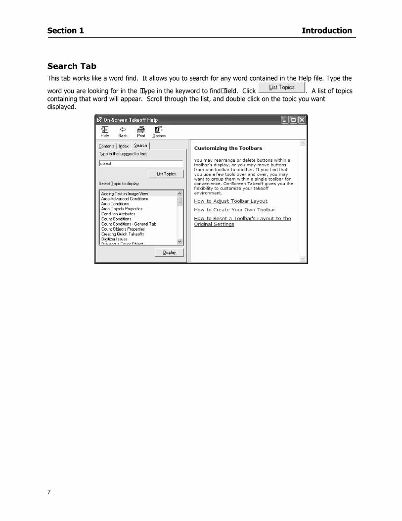
Section 1 Introduction
7
Search Tab This tab works like a word find It allows you to search for any word contained in the Help file Type the
word you are looking for in the lsquoType in the keyword to findrsquo field Click A list of topics containing that word will appear Scroll through the list and double click on the topic you want displayed
Section 2
8
Setup
This section will
Let you know what system requirements you will need to have in place
Recommend components that work well with the software
Help Full Mode users install a digitizer
Section 2 Setup
9
Minimum System Requirements To use On-Screen Takeoff your computer must meet the following minimum system requirements
An IBM PC or 100 compatible computer with a Pentium II or faster Intel processor
Memory Requirements 200 MB of available hard-disk space and256 MB RAM (128 MB preferred)
Windows 2000 SP4 and Windows XP SP2 256 color video card Super VGA display card Mouse 15-inch monitor
While these are the minimum system requirements Windows places heavy demands on your systems resources The more available memory in your computer the faster and more efficient On-Screen Takeoff will operate
Recommended Components
For the best performance we recommend the following components
Pentium III or faster processor
512 or more of RAM
12X speed CD-ROM or better
17-inch monitor or dual monitors Graphic adapter with 128 MB or more VRAM Sound card and speakers installed
NOTE In order to utilize the Training Videos you must have a sound card and speakers installed
Compatible File Formats The resolution in electronic plans does not need to be more that 200 DPI (Dots per Inch) The preferred file format is a black and white TIF (Group4) On-Screen Takeoff recognizes image files with the following extensions
File Extensions View Mode Lite Mode Full Mode TIF X X X PDF X X X OSE X X X JPG X X X CPC X X X CAL X DGN X DWG X DXF X OSP X PLN X PLT X
Section 2 Setup
10
NOTE Use the following image types for best results
Convert to TIF
The converted files will be stored in a folder with the name of the current On-Screen Takeoff project Since the conversion can be very time consuming you should only select this option if you really intend to convert vector files to TIF
1 Select File gt Project Properties
2 In the Pages Field add your image See Section 5 Establishing Project Setting Adding Pages
3 Click
4 Then select the page with the drawing you wish to convert
5 Click
Installing Your Digitizer The following instructions are a quick start to installing your digitizer For more specific information please reference Appendix I Installing Your Digitizer at the end of this guide
Connecting Your Digitizer
Upon receiving your digitizer (either a GTCO or another brand) you will need to connect it to your computer
1 Lay the digitizer out flat
2 Connect the Stylus to the digitizer
3 Plug in the power supply
4 Plug the interface cable into the digitizer
5 Plug the other end of the interface cable into the computer
NOTE On-Screen Takeoff is compatible with any tablet that is WinTab compatible
Digitizer options are only available in Full Mode If you are in View or Lite Mode and would like
to use this feature click from the main toolbar to purchase the upgrade
Section 3
11
Toolbars and Menus
This section will
Introduce the program toolbars
Familiarize you with On-Screen Take Offtrade Menu options
Section 3 Toolbars and Menus
12
Toolbars On-Screen Takeoff is equipped with several helpful toolbars for application efficiency See Appendix II Toolbar Item` Details for a detailed description of each toolbar item Individually the toolbars may be displayed moved docked reshaped or hidden from view You can also create costume toolbars to fit your needs
Main Toolbar
Tool Toolbar
Zoom Toolbar
View Toolbar
Navigate Toolbar
Takeoff Toolbar
Image Toolbar Viewing Toolbars Toolbars are displayed on the screen and will be consistent on each tab or page (Some toolbars or toolbar items will be in an inactive state if they donrsquot have a supporting element in the application)
1 Select View gt Toolbars and select the appropriate toolbar name
OR
2 Right-click on a toolbar region of the screen
3 Check the toolbars you want to display
Section 3 Toolbars and Menus
13
Moving Toolbars The toolbars may be positioned anywhere on the screen you wish This feature is provided to allow the flexibility for positioning the toolbars so they are out of your way yet handy for use
1 Click on an edge of the toolbar holding down the mouse button drag it to its new position
2 Release the mouse button to set it in place
NOTE If the toolbar is dropped anywhere other than a screen edge it will become free floating This feature is especially handy when using multiple monitors
Docking Toolbars The toolbars can be docked to any of the screen edges
1 Click on the title bar of an undocked toolbar
2 Drag the toolbar to any location on the screen
Hiding Toolbars
1 Select View gt Toolbars and select the toolbar you wish to remove from the screen
2 Right-click on the toolbar or dock bar areas
3 A floating toolbar can be closed by clicking on the in the upper right corner of the toolbar
Resizing Toolbars Only undocked (floating) toolbars may be resized
1 Position the mouse pointer over an edge
2 Click and drag
3 The toolbar can be resized as desired
Customizing the Toolbars You may rearrange or delete buttons within a toolbarrsquos display or you may move buttons from one toolbar to another If you find that you use a few tools over and over you may want to group them within a single toolbar for convenience On-Screen Takeoff gives you the flexibility to customize your takeoff environment
1 Select Tools gt Customize The Customize dialog will open
2 With the dialog open click on a toolbar button and drag buttons from one toolbar to another or a new location within the same toolbar
3 To add a button without altering another toolbar click on the Commands tab of the Customize dialog and drag the appropriate symbol from the Buttons section to a toolbar
4 To remove a button drag it to within the takeoff area of the application
Section 3 Toolbars and Menus
14
Menus
Section 3 Toolbars and Menus
15
Digitizer Menu
Section 4
16
Features
This section will
Show you how open On-Screen Takeoff
Describe the On-Screen Takeoff environment
Teach you how to navigate pages
Section 4 Features
17
Start On-Screen Takeoff
1 On your desktop double-click your On-Screen Takeoff icon
2 The application will open
OR
3 Left-click on the Start button on your computerrsquos toolbar
4 Scroll up to Programs gt On Center Software
5 Highlight On-Screen Takeoff and click On-Screen Takeoff will open On-Screen Takeoff opens to an untitled blank project The Image view of the screen will be a blank page
Two blank dock bars the Pan dock bar and the Takeoff dock bar appear at the left side of the screen Along the bottom the Status bar displays user status or context-sensitive messages as well as paper size and current zoom percentage of the plan sheet on screen The menu bar and several task specific toolbars are located at the top of the screen
NOTE All toolbars and dock bars may be accessed to view or hide through View gt Toolbars on the menu bar
Section 4 Features
18
Quick Start Video When On-Screen Takeoff opens you will be given an option to watch the Quick Start video (recommended) or start the program without watching the video
The 20 minute video will demonstrate key program functionality and allow you to view application instruction for enhanced learning
If you would like to watch the video click If you prefer to get started without
the video click If you have already viewed the video click the lsquoDo not show this message againrsquo box to prevent this dialog from appearing each time you open the program
NOTE If you decide later that you would like to watch the Quick Start video go to Help gt Watch
Quick Start Videos
On-Screen Takeoff Environment The On-Screen Takeoff environment acts like your drafting table allowing you to work on several sheets of plans at once and to reference at a glance the entire drawing and your position on that drawing while giving you the power of a computer to track analyze print and export your takeoff quantities and plans
The screen is bordered at the top by the Menu bar with pull-down menus and at the bottom by the Status bar which indicates current user status plan page size and current zoom percentage of page The largest portion of the application screen will be your takeoff area bounded on the left (by default) by two dock bars and on the top by several toolbars
In the takeoff area you may view your project plans (images) andor takeoff objects the takeoff list with quantities the worksheet or a legend of your condition list
The main window of On-Screen Takeoff has three tabs located at the bottom left allowing for quick change between Image Takeoff or Worksheet views Select the desired view option on the toolbar and it will automatically open on your screen
Section 4 Features
19
Image View
This view shows the plan file andor takeoff conditions drawn from your plans
Takeoff View This view displays the height if applicable and quantity breakdowns of your conditions according to result types indicated (eg linear feet square feet or count of items) for zones pages and the project as a whole It also displays notes per condition
Section 4 Features
20
Worksheet View This view displays the condition and quantity in units of measure specified in the first results field of the Results tab in the Condition dialog and allows the user to enter amounts for material labor and subcontractor takeoffs
NOTE When in the Worksheet view tab out the field then save This is keep all the values saved
Navigating On-Screen Takeoff
Auto Scrolling When creating linear areas or zones On-Screen Takeoff will automatically scroll the image view when necessary It will move as your mouse or digitizer moves beyond the edge of the current view
Changing Pages
1 Select View gt Next Page Previous Page or Go To Page (specify page number for the Go to Page option)
2 You may also select the corresponding arrows for these options from the Navigate Toolbar The
drop down arrow in the Page field will list the pages The and arrows will take you to the
previous or next page The and arrows will take you to the first or last page
OR
Section 4 Features
21
3 Or press Ctrl G for the Go To Page dialog
Hot Links Hot links allow you to move quickly from one drawing to the pertinent area of another drawing A hot link is handy when viewing enlarged areas of a page and needing the ability to jump back to a reference page
1 Select Tools gt Hot Link
OR
2 Click from the Tools Toolbar
3 Click on the page where you want to set the link The Hot Link dialog will open
4 Using the current page display on the Navigate Toolbar access the pull-down menu of pages by
clicking on the arrow at the right
5 Select the page for your link (You may also choose View gt Go to Page and select by page number)
6 Manipulate the view using the zoom tool and the scroll bars
7 Click
8 After joining a hot link to another page the hot link arrows in the Navigation Toolbar will become active
9 Move a hot link to another location on the page by clicking then click and drag the hot link image anywhere on the page
Section 5
22
Projects
This section will
Help you create settings important to your projects
Explain how On-Screen Takeoff works with your electronic or paper plans
Section 5 Projects
23
Project Template Files You can begin your project with a template Templates allow you to take advantage of conditions and settings used with previous projects
On-Screen Takeoff templates contain condition lists and established layer separations from previous projects you have created You may also use the sample templates provided with On-Screen Takeoff as a great starting point All aspects of the templates may be adjusted for a new project
1 Select File gt New and click the OK button
2 From the New dialog box choose the template that best fits your project
3 The conditions for this template will appear in the Takeoff Dock bar and the Project Properties dialog will open asking for further information
4 Use File gt Save or File gt Save As to rename and save your new project
Saving a Project as a Template File You can save your condition properties and layers as a template for future projects
1 Select File gt Save As
2 Enter a name for your template and select On-Screen Takeoff Template Files (tpo) from the Save As type field of the dialog (click on the down arrow to select)
3 Click the OK button to accept and close the dialog Modifying a Template File Follow these steps to modify an existing template file if you need to change or add conditions andor layers
1 Select File gt Open
2 Navigate to your Projects directory
3 In the File Type drop-down select On-Screen Takeoff Template files (tpo)
4 Choose the On-Screen Takeoff template file you would like to modify and click the OK button
5 Make appropriate changes
6 Save and close file
The On-Screen Takeoff template files cannot save takeoff information
Section 5 Projects
24
Opening an Existing Project File 1 Select File gt Open
2 Navigate to the desired file location
3 Click the Open button
NOTE If your latest changes to a project file have not been saved On-Screen Takeoff will ask
you whether you would like to save the file and gives you the option of canceling the operation
Creating a New Project
1 Select File gt New
2 For a blank untitled project click
3 At this point the Project Properties dialog will pop-up for more information about your takeoff
NOTE The following are important to keep in mind when beginning a new project
At the start of your project fill out the Project Properties settings to establish the name for all printed output from your project set the default page size and scale for your plans number and names of different pages within the project and locations of electronic drawings
Scale settings can significantly affect quantity outcomes Be sure to set the scale for each page of drawings before beginning condition takeoffs
When using a digitizer remember to make a mark with a pen or pencil in the upper left and lower right corners of the first sheet of the paper plans to delineate the takeoff area for that sheet You can then set the takeoff area on On-Screen Takeoff using your marks
Save your project before you begin taking off any conditions On-Screen Takeoff will write a back-up file using the same file name
Remember the Undo feature If you make a mistake select Edit gt Undo and reverse the process step by step
Section 5 Projects
25
Project Properties
You can either set your Project Properties when you create a new takeoff or once your project file is saved under the appropriate name
1 Select File gt Project Properties the Project Properties dialog box will appear
2 Type in the name of your project to appear on printouts Use the backspace andor delete keys to edit the name as necessary
3 Press the Tab key to move to the Default Image Size option or click within the Image Size box You may click on the arrow at the right for the pull-down menu of page size options or you can use the down-arrow key on your keyboard to scroll through the list to the appropriate selection
4 Press the Tab key to move to the Default Scale option Select a scale by using the drop down arrow If your scale is metric you will need to click in the box next to Metric to convert to that measurement
5 Establish the number of pages for your project plans And load image files See Adding Pages to
Your Project
Adding Pages to Projects Individual Electronic Plans
1 Click on in the Project Properties dialog
2 In the Add Images dialog use the drop down arrow to navigate to the appropriate directory and folder containing your image
3 Select the file so that it displays in the File name field then click The file will display by name and path in the Image File field in Project Properties dialog
4 Click to accept and your project will automatically open
5 Save your project with the new settings by selecting File gt Save
Section 5 Projects
26
Electronic plans scanned from blueprints (as opposed to blue lines) will display as white lines on a black background and are difficult to read on your computer screen Select Image gt Invert and the colors will invert to black on white
You may have noticed the Page column in the Project Properties dialog Generally plan images occupy one page and 1 will be listed in the column indicating Page 1 of your plan file If you import a multi-page TIF a plan file containing more than one page of plans they will import as separate pages and each successive page will be indicated under the Page column as 1 2 3 etc of the plan file
Group of Electronic Plans You may add all the electronic plan files from a particular source (for example from a CD) by using the Auto Add feature
1 Click the button in the Project Properties dialog
2 Browse until you find the appropriate directory and folder containing your plan images
3 Click on any file displayed within your target folder so that the file name appears in the File name box of the Auto Add dialog
4 Click The image paths and file names will be recorded into the project properties arranged alphabetically
5 Click to accept your choices and your project will automatically open
6 Save your project with the new settings by selecting File gt Save
To load Dodge Plans into your Project Properties see Appendix IIi Loading Plans from a Dodge CD
Paper Plans On-Screen Takeoff makes it easy for Full Mode users to perform quantity takeoffs from paper plans using a digitizer
1 Add pages by clicking until you have the number of pages initially in the project
2 Name each page by clicking within the Title area and typing the name
3 Click to accept your choices and close the Project Properties dialog
4 Save your project with the new project properties settings by selecting File gt Save
Section 5 Projects
27
Setting Up a Drawing Template On-Screen Takeoff provides the convenience of using the same work surface for both digitizer and mouse to allow the user to draw conditions and then edit settings of the project or add or change conditions without breaking stride A mouse pad template included with the program defines the area of the digitizer in which use of the stylus or cursor will be recognized as mouse movement as opposed to drawing movement
1 Place your stylus on On-Screen Takeoff
2 Placing the template identifies the location mouse movements will be recognized by the program
Before placing the template the template must be applied to the digitizer surface This may have been done during the installation of your digitizer We suggest attaching the template to the lower right corner of the digitizer surface about one inch inside the grid area
3 Select Digitizer gt Place Template
4 Follow the instruction prompts on the screen clicking first on the target symbol at the left of the On-Screen Takeoff box on the template then on the target at the right
Setting Takeoff Area Before you can begin taking off a drawing you must define the drawing area on the digitizer This requires defining an area that will include all objects on each drawing of your plans As you add pages to your takeoff the same area of the digitizer will be active
1 Secure the plans to the digitizer with tape or a set of clamps
2 With a pen or a pencil mark the upper left corner and the lower right corner of the first page in your set of plans
3 Select Digitizer gt Set Takeoff Area
4 Click each mark with the stylus pen as prompted
5 Verify the active area of the digitizer by looking at the image size located in the lower right corner of your screen
If you close the program before the takeoff is complete you will need to reestablish the takeoff area before you can add additional condition quantities
Electronic plans appear on your computer screen eliminating the need to set a takeoff area You simply drag your mouse across the conditions you wish to takeoff The conditions will be highlighted and quantities will be totaled instantly Electronic plans are available through a variety of services For information contact an On Center Software account manager
Section 5 Projects
28
Setting Scale for Specific Pages You may set the scale in each page view separately This will override the default scale setting in Project Properties for that page Setting the correct scale for the drawing before taking off quantities ensures accurate calculations Be careful to check the scale for each drawing in your project before doing takeoffs
1 Display the page you want to set select Edit gt Set Scale
2 Use the drop down arrow to select a scale that will be applied to that page
3 Click
OR
4 Access the pull-down scale settings on the Navigate toolbar
NOTE As you draw objects notice that the drawn object is similar in width to the object on your plans If it is not the scale set may not be correct
Calculating Scale You may calculate scale according to a known measurement between two points either with a digitizer or on electronic plans
1 Select Edit gt Calculate Scale using Image or Edit gt Calculate Scale using Digitizer
2 Follow the instructions in the related Calculate Scale dialog box You will be asked to click on the first and second points then to enter the dimension for that distance
3 The scale will be recalculated for the displayed page and the Scale display on the Navigate toolbar will show the new scale
Section 6
29
Conditions and Takeoff
This section will Draw Conditions to Takeoff Plan Quantities
What Zones will do to help your takeoff process
Discuss the ins and outs of Takeoffs
Section 6 Conditions and Takeoff
30
Creating Conditions
If you are starting a new project from scratch you will need to create conditions to takeoff quantities such as floor areas wall lengths and corner bead counts If you are using a template you will have several pre-designed conditions already listed on the Takeoff dock bar However you may want to change the characteristics of some conditions or create additional conditions for a particular project
1 Right Click within the Takeoff dock bar Select New gt Condition
Or
2 From the Takeoff dock bar Click (if the buttons are not showing right-click in the Takeoff dock bar area and select Show Buttons from the pop-up menu) The New Condition dialog appears
3 Select the condition type (Linear Area Count or Zone) from the pull-down menu accessed by the
down arrow next to the Type option
4 Press Tab or use the mouse (or stylus) to move to Name and enter a name for your condition
5 Specify the desired condition attributes See Condition Attributes for more detail
6 Click for condition to apply
Section 6 Conditions and Takeoff
31
Condition Attributes Each condition type will have related attributes to select or specify within the General and Advanced tabs of the New Condition dialog Once a condition has been used to takeoff a quantity from your plans certain attributes cannot be changed
All conditions allow the user to specify color and fill pattern for the object drawn
Linear Conditions
General Specify width and height by feet and inches Specify pitch in inches up to the nearest thousandth of an inch if applicable
Advanced Specify rounding for object quantities and droprun default length for electrical or plumbing drops at the ends of lines Select Connect to have lines connect at the corners where one line of the condition ends and another begins (and indicate Tolerance for the featurersquos activation as distance between the ends of two lines) Choose Trim to have lines automatically trim to a line being crossed Choose Curve to draw a curved line
Follow these examples for inputting feet and inches For 7 feet 6 inches type 706 for 13 feet 7 inches type 1307 For 20 feet type 2000
Section 6 Conditions and Takeoff
32
Area Conditions
General If needed you can specify the thickness (in inches) andor pitch (in inches)
Advanced Specify rounding for object quantities Choose to display an adjustable grid within the area and indicate matrix cell dimensions
Section 6 Conditions and Takeoff
33
Count Conditions
General
Specify height and indicate the size (in inches) and shape (square circle triangle rectangle or opening) of the count object as it will appear on screen
Advanced Count conditions have advanced attributes These options are available for all shapes except for openings
Zone Conditions Zones allow you to subdivide condition quantities making it easier to modify and complete jobs in phases They can be used at the end of a takeoff to isolate a group of condition quantities that are in different areas of the takeoff
Zones can also be used to break a takeoff into multi-phases and can even be used to isolate quantities while a job is in progress to group the amount of work that has been completed to date They can be applied to one or multiple pages in your plans automatically calculating the takeoff quantities for each zoned area
Section 6 Conditions and Takeoff
34
The zone feature is only available in Lite and Full Mode If you are in View Mode and would like
to use this feature click from the main toolbar to purchase the upgrade
Condition Notes A Note tab is provided for comments regarding the condition These notes will display on the Takeoff List report and will import into Quick Bid
Section 6 Conditions and Takeoff
35
Condition Results The Results tab of the New Condition is based on condition type Initial settings default to linear feet (LF) for linear conditions square feet (SF) for area conditions and count of items (EA) for count conditions and zones The first of the results fields will display for the condition items in the Takeoff dock bar area All results will display in worksheets and Takeoff List reports as well as in an Excel spreadsheet after being exported
Copying Conditions You may use the condition attributes from a condition yoursquove already created for any future conditions of the same type
1 Click on a condition to select it
2 Click the Copy button from the toolbar
OR
3 Right-click in the Takeoff dock bar area and select copy
4 A new condition will appear in the list with the same condition attributes as the previous condition but with the quantities zeroed
Editing Conditions Once you have copied a condition you might want to change several attributes You can also edit an existing condition to fit any updated needs
1 Highlight the desired condition on the Takeoff dock bar
2 Click the Change button
OR
3 Double-click on the condition you wish to edit to bring up the Change Condition dialog
NOTE The Change Condition dialog differs from the New Condition dialog only in that if takeoffs
Section 6 Conditions and Takeoff
36
have been performed in your project with this condition you will not be able to change the type of condition or certain properties under the advanced tab of the dialog box
Deleting Conditions 1 Click on the condition in the Takeoff Dock bar area
2 Click the Delete button on the toolbar
OR
3 Right-click and select Delete from the pop-up menu
All takeoff associated with the deleted condition will be deleted immediately and permanently
Organizing Project Conditions Within your project you can create folders andor sub-folders for different types of conditions You may even want to create a folder containing conditions with reset values
To get started organizing your conditions make sure you are viewing the condition tree (right-click in the Takeoff dock bar area and select Show Tree)
Creating Folders and Sub-Folders 1 Right-click in the Takeoff Dock bar area
2 Select New gt Folder from the pop-up menu
Copying Folders
1 Click on the folder and click Copy on the toolbar
2 All copied conditions within the new folder will have values reset to zero
Renaming Folders
1 Click on the folder
2 Right-click and select Rename from the pop-up menu
3 Enter a name for your folder and click the Enter button
Changing Condition Order
You may move conditions up or down in the condition list of the Takeoff dock bar to suit your project needs
1 Select the condition you would like to move by clicking to highlight it
NOTE When you are ready to move the highlighted conditions be sure that you start
moving using the last condition chosen That condition will have a highlighted boarder
Section 6 Conditions and Takeoff
37
2 Drag and drop any the condition from one place to another in the list You may also move a condition to another folder on the list in this way
Drawing with Conditions Snap Angles Set up snap angles to prevent lines from appearing jagged Snap angles are commonly set at 15deg and shift snap angles at 0deg
1 Go to Tools gt Options Options dialog appears
2 Under the General tab make the desired settings
3 Click to save the settings As they are drawn lines will snap to the set degree
Drawing a Linear Object 1 Select a condition from the Condition List in the Takeoff dock bar
2 Move the cursor into the Image takeoff area of the screen you will see the cursor display as crosshairs
3 Click and hold left mouse button then drag mouse to draw a line
4 Release mouse button to set line
Section 6 Conditions and Takeoff
38
5 Repeat steps for further lines
Continuous Mode This feature allows you to draw an object that has connected lines
1 Click the icon from the Takeoff toolbar
OR
2 Go to Tools gt Continuous Mode
3 Follow steps 1-3 from Draw a Linear Object
4 Click at each point of intersection The object will be connected
5 Double-click after making the final point to set the lines
Drawing a Curve To draw a curved line the Curve option must be checked under the Advanced tab of the Condition dialog
1 Click where you want to begin the curve and drag in a straight line to the position for the other endpoint of the curve
2 Click on the line to select it Handles in the shapes of small squares will appear at either end of
Section 6 Conditions and Takeoff
39
the line and in the center of the line
3 Move the cursor over the center handles until the cursor becomes a two-way arrow
4 Click and drag in the direction of the curve bending the line as you move the cursor Release to set the curve (The line you began with will disappear)
Draw a circle by drawing two curved lines connected
Drawing an Area Object Area conditions are drawn similarly to continuous mode lines You may trace any number of adjoining walls at different angles to complete your area takeoff
NOTE When drawing an area do not intersect the perimeter or line of the object you are drawing
1 Click at each point
2 Double-click when yoursquove returned to your starting point
3 The area will be filled with the pattern set for that condition
NOTE The simulated circle will be good enough for you to be able to make a bid
To create a circular area click from point to point with very short distances in between points simulating a circlersquos perimeter Double-click after setting the last point to set the area
Section 6 Conditions and Takeoff
40
Grid Options Grids give you an added advantage when installing materials such as tiles Use this feature to get a count for how many tiles are needed for an area
1 Double-click on an area condition in the Takeoff dock bar to open its Condition dialog
2 Click on the Advanced tab to show its options
3 Check the box next to Grid by clicking in it
4 Indicate the dimensions of the cell matrix in inches (For example 200 x 400)
5 Under Results tab choose each (EA) for one of the results fields This will tabulate a number of grid cells (including partial grid cells) in area
6 Click to save your settings
7 Use the Move Grid and Rotate Grid features in the Tools menu to manipulate the grid as desired
Grid Calculation
1 Go to Tools gt Options menu
1 Specify if On-Screen Takeoff automatically should Calculate Grid Position
2 If AreaGrid Size is selected On-Screen Takeoff will calculate the number of items needed to fill the grid based on grid demintions
3 Click to accept and close the dialog
To move a line at any angle (regardless of default setting) press the Shift key while moving the mouse
Section 6 Conditions and Takeoff
41
Backout Mode This feature allows you to take out part of an area and deduct that amount of square footage
1 Select Tools gt Backout Mode
2 Outline the are you want backed out as you would when drawing a regular area object (see Drawing an Area Object)
3 The outlined area will clear and quantities will be recalculated
NOTE The perimeter of the backout area will be added to the LF quantity for that condition
Drawing a Count Object Square triangle rectangle and circle shaped count objects can easily be placed on images
1 Select the condition
2 Click in the location where you want the object to appear
3 To place an opening-shaped count item like a door or window you must click over an existing linear object such as a wall
4 On the Results tab you can change the height properties to give you the result you need
5 If Backout is checked on the advanced tab for each count opening the opening-shaped count item will back out a corresponding section of the linear object
Opening shaped count items are sized at 3rsquo0rdquo by default
Drawing a Zone Zones are drawn in the same way as area objects and may be any polygonal shape You may trace any number of adjoining walls at different angles to complete the zone perimeter
1 Click at each point
2 Double-click when yoursquove returned to your starting point
Section 6 Conditions and Takeoff
42
Selecting Objects
1 Use the Select Tool to select objects
You can also select all objects that correspond to a condition
1 Click on a condition to select it
2 Right-click and choose Select All
3 All objects with this condition will be highlighted with squares as an outline
Moving and Resizing Objects Linear
1 To move or resize a linear object click anywhere on the line to select it
2 To move the line position your pointer over the center handles When the mouse is positioned over the handles you will see a two-way arrow You will only be able to move the line in the direction of the arrows
3 Drag the line to a new position
4 Clicking and dragging the handles on the ends of the line will allow you to lengthen or shorten your line
Area and Zone
1 To move an area object or zone in its entirety click and drag it to its new position
2 Grabbing a handle at a corner or intersection of the object will allow you to adjust and change its perimeter
Section 6 Conditions and Takeoff
43
Count 1 To move a square circle rectangle or triangle shaped count object click and drag
2 Click and drag an opening shaped count object along the length of the linear object to the desired position then release
NOTE An opening shaped count object may not be moved from its associated linear condition object however it may be moved up and down the length of the linear object
Layers On-Screen Takeoff allows you to sort and separate your takeoff objects within the same job and on the same page On-Screen Takeoff gives you this flexibility through the use of layers
By assigning different conditions to different layers (for example differentiating between floors ceilings and walls) you can choose to view all layers or turn off certain layers to display and print the remaining groups of conditions only You may also remove the background image of electronic plans add text and hot link symbols or print only your condition takeoffs
Layers are only available in Full Mode If you are in View or Lite Mode and would like to use this
feature click from the main toolbar to purchase the upgrade Default Layers
On-Screen Takeoff begins every project with three default layers Image Annotation and Default The Image layer holds the electronic plan files you may have in your project The Annotation layer possesses all text notations highlighting and hot links in the project The Default layer will appear in the Condition dialog when creating or editing a condition (listed in the takeoff dock bar) Conditions are assigned to the Default layer unless otherwise specified by the user
Creating Layers To assign a condition to a layer other than the default layer you must first create additional layers for your project
1 Select View gt Layers to open the Layers dialog
2 Click An unnamed layer will be added
3 Click within the empty box and type a name for your layer (for example Wall)
4 New layers are added as active layers The adjacent box under the Show column will be checked
Section 6 Conditions and Takeoff
44
Assigning a Layer to a Condition 1 Open the Condition dialog box by creating a new condition or editing an existing condition
2 Under the General tab click on the down arrow in the Layer field to display optional layers
3 Select the desired layer for the condition Only the Default layer and layers you have added will be displayed
4 Click
View and Hide Layers
1 Select View gt Layers
2 Under the Show column check the box to view or remove the check (by clicking on it) to hide the specific layer
3 Click to accept and close the Layers dialog
Section 6 Conditions and Takeoff
45
Assigning Text to a Layer When adding text to an image On-Screen Takeoff has the capability to assign the text to a specified layer
1 Select the Text Tool
2 Click at the point you want to place your text
3 Type in your text using the Enter key for line breaks
4 Click the drop down arrow next to the Layer field and select the desired layer
Section 7
46
Printing and Exporting
This section will
Printing options and procedures
Exporting data by copying and pasting
Exporting quantity results to Excel spreadsheets
Section 7 Printing and Exporting
47
Print Setup On-Screen Takeoff allows the user to print the image takeoff list and worksheet
1 Select File gt Print Setup The Print Setup dialog will open
2 Select a printer or leave the default selection listed (change from the default printer displayed by clicking on the down arrow at the right of the field)
3 Indicate page size and printer tray option (Source) Access page size options by clicking on the
down arrow at the right of the field
4 Choose Portrait or Landscape orientation
5 Click to accept and close the dialog
Printing Images The image area can include the electronic plans the takeoff objects added text and hot links To print a subset of these (for example just the takeoffs without the plans or the added text and hot link symbols) hide layers that you do not want to print (see Section 6 View and Hide Layers) When you are printing your images every page will show the scale of the takeoff you are printing
1 Click on the Image tab to display the area of your project
2 Select File gt Print (or Ctrl + P)
Section 7 Printing and Exporting
48
3 Select the desired view (What to print) and the Image Range
4 Click The second Print dialog will open
5 Change settings accordingly or click if you accept the default settings
Printing Takeoff Lists and Worksheets In Takeoff Lists and Worksheets you may hide columns to print only certain results or adjust column widths to fit the report within the page size selected
1 In Takeoff List or Worksheet view move your cursor to the right side of the columnrsquos title bar the cursor will display as a two-way arrow
Section 7 Printing and Exporting
49
2 Click and drag to adjust the width of the column Holding the mouse button you may
slide the title bar under the title bar to its left to hide the column completely
3 Select File gt Print or press Ctrl + P to access the Print dialog
4 Indicate desired printer and choose the number of copies
5 Click to print and close the dialog
When printing the condition list we suggest printing in landscape
To reset to the default column widths double-click on the right border of a column heading will reset the column to its right (or previously to its right before being hidden)
Print Preview 1 Select File gt Print Preview
2 Use and to vary your view 3 If viewing an image choose current full or scale view to see how it displays
4 For printed outputs that cover more than one page use and to view adjacent pages or click on the down arrow next to Page field and select the page you want displayed
Exporting Using the CopyPaste Feature You may copy all the data or sections from the worksheet and the takeoff list view in On-Screen Takeoff and paste it into another application When pasting into Excel the cell layout will be maintained
1 Highlight the areas you wish to paste Click and hold the left mouse button down as you drag the cursor over the area to be selected then releasing the mouse button
OR
2 Select the entire takeoff list quickly click on the left On-Screen Takeoff column header and hold and drag the cursor across the remaining column headings
The number of pages for the view selected will display in the lower left-hand corner The zoom percentage that applies to the view will be displayed in the lower right-hand corner next to page size of the drawing
Section 7 Printing and Exporting
50
3 In the worksheet view you may highlight rows by clicking on the numbered buttons to the left of each row clicking and dragging across column headings or clicking and dragging over individual cells in the worksheet
Click anywhere in the appropriate view to deselect the area
4 Once your selection is highlighted you may select Edit gt Copy or Ctrl C from the keyboard 5 On your monitor switch to the application into which you want to paste your selection 6 Select Edit gt Paste in the new application or simply press Ctrl + V to paste
The colored keys for conditions cannot be pasted
Using the Export Feature You may export condition quantities to specified cell location within an Excel worksheet file Cell target locations are assigned in the Results tab of the condition dialogs on the Export line relating to each quantity measurement type
On-Screen Takeoff will export takeoff quantity results for up to three different quantity types that you specify For instance you may want to know the number of square feet in a ceiling area as well as the number of linear feet in its perimeter
Section 7 Printing and Exporting
51
1 Bring up the Condition dialog by double-clicking on a condition in the takeoff dock bar or by
selecting the condition and clicking
2 Click on the Results tab to access its fields The default quantities for the condition type will display
3 For each results field click on the arrow to access the pull-down menu and select the appropriate quantity (for example SF LF EA etchellip)
4 Have your Excel spreadsheet opened and saved in a file
5 Specify the Excel spreadsheet cell locations where you want the results to go
6 For a cell in the first sheet of your spreadsheet type in the cell address (eg a1) Case is not important
7 For a cell on a successive sheet of your spreadsheet type in sheet the number followed by a comma and the cell address without any spaces (eg sheet2a1) Case is not important
8 Click
9 Select File gt Export gt Condition Qty to Excel
Section 7 Printing and Exporting
52
10 Browse to the location of the Excel spreadsheet file click file to select it
11 Click to export On-Screen Takeoff results to specified cell locations in the Excel file When you return to the Excel application you will see the values have been added to the specified cell locations in your spreadsheet
12 Save your Excel file
Exporting Worksheet to Excel
1 Assign condition quantities you want to export
2 Open saved Excel spreadsheet file to which you will be exporting
3 From On-Screen Takeoff Select File gt Export gt Worksheet to Excel
4 Browse to the location of the Excel spreadsheet file click file to select it
5 Click When you return to the Excel application you will see the values from the Worksheet Tab have been added to your spreadsheet
6 Save your Excel file
Exporting Takeoff to CVS 1 Assign condition quantities you want to export
2 Open saved Excel spreadsheet file to which you will be exporting
3 Click the Takeoff Tab in the project you want to export the information
4 Select File gt Export gt Takeoff to CSV
5 Browse to the location of the CSV spreadsheet file click file to select it
6 Click the Save
NOTE CSV files can be opened in Excel Lotus Access etc One may consider this option more of a ldquodumprdquo into a file
The Excel application must be active (it may be minimized on the application bar) with the target spreadsheet open in the application Otherwise an error will occur with the export operation that will affect both the On-Screen Takeofftrade file and the Excel spreadsheet
Section 8
53
Advanced Features
This section will
Some special features of working with condition objects in the takeoff area
Details of advanced options for conditions
Advanced features of the Project Properties dialog
Section 8 Advanced Features
54
Features to Use with Objects Roping Feature You can move copy or delete using this feature Using the Select tool (the pointer) you may select several objects at once by clicking and dragging an outline around the objects then releasing the mouse button Roping may select either objects completely within the outlined area (inclusive) or objects both within and touched by the outlined area (touching) Specify your roping preference under Tools gt Options
1 Click and hold the mouse button at a point on the screen near the objects to be selected and drag to surround the objects with an outline
2 Release the mouse button The objects will be selected
3 You may now
Move the group around on the page by clicking within the group dragging the mouse and releasing the button to place the objects
Delete the group of objects by clicking the Delete key or
Copy and paste by pressing Ctrl C to copy the group then Ctrl V to paste it The pasted copy of the grouped objects will appear slightly offset from the original objects
Section 8 Advanced Features
55
Applying a DropRun Count
Use the droprun feature when calculating quantities to take into account the drop or run of a linear condition such as electrical lines or plumbing pipes Drop or run lengths may be added separately to any linear condition on screen while a default droprun length may be indicated for a condition as a whole
1 Select the desired linear condition from the Condition List in the Takeoff Dock bar
2 Click the Change button in the toolbar to open the Change Condition dialog
3 Click the Advanced tab to access the advanced options and click inside the DropRun check box
4 Enter a default length to be applied to all of this condition Entering 800 will be interpreted as 8 0 (You must enter both place markers for inches) You can leave the length blank and manually enter drop run on each segment drawn
5 Click the OK button to accept and close the dialog
Edit DropRun Count
1 With the related linear condition in the Takeoff Dock bar highlighted or with the pointer tool selected
2 click on the desired linear object in the image takeoff area The Count button will become active
3 Click on the Count button (alternatively select Tools gt Count) The default droprun amount will show in the pop-up Count dialog (Default length will be zero if droprun has not been selected in this conditionrsquos properties)
4 Type in the desired length Entering 800 will be interpreted as 8 0 (You must enter both place markers for inches)
5 Click the OK button The additional amount will be reflected in the corresponding quantity The new DropRun count will apply only to the object edited
Adding Text in Image View
On-Screen Takeoff allows you to place text comments around your quantity takeoffs that may be printed along with plan images and objects Text is automatically placed within the Annotation Layer (that includes text and hot links)
1 To place text on the image select the Text Tool and click at the point you want to place your text opening a text box
2 Type in your information clicking Enter for line breaks
3 When you are finished click the OK button to exit the text box
4 To reposition text simply click on the text (with the Text Tool active) to select it
5 Move the cursor over the text the cursor will now display as a four-way arrow
6 Click and drag the mouse to position the text as desired
Section 8 Advanced Features
56
1 To edit existing text use the Text Tool to double-click on the text to open the editing box
2 Enter additional text or use the Backspace key to delete text as necessary
Formatting Text Once created you may format the font size type style and color of your text
1 Click on the text to select it and select Tools gt Font or click on the Font button in the Takeoff Toolbar
2 Select the desired features (color options are disabled) and click the OK button
3 Click on the text to select it and select Tools gt Color or click on the Color button in the Takeoff Toolbar The Color dialog will open
4 Click on a color in the Basic Color palette or create a color and add to the Custom Colors palette (Be sure to click on the color in the Custom Colors palette to select it)
5 Click the OK button
Object Properties
Linear Objects
Linear objects may be set to connect at corners
A linear object may be set to trim automatically when crossing another linear object (Check the trim option under the advanced tab of the Condition dialog)
When you move a connected linear object objects automatically move and resize connected lines accordingly (quantities are then recalculated)
This feature requires that the connected linear object be moved using the center handles (does not apply when resizing the line from the ends)
Objects constrain to snap increments defined in the Tools gt Options menu (with the mouse 15deg by default incremental when shift key is held down)
Objects are measured from centerline to centerline
Section 8 Advanced Features
57
Area Objects When drawing an area use your escape key to undo the last line drawn You may reverse your
drawing of an area using the escape key
The area will not fill with color and pattern until the user double-clicks after the last line is set
Lines drawn to delineate an area object constrain to snap increments defined in the Tools gt Options menu (with the mouse 15deg by default incremental when shift key is held down)
After selecting an area to move or adjust position the mouse in the center to move the entire area position the mouse at the sides or corners to adjust the perimeter
Count Objects
All count objects are quantified by the physical number of objects per page and reported as EA for the UOM The quantity for the current Image View is (displayed in the Condition List) and the total quantity in your project is displayed in the Takeoff View and Worksheet View)
Square circle rectangle and triangle shaped count objects do not displace or subtract from other object quantities when placed on top of them However on the Advanced Tab for the count condition a connect property can be set (this is a check box) so that when a count object of this shape is put on top of a Linear type takeoff object it will move with the linear if said linear is moved
An opened-shaped count object must be placed within a linear object Opening shaped count objects may also be measured by linear foot or linear yard (EA SF and SY are also options) Opening shaped count items default to a width of 3rsquo 0rdquo at the time of creation This size can be changed The small medium and large size are not options on this type of condition anymore Check Backout on the Advanced tab for each Count object back out the footage (or yardage) of opening-shaped count objects in which they are placed
NOTE In order to see this Backout functionality (in quantity) for SY or SF deductions at least one of the
results for the Linear(s) this object will be placed on must be set to SY or SF and the count object must have a height quantity
Advanced Features of Conditions The Round Feature Under the Advanced tab of the linear and area Condition dialogues you may specify quantity rounding (in inches) For linear objects rounding applies to each linear object drawn For area objects rounding will apply to each segment of the area perimeter adjusting the perimeter and area calculations For example With a linear condition entering 12 in the Round field will round up each related linear object to the nearest 12 inches or one foot With this setting two walls of 1 4 would each round to 2 0 totaling 4 0
NOTE In the Takeoff Dock bar condition list and in the On-Screen Takeoff reports quantities will be displayed in whole numbers rounded up to the nearest foot However calculations are based on true quantities without rounding unless the Round Feature is engaged
Pitch Pitch may apply either to linear or area conditions It is measured in rise per linear foot Entering 12 indicates a 12 rise per 12 of linear distance (a pitch of 12 over 12) or an angle of 45deg
Section 8 Advanced Features
58
Advanced Features of Project Properties Selecting Multiple Pages
1 Select a single page entry by clicking on the numbered gray button to the left of the entry
2 Drag the cursor down the column of numbers to select consecutive pages
3 Click on the blank button at the top of this column to select all pages in the Properties dialog
Section 8 Advanced Features
59
Changing Image Assigned to a Drawing 1 Select the page entry by clicking on the numbered gray button to the left of the entry 2 Click the Change Image button The Change Image dialog box will appear
3 Navigate to the desired file and select by clicking on it
4 Click the Open button The electronic file assigned to the page will have been changed to reflect the new file choice
Changing Image File Path 1 Select pages as described above
2 Choose Change Folder
3 In the Change Folder dialog navigate to the appropriate folder
4 Click the OK button The file path will have been changed for the selected page entries
Delete a Page from Project Properties 1 Select the page you want to delete by clicking on its associated number (in the gray box at the
left of the entry)
2 Choose Delete Page
All Takeoff on the page will be deleted immediately and permanently
Section 8 Advanced Features
60
Advanced Features of Tool Options
Calculation Method On-Screen Takeoff has built-in calculation options to allow for faster work and faster saves until your takeoff is complete Calculation options are found by selecting Tools gt Options then clicking on the Calculation tab
Calculation method can be set to Automatic Automatic except Grids and Manual Manual will allow the program to operate more quickly while Automatic or Automatic except Grids allows the user to see quantity changes as takeoffs are made
In any mode you may press F9 to recalculate quantities for the On-Screen Takeoff current totals
Configuration Tab
When the ldquoPage Label (A01)rdquo radial button is chosen On-Screen Takeoff puts the numbered label on all the pages of in your current page indicator in your Navigate Toolbar If the Page Descriptionrdquo radial button is chosen then a description of what takeoff is on that specific page will be shown in your current page indicator in your Navigate Toolbar
This section of the configuration tab gives you options on how you want to export your information When the ldquoFolderSubfolder Namesrdquo radial button is chosen than on your file that you are exporting to will have all the conditions folders and subfolders In the Delimiter box you can choose the symbol that is needed to separate the information you are exporting Some files need semicolons () or colons () to make sure the information comes exported in is separated it the appropriate places
Section 8 Advanced Features
61
In previous versions of On-Screen Takeoff there are views that users need to have in order for them to display their information By either choosing ldquoOST 1xrdquo or ldquoOST 2xrdquo it will let the program know you want your columns of information exported in that specific format
When you have the Confirm Deletions radial button of ldquoYesrdquo chosen than every time you delete anything you will get a dialog box confirming your intentions of deletion
While working with your takeoff you have a choice to either view the legend of your conditions or hide it Choose whichever radial button that suits your needs
For those who prefer to use the Enter key to navigate in dialog boxes this option is just for that
Font Tab The Font tab is designed for you to make your own look and feel for the application At the bottom of this tab it will show you sample of the fonts and colors you have chosen
Renaming the Current Page You may change the name of the current page in the takeoff area of On-Screen Takeoff by selecting Edit gt Rename Page
This opens the Name Page dialog and you may simply type in a new name and click the Enter button The new name for the file will be reflected on the title bar for the page and in Project Properties
You also may access the Rename Page function by right-clicking in the takeoff area while in Image View and selecting the option from the pop-up menu that appears
Section 9
62
Saving and Exiting
This section will
Explain how to save projects
Show you how to safely exit the program
Section 9 Saving and Exiting
63
Saving Your Project
1 Select File gt Save 2 If your project has not previously been saved a Save dialog box will open to allow you to name
the file and choose the directory and folder in which to save your file 3 Once saved File gt Save will simply save the current version of the file
OR
4 Select File gt Save As then type in a new name for the file and save to the desired file path
The Auto-save Feature With the Auto-save feature On-Screen Takeoff automatically backs up your open project You may choose to have more than one level of backup files The first backup copy will have the extension b00 and successive files will be b01 b02 and so on If you have designated four levels of backup files after the fourth backup copy has been created (b03) the next file will be saved over the file with extension b00 Further backup saves will then rotate through the four backup files in the same way
1 Select Tools gt Options 2 In the Auto-save area (under the General tab) select the frequency of backup file creation (in
minutes) and the number of levels for the feature 3 You also may disengage the feature by clicking in the check box to clear it
The Auto-save feature automatically saves backup copies to the directory of the current project If you are working from a write-protected area such as a CD-ROM On-Screen Takeoff will place backup files in the On-Screen Takeoff folder
Exiting When you are finished using On-Screen Takeoff it is very easy to exit Exiting is very important because of security reasons If someone were to use your computer they could enter the application and view and manipulate information
Section 9 Saving and Exiting
64
On-Screen Takeoff closes the open project when you open another or create a new project or when you exit the program
1 Select File gt Exit
OR
2 You also may click at the upper right-hand corner of the application to exit
NOTE If your latest changes to a project file have not been saved On-Screen Takeoff will ask you whether you would like to save the file and gives you the option of canceling the operation
Appendix I Installing Your Digitizer
65
Appendix I Installing Your Digitizer When you get your digitizer from GTCO you will need to connect it to your computer Follow the instructions outlined below to do this
Note For rollup digitizers the metal bar must be oriented to the top or right hand side
Connecting the Digitizer 1 Lay the digitizer out flat 2 Connect the Stylus to the digitizer 3 Plug in the power adapter 4 Plug the interface (IO) cable into the digitizer 5 Plug the other end of the interface cable into an open serial port on computer
Note GTCO Technical support phone number is 410-381-6688 The electronic manual (on diskette) from GTCO contains more detailed installation and operation instructions for the GTCO digitizer model you have
Installing other Digitizer Drivers If you are using a GTCO Digitizer you will need to install the GTCO TabletWorks Drivers
If you are using a Digitizer not supported by GTCO Tablet Works 10 please contact the manufacturer of your digitizer for assistance with installation
Installing GTCO TabletWorks Drivers 1 Insert the On Center CD into the CD-ROM drive The CD Startup screen will open 2 Click on Install Software 3 Select Additional Software and Drivers 4 Select Digitizer Driver 5 Follow the instructions for installing TabletWorks 10
Adhering the Template The template is a small plastic sticker used to enable mouse function when using the digitizer with On-Screen Takeoff Place your template on your digitizer We suggest placing it in the bottom right corner of the digitizer about one inch inside the takeoff area
Note You may either peel off the back of the template and use the adhesive surface or you can tape the template down
Appendix I Installing Your Digitizer
66
Testing the Digitizer Drivers Before running OST you may test the digitizer by moving the stylus around on the digitizer pad it should move the mouse cursor (if mouse emulation is enabled)
If the digitizer does not move the mouse cursor on the screen
The superset codes may need to be reset Reset the superset codes by touching on the border of the digitizer with the stylus The digitizer should beep several times
The digitizer may not be communicating with the computer Be sure the COM port selected is correct Be sure the COM port selected is correct If you are not able to get the digitizer to move the mouse cursor you need to call GTCO technical support for help
Note The Mouse Emulation is not required for On-Screen Takeoff to work properly It is used only for the Template functionality if the digitizer is moving the cursor the wrong direction (up instead of sideways or vice-versa)
Click the L-shaped arrow symbol on the digitizer with the stylus
Appendix II Toolbar Item Details
67
Appendix II Toolbar Items Main Toolbar
Appendix II Toolbar Item Details
68
Tool Toolbar
Appendix II Toolbar Item Details
69
Zoom Toolbar
View Toolbar
Navigate Toolbar
Appendix II Toolbar Item Details
70
Navigate Toolbar (Continued)
Takeoff Toolbar
Appendix II Toolbar Item Details
71
Takeoff Toolbar (Continued)
Image Toolbar
Appendix III Loading Plans from a Dodge CD
72
Appendix III Loading Plans from a Dodge CD
This section will detail how to load plans from a F W Dodge CD-ROM into an On-Screen Takeoff project file ready for takeoffs
Dodge files may be added to the Project Properties dialog However loading the files in that way will load the files by number rather than name description If you want to load one page only from your Dodge CD You will have to rename the page to display the name rather than number of the file
To load plan files from a Dodge CD so that the files load sequentially by file number but are displayed by name rather than by number within your project follow the instructions below
Opening a Dodge project from a CD-ROM 1 Insert the CD into the drive 2 Choose File gt Custom 3 Choose Dodge Plans Project (plansdat) as the file type 4 Select the appropriate file type by clicking on the down arrow at the right of the Files of type
field 5 In the Look in field access your drive paths by clicking on the down arrow at the right of the
field then
Navigate to your CD-ROM drive Open the data folder and Open the Projects folder
6 Select the desired project and open its folder 7 Open the plansdat file 8 All the images will come in sequenced correctly for that job along with the full descriptions
(names) of each page If there is not a plans folder in the project folder then plans do not exist for that project on the CD Opening the plansdat file will yield an empty project
Appendix IV Using the Plan Viewer
73
Appendix IV Using On-Screen Takeoff Plan Viewer The On-Screen Takeoff Plan Viewer is a limited version of On Center Softwarersquos commercial takeoff software If your status bar located at the very bottom of the main window says View Mode in the lower left-hand corner then you are using the Plan Viewer You can use the plan viewer to
View CD-based amp converted CAD drawings
View a previously created OST file and associated drawings
Download electronic plans online
Navigate through drawings
Quickly Takeoff linearsareas and counts
Zoom in to view the plan better
Print drawings directly from the viewer
Viewing an On-Screen Takeoff Project File
1 To open an OST file that was previously created with of On-Screen Takeoff 2 Select File gt Open 3 An Open dialog will appear if you do not see the OST file you are looking for select the
Look In drop down arrow 4 A drop down menu will appear listing the various folders drives and mapped drives located
on your computer select the correct drive or folder location and continue to browse to the location of your OST file
5 When you see your OST file double-click it to open it 6 Any takeoff and drawings should appear on the Image tab view
If you do not see the drawings but do see the colored takeoff layer the drawings may
not be located in the same place they were originally saved at Go to File gt Project Properties and check the Image File path for each listed page If the image file path is pointing to a CD drive make sure the CD is inside the CR-ROM
Downloading Electronic Plans If your Online Plan Service provides a special file format (OSX) required to use this feature of our plan viewer you can immediately downloaded all electronic plans of a project directly from our viewer
Most Plan Room web sites will automatically open On-Screen Takeoff when a request to download plans is made Your particular Plan Room may differ in operation so please contact the provider directly with questions on using the site
Appendix IV Using the Plan Viewer
74
When you request to download or open a project file from a Plan Room you will usually have the open to open or save an OSX file Choosing open will automatically open On-Screen Takeoff Alternately you may choose to save the file to a local hard drive After you have saved the file either double-click it to launch On-Screen Takeoff or open the OSX file using On-Screen Takeoff by clicking File then Open and locating the file on your hard drive You will need to change the file type to OSX
After the OSX file is opened you will see an additional tab appear in the Conditions List window called Pages
The Pages tab shows the hierarchy of your project Gray file icons represent pages that have not been downloaded and blue icons represents pages that have been downloaded
To download a page simply double-click the page icon
If you wish to select a group of pages to download you can use the Ctrl or Shift key to multiple select them then click the Download button
If you wish to download all pages at once click the Download All button
Downloaded pages will now appear in the Project Properties dialog in the same order in which they appear in the Pages tab
Creating Quick Takeoffs With On-Screen Takeoff you can create quick takeoffs to measure quantities even if you dont have the full version of our program However using the Quick Takeoff functionality shows you just a fraction of what the full version can do
The Quick Takeoff Toolbar is located at the top of the image view It has three buttons designated for three types of takeoffs Linear Area and Count The Quantity drop down list will show secondary quantities for Linears and Areas The Units drop down allows you to select how you want your quantities displayed Feet Inches Yards Millimeters and Meters
NOTE Every time change the type of takeoff you are performing (switching from Area to Linear for example) the previous quantities and takeoff objects will disappear They will also disappear when you changes pages
NOTE You can use the Dimension Tool to basically measure the distance between two points or linears The distance will display on the status bar at the bottom of the application
The Quick Takeoff Toolbar
Appendix V Frequently Asked Questions
75
Appendix V Frequently Asked Questions General
Where is On-Screen Takeoff installed on my computer
Typically it is installed in CProgram FilesOn-Screen Takeoff
In Explorer how do I recognize On-Screen Takeoff file types
On-Screen Takeoff data is stored in a single file per job lsquojob name OSTrsquo On-Screen Takeoff templates are stored as lsquotemplate nameTPOrsquo
Can only one project at a time be open
Yes For that reason opening another project automatically closes the project on screen You will be asked to save any changes
Is only one scale allowed per page What about on drawings that have multiple detail sections on a page and each of those drawings have different scales
Yes For pages with drawings of different scales copy the drawing to another project page and set the appropriate scale
I cannot perform backout on an area that is along a linear
As a workaround use the On-Screen Takeoff layers feature to help you with this issue Electronic Images
How do I start a project from drawings that have been scanned and written to a CD-ROM
Open a new project Select File gt Project Properties and select Auto Add Navigate to your CD and the appropriate folder and select any image file in that location Click Open All files in the location will load into your project Recommended that images are copied from CD to hard drive for performance
If I get a disk of drawings in AutoCAD format (R13 or R14) can I read them in On-Screen Takeoff
Yes On-Screen Takeoff now reads DWG DXF and many other format that are saved with AutoCAD
Appendix V Frequently Asked Questions
76
When I click on the all pages button what is supposed to happen Currently nothing seems to change when I click on that button
The All Pages button is used to apply the Darken and Enhance Plans feature to all pages in the project (as opposed to only the current page on screen)
Is there a way to deduct a large skylight from an area condition
Yes with the related area condition selected in the Takeoff Dock bar unselect the Backout button on the Takeoff Toolbar then draw the Backout area The area quantity will be deducted from the related condition object and the linear measurement of the Backout perimeter will be added
Digitizer Issues
How do I connect a Digitizer to the computer
See Appendix I Connecting a Digitizer
The Place Template menu choice is disabled
On-Screen Takeoff may need to be authorized or the digitizer or the digitzer drivers are not installed
It wonrsquot let me select the Set Takeoff Area menu choice
On-Screen Takeoff may need to be authorized or no job is open a digitizer is not installed or the drivers are not installed
The digitizer stylus is not moving the cursor or crosshairs
Click S-0-1 superset on the digitizer
How do I convert my old GTCO Digitizer to work with On- Screen Takeofftrade
Call GTCO and they may be able to reconfigure your digitizer to be compatible with On-Screen Takeoff
Printing Issues Which Printers work with On-Screen Takeoff
Compatible printers include On-Screen Takeoff Hewlett Packard Epson and Canon printers If you are having printer difficulties please contact support and specify the type of printer along with other pertinent information Contact support at wwwoncentercomsupport or email supportoncentercom
Which Plotters work with On-Screen Takeoff
Compatible Plotters include Hewlett Packard DesignJet plotters and the EnCAD Cadjet II If you are having plotter difficulties please contact support and specify the type of plotter concerned
ViewingDisplay I can no longer see my condition list How do I get it back
The toolbars and Dock bars can be turned on and off through the View gt Toolbars menu options
Appendix V Frequently Asked Questions
77
This is also accessible by right-clicking in the toolbar area and selecting (or deselecting) a toolbar listed
I cannot view my folders in the condition list
Right-click in the Takeoff Dock barcondition list area and select Show Tree to display your folders
My Status Bar reads Viewer Mode and I am unable to draw conditions
On-Screen Takeoff needs to be Authorized Or you need to purchase an upgrade Click the Perform Advanced Takeoff button on the main toolbar
I hid a Dock bar and when I selected to view it again it appeared alongside the other Dock
bar instead of stacked on top of it How do I fix it
Pick up the Dock bar by clicking on the bar at the top and continuing to hold down the mouse button drag the Dock bar over the other one It will resize and appear stacked with the other
When I open image files from a CD the images are all upside down How do I get them right
side up
To flip pages from top to bottom follow the steps below 1 Click the All Pages button on the Image Toolbar (All Pages is engaged when the button
is not clicked) 2 Click the Flip Horizontal button on the Image Toolbar 3 Click the All Pages button again to disengage
Templates How do I create a Template
Follow the steps below 1 Create a typical project 2 Choose File gt Save As 3 Choose On-Screen Takeoff Template Files as the file type to save 4 Name the file This will save all of the condition setups as well as the layers for the
project
How do I create a new project from a template
Follow the steps below 1 Choose File gt New 2 Select a template from those listed in the New dialog This will open a new project with
conditions and layers saved from a previous project but no pages or takeoff
78
INDEX
Area Conditions 32
Area Objects 57
Auto Scrolling 20
Auto-save 63
Backout Mode 41
Calculation Method 60
Conditions 29
Configuration 60
Contents Tab 6
Continuous Mode 38
Count Conditions 33
Count Objects 57
Digitizer 10 65 76
Docking Toolbars 13
Dodge CD 72
Drawing 27 37
DropRun Count 55
Environment 18
Exiting 63
Exporting 49
Features 16
Font 61
Frequently Asked Questions 75
Grid 40
Help File 5
Hiding Toolbars 13
Hot Links 21
Image 19 59
Image files 9
Image Toolbar 12 71
Images 75
Index Tab 6
Layers 43
Linear Conditions 31
Linear Objects 56
Main Toolbar 12 67
Menus 14
Moving Toolbars 13
Navigate Toolbar 12 69
Navigating 20
On-Screen Takeofftrade 2
Page 59 61
Pages 20 25 28
Plan Viewer 73
Plans 26
Printing 47 76
Project Properties 25
Projects 22
Quick Start Video 18
Resizing Toolbars 13
Roping 54
Saving 63
Scale 28
Search Tab 7
Selecting Objects 42
Setup 8
Start On-Screen Takeofftrade 17
System Requirements 9
Takeoff 19 27
Takeoff Toolbar 70 71
Takeoff Toolbar 12
Template Files 23
TIF (Group4) 9
Tool Toolbar 12 68
Toolbar 67
Toolbars 12
View Toolbar 12 69
Viewing Toolbars 12
Worksheet 20
Zone Conditions 33
Zoom Toolbar 12 69
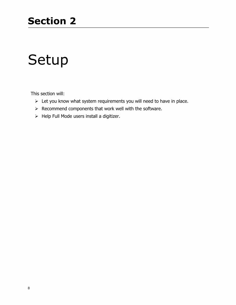
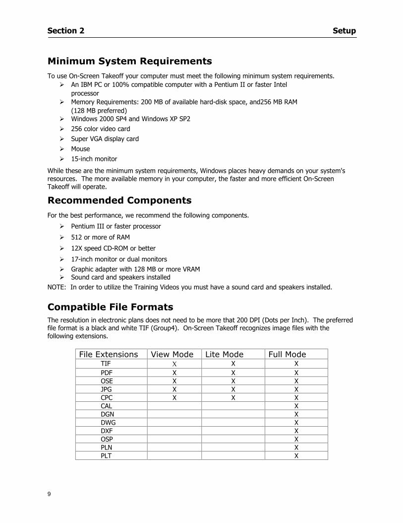
Section 2 Setup
9
Minimum System Requirements To use On-Screen Takeoff your computer must meet the following minimum system requirements
An IBM PC or 100 compatible computer with a Pentium II or faster Intel processor
Memory Requirements 200 MB of available hard-disk space and256 MB RAM (128 MB preferred)
Windows 2000 SP4 and Windows XP SP2 256 color video card Super VGA display card Mouse 15-inch monitor
While these are the minimum system requirements Windows places heavy demands on your systems resources The more available memory in your computer the faster and more efficient On-Screen Takeoff will operate
Recommended Components
For the best performance we recommend the following components
Pentium III or faster processor
512 or more of RAM
12X speed CD-ROM or better
17-inch monitor or dual monitors Graphic adapter with 128 MB or more VRAM Sound card and speakers installed
NOTE In order to utilize the Training Videos you must have a sound card and speakers installed
Compatible File Formats The resolution in electronic plans does not need to be more that 200 DPI (Dots per Inch) The preferred file format is a black and white TIF (Group4) On-Screen Takeoff recognizes image files with the following extensions
File Extensions View Mode Lite Mode Full Mode TIF X X X PDF X X X OSE X X X JPG X X X CPC X X X CAL X DGN X DWG X DXF X OSP X PLN X PLT X
Section 2 Setup
10
NOTE Use the following image types for best results
Convert to TIF
The converted files will be stored in a folder with the name of the current On-Screen Takeoff project Since the conversion can be very time consuming you should only select this option if you really intend to convert vector files to TIF
1 Select File gt Project Properties
2 In the Pages Field add your image See Section 5 Establishing Project Setting Adding Pages
3 Click
4 Then select the page with the drawing you wish to convert
5 Click
Installing Your Digitizer The following instructions are a quick start to installing your digitizer For more specific information please reference Appendix I Installing Your Digitizer at the end of this guide
Connecting Your Digitizer
Upon receiving your digitizer (either a GTCO or another brand) you will need to connect it to your computer
1 Lay the digitizer out flat
2 Connect the Stylus to the digitizer
3 Plug in the power supply
4 Plug the interface cable into the digitizer
5 Plug the other end of the interface cable into the computer
NOTE On-Screen Takeoff is compatible with any tablet that is WinTab compatible
Digitizer options are only available in Full Mode If you are in View or Lite Mode and would like
to use this feature click from the main toolbar to purchase the upgrade
Section 3
11
Toolbars and Menus
This section will
Introduce the program toolbars
Familiarize you with On-Screen Take Offtrade Menu options
Section 3 Toolbars and Menus
12
Toolbars On-Screen Takeoff is equipped with several helpful toolbars for application efficiency See Appendix II Toolbar Item` Details for a detailed description of each toolbar item Individually the toolbars may be displayed moved docked reshaped or hidden from view You can also create costume toolbars to fit your needs
Main Toolbar
Tool Toolbar
Zoom Toolbar
View Toolbar
Navigate Toolbar
Takeoff Toolbar
Image Toolbar Viewing Toolbars Toolbars are displayed on the screen and will be consistent on each tab or page (Some toolbars or toolbar items will be in an inactive state if they donrsquot have a supporting element in the application)
1 Select View gt Toolbars and select the appropriate toolbar name
OR
2 Right-click on a toolbar region of the screen
3 Check the toolbars you want to display
Section 3 Toolbars and Menus
13
Moving Toolbars The toolbars may be positioned anywhere on the screen you wish This feature is provided to allow the flexibility for positioning the toolbars so they are out of your way yet handy for use
1 Click on an edge of the toolbar holding down the mouse button drag it to its new position
2 Release the mouse button to set it in place
NOTE If the toolbar is dropped anywhere other than a screen edge it will become free floating This feature is especially handy when using multiple monitors
Docking Toolbars The toolbars can be docked to any of the screen edges
1 Click on the title bar of an undocked toolbar
2 Drag the toolbar to any location on the screen
Hiding Toolbars
1 Select View gt Toolbars and select the toolbar you wish to remove from the screen
2 Right-click on the toolbar or dock bar areas
3 A floating toolbar can be closed by clicking on the in the upper right corner of the toolbar
Resizing Toolbars Only undocked (floating) toolbars may be resized
1 Position the mouse pointer over an edge
2 Click and drag
3 The toolbar can be resized as desired
Customizing the Toolbars You may rearrange or delete buttons within a toolbarrsquos display or you may move buttons from one toolbar to another If you find that you use a few tools over and over you may want to group them within a single toolbar for convenience On-Screen Takeoff gives you the flexibility to customize your takeoff environment
1 Select Tools gt Customize The Customize dialog will open
2 With the dialog open click on a toolbar button and drag buttons from one toolbar to another or a new location within the same toolbar
3 To add a button without altering another toolbar click on the Commands tab of the Customize dialog and drag the appropriate symbol from the Buttons section to a toolbar
4 To remove a button drag it to within the takeoff area of the application
Section 3 Toolbars and Menus
14
Menus
Section 3 Toolbars and Menus
15
Digitizer Menu
Section 4
16
Features
This section will
Show you how open On-Screen Takeoff
Describe the On-Screen Takeoff environment
Teach you how to navigate pages
Section 4 Features
17
Start On-Screen Takeoff
1 On your desktop double-click your On-Screen Takeoff icon
2 The application will open
OR
3 Left-click on the Start button on your computerrsquos toolbar
4 Scroll up to Programs gt On Center Software
5 Highlight On-Screen Takeoff and click On-Screen Takeoff will open On-Screen Takeoff opens to an untitled blank project The Image view of the screen will be a blank page
Two blank dock bars the Pan dock bar and the Takeoff dock bar appear at the left side of the screen Along the bottom the Status bar displays user status or context-sensitive messages as well as paper size and current zoom percentage of the plan sheet on screen The menu bar and several task specific toolbars are located at the top of the screen
NOTE All toolbars and dock bars may be accessed to view or hide through View gt Toolbars on the menu bar
Section 4 Features
18
Quick Start Video When On-Screen Takeoff opens you will be given an option to watch the Quick Start video (recommended) or start the program without watching the video
The 20 minute video will demonstrate key program functionality and allow you to view application instruction for enhanced learning
If you would like to watch the video click If you prefer to get started without
the video click If you have already viewed the video click the lsquoDo not show this message againrsquo box to prevent this dialog from appearing each time you open the program
NOTE If you decide later that you would like to watch the Quick Start video go to Help gt Watch
Quick Start Videos
On-Screen Takeoff Environment The On-Screen Takeoff environment acts like your drafting table allowing you to work on several sheets of plans at once and to reference at a glance the entire drawing and your position on that drawing while giving you the power of a computer to track analyze print and export your takeoff quantities and plans
The screen is bordered at the top by the Menu bar with pull-down menus and at the bottom by the Status bar which indicates current user status plan page size and current zoom percentage of page The largest portion of the application screen will be your takeoff area bounded on the left (by default) by two dock bars and on the top by several toolbars
In the takeoff area you may view your project plans (images) andor takeoff objects the takeoff list with quantities the worksheet or a legend of your condition list
The main window of On-Screen Takeoff has three tabs located at the bottom left allowing for quick change between Image Takeoff or Worksheet views Select the desired view option on the toolbar and it will automatically open on your screen
Section 4 Features
19
Image View
This view shows the plan file andor takeoff conditions drawn from your plans
Takeoff View This view displays the height if applicable and quantity breakdowns of your conditions according to result types indicated (eg linear feet square feet or count of items) for zones pages and the project as a whole It also displays notes per condition
Section 4 Features
20
Worksheet View This view displays the condition and quantity in units of measure specified in the first results field of the Results tab in the Condition dialog and allows the user to enter amounts for material labor and subcontractor takeoffs
NOTE When in the Worksheet view tab out the field then save This is keep all the values saved
Navigating On-Screen Takeoff
Auto Scrolling When creating linear areas or zones On-Screen Takeoff will automatically scroll the image view when necessary It will move as your mouse or digitizer moves beyond the edge of the current view
Changing Pages
1 Select View gt Next Page Previous Page or Go To Page (specify page number for the Go to Page option)
2 You may also select the corresponding arrows for these options from the Navigate Toolbar The
drop down arrow in the Page field will list the pages The and arrows will take you to the
previous or next page The and arrows will take you to the first or last page
OR
Section 4 Features
21
3 Or press Ctrl G for the Go To Page dialog
Hot Links Hot links allow you to move quickly from one drawing to the pertinent area of another drawing A hot link is handy when viewing enlarged areas of a page and needing the ability to jump back to a reference page
1 Select Tools gt Hot Link
OR
2 Click from the Tools Toolbar
3 Click on the page where you want to set the link The Hot Link dialog will open
4 Using the current page display on the Navigate Toolbar access the pull-down menu of pages by
clicking on the arrow at the right
5 Select the page for your link (You may also choose View gt Go to Page and select by page number)
6 Manipulate the view using the zoom tool and the scroll bars
7 Click
8 After joining a hot link to another page the hot link arrows in the Navigation Toolbar will become active
9 Move a hot link to another location on the page by clicking then click and drag the hot link image anywhere on the page
Section 5
22
Projects
This section will
Help you create settings important to your projects
Explain how On-Screen Takeoff works with your electronic or paper plans
Section 5 Projects
23
Project Template Files You can begin your project with a template Templates allow you to take advantage of conditions and settings used with previous projects
On-Screen Takeoff templates contain condition lists and established layer separations from previous projects you have created You may also use the sample templates provided with On-Screen Takeoff as a great starting point All aspects of the templates may be adjusted for a new project
1 Select File gt New and click the OK button
2 From the New dialog box choose the template that best fits your project
3 The conditions for this template will appear in the Takeoff Dock bar and the Project Properties dialog will open asking for further information
4 Use File gt Save or File gt Save As to rename and save your new project
Saving a Project as a Template File You can save your condition properties and layers as a template for future projects
1 Select File gt Save As
2 Enter a name for your template and select On-Screen Takeoff Template Files (tpo) from the Save As type field of the dialog (click on the down arrow to select)
3 Click the OK button to accept and close the dialog Modifying a Template File Follow these steps to modify an existing template file if you need to change or add conditions andor layers
1 Select File gt Open
2 Navigate to your Projects directory
3 In the File Type drop-down select On-Screen Takeoff Template files (tpo)
4 Choose the On-Screen Takeoff template file you would like to modify and click the OK button
5 Make appropriate changes
6 Save and close file
The On-Screen Takeoff template files cannot save takeoff information
Section 5 Projects
24
Opening an Existing Project File 1 Select File gt Open
2 Navigate to the desired file location
3 Click the Open button
NOTE If your latest changes to a project file have not been saved On-Screen Takeoff will ask
you whether you would like to save the file and gives you the option of canceling the operation
Creating a New Project
1 Select File gt New
2 For a blank untitled project click
3 At this point the Project Properties dialog will pop-up for more information about your takeoff
NOTE The following are important to keep in mind when beginning a new project
At the start of your project fill out the Project Properties settings to establish the name for all printed output from your project set the default page size and scale for your plans number and names of different pages within the project and locations of electronic drawings
Scale settings can significantly affect quantity outcomes Be sure to set the scale for each page of drawings before beginning condition takeoffs
When using a digitizer remember to make a mark with a pen or pencil in the upper left and lower right corners of the first sheet of the paper plans to delineate the takeoff area for that sheet You can then set the takeoff area on On-Screen Takeoff using your marks
Save your project before you begin taking off any conditions On-Screen Takeoff will write a back-up file using the same file name
Remember the Undo feature If you make a mistake select Edit gt Undo and reverse the process step by step
Section 5 Projects
25
Project Properties
You can either set your Project Properties when you create a new takeoff or once your project file is saved under the appropriate name
1 Select File gt Project Properties the Project Properties dialog box will appear
2 Type in the name of your project to appear on printouts Use the backspace andor delete keys to edit the name as necessary
3 Press the Tab key to move to the Default Image Size option or click within the Image Size box You may click on the arrow at the right for the pull-down menu of page size options or you can use the down-arrow key on your keyboard to scroll through the list to the appropriate selection
4 Press the Tab key to move to the Default Scale option Select a scale by using the drop down arrow If your scale is metric you will need to click in the box next to Metric to convert to that measurement
5 Establish the number of pages for your project plans And load image files See Adding Pages to
Your Project
Adding Pages to Projects Individual Electronic Plans
1 Click on in the Project Properties dialog
2 In the Add Images dialog use the drop down arrow to navigate to the appropriate directory and folder containing your image
3 Select the file so that it displays in the File name field then click The file will display by name and path in the Image File field in Project Properties dialog
4 Click to accept and your project will automatically open
5 Save your project with the new settings by selecting File gt Save
Section 5 Projects
26
Electronic plans scanned from blueprints (as opposed to blue lines) will display as white lines on a black background and are difficult to read on your computer screen Select Image gt Invert and the colors will invert to black on white
You may have noticed the Page column in the Project Properties dialog Generally plan images occupy one page and 1 will be listed in the column indicating Page 1 of your plan file If you import a multi-page TIF a plan file containing more than one page of plans they will import as separate pages and each successive page will be indicated under the Page column as 1 2 3 etc of the plan file
Group of Electronic Plans You may add all the electronic plan files from a particular source (for example from a CD) by using the Auto Add feature
1 Click the button in the Project Properties dialog
2 Browse until you find the appropriate directory and folder containing your plan images
3 Click on any file displayed within your target folder so that the file name appears in the File name box of the Auto Add dialog
4 Click The image paths and file names will be recorded into the project properties arranged alphabetically
5 Click to accept your choices and your project will automatically open
6 Save your project with the new settings by selecting File gt Save
To load Dodge Plans into your Project Properties see Appendix IIi Loading Plans from a Dodge CD
Paper Plans On-Screen Takeoff makes it easy for Full Mode users to perform quantity takeoffs from paper plans using a digitizer
1 Add pages by clicking until you have the number of pages initially in the project
2 Name each page by clicking within the Title area and typing the name
3 Click to accept your choices and close the Project Properties dialog
4 Save your project with the new project properties settings by selecting File gt Save
Section 5 Projects
27
Setting Up a Drawing Template On-Screen Takeoff provides the convenience of using the same work surface for both digitizer and mouse to allow the user to draw conditions and then edit settings of the project or add or change conditions without breaking stride A mouse pad template included with the program defines the area of the digitizer in which use of the stylus or cursor will be recognized as mouse movement as opposed to drawing movement
1 Place your stylus on On-Screen Takeoff
2 Placing the template identifies the location mouse movements will be recognized by the program
Before placing the template the template must be applied to the digitizer surface This may have been done during the installation of your digitizer We suggest attaching the template to the lower right corner of the digitizer surface about one inch inside the grid area
3 Select Digitizer gt Place Template
4 Follow the instruction prompts on the screen clicking first on the target symbol at the left of the On-Screen Takeoff box on the template then on the target at the right
Setting Takeoff Area Before you can begin taking off a drawing you must define the drawing area on the digitizer This requires defining an area that will include all objects on each drawing of your plans As you add pages to your takeoff the same area of the digitizer will be active
1 Secure the plans to the digitizer with tape or a set of clamps
2 With a pen or a pencil mark the upper left corner and the lower right corner of the first page in your set of plans
3 Select Digitizer gt Set Takeoff Area
4 Click each mark with the stylus pen as prompted
5 Verify the active area of the digitizer by looking at the image size located in the lower right corner of your screen
If you close the program before the takeoff is complete you will need to reestablish the takeoff area before you can add additional condition quantities
Electronic plans appear on your computer screen eliminating the need to set a takeoff area You simply drag your mouse across the conditions you wish to takeoff The conditions will be highlighted and quantities will be totaled instantly Electronic plans are available through a variety of services For information contact an On Center Software account manager
Section 5 Projects
28
Setting Scale for Specific Pages You may set the scale in each page view separately This will override the default scale setting in Project Properties for that page Setting the correct scale for the drawing before taking off quantities ensures accurate calculations Be careful to check the scale for each drawing in your project before doing takeoffs
1 Display the page you want to set select Edit gt Set Scale
2 Use the drop down arrow to select a scale that will be applied to that page
3 Click
OR
4 Access the pull-down scale settings on the Navigate toolbar
NOTE As you draw objects notice that the drawn object is similar in width to the object on your plans If it is not the scale set may not be correct
Calculating Scale You may calculate scale according to a known measurement between two points either with a digitizer or on electronic plans
1 Select Edit gt Calculate Scale using Image or Edit gt Calculate Scale using Digitizer
2 Follow the instructions in the related Calculate Scale dialog box You will be asked to click on the first and second points then to enter the dimension for that distance
3 The scale will be recalculated for the displayed page and the Scale display on the Navigate toolbar will show the new scale
Section 6
29
Conditions and Takeoff
This section will Draw Conditions to Takeoff Plan Quantities
What Zones will do to help your takeoff process
Discuss the ins and outs of Takeoffs
Section 6 Conditions and Takeoff
30
Creating Conditions
If you are starting a new project from scratch you will need to create conditions to takeoff quantities such as floor areas wall lengths and corner bead counts If you are using a template you will have several pre-designed conditions already listed on the Takeoff dock bar However you may want to change the characteristics of some conditions or create additional conditions for a particular project
1 Right Click within the Takeoff dock bar Select New gt Condition
Or
2 From the Takeoff dock bar Click (if the buttons are not showing right-click in the Takeoff dock bar area and select Show Buttons from the pop-up menu) The New Condition dialog appears
3 Select the condition type (Linear Area Count or Zone) from the pull-down menu accessed by the
down arrow next to the Type option
4 Press Tab or use the mouse (or stylus) to move to Name and enter a name for your condition
5 Specify the desired condition attributes See Condition Attributes for more detail
6 Click for condition to apply
Section 6 Conditions and Takeoff
31
Condition Attributes Each condition type will have related attributes to select or specify within the General and Advanced tabs of the New Condition dialog Once a condition has been used to takeoff a quantity from your plans certain attributes cannot be changed
All conditions allow the user to specify color and fill pattern for the object drawn
Linear Conditions
General Specify width and height by feet and inches Specify pitch in inches up to the nearest thousandth of an inch if applicable
Advanced Specify rounding for object quantities and droprun default length for electrical or plumbing drops at the ends of lines Select Connect to have lines connect at the corners where one line of the condition ends and another begins (and indicate Tolerance for the featurersquos activation as distance between the ends of two lines) Choose Trim to have lines automatically trim to a line being crossed Choose Curve to draw a curved line
Follow these examples for inputting feet and inches For 7 feet 6 inches type 706 for 13 feet 7 inches type 1307 For 20 feet type 2000
Section 6 Conditions and Takeoff
32
Area Conditions
General If needed you can specify the thickness (in inches) andor pitch (in inches)
Advanced Specify rounding for object quantities Choose to display an adjustable grid within the area and indicate matrix cell dimensions
Section 6 Conditions and Takeoff
33
Count Conditions
General
Specify height and indicate the size (in inches) and shape (square circle triangle rectangle or opening) of the count object as it will appear on screen
Advanced Count conditions have advanced attributes These options are available for all shapes except for openings
Zone Conditions Zones allow you to subdivide condition quantities making it easier to modify and complete jobs in phases They can be used at the end of a takeoff to isolate a group of condition quantities that are in different areas of the takeoff
Zones can also be used to break a takeoff into multi-phases and can even be used to isolate quantities while a job is in progress to group the amount of work that has been completed to date They can be applied to one or multiple pages in your plans automatically calculating the takeoff quantities for each zoned area
Section 6 Conditions and Takeoff
34
The zone feature is only available in Lite and Full Mode If you are in View Mode and would like
to use this feature click from the main toolbar to purchase the upgrade
Condition Notes A Note tab is provided for comments regarding the condition These notes will display on the Takeoff List report and will import into Quick Bid
Section 6 Conditions and Takeoff
35
Condition Results The Results tab of the New Condition is based on condition type Initial settings default to linear feet (LF) for linear conditions square feet (SF) for area conditions and count of items (EA) for count conditions and zones The first of the results fields will display for the condition items in the Takeoff dock bar area All results will display in worksheets and Takeoff List reports as well as in an Excel spreadsheet after being exported
Copying Conditions You may use the condition attributes from a condition yoursquove already created for any future conditions of the same type
1 Click on a condition to select it
2 Click the Copy button from the toolbar
OR
3 Right-click in the Takeoff dock bar area and select copy
4 A new condition will appear in the list with the same condition attributes as the previous condition but with the quantities zeroed
Editing Conditions Once you have copied a condition you might want to change several attributes You can also edit an existing condition to fit any updated needs
1 Highlight the desired condition on the Takeoff dock bar
2 Click the Change button
OR
3 Double-click on the condition you wish to edit to bring up the Change Condition dialog
NOTE The Change Condition dialog differs from the New Condition dialog only in that if takeoffs
Section 6 Conditions and Takeoff
36
have been performed in your project with this condition you will not be able to change the type of condition or certain properties under the advanced tab of the dialog box
Deleting Conditions 1 Click on the condition in the Takeoff Dock bar area
2 Click the Delete button on the toolbar
OR
3 Right-click and select Delete from the pop-up menu
All takeoff associated with the deleted condition will be deleted immediately and permanently
Organizing Project Conditions Within your project you can create folders andor sub-folders for different types of conditions You may even want to create a folder containing conditions with reset values
To get started organizing your conditions make sure you are viewing the condition tree (right-click in the Takeoff dock bar area and select Show Tree)
Creating Folders and Sub-Folders 1 Right-click in the Takeoff Dock bar area
2 Select New gt Folder from the pop-up menu
Copying Folders
1 Click on the folder and click Copy on the toolbar
2 All copied conditions within the new folder will have values reset to zero
Renaming Folders
1 Click on the folder
2 Right-click and select Rename from the pop-up menu
3 Enter a name for your folder and click the Enter button
Changing Condition Order
You may move conditions up or down in the condition list of the Takeoff dock bar to suit your project needs
1 Select the condition you would like to move by clicking to highlight it
NOTE When you are ready to move the highlighted conditions be sure that you start
moving using the last condition chosen That condition will have a highlighted boarder
Section 6 Conditions and Takeoff
37
2 Drag and drop any the condition from one place to another in the list You may also move a condition to another folder on the list in this way
Drawing with Conditions Snap Angles Set up snap angles to prevent lines from appearing jagged Snap angles are commonly set at 15deg and shift snap angles at 0deg
1 Go to Tools gt Options Options dialog appears
2 Under the General tab make the desired settings
3 Click to save the settings As they are drawn lines will snap to the set degree
Drawing a Linear Object 1 Select a condition from the Condition List in the Takeoff dock bar
2 Move the cursor into the Image takeoff area of the screen you will see the cursor display as crosshairs
3 Click and hold left mouse button then drag mouse to draw a line
4 Release mouse button to set line
Section 6 Conditions and Takeoff
38
5 Repeat steps for further lines
Continuous Mode This feature allows you to draw an object that has connected lines
1 Click the icon from the Takeoff toolbar
OR
2 Go to Tools gt Continuous Mode
3 Follow steps 1-3 from Draw a Linear Object
4 Click at each point of intersection The object will be connected
5 Double-click after making the final point to set the lines
Drawing a Curve To draw a curved line the Curve option must be checked under the Advanced tab of the Condition dialog
1 Click where you want to begin the curve and drag in a straight line to the position for the other endpoint of the curve
2 Click on the line to select it Handles in the shapes of small squares will appear at either end of
Section 6 Conditions and Takeoff
39
the line and in the center of the line
3 Move the cursor over the center handles until the cursor becomes a two-way arrow
4 Click and drag in the direction of the curve bending the line as you move the cursor Release to set the curve (The line you began with will disappear)
Draw a circle by drawing two curved lines connected
Drawing an Area Object Area conditions are drawn similarly to continuous mode lines You may trace any number of adjoining walls at different angles to complete your area takeoff
NOTE When drawing an area do not intersect the perimeter or line of the object you are drawing
1 Click at each point
2 Double-click when yoursquove returned to your starting point
3 The area will be filled with the pattern set for that condition
NOTE The simulated circle will be good enough for you to be able to make a bid
To create a circular area click from point to point with very short distances in between points simulating a circlersquos perimeter Double-click after setting the last point to set the area
Section 6 Conditions and Takeoff
40
Grid Options Grids give you an added advantage when installing materials such as tiles Use this feature to get a count for how many tiles are needed for an area
1 Double-click on an area condition in the Takeoff dock bar to open its Condition dialog
2 Click on the Advanced tab to show its options
3 Check the box next to Grid by clicking in it
4 Indicate the dimensions of the cell matrix in inches (For example 200 x 400)
5 Under Results tab choose each (EA) for one of the results fields This will tabulate a number of grid cells (including partial grid cells) in area
6 Click to save your settings
7 Use the Move Grid and Rotate Grid features in the Tools menu to manipulate the grid as desired
Grid Calculation
1 Go to Tools gt Options menu
1 Specify if On-Screen Takeoff automatically should Calculate Grid Position
2 If AreaGrid Size is selected On-Screen Takeoff will calculate the number of items needed to fill the grid based on grid demintions
3 Click to accept and close the dialog
To move a line at any angle (regardless of default setting) press the Shift key while moving the mouse
Section 6 Conditions and Takeoff
41
Backout Mode This feature allows you to take out part of an area and deduct that amount of square footage
1 Select Tools gt Backout Mode
2 Outline the are you want backed out as you would when drawing a regular area object (see Drawing an Area Object)
3 The outlined area will clear and quantities will be recalculated
NOTE The perimeter of the backout area will be added to the LF quantity for that condition
Drawing a Count Object Square triangle rectangle and circle shaped count objects can easily be placed on images
1 Select the condition
2 Click in the location where you want the object to appear
3 To place an opening-shaped count item like a door or window you must click over an existing linear object such as a wall
4 On the Results tab you can change the height properties to give you the result you need
5 If Backout is checked on the advanced tab for each count opening the opening-shaped count item will back out a corresponding section of the linear object
Opening shaped count items are sized at 3rsquo0rdquo by default
Drawing a Zone Zones are drawn in the same way as area objects and may be any polygonal shape You may trace any number of adjoining walls at different angles to complete the zone perimeter
1 Click at each point
2 Double-click when yoursquove returned to your starting point
Section 6 Conditions and Takeoff
42
Selecting Objects
1 Use the Select Tool to select objects
You can also select all objects that correspond to a condition
1 Click on a condition to select it
2 Right-click and choose Select All
3 All objects with this condition will be highlighted with squares as an outline
Moving and Resizing Objects Linear
1 To move or resize a linear object click anywhere on the line to select it
2 To move the line position your pointer over the center handles When the mouse is positioned over the handles you will see a two-way arrow You will only be able to move the line in the direction of the arrows
3 Drag the line to a new position
4 Clicking and dragging the handles on the ends of the line will allow you to lengthen or shorten your line
Area and Zone
1 To move an area object or zone in its entirety click and drag it to its new position
2 Grabbing a handle at a corner or intersection of the object will allow you to adjust and change its perimeter
Section 6 Conditions and Takeoff
43
Count 1 To move a square circle rectangle or triangle shaped count object click and drag
2 Click and drag an opening shaped count object along the length of the linear object to the desired position then release
NOTE An opening shaped count object may not be moved from its associated linear condition object however it may be moved up and down the length of the linear object
Layers On-Screen Takeoff allows you to sort and separate your takeoff objects within the same job and on the same page On-Screen Takeoff gives you this flexibility through the use of layers
By assigning different conditions to different layers (for example differentiating between floors ceilings and walls) you can choose to view all layers or turn off certain layers to display and print the remaining groups of conditions only You may also remove the background image of electronic plans add text and hot link symbols or print only your condition takeoffs
Layers are only available in Full Mode If you are in View or Lite Mode and would like to use this
feature click from the main toolbar to purchase the upgrade Default Layers
On-Screen Takeoff begins every project with three default layers Image Annotation and Default The Image layer holds the electronic plan files you may have in your project The Annotation layer possesses all text notations highlighting and hot links in the project The Default layer will appear in the Condition dialog when creating or editing a condition (listed in the takeoff dock bar) Conditions are assigned to the Default layer unless otherwise specified by the user
Creating Layers To assign a condition to a layer other than the default layer you must first create additional layers for your project
1 Select View gt Layers to open the Layers dialog
2 Click An unnamed layer will be added
3 Click within the empty box and type a name for your layer (for example Wall)
4 New layers are added as active layers The adjacent box under the Show column will be checked
Section 6 Conditions and Takeoff
44
Assigning a Layer to a Condition 1 Open the Condition dialog box by creating a new condition or editing an existing condition
2 Under the General tab click on the down arrow in the Layer field to display optional layers
3 Select the desired layer for the condition Only the Default layer and layers you have added will be displayed
4 Click
View and Hide Layers
1 Select View gt Layers
2 Under the Show column check the box to view or remove the check (by clicking on it) to hide the specific layer
3 Click to accept and close the Layers dialog
Section 6 Conditions and Takeoff
45
Assigning Text to a Layer When adding text to an image On-Screen Takeoff has the capability to assign the text to a specified layer
1 Select the Text Tool
2 Click at the point you want to place your text
3 Type in your text using the Enter key for line breaks
4 Click the drop down arrow next to the Layer field and select the desired layer
Section 7
46
Printing and Exporting
This section will
Printing options and procedures
Exporting data by copying and pasting
Exporting quantity results to Excel spreadsheets
Section 7 Printing and Exporting
47
Print Setup On-Screen Takeoff allows the user to print the image takeoff list and worksheet
1 Select File gt Print Setup The Print Setup dialog will open
2 Select a printer or leave the default selection listed (change from the default printer displayed by clicking on the down arrow at the right of the field)
3 Indicate page size and printer tray option (Source) Access page size options by clicking on the
down arrow at the right of the field
4 Choose Portrait or Landscape orientation
5 Click to accept and close the dialog
Printing Images The image area can include the electronic plans the takeoff objects added text and hot links To print a subset of these (for example just the takeoffs without the plans or the added text and hot link symbols) hide layers that you do not want to print (see Section 6 View and Hide Layers) When you are printing your images every page will show the scale of the takeoff you are printing
1 Click on the Image tab to display the area of your project
2 Select File gt Print (or Ctrl + P)
Section 7 Printing and Exporting
48
3 Select the desired view (What to print) and the Image Range
4 Click The second Print dialog will open
5 Change settings accordingly or click if you accept the default settings
Printing Takeoff Lists and Worksheets In Takeoff Lists and Worksheets you may hide columns to print only certain results or adjust column widths to fit the report within the page size selected
1 In Takeoff List or Worksheet view move your cursor to the right side of the columnrsquos title bar the cursor will display as a two-way arrow
Section 7 Printing and Exporting
49
2 Click and drag to adjust the width of the column Holding the mouse button you may
slide the title bar under the title bar to its left to hide the column completely
3 Select File gt Print or press Ctrl + P to access the Print dialog
4 Indicate desired printer and choose the number of copies
5 Click to print and close the dialog
When printing the condition list we suggest printing in landscape
To reset to the default column widths double-click on the right border of a column heading will reset the column to its right (or previously to its right before being hidden)
Print Preview 1 Select File gt Print Preview
2 Use and to vary your view 3 If viewing an image choose current full or scale view to see how it displays
4 For printed outputs that cover more than one page use and to view adjacent pages or click on the down arrow next to Page field and select the page you want displayed
Exporting Using the CopyPaste Feature You may copy all the data or sections from the worksheet and the takeoff list view in On-Screen Takeoff and paste it into another application When pasting into Excel the cell layout will be maintained
1 Highlight the areas you wish to paste Click and hold the left mouse button down as you drag the cursor over the area to be selected then releasing the mouse button
OR
2 Select the entire takeoff list quickly click on the left On-Screen Takeoff column header and hold and drag the cursor across the remaining column headings
The number of pages for the view selected will display in the lower left-hand corner The zoom percentage that applies to the view will be displayed in the lower right-hand corner next to page size of the drawing
Section 7 Printing and Exporting
50
3 In the worksheet view you may highlight rows by clicking on the numbered buttons to the left of each row clicking and dragging across column headings or clicking and dragging over individual cells in the worksheet
Click anywhere in the appropriate view to deselect the area
4 Once your selection is highlighted you may select Edit gt Copy or Ctrl C from the keyboard 5 On your monitor switch to the application into which you want to paste your selection 6 Select Edit gt Paste in the new application or simply press Ctrl + V to paste
The colored keys for conditions cannot be pasted
Using the Export Feature You may export condition quantities to specified cell location within an Excel worksheet file Cell target locations are assigned in the Results tab of the condition dialogs on the Export line relating to each quantity measurement type
On-Screen Takeoff will export takeoff quantity results for up to three different quantity types that you specify For instance you may want to know the number of square feet in a ceiling area as well as the number of linear feet in its perimeter
Section 7 Printing and Exporting
51
1 Bring up the Condition dialog by double-clicking on a condition in the takeoff dock bar or by
selecting the condition and clicking
2 Click on the Results tab to access its fields The default quantities for the condition type will display
3 For each results field click on the arrow to access the pull-down menu and select the appropriate quantity (for example SF LF EA etchellip)
4 Have your Excel spreadsheet opened and saved in a file
5 Specify the Excel spreadsheet cell locations where you want the results to go
6 For a cell in the first sheet of your spreadsheet type in the cell address (eg a1) Case is not important
7 For a cell on a successive sheet of your spreadsheet type in sheet the number followed by a comma and the cell address without any spaces (eg sheet2a1) Case is not important
8 Click
9 Select File gt Export gt Condition Qty to Excel
Section 7 Printing and Exporting
52
10 Browse to the location of the Excel spreadsheet file click file to select it
11 Click to export On-Screen Takeoff results to specified cell locations in the Excel file When you return to the Excel application you will see the values have been added to the specified cell locations in your spreadsheet
12 Save your Excel file
Exporting Worksheet to Excel
1 Assign condition quantities you want to export
2 Open saved Excel spreadsheet file to which you will be exporting
3 From On-Screen Takeoff Select File gt Export gt Worksheet to Excel
4 Browse to the location of the Excel spreadsheet file click file to select it
5 Click When you return to the Excel application you will see the values from the Worksheet Tab have been added to your spreadsheet
6 Save your Excel file
Exporting Takeoff to CVS 1 Assign condition quantities you want to export
2 Open saved Excel spreadsheet file to which you will be exporting
3 Click the Takeoff Tab in the project you want to export the information
4 Select File gt Export gt Takeoff to CSV
5 Browse to the location of the CSV spreadsheet file click file to select it
6 Click the Save
NOTE CSV files can be opened in Excel Lotus Access etc One may consider this option more of a ldquodumprdquo into a file
The Excel application must be active (it may be minimized on the application bar) with the target spreadsheet open in the application Otherwise an error will occur with the export operation that will affect both the On-Screen Takeofftrade file and the Excel spreadsheet
Section 8
53
Advanced Features
This section will
Some special features of working with condition objects in the takeoff area
Details of advanced options for conditions
Advanced features of the Project Properties dialog
Section 8 Advanced Features
54
Features to Use with Objects Roping Feature You can move copy or delete using this feature Using the Select tool (the pointer) you may select several objects at once by clicking and dragging an outline around the objects then releasing the mouse button Roping may select either objects completely within the outlined area (inclusive) or objects both within and touched by the outlined area (touching) Specify your roping preference under Tools gt Options
1 Click and hold the mouse button at a point on the screen near the objects to be selected and drag to surround the objects with an outline
2 Release the mouse button The objects will be selected
3 You may now
Move the group around on the page by clicking within the group dragging the mouse and releasing the button to place the objects
Delete the group of objects by clicking the Delete key or
Copy and paste by pressing Ctrl C to copy the group then Ctrl V to paste it The pasted copy of the grouped objects will appear slightly offset from the original objects
Section 8 Advanced Features
55
Applying a DropRun Count
Use the droprun feature when calculating quantities to take into account the drop or run of a linear condition such as electrical lines or plumbing pipes Drop or run lengths may be added separately to any linear condition on screen while a default droprun length may be indicated for a condition as a whole
1 Select the desired linear condition from the Condition List in the Takeoff Dock bar
2 Click the Change button in the toolbar to open the Change Condition dialog
3 Click the Advanced tab to access the advanced options and click inside the DropRun check box
4 Enter a default length to be applied to all of this condition Entering 800 will be interpreted as 8 0 (You must enter both place markers for inches) You can leave the length blank and manually enter drop run on each segment drawn
5 Click the OK button to accept and close the dialog
Edit DropRun Count
1 With the related linear condition in the Takeoff Dock bar highlighted or with the pointer tool selected
2 click on the desired linear object in the image takeoff area The Count button will become active
3 Click on the Count button (alternatively select Tools gt Count) The default droprun amount will show in the pop-up Count dialog (Default length will be zero if droprun has not been selected in this conditionrsquos properties)
4 Type in the desired length Entering 800 will be interpreted as 8 0 (You must enter both place markers for inches)
5 Click the OK button The additional amount will be reflected in the corresponding quantity The new DropRun count will apply only to the object edited
Adding Text in Image View
On-Screen Takeoff allows you to place text comments around your quantity takeoffs that may be printed along with plan images and objects Text is automatically placed within the Annotation Layer (that includes text and hot links)
1 To place text on the image select the Text Tool and click at the point you want to place your text opening a text box
2 Type in your information clicking Enter for line breaks
3 When you are finished click the OK button to exit the text box
4 To reposition text simply click on the text (with the Text Tool active) to select it
5 Move the cursor over the text the cursor will now display as a four-way arrow
6 Click and drag the mouse to position the text as desired
Section 8 Advanced Features
56
1 To edit existing text use the Text Tool to double-click on the text to open the editing box
2 Enter additional text or use the Backspace key to delete text as necessary
Formatting Text Once created you may format the font size type style and color of your text
1 Click on the text to select it and select Tools gt Font or click on the Font button in the Takeoff Toolbar
2 Select the desired features (color options are disabled) and click the OK button
3 Click on the text to select it and select Tools gt Color or click on the Color button in the Takeoff Toolbar The Color dialog will open
4 Click on a color in the Basic Color palette or create a color and add to the Custom Colors palette (Be sure to click on the color in the Custom Colors palette to select it)
5 Click the OK button
Object Properties
Linear Objects
Linear objects may be set to connect at corners
A linear object may be set to trim automatically when crossing another linear object (Check the trim option under the advanced tab of the Condition dialog)
When you move a connected linear object objects automatically move and resize connected lines accordingly (quantities are then recalculated)
This feature requires that the connected linear object be moved using the center handles (does not apply when resizing the line from the ends)
Objects constrain to snap increments defined in the Tools gt Options menu (with the mouse 15deg by default incremental when shift key is held down)
Objects are measured from centerline to centerline
Section 8 Advanced Features
57
Area Objects When drawing an area use your escape key to undo the last line drawn You may reverse your
drawing of an area using the escape key
The area will not fill with color and pattern until the user double-clicks after the last line is set
Lines drawn to delineate an area object constrain to snap increments defined in the Tools gt Options menu (with the mouse 15deg by default incremental when shift key is held down)
After selecting an area to move or adjust position the mouse in the center to move the entire area position the mouse at the sides or corners to adjust the perimeter
Count Objects
All count objects are quantified by the physical number of objects per page and reported as EA for the UOM The quantity for the current Image View is (displayed in the Condition List) and the total quantity in your project is displayed in the Takeoff View and Worksheet View)
Square circle rectangle and triangle shaped count objects do not displace or subtract from other object quantities when placed on top of them However on the Advanced Tab for the count condition a connect property can be set (this is a check box) so that when a count object of this shape is put on top of a Linear type takeoff object it will move with the linear if said linear is moved
An opened-shaped count object must be placed within a linear object Opening shaped count objects may also be measured by linear foot or linear yard (EA SF and SY are also options) Opening shaped count items default to a width of 3rsquo 0rdquo at the time of creation This size can be changed The small medium and large size are not options on this type of condition anymore Check Backout on the Advanced tab for each Count object back out the footage (or yardage) of opening-shaped count objects in which they are placed
NOTE In order to see this Backout functionality (in quantity) for SY or SF deductions at least one of the
results for the Linear(s) this object will be placed on must be set to SY or SF and the count object must have a height quantity
Advanced Features of Conditions The Round Feature Under the Advanced tab of the linear and area Condition dialogues you may specify quantity rounding (in inches) For linear objects rounding applies to each linear object drawn For area objects rounding will apply to each segment of the area perimeter adjusting the perimeter and area calculations For example With a linear condition entering 12 in the Round field will round up each related linear object to the nearest 12 inches or one foot With this setting two walls of 1 4 would each round to 2 0 totaling 4 0
NOTE In the Takeoff Dock bar condition list and in the On-Screen Takeoff reports quantities will be displayed in whole numbers rounded up to the nearest foot However calculations are based on true quantities without rounding unless the Round Feature is engaged
Pitch Pitch may apply either to linear or area conditions It is measured in rise per linear foot Entering 12 indicates a 12 rise per 12 of linear distance (a pitch of 12 over 12) or an angle of 45deg
Section 8 Advanced Features
58
Advanced Features of Project Properties Selecting Multiple Pages
1 Select a single page entry by clicking on the numbered gray button to the left of the entry
2 Drag the cursor down the column of numbers to select consecutive pages
3 Click on the blank button at the top of this column to select all pages in the Properties dialog
Section 8 Advanced Features
59
Changing Image Assigned to a Drawing 1 Select the page entry by clicking on the numbered gray button to the left of the entry 2 Click the Change Image button The Change Image dialog box will appear
3 Navigate to the desired file and select by clicking on it
4 Click the Open button The electronic file assigned to the page will have been changed to reflect the new file choice
Changing Image File Path 1 Select pages as described above
2 Choose Change Folder
3 In the Change Folder dialog navigate to the appropriate folder
4 Click the OK button The file path will have been changed for the selected page entries
Delete a Page from Project Properties 1 Select the page you want to delete by clicking on its associated number (in the gray box at the
left of the entry)
2 Choose Delete Page
All Takeoff on the page will be deleted immediately and permanently
Section 8 Advanced Features
60
Advanced Features of Tool Options
Calculation Method On-Screen Takeoff has built-in calculation options to allow for faster work and faster saves until your takeoff is complete Calculation options are found by selecting Tools gt Options then clicking on the Calculation tab
Calculation method can be set to Automatic Automatic except Grids and Manual Manual will allow the program to operate more quickly while Automatic or Automatic except Grids allows the user to see quantity changes as takeoffs are made
In any mode you may press F9 to recalculate quantities for the On-Screen Takeoff current totals
Configuration Tab
When the ldquoPage Label (A01)rdquo radial button is chosen On-Screen Takeoff puts the numbered label on all the pages of in your current page indicator in your Navigate Toolbar If the Page Descriptionrdquo radial button is chosen then a description of what takeoff is on that specific page will be shown in your current page indicator in your Navigate Toolbar
This section of the configuration tab gives you options on how you want to export your information When the ldquoFolderSubfolder Namesrdquo radial button is chosen than on your file that you are exporting to will have all the conditions folders and subfolders In the Delimiter box you can choose the symbol that is needed to separate the information you are exporting Some files need semicolons () or colons () to make sure the information comes exported in is separated it the appropriate places
Section 8 Advanced Features
61
In previous versions of On-Screen Takeoff there are views that users need to have in order for them to display their information By either choosing ldquoOST 1xrdquo or ldquoOST 2xrdquo it will let the program know you want your columns of information exported in that specific format
When you have the Confirm Deletions radial button of ldquoYesrdquo chosen than every time you delete anything you will get a dialog box confirming your intentions of deletion
While working with your takeoff you have a choice to either view the legend of your conditions or hide it Choose whichever radial button that suits your needs
For those who prefer to use the Enter key to navigate in dialog boxes this option is just for that
Font Tab The Font tab is designed for you to make your own look and feel for the application At the bottom of this tab it will show you sample of the fonts and colors you have chosen
Renaming the Current Page You may change the name of the current page in the takeoff area of On-Screen Takeoff by selecting Edit gt Rename Page
This opens the Name Page dialog and you may simply type in a new name and click the Enter button The new name for the file will be reflected on the title bar for the page and in Project Properties
You also may access the Rename Page function by right-clicking in the takeoff area while in Image View and selecting the option from the pop-up menu that appears
Section 9
62
Saving and Exiting
This section will
Explain how to save projects
Show you how to safely exit the program
Section 9 Saving and Exiting
63
Saving Your Project
1 Select File gt Save 2 If your project has not previously been saved a Save dialog box will open to allow you to name
the file and choose the directory and folder in which to save your file 3 Once saved File gt Save will simply save the current version of the file
OR
4 Select File gt Save As then type in a new name for the file and save to the desired file path
The Auto-save Feature With the Auto-save feature On-Screen Takeoff automatically backs up your open project You may choose to have more than one level of backup files The first backup copy will have the extension b00 and successive files will be b01 b02 and so on If you have designated four levels of backup files after the fourth backup copy has been created (b03) the next file will be saved over the file with extension b00 Further backup saves will then rotate through the four backup files in the same way
1 Select Tools gt Options 2 In the Auto-save area (under the General tab) select the frequency of backup file creation (in
minutes) and the number of levels for the feature 3 You also may disengage the feature by clicking in the check box to clear it
The Auto-save feature automatically saves backup copies to the directory of the current project If you are working from a write-protected area such as a CD-ROM On-Screen Takeoff will place backup files in the On-Screen Takeoff folder
Exiting When you are finished using On-Screen Takeoff it is very easy to exit Exiting is very important because of security reasons If someone were to use your computer they could enter the application and view and manipulate information
Section 9 Saving and Exiting
64
On-Screen Takeoff closes the open project when you open another or create a new project or when you exit the program
1 Select File gt Exit
OR
2 You also may click at the upper right-hand corner of the application to exit
NOTE If your latest changes to a project file have not been saved On-Screen Takeoff will ask you whether you would like to save the file and gives you the option of canceling the operation
Appendix I Installing Your Digitizer
65
Appendix I Installing Your Digitizer When you get your digitizer from GTCO you will need to connect it to your computer Follow the instructions outlined below to do this
Note For rollup digitizers the metal bar must be oriented to the top or right hand side
Connecting the Digitizer 1 Lay the digitizer out flat 2 Connect the Stylus to the digitizer 3 Plug in the power adapter 4 Plug the interface (IO) cable into the digitizer 5 Plug the other end of the interface cable into an open serial port on computer
Note GTCO Technical support phone number is 410-381-6688 The electronic manual (on diskette) from GTCO contains more detailed installation and operation instructions for the GTCO digitizer model you have
Installing other Digitizer Drivers If you are using a GTCO Digitizer you will need to install the GTCO TabletWorks Drivers
If you are using a Digitizer not supported by GTCO Tablet Works 10 please contact the manufacturer of your digitizer for assistance with installation
Installing GTCO TabletWorks Drivers 1 Insert the On Center CD into the CD-ROM drive The CD Startup screen will open 2 Click on Install Software 3 Select Additional Software and Drivers 4 Select Digitizer Driver 5 Follow the instructions for installing TabletWorks 10
Adhering the Template The template is a small plastic sticker used to enable mouse function when using the digitizer with On-Screen Takeoff Place your template on your digitizer We suggest placing it in the bottom right corner of the digitizer about one inch inside the takeoff area
Note You may either peel off the back of the template and use the adhesive surface or you can tape the template down
Appendix I Installing Your Digitizer
66
Testing the Digitizer Drivers Before running OST you may test the digitizer by moving the stylus around on the digitizer pad it should move the mouse cursor (if mouse emulation is enabled)
If the digitizer does not move the mouse cursor on the screen
The superset codes may need to be reset Reset the superset codes by touching on the border of the digitizer with the stylus The digitizer should beep several times
The digitizer may not be communicating with the computer Be sure the COM port selected is correct Be sure the COM port selected is correct If you are not able to get the digitizer to move the mouse cursor you need to call GTCO technical support for help
Note The Mouse Emulation is not required for On-Screen Takeoff to work properly It is used only for the Template functionality if the digitizer is moving the cursor the wrong direction (up instead of sideways or vice-versa)
Click the L-shaped arrow symbol on the digitizer with the stylus
Appendix II Toolbar Item Details
67
Appendix II Toolbar Items Main Toolbar
Appendix II Toolbar Item Details
68
Tool Toolbar
Appendix II Toolbar Item Details
69
Zoom Toolbar
View Toolbar
Navigate Toolbar
Appendix II Toolbar Item Details
70
Navigate Toolbar (Continued)
Takeoff Toolbar
Appendix II Toolbar Item Details
71
Takeoff Toolbar (Continued)
Image Toolbar
Appendix III Loading Plans from a Dodge CD
72
Appendix III Loading Plans from a Dodge CD
This section will detail how to load plans from a F W Dodge CD-ROM into an On-Screen Takeoff project file ready for takeoffs
Dodge files may be added to the Project Properties dialog However loading the files in that way will load the files by number rather than name description If you want to load one page only from your Dodge CD You will have to rename the page to display the name rather than number of the file
To load plan files from a Dodge CD so that the files load sequentially by file number but are displayed by name rather than by number within your project follow the instructions below
Opening a Dodge project from a CD-ROM 1 Insert the CD into the drive 2 Choose File gt Custom 3 Choose Dodge Plans Project (plansdat) as the file type 4 Select the appropriate file type by clicking on the down arrow at the right of the Files of type
field 5 In the Look in field access your drive paths by clicking on the down arrow at the right of the
field then
Navigate to your CD-ROM drive Open the data folder and Open the Projects folder
6 Select the desired project and open its folder 7 Open the plansdat file 8 All the images will come in sequenced correctly for that job along with the full descriptions
(names) of each page If there is not a plans folder in the project folder then plans do not exist for that project on the CD Opening the plansdat file will yield an empty project
Appendix IV Using the Plan Viewer
73
Appendix IV Using On-Screen Takeoff Plan Viewer The On-Screen Takeoff Plan Viewer is a limited version of On Center Softwarersquos commercial takeoff software If your status bar located at the very bottom of the main window says View Mode in the lower left-hand corner then you are using the Plan Viewer You can use the plan viewer to
View CD-based amp converted CAD drawings
View a previously created OST file and associated drawings
Download electronic plans online
Navigate through drawings
Quickly Takeoff linearsareas and counts
Zoom in to view the plan better
Print drawings directly from the viewer
Viewing an On-Screen Takeoff Project File
1 To open an OST file that was previously created with of On-Screen Takeoff 2 Select File gt Open 3 An Open dialog will appear if you do not see the OST file you are looking for select the
Look In drop down arrow 4 A drop down menu will appear listing the various folders drives and mapped drives located
on your computer select the correct drive or folder location and continue to browse to the location of your OST file
5 When you see your OST file double-click it to open it 6 Any takeoff and drawings should appear on the Image tab view
If you do not see the drawings but do see the colored takeoff layer the drawings may
not be located in the same place they were originally saved at Go to File gt Project Properties and check the Image File path for each listed page If the image file path is pointing to a CD drive make sure the CD is inside the CR-ROM
Downloading Electronic Plans If your Online Plan Service provides a special file format (OSX) required to use this feature of our plan viewer you can immediately downloaded all electronic plans of a project directly from our viewer
Most Plan Room web sites will automatically open On-Screen Takeoff when a request to download plans is made Your particular Plan Room may differ in operation so please contact the provider directly with questions on using the site
Appendix IV Using the Plan Viewer
74
When you request to download or open a project file from a Plan Room you will usually have the open to open or save an OSX file Choosing open will automatically open On-Screen Takeoff Alternately you may choose to save the file to a local hard drive After you have saved the file either double-click it to launch On-Screen Takeoff or open the OSX file using On-Screen Takeoff by clicking File then Open and locating the file on your hard drive You will need to change the file type to OSX
After the OSX file is opened you will see an additional tab appear in the Conditions List window called Pages
The Pages tab shows the hierarchy of your project Gray file icons represent pages that have not been downloaded and blue icons represents pages that have been downloaded
To download a page simply double-click the page icon
If you wish to select a group of pages to download you can use the Ctrl or Shift key to multiple select them then click the Download button
If you wish to download all pages at once click the Download All button
Downloaded pages will now appear in the Project Properties dialog in the same order in which they appear in the Pages tab
Creating Quick Takeoffs With On-Screen Takeoff you can create quick takeoffs to measure quantities even if you dont have the full version of our program However using the Quick Takeoff functionality shows you just a fraction of what the full version can do
The Quick Takeoff Toolbar is located at the top of the image view It has three buttons designated for three types of takeoffs Linear Area and Count The Quantity drop down list will show secondary quantities for Linears and Areas The Units drop down allows you to select how you want your quantities displayed Feet Inches Yards Millimeters and Meters
NOTE Every time change the type of takeoff you are performing (switching from Area to Linear for example) the previous quantities and takeoff objects will disappear They will also disappear when you changes pages
NOTE You can use the Dimension Tool to basically measure the distance between two points or linears The distance will display on the status bar at the bottom of the application
The Quick Takeoff Toolbar
Appendix V Frequently Asked Questions
75
Appendix V Frequently Asked Questions General
Where is On-Screen Takeoff installed on my computer
Typically it is installed in CProgram FilesOn-Screen Takeoff
In Explorer how do I recognize On-Screen Takeoff file types
On-Screen Takeoff data is stored in a single file per job lsquojob name OSTrsquo On-Screen Takeoff templates are stored as lsquotemplate nameTPOrsquo
Can only one project at a time be open
Yes For that reason opening another project automatically closes the project on screen You will be asked to save any changes
Is only one scale allowed per page What about on drawings that have multiple detail sections on a page and each of those drawings have different scales
Yes For pages with drawings of different scales copy the drawing to another project page and set the appropriate scale
I cannot perform backout on an area that is along a linear
As a workaround use the On-Screen Takeoff layers feature to help you with this issue Electronic Images
How do I start a project from drawings that have been scanned and written to a CD-ROM
Open a new project Select File gt Project Properties and select Auto Add Navigate to your CD and the appropriate folder and select any image file in that location Click Open All files in the location will load into your project Recommended that images are copied from CD to hard drive for performance
If I get a disk of drawings in AutoCAD format (R13 or R14) can I read them in On-Screen Takeoff
Yes On-Screen Takeoff now reads DWG DXF and many other format that are saved with AutoCAD
Appendix V Frequently Asked Questions
76
When I click on the all pages button what is supposed to happen Currently nothing seems to change when I click on that button
The All Pages button is used to apply the Darken and Enhance Plans feature to all pages in the project (as opposed to only the current page on screen)
Is there a way to deduct a large skylight from an area condition
Yes with the related area condition selected in the Takeoff Dock bar unselect the Backout button on the Takeoff Toolbar then draw the Backout area The area quantity will be deducted from the related condition object and the linear measurement of the Backout perimeter will be added
Digitizer Issues
How do I connect a Digitizer to the computer
See Appendix I Connecting a Digitizer
The Place Template menu choice is disabled
On-Screen Takeoff may need to be authorized or the digitizer or the digitzer drivers are not installed
It wonrsquot let me select the Set Takeoff Area menu choice
On-Screen Takeoff may need to be authorized or no job is open a digitizer is not installed or the drivers are not installed
The digitizer stylus is not moving the cursor or crosshairs
Click S-0-1 superset on the digitizer
How do I convert my old GTCO Digitizer to work with On- Screen Takeofftrade
Call GTCO and they may be able to reconfigure your digitizer to be compatible with On-Screen Takeoff
Printing Issues Which Printers work with On-Screen Takeoff
Compatible printers include On-Screen Takeoff Hewlett Packard Epson and Canon printers If you are having printer difficulties please contact support and specify the type of printer along with other pertinent information Contact support at wwwoncentercomsupport or email supportoncentercom
Which Plotters work with On-Screen Takeoff
Compatible Plotters include Hewlett Packard DesignJet plotters and the EnCAD Cadjet II If you are having plotter difficulties please contact support and specify the type of plotter concerned
ViewingDisplay I can no longer see my condition list How do I get it back
The toolbars and Dock bars can be turned on and off through the View gt Toolbars menu options
Appendix V Frequently Asked Questions
77
This is also accessible by right-clicking in the toolbar area and selecting (or deselecting) a toolbar listed
I cannot view my folders in the condition list
Right-click in the Takeoff Dock barcondition list area and select Show Tree to display your folders
My Status Bar reads Viewer Mode and I am unable to draw conditions
On-Screen Takeoff needs to be Authorized Or you need to purchase an upgrade Click the Perform Advanced Takeoff button on the main toolbar
I hid a Dock bar and when I selected to view it again it appeared alongside the other Dock
bar instead of stacked on top of it How do I fix it
Pick up the Dock bar by clicking on the bar at the top and continuing to hold down the mouse button drag the Dock bar over the other one It will resize and appear stacked with the other
When I open image files from a CD the images are all upside down How do I get them right
side up
To flip pages from top to bottom follow the steps below 1 Click the All Pages button on the Image Toolbar (All Pages is engaged when the button
is not clicked) 2 Click the Flip Horizontal button on the Image Toolbar 3 Click the All Pages button again to disengage
Templates How do I create a Template
Follow the steps below 1 Create a typical project 2 Choose File gt Save As 3 Choose On-Screen Takeoff Template Files as the file type to save 4 Name the file This will save all of the condition setups as well as the layers for the
project
How do I create a new project from a template
Follow the steps below 1 Choose File gt New 2 Select a template from those listed in the New dialog This will open a new project with
conditions and layers saved from a previous project but no pages or takeoff
78
INDEX
Area Conditions 32
Area Objects 57
Auto Scrolling 20
Auto-save 63
Backout Mode 41
Calculation Method 60
Conditions 29
Configuration 60
Contents Tab 6
Continuous Mode 38
Count Conditions 33
Count Objects 57
Digitizer 10 65 76
Docking Toolbars 13
Dodge CD 72
Drawing 27 37
DropRun Count 55
Environment 18
Exiting 63
Exporting 49
Features 16
Font 61
Frequently Asked Questions 75
Grid 40
Help File 5
Hiding Toolbars 13
Hot Links 21
Image 19 59
Image files 9
Image Toolbar 12 71
Images 75
Index Tab 6
Layers 43
Linear Conditions 31
Linear Objects 56
Main Toolbar 12 67
Menus 14
Moving Toolbars 13
Navigate Toolbar 12 69
Navigating 20
On-Screen Takeofftrade 2
Page 59 61
Pages 20 25 28
Plan Viewer 73
Plans 26
Printing 47 76
Project Properties 25
Projects 22
Quick Start Video 18
Resizing Toolbars 13
Roping 54
Saving 63
Scale 28
Search Tab 7
Selecting Objects 42
Setup 8
Start On-Screen Takeofftrade 17
System Requirements 9
Takeoff 19 27
Takeoff Toolbar 70 71
Takeoff Toolbar 12
Template Files 23
TIF (Group4) 9
Tool Toolbar 12 68
Toolbar 67
Toolbars 12
View Toolbar 12 69
Viewing Toolbars 12
Worksheet 20
Zone Conditions 33
Zoom Toolbar 12 69
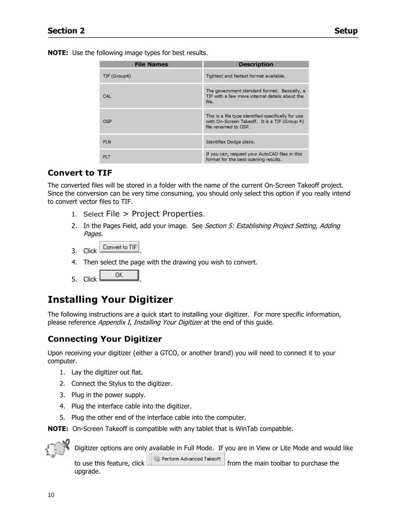
Section 2 Setup
10
NOTE Use the following image types for best results
Convert to TIF
The converted files will be stored in a folder with the name of the current On-Screen Takeoff project Since the conversion can be very time consuming you should only select this option if you really intend to convert vector files to TIF
1 Select File gt Project Properties
2 In the Pages Field add your image See Section 5 Establishing Project Setting Adding Pages
3 Click
4 Then select the page with the drawing you wish to convert
5 Click
Installing Your Digitizer The following instructions are a quick start to installing your digitizer For more specific information please reference Appendix I Installing Your Digitizer at the end of this guide
Connecting Your Digitizer
Upon receiving your digitizer (either a GTCO or another brand) you will need to connect it to your computer
1 Lay the digitizer out flat
2 Connect the Stylus to the digitizer
3 Plug in the power supply
4 Plug the interface cable into the digitizer
5 Plug the other end of the interface cable into the computer
NOTE On-Screen Takeoff is compatible with any tablet that is WinTab compatible
Digitizer options are only available in Full Mode If you are in View or Lite Mode and would like
to use this feature click from the main toolbar to purchase the upgrade
Section 3
11
Toolbars and Menus
This section will
Introduce the program toolbars
Familiarize you with On-Screen Take Offtrade Menu options
Section 3 Toolbars and Menus
12
Toolbars On-Screen Takeoff is equipped with several helpful toolbars for application efficiency See Appendix II Toolbar Item` Details for a detailed description of each toolbar item Individually the toolbars may be displayed moved docked reshaped or hidden from view You can also create costume toolbars to fit your needs
Main Toolbar
Tool Toolbar
Zoom Toolbar
View Toolbar
Navigate Toolbar
Takeoff Toolbar
Image Toolbar Viewing Toolbars Toolbars are displayed on the screen and will be consistent on each tab or page (Some toolbars or toolbar items will be in an inactive state if they donrsquot have a supporting element in the application)
1 Select View gt Toolbars and select the appropriate toolbar name
OR
2 Right-click on a toolbar region of the screen
3 Check the toolbars you want to display
Section 3 Toolbars and Menus
13
Moving Toolbars The toolbars may be positioned anywhere on the screen you wish This feature is provided to allow the flexibility for positioning the toolbars so they are out of your way yet handy for use
1 Click on an edge of the toolbar holding down the mouse button drag it to its new position
2 Release the mouse button to set it in place
NOTE If the toolbar is dropped anywhere other than a screen edge it will become free floating This feature is especially handy when using multiple monitors
Docking Toolbars The toolbars can be docked to any of the screen edges
1 Click on the title bar of an undocked toolbar
2 Drag the toolbar to any location on the screen
Hiding Toolbars
1 Select View gt Toolbars and select the toolbar you wish to remove from the screen
2 Right-click on the toolbar or dock bar areas
3 A floating toolbar can be closed by clicking on the in the upper right corner of the toolbar
Resizing Toolbars Only undocked (floating) toolbars may be resized
1 Position the mouse pointer over an edge
2 Click and drag
3 The toolbar can be resized as desired
Customizing the Toolbars You may rearrange or delete buttons within a toolbarrsquos display or you may move buttons from one toolbar to another If you find that you use a few tools over and over you may want to group them within a single toolbar for convenience On-Screen Takeoff gives you the flexibility to customize your takeoff environment
1 Select Tools gt Customize The Customize dialog will open
2 With the dialog open click on a toolbar button and drag buttons from one toolbar to another or a new location within the same toolbar
3 To add a button without altering another toolbar click on the Commands tab of the Customize dialog and drag the appropriate symbol from the Buttons section to a toolbar
4 To remove a button drag it to within the takeoff area of the application
Section 3 Toolbars and Menus
14
Menus
Section 3 Toolbars and Menus
15
Digitizer Menu
Section 4
16
Features
This section will
Show you how open On-Screen Takeoff
Describe the On-Screen Takeoff environment
Teach you how to navigate pages
Section 4 Features
17
Start On-Screen Takeoff
1 On your desktop double-click your On-Screen Takeoff icon
2 The application will open
OR
3 Left-click on the Start button on your computerrsquos toolbar
4 Scroll up to Programs gt On Center Software
5 Highlight On-Screen Takeoff and click On-Screen Takeoff will open On-Screen Takeoff opens to an untitled blank project The Image view of the screen will be a blank page
Two blank dock bars the Pan dock bar and the Takeoff dock bar appear at the left side of the screen Along the bottom the Status bar displays user status or context-sensitive messages as well as paper size and current zoom percentage of the plan sheet on screen The menu bar and several task specific toolbars are located at the top of the screen
NOTE All toolbars and dock bars may be accessed to view or hide through View gt Toolbars on the menu bar
Section 4 Features
18
Quick Start Video When On-Screen Takeoff opens you will be given an option to watch the Quick Start video (recommended) or start the program without watching the video
The 20 minute video will demonstrate key program functionality and allow you to view application instruction for enhanced learning
If you would like to watch the video click If you prefer to get started without
the video click If you have already viewed the video click the lsquoDo not show this message againrsquo box to prevent this dialog from appearing each time you open the program
NOTE If you decide later that you would like to watch the Quick Start video go to Help gt Watch
Quick Start Videos
On-Screen Takeoff Environment The On-Screen Takeoff environment acts like your drafting table allowing you to work on several sheets of plans at once and to reference at a glance the entire drawing and your position on that drawing while giving you the power of a computer to track analyze print and export your takeoff quantities and plans
The screen is bordered at the top by the Menu bar with pull-down menus and at the bottom by the Status bar which indicates current user status plan page size and current zoom percentage of page The largest portion of the application screen will be your takeoff area bounded on the left (by default) by two dock bars and on the top by several toolbars
In the takeoff area you may view your project plans (images) andor takeoff objects the takeoff list with quantities the worksheet or a legend of your condition list
The main window of On-Screen Takeoff has three tabs located at the bottom left allowing for quick change between Image Takeoff or Worksheet views Select the desired view option on the toolbar and it will automatically open on your screen
Section 4 Features
19
Image View
This view shows the plan file andor takeoff conditions drawn from your plans
Takeoff View This view displays the height if applicable and quantity breakdowns of your conditions according to result types indicated (eg linear feet square feet or count of items) for zones pages and the project as a whole It also displays notes per condition
Section 4 Features
20
Worksheet View This view displays the condition and quantity in units of measure specified in the first results field of the Results tab in the Condition dialog and allows the user to enter amounts for material labor and subcontractor takeoffs
NOTE When in the Worksheet view tab out the field then save This is keep all the values saved
Navigating On-Screen Takeoff
Auto Scrolling When creating linear areas or zones On-Screen Takeoff will automatically scroll the image view when necessary It will move as your mouse or digitizer moves beyond the edge of the current view
Changing Pages
1 Select View gt Next Page Previous Page or Go To Page (specify page number for the Go to Page option)
2 You may also select the corresponding arrows for these options from the Navigate Toolbar The
drop down arrow in the Page field will list the pages The and arrows will take you to the
previous or next page The and arrows will take you to the first or last page
OR
Section 4 Features
21
3 Or press Ctrl G for the Go To Page dialog
Hot Links Hot links allow you to move quickly from one drawing to the pertinent area of another drawing A hot link is handy when viewing enlarged areas of a page and needing the ability to jump back to a reference page
1 Select Tools gt Hot Link
OR
2 Click from the Tools Toolbar
3 Click on the page where you want to set the link The Hot Link dialog will open
4 Using the current page display on the Navigate Toolbar access the pull-down menu of pages by
clicking on the arrow at the right
5 Select the page for your link (You may also choose View gt Go to Page and select by page number)
6 Manipulate the view using the zoom tool and the scroll bars
7 Click
8 After joining a hot link to another page the hot link arrows in the Navigation Toolbar will become active
9 Move a hot link to another location on the page by clicking then click and drag the hot link image anywhere on the page
Section 5
22
Projects
This section will
Help you create settings important to your projects
Explain how On-Screen Takeoff works with your electronic or paper plans
Section 5 Projects
23
Project Template Files You can begin your project with a template Templates allow you to take advantage of conditions and settings used with previous projects
On-Screen Takeoff templates contain condition lists and established layer separations from previous projects you have created You may also use the sample templates provided with On-Screen Takeoff as a great starting point All aspects of the templates may be adjusted for a new project
1 Select File gt New and click the OK button
2 From the New dialog box choose the template that best fits your project
3 The conditions for this template will appear in the Takeoff Dock bar and the Project Properties dialog will open asking for further information
4 Use File gt Save or File gt Save As to rename and save your new project
Saving a Project as a Template File You can save your condition properties and layers as a template for future projects
1 Select File gt Save As
2 Enter a name for your template and select On-Screen Takeoff Template Files (tpo) from the Save As type field of the dialog (click on the down arrow to select)
3 Click the OK button to accept and close the dialog Modifying a Template File Follow these steps to modify an existing template file if you need to change or add conditions andor layers
1 Select File gt Open
2 Navigate to your Projects directory
3 In the File Type drop-down select On-Screen Takeoff Template files (tpo)
4 Choose the On-Screen Takeoff template file you would like to modify and click the OK button
5 Make appropriate changes
6 Save and close file
The On-Screen Takeoff template files cannot save takeoff information
Section 5 Projects
24
Opening an Existing Project File 1 Select File gt Open
2 Navigate to the desired file location
3 Click the Open button
NOTE If your latest changes to a project file have not been saved On-Screen Takeoff will ask
you whether you would like to save the file and gives you the option of canceling the operation
Creating a New Project
1 Select File gt New
2 For a blank untitled project click
3 At this point the Project Properties dialog will pop-up for more information about your takeoff
NOTE The following are important to keep in mind when beginning a new project
At the start of your project fill out the Project Properties settings to establish the name for all printed output from your project set the default page size and scale for your plans number and names of different pages within the project and locations of electronic drawings
Scale settings can significantly affect quantity outcomes Be sure to set the scale for each page of drawings before beginning condition takeoffs
When using a digitizer remember to make a mark with a pen or pencil in the upper left and lower right corners of the first sheet of the paper plans to delineate the takeoff area for that sheet You can then set the takeoff area on On-Screen Takeoff using your marks
Save your project before you begin taking off any conditions On-Screen Takeoff will write a back-up file using the same file name
Remember the Undo feature If you make a mistake select Edit gt Undo and reverse the process step by step
Section 5 Projects
25
Project Properties
You can either set your Project Properties when you create a new takeoff or once your project file is saved under the appropriate name
1 Select File gt Project Properties the Project Properties dialog box will appear
2 Type in the name of your project to appear on printouts Use the backspace andor delete keys to edit the name as necessary
3 Press the Tab key to move to the Default Image Size option or click within the Image Size box You may click on the arrow at the right for the pull-down menu of page size options or you can use the down-arrow key on your keyboard to scroll through the list to the appropriate selection
4 Press the Tab key to move to the Default Scale option Select a scale by using the drop down arrow If your scale is metric you will need to click in the box next to Metric to convert to that measurement
5 Establish the number of pages for your project plans And load image files See Adding Pages to
Your Project
Adding Pages to Projects Individual Electronic Plans
1 Click on in the Project Properties dialog
2 In the Add Images dialog use the drop down arrow to navigate to the appropriate directory and folder containing your image
3 Select the file so that it displays in the File name field then click The file will display by name and path in the Image File field in Project Properties dialog
4 Click to accept and your project will automatically open
5 Save your project with the new settings by selecting File gt Save
Section 5 Projects
26
Electronic plans scanned from blueprints (as opposed to blue lines) will display as white lines on a black background and are difficult to read on your computer screen Select Image gt Invert and the colors will invert to black on white
You may have noticed the Page column in the Project Properties dialog Generally plan images occupy one page and 1 will be listed in the column indicating Page 1 of your plan file If you import a multi-page TIF a plan file containing more than one page of plans they will import as separate pages and each successive page will be indicated under the Page column as 1 2 3 etc of the plan file
Group of Electronic Plans You may add all the electronic plan files from a particular source (for example from a CD) by using the Auto Add feature
1 Click the button in the Project Properties dialog
2 Browse until you find the appropriate directory and folder containing your plan images
3 Click on any file displayed within your target folder so that the file name appears in the File name box of the Auto Add dialog
4 Click The image paths and file names will be recorded into the project properties arranged alphabetically
5 Click to accept your choices and your project will automatically open
6 Save your project with the new settings by selecting File gt Save
To load Dodge Plans into your Project Properties see Appendix IIi Loading Plans from a Dodge CD
Paper Plans On-Screen Takeoff makes it easy for Full Mode users to perform quantity takeoffs from paper plans using a digitizer
1 Add pages by clicking until you have the number of pages initially in the project
2 Name each page by clicking within the Title area and typing the name
3 Click to accept your choices and close the Project Properties dialog
4 Save your project with the new project properties settings by selecting File gt Save
Section 5 Projects
27
Setting Up a Drawing Template On-Screen Takeoff provides the convenience of using the same work surface for both digitizer and mouse to allow the user to draw conditions and then edit settings of the project or add or change conditions without breaking stride A mouse pad template included with the program defines the area of the digitizer in which use of the stylus or cursor will be recognized as mouse movement as opposed to drawing movement
1 Place your stylus on On-Screen Takeoff
2 Placing the template identifies the location mouse movements will be recognized by the program
Before placing the template the template must be applied to the digitizer surface This may have been done during the installation of your digitizer We suggest attaching the template to the lower right corner of the digitizer surface about one inch inside the grid area
3 Select Digitizer gt Place Template
4 Follow the instruction prompts on the screen clicking first on the target symbol at the left of the On-Screen Takeoff box on the template then on the target at the right
Setting Takeoff Area Before you can begin taking off a drawing you must define the drawing area on the digitizer This requires defining an area that will include all objects on each drawing of your plans As you add pages to your takeoff the same area of the digitizer will be active
1 Secure the plans to the digitizer with tape or a set of clamps
2 With a pen or a pencil mark the upper left corner and the lower right corner of the first page in your set of plans
3 Select Digitizer gt Set Takeoff Area
4 Click each mark with the stylus pen as prompted
5 Verify the active area of the digitizer by looking at the image size located in the lower right corner of your screen
If you close the program before the takeoff is complete you will need to reestablish the takeoff area before you can add additional condition quantities
Electronic plans appear on your computer screen eliminating the need to set a takeoff area You simply drag your mouse across the conditions you wish to takeoff The conditions will be highlighted and quantities will be totaled instantly Electronic plans are available through a variety of services For information contact an On Center Software account manager
Section 5 Projects
28
Setting Scale for Specific Pages You may set the scale in each page view separately This will override the default scale setting in Project Properties for that page Setting the correct scale for the drawing before taking off quantities ensures accurate calculations Be careful to check the scale for each drawing in your project before doing takeoffs
1 Display the page you want to set select Edit gt Set Scale
2 Use the drop down arrow to select a scale that will be applied to that page
3 Click
OR
4 Access the pull-down scale settings on the Navigate toolbar
NOTE As you draw objects notice that the drawn object is similar in width to the object on your plans If it is not the scale set may not be correct
Calculating Scale You may calculate scale according to a known measurement between two points either with a digitizer or on electronic plans
1 Select Edit gt Calculate Scale using Image or Edit gt Calculate Scale using Digitizer
2 Follow the instructions in the related Calculate Scale dialog box You will be asked to click on the first and second points then to enter the dimension for that distance
3 The scale will be recalculated for the displayed page and the Scale display on the Navigate toolbar will show the new scale
Section 6
29
Conditions and Takeoff
This section will Draw Conditions to Takeoff Plan Quantities
What Zones will do to help your takeoff process
Discuss the ins and outs of Takeoffs
Section 6 Conditions and Takeoff
30
Creating Conditions
If you are starting a new project from scratch you will need to create conditions to takeoff quantities such as floor areas wall lengths and corner bead counts If you are using a template you will have several pre-designed conditions already listed on the Takeoff dock bar However you may want to change the characteristics of some conditions or create additional conditions for a particular project
1 Right Click within the Takeoff dock bar Select New gt Condition
Or
2 From the Takeoff dock bar Click (if the buttons are not showing right-click in the Takeoff dock bar area and select Show Buttons from the pop-up menu) The New Condition dialog appears
3 Select the condition type (Linear Area Count or Zone) from the pull-down menu accessed by the
down arrow next to the Type option
4 Press Tab or use the mouse (or stylus) to move to Name and enter a name for your condition
5 Specify the desired condition attributes See Condition Attributes for more detail
6 Click for condition to apply
Section 6 Conditions and Takeoff
31
Condition Attributes Each condition type will have related attributes to select or specify within the General and Advanced tabs of the New Condition dialog Once a condition has been used to takeoff a quantity from your plans certain attributes cannot be changed
All conditions allow the user to specify color and fill pattern for the object drawn
Linear Conditions
General Specify width and height by feet and inches Specify pitch in inches up to the nearest thousandth of an inch if applicable
Advanced Specify rounding for object quantities and droprun default length for electrical or plumbing drops at the ends of lines Select Connect to have lines connect at the corners where one line of the condition ends and another begins (and indicate Tolerance for the featurersquos activation as distance between the ends of two lines) Choose Trim to have lines automatically trim to a line being crossed Choose Curve to draw a curved line
Follow these examples for inputting feet and inches For 7 feet 6 inches type 706 for 13 feet 7 inches type 1307 For 20 feet type 2000
Section 6 Conditions and Takeoff
32
Area Conditions
General If needed you can specify the thickness (in inches) andor pitch (in inches)
Advanced Specify rounding for object quantities Choose to display an adjustable grid within the area and indicate matrix cell dimensions
Section 6 Conditions and Takeoff
33
Count Conditions
General
Specify height and indicate the size (in inches) and shape (square circle triangle rectangle or opening) of the count object as it will appear on screen
Advanced Count conditions have advanced attributes These options are available for all shapes except for openings
Zone Conditions Zones allow you to subdivide condition quantities making it easier to modify and complete jobs in phases They can be used at the end of a takeoff to isolate a group of condition quantities that are in different areas of the takeoff
Zones can also be used to break a takeoff into multi-phases and can even be used to isolate quantities while a job is in progress to group the amount of work that has been completed to date They can be applied to one or multiple pages in your plans automatically calculating the takeoff quantities for each zoned area
Section 6 Conditions and Takeoff
34
The zone feature is only available in Lite and Full Mode If you are in View Mode and would like
to use this feature click from the main toolbar to purchase the upgrade
Condition Notes A Note tab is provided for comments regarding the condition These notes will display on the Takeoff List report and will import into Quick Bid
Section 6 Conditions and Takeoff
35
Condition Results The Results tab of the New Condition is based on condition type Initial settings default to linear feet (LF) for linear conditions square feet (SF) for area conditions and count of items (EA) for count conditions and zones The first of the results fields will display for the condition items in the Takeoff dock bar area All results will display in worksheets and Takeoff List reports as well as in an Excel spreadsheet after being exported
Copying Conditions You may use the condition attributes from a condition yoursquove already created for any future conditions of the same type
1 Click on a condition to select it
2 Click the Copy button from the toolbar
OR
3 Right-click in the Takeoff dock bar area and select copy
4 A new condition will appear in the list with the same condition attributes as the previous condition but with the quantities zeroed
Editing Conditions Once you have copied a condition you might want to change several attributes You can also edit an existing condition to fit any updated needs
1 Highlight the desired condition on the Takeoff dock bar
2 Click the Change button
OR
3 Double-click on the condition you wish to edit to bring up the Change Condition dialog
NOTE The Change Condition dialog differs from the New Condition dialog only in that if takeoffs
Section 6 Conditions and Takeoff
36
have been performed in your project with this condition you will not be able to change the type of condition or certain properties under the advanced tab of the dialog box
Deleting Conditions 1 Click on the condition in the Takeoff Dock bar area
2 Click the Delete button on the toolbar
OR
3 Right-click and select Delete from the pop-up menu
All takeoff associated with the deleted condition will be deleted immediately and permanently
Organizing Project Conditions Within your project you can create folders andor sub-folders for different types of conditions You may even want to create a folder containing conditions with reset values
To get started organizing your conditions make sure you are viewing the condition tree (right-click in the Takeoff dock bar area and select Show Tree)
Creating Folders and Sub-Folders 1 Right-click in the Takeoff Dock bar area
2 Select New gt Folder from the pop-up menu
Copying Folders
1 Click on the folder and click Copy on the toolbar
2 All copied conditions within the new folder will have values reset to zero
Renaming Folders
1 Click on the folder
2 Right-click and select Rename from the pop-up menu
3 Enter a name for your folder and click the Enter button
Changing Condition Order
You may move conditions up or down in the condition list of the Takeoff dock bar to suit your project needs
1 Select the condition you would like to move by clicking to highlight it
NOTE When you are ready to move the highlighted conditions be sure that you start
moving using the last condition chosen That condition will have a highlighted boarder
Section 6 Conditions and Takeoff
37
2 Drag and drop any the condition from one place to another in the list You may also move a condition to another folder on the list in this way
Drawing with Conditions Snap Angles Set up snap angles to prevent lines from appearing jagged Snap angles are commonly set at 15deg and shift snap angles at 0deg
1 Go to Tools gt Options Options dialog appears
2 Under the General tab make the desired settings
3 Click to save the settings As they are drawn lines will snap to the set degree
Drawing a Linear Object 1 Select a condition from the Condition List in the Takeoff dock bar
2 Move the cursor into the Image takeoff area of the screen you will see the cursor display as crosshairs
3 Click and hold left mouse button then drag mouse to draw a line
4 Release mouse button to set line
Section 6 Conditions and Takeoff
38
5 Repeat steps for further lines
Continuous Mode This feature allows you to draw an object that has connected lines
1 Click the icon from the Takeoff toolbar
OR
2 Go to Tools gt Continuous Mode
3 Follow steps 1-3 from Draw a Linear Object
4 Click at each point of intersection The object will be connected
5 Double-click after making the final point to set the lines
Drawing a Curve To draw a curved line the Curve option must be checked under the Advanced tab of the Condition dialog
1 Click where you want to begin the curve and drag in a straight line to the position for the other endpoint of the curve
2 Click on the line to select it Handles in the shapes of small squares will appear at either end of
Section 6 Conditions and Takeoff
39
the line and in the center of the line
3 Move the cursor over the center handles until the cursor becomes a two-way arrow
4 Click and drag in the direction of the curve bending the line as you move the cursor Release to set the curve (The line you began with will disappear)
Draw a circle by drawing two curved lines connected
Drawing an Area Object Area conditions are drawn similarly to continuous mode lines You may trace any number of adjoining walls at different angles to complete your area takeoff
NOTE When drawing an area do not intersect the perimeter or line of the object you are drawing
1 Click at each point
2 Double-click when yoursquove returned to your starting point
3 The area will be filled with the pattern set for that condition
NOTE The simulated circle will be good enough for you to be able to make a bid
To create a circular area click from point to point with very short distances in between points simulating a circlersquos perimeter Double-click after setting the last point to set the area
Section 6 Conditions and Takeoff
40
Grid Options Grids give you an added advantage when installing materials such as tiles Use this feature to get a count for how many tiles are needed for an area
1 Double-click on an area condition in the Takeoff dock bar to open its Condition dialog
2 Click on the Advanced tab to show its options
3 Check the box next to Grid by clicking in it
4 Indicate the dimensions of the cell matrix in inches (For example 200 x 400)
5 Under Results tab choose each (EA) for one of the results fields This will tabulate a number of grid cells (including partial grid cells) in area
6 Click to save your settings
7 Use the Move Grid and Rotate Grid features in the Tools menu to manipulate the grid as desired
Grid Calculation
1 Go to Tools gt Options menu
1 Specify if On-Screen Takeoff automatically should Calculate Grid Position
2 If AreaGrid Size is selected On-Screen Takeoff will calculate the number of items needed to fill the grid based on grid demintions
3 Click to accept and close the dialog
To move a line at any angle (regardless of default setting) press the Shift key while moving the mouse
Section 6 Conditions and Takeoff
41
Backout Mode This feature allows you to take out part of an area and deduct that amount of square footage
1 Select Tools gt Backout Mode
2 Outline the are you want backed out as you would when drawing a regular area object (see Drawing an Area Object)
3 The outlined area will clear and quantities will be recalculated
NOTE The perimeter of the backout area will be added to the LF quantity for that condition
Drawing a Count Object Square triangle rectangle and circle shaped count objects can easily be placed on images
1 Select the condition
2 Click in the location where you want the object to appear
3 To place an opening-shaped count item like a door or window you must click over an existing linear object such as a wall
4 On the Results tab you can change the height properties to give you the result you need
5 If Backout is checked on the advanced tab for each count opening the opening-shaped count item will back out a corresponding section of the linear object
Opening shaped count items are sized at 3rsquo0rdquo by default
Drawing a Zone Zones are drawn in the same way as area objects and may be any polygonal shape You may trace any number of adjoining walls at different angles to complete the zone perimeter
1 Click at each point
2 Double-click when yoursquove returned to your starting point
Section 6 Conditions and Takeoff
42
Selecting Objects
1 Use the Select Tool to select objects
You can also select all objects that correspond to a condition
1 Click on a condition to select it
2 Right-click and choose Select All
3 All objects with this condition will be highlighted with squares as an outline
Moving and Resizing Objects Linear
1 To move or resize a linear object click anywhere on the line to select it
2 To move the line position your pointer over the center handles When the mouse is positioned over the handles you will see a two-way arrow You will only be able to move the line in the direction of the arrows
3 Drag the line to a new position
4 Clicking and dragging the handles on the ends of the line will allow you to lengthen or shorten your line
Area and Zone
1 To move an area object or zone in its entirety click and drag it to its new position
2 Grabbing a handle at a corner or intersection of the object will allow you to adjust and change its perimeter
Section 6 Conditions and Takeoff
43
Count 1 To move a square circle rectangle or triangle shaped count object click and drag
2 Click and drag an opening shaped count object along the length of the linear object to the desired position then release
NOTE An opening shaped count object may not be moved from its associated linear condition object however it may be moved up and down the length of the linear object
Layers On-Screen Takeoff allows you to sort and separate your takeoff objects within the same job and on the same page On-Screen Takeoff gives you this flexibility through the use of layers
By assigning different conditions to different layers (for example differentiating between floors ceilings and walls) you can choose to view all layers or turn off certain layers to display and print the remaining groups of conditions only You may also remove the background image of electronic plans add text and hot link symbols or print only your condition takeoffs
Layers are only available in Full Mode If you are in View or Lite Mode and would like to use this
feature click from the main toolbar to purchase the upgrade Default Layers
On-Screen Takeoff begins every project with three default layers Image Annotation and Default The Image layer holds the electronic plan files you may have in your project The Annotation layer possesses all text notations highlighting and hot links in the project The Default layer will appear in the Condition dialog when creating or editing a condition (listed in the takeoff dock bar) Conditions are assigned to the Default layer unless otherwise specified by the user
Creating Layers To assign a condition to a layer other than the default layer you must first create additional layers for your project
1 Select View gt Layers to open the Layers dialog
2 Click An unnamed layer will be added
3 Click within the empty box and type a name for your layer (for example Wall)
4 New layers are added as active layers The adjacent box under the Show column will be checked
Section 6 Conditions and Takeoff
44
Assigning a Layer to a Condition 1 Open the Condition dialog box by creating a new condition or editing an existing condition
2 Under the General tab click on the down arrow in the Layer field to display optional layers
3 Select the desired layer for the condition Only the Default layer and layers you have added will be displayed
4 Click
View and Hide Layers
1 Select View gt Layers
2 Under the Show column check the box to view or remove the check (by clicking on it) to hide the specific layer
3 Click to accept and close the Layers dialog
Section 6 Conditions and Takeoff
45
Assigning Text to a Layer When adding text to an image On-Screen Takeoff has the capability to assign the text to a specified layer
1 Select the Text Tool
2 Click at the point you want to place your text
3 Type in your text using the Enter key for line breaks
4 Click the drop down arrow next to the Layer field and select the desired layer
Section 7
46
Printing and Exporting
This section will
Printing options and procedures
Exporting data by copying and pasting
Exporting quantity results to Excel spreadsheets
Section 7 Printing and Exporting
47
Print Setup On-Screen Takeoff allows the user to print the image takeoff list and worksheet
1 Select File gt Print Setup The Print Setup dialog will open
2 Select a printer or leave the default selection listed (change from the default printer displayed by clicking on the down arrow at the right of the field)
3 Indicate page size and printer tray option (Source) Access page size options by clicking on the
down arrow at the right of the field
4 Choose Portrait or Landscape orientation
5 Click to accept and close the dialog
Printing Images The image area can include the electronic plans the takeoff objects added text and hot links To print a subset of these (for example just the takeoffs without the plans or the added text and hot link symbols) hide layers that you do not want to print (see Section 6 View and Hide Layers) When you are printing your images every page will show the scale of the takeoff you are printing
1 Click on the Image tab to display the area of your project
2 Select File gt Print (or Ctrl + P)
Section 7 Printing and Exporting
48
3 Select the desired view (What to print) and the Image Range
4 Click The second Print dialog will open
5 Change settings accordingly or click if you accept the default settings
Printing Takeoff Lists and Worksheets In Takeoff Lists and Worksheets you may hide columns to print only certain results or adjust column widths to fit the report within the page size selected
1 In Takeoff List or Worksheet view move your cursor to the right side of the columnrsquos title bar the cursor will display as a two-way arrow
Section 7 Printing and Exporting
49
2 Click and drag to adjust the width of the column Holding the mouse button you may
slide the title bar under the title bar to its left to hide the column completely
3 Select File gt Print or press Ctrl + P to access the Print dialog
4 Indicate desired printer and choose the number of copies
5 Click to print and close the dialog
When printing the condition list we suggest printing in landscape
To reset to the default column widths double-click on the right border of a column heading will reset the column to its right (or previously to its right before being hidden)
Print Preview 1 Select File gt Print Preview
2 Use and to vary your view 3 If viewing an image choose current full or scale view to see how it displays
4 For printed outputs that cover more than one page use and to view adjacent pages or click on the down arrow next to Page field and select the page you want displayed
Exporting Using the CopyPaste Feature You may copy all the data or sections from the worksheet and the takeoff list view in On-Screen Takeoff and paste it into another application When pasting into Excel the cell layout will be maintained
1 Highlight the areas you wish to paste Click and hold the left mouse button down as you drag the cursor over the area to be selected then releasing the mouse button
OR
2 Select the entire takeoff list quickly click on the left On-Screen Takeoff column header and hold and drag the cursor across the remaining column headings
The number of pages for the view selected will display in the lower left-hand corner The zoom percentage that applies to the view will be displayed in the lower right-hand corner next to page size of the drawing
Section 7 Printing and Exporting
50
3 In the worksheet view you may highlight rows by clicking on the numbered buttons to the left of each row clicking and dragging across column headings or clicking and dragging over individual cells in the worksheet
Click anywhere in the appropriate view to deselect the area
4 Once your selection is highlighted you may select Edit gt Copy or Ctrl C from the keyboard 5 On your monitor switch to the application into which you want to paste your selection 6 Select Edit gt Paste in the new application or simply press Ctrl + V to paste
The colored keys for conditions cannot be pasted
Using the Export Feature You may export condition quantities to specified cell location within an Excel worksheet file Cell target locations are assigned in the Results tab of the condition dialogs on the Export line relating to each quantity measurement type
On-Screen Takeoff will export takeoff quantity results for up to three different quantity types that you specify For instance you may want to know the number of square feet in a ceiling area as well as the number of linear feet in its perimeter
Section 7 Printing and Exporting
51
1 Bring up the Condition dialog by double-clicking on a condition in the takeoff dock bar or by
selecting the condition and clicking
2 Click on the Results tab to access its fields The default quantities for the condition type will display
3 For each results field click on the arrow to access the pull-down menu and select the appropriate quantity (for example SF LF EA etchellip)
4 Have your Excel spreadsheet opened and saved in a file
5 Specify the Excel spreadsheet cell locations where you want the results to go
6 For a cell in the first sheet of your spreadsheet type in the cell address (eg a1) Case is not important
7 For a cell on a successive sheet of your spreadsheet type in sheet the number followed by a comma and the cell address without any spaces (eg sheet2a1) Case is not important
8 Click
9 Select File gt Export gt Condition Qty to Excel
Section 7 Printing and Exporting
52
10 Browse to the location of the Excel spreadsheet file click file to select it
11 Click to export On-Screen Takeoff results to specified cell locations in the Excel file When you return to the Excel application you will see the values have been added to the specified cell locations in your spreadsheet
12 Save your Excel file
Exporting Worksheet to Excel
1 Assign condition quantities you want to export
2 Open saved Excel spreadsheet file to which you will be exporting
3 From On-Screen Takeoff Select File gt Export gt Worksheet to Excel
4 Browse to the location of the Excel spreadsheet file click file to select it
5 Click When you return to the Excel application you will see the values from the Worksheet Tab have been added to your spreadsheet
6 Save your Excel file
Exporting Takeoff to CVS 1 Assign condition quantities you want to export
2 Open saved Excel spreadsheet file to which you will be exporting
3 Click the Takeoff Tab in the project you want to export the information
4 Select File gt Export gt Takeoff to CSV
5 Browse to the location of the CSV spreadsheet file click file to select it
6 Click the Save
NOTE CSV files can be opened in Excel Lotus Access etc One may consider this option more of a ldquodumprdquo into a file
The Excel application must be active (it may be minimized on the application bar) with the target spreadsheet open in the application Otherwise an error will occur with the export operation that will affect both the On-Screen Takeofftrade file and the Excel spreadsheet
Section 8
53
Advanced Features
This section will
Some special features of working with condition objects in the takeoff area
Details of advanced options for conditions
Advanced features of the Project Properties dialog
Section 8 Advanced Features
54
Features to Use with Objects Roping Feature You can move copy or delete using this feature Using the Select tool (the pointer) you may select several objects at once by clicking and dragging an outline around the objects then releasing the mouse button Roping may select either objects completely within the outlined area (inclusive) or objects both within and touched by the outlined area (touching) Specify your roping preference under Tools gt Options
1 Click and hold the mouse button at a point on the screen near the objects to be selected and drag to surround the objects with an outline
2 Release the mouse button The objects will be selected
3 You may now
Move the group around on the page by clicking within the group dragging the mouse and releasing the button to place the objects
Delete the group of objects by clicking the Delete key or
Copy and paste by pressing Ctrl C to copy the group then Ctrl V to paste it The pasted copy of the grouped objects will appear slightly offset from the original objects
Section 8 Advanced Features
55
Applying a DropRun Count
Use the droprun feature when calculating quantities to take into account the drop or run of a linear condition such as electrical lines or plumbing pipes Drop or run lengths may be added separately to any linear condition on screen while a default droprun length may be indicated for a condition as a whole
1 Select the desired linear condition from the Condition List in the Takeoff Dock bar
2 Click the Change button in the toolbar to open the Change Condition dialog
3 Click the Advanced tab to access the advanced options and click inside the DropRun check box
4 Enter a default length to be applied to all of this condition Entering 800 will be interpreted as 8 0 (You must enter both place markers for inches) You can leave the length blank and manually enter drop run on each segment drawn
5 Click the OK button to accept and close the dialog
Edit DropRun Count
1 With the related linear condition in the Takeoff Dock bar highlighted or with the pointer tool selected
2 click on the desired linear object in the image takeoff area The Count button will become active
3 Click on the Count button (alternatively select Tools gt Count) The default droprun amount will show in the pop-up Count dialog (Default length will be zero if droprun has not been selected in this conditionrsquos properties)
4 Type in the desired length Entering 800 will be interpreted as 8 0 (You must enter both place markers for inches)
5 Click the OK button The additional amount will be reflected in the corresponding quantity The new DropRun count will apply only to the object edited
Adding Text in Image View
On-Screen Takeoff allows you to place text comments around your quantity takeoffs that may be printed along with plan images and objects Text is automatically placed within the Annotation Layer (that includes text and hot links)
1 To place text on the image select the Text Tool and click at the point you want to place your text opening a text box
2 Type in your information clicking Enter for line breaks
3 When you are finished click the OK button to exit the text box
4 To reposition text simply click on the text (with the Text Tool active) to select it
5 Move the cursor over the text the cursor will now display as a four-way arrow
6 Click and drag the mouse to position the text as desired
Section 8 Advanced Features
56
1 To edit existing text use the Text Tool to double-click on the text to open the editing box
2 Enter additional text or use the Backspace key to delete text as necessary
Formatting Text Once created you may format the font size type style and color of your text
1 Click on the text to select it and select Tools gt Font or click on the Font button in the Takeoff Toolbar
2 Select the desired features (color options are disabled) and click the OK button
3 Click on the text to select it and select Tools gt Color or click on the Color button in the Takeoff Toolbar The Color dialog will open
4 Click on a color in the Basic Color palette or create a color and add to the Custom Colors palette (Be sure to click on the color in the Custom Colors palette to select it)
5 Click the OK button
Object Properties
Linear Objects
Linear objects may be set to connect at corners
A linear object may be set to trim automatically when crossing another linear object (Check the trim option under the advanced tab of the Condition dialog)
When you move a connected linear object objects automatically move and resize connected lines accordingly (quantities are then recalculated)
This feature requires that the connected linear object be moved using the center handles (does not apply when resizing the line from the ends)
Objects constrain to snap increments defined in the Tools gt Options menu (with the mouse 15deg by default incremental when shift key is held down)
Objects are measured from centerline to centerline
Section 8 Advanced Features
57
Area Objects When drawing an area use your escape key to undo the last line drawn You may reverse your
drawing of an area using the escape key
The area will not fill with color and pattern until the user double-clicks after the last line is set
Lines drawn to delineate an area object constrain to snap increments defined in the Tools gt Options menu (with the mouse 15deg by default incremental when shift key is held down)
After selecting an area to move or adjust position the mouse in the center to move the entire area position the mouse at the sides or corners to adjust the perimeter
Count Objects
All count objects are quantified by the physical number of objects per page and reported as EA for the UOM The quantity for the current Image View is (displayed in the Condition List) and the total quantity in your project is displayed in the Takeoff View and Worksheet View)
Square circle rectangle and triangle shaped count objects do not displace or subtract from other object quantities when placed on top of them However on the Advanced Tab for the count condition a connect property can be set (this is a check box) so that when a count object of this shape is put on top of a Linear type takeoff object it will move with the linear if said linear is moved
An opened-shaped count object must be placed within a linear object Opening shaped count objects may also be measured by linear foot or linear yard (EA SF and SY are also options) Opening shaped count items default to a width of 3rsquo 0rdquo at the time of creation This size can be changed The small medium and large size are not options on this type of condition anymore Check Backout on the Advanced tab for each Count object back out the footage (or yardage) of opening-shaped count objects in which they are placed
NOTE In order to see this Backout functionality (in quantity) for SY or SF deductions at least one of the
results for the Linear(s) this object will be placed on must be set to SY or SF and the count object must have a height quantity
Advanced Features of Conditions The Round Feature Under the Advanced tab of the linear and area Condition dialogues you may specify quantity rounding (in inches) For linear objects rounding applies to each linear object drawn For area objects rounding will apply to each segment of the area perimeter adjusting the perimeter and area calculations For example With a linear condition entering 12 in the Round field will round up each related linear object to the nearest 12 inches or one foot With this setting two walls of 1 4 would each round to 2 0 totaling 4 0
NOTE In the Takeoff Dock bar condition list and in the On-Screen Takeoff reports quantities will be displayed in whole numbers rounded up to the nearest foot However calculations are based on true quantities without rounding unless the Round Feature is engaged
Pitch Pitch may apply either to linear or area conditions It is measured in rise per linear foot Entering 12 indicates a 12 rise per 12 of linear distance (a pitch of 12 over 12) or an angle of 45deg
Section 8 Advanced Features
58
Advanced Features of Project Properties Selecting Multiple Pages
1 Select a single page entry by clicking on the numbered gray button to the left of the entry
2 Drag the cursor down the column of numbers to select consecutive pages
3 Click on the blank button at the top of this column to select all pages in the Properties dialog
Section 8 Advanced Features
59
Changing Image Assigned to a Drawing 1 Select the page entry by clicking on the numbered gray button to the left of the entry 2 Click the Change Image button The Change Image dialog box will appear
3 Navigate to the desired file and select by clicking on it
4 Click the Open button The electronic file assigned to the page will have been changed to reflect the new file choice
Changing Image File Path 1 Select pages as described above
2 Choose Change Folder
3 In the Change Folder dialog navigate to the appropriate folder
4 Click the OK button The file path will have been changed for the selected page entries
Delete a Page from Project Properties 1 Select the page you want to delete by clicking on its associated number (in the gray box at the
left of the entry)
2 Choose Delete Page
All Takeoff on the page will be deleted immediately and permanently
Section 8 Advanced Features
60
Advanced Features of Tool Options
Calculation Method On-Screen Takeoff has built-in calculation options to allow for faster work and faster saves until your takeoff is complete Calculation options are found by selecting Tools gt Options then clicking on the Calculation tab
Calculation method can be set to Automatic Automatic except Grids and Manual Manual will allow the program to operate more quickly while Automatic or Automatic except Grids allows the user to see quantity changes as takeoffs are made
In any mode you may press F9 to recalculate quantities for the On-Screen Takeoff current totals
Configuration Tab
When the ldquoPage Label (A01)rdquo radial button is chosen On-Screen Takeoff puts the numbered label on all the pages of in your current page indicator in your Navigate Toolbar If the Page Descriptionrdquo radial button is chosen then a description of what takeoff is on that specific page will be shown in your current page indicator in your Navigate Toolbar
This section of the configuration tab gives you options on how you want to export your information When the ldquoFolderSubfolder Namesrdquo radial button is chosen than on your file that you are exporting to will have all the conditions folders and subfolders In the Delimiter box you can choose the symbol that is needed to separate the information you are exporting Some files need semicolons () or colons () to make sure the information comes exported in is separated it the appropriate places
Section 8 Advanced Features
61
In previous versions of On-Screen Takeoff there are views that users need to have in order for them to display their information By either choosing ldquoOST 1xrdquo or ldquoOST 2xrdquo it will let the program know you want your columns of information exported in that specific format
When you have the Confirm Deletions radial button of ldquoYesrdquo chosen than every time you delete anything you will get a dialog box confirming your intentions of deletion
While working with your takeoff you have a choice to either view the legend of your conditions or hide it Choose whichever radial button that suits your needs
For those who prefer to use the Enter key to navigate in dialog boxes this option is just for that
Font Tab The Font tab is designed for you to make your own look and feel for the application At the bottom of this tab it will show you sample of the fonts and colors you have chosen
Renaming the Current Page You may change the name of the current page in the takeoff area of On-Screen Takeoff by selecting Edit gt Rename Page
This opens the Name Page dialog and you may simply type in a new name and click the Enter button The new name for the file will be reflected on the title bar for the page and in Project Properties
You also may access the Rename Page function by right-clicking in the takeoff area while in Image View and selecting the option from the pop-up menu that appears
Section 9
62
Saving and Exiting
This section will
Explain how to save projects
Show you how to safely exit the program
Section 9 Saving and Exiting
63
Saving Your Project
1 Select File gt Save 2 If your project has not previously been saved a Save dialog box will open to allow you to name
the file and choose the directory and folder in which to save your file 3 Once saved File gt Save will simply save the current version of the file
OR
4 Select File gt Save As then type in a new name for the file and save to the desired file path
The Auto-save Feature With the Auto-save feature On-Screen Takeoff automatically backs up your open project You may choose to have more than one level of backup files The first backup copy will have the extension b00 and successive files will be b01 b02 and so on If you have designated four levels of backup files after the fourth backup copy has been created (b03) the next file will be saved over the file with extension b00 Further backup saves will then rotate through the four backup files in the same way
1 Select Tools gt Options 2 In the Auto-save area (under the General tab) select the frequency of backup file creation (in
minutes) and the number of levels for the feature 3 You also may disengage the feature by clicking in the check box to clear it
The Auto-save feature automatically saves backup copies to the directory of the current project If you are working from a write-protected area such as a CD-ROM On-Screen Takeoff will place backup files in the On-Screen Takeoff folder
Exiting When you are finished using On-Screen Takeoff it is very easy to exit Exiting is very important because of security reasons If someone were to use your computer they could enter the application and view and manipulate information
Section 9 Saving and Exiting
64
On-Screen Takeoff closes the open project when you open another or create a new project or when you exit the program
1 Select File gt Exit
OR
2 You also may click at the upper right-hand corner of the application to exit
NOTE If your latest changes to a project file have not been saved On-Screen Takeoff will ask you whether you would like to save the file and gives you the option of canceling the operation
Appendix I Installing Your Digitizer
65
Appendix I Installing Your Digitizer When you get your digitizer from GTCO you will need to connect it to your computer Follow the instructions outlined below to do this
Note For rollup digitizers the metal bar must be oriented to the top or right hand side
Connecting the Digitizer 1 Lay the digitizer out flat 2 Connect the Stylus to the digitizer 3 Plug in the power adapter 4 Plug the interface (IO) cable into the digitizer 5 Plug the other end of the interface cable into an open serial port on computer
Note GTCO Technical support phone number is 410-381-6688 The electronic manual (on diskette) from GTCO contains more detailed installation and operation instructions for the GTCO digitizer model you have
Installing other Digitizer Drivers If you are using a GTCO Digitizer you will need to install the GTCO TabletWorks Drivers
If you are using a Digitizer not supported by GTCO Tablet Works 10 please contact the manufacturer of your digitizer for assistance with installation
Installing GTCO TabletWorks Drivers 1 Insert the On Center CD into the CD-ROM drive The CD Startup screen will open 2 Click on Install Software 3 Select Additional Software and Drivers 4 Select Digitizer Driver 5 Follow the instructions for installing TabletWorks 10
Adhering the Template The template is a small plastic sticker used to enable mouse function when using the digitizer with On-Screen Takeoff Place your template on your digitizer We suggest placing it in the bottom right corner of the digitizer about one inch inside the takeoff area
Note You may either peel off the back of the template and use the adhesive surface or you can tape the template down
Appendix I Installing Your Digitizer
66
Testing the Digitizer Drivers Before running OST you may test the digitizer by moving the stylus around on the digitizer pad it should move the mouse cursor (if mouse emulation is enabled)
If the digitizer does not move the mouse cursor on the screen
The superset codes may need to be reset Reset the superset codes by touching on the border of the digitizer with the stylus The digitizer should beep several times
The digitizer may not be communicating with the computer Be sure the COM port selected is correct Be sure the COM port selected is correct If you are not able to get the digitizer to move the mouse cursor you need to call GTCO technical support for help
Note The Mouse Emulation is not required for On-Screen Takeoff to work properly It is used only for the Template functionality if the digitizer is moving the cursor the wrong direction (up instead of sideways or vice-versa)
Click the L-shaped arrow symbol on the digitizer with the stylus
Appendix II Toolbar Item Details
67
Appendix II Toolbar Items Main Toolbar
Appendix II Toolbar Item Details
68
Tool Toolbar
Appendix II Toolbar Item Details
69
Zoom Toolbar
View Toolbar
Navigate Toolbar
Appendix II Toolbar Item Details
70
Navigate Toolbar (Continued)
Takeoff Toolbar
Appendix II Toolbar Item Details
71
Takeoff Toolbar (Continued)
Image Toolbar
Appendix III Loading Plans from a Dodge CD
72
Appendix III Loading Plans from a Dodge CD
This section will detail how to load plans from a F W Dodge CD-ROM into an On-Screen Takeoff project file ready for takeoffs
Dodge files may be added to the Project Properties dialog However loading the files in that way will load the files by number rather than name description If you want to load one page only from your Dodge CD You will have to rename the page to display the name rather than number of the file
To load plan files from a Dodge CD so that the files load sequentially by file number but are displayed by name rather than by number within your project follow the instructions below
Opening a Dodge project from a CD-ROM 1 Insert the CD into the drive 2 Choose File gt Custom 3 Choose Dodge Plans Project (plansdat) as the file type 4 Select the appropriate file type by clicking on the down arrow at the right of the Files of type
field 5 In the Look in field access your drive paths by clicking on the down arrow at the right of the
field then
Navigate to your CD-ROM drive Open the data folder and Open the Projects folder
6 Select the desired project and open its folder 7 Open the plansdat file 8 All the images will come in sequenced correctly for that job along with the full descriptions
(names) of each page If there is not a plans folder in the project folder then plans do not exist for that project on the CD Opening the plansdat file will yield an empty project
Appendix IV Using the Plan Viewer
73
Appendix IV Using On-Screen Takeoff Plan Viewer The On-Screen Takeoff Plan Viewer is a limited version of On Center Softwarersquos commercial takeoff software If your status bar located at the very bottom of the main window says View Mode in the lower left-hand corner then you are using the Plan Viewer You can use the plan viewer to
View CD-based amp converted CAD drawings
View a previously created OST file and associated drawings
Download electronic plans online
Navigate through drawings
Quickly Takeoff linearsareas and counts
Zoom in to view the plan better
Print drawings directly from the viewer
Viewing an On-Screen Takeoff Project File
1 To open an OST file that was previously created with of On-Screen Takeoff 2 Select File gt Open 3 An Open dialog will appear if you do not see the OST file you are looking for select the
Look In drop down arrow 4 A drop down menu will appear listing the various folders drives and mapped drives located
on your computer select the correct drive or folder location and continue to browse to the location of your OST file
5 When you see your OST file double-click it to open it 6 Any takeoff and drawings should appear on the Image tab view
If you do not see the drawings but do see the colored takeoff layer the drawings may
not be located in the same place they were originally saved at Go to File gt Project Properties and check the Image File path for each listed page If the image file path is pointing to a CD drive make sure the CD is inside the CR-ROM
Downloading Electronic Plans If your Online Plan Service provides a special file format (OSX) required to use this feature of our plan viewer you can immediately downloaded all electronic plans of a project directly from our viewer
Most Plan Room web sites will automatically open On-Screen Takeoff when a request to download plans is made Your particular Plan Room may differ in operation so please contact the provider directly with questions on using the site
Appendix IV Using the Plan Viewer
74
When you request to download or open a project file from a Plan Room you will usually have the open to open or save an OSX file Choosing open will automatically open On-Screen Takeoff Alternately you may choose to save the file to a local hard drive After you have saved the file either double-click it to launch On-Screen Takeoff or open the OSX file using On-Screen Takeoff by clicking File then Open and locating the file on your hard drive You will need to change the file type to OSX
After the OSX file is opened you will see an additional tab appear in the Conditions List window called Pages
The Pages tab shows the hierarchy of your project Gray file icons represent pages that have not been downloaded and blue icons represents pages that have been downloaded
To download a page simply double-click the page icon
If you wish to select a group of pages to download you can use the Ctrl or Shift key to multiple select them then click the Download button
If you wish to download all pages at once click the Download All button
Downloaded pages will now appear in the Project Properties dialog in the same order in which they appear in the Pages tab
Creating Quick Takeoffs With On-Screen Takeoff you can create quick takeoffs to measure quantities even if you dont have the full version of our program However using the Quick Takeoff functionality shows you just a fraction of what the full version can do
The Quick Takeoff Toolbar is located at the top of the image view It has three buttons designated for three types of takeoffs Linear Area and Count The Quantity drop down list will show secondary quantities for Linears and Areas The Units drop down allows you to select how you want your quantities displayed Feet Inches Yards Millimeters and Meters
NOTE Every time change the type of takeoff you are performing (switching from Area to Linear for example) the previous quantities and takeoff objects will disappear They will also disappear when you changes pages
NOTE You can use the Dimension Tool to basically measure the distance between two points or linears The distance will display on the status bar at the bottom of the application
The Quick Takeoff Toolbar
Appendix V Frequently Asked Questions
75
Appendix V Frequently Asked Questions General
Where is On-Screen Takeoff installed on my computer
Typically it is installed in CProgram FilesOn-Screen Takeoff
In Explorer how do I recognize On-Screen Takeoff file types
On-Screen Takeoff data is stored in a single file per job lsquojob name OSTrsquo On-Screen Takeoff templates are stored as lsquotemplate nameTPOrsquo
Can only one project at a time be open
Yes For that reason opening another project automatically closes the project on screen You will be asked to save any changes
Is only one scale allowed per page What about on drawings that have multiple detail sections on a page and each of those drawings have different scales
Yes For pages with drawings of different scales copy the drawing to another project page and set the appropriate scale
I cannot perform backout on an area that is along a linear
As a workaround use the On-Screen Takeoff layers feature to help you with this issue Electronic Images
How do I start a project from drawings that have been scanned and written to a CD-ROM
Open a new project Select File gt Project Properties and select Auto Add Navigate to your CD and the appropriate folder and select any image file in that location Click Open All files in the location will load into your project Recommended that images are copied from CD to hard drive for performance
If I get a disk of drawings in AutoCAD format (R13 or R14) can I read them in On-Screen Takeoff
Yes On-Screen Takeoff now reads DWG DXF and many other format that are saved with AutoCAD
Appendix V Frequently Asked Questions
76
When I click on the all pages button what is supposed to happen Currently nothing seems to change when I click on that button
The All Pages button is used to apply the Darken and Enhance Plans feature to all pages in the project (as opposed to only the current page on screen)
Is there a way to deduct a large skylight from an area condition
Yes with the related area condition selected in the Takeoff Dock bar unselect the Backout button on the Takeoff Toolbar then draw the Backout area The area quantity will be deducted from the related condition object and the linear measurement of the Backout perimeter will be added
Digitizer Issues
How do I connect a Digitizer to the computer
See Appendix I Connecting a Digitizer
The Place Template menu choice is disabled
On-Screen Takeoff may need to be authorized or the digitizer or the digitzer drivers are not installed
It wonrsquot let me select the Set Takeoff Area menu choice
On-Screen Takeoff may need to be authorized or no job is open a digitizer is not installed or the drivers are not installed
The digitizer stylus is not moving the cursor or crosshairs
Click S-0-1 superset on the digitizer
How do I convert my old GTCO Digitizer to work with On- Screen Takeofftrade
Call GTCO and they may be able to reconfigure your digitizer to be compatible with On-Screen Takeoff
Printing Issues Which Printers work with On-Screen Takeoff
Compatible printers include On-Screen Takeoff Hewlett Packard Epson and Canon printers If you are having printer difficulties please contact support and specify the type of printer along with other pertinent information Contact support at wwwoncentercomsupport or email supportoncentercom
Which Plotters work with On-Screen Takeoff
Compatible Plotters include Hewlett Packard DesignJet plotters and the EnCAD Cadjet II If you are having plotter difficulties please contact support and specify the type of plotter concerned
ViewingDisplay I can no longer see my condition list How do I get it back
The toolbars and Dock bars can be turned on and off through the View gt Toolbars menu options
Appendix V Frequently Asked Questions
77
This is also accessible by right-clicking in the toolbar area and selecting (or deselecting) a toolbar listed
I cannot view my folders in the condition list
Right-click in the Takeoff Dock barcondition list area and select Show Tree to display your folders
My Status Bar reads Viewer Mode and I am unable to draw conditions
On-Screen Takeoff needs to be Authorized Or you need to purchase an upgrade Click the Perform Advanced Takeoff button on the main toolbar
I hid a Dock bar and when I selected to view it again it appeared alongside the other Dock
bar instead of stacked on top of it How do I fix it
Pick up the Dock bar by clicking on the bar at the top and continuing to hold down the mouse button drag the Dock bar over the other one It will resize and appear stacked with the other
When I open image files from a CD the images are all upside down How do I get them right
side up
To flip pages from top to bottom follow the steps below 1 Click the All Pages button on the Image Toolbar (All Pages is engaged when the button
is not clicked) 2 Click the Flip Horizontal button on the Image Toolbar 3 Click the All Pages button again to disengage
Templates How do I create a Template
Follow the steps below 1 Create a typical project 2 Choose File gt Save As 3 Choose On-Screen Takeoff Template Files as the file type to save 4 Name the file This will save all of the condition setups as well as the layers for the
project
How do I create a new project from a template
Follow the steps below 1 Choose File gt New 2 Select a template from those listed in the New dialog This will open a new project with
conditions and layers saved from a previous project but no pages or takeoff
78
INDEX
Area Conditions 32
Area Objects 57
Auto Scrolling 20
Auto-save 63
Backout Mode 41
Calculation Method 60
Conditions 29
Configuration 60
Contents Tab 6
Continuous Mode 38
Count Conditions 33
Count Objects 57
Digitizer 10 65 76
Docking Toolbars 13
Dodge CD 72
Drawing 27 37
DropRun Count 55
Environment 18
Exiting 63
Exporting 49
Features 16
Font 61
Frequently Asked Questions 75
Grid 40
Help File 5
Hiding Toolbars 13
Hot Links 21
Image 19 59
Image files 9
Image Toolbar 12 71
Images 75
Index Tab 6
Layers 43
Linear Conditions 31
Linear Objects 56
Main Toolbar 12 67
Menus 14
Moving Toolbars 13
Navigate Toolbar 12 69
Navigating 20
On-Screen Takeofftrade 2
Page 59 61
Pages 20 25 28
Plan Viewer 73
Plans 26
Printing 47 76
Project Properties 25
Projects 22
Quick Start Video 18
Resizing Toolbars 13
Roping 54
Saving 63
Scale 28
Search Tab 7
Selecting Objects 42
Setup 8
Start On-Screen Takeofftrade 17
System Requirements 9
Takeoff 19 27
Takeoff Toolbar 70 71
Takeoff Toolbar 12
Template Files 23
TIF (Group4) 9
Tool Toolbar 12 68
Toolbar 67
Toolbars 12
View Toolbar 12 69
Viewing Toolbars 12
Worksheet 20
Zone Conditions 33
Zoom Toolbar 12 69
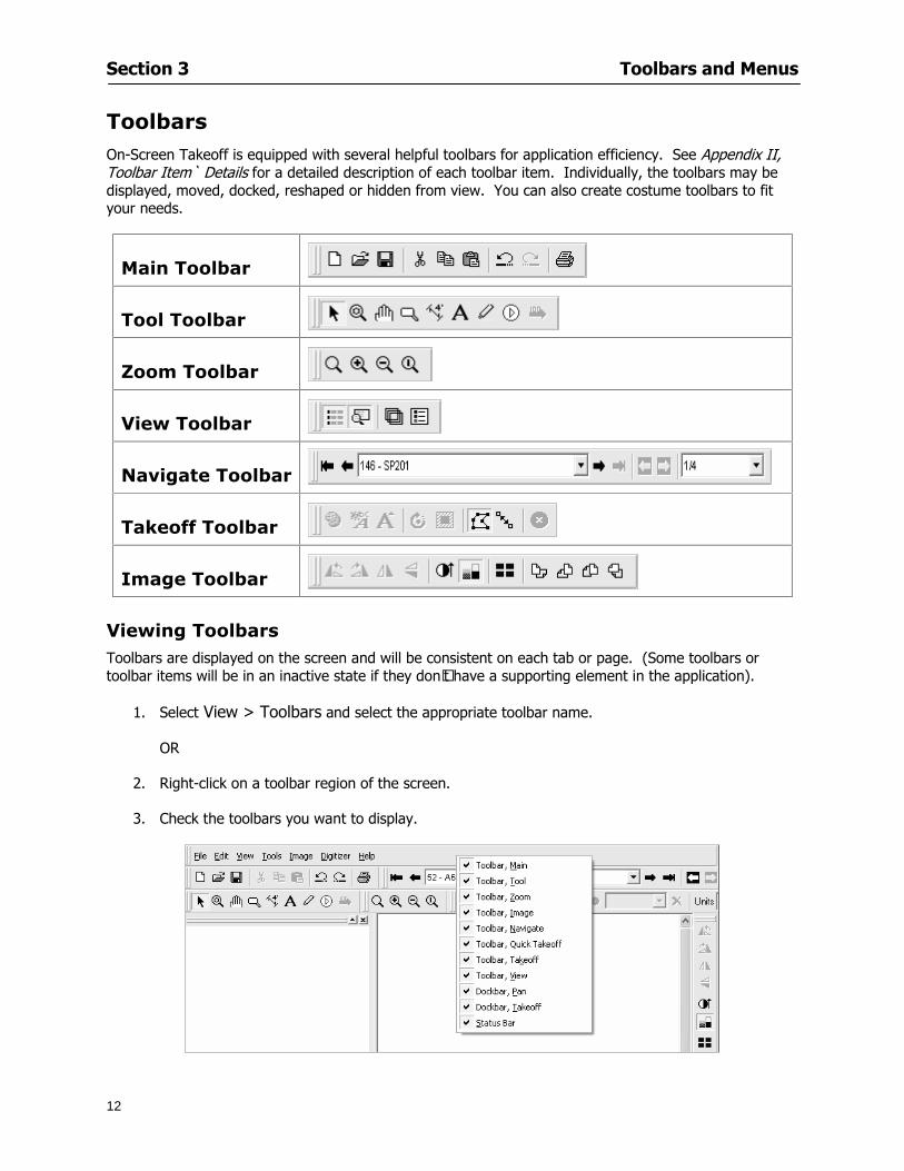
Section 3 Toolbars and Menus
12
Toolbars On-Screen Takeoff is equipped with several helpful toolbars for application efficiency See Appendix II Toolbar Item` Details for a detailed description of each toolbar item Individually the toolbars may be displayed moved docked reshaped or hidden from view You can also create costume toolbars to fit your needs
Main Toolbar
Tool Toolbar
Zoom Toolbar
View Toolbar
Navigate Toolbar
Takeoff Toolbar
Image Toolbar Viewing Toolbars Toolbars are displayed on the screen and will be consistent on each tab or page (Some toolbars or toolbar items will be in an inactive state if they donrsquot have a supporting element in the application)
1 Select View gt Toolbars and select the appropriate toolbar name
OR
2 Right-click on a toolbar region of the screen
3 Check the toolbars you want to display
Section 3 Toolbars and Menus
13
Moving Toolbars The toolbars may be positioned anywhere on the screen you wish This feature is provided to allow the flexibility for positioning the toolbars so they are out of your way yet handy for use
1 Click on an edge of the toolbar holding down the mouse button drag it to its new position
2 Release the mouse button to set it in place
NOTE If the toolbar is dropped anywhere other than a screen edge it will become free floating This feature is especially handy when using multiple monitors
Docking Toolbars The toolbars can be docked to any of the screen edges
1 Click on the title bar of an undocked toolbar
2 Drag the toolbar to any location on the screen
Hiding Toolbars
1 Select View gt Toolbars and select the toolbar you wish to remove from the screen
2 Right-click on the toolbar or dock bar areas
3 A floating toolbar can be closed by clicking on the in the upper right corner of the toolbar
Resizing Toolbars Only undocked (floating) toolbars may be resized
1 Position the mouse pointer over an edge
2 Click and drag
3 The toolbar can be resized as desired
Customizing the Toolbars You may rearrange or delete buttons within a toolbarrsquos display or you may move buttons from one toolbar to another If you find that you use a few tools over and over you may want to group them within a single toolbar for convenience On-Screen Takeoff gives you the flexibility to customize your takeoff environment
1 Select Tools gt Customize The Customize dialog will open
2 With the dialog open click on a toolbar button and drag buttons from one toolbar to another or a new location within the same toolbar
3 To add a button without altering another toolbar click on the Commands tab of the Customize dialog and drag the appropriate symbol from the Buttons section to a toolbar
4 To remove a button drag it to within the takeoff area of the application
Section 3 Toolbars and Menus
14
Menus
Section 3 Toolbars and Menus
15
Digitizer Menu
Section 4
16
Features
This section will
Show you how open On-Screen Takeoff
Describe the On-Screen Takeoff environment
Teach you how to navigate pages
Section 4 Features
17
Start On-Screen Takeoff
1 On your desktop double-click your On-Screen Takeoff icon
2 The application will open
OR
3 Left-click on the Start button on your computerrsquos toolbar
4 Scroll up to Programs gt On Center Software
5 Highlight On-Screen Takeoff and click On-Screen Takeoff will open On-Screen Takeoff opens to an untitled blank project The Image view of the screen will be a blank page
Two blank dock bars the Pan dock bar and the Takeoff dock bar appear at the left side of the screen Along the bottom the Status bar displays user status or context-sensitive messages as well as paper size and current zoom percentage of the plan sheet on screen The menu bar and several task specific toolbars are located at the top of the screen
NOTE All toolbars and dock bars may be accessed to view or hide through View gt Toolbars on the menu bar
Section 4 Features
18
Quick Start Video When On-Screen Takeoff opens you will be given an option to watch the Quick Start video (recommended) or start the program without watching the video
The 20 minute video will demonstrate key program functionality and allow you to view application instruction for enhanced learning
If you would like to watch the video click If you prefer to get started without
the video click If you have already viewed the video click the lsquoDo not show this message againrsquo box to prevent this dialog from appearing each time you open the program
NOTE If you decide later that you would like to watch the Quick Start video go to Help gt Watch
Quick Start Videos
On-Screen Takeoff Environment The On-Screen Takeoff environment acts like your drafting table allowing you to work on several sheets of plans at once and to reference at a glance the entire drawing and your position on that drawing while giving you the power of a computer to track analyze print and export your takeoff quantities and plans
The screen is bordered at the top by the Menu bar with pull-down menus and at the bottom by the Status bar which indicates current user status plan page size and current zoom percentage of page The largest portion of the application screen will be your takeoff area bounded on the left (by default) by two dock bars and on the top by several toolbars
In the takeoff area you may view your project plans (images) andor takeoff objects the takeoff list with quantities the worksheet or a legend of your condition list
The main window of On-Screen Takeoff has three tabs located at the bottom left allowing for quick change between Image Takeoff or Worksheet views Select the desired view option on the toolbar and it will automatically open on your screen
Section 4 Features
19
Image View
This view shows the plan file andor takeoff conditions drawn from your plans
Takeoff View This view displays the height if applicable and quantity breakdowns of your conditions according to result types indicated (eg linear feet square feet or count of items) for zones pages and the project as a whole It also displays notes per condition
Section 4 Features
20
Worksheet View This view displays the condition and quantity in units of measure specified in the first results field of the Results tab in the Condition dialog and allows the user to enter amounts for material labor and subcontractor takeoffs
NOTE When in the Worksheet view tab out the field then save This is keep all the values saved
Navigating On-Screen Takeoff
Auto Scrolling When creating linear areas or zones On-Screen Takeoff will automatically scroll the image view when necessary It will move as your mouse or digitizer moves beyond the edge of the current view
Changing Pages
1 Select View gt Next Page Previous Page or Go To Page (specify page number for the Go to Page option)
2 You may also select the corresponding arrows for these options from the Navigate Toolbar The
drop down arrow in the Page field will list the pages The and arrows will take you to the
previous or next page The and arrows will take you to the first or last page
OR
Section 4 Features
21
3 Or press Ctrl G for the Go To Page dialog
Hot Links Hot links allow you to move quickly from one drawing to the pertinent area of another drawing A hot link is handy when viewing enlarged areas of a page and needing the ability to jump back to a reference page
1 Select Tools gt Hot Link
OR
2 Click from the Tools Toolbar
3 Click on the page where you want to set the link The Hot Link dialog will open
4 Using the current page display on the Navigate Toolbar access the pull-down menu of pages by
clicking on the arrow at the right
5 Select the page for your link (You may also choose View gt Go to Page and select by page number)
6 Manipulate the view using the zoom tool and the scroll bars
7 Click
8 After joining a hot link to another page the hot link arrows in the Navigation Toolbar will become active
9 Move a hot link to another location on the page by clicking then click and drag the hot link image anywhere on the page
Section 5
22
Projects
This section will
Help you create settings important to your projects
Explain how On-Screen Takeoff works with your electronic or paper plans
Section 5 Projects
23
Project Template Files You can begin your project with a template Templates allow you to take advantage of conditions and settings used with previous projects
On-Screen Takeoff templates contain condition lists and established layer separations from previous projects you have created You may also use the sample templates provided with On-Screen Takeoff as a great starting point All aspects of the templates may be adjusted for a new project
1 Select File gt New and click the OK button
2 From the New dialog box choose the template that best fits your project
3 The conditions for this template will appear in the Takeoff Dock bar and the Project Properties dialog will open asking for further information
4 Use File gt Save or File gt Save As to rename and save your new project
Saving a Project as a Template File You can save your condition properties and layers as a template for future projects
1 Select File gt Save As
2 Enter a name for your template and select On-Screen Takeoff Template Files (tpo) from the Save As type field of the dialog (click on the down arrow to select)
3 Click the OK button to accept and close the dialog Modifying a Template File Follow these steps to modify an existing template file if you need to change or add conditions andor layers
1 Select File gt Open
2 Navigate to your Projects directory
3 In the File Type drop-down select On-Screen Takeoff Template files (tpo)
4 Choose the On-Screen Takeoff template file you would like to modify and click the OK button
5 Make appropriate changes
6 Save and close file
The On-Screen Takeoff template files cannot save takeoff information
Section 5 Projects
24
Opening an Existing Project File 1 Select File gt Open
2 Navigate to the desired file location
3 Click the Open button
NOTE If your latest changes to a project file have not been saved On-Screen Takeoff will ask
you whether you would like to save the file and gives you the option of canceling the operation
Creating a New Project
1 Select File gt New
2 For a blank untitled project click
3 At this point the Project Properties dialog will pop-up for more information about your takeoff
NOTE The following are important to keep in mind when beginning a new project
At the start of your project fill out the Project Properties settings to establish the name for all printed output from your project set the default page size and scale for your plans number and names of different pages within the project and locations of electronic drawings
Scale settings can significantly affect quantity outcomes Be sure to set the scale for each page of drawings before beginning condition takeoffs
When using a digitizer remember to make a mark with a pen or pencil in the upper left and lower right corners of the first sheet of the paper plans to delineate the takeoff area for that sheet You can then set the takeoff area on On-Screen Takeoff using your marks
Save your project before you begin taking off any conditions On-Screen Takeoff will write a back-up file using the same file name
Remember the Undo feature If you make a mistake select Edit gt Undo and reverse the process step by step
Section 5 Projects
25
Project Properties
You can either set your Project Properties when you create a new takeoff or once your project file is saved under the appropriate name
1 Select File gt Project Properties the Project Properties dialog box will appear
2 Type in the name of your project to appear on printouts Use the backspace andor delete keys to edit the name as necessary
3 Press the Tab key to move to the Default Image Size option or click within the Image Size box You may click on the arrow at the right for the pull-down menu of page size options or you can use the down-arrow key on your keyboard to scroll through the list to the appropriate selection
4 Press the Tab key to move to the Default Scale option Select a scale by using the drop down arrow If your scale is metric you will need to click in the box next to Metric to convert to that measurement
5 Establish the number of pages for your project plans And load image files See Adding Pages to
Your Project
Adding Pages to Projects Individual Electronic Plans
1 Click on in the Project Properties dialog
2 In the Add Images dialog use the drop down arrow to navigate to the appropriate directory and folder containing your image
3 Select the file so that it displays in the File name field then click The file will display by name and path in the Image File field in Project Properties dialog
4 Click to accept and your project will automatically open
5 Save your project with the new settings by selecting File gt Save
Section 5 Projects
26
Electronic plans scanned from blueprints (as opposed to blue lines) will display as white lines on a black background and are difficult to read on your computer screen Select Image gt Invert and the colors will invert to black on white
You may have noticed the Page column in the Project Properties dialog Generally plan images occupy one page and 1 will be listed in the column indicating Page 1 of your plan file If you import a multi-page TIF a plan file containing more than one page of plans they will import as separate pages and each successive page will be indicated under the Page column as 1 2 3 etc of the plan file
Group of Electronic Plans You may add all the electronic plan files from a particular source (for example from a CD) by using the Auto Add feature
1 Click the button in the Project Properties dialog
2 Browse until you find the appropriate directory and folder containing your plan images
3 Click on any file displayed within your target folder so that the file name appears in the File name box of the Auto Add dialog
4 Click The image paths and file names will be recorded into the project properties arranged alphabetically
5 Click to accept your choices and your project will automatically open
6 Save your project with the new settings by selecting File gt Save
To load Dodge Plans into your Project Properties see Appendix IIi Loading Plans from a Dodge CD
Paper Plans On-Screen Takeoff makes it easy for Full Mode users to perform quantity takeoffs from paper plans using a digitizer
1 Add pages by clicking until you have the number of pages initially in the project
2 Name each page by clicking within the Title area and typing the name
3 Click to accept your choices and close the Project Properties dialog
4 Save your project with the new project properties settings by selecting File gt Save
Section 5 Projects
27
Setting Up a Drawing Template On-Screen Takeoff provides the convenience of using the same work surface for both digitizer and mouse to allow the user to draw conditions and then edit settings of the project or add or change conditions without breaking stride A mouse pad template included with the program defines the area of the digitizer in which use of the stylus or cursor will be recognized as mouse movement as opposed to drawing movement
1 Place your stylus on On-Screen Takeoff
2 Placing the template identifies the location mouse movements will be recognized by the program
Before placing the template the template must be applied to the digitizer surface This may have been done during the installation of your digitizer We suggest attaching the template to the lower right corner of the digitizer surface about one inch inside the grid area
3 Select Digitizer gt Place Template
4 Follow the instruction prompts on the screen clicking first on the target symbol at the left of the On-Screen Takeoff box on the template then on the target at the right
Setting Takeoff Area Before you can begin taking off a drawing you must define the drawing area on the digitizer This requires defining an area that will include all objects on each drawing of your plans As you add pages to your takeoff the same area of the digitizer will be active
1 Secure the plans to the digitizer with tape or a set of clamps
2 With a pen or a pencil mark the upper left corner and the lower right corner of the first page in your set of plans
3 Select Digitizer gt Set Takeoff Area
4 Click each mark with the stylus pen as prompted
5 Verify the active area of the digitizer by looking at the image size located in the lower right corner of your screen
If you close the program before the takeoff is complete you will need to reestablish the takeoff area before you can add additional condition quantities
Electronic plans appear on your computer screen eliminating the need to set a takeoff area You simply drag your mouse across the conditions you wish to takeoff The conditions will be highlighted and quantities will be totaled instantly Electronic plans are available through a variety of services For information contact an On Center Software account manager
Section 5 Projects
28
Setting Scale for Specific Pages You may set the scale in each page view separately This will override the default scale setting in Project Properties for that page Setting the correct scale for the drawing before taking off quantities ensures accurate calculations Be careful to check the scale for each drawing in your project before doing takeoffs
1 Display the page you want to set select Edit gt Set Scale
2 Use the drop down arrow to select a scale that will be applied to that page
3 Click
OR
4 Access the pull-down scale settings on the Navigate toolbar
NOTE As you draw objects notice that the drawn object is similar in width to the object on your plans If it is not the scale set may not be correct
Calculating Scale You may calculate scale according to a known measurement between two points either with a digitizer or on electronic plans
1 Select Edit gt Calculate Scale using Image or Edit gt Calculate Scale using Digitizer
2 Follow the instructions in the related Calculate Scale dialog box You will be asked to click on the first and second points then to enter the dimension for that distance
3 The scale will be recalculated for the displayed page and the Scale display on the Navigate toolbar will show the new scale
Section 6
29
Conditions and Takeoff
This section will Draw Conditions to Takeoff Plan Quantities
What Zones will do to help your takeoff process
Discuss the ins and outs of Takeoffs
Section 6 Conditions and Takeoff
30
Creating Conditions
If you are starting a new project from scratch you will need to create conditions to takeoff quantities such as floor areas wall lengths and corner bead counts If you are using a template you will have several pre-designed conditions already listed on the Takeoff dock bar However you may want to change the characteristics of some conditions or create additional conditions for a particular project
1 Right Click within the Takeoff dock bar Select New gt Condition
Or
2 From the Takeoff dock bar Click (if the buttons are not showing right-click in the Takeoff dock bar area and select Show Buttons from the pop-up menu) The New Condition dialog appears
3 Select the condition type (Linear Area Count or Zone) from the pull-down menu accessed by the
down arrow next to the Type option
4 Press Tab or use the mouse (or stylus) to move to Name and enter a name for your condition
5 Specify the desired condition attributes See Condition Attributes for more detail
6 Click for condition to apply
Section 6 Conditions and Takeoff
31
Condition Attributes Each condition type will have related attributes to select or specify within the General and Advanced tabs of the New Condition dialog Once a condition has been used to takeoff a quantity from your plans certain attributes cannot be changed
All conditions allow the user to specify color and fill pattern for the object drawn
Linear Conditions
General Specify width and height by feet and inches Specify pitch in inches up to the nearest thousandth of an inch if applicable
Advanced Specify rounding for object quantities and droprun default length for electrical or plumbing drops at the ends of lines Select Connect to have lines connect at the corners where one line of the condition ends and another begins (and indicate Tolerance for the featurersquos activation as distance between the ends of two lines) Choose Trim to have lines automatically trim to a line being crossed Choose Curve to draw a curved line
Follow these examples for inputting feet and inches For 7 feet 6 inches type 706 for 13 feet 7 inches type 1307 For 20 feet type 2000
Section 6 Conditions and Takeoff
32
Area Conditions
General If needed you can specify the thickness (in inches) andor pitch (in inches)
Advanced Specify rounding for object quantities Choose to display an adjustable grid within the area and indicate matrix cell dimensions
Section 6 Conditions and Takeoff
33
Count Conditions
General
Specify height and indicate the size (in inches) and shape (square circle triangle rectangle or opening) of the count object as it will appear on screen
Advanced Count conditions have advanced attributes These options are available for all shapes except for openings
Zone Conditions Zones allow you to subdivide condition quantities making it easier to modify and complete jobs in phases They can be used at the end of a takeoff to isolate a group of condition quantities that are in different areas of the takeoff
Zones can also be used to break a takeoff into multi-phases and can even be used to isolate quantities while a job is in progress to group the amount of work that has been completed to date They can be applied to one or multiple pages in your plans automatically calculating the takeoff quantities for each zoned area
Section 6 Conditions and Takeoff
34
The zone feature is only available in Lite and Full Mode If you are in View Mode and would like
to use this feature click from the main toolbar to purchase the upgrade
Condition Notes A Note tab is provided for comments regarding the condition These notes will display on the Takeoff List report and will import into Quick Bid
Section 6 Conditions and Takeoff
35
Condition Results The Results tab of the New Condition is based on condition type Initial settings default to linear feet (LF) for linear conditions square feet (SF) for area conditions and count of items (EA) for count conditions and zones The first of the results fields will display for the condition items in the Takeoff dock bar area All results will display in worksheets and Takeoff List reports as well as in an Excel spreadsheet after being exported
Copying Conditions You may use the condition attributes from a condition yoursquove already created for any future conditions of the same type
1 Click on a condition to select it
2 Click the Copy button from the toolbar
OR
3 Right-click in the Takeoff dock bar area and select copy
4 A new condition will appear in the list with the same condition attributes as the previous condition but with the quantities zeroed
Editing Conditions Once you have copied a condition you might want to change several attributes You can also edit an existing condition to fit any updated needs
1 Highlight the desired condition on the Takeoff dock bar
2 Click the Change button
OR
3 Double-click on the condition you wish to edit to bring up the Change Condition dialog
NOTE The Change Condition dialog differs from the New Condition dialog only in that if takeoffs
Section 6 Conditions and Takeoff
36
have been performed in your project with this condition you will not be able to change the type of condition or certain properties under the advanced tab of the dialog box
Deleting Conditions 1 Click on the condition in the Takeoff Dock bar area
2 Click the Delete button on the toolbar
OR
3 Right-click and select Delete from the pop-up menu
All takeoff associated with the deleted condition will be deleted immediately and permanently
Organizing Project Conditions Within your project you can create folders andor sub-folders for different types of conditions You may even want to create a folder containing conditions with reset values
To get started organizing your conditions make sure you are viewing the condition tree (right-click in the Takeoff dock bar area and select Show Tree)
Creating Folders and Sub-Folders 1 Right-click in the Takeoff Dock bar area
2 Select New gt Folder from the pop-up menu
Copying Folders
1 Click on the folder and click Copy on the toolbar
2 All copied conditions within the new folder will have values reset to zero
Renaming Folders
1 Click on the folder
2 Right-click and select Rename from the pop-up menu
3 Enter a name for your folder and click the Enter button
Changing Condition Order
You may move conditions up or down in the condition list of the Takeoff dock bar to suit your project needs
1 Select the condition you would like to move by clicking to highlight it
NOTE When you are ready to move the highlighted conditions be sure that you start
moving using the last condition chosen That condition will have a highlighted boarder
Section 6 Conditions and Takeoff
37
2 Drag and drop any the condition from one place to another in the list You may also move a condition to another folder on the list in this way
Drawing with Conditions Snap Angles Set up snap angles to prevent lines from appearing jagged Snap angles are commonly set at 15deg and shift snap angles at 0deg
1 Go to Tools gt Options Options dialog appears
2 Under the General tab make the desired settings
3 Click to save the settings As they are drawn lines will snap to the set degree
Drawing a Linear Object 1 Select a condition from the Condition List in the Takeoff dock bar
2 Move the cursor into the Image takeoff area of the screen you will see the cursor display as crosshairs
3 Click and hold left mouse button then drag mouse to draw a line
4 Release mouse button to set line
Section 6 Conditions and Takeoff
38
5 Repeat steps for further lines
Continuous Mode This feature allows you to draw an object that has connected lines
1 Click the icon from the Takeoff toolbar
OR
2 Go to Tools gt Continuous Mode
3 Follow steps 1-3 from Draw a Linear Object
4 Click at each point of intersection The object will be connected
5 Double-click after making the final point to set the lines
Drawing a Curve To draw a curved line the Curve option must be checked under the Advanced tab of the Condition dialog
1 Click where you want to begin the curve and drag in a straight line to the position for the other endpoint of the curve
2 Click on the line to select it Handles in the shapes of small squares will appear at either end of
Section 6 Conditions and Takeoff
39
the line and in the center of the line
3 Move the cursor over the center handles until the cursor becomes a two-way arrow
4 Click and drag in the direction of the curve bending the line as you move the cursor Release to set the curve (The line you began with will disappear)
Draw a circle by drawing two curved lines connected
Drawing an Area Object Area conditions are drawn similarly to continuous mode lines You may trace any number of adjoining walls at different angles to complete your area takeoff
NOTE When drawing an area do not intersect the perimeter or line of the object you are drawing
1 Click at each point
2 Double-click when yoursquove returned to your starting point
3 The area will be filled with the pattern set for that condition
NOTE The simulated circle will be good enough for you to be able to make a bid
To create a circular area click from point to point with very short distances in between points simulating a circlersquos perimeter Double-click after setting the last point to set the area
Section 6 Conditions and Takeoff
40
Grid Options Grids give you an added advantage when installing materials such as tiles Use this feature to get a count for how many tiles are needed for an area
1 Double-click on an area condition in the Takeoff dock bar to open its Condition dialog
2 Click on the Advanced tab to show its options
3 Check the box next to Grid by clicking in it
4 Indicate the dimensions of the cell matrix in inches (For example 200 x 400)
5 Under Results tab choose each (EA) for one of the results fields This will tabulate a number of grid cells (including partial grid cells) in area
6 Click to save your settings
7 Use the Move Grid and Rotate Grid features in the Tools menu to manipulate the grid as desired
Grid Calculation
1 Go to Tools gt Options menu
1 Specify if On-Screen Takeoff automatically should Calculate Grid Position
2 If AreaGrid Size is selected On-Screen Takeoff will calculate the number of items needed to fill the grid based on grid demintions
3 Click to accept and close the dialog
To move a line at any angle (regardless of default setting) press the Shift key while moving the mouse
Section 6 Conditions and Takeoff
41
Backout Mode This feature allows you to take out part of an area and deduct that amount of square footage
1 Select Tools gt Backout Mode
2 Outline the are you want backed out as you would when drawing a regular area object (see Drawing an Area Object)
3 The outlined area will clear and quantities will be recalculated
NOTE The perimeter of the backout area will be added to the LF quantity for that condition
Drawing a Count Object Square triangle rectangle and circle shaped count objects can easily be placed on images
1 Select the condition
2 Click in the location where you want the object to appear
3 To place an opening-shaped count item like a door or window you must click over an existing linear object such as a wall
4 On the Results tab you can change the height properties to give you the result you need
5 If Backout is checked on the advanced tab for each count opening the opening-shaped count item will back out a corresponding section of the linear object
Opening shaped count items are sized at 3rsquo0rdquo by default
Drawing a Zone Zones are drawn in the same way as area objects and may be any polygonal shape You may trace any number of adjoining walls at different angles to complete the zone perimeter
1 Click at each point
2 Double-click when yoursquove returned to your starting point
Section 6 Conditions and Takeoff
42
Selecting Objects
1 Use the Select Tool to select objects
You can also select all objects that correspond to a condition
1 Click on a condition to select it
2 Right-click and choose Select All
3 All objects with this condition will be highlighted with squares as an outline
Moving and Resizing Objects Linear
1 To move or resize a linear object click anywhere on the line to select it
2 To move the line position your pointer over the center handles When the mouse is positioned over the handles you will see a two-way arrow You will only be able to move the line in the direction of the arrows
3 Drag the line to a new position
4 Clicking and dragging the handles on the ends of the line will allow you to lengthen or shorten your line
Area and Zone
1 To move an area object or zone in its entirety click and drag it to its new position
2 Grabbing a handle at a corner or intersection of the object will allow you to adjust and change its perimeter
Section 6 Conditions and Takeoff
43
Count 1 To move a square circle rectangle or triangle shaped count object click and drag
2 Click and drag an opening shaped count object along the length of the linear object to the desired position then release
NOTE An opening shaped count object may not be moved from its associated linear condition object however it may be moved up and down the length of the linear object
Layers On-Screen Takeoff allows you to sort and separate your takeoff objects within the same job and on the same page On-Screen Takeoff gives you this flexibility through the use of layers
By assigning different conditions to different layers (for example differentiating between floors ceilings and walls) you can choose to view all layers or turn off certain layers to display and print the remaining groups of conditions only You may also remove the background image of electronic plans add text and hot link symbols or print only your condition takeoffs
Layers are only available in Full Mode If you are in View or Lite Mode and would like to use this
feature click from the main toolbar to purchase the upgrade Default Layers
On-Screen Takeoff begins every project with three default layers Image Annotation and Default The Image layer holds the electronic plan files you may have in your project The Annotation layer possesses all text notations highlighting and hot links in the project The Default layer will appear in the Condition dialog when creating or editing a condition (listed in the takeoff dock bar) Conditions are assigned to the Default layer unless otherwise specified by the user
Creating Layers To assign a condition to a layer other than the default layer you must first create additional layers for your project
1 Select View gt Layers to open the Layers dialog
2 Click An unnamed layer will be added
3 Click within the empty box and type a name for your layer (for example Wall)
4 New layers are added as active layers The adjacent box under the Show column will be checked
Section 6 Conditions and Takeoff
44
Assigning a Layer to a Condition 1 Open the Condition dialog box by creating a new condition or editing an existing condition
2 Under the General tab click on the down arrow in the Layer field to display optional layers
3 Select the desired layer for the condition Only the Default layer and layers you have added will be displayed
4 Click
View and Hide Layers
1 Select View gt Layers
2 Under the Show column check the box to view or remove the check (by clicking on it) to hide the specific layer
3 Click to accept and close the Layers dialog
Section 6 Conditions and Takeoff
45
Assigning Text to a Layer When adding text to an image On-Screen Takeoff has the capability to assign the text to a specified layer
1 Select the Text Tool
2 Click at the point you want to place your text
3 Type in your text using the Enter key for line breaks
4 Click the drop down arrow next to the Layer field and select the desired layer
Section 7
46
Printing and Exporting
This section will
Printing options and procedures
Exporting data by copying and pasting
Exporting quantity results to Excel spreadsheets
Section 7 Printing and Exporting
47
Print Setup On-Screen Takeoff allows the user to print the image takeoff list and worksheet
1 Select File gt Print Setup The Print Setup dialog will open
2 Select a printer or leave the default selection listed (change from the default printer displayed by clicking on the down arrow at the right of the field)
3 Indicate page size and printer tray option (Source) Access page size options by clicking on the
down arrow at the right of the field
4 Choose Portrait or Landscape orientation
5 Click to accept and close the dialog
Printing Images The image area can include the electronic plans the takeoff objects added text and hot links To print a subset of these (for example just the takeoffs without the plans or the added text and hot link symbols) hide layers that you do not want to print (see Section 6 View and Hide Layers) When you are printing your images every page will show the scale of the takeoff you are printing
1 Click on the Image tab to display the area of your project
2 Select File gt Print (or Ctrl + P)
Section 7 Printing and Exporting
48
3 Select the desired view (What to print) and the Image Range
4 Click The second Print dialog will open
5 Change settings accordingly or click if you accept the default settings
Printing Takeoff Lists and Worksheets In Takeoff Lists and Worksheets you may hide columns to print only certain results or adjust column widths to fit the report within the page size selected
1 In Takeoff List or Worksheet view move your cursor to the right side of the columnrsquos title bar the cursor will display as a two-way arrow
Section 7 Printing and Exporting
49
2 Click and drag to adjust the width of the column Holding the mouse button you may
slide the title bar under the title bar to its left to hide the column completely
3 Select File gt Print or press Ctrl + P to access the Print dialog
4 Indicate desired printer and choose the number of copies
5 Click to print and close the dialog
When printing the condition list we suggest printing in landscape
To reset to the default column widths double-click on the right border of a column heading will reset the column to its right (or previously to its right before being hidden)
Print Preview 1 Select File gt Print Preview
2 Use and to vary your view 3 If viewing an image choose current full or scale view to see how it displays
4 For printed outputs that cover more than one page use and to view adjacent pages or click on the down arrow next to Page field and select the page you want displayed
Exporting Using the CopyPaste Feature You may copy all the data or sections from the worksheet and the takeoff list view in On-Screen Takeoff and paste it into another application When pasting into Excel the cell layout will be maintained
1 Highlight the areas you wish to paste Click and hold the left mouse button down as you drag the cursor over the area to be selected then releasing the mouse button
OR
2 Select the entire takeoff list quickly click on the left On-Screen Takeoff column header and hold and drag the cursor across the remaining column headings
The number of pages for the view selected will display in the lower left-hand corner The zoom percentage that applies to the view will be displayed in the lower right-hand corner next to page size of the drawing
Section 7 Printing and Exporting
50
3 In the worksheet view you may highlight rows by clicking on the numbered buttons to the left of each row clicking and dragging across column headings or clicking and dragging over individual cells in the worksheet
Click anywhere in the appropriate view to deselect the area
4 Once your selection is highlighted you may select Edit gt Copy or Ctrl C from the keyboard 5 On your monitor switch to the application into which you want to paste your selection 6 Select Edit gt Paste in the new application or simply press Ctrl + V to paste
The colored keys for conditions cannot be pasted
Using the Export Feature You may export condition quantities to specified cell location within an Excel worksheet file Cell target locations are assigned in the Results tab of the condition dialogs on the Export line relating to each quantity measurement type
On-Screen Takeoff will export takeoff quantity results for up to three different quantity types that you specify For instance you may want to know the number of square feet in a ceiling area as well as the number of linear feet in its perimeter
Section 7 Printing and Exporting
51
1 Bring up the Condition dialog by double-clicking on a condition in the takeoff dock bar or by
selecting the condition and clicking
2 Click on the Results tab to access its fields The default quantities for the condition type will display
3 For each results field click on the arrow to access the pull-down menu and select the appropriate quantity (for example SF LF EA etchellip)
4 Have your Excel spreadsheet opened and saved in a file
5 Specify the Excel spreadsheet cell locations where you want the results to go
6 For a cell in the first sheet of your spreadsheet type in the cell address (eg a1) Case is not important
7 For a cell on a successive sheet of your spreadsheet type in sheet the number followed by a comma and the cell address without any spaces (eg sheet2a1) Case is not important
8 Click
9 Select File gt Export gt Condition Qty to Excel
Section 7 Printing and Exporting
52
10 Browse to the location of the Excel spreadsheet file click file to select it
11 Click to export On-Screen Takeoff results to specified cell locations in the Excel file When you return to the Excel application you will see the values have been added to the specified cell locations in your spreadsheet
12 Save your Excel file
Exporting Worksheet to Excel
1 Assign condition quantities you want to export
2 Open saved Excel spreadsheet file to which you will be exporting
3 From On-Screen Takeoff Select File gt Export gt Worksheet to Excel
4 Browse to the location of the Excel spreadsheet file click file to select it
5 Click When you return to the Excel application you will see the values from the Worksheet Tab have been added to your spreadsheet
6 Save your Excel file
Exporting Takeoff to CVS 1 Assign condition quantities you want to export
2 Open saved Excel spreadsheet file to which you will be exporting
3 Click the Takeoff Tab in the project you want to export the information
4 Select File gt Export gt Takeoff to CSV
5 Browse to the location of the CSV spreadsheet file click file to select it
6 Click the Save
NOTE CSV files can be opened in Excel Lotus Access etc One may consider this option more of a ldquodumprdquo into a file
The Excel application must be active (it may be minimized on the application bar) with the target spreadsheet open in the application Otherwise an error will occur with the export operation that will affect both the On-Screen Takeofftrade file and the Excel spreadsheet
Section 8
53
Advanced Features
This section will
Some special features of working with condition objects in the takeoff area
Details of advanced options for conditions
Advanced features of the Project Properties dialog
Section 8 Advanced Features
54
Features to Use with Objects Roping Feature You can move copy or delete using this feature Using the Select tool (the pointer) you may select several objects at once by clicking and dragging an outline around the objects then releasing the mouse button Roping may select either objects completely within the outlined area (inclusive) or objects both within and touched by the outlined area (touching) Specify your roping preference under Tools gt Options
1 Click and hold the mouse button at a point on the screen near the objects to be selected and drag to surround the objects with an outline
2 Release the mouse button The objects will be selected
3 You may now
Move the group around on the page by clicking within the group dragging the mouse and releasing the button to place the objects
Delete the group of objects by clicking the Delete key or
Copy and paste by pressing Ctrl C to copy the group then Ctrl V to paste it The pasted copy of the grouped objects will appear slightly offset from the original objects
Section 8 Advanced Features
55
Applying a DropRun Count
Use the droprun feature when calculating quantities to take into account the drop or run of a linear condition such as electrical lines or plumbing pipes Drop or run lengths may be added separately to any linear condition on screen while a default droprun length may be indicated for a condition as a whole
1 Select the desired linear condition from the Condition List in the Takeoff Dock bar
2 Click the Change button in the toolbar to open the Change Condition dialog
3 Click the Advanced tab to access the advanced options and click inside the DropRun check box
4 Enter a default length to be applied to all of this condition Entering 800 will be interpreted as 8 0 (You must enter both place markers for inches) You can leave the length blank and manually enter drop run on each segment drawn
5 Click the OK button to accept and close the dialog
Edit DropRun Count
1 With the related linear condition in the Takeoff Dock bar highlighted or with the pointer tool selected
2 click on the desired linear object in the image takeoff area The Count button will become active
3 Click on the Count button (alternatively select Tools gt Count) The default droprun amount will show in the pop-up Count dialog (Default length will be zero if droprun has not been selected in this conditionrsquos properties)
4 Type in the desired length Entering 800 will be interpreted as 8 0 (You must enter both place markers for inches)
5 Click the OK button The additional amount will be reflected in the corresponding quantity The new DropRun count will apply only to the object edited
Adding Text in Image View
On-Screen Takeoff allows you to place text comments around your quantity takeoffs that may be printed along with plan images and objects Text is automatically placed within the Annotation Layer (that includes text and hot links)
1 To place text on the image select the Text Tool and click at the point you want to place your text opening a text box
2 Type in your information clicking Enter for line breaks
3 When you are finished click the OK button to exit the text box
4 To reposition text simply click on the text (with the Text Tool active) to select it
5 Move the cursor over the text the cursor will now display as a four-way arrow
6 Click and drag the mouse to position the text as desired
Section 8 Advanced Features
56
1 To edit existing text use the Text Tool to double-click on the text to open the editing box
2 Enter additional text or use the Backspace key to delete text as necessary
Formatting Text Once created you may format the font size type style and color of your text
1 Click on the text to select it and select Tools gt Font or click on the Font button in the Takeoff Toolbar
2 Select the desired features (color options are disabled) and click the OK button
3 Click on the text to select it and select Tools gt Color or click on the Color button in the Takeoff Toolbar The Color dialog will open
4 Click on a color in the Basic Color palette or create a color and add to the Custom Colors palette (Be sure to click on the color in the Custom Colors palette to select it)
5 Click the OK button
Object Properties
Linear Objects
Linear objects may be set to connect at corners
A linear object may be set to trim automatically when crossing another linear object (Check the trim option under the advanced tab of the Condition dialog)
When you move a connected linear object objects automatically move and resize connected lines accordingly (quantities are then recalculated)
This feature requires that the connected linear object be moved using the center handles (does not apply when resizing the line from the ends)
Objects constrain to snap increments defined in the Tools gt Options menu (with the mouse 15deg by default incremental when shift key is held down)
Objects are measured from centerline to centerline
Section 8 Advanced Features
57
Area Objects When drawing an area use your escape key to undo the last line drawn You may reverse your
drawing of an area using the escape key
The area will not fill with color and pattern until the user double-clicks after the last line is set
Lines drawn to delineate an area object constrain to snap increments defined in the Tools gt Options menu (with the mouse 15deg by default incremental when shift key is held down)
After selecting an area to move or adjust position the mouse in the center to move the entire area position the mouse at the sides or corners to adjust the perimeter
Count Objects
All count objects are quantified by the physical number of objects per page and reported as EA for the UOM The quantity for the current Image View is (displayed in the Condition List) and the total quantity in your project is displayed in the Takeoff View and Worksheet View)
Square circle rectangle and triangle shaped count objects do not displace or subtract from other object quantities when placed on top of them However on the Advanced Tab for the count condition a connect property can be set (this is a check box) so that when a count object of this shape is put on top of a Linear type takeoff object it will move with the linear if said linear is moved
An opened-shaped count object must be placed within a linear object Opening shaped count objects may also be measured by linear foot or linear yard (EA SF and SY are also options) Opening shaped count items default to a width of 3rsquo 0rdquo at the time of creation This size can be changed The small medium and large size are not options on this type of condition anymore Check Backout on the Advanced tab for each Count object back out the footage (or yardage) of opening-shaped count objects in which they are placed
NOTE In order to see this Backout functionality (in quantity) for SY or SF deductions at least one of the
results for the Linear(s) this object will be placed on must be set to SY or SF and the count object must have a height quantity
Advanced Features of Conditions The Round Feature Under the Advanced tab of the linear and area Condition dialogues you may specify quantity rounding (in inches) For linear objects rounding applies to each linear object drawn For area objects rounding will apply to each segment of the area perimeter adjusting the perimeter and area calculations For example With a linear condition entering 12 in the Round field will round up each related linear object to the nearest 12 inches or one foot With this setting two walls of 1 4 would each round to 2 0 totaling 4 0
NOTE In the Takeoff Dock bar condition list and in the On-Screen Takeoff reports quantities will be displayed in whole numbers rounded up to the nearest foot However calculations are based on true quantities without rounding unless the Round Feature is engaged
Pitch Pitch may apply either to linear or area conditions It is measured in rise per linear foot Entering 12 indicates a 12 rise per 12 of linear distance (a pitch of 12 over 12) or an angle of 45deg
Section 8 Advanced Features
58
Advanced Features of Project Properties Selecting Multiple Pages
1 Select a single page entry by clicking on the numbered gray button to the left of the entry
2 Drag the cursor down the column of numbers to select consecutive pages
3 Click on the blank button at the top of this column to select all pages in the Properties dialog
Section 8 Advanced Features
59
Changing Image Assigned to a Drawing 1 Select the page entry by clicking on the numbered gray button to the left of the entry 2 Click the Change Image button The Change Image dialog box will appear
3 Navigate to the desired file and select by clicking on it
4 Click the Open button The electronic file assigned to the page will have been changed to reflect the new file choice
Changing Image File Path 1 Select pages as described above
2 Choose Change Folder
3 In the Change Folder dialog navigate to the appropriate folder
4 Click the OK button The file path will have been changed for the selected page entries
Delete a Page from Project Properties 1 Select the page you want to delete by clicking on its associated number (in the gray box at the
left of the entry)
2 Choose Delete Page
All Takeoff on the page will be deleted immediately and permanently
Section 8 Advanced Features
60
Advanced Features of Tool Options
Calculation Method On-Screen Takeoff has built-in calculation options to allow for faster work and faster saves until your takeoff is complete Calculation options are found by selecting Tools gt Options then clicking on the Calculation tab
Calculation method can be set to Automatic Automatic except Grids and Manual Manual will allow the program to operate more quickly while Automatic or Automatic except Grids allows the user to see quantity changes as takeoffs are made
In any mode you may press F9 to recalculate quantities for the On-Screen Takeoff current totals
Configuration Tab
When the ldquoPage Label (A01)rdquo radial button is chosen On-Screen Takeoff puts the numbered label on all the pages of in your current page indicator in your Navigate Toolbar If the Page Descriptionrdquo radial button is chosen then a description of what takeoff is on that specific page will be shown in your current page indicator in your Navigate Toolbar
This section of the configuration tab gives you options on how you want to export your information When the ldquoFolderSubfolder Namesrdquo radial button is chosen than on your file that you are exporting to will have all the conditions folders and subfolders In the Delimiter box you can choose the symbol that is needed to separate the information you are exporting Some files need semicolons () or colons () to make sure the information comes exported in is separated it the appropriate places
Section 8 Advanced Features
61
In previous versions of On-Screen Takeoff there are views that users need to have in order for them to display their information By either choosing ldquoOST 1xrdquo or ldquoOST 2xrdquo it will let the program know you want your columns of information exported in that specific format
When you have the Confirm Deletions radial button of ldquoYesrdquo chosen than every time you delete anything you will get a dialog box confirming your intentions of deletion
While working with your takeoff you have a choice to either view the legend of your conditions or hide it Choose whichever radial button that suits your needs
For those who prefer to use the Enter key to navigate in dialog boxes this option is just for that
Font Tab The Font tab is designed for you to make your own look and feel for the application At the bottom of this tab it will show you sample of the fonts and colors you have chosen
Renaming the Current Page You may change the name of the current page in the takeoff area of On-Screen Takeoff by selecting Edit gt Rename Page
This opens the Name Page dialog and you may simply type in a new name and click the Enter button The new name for the file will be reflected on the title bar for the page and in Project Properties
You also may access the Rename Page function by right-clicking in the takeoff area while in Image View and selecting the option from the pop-up menu that appears
Section 9
62
Saving and Exiting
This section will
Explain how to save projects
Show you how to safely exit the program
Section 9 Saving and Exiting
63
Saving Your Project
1 Select File gt Save 2 If your project has not previously been saved a Save dialog box will open to allow you to name
the file and choose the directory and folder in which to save your file 3 Once saved File gt Save will simply save the current version of the file
OR
4 Select File gt Save As then type in a new name for the file and save to the desired file path
The Auto-save Feature With the Auto-save feature On-Screen Takeoff automatically backs up your open project You may choose to have more than one level of backup files The first backup copy will have the extension b00 and successive files will be b01 b02 and so on If you have designated four levels of backup files after the fourth backup copy has been created (b03) the next file will be saved over the file with extension b00 Further backup saves will then rotate through the four backup files in the same way
1 Select Tools gt Options 2 In the Auto-save area (under the General tab) select the frequency of backup file creation (in
minutes) and the number of levels for the feature 3 You also may disengage the feature by clicking in the check box to clear it
The Auto-save feature automatically saves backup copies to the directory of the current project If you are working from a write-protected area such as a CD-ROM On-Screen Takeoff will place backup files in the On-Screen Takeoff folder
Exiting When you are finished using On-Screen Takeoff it is very easy to exit Exiting is very important because of security reasons If someone were to use your computer they could enter the application and view and manipulate information
Section 9 Saving and Exiting
64
On-Screen Takeoff closes the open project when you open another or create a new project or when you exit the program
1 Select File gt Exit
OR
2 You also may click at the upper right-hand corner of the application to exit
NOTE If your latest changes to a project file have not been saved On-Screen Takeoff will ask you whether you would like to save the file and gives you the option of canceling the operation
Appendix I Installing Your Digitizer
65
Appendix I Installing Your Digitizer When you get your digitizer from GTCO you will need to connect it to your computer Follow the instructions outlined below to do this
Note For rollup digitizers the metal bar must be oriented to the top or right hand side
Connecting the Digitizer 1 Lay the digitizer out flat 2 Connect the Stylus to the digitizer 3 Plug in the power adapter 4 Plug the interface (IO) cable into the digitizer 5 Plug the other end of the interface cable into an open serial port on computer
Note GTCO Technical support phone number is 410-381-6688 The electronic manual (on diskette) from GTCO contains more detailed installation and operation instructions for the GTCO digitizer model you have
Installing other Digitizer Drivers If you are using a GTCO Digitizer you will need to install the GTCO TabletWorks Drivers
If you are using a Digitizer not supported by GTCO Tablet Works 10 please contact the manufacturer of your digitizer for assistance with installation
Installing GTCO TabletWorks Drivers 1 Insert the On Center CD into the CD-ROM drive The CD Startup screen will open 2 Click on Install Software 3 Select Additional Software and Drivers 4 Select Digitizer Driver 5 Follow the instructions for installing TabletWorks 10
Adhering the Template The template is a small plastic sticker used to enable mouse function when using the digitizer with On-Screen Takeoff Place your template on your digitizer We suggest placing it in the bottom right corner of the digitizer about one inch inside the takeoff area
Note You may either peel off the back of the template and use the adhesive surface or you can tape the template down
Appendix I Installing Your Digitizer
66
Testing the Digitizer Drivers Before running OST you may test the digitizer by moving the stylus around on the digitizer pad it should move the mouse cursor (if mouse emulation is enabled)
If the digitizer does not move the mouse cursor on the screen
The superset codes may need to be reset Reset the superset codes by touching on the border of the digitizer with the stylus The digitizer should beep several times
The digitizer may not be communicating with the computer Be sure the COM port selected is correct Be sure the COM port selected is correct If you are not able to get the digitizer to move the mouse cursor you need to call GTCO technical support for help
Note The Mouse Emulation is not required for On-Screen Takeoff to work properly It is used only for the Template functionality if the digitizer is moving the cursor the wrong direction (up instead of sideways or vice-versa)
Click the L-shaped arrow symbol on the digitizer with the stylus
Appendix II Toolbar Item Details
67
Appendix II Toolbar Items Main Toolbar
Appendix II Toolbar Item Details
68
Tool Toolbar
Appendix II Toolbar Item Details
69
Zoom Toolbar
View Toolbar
Navigate Toolbar
Appendix II Toolbar Item Details
70
Navigate Toolbar (Continued)
Takeoff Toolbar
Appendix II Toolbar Item Details
71
Takeoff Toolbar (Continued)
Image Toolbar
Appendix III Loading Plans from a Dodge CD
72
Appendix III Loading Plans from a Dodge CD
This section will detail how to load plans from a F W Dodge CD-ROM into an On-Screen Takeoff project file ready for takeoffs
Dodge files may be added to the Project Properties dialog However loading the files in that way will load the files by number rather than name description If you want to load one page only from your Dodge CD You will have to rename the page to display the name rather than number of the file
To load plan files from a Dodge CD so that the files load sequentially by file number but are displayed by name rather than by number within your project follow the instructions below
Opening a Dodge project from a CD-ROM 1 Insert the CD into the drive 2 Choose File gt Custom 3 Choose Dodge Plans Project (plansdat) as the file type 4 Select the appropriate file type by clicking on the down arrow at the right of the Files of type
field 5 In the Look in field access your drive paths by clicking on the down arrow at the right of the
field then
Navigate to your CD-ROM drive Open the data folder and Open the Projects folder
6 Select the desired project and open its folder 7 Open the plansdat file 8 All the images will come in sequenced correctly for that job along with the full descriptions
(names) of each page If there is not a plans folder in the project folder then plans do not exist for that project on the CD Opening the plansdat file will yield an empty project
Appendix IV Using the Plan Viewer
73
Appendix IV Using On-Screen Takeoff Plan Viewer The On-Screen Takeoff Plan Viewer is a limited version of On Center Softwarersquos commercial takeoff software If your status bar located at the very bottom of the main window says View Mode in the lower left-hand corner then you are using the Plan Viewer You can use the plan viewer to
View CD-based amp converted CAD drawings
View a previously created OST file and associated drawings
Download electronic plans online
Navigate through drawings
Quickly Takeoff linearsareas and counts
Zoom in to view the plan better
Print drawings directly from the viewer
Viewing an On-Screen Takeoff Project File
1 To open an OST file that was previously created with of On-Screen Takeoff 2 Select File gt Open 3 An Open dialog will appear if you do not see the OST file you are looking for select the
Look In drop down arrow 4 A drop down menu will appear listing the various folders drives and mapped drives located
on your computer select the correct drive or folder location and continue to browse to the location of your OST file
5 When you see your OST file double-click it to open it 6 Any takeoff and drawings should appear on the Image tab view
If you do not see the drawings but do see the colored takeoff layer the drawings may
not be located in the same place they were originally saved at Go to File gt Project Properties and check the Image File path for each listed page If the image file path is pointing to a CD drive make sure the CD is inside the CR-ROM
Downloading Electronic Plans If your Online Plan Service provides a special file format (OSX) required to use this feature of our plan viewer you can immediately downloaded all electronic plans of a project directly from our viewer
Most Plan Room web sites will automatically open On-Screen Takeoff when a request to download plans is made Your particular Plan Room may differ in operation so please contact the provider directly with questions on using the site
Appendix IV Using the Plan Viewer
74
When you request to download or open a project file from a Plan Room you will usually have the open to open or save an OSX file Choosing open will automatically open On-Screen Takeoff Alternately you may choose to save the file to a local hard drive After you have saved the file either double-click it to launch On-Screen Takeoff or open the OSX file using On-Screen Takeoff by clicking File then Open and locating the file on your hard drive You will need to change the file type to OSX
After the OSX file is opened you will see an additional tab appear in the Conditions List window called Pages
The Pages tab shows the hierarchy of your project Gray file icons represent pages that have not been downloaded and blue icons represents pages that have been downloaded
To download a page simply double-click the page icon
If you wish to select a group of pages to download you can use the Ctrl or Shift key to multiple select them then click the Download button
If you wish to download all pages at once click the Download All button
Downloaded pages will now appear in the Project Properties dialog in the same order in which they appear in the Pages tab
Creating Quick Takeoffs With On-Screen Takeoff you can create quick takeoffs to measure quantities even if you dont have the full version of our program However using the Quick Takeoff functionality shows you just a fraction of what the full version can do
The Quick Takeoff Toolbar is located at the top of the image view It has three buttons designated for three types of takeoffs Linear Area and Count The Quantity drop down list will show secondary quantities for Linears and Areas The Units drop down allows you to select how you want your quantities displayed Feet Inches Yards Millimeters and Meters
NOTE Every time change the type of takeoff you are performing (switching from Area to Linear for example) the previous quantities and takeoff objects will disappear They will also disappear when you changes pages
NOTE You can use the Dimension Tool to basically measure the distance between two points or linears The distance will display on the status bar at the bottom of the application
The Quick Takeoff Toolbar
Appendix V Frequently Asked Questions
75
Appendix V Frequently Asked Questions General
Where is On-Screen Takeoff installed on my computer
Typically it is installed in CProgram FilesOn-Screen Takeoff
In Explorer how do I recognize On-Screen Takeoff file types
On-Screen Takeoff data is stored in a single file per job lsquojob name OSTrsquo On-Screen Takeoff templates are stored as lsquotemplate nameTPOrsquo
Can only one project at a time be open
Yes For that reason opening another project automatically closes the project on screen You will be asked to save any changes
Is only one scale allowed per page What about on drawings that have multiple detail sections on a page and each of those drawings have different scales
Yes For pages with drawings of different scales copy the drawing to another project page and set the appropriate scale
I cannot perform backout on an area that is along a linear
As a workaround use the On-Screen Takeoff layers feature to help you with this issue Electronic Images
How do I start a project from drawings that have been scanned and written to a CD-ROM
Open a new project Select File gt Project Properties and select Auto Add Navigate to your CD and the appropriate folder and select any image file in that location Click Open All files in the location will load into your project Recommended that images are copied from CD to hard drive for performance
If I get a disk of drawings in AutoCAD format (R13 or R14) can I read them in On-Screen Takeoff
Yes On-Screen Takeoff now reads DWG DXF and many other format that are saved with AutoCAD
Appendix V Frequently Asked Questions
76
When I click on the all pages button what is supposed to happen Currently nothing seems to change when I click on that button
The All Pages button is used to apply the Darken and Enhance Plans feature to all pages in the project (as opposed to only the current page on screen)
Is there a way to deduct a large skylight from an area condition
Yes with the related area condition selected in the Takeoff Dock bar unselect the Backout button on the Takeoff Toolbar then draw the Backout area The area quantity will be deducted from the related condition object and the linear measurement of the Backout perimeter will be added
Digitizer Issues
How do I connect a Digitizer to the computer
See Appendix I Connecting a Digitizer
The Place Template menu choice is disabled
On-Screen Takeoff may need to be authorized or the digitizer or the digitzer drivers are not installed
It wonrsquot let me select the Set Takeoff Area menu choice
On-Screen Takeoff may need to be authorized or no job is open a digitizer is not installed or the drivers are not installed
The digitizer stylus is not moving the cursor or crosshairs
Click S-0-1 superset on the digitizer
How do I convert my old GTCO Digitizer to work with On- Screen Takeofftrade
Call GTCO and they may be able to reconfigure your digitizer to be compatible with On-Screen Takeoff
Printing Issues Which Printers work with On-Screen Takeoff
Compatible printers include On-Screen Takeoff Hewlett Packard Epson and Canon printers If you are having printer difficulties please contact support and specify the type of printer along with other pertinent information Contact support at wwwoncentercomsupport or email supportoncentercom
Which Plotters work with On-Screen Takeoff
Compatible Plotters include Hewlett Packard DesignJet plotters and the EnCAD Cadjet II If you are having plotter difficulties please contact support and specify the type of plotter concerned
ViewingDisplay I can no longer see my condition list How do I get it back
The toolbars and Dock bars can be turned on and off through the View gt Toolbars menu options
Appendix V Frequently Asked Questions
77
This is also accessible by right-clicking in the toolbar area and selecting (or deselecting) a toolbar listed
I cannot view my folders in the condition list
Right-click in the Takeoff Dock barcondition list area and select Show Tree to display your folders
My Status Bar reads Viewer Mode and I am unable to draw conditions
On-Screen Takeoff needs to be Authorized Or you need to purchase an upgrade Click the Perform Advanced Takeoff button on the main toolbar
I hid a Dock bar and when I selected to view it again it appeared alongside the other Dock
bar instead of stacked on top of it How do I fix it
Pick up the Dock bar by clicking on the bar at the top and continuing to hold down the mouse button drag the Dock bar over the other one It will resize and appear stacked with the other
When I open image files from a CD the images are all upside down How do I get them right
side up
To flip pages from top to bottom follow the steps below 1 Click the All Pages button on the Image Toolbar (All Pages is engaged when the button
is not clicked) 2 Click the Flip Horizontal button on the Image Toolbar 3 Click the All Pages button again to disengage
Templates How do I create a Template
Follow the steps below 1 Create a typical project 2 Choose File gt Save As 3 Choose On-Screen Takeoff Template Files as the file type to save 4 Name the file This will save all of the condition setups as well as the layers for the
project
How do I create a new project from a template
Follow the steps below 1 Choose File gt New 2 Select a template from those listed in the New dialog This will open a new project with
conditions and layers saved from a previous project but no pages or takeoff
78
INDEX
Area Conditions 32
Area Objects 57
Auto Scrolling 20
Auto-save 63
Backout Mode 41
Calculation Method 60
Conditions 29
Configuration 60
Contents Tab 6
Continuous Mode 38
Count Conditions 33
Count Objects 57
Digitizer 10 65 76
Docking Toolbars 13
Dodge CD 72
Drawing 27 37
DropRun Count 55
Environment 18
Exiting 63
Exporting 49
Features 16
Font 61
Frequently Asked Questions 75
Grid 40
Help File 5
Hiding Toolbars 13
Hot Links 21
Image 19 59
Image files 9
Image Toolbar 12 71
Images 75
Index Tab 6
Layers 43
Linear Conditions 31
Linear Objects 56
Main Toolbar 12 67
Menus 14
Moving Toolbars 13
Navigate Toolbar 12 69
Navigating 20
On-Screen Takeofftrade 2
Page 59 61
Pages 20 25 28
Plan Viewer 73
Plans 26
Printing 47 76
Project Properties 25
Projects 22
Quick Start Video 18
Resizing Toolbars 13
Roping 54
Saving 63
Scale 28
Search Tab 7
Selecting Objects 42
Setup 8
Start On-Screen Takeofftrade 17
System Requirements 9
Takeoff 19 27
Takeoff Toolbar 70 71
Takeoff Toolbar 12
Template Files 23
TIF (Group4) 9
Tool Toolbar 12 68
Toolbar 67
Toolbars 12
View Toolbar 12 69
Viewing Toolbars 12
Worksheet 20
Zone Conditions 33
Zoom Toolbar 12 69
Section 3 Toolbars and Menus
13
Moving Toolbars The toolbars may be positioned anywhere on the screen you wish This feature is provided to allow the flexibility for positioning the toolbars so they are out of your way yet handy for use
1 Click on an edge of the toolbar holding down the mouse button drag it to its new position
2 Release the mouse button to set it in place
NOTE If the toolbar is dropped anywhere other than a screen edge it will become free floating This feature is especially handy when using multiple monitors
Docking Toolbars The toolbars can be docked to any of the screen edges
1 Click on the title bar of an undocked toolbar
2 Drag the toolbar to any location on the screen
Hiding Toolbars
1 Select View gt Toolbars and select the toolbar you wish to remove from the screen
2 Right-click on the toolbar or dock bar areas
3 A floating toolbar can be closed by clicking on the in the upper right corner of the toolbar
Resizing Toolbars Only undocked (floating) toolbars may be resized
1 Position the mouse pointer over an edge
2 Click and drag
3 The toolbar can be resized as desired
Customizing the Toolbars You may rearrange or delete buttons within a toolbarrsquos display or you may move buttons from one toolbar to another If you find that you use a few tools over and over you may want to group them within a single toolbar for convenience On-Screen Takeoff gives you the flexibility to customize your takeoff environment
1 Select Tools gt Customize The Customize dialog will open
2 With the dialog open click on a toolbar button and drag buttons from one toolbar to another or a new location within the same toolbar
3 To add a button without altering another toolbar click on the Commands tab of the Customize dialog and drag the appropriate symbol from the Buttons section to a toolbar
4 To remove a button drag it to within the takeoff area of the application
Section 3 Toolbars and Menus
14
Menus
Section 3 Toolbars and Menus
15
Digitizer Menu
Section 4
16
Features
This section will
Show you how open On-Screen Takeoff
Describe the On-Screen Takeoff environment
Teach you how to navigate pages
Section 4 Features
17
Start On-Screen Takeoff
1 On your desktop double-click your On-Screen Takeoff icon
2 The application will open
OR
3 Left-click on the Start button on your computerrsquos toolbar
4 Scroll up to Programs gt On Center Software
5 Highlight On-Screen Takeoff and click On-Screen Takeoff will open On-Screen Takeoff opens to an untitled blank project The Image view of the screen will be a blank page
Two blank dock bars the Pan dock bar and the Takeoff dock bar appear at the left side of the screen Along the bottom the Status bar displays user status or context-sensitive messages as well as paper size and current zoom percentage of the plan sheet on screen The menu bar and several task specific toolbars are located at the top of the screen
NOTE All toolbars and dock bars may be accessed to view or hide through View gt Toolbars on the menu bar
Section 4 Features
18
Quick Start Video When On-Screen Takeoff opens you will be given an option to watch the Quick Start video (recommended) or start the program without watching the video
The 20 minute video will demonstrate key program functionality and allow you to view application instruction for enhanced learning
If you would like to watch the video click If you prefer to get started without
the video click If you have already viewed the video click the lsquoDo not show this message againrsquo box to prevent this dialog from appearing each time you open the program
NOTE If you decide later that you would like to watch the Quick Start video go to Help gt Watch
Quick Start Videos
On-Screen Takeoff Environment The On-Screen Takeoff environment acts like your drafting table allowing you to work on several sheets of plans at once and to reference at a glance the entire drawing and your position on that drawing while giving you the power of a computer to track analyze print and export your takeoff quantities and plans
The screen is bordered at the top by the Menu bar with pull-down menus and at the bottom by the Status bar which indicates current user status plan page size and current zoom percentage of page The largest portion of the application screen will be your takeoff area bounded on the left (by default) by two dock bars and on the top by several toolbars
In the takeoff area you may view your project plans (images) andor takeoff objects the takeoff list with quantities the worksheet or a legend of your condition list
The main window of On-Screen Takeoff has three tabs located at the bottom left allowing for quick change between Image Takeoff or Worksheet views Select the desired view option on the toolbar and it will automatically open on your screen
Section 4 Features
19
Image View
This view shows the plan file andor takeoff conditions drawn from your plans
Takeoff View This view displays the height if applicable and quantity breakdowns of your conditions according to result types indicated (eg linear feet square feet or count of items) for zones pages and the project as a whole It also displays notes per condition
Section 4 Features
20
Worksheet View This view displays the condition and quantity in units of measure specified in the first results field of the Results tab in the Condition dialog and allows the user to enter amounts for material labor and subcontractor takeoffs
NOTE When in the Worksheet view tab out the field then save This is keep all the values saved
Navigating On-Screen Takeoff
Auto Scrolling When creating linear areas or zones On-Screen Takeoff will automatically scroll the image view when necessary It will move as your mouse or digitizer moves beyond the edge of the current view
Changing Pages
1 Select View gt Next Page Previous Page or Go To Page (specify page number for the Go to Page option)
2 You may also select the corresponding arrows for these options from the Navigate Toolbar The
drop down arrow in the Page field will list the pages The and arrows will take you to the
previous or next page The and arrows will take you to the first or last page
OR
Section 4 Features
21
3 Or press Ctrl G for the Go To Page dialog
Hot Links Hot links allow you to move quickly from one drawing to the pertinent area of another drawing A hot link is handy when viewing enlarged areas of a page and needing the ability to jump back to a reference page
1 Select Tools gt Hot Link
OR
2 Click from the Tools Toolbar
3 Click on the page where you want to set the link The Hot Link dialog will open
4 Using the current page display on the Navigate Toolbar access the pull-down menu of pages by
clicking on the arrow at the right
5 Select the page for your link (You may also choose View gt Go to Page and select by page number)
6 Manipulate the view using the zoom tool and the scroll bars
7 Click
8 After joining a hot link to another page the hot link arrows in the Navigation Toolbar will become active
9 Move a hot link to another location on the page by clicking then click and drag the hot link image anywhere on the page
Section 5
22
Projects
This section will
Help you create settings important to your projects
Explain how On-Screen Takeoff works with your electronic or paper plans
Section 5 Projects
23
Project Template Files You can begin your project with a template Templates allow you to take advantage of conditions and settings used with previous projects
On-Screen Takeoff templates contain condition lists and established layer separations from previous projects you have created You may also use the sample templates provided with On-Screen Takeoff as a great starting point All aspects of the templates may be adjusted for a new project
1 Select File gt New and click the OK button
2 From the New dialog box choose the template that best fits your project
3 The conditions for this template will appear in the Takeoff Dock bar and the Project Properties dialog will open asking for further information
4 Use File gt Save or File gt Save As to rename and save your new project
Saving a Project as a Template File You can save your condition properties and layers as a template for future projects
1 Select File gt Save As
2 Enter a name for your template and select On-Screen Takeoff Template Files (tpo) from the Save As type field of the dialog (click on the down arrow to select)
3 Click the OK button to accept and close the dialog Modifying a Template File Follow these steps to modify an existing template file if you need to change or add conditions andor layers
1 Select File gt Open
2 Navigate to your Projects directory
3 In the File Type drop-down select On-Screen Takeoff Template files (tpo)
4 Choose the On-Screen Takeoff template file you would like to modify and click the OK button
5 Make appropriate changes
6 Save and close file
The On-Screen Takeoff template files cannot save takeoff information
Section 5 Projects
24
Opening an Existing Project File 1 Select File gt Open
2 Navigate to the desired file location
3 Click the Open button
NOTE If your latest changes to a project file have not been saved On-Screen Takeoff will ask
you whether you would like to save the file and gives you the option of canceling the operation
Creating a New Project
1 Select File gt New
2 For a blank untitled project click
3 At this point the Project Properties dialog will pop-up for more information about your takeoff
NOTE The following are important to keep in mind when beginning a new project
At the start of your project fill out the Project Properties settings to establish the name for all printed output from your project set the default page size and scale for your plans number and names of different pages within the project and locations of electronic drawings
Scale settings can significantly affect quantity outcomes Be sure to set the scale for each page of drawings before beginning condition takeoffs
When using a digitizer remember to make a mark with a pen or pencil in the upper left and lower right corners of the first sheet of the paper plans to delineate the takeoff area for that sheet You can then set the takeoff area on On-Screen Takeoff using your marks
Save your project before you begin taking off any conditions On-Screen Takeoff will write a back-up file using the same file name
Remember the Undo feature If you make a mistake select Edit gt Undo and reverse the process step by step
Section 5 Projects
25
Project Properties
You can either set your Project Properties when you create a new takeoff or once your project file is saved under the appropriate name
1 Select File gt Project Properties the Project Properties dialog box will appear
2 Type in the name of your project to appear on printouts Use the backspace andor delete keys to edit the name as necessary
3 Press the Tab key to move to the Default Image Size option or click within the Image Size box You may click on the arrow at the right for the pull-down menu of page size options or you can use the down-arrow key on your keyboard to scroll through the list to the appropriate selection
4 Press the Tab key to move to the Default Scale option Select a scale by using the drop down arrow If your scale is metric you will need to click in the box next to Metric to convert to that measurement
5 Establish the number of pages for your project plans And load image files See Adding Pages to
Your Project
Adding Pages to Projects Individual Electronic Plans
1 Click on in the Project Properties dialog
2 In the Add Images dialog use the drop down arrow to navigate to the appropriate directory and folder containing your image
3 Select the file so that it displays in the File name field then click The file will display by name and path in the Image File field in Project Properties dialog
4 Click to accept and your project will automatically open
5 Save your project with the new settings by selecting File gt Save
Section 5 Projects
26
Electronic plans scanned from blueprints (as opposed to blue lines) will display as white lines on a black background and are difficult to read on your computer screen Select Image gt Invert and the colors will invert to black on white
You may have noticed the Page column in the Project Properties dialog Generally plan images occupy one page and 1 will be listed in the column indicating Page 1 of your plan file If you import a multi-page TIF a plan file containing more than one page of plans they will import as separate pages and each successive page will be indicated under the Page column as 1 2 3 etc of the plan file
Group of Electronic Plans You may add all the electronic plan files from a particular source (for example from a CD) by using the Auto Add feature
1 Click the button in the Project Properties dialog
2 Browse until you find the appropriate directory and folder containing your plan images
3 Click on any file displayed within your target folder so that the file name appears in the File name box of the Auto Add dialog
4 Click The image paths and file names will be recorded into the project properties arranged alphabetically
5 Click to accept your choices and your project will automatically open
6 Save your project with the new settings by selecting File gt Save
To load Dodge Plans into your Project Properties see Appendix IIi Loading Plans from a Dodge CD
Paper Plans On-Screen Takeoff makes it easy for Full Mode users to perform quantity takeoffs from paper plans using a digitizer
1 Add pages by clicking until you have the number of pages initially in the project
2 Name each page by clicking within the Title area and typing the name
3 Click to accept your choices and close the Project Properties dialog
4 Save your project with the new project properties settings by selecting File gt Save
Section 5 Projects
27
Setting Up a Drawing Template On-Screen Takeoff provides the convenience of using the same work surface for both digitizer and mouse to allow the user to draw conditions and then edit settings of the project or add or change conditions without breaking stride A mouse pad template included with the program defines the area of the digitizer in which use of the stylus or cursor will be recognized as mouse movement as opposed to drawing movement
1 Place your stylus on On-Screen Takeoff
2 Placing the template identifies the location mouse movements will be recognized by the program
Before placing the template the template must be applied to the digitizer surface This may have been done during the installation of your digitizer We suggest attaching the template to the lower right corner of the digitizer surface about one inch inside the grid area
3 Select Digitizer gt Place Template
4 Follow the instruction prompts on the screen clicking first on the target symbol at the left of the On-Screen Takeoff box on the template then on the target at the right
Setting Takeoff Area Before you can begin taking off a drawing you must define the drawing area on the digitizer This requires defining an area that will include all objects on each drawing of your plans As you add pages to your takeoff the same area of the digitizer will be active
1 Secure the plans to the digitizer with tape or a set of clamps
2 With a pen or a pencil mark the upper left corner and the lower right corner of the first page in your set of plans
3 Select Digitizer gt Set Takeoff Area
4 Click each mark with the stylus pen as prompted
5 Verify the active area of the digitizer by looking at the image size located in the lower right corner of your screen
If you close the program before the takeoff is complete you will need to reestablish the takeoff area before you can add additional condition quantities
Electronic plans appear on your computer screen eliminating the need to set a takeoff area You simply drag your mouse across the conditions you wish to takeoff The conditions will be highlighted and quantities will be totaled instantly Electronic plans are available through a variety of services For information contact an On Center Software account manager
Section 5 Projects
28
Setting Scale for Specific Pages You may set the scale in each page view separately This will override the default scale setting in Project Properties for that page Setting the correct scale for the drawing before taking off quantities ensures accurate calculations Be careful to check the scale for each drawing in your project before doing takeoffs
1 Display the page you want to set select Edit gt Set Scale
2 Use the drop down arrow to select a scale that will be applied to that page
3 Click
OR
4 Access the pull-down scale settings on the Navigate toolbar
NOTE As you draw objects notice that the drawn object is similar in width to the object on your plans If it is not the scale set may not be correct
Calculating Scale You may calculate scale according to a known measurement between two points either with a digitizer or on electronic plans
1 Select Edit gt Calculate Scale using Image or Edit gt Calculate Scale using Digitizer
2 Follow the instructions in the related Calculate Scale dialog box You will be asked to click on the first and second points then to enter the dimension for that distance
3 The scale will be recalculated for the displayed page and the Scale display on the Navigate toolbar will show the new scale
Section 6
29
Conditions and Takeoff
This section will Draw Conditions to Takeoff Plan Quantities
What Zones will do to help your takeoff process
Discuss the ins and outs of Takeoffs
Section 6 Conditions and Takeoff
30
Creating Conditions
If you are starting a new project from scratch you will need to create conditions to takeoff quantities such as floor areas wall lengths and corner bead counts If you are using a template you will have several pre-designed conditions already listed on the Takeoff dock bar However you may want to change the characteristics of some conditions or create additional conditions for a particular project
1 Right Click within the Takeoff dock bar Select New gt Condition
Or
2 From the Takeoff dock bar Click (if the buttons are not showing right-click in the Takeoff dock bar area and select Show Buttons from the pop-up menu) The New Condition dialog appears
3 Select the condition type (Linear Area Count or Zone) from the pull-down menu accessed by the
down arrow next to the Type option
4 Press Tab or use the mouse (or stylus) to move to Name and enter a name for your condition
5 Specify the desired condition attributes See Condition Attributes for more detail
6 Click for condition to apply
Section 6 Conditions and Takeoff
31
Condition Attributes Each condition type will have related attributes to select or specify within the General and Advanced tabs of the New Condition dialog Once a condition has been used to takeoff a quantity from your plans certain attributes cannot be changed
All conditions allow the user to specify color and fill pattern for the object drawn
Linear Conditions
General Specify width and height by feet and inches Specify pitch in inches up to the nearest thousandth of an inch if applicable
Advanced Specify rounding for object quantities and droprun default length for electrical or plumbing drops at the ends of lines Select Connect to have lines connect at the corners where one line of the condition ends and another begins (and indicate Tolerance for the featurersquos activation as distance between the ends of two lines) Choose Trim to have lines automatically trim to a line being crossed Choose Curve to draw a curved line
Follow these examples for inputting feet and inches For 7 feet 6 inches type 706 for 13 feet 7 inches type 1307 For 20 feet type 2000
Section 6 Conditions and Takeoff
32
Area Conditions
General If needed you can specify the thickness (in inches) andor pitch (in inches)
Advanced Specify rounding for object quantities Choose to display an adjustable grid within the area and indicate matrix cell dimensions
Section 6 Conditions and Takeoff
33
Count Conditions
General
Specify height and indicate the size (in inches) and shape (square circle triangle rectangle or opening) of the count object as it will appear on screen
Advanced Count conditions have advanced attributes These options are available for all shapes except for openings
Zone Conditions Zones allow you to subdivide condition quantities making it easier to modify and complete jobs in phases They can be used at the end of a takeoff to isolate a group of condition quantities that are in different areas of the takeoff
Zones can also be used to break a takeoff into multi-phases and can even be used to isolate quantities while a job is in progress to group the amount of work that has been completed to date They can be applied to one or multiple pages in your plans automatically calculating the takeoff quantities for each zoned area
Section 6 Conditions and Takeoff
34
The zone feature is only available in Lite and Full Mode If you are in View Mode and would like
to use this feature click from the main toolbar to purchase the upgrade
Condition Notes A Note tab is provided for comments regarding the condition These notes will display on the Takeoff List report and will import into Quick Bid
Section 6 Conditions and Takeoff
35
Condition Results The Results tab of the New Condition is based on condition type Initial settings default to linear feet (LF) for linear conditions square feet (SF) for area conditions and count of items (EA) for count conditions and zones The first of the results fields will display for the condition items in the Takeoff dock bar area All results will display in worksheets and Takeoff List reports as well as in an Excel spreadsheet after being exported
Copying Conditions You may use the condition attributes from a condition yoursquove already created for any future conditions of the same type
1 Click on a condition to select it
2 Click the Copy button from the toolbar
OR
3 Right-click in the Takeoff dock bar area and select copy
4 A new condition will appear in the list with the same condition attributes as the previous condition but with the quantities zeroed
Editing Conditions Once you have copied a condition you might want to change several attributes You can also edit an existing condition to fit any updated needs
1 Highlight the desired condition on the Takeoff dock bar
2 Click the Change button
OR
3 Double-click on the condition you wish to edit to bring up the Change Condition dialog
NOTE The Change Condition dialog differs from the New Condition dialog only in that if takeoffs
Section 6 Conditions and Takeoff
36
have been performed in your project with this condition you will not be able to change the type of condition or certain properties under the advanced tab of the dialog box
Deleting Conditions 1 Click on the condition in the Takeoff Dock bar area
2 Click the Delete button on the toolbar
OR
3 Right-click and select Delete from the pop-up menu
All takeoff associated with the deleted condition will be deleted immediately and permanently
Organizing Project Conditions Within your project you can create folders andor sub-folders for different types of conditions You may even want to create a folder containing conditions with reset values
To get started organizing your conditions make sure you are viewing the condition tree (right-click in the Takeoff dock bar area and select Show Tree)
Creating Folders and Sub-Folders 1 Right-click in the Takeoff Dock bar area
2 Select New gt Folder from the pop-up menu
Copying Folders
1 Click on the folder and click Copy on the toolbar
2 All copied conditions within the new folder will have values reset to zero
Renaming Folders
1 Click on the folder
2 Right-click and select Rename from the pop-up menu
3 Enter a name for your folder and click the Enter button
Changing Condition Order
You may move conditions up or down in the condition list of the Takeoff dock bar to suit your project needs
1 Select the condition you would like to move by clicking to highlight it
NOTE When you are ready to move the highlighted conditions be sure that you start
moving using the last condition chosen That condition will have a highlighted boarder
Section 6 Conditions and Takeoff
37
2 Drag and drop any the condition from one place to another in the list You may also move a condition to another folder on the list in this way
Drawing with Conditions Snap Angles Set up snap angles to prevent lines from appearing jagged Snap angles are commonly set at 15deg and shift snap angles at 0deg
1 Go to Tools gt Options Options dialog appears
2 Under the General tab make the desired settings
3 Click to save the settings As they are drawn lines will snap to the set degree
Drawing a Linear Object 1 Select a condition from the Condition List in the Takeoff dock bar
2 Move the cursor into the Image takeoff area of the screen you will see the cursor display as crosshairs
3 Click and hold left mouse button then drag mouse to draw a line
4 Release mouse button to set line
Section 6 Conditions and Takeoff
38
5 Repeat steps for further lines
Continuous Mode This feature allows you to draw an object that has connected lines
1 Click the icon from the Takeoff toolbar
OR
2 Go to Tools gt Continuous Mode
3 Follow steps 1-3 from Draw a Linear Object
4 Click at each point of intersection The object will be connected
5 Double-click after making the final point to set the lines
Drawing a Curve To draw a curved line the Curve option must be checked under the Advanced tab of the Condition dialog
1 Click where you want to begin the curve and drag in a straight line to the position for the other endpoint of the curve
2 Click on the line to select it Handles in the shapes of small squares will appear at either end of
Section 6 Conditions and Takeoff
39
the line and in the center of the line
3 Move the cursor over the center handles until the cursor becomes a two-way arrow
4 Click and drag in the direction of the curve bending the line as you move the cursor Release to set the curve (The line you began with will disappear)
Draw a circle by drawing two curved lines connected
Drawing an Area Object Area conditions are drawn similarly to continuous mode lines You may trace any number of adjoining walls at different angles to complete your area takeoff
NOTE When drawing an area do not intersect the perimeter or line of the object you are drawing
1 Click at each point
2 Double-click when yoursquove returned to your starting point
3 The area will be filled with the pattern set for that condition
NOTE The simulated circle will be good enough for you to be able to make a bid
To create a circular area click from point to point with very short distances in between points simulating a circlersquos perimeter Double-click after setting the last point to set the area
Section 6 Conditions and Takeoff
40
Grid Options Grids give you an added advantage when installing materials such as tiles Use this feature to get a count for how many tiles are needed for an area
1 Double-click on an area condition in the Takeoff dock bar to open its Condition dialog
2 Click on the Advanced tab to show its options
3 Check the box next to Grid by clicking in it
4 Indicate the dimensions of the cell matrix in inches (For example 200 x 400)
5 Under Results tab choose each (EA) for one of the results fields This will tabulate a number of grid cells (including partial grid cells) in area
6 Click to save your settings
7 Use the Move Grid and Rotate Grid features in the Tools menu to manipulate the grid as desired
Grid Calculation
1 Go to Tools gt Options menu
1 Specify if On-Screen Takeoff automatically should Calculate Grid Position
2 If AreaGrid Size is selected On-Screen Takeoff will calculate the number of items needed to fill the grid based on grid demintions
3 Click to accept and close the dialog
To move a line at any angle (regardless of default setting) press the Shift key while moving the mouse
Section 6 Conditions and Takeoff
41
Backout Mode This feature allows you to take out part of an area and deduct that amount of square footage
1 Select Tools gt Backout Mode
2 Outline the are you want backed out as you would when drawing a regular area object (see Drawing an Area Object)
3 The outlined area will clear and quantities will be recalculated
NOTE The perimeter of the backout area will be added to the LF quantity for that condition
Drawing a Count Object Square triangle rectangle and circle shaped count objects can easily be placed on images
1 Select the condition
2 Click in the location where you want the object to appear
3 To place an opening-shaped count item like a door or window you must click over an existing linear object such as a wall
4 On the Results tab you can change the height properties to give you the result you need
5 If Backout is checked on the advanced tab for each count opening the opening-shaped count item will back out a corresponding section of the linear object
Opening shaped count items are sized at 3rsquo0rdquo by default
Drawing a Zone Zones are drawn in the same way as area objects and may be any polygonal shape You may trace any number of adjoining walls at different angles to complete the zone perimeter
1 Click at each point
2 Double-click when yoursquove returned to your starting point
Section 6 Conditions and Takeoff
42
Selecting Objects
1 Use the Select Tool to select objects
You can also select all objects that correspond to a condition
1 Click on a condition to select it
2 Right-click and choose Select All
3 All objects with this condition will be highlighted with squares as an outline
Moving and Resizing Objects Linear
1 To move or resize a linear object click anywhere on the line to select it
2 To move the line position your pointer over the center handles When the mouse is positioned over the handles you will see a two-way arrow You will only be able to move the line in the direction of the arrows
3 Drag the line to a new position
4 Clicking and dragging the handles on the ends of the line will allow you to lengthen or shorten your line
Area and Zone
1 To move an area object or zone in its entirety click and drag it to its new position
2 Grabbing a handle at a corner or intersection of the object will allow you to adjust and change its perimeter
Section 6 Conditions and Takeoff
43
Count 1 To move a square circle rectangle or triangle shaped count object click and drag
2 Click and drag an opening shaped count object along the length of the linear object to the desired position then release
NOTE An opening shaped count object may not be moved from its associated linear condition object however it may be moved up and down the length of the linear object
Layers On-Screen Takeoff allows you to sort and separate your takeoff objects within the same job and on the same page On-Screen Takeoff gives you this flexibility through the use of layers
By assigning different conditions to different layers (for example differentiating between floors ceilings and walls) you can choose to view all layers or turn off certain layers to display and print the remaining groups of conditions only You may also remove the background image of electronic plans add text and hot link symbols or print only your condition takeoffs
Layers are only available in Full Mode If you are in View or Lite Mode and would like to use this
feature click from the main toolbar to purchase the upgrade Default Layers
On-Screen Takeoff begins every project with three default layers Image Annotation and Default The Image layer holds the electronic plan files you may have in your project The Annotation layer possesses all text notations highlighting and hot links in the project The Default layer will appear in the Condition dialog when creating or editing a condition (listed in the takeoff dock bar) Conditions are assigned to the Default layer unless otherwise specified by the user
Creating Layers To assign a condition to a layer other than the default layer you must first create additional layers for your project
1 Select View gt Layers to open the Layers dialog
2 Click An unnamed layer will be added
3 Click within the empty box and type a name for your layer (for example Wall)
4 New layers are added as active layers The adjacent box under the Show column will be checked
Section 6 Conditions and Takeoff
44
Assigning a Layer to a Condition 1 Open the Condition dialog box by creating a new condition or editing an existing condition
2 Under the General tab click on the down arrow in the Layer field to display optional layers
3 Select the desired layer for the condition Only the Default layer and layers you have added will be displayed
4 Click
View and Hide Layers
1 Select View gt Layers
2 Under the Show column check the box to view or remove the check (by clicking on it) to hide the specific layer
3 Click to accept and close the Layers dialog
Section 6 Conditions and Takeoff
45
Assigning Text to a Layer When adding text to an image On-Screen Takeoff has the capability to assign the text to a specified layer
1 Select the Text Tool
2 Click at the point you want to place your text
3 Type in your text using the Enter key for line breaks
4 Click the drop down arrow next to the Layer field and select the desired layer
Section 7
46
Printing and Exporting
This section will
Printing options and procedures
Exporting data by copying and pasting
Exporting quantity results to Excel spreadsheets
Section 7 Printing and Exporting
47
Print Setup On-Screen Takeoff allows the user to print the image takeoff list and worksheet
1 Select File gt Print Setup The Print Setup dialog will open
2 Select a printer or leave the default selection listed (change from the default printer displayed by clicking on the down arrow at the right of the field)
3 Indicate page size and printer tray option (Source) Access page size options by clicking on the
down arrow at the right of the field
4 Choose Portrait or Landscape orientation
5 Click to accept and close the dialog
Printing Images The image area can include the electronic plans the takeoff objects added text and hot links To print a subset of these (for example just the takeoffs without the plans or the added text and hot link symbols) hide layers that you do not want to print (see Section 6 View and Hide Layers) When you are printing your images every page will show the scale of the takeoff you are printing
1 Click on the Image tab to display the area of your project
2 Select File gt Print (or Ctrl + P)
Section 7 Printing and Exporting
48
3 Select the desired view (What to print) and the Image Range
4 Click The second Print dialog will open
5 Change settings accordingly or click if you accept the default settings
Printing Takeoff Lists and Worksheets In Takeoff Lists and Worksheets you may hide columns to print only certain results or adjust column widths to fit the report within the page size selected
1 In Takeoff List or Worksheet view move your cursor to the right side of the columnrsquos title bar the cursor will display as a two-way arrow
Section 7 Printing and Exporting
49
2 Click and drag to adjust the width of the column Holding the mouse button you may
slide the title bar under the title bar to its left to hide the column completely
3 Select File gt Print or press Ctrl + P to access the Print dialog
4 Indicate desired printer and choose the number of copies
5 Click to print and close the dialog
When printing the condition list we suggest printing in landscape
To reset to the default column widths double-click on the right border of a column heading will reset the column to its right (or previously to its right before being hidden)
Print Preview 1 Select File gt Print Preview
2 Use and to vary your view 3 If viewing an image choose current full or scale view to see how it displays
4 For printed outputs that cover more than one page use and to view adjacent pages or click on the down arrow next to Page field and select the page you want displayed
Exporting Using the CopyPaste Feature You may copy all the data or sections from the worksheet and the takeoff list view in On-Screen Takeoff and paste it into another application When pasting into Excel the cell layout will be maintained
1 Highlight the areas you wish to paste Click and hold the left mouse button down as you drag the cursor over the area to be selected then releasing the mouse button
OR
2 Select the entire takeoff list quickly click on the left On-Screen Takeoff column header and hold and drag the cursor across the remaining column headings
The number of pages for the view selected will display in the lower left-hand corner The zoom percentage that applies to the view will be displayed in the lower right-hand corner next to page size of the drawing
Section 7 Printing and Exporting
50
3 In the worksheet view you may highlight rows by clicking on the numbered buttons to the left of each row clicking and dragging across column headings or clicking and dragging over individual cells in the worksheet
Click anywhere in the appropriate view to deselect the area
4 Once your selection is highlighted you may select Edit gt Copy or Ctrl C from the keyboard 5 On your monitor switch to the application into which you want to paste your selection 6 Select Edit gt Paste in the new application or simply press Ctrl + V to paste
The colored keys for conditions cannot be pasted
Using the Export Feature You may export condition quantities to specified cell location within an Excel worksheet file Cell target locations are assigned in the Results tab of the condition dialogs on the Export line relating to each quantity measurement type
On-Screen Takeoff will export takeoff quantity results for up to three different quantity types that you specify For instance you may want to know the number of square feet in a ceiling area as well as the number of linear feet in its perimeter
Section 7 Printing and Exporting
51
1 Bring up the Condition dialog by double-clicking on a condition in the takeoff dock bar or by
selecting the condition and clicking
2 Click on the Results tab to access its fields The default quantities for the condition type will display
3 For each results field click on the arrow to access the pull-down menu and select the appropriate quantity (for example SF LF EA etchellip)
4 Have your Excel spreadsheet opened and saved in a file
5 Specify the Excel spreadsheet cell locations where you want the results to go
6 For a cell in the first sheet of your spreadsheet type in the cell address (eg a1) Case is not important
7 For a cell on a successive sheet of your spreadsheet type in sheet the number followed by a comma and the cell address without any spaces (eg sheet2a1) Case is not important
8 Click
9 Select File gt Export gt Condition Qty to Excel
Section 7 Printing and Exporting
52
10 Browse to the location of the Excel spreadsheet file click file to select it
11 Click to export On-Screen Takeoff results to specified cell locations in the Excel file When you return to the Excel application you will see the values have been added to the specified cell locations in your spreadsheet
12 Save your Excel file
Exporting Worksheet to Excel
1 Assign condition quantities you want to export
2 Open saved Excel spreadsheet file to which you will be exporting
3 From On-Screen Takeoff Select File gt Export gt Worksheet to Excel
4 Browse to the location of the Excel spreadsheet file click file to select it
5 Click When you return to the Excel application you will see the values from the Worksheet Tab have been added to your spreadsheet
6 Save your Excel file
Exporting Takeoff to CVS 1 Assign condition quantities you want to export
2 Open saved Excel spreadsheet file to which you will be exporting
3 Click the Takeoff Tab in the project you want to export the information
4 Select File gt Export gt Takeoff to CSV
5 Browse to the location of the CSV spreadsheet file click file to select it
6 Click the Save
NOTE CSV files can be opened in Excel Lotus Access etc One may consider this option more of a ldquodumprdquo into a file
The Excel application must be active (it may be minimized on the application bar) with the target spreadsheet open in the application Otherwise an error will occur with the export operation that will affect both the On-Screen Takeofftrade file and the Excel spreadsheet
Section 8
53
Advanced Features
This section will
Some special features of working with condition objects in the takeoff area
Details of advanced options for conditions
Advanced features of the Project Properties dialog
Section 8 Advanced Features
54
Features to Use with Objects Roping Feature You can move copy or delete using this feature Using the Select tool (the pointer) you may select several objects at once by clicking and dragging an outline around the objects then releasing the mouse button Roping may select either objects completely within the outlined area (inclusive) or objects both within and touched by the outlined area (touching) Specify your roping preference under Tools gt Options
1 Click and hold the mouse button at a point on the screen near the objects to be selected and drag to surround the objects with an outline
2 Release the mouse button The objects will be selected
3 You may now
Move the group around on the page by clicking within the group dragging the mouse and releasing the button to place the objects
Delete the group of objects by clicking the Delete key or
Copy and paste by pressing Ctrl C to copy the group then Ctrl V to paste it The pasted copy of the grouped objects will appear slightly offset from the original objects
Section 8 Advanced Features
55
Applying a DropRun Count
Use the droprun feature when calculating quantities to take into account the drop or run of a linear condition such as electrical lines or plumbing pipes Drop or run lengths may be added separately to any linear condition on screen while a default droprun length may be indicated for a condition as a whole
1 Select the desired linear condition from the Condition List in the Takeoff Dock bar
2 Click the Change button in the toolbar to open the Change Condition dialog
3 Click the Advanced tab to access the advanced options and click inside the DropRun check box
4 Enter a default length to be applied to all of this condition Entering 800 will be interpreted as 8 0 (You must enter both place markers for inches) You can leave the length blank and manually enter drop run on each segment drawn
5 Click the OK button to accept and close the dialog
Edit DropRun Count
1 With the related linear condition in the Takeoff Dock bar highlighted or with the pointer tool selected
2 click on the desired linear object in the image takeoff area The Count button will become active
3 Click on the Count button (alternatively select Tools gt Count) The default droprun amount will show in the pop-up Count dialog (Default length will be zero if droprun has not been selected in this conditionrsquos properties)
4 Type in the desired length Entering 800 will be interpreted as 8 0 (You must enter both place markers for inches)
5 Click the OK button The additional amount will be reflected in the corresponding quantity The new DropRun count will apply only to the object edited
Adding Text in Image View
On-Screen Takeoff allows you to place text comments around your quantity takeoffs that may be printed along with plan images and objects Text is automatically placed within the Annotation Layer (that includes text and hot links)
1 To place text on the image select the Text Tool and click at the point you want to place your text opening a text box
2 Type in your information clicking Enter for line breaks
3 When you are finished click the OK button to exit the text box
4 To reposition text simply click on the text (with the Text Tool active) to select it
5 Move the cursor over the text the cursor will now display as a four-way arrow
6 Click and drag the mouse to position the text as desired
Section 8 Advanced Features
56
1 To edit existing text use the Text Tool to double-click on the text to open the editing box
2 Enter additional text or use the Backspace key to delete text as necessary
Formatting Text Once created you may format the font size type style and color of your text
1 Click on the text to select it and select Tools gt Font or click on the Font button in the Takeoff Toolbar
2 Select the desired features (color options are disabled) and click the OK button
3 Click on the text to select it and select Tools gt Color or click on the Color button in the Takeoff Toolbar The Color dialog will open
4 Click on a color in the Basic Color palette or create a color and add to the Custom Colors palette (Be sure to click on the color in the Custom Colors palette to select it)
5 Click the OK button
Object Properties
Linear Objects
Linear objects may be set to connect at corners
A linear object may be set to trim automatically when crossing another linear object (Check the trim option under the advanced tab of the Condition dialog)
When you move a connected linear object objects automatically move and resize connected lines accordingly (quantities are then recalculated)
This feature requires that the connected linear object be moved using the center handles (does not apply when resizing the line from the ends)
Objects constrain to snap increments defined in the Tools gt Options menu (with the mouse 15deg by default incremental when shift key is held down)
Objects are measured from centerline to centerline
Section 8 Advanced Features
57
Area Objects When drawing an area use your escape key to undo the last line drawn You may reverse your
drawing of an area using the escape key
The area will not fill with color and pattern until the user double-clicks after the last line is set
Lines drawn to delineate an area object constrain to snap increments defined in the Tools gt Options menu (with the mouse 15deg by default incremental when shift key is held down)
After selecting an area to move or adjust position the mouse in the center to move the entire area position the mouse at the sides or corners to adjust the perimeter
Count Objects
All count objects are quantified by the physical number of objects per page and reported as EA for the UOM The quantity for the current Image View is (displayed in the Condition List) and the total quantity in your project is displayed in the Takeoff View and Worksheet View)
Square circle rectangle and triangle shaped count objects do not displace or subtract from other object quantities when placed on top of them However on the Advanced Tab for the count condition a connect property can be set (this is a check box) so that when a count object of this shape is put on top of a Linear type takeoff object it will move with the linear if said linear is moved
An opened-shaped count object must be placed within a linear object Opening shaped count objects may also be measured by linear foot or linear yard (EA SF and SY are also options) Opening shaped count items default to a width of 3rsquo 0rdquo at the time of creation This size can be changed The small medium and large size are not options on this type of condition anymore Check Backout on the Advanced tab for each Count object back out the footage (or yardage) of opening-shaped count objects in which they are placed
NOTE In order to see this Backout functionality (in quantity) for SY or SF deductions at least one of the
results for the Linear(s) this object will be placed on must be set to SY or SF and the count object must have a height quantity
Advanced Features of Conditions The Round Feature Under the Advanced tab of the linear and area Condition dialogues you may specify quantity rounding (in inches) For linear objects rounding applies to each linear object drawn For area objects rounding will apply to each segment of the area perimeter adjusting the perimeter and area calculations For example With a linear condition entering 12 in the Round field will round up each related linear object to the nearest 12 inches or one foot With this setting two walls of 1 4 would each round to 2 0 totaling 4 0
NOTE In the Takeoff Dock bar condition list and in the On-Screen Takeoff reports quantities will be displayed in whole numbers rounded up to the nearest foot However calculations are based on true quantities without rounding unless the Round Feature is engaged
Pitch Pitch may apply either to linear or area conditions It is measured in rise per linear foot Entering 12 indicates a 12 rise per 12 of linear distance (a pitch of 12 over 12) or an angle of 45deg
Section 8 Advanced Features
58
Advanced Features of Project Properties Selecting Multiple Pages
1 Select a single page entry by clicking on the numbered gray button to the left of the entry
2 Drag the cursor down the column of numbers to select consecutive pages
3 Click on the blank button at the top of this column to select all pages in the Properties dialog
Section 8 Advanced Features
59
Changing Image Assigned to a Drawing 1 Select the page entry by clicking on the numbered gray button to the left of the entry 2 Click the Change Image button The Change Image dialog box will appear
3 Navigate to the desired file and select by clicking on it
4 Click the Open button The electronic file assigned to the page will have been changed to reflect the new file choice
Changing Image File Path 1 Select pages as described above
2 Choose Change Folder
3 In the Change Folder dialog navigate to the appropriate folder
4 Click the OK button The file path will have been changed for the selected page entries
Delete a Page from Project Properties 1 Select the page you want to delete by clicking on its associated number (in the gray box at the
left of the entry)
2 Choose Delete Page
All Takeoff on the page will be deleted immediately and permanently
Section 8 Advanced Features
60
Advanced Features of Tool Options
Calculation Method On-Screen Takeoff has built-in calculation options to allow for faster work and faster saves until your takeoff is complete Calculation options are found by selecting Tools gt Options then clicking on the Calculation tab
Calculation method can be set to Automatic Automatic except Grids and Manual Manual will allow the program to operate more quickly while Automatic or Automatic except Grids allows the user to see quantity changes as takeoffs are made
In any mode you may press F9 to recalculate quantities for the On-Screen Takeoff current totals
Configuration Tab
When the ldquoPage Label (A01)rdquo radial button is chosen On-Screen Takeoff puts the numbered label on all the pages of in your current page indicator in your Navigate Toolbar If the Page Descriptionrdquo radial button is chosen then a description of what takeoff is on that specific page will be shown in your current page indicator in your Navigate Toolbar
This section of the configuration tab gives you options on how you want to export your information When the ldquoFolderSubfolder Namesrdquo radial button is chosen than on your file that you are exporting to will have all the conditions folders and subfolders In the Delimiter box you can choose the symbol that is needed to separate the information you are exporting Some files need semicolons () or colons () to make sure the information comes exported in is separated it the appropriate places
Section 8 Advanced Features
61
In previous versions of On-Screen Takeoff there are views that users need to have in order for them to display their information By either choosing ldquoOST 1xrdquo or ldquoOST 2xrdquo it will let the program know you want your columns of information exported in that specific format
When you have the Confirm Deletions radial button of ldquoYesrdquo chosen than every time you delete anything you will get a dialog box confirming your intentions of deletion
While working with your takeoff you have a choice to either view the legend of your conditions or hide it Choose whichever radial button that suits your needs
For those who prefer to use the Enter key to navigate in dialog boxes this option is just for that
Font Tab The Font tab is designed for you to make your own look and feel for the application At the bottom of this tab it will show you sample of the fonts and colors you have chosen
Renaming the Current Page You may change the name of the current page in the takeoff area of On-Screen Takeoff by selecting Edit gt Rename Page
This opens the Name Page dialog and you may simply type in a new name and click the Enter button The new name for the file will be reflected on the title bar for the page and in Project Properties
You also may access the Rename Page function by right-clicking in the takeoff area while in Image View and selecting the option from the pop-up menu that appears
Section 9
62
Saving and Exiting
This section will
Explain how to save projects
Show you how to safely exit the program
Section 9 Saving and Exiting
63
Saving Your Project
1 Select File gt Save 2 If your project has not previously been saved a Save dialog box will open to allow you to name
the file and choose the directory and folder in which to save your file 3 Once saved File gt Save will simply save the current version of the file
OR
4 Select File gt Save As then type in a new name for the file and save to the desired file path
The Auto-save Feature With the Auto-save feature On-Screen Takeoff automatically backs up your open project You may choose to have more than one level of backup files The first backup copy will have the extension b00 and successive files will be b01 b02 and so on If you have designated four levels of backup files after the fourth backup copy has been created (b03) the next file will be saved over the file with extension b00 Further backup saves will then rotate through the four backup files in the same way
1 Select Tools gt Options 2 In the Auto-save area (under the General tab) select the frequency of backup file creation (in
minutes) and the number of levels for the feature 3 You also may disengage the feature by clicking in the check box to clear it
The Auto-save feature automatically saves backup copies to the directory of the current project If you are working from a write-protected area such as a CD-ROM On-Screen Takeoff will place backup files in the On-Screen Takeoff folder
Exiting When you are finished using On-Screen Takeoff it is very easy to exit Exiting is very important because of security reasons If someone were to use your computer they could enter the application and view and manipulate information
Section 9 Saving and Exiting
64
On-Screen Takeoff closes the open project when you open another or create a new project or when you exit the program
1 Select File gt Exit
OR
2 You also may click at the upper right-hand corner of the application to exit
NOTE If your latest changes to a project file have not been saved On-Screen Takeoff will ask you whether you would like to save the file and gives you the option of canceling the operation
Appendix I Installing Your Digitizer
65
Appendix I Installing Your Digitizer When you get your digitizer from GTCO you will need to connect it to your computer Follow the instructions outlined below to do this
Note For rollup digitizers the metal bar must be oriented to the top or right hand side
Connecting the Digitizer 1 Lay the digitizer out flat 2 Connect the Stylus to the digitizer 3 Plug in the power adapter 4 Plug the interface (IO) cable into the digitizer 5 Plug the other end of the interface cable into an open serial port on computer
Note GTCO Technical support phone number is 410-381-6688 The electronic manual (on diskette) from GTCO contains more detailed installation and operation instructions for the GTCO digitizer model you have
Installing other Digitizer Drivers If you are using a GTCO Digitizer you will need to install the GTCO TabletWorks Drivers
If you are using a Digitizer not supported by GTCO Tablet Works 10 please contact the manufacturer of your digitizer for assistance with installation
Installing GTCO TabletWorks Drivers 1 Insert the On Center CD into the CD-ROM drive The CD Startup screen will open 2 Click on Install Software 3 Select Additional Software and Drivers 4 Select Digitizer Driver 5 Follow the instructions for installing TabletWorks 10
Adhering the Template The template is a small plastic sticker used to enable mouse function when using the digitizer with On-Screen Takeoff Place your template on your digitizer We suggest placing it in the bottom right corner of the digitizer about one inch inside the takeoff area
Note You may either peel off the back of the template and use the adhesive surface or you can tape the template down
Appendix I Installing Your Digitizer
66
Testing the Digitizer Drivers Before running OST you may test the digitizer by moving the stylus around on the digitizer pad it should move the mouse cursor (if mouse emulation is enabled)
If the digitizer does not move the mouse cursor on the screen
The superset codes may need to be reset Reset the superset codes by touching on the border of the digitizer with the stylus The digitizer should beep several times
The digitizer may not be communicating with the computer Be sure the COM port selected is correct Be sure the COM port selected is correct If you are not able to get the digitizer to move the mouse cursor you need to call GTCO technical support for help
Note The Mouse Emulation is not required for On-Screen Takeoff to work properly It is used only for the Template functionality if the digitizer is moving the cursor the wrong direction (up instead of sideways or vice-versa)
Click the L-shaped arrow symbol on the digitizer with the stylus
Appendix II Toolbar Item Details
67
Appendix II Toolbar Items Main Toolbar
Appendix II Toolbar Item Details
68
Tool Toolbar
Appendix II Toolbar Item Details
69
Zoom Toolbar
View Toolbar
Navigate Toolbar
Appendix II Toolbar Item Details
70
Navigate Toolbar (Continued)
Takeoff Toolbar
Appendix II Toolbar Item Details
71
Takeoff Toolbar (Continued)
Image Toolbar
Appendix III Loading Plans from a Dodge CD
72
Appendix III Loading Plans from a Dodge CD
This section will detail how to load plans from a F W Dodge CD-ROM into an On-Screen Takeoff project file ready for takeoffs
Dodge files may be added to the Project Properties dialog However loading the files in that way will load the files by number rather than name description If you want to load one page only from your Dodge CD You will have to rename the page to display the name rather than number of the file
To load plan files from a Dodge CD so that the files load sequentially by file number but are displayed by name rather than by number within your project follow the instructions below
Opening a Dodge project from a CD-ROM 1 Insert the CD into the drive 2 Choose File gt Custom 3 Choose Dodge Plans Project (plansdat) as the file type 4 Select the appropriate file type by clicking on the down arrow at the right of the Files of type
field 5 In the Look in field access your drive paths by clicking on the down arrow at the right of the
field then
Navigate to your CD-ROM drive Open the data folder and Open the Projects folder
6 Select the desired project and open its folder 7 Open the plansdat file 8 All the images will come in sequenced correctly for that job along with the full descriptions
(names) of each page If there is not a plans folder in the project folder then plans do not exist for that project on the CD Opening the plansdat file will yield an empty project
Appendix IV Using the Plan Viewer
73
Appendix IV Using On-Screen Takeoff Plan Viewer The On-Screen Takeoff Plan Viewer is a limited version of On Center Softwarersquos commercial takeoff software If your status bar located at the very bottom of the main window says View Mode in the lower left-hand corner then you are using the Plan Viewer You can use the plan viewer to
View CD-based amp converted CAD drawings
View a previously created OST file and associated drawings
Download electronic plans online
Navigate through drawings
Quickly Takeoff linearsareas and counts
Zoom in to view the plan better
Print drawings directly from the viewer
Viewing an On-Screen Takeoff Project File
1 To open an OST file that was previously created with of On-Screen Takeoff 2 Select File gt Open 3 An Open dialog will appear if you do not see the OST file you are looking for select the
Look In drop down arrow 4 A drop down menu will appear listing the various folders drives and mapped drives located
on your computer select the correct drive or folder location and continue to browse to the location of your OST file
5 When you see your OST file double-click it to open it 6 Any takeoff and drawings should appear on the Image tab view
If you do not see the drawings but do see the colored takeoff layer the drawings may
not be located in the same place they were originally saved at Go to File gt Project Properties and check the Image File path for each listed page If the image file path is pointing to a CD drive make sure the CD is inside the CR-ROM
Downloading Electronic Plans If your Online Plan Service provides a special file format (OSX) required to use this feature of our plan viewer you can immediately downloaded all electronic plans of a project directly from our viewer
Most Plan Room web sites will automatically open On-Screen Takeoff when a request to download plans is made Your particular Plan Room may differ in operation so please contact the provider directly with questions on using the site
Appendix IV Using the Plan Viewer
74
When you request to download or open a project file from a Plan Room you will usually have the open to open or save an OSX file Choosing open will automatically open On-Screen Takeoff Alternately you may choose to save the file to a local hard drive After you have saved the file either double-click it to launch On-Screen Takeoff or open the OSX file using On-Screen Takeoff by clicking File then Open and locating the file on your hard drive You will need to change the file type to OSX
After the OSX file is opened you will see an additional tab appear in the Conditions List window called Pages
The Pages tab shows the hierarchy of your project Gray file icons represent pages that have not been downloaded and blue icons represents pages that have been downloaded
To download a page simply double-click the page icon
If you wish to select a group of pages to download you can use the Ctrl or Shift key to multiple select them then click the Download button
If you wish to download all pages at once click the Download All button
Downloaded pages will now appear in the Project Properties dialog in the same order in which they appear in the Pages tab
Creating Quick Takeoffs With On-Screen Takeoff you can create quick takeoffs to measure quantities even if you dont have the full version of our program However using the Quick Takeoff functionality shows you just a fraction of what the full version can do
The Quick Takeoff Toolbar is located at the top of the image view It has three buttons designated for three types of takeoffs Linear Area and Count The Quantity drop down list will show secondary quantities for Linears and Areas The Units drop down allows you to select how you want your quantities displayed Feet Inches Yards Millimeters and Meters
NOTE Every time change the type of takeoff you are performing (switching from Area to Linear for example) the previous quantities and takeoff objects will disappear They will also disappear when you changes pages
NOTE You can use the Dimension Tool to basically measure the distance between two points or linears The distance will display on the status bar at the bottom of the application
The Quick Takeoff Toolbar
Appendix V Frequently Asked Questions
75
Appendix V Frequently Asked Questions General
Where is On-Screen Takeoff installed on my computer
Typically it is installed in CProgram FilesOn-Screen Takeoff
In Explorer how do I recognize On-Screen Takeoff file types
On-Screen Takeoff data is stored in a single file per job lsquojob name OSTrsquo On-Screen Takeoff templates are stored as lsquotemplate nameTPOrsquo
Can only one project at a time be open
Yes For that reason opening another project automatically closes the project on screen You will be asked to save any changes
Is only one scale allowed per page What about on drawings that have multiple detail sections on a page and each of those drawings have different scales
Yes For pages with drawings of different scales copy the drawing to another project page and set the appropriate scale
I cannot perform backout on an area that is along a linear
As a workaround use the On-Screen Takeoff layers feature to help you with this issue Electronic Images
How do I start a project from drawings that have been scanned and written to a CD-ROM
Open a new project Select File gt Project Properties and select Auto Add Navigate to your CD and the appropriate folder and select any image file in that location Click Open All files in the location will load into your project Recommended that images are copied from CD to hard drive for performance
If I get a disk of drawings in AutoCAD format (R13 or R14) can I read them in On-Screen Takeoff
Yes On-Screen Takeoff now reads DWG DXF and many other format that are saved with AutoCAD
Appendix V Frequently Asked Questions
76
When I click on the all pages button what is supposed to happen Currently nothing seems to change when I click on that button
The All Pages button is used to apply the Darken and Enhance Plans feature to all pages in the project (as opposed to only the current page on screen)
Is there a way to deduct a large skylight from an area condition
Yes with the related area condition selected in the Takeoff Dock bar unselect the Backout button on the Takeoff Toolbar then draw the Backout area The area quantity will be deducted from the related condition object and the linear measurement of the Backout perimeter will be added
Digitizer Issues
How do I connect a Digitizer to the computer
See Appendix I Connecting a Digitizer
The Place Template menu choice is disabled
On-Screen Takeoff may need to be authorized or the digitizer or the digitzer drivers are not installed
It wonrsquot let me select the Set Takeoff Area menu choice
On-Screen Takeoff may need to be authorized or no job is open a digitizer is not installed or the drivers are not installed
The digitizer stylus is not moving the cursor or crosshairs
Click S-0-1 superset on the digitizer
How do I convert my old GTCO Digitizer to work with On- Screen Takeofftrade
Call GTCO and they may be able to reconfigure your digitizer to be compatible with On-Screen Takeoff
Printing Issues Which Printers work with On-Screen Takeoff
Compatible printers include On-Screen Takeoff Hewlett Packard Epson and Canon printers If you are having printer difficulties please contact support and specify the type of printer along with other pertinent information Contact support at wwwoncentercomsupport or email supportoncentercom
Which Plotters work with On-Screen Takeoff
Compatible Plotters include Hewlett Packard DesignJet plotters and the EnCAD Cadjet II If you are having plotter difficulties please contact support and specify the type of plotter concerned
ViewingDisplay I can no longer see my condition list How do I get it back
The toolbars and Dock bars can be turned on and off through the View gt Toolbars menu options
Appendix V Frequently Asked Questions
77
This is also accessible by right-clicking in the toolbar area and selecting (or deselecting) a toolbar listed
I cannot view my folders in the condition list
Right-click in the Takeoff Dock barcondition list area and select Show Tree to display your folders
My Status Bar reads Viewer Mode and I am unable to draw conditions
On-Screen Takeoff needs to be Authorized Or you need to purchase an upgrade Click the Perform Advanced Takeoff button on the main toolbar
I hid a Dock bar and when I selected to view it again it appeared alongside the other Dock
bar instead of stacked on top of it How do I fix it
Pick up the Dock bar by clicking on the bar at the top and continuing to hold down the mouse button drag the Dock bar over the other one It will resize and appear stacked with the other
When I open image files from a CD the images are all upside down How do I get them right
side up
To flip pages from top to bottom follow the steps below 1 Click the All Pages button on the Image Toolbar (All Pages is engaged when the button
is not clicked) 2 Click the Flip Horizontal button on the Image Toolbar 3 Click the All Pages button again to disengage
Templates How do I create a Template
Follow the steps below 1 Create a typical project 2 Choose File gt Save As 3 Choose On-Screen Takeoff Template Files as the file type to save 4 Name the file This will save all of the condition setups as well as the layers for the
project
How do I create a new project from a template
Follow the steps below 1 Choose File gt New 2 Select a template from those listed in the New dialog This will open a new project with
conditions and layers saved from a previous project but no pages or takeoff
78
INDEX
Area Conditions 32
Area Objects 57
Auto Scrolling 20
Auto-save 63
Backout Mode 41
Calculation Method 60
Conditions 29
Configuration 60
Contents Tab 6
Continuous Mode 38
Count Conditions 33
Count Objects 57
Digitizer 10 65 76
Docking Toolbars 13
Dodge CD 72
Drawing 27 37
DropRun Count 55
Environment 18
Exiting 63
Exporting 49
Features 16
Font 61
Frequently Asked Questions 75
Grid 40
Help File 5
Hiding Toolbars 13
Hot Links 21
Image 19 59
Image files 9
Image Toolbar 12 71
Images 75
Index Tab 6
Layers 43
Linear Conditions 31
Linear Objects 56
Main Toolbar 12 67
Menus 14
Moving Toolbars 13
Navigate Toolbar 12 69
Navigating 20
On-Screen Takeofftrade 2
Page 59 61
Pages 20 25 28
Plan Viewer 73
Plans 26
Printing 47 76
Project Properties 25
Projects 22
Quick Start Video 18
Resizing Toolbars 13
Roping 54
Saving 63
Scale 28
Search Tab 7
Selecting Objects 42
Setup 8
Start On-Screen Takeofftrade 17
System Requirements 9
Takeoff 19 27
Takeoff Toolbar 70 71
Takeoff Toolbar 12
Template Files 23
TIF (Group4) 9
Tool Toolbar 12 68
Toolbar 67
Toolbars 12
View Toolbar 12 69
Viewing Toolbars 12
Worksheet 20
Zone Conditions 33
Zoom Toolbar 12 69
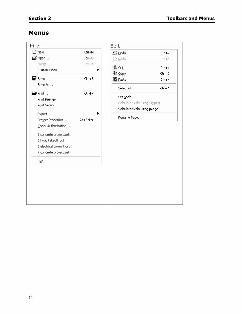
Section 3 Toolbars and Menus
14
Menus
Section 3 Toolbars and Menus
15
Digitizer Menu
Section 4
16
Features
This section will
Show you how open On-Screen Takeoff
Describe the On-Screen Takeoff environment
Teach you how to navigate pages
Section 4 Features
17
Start On-Screen Takeoff
1 On your desktop double-click your On-Screen Takeoff icon
2 The application will open
OR
3 Left-click on the Start button on your computerrsquos toolbar
4 Scroll up to Programs gt On Center Software
5 Highlight On-Screen Takeoff and click On-Screen Takeoff will open On-Screen Takeoff opens to an untitled blank project The Image view of the screen will be a blank page
Two blank dock bars the Pan dock bar and the Takeoff dock bar appear at the left side of the screen Along the bottom the Status bar displays user status or context-sensitive messages as well as paper size and current zoom percentage of the plan sheet on screen The menu bar and several task specific toolbars are located at the top of the screen
NOTE All toolbars and dock bars may be accessed to view or hide through View gt Toolbars on the menu bar
Section 4 Features
18
Quick Start Video When On-Screen Takeoff opens you will be given an option to watch the Quick Start video (recommended) or start the program without watching the video
The 20 minute video will demonstrate key program functionality and allow you to view application instruction for enhanced learning
If you would like to watch the video click If you prefer to get started without
the video click If you have already viewed the video click the lsquoDo not show this message againrsquo box to prevent this dialog from appearing each time you open the program
NOTE If you decide later that you would like to watch the Quick Start video go to Help gt Watch
Quick Start Videos
On-Screen Takeoff Environment The On-Screen Takeoff environment acts like your drafting table allowing you to work on several sheets of plans at once and to reference at a glance the entire drawing and your position on that drawing while giving you the power of a computer to track analyze print and export your takeoff quantities and plans
The screen is bordered at the top by the Menu bar with pull-down menus and at the bottom by the Status bar which indicates current user status plan page size and current zoom percentage of page The largest portion of the application screen will be your takeoff area bounded on the left (by default) by two dock bars and on the top by several toolbars
In the takeoff area you may view your project plans (images) andor takeoff objects the takeoff list with quantities the worksheet or a legend of your condition list
The main window of On-Screen Takeoff has three tabs located at the bottom left allowing for quick change between Image Takeoff or Worksheet views Select the desired view option on the toolbar and it will automatically open on your screen
Section 4 Features
19
Image View
This view shows the plan file andor takeoff conditions drawn from your plans
Takeoff View This view displays the height if applicable and quantity breakdowns of your conditions according to result types indicated (eg linear feet square feet or count of items) for zones pages and the project as a whole It also displays notes per condition
Section 4 Features
20
Worksheet View This view displays the condition and quantity in units of measure specified in the first results field of the Results tab in the Condition dialog and allows the user to enter amounts for material labor and subcontractor takeoffs
NOTE When in the Worksheet view tab out the field then save This is keep all the values saved
Navigating On-Screen Takeoff
Auto Scrolling When creating linear areas or zones On-Screen Takeoff will automatically scroll the image view when necessary It will move as your mouse or digitizer moves beyond the edge of the current view
Changing Pages
1 Select View gt Next Page Previous Page or Go To Page (specify page number for the Go to Page option)
2 You may also select the corresponding arrows for these options from the Navigate Toolbar The
drop down arrow in the Page field will list the pages The and arrows will take you to the
previous or next page The and arrows will take you to the first or last page
OR
Section 4 Features
21
3 Or press Ctrl G for the Go To Page dialog
Hot Links Hot links allow you to move quickly from one drawing to the pertinent area of another drawing A hot link is handy when viewing enlarged areas of a page and needing the ability to jump back to a reference page
1 Select Tools gt Hot Link
OR
2 Click from the Tools Toolbar
3 Click on the page where you want to set the link The Hot Link dialog will open
4 Using the current page display on the Navigate Toolbar access the pull-down menu of pages by
clicking on the arrow at the right
5 Select the page for your link (You may also choose View gt Go to Page and select by page number)
6 Manipulate the view using the zoom tool and the scroll bars
7 Click
8 After joining a hot link to another page the hot link arrows in the Navigation Toolbar will become active
9 Move a hot link to another location on the page by clicking then click and drag the hot link image anywhere on the page
Section 5
22
Projects
This section will
Help you create settings important to your projects
Explain how On-Screen Takeoff works with your electronic or paper plans
Section 5 Projects
23
Project Template Files You can begin your project with a template Templates allow you to take advantage of conditions and settings used with previous projects
On-Screen Takeoff templates contain condition lists and established layer separations from previous projects you have created You may also use the sample templates provided with On-Screen Takeoff as a great starting point All aspects of the templates may be adjusted for a new project
1 Select File gt New and click the OK button
2 From the New dialog box choose the template that best fits your project
3 The conditions for this template will appear in the Takeoff Dock bar and the Project Properties dialog will open asking for further information
4 Use File gt Save or File gt Save As to rename and save your new project
Saving a Project as a Template File You can save your condition properties and layers as a template for future projects
1 Select File gt Save As
2 Enter a name for your template and select On-Screen Takeoff Template Files (tpo) from the Save As type field of the dialog (click on the down arrow to select)
3 Click the OK button to accept and close the dialog Modifying a Template File Follow these steps to modify an existing template file if you need to change or add conditions andor layers
1 Select File gt Open
2 Navigate to your Projects directory
3 In the File Type drop-down select On-Screen Takeoff Template files (tpo)
4 Choose the On-Screen Takeoff template file you would like to modify and click the OK button
5 Make appropriate changes
6 Save and close file
The On-Screen Takeoff template files cannot save takeoff information
Section 5 Projects
24
Opening an Existing Project File 1 Select File gt Open
2 Navigate to the desired file location
3 Click the Open button
NOTE If your latest changes to a project file have not been saved On-Screen Takeoff will ask
you whether you would like to save the file and gives you the option of canceling the operation
Creating a New Project
1 Select File gt New
2 For a blank untitled project click
3 At this point the Project Properties dialog will pop-up for more information about your takeoff
NOTE The following are important to keep in mind when beginning a new project
At the start of your project fill out the Project Properties settings to establish the name for all printed output from your project set the default page size and scale for your plans number and names of different pages within the project and locations of electronic drawings
Scale settings can significantly affect quantity outcomes Be sure to set the scale for each page of drawings before beginning condition takeoffs
When using a digitizer remember to make a mark with a pen or pencil in the upper left and lower right corners of the first sheet of the paper plans to delineate the takeoff area for that sheet You can then set the takeoff area on On-Screen Takeoff using your marks
Save your project before you begin taking off any conditions On-Screen Takeoff will write a back-up file using the same file name
Remember the Undo feature If you make a mistake select Edit gt Undo and reverse the process step by step
Section 5 Projects
25
Project Properties
You can either set your Project Properties when you create a new takeoff or once your project file is saved under the appropriate name
1 Select File gt Project Properties the Project Properties dialog box will appear
2 Type in the name of your project to appear on printouts Use the backspace andor delete keys to edit the name as necessary
3 Press the Tab key to move to the Default Image Size option or click within the Image Size box You may click on the arrow at the right for the pull-down menu of page size options or you can use the down-arrow key on your keyboard to scroll through the list to the appropriate selection
4 Press the Tab key to move to the Default Scale option Select a scale by using the drop down arrow If your scale is metric you will need to click in the box next to Metric to convert to that measurement
5 Establish the number of pages for your project plans And load image files See Adding Pages to
Your Project
Adding Pages to Projects Individual Electronic Plans
1 Click on in the Project Properties dialog
2 In the Add Images dialog use the drop down arrow to navigate to the appropriate directory and folder containing your image
3 Select the file so that it displays in the File name field then click The file will display by name and path in the Image File field in Project Properties dialog
4 Click to accept and your project will automatically open
5 Save your project with the new settings by selecting File gt Save
Section 5 Projects
26
Electronic plans scanned from blueprints (as opposed to blue lines) will display as white lines on a black background and are difficult to read on your computer screen Select Image gt Invert and the colors will invert to black on white
You may have noticed the Page column in the Project Properties dialog Generally plan images occupy one page and 1 will be listed in the column indicating Page 1 of your plan file If you import a multi-page TIF a plan file containing more than one page of plans they will import as separate pages and each successive page will be indicated under the Page column as 1 2 3 etc of the plan file
Group of Electronic Plans You may add all the electronic plan files from a particular source (for example from a CD) by using the Auto Add feature
1 Click the button in the Project Properties dialog
2 Browse until you find the appropriate directory and folder containing your plan images
3 Click on any file displayed within your target folder so that the file name appears in the File name box of the Auto Add dialog
4 Click The image paths and file names will be recorded into the project properties arranged alphabetically
5 Click to accept your choices and your project will automatically open
6 Save your project with the new settings by selecting File gt Save
To load Dodge Plans into your Project Properties see Appendix IIi Loading Plans from a Dodge CD
Paper Plans On-Screen Takeoff makes it easy for Full Mode users to perform quantity takeoffs from paper plans using a digitizer
1 Add pages by clicking until you have the number of pages initially in the project
2 Name each page by clicking within the Title area and typing the name
3 Click to accept your choices and close the Project Properties dialog
4 Save your project with the new project properties settings by selecting File gt Save
Section 5 Projects
27
Setting Up a Drawing Template On-Screen Takeoff provides the convenience of using the same work surface for both digitizer and mouse to allow the user to draw conditions and then edit settings of the project or add or change conditions without breaking stride A mouse pad template included with the program defines the area of the digitizer in which use of the stylus or cursor will be recognized as mouse movement as opposed to drawing movement
1 Place your stylus on On-Screen Takeoff
2 Placing the template identifies the location mouse movements will be recognized by the program
Before placing the template the template must be applied to the digitizer surface This may have been done during the installation of your digitizer We suggest attaching the template to the lower right corner of the digitizer surface about one inch inside the grid area
3 Select Digitizer gt Place Template
4 Follow the instruction prompts on the screen clicking first on the target symbol at the left of the On-Screen Takeoff box on the template then on the target at the right
Setting Takeoff Area Before you can begin taking off a drawing you must define the drawing area on the digitizer This requires defining an area that will include all objects on each drawing of your plans As you add pages to your takeoff the same area of the digitizer will be active
1 Secure the plans to the digitizer with tape or a set of clamps
2 With a pen or a pencil mark the upper left corner and the lower right corner of the first page in your set of plans
3 Select Digitizer gt Set Takeoff Area
4 Click each mark with the stylus pen as prompted
5 Verify the active area of the digitizer by looking at the image size located in the lower right corner of your screen
If you close the program before the takeoff is complete you will need to reestablish the takeoff area before you can add additional condition quantities
Electronic plans appear on your computer screen eliminating the need to set a takeoff area You simply drag your mouse across the conditions you wish to takeoff The conditions will be highlighted and quantities will be totaled instantly Electronic plans are available through a variety of services For information contact an On Center Software account manager
Section 5 Projects
28
Setting Scale for Specific Pages You may set the scale in each page view separately This will override the default scale setting in Project Properties for that page Setting the correct scale for the drawing before taking off quantities ensures accurate calculations Be careful to check the scale for each drawing in your project before doing takeoffs
1 Display the page you want to set select Edit gt Set Scale
2 Use the drop down arrow to select a scale that will be applied to that page
3 Click
OR
4 Access the pull-down scale settings on the Navigate toolbar
NOTE As you draw objects notice that the drawn object is similar in width to the object on your plans If it is not the scale set may not be correct
Calculating Scale You may calculate scale according to a known measurement between two points either with a digitizer or on electronic plans
1 Select Edit gt Calculate Scale using Image or Edit gt Calculate Scale using Digitizer
2 Follow the instructions in the related Calculate Scale dialog box You will be asked to click on the first and second points then to enter the dimension for that distance
3 The scale will be recalculated for the displayed page and the Scale display on the Navigate toolbar will show the new scale
Section 6
29
Conditions and Takeoff
This section will Draw Conditions to Takeoff Plan Quantities
What Zones will do to help your takeoff process
Discuss the ins and outs of Takeoffs
Section 6 Conditions and Takeoff
30
Creating Conditions
If you are starting a new project from scratch you will need to create conditions to takeoff quantities such as floor areas wall lengths and corner bead counts If you are using a template you will have several pre-designed conditions already listed on the Takeoff dock bar However you may want to change the characteristics of some conditions or create additional conditions for a particular project
1 Right Click within the Takeoff dock bar Select New gt Condition
Or
2 From the Takeoff dock bar Click (if the buttons are not showing right-click in the Takeoff dock bar area and select Show Buttons from the pop-up menu) The New Condition dialog appears
3 Select the condition type (Linear Area Count or Zone) from the pull-down menu accessed by the
down arrow next to the Type option
4 Press Tab or use the mouse (or stylus) to move to Name and enter a name for your condition
5 Specify the desired condition attributes See Condition Attributes for more detail
6 Click for condition to apply
Section 6 Conditions and Takeoff
31
Condition Attributes Each condition type will have related attributes to select or specify within the General and Advanced tabs of the New Condition dialog Once a condition has been used to takeoff a quantity from your plans certain attributes cannot be changed
All conditions allow the user to specify color and fill pattern for the object drawn
Linear Conditions
General Specify width and height by feet and inches Specify pitch in inches up to the nearest thousandth of an inch if applicable
Advanced Specify rounding for object quantities and droprun default length for electrical or plumbing drops at the ends of lines Select Connect to have lines connect at the corners where one line of the condition ends and another begins (and indicate Tolerance for the featurersquos activation as distance between the ends of two lines) Choose Trim to have lines automatically trim to a line being crossed Choose Curve to draw a curved line
Follow these examples for inputting feet and inches For 7 feet 6 inches type 706 for 13 feet 7 inches type 1307 For 20 feet type 2000
Section 6 Conditions and Takeoff
32
Area Conditions
General If needed you can specify the thickness (in inches) andor pitch (in inches)
Advanced Specify rounding for object quantities Choose to display an adjustable grid within the area and indicate matrix cell dimensions
Section 6 Conditions and Takeoff
33
Count Conditions
General
Specify height and indicate the size (in inches) and shape (square circle triangle rectangle or opening) of the count object as it will appear on screen
Advanced Count conditions have advanced attributes These options are available for all shapes except for openings
Zone Conditions Zones allow you to subdivide condition quantities making it easier to modify and complete jobs in phases They can be used at the end of a takeoff to isolate a group of condition quantities that are in different areas of the takeoff
Zones can also be used to break a takeoff into multi-phases and can even be used to isolate quantities while a job is in progress to group the amount of work that has been completed to date They can be applied to one or multiple pages in your plans automatically calculating the takeoff quantities for each zoned area
Section 6 Conditions and Takeoff
34
The zone feature is only available in Lite and Full Mode If you are in View Mode and would like
to use this feature click from the main toolbar to purchase the upgrade
Condition Notes A Note tab is provided for comments regarding the condition These notes will display on the Takeoff List report and will import into Quick Bid
Section 6 Conditions and Takeoff
35
Condition Results The Results tab of the New Condition is based on condition type Initial settings default to linear feet (LF) for linear conditions square feet (SF) for area conditions and count of items (EA) for count conditions and zones The first of the results fields will display for the condition items in the Takeoff dock bar area All results will display in worksheets and Takeoff List reports as well as in an Excel spreadsheet after being exported
Copying Conditions You may use the condition attributes from a condition yoursquove already created for any future conditions of the same type
1 Click on a condition to select it
2 Click the Copy button from the toolbar
OR
3 Right-click in the Takeoff dock bar area and select copy
4 A new condition will appear in the list with the same condition attributes as the previous condition but with the quantities zeroed
Editing Conditions Once you have copied a condition you might want to change several attributes You can also edit an existing condition to fit any updated needs
1 Highlight the desired condition on the Takeoff dock bar
2 Click the Change button
OR
3 Double-click on the condition you wish to edit to bring up the Change Condition dialog
NOTE The Change Condition dialog differs from the New Condition dialog only in that if takeoffs
Section 6 Conditions and Takeoff
36
have been performed in your project with this condition you will not be able to change the type of condition or certain properties under the advanced tab of the dialog box
Deleting Conditions 1 Click on the condition in the Takeoff Dock bar area
2 Click the Delete button on the toolbar
OR
3 Right-click and select Delete from the pop-up menu
All takeoff associated with the deleted condition will be deleted immediately and permanently
Organizing Project Conditions Within your project you can create folders andor sub-folders for different types of conditions You may even want to create a folder containing conditions with reset values
To get started organizing your conditions make sure you are viewing the condition tree (right-click in the Takeoff dock bar area and select Show Tree)
Creating Folders and Sub-Folders 1 Right-click in the Takeoff Dock bar area
2 Select New gt Folder from the pop-up menu
Copying Folders
1 Click on the folder and click Copy on the toolbar
2 All copied conditions within the new folder will have values reset to zero
Renaming Folders
1 Click on the folder
2 Right-click and select Rename from the pop-up menu
3 Enter a name for your folder and click the Enter button
Changing Condition Order
You may move conditions up or down in the condition list of the Takeoff dock bar to suit your project needs
1 Select the condition you would like to move by clicking to highlight it
NOTE When you are ready to move the highlighted conditions be sure that you start
moving using the last condition chosen That condition will have a highlighted boarder
Section 6 Conditions and Takeoff
37
2 Drag and drop any the condition from one place to another in the list You may also move a condition to another folder on the list in this way
Drawing with Conditions Snap Angles Set up snap angles to prevent lines from appearing jagged Snap angles are commonly set at 15deg and shift snap angles at 0deg
1 Go to Tools gt Options Options dialog appears
2 Under the General tab make the desired settings
3 Click to save the settings As they are drawn lines will snap to the set degree
Drawing a Linear Object 1 Select a condition from the Condition List in the Takeoff dock bar
2 Move the cursor into the Image takeoff area of the screen you will see the cursor display as crosshairs
3 Click and hold left mouse button then drag mouse to draw a line
4 Release mouse button to set line
Section 6 Conditions and Takeoff
38
5 Repeat steps for further lines
Continuous Mode This feature allows you to draw an object that has connected lines
1 Click the icon from the Takeoff toolbar
OR
2 Go to Tools gt Continuous Mode
3 Follow steps 1-3 from Draw a Linear Object
4 Click at each point of intersection The object will be connected
5 Double-click after making the final point to set the lines
Drawing a Curve To draw a curved line the Curve option must be checked under the Advanced tab of the Condition dialog
1 Click where you want to begin the curve and drag in a straight line to the position for the other endpoint of the curve
2 Click on the line to select it Handles in the shapes of small squares will appear at either end of
Section 6 Conditions and Takeoff
39
the line and in the center of the line
3 Move the cursor over the center handles until the cursor becomes a two-way arrow
4 Click and drag in the direction of the curve bending the line as you move the cursor Release to set the curve (The line you began with will disappear)
Draw a circle by drawing two curved lines connected
Drawing an Area Object Area conditions are drawn similarly to continuous mode lines You may trace any number of adjoining walls at different angles to complete your area takeoff
NOTE When drawing an area do not intersect the perimeter or line of the object you are drawing
1 Click at each point
2 Double-click when yoursquove returned to your starting point
3 The area will be filled with the pattern set for that condition
NOTE The simulated circle will be good enough for you to be able to make a bid
To create a circular area click from point to point with very short distances in between points simulating a circlersquos perimeter Double-click after setting the last point to set the area
Section 6 Conditions and Takeoff
40
Grid Options Grids give you an added advantage when installing materials such as tiles Use this feature to get a count for how many tiles are needed for an area
1 Double-click on an area condition in the Takeoff dock bar to open its Condition dialog
2 Click on the Advanced tab to show its options
3 Check the box next to Grid by clicking in it
4 Indicate the dimensions of the cell matrix in inches (For example 200 x 400)
5 Under Results tab choose each (EA) for one of the results fields This will tabulate a number of grid cells (including partial grid cells) in area
6 Click to save your settings
7 Use the Move Grid and Rotate Grid features in the Tools menu to manipulate the grid as desired
Grid Calculation
1 Go to Tools gt Options menu
1 Specify if On-Screen Takeoff automatically should Calculate Grid Position
2 If AreaGrid Size is selected On-Screen Takeoff will calculate the number of items needed to fill the grid based on grid demintions
3 Click to accept and close the dialog
To move a line at any angle (regardless of default setting) press the Shift key while moving the mouse
Section 6 Conditions and Takeoff
41
Backout Mode This feature allows you to take out part of an area and deduct that amount of square footage
1 Select Tools gt Backout Mode
2 Outline the are you want backed out as you would when drawing a regular area object (see Drawing an Area Object)
3 The outlined area will clear and quantities will be recalculated
NOTE The perimeter of the backout area will be added to the LF quantity for that condition
Drawing a Count Object Square triangle rectangle and circle shaped count objects can easily be placed on images
1 Select the condition
2 Click in the location where you want the object to appear
3 To place an opening-shaped count item like a door or window you must click over an existing linear object such as a wall
4 On the Results tab you can change the height properties to give you the result you need
5 If Backout is checked on the advanced tab for each count opening the opening-shaped count item will back out a corresponding section of the linear object
Opening shaped count items are sized at 3rsquo0rdquo by default
Drawing a Zone Zones are drawn in the same way as area objects and may be any polygonal shape You may trace any number of adjoining walls at different angles to complete the zone perimeter
1 Click at each point
2 Double-click when yoursquove returned to your starting point
Section 6 Conditions and Takeoff
42
Selecting Objects
1 Use the Select Tool to select objects
You can also select all objects that correspond to a condition
1 Click on a condition to select it
2 Right-click and choose Select All
3 All objects with this condition will be highlighted with squares as an outline
Moving and Resizing Objects Linear
1 To move or resize a linear object click anywhere on the line to select it
2 To move the line position your pointer over the center handles When the mouse is positioned over the handles you will see a two-way arrow You will only be able to move the line in the direction of the arrows
3 Drag the line to a new position
4 Clicking and dragging the handles on the ends of the line will allow you to lengthen or shorten your line
Area and Zone
1 To move an area object or zone in its entirety click and drag it to its new position
2 Grabbing a handle at a corner or intersection of the object will allow you to adjust and change its perimeter
Section 6 Conditions and Takeoff
43
Count 1 To move a square circle rectangle or triangle shaped count object click and drag
2 Click and drag an opening shaped count object along the length of the linear object to the desired position then release
NOTE An opening shaped count object may not be moved from its associated linear condition object however it may be moved up and down the length of the linear object
Layers On-Screen Takeoff allows you to sort and separate your takeoff objects within the same job and on the same page On-Screen Takeoff gives you this flexibility through the use of layers
By assigning different conditions to different layers (for example differentiating between floors ceilings and walls) you can choose to view all layers or turn off certain layers to display and print the remaining groups of conditions only You may also remove the background image of electronic plans add text and hot link symbols or print only your condition takeoffs
Layers are only available in Full Mode If you are in View or Lite Mode and would like to use this
feature click from the main toolbar to purchase the upgrade Default Layers
On-Screen Takeoff begins every project with three default layers Image Annotation and Default The Image layer holds the electronic plan files you may have in your project The Annotation layer possesses all text notations highlighting and hot links in the project The Default layer will appear in the Condition dialog when creating or editing a condition (listed in the takeoff dock bar) Conditions are assigned to the Default layer unless otherwise specified by the user
Creating Layers To assign a condition to a layer other than the default layer you must first create additional layers for your project
1 Select View gt Layers to open the Layers dialog
2 Click An unnamed layer will be added
3 Click within the empty box and type a name for your layer (for example Wall)
4 New layers are added as active layers The adjacent box under the Show column will be checked
Section 6 Conditions and Takeoff
44
Assigning a Layer to a Condition 1 Open the Condition dialog box by creating a new condition or editing an existing condition
2 Under the General tab click on the down arrow in the Layer field to display optional layers
3 Select the desired layer for the condition Only the Default layer and layers you have added will be displayed
4 Click
View and Hide Layers
1 Select View gt Layers
2 Under the Show column check the box to view or remove the check (by clicking on it) to hide the specific layer
3 Click to accept and close the Layers dialog
Section 6 Conditions and Takeoff
45
Assigning Text to a Layer When adding text to an image On-Screen Takeoff has the capability to assign the text to a specified layer
1 Select the Text Tool
2 Click at the point you want to place your text
3 Type in your text using the Enter key for line breaks
4 Click the drop down arrow next to the Layer field and select the desired layer
Section 7
46
Printing and Exporting
This section will
Printing options and procedures
Exporting data by copying and pasting
Exporting quantity results to Excel spreadsheets
Section 7 Printing and Exporting
47
Print Setup On-Screen Takeoff allows the user to print the image takeoff list and worksheet
1 Select File gt Print Setup The Print Setup dialog will open
2 Select a printer or leave the default selection listed (change from the default printer displayed by clicking on the down arrow at the right of the field)
3 Indicate page size and printer tray option (Source) Access page size options by clicking on the
down arrow at the right of the field
4 Choose Portrait or Landscape orientation
5 Click to accept and close the dialog
Printing Images The image area can include the electronic plans the takeoff objects added text and hot links To print a subset of these (for example just the takeoffs without the plans or the added text and hot link symbols) hide layers that you do not want to print (see Section 6 View and Hide Layers) When you are printing your images every page will show the scale of the takeoff you are printing
1 Click on the Image tab to display the area of your project
2 Select File gt Print (or Ctrl + P)
Section 7 Printing and Exporting
48
3 Select the desired view (What to print) and the Image Range
4 Click The second Print dialog will open
5 Change settings accordingly or click if you accept the default settings
Printing Takeoff Lists and Worksheets In Takeoff Lists and Worksheets you may hide columns to print only certain results or adjust column widths to fit the report within the page size selected
1 In Takeoff List or Worksheet view move your cursor to the right side of the columnrsquos title bar the cursor will display as a two-way arrow
Section 7 Printing and Exporting
49
2 Click and drag to adjust the width of the column Holding the mouse button you may
slide the title bar under the title bar to its left to hide the column completely
3 Select File gt Print or press Ctrl + P to access the Print dialog
4 Indicate desired printer and choose the number of copies
5 Click to print and close the dialog
When printing the condition list we suggest printing in landscape
To reset to the default column widths double-click on the right border of a column heading will reset the column to its right (or previously to its right before being hidden)
Print Preview 1 Select File gt Print Preview
2 Use and to vary your view 3 If viewing an image choose current full or scale view to see how it displays
4 For printed outputs that cover more than one page use and to view adjacent pages or click on the down arrow next to Page field and select the page you want displayed
Exporting Using the CopyPaste Feature You may copy all the data or sections from the worksheet and the takeoff list view in On-Screen Takeoff and paste it into another application When pasting into Excel the cell layout will be maintained
1 Highlight the areas you wish to paste Click and hold the left mouse button down as you drag the cursor over the area to be selected then releasing the mouse button
OR
2 Select the entire takeoff list quickly click on the left On-Screen Takeoff column header and hold and drag the cursor across the remaining column headings
The number of pages for the view selected will display in the lower left-hand corner The zoom percentage that applies to the view will be displayed in the lower right-hand corner next to page size of the drawing
Section 7 Printing and Exporting
50
3 In the worksheet view you may highlight rows by clicking on the numbered buttons to the left of each row clicking and dragging across column headings or clicking and dragging over individual cells in the worksheet
Click anywhere in the appropriate view to deselect the area
4 Once your selection is highlighted you may select Edit gt Copy or Ctrl C from the keyboard 5 On your monitor switch to the application into which you want to paste your selection 6 Select Edit gt Paste in the new application or simply press Ctrl + V to paste
The colored keys for conditions cannot be pasted
Using the Export Feature You may export condition quantities to specified cell location within an Excel worksheet file Cell target locations are assigned in the Results tab of the condition dialogs on the Export line relating to each quantity measurement type
On-Screen Takeoff will export takeoff quantity results for up to three different quantity types that you specify For instance you may want to know the number of square feet in a ceiling area as well as the number of linear feet in its perimeter
Section 7 Printing and Exporting
51
1 Bring up the Condition dialog by double-clicking on a condition in the takeoff dock bar or by
selecting the condition and clicking
2 Click on the Results tab to access its fields The default quantities for the condition type will display
3 For each results field click on the arrow to access the pull-down menu and select the appropriate quantity (for example SF LF EA etchellip)
4 Have your Excel spreadsheet opened and saved in a file
5 Specify the Excel spreadsheet cell locations where you want the results to go
6 For a cell in the first sheet of your spreadsheet type in the cell address (eg a1) Case is not important
7 For a cell on a successive sheet of your spreadsheet type in sheet the number followed by a comma and the cell address without any spaces (eg sheet2a1) Case is not important
8 Click
9 Select File gt Export gt Condition Qty to Excel
Section 7 Printing and Exporting
52
10 Browse to the location of the Excel spreadsheet file click file to select it
11 Click to export On-Screen Takeoff results to specified cell locations in the Excel file When you return to the Excel application you will see the values have been added to the specified cell locations in your spreadsheet
12 Save your Excel file
Exporting Worksheet to Excel
1 Assign condition quantities you want to export
2 Open saved Excel spreadsheet file to which you will be exporting
3 From On-Screen Takeoff Select File gt Export gt Worksheet to Excel
4 Browse to the location of the Excel spreadsheet file click file to select it
5 Click When you return to the Excel application you will see the values from the Worksheet Tab have been added to your spreadsheet
6 Save your Excel file
Exporting Takeoff to CVS 1 Assign condition quantities you want to export
2 Open saved Excel spreadsheet file to which you will be exporting
3 Click the Takeoff Tab in the project you want to export the information
4 Select File gt Export gt Takeoff to CSV
5 Browse to the location of the CSV spreadsheet file click file to select it
6 Click the Save
NOTE CSV files can be opened in Excel Lotus Access etc One may consider this option more of a ldquodumprdquo into a file
The Excel application must be active (it may be minimized on the application bar) with the target spreadsheet open in the application Otherwise an error will occur with the export operation that will affect both the On-Screen Takeofftrade file and the Excel spreadsheet
Section 8
53
Advanced Features
This section will
Some special features of working with condition objects in the takeoff area
Details of advanced options for conditions
Advanced features of the Project Properties dialog
Section 8 Advanced Features
54
Features to Use with Objects Roping Feature You can move copy or delete using this feature Using the Select tool (the pointer) you may select several objects at once by clicking and dragging an outline around the objects then releasing the mouse button Roping may select either objects completely within the outlined area (inclusive) or objects both within and touched by the outlined area (touching) Specify your roping preference under Tools gt Options
1 Click and hold the mouse button at a point on the screen near the objects to be selected and drag to surround the objects with an outline
2 Release the mouse button The objects will be selected
3 You may now
Move the group around on the page by clicking within the group dragging the mouse and releasing the button to place the objects
Delete the group of objects by clicking the Delete key or
Copy and paste by pressing Ctrl C to copy the group then Ctrl V to paste it The pasted copy of the grouped objects will appear slightly offset from the original objects
Section 8 Advanced Features
55
Applying a DropRun Count
Use the droprun feature when calculating quantities to take into account the drop or run of a linear condition such as electrical lines or plumbing pipes Drop or run lengths may be added separately to any linear condition on screen while a default droprun length may be indicated for a condition as a whole
1 Select the desired linear condition from the Condition List in the Takeoff Dock bar
2 Click the Change button in the toolbar to open the Change Condition dialog
3 Click the Advanced tab to access the advanced options and click inside the DropRun check box
4 Enter a default length to be applied to all of this condition Entering 800 will be interpreted as 8 0 (You must enter both place markers for inches) You can leave the length blank and manually enter drop run on each segment drawn
5 Click the OK button to accept and close the dialog
Edit DropRun Count
1 With the related linear condition in the Takeoff Dock bar highlighted or with the pointer tool selected
2 click on the desired linear object in the image takeoff area The Count button will become active
3 Click on the Count button (alternatively select Tools gt Count) The default droprun amount will show in the pop-up Count dialog (Default length will be zero if droprun has not been selected in this conditionrsquos properties)
4 Type in the desired length Entering 800 will be interpreted as 8 0 (You must enter both place markers for inches)
5 Click the OK button The additional amount will be reflected in the corresponding quantity The new DropRun count will apply only to the object edited
Adding Text in Image View
On-Screen Takeoff allows you to place text comments around your quantity takeoffs that may be printed along with plan images and objects Text is automatically placed within the Annotation Layer (that includes text and hot links)
1 To place text on the image select the Text Tool and click at the point you want to place your text opening a text box
2 Type in your information clicking Enter for line breaks
3 When you are finished click the OK button to exit the text box
4 To reposition text simply click on the text (with the Text Tool active) to select it
5 Move the cursor over the text the cursor will now display as a four-way arrow
6 Click and drag the mouse to position the text as desired
Section 8 Advanced Features
56
1 To edit existing text use the Text Tool to double-click on the text to open the editing box
2 Enter additional text or use the Backspace key to delete text as necessary
Formatting Text Once created you may format the font size type style and color of your text
1 Click on the text to select it and select Tools gt Font or click on the Font button in the Takeoff Toolbar
2 Select the desired features (color options are disabled) and click the OK button
3 Click on the text to select it and select Tools gt Color or click on the Color button in the Takeoff Toolbar The Color dialog will open
4 Click on a color in the Basic Color palette or create a color and add to the Custom Colors palette (Be sure to click on the color in the Custom Colors palette to select it)
5 Click the OK button
Object Properties
Linear Objects
Linear objects may be set to connect at corners
A linear object may be set to trim automatically when crossing another linear object (Check the trim option under the advanced tab of the Condition dialog)
When you move a connected linear object objects automatically move and resize connected lines accordingly (quantities are then recalculated)
This feature requires that the connected linear object be moved using the center handles (does not apply when resizing the line from the ends)
Objects constrain to snap increments defined in the Tools gt Options menu (with the mouse 15deg by default incremental when shift key is held down)
Objects are measured from centerline to centerline
Section 8 Advanced Features
57
Area Objects When drawing an area use your escape key to undo the last line drawn You may reverse your
drawing of an area using the escape key
The area will not fill with color and pattern until the user double-clicks after the last line is set
Lines drawn to delineate an area object constrain to snap increments defined in the Tools gt Options menu (with the mouse 15deg by default incremental when shift key is held down)
After selecting an area to move or adjust position the mouse in the center to move the entire area position the mouse at the sides or corners to adjust the perimeter
Count Objects
All count objects are quantified by the physical number of objects per page and reported as EA for the UOM The quantity for the current Image View is (displayed in the Condition List) and the total quantity in your project is displayed in the Takeoff View and Worksheet View)
Square circle rectangle and triangle shaped count objects do not displace or subtract from other object quantities when placed on top of them However on the Advanced Tab for the count condition a connect property can be set (this is a check box) so that when a count object of this shape is put on top of a Linear type takeoff object it will move with the linear if said linear is moved
An opened-shaped count object must be placed within a linear object Opening shaped count objects may also be measured by linear foot or linear yard (EA SF and SY are also options) Opening shaped count items default to a width of 3rsquo 0rdquo at the time of creation This size can be changed The small medium and large size are not options on this type of condition anymore Check Backout on the Advanced tab for each Count object back out the footage (or yardage) of opening-shaped count objects in which they are placed
NOTE In order to see this Backout functionality (in quantity) for SY or SF deductions at least one of the
results for the Linear(s) this object will be placed on must be set to SY or SF and the count object must have a height quantity
Advanced Features of Conditions The Round Feature Under the Advanced tab of the linear and area Condition dialogues you may specify quantity rounding (in inches) For linear objects rounding applies to each linear object drawn For area objects rounding will apply to each segment of the area perimeter adjusting the perimeter and area calculations For example With a linear condition entering 12 in the Round field will round up each related linear object to the nearest 12 inches or one foot With this setting two walls of 1 4 would each round to 2 0 totaling 4 0
NOTE In the Takeoff Dock bar condition list and in the On-Screen Takeoff reports quantities will be displayed in whole numbers rounded up to the nearest foot However calculations are based on true quantities without rounding unless the Round Feature is engaged
Pitch Pitch may apply either to linear or area conditions It is measured in rise per linear foot Entering 12 indicates a 12 rise per 12 of linear distance (a pitch of 12 over 12) or an angle of 45deg
Section 8 Advanced Features
58
Advanced Features of Project Properties Selecting Multiple Pages
1 Select a single page entry by clicking on the numbered gray button to the left of the entry
2 Drag the cursor down the column of numbers to select consecutive pages
3 Click on the blank button at the top of this column to select all pages in the Properties dialog
Section 8 Advanced Features
59
Changing Image Assigned to a Drawing 1 Select the page entry by clicking on the numbered gray button to the left of the entry 2 Click the Change Image button The Change Image dialog box will appear
3 Navigate to the desired file and select by clicking on it
4 Click the Open button The electronic file assigned to the page will have been changed to reflect the new file choice
Changing Image File Path 1 Select pages as described above
2 Choose Change Folder
3 In the Change Folder dialog navigate to the appropriate folder
4 Click the OK button The file path will have been changed for the selected page entries
Delete a Page from Project Properties 1 Select the page you want to delete by clicking on its associated number (in the gray box at the
left of the entry)
2 Choose Delete Page
All Takeoff on the page will be deleted immediately and permanently
Section 8 Advanced Features
60
Advanced Features of Tool Options
Calculation Method On-Screen Takeoff has built-in calculation options to allow for faster work and faster saves until your takeoff is complete Calculation options are found by selecting Tools gt Options then clicking on the Calculation tab
Calculation method can be set to Automatic Automatic except Grids and Manual Manual will allow the program to operate more quickly while Automatic or Automatic except Grids allows the user to see quantity changes as takeoffs are made
In any mode you may press F9 to recalculate quantities for the On-Screen Takeoff current totals
Configuration Tab
When the ldquoPage Label (A01)rdquo radial button is chosen On-Screen Takeoff puts the numbered label on all the pages of in your current page indicator in your Navigate Toolbar If the Page Descriptionrdquo radial button is chosen then a description of what takeoff is on that specific page will be shown in your current page indicator in your Navigate Toolbar
This section of the configuration tab gives you options on how you want to export your information When the ldquoFolderSubfolder Namesrdquo radial button is chosen than on your file that you are exporting to will have all the conditions folders and subfolders In the Delimiter box you can choose the symbol that is needed to separate the information you are exporting Some files need semicolons () or colons () to make sure the information comes exported in is separated it the appropriate places
Section 8 Advanced Features
61
In previous versions of On-Screen Takeoff there are views that users need to have in order for them to display their information By either choosing ldquoOST 1xrdquo or ldquoOST 2xrdquo it will let the program know you want your columns of information exported in that specific format
When you have the Confirm Deletions radial button of ldquoYesrdquo chosen than every time you delete anything you will get a dialog box confirming your intentions of deletion
While working with your takeoff you have a choice to either view the legend of your conditions or hide it Choose whichever radial button that suits your needs
For those who prefer to use the Enter key to navigate in dialog boxes this option is just for that
Font Tab The Font tab is designed for you to make your own look and feel for the application At the bottom of this tab it will show you sample of the fonts and colors you have chosen
Renaming the Current Page You may change the name of the current page in the takeoff area of On-Screen Takeoff by selecting Edit gt Rename Page
This opens the Name Page dialog and you may simply type in a new name and click the Enter button The new name for the file will be reflected on the title bar for the page and in Project Properties
You also may access the Rename Page function by right-clicking in the takeoff area while in Image View and selecting the option from the pop-up menu that appears
Section 9
62
Saving and Exiting
This section will
Explain how to save projects
Show you how to safely exit the program
Section 9 Saving and Exiting
63
Saving Your Project
1 Select File gt Save 2 If your project has not previously been saved a Save dialog box will open to allow you to name
the file and choose the directory and folder in which to save your file 3 Once saved File gt Save will simply save the current version of the file
OR
4 Select File gt Save As then type in a new name for the file and save to the desired file path
The Auto-save Feature With the Auto-save feature On-Screen Takeoff automatically backs up your open project You may choose to have more than one level of backup files The first backup copy will have the extension b00 and successive files will be b01 b02 and so on If you have designated four levels of backup files after the fourth backup copy has been created (b03) the next file will be saved over the file with extension b00 Further backup saves will then rotate through the four backup files in the same way
1 Select Tools gt Options 2 In the Auto-save area (under the General tab) select the frequency of backup file creation (in
minutes) and the number of levels for the feature 3 You also may disengage the feature by clicking in the check box to clear it
The Auto-save feature automatically saves backup copies to the directory of the current project If you are working from a write-protected area such as a CD-ROM On-Screen Takeoff will place backup files in the On-Screen Takeoff folder
Exiting When you are finished using On-Screen Takeoff it is very easy to exit Exiting is very important because of security reasons If someone were to use your computer they could enter the application and view and manipulate information
Section 9 Saving and Exiting
64
On-Screen Takeoff closes the open project when you open another or create a new project or when you exit the program
1 Select File gt Exit
OR
2 You also may click at the upper right-hand corner of the application to exit
NOTE If your latest changes to a project file have not been saved On-Screen Takeoff will ask you whether you would like to save the file and gives you the option of canceling the operation
Appendix I Installing Your Digitizer
65
Appendix I Installing Your Digitizer When you get your digitizer from GTCO you will need to connect it to your computer Follow the instructions outlined below to do this
Note For rollup digitizers the metal bar must be oriented to the top or right hand side
Connecting the Digitizer 1 Lay the digitizer out flat 2 Connect the Stylus to the digitizer 3 Plug in the power adapter 4 Plug the interface (IO) cable into the digitizer 5 Plug the other end of the interface cable into an open serial port on computer
Note GTCO Technical support phone number is 410-381-6688 The electronic manual (on diskette) from GTCO contains more detailed installation and operation instructions for the GTCO digitizer model you have
Installing other Digitizer Drivers If you are using a GTCO Digitizer you will need to install the GTCO TabletWorks Drivers
If you are using a Digitizer not supported by GTCO Tablet Works 10 please contact the manufacturer of your digitizer for assistance with installation
Installing GTCO TabletWorks Drivers 1 Insert the On Center CD into the CD-ROM drive The CD Startup screen will open 2 Click on Install Software 3 Select Additional Software and Drivers 4 Select Digitizer Driver 5 Follow the instructions for installing TabletWorks 10
Adhering the Template The template is a small plastic sticker used to enable mouse function when using the digitizer with On-Screen Takeoff Place your template on your digitizer We suggest placing it in the bottom right corner of the digitizer about one inch inside the takeoff area
Note You may either peel off the back of the template and use the adhesive surface or you can tape the template down
Appendix I Installing Your Digitizer
66
Testing the Digitizer Drivers Before running OST you may test the digitizer by moving the stylus around on the digitizer pad it should move the mouse cursor (if mouse emulation is enabled)
If the digitizer does not move the mouse cursor on the screen
The superset codes may need to be reset Reset the superset codes by touching on the border of the digitizer with the stylus The digitizer should beep several times
The digitizer may not be communicating with the computer Be sure the COM port selected is correct Be sure the COM port selected is correct If you are not able to get the digitizer to move the mouse cursor you need to call GTCO technical support for help
Note The Mouse Emulation is not required for On-Screen Takeoff to work properly It is used only for the Template functionality if the digitizer is moving the cursor the wrong direction (up instead of sideways or vice-versa)
Click the L-shaped arrow symbol on the digitizer with the stylus
Appendix II Toolbar Item Details
67
Appendix II Toolbar Items Main Toolbar
Appendix II Toolbar Item Details
68
Tool Toolbar
Appendix II Toolbar Item Details
69
Zoom Toolbar
View Toolbar
Navigate Toolbar
Appendix II Toolbar Item Details
70
Navigate Toolbar (Continued)
Takeoff Toolbar
Appendix II Toolbar Item Details
71
Takeoff Toolbar (Continued)
Image Toolbar
Appendix III Loading Plans from a Dodge CD
72
Appendix III Loading Plans from a Dodge CD
This section will detail how to load plans from a F W Dodge CD-ROM into an On-Screen Takeoff project file ready for takeoffs
Dodge files may be added to the Project Properties dialog However loading the files in that way will load the files by number rather than name description If you want to load one page only from your Dodge CD You will have to rename the page to display the name rather than number of the file
To load plan files from a Dodge CD so that the files load sequentially by file number but are displayed by name rather than by number within your project follow the instructions below
Opening a Dodge project from a CD-ROM 1 Insert the CD into the drive 2 Choose File gt Custom 3 Choose Dodge Plans Project (plansdat) as the file type 4 Select the appropriate file type by clicking on the down arrow at the right of the Files of type
field 5 In the Look in field access your drive paths by clicking on the down arrow at the right of the
field then
Navigate to your CD-ROM drive Open the data folder and Open the Projects folder
6 Select the desired project and open its folder 7 Open the plansdat file 8 All the images will come in sequenced correctly for that job along with the full descriptions
(names) of each page If there is not a plans folder in the project folder then plans do not exist for that project on the CD Opening the plansdat file will yield an empty project
Appendix IV Using the Plan Viewer
73
Appendix IV Using On-Screen Takeoff Plan Viewer The On-Screen Takeoff Plan Viewer is a limited version of On Center Softwarersquos commercial takeoff software If your status bar located at the very bottom of the main window says View Mode in the lower left-hand corner then you are using the Plan Viewer You can use the plan viewer to
View CD-based amp converted CAD drawings
View a previously created OST file and associated drawings
Download electronic plans online
Navigate through drawings
Quickly Takeoff linearsareas and counts
Zoom in to view the plan better
Print drawings directly from the viewer
Viewing an On-Screen Takeoff Project File
1 To open an OST file that was previously created with of On-Screen Takeoff 2 Select File gt Open 3 An Open dialog will appear if you do not see the OST file you are looking for select the
Look In drop down arrow 4 A drop down menu will appear listing the various folders drives and mapped drives located
on your computer select the correct drive or folder location and continue to browse to the location of your OST file
5 When you see your OST file double-click it to open it 6 Any takeoff and drawings should appear on the Image tab view
If you do not see the drawings but do see the colored takeoff layer the drawings may
not be located in the same place they were originally saved at Go to File gt Project Properties and check the Image File path for each listed page If the image file path is pointing to a CD drive make sure the CD is inside the CR-ROM
Downloading Electronic Plans If your Online Plan Service provides a special file format (OSX) required to use this feature of our plan viewer you can immediately downloaded all electronic plans of a project directly from our viewer
Most Plan Room web sites will automatically open On-Screen Takeoff when a request to download plans is made Your particular Plan Room may differ in operation so please contact the provider directly with questions on using the site
Appendix IV Using the Plan Viewer
74
When you request to download or open a project file from a Plan Room you will usually have the open to open or save an OSX file Choosing open will automatically open On-Screen Takeoff Alternately you may choose to save the file to a local hard drive After you have saved the file either double-click it to launch On-Screen Takeoff or open the OSX file using On-Screen Takeoff by clicking File then Open and locating the file on your hard drive You will need to change the file type to OSX
After the OSX file is opened you will see an additional tab appear in the Conditions List window called Pages
The Pages tab shows the hierarchy of your project Gray file icons represent pages that have not been downloaded and blue icons represents pages that have been downloaded
To download a page simply double-click the page icon
If you wish to select a group of pages to download you can use the Ctrl or Shift key to multiple select them then click the Download button
If you wish to download all pages at once click the Download All button
Downloaded pages will now appear in the Project Properties dialog in the same order in which they appear in the Pages tab
Creating Quick Takeoffs With On-Screen Takeoff you can create quick takeoffs to measure quantities even if you dont have the full version of our program However using the Quick Takeoff functionality shows you just a fraction of what the full version can do
The Quick Takeoff Toolbar is located at the top of the image view It has three buttons designated for three types of takeoffs Linear Area and Count The Quantity drop down list will show secondary quantities for Linears and Areas The Units drop down allows you to select how you want your quantities displayed Feet Inches Yards Millimeters and Meters
NOTE Every time change the type of takeoff you are performing (switching from Area to Linear for example) the previous quantities and takeoff objects will disappear They will also disappear when you changes pages
NOTE You can use the Dimension Tool to basically measure the distance between two points or linears The distance will display on the status bar at the bottom of the application
The Quick Takeoff Toolbar
Appendix V Frequently Asked Questions
75
Appendix V Frequently Asked Questions General
Where is On-Screen Takeoff installed on my computer
Typically it is installed in CProgram FilesOn-Screen Takeoff
In Explorer how do I recognize On-Screen Takeoff file types
On-Screen Takeoff data is stored in a single file per job lsquojob name OSTrsquo On-Screen Takeoff templates are stored as lsquotemplate nameTPOrsquo
Can only one project at a time be open
Yes For that reason opening another project automatically closes the project on screen You will be asked to save any changes
Is only one scale allowed per page What about on drawings that have multiple detail sections on a page and each of those drawings have different scales
Yes For pages with drawings of different scales copy the drawing to another project page and set the appropriate scale
I cannot perform backout on an area that is along a linear
As a workaround use the On-Screen Takeoff layers feature to help you with this issue Electronic Images
How do I start a project from drawings that have been scanned and written to a CD-ROM
Open a new project Select File gt Project Properties and select Auto Add Navigate to your CD and the appropriate folder and select any image file in that location Click Open All files in the location will load into your project Recommended that images are copied from CD to hard drive for performance
If I get a disk of drawings in AutoCAD format (R13 or R14) can I read them in On-Screen Takeoff
Yes On-Screen Takeoff now reads DWG DXF and many other format that are saved with AutoCAD
Appendix V Frequently Asked Questions
76
When I click on the all pages button what is supposed to happen Currently nothing seems to change when I click on that button
The All Pages button is used to apply the Darken and Enhance Plans feature to all pages in the project (as opposed to only the current page on screen)
Is there a way to deduct a large skylight from an area condition
Yes with the related area condition selected in the Takeoff Dock bar unselect the Backout button on the Takeoff Toolbar then draw the Backout area The area quantity will be deducted from the related condition object and the linear measurement of the Backout perimeter will be added
Digitizer Issues
How do I connect a Digitizer to the computer
See Appendix I Connecting a Digitizer
The Place Template menu choice is disabled
On-Screen Takeoff may need to be authorized or the digitizer or the digitzer drivers are not installed
It wonrsquot let me select the Set Takeoff Area menu choice
On-Screen Takeoff may need to be authorized or no job is open a digitizer is not installed or the drivers are not installed
The digitizer stylus is not moving the cursor or crosshairs
Click S-0-1 superset on the digitizer
How do I convert my old GTCO Digitizer to work with On- Screen Takeofftrade
Call GTCO and they may be able to reconfigure your digitizer to be compatible with On-Screen Takeoff
Printing Issues Which Printers work with On-Screen Takeoff
Compatible printers include On-Screen Takeoff Hewlett Packard Epson and Canon printers If you are having printer difficulties please contact support and specify the type of printer along with other pertinent information Contact support at wwwoncentercomsupport or email supportoncentercom
Which Plotters work with On-Screen Takeoff
Compatible Plotters include Hewlett Packard DesignJet plotters and the EnCAD Cadjet II If you are having plotter difficulties please contact support and specify the type of plotter concerned
ViewingDisplay I can no longer see my condition list How do I get it back
The toolbars and Dock bars can be turned on and off through the View gt Toolbars menu options
Appendix V Frequently Asked Questions
77
This is also accessible by right-clicking in the toolbar area and selecting (or deselecting) a toolbar listed
I cannot view my folders in the condition list
Right-click in the Takeoff Dock barcondition list area and select Show Tree to display your folders
My Status Bar reads Viewer Mode and I am unable to draw conditions
On-Screen Takeoff needs to be Authorized Or you need to purchase an upgrade Click the Perform Advanced Takeoff button on the main toolbar
I hid a Dock bar and when I selected to view it again it appeared alongside the other Dock
bar instead of stacked on top of it How do I fix it
Pick up the Dock bar by clicking on the bar at the top and continuing to hold down the mouse button drag the Dock bar over the other one It will resize and appear stacked with the other
When I open image files from a CD the images are all upside down How do I get them right
side up
To flip pages from top to bottom follow the steps below 1 Click the All Pages button on the Image Toolbar (All Pages is engaged when the button
is not clicked) 2 Click the Flip Horizontal button on the Image Toolbar 3 Click the All Pages button again to disengage
Templates How do I create a Template
Follow the steps below 1 Create a typical project 2 Choose File gt Save As 3 Choose On-Screen Takeoff Template Files as the file type to save 4 Name the file This will save all of the condition setups as well as the layers for the
project
How do I create a new project from a template
Follow the steps below 1 Choose File gt New 2 Select a template from those listed in the New dialog This will open a new project with
conditions and layers saved from a previous project but no pages or takeoff
78
INDEX
Area Conditions 32
Area Objects 57
Auto Scrolling 20
Auto-save 63
Backout Mode 41
Calculation Method 60
Conditions 29
Configuration 60
Contents Tab 6
Continuous Mode 38
Count Conditions 33
Count Objects 57
Digitizer 10 65 76
Docking Toolbars 13
Dodge CD 72
Drawing 27 37
DropRun Count 55
Environment 18
Exiting 63
Exporting 49
Features 16
Font 61
Frequently Asked Questions 75
Grid 40
Help File 5
Hiding Toolbars 13
Hot Links 21
Image 19 59
Image files 9
Image Toolbar 12 71
Images 75
Index Tab 6
Layers 43
Linear Conditions 31
Linear Objects 56
Main Toolbar 12 67
Menus 14
Moving Toolbars 13
Navigate Toolbar 12 69
Navigating 20
On-Screen Takeofftrade 2
Page 59 61
Pages 20 25 28
Plan Viewer 73
Plans 26
Printing 47 76
Project Properties 25
Projects 22
Quick Start Video 18
Resizing Toolbars 13
Roping 54
Saving 63
Scale 28
Search Tab 7
Selecting Objects 42
Setup 8
Start On-Screen Takeofftrade 17
System Requirements 9
Takeoff 19 27
Takeoff Toolbar 70 71
Takeoff Toolbar 12
Template Files 23
TIF (Group4) 9
Tool Toolbar 12 68
Toolbar 67
Toolbars 12
View Toolbar 12 69
Viewing Toolbars 12
Worksheet 20
Zone Conditions 33
Zoom Toolbar 12 69
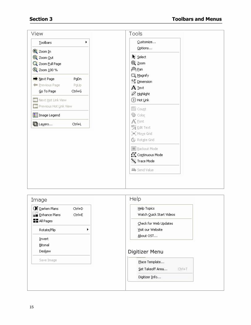
Section 3 Toolbars and Menus
15
Digitizer Menu
Section 4
16
Features
This section will
Show you how open On-Screen Takeoff
Describe the On-Screen Takeoff environment
Teach you how to navigate pages
Section 4 Features
17
Start On-Screen Takeoff
1 On your desktop double-click your On-Screen Takeoff icon
2 The application will open
OR
3 Left-click on the Start button on your computerrsquos toolbar
4 Scroll up to Programs gt On Center Software
5 Highlight On-Screen Takeoff and click On-Screen Takeoff will open On-Screen Takeoff opens to an untitled blank project The Image view of the screen will be a blank page
Two blank dock bars the Pan dock bar and the Takeoff dock bar appear at the left side of the screen Along the bottom the Status bar displays user status or context-sensitive messages as well as paper size and current zoom percentage of the plan sheet on screen The menu bar and several task specific toolbars are located at the top of the screen
NOTE All toolbars and dock bars may be accessed to view or hide through View gt Toolbars on the menu bar
Section 4 Features
18
Quick Start Video When On-Screen Takeoff opens you will be given an option to watch the Quick Start video (recommended) or start the program without watching the video
The 20 minute video will demonstrate key program functionality and allow you to view application instruction for enhanced learning
If you would like to watch the video click If you prefer to get started without
the video click If you have already viewed the video click the lsquoDo not show this message againrsquo box to prevent this dialog from appearing each time you open the program
NOTE If you decide later that you would like to watch the Quick Start video go to Help gt Watch
Quick Start Videos
On-Screen Takeoff Environment The On-Screen Takeoff environment acts like your drafting table allowing you to work on several sheets of plans at once and to reference at a glance the entire drawing and your position on that drawing while giving you the power of a computer to track analyze print and export your takeoff quantities and plans
The screen is bordered at the top by the Menu bar with pull-down menus and at the bottom by the Status bar which indicates current user status plan page size and current zoom percentage of page The largest portion of the application screen will be your takeoff area bounded on the left (by default) by two dock bars and on the top by several toolbars
In the takeoff area you may view your project plans (images) andor takeoff objects the takeoff list with quantities the worksheet or a legend of your condition list
The main window of On-Screen Takeoff has three tabs located at the bottom left allowing for quick change between Image Takeoff or Worksheet views Select the desired view option on the toolbar and it will automatically open on your screen
Section 4 Features
19
Image View
This view shows the plan file andor takeoff conditions drawn from your plans
Takeoff View This view displays the height if applicable and quantity breakdowns of your conditions according to result types indicated (eg linear feet square feet or count of items) for zones pages and the project as a whole It also displays notes per condition
Section 4 Features
20
Worksheet View This view displays the condition and quantity in units of measure specified in the first results field of the Results tab in the Condition dialog and allows the user to enter amounts for material labor and subcontractor takeoffs
NOTE When in the Worksheet view tab out the field then save This is keep all the values saved
Navigating On-Screen Takeoff
Auto Scrolling When creating linear areas or zones On-Screen Takeoff will automatically scroll the image view when necessary It will move as your mouse or digitizer moves beyond the edge of the current view
Changing Pages
1 Select View gt Next Page Previous Page or Go To Page (specify page number for the Go to Page option)
2 You may also select the corresponding arrows for these options from the Navigate Toolbar The
drop down arrow in the Page field will list the pages The and arrows will take you to the
previous or next page The and arrows will take you to the first or last page
OR
Section 4 Features
21
3 Or press Ctrl G for the Go To Page dialog
Hot Links Hot links allow you to move quickly from one drawing to the pertinent area of another drawing A hot link is handy when viewing enlarged areas of a page and needing the ability to jump back to a reference page
1 Select Tools gt Hot Link
OR
2 Click from the Tools Toolbar
3 Click on the page where you want to set the link The Hot Link dialog will open
4 Using the current page display on the Navigate Toolbar access the pull-down menu of pages by
clicking on the arrow at the right
5 Select the page for your link (You may also choose View gt Go to Page and select by page number)
6 Manipulate the view using the zoom tool and the scroll bars
7 Click
8 After joining a hot link to another page the hot link arrows in the Navigation Toolbar will become active
9 Move a hot link to another location on the page by clicking then click and drag the hot link image anywhere on the page
Section 5
22
Projects
This section will
Help you create settings important to your projects
Explain how On-Screen Takeoff works with your electronic or paper plans
Section 5 Projects
23
Project Template Files You can begin your project with a template Templates allow you to take advantage of conditions and settings used with previous projects
On-Screen Takeoff templates contain condition lists and established layer separations from previous projects you have created You may also use the sample templates provided with On-Screen Takeoff as a great starting point All aspects of the templates may be adjusted for a new project
1 Select File gt New and click the OK button
2 From the New dialog box choose the template that best fits your project
3 The conditions for this template will appear in the Takeoff Dock bar and the Project Properties dialog will open asking for further information
4 Use File gt Save or File gt Save As to rename and save your new project
Saving a Project as a Template File You can save your condition properties and layers as a template for future projects
1 Select File gt Save As
2 Enter a name for your template and select On-Screen Takeoff Template Files (tpo) from the Save As type field of the dialog (click on the down arrow to select)
3 Click the OK button to accept and close the dialog Modifying a Template File Follow these steps to modify an existing template file if you need to change or add conditions andor layers
1 Select File gt Open
2 Navigate to your Projects directory
3 In the File Type drop-down select On-Screen Takeoff Template files (tpo)
4 Choose the On-Screen Takeoff template file you would like to modify and click the OK button
5 Make appropriate changes
6 Save and close file
The On-Screen Takeoff template files cannot save takeoff information
Section 5 Projects
24
Opening an Existing Project File 1 Select File gt Open
2 Navigate to the desired file location
3 Click the Open button
NOTE If your latest changes to a project file have not been saved On-Screen Takeoff will ask
you whether you would like to save the file and gives you the option of canceling the operation
Creating a New Project
1 Select File gt New
2 For a blank untitled project click
3 At this point the Project Properties dialog will pop-up for more information about your takeoff
NOTE The following are important to keep in mind when beginning a new project
At the start of your project fill out the Project Properties settings to establish the name for all printed output from your project set the default page size and scale for your plans number and names of different pages within the project and locations of electronic drawings
Scale settings can significantly affect quantity outcomes Be sure to set the scale for each page of drawings before beginning condition takeoffs
When using a digitizer remember to make a mark with a pen or pencil in the upper left and lower right corners of the first sheet of the paper plans to delineate the takeoff area for that sheet You can then set the takeoff area on On-Screen Takeoff using your marks
Save your project before you begin taking off any conditions On-Screen Takeoff will write a back-up file using the same file name
Remember the Undo feature If you make a mistake select Edit gt Undo and reverse the process step by step
Section 5 Projects
25
Project Properties
You can either set your Project Properties when you create a new takeoff or once your project file is saved under the appropriate name
1 Select File gt Project Properties the Project Properties dialog box will appear
2 Type in the name of your project to appear on printouts Use the backspace andor delete keys to edit the name as necessary
3 Press the Tab key to move to the Default Image Size option or click within the Image Size box You may click on the arrow at the right for the pull-down menu of page size options or you can use the down-arrow key on your keyboard to scroll through the list to the appropriate selection
4 Press the Tab key to move to the Default Scale option Select a scale by using the drop down arrow If your scale is metric you will need to click in the box next to Metric to convert to that measurement
5 Establish the number of pages for your project plans And load image files See Adding Pages to
Your Project
Adding Pages to Projects Individual Electronic Plans
1 Click on in the Project Properties dialog
2 In the Add Images dialog use the drop down arrow to navigate to the appropriate directory and folder containing your image
3 Select the file so that it displays in the File name field then click The file will display by name and path in the Image File field in Project Properties dialog
4 Click to accept and your project will automatically open
5 Save your project with the new settings by selecting File gt Save
Section 5 Projects
26
Electronic plans scanned from blueprints (as opposed to blue lines) will display as white lines on a black background and are difficult to read on your computer screen Select Image gt Invert and the colors will invert to black on white
You may have noticed the Page column in the Project Properties dialog Generally plan images occupy one page and 1 will be listed in the column indicating Page 1 of your plan file If you import a multi-page TIF a plan file containing more than one page of plans they will import as separate pages and each successive page will be indicated under the Page column as 1 2 3 etc of the plan file
Group of Electronic Plans You may add all the electronic plan files from a particular source (for example from a CD) by using the Auto Add feature
1 Click the button in the Project Properties dialog
2 Browse until you find the appropriate directory and folder containing your plan images
3 Click on any file displayed within your target folder so that the file name appears in the File name box of the Auto Add dialog
4 Click The image paths and file names will be recorded into the project properties arranged alphabetically
5 Click to accept your choices and your project will automatically open
6 Save your project with the new settings by selecting File gt Save
To load Dodge Plans into your Project Properties see Appendix IIi Loading Plans from a Dodge CD
Paper Plans On-Screen Takeoff makes it easy for Full Mode users to perform quantity takeoffs from paper plans using a digitizer
1 Add pages by clicking until you have the number of pages initially in the project
2 Name each page by clicking within the Title area and typing the name
3 Click to accept your choices and close the Project Properties dialog
4 Save your project with the new project properties settings by selecting File gt Save
Section 5 Projects
27
Setting Up a Drawing Template On-Screen Takeoff provides the convenience of using the same work surface for both digitizer and mouse to allow the user to draw conditions and then edit settings of the project or add or change conditions without breaking stride A mouse pad template included with the program defines the area of the digitizer in which use of the stylus or cursor will be recognized as mouse movement as opposed to drawing movement
1 Place your stylus on On-Screen Takeoff
2 Placing the template identifies the location mouse movements will be recognized by the program
Before placing the template the template must be applied to the digitizer surface This may have been done during the installation of your digitizer We suggest attaching the template to the lower right corner of the digitizer surface about one inch inside the grid area
3 Select Digitizer gt Place Template
4 Follow the instruction prompts on the screen clicking first on the target symbol at the left of the On-Screen Takeoff box on the template then on the target at the right
Setting Takeoff Area Before you can begin taking off a drawing you must define the drawing area on the digitizer This requires defining an area that will include all objects on each drawing of your plans As you add pages to your takeoff the same area of the digitizer will be active
1 Secure the plans to the digitizer with tape or a set of clamps
2 With a pen or a pencil mark the upper left corner and the lower right corner of the first page in your set of plans
3 Select Digitizer gt Set Takeoff Area
4 Click each mark with the stylus pen as prompted
5 Verify the active area of the digitizer by looking at the image size located in the lower right corner of your screen
If you close the program before the takeoff is complete you will need to reestablish the takeoff area before you can add additional condition quantities
Electronic plans appear on your computer screen eliminating the need to set a takeoff area You simply drag your mouse across the conditions you wish to takeoff The conditions will be highlighted and quantities will be totaled instantly Electronic plans are available through a variety of services For information contact an On Center Software account manager
Section 5 Projects
28
Setting Scale for Specific Pages You may set the scale in each page view separately This will override the default scale setting in Project Properties for that page Setting the correct scale for the drawing before taking off quantities ensures accurate calculations Be careful to check the scale for each drawing in your project before doing takeoffs
1 Display the page you want to set select Edit gt Set Scale
2 Use the drop down arrow to select a scale that will be applied to that page
3 Click
OR
4 Access the pull-down scale settings on the Navigate toolbar
NOTE As you draw objects notice that the drawn object is similar in width to the object on your plans If it is not the scale set may not be correct
Calculating Scale You may calculate scale according to a known measurement between two points either with a digitizer or on electronic plans
1 Select Edit gt Calculate Scale using Image or Edit gt Calculate Scale using Digitizer
2 Follow the instructions in the related Calculate Scale dialog box You will be asked to click on the first and second points then to enter the dimension for that distance
3 The scale will be recalculated for the displayed page and the Scale display on the Navigate toolbar will show the new scale
Section 6
29
Conditions and Takeoff
This section will Draw Conditions to Takeoff Plan Quantities
What Zones will do to help your takeoff process
Discuss the ins and outs of Takeoffs
Section 6 Conditions and Takeoff
30
Creating Conditions
If you are starting a new project from scratch you will need to create conditions to takeoff quantities such as floor areas wall lengths and corner bead counts If you are using a template you will have several pre-designed conditions already listed on the Takeoff dock bar However you may want to change the characteristics of some conditions or create additional conditions for a particular project
1 Right Click within the Takeoff dock bar Select New gt Condition
Or
2 From the Takeoff dock bar Click (if the buttons are not showing right-click in the Takeoff dock bar area and select Show Buttons from the pop-up menu) The New Condition dialog appears
3 Select the condition type (Linear Area Count or Zone) from the pull-down menu accessed by the
down arrow next to the Type option
4 Press Tab or use the mouse (or stylus) to move to Name and enter a name for your condition
5 Specify the desired condition attributes See Condition Attributes for more detail
6 Click for condition to apply
Section 6 Conditions and Takeoff
31
Condition Attributes Each condition type will have related attributes to select or specify within the General and Advanced tabs of the New Condition dialog Once a condition has been used to takeoff a quantity from your plans certain attributes cannot be changed
All conditions allow the user to specify color and fill pattern for the object drawn
Linear Conditions
General Specify width and height by feet and inches Specify pitch in inches up to the nearest thousandth of an inch if applicable
Advanced Specify rounding for object quantities and droprun default length for electrical or plumbing drops at the ends of lines Select Connect to have lines connect at the corners where one line of the condition ends and another begins (and indicate Tolerance for the featurersquos activation as distance between the ends of two lines) Choose Trim to have lines automatically trim to a line being crossed Choose Curve to draw a curved line
Follow these examples for inputting feet and inches For 7 feet 6 inches type 706 for 13 feet 7 inches type 1307 For 20 feet type 2000
Section 6 Conditions and Takeoff
32
Area Conditions
General If needed you can specify the thickness (in inches) andor pitch (in inches)
Advanced Specify rounding for object quantities Choose to display an adjustable grid within the area and indicate matrix cell dimensions
Section 6 Conditions and Takeoff
33
Count Conditions
General
Specify height and indicate the size (in inches) and shape (square circle triangle rectangle or opening) of the count object as it will appear on screen
Advanced Count conditions have advanced attributes These options are available for all shapes except for openings
Zone Conditions Zones allow you to subdivide condition quantities making it easier to modify and complete jobs in phases They can be used at the end of a takeoff to isolate a group of condition quantities that are in different areas of the takeoff
Zones can also be used to break a takeoff into multi-phases and can even be used to isolate quantities while a job is in progress to group the amount of work that has been completed to date They can be applied to one or multiple pages in your plans automatically calculating the takeoff quantities for each zoned area
Section 6 Conditions and Takeoff
34
The zone feature is only available in Lite and Full Mode If you are in View Mode and would like
to use this feature click from the main toolbar to purchase the upgrade
Condition Notes A Note tab is provided for comments regarding the condition These notes will display on the Takeoff List report and will import into Quick Bid
Section 6 Conditions and Takeoff
35
Condition Results The Results tab of the New Condition is based on condition type Initial settings default to linear feet (LF) for linear conditions square feet (SF) for area conditions and count of items (EA) for count conditions and zones The first of the results fields will display for the condition items in the Takeoff dock bar area All results will display in worksheets and Takeoff List reports as well as in an Excel spreadsheet after being exported
Copying Conditions You may use the condition attributes from a condition yoursquove already created for any future conditions of the same type
1 Click on a condition to select it
2 Click the Copy button from the toolbar
OR
3 Right-click in the Takeoff dock bar area and select copy
4 A new condition will appear in the list with the same condition attributes as the previous condition but with the quantities zeroed
Editing Conditions Once you have copied a condition you might want to change several attributes You can also edit an existing condition to fit any updated needs
1 Highlight the desired condition on the Takeoff dock bar
2 Click the Change button
OR
3 Double-click on the condition you wish to edit to bring up the Change Condition dialog
NOTE The Change Condition dialog differs from the New Condition dialog only in that if takeoffs
Section 6 Conditions and Takeoff
36
have been performed in your project with this condition you will not be able to change the type of condition or certain properties under the advanced tab of the dialog box
Deleting Conditions 1 Click on the condition in the Takeoff Dock bar area
2 Click the Delete button on the toolbar
OR
3 Right-click and select Delete from the pop-up menu
All takeoff associated with the deleted condition will be deleted immediately and permanently
Organizing Project Conditions Within your project you can create folders andor sub-folders for different types of conditions You may even want to create a folder containing conditions with reset values
To get started organizing your conditions make sure you are viewing the condition tree (right-click in the Takeoff dock bar area and select Show Tree)
Creating Folders and Sub-Folders 1 Right-click in the Takeoff Dock bar area
2 Select New gt Folder from the pop-up menu
Copying Folders
1 Click on the folder and click Copy on the toolbar
2 All copied conditions within the new folder will have values reset to zero
Renaming Folders
1 Click on the folder
2 Right-click and select Rename from the pop-up menu
3 Enter a name for your folder and click the Enter button
Changing Condition Order
You may move conditions up or down in the condition list of the Takeoff dock bar to suit your project needs
1 Select the condition you would like to move by clicking to highlight it
NOTE When you are ready to move the highlighted conditions be sure that you start
moving using the last condition chosen That condition will have a highlighted boarder
Section 6 Conditions and Takeoff
37
2 Drag and drop any the condition from one place to another in the list You may also move a condition to another folder on the list in this way
Drawing with Conditions Snap Angles Set up snap angles to prevent lines from appearing jagged Snap angles are commonly set at 15deg and shift snap angles at 0deg
1 Go to Tools gt Options Options dialog appears
2 Under the General tab make the desired settings
3 Click to save the settings As they are drawn lines will snap to the set degree
Drawing a Linear Object 1 Select a condition from the Condition List in the Takeoff dock bar
2 Move the cursor into the Image takeoff area of the screen you will see the cursor display as crosshairs
3 Click and hold left mouse button then drag mouse to draw a line
4 Release mouse button to set line
Section 6 Conditions and Takeoff
38
5 Repeat steps for further lines
Continuous Mode This feature allows you to draw an object that has connected lines
1 Click the icon from the Takeoff toolbar
OR
2 Go to Tools gt Continuous Mode
3 Follow steps 1-3 from Draw a Linear Object
4 Click at each point of intersection The object will be connected
5 Double-click after making the final point to set the lines
Drawing a Curve To draw a curved line the Curve option must be checked under the Advanced tab of the Condition dialog
1 Click where you want to begin the curve and drag in a straight line to the position for the other endpoint of the curve
2 Click on the line to select it Handles in the shapes of small squares will appear at either end of
Section 6 Conditions and Takeoff
39
the line and in the center of the line
3 Move the cursor over the center handles until the cursor becomes a two-way arrow
4 Click and drag in the direction of the curve bending the line as you move the cursor Release to set the curve (The line you began with will disappear)
Draw a circle by drawing two curved lines connected
Drawing an Area Object Area conditions are drawn similarly to continuous mode lines You may trace any number of adjoining walls at different angles to complete your area takeoff
NOTE When drawing an area do not intersect the perimeter or line of the object you are drawing
1 Click at each point
2 Double-click when yoursquove returned to your starting point
3 The area will be filled with the pattern set for that condition
NOTE The simulated circle will be good enough for you to be able to make a bid
To create a circular area click from point to point with very short distances in between points simulating a circlersquos perimeter Double-click after setting the last point to set the area
Section 6 Conditions and Takeoff
40
Grid Options Grids give you an added advantage when installing materials such as tiles Use this feature to get a count for how many tiles are needed for an area
1 Double-click on an area condition in the Takeoff dock bar to open its Condition dialog
2 Click on the Advanced tab to show its options
3 Check the box next to Grid by clicking in it
4 Indicate the dimensions of the cell matrix in inches (For example 200 x 400)
5 Under Results tab choose each (EA) for one of the results fields This will tabulate a number of grid cells (including partial grid cells) in area
6 Click to save your settings
7 Use the Move Grid and Rotate Grid features in the Tools menu to manipulate the grid as desired
Grid Calculation
1 Go to Tools gt Options menu
1 Specify if On-Screen Takeoff automatically should Calculate Grid Position
2 If AreaGrid Size is selected On-Screen Takeoff will calculate the number of items needed to fill the grid based on grid demintions
3 Click to accept and close the dialog
To move a line at any angle (regardless of default setting) press the Shift key while moving the mouse
Section 6 Conditions and Takeoff
41
Backout Mode This feature allows you to take out part of an area and deduct that amount of square footage
1 Select Tools gt Backout Mode
2 Outline the are you want backed out as you would when drawing a regular area object (see Drawing an Area Object)
3 The outlined area will clear and quantities will be recalculated
NOTE The perimeter of the backout area will be added to the LF quantity for that condition
Drawing a Count Object Square triangle rectangle and circle shaped count objects can easily be placed on images
1 Select the condition
2 Click in the location where you want the object to appear
3 To place an opening-shaped count item like a door or window you must click over an existing linear object such as a wall
4 On the Results tab you can change the height properties to give you the result you need
5 If Backout is checked on the advanced tab for each count opening the opening-shaped count item will back out a corresponding section of the linear object
Opening shaped count items are sized at 3rsquo0rdquo by default
Drawing a Zone Zones are drawn in the same way as area objects and may be any polygonal shape You may trace any number of adjoining walls at different angles to complete the zone perimeter
1 Click at each point
2 Double-click when yoursquove returned to your starting point
Section 6 Conditions and Takeoff
42
Selecting Objects
1 Use the Select Tool to select objects
You can also select all objects that correspond to a condition
1 Click on a condition to select it
2 Right-click and choose Select All
3 All objects with this condition will be highlighted with squares as an outline
Moving and Resizing Objects Linear
1 To move or resize a linear object click anywhere on the line to select it
2 To move the line position your pointer over the center handles When the mouse is positioned over the handles you will see a two-way arrow You will only be able to move the line in the direction of the arrows
3 Drag the line to a new position
4 Clicking and dragging the handles on the ends of the line will allow you to lengthen or shorten your line
Area and Zone
1 To move an area object or zone in its entirety click and drag it to its new position
2 Grabbing a handle at a corner or intersection of the object will allow you to adjust and change its perimeter
Section 6 Conditions and Takeoff
43
Count 1 To move a square circle rectangle or triangle shaped count object click and drag
2 Click and drag an opening shaped count object along the length of the linear object to the desired position then release
NOTE An opening shaped count object may not be moved from its associated linear condition object however it may be moved up and down the length of the linear object
Layers On-Screen Takeoff allows you to sort and separate your takeoff objects within the same job and on the same page On-Screen Takeoff gives you this flexibility through the use of layers
By assigning different conditions to different layers (for example differentiating between floors ceilings and walls) you can choose to view all layers or turn off certain layers to display and print the remaining groups of conditions only You may also remove the background image of electronic plans add text and hot link symbols or print only your condition takeoffs
Layers are only available in Full Mode If you are in View or Lite Mode and would like to use this
feature click from the main toolbar to purchase the upgrade Default Layers
On-Screen Takeoff begins every project with three default layers Image Annotation and Default The Image layer holds the electronic plan files you may have in your project The Annotation layer possesses all text notations highlighting and hot links in the project The Default layer will appear in the Condition dialog when creating or editing a condition (listed in the takeoff dock bar) Conditions are assigned to the Default layer unless otherwise specified by the user
Creating Layers To assign a condition to a layer other than the default layer you must first create additional layers for your project
1 Select View gt Layers to open the Layers dialog
2 Click An unnamed layer will be added
3 Click within the empty box and type a name for your layer (for example Wall)
4 New layers are added as active layers The adjacent box under the Show column will be checked
Section 6 Conditions and Takeoff
44
Assigning a Layer to a Condition 1 Open the Condition dialog box by creating a new condition or editing an existing condition
2 Under the General tab click on the down arrow in the Layer field to display optional layers
3 Select the desired layer for the condition Only the Default layer and layers you have added will be displayed
4 Click
View and Hide Layers
1 Select View gt Layers
2 Under the Show column check the box to view or remove the check (by clicking on it) to hide the specific layer
3 Click to accept and close the Layers dialog
Section 6 Conditions and Takeoff
45
Assigning Text to a Layer When adding text to an image On-Screen Takeoff has the capability to assign the text to a specified layer
1 Select the Text Tool
2 Click at the point you want to place your text
3 Type in your text using the Enter key for line breaks
4 Click the drop down arrow next to the Layer field and select the desired layer
Section 7
46
Printing and Exporting
This section will
Printing options and procedures
Exporting data by copying and pasting
Exporting quantity results to Excel spreadsheets
Section 7 Printing and Exporting
47
Print Setup On-Screen Takeoff allows the user to print the image takeoff list and worksheet
1 Select File gt Print Setup The Print Setup dialog will open
2 Select a printer or leave the default selection listed (change from the default printer displayed by clicking on the down arrow at the right of the field)
3 Indicate page size and printer tray option (Source) Access page size options by clicking on the
down arrow at the right of the field
4 Choose Portrait or Landscape orientation
5 Click to accept and close the dialog
Printing Images The image area can include the electronic plans the takeoff objects added text and hot links To print a subset of these (for example just the takeoffs without the plans or the added text and hot link symbols) hide layers that you do not want to print (see Section 6 View and Hide Layers) When you are printing your images every page will show the scale of the takeoff you are printing
1 Click on the Image tab to display the area of your project
2 Select File gt Print (or Ctrl + P)
Section 7 Printing and Exporting
48
3 Select the desired view (What to print) and the Image Range
4 Click The second Print dialog will open
5 Change settings accordingly or click if you accept the default settings
Printing Takeoff Lists and Worksheets In Takeoff Lists and Worksheets you may hide columns to print only certain results or adjust column widths to fit the report within the page size selected
1 In Takeoff List or Worksheet view move your cursor to the right side of the columnrsquos title bar the cursor will display as a two-way arrow
Section 7 Printing and Exporting
49
2 Click and drag to adjust the width of the column Holding the mouse button you may
slide the title bar under the title bar to its left to hide the column completely
3 Select File gt Print or press Ctrl + P to access the Print dialog
4 Indicate desired printer and choose the number of copies
5 Click to print and close the dialog
When printing the condition list we suggest printing in landscape
To reset to the default column widths double-click on the right border of a column heading will reset the column to its right (or previously to its right before being hidden)
Print Preview 1 Select File gt Print Preview
2 Use and to vary your view 3 If viewing an image choose current full or scale view to see how it displays
4 For printed outputs that cover more than one page use and to view adjacent pages or click on the down arrow next to Page field and select the page you want displayed
Exporting Using the CopyPaste Feature You may copy all the data or sections from the worksheet and the takeoff list view in On-Screen Takeoff and paste it into another application When pasting into Excel the cell layout will be maintained
1 Highlight the areas you wish to paste Click and hold the left mouse button down as you drag the cursor over the area to be selected then releasing the mouse button
OR
2 Select the entire takeoff list quickly click on the left On-Screen Takeoff column header and hold and drag the cursor across the remaining column headings
The number of pages for the view selected will display in the lower left-hand corner The zoom percentage that applies to the view will be displayed in the lower right-hand corner next to page size of the drawing
Section 7 Printing and Exporting
50
3 In the worksheet view you may highlight rows by clicking on the numbered buttons to the left of each row clicking and dragging across column headings or clicking and dragging over individual cells in the worksheet
Click anywhere in the appropriate view to deselect the area
4 Once your selection is highlighted you may select Edit gt Copy or Ctrl C from the keyboard 5 On your monitor switch to the application into which you want to paste your selection 6 Select Edit gt Paste in the new application or simply press Ctrl + V to paste
The colored keys for conditions cannot be pasted
Using the Export Feature You may export condition quantities to specified cell location within an Excel worksheet file Cell target locations are assigned in the Results tab of the condition dialogs on the Export line relating to each quantity measurement type
On-Screen Takeoff will export takeoff quantity results for up to three different quantity types that you specify For instance you may want to know the number of square feet in a ceiling area as well as the number of linear feet in its perimeter
Section 7 Printing and Exporting
51
1 Bring up the Condition dialog by double-clicking on a condition in the takeoff dock bar or by
selecting the condition and clicking
2 Click on the Results tab to access its fields The default quantities for the condition type will display
3 For each results field click on the arrow to access the pull-down menu and select the appropriate quantity (for example SF LF EA etchellip)
4 Have your Excel spreadsheet opened and saved in a file
5 Specify the Excel spreadsheet cell locations where you want the results to go
6 For a cell in the first sheet of your spreadsheet type in the cell address (eg a1) Case is not important
7 For a cell on a successive sheet of your spreadsheet type in sheet the number followed by a comma and the cell address without any spaces (eg sheet2a1) Case is not important
8 Click
9 Select File gt Export gt Condition Qty to Excel
Section 7 Printing and Exporting
52
10 Browse to the location of the Excel spreadsheet file click file to select it
11 Click to export On-Screen Takeoff results to specified cell locations in the Excel file When you return to the Excel application you will see the values have been added to the specified cell locations in your spreadsheet
12 Save your Excel file
Exporting Worksheet to Excel
1 Assign condition quantities you want to export
2 Open saved Excel spreadsheet file to which you will be exporting
3 From On-Screen Takeoff Select File gt Export gt Worksheet to Excel
4 Browse to the location of the Excel spreadsheet file click file to select it
5 Click When you return to the Excel application you will see the values from the Worksheet Tab have been added to your spreadsheet
6 Save your Excel file
Exporting Takeoff to CVS 1 Assign condition quantities you want to export
2 Open saved Excel spreadsheet file to which you will be exporting
3 Click the Takeoff Tab in the project you want to export the information
4 Select File gt Export gt Takeoff to CSV
5 Browse to the location of the CSV spreadsheet file click file to select it
6 Click the Save
NOTE CSV files can be opened in Excel Lotus Access etc One may consider this option more of a ldquodumprdquo into a file
The Excel application must be active (it may be minimized on the application bar) with the target spreadsheet open in the application Otherwise an error will occur with the export operation that will affect both the On-Screen Takeofftrade file and the Excel spreadsheet
Section 8
53
Advanced Features
This section will
Some special features of working with condition objects in the takeoff area
Details of advanced options for conditions
Advanced features of the Project Properties dialog
Section 8 Advanced Features
54
Features to Use with Objects Roping Feature You can move copy or delete using this feature Using the Select tool (the pointer) you may select several objects at once by clicking and dragging an outline around the objects then releasing the mouse button Roping may select either objects completely within the outlined area (inclusive) or objects both within and touched by the outlined area (touching) Specify your roping preference under Tools gt Options
1 Click and hold the mouse button at a point on the screen near the objects to be selected and drag to surround the objects with an outline
2 Release the mouse button The objects will be selected
3 You may now
Move the group around on the page by clicking within the group dragging the mouse and releasing the button to place the objects
Delete the group of objects by clicking the Delete key or
Copy and paste by pressing Ctrl C to copy the group then Ctrl V to paste it The pasted copy of the grouped objects will appear slightly offset from the original objects
Section 8 Advanced Features
55
Applying a DropRun Count
Use the droprun feature when calculating quantities to take into account the drop or run of a linear condition such as electrical lines or plumbing pipes Drop or run lengths may be added separately to any linear condition on screen while a default droprun length may be indicated for a condition as a whole
1 Select the desired linear condition from the Condition List in the Takeoff Dock bar
2 Click the Change button in the toolbar to open the Change Condition dialog
3 Click the Advanced tab to access the advanced options and click inside the DropRun check box
4 Enter a default length to be applied to all of this condition Entering 800 will be interpreted as 8 0 (You must enter both place markers for inches) You can leave the length blank and manually enter drop run on each segment drawn
5 Click the OK button to accept and close the dialog
Edit DropRun Count
1 With the related linear condition in the Takeoff Dock bar highlighted or with the pointer tool selected
2 click on the desired linear object in the image takeoff area The Count button will become active
3 Click on the Count button (alternatively select Tools gt Count) The default droprun amount will show in the pop-up Count dialog (Default length will be zero if droprun has not been selected in this conditionrsquos properties)
4 Type in the desired length Entering 800 will be interpreted as 8 0 (You must enter both place markers for inches)
5 Click the OK button The additional amount will be reflected in the corresponding quantity The new DropRun count will apply only to the object edited
Adding Text in Image View
On-Screen Takeoff allows you to place text comments around your quantity takeoffs that may be printed along with plan images and objects Text is automatically placed within the Annotation Layer (that includes text and hot links)
1 To place text on the image select the Text Tool and click at the point you want to place your text opening a text box
2 Type in your information clicking Enter for line breaks
3 When you are finished click the OK button to exit the text box
4 To reposition text simply click on the text (with the Text Tool active) to select it
5 Move the cursor over the text the cursor will now display as a four-way arrow
6 Click and drag the mouse to position the text as desired
Section 8 Advanced Features
56
1 To edit existing text use the Text Tool to double-click on the text to open the editing box
2 Enter additional text or use the Backspace key to delete text as necessary
Formatting Text Once created you may format the font size type style and color of your text
1 Click on the text to select it and select Tools gt Font or click on the Font button in the Takeoff Toolbar
2 Select the desired features (color options are disabled) and click the OK button
3 Click on the text to select it and select Tools gt Color or click on the Color button in the Takeoff Toolbar The Color dialog will open
4 Click on a color in the Basic Color palette or create a color and add to the Custom Colors palette (Be sure to click on the color in the Custom Colors palette to select it)
5 Click the OK button
Object Properties
Linear Objects
Linear objects may be set to connect at corners
A linear object may be set to trim automatically when crossing another linear object (Check the trim option under the advanced tab of the Condition dialog)
When you move a connected linear object objects automatically move and resize connected lines accordingly (quantities are then recalculated)
This feature requires that the connected linear object be moved using the center handles (does not apply when resizing the line from the ends)
Objects constrain to snap increments defined in the Tools gt Options menu (with the mouse 15deg by default incremental when shift key is held down)
Objects are measured from centerline to centerline
Section 8 Advanced Features
57
Area Objects When drawing an area use your escape key to undo the last line drawn You may reverse your
drawing of an area using the escape key
The area will not fill with color and pattern until the user double-clicks after the last line is set
Lines drawn to delineate an area object constrain to snap increments defined in the Tools gt Options menu (with the mouse 15deg by default incremental when shift key is held down)
After selecting an area to move or adjust position the mouse in the center to move the entire area position the mouse at the sides or corners to adjust the perimeter
Count Objects
All count objects are quantified by the physical number of objects per page and reported as EA for the UOM The quantity for the current Image View is (displayed in the Condition List) and the total quantity in your project is displayed in the Takeoff View and Worksheet View)
Square circle rectangle and triangle shaped count objects do not displace or subtract from other object quantities when placed on top of them However on the Advanced Tab for the count condition a connect property can be set (this is a check box) so that when a count object of this shape is put on top of a Linear type takeoff object it will move with the linear if said linear is moved
An opened-shaped count object must be placed within a linear object Opening shaped count objects may also be measured by linear foot or linear yard (EA SF and SY are also options) Opening shaped count items default to a width of 3rsquo 0rdquo at the time of creation This size can be changed The small medium and large size are not options on this type of condition anymore Check Backout on the Advanced tab for each Count object back out the footage (or yardage) of opening-shaped count objects in which they are placed
NOTE In order to see this Backout functionality (in quantity) for SY or SF deductions at least one of the
results for the Linear(s) this object will be placed on must be set to SY or SF and the count object must have a height quantity
Advanced Features of Conditions The Round Feature Under the Advanced tab of the linear and area Condition dialogues you may specify quantity rounding (in inches) For linear objects rounding applies to each linear object drawn For area objects rounding will apply to each segment of the area perimeter adjusting the perimeter and area calculations For example With a linear condition entering 12 in the Round field will round up each related linear object to the nearest 12 inches or one foot With this setting two walls of 1 4 would each round to 2 0 totaling 4 0
NOTE In the Takeoff Dock bar condition list and in the On-Screen Takeoff reports quantities will be displayed in whole numbers rounded up to the nearest foot However calculations are based on true quantities without rounding unless the Round Feature is engaged
Pitch Pitch may apply either to linear or area conditions It is measured in rise per linear foot Entering 12 indicates a 12 rise per 12 of linear distance (a pitch of 12 over 12) or an angle of 45deg
Section 8 Advanced Features
58
Advanced Features of Project Properties Selecting Multiple Pages
1 Select a single page entry by clicking on the numbered gray button to the left of the entry
2 Drag the cursor down the column of numbers to select consecutive pages
3 Click on the blank button at the top of this column to select all pages in the Properties dialog
Section 8 Advanced Features
59
Changing Image Assigned to a Drawing 1 Select the page entry by clicking on the numbered gray button to the left of the entry 2 Click the Change Image button The Change Image dialog box will appear
3 Navigate to the desired file and select by clicking on it
4 Click the Open button The electronic file assigned to the page will have been changed to reflect the new file choice
Changing Image File Path 1 Select pages as described above
2 Choose Change Folder
3 In the Change Folder dialog navigate to the appropriate folder
4 Click the OK button The file path will have been changed for the selected page entries
Delete a Page from Project Properties 1 Select the page you want to delete by clicking on its associated number (in the gray box at the
left of the entry)
2 Choose Delete Page
All Takeoff on the page will be deleted immediately and permanently
Section 8 Advanced Features
60
Advanced Features of Tool Options
Calculation Method On-Screen Takeoff has built-in calculation options to allow for faster work and faster saves until your takeoff is complete Calculation options are found by selecting Tools gt Options then clicking on the Calculation tab
Calculation method can be set to Automatic Automatic except Grids and Manual Manual will allow the program to operate more quickly while Automatic or Automatic except Grids allows the user to see quantity changes as takeoffs are made
In any mode you may press F9 to recalculate quantities for the On-Screen Takeoff current totals
Configuration Tab
When the ldquoPage Label (A01)rdquo radial button is chosen On-Screen Takeoff puts the numbered label on all the pages of in your current page indicator in your Navigate Toolbar If the Page Descriptionrdquo radial button is chosen then a description of what takeoff is on that specific page will be shown in your current page indicator in your Navigate Toolbar
This section of the configuration tab gives you options on how you want to export your information When the ldquoFolderSubfolder Namesrdquo radial button is chosen than on your file that you are exporting to will have all the conditions folders and subfolders In the Delimiter box you can choose the symbol that is needed to separate the information you are exporting Some files need semicolons () or colons () to make sure the information comes exported in is separated it the appropriate places
Section 8 Advanced Features
61
In previous versions of On-Screen Takeoff there are views that users need to have in order for them to display their information By either choosing ldquoOST 1xrdquo or ldquoOST 2xrdquo it will let the program know you want your columns of information exported in that specific format
When you have the Confirm Deletions radial button of ldquoYesrdquo chosen than every time you delete anything you will get a dialog box confirming your intentions of deletion
While working with your takeoff you have a choice to either view the legend of your conditions or hide it Choose whichever radial button that suits your needs
For those who prefer to use the Enter key to navigate in dialog boxes this option is just for that
Font Tab The Font tab is designed for you to make your own look and feel for the application At the bottom of this tab it will show you sample of the fonts and colors you have chosen
Renaming the Current Page You may change the name of the current page in the takeoff area of On-Screen Takeoff by selecting Edit gt Rename Page
This opens the Name Page dialog and you may simply type in a new name and click the Enter button The new name for the file will be reflected on the title bar for the page and in Project Properties
You also may access the Rename Page function by right-clicking in the takeoff area while in Image View and selecting the option from the pop-up menu that appears
Section 9
62
Saving and Exiting
This section will
Explain how to save projects
Show you how to safely exit the program
Section 9 Saving and Exiting
63
Saving Your Project
1 Select File gt Save 2 If your project has not previously been saved a Save dialog box will open to allow you to name
the file and choose the directory and folder in which to save your file 3 Once saved File gt Save will simply save the current version of the file
OR
4 Select File gt Save As then type in a new name for the file and save to the desired file path
The Auto-save Feature With the Auto-save feature On-Screen Takeoff automatically backs up your open project You may choose to have more than one level of backup files The first backup copy will have the extension b00 and successive files will be b01 b02 and so on If you have designated four levels of backup files after the fourth backup copy has been created (b03) the next file will be saved over the file with extension b00 Further backup saves will then rotate through the four backup files in the same way
1 Select Tools gt Options 2 In the Auto-save area (under the General tab) select the frequency of backup file creation (in
minutes) and the number of levels for the feature 3 You also may disengage the feature by clicking in the check box to clear it
The Auto-save feature automatically saves backup copies to the directory of the current project If you are working from a write-protected area such as a CD-ROM On-Screen Takeoff will place backup files in the On-Screen Takeoff folder
Exiting When you are finished using On-Screen Takeoff it is very easy to exit Exiting is very important because of security reasons If someone were to use your computer they could enter the application and view and manipulate information
Section 9 Saving and Exiting
64
On-Screen Takeoff closes the open project when you open another or create a new project or when you exit the program
1 Select File gt Exit
OR
2 You also may click at the upper right-hand corner of the application to exit
NOTE If your latest changes to a project file have not been saved On-Screen Takeoff will ask you whether you would like to save the file and gives you the option of canceling the operation
Appendix I Installing Your Digitizer
65
Appendix I Installing Your Digitizer When you get your digitizer from GTCO you will need to connect it to your computer Follow the instructions outlined below to do this
Note For rollup digitizers the metal bar must be oriented to the top or right hand side
Connecting the Digitizer 1 Lay the digitizer out flat 2 Connect the Stylus to the digitizer 3 Plug in the power adapter 4 Plug the interface (IO) cable into the digitizer 5 Plug the other end of the interface cable into an open serial port on computer
Note GTCO Technical support phone number is 410-381-6688 The electronic manual (on diskette) from GTCO contains more detailed installation and operation instructions for the GTCO digitizer model you have
Installing other Digitizer Drivers If you are using a GTCO Digitizer you will need to install the GTCO TabletWorks Drivers
If you are using a Digitizer not supported by GTCO Tablet Works 10 please contact the manufacturer of your digitizer for assistance with installation
Installing GTCO TabletWorks Drivers 1 Insert the On Center CD into the CD-ROM drive The CD Startup screen will open 2 Click on Install Software 3 Select Additional Software and Drivers 4 Select Digitizer Driver 5 Follow the instructions for installing TabletWorks 10
Adhering the Template The template is a small plastic sticker used to enable mouse function when using the digitizer with On-Screen Takeoff Place your template on your digitizer We suggest placing it in the bottom right corner of the digitizer about one inch inside the takeoff area
Note You may either peel off the back of the template and use the adhesive surface or you can tape the template down
Appendix I Installing Your Digitizer
66
Testing the Digitizer Drivers Before running OST you may test the digitizer by moving the stylus around on the digitizer pad it should move the mouse cursor (if mouse emulation is enabled)
If the digitizer does not move the mouse cursor on the screen
The superset codes may need to be reset Reset the superset codes by touching on the border of the digitizer with the stylus The digitizer should beep several times
The digitizer may not be communicating with the computer Be sure the COM port selected is correct Be sure the COM port selected is correct If you are not able to get the digitizer to move the mouse cursor you need to call GTCO technical support for help
Note The Mouse Emulation is not required for On-Screen Takeoff to work properly It is used only for the Template functionality if the digitizer is moving the cursor the wrong direction (up instead of sideways or vice-versa)
Click the L-shaped arrow symbol on the digitizer with the stylus
Appendix II Toolbar Item Details
67
Appendix II Toolbar Items Main Toolbar
Appendix II Toolbar Item Details
68
Tool Toolbar
Appendix II Toolbar Item Details
69
Zoom Toolbar
View Toolbar
Navigate Toolbar
Appendix II Toolbar Item Details
70
Navigate Toolbar (Continued)
Takeoff Toolbar
Appendix II Toolbar Item Details
71
Takeoff Toolbar (Continued)
Image Toolbar
Appendix III Loading Plans from a Dodge CD
72
Appendix III Loading Plans from a Dodge CD
This section will detail how to load plans from a F W Dodge CD-ROM into an On-Screen Takeoff project file ready for takeoffs
Dodge files may be added to the Project Properties dialog However loading the files in that way will load the files by number rather than name description If you want to load one page only from your Dodge CD You will have to rename the page to display the name rather than number of the file
To load plan files from a Dodge CD so that the files load sequentially by file number but are displayed by name rather than by number within your project follow the instructions below
Opening a Dodge project from a CD-ROM 1 Insert the CD into the drive 2 Choose File gt Custom 3 Choose Dodge Plans Project (plansdat) as the file type 4 Select the appropriate file type by clicking on the down arrow at the right of the Files of type
field 5 In the Look in field access your drive paths by clicking on the down arrow at the right of the
field then
Navigate to your CD-ROM drive Open the data folder and Open the Projects folder
6 Select the desired project and open its folder 7 Open the plansdat file 8 All the images will come in sequenced correctly for that job along with the full descriptions
(names) of each page If there is not a plans folder in the project folder then plans do not exist for that project on the CD Opening the plansdat file will yield an empty project
Appendix IV Using the Plan Viewer
73
Appendix IV Using On-Screen Takeoff Plan Viewer The On-Screen Takeoff Plan Viewer is a limited version of On Center Softwarersquos commercial takeoff software If your status bar located at the very bottom of the main window says View Mode in the lower left-hand corner then you are using the Plan Viewer You can use the plan viewer to
View CD-based amp converted CAD drawings
View a previously created OST file and associated drawings
Download electronic plans online
Navigate through drawings
Quickly Takeoff linearsareas and counts
Zoom in to view the plan better
Print drawings directly from the viewer
Viewing an On-Screen Takeoff Project File
1 To open an OST file that was previously created with of On-Screen Takeoff 2 Select File gt Open 3 An Open dialog will appear if you do not see the OST file you are looking for select the
Look In drop down arrow 4 A drop down menu will appear listing the various folders drives and mapped drives located
on your computer select the correct drive or folder location and continue to browse to the location of your OST file
5 When you see your OST file double-click it to open it 6 Any takeoff and drawings should appear on the Image tab view
If you do not see the drawings but do see the colored takeoff layer the drawings may
not be located in the same place they were originally saved at Go to File gt Project Properties and check the Image File path for each listed page If the image file path is pointing to a CD drive make sure the CD is inside the CR-ROM
Downloading Electronic Plans If your Online Plan Service provides a special file format (OSX) required to use this feature of our plan viewer you can immediately downloaded all electronic plans of a project directly from our viewer
Most Plan Room web sites will automatically open On-Screen Takeoff when a request to download plans is made Your particular Plan Room may differ in operation so please contact the provider directly with questions on using the site
Appendix IV Using the Plan Viewer
74
When you request to download or open a project file from a Plan Room you will usually have the open to open or save an OSX file Choosing open will automatically open On-Screen Takeoff Alternately you may choose to save the file to a local hard drive After you have saved the file either double-click it to launch On-Screen Takeoff or open the OSX file using On-Screen Takeoff by clicking File then Open and locating the file on your hard drive You will need to change the file type to OSX
After the OSX file is opened you will see an additional tab appear in the Conditions List window called Pages
The Pages tab shows the hierarchy of your project Gray file icons represent pages that have not been downloaded and blue icons represents pages that have been downloaded
To download a page simply double-click the page icon
If you wish to select a group of pages to download you can use the Ctrl or Shift key to multiple select them then click the Download button
If you wish to download all pages at once click the Download All button
Downloaded pages will now appear in the Project Properties dialog in the same order in which they appear in the Pages tab
Creating Quick Takeoffs With On-Screen Takeoff you can create quick takeoffs to measure quantities even if you dont have the full version of our program However using the Quick Takeoff functionality shows you just a fraction of what the full version can do
The Quick Takeoff Toolbar is located at the top of the image view It has three buttons designated for three types of takeoffs Linear Area and Count The Quantity drop down list will show secondary quantities for Linears and Areas The Units drop down allows you to select how you want your quantities displayed Feet Inches Yards Millimeters and Meters
NOTE Every time change the type of takeoff you are performing (switching from Area to Linear for example) the previous quantities and takeoff objects will disappear They will also disappear when you changes pages
NOTE You can use the Dimension Tool to basically measure the distance between two points or linears The distance will display on the status bar at the bottom of the application
The Quick Takeoff Toolbar
Appendix V Frequently Asked Questions
75
Appendix V Frequently Asked Questions General
Where is On-Screen Takeoff installed on my computer
Typically it is installed in CProgram FilesOn-Screen Takeoff
In Explorer how do I recognize On-Screen Takeoff file types
On-Screen Takeoff data is stored in a single file per job lsquojob name OSTrsquo On-Screen Takeoff templates are stored as lsquotemplate nameTPOrsquo
Can only one project at a time be open
Yes For that reason opening another project automatically closes the project on screen You will be asked to save any changes
Is only one scale allowed per page What about on drawings that have multiple detail sections on a page and each of those drawings have different scales
Yes For pages with drawings of different scales copy the drawing to another project page and set the appropriate scale
I cannot perform backout on an area that is along a linear
As a workaround use the On-Screen Takeoff layers feature to help you with this issue Electronic Images
How do I start a project from drawings that have been scanned and written to a CD-ROM
Open a new project Select File gt Project Properties and select Auto Add Navigate to your CD and the appropriate folder and select any image file in that location Click Open All files in the location will load into your project Recommended that images are copied from CD to hard drive for performance
If I get a disk of drawings in AutoCAD format (R13 or R14) can I read them in On-Screen Takeoff
Yes On-Screen Takeoff now reads DWG DXF and many other format that are saved with AutoCAD
Appendix V Frequently Asked Questions
76
When I click on the all pages button what is supposed to happen Currently nothing seems to change when I click on that button
The All Pages button is used to apply the Darken and Enhance Plans feature to all pages in the project (as opposed to only the current page on screen)
Is there a way to deduct a large skylight from an area condition
Yes with the related area condition selected in the Takeoff Dock bar unselect the Backout button on the Takeoff Toolbar then draw the Backout area The area quantity will be deducted from the related condition object and the linear measurement of the Backout perimeter will be added
Digitizer Issues
How do I connect a Digitizer to the computer
See Appendix I Connecting a Digitizer
The Place Template menu choice is disabled
On-Screen Takeoff may need to be authorized or the digitizer or the digitzer drivers are not installed
It wonrsquot let me select the Set Takeoff Area menu choice
On-Screen Takeoff may need to be authorized or no job is open a digitizer is not installed or the drivers are not installed
The digitizer stylus is not moving the cursor or crosshairs
Click S-0-1 superset on the digitizer
How do I convert my old GTCO Digitizer to work with On- Screen Takeofftrade
Call GTCO and they may be able to reconfigure your digitizer to be compatible with On-Screen Takeoff
Printing Issues Which Printers work with On-Screen Takeoff
Compatible printers include On-Screen Takeoff Hewlett Packard Epson and Canon printers If you are having printer difficulties please contact support and specify the type of printer along with other pertinent information Contact support at wwwoncentercomsupport or email supportoncentercom
Which Plotters work with On-Screen Takeoff
Compatible Plotters include Hewlett Packard DesignJet plotters and the EnCAD Cadjet II If you are having plotter difficulties please contact support and specify the type of plotter concerned
ViewingDisplay I can no longer see my condition list How do I get it back
The toolbars and Dock bars can be turned on and off through the View gt Toolbars menu options
Appendix V Frequently Asked Questions
77
This is also accessible by right-clicking in the toolbar area and selecting (or deselecting) a toolbar listed
I cannot view my folders in the condition list
Right-click in the Takeoff Dock barcondition list area and select Show Tree to display your folders
My Status Bar reads Viewer Mode and I am unable to draw conditions
On-Screen Takeoff needs to be Authorized Or you need to purchase an upgrade Click the Perform Advanced Takeoff button on the main toolbar
I hid a Dock bar and when I selected to view it again it appeared alongside the other Dock
bar instead of stacked on top of it How do I fix it
Pick up the Dock bar by clicking on the bar at the top and continuing to hold down the mouse button drag the Dock bar over the other one It will resize and appear stacked with the other
When I open image files from a CD the images are all upside down How do I get them right
side up
To flip pages from top to bottom follow the steps below 1 Click the All Pages button on the Image Toolbar (All Pages is engaged when the button
is not clicked) 2 Click the Flip Horizontal button on the Image Toolbar 3 Click the All Pages button again to disengage
Templates How do I create a Template
Follow the steps below 1 Create a typical project 2 Choose File gt Save As 3 Choose On-Screen Takeoff Template Files as the file type to save 4 Name the file This will save all of the condition setups as well as the layers for the
project
How do I create a new project from a template
Follow the steps below 1 Choose File gt New 2 Select a template from those listed in the New dialog This will open a new project with
conditions and layers saved from a previous project but no pages or takeoff
78
INDEX
Area Conditions 32
Area Objects 57
Auto Scrolling 20
Auto-save 63
Backout Mode 41
Calculation Method 60
Conditions 29
Configuration 60
Contents Tab 6
Continuous Mode 38
Count Conditions 33
Count Objects 57
Digitizer 10 65 76
Docking Toolbars 13
Dodge CD 72
Drawing 27 37
DropRun Count 55
Environment 18
Exiting 63
Exporting 49
Features 16
Font 61
Frequently Asked Questions 75
Grid 40
Help File 5
Hiding Toolbars 13
Hot Links 21
Image 19 59
Image files 9
Image Toolbar 12 71
Images 75
Index Tab 6
Layers 43
Linear Conditions 31
Linear Objects 56
Main Toolbar 12 67
Menus 14
Moving Toolbars 13
Navigate Toolbar 12 69
Navigating 20
On-Screen Takeofftrade 2
Page 59 61
Pages 20 25 28
Plan Viewer 73
Plans 26
Printing 47 76
Project Properties 25
Projects 22
Quick Start Video 18
Resizing Toolbars 13
Roping 54
Saving 63
Scale 28
Search Tab 7
Selecting Objects 42
Setup 8
Start On-Screen Takeofftrade 17
System Requirements 9
Takeoff 19 27
Takeoff Toolbar 70 71
Takeoff Toolbar 12
Template Files 23
TIF (Group4) 9
Tool Toolbar 12 68
Toolbar 67
Toolbars 12
View Toolbar 12 69
Viewing Toolbars 12
Worksheet 20
Zone Conditions 33
Zoom Toolbar 12 69
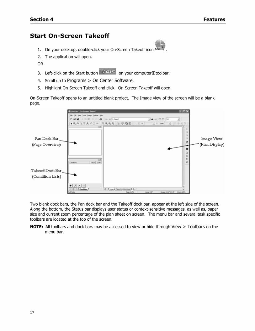
Section 4 Features
17
Start On-Screen Takeoff
1 On your desktop double-click your On-Screen Takeoff icon
2 The application will open
OR
3 Left-click on the Start button on your computerrsquos toolbar
4 Scroll up to Programs gt On Center Software
5 Highlight On-Screen Takeoff and click On-Screen Takeoff will open On-Screen Takeoff opens to an untitled blank project The Image view of the screen will be a blank page
Two blank dock bars the Pan dock bar and the Takeoff dock bar appear at the left side of the screen Along the bottom the Status bar displays user status or context-sensitive messages as well as paper size and current zoom percentage of the plan sheet on screen The menu bar and several task specific toolbars are located at the top of the screen
NOTE All toolbars and dock bars may be accessed to view or hide through View gt Toolbars on the menu bar
Section 4 Features
18
Quick Start Video When On-Screen Takeoff opens you will be given an option to watch the Quick Start video (recommended) or start the program without watching the video
The 20 minute video will demonstrate key program functionality and allow you to view application instruction for enhanced learning
If you would like to watch the video click If you prefer to get started without
the video click If you have already viewed the video click the lsquoDo not show this message againrsquo box to prevent this dialog from appearing each time you open the program
NOTE If you decide later that you would like to watch the Quick Start video go to Help gt Watch
Quick Start Videos
On-Screen Takeoff Environment The On-Screen Takeoff environment acts like your drafting table allowing you to work on several sheets of plans at once and to reference at a glance the entire drawing and your position on that drawing while giving you the power of a computer to track analyze print and export your takeoff quantities and plans
The screen is bordered at the top by the Menu bar with pull-down menus and at the bottom by the Status bar which indicates current user status plan page size and current zoom percentage of page The largest portion of the application screen will be your takeoff area bounded on the left (by default) by two dock bars and on the top by several toolbars
In the takeoff area you may view your project plans (images) andor takeoff objects the takeoff list with quantities the worksheet or a legend of your condition list
The main window of On-Screen Takeoff has three tabs located at the bottom left allowing for quick change between Image Takeoff or Worksheet views Select the desired view option on the toolbar and it will automatically open on your screen
Section 4 Features
19
Image View
This view shows the plan file andor takeoff conditions drawn from your plans
Takeoff View This view displays the height if applicable and quantity breakdowns of your conditions according to result types indicated (eg linear feet square feet or count of items) for zones pages and the project as a whole It also displays notes per condition
Section 4 Features
20
Worksheet View This view displays the condition and quantity in units of measure specified in the first results field of the Results tab in the Condition dialog and allows the user to enter amounts for material labor and subcontractor takeoffs
NOTE When in the Worksheet view tab out the field then save This is keep all the values saved
Navigating On-Screen Takeoff
Auto Scrolling When creating linear areas or zones On-Screen Takeoff will automatically scroll the image view when necessary It will move as your mouse or digitizer moves beyond the edge of the current view
Changing Pages
1 Select View gt Next Page Previous Page or Go To Page (specify page number for the Go to Page option)
2 You may also select the corresponding arrows for these options from the Navigate Toolbar The
drop down arrow in the Page field will list the pages The and arrows will take you to the
previous or next page The and arrows will take you to the first or last page
OR
Section 4 Features
21
3 Or press Ctrl G for the Go To Page dialog
Hot Links Hot links allow you to move quickly from one drawing to the pertinent area of another drawing A hot link is handy when viewing enlarged areas of a page and needing the ability to jump back to a reference page
1 Select Tools gt Hot Link
OR
2 Click from the Tools Toolbar
3 Click on the page where you want to set the link The Hot Link dialog will open
4 Using the current page display on the Navigate Toolbar access the pull-down menu of pages by
clicking on the arrow at the right
5 Select the page for your link (You may also choose View gt Go to Page and select by page number)
6 Manipulate the view using the zoom tool and the scroll bars
7 Click
8 After joining a hot link to another page the hot link arrows in the Navigation Toolbar will become active
9 Move a hot link to another location on the page by clicking then click and drag the hot link image anywhere on the page
Section 5
22
Projects
This section will
Help you create settings important to your projects
Explain how On-Screen Takeoff works with your electronic or paper plans
Section 5 Projects
23
Project Template Files You can begin your project with a template Templates allow you to take advantage of conditions and settings used with previous projects
On-Screen Takeoff templates contain condition lists and established layer separations from previous projects you have created You may also use the sample templates provided with On-Screen Takeoff as a great starting point All aspects of the templates may be adjusted for a new project
1 Select File gt New and click the OK button
2 From the New dialog box choose the template that best fits your project
3 The conditions for this template will appear in the Takeoff Dock bar and the Project Properties dialog will open asking for further information
4 Use File gt Save or File gt Save As to rename and save your new project
Saving a Project as a Template File You can save your condition properties and layers as a template for future projects
1 Select File gt Save As
2 Enter a name for your template and select On-Screen Takeoff Template Files (tpo) from the Save As type field of the dialog (click on the down arrow to select)
3 Click the OK button to accept and close the dialog Modifying a Template File Follow these steps to modify an existing template file if you need to change or add conditions andor layers
1 Select File gt Open
2 Navigate to your Projects directory
3 In the File Type drop-down select On-Screen Takeoff Template files (tpo)
4 Choose the On-Screen Takeoff template file you would like to modify and click the OK button
5 Make appropriate changes
6 Save and close file
The On-Screen Takeoff template files cannot save takeoff information
Section 5 Projects
24
Opening an Existing Project File 1 Select File gt Open
2 Navigate to the desired file location
3 Click the Open button
NOTE If your latest changes to a project file have not been saved On-Screen Takeoff will ask
you whether you would like to save the file and gives you the option of canceling the operation
Creating a New Project
1 Select File gt New
2 For a blank untitled project click
3 At this point the Project Properties dialog will pop-up for more information about your takeoff
NOTE The following are important to keep in mind when beginning a new project
At the start of your project fill out the Project Properties settings to establish the name for all printed output from your project set the default page size and scale for your plans number and names of different pages within the project and locations of electronic drawings
Scale settings can significantly affect quantity outcomes Be sure to set the scale for each page of drawings before beginning condition takeoffs
When using a digitizer remember to make a mark with a pen or pencil in the upper left and lower right corners of the first sheet of the paper plans to delineate the takeoff area for that sheet You can then set the takeoff area on On-Screen Takeoff using your marks
Save your project before you begin taking off any conditions On-Screen Takeoff will write a back-up file using the same file name
Remember the Undo feature If you make a mistake select Edit gt Undo and reverse the process step by step
Section 5 Projects
25
Project Properties
You can either set your Project Properties when you create a new takeoff or once your project file is saved under the appropriate name
1 Select File gt Project Properties the Project Properties dialog box will appear
2 Type in the name of your project to appear on printouts Use the backspace andor delete keys to edit the name as necessary
3 Press the Tab key to move to the Default Image Size option or click within the Image Size box You may click on the arrow at the right for the pull-down menu of page size options or you can use the down-arrow key on your keyboard to scroll through the list to the appropriate selection
4 Press the Tab key to move to the Default Scale option Select a scale by using the drop down arrow If your scale is metric you will need to click in the box next to Metric to convert to that measurement
5 Establish the number of pages for your project plans And load image files See Adding Pages to
Your Project
Adding Pages to Projects Individual Electronic Plans
1 Click on in the Project Properties dialog
2 In the Add Images dialog use the drop down arrow to navigate to the appropriate directory and folder containing your image
3 Select the file so that it displays in the File name field then click The file will display by name and path in the Image File field in Project Properties dialog
4 Click to accept and your project will automatically open
5 Save your project with the new settings by selecting File gt Save
Section 5 Projects
26
Electronic plans scanned from blueprints (as opposed to blue lines) will display as white lines on a black background and are difficult to read on your computer screen Select Image gt Invert and the colors will invert to black on white
You may have noticed the Page column in the Project Properties dialog Generally plan images occupy one page and 1 will be listed in the column indicating Page 1 of your plan file If you import a multi-page TIF a plan file containing more than one page of plans they will import as separate pages and each successive page will be indicated under the Page column as 1 2 3 etc of the plan file
Group of Electronic Plans You may add all the electronic plan files from a particular source (for example from a CD) by using the Auto Add feature
1 Click the button in the Project Properties dialog
2 Browse until you find the appropriate directory and folder containing your plan images
3 Click on any file displayed within your target folder so that the file name appears in the File name box of the Auto Add dialog
4 Click The image paths and file names will be recorded into the project properties arranged alphabetically
5 Click to accept your choices and your project will automatically open
6 Save your project with the new settings by selecting File gt Save
To load Dodge Plans into your Project Properties see Appendix IIi Loading Plans from a Dodge CD
Paper Plans On-Screen Takeoff makes it easy for Full Mode users to perform quantity takeoffs from paper plans using a digitizer
1 Add pages by clicking until you have the number of pages initially in the project
2 Name each page by clicking within the Title area and typing the name
3 Click to accept your choices and close the Project Properties dialog
4 Save your project with the new project properties settings by selecting File gt Save
Section 5 Projects
27
Setting Up a Drawing Template On-Screen Takeoff provides the convenience of using the same work surface for both digitizer and mouse to allow the user to draw conditions and then edit settings of the project or add or change conditions without breaking stride A mouse pad template included with the program defines the area of the digitizer in which use of the stylus or cursor will be recognized as mouse movement as opposed to drawing movement
1 Place your stylus on On-Screen Takeoff
2 Placing the template identifies the location mouse movements will be recognized by the program
Before placing the template the template must be applied to the digitizer surface This may have been done during the installation of your digitizer We suggest attaching the template to the lower right corner of the digitizer surface about one inch inside the grid area
3 Select Digitizer gt Place Template
4 Follow the instruction prompts on the screen clicking first on the target symbol at the left of the On-Screen Takeoff box on the template then on the target at the right
Setting Takeoff Area Before you can begin taking off a drawing you must define the drawing area on the digitizer This requires defining an area that will include all objects on each drawing of your plans As you add pages to your takeoff the same area of the digitizer will be active
1 Secure the plans to the digitizer with tape or a set of clamps
2 With a pen or a pencil mark the upper left corner and the lower right corner of the first page in your set of plans
3 Select Digitizer gt Set Takeoff Area
4 Click each mark with the stylus pen as prompted
5 Verify the active area of the digitizer by looking at the image size located in the lower right corner of your screen
If you close the program before the takeoff is complete you will need to reestablish the takeoff area before you can add additional condition quantities
Electronic plans appear on your computer screen eliminating the need to set a takeoff area You simply drag your mouse across the conditions you wish to takeoff The conditions will be highlighted and quantities will be totaled instantly Electronic plans are available through a variety of services For information contact an On Center Software account manager
Section 5 Projects
28
Setting Scale for Specific Pages You may set the scale in each page view separately This will override the default scale setting in Project Properties for that page Setting the correct scale for the drawing before taking off quantities ensures accurate calculations Be careful to check the scale for each drawing in your project before doing takeoffs
1 Display the page you want to set select Edit gt Set Scale
2 Use the drop down arrow to select a scale that will be applied to that page
3 Click
OR
4 Access the pull-down scale settings on the Navigate toolbar
NOTE As you draw objects notice that the drawn object is similar in width to the object on your plans If it is not the scale set may not be correct
Calculating Scale You may calculate scale according to a known measurement between two points either with a digitizer or on electronic plans
1 Select Edit gt Calculate Scale using Image or Edit gt Calculate Scale using Digitizer
2 Follow the instructions in the related Calculate Scale dialog box You will be asked to click on the first and second points then to enter the dimension for that distance
3 The scale will be recalculated for the displayed page and the Scale display on the Navigate toolbar will show the new scale
Section 6
29
Conditions and Takeoff
This section will Draw Conditions to Takeoff Plan Quantities
What Zones will do to help your takeoff process
Discuss the ins and outs of Takeoffs
Section 6 Conditions and Takeoff
30
Creating Conditions
If you are starting a new project from scratch you will need to create conditions to takeoff quantities such as floor areas wall lengths and corner bead counts If you are using a template you will have several pre-designed conditions already listed on the Takeoff dock bar However you may want to change the characteristics of some conditions or create additional conditions for a particular project
1 Right Click within the Takeoff dock bar Select New gt Condition
Or
2 From the Takeoff dock bar Click (if the buttons are not showing right-click in the Takeoff dock bar area and select Show Buttons from the pop-up menu) The New Condition dialog appears
3 Select the condition type (Linear Area Count or Zone) from the pull-down menu accessed by the
down arrow next to the Type option
4 Press Tab or use the mouse (or stylus) to move to Name and enter a name for your condition
5 Specify the desired condition attributes See Condition Attributes for more detail
6 Click for condition to apply
Section 6 Conditions and Takeoff
31
Condition Attributes Each condition type will have related attributes to select or specify within the General and Advanced tabs of the New Condition dialog Once a condition has been used to takeoff a quantity from your plans certain attributes cannot be changed
All conditions allow the user to specify color and fill pattern for the object drawn
Linear Conditions
General Specify width and height by feet and inches Specify pitch in inches up to the nearest thousandth of an inch if applicable
Advanced Specify rounding for object quantities and droprun default length for electrical or plumbing drops at the ends of lines Select Connect to have lines connect at the corners where one line of the condition ends and another begins (and indicate Tolerance for the featurersquos activation as distance between the ends of two lines) Choose Trim to have lines automatically trim to a line being crossed Choose Curve to draw a curved line
Follow these examples for inputting feet and inches For 7 feet 6 inches type 706 for 13 feet 7 inches type 1307 For 20 feet type 2000
Section 6 Conditions and Takeoff
32
Area Conditions
General If needed you can specify the thickness (in inches) andor pitch (in inches)
Advanced Specify rounding for object quantities Choose to display an adjustable grid within the area and indicate matrix cell dimensions
Section 6 Conditions and Takeoff
33
Count Conditions
General
Specify height and indicate the size (in inches) and shape (square circle triangle rectangle or opening) of the count object as it will appear on screen
Advanced Count conditions have advanced attributes These options are available for all shapes except for openings
Zone Conditions Zones allow you to subdivide condition quantities making it easier to modify and complete jobs in phases They can be used at the end of a takeoff to isolate a group of condition quantities that are in different areas of the takeoff
Zones can also be used to break a takeoff into multi-phases and can even be used to isolate quantities while a job is in progress to group the amount of work that has been completed to date They can be applied to one or multiple pages in your plans automatically calculating the takeoff quantities for each zoned area
Section 6 Conditions and Takeoff
34
The zone feature is only available in Lite and Full Mode If you are in View Mode and would like
to use this feature click from the main toolbar to purchase the upgrade
Condition Notes A Note tab is provided for comments regarding the condition These notes will display on the Takeoff List report and will import into Quick Bid
Section 6 Conditions and Takeoff
35
Condition Results The Results tab of the New Condition is based on condition type Initial settings default to linear feet (LF) for linear conditions square feet (SF) for area conditions and count of items (EA) for count conditions and zones The first of the results fields will display for the condition items in the Takeoff dock bar area All results will display in worksheets and Takeoff List reports as well as in an Excel spreadsheet after being exported
Copying Conditions You may use the condition attributes from a condition yoursquove already created for any future conditions of the same type
1 Click on a condition to select it
2 Click the Copy button from the toolbar
OR
3 Right-click in the Takeoff dock bar area and select copy
4 A new condition will appear in the list with the same condition attributes as the previous condition but with the quantities zeroed
Editing Conditions Once you have copied a condition you might want to change several attributes You can also edit an existing condition to fit any updated needs
1 Highlight the desired condition on the Takeoff dock bar
2 Click the Change button
OR
3 Double-click on the condition you wish to edit to bring up the Change Condition dialog
NOTE The Change Condition dialog differs from the New Condition dialog only in that if takeoffs
Section 6 Conditions and Takeoff
36
have been performed in your project with this condition you will not be able to change the type of condition or certain properties under the advanced tab of the dialog box
Deleting Conditions 1 Click on the condition in the Takeoff Dock bar area
2 Click the Delete button on the toolbar
OR
3 Right-click and select Delete from the pop-up menu
All takeoff associated with the deleted condition will be deleted immediately and permanently
Organizing Project Conditions Within your project you can create folders andor sub-folders for different types of conditions You may even want to create a folder containing conditions with reset values
To get started organizing your conditions make sure you are viewing the condition tree (right-click in the Takeoff dock bar area and select Show Tree)
Creating Folders and Sub-Folders 1 Right-click in the Takeoff Dock bar area
2 Select New gt Folder from the pop-up menu
Copying Folders
1 Click on the folder and click Copy on the toolbar
2 All copied conditions within the new folder will have values reset to zero
Renaming Folders
1 Click on the folder
2 Right-click and select Rename from the pop-up menu
3 Enter a name for your folder and click the Enter button
Changing Condition Order
You may move conditions up or down in the condition list of the Takeoff dock bar to suit your project needs
1 Select the condition you would like to move by clicking to highlight it
NOTE When you are ready to move the highlighted conditions be sure that you start
moving using the last condition chosen That condition will have a highlighted boarder
Section 6 Conditions and Takeoff
37
2 Drag and drop any the condition from one place to another in the list You may also move a condition to another folder on the list in this way
Drawing with Conditions Snap Angles Set up snap angles to prevent lines from appearing jagged Snap angles are commonly set at 15deg and shift snap angles at 0deg
1 Go to Tools gt Options Options dialog appears
2 Under the General tab make the desired settings
3 Click to save the settings As they are drawn lines will snap to the set degree
Drawing a Linear Object 1 Select a condition from the Condition List in the Takeoff dock bar
2 Move the cursor into the Image takeoff area of the screen you will see the cursor display as crosshairs
3 Click and hold left mouse button then drag mouse to draw a line
4 Release mouse button to set line
Section 6 Conditions and Takeoff
38
5 Repeat steps for further lines
Continuous Mode This feature allows you to draw an object that has connected lines
1 Click the icon from the Takeoff toolbar
OR
2 Go to Tools gt Continuous Mode
3 Follow steps 1-3 from Draw a Linear Object
4 Click at each point of intersection The object will be connected
5 Double-click after making the final point to set the lines
Drawing a Curve To draw a curved line the Curve option must be checked under the Advanced tab of the Condition dialog
1 Click where you want to begin the curve and drag in a straight line to the position for the other endpoint of the curve
2 Click on the line to select it Handles in the shapes of small squares will appear at either end of
Section 6 Conditions and Takeoff
39
the line and in the center of the line
3 Move the cursor over the center handles until the cursor becomes a two-way arrow
4 Click and drag in the direction of the curve bending the line as you move the cursor Release to set the curve (The line you began with will disappear)
Draw a circle by drawing two curved lines connected
Drawing an Area Object Area conditions are drawn similarly to continuous mode lines You may trace any number of adjoining walls at different angles to complete your area takeoff
NOTE When drawing an area do not intersect the perimeter or line of the object you are drawing
1 Click at each point
2 Double-click when yoursquove returned to your starting point
3 The area will be filled with the pattern set for that condition
NOTE The simulated circle will be good enough for you to be able to make a bid
To create a circular area click from point to point with very short distances in between points simulating a circlersquos perimeter Double-click after setting the last point to set the area
Section 6 Conditions and Takeoff
40
Grid Options Grids give you an added advantage when installing materials such as tiles Use this feature to get a count for how many tiles are needed for an area
1 Double-click on an area condition in the Takeoff dock bar to open its Condition dialog
2 Click on the Advanced tab to show its options
3 Check the box next to Grid by clicking in it
4 Indicate the dimensions of the cell matrix in inches (For example 200 x 400)
5 Under Results tab choose each (EA) for one of the results fields This will tabulate a number of grid cells (including partial grid cells) in area
6 Click to save your settings
7 Use the Move Grid and Rotate Grid features in the Tools menu to manipulate the grid as desired
Grid Calculation
1 Go to Tools gt Options menu
1 Specify if On-Screen Takeoff automatically should Calculate Grid Position
2 If AreaGrid Size is selected On-Screen Takeoff will calculate the number of items needed to fill the grid based on grid demintions
3 Click to accept and close the dialog
To move a line at any angle (regardless of default setting) press the Shift key while moving the mouse
Section 6 Conditions and Takeoff
41
Backout Mode This feature allows you to take out part of an area and deduct that amount of square footage
1 Select Tools gt Backout Mode
2 Outline the are you want backed out as you would when drawing a regular area object (see Drawing an Area Object)
3 The outlined area will clear and quantities will be recalculated
NOTE The perimeter of the backout area will be added to the LF quantity for that condition
Drawing a Count Object Square triangle rectangle and circle shaped count objects can easily be placed on images
1 Select the condition
2 Click in the location where you want the object to appear
3 To place an opening-shaped count item like a door or window you must click over an existing linear object such as a wall
4 On the Results tab you can change the height properties to give you the result you need
5 If Backout is checked on the advanced tab for each count opening the opening-shaped count item will back out a corresponding section of the linear object
Opening shaped count items are sized at 3rsquo0rdquo by default
Drawing a Zone Zones are drawn in the same way as area objects and may be any polygonal shape You may trace any number of adjoining walls at different angles to complete the zone perimeter
1 Click at each point
2 Double-click when yoursquove returned to your starting point
Section 6 Conditions and Takeoff
42
Selecting Objects
1 Use the Select Tool to select objects
You can also select all objects that correspond to a condition
1 Click on a condition to select it
2 Right-click and choose Select All
3 All objects with this condition will be highlighted with squares as an outline
Moving and Resizing Objects Linear
1 To move or resize a linear object click anywhere on the line to select it
2 To move the line position your pointer over the center handles When the mouse is positioned over the handles you will see a two-way arrow You will only be able to move the line in the direction of the arrows
3 Drag the line to a new position
4 Clicking and dragging the handles on the ends of the line will allow you to lengthen or shorten your line
Area and Zone
1 To move an area object or zone in its entirety click and drag it to its new position
2 Grabbing a handle at a corner or intersection of the object will allow you to adjust and change its perimeter
Section 6 Conditions and Takeoff
43
Count 1 To move a square circle rectangle or triangle shaped count object click and drag
2 Click and drag an opening shaped count object along the length of the linear object to the desired position then release
NOTE An opening shaped count object may not be moved from its associated linear condition object however it may be moved up and down the length of the linear object
Layers On-Screen Takeoff allows you to sort and separate your takeoff objects within the same job and on the same page On-Screen Takeoff gives you this flexibility through the use of layers
By assigning different conditions to different layers (for example differentiating between floors ceilings and walls) you can choose to view all layers or turn off certain layers to display and print the remaining groups of conditions only You may also remove the background image of electronic plans add text and hot link symbols or print only your condition takeoffs
Layers are only available in Full Mode If you are in View or Lite Mode and would like to use this
feature click from the main toolbar to purchase the upgrade Default Layers
On-Screen Takeoff begins every project with three default layers Image Annotation and Default The Image layer holds the electronic plan files you may have in your project The Annotation layer possesses all text notations highlighting and hot links in the project The Default layer will appear in the Condition dialog when creating or editing a condition (listed in the takeoff dock bar) Conditions are assigned to the Default layer unless otherwise specified by the user
Creating Layers To assign a condition to a layer other than the default layer you must first create additional layers for your project
1 Select View gt Layers to open the Layers dialog
2 Click An unnamed layer will be added
3 Click within the empty box and type a name for your layer (for example Wall)
4 New layers are added as active layers The adjacent box under the Show column will be checked
Section 6 Conditions and Takeoff
44
Assigning a Layer to a Condition 1 Open the Condition dialog box by creating a new condition or editing an existing condition
2 Under the General tab click on the down arrow in the Layer field to display optional layers
3 Select the desired layer for the condition Only the Default layer and layers you have added will be displayed
4 Click
View and Hide Layers
1 Select View gt Layers
2 Under the Show column check the box to view or remove the check (by clicking on it) to hide the specific layer
3 Click to accept and close the Layers dialog
Section 6 Conditions and Takeoff
45
Assigning Text to a Layer When adding text to an image On-Screen Takeoff has the capability to assign the text to a specified layer
1 Select the Text Tool
2 Click at the point you want to place your text
3 Type in your text using the Enter key for line breaks
4 Click the drop down arrow next to the Layer field and select the desired layer
Section 7
46
Printing and Exporting
This section will
Printing options and procedures
Exporting data by copying and pasting
Exporting quantity results to Excel spreadsheets
Section 7 Printing and Exporting
47
Print Setup On-Screen Takeoff allows the user to print the image takeoff list and worksheet
1 Select File gt Print Setup The Print Setup dialog will open
2 Select a printer or leave the default selection listed (change from the default printer displayed by clicking on the down arrow at the right of the field)
3 Indicate page size and printer tray option (Source) Access page size options by clicking on the
down arrow at the right of the field
4 Choose Portrait or Landscape orientation
5 Click to accept and close the dialog
Printing Images The image area can include the electronic plans the takeoff objects added text and hot links To print a subset of these (for example just the takeoffs without the plans or the added text and hot link symbols) hide layers that you do not want to print (see Section 6 View and Hide Layers) When you are printing your images every page will show the scale of the takeoff you are printing
1 Click on the Image tab to display the area of your project
2 Select File gt Print (or Ctrl + P)
Section 7 Printing and Exporting
48
3 Select the desired view (What to print) and the Image Range
4 Click The second Print dialog will open
5 Change settings accordingly or click if you accept the default settings
Printing Takeoff Lists and Worksheets In Takeoff Lists and Worksheets you may hide columns to print only certain results or adjust column widths to fit the report within the page size selected
1 In Takeoff List or Worksheet view move your cursor to the right side of the columnrsquos title bar the cursor will display as a two-way arrow
Section 7 Printing and Exporting
49
2 Click and drag to adjust the width of the column Holding the mouse button you may
slide the title bar under the title bar to its left to hide the column completely
3 Select File gt Print or press Ctrl + P to access the Print dialog
4 Indicate desired printer and choose the number of copies
5 Click to print and close the dialog
When printing the condition list we suggest printing in landscape
To reset to the default column widths double-click on the right border of a column heading will reset the column to its right (or previously to its right before being hidden)
Print Preview 1 Select File gt Print Preview
2 Use and to vary your view 3 If viewing an image choose current full or scale view to see how it displays
4 For printed outputs that cover more than one page use and to view adjacent pages or click on the down arrow next to Page field and select the page you want displayed
Exporting Using the CopyPaste Feature You may copy all the data or sections from the worksheet and the takeoff list view in On-Screen Takeoff and paste it into another application When pasting into Excel the cell layout will be maintained
1 Highlight the areas you wish to paste Click and hold the left mouse button down as you drag the cursor over the area to be selected then releasing the mouse button
OR
2 Select the entire takeoff list quickly click on the left On-Screen Takeoff column header and hold and drag the cursor across the remaining column headings
The number of pages for the view selected will display in the lower left-hand corner The zoom percentage that applies to the view will be displayed in the lower right-hand corner next to page size of the drawing
Section 7 Printing and Exporting
50
3 In the worksheet view you may highlight rows by clicking on the numbered buttons to the left of each row clicking and dragging across column headings or clicking and dragging over individual cells in the worksheet
Click anywhere in the appropriate view to deselect the area
4 Once your selection is highlighted you may select Edit gt Copy or Ctrl C from the keyboard 5 On your monitor switch to the application into which you want to paste your selection 6 Select Edit gt Paste in the new application or simply press Ctrl + V to paste
The colored keys for conditions cannot be pasted
Using the Export Feature You may export condition quantities to specified cell location within an Excel worksheet file Cell target locations are assigned in the Results tab of the condition dialogs on the Export line relating to each quantity measurement type
On-Screen Takeoff will export takeoff quantity results for up to three different quantity types that you specify For instance you may want to know the number of square feet in a ceiling area as well as the number of linear feet in its perimeter
Section 7 Printing and Exporting
51
1 Bring up the Condition dialog by double-clicking on a condition in the takeoff dock bar or by
selecting the condition and clicking
2 Click on the Results tab to access its fields The default quantities for the condition type will display
3 For each results field click on the arrow to access the pull-down menu and select the appropriate quantity (for example SF LF EA etchellip)
4 Have your Excel spreadsheet opened and saved in a file
5 Specify the Excel spreadsheet cell locations where you want the results to go
6 For a cell in the first sheet of your spreadsheet type in the cell address (eg a1) Case is not important
7 For a cell on a successive sheet of your spreadsheet type in sheet the number followed by a comma and the cell address without any spaces (eg sheet2a1) Case is not important
8 Click
9 Select File gt Export gt Condition Qty to Excel
Section 7 Printing and Exporting
52
10 Browse to the location of the Excel spreadsheet file click file to select it
11 Click to export On-Screen Takeoff results to specified cell locations in the Excel file When you return to the Excel application you will see the values have been added to the specified cell locations in your spreadsheet
12 Save your Excel file
Exporting Worksheet to Excel
1 Assign condition quantities you want to export
2 Open saved Excel spreadsheet file to which you will be exporting
3 From On-Screen Takeoff Select File gt Export gt Worksheet to Excel
4 Browse to the location of the Excel spreadsheet file click file to select it
5 Click When you return to the Excel application you will see the values from the Worksheet Tab have been added to your spreadsheet
6 Save your Excel file
Exporting Takeoff to CVS 1 Assign condition quantities you want to export
2 Open saved Excel spreadsheet file to which you will be exporting
3 Click the Takeoff Tab in the project you want to export the information
4 Select File gt Export gt Takeoff to CSV
5 Browse to the location of the CSV spreadsheet file click file to select it
6 Click the Save
NOTE CSV files can be opened in Excel Lotus Access etc One may consider this option more of a ldquodumprdquo into a file
The Excel application must be active (it may be minimized on the application bar) with the target spreadsheet open in the application Otherwise an error will occur with the export operation that will affect both the On-Screen Takeofftrade file and the Excel spreadsheet
Section 8
53
Advanced Features
This section will
Some special features of working with condition objects in the takeoff area
Details of advanced options for conditions
Advanced features of the Project Properties dialog
Section 8 Advanced Features
54
Features to Use with Objects Roping Feature You can move copy or delete using this feature Using the Select tool (the pointer) you may select several objects at once by clicking and dragging an outline around the objects then releasing the mouse button Roping may select either objects completely within the outlined area (inclusive) or objects both within and touched by the outlined area (touching) Specify your roping preference under Tools gt Options
1 Click and hold the mouse button at a point on the screen near the objects to be selected and drag to surround the objects with an outline
2 Release the mouse button The objects will be selected
3 You may now
Move the group around on the page by clicking within the group dragging the mouse and releasing the button to place the objects
Delete the group of objects by clicking the Delete key or
Copy and paste by pressing Ctrl C to copy the group then Ctrl V to paste it The pasted copy of the grouped objects will appear slightly offset from the original objects
Section 8 Advanced Features
55
Applying a DropRun Count
Use the droprun feature when calculating quantities to take into account the drop or run of a linear condition such as electrical lines or plumbing pipes Drop or run lengths may be added separately to any linear condition on screen while a default droprun length may be indicated for a condition as a whole
1 Select the desired linear condition from the Condition List in the Takeoff Dock bar
2 Click the Change button in the toolbar to open the Change Condition dialog
3 Click the Advanced tab to access the advanced options and click inside the DropRun check box
4 Enter a default length to be applied to all of this condition Entering 800 will be interpreted as 8 0 (You must enter both place markers for inches) You can leave the length blank and manually enter drop run on each segment drawn
5 Click the OK button to accept and close the dialog
Edit DropRun Count
1 With the related linear condition in the Takeoff Dock bar highlighted or with the pointer tool selected
2 click on the desired linear object in the image takeoff area The Count button will become active
3 Click on the Count button (alternatively select Tools gt Count) The default droprun amount will show in the pop-up Count dialog (Default length will be zero if droprun has not been selected in this conditionrsquos properties)
4 Type in the desired length Entering 800 will be interpreted as 8 0 (You must enter both place markers for inches)
5 Click the OK button The additional amount will be reflected in the corresponding quantity The new DropRun count will apply only to the object edited
Adding Text in Image View
On-Screen Takeoff allows you to place text comments around your quantity takeoffs that may be printed along with plan images and objects Text is automatically placed within the Annotation Layer (that includes text and hot links)
1 To place text on the image select the Text Tool and click at the point you want to place your text opening a text box
2 Type in your information clicking Enter for line breaks
3 When you are finished click the OK button to exit the text box
4 To reposition text simply click on the text (with the Text Tool active) to select it
5 Move the cursor over the text the cursor will now display as a four-way arrow
6 Click and drag the mouse to position the text as desired
Section 8 Advanced Features
56
1 To edit existing text use the Text Tool to double-click on the text to open the editing box
2 Enter additional text or use the Backspace key to delete text as necessary
Formatting Text Once created you may format the font size type style and color of your text
1 Click on the text to select it and select Tools gt Font or click on the Font button in the Takeoff Toolbar
2 Select the desired features (color options are disabled) and click the OK button
3 Click on the text to select it and select Tools gt Color or click on the Color button in the Takeoff Toolbar The Color dialog will open
4 Click on a color in the Basic Color palette or create a color and add to the Custom Colors palette (Be sure to click on the color in the Custom Colors palette to select it)
5 Click the OK button
Object Properties
Linear Objects
Linear objects may be set to connect at corners
A linear object may be set to trim automatically when crossing another linear object (Check the trim option under the advanced tab of the Condition dialog)
When you move a connected linear object objects automatically move and resize connected lines accordingly (quantities are then recalculated)
This feature requires that the connected linear object be moved using the center handles (does not apply when resizing the line from the ends)
Objects constrain to snap increments defined in the Tools gt Options menu (with the mouse 15deg by default incremental when shift key is held down)
Objects are measured from centerline to centerline
Section 8 Advanced Features
57
Area Objects When drawing an area use your escape key to undo the last line drawn You may reverse your
drawing of an area using the escape key
The area will not fill with color and pattern until the user double-clicks after the last line is set
Lines drawn to delineate an area object constrain to snap increments defined in the Tools gt Options menu (with the mouse 15deg by default incremental when shift key is held down)
After selecting an area to move or adjust position the mouse in the center to move the entire area position the mouse at the sides or corners to adjust the perimeter
Count Objects
All count objects are quantified by the physical number of objects per page and reported as EA for the UOM The quantity for the current Image View is (displayed in the Condition List) and the total quantity in your project is displayed in the Takeoff View and Worksheet View)
Square circle rectangle and triangle shaped count objects do not displace or subtract from other object quantities when placed on top of them However on the Advanced Tab for the count condition a connect property can be set (this is a check box) so that when a count object of this shape is put on top of a Linear type takeoff object it will move with the linear if said linear is moved
An opened-shaped count object must be placed within a linear object Opening shaped count objects may also be measured by linear foot or linear yard (EA SF and SY are also options) Opening shaped count items default to a width of 3rsquo 0rdquo at the time of creation This size can be changed The small medium and large size are not options on this type of condition anymore Check Backout on the Advanced tab for each Count object back out the footage (or yardage) of opening-shaped count objects in which they are placed
NOTE In order to see this Backout functionality (in quantity) for SY or SF deductions at least one of the
results for the Linear(s) this object will be placed on must be set to SY or SF and the count object must have a height quantity
Advanced Features of Conditions The Round Feature Under the Advanced tab of the linear and area Condition dialogues you may specify quantity rounding (in inches) For linear objects rounding applies to each linear object drawn For area objects rounding will apply to each segment of the area perimeter adjusting the perimeter and area calculations For example With a linear condition entering 12 in the Round field will round up each related linear object to the nearest 12 inches or one foot With this setting two walls of 1 4 would each round to 2 0 totaling 4 0
NOTE In the Takeoff Dock bar condition list and in the On-Screen Takeoff reports quantities will be displayed in whole numbers rounded up to the nearest foot However calculations are based on true quantities without rounding unless the Round Feature is engaged
Pitch Pitch may apply either to linear or area conditions It is measured in rise per linear foot Entering 12 indicates a 12 rise per 12 of linear distance (a pitch of 12 over 12) or an angle of 45deg
Section 8 Advanced Features
58
Advanced Features of Project Properties Selecting Multiple Pages
1 Select a single page entry by clicking on the numbered gray button to the left of the entry
2 Drag the cursor down the column of numbers to select consecutive pages
3 Click on the blank button at the top of this column to select all pages in the Properties dialog
Section 8 Advanced Features
59
Changing Image Assigned to a Drawing 1 Select the page entry by clicking on the numbered gray button to the left of the entry 2 Click the Change Image button The Change Image dialog box will appear
3 Navigate to the desired file and select by clicking on it
4 Click the Open button The electronic file assigned to the page will have been changed to reflect the new file choice
Changing Image File Path 1 Select pages as described above
2 Choose Change Folder
3 In the Change Folder dialog navigate to the appropriate folder
4 Click the OK button The file path will have been changed for the selected page entries
Delete a Page from Project Properties 1 Select the page you want to delete by clicking on its associated number (in the gray box at the
left of the entry)
2 Choose Delete Page
All Takeoff on the page will be deleted immediately and permanently
Section 8 Advanced Features
60
Advanced Features of Tool Options
Calculation Method On-Screen Takeoff has built-in calculation options to allow for faster work and faster saves until your takeoff is complete Calculation options are found by selecting Tools gt Options then clicking on the Calculation tab
Calculation method can be set to Automatic Automatic except Grids and Manual Manual will allow the program to operate more quickly while Automatic or Automatic except Grids allows the user to see quantity changes as takeoffs are made
In any mode you may press F9 to recalculate quantities for the On-Screen Takeoff current totals
Configuration Tab
When the ldquoPage Label (A01)rdquo radial button is chosen On-Screen Takeoff puts the numbered label on all the pages of in your current page indicator in your Navigate Toolbar If the Page Descriptionrdquo radial button is chosen then a description of what takeoff is on that specific page will be shown in your current page indicator in your Navigate Toolbar
This section of the configuration tab gives you options on how you want to export your information When the ldquoFolderSubfolder Namesrdquo radial button is chosen than on your file that you are exporting to will have all the conditions folders and subfolders In the Delimiter box you can choose the symbol that is needed to separate the information you are exporting Some files need semicolons () or colons () to make sure the information comes exported in is separated it the appropriate places
Section 8 Advanced Features
61
In previous versions of On-Screen Takeoff there are views that users need to have in order for them to display their information By either choosing ldquoOST 1xrdquo or ldquoOST 2xrdquo it will let the program know you want your columns of information exported in that specific format
When you have the Confirm Deletions radial button of ldquoYesrdquo chosen than every time you delete anything you will get a dialog box confirming your intentions of deletion
While working with your takeoff you have a choice to either view the legend of your conditions or hide it Choose whichever radial button that suits your needs
For those who prefer to use the Enter key to navigate in dialog boxes this option is just for that
Font Tab The Font tab is designed for you to make your own look and feel for the application At the bottom of this tab it will show you sample of the fonts and colors you have chosen
Renaming the Current Page You may change the name of the current page in the takeoff area of On-Screen Takeoff by selecting Edit gt Rename Page
This opens the Name Page dialog and you may simply type in a new name and click the Enter button The new name for the file will be reflected on the title bar for the page and in Project Properties
You also may access the Rename Page function by right-clicking in the takeoff area while in Image View and selecting the option from the pop-up menu that appears
Section 9
62
Saving and Exiting
This section will
Explain how to save projects
Show you how to safely exit the program
Section 9 Saving and Exiting
63
Saving Your Project
1 Select File gt Save 2 If your project has not previously been saved a Save dialog box will open to allow you to name
the file and choose the directory and folder in which to save your file 3 Once saved File gt Save will simply save the current version of the file
OR
4 Select File gt Save As then type in a new name for the file and save to the desired file path
The Auto-save Feature With the Auto-save feature On-Screen Takeoff automatically backs up your open project You may choose to have more than one level of backup files The first backup copy will have the extension b00 and successive files will be b01 b02 and so on If you have designated four levels of backup files after the fourth backup copy has been created (b03) the next file will be saved over the file with extension b00 Further backup saves will then rotate through the four backup files in the same way
1 Select Tools gt Options 2 In the Auto-save area (under the General tab) select the frequency of backup file creation (in
minutes) and the number of levels for the feature 3 You also may disengage the feature by clicking in the check box to clear it
The Auto-save feature automatically saves backup copies to the directory of the current project If you are working from a write-protected area such as a CD-ROM On-Screen Takeoff will place backup files in the On-Screen Takeoff folder
Exiting When you are finished using On-Screen Takeoff it is very easy to exit Exiting is very important because of security reasons If someone were to use your computer they could enter the application and view and manipulate information
Section 9 Saving and Exiting
64
On-Screen Takeoff closes the open project when you open another or create a new project or when you exit the program
1 Select File gt Exit
OR
2 You also may click at the upper right-hand corner of the application to exit
NOTE If your latest changes to a project file have not been saved On-Screen Takeoff will ask you whether you would like to save the file and gives you the option of canceling the operation
Appendix I Installing Your Digitizer
65
Appendix I Installing Your Digitizer When you get your digitizer from GTCO you will need to connect it to your computer Follow the instructions outlined below to do this
Note For rollup digitizers the metal bar must be oriented to the top or right hand side
Connecting the Digitizer 1 Lay the digitizer out flat 2 Connect the Stylus to the digitizer 3 Plug in the power adapter 4 Plug the interface (IO) cable into the digitizer 5 Plug the other end of the interface cable into an open serial port on computer
Note GTCO Technical support phone number is 410-381-6688 The electronic manual (on diskette) from GTCO contains more detailed installation and operation instructions for the GTCO digitizer model you have
Installing other Digitizer Drivers If you are using a GTCO Digitizer you will need to install the GTCO TabletWorks Drivers
If you are using a Digitizer not supported by GTCO Tablet Works 10 please contact the manufacturer of your digitizer for assistance with installation
Installing GTCO TabletWorks Drivers 1 Insert the On Center CD into the CD-ROM drive The CD Startup screen will open 2 Click on Install Software 3 Select Additional Software and Drivers 4 Select Digitizer Driver 5 Follow the instructions for installing TabletWorks 10
Adhering the Template The template is a small plastic sticker used to enable mouse function when using the digitizer with On-Screen Takeoff Place your template on your digitizer We suggest placing it in the bottom right corner of the digitizer about one inch inside the takeoff area
Note You may either peel off the back of the template and use the adhesive surface or you can tape the template down
Appendix I Installing Your Digitizer
66
Testing the Digitizer Drivers Before running OST you may test the digitizer by moving the stylus around on the digitizer pad it should move the mouse cursor (if mouse emulation is enabled)
If the digitizer does not move the mouse cursor on the screen
The superset codes may need to be reset Reset the superset codes by touching on the border of the digitizer with the stylus The digitizer should beep several times
The digitizer may not be communicating with the computer Be sure the COM port selected is correct Be sure the COM port selected is correct If you are not able to get the digitizer to move the mouse cursor you need to call GTCO technical support for help
Note The Mouse Emulation is not required for On-Screen Takeoff to work properly It is used only for the Template functionality if the digitizer is moving the cursor the wrong direction (up instead of sideways or vice-versa)
Click the L-shaped arrow symbol on the digitizer with the stylus
Appendix II Toolbar Item Details
67
Appendix II Toolbar Items Main Toolbar
Appendix II Toolbar Item Details
68
Tool Toolbar
Appendix II Toolbar Item Details
69
Zoom Toolbar
View Toolbar
Navigate Toolbar
Appendix II Toolbar Item Details
70
Navigate Toolbar (Continued)
Takeoff Toolbar
Appendix II Toolbar Item Details
71
Takeoff Toolbar (Continued)
Image Toolbar
Appendix III Loading Plans from a Dodge CD
72
Appendix III Loading Plans from a Dodge CD
This section will detail how to load plans from a F W Dodge CD-ROM into an On-Screen Takeoff project file ready for takeoffs
Dodge files may be added to the Project Properties dialog However loading the files in that way will load the files by number rather than name description If you want to load one page only from your Dodge CD You will have to rename the page to display the name rather than number of the file
To load plan files from a Dodge CD so that the files load sequentially by file number but are displayed by name rather than by number within your project follow the instructions below
Opening a Dodge project from a CD-ROM 1 Insert the CD into the drive 2 Choose File gt Custom 3 Choose Dodge Plans Project (plansdat) as the file type 4 Select the appropriate file type by clicking on the down arrow at the right of the Files of type
field 5 In the Look in field access your drive paths by clicking on the down arrow at the right of the
field then
Navigate to your CD-ROM drive Open the data folder and Open the Projects folder
6 Select the desired project and open its folder 7 Open the plansdat file 8 All the images will come in sequenced correctly for that job along with the full descriptions
(names) of each page If there is not a plans folder in the project folder then plans do not exist for that project on the CD Opening the plansdat file will yield an empty project
Appendix IV Using the Plan Viewer
73
Appendix IV Using On-Screen Takeoff Plan Viewer The On-Screen Takeoff Plan Viewer is a limited version of On Center Softwarersquos commercial takeoff software If your status bar located at the very bottom of the main window says View Mode in the lower left-hand corner then you are using the Plan Viewer You can use the plan viewer to
View CD-based amp converted CAD drawings
View a previously created OST file and associated drawings
Download electronic plans online
Navigate through drawings
Quickly Takeoff linearsareas and counts
Zoom in to view the plan better
Print drawings directly from the viewer
Viewing an On-Screen Takeoff Project File
1 To open an OST file that was previously created with of On-Screen Takeoff 2 Select File gt Open 3 An Open dialog will appear if you do not see the OST file you are looking for select the
Look In drop down arrow 4 A drop down menu will appear listing the various folders drives and mapped drives located
on your computer select the correct drive or folder location and continue to browse to the location of your OST file
5 When you see your OST file double-click it to open it 6 Any takeoff and drawings should appear on the Image tab view
If you do not see the drawings but do see the colored takeoff layer the drawings may
not be located in the same place they were originally saved at Go to File gt Project Properties and check the Image File path for each listed page If the image file path is pointing to a CD drive make sure the CD is inside the CR-ROM
Downloading Electronic Plans If your Online Plan Service provides a special file format (OSX) required to use this feature of our plan viewer you can immediately downloaded all electronic plans of a project directly from our viewer
Most Plan Room web sites will automatically open On-Screen Takeoff when a request to download plans is made Your particular Plan Room may differ in operation so please contact the provider directly with questions on using the site
Appendix IV Using the Plan Viewer
74
When you request to download or open a project file from a Plan Room you will usually have the open to open or save an OSX file Choosing open will automatically open On-Screen Takeoff Alternately you may choose to save the file to a local hard drive After you have saved the file either double-click it to launch On-Screen Takeoff or open the OSX file using On-Screen Takeoff by clicking File then Open and locating the file on your hard drive You will need to change the file type to OSX
After the OSX file is opened you will see an additional tab appear in the Conditions List window called Pages
The Pages tab shows the hierarchy of your project Gray file icons represent pages that have not been downloaded and blue icons represents pages that have been downloaded
To download a page simply double-click the page icon
If you wish to select a group of pages to download you can use the Ctrl or Shift key to multiple select them then click the Download button
If you wish to download all pages at once click the Download All button
Downloaded pages will now appear in the Project Properties dialog in the same order in which they appear in the Pages tab
Creating Quick Takeoffs With On-Screen Takeoff you can create quick takeoffs to measure quantities even if you dont have the full version of our program However using the Quick Takeoff functionality shows you just a fraction of what the full version can do
The Quick Takeoff Toolbar is located at the top of the image view It has three buttons designated for three types of takeoffs Linear Area and Count The Quantity drop down list will show secondary quantities for Linears and Areas The Units drop down allows you to select how you want your quantities displayed Feet Inches Yards Millimeters and Meters
NOTE Every time change the type of takeoff you are performing (switching from Area to Linear for example) the previous quantities and takeoff objects will disappear They will also disappear when you changes pages
NOTE You can use the Dimension Tool to basically measure the distance between two points or linears The distance will display on the status bar at the bottom of the application
The Quick Takeoff Toolbar
Appendix V Frequently Asked Questions
75
Appendix V Frequently Asked Questions General
Where is On-Screen Takeoff installed on my computer
Typically it is installed in CProgram FilesOn-Screen Takeoff
In Explorer how do I recognize On-Screen Takeoff file types
On-Screen Takeoff data is stored in a single file per job lsquojob name OSTrsquo On-Screen Takeoff templates are stored as lsquotemplate nameTPOrsquo
Can only one project at a time be open
Yes For that reason opening another project automatically closes the project on screen You will be asked to save any changes
Is only one scale allowed per page What about on drawings that have multiple detail sections on a page and each of those drawings have different scales
Yes For pages with drawings of different scales copy the drawing to another project page and set the appropriate scale
I cannot perform backout on an area that is along a linear
As a workaround use the On-Screen Takeoff layers feature to help you with this issue Electronic Images
How do I start a project from drawings that have been scanned and written to a CD-ROM
Open a new project Select File gt Project Properties and select Auto Add Navigate to your CD and the appropriate folder and select any image file in that location Click Open All files in the location will load into your project Recommended that images are copied from CD to hard drive for performance
If I get a disk of drawings in AutoCAD format (R13 or R14) can I read them in On-Screen Takeoff
Yes On-Screen Takeoff now reads DWG DXF and many other format that are saved with AutoCAD
Appendix V Frequently Asked Questions
76
When I click on the all pages button what is supposed to happen Currently nothing seems to change when I click on that button
The All Pages button is used to apply the Darken and Enhance Plans feature to all pages in the project (as opposed to only the current page on screen)
Is there a way to deduct a large skylight from an area condition
Yes with the related area condition selected in the Takeoff Dock bar unselect the Backout button on the Takeoff Toolbar then draw the Backout area The area quantity will be deducted from the related condition object and the linear measurement of the Backout perimeter will be added
Digitizer Issues
How do I connect a Digitizer to the computer
See Appendix I Connecting a Digitizer
The Place Template menu choice is disabled
On-Screen Takeoff may need to be authorized or the digitizer or the digitzer drivers are not installed
It wonrsquot let me select the Set Takeoff Area menu choice
On-Screen Takeoff may need to be authorized or no job is open a digitizer is not installed or the drivers are not installed
The digitizer stylus is not moving the cursor or crosshairs
Click S-0-1 superset on the digitizer
How do I convert my old GTCO Digitizer to work with On- Screen Takeofftrade
Call GTCO and they may be able to reconfigure your digitizer to be compatible with On-Screen Takeoff
Printing Issues Which Printers work with On-Screen Takeoff
Compatible printers include On-Screen Takeoff Hewlett Packard Epson and Canon printers If you are having printer difficulties please contact support and specify the type of printer along with other pertinent information Contact support at wwwoncentercomsupport or email supportoncentercom
Which Plotters work with On-Screen Takeoff
Compatible Plotters include Hewlett Packard DesignJet plotters and the EnCAD Cadjet II If you are having plotter difficulties please contact support and specify the type of plotter concerned
ViewingDisplay I can no longer see my condition list How do I get it back
The toolbars and Dock bars can be turned on and off through the View gt Toolbars menu options
Appendix V Frequently Asked Questions
77
This is also accessible by right-clicking in the toolbar area and selecting (or deselecting) a toolbar listed
I cannot view my folders in the condition list
Right-click in the Takeoff Dock barcondition list area and select Show Tree to display your folders
My Status Bar reads Viewer Mode and I am unable to draw conditions
On-Screen Takeoff needs to be Authorized Or you need to purchase an upgrade Click the Perform Advanced Takeoff button on the main toolbar
I hid a Dock bar and when I selected to view it again it appeared alongside the other Dock
bar instead of stacked on top of it How do I fix it
Pick up the Dock bar by clicking on the bar at the top and continuing to hold down the mouse button drag the Dock bar over the other one It will resize and appear stacked with the other
When I open image files from a CD the images are all upside down How do I get them right
side up
To flip pages from top to bottom follow the steps below 1 Click the All Pages button on the Image Toolbar (All Pages is engaged when the button
is not clicked) 2 Click the Flip Horizontal button on the Image Toolbar 3 Click the All Pages button again to disengage
Templates How do I create a Template
Follow the steps below 1 Create a typical project 2 Choose File gt Save As 3 Choose On-Screen Takeoff Template Files as the file type to save 4 Name the file This will save all of the condition setups as well as the layers for the
project
How do I create a new project from a template
Follow the steps below 1 Choose File gt New 2 Select a template from those listed in the New dialog This will open a new project with
conditions and layers saved from a previous project but no pages or takeoff
78
INDEX
Area Conditions 32
Area Objects 57
Auto Scrolling 20
Auto-save 63
Backout Mode 41
Calculation Method 60
Conditions 29
Configuration 60
Contents Tab 6
Continuous Mode 38
Count Conditions 33
Count Objects 57
Digitizer 10 65 76
Docking Toolbars 13
Dodge CD 72
Drawing 27 37
DropRun Count 55
Environment 18
Exiting 63
Exporting 49
Features 16
Font 61
Frequently Asked Questions 75
Grid 40
Help File 5
Hiding Toolbars 13
Hot Links 21
Image 19 59
Image files 9
Image Toolbar 12 71
Images 75
Index Tab 6
Layers 43
Linear Conditions 31
Linear Objects 56
Main Toolbar 12 67
Menus 14
Moving Toolbars 13
Navigate Toolbar 12 69
Navigating 20
On-Screen Takeofftrade 2
Page 59 61
Pages 20 25 28
Plan Viewer 73
Plans 26
Printing 47 76
Project Properties 25
Projects 22
Quick Start Video 18
Resizing Toolbars 13
Roping 54
Saving 63
Scale 28
Search Tab 7
Selecting Objects 42
Setup 8
Start On-Screen Takeofftrade 17
System Requirements 9
Takeoff 19 27
Takeoff Toolbar 70 71
Takeoff Toolbar 12
Template Files 23
TIF (Group4) 9
Tool Toolbar 12 68
Toolbar 67
Toolbars 12
View Toolbar 12 69
Viewing Toolbars 12
Worksheet 20
Zone Conditions 33
Zoom Toolbar 12 69
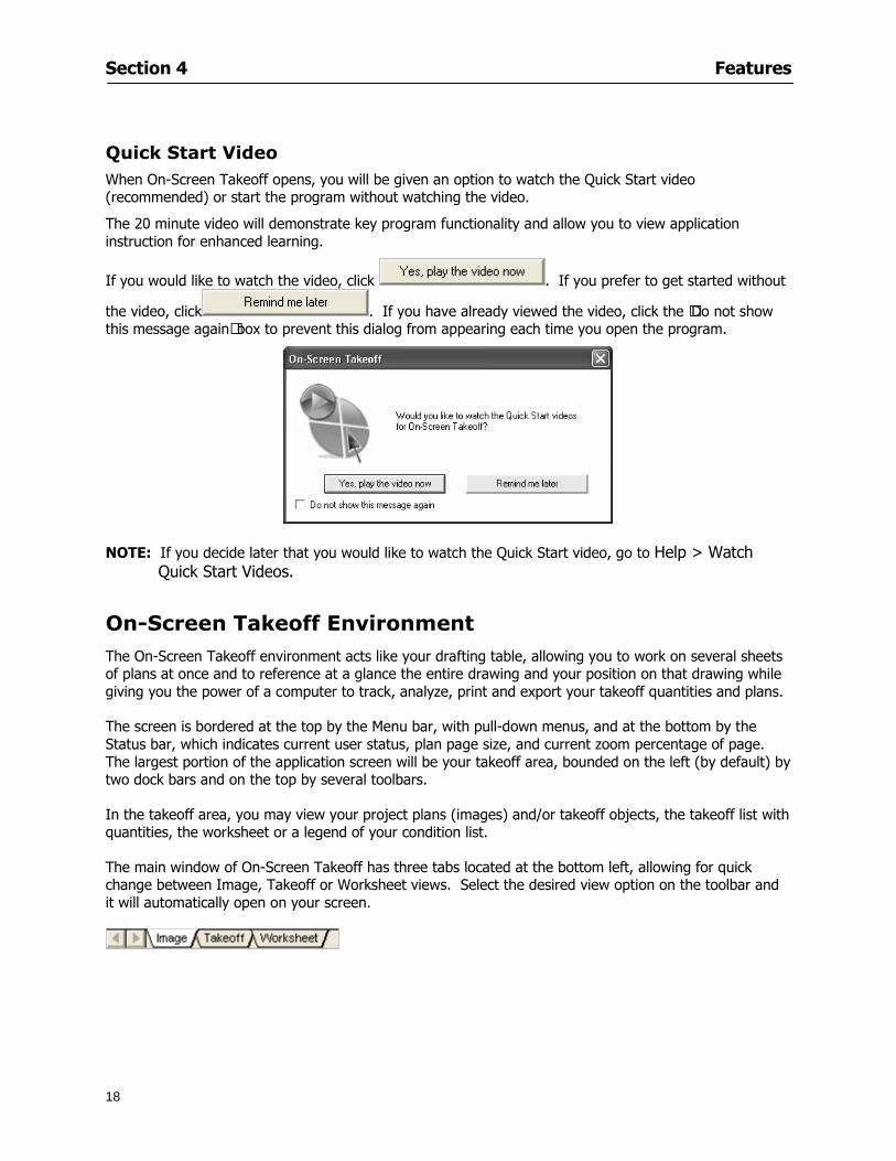
Section 4 Features
18
Quick Start Video When On-Screen Takeoff opens you will be given an option to watch the Quick Start video (recommended) or start the program without watching the video
The 20 minute video will demonstrate key program functionality and allow you to view application instruction for enhanced learning
If you would like to watch the video click If you prefer to get started without
the video click If you have already viewed the video click the lsquoDo not show this message againrsquo box to prevent this dialog from appearing each time you open the program
NOTE If you decide later that you would like to watch the Quick Start video go to Help gt Watch
Quick Start Videos
On-Screen Takeoff Environment The On-Screen Takeoff environment acts like your drafting table allowing you to work on several sheets of plans at once and to reference at a glance the entire drawing and your position on that drawing while giving you the power of a computer to track analyze print and export your takeoff quantities and plans
The screen is bordered at the top by the Menu bar with pull-down menus and at the bottom by the Status bar which indicates current user status plan page size and current zoom percentage of page The largest portion of the application screen will be your takeoff area bounded on the left (by default) by two dock bars and on the top by several toolbars
In the takeoff area you may view your project plans (images) andor takeoff objects the takeoff list with quantities the worksheet or a legend of your condition list
The main window of On-Screen Takeoff has three tabs located at the bottom left allowing for quick change between Image Takeoff or Worksheet views Select the desired view option on the toolbar and it will automatically open on your screen
Section 4 Features
19
Image View
This view shows the plan file andor takeoff conditions drawn from your plans
Takeoff View This view displays the height if applicable and quantity breakdowns of your conditions according to result types indicated (eg linear feet square feet or count of items) for zones pages and the project as a whole It also displays notes per condition
Section 4 Features
20
Worksheet View This view displays the condition and quantity in units of measure specified in the first results field of the Results tab in the Condition dialog and allows the user to enter amounts for material labor and subcontractor takeoffs
NOTE When in the Worksheet view tab out the field then save This is keep all the values saved
Navigating On-Screen Takeoff
Auto Scrolling When creating linear areas or zones On-Screen Takeoff will automatically scroll the image view when necessary It will move as your mouse or digitizer moves beyond the edge of the current view
Changing Pages
1 Select View gt Next Page Previous Page or Go To Page (specify page number for the Go to Page option)
2 You may also select the corresponding arrows for these options from the Navigate Toolbar The
drop down arrow in the Page field will list the pages The and arrows will take you to the
previous or next page The and arrows will take you to the first or last page
OR
Section 4 Features
21
3 Or press Ctrl G for the Go To Page dialog
Hot Links Hot links allow you to move quickly from one drawing to the pertinent area of another drawing A hot link is handy when viewing enlarged areas of a page and needing the ability to jump back to a reference page
1 Select Tools gt Hot Link
OR
2 Click from the Tools Toolbar
3 Click on the page where you want to set the link The Hot Link dialog will open
4 Using the current page display on the Navigate Toolbar access the pull-down menu of pages by
clicking on the arrow at the right
5 Select the page for your link (You may also choose View gt Go to Page and select by page number)
6 Manipulate the view using the zoom tool and the scroll bars
7 Click
8 After joining a hot link to another page the hot link arrows in the Navigation Toolbar will become active
9 Move a hot link to another location on the page by clicking then click and drag the hot link image anywhere on the page
Section 5
22
Projects
This section will
Help you create settings important to your projects
Explain how On-Screen Takeoff works with your electronic or paper plans
Section 5 Projects
23
Project Template Files You can begin your project with a template Templates allow you to take advantage of conditions and settings used with previous projects
On-Screen Takeoff templates contain condition lists and established layer separations from previous projects you have created You may also use the sample templates provided with On-Screen Takeoff as a great starting point All aspects of the templates may be adjusted for a new project
1 Select File gt New and click the OK button
2 From the New dialog box choose the template that best fits your project
3 The conditions for this template will appear in the Takeoff Dock bar and the Project Properties dialog will open asking for further information
4 Use File gt Save or File gt Save As to rename and save your new project
Saving a Project as a Template File You can save your condition properties and layers as a template for future projects
1 Select File gt Save As
2 Enter a name for your template and select On-Screen Takeoff Template Files (tpo) from the Save As type field of the dialog (click on the down arrow to select)
3 Click the OK button to accept and close the dialog Modifying a Template File Follow these steps to modify an existing template file if you need to change or add conditions andor layers
1 Select File gt Open
2 Navigate to your Projects directory
3 In the File Type drop-down select On-Screen Takeoff Template files (tpo)
4 Choose the On-Screen Takeoff template file you would like to modify and click the OK button
5 Make appropriate changes
6 Save and close file
The On-Screen Takeoff template files cannot save takeoff information
Section 5 Projects
24
Opening an Existing Project File 1 Select File gt Open
2 Navigate to the desired file location
3 Click the Open button
NOTE If your latest changes to a project file have not been saved On-Screen Takeoff will ask
you whether you would like to save the file and gives you the option of canceling the operation
Creating a New Project
1 Select File gt New
2 For a blank untitled project click
3 At this point the Project Properties dialog will pop-up for more information about your takeoff
NOTE The following are important to keep in mind when beginning a new project
At the start of your project fill out the Project Properties settings to establish the name for all printed output from your project set the default page size and scale for your plans number and names of different pages within the project and locations of electronic drawings
Scale settings can significantly affect quantity outcomes Be sure to set the scale for each page of drawings before beginning condition takeoffs
When using a digitizer remember to make a mark with a pen or pencil in the upper left and lower right corners of the first sheet of the paper plans to delineate the takeoff area for that sheet You can then set the takeoff area on On-Screen Takeoff using your marks
Save your project before you begin taking off any conditions On-Screen Takeoff will write a back-up file using the same file name
Remember the Undo feature If you make a mistake select Edit gt Undo and reverse the process step by step
Section 5 Projects
25
Project Properties
You can either set your Project Properties when you create a new takeoff or once your project file is saved under the appropriate name
1 Select File gt Project Properties the Project Properties dialog box will appear
2 Type in the name of your project to appear on printouts Use the backspace andor delete keys to edit the name as necessary
3 Press the Tab key to move to the Default Image Size option or click within the Image Size box You may click on the arrow at the right for the pull-down menu of page size options or you can use the down-arrow key on your keyboard to scroll through the list to the appropriate selection
4 Press the Tab key to move to the Default Scale option Select a scale by using the drop down arrow If your scale is metric you will need to click in the box next to Metric to convert to that measurement
5 Establish the number of pages for your project plans And load image files See Adding Pages to
Your Project
Adding Pages to Projects Individual Electronic Plans
1 Click on in the Project Properties dialog
2 In the Add Images dialog use the drop down arrow to navigate to the appropriate directory and folder containing your image
3 Select the file so that it displays in the File name field then click The file will display by name and path in the Image File field in Project Properties dialog
4 Click to accept and your project will automatically open
5 Save your project with the new settings by selecting File gt Save
Section 5 Projects
26
Electronic plans scanned from blueprints (as opposed to blue lines) will display as white lines on a black background and are difficult to read on your computer screen Select Image gt Invert and the colors will invert to black on white
You may have noticed the Page column in the Project Properties dialog Generally plan images occupy one page and 1 will be listed in the column indicating Page 1 of your plan file If you import a multi-page TIF a plan file containing more than one page of plans they will import as separate pages and each successive page will be indicated under the Page column as 1 2 3 etc of the plan file
Group of Electronic Plans You may add all the electronic plan files from a particular source (for example from a CD) by using the Auto Add feature
1 Click the button in the Project Properties dialog
2 Browse until you find the appropriate directory and folder containing your plan images
3 Click on any file displayed within your target folder so that the file name appears in the File name box of the Auto Add dialog
4 Click The image paths and file names will be recorded into the project properties arranged alphabetically
5 Click to accept your choices and your project will automatically open
6 Save your project with the new settings by selecting File gt Save
To load Dodge Plans into your Project Properties see Appendix IIi Loading Plans from a Dodge CD
Paper Plans On-Screen Takeoff makes it easy for Full Mode users to perform quantity takeoffs from paper plans using a digitizer
1 Add pages by clicking until you have the number of pages initially in the project
2 Name each page by clicking within the Title area and typing the name
3 Click to accept your choices and close the Project Properties dialog
4 Save your project with the new project properties settings by selecting File gt Save
Section 5 Projects
27
Setting Up a Drawing Template On-Screen Takeoff provides the convenience of using the same work surface for both digitizer and mouse to allow the user to draw conditions and then edit settings of the project or add or change conditions without breaking stride A mouse pad template included with the program defines the area of the digitizer in which use of the stylus or cursor will be recognized as mouse movement as opposed to drawing movement
1 Place your stylus on On-Screen Takeoff
2 Placing the template identifies the location mouse movements will be recognized by the program
Before placing the template the template must be applied to the digitizer surface This may have been done during the installation of your digitizer We suggest attaching the template to the lower right corner of the digitizer surface about one inch inside the grid area
3 Select Digitizer gt Place Template
4 Follow the instruction prompts on the screen clicking first on the target symbol at the left of the On-Screen Takeoff box on the template then on the target at the right
Setting Takeoff Area Before you can begin taking off a drawing you must define the drawing area on the digitizer This requires defining an area that will include all objects on each drawing of your plans As you add pages to your takeoff the same area of the digitizer will be active
1 Secure the plans to the digitizer with tape or a set of clamps
2 With a pen or a pencil mark the upper left corner and the lower right corner of the first page in your set of plans
3 Select Digitizer gt Set Takeoff Area
4 Click each mark with the stylus pen as prompted
5 Verify the active area of the digitizer by looking at the image size located in the lower right corner of your screen
If you close the program before the takeoff is complete you will need to reestablish the takeoff area before you can add additional condition quantities
Electronic plans appear on your computer screen eliminating the need to set a takeoff area You simply drag your mouse across the conditions you wish to takeoff The conditions will be highlighted and quantities will be totaled instantly Electronic plans are available through a variety of services For information contact an On Center Software account manager
Section 5 Projects
28
Setting Scale for Specific Pages You may set the scale in each page view separately This will override the default scale setting in Project Properties for that page Setting the correct scale for the drawing before taking off quantities ensures accurate calculations Be careful to check the scale for each drawing in your project before doing takeoffs
1 Display the page you want to set select Edit gt Set Scale
2 Use the drop down arrow to select a scale that will be applied to that page
3 Click
OR
4 Access the pull-down scale settings on the Navigate toolbar
NOTE As you draw objects notice that the drawn object is similar in width to the object on your plans If it is not the scale set may not be correct
Calculating Scale You may calculate scale according to a known measurement between two points either with a digitizer or on electronic plans
1 Select Edit gt Calculate Scale using Image or Edit gt Calculate Scale using Digitizer
2 Follow the instructions in the related Calculate Scale dialog box You will be asked to click on the first and second points then to enter the dimension for that distance
3 The scale will be recalculated for the displayed page and the Scale display on the Navigate toolbar will show the new scale
Section 6
29
Conditions and Takeoff
This section will Draw Conditions to Takeoff Plan Quantities
What Zones will do to help your takeoff process
Discuss the ins and outs of Takeoffs
Section 6 Conditions and Takeoff
30
Creating Conditions
If you are starting a new project from scratch you will need to create conditions to takeoff quantities such as floor areas wall lengths and corner bead counts If you are using a template you will have several pre-designed conditions already listed on the Takeoff dock bar However you may want to change the characteristics of some conditions or create additional conditions for a particular project
1 Right Click within the Takeoff dock bar Select New gt Condition
Or
2 From the Takeoff dock bar Click (if the buttons are not showing right-click in the Takeoff dock bar area and select Show Buttons from the pop-up menu) The New Condition dialog appears
3 Select the condition type (Linear Area Count or Zone) from the pull-down menu accessed by the
down arrow next to the Type option
4 Press Tab or use the mouse (or stylus) to move to Name and enter a name for your condition
5 Specify the desired condition attributes See Condition Attributes for more detail
6 Click for condition to apply
Section 6 Conditions and Takeoff
31
Condition Attributes Each condition type will have related attributes to select or specify within the General and Advanced tabs of the New Condition dialog Once a condition has been used to takeoff a quantity from your plans certain attributes cannot be changed
All conditions allow the user to specify color and fill pattern for the object drawn
Linear Conditions
General Specify width and height by feet and inches Specify pitch in inches up to the nearest thousandth of an inch if applicable
Advanced Specify rounding for object quantities and droprun default length for electrical or plumbing drops at the ends of lines Select Connect to have lines connect at the corners where one line of the condition ends and another begins (and indicate Tolerance for the featurersquos activation as distance between the ends of two lines) Choose Trim to have lines automatically trim to a line being crossed Choose Curve to draw a curved line
Follow these examples for inputting feet and inches For 7 feet 6 inches type 706 for 13 feet 7 inches type 1307 For 20 feet type 2000
Section 6 Conditions and Takeoff
32
Area Conditions
General If needed you can specify the thickness (in inches) andor pitch (in inches)
Advanced Specify rounding for object quantities Choose to display an adjustable grid within the area and indicate matrix cell dimensions
Section 6 Conditions and Takeoff
33
Count Conditions
General
Specify height and indicate the size (in inches) and shape (square circle triangle rectangle or opening) of the count object as it will appear on screen
Advanced Count conditions have advanced attributes These options are available for all shapes except for openings
Zone Conditions Zones allow you to subdivide condition quantities making it easier to modify and complete jobs in phases They can be used at the end of a takeoff to isolate a group of condition quantities that are in different areas of the takeoff
Zones can also be used to break a takeoff into multi-phases and can even be used to isolate quantities while a job is in progress to group the amount of work that has been completed to date They can be applied to one or multiple pages in your plans automatically calculating the takeoff quantities for each zoned area
Section 6 Conditions and Takeoff
34
The zone feature is only available in Lite and Full Mode If you are in View Mode and would like
to use this feature click from the main toolbar to purchase the upgrade
Condition Notes A Note tab is provided for comments regarding the condition These notes will display on the Takeoff List report and will import into Quick Bid
Section 6 Conditions and Takeoff
35
Condition Results The Results tab of the New Condition is based on condition type Initial settings default to linear feet (LF) for linear conditions square feet (SF) for area conditions and count of items (EA) for count conditions and zones The first of the results fields will display for the condition items in the Takeoff dock bar area All results will display in worksheets and Takeoff List reports as well as in an Excel spreadsheet after being exported
Copying Conditions You may use the condition attributes from a condition yoursquove already created for any future conditions of the same type
1 Click on a condition to select it
2 Click the Copy button from the toolbar
OR
3 Right-click in the Takeoff dock bar area and select copy
4 A new condition will appear in the list with the same condition attributes as the previous condition but with the quantities zeroed
Editing Conditions Once you have copied a condition you might want to change several attributes You can also edit an existing condition to fit any updated needs
1 Highlight the desired condition on the Takeoff dock bar
2 Click the Change button
OR
3 Double-click on the condition you wish to edit to bring up the Change Condition dialog
NOTE The Change Condition dialog differs from the New Condition dialog only in that if takeoffs
Section 6 Conditions and Takeoff
36
have been performed in your project with this condition you will not be able to change the type of condition or certain properties under the advanced tab of the dialog box
Deleting Conditions 1 Click on the condition in the Takeoff Dock bar area
2 Click the Delete button on the toolbar
OR
3 Right-click and select Delete from the pop-up menu
All takeoff associated with the deleted condition will be deleted immediately and permanently
Organizing Project Conditions Within your project you can create folders andor sub-folders for different types of conditions You may even want to create a folder containing conditions with reset values
To get started organizing your conditions make sure you are viewing the condition tree (right-click in the Takeoff dock bar area and select Show Tree)
Creating Folders and Sub-Folders 1 Right-click in the Takeoff Dock bar area
2 Select New gt Folder from the pop-up menu
Copying Folders
1 Click on the folder and click Copy on the toolbar
2 All copied conditions within the new folder will have values reset to zero
Renaming Folders
1 Click on the folder
2 Right-click and select Rename from the pop-up menu
3 Enter a name for your folder and click the Enter button
Changing Condition Order
You may move conditions up or down in the condition list of the Takeoff dock bar to suit your project needs
1 Select the condition you would like to move by clicking to highlight it
NOTE When you are ready to move the highlighted conditions be sure that you start
moving using the last condition chosen That condition will have a highlighted boarder
Section 6 Conditions and Takeoff
37
2 Drag and drop any the condition from one place to another in the list You may also move a condition to another folder on the list in this way
Drawing with Conditions Snap Angles Set up snap angles to prevent lines from appearing jagged Snap angles are commonly set at 15deg and shift snap angles at 0deg
1 Go to Tools gt Options Options dialog appears
2 Under the General tab make the desired settings
3 Click to save the settings As they are drawn lines will snap to the set degree
Drawing a Linear Object 1 Select a condition from the Condition List in the Takeoff dock bar
2 Move the cursor into the Image takeoff area of the screen you will see the cursor display as crosshairs
3 Click and hold left mouse button then drag mouse to draw a line
4 Release mouse button to set line
Section 6 Conditions and Takeoff
38
5 Repeat steps for further lines
Continuous Mode This feature allows you to draw an object that has connected lines
1 Click the icon from the Takeoff toolbar
OR
2 Go to Tools gt Continuous Mode
3 Follow steps 1-3 from Draw a Linear Object
4 Click at each point of intersection The object will be connected
5 Double-click after making the final point to set the lines
Drawing a Curve To draw a curved line the Curve option must be checked under the Advanced tab of the Condition dialog
1 Click where you want to begin the curve and drag in a straight line to the position for the other endpoint of the curve
2 Click on the line to select it Handles in the shapes of small squares will appear at either end of
Section 6 Conditions and Takeoff
39
the line and in the center of the line
3 Move the cursor over the center handles until the cursor becomes a two-way arrow
4 Click and drag in the direction of the curve bending the line as you move the cursor Release to set the curve (The line you began with will disappear)
Draw a circle by drawing two curved lines connected
Drawing an Area Object Area conditions are drawn similarly to continuous mode lines You may trace any number of adjoining walls at different angles to complete your area takeoff
NOTE When drawing an area do not intersect the perimeter or line of the object you are drawing
1 Click at each point
2 Double-click when yoursquove returned to your starting point
3 The area will be filled with the pattern set for that condition
NOTE The simulated circle will be good enough for you to be able to make a bid
To create a circular area click from point to point with very short distances in between points simulating a circlersquos perimeter Double-click after setting the last point to set the area
Section 6 Conditions and Takeoff
40
Grid Options Grids give you an added advantage when installing materials such as tiles Use this feature to get a count for how many tiles are needed for an area
1 Double-click on an area condition in the Takeoff dock bar to open its Condition dialog
2 Click on the Advanced tab to show its options
3 Check the box next to Grid by clicking in it
4 Indicate the dimensions of the cell matrix in inches (For example 200 x 400)
5 Under Results tab choose each (EA) for one of the results fields This will tabulate a number of grid cells (including partial grid cells) in area
6 Click to save your settings
7 Use the Move Grid and Rotate Grid features in the Tools menu to manipulate the grid as desired
Grid Calculation
1 Go to Tools gt Options menu
1 Specify if On-Screen Takeoff automatically should Calculate Grid Position
2 If AreaGrid Size is selected On-Screen Takeoff will calculate the number of items needed to fill the grid based on grid demintions
3 Click to accept and close the dialog
To move a line at any angle (regardless of default setting) press the Shift key while moving the mouse
Section 6 Conditions and Takeoff
41
Backout Mode This feature allows you to take out part of an area and deduct that amount of square footage
1 Select Tools gt Backout Mode
2 Outline the are you want backed out as you would when drawing a regular area object (see Drawing an Area Object)
3 The outlined area will clear and quantities will be recalculated
NOTE The perimeter of the backout area will be added to the LF quantity for that condition
Drawing a Count Object Square triangle rectangle and circle shaped count objects can easily be placed on images
1 Select the condition
2 Click in the location where you want the object to appear
3 To place an opening-shaped count item like a door or window you must click over an existing linear object such as a wall
4 On the Results tab you can change the height properties to give you the result you need
5 If Backout is checked on the advanced tab for each count opening the opening-shaped count item will back out a corresponding section of the linear object
Opening shaped count items are sized at 3rsquo0rdquo by default
Drawing a Zone Zones are drawn in the same way as area objects and may be any polygonal shape You may trace any number of adjoining walls at different angles to complete the zone perimeter
1 Click at each point
2 Double-click when yoursquove returned to your starting point
Section 6 Conditions and Takeoff
42
Selecting Objects
1 Use the Select Tool to select objects
You can also select all objects that correspond to a condition
1 Click on a condition to select it
2 Right-click and choose Select All
3 All objects with this condition will be highlighted with squares as an outline
Moving and Resizing Objects Linear
1 To move or resize a linear object click anywhere on the line to select it
2 To move the line position your pointer over the center handles When the mouse is positioned over the handles you will see a two-way arrow You will only be able to move the line in the direction of the arrows
3 Drag the line to a new position
4 Clicking and dragging the handles on the ends of the line will allow you to lengthen or shorten your line
Area and Zone
1 To move an area object or zone in its entirety click and drag it to its new position
2 Grabbing a handle at a corner or intersection of the object will allow you to adjust and change its perimeter
Section 6 Conditions and Takeoff
43
Count 1 To move a square circle rectangle or triangle shaped count object click and drag
2 Click and drag an opening shaped count object along the length of the linear object to the desired position then release
NOTE An opening shaped count object may not be moved from its associated linear condition object however it may be moved up and down the length of the linear object
Layers On-Screen Takeoff allows you to sort and separate your takeoff objects within the same job and on the same page On-Screen Takeoff gives you this flexibility through the use of layers
By assigning different conditions to different layers (for example differentiating between floors ceilings and walls) you can choose to view all layers or turn off certain layers to display and print the remaining groups of conditions only You may also remove the background image of electronic plans add text and hot link symbols or print only your condition takeoffs
Layers are only available in Full Mode If you are in View or Lite Mode and would like to use this
feature click from the main toolbar to purchase the upgrade Default Layers
On-Screen Takeoff begins every project with three default layers Image Annotation and Default The Image layer holds the electronic plan files you may have in your project The Annotation layer possesses all text notations highlighting and hot links in the project The Default layer will appear in the Condition dialog when creating or editing a condition (listed in the takeoff dock bar) Conditions are assigned to the Default layer unless otherwise specified by the user
Creating Layers To assign a condition to a layer other than the default layer you must first create additional layers for your project
1 Select View gt Layers to open the Layers dialog
2 Click An unnamed layer will be added
3 Click within the empty box and type a name for your layer (for example Wall)
4 New layers are added as active layers The adjacent box under the Show column will be checked
Section 6 Conditions and Takeoff
44
Assigning a Layer to a Condition 1 Open the Condition dialog box by creating a new condition or editing an existing condition
2 Under the General tab click on the down arrow in the Layer field to display optional layers
3 Select the desired layer for the condition Only the Default layer and layers you have added will be displayed
4 Click
View and Hide Layers
1 Select View gt Layers
2 Under the Show column check the box to view or remove the check (by clicking on it) to hide the specific layer
3 Click to accept and close the Layers dialog
Section 6 Conditions and Takeoff
45
Assigning Text to a Layer When adding text to an image On-Screen Takeoff has the capability to assign the text to a specified layer
1 Select the Text Tool
2 Click at the point you want to place your text
3 Type in your text using the Enter key for line breaks
4 Click the drop down arrow next to the Layer field and select the desired layer
Section 7
46
Printing and Exporting
This section will
Printing options and procedures
Exporting data by copying and pasting
Exporting quantity results to Excel spreadsheets
Section 7 Printing and Exporting
47
Print Setup On-Screen Takeoff allows the user to print the image takeoff list and worksheet
1 Select File gt Print Setup The Print Setup dialog will open
2 Select a printer or leave the default selection listed (change from the default printer displayed by clicking on the down arrow at the right of the field)
3 Indicate page size and printer tray option (Source) Access page size options by clicking on the
down arrow at the right of the field
4 Choose Portrait or Landscape orientation
5 Click to accept and close the dialog
Printing Images The image area can include the electronic plans the takeoff objects added text and hot links To print a subset of these (for example just the takeoffs without the plans or the added text and hot link symbols) hide layers that you do not want to print (see Section 6 View and Hide Layers) When you are printing your images every page will show the scale of the takeoff you are printing
1 Click on the Image tab to display the area of your project
2 Select File gt Print (or Ctrl + P)
Section 7 Printing and Exporting
48
3 Select the desired view (What to print) and the Image Range
4 Click The second Print dialog will open
5 Change settings accordingly or click if you accept the default settings
Printing Takeoff Lists and Worksheets In Takeoff Lists and Worksheets you may hide columns to print only certain results or adjust column widths to fit the report within the page size selected
1 In Takeoff List or Worksheet view move your cursor to the right side of the columnrsquos title bar the cursor will display as a two-way arrow
Section 7 Printing and Exporting
49
2 Click and drag to adjust the width of the column Holding the mouse button you may
slide the title bar under the title bar to its left to hide the column completely
3 Select File gt Print or press Ctrl + P to access the Print dialog
4 Indicate desired printer and choose the number of copies
5 Click to print and close the dialog
When printing the condition list we suggest printing in landscape
To reset to the default column widths double-click on the right border of a column heading will reset the column to its right (or previously to its right before being hidden)
Print Preview 1 Select File gt Print Preview
2 Use and to vary your view 3 If viewing an image choose current full or scale view to see how it displays
4 For printed outputs that cover more than one page use and to view adjacent pages or click on the down arrow next to Page field and select the page you want displayed
Exporting Using the CopyPaste Feature You may copy all the data or sections from the worksheet and the takeoff list view in On-Screen Takeoff and paste it into another application When pasting into Excel the cell layout will be maintained
1 Highlight the areas you wish to paste Click and hold the left mouse button down as you drag the cursor over the area to be selected then releasing the mouse button
OR
2 Select the entire takeoff list quickly click on the left On-Screen Takeoff column header and hold and drag the cursor across the remaining column headings
The number of pages for the view selected will display in the lower left-hand corner The zoom percentage that applies to the view will be displayed in the lower right-hand corner next to page size of the drawing
Section 7 Printing and Exporting
50
3 In the worksheet view you may highlight rows by clicking on the numbered buttons to the left of each row clicking and dragging across column headings or clicking and dragging over individual cells in the worksheet
Click anywhere in the appropriate view to deselect the area
4 Once your selection is highlighted you may select Edit gt Copy or Ctrl C from the keyboard 5 On your monitor switch to the application into which you want to paste your selection 6 Select Edit gt Paste in the new application or simply press Ctrl + V to paste
The colored keys for conditions cannot be pasted
Using the Export Feature You may export condition quantities to specified cell location within an Excel worksheet file Cell target locations are assigned in the Results tab of the condition dialogs on the Export line relating to each quantity measurement type
On-Screen Takeoff will export takeoff quantity results for up to three different quantity types that you specify For instance you may want to know the number of square feet in a ceiling area as well as the number of linear feet in its perimeter
Section 7 Printing and Exporting
51
1 Bring up the Condition dialog by double-clicking on a condition in the takeoff dock bar or by
selecting the condition and clicking
2 Click on the Results tab to access its fields The default quantities for the condition type will display
3 For each results field click on the arrow to access the pull-down menu and select the appropriate quantity (for example SF LF EA etchellip)
4 Have your Excel spreadsheet opened and saved in a file
5 Specify the Excel spreadsheet cell locations where you want the results to go
6 For a cell in the first sheet of your spreadsheet type in the cell address (eg a1) Case is not important
7 For a cell on a successive sheet of your spreadsheet type in sheet the number followed by a comma and the cell address without any spaces (eg sheet2a1) Case is not important
8 Click
9 Select File gt Export gt Condition Qty to Excel
Section 7 Printing and Exporting
52
10 Browse to the location of the Excel spreadsheet file click file to select it
11 Click to export On-Screen Takeoff results to specified cell locations in the Excel file When you return to the Excel application you will see the values have been added to the specified cell locations in your spreadsheet
12 Save your Excel file
Exporting Worksheet to Excel
1 Assign condition quantities you want to export
2 Open saved Excel spreadsheet file to which you will be exporting
3 From On-Screen Takeoff Select File gt Export gt Worksheet to Excel
4 Browse to the location of the Excel spreadsheet file click file to select it
5 Click When you return to the Excel application you will see the values from the Worksheet Tab have been added to your spreadsheet
6 Save your Excel file
Exporting Takeoff to CVS 1 Assign condition quantities you want to export
2 Open saved Excel spreadsheet file to which you will be exporting
3 Click the Takeoff Tab in the project you want to export the information
4 Select File gt Export gt Takeoff to CSV
5 Browse to the location of the CSV spreadsheet file click file to select it
6 Click the Save
NOTE CSV files can be opened in Excel Lotus Access etc One may consider this option more of a ldquodumprdquo into a file
The Excel application must be active (it may be minimized on the application bar) with the target spreadsheet open in the application Otherwise an error will occur with the export operation that will affect both the On-Screen Takeofftrade file and the Excel spreadsheet
Section 8
53
Advanced Features
This section will
Some special features of working with condition objects in the takeoff area
Details of advanced options for conditions
Advanced features of the Project Properties dialog
Section 8 Advanced Features
54
Features to Use with Objects Roping Feature You can move copy or delete using this feature Using the Select tool (the pointer) you may select several objects at once by clicking and dragging an outline around the objects then releasing the mouse button Roping may select either objects completely within the outlined area (inclusive) or objects both within and touched by the outlined area (touching) Specify your roping preference under Tools gt Options
1 Click and hold the mouse button at a point on the screen near the objects to be selected and drag to surround the objects with an outline
2 Release the mouse button The objects will be selected
3 You may now
Move the group around on the page by clicking within the group dragging the mouse and releasing the button to place the objects
Delete the group of objects by clicking the Delete key or
Copy and paste by pressing Ctrl C to copy the group then Ctrl V to paste it The pasted copy of the grouped objects will appear slightly offset from the original objects
Section 8 Advanced Features
55
Applying a DropRun Count
Use the droprun feature when calculating quantities to take into account the drop or run of a linear condition such as electrical lines or plumbing pipes Drop or run lengths may be added separately to any linear condition on screen while a default droprun length may be indicated for a condition as a whole
1 Select the desired linear condition from the Condition List in the Takeoff Dock bar
2 Click the Change button in the toolbar to open the Change Condition dialog
3 Click the Advanced tab to access the advanced options and click inside the DropRun check box
4 Enter a default length to be applied to all of this condition Entering 800 will be interpreted as 8 0 (You must enter both place markers for inches) You can leave the length blank and manually enter drop run on each segment drawn
5 Click the OK button to accept and close the dialog
Edit DropRun Count
1 With the related linear condition in the Takeoff Dock bar highlighted or with the pointer tool selected
2 click on the desired linear object in the image takeoff area The Count button will become active
3 Click on the Count button (alternatively select Tools gt Count) The default droprun amount will show in the pop-up Count dialog (Default length will be zero if droprun has not been selected in this conditionrsquos properties)
4 Type in the desired length Entering 800 will be interpreted as 8 0 (You must enter both place markers for inches)
5 Click the OK button The additional amount will be reflected in the corresponding quantity The new DropRun count will apply only to the object edited
Adding Text in Image View
On-Screen Takeoff allows you to place text comments around your quantity takeoffs that may be printed along with plan images and objects Text is automatically placed within the Annotation Layer (that includes text and hot links)
1 To place text on the image select the Text Tool and click at the point you want to place your text opening a text box
2 Type in your information clicking Enter for line breaks
3 When you are finished click the OK button to exit the text box
4 To reposition text simply click on the text (with the Text Tool active) to select it
5 Move the cursor over the text the cursor will now display as a four-way arrow
6 Click and drag the mouse to position the text as desired
Section 8 Advanced Features
56
1 To edit existing text use the Text Tool to double-click on the text to open the editing box
2 Enter additional text or use the Backspace key to delete text as necessary
Formatting Text Once created you may format the font size type style and color of your text
1 Click on the text to select it and select Tools gt Font or click on the Font button in the Takeoff Toolbar
2 Select the desired features (color options are disabled) and click the OK button
3 Click on the text to select it and select Tools gt Color or click on the Color button in the Takeoff Toolbar The Color dialog will open
4 Click on a color in the Basic Color palette or create a color and add to the Custom Colors palette (Be sure to click on the color in the Custom Colors palette to select it)
5 Click the OK button
Object Properties
Linear Objects
Linear objects may be set to connect at corners
A linear object may be set to trim automatically when crossing another linear object (Check the trim option under the advanced tab of the Condition dialog)
When you move a connected linear object objects automatically move and resize connected lines accordingly (quantities are then recalculated)
This feature requires that the connected linear object be moved using the center handles (does not apply when resizing the line from the ends)
Objects constrain to snap increments defined in the Tools gt Options menu (with the mouse 15deg by default incremental when shift key is held down)
Objects are measured from centerline to centerline
Section 8 Advanced Features
57
Area Objects When drawing an area use your escape key to undo the last line drawn You may reverse your
drawing of an area using the escape key
The area will not fill with color and pattern until the user double-clicks after the last line is set
Lines drawn to delineate an area object constrain to snap increments defined in the Tools gt Options menu (with the mouse 15deg by default incremental when shift key is held down)
After selecting an area to move or adjust position the mouse in the center to move the entire area position the mouse at the sides or corners to adjust the perimeter
Count Objects
All count objects are quantified by the physical number of objects per page and reported as EA for the UOM The quantity for the current Image View is (displayed in the Condition List) and the total quantity in your project is displayed in the Takeoff View and Worksheet View)
Square circle rectangle and triangle shaped count objects do not displace or subtract from other object quantities when placed on top of them However on the Advanced Tab for the count condition a connect property can be set (this is a check box) so that when a count object of this shape is put on top of a Linear type takeoff object it will move with the linear if said linear is moved
An opened-shaped count object must be placed within a linear object Opening shaped count objects may also be measured by linear foot or linear yard (EA SF and SY are also options) Opening shaped count items default to a width of 3rsquo 0rdquo at the time of creation This size can be changed The small medium and large size are not options on this type of condition anymore Check Backout on the Advanced tab for each Count object back out the footage (or yardage) of opening-shaped count objects in which they are placed
NOTE In order to see this Backout functionality (in quantity) for SY or SF deductions at least one of the
results for the Linear(s) this object will be placed on must be set to SY or SF and the count object must have a height quantity
Advanced Features of Conditions The Round Feature Under the Advanced tab of the linear and area Condition dialogues you may specify quantity rounding (in inches) For linear objects rounding applies to each linear object drawn For area objects rounding will apply to each segment of the area perimeter adjusting the perimeter and area calculations For example With a linear condition entering 12 in the Round field will round up each related linear object to the nearest 12 inches or one foot With this setting two walls of 1 4 would each round to 2 0 totaling 4 0
NOTE In the Takeoff Dock bar condition list and in the On-Screen Takeoff reports quantities will be displayed in whole numbers rounded up to the nearest foot However calculations are based on true quantities without rounding unless the Round Feature is engaged
Pitch Pitch may apply either to linear or area conditions It is measured in rise per linear foot Entering 12 indicates a 12 rise per 12 of linear distance (a pitch of 12 over 12) or an angle of 45deg
Section 8 Advanced Features
58
Advanced Features of Project Properties Selecting Multiple Pages
1 Select a single page entry by clicking on the numbered gray button to the left of the entry
2 Drag the cursor down the column of numbers to select consecutive pages
3 Click on the blank button at the top of this column to select all pages in the Properties dialog
Section 8 Advanced Features
59
Changing Image Assigned to a Drawing 1 Select the page entry by clicking on the numbered gray button to the left of the entry 2 Click the Change Image button The Change Image dialog box will appear
3 Navigate to the desired file and select by clicking on it
4 Click the Open button The electronic file assigned to the page will have been changed to reflect the new file choice
Changing Image File Path 1 Select pages as described above
2 Choose Change Folder
3 In the Change Folder dialog navigate to the appropriate folder
4 Click the OK button The file path will have been changed for the selected page entries
Delete a Page from Project Properties 1 Select the page you want to delete by clicking on its associated number (in the gray box at the
left of the entry)
2 Choose Delete Page
All Takeoff on the page will be deleted immediately and permanently
Section 8 Advanced Features
60
Advanced Features of Tool Options
Calculation Method On-Screen Takeoff has built-in calculation options to allow for faster work and faster saves until your takeoff is complete Calculation options are found by selecting Tools gt Options then clicking on the Calculation tab
Calculation method can be set to Automatic Automatic except Grids and Manual Manual will allow the program to operate more quickly while Automatic or Automatic except Grids allows the user to see quantity changes as takeoffs are made
In any mode you may press F9 to recalculate quantities for the On-Screen Takeoff current totals
Configuration Tab
When the ldquoPage Label (A01)rdquo radial button is chosen On-Screen Takeoff puts the numbered label on all the pages of in your current page indicator in your Navigate Toolbar If the Page Descriptionrdquo radial button is chosen then a description of what takeoff is on that specific page will be shown in your current page indicator in your Navigate Toolbar
This section of the configuration tab gives you options on how you want to export your information When the ldquoFolderSubfolder Namesrdquo radial button is chosen than on your file that you are exporting to will have all the conditions folders and subfolders In the Delimiter box you can choose the symbol that is needed to separate the information you are exporting Some files need semicolons () or colons () to make sure the information comes exported in is separated it the appropriate places
Section 8 Advanced Features
61
In previous versions of On-Screen Takeoff there are views that users need to have in order for them to display their information By either choosing ldquoOST 1xrdquo or ldquoOST 2xrdquo it will let the program know you want your columns of information exported in that specific format
When you have the Confirm Deletions radial button of ldquoYesrdquo chosen than every time you delete anything you will get a dialog box confirming your intentions of deletion
While working with your takeoff you have a choice to either view the legend of your conditions or hide it Choose whichever radial button that suits your needs
For those who prefer to use the Enter key to navigate in dialog boxes this option is just for that
Font Tab The Font tab is designed for you to make your own look and feel for the application At the bottom of this tab it will show you sample of the fonts and colors you have chosen
Renaming the Current Page You may change the name of the current page in the takeoff area of On-Screen Takeoff by selecting Edit gt Rename Page
This opens the Name Page dialog and you may simply type in a new name and click the Enter button The new name for the file will be reflected on the title bar for the page and in Project Properties
You also may access the Rename Page function by right-clicking in the takeoff area while in Image View and selecting the option from the pop-up menu that appears
Section 9
62
Saving and Exiting
This section will
Explain how to save projects
Show you how to safely exit the program
Section 9 Saving and Exiting
63
Saving Your Project
1 Select File gt Save 2 If your project has not previously been saved a Save dialog box will open to allow you to name
the file and choose the directory and folder in which to save your file 3 Once saved File gt Save will simply save the current version of the file
OR
4 Select File gt Save As then type in a new name for the file and save to the desired file path
The Auto-save Feature With the Auto-save feature On-Screen Takeoff automatically backs up your open project You may choose to have more than one level of backup files The first backup copy will have the extension b00 and successive files will be b01 b02 and so on If you have designated four levels of backup files after the fourth backup copy has been created (b03) the next file will be saved over the file with extension b00 Further backup saves will then rotate through the four backup files in the same way
1 Select Tools gt Options 2 In the Auto-save area (under the General tab) select the frequency of backup file creation (in
minutes) and the number of levels for the feature 3 You also may disengage the feature by clicking in the check box to clear it
The Auto-save feature automatically saves backup copies to the directory of the current project If you are working from a write-protected area such as a CD-ROM On-Screen Takeoff will place backup files in the On-Screen Takeoff folder
Exiting When you are finished using On-Screen Takeoff it is very easy to exit Exiting is very important because of security reasons If someone were to use your computer they could enter the application and view and manipulate information
Section 9 Saving and Exiting
64
On-Screen Takeoff closes the open project when you open another or create a new project or when you exit the program
1 Select File gt Exit
OR
2 You also may click at the upper right-hand corner of the application to exit
NOTE If your latest changes to a project file have not been saved On-Screen Takeoff will ask you whether you would like to save the file and gives you the option of canceling the operation
Appendix I Installing Your Digitizer
65
Appendix I Installing Your Digitizer When you get your digitizer from GTCO you will need to connect it to your computer Follow the instructions outlined below to do this
Note For rollup digitizers the metal bar must be oriented to the top or right hand side
Connecting the Digitizer 1 Lay the digitizer out flat 2 Connect the Stylus to the digitizer 3 Plug in the power adapter 4 Plug the interface (IO) cable into the digitizer 5 Plug the other end of the interface cable into an open serial port on computer
Note GTCO Technical support phone number is 410-381-6688 The electronic manual (on diskette) from GTCO contains more detailed installation and operation instructions for the GTCO digitizer model you have
Installing other Digitizer Drivers If you are using a GTCO Digitizer you will need to install the GTCO TabletWorks Drivers
If you are using a Digitizer not supported by GTCO Tablet Works 10 please contact the manufacturer of your digitizer for assistance with installation
Installing GTCO TabletWorks Drivers 1 Insert the On Center CD into the CD-ROM drive The CD Startup screen will open 2 Click on Install Software 3 Select Additional Software and Drivers 4 Select Digitizer Driver 5 Follow the instructions for installing TabletWorks 10
Adhering the Template The template is a small plastic sticker used to enable mouse function when using the digitizer with On-Screen Takeoff Place your template on your digitizer We suggest placing it in the bottom right corner of the digitizer about one inch inside the takeoff area
Note You may either peel off the back of the template and use the adhesive surface or you can tape the template down
Appendix I Installing Your Digitizer
66
Testing the Digitizer Drivers Before running OST you may test the digitizer by moving the stylus around on the digitizer pad it should move the mouse cursor (if mouse emulation is enabled)
If the digitizer does not move the mouse cursor on the screen
The superset codes may need to be reset Reset the superset codes by touching on the border of the digitizer with the stylus The digitizer should beep several times
The digitizer may not be communicating with the computer Be sure the COM port selected is correct Be sure the COM port selected is correct If you are not able to get the digitizer to move the mouse cursor you need to call GTCO technical support for help
Note The Mouse Emulation is not required for On-Screen Takeoff to work properly It is used only for the Template functionality if the digitizer is moving the cursor the wrong direction (up instead of sideways or vice-versa)
Click the L-shaped arrow symbol on the digitizer with the stylus
Appendix II Toolbar Item Details
67
Appendix II Toolbar Items Main Toolbar
Appendix II Toolbar Item Details
68
Tool Toolbar
Appendix II Toolbar Item Details
69
Zoom Toolbar
View Toolbar
Navigate Toolbar
Appendix II Toolbar Item Details
70
Navigate Toolbar (Continued)
Takeoff Toolbar
Appendix II Toolbar Item Details
71
Takeoff Toolbar (Continued)
Image Toolbar
Appendix III Loading Plans from a Dodge CD
72
Appendix III Loading Plans from a Dodge CD
This section will detail how to load plans from a F W Dodge CD-ROM into an On-Screen Takeoff project file ready for takeoffs
Dodge files may be added to the Project Properties dialog However loading the files in that way will load the files by number rather than name description If you want to load one page only from your Dodge CD You will have to rename the page to display the name rather than number of the file
To load plan files from a Dodge CD so that the files load sequentially by file number but are displayed by name rather than by number within your project follow the instructions below
Opening a Dodge project from a CD-ROM 1 Insert the CD into the drive 2 Choose File gt Custom 3 Choose Dodge Plans Project (plansdat) as the file type 4 Select the appropriate file type by clicking on the down arrow at the right of the Files of type
field 5 In the Look in field access your drive paths by clicking on the down arrow at the right of the
field then
Navigate to your CD-ROM drive Open the data folder and Open the Projects folder
6 Select the desired project and open its folder 7 Open the plansdat file 8 All the images will come in sequenced correctly for that job along with the full descriptions
(names) of each page If there is not a plans folder in the project folder then plans do not exist for that project on the CD Opening the plansdat file will yield an empty project
Appendix IV Using the Plan Viewer
73
Appendix IV Using On-Screen Takeoff Plan Viewer The On-Screen Takeoff Plan Viewer is a limited version of On Center Softwarersquos commercial takeoff software If your status bar located at the very bottom of the main window says View Mode in the lower left-hand corner then you are using the Plan Viewer You can use the plan viewer to
View CD-based amp converted CAD drawings
View a previously created OST file and associated drawings
Download electronic plans online
Navigate through drawings
Quickly Takeoff linearsareas and counts
Zoom in to view the plan better
Print drawings directly from the viewer
Viewing an On-Screen Takeoff Project File
1 To open an OST file that was previously created with of On-Screen Takeoff 2 Select File gt Open 3 An Open dialog will appear if you do not see the OST file you are looking for select the
Look In drop down arrow 4 A drop down menu will appear listing the various folders drives and mapped drives located
on your computer select the correct drive or folder location and continue to browse to the location of your OST file
5 When you see your OST file double-click it to open it 6 Any takeoff and drawings should appear on the Image tab view
If you do not see the drawings but do see the colored takeoff layer the drawings may
not be located in the same place they were originally saved at Go to File gt Project Properties and check the Image File path for each listed page If the image file path is pointing to a CD drive make sure the CD is inside the CR-ROM
Downloading Electronic Plans If your Online Plan Service provides a special file format (OSX) required to use this feature of our plan viewer you can immediately downloaded all electronic plans of a project directly from our viewer
Most Plan Room web sites will automatically open On-Screen Takeoff when a request to download plans is made Your particular Plan Room may differ in operation so please contact the provider directly with questions on using the site
Appendix IV Using the Plan Viewer
74
When you request to download or open a project file from a Plan Room you will usually have the open to open or save an OSX file Choosing open will automatically open On-Screen Takeoff Alternately you may choose to save the file to a local hard drive After you have saved the file either double-click it to launch On-Screen Takeoff or open the OSX file using On-Screen Takeoff by clicking File then Open and locating the file on your hard drive You will need to change the file type to OSX
After the OSX file is opened you will see an additional tab appear in the Conditions List window called Pages
The Pages tab shows the hierarchy of your project Gray file icons represent pages that have not been downloaded and blue icons represents pages that have been downloaded
To download a page simply double-click the page icon
If you wish to select a group of pages to download you can use the Ctrl or Shift key to multiple select them then click the Download button
If you wish to download all pages at once click the Download All button
Downloaded pages will now appear in the Project Properties dialog in the same order in which they appear in the Pages tab
Creating Quick Takeoffs With On-Screen Takeoff you can create quick takeoffs to measure quantities even if you dont have the full version of our program However using the Quick Takeoff functionality shows you just a fraction of what the full version can do
The Quick Takeoff Toolbar is located at the top of the image view It has three buttons designated for three types of takeoffs Linear Area and Count The Quantity drop down list will show secondary quantities for Linears and Areas The Units drop down allows you to select how you want your quantities displayed Feet Inches Yards Millimeters and Meters
NOTE Every time change the type of takeoff you are performing (switching from Area to Linear for example) the previous quantities and takeoff objects will disappear They will also disappear when you changes pages
NOTE You can use the Dimension Tool to basically measure the distance between two points or linears The distance will display on the status bar at the bottom of the application
The Quick Takeoff Toolbar
Appendix V Frequently Asked Questions
75
Appendix V Frequently Asked Questions General
Where is On-Screen Takeoff installed on my computer
Typically it is installed in CProgram FilesOn-Screen Takeoff
In Explorer how do I recognize On-Screen Takeoff file types
On-Screen Takeoff data is stored in a single file per job lsquojob name OSTrsquo On-Screen Takeoff templates are stored as lsquotemplate nameTPOrsquo
Can only one project at a time be open
Yes For that reason opening another project automatically closes the project on screen You will be asked to save any changes
Is only one scale allowed per page What about on drawings that have multiple detail sections on a page and each of those drawings have different scales
Yes For pages with drawings of different scales copy the drawing to another project page and set the appropriate scale
I cannot perform backout on an area that is along a linear
As a workaround use the On-Screen Takeoff layers feature to help you with this issue Electronic Images
How do I start a project from drawings that have been scanned and written to a CD-ROM
Open a new project Select File gt Project Properties and select Auto Add Navigate to your CD and the appropriate folder and select any image file in that location Click Open All files in the location will load into your project Recommended that images are copied from CD to hard drive for performance
If I get a disk of drawings in AutoCAD format (R13 or R14) can I read them in On-Screen Takeoff
Yes On-Screen Takeoff now reads DWG DXF and many other format that are saved with AutoCAD
Appendix V Frequently Asked Questions
76
When I click on the all pages button what is supposed to happen Currently nothing seems to change when I click on that button
The All Pages button is used to apply the Darken and Enhance Plans feature to all pages in the project (as opposed to only the current page on screen)
Is there a way to deduct a large skylight from an area condition
Yes with the related area condition selected in the Takeoff Dock bar unselect the Backout button on the Takeoff Toolbar then draw the Backout area The area quantity will be deducted from the related condition object and the linear measurement of the Backout perimeter will be added
Digitizer Issues
How do I connect a Digitizer to the computer
See Appendix I Connecting a Digitizer
The Place Template menu choice is disabled
On-Screen Takeoff may need to be authorized or the digitizer or the digitzer drivers are not installed
It wonrsquot let me select the Set Takeoff Area menu choice
On-Screen Takeoff may need to be authorized or no job is open a digitizer is not installed or the drivers are not installed
The digitizer stylus is not moving the cursor or crosshairs
Click S-0-1 superset on the digitizer
How do I convert my old GTCO Digitizer to work with On- Screen Takeofftrade
Call GTCO and they may be able to reconfigure your digitizer to be compatible with On-Screen Takeoff
Printing Issues Which Printers work with On-Screen Takeoff
Compatible printers include On-Screen Takeoff Hewlett Packard Epson and Canon printers If you are having printer difficulties please contact support and specify the type of printer along with other pertinent information Contact support at wwwoncentercomsupport or email supportoncentercom
Which Plotters work with On-Screen Takeoff
Compatible Plotters include Hewlett Packard DesignJet plotters and the EnCAD Cadjet II If you are having plotter difficulties please contact support and specify the type of plotter concerned
ViewingDisplay I can no longer see my condition list How do I get it back
The toolbars and Dock bars can be turned on and off through the View gt Toolbars menu options
Appendix V Frequently Asked Questions
77
This is also accessible by right-clicking in the toolbar area and selecting (or deselecting) a toolbar listed
I cannot view my folders in the condition list
Right-click in the Takeoff Dock barcondition list area and select Show Tree to display your folders
My Status Bar reads Viewer Mode and I am unable to draw conditions
On-Screen Takeoff needs to be Authorized Or you need to purchase an upgrade Click the Perform Advanced Takeoff button on the main toolbar
I hid a Dock bar and when I selected to view it again it appeared alongside the other Dock
bar instead of stacked on top of it How do I fix it
Pick up the Dock bar by clicking on the bar at the top and continuing to hold down the mouse button drag the Dock bar over the other one It will resize and appear stacked with the other
When I open image files from a CD the images are all upside down How do I get them right
side up
To flip pages from top to bottom follow the steps below 1 Click the All Pages button on the Image Toolbar (All Pages is engaged when the button
is not clicked) 2 Click the Flip Horizontal button on the Image Toolbar 3 Click the All Pages button again to disengage
Templates How do I create a Template
Follow the steps below 1 Create a typical project 2 Choose File gt Save As 3 Choose On-Screen Takeoff Template Files as the file type to save 4 Name the file This will save all of the condition setups as well as the layers for the
project
How do I create a new project from a template
Follow the steps below 1 Choose File gt New 2 Select a template from those listed in the New dialog This will open a new project with
conditions and layers saved from a previous project but no pages or takeoff
78
INDEX
Area Conditions 32
Area Objects 57
Auto Scrolling 20
Auto-save 63
Backout Mode 41
Calculation Method 60
Conditions 29
Configuration 60
Contents Tab 6
Continuous Mode 38
Count Conditions 33
Count Objects 57
Digitizer 10 65 76
Docking Toolbars 13
Dodge CD 72
Drawing 27 37
DropRun Count 55
Environment 18
Exiting 63
Exporting 49
Features 16
Font 61
Frequently Asked Questions 75
Grid 40
Help File 5
Hiding Toolbars 13
Hot Links 21
Image 19 59
Image files 9
Image Toolbar 12 71
Images 75
Index Tab 6
Layers 43
Linear Conditions 31
Linear Objects 56
Main Toolbar 12 67
Menus 14
Moving Toolbars 13
Navigate Toolbar 12 69
Navigating 20
On-Screen Takeofftrade 2
Page 59 61
Pages 20 25 28
Plan Viewer 73
Plans 26
Printing 47 76
Project Properties 25
Projects 22
Quick Start Video 18
Resizing Toolbars 13
Roping 54
Saving 63
Scale 28
Search Tab 7
Selecting Objects 42
Setup 8
Start On-Screen Takeofftrade 17
System Requirements 9
Takeoff 19 27
Takeoff Toolbar 70 71
Takeoff Toolbar 12
Template Files 23
TIF (Group4) 9
Tool Toolbar 12 68
Toolbar 67
Toolbars 12
View Toolbar 12 69
Viewing Toolbars 12
Worksheet 20
Zone Conditions 33
Zoom Toolbar 12 69
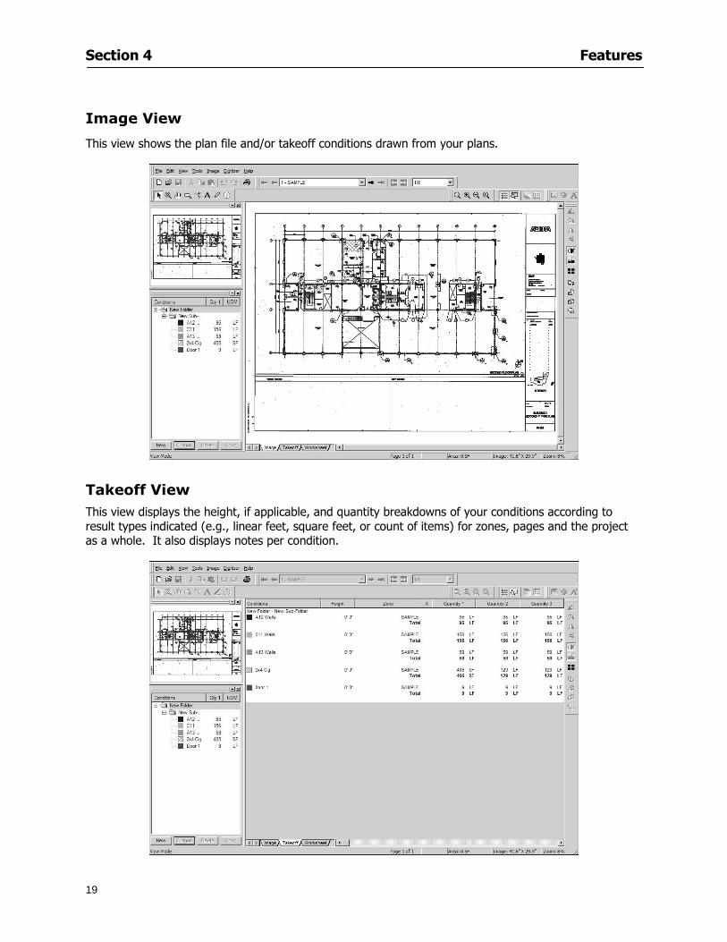
Section 4 Features
19
Image View
This view shows the plan file andor takeoff conditions drawn from your plans
Takeoff View This view displays the height if applicable and quantity breakdowns of your conditions according to result types indicated (eg linear feet square feet or count of items) for zones pages and the project as a whole It also displays notes per condition
Section 4 Features
20
Worksheet View This view displays the condition and quantity in units of measure specified in the first results field of the Results tab in the Condition dialog and allows the user to enter amounts for material labor and subcontractor takeoffs
NOTE When in the Worksheet view tab out the field then save This is keep all the values saved
Navigating On-Screen Takeoff
Auto Scrolling When creating linear areas or zones On-Screen Takeoff will automatically scroll the image view when necessary It will move as your mouse or digitizer moves beyond the edge of the current view
Changing Pages
1 Select View gt Next Page Previous Page or Go To Page (specify page number for the Go to Page option)
2 You may also select the corresponding arrows for these options from the Navigate Toolbar The
drop down arrow in the Page field will list the pages The and arrows will take you to the
previous or next page The and arrows will take you to the first or last page
OR
Section 4 Features
21
3 Or press Ctrl G for the Go To Page dialog
Hot Links Hot links allow you to move quickly from one drawing to the pertinent area of another drawing A hot link is handy when viewing enlarged areas of a page and needing the ability to jump back to a reference page
1 Select Tools gt Hot Link
OR
2 Click from the Tools Toolbar
3 Click on the page where you want to set the link The Hot Link dialog will open
4 Using the current page display on the Navigate Toolbar access the pull-down menu of pages by
clicking on the arrow at the right
5 Select the page for your link (You may also choose View gt Go to Page and select by page number)
6 Manipulate the view using the zoom tool and the scroll bars
7 Click
8 After joining a hot link to another page the hot link arrows in the Navigation Toolbar will become active
9 Move a hot link to another location on the page by clicking then click and drag the hot link image anywhere on the page
Section 5
22
Projects
This section will
Help you create settings important to your projects
Explain how On-Screen Takeoff works with your electronic or paper plans
Section 5 Projects
23
Project Template Files You can begin your project with a template Templates allow you to take advantage of conditions and settings used with previous projects
On-Screen Takeoff templates contain condition lists and established layer separations from previous projects you have created You may also use the sample templates provided with On-Screen Takeoff as a great starting point All aspects of the templates may be adjusted for a new project
1 Select File gt New and click the OK button
2 From the New dialog box choose the template that best fits your project
3 The conditions for this template will appear in the Takeoff Dock bar and the Project Properties dialog will open asking for further information
4 Use File gt Save or File gt Save As to rename and save your new project
Saving a Project as a Template File You can save your condition properties and layers as a template for future projects
1 Select File gt Save As
2 Enter a name for your template and select On-Screen Takeoff Template Files (tpo) from the Save As type field of the dialog (click on the down arrow to select)
3 Click the OK button to accept and close the dialog Modifying a Template File Follow these steps to modify an existing template file if you need to change or add conditions andor layers
1 Select File gt Open
2 Navigate to your Projects directory
3 In the File Type drop-down select On-Screen Takeoff Template files (tpo)
4 Choose the On-Screen Takeoff template file you would like to modify and click the OK button
5 Make appropriate changes
6 Save and close file
The On-Screen Takeoff template files cannot save takeoff information
Section 5 Projects
24
Opening an Existing Project File 1 Select File gt Open
2 Navigate to the desired file location
3 Click the Open button
NOTE If your latest changes to a project file have not been saved On-Screen Takeoff will ask
you whether you would like to save the file and gives you the option of canceling the operation
Creating a New Project
1 Select File gt New
2 For a blank untitled project click
3 At this point the Project Properties dialog will pop-up for more information about your takeoff
NOTE The following are important to keep in mind when beginning a new project
At the start of your project fill out the Project Properties settings to establish the name for all printed output from your project set the default page size and scale for your plans number and names of different pages within the project and locations of electronic drawings
Scale settings can significantly affect quantity outcomes Be sure to set the scale for each page of drawings before beginning condition takeoffs
When using a digitizer remember to make a mark with a pen or pencil in the upper left and lower right corners of the first sheet of the paper plans to delineate the takeoff area for that sheet You can then set the takeoff area on On-Screen Takeoff using your marks
Save your project before you begin taking off any conditions On-Screen Takeoff will write a back-up file using the same file name
Remember the Undo feature If you make a mistake select Edit gt Undo and reverse the process step by step
Section 5 Projects
25
Project Properties
You can either set your Project Properties when you create a new takeoff or once your project file is saved under the appropriate name
1 Select File gt Project Properties the Project Properties dialog box will appear
2 Type in the name of your project to appear on printouts Use the backspace andor delete keys to edit the name as necessary
3 Press the Tab key to move to the Default Image Size option or click within the Image Size box You may click on the arrow at the right for the pull-down menu of page size options or you can use the down-arrow key on your keyboard to scroll through the list to the appropriate selection
4 Press the Tab key to move to the Default Scale option Select a scale by using the drop down arrow If your scale is metric you will need to click in the box next to Metric to convert to that measurement
5 Establish the number of pages for your project plans And load image files See Adding Pages to
Your Project
Adding Pages to Projects Individual Electronic Plans
1 Click on in the Project Properties dialog
2 In the Add Images dialog use the drop down arrow to navigate to the appropriate directory and folder containing your image
3 Select the file so that it displays in the File name field then click The file will display by name and path in the Image File field in Project Properties dialog
4 Click to accept and your project will automatically open
5 Save your project with the new settings by selecting File gt Save
Section 5 Projects
26
Electronic plans scanned from blueprints (as opposed to blue lines) will display as white lines on a black background and are difficult to read on your computer screen Select Image gt Invert and the colors will invert to black on white
You may have noticed the Page column in the Project Properties dialog Generally plan images occupy one page and 1 will be listed in the column indicating Page 1 of your plan file If you import a multi-page TIF a plan file containing more than one page of plans they will import as separate pages and each successive page will be indicated under the Page column as 1 2 3 etc of the plan file
Group of Electronic Plans You may add all the electronic plan files from a particular source (for example from a CD) by using the Auto Add feature
1 Click the button in the Project Properties dialog
2 Browse until you find the appropriate directory and folder containing your plan images
3 Click on any file displayed within your target folder so that the file name appears in the File name box of the Auto Add dialog
4 Click The image paths and file names will be recorded into the project properties arranged alphabetically
5 Click to accept your choices and your project will automatically open
6 Save your project with the new settings by selecting File gt Save
To load Dodge Plans into your Project Properties see Appendix IIi Loading Plans from a Dodge CD
Paper Plans On-Screen Takeoff makes it easy for Full Mode users to perform quantity takeoffs from paper plans using a digitizer
1 Add pages by clicking until you have the number of pages initially in the project
2 Name each page by clicking within the Title area and typing the name
3 Click to accept your choices and close the Project Properties dialog
4 Save your project with the new project properties settings by selecting File gt Save
Section 5 Projects
27
Setting Up a Drawing Template On-Screen Takeoff provides the convenience of using the same work surface for both digitizer and mouse to allow the user to draw conditions and then edit settings of the project or add or change conditions without breaking stride A mouse pad template included with the program defines the area of the digitizer in which use of the stylus or cursor will be recognized as mouse movement as opposed to drawing movement
1 Place your stylus on On-Screen Takeoff
2 Placing the template identifies the location mouse movements will be recognized by the program
Before placing the template the template must be applied to the digitizer surface This may have been done during the installation of your digitizer We suggest attaching the template to the lower right corner of the digitizer surface about one inch inside the grid area
3 Select Digitizer gt Place Template
4 Follow the instruction prompts on the screen clicking first on the target symbol at the left of the On-Screen Takeoff box on the template then on the target at the right
Setting Takeoff Area Before you can begin taking off a drawing you must define the drawing area on the digitizer This requires defining an area that will include all objects on each drawing of your plans As you add pages to your takeoff the same area of the digitizer will be active
1 Secure the plans to the digitizer with tape or a set of clamps
2 With a pen or a pencil mark the upper left corner and the lower right corner of the first page in your set of plans
3 Select Digitizer gt Set Takeoff Area
4 Click each mark with the stylus pen as prompted
5 Verify the active area of the digitizer by looking at the image size located in the lower right corner of your screen
If you close the program before the takeoff is complete you will need to reestablish the takeoff area before you can add additional condition quantities
Electronic plans appear on your computer screen eliminating the need to set a takeoff area You simply drag your mouse across the conditions you wish to takeoff The conditions will be highlighted and quantities will be totaled instantly Electronic plans are available through a variety of services For information contact an On Center Software account manager
Section 5 Projects
28
Setting Scale for Specific Pages You may set the scale in each page view separately This will override the default scale setting in Project Properties for that page Setting the correct scale for the drawing before taking off quantities ensures accurate calculations Be careful to check the scale for each drawing in your project before doing takeoffs
1 Display the page you want to set select Edit gt Set Scale
2 Use the drop down arrow to select a scale that will be applied to that page
3 Click
OR
4 Access the pull-down scale settings on the Navigate toolbar
NOTE As you draw objects notice that the drawn object is similar in width to the object on your plans If it is not the scale set may not be correct
Calculating Scale You may calculate scale according to a known measurement between two points either with a digitizer or on electronic plans
1 Select Edit gt Calculate Scale using Image or Edit gt Calculate Scale using Digitizer
2 Follow the instructions in the related Calculate Scale dialog box You will be asked to click on the first and second points then to enter the dimension for that distance
3 The scale will be recalculated for the displayed page and the Scale display on the Navigate toolbar will show the new scale
Section 6
29
Conditions and Takeoff
This section will Draw Conditions to Takeoff Plan Quantities
What Zones will do to help your takeoff process
Discuss the ins and outs of Takeoffs
Section 6 Conditions and Takeoff
30
Creating Conditions
If you are starting a new project from scratch you will need to create conditions to takeoff quantities such as floor areas wall lengths and corner bead counts If you are using a template you will have several pre-designed conditions already listed on the Takeoff dock bar However you may want to change the characteristics of some conditions or create additional conditions for a particular project
1 Right Click within the Takeoff dock bar Select New gt Condition
Or
2 From the Takeoff dock bar Click (if the buttons are not showing right-click in the Takeoff dock bar area and select Show Buttons from the pop-up menu) The New Condition dialog appears
3 Select the condition type (Linear Area Count or Zone) from the pull-down menu accessed by the
down arrow next to the Type option
4 Press Tab or use the mouse (or stylus) to move to Name and enter a name for your condition
5 Specify the desired condition attributes See Condition Attributes for more detail
6 Click for condition to apply
Section 6 Conditions and Takeoff
31
Condition Attributes Each condition type will have related attributes to select or specify within the General and Advanced tabs of the New Condition dialog Once a condition has been used to takeoff a quantity from your plans certain attributes cannot be changed
All conditions allow the user to specify color and fill pattern for the object drawn
Linear Conditions
General Specify width and height by feet and inches Specify pitch in inches up to the nearest thousandth of an inch if applicable
Advanced Specify rounding for object quantities and droprun default length for electrical or plumbing drops at the ends of lines Select Connect to have lines connect at the corners where one line of the condition ends and another begins (and indicate Tolerance for the featurersquos activation as distance between the ends of two lines) Choose Trim to have lines automatically trim to a line being crossed Choose Curve to draw a curved line
Follow these examples for inputting feet and inches For 7 feet 6 inches type 706 for 13 feet 7 inches type 1307 For 20 feet type 2000
Section 6 Conditions and Takeoff
32
Area Conditions
General If needed you can specify the thickness (in inches) andor pitch (in inches)
Advanced Specify rounding for object quantities Choose to display an adjustable grid within the area and indicate matrix cell dimensions
Section 6 Conditions and Takeoff
33
Count Conditions
General
Specify height and indicate the size (in inches) and shape (square circle triangle rectangle or opening) of the count object as it will appear on screen
Advanced Count conditions have advanced attributes These options are available for all shapes except for openings
Zone Conditions Zones allow you to subdivide condition quantities making it easier to modify and complete jobs in phases They can be used at the end of a takeoff to isolate a group of condition quantities that are in different areas of the takeoff
Zones can also be used to break a takeoff into multi-phases and can even be used to isolate quantities while a job is in progress to group the amount of work that has been completed to date They can be applied to one or multiple pages in your plans automatically calculating the takeoff quantities for each zoned area
Section 6 Conditions and Takeoff
34
The zone feature is only available in Lite and Full Mode If you are in View Mode and would like
to use this feature click from the main toolbar to purchase the upgrade
Condition Notes A Note tab is provided for comments regarding the condition These notes will display on the Takeoff List report and will import into Quick Bid
Section 6 Conditions and Takeoff
35
Condition Results The Results tab of the New Condition is based on condition type Initial settings default to linear feet (LF) for linear conditions square feet (SF) for area conditions and count of items (EA) for count conditions and zones The first of the results fields will display for the condition items in the Takeoff dock bar area All results will display in worksheets and Takeoff List reports as well as in an Excel spreadsheet after being exported
Copying Conditions You may use the condition attributes from a condition yoursquove already created for any future conditions of the same type
1 Click on a condition to select it
2 Click the Copy button from the toolbar
OR
3 Right-click in the Takeoff dock bar area and select copy
4 A new condition will appear in the list with the same condition attributes as the previous condition but with the quantities zeroed
Editing Conditions Once you have copied a condition you might want to change several attributes You can also edit an existing condition to fit any updated needs
1 Highlight the desired condition on the Takeoff dock bar
2 Click the Change button
OR
3 Double-click on the condition you wish to edit to bring up the Change Condition dialog
NOTE The Change Condition dialog differs from the New Condition dialog only in that if takeoffs
Section 6 Conditions and Takeoff
36
have been performed in your project with this condition you will not be able to change the type of condition or certain properties under the advanced tab of the dialog box
Deleting Conditions 1 Click on the condition in the Takeoff Dock bar area
2 Click the Delete button on the toolbar
OR
3 Right-click and select Delete from the pop-up menu
All takeoff associated with the deleted condition will be deleted immediately and permanently
Organizing Project Conditions Within your project you can create folders andor sub-folders for different types of conditions You may even want to create a folder containing conditions with reset values
To get started organizing your conditions make sure you are viewing the condition tree (right-click in the Takeoff dock bar area and select Show Tree)
Creating Folders and Sub-Folders 1 Right-click in the Takeoff Dock bar area
2 Select New gt Folder from the pop-up menu
Copying Folders
1 Click on the folder and click Copy on the toolbar
2 All copied conditions within the new folder will have values reset to zero
Renaming Folders
1 Click on the folder
2 Right-click and select Rename from the pop-up menu
3 Enter a name for your folder and click the Enter button
Changing Condition Order
You may move conditions up or down in the condition list of the Takeoff dock bar to suit your project needs
1 Select the condition you would like to move by clicking to highlight it
NOTE When you are ready to move the highlighted conditions be sure that you start
moving using the last condition chosen That condition will have a highlighted boarder
Section 6 Conditions and Takeoff
37
2 Drag and drop any the condition from one place to another in the list You may also move a condition to another folder on the list in this way
Drawing with Conditions Snap Angles Set up snap angles to prevent lines from appearing jagged Snap angles are commonly set at 15deg and shift snap angles at 0deg
1 Go to Tools gt Options Options dialog appears
2 Under the General tab make the desired settings
3 Click to save the settings As they are drawn lines will snap to the set degree
Drawing a Linear Object 1 Select a condition from the Condition List in the Takeoff dock bar
2 Move the cursor into the Image takeoff area of the screen you will see the cursor display as crosshairs
3 Click and hold left mouse button then drag mouse to draw a line
4 Release mouse button to set line
Section 6 Conditions and Takeoff
38
5 Repeat steps for further lines
Continuous Mode This feature allows you to draw an object that has connected lines
1 Click the icon from the Takeoff toolbar
OR
2 Go to Tools gt Continuous Mode
3 Follow steps 1-3 from Draw a Linear Object
4 Click at each point of intersection The object will be connected
5 Double-click after making the final point to set the lines
Drawing a Curve To draw a curved line the Curve option must be checked under the Advanced tab of the Condition dialog
1 Click where you want to begin the curve and drag in a straight line to the position for the other endpoint of the curve
2 Click on the line to select it Handles in the shapes of small squares will appear at either end of
Section 6 Conditions and Takeoff
39
the line and in the center of the line
3 Move the cursor over the center handles until the cursor becomes a two-way arrow
4 Click and drag in the direction of the curve bending the line as you move the cursor Release to set the curve (The line you began with will disappear)
Draw a circle by drawing two curved lines connected
Drawing an Area Object Area conditions are drawn similarly to continuous mode lines You may trace any number of adjoining walls at different angles to complete your area takeoff
NOTE When drawing an area do not intersect the perimeter or line of the object you are drawing
1 Click at each point
2 Double-click when yoursquove returned to your starting point
3 The area will be filled with the pattern set for that condition
NOTE The simulated circle will be good enough for you to be able to make a bid
To create a circular area click from point to point with very short distances in between points simulating a circlersquos perimeter Double-click after setting the last point to set the area
Section 6 Conditions and Takeoff
40
Grid Options Grids give you an added advantage when installing materials such as tiles Use this feature to get a count for how many tiles are needed for an area
1 Double-click on an area condition in the Takeoff dock bar to open its Condition dialog
2 Click on the Advanced tab to show its options
3 Check the box next to Grid by clicking in it
4 Indicate the dimensions of the cell matrix in inches (For example 200 x 400)
5 Under Results tab choose each (EA) for one of the results fields This will tabulate a number of grid cells (including partial grid cells) in area
6 Click to save your settings
7 Use the Move Grid and Rotate Grid features in the Tools menu to manipulate the grid as desired
Grid Calculation
1 Go to Tools gt Options menu
1 Specify if On-Screen Takeoff automatically should Calculate Grid Position
2 If AreaGrid Size is selected On-Screen Takeoff will calculate the number of items needed to fill the grid based on grid demintions
3 Click to accept and close the dialog
To move a line at any angle (regardless of default setting) press the Shift key while moving the mouse
Section 6 Conditions and Takeoff
41
Backout Mode This feature allows you to take out part of an area and deduct that amount of square footage
1 Select Tools gt Backout Mode
2 Outline the are you want backed out as you would when drawing a regular area object (see Drawing an Area Object)
3 The outlined area will clear and quantities will be recalculated
NOTE The perimeter of the backout area will be added to the LF quantity for that condition
Drawing a Count Object Square triangle rectangle and circle shaped count objects can easily be placed on images
1 Select the condition
2 Click in the location where you want the object to appear
3 To place an opening-shaped count item like a door or window you must click over an existing linear object such as a wall
4 On the Results tab you can change the height properties to give you the result you need
5 If Backout is checked on the advanced tab for each count opening the opening-shaped count item will back out a corresponding section of the linear object
Opening shaped count items are sized at 3rsquo0rdquo by default
Drawing a Zone Zones are drawn in the same way as area objects and may be any polygonal shape You may trace any number of adjoining walls at different angles to complete the zone perimeter
1 Click at each point
2 Double-click when yoursquove returned to your starting point
Section 6 Conditions and Takeoff
42
Selecting Objects
1 Use the Select Tool to select objects
You can also select all objects that correspond to a condition
1 Click on a condition to select it
2 Right-click and choose Select All
3 All objects with this condition will be highlighted with squares as an outline
Moving and Resizing Objects Linear
1 To move or resize a linear object click anywhere on the line to select it
2 To move the line position your pointer over the center handles When the mouse is positioned over the handles you will see a two-way arrow You will only be able to move the line in the direction of the arrows
3 Drag the line to a new position
4 Clicking and dragging the handles on the ends of the line will allow you to lengthen or shorten your line
Area and Zone
1 To move an area object or zone in its entirety click and drag it to its new position
2 Grabbing a handle at a corner or intersection of the object will allow you to adjust and change its perimeter
Section 6 Conditions and Takeoff
43
Count 1 To move a square circle rectangle or triangle shaped count object click and drag
2 Click and drag an opening shaped count object along the length of the linear object to the desired position then release
NOTE An opening shaped count object may not be moved from its associated linear condition object however it may be moved up and down the length of the linear object
Layers On-Screen Takeoff allows you to sort and separate your takeoff objects within the same job and on the same page On-Screen Takeoff gives you this flexibility through the use of layers
By assigning different conditions to different layers (for example differentiating between floors ceilings and walls) you can choose to view all layers or turn off certain layers to display and print the remaining groups of conditions only You may also remove the background image of electronic plans add text and hot link symbols or print only your condition takeoffs
Layers are only available in Full Mode If you are in View or Lite Mode and would like to use this
feature click from the main toolbar to purchase the upgrade Default Layers
On-Screen Takeoff begins every project with three default layers Image Annotation and Default The Image layer holds the electronic plan files you may have in your project The Annotation layer possesses all text notations highlighting and hot links in the project The Default layer will appear in the Condition dialog when creating or editing a condition (listed in the takeoff dock bar) Conditions are assigned to the Default layer unless otherwise specified by the user
Creating Layers To assign a condition to a layer other than the default layer you must first create additional layers for your project
1 Select View gt Layers to open the Layers dialog
2 Click An unnamed layer will be added
3 Click within the empty box and type a name for your layer (for example Wall)
4 New layers are added as active layers The adjacent box under the Show column will be checked
Section 6 Conditions and Takeoff
44
Assigning a Layer to a Condition 1 Open the Condition dialog box by creating a new condition or editing an existing condition
2 Under the General tab click on the down arrow in the Layer field to display optional layers
3 Select the desired layer for the condition Only the Default layer and layers you have added will be displayed
4 Click
View and Hide Layers
1 Select View gt Layers
2 Under the Show column check the box to view or remove the check (by clicking on it) to hide the specific layer
3 Click to accept and close the Layers dialog
Section 6 Conditions and Takeoff
45
Assigning Text to a Layer When adding text to an image On-Screen Takeoff has the capability to assign the text to a specified layer
1 Select the Text Tool
2 Click at the point you want to place your text
3 Type in your text using the Enter key for line breaks
4 Click the drop down arrow next to the Layer field and select the desired layer
Section 7
46
Printing and Exporting
This section will
Printing options and procedures
Exporting data by copying and pasting
Exporting quantity results to Excel spreadsheets
Section 7 Printing and Exporting
47
Print Setup On-Screen Takeoff allows the user to print the image takeoff list and worksheet
1 Select File gt Print Setup The Print Setup dialog will open
2 Select a printer or leave the default selection listed (change from the default printer displayed by clicking on the down arrow at the right of the field)
3 Indicate page size and printer tray option (Source) Access page size options by clicking on the
down arrow at the right of the field
4 Choose Portrait or Landscape orientation
5 Click to accept and close the dialog
Printing Images The image area can include the electronic plans the takeoff objects added text and hot links To print a subset of these (for example just the takeoffs without the plans or the added text and hot link symbols) hide layers that you do not want to print (see Section 6 View and Hide Layers) When you are printing your images every page will show the scale of the takeoff you are printing
1 Click on the Image tab to display the area of your project
2 Select File gt Print (or Ctrl + P)
Section 7 Printing and Exporting
48
3 Select the desired view (What to print) and the Image Range
4 Click The second Print dialog will open
5 Change settings accordingly or click if you accept the default settings
Printing Takeoff Lists and Worksheets In Takeoff Lists and Worksheets you may hide columns to print only certain results or adjust column widths to fit the report within the page size selected
1 In Takeoff List or Worksheet view move your cursor to the right side of the columnrsquos title bar the cursor will display as a two-way arrow
Section 7 Printing and Exporting
49
2 Click and drag to adjust the width of the column Holding the mouse button you may
slide the title bar under the title bar to its left to hide the column completely
3 Select File gt Print or press Ctrl + P to access the Print dialog
4 Indicate desired printer and choose the number of copies
5 Click to print and close the dialog
When printing the condition list we suggest printing in landscape
To reset to the default column widths double-click on the right border of a column heading will reset the column to its right (or previously to its right before being hidden)
Print Preview 1 Select File gt Print Preview
2 Use and to vary your view 3 If viewing an image choose current full or scale view to see how it displays
4 For printed outputs that cover more than one page use and to view adjacent pages or click on the down arrow next to Page field and select the page you want displayed
Exporting Using the CopyPaste Feature You may copy all the data or sections from the worksheet and the takeoff list view in On-Screen Takeoff and paste it into another application When pasting into Excel the cell layout will be maintained
1 Highlight the areas you wish to paste Click and hold the left mouse button down as you drag the cursor over the area to be selected then releasing the mouse button
OR
2 Select the entire takeoff list quickly click on the left On-Screen Takeoff column header and hold and drag the cursor across the remaining column headings
The number of pages for the view selected will display in the lower left-hand corner The zoom percentage that applies to the view will be displayed in the lower right-hand corner next to page size of the drawing
Section 7 Printing and Exporting
50
3 In the worksheet view you may highlight rows by clicking on the numbered buttons to the left of each row clicking and dragging across column headings or clicking and dragging over individual cells in the worksheet
Click anywhere in the appropriate view to deselect the area
4 Once your selection is highlighted you may select Edit gt Copy or Ctrl C from the keyboard 5 On your monitor switch to the application into which you want to paste your selection 6 Select Edit gt Paste in the new application or simply press Ctrl + V to paste
The colored keys for conditions cannot be pasted
Using the Export Feature You may export condition quantities to specified cell location within an Excel worksheet file Cell target locations are assigned in the Results tab of the condition dialogs on the Export line relating to each quantity measurement type
On-Screen Takeoff will export takeoff quantity results for up to three different quantity types that you specify For instance you may want to know the number of square feet in a ceiling area as well as the number of linear feet in its perimeter
Section 7 Printing and Exporting
51
1 Bring up the Condition dialog by double-clicking on a condition in the takeoff dock bar or by
selecting the condition and clicking
2 Click on the Results tab to access its fields The default quantities for the condition type will display
3 For each results field click on the arrow to access the pull-down menu and select the appropriate quantity (for example SF LF EA etchellip)
4 Have your Excel spreadsheet opened and saved in a file
5 Specify the Excel spreadsheet cell locations where you want the results to go
6 For a cell in the first sheet of your spreadsheet type in the cell address (eg a1) Case is not important
7 For a cell on a successive sheet of your spreadsheet type in sheet the number followed by a comma and the cell address without any spaces (eg sheet2a1) Case is not important
8 Click
9 Select File gt Export gt Condition Qty to Excel
Section 7 Printing and Exporting
52
10 Browse to the location of the Excel spreadsheet file click file to select it
11 Click to export On-Screen Takeoff results to specified cell locations in the Excel file When you return to the Excel application you will see the values have been added to the specified cell locations in your spreadsheet
12 Save your Excel file
Exporting Worksheet to Excel
1 Assign condition quantities you want to export
2 Open saved Excel spreadsheet file to which you will be exporting
3 From On-Screen Takeoff Select File gt Export gt Worksheet to Excel
4 Browse to the location of the Excel spreadsheet file click file to select it
5 Click When you return to the Excel application you will see the values from the Worksheet Tab have been added to your spreadsheet
6 Save your Excel file
Exporting Takeoff to CVS 1 Assign condition quantities you want to export
2 Open saved Excel spreadsheet file to which you will be exporting
3 Click the Takeoff Tab in the project you want to export the information
4 Select File gt Export gt Takeoff to CSV
5 Browse to the location of the CSV spreadsheet file click file to select it
6 Click the Save
NOTE CSV files can be opened in Excel Lotus Access etc One may consider this option more of a ldquodumprdquo into a file
The Excel application must be active (it may be minimized on the application bar) with the target spreadsheet open in the application Otherwise an error will occur with the export operation that will affect both the On-Screen Takeofftrade file and the Excel spreadsheet
Section 8
53
Advanced Features
This section will
Some special features of working with condition objects in the takeoff area
Details of advanced options for conditions
Advanced features of the Project Properties dialog
Section 8 Advanced Features
54
Features to Use with Objects Roping Feature You can move copy or delete using this feature Using the Select tool (the pointer) you may select several objects at once by clicking and dragging an outline around the objects then releasing the mouse button Roping may select either objects completely within the outlined area (inclusive) or objects both within and touched by the outlined area (touching) Specify your roping preference under Tools gt Options
1 Click and hold the mouse button at a point on the screen near the objects to be selected and drag to surround the objects with an outline
2 Release the mouse button The objects will be selected
3 You may now
Move the group around on the page by clicking within the group dragging the mouse and releasing the button to place the objects
Delete the group of objects by clicking the Delete key or
Copy and paste by pressing Ctrl C to copy the group then Ctrl V to paste it The pasted copy of the grouped objects will appear slightly offset from the original objects
Section 8 Advanced Features
55
Applying a DropRun Count
Use the droprun feature when calculating quantities to take into account the drop or run of a linear condition such as electrical lines or plumbing pipes Drop or run lengths may be added separately to any linear condition on screen while a default droprun length may be indicated for a condition as a whole
1 Select the desired linear condition from the Condition List in the Takeoff Dock bar
2 Click the Change button in the toolbar to open the Change Condition dialog
3 Click the Advanced tab to access the advanced options and click inside the DropRun check box
4 Enter a default length to be applied to all of this condition Entering 800 will be interpreted as 8 0 (You must enter both place markers for inches) You can leave the length blank and manually enter drop run on each segment drawn
5 Click the OK button to accept and close the dialog
Edit DropRun Count
1 With the related linear condition in the Takeoff Dock bar highlighted or with the pointer tool selected
2 click on the desired linear object in the image takeoff area The Count button will become active
3 Click on the Count button (alternatively select Tools gt Count) The default droprun amount will show in the pop-up Count dialog (Default length will be zero if droprun has not been selected in this conditionrsquos properties)
4 Type in the desired length Entering 800 will be interpreted as 8 0 (You must enter both place markers for inches)
5 Click the OK button The additional amount will be reflected in the corresponding quantity The new DropRun count will apply only to the object edited
Adding Text in Image View
On-Screen Takeoff allows you to place text comments around your quantity takeoffs that may be printed along with plan images and objects Text is automatically placed within the Annotation Layer (that includes text and hot links)
1 To place text on the image select the Text Tool and click at the point you want to place your text opening a text box
2 Type in your information clicking Enter for line breaks
3 When you are finished click the OK button to exit the text box
4 To reposition text simply click on the text (with the Text Tool active) to select it
5 Move the cursor over the text the cursor will now display as a four-way arrow
6 Click and drag the mouse to position the text as desired
Section 8 Advanced Features
56
1 To edit existing text use the Text Tool to double-click on the text to open the editing box
2 Enter additional text or use the Backspace key to delete text as necessary
Formatting Text Once created you may format the font size type style and color of your text
1 Click on the text to select it and select Tools gt Font or click on the Font button in the Takeoff Toolbar
2 Select the desired features (color options are disabled) and click the OK button
3 Click on the text to select it and select Tools gt Color or click on the Color button in the Takeoff Toolbar The Color dialog will open
4 Click on a color in the Basic Color palette or create a color and add to the Custom Colors palette (Be sure to click on the color in the Custom Colors palette to select it)
5 Click the OK button
Object Properties
Linear Objects
Linear objects may be set to connect at corners
A linear object may be set to trim automatically when crossing another linear object (Check the trim option under the advanced tab of the Condition dialog)
When you move a connected linear object objects automatically move and resize connected lines accordingly (quantities are then recalculated)
This feature requires that the connected linear object be moved using the center handles (does not apply when resizing the line from the ends)
Objects constrain to snap increments defined in the Tools gt Options menu (with the mouse 15deg by default incremental when shift key is held down)
Objects are measured from centerline to centerline
Section 8 Advanced Features
57
Area Objects When drawing an area use your escape key to undo the last line drawn You may reverse your
drawing of an area using the escape key
The area will not fill with color and pattern until the user double-clicks after the last line is set
Lines drawn to delineate an area object constrain to snap increments defined in the Tools gt Options menu (with the mouse 15deg by default incremental when shift key is held down)
After selecting an area to move or adjust position the mouse in the center to move the entire area position the mouse at the sides or corners to adjust the perimeter
Count Objects
All count objects are quantified by the physical number of objects per page and reported as EA for the UOM The quantity for the current Image View is (displayed in the Condition List) and the total quantity in your project is displayed in the Takeoff View and Worksheet View)
Square circle rectangle and triangle shaped count objects do not displace or subtract from other object quantities when placed on top of them However on the Advanced Tab for the count condition a connect property can be set (this is a check box) so that when a count object of this shape is put on top of a Linear type takeoff object it will move with the linear if said linear is moved
An opened-shaped count object must be placed within a linear object Opening shaped count objects may also be measured by linear foot or linear yard (EA SF and SY are also options) Opening shaped count items default to a width of 3rsquo 0rdquo at the time of creation This size can be changed The small medium and large size are not options on this type of condition anymore Check Backout on the Advanced tab for each Count object back out the footage (or yardage) of opening-shaped count objects in which they are placed
NOTE In order to see this Backout functionality (in quantity) for SY or SF deductions at least one of the
results for the Linear(s) this object will be placed on must be set to SY or SF and the count object must have a height quantity
Advanced Features of Conditions The Round Feature Under the Advanced tab of the linear and area Condition dialogues you may specify quantity rounding (in inches) For linear objects rounding applies to each linear object drawn For area objects rounding will apply to each segment of the area perimeter adjusting the perimeter and area calculations For example With a linear condition entering 12 in the Round field will round up each related linear object to the nearest 12 inches or one foot With this setting two walls of 1 4 would each round to 2 0 totaling 4 0
NOTE In the Takeoff Dock bar condition list and in the On-Screen Takeoff reports quantities will be displayed in whole numbers rounded up to the nearest foot However calculations are based on true quantities without rounding unless the Round Feature is engaged
Pitch Pitch may apply either to linear or area conditions It is measured in rise per linear foot Entering 12 indicates a 12 rise per 12 of linear distance (a pitch of 12 over 12) or an angle of 45deg
Section 8 Advanced Features
58
Advanced Features of Project Properties Selecting Multiple Pages
1 Select a single page entry by clicking on the numbered gray button to the left of the entry
2 Drag the cursor down the column of numbers to select consecutive pages
3 Click on the blank button at the top of this column to select all pages in the Properties dialog
Section 8 Advanced Features
59
Changing Image Assigned to a Drawing 1 Select the page entry by clicking on the numbered gray button to the left of the entry 2 Click the Change Image button The Change Image dialog box will appear
3 Navigate to the desired file and select by clicking on it
4 Click the Open button The electronic file assigned to the page will have been changed to reflect the new file choice
Changing Image File Path 1 Select pages as described above
2 Choose Change Folder
3 In the Change Folder dialog navigate to the appropriate folder
4 Click the OK button The file path will have been changed for the selected page entries
Delete a Page from Project Properties 1 Select the page you want to delete by clicking on its associated number (in the gray box at the
left of the entry)
2 Choose Delete Page
All Takeoff on the page will be deleted immediately and permanently
Section 8 Advanced Features
60
Advanced Features of Tool Options
Calculation Method On-Screen Takeoff has built-in calculation options to allow for faster work and faster saves until your takeoff is complete Calculation options are found by selecting Tools gt Options then clicking on the Calculation tab
Calculation method can be set to Automatic Automatic except Grids and Manual Manual will allow the program to operate more quickly while Automatic or Automatic except Grids allows the user to see quantity changes as takeoffs are made
In any mode you may press F9 to recalculate quantities for the On-Screen Takeoff current totals
Configuration Tab
When the ldquoPage Label (A01)rdquo radial button is chosen On-Screen Takeoff puts the numbered label on all the pages of in your current page indicator in your Navigate Toolbar If the Page Descriptionrdquo radial button is chosen then a description of what takeoff is on that specific page will be shown in your current page indicator in your Navigate Toolbar
This section of the configuration tab gives you options on how you want to export your information When the ldquoFolderSubfolder Namesrdquo radial button is chosen than on your file that you are exporting to will have all the conditions folders and subfolders In the Delimiter box you can choose the symbol that is needed to separate the information you are exporting Some files need semicolons () or colons () to make sure the information comes exported in is separated it the appropriate places
Section 8 Advanced Features
61
In previous versions of On-Screen Takeoff there are views that users need to have in order for them to display their information By either choosing ldquoOST 1xrdquo or ldquoOST 2xrdquo it will let the program know you want your columns of information exported in that specific format
When you have the Confirm Deletions radial button of ldquoYesrdquo chosen than every time you delete anything you will get a dialog box confirming your intentions of deletion
While working with your takeoff you have a choice to either view the legend of your conditions or hide it Choose whichever radial button that suits your needs
For those who prefer to use the Enter key to navigate in dialog boxes this option is just for that
Font Tab The Font tab is designed for you to make your own look and feel for the application At the bottom of this tab it will show you sample of the fonts and colors you have chosen
Renaming the Current Page You may change the name of the current page in the takeoff area of On-Screen Takeoff by selecting Edit gt Rename Page
This opens the Name Page dialog and you may simply type in a new name and click the Enter button The new name for the file will be reflected on the title bar for the page and in Project Properties
You also may access the Rename Page function by right-clicking in the takeoff area while in Image View and selecting the option from the pop-up menu that appears
Section 9
62
Saving and Exiting
This section will
Explain how to save projects
Show you how to safely exit the program
Section 9 Saving and Exiting
63
Saving Your Project
1 Select File gt Save 2 If your project has not previously been saved a Save dialog box will open to allow you to name
the file and choose the directory and folder in which to save your file 3 Once saved File gt Save will simply save the current version of the file
OR
4 Select File gt Save As then type in a new name for the file and save to the desired file path
The Auto-save Feature With the Auto-save feature On-Screen Takeoff automatically backs up your open project You may choose to have more than one level of backup files The first backup copy will have the extension b00 and successive files will be b01 b02 and so on If you have designated four levels of backup files after the fourth backup copy has been created (b03) the next file will be saved over the file with extension b00 Further backup saves will then rotate through the four backup files in the same way
1 Select Tools gt Options 2 In the Auto-save area (under the General tab) select the frequency of backup file creation (in
minutes) and the number of levels for the feature 3 You also may disengage the feature by clicking in the check box to clear it
The Auto-save feature automatically saves backup copies to the directory of the current project If you are working from a write-protected area such as a CD-ROM On-Screen Takeoff will place backup files in the On-Screen Takeoff folder
Exiting When you are finished using On-Screen Takeoff it is very easy to exit Exiting is very important because of security reasons If someone were to use your computer they could enter the application and view and manipulate information
Section 9 Saving and Exiting
64
On-Screen Takeoff closes the open project when you open another or create a new project or when you exit the program
1 Select File gt Exit
OR
2 You also may click at the upper right-hand corner of the application to exit
NOTE If your latest changes to a project file have not been saved On-Screen Takeoff will ask you whether you would like to save the file and gives you the option of canceling the operation
Appendix I Installing Your Digitizer
65
Appendix I Installing Your Digitizer When you get your digitizer from GTCO you will need to connect it to your computer Follow the instructions outlined below to do this
Note For rollup digitizers the metal bar must be oriented to the top or right hand side
Connecting the Digitizer 1 Lay the digitizer out flat 2 Connect the Stylus to the digitizer 3 Plug in the power adapter 4 Plug the interface (IO) cable into the digitizer 5 Plug the other end of the interface cable into an open serial port on computer
Note GTCO Technical support phone number is 410-381-6688 The electronic manual (on diskette) from GTCO contains more detailed installation and operation instructions for the GTCO digitizer model you have
Installing other Digitizer Drivers If you are using a GTCO Digitizer you will need to install the GTCO TabletWorks Drivers
If you are using a Digitizer not supported by GTCO Tablet Works 10 please contact the manufacturer of your digitizer for assistance with installation
Installing GTCO TabletWorks Drivers 1 Insert the On Center CD into the CD-ROM drive The CD Startup screen will open 2 Click on Install Software 3 Select Additional Software and Drivers 4 Select Digitizer Driver 5 Follow the instructions for installing TabletWorks 10
Adhering the Template The template is a small plastic sticker used to enable mouse function when using the digitizer with On-Screen Takeoff Place your template on your digitizer We suggest placing it in the bottom right corner of the digitizer about one inch inside the takeoff area
Note You may either peel off the back of the template and use the adhesive surface or you can tape the template down
Appendix I Installing Your Digitizer
66
Testing the Digitizer Drivers Before running OST you may test the digitizer by moving the stylus around on the digitizer pad it should move the mouse cursor (if mouse emulation is enabled)
If the digitizer does not move the mouse cursor on the screen
The superset codes may need to be reset Reset the superset codes by touching on the border of the digitizer with the stylus The digitizer should beep several times
The digitizer may not be communicating with the computer Be sure the COM port selected is correct Be sure the COM port selected is correct If you are not able to get the digitizer to move the mouse cursor you need to call GTCO technical support for help
Note The Mouse Emulation is not required for On-Screen Takeoff to work properly It is used only for the Template functionality if the digitizer is moving the cursor the wrong direction (up instead of sideways or vice-versa)
Click the L-shaped arrow symbol on the digitizer with the stylus
Appendix II Toolbar Item Details
67
Appendix II Toolbar Items Main Toolbar
Appendix II Toolbar Item Details
68
Tool Toolbar
Appendix II Toolbar Item Details
69
Zoom Toolbar
View Toolbar
Navigate Toolbar
Appendix II Toolbar Item Details
70
Navigate Toolbar (Continued)
Takeoff Toolbar
Appendix II Toolbar Item Details
71
Takeoff Toolbar (Continued)
Image Toolbar
Appendix III Loading Plans from a Dodge CD
72
Appendix III Loading Plans from a Dodge CD
This section will detail how to load plans from a F W Dodge CD-ROM into an On-Screen Takeoff project file ready for takeoffs
Dodge files may be added to the Project Properties dialog However loading the files in that way will load the files by number rather than name description If you want to load one page only from your Dodge CD You will have to rename the page to display the name rather than number of the file
To load plan files from a Dodge CD so that the files load sequentially by file number but are displayed by name rather than by number within your project follow the instructions below
Opening a Dodge project from a CD-ROM 1 Insert the CD into the drive 2 Choose File gt Custom 3 Choose Dodge Plans Project (plansdat) as the file type 4 Select the appropriate file type by clicking on the down arrow at the right of the Files of type
field 5 In the Look in field access your drive paths by clicking on the down arrow at the right of the
field then
Navigate to your CD-ROM drive Open the data folder and Open the Projects folder
6 Select the desired project and open its folder 7 Open the plansdat file 8 All the images will come in sequenced correctly for that job along with the full descriptions
(names) of each page If there is not a plans folder in the project folder then plans do not exist for that project on the CD Opening the plansdat file will yield an empty project
Appendix IV Using the Plan Viewer
73
Appendix IV Using On-Screen Takeoff Plan Viewer The On-Screen Takeoff Plan Viewer is a limited version of On Center Softwarersquos commercial takeoff software If your status bar located at the very bottom of the main window says View Mode in the lower left-hand corner then you are using the Plan Viewer You can use the plan viewer to
View CD-based amp converted CAD drawings
View a previously created OST file and associated drawings
Download electronic plans online
Navigate through drawings
Quickly Takeoff linearsareas and counts
Zoom in to view the plan better
Print drawings directly from the viewer
Viewing an On-Screen Takeoff Project File
1 To open an OST file that was previously created with of On-Screen Takeoff 2 Select File gt Open 3 An Open dialog will appear if you do not see the OST file you are looking for select the
Look In drop down arrow 4 A drop down menu will appear listing the various folders drives and mapped drives located
on your computer select the correct drive or folder location and continue to browse to the location of your OST file
5 When you see your OST file double-click it to open it 6 Any takeoff and drawings should appear on the Image tab view
If you do not see the drawings but do see the colored takeoff layer the drawings may
not be located in the same place they were originally saved at Go to File gt Project Properties and check the Image File path for each listed page If the image file path is pointing to a CD drive make sure the CD is inside the CR-ROM
Downloading Electronic Plans If your Online Plan Service provides a special file format (OSX) required to use this feature of our plan viewer you can immediately downloaded all electronic plans of a project directly from our viewer
Most Plan Room web sites will automatically open On-Screen Takeoff when a request to download plans is made Your particular Plan Room may differ in operation so please contact the provider directly with questions on using the site
Appendix IV Using the Plan Viewer
74
When you request to download or open a project file from a Plan Room you will usually have the open to open or save an OSX file Choosing open will automatically open On-Screen Takeoff Alternately you may choose to save the file to a local hard drive After you have saved the file either double-click it to launch On-Screen Takeoff or open the OSX file using On-Screen Takeoff by clicking File then Open and locating the file on your hard drive You will need to change the file type to OSX
After the OSX file is opened you will see an additional tab appear in the Conditions List window called Pages
The Pages tab shows the hierarchy of your project Gray file icons represent pages that have not been downloaded and blue icons represents pages that have been downloaded
To download a page simply double-click the page icon
If you wish to select a group of pages to download you can use the Ctrl or Shift key to multiple select them then click the Download button
If you wish to download all pages at once click the Download All button
Downloaded pages will now appear in the Project Properties dialog in the same order in which they appear in the Pages tab
Creating Quick Takeoffs With On-Screen Takeoff you can create quick takeoffs to measure quantities even if you dont have the full version of our program However using the Quick Takeoff functionality shows you just a fraction of what the full version can do
The Quick Takeoff Toolbar is located at the top of the image view It has three buttons designated for three types of takeoffs Linear Area and Count The Quantity drop down list will show secondary quantities for Linears and Areas The Units drop down allows you to select how you want your quantities displayed Feet Inches Yards Millimeters and Meters
NOTE Every time change the type of takeoff you are performing (switching from Area to Linear for example) the previous quantities and takeoff objects will disappear They will also disappear when you changes pages
NOTE You can use the Dimension Tool to basically measure the distance between two points or linears The distance will display on the status bar at the bottom of the application
The Quick Takeoff Toolbar
Appendix V Frequently Asked Questions
75
Appendix V Frequently Asked Questions General
Where is On-Screen Takeoff installed on my computer
Typically it is installed in CProgram FilesOn-Screen Takeoff
In Explorer how do I recognize On-Screen Takeoff file types
On-Screen Takeoff data is stored in a single file per job lsquojob name OSTrsquo On-Screen Takeoff templates are stored as lsquotemplate nameTPOrsquo
Can only one project at a time be open
Yes For that reason opening another project automatically closes the project on screen You will be asked to save any changes
Is only one scale allowed per page What about on drawings that have multiple detail sections on a page and each of those drawings have different scales
Yes For pages with drawings of different scales copy the drawing to another project page and set the appropriate scale
I cannot perform backout on an area that is along a linear
As a workaround use the On-Screen Takeoff layers feature to help you with this issue Electronic Images
How do I start a project from drawings that have been scanned and written to a CD-ROM
Open a new project Select File gt Project Properties and select Auto Add Navigate to your CD and the appropriate folder and select any image file in that location Click Open All files in the location will load into your project Recommended that images are copied from CD to hard drive for performance
If I get a disk of drawings in AutoCAD format (R13 or R14) can I read them in On-Screen Takeoff
Yes On-Screen Takeoff now reads DWG DXF and many other format that are saved with AutoCAD
Appendix V Frequently Asked Questions
76
When I click on the all pages button what is supposed to happen Currently nothing seems to change when I click on that button
The All Pages button is used to apply the Darken and Enhance Plans feature to all pages in the project (as opposed to only the current page on screen)
Is there a way to deduct a large skylight from an area condition
Yes with the related area condition selected in the Takeoff Dock bar unselect the Backout button on the Takeoff Toolbar then draw the Backout area The area quantity will be deducted from the related condition object and the linear measurement of the Backout perimeter will be added
Digitizer Issues
How do I connect a Digitizer to the computer
See Appendix I Connecting a Digitizer
The Place Template menu choice is disabled
On-Screen Takeoff may need to be authorized or the digitizer or the digitzer drivers are not installed
It wonrsquot let me select the Set Takeoff Area menu choice
On-Screen Takeoff may need to be authorized or no job is open a digitizer is not installed or the drivers are not installed
The digitizer stylus is not moving the cursor or crosshairs
Click S-0-1 superset on the digitizer
How do I convert my old GTCO Digitizer to work with On- Screen Takeofftrade
Call GTCO and they may be able to reconfigure your digitizer to be compatible with On-Screen Takeoff
Printing Issues Which Printers work with On-Screen Takeoff
Compatible printers include On-Screen Takeoff Hewlett Packard Epson and Canon printers If you are having printer difficulties please contact support and specify the type of printer along with other pertinent information Contact support at wwwoncentercomsupport or email supportoncentercom
Which Plotters work with On-Screen Takeoff
Compatible Plotters include Hewlett Packard DesignJet plotters and the EnCAD Cadjet II If you are having plotter difficulties please contact support and specify the type of plotter concerned
ViewingDisplay I can no longer see my condition list How do I get it back
The toolbars and Dock bars can be turned on and off through the View gt Toolbars menu options
Appendix V Frequently Asked Questions
77
This is also accessible by right-clicking in the toolbar area and selecting (or deselecting) a toolbar listed
I cannot view my folders in the condition list
Right-click in the Takeoff Dock barcondition list area and select Show Tree to display your folders
My Status Bar reads Viewer Mode and I am unable to draw conditions
On-Screen Takeoff needs to be Authorized Or you need to purchase an upgrade Click the Perform Advanced Takeoff button on the main toolbar
I hid a Dock bar and when I selected to view it again it appeared alongside the other Dock
bar instead of stacked on top of it How do I fix it
Pick up the Dock bar by clicking on the bar at the top and continuing to hold down the mouse button drag the Dock bar over the other one It will resize and appear stacked with the other
When I open image files from a CD the images are all upside down How do I get them right
side up
To flip pages from top to bottom follow the steps below 1 Click the All Pages button on the Image Toolbar (All Pages is engaged when the button
is not clicked) 2 Click the Flip Horizontal button on the Image Toolbar 3 Click the All Pages button again to disengage
Templates How do I create a Template
Follow the steps below 1 Create a typical project 2 Choose File gt Save As 3 Choose On-Screen Takeoff Template Files as the file type to save 4 Name the file This will save all of the condition setups as well as the layers for the
project
How do I create a new project from a template
Follow the steps below 1 Choose File gt New 2 Select a template from those listed in the New dialog This will open a new project with
conditions and layers saved from a previous project but no pages or takeoff
78
INDEX
Area Conditions 32
Area Objects 57
Auto Scrolling 20
Auto-save 63
Backout Mode 41
Calculation Method 60
Conditions 29
Configuration 60
Contents Tab 6
Continuous Mode 38
Count Conditions 33
Count Objects 57
Digitizer 10 65 76
Docking Toolbars 13
Dodge CD 72
Drawing 27 37
DropRun Count 55
Environment 18
Exiting 63
Exporting 49
Features 16
Font 61
Frequently Asked Questions 75
Grid 40
Help File 5
Hiding Toolbars 13
Hot Links 21
Image 19 59
Image files 9
Image Toolbar 12 71
Images 75
Index Tab 6
Layers 43
Linear Conditions 31
Linear Objects 56
Main Toolbar 12 67
Menus 14
Moving Toolbars 13
Navigate Toolbar 12 69
Navigating 20
On-Screen Takeofftrade 2
Page 59 61
Pages 20 25 28
Plan Viewer 73
Plans 26
Printing 47 76
Project Properties 25
Projects 22
Quick Start Video 18
Resizing Toolbars 13
Roping 54
Saving 63
Scale 28
Search Tab 7
Selecting Objects 42
Setup 8
Start On-Screen Takeofftrade 17
System Requirements 9
Takeoff 19 27
Takeoff Toolbar 70 71
Takeoff Toolbar 12
Template Files 23
TIF (Group4) 9
Tool Toolbar 12 68
Toolbar 67
Toolbars 12
View Toolbar 12 69
Viewing Toolbars 12
Worksheet 20
Zone Conditions 33
Zoom Toolbar 12 69
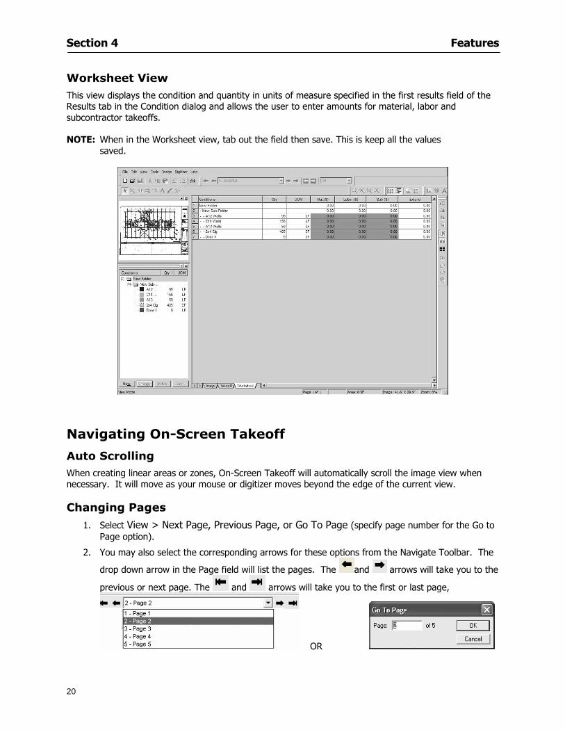
Section 4 Features
20
Worksheet View This view displays the condition and quantity in units of measure specified in the first results field of the Results tab in the Condition dialog and allows the user to enter amounts for material labor and subcontractor takeoffs
NOTE When in the Worksheet view tab out the field then save This is keep all the values saved
Navigating On-Screen Takeoff
Auto Scrolling When creating linear areas or zones On-Screen Takeoff will automatically scroll the image view when necessary It will move as your mouse or digitizer moves beyond the edge of the current view
Changing Pages
1 Select View gt Next Page Previous Page or Go To Page (specify page number for the Go to Page option)
2 You may also select the corresponding arrows for these options from the Navigate Toolbar The
drop down arrow in the Page field will list the pages The and arrows will take you to the
previous or next page The and arrows will take you to the first or last page
OR
Section 4 Features
21
3 Or press Ctrl G for the Go To Page dialog
Hot Links Hot links allow you to move quickly from one drawing to the pertinent area of another drawing A hot link is handy when viewing enlarged areas of a page and needing the ability to jump back to a reference page
1 Select Tools gt Hot Link
OR
2 Click from the Tools Toolbar
3 Click on the page where you want to set the link The Hot Link dialog will open
4 Using the current page display on the Navigate Toolbar access the pull-down menu of pages by
clicking on the arrow at the right
5 Select the page for your link (You may also choose View gt Go to Page and select by page number)
6 Manipulate the view using the zoom tool and the scroll bars
7 Click
8 After joining a hot link to another page the hot link arrows in the Navigation Toolbar will become active
9 Move a hot link to another location on the page by clicking then click and drag the hot link image anywhere on the page
Section 5
22
Projects
This section will
Help you create settings important to your projects
Explain how On-Screen Takeoff works with your electronic or paper plans
Section 5 Projects
23
Project Template Files You can begin your project with a template Templates allow you to take advantage of conditions and settings used with previous projects
On-Screen Takeoff templates contain condition lists and established layer separations from previous projects you have created You may also use the sample templates provided with On-Screen Takeoff as a great starting point All aspects of the templates may be adjusted for a new project
1 Select File gt New and click the OK button
2 From the New dialog box choose the template that best fits your project
3 The conditions for this template will appear in the Takeoff Dock bar and the Project Properties dialog will open asking for further information
4 Use File gt Save or File gt Save As to rename and save your new project
Saving a Project as a Template File You can save your condition properties and layers as a template for future projects
1 Select File gt Save As
2 Enter a name for your template and select On-Screen Takeoff Template Files (tpo) from the Save As type field of the dialog (click on the down arrow to select)
3 Click the OK button to accept and close the dialog Modifying a Template File Follow these steps to modify an existing template file if you need to change or add conditions andor layers
1 Select File gt Open
2 Navigate to your Projects directory
3 In the File Type drop-down select On-Screen Takeoff Template files (tpo)
4 Choose the On-Screen Takeoff template file you would like to modify and click the OK button
5 Make appropriate changes
6 Save and close file
The On-Screen Takeoff template files cannot save takeoff information
Section 5 Projects
24
Opening an Existing Project File 1 Select File gt Open
2 Navigate to the desired file location
3 Click the Open button
NOTE If your latest changes to a project file have not been saved On-Screen Takeoff will ask
you whether you would like to save the file and gives you the option of canceling the operation
Creating a New Project
1 Select File gt New
2 For a blank untitled project click
3 At this point the Project Properties dialog will pop-up for more information about your takeoff
NOTE The following are important to keep in mind when beginning a new project
At the start of your project fill out the Project Properties settings to establish the name for all printed output from your project set the default page size and scale for your plans number and names of different pages within the project and locations of electronic drawings
Scale settings can significantly affect quantity outcomes Be sure to set the scale for each page of drawings before beginning condition takeoffs
When using a digitizer remember to make a mark with a pen or pencil in the upper left and lower right corners of the first sheet of the paper plans to delineate the takeoff area for that sheet You can then set the takeoff area on On-Screen Takeoff using your marks
Save your project before you begin taking off any conditions On-Screen Takeoff will write a back-up file using the same file name
Remember the Undo feature If you make a mistake select Edit gt Undo and reverse the process step by step
Section 5 Projects
25
Project Properties
You can either set your Project Properties when you create a new takeoff or once your project file is saved under the appropriate name
1 Select File gt Project Properties the Project Properties dialog box will appear
2 Type in the name of your project to appear on printouts Use the backspace andor delete keys to edit the name as necessary
3 Press the Tab key to move to the Default Image Size option or click within the Image Size box You may click on the arrow at the right for the pull-down menu of page size options or you can use the down-arrow key on your keyboard to scroll through the list to the appropriate selection
4 Press the Tab key to move to the Default Scale option Select a scale by using the drop down arrow If your scale is metric you will need to click in the box next to Metric to convert to that measurement
5 Establish the number of pages for your project plans And load image files See Adding Pages to
Your Project
Adding Pages to Projects Individual Electronic Plans
1 Click on in the Project Properties dialog
2 In the Add Images dialog use the drop down arrow to navigate to the appropriate directory and folder containing your image
3 Select the file so that it displays in the File name field then click The file will display by name and path in the Image File field in Project Properties dialog
4 Click to accept and your project will automatically open
5 Save your project with the new settings by selecting File gt Save
Section 5 Projects
26
Electronic plans scanned from blueprints (as opposed to blue lines) will display as white lines on a black background and are difficult to read on your computer screen Select Image gt Invert and the colors will invert to black on white
You may have noticed the Page column in the Project Properties dialog Generally plan images occupy one page and 1 will be listed in the column indicating Page 1 of your plan file If you import a multi-page TIF a plan file containing more than one page of plans they will import as separate pages and each successive page will be indicated under the Page column as 1 2 3 etc of the plan file
Group of Electronic Plans You may add all the electronic plan files from a particular source (for example from a CD) by using the Auto Add feature
1 Click the button in the Project Properties dialog
2 Browse until you find the appropriate directory and folder containing your plan images
3 Click on any file displayed within your target folder so that the file name appears in the File name box of the Auto Add dialog
4 Click The image paths and file names will be recorded into the project properties arranged alphabetically
5 Click to accept your choices and your project will automatically open
6 Save your project with the new settings by selecting File gt Save
To load Dodge Plans into your Project Properties see Appendix IIi Loading Plans from a Dodge CD
Paper Plans On-Screen Takeoff makes it easy for Full Mode users to perform quantity takeoffs from paper plans using a digitizer
1 Add pages by clicking until you have the number of pages initially in the project
2 Name each page by clicking within the Title area and typing the name
3 Click to accept your choices and close the Project Properties dialog
4 Save your project with the new project properties settings by selecting File gt Save
Section 5 Projects
27
Setting Up a Drawing Template On-Screen Takeoff provides the convenience of using the same work surface for both digitizer and mouse to allow the user to draw conditions and then edit settings of the project or add or change conditions without breaking stride A mouse pad template included with the program defines the area of the digitizer in which use of the stylus or cursor will be recognized as mouse movement as opposed to drawing movement
1 Place your stylus on On-Screen Takeoff
2 Placing the template identifies the location mouse movements will be recognized by the program
Before placing the template the template must be applied to the digitizer surface This may have been done during the installation of your digitizer We suggest attaching the template to the lower right corner of the digitizer surface about one inch inside the grid area
3 Select Digitizer gt Place Template
4 Follow the instruction prompts on the screen clicking first on the target symbol at the left of the On-Screen Takeoff box on the template then on the target at the right
Setting Takeoff Area Before you can begin taking off a drawing you must define the drawing area on the digitizer This requires defining an area that will include all objects on each drawing of your plans As you add pages to your takeoff the same area of the digitizer will be active
1 Secure the plans to the digitizer with tape or a set of clamps
2 With a pen or a pencil mark the upper left corner and the lower right corner of the first page in your set of plans
3 Select Digitizer gt Set Takeoff Area
4 Click each mark with the stylus pen as prompted
5 Verify the active area of the digitizer by looking at the image size located in the lower right corner of your screen
If you close the program before the takeoff is complete you will need to reestablish the takeoff area before you can add additional condition quantities
Electronic plans appear on your computer screen eliminating the need to set a takeoff area You simply drag your mouse across the conditions you wish to takeoff The conditions will be highlighted and quantities will be totaled instantly Electronic plans are available through a variety of services For information contact an On Center Software account manager
Section 5 Projects
28
Setting Scale for Specific Pages You may set the scale in each page view separately This will override the default scale setting in Project Properties for that page Setting the correct scale for the drawing before taking off quantities ensures accurate calculations Be careful to check the scale for each drawing in your project before doing takeoffs
1 Display the page you want to set select Edit gt Set Scale
2 Use the drop down arrow to select a scale that will be applied to that page
3 Click
OR
4 Access the pull-down scale settings on the Navigate toolbar
NOTE As you draw objects notice that the drawn object is similar in width to the object on your plans If it is not the scale set may not be correct
Calculating Scale You may calculate scale according to a known measurement between two points either with a digitizer or on electronic plans
1 Select Edit gt Calculate Scale using Image or Edit gt Calculate Scale using Digitizer
2 Follow the instructions in the related Calculate Scale dialog box You will be asked to click on the first and second points then to enter the dimension for that distance
3 The scale will be recalculated for the displayed page and the Scale display on the Navigate toolbar will show the new scale
Section 6
29
Conditions and Takeoff
This section will Draw Conditions to Takeoff Plan Quantities
What Zones will do to help your takeoff process
Discuss the ins and outs of Takeoffs
Section 6 Conditions and Takeoff
30
Creating Conditions
If you are starting a new project from scratch you will need to create conditions to takeoff quantities such as floor areas wall lengths and corner bead counts If you are using a template you will have several pre-designed conditions already listed on the Takeoff dock bar However you may want to change the characteristics of some conditions or create additional conditions for a particular project
1 Right Click within the Takeoff dock bar Select New gt Condition
Or
2 From the Takeoff dock bar Click (if the buttons are not showing right-click in the Takeoff dock bar area and select Show Buttons from the pop-up menu) The New Condition dialog appears
3 Select the condition type (Linear Area Count or Zone) from the pull-down menu accessed by the
down arrow next to the Type option
4 Press Tab or use the mouse (or stylus) to move to Name and enter a name for your condition
5 Specify the desired condition attributes See Condition Attributes for more detail
6 Click for condition to apply
Section 6 Conditions and Takeoff
31
Condition Attributes Each condition type will have related attributes to select or specify within the General and Advanced tabs of the New Condition dialog Once a condition has been used to takeoff a quantity from your plans certain attributes cannot be changed
All conditions allow the user to specify color and fill pattern for the object drawn
Linear Conditions
General Specify width and height by feet and inches Specify pitch in inches up to the nearest thousandth of an inch if applicable
Advanced Specify rounding for object quantities and droprun default length for electrical or plumbing drops at the ends of lines Select Connect to have lines connect at the corners where one line of the condition ends and another begins (and indicate Tolerance for the featurersquos activation as distance between the ends of two lines) Choose Trim to have lines automatically trim to a line being crossed Choose Curve to draw a curved line
Follow these examples for inputting feet and inches For 7 feet 6 inches type 706 for 13 feet 7 inches type 1307 For 20 feet type 2000
Section 6 Conditions and Takeoff
32
Area Conditions
General If needed you can specify the thickness (in inches) andor pitch (in inches)
Advanced Specify rounding for object quantities Choose to display an adjustable grid within the area and indicate matrix cell dimensions
Section 6 Conditions and Takeoff
33
Count Conditions
General
Specify height and indicate the size (in inches) and shape (square circle triangle rectangle or opening) of the count object as it will appear on screen
Advanced Count conditions have advanced attributes These options are available for all shapes except for openings
Zone Conditions Zones allow you to subdivide condition quantities making it easier to modify and complete jobs in phases They can be used at the end of a takeoff to isolate a group of condition quantities that are in different areas of the takeoff
Zones can also be used to break a takeoff into multi-phases and can even be used to isolate quantities while a job is in progress to group the amount of work that has been completed to date They can be applied to one or multiple pages in your plans automatically calculating the takeoff quantities for each zoned area
Section 6 Conditions and Takeoff
34
The zone feature is only available in Lite and Full Mode If you are in View Mode and would like
to use this feature click from the main toolbar to purchase the upgrade
Condition Notes A Note tab is provided for comments regarding the condition These notes will display on the Takeoff List report and will import into Quick Bid
Section 6 Conditions and Takeoff
35
Condition Results The Results tab of the New Condition is based on condition type Initial settings default to linear feet (LF) for linear conditions square feet (SF) for area conditions and count of items (EA) for count conditions and zones The first of the results fields will display for the condition items in the Takeoff dock bar area All results will display in worksheets and Takeoff List reports as well as in an Excel spreadsheet after being exported
Copying Conditions You may use the condition attributes from a condition yoursquove already created for any future conditions of the same type
1 Click on a condition to select it
2 Click the Copy button from the toolbar
OR
3 Right-click in the Takeoff dock bar area and select copy
4 A new condition will appear in the list with the same condition attributes as the previous condition but with the quantities zeroed
Editing Conditions Once you have copied a condition you might want to change several attributes You can also edit an existing condition to fit any updated needs
1 Highlight the desired condition on the Takeoff dock bar
2 Click the Change button
OR
3 Double-click on the condition you wish to edit to bring up the Change Condition dialog
NOTE The Change Condition dialog differs from the New Condition dialog only in that if takeoffs
Section 6 Conditions and Takeoff
36
have been performed in your project with this condition you will not be able to change the type of condition or certain properties under the advanced tab of the dialog box
Deleting Conditions 1 Click on the condition in the Takeoff Dock bar area
2 Click the Delete button on the toolbar
OR
3 Right-click and select Delete from the pop-up menu
All takeoff associated with the deleted condition will be deleted immediately and permanently
Organizing Project Conditions Within your project you can create folders andor sub-folders for different types of conditions You may even want to create a folder containing conditions with reset values
To get started organizing your conditions make sure you are viewing the condition tree (right-click in the Takeoff dock bar area and select Show Tree)
Creating Folders and Sub-Folders 1 Right-click in the Takeoff Dock bar area
2 Select New gt Folder from the pop-up menu
Copying Folders
1 Click on the folder and click Copy on the toolbar
2 All copied conditions within the new folder will have values reset to zero
Renaming Folders
1 Click on the folder
2 Right-click and select Rename from the pop-up menu
3 Enter a name for your folder and click the Enter button
Changing Condition Order
You may move conditions up or down in the condition list of the Takeoff dock bar to suit your project needs
1 Select the condition you would like to move by clicking to highlight it
NOTE When you are ready to move the highlighted conditions be sure that you start
moving using the last condition chosen That condition will have a highlighted boarder
Section 6 Conditions and Takeoff
37
2 Drag and drop any the condition from one place to another in the list You may also move a condition to another folder on the list in this way
Drawing with Conditions Snap Angles Set up snap angles to prevent lines from appearing jagged Snap angles are commonly set at 15deg and shift snap angles at 0deg
1 Go to Tools gt Options Options dialog appears
2 Under the General tab make the desired settings
3 Click to save the settings As they are drawn lines will snap to the set degree
Drawing a Linear Object 1 Select a condition from the Condition List in the Takeoff dock bar
2 Move the cursor into the Image takeoff area of the screen you will see the cursor display as crosshairs
3 Click and hold left mouse button then drag mouse to draw a line
4 Release mouse button to set line
Section 6 Conditions and Takeoff
38
5 Repeat steps for further lines
Continuous Mode This feature allows you to draw an object that has connected lines
1 Click the icon from the Takeoff toolbar
OR
2 Go to Tools gt Continuous Mode
3 Follow steps 1-3 from Draw a Linear Object
4 Click at each point of intersection The object will be connected
5 Double-click after making the final point to set the lines
Drawing a Curve To draw a curved line the Curve option must be checked under the Advanced tab of the Condition dialog
1 Click where you want to begin the curve and drag in a straight line to the position for the other endpoint of the curve
2 Click on the line to select it Handles in the shapes of small squares will appear at either end of
Section 6 Conditions and Takeoff
39
the line and in the center of the line
3 Move the cursor over the center handles until the cursor becomes a two-way arrow
4 Click and drag in the direction of the curve bending the line as you move the cursor Release to set the curve (The line you began with will disappear)
Draw a circle by drawing two curved lines connected
Drawing an Area Object Area conditions are drawn similarly to continuous mode lines You may trace any number of adjoining walls at different angles to complete your area takeoff
NOTE When drawing an area do not intersect the perimeter or line of the object you are drawing
1 Click at each point
2 Double-click when yoursquove returned to your starting point
3 The area will be filled with the pattern set for that condition
NOTE The simulated circle will be good enough for you to be able to make a bid
To create a circular area click from point to point with very short distances in between points simulating a circlersquos perimeter Double-click after setting the last point to set the area
Section 6 Conditions and Takeoff
40
Grid Options Grids give you an added advantage when installing materials such as tiles Use this feature to get a count for how many tiles are needed for an area
1 Double-click on an area condition in the Takeoff dock bar to open its Condition dialog
2 Click on the Advanced tab to show its options
3 Check the box next to Grid by clicking in it
4 Indicate the dimensions of the cell matrix in inches (For example 200 x 400)
5 Under Results tab choose each (EA) for one of the results fields This will tabulate a number of grid cells (including partial grid cells) in area
6 Click to save your settings
7 Use the Move Grid and Rotate Grid features in the Tools menu to manipulate the grid as desired
Grid Calculation
1 Go to Tools gt Options menu
1 Specify if On-Screen Takeoff automatically should Calculate Grid Position
2 If AreaGrid Size is selected On-Screen Takeoff will calculate the number of items needed to fill the grid based on grid demintions
3 Click to accept and close the dialog
To move a line at any angle (regardless of default setting) press the Shift key while moving the mouse
Section 6 Conditions and Takeoff
41
Backout Mode This feature allows you to take out part of an area and deduct that amount of square footage
1 Select Tools gt Backout Mode
2 Outline the are you want backed out as you would when drawing a regular area object (see Drawing an Area Object)
3 The outlined area will clear and quantities will be recalculated
NOTE The perimeter of the backout area will be added to the LF quantity for that condition
Drawing a Count Object Square triangle rectangle and circle shaped count objects can easily be placed on images
1 Select the condition
2 Click in the location where you want the object to appear
3 To place an opening-shaped count item like a door or window you must click over an existing linear object such as a wall
4 On the Results tab you can change the height properties to give you the result you need
5 If Backout is checked on the advanced tab for each count opening the opening-shaped count item will back out a corresponding section of the linear object
Opening shaped count items are sized at 3rsquo0rdquo by default
Drawing a Zone Zones are drawn in the same way as area objects and may be any polygonal shape You may trace any number of adjoining walls at different angles to complete the zone perimeter
1 Click at each point
2 Double-click when yoursquove returned to your starting point
Section 6 Conditions and Takeoff
42
Selecting Objects
1 Use the Select Tool to select objects
You can also select all objects that correspond to a condition
1 Click on a condition to select it
2 Right-click and choose Select All
3 All objects with this condition will be highlighted with squares as an outline
Moving and Resizing Objects Linear
1 To move or resize a linear object click anywhere on the line to select it
2 To move the line position your pointer over the center handles When the mouse is positioned over the handles you will see a two-way arrow You will only be able to move the line in the direction of the arrows
3 Drag the line to a new position
4 Clicking and dragging the handles on the ends of the line will allow you to lengthen or shorten your line
Area and Zone
1 To move an area object or zone in its entirety click and drag it to its new position
2 Grabbing a handle at a corner or intersection of the object will allow you to adjust and change its perimeter
Section 6 Conditions and Takeoff
43
Count 1 To move a square circle rectangle or triangle shaped count object click and drag
2 Click and drag an opening shaped count object along the length of the linear object to the desired position then release
NOTE An opening shaped count object may not be moved from its associated linear condition object however it may be moved up and down the length of the linear object
Layers On-Screen Takeoff allows you to sort and separate your takeoff objects within the same job and on the same page On-Screen Takeoff gives you this flexibility through the use of layers
By assigning different conditions to different layers (for example differentiating between floors ceilings and walls) you can choose to view all layers or turn off certain layers to display and print the remaining groups of conditions only You may also remove the background image of electronic plans add text and hot link symbols or print only your condition takeoffs
Layers are only available in Full Mode If you are in View or Lite Mode and would like to use this
feature click from the main toolbar to purchase the upgrade Default Layers
On-Screen Takeoff begins every project with three default layers Image Annotation and Default The Image layer holds the electronic plan files you may have in your project The Annotation layer possesses all text notations highlighting and hot links in the project The Default layer will appear in the Condition dialog when creating or editing a condition (listed in the takeoff dock bar) Conditions are assigned to the Default layer unless otherwise specified by the user
Creating Layers To assign a condition to a layer other than the default layer you must first create additional layers for your project
1 Select View gt Layers to open the Layers dialog
2 Click An unnamed layer will be added
3 Click within the empty box and type a name for your layer (for example Wall)
4 New layers are added as active layers The adjacent box under the Show column will be checked
Section 6 Conditions and Takeoff
44
Assigning a Layer to a Condition 1 Open the Condition dialog box by creating a new condition or editing an existing condition
2 Under the General tab click on the down arrow in the Layer field to display optional layers
3 Select the desired layer for the condition Only the Default layer and layers you have added will be displayed
4 Click
View and Hide Layers
1 Select View gt Layers
2 Under the Show column check the box to view or remove the check (by clicking on it) to hide the specific layer
3 Click to accept and close the Layers dialog
Section 6 Conditions and Takeoff
45
Assigning Text to a Layer When adding text to an image On-Screen Takeoff has the capability to assign the text to a specified layer
1 Select the Text Tool
2 Click at the point you want to place your text
3 Type in your text using the Enter key for line breaks
4 Click the drop down arrow next to the Layer field and select the desired layer
Section 7
46
Printing and Exporting
This section will
Printing options and procedures
Exporting data by copying and pasting
Exporting quantity results to Excel spreadsheets
Section 7 Printing and Exporting
47
Print Setup On-Screen Takeoff allows the user to print the image takeoff list and worksheet
1 Select File gt Print Setup The Print Setup dialog will open
2 Select a printer or leave the default selection listed (change from the default printer displayed by clicking on the down arrow at the right of the field)
3 Indicate page size and printer tray option (Source) Access page size options by clicking on the
down arrow at the right of the field
4 Choose Portrait or Landscape orientation
5 Click to accept and close the dialog
Printing Images The image area can include the electronic plans the takeoff objects added text and hot links To print a subset of these (for example just the takeoffs without the plans or the added text and hot link symbols) hide layers that you do not want to print (see Section 6 View and Hide Layers) When you are printing your images every page will show the scale of the takeoff you are printing
1 Click on the Image tab to display the area of your project
2 Select File gt Print (or Ctrl + P)
Section 7 Printing and Exporting
48
3 Select the desired view (What to print) and the Image Range
4 Click The second Print dialog will open
5 Change settings accordingly or click if you accept the default settings
Printing Takeoff Lists and Worksheets In Takeoff Lists and Worksheets you may hide columns to print only certain results or adjust column widths to fit the report within the page size selected
1 In Takeoff List or Worksheet view move your cursor to the right side of the columnrsquos title bar the cursor will display as a two-way arrow
Section 7 Printing and Exporting
49
2 Click and drag to adjust the width of the column Holding the mouse button you may
slide the title bar under the title bar to its left to hide the column completely
3 Select File gt Print or press Ctrl + P to access the Print dialog
4 Indicate desired printer and choose the number of copies
5 Click to print and close the dialog
When printing the condition list we suggest printing in landscape
To reset to the default column widths double-click on the right border of a column heading will reset the column to its right (or previously to its right before being hidden)
Print Preview 1 Select File gt Print Preview
2 Use and to vary your view 3 If viewing an image choose current full or scale view to see how it displays
4 For printed outputs that cover more than one page use and to view adjacent pages or click on the down arrow next to Page field and select the page you want displayed
Exporting Using the CopyPaste Feature You may copy all the data or sections from the worksheet and the takeoff list view in On-Screen Takeoff and paste it into another application When pasting into Excel the cell layout will be maintained
1 Highlight the areas you wish to paste Click and hold the left mouse button down as you drag the cursor over the area to be selected then releasing the mouse button
OR
2 Select the entire takeoff list quickly click on the left On-Screen Takeoff column header and hold and drag the cursor across the remaining column headings
The number of pages for the view selected will display in the lower left-hand corner The zoom percentage that applies to the view will be displayed in the lower right-hand corner next to page size of the drawing
Section 7 Printing and Exporting
50
3 In the worksheet view you may highlight rows by clicking on the numbered buttons to the left of each row clicking and dragging across column headings or clicking and dragging over individual cells in the worksheet
Click anywhere in the appropriate view to deselect the area
4 Once your selection is highlighted you may select Edit gt Copy or Ctrl C from the keyboard 5 On your monitor switch to the application into which you want to paste your selection 6 Select Edit gt Paste in the new application or simply press Ctrl + V to paste
The colored keys for conditions cannot be pasted
Using the Export Feature You may export condition quantities to specified cell location within an Excel worksheet file Cell target locations are assigned in the Results tab of the condition dialogs on the Export line relating to each quantity measurement type
On-Screen Takeoff will export takeoff quantity results for up to three different quantity types that you specify For instance you may want to know the number of square feet in a ceiling area as well as the number of linear feet in its perimeter
Section 7 Printing and Exporting
51
1 Bring up the Condition dialog by double-clicking on a condition in the takeoff dock bar or by
selecting the condition and clicking
2 Click on the Results tab to access its fields The default quantities for the condition type will display
3 For each results field click on the arrow to access the pull-down menu and select the appropriate quantity (for example SF LF EA etchellip)
4 Have your Excel spreadsheet opened and saved in a file
5 Specify the Excel spreadsheet cell locations where you want the results to go
6 For a cell in the first sheet of your spreadsheet type in the cell address (eg a1) Case is not important
7 For a cell on a successive sheet of your spreadsheet type in sheet the number followed by a comma and the cell address without any spaces (eg sheet2a1) Case is not important
8 Click
9 Select File gt Export gt Condition Qty to Excel
Section 7 Printing and Exporting
52
10 Browse to the location of the Excel spreadsheet file click file to select it
11 Click to export On-Screen Takeoff results to specified cell locations in the Excel file When you return to the Excel application you will see the values have been added to the specified cell locations in your spreadsheet
12 Save your Excel file
Exporting Worksheet to Excel
1 Assign condition quantities you want to export
2 Open saved Excel spreadsheet file to which you will be exporting
3 From On-Screen Takeoff Select File gt Export gt Worksheet to Excel
4 Browse to the location of the Excel spreadsheet file click file to select it
5 Click When you return to the Excel application you will see the values from the Worksheet Tab have been added to your spreadsheet
6 Save your Excel file
Exporting Takeoff to CVS 1 Assign condition quantities you want to export
2 Open saved Excel spreadsheet file to which you will be exporting
3 Click the Takeoff Tab in the project you want to export the information
4 Select File gt Export gt Takeoff to CSV
5 Browse to the location of the CSV spreadsheet file click file to select it
6 Click the Save
NOTE CSV files can be opened in Excel Lotus Access etc One may consider this option more of a ldquodumprdquo into a file
The Excel application must be active (it may be minimized on the application bar) with the target spreadsheet open in the application Otherwise an error will occur with the export operation that will affect both the On-Screen Takeofftrade file and the Excel spreadsheet
Section 8
53
Advanced Features
This section will
Some special features of working with condition objects in the takeoff area
Details of advanced options for conditions
Advanced features of the Project Properties dialog
Section 8 Advanced Features
54
Features to Use with Objects Roping Feature You can move copy or delete using this feature Using the Select tool (the pointer) you may select several objects at once by clicking and dragging an outline around the objects then releasing the mouse button Roping may select either objects completely within the outlined area (inclusive) or objects both within and touched by the outlined area (touching) Specify your roping preference under Tools gt Options
1 Click and hold the mouse button at a point on the screen near the objects to be selected and drag to surround the objects with an outline
2 Release the mouse button The objects will be selected
3 You may now
Move the group around on the page by clicking within the group dragging the mouse and releasing the button to place the objects
Delete the group of objects by clicking the Delete key or
Copy and paste by pressing Ctrl C to copy the group then Ctrl V to paste it The pasted copy of the grouped objects will appear slightly offset from the original objects
Section 8 Advanced Features
55
Applying a DropRun Count
Use the droprun feature when calculating quantities to take into account the drop or run of a linear condition such as electrical lines or plumbing pipes Drop or run lengths may be added separately to any linear condition on screen while a default droprun length may be indicated for a condition as a whole
1 Select the desired linear condition from the Condition List in the Takeoff Dock bar
2 Click the Change button in the toolbar to open the Change Condition dialog
3 Click the Advanced tab to access the advanced options and click inside the DropRun check box
4 Enter a default length to be applied to all of this condition Entering 800 will be interpreted as 8 0 (You must enter both place markers for inches) You can leave the length blank and manually enter drop run on each segment drawn
5 Click the OK button to accept and close the dialog
Edit DropRun Count
1 With the related linear condition in the Takeoff Dock bar highlighted or with the pointer tool selected
2 click on the desired linear object in the image takeoff area The Count button will become active
3 Click on the Count button (alternatively select Tools gt Count) The default droprun amount will show in the pop-up Count dialog (Default length will be zero if droprun has not been selected in this conditionrsquos properties)
4 Type in the desired length Entering 800 will be interpreted as 8 0 (You must enter both place markers for inches)
5 Click the OK button The additional amount will be reflected in the corresponding quantity The new DropRun count will apply only to the object edited
Adding Text in Image View
On-Screen Takeoff allows you to place text comments around your quantity takeoffs that may be printed along with plan images and objects Text is automatically placed within the Annotation Layer (that includes text and hot links)
1 To place text on the image select the Text Tool and click at the point you want to place your text opening a text box
2 Type in your information clicking Enter for line breaks
3 When you are finished click the OK button to exit the text box
4 To reposition text simply click on the text (with the Text Tool active) to select it
5 Move the cursor over the text the cursor will now display as a four-way arrow
6 Click and drag the mouse to position the text as desired
Section 8 Advanced Features
56
1 To edit existing text use the Text Tool to double-click on the text to open the editing box
2 Enter additional text or use the Backspace key to delete text as necessary
Formatting Text Once created you may format the font size type style and color of your text
1 Click on the text to select it and select Tools gt Font or click on the Font button in the Takeoff Toolbar
2 Select the desired features (color options are disabled) and click the OK button
3 Click on the text to select it and select Tools gt Color or click on the Color button in the Takeoff Toolbar The Color dialog will open
4 Click on a color in the Basic Color palette or create a color and add to the Custom Colors palette (Be sure to click on the color in the Custom Colors palette to select it)
5 Click the OK button
Object Properties
Linear Objects
Linear objects may be set to connect at corners
A linear object may be set to trim automatically when crossing another linear object (Check the trim option under the advanced tab of the Condition dialog)
When you move a connected linear object objects automatically move and resize connected lines accordingly (quantities are then recalculated)
This feature requires that the connected linear object be moved using the center handles (does not apply when resizing the line from the ends)
Objects constrain to snap increments defined in the Tools gt Options menu (with the mouse 15deg by default incremental when shift key is held down)
Objects are measured from centerline to centerline
Section 8 Advanced Features
57
Area Objects When drawing an area use your escape key to undo the last line drawn You may reverse your
drawing of an area using the escape key
The area will not fill with color and pattern until the user double-clicks after the last line is set
Lines drawn to delineate an area object constrain to snap increments defined in the Tools gt Options menu (with the mouse 15deg by default incremental when shift key is held down)
After selecting an area to move or adjust position the mouse in the center to move the entire area position the mouse at the sides or corners to adjust the perimeter
Count Objects
All count objects are quantified by the physical number of objects per page and reported as EA for the UOM The quantity for the current Image View is (displayed in the Condition List) and the total quantity in your project is displayed in the Takeoff View and Worksheet View)
Square circle rectangle and triangle shaped count objects do not displace or subtract from other object quantities when placed on top of them However on the Advanced Tab for the count condition a connect property can be set (this is a check box) so that when a count object of this shape is put on top of a Linear type takeoff object it will move with the linear if said linear is moved
An opened-shaped count object must be placed within a linear object Opening shaped count objects may also be measured by linear foot or linear yard (EA SF and SY are also options) Opening shaped count items default to a width of 3rsquo 0rdquo at the time of creation This size can be changed The small medium and large size are not options on this type of condition anymore Check Backout on the Advanced tab for each Count object back out the footage (or yardage) of opening-shaped count objects in which they are placed
NOTE In order to see this Backout functionality (in quantity) for SY or SF deductions at least one of the
results for the Linear(s) this object will be placed on must be set to SY or SF and the count object must have a height quantity
Advanced Features of Conditions The Round Feature Under the Advanced tab of the linear and area Condition dialogues you may specify quantity rounding (in inches) For linear objects rounding applies to each linear object drawn For area objects rounding will apply to each segment of the area perimeter adjusting the perimeter and area calculations For example With a linear condition entering 12 in the Round field will round up each related linear object to the nearest 12 inches or one foot With this setting two walls of 1 4 would each round to 2 0 totaling 4 0
NOTE In the Takeoff Dock bar condition list and in the On-Screen Takeoff reports quantities will be displayed in whole numbers rounded up to the nearest foot However calculations are based on true quantities without rounding unless the Round Feature is engaged
Pitch Pitch may apply either to linear or area conditions It is measured in rise per linear foot Entering 12 indicates a 12 rise per 12 of linear distance (a pitch of 12 over 12) or an angle of 45deg
Section 8 Advanced Features
58
Advanced Features of Project Properties Selecting Multiple Pages
1 Select a single page entry by clicking on the numbered gray button to the left of the entry
2 Drag the cursor down the column of numbers to select consecutive pages
3 Click on the blank button at the top of this column to select all pages in the Properties dialog
Section 8 Advanced Features
59
Changing Image Assigned to a Drawing 1 Select the page entry by clicking on the numbered gray button to the left of the entry 2 Click the Change Image button The Change Image dialog box will appear
3 Navigate to the desired file and select by clicking on it
4 Click the Open button The electronic file assigned to the page will have been changed to reflect the new file choice
Changing Image File Path 1 Select pages as described above
2 Choose Change Folder
3 In the Change Folder dialog navigate to the appropriate folder
4 Click the OK button The file path will have been changed for the selected page entries
Delete a Page from Project Properties 1 Select the page you want to delete by clicking on its associated number (in the gray box at the
left of the entry)
2 Choose Delete Page
All Takeoff on the page will be deleted immediately and permanently
Section 8 Advanced Features
60
Advanced Features of Tool Options
Calculation Method On-Screen Takeoff has built-in calculation options to allow for faster work and faster saves until your takeoff is complete Calculation options are found by selecting Tools gt Options then clicking on the Calculation tab
Calculation method can be set to Automatic Automatic except Grids and Manual Manual will allow the program to operate more quickly while Automatic or Automatic except Grids allows the user to see quantity changes as takeoffs are made
In any mode you may press F9 to recalculate quantities for the On-Screen Takeoff current totals
Configuration Tab
When the ldquoPage Label (A01)rdquo radial button is chosen On-Screen Takeoff puts the numbered label on all the pages of in your current page indicator in your Navigate Toolbar If the Page Descriptionrdquo radial button is chosen then a description of what takeoff is on that specific page will be shown in your current page indicator in your Navigate Toolbar
This section of the configuration tab gives you options on how you want to export your information When the ldquoFolderSubfolder Namesrdquo radial button is chosen than on your file that you are exporting to will have all the conditions folders and subfolders In the Delimiter box you can choose the symbol that is needed to separate the information you are exporting Some files need semicolons () or colons () to make sure the information comes exported in is separated it the appropriate places
Section 8 Advanced Features
61
In previous versions of On-Screen Takeoff there are views that users need to have in order for them to display their information By either choosing ldquoOST 1xrdquo or ldquoOST 2xrdquo it will let the program know you want your columns of information exported in that specific format
When you have the Confirm Deletions radial button of ldquoYesrdquo chosen than every time you delete anything you will get a dialog box confirming your intentions of deletion
While working with your takeoff you have a choice to either view the legend of your conditions or hide it Choose whichever radial button that suits your needs
For those who prefer to use the Enter key to navigate in dialog boxes this option is just for that
Font Tab The Font tab is designed for you to make your own look and feel for the application At the bottom of this tab it will show you sample of the fonts and colors you have chosen
Renaming the Current Page You may change the name of the current page in the takeoff area of On-Screen Takeoff by selecting Edit gt Rename Page
This opens the Name Page dialog and you may simply type in a new name and click the Enter button The new name for the file will be reflected on the title bar for the page and in Project Properties
You also may access the Rename Page function by right-clicking in the takeoff area while in Image View and selecting the option from the pop-up menu that appears
Section 9
62
Saving and Exiting
This section will
Explain how to save projects
Show you how to safely exit the program
Section 9 Saving and Exiting
63
Saving Your Project
1 Select File gt Save 2 If your project has not previously been saved a Save dialog box will open to allow you to name
the file and choose the directory and folder in which to save your file 3 Once saved File gt Save will simply save the current version of the file
OR
4 Select File gt Save As then type in a new name for the file and save to the desired file path
The Auto-save Feature With the Auto-save feature On-Screen Takeoff automatically backs up your open project You may choose to have more than one level of backup files The first backup copy will have the extension b00 and successive files will be b01 b02 and so on If you have designated four levels of backup files after the fourth backup copy has been created (b03) the next file will be saved over the file with extension b00 Further backup saves will then rotate through the four backup files in the same way
1 Select Tools gt Options 2 In the Auto-save area (under the General tab) select the frequency of backup file creation (in
minutes) and the number of levels for the feature 3 You also may disengage the feature by clicking in the check box to clear it
The Auto-save feature automatically saves backup copies to the directory of the current project If you are working from a write-protected area such as a CD-ROM On-Screen Takeoff will place backup files in the On-Screen Takeoff folder
Exiting When you are finished using On-Screen Takeoff it is very easy to exit Exiting is very important because of security reasons If someone were to use your computer they could enter the application and view and manipulate information
Section 9 Saving and Exiting
64
On-Screen Takeoff closes the open project when you open another or create a new project or when you exit the program
1 Select File gt Exit
OR
2 You also may click at the upper right-hand corner of the application to exit
NOTE If your latest changes to a project file have not been saved On-Screen Takeoff will ask you whether you would like to save the file and gives you the option of canceling the operation
Appendix I Installing Your Digitizer
65
Appendix I Installing Your Digitizer When you get your digitizer from GTCO you will need to connect it to your computer Follow the instructions outlined below to do this
Note For rollup digitizers the metal bar must be oriented to the top or right hand side
Connecting the Digitizer 1 Lay the digitizer out flat 2 Connect the Stylus to the digitizer 3 Plug in the power adapter 4 Plug the interface (IO) cable into the digitizer 5 Plug the other end of the interface cable into an open serial port on computer
Note GTCO Technical support phone number is 410-381-6688 The electronic manual (on diskette) from GTCO contains more detailed installation and operation instructions for the GTCO digitizer model you have
Installing other Digitizer Drivers If you are using a GTCO Digitizer you will need to install the GTCO TabletWorks Drivers
If you are using a Digitizer not supported by GTCO Tablet Works 10 please contact the manufacturer of your digitizer for assistance with installation
Installing GTCO TabletWorks Drivers 1 Insert the On Center CD into the CD-ROM drive The CD Startup screen will open 2 Click on Install Software 3 Select Additional Software and Drivers 4 Select Digitizer Driver 5 Follow the instructions for installing TabletWorks 10
Adhering the Template The template is a small plastic sticker used to enable mouse function when using the digitizer with On-Screen Takeoff Place your template on your digitizer We suggest placing it in the bottom right corner of the digitizer about one inch inside the takeoff area
Note You may either peel off the back of the template and use the adhesive surface or you can tape the template down
Appendix I Installing Your Digitizer
66
Testing the Digitizer Drivers Before running OST you may test the digitizer by moving the stylus around on the digitizer pad it should move the mouse cursor (if mouse emulation is enabled)
If the digitizer does not move the mouse cursor on the screen
The superset codes may need to be reset Reset the superset codes by touching on the border of the digitizer with the stylus The digitizer should beep several times
The digitizer may not be communicating with the computer Be sure the COM port selected is correct Be sure the COM port selected is correct If you are not able to get the digitizer to move the mouse cursor you need to call GTCO technical support for help
Note The Mouse Emulation is not required for On-Screen Takeoff to work properly It is used only for the Template functionality if the digitizer is moving the cursor the wrong direction (up instead of sideways or vice-versa)
Click the L-shaped arrow symbol on the digitizer with the stylus
Appendix II Toolbar Item Details
67
Appendix II Toolbar Items Main Toolbar
Appendix II Toolbar Item Details
68
Tool Toolbar
Appendix II Toolbar Item Details
69
Zoom Toolbar
View Toolbar
Navigate Toolbar
Appendix II Toolbar Item Details
70
Navigate Toolbar (Continued)
Takeoff Toolbar
Appendix II Toolbar Item Details
71
Takeoff Toolbar (Continued)
Image Toolbar
Appendix III Loading Plans from a Dodge CD
72
Appendix III Loading Plans from a Dodge CD
This section will detail how to load plans from a F W Dodge CD-ROM into an On-Screen Takeoff project file ready for takeoffs
Dodge files may be added to the Project Properties dialog However loading the files in that way will load the files by number rather than name description If you want to load one page only from your Dodge CD You will have to rename the page to display the name rather than number of the file
To load plan files from a Dodge CD so that the files load sequentially by file number but are displayed by name rather than by number within your project follow the instructions below
Opening a Dodge project from a CD-ROM 1 Insert the CD into the drive 2 Choose File gt Custom 3 Choose Dodge Plans Project (plansdat) as the file type 4 Select the appropriate file type by clicking on the down arrow at the right of the Files of type
field 5 In the Look in field access your drive paths by clicking on the down arrow at the right of the
field then
Navigate to your CD-ROM drive Open the data folder and Open the Projects folder
6 Select the desired project and open its folder 7 Open the plansdat file 8 All the images will come in sequenced correctly for that job along with the full descriptions
(names) of each page If there is not a plans folder in the project folder then plans do not exist for that project on the CD Opening the plansdat file will yield an empty project
Appendix IV Using the Plan Viewer
73
Appendix IV Using On-Screen Takeoff Plan Viewer The On-Screen Takeoff Plan Viewer is a limited version of On Center Softwarersquos commercial takeoff software If your status bar located at the very bottom of the main window says View Mode in the lower left-hand corner then you are using the Plan Viewer You can use the plan viewer to
View CD-based amp converted CAD drawings
View a previously created OST file and associated drawings
Download electronic plans online
Navigate through drawings
Quickly Takeoff linearsareas and counts
Zoom in to view the plan better
Print drawings directly from the viewer
Viewing an On-Screen Takeoff Project File
1 To open an OST file that was previously created with of On-Screen Takeoff 2 Select File gt Open 3 An Open dialog will appear if you do not see the OST file you are looking for select the
Look In drop down arrow 4 A drop down menu will appear listing the various folders drives and mapped drives located
on your computer select the correct drive or folder location and continue to browse to the location of your OST file
5 When you see your OST file double-click it to open it 6 Any takeoff and drawings should appear on the Image tab view
If you do not see the drawings but do see the colored takeoff layer the drawings may
not be located in the same place they were originally saved at Go to File gt Project Properties and check the Image File path for each listed page If the image file path is pointing to a CD drive make sure the CD is inside the CR-ROM
Downloading Electronic Plans If your Online Plan Service provides a special file format (OSX) required to use this feature of our plan viewer you can immediately downloaded all electronic plans of a project directly from our viewer
Most Plan Room web sites will automatically open On-Screen Takeoff when a request to download plans is made Your particular Plan Room may differ in operation so please contact the provider directly with questions on using the site
Appendix IV Using the Plan Viewer
74
When you request to download or open a project file from a Plan Room you will usually have the open to open or save an OSX file Choosing open will automatically open On-Screen Takeoff Alternately you may choose to save the file to a local hard drive After you have saved the file either double-click it to launch On-Screen Takeoff or open the OSX file using On-Screen Takeoff by clicking File then Open and locating the file on your hard drive You will need to change the file type to OSX
After the OSX file is opened you will see an additional tab appear in the Conditions List window called Pages
The Pages tab shows the hierarchy of your project Gray file icons represent pages that have not been downloaded and blue icons represents pages that have been downloaded
To download a page simply double-click the page icon
If you wish to select a group of pages to download you can use the Ctrl or Shift key to multiple select them then click the Download button
If you wish to download all pages at once click the Download All button
Downloaded pages will now appear in the Project Properties dialog in the same order in which they appear in the Pages tab
Creating Quick Takeoffs With On-Screen Takeoff you can create quick takeoffs to measure quantities even if you dont have the full version of our program However using the Quick Takeoff functionality shows you just a fraction of what the full version can do
The Quick Takeoff Toolbar is located at the top of the image view It has three buttons designated for three types of takeoffs Linear Area and Count The Quantity drop down list will show secondary quantities for Linears and Areas The Units drop down allows you to select how you want your quantities displayed Feet Inches Yards Millimeters and Meters
NOTE Every time change the type of takeoff you are performing (switching from Area to Linear for example) the previous quantities and takeoff objects will disappear They will also disappear when you changes pages
NOTE You can use the Dimension Tool to basically measure the distance between two points or linears The distance will display on the status bar at the bottom of the application
The Quick Takeoff Toolbar
Appendix V Frequently Asked Questions
75
Appendix V Frequently Asked Questions General
Where is On-Screen Takeoff installed on my computer
Typically it is installed in CProgram FilesOn-Screen Takeoff
In Explorer how do I recognize On-Screen Takeoff file types
On-Screen Takeoff data is stored in a single file per job lsquojob name OSTrsquo On-Screen Takeoff templates are stored as lsquotemplate nameTPOrsquo
Can only one project at a time be open
Yes For that reason opening another project automatically closes the project on screen You will be asked to save any changes
Is only one scale allowed per page What about on drawings that have multiple detail sections on a page and each of those drawings have different scales
Yes For pages with drawings of different scales copy the drawing to another project page and set the appropriate scale
I cannot perform backout on an area that is along a linear
As a workaround use the On-Screen Takeoff layers feature to help you with this issue Electronic Images
How do I start a project from drawings that have been scanned and written to a CD-ROM
Open a new project Select File gt Project Properties and select Auto Add Navigate to your CD and the appropriate folder and select any image file in that location Click Open All files in the location will load into your project Recommended that images are copied from CD to hard drive for performance
If I get a disk of drawings in AutoCAD format (R13 or R14) can I read them in On-Screen Takeoff
Yes On-Screen Takeoff now reads DWG DXF and many other format that are saved with AutoCAD
Appendix V Frequently Asked Questions
76
When I click on the all pages button what is supposed to happen Currently nothing seems to change when I click on that button
The All Pages button is used to apply the Darken and Enhance Plans feature to all pages in the project (as opposed to only the current page on screen)
Is there a way to deduct a large skylight from an area condition
Yes with the related area condition selected in the Takeoff Dock bar unselect the Backout button on the Takeoff Toolbar then draw the Backout area The area quantity will be deducted from the related condition object and the linear measurement of the Backout perimeter will be added
Digitizer Issues
How do I connect a Digitizer to the computer
See Appendix I Connecting a Digitizer
The Place Template menu choice is disabled
On-Screen Takeoff may need to be authorized or the digitizer or the digitzer drivers are not installed
It wonrsquot let me select the Set Takeoff Area menu choice
On-Screen Takeoff may need to be authorized or no job is open a digitizer is not installed or the drivers are not installed
The digitizer stylus is not moving the cursor or crosshairs
Click S-0-1 superset on the digitizer
How do I convert my old GTCO Digitizer to work with On- Screen Takeofftrade
Call GTCO and they may be able to reconfigure your digitizer to be compatible with On-Screen Takeoff
Printing Issues Which Printers work with On-Screen Takeoff
Compatible printers include On-Screen Takeoff Hewlett Packard Epson and Canon printers If you are having printer difficulties please contact support and specify the type of printer along with other pertinent information Contact support at wwwoncentercomsupport or email supportoncentercom
Which Plotters work with On-Screen Takeoff
Compatible Plotters include Hewlett Packard DesignJet plotters and the EnCAD Cadjet II If you are having plotter difficulties please contact support and specify the type of plotter concerned
ViewingDisplay I can no longer see my condition list How do I get it back
The toolbars and Dock bars can be turned on and off through the View gt Toolbars menu options
Appendix V Frequently Asked Questions
77
This is also accessible by right-clicking in the toolbar area and selecting (or deselecting) a toolbar listed
I cannot view my folders in the condition list
Right-click in the Takeoff Dock barcondition list area and select Show Tree to display your folders
My Status Bar reads Viewer Mode and I am unable to draw conditions
On-Screen Takeoff needs to be Authorized Or you need to purchase an upgrade Click the Perform Advanced Takeoff button on the main toolbar
I hid a Dock bar and when I selected to view it again it appeared alongside the other Dock
bar instead of stacked on top of it How do I fix it
Pick up the Dock bar by clicking on the bar at the top and continuing to hold down the mouse button drag the Dock bar over the other one It will resize and appear stacked with the other
When I open image files from a CD the images are all upside down How do I get them right
side up
To flip pages from top to bottom follow the steps below 1 Click the All Pages button on the Image Toolbar (All Pages is engaged when the button
is not clicked) 2 Click the Flip Horizontal button on the Image Toolbar 3 Click the All Pages button again to disengage
Templates How do I create a Template
Follow the steps below 1 Create a typical project 2 Choose File gt Save As 3 Choose On-Screen Takeoff Template Files as the file type to save 4 Name the file This will save all of the condition setups as well as the layers for the
project
How do I create a new project from a template
Follow the steps below 1 Choose File gt New 2 Select a template from those listed in the New dialog This will open a new project with
conditions and layers saved from a previous project but no pages or takeoff
78
INDEX
Area Conditions 32
Area Objects 57
Auto Scrolling 20
Auto-save 63
Backout Mode 41
Calculation Method 60
Conditions 29
Configuration 60
Contents Tab 6
Continuous Mode 38
Count Conditions 33
Count Objects 57
Digitizer 10 65 76
Docking Toolbars 13
Dodge CD 72
Drawing 27 37
DropRun Count 55
Environment 18
Exiting 63
Exporting 49
Features 16
Font 61
Frequently Asked Questions 75
Grid 40
Help File 5
Hiding Toolbars 13
Hot Links 21
Image 19 59
Image files 9
Image Toolbar 12 71
Images 75
Index Tab 6
Layers 43
Linear Conditions 31
Linear Objects 56
Main Toolbar 12 67
Menus 14
Moving Toolbars 13
Navigate Toolbar 12 69
Navigating 20
On-Screen Takeofftrade 2
Page 59 61
Pages 20 25 28
Plan Viewer 73
Plans 26
Printing 47 76
Project Properties 25
Projects 22
Quick Start Video 18
Resizing Toolbars 13
Roping 54
Saving 63
Scale 28
Search Tab 7
Selecting Objects 42
Setup 8
Start On-Screen Takeofftrade 17
System Requirements 9
Takeoff 19 27
Takeoff Toolbar 70 71
Takeoff Toolbar 12
Template Files 23
TIF (Group4) 9
Tool Toolbar 12 68
Toolbar 67
Toolbars 12
View Toolbar 12 69
Viewing Toolbars 12
Worksheet 20
Zone Conditions 33
Zoom Toolbar 12 69
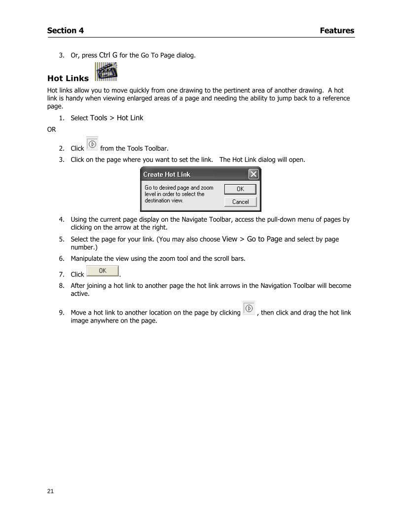
Section 4 Features
21
3 Or press Ctrl G for the Go To Page dialog
Hot Links Hot links allow you to move quickly from one drawing to the pertinent area of another drawing A hot link is handy when viewing enlarged areas of a page and needing the ability to jump back to a reference page
1 Select Tools gt Hot Link
OR
2 Click from the Tools Toolbar
3 Click on the page where you want to set the link The Hot Link dialog will open
4 Using the current page display on the Navigate Toolbar access the pull-down menu of pages by
clicking on the arrow at the right
5 Select the page for your link (You may also choose View gt Go to Page and select by page number)
6 Manipulate the view using the zoom tool and the scroll bars
7 Click
8 After joining a hot link to another page the hot link arrows in the Navigation Toolbar will become active
9 Move a hot link to another location on the page by clicking then click and drag the hot link image anywhere on the page
Section 5
22
Projects
This section will
Help you create settings important to your projects
Explain how On-Screen Takeoff works with your electronic or paper plans
Section 5 Projects
23
Project Template Files You can begin your project with a template Templates allow you to take advantage of conditions and settings used with previous projects
On-Screen Takeoff templates contain condition lists and established layer separations from previous projects you have created You may also use the sample templates provided with On-Screen Takeoff as a great starting point All aspects of the templates may be adjusted for a new project
1 Select File gt New and click the OK button
2 From the New dialog box choose the template that best fits your project
3 The conditions for this template will appear in the Takeoff Dock bar and the Project Properties dialog will open asking for further information
4 Use File gt Save or File gt Save As to rename and save your new project
Saving a Project as a Template File You can save your condition properties and layers as a template for future projects
1 Select File gt Save As
2 Enter a name for your template and select On-Screen Takeoff Template Files (tpo) from the Save As type field of the dialog (click on the down arrow to select)
3 Click the OK button to accept and close the dialog Modifying a Template File Follow these steps to modify an existing template file if you need to change or add conditions andor layers
1 Select File gt Open
2 Navigate to your Projects directory
3 In the File Type drop-down select On-Screen Takeoff Template files (tpo)
4 Choose the On-Screen Takeoff template file you would like to modify and click the OK button
5 Make appropriate changes
6 Save and close file
The On-Screen Takeoff template files cannot save takeoff information
Section 5 Projects
24
Opening an Existing Project File 1 Select File gt Open
2 Navigate to the desired file location
3 Click the Open button
NOTE If your latest changes to a project file have not been saved On-Screen Takeoff will ask
you whether you would like to save the file and gives you the option of canceling the operation
Creating a New Project
1 Select File gt New
2 For a blank untitled project click
3 At this point the Project Properties dialog will pop-up for more information about your takeoff
NOTE The following are important to keep in mind when beginning a new project
At the start of your project fill out the Project Properties settings to establish the name for all printed output from your project set the default page size and scale for your plans number and names of different pages within the project and locations of electronic drawings
Scale settings can significantly affect quantity outcomes Be sure to set the scale for each page of drawings before beginning condition takeoffs
When using a digitizer remember to make a mark with a pen or pencil in the upper left and lower right corners of the first sheet of the paper plans to delineate the takeoff area for that sheet You can then set the takeoff area on On-Screen Takeoff using your marks
Save your project before you begin taking off any conditions On-Screen Takeoff will write a back-up file using the same file name
Remember the Undo feature If you make a mistake select Edit gt Undo and reverse the process step by step
Section 5 Projects
25
Project Properties
You can either set your Project Properties when you create a new takeoff or once your project file is saved under the appropriate name
1 Select File gt Project Properties the Project Properties dialog box will appear
2 Type in the name of your project to appear on printouts Use the backspace andor delete keys to edit the name as necessary
3 Press the Tab key to move to the Default Image Size option or click within the Image Size box You may click on the arrow at the right for the pull-down menu of page size options or you can use the down-arrow key on your keyboard to scroll through the list to the appropriate selection
4 Press the Tab key to move to the Default Scale option Select a scale by using the drop down arrow If your scale is metric you will need to click in the box next to Metric to convert to that measurement
5 Establish the number of pages for your project plans And load image files See Adding Pages to
Your Project
Adding Pages to Projects Individual Electronic Plans
1 Click on in the Project Properties dialog
2 In the Add Images dialog use the drop down arrow to navigate to the appropriate directory and folder containing your image
3 Select the file so that it displays in the File name field then click The file will display by name and path in the Image File field in Project Properties dialog
4 Click to accept and your project will automatically open
5 Save your project with the new settings by selecting File gt Save
Section 5 Projects
26
Electronic plans scanned from blueprints (as opposed to blue lines) will display as white lines on a black background and are difficult to read on your computer screen Select Image gt Invert and the colors will invert to black on white
You may have noticed the Page column in the Project Properties dialog Generally plan images occupy one page and 1 will be listed in the column indicating Page 1 of your plan file If you import a multi-page TIF a plan file containing more than one page of plans they will import as separate pages and each successive page will be indicated under the Page column as 1 2 3 etc of the plan file
Group of Electronic Plans You may add all the electronic plan files from a particular source (for example from a CD) by using the Auto Add feature
1 Click the button in the Project Properties dialog
2 Browse until you find the appropriate directory and folder containing your plan images
3 Click on any file displayed within your target folder so that the file name appears in the File name box of the Auto Add dialog
4 Click The image paths and file names will be recorded into the project properties arranged alphabetically
5 Click to accept your choices and your project will automatically open
6 Save your project with the new settings by selecting File gt Save
To load Dodge Plans into your Project Properties see Appendix IIi Loading Plans from a Dodge CD
Paper Plans On-Screen Takeoff makes it easy for Full Mode users to perform quantity takeoffs from paper plans using a digitizer
1 Add pages by clicking until you have the number of pages initially in the project
2 Name each page by clicking within the Title area and typing the name
3 Click to accept your choices and close the Project Properties dialog
4 Save your project with the new project properties settings by selecting File gt Save
Section 5 Projects
27
Setting Up a Drawing Template On-Screen Takeoff provides the convenience of using the same work surface for both digitizer and mouse to allow the user to draw conditions and then edit settings of the project or add or change conditions without breaking stride A mouse pad template included with the program defines the area of the digitizer in which use of the stylus or cursor will be recognized as mouse movement as opposed to drawing movement
1 Place your stylus on On-Screen Takeoff
2 Placing the template identifies the location mouse movements will be recognized by the program
Before placing the template the template must be applied to the digitizer surface This may have been done during the installation of your digitizer We suggest attaching the template to the lower right corner of the digitizer surface about one inch inside the grid area
3 Select Digitizer gt Place Template
4 Follow the instruction prompts on the screen clicking first on the target symbol at the left of the On-Screen Takeoff box on the template then on the target at the right
Setting Takeoff Area Before you can begin taking off a drawing you must define the drawing area on the digitizer This requires defining an area that will include all objects on each drawing of your plans As you add pages to your takeoff the same area of the digitizer will be active
1 Secure the plans to the digitizer with tape or a set of clamps
2 With a pen or a pencil mark the upper left corner and the lower right corner of the first page in your set of plans
3 Select Digitizer gt Set Takeoff Area
4 Click each mark with the stylus pen as prompted
5 Verify the active area of the digitizer by looking at the image size located in the lower right corner of your screen
If you close the program before the takeoff is complete you will need to reestablish the takeoff area before you can add additional condition quantities
Electronic plans appear on your computer screen eliminating the need to set a takeoff area You simply drag your mouse across the conditions you wish to takeoff The conditions will be highlighted and quantities will be totaled instantly Electronic plans are available through a variety of services For information contact an On Center Software account manager
Section 5 Projects
28
Setting Scale for Specific Pages You may set the scale in each page view separately This will override the default scale setting in Project Properties for that page Setting the correct scale for the drawing before taking off quantities ensures accurate calculations Be careful to check the scale for each drawing in your project before doing takeoffs
1 Display the page you want to set select Edit gt Set Scale
2 Use the drop down arrow to select a scale that will be applied to that page
3 Click
OR
4 Access the pull-down scale settings on the Navigate toolbar
NOTE As you draw objects notice that the drawn object is similar in width to the object on your plans If it is not the scale set may not be correct
Calculating Scale You may calculate scale according to a known measurement between two points either with a digitizer or on electronic plans
1 Select Edit gt Calculate Scale using Image or Edit gt Calculate Scale using Digitizer
2 Follow the instructions in the related Calculate Scale dialog box You will be asked to click on the first and second points then to enter the dimension for that distance
3 The scale will be recalculated for the displayed page and the Scale display on the Navigate toolbar will show the new scale
Section 6
29
Conditions and Takeoff
This section will Draw Conditions to Takeoff Plan Quantities
What Zones will do to help your takeoff process
Discuss the ins and outs of Takeoffs
Section 6 Conditions and Takeoff
30
Creating Conditions
If you are starting a new project from scratch you will need to create conditions to takeoff quantities such as floor areas wall lengths and corner bead counts If you are using a template you will have several pre-designed conditions already listed on the Takeoff dock bar However you may want to change the characteristics of some conditions or create additional conditions for a particular project
1 Right Click within the Takeoff dock bar Select New gt Condition
Or
2 From the Takeoff dock bar Click (if the buttons are not showing right-click in the Takeoff dock bar area and select Show Buttons from the pop-up menu) The New Condition dialog appears
3 Select the condition type (Linear Area Count or Zone) from the pull-down menu accessed by the
down arrow next to the Type option
4 Press Tab or use the mouse (or stylus) to move to Name and enter a name for your condition
5 Specify the desired condition attributes See Condition Attributes for more detail
6 Click for condition to apply
Section 6 Conditions and Takeoff
31
Condition Attributes Each condition type will have related attributes to select or specify within the General and Advanced tabs of the New Condition dialog Once a condition has been used to takeoff a quantity from your plans certain attributes cannot be changed
All conditions allow the user to specify color and fill pattern for the object drawn
Linear Conditions
General Specify width and height by feet and inches Specify pitch in inches up to the nearest thousandth of an inch if applicable
Advanced Specify rounding for object quantities and droprun default length for electrical or plumbing drops at the ends of lines Select Connect to have lines connect at the corners where one line of the condition ends and another begins (and indicate Tolerance for the featurersquos activation as distance between the ends of two lines) Choose Trim to have lines automatically trim to a line being crossed Choose Curve to draw a curved line
Follow these examples for inputting feet and inches For 7 feet 6 inches type 706 for 13 feet 7 inches type 1307 For 20 feet type 2000
Section 6 Conditions and Takeoff
32
Area Conditions
General If needed you can specify the thickness (in inches) andor pitch (in inches)
Advanced Specify rounding for object quantities Choose to display an adjustable grid within the area and indicate matrix cell dimensions
Section 6 Conditions and Takeoff
33
Count Conditions
General
Specify height and indicate the size (in inches) and shape (square circle triangle rectangle or opening) of the count object as it will appear on screen
Advanced Count conditions have advanced attributes These options are available for all shapes except for openings
Zone Conditions Zones allow you to subdivide condition quantities making it easier to modify and complete jobs in phases They can be used at the end of a takeoff to isolate a group of condition quantities that are in different areas of the takeoff
Zones can also be used to break a takeoff into multi-phases and can even be used to isolate quantities while a job is in progress to group the amount of work that has been completed to date They can be applied to one or multiple pages in your plans automatically calculating the takeoff quantities for each zoned area
Section 6 Conditions and Takeoff
34
The zone feature is only available in Lite and Full Mode If you are in View Mode and would like
to use this feature click from the main toolbar to purchase the upgrade
Condition Notes A Note tab is provided for comments regarding the condition These notes will display on the Takeoff List report and will import into Quick Bid
Section 6 Conditions and Takeoff
35
Condition Results The Results tab of the New Condition is based on condition type Initial settings default to linear feet (LF) for linear conditions square feet (SF) for area conditions and count of items (EA) for count conditions and zones The first of the results fields will display for the condition items in the Takeoff dock bar area All results will display in worksheets and Takeoff List reports as well as in an Excel spreadsheet after being exported
Copying Conditions You may use the condition attributes from a condition yoursquove already created for any future conditions of the same type
1 Click on a condition to select it
2 Click the Copy button from the toolbar
OR
3 Right-click in the Takeoff dock bar area and select copy
4 A new condition will appear in the list with the same condition attributes as the previous condition but with the quantities zeroed
Editing Conditions Once you have copied a condition you might want to change several attributes You can also edit an existing condition to fit any updated needs
1 Highlight the desired condition on the Takeoff dock bar
2 Click the Change button
OR
3 Double-click on the condition you wish to edit to bring up the Change Condition dialog
NOTE The Change Condition dialog differs from the New Condition dialog only in that if takeoffs
Section 6 Conditions and Takeoff
36
have been performed in your project with this condition you will not be able to change the type of condition or certain properties under the advanced tab of the dialog box
Deleting Conditions 1 Click on the condition in the Takeoff Dock bar area
2 Click the Delete button on the toolbar
OR
3 Right-click and select Delete from the pop-up menu
All takeoff associated with the deleted condition will be deleted immediately and permanently
Organizing Project Conditions Within your project you can create folders andor sub-folders for different types of conditions You may even want to create a folder containing conditions with reset values
To get started organizing your conditions make sure you are viewing the condition tree (right-click in the Takeoff dock bar area and select Show Tree)
Creating Folders and Sub-Folders 1 Right-click in the Takeoff Dock bar area
2 Select New gt Folder from the pop-up menu
Copying Folders
1 Click on the folder and click Copy on the toolbar
2 All copied conditions within the new folder will have values reset to zero
Renaming Folders
1 Click on the folder
2 Right-click and select Rename from the pop-up menu
3 Enter a name for your folder and click the Enter button
Changing Condition Order
You may move conditions up or down in the condition list of the Takeoff dock bar to suit your project needs
1 Select the condition you would like to move by clicking to highlight it
NOTE When you are ready to move the highlighted conditions be sure that you start
moving using the last condition chosen That condition will have a highlighted boarder
Section 6 Conditions and Takeoff
37
2 Drag and drop any the condition from one place to another in the list You may also move a condition to another folder on the list in this way
Drawing with Conditions Snap Angles Set up snap angles to prevent lines from appearing jagged Snap angles are commonly set at 15deg and shift snap angles at 0deg
1 Go to Tools gt Options Options dialog appears
2 Under the General tab make the desired settings
3 Click to save the settings As they are drawn lines will snap to the set degree
Drawing a Linear Object 1 Select a condition from the Condition List in the Takeoff dock bar
2 Move the cursor into the Image takeoff area of the screen you will see the cursor display as crosshairs
3 Click and hold left mouse button then drag mouse to draw a line
4 Release mouse button to set line
Section 6 Conditions and Takeoff
38
5 Repeat steps for further lines
Continuous Mode This feature allows you to draw an object that has connected lines
1 Click the icon from the Takeoff toolbar
OR
2 Go to Tools gt Continuous Mode
3 Follow steps 1-3 from Draw a Linear Object
4 Click at each point of intersection The object will be connected
5 Double-click after making the final point to set the lines
Drawing a Curve To draw a curved line the Curve option must be checked under the Advanced tab of the Condition dialog
1 Click where you want to begin the curve and drag in a straight line to the position for the other endpoint of the curve
2 Click on the line to select it Handles in the shapes of small squares will appear at either end of
Section 6 Conditions and Takeoff
39
the line and in the center of the line
3 Move the cursor over the center handles until the cursor becomes a two-way arrow
4 Click and drag in the direction of the curve bending the line as you move the cursor Release to set the curve (The line you began with will disappear)
Draw a circle by drawing two curved lines connected
Drawing an Area Object Area conditions are drawn similarly to continuous mode lines You may trace any number of adjoining walls at different angles to complete your area takeoff
NOTE When drawing an area do not intersect the perimeter or line of the object you are drawing
1 Click at each point
2 Double-click when yoursquove returned to your starting point
3 The area will be filled with the pattern set for that condition
NOTE The simulated circle will be good enough for you to be able to make a bid
To create a circular area click from point to point with very short distances in between points simulating a circlersquos perimeter Double-click after setting the last point to set the area
Section 6 Conditions and Takeoff
40
Grid Options Grids give you an added advantage when installing materials such as tiles Use this feature to get a count for how many tiles are needed for an area
1 Double-click on an area condition in the Takeoff dock bar to open its Condition dialog
2 Click on the Advanced tab to show its options
3 Check the box next to Grid by clicking in it
4 Indicate the dimensions of the cell matrix in inches (For example 200 x 400)
5 Under Results tab choose each (EA) for one of the results fields This will tabulate a number of grid cells (including partial grid cells) in area
6 Click to save your settings
7 Use the Move Grid and Rotate Grid features in the Tools menu to manipulate the grid as desired
Grid Calculation
1 Go to Tools gt Options menu
1 Specify if On-Screen Takeoff automatically should Calculate Grid Position
2 If AreaGrid Size is selected On-Screen Takeoff will calculate the number of items needed to fill the grid based on grid demintions
3 Click to accept and close the dialog
To move a line at any angle (regardless of default setting) press the Shift key while moving the mouse
Section 6 Conditions and Takeoff
41
Backout Mode This feature allows you to take out part of an area and deduct that amount of square footage
1 Select Tools gt Backout Mode
2 Outline the are you want backed out as you would when drawing a regular area object (see Drawing an Area Object)
3 The outlined area will clear and quantities will be recalculated
NOTE The perimeter of the backout area will be added to the LF quantity for that condition
Drawing a Count Object Square triangle rectangle and circle shaped count objects can easily be placed on images
1 Select the condition
2 Click in the location where you want the object to appear
3 To place an opening-shaped count item like a door or window you must click over an existing linear object such as a wall
4 On the Results tab you can change the height properties to give you the result you need
5 If Backout is checked on the advanced tab for each count opening the opening-shaped count item will back out a corresponding section of the linear object
Opening shaped count items are sized at 3rsquo0rdquo by default
Drawing a Zone Zones are drawn in the same way as area objects and may be any polygonal shape You may trace any number of adjoining walls at different angles to complete the zone perimeter
1 Click at each point
2 Double-click when yoursquove returned to your starting point
Section 6 Conditions and Takeoff
42
Selecting Objects
1 Use the Select Tool to select objects
You can also select all objects that correspond to a condition
1 Click on a condition to select it
2 Right-click and choose Select All
3 All objects with this condition will be highlighted with squares as an outline
Moving and Resizing Objects Linear
1 To move or resize a linear object click anywhere on the line to select it
2 To move the line position your pointer over the center handles When the mouse is positioned over the handles you will see a two-way arrow You will only be able to move the line in the direction of the arrows
3 Drag the line to a new position
4 Clicking and dragging the handles on the ends of the line will allow you to lengthen or shorten your line
Area and Zone
1 To move an area object or zone in its entirety click and drag it to its new position
2 Grabbing a handle at a corner or intersection of the object will allow you to adjust and change its perimeter
Section 6 Conditions and Takeoff
43
Count 1 To move a square circle rectangle or triangle shaped count object click and drag
2 Click and drag an opening shaped count object along the length of the linear object to the desired position then release
NOTE An opening shaped count object may not be moved from its associated linear condition object however it may be moved up and down the length of the linear object
Layers On-Screen Takeoff allows you to sort and separate your takeoff objects within the same job and on the same page On-Screen Takeoff gives you this flexibility through the use of layers
By assigning different conditions to different layers (for example differentiating between floors ceilings and walls) you can choose to view all layers or turn off certain layers to display and print the remaining groups of conditions only You may also remove the background image of electronic plans add text and hot link symbols or print only your condition takeoffs
Layers are only available in Full Mode If you are in View or Lite Mode and would like to use this
feature click from the main toolbar to purchase the upgrade Default Layers
On-Screen Takeoff begins every project with three default layers Image Annotation and Default The Image layer holds the electronic plan files you may have in your project The Annotation layer possesses all text notations highlighting and hot links in the project The Default layer will appear in the Condition dialog when creating or editing a condition (listed in the takeoff dock bar) Conditions are assigned to the Default layer unless otherwise specified by the user
Creating Layers To assign a condition to a layer other than the default layer you must first create additional layers for your project
1 Select View gt Layers to open the Layers dialog
2 Click An unnamed layer will be added
3 Click within the empty box and type a name for your layer (for example Wall)
4 New layers are added as active layers The adjacent box under the Show column will be checked
Section 6 Conditions and Takeoff
44
Assigning a Layer to a Condition 1 Open the Condition dialog box by creating a new condition or editing an existing condition
2 Under the General tab click on the down arrow in the Layer field to display optional layers
3 Select the desired layer for the condition Only the Default layer and layers you have added will be displayed
4 Click
View and Hide Layers
1 Select View gt Layers
2 Under the Show column check the box to view or remove the check (by clicking on it) to hide the specific layer
3 Click to accept and close the Layers dialog
Section 6 Conditions and Takeoff
45
Assigning Text to a Layer When adding text to an image On-Screen Takeoff has the capability to assign the text to a specified layer
1 Select the Text Tool
2 Click at the point you want to place your text
3 Type in your text using the Enter key for line breaks
4 Click the drop down arrow next to the Layer field and select the desired layer
Section 7
46
Printing and Exporting
This section will
Printing options and procedures
Exporting data by copying and pasting
Exporting quantity results to Excel spreadsheets
Section 7 Printing and Exporting
47
Print Setup On-Screen Takeoff allows the user to print the image takeoff list and worksheet
1 Select File gt Print Setup The Print Setup dialog will open
2 Select a printer or leave the default selection listed (change from the default printer displayed by clicking on the down arrow at the right of the field)
3 Indicate page size and printer tray option (Source) Access page size options by clicking on the
down arrow at the right of the field
4 Choose Portrait or Landscape orientation
5 Click to accept and close the dialog
Printing Images The image area can include the electronic plans the takeoff objects added text and hot links To print a subset of these (for example just the takeoffs without the plans or the added text and hot link symbols) hide layers that you do not want to print (see Section 6 View and Hide Layers) When you are printing your images every page will show the scale of the takeoff you are printing
1 Click on the Image tab to display the area of your project
2 Select File gt Print (or Ctrl + P)
Section 7 Printing and Exporting
48
3 Select the desired view (What to print) and the Image Range
4 Click The second Print dialog will open
5 Change settings accordingly or click if you accept the default settings
Printing Takeoff Lists and Worksheets In Takeoff Lists and Worksheets you may hide columns to print only certain results or adjust column widths to fit the report within the page size selected
1 In Takeoff List or Worksheet view move your cursor to the right side of the columnrsquos title bar the cursor will display as a two-way arrow
Section 7 Printing and Exporting
49
2 Click and drag to adjust the width of the column Holding the mouse button you may
slide the title bar under the title bar to its left to hide the column completely
3 Select File gt Print or press Ctrl + P to access the Print dialog
4 Indicate desired printer and choose the number of copies
5 Click to print and close the dialog
When printing the condition list we suggest printing in landscape
To reset to the default column widths double-click on the right border of a column heading will reset the column to its right (or previously to its right before being hidden)
Print Preview 1 Select File gt Print Preview
2 Use and to vary your view 3 If viewing an image choose current full or scale view to see how it displays
4 For printed outputs that cover more than one page use and to view adjacent pages or click on the down arrow next to Page field and select the page you want displayed
Exporting Using the CopyPaste Feature You may copy all the data or sections from the worksheet and the takeoff list view in On-Screen Takeoff and paste it into another application When pasting into Excel the cell layout will be maintained
1 Highlight the areas you wish to paste Click and hold the left mouse button down as you drag the cursor over the area to be selected then releasing the mouse button
OR
2 Select the entire takeoff list quickly click on the left On-Screen Takeoff column header and hold and drag the cursor across the remaining column headings
The number of pages for the view selected will display in the lower left-hand corner The zoom percentage that applies to the view will be displayed in the lower right-hand corner next to page size of the drawing
Section 7 Printing and Exporting
50
3 In the worksheet view you may highlight rows by clicking on the numbered buttons to the left of each row clicking and dragging across column headings or clicking and dragging over individual cells in the worksheet
Click anywhere in the appropriate view to deselect the area
4 Once your selection is highlighted you may select Edit gt Copy or Ctrl C from the keyboard 5 On your monitor switch to the application into which you want to paste your selection 6 Select Edit gt Paste in the new application or simply press Ctrl + V to paste
The colored keys for conditions cannot be pasted
Using the Export Feature You may export condition quantities to specified cell location within an Excel worksheet file Cell target locations are assigned in the Results tab of the condition dialogs on the Export line relating to each quantity measurement type
On-Screen Takeoff will export takeoff quantity results for up to three different quantity types that you specify For instance you may want to know the number of square feet in a ceiling area as well as the number of linear feet in its perimeter
Section 7 Printing and Exporting
51
1 Bring up the Condition dialog by double-clicking on a condition in the takeoff dock bar or by
selecting the condition and clicking
2 Click on the Results tab to access its fields The default quantities for the condition type will display
3 For each results field click on the arrow to access the pull-down menu and select the appropriate quantity (for example SF LF EA etchellip)
4 Have your Excel spreadsheet opened and saved in a file
5 Specify the Excel spreadsheet cell locations where you want the results to go
6 For a cell in the first sheet of your spreadsheet type in the cell address (eg a1) Case is not important
7 For a cell on a successive sheet of your spreadsheet type in sheet the number followed by a comma and the cell address without any spaces (eg sheet2a1) Case is not important
8 Click
9 Select File gt Export gt Condition Qty to Excel
Section 7 Printing and Exporting
52
10 Browse to the location of the Excel spreadsheet file click file to select it
11 Click to export On-Screen Takeoff results to specified cell locations in the Excel file When you return to the Excel application you will see the values have been added to the specified cell locations in your spreadsheet
12 Save your Excel file
Exporting Worksheet to Excel
1 Assign condition quantities you want to export
2 Open saved Excel spreadsheet file to which you will be exporting
3 From On-Screen Takeoff Select File gt Export gt Worksheet to Excel
4 Browse to the location of the Excel spreadsheet file click file to select it
5 Click When you return to the Excel application you will see the values from the Worksheet Tab have been added to your spreadsheet
6 Save your Excel file
Exporting Takeoff to CVS 1 Assign condition quantities you want to export
2 Open saved Excel spreadsheet file to which you will be exporting
3 Click the Takeoff Tab in the project you want to export the information
4 Select File gt Export gt Takeoff to CSV
5 Browse to the location of the CSV spreadsheet file click file to select it
6 Click the Save
NOTE CSV files can be opened in Excel Lotus Access etc One may consider this option more of a ldquodumprdquo into a file
The Excel application must be active (it may be minimized on the application bar) with the target spreadsheet open in the application Otherwise an error will occur with the export operation that will affect both the On-Screen Takeofftrade file and the Excel spreadsheet
Section 8
53
Advanced Features
This section will
Some special features of working with condition objects in the takeoff area
Details of advanced options for conditions
Advanced features of the Project Properties dialog
Section 8 Advanced Features
54
Features to Use with Objects Roping Feature You can move copy or delete using this feature Using the Select tool (the pointer) you may select several objects at once by clicking and dragging an outline around the objects then releasing the mouse button Roping may select either objects completely within the outlined area (inclusive) or objects both within and touched by the outlined area (touching) Specify your roping preference under Tools gt Options
1 Click and hold the mouse button at a point on the screen near the objects to be selected and drag to surround the objects with an outline
2 Release the mouse button The objects will be selected
3 You may now
Move the group around on the page by clicking within the group dragging the mouse and releasing the button to place the objects
Delete the group of objects by clicking the Delete key or
Copy and paste by pressing Ctrl C to copy the group then Ctrl V to paste it The pasted copy of the grouped objects will appear slightly offset from the original objects
Section 8 Advanced Features
55
Applying a DropRun Count
Use the droprun feature when calculating quantities to take into account the drop or run of a linear condition such as electrical lines or plumbing pipes Drop or run lengths may be added separately to any linear condition on screen while a default droprun length may be indicated for a condition as a whole
1 Select the desired linear condition from the Condition List in the Takeoff Dock bar
2 Click the Change button in the toolbar to open the Change Condition dialog
3 Click the Advanced tab to access the advanced options and click inside the DropRun check box
4 Enter a default length to be applied to all of this condition Entering 800 will be interpreted as 8 0 (You must enter both place markers for inches) You can leave the length blank and manually enter drop run on each segment drawn
5 Click the OK button to accept and close the dialog
Edit DropRun Count
1 With the related linear condition in the Takeoff Dock bar highlighted or with the pointer tool selected
2 click on the desired linear object in the image takeoff area The Count button will become active
3 Click on the Count button (alternatively select Tools gt Count) The default droprun amount will show in the pop-up Count dialog (Default length will be zero if droprun has not been selected in this conditionrsquos properties)
4 Type in the desired length Entering 800 will be interpreted as 8 0 (You must enter both place markers for inches)
5 Click the OK button The additional amount will be reflected in the corresponding quantity The new DropRun count will apply only to the object edited
Adding Text in Image View
On-Screen Takeoff allows you to place text comments around your quantity takeoffs that may be printed along with plan images and objects Text is automatically placed within the Annotation Layer (that includes text and hot links)
1 To place text on the image select the Text Tool and click at the point you want to place your text opening a text box
2 Type in your information clicking Enter for line breaks
3 When you are finished click the OK button to exit the text box
4 To reposition text simply click on the text (with the Text Tool active) to select it
5 Move the cursor over the text the cursor will now display as a four-way arrow
6 Click and drag the mouse to position the text as desired
Section 8 Advanced Features
56
1 To edit existing text use the Text Tool to double-click on the text to open the editing box
2 Enter additional text or use the Backspace key to delete text as necessary
Formatting Text Once created you may format the font size type style and color of your text
1 Click on the text to select it and select Tools gt Font or click on the Font button in the Takeoff Toolbar
2 Select the desired features (color options are disabled) and click the OK button
3 Click on the text to select it and select Tools gt Color or click on the Color button in the Takeoff Toolbar The Color dialog will open
4 Click on a color in the Basic Color palette or create a color and add to the Custom Colors palette (Be sure to click on the color in the Custom Colors palette to select it)
5 Click the OK button
Object Properties
Linear Objects
Linear objects may be set to connect at corners
A linear object may be set to trim automatically when crossing another linear object (Check the trim option under the advanced tab of the Condition dialog)
When you move a connected linear object objects automatically move and resize connected lines accordingly (quantities are then recalculated)
This feature requires that the connected linear object be moved using the center handles (does not apply when resizing the line from the ends)
Objects constrain to snap increments defined in the Tools gt Options menu (with the mouse 15deg by default incremental when shift key is held down)
Objects are measured from centerline to centerline
Section 8 Advanced Features
57
Area Objects When drawing an area use your escape key to undo the last line drawn You may reverse your
drawing of an area using the escape key
The area will not fill with color and pattern until the user double-clicks after the last line is set
Lines drawn to delineate an area object constrain to snap increments defined in the Tools gt Options menu (with the mouse 15deg by default incremental when shift key is held down)
After selecting an area to move or adjust position the mouse in the center to move the entire area position the mouse at the sides or corners to adjust the perimeter
Count Objects
All count objects are quantified by the physical number of objects per page and reported as EA for the UOM The quantity for the current Image View is (displayed in the Condition List) and the total quantity in your project is displayed in the Takeoff View and Worksheet View)
Square circle rectangle and triangle shaped count objects do not displace or subtract from other object quantities when placed on top of them However on the Advanced Tab for the count condition a connect property can be set (this is a check box) so that when a count object of this shape is put on top of a Linear type takeoff object it will move with the linear if said linear is moved
An opened-shaped count object must be placed within a linear object Opening shaped count objects may also be measured by linear foot or linear yard (EA SF and SY are also options) Opening shaped count items default to a width of 3rsquo 0rdquo at the time of creation This size can be changed The small medium and large size are not options on this type of condition anymore Check Backout on the Advanced tab for each Count object back out the footage (or yardage) of opening-shaped count objects in which they are placed
NOTE In order to see this Backout functionality (in quantity) for SY or SF deductions at least one of the
results for the Linear(s) this object will be placed on must be set to SY or SF and the count object must have a height quantity
Advanced Features of Conditions The Round Feature Under the Advanced tab of the linear and area Condition dialogues you may specify quantity rounding (in inches) For linear objects rounding applies to each linear object drawn For area objects rounding will apply to each segment of the area perimeter adjusting the perimeter and area calculations For example With a linear condition entering 12 in the Round field will round up each related linear object to the nearest 12 inches or one foot With this setting two walls of 1 4 would each round to 2 0 totaling 4 0
NOTE In the Takeoff Dock bar condition list and in the On-Screen Takeoff reports quantities will be displayed in whole numbers rounded up to the nearest foot However calculations are based on true quantities without rounding unless the Round Feature is engaged
Pitch Pitch may apply either to linear or area conditions It is measured in rise per linear foot Entering 12 indicates a 12 rise per 12 of linear distance (a pitch of 12 over 12) or an angle of 45deg
Section 8 Advanced Features
58
Advanced Features of Project Properties Selecting Multiple Pages
1 Select a single page entry by clicking on the numbered gray button to the left of the entry
2 Drag the cursor down the column of numbers to select consecutive pages
3 Click on the blank button at the top of this column to select all pages in the Properties dialog
Section 8 Advanced Features
59
Changing Image Assigned to a Drawing 1 Select the page entry by clicking on the numbered gray button to the left of the entry 2 Click the Change Image button The Change Image dialog box will appear
3 Navigate to the desired file and select by clicking on it
4 Click the Open button The electronic file assigned to the page will have been changed to reflect the new file choice
Changing Image File Path 1 Select pages as described above
2 Choose Change Folder
3 In the Change Folder dialog navigate to the appropriate folder
4 Click the OK button The file path will have been changed for the selected page entries
Delete a Page from Project Properties 1 Select the page you want to delete by clicking on its associated number (in the gray box at the
left of the entry)
2 Choose Delete Page
All Takeoff on the page will be deleted immediately and permanently
Section 8 Advanced Features
60
Advanced Features of Tool Options
Calculation Method On-Screen Takeoff has built-in calculation options to allow for faster work and faster saves until your takeoff is complete Calculation options are found by selecting Tools gt Options then clicking on the Calculation tab
Calculation method can be set to Automatic Automatic except Grids and Manual Manual will allow the program to operate more quickly while Automatic or Automatic except Grids allows the user to see quantity changes as takeoffs are made
In any mode you may press F9 to recalculate quantities for the On-Screen Takeoff current totals
Configuration Tab
When the ldquoPage Label (A01)rdquo radial button is chosen On-Screen Takeoff puts the numbered label on all the pages of in your current page indicator in your Navigate Toolbar If the Page Descriptionrdquo radial button is chosen then a description of what takeoff is on that specific page will be shown in your current page indicator in your Navigate Toolbar
This section of the configuration tab gives you options on how you want to export your information When the ldquoFolderSubfolder Namesrdquo radial button is chosen than on your file that you are exporting to will have all the conditions folders and subfolders In the Delimiter box you can choose the symbol that is needed to separate the information you are exporting Some files need semicolons () or colons () to make sure the information comes exported in is separated it the appropriate places
Section 8 Advanced Features
61
In previous versions of On-Screen Takeoff there are views that users need to have in order for them to display their information By either choosing ldquoOST 1xrdquo or ldquoOST 2xrdquo it will let the program know you want your columns of information exported in that specific format
When you have the Confirm Deletions radial button of ldquoYesrdquo chosen than every time you delete anything you will get a dialog box confirming your intentions of deletion
While working with your takeoff you have a choice to either view the legend of your conditions or hide it Choose whichever radial button that suits your needs
For those who prefer to use the Enter key to navigate in dialog boxes this option is just for that
Font Tab The Font tab is designed for you to make your own look and feel for the application At the bottom of this tab it will show you sample of the fonts and colors you have chosen
Renaming the Current Page You may change the name of the current page in the takeoff area of On-Screen Takeoff by selecting Edit gt Rename Page
This opens the Name Page dialog and you may simply type in a new name and click the Enter button The new name for the file will be reflected on the title bar for the page and in Project Properties
You also may access the Rename Page function by right-clicking in the takeoff area while in Image View and selecting the option from the pop-up menu that appears
Section 9
62
Saving and Exiting
This section will
Explain how to save projects
Show you how to safely exit the program
Section 9 Saving and Exiting
63
Saving Your Project
1 Select File gt Save 2 If your project has not previously been saved a Save dialog box will open to allow you to name
the file and choose the directory and folder in which to save your file 3 Once saved File gt Save will simply save the current version of the file
OR
4 Select File gt Save As then type in a new name for the file and save to the desired file path
The Auto-save Feature With the Auto-save feature On-Screen Takeoff automatically backs up your open project You may choose to have more than one level of backup files The first backup copy will have the extension b00 and successive files will be b01 b02 and so on If you have designated four levels of backup files after the fourth backup copy has been created (b03) the next file will be saved over the file with extension b00 Further backup saves will then rotate through the four backup files in the same way
1 Select Tools gt Options 2 In the Auto-save area (under the General tab) select the frequency of backup file creation (in
minutes) and the number of levels for the feature 3 You also may disengage the feature by clicking in the check box to clear it
The Auto-save feature automatically saves backup copies to the directory of the current project If you are working from a write-protected area such as a CD-ROM On-Screen Takeoff will place backup files in the On-Screen Takeoff folder
Exiting When you are finished using On-Screen Takeoff it is very easy to exit Exiting is very important because of security reasons If someone were to use your computer they could enter the application and view and manipulate information
Section 9 Saving and Exiting
64
On-Screen Takeoff closes the open project when you open another or create a new project or when you exit the program
1 Select File gt Exit
OR
2 You also may click at the upper right-hand corner of the application to exit
NOTE If your latest changes to a project file have not been saved On-Screen Takeoff will ask you whether you would like to save the file and gives you the option of canceling the operation
Appendix I Installing Your Digitizer
65
Appendix I Installing Your Digitizer When you get your digitizer from GTCO you will need to connect it to your computer Follow the instructions outlined below to do this
Note For rollup digitizers the metal bar must be oriented to the top or right hand side
Connecting the Digitizer 1 Lay the digitizer out flat 2 Connect the Stylus to the digitizer 3 Plug in the power adapter 4 Plug the interface (IO) cable into the digitizer 5 Plug the other end of the interface cable into an open serial port on computer
Note GTCO Technical support phone number is 410-381-6688 The electronic manual (on diskette) from GTCO contains more detailed installation and operation instructions for the GTCO digitizer model you have
Installing other Digitizer Drivers If you are using a GTCO Digitizer you will need to install the GTCO TabletWorks Drivers
If you are using a Digitizer not supported by GTCO Tablet Works 10 please contact the manufacturer of your digitizer for assistance with installation
Installing GTCO TabletWorks Drivers 1 Insert the On Center CD into the CD-ROM drive The CD Startup screen will open 2 Click on Install Software 3 Select Additional Software and Drivers 4 Select Digitizer Driver 5 Follow the instructions for installing TabletWorks 10
Adhering the Template The template is a small plastic sticker used to enable mouse function when using the digitizer with On-Screen Takeoff Place your template on your digitizer We suggest placing it in the bottom right corner of the digitizer about one inch inside the takeoff area
Note You may either peel off the back of the template and use the adhesive surface or you can tape the template down
Appendix I Installing Your Digitizer
66
Testing the Digitizer Drivers Before running OST you may test the digitizer by moving the stylus around on the digitizer pad it should move the mouse cursor (if mouse emulation is enabled)
If the digitizer does not move the mouse cursor on the screen
The superset codes may need to be reset Reset the superset codes by touching on the border of the digitizer with the stylus The digitizer should beep several times
The digitizer may not be communicating with the computer Be sure the COM port selected is correct Be sure the COM port selected is correct If you are not able to get the digitizer to move the mouse cursor you need to call GTCO technical support for help
Note The Mouse Emulation is not required for On-Screen Takeoff to work properly It is used only for the Template functionality if the digitizer is moving the cursor the wrong direction (up instead of sideways or vice-versa)
Click the L-shaped arrow symbol on the digitizer with the stylus
Appendix II Toolbar Item Details
67
Appendix II Toolbar Items Main Toolbar
Appendix II Toolbar Item Details
68
Tool Toolbar
Appendix II Toolbar Item Details
69
Zoom Toolbar
View Toolbar
Navigate Toolbar
Appendix II Toolbar Item Details
70
Navigate Toolbar (Continued)
Takeoff Toolbar
Appendix II Toolbar Item Details
71
Takeoff Toolbar (Continued)
Image Toolbar
Appendix III Loading Plans from a Dodge CD
72
Appendix III Loading Plans from a Dodge CD
This section will detail how to load plans from a F W Dodge CD-ROM into an On-Screen Takeoff project file ready for takeoffs
Dodge files may be added to the Project Properties dialog However loading the files in that way will load the files by number rather than name description If you want to load one page only from your Dodge CD You will have to rename the page to display the name rather than number of the file
To load plan files from a Dodge CD so that the files load sequentially by file number but are displayed by name rather than by number within your project follow the instructions below
Opening a Dodge project from a CD-ROM 1 Insert the CD into the drive 2 Choose File gt Custom 3 Choose Dodge Plans Project (plansdat) as the file type 4 Select the appropriate file type by clicking on the down arrow at the right of the Files of type
field 5 In the Look in field access your drive paths by clicking on the down arrow at the right of the
field then
Navigate to your CD-ROM drive Open the data folder and Open the Projects folder
6 Select the desired project and open its folder 7 Open the plansdat file 8 All the images will come in sequenced correctly for that job along with the full descriptions
(names) of each page If there is not a plans folder in the project folder then plans do not exist for that project on the CD Opening the plansdat file will yield an empty project
Appendix IV Using the Plan Viewer
73
Appendix IV Using On-Screen Takeoff Plan Viewer The On-Screen Takeoff Plan Viewer is a limited version of On Center Softwarersquos commercial takeoff software If your status bar located at the very bottom of the main window says View Mode in the lower left-hand corner then you are using the Plan Viewer You can use the plan viewer to
View CD-based amp converted CAD drawings
View a previously created OST file and associated drawings
Download electronic plans online
Navigate through drawings
Quickly Takeoff linearsareas and counts
Zoom in to view the plan better
Print drawings directly from the viewer
Viewing an On-Screen Takeoff Project File
1 To open an OST file that was previously created with of On-Screen Takeoff 2 Select File gt Open 3 An Open dialog will appear if you do not see the OST file you are looking for select the
Look In drop down arrow 4 A drop down menu will appear listing the various folders drives and mapped drives located
on your computer select the correct drive or folder location and continue to browse to the location of your OST file
5 When you see your OST file double-click it to open it 6 Any takeoff and drawings should appear on the Image tab view
If you do not see the drawings but do see the colored takeoff layer the drawings may
not be located in the same place they were originally saved at Go to File gt Project Properties and check the Image File path for each listed page If the image file path is pointing to a CD drive make sure the CD is inside the CR-ROM
Downloading Electronic Plans If your Online Plan Service provides a special file format (OSX) required to use this feature of our plan viewer you can immediately downloaded all electronic plans of a project directly from our viewer
Most Plan Room web sites will automatically open On-Screen Takeoff when a request to download plans is made Your particular Plan Room may differ in operation so please contact the provider directly with questions on using the site
Appendix IV Using the Plan Viewer
74
When you request to download or open a project file from a Plan Room you will usually have the open to open or save an OSX file Choosing open will automatically open On-Screen Takeoff Alternately you may choose to save the file to a local hard drive After you have saved the file either double-click it to launch On-Screen Takeoff or open the OSX file using On-Screen Takeoff by clicking File then Open and locating the file on your hard drive You will need to change the file type to OSX
After the OSX file is opened you will see an additional tab appear in the Conditions List window called Pages
The Pages tab shows the hierarchy of your project Gray file icons represent pages that have not been downloaded and blue icons represents pages that have been downloaded
To download a page simply double-click the page icon
If you wish to select a group of pages to download you can use the Ctrl or Shift key to multiple select them then click the Download button
If you wish to download all pages at once click the Download All button
Downloaded pages will now appear in the Project Properties dialog in the same order in which they appear in the Pages tab
Creating Quick Takeoffs With On-Screen Takeoff you can create quick takeoffs to measure quantities even if you dont have the full version of our program However using the Quick Takeoff functionality shows you just a fraction of what the full version can do
The Quick Takeoff Toolbar is located at the top of the image view It has three buttons designated for three types of takeoffs Linear Area and Count The Quantity drop down list will show secondary quantities for Linears and Areas The Units drop down allows you to select how you want your quantities displayed Feet Inches Yards Millimeters and Meters
NOTE Every time change the type of takeoff you are performing (switching from Area to Linear for example) the previous quantities and takeoff objects will disappear They will also disappear when you changes pages
NOTE You can use the Dimension Tool to basically measure the distance between two points or linears The distance will display on the status bar at the bottom of the application
The Quick Takeoff Toolbar
Appendix V Frequently Asked Questions
75
Appendix V Frequently Asked Questions General
Where is On-Screen Takeoff installed on my computer
Typically it is installed in CProgram FilesOn-Screen Takeoff
In Explorer how do I recognize On-Screen Takeoff file types
On-Screen Takeoff data is stored in a single file per job lsquojob name OSTrsquo On-Screen Takeoff templates are stored as lsquotemplate nameTPOrsquo
Can only one project at a time be open
Yes For that reason opening another project automatically closes the project on screen You will be asked to save any changes
Is only one scale allowed per page What about on drawings that have multiple detail sections on a page and each of those drawings have different scales
Yes For pages with drawings of different scales copy the drawing to another project page and set the appropriate scale
I cannot perform backout on an area that is along a linear
As a workaround use the On-Screen Takeoff layers feature to help you with this issue Electronic Images
How do I start a project from drawings that have been scanned and written to a CD-ROM
Open a new project Select File gt Project Properties and select Auto Add Navigate to your CD and the appropriate folder and select any image file in that location Click Open All files in the location will load into your project Recommended that images are copied from CD to hard drive for performance
If I get a disk of drawings in AutoCAD format (R13 or R14) can I read them in On-Screen Takeoff
Yes On-Screen Takeoff now reads DWG DXF and many other format that are saved with AutoCAD
Appendix V Frequently Asked Questions
76
When I click on the all pages button what is supposed to happen Currently nothing seems to change when I click on that button
The All Pages button is used to apply the Darken and Enhance Plans feature to all pages in the project (as opposed to only the current page on screen)
Is there a way to deduct a large skylight from an area condition
Yes with the related area condition selected in the Takeoff Dock bar unselect the Backout button on the Takeoff Toolbar then draw the Backout area The area quantity will be deducted from the related condition object and the linear measurement of the Backout perimeter will be added
Digitizer Issues
How do I connect a Digitizer to the computer
See Appendix I Connecting a Digitizer
The Place Template menu choice is disabled
On-Screen Takeoff may need to be authorized or the digitizer or the digitzer drivers are not installed
It wonrsquot let me select the Set Takeoff Area menu choice
On-Screen Takeoff may need to be authorized or no job is open a digitizer is not installed or the drivers are not installed
The digitizer stylus is not moving the cursor or crosshairs
Click S-0-1 superset on the digitizer
How do I convert my old GTCO Digitizer to work with On- Screen Takeofftrade
Call GTCO and they may be able to reconfigure your digitizer to be compatible with On-Screen Takeoff
Printing Issues Which Printers work with On-Screen Takeoff
Compatible printers include On-Screen Takeoff Hewlett Packard Epson and Canon printers If you are having printer difficulties please contact support and specify the type of printer along with other pertinent information Contact support at wwwoncentercomsupport or email supportoncentercom
Which Plotters work with On-Screen Takeoff
Compatible Plotters include Hewlett Packard DesignJet plotters and the EnCAD Cadjet II If you are having plotter difficulties please contact support and specify the type of plotter concerned
ViewingDisplay I can no longer see my condition list How do I get it back
The toolbars and Dock bars can be turned on and off through the View gt Toolbars menu options
Appendix V Frequently Asked Questions
77
This is also accessible by right-clicking in the toolbar area and selecting (or deselecting) a toolbar listed
I cannot view my folders in the condition list
Right-click in the Takeoff Dock barcondition list area and select Show Tree to display your folders
My Status Bar reads Viewer Mode and I am unable to draw conditions
On-Screen Takeoff needs to be Authorized Or you need to purchase an upgrade Click the Perform Advanced Takeoff button on the main toolbar
I hid a Dock bar and when I selected to view it again it appeared alongside the other Dock
bar instead of stacked on top of it How do I fix it
Pick up the Dock bar by clicking on the bar at the top and continuing to hold down the mouse button drag the Dock bar over the other one It will resize and appear stacked with the other
When I open image files from a CD the images are all upside down How do I get them right
side up
To flip pages from top to bottom follow the steps below 1 Click the All Pages button on the Image Toolbar (All Pages is engaged when the button
is not clicked) 2 Click the Flip Horizontal button on the Image Toolbar 3 Click the All Pages button again to disengage
Templates How do I create a Template
Follow the steps below 1 Create a typical project 2 Choose File gt Save As 3 Choose On-Screen Takeoff Template Files as the file type to save 4 Name the file This will save all of the condition setups as well as the layers for the
project
How do I create a new project from a template
Follow the steps below 1 Choose File gt New 2 Select a template from those listed in the New dialog This will open a new project with
conditions and layers saved from a previous project but no pages or takeoff
78
INDEX
Area Conditions 32
Area Objects 57
Auto Scrolling 20
Auto-save 63
Backout Mode 41
Calculation Method 60
Conditions 29
Configuration 60
Contents Tab 6
Continuous Mode 38
Count Conditions 33
Count Objects 57
Digitizer 10 65 76
Docking Toolbars 13
Dodge CD 72
Drawing 27 37
DropRun Count 55
Environment 18
Exiting 63
Exporting 49
Features 16
Font 61
Frequently Asked Questions 75
Grid 40
Help File 5
Hiding Toolbars 13
Hot Links 21
Image 19 59
Image files 9
Image Toolbar 12 71
Images 75
Index Tab 6
Layers 43
Linear Conditions 31
Linear Objects 56
Main Toolbar 12 67
Menus 14
Moving Toolbars 13
Navigate Toolbar 12 69
Navigating 20
On-Screen Takeofftrade 2
Page 59 61
Pages 20 25 28
Plan Viewer 73
Plans 26
Printing 47 76
Project Properties 25
Projects 22
Quick Start Video 18
Resizing Toolbars 13
Roping 54
Saving 63
Scale 28
Search Tab 7
Selecting Objects 42
Setup 8
Start On-Screen Takeofftrade 17
System Requirements 9
Takeoff 19 27
Takeoff Toolbar 70 71
Takeoff Toolbar 12
Template Files 23
TIF (Group4) 9
Tool Toolbar 12 68
Toolbar 67
Toolbars 12
View Toolbar 12 69
Viewing Toolbars 12
Worksheet 20
Zone Conditions 33
Zoom Toolbar 12 69
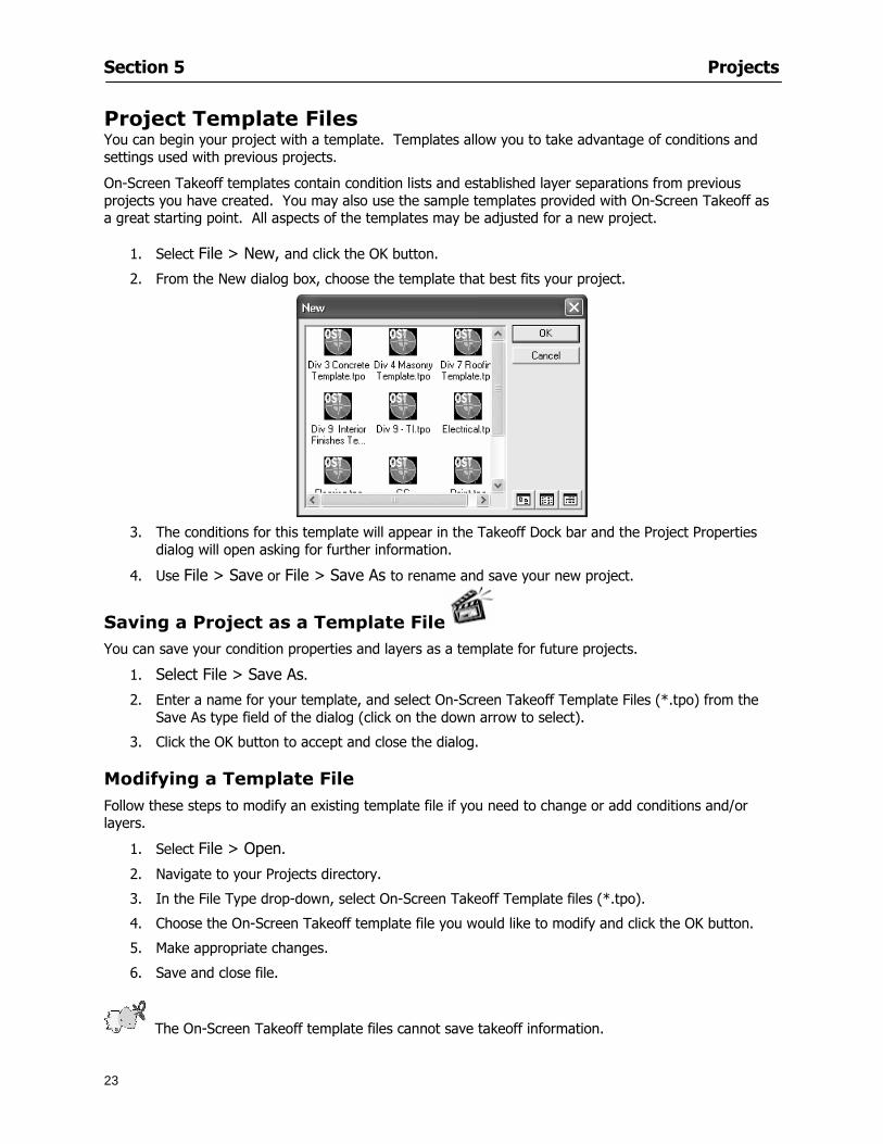
Section 5 Projects
23
Project Template Files You can begin your project with a template Templates allow you to take advantage of conditions and settings used with previous projects
On-Screen Takeoff templates contain condition lists and established layer separations from previous projects you have created You may also use the sample templates provided with On-Screen Takeoff as a great starting point All aspects of the templates may be adjusted for a new project
1 Select File gt New and click the OK button
2 From the New dialog box choose the template that best fits your project
3 The conditions for this template will appear in the Takeoff Dock bar and the Project Properties dialog will open asking for further information
4 Use File gt Save or File gt Save As to rename and save your new project
Saving a Project as a Template File You can save your condition properties and layers as a template for future projects
1 Select File gt Save As
2 Enter a name for your template and select On-Screen Takeoff Template Files (tpo) from the Save As type field of the dialog (click on the down arrow to select)
3 Click the OK button to accept and close the dialog Modifying a Template File Follow these steps to modify an existing template file if you need to change or add conditions andor layers
1 Select File gt Open
2 Navigate to your Projects directory
3 In the File Type drop-down select On-Screen Takeoff Template files (tpo)
4 Choose the On-Screen Takeoff template file you would like to modify and click the OK button
5 Make appropriate changes
6 Save and close file
The On-Screen Takeoff template files cannot save takeoff information
Section 5 Projects
24
Opening an Existing Project File 1 Select File gt Open
2 Navigate to the desired file location
3 Click the Open button
NOTE If your latest changes to a project file have not been saved On-Screen Takeoff will ask
you whether you would like to save the file and gives you the option of canceling the operation
Creating a New Project
1 Select File gt New
2 For a blank untitled project click
3 At this point the Project Properties dialog will pop-up for more information about your takeoff
NOTE The following are important to keep in mind when beginning a new project
At the start of your project fill out the Project Properties settings to establish the name for all printed output from your project set the default page size and scale for your plans number and names of different pages within the project and locations of electronic drawings
Scale settings can significantly affect quantity outcomes Be sure to set the scale for each page of drawings before beginning condition takeoffs
When using a digitizer remember to make a mark with a pen or pencil in the upper left and lower right corners of the first sheet of the paper plans to delineate the takeoff area for that sheet You can then set the takeoff area on On-Screen Takeoff using your marks
Save your project before you begin taking off any conditions On-Screen Takeoff will write a back-up file using the same file name
Remember the Undo feature If you make a mistake select Edit gt Undo and reverse the process step by step
Section 5 Projects
25
Project Properties
You can either set your Project Properties when you create a new takeoff or once your project file is saved under the appropriate name
1 Select File gt Project Properties the Project Properties dialog box will appear
2 Type in the name of your project to appear on printouts Use the backspace andor delete keys to edit the name as necessary
3 Press the Tab key to move to the Default Image Size option or click within the Image Size box You may click on the arrow at the right for the pull-down menu of page size options or you can use the down-arrow key on your keyboard to scroll through the list to the appropriate selection
4 Press the Tab key to move to the Default Scale option Select a scale by using the drop down arrow If your scale is metric you will need to click in the box next to Metric to convert to that measurement
5 Establish the number of pages for your project plans And load image files See Adding Pages to
Your Project
Adding Pages to Projects Individual Electronic Plans
1 Click on in the Project Properties dialog
2 In the Add Images dialog use the drop down arrow to navigate to the appropriate directory and folder containing your image
3 Select the file so that it displays in the File name field then click The file will display by name and path in the Image File field in Project Properties dialog
4 Click to accept and your project will automatically open
5 Save your project with the new settings by selecting File gt Save
Section 5 Projects
26
Electronic plans scanned from blueprints (as opposed to blue lines) will display as white lines on a black background and are difficult to read on your computer screen Select Image gt Invert and the colors will invert to black on white
You may have noticed the Page column in the Project Properties dialog Generally plan images occupy one page and 1 will be listed in the column indicating Page 1 of your plan file If you import a multi-page TIF a plan file containing more than one page of plans they will import as separate pages and each successive page will be indicated under the Page column as 1 2 3 etc of the plan file
Group of Electronic Plans You may add all the electronic plan files from a particular source (for example from a CD) by using the Auto Add feature
1 Click the button in the Project Properties dialog
2 Browse until you find the appropriate directory and folder containing your plan images
3 Click on any file displayed within your target folder so that the file name appears in the File name box of the Auto Add dialog
4 Click The image paths and file names will be recorded into the project properties arranged alphabetically
5 Click to accept your choices and your project will automatically open
6 Save your project with the new settings by selecting File gt Save
To load Dodge Plans into your Project Properties see Appendix IIi Loading Plans from a Dodge CD
Paper Plans On-Screen Takeoff makes it easy for Full Mode users to perform quantity takeoffs from paper plans using a digitizer
1 Add pages by clicking until you have the number of pages initially in the project
2 Name each page by clicking within the Title area and typing the name
3 Click to accept your choices and close the Project Properties dialog
4 Save your project with the new project properties settings by selecting File gt Save
Section 5 Projects
27
Setting Up a Drawing Template On-Screen Takeoff provides the convenience of using the same work surface for both digitizer and mouse to allow the user to draw conditions and then edit settings of the project or add or change conditions without breaking stride A mouse pad template included with the program defines the area of the digitizer in which use of the stylus or cursor will be recognized as mouse movement as opposed to drawing movement
1 Place your stylus on On-Screen Takeoff
2 Placing the template identifies the location mouse movements will be recognized by the program
Before placing the template the template must be applied to the digitizer surface This may have been done during the installation of your digitizer We suggest attaching the template to the lower right corner of the digitizer surface about one inch inside the grid area
3 Select Digitizer gt Place Template
4 Follow the instruction prompts on the screen clicking first on the target symbol at the left of the On-Screen Takeoff box on the template then on the target at the right
Setting Takeoff Area Before you can begin taking off a drawing you must define the drawing area on the digitizer This requires defining an area that will include all objects on each drawing of your plans As you add pages to your takeoff the same area of the digitizer will be active
1 Secure the plans to the digitizer with tape or a set of clamps
2 With a pen or a pencil mark the upper left corner and the lower right corner of the first page in your set of plans
3 Select Digitizer gt Set Takeoff Area
4 Click each mark with the stylus pen as prompted
5 Verify the active area of the digitizer by looking at the image size located in the lower right corner of your screen
If you close the program before the takeoff is complete you will need to reestablish the takeoff area before you can add additional condition quantities
Electronic plans appear on your computer screen eliminating the need to set a takeoff area You simply drag your mouse across the conditions you wish to takeoff The conditions will be highlighted and quantities will be totaled instantly Electronic plans are available through a variety of services For information contact an On Center Software account manager
Section 5 Projects
28
Setting Scale for Specific Pages You may set the scale in each page view separately This will override the default scale setting in Project Properties for that page Setting the correct scale for the drawing before taking off quantities ensures accurate calculations Be careful to check the scale for each drawing in your project before doing takeoffs
1 Display the page you want to set select Edit gt Set Scale
2 Use the drop down arrow to select a scale that will be applied to that page
3 Click
OR
4 Access the pull-down scale settings on the Navigate toolbar
NOTE As you draw objects notice that the drawn object is similar in width to the object on your plans If it is not the scale set may not be correct
Calculating Scale You may calculate scale according to a known measurement between two points either with a digitizer or on electronic plans
1 Select Edit gt Calculate Scale using Image or Edit gt Calculate Scale using Digitizer
2 Follow the instructions in the related Calculate Scale dialog box You will be asked to click on the first and second points then to enter the dimension for that distance
3 The scale will be recalculated for the displayed page and the Scale display on the Navigate toolbar will show the new scale
Section 6
29
Conditions and Takeoff
This section will Draw Conditions to Takeoff Plan Quantities
What Zones will do to help your takeoff process
Discuss the ins and outs of Takeoffs
Section 6 Conditions and Takeoff
30
Creating Conditions
If you are starting a new project from scratch you will need to create conditions to takeoff quantities such as floor areas wall lengths and corner bead counts If you are using a template you will have several pre-designed conditions already listed on the Takeoff dock bar However you may want to change the characteristics of some conditions or create additional conditions for a particular project
1 Right Click within the Takeoff dock bar Select New gt Condition
Or
2 From the Takeoff dock bar Click (if the buttons are not showing right-click in the Takeoff dock bar area and select Show Buttons from the pop-up menu) The New Condition dialog appears
3 Select the condition type (Linear Area Count or Zone) from the pull-down menu accessed by the
down arrow next to the Type option
4 Press Tab or use the mouse (or stylus) to move to Name and enter a name for your condition
5 Specify the desired condition attributes See Condition Attributes for more detail
6 Click for condition to apply
Section 6 Conditions and Takeoff
31
Condition Attributes Each condition type will have related attributes to select or specify within the General and Advanced tabs of the New Condition dialog Once a condition has been used to takeoff a quantity from your plans certain attributes cannot be changed
All conditions allow the user to specify color and fill pattern for the object drawn
Linear Conditions
General Specify width and height by feet and inches Specify pitch in inches up to the nearest thousandth of an inch if applicable
Advanced Specify rounding for object quantities and droprun default length for electrical or plumbing drops at the ends of lines Select Connect to have lines connect at the corners where one line of the condition ends and another begins (and indicate Tolerance for the featurersquos activation as distance between the ends of two lines) Choose Trim to have lines automatically trim to a line being crossed Choose Curve to draw a curved line
Follow these examples for inputting feet and inches For 7 feet 6 inches type 706 for 13 feet 7 inches type 1307 For 20 feet type 2000
Section 6 Conditions and Takeoff
32
Area Conditions
General If needed you can specify the thickness (in inches) andor pitch (in inches)
Advanced Specify rounding for object quantities Choose to display an adjustable grid within the area and indicate matrix cell dimensions
Section 6 Conditions and Takeoff
33
Count Conditions
General
Specify height and indicate the size (in inches) and shape (square circle triangle rectangle or opening) of the count object as it will appear on screen
Advanced Count conditions have advanced attributes These options are available for all shapes except for openings
Zone Conditions Zones allow you to subdivide condition quantities making it easier to modify and complete jobs in phases They can be used at the end of a takeoff to isolate a group of condition quantities that are in different areas of the takeoff
Zones can also be used to break a takeoff into multi-phases and can even be used to isolate quantities while a job is in progress to group the amount of work that has been completed to date They can be applied to one or multiple pages in your plans automatically calculating the takeoff quantities for each zoned area
Section 6 Conditions and Takeoff
34
The zone feature is only available in Lite and Full Mode If you are in View Mode and would like
to use this feature click from the main toolbar to purchase the upgrade
Condition Notes A Note tab is provided for comments regarding the condition These notes will display on the Takeoff List report and will import into Quick Bid
Section 6 Conditions and Takeoff
35
Condition Results The Results tab of the New Condition is based on condition type Initial settings default to linear feet (LF) for linear conditions square feet (SF) for area conditions and count of items (EA) for count conditions and zones The first of the results fields will display for the condition items in the Takeoff dock bar area All results will display in worksheets and Takeoff List reports as well as in an Excel spreadsheet after being exported
Copying Conditions You may use the condition attributes from a condition yoursquove already created for any future conditions of the same type
1 Click on a condition to select it
2 Click the Copy button from the toolbar
OR
3 Right-click in the Takeoff dock bar area and select copy
4 A new condition will appear in the list with the same condition attributes as the previous condition but with the quantities zeroed
Editing Conditions Once you have copied a condition you might want to change several attributes You can also edit an existing condition to fit any updated needs
1 Highlight the desired condition on the Takeoff dock bar
2 Click the Change button
OR
3 Double-click on the condition you wish to edit to bring up the Change Condition dialog
NOTE The Change Condition dialog differs from the New Condition dialog only in that if takeoffs
Section 6 Conditions and Takeoff
36
have been performed in your project with this condition you will not be able to change the type of condition or certain properties under the advanced tab of the dialog box
Deleting Conditions 1 Click on the condition in the Takeoff Dock bar area
2 Click the Delete button on the toolbar
OR
3 Right-click and select Delete from the pop-up menu
All takeoff associated with the deleted condition will be deleted immediately and permanently
Organizing Project Conditions Within your project you can create folders andor sub-folders for different types of conditions You may even want to create a folder containing conditions with reset values
To get started organizing your conditions make sure you are viewing the condition tree (right-click in the Takeoff dock bar area and select Show Tree)
Creating Folders and Sub-Folders 1 Right-click in the Takeoff Dock bar area
2 Select New gt Folder from the pop-up menu
Copying Folders
1 Click on the folder and click Copy on the toolbar
2 All copied conditions within the new folder will have values reset to zero
Renaming Folders
1 Click on the folder
2 Right-click and select Rename from the pop-up menu
3 Enter a name for your folder and click the Enter button
Changing Condition Order
You may move conditions up or down in the condition list of the Takeoff dock bar to suit your project needs
1 Select the condition you would like to move by clicking to highlight it
NOTE When you are ready to move the highlighted conditions be sure that you start
moving using the last condition chosen That condition will have a highlighted boarder
Section 6 Conditions and Takeoff
37
2 Drag and drop any the condition from one place to another in the list You may also move a condition to another folder on the list in this way
Drawing with Conditions Snap Angles Set up snap angles to prevent lines from appearing jagged Snap angles are commonly set at 15deg and shift snap angles at 0deg
1 Go to Tools gt Options Options dialog appears
2 Under the General tab make the desired settings
3 Click to save the settings As they are drawn lines will snap to the set degree
Drawing a Linear Object 1 Select a condition from the Condition List in the Takeoff dock bar
2 Move the cursor into the Image takeoff area of the screen you will see the cursor display as crosshairs
3 Click and hold left mouse button then drag mouse to draw a line
4 Release mouse button to set line
Section 6 Conditions and Takeoff
38
5 Repeat steps for further lines
Continuous Mode This feature allows you to draw an object that has connected lines
1 Click the icon from the Takeoff toolbar
OR
2 Go to Tools gt Continuous Mode
3 Follow steps 1-3 from Draw a Linear Object
4 Click at each point of intersection The object will be connected
5 Double-click after making the final point to set the lines
Drawing a Curve To draw a curved line the Curve option must be checked under the Advanced tab of the Condition dialog
1 Click where you want to begin the curve and drag in a straight line to the position for the other endpoint of the curve
2 Click on the line to select it Handles in the shapes of small squares will appear at either end of
Section 6 Conditions and Takeoff
39
the line and in the center of the line
3 Move the cursor over the center handles until the cursor becomes a two-way arrow
4 Click and drag in the direction of the curve bending the line as you move the cursor Release to set the curve (The line you began with will disappear)
Draw a circle by drawing two curved lines connected
Drawing an Area Object Area conditions are drawn similarly to continuous mode lines You may trace any number of adjoining walls at different angles to complete your area takeoff
NOTE When drawing an area do not intersect the perimeter or line of the object you are drawing
1 Click at each point
2 Double-click when yoursquove returned to your starting point
3 The area will be filled with the pattern set for that condition
NOTE The simulated circle will be good enough for you to be able to make a bid
To create a circular area click from point to point with very short distances in between points simulating a circlersquos perimeter Double-click after setting the last point to set the area
Section 6 Conditions and Takeoff
40
Grid Options Grids give you an added advantage when installing materials such as tiles Use this feature to get a count for how many tiles are needed for an area
1 Double-click on an area condition in the Takeoff dock bar to open its Condition dialog
2 Click on the Advanced tab to show its options
3 Check the box next to Grid by clicking in it
4 Indicate the dimensions of the cell matrix in inches (For example 200 x 400)
5 Under Results tab choose each (EA) for one of the results fields This will tabulate a number of grid cells (including partial grid cells) in area
6 Click to save your settings
7 Use the Move Grid and Rotate Grid features in the Tools menu to manipulate the grid as desired
Grid Calculation
1 Go to Tools gt Options menu
1 Specify if On-Screen Takeoff automatically should Calculate Grid Position
2 If AreaGrid Size is selected On-Screen Takeoff will calculate the number of items needed to fill the grid based on grid demintions
3 Click to accept and close the dialog
To move a line at any angle (regardless of default setting) press the Shift key while moving the mouse
Section 6 Conditions and Takeoff
41
Backout Mode This feature allows you to take out part of an area and deduct that amount of square footage
1 Select Tools gt Backout Mode
2 Outline the are you want backed out as you would when drawing a regular area object (see Drawing an Area Object)
3 The outlined area will clear and quantities will be recalculated
NOTE The perimeter of the backout area will be added to the LF quantity for that condition
Drawing a Count Object Square triangle rectangle and circle shaped count objects can easily be placed on images
1 Select the condition
2 Click in the location where you want the object to appear
3 To place an opening-shaped count item like a door or window you must click over an existing linear object such as a wall
4 On the Results tab you can change the height properties to give you the result you need
5 If Backout is checked on the advanced tab for each count opening the opening-shaped count item will back out a corresponding section of the linear object
Opening shaped count items are sized at 3rsquo0rdquo by default
Drawing a Zone Zones are drawn in the same way as area objects and may be any polygonal shape You may trace any number of adjoining walls at different angles to complete the zone perimeter
1 Click at each point
2 Double-click when yoursquove returned to your starting point
Section 6 Conditions and Takeoff
42
Selecting Objects
1 Use the Select Tool to select objects
You can also select all objects that correspond to a condition
1 Click on a condition to select it
2 Right-click and choose Select All
3 All objects with this condition will be highlighted with squares as an outline
Moving and Resizing Objects Linear
1 To move or resize a linear object click anywhere on the line to select it
2 To move the line position your pointer over the center handles When the mouse is positioned over the handles you will see a two-way arrow You will only be able to move the line in the direction of the arrows
3 Drag the line to a new position
4 Clicking and dragging the handles on the ends of the line will allow you to lengthen or shorten your line
Area and Zone
1 To move an area object or zone in its entirety click and drag it to its new position
2 Grabbing a handle at a corner or intersection of the object will allow you to adjust and change its perimeter
Section 6 Conditions and Takeoff
43
Count 1 To move a square circle rectangle or triangle shaped count object click and drag
2 Click and drag an opening shaped count object along the length of the linear object to the desired position then release
NOTE An opening shaped count object may not be moved from its associated linear condition object however it may be moved up and down the length of the linear object
Layers On-Screen Takeoff allows you to sort and separate your takeoff objects within the same job and on the same page On-Screen Takeoff gives you this flexibility through the use of layers
By assigning different conditions to different layers (for example differentiating between floors ceilings and walls) you can choose to view all layers or turn off certain layers to display and print the remaining groups of conditions only You may also remove the background image of electronic plans add text and hot link symbols or print only your condition takeoffs
Layers are only available in Full Mode If you are in View or Lite Mode and would like to use this
feature click from the main toolbar to purchase the upgrade Default Layers
On-Screen Takeoff begins every project with three default layers Image Annotation and Default The Image layer holds the electronic plan files you may have in your project The Annotation layer possesses all text notations highlighting and hot links in the project The Default layer will appear in the Condition dialog when creating or editing a condition (listed in the takeoff dock bar) Conditions are assigned to the Default layer unless otherwise specified by the user
Creating Layers To assign a condition to a layer other than the default layer you must first create additional layers for your project
1 Select View gt Layers to open the Layers dialog
2 Click An unnamed layer will be added
3 Click within the empty box and type a name for your layer (for example Wall)
4 New layers are added as active layers The adjacent box under the Show column will be checked
Section 6 Conditions and Takeoff
44
Assigning a Layer to a Condition 1 Open the Condition dialog box by creating a new condition or editing an existing condition
2 Under the General tab click on the down arrow in the Layer field to display optional layers
3 Select the desired layer for the condition Only the Default layer and layers you have added will be displayed
4 Click
View and Hide Layers
1 Select View gt Layers
2 Under the Show column check the box to view or remove the check (by clicking on it) to hide the specific layer
3 Click to accept and close the Layers dialog
Section 6 Conditions and Takeoff
45
Assigning Text to a Layer When adding text to an image On-Screen Takeoff has the capability to assign the text to a specified layer
1 Select the Text Tool
2 Click at the point you want to place your text
3 Type in your text using the Enter key for line breaks
4 Click the drop down arrow next to the Layer field and select the desired layer
Section 7
46
Printing and Exporting
This section will
Printing options and procedures
Exporting data by copying and pasting
Exporting quantity results to Excel spreadsheets
Section 7 Printing and Exporting
47
Print Setup On-Screen Takeoff allows the user to print the image takeoff list and worksheet
1 Select File gt Print Setup The Print Setup dialog will open
2 Select a printer or leave the default selection listed (change from the default printer displayed by clicking on the down arrow at the right of the field)
3 Indicate page size and printer tray option (Source) Access page size options by clicking on the
down arrow at the right of the field
4 Choose Portrait or Landscape orientation
5 Click to accept and close the dialog
Printing Images The image area can include the electronic plans the takeoff objects added text and hot links To print a subset of these (for example just the takeoffs without the plans or the added text and hot link symbols) hide layers that you do not want to print (see Section 6 View and Hide Layers) When you are printing your images every page will show the scale of the takeoff you are printing
1 Click on the Image tab to display the area of your project
2 Select File gt Print (or Ctrl + P)
Section 7 Printing and Exporting
48
3 Select the desired view (What to print) and the Image Range
4 Click The second Print dialog will open
5 Change settings accordingly or click if you accept the default settings
Printing Takeoff Lists and Worksheets In Takeoff Lists and Worksheets you may hide columns to print only certain results or adjust column widths to fit the report within the page size selected
1 In Takeoff List or Worksheet view move your cursor to the right side of the columnrsquos title bar the cursor will display as a two-way arrow
Section 7 Printing and Exporting
49
2 Click and drag to adjust the width of the column Holding the mouse button you may
slide the title bar under the title bar to its left to hide the column completely
3 Select File gt Print or press Ctrl + P to access the Print dialog
4 Indicate desired printer and choose the number of copies
5 Click to print and close the dialog
When printing the condition list we suggest printing in landscape
To reset to the default column widths double-click on the right border of a column heading will reset the column to its right (or previously to its right before being hidden)
Print Preview 1 Select File gt Print Preview
2 Use and to vary your view 3 If viewing an image choose current full or scale view to see how it displays
4 For printed outputs that cover more than one page use and to view adjacent pages or click on the down arrow next to Page field and select the page you want displayed
Exporting Using the CopyPaste Feature You may copy all the data or sections from the worksheet and the takeoff list view in On-Screen Takeoff and paste it into another application When pasting into Excel the cell layout will be maintained
1 Highlight the areas you wish to paste Click and hold the left mouse button down as you drag the cursor over the area to be selected then releasing the mouse button
OR
2 Select the entire takeoff list quickly click on the left On-Screen Takeoff column header and hold and drag the cursor across the remaining column headings
The number of pages for the view selected will display in the lower left-hand corner The zoom percentage that applies to the view will be displayed in the lower right-hand corner next to page size of the drawing
Section 7 Printing and Exporting
50
3 In the worksheet view you may highlight rows by clicking on the numbered buttons to the left of each row clicking and dragging across column headings or clicking and dragging over individual cells in the worksheet
Click anywhere in the appropriate view to deselect the area
4 Once your selection is highlighted you may select Edit gt Copy or Ctrl C from the keyboard 5 On your monitor switch to the application into which you want to paste your selection 6 Select Edit gt Paste in the new application or simply press Ctrl + V to paste
The colored keys for conditions cannot be pasted
Using the Export Feature You may export condition quantities to specified cell location within an Excel worksheet file Cell target locations are assigned in the Results tab of the condition dialogs on the Export line relating to each quantity measurement type
On-Screen Takeoff will export takeoff quantity results for up to three different quantity types that you specify For instance you may want to know the number of square feet in a ceiling area as well as the number of linear feet in its perimeter
Section 7 Printing and Exporting
51
1 Bring up the Condition dialog by double-clicking on a condition in the takeoff dock bar or by
selecting the condition and clicking
2 Click on the Results tab to access its fields The default quantities for the condition type will display
3 For each results field click on the arrow to access the pull-down menu and select the appropriate quantity (for example SF LF EA etchellip)
4 Have your Excel spreadsheet opened and saved in a file
5 Specify the Excel spreadsheet cell locations where you want the results to go
6 For a cell in the first sheet of your spreadsheet type in the cell address (eg a1) Case is not important
7 For a cell on a successive sheet of your spreadsheet type in sheet the number followed by a comma and the cell address without any spaces (eg sheet2a1) Case is not important
8 Click
9 Select File gt Export gt Condition Qty to Excel
Section 7 Printing and Exporting
52
10 Browse to the location of the Excel spreadsheet file click file to select it
11 Click to export On-Screen Takeoff results to specified cell locations in the Excel file When you return to the Excel application you will see the values have been added to the specified cell locations in your spreadsheet
12 Save your Excel file
Exporting Worksheet to Excel
1 Assign condition quantities you want to export
2 Open saved Excel spreadsheet file to which you will be exporting
3 From On-Screen Takeoff Select File gt Export gt Worksheet to Excel
4 Browse to the location of the Excel spreadsheet file click file to select it
5 Click When you return to the Excel application you will see the values from the Worksheet Tab have been added to your spreadsheet
6 Save your Excel file
Exporting Takeoff to CVS 1 Assign condition quantities you want to export
2 Open saved Excel spreadsheet file to which you will be exporting
3 Click the Takeoff Tab in the project you want to export the information
4 Select File gt Export gt Takeoff to CSV
5 Browse to the location of the CSV spreadsheet file click file to select it
6 Click the Save
NOTE CSV files can be opened in Excel Lotus Access etc One may consider this option more of a ldquodumprdquo into a file
The Excel application must be active (it may be minimized on the application bar) with the target spreadsheet open in the application Otherwise an error will occur with the export operation that will affect both the On-Screen Takeofftrade file and the Excel spreadsheet
Section 8
53
Advanced Features
This section will
Some special features of working with condition objects in the takeoff area
Details of advanced options for conditions
Advanced features of the Project Properties dialog
Section 8 Advanced Features
54
Features to Use with Objects Roping Feature You can move copy or delete using this feature Using the Select tool (the pointer) you may select several objects at once by clicking and dragging an outline around the objects then releasing the mouse button Roping may select either objects completely within the outlined area (inclusive) or objects both within and touched by the outlined area (touching) Specify your roping preference under Tools gt Options
1 Click and hold the mouse button at a point on the screen near the objects to be selected and drag to surround the objects with an outline
2 Release the mouse button The objects will be selected
3 You may now
Move the group around on the page by clicking within the group dragging the mouse and releasing the button to place the objects
Delete the group of objects by clicking the Delete key or
Copy and paste by pressing Ctrl C to copy the group then Ctrl V to paste it The pasted copy of the grouped objects will appear slightly offset from the original objects
Section 8 Advanced Features
55
Applying a DropRun Count
Use the droprun feature when calculating quantities to take into account the drop or run of a linear condition such as electrical lines or plumbing pipes Drop or run lengths may be added separately to any linear condition on screen while a default droprun length may be indicated for a condition as a whole
1 Select the desired linear condition from the Condition List in the Takeoff Dock bar
2 Click the Change button in the toolbar to open the Change Condition dialog
3 Click the Advanced tab to access the advanced options and click inside the DropRun check box
4 Enter a default length to be applied to all of this condition Entering 800 will be interpreted as 8 0 (You must enter both place markers for inches) You can leave the length blank and manually enter drop run on each segment drawn
5 Click the OK button to accept and close the dialog
Edit DropRun Count
1 With the related linear condition in the Takeoff Dock bar highlighted or with the pointer tool selected
2 click on the desired linear object in the image takeoff area The Count button will become active
3 Click on the Count button (alternatively select Tools gt Count) The default droprun amount will show in the pop-up Count dialog (Default length will be zero if droprun has not been selected in this conditionrsquos properties)
4 Type in the desired length Entering 800 will be interpreted as 8 0 (You must enter both place markers for inches)
5 Click the OK button The additional amount will be reflected in the corresponding quantity The new DropRun count will apply only to the object edited
Adding Text in Image View
On-Screen Takeoff allows you to place text comments around your quantity takeoffs that may be printed along with plan images and objects Text is automatically placed within the Annotation Layer (that includes text and hot links)
1 To place text on the image select the Text Tool and click at the point you want to place your text opening a text box
2 Type in your information clicking Enter for line breaks
3 When you are finished click the OK button to exit the text box
4 To reposition text simply click on the text (with the Text Tool active) to select it
5 Move the cursor over the text the cursor will now display as a four-way arrow
6 Click and drag the mouse to position the text as desired
Section 8 Advanced Features
56
1 To edit existing text use the Text Tool to double-click on the text to open the editing box
2 Enter additional text or use the Backspace key to delete text as necessary
Formatting Text Once created you may format the font size type style and color of your text
1 Click on the text to select it and select Tools gt Font or click on the Font button in the Takeoff Toolbar
2 Select the desired features (color options are disabled) and click the OK button
3 Click on the text to select it and select Tools gt Color or click on the Color button in the Takeoff Toolbar The Color dialog will open
4 Click on a color in the Basic Color palette or create a color and add to the Custom Colors palette (Be sure to click on the color in the Custom Colors palette to select it)
5 Click the OK button
Object Properties
Linear Objects
Linear objects may be set to connect at corners
A linear object may be set to trim automatically when crossing another linear object (Check the trim option under the advanced tab of the Condition dialog)
When you move a connected linear object objects automatically move and resize connected lines accordingly (quantities are then recalculated)
This feature requires that the connected linear object be moved using the center handles (does not apply when resizing the line from the ends)
Objects constrain to snap increments defined in the Tools gt Options menu (with the mouse 15deg by default incremental when shift key is held down)
Objects are measured from centerline to centerline
Section 8 Advanced Features
57
Area Objects When drawing an area use your escape key to undo the last line drawn You may reverse your
drawing of an area using the escape key
The area will not fill with color and pattern until the user double-clicks after the last line is set
Lines drawn to delineate an area object constrain to snap increments defined in the Tools gt Options menu (with the mouse 15deg by default incremental when shift key is held down)
After selecting an area to move or adjust position the mouse in the center to move the entire area position the mouse at the sides or corners to adjust the perimeter
Count Objects
All count objects are quantified by the physical number of objects per page and reported as EA for the UOM The quantity for the current Image View is (displayed in the Condition List) and the total quantity in your project is displayed in the Takeoff View and Worksheet View)
Square circle rectangle and triangle shaped count objects do not displace or subtract from other object quantities when placed on top of them However on the Advanced Tab for the count condition a connect property can be set (this is a check box) so that when a count object of this shape is put on top of a Linear type takeoff object it will move with the linear if said linear is moved
An opened-shaped count object must be placed within a linear object Opening shaped count objects may also be measured by linear foot or linear yard (EA SF and SY are also options) Opening shaped count items default to a width of 3rsquo 0rdquo at the time of creation This size can be changed The small medium and large size are not options on this type of condition anymore Check Backout on the Advanced tab for each Count object back out the footage (or yardage) of opening-shaped count objects in which they are placed
NOTE In order to see this Backout functionality (in quantity) for SY or SF deductions at least one of the
results for the Linear(s) this object will be placed on must be set to SY or SF and the count object must have a height quantity
Advanced Features of Conditions The Round Feature Under the Advanced tab of the linear and area Condition dialogues you may specify quantity rounding (in inches) For linear objects rounding applies to each linear object drawn For area objects rounding will apply to each segment of the area perimeter adjusting the perimeter and area calculations For example With a linear condition entering 12 in the Round field will round up each related linear object to the nearest 12 inches or one foot With this setting two walls of 1 4 would each round to 2 0 totaling 4 0
NOTE In the Takeoff Dock bar condition list and in the On-Screen Takeoff reports quantities will be displayed in whole numbers rounded up to the nearest foot However calculations are based on true quantities without rounding unless the Round Feature is engaged
Pitch Pitch may apply either to linear or area conditions It is measured in rise per linear foot Entering 12 indicates a 12 rise per 12 of linear distance (a pitch of 12 over 12) or an angle of 45deg
Section 8 Advanced Features
58
Advanced Features of Project Properties Selecting Multiple Pages
1 Select a single page entry by clicking on the numbered gray button to the left of the entry
2 Drag the cursor down the column of numbers to select consecutive pages
3 Click on the blank button at the top of this column to select all pages in the Properties dialog
Section 8 Advanced Features
59
Changing Image Assigned to a Drawing 1 Select the page entry by clicking on the numbered gray button to the left of the entry 2 Click the Change Image button The Change Image dialog box will appear
3 Navigate to the desired file and select by clicking on it
4 Click the Open button The electronic file assigned to the page will have been changed to reflect the new file choice
Changing Image File Path 1 Select pages as described above
2 Choose Change Folder
3 In the Change Folder dialog navigate to the appropriate folder
4 Click the OK button The file path will have been changed for the selected page entries
Delete a Page from Project Properties 1 Select the page you want to delete by clicking on its associated number (in the gray box at the
left of the entry)
2 Choose Delete Page
All Takeoff on the page will be deleted immediately and permanently
Section 8 Advanced Features
60
Advanced Features of Tool Options
Calculation Method On-Screen Takeoff has built-in calculation options to allow for faster work and faster saves until your takeoff is complete Calculation options are found by selecting Tools gt Options then clicking on the Calculation tab
Calculation method can be set to Automatic Automatic except Grids and Manual Manual will allow the program to operate more quickly while Automatic or Automatic except Grids allows the user to see quantity changes as takeoffs are made
In any mode you may press F9 to recalculate quantities for the On-Screen Takeoff current totals
Configuration Tab
When the ldquoPage Label (A01)rdquo radial button is chosen On-Screen Takeoff puts the numbered label on all the pages of in your current page indicator in your Navigate Toolbar If the Page Descriptionrdquo radial button is chosen then a description of what takeoff is on that specific page will be shown in your current page indicator in your Navigate Toolbar
This section of the configuration tab gives you options on how you want to export your information When the ldquoFolderSubfolder Namesrdquo radial button is chosen than on your file that you are exporting to will have all the conditions folders and subfolders In the Delimiter box you can choose the symbol that is needed to separate the information you are exporting Some files need semicolons () or colons () to make sure the information comes exported in is separated it the appropriate places
Section 8 Advanced Features
61
In previous versions of On-Screen Takeoff there are views that users need to have in order for them to display their information By either choosing ldquoOST 1xrdquo or ldquoOST 2xrdquo it will let the program know you want your columns of information exported in that specific format
When you have the Confirm Deletions radial button of ldquoYesrdquo chosen than every time you delete anything you will get a dialog box confirming your intentions of deletion
While working with your takeoff you have a choice to either view the legend of your conditions or hide it Choose whichever radial button that suits your needs
For those who prefer to use the Enter key to navigate in dialog boxes this option is just for that
Font Tab The Font tab is designed for you to make your own look and feel for the application At the bottom of this tab it will show you sample of the fonts and colors you have chosen
Renaming the Current Page You may change the name of the current page in the takeoff area of On-Screen Takeoff by selecting Edit gt Rename Page
This opens the Name Page dialog and you may simply type in a new name and click the Enter button The new name for the file will be reflected on the title bar for the page and in Project Properties
You also may access the Rename Page function by right-clicking in the takeoff area while in Image View and selecting the option from the pop-up menu that appears
Section 9
62
Saving and Exiting
This section will
Explain how to save projects
Show you how to safely exit the program
Section 9 Saving and Exiting
63
Saving Your Project
1 Select File gt Save 2 If your project has not previously been saved a Save dialog box will open to allow you to name
the file and choose the directory and folder in which to save your file 3 Once saved File gt Save will simply save the current version of the file
OR
4 Select File gt Save As then type in a new name for the file and save to the desired file path
The Auto-save Feature With the Auto-save feature On-Screen Takeoff automatically backs up your open project You may choose to have more than one level of backup files The first backup copy will have the extension b00 and successive files will be b01 b02 and so on If you have designated four levels of backup files after the fourth backup copy has been created (b03) the next file will be saved over the file with extension b00 Further backup saves will then rotate through the four backup files in the same way
1 Select Tools gt Options 2 In the Auto-save area (under the General tab) select the frequency of backup file creation (in
minutes) and the number of levels for the feature 3 You also may disengage the feature by clicking in the check box to clear it
The Auto-save feature automatically saves backup copies to the directory of the current project If you are working from a write-protected area such as a CD-ROM On-Screen Takeoff will place backup files in the On-Screen Takeoff folder
Exiting When you are finished using On-Screen Takeoff it is very easy to exit Exiting is very important because of security reasons If someone were to use your computer they could enter the application and view and manipulate information
Section 9 Saving and Exiting
64
On-Screen Takeoff closes the open project when you open another or create a new project or when you exit the program
1 Select File gt Exit
OR
2 You also may click at the upper right-hand corner of the application to exit
NOTE If your latest changes to a project file have not been saved On-Screen Takeoff will ask you whether you would like to save the file and gives you the option of canceling the operation
Appendix I Installing Your Digitizer
65
Appendix I Installing Your Digitizer When you get your digitizer from GTCO you will need to connect it to your computer Follow the instructions outlined below to do this
Note For rollup digitizers the metal bar must be oriented to the top or right hand side
Connecting the Digitizer 1 Lay the digitizer out flat 2 Connect the Stylus to the digitizer 3 Plug in the power adapter 4 Plug the interface (IO) cable into the digitizer 5 Plug the other end of the interface cable into an open serial port on computer
Note GTCO Technical support phone number is 410-381-6688 The electronic manual (on diskette) from GTCO contains more detailed installation and operation instructions for the GTCO digitizer model you have
Installing other Digitizer Drivers If you are using a GTCO Digitizer you will need to install the GTCO TabletWorks Drivers
If you are using a Digitizer not supported by GTCO Tablet Works 10 please contact the manufacturer of your digitizer for assistance with installation
Installing GTCO TabletWorks Drivers 1 Insert the On Center CD into the CD-ROM drive The CD Startup screen will open 2 Click on Install Software 3 Select Additional Software and Drivers 4 Select Digitizer Driver 5 Follow the instructions for installing TabletWorks 10
Adhering the Template The template is a small plastic sticker used to enable mouse function when using the digitizer with On-Screen Takeoff Place your template on your digitizer We suggest placing it in the bottom right corner of the digitizer about one inch inside the takeoff area
Note You may either peel off the back of the template and use the adhesive surface or you can tape the template down
Appendix I Installing Your Digitizer
66
Testing the Digitizer Drivers Before running OST you may test the digitizer by moving the stylus around on the digitizer pad it should move the mouse cursor (if mouse emulation is enabled)
If the digitizer does not move the mouse cursor on the screen
The superset codes may need to be reset Reset the superset codes by touching on the border of the digitizer with the stylus The digitizer should beep several times
The digitizer may not be communicating with the computer Be sure the COM port selected is correct Be sure the COM port selected is correct If you are not able to get the digitizer to move the mouse cursor you need to call GTCO technical support for help
Note The Mouse Emulation is not required for On-Screen Takeoff to work properly It is used only for the Template functionality if the digitizer is moving the cursor the wrong direction (up instead of sideways or vice-versa)
Click the L-shaped arrow symbol on the digitizer with the stylus
Appendix II Toolbar Item Details
67
Appendix II Toolbar Items Main Toolbar
Appendix II Toolbar Item Details
68
Tool Toolbar
Appendix II Toolbar Item Details
69
Zoom Toolbar
View Toolbar
Navigate Toolbar
Appendix II Toolbar Item Details
70
Navigate Toolbar (Continued)
Takeoff Toolbar
Appendix II Toolbar Item Details
71
Takeoff Toolbar (Continued)
Image Toolbar
Appendix III Loading Plans from a Dodge CD
72
Appendix III Loading Plans from a Dodge CD
This section will detail how to load plans from a F W Dodge CD-ROM into an On-Screen Takeoff project file ready for takeoffs
Dodge files may be added to the Project Properties dialog However loading the files in that way will load the files by number rather than name description If you want to load one page only from your Dodge CD You will have to rename the page to display the name rather than number of the file
To load plan files from a Dodge CD so that the files load sequentially by file number but are displayed by name rather than by number within your project follow the instructions below
Opening a Dodge project from a CD-ROM 1 Insert the CD into the drive 2 Choose File gt Custom 3 Choose Dodge Plans Project (plansdat) as the file type 4 Select the appropriate file type by clicking on the down arrow at the right of the Files of type
field 5 In the Look in field access your drive paths by clicking on the down arrow at the right of the
field then
Navigate to your CD-ROM drive Open the data folder and Open the Projects folder
6 Select the desired project and open its folder 7 Open the plansdat file 8 All the images will come in sequenced correctly for that job along with the full descriptions
(names) of each page If there is not a plans folder in the project folder then plans do not exist for that project on the CD Opening the plansdat file will yield an empty project
Appendix IV Using the Plan Viewer
73
Appendix IV Using On-Screen Takeoff Plan Viewer The On-Screen Takeoff Plan Viewer is a limited version of On Center Softwarersquos commercial takeoff software If your status bar located at the very bottom of the main window says View Mode in the lower left-hand corner then you are using the Plan Viewer You can use the plan viewer to
View CD-based amp converted CAD drawings
View a previously created OST file and associated drawings
Download electronic plans online
Navigate through drawings
Quickly Takeoff linearsareas and counts
Zoom in to view the plan better
Print drawings directly from the viewer
Viewing an On-Screen Takeoff Project File
1 To open an OST file that was previously created with of On-Screen Takeoff 2 Select File gt Open 3 An Open dialog will appear if you do not see the OST file you are looking for select the
Look In drop down arrow 4 A drop down menu will appear listing the various folders drives and mapped drives located
on your computer select the correct drive or folder location and continue to browse to the location of your OST file
5 When you see your OST file double-click it to open it 6 Any takeoff and drawings should appear on the Image tab view
If you do not see the drawings but do see the colored takeoff layer the drawings may
not be located in the same place they were originally saved at Go to File gt Project Properties and check the Image File path for each listed page If the image file path is pointing to a CD drive make sure the CD is inside the CR-ROM
Downloading Electronic Plans If your Online Plan Service provides a special file format (OSX) required to use this feature of our plan viewer you can immediately downloaded all electronic plans of a project directly from our viewer
Most Plan Room web sites will automatically open On-Screen Takeoff when a request to download plans is made Your particular Plan Room may differ in operation so please contact the provider directly with questions on using the site
Appendix IV Using the Plan Viewer
74
When you request to download or open a project file from a Plan Room you will usually have the open to open or save an OSX file Choosing open will automatically open On-Screen Takeoff Alternately you may choose to save the file to a local hard drive After you have saved the file either double-click it to launch On-Screen Takeoff or open the OSX file using On-Screen Takeoff by clicking File then Open and locating the file on your hard drive You will need to change the file type to OSX
After the OSX file is opened you will see an additional tab appear in the Conditions List window called Pages
The Pages tab shows the hierarchy of your project Gray file icons represent pages that have not been downloaded and blue icons represents pages that have been downloaded
To download a page simply double-click the page icon
If you wish to select a group of pages to download you can use the Ctrl or Shift key to multiple select them then click the Download button
If you wish to download all pages at once click the Download All button
Downloaded pages will now appear in the Project Properties dialog in the same order in which they appear in the Pages tab
Creating Quick Takeoffs With On-Screen Takeoff you can create quick takeoffs to measure quantities even if you dont have the full version of our program However using the Quick Takeoff functionality shows you just a fraction of what the full version can do
The Quick Takeoff Toolbar is located at the top of the image view It has three buttons designated for three types of takeoffs Linear Area and Count The Quantity drop down list will show secondary quantities for Linears and Areas The Units drop down allows you to select how you want your quantities displayed Feet Inches Yards Millimeters and Meters
NOTE Every time change the type of takeoff you are performing (switching from Area to Linear for example) the previous quantities and takeoff objects will disappear They will also disappear when you changes pages
NOTE You can use the Dimension Tool to basically measure the distance between two points or linears The distance will display on the status bar at the bottom of the application
The Quick Takeoff Toolbar
Appendix V Frequently Asked Questions
75
Appendix V Frequently Asked Questions General
Where is On-Screen Takeoff installed on my computer
Typically it is installed in CProgram FilesOn-Screen Takeoff
In Explorer how do I recognize On-Screen Takeoff file types
On-Screen Takeoff data is stored in a single file per job lsquojob name OSTrsquo On-Screen Takeoff templates are stored as lsquotemplate nameTPOrsquo
Can only one project at a time be open
Yes For that reason opening another project automatically closes the project on screen You will be asked to save any changes
Is only one scale allowed per page What about on drawings that have multiple detail sections on a page and each of those drawings have different scales
Yes For pages with drawings of different scales copy the drawing to another project page and set the appropriate scale
I cannot perform backout on an area that is along a linear
As a workaround use the On-Screen Takeoff layers feature to help you with this issue Electronic Images
How do I start a project from drawings that have been scanned and written to a CD-ROM
Open a new project Select File gt Project Properties and select Auto Add Navigate to your CD and the appropriate folder and select any image file in that location Click Open All files in the location will load into your project Recommended that images are copied from CD to hard drive for performance
If I get a disk of drawings in AutoCAD format (R13 or R14) can I read them in On-Screen Takeoff
Yes On-Screen Takeoff now reads DWG DXF and many other format that are saved with AutoCAD
Appendix V Frequently Asked Questions
76
When I click on the all pages button what is supposed to happen Currently nothing seems to change when I click on that button
The All Pages button is used to apply the Darken and Enhance Plans feature to all pages in the project (as opposed to only the current page on screen)
Is there a way to deduct a large skylight from an area condition
Yes with the related area condition selected in the Takeoff Dock bar unselect the Backout button on the Takeoff Toolbar then draw the Backout area The area quantity will be deducted from the related condition object and the linear measurement of the Backout perimeter will be added
Digitizer Issues
How do I connect a Digitizer to the computer
See Appendix I Connecting a Digitizer
The Place Template menu choice is disabled
On-Screen Takeoff may need to be authorized or the digitizer or the digitzer drivers are not installed
It wonrsquot let me select the Set Takeoff Area menu choice
On-Screen Takeoff may need to be authorized or no job is open a digitizer is not installed or the drivers are not installed
The digitizer stylus is not moving the cursor or crosshairs
Click S-0-1 superset on the digitizer
How do I convert my old GTCO Digitizer to work with On- Screen Takeofftrade
Call GTCO and they may be able to reconfigure your digitizer to be compatible with On-Screen Takeoff
Printing Issues Which Printers work with On-Screen Takeoff
Compatible printers include On-Screen Takeoff Hewlett Packard Epson and Canon printers If you are having printer difficulties please contact support and specify the type of printer along with other pertinent information Contact support at wwwoncentercomsupport or email supportoncentercom
Which Plotters work with On-Screen Takeoff
Compatible Plotters include Hewlett Packard DesignJet plotters and the EnCAD Cadjet II If you are having plotter difficulties please contact support and specify the type of plotter concerned
ViewingDisplay I can no longer see my condition list How do I get it back
The toolbars and Dock bars can be turned on and off through the View gt Toolbars menu options
Appendix V Frequently Asked Questions
77
This is also accessible by right-clicking in the toolbar area and selecting (or deselecting) a toolbar listed
I cannot view my folders in the condition list
Right-click in the Takeoff Dock barcondition list area and select Show Tree to display your folders
My Status Bar reads Viewer Mode and I am unable to draw conditions
On-Screen Takeoff needs to be Authorized Or you need to purchase an upgrade Click the Perform Advanced Takeoff button on the main toolbar
I hid a Dock bar and when I selected to view it again it appeared alongside the other Dock
bar instead of stacked on top of it How do I fix it
Pick up the Dock bar by clicking on the bar at the top and continuing to hold down the mouse button drag the Dock bar over the other one It will resize and appear stacked with the other
When I open image files from a CD the images are all upside down How do I get them right
side up
To flip pages from top to bottom follow the steps below 1 Click the All Pages button on the Image Toolbar (All Pages is engaged when the button
is not clicked) 2 Click the Flip Horizontal button on the Image Toolbar 3 Click the All Pages button again to disengage
Templates How do I create a Template
Follow the steps below 1 Create a typical project 2 Choose File gt Save As 3 Choose On-Screen Takeoff Template Files as the file type to save 4 Name the file This will save all of the condition setups as well as the layers for the
project
How do I create a new project from a template
Follow the steps below 1 Choose File gt New 2 Select a template from those listed in the New dialog This will open a new project with
conditions and layers saved from a previous project but no pages or takeoff
78
INDEX
Area Conditions 32
Area Objects 57
Auto Scrolling 20
Auto-save 63
Backout Mode 41
Calculation Method 60
Conditions 29
Configuration 60
Contents Tab 6
Continuous Mode 38
Count Conditions 33
Count Objects 57
Digitizer 10 65 76
Docking Toolbars 13
Dodge CD 72
Drawing 27 37
DropRun Count 55
Environment 18
Exiting 63
Exporting 49
Features 16
Font 61
Frequently Asked Questions 75
Grid 40
Help File 5
Hiding Toolbars 13
Hot Links 21
Image 19 59
Image files 9
Image Toolbar 12 71
Images 75
Index Tab 6
Layers 43
Linear Conditions 31
Linear Objects 56
Main Toolbar 12 67
Menus 14
Moving Toolbars 13
Navigate Toolbar 12 69
Navigating 20
On-Screen Takeofftrade 2
Page 59 61
Pages 20 25 28
Plan Viewer 73
Plans 26
Printing 47 76
Project Properties 25
Projects 22
Quick Start Video 18
Resizing Toolbars 13
Roping 54
Saving 63
Scale 28
Search Tab 7
Selecting Objects 42
Setup 8
Start On-Screen Takeofftrade 17
System Requirements 9
Takeoff 19 27
Takeoff Toolbar 70 71
Takeoff Toolbar 12
Template Files 23
TIF (Group4) 9
Tool Toolbar 12 68
Toolbar 67
Toolbars 12
View Toolbar 12 69
Viewing Toolbars 12
Worksheet 20
Zone Conditions 33
Zoom Toolbar 12 69
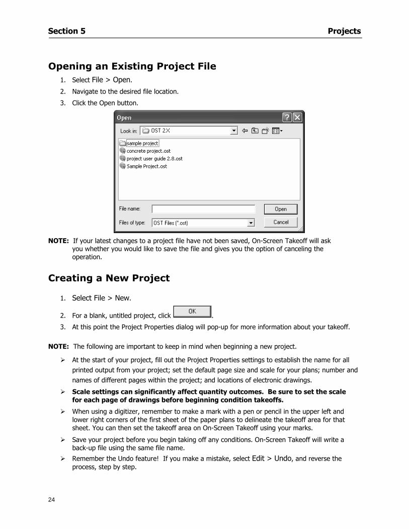
Section 5 Projects
24
Opening an Existing Project File 1 Select File gt Open
2 Navigate to the desired file location
3 Click the Open button
NOTE If your latest changes to a project file have not been saved On-Screen Takeoff will ask
you whether you would like to save the file and gives you the option of canceling the operation
Creating a New Project
1 Select File gt New
2 For a blank untitled project click
3 At this point the Project Properties dialog will pop-up for more information about your takeoff
NOTE The following are important to keep in mind when beginning a new project
At the start of your project fill out the Project Properties settings to establish the name for all printed output from your project set the default page size and scale for your plans number and names of different pages within the project and locations of electronic drawings
Scale settings can significantly affect quantity outcomes Be sure to set the scale for each page of drawings before beginning condition takeoffs
When using a digitizer remember to make a mark with a pen or pencil in the upper left and lower right corners of the first sheet of the paper plans to delineate the takeoff area for that sheet You can then set the takeoff area on On-Screen Takeoff using your marks
Save your project before you begin taking off any conditions On-Screen Takeoff will write a back-up file using the same file name
Remember the Undo feature If you make a mistake select Edit gt Undo and reverse the process step by step
Section 5 Projects
25
Project Properties
You can either set your Project Properties when you create a new takeoff or once your project file is saved under the appropriate name
1 Select File gt Project Properties the Project Properties dialog box will appear
2 Type in the name of your project to appear on printouts Use the backspace andor delete keys to edit the name as necessary
3 Press the Tab key to move to the Default Image Size option or click within the Image Size box You may click on the arrow at the right for the pull-down menu of page size options or you can use the down-arrow key on your keyboard to scroll through the list to the appropriate selection
4 Press the Tab key to move to the Default Scale option Select a scale by using the drop down arrow If your scale is metric you will need to click in the box next to Metric to convert to that measurement
5 Establish the number of pages for your project plans And load image files See Adding Pages to
Your Project
Adding Pages to Projects Individual Electronic Plans
1 Click on in the Project Properties dialog
2 In the Add Images dialog use the drop down arrow to navigate to the appropriate directory and folder containing your image
3 Select the file so that it displays in the File name field then click The file will display by name and path in the Image File field in Project Properties dialog
4 Click to accept and your project will automatically open
5 Save your project with the new settings by selecting File gt Save
Section 5 Projects
26
Electronic plans scanned from blueprints (as opposed to blue lines) will display as white lines on a black background and are difficult to read on your computer screen Select Image gt Invert and the colors will invert to black on white
You may have noticed the Page column in the Project Properties dialog Generally plan images occupy one page and 1 will be listed in the column indicating Page 1 of your plan file If you import a multi-page TIF a plan file containing more than one page of plans they will import as separate pages and each successive page will be indicated under the Page column as 1 2 3 etc of the plan file
Group of Electronic Plans You may add all the electronic plan files from a particular source (for example from a CD) by using the Auto Add feature
1 Click the button in the Project Properties dialog
2 Browse until you find the appropriate directory and folder containing your plan images
3 Click on any file displayed within your target folder so that the file name appears in the File name box of the Auto Add dialog
4 Click The image paths and file names will be recorded into the project properties arranged alphabetically
5 Click to accept your choices and your project will automatically open
6 Save your project with the new settings by selecting File gt Save
To load Dodge Plans into your Project Properties see Appendix IIi Loading Plans from a Dodge CD
Paper Plans On-Screen Takeoff makes it easy for Full Mode users to perform quantity takeoffs from paper plans using a digitizer
1 Add pages by clicking until you have the number of pages initially in the project
2 Name each page by clicking within the Title area and typing the name
3 Click to accept your choices and close the Project Properties dialog
4 Save your project with the new project properties settings by selecting File gt Save
Section 5 Projects
27
Setting Up a Drawing Template On-Screen Takeoff provides the convenience of using the same work surface for both digitizer and mouse to allow the user to draw conditions and then edit settings of the project or add or change conditions without breaking stride A mouse pad template included with the program defines the area of the digitizer in which use of the stylus or cursor will be recognized as mouse movement as opposed to drawing movement
1 Place your stylus on On-Screen Takeoff
2 Placing the template identifies the location mouse movements will be recognized by the program
Before placing the template the template must be applied to the digitizer surface This may have been done during the installation of your digitizer We suggest attaching the template to the lower right corner of the digitizer surface about one inch inside the grid area
3 Select Digitizer gt Place Template
4 Follow the instruction prompts on the screen clicking first on the target symbol at the left of the On-Screen Takeoff box on the template then on the target at the right
Setting Takeoff Area Before you can begin taking off a drawing you must define the drawing area on the digitizer This requires defining an area that will include all objects on each drawing of your plans As you add pages to your takeoff the same area of the digitizer will be active
1 Secure the plans to the digitizer with tape or a set of clamps
2 With a pen or a pencil mark the upper left corner and the lower right corner of the first page in your set of plans
3 Select Digitizer gt Set Takeoff Area
4 Click each mark with the stylus pen as prompted
5 Verify the active area of the digitizer by looking at the image size located in the lower right corner of your screen
If you close the program before the takeoff is complete you will need to reestablish the takeoff area before you can add additional condition quantities
Electronic plans appear on your computer screen eliminating the need to set a takeoff area You simply drag your mouse across the conditions you wish to takeoff The conditions will be highlighted and quantities will be totaled instantly Electronic plans are available through a variety of services For information contact an On Center Software account manager
Section 5 Projects
28
Setting Scale for Specific Pages You may set the scale in each page view separately This will override the default scale setting in Project Properties for that page Setting the correct scale for the drawing before taking off quantities ensures accurate calculations Be careful to check the scale for each drawing in your project before doing takeoffs
1 Display the page you want to set select Edit gt Set Scale
2 Use the drop down arrow to select a scale that will be applied to that page
3 Click
OR
4 Access the pull-down scale settings on the Navigate toolbar
NOTE As you draw objects notice that the drawn object is similar in width to the object on your plans If it is not the scale set may not be correct
Calculating Scale You may calculate scale according to a known measurement between two points either with a digitizer or on electronic plans
1 Select Edit gt Calculate Scale using Image or Edit gt Calculate Scale using Digitizer
2 Follow the instructions in the related Calculate Scale dialog box You will be asked to click on the first and second points then to enter the dimension for that distance
3 The scale will be recalculated for the displayed page and the Scale display on the Navigate toolbar will show the new scale
Section 6
29
Conditions and Takeoff
This section will Draw Conditions to Takeoff Plan Quantities
What Zones will do to help your takeoff process
Discuss the ins and outs of Takeoffs
Section 6 Conditions and Takeoff
30
Creating Conditions
If you are starting a new project from scratch you will need to create conditions to takeoff quantities such as floor areas wall lengths and corner bead counts If you are using a template you will have several pre-designed conditions already listed on the Takeoff dock bar However you may want to change the characteristics of some conditions or create additional conditions for a particular project
1 Right Click within the Takeoff dock bar Select New gt Condition
Or
2 From the Takeoff dock bar Click (if the buttons are not showing right-click in the Takeoff dock bar area and select Show Buttons from the pop-up menu) The New Condition dialog appears
3 Select the condition type (Linear Area Count or Zone) from the pull-down menu accessed by the
down arrow next to the Type option
4 Press Tab or use the mouse (or stylus) to move to Name and enter a name for your condition
5 Specify the desired condition attributes See Condition Attributes for more detail
6 Click for condition to apply
Section 6 Conditions and Takeoff
31
Condition Attributes Each condition type will have related attributes to select or specify within the General and Advanced tabs of the New Condition dialog Once a condition has been used to takeoff a quantity from your plans certain attributes cannot be changed
All conditions allow the user to specify color and fill pattern for the object drawn
Linear Conditions
General Specify width and height by feet and inches Specify pitch in inches up to the nearest thousandth of an inch if applicable
Advanced Specify rounding for object quantities and droprun default length for electrical or plumbing drops at the ends of lines Select Connect to have lines connect at the corners where one line of the condition ends and another begins (and indicate Tolerance for the featurersquos activation as distance between the ends of two lines) Choose Trim to have lines automatically trim to a line being crossed Choose Curve to draw a curved line
Follow these examples for inputting feet and inches For 7 feet 6 inches type 706 for 13 feet 7 inches type 1307 For 20 feet type 2000
Section 6 Conditions and Takeoff
32
Area Conditions
General If needed you can specify the thickness (in inches) andor pitch (in inches)
Advanced Specify rounding for object quantities Choose to display an adjustable grid within the area and indicate matrix cell dimensions
Section 6 Conditions and Takeoff
33
Count Conditions
General
Specify height and indicate the size (in inches) and shape (square circle triangle rectangle or opening) of the count object as it will appear on screen
Advanced Count conditions have advanced attributes These options are available for all shapes except for openings
Zone Conditions Zones allow you to subdivide condition quantities making it easier to modify and complete jobs in phases They can be used at the end of a takeoff to isolate a group of condition quantities that are in different areas of the takeoff
Zones can also be used to break a takeoff into multi-phases and can even be used to isolate quantities while a job is in progress to group the amount of work that has been completed to date They can be applied to one or multiple pages in your plans automatically calculating the takeoff quantities for each zoned area
Section 6 Conditions and Takeoff
34
The zone feature is only available in Lite and Full Mode If you are in View Mode and would like
to use this feature click from the main toolbar to purchase the upgrade
Condition Notes A Note tab is provided for comments regarding the condition These notes will display on the Takeoff List report and will import into Quick Bid
Section 6 Conditions and Takeoff
35
Condition Results The Results tab of the New Condition is based on condition type Initial settings default to linear feet (LF) for linear conditions square feet (SF) for area conditions and count of items (EA) for count conditions and zones The first of the results fields will display for the condition items in the Takeoff dock bar area All results will display in worksheets and Takeoff List reports as well as in an Excel spreadsheet after being exported
Copying Conditions You may use the condition attributes from a condition yoursquove already created for any future conditions of the same type
1 Click on a condition to select it
2 Click the Copy button from the toolbar
OR
3 Right-click in the Takeoff dock bar area and select copy
4 A new condition will appear in the list with the same condition attributes as the previous condition but with the quantities zeroed
Editing Conditions Once you have copied a condition you might want to change several attributes You can also edit an existing condition to fit any updated needs
1 Highlight the desired condition on the Takeoff dock bar
2 Click the Change button
OR
3 Double-click on the condition you wish to edit to bring up the Change Condition dialog
NOTE The Change Condition dialog differs from the New Condition dialog only in that if takeoffs
Section 6 Conditions and Takeoff
36
have been performed in your project with this condition you will not be able to change the type of condition or certain properties under the advanced tab of the dialog box
Deleting Conditions 1 Click on the condition in the Takeoff Dock bar area
2 Click the Delete button on the toolbar
OR
3 Right-click and select Delete from the pop-up menu
All takeoff associated with the deleted condition will be deleted immediately and permanently
Organizing Project Conditions Within your project you can create folders andor sub-folders for different types of conditions You may even want to create a folder containing conditions with reset values
To get started organizing your conditions make sure you are viewing the condition tree (right-click in the Takeoff dock bar area and select Show Tree)
Creating Folders and Sub-Folders 1 Right-click in the Takeoff Dock bar area
2 Select New gt Folder from the pop-up menu
Copying Folders
1 Click on the folder and click Copy on the toolbar
2 All copied conditions within the new folder will have values reset to zero
Renaming Folders
1 Click on the folder
2 Right-click and select Rename from the pop-up menu
3 Enter a name for your folder and click the Enter button
Changing Condition Order
You may move conditions up or down in the condition list of the Takeoff dock bar to suit your project needs
1 Select the condition you would like to move by clicking to highlight it
NOTE When you are ready to move the highlighted conditions be sure that you start
moving using the last condition chosen That condition will have a highlighted boarder
Section 6 Conditions and Takeoff
37
2 Drag and drop any the condition from one place to another in the list You may also move a condition to another folder on the list in this way
Drawing with Conditions Snap Angles Set up snap angles to prevent lines from appearing jagged Snap angles are commonly set at 15deg and shift snap angles at 0deg
1 Go to Tools gt Options Options dialog appears
2 Under the General tab make the desired settings
3 Click to save the settings As they are drawn lines will snap to the set degree
Drawing a Linear Object 1 Select a condition from the Condition List in the Takeoff dock bar
2 Move the cursor into the Image takeoff area of the screen you will see the cursor display as crosshairs
3 Click and hold left mouse button then drag mouse to draw a line
4 Release mouse button to set line
Section 6 Conditions and Takeoff
38
5 Repeat steps for further lines
Continuous Mode This feature allows you to draw an object that has connected lines
1 Click the icon from the Takeoff toolbar
OR
2 Go to Tools gt Continuous Mode
3 Follow steps 1-3 from Draw a Linear Object
4 Click at each point of intersection The object will be connected
5 Double-click after making the final point to set the lines
Drawing a Curve To draw a curved line the Curve option must be checked under the Advanced tab of the Condition dialog
1 Click where you want to begin the curve and drag in a straight line to the position for the other endpoint of the curve
2 Click on the line to select it Handles in the shapes of small squares will appear at either end of
Section 6 Conditions and Takeoff
39
the line and in the center of the line
3 Move the cursor over the center handles until the cursor becomes a two-way arrow
4 Click and drag in the direction of the curve bending the line as you move the cursor Release to set the curve (The line you began with will disappear)
Draw a circle by drawing two curved lines connected
Drawing an Area Object Area conditions are drawn similarly to continuous mode lines You may trace any number of adjoining walls at different angles to complete your area takeoff
NOTE When drawing an area do not intersect the perimeter or line of the object you are drawing
1 Click at each point
2 Double-click when yoursquove returned to your starting point
3 The area will be filled with the pattern set for that condition
NOTE The simulated circle will be good enough for you to be able to make a bid
To create a circular area click from point to point with very short distances in between points simulating a circlersquos perimeter Double-click after setting the last point to set the area
Section 6 Conditions and Takeoff
40
Grid Options Grids give you an added advantage when installing materials such as tiles Use this feature to get a count for how many tiles are needed for an area
1 Double-click on an area condition in the Takeoff dock bar to open its Condition dialog
2 Click on the Advanced tab to show its options
3 Check the box next to Grid by clicking in it
4 Indicate the dimensions of the cell matrix in inches (For example 200 x 400)
5 Under Results tab choose each (EA) for one of the results fields This will tabulate a number of grid cells (including partial grid cells) in area
6 Click to save your settings
7 Use the Move Grid and Rotate Grid features in the Tools menu to manipulate the grid as desired
Grid Calculation
1 Go to Tools gt Options menu
1 Specify if On-Screen Takeoff automatically should Calculate Grid Position
2 If AreaGrid Size is selected On-Screen Takeoff will calculate the number of items needed to fill the grid based on grid demintions
3 Click to accept and close the dialog
To move a line at any angle (regardless of default setting) press the Shift key while moving the mouse
Section 6 Conditions and Takeoff
41
Backout Mode This feature allows you to take out part of an area and deduct that amount of square footage
1 Select Tools gt Backout Mode
2 Outline the are you want backed out as you would when drawing a regular area object (see Drawing an Area Object)
3 The outlined area will clear and quantities will be recalculated
NOTE The perimeter of the backout area will be added to the LF quantity for that condition
Drawing a Count Object Square triangle rectangle and circle shaped count objects can easily be placed on images
1 Select the condition
2 Click in the location where you want the object to appear
3 To place an opening-shaped count item like a door or window you must click over an existing linear object such as a wall
4 On the Results tab you can change the height properties to give you the result you need
5 If Backout is checked on the advanced tab for each count opening the opening-shaped count item will back out a corresponding section of the linear object
Opening shaped count items are sized at 3rsquo0rdquo by default
Drawing a Zone Zones are drawn in the same way as area objects and may be any polygonal shape You may trace any number of adjoining walls at different angles to complete the zone perimeter
1 Click at each point
2 Double-click when yoursquove returned to your starting point
Section 6 Conditions and Takeoff
42
Selecting Objects
1 Use the Select Tool to select objects
You can also select all objects that correspond to a condition
1 Click on a condition to select it
2 Right-click and choose Select All
3 All objects with this condition will be highlighted with squares as an outline
Moving and Resizing Objects Linear
1 To move or resize a linear object click anywhere on the line to select it
2 To move the line position your pointer over the center handles When the mouse is positioned over the handles you will see a two-way arrow You will only be able to move the line in the direction of the arrows
3 Drag the line to a new position
4 Clicking and dragging the handles on the ends of the line will allow you to lengthen or shorten your line
Area and Zone
1 To move an area object or zone in its entirety click and drag it to its new position
2 Grabbing a handle at a corner or intersection of the object will allow you to adjust and change its perimeter
Section 6 Conditions and Takeoff
43
Count 1 To move a square circle rectangle or triangle shaped count object click and drag
2 Click and drag an opening shaped count object along the length of the linear object to the desired position then release
NOTE An opening shaped count object may not be moved from its associated linear condition object however it may be moved up and down the length of the linear object
Layers On-Screen Takeoff allows you to sort and separate your takeoff objects within the same job and on the same page On-Screen Takeoff gives you this flexibility through the use of layers
By assigning different conditions to different layers (for example differentiating between floors ceilings and walls) you can choose to view all layers or turn off certain layers to display and print the remaining groups of conditions only You may also remove the background image of electronic plans add text and hot link symbols or print only your condition takeoffs
Layers are only available in Full Mode If you are in View or Lite Mode and would like to use this
feature click from the main toolbar to purchase the upgrade Default Layers
On-Screen Takeoff begins every project with three default layers Image Annotation and Default The Image layer holds the electronic plan files you may have in your project The Annotation layer possesses all text notations highlighting and hot links in the project The Default layer will appear in the Condition dialog when creating or editing a condition (listed in the takeoff dock bar) Conditions are assigned to the Default layer unless otherwise specified by the user
Creating Layers To assign a condition to a layer other than the default layer you must first create additional layers for your project
1 Select View gt Layers to open the Layers dialog
2 Click An unnamed layer will be added
3 Click within the empty box and type a name for your layer (for example Wall)
4 New layers are added as active layers The adjacent box under the Show column will be checked
Section 6 Conditions and Takeoff
44
Assigning a Layer to a Condition 1 Open the Condition dialog box by creating a new condition or editing an existing condition
2 Under the General tab click on the down arrow in the Layer field to display optional layers
3 Select the desired layer for the condition Only the Default layer and layers you have added will be displayed
4 Click
View and Hide Layers
1 Select View gt Layers
2 Under the Show column check the box to view or remove the check (by clicking on it) to hide the specific layer
3 Click to accept and close the Layers dialog
Section 6 Conditions and Takeoff
45
Assigning Text to a Layer When adding text to an image On-Screen Takeoff has the capability to assign the text to a specified layer
1 Select the Text Tool
2 Click at the point you want to place your text
3 Type in your text using the Enter key for line breaks
4 Click the drop down arrow next to the Layer field and select the desired layer
Section 7
46
Printing and Exporting
This section will
Printing options and procedures
Exporting data by copying and pasting
Exporting quantity results to Excel spreadsheets
Section 7 Printing and Exporting
47
Print Setup On-Screen Takeoff allows the user to print the image takeoff list and worksheet
1 Select File gt Print Setup The Print Setup dialog will open
2 Select a printer or leave the default selection listed (change from the default printer displayed by clicking on the down arrow at the right of the field)
3 Indicate page size and printer tray option (Source) Access page size options by clicking on the
down arrow at the right of the field
4 Choose Portrait or Landscape orientation
5 Click to accept and close the dialog
Printing Images The image area can include the electronic plans the takeoff objects added text and hot links To print a subset of these (for example just the takeoffs without the plans or the added text and hot link symbols) hide layers that you do not want to print (see Section 6 View and Hide Layers) When you are printing your images every page will show the scale of the takeoff you are printing
1 Click on the Image tab to display the area of your project
2 Select File gt Print (or Ctrl + P)
Section 7 Printing and Exporting
48
3 Select the desired view (What to print) and the Image Range
4 Click The second Print dialog will open
5 Change settings accordingly or click if you accept the default settings
Printing Takeoff Lists and Worksheets In Takeoff Lists and Worksheets you may hide columns to print only certain results or adjust column widths to fit the report within the page size selected
1 In Takeoff List or Worksheet view move your cursor to the right side of the columnrsquos title bar the cursor will display as a two-way arrow
Section 7 Printing and Exporting
49
2 Click and drag to adjust the width of the column Holding the mouse button you may
slide the title bar under the title bar to its left to hide the column completely
3 Select File gt Print or press Ctrl + P to access the Print dialog
4 Indicate desired printer and choose the number of copies
5 Click to print and close the dialog
When printing the condition list we suggest printing in landscape
To reset to the default column widths double-click on the right border of a column heading will reset the column to its right (or previously to its right before being hidden)
Print Preview 1 Select File gt Print Preview
2 Use and to vary your view 3 If viewing an image choose current full or scale view to see how it displays
4 For printed outputs that cover more than one page use and to view adjacent pages or click on the down arrow next to Page field and select the page you want displayed
Exporting Using the CopyPaste Feature You may copy all the data or sections from the worksheet and the takeoff list view in On-Screen Takeoff and paste it into another application When pasting into Excel the cell layout will be maintained
1 Highlight the areas you wish to paste Click and hold the left mouse button down as you drag the cursor over the area to be selected then releasing the mouse button
OR
2 Select the entire takeoff list quickly click on the left On-Screen Takeoff column header and hold and drag the cursor across the remaining column headings
The number of pages for the view selected will display in the lower left-hand corner The zoom percentage that applies to the view will be displayed in the lower right-hand corner next to page size of the drawing
Section 7 Printing and Exporting
50
3 In the worksheet view you may highlight rows by clicking on the numbered buttons to the left of each row clicking and dragging across column headings or clicking and dragging over individual cells in the worksheet
Click anywhere in the appropriate view to deselect the area
4 Once your selection is highlighted you may select Edit gt Copy or Ctrl C from the keyboard 5 On your monitor switch to the application into which you want to paste your selection 6 Select Edit gt Paste in the new application or simply press Ctrl + V to paste
The colored keys for conditions cannot be pasted
Using the Export Feature You may export condition quantities to specified cell location within an Excel worksheet file Cell target locations are assigned in the Results tab of the condition dialogs on the Export line relating to each quantity measurement type
On-Screen Takeoff will export takeoff quantity results for up to three different quantity types that you specify For instance you may want to know the number of square feet in a ceiling area as well as the number of linear feet in its perimeter
Section 7 Printing and Exporting
51
1 Bring up the Condition dialog by double-clicking on a condition in the takeoff dock bar or by
selecting the condition and clicking
2 Click on the Results tab to access its fields The default quantities for the condition type will display
3 For each results field click on the arrow to access the pull-down menu and select the appropriate quantity (for example SF LF EA etchellip)
4 Have your Excel spreadsheet opened and saved in a file
5 Specify the Excel spreadsheet cell locations where you want the results to go
6 For a cell in the first sheet of your spreadsheet type in the cell address (eg a1) Case is not important
7 For a cell on a successive sheet of your spreadsheet type in sheet the number followed by a comma and the cell address without any spaces (eg sheet2a1) Case is not important
8 Click
9 Select File gt Export gt Condition Qty to Excel
Section 7 Printing and Exporting
52
10 Browse to the location of the Excel spreadsheet file click file to select it
11 Click to export On-Screen Takeoff results to specified cell locations in the Excel file When you return to the Excel application you will see the values have been added to the specified cell locations in your spreadsheet
12 Save your Excel file
Exporting Worksheet to Excel
1 Assign condition quantities you want to export
2 Open saved Excel spreadsheet file to which you will be exporting
3 From On-Screen Takeoff Select File gt Export gt Worksheet to Excel
4 Browse to the location of the Excel spreadsheet file click file to select it
5 Click When you return to the Excel application you will see the values from the Worksheet Tab have been added to your spreadsheet
6 Save your Excel file
Exporting Takeoff to CVS 1 Assign condition quantities you want to export
2 Open saved Excel spreadsheet file to which you will be exporting
3 Click the Takeoff Tab in the project you want to export the information
4 Select File gt Export gt Takeoff to CSV
5 Browse to the location of the CSV spreadsheet file click file to select it
6 Click the Save
NOTE CSV files can be opened in Excel Lotus Access etc One may consider this option more of a ldquodumprdquo into a file
The Excel application must be active (it may be minimized on the application bar) with the target spreadsheet open in the application Otherwise an error will occur with the export operation that will affect both the On-Screen Takeofftrade file and the Excel spreadsheet
Section 8
53
Advanced Features
This section will
Some special features of working with condition objects in the takeoff area
Details of advanced options for conditions
Advanced features of the Project Properties dialog
Section 8 Advanced Features
54
Features to Use with Objects Roping Feature You can move copy or delete using this feature Using the Select tool (the pointer) you may select several objects at once by clicking and dragging an outline around the objects then releasing the mouse button Roping may select either objects completely within the outlined area (inclusive) or objects both within and touched by the outlined area (touching) Specify your roping preference under Tools gt Options
1 Click and hold the mouse button at a point on the screen near the objects to be selected and drag to surround the objects with an outline
2 Release the mouse button The objects will be selected
3 You may now
Move the group around on the page by clicking within the group dragging the mouse and releasing the button to place the objects
Delete the group of objects by clicking the Delete key or
Copy and paste by pressing Ctrl C to copy the group then Ctrl V to paste it The pasted copy of the grouped objects will appear slightly offset from the original objects
Section 8 Advanced Features
55
Applying a DropRun Count
Use the droprun feature when calculating quantities to take into account the drop or run of a linear condition such as electrical lines or plumbing pipes Drop or run lengths may be added separately to any linear condition on screen while a default droprun length may be indicated for a condition as a whole
1 Select the desired linear condition from the Condition List in the Takeoff Dock bar
2 Click the Change button in the toolbar to open the Change Condition dialog
3 Click the Advanced tab to access the advanced options and click inside the DropRun check box
4 Enter a default length to be applied to all of this condition Entering 800 will be interpreted as 8 0 (You must enter both place markers for inches) You can leave the length blank and manually enter drop run on each segment drawn
5 Click the OK button to accept and close the dialog
Edit DropRun Count
1 With the related linear condition in the Takeoff Dock bar highlighted or with the pointer tool selected
2 click on the desired linear object in the image takeoff area The Count button will become active
3 Click on the Count button (alternatively select Tools gt Count) The default droprun amount will show in the pop-up Count dialog (Default length will be zero if droprun has not been selected in this conditionrsquos properties)
4 Type in the desired length Entering 800 will be interpreted as 8 0 (You must enter both place markers for inches)
5 Click the OK button The additional amount will be reflected in the corresponding quantity The new DropRun count will apply only to the object edited
Adding Text in Image View
On-Screen Takeoff allows you to place text comments around your quantity takeoffs that may be printed along with plan images and objects Text is automatically placed within the Annotation Layer (that includes text and hot links)
1 To place text on the image select the Text Tool and click at the point you want to place your text opening a text box
2 Type in your information clicking Enter for line breaks
3 When you are finished click the OK button to exit the text box
4 To reposition text simply click on the text (with the Text Tool active) to select it
5 Move the cursor over the text the cursor will now display as a four-way arrow
6 Click and drag the mouse to position the text as desired
Section 8 Advanced Features
56
1 To edit existing text use the Text Tool to double-click on the text to open the editing box
2 Enter additional text or use the Backspace key to delete text as necessary
Formatting Text Once created you may format the font size type style and color of your text
1 Click on the text to select it and select Tools gt Font or click on the Font button in the Takeoff Toolbar
2 Select the desired features (color options are disabled) and click the OK button
3 Click on the text to select it and select Tools gt Color or click on the Color button in the Takeoff Toolbar The Color dialog will open
4 Click on a color in the Basic Color palette or create a color and add to the Custom Colors palette (Be sure to click on the color in the Custom Colors palette to select it)
5 Click the OK button
Object Properties
Linear Objects
Linear objects may be set to connect at corners
A linear object may be set to trim automatically when crossing another linear object (Check the trim option under the advanced tab of the Condition dialog)
When you move a connected linear object objects automatically move and resize connected lines accordingly (quantities are then recalculated)
This feature requires that the connected linear object be moved using the center handles (does not apply when resizing the line from the ends)
Objects constrain to snap increments defined in the Tools gt Options menu (with the mouse 15deg by default incremental when shift key is held down)
Objects are measured from centerline to centerline
Section 8 Advanced Features
57
Area Objects When drawing an area use your escape key to undo the last line drawn You may reverse your
drawing of an area using the escape key
The area will not fill with color and pattern until the user double-clicks after the last line is set
Lines drawn to delineate an area object constrain to snap increments defined in the Tools gt Options menu (with the mouse 15deg by default incremental when shift key is held down)
After selecting an area to move or adjust position the mouse in the center to move the entire area position the mouse at the sides or corners to adjust the perimeter
Count Objects
All count objects are quantified by the physical number of objects per page and reported as EA for the UOM The quantity for the current Image View is (displayed in the Condition List) and the total quantity in your project is displayed in the Takeoff View and Worksheet View)
Square circle rectangle and triangle shaped count objects do not displace or subtract from other object quantities when placed on top of them However on the Advanced Tab for the count condition a connect property can be set (this is a check box) so that when a count object of this shape is put on top of a Linear type takeoff object it will move with the linear if said linear is moved
An opened-shaped count object must be placed within a linear object Opening shaped count objects may also be measured by linear foot or linear yard (EA SF and SY are also options) Opening shaped count items default to a width of 3rsquo 0rdquo at the time of creation This size can be changed The small medium and large size are not options on this type of condition anymore Check Backout on the Advanced tab for each Count object back out the footage (or yardage) of opening-shaped count objects in which they are placed
NOTE In order to see this Backout functionality (in quantity) for SY or SF deductions at least one of the
results for the Linear(s) this object will be placed on must be set to SY or SF and the count object must have a height quantity
Advanced Features of Conditions The Round Feature Under the Advanced tab of the linear and area Condition dialogues you may specify quantity rounding (in inches) For linear objects rounding applies to each linear object drawn For area objects rounding will apply to each segment of the area perimeter adjusting the perimeter and area calculations For example With a linear condition entering 12 in the Round field will round up each related linear object to the nearest 12 inches or one foot With this setting two walls of 1 4 would each round to 2 0 totaling 4 0
NOTE In the Takeoff Dock bar condition list and in the On-Screen Takeoff reports quantities will be displayed in whole numbers rounded up to the nearest foot However calculations are based on true quantities without rounding unless the Round Feature is engaged
Pitch Pitch may apply either to linear or area conditions It is measured in rise per linear foot Entering 12 indicates a 12 rise per 12 of linear distance (a pitch of 12 over 12) or an angle of 45deg
Section 8 Advanced Features
58
Advanced Features of Project Properties Selecting Multiple Pages
1 Select a single page entry by clicking on the numbered gray button to the left of the entry
2 Drag the cursor down the column of numbers to select consecutive pages
3 Click on the blank button at the top of this column to select all pages in the Properties dialog
Section 8 Advanced Features
59
Changing Image Assigned to a Drawing 1 Select the page entry by clicking on the numbered gray button to the left of the entry 2 Click the Change Image button The Change Image dialog box will appear
3 Navigate to the desired file and select by clicking on it
4 Click the Open button The electronic file assigned to the page will have been changed to reflect the new file choice
Changing Image File Path 1 Select pages as described above
2 Choose Change Folder
3 In the Change Folder dialog navigate to the appropriate folder
4 Click the OK button The file path will have been changed for the selected page entries
Delete a Page from Project Properties 1 Select the page you want to delete by clicking on its associated number (in the gray box at the
left of the entry)
2 Choose Delete Page
All Takeoff on the page will be deleted immediately and permanently
Section 8 Advanced Features
60
Advanced Features of Tool Options
Calculation Method On-Screen Takeoff has built-in calculation options to allow for faster work and faster saves until your takeoff is complete Calculation options are found by selecting Tools gt Options then clicking on the Calculation tab
Calculation method can be set to Automatic Automatic except Grids and Manual Manual will allow the program to operate more quickly while Automatic or Automatic except Grids allows the user to see quantity changes as takeoffs are made
In any mode you may press F9 to recalculate quantities for the On-Screen Takeoff current totals
Configuration Tab
When the ldquoPage Label (A01)rdquo radial button is chosen On-Screen Takeoff puts the numbered label on all the pages of in your current page indicator in your Navigate Toolbar If the Page Descriptionrdquo radial button is chosen then a description of what takeoff is on that specific page will be shown in your current page indicator in your Navigate Toolbar
This section of the configuration tab gives you options on how you want to export your information When the ldquoFolderSubfolder Namesrdquo radial button is chosen than on your file that you are exporting to will have all the conditions folders and subfolders In the Delimiter box you can choose the symbol that is needed to separate the information you are exporting Some files need semicolons () or colons () to make sure the information comes exported in is separated it the appropriate places
Section 8 Advanced Features
61
In previous versions of On-Screen Takeoff there are views that users need to have in order for them to display their information By either choosing ldquoOST 1xrdquo or ldquoOST 2xrdquo it will let the program know you want your columns of information exported in that specific format
When you have the Confirm Deletions radial button of ldquoYesrdquo chosen than every time you delete anything you will get a dialog box confirming your intentions of deletion
While working with your takeoff you have a choice to either view the legend of your conditions or hide it Choose whichever radial button that suits your needs
For those who prefer to use the Enter key to navigate in dialog boxes this option is just for that
Font Tab The Font tab is designed for you to make your own look and feel for the application At the bottom of this tab it will show you sample of the fonts and colors you have chosen
Renaming the Current Page You may change the name of the current page in the takeoff area of On-Screen Takeoff by selecting Edit gt Rename Page
This opens the Name Page dialog and you may simply type in a new name and click the Enter button The new name for the file will be reflected on the title bar for the page and in Project Properties
You also may access the Rename Page function by right-clicking in the takeoff area while in Image View and selecting the option from the pop-up menu that appears
Section 9
62
Saving and Exiting
This section will
Explain how to save projects
Show you how to safely exit the program
Section 9 Saving and Exiting
63
Saving Your Project
1 Select File gt Save 2 If your project has not previously been saved a Save dialog box will open to allow you to name
the file and choose the directory and folder in which to save your file 3 Once saved File gt Save will simply save the current version of the file
OR
4 Select File gt Save As then type in a new name for the file and save to the desired file path
The Auto-save Feature With the Auto-save feature On-Screen Takeoff automatically backs up your open project You may choose to have more than one level of backup files The first backup copy will have the extension b00 and successive files will be b01 b02 and so on If you have designated four levels of backup files after the fourth backup copy has been created (b03) the next file will be saved over the file with extension b00 Further backup saves will then rotate through the four backup files in the same way
1 Select Tools gt Options 2 In the Auto-save area (under the General tab) select the frequency of backup file creation (in
minutes) and the number of levels for the feature 3 You also may disengage the feature by clicking in the check box to clear it
The Auto-save feature automatically saves backup copies to the directory of the current project If you are working from a write-protected area such as a CD-ROM On-Screen Takeoff will place backup files in the On-Screen Takeoff folder
Exiting When you are finished using On-Screen Takeoff it is very easy to exit Exiting is very important because of security reasons If someone were to use your computer they could enter the application and view and manipulate information
Section 9 Saving and Exiting
64
On-Screen Takeoff closes the open project when you open another or create a new project or when you exit the program
1 Select File gt Exit
OR
2 You also may click at the upper right-hand corner of the application to exit
NOTE If your latest changes to a project file have not been saved On-Screen Takeoff will ask you whether you would like to save the file and gives you the option of canceling the operation
Appendix I Installing Your Digitizer
65
Appendix I Installing Your Digitizer When you get your digitizer from GTCO you will need to connect it to your computer Follow the instructions outlined below to do this
Note For rollup digitizers the metal bar must be oriented to the top or right hand side
Connecting the Digitizer 1 Lay the digitizer out flat 2 Connect the Stylus to the digitizer 3 Plug in the power adapter 4 Plug the interface (IO) cable into the digitizer 5 Plug the other end of the interface cable into an open serial port on computer
Note GTCO Technical support phone number is 410-381-6688 The electronic manual (on diskette) from GTCO contains more detailed installation and operation instructions for the GTCO digitizer model you have
Installing other Digitizer Drivers If you are using a GTCO Digitizer you will need to install the GTCO TabletWorks Drivers
If you are using a Digitizer not supported by GTCO Tablet Works 10 please contact the manufacturer of your digitizer for assistance with installation
Installing GTCO TabletWorks Drivers 1 Insert the On Center CD into the CD-ROM drive The CD Startup screen will open 2 Click on Install Software 3 Select Additional Software and Drivers 4 Select Digitizer Driver 5 Follow the instructions for installing TabletWorks 10
Adhering the Template The template is a small plastic sticker used to enable mouse function when using the digitizer with On-Screen Takeoff Place your template on your digitizer We suggest placing it in the bottom right corner of the digitizer about one inch inside the takeoff area
Note You may either peel off the back of the template and use the adhesive surface or you can tape the template down
Appendix I Installing Your Digitizer
66
Testing the Digitizer Drivers Before running OST you may test the digitizer by moving the stylus around on the digitizer pad it should move the mouse cursor (if mouse emulation is enabled)
If the digitizer does not move the mouse cursor on the screen
The superset codes may need to be reset Reset the superset codes by touching on the border of the digitizer with the stylus The digitizer should beep several times
The digitizer may not be communicating with the computer Be sure the COM port selected is correct Be sure the COM port selected is correct If you are not able to get the digitizer to move the mouse cursor you need to call GTCO technical support for help
Note The Mouse Emulation is not required for On-Screen Takeoff to work properly It is used only for the Template functionality if the digitizer is moving the cursor the wrong direction (up instead of sideways or vice-versa)
Click the L-shaped arrow symbol on the digitizer with the stylus
Appendix II Toolbar Item Details
67
Appendix II Toolbar Items Main Toolbar
Appendix II Toolbar Item Details
68
Tool Toolbar
Appendix II Toolbar Item Details
69
Zoom Toolbar
View Toolbar
Navigate Toolbar
Appendix II Toolbar Item Details
70
Navigate Toolbar (Continued)
Takeoff Toolbar
Appendix II Toolbar Item Details
71
Takeoff Toolbar (Continued)
Image Toolbar
Appendix III Loading Plans from a Dodge CD
72
Appendix III Loading Plans from a Dodge CD
This section will detail how to load plans from a F W Dodge CD-ROM into an On-Screen Takeoff project file ready for takeoffs
Dodge files may be added to the Project Properties dialog However loading the files in that way will load the files by number rather than name description If you want to load one page only from your Dodge CD You will have to rename the page to display the name rather than number of the file
To load plan files from a Dodge CD so that the files load sequentially by file number but are displayed by name rather than by number within your project follow the instructions below
Opening a Dodge project from a CD-ROM 1 Insert the CD into the drive 2 Choose File gt Custom 3 Choose Dodge Plans Project (plansdat) as the file type 4 Select the appropriate file type by clicking on the down arrow at the right of the Files of type
field 5 In the Look in field access your drive paths by clicking on the down arrow at the right of the
field then
Navigate to your CD-ROM drive Open the data folder and Open the Projects folder
6 Select the desired project and open its folder 7 Open the plansdat file 8 All the images will come in sequenced correctly for that job along with the full descriptions
(names) of each page If there is not a plans folder in the project folder then plans do not exist for that project on the CD Opening the plansdat file will yield an empty project
Appendix IV Using the Plan Viewer
73
Appendix IV Using On-Screen Takeoff Plan Viewer The On-Screen Takeoff Plan Viewer is a limited version of On Center Softwarersquos commercial takeoff software If your status bar located at the very bottom of the main window says View Mode in the lower left-hand corner then you are using the Plan Viewer You can use the plan viewer to
View CD-based amp converted CAD drawings
View a previously created OST file and associated drawings
Download electronic plans online
Navigate through drawings
Quickly Takeoff linearsareas and counts
Zoom in to view the plan better
Print drawings directly from the viewer
Viewing an On-Screen Takeoff Project File
1 To open an OST file that was previously created with of On-Screen Takeoff 2 Select File gt Open 3 An Open dialog will appear if you do not see the OST file you are looking for select the
Look In drop down arrow 4 A drop down menu will appear listing the various folders drives and mapped drives located
on your computer select the correct drive or folder location and continue to browse to the location of your OST file
5 When you see your OST file double-click it to open it 6 Any takeoff and drawings should appear on the Image tab view
If you do not see the drawings but do see the colored takeoff layer the drawings may
not be located in the same place they were originally saved at Go to File gt Project Properties and check the Image File path for each listed page If the image file path is pointing to a CD drive make sure the CD is inside the CR-ROM
Downloading Electronic Plans If your Online Plan Service provides a special file format (OSX) required to use this feature of our plan viewer you can immediately downloaded all electronic plans of a project directly from our viewer
Most Plan Room web sites will automatically open On-Screen Takeoff when a request to download plans is made Your particular Plan Room may differ in operation so please contact the provider directly with questions on using the site
Appendix IV Using the Plan Viewer
74
When you request to download or open a project file from a Plan Room you will usually have the open to open or save an OSX file Choosing open will automatically open On-Screen Takeoff Alternately you may choose to save the file to a local hard drive After you have saved the file either double-click it to launch On-Screen Takeoff or open the OSX file using On-Screen Takeoff by clicking File then Open and locating the file on your hard drive You will need to change the file type to OSX
After the OSX file is opened you will see an additional tab appear in the Conditions List window called Pages
The Pages tab shows the hierarchy of your project Gray file icons represent pages that have not been downloaded and blue icons represents pages that have been downloaded
To download a page simply double-click the page icon
If you wish to select a group of pages to download you can use the Ctrl or Shift key to multiple select them then click the Download button
If you wish to download all pages at once click the Download All button
Downloaded pages will now appear in the Project Properties dialog in the same order in which they appear in the Pages tab
Creating Quick Takeoffs With On-Screen Takeoff you can create quick takeoffs to measure quantities even if you dont have the full version of our program However using the Quick Takeoff functionality shows you just a fraction of what the full version can do
The Quick Takeoff Toolbar is located at the top of the image view It has three buttons designated for three types of takeoffs Linear Area and Count The Quantity drop down list will show secondary quantities for Linears and Areas The Units drop down allows you to select how you want your quantities displayed Feet Inches Yards Millimeters and Meters
NOTE Every time change the type of takeoff you are performing (switching from Area to Linear for example) the previous quantities and takeoff objects will disappear They will also disappear when you changes pages
NOTE You can use the Dimension Tool to basically measure the distance between two points or linears The distance will display on the status bar at the bottom of the application
The Quick Takeoff Toolbar
Appendix V Frequently Asked Questions
75
Appendix V Frequently Asked Questions General
Where is On-Screen Takeoff installed on my computer
Typically it is installed in CProgram FilesOn-Screen Takeoff
In Explorer how do I recognize On-Screen Takeoff file types
On-Screen Takeoff data is stored in a single file per job lsquojob name OSTrsquo On-Screen Takeoff templates are stored as lsquotemplate nameTPOrsquo
Can only one project at a time be open
Yes For that reason opening another project automatically closes the project on screen You will be asked to save any changes
Is only one scale allowed per page What about on drawings that have multiple detail sections on a page and each of those drawings have different scales
Yes For pages with drawings of different scales copy the drawing to another project page and set the appropriate scale
I cannot perform backout on an area that is along a linear
As a workaround use the On-Screen Takeoff layers feature to help you with this issue Electronic Images
How do I start a project from drawings that have been scanned and written to a CD-ROM
Open a new project Select File gt Project Properties and select Auto Add Navigate to your CD and the appropriate folder and select any image file in that location Click Open All files in the location will load into your project Recommended that images are copied from CD to hard drive for performance
If I get a disk of drawings in AutoCAD format (R13 or R14) can I read them in On-Screen Takeoff
Yes On-Screen Takeoff now reads DWG DXF and many other format that are saved with AutoCAD
Appendix V Frequently Asked Questions
76
When I click on the all pages button what is supposed to happen Currently nothing seems to change when I click on that button
The All Pages button is used to apply the Darken and Enhance Plans feature to all pages in the project (as opposed to only the current page on screen)
Is there a way to deduct a large skylight from an area condition
Yes with the related area condition selected in the Takeoff Dock bar unselect the Backout button on the Takeoff Toolbar then draw the Backout area The area quantity will be deducted from the related condition object and the linear measurement of the Backout perimeter will be added
Digitizer Issues
How do I connect a Digitizer to the computer
See Appendix I Connecting a Digitizer
The Place Template menu choice is disabled
On-Screen Takeoff may need to be authorized or the digitizer or the digitzer drivers are not installed
It wonrsquot let me select the Set Takeoff Area menu choice
On-Screen Takeoff may need to be authorized or no job is open a digitizer is not installed or the drivers are not installed
The digitizer stylus is not moving the cursor or crosshairs
Click S-0-1 superset on the digitizer
How do I convert my old GTCO Digitizer to work with On- Screen Takeofftrade
Call GTCO and they may be able to reconfigure your digitizer to be compatible with On-Screen Takeoff
Printing Issues Which Printers work with On-Screen Takeoff
Compatible printers include On-Screen Takeoff Hewlett Packard Epson and Canon printers If you are having printer difficulties please contact support and specify the type of printer along with other pertinent information Contact support at wwwoncentercomsupport or email supportoncentercom
Which Plotters work with On-Screen Takeoff
Compatible Plotters include Hewlett Packard DesignJet plotters and the EnCAD Cadjet II If you are having plotter difficulties please contact support and specify the type of plotter concerned
ViewingDisplay I can no longer see my condition list How do I get it back
The toolbars and Dock bars can be turned on and off through the View gt Toolbars menu options
Appendix V Frequently Asked Questions
77
This is also accessible by right-clicking in the toolbar area and selecting (or deselecting) a toolbar listed
I cannot view my folders in the condition list
Right-click in the Takeoff Dock barcondition list area and select Show Tree to display your folders
My Status Bar reads Viewer Mode and I am unable to draw conditions
On-Screen Takeoff needs to be Authorized Or you need to purchase an upgrade Click the Perform Advanced Takeoff button on the main toolbar
I hid a Dock bar and when I selected to view it again it appeared alongside the other Dock
bar instead of stacked on top of it How do I fix it
Pick up the Dock bar by clicking on the bar at the top and continuing to hold down the mouse button drag the Dock bar over the other one It will resize and appear stacked with the other
When I open image files from a CD the images are all upside down How do I get them right
side up
To flip pages from top to bottom follow the steps below 1 Click the All Pages button on the Image Toolbar (All Pages is engaged when the button
is not clicked) 2 Click the Flip Horizontal button on the Image Toolbar 3 Click the All Pages button again to disengage
Templates How do I create a Template
Follow the steps below 1 Create a typical project 2 Choose File gt Save As 3 Choose On-Screen Takeoff Template Files as the file type to save 4 Name the file This will save all of the condition setups as well as the layers for the
project
How do I create a new project from a template
Follow the steps below 1 Choose File gt New 2 Select a template from those listed in the New dialog This will open a new project with
conditions and layers saved from a previous project but no pages or takeoff
78
INDEX
Area Conditions 32
Area Objects 57
Auto Scrolling 20
Auto-save 63
Backout Mode 41
Calculation Method 60
Conditions 29
Configuration 60
Contents Tab 6
Continuous Mode 38
Count Conditions 33
Count Objects 57
Digitizer 10 65 76
Docking Toolbars 13
Dodge CD 72
Drawing 27 37
DropRun Count 55
Environment 18
Exiting 63
Exporting 49
Features 16
Font 61
Frequently Asked Questions 75
Grid 40
Help File 5
Hiding Toolbars 13
Hot Links 21
Image 19 59
Image files 9
Image Toolbar 12 71
Images 75
Index Tab 6
Layers 43
Linear Conditions 31
Linear Objects 56
Main Toolbar 12 67
Menus 14
Moving Toolbars 13
Navigate Toolbar 12 69
Navigating 20
On-Screen Takeofftrade 2
Page 59 61
Pages 20 25 28
Plan Viewer 73
Plans 26
Printing 47 76
Project Properties 25
Projects 22
Quick Start Video 18
Resizing Toolbars 13
Roping 54
Saving 63
Scale 28
Search Tab 7
Selecting Objects 42
Setup 8
Start On-Screen Takeofftrade 17
System Requirements 9
Takeoff 19 27
Takeoff Toolbar 70 71
Takeoff Toolbar 12
Template Files 23
TIF (Group4) 9
Tool Toolbar 12 68
Toolbar 67
Toolbars 12
View Toolbar 12 69
Viewing Toolbars 12
Worksheet 20
Zone Conditions 33
Zoom Toolbar 12 69
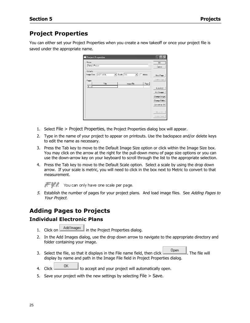
Section 5 Projects
25
Project Properties
You can either set your Project Properties when you create a new takeoff or once your project file is saved under the appropriate name
1 Select File gt Project Properties the Project Properties dialog box will appear
2 Type in the name of your project to appear on printouts Use the backspace andor delete keys to edit the name as necessary
3 Press the Tab key to move to the Default Image Size option or click within the Image Size box You may click on the arrow at the right for the pull-down menu of page size options or you can use the down-arrow key on your keyboard to scroll through the list to the appropriate selection
4 Press the Tab key to move to the Default Scale option Select a scale by using the drop down arrow If your scale is metric you will need to click in the box next to Metric to convert to that measurement
5 Establish the number of pages for your project plans And load image files See Adding Pages to
Your Project
Adding Pages to Projects Individual Electronic Plans
1 Click on in the Project Properties dialog
2 In the Add Images dialog use the drop down arrow to navigate to the appropriate directory and folder containing your image
3 Select the file so that it displays in the File name field then click The file will display by name and path in the Image File field in Project Properties dialog
4 Click to accept and your project will automatically open
5 Save your project with the new settings by selecting File gt Save
Section 5 Projects
26
Electronic plans scanned from blueprints (as opposed to blue lines) will display as white lines on a black background and are difficult to read on your computer screen Select Image gt Invert and the colors will invert to black on white
You may have noticed the Page column in the Project Properties dialog Generally plan images occupy one page and 1 will be listed in the column indicating Page 1 of your plan file If you import a multi-page TIF a plan file containing more than one page of plans they will import as separate pages and each successive page will be indicated under the Page column as 1 2 3 etc of the plan file
Group of Electronic Plans You may add all the electronic plan files from a particular source (for example from a CD) by using the Auto Add feature
1 Click the button in the Project Properties dialog
2 Browse until you find the appropriate directory and folder containing your plan images
3 Click on any file displayed within your target folder so that the file name appears in the File name box of the Auto Add dialog
4 Click The image paths and file names will be recorded into the project properties arranged alphabetically
5 Click to accept your choices and your project will automatically open
6 Save your project with the new settings by selecting File gt Save
To load Dodge Plans into your Project Properties see Appendix IIi Loading Plans from a Dodge CD
Paper Plans On-Screen Takeoff makes it easy for Full Mode users to perform quantity takeoffs from paper plans using a digitizer
1 Add pages by clicking until you have the number of pages initially in the project
2 Name each page by clicking within the Title area and typing the name
3 Click to accept your choices and close the Project Properties dialog
4 Save your project with the new project properties settings by selecting File gt Save
Section 5 Projects
27
Setting Up a Drawing Template On-Screen Takeoff provides the convenience of using the same work surface for both digitizer and mouse to allow the user to draw conditions and then edit settings of the project or add or change conditions without breaking stride A mouse pad template included with the program defines the area of the digitizer in which use of the stylus or cursor will be recognized as mouse movement as opposed to drawing movement
1 Place your stylus on On-Screen Takeoff
2 Placing the template identifies the location mouse movements will be recognized by the program
Before placing the template the template must be applied to the digitizer surface This may have been done during the installation of your digitizer We suggest attaching the template to the lower right corner of the digitizer surface about one inch inside the grid area
3 Select Digitizer gt Place Template
4 Follow the instruction prompts on the screen clicking first on the target symbol at the left of the On-Screen Takeoff box on the template then on the target at the right
Setting Takeoff Area Before you can begin taking off a drawing you must define the drawing area on the digitizer This requires defining an area that will include all objects on each drawing of your plans As you add pages to your takeoff the same area of the digitizer will be active
1 Secure the plans to the digitizer with tape or a set of clamps
2 With a pen or a pencil mark the upper left corner and the lower right corner of the first page in your set of plans
3 Select Digitizer gt Set Takeoff Area
4 Click each mark with the stylus pen as prompted
5 Verify the active area of the digitizer by looking at the image size located in the lower right corner of your screen
If you close the program before the takeoff is complete you will need to reestablish the takeoff area before you can add additional condition quantities
Electronic plans appear on your computer screen eliminating the need to set a takeoff area You simply drag your mouse across the conditions you wish to takeoff The conditions will be highlighted and quantities will be totaled instantly Electronic plans are available through a variety of services For information contact an On Center Software account manager
Section 5 Projects
28
Setting Scale for Specific Pages You may set the scale in each page view separately This will override the default scale setting in Project Properties for that page Setting the correct scale for the drawing before taking off quantities ensures accurate calculations Be careful to check the scale for each drawing in your project before doing takeoffs
1 Display the page you want to set select Edit gt Set Scale
2 Use the drop down arrow to select a scale that will be applied to that page
3 Click
OR
4 Access the pull-down scale settings on the Navigate toolbar
NOTE As you draw objects notice that the drawn object is similar in width to the object on your plans If it is not the scale set may not be correct
Calculating Scale You may calculate scale according to a known measurement between two points either with a digitizer or on electronic plans
1 Select Edit gt Calculate Scale using Image or Edit gt Calculate Scale using Digitizer
2 Follow the instructions in the related Calculate Scale dialog box You will be asked to click on the first and second points then to enter the dimension for that distance
3 The scale will be recalculated for the displayed page and the Scale display on the Navigate toolbar will show the new scale
Section 6
29
Conditions and Takeoff
This section will Draw Conditions to Takeoff Plan Quantities
What Zones will do to help your takeoff process
Discuss the ins and outs of Takeoffs
Section 6 Conditions and Takeoff
30
Creating Conditions
If you are starting a new project from scratch you will need to create conditions to takeoff quantities such as floor areas wall lengths and corner bead counts If you are using a template you will have several pre-designed conditions already listed on the Takeoff dock bar However you may want to change the characteristics of some conditions or create additional conditions for a particular project
1 Right Click within the Takeoff dock bar Select New gt Condition
Or
2 From the Takeoff dock bar Click (if the buttons are not showing right-click in the Takeoff dock bar area and select Show Buttons from the pop-up menu) The New Condition dialog appears
3 Select the condition type (Linear Area Count or Zone) from the pull-down menu accessed by the
down arrow next to the Type option
4 Press Tab or use the mouse (or stylus) to move to Name and enter a name for your condition
5 Specify the desired condition attributes See Condition Attributes for more detail
6 Click for condition to apply
Section 6 Conditions and Takeoff
31
Condition Attributes Each condition type will have related attributes to select or specify within the General and Advanced tabs of the New Condition dialog Once a condition has been used to takeoff a quantity from your plans certain attributes cannot be changed
All conditions allow the user to specify color and fill pattern for the object drawn
Linear Conditions
General Specify width and height by feet and inches Specify pitch in inches up to the nearest thousandth of an inch if applicable
Advanced Specify rounding for object quantities and droprun default length for electrical or plumbing drops at the ends of lines Select Connect to have lines connect at the corners where one line of the condition ends and another begins (and indicate Tolerance for the featurersquos activation as distance between the ends of two lines) Choose Trim to have lines automatically trim to a line being crossed Choose Curve to draw a curved line
Follow these examples for inputting feet and inches For 7 feet 6 inches type 706 for 13 feet 7 inches type 1307 For 20 feet type 2000
Section 6 Conditions and Takeoff
32
Area Conditions
General If needed you can specify the thickness (in inches) andor pitch (in inches)
Advanced Specify rounding for object quantities Choose to display an adjustable grid within the area and indicate matrix cell dimensions
Section 6 Conditions and Takeoff
33
Count Conditions
General
Specify height and indicate the size (in inches) and shape (square circle triangle rectangle or opening) of the count object as it will appear on screen
Advanced Count conditions have advanced attributes These options are available for all shapes except for openings
Zone Conditions Zones allow you to subdivide condition quantities making it easier to modify and complete jobs in phases They can be used at the end of a takeoff to isolate a group of condition quantities that are in different areas of the takeoff
Zones can also be used to break a takeoff into multi-phases and can even be used to isolate quantities while a job is in progress to group the amount of work that has been completed to date They can be applied to one or multiple pages in your plans automatically calculating the takeoff quantities for each zoned area
Section 6 Conditions and Takeoff
34
The zone feature is only available in Lite and Full Mode If you are in View Mode and would like
to use this feature click from the main toolbar to purchase the upgrade
Condition Notes A Note tab is provided for comments regarding the condition These notes will display on the Takeoff List report and will import into Quick Bid
Section 6 Conditions and Takeoff
35
Condition Results The Results tab of the New Condition is based on condition type Initial settings default to linear feet (LF) for linear conditions square feet (SF) for area conditions and count of items (EA) for count conditions and zones The first of the results fields will display for the condition items in the Takeoff dock bar area All results will display in worksheets and Takeoff List reports as well as in an Excel spreadsheet after being exported
Copying Conditions You may use the condition attributes from a condition yoursquove already created for any future conditions of the same type
1 Click on a condition to select it
2 Click the Copy button from the toolbar
OR
3 Right-click in the Takeoff dock bar area and select copy
4 A new condition will appear in the list with the same condition attributes as the previous condition but with the quantities zeroed
Editing Conditions Once you have copied a condition you might want to change several attributes You can also edit an existing condition to fit any updated needs
1 Highlight the desired condition on the Takeoff dock bar
2 Click the Change button
OR
3 Double-click on the condition you wish to edit to bring up the Change Condition dialog
NOTE The Change Condition dialog differs from the New Condition dialog only in that if takeoffs
Section 6 Conditions and Takeoff
36
have been performed in your project with this condition you will not be able to change the type of condition or certain properties under the advanced tab of the dialog box
Deleting Conditions 1 Click on the condition in the Takeoff Dock bar area
2 Click the Delete button on the toolbar
OR
3 Right-click and select Delete from the pop-up menu
All takeoff associated with the deleted condition will be deleted immediately and permanently
Organizing Project Conditions Within your project you can create folders andor sub-folders for different types of conditions You may even want to create a folder containing conditions with reset values
To get started organizing your conditions make sure you are viewing the condition tree (right-click in the Takeoff dock bar area and select Show Tree)
Creating Folders and Sub-Folders 1 Right-click in the Takeoff Dock bar area
2 Select New gt Folder from the pop-up menu
Copying Folders
1 Click on the folder and click Copy on the toolbar
2 All copied conditions within the new folder will have values reset to zero
Renaming Folders
1 Click on the folder
2 Right-click and select Rename from the pop-up menu
3 Enter a name for your folder and click the Enter button
Changing Condition Order
You may move conditions up or down in the condition list of the Takeoff dock bar to suit your project needs
1 Select the condition you would like to move by clicking to highlight it
NOTE When you are ready to move the highlighted conditions be sure that you start
moving using the last condition chosen That condition will have a highlighted boarder
Section 6 Conditions and Takeoff
37
2 Drag and drop any the condition from one place to another in the list You may also move a condition to another folder on the list in this way
Drawing with Conditions Snap Angles Set up snap angles to prevent lines from appearing jagged Snap angles are commonly set at 15deg and shift snap angles at 0deg
1 Go to Tools gt Options Options dialog appears
2 Under the General tab make the desired settings
3 Click to save the settings As they are drawn lines will snap to the set degree
Drawing a Linear Object 1 Select a condition from the Condition List in the Takeoff dock bar
2 Move the cursor into the Image takeoff area of the screen you will see the cursor display as crosshairs
3 Click and hold left mouse button then drag mouse to draw a line
4 Release mouse button to set line
Section 6 Conditions and Takeoff
38
5 Repeat steps for further lines
Continuous Mode This feature allows you to draw an object that has connected lines
1 Click the icon from the Takeoff toolbar
OR
2 Go to Tools gt Continuous Mode
3 Follow steps 1-3 from Draw a Linear Object
4 Click at each point of intersection The object will be connected
5 Double-click after making the final point to set the lines
Drawing a Curve To draw a curved line the Curve option must be checked under the Advanced tab of the Condition dialog
1 Click where you want to begin the curve and drag in a straight line to the position for the other endpoint of the curve
2 Click on the line to select it Handles in the shapes of small squares will appear at either end of
Section 6 Conditions and Takeoff
39
the line and in the center of the line
3 Move the cursor over the center handles until the cursor becomes a two-way arrow
4 Click and drag in the direction of the curve bending the line as you move the cursor Release to set the curve (The line you began with will disappear)
Draw a circle by drawing two curved lines connected
Drawing an Area Object Area conditions are drawn similarly to continuous mode lines You may trace any number of adjoining walls at different angles to complete your area takeoff
NOTE When drawing an area do not intersect the perimeter or line of the object you are drawing
1 Click at each point
2 Double-click when yoursquove returned to your starting point
3 The area will be filled with the pattern set for that condition
NOTE The simulated circle will be good enough for you to be able to make a bid
To create a circular area click from point to point with very short distances in between points simulating a circlersquos perimeter Double-click after setting the last point to set the area
Section 6 Conditions and Takeoff
40
Grid Options Grids give you an added advantage when installing materials such as tiles Use this feature to get a count for how many tiles are needed for an area
1 Double-click on an area condition in the Takeoff dock bar to open its Condition dialog
2 Click on the Advanced tab to show its options
3 Check the box next to Grid by clicking in it
4 Indicate the dimensions of the cell matrix in inches (For example 200 x 400)
5 Under Results tab choose each (EA) for one of the results fields This will tabulate a number of grid cells (including partial grid cells) in area
6 Click to save your settings
7 Use the Move Grid and Rotate Grid features in the Tools menu to manipulate the grid as desired
Grid Calculation
1 Go to Tools gt Options menu
1 Specify if On-Screen Takeoff automatically should Calculate Grid Position
2 If AreaGrid Size is selected On-Screen Takeoff will calculate the number of items needed to fill the grid based on grid demintions
3 Click to accept and close the dialog
To move a line at any angle (regardless of default setting) press the Shift key while moving the mouse
Section 6 Conditions and Takeoff
41
Backout Mode This feature allows you to take out part of an area and deduct that amount of square footage
1 Select Tools gt Backout Mode
2 Outline the are you want backed out as you would when drawing a regular area object (see Drawing an Area Object)
3 The outlined area will clear and quantities will be recalculated
NOTE The perimeter of the backout area will be added to the LF quantity for that condition
Drawing a Count Object Square triangle rectangle and circle shaped count objects can easily be placed on images
1 Select the condition
2 Click in the location where you want the object to appear
3 To place an opening-shaped count item like a door or window you must click over an existing linear object such as a wall
4 On the Results tab you can change the height properties to give you the result you need
5 If Backout is checked on the advanced tab for each count opening the opening-shaped count item will back out a corresponding section of the linear object
Opening shaped count items are sized at 3rsquo0rdquo by default
Drawing a Zone Zones are drawn in the same way as area objects and may be any polygonal shape You may trace any number of adjoining walls at different angles to complete the zone perimeter
1 Click at each point
2 Double-click when yoursquove returned to your starting point
Section 6 Conditions and Takeoff
42
Selecting Objects
1 Use the Select Tool to select objects
You can also select all objects that correspond to a condition
1 Click on a condition to select it
2 Right-click and choose Select All
3 All objects with this condition will be highlighted with squares as an outline
Moving and Resizing Objects Linear
1 To move or resize a linear object click anywhere on the line to select it
2 To move the line position your pointer over the center handles When the mouse is positioned over the handles you will see a two-way arrow You will only be able to move the line in the direction of the arrows
3 Drag the line to a new position
4 Clicking and dragging the handles on the ends of the line will allow you to lengthen or shorten your line
Area and Zone
1 To move an area object or zone in its entirety click and drag it to its new position
2 Grabbing a handle at a corner or intersection of the object will allow you to adjust and change its perimeter
Section 6 Conditions and Takeoff
43
Count 1 To move a square circle rectangle or triangle shaped count object click and drag
2 Click and drag an opening shaped count object along the length of the linear object to the desired position then release
NOTE An opening shaped count object may not be moved from its associated linear condition object however it may be moved up and down the length of the linear object
Layers On-Screen Takeoff allows you to sort and separate your takeoff objects within the same job and on the same page On-Screen Takeoff gives you this flexibility through the use of layers
By assigning different conditions to different layers (for example differentiating between floors ceilings and walls) you can choose to view all layers or turn off certain layers to display and print the remaining groups of conditions only You may also remove the background image of electronic plans add text and hot link symbols or print only your condition takeoffs
Layers are only available in Full Mode If you are in View or Lite Mode and would like to use this
feature click from the main toolbar to purchase the upgrade Default Layers
On-Screen Takeoff begins every project with three default layers Image Annotation and Default The Image layer holds the electronic plan files you may have in your project The Annotation layer possesses all text notations highlighting and hot links in the project The Default layer will appear in the Condition dialog when creating or editing a condition (listed in the takeoff dock bar) Conditions are assigned to the Default layer unless otherwise specified by the user
Creating Layers To assign a condition to a layer other than the default layer you must first create additional layers for your project
1 Select View gt Layers to open the Layers dialog
2 Click An unnamed layer will be added
3 Click within the empty box and type a name for your layer (for example Wall)
4 New layers are added as active layers The adjacent box under the Show column will be checked
Section 6 Conditions and Takeoff
44
Assigning a Layer to a Condition 1 Open the Condition dialog box by creating a new condition or editing an existing condition
2 Under the General tab click on the down arrow in the Layer field to display optional layers
3 Select the desired layer for the condition Only the Default layer and layers you have added will be displayed
4 Click
View and Hide Layers
1 Select View gt Layers
2 Under the Show column check the box to view or remove the check (by clicking on it) to hide the specific layer
3 Click to accept and close the Layers dialog
Section 6 Conditions and Takeoff
45
Assigning Text to a Layer When adding text to an image On-Screen Takeoff has the capability to assign the text to a specified layer
1 Select the Text Tool
2 Click at the point you want to place your text
3 Type in your text using the Enter key for line breaks
4 Click the drop down arrow next to the Layer field and select the desired layer
Section 7
46
Printing and Exporting
This section will
Printing options and procedures
Exporting data by copying and pasting
Exporting quantity results to Excel spreadsheets
Section 7 Printing and Exporting
47
Print Setup On-Screen Takeoff allows the user to print the image takeoff list and worksheet
1 Select File gt Print Setup The Print Setup dialog will open
2 Select a printer or leave the default selection listed (change from the default printer displayed by clicking on the down arrow at the right of the field)
3 Indicate page size and printer tray option (Source) Access page size options by clicking on the
down arrow at the right of the field
4 Choose Portrait or Landscape orientation
5 Click to accept and close the dialog
Printing Images The image area can include the electronic plans the takeoff objects added text and hot links To print a subset of these (for example just the takeoffs without the plans or the added text and hot link symbols) hide layers that you do not want to print (see Section 6 View and Hide Layers) When you are printing your images every page will show the scale of the takeoff you are printing
1 Click on the Image tab to display the area of your project
2 Select File gt Print (or Ctrl + P)
Section 7 Printing and Exporting
48
3 Select the desired view (What to print) and the Image Range
4 Click The second Print dialog will open
5 Change settings accordingly or click if you accept the default settings
Printing Takeoff Lists and Worksheets In Takeoff Lists and Worksheets you may hide columns to print only certain results or adjust column widths to fit the report within the page size selected
1 In Takeoff List or Worksheet view move your cursor to the right side of the columnrsquos title bar the cursor will display as a two-way arrow
Section 7 Printing and Exporting
49
2 Click and drag to adjust the width of the column Holding the mouse button you may
slide the title bar under the title bar to its left to hide the column completely
3 Select File gt Print or press Ctrl + P to access the Print dialog
4 Indicate desired printer and choose the number of copies
5 Click to print and close the dialog
When printing the condition list we suggest printing in landscape
To reset to the default column widths double-click on the right border of a column heading will reset the column to its right (or previously to its right before being hidden)
Print Preview 1 Select File gt Print Preview
2 Use and to vary your view 3 If viewing an image choose current full or scale view to see how it displays
4 For printed outputs that cover more than one page use and to view adjacent pages or click on the down arrow next to Page field and select the page you want displayed
Exporting Using the CopyPaste Feature You may copy all the data or sections from the worksheet and the takeoff list view in On-Screen Takeoff and paste it into another application When pasting into Excel the cell layout will be maintained
1 Highlight the areas you wish to paste Click and hold the left mouse button down as you drag the cursor over the area to be selected then releasing the mouse button
OR
2 Select the entire takeoff list quickly click on the left On-Screen Takeoff column header and hold and drag the cursor across the remaining column headings
The number of pages for the view selected will display in the lower left-hand corner The zoom percentage that applies to the view will be displayed in the lower right-hand corner next to page size of the drawing
Section 7 Printing and Exporting
50
3 In the worksheet view you may highlight rows by clicking on the numbered buttons to the left of each row clicking and dragging across column headings or clicking and dragging over individual cells in the worksheet
Click anywhere in the appropriate view to deselect the area
4 Once your selection is highlighted you may select Edit gt Copy or Ctrl C from the keyboard 5 On your monitor switch to the application into which you want to paste your selection 6 Select Edit gt Paste in the new application or simply press Ctrl + V to paste
The colored keys for conditions cannot be pasted
Using the Export Feature You may export condition quantities to specified cell location within an Excel worksheet file Cell target locations are assigned in the Results tab of the condition dialogs on the Export line relating to each quantity measurement type
On-Screen Takeoff will export takeoff quantity results for up to three different quantity types that you specify For instance you may want to know the number of square feet in a ceiling area as well as the number of linear feet in its perimeter
Section 7 Printing and Exporting
51
1 Bring up the Condition dialog by double-clicking on a condition in the takeoff dock bar or by
selecting the condition and clicking
2 Click on the Results tab to access its fields The default quantities for the condition type will display
3 For each results field click on the arrow to access the pull-down menu and select the appropriate quantity (for example SF LF EA etchellip)
4 Have your Excel spreadsheet opened and saved in a file
5 Specify the Excel spreadsheet cell locations where you want the results to go
6 For a cell in the first sheet of your spreadsheet type in the cell address (eg a1) Case is not important
7 For a cell on a successive sheet of your spreadsheet type in sheet the number followed by a comma and the cell address without any spaces (eg sheet2a1) Case is not important
8 Click
9 Select File gt Export gt Condition Qty to Excel
Section 7 Printing and Exporting
52
10 Browse to the location of the Excel spreadsheet file click file to select it
11 Click to export On-Screen Takeoff results to specified cell locations in the Excel file When you return to the Excel application you will see the values have been added to the specified cell locations in your spreadsheet
12 Save your Excel file
Exporting Worksheet to Excel
1 Assign condition quantities you want to export
2 Open saved Excel spreadsheet file to which you will be exporting
3 From On-Screen Takeoff Select File gt Export gt Worksheet to Excel
4 Browse to the location of the Excel spreadsheet file click file to select it
5 Click When you return to the Excel application you will see the values from the Worksheet Tab have been added to your spreadsheet
6 Save your Excel file
Exporting Takeoff to CVS 1 Assign condition quantities you want to export
2 Open saved Excel spreadsheet file to which you will be exporting
3 Click the Takeoff Tab in the project you want to export the information
4 Select File gt Export gt Takeoff to CSV
5 Browse to the location of the CSV spreadsheet file click file to select it
6 Click the Save
NOTE CSV files can be opened in Excel Lotus Access etc One may consider this option more of a ldquodumprdquo into a file
The Excel application must be active (it may be minimized on the application bar) with the target spreadsheet open in the application Otherwise an error will occur with the export operation that will affect both the On-Screen Takeofftrade file and the Excel spreadsheet
Section 8
53
Advanced Features
This section will
Some special features of working with condition objects in the takeoff area
Details of advanced options for conditions
Advanced features of the Project Properties dialog
Section 8 Advanced Features
54
Features to Use with Objects Roping Feature You can move copy or delete using this feature Using the Select tool (the pointer) you may select several objects at once by clicking and dragging an outline around the objects then releasing the mouse button Roping may select either objects completely within the outlined area (inclusive) or objects both within and touched by the outlined area (touching) Specify your roping preference under Tools gt Options
1 Click and hold the mouse button at a point on the screen near the objects to be selected and drag to surround the objects with an outline
2 Release the mouse button The objects will be selected
3 You may now
Move the group around on the page by clicking within the group dragging the mouse and releasing the button to place the objects
Delete the group of objects by clicking the Delete key or
Copy and paste by pressing Ctrl C to copy the group then Ctrl V to paste it The pasted copy of the grouped objects will appear slightly offset from the original objects
Section 8 Advanced Features
55
Applying a DropRun Count
Use the droprun feature when calculating quantities to take into account the drop or run of a linear condition such as electrical lines or plumbing pipes Drop or run lengths may be added separately to any linear condition on screen while a default droprun length may be indicated for a condition as a whole
1 Select the desired linear condition from the Condition List in the Takeoff Dock bar
2 Click the Change button in the toolbar to open the Change Condition dialog
3 Click the Advanced tab to access the advanced options and click inside the DropRun check box
4 Enter a default length to be applied to all of this condition Entering 800 will be interpreted as 8 0 (You must enter both place markers for inches) You can leave the length blank and manually enter drop run on each segment drawn
5 Click the OK button to accept and close the dialog
Edit DropRun Count
1 With the related linear condition in the Takeoff Dock bar highlighted or with the pointer tool selected
2 click on the desired linear object in the image takeoff area The Count button will become active
3 Click on the Count button (alternatively select Tools gt Count) The default droprun amount will show in the pop-up Count dialog (Default length will be zero if droprun has not been selected in this conditionrsquos properties)
4 Type in the desired length Entering 800 will be interpreted as 8 0 (You must enter both place markers for inches)
5 Click the OK button The additional amount will be reflected in the corresponding quantity The new DropRun count will apply only to the object edited
Adding Text in Image View
On-Screen Takeoff allows you to place text comments around your quantity takeoffs that may be printed along with plan images and objects Text is automatically placed within the Annotation Layer (that includes text and hot links)
1 To place text on the image select the Text Tool and click at the point you want to place your text opening a text box
2 Type in your information clicking Enter for line breaks
3 When you are finished click the OK button to exit the text box
4 To reposition text simply click on the text (with the Text Tool active) to select it
5 Move the cursor over the text the cursor will now display as a four-way arrow
6 Click and drag the mouse to position the text as desired
Section 8 Advanced Features
56
1 To edit existing text use the Text Tool to double-click on the text to open the editing box
2 Enter additional text or use the Backspace key to delete text as necessary
Formatting Text Once created you may format the font size type style and color of your text
1 Click on the text to select it and select Tools gt Font or click on the Font button in the Takeoff Toolbar
2 Select the desired features (color options are disabled) and click the OK button
3 Click on the text to select it and select Tools gt Color or click on the Color button in the Takeoff Toolbar The Color dialog will open
4 Click on a color in the Basic Color palette or create a color and add to the Custom Colors palette (Be sure to click on the color in the Custom Colors palette to select it)
5 Click the OK button
Object Properties
Linear Objects
Linear objects may be set to connect at corners
A linear object may be set to trim automatically when crossing another linear object (Check the trim option under the advanced tab of the Condition dialog)
When you move a connected linear object objects automatically move and resize connected lines accordingly (quantities are then recalculated)
This feature requires that the connected linear object be moved using the center handles (does not apply when resizing the line from the ends)
Objects constrain to snap increments defined in the Tools gt Options menu (with the mouse 15deg by default incremental when shift key is held down)
Objects are measured from centerline to centerline
Section 8 Advanced Features
57
Area Objects When drawing an area use your escape key to undo the last line drawn You may reverse your
drawing of an area using the escape key
The area will not fill with color and pattern until the user double-clicks after the last line is set
Lines drawn to delineate an area object constrain to snap increments defined in the Tools gt Options menu (with the mouse 15deg by default incremental when shift key is held down)
After selecting an area to move or adjust position the mouse in the center to move the entire area position the mouse at the sides or corners to adjust the perimeter
Count Objects
All count objects are quantified by the physical number of objects per page and reported as EA for the UOM The quantity for the current Image View is (displayed in the Condition List) and the total quantity in your project is displayed in the Takeoff View and Worksheet View)
Square circle rectangle and triangle shaped count objects do not displace or subtract from other object quantities when placed on top of them However on the Advanced Tab for the count condition a connect property can be set (this is a check box) so that when a count object of this shape is put on top of a Linear type takeoff object it will move with the linear if said linear is moved
An opened-shaped count object must be placed within a linear object Opening shaped count objects may also be measured by linear foot or linear yard (EA SF and SY are also options) Opening shaped count items default to a width of 3rsquo 0rdquo at the time of creation This size can be changed The small medium and large size are not options on this type of condition anymore Check Backout on the Advanced tab for each Count object back out the footage (or yardage) of opening-shaped count objects in which they are placed
NOTE In order to see this Backout functionality (in quantity) for SY or SF deductions at least one of the
results for the Linear(s) this object will be placed on must be set to SY or SF and the count object must have a height quantity
Advanced Features of Conditions The Round Feature Under the Advanced tab of the linear and area Condition dialogues you may specify quantity rounding (in inches) For linear objects rounding applies to each linear object drawn For area objects rounding will apply to each segment of the area perimeter adjusting the perimeter and area calculations For example With a linear condition entering 12 in the Round field will round up each related linear object to the nearest 12 inches or one foot With this setting two walls of 1 4 would each round to 2 0 totaling 4 0
NOTE In the Takeoff Dock bar condition list and in the On-Screen Takeoff reports quantities will be displayed in whole numbers rounded up to the nearest foot However calculations are based on true quantities without rounding unless the Round Feature is engaged
Pitch Pitch may apply either to linear or area conditions It is measured in rise per linear foot Entering 12 indicates a 12 rise per 12 of linear distance (a pitch of 12 over 12) or an angle of 45deg
Section 8 Advanced Features
58
Advanced Features of Project Properties Selecting Multiple Pages
1 Select a single page entry by clicking on the numbered gray button to the left of the entry
2 Drag the cursor down the column of numbers to select consecutive pages
3 Click on the blank button at the top of this column to select all pages in the Properties dialog
Section 8 Advanced Features
59
Changing Image Assigned to a Drawing 1 Select the page entry by clicking on the numbered gray button to the left of the entry 2 Click the Change Image button The Change Image dialog box will appear
3 Navigate to the desired file and select by clicking on it
4 Click the Open button The electronic file assigned to the page will have been changed to reflect the new file choice
Changing Image File Path 1 Select pages as described above
2 Choose Change Folder
3 In the Change Folder dialog navigate to the appropriate folder
4 Click the OK button The file path will have been changed for the selected page entries
Delete a Page from Project Properties 1 Select the page you want to delete by clicking on its associated number (in the gray box at the
left of the entry)
2 Choose Delete Page
All Takeoff on the page will be deleted immediately and permanently
Section 8 Advanced Features
60
Advanced Features of Tool Options
Calculation Method On-Screen Takeoff has built-in calculation options to allow for faster work and faster saves until your takeoff is complete Calculation options are found by selecting Tools gt Options then clicking on the Calculation tab
Calculation method can be set to Automatic Automatic except Grids and Manual Manual will allow the program to operate more quickly while Automatic or Automatic except Grids allows the user to see quantity changes as takeoffs are made
In any mode you may press F9 to recalculate quantities for the On-Screen Takeoff current totals
Configuration Tab
When the ldquoPage Label (A01)rdquo radial button is chosen On-Screen Takeoff puts the numbered label on all the pages of in your current page indicator in your Navigate Toolbar If the Page Descriptionrdquo radial button is chosen then a description of what takeoff is on that specific page will be shown in your current page indicator in your Navigate Toolbar
This section of the configuration tab gives you options on how you want to export your information When the ldquoFolderSubfolder Namesrdquo radial button is chosen than on your file that you are exporting to will have all the conditions folders and subfolders In the Delimiter box you can choose the symbol that is needed to separate the information you are exporting Some files need semicolons () or colons () to make sure the information comes exported in is separated it the appropriate places
Section 8 Advanced Features
61
In previous versions of On-Screen Takeoff there are views that users need to have in order for them to display their information By either choosing ldquoOST 1xrdquo or ldquoOST 2xrdquo it will let the program know you want your columns of information exported in that specific format
When you have the Confirm Deletions radial button of ldquoYesrdquo chosen than every time you delete anything you will get a dialog box confirming your intentions of deletion
While working with your takeoff you have a choice to either view the legend of your conditions or hide it Choose whichever radial button that suits your needs
For those who prefer to use the Enter key to navigate in dialog boxes this option is just for that
Font Tab The Font tab is designed for you to make your own look and feel for the application At the bottom of this tab it will show you sample of the fonts and colors you have chosen
Renaming the Current Page You may change the name of the current page in the takeoff area of On-Screen Takeoff by selecting Edit gt Rename Page
This opens the Name Page dialog and you may simply type in a new name and click the Enter button The new name for the file will be reflected on the title bar for the page and in Project Properties
You also may access the Rename Page function by right-clicking in the takeoff area while in Image View and selecting the option from the pop-up menu that appears
Section 9
62
Saving and Exiting
This section will
Explain how to save projects
Show you how to safely exit the program
Section 9 Saving and Exiting
63
Saving Your Project
1 Select File gt Save 2 If your project has not previously been saved a Save dialog box will open to allow you to name
the file and choose the directory and folder in which to save your file 3 Once saved File gt Save will simply save the current version of the file
OR
4 Select File gt Save As then type in a new name for the file and save to the desired file path
The Auto-save Feature With the Auto-save feature On-Screen Takeoff automatically backs up your open project You may choose to have more than one level of backup files The first backup copy will have the extension b00 and successive files will be b01 b02 and so on If you have designated four levels of backup files after the fourth backup copy has been created (b03) the next file will be saved over the file with extension b00 Further backup saves will then rotate through the four backup files in the same way
1 Select Tools gt Options 2 In the Auto-save area (under the General tab) select the frequency of backup file creation (in
minutes) and the number of levels for the feature 3 You also may disengage the feature by clicking in the check box to clear it
The Auto-save feature automatically saves backup copies to the directory of the current project If you are working from a write-protected area such as a CD-ROM On-Screen Takeoff will place backup files in the On-Screen Takeoff folder
Exiting When you are finished using On-Screen Takeoff it is very easy to exit Exiting is very important because of security reasons If someone were to use your computer they could enter the application and view and manipulate information
Section 9 Saving and Exiting
64
On-Screen Takeoff closes the open project when you open another or create a new project or when you exit the program
1 Select File gt Exit
OR
2 You also may click at the upper right-hand corner of the application to exit
NOTE If your latest changes to a project file have not been saved On-Screen Takeoff will ask you whether you would like to save the file and gives you the option of canceling the operation
Appendix I Installing Your Digitizer
65
Appendix I Installing Your Digitizer When you get your digitizer from GTCO you will need to connect it to your computer Follow the instructions outlined below to do this
Note For rollup digitizers the metal bar must be oriented to the top or right hand side
Connecting the Digitizer 1 Lay the digitizer out flat 2 Connect the Stylus to the digitizer 3 Plug in the power adapter 4 Plug the interface (IO) cable into the digitizer 5 Plug the other end of the interface cable into an open serial port on computer
Note GTCO Technical support phone number is 410-381-6688 The electronic manual (on diskette) from GTCO contains more detailed installation and operation instructions for the GTCO digitizer model you have
Installing other Digitizer Drivers If you are using a GTCO Digitizer you will need to install the GTCO TabletWorks Drivers
If you are using a Digitizer not supported by GTCO Tablet Works 10 please contact the manufacturer of your digitizer for assistance with installation
Installing GTCO TabletWorks Drivers 1 Insert the On Center CD into the CD-ROM drive The CD Startup screen will open 2 Click on Install Software 3 Select Additional Software and Drivers 4 Select Digitizer Driver 5 Follow the instructions for installing TabletWorks 10
Adhering the Template The template is a small plastic sticker used to enable mouse function when using the digitizer with On-Screen Takeoff Place your template on your digitizer We suggest placing it in the bottom right corner of the digitizer about one inch inside the takeoff area
Note You may either peel off the back of the template and use the adhesive surface or you can tape the template down
Appendix I Installing Your Digitizer
66
Testing the Digitizer Drivers Before running OST you may test the digitizer by moving the stylus around on the digitizer pad it should move the mouse cursor (if mouse emulation is enabled)
If the digitizer does not move the mouse cursor on the screen
The superset codes may need to be reset Reset the superset codes by touching on the border of the digitizer with the stylus The digitizer should beep several times
The digitizer may not be communicating with the computer Be sure the COM port selected is correct Be sure the COM port selected is correct If you are not able to get the digitizer to move the mouse cursor you need to call GTCO technical support for help
Note The Mouse Emulation is not required for On-Screen Takeoff to work properly It is used only for the Template functionality if the digitizer is moving the cursor the wrong direction (up instead of sideways or vice-versa)
Click the L-shaped arrow symbol on the digitizer with the stylus
Appendix II Toolbar Item Details
67
Appendix II Toolbar Items Main Toolbar
Appendix II Toolbar Item Details
68
Tool Toolbar
Appendix II Toolbar Item Details
69
Zoom Toolbar
View Toolbar
Navigate Toolbar
Appendix II Toolbar Item Details
70
Navigate Toolbar (Continued)
Takeoff Toolbar
Appendix II Toolbar Item Details
71
Takeoff Toolbar (Continued)
Image Toolbar
Appendix III Loading Plans from a Dodge CD
72
Appendix III Loading Plans from a Dodge CD
This section will detail how to load plans from a F W Dodge CD-ROM into an On-Screen Takeoff project file ready for takeoffs
Dodge files may be added to the Project Properties dialog However loading the files in that way will load the files by number rather than name description If you want to load one page only from your Dodge CD You will have to rename the page to display the name rather than number of the file
To load plan files from a Dodge CD so that the files load sequentially by file number but are displayed by name rather than by number within your project follow the instructions below
Opening a Dodge project from a CD-ROM 1 Insert the CD into the drive 2 Choose File gt Custom 3 Choose Dodge Plans Project (plansdat) as the file type 4 Select the appropriate file type by clicking on the down arrow at the right of the Files of type
field 5 In the Look in field access your drive paths by clicking on the down arrow at the right of the
field then
Navigate to your CD-ROM drive Open the data folder and Open the Projects folder
6 Select the desired project and open its folder 7 Open the plansdat file 8 All the images will come in sequenced correctly for that job along with the full descriptions
(names) of each page If there is not a plans folder in the project folder then plans do not exist for that project on the CD Opening the plansdat file will yield an empty project
Appendix IV Using the Plan Viewer
73
Appendix IV Using On-Screen Takeoff Plan Viewer The On-Screen Takeoff Plan Viewer is a limited version of On Center Softwarersquos commercial takeoff software If your status bar located at the very bottom of the main window says View Mode in the lower left-hand corner then you are using the Plan Viewer You can use the plan viewer to
View CD-based amp converted CAD drawings
View a previously created OST file and associated drawings
Download electronic plans online
Navigate through drawings
Quickly Takeoff linearsareas and counts
Zoom in to view the plan better
Print drawings directly from the viewer
Viewing an On-Screen Takeoff Project File
1 To open an OST file that was previously created with of On-Screen Takeoff 2 Select File gt Open 3 An Open dialog will appear if you do not see the OST file you are looking for select the
Look In drop down arrow 4 A drop down menu will appear listing the various folders drives and mapped drives located
on your computer select the correct drive or folder location and continue to browse to the location of your OST file
5 When you see your OST file double-click it to open it 6 Any takeoff and drawings should appear on the Image tab view
If you do not see the drawings but do see the colored takeoff layer the drawings may
not be located in the same place they were originally saved at Go to File gt Project Properties and check the Image File path for each listed page If the image file path is pointing to a CD drive make sure the CD is inside the CR-ROM
Downloading Electronic Plans If your Online Plan Service provides a special file format (OSX) required to use this feature of our plan viewer you can immediately downloaded all electronic plans of a project directly from our viewer
Most Plan Room web sites will automatically open On-Screen Takeoff when a request to download plans is made Your particular Plan Room may differ in operation so please contact the provider directly with questions on using the site
Appendix IV Using the Plan Viewer
74
When you request to download or open a project file from a Plan Room you will usually have the open to open or save an OSX file Choosing open will automatically open On-Screen Takeoff Alternately you may choose to save the file to a local hard drive After you have saved the file either double-click it to launch On-Screen Takeoff or open the OSX file using On-Screen Takeoff by clicking File then Open and locating the file on your hard drive You will need to change the file type to OSX
After the OSX file is opened you will see an additional tab appear in the Conditions List window called Pages
The Pages tab shows the hierarchy of your project Gray file icons represent pages that have not been downloaded and blue icons represents pages that have been downloaded
To download a page simply double-click the page icon
If you wish to select a group of pages to download you can use the Ctrl or Shift key to multiple select them then click the Download button
If you wish to download all pages at once click the Download All button
Downloaded pages will now appear in the Project Properties dialog in the same order in which they appear in the Pages tab
Creating Quick Takeoffs With On-Screen Takeoff you can create quick takeoffs to measure quantities even if you dont have the full version of our program However using the Quick Takeoff functionality shows you just a fraction of what the full version can do
The Quick Takeoff Toolbar is located at the top of the image view It has three buttons designated for three types of takeoffs Linear Area and Count The Quantity drop down list will show secondary quantities for Linears and Areas The Units drop down allows you to select how you want your quantities displayed Feet Inches Yards Millimeters and Meters
NOTE Every time change the type of takeoff you are performing (switching from Area to Linear for example) the previous quantities and takeoff objects will disappear They will also disappear when you changes pages
NOTE You can use the Dimension Tool to basically measure the distance between two points or linears The distance will display on the status bar at the bottom of the application
The Quick Takeoff Toolbar
Appendix V Frequently Asked Questions
75
Appendix V Frequently Asked Questions General
Where is On-Screen Takeoff installed on my computer
Typically it is installed in CProgram FilesOn-Screen Takeoff
In Explorer how do I recognize On-Screen Takeoff file types
On-Screen Takeoff data is stored in a single file per job lsquojob name OSTrsquo On-Screen Takeoff templates are stored as lsquotemplate nameTPOrsquo
Can only one project at a time be open
Yes For that reason opening another project automatically closes the project on screen You will be asked to save any changes
Is only one scale allowed per page What about on drawings that have multiple detail sections on a page and each of those drawings have different scales
Yes For pages with drawings of different scales copy the drawing to another project page and set the appropriate scale
I cannot perform backout on an area that is along a linear
As a workaround use the On-Screen Takeoff layers feature to help you with this issue Electronic Images
How do I start a project from drawings that have been scanned and written to a CD-ROM
Open a new project Select File gt Project Properties and select Auto Add Navigate to your CD and the appropriate folder and select any image file in that location Click Open All files in the location will load into your project Recommended that images are copied from CD to hard drive for performance
If I get a disk of drawings in AutoCAD format (R13 or R14) can I read them in On-Screen Takeoff
Yes On-Screen Takeoff now reads DWG DXF and many other format that are saved with AutoCAD
Appendix V Frequently Asked Questions
76
When I click on the all pages button what is supposed to happen Currently nothing seems to change when I click on that button
The All Pages button is used to apply the Darken and Enhance Plans feature to all pages in the project (as opposed to only the current page on screen)
Is there a way to deduct a large skylight from an area condition
Yes with the related area condition selected in the Takeoff Dock bar unselect the Backout button on the Takeoff Toolbar then draw the Backout area The area quantity will be deducted from the related condition object and the linear measurement of the Backout perimeter will be added
Digitizer Issues
How do I connect a Digitizer to the computer
See Appendix I Connecting a Digitizer
The Place Template menu choice is disabled
On-Screen Takeoff may need to be authorized or the digitizer or the digitzer drivers are not installed
It wonrsquot let me select the Set Takeoff Area menu choice
On-Screen Takeoff may need to be authorized or no job is open a digitizer is not installed or the drivers are not installed
The digitizer stylus is not moving the cursor or crosshairs
Click S-0-1 superset on the digitizer
How do I convert my old GTCO Digitizer to work with On- Screen Takeofftrade
Call GTCO and they may be able to reconfigure your digitizer to be compatible with On-Screen Takeoff
Printing Issues Which Printers work with On-Screen Takeoff
Compatible printers include On-Screen Takeoff Hewlett Packard Epson and Canon printers If you are having printer difficulties please contact support and specify the type of printer along with other pertinent information Contact support at wwwoncentercomsupport or email supportoncentercom
Which Plotters work with On-Screen Takeoff
Compatible Plotters include Hewlett Packard DesignJet plotters and the EnCAD Cadjet II If you are having plotter difficulties please contact support and specify the type of plotter concerned
ViewingDisplay I can no longer see my condition list How do I get it back
The toolbars and Dock bars can be turned on and off through the View gt Toolbars menu options
Appendix V Frequently Asked Questions
77
This is also accessible by right-clicking in the toolbar area and selecting (or deselecting) a toolbar listed
I cannot view my folders in the condition list
Right-click in the Takeoff Dock barcondition list area and select Show Tree to display your folders
My Status Bar reads Viewer Mode and I am unable to draw conditions
On-Screen Takeoff needs to be Authorized Or you need to purchase an upgrade Click the Perform Advanced Takeoff button on the main toolbar
I hid a Dock bar and when I selected to view it again it appeared alongside the other Dock
bar instead of stacked on top of it How do I fix it
Pick up the Dock bar by clicking on the bar at the top and continuing to hold down the mouse button drag the Dock bar over the other one It will resize and appear stacked with the other
When I open image files from a CD the images are all upside down How do I get them right
side up
To flip pages from top to bottom follow the steps below 1 Click the All Pages button on the Image Toolbar (All Pages is engaged when the button
is not clicked) 2 Click the Flip Horizontal button on the Image Toolbar 3 Click the All Pages button again to disengage
Templates How do I create a Template
Follow the steps below 1 Create a typical project 2 Choose File gt Save As 3 Choose On-Screen Takeoff Template Files as the file type to save 4 Name the file This will save all of the condition setups as well as the layers for the
project
How do I create a new project from a template
Follow the steps below 1 Choose File gt New 2 Select a template from those listed in the New dialog This will open a new project with
conditions and layers saved from a previous project but no pages or takeoff
78
INDEX
Area Conditions 32
Area Objects 57
Auto Scrolling 20
Auto-save 63
Backout Mode 41
Calculation Method 60
Conditions 29
Configuration 60
Contents Tab 6
Continuous Mode 38
Count Conditions 33
Count Objects 57
Digitizer 10 65 76
Docking Toolbars 13
Dodge CD 72
Drawing 27 37
DropRun Count 55
Environment 18
Exiting 63
Exporting 49
Features 16
Font 61
Frequently Asked Questions 75
Grid 40
Help File 5
Hiding Toolbars 13
Hot Links 21
Image 19 59
Image files 9
Image Toolbar 12 71
Images 75
Index Tab 6
Layers 43
Linear Conditions 31
Linear Objects 56
Main Toolbar 12 67
Menus 14
Moving Toolbars 13
Navigate Toolbar 12 69
Navigating 20
On-Screen Takeofftrade 2
Page 59 61
Pages 20 25 28
Plan Viewer 73
Plans 26
Printing 47 76
Project Properties 25
Projects 22
Quick Start Video 18
Resizing Toolbars 13
Roping 54
Saving 63
Scale 28
Search Tab 7
Selecting Objects 42
Setup 8
Start On-Screen Takeofftrade 17
System Requirements 9
Takeoff 19 27
Takeoff Toolbar 70 71
Takeoff Toolbar 12
Template Files 23
TIF (Group4) 9
Tool Toolbar 12 68
Toolbar 67
Toolbars 12
View Toolbar 12 69
Viewing Toolbars 12
Worksheet 20
Zone Conditions 33
Zoom Toolbar 12 69
Section 5 Projects
26
Electronic plans scanned from blueprints (as opposed to blue lines) will display as white lines on a black background and are difficult to read on your computer screen Select Image gt Invert and the colors will invert to black on white
You may have noticed the Page column in the Project Properties dialog Generally plan images occupy one page and 1 will be listed in the column indicating Page 1 of your plan file If you import a multi-page TIF a plan file containing more than one page of plans they will import as separate pages and each successive page will be indicated under the Page column as 1 2 3 etc of the plan file
Group of Electronic Plans You may add all the electronic plan files from a particular source (for example from a CD) by using the Auto Add feature
1 Click the button in the Project Properties dialog
2 Browse until you find the appropriate directory and folder containing your plan images
3 Click on any file displayed within your target folder so that the file name appears in the File name box of the Auto Add dialog
4 Click The image paths and file names will be recorded into the project properties arranged alphabetically
5 Click to accept your choices and your project will automatically open
6 Save your project with the new settings by selecting File gt Save
To load Dodge Plans into your Project Properties see Appendix IIi Loading Plans from a Dodge CD
Paper Plans On-Screen Takeoff makes it easy for Full Mode users to perform quantity takeoffs from paper plans using a digitizer
1 Add pages by clicking until you have the number of pages initially in the project
2 Name each page by clicking within the Title area and typing the name
3 Click to accept your choices and close the Project Properties dialog
4 Save your project with the new project properties settings by selecting File gt Save
Section 5 Projects
27
Setting Up a Drawing Template On-Screen Takeoff provides the convenience of using the same work surface for both digitizer and mouse to allow the user to draw conditions and then edit settings of the project or add or change conditions without breaking stride A mouse pad template included with the program defines the area of the digitizer in which use of the stylus or cursor will be recognized as mouse movement as opposed to drawing movement
1 Place your stylus on On-Screen Takeoff
2 Placing the template identifies the location mouse movements will be recognized by the program
Before placing the template the template must be applied to the digitizer surface This may have been done during the installation of your digitizer We suggest attaching the template to the lower right corner of the digitizer surface about one inch inside the grid area
3 Select Digitizer gt Place Template
4 Follow the instruction prompts on the screen clicking first on the target symbol at the left of the On-Screen Takeoff box on the template then on the target at the right
Setting Takeoff Area Before you can begin taking off a drawing you must define the drawing area on the digitizer This requires defining an area that will include all objects on each drawing of your plans As you add pages to your takeoff the same area of the digitizer will be active
1 Secure the plans to the digitizer with tape or a set of clamps
2 With a pen or a pencil mark the upper left corner and the lower right corner of the first page in your set of plans
3 Select Digitizer gt Set Takeoff Area
4 Click each mark with the stylus pen as prompted
5 Verify the active area of the digitizer by looking at the image size located in the lower right corner of your screen
If you close the program before the takeoff is complete you will need to reestablish the takeoff area before you can add additional condition quantities
Electronic plans appear on your computer screen eliminating the need to set a takeoff area You simply drag your mouse across the conditions you wish to takeoff The conditions will be highlighted and quantities will be totaled instantly Electronic plans are available through a variety of services For information contact an On Center Software account manager
Section 5 Projects
28
Setting Scale for Specific Pages You may set the scale in each page view separately This will override the default scale setting in Project Properties for that page Setting the correct scale for the drawing before taking off quantities ensures accurate calculations Be careful to check the scale for each drawing in your project before doing takeoffs
1 Display the page you want to set select Edit gt Set Scale
2 Use the drop down arrow to select a scale that will be applied to that page
3 Click
OR
4 Access the pull-down scale settings on the Navigate toolbar
NOTE As you draw objects notice that the drawn object is similar in width to the object on your plans If it is not the scale set may not be correct
Calculating Scale You may calculate scale according to a known measurement between two points either with a digitizer or on electronic plans
1 Select Edit gt Calculate Scale using Image or Edit gt Calculate Scale using Digitizer
2 Follow the instructions in the related Calculate Scale dialog box You will be asked to click on the first and second points then to enter the dimension for that distance
3 The scale will be recalculated for the displayed page and the Scale display on the Navigate toolbar will show the new scale
Section 6
29
Conditions and Takeoff
This section will Draw Conditions to Takeoff Plan Quantities
What Zones will do to help your takeoff process
Discuss the ins and outs of Takeoffs
Section 6 Conditions and Takeoff
30
Creating Conditions
If you are starting a new project from scratch you will need to create conditions to takeoff quantities such as floor areas wall lengths and corner bead counts If you are using a template you will have several pre-designed conditions already listed on the Takeoff dock bar However you may want to change the characteristics of some conditions or create additional conditions for a particular project
1 Right Click within the Takeoff dock bar Select New gt Condition
Or
2 From the Takeoff dock bar Click (if the buttons are not showing right-click in the Takeoff dock bar area and select Show Buttons from the pop-up menu) The New Condition dialog appears
3 Select the condition type (Linear Area Count or Zone) from the pull-down menu accessed by the
down arrow next to the Type option
4 Press Tab or use the mouse (or stylus) to move to Name and enter a name for your condition
5 Specify the desired condition attributes See Condition Attributes for more detail
6 Click for condition to apply
Section 6 Conditions and Takeoff
31
Condition Attributes Each condition type will have related attributes to select or specify within the General and Advanced tabs of the New Condition dialog Once a condition has been used to takeoff a quantity from your plans certain attributes cannot be changed
All conditions allow the user to specify color and fill pattern for the object drawn
Linear Conditions
General Specify width and height by feet and inches Specify pitch in inches up to the nearest thousandth of an inch if applicable
Advanced Specify rounding for object quantities and droprun default length for electrical or plumbing drops at the ends of lines Select Connect to have lines connect at the corners where one line of the condition ends and another begins (and indicate Tolerance for the featurersquos activation as distance between the ends of two lines) Choose Trim to have lines automatically trim to a line being crossed Choose Curve to draw a curved line
Follow these examples for inputting feet and inches For 7 feet 6 inches type 706 for 13 feet 7 inches type 1307 For 20 feet type 2000
Section 6 Conditions and Takeoff
32
Area Conditions
General If needed you can specify the thickness (in inches) andor pitch (in inches)
Advanced Specify rounding for object quantities Choose to display an adjustable grid within the area and indicate matrix cell dimensions
Section 6 Conditions and Takeoff
33
Count Conditions
General
Specify height and indicate the size (in inches) and shape (square circle triangle rectangle or opening) of the count object as it will appear on screen
Advanced Count conditions have advanced attributes These options are available for all shapes except for openings
Zone Conditions Zones allow you to subdivide condition quantities making it easier to modify and complete jobs in phases They can be used at the end of a takeoff to isolate a group of condition quantities that are in different areas of the takeoff
Zones can also be used to break a takeoff into multi-phases and can even be used to isolate quantities while a job is in progress to group the amount of work that has been completed to date They can be applied to one or multiple pages in your plans automatically calculating the takeoff quantities for each zoned area
Section 6 Conditions and Takeoff
34
The zone feature is only available in Lite and Full Mode If you are in View Mode and would like
to use this feature click from the main toolbar to purchase the upgrade
Condition Notes A Note tab is provided for comments regarding the condition These notes will display on the Takeoff List report and will import into Quick Bid
Section 6 Conditions and Takeoff
35
Condition Results The Results tab of the New Condition is based on condition type Initial settings default to linear feet (LF) for linear conditions square feet (SF) for area conditions and count of items (EA) for count conditions and zones The first of the results fields will display for the condition items in the Takeoff dock bar area All results will display in worksheets and Takeoff List reports as well as in an Excel spreadsheet after being exported
Copying Conditions You may use the condition attributes from a condition yoursquove already created for any future conditions of the same type
1 Click on a condition to select it
2 Click the Copy button from the toolbar
OR
3 Right-click in the Takeoff dock bar area and select copy
4 A new condition will appear in the list with the same condition attributes as the previous condition but with the quantities zeroed
Editing Conditions Once you have copied a condition you might want to change several attributes You can also edit an existing condition to fit any updated needs
1 Highlight the desired condition on the Takeoff dock bar
2 Click the Change button
OR
3 Double-click on the condition you wish to edit to bring up the Change Condition dialog
NOTE The Change Condition dialog differs from the New Condition dialog only in that if takeoffs
Section 6 Conditions and Takeoff
36
have been performed in your project with this condition you will not be able to change the type of condition or certain properties under the advanced tab of the dialog box
Deleting Conditions 1 Click on the condition in the Takeoff Dock bar area
2 Click the Delete button on the toolbar
OR
3 Right-click and select Delete from the pop-up menu
All takeoff associated with the deleted condition will be deleted immediately and permanently
Organizing Project Conditions Within your project you can create folders andor sub-folders for different types of conditions You may even want to create a folder containing conditions with reset values
To get started organizing your conditions make sure you are viewing the condition tree (right-click in the Takeoff dock bar area and select Show Tree)
Creating Folders and Sub-Folders 1 Right-click in the Takeoff Dock bar area
2 Select New gt Folder from the pop-up menu
Copying Folders
1 Click on the folder and click Copy on the toolbar
2 All copied conditions within the new folder will have values reset to zero
Renaming Folders
1 Click on the folder
2 Right-click and select Rename from the pop-up menu
3 Enter a name for your folder and click the Enter button
Changing Condition Order
You may move conditions up or down in the condition list of the Takeoff dock bar to suit your project needs
1 Select the condition you would like to move by clicking to highlight it
NOTE When you are ready to move the highlighted conditions be sure that you start
moving using the last condition chosen That condition will have a highlighted boarder
Section 6 Conditions and Takeoff
37
2 Drag and drop any the condition from one place to another in the list You may also move a condition to another folder on the list in this way
Drawing with Conditions Snap Angles Set up snap angles to prevent lines from appearing jagged Snap angles are commonly set at 15deg and shift snap angles at 0deg
1 Go to Tools gt Options Options dialog appears
2 Under the General tab make the desired settings
3 Click to save the settings As they are drawn lines will snap to the set degree
Drawing a Linear Object 1 Select a condition from the Condition List in the Takeoff dock bar
2 Move the cursor into the Image takeoff area of the screen you will see the cursor display as crosshairs
3 Click and hold left mouse button then drag mouse to draw a line
4 Release mouse button to set line
Section 6 Conditions and Takeoff
38
5 Repeat steps for further lines
Continuous Mode This feature allows you to draw an object that has connected lines
1 Click the icon from the Takeoff toolbar
OR
2 Go to Tools gt Continuous Mode
3 Follow steps 1-3 from Draw a Linear Object
4 Click at each point of intersection The object will be connected
5 Double-click after making the final point to set the lines
Drawing a Curve To draw a curved line the Curve option must be checked under the Advanced tab of the Condition dialog
1 Click where you want to begin the curve and drag in a straight line to the position for the other endpoint of the curve
2 Click on the line to select it Handles in the shapes of small squares will appear at either end of
Section 6 Conditions and Takeoff
39
the line and in the center of the line
3 Move the cursor over the center handles until the cursor becomes a two-way arrow
4 Click and drag in the direction of the curve bending the line as you move the cursor Release to set the curve (The line you began with will disappear)
Draw a circle by drawing two curved lines connected
Drawing an Area Object Area conditions are drawn similarly to continuous mode lines You may trace any number of adjoining walls at different angles to complete your area takeoff
NOTE When drawing an area do not intersect the perimeter or line of the object you are drawing
1 Click at each point
2 Double-click when yoursquove returned to your starting point
3 The area will be filled with the pattern set for that condition
NOTE The simulated circle will be good enough for you to be able to make a bid
To create a circular area click from point to point with very short distances in between points simulating a circlersquos perimeter Double-click after setting the last point to set the area
Section 6 Conditions and Takeoff
40
Grid Options Grids give you an added advantage when installing materials such as tiles Use this feature to get a count for how many tiles are needed for an area
1 Double-click on an area condition in the Takeoff dock bar to open its Condition dialog
2 Click on the Advanced tab to show its options
3 Check the box next to Grid by clicking in it
4 Indicate the dimensions of the cell matrix in inches (For example 200 x 400)
5 Under Results tab choose each (EA) for one of the results fields This will tabulate a number of grid cells (including partial grid cells) in area
6 Click to save your settings
7 Use the Move Grid and Rotate Grid features in the Tools menu to manipulate the grid as desired
Grid Calculation
1 Go to Tools gt Options menu
1 Specify if On-Screen Takeoff automatically should Calculate Grid Position
2 If AreaGrid Size is selected On-Screen Takeoff will calculate the number of items needed to fill the grid based on grid demintions
3 Click to accept and close the dialog
To move a line at any angle (regardless of default setting) press the Shift key while moving the mouse
Section 6 Conditions and Takeoff
41
Backout Mode This feature allows you to take out part of an area and deduct that amount of square footage
1 Select Tools gt Backout Mode
2 Outline the are you want backed out as you would when drawing a regular area object (see Drawing an Area Object)
3 The outlined area will clear and quantities will be recalculated
NOTE The perimeter of the backout area will be added to the LF quantity for that condition
Drawing a Count Object Square triangle rectangle and circle shaped count objects can easily be placed on images
1 Select the condition
2 Click in the location where you want the object to appear
3 To place an opening-shaped count item like a door or window you must click over an existing linear object such as a wall
4 On the Results tab you can change the height properties to give you the result you need
5 If Backout is checked on the advanced tab for each count opening the opening-shaped count item will back out a corresponding section of the linear object
Opening shaped count items are sized at 3rsquo0rdquo by default
Drawing a Zone Zones are drawn in the same way as area objects and may be any polygonal shape You may trace any number of adjoining walls at different angles to complete the zone perimeter
1 Click at each point
2 Double-click when yoursquove returned to your starting point
Section 6 Conditions and Takeoff
42
Selecting Objects
1 Use the Select Tool to select objects
You can also select all objects that correspond to a condition
1 Click on a condition to select it
2 Right-click and choose Select All
3 All objects with this condition will be highlighted with squares as an outline
Moving and Resizing Objects Linear
1 To move or resize a linear object click anywhere on the line to select it
2 To move the line position your pointer over the center handles When the mouse is positioned over the handles you will see a two-way arrow You will only be able to move the line in the direction of the arrows
3 Drag the line to a new position
4 Clicking and dragging the handles on the ends of the line will allow you to lengthen or shorten your line
Area and Zone
1 To move an area object or zone in its entirety click and drag it to its new position
2 Grabbing a handle at a corner or intersection of the object will allow you to adjust and change its perimeter
Section 6 Conditions and Takeoff
43
Count 1 To move a square circle rectangle or triangle shaped count object click and drag
2 Click and drag an opening shaped count object along the length of the linear object to the desired position then release
NOTE An opening shaped count object may not be moved from its associated linear condition object however it may be moved up and down the length of the linear object
Layers On-Screen Takeoff allows you to sort and separate your takeoff objects within the same job and on the same page On-Screen Takeoff gives you this flexibility through the use of layers
By assigning different conditions to different layers (for example differentiating between floors ceilings and walls) you can choose to view all layers or turn off certain layers to display and print the remaining groups of conditions only You may also remove the background image of electronic plans add text and hot link symbols or print only your condition takeoffs
Layers are only available in Full Mode If you are in View or Lite Mode and would like to use this
feature click from the main toolbar to purchase the upgrade Default Layers
On-Screen Takeoff begins every project with three default layers Image Annotation and Default The Image layer holds the electronic plan files you may have in your project The Annotation layer possesses all text notations highlighting and hot links in the project The Default layer will appear in the Condition dialog when creating or editing a condition (listed in the takeoff dock bar) Conditions are assigned to the Default layer unless otherwise specified by the user
Creating Layers To assign a condition to a layer other than the default layer you must first create additional layers for your project
1 Select View gt Layers to open the Layers dialog
2 Click An unnamed layer will be added
3 Click within the empty box and type a name for your layer (for example Wall)
4 New layers are added as active layers The adjacent box under the Show column will be checked
Section 6 Conditions and Takeoff
44
Assigning a Layer to a Condition 1 Open the Condition dialog box by creating a new condition or editing an existing condition
2 Under the General tab click on the down arrow in the Layer field to display optional layers
3 Select the desired layer for the condition Only the Default layer and layers you have added will be displayed
4 Click
View and Hide Layers
1 Select View gt Layers
2 Under the Show column check the box to view or remove the check (by clicking on it) to hide the specific layer
3 Click to accept and close the Layers dialog
Section 6 Conditions and Takeoff
45
Assigning Text to a Layer When adding text to an image On-Screen Takeoff has the capability to assign the text to a specified layer
1 Select the Text Tool
2 Click at the point you want to place your text
3 Type in your text using the Enter key for line breaks
4 Click the drop down arrow next to the Layer field and select the desired layer
Section 7
46
Printing and Exporting
This section will
Printing options and procedures
Exporting data by copying and pasting
Exporting quantity results to Excel spreadsheets
Section 7 Printing and Exporting
47
Print Setup On-Screen Takeoff allows the user to print the image takeoff list and worksheet
1 Select File gt Print Setup The Print Setup dialog will open
2 Select a printer or leave the default selection listed (change from the default printer displayed by clicking on the down arrow at the right of the field)
3 Indicate page size and printer tray option (Source) Access page size options by clicking on the
down arrow at the right of the field
4 Choose Portrait or Landscape orientation
5 Click to accept and close the dialog
Printing Images The image area can include the electronic plans the takeoff objects added text and hot links To print a subset of these (for example just the takeoffs without the plans or the added text and hot link symbols) hide layers that you do not want to print (see Section 6 View and Hide Layers) When you are printing your images every page will show the scale of the takeoff you are printing
1 Click on the Image tab to display the area of your project
2 Select File gt Print (or Ctrl + P)
Section 7 Printing and Exporting
48
3 Select the desired view (What to print) and the Image Range
4 Click The second Print dialog will open
5 Change settings accordingly or click if you accept the default settings
Printing Takeoff Lists and Worksheets In Takeoff Lists and Worksheets you may hide columns to print only certain results or adjust column widths to fit the report within the page size selected
1 In Takeoff List or Worksheet view move your cursor to the right side of the columnrsquos title bar the cursor will display as a two-way arrow
Section 7 Printing and Exporting
49
2 Click and drag to adjust the width of the column Holding the mouse button you may
slide the title bar under the title bar to its left to hide the column completely
3 Select File gt Print or press Ctrl + P to access the Print dialog
4 Indicate desired printer and choose the number of copies
5 Click to print and close the dialog
When printing the condition list we suggest printing in landscape
To reset to the default column widths double-click on the right border of a column heading will reset the column to its right (or previously to its right before being hidden)
Print Preview 1 Select File gt Print Preview
2 Use and to vary your view 3 If viewing an image choose current full or scale view to see how it displays
4 For printed outputs that cover more than one page use and to view adjacent pages or click on the down arrow next to Page field and select the page you want displayed
Exporting Using the CopyPaste Feature You may copy all the data or sections from the worksheet and the takeoff list view in On-Screen Takeoff and paste it into another application When pasting into Excel the cell layout will be maintained
1 Highlight the areas you wish to paste Click and hold the left mouse button down as you drag the cursor over the area to be selected then releasing the mouse button
OR
2 Select the entire takeoff list quickly click on the left On-Screen Takeoff column header and hold and drag the cursor across the remaining column headings
The number of pages for the view selected will display in the lower left-hand corner The zoom percentage that applies to the view will be displayed in the lower right-hand corner next to page size of the drawing
Section 7 Printing and Exporting
50
3 In the worksheet view you may highlight rows by clicking on the numbered buttons to the left of each row clicking and dragging across column headings or clicking and dragging over individual cells in the worksheet
Click anywhere in the appropriate view to deselect the area
4 Once your selection is highlighted you may select Edit gt Copy or Ctrl C from the keyboard 5 On your monitor switch to the application into which you want to paste your selection 6 Select Edit gt Paste in the new application or simply press Ctrl + V to paste
The colored keys for conditions cannot be pasted
Using the Export Feature You may export condition quantities to specified cell location within an Excel worksheet file Cell target locations are assigned in the Results tab of the condition dialogs on the Export line relating to each quantity measurement type
On-Screen Takeoff will export takeoff quantity results for up to three different quantity types that you specify For instance you may want to know the number of square feet in a ceiling area as well as the number of linear feet in its perimeter
Section 7 Printing and Exporting
51
1 Bring up the Condition dialog by double-clicking on a condition in the takeoff dock bar or by
selecting the condition and clicking
2 Click on the Results tab to access its fields The default quantities for the condition type will display
3 For each results field click on the arrow to access the pull-down menu and select the appropriate quantity (for example SF LF EA etchellip)
4 Have your Excel spreadsheet opened and saved in a file
5 Specify the Excel spreadsheet cell locations where you want the results to go
6 For a cell in the first sheet of your spreadsheet type in the cell address (eg a1) Case is not important
7 For a cell on a successive sheet of your spreadsheet type in sheet the number followed by a comma and the cell address without any spaces (eg sheet2a1) Case is not important
8 Click
9 Select File gt Export gt Condition Qty to Excel
Section 7 Printing and Exporting
52
10 Browse to the location of the Excel spreadsheet file click file to select it
11 Click to export On-Screen Takeoff results to specified cell locations in the Excel file When you return to the Excel application you will see the values have been added to the specified cell locations in your spreadsheet
12 Save your Excel file
Exporting Worksheet to Excel
1 Assign condition quantities you want to export
2 Open saved Excel spreadsheet file to which you will be exporting
3 From On-Screen Takeoff Select File gt Export gt Worksheet to Excel
4 Browse to the location of the Excel spreadsheet file click file to select it
5 Click When you return to the Excel application you will see the values from the Worksheet Tab have been added to your spreadsheet
6 Save your Excel file
Exporting Takeoff to CVS 1 Assign condition quantities you want to export
2 Open saved Excel spreadsheet file to which you will be exporting
3 Click the Takeoff Tab in the project you want to export the information
4 Select File gt Export gt Takeoff to CSV
5 Browse to the location of the CSV spreadsheet file click file to select it
6 Click the Save
NOTE CSV files can be opened in Excel Lotus Access etc One may consider this option more of a ldquodumprdquo into a file
The Excel application must be active (it may be minimized on the application bar) with the target spreadsheet open in the application Otherwise an error will occur with the export operation that will affect both the On-Screen Takeofftrade file and the Excel spreadsheet
Section 8
53
Advanced Features
This section will
Some special features of working with condition objects in the takeoff area
Details of advanced options for conditions
Advanced features of the Project Properties dialog
Section 8 Advanced Features
54
Features to Use with Objects Roping Feature You can move copy or delete using this feature Using the Select tool (the pointer) you may select several objects at once by clicking and dragging an outline around the objects then releasing the mouse button Roping may select either objects completely within the outlined area (inclusive) or objects both within and touched by the outlined area (touching) Specify your roping preference under Tools gt Options
1 Click and hold the mouse button at a point on the screen near the objects to be selected and drag to surround the objects with an outline
2 Release the mouse button The objects will be selected
3 You may now
Move the group around on the page by clicking within the group dragging the mouse and releasing the button to place the objects
Delete the group of objects by clicking the Delete key or
Copy and paste by pressing Ctrl C to copy the group then Ctrl V to paste it The pasted copy of the grouped objects will appear slightly offset from the original objects
Section 8 Advanced Features
55
Applying a DropRun Count
Use the droprun feature when calculating quantities to take into account the drop or run of a linear condition such as electrical lines or plumbing pipes Drop or run lengths may be added separately to any linear condition on screen while a default droprun length may be indicated for a condition as a whole
1 Select the desired linear condition from the Condition List in the Takeoff Dock bar
2 Click the Change button in the toolbar to open the Change Condition dialog
3 Click the Advanced tab to access the advanced options and click inside the DropRun check box
4 Enter a default length to be applied to all of this condition Entering 800 will be interpreted as 8 0 (You must enter both place markers for inches) You can leave the length blank and manually enter drop run on each segment drawn
5 Click the OK button to accept and close the dialog
Edit DropRun Count
1 With the related linear condition in the Takeoff Dock bar highlighted or with the pointer tool selected
2 click on the desired linear object in the image takeoff area The Count button will become active
3 Click on the Count button (alternatively select Tools gt Count) The default droprun amount will show in the pop-up Count dialog (Default length will be zero if droprun has not been selected in this conditionrsquos properties)
4 Type in the desired length Entering 800 will be interpreted as 8 0 (You must enter both place markers for inches)
5 Click the OK button The additional amount will be reflected in the corresponding quantity The new DropRun count will apply only to the object edited
Adding Text in Image View
On-Screen Takeoff allows you to place text comments around your quantity takeoffs that may be printed along with plan images and objects Text is automatically placed within the Annotation Layer (that includes text and hot links)
1 To place text on the image select the Text Tool and click at the point you want to place your text opening a text box
2 Type in your information clicking Enter for line breaks
3 When you are finished click the OK button to exit the text box
4 To reposition text simply click on the text (with the Text Tool active) to select it
5 Move the cursor over the text the cursor will now display as a four-way arrow
6 Click and drag the mouse to position the text as desired
Section 8 Advanced Features
56
1 To edit existing text use the Text Tool to double-click on the text to open the editing box
2 Enter additional text or use the Backspace key to delete text as necessary
Formatting Text Once created you may format the font size type style and color of your text
1 Click on the text to select it and select Tools gt Font or click on the Font button in the Takeoff Toolbar
2 Select the desired features (color options are disabled) and click the OK button
3 Click on the text to select it and select Tools gt Color or click on the Color button in the Takeoff Toolbar The Color dialog will open
4 Click on a color in the Basic Color palette or create a color and add to the Custom Colors palette (Be sure to click on the color in the Custom Colors palette to select it)
5 Click the OK button
Object Properties
Linear Objects
Linear objects may be set to connect at corners
A linear object may be set to trim automatically when crossing another linear object (Check the trim option under the advanced tab of the Condition dialog)
When you move a connected linear object objects automatically move and resize connected lines accordingly (quantities are then recalculated)
This feature requires that the connected linear object be moved using the center handles (does not apply when resizing the line from the ends)
Objects constrain to snap increments defined in the Tools gt Options menu (with the mouse 15deg by default incremental when shift key is held down)
Objects are measured from centerline to centerline
Section 8 Advanced Features
57
Area Objects When drawing an area use your escape key to undo the last line drawn You may reverse your
drawing of an area using the escape key
The area will not fill with color and pattern until the user double-clicks after the last line is set
Lines drawn to delineate an area object constrain to snap increments defined in the Tools gt Options menu (with the mouse 15deg by default incremental when shift key is held down)
After selecting an area to move or adjust position the mouse in the center to move the entire area position the mouse at the sides or corners to adjust the perimeter
Count Objects
All count objects are quantified by the physical number of objects per page and reported as EA for the UOM The quantity for the current Image View is (displayed in the Condition List) and the total quantity in your project is displayed in the Takeoff View and Worksheet View)
Square circle rectangle and triangle shaped count objects do not displace or subtract from other object quantities when placed on top of them However on the Advanced Tab for the count condition a connect property can be set (this is a check box) so that when a count object of this shape is put on top of a Linear type takeoff object it will move with the linear if said linear is moved
An opened-shaped count object must be placed within a linear object Opening shaped count objects may also be measured by linear foot or linear yard (EA SF and SY are also options) Opening shaped count items default to a width of 3rsquo 0rdquo at the time of creation This size can be changed The small medium and large size are not options on this type of condition anymore Check Backout on the Advanced tab for each Count object back out the footage (or yardage) of opening-shaped count objects in which they are placed
NOTE In order to see this Backout functionality (in quantity) for SY or SF deductions at least one of the
results for the Linear(s) this object will be placed on must be set to SY or SF and the count object must have a height quantity
Advanced Features of Conditions The Round Feature Under the Advanced tab of the linear and area Condition dialogues you may specify quantity rounding (in inches) For linear objects rounding applies to each linear object drawn For area objects rounding will apply to each segment of the area perimeter adjusting the perimeter and area calculations For example With a linear condition entering 12 in the Round field will round up each related linear object to the nearest 12 inches or one foot With this setting two walls of 1 4 would each round to 2 0 totaling 4 0
NOTE In the Takeoff Dock bar condition list and in the On-Screen Takeoff reports quantities will be displayed in whole numbers rounded up to the nearest foot However calculations are based on true quantities without rounding unless the Round Feature is engaged
Pitch Pitch may apply either to linear or area conditions It is measured in rise per linear foot Entering 12 indicates a 12 rise per 12 of linear distance (a pitch of 12 over 12) or an angle of 45deg
Section 8 Advanced Features
58
Advanced Features of Project Properties Selecting Multiple Pages
1 Select a single page entry by clicking on the numbered gray button to the left of the entry
2 Drag the cursor down the column of numbers to select consecutive pages
3 Click on the blank button at the top of this column to select all pages in the Properties dialog
Section 8 Advanced Features
59
Changing Image Assigned to a Drawing 1 Select the page entry by clicking on the numbered gray button to the left of the entry 2 Click the Change Image button The Change Image dialog box will appear
3 Navigate to the desired file and select by clicking on it
4 Click the Open button The electronic file assigned to the page will have been changed to reflect the new file choice
Changing Image File Path 1 Select pages as described above
2 Choose Change Folder
3 In the Change Folder dialog navigate to the appropriate folder
4 Click the OK button The file path will have been changed for the selected page entries
Delete a Page from Project Properties 1 Select the page you want to delete by clicking on its associated number (in the gray box at the
left of the entry)
2 Choose Delete Page
All Takeoff on the page will be deleted immediately and permanently
Section 8 Advanced Features
60
Advanced Features of Tool Options
Calculation Method On-Screen Takeoff has built-in calculation options to allow for faster work and faster saves until your takeoff is complete Calculation options are found by selecting Tools gt Options then clicking on the Calculation tab
Calculation method can be set to Automatic Automatic except Grids and Manual Manual will allow the program to operate more quickly while Automatic or Automatic except Grids allows the user to see quantity changes as takeoffs are made
In any mode you may press F9 to recalculate quantities for the On-Screen Takeoff current totals
Configuration Tab
When the ldquoPage Label (A01)rdquo radial button is chosen On-Screen Takeoff puts the numbered label on all the pages of in your current page indicator in your Navigate Toolbar If the Page Descriptionrdquo radial button is chosen then a description of what takeoff is on that specific page will be shown in your current page indicator in your Navigate Toolbar
This section of the configuration tab gives you options on how you want to export your information When the ldquoFolderSubfolder Namesrdquo radial button is chosen than on your file that you are exporting to will have all the conditions folders and subfolders In the Delimiter box you can choose the symbol that is needed to separate the information you are exporting Some files need semicolons () or colons () to make sure the information comes exported in is separated it the appropriate places
Section 8 Advanced Features
61
In previous versions of On-Screen Takeoff there are views that users need to have in order for them to display their information By either choosing ldquoOST 1xrdquo or ldquoOST 2xrdquo it will let the program know you want your columns of information exported in that specific format
When you have the Confirm Deletions radial button of ldquoYesrdquo chosen than every time you delete anything you will get a dialog box confirming your intentions of deletion
While working with your takeoff you have a choice to either view the legend of your conditions or hide it Choose whichever radial button that suits your needs
For those who prefer to use the Enter key to navigate in dialog boxes this option is just for that
Font Tab The Font tab is designed for you to make your own look and feel for the application At the bottom of this tab it will show you sample of the fonts and colors you have chosen
Renaming the Current Page You may change the name of the current page in the takeoff area of On-Screen Takeoff by selecting Edit gt Rename Page
This opens the Name Page dialog and you may simply type in a new name and click the Enter button The new name for the file will be reflected on the title bar for the page and in Project Properties
You also may access the Rename Page function by right-clicking in the takeoff area while in Image View and selecting the option from the pop-up menu that appears
Section 9
62
Saving and Exiting
This section will
Explain how to save projects
Show you how to safely exit the program
Section 9 Saving and Exiting
63
Saving Your Project
1 Select File gt Save 2 If your project has not previously been saved a Save dialog box will open to allow you to name
the file and choose the directory and folder in which to save your file 3 Once saved File gt Save will simply save the current version of the file
OR
4 Select File gt Save As then type in a new name for the file and save to the desired file path
The Auto-save Feature With the Auto-save feature On-Screen Takeoff automatically backs up your open project You may choose to have more than one level of backup files The first backup copy will have the extension b00 and successive files will be b01 b02 and so on If you have designated four levels of backup files after the fourth backup copy has been created (b03) the next file will be saved over the file with extension b00 Further backup saves will then rotate through the four backup files in the same way
1 Select Tools gt Options 2 In the Auto-save area (under the General tab) select the frequency of backup file creation (in
minutes) and the number of levels for the feature 3 You also may disengage the feature by clicking in the check box to clear it
The Auto-save feature automatically saves backup copies to the directory of the current project If you are working from a write-protected area such as a CD-ROM On-Screen Takeoff will place backup files in the On-Screen Takeoff folder
Exiting When you are finished using On-Screen Takeoff it is very easy to exit Exiting is very important because of security reasons If someone were to use your computer they could enter the application and view and manipulate information
Section 9 Saving and Exiting
64
On-Screen Takeoff closes the open project when you open another or create a new project or when you exit the program
1 Select File gt Exit
OR
2 You also may click at the upper right-hand corner of the application to exit
NOTE If your latest changes to a project file have not been saved On-Screen Takeoff will ask you whether you would like to save the file and gives you the option of canceling the operation
Appendix I Installing Your Digitizer
65
Appendix I Installing Your Digitizer When you get your digitizer from GTCO you will need to connect it to your computer Follow the instructions outlined below to do this
Note For rollup digitizers the metal bar must be oriented to the top or right hand side
Connecting the Digitizer 1 Lay the digitizer out flat 2 Connect the Stylus to the digitizer 3 Plug in the power adapter 4 Plug the interface (IO) cable into the digitizer 5 Plug the other end of the interface cable into an open serial port on computer
Note GTCO Technical support phone number is 410-381-6688 The electronic manual (on diskette) from GTCO contains more detailed installation and operation instructions for the GTCO digitizer model you have
Installing other Digitizer Drivers If you are using a GTCO Digitizer you will need to install the GTCO TabletWorks Drivers
If you are using a Digitizer not supported by GTCO Tablet Works 10 please contact the manufacturer of your digitizer for assistance with installation
Installing GTCO TabletWorks Drivers 1 Insert the On Center CD into the CD-ROM drive The CD Startup screen will open 2 Click on Install Software 3 Select Additional Software and Drivers 4 Select Digitizer Driver 5 Follow the instructions for installing TabletWorks 10
Adhering the Template The template is a small plastic sticker used to enable mouse function when using the digitizer with On-Screen Takeoff Place your template on your digitizer We suggest placing it in the bottom right corner of the digitizer about one inch inside the takeoff area
Note You may either peel off the back of the template and use the adhesive surface or you can tape the template down
Appendix I Installing Your Digitizer
66
Testing the Digitizer Drivers Before running OST you may test the digitizer by moving the stylus around on the digitizer pad it should move the mouse cursor (if mouse emulation is enabled)
If the digitizer does not move the mouse cursor on the screen
The superset codes may need to be reset Reset the superset codes by touching on the border of the digitizer with the stylus The digitizer should beep several times
The digitizer may not be communicating with the computer Be sure the COM port selected is correct Be sure the COM port selected is correct If you are not able to get the digitizer to move the mouse cursor you need to call GTCO technical support for help
Note The Mouse Emulation is not required for On-Screen Takeoff to work properly It is used only for the Template functionality if the digitizer is moving the cursor the wrong direction (up instead of sideways or vice-versa)
Click the L-shaped arrow symbol on the digitizer with the stylus
Appendix II Toolbar Item Details
67
Appendix II Toolbar Items Main Toolbar
Appendix II Toolbar Item Details
68
Tool Toolbar
Appendix II Toolbar Item Details
69
Zoom Toolbar
View Toolbar
Navigate Toolbar
Appendix II Toolbar Item Details
70
Navigate Toolbar (Continued)
Takeoff Toolbar
Appendix II Toolbar Item Details
71
Takeoff Toolbar (Continued)
Image Toolbar
Appendix III Loading Plans from a Dodge CD
72
Appendix III Loading Plans from a Dodge CD
This section will detail how to load plans from a F W Dodge CD-ROM into an On-Screen Takeoff project file ready for takeoffs
Dodge files may be added to the Project Properties dialog However loading the files in that way will load the files by number rather than name description If you want to load one page only from your Dodge CD You will have to rename the page to display the name rather than number of the file
To load plan files from a Dodge CD so that the files load sequentially by file number but are displayed by name rather than by number within your project follow the instructions below
Opening a Dodge project from a CD-ROM 1 Insert the CD into the drive 2 Choose File gt Custom 3 Choose Dodge Plans Project (plansdat) as the file type 4 Select the appropriate file type by clicking on the down arrow at the right of the Files of type
field 5 In the Look in field access your drive paths by clicking on the down arrow at the right of the
field then
Navigate to your CD-ROM drive Open the data folder and Open the Projects folder
6 Select the desired project and open its folder 7 Open the plansdat file 8 All the images will come in sequenced correctly for that job along with the full descriptions
(names) of each page If there is not a plans folder in the project folder then plans do not exist for that project on the CD Opening the plansdat file will yield an empty project
Appendix IV Using the Plan Viewer
73
Appendix IV Using On-Screen Takeoff Plan Viewer The On-Screen Takeoff Plan Viewer is a limited version of On Center Softwarersquos commercial takeoff software If your status bar located at the very bottom of the main window says View Mode in the lower left-hand corner then you are using the Plan Viewer You can use the plan viewer to
View CD-based amp converted CAD drawings
View a previously created OST file and associated drawings
Download electronic plans online
Navigate through drawings
Quickly Takeoff linearsareas and counts
Zoom in to view the plan better
Print drawings directly from the viewer
Viewing an On-Screen Takeoff Project File
1 To open an OST file that was previously created with of On-Screen Takeoff 2 Select File gt Open 3 An Open dialog will appear if you do not see the OST file you are looking for select the
Look In drop down arrow 4 A drop down menu will appear listing the various folders drives and mapped drives located
on your computer select the correct drive or folder location and continue to browse to the location of your OST file
5 When you see your OST file double-click it to open it 6 Any takeoff and drawings should appear on the Image tab view
If you do not see the drawings but do see the colored takeoff layer the drawings may
not be located in the same place they were originally saved at Go to File gt Project Properties and check the Image File path for each listed page If the image file path is pointing to a CD drive make sure the CD is inside the CR-ROM
Downloading Electronic Plans If your Online Plan Service provides a special file format (OSX) required to use this feature of our plan viewer you can immediately downloaded all electronic plans of a project directly from our viewer
Most Plan Room web sites will automatically open On-Screen Takeoff when a request to download plans is made Your particular Plan Room may differ in operation so please contact the provider directly with questions on using the site
Appendix IV Using the Plan Viewer
74
When you request to download or open a project file from a Plan Room you will usually have the open to open or save an OSX file Choosing open will automatically open On-Screen Takeoff Alternately you may choose to save the file to a local hard drive After you have saved the file either double-click it to launch On-Screen Takeoff or open the OSX file using On-Screen Takeoff by clicking File then Open and locating the file on your hard drive You will need to change the file type to OSX
After the OSX file is opened you will see an additional tab appear in the Conditions List window called Pages
The Pages tab shows the hierarchy of your project Gray file icons represent pages that have not been downloaded and blue icons represents pages that have been downloaded
To download a page simply double-click the page icon
If you wish to select a group of pages to download you can use the Ctrl or Shift key to multiple select them then click the Download button
If you wish to download all pages at once click the Download All button
Downloaded pages will now appear in the Project Properties dialog in the same order in which they appear in the Pages tab
Creating Quick Takeoffs With On-Screen Takeoff you can create quick takeoffs to measure quantities even if you dont have the full version of our program However using the Quick Takeoff functionality shows you just a fraction of what the full version can do
The Quick Takeoff Toolbar is located at the top of the image view It has three buttons designated for three types of takeoffs Linear Area and Count The Quantity drop down list will show secondary quantities for Linears and Areas The Units drop down allows you to select how you want your quantities displayed Feet Inches Yards Millimeters and Meters
NOTE Every time change the type of takeoff you are performing (switching from Area to Linear for example) the previous quantities and takeoff objects will disappear They will also disappear when you changes pages
NOTE You can use the Dimension Tool to basically measure the distance between two points or linears The distance will display on the status bar at the bottom of the application
The Quick Takeoff Toolbar
Appendix V Frequently Asked Questions
75
Appendix V Frequently Asked Questions General
Where is On-Screen Takeoff installed on my computer
Typically it is installed in CProgram FilesOn-Screen Takeoff
In Explorer how do I recognize On-Screen Takeoff file types
On-Screen Takeoff data is stored in a single file per job lsquojob name OSTrsquo On-Screen Takeoff templates are stored as lsquotemplate nameTPOrsquo
Can only one project at a time be open
Yes For that reason opening another project automatically closes the project on screen You will be asked to save any changes
Is only one scale allowed per page What about on drawings that have multiple detail sections on a page and each of those drawings have different scales
Yes For pages with drawings of different scales copy the drawing to another project page and set the appropriate scale
I cannot perform backout on an area that is along a linear
As a workaround use the On-Screen Takeoff layers feature to help you with this issue Electronic Images
How do I start a project from drawings that have been scanned and written to a CD-ROM
Open a new project Select File gt Project Properties and select Auto Add Navigate to your CD and the appropriate folder and select any image file in that location Click Open All files in the location will load into your project Recommended that images are copied from CD to hard drive for performance
If I get a disk of drawings in AutoCAD format (R13 or R14) can I read them in On-Screen Takeoff
Yes On-Screen Takeoff now reads DWG DXF and many other format that are saved with AutoCAD
Appendix V Frequently Asked Questions
76
When I click on the all pages button what is supposed to happen Currently nothing seems to change when I click on that button
The All Pages button is used to apply the Darken and Enhance Plans feature to all pages in the project (as opposed to only the current page on screen)
Is there a way to deduct a large skylight from an area condition
Yes with the related area condition selected in the Takeoff Dock bar unselect the Backout button on the Takeoff Toolbar then draw the Backout area The area quantity will be deducted from the related condition object and the linear measurement of the Backout perimeter will be added
Digitizer Issues
How do I connect a Digitizer to the computer
See Appendix I Connecting a Digitizer
The Place Template menu choice is disabled
On-Screen Takeoff may need to be authorized or the digitizer or the digitzer drivers are not installed
It wonrsquot let me select the Set Takeoff Area menu choice
On-Screen Takeoff may need to be authorized or no job is open a digitizer is not installed or the drivers are not installed
The digitizer stylus is not moving the cursor or crosshairs
Click S-0-1 superset on the digitizer
How do I convert my old GTCO Digitizer to work with On- Screen Takeofftrade
Call GTCO and they may be able to reconfigure your digitizer to be compatible with On-Screen Takeoff
Printing Issues Which Printers work with On-Screen Takeoff
Compatible printers include On-Screen Takeoff Hewlett Packard Epson and Canon printers If you are having printer difficulties please contact support and specify the type of printer along with other pertinent information Contact support at wwwoncentercomsupport or email supportoncentercom
Which Plotters work with On-Screen Takeoff
Compatible Plotters include Hewlett Packard DesignJet plotters and the EnCAD Cadjet II If you are having plotter difficulties please contact support and specify the type of plotter concerned
ViewingDisplay I can no longer see my condition list How do I get it back
The toolbars and Dock bars can be turned on and off through the View gt Toolbars menu options
Appendix V Frequently Asked Questions
77
This is also accessible by right-clicking in the toolbar area and selecting (or deselecting) a toolbar listed
I cannot view my folders in the condition list
Right-click in the Takeoff Dock barcondition list area and select Show Tree to display your folders
My Status Bar reads Viewer Mode and I am unable to draw conditions
On-Screen Takeoff needs to be Authorized Or you need to purchase an upgrade Click the Perform Advanced Takeoff button on the main toolbar
I hid a Dock bar and when I selected to view it again it appeared alongside the other Dock
bar instead of stacked on top of it How do I fix it
Pick up the Dock bar by clicking on the bar at the top and continuing to hold down the mouse button drag the Dock bar over the other one It will resize and appear stacked with the other
When I open image files from a CD the images are all upside down How do I get them right
side up
To flip pages from top to bottom follow the steps below 1 Click the All Pages button on the Image Toolbar (All Pages is engaged when the button
is not clicked) 2 Click the Flip Horizontal button on the Image Toolbar 3 Click the All Pages button again to disengage
Templates How do I create a Template
Follow the steps below 1 Create a typical project 2 Choose File gt Save As 3 Choose On-Screen Takeoff Template Files as the file type to save 4 Name the file This will save all of the condition setups as well as the layers for the
project
How do I create a new project from a template
Follow the steps below 1 Choose File gt New 2 Select a template from those listed in the New dialog This will open a new project with
conditions and layers saved from a previous project but no pages or takeoff
78
INDEX
Area Conditions 32
Area Objects 57
Auto Scrolling 20
Auto-save 63
Backout Mode 41
Calculation Method 60
Conditions 29
Configuration 60
Contents Tab 6
Continuous Mode 38
Count Conditions 33
Count Objects 57
Digitizer 10 65 76
Docking Toolbars 13
Dodge CD 72
Drawing 27 37
DropRun Count 55
Environment 18
Exiting 63
Exporting 49
Features 16
Font 61
Frequently Asked Questions 75
Grid 40
Help File 5
Hiding Toolbars 13
Hot Links 21
Image 19 59
Image files 9
Image Toolbar 12 71
Images 75
Index Tab 6
Layers 43
Linear Conditions 31
Linear Objects 56
Main Toolbar 12 67
Menus 14
Moving Toolbars 13
Navigate Toolbar 12 69
Navigating 20
On-Screen Takeofftrade 2
Page 59 61
Pages 20 25 28
Plan Viewer 73
Plans 26
Printing 47 76
Project Properties 25
Projects 22
Quick Start Video 18
Resizing Toolbars 13
Roping 54
Saving 63
Scale 28
Search Tab 7
Selecting Objects 42
Setup 8
Start On-Screen Takeofftrade 17
System Requirements 9
Takeoff 19 27
Takeoff Toolbar 70 71
Takeoff Toolbar 12
Template Files 23
TIF (Group4) 9
Tool Toolbar 12 68
Toolbar 67
Toolbars 12
View Toolbar 12 69
Viewing Toolbars 12
Worksheet 20
Zone Conditions 33
Zoom Toolbar 12 69
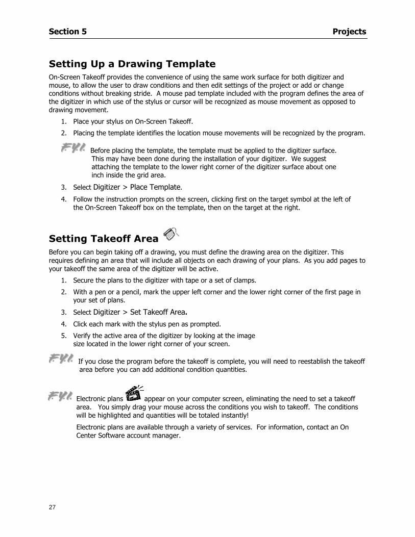
Section 5 Projects
27
Setting Up a Drawing Template On-Screen Takeoff provides the convenience of using the same work surface for both digitizer and mouse to allow the user to draw conditions and then edit settings of the project or add or change conditions without breaking stride A mouse pad template included with the program defines the area of the digitizer in which use of the stylus or cursor will be recognized as mouse movement as opposed to drawing movement
1 Place your stylus on On-Screen Takeoff
2 Placing the template identifies the location mouse movements will be recognized by the program
Before placing the template the template must be applied to the digitizer surface This may have been done during the installation of your digitizer We suggest attaching the template to the lower right corner of the digitizer surface about one inch inside the grid area
3 Select Digitizer gt Place Template
4 Follow the instruction prompts on the screen clicking first on the target symbol at the left of the On-Screen Takeoff box on the template then on the target at the right
Setting Takeoff Area Before you can begin taking off a drawing you must define the drawing area on the digitizer This requires defining an area that will include all objects on each drawing of your plans As you add pages to your takeoff the same area of the digitizer will be active
1 Secure the plans to the digitizer with tape or a set of clamps
2 With a pen or a pencil mark the upper left corner and the lower right corner of the first page in your set of plans
3 Select Digitizer gt Set Takeoff Area
4 Click each mark with the stylus pen as prompted
5 Verify the active area of the digitizer by looking at the image size located in the lower right corner of your screen
If you close the program before the takeoff is complete you will need to reestablish the takeoff area before you can add additional condition quantities
Electronic plans appear on your computer screen eliminating the need to set a takeoff area You simply drag your mouse across the conditions you wish to takeoff The conditions will be highlighted and quantities will be totaled instantly Electronic plans are available through a variety of services For information contact an On Center Software account manager
Section 5 Projects
28
Setting Scale for Specific Pages You may set the scale in each page view separately This will override the default scale setting in Project Properties for that page Setting the correct scale for the drawing before taking off quantities ensures accurate calculations Be careful to check the scale for each drawing in your project before doing takeoffs
1 Display the page you want to set select Edit gt Set Scale
2 Use the drop down arrow to select a scale that will be applied to that page
3 Click
OR
4 Access the pull-down scale settings on the Navigate toolbar
NOTE As you draw objects notice that the drawn object is similar in width to the object on your plans If it is not the scale set may not be correct
Calculating Scale You may calculate scale according to a known measurement between two points either with a digitizer or on electronic plans
1 Select Edit gt Calculate Scale using Image or Edit gt Calculate Scale using Digitizer
2 Follow the instructions in the related Calculate Scale dialog box You will be asked to click on the first and second points then to enter the dimension for that distance
3 The scale will be recalculated for the displayed page and the Scale display on the Navigate toolbar will show the new scale
Section 6
29
Conditions and Takeoff
This section will Draw Conditions to Takeoff Plan Quantities
What Zones will do to help your takeoff process
Discuss the ins and outs of Takeoffs
Section 6 Conditions and Takeoff
30
Creating Conditions
If you are starting a new project from scratch you will need to create conditions to takeoff quantities such as floor areas wall lengths and corner bead counts If you are using a template you will have several pre-designed conditions already listed on the Takeoff dock bar However you may want to change the characteristics of some conditions or create additional conditions for a particular project
1 Right Click within the Takeoff dock bar Select New gt Condition
Or
2 From the Takeoff dock bar Click (if the buttons are not showing right-click in the Takeoff dock bar area and select Show Buttons from the pop-up menu) The New Condition dialog appears
3 Select the condition type (Linear Area Count or Zone) from the pull-down menu accessed by the
down arrow next to the Type option
4 Press Tab or use the mouse (or stylus) to move to Name and enter a name for your condition
5 Specify the desired condition attributes See Condition Attributes for more detail
6 Click for condition to apply
Section 6 Conditions and Takeoff
31
Condition Attributes Each condition type will have related attributes to select or specify within the General and Advanced tabs of the New Condition dialog Once a condition has been used to takeoff a quantity from your plans certain attributes cannot be changed
All conditions allow the user to specify color and fill pattern for the object drawn
Linear Conditions
General Specify width and height by feet and inches Specify pitch in inches up to the nearest thousandth of an inch if applicable
Advanced Specify rounding for object quantities and droprun default length for electrical or plumbing drops at the ends of lines Select Connect to have lines connect at the corners where one line of the condition ends and another begins (and indicate Tolerance for the featurersquos activation as distance between the ends of two lines) Choose Trim to have lines automatically trim to a line being crossed Choose Curve to draw a curved line
Follow these examples for inputting feet and inches For 7 feet 6 inches type 706 for 13 feet 7 inches type 1307 For 20 feet type 2000
Section 6 Conditions and Takeoff
32
Area Conditions
General If needed you can specify the thickness (in inches) andor pitch (in inches)
Advanced Specify rounding for object quantities Choose to display an adjustable grid within the area and indicate matrix cell dimensions
Section 6 Conditions and Takeoff
33
Count Conditions
General
Specify height and indicate the size (in inches) and shape (square circle triangle rectangle or opening) of the count object as it will appear on screen
Advanced Count conditions have advanced attributes These options are available for all shapes except for openings
Zone Conditions Zones allow you to subdivide condition quantities making it easier to modify and complete jobs in phases They can be used at the end of a takeoff to isolate a group of condition quantities that are in different areas of the takeoff
Zones can also be used to break a takeoff into multi-phases and can even be used to isolate quantities while a job is in progress to group the amount of work that has been completed to date They can be applied to one or multiple pages in your plans automatically calculating the takeoff quantities for each zoned area
Section 6 Conditions and Takeoff
34
The zone feature is only available in Lite and Full Mode If you are in View Mode and would like
to use this feature click from the main toolbar to purchase the upgrade
Condition Notes A Note tab is provided for comments regarding the condition These notes will display on the Takeoff List report and will import into Quick Bid
Section 6 Conditions and Takeoff
35
Condition Results The Results tab of the New Condition is based on condition type Initial settings default to linear feet (LF) for linear conditions square feet (SF) for area conditions and count of items (EA) for count conditions and zones The first of the results fields will display for the condition items in the Takeoff dock bar area All results will display in worksheets and Takeoff List reports as well as in an Excel spreadsheet after being exported
Copying Conditions You may use the condition attributes from a condition yoursquove already created for any future conditions of the same type
1 Click on a condition to select it
2 Click the Copy button from the toolbar
OR
3 Right-click in the Takeoff dock bar area and select copy
4 A new condition will appear in the list with the same condition attributes as the previous condition but with the quantities zeroed
Editing Conditions Once you have copied a condition you might want to change several attributes You can also edit an existing condition to fit any updated needs
1 Highlight the desired condition on the Takeoff dock bar
2 Click the Change button
OR
3 Double-click on the condition you wish to edit to bring up the Change Condition dialog
NOTE The Change Condition dialog differs from the New Condition dialog only in that if takeoffs
Section 6 Conditions and Takeoff
36
have been performed in your project with this condition you will not be able to change the type of condition or certain properties under the advanced tab of the dialog box
Deleting Conditions 1 Click on the condition in the Takeoff Dock bar area
2 Click the Delete button on the toolbar
OR
3 Right-click and select Delete from the pop-up menu
All takeoff associated with the deleted condition will be deleted immediately and permanently
Organizing Project Conditions Within your project you can create folders andor sub-folders for different types of conditions You may even want to create a folder containing conditions with reset values
To get started organizing your conditions make sure you are viewing the condition tree (right-click in the Takeoff dock bar area and select Show Tree)
Creating Folders and Sub-Folders 1 Right-click in the Takeoff Dock bar area
2 Select New gt Folder from the pop-up menu
Copying Folders
1 Click on the folder and click Copy on the toolbar
2 All copied conditions within the new folder will have values reset to zero
Renaming Folders
1 Click on the folder
2 Right-click and select Rename from the pop-up menu
3 Enter a name for your folder and click the Enter button
Changing Condition Order
You may move conditions up or down in the condition list of the Takeoff dock bar to suit your project needs
1 Select the condition you would like to move by clicking to highlight it
NOTE When you are ready to move the highlighted conditions be sure that you start
moving using the last condition chosen That condition will have a highlighted boarder
Section 6 Conditions and Takeoff
37
2 Drag and drop any the condition from one place to another in the list You may also move a condition to another folder on the list in this way
Drawing with Conditions Snap Angles Set up snap angles to prevent lines from appearing jagged Snap angles are commonly set at 15deg and shift snap angles at 0deg
1 Go to Tools gt Options Options dialog appears
2 Under the General tab make the desired settings
3 Click to save the settings As they are drawn lines will snap to the set degree
Drawing a Linear Object 1 Select a condition from the Condition List in the Takeoff dock bar
2 Move the cursor into the Image takeoff area of the screen you will see the cursor display as crosshairs
3 Click and hold left mouse button then drag mouse to draw a line
4 Release mouse button to set line
Section 6 Conditions and Takeoff
38
5 Repeat steps for further lines
Continuous Mode This feature allows you to draw an object that has connected lines
1 Click the icon from the Takeoff toolbar
OR
2 Go to Tools gt Continuous Mode
3 Follow steps 1-3 from Draw a Linear Object
4 Click at each point of intersection The object will be connected
5 Double-click after making the final point to set the lines
Drawing a Curve To draw a curved line the Curve option must be checked under the Advanced tab of the Condition dialog
1 Click where you want to begin the curve and drag in a straight line to the position for the other endpoint of the curve
2 Click on the line to select it Handles in the shapes of small squares will appear at either end of
Section 6 Conditions and Takeoff
39
the line and in the center of the line
3 Move the cursor over the center handles until the cursor becomes a two-way arrow
4 Click and drag in the direction of the curve bending the line as you move the cursor Release to set the curve (The line you began with will disappear)
Draw a circle by drawing two curved lines connected
Drawing an Area Object Area conditions are drawn similarly to continuous mode lines You may trace any number of adjoining walls at different angles to complete your area takeoff
NOTE When drawing an area do not intersect the perimeter or line of the object you are drawing
1 Click at each point
2 Double-click when yoursquove returned to your starting point
3 The area will be filled with the pattern set for that condition
NOTE The simulated circle will be good enough for you to be able to make a bid
To create a circular area click from point to point with very short distances in between points simulating a circlersquos perimeter Double-click after setting the last point to set the area
Section 6 Conditions and Takeoff
40
Grid Options Grids give you an added advantage when installing materials such as tiles Use this feature to get a count for how many tiles are needed for an area
1 Double-click on an area condition in the Takeoff dock bar to open its Condition dialog
2 Click on the Advanced tab to show its options
3 Check the box next to Grid by clicking in it
4 Indicate the dimensions of the cell matrix in inches (For example 200 x 400)
5 Under Results tab choose each (EA) for one of the results fields This will tabulate a number of grid cells (including partial grid cells) in area
6 Click to save your settings
7 Use the Move Grid and Rotate Grid features in the Tools menu to manipulate the grid as desired
Grid Calculation
1 Go to Tools gt Options menu
1 Specify if On-Screen Takeoff automatically should Calculate Grid Position
2 If AreaGrid Size is selected On-Screen Takeoff will calculate the number of items needed to fill the grid based on grid demintions
3 Click to accept and close the dialog
To move a line at any angle (regardless of default setting) press the Shift key while moving the mouse
Section 6 Conditions and Takeoff
41
Backout Mode This feature allows you to take out part of an area and deduct that amount of square footage
1 Select Tools gt Backout Mode
2 Outline the are you want backed out as you would when drawing a regular area object (see Drawing an Area Object)
3 The outlined area will clear and quantities will be recalculated
NOTE The perimeter of the backout area will be added to the LF quantity for that condition
Drawing a Count Object Square triangle rectangle and circle shaped count objects can easily be placed on images
1 Select the condition
2 Click in the location where you want the object to appear
3 To place an opening-shaped count item like a door or window you must click over an existing linear object such as a wall
4 On the Results tab you can change the height properties to give you the result you need
5 If Backout is checked on the advanced tab for each count opening the opening-shaped count item will back out a corresponding section of the linear object
Opening shaped count items are sized at 3rsquo0rdquo by default
Drawing a Zone Zones are drawn in the same way as area objects and may be any polygonal shape You may trace any number of adjoining walls at different angles to complete the zone perimeter
1 Click at each point
2 Double-click when yoursquove returned to your starting point
Section 6 Conditions and Takeoff
42
Selecting Objects
1 Use the Select Tool to select objects
You can also select all objects that correspond to a condition
1 Click on a condition to select it
2 Right-click and choose Select All
3 All objects with this condition will be highlighted with squares as an outline
Moving and Resizing Objects Linear
1 To move or resize a linear object click anywhere on the line to select it
2 To move the line position your pointer over the center handles When the mouse is positioned over the handles you will see a two-way arrow You will only be able to move the line in the direction of the arrows
3 Drag the line to a new position
4 Clicking and dragging the handles on the ends of the line will allow you to lengthen or shorten your line
Area and Zone
1 To move an area object or zone in its entirety click and drag it to its new position
2 Grabbing a handle at a corner or intersection of the object will allow you to adjust and change its perimeter
Section 6 Conditions and Takeoff
43
Count 1 To move a square circle rectangle or triangle shaped count object click and drag
2 Click and drag an opening shaped count object along the length of the linear object to the desired position then release
NOTE An opening shaped count object may not be moved from its associated linear condition object however it may be moved up and down the length of the linear object
Layers On-Screen Takeoff allows you to sort and separate your takeoff objects within the same job and on the same page On-Screen Takeoff gives you this flexibility through the use of layers
By assigning different conditions to different layers (for example differentiating between floors ceilings and walls) you can choose to view all layers or turn off certain layers to display and print the remaining groups of conditions only You may also remove the background image of electronic plans add text and hot link symbols or print only your condition takeoffs
Layers are only available in Full Mode If you are in View or Lite Mode and would like to use this
feature click from the main toolbar to purchase the upgrade Default Layers
On-Screen Takeoff begins every project with three default layers Image Annotation and Default The Image layer holds the electronic plan files you may have in your project The Annotation layer possesses all text notations highlighting and hot links in the project The Default layer will appear in the Condition dialog when creating or editing a condition (listed in the takeoff dock bar) Conditions are assigned to the Default layer unless otherwise specified by the user
Creating Layers To assign a condition to a layer other than the default layer you must first create additional layers for your project
1 Select View gt Layers to open the Layers dialog
2 Click An unnamed layer will be added
3 Click within the empty box and type a name for your layer (for example Wall)
4 New layers are added as active layers The adjacent box under the Show column will be checked
Section 6 Conditions and Takeoff
44
Assigning a Layer to a Condition 1 Open the Condition dialog box by creating a new condition or editing an existing condition
2 Under the General tab click on the down arrow in the Layer field to display optional layers
3 Select the desired layer for the condition Only the Default layer and layers you have added will be displayed
4 Click
View and Hide Layers
1 Select View gt Layers
2 Under the Show column check the box to view or remove the check (by clicking on it) to hide the specific layer
3 Click to accept and close the Layers dialog
Section 6 Conditions and Takeoff
45
Assigning Text to a Layer When adding text to an image On-Screen Takeoff has the capability to assign the text to a specified layer
1 Select the Text Tool
2 Click at the point you want to place your text
3 Type in your text using the Enter key for line breaks
4 Click the drop down arrow next to the Layer field and select the desired layer
Section 7
46
Printing and Exporting
This section will
Printing options and procedures
Exporting data by copying and pasting
Exporting quantity results to Excel spreadsheets
Section 7 Printing and Exporting
47
Print Setup On-Screen Takeoff allows the user to print the image takeoff list and worksheet
1 Select File gt Print Setup The Print Setup dialog will open
2 Select a printer or leave the default selection listed (change from the default printer displayed by clicking on the down arrow at the right of the field)
3 Indicate page size and printer tray option (Source) Access page size options by clicking on the
down arrow at the right of the field
4 Choose Portrait or Landscape orientation
5 Click to accept and close the dialog
Printing Images The image area can include the electronic plans the takeoff objects added text and hot links To print a subset of these (for example just the takeoffs without the plans or the added text and hot link symbols) hide layers that you do not want to print (see Section 6 View and Hide Layers) When you are printing your images every page will show the scale of the takeoff you are printing
1 Click on the Image tab to display the area of your project
2 Select File gt Print (or Ctrl + P)
Section 7 Printing and Exporting
48
3 Select the desired view (What to print) and the Image Range
4 Click The second Print dialog will open
5 Change settings accordingly or click if you accept the default settings
Printing Takeoff Lists and Worksheets In Takeoff Lists and Worksheets you may hide columns to print only certain results or adjust column widths to fit the report within the page size selected
1 In Takeoff List or Worksheet view move your cursor to the right side of the columnrsquos title bar the cursor will display as a two-way arrow
Section 7 Printing and Exporting
49
2 Click and drag to adjust the width of the column Holding the mouse button you may
slide the title bar under the title bar to its left to hide the column completely
3 Select File gt Print or press Ctrl + P to access the Print dialog
4 Indicate desired printer and choose the number of copies
5 Click to print and close the dialog
When printing the condition list we suggest printing in landscape
To reset to the default column widths double-click on the right border of a column heading will reset the column to its right (or previously to its right before being hidden)
Print Preview 1 Select File gt Print Preview
2 Use and to vary your view 3 If viewing an image choose current full or scale view to see how it displays
4 For printed outputs that cover more than one page use and to view adjacent pages or click on the down arrow next to Page field and select the page you want displayed
Exporting Using the CopyPaste Feature You may copy all the data or sections from the worksheet and the takeoff list view in On-Screen Takeoff and paste it into another application When pasting into Excel the cell layout will be maintained
1 Highlight the areas you wish to paste Click and hold the left mouse button down as you drag the cursor over the area to be selected then releasing the mouse button
OR
2 Select the entire takeoff list quickly click on the left On-Screen Takeoff column header and hold and drag the cursor across the remaining column headings
The number of pages for the view selected will display in the lower left-hand corner The zoom percentage that applies to the view will be displayed in the lower right-hand corner next to page size of the drawing
Section 7 Printing and Exporting
50
3 In the worksheet view you may highlight rows by clicking on the numbered buttons to the left of each row clicking and dragging across column headings or clicking and dragging over individual cells in the worksheet
Click anywhere in the appropriate view to deselect the area
4 Once your selection is highlighted you may select Edit gt Copy or Ctrl C from the keyboard 5 On your monitor switch to the application into which you want to paste your selection 6 Select Edit gt Paste in the new application or simply press Ctrl + V to paste
The colored keys for conditions cannot be pasted
Using the Export Feature You may export condition quantities to specified cell location within an Excel worksheet file Cell target locations are assigned in the Results tab of the condition dialogs on the Export line relating to each quantity measurement type
On-Screen Takeoff will export takeoff quantity results for up to three different quantity types that you specify For instance you may want to know the number of square feet in a ceiling area as well as the number of linear feet in its perimeter
Section 7 Printing and Exporting
51
1 Bring up the Condition dialog by double-clicking on a condition in the takeoff dock bar or by
selecting the condition and clicking
2 Click on the Results tab to access its fields The default quantities for the condition type will display
3 For each results field click on the arrow to access the pull-down menu and select the appropriate quantity (for example SF LF EA etchellip)
4 Have your Excel spreadsheet opened and saved in a file
5 Specify the Excel spreadsheet cell locations where you want the results to go
6 For a cell in the first sheet of your spreadsheet type in the cell address (eg a1) Case is not important
7 For a cell on a successive sheet of your spreadsheet type in sheet the number followed by a comma and the cell address without any spaces (eg sheet2a1) Case is not important
8 Click
9 Select File gt Export gt Condition Qty to Excel
Section 7 Printing and Exporting
52
10 Browse to the location of the Excel spreadsheet file click file to select it
11 Click to export On-Screen Takeoff results to specified cell locations in the Excel file When you return to the Excel application you will see the values have been added to the specified cell locations in your spreadsheet
12 Save your Excel file
Exporting Worksheet to Excel
1 Assign condition quantities you want to export
2 Open saved Excel spreadsheet file to which you will be exporting
3 From On-Screen Takeoff Select File gt Export gt Worksheet to Excel
4 Browse to the location of the Excel spreadsheet file click file to select it
5 Click When you return to the Excel application you will see the values from the Worksheet Tab have been added to your spreadsheet
6 Save your Excel file
Exporting Takeoff to CVS 1 Assign condition quantities you want to export
2 Open saved Excel spreadsheet file to which you will be exporting
3 Click the Takeoff Tab in the project you want to export the information
4 Select File gt Export gt Takeoff to CSV
5 Browse to the location of the CSV spreadsheet file click file to select it
6 Click the Save
NOTE CSV files can be opened in Excel Lotus Access etc One may consider this option more of a ldquodumprdquo into a file
The Excel application must be active (it may be minimized on the application bar) with the target spreadsheet open in the application Otherwise an error will occur with the export operation that will affect both the On-Screen Takeofftrade file and the Excel spreadsheet
Section 8
53
Advanced Features
This section will
Some special features of working with condition objects in the takeoff area
Details of advanced options for conditions
Advanced features of the Project Properties dialog
Section 8 Advanced Features
54
Features to Use with Objects Roping Feature You can move copy or delete using this feature Using the Select tool (the pointer) you may select several objects at once by clicking and dragging an outline around the objects then releasing the mouse button Roping may select either objects completely within the outlined area (inclusive) or objects both within and touched by the outlined area (touching) Specify your roping preference under Tools gt Options
1 Click and hold the mouse button at a point on the screen near the objects to be selected and drag to surround the objects with an outline
2 Release the mouse button The objects will be selected
3 You may now
Move the group around on the page by clicking within the group dragging the mouse and releasing the button to place the objects
Delete the group of objects by clicking the Delete key or
Copy and paste by pressing Ctrl C to copy the group then Ctrl V to paste it The pasted copy of the grouped objects will appear slightly offset from the original objects
Section 8 Advanced Features
55
Applying a DropRun Count
Use the droprun feature when calculating quantities to take into account the drop or run of a linear condition such as electrical lines or plumbing pipes Drop or run lengths may be added separately to any linear condition on screen while a default droprun length may be indicated for a condition as a whole
1 Select the desired linear condition from the Condition List in the Takeoff Dock bar
2 Click the Change button in the toolbar to open the Change Condition dialog
3 Click the Advanced tab to access the advanced options and click inside the DropRun check box
4 Enter a default length to be applied to all of this condition Entering 800 will be interpreted as 8 0 (You must enter both place markers for inches) You can leave the length blank and manually enter drop run on each segment drawn
5 Click the OK button to accept and close the dialog
Edit DropRun Count
1 With the related linear condition in the Takeoff Dock bar highlighted or with the pointer tool selected
2 click on the desired linear object in the image takeoff area The Count button will become active
3 Click on the Count button (alternatively select Tools gt Count) The default droprun amount will show in the pop-up Count dialog (Default length will be zero if droprun has not been selected in this conditionrsquos properties)
4 Type in the desired length Entering 800 will be interpreted as 8 0 (You must enter both place markers for inches)
5 Click the OK button The additional amount will be reflected in the corresponding quantity The new DropRun count will apply only to the object edited
Adding Text in Image View
On-Screen Takeoff allows you to place text comments around your quantity takeoffs that may be printed along with plan images and objects Text is automatically placed within the Annotation Layer (that includes text and hot links)
1 To place text on the image select the Text Tool and click at the point you want to place your text opening a text box
2 Type in your information clicking Enter for line breaks
3 When you are finished click the OK button to exit the text box
4 To reposition text simply click on the text (with the Text Tool active) to select it
5 Move the cursor over the text the cursor will now display as a four-way arrow
6 Click and drag the mouse to position the text as desired
Section 8 Advanced Features
56
1 To edit existing text use the Text Tool to double-click on the text to open the editing box
2 Enter additional text or use the Backspace key to delete text as necessary
Formatting Text Once created you may format the font size type style and color of your text
1 Click on the text to select it and select Tools gt Font or click on the Font button in the Takeoff Toolbar
2 Select the desired features (color options are disabled) and click the OK button
3 Click on the text to select it and select Tools gt Color or click on the Color button in the Takeoff Toolbar The Color dialog will open
4 Click on a color in the Basic Color palette or create a color and add to the Custom Colors palette (Be sure to click on the color in the Custom Colors palette to select it)
5 Click the OK button
Object Properties
Linear Objects
Linear objects may be set to connect at corners
A linear object may be set to trim automatically when crossing another linear object (Check the trim option under the advanced tab of the Condition dialog)
When you move a connected linear object objects automatically move and resize connected lines accordingly (quantities are then recalculated)
This feature requires that the connected linear object be moved using the center handles (does not apply when resizing the line from the ends)
Objects constrain to snap increments defined in the Tools gt Options menu (with the mouse 15deg by default incremental when shift key is held down)
Objects are measured from centerline to centerline
Section 8 Advanced Features
57
Area Objects When drawing an area use your escape key to undo the last line drawn You may reverse your
drawing of an area using the escape key
The area will not fill with color and pattern until the user double-clicks after the last line is set
Lines drawn to delineate an area object constrain to snap increments defined in the Tools gt Options menu (with the mouse 15deg by default incremental when shift key is held down)
After selecting an area to move or adjust position the mouse in the center to move the entire area position the mouse at the sides or corners to adjust the perimeter
Count Objects
All count objects are quantified by the physical number of objects per page and reported as EA for the UOM The quantity for the current Image View is (displayed in the Condition List) and the total quantity in your project is displayed in the Takeoff View and Worksheet View)
Square circle rectangle and triangle shaped count objects do not displace or subtract from other object quantities when placed on top of them However on the Advanced Tab for the count condition a connect property can be set (this is a check box) so that when a count object of this shape is put on top of a Linear type takeoff object it will move with the linear if said linear is moved
An opened-shaped count object must be placed within a linear object Opening shaped count objects may also be measured by linear foot or linear yard (EA SF and SY are also options) Opening shaped count items default to a width of 3rsquo 0rdquo at the time of creation This size can be changed The small medium and large size are not options on this type of condition anymore Check Backout on the Advanced tab for each Count object back out the footage (or yardage) of opening-shaped count objects in which they are placed
NOTE In order to see this Backout functionality (in quantity) for SY or SF deductions at least one of the
results for the Linear(s) this object will be placed on must be set to SY or SF and the count object must have a height quantity
Advanced Features of Conditions The Round Feature Under the Advanced tab of the linear and area Condition dialogues you may specify quantity rounding (in inches) For linear objects rounding applies to each linear object drawn For area objects rounding will apply to each segment of the area perimeter adjusting the perimeter and area calculations For example With a linear condition entering 12 in the Round field will round up each related linear object to the nearest 12 inches or one foot With this setting two walls of 1 4 would each round to 2 0 totaling 4 0
NOTE In the Takeoff Dock bar condition list and in the On-Screen Takeoff reports quantities will be displayed in whole numbers rounded up to the nearest foot However calculations are based on true quantities without rounding unless the Round Feature is engaged
Pitch Pitch may apply either to linear or area conditions It is measured in rise per linear foot Entering 12 indicates a 12 rise per 12 of linear distance (a pitch of 12 over 12) or an angle of 45deg
Section 8 Advanced Features
58
Advanced Features of Project Properties Selecting Multiple Pages
1 Select a single page entry by clicking on the numbered gray button to the left of the entry
2 Drag the cursor down the column of numbers to select consecutive pages
3 Click on the blank button at the top of this column to select all pages in the Properties dialog
Section 8 Advanced Features
59
Changing Image Assigned to a Drawing 1 Select the page entry by clicking on the numbered gray button to the left of the entry 2 Click the Change Image button The Change Image dialog box will appear
3 Navigate to the desired file and select by clicking on it
4 Click the Open button The electronic file assigned to the page will have been changed to reflect the new file choice
Changing Image File Path 1 Select pages as described above
2 Choose Change Folder
3 In the Change Folder dialog navigate to the appropriate folder
4 Click the OK button The file path will have been changed for the selected page entries
Delete a Page from Project Properties 1 Select the page you want to delete by clicking on its associated number (in the gray box at the
left of the entry)
2 Choose Delete Page
All Takeoff on the page will be deleted immediately and permanently
Section 8 Advanced Features
60
Advanced Features of Tool Options
Calculation Method On-Screen Takeoff has built-in calculation options to allow for faster work and faster saves until your takeoff is complete Calculation options are found by selecting Tools gt Options then clicking on the Calculation tab
Calculation method can be set to Automatic Automatic except Grids and Manual Manual will allow the program to operate more quickly while Automatic or Automatic except Grids allows the user to see quantity changes as takeoffs are made
In any mode you may press F9 to recalculate quantities for the On-Screen Takeoff current totals
Configuration Tab
When the ldquoPage Label (A01)rdquo radial button is chosen On-Screen Takeoff puts the numbered label on all the pages of in your current page indicator in your Navigate Toolbar If the Page Descriptionrdquo radial button is chosen then a description of what takeoff is on that specific page will be shown in your current page indicator in your Navigate Toolbar
This section of the configuration tab gives you options on how you want to export your information When the ldquoFolderSubfolder Namesrdquo radial button is chosen than on your file that you are exporting to will have all the conditions folders and subfolders In the Delimiter box you can choose the symbol that is needed to separate the information you are exporting Some files need semicolons () or colons () to make sure the information comes exported in is separated it the appropriate places
Section 8 Advanced Features
61
In previous versions of On-Screen Takeoff there are views that users need to have in order for them to display their information By either choosing ldquoOST 1xrdquo or ldquoOST 2xrdquo it will let the program know you want your columns of information exported in that specific format
When you have the Confirm Deletions radial button of ldquoYesrdquo chosen than every time you delete anything you will get a dialog box confirming your intentions of deletion
While working with your takeoff you have a choice to either view the legend of your conditions or hide it Choose whichever radial button that suits your needs
For those who prefer to use the Enter key to navigate in dialog boxes this option is just for that
Font Tab The Font tab is designed for you to make your own look and feel for the application At the bottom of this tab it will show you sample of the fonts and colors you have chosen
Renaming the Current Page You may change the name of the current page in the takeoff area of On-Screen Takeoff by selecting Edit gt Rename Page
This opens the Name Page dialog and you may simply type in a new name and click the Enter button The new name for the file will be reflected on the title bar for the page and in Project Properties
You also may access the Rename Page function by right-clicking in the takeoff area while in Image View and selecting the option from the pop-up menu that appears
Section 9
62
Saving and Exiting
This section will
Explain how to save projects
Show you how to safely exit the program
Section 9 Saving and Exiting
63
Saving Your Project
1 Select File gt Save 2 If your project has not previously been saved a Save dialog box will open to allow you to name
the file and choose the directory and folder in which to save your file 3 Once saved File gt Save will simply save the current version of the file
OR
4 Select File gt Save As then type in a new name for the file and save to the desired file path
The Auto-save Feature With the Auto-save feature On-Screen Takeoff automatically backs up your open project You may choose to have more than one level of backup files The first backup copy will have the extension b00 and successive files will be b01 b02 and so on If you have designated four levels of backup files after the fourth backup copy has been created (b03) the next file will be saved over the file with extension b00 Further backup saves will then rotate through the four backup files in the same way
1 Select Tools gt Options 2 In the Auto-save area (under the General tab) select the frequency of backup file creation (in
minutes) and the number of levels for the feature 3 You also may disengage the feature by clicking in the check box to clear it
The Auto-save feature automatically saves backup copies to the directory of the current project If you are working from a write-protected area such as a CD-ROM On-Screen Takeoff will place backup files in the On-Screen Takeoff folder
Exiting When you are finished using On-Screen Takeoff it is very easy to exit Exiting is very important because of security reasons If someone were to use your computer they could enter the application and view and manipulate information
Section 9 Saving and Exiting
64
On-Screen Takeoff closes the open project when you open another or create a new project or when you exit the program
1 Select File gt Exit
OR
2 You also may click at the upper right-hand corner of the application to exit
NOTE If your latest changes to a project file have not been saved On-Screen Takeoff will ask you whether you would like to save the file and gives you the option of canceling the operation
Appendix I Installing Your Digitizer
65
Appendix I Installing Your Digitizer When you get your digitizer from GTCO you will need to connect it to your computer Follow the instructions outlined below to do this
Note For rollup digitizers the metal bar must be oriented to the top or right hand side
Connecting the Digitizer 1 Lay the digitizer out flat 2 Connect the Stylus to the digitizer 3 Plug in the power adapter 4 Plug the interface (IO) cable into the digitizer 5 Plug the other end of the interface cable into an open serial port on computer
Note GTCO Technical support phone number is 410-381-6688 The electronic manual (on diskette) from GTCO contains more detailed installation and operation instructions for the GTCO digitizer model you have
Installing other Digitizer Drivers If you are using a GTCO Digitizer you will need to install the GTCO TabletWorks Drivers
If you are using a Digitizer not supported by GTCO Tablet Works 10 please contact the manufacturer of your digitizer for assistance with installation
Installing GTCO TabletWorks Drivers 1 Insert the On Center CD into the CD-ROM drive The CD Startup screen will open 2 Click on Install Software 3 Select Additional Software and Drivers 4 Select Digitizer Driver 5 Follow the instructions for installing TabletWorks 10
Adhering the Template The template is a small plastic sticker used to enable mouse function when using the digitizer with On-Screen Takeoff Place your template on your digitizer We suggest placing it in the bottom right corner of the digitizer about one inch inside the takeoff area
Note You may either peel off the back of the template and use the adhesive surface or you can tape the template down
Appendix I Installing Your Digitizer
66
Testing the Digitizer Drivers Before running OST you may test the digitizer by moving the stylus around on the digitizer pad it should move the mouse cursor (if mouse emulation is enabled)
If the digitizer does not move the mouse cursor on the screen
The superset codes may need to be reset Reset the superset codes by touching on the border of the digitizer with the stylus The digitizer should beep several times
The digitizer may not be communicating with the computer Be sure the COM port selected is correct Be sure the COM port selected is correct If you are not able to get the digitizer to move the mouse cursor you need to call GTCO technical support for help
Note The Mouse Emulation is not required for On-Screen Takeoff to work properly It is used only for the Template functionality if the digitizer is moving the cursor the wrong direction (up instead of sideways or vice-versa)
Click the L-shaped arrow symbol on the digitizer with the stylus
Appendix II Toolbar Item Details
67
Appendix II Toolbar Items Main Toolbar
Appendix II Toolbar Item Details
68
Tool Toolbar
Appendix II Toolbar Item Details
69
Zoom Toolbar
View Toolbar
Navigate Toolbar
Appendix II Toolbar Item Details
70
Navigate Toolbar (Continued)
Takeoff Toolbar
Appendix II Toolbar Item Details
71
Takeoff Toolbar (Continued)
Image Toolbar
Appendix III Loading Plans from a Dodge CD
72
Appendix III Loading Plans from a Dodge CD
This section will detail how to load plans from a F W Dodge CD-ROM into an On-Screen Takeoff project file ready for takeoffs
Dodge files may be added to the Project Properties dialog However loading the files in that way will load the files by number rather than name description If you want to load one page only from your Dodge CD You will have to rename the page to display the name rather than number of the file
To load plan files from a Dodge CD so that the files load sequentially by file number but are displayed by name rather than by number within your project follow the instructions below
Opening a Dodge project from a CD-ROM 1 Insert the CD into the drive 2 Choose File gt Custom 3 Choose Dodge Plans Project (plansdat) as the file type 4 Select the appropriate file type by clicking on the down arrow at the right of the Files of type
field 5 In the Look in field access your drive paths by clicking on the down arrow at the right of the
field then
Navigate to your CD-ROM drive Open the data folder and Open the Projects folder
6 Select the desired project and open its folder 7 Open the plansdat file 8 All the images will come in sequenced correctly for that job along with the full descriptions
(names) of each page If there is not a plans folder in the project folder then plans do not exist for that project on the CD Opening the plansdat file will yield an empty project
Appendix IV Using the Plan Viewer
73
Appendix IV Using On-Screen Takeoff Plan Viewer The On-Screen Takeoff Plan Viewer is a limited version of On Center Softwarersquos commercial takeoff software If your status bar located at the very bottom of the main window says View Mode in the lower left-hand corner then you are using the Plan Viewer You can use the plan viewer to
View CD-based amp converted CAD drawings
View a previously created OST file and associated drawings
Download electronic plans online
Navigate through drawings
Quickly Takeoff linearsareas and counts
Zoom in to view the plan better
Print drawings directly from the viewer
Viewing an On-Screen Takeoff Project File
1 To open an OST file that was previously created with of On-Screen Takeoff 2 Select File gt Open 3 An Open dialog will appear if you do not see the OST file you are looking for select the
Look In drop down arrow 4 A drop down menu will appear listing the various folders drives and mapped drives located
on your computer select the correct drive or folder location and continue to browse to the location of your OST file
5 When you see your OST file double-click it to open it 6 Any takeoff and drawings should appear on the Image tab view
If you do not see the drawings but do see the colored takeoff layer the drawings may
not be located in the same place they were originally saved at Go to File gt Project Properties and check the Image File path for each listed page If the image file path is pointing to a CD drive make sure the CD is inside the CR-ROM
Downloading Electronic Plans If your Online Plan Service provides a special file format (OSX) required to use this feature of our plan viewer you can immediately downloaded all electronic plans of a project directly from our viewer
Most Plan Room web sites will automatically open On-Screen Takeoff when a request to download plans is made Your particular Plan Room may differ in operation so please contact the provider directly with questions on using the site
Appendix IV Using the Plan Viewer
74
When you request to download or open a project file from a Plan Room you will usually have the open to open or save an OSX file Choosing open will automatically open On-Screen Takeoff Alternately you may choose to save the file to a local hard drive After you have saved the file either double-click it to launch On-Screen Takeoff or open the OSX file using On-Screen Takeoff by clicking File then Open and locating the file on your hard drive You will need to change the file type to OSX
After the OSX file is opened you will see an additional tab appear in the Conditions List window called Pages
The Pages tab shows the hierarchy of your project Gray file icons represent pages that have not been downloaded and blue icons represents pages that have been downloaded
To download a page simply double-click the page icon
If you wish to select a group of pages to download you can use the Ctrl or Shift key to multiple select them then click the Download button
If you wish to download all pages at once click the Download All button
Downloaded pages will now appear in the Project Properties dialog in the same order in which they appear in the Pages tab
Creating Quick Takeoffs With On-Screen Takeoff you can create quick takeoffs to measure quantities even if you dont have the full version of our program However using the Quick Takeoff functionality shows you just a fraction of what the full version can do
The Quick Takeoff Toolbar is located at the top of the image view It has three buttons designated for three types of takeoffs Linear Area and Count The Quantity drop down list will show secondary quantities for Linears and Areas The Units drop down allows you to select how you want your quantities displayed Feet Inches Yards Millimeters and Meters
NOTE Every time change the type of takeoff you are performing (switching from Area to Linear for example) the previous quantities and takeoff objects will disappear They will also disappear when you changes pages
NOTE You can use the Dimension Tool to basically measure the distance between two points or linears The distance will display on the status bar at the bottom of the application
The Quick Takeoff Toolbar
Appendix V Frequently Asked Questions
75
Appendix V Frequently Asked Questions General
Where is On-Screen Takeoff installed on my computer
Typically it is installed in CProgram FilesOn-Screen Takeoff
In Explorer how do I recognize On-Screen Takeoff file types
On-Screen Takeoff data is stored in a single file per job lsquojob name OSTrsquo On-Screen Takeoff templates are stored as lsquotemplate nameTPOrsquo
Can only one project at a time be open
Yes For that reason opening another project automatically closes the project on screen You will be asked to save any changes
Is only one scale allowed per page What about on drawings that have multiple detail sections on a page and each of those drawings have different scales
Yes For pages with drawings of different scales copy the drawing to another project page and set the appropriate scale
I cannot perform backout on an area that is along a linear
As a workaround use the On-Screen Takeoff layers feature to help you with this issue Electronic Images
How do I start a project from drawings that have been scanned and written to a CD-ROM
Open a new project Select File gt Project Properties and select Auto Add Navigate to your CD and the appropriate folder and select any image file in that location Click Open All files in the location will load into your project Recommended that images are copied from CD to hard drive for performance
If I get a disk of drawings in AutoCAD format (R13 or R14) can I read them in On-Screen Takeoff
Yes On-Screen Takeoff now reads DWG DXF and many other format that are saved with AutoCAD
Appendix V Frequently Asked Questions
76
When I click on the all pages button what is supposed to happen Currently nothing seems to change when I click on that button
The All Pages button is used to apply the Darken and Enhance Plans feature to all pages in the project (as opposed to only the current page on screen)
Is there a way to deduct a large skylight from an area condition
Yes with the related area condition selected in the Takeoff Dock bar unselect the Backout button on the Takeoff Toolbar then draw the Backout area The area quantity will be deducted from the related condition object and the linear measurement of the Backout perimeter will be added
Digitizer Issues
How do I connect a Digitizer to the computer
See Appendix I Connecting a Digitizer
The Place Template menu choice is disabled
On-Screen Takeoff may need to be authorized or the digitizer or the digitzer drivers are not installed
It wonrsquot let me select the Set Takeoff Area menu choice
On-Screen Takeoff may need to be authorized or no job is open a digitizer is not installed or the drivers are not installed
The digitizer stylus is not moving the cursor or crosshairs
Click S-0-1 superset on the digitizer
How do I convert my old GTCO Digitizer to work with On- Screen Takeofftrade
Call GTCO and they may be able to reconfigure your digitizer to be compatible with On-Screen Takeoff
Printing Issues Which Printers work with On-Screen Takeoff
Compatible printers include On-Screen Takeoff Hewlett Packard Epson and Canon printers If you are having printer difficulties please contact support and specify the type of printer along with other pertinent information Contact support at wwwoncentercomsupport or email supportoncentercom
Which Plotters work with On-Screen Takeoff
Compatible Plotters include Hewlett Packard DesignJet plotters and the EnCAD Cadjet II If you are having plotter difficulties please contact support and specify the type of plotter concerned
ViewingDisplay I can no longer see my condition list How do I get it back
The toolbars and Dock bars can be turned on and off through the View gt Toolbars menu options
Appendix V Frequently Asked Questions
77
This is also accessible by right-clicking in the toolbar area and selecting (or deselecting) a toolbar listed
I cannot view my folders in the condition list
Right-click in the Takeoff Dock barcondition list area and select Show Tree to display your folders
My Status Bar reads Viewer Mode and I am unable to draw conditions
On-Screen Takeoff needs to be Authorized Or you need to purchase an upgrade Click the Perform Advanced Takeoff button on the main toolbar
I hid a Dock bar and when I selected to view it again it appeared alongside the other Dock
bar instead of stacked on top of it How do I fix it
Pick up the Dock bar by clicking on the bar at the top and continuing to hold down the mouse button drag the Dock bar over the other one It will resize and appear stacked with the other
When I open image files from a CD the images are all upside down How do I get them right
side up
To flip pages from top to bottom follow the steps below 1 Click the All Pages button on the Image Toolbar (All Pages is engaged when the button
is not clicked) 2 Click the Flip Horizontal button on the Image Toolbar 3 Click the All Pages button again to disengage
Templates How do I create a Template
Follow the steps below 1 Create a typical project 2 Choose File gt Save As 3 Choose On-Screen Takeoff Template Files as the file type to save 4 Name the file This will save all of the condition setups as well as the layers for the
project
How do I create a new project from a template
Follow the steps below 1 Choose File gt New 2 Select a template from those listed in the New dialog This will open a new project with
conditions and layers saved from a previous project but no pages or takeoff
78
INDEX
Area Conditions 32
Area Objects 57
Auto Scrolling 20
Auto-save 63
Backout Mode 41
Calculation Method 60
Conditions 29
Configuration 60
Contents Tab 6
Continuous Mode 38
Count Conditions 33
Count Objects 57
Digitizer 10 65 76
Docking Toolbars 13
Dodge CD 72
Drawing 27 37
DropRun Count 55
Environment 18
Exiting 63
Exporting 49
Features 16
Font 61
Frequently Asked Questions 75
Grid 40
Help File 5
Hiding Toolbars 13
Hot Links 21
Image 19 59
Image files 9
Image Toolbar 12 71
Images 75
Index Tab 6
Layers 43
Linear Conditions 31
Linear Objects 56
Main Toolbar 12 67
Menus 14
Moving Toolbars 13
Navigate Toolbar 12 69
Navigating 20
On-Screen Takeofftrade 2
Page 59 61
Pages 20 25 28
Plan Viewer 73
Plans 26
Printing 47 76
Project Properties 25
Projects 22
Quick Start Video 18
Resizing Toolbars 13
Roping 54
Saving 63
Scale 28
Search Tab 7
Selecting Objects 42
Setup 8
Start On-Screen Takeofftrade 17
System Requirements 9
Takeoff 19 27
Takeoff Toolbar 70 71
Takeoff Toolbar 12
Template Files 23
TIF (Group4) 9
Tool Toolbar 12 68
Toolbar 67
Toolbars 12
View Toolbar 12 69
Viewing Toolbars 12
Worksheet 20
Zone Conditions 33
Zoom Toolbar 12 69
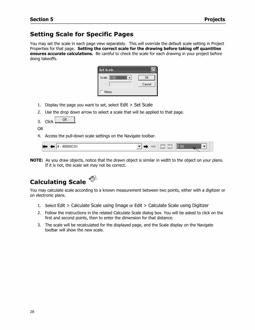
Section 5 Projects
28
Setting Scale for Specific Pages You may set the scale in each page view separately This will override the default scale setting in Project Properties for that page Setting the correct scale for the drawing before taking off quantities ensures accurate calculations Be careful to check the scale for each drawing in your project before doing takeoffs
1 Display the page you want to set select Edit gt Set Scale
2 Use the drop down arrow to select a scale that will be applied to that page
3 Click
OR
4 Access the pull-down scale settings on the Navigate toolbar
NOTE As you draw objects notice that the drawn object is similar in width to the object on your plans If it is not the scale set may not be correct
Calculating Scale You may calculate scale according to a known measurement between two points either with a digitizer or on electronic plans
1 Select Edit gt Calculate Scale using Image or Edit gt Calculate Scale using Digitizer
2 Follow the instructions in the related Calculate Scale dialog box You will be asked to click on the first and second points then to enter the dimension for that distance
3 The scale will be recalculated for the displayed page and the Scale display on the Navigate toolbar will show the new scale
Section 6
29
Conditions and Takeoff
This section will Draw Conditions to Takeoff Plan Quantities
What Zones will do to help your takeoff process
Discuss the ins and outs of Takeoffs
Section 6 Conditions and Takeoff
30
Creating Conditions
If you are starting a new project from scratch you will need to create conditions to takeoff quantities such as floor areas wall lengths and corner bead counts If you are using a template you will have several pre-designed conditions already listed on the Takeoff dock bar However you may want to change the characteristics of some conditions or create additional conditions for a particular project
1 Right Click within the Takeoff dock bar Select New gt Condition
Or
2 From the Takeoff dock bar Click (if the buttons are not showing right-click in the Takeoff dock bar area and select Show Buttons from the pop-up menu) The New Condition dialog appears
3 Select the condition type (Linear Area Count or Zone) from the pull-down menu accessed by the
down arrow next to the Type option
4 Press Tab or use the mouse (or stylus) to move to Name and enter a name for your condition
5 Specify the desired condition attributes See Condition Attributes for more detail
6 Click for condition to apply
Section 6 Conditions and Takeoff
31
Condition Attributes Each condition type will have related attributes to select or specify within the General and Advanced tabs of the New Condition dialog Once a condition has been used to takeoff a quantity from your plans certain attributes cannot be changed
All conditions allow the user to specify color and fill pattern for the object drawn
Linear Conditions
General Specify width and height by feet and inches Specify pitch in inches up to the nearest thousandth of an inch if applicable
Advanced Specify rounding for object quantities and droprun default length for electrical or plumbing drops at the ends of lines Select Connect to have lines connect at the corners where one line of the condition ends and another begins (and indicate Tolerance for the featurersquos activation as distance between the ends of two lines) Choose Trim to have lines automatically trim to a line being crossed Choose Curve to draw a curved line
Follow these examples for inputting feet and inches For 7 feet 6 inches type 706 for 13 feet 7 inches type 1307 For 20 feet type 2000
Section 6 Conditions and Takeoff
32
Area Conditions
General If needed you can specify the thickness (in inches) andor pitch (in inches)
Advanced Specify rounding for object quantities Choose to display an adjustable grid within the area and indicate matrix cell dimensions
Section 6 Conditions and Takeoff
33
Count Conditions
General
Specify height and indicate the size (in inches) and shape (square circle triangle rectangle or opening) of the count object as it will appear on screen
Advanced Count conditions have advanced attributes These options are available for all shapes except for openings
Zone Conditions Zones allow you to subdivide condition quantities making it easier to modify and complete jobs in phases They can be used at the end of a takeoff to isolate a group of condition quantities that are in different areas of the takeoff
Zones can also be used to break a takeoff into multi-phases and can even be used to isolate quantities while a job is in progress to group the amount of work that has been completed to date They can be applied to one or multiple pages in your plans automatically calculating the takeoff quantities for each zoned area
Section 6 Conditions and Takeoff
34
The zone feature is only available in Lite and Full Mode If you are in View Mode and would like
to use this feature click from the main toolbar to purchase the upgrade
Condition Notes A Note tab is provided for comments regarding the condition These notes will display on the Takeoff List report and will import into Quick Bid
Section 6 Conditions and Takeoff
35
Condition Results The Results tab of the New Condition is based on condition type Initial settings default to linear feet (LF) for linear conditions square feet (SF) for area conditions and count of items (EA) for count conditions and zones The first of the results fields will display for the condition items in the Takeoff dock bar area All results will display in worksheets and Takeoff List reports as well as in an Excel spreadsheet after being exported
Copying Conditions You may use the condition attributes from a condition yoursquove already created for any future conditions of the same type
1 Click on a condition to select it
2 Click the Copy button from the toolbar
OR
3 Right-click in the Takeoff dock bar area and select copy
4 A new condition will appear in the list with the same condition attributes as the previous condition but with the quantities zeroed
Editing Conditions Once you have copied a condition you might want to change several attributes You can also edit an existing condition to fit any updated needs
1 Highlight the desired condition on the Takeoff dock bar
2 Click the Change button
OR
3 Double-click on the condition you wish to edit to bring up the Change Condition dialog
NOTE The Change Condition dialog differs from the New Condition dialog only in that if takeoffs
Section 6 Conditions and Takeoff
36
have been performed in your project with this condition you will not be able to change the type of condition or certain properties under the advanced tab of the dialog box
Deleting Conditions 1 Click on the condition in the Takeoff Dock bar area
2 Click the Delete button on the toolbar
OR
3 Right-click and select Delete from the pop-up menu
All takeoff associated with the deleted condition will be deleted immediately and permanently
Organizing Project Conditions Within your project you can create folders andor sub-folders for different types of conditions You may even want to create a folder containing conditions with reset values
To get started organizing your conditions make sure you are viewing the condition tree (right-click in the Takeoff dock bar area and select Show Tree)
Creating Folders and Sub-Folders 1 Right-click in the Takeoff Dock bar area
2 Select New gt Folder from the pop-up menu
Copying Folders
1 Click on the folder and click Copy on the toolbar
2 All copied conditions within the new folder will have values reset to zero
Renaming Folders
1 Click on the folder
2 Right-click and select Rename from the pop-up menu
3 Enter a name for your folder and click the Enter button
Changing Condition Order
You may move conditions up or down in the condition list of the Takeoff dock bar to suit your project needs
1 Select the condition you would like to move by clicking to highlight it
NOTE When you are ready to move the highlighted conditions be sure that you start
moving using the last condition chosen That condition will have a highlighted boarder
Section 6 Conditions and Takeoff
37
2 Drag and drop any the condition from one place to another in the list You may also move a condition to another folder on the list in this way
Drawing with Conditions Snap Angles Set up snap angles to prevent lines from appearing jagged Snap angles are commonly set at 15deg and shift snap angles at 0deg
1 Go to Tools gt Options Options dialog appears
2 Under the General tab make the desired settings
3 Click to save the settings As they are drawn lines will snap to the set degree
Drawing a Linear Object 1 Select a condition from the Condition List in the Takeoff dock bar
2 Move the cursor into the Image takeoff area of the screen you will see the cursor display as crosshairs
3 Click and hold left mouse button then drag mouse to draw a line
4 Release mouse button to set line
Section 6 Conditions and Takeoff
38
5 Repeat steps for further lines
Continuous Mode This feature allows you to draw an object that has connected lines
1 Click the icon from the Takeoff toolbar
OR
2 Go to Tools gt Continuous Mode
3 Follow steps 1-3 from Draw a Linear Object
4 Click at each point of intersection The object will be connected
5 Double-click after making the final point to set the lines
Drawing a Curve To draw a curved line the Curve option must be checked under the Advanced tab of the Condition dialog
1 Click where you want to begin the curve and drag in a straight line to the position for the other endpoint of the curve
2 Click on the line to select it Handles in the shapes of small squares will appear at either end of
Section 6 Conditions and Takeoff
39
the line and in the center of the line
3 Move the cursor over the center handles until the cursor becomes a two-way arrow
4 Click and drag in the direction of the curve bending the line as you move the cursor Release to set the curve (The line you began with will disappear)
Draw a circle by drawing two curved lines connected
Drawing an Area Object Area conditions are drawn similarly to continuous mode lines You may trace any number of adjoining walls at different angles to complete your area takeoff
NOTE When drawing an area do not intersect the perimeter or line of the object you are drawing
1 Click at each point
2 Double-click when yoursquove returned to your starting point
3 The area will be filled with the pattern set for that condition
NOTE The simulated circle will be good enough for you to be able to make a bid
To create a circular area click from point to point with very short distances in between points simulating a circlersquos perimeter Double-click after setting the last point to set the area
Section 6 Conditions and Takeoff
40
Grid Options Grids give you an added advantage when installing materials such as tiles Use this feature to get a count for how many tiles are needed for an area
1 Double-click on an area condition in the Takeoff dock bar to open its Condition dialog
2 Click on the Advanced tab to show its options
3 Check the box next to Grid by clicking in it
4 Indicate the dimensions of the cell matrix in inches (For example 200 x 400)
5 Under Results tab choose each (EA) for one of the results fields This will tabulate a number of grid cells (including partial grid cells) in area
6 Click to save your settings
7 Use the Move Grid and Rotate Grid features in the Tools menu to manipulate the grid as desired
Grid Calculation
1 Go to Tools gt Options menu
1 Specify if On-Screen Takeoff automatically should Calculate Grid Position
2 If AreaGrid Size is selected On-Screen Takeoff will calculate the number of items needed to fill the grid based on grid demintions
3 Click to accept and close the dialog
To move a line at any angle (regardless of default setting) press the Shift key while moving the mouse
Section 6 Conditions and Takeoff
41
Backout Mode This feature allows you to take out part of an area and deduct that amount of square footage
1 Select Tools gt Backout Mode
2 Outline the are you want backed out as you would when drawing a regular area object (see Drawing an Area Object)
3 The outlined area will clear and quantities will be recalculated
NOTE The perimeter of the backout area will be added to the LF quantity for that condition
Drawing a Count Object Square triangle rectangle and circle shaped count objects can easily be placed on images
1 Select the condition
2 Click in the location where you want the object to appear
3 To place an opening-shaped count item like a door or window you must click over an existing linear object such as a wall
4 On the Results tab you can change the height properties to give you the result you need
5 If Backout is checked on the advanced tab for each count opening the opening-shaped count item will back out a corresponding section of the linear object
Opening shaped count items are sized at 3rsquo0rdquo by default
Drawing a Zone Zones are drawn in the same way as area objects and may be any polygonal shape You may trace any number of adjoining walls at different angles to complete the zone perimeter
1 Click at each point
2 Double-click when yoursquove returned to your starting point
Section 6 Conditions and Takeoff
42
Selecting Objects
1 Use the Select Tool to select objects
You can also select all objects that correspond to a condition
1 Click on a condition to select it
2 Right-click and choose Select All
3 All objects with this condition will be highlighted with squares as an outline
Moving and Resizing Objects Linear
1 To move or resize a linear object click anywhere on the line to select it
2 To move the line position your pointer over the center handles When the mouse is positioned over the handles you will see a two-way arrow You will only be able to move the line in the direction of the arrows
3 Drag the line to a new position
4 Clicking and dragging the handles on the ends of the line will allow you to lengthen or shorten your line
Area and Zone
1 To move an area object or zone in its entirety click and drag it to its new position
2 Grabbing a handle at a corner or intersection of the object will allow you to adjust and change its perimeter
Section 6 Conditions and Takeoff
43
Count 1 To move a square circle rectangle or triangle shaped count object click and drag
2 Click and drag an opening shaped count object along the length of the linear object to the desired position then release
NOTE An opening shaped count object may not be moved from its associated linear condition object however it may be moved up and down the length of the linear object
Layers On-Screen Takeoff allows you to sort and separate your takeoff objects within the same job and on the same page On-Screen Takeoff gives you this flexibility through the use of layers
By assigning different conditions to different layers (for example differentiating between floors ceilings and walls) you can choose to view all layers or turn off certain layers to display and print the remaining groups of conditions only You may also remove the background image of electronic plans add text and hot link symbols or print only your condition takeoffs
Layers are only available in Full Mode If you are in View or Lite Mode and would like to use this
feature click from the main toolbar to purchase the upgrade Default Layers
On-Screen Takeoff begins every project with three default layers Image Annotation and Default The Image layer holds the electronic plan files you may have in your project The Annotation layer possesses all text notations highlighting and hot links in the project The Default layer will appear in the Condition dialog when creating or editing a condition (listed in the takeoff dock bar) Conditions are assigned to the Default layer unless otherwise specified by the user
Creating Layers To assign a condition to a layer other than the default layer you must first create additional layers for your project
1 Select View gt Layers to open the Layers dialog
2 Click An unnamed layer will be added
3 Click within the empty box and type a name for your layer (for example Wall)
4 New layers are added as active layers The adjacent box under the Show column will be checked
Section 6 Conditions and Takeoff
44
Assigning a Layer to a Condition 1 Open the Condition dialog box by creating a new condition or editing an existing condition
2 Under the General tab click on the down arrow in the Layer field to display optional layers
3 Select the desired layer for the condition Only the Default layer and layers you have added will be displayed
4 Click
View and Hide Layers
1 Select View gt Layers
2 Under the Show column check the box to view or remove the check (by clicking on it) to hide the specific layer
3 Click to accept and close the Layers dialog
Section 6 Conditions and Takeoff
45
Assigning Text to a Layer When adding text to an image On-Screen Takeoff has the capability to assign the text to a specified layer
1 Select the Text Tool
2 Click at the point you want to place your text
3 Type in your text using the Enter key for line breaks
4 Click the drop down arrow next to the Layer field and select the desired layer
Section 7
46
Printing and Exporting
This section will
Printing options and procedures
Exporting data by copying and pasting
Exporting quantity results to Excel spreadsheets
Section 7 Printing and Exporting
47
Print Setup On-Screen Takeoff allows the user to print the image takeoff list and worksheet
1 Select File gt Print Setup The Print Setup dialog will open
2 Select a printer or leave the default selection listed (change from the default printer displayed by clicking on the down arrow at the right of the field)
3 Indicate page size and printer tray option (Source) Access page size options by clicking on the
down arrow at the right of the field
4 Choose Portrait or Landscape orientation
5 Click to accept and close the dialog
Printing Images The image area can include the electronic plans the takeoff objects added text and hot links To print a subset of these (for example just the takeoffs without the plans or the added text and hot link symbols) hide layers that you do not want to print (see Section 6 View and Hide Layers) When you are printing your images every page will show the scale of the takeoff you are printing
1 Click on the Image tab to display the area of your project
2 Select File gt Print (or Ctrl + P)
Section 7 Printing and Exporting
48
3 Select the desired view (What to print) and the Image Range
4 Click The second Print dialog will open
5 Change settings accordingly or click if you accept the default settings
Printing Takeoff Lists and Worksheets In Takeoff Lists and Worksheets you may hide columns to print only certain results or adjust column widths to fit the report within the page size selected
1 In Takeoff List or Worksheet view move your cursor to the right side of the columnrsquos title bar the cursor will display as a two-way arrow
Section 7 Printing and Exporting
49
2 Click and drag to adjust the width of the column Holding the mouse button you may
slide the title bar under the title bar to its left to hide the column completely
3 Select File gt Print or press Ctrl + P to access the Print dialog
4 Indicate desired printer and choose the number of copies
5 Click to print and close the dialog
When printing the condition list we suggest printing in landscape
To reset to the default column widths double-click on the right border of a column heading will reset the column to its right (or previously to its right before being hidden)
Print Preview 1 Select File gt Print Preview
2 Use and to vary your view 3 If viewing an image choose current full or scale view to see how it displays
4 For printed outputs that cover more than one page use and to view adjacent pages or click on the down arrow next to Page field and select the page you want displayed
Exporting Using the CopyPaste Feature You may copy all the data or sections from the worksheet and the takeoff list view in On-Screen Takeoff and paste it into another application When pasting into Excel the cell layout will be maintained
1 Highlight the areas you wish to paste Click and hold the left mouse button down as you drag the cursor over the area to be selected then releasing the mouse button
OR
2 Select the entire takeoff list quickly click on the left On-Screen Takeoff column header and hold and drag the cursor across the remaining column headings
The number of pages for the view selected will display in the lower left-hand corner The zoom percentage that applies to the view will be displayed in the lower right-hand corner next to page size of the drawing
Section 7 Printing and Exporting
50
3 In the worksheet view you may highlight rows by clicking on the numbered buttons to the left of each row clicking and dragging across column headings or clicking and dragging over individual cells in the worksheet
Click anywhere in the appropriate view to deselect the area
4 Once your selection is highlighted you may select Edit gt Copy or Ctrl C from the keyboard 5 On your monitor switch to the application into which you want to paste your selection 6 Select Edit gt Paste in the new application or simply press Ctrl + V to paste
The colored keys for conditions cannot be pasted
Using the Export Feature You may export condition quantities to specified cell location within an Excel worksheet file Cell target locations are assigned in the Results tab of the condition dialogs on the Export line relating to each quantity measurement type
On-Screen Takeoff will export takeoff quantity results for up to three different quantity types that you specify For instance you may want to know the number of square feet in a ceiling area as well as the number of linear feet in its perimeter
Section 7 Printing and Exporting
51
1 Bring up the Condition dialog by double-clicking on a condition in the takeoff dock bar or by
selecting the condition and clicking
2 Click on the Results tab to access its fields The default quantities for the condition type will display
3 For each results field click on the arrow to access the pull-down menu and select the appropriate quantity (for example SF LF EA etchellip)
4 Have your Excel spreadsheet opened and saved in a file
5 Specify the Excel spreadsheet cell locations where you want the results to go
6 For a cell in the first sheet of your spreadsheet type in the cell address (eg a1) Case is not important
7 For a cell on a successive sheet of your spreadsheet type in sheet the number followed by a comma and the cell address without any spaces (eg sheet2a1) Case is not important
8 Click
9 Select File gt Export gt Condition Qty to Excel
Section 7 Printing and Exporting
52
10 Browse to the location of the Excel spreadsheet file click file to select it
11 Click to export On-Screen Takeoff results to specified cell locations in the Excel file When you return to the Excel application you will see the values have been added to the specified cell locations in your spreadsheet
12 Save your Excel file
Exporting Worksheet to Excel
1 Assign condition quantities you want to export
2 Open saved Excel spreadsheet file to which you will be exporting
3 From On-Screen Takeoff Select File gt Export gt Worksheet to Excel
4 Browse to the location of the Excel spreadsheet file click file to select it
5 Click When you return to the Excel application you will see the values from the Worksheet Tab have been added to your spreadsheet
6 Save your Excel file
Exporting Takeoff to CVS 1 Assign condition quantities you want to export
2 Open saved Excel spreadsheet file to which you will be exporting
3 Click the Takeoff Tab in the project you want to export the information
4 Select File gt Export gt Takeoff to CSV
5 Browse to the location of the CSV spreadsheet file click file to select it
6 Click the Save
NOTE CSV files can be opened in Excel Lotus Access etc One may consider this option more of a ldquodumprdquo into a file
The Excel application must be active (it may be minimized on the application bar) with the target spreadsheet open in the application Otherwise an error will occur with the export operation that will affect both the On-Screen Takeofftrade file and the Excel spreadsheet
Section 8
53
Advanced Features
This section will
Some special features of working with condition objects in the takeoff area
Details of advanced options for conditions
Advanced features of the Project Properties dialog
Section 8 Advanced Features
54
Features to Use with Objects Roping Feature You can move copy or delete using this feature Using the Select tool (the pointer) you may select several objects at once by clicking and dragging an outline around the objects then releasing the mouse button Roping may select either objects completely within the outlined area (inclusive) or objects both within and touched by the outlined area (touching) Specify your roping preference under Tools gt Options
1 Click and hold the mouse button at a point on the screen near the objects to be selected and drag to surround the objects with an outline
2 Release the mouse button The objects will be selected
3 You may now
Move the group around on the page by clicking within the group dragging the mouse and releasing the button to place the objects
Delete the group of objects by clicking the Delete key or
Copy and paste by pressing Ctrl C to copy the group then Ctrl V to paste it The pasted copy of the grouped objects will appear slightly offset from the original objects
Section 8 Advanced Features
55
Applying a DropRun Count
Use the droprun feature when calculating quantities to take into account the drop or run of a linear condition such as electrical lines or plumbing pipes Drop or run lengths may be added separately to any linear condition on screen while a default droprun length may be indicated for a condition as a whole
1 Select the desired linear condition from the Condition List in the Takeoff Dock bar
2 Click the Change button in the toolbar to open the Change Condition dialog
3 Click the Advanced tab to access the advanced options and click inside the DropRun check box
4 Enter a default length to be applied to all of this condition Entering 800 will be interpreted as 8 0 (You must enter both place markers for inches) You can leave the length blank and manually enter drop run on each segment drawn
5 Click the OK button to accept and close the dialog
Edit DropRun Count
1 With the related linear condition in the Takeoff Dock bar highlighted or with the pointer tool selected
2 click on the desired linear object in the image takeoff area The Count button will become active
3 Click on the Count button (alternatively select Tools gt Count) The default droprun amount will show in the pop-up Count dialog (Default length will be zero if droprun has not been selected in this conditionrsquos properties)
4 Type in the desired length Entering 800 will be interpreted as 8 0 (You must enter both place markers for inches)
5 Click the OK button The additional amount will be reflected in the corresponding quantity The new DropRun count will apply only to the object edited
Adding Text in Image View
On-Screen Takeoff allows you to place text comments around your quantity takeoffs that may be printed along with plan images and objects Text is automatically placed within the Annotation Layer (that includes text and hot links)
1 To place text on the image select the Text Tool and click at the point you want to place your text opening a text box
2 Type in your information clicking Enter for line breaks
3 When you are finished click the OK button to exit the text box
4 To reposition text simply click on the text (with the Text Tool active) to select it
5 Move the cursor over the text the cursor will now display as a four-way arrow
6 Click and drag the mouse to position the text as desired
Section 8 Advanced Features
56
1 To edit existing text use the Text Tool to double-click on the text to open the editing box
2 Enter additional text or use the Backspace key to delete text as necessary
Formatting Text Once created you may format the font size type style and color of your text
1 Click on the text to select it and select Tools gt Font or click on the Font button in the Takeoff Toolbar
2 Select the desired features (color options are disabled) and click the OK button
3 Click on the text to select it and select Tools gt Color or click on the Color button in the Takeoff Toolbar The Color dialog will open
4 Click on a color in the Basic Color palette or create a color and add to the Custom Colors palette (Be sure to click on the color in the Custom Colors palette to select it)
5 Click the OK button
Object Properties
Linear Objects
Linear objects may be set to connect at corners
A linear object may be set to trim automatically when crossing another linear object (Check the trim option under the advanced tab of the Condition dialog)
When you move a connected linear object objects automatically move and resize connected lines accordingly (quantities are then recalculated)
This feature requires that the connected linear object be moved using the center handles (does not apply when resizing the line from the ends)
Objects constrain to snap increments defined in the Tools gt Options menu (with the mouse 15deg by default incremental when shift key is held down)
Objects are measured from centerline to centerline
Section 8 Advanced Features
57
Area Objects When drawing an area use your escape key to undo the last line drawn You may reverse your
drawing of an area using the escape key
The area will not fill with color and pattern until the user double-clicks after the last line is set
Lines drawn to delineate an area object constrain to snap increments defined in the Tools gt Options menu (with the mouse 15deg by default incremental when shift key is held down)
After selecting an area to move or adjust position the mouse in the center to move the entire area position the mouse at the sides or corners to adjust the perimeter
Count Objects
All count objects are quantified by the physical number of objects per page and reported as EA for the UOM The quantity for the current Image View is (displayed in the Condition List) and the total quantity in your project is displayed in the Takeoff View and Worksheet View)
Square circle rectangle and triangle shaped count objects do not displace or subtract from other object quantities when placed on top of them However on the Advanced Tab for the count condition a connect property can be set (this is a check box) so that when a count object of this shape is put on top of a Linear type takeoff object it will move with the linear if said linear is moved
An opened-shaped count object must be placed within a linear object Opening shaped count objects may also be measured by linear foot or linear yard (EA SF and SY are also options) Opening shaped count items default to a width of 3rsquo 0rdquo at the time of creation This size can be changed The small medium and large size are not options on this type of condition anymore Check Backout on the Advanced tab for each Count object back out the footage (or yardage) of opening-shaped count objects in which they are placed
NOTE In order to see this Backout functionality (in quantity) for SY or SF deductions at least one of the
results for the Linear(s) this object will be placed on must be set to SY or SF and the count object must have a height quantity
Advanced Features of Conditions The Round Feature Under the Advanced tab of the linear and area Condition dialogues you may specify quantity rounding (in inches) For linear objects rounding applies to each linear object drawn For area objects rounding will apply to each segment of the area perimeter adjusting the perimeter and area calculations For example With a linear condition entering 12 in the Round field will round up each related linear object to the nearest 12 inches or one foot With this setting two walls of 1 4 would each round to 2 0 totaling 4 0
NOTE In the Takeoff Dock bar condition list and in the On-Screen Takeoff reports quantities will be displayed in whole numbers rounded up to the nearest foot However calculations are based on true quantities without rounding unless the Round Feature is engaged
Pitch Pitch may apply either to linear or area conditions It is measured in rise per linear foot Entering 12 indicates a 12 rise per 12 of linear distance (a pitch of 12 over 12) or an angle of 45deg
Section 8 Advanced Features
58
Advanced Features of Project Properties Selecting Multiple Pages
1 Select a single page entry by clicking on the numbered gray button to the left of the entry
2 Drag the cursor down the column of numbers to select consecutive pages
3 Click on the blank button at the top of this column to select all pages in the Properties dialog
Section 8 Advanced Features
59
Changing Image Assigned to a Drawing 1 Select the page entry by clicking on the numbered gray button to the left of the entry 2 Click the Change Image button The Change Image dialog box will appear
3 Navigate to the desired file and select by clicking on it
4 Click the Open button The electronic file assigned to the page will have been changed to reflect the new file choice
Changing Image File Path 1 Select pages as described above
2 Choose Change Folder
3 In the Change Folder dialog navigate to the appropriate folder
4 Click the OK button The file path will have been changed for the selected page entries
Delete a Page from Project Properties 1 Select the page you want to delete by clicking on its associated number (in the gray box at the
left of the entry)
2 Choose Delete Page
All Takeoff on the page will be deleted immediately and permanently
Section 8 Advanced Features
60
Advanced Features of Tool Options
Calculation Method On-Screen Takeoff has built-in calculation options to allow for faster work and faster saves until your takeoff is complete Calculation options are found by selecting Tools gt Options then clicking on the Calculation tab
Calculation method can be set to Automatic Automatic except Grids and Manual Manual will allow the program to operate more quickly while Automatic or Automatic except Grids allows the user to see quantity changes as takeoffs are made
In any mode you may press F9 to recalculate quantities for the On-Screen Takeoff current totals
Configuration Tab
When the ldquoPage Label (A01)rdquo radial button is chosen On-Screen Takeoff puts the numbered label on all the pages of in your current page indicator in your Navigate Toolbar If the Page Descriptionrdquo radial button is chosen then a description of what takeoff is on that specific page will be shown in your current page indicator in your Navigate Toolbar
This section of the configuration tab gives you options on how you want to export your information When the ldquoFolderSubfolder Namesrdquo radial button is chosen than on your file that you are exporting to will have all the conditions folders and subfolders In the Delimiter box you can choose the symbol that is needed to separate the information you are exporting Some files need semicolons () or colons () to make sure the information comes exported in is separated it the appropriate places
Section 8 Advanced Features
61
In previous versions of On-Screen Takeoff there are views that users need to have in order for them to display their information By either choosing ldquoOST 1xrdquo or ldquoOST 2xrdquo it will let the program know you want your columns of information exported in that specific format
When you have the Confirm Deletions radial button of ldquoYesrdquo chosen than every time you delete anything you will get a dialog box confirming your intentions of deletion
While working with your takeoff you have a choice to either view the legend of your conditions or hide it Choose whichever radial button that suits your needs
For those who prefer to use the Enter key to navigate in dialog boxes this option is just for that
Font Tab The Font tab is designed for you to make your own look and feel for the application At the bottom of this tab it will show you sample of the fonts and colors you have chosen
Renaming the Current Page You may change the name of the current page in the takeoff area of On-Screen Takeoff by selecting Edit gt Rename Page
This opens the Name Page dialog and you may simply type in a new name and click the Enter button The new name for the file will be reflected on the title bar for the page and in Project Properties
You also may access the Rename Page function by right-clicking in the takeoff area while in Image View and selecting the option from the pop-up menu that appears
Section 9
62
Saving and Exiting
This section will
Explain how to save projects
Show you how to safely exit the program
Section 9 Saving and Exiting
63
Saving Your Project
1 Select File gt Save 2 If your project has not previously been saved a Save dialog box will open to allow you to name
the file and choose the directory and folder in which to save your file 3 Once saved File gt Save will simply save the current version of the file
OR
4 Select File gt Save As then type in a new name for the file and save to the desired file path
The Auto-save Feature With the Auto-save feature On-Screen Takeoff automatically backs up your open project You may choose to have more than one level of backup files The first backup copy will have the extension b00 and successive files will be b01 b02 and so on If you have designated four levels of backup files after the fourth backup copy has been created (b03) the next file will be saved over the file with extension b00 Further backup saves will then rotate through the four backup files in the same way
1 Select Tools gt Options 2 In the Auto-save area (under the General tab) select the frequency of backup file creation (in
minutes) and the number of levels for the feature 3 You also may disengage the feature by clicking in the check box to clear it
The Auto-save feature automatically saves backup copies to the directory of the current project If you are working from a write-protected area such as a CD-ROM On-Screen Takeoff will place backup files in the On-Screen Takeoff folder
Exiting When you are finished using On-Screen Takeoff it is very easy to exit Exiting is very important because of security reasons If someone were to use your computer they could enter the application and view and manipulate information
Section 9 Saving and Exiting
64
On-Screen Takeoff closes the open project when you open another or create a new project or when you exit the program
1 Select File gt Exit
OR
2 You also may click at the upper right-hand corner of the application to exit
NOTE If your latest changes to a project file have not been saved On-Screen Takeoff will ask you whether you would like to save the file and gives you the option of canceling the operation
Appendix I Installing Your Digitizer
65
Appendix I Installing Your Digitizer When you get your digitizer from GTCO you will need to connect it to your computer Follow the instructions outlined below to do this
Note For rollup digitizers the metal bar must be oriented to the top or right hand side
Connecting the Digitizer 1 Lay the digitizer out flat 2 Connect the Stylus to the digitizer 3 Plug in the power adapter 4 Plug the interface (IO) cable into the digitizer 5 Plug the other end of the interface cable into an open serial port on computer
Note GTCO Technical support phone number is 410-381-6688 The electronic manual (on diskette) from GTCO contains more detailed installation and operation instructions for the GTCO digitizer model you have
Installing other Digitizer Drivers If you are using a GTCO Digitizer you will need to install the GTCO TabletWorks Drivers
If you are using a Digitizer not supported by GTCO Tablet Works 10 please contact the manufacturer of your digitizer for assistance with installation
Installing GTCO TabletWorks Drivers 1 Insert the On Center CD into the CD-ROM drive The CD Startup screen will open 2 Click on Install Software 3 Select Additional Software and Drivers 4 Select Digitizer Driver 5 Follow the instructions for installing TabletWorks 10
Adhering the Template The template is a small plastic sticker used to enable mouse function when using the digitizer with On-Screen Takeoff Place your template on your digitizer We suggest placing it in the bottom right corner of the digitizer about one inch inside the takeoff area
Note You may either peel off the back of the template and use the adhesive surface or you can tape the template down
Appendix I Installing Your Digitizer
66
Testing the Digitizer Drivers Before running OST you may test the digitizer by moving the stylus around on the digitizer pad it should move the mouse cursor (if mouse emulation is enabled)
If the digitizer does not move the mouse cursor on the screen
The superset codes may need to be reset Reset the superset codes by touching on the border of the digitizer with the stylus The digitizer should beep several times
The digitizer may not be communicating with the computer Be sure the COM port selected is correct Be sure the COM port selected is correct If you are not able to get the digitizer to move the mouse cursor you need to call GTCO technical support for help
Note The Mouse Emulation is not required for On-Screen Takeoff to work properly It is used only for the Template functionality if the digitizer is moving the cursor the wrong direction (up instead of sideways or vice-versa)
Click the L-shaped arrow symbol on the digitizer with the stylus
Appendix II Toolbar Item Details
67
Appendix II Toolbar Items Main Toolbar
Appendix II Toolbar Item Details
68
Tool Toolbar
Appendix II Toolbar Item Details
69
Zoom Toolbar
View Toolbar
Navigate Toolbar
Appendix II Toolbar Item Details
70
Navigate Toolbar (Continued)
Takeoff Toolbar
Appendix II Toolbar Item Details
71
Takeoff Toolbar (Continued)
Image Toolbar
Appendix III Loading Plans from a Dodge CD
72
Appendix III Loading Plans from a Dodge CD
This section will detail how to load plans from a F W Dodge CD-ROM into an On-Screen Takeoff project file ready for takeoffs
Dodge files may be added to the Project Properties dialog However loading the files in that way will load the files by number rather than name description If you want to load one page only from your Dodge CD You will have to rename the page to display the name rather than number of the file
To load plan files from a Dodge CD so that the files load sequentially by file number but are displayed by name rather than by number within your project follow the instructions below
Opening a Dodge project from a CD-ROM 1 Insert the CD into the drive 2 Choose File gt Custom 3 Choose Dodge Plans Project (plansdat) as the file type 4 Select the appropriate file type by clicking on the down arrow at the right of the Files of type
field 5 In the Look in field access your drive paths by clicking on the down arrow at the right of the
field then
Navigate to your CD-ROM drive Open the data folder and Open the Projects folder
6 Select the desired project and open its folder 7 Open the plansdat file 8 All the images will come in sequenced correctly for that job along with the full descriptions
(names) of each page If there is not a plans folder in the project folder then plans do not exist for that project on the CD Opening the plansdat file will yield an empty project
Appendix IV Using the Plan Viewer
73
Appendix IV Using On-Screen Takeoff Plan Viewer The On-Screen Takeoff Plan Viewer is a limited version of On Center Softwarersquos commercial takeoff software If your status bar located at the very bottom of the main window says View Mode in the lower left-hand corner then you are using the Plan Viewer You can use the plan viewer to
View CD-based amp converted CAD drawings
View a previously created OST file and associated drawings
Download electronic plans online
Navigate through drawings
Quickly Takeoff linearsareas and counts
Zoom in to view the plan better
Print drawings directly from the viewer
Viewing an On-Screen Takeoff Project File
1 To open an OST file that was previously created with of On-Screen Takeoff 2 Select File gt Open 3 An Open dialog will appear if you do not see the OST file you are looking for select the
Look In drop down arrow 4 A drop down menu will appear listing the various folders drives and mapped drives located
on your computer select the correct drive or folder location and continue to browse to the location of your OST file
5 When you see your OST file double-click it to open it 6 Any takeoff and drawings should appear on the Image tab view
If you do not see the drawings but do see the colored takeoff layer the drawings may
not be located in the same place they were originally saved at Go to File gt Project Properties and check the Image File path for each listed page If the image file path is pointing to a CD drive make sure the CD is inside the CR-ROM
Downloading Electronic Plans If your Online Plan Service provides a special file format (OSX) required to use this feature of our plan viewer you can immediately downloaded all electronic plans of a project directly from our viewer
Most Plan Room web sites will automatically open On-Screen Takeoff when a request to download plans is made Your particular Plan Room may differ in operation so please contact the provider directly with questions on using the site
Appendix IV Using the Plan Viewer
74
When you request to download or open a project file from a Plan Room you will usually have the open to open or save an OSX file Choosing open will automatically open On-Screen Takeoff Alternately you may choose to save the file to a local hard drive After you have saved the file either double-click it to launch On-Screen Takeoff or open the OSX file using On-Screen Takeoff by clicking File then Open and locating the file on your hard drive You will need to change the file type to OSX
After the OSX file is opened you will see an additional tab appear in the Conditions List window called Pages
The Pages tab shows the hierarchy of your project Gray file icons represent pages that have not been downloaded and blue icons represents pages that have been downloaded
To download a page simply double-click the page icon
If you wish to select a group of pages to download you can use the Ctrl or Shift key to multiple select them then click the Download button
If you wish to download all pages at once click the Download All button
Downloaded pages will now appear in the Project Properties dialog in the same order in which they appear in the Pages tab
Creating Quick Takeoffs With On-Screen Takeoff you can create quick takeoffs to measure quantities even if you dont have the full version of our program However using the Quick Takeoff functionality shows you just a fraction of what the full version can do
The Quick Takeoff Toolbar is located at the top of the image view It has three buttons designated for three types of takeoffs Linear Area and Count The Quantity drop down list will show secondary quantities for Linears and Areas The Units drop down allows you to select how you want your quantities displayed Feet Inches Yards Millimeters and Meters
NOTE Every time change the type of takeoff you are performing (switching from Area to Linear for example) the previous quantities and takeoff objects will disappear They will also disappear when you changes pages
NOTE You can use the Dimension Tool to basically measure the distance between two points or linears The distance will display on the status bar at the bottom of the application
The Quick Takeoff Toolbar
Appendix V Frequently Asked Questions
75
Appendix V Frequently Asked Questions General
Where is On-Screen Takeoff installed on my computer
Typically it is installed in CProgram FilesOn-Screen Takeoff
In Explorer how do I recognize On-Screen Takeoff file types
On-Screen Takeoff data is stored in a single file per job lsquojob name OSTrsquo On-Screen Takeoff templates are stored as lsquotemplate nameTPOrsquo
Can only one project at a time be open
Yes For that reason opening another project automatically closes the project on screen You will be asked to save any changes
Is only one scale allowed per page What about on drawings that have multiple detail sections on a page and each of those drawings have different scales
Yes For pages with drawings of different scales copy the drawing to another project page and set the appropriate scale
I cannot perform backout on an area that is along a linear
As a workaround use the On-Screen Takeoff layers feature to help you with this issue Electronic Images
How do I start a project from drawings that have been scanned and written to a CD-ROM
Open a new project Select File gt Project Properties and select Auto Add Navigate to your CD and the appropriate folder and select any image file in that location Click Open All files in the location will load into your project Recommended that images are copied from CD to hard drive for performance
If I get a disk of drawings in AutoCAD format (R13 or R14) can I read them in On-Screen Takeoff
Yes On-Screen Takeoff now reads DWG DXF and many other format that are saved with AutoCAD
Appendix V Frequently Asked Questions
76
When I click on the all pages button what is supposed to happen Currently nothing seems to change when I click on that button
The All Pages button is used to apply the Darken and Enhance Plans feature to all pages in the project (as opposed to only the current page on screen)
Is there a way to deduct a large skylight from an area condition
Yes with the related area condition selected in the Takeoff Dock bar unselect the Backout button on the Takeoff Toolbar then draw the Backout area The area quantity will be deducted from the related condition object and the linear measurement of the Backout perimeter will be added
Digitizer Issues
How do I connect a Digitizer to the computer
See Appendix I Connecting a Digitizer
The Place Template menu choice is disabled
On-Screen Takeoff may need to be authorized or the digitizer or the digitzer drivers are not installed
It wonrsquot let me select the Set Takeoff Area menu choice
On-Screen Takeoff may need to be authorized or no job is open a digitizer is not installed or the drivers are not installed
The digitizer stylus is not moving the cursor or crosshairs
Click S-0-1 superset on the digitizer
How do I convert my old GTCO Digitizer to work with On- Screen Takeofftrade
Call GTCO and they may be able to reconfigure your digitizer to be compatible with On-Screen Takeoff
Printing Issues Which Printers work with On-Screen Takeoff
Compatible printers include On-Screen Takeoff Hewlett Packard Epson and Canon printers If you are having printer difficulties please contact support and specify the type of printer along with other pertinent information Contact support at wwwoncentercomsupport or email supportoncentercom
Which Plotters work with On-Screen Takeoff
Compatible Plotters include Hewlett Packard DesignJet plotters and the EnCAD Cadjet II If you are having plotter difficulties please contact support and specify the type of plotter concerned
ViewingDisplay I can no longer see my condition list How do I get it back
The toolbars and Dock bars can be turned on and off through the View gt Toolbars menu options
Appendix V Frequently Asked Questions
77
This is also accessible by right-clicking in the toolbar area and selecting (or deselecting) a toolbar listed
I cannot view my folders in the condition list
Right-click in the Takeoff Dock barcondition list area and select Show Tree to display your folders
My Status Bar reads Viewer Mode and I am unable to draw conditions
On-Screen Takeoff needs to be Authorized Or you need to purchase an upgrade Click the Perform Advanced Takeoff button on the main toolbar
I hid a Dock bar and when I selected to view it again it appeared alongside the other Dock
bar instead of stacked on top of it How do I fix it
Pick up the Dock bar by clicking on the bar at the top and continuing to hold down the mouse button drag the Dock bar over the other one It will resize and appear stacked with the other
When I open image files from a CD the images are all upside down How do I get them right
side up
To flip pages from top to bottom follow the steps below 1 Click the All Pages button on the Image Toolbar (All Pages is engaged when the button
is not clicked) 2 Click the Flip Horizontal button on the Image Toolbar 3 Click the All Pages button again to disengage
Templates How do I create a Template
Follow the steps below 1 Create a typical project 2 Choose File gt Save As 3 Choose On-Screen Takeoff Template Files as the file type to save 4 Name the file This will save all of the condition setups as well as the layers for the
project
How do I create a new project from a template
Follow the steps below 1 Choose File gt New 2 Select a template from those listed in the New dialog This will open a new project with
conditions and layers saved from a previous project but no pages or takeoff
78
INDEX
Area Conditions 32
Area Objects 57
Auto Scrolling 20
Auto-save 63
Backout Mode 41
Calculation Method 60
Conditions 29
Configuration 60
Contents Tab 6
Continuous Mode 38
Count Conditions 33
Count Objects 57
Digitizer 10 65 76
Docking Toolbars 13
Dodge CD 72
Drawing 27 37
DropRun Count 55
Environment 18
Exiting 63
Exporting 49
Features 16
Font 61
Frequently Asked Questions 75
Grid 40
Help File 5
Hiding Toolbars 13
Hot Links 21
Image 19 59
Image files 9
Image Toolbar 12 71
Images 75
Index Tab 6
Layers 43
Linear Conditions 31
Linear Objects 56
Main Toolbar 12 67
Menus 14
Moving Toolbars 13
Navigate Toolbar 12 69
Navigating 20
On-Screen Takeofftrade 2
Page 59 61
Pages 20 25 28
Plan Viewer 73
Plans 26
Printing 47 76
Project Properties 25
Projects 22
Quick Start Video 18
Resizing Toolbars 13
Roping 54
Saving 63
Scale 28
Search Tab 7
Selecting Objects 42
Setup 8
Start On-Screen Takeofftrade 17
System Requirements 9
Takeoff 19 27
Takeoff Toolbar 70 71
Takeoff Toolbar 12
Template Files 23
TIF (Group4) 9
Tool Toolbar 12 68
Toolbar 67
Toolbars 12
View Toolbar 12 69
Viewing Toolbars 12
Worksheet 20
Zone Conditions 33
Zoom Toolbar 12 69
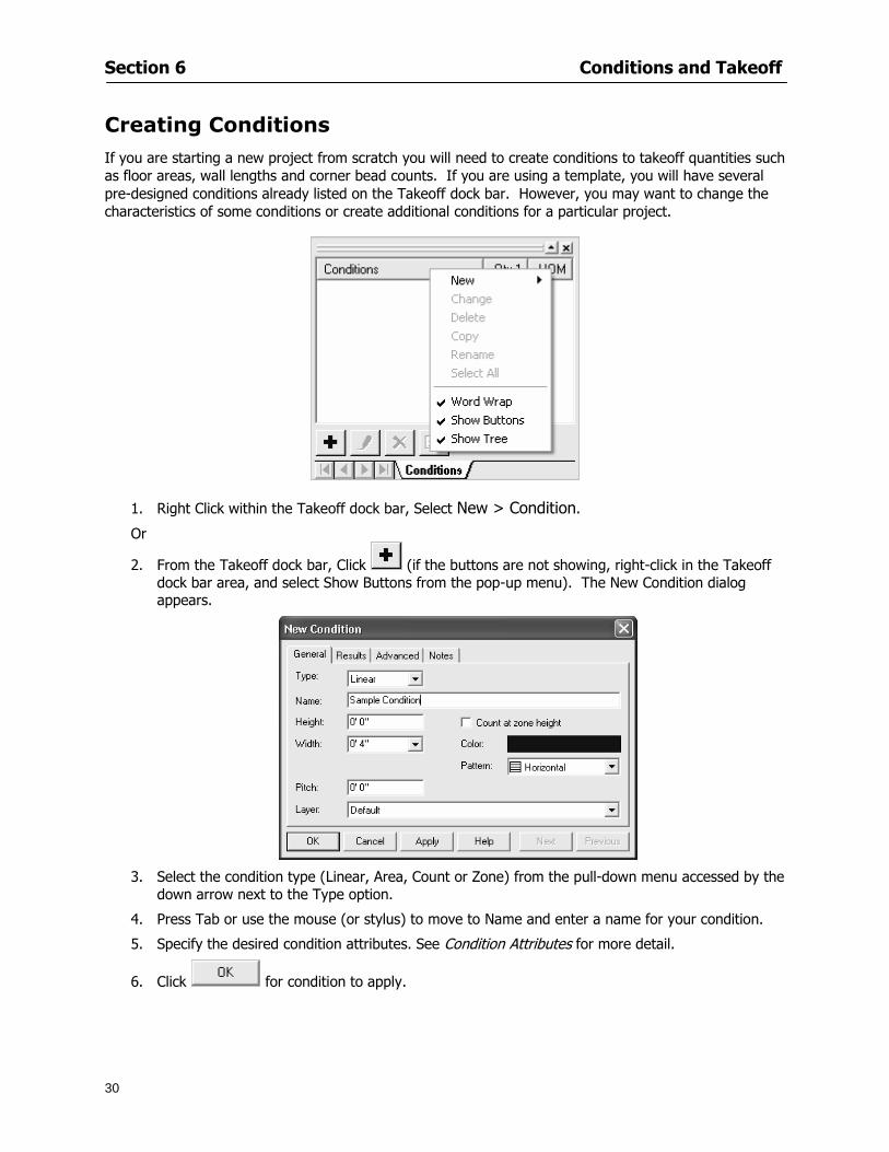
Section 6 Conditions and Takeoff
30
Creating Conditions
If you are starting a new project from scratch you will need to create conditions to takeoff quantities such as floor areas wall lengths and corner bead counts If you are using a template you will have several pre-designed conditions already listed on the Takeoff dock bar However you may want to change the characteristics of some conditions or create additional conditions for a particular project
1 Right Click within the Takeoff dock bar Select New gt Condition
Or
2 From the Takeoff dock bar Click (if the buttons are not showing right-click in the Takeoff dock bar area and select Show Buttons from the pop-up menu) The New Condition dialog appears
3 Select the condition type (Linear Area Count or Zone) from the pull-down menu accessed by the
down arrow next to the Type option
4 Press Tab or use the mouse (or stylus) to move to Name and enter a name for your condition
5 Specify the desired condition attributes See Condition Attributes for more detail
6 Click for condition to apply
Section 6 Conditions and Takeoff
31
Condition Attributes Each condition type will have related attributes to select or specify within the General and Advanced tabs of the New Condition dialog Once a condition has been used to takeoff a quantity from your plans certain attributes cannot be changed
All conditions allow the user to specify color and fill pattern for the object drawn
Linear Conditions
General Specify width and height by feet and inches Specify pitch in inches up to the nearest thousandth of an inch if applicable
Advanced Specify rounding for object quantities and droprun default length for electrical or plumbing drops at the ends of lines Select Connect to have lines connect at the corners where one line of the condition ends and another begins (and indicate Tolerance for the featurersquos activation as distance between the ends of two lines) Choose Trim to have lines automatically trim to a line being crossed Choose Curve to draw a curved line
Follow these examples for inputting feet and inches For 7 feet 6 inches type 706 for 13 feet 7 inches type 1307 For 20 feet type 2000
Section 6 Conditions and Takeoff
32
Area Conditions
General If needed you can specify the thickness (in inches) andor pitch (in inches)
Advanced Specify rounding for object quantities Choose to display an adjustable grid within the area and indicate matrix cell dimensions
Section 6 Conditions and Takeoff
33
Count Conditions
General
Specify height and indicate the size (in inches) and shape (square circle triangle rectangle or opening) of the count object as it will appear on screen
Advanced Count conditions have advanced attributes These options are available for all shapes except for openings
Zone Conditions Zones allow you to subdivide condition quantities making it easier to modify and complete jobs in phases They can be used at the end of a takeoff to isolate a group of condition quantities that are in different areas of the takeoff
Zones can also be used to break a takeoff into multi-phases and can even be used to isolate quantities while a job is in progress to group the amount of work that has been completed to date They can be applied to one or multiple pages in your plans automatically calculating the takeoff quantities for each zoned area
Section 6 Conditions and Takeoff
34
The zone feature is only available in Lite and Full Mode If you are in View Mode and would like
to use this feature click from the main toolbar to purchase the upgrade
Condition Notes A Note tab is provided for comments regarding the condition These notes will display on the Takeoff List report and will import into Quick Bid
Section 6 Conditions and Takeoff
35
Condition Results The Results tab of the New Condition is based on condition type Initial settings default to linear feet (LF) for linear conditions square feet (SF) for area conditions and count of items (EA) for count conditions and zones The first of the results fields will display for the condition items in the Takeoff dock bar area All results will display in worksheets and Takeoff List reports as well as in an Excel spreadsheet after being exported
Copying Conditions You may use the condition attributes from a condition yoursquove already created for any future conditions of the same type
1 Click on a condition to select it
2 Click the Copy button from the toolbar
OR
3 Right-click in the Takeoff dock bar area and select copy
4 A new condition will appear in the list with the same condition attributes as the previous condition but with the quantities zeroed
Editing Conditions Once you have copied a condition you might want to change several attributes You can also edit an existing condition to fit any updated needs
1 Highlight the desired condition on the Takeoff dock bar
2 Click the Change button
OR
3 Double-click on the condition you wish to edit to bring up the Change Condition dialog
NOTE The Change Condition dialog differs from the New Condition dialog only in that if takeoffs
Section 6 Conditions and Takeoff
36
have been performed in your project with this condition you will not be able to change the type of condition or certain properties under the advanced tab of the dialog box
Deleting Conditions 1 Click on the condition in the Takeoff Dock bar area
2 Click the Delete button on the toolbar
OR
3 Right-click and select Delete from the pop-up menu
All takeoff associated with the deleted condition will be deleted immediately and permanently
Organizing Project Conditions Within your project you can create folders andor sub-folders for different types of conditions You may even want to create a folder containing conditions with reset values
To get started organizing your conditions make sure you are viewing the condition tree (right-click in the Takeoff dock bar area and select Show Tree)
Creating Folders and Sub-Folders 1 Right-click in the Takeoff Dock bar area
2 Select New gt Folder from the pop-up menu
Copying Folders
1 Click on the folder and click Copy on the toolbar
2 All copied conditions within the new folder will have values reset to zero
Renaming Folders
1 Click on the folder
2 Right-click and select Rename from the pop-up menu
3 Enter a name for your folder and click the Enter button
Changing Condition Order
You may move conditions up or down in the condition list of the Takeoff dock bar to suit your project needs
1 Select the condition you would like to move by clicking to highlight it
NOTE When you are ready to move the highlighted conditions be sure that you start
moving using the last condition chosen That condition will have a highlighted boarder
Section 6 Conditions and Takeoff
37
2 Drag and drop any the condition from one place to another in the list You may also move a condition to another folder on the list in this way
Drawing with Conditions Snap Angles Set up snap angles to prevent lines from appearing jagged Snap angles are commonly set at 15deg and shift snap angles at 0deg
1 Go to Tools gt Options Options dialog appears
2 Under the General tab make the desired settings
3 Click to save the settings As they are drawn lines will snap to the set degree
Drawing a Linear Object 1 Select a condition from the Condition List in the Takeoff dock bar
2 Move the cursor into the Image takeoff area of the screen you will see the cursor display as crosshairs
3 Click and hold left mouse button then drag mouse to draw a line
4 Release mouse button to set line
Section 6 Conditions and Takeoff
38
5 Repeat steps for further lines
Continuous Mode This feature allows you to draw an object that has connected lines
1 Click the icon from the Takeoff toolbar
OR
2 Go to Tools gt Continuous Mode
3 Follow steps 1-3 from Draw a Linear Object
4 Click at each point of intersection The object will be connected
5 Double-click after making the final point to set the lines
Drawing a Curve To draw a curved line the Curve option must be checked under the Advanced tab of the Condition dialog
1 Click where you want to begin the curve and drag in a straight line to the position for the other endpoint of the curve
2 Click on the line to select it Handles in the shapes of small squares will appear at either end of
Section 6 Conditions and Takeoff
39
the line and in the center of the line
3 Move the cursor over the center handles until the cursor becomes a two-way arrow
4 Click and drag in the direction of the curve bending the line as you move the cursor Release to set the curve (The line you began with will disappear)
Draw a circle by drawing two curved lines connected
Drawing an Area Object Area conditions are drawn similarly to continuous mode lines You may trace any number of adjoining walls at different angles to complete your area takeoff
NOTE When drawing an area do not intersect the perimeter or line of the object you are drawing
1 Click at each point
2 Double-click when yoursquove returned to your starting point
3 The area will be filled with the pattern set for that condition
NOTE The simulated circle will be good enough for you to be able to make a bid
To create a circular area click from point to point with very short distances in between points simulating a circlersquos perimeter Double-click after setting the last point to set the area
Section 6 Conditions and Takeoff
40
Grid Options Grids give you an added advantage when installing materials such as tiles Use this feature to get a count for how many tiles are needed for an area
1 Double-click on an area condition in the Takeoff dock bar to open its Condition dialog
2 Click on the Advanced tab to show its options
3 Check the box next to Grid by clicking in it
4 Indicate the dimensions of the cell matrix in inches (For example 200 x 400)
5 Under Results tab choose each (EA) for one of the results fields This will tabulate a number of grid cells (including partial grid cells) in area
6 Click to save your settings
7 Use the Move Grid and Rotate Grid features in the Tools menu to manipulate the grid as desired
Grid Calculation
1 Go to Tools gt Options menu
1 Specify if On-Screen Takeoff automatically should Calculate Grid Position
2 If AreaGrid Size is selected On-Screen Takeoff will calculate the number of items needed to fill the grid based on grid demintions
3 Click to accept and close the dialog
To move a line at any angle (regardless of default setting) press the Shift key while moving the mouse
Section 6 Conditions and Takeoff
41
Backout Mode This feature allows you to take out part of an area and deduct that amount of square footage
1 Select Tools gt Backout Mode
2 Outline the are you want backed out as you would when drawing a regular area object (see Drawing an Area Object)
3 The outlined area will clear and quantities will be recalculated
NOTE The perimeter of the backout area will be added to the LF quantity for that condition
Drawing a Count Object Square triangle rectangle and circle shaped count objects can easily be placed on images
1 Select the condition
2 Click in the location where you want the object to appear
3 To place an opening-shaped count item like a door or window you must click over an existing linear object such as a wall
4 On the Results tab you can change the height properties to give you the result you need
5 If Backout is checked on the advanced tab for each count opening the opening-shaped count item will back out a corresponding section of the linear object
Opening shaped count items are sized at 3rsquo0rdquo by default
Drawing a Zone Zones are drawn in the same way as area objects and may be any polygonal shape You may trace any number of adjoining walls at different angles to complete the zone perimeter
1 Click at each point
2 Double-click when yoursquove returned to your starting point
Section 6 Conditions and Takeoff
42
Selecting Objects
1 Use the Select Tool to select objects
You can also select all objects that correspond to a condition
1 Click on a condition to select it
2 Right-click and choose Select All
3 All objects with this condition will be highlighted with squares as an outline
Moving and Resizing Objects Linear
1 To move or resize a linear object click anywhere on the line to select it
2 To move the line position your pointer over the center handles When the mouse is positioned over the handles you will see a two-way arrow You will only be able to move the line in the direction of the arrows
3 Drag the line to a new position
4 Clicking and dragging the handles on the ends of the line will allow you to lengthen or shorten your line
Area and Zone
1 To move an area object or zone in its entirety click and drag it to its new position
2 Grabbing a handle at a corner or intersection of the object will allow you to adjust and change its perimeter
Section 6 Conditions and Takeoff
43
Count 1 To move a square circle rectangle or triangle shaped count object click and drag
2 Click and drag an opening shaped count object along the length of the linear object to the desired position then release
NOTE An opening shaped count object may not be moved from its associated linear condition object however it may be moved up and down the length of the linear object
Layers On-Screen Takeoff allows you to sort and separate your takeoff objects within the same job and on the same page On-Screen Takeoff gives you this flexibility through the use of layers
By assigning different conditions to different layers (for example differentiating between floors ceilings and walls) you can choose to view all layers or turn off certain layers to display and print the remaining groups of conditions only You may also remove the background image of electronic plans add text and hot link symbols or print only your condition takeoffs
Layers are only available in Full Mode If you are in View or Lite Mode and would like to use this
feature click from the main toolbar to purchase the upgrade Default Layers
On-Screen Takeoff begins every project with three default layers Image Annotation and Default The Image layer holds the electronic plan files you may have in your project The Annotation layer possesses all text notations highlighting and hot links in the project The Default layer will appear in the Condition dialog when creating or editing a condition (listed in the takeoff dock bar) Conditions are assigned to the Default layer unless otherwise specified by the user
Creating Layers To assign a condition to a layer other than the default layer you must first create additional layers for your project
1 Select View gt Layers to open the Layers dialog
2 Click An unnamed layer will be added
3 Click within the empty box and type a name for your layer (for example Wall)
4 New layers are added as active layers The adjacent box under the Show column will be checked
Section 6 Conditions and Takeoff
44
Assigning a Layer to a Condition 1 Open the Condition dialog box by creating a new condition or editing an existing condition
2 Under the General tab click on the down arrow in the Layer field to display optional layers
3 Select the desired layer for the condition Only the Default layer and layers you have added will be displayed
4 Click
View and Hide Layers
1 Select View gt Layers
2 Under the Show column check the box to view or remove the check (by clicking on it) to hide the specific layer
3 Click to accept and close the Layers dialog
Section 6 Conditions and Takeoff
45
Assigning Text to a Layer When adding text to an image On-Screen Takeoff has the capability to assign the text to a specified layer
1 Select the Text Tool
2 Click at the point you want to place your text
3 Type in your text using the Enter key for line breaks
4 Click the drop down arrow next to the Layer field and select the desired layer
Section 7
46
Printing and Exporting
This section will
Printing options and procedures
Exporting data by copying and pasting
Exporting quantity results to Excel spreadsheets
Section 7 Printing and Exporting
47
Print Setup On-Screen Takeoff allows the user to print the image takeoff list and worksheet
1 Select File gt Print Setup The Print Setup dialog will open
2 Select a printer or leave the default selection listed (change from the default printer displayed by clicking on the down arrow at the right of the field)
3 Indicate page size and printer tray option (Source) Access page size options by clicking on the
down arrow at the right of the field
4 Choose Portrait or Landscape orientation
5 Click to accept and close the dialog
Printing Images The image area can include the electronic plans the takeoff objects added text and hot links To print a subset of these (for example just the takeoffs without the plans or the added text and hot link symbols) hide layers that you do not want to print (see Section 6 View and Hide Layers) When you are printing your images every page will show the scale of the takeoff you are printing
1 Click on the Image tab to display the area of your project
2 Select File gt Print (or Ctrl + P)
Section 7 Printing and Exporting
48
3 Select the desired view (What to print) and the Image Range
4 Click The second Print dialog will open
5 Change settings accordingly or click if you accept the default settings
Printing Takeoff Lists and Worksheets In Takeoff Lists and Worksheets you may hide columns to print only certain results or adjust column widths to fit the report within the page size selected
1 In Takeoff List or Worksheet view move your cursor to the right side of the columnrsquos title bar the cursor will display as a two-way arrow
Section 7 Printing and Exporting
49
2 Click and drag to adjust the width of the column Holding the mouse button you may
slide the title bar under the title bar to its left to hide the column completely
3 Select File gt Print or press Ctrl + P to access the Print dialog
4 Indicate desired printer and choose the number of copies
5 Click to print and close the dialog
When printing the condition list we suggest printing in landscape
To reset to the default column widths double-click on the right border of a column heading will reset the column to its right (or previously to its right before being hidden)
Print Preview 1 Select File gt Print Preview
2 Use and to vary your view 3 If viewing an image choose current full or scale view to see how it displays
4 For printed outputs that cover more than one page use and to view adjacent pages or click on the down arrow next to Page field and select the page you want displayed
Exporting Using the CopyPaste Feature You may copy all the data or sections from the worksheet and the takeoff list view in On-Screen Takeoff and paste it into another application When pasting into Excel the cell layout will be maintained
1 Highlight the areas you wish to paste Click and hold the left mouse button down as you drag the cursor over the area to be selected then releasing the mouse button
OR
2 Select the entire takeoff list quickly click on the left On-Screen Takeoff column header and hold and drag the cursor across the remaining column headings
The number of pages for the view selected will display in the lower left-hand corner The zoom percentage that applies to the view will be displayed in the lower right-hand corner next to page size of the drawing
Section 7 Printing and Exporting
50
3 In the worksheet view you may highlight rows by clicking on the numbered buttons to the left of each row clicking and dragging across column headings or clicking and dragging over individual cells in the worksheet
Click anywhere in the appropriate view to deselect the area
4 Once your selection is highlighted you may select Edit gt Copy or Ctrl C from the keyboard 5 On your monitor switch to the application into which you want to paste your selection 6 Select Edit gt Paste in the new application or simply press Ctrl + V to paste
The colored keys for conditions cannot be pasted
Using the Export Feature You may export condition quantities to specified cell location within an Excel worksheet file Cell target locations are assigned in the Results tab of the condition dialogs on the Export line relating to each quantity measurement type
On-Screen Takeoff will export takeoff quantity results for up to three different quantity types that you specify For instance you may want to know the number of square feet in a ceiling area as well as the number of linear feet in its perimeter
Section 7 Printing and Exporting
51
1 Bring up the Condition dialog by double-clicking on a condition in the takeoff dock bar or by
selecting the condition and clicking
2 Click on the Results tab to access its fields The default quantities for the condition type will display
3 For each results field click on the arrow to access the pull-down menu and select the appropriate quantity (for example SF LF EA etchellip)
4 Have your Excel spreadsheet opened and saved in a file
5 Specify the Excel spreadsheet cell locations where you want the results to go
6 For a cell in the first sheet of your spreadsheet type in the cell address (eg a1) Case is not important
7 For a cell on a successive sheet of your spreadsheet type in sheet the number followed by a comma and the cell address without any spaces (eg sheet2a1) Case is not important
8 Click
9 Select File gt Export gt Condition Qty to Excel
Section 7 Printing and Exporting
52
10 Browse to the location of the Excel spreadsheet file click file to select it
11 Click to export On-Screen Takeoff results to specified cell locations in the Excel file When you return to the Excel application you will see the values have been added to the specified cell locations in your spreadsheet
12 Save your Excel file
Exporting Worksheet to Excel
1 Assign condition quantities you want to export
2 Open saved Excel spreadsheet file to which you will be exporting
3 From On-Screen Takeoff Select File gt Export gt Worksheet to Excel
4 Browse to the location of the Excel spreadsheet file click file to select it
5 Click When you return to the Excel application you will see the values from the Worksheet Tab have been added to your spreadsheet
6 Save your Excel file
Exporting Takeoff to CVS 1 Assign condition quantities you want to export
2 Open saved Excel spreadsheet file to which you will be exporting
3 Click the Takeoff Tab in the project you want to export the information
4 Select File gt Export gt Takeoff to CSV
5 Browse to the location of the CSV spreadsheet file click file to select it
6 Click the Save
NOTE CSV files can be opened in Excel Lotus Access etc One may consider this option more of a ldquodumprdquo into a file
The Excel application must be active (it may be minimized on the application bar) with the target spreadsheet open in the application Otherwise an error will occur with the export operation that will affect both the On-Screen Takeofftrade file and the Excel spreadsheet
Section 8
53
Advanced Features
This section will
Some special features of working with condition objects in the takeoff area
Details of advanced options for conditions
Advanced features of the Project Properties dialog
Section 8 Advanced Features
54
Features to Use with Objects Roping Feature You can move copy or delete using this feature Using the Select tool (the pointer) you may select several objects at once by clicking and dragging an outline around the objects then releasing the mouse button Roping may select either objects completely within the outlined area (inclusive) or objects both within and touched by the outlined area (touching) Specify your roping preference under Tools gt Options
1 Click and hold the mouse button at a point on the screen near the objects to be selected and drag to surround the objects with an outline
2 Release the mouse button The objects will be selected
3 You may now
Move the group around on the page by clicking within the group dragging the mouse and releasing the button to place the objects
Delete the group of objects by clicking the Delete key or
Copy and paste by pressing Ctrl C to copy the group then Ctrl V to paste it The pasted copy of the grouped objects will appear slightly offset from the original objects
Section 8 Advanced Features
55
Applying a DropRun Count
Use the droprun feature when calculating quantities to take into account the drop or run of a linear condition such as electrical lines or plumbing pipes Drop or run lengths may be added separately to any linear condition on screen while a default droprun length may be indicated for a condition as a whole
1 Select the desired linear condition from the Condition List in the Takeoff Dock bar
2 Click the Change button in the toolbar to open the Change Condition dialog
3 Click the Advanced tab to access the advanced options and click inside the DropRun check box
4 Enter a default length to be applied to all of this condition Entering 800 will be interpreted as 8 0 (You must enter both place markers for inches) You can leave the length blank and manually enter drop run on each segment drawn
5 Click the OK button to accept and close the dialog
Edit DropRun Count
1 With the related linear condition in the Takeoff Dock bar highlighted or with the pointer tool selected
2 click on the desired linear object in the image takeoff area The Count button will become active
3 Click on the Count button (alternatively select Tools gt Count) The default droprun amount will show in the pop-up Count dialog (Default length will be zero if droprun has not been selected in this conditionrsquos properties)
4 Type in the desired length Entering 800 will be interpreted as 8 0 (You must enter both place markers for inches)
5 Click the OK button The additional amount will be reflected in the corresponding quantity The new DropRun count will apply only to the object edited
Adding Text in Image View
On-Screen Takeoff allows you to place text comments around your quantity takeoffs that may be printed along with plan images and objects Text is automatically placed within the Annotation Layer (that includes text and hot links)
1 To place text on the image select the Text Tool and click at the point you want to place your text opening a text box
2 Type in your information clicking Enter for line breaks
3 When you are finished click the OK button to exit the text box
4 To reposition text simply click on the text (with the Text Tool active) to select it
5 Move the cursor over the text the cursor will now display as a four-way arrow
6 Click and drag the mouse to position the text as desired
Section 8 Advanced Features
56
1 To edit existing text use the Text Tool to double-click on the text to open the editing box
2 Enter additional text or use the Backspace key to delete text as necessary
Formatting Text Once created you may format the font size type style and color of your text
1 Click on the text to select it and select Tools gt Font or click on the Font button in the Takeoff Toolbar
2 Select the desired features (color options are disabled) and click the OK button
3 Click on the text to select it and select Tools gt Color or click on the Color button in the Takeoff Toolbar The Color dialog will open
4 Click on a color in the Basic Color palette or create a color and add to the Custom Colors palette (Be sure to click on the color in the Custom Colors palette to select it)
5 Click the OK button
Object Properties
Linear Objects
Linear objects may be set to connect at corners
A linear object may be set to trim automatically when crossing another linear object (Check the trim option under the advanced tab of the Condition dialog)
When you move a connected linear object objects automatically move and resize connected lines accordingly (quantities are then recalculated)
This feature requires that the connected linear object be moved using the center handles (does not apply when resizing the line from the ends)
Objects constrain to snap increments defined in the Tools gt Options menu (with the mouse 15deg by default incremental when shift key is held down)
Objects are measured from centerline to centerline
Section 8 Advanced Features
57
Area Objects When drawing an area use your escape key to undo the last line drawn You may reverse your
drawing of an area using the escape key
The area will not fill with color and pattern until the user double-clicks after the last line is set
Lines drawn to delineate an area object constrain to snap increments defined in the Tools gt Options menu (with the mouse 15deg by default incremental when shift key is held down)
After selecting an area to move or adjust position the mouse in the center to move the entire area position the mouse at the sides or corners to adjust the perimeter
Count Objects
All count objects are quantified by the physical number of objects per page and reported as EA for the UOM The quantity for the current Image View is (displayed in the Condition List) and the total quantity in your project is displayed in the Takeoff View and Worksheet View)
Square circle rectangle and triangle shaped count objects do not displace or subtract from other object quantities when placed on top of them However on the Advanced Tab for the count condition a connect property can be set (this is a check box) so that when a count object of this shape is put on top of a Linear type takeoff object it will move with the linear if said linear is moved
An opened-shaped count object must be placed within a linear object Opening shaped count objects may also be measured by linear foot or linear yard (EA SF and SY are also options) Opening shaped count items default to a width of 3rsquo 0rdquo at the time of creation This size can be changed The small medium and large size are not options on this type of condition anymore Check Backout on the Advanced tab for each Count object back out the footage (or yardage) of opening-shaped count objects in which they are placed
NOTE In order to see this Backout functionality (in quantity) for SY or SF deductions at least one of the
results for the Linear(s) this object will be placed on must be set to SY or SF and the count object must have a height quantity
Advanced Features of Conditions The Round Feature Under the Advanced tab of the linear and area Condition dialogues you may specify quantity rounding (in inches) For linear objects rounding applies to each linear object drawn For area objects rounding will apply to each segment of the area perimeter adjusting the perimeter and area calculations For example With a linear condition entering 12 in the Round field will round up each related linear object to the nearest 12 inches or one foot With this setting two walls of 1 4 would each round to 2 0 totaling 4 0
NOTE In the Takeoff Dock bar condition list and in the On-Screen Takeoff reports quantities will be displayed in whole numbers rounded up to the nearest foot However calculations are based on true quantities without rounding unless the Round Feature is engaged
Pitch Pitch may apply either to linear or area conditions It is measured in rise per linear foot Entering 12 indicates a 12 rise per 12 of linear distance (a pitch of 12 over 12) or an angle of 45deg
Section 8 Advanced Features
58
Advanced Features of Project Properties Selecting Multiple Pages
1 Select a single page entry by clicking on the numbered gray button to the left of the entry
2 Drag the cursor down the column of numbers to select consecutive pages
3 Click on the blank button at the top of this column to select all pages in the Properties dialog
Section 8 Advanced Features
59
Changing Image Assigned to a Drawing 1 Select the page entry by clicking on the numbered gray button to the left of the entry 2 Click the Change Image button The Change Image dialog box will appear
3 Navigate to the desired file and select by clicking on it
4 Click the Open button The electronic file assigned to the page will have been changed to reflect the new file choice
Changing Image File Path 1 Select pages as described above
2 Choose Change Folder
3 In the Change Folder dialog navigate to the appropriate folder
4 Click the OK button The file path will have been changed for the selected page entries
Delete a Page from Project Properties 1 Select the page you want to delete by clicking on its associated number (in the gray box at the
left of the entry)
2 Choose Delete Page
All Takeoff on the page will be deleted immediately and permanently
Section 8 Advanced Features
60
Advanced Features of Tool Options
Calculation Method On-Screen Takeoff has built-in calculation options to allow for faster work and faster saves until your takeoff is complete Calculation options are found by selecting Tools gt Options then clicking on the Calculation tab
Calculation method can be set to Automatic Automatic except Grids and Manual Manual will allow the program to operate more quickly while Automatic or Automatic except Grids allows the user to see quantity changes as takeoffs are made
In any mode you may press F9 to recalculate quantities for the On-Screen Takeoff current totals
Configuration Tab
When the ldquoPage Label (A01)rdquo radial button is chosen On-Screen Takeoff puts the numbered label on all the pages of in your current page indicator in your Navigate Toolbar If the Page Descriptionrdquo radial button is chosen then a description of what takeoff is on that specific page will be shown in your current page indicator in your Navigate Toolbar
This section of the configuration tab gives you options on how you want to export your information When the ldquoFolderSubfolder Namesrdquo radial button is chosen than on your file that you are exporting to will have all the conditions folders and subfolders In the Delimiter box you can choose the symbol that is needed to separate the information you are exporting Some files need semicolons () or colons () to make sure the information comes exported in is separated it the appropriate places
Section 8 Advanced Features
61
In previous versions of On-Screen Takeoff there are views that users need to have in order for them to display their information By either choosing ldquoOST 1xrdquo or ldquoOST 2xrdquo it will let the program know you want your columns of information exported in that specific format
When you have the Confirm Deletions radial button of ldquoYesrdquo chosen than every time you delete anything you will get a dialog box confirming your intentions of deletion
While working with your takeoff you have a choice to either view the legend of your conditions or hide it Choose whichever radial button that suits your needs
For those who prefer to use the Enter key to navigate in dialog boxes this option is just for that
Font Tab The Font tab is designed for you to make your own look and feel for the application At the bottom of this tab it will show you sample of the fonts and colors you have chosen
Renaming the Current Page You may change the name of the current page in the takeoff area of On-Screen Takeoff by selecting Edit gt Rename Page
This opens the Name Page dialog and you may simply type in a new name and click the Enter button The new name for the file will be reflected on the title bar for the page and in Project Properties
You also may access the Rename Page function by right-clicking in the takeoff area while in Image View and selecting the option from the pop-up menu that appears
Section 9
62
Saving and Exiting
This section will
Explain how to save projects
Show you how to safely exit the program
Section 9 Saving and Exiting
63
Saving Your Project
1 Select File gt Save 2 If your project has not previously been saved a Save dialog box will open to allow you to name
the file and choose the directory and folder in which to save your file 3 Once saved File gt Save will simply save the current version of the file
OR
4 Select File gt Save As then type in a new name for the file and save to the desired file path
The Auto-save Feature With the Auto-save feature On-Screen Takeoff automatically backs up your open project You may choose to have more than one level of backup files The first backup copy will have the extension b00 and successive files will be b01 b02 and so on If you have designated four levels of backup files after the fourth backup copy has been created (b03) the next file will be saved over the file with extension b00 Further backup saves will then rotate through the four backup files in the same way
1 Select Tools gt Options 2 In the Auto-save area (under the General tab) select the frequency of backup file creation (in
minutes) and the number of levels for the feature 3 You also may disengage the feature by clicking in the check box to clear it
The Auto-save feature automatically saves backup copies to the directory of the current project If you are working from a write-protected area such as a CD-ROM On-Screen Takeoff will place backup files in the On-Screen Takeoff folder
Exiting When you are finished using On-Screen Takeoff it is very easy to exit Exiting is very important because of security reasons If someone were to use your computer they could enter the application and view and manipulate information
Section 9 Saving and Exiting
64
On-Screen Takeoff closes the open project when you open another or create a new project or when you exit the program
1 Select File gt Exit
OR
2 You also may click at the upper right-hand corner of the application to exit
NOTE If your latest changes to a project file have not been saved On-Screen Takeoff will ask you whether you would like to save the file and gives you the option of canceling the operation
Appendix I Installing Your Digitizer
65
Appendix I Installing Your Digitizer When you get your digitizer from GTCO you will need to connect it to your computer Follow the instructions outlined below to do this
Note For rollup digitizers the metal bar must be oriented to the top or right hand side
Connecting the Digitizer 1 Lay the digitizer out flat 2 Connect the Stylus to the digitizer 3 Plug in the power adapter 4 Plug the interface (IO) cable into the digitizer 5 Plug the other end of the interface cable into an open serial port on computer
Note GTCO Technical support phone number is 410-381-6688 The electronic manual (on diskette) from GTCO contains more detailed installation and operation instructions for the GTCO digitizer model you have
Installing other Digitizer Drivers If you are using a GTCO Digitizer you will need to install the GTCO TabletWorks Drivers
If you are using a Digitizer not supported by GTCO Tablet Works 10 please contact the manufacturer of your digitizer for assistance with installation
Installing GTCO TabletWorks Drivers 1 Insert the On Center CD into the CD-ROM drive The CD Startup screen will open 2 Click on Install Software 3 Select Additional Software and Drivers 4 Select Digitizer Driver 5 Follow the instructions for installing TabletWorks 10
Adhering the Template The template is a small plastic sticker used to enable mouse function when using the digitizer with On-Screen Takeoff Place your template on your digitizer We suggest placing it in the bottom right corner of the digitizer about one inch inside the takeoff area
Note You may either peel off the back of the template and use the adhesive surface or you can tape the template down
Appendix I Installing Your Digitizer
66
Testing the Digitizer Drivers Before running OST you may test the digitizer by moving the stylus around on the digitizer pad it should move the mouse cursor (if mouse emulation is enabled)
If the digitizer does not move the mouse cursor on the screen
The superset codes may need to be reset Reset the superset codes by touching on the border of the digitizer with the stylus The digitizer should beep several times
The digitizer may not be communicating with the computer Be sure the COM port selected is correct Be sure the COM port selected is correct If you are not able to get the digitizer to move the mouse cursor you need to call GTCO technical support for help
Note The Mouse Emulation is not required for On-Screen Takeoff to work properly It is used only for the Template functionality if the digitizer is moving the cursor the wrong direction (up instead of sideways or vice-versa)
Click the L-shaped arrow symbol on the digitizer with the stylus
Appendix II Toolbar Item Details
67
Appendix II Toolbar Items Main Toolbar
Appendix II Toolbar Item Details
68
Tool Toolbar
Appendix II Toolbar Item Details
69
Zoom Toolbar
View Toolbar
Navigate Toolbar
Appendix II Toolbar Item Details
70
Navigate Toolbar (Continued)
Takeoff Toolbar
Appendix II Toolbar Item Details
71
Takeoff Toolbar (Continued)
Image Toolbar
Appendix III Loading Plans from a Dodge CD
72
Appendix III Loading Plans from a Dodge CD
This section will detail how to load plans from a F W Dodge CD-ROM into an On-Screen Takeoff project file ready for takeoffs
Dodge files may be added to the Project Properties dialog However loading the files in that way will load the files by number rather than name description If you want to load one page only from your Dodge CD You will have to rename the page to display the name rather than number of the file
To load plan files from a Dodge CD so that the files load sequentially by file number but are displayed by name rather than by number within your project follow the instructions below
Opening a Dodge project from a CD-ROM 1 Insert the CD into the drive 2 Choose File gt Custom 3 Choose Dodge Plans Project (plansdat) as the file type 4 Select the appropriate file type by clicking on the down arrow at the right of the Files of type
field 5 In the Look in field access your drive paths by clicking on the down arrow at the right of the
field then
Navigate to your CD-ROM drive Open the data folder and Open the Projects folder
6 Select the desired project and open its folder 7 Open the plansdat file 8 All the images will come in sequenced correctly for that job along with the full descriptions
(names) of each page If there is not a plans folder in the project folder then plans do not exist for that project on the CD Opening the plansdat file will yield an empty project
Appendix IV Using the Plan Viewer
73
Appendix IV Using On-Screen Takeoff Plan Viewer The On-Screen Takeoff Plan Viewer is a limited version of On Center Softwarersquos commercial takeoff software If your status bar located at the very bottom of the main window says View Mode in the lower left-hand corner then you are using the Plan Viewer You can use the plan viewer to
View CD-based amp converted CAD drawings
View a previously created OST file and associated drawings
Download electronic plans online
Navigate through drawings
Quickly Takeoff linearsareas and counts
Zoom in to view the plan better
Print drawings directly from the viewer
Viewing an On-Screen Takeoff Project File
1 To open an OST file that was previously created with of On-Screen Takeoff 2 Select File gt Open 3 An Open dialog will appear if you do not see the OST file you are looking for select the
Look In drop down arrow 4 A drop down menu will appear listing the various folders drives and mapped drives located
on your computer select the correct drive or folder location and continue to browse to the location of your OST file
5 When you see your OST file double-click it to open it 6 Any takeoff and drawings should appear on the Image tab view
If you do not see the drawings but do see the colored takeoff layer the drawings may
not be located in the same place they were originally saved at Go to File gt Project Properties and check the Image File path for each listed page If the image file path is pointing to a CD drive make sure the CD is inside the CR-ROM
Downloading Electronic Plans If your Online Plan Service provides a special file format (OSX) required to use this feature of our plan viewer you can immediately downloaded all electronic plans of a project directly from our viewer
Most Plan Room web sites will automatically open On-Screen Takeoff when a request to download plans is made Your particular Plan Room may differ in operation so please contact the provider directly with questions on using the site
Appendix IV Using the Plan Viewer
74
When you request to download or open a project file from a Plan Room you will usually have the open to open or save an OSX file Choosing open will automatically open On-Screen Takeoff Alternately you may choose to save the file to a local hard drive After you have saved the file either double-click it to launch On-Screen Takeoff or open the OSX file using On-Screen Takeoff by clicking File then Open and locating the file on your hard drive You will need to change the file type to OSX
After the OSX file is opened you will see an additional tab appear in the Conditions List window called Pages
The Pages tab shows the hierarchy of your project Gray file icons represent pages that have not been downloaded and blue icons represents pages that have been downloaded
To download a page simply double-click the page icon
If you wish to select a group of pages to download you can use the Ctrl or Shift key to multiple select them then click the Download button
If you wish to download all pages at once click the Download All button
Downloaded pages will now appear in the Project Properties dialog in the same order in which they appear in the Pages tab
Creating Quick Takeoffs With On-Screen Takeoff you can create quick takeoffs to measure quantities even if you dont have the full version of our program However using the Quick Takeoff functionality shows you just a fraction of what the full version can do
The Quick Takeoff Toolbar is located at the top of the image view It has three buttons designated for three types of takeoffs Linear Area and Count The Quantity drop down list will show secondary quantities for Linears and Areas The Units drop down allows you to select how you want your quantities displayed Feet Inches Yards Millimeters and Meters
NOTE Every time change the type of takeoff you are performing (switching from Area to Linear for example) the previous quantities and takeoff objects will disappear They will also disappear when you changes pages
NOTE You can use the Dimension Tool to basically measure the distance between two points or linears The distance will display on the status bar at the bottom of the application
The Quick Takeoff Toolbar
Appendix V Frequently Asked Questions
75
Appendix V Frequently Asked Questions General
Where is On-Screen Takeoff installed on my computer
Typically it is installed in CProgram FilesOn-Screen Takeoff
In Explorer how do I recognize On-Screen Takeoff file types
On-Screen Takeoff data is stored in a single file per job lsquojob name OSTrsquo On-Screen Takeoff templates are stored as lsquotemplate nameTPOrsquo
Can only one project at a time be open
Yes For that reason opening another project automatically closes the project on screen You will be asked to save any changes
Is only one scale allowed per page What about on drawings that have multiple detail sections on a page and each of those drawings have different scales
Yes For pages with drawings of different scales copy the drawing to another project page and set the appropriate scale
I cannot perform backout on an area that is along a linear
As a workaround use the On-Screen Takeoff layers feature to help you with this issue Electronic Images
How do I start a project from drawings that have been scanned and written to a CD-ROM
Open a new project Select File gt Project Properties and select Auto Add Navigate to your CD and the appropriate folder and select any image file in that location Click Open All files in the location will load into your project Recommended that images are copied from CD to hard drive for performance
If I get a disk of drawings in AutoCAD format (R13 or R14) can I read them in On-Screen Takeoff
Yes On-Screen Takeoff now reads DWG DXF and many other format that are saved with AutoCAD
Appendix V Frequently Asked Questions
76
When I click on the all pages button what is supposed to happen Currently nothing seems to change when I click on that button
The All Pages button is used to apply the Darken and Enhance Plans feature to all pages in the project (as opposed to only the current page on screen)
Is there a way to deduct a large skylight from an area condition
Yes with the related area condition selected in the Takeoff Dock bar unselect the Backout button on the Takeoff Toolbar then draw the Backout area The area quantity will be deducted from the related condition object and the linear measurement of the Backout perimeter will be added
Digitizer Issues
How do I connect a Digitizer to the computer
See Appendix I Connecting a Digitizer
The Place Template menu choice is disabled
On-Screen Takeoff may need to be authorized or the digitizer or the digitzer drivers are not installed
It wonrsquot let me select the Set Takeoff Area menu choice
On-Screen Takeoff may need to be authorized or no job is open a digitizer is not installed or the drivers are not installed
The digitizer stylus is not moving the cursor or crosshairs
Click S-0-1 superset on the digitizer
How do I convert my old GTCO Digitizer to work with On- Screen Takeofftrade
Call GTCO and they may be able to reconfigure your digitizer to be compatible with On-Screen Takeoff
Printing Issues Which Printers work with On-Screen Takeoff
Compatible printers include On-Screen Takeoff Hewlett Packard Epson and Canon printers If you are having printer difficulties please contact support and specify the type of printer along with other pertinent information Contact support at wwwoncentercomsupport or email supportoncentercom
Which Plotters work with On-Screen Takeoff
Compatible Plotters include Hewlett Packard DesignJet plotters and the EnCAD Cadjet II If you are having plotter difficulties please contact support and specify the type of plotter concerned
ViewingDisplay I can no longer see my condition list How do I get it back
The toolbars and Dock bars can be turned on and off through the View gt Toolbars menu options
Appendix V Frequently Asked Questions
77
This is also accessible by right-clicking in the toolbar area and selecting (or deselecting) a toolbar listed
I cannot view my folders in the condition list
Right-click in the Takeoff Dock barcondition list area and select Show Tree to display your folders
My Status Bar reads Viewer Mode and I am unable to draw conditions
On-Screen Takeoff needs to be Authorized Or you need to purchase an upgrade Click the Perform Advanced Takeoff button on the main toolbar
I hid a Dock bar and when I selected to view it again it appeared alongside the other Dock
bar instead of stacked on top of it How do I fix it
Pick up the Dock bar by clicking on the bar at the top and continuing to hold down the mouse button drag the Dock bar over the other one It will resize and appear stacked with the other
When I open image files from a CD the images are all upside down How do I get them right
side up
To flip pages from top to bottom follow the steps below 1 Click the All Pages button on the Image Toolbar (All Pages is engaged when the button
is not clicked) 2 Click the Flip Horizontal button on the Image Toolbar 3 Click the All Pages button again to disengage
Templates How do I create a Template
Follow the steps below 1 Create a typical project 2 Choose File gt Save As 3 Choose On-Screen Takeoff Template Files as the file type to save 4 Name the file This will save all of the condition setups as well as the layers for the
project
How do I create a new project from a template
Follow the steps below 1 Choose File gt New 2 Select a template from those listed in the New dialog This will open a new project with
conditions and layers saved from a previous project but no pages or takeoff
78
INDEX
Area Conditions 32
Area Objects 57
Auto Scrolling 20
Auto-save 63
Backout Mode 41
Calculation Method 60
Conditions 29
Configuration 60
Contents Tab 6
Continuous Mode 38
Count Conditions 33
Count Objects 57
Digitizer 10 65 76
Docking Toolbars 13
Dodge CD 72
Drawing 27 37
DropRun Count 55
Environment 18
Exiting 63
Exporting 49
Features 16
Font 61
Frequently Asked Questions 75
Grid 40
Help File 5
Hiding Toolbars 13
Hot Links 21
Image 19 59
Image files 9
Image Toolbar 12 71
Images 75
Index Tab 6
Layers 43
Linear Conditions 31
Linear Objects 56
Main Toolbar 12 67
Menus 14
Moving Toolbars 13
Navigate Toolbar 12 69
Navigating 20
On-Screen Takeofftrade 2
Page 59 61
Pages 20 25 28
Plan Viewer 73
Plans 26
Printing 47 76
Project Properties 25
Projects 22
Quick Start Video 18
Resizing Toolbars 13
Roping 54
Saving 63
Scale 28
Search Tab 7
Selecting Objects 42
Setup 8
Start On-Screen Takeofftrade 17
System Requirements 9
Takeoff 19 27
Takeoff Toolbar 70 71
Takeoff Toolbar 12
Template Files 23
TIF (Group4) 9
Tool Toolbar 12 68
Toolbar 67
Toolbars 12
View Toolbar 12 69
Viewing Toolbars 12
Worksheet 20
Zone Conditions 33
Zoom Toolbar 12 69
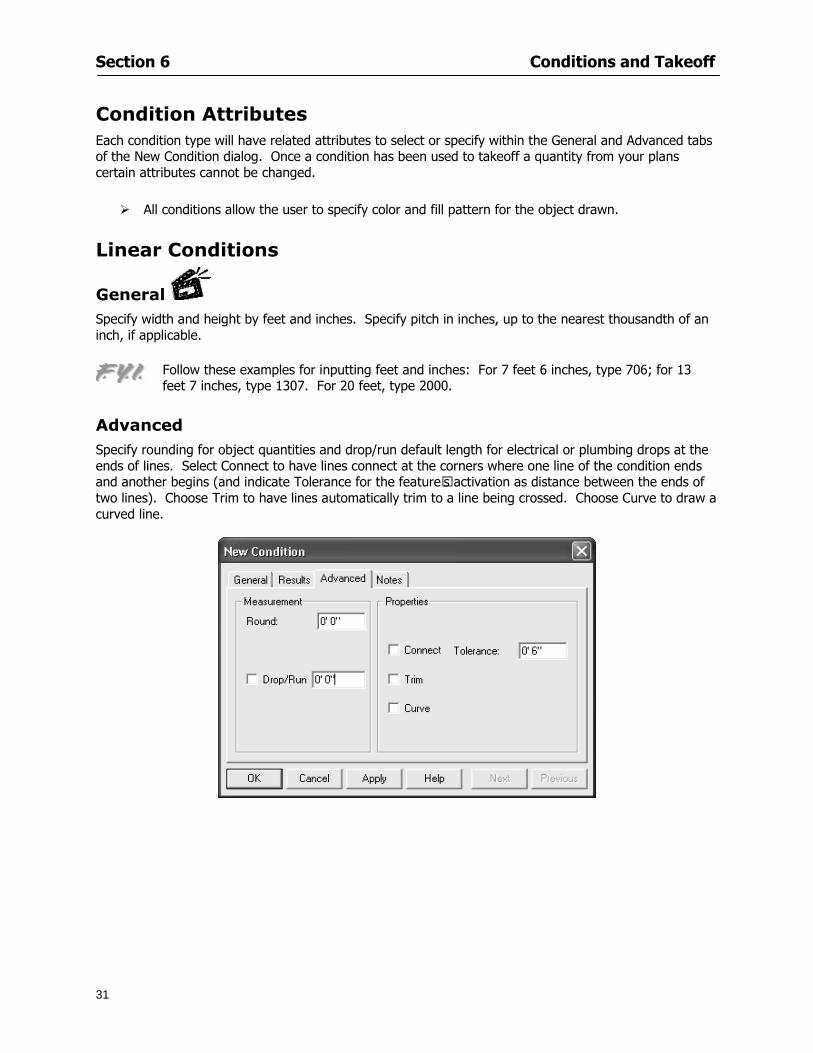
Section 6 Conditions and Takeoff
31
Condition Attributes Each condition type will have related attributes to select or specify within the General and Advanced tabs of the New Condition dialog Once a condition has been used to takeoff a quantity from your plans certain attributes cannot be changed
All conditions allow the user to specify color and fill pattern for the object drawn
Linear Conditions
General Specify width and height by feet and inches Specify pitch in inches up to the nearest thousandth of an inch if applicable
Advanced Specify rounding for object quantities and droprun default length for electrical or plumbing drops at the ends of lines Select Connect to have lines connect at the corners where one line of the condition ends and another begins (and indicate Tolerance for the featurersquos activation as distance between the ends of two lines) Choose Trim to have lines automatically trim to a line being crossed Choose Curve to draw a curved line
Follow these examples for inputting feet and inches For 7 feet 6 inches type 706 for 13 feet 7 inches type 1307 For 20 feet type 2000
Section 6 Conditions and Takeoff
32
Area Conditions
General If needed you can specify the thickness (in inches) andor pitch (in inches)
Advanced Specify rounding for object quantities Choose to display an adjustable grid within the area and indicate matrix cell dimensions
Section 6 Conditions and Takeoff
33
Count Conditions
General
Specify height and indicate the size (in inches) and shape (square circle triangle rectangle or opening) of the count object as it will appear on screen
Advanced Count conditions have advanced attributes These options are available for all shapes except for openings
Zone Conditions Zones allow you to subdivide condition quantities making it easier to modify and complete jobs in phases They can be used at the end of a takeoff to isolate a group of condition quantities that are in different areas of the takeoff
Zones can also be used to break a takeoff into multi-phases and can even be used to isolate quantities while a job is in progress to group the amount of work that has been completed to date They can be applied to one or multiple pages in your plans automatically calculating the takeoff quantities for each zoned area
Section 6 Conditions and Takeoff
34
The zone feature is only available in Lite and Full Mode If you are in View Mode and would like
to use this feature click from the main toolbar to purchase the upgrade
Condition Notes A Note tab is provided for comments regarding the condition These notes will display on the Takeoff List report and will import into Quick Bid
Section 6 Conditions and Takeoff
35
Condition Results The Results tab of the New Condition is based on condition type Initial settings default to linear feet (LF) for linear conditions square feet (SF) for area conditions and count of items (EA) for count conditions and zones The first of the results fields will display for the condition items in the Takeoff dock bar area All results will display in worksheets and Takeoff List reports as well as in an Excel spreadsheet after being exported
Copying Conditions You may use the condition attributes from a condition yoursquove already created for any future conditions of the same type
1 Click on a condition to select it
2 Click the Copy button from the toolbar
OR
3 Right-click in the Takeoff dock bar area and select copy
4 A new condition will appear in the list with the same condition attributes as the previous condition but with the quantities zeroed
Editing Conditions Once you have copied a condition you might want to change several attributes You can also edit an existing condition to fit any updated needs
1 Highlight the desired condition on the Takeoff dock bar
2 Click the Change button
OR
3 Double-click on the condition you wish to edit to bring up the Change Condition dialog
NOTE The Change Condition dialog differs from the New Condition dialog only in that if takeoffs
Section 6 Conditions and Takeoff
36
have been performed in your project with this condition you will not be able to change the type of condition or certain properties under the advanced tab of the dialog box
Deleting Conditions 1 Click on the condition in the Takeoff Dock bar area
2 Click the Delete button on the toolbar
OR
3 Right-click and select Delete from the pop-up menu
All takeoff associated with the deleted condition will be deleted immediately and permanently
Organizing Project Conditions Within your project you can create folders andor sub-folders for different types of conditions You may even want to create a folder containing conditions with reset values
To get started organizing your conditions make sure you are viewing the condition tree (right-click in the Takeoff dock bar area and select Show Tree)
Creating Folders and Sub-Folders 1 Right-click in the Takeoff Dock bar area
2 Select New gt Folder from the pop-up menu
Copying Folders
1 Click on the folder and click Copy on the toolbar
2 All copied conditions within the new folder will have values reset to zero
Renaming Folders
1 Click on the folder
2 Right-click and select Rename from the pop-up menu
3 Enter a name for your folder and click the Enter button
Changing Condition Order
You may move conditions up or down in the condition list of the Takeoff dock bar to suit your project needs
1 Select the condition you would like to move by clicking to highlight it
NOTE When you are ready to move the highlighted conditions be sure that you start
moving using the last condition chosen That condition will have a highlighted boarder
Section 6 Conditions and Takeoff
37
2 Drag and drop any the condition from one place to another in the list You may also move a condition to another folder on the list in this way
Drawing with Conditions Snap Angles Set up snap angles to prevent lines from appearing jagged Snap angles are commonly set at 15deg and shift snap angles at 0deg
1 Go to Tools gt Options Options dialog appears
2 Under the General tab make the desired settings
3 Click to save the settings As they are drawn lines will snap to the set degree
Drawing a Linear Object 1 Select a condition from the Condition List in the Takeoff dock bar
2 Move the cursor into the Image takeoff area of the screen you will see the cursor display as crosshairs
3 Click and hold left mouse button then drag mouse to draw a line
4 Release mouse button to set line
Section 6 Conditions and Takeoff
38
5 Repeat steps for further lines
Continuous Mode This feature allows you to draw an object that has connected lines
1 Click the icon from the Takeoff toolbar
OR
2 Go to Tools gt Continuous Mode
3 Follow steps 1-3 from Draw a Linear Object
4 Click at each point of intersection The object will be connected
5 Double-click after making the final point to set the lines
Drawing a Curve To draw a curved line the Curve option must be checked under the Advanced tab of the Condition dialog
1 Click where you want to begin the curve and drag in a straight line to the position for the other endpoint of the curve
2 Click on the line to select it Handles in the shapes of small squares will appear at either end of
Section 6 Conditions and Takeoff
39
the line and in the center of the line
3 Move the cursor over the center handles until the cursor becomes a two-way arrow
4 Click and drag in the direction of the curve bending the line as you move the cursor Release to set the curve (The line you began with will disappear)
Draw a circle by drawing two curved lines connected
Drawing an Area Object Area conditions are drawn similarly to continuous mode lines You may trace any number of adjoining walls at different angles to complete your area takeoff
NOTE When drawing an area do not intersect the perimeter or line of the object you are drawing
1 Click at each point
2 Double-click when yoursquove returned to your starting point
3 The area will be filled with the pattern set for that condition
NOTE The simulated circle will be good enough for you to be able to make a bid
To create a circular area click from point to point with very short distances in between points simulating a circlersquos perimeter Double-click after setting the last point to set the area
Section 6 Conditions and Takeoff
40
Grid Options Grids give you an added advantage when installing materials such as tiles Use this feature to get a count for how many tiles are needed for an area
1 Double-click on an area condition in the Takeoff dock bar to open its Condition dialog
2 Click on the Advanced tab to show its options
3 Check the box next to Grid by clicking in it
4 Indicate the dimensions of the cell matrix in inches (For example 200 x 400)
5 Under Results tab choose each (EA) for one of the results fields This will tabulate a number of grid cells (including partial grid cells) in area
6 Click to save your settings
7 Use the Move Grid and Rotate Grid features in the Tools menu to manipulate the grid as desired
Grid Calculation
1 Go to Tools gt Options menu
1 Specify if On-Screen Takeoff automatically should Calculate Grid Position
2 If AreaGrid Size is selected On-Screen Takeoff will calculate the number of items needed to fill the grid based on grid demintions
3 Click to accept and close the dialog
To move a line at any angle (regardless of default setting) press the Shift key while moving the mouse
Section 6 Conditions and Takeoff
41
Backout Mode This feature allows you to take out part of an area and deduct that amount of square footage
1 Select Tools gt Backout Mode
2 Outline the are you want backed out as you would when drawing a regular area object (see Drawing an Area Object)
3 The outlined area will clear and quantities will be recalculated
NOTE The perimeter of the backout area will be added to the LF quantity for that condition
Drawing a Count Object Square triangle rectangle and circle shaped count objects can easily be placed on images
1 Select the condition
2 Click in the location where you want the object to appear
3 To place an opening-shaped count item like a door or window you must click over an existing linear object such as a wall
4 On the Results tab you can change the height properties to give you the result you need
5 If Backout is checked on the advanced tab for each count opening the opening-shaped count item will back out a corresponding section of the linear object
Opening shaped count items are sized at 3rsquo0rdquo by default
Drawing a Zone Zones are drawn in the same way as area objects and may be any polygonal shape You may trace any number of adjoining walls at different angles to complete the zone perimeter
1 Click at each point
2 Double-click when yoursquove returned to your starting point
Section 6 Conditions and Takeoff
42
Selecting Objects
1 Use the Select Tool to select objects
You can also select all objects that correspond to a condition
1 Click on a condition to select it
2 Right-click and choose Select All
3 All objects with this condition will be highlighted with squares as an outline
Moving and Resizing Objects Linear
1 To move or resize a linear object click anywhere on the line to select it
2 To move the line position your pointer over the center handles When the mouse is positioned over the handles you will see a two-way arrow You will only be able to move the line in the direction of the arrows
3 Drag the line to a new position
4 Clicking and dragging the handles on the ends of the line will allow you to lengthen or shorten your line
Area and Zone
1 To move an area object or zone in its entirety click and drag it to its new position
2 Grabbing a handle at a corner or intersection of the object will allow you to adjust and change its perimeter
Section 6 Conditions and Takeoff
43
Count 1 To move a square circle rectangle or triangle shaped count object click and drag
2 Click and drag an opening shaped count object along the length of the linear object to the desired position then release
NOTE An opening shaped count object may not be moved from its associated linear condition object however it may be moved up and down the length of the linear object
Layers On-Screen Takeoff allows you to sort and separate your takeoff objects within the same job and on the same page On-Screen Takeoff gives you this flexibility through the use of layers
By assigning different conditions to different layers (for example differentiating between floors ceilings and walls) you can choose to view all layers or turn off certain layers to display and print the remaining groups of conditions only You may also remove the background image of electronic plans add text and hot link symbols or print only your condition takeoffs
Layers are only available in Full Mode If you are in View or Lite Mode and would like to use this
feature click from the main toolbar to purchase the upgrade Default Layers
On-Screen Takeoff begins every project with three default layers Image Annotation and Default The Image layer holds the electronic plan files you may have in your project The Annotation layer possesses all text notations highlighting and hot links in the project The Default layer will appear in the Condition dialog when creating or editing a condition (listed in the takeoff dock bar) Conditions are assigned to the Default layer unless otherwise specified by the user
Creating Layers To assign a condition to a layer other than the default layer you must first create additional layers for your project
1 Select View gt Layers to open the Layers dialog
2 Click An unnamed layer will be added
3 Click within the empty box and type a name for your layer (for example Wall)
4 New layers are added as active layers The adjacent box under the Show column will be checked
Section 6 Conditions and Takeoff
44
Assigning a Layer to a Condition 1 Open the Condition dialog box by creating a new condition or editing an existing condition
2 Under the General tab click on the down arrow in the Layer field to display optional layers
3 Select the desired layer for the condition Only the Default layer and layers you have added will be displayed
4 Click
View and Hide Layers
1 Select View gt Layers
2 Under the Show column check the box to view or remove the check (by clicking on it) to hide the specific layer
3 Click to accept and close the Layers dialog
Section 6 Conditions and Takeoff
45
Assigning Text to a Layer When adding text to an image On-Screen Takeoff has the capability to assign the text to a specified layer
1 Select the Text Tool
2 Click at the point you want to place your text
3 Type in your text using the Enter key for line breaks
4 Click the drop down arrow next to the Layer field and select the desired layer
Section 7
46
Printing and Exporting
This section will
Printing options and procedures
Exporting data by copying and pasting
Exporting quantity results to Excel spreadsheets
Section 7 Printing and Exporting
47
Print Setup On-Screen Takeoff allows the user to print the image takeoff list and worksheet
1 Select File gt Print Setup The Print Setup dialog will open
2 Select a printer or leave the default selection listed (change from the default printer displayed by clicking on the down arrow at the right of the field)
3 Indicate page size and printer tray option (Source) Access page size options by clicking on the
down arrow at the right of the field
4 Choose Portrait or Landscape orientation
5 Click to accept and close the dialog
Printing Images The image area can include the electronic plans the takeoff objects added text and hot links To print a subset of these (for example just the takeoffs without the plans or the added text and hot link symbols) hide layers that you do not want to print (see Section 6 View and Hide Layers) When you are printing your images every page will show the scale of the takeoff you are printing
1 Click on the Image tab to display the area of your project
2 Select File gt Print (or Ctrl + P)
Section 7 Printing and Exporting
48
3 Select the desired view (What to print) and the Image Range
4 Click The second Print dialog will open
5 Change settings accordingly or click if you accept the default settings
Printing Takeoff Lists and Worksheets In Takeoff Lists and Worksheets you may hide columns to print only certain results or adjust column widths to fit the report within the page size selected
1 In Takeoff List or Worksheet view move your cursor to the right side of the columnrsquos title bar the cursor will display as a two-way arrow
Section 7 Printing and Exporting
49
2 Click and drag to adjust the width of the column Holding the mouse button you may
slide the title bar under the title bar to its left to hide the column completely
3 Select File gt Print or press Ctrl + P to access the Print dialog
4 Indicate desired printer and choose the number of copies
5 Click to print and close the dialog
When printing the condition list we suggest printing in landscape
To reset to the default column widths double-click on the right border of a column heading will reset the column to its right (or previously to its right before being hidden)
Print Preview 1 Select File gt Print Preview
2 Use and to vary your view 3 If viewing an image choose current full or scale view to see how it displays
4 For printed outputs that cover more than one page use and to view adjacent pages or click on the down arrow next to Page field and select the page you want displayed
Exporting Using the CopyPaste Feature You may copy all the data or sections from the worksheet and the takeoff list view in On-Screen Takeoff and paste it into another application When pasting into Excel the cell layout will be maintained
1 Highlight the areas you wish to paste Click and hold the left mouse button down as you drag the cursor over the area to be selected then releasing the mouse button
OR
2 Select the entire takeoff list quickly click on the left On-Screen Takeoff column header and hold and drag the cursor across the remaining column headings
The number of pages for the view selected will display in the lower left-hand corner The zoom percentage that applies to the view will be displayed in the lower right-hand corner next to page size of the drawing
Section 7 Printing and Exporting
50
3 In the worksheet view you may highlight rows by clicking on the numbered buttons to the left of each row clicking and dragging across column headings or clicking and dragging over individual cells in the worksheet
Click anywhere in the appropriate view to deselect the area
4 Once your selection is highlighted you may select Edit gt Copy or Ctrl C from the keyboard 5 On your monitor switch to the application into which you want to paste your selection 6 Select Edit gt Paste in the new application or simply press Ctrl + V to paste
The colored keys for conditions cannot be pasted
Using the Export Feature You may export condition quantities to specified cell location within an Excel worksheet file Cell target locations are assigned in the Results tab of the condition dialogs on the Export line relating to each quantity measurement type
On-Screen Takeoff will export takeoff quantity results for up to three different quantity types that you specify For instance you may want to know the number of square feet in a ceiling area as well as the number of linear feet in its perimeter
Section 7 Printing and Exporting
51
1 Bring up the Condition dialog by double-clicking on a condition in the takeoff dock bar or by
selecting the condition and clicking
2 Click on the Results tab to access its fields The default quantities for the condition type will display
3 For each results field click on the arrow to access the pull-down menu and select the appropriate quantity (for example SF LF EA etchellip)
4 Have your Excel spreadsheet opened and saved in a file
5 Specify the Excel spreadsheet cell locations where you want the results to go
6 For a cell in the first sheet of your spreadsheet type in the cell address (eg a1) Case is not important
7 For a cell on a successive sheet of your spreadsheet type in sheet the number followed by a comma and the cell address without any spaces (eg sheet2a1) Case is not important
8 Click
9 Select File gt Export gt Condition Qty to Excel
Section 7 Printing and Exporting
52
10 Browse to the location of the Excel spreadsheet file click file to select it
11 Click to export On-Screen Takeoff results to specified cell locations in the Excel file When you return to the Excel application you will see the values have been added to the specified cell locations in your spreadsheet
12 Save your Excel file
Exporting Worksheet to Excel
1 Assign condition quantities you want to export
2 Open saved Excel spreadsheet file to which you will be exporting
3 From On-Screen Takeoff Select File gt Export gt Worksheet to Excel
4 Browse to the location of the Excel spreadsheet file click file to select it
5 Click When you return to the Excel application you will see the values from the Worksheet Tab have been added to your spreadsheet
6 Save your Excel file
Exporting Takeoff to CVS 1 Assign condition quantities you want to export
2 Open saved Excel spreadsheet file to which you will be exporting
3 Click the Takeoff Tab in the project you want to export the information
4 Select File gt Export gt Takeoff to CSV
5 Browse to the location of the CSV spreadsheet file click file to select it
6 Click the Save
NOTE CSV files can be opened in Excel Lotus Access etc One may consider this option more of a ldquodumprdquo into a file
The Excel application must be active (it may be minimized on the application bar) with the target spreadsheet open in the application Otherwise an error will occur with the export operation that will affect both the On-Screen Takeofftrade file and the Excel spreadsheet
Section 8
53
Advanced Features
This section will
Some special features of working with condition objects in the takeoff area
Details of advanced options for conditions
Advanced features of the Project Properties dialog
Section 8 Advanced Features
54
Features to Use with Objects Roping Feature You can move copy or delete using this feature Using the Select tool (the pointer) you may select several objects at once by clicking and dragging an outline around the objects then releasing the mouse button Roping may select either objects completely within the outlined area (inclusive) or objects both within and touched by the outlined area (touching) Specify your roping preference under Tools gt Options
1 Click and hold the mouse button at a point on the screen near the objects to be selected and drag to surround the objects with an outline
2 Release the mouse button The objects will be selected
3 You may now
Move the group around on the page by clicking within the group dragging the mouse and releasing the button to place the objects
Delete the group of objects by clicking the Delete key or
Copy and paste by pressing Ctrl C to copy the group then Ctrl V to paste it The pasted copy of the grouped objects will appear slightly offset from the original objects
Section 8 Advanced Features
55
Applying a DropRun Count
Use the droprun feature when calculating quantities to take into account the drop or run of a linear condition such as electrical lines or plumbing pipes Drop or run lengths may be added separately to any linear condition on screen while a default droprun length may be indicated for a condition as a whole
1 Select the desired linear condition from the Condition List in the Takeoff Dock bar
2 Click the Change button in the toolbar to open the Change Condition dialog
3 Click the Advanced tab to access the advanced options and click inside the DropRun check box
4 Enter a default length to be applied to all of this condition Entering 800 will be interpreted as 8 0 (You must enter both place markers for inches) You can leave the length blank and manually enter drop run on each segment drawn
5 Click the OK button to accept and close the dialog
Edit DropRun Count
1 With the related linear condition in the Takeoff Dock bar highlighted or with the pointer tool selected
2 click on the desired linear object in the image takeoff area The Count button will become active
3 Click on the Count button (alternatively select Tools gt Count) The default droprun amount will show in the pop-up Count dialog (Default length will be zero if droprun has not been selected in this conditionrsquos properties)
4 Type in the desired length Entering 800 will be interpreted as 8 0 (You must enter both place markers for inches)
5 Click the OK button The additional amount will be reflected in the corresponding quantity The new DropRun count will apply only to the object edited
Adding Text in Image View
On-Screen Takeoff allows you to place text comments around your quantity takeoffs that may be printed along with plan images and objects Text is automatically placed within the Annotation Layer (that includes text and hot links)
1 To place text on the image select the Text Tool and click at the point you want to place your text opening a text box
2 Type in your information clicking Enter for line breaks
3 When you are finished click the OK button to exit the text box
4 To reposition text simply click on the text (with the Text Tool active) to select it
5 Move the cursor over the text the cursor will now display as a four-way arrow
6 Click and drag the mouse to position the text as desired
Section 8 Advanced Features
56
1 To edit existing text use the Text Tool to double-click on the text to open the editing box
2 Enter additional text or use the Backspace key to delete text as necessary
Formatting Text Once created you may format the font size type style and color of your text
1 Click on the text to select it and select Tools gt Font or click on the Font button in the Takeoff Toolbar
2 Select the desired features (color options are disabled) and click the OK button
3 Click on the text to select it and select Tools gt Color or click on the Color button in the Takeoff Toolbar The Color dialog will open
4 Click on a color in the Basic Color palette or create a color and add to the Custom Colors palette (Be sure to click on the color in the Custom Colors palette to select it)
5 Click the OK button
Object Properties
Linear Objects
Linear objects may be set to connect at corners
A linear object may be set to trim automatically when crossing another linear object (Check the trim option under the advanced tab of the Condition dialog)
When you move a connected linear object objects automatically move and resize connected lines accordingly (quantities are then recalculated)
This feature requires that the connected linear object be moved using the center handles (does not apply when resizing the line from the ends)
Objects constrain to snap increments defined in the Tools gt Options menu (with the mouse 15deg by default incremental when shift key is held down)
Objects are measured from centerline to centerline
Section 8 Advanced Features
57
Area Objects When drawing an area use your escape key to undo the last line drawn You may reverse your
drawing of an area using the escape key
The area will not fill with color and pattern until the user double-clicks after the last line is set
Lines drawn to delineate an area object constrain to snap increments defined in the Tools gt Options menu (with the mouse 15deg by default incremental when shift key is held down)
After selecting an area to move or adjust position the mouse in the center to move the entire area position the mouse at the sides or corners to adjust the perimeter
Count Objects
All count objects are quantified by the physical number of objects per page and reported as EA for the UOM The quantity for the current Image View is (displayed in the Condition List) and the total quantity in your project is displayed in the Takeoff View and Worksheet View)
Square circle rectangle and triangle shaped count objects do not displace or subtract from other object quantities when placed on top of them However on the Advanced Tab for the count condition a connect property can be set (this is a check box) so that when a count object of this shape is put on top of a Linear type takeoff object it will move with the linear if said linear is moved
An opened-shaped count object must be placed within a linear object Opening shaped count objects may also be measured by linear foot or linear yard (EA SF and SY are also options) Opening shaped count items default to a width of 3rsquo 0rdquo at the time of creation This size can be changed The small medium and large size are not options on this type of condition anymore Check Backout on the Advanced tab for each Count object back out the footage (or yardage) of opening-shaped count objects in which they are placed
NOTE In order to see this Backout functionality (in quantity) for SY or SF deductions at least one of the
results for the Linear(s) this object will be placed on must be set to SY or SF and the count object must have a height quantity
Advanced Features of Conditions The Round Feature Under the Advanced tab of the linear and area Condition dialogues you may specify quantity rounding (in inches) For linear objects rounding applies to each linear object drawn For area objects rounding will apply to each segment of the area perimeter adjusting the perimeter and area calculations For example With a linear condition entering 12 in the Round field will round up each related linear object to the nearest 12 inches or one foot With this setting two walls of 1 4 would each round to 2 0 totaling 4 0
NOTE In the Takeoff Dock bar condition list and in the On-Screen Takeoff reports quantities will be displayed in whole numbers rounded up to the nearest foot However calculations are based on true quantities without rounding unless the Round Feature is engaged
Pitch Pitch may apply either to linear or area conditions It is measured in rise per linear foot Entering 12 indicates a 12 rise per 12 of linear distance (a pitch of 12 over 12) or an angle of 45deg
Section 8 Advanced Features
58
Advanced Features of Project Properties Selecting Multiple Pages
1 Select a single page entry by clicking on the numbered gray button to the left of the entry
2 Drag the cursor down the column of numbers to select consecutive pages
3 Click on the blank button at the top of this column to select all pages in the Properties dialog
Section 8 Advanced Features
59
Changing Image Assigned to a Drawing 1 Select the page entry by clicking on the numbered gray button to the left of the entry 2 Click the Change Image button The Change Image dialog box will appear
3 Navigate to the desired file and select by clicking on it
4 Click the Open button The electronic file assigned to the page will have been changed to reflect the new file choice
Changing Image File Path 1 Select pages as described above
2 Choose Change Folder
3 In the Change Folder dialog navigate to the appropriate folder
4 Click the OK button The file path will have been changed for the selected page entries
Delete a Page from Project Properties 1 Select the page you want to delete by clicking on its associated number (in the gray box at the
left of the entry)
2 Choose Delete Page
All Takeoff on the page will be deleted immediately and permanently
Section 8 Advanced Features
60
Advanced Features of Tool Options
Calculation Method On-Screen Takeoff has built-in calculation options to allow for faster work and faster saves until your takeoff is complete Calculation options are found by selecting Tools gt Options then clicking on the Calculation tab
Calculation method can be set to Automatic Automatic except Grids and Manual Manual will allow the program to operate more quickly while Automatic or Automatic except Grids allows the user to see quantity changes as takeoffs are made
In any mode you may press F9 to recalculate quantities for the On-Screen Takeoff current totals
Configuration Tab
When the ldquoPage Label (A01)rdquo radial button is chosen On-Screen Takeoff puts the numbered label on all the pages of in your current page indicator in your Navigate Toolbar If the Page Descriptionrdquo radial button is chosen then a description of what takeoff is on that specific page will be shown in your current page indicator in your Navigate Toolbar
This section of the configuration tab gives you options on how you want to export your information When the ldquoFolderSubfolder Namesrdquo radial button is chosen than on your file that you are exporting to will have all the conditions folders and subfolders In the Delimiter box you can choose the symbol that is needed to separate the information you are exporting Some files need semicolons () or colons () to make sure the information comes exported in is separated it the appropriate places
Section 8 Advanced Features
61
In previous versions of On-Screen Takeoff there are views that users need to have in order for them to display their information By either choosing ldquoOST 1xrdquo or ldquoOST 2xrdquo it will let the program know you want your columns of information exported in that specific format
When you have the Confirm Deletions radial button of ldquoYesrdquo chosen than every time you delete anything you will get a dialog box confirming your intentions of deletion
While working with your takeoff you have a choice to either view the legend of your conditions or hide it Choose whichever radial button that suits your needs
For those who prefer to use the Enter key to navigate in dialog boxes this option is just for that
Font Tab The Font tab is designed for you to make your own look and feel for the application At the bottom of this tab it will show you sample of the fonts and colors you have chosen
Renaming the Current Page You may change the name of the current page in the takeoff area of On-Screen Takeoff by selecting Edit gt Rename Page
This opens the Name Page dialog and you may simply type in a new name and click the Enter button The new name for the file will be reflected on the title bar for the page and in Project Properties
You also may access the Rename Page function by right-clicking in the takeoff area while in Image View and selecting the option from the pop-up menu that appears
Section 9
62
Saving and Exiting
This section will
Explain how to save projects
Show you how to safely exit the program
Section 9 Saving and Exiting
63
Saving Your Project
1 Select File gt Save 2 If your project has not previously been saved a Save dialog box will open to allow you to name
the file and choose the directory and folder in which to save your file 3 Once saved File gt Save will simply save the current version of the file
OR
4 Select File gt Save As then type in a new name for the file and save to the desired file path
The Auto-save Feature With the Auto-save feature On-Screen Takeoff automatically backs up your open project You may choose to have more than one level of backup files The first backup copy will have the extension b00 and successive files will be b01 b02 and so on If you have designated four levels of backup files after the fourth backup copy has been created (b03) the next file will be saved over the file with extension b00 Further backup saves will then rotate through the four backup files in the same way
1 Select Tools gt Options 2 In the Auto-save area (under the General tab) select the frequency of backup file creation (in
minutes) and the number of levels for the feature 3 You also may disengage the feature by clicking in the check box to clear it
The Auto-save feature automatically saves backup copies to the directory of the current project If you are working from a write-protected area such as a CD-ROM On-Screen Takeoff will place backup files in the On-Screen Takeoff folder
Exiting When you are finished using On-Screen Takeoff it is very easy to exit Exiting is very important because of security reasons If someone were to use your computer they could enter the application and view and manipulate information
Section 9 Saving and Exiting
64
On-Screen Takeoff closes the open project when you open another or create a new project or when you exit the program
1 Select File gt Exit
OR
2 You also may click at the upper right-hand corner of the application to exit
NOTE If your latest changes to a project file have not been saved On-Screen Takeoff will ask you whether you would like to save the file and gives you the option of canceling the operation
Appendix I Installing Your Digitizer
65
Appendix I Installing Your Digitizer When you get your digitizer from GTCO you will need to connect it to your computer Follow the instructions outlined below to do this
Note For rollup digitizers the metal bar must be oriented to the top or right hand side
Connecting the Digitizer 1 Lay the digitizer out flat 2 Connect the Stylus to the digitizer 3 Plug in the power adapter 4 Plug the interface (IO) cable into the digitizer 5 Plug the other end of the interface cable into an open serial port on computer
Note GTCO Technical support phone number is 410-381-6688 The electronic manual (on diskette) from GTCO contains more detailed installation and operation instructions for the GTCO digitizer model you have
Installing other Digitizer Drivers If you are using a GTCO Digitizer you will need to install the GTCO TabletWorks Drivers
If you are using a Digitizer not supported by GTCO Tablet Works 10 please contact the manufacturer of your digitizer for assistance with installation
Installing GTCO TabletWorks Drivers 1 Insert the On Center CD into the CD-ROM drive The CD Startup screen will open 2 Click on Install Software 3 Select Additional Software and Drivers 4 Select Digitizer Driver 5 Follow the instructions for installing TabletWorks 10
Adhering the Template The template is a small plastic sticker used to enable mouse function when using the digitizer with On-Screen Takeoff Place your template on your digitizer We suggest placing it in the bottom right corner of the digitizer about one inch inside the takeoff area
Note You may either peel off the back of the template and use the adhesive surface or you can tape the template down
Appendix I Installing Your Digitizer
66
Testing the Digitizer Drivers Before running OST you may test the digitizer by moving the stylus around on the digitizer pad it should move the mouse cursor (if mouse emulation is enabled)
If the digitizer does not move the mouse cursor on the screen
The superset codes may need to be reset Reset the superset codes by touching on the border of the digitizer with the stylus The digitizer should beep several times
The digitizer may not be communicating with the computer Be sure the COM port selected is correct Be sure the COM port selected is correct If you are not able to get the digitizer to move the mouse cursor you need to call GTCO technical support for help
Note The Mouse Emulation is not required for On-Screen Takeoff to work properly It is used only for the Template functionality if the digitizer is moving the cursor the wrong direction (up instead of sideways or vice-versa)
Click the L-shaped arrow symbol on the digitizer with the stylus
Appendix II Toolbar Item Details
67
Appendix II Toolbar Items Main Toolbar
Appendix II Toolbar Item Details
68
Tool Toolbar
Appendix II Toolbar Item Details
69
Zoom Toolbar
View Toolbar
Navigate Toolbar
Appendix II Toolbar Item Details
70
Navigate Toolbar (Continued)
Takeoff Toolbar
Appendix II Toolbar Item Details
71
Takeoff Toolbar (Continued)
Image Toolbar
Appendix III Loading Plans from a Dodge CD
72
Appendix III Loading Plans from a Dodge CD
This section will detail how to load plans from a F W Dodge CD-ROM into an On-Screen Takeoff project file ready for takeoffs
Dodge files may be added to the Project Properties dialog However loading the files in that way will load the files by number rather than name description If you want to load one page only from your Dodge CD You will have to rename the page to display the name rather than number of the file
To load plan files from a Dodge CD so that the files load sequentially by file number but are displayed by name rather than by number within your project follow the instructions below
Opening a Dodge project from a CD-ROM 1 Insert the CD into the drive 2 Choose File gt Custom 3 Choose Dodge Plans Project (plansdat) as the file type 4 Select the appropriate file type by clicking on the down arrow at the right of the Files of type
field 5 In the Look in field access your drive paths by clicking on the down arrow at the right of the
field then
Navigate to your CD-ROM drive Open the data folder and Open the Projects folder
6 Select the desired project and open its folder 7 Open the plansdat file 8 All the images will come in sequenced correctly for that job along with the full descriptions
(names) of each page If there is not a plans folder in the project folder then plans do not exist for that project on the CD Opening the plansdat file will yield an empty project
Appendix IV Using the Plan Viewer
73
Appendix IV Using On-Screen Takeoff Plan Viewer The On-Screen Takeoff Plan Viewer is a limited version of On Center Softwarersquos commercial takeoff software If your status bar located at the very bottom of the main window says View Mode in the lower left-hand corner then you are using the Plan Viewer You can use the plan viewer to
View CD-based amp converted CAD drawings
View a previously created OST file and associated drawings
Download electronic plans online
Navigate through drawings
Quickly Takeoff linearsareas and counts
Zoom in to view the plan better
Print drawings directly from the viewer
Viewing an On-Screen Takeoff Project File
1 To open an OST file that was previously created with of On-Screen Takeoff 2 Select File gt Open 3 An Open dialog will appear if you do not see the OST file you are looking for select the
Look In drop down arrow 4 A drop down menu will appear listing the various folders drives and mapped drives located
on your computer select the correct drive or folder location and continue to browse to the location of your OST file
5 When you see your OST file double-click it to open it 6 Any takeoff and drawings should appear on the Image tab view
If you do not see the drawings but do see the colored takeoff layer the drawings may
not be located in the same place they were originally saved at Go to File gt Project Properties and check the Image File path for each listed page If the image file path is pointing to a CD drive make sure the CD is inside the CR-ROM
Downloading Electronic Plans If your Online Plan Service provides a special file format (OSX) required to use this feature of our plan viewer you can immediately downloaded all electronic plans of a project directly from our viewer
Most Plan Room web sites will automatically open On-Screen Takeoff when a request to download plans is made Your particular Plan Room may differ in operation so please contact the provider directly with questions on using the site
Appendix IV Using the Plan Viewer
74
When you request to download or open a project file from a Plan Room you will usually have the open to open or save an OSX file Choosing open will automatically open On-Screen Takeoff Alternately you may choose to save the file to a local hard drive After you have saved the file either double-click it to launch On-Screen Takeoff or open the OSX file using On-Screen Takeoff by clicking File then Open and locating the file on your hard drive You will need to change the file type to OSX
After the OSX file is opened you will see an additional tab appear in the Conditions List window called Pages
The Pages tab shows the hierarchy of your project Gray file icons represent pages that have not been downloaded and blue icons represents pages that have been downloaded
To download a page simply double-click the page icon
If you wish to select a group of pages to download you can use the Ctrl or Shift key to multiple select them then click the Download button
If you wish to download all pages at once click the Download All button
Downloaded pages will now appear in the Project Properties dialog in the same order in which they appear in the Pages tab
Creating Quick Takeoffs With On-Screen Takeoff you can create quick takeoffs to measure quantities even if you dont have the full version of our program However using the Quick Takeoff functionality shows you just a fraction of what the full version can do
The Quick Takeoff Toolbar is located at the top of the image view It has three buttons designated for three types of takeoffs Linear Area and Count The Quantity drop down list will show secondary quantities for Linears and Areas The Units drop down allows you to select how you want your quantities displayed Feet Inches Yards Millimeters and Meters
NOTE Every time change the type of takeoff you are performing (switching from Area to Linear for example) the previous quantities and takeoff objects will disappear They will also disappear when you changes pages
NOTE You can use the Dimension Tool to basically measure the distance between two points or linears The distance will display on the status bar at the bottom of the application
The Quick Takeoff Toolbar
Appendix V Frequently Asked Questions
75
Appendix V Frequently Asked Questions General
Where is On-Screen Takeoff installed on my computer
Typically it is installed in CProgram FilesOn-Screen Takeoff
In Explorer how do I recognize On-Screen Takeoff file types
On-Screen Takeoff data is stored in a single file per job lsquojob name OSTrsquo On-Screen Takeoff templates are stored as lsquotemplate nameTPOrsquo
Can only one project at a time be open
Yes For that reason opening another project automatically closes the project on screen You will be asked to save any changes
Is only one scale allowed per page What about on drawings that have multiple detail sections on a page and each of those drawings have different scales
Yes For pages with drawings of different scales copy the drawing to another project page and set the appropriate scale
I cannot perform backout on an area that is along a linear
As a workaround use the On-Screen Takeoff layers feature to help you with this issue Electronic Images
How do I start a project from drawings that have been scanned and written to a CD-ROM
Open a new project Select File gt Project Properties and select Auto Add Navigate to your CD and the appropriate folder and select any image file in that location Click Open All files in the location will load into your project Recommended that images are copied from CD to hard drive for performance
If I get a disk of drawings in AutoCAD format (R13 or R14) can I read them in On-Screen Takeoff
Yes On-Screen Takeoff now reads DWG DXF and many other format that are saved with AutoCAD
Appendix V Frequently Asked Questions
76
When I click on the all pages button what is supposed to happen Currently nothing seems to change when I click on that button
The All Pages button is used to apply the Darken and Enhance Plans feature to all pages in the project (as opposed to only the current page on screen)
Is there a way to deduct a large skylight from an area condition
Yes with the related area condition selected in the Takeoff Dock bar unselect the Backout button on the Takeoff Toolbar then draw the Backout area The area quantity will be deducted from the related condition object and the linear measurement of the Backout perimeter will be added
Digitizer Issues
How do I connect a Digitizer to the computer
See Appendix I Connecting a Digitizer
The Place Template menu choice is disabled
On-Screen Takeoff may need to be authorized or the digitizer or the digitzer drivers are not installed
It wonrsquot let me select the Set Takeoff Area menu choice
On-Screen Takeoff may need to be authorized or no job is open a digitizer is not installed or the drivers are not installed
The digitizer stylus is not moving the cursor or crosshairs
Click S-0-1 superset on the digitizer
How do I convert my old GTCO Digitizer to work with On- Screen Takeofftrade
Call GTCO and they may be able to reconfigure your digitizer to be compatible with On-Screen Takeoff
Printing Issues Which Printers work with On-Screen Takeoff
Compatible printers include On-Screen Takeoff Hewlett Packard Epson and Canon printers If you are having printer difficulties please contact support and specify the type of printer along with other pertinent information Contact support at wwwoncentercomsupport or email supportoncentercom
Which Plotters work with On-Screen Takeoff
Compatible Plotters include Hewlett Packard DesignJet plotters and the EnCAD Cadjet II If you are having plotter difficulties please contact support and specify the type of plotter concerned
ViewingDisplay I can no longer see my condition list How do I get it back
The toolbars and Dock bars can be turned on and off through the View gt Toolbars menu options
Appendix V Frequently Asked Questions
77
This is also accessible by right-clicking in the toolbar area and selecting (or deselecting) a toolbar listed
I cannot view my folders in the condition list
Right-click in the Takeoff Dock barcondition list area and select Show Tree to display your folders
My Status Bar reads Viewer Mode and I am unable to draw conditions
On-Screen Takeoff needs to be Authorized Or you need to purchase an upgrade Click the Perform Advanced Takeoff button on the main toolbar
I hid a Dock bar and when I selected to view it again it appeared alongside the other Dock
bar instead of stacked on top of it How do I fix it
Pick up the Dock bar by clicking on the bar at the top and continuing to hold down the mouse button drag the Dock bar over the other one It will resize and appear stacked with the other
When I open image files from a CD the images are all upside down How do I get them right
side up
To flip pages from top to bottom follow the steps below 1 Click the All Pages button on the Image Toolbar (All Pages is engaged when the button
is not clicked) 2 Click the Flip Horizontal button on the Image Toolbar 3 Click the All Pages button again to disengage
Templates How do I create a Template
Follow the steps below 1 Create a typical project 2 Choose File gt Save As 3 Choose On-Screen Takeoff Template Files as the file type to save 4 Name the file This will save all of the condition setups as well as the layers for the
project
How do I create a new project from a template
Follow the steps below 1 Choose File gt New 2 Select a template from those listed in the New dialog This will open a new project with
conditions and layers saved from a previous project but no pages or takeoff
78
INDEX
Area Conditions 32
Area Objects 57
Auto Scrolling 20
Auto-save 63
Backout Mode 41
Calculation Method 60
Conditions 29
Configuration 60
Contents Tab 6
Continuous Mode 38
Count Conditions 33
Count Objects 57
Digitizer 10 65 76
Docking Toolbars 13
Dodge CD 72
Drawing 27 37
DropRun Count 55
Environment 18
Exiting 63
Exporting 49
Features 16
Font 61
Frequently Asked Questions 75
Grid 40
Help File 5
Hiding Toolbars 13
Hot Links 21
Image 19 59
Image files 9
Image Toolbar 12 71
Images 75
Index Tab 6
Layers 43
Linear Conditions 31
Linear Objects 56
Main Toolbar 12 67
Menus 14
Moving Toolbars 13
Navigate Toolbar 12 69
Navigating 20
On-Screen Takeofftrade 2
Page 59 61
Pages 20 25 28
Plan Viewer 73
Plans 26
Printing 47 76
Project Properties 25
Projects 22
Quick Start Video 18
Resizing Toolbars 13
Roping 54
Saving 63
Scale 28
Search Tab 7
Selecting Objects 42
Setup 8
Start On-Screen Takeofftrade 17
System Requirements 9
Takeoff 19 27
Takeoff Toolbar 70 71
Takeoff Toolbar 12
Template Files 23
TIF (Group4) 9
Tool Toolbar 12 68
Toolbar 67
Toolbars 12
View Toolbar 12 69
Viewing Toolbars 12
Worksheet 20
Zone Conditions 33
Zoom Toolbar 12 69
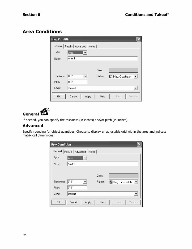
Section 6 Conditions and Takeoff
32
Area Conditions
General If needed you can specify the thickness (in inches) andor pitch (in inches)
Advanced Specify rounding for object quantities Choose to display an adjustable grid within the area and indicate matrix cell dimensions
Section 6 Conditions and Takeoff
33
Count Conditions
General
Specify height and indicate the size (in inches) and shape (square circle triangle rectangle or opening) of the count object as it will appear on screen
Advanced Count conditions have advanced attributes These options are available for all shapes except for openings
Zone Conditions Zones allow you to subdivide condition quantities making it easier to modify and complete jobs in phases They can be used at the end of a takeoff to isolate a group of condition quantities that are in different areas of the takeoff
Zones can also be used to break a takeoff into multi-phases and can even be used to isolate quantities while a job is in progress to group the amount of work that has been completed to date They can be applied to one or multiple pages in your plans automatically calculating the takeoff quantities for each zoned area
Section 6 Conditions and Takeoff
34
The zone feature is only available in Lite and Full Mode If you are in View Mode and would like
to use this feature click from the main toolbar to purchase the upgrade
Condition Notes A Note tab is provided for comments regarding the condition These notes will display on the Takeoff List report and will import into Quick Bid
Section 6 Conditions and Takeoff
35
Condition Results The Results tab of the New Condition is based on condition type Initial settings default to linear feet (LF) for linear conditions square feet (SF) for area conditions and count of items (EA) for count conditions and zones The first of the results fields will display for the condition items in the Takeoff dock bar area All results will display in worksheets and Takeoff List reports as well as in an Excel spreadsheet after being exported
Copying Conditions You may use the condition attributes from a condition yoursquove already created for any future conditions of the same type
1 Click on a condition to select it
2 Click the Copy button from the toolbar
OR
3 Right-click in the Takeoff dock bar area and select copy
4 A new condition will appear in the list with the same condition attributes as the previous condition but with the quantities zeroed
Editing Conditions Once you have copied a condition you might want to change several attributes You can also edit an existing condition to fit any updated needs
1 Highlight the desired condition on the Takeoff dock bar
2 Click the Change button
OR
3 Double-click on the condition you wish to edit to bring up the Change Condition dialog
NOTE The Change Condition dialog differs from the New Condition dialog only in that if takeoffs
Section 6 Conditions and Takeoff
36
have been performed in your project with this condition you will not be able to change the type of condition or certain properties under the advanced tab of the dialog box
Deleting Conditions 1 Click on the condition in the Takeoff Dock bar area
2 Click the Delete button on the toolbar
OR
3 Right-click and select Delete from the pop-up menu
All takeoff associated with the deleted condition will be deleted immediately and permanently
Organizing Project Conditions Within your project you can create folders andor sub-folders for different types of conditions You may even want to create a folder containing conditions with reset values
To get started organizing your conditions make sure you are viewing the condition tree (right-click in the Takeoff dock bar area and select Show Tree)
Creating Folders and Sub-Folders 1 Right-click in the Takeoff Dock bar area
2 Select New gt Folder from the pop-up menu
Copying Folders
1 Click on the folder and click Copy on the toolbar
2 All copied conditions within the new folder will have values reset to zero
Renaming Folders
1 Click on the folder
2 Right-click and select Rename from the pop-up menu
3 Enter a name for your folder and click the Enter button
Changing Condition Order
You may move conditions up or down in the condition list of the Takeoff dock bar to suit your project needs
1 Select the condition you would like to move by clicking to highlight it
NOTE When you are ready to move the highlighted conditions be sure that you start
moving using the last condition chosen That condition will have a highlighted boarder
Section 6 Conditions and Takeoff
37
2 Drag and drop any the condition from one place to another in the list You may also move a condition to another folder on the list in this way
Drawing with Conditions Snap Angles Set up snap angles to prevent lines from appearing jagged Snap angles are commonly set at 15deg and shift snap angles at 0deg
1 Go to Tools gt Options Options dialog appears
2 Under the General tab make the desired settings
3 Click to save the settings As they are drawn lines will snap to the set degree
Drawing a Linear Object 1 Select a condition from the Condition List in the Takeoff dock bar
2 Move the cursor into the Image takeoff area of the screen you will see the cursor display as crosshairs
3 Click and hold left mouse button then drag mouse to draw a line
4 Release mouse button to set line
Section 6 Conditions and Takeoff
38
5 Repeat steps for further lines
Continuous Mode This feature allows you to draw an object that has connected lines
1 Click the icon from the Takeoff toolbar
OR
2 Go to Tools gt Continuous Mode
3 Follow steps 1-3 from Draw a Linear Object
4 Click at each point of intersection The object will be connected
5 Double-click after making the final point to set the lines
Drawing a Curve To draw a curved line the Curve option must be checked under the Advanced tab of the Condition dialog
1 Click where you want to begin the curve and drag in a straight line to the position for the other endpoint of the curve
2 Click on the line to select it Handles in the shapes of small squares will appear at either end of
Section 6 Conditions and Takeoff
39
the line and in the center of the line
3 Move the cursor over the center handles until the cursor becomes a two-way arrow
4 Click and drag in the direction of the curve bending the line as you move the cursor Release to set the curve (The line you began with will disappear)
Draw a circle by drawing two curved lines connected
Drawing an Area Object Area conditions are drawn similarly to continuous mode lines You may trace any number of adjoining walls at different angles to complete your area takeoff
NOTE When drawing an area do not intersect the perimeter or line of the object you are drawing
1 Click at each point
2 Double-click when yoursquove returned to your starting point
3 The area will be filled with the pattern set for that condition
NOTE The simulated circle will be good enough for you to be able to make a bid
To create a circular area click from point to point with very short distances in between points simulating a circlersquos perimeter Double-click after setting the last point to set the area
Section 6 Conditions and Takeoff
40
Grid Options Grids give you an added advantage when installing materials such as tiles Use this feature to get a count for how many tiles are needed for an area
1 Double-click on an area condition in the Takeoff dock bar to open its Condition dialog
2 Click on the Advanced tab to show its options
3 Check the box next to Grid by clicking in it
4 Indicate the dimensions of the cell matrix in inches (For example 200 x 400)
5 Under Results tab choose each (EA) for one of the results fields This will tabulate a number of grid cells (including partial grid cells) in area
6 Click to save your settings
7 Use the Move Grid and Rotate Grid features in the Tools menu to manipulate the grid as desired
Grid Calculation
1 Go to Tools gt Options menu
1 Specify if On-Screen Takeoff automatically should Calculate Grid Position
2 If AreaGrid Size is selected On-Screen Takeoff will calculate the number of items needed to fill the grid based on grid demintions
3 Click to accept and close the dialog
To move a line at any angle (regardless of default setting) press the Shift key while moving the mouse
Section 6 Conditions and Takeoff
41
Backout Mode This feature allows you to take out part of an area and deduct that amount of square footage
1 Select Tools gt Backout Mode
2 Outline the are you want backed out as you would when drawing a regular area object (see Drawing an Area Object)
3 The outlined area will clear and quantities will be recalculated
NOTE The perimeter of the backout area will be added to the LF quantity for that condition
Drawing a Count Object Square triangle rectangle and circle shaped count objects can easily be placed on images
1 Select the condition
2 Click in the location where you want the object to appear
3 To place an opening-shaped count item like a door or window you must click over an existing linear object such as a wall
4 On the Results tab you can change the height properties to give you the result you need
5 If Backout is checked on the advanced tab for each count opening the opening-shaped count item will back out a corresponding section of the linear object
Opening shaped count items are sized at 3rsquo0rdquo by default
Drawing a Zone Zones are drawn in the same way as area objects and may be any polygonal shape You may trace any number of adjoining walls at different angles to complete the zone perimeter
1 Click at each point
2 Double-click when yoursquove returned to your starting point
Section 6 Conditions and Takeoff
42
Selecting Objects
1 Use the Select Tool to select objects
You can also select all objects that correspond to a condition
1 Click on a condition to select it
2 Right-click and choose Select All
3 All objects with this condition will be highlighted with squares as an outline
Moving and Resizing Objects Linear
1 To move or resize a linear object click anywhere on the line to select it
2 To move the line position your pointer over the center handles When the mouse is positioned over the handles you will see a two-way arrow You will only be able to move the line in the direction of the arrows
3 Drag the line to a new position
4 Clicking and dragging the handles on the ends of the line will allow you to lengthen or shorten your line
Area and Zone
1 To move an area object or zone in its entirety click and drag it to its new position
2 Grabbing a handle at a corner or intersection of the object will allow you to adjust and change its perimeter
Section 6 Conditions and Takeoff
43
Count 1 To move a square circle rectangle or triangle shaped count object click and drag
2 Click and drag an opening shaped count object along the length of the linear object to the desired position then release
NOTE An opening shaped count object may not be moved from its associated linear condition object however it may be moved up and down the length of the linear object
Layers On-Screen Takeoff allows you to sort and separate your takeoff objects within the same job and on the same page On-Screen Takeoff gives you this flexibility through the use of layers
By assigning different conditions to different layers (for example differentiating between floors ceilings and walls) you can choose to view all layers or turn off certain layers to display and print the remaining groups of conditions only You may also remove the background image of electronic plans add text and hot link symbols or print only your condition takeoffs
Layers are only available in Full Mode If you are in View or Lite Mode and would like to use this
feature click from the main toolbar to purchase the upgrade Default Layers
On-Screen Takeoff begins every project with three default layers Image Annotation and Default The Image layer holds the electronic plan files you may have in your project The Annotation layer possesses all text notations highlighting and hot links in the project The Default layer will appear in the Condition dialog when creating or editing a condition (listed in the takeoff dock bar) Conditions are assigned to the Default layer unless otherwise specified by the user
Creating Layers To assign a condition to a layer other than the default layer you must first create additional layers for your project
1 Select View gt Layers to open the Layers dialog
2 Click An unnamed layer will be added
3 Click within the empty box and type a name for your layer (for example Wall)
4 New layers are added as active layers The adjacent box under the Show column will be checked
Section 6 Conditions and Takeoff
44
Assigning a Layer to a Condition 1 Open the Condition dialog box by creating a new condition or editing an existing condition
2 Under the General tab click on the down arrow in the Layer field to display optional layers
3 Select the desired layer for the condition Only the Default layer and layers you have added will be displayed
4 Click
View and Hide Layers
1 Select View gt Layers
2 Under the Show column check the box to view or remove the check (by clicking on it) to hide the specific layer
3 Click to accept and close the Layers dialog
Section 6 Conditions and Takeoff
45
Assigning Text to a Layer When adding text to an image On-Screen Takeoff has the capability to assign the text to a specified layer
1 Select the Text Tool
2 Click at the point you want to place your text
3 Type in your text using the Enter key for line breaks
4 Click the drop down arrow next to the Layer field and select the desired layer
Section 7
46
Printing and Exporting
This section will
Printing options and procedures
Exporting data by copying and pasting
Exporting quantity results to Excel spreadsheets
Section 7 Printing and Exporting
47
Print Setup On-Screen Takeoff allows the user to print the image takeoff list and worksheet
1 Select File gt Print Setup The Print Setup dialog will open
2 Select a printer or leave the default selection listed (change from the default printer displayed by clicking on the down arrow at the right of the field)
3 Indicate page size and printer tray option (Source) Access page size options by clicking on the
down arrow at the right of the field
4 Choose Portrait or Landscape orientation
5 Click to accept and close the dialog
Printing Images The image area can include the electronic plans the takeoff objects added text and hot links To print a subset of these (for example just the takeoffs without the plans or the added text and hot link symbols) hide layers that you do not want to print (see Section 6 View and Hide Layers) When you are printing your images every page will show the scale of the takeoff you are printing
1 Click on the Image tab to display the area of your project
2 Select File gt Print (or Ctrl + P)
Section 7 Printing and Exporting
48
3 Select the desired view (What to print) and the Image Range
4 Click The second Print dialog will open
5 Change settings accordingly or click if you accept the default settings
Printing Takeoff Lists and Worksheets In Takeoff Lists and Worksheets you may hide columns to print only certain results or adjust column widths to fit the report within the page size selected
1 In Takeoff List or Worksheet view move your cursor to the right side of the columnrsquos title bar the cursor will display as a two-way arrow
Section 7 Printing and Exporting
49
2 Click and drag to adjust the width of the column Holding the mouse button you may
slide the title bar under the title bar to its left to hide the column completely
3 Select File gt Print or press Ctrl + P to access the Print dialog
4 Indicate desired printer and choose the number of copies
5 Click to print and close the dialog
When printing the condition list we suggest printing in landscape
To reset to the default column widths double-click on the right border of a column heading will reset the column to its right (or previously to its right before being hidden)
Print Preview 1 Select File gt Print Preview
2 Use and to vary your view 3 If viewing an image choose current full or scale view to see how it displays
4 For printed outputs that cover more than one page use and to view adjacent pages or click on the down arrow next to Page field and select the page you want displayed
Exporting Using the CopyPaste Feature You may copy all the data or sections from the worksheet and the takeoff list view in On-Screen Takeoff and paste it into another application When pasting into Excel the cell layout will be maintained
1 Highlight the areas you wish to paste Click and hold the left mouse button down as you drag the cursor over the area to be selected then releasing the mouse button
OR
2 Select the entire takeoff list quickly click on the left On-Screen Takeoff column header and hold and drag the cursor across the remaining column headings
The number of pages for the view selected will display in the lower left-hand corner The zoom percentage that applies to the view will be displayed in the lower right-hand corner next to page size of the drawing
Section 7 Printing and Exporting
50
3 In the worksheet view you may highlight rows by clicking on the numbered buttons to the left of each row clicking and dragging across column headings or clicking and dragging over individual cells in the worksheet
Click anywhere in the appropriate view to deselect the area
4 Once your selection is highlighted you may select Edit gt Copy or Ctrl C from the keyboard 5 On your monitor switch to the application into which you want to paste your selection 6 Select Edit gt Paste in the new application or simply press Ctrl + V to paste
The colored keys for conditions cannot be pasted
Using the Export Feature You may export condition quantities to specified cell location within an Excel worksheet file Cell target locations are assigned in the Results tab of the condition dialogs on the Export line relating to each quantity measurement type
On-Screen Takeoff will export takeoff quantity results for up to three different quantity types that you specify For instance you may want to know the number of square feet in a ceiling area as well as the number of linear feet in its perimeter
Section 7 Printing and Exporting
51
1 Bring up the Condition dialog by double-clicking on a condition in the takeoff dock bar or by
selecting the condition and clicking
2 Click on the Results tab to access its fields The default quantities for the condition type will display
3 For each results field click on the arrow to access the pull-down menu and select the appropriate quantity (for example SF LF EA etchellip)
4 Have your Excel spreadsheet opened and saved in a file
5 Specify the Excel spreadsheet cell locations where you want the results to go
6 For a cell in the first sheet of your spreadsheet type in the cell address (eg a1) Case is not important
7 For a cell on a successive sheet of your spreadsheet type in sheet the number followed by a comma and the cell address without any spaces (eg sheet2a1) Case is not important
8 Click
9 Select File gt Export gt Condition Qty to Excel
Section 7 Printing and Exporting
52
10 Browse to the location of the Excel spreadsheet file click file to select it
11 Click to export On-Screen Takeoff results to specified cell locations in the Excel file When you return to the Excel application you will see the values have been added to the specified cell locations in your spreadsheet
12 Save your Excel file
Exporting Worksheet to Excel
1 Assign condition quantities you want to export
2 Open saved Excel spreadsheet file to which you will be exporting
3 From On-Screen Takeoff Select File gt Export gt Worksheet to Excel
4 Browse to the location of the Excel spreadsheet file click file to select it
5 Click When you return to the Excel application you will see the values from the Worksheet Tab have been added to your spreadsheet
6 Save your Excel file
Exporting Takeoff to CVS 1 Assign condition quantities you want to export
2 Open saved Excel spreadsheet file to which you will be exporting
3 Click the Takeoff Tab in the project you want to export the information
4 Select File gt Export gt Takeoff to CSV
5 Browse to the location of the CSV spreadsheet file click file to select it
6 Click the Save
NOTE CSV files can be opened in Excel Lotus Access etc One may consider this option more of a ldquodumprdquo into a file
The Excel application must be active (it may be minimized on the application bar) with the target spreadsheet open in the application Otherwise an error will occur with the export operation that will affect both the On-Screen Takeofftrade file and the Excel spreadsheet
Section 8
53
Advanced Features
This section will
Some special features of working with condition objects in the takeoff area
Details of advanced options for conditions
Advanced features of the Project Properties dialog
Section 8 Advanced Features
54
Features to Use with Objects Roping Feature You can move copy or delete using this feature Using the Select tool (the pointer) you may select several objects at once by clicking and dragging an outline around the objects then releasing the mouse button Roping may select either objects completely within the outlined area (inclusive) or objects both within and touched by the outlined area (touching) Specify your roping preference under Tools gt Options
1 Click and hold the mouse button at a point on the screen near the objects to be selected and drag to surround the objects with an outline
2 Release the mouse button The objects will be selected
3 You may now
Move the group around on the page by clicking within the group dragging the mouse and releasing the button to place the objects
Delete the group of objects by clicking the Delete key or
Copy and paste by pressing Ctrl C to copy the group then Ctrl V to paste it The pasted copy of the grouped objects will appear slightly offset from the original objects
Section 8 Advanced Features
55
Applying a DropRun Count
Use the droprun feature when calculating quantities to take into account the drop or run of a linear condition such as electrical lines or plumbing pipes Drop or run lengths may be added separately to any linear condition on screen while a default droprun length may be indicated for a condition as a whole
1 Select the desired linear condition from the Condition List in the Takeoff Dock bar
2 Click the Change button in the toolbar to open the Change Condition dialog
3 Click the Advanced tab to access the advanced options and click inside the DropRun check box
4 Enter a default length to be applied to all of this condition Entering 800 will be interpreted as 8 0 (You must enter both place markers for inches) You can leave the length blank and manually enter drop run on each segment drawn
5 Click the OK button to accept and close the dialog
Edit DropRun Count
1 With the related linear condition in the Takeoff Dock bar highlighted or with the pointer tool selected
2 click on the desired linear object in the image takeoff area The Count button will become active
3 Click on the Count button (alternatively select Tools gt Count) The default droprun amount will show in the pop-up Count dialog (Default length will be zero if droprun has not been selected in this conditionrsquos properties)
4 Type in the desired length Entering 800 will be interpreted as 8 0 (You must enter both place markers for inches)
5 Click the OK button The additional amount will be reflected in the corresponding quantity The new DropRun count will apply only to the object edited
Adding Text in Image View
On-Screen Takeoff allows you to place text comments around your quantity takeoffs that may be printed along with plan images and objects Text is automatically placed within the Annotation Layer (that includes text and hot links)
1 To place text on the image select the Text Tool and click at the point you want to place your text opening a text box
2 Type in your information clicking Enter for line breaks
3 When you are finished click the OK button to exit the text box
4 To reposition text simply click on the text (with the Text Tool active) to select it
5 Move the cursor over the text the cursor will now display as a four-way arrow
6 Click and drag the mouse to position the text as desired
Section 8 Advanced Features
56
1 To edit existing text use the Text Tool to double-click on the text to open the editing box
2 Enter additional text or use the Backspace key to delete text as necessary
Formatting Text Once created you may format the font size type style and color of your text
1 Click on the text to select it and select Tools gt Font or click on the Font button in the Takeoff Toolbar
2 Select the desired features (color options are disabled) and click the OK button
3 Click on the text to select it and select Tools gt Color or click on the Color button in the Takeoff Toolbar The Color dialog will open
4 Click on a color in the Basic Color palette or create a color and add to the Custom Colors palette (Be sure to click on the color in the Custom Colors palette to select it)
5 Click the OK button
Object Properties
Linear Objects
Linear objects may be set to connect at corners
A linear object may be set to trim automatically when crossing another linear object (Check the trim option under the advanced tab of the Condition dialog)
When you move a connected linear object objects automatically move and resize connected lines accordingly (quantities are then recalculated)
This feature requires that the connected linear object be moved using the center handles (does not apply when resizing the line from the ends)
Objects constrain to snap increments defined in the Tools gt Options menu (with the mouse 15deg by default incremental when shift key is held down)
Objects are measured from centerline to centerline
Section 8 Advanced Features
57
Area Objects When drawing an area use your escape key to undo the last line drawn You may reverse your
drawing of an area using the escape key
The area will not fill with color and pattern until the user double-clicks after the last line is set
Lines drawn to delineate an area object constrain to snap increments defined in the Tools gt Options menu (with the mouse 15deg by default incremental when shift key is held down)
After selecting an area to move or adjust position the mouse in the center to move the entire area position the mouse at the sides or corners to adjust the perimeter
Count Objects
All count objects are quantified by the physical number of objects per page and reported as EA for the UOM The quantity for the current Image View is (displayed in the Condition List) and the total quantity in your project is displayed in the Takeoff View and Worksheet View)
Square circle rectangle and triangle shaped count objects do not displace or subtract from other object quantities when placed on top of them However on the Advanced Tab for the count condition a connect property can be set (this is a check box) so that when a count object of this shape is put on top of a Linear type takeoff object it will move with the linear if said linear is moved
An opened-shaped count object must be placed within a linear object Opening shaped count objects may also be measured by linear foot or linear yard (EA SF and SY are also options) Opening shaped count items default to a width of 3rsquo 0rdquo at the time of creation This size can be changed The small medium and large size are not options on this type of condition anymore Check Backout on the Advanced tab for each Count object back out the footage (or yardage) of opening-shaped count objects in which they are placed
NOTE In order to see this Backout functionality (in quantity) for SY or SF deductions at least one of the
results for the Linear(s) this object will be placed on must be set to SY or SF and the count object must have a height quantity
Advanced Features of Conditions The Round Feature Under the Advanced tab of the linear and area Condition dialogues you may specify quantity rounding (in inches) For linear objects rounding applies to each linear object drawn For area objects rounding will apply to each segment of the area perimeter adjusting the perimeter and area calculations For example With a linear condition entering 12 in the Round field will round up each related linear object to the nearest 12 inches or one foot With this setting two walls of 1 4 would each round to 2 0 totaling 4 0
NOTE In the Takeoff Dock bar condition list and in the On-Screen Takeoff reports quantities will be displayed in whole numbers rounded up to the nearest foot However calculations are based on true quantities without rounding unless the Round Feature is engaged
Pitch Pitch may apply either to linear or area conditions It is measured in rise per linear foot Entering 12 indicates a 12 rise per 12 of linear distance (a pitch of 12 over 12) or an angle of 45deg
Section 8 Advanced Features
58
Advanced Features of Project Properties Selecting Multiple Pages
1 Select a single page entry by clicking on the numbered gray button to the left of the entry
2 Drag the cursor down the column of numbers to select consecutive pages
3 Click on the blank button at the top of this column to select all pages in the Properties dialog
Section 8 Advanced Features
59
Changing Image Assigned to a Drawing 1 Select the page entry by clicking on the numbered gray button to the left of the entry 2 Click the Change Image button The Change Image dialog box will appear
3 Navigate to the desired file and select by clicking on it
4 Click the Open button The electronic file assigned to the page will have been changed to reflect the new file choice
Changing Image File Path 1 Select pages as described above
2 Choose Change Folder
3 In the Change Folder dialog navigate to the appropriate folder
4 Click the OK button The file path will have been changed for the selected page entries
Delete a Page from Project Properties 1 Select the page you want to delete by clicking on its associated number (in the gray box at the
left of the entry)
2 Choose Delete Page
All Takeoff on the page will be deleted immediately and permanently
Section 8 Advanced Features
60
Advanced Features of Tool Options
Calculation Method On-Screen Takeoff has built-in calculation options to allow for faster work and faster saves until your takeoff is complete Calculation options are found by selecting Tools gt Options then clicking on the Calculation tab
Calculation method can be set to Automatic Automatic except Grids and Manual Manual will allow the program to operate more quickly while Automatic or Automatic except Grids allows the user to see quantity changes as takeoffs are made
In any mode you may press F9 to recalculate quantities for the On-Screen Takeoff current totals
Configuration Tab
When the ldquoPage Label (A01)rdquo radial button is chosen On-Screen Takeoff puts the numbered label on all the pages of in your current page indicator in your Navigate Toolbar If the Page Descriptionrdquo radial button is chosen then a description of what takeoff is on that specific page will be shown in your current page indicator in your Navigate Toolbar
This section of the configuration tab gives you options on how you want to export your information When the ldquoFolderSubfolder Namesrdquo radial button is chosen than on your file that you are exporting to will have all the conditions folders and subfolders In the Delimiter box you can choose the symbol that is needed to separate the information you are exporting Some files need semicolons () or colons () to make sure the information comes exported in is separated it the appropriate places
Section 8 Advanced Features
61
In previous versions of On-Screen Takeoff there are views that users need to have in order for them to display their information By either choosing ldquoOST 1xrdquo or ldquoOST 2xrdquo it will let the program know you want your columns of information exported in that specific format
When you have the Confirm Deletions radial button of ldquoYesrdquo chosen than every time you delete anything you will get a dialog box confirming your intentions of deletion
While working with your takeoff you have a choice to either view the legend of your conditions or hide it Choose whichever radial button that suits your needs
For those who prefer to use the Enter key to navigate in dialog boxes this option is just for that
Font Tab The Font tab is designed for you to make your own look and feel for the application At the bottom of this tab it will show you sample of the fonts and colors you have chosen
Renaming the Current Page You may change the name of the current page in the takeoff area of On-Screen Takeoff by selecting Edit gt Rename Page
This opens the Name Page dialog and you may simply type in a new name and click the Enter button The new name for the file will be reflected on the title bar for the page and in Project Properties
You also may access the Rename Page function by right-clicking in the takeoff area while in Image View and selecting the option from the pop-up menu that appears
Section 9
62
Saving and Exiting
This section will
Explain how to save projects
Show you how to safely exit the program
Section 9 Saving and Exiting
63
Saving Your Project
1 Select File gt Save 2 If your project has not previously been saved a Save dialog box will open to allow you to name
the file and choose the directory and folder in which to save your file 3 Once saved File gt Save will simply save the current version of the file
OR
4 Select File gt Save As then type in a new name for the file and save to the desired file path
The Auto-save Feature With the Auto-save feature On-Screen Takeoff automatically backs up your open project You may choose to have more than one level of backup files The first backup copy will have the extension b00 and successive files will be b01 b02 and so on If you have designated four levels of backup files after the fourth backup copy has been created (b03) the next file will be saved over the file with extension b00 Further backup saves will then rotate through the four backup files in the same way
1 Select Tools gt Options 2 In the Auto-save area (under the General tab) select the frequency of backup file creation (in
minutes) and the number of levels for the feature 3 You also may disengage the feature by clicking in the check box to clear it
The Auto-save feature automatically saves backup copies to the directory of the current project If you are working from a write-protected area such as a CD-ROM On-Screen Takeoff will place backup files in the On-Screen Takeoff folder
Exiting When you are finished using On-Screen Takeoff it is very easy to exit Exiting is very important because of security reasons If someone were to use your computer they could enter the application and view and manipulate information
Section 9 Saving and Exiting
64
On-Screen Takeoff closes the open project when you open another or create a new project or when you exit the program
1 Select File gt Exit
OR
2 You also may click at the upper right-hand corner of the application to exit
NOTE If your latest changes to a project file have not been saved On-Screen Takeoff will ask you whether you would like to save the file and gives you the option of canceling the operation
Appendix I Installing Your Digitizer
65
Appendix I Installing Your Digitizer When you get your digitizer from GTCO you will need to connect it to your computer Follow the instructions outlined below to do this
Note For rollup digitizers the metal bar must be oriented to the top or right hand side
Connecting the Digitizer 1 Lay the digitizer out flat 2 Connect the Stylus to the digitizer 3 Plug in the power adapter 4 Plug the interface (IO) cable into the digitizer 5 Plug the other end of the interface cable into an open serial port on computer
Note GTCO Technical support phone number is 410-381-6688 The electronic manual (on diskette) from GTCO contains more detailed installation and operation instructions for the GTCO digitizer model you have
Installing other Digitizer Drivers If you are using a GTCO Digitizer you will need to install the GTCO TabletWorks Drivers
If you are using a Digitizer not supported by GTCO Tablet Works 10 please contact the manufacturer of your digitizer for assistance with installation
Installing GTCO TabletWorks Drivers 1 Insert the On Center CD into the CD-ROM drive The CD Startup screen will open 2 Click on Install Software 3 Select Additional Software and Drivers 4 Select Digitizer Driver 5 Follow the instructions for installing TabletWorks 10
Adhering the Template The template is a small plastic sticker used to enable mouse function when using the digitizer with On-Screen Takeoff Place your template on your digitizer We suggest placing it in the bottom right corner of the digitizer about one inch inside the takeoff area
Note You may either peel off the back of the template and use the adhesive surface or you can tape the template down
Appendix I Installing Your Digitizer
66
Testing the Digitizer Drivers Before running OST you may test the digitizer by moving the stylus around on the digitizer pad it should move the mouse cursor (if mouse emulation is enabled)
If the digitizer does not move the mouse cursor on the screen
The superset codes may need to be reset Reset the superset codes by touching on the border of the digitizer with the stylus The digitizer should beep several times
The digitizer may not be communicating with the computer Be sure the COM port selected is correct Be sure the COM port selected is correct If you are not able to get the digitizer to move the mouse cursor you need to call GTCO technical support for help
Note The Mouse Emulation is not required for On-Screen Takeoff to work properly It is used only for the Template functionality if the digitizer is moving the cursor the wrong direction (up instead of sideways or vice-versa)
Click the L-shaped arrow symbol on the digitizer with the stylus
Appendix II Toolbar Item Details
67
Appendix II Toolbar Items Main Toolbar
Appendix II Toolbar Item Details
68
Tool Toolbar
Appendix II Toolbar Item Details
69
Zoom Toolbar
View Toolbar
Navigate Toolbar
Appendix II Toolbar Item Details
70
Navigate Toolbar (Continued)
Takeoff Toolbar
Appendix II Toolbar Item Details
71
Takeoff Toolbar (Continued)
Image Toolbar
Appendix III Loading Plans from a Dodge CD
72
Appendix III Loading Plans from a Dodge CD
This section will detail how to load plans from a F W Dodge CD-ROM into an On-Screen Takeoff project file ready for takeoffs
Dodge files may be added to the Project Properties dialog However loading the files in that way will load the files by number rather than name description If you want to load one page only from your Dodge CD You will have to rename the page to display the name rather than number of the file
To load plan files from a Dodge CD so that the files load sequentially by file number but are displayed by name rather than by number within your project follow the instructions below
Opening a Dodge project from a CD-ROM 1 Insert the CD into the drive 2 Choose File gt Custom 3 Choose Dodge Plans Project (plansdat) as the file type 4 Select the appropriate file type by clicking on the down arrow at the right of the Files of type
field 5 In the Look in field access your drive paths by clicking on the down arrow at the right of the
field then
Navigate to your CD-ROM drive Open the data folder and Open the Projects folder
6 Select the desired project and open its folder 7 Open the plansdat file 8 All the images will come in sequenced correctly for that job along with the full descriptions
(names) of each page If there is not a plans folder in the project folder then plans do not exist for that project on the CD Opening the plansdat file will yield an empty project
Appendix IV Using the Plan Viewer
73
Appendix IV Using On-Screen Takeoff Plan Viewer The On-Screen Takeoff Plan Viewer is a limited version of On Center Softwarersquos commercial takeoff software If your status bar located at the very bottom of the main window says View Mode in the lower left-hand corner then you are using the Plan Viewer You can use the plan viewer to
View CD-based amp converted CAD drawings
View a previously created OST file and associated drawings
Download electronic plans online
Navigate through drawings
Quickly Takeoff linearsareas and counts
Zoom in to view the plan better
Print drawings directly from the viewer
Viewing an On-Screen Takeoff Project File
1 To open an OST file that was previously created with of On-Screen Takeoff 2 Select File gt Open 3 An Open dialog will appear if you do not see the OST file you are looking for select the
Look In drop down arrow 4 A drop down menu will appear listing the various folders drives and mapped drives located
on your computer select the correct drive or folder location and continue to browse to the location of your OST file
5 When you see your OST file double-click it to open it 6 Any takeoff and drawings should appear on the Image tab view
If you do not see the drawings but do see the colored takeoff layer the drawings may
not be located in the same place they were originally saved at Go to File gt Project Properties and check the Image File path for each listed page If the image file path is pointing to a CD drive make sure the CD is inside the CR-ROM
Downloading Electronic Plans If your Online Plan Service provides a special file format (OSX) required to use this feature of our plan viewer you can immediately downloaded all electronic plans of a project directly from our viewer
Most Plan Room web sites will automatically open On-Screen Takeoff when a request to download plans is made Your particular Plan Room may differ in operation so please contact the provider directly with questions on using the site
Appendix IV Using the Plan Viewer
74
When you request to download or open a project file from a Plan Room you will usually have the open to open or save an OSX file Choosing open will automatically open On-Screen Takeoff Alternately you may choose to save the file to a local hard drive After you have saved the file either double-click it to launch On-Screen Takeoff or open the OSX file using On-Screen Takeoff by clicking File then Open and locating the file on your hard drive You will need to change the file type to OSX
After the OSX file is opened you will see an additional tab appear in the Conditions List window called Pages
The Pages tab shows the hierarchy of your project Gray file icons represent pages that have not been downloaded and blue icons represents pages that have been downloaded
To download a page simply double-click the page icon
If you wish to select a group of pages to download you can use the Ctrl or Shift key to multiple select them then click the Download button
If you wish to download all pages at once click the Download All button
Downloaded pages will now appear in the Project Properties dialog in the same order in which they appear in the Pages tab
Creating Quick Takeoffs With On-Screen Takeoff you can create quick takeoffs to measure quantities even if you dont have the full version of our program However using the Quick Takeoff functionality shows you just a fraction of what the full version can do
The Quick Takeoff Toolbar is located at the top of the image view It has three buttons designated for three types of takeoffs Linear Area and Count The Quantity drop down list will show secondary quantities for Linears and Areas The Units drop down allows you to select how you want your quantities displayed Feet Inches Yards Millimeters and Meters
NOTE Every time change the type of takeoff you are performing (switching from Area to Linear for example) the previous quantities and takeoff objects will disappear They will also disappear when you changes pages
NOTE You can use the Dimension Tool to basically measure the distance between two points or linears The distance will display on the status bar at the bottom of the application
The Quick Takeoff Toolbar
Appendix V Frequently Asked Questions
75
Appendix V Frequently Asked Questions General
Where is On-Screen Takeoff installed on my computer
Typically it is installed in CProgram FilesOn-Screen Takeoff
In Explorer how do I recognize On-Screen Takeoff file types
On-Screen Takeoff data is stored in a single file per job lsquojob name OSTrsquo On-Screen Takeoff templates are stored as lsquotemplate nameTPOrsquo
Can only one project at a time be open
Yes For that reason opening another project automatically closes the project on screen You will be asked to save any changes
Is only one scale allowed per page What about on drawings that have multiple detail sections on a page and each of those drawings have different scales
Yes For pages with drawings of different scales copy the drawing to another project page and set the appropriate scale
I cannot perform backout on an area that is along a linear
As a workaround use the On-Screen Takeoff layers feature to help you with this issue Electronic Images
How do I start a project from drawings that have been scanned and written to a CD-ROM
Open a new project Select File gt Project Properties and select Auto Add Navigate to your CD and the appropriate folder and select any image file in that location Click Open All files in the location will load into your project Recommended that images are copied from CD to hard drive for performance
If I get a disk of drawings in AutoCAD format (R13 or R14) can I read them in On-Screen Takeoff
Yes On-Screen Takeoff now reads DWG DXF and many other format that are saved with AutoCAD
Appendix V Frequently Asked Questions
76
When I click on the all pages button what is supposed to happen Currently nothing seems to change when I click on that button
The All Pages button is used to apply the Darken and Enhance Plans feature to all pages in the project (as opposed to only the current page on screen)
Is there a way to deduct a large skylight from an area condition
Yes with the related area condition selected in the Takeoff Dock bar unselect the Backout button on the Takeoff Toolbar then draw the Backout area The area quantity will be deducted from the related condition object and the linear measurement of the Backout perimeter will be added
Digitizer Issues
How do I connect a Digitizer to the computer
See Appendix I Connecting a Digitizer
The Place Template menu choice is disabled
On-Screen Takeoff may need to be authorized or the digitizer or the digitzer drivers are not installed
It wonrsquot let me select the Set Takeoff Area menu choice
On-Screen Takeoff may need to be authorized or no job is open a digitizer is not installed or the drivers are not installed
The digitizer stylus is not moving the cursor or crosshairs
Click S-0-1 superset on the digitizer
How do I convert my old GTCO Digitizer to work with On- Screen Takeofftrade
Call GTCO and they may be able to reconfigure your digitizer to be compatible with On-Screen Takeoff
Printing Issues Which Printers work with On-Screen Takeoff
Compatible printers include On-Screen Takeoff Hewlett Packard Epson and Canon printers If you are having printer difficulties please contact support and specify the type of printer along with other pertinent information Contact support at wwwoncentercomsupport or email supportoncentercom
Which Plotters work with On-Screen Takeoff
Compatible Plotters include Hewlett Packard DesignJet plotters and the EnCAD Cadjet II If you are having plotter difficulties please contact support and specify the type of plotter concerned
ViewingDisplay I can no longer see my condition list How do I get it back
The toolbars and Dock bars can be turned on and off through the View gt Toolbars menu options
Appendix V Frequently Asked Questions
77
This is also accessible by right-clicking in the toolbar area and selecting (or deselecting) a toolbar listed
I cannot view my folders in the condition list
Right-click in the Takeoff Dock barcondition list area and select Show Tree to display your folders
My Status Bar reads Viewer Mode and I am unable to draw conditions
On-Screen Takeoff needs to be Authorized Or you need to purchase an upgrade Click the Perform Advanced Takeoff button on the main toolbar
I hid a Dock bar and when I selected to view it again it appeared alongside the other Dock
bar instead of stacked on top of it How do I fix it
Pick up the Dock bar by clicking on the bar at the top and continuing to hold down the mouse button drag the Dock bar over the other one It will resize and appear stacked with the other
When I open image files from a CD the images are all upside down How do I get them right
side up
To flip pages from top to bottom follow the steps below 1 Click the All Pages button on the Image Toolbar (All Pages is engaged when the button
is not clicked) 2 Click the Flip Horizontal button on the Image Toolbar 3 Click the All Pages button again to disengage
Templates How do I create a Template
Follow the steps below 1 Create a typical project 2 Choose File gt Save As 3 Choose On-Screen Takeoff Template Files as the file type to save 4 Name the file This will save all of the condition setups as well as the layers for the
project
How do I create a new project from a template
Follow the steps below 1 Choose File gt New 2 Select a template from those listed in the New dialog This will open a new project with
conditions and layers saved from a previous project but no pages or takeoff
78
INDEX
Area Conditions 32
Area Objects 57
Auto Scrolling 20
Auto-save 63
Backout Mode 41
Calculation Method 60
Conditions 29
Configuration 60
Contents Tab 6
Continuous Mode 38
Count Conditions 33
Count Objects 57
Digitizer 10 65 76
Docking Toolbars 13
Dodge CD 72
Drawing 27 37
DropRun Count 55
Environment 18
Exiting 63
Exporting 49
Features 16
Font 61
Frequently Asked Questions 75
Grid 40
Help File 5
Hiding Toolbars 13
Hot Links 21
Image 19 59
Image files 9
Image Toolbar 12 71
Images 75
Index Tab 6
Layers 43
Linear Conditions 31
Linear Objects 56
Main Toolbar 12 67
Menus 14
Moving Toolbars 13
Navigate Toolbar 12 69
Navigating 20
On-Screen Takeofftrade 2
Page 59 61
Pages 20 25 28
Plan Viewer 73
Plans 26
Printing 47 76
Project Properties 25
Projects 22
Quick Start Video 18
Resizing Toolbars 13
Roping 54
Saving 63
Scale 28
Search Tab 7
Selecting Objects 42
Setup 8
Start On-Screen Takeofftrade 17
System Requirements 9
Takeoff 19 27
Takeoff Toolbar 70 71
Takeoff Toolbar 12
Template Files 23
TIF (Group4) 9
Tool Toolbar 12 68
Toolbar 67
Toolbars 12
View Toolbar 12 69
Viewing Toolbars 12
Worksheet 20
Zone Conditions 33
Zoom Toolbar 12 69
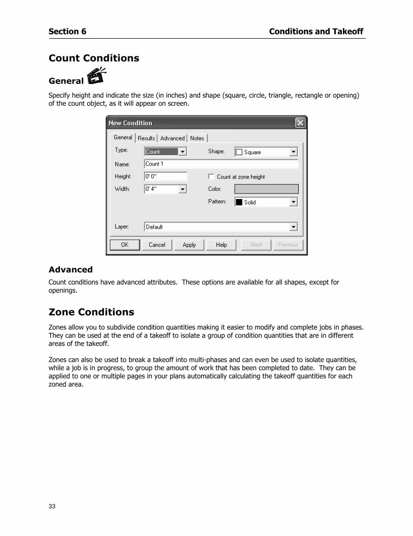
Section 6 Conditions and Takeoff
33
Count Conditions
General
Specify height and indicate the size (in inches) and shape (square circle triangle rectangle or opening) of the count object as it will appear on screen
Advanced Count conditions have advanced attributes These options are available for all shapes except for openings
Zone Conditions Zones allow you to subdivide condition quantities making it easier to modify and complete jobs in phases They can be used at the end of a takeoff to isolate a group of condition quantities that are in different areas of the takeoff
Zones can also be used to break a takeoff into multi-phases and can even be used to isolate quantities while a job is in progress to group the amount of work that has been completed to date They can be applied to one or multiple pages in your plans automatically calculating the takeoff quantities for each zoned area
Section 6 Conditions and Takeoff
34
The zone feature is only available in Lite and Full Mode If you are in View Mode and would like
to use this feature click from the main toolbar to purchase the upgrade
Condition Notes A Note tab is provided for comments regarding the condition These notes will display on the Takeoff List report and will import into Quick Bid
Section 6 Conditions and Takeoff
35
Condition Results The Results tab of the New Condition is based on condition type Initial settings default to linear feet (LF) for linear conditions square feet (SF) for area conditions and count of items (EA) for count conditions and zones The first of the results fields will display for the condition items in the Takeoff dock bar area All results will display in worksheets and Takeoff List reports as well as in an Excel spreadsheet after being exported
Copying Conditions You may use the condition attributes from a condition yoursquove already created for any future conditions of the same type
1 Click on a condition to select it
2 Click the Copy button from the toolbar
OR
3 Right-click in the Takeoff dock bar area and select copy
4 A new condition will appear in the list with the same condition attributes as the previous condition but with the quantities zeroed
Editing Conditions Once you have copied a condition you might want to change several attributes You can also edit an existing condition to fit any updated needs
1 Highlight the desired condition on the Takeoff dock bar
2 Click the Change button
OR
3 Double-click on the condition you wish to edit to bring up the Change Condition dialog
NOTE The Change Condition dialog differs from the New Condition dialog only in that if takeoffs
Section 6 Conditions and Takeoff
36
have been performed in your project with this condition you will not be able to change the type of condition or certain properties under the advanced tab of the dialog box
Deleting Conditions 1 Click on the condition in the Takeoff Dock bar area
2 Click the Delete button on the toolbar
OR
3 Right-click and select Delete from the pop-up menu
All takeoff associated with the deleted condition will be deleted immediately and permanently
Organizing Project Conditions Within your project you can create folders andor sub-folders for different types of conditions You may even want to create a folder containing conditions with reset values
To get started organizing your conditions make sure you are viewing the condition tree (right-click in the Takeoff dock bar area and select Show Tree)
Creating Folders and Sub-Folders 1 Right-click in the Takeoff Dock bar area
2 Select New gt Folder from the pop-up menu
Copying Folders
1 Click on the folder and click Copy on the toolbar
2 All copied conditions within the new folder will have values reset to zero
Renaming Folders
1 Click on the folder
2 Right-click and select Rename from the pop-up menu
3 Enter a name for your folder and click the Enter button
Changing Condition Order
You may move conditions up or down in the condition list of the Takeoff dock bar to suit your project needs
1 Select the condition you would like to move by clicking to highlight it
NOTE When you are ready to move the highlighted conditions be sure that you start
moving using the last condition chosen That condition will have a highlighted boarder
Section 6 Conditions and Takeoff
37
2 Drag and drop any the condition from one place to another in the list You may also move a condition to another folder on the list in this way
Drawing with Conditions Snap Angles Set up snap angles to prevent lines from appearing jagged Snap angles are commonly set at 15deg and shift snap angles at 0deg
1 Go to Tools gt Options Options dialog appears
2 Under the General tab make the desired settings
3 Click to save the settings As they are drawn lines will snap to the set degree
Drawing a Linear Object 1 Select a condition from the Condition List in the Takeoff dock bar
2 Move the cursor into the Image takeoff area of the screen you will see the cursor display as crosshairs
3 Click and hold left mouse button then drag mouse to draw a line
4 Release mouse button to set line
Section 6 Conditions and Takeoff
38
5 Repeat steps for further lines
Continuous Mode This feature allows you to draw an object that has connected lines
1 Click the icon from the Takeoff toolbar
OR
2 Go to Tools gt Continuous Mode
3 Follow steps 1-3 from Draw a Linear Object
4 Click at each point of intersection The object will be connected
5 Double-click after making the final point to set the lines
Drawing a Curve To draw a curved line the Curve option must be checked under the Advanced tab of the Condition dialog
1 Click where you want to begin the curve and drag in a straight line to the position for the other endpoint of the curve
2 Click on the line to select it Handles in the shapes of small squares will appear at either end of
Section 6 Conditions and Takeoff
39
the line and in the center of the line
3 Move the cursor over the center handles until the cursor becomes a two-way arrow
4 Click and drag in the direction of the curve bending the line as you move the cursor Release to set the curve (The line you began with will disappear)
Draw a circle by drawing two curved lines connected
Drawing an Area Object Area conditions are drawn similarly to continuous mode lines You may trace any number of adjoining walls at different angles to complete your area takeoff
NOTE When drawing an area do not intersect the perimeter or line of the object you are drawing
1 Click at each point
2 Double-click when yoursquove returned to your starting point
3 The area will be filled with the pattern set for that condition
NOTE The simulated circle will be good enough for you to be able to make a bid
To create a circular area click from point to point with very short distances in between points simulating a circlersquos perimeter Double-click after setting the last point to set the area
Section 6 Conditions and Takeoff
40
Grid Options Grids give you an added advantage when installing materials such as tiles Use this feature to get a count for how many tiles are needed for an area
1 Double-click on an area condition in the Takeoff dock bar to open its Condition dialog
2 Click on the Advanced tab to show its options
3 Check the box next to Grid by clicking in it
4 Indicate the dimensions of the cell matrix in inches (For example 200 x 400)
5 Under Results tab choose each (EA) for one of the results fields This will tabulate a number of grid cells (including partial grid cells) in area
6 Click to save your settings
7 Use the Move Grid and Rotate Grid features in the Tools menu to manipulate the grid as desired
Grid Calculation
1 Go to Tools gt Options menu
1 Specify if On-Screen Takeoff automatically should Calculate Grid Position
2 If AreaGrid Size is selected On-Screen Takeoff will calculate the number of items needed to fill the grid based on grid demintions
3 Click to accept and close the dialog
To move a line at any angle (regardless of default setting) press the Shift key while moving the mouse
Section 6 Conditions and Takeoff
41
Backout Mode This feature allows you to take out part of an area and deduct that amount of square footage
1 Select Tools gt Backout Mode
2 Outline the are you want backed out as you would when drawing a regular area object (see Drawing an Area Object)
3 The outlined area will clear and quantities will be recalculated
NOTE The perimeter of the backout area will be added to the LF quantity for that condition
Drawing a Count Object Square triangle rectangle and circle shaped count objects can easily be placed on images
1 Select the condition
2 Click in the location where you want the object to appear
3 To place an opening-shaped count item like a door or window you must click over an existing linear object such as a wall
4 On the Results tab you can change the height properties to give you the result you need
5 If Backout is checked on the advanced tab for each count opening the opening-shaped count item will back out a corresponding section of the linear object
Opening shaped count items are sized at 3rsquo0rdquo by default
Drawing a Zone Zones are drawn in the same way as area objects and may be any polygonal shape You may trace any number of adjoining walls at different angles to complete the zone perimeter
1 Click at each point
2 Double-click when yoursquove returned to your starting point
Section 6 Conditions and Takeoff
42
Selecting Objects
1 Use the Select Tool to select objects
You can also select all objects that correspond to a condition
1 Click on a condition to select it
2 Right-click and choose Select All
3 All objects with this condition will be highlighted with squares as an outline
Moving and Resizing Objects Linear
1 To move or resize a linear object click anywhere on the line to select it
2 To move the line position your pointer over the center handles When the mouse is positioned over the handles you will see a two-way arrow You will only be able to move the line in the direction of the arrows
3 Drag the line to a new position
4 Clicking and dragging the handles on the ends of the line will allow you to lengthen or shorten your line
Area and Zone
1 To move an area object or zone in its entirety click and drag it to its new position
2 Grabbing a handle at a corner or intersection of the object will allow you to adjust and change its perimeter
Section 6 Conditions and Takeoff
43
Count 1 To move a square circle rectangle or triangle shaped count object click and drag
2 Click and drag an opening shaped count object along the length of the linear object to the desired position then release
NOTE An opening shaped count object may not be moved from its associated linear condition object however it may be moved up and down the length of the linear object
Layers On-Screen Takeoff allows you to sort and separate your takeoff objects within the same job and on the same page On-Screen Takeoff gives you this flexibility through the use of layers
By assigning different conditions to different layers (for example differentiating between floors ceilings and walls) you can choose to view all layers or turn off certain layers to display and print the remaining groups of conditions only You may also remove the background image of electronic plans add text and hot link symbols or print only your condition takeoffs
Layers are only available in Full Mode If you are in View or Lite Mode and would like to use this
feature click from the main toolbar to purchase the upgrade Default Layers
On-Screen Takeoff begins every project with three default layers Image Annotation and Default The Image layer holds the electronic plan files you may have in your project The Annotation layer possesses all text notations highlighting and hot links in the project The Default layer will appear in the Condition dialog when creating or editing a condition (listed in the takeoff dock bar) Conditions are assigned to the Default layer unless otherwise specified by the user
Creating Layers To assign a condition to a layer other than the default layer you must first create additional layers for your project
1 Select View gt Layers to open the Layers dialog
2 Click An unnamed layer will be added
3 Click within the empty box and type a name for your layer (for example Wall)
4 New layers are added as active layers The adjacent box under the Show column will be checked
Section 6 Conditions and Takeoff
44
Assigning a Layer to a Condition 1 Open the Condition dialog box by creating a new condition or editing an existing condition
2 Under the General tab click on the down arrow in the Layer field to display optional layers
3 Select the desired layer for the condition Only the Default layer and layers you have added will be displayed
4 Click
View and Hide Layers
1 Select View gt Layers
2 Under the Show column check the box to view or remove the check (by clicking on it) to hide the specific layer
3 Click to accept and close the Layers dialog
Section 6 Conditions and Takeoff
45
Assigning Text to a Layer When adding text to an image On-Screen Takeoff has the capability to assign the text to a specified layer
1 Select the Text Tool
2 Click at the point you want to place your text
3 Type in your text using the Enter key for line breaks
4 Click the drop down arrow next to the Layer field and select the desired layer
Section 7
46
Printing and Exporting
This section will
Printing options and procedures
Exporting data by copying and pasting
Exporting quantity results to Excel spreadsheets
Section 7 Printing and Exporting
47
Print Setup On-Screen Takeoff allows the user to print the image takeoff list and worksheet
1 Select File gt Print Setup The Print Setup dialog will open
2 Select a printer or leave the default selection listed (change from the default printer displayed by clicking on the down arrow at the right of the field)
3 Indicate page size and printer tray option (Source) Access page size options by clicking on the
down arrow at the right of the field
4 Choose Portrait or Landscape orientation
5 Click to accept and close the dialog
Printing Images The image area can include the electronic plans the takeoff objects added text and hot links To print a subset of these (for example just the takeoffs without the plans or the added text and hot link symbols) hide layers that you do not want to print (see Section 6 View and Hide Layers) When you are printing your images every page will show the scale of the takeoff you are printing
1 Click on the Image tab to display the area of your project
2 Select File gt Print (or Ctrl + P)
Section 7 Printing and Exporting
48
3 Select the desired view (What to print) and the Image Range
4 Click The second Print dialog will open
5 Change settings accordingly or click if you accept the default settings
Printing Takeoff Lists and Worksheets In Takeoff Lists and Worksheets you may hide columns to print only certain results or adjust column widths to fit the report within the page size selected
1 In Takeoff List or Worksheet view move your cursor to the right side of the columnrsquos title bar the cursor will display as a two-way arrow
Section 7 Printing and Exporting
49
2 Click and drag to adjust the width of the column Holding the mouse button you may
slide the title bar under the title bar to its left to hide the column completely
3 Select File gt Print or press Ctrl + P to access the Print dialog
4 Indicate desired printer and choose the number of copies
5 Click to print and close the dialog
When printing the condition list we suggest printing in landscape
To reset to the default column widths double-click on the right border of a column heading will reset the column to its right (or previously to its right before being hidden)
Print Preview 1 Select File gt Print Preview
2 Use and to vary your view 3 If viewing an image choose current full or scale view to see how it displays
4 For printed outputs that cover more than one page use and to view adjacent pages or click on the down arrow next to Page field and select the page you want displayed
Exporting Using the CopyPaste Feature You may copy all the data or sections from the worksheet and the takeoff list view in On-Screen Takeoff and paste it into another application When pasting into Excel the cell layout will be maintained
1 Highlight the areas you wish to paste Click and hold the left mouse button down as you drag the cursor over the area to be selected then releasing the mouse button
OR
2 Select the entire takeoff list quickly click on the left On-Screen Takeoff column header and hold and drag the cursor across the remaining column headings
The number of pages for the view selected will display in the lower left-hand corner The zoom percentage that applies to the view will be displayed in the lower right-hand corner next to page size of the drawing
Section 7 Printing and Exporting
50
3 In the worksheet view you may highlight rows by clicking on the numbered buttons to the left of each row clicking and dragging across column headings or clicking and dragging over individual cells in the worksheet
Click anywhere in the appropriate view to deselect the area
4 Once your selection is highlighted you may select Edit gt Copy or Ctrl C from the keyboard 5 On your monitor switch to the application into which you want to paste your selection 6 Select Edit gt Paste in the new application or simply press Ctrl + V to paste
The colored keys for conditions cannot be pasted
Using the Export Feature You may export condition quantities to specified cell location within an Excel worksheet file Cell target locations are assigned in the Results tab of the condition dialogs on the Export line relating to each quantity measurement type
On-Screen Takeoff will export takeoff quantity results for up to three different quantity types that you specify For instance you may want to know the number of square feet in a ceiling area as well as the number of linear feet in its perimeter
Section 7 Printing and Exporting
51
1 Bring up the Condition dialog by double-clicking on a condition in the takeoff dock bar or by
selecting the condition and clicking
2 Click on the Results tab to access its fields The default quantities for the condition type will display
3 For each results field click on the arrow to access the pull-down menu and select the appropriate quantity (for example SF LF EA etchellip)
4 Have your Excel spreadsheet opened and saved in a file
5 Specify the Excel spreadsheet cell locations where you want the results to go
6 For a cell in the first sheet of your spreadsheet type in the cell address (eg a1) Case is not important
7 For a cell on a successive sheet of your spreadsheet type in sheet the number followed by a comma and the cell address without any spaces (eg sheet2a1) Case is not important
8 Click
9 Select File gt Export gt Condition Qty to Excel
Section 7 Printing and Exporting
52
10 Browse to the location of the Excel spreadsheet file click file to select it
11 Click to export On-Screen Takeoff results to specified cell locations in the Excel file When you return to the Excel application you will see the values have been added to the specified cell locations in your spreadsheet
12 Save your Excel file
Exporting Worksheet to Excel
1 Assign condition quantities you want to export
2 Open saved Excel spreadsheet file to which you will be exporting
3 From On-Screen Takeoff Select File gt Export gt Worksheet to Excel
4 Browse to the location of the Excel spreadsheet file click file to select it
5 Click When you return to the Excel application you will see the values from the Worksheet Tab have been added to your spreadsheet
6 Save your Excel file
Exporting Takeoff to CVS 1 Assign condition quantities you want to export
2 Open saved Excel spreadsheet file to which you will be exporting
3 Click the Takeoff Tab in the project you want to export the information
4 Select File gt Export gt Takeoff to CSV
5 Browse to the location of the CSV spreadsheet file click file to select it
6 Click the Save
NOTE CSV files can be opened in Excel Lotus Access etc One may consider this option more of a ldquodumprdquo into a file
The Excel application must be active (it may be minimized on the application bar) with the target spreadsheet open in the application Otherwise an error will occur with the export operation that will affect both the On-Screen Takeofftrade file and the Excel spreadsheet
Section 8
53
Advanced Features
This section will
Some special features of working with condition objects in the takeoff area
Details of advanced options for conditions
Advanced features of the Project Properties dialog
Section 8 Advanced Features
54
Features to Use with Objects Roping Feature You can move copy or delete using this feature Using the Select tool (the pointer) you may select several objects at once by clicking and dragging an outline around the objects then releasing the mouse button Roping may select either objects completely within the outlined area (inclusive) or objects both within and touched by the outlined area (touching) Specify your roping preference under Tools gt Options
1 Click and hold the mouse button at a point on the screen near the objects to be selected and drag to surround the objects with an outline
2 Release the mouse button The objects will be selected
3 You may now
Move the group around on the page by clicking within the group dragging the mouse and releasing the button to place the objects
Delete the group of objects by clicking the Delete key or
Copy and paste by pressing Ctrl C to copy the group then Ctrl V to paste it The pasted copy of the grouped objects will appear slightly offset from the original objects
Section 8 Advanced Features
55
Applying a DropRun Count
Use the droprun feature when calculating quantities to take into account the drop or run of a linear condition such as electrical lines or plumbing pipes Drop or run lengths may be added separately to any linear condition on screen while a default droprun length may be indicated for a condition as a whole
1 Select the desired linear condition from the Condition List in the Takeoff Dock bar
2 Click the Change button in the toolbar to open the Change Condition dialog
3 Click the Advanced tab to access the advanced options and click inside the DropRun check box
4 Enter a default length to be applied to all of this condition Entering 800 will be interpreted as 8 0 (You must enter both place markers for inches) You can leave the length blank and manually enter drop run on each segment drawn
5 Click the OK button to accept and close the dialog
Edit DropRun Count
1 With the related linear condition in the Takeoff Dock bar highlighted or with the pointer tool selected
2 click on the desired linear object in the image takeoff area The Count button will become active
3 Click on the Count button (alternatively select Tools gt Count) The default droprun amount will show in the pop-up Count dialog (Default length will be zero if droprun has not been selected in this conditionrsquos properties)
4 Type in the desired length Entering 800 will be interpreted as 8 0 (You must enter both place markers for inches)
5 Click the OK button The additional amount will be reflected in the corresponding quantity The new DropRun count will apply only to the object edited
Adding Text in Image View
On-Screen Takeoff allows you to place text comments around your quantity takeoffs that may be printed along with plan images and objects Text is automatically placed within the Annotation Layer (that includes text and hot links)
1 To place text on the image select the Text Tool and click at the point you want to place your text opening a text box
2 Type in your information clicking Enter for line breaks
3 When you are finished click the OK button to exit the text box
4 To reposition text simply click on the text (with the Text Tool active) to select it
5 Move the cursor over the text the cursor will now display as a four-way arrow
6 Click and drag the mouse to position the text as desired
Section 8 Advanced Features
56
1 To edit existing text use the Text Tool to double-click on the text to open the editing box
2 Enter additional text or use the Backspace key to delete text as necessary
Formatting Text Once created you may format the font size type style and color of your text
1 Click on the text to select it and select Tools gt Font or click on the Font button in the Takeoff Toolbar
2 Select the desired features (color options are disabled) and click the OK button
3 Click on the text to select it and select Tools gt Color or click on the Color button in the Takeoff Toolbar The Color dialog will open
4 Click on a color in the Basic Color palette or create a color and add to the Custom Colors palette (Be sure to click on the color in the Custom Colors palette to select it)
5 Click the OK button
Object Properties
Linear Objects
Linear objects may be set to connect at corners
A linear object may be set to trim automatically when crossing another linear object (Check the trim option under the advanced tab of the Condition dialog)
When you move a connected linear object objects automatically move and resize connected lines accordingly (quantities are then recalculated)
This feature requires that the connected linear object be moved using the center handles (does not apply when resizing the line from the ends)
Objects constrain to snap increments defined in the Tools gt Options menu (with the mouse 15deg by default incremental when shift key is held down)
Objects are measured from centerline to centerline
Section 8 Advanced Features
57
Area Objects When drawing an area use your escape key to undo the last line drawn You may reverse your
drawing of an area using the escape key
The area will not fill with color and pattern until the user double-clicks after the last line is set
Lines drawn to delineate an area object constrain to snap increments defined in the Tools gt Options menu (with the mouse 15deg by default incremental when shift key is held down)
After selecting an area to move or adjust position the mouse in the center to move the entire area position the mouse at the sides or corners to adjust the perimeter
Count Objects
All count objects are quantified by the physical number of objects per page and reported as EA for the UOM The quantity for the current Image View is (displayed in the Condition List) and the total quantity in your project is displayed in the Takeoff View and Worksheet View)
Square circle rectangle and triangle shaped count objects do not displace or subtract from other object quantities when placed on top of them However on the Advanced Tab for the count condition a connect property can be set (this is a check box) so that when a count object of this shape is put on top of a Linear type takeoff object it will move with the linear if said linear is moved
An opened-shaped count object must be placed within a linear object Opening shaped count objects may also be measured by linear foot or linear yard (EA SF and SY are also options) Opening shaped count items default to a width of 3rsquo 0rdquo at the time of creation This size can be changed The small medium and large size are not options on this type of condition anymore Check Backout on the Advanced tab for each Count object back out the footage (or yardage) of opening-shaped count objects in which they are placed
NOTE In order to see this Backout functionality (in quantity) for SY or SF deductions at least one of the
results for the Linear(s) this object will be placed on must be set to SY or SF and the count object must have a height quantity
Advanced Features of Conditions The Round Feature Under the Advanced tab of the linear and area Condition dialogues you may specify quantity rounding (in inches) For linear objects rounding applies to each linear object drawn For area objects rounding will apply to each segment of the area perimeter adjusting the perimeter and area calculations For example With a linear condition entering 12 in the Round field will round up each related linear object to the nearest 12 inches or one foot With this setting two walls of 1 4 would each round to 2 0 totaling 4 0
NOTE In the Takeoff Dock bar condition list and in the On-Screen Takeoff reports quantities will be displayed in whole numbers rounded up to the nearest foot However calculations are based on true quantities without rounding unless the Round Feature is engaged
Pitch Pitch may apply either to linear or area conditions It is measured in rise per linear foot Entering 12 indicates a 12 rise per 12 of linear distance (a pitch of 12 over 12) or an angle of 45deg
Section 8 Advanced Features
58
Advanced Features of Project Properties Selecting Multiple Pages
1 Select a single page entry by clicking on the numbered gray button to the left of the entry
2 Drag the cursor down the column of numbers to select consecutive pages
3 Click on the blank button at the top of this column to select all pages in the Properties dialog
Section 8 Advanced Features
59
Changing Image Assigned to a Drawing 1 Select the page entry by clicking on the numbered gray button to the left of the entry 2 Click the Change Image button The Change Image dialog box will appear
3 Navigate to the desired file and select by clicking on it
4 Click the Open button The electronic file assigned to the page will have been changed to reflect the new file choice
Changing Image File Path 1 Select pages as described above
2 Choose Change Folder
3 In the Change Folder dialog navigate to the appropriate folder
4 Click the OK button The file path will have been changed for the selected page entries
Delete a Page from Project Properties 1 Select the page you want to delete by clicking on its associated number (in the gray box at the
left of the entry)
2 Choose Delete Page
All Takeoff on the page will be deleted immediately and permanently
Section 8 Advanced Features
60
Advanced Features of Tool Options
Calculation Method On-Screen Takeoff has built-in calculation options to allow for faster work and faster saves until your takeoff is complete Calculation options are found by selecting Tools gt Options then clicking on the Calculation tab
Calculation method can be set to Automatic Automatic except Grids and Manual Manual will allow the program to operate more quickly while Automatic or Automatic except Grids allows the user to see quantity changes as takeoffs are made
In any mode you may press F9 to recalculate quantities for the On-Screen Takeoff current totals
Configuration Tab
When the ldquoPage Label (A01)rdquo radial button is chosen On-Screen Takeoff puts the numbered label on all the pages of in your current page indicator in your Navigate Toolbar If the Page Descriptionrdquo radial button is chosen then a description of what takeoff is on that specific page will be shown in your current page indicator in your Navigate Toolbar
This section of the configuration tab gives you options on how you want to export your information When the ldquoFolderSubfolder Namesrdquo radial button is chosen than on your file that you are exporting to will have all the conditions folders and subfolders In the Delimiter box you can choose the symbol that is needed to separate the information you are exporting Some files need semicolons () or colons () to make sure the information comes exported in is separated it the appropriate places
Section 8 Advanced Features
61
In previous versions of On-Screen Takeoff there are views that users need to have in order for them to display their information By either choosing ldquoOST 1xrdquo or ldquoOST 2xrdquo it will let the program know you want your columns of information exported in that specific format
When you have the Confirm Deletions radial button of ldquoYesrdquo chosen than every time you delete anything you will get a dialog box confirming your intentions of deletion
While working with your takeoff you have a choice to either view the legend of your conditions or hide it Choose whichever radial button that suits your needs
For those who prefer to use the Enter key to navigate in dialog boxes this option is just for that
Font Tab The Font tab is designed for you to make your own look and feel for the application At the bottom of this tab it will show you sample of the fonts and colors you have chosen
Renaming the Current Page You may change the name of the current page in the takeoff area of On-Screen Takeoff by selecting Edit gt Rename Page
This opens the Name Page dialog and you may simply type in a new name and click the Enter button The new name for the file will be reflected on the title bar for the page and in Project Properties
You also may access the Rename Page function by right-clicking in the takeoff area while in Image View and selecting the option from the pop-up menu that appears
Section 9
62
Saving and Exiting
This section will
Explain how to save projects
Show you how to safely exit the program
Section 9 Saving and Exiting
63
Saving Your Project
1 Select File gt Save 2 If your project has not previously been saved a Save dialog box will open to allow you to name
the file and choose the directory and folder in which to save your file 3 Once saved File gt Save will simply save the current version of the file
OR
4 Select File gt Save As then type in a new name for the file and save to the desired file path
The Auto-save Feature With the Auto-save feature On-Screen Takeoff automatically backs up your open project You may choose to have more than one level of backup files The first backup copy will have the extension b00 and successive files will be b01 b02 and so on If you have designated four levels of backup files after the fourth backup copy has been created (b03) the next file will be saved over the file with extension b00 Further backup saves will then rotate through the four backup files in the same way
1 Select Tools gt Options 2 In the Auto-save area (under the General tab) select the frequency of backup file creation (in
minutes) and the number of levels for the feature 3 You also may disengage the feature by clicking in the check box to clear it
The Auto-save feature automatically saves backup copies to the directory of the current project If you are working from a write-protected area such as a CD-ROM On-Screen Takeoff will place backup files in the On-Screen Takeoff folder
Exiting When you are finished using On-Screen Takeoff it is very easy to exit Exiting is very important because of security reasons If someone were to use your computer they could enter the application and view and manipulate information
Section 9 Saving and Exiting
64
On-Screen Takeoff closes the open project when you open another or create a new project or when you exit the program
1 Select File gt Exit
OR
2 You also may click at the upper right-hand corner of the application to exit
NOTE If your latest changes to a project file have not been saved On-Screen Takeoff will ask you whether you would like to save the file and gives you the option of canceling the operation
Appendix I Installing Your Digitizer
65
Appendix I Installing Your Digitizer When you get your digitizer from GTCO you will need to connect it to your computer Follow the instructions outlined below to do this
Note For rollup digitizers the metal bar must be oriented to the top or right hand side
Connecting the Digitizer 1 Lay the digitizer out flat 2 Connect the Stylus to the digitizer 3 Plug in the power adapter 4 Plug the interface (IO) cable into the digitizer 5 Plug the other end of the interface cable into an open serial port on computer
Note GTCO Technical support phone number is 410-381-6688 The electronic manual (on diskette) from GTCO contains more detailed installation and operation instructions for the GTCO digitizer model you have
Installing other Digitizer Drivers If you are using a GTCO Digitizer you will need to install the GTCO TabletWorks Drivers
If you are using a Digitizer not supported by GTCO Tablet Works 10 please contact the manufacturer of your digitizer for assistance with installation
Installing GTCO TabletWorks Drivers 1 Insert the On Center CD into the CD-ROM drive The CD Startup screen will open 2 Click on Install Software 3 Select Additional Software and Drivers 4 Select Digitizer Driver 5 Follow the instructions for installing TabletWorks 10
Adhering the Template The template is a small plastic sticker used to enable mouse function when using the digitizer with On-Screen Takeoff Place your template on your digitizer We suggest placing it in the bottom right corner of the digitizer about one inch inside the takeoff area
Note You may either peel off the back of the template and use the adhesive surface or you can tape the template down
Appendix I Installing Your Digitizer
66
Testing the Digitizer Drivers Before running OST you may test the digitizer by moving the stylus around on the digitizer pad it should move the mouse cursor (if mouse emulation is enabled)
If the digitizer does not move the mouse cursor on the screen
The superset codes may need to be reset Reset the superset codes by touching on the border of the digitizer with the stylus The digitizer should beep several times
The digitizer may not be communicating with the computer Be sure the COM port selected is correct Be sure the COM port selected is correct If you are not able to get the digitizer to move the mouse cursor you need to call GTCO technical support for help
Note The Mouse Emulation is not required for On-Screen Takeoff to work properly It is used only for the Template functionality if the digitizer is moving the cursor the wrong direction (up instead of sideways or vice-versa)
Click the L-shaped arrow symbol on the digitizer with the stylus
Appendix II Toolbar Item Details
67
Appendix II Toolbar Items Main Toolbar
Appendix II Toolbar Item Details
68
Tool Toolbar
Appendix II Toolbar Item Details
69
Zoom Toolbar
View Toolbar
Navigate Toolbar
Appendix II Toolbar Item Details
70
Navigate Toolbar (Continued)
Takeoff Toolbar
Appendix II Toolbar Item Details
71
Takeoff Toolbar (Continued)
Image Toolbar
Appendix III Loading Plans from a Dodge CD
72
Appendix III Loading Plans from a Dodge CD
This section will detail how to load plans from a F W Dodge CD-ROM into an On-Screen Takeoff project file ready for takeoffs
Dodge files may be added to the Project Properties dialog However loading the files in that way will load the files by number rather than name description If you want to load one page only from your Dodge CD You will have to rename the page to display the name rather than number of the file
To load plan files from a Dodge CD so that the files load sequentially by file number but are displayed by name rather than by number within your project follow the instructions below
Opening a Dodge project from a CD-ROM 1 Insert the CD into the drive 2 Choose File gt Custom 3 Choose Dodge Plans Project (plansdat) as the file type 4 Select the appropriate file type by clicking on the down arrow at the right of the Files of type
field 5 In the Look in field access your drive paths by clicking on the down arrow at the right of the
field then
Navigate to your CD-ROM drive Open the data folder and Open the Projects folder
6 Select the desired project and open its folder 7 Open the plansdat file 8 All the images will come in sequenced correctly for that job along with the full descriptions
(names) of each page If there is not a plans folder in the project folder then plans do not exist for that project on the CD Opening the plansdat file will yield an empty project
Appendix IV Using the Plan Viewer
73
Appendix IV Using On-Screen Takeoff Plan Viewer The On-Screen Takeoff Plan Viewer is a limited version of On Center Softwarersquos commercial takeoff software If your status bar located at the very bottom of the main window says View Mode in the lower left-hand corner then you are using the Plan Viewer You can use the plan viewer to
View CD-based amp converted CAD drawings
View a previously created OST file and associated drawings
Download electronic plans online
Navigate through drawings
Quickly Takeoff linearsareas and counts
Zoom in to view the plan better
Print drawings directly from the viewer
Viewing an On-Screen Takeoff Project File
1 To open an OST file that was previously created with of On-Screen Takeoff 2 Select File gt Open 3 An Open dialog will appear if you do not see the OST file you are looking for select the
Look In drop down arrow 4 A drop down menu will appear listing the various folders drives and mapped drives located
on your computer select the correct drive or folder location and continue to browse to the location of your OST file
5 When you see your OST file double-click it to open it 6 Any takeoff and drawings should appear on the Image tab view
If you do not see the drawings but do see the colored takeoff layer the drawings may
not be located in the same place they were originally saved at Go to File gt Project Properties and check the Image File path for each listed page If the image file path is pointing to a CD drive make sure the CD is inside the CR-ROM
Downloading Electronic Plans If your Online Plan Service provides a special file format (OSX) required to use this feature of our plan viewer you can immediately downloaded all electronic plans of a project directly from our viewer
Most Plan Room web sites will automatically open On-Screen Takeoff when a request to download plans is made Your particular Plan Room may differ in operation so please contact the provider directly with questions on using the site
Appendix IV Using the Plan Viewer
74
When you request to download or open a project file from a Plan Room you will usually have the open to open or save an OSX file Choosing open will automatically open On-Screen Takeoff Alternately you may choose to save the file to a local hard drive After you have saved the file either double-click it to launch On-Screen Takeoff or open the OSX file using On-Screen Takeoff by clicking File then Open and locating the file on your hard drive You will need to change the file type to OSX
After the OSX file is opened you will see an additional tab appear in the Conditions List window called Pages
The Pages tab shows the hierarchy of your project Gray file icons represent pages that have not been downloaded and blue icons represents pages that have been downloaded
To download a page simply double-click the page icon
If you wish to select a group of pages to download you can use the Ctrl or Shift key to multiple select them then click the Download button
If you wish to download all pages at once click the Download All button
Downloaded pages will now appear in the Project Properties dialog in the same order in which they appear in the Pages tab
Creating Quick Takeoffs With On-Screen Takeoff you can create quick takeoffs to measure quantities even if you dont have the full version of our program However using the Quick Takeoff functionality shows you just a fraction of what the full version can do
The Quick Takeoff Toolbar is located at the top of the image view It has three buttons designated for three types of takeoffs Linear Area and Count The Quantity drop down list will show secondary quantities for Linears and Areas The Units drop down allows you to select how you want your quantities displayed Feet Inches Yards Millimeters and Meters
NOTE Every time change the type of takeoff you are performing (switching from Area to Linear for example) the previous quantities and takeoff objects will disappear They will also disappear when you changes pages
NOTE You can use the Dimension Tool to basically measure the distance between two points or linears The distance will display on the status bar at the bottom of the application
The Quick Takeoff Toolbar
Appendix V Frequently Asked Questions
75
Appendix V Frequently Asked Questions General
Where is On-Screen Takeoff installed on my computer
Typically it is installed in CProgram FilesOn-Screen Takeoff
In Explorer how do I recognize On-Screen Takeoff file types
On-Screen Takeoff data is stored in a single file per job lsquojob name OSTrsquo On-Screen Takeoff templates are stored as lsquotemplate nameTPOrsquo
Can only one project at a time be open
Yes For that reason opening another project automatically closes the project on screen You will be asked to save any changes
Is only one scale allowed per page What about on drawings that have multiple detail sections on a page and each of those drawings have different scales
Yes For pages with drawings of different scales copy the drawing to another project page and set the appropriate scale
I cannot perform backout on an area that is along a linear
As a workaround use the On-Screen Takeoff layers feature to help you with this issue Electronic Images
How do I start a project from drawings that have been scanned and written to a CD-ROM
Open a new project Select File gt Project Properties and select Auto Add Navigate to your CD and the appropriate folder and select any image file in that location Click Open All files in the location will load into your project Recommended that images are copied from CD to hard drive for performance
If I get a disk of drawings in AutoCAD format (R13 or R14) can I read them in On-Screen Takeoff
Yes On-Screen Takeoff now reads DWG DXF and many other format that are saved with AutoCAD
Appendix V Frequently Asked Questions
76
When I click on the all pages button what is supposed to happen Currently nothing seems to change when I click on that button
The All Pages button is used to apply the Darken and Enhance Plans feature to all pages in the project (as opposed to only the current page on screen)
Is there a way to deduct a large skylight from an area condition
Yes with the related area condition selected in the Takeoff Dock bar unselect the Backout button on the Takeoff Toolbar then draw the Backout area The area quantity will be deducted from the related condition object and the linear measurement of the Backout perimeter will be added
Digitizer Issues
How do I connect a Digitizer to the computer
See Appendix I Connecting a Digitizer
The Place Template menu choice is disabled
On-Screen Takeoff may need to be authorized or the digitizer or the digitzer drivers are not installed
It wonrsquot let me select the Set Takeoff Area menu choice
On-Screen Takeoff may need to be authorized or no job is open a digitizer is not installed or the drivers are not installed
The digitizer stylus is not moving the cursor or crosshairs
Click S-0-1 superset on the digitizer
How do I convert my old GTCO Digitizer to work with On- Screen Takeofftrade
Call GTCO and they may be able to reconfigure your digitizer to be compatible with On-Screen Takeoff
Printing Issues Which Printers work with On-Screen Takeoff
Compatible printers include On-Screen Takeoff Hewlett Packard Epson and Canon printers If you are having printer difficulties please contact support and specify the type of printer along with other pertinent information Contact support at wwwoncentercomsupport or email supportoncentercom
Which Plotters work with On-Screen Takeoff
Compatible Plotters include Hewlett Packard DesignJet plotters and the EnCAD Cadjet II If you are having plotter difficulties please contact support and specify the type of plotter concerned
ViewingDisplay I can no longer see my condition list How do I get it back
The toolbars and Dock bars can be turned on and off through the View gt Toolbars menu options
Appendix V Frequently Asked Questions
77
This is also accessible by right-clicking in the toolbar area and selecting (or deselecting) a toolbar listed
I cannot view my folders in the condition list
Right-click in the Takeoff Dock barcondition list area and select Show Tree to display your folders
My Status Bar reads Viewer Mode and I am unable to draw conditions
On-Screen Takeoff needs to be Authorized Or you need to purchase an upgrade Click the Perform Advanced Takeoff button on the main toolbar
I hid a Dock bar and when I selected to view it again it appeared alongside the other Dock
bar instead of stacked on top of it How do I fix it
Pick up the Dock bar by clicking on the bar at the top and continuing to hold down the mouse button drag the Dock bar over the other one It will resize and appear stacked with the other
When I open image files from a CD the images are all upside down How do I get them right
side up
To flip pages from top to bottom follow the steps below 1 Click the All Pages button on the Image Toolbar (All Pages is engaged when the button
is not clicked) 2 Click the Flip Horizontal button on the Image Toolbar 3 Click the All Pages button again to disengage
Templates How do I create a Template
Follow the steps below 1 Create a typical project 2 Choose File gt Save As 3 Choose On-Screen Takeoff Template Files as the file type to save 4 Name the file This will save all of the condition setups as well as the layers for the
project
How do I create a new project from a template
Follow the steps below 1 Choose File gt New 2 Select a template from those listed in the New dialog This will open a new project with
conditions and layers saved from a previous project but no pages or takeoff
78
INDEX
Area Conditions 32
Area Objects 57
Auto Scrolling 20
Auto-save 63
Backout Mode 41
Calculation Method 60
Conditions 29
Configuration 60
Contents Tab 6
Continuous Mode 38
Count Conditions 33
Count Objects 57
Digitizer 10 65 76
Docking Toolbars 13
Dodge CD 72
Drawing 27 37
DropRun Count 55
Environment 18
Exiting 63
Exporting 49
Features 16
Font 61
Frequently Asked Questions 75
Grid 40
Help File 5
Hiding Toolbars 13
Hot Links 21
Image 19 59
Image files 9
Image Toolbar 12 71
Images 75
Index Tab 6
Layers 43
Linear Conditions 31
Linear Objects 56
Main Toolbar 12 67
Menus 14
Moving Toolbars 13
Navigate Toolbar 12 69
Navigating 20
On-Screen Takeofftrade 2
Page 59 61
Pages 20 25 28
Plan Viewer 73
Plans 26
Printing 47 76
Project Properties 25
Projects 22
Quick Start Video 18
Resizing Toolbars 13
Roping 54
Saving 63
Scale 28
Search Tab 7
Selecting Objects 42
Setup 8
Start On-Screen Takeofftrade 17
System Requirements 9
Takeoff 19 27
Takeoff Toolbar 70 71
Takeoff Toolbar 12
Template Files 23
TIF (Group4) 9
Tool Toolbar 12 68
Toolbar 67
Toolbars 12
View Toolbar 12 69
Viewing Toolbars 12
Worksheet 20
Zone Conditions 33
Zoom Toolbar 12 69
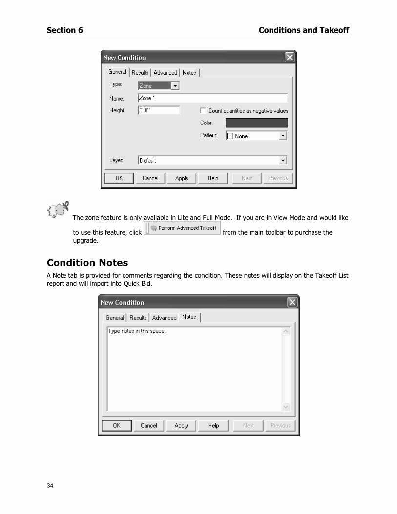
Section 6 Conditions and Takeoff
34
The zone feature is only available in Lite and Full Mode If you are in View Mode and would like
to use this feature click from the main toolbar to purchase the upgrade
Condition Notes A Note tab is provided for comments regarding the condition These notes will display on the Takeoff List report and will import into Quick Bid
Section 6 Conditions and Takeoff
35
Condition Results The Results tab of the New Condition is based on condition type Initial settings default to linear feet (LF) for linear conditions square feet (SF) for area conditions and count of items (EA) for count conditions and zones The first of the results fields will display for the condition items in the Takeoff dock bar area All results will display in worksheets and Takeoff List reports as well as in an Excel spreadsheet after being exported
Copying Conditions You may use the condition attributes from a condition yoursquove already created for any future conditions of the same type
1 Click on a condition to select it
2 Click the Copy button from the toolbar
OR
3 Right-click in the Takeoff dock bar area and select copy
4 A new condition will appear in the list with the same condition attributes as the previous condition but with the quantities zeroed
Editing Conditions Once you have copied a condition you might want to change several attributes You can also edit an existing condition to fit any updated needs
1 Highlight the desired condition on the Takeoff dock bar
2 Click the Change button
OR
3 Double-click on the condition you wish to edit to bring up the Change Condition dialog
NOTE The Change Condition dialog differs from the New Condition dialog only in that if takeoffs
Section 6 Conditions and Takeoff
36
have been performed in your project with this condition you will not be able to change the type of condition or certain properties under the advanced tab of the dialog box
Deleting Conditions 1 Click on the condition in the Takeoff Dock bar area
2 Click the Delete button on the toolbar
OR
3 Right-click and select Delete from the pop-up menu
All takeoff associated with the deleted condition will be deleted immediately and permanently
Organizing Project Conditions Within your project you can create folders andor sub-folders for different types of conditions You may even want to create a folder containing conditions with reset values
To get started organizing your conditions make sure you are viewing the condition tree (right-click in the Takeoff dock bar area and select Show Tree)
Creating Folders and Sub-Folders 1 Right-click in the Takeoff Dock bar area
2 Select New gt Folder from the pop-up menu
Copying Folders
1 Click on the folder and click Copy on the toolbar
2 All copied conditions within the new folder will have values reset to zero
Renaming Folders
1 Click on the folder
2 Right-click and select Rename from the pop-up menu
3 Enter a name for your folder and click the Enter button
Changing Condition Order
You may move conditions up or down in the condition list of the Takeoff dock bar to suit your project needs
1 Select the condition you would like to move by clicking to highlight it
NOTE When you are ready to move the highlighted conditions be sure that you start
moving using the last condition chosen That condition will have a highlighted boarder
Section 6 Conditions and Takeoff
37
2 Drag and drop any the condition from one place to another in the list You may also move a condition to another folder on the list in this way
Drawing with Conditions Snap Angles Set up snap angles to prevent lines from appearing jagged Snap angles are commonly set at 15deg and shift snap angles at 0deg
1 Go to Tools gt Options Options dialog appears
2 Under the General tab make the desired settings
3 Click to save the settings As they are drawn lines will snap to the set degree
Drawing a Linear Object 1 Select a condition from the Condition List in the Takeoff dock bar
2 Move the cursor into the Image takeoff area of the screen you will see the cursor display as crosshairs
3 Click and hold left mouse button then drag mouse to draw a line
4 Release mouse button to set line
Section 6 Conditions and Takeoff
38
5 Repeat steps for further lines
Continuous Mode This feature allows you to draw an object that has connected lines
1 Click the icon from the Takeoff toolbar
OR
2 Go to Tools gt Continuous Mode
3 Follow steps 1-3 from Draw a Linear Object
4 Click at each point of intersection The object will be connected
5 Double-click after making the final point to set the lines
Drawing a Curve To draw a curved line the Curve option must be checked under the Advanced tab of the Condition dialog
1 Click where you want to begin the curve and drag in a straight line to the position for the other endpoint of the curve
2 Click on the line to select it Handles in the shapes of small squares will appear at either end of
Section 6 Conditions and Takeoff
39
the line and in the center of the line
3 Move the cursor over the center handles until the cursor becomes a two-way arrow
4 Click and drag in the direction of the curve bending the line as you move the cursor Release to set the curve (The line you began with will disappear)
Draw a circle by drawing two curved lines connected
Drawing an Area Object Area conditions are drawn similarly to continuous mode lines You may trace any number of adjoining walls at different angles to complete your area takeoff
NOTE When drawing an area do not intersect the perimeter or line of the object you are drawing
1 Click at each point
2 Double-click when yoursquove returned to your starting point
3 The area will be filled with the pattern set for that condition
NOTE The simulated circle will be good enough for you to be able to make a bid
To create a circular area click from point to point with very short distances in between points simulating a circlersquos perimeter Double-click after setting the last point to set the area
Section 6 Conditions and Takeoff
40
Grid Options Grids give you an added advantage when installing materials such as tiles Use this feature to get a count for how many tiles are needed for an area
1 Double-click on an area condition in the Takeoff dock bar to open its Condition dialog
2 Click on the Advanced tab to show its options
3 Check the box next to Grid by clicking in it
4 Indicate the dimensions of the cell matrix in inches (For example 200 x 400)
5 Under Results tab choose each (EA) for one of the results fields This will tabulate a number of grid cells (including partial grid cells) in area
6 Click to save your settings
7 Use the Move Grid and Rotate Grid features in the Tools menu to manipulate the grid as desired
Grid Calculation
1 Go to Tools gt Options menu
1 Specify if On-Screen Takeoff automatically should Calculate Grid Position
2 If AreaGrid Size is selected On-Screen Takeoff will calculate the number of items needed to fill the grid based on grid demintions
3 Click to accept and close the dialog
To move a line at any angle (regardless of default setting) press the Shift key while moving the mouse
Section 6 Conditions and Takeoff
41
Backout Mode This feature allows you to take out part of an area and deduct that amount of square footage
1 Select Tools gt Backout Mode
2 Outline the are you want backed out as you would when drawing a regular area object (see Drawing an Area Object)
3 The outlined area will clear and quantities will be recalculated
NOTE The perimeter of the backout area will be added to the LF quantity for that condition
Drawing a Count Object Square triangle rectangle and circle shaped count objects can easily be placed on images
1 Select the condition
2 Click in the location where you want the object to appear
3 To place an opening-shaped count item like a door or window you must click over an existing linear object such as a wall
4 On the Results tab you can change the height properties to give you the result you need
5 If Backout is checked on the advanced tab for each count opening the opening-shaped count item will back out a corresponding section of the linear object
Opening shaped count items are sized at 3rsquo0rdquo by default
Drawing a Zone Zones are drawn in the same way as area objects and may be any polygonal shape You may trace any number of adjoining walls at different angles to complete the zone perimeter
1 Click at each point
2 Double-click when yoursquove returned to your starting point
Section 6 Conditions and Takeoff
42
Selecting Objects
1 Use the Select Tool to select objects
You can also select all objects that correspond to a condition
1 Click on a condition to select it
2 Right-click and choose Select All
3 All objects with this condition will be highlighted with squares as an outline
Moving and Resizing Objects Linear
1 To move or resize a linear object click anywhere on the line to select it
2 To move the line position your pointer over the center handles When the mouse is positioned over the handles you will see a two-way arrow You will only be able to move the line in the direction of the arrows
3 Drag the line to a new position
4 Clicking and dragging the handles on the ends of the line will allow you to lengthen or shorten your line
Area and Zone
1 To move an area object or zone in its entirety click and drag it to its new position
2 Grabbing a handle at a corner or intersection of the object will allow you to adjust and change its perimeter
Section 6 Conditions and Takeoff
43
Count 1 To move a square circle rectangle or triangle shaped count object click and drag
2 Click and drag an opening shaped count object along the length of the linear object to the desired position then release
NOTE An opening shaped count object may not be moved from its associated linear condition object however it may be moved up and down the length of the linear object
Layers On-Screen Takeoff allows you to sort and separate your takeoff objects within the same job and on the same page On-Screen Takeoff gives you this flexibility through the use of layers
By assigning different conditions to different layers (for example differentiating between floors ceilings and walls) you can choose to view all layers or turn off certain layers to display and print the remaining groups of conditions only You may also remove the background image of electronic plans add text and hot link symbols or print only your condition takeoffs
Layers are only available in Full Mode If you are in View or Lite Mode and would like to use this
feature click from the main toolbar to purchase the upgrade Default Layers
On-Screen Takeoff begins every project with three default layers Image Annotation and Default The Image layer holds the electronic plan files you may have in your project The Annotation layer possesses all text notations highlighting and hot links in the project The Default layer will appear in the Condition dialog when creating or editing a condition (listed in the takeoff dock bar) Conditions are assigned to the Default layer unless otherwise specified by the user
Creating Layers To assign a condition to a layer other than the default layer you must first create additional layers for your project
1 Select View gt Layers to open the Layers dialog
2 Click An unnamed layer will be added
3 Click within the empty box and type a name for your layer (for example Wall)
4 New layers are added as active layers The adjacent box under the Show column will be checked
Section 6 Conditions and Takeoff
44
Assigning a Layer to a Condition 1 Open the Condition dialog box by creating a new condition or editing an existing condition
2 Under the General tab click on the down arrow in the Layer field to display optional layers
3 Select the desired layer for the condition Only the Default layer and layers you have added will be displayed
4 Click
View and Hide Layers
1 Select View gt Layers
2 Under the Show column check the box to view or remove the check (by clicking on it) to hide the specific layer
3 Click to accept and close the Layers dialog
Section 6 Conditions and Takeoff
45
Assigning Text to a Layer When adding text to an image On-Screen Takeoff has the capability to assign the text to a specified layer
1 Select the Text Tool
2 Click at the point you want to place your text
3 Type in your text using the Enter key for line breaks
4 Click the drop down arrow next to the Layer field and select the desired layer
Section 7
46
Printing and Exporting
This section will
Printing options and procedures
Exporting data by copying and pasting
Exporting quantity results to Excel spreadsheets
Section 7 Printing and Exporting
47
Print Setup On-Screen Takeoff allows the user to print the image takeoff list and worksheet
1 Select File gt Print Setup The Print Setup dialog will open
2 Select a printer or leave the default selection listed (change from the default printer displayed by clicking on the down arrow at the right of the field)
3 Indicate page size and printer tray option (Source) Access page size options by clicking on the
down arrow at the right of the field
4 Choose Portrait or Landscape orientation
5 Click to accept and close the dialog
Printing Images The image area can include the electronic plans the takeoff objects added text and hot links To print a subset of these (for example just the takeoffs without the plans or the added text and hot link symbols) hide layers that you do not want to print (see Section 6 View and Hide Layers) When you are printing your images every page will show the scale of the takeoff you are printing
1 Click on the Image tab to display the area of your project
2 Select File gt Print (or Ctrl + P)
Section 7 Printing and Exporting
48
3 Select the desired view (What to print) and the Image Range
4 Click The second Print dialog will open
5 Change settings accordingly or click if you accept the default settings
Printing Takeoff Lists and Worksheets In Takeoff Lists and Worksheets you may hide columns to print only certain results or adjust column widths to fit the report within the page size selected
1 In Takeoff List or Worksheet view move your cursor to the right side of the columnrsquos title bar the cursor will display as a two-way arrow
Section 7 Printing and Exporting
49
2 Click and drag to adjust the width of the column Holding the mouse button you may
slide the title bar under the title bar to its left to hide the column completely
3 Select File gt Print or press Ctrl + P to access the Print dialog
4 Indicate desired printer and choose the number of copies
5 Click to print and close the dialog
When printing the condition list we suggest printing in landscape
To reset to the default column widths double-click on the right border of a column heading will reset the column to its right (or previously to its right before being hidden)
Print Preview 1 Select File gt Print Preview
2 Use and to vary your view 3 If viewing an image choose current full or scale view to see how it displays
4 For printed outputs that cover more than one page use and to view adjacent pages or click on the down arrow next to Page field and select the page you want displayed
Exporting Using the CopyPaste Feature You may copy all the data or sections from the worksheet and the takeoff list view in On-Screen Takeoff and paste it into another application When pasting into Excel the cell layout will be maintained
1 Highlight the areas you wish to paste Click and hold the left mouse button down as you drag the cursor over the area to be selected then releasing the mouse button
OR
2 Select the entire takeoff list quickly click on the left On-Screen Takeoff column header and hold and drag the cursor across the remaining column headings
The number of pages for the view selected will display in the lower left-hand corner The zoom percentage that applies to the view will be displayed in the lower right-hand corner next to page size of the drawing
Section 7 Printing and Exporting
50
3 In the worksheet view you may highlight rows by clicking on the numbered buttons to the left of each row clicking and dragging across column headings or clicking and dragging over individual cells in the worksheet
Click anywhere in the appropriate view to deselect the area
4 Once your selection is highlighted you may select Edit gt Copy or Ctrl C from the keyboard 5 On your monitor switch to the application into which you want to paste your selection 6 Select Edit gt Paste in the new application or simply press Ctrl + V to paste
The colored keys for conditions cannot be pasted
Using the Export Feature You may export condition quantities to specified cell location within an Excel worksheet file Cell target locations are assigned in the Results tab of the condition dialogs on the Export line relating to each quantity measurement type
On-Screen Takeoff will export takeoff quantity results for up to three different quantity types that you specify For instance you may want to know the number of square feet in a ceiling area as well as the number of linear feet in its perimeter
Section 7 Printing and Exporting
51
1 Bring up the Condition dialog by double-clicking on a condition in the takeoff dock bar or by
selecting the condition and clicking
2 Click on the Results tab to access its fields The default quantities for the condition type will display
3 For each results field click on the arrow to access the pull-down menu and select the appropriate quantity (for example SF LF EA etchellip)
4 Have your Excel spreadsheet opened and saved in a file
5 Specify the Excel spreadsheet cell locations where you want the results to go
6 For a cell in the first sheet of your spreadsheet type in the cell address (eg a1) Case is not important
7 For a cell on a successive sheet of your spreadsheet type in sheet the number followed by a comma and the cell address without any spaces (eg sheet2a1) Case is not important
8 Click
9 Select File gt Export gt Condition Qty to Excel
Section 7 Printing and Exporting
52
10 Browse to the location of the Excel spreadsheet file click file to select it
11 Click to export On-Screen Takeoff results to specified cell locations in the Excel file When you return to the Excel application you will see the values have been added to the specified cell locations in your spreadsheet
12 Save your Excel file
Exporting Worksheet to Excel
1 Assign condition quantities you want to export
2 Open saved Excel spreadsheet file to which you will be exporting
3 From On-Screen Takeoff Select File gt Export gt Worksheet to Excel
4 Browse to the location of the Excel spreadsheet file click file to select it
5 Click When you return to the Excel application you will see the values from the Worksheet Tab have been added to your spreadsheet
6 Save your Excel file
Exporting Takeoff to CVS 1 Assign condition quantities you want to export
2 Open saved Excel spreadsheet file to which you will be exporting
3 Click the Takeoff Tab in the project you want to export the information
4 Select File gt Export gt Takeoff to CSV
5 Browse to the location of the CSV spreadsheet file click file to select it
6 Click the Save
NOTE CSV files can be opened in Excel Lotus Access etc One may consider this option more of a ldquodumprdquo into a file
The Excel application must be active (it may be minimized on the application bar) with the target spreadsheet open in the application Otherwise an error will occur with the export operation that will affect both the On-Screen Takeofftrade file and the Excel spreadsheet
Section 8
53
Advanced Features
This section will
Some special features of working with condition objects in the takeoff area
Details of advanced options for conditions
Advanced features of the Project Properties dialog
Section 8 Advanced Features
54
Features to Use with Objects Roping Feature You can move copy or delete using this feature Using the Select tool (the pointer) you may select several objects at once by clicking and dragging an outline around the objects then releasing the mouse button Roping may select either objects completely within the outlined area (inclusive) or objects both within and touched by the outlined area (touching) Specify your roping preference under Tools gt Options
1 Click and hold the mouse button at a point on the screen near the objects to be selected and drag to surround the objects with an outline
2 Release the mouse button The objects will be selected
3 You may now
Move the group around on the page by clicking within the group dragging the mouse and releasing the button to place the objects
Delete the group of objects by clicking the Delete key or
Copy and paste by pressing Ctrl C to copy the group then Ctrl V to paste it The pasted copy of the grouped objects will appear slightly offset from the original objects
Section 8 Advanced Features
55
Applying a DropRun Count
Use the droprun feature when calculating quantities to take into account the drop or run of a linear condition such as electrical lines or plumbing pipes Drop or run lengths may be added separately to any linear condition on screen while a default droprun length may be indicated for a condition as a whole
1 Select the desired linear condition from the Condition List in the Takeoff Dock bar
2 Click the Change button in the toolbar to open the Change Condition dialog
3 Click the Advanced tab to access the advanced options and click inside the DropRun check box
4 Enter a default length to be applied to all of this condition Entering 800 will be interpreted as 8 0 (You must enter both place markers for inches) You can leave the length blank and manually enter drop run on each segment drawn
5 Click the OK button to accept and close the dialog
Edit DropRun Count
1 With the related linear condition in the Takeoff Dock bar highlighted or with the pointer tool selected
2 click on the desired linear object in the image takeoff area The Count button will become active
3 Click on the Count button (alternatively select Tools gt Count) The default droprun amount will show in the pop-up Count dialog (Default length will be zero if droprun has not been selected in this conditionrsquos properties)
4 Type in the desired length Entering 800 will be interpreted as 8 0 (You must enter both place markers for inches)
5 Click the OK button The additional amount will be reflected in the corresponding quantity The new DropRun count will apply only to the object edited
Adding Text in Image View
On-Screen Takeoff allows you to place text comments around your quantity takeoffs that may be printed along with plan images and objects Text is automatically placed within the Annotation Layer (that includes text and hot links)
1 To place text on the image select the Text Tool and click at the point you want to place your text opening a text box
2 Type in your information clicking Enter for line breaks
3 When you are finished click the OK button to exit the text box
4 To reposition text simply click on the text (with the Text Tool active) to select it
5 Move the cursor over the text the cursor will now display as a four-way arrow
6 Click and drag the mouse to position the text as desired
Section 8 Advanced Features
56
1 To edit existing text use the Text Tool to double-click on the text to open the editing box
2 Enter additional text or use the Backspace key to delete text as necessary
Formatting Text Once created you may format the font size type style and color of your text
1 Click on the text to select it and select Tools gt Font or click on the Font button in the Takeoff Toolbar
2 Select the desired features (color options are disabled) and click the OK button
3 Click on the text to select it and select Tools gt Color or click on the Color button in the Takeoff Toolbar The Color dialog will open
4 Click on a color in the Basic Color palette or create a color and add to the Custom Colors palette (Be sure to click on the color in the Custom Colors palette to select it)
5 Click the OK button
Object Properties
Linear Objects
Linear objects may be set to connect at corners
A linear object may be set to trim automatically when crossing another linear object (Check the trim option under the advanced tab of the Condition dialog)
When you move a connected linear object objects automatically move and resize connected lines accordingly (quantities are then recalculated)
This feature requires that the connected linear object be moved using the center handles (does not apply when resizing the line from the ends)
Objects constrain to snap increments defined in the Tools gt Options menu (with the mouse 15deg by default incremental when shift key is held down)
Objects are measured from centerline to centerline
Section 8 Advanced Features
57
Area Objects When drawing an area use your escape key to undo the last line drawn You may reverse your
drawing of an area using the escape key
The area will not fill with color and pattern until the user double-clicks after the last line is set
Lines drawn to delineate an area object constrain to snap increments defined in the Tools gt Options menu (with the mouse 15deg by default incremental when shift key is held down)
After selecting an area to move or adjust position the mouse in the center to move the entire area position the mouse at the sides or corners to adjust the perimeter
Count Objects
All count objects are quantified by the physical number of objects per page and reported as EA for the UOM The quantity for the current Image View is (displayed in the Condition List) and the total quantity in your project is displayed in the Takeoff View and Worksheet View)
Square circle rectangle and triangle shaped count objects do not displace or subtract from other object quantities when placed on top of them However on the Advanced Tab for the count condition a connect property can be set (this is a check box) so that when a count object of this shape is put on top of a Linear type takeoff object it will move with the linear if said linear is moved
An opened-shaped count object must be placed within a linear object Opening shaped count objects may also be measured by linear foot or linear yard (EA SF and SY are also options) Opening shaped count items default to a width of 3rsquo 0rdquo at the time of creation This size can be changed The small medium and large size are not options on this type of condition anymore Check Backout on the Advanced tab for each Count object back out the footage (or yardage) of opening-shaped count objects in which they are placed
NOTE In order to see this Backout functionality (in quantity) for SY or SF deductions at least one of the
results for the Linear(s) this object will be placed on must be set to SY or SF and the count object must have a height quantity
Advanced Features of Conditions The Round Feature Under the Advanced tab of the linear and area Condition dialogues you may specify quantity rounding (in inches) For linear objects rounding applies to each linear object drawn For area objects rounding will apply to each segment of the area perimeter adjusting the perimeter and area calculations For example With a linear condition entering 12 in the Round field will round up each related linear object to the nearest 12 inches or one foot With this setting two walls of 1 4 would each round to 2 0 totaling 4 0
NOTE In the Takeoff Dock bar condition list and in the On-Screen Takeoff reports quantities will be displayed in whole numbers rounded up to the nearest foot However calculations are based on true quantities without rounding unless the Round Feature is engaged
Pitch Pitch may apply either to linear or area conditions It is measured in rise per linear foot Entering 12 indicates a 12 rise per 12 of linear distance (a pitch of 12 over 12) or an angle of 45deg
Section 8 Advanced Features
58
Advanced Features of Project Properties Selecting Multiple Pages
1 Select a single page entry by clicking on the numbered gray button to the left of the entry
2 Drag the cursor down the column of numbers to select consecutive pages
3 Click on the blank button at the top of this column to select all pages in the Properties dialog
Section 8 Advanced Features
59
Changing Image Assigned to a Drawing 1 Select the page entry by clicking on the numbered gray button to the left of the entry 2 Click the Change Image button The Change Image dialog box will appear
3 Navigate to the desired file and select by clicking on it
4 Click the Open button The electronic file assigned to the page will have been changed to reflect the new file choice
Changing Image File Path 1 Select pages as described above
2 Choose Change Folder
3 In the Change Folder dialog navigate to the appropriate folder
4 Click the OK button The file path will have been changed for the selected page entries
Delete a Page from Project Properties 1 Select the page you want to delete by clicking on its associated number (in the gray box at the
left of the entry)
2 Choose Delete Page
All Takeoff on the page will be deleted immediately and permanently
Section 8 Advanced Features
60
Advanced Features of Tool Options
Calculation Method On-Screen Takeoff has built-in calculation options to allow for faster work and faster saves until your takeoff is complete Calculation options are found by selecting Tools gt Options then clicking on the Calculation tab
Calculation method can be set to Automatic Automatic except Grids and Manual Manual will allow the program to operate more quickly while Automatic or Automatic except Grids allows the user to see quantity changes as takeoffs are made
In any mode you may press F9 to recalculate quantities for the On-Screen Takeoff current totals
Configuration Tab
When the ldquoPage Label (A01)rdquo radial button is chosen On-Screen Takeoff puts the numbered label on all the pages of in your current page indicator in your Navigate Toolbar If the Page Descriptionrdquo radial button is chosen then a description of what takeoff is on that specific page will be shown in your current page indicator in your Navigate Toolbar
This section of the configuration tab gives you options on how you want to export your information When the ldquoFolderSubfolder Namesrdquo radial button is chosen than on your file that you are exporting to will have all the conditions folders and subfolders In the Delimiter box you can choose the symbol that is needed to separate the information you are exporting Some files need semicolons () or colons () to make sure the information comes exported in is separated it the appropriate places
Section 8 Advanced Features
61
In previous versions of On-Screen Takeoff there are views that users need to have in order for them to display their information By either choosing ldquoOST 1xrdquo or ldquoOST 2xrdquo it will let the program know you want your columns of information exported in that specific format
When you have the Confirm Deletions radial button of ldquoYesrdquo chosen than every time you delete anything you will get a dialog box confirming your intentions of deletion
While working with your takeoff you have a choice to either view the legend of your conditions or hide it Choose whichever radial button that suits your needs
For those who prefer to use the Enter key to navigate in dialog boxes this option is just for that
Font Tab The Font tab is designed for you to make your own look and feel for the application At the bottom of this tab it will show you sample of the fonts and colors you have chosen
Renaming the Current Page You may change the name of the current page in the takeoff area of On-Screen Takeoff by selecting Edit gt Rename Page
This opens the Name Page dialog and you may simply type in a new name and click the Enter button The new name for the file will be reflected on the title bar for the page and in Project Properties
You also may access the Rename Page function by right-clicking in the takeoff area while in Image View and selecting the option from the pop-up menu that appears
Section 9
62
Saving and Exiting
This section will
Explain how to save projects
Show you how to safely exit the program
Section 9 Saving and Exiting
63
Saving Your Project
1 Select File gt Save 2 If your project has not previously been saved a Save dialog box will open to allow you to name
the file and choose the directory and folder in which to save your file 3 Once saved File gt Save will simply save the current version of the file
OR
4 Select File gt Save As then type in a new name for the file and save to the desired file path
The Auto-save Feature With the Auto-save feature On-Screen Takeoff automatically backs up your open project You may choose to have more than one level of backup files The first backup copy will have the extension b00 and successive files will be b01 b02 and so on If you have designated four levels of backup files after the fourth backup copy has been created (b03) the next file will be saved over the file with extension b00 Further backup saves will then rotate through the four backup files in the same way
1 Select Tools gt Options 2 In the Auto-save area (under the General tab) select the frequency of backup file creation (in
minutes) and the number of levels for the feature 3 You also may disengage the feature by clicking in the check box to clear it
The Auto-save feature automatically saves backup copies to the directory of the current project If you are working from a write-protected area such as a CD-ROM On-Screen Takeoff will place backup files in the On-Screen Takeoff folder
Exiting When you are finished using On-Screen Takeoff it is very easy to exit Exiting is very important because of security reasons If someone were to use your computer they could enter the application and view and manipulate information
Section 9 Saving and Exiting
64
On-Screen Takeoff closes the open project when you open another or create a new project or when you exit the program
1 Select File gt Exit
OR
2 You also may click at the upper right-hand corner of the application to exit
NOTE If your latest changes to a project file have not been saved On-Screen Takeoff will ask you whether you would like to save the file and gives you the option of canceling the operation
Appendix I Installing Your Digitizer
65
Appendix I Installing Your Digitizer When you get your digitizer from GTCO you will need to connect it to your computer Follow the instructions outlined below to do this
Note For rollup digitizers the metal bar must be oriented to the top or right hand side
Connecting the Digitizer 1 Lay the digitizer out flat 2 Connect the Stylus to the digitizer 3 Plug in the power adapter 4 Plug the interface (IO) cable into the digitizer 5 Plug the other end of the interface cable into an open serial port on computer
Note GTCO Technical support phone number is 410-381-6688 The electronic manual (on diskette) from GTCO contains more detailed installation and operation instructions for the GTCO digitizer model you have
Installing other Digitizer Drivers If you are using a GTCO Digitizer you will need to install the GTCO TabletWorks Drivers
If you are using a Digitizer not supported by GTCO Tablet Works 10 please contact the manufacturer of your digitizer for assistance with installation
Installing GTCO TabletWorks Drivers 1 Insert the On Center CD into the CD-ROM drive The CD Startup screen will open 2 Click on Install Software 3 Select Additional Software and Drivers 4 Select Digitizer Driver 5 Follow the instructions for installing TabletWorks 10
Adhering the Template The template is a small plastic sticker used to enable mouse function when using the digitizer with On-Screen Takeoff Place your template on your digitizer We suggest placing it in the bottom right corner of the digitizer about one inch inside the takeoff area
Note You may either peel off the back of the template and use the adhesive surface or you can tape the template down
Appendix I Installing Your Digitizer
66
Testing the Digitizer Drivers Before running OST you may test the digitizer by moving the stylus around on the digitizer pad it should move the mouse cursor (if mouse emulation is enabled)
If the digitizer does not move the mouse cursor on the screen
The superset codes may need to be reset Reset the superset codes by touching on the border of the digitizer with the stylus The digitizer should beep several times
The digitizer may not be communicating with the computer Be sure the COM port selected is correct Be sure the COM port selected is correct If you are not able to get the digitizer to move the mouse cursor you need to call GTCO technical support for help
Note The Mouse Emulation is not required for On-Screen Takeoff to work properly It is used only for the Template functionality if the digitizer is moving the cursor the wrong direction (up instead of sideways or vice-versa)
Click the L-shaped arrow symbol on the digitizer with the stylus
Appendix II Toolbar Item Details
67
Appendix II Toolbar Items Main Toolbar
Appendix II Toolbar Item Details
68
Tool Toolbar
Appendix II Toolbar Item Details
69
Zoom Toolbar
View Toolbar
Navigate Toolbar
Appendix II Toolbar Item Details
70
Navigate Toolbar (Continued)
Takeoff Toolbar
Appendix II Toolbar Item Details
71
Takeoff Toolbar (Continued)
Image Toolbar
Appendix III Loading Plans from a Dodge CD
72
Appendix III Loading Plans from a Dodge CD
This section will detail how to load plans from a F W Dodge CD-ROM into an On-Screen Takeoff project file ready for takeoffs
Dodge files may be added to the Project Properties dialog However loading the files in that way will load the files by number rather than name description If you want to load one page only from your Dodge CD You will have to rename the page to display the name rather than number of the file
To load plan files from a Dodge CD so that the files load sequentially by file number but are displayed by name rather than by number within your project follow the instructions below
Opening a Dodge project from a CD-ROM 1 Insert the CD into the drive 2 Choose File gt Custom 3 Choose Dodge Plans Project (plansdat) as the file type 4 Select the appropriate file type by clicking on the down arrow at the right of the Files of type
field 5 In the Look in field access your drive paths by clicking on the down arrow at the right of the
field then
Navigate to your CD-ROM drive Open the data folder and Open the Projects folder
6 Select the desired project and open its folder 7 Open the plansdat file 8 All the images will come in sequenced correctly for that job along with the full descriptions
(names) of each page If there is not a plans folder in the project folder then plans do not exist for that project on the CD Opening the plansdat file will yield an empty project
Appendix IV Using the Plan Viewer
73
Appendix IV Using On-Screen Takeoff Plan Viewer The On-Screen Takeoff Plan Viewer is a limited version of On Center Softwarersquos commercial takeoff software If your status bar located at the very bottom of the main window says View Mode in the lower left-hand corner then you are using the Plan Viewer You can use the plan viewer to
View CD-based amp converted CAD drawings
View a previously created OST file and associated drawings
Download electronic plans online
Navigate through drawings
Quickly Takeoff linearsareas and counts
Zoom in to view the plan better
Print drawings directly from the viewer
Viewing an On-Screen Takeoff Project File
1 To open an OST file that was previously created with of On-Screen Takeoff 2 Select File gt Open 3 An Open dialog will appear if you do not see the OST file you are looking for select the
Look In drop down arrow 4 A drop down menu will appear listing the various folders drives and mapped drives located
on your computer select the correct drive or folder location and continue to browse to the location of your OST file
5 When you see your OST file double-click it to open it 6 Any takeoff and drawings should appear on the Image tab view
If you do not see the drawings but do see the colored takeoff layer the drawings may
not be located in the same place they were originally saved at Go to File gt Project Properties and check the Image File path for each listed page If the image file path is pointing to a CD drive make sure the CD is inside the CR-ROM
Downloading Electronic Plans If your Online Plan Service provides a special file format (OSX) required to use this feature of our plan viewer you can immediately downloaded all electronic plans of a project directly from our viewer
Most Plan Room web sites will automatically open On-Screen Takeoff when a request to download plans is made Your particular Plan Room may differ in operation so please contact the provider directly with questions on using the site
Appendix IV Using the Plan Viewer
74
When you request to download or open a project file from a Plan Room you will usually have the open to open or save an OSX file Choosing open will automatically open On-Screen Takeoff Alternately you may choose to save the file to a local hard drive After you have saved the file either double-click it to launch On-Screen Takeoff or open the OSX file using On-Screen Takeoff by clicking File then Open and locating the file on your hard drive You will need to change the file type to OSX
After the OSX file is opened you will see an additional tab appear in the Conditions List window called Pages
The Pages tab shows the hierarchy of your project Gray file icons represent pages that have not been downloaded and blue icons represents pages that have been downloaded
To download a page simply double-click the page icon
If you wish to select a group of pages to download you can use the Ctrl or Shift key to multiple select them then click the Download button
If you wish to download all pages at once click the Download All button
Downloaded pages will now appear in the Project Properties dialog in the same order in which they appear in the Pages tab
Creating Quick Takeoffs With On-Screen Takeoff you can create quick takeoffs to measure quantities even if you dont have the full version of our program However using the Quick Takeoff functionality shows you just a fraction of what the full version can do
The Quick Takeoff Toolbar is located at the top of the image view It has three buttons designated for three types of takeoffs Linear Area and Count The Quantity drop down list will show secondary quantities for Linears and Areas The Units drop down allows you to select how you want your quantities displayed Feet Inches Yards Millimeters and Meters
NOTE Every time change the type of takeoff you are performing (switching from Area to Linear for example) the previous quantities and takeoff objects will disappear They will also disappear when you changes pages
NOTE You can use the Dimension Tool to basically measure the distance between two points or linears The distance will display on the status bar at the bottom of the application
The Quick Takeoff Toolbar
Appendix V Frequently Asked Questions
75
Appendix V Frequently Asked Questions General
Where is On-Screen Takeoff installed on my computer
Typically it is installed in CProgram FilesOn-Screen Takeoff
In Explorer how do I recognize On-Screen Takeoff file types
On-Screen Takeoff data is stored in a single file per job lsquojob name OSTrsquo On-Screen Takeoff templates are stored as lsquotemplate nameTPOrsquo
Can only one project at a time be open
Yes For that reason opening another project automatically closes the project on screen You will be asked to save any changes
Is only one scale allowed per page What about on drawings that have multiple detail sections on a page and each of those drawings have different scales
Yes For pages with drawings of different scales copy the drawing to another project page and set the appropriate scale
I cannot perform backout on an area that is along a linear
As a workaround use the On-Screen Takeoff layers feature to help you with this issue Electronic Images
How do I start a project from drawings that have been scanned and written to a CD-ROM
Open a new project Select File gt Project Properties and select Auto Add Navigate to your CD and the appropriate folder and select any image file in that location Click Open All files in the location will load into your project Recommended that images are copied from CD to hard drive for performance
If I get a disk of drawings in AutoCAD format (R13 or R14) can I read them in On-Screen Takeoff
Yes On-Screen Takeoff now reads DWG DXF and many other format that are saved with AutoCAD
Appendix V Frequently Asked Questions
76
When I click on the all pages button what is supposed to happen Currently nothing seems to change when I click on that button
The All Pages button is used to apply the Darken and Enhance Plans feature to all pages in the project (as opposed to only the current page on screen)
Is there a way to deduct a large skylight from an area condition
Yes with the related area condition selected in the Takeoff Dock bar unselect the Backout button on the Takeoff Toolbar then draw the Backout area The area quantity will be deducted from the related condition object and the linear measurement of the Backout perimeter will be added
Digitizer Issues
How do I connect a Digitizer to the computer
See Appendix I Connecting a Digitizer
The Place Template menu choice is disabled
On-Screen Takeoff may need to be authorized or the digitizer or the digitzer drivers are not installed
It wonrsquot let me select the Set Takeoff Area menu choice
On-Screen Takeoff may need to be authorized or no job is open a digitizer is not installed or the drivers are not installed
The digitizer stylus is not moving the cursor or crosshairs
Click S-0-1 superset on the digitizer
How do I convert my old GTCO Digitizer to work with On- Screen Takeofftrade
Call GTCO and they may be able to reconfigure your digitizer to be compatible with On-Screen Takeoff
Printing Issues Which Printers work with On-Screen Takeoff
Compatible printers include On-Screen Takeoff Hewlett Packard Epson and Canon printers If you are having printer difficulties please contact support and specify the type of printer along with other pertinent information Contact support at wwwoncentercomsupport or email supportoncentercom
Which Plotters work with On-Screen Takeoff
Compatible Plotters include Hewlett Packard DesignJet plotters and the EnCAD Cadjet II If you are having plotter difficulties please contact support and specify the type of plotter concerned
ViewingDisplay I can no longer see my condition list How do I get it back
The toolbars and Dock bars can be turned on and off through the View gt Toolbars menu options
Appendix V Frequently Asked Questions
77
This is also accessible by right-clicking in the toolbar area and selecting (or deselecting) a toolbar listed
I cannot view my folders in the condition list
Right-click in the Takeoff Dock barcondition list area and select Show Tree to display your folders
My Status Bar reads Viewer Mode and I am unable to draw conditions
On-Screen Takeoff needs to be Authorized Or you need to purchase an upgrade Click the Perform Advanced Takeoff button on the main toolbar
I hid a Dock bar and when I selected to view it again it appeared alongside the other Dock
bar instead of stacked on top of it How do I fix it
Pick up the Dock bar by clicking on the bar at the top and continuing to hold down the mouse button drag the Dock bar over the other one It will resize and appear stacked with the other
When I open image files from a CD the images are all upside down How do I get them right
side up
To flip pages from top to bottom follow the steps below 1 Click the All Pages button on the Image Toolbar (All Pages is engaged when the button
is not clicked) 2 Click the Flip Horizontal button on the Image Toolbar 3 Click the All Pages button again to disengage
Templates How do I create a Template
Follow the steps below 1 Create a typical project 2 Choose File gt Save As 3 Choose On-Screen Takeoff Template Files as the file type to save 4 Name the file This will save all of the condition setups as well as the layers for the
project
How do I create a new project from a template
Follow the steps below 1 Choose File gt New 2 Select a template from those listed in the New dialog This will open a new project with
conditions and layers saved from a previous project but no pages or takeoff
78
INDEX
Area Conditions 32
Area Objects 57
Auto Scrolling 20
Auto-save 63
Backout Mode 41
Calculation Method 60
Conditions 29
Configuration 60
Contents Tab 6
Continuous Mode 38
Count Conditions 33
Count Objects 57
Digitizer 10 65 76
Docking Toolbars 13
Dodge CD 72
Drawing 27 37
DropRun Count 55
Environment 18
Exiting 63
Exporting 49
Features 16
Font 61
Frequently Asked Questions 75
Grid 40
Help File 5
Hiding Toolbars 13
Hot Links 21
Image 19 59
Image files 9
Image Toolbar 12 71
Images 75
Index Tab 6
Layers 43
Linear Conditions 31
Linear Objects 56
Main Toolbar 12 67
Menus 14
Moving Toolbars 13
Navigate Toolbar 12 69
Navigating 20
On-Screen Takeofftrade 2
Page 59 61
Pages 20 25 28
Plan Viewer 73
Plans 26
Printing 47 76
Project Properties 25
Projects 22
Quick Start Video 18
Resizing Toolbars 13
Roping 54
Saving 63
Scale 28
Search Tab 7
Selecting Objects 42
Setup 8
Start On-Screen Takeofftrade 17
System Requirements 9
Takeoff 19 27
Takeoff Toolbar 70 71
Takeoff Toolbar 12
Template Files 23
TIF (Group4) 9
Tool Toolbar 12 68
Toolbar 67
Toolbars 12
View Toolbar 12 69
Viewing Toolbars 12
Worksheet 20
Zone Conditions 33
Zoom Toolbar 12 69
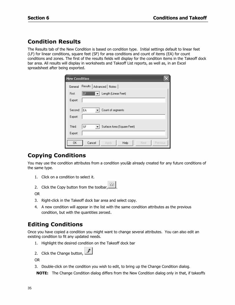
Section 6 Conditions and Takeoff
35
Condition Results The Results tab of the New Condition is based on condition type Initial settings default to linear feet (LF) for linear conditions square feet (SF) for area conditions and count of items (EA) for count conditions and zones The first of the results fields will display for the condition items in the Takeoff dock bar area All results will display in worksheets and Takeoff List reports as well as in an Excel spreadsheet after being exported
Copying Conditions You may use the condition attributes from a condition yoursquove already created for any future conditions of the same type
1 Click on a condition to select it
2 Click the Copy button from the toolbar
OR
3 Right-click in the Takeoff dock bar area and select copy
4 A new condition will appear in the list with the same condition attributes as the previous condition but with the quantities zeroed
Editing Conditions Once you have copied a condition you might want to change several attributes You can also edit an existing condition to fit any updated needs
1 Highlight the desired condition on the Takeoff dock bar
2 Click the Change button
OR
3 Double-click on the condition you wish to edit to bring up the Change Condition dialog
NOTE The Change Condition dialog differs from the New Condition dialog only in that if takeoffs
Section 6 Conditions and Takeoff
36
have been performed in your project with this condition you will not be able to change the type of condition or certain properties under the advanced tab of the dialog box
Deleting Conditions 1 Click on the condition in the Takeoff Dock bar area
2 Click the Delete button on the toolbar
OR
3 Right-click and select Delete from the pop-up menu
All takeoff associated with the deleted condition will be deleted immediately and permanently
Organizing Project Conditions Within your project you can create folders andor sub-folders for different types of conditions You may even want to create a folder containing conditions with reset values
To get started organizing your conditions make sure you are viewing the condition tree (right-click in the Takeoff dock bar area and select Show Tree)
Creating Folders and Sub-Folders 1 Right-click in the Takeoff Dock bar area
2 Select New gt Folder from the pop-up menu
Copying Folders
1 Click on the folder and click Copy on the toolbar
2 All copied conditions within the new folder will have values reset to zero
Renaming Folders
1 Click on the folder
2 Right-click and select Rename from the pop-up menu
3 Enter a name for your folder and click the Enter button
Changing Condition Order
You may move conditions up or down in the condition list of the Takeoff dock bar to suit your project needs
1 Select the condition you would like to move by clicking to highlight it
NOTE When you are ready to move the highlighted conditions be sure that you start
moving using the last condition chosen That condition will have a highlighted boarder
Section 6 Conditions and Takeoff
37
2 Drag and drop any the condition from one place to another in the list You may also move a condition to another folder on the list in this way
Drawing with Conditions Snap Angles Set up snap angles to prevent lines from appearing jagged Snap angles are commonly set at 15deg and shift snap angles at 0deg
1 Go to Tools gt Options Options dialog appears
2 Under the General tab make the desired settings
3 Click to save the settings As they are drawn lines will snap to the set degree
Drawing a Linear Object 1 Select a condition from the Condition List in the Takeoff dock bar
2 Move the cursor into the Image takeoff area of the screen you will see the cursor display as crosshairs
3 Click and hold left mouse button then drag mouse to draw a line
4 Release mouse button to set line
Section 6 Conditions and Takeoff
38
5 Repeat steps for further lines
Continuous Mode This feature allows you to draw an object that has connected lines
1 Click the icon from the Takeoff toolbar
OR
2 Go to Tools gt Continuous Mode
3 Follow steps 1-3 from Draw a Linear Object
4 Click at each point of intersection The object will be connected
5 Double-click after making the final point to set the lines
Drawing a Curve To draw a curved line the Curve option must be checked under the Advanced tab of the Condition dialog
1 Click where you want to begin the curve and drag in a straight line to the position for the other endpoint of the curve
2 Click on the line to select it Handles in the shapes of small squares will appear at either end of
Section 6 Conditions and Takeoff
39
the line and in the center of the line
3 Move the cursor over the center handles until the cursor becomes a two-way arrow
4 Click and drag in the direction of the curve bending the line as you move the cursor Release to set the curve (The line you began with will disappear)
Draw a circle by drawing two curved lines connected
Drawing an Area Object Area conditions are drawn similarly to continuous mode lines You may trace any number of adjoining walls at different angles to complete your area takeoff
NOTE When drawing an area do not intersect the perimeter or line of the object you are drawing
1 Click at each point
2 Double-click when yoursquove returned to your starting point
3 The area will be filled with the pattern set for that condition
NOTE The simulated circle will be good enough for you to be able to make a bid
To create a circular area click from point to point with very short distances in between points simulating a circlersquos perimeter Double-click after setting the last point to set the area
Section 6 Conditions and Takeoff
40
Grid Options Grids give you an added advantage when installing materials such as tiles Use this feature to get a count for how many tiles are needed for an area
1 Double-click on an area condition in the Takeoff dock bar to open its Condition dialog
2 Click on the Advanced tab to show its options
3 Check the box next to Grid by clicking in it
4 Indicate the dimensions of the cell matrix in inches (For example 200 x 400)
5 Under Results tab choose each (EA) for one of the results fields This will tabulate a number of grid cells (including partial grid cells) in area
6 Click to save your settings
7 Use the Move Grid and Rotate Grid features in the Tools menu to manipulate the grid as desired
Grid Calculation
1 Go to Tools gt Options menu
1 Specify if On-Screen Takeoff automatically should Calculate Grid Position
2 If AreaGrid Size is selected On-Screen Takeoff will calculate the number of items needed to fill the grid based on grid demintions
3 Click to accept and close the dialog
To move a line at any angle (regardless of default setting) press the Shift key while moving the mouse
Section 6 Conditions and Takeoff
41
Backout Mode This feature allows you to take out part of an area and deduct that amount of square footage
1 Select Tools gt Backout Mode
2 Outline the are you want backed out as you would when drawing a regular area object (see Drawing an Area Object)
3 The outlined area will clear and quantities will be recalculated
NOTE The perimeter of the backout area will be added to the LF quantity for that condition
Drawing a Count Object Square triangle rectangle and circle shaped count objects can easily be placed on images
1 Select the condition
2 Click in the location where you want the object to appear
3 To place an opening-shaped count item like a door or window you must click over an existing linear object such as a wall
4 On the Results tab you can change the height properties to give you the result you need
5 If Backout is checked on the advanced tab for each count opening the opening-shaped count item will back out a corresponding section of the linear object
Opening shaped count items are sized at 3rsquo0rdquo by default
Drawing a Zone Zones are drawn in the same way as area objects and may be any polygonal shape You may trace any number of adjoining walls at different angles to complete the zone perimeter
1 Click at each point
2 Double-click when yoursquove returned to your starting point
Section 6 Conditions and Takeoff
42
Selecting Objects
1 Use the Select Tool to select objects
You can also select all objects that correspond to a condition
1 Click on a condition to select it
2 Right-click and choose Select All
3 All objects with this condition will be highlighted with squares as an outline
Moving and Resizing Objects Linear
1 To move or resize a linear object click anywhere on the line to select it
2 To move the line position your pointer over the center handles When the mouse is positioned over the handles you will see a two-way arrow You will only be able to move the line in the direction of the arrows
3 Drag the line to a new position
4 Clicking and dragging the handles on the ends of the line will allow you to lengthen or shorten your line
Area and Zone
1 To move an area object or zone in its entirety click and drag it to its new position
2 Grabbing a handle at a corner or intersection of the object will allow you to adjust and change its perimeter
Section 6 Conditions and Takeoff
43
Count 1 To move a square circle rectangle or triangle shaped count object click and drag
2 Click and drag an opening shaped count object along the length of the linear object to the desired position then release
NOTE An opening shaped count object may not be moved from its associated linear condition object however it may be moved up and down the length of the linear object
Layers On-Screen Takeoff allows you to sort and separate your takeoff objects within the same job and on the same page On-Screen Takeoff gives you this flexibility through the use of layers
By assigning different conditions to different layers (for example differentiating between floors ceilings and walls) you can choose to view all layers or turn off certain layers to display and print the remaining groups of conditions only You may also remove the background image of electronic plans add text and hot link symbols or print only your condition takeoffs
Layers are only available in Full Mode If you are in View or Lite Mode and would like to use this
feature click from the main toolbar to purchase the upgrade Default Layers
On-Screen Takeoff begins every project with three default layers Image Annotation and Default The Image layer holds the electronic plan files you may have in your project The Annotation layer possesses all text notations highlighting and hot links in the project The Default layer will appear in the Condition dialog when creating or editing a condition (listed in the takeoff dock bar) Conditions are assigned to the Default layer unless otherwise specified by the user
Creating Layers To assign a condition to a layer other than the default layer you must first create additional layers for your project
1 Select View gt Layers to open the Layers dialog
2 Click An unnamed layer will be added
3 Click within the empty box and type a name for your layer (for example Wall)
4 New layers are added as active layers The adjacent box under the Show column will be checked
Section 6 Conditions and Takeoff
44
Assigning a Layer to a Condition 1 Open the Condition dialog box by creating a new condition or editing an existing condition
2 Under the General tab click on the down arrow in the Layer field to display optional layers
3 Select the desired layer for the condition Only the Default layer and layers you have added will be displayed
4 Click
View and Hide Layers
1 Select View gt Layers
2 Under the Show column check the box to view or remove the check (by clicking on it) to hide the specific layer
3 Click to accept and close the Layers dialog
Section 6 Conditions and Takeoff
45
Assigning Text to a Layer When adding text to an image On-Screen Takeoff has the capability to assign the text to a specified layer
1 Select the Text Tool
2 Click at the point you want to place your text
3 Type in your text using the Enter key for line breaks
4 Click the drop down arrow next to the Layer field and select the desired layer
Section 7
46
Printing and Exporting
This section will
Printing options and procedures
Exporting data by copying and pasting
Exporting quantity results to Excel spreadsheets
Section 7 Printing and Exporting
47
Print Setup On-Screen Takeoff allows the user to print the image takeoff list and worksheet
1 Select File gt Print Setup The Print Setup dialog will open
2 Select a printer or leave the default selection listed (change from the default printer displayed by clicking on the down arrow at the right of the field)
3 Indicate page size and printer tray option (Source) Access page size options by clicking on the
down arrow at the right of the field
4 Choose Portrait or Landscape orientation
5 Click to accept and close the dialog
Printing Images The image area can include the electronic plans the takeoff objects added text and hot links To print a subset of these (for example just the takeoffs without the plans or the added text and hot link symbols) hide layers that you do not want to print (see Section 6 View and Hide Layers) When you are printing your images every page will show the scale of the takeoff you are printing
1 Click on the Image tab to display the area of your project
2 Select File gt Print (or Ctrl + P)
Section 7 Printing and Exporting
48
3 Select the desired view (What to print) and the Image Range
4 Click The second Print dialog will open
5 Change settings accordingly or click if you accept the default settings
Printing Takeoff Lists and Worksheets In Takeoff Lists and Worksheets you may hide columns to print only certain results or adjust column widths to fit the report within the page size selected
1 In Takeoff List or Worksheet view move your cursor to the right side of the columnrsquos title bar the cursor will display as a two-way arrow
Section 7 Printing and Exporting
49
2 Click and drag to adjust the width of the column Holding the mouse button you may
slide the title bar under the title bar to its left to hide the column completely
3 Select File gt Print or press Ctrl + P to access the Print dialog
4 Indicate desired printer and choose the number of copies
5 Click to print and close the dialog
When printing the condition list we suggest printing in landscape
To reset to the default column widths double-click on the right border of a column heading will reset the column to its right (or previously to its right before being hidden)
Print Preview 1 Select File gt Print Preview
2 Use and to vary your view 3 If viewing an image choose current full or scale view to see how it displays
4 For printed outputs that cover more than one page use and to view adjacent pages or click on the down arrow next to Page field and select the page you want displayed
Exporting Using the CopyPaste Feature You may copy all the data or sections from the worksheet and the takeoff list view in On-Screen Takeoff and paste it into another application When pasting into Excel the cell layout will be maintained
1 Highlight the areas you wish to paste Click and hold the left mouse button down as you drag the cursor over the area to be selected then releasing the mouse button
OR
2 Select the entire takeoff list quickly click on the left On-Screen Takeoff column header and hold and drag the cursor across the remaining column headings
The number of pages for the view selected will display in the lower left-hand corner The zoom percentage that applies to the view will be displayed in the lower right-hand corner next to page size of the drawing
Section 7 Printing and Exporting
50
3 In the worksheet view you may highlight rows by clicking on the numbered buttons to the left of each row clicking and dragging across column headings or clicking and dragging over individual cells in the worksheet
Click anywhere in the appropriate view to deselect the area
4 Once your selection is highlighted you may select Edit gt Copy or Ctrl C from the keyboard 5 On your monitor switch to the application into which you want to paste your selection 6 Select Edit gt Paste in the new application or simply press Ctrl + V to paste
The colored keys for conditions cannot be pasted
Using the Export Feature You may export condition quantities to specified cell location within an Excel worksheet file Cell target locations are assigned in the Results tab of the condition dialogs on the Export line relating to each quantity measurement type
On-Screen Takeoff will export takeoff quantity results for up to three different quantity types that you specify For instance you may want to know the number of square feet in a ceiling area as well as the number of linear feet in its perimeter
Section 7 Printing and Exporting
51
1 Bring up the Condition dialog by double-clicking on a condition in the takeoff dock bar or by
selecting the condition and clicking
2 Click on the Results tab to access its fields The default quantities for the condition type will display
3 For each results field click on the arrow to access the pull-down menu and select the appropriate quantity (for example SF LF EA etchellip)
4 Have your Excel spreadsheet opened and saved in a file
5 Specify the Excel spreadsheet cell locations where you want the results to go
6 For a cell in the first sheet of your spreadsheet type in the cell address (eg a1) Case is not important
7 For a cell on a successive sheet of your spreadsheet type in sheet the number followed by a comma and the cell address without any spaces (eg sheet2a1) Case is not important
8 Click
9 Select File gt Export gt Condition Qty to Excel
Section 7 Printing and Exporting
52
10 Browse to the location of the Excel spreadsheet file click file to select it
11 Click to export On-Screen Takeoff results to specified cell locations in the Excel file When you return to the Excel application you will see the values have been added to the specified cell locations in your spreadsheet
12 Save your Excel file
Exporting Worksheet to Excel
1 Assign condition quantities you want to export
2 Open saved Excel spreadsheet file to which you will be exporting
3 From On-Screen Takeoff Select File gt Export gt Worksheet to Excel
4 Browse to the location of the Excel spreadsheet file click file to select it
5 Click When you return to the Excel application you will see the values from the Worksheet Tab have been added to your spreadsheet
6 Save your Excel file
Exporting Takeoff to CVS 1 Assign condition quantities you want to export
2 Open saved Excel spreadsheet file to which you will be exporting
3 Click the Takeoff Tab in the project you want to export the information
4 Select File gt Export gt Takeoff to CSV
5 Browse to the location of the CSV spreadsheet file click file to select it
6 Click the Save
NOTE CSV files can be opened in Excel Lotus Access etc One may consider this option more of a ldquodumprdquo into a file
The Excel application must be active (it may be minimized on the application bar) with the target spreadsheet open in the application Otherwise an error will occur with the export operation that will affect both the On-Screen Takeofftrade file and the Excel spreadsheet
Section 8
53
Advanced Features
This section will
Some special features of working with condition objects in the takeoff area
Details of advanced options for conditions
Advanced features of the Project Properties dialog
Section 8 Advanced Features
54
Features to Use with Objects Roping Feature You can move copy or delete using this feature Using the Select tool (the pointer) you may select several objects at once by clicking and dragging an outline around the objects then releasing the mouse button Roping may select either objects completely within the outlined area (inclusive) or objects both within and touched by the outlined area (touching) Specify your roping preference under Tools gt Options
1 Click and hold the mouse button at a point on the screen near the objects to be selected and drag to surround the objects with an outline
2 Release the mouse button The objects will be selected
3 You may now
Move the group around on the page by clicking within the group dragging the mouse and releasing the button to place the objects
Delete the group of objects by clicking the Delete key or
Copy and paste by pressing Ctrl C to copy the group then Ctrl V to paste it The pasted copy of the grouped objects will appear slightly offset from the original objects
Section 8 Advanced Features
55
Applying a DropRun Count
Use the droprun feature when calculating quantities to take into account the drop or run of a linear condition such as electrical lines or plumbing pipes Drop or run lengths may be added separately to any linear condition on screen while a default droprun length may be indicated for a condition as a whole
1 Select the desired linear condition from the Condition List in the Takeoff Dock bar
2 Click the Change button in the toolbar to open the Change Condition dialog
3 Click the Advanced tab to access the advanced options and click inside the DropRun check box
4 Enter a default length to be applied to all of this condition Entering 800 will be interpreted as 8 0 (You must enter both place markers for inches) You can leave the length blank and manually enter drop run on each segment drawn
5 Click the OK button to accept and close the dialog
Edit DropRun Count
1 With the related linear condition in the Takeoff Dock bar highlighted or with the pointer tool selected
2 click on the desired linear object in the image takeoff area The Count button will become active
3 Click on the Count button (alternatively select Tools gt Count) The default droprun amount will show in the pop-up Count dialog (Default length will be zero if droprun has not been selected in this conditionrsquos properties)
4 Type in the desired length Entering 800 will be interpreted as 8 0 (You must enter both place markers for inches)
5 Click the OK button The additional amount will be reflected in the corresponding quantity The new DropRun count will apply only to the object edited
Adding Text in Image View
On-Screen Takeoff allows you to place text comments around your quantity takeoffs that may be printed along with plan images and objects Text is automatically placed within the Annotation Layer (that includes text and hot links)
1 To place text on the image select the Text Tool and click at the point you want to place your text opening a text box
2 Type in your information clicking Enter for line breaks
3 When you are finished click the OK button to exit the text box
4 To reposition text simply click on the text (with the Text Tool active) to select it
5 Move the cursor over the text the cursor will now display as a four-way arrow
6 Click and drag the mouse to position the text as desired
Section 8 Advanced Features
56
1 To edit existing text use the Text Tool to double-click on the text to open the editing box
2 Enter additional text or use the Backspace key to delete text as necessary
Formatting Text Once created you may format the font size type style and color of your text
1 Click on the text to select it and select Tools gt Font or click on the Font button in the Takeoff Toolbar
2 Select the desired features (color options are disabled) and click the OK button
3 Click on the text to select it and select Tools gt Color or click on the Color button in the Takeoff Toolbar The Color dialog will open
4 Click on a color in the Basic Color palette or create a color and add to the Custom Colors palette (Be sure to click on the color in the Custom Colors palette to select it)
5 Click the OK button
Object Properties
Linear Objects
Linear objects may be set to connect at corners
A linear object may be set to trim automatically when crossing another linear object (Check the trim option under the advanced tab of the Condition dialog)
When you move a connected linear object objects automatically move and resize connected lines accordingly (quantities are then recalculated)
This feature requires that the connected linear object be moved using the center handles (does not apply when resizing the line from the ends)
Objects constrain to snap increments defined in the Tools gt Options menu (with the mouse 15deg by default incremental when shift key is held down)
Objects are measured from centerline to centerline
Section 8 Advanced Features
57
Area Objects When drawing an area use your escape key to undo the last line drawn You may reverse your
drawing of an area using the escape key
The area will not fill with color and pattern until the user double-clicks after the last line is set
Lines drawn to delineate an area object constrain to snap increments defined in the Tools gt Options menu (with the mouse 15deg by default incremental when shift key is held down)
After selecting an area to move or adjust position the mouse in the center to move the entire area position the mouse at the sides or corners to adjust the perimeter
Count Objects
All count objects are quantified by the physical number of objects per page and reported as EA for the UOM The quantity for the current Image View is (displayed in the Condition List) and the total quantity in your project is displayed in the Takeoff View and Worksheet View)
Square circle rectangle and triangle shaped count objects do not displace or subtract from other object quantities when placed on top of them However on the Advanced Tab for the count condition a connect property can be set (this is a check box) so that when a count object of this shape is put on top of a Linear type takeoff object it will move with the linear if said linear is moved
An opened-shaped count object must be placed within a linear object Opening shaped count objects may also be measured by linear foot or linear yard (EA SF and SY are also options) Opening shaped count items default to a width of 3rsquo 0rdquo at the time of creation This size can be changed The small medium and large size are not options on this type of condition anymore Check Backout on the Advanced tab for each Count object back out the footage (or yardage) of opening-shaped count objects in which they are placed
NOTE In order to see this Backout functionality (in quantity) for SY or SF deductions at least one of the
results for the Linear(s) this object will be placed on must be set to SY or SF and the count object must have a height quantity
Advanced Features of Conditions The Round Feature Under the Advanced tab of the linear and area Condition dialogues you may specify quantity rounding (in inches) For linear objects rounding applies to each linear object drawn For area objects rounding will apply to each segment of the area perimeter adjusting the perimeter and area calculations For example With a linear condition entering 12 in the Round field will round up each related linear object to the nearest 12 inches or one foot With this setting two walls of 1 4 would each round to 2 0 totaling 4 0
NOTE In the Takeoff Dock bar condition list and in the On-Screen Takeoff reports quantities will be displayed in whole numbers rounded up to the nearest foot However calculations are based on true quantities without rounding unless the Round Feature is engaged
Pitch Pitch may apply either to linear or area conditions It is measured in rise per linear foot Entering 12 indicates a 12 rise per 12 of linear distance (a pitch of 12 over 12) or an angle of 45deg
Section 8 Advanced Features
58
Advanced Features of Project Properties Selecting Multiple Pages
1 Select a single page entry by clicking on the numbered gray button to the left of the entry
2 Drag the cursor down the column of numbers to select consecutive pages
3 Click on the blank button at the top of this column to select all pages in the Properties dialog
Section 8 Advanced Features
59
Changing Image Assigned to a Drawing 1 Select the page entry by clicking on the numbered gray button to the left of the entry 2 Click the Change Image button The Change Image dialog box will appear
3 Navigate to the desired file and select by clicking on it
4 Click the Open button The electronic file assigned to the page will have been changed to reflect the new file choice
Changing Image File Path 1 Select pages as described above
2 Choose Change Folder
3 In the Change Folder dialog navigate to the appropriate folder
4 Click the OK button The file path will have been changed for the selected page entries
Delete a Page from Project Properties 1 Select the page you want to delete by clicking on its associated number (in the gray box at the
left of the entry)
2 Choose Delete Page
All Takeoff on the page will be deleted immediately and permanently
Section 8 Advanced Features
60
Advanced Features of Tool Options
Calculation Method On-Screen Takeoff has built-in calculation options to allow for faster work and faster saves until your takeoff is complete Calculation options are found by selecting Tools gt Options then clicking on the Calculation tab
Calculation method can be set to Automatic Automatic except Grids and Manual Manual will allow the program to operate more quickly while Automatic or Automatic except Grids allows the user to see quantity changes as takeoffs are made
In any mode you may press F9 to recalculate quantities for the On-Screen Takeoff current totals
Configuration Tab
When the ldquoPage Label (A01)rdquo radial button is chosen On-Screen Takeoff puts the numbered label on all the pages of in your current page indicator in your Navigate Toolbar If the Page Descriptionrdquo radial button is chosen then a description of what takeoff is on that specific page will be shown in your current page indicator in your Navigate Toolbar
This section of the configuration tab gives you options on how you want to export your information When the ldquoFolderSubfolder Namesrdquo radial button is chosen than on your file that you are exporting to will have all the conditions folders and subfolders In the Delimiter box you can choose the symbol that is needed to separate the information you are exporting Some files need semicolons () or colons () to make sure the information comes exported in is separated it the appropriate places
Section 8 Advanced Features
61
In previous versions of On-Screen Takeoff there are views that users need to have in order for them to display their information By either choosing ldquoOST 1xrdquo or ldquoOST 2xrdquo it will let the program know you want your columns of information exported in that specific format
When you have the Confirm Deletions radial button of ldquoYesrdquo chosen than every time you delete anything you will get a dialog box confirming your intentions of deletion
While working with your takeoff you have a choice to either view the legend of your conditions or hide it Choose whichever radial button that suits your needs
For those who prefer to use the Enter key to navigate in dialog boxes this option is just for that
Font Tab The Font tab is designed for you to make your own look and feel for the application At the bottom of this tab it will show you sample of the fonts and colors you have chosen
Renaming the Current Page You may change the name of the current page in the takeoff area of On-Screen Takeoff by selecting Edit gt Rename Page
This opens the Name Page dialog and you may simply type in a new name and click the Enter button The new name for the file will be reflected on the title bar for the page and in Project Properties
You also may access the Rename Page function by right-clicking in the takeoff area while in Image View and selecting the option from the pop-up menu that appears
Section 9
62
Saving and Exiting
This section will
Explain how to save projects
Show you how to safely exit the program
Section 9 Saving and Exiting
63
Saving Your Project
1 Select File gt Save 2 If your project has not previously been saved a Save dialog box will open to allow you to name
the file and choose the directory and folder in which to save your file 3 Once saved File gt Save will simply save the current version of the file
OR
4 Select File gt Save As then type in a new name for the file and save to the desired file path
The Auto-save Feature With the Auto-save feature On-Screen Takeoff automatically backs up your open project You may choose to have more than one level of backup files The first backup copy will have the extension b00 and successive files will be b01 b02 and so on If you have designated four levels of backup files after the fourth backup copy has been created (b03) the next file will be saved over the file with extension b00 Further backup saves will then rotate through the four backup files in the same way
1 Select Tools gt Options 2 In the Auto-save area (under the General tab) select the frequency of backup file creation (in
minutes) and the number of levels for the feature 3 You also may disengage the feature by clicking in the check box to clear it
The Auto-save feature automatically saves backup copies to the directory of the current project If you are working from a write-protected area such as a CD-ROM On-Screen Takeoff will place backup files in the On-Screen Takeoff folder
Exiting When you are finished using On-Screen Takeoff it is very easy to exit Exiting is very important because of security reasons If someone were to use your computer they could enter the application and view and manipulate information
Section 9 Saving and Exiting
64
On-Screen Takeoff closes the open project when you open another or create a new project or when you exit the program
1 Select File gt Exit
OR
2 You also may click at the upper right-hand corner of the application to exit
NOTE If your latest changes to a project file have not been saved On-Screen Takeoff will ask you whether you would like to save the file and gives you the option of canceling the operation
Appendix I Installing Your Digitizer
65
Appendix I Installing Your Digitizer When you get your digitizer from GTCO you will need to connect it to your computer Follow the instructions outlined below to do this
Note For rollup digitizers the metal bar must be oriented to the top or right hand side
Connecting the Digitizer 1 Lay the digitizer out flat 2 Connect the Stylus to the digitizer 3 Plug in the power adapter 4 Plug the interface (IO) cable into the digitizer 5 Plug the other end of the interface cable into an open serial port on computer
Note GTCO Technical support phone number is 410-381-6688 The electronic manual (on diskette) from GTCO contains more detailed installation and operation instructions for the GTCO digitizer model you have
Installing other Digitizer Drivers If you are using a GTCO Digitizer you will need to install the GTCO TabletWorks Drivers
If you are using a Digitizer not supported by GTCO Tablet Works 10 please contact the manufacturer of your digitizer for assistance with installation
Installing GTCO TabletWorks Drivers 1 Insert the On Center CD into the CD-ROM drive The CD Startup screen will open 2 Click on Install Software 3 Select Additional Software and Drivers 4 Select Digitizer Driver 5 Follow the instructions for installing TabletWorks 10
Adhering the Template The template is a small plastic sticker used to enable mouse function when using the digitizer with On-Screen Takeoff Place your template on your digitizer We suggest placing it in the bottom right corner of the digitizer about one inch inside the takeoff area
Note You may either peel off the back of the template and use the adhesive surface or you can tape the template down
Appendix I Installing Your Digitizer
66
Testing the Digitizer Drivers Before running OST you may test the digitizer by moving the stylus around on the digitizer pad it should move the mouse cursor (if mouse emulation is enabled)
If the digitizer does not move the mouse cursor on the screen
The superset codes may need to be reset Reset the superset codes by touching on the border of the digitizer with the stylus The digitizer should beep several times
The digitizer may not be communicating with the computer Be sure the COM port selected is correct Be sure the COM port selected is correct If you are not able to get the digitizer to move the mouse cursor you need to call GTCO technical support for help
Note The Mouse Emulation is not required for On-Screen Takeoff to work properly It is used only for the Template functionality if the digitizer is moving the cursor the wrong direction (up instead of sideways or vice-versa)
Click the L-shaped arrow symbol on the digitizer with the stylus
Appendix II Toolbar Item Details
67
Appendix II Toolbar Items Main Toolbar
Appendix II Toolbar Item Details
68
Tool Toolbar
Appendix II Toolbar Item Details
69
Zoom Toolbar
View Toolbar
Navigate Toolbar
Appendix II Toolbar Item Details
70
Navigate Toolbar (Continued)
Takeoff Toolbar
Appendix II Toolbar Item Details
71
Takeoff Toolbar (Continued)
Image Toolbar
Appendix III Loading Plans from a Dodge CD
72
Appendix III Loading Plans from a Dodge CD
This section will detail how to load plans from a F W Dodge CD-ROM into an On-Screen Takeoff project file ready for takeoffs
Dodge files may be added to the Project Properties dialog However loading the files in that way will load the files by number rather than name description If you want to load one page only from your Dodge CD You will have to rename the page to display the name rather than number of the file
To load plan files from a Dodge CD so that the files load sequentially by file number but are displayed by name rather than by number within your project follow the instructions below
Opening a Dodge project from a CD-ROM 1 Insert the CD into the drive 2 Choose File gt Custom 3 Choose Dodge Plans Project (plansdat) as the file type 4 Select the appropriate file type by clicking on the down arrow at the right of the Files of type
field 5 In the Look in field access your drive paths by clicking on the down arrow at the right of the
field then
Navigate to your CD-ROM drive Open the data folder and Open the Projects folder
6 Select the desired project and open its folder 7 Open the plansdat file 8 All the images will come in sequenced correctly for that job along with the full descriptions
(names) of each page If there is not a plans folder in the project folder then plans do not exist for that project on the CD Opening the plansdat file will yield an empty project
Appendix IV Using the Plan Viewer
73
Appendix IV Using On-Screen Takeoff Plan Viewer The On-Screen Takeoff Plan Viewer is a limited version of On Center Softwarersquos commercial takeoff software If your status bar located at the very bottom of the main window says View Mode in the lower left-hand corner then you are using the Plan Viewer You can use the plan viewer to
View CD-based amp converted CAD drawings
View a previously created OST file and associated drawings
Download electronic plans online
Navigate through drawings
Quickly Takeoff linearsareas and counts
Zoom in to view the plan better
Print drawings directly from the viewer
Viewing an On-Screen Takeoff Project File
1 To open an OST file that was previously created with of On-Screen Takeoff 2 Select File gt Open 3 An Open dialog will appear if you do not see the OST file you are looking for select the
Look In drop down arrow 4 A drop down menu will appear listing the various folders drives and mapped drives located
on your computer select the correct drive or folder location and continue to browse to the location of your OST file
5 When you see your OST file double-click it to open it 6 Any takeoff and drawings should appear on the Image tab view
If you do not see the drawings but do see the colored takeoff layer the drawings may
not be located in the same place they were originally saved at Go to File gt Project Properties and check the Image File path for each listed page If the image file path is pointing to a CD drive make sure the CD is inside the CR-ROM
Downloading Electronic Plans If your Online Plan Service provides a special file format (OSX) required to use this feature of our plan viewer you can immediately downloaded all electronic plans of a project directly from our viewer
Most Plan Room web sites will automatically open On-Screen Takeoff when a request to download plans is made Your particular Plan Room may differ in operation so please contact the provider directly with questions on using the site
Appendix IV Using the Plan Viewer
74
When you request to download or open a project file from a Plan Room you will usually have the open to open or save an OSX file Choosing open will automatically open On-Screen Takeoff Alternately you may choose to save the file to a local hard drive After you have saved the file either double-click it to launch On-Screen Takeoff or open the OSX file using On-Screen Takeoff by clicking File then Open and locating the file on your hard drive You will need to change the file type to OSX
After the OSX file is opened you will see an additional tab appear in the Conditions List window called Pages
The Pages tab shows the hierarchy of your project Gray file icons represent pages that have not been downloaded and blue icons represents pages that have been downloaded
To download a page simply double-click the page icon
If you wish to select a group of pages to download you can use the Ctrl or Shift key to multiple select them then click the Download button
If you wish to download all pages at once click the Download All button
Downloaded pages will now appear in the Project Properties dialog in the same order in which they appear in the Pages tab
Creating Quick Takeoffs With On-Screen Takeoff you can create quick takeoffs to measure quantities even if you dont have the full version of our program However using the Quick Takeoff functionality shows you just a fraction of what the full version can do
The Quick Takeoff Toolbar is located at the top of the image view It has three buttons designated for three types of takeoffs Linear Area and Count The Quantity drop down list will show secondary quantities for Linears and Areas The Units drop down allows you to select how you want your quantities displayed Feet Inches Yards Millimeters and Meters
NOTE Every time change the type of takeoff you are performing (switching from Area to Linear for example) the previous quantities and takeoff objects will disappear They will also disappear when you changes pages
NOTE You can use the Dimension Tool to basically measure the distance between two points or linears The distance will display on the status bar at the bottom of the application
The Quick Takeoff Toolbar
Appendix V Frequently Asked Questions
75
Appendix V Frequently Asked Questions General
Where is On-Screen Takeoff installed on my computer
Typically it is installed in CProgram FilesOn-Screen Takeoff
In Explorer how do I recognize On-Screen Takeoff file types
On-Screen Takeoff data is stored in a single file per job lsquojob name OSTrsquo On-Screen Takeoff templates are stored as lsquotemplate nameTPOrsquo
Can only one project at a time be open
Yes For that reason opening another project automatically closes the project on screen You will be asked to save any changes
Is only one scale allowed per page What about on drawings that have multiple detail sections on a page and each of those drawings have different scales
Yes For pages with drawings of different scales copy the drawing to another project page and set the appropriate scale
I cannot perform backout on an area that is along a linear
As a workaround use the On-Screen Takeoff layers feature to help you with this issue Electronic Images
How do I start a project from drawings that have been scanned and written to a CD-ROM
Open a new project Select File gt Project Properties and select Auto Add Navigate to your CD and the appropriate folder and select any image file in that location Click Open All files in the location will load into your project Recommended that images are copied from CD to hard drive for performance
If I get a disk of drawings in AutoCAD format (R13 or R14) can I read them in On-Screen Takeoff
Yes On-Screen Takeoff now reads DWG DXF and many other format that are saved with AutoCAD
Appendix V Frequently Asked Questions
76
When I click on the all pages button what is supposed to happen Currently nothing seems to change when I click on that button
The All Pages button is used to apply the Darken and Enhance Plans feature to all pages in the project (as opposed to only the current page on screen)
Is there a way to deduct a large skylight from an area condition
Yes with the related area condition selected in the Takeoff Dock bar unselect the Backout button on the Takeoff Toolbar then draw the Backout area The area quantity will be deducted from the related condition object and the linear measurement of the Backout perimeter will be added
Digitizer Issues
How do I connect a Digitizer to the computer
See Appendix I Connecting a Digitizer
The Place Template menu choice is disabled
On-Screen Takeoff may need to be authorized or the digitizer or the digitzer drivers are not installed
It wonrsquot let me select the Set Takeoff Area menu choice
On-Screen Takeoff may need to be authorized or no job is open a digitizer is not installed or the drivers are not installed
The digitizer stylus is not moving the cursor or crosshairs
Click S-0-1 superset on the digitizer
How do I convert my old GTCO Digitizer to work with On- Screen Takeofftrade
Call GTCO and they may be able to reconfigure your digitizer to be compatible with On-Screen Takeoff
Printing Issues Which Printers work with On-Screen Takeoff
Compatible printers include On-Screen Takeoff Hewlett Packard Epson and Canon printers If you are having printer difficulties please contact support and specify the type of printer along with other pertinent information Contact support at wwwoncentercomsupport or email supportoncentercom
Which Plotters work with On-Screen Takeoff
Compatible Plotters include Hewlett Packard DesignJet plotters and the EnCAD Cadjet II If you are having plotter difficulties please contact support and specify the type of plotter concerned
ViewingDisplay I can no longer see my condition list How do I get it back
The toolbars and Dock bars can be turned on and off through the View gt Toolbars menu options
Appendix V Frequently Asked Questions
77
This is also accessible by right-clicking in the toolbar area and selecting (or deselecting) a toolbar listed
I cannot view my folders in the condition list
Right-click in the Takeoff Dock barcondition list area and select Show Tree to display your folders
My Status Bar reads Viewer Mode and I am unable to draw conditions
On-Screen Takeoff needs to be Authorized Or you need to purchase an upgrade Click the Perform Advanced Takeoff button on the main toolbar
I hid a Dock bar and when I selected to view it again it appeared alongside the other Dock
bar instead of stacked on top of it How do I fix it
Pick up the Dock bar by clicking on the bar at the top and continuing to hold down the mouse button drag the Dock bar over the other one It will resize and appear stacked with the other
When I open image files from a CD the images are all upside down How do I get them right
side up
To flip pages from top to bottom follow the steps below 1 Click the All Pages button on the Image Toolbar (All Pages is engaged when the button
is not clicked) 2 Click the Flip Horizontal button on the Image Toolbar 3 Click the All Pages button again to disengage
Templates How do I create a Template
Follow the steps below 1 Create a typical project 2 Choose File gt Save As 3 Choose On-Screen Takeoff Template Files as the file type to save 4 Name the file This will save all of the condition setups as well as the layers for the
project
How do I create a new project from a template
Follow the steps below 1 Choose File gt New 2 Select a template from those listed in the New dialog This will open a new project with
conditions and layers saved from a previous project but no pages or takeoff
78
INDEX
Area Conditions 32
Area Objects 57
Auto Scrolling 20
Auto-save 63
Backout Mode 41
Calculation Method 60
Conditions 29
Configuration 60
Contents Tab 6
Continuous Mode 38
Count Conditions 33
Count Objects 57
Digitizer 10 65 76
Docking Toolbars 13
Dodge CD 72
Drawing 27 37
DropRun Count 55
Environment 18
Exiting 63
Exporting 49
Features 16
Font 61
Frequently Asked Questions 75
Grid 40
Help File 5
Hiding Toolbars 13
Hot Links 21
Image 19 59
Image files 9
Image Toolbar 12 71
Images 75
Index Tab 6
Layers 43
Linear Conditions 31
Linear Objects 56
Main Toolbar 12 67
Menus 14
Moving Toolbars 13
Navigate Toolbar 12 69
Navigating 20
On-Screen Takeofftrade 2
Page 59 61
Pages 20 25 28
Plan Viewer 73
Plans 26
Printing 47 76
Project Properties 25
Projects 22
Quick Start Video 18
Resizing Toolbars 13
Roping 54
Saving 63
Scale 28
Search Tab 7
Selecting Objects 42
Setup 8
Start On-Screen Takeofftrade 17
System Requirements 9
Takeoff 19 27
Takeoff Toolbar 70 71
Takeoff Toolbar 12
Template Files 23
TIF (Group4) 9
Tool Toolbar 12 68
Toolbar 67
Toolbars 12
View Toolbar 12 69
Viewing Toolbars 12
Worksheet 20
Zone Conditions 33
Zoom Toolbar 12 69
Section 6 Conditions and Takeoff
36
have been performed in your project with this condition you will not be able to change the type of condition or certain properties under the advanced tab of the dialog box
Deleting Conditions 1 Click on the condition in the Takeoff Dock bar area
2 Click the Delete button on the toolbar
OR
3 Right-click and select Delete from the pop-up menu
All takeoff associated with the deleted condition will be deleted immediately and permanently
Organizing Project Conditions Within your project you can create folders andor sub-folders for different types of conditions You may even want to create a folder containing conditions with reset values
To get started organizing your conditions make sure you are viewing the condition tree (right-click in the Takeoff dock bar area and select Show Tree)
Creating Folders and Sub-Folders 1 Right-click in the Takeoff Dock bar area
2 Select New gt Folder from the pop-up menu
Copying Folders
1 Click on the folder and click Copy on the toolbar
2 All copied conditions within the new folder will have values reset to zero
Renaming Folders
1 Click on the folder
2 Right-click and select Rename from the pop-up menu
3 Enter a name for your folder and click the Enter button
Changing Condition Order
You may move conditions up or down in the condition list of the Takeoff dock bar to suit your project needs
1 Select the condition you would like to move by clicking to highlight it
NOTE When you are ready to move the highlighted conditions be sure that you start
moving using the last condition chosen That condition will have a highlighted boarder
Section 6 Conditions and Takeoff
37
2 Drag and drop any the condition from one place to another in the list You may also move a condition to another folder on the list in this way
Drawing with Conditions Snap Angles Set up snap angles to prevent lines from appearing jagged Snap angles are commonly set at 15deg and shift snap angles at 0deg
1 Go to Tools gt Options Options dialog appears
2 Under the General tab make the desired settings
3 Click to save the settings As they are drawn lines will snap to the set degree
Drawing a Linear Object 1 Select a condition from the Condition List in the Takeoff dock bar
2 Move the cursor into the Image takeoff area of the screen you will see the cursor display as crosshairs
3 Click and hold left mouse button then drag mouse to draw a line
4 Release mouse button to set line
Section 6 Conditions and Takeoff
38
5 Repeat steps for further lines
Continuous Mode This feature allows you to draw an object that has connected lines
1 Click the icon from the Takeoff toolbar
OR
2 Go to Tools gt Continuous Mode
3 Follow steps 1-3 from Draw a Linear Object
4 Click at each point of intersection The object will be connected
5 Double-click after making the final point to set the lines
Drawing a Curve To draw a curved line the Curve option must be checked under the Advanced tab of the Condition dialog
1 Click where you want to begin the curve and drag in a straight line to the position for the other endpoint of the curve
2 Click on the line to select it Handles in the shapes of small squares will appear at either end of
Section 6 Conditions and Takeoff
39
the line and in the center of the line
3 Move the cursor over the center handles until the cursor becomes a two-way arrow
4 Click and drag in the direction of the curve bending the line as you move the cursor Release to set the curve (The line you began with will disappear)
Draw a circle by drawing two curved lines connected
Drawing an Area Object Area conditions are drawn similarly to continuous mode lines You may trace any number of adjoining walls at different angles to complete your area takeoff
NOTE When drawing an area do not intersect the perimeter or line of the object you are drawing
1 Click at each point
2 Double-click when yoursquove returned to your starting point
3 The area will be filled with the pattern set for that condition
NOTE The simulated circle will be good enough for you to be able to make a bid
To create a circular area click from point to point with very short distances in between points simulating a circlersquos perimeter Double-click after setting the last point to set the area
Section 6 Conditions and Takeoff
40
Grid Options Grids give you an added advantage when installing materials such as tiles Use this feature to get a count for how many tiles are needed for an area
1 Double-click on an area condition in the Takeoff dock bar to open its Condition dialog
2 Click on the Advanced tab to show its options
3 Check the box next to Grid by clicking in it
4 Indicate the dimensions of the cell matrix in inches (For example 200 x 400)
5 Under Results tab choose each (EA) for one of the results fields This will tabulate a number of grid cells (including partial grid cells) in area
6 Click to save your settings
7 Use the Move Grid and Rotate Grid features in the Tools menu to manipulate the grid as desired
Grid Calculation
1 Go to Tools gt Options menu
1 Specify if On-Screen Takeoff automatically should Calculate Grid Position
2 If AreaGrid Size is selected On-Screen Takeoff will calculate the number of items needed to fill the grid based on grid demintions
3 Click to accept and close the dialog
To move a line at any angle (regardless of default setting) press the Shift key while moving the mouse
Section 6 Conditions and Takeoff
41
Backout Mode This feature allows you to take out part of an area and deduct that amount of square footage
1 Select Tools gt Backout Mode
2 Outline the are you want backed out as you would when drawing a regular area object (see Drawing an Area Object)
3 The outlined area will clear and quantities will be recalculated
NOTE The perimeter of the backout area will be added to the LF quantity for that condition
Drawing a Count Object Square triangle rectangle and circle shaped count objects can easily be placed on images
1 Select the condition
2 Click in the location where you want the object to appear
3 To place an opening-shaped count item like a door or window you must click over an existing linear object such as a wall
4 On the Results tab you can change the height properties to give you the result you need
5 If Backout is checked on the advanced tab for each count opening the opening-shaped count item will back out a corresponding section of the linear object
Opening shaped count items are sized at 3rsquo0rdquo by default
Drawing a Zone Zones are drawn in the same way as area objects and may be any polygonal shape You may trace any number of adjoining walls at different angles to complete the zone perimeter
1 Click at each point
2 Double-click when yoursquove returned to your starting point
Section 6 Conditions and Takeoff
42
Selecting Objects
1 Use the Select Tool to select objects
You can also select all objects that correspond to a condition
1 Click on a condition to select it
2 Right-click and choose Select All
3 All objects with this condition will be highlighted with squares as an outline
Moving and Resizing Objects Linear
1 To move or resize a linear object click anywhere on the line to select it
2 To move the line position your pointer over the center handles When the mouse is positioned over the handles you will see a two-way arrow You will only be able to move the line in the direction of the arrows
3 Drag the line to a new position
4 Clicking and dragging the handles on the ends of the line will allow you to lengthen or shorten your line
Area and Zone
1 To move an area object or zone in its entirety click and drag it to its new position
2 Grabbing a handle at a corner or intersection of the object will allow you to adjust and change its perimeter
Section 6 Conditions and Takeoff
43
Count 1 To move a square circle rectangle or triangle shaped count object click and drag
2 Click and drag an opening shaped count object along the length of the linear object to the desired position then release
NOTE An opening shaped count object may not be moved from its associated linear condition object however it may be moved up and down the length of the linear object
Layers On-Screen Takeoff allows you to sort and separate your takeoff objects within the same job and on the same page On-Screen Takeoff gives you this flexibility through the use of layers
By assigning different conditions to different layers (for example differentiating between floors ceilings and walls) you can choose to view all layers or turn off certain layers to display and print the remaining groups of conditions only You may also remove the background image of electronic plans add text and hot link symbols or print only your condition takeoffs
Layers are only available in Full Mode If you are in View or Lite Mode and would like to use this
feature click from the main toolbar to purchase the upgrade Default Layers
On-Screen Takeoff begins every project with three default layers Image Annotation and Default The Image layer holds the electronic plan files you may have in your project The Annotation layer possesses all text notations highlighting and hot links in the project The Default layer will appear in the Condition dialog when creating or editing a condition (listed in the takeoff dock bar) Conditions are assigned to the Default layer unless otherwise specified by the user
Creating Layers To assign a condition to a layer other than the default layer you must first create additional layers for your project
1 Select View gt Layers to open the Layers dialog
2 Click An unnamed layer will be added
3 Click within the empty box and type a name for your layer (for example Wall)
4 New layers are added as active layers The adjacent box under the Show column will be checked
Section 6 Conditions and Takeoff
44
Assigning a Layer to a Condition 1 Open the Condition dialog box by creating a new condition or editing an existing condition
2 Under the General tab click on the down arrow in the Layer field to display optional layers
3 Select the desired layer for the condition Only the Default layer and layers you have added will be displayed
4 Click
View and Hide Layers
1 Select View gt Layers
2 Under the Show column check the box to view or remove the check (by clicking on it) to hide the specific layer
3 Click to accept and close the Layers dialog
Section 6 Conditions and Takeoff
45
Assigning Text to a Layer When adding text to an image On-Screen Takeoff has the capability to assign the text to a specified layer
1 Select the Text Tool
2 Click at the point you want to place your text
3 Type in your text using the Enter key for line breaks
4 Click the drop down arrow next to the Layer field and select the desired layer
Section 7
46
Printing and Exporting
This section will
Printing options and procedures
Exporting data by copying and pasting
Exporting quantity results to Excel spreadsheets
Section 7 Printing and Exporting
47
Print Setup On-Screen Takeoff allows the user to print the image takeoff list and worksheet
1 Select File gt Print Setup The Print Setup dialog will open
2 Select a printer or leave the default selection listed (change from the default printer displayed by clicking on the down arrow at the right of the field)
3 Indicate page size and printer tray option (Source) Access page size options by clicking on the
down arrow at the right of the field
4 Choose Portrait or Landscape orientation
5 Click to accept and close the dialog
Printing Images The image area can include the electronic plans the takeoff objects added text and hot links To print a subset of these (for example just the takeoffs without the plans or the added text and hot link symbols) hide layers that you do not want to print (see Section 6 View and Hide Layers) When you are printing your images every page will show the scale of the takeoff you are printing
1 Click on the Image tab to display the area of your project
2 Select File gt Print (or Ctrl + P)
Section 7 Printing and Exporting
48
3 Select the desired view (What to print) and the Image Range
4 Click The second Print dialog will open
5 Change settings accordingly or click if you accept the default settings
Printing Takeoff Lists and Worksheets In Takeoff Lists and Worksheets you may hide columns to print only certain results or adjust column widths to fit the report within the page size selected
1 In Takeoff List or Worksheet view move your cursor to the right side of the columnrsquos title bar the cursor will display as a two-way arrow
Section 7 Printing and Exporting
49
2 Click and drag to adjust the width of the column Holding the mouse button you may
slide the title bar under the title bar to its left to hide the column completely
3 Select File gt Print or press Ctrl + P to access the Print dialog
4 Indicate desired printer and choose the number of copies
5 Click to print and close the dialog
When printing the condition list we suggest printing in landscape
To reset to the default column widths double-click on the right border of a column heading will reset the column to its right (or previously to its right before being hidden)
Print Preview 1 Select File gt Print Preview
2 Use and to vary your view 3 If viewing an image choose current full or scale view to see how it displays
4 For printed outputs that cover more than one page use and to view adjacent pages or click on the down arrow next to Page field and select the page you want displayed
Exporting Using the CopyPaste Feature You may copy all the data or sections from the worksheet and the takeoff list view in On-Screen Takeoff and paste it into another application When pasting into Excel the cell layout will be maintained
1 Highlight the areas you wish to paste Click and hold the left mouse button down as you drag the cursor over the area to be selected then releasing the mouse button
OR
2 Select the entire takeoff list quickly click on the left On-Screen Takeoff column header and hold and drag the cursor across the remaining column headings
The number of pages for the view selected will display in the lower left-hand corner The zoom percentage that applies to the view will be displayed in the lower right-hand corner next to page size of the drawing
Section 7 Printing and Exporting
50
3 In the worksheet view you may highlight rows by clicking on the numbered buttons to the left of each row clicking and dragging across column headings or clicking and dragging over individual cells in the worksheet
Click anywhere in the appropriate view to deselect the area
4 Once your selection is highlighted you may select Edit gt Copy or Ctrl C from the keyboard 5 On your monitor switch to the application into which you want to paste your selection 6 Select Edit gt Paste in the new application or simply press Ctrl + V to paste
The colored keys for conditions cannot be pasted
Using the Export Feature You may export condition quantities to specified cell location within an Excel worksheet file Cell target locations are assigned in the Results tab of the condition dialogs on the Export line relating to each quantity measurement type
On-Screen Takeoff will export takeoff quantity results for up to three different quantity types that you specify For instance you may want to know the number of square feet in a ceiling area as well as the number of linear feet in its perimeter
Section 7 Printing and Exporting
51
1 Bring up the Condition dialog by double-clicking on a condition in the takeoff dock bar or by
selecting the condition and clicking
2 Click on the Results tab to access its fields The default quantities for the condition type will display
3 For each results field click on the arrow to access the pull-down menu and select the appropriate quantity (for example SF LF EA etchellip)
4 Have your Excel spreadsheet opened and saved in a file
5 Specify the Excel spreadsheet cell locations where you want the results to go
6 For a cell in the first sheet of your spreadsheet type in the cell address (eg a1) Case is not important
7 For a cell on a successive sheet of your spreadsheet type in sheet the number followed by a comma and the cell address without any spaces (eg sheet2a1) Case is not important
8 Click
9 Select File gt Export gt Condition Qty to Excel
Section 7 Printing and Exporting
52
10 Browse to the location of the Excel spreadsheet file click file to select it
11 Click to export On-Screen Takeoff results to specified cell locations in the Excel file When you return to the Excel application you will see the values have been added to the specified cell locations in your spreadsheet
12 Save your Excel file
Exporting Worksheet to Excel
1 Assign condition quantities you want to export
2 Open saved Excel spreadsheet file to which you will be exporting
3 From On-Screen Takeoff Select File gt Export gt Worksheet to Excel
4 Browse to the location of the Excel spreadsheet file click file to select it
5 Click When you return to the Excel application you will see the values from the Worksheet Tab have been added to your spreadsheet
6 Save your Excel file
Exporting Takeoff to CVS 1 Assign condition quantities you want to export
2 Open saved Excel spreadsheet file to which you will be exporting
3 Click the Takeoff Tab in the project you want to export the information
4 Select File gt Export gt Takeoff to CSV
5 Browse to the location of the CSV spreadsheet file click file to select it
6 Click the Save
NOTE CSV files can be opened in Excel Lotus Access etc One may consider this option more of a ldquodumprdquo into a file
The Excel application must be active (it may be minimized on the application bar) with the target spreadsheet open in the application Otherwise an error will occur with the export operation that will affect both the On-Screen Takeofftrade file and the Excel spreadsheet
Section 8
53
Advanced Features
This section will
Some special features of working with condition objects in the takeoff area
Details of advanced options for conditions
Advanced features of the Project Properties dialog
Section 8 Advanced Features
54
Features to Use with Objects Roping Feature You can move copy or delete using this feature Using the Select tool (the pointer) you may select several objects at once by clicking and dragging an outline around the objects then releasing the mouse button Roping may select either objects completely within the outlined area (inclusive) or objects both within and touched by the outlined area (touching) Specify your roping preference under Tools gt Options
1 Click and hold the mouse button at a point on the screen near the objects to be selected and drag to surround the objects with an outline
2 Release the mouse button The objects will be selected
3 You may now
Move the group around on the page by clicking within the group dragging the mouse and releasing the button to place the objects
Delete the group of objects by clicking the Delete key or
Copy and paste by pressing Ctrl C to copy the group then Ctrl V to paste it The pasted copy of the grouped objects will appear slightly offset from the original objects
Section 8 Advanced Features
55
Applying a DropRun Count
Use the droprun feature when calculating quantities to take into account the drop or run of a linear condition such as electrical lines or plumbing pipes Drop or run lengths may be added separately to any linear condition on screen while a default droprun length may be indicated for a condition as a whole
1 Select the desired linear condition from the Condition List in the Takeoff Dock bar
2 Click the Change button in the toolbar to open the Change Condition dialog
3 Click the Advanced tab to access the advanced options and click inside the DropRun check box
4 Enter a default length to be applied to all of this condition Entering 800 will be interpreted as 8 0 (You must enter both place markers for inches) You can leave the length blank and manually enter drop run on each segment drawn
5 Click the OK button to accept and close the dialog
Edit DropRun Count
1 With the related linear condition in the Takeoff Dock bar highlighted or with the pointer tool selected
2 click on the desired linear object in the image takeoff area The Count button will become active
3 Click on the Count button (alternatively select Tools gt Count) The default droprun amount will show in the pop-up Count dialog (Default length will be zero if droprun has not been selected in this conditionrsquos properties)
4 Type in the desired length Entering 800 will be interpreted as 8 0 (You must enter both place markers for inches)
5 Click the OK button The additional amount will be reflected in the corresponding quantity The new DropRun count will apply only to the object edited
Adding Text in Image View
On-Screen Takeoff allows you to place text comments around your quantity takeoffs that may be printed along with plan images and objects Text is automatically placed within the Annotation Layer (that includes text and hot links)
1 To place text on the image select the Text Tool and click at the point you want to place your text opening a text box
2 Type in your information clicking Enter for line breaks
3 When you are finished click the OK button to exit the text box
4 To reposition text simply click on the text (with the Text Tool active) to select it
5 Move the cursor over the text the cursor will now display as a four-way arrow
6 Click and drag the mouse to position the text as desired
Section 8 Advanced Features
56
1 To edit existing text use the Text Tool to double-click on the text to open the editing box
2 Enter additional text or use the Backspace key to delete text as necessary
Formatting Text Once created you may format the font size type style and color of your text
1 Click on the text to select it and select Tools gt Font or click on the Font button in the Takeoff Toolbar
2 Select the desired features (color options are disabled) and click the OK button
3 Click on the text to select it and select Tools gt Color or click on the Color button in the Takeoff Toolbar The Color dialog will open
4 Click on a color in the Basic Color palette or create a color and add to the Custom Colors palette (Be sure to click on the color in the Custom Colors palette to select it)
5 Click the OK button
Object Properties
Linear Objects
Linear objects may be set to connect at corners
A linear object may be set to trim automatically when crossing another linear object (Check the trim option under the advanced tab of the Condition dialog)
When you move a connected linear object objects automatically move and resize connected lines accordingly (quantities are then recalculated)
This feature requires that the connected linear object be moved using the center handles (does not apply when resizing the line from the ends)
Objects constrain to snap increments defined in the Tools gt Options menu (with the mouse 15deg by default incremental when shift key is held down)
Objects are measured from centerline to centerline
Section 8 Advanced Features
57
Area Objects When drawing an area use your escape key to undo the last line drawn You may reverse your
drawing of an area using the escape key
The area will not fill with color and pattern until the user double-clicks after the last line is set
Lines drawn to delineate an area object constrain to snap increments defined in the Tools gt Options menu (with the mouse 15deg by default incremental when shift key is held down)
After selecting an area to move or adjust position the mouse in the center to move the entire area position the mouse at the sides or corners to adjust the perimeter
Count Objects
All count objects are quantified by the physical number of objects per page and reported as EA for the UOM The quantity for the current Image View is (displayed in the Condition List) and the total quantity in your project is displayed in the Takeoff View and Worksheet View)
Square circle rectangle and triangle shaped count objects do not displace or subtract from other object quantities when placed on top of them However on the Advanced Tab for the count condition a connect property can be set (this is a check box) so that when a count object of this shape is put on top of a Linear type takeoff object it will move with the linear if said linear is moved
An opened-shaped count object must be placed within a linear object Opening shaped count objects may also be measured by linear foot or linear yard (EA SF and SY are also options) Opening shaped count items default to a width of 3rsquo 0rdquo at the time of creation This size can be changed The small medium and large size are not options on this type of condition anymore Check Backout on the Advanced tab for each Count object back out the footage (or yardage) of opening-shaped count objects in which they are placed
NOTE In order to see this Backout functionality (in quantity) for SY or SF deductions at least one of the
results for the Linear(s) this object will be placed on must be set to SY or SF and the count object must have a height quantity
Advanced Features of Conditions The Round Feature Under the Advanced tab of the linear and area Condition dialogues you may specify quantity rounding (in inches) For linear objects rounding applies to each linear object drawn For area objects rounding will apply to each segment of the area perimeter adjusting the perimeter and area calculations For example With a linear condition entering 12 in the Round field will round up each related linear object to the nearest 12 inches or one foot With this setting two walls of 1 4 would each round to 2 0 totaling 4 0
NOTE In the Takeoff Dock bar condition list and in the On-Screen Takeoff reports quantities will be displayed in whole numbers rounded up to the nearest foot However calculations are based on true quantities without rounding unless the Round Feature is engaged
Pitch Pitch may apply either to linear or area conditions It is measured in rise per linear foot Entering 12 indicates a 12 rise per 12 of linear distance (a pitch of 12 over 12) or an angle of 45deg
Section 8 Advanced Features
58
Advanced Features of Project Properties Selecting Multiple Pages
1 Select a single page entry by clicking on the numbered gray button to the left of the entry
2 Drag the cursor down the column of numbers to select consecutive pages
3 Click on the blank button at the top of this column to select all pages in the Properties dialog
Section 8 Advanced Features
59
Changing Image Assigned to a Drawing 1 Select the page entry by clicking on the numbered gray button to the left of the entry 2 Click the Change Image button The Change Image dialog box will appear
3 Navigate to the desired file and select by clicking on it
4 Click the Open button The electronic file assigned to the page will have been changed to reflect the new file choice
Changing Image File Path 1 Select pages as described above
2 Choose Change Folder
3 In the Change Folder dialog navigate to the appropriate folder
4 Click the OK button The file path will have been changed for the selected page entries
Delete a Page from Project Properties 1 Select the page you want to delete by clicking on its associated number (in the gray box at the
left of the entry)
2 Choose Delete Page
All Takeoff on the page will be deleted immediately and permanently
Section 8 Advanced Features
60
Advanced Features of Tool Options
Calculation Method On-Screen Takeoff has built-in calculation options to allow for faster work and faster saves until your takeoff is complete Calculation options are found by selecting Tools gt Options then clicking on the Calculation tab
Calculation method can be set to Automatic Automatic except Grids and Manual Manual will allow the program to operate more quickly while Automatic or Automatic except Grids allows the user to see quantity changes as takeoffs are made
In any mode you may press F9 to recalculate quantities for the On-Screen Takeoff current totals
Configuration Tab
When the ldquoPage Label (A01)rdquo radial button is chosen On-Screen Takeoff puts the numbered label on all the pages of in your current page indicator in your Navigate Toolbar If the Page Descriptionrdquo radial button is chosen then a description of what takeoff is on that specific page will be shown in your current page indicator in your Navigate Toolbar
This section of the configuration tab gives you options on how you want to export your information When the ldquoFolderSubfolder Namesrdquo radial button is chosen than on your file that you are exporting to will have all the conditions folders and subfolders In the Delimiter box you can choose the symbol that is needed to separate the information you are exporting Some files need semicolons () or colons () to make sure the information comes exported in is separated it the appropriate places
Section 8 Advanced Features
61
In previous versions of On-Screen Takeoff there are views that users need to have in order for them to display their information By either choosing ldquoOST 1xrdquo or ldquoOST 2xrdquo it will let the program know you want your columns of information exported in that specific format
When you have the Confirm Deletions radial button of ldquoYesrdquo chosen than every time you delete anything you will get a dialog box confirming your intentions of deletion
While working with your takeoff you have a choice to either view the legend of your conditions or hide it Choose whichever radial button that suits your needs
For those who prefer to use the Enter key to navigate in dialog boxes this option is just for that
Font Tab The Font tab is designed for you to make your own look and feel for the application At the bottom of this tab it will show you sample of the fonts and colors you have chosen
Renaming the Current Page You may change the name of the current page in the takeoff area of On-Screen Takeoff by selecting Edit gt Rename Page
This opens the Name Page dialog and you may simply type in a new name and click the Enter button The new name for the file will be reflected on the title bar for the page and in Project Properties
You also may access the Rename Page function by right-clicking in the takeoff area while in Image View and selecting the option from the pop-up menu that appears
Section 9
62
Saving and Exiting
This section will
Explain how to save projects
Show you how to safely exit the program
Section 9 Saving and Exiting
63
Saving Your Project
1 Select File gt Save 2 If your project has not previously been saved a Save dialog box will open to allow you to name
the file and choose the directory and folder in which to save your file 3 Once saved File gt Save will simply save the current version of the file
OR
4 Select File gt Save As then type in a new name for the file and save to the desired file path
The Auto-save Feature With the Auto-save feature On-Screen Takeoff automatically backs up your open project You may choose to have more than one level of backup files The first backup copy will have the extension b00 and successive files will be b01 b02 and so on If you have designated four levels of backup files after the fourth backup copy has been created (b03) the next file will be saved over the file with extension b00 Further backup saves will then rotate through the four backup files in the same way
1 Select Tools gt Options 2 In the Auto-save area (under the General tab) select the frequency of backup file creation (in
minutes) and the number of levels for the feature 3 You also may disengage the feature by clicking in the check box to clear it
The Auto-save feature automatically saves backup copies to the directory of the current project If you are working from a write-protected area such as a CD-ROM On-Screen Takeoff will place backup files in the On-Screen Takeoff folder
Exiting When you are finished using On-Screen Takeoff it is very easy to exit Exiting is very important because of security reasons If someone were to use your computer they could enter the application and view and manipulate information
Section 9 Saving and Exiting
64
On-Screen Takeoff closes the open project when you open another or create a new project or when you exit the program
1 Select File gt Exit
OR
2 You also may click at the upper right-hand corner of the application to exit
NOTE If your latest changes to a project file have not been saved On-Screen Takeoff will ask you whether you would like to save the file and gives you the option of canceling the operation
Appendix I Installing Your Digitizer
65
Appendix I Installing Your Digitizer When you get your digitizer from GTCO you will need to connect it to your computer Follow the instructions outlined below to do this
Note For rollup digitizers the metal bar must be oriented to the top or right hand side
Connecting the Digitizer 1 Lay the digitizer out flat 2 Connect the Stylus to the digitizer 3 Plug in the power adapter 4 Plug the interface (IO) cable into the digitizer 5 Plug the other end of the interface cable into an open serial port on computer
Note GTCO Technical support phone number is 410-381-6688 The electronic manual (on diskette) from GTCO contains more detailed installation and operation instructions for the GTCO digitizer model you have
Installing other Digitizer Drivers If you are using a GTCO Digitizer you will need to install the GTCO TabletWorks Drivers
If you are using a Digitizer not supported by GTCO Tablet Works 10 please contact the manufacturer of your digitizer for assistance with installation
Installing GTCO TabletWorks Drivers 1 Insert the On Center CD into the CD-ROM drive The CD Startup screen will open 2 Click on Install Software 3 Select Additional Software and Drivers 4 Select Digitizer Driver 5 Follow the instructions for installing TabletWorks 10
Adhering the Template The template is a small plastic sticker used to enable mouse function when using the digitizer with On-Screen Takeoff Place your template on your digitizer We suggest placing it in the bottom right corner of the digitizer about one inch inside the takeoff area
Note You may either peel off the back of the template and use the adhesive surface or you can tape the template down
Appendix I Installing Your Digitizer
66
Testing the Digitizer Drivers Before running OST you may test the digitizer by moving the stylus around on the digitizer pad it should move the mouse cursor (if mouse emulation is enabled)
If the digitizer does not move the mouse cursor on the screen
The superset codes may need to be reset Reset the superset codes by touching on the border of the digitizer with the stylus The digitizer should beep several times
The digitizer may not be communicating with the computer Be sure the COM port selected is correct Be sure the COM port selected is correct If you are not able to get the digitizer to move the mouse cursor you need to call GTCO technical support for help
Note The Mouse Emulation is not required for On-Screen Takeoff to work properly It is used only for the Template functionality if the digitizer is moving the cursor the wrong direction (up instead of sideways or vice-versa)
Click the L-shaped arrow symbol on the digitizer with the stylus
Appendix II Toolbar Item Details
67
Appendix II Toolbar Items Main Toolbar
Appendix II Toolbar Item Details
68
Tool Toolbar
Appendix II Toolbar Item Details
69
Zoom Toolbar
View Toolbar
Navigate Toolbar
Appendix II Toolbar Item Details
70
Navigate Toolbar (Continued)
Takeoff Toolbar
Appendix II Toolbar Item Details
71
Takeoff Toolbar (Continued)
Image Toolbar
Appendix III Loading Plans from a Dodge CD
72
Appendix III Loading Plans from a Dodge CD
This section will detail how to load plans from a F W Dodge CD-ROM into an On-Screen Takeoff project file ready for takeoffs
Dodge files may be added to the Project Properties dialog However loading the files in that way will load the files by number rather than name description If you want to load one page only from your Dodge CD You will have to rename the page to display the name rather than number of the file
To load plan files from a Dodge CD so that the files load sequentially by file number but are displayed by name rather than by number within your project follow the instructions below
Opening a Dodge project from a CD-ROM 1 Insert the CD into the drive 2 Choose File gt Custom 3 Choose Dodge Plans Project (plansdat) as the file type 4 Select the appropriate file type by clicking on the down arrow at the right of the Files of type
field 5 In the Look in field access your drive paths by clicking on the down arrow at the right of the
field then
Navigate to your CD-ROM drive Open the data folder and Open the Projects folder
6 Select the desired project and open its folder 7 Open the plansdat file 8 All the images will come in sequenced correctly for that job along with the full descriptions
(names) of each page If there is not a plans folder in the project folder then plans do not exist for that project on the CD Opening the plansdat file will yield an empty project
Appendix IV Using the Plan Viewer
73
Appendix IV Using On-Screen Takeoff Plan Viewer The On-Screen Takeoff Plan Viewer is a limited version of On Center Softwarersquos commercial takeoff software If your status bar located at the very bottom of the main window says View Mode in the lower left-hand corner then you are using the Plan Viewer You can use the plan viewer to
View CD-based amp converted CAD drawings
View a previously created OST file and associated drawings
Download electronic plans online
Navigate through drawings
Quickly Takeoff linearsareas and counts
Zoom in to view the plan better
Print drawings directly from the viewer
Viewing an On-Screen Takeoff Project File
1 To open an OST file that was previously created with of On-Screen Takeoff 2 Select File gt Open 3 An Open dialog will appear if you do not see the OST file you are looking for select the
Look In drop down arrow 4 A drop down menu will appear listing the various folders drives and mapped drives located
on your computer select the correct drive or folder location and continue to browse to the location of your OST file
5 When you see your OST file double-click it to open it 6 Any takeoff and drawings should appear on the Image tab view
If you do not see the drawings but do see the colored takeoff layer the drawings may
not be located in the same place they were originally saved at Go to File gt Project Properties and check the Image File path for each listed page If the image file path is pointing to a CD drive make sure the CD is inside the CR-ROM
Downloading Electronic Plans If your Online Plan Service provides a special file format (OSX) required to use this feature of our plan viewer you can immediately downloaded all electronic plans of a project directly from our viewer
Most Plan Room web sites will automatically open On-Screen Takeoff when a request to download plans is made Your particular Plan Room may differ in operation so please contact the provider directly with questions on using the site
Appendix IV Using the Plan Viewer
74
When you request to download or open a project file from a Plan Room you will usually have the open to open or save an OSX file Choosing open will automatically open On-Screen Takeoff Alternately you may choose to save the file to a local hard drive After you have saved the file either double-click it to launch On-Screen Takeoff or open the OSX file using On-Screen Takeoff by clicking File then Open and locating the file on your hard drive You will need to change the file type to OSX
After the OSX file is opened you will see an additional tab appear in the Conditions List window called Pages
The Pages tab shows the hierarchy of your project Gray file icons represent pages that have not been downloaded and blue icons represents pages that have been downloaded
To download a page simply double-click the page icon
If you wish to select a group of pages to download you can use the Ctrl or Shift key to multiple select them then click the Download button
If you wish to download all pages at once click the Download All button
Downloaded pages will now appear in the Project Properties dialog in the same order in which they appear in the Pages tab
Creating Quick Takeoffs With On-Screen Takeoff you can create quick takeoffs to measure quantities even if you dont have the full version of our program However using the Quick Takeoff functionality shows you just a fraction of what the full version can do
The Quick Takeoff Toolbar is located at the top of the image view It has three buttons designated for three types of takeoffs Linear Area and Count The Quantity drop down list will show secondary quantities for Linears and Areas The Units drop down allows you to select how you want your quantities displayed Feet Inches Yards Millimeters and Meters
NOTE Every time change the type of takeoff you are performing (switching from Area to Linear for example) the previous quantities and takeoff objects will disappear They will also disappear when you changes pages
NOTE You can use the Dimension Tool to basically measure the distance between two points or linears The distance will display on the status bar at the bottom of the application
The Quick Takeoff Toolbar
Appendix V Frequently Asked Questions
75
Appendix V Frequently Asked Questions General
Where is On-Screen Takeoff installed on my computer
Typically it is installed in CProgram FilesOn-Screen Takeoff
In Explorer how do I recognize On-Screen Takeoff file types
On-Screen Takeoff data is stored in a single file per job lsquojob name OSTrsquo On-Screen Takeoff templates are stored as lsquotemplate nameTPOrsquo
Can only one project at a time be open
Yes For that reason opening another project automatically closes the project on screen You will be asked to save any changes
Is only one scale allowed per page What about on drawings that have multiple detail sections on a page and each of those drawings have different scales
Yes For pages with drawings of different scales copy the drawing to another project page and set the appropriate scale
I cannot perform backout on an area that is along a linear
As a workaround use the On-Screen Takeoff layers feature to help you with this issue Electronic Images
How do I start a project from drawings that have been scanned and written to a CD-ROM
Open a new project Select File gt Project Properties and select Auto Add Navigate to your CD and the appropriate folder and select any image file in that location Click Open All files in the location will load into your project Recommended that images are copied from CD to hard drive for performance
If I get a disk of drawings in AutoCAD format (R13 or R14) can I read them in On-Screen Takeoff
Yes On-Screen Takeoff now reads DWG DXF and many other format that are saved with AutoCAD
Appendix V Frequently Asked Questions
76
When I click on the all pages button what is supposed to happen Currently nothing seems to change when I click on that button
The All Pages button is used to apply the Darken and Enhance Plans feature to all pages in the project (as opposed to only the current page on screen)
Is there a way to deduct a large skylight from an area condition
Yes with the related area condition selected in the Takeoff Dock bar unselect the Backout button on the Takeoff Toolbar then draw the Backout area The area quantity will be deducted from the related condition object and the linear measurement of the Backout perimeter will be added
Digitizer Issues
How do I connect a Digitizer to the computer
See Appendix I Connecting a Digitizer
The Place Template menu choice is disabled
On-Screen Takeoff may need to be authorized or the digitizer or the digitzer drivers are not installed
It wonrsquot let me select the Set Takeoff Area menu choice
On-Screen Takeoff may need to be authorized or no job is open a digitizer is not installed or the drivers are not installed
The digitizer stylus is not moving the cursor or crosshairs
Click S-0-1 superset on the digitizer
How do I convert my old GTCO Digitizer to work with On- Screen Takeofftrade
Call GTCO and they may be able to reconfigure your digitizer to be compatible with On-Screen Takeoff
Printing Issues Which Printers work with On-Screen Takeoff
Compatible printers include On-Screen Takeoff Hewlett Packard Epson and Canon printers If you are having printer difficulties please contact support and specify the type of printer along with other pertinent information Contact support at wwwoncentercomsupport or email supportoncentercom
Which Plotters work with On-Screen Takeoff
Compatible Plotters include Hewlett Packard DesignJet plotters and the EnCAD Cadjet II If you are having plotter difficulties please contact support and specify the type of plotter concerned
ViewingDisplay I can no longer see my condition list How do I get it back
The toolbars and Dock bars can be turned on and off through the View gt Toolbars menu options
Appendix V Frequently Asked Questions
77
This is also accessible by right-clicking in the toolbar area and selecting (or deselecting) a toolbar listed
I cannot view my folders in the condition list
Right-click in the Takeoff Dock barcondition list area and select Show Tree to display your folders
My Status Bar reads Viewer Mode and I am unable to draw conditions
On-Screen Takeoff needs to be Authorized Or you need to purchase an upgrade Click the Perform Advanced Takeoff button on the main toolbar
I hid a Dock bar and when I selected to view it again it appeared alongside the other Dock
bar instead of stacked on top of it How do I fix it
Pick up the Dock bar by clicking on the bar at the top and continuing to hold down the mouse button drag the Dock bar over the other one It will resize and appear stacked with the other
When I open image files from a CD the images are all upside down How do I get them right
side up
To flip pages from top to bottom follow the steps below 1 Click the All Pages button on the Image Toolbar (All Pages is engaged when the button
is not clicked) 2 Click the Flip Horizontal button on the Image Toolbar 3 Click the All Pages button again to disengage
Templates How do I create a Template
Follow the steps below 1 Create a typical project 2 Choose File gt Save As 3 Choose On-Screen Takeoff Template Files as the file type to save 4 Name the file This will save all of the condition setups as well as the layers for the
project
How do I create a new project from a template
Follow the steps below 1 Choose File gt New 2 Select a template from those listed in the New dialog This will open a new project with
conditions and layers saved from a previous project but no pages or takeoff
78
INDEX
Area Conditions 32
Area Objects 57
Auto Scrolling 20
Auto-save 63
Backout Mode 41
Calculation Method 60
Conditions 29
Configuration 60
Contents Tab 6
Continuous Mode 38
Count Conditions 33
Count Objects 57
Digitizer 10 65 76
Docking Toolbars 13
Dodge CD 72
Drawing 27 37
DropRun Count 55
Environment 18
Exiting 63
Exporting 49
Features 16
Font 61
Frequently Asked Questions 75
Grid 40
Help File 5
Hiding Toolbars 13
Hot Links 21
Image 19 59
Image files 9
Image Toolbar 12 71
Images 75
Index Tab 6
Layers 43
Linear Conditions 31
Linear Objects 56
Main Toolbar 12 67
Menus 14
Moving Toolbars 13
Navigate Toolbar 12 69
Navigating 20
On-Screen Takeofftrade 2
Page 59 61
Pages 20 25 28
Plan Viewer 73
Plans 26
Printing 47 76
Project Properties 25
Projects 22
Quick Start Video 18
Resizing Toolbars 13
Roping 54
Saving 63
Scale 28
Search Tab 7
Selecting Objects 42
Setup 8
Start On-Screen Takeofftrade 17
System Requirements 9
Takeoff 19 27
Takeoff Toolbar 70 71
Takeoff Toolbar 12
Template Files 23
TIF (Group4) 9
Tool Toolbar 12 68
Toolbar 67
Toolbars 12
View Toolbar 12 69
Viewing Toolbars 12
Worksheet 20
Zone Conditions 33
Zoom Toolbar 12 69
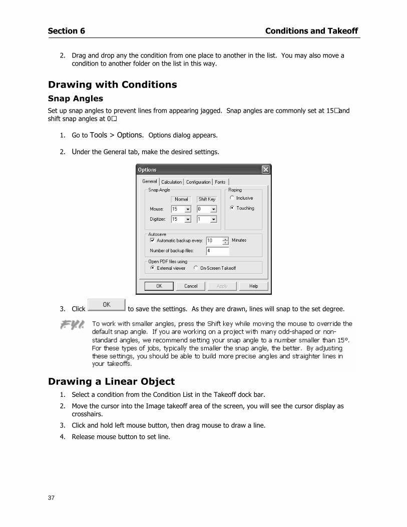
Section 6 Conditions and Takeoff
37
2 Drag and drop any the condition from one place to another in the list You may also move a condition to another folder on the list in this way
Drawing with Conditions Snap Angles Set up snap angles to prevent lines from appearing jagged Snap angles are commonly set at 15deg and shift snap angles at 0deg
1 Go to Tools gt Options Options dialog appears
2 Under the General tab make the desired settings
3 Click to save the settings As they are drawn lines will snap to the set degree
Drawing a Linear Object 1 Select a condition from the Condition List in the Takeoff dock bar
2 Move the cursor into the Image takeoff area of the screen you will see the cursor display as crosshairs
3 Click and hold left mouse button then drag mouse to draw a line
4 Release mouse button to set line
Section 6 Conditions and Takeoff
38
5 Repeat steps for further lines
Continuous Mode This feature allows you to draw an object that has connected lines
1 Click the icon from the Takeoff toolbar
OR
2 Go to Tools gt Continuous Mode
3 Follow steps 1-3 from Draw a Linear Object
4 Click at each point of intersection The object will be connected
5 Double-click after making the final point to set the lines
Drawing a Curve To draw a curved line the Curve option must be checked under the Advanced tab of the Condition dialog
1 Click where you want to begin the curve and drag in a straight line to the position for the other endpoint of the curve
2 Click on the line to select it Handles in the shapes of small squares will appear at either end of
Section 6 Conditions and Takeoff
39
the line and in the center of the line
3 Move the cursor over the center handles until the cursor becomes a two-way arrow
4 Click and drag in the direction of the curve bending the line as you move the cursor Release to set the curve (The line you began with will disappear)
Draw a circle by drawing two curved lines connected
Drawing an Area Object Area conditions are drawn similarly to continuous mode lines You may trace any number of adjoining walls at different angles to complete your area takeoff
NOTE When drawing an area do not intersect the perimeter or line of the object you are drawing
1 Click at each point
2 Double-click when yoursquove returned to your starting point
3 The area will be filled with the pattern set for that condition
NOTE The simulated circle will be good enough for you to be able to make a bid
To create a circular area click from point to point with very short distances in between points simulating a circlersquos perimeter Double-click after setting the last point to set the area
Section 6 Conditions and Takeoff
40
Grid Options Grids give you an added advantage when installing materials such as tiles Use this feature to get a count for how many tiles are needed for an area
1 Double-click on an area condition in the Takeoff dock bar to open its Condition dialog
2 Click on the Advanced tab to show its options
3 Check the box next to Grid by clicking in it
4 Indicate the dimensions of the cell matrix in inches (For example 200 x 400)
5 Under Results tab choose each (EA) for one of the results fields This will tabulate a number of grid cells (including partial grid cells) in area
6 Click to save your settings
7 Use the Move Grid and Rotate Grid features in the Tools menu to manipulate the grid as desired
Grid Calculation
1 Go to Tools gt Options menu
1 Specify if On-Screen Takeoff automatically should Calculate Grid Position
2 If AreaGrid Size is selected On-Screen Takeoff will calculate the number of items needed to fill the grid based on grid demintions
3 Click to accept and close the dialog
To move a line at any angle (regardless of default setting) press the Shift key while moving the mouse
Section 6 Conditions and Takeoff
41
Backout Mode This feature allows you to take out part of an area and deduct that amount of square footage
1 Select Tools gt Backout Mode
2 Outline the are you want backed out as you would when drawing a regular area object (see Drawing an Area Object)
3 The outlined area will clear and quantities will be recalculated
NOTE The perimeter of the backout area will be added to the LF quantity for that condition
Drawing a Count Object Square triangle rectangle and circle shaped count objects can easily be placed on images
1 Select the condition
2 Click in the location where you want the object to appear
3 To place an opening-shaped count item like a door or window you must click over an existing linear object such as a wall
4 On the Results tab you can change the height properties to give you the result you need
5 If Backout is checked on the advanced tab for each count opening the opening-shaped count item will back out a corresponding section of the linear object
Opening shaped count items are sized at 3rsquo0rdquo by default
Drawing a Zone Zones are drawn in the same way as area objects and may be any polygonal shape You may trace any number of adjoining walls at different angles to complete the zone perimeter
1 Click at each point
2 Double-click when yoursquove returned to your starting point
Section 6 Conditions and Takeoff
42
Selecting Objects
1 Use the Select Tool to select objects
You can also select all objects that correspond to a condition
1 Click on a condition to select it
2 Right-click and choose Select All
3 All objects with this condition will be highlighted with squares as an outline
Moving and Resizing Objects Linear
1 To move or resize a linear object click anywhere on the line to select it
2 To move the line position your pointer over the center handles When the mouse is positioned over the handles you will see a two-way arrow You will only be able to move the line in the direction of the arrows
3 Drag the line to a new position
4 Clicking and dragging the handles on the ends of the line will allow you to lengthen or shorten your line
Area and Zone
1 To move an area object or zone in its entirety click and drag it to its new position
2 Grabbing a handle at a corner or intersection of the object will allow you to adjust and change its perimeter
Section 6 Conditions and Takeoff
43
Count 1 To move a square circle rectangle or triangle shaped count object click and drag
2 Click and drag an opening shaped count object along the length of the linear object to the desired position then release
NOTE An opening shaped count object may not be moved from its associated linear condition object however it may be moved up and down the length of the linear object
Layers On-Screen Takeoff allows you to sort and separate your takeoff objects within the same job and on the same page On-Screen Takeoff gives you this flexibility through the use of layers
By assigning different conditions to different layers (for example differentiating between floors ceilings and walls) you can choose to view all layers or turn off certain layers to display and print the remaining groups of conditions only You may also remove the background image of electronic plans add text and hot link symbols or print only your condition takeoffs
Layers are only available in Full Mode If you are in View or Lite Mode and would like to use this
feature click from the main toolbar to purchase the upgrade Default Layers
On-Screen Takeoff begins every project with three default layers Image Annotation and Default The Image layer holds the electronic plan files you may have in your project The Annotation layer possesses all text notations highlighting and hot links in the project The Default layer will appear in the Condition dialog when creating or editing a condition (listed in the takeoff dock bar) Conditions are assigned to the Default layer unless otherwise specified by the user
Creating Layers To assign a condition to a layer other than the default layer you must first create additional layers for your project
1 Select View gt Layers to open the Layers dialog
2 Click An unnamed layer will be added
3 Click within the empty box and type a name for your layer (for example Wall)
4 New layers are added as active layers The adjacent box under the Show column will be checked
Section 6 Conditions and Takeoff
44
Assigning a Layer to a Condition 1 Open the Condition dialog box by creating a new condition or editing an existing condition
2 Under the General tab click on the down arrow in the Layer field to display optional layers
3 Select the desired layer for the condition Only the Default layer and layers you have added will be displayed
4 Click
View and Hide Layers
1 Select View gt Layers
2 Under the Show column check the box to view or remove the check (by clicking on it) to hide the specific layer
3 Click to accept and close the Layers dialog
Section 6 Conditions and Takeoff
45
Assigning Text to a Layer When adding text to an image On-Screen Takeoff has the capability to assign the text to a specified layer
1 Select the Text Tool
2 Click at the point you want to place your text
3 Type in your text using the Enter key for line breaks
4 Click the drop down arrow next to the Layer field and select the desired layer
Section 7
46
Printing and Exporting
This section will
Printing options and procedures
Exporting data by copying and pasting
Exporting quantity results to Excel spreadsheets
Section 7 Printing and Exporting
47
Print Setup On-Screen Takeoff allows the user to print the image takeoff list and worksheet
1 Select File gt Print Setup The Print Setup dialog will open
2 Select a printer or leave the default selection listed (change from the default printer displayed by clicking on the down arrow at the right of the field)
3 Indicate page size and printer tray option (Source) Access page size options by clicking on the
down arrow at the right of the field
4 Choose Portrait or Landscape orientation
5 Click to accept and close the dialog
Printing Images The image area can include the electronic plans the takeoff objects added text and hot links To print a subset of these (for example just the takeoffs without the plans or the added text and hot link symbols) hide layers that you do not want to print (see Section 6 View and Hide Layers) When you are printing your images every page will show the scale of the takeoff you are printing
1 Click on the Image tab to display the area of your project
2 Select File gt Print (or Ctrl + P)
Section 7 Printing and Exporting
48
3 Select the desired view (What to print) and the Image Range
4 Click The second Print dialog will open
5 Change settings accordingly or click if you accept the default settings
Printing Takeoff Lists and Worksheets In Takeoff Lists and Worksheets you may hide columns to print only certain results or adjust column widths to fit the report within the page size selected
1 In Takeoff List or Worksheet view move your cursor to the right side of the columnrsquos title bar the cursor will display as a two-way arrow
Section 7 Printing and Exporting
49
2 Click and drag to adjust the width of the column Holding the mouse button you may
slide the title bar under the title bar to its left to hide the column completely
3 Select File gt Print or press Ctrl + P to access the Print dialog
4 Indicate desired printer and choose the number of copies
5 Click to print and close the dialog
When printing the condition list we suggest printing in landscape
To reset to the default column widths double-click on the right border of a column heading will reset the column to its right (or previously to its right before being hidden)
Print Preview 1 Select File gt Print Preview
2 Use and to vary your view 3 If viewing an image choose current full or scale view to see how it displays
4 For printed outputs that cover more than one page use and to view adjacent pages or click on the down arrow next to Page field and select the page you want displayed
Exporting Using the CopyPaste Feature You may copy all the data or sections from the worksheet and the takeoff list view in On-Screen Takeoff and paste it into another application When pasting into Excel the cell layout will be maintained
1 Highlight the areas you wish to paste Click and hold the left mouse button down as you drag the cursor over the area to be selected then releasing the mouse button
OR
2 Select the entire takeoff list quickly click on the left On-Screen Takeoff column header and hold and drag the cursor across the remaining column headings
The number of pages for the view selected will display in the lower left-hand corner The zoom percentage that applies to the view will be displayed in the lower right-hand corner next to page size of the drawing
Section 7 Printing and Exporting
50
3 In the worksheet view you may highlight rows by clicking on the numbered buttons to the left of each row clicking and dragging across column headings or clicking and dragging over individual cells in the worksheet
Click anywhere in the appropriate view to deselect the area
4 Once your selection is highlighted you may select Edit gt Copy or Ctrl C from the keyboard 5 On your monitor switch to the application into which you want to paste your selection 6 Select Edit gt Paste in the new application or simply press Ctrl + V to paste
The colored keys for conditions cannot be pasted
Using the Export Feature You may export condition quantities to specified cell location within an Excel worksheet file Cell target locations are assigned in the Results tab of the condition dialogs on the Export line relating to each quantity measurement type
On-Screen Takeoff will export takeoff quantity results for up to three different quantity types that you specify For instance you may want to know the number of square feet in a ceiling area as well as the number of linear feet in its perimeter
Section 7 Printing and Exporting
51
1 Bring up the Condition dialog by double-clicking on a condition in the takeoff dock bar or by
selecting the condition and clicking
2 Click on the Results tab to access its fields The default quantities for the condition type will display
3 For each results field click on the arrow to access the pull-down menu and select the appropriate quantity (for example SF LF EA etchellip)
4 Have your Excel spreadsheet opened and saved in a file
5 Specify the Excel spreadsheet cell locations where you want the results to go
6 For a cell in the first sheet of your spreadsheet type in the cell address (eg a1) Case is not important
7 For a cell on a successive sheet of your spreadsheet type in sheet the number followed by a comma and the cell address without any spaces (eg sheet2a1) Case is not important
8 Click
9 Select File gt Export gt Condition Qty to Excel
Section 7 Printing and Exporting
52
10 Browse to the location of the Excel spreadsheet file click file to select it
11 Click to export On-Screen Takeoff results to specified cell locations in the Excel file When you return to the Excel application you will see the values have been added to the specified cell locations in your spreadsheet
12 Save your Excel file
Exporting Worksheet to Excel
1 Assign condition quantities you want to export
2 Open saved Excel spreadsheet file to which you will be exporting
3 From On-Screen Takeoff Select File gt Export gt Worksheet to Excel
4 Browse to the location of the Excel spreadsheet file click file to select it
5 Click When you return to the Excel application you will see the values from the Worksheet Tab have been added to your spreadsheet
6 Save your Excel file
Exporting Takeoff to CVS 1 Assign condition quantities you want to export
2 Open saved Excel spreadsheet file to which you will be exporting
3 Click the Takeoff Tab in the project you want to export the information
4 Select File gt Export gt Takeoff to CSV
5 Browse to the location of the CSV spreadsheet file click file to select it
6 Click the Save
NOTE CSV files can be opened in Excel Lotus Access etc One may consider this option more of a ldquodumprdquo into a file
The Excel application must be active (it may be minimized on the application bar) with the target spreadsheet open in the application Otherwise an error will occur with the export operation that will affect both the On-Screen Takeofftrade file and the Excel spreadsheet
Section 8
53
Advanced Features
This section will
Some special features of working with condition objects in the takeoff area
Details of advanced options for conditions
Advanced features of the Project Properties dialog
Section 8 Advanced Features
54
Features to Use with Objects Roping Feature You can move copy or delete using this feature Using the Select tool (the pointer) you may select several objects at once by clicking and dragging an outline around the objects then releasing the mouse button Roping may select either objects completely within the outlined area (inclusive) or objects both within and touched by the outlined area (touching) Specify your roping preference under Tools gt Options
1 Click and hold the mouse button at a point on the screen near the objects to be selected and drag to surround the objects with an outline
2 Release the mouse button The objects will be selected
3 You may now
Move the group around on the page by clicking within the group dragging the mouse and releasing the button to place the objects
Delete the group of objects by clicking the Delete key or
Copy and paste by pressing Ctrl C to copy the group then Ctrl V to paste it The pasted copy of the grouped objects will appear slightly offset from the original objects
Section 8 Advanced Features
55
Applying a DropRun Count
Use the droprun feature when calculating quantities to take into account the drop or run of a linear condition such as electrical lines or plumbing pipes Drop or run lengths may be added separately to any linear condition on screen while a default droprun length may be indicated for a condition as a whole
1 Select the desired linear condition from the Condition List in the Takeoff Dock bar
2 Click the Change button in the toolbar to open the Change Condition dialog
3 Click the Advanced tab to access the advanced options and click inside the DropRun check box
4 Enter a default length to be applied to all of this condition Entering 800 will be interpreted as 8 0 (You must enter both place markers for inches) You can leave the length blank and manually enter drop run on each segment drawn
5 Click the OK button to accept and close the dialog
Edit DropRun Count
1 With the related linear condition in the Takeoff Dock bar highlighted or with the pointer tool selected
2 click on the desired linear object in the image takeoff area The Count button will become active
3 Click on the Count button (alternatively select Tools gt Count) The default droprun amount will show in the pop-up Count dialog (Default length will be zero if droprun has not been selected in this conditionrsquos properties)
4 Type in the desired length Entering 800 will be interpreted as 8 0 (You must enter both place markers for inches)
5 Click the OK button The additional amount will be reflected in the corresponding quantity The new DropRun count will apply only to the object edited
Adding Text in Image View
On-Screen Takeoff allows you to place text comments around your quantity takeoffs that may be printed along with plan images and objects Text is automatically placed within the Annotation Layer (that includes text and hot links)
1 To place text on the image select the Text Tool and click at the point you want to place your text opening a text box
2 Type in your information clicking Enter for line breaks
3 When you are finished click the OK button to exit the text box
4 To reposition text simply click on the text (with the Text Tool active) to select it
5 Move the cursor over the text the cursor will now display as a four-way arrow
6 Click and drag the mouse to position the text as desired
Section 8 Advanced Features
56
1 To edit existing text use the Text Tool to double-click on the text to open the editing box
2 Enter additional text or use the Backspace key to delete text as necessary
Formatting Text Once created you may format the font size type style and color of your text
1 Click on the text to select it and select Tools gt Font or click on the Font button in the Takeoff Toolbar
2 Select the desired features (color options are disabled) and click the OK button
3 Click on the text to select it and select Tools gt Color or click on the Color button in the Takeoff Toolbar The Color dialog will open
4 Click on a color in the Basic Color palette or create a color and add to the Custom Colors palette (Be sure to click on the color in the Custom Colors palette to select it)
5 Click the OK button
Object Properties
Linear Objects
Linear objects may be set to connect at corners
A linear object may be set to trim automatically when crossing another linear object (Check the trim option under the advanced tab of the Condition dialog)
When you move a connected linear object objects automatically move and resize connected lines accordingly (quantities are then recalculated)
This feature requires that the connected linear object be moved using the center handles (does not apply when resizing the line from the ends)
Objects constrain to snap increments defined in the Tools gt Options menu (with the mouse 15deg by default incremental when shift key is held down)
Objects are measured from centerline to centerline
Section 8 Advanced Features
57
Area Objects When drawing an area use your escape key to undo the last line drawn You may reverse your
drawing of an area using the escape key
The area will not fill with color and pattern until the user double-clicks after the last line is set
Lines drawn to delineate an area object constrain to snap increments defined in the Tools gt Options menu (with the mouse 15deg by default incremental when shift key is held down)
After selecting an area to move or adjust position the mouse in the center to move the entire area position the mouse at the sides or corners to adjust the perimeter
Count Objects
All count objects are quantified by the physical number of objects per page and reported as EA for the UOM The quantity for the current Image View is (displayed in the Condition List) and the total quantity in your project is displayed in the Takeoff View and Worksheet View)
Square circle rectangle and triangle shaped count objects do not displace or subtract from other object quantities when placed on top of them However on the Advanced Tab for the count condition a connect property can be set (this is a check box) so that when a count object of this shape is put on top of a Linear type takeoff object it will move with the linear if said linear is moved
An opened-shaped count object must be placed within a linear object Opening shaped count objects may also be measured by linear foot or linear yard (EA SF and SY are also options) Opening shaped count items default to a width of 3rsquo 0rdquo at the time of creation This size can be changed The small medium and large size are not options on this type of condition anymore Check Backout on the Advanced tab for each Count object back out the footage (or yardage) of opening-shaped count objects in which they are placed
NOTE In order to see this Backout functionality (in quantity) for SY or SF deductions at least one of the
results for the Linear(s) this object will be placed on must be set to SY or SF and the count object must have a height quantity
Advanced Features of Conditions The Round Feature Under the Advanced tab of the linear and area Condition dialogues you may specify quantity rounding (in inches) For linear objects rounding applies to each linear object drawn For area objects rounding will apply to each segment of the area perimeter adjusting the perimeter and area calculations For example With a linear condition entering 12 in the Round field will round up each related linear object to the nearest 12 inches or one foot With this setting two walls of 1 4 would each round to 2 0 totaling 4 0
NOTE In the Takeoff Dock bar condition list and in the On-Screen Takeoff reports quantities will be displayed in whole numbers rounded up to the nearest foot However calculations are based on true quantities without rounding unless the Round Feature is engaged
Pitch Pitch may apply either to linear or area conditions It is measured in rise per linear foot Entering 12 indicates a 12 rise per 12 of linear distance (a pitch of 12 over 12) or an angle of 45deg
Section 8 Advanced Features
58
Advanced Features of Project Properties Selecting Multiple Pages
1 Select a single page entry by clicking on the numbered gray button to the left of the entry
2 Drag the cursor down the column of numbers to select consecutive pages
3 Click on the blank button at the top of this column to select all pages in the Properties dialog
Section 8 Advanced Features
59
Changing Image Assigned to a Drawing 1 Select the page entry by clicking on the numbered gray button to the left of the entry 2 Click the Change Image button The Change Image dialog box will appear
3 Navigate to the desired file and select by clicking on it
4 Click the Open button The electronic file assigned to the page will have been changed to reflect the new file choice
Changing Image File Path 1 Select pages as described above
2 Choose Change Folder
3 In the Change Folder dialog navigate to the appropriate folder
4 Click the OK button The file path will have been changed for the selected page entries
Delete a Page from Project Properties 1 Select the page you want to delete by clicking on its associated number (in the gray box at the
left of the entry)
2 Choose Delete Page
All Takeoff on the page will be deleted immediately and permanently
Section 8 Advanced Features
60
Advanced Features of Tool Options
Calculation Method On-Screen Takeoff has built-in calculation options to allow for faster work and faster saves until your takeoff is complete Calculation options are found by selecting Tools gt Options then clicking on the Calculation tab
Calculation method can be set to Automatic Automatic except Grids and Manual Manual will allow the program to operate more quickly while Automatic or Automatic except Grids allows the user to see quantity changes as takeoffs are made
In any mode you may press F9 to recalculate quantities for the On-Screen Takeoff current totals
Configuration Tab
When the ldquoPage Label (A01)rdquo radial button is chosen On-Screen Takeoff puts the numbered label on all the pages of in your current page indicator in your Navigate Toolbar If the Page Descriptionrdquo radial button is chosen then a description of what takeoff is on that specific page will be shown in your current page indicator in your Navigate Toolbar
This section of the configuration tab gives you options on how you want to export your information When the ldquoFolderSubfolder Namesrdquo radial button is chosen than on your file that you are exporting to will have all the conditions folders and subfolders In the Delimiter box you can choose the symbol that is needed to separate the information you are exporting Some files need semicolons () or colons () to make sure the information comes exported in is separated it the appropriate places
Section 8 Advanced Features
61
In previous versions of On-Screen Takeoff there are views that users need to have in order for them to display their information By either choosing ldquoOST 1xrdquo or ldquoOST 2xrdquo it will let the program know you want your columns of information exported in that specific format
When you have the Confirm Deletions radial button of ldquoYesrdquo chosen than every time you delete anything you will get a dialog box confirming your intentions of deletion
While working with your takeoff you have a choice to either view the legend of your conditions or hide it Choose whichever radial button that suits your needs
For those who prefer to use the Enter key to navigate in dialog boxes this option is just for that
Font Tab The Font tab is designed for you to make your own look and feel for the application At the bottom of this tab it will show you sample of the fonts and colors you have chosen
Renaming the Current Page You may change the name of the current page in the takeoff area of On-Screen Takeoff by selecting Edit gt Rename Page
This opens the Name Page dialog and you may simply type in a new name and click the Enter button The new name for the file will be reflected on the title bar for the page and in Project Properties
You also may access the Rename Page function by right-clicking in the takeoff area while in Image View and selecting the option from the pop-up menu that appears
Section 9
62
Saving and Exiting
This section will
Explain how to save projects
Show you how to safely exit the program
Section 9 Saving and Exiting
63
Saving Your Project
1 Select File gt Save 2 If your project has not previously been saved a Save dialog box will open to allow you to name
the file and choose the directory and folder in which to save your file 3 Once saved File gt Save will simply save the current version of the file
OR
4 Select File gt Save As then type in a new name for the file and save to the desired file path
The Auto-save Feature With the Auto-save feature On-Screen Takeoff automatically backs up your open project You may choose to have more than one level of backup files The first backup copy will have the extension b00 and successive files will be b01 b02 and so on If you have designated four levels of backup files after the fourth backup copy has been created (b03) the next file will be saved over the file with extension b00 Further backup saves will then rotate through the four backup files in the same way
1 Select Tools gt Options 2 In the Auto-save area (under the General tab) select the frequency of backup file creation (in
minutes) and the number of levels for the feature 3 You also may disengage the feature by clicking in the check box to clear it
The Auto-save feature automatically saves backup copies to the directory of the current project If you are working from a write-protected area such as a CD-ROM On-Screen Takeoff will place backup files in the On-Screen Takeoff folder
Exiting When you are finished using On-Screen Takeoff it is very easy to exit Exiting is very important because of security reasons If someone were to use your computer they could enter the application and view and manipulate information
Section 9 Saving and Exiting
64
On-Screen Takeoff closes the open project when you open another or create a new project or when you exit the program
1 Select File gt Exit
OR
2 You also may click at the upper right-hand corner of the application to exit
NOTE If your latest changes to a project file have not been saved On-Screen Takeoff will ask you whether you would like to save the file and gives you the option of canceling the operation
Appendix I Installing Your Digitizer
65
Appendix I Installing Your Digitizer When you get your digitizer from GTCO you will need to connect it to your computer Follow the instructions outlined below to do this
Note For rollup digitizers the metal bar must be oriented to the top or right hand side
Connecting the Digitizer 1 Lay the digitizer out flat 2 Connect the Stylus to the digitizer 3 Plug in the power adapter 4 Plug the interface (IO) cable into the digitizer 5 Plug the other end of the interface cable into an open serial port on computer
Note GTCO Technical support phone number is 410-381-6688 The electronic manual (on diskette) from GTCO contains more detailed installation and operation instructions for the GTCO digitizer model you have
Installing other Digitizer Drivers If you are using a GTCO Digitizer you will need to install the GTCO TabletWorks Drivers
If you are using a Digitizer not supported by GTCO Tablet Works 10 please contact the manufacturer of your digitizer for assistance with installation
Installing GTCO TabletWorks Drivers 1 Insert the On Center CD into the CD-ROM drive The CD Startup screen will open 2 Click on Install Software 3 Select Additional Software and Drivers 4 Select Digitizer Driver 5 Follow the instructions for installing TabletWorks 10
Adhering the Template The template is a small plastic sticker used to enable mouse function when using the digitizer with On-Screen Takeoff Place your template on your digitizer We suggest placing it in the bottom right corner of the digitizer about one inch inside the takeoff area
Note You may either peel off the back of the template and use the adhesive surface or you can tape the template down
Appendix I Installing Your Digitizer
66
Testing the Digitizer Drivers Before running OST you may test the digitizer by moving the stylus around on the digitizer pad it should move the mouse cursor (if mouse emulation is enabled)
If the digitizer does not move the mouse cursor on the screen
The superset codes may need to be reset Reset the superset codes by touching on the border of the digitizer with the stylus The digitizer should beep several times
The digitizer may not be communicating with the computer Be sure the COM port selected is correct Be sure the COM port selected is correct If you are not able to get the digitizer to move the mouse cursor you need to call GTCO technical support for help
Note The Mouse Emulation is not required for On-Screen Takeoff to work properly It is used only for the Template functionality if the digitizer is moving the cursor the wrong direction (up instead of sideways or vice-versa)
Click the L-shaped arrow symbol on the digitizer with the stylus
Appendix II Toolbar Item Details
67
Appendix II Toolbar Items Main Toolbar
Appendix II Toolbar Item Details
68
Tool Toolbar
Appendix II Toolbar Item Details
69
Zoom Toolbar
View Toolbar
Navigate Toolbar
Appendix II Toolbar Item Details
70
Navigate Toolbar (Continued)
Takeoff Toolbar
Appendix II Toolbar Item Details
71
Takeoff Toolbar (Continued)
Image Toolbar
Appendix III Loading Plans from a Dodge CD
72
Appendix III Loading Plans from a Dodge CD
This section will detail how to load plans from a F W Dodge CD-ROM into an On-Screen Takeoff project file ready for takeoffs
Dodge files may be added to the Project Properties dialog However loading the files in that way will load the files by number rather than name description If you want to load one page only from your Dodge CD You will have to rename the page to display the name rather than number of the file
To load plan files from a Dodge CD so that the files load sequentially by file number but are displayed by name rather than by number within your project follow the instructions below
Opening a Dodge project from a CD-ROM 1 Insert the CD into the drive 2 Choose File gt Custom 3 Choose Dodge Plans Project (plansdat) as the file type 4 Select the appropriate file type by clicking on the down arrow at the right of the Files of type
field 5 In the Look in field access your drive paths by clicking on the down arrow at the right of the
field then
Navigate to your CD-ROM drive Open the data folder and Open the Projects folder
6 Select the desired project and open its folder 7 Open the plansdat file 8 All the images will come in sequenced correctly for that job along with the full descriptions
(names) of each page If there is not a plans folder in the project folder then plans do not exist for that project on the CD Opening the plansdat file will yield an empty project
Appendix IV Using the Plan Viewer
73
Appendix IV Using On-Screen Takeoff Plan Viewer The On-Screen Takeoff Plan Viewer is a limited version of On Center Softwarersquos commercial takeoff software If your status bar located at the very bottom of the main window says View Mode in the lower left-hand corner then you are using the Plan Viewer You can use the plan viewer to
View CD-based amp converted CAD drawings
View a previously created OST file and associated drawings
Download electronic plans online
Navigate through drawings
Quickly Takeoff linearsareas and counts
Zoom in to view the plan better
Print drawings directly from the viewer
Viewing an On-Screen Takeoff Project File
1 To open an OST file that was previously created with of On-Screen Takeoff 2 Select File gt Open 3 An Open dialog will appear if you do not see the OST file you are looking for select the
Look In drop down arrow 4 A drop down menu will appear listing the various folders drives and mapped drives located
on your computer select the correct drive or folder location and continue to browse to the location of your OST file
5 When you see your OST file double-click it to open it 6 Any takeoff and drawings should appear on the Image tab view
If you do not see the drawings but do see the colored takeoff layer the drawings may
not be located in the same place they were originally saved at Go to File gt Project Properties and check the Image File path for each listed page If the image file path is pointing to a CD drive make sure the CD is inside the CR-ROM
Downloading Electronic Plans If your Online Plan Service provides a special file format (OSX) required to use this feature of our plan viewer you can immediately downloaded all electronic plans of a project directly from our viewer
Most Plan Room web sites will automatically open On-Screen Takeoff when a request to download plans is made Your particular Plan Room may differ in operation so please contact the provider directly with questions on using the site
Appendix IV Using the Plan Viewer
74
When you request to download or open a project file from a Plan Room you will usually have the open to open or save an OSX file Choosing open will automatically open On-Screen Takeoff Alternately you may choose to save the file to a local hard drive After you have saved the file either double-click it to launch On-Screen Takeoff or open the OSX file using On-Screen Takeoff by clicking File then Open and locating the file on your hard drive You will need to change the file type to OSX
After the OSX file is opened you will see an additional tab appear in the Conditions List window called Pages
The Pages tab shows the hierarchy of your project Gray file icons represent pages that have not been downloaded and blue icons represents pages that have been downloaded
To download a page simply double-click the page icon
If you wish to select a group of pages to download you can use the Ctrl or Shift key to multiple select them then click the Download button
If you wish to download all pages at once click the Download All button
Downloaded pages will now appear in the Project Properties dialog in the same order in which they appear in the Pages tab
Creating Quick Takeoffs With On-Screen Takeoff you can create quick takeoffs to measure quantities even if you dont have the full version of our program However using the Quick Takeoff functionality shows you just a fraction of what the full version can do
The Quick Takeoff Toolbar is located at the top of the image view It has three buttons designated for three types of takeoffs Linear Area and Count The Quantity drop down list will show secondary quantities for Linears and Areas The Units drop down allows you to select how you want your quantities displayed Feet Inches Yards Millimeters and Meters
NOTE Every time change the type of takeoff you are performing (switching from Area to Linear for example) the previous quantities and takeoff objects will disappear They will also disappear when you changes pages
NOTE You can use the Dimension Tool to basically measure the distance between two points or linears The distance will display on the status bar at the bottom of the application
The Quick Takeoff Toolbar
Appendix V Frequently Asked Questions
75
Appendix V Frequently Asked Questions General
Where is On-Screen Takeoff installed on my computer
Typically it is installed in CProgram FilesOn-Screen Takeoff
In Explorer how do I recognize On-Screen Takeoff file types
On-Screen Takeoff data is stored in a single file per job lsquojob name OSTrsquo On-Screen Takeoff templates are stored as lsquotemplate nameTPOrsquo
Can only one project at a time be open
Yes For that reason opening another project automatically closes the project on screen You will be asked to save any changes
Is only one scale allowed per page What about on drawings that have multiple detail sections on a page and each of those drawings have different scales
Yes For pages with drawings of different scales copy the drawing to another project page and set the appropriate scale
I cannot perform backout on an area that is along a linear
As a workaround use the On-Screen Takeoff layers feature to help you with this issue Electronic Images
How do I start a project from drawings that have been scanned and written to a CD-ROM
Open a new project Select File gt Project Properties and select Auto Add Navigate to your CD and the appropriate folder and select any image file in that location Click Open All files in the location will load into your project Recommended that images are copied from CD to hard drive for performance
If I get a disk of drawings in AutoCAD format (R13 or R14) can I read them in On-Screen Takeoff
Yes On-Screen Takeoff now reads DWG DXF and many other format that are saved with AutoCAD
Appendix V Frequently Asked Questions
76
When I click on the all pages button what is supposed to happen Currently nothing seems to change when I click on that button
The All Pages button is used to apply the Darken and Enhance Plans feature to all pages in the project (as opposed to only the current page on screen)
Is there a way to deduct a large skylight from an area condition
Yes with the related area condition selected in the Takeoff Dock bar unselect the Backout button on the Takeoff Toolbar then draw the Backout area The area quantity will be deducted from the related condition object and the linear measurement of the Backout perimeter will be added
Digitizer Issues
How do I connect a Digitizer to the computer
See Appendix I Connecting a Digitizer
The Place Template menu choice is disabled
On-Screen Takeoff may need to be authorized or the digitizer or the digitzer drivers are not installed
It wonrsquot let me select the Set Takeoff Area menu choice
On-Screen Takeoff may need to be authorized or no job is open a digitizer is not installed or the drivers are not installed
The digitizer stylus is not moving the cursor or crosshairs
Click S-0-1 superset on the digitizer
How do I convert my old GTCO Digitizer to work with On- Screen Takeofftrade
Call GTCO and they may be able to reconfigure your digitizer to be compatible with On-Screen Takeoff
Printing Issues Which Printers work with On-Screen Takeoff
Compatible printers include On-Screen Takeoff Hewlett Packard Epson and Canon printers If you are having printer difficulties please contact support and specify the type of printer along with other pertinent information Contact support at wwwoncentercomsupport or email supportoncentercom
Which Plotters work with On-Screen Takeoff
Compatible Plotters include Hewlett Packard DesignJet plotters and the EnCAD Cadjet II If you are having plotter difficulties please contact support and specify the type of plotter concerned
ViewingDisplay I can no longer see my condition list How do I get it back
The toolbars and Dock bars can be turned on and off through the View gt Toolbars menu options
Appendix V Frequently Asked Questions
77
This is also accessible by right-clicking in the toolbar area and selecting (or deselecting) a toolbar listed
I cannot view my folders in the condition list
Right-click in the Takeoff Dock barcondition list area and select Show Tree to display your folders
My Status Bar reads Viewer Mode and I am unable to draw conditions
On-Screen Takeoff needs to be Authorized Or you need to purchase an upgrade Click the Perform Advanced Takeoff button on the main toolbar
I hid a Dock bar and when I selected to view it again it appeared alongside the other Dock
bar instead of stacked on top of it How do I fix it
Pick up the Dock bar by clicking on the bar at the top and continuing to hold down the mouse button drag the Dock bar over the other one It will resize and appear stacked with the other
When I open image files from a CD the images are all upside down How do I get them right
side up
To flip pages from top to bottom follow the steps below 1 Click the All Pages button on the Image Toolbar (All Pages is engaged when the button
is not clicked) 2 Click the Flip Horizontal button on the Image Toolbar 3 Click the All Pages button again to disengage
Templates How do I create a Template
Follow the steps below 1 Create a typical project 2 Choose File gt Save As 3 Choose On-Screen Takeoff Template Files as the file type to save 4 Name the file This will save all of the condition setups as well as the layers for the
project
How do I create a new project from a template
Follow the steps below 1 Choose File gt New 2 Select a template from those listed in the New dialog This will open a new project with
conditions and layers saved from a previous project but no pages or takeoff
78
INDEX
Area Conditions 32
Area Objects 57
Auto Scrolling 20
Auto-save 63
Backout Mode 41
Calculation Method 60
Conditions 29
Configuration 60
Contents Tab 6
Continuous Mode 38
Count Conditions 33
Count Objects 57
Digitizer 10 65 76
Docking Toolbars 13
Dodge CD 72
Drawing 27 37
DropRun Count 55
Environment 18
Exiting 63
Exporting 49
Features 16
Font 61
Frequently Asked Questions 75
Grid 40
Help File 5
Hiding Toolbars 13
Hot Links 21
Image 19 59
Image files 9
Image Toolbar 12 71
Images 75
Index Tab 6
Layers 43
Linear Conditions 31
Linear Objects 56
Main Toolbar 12 67
Menus 14
Moving Toolbars 13
Navigate Toolbar 12 69
Navigating 20
On-Screen Takeofftrade 2
Page 59 61
Pages 20 25 28
Plan Viewer 73
Plans 26
Printing 47 76
Project Properties 25
Projects 22
Quick Start Video 18
Resizing Toolbars 13
Roping 54
Saving 63
Scale 28
Search Tab 7
Selecting Objects 42
Setup 8
Start On-Screen Takeofftrade 17
System Requirements 9
Takeoff 19 27
Takeoff Toolbar 70 71
Takeoff Toolbar 12
Template Files 23
TIF (Group4) 9
Tool Toolbar 12 68
Toolbar 67
Toolbars 12
View Toolbar 12 69
Viewing Toolbars 12
Worksheet 20
Zone Conditions 33
Zoom Toolbar 12 69
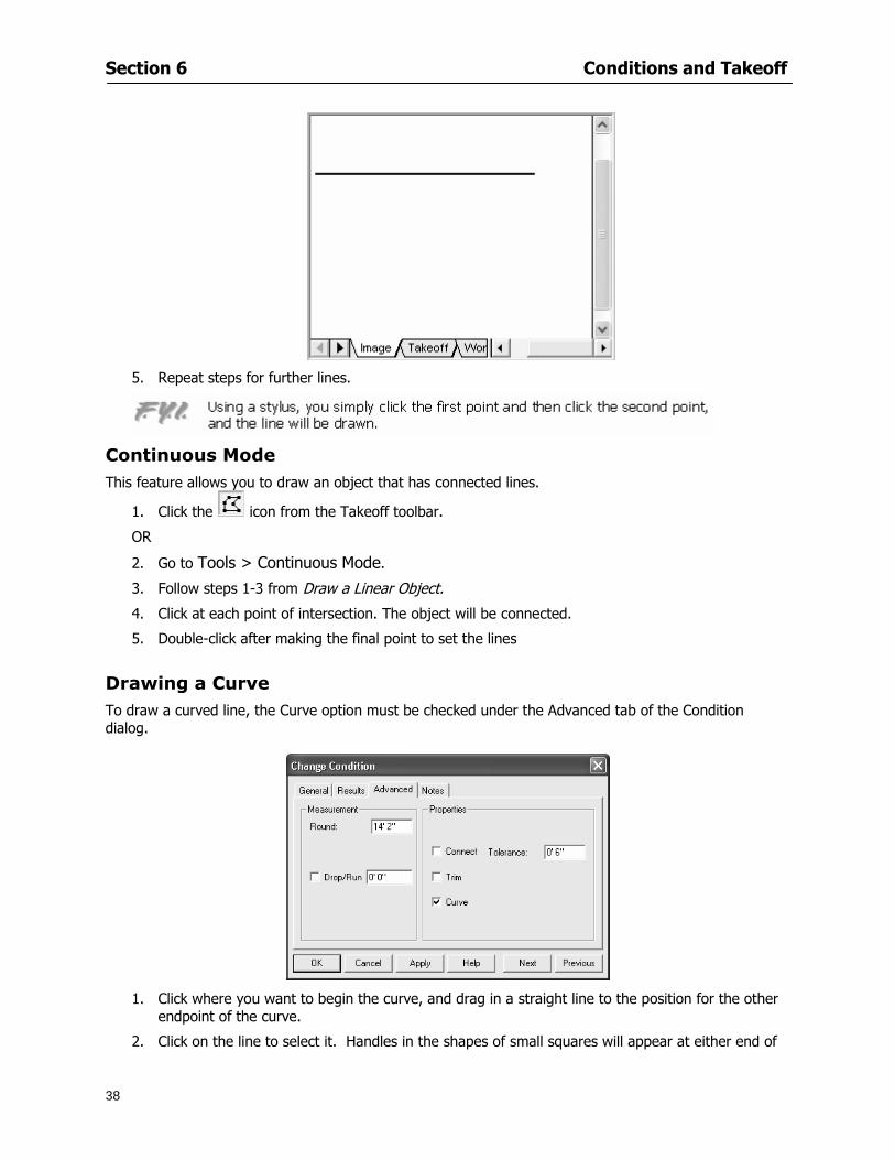
Section 6 Conditions and Takeoff
38
5 Repeat steps for further lines
Continuous Mode This feature allows you to draw an object that has connected lines
1 Click the icon from the Takeoff toolbar
OR
2 Go to Tools gt Continuous Mode
3 Follow steps 1-3 from Draw a Linear Object
4 Click at each point of intersection The object will be connected
5 Double-click after making the final point to set the lines
Drawing a Curve To draw a curved line the Curve option must be checked under the Advanced tab of the Condition dialog
1 Click where you want to begin the curve and drag in a straight line to the position for the other endpoint of the curve
2 Click on the line to select it Handles in the shapes of small squares will appear at either end of
Section 6 Conditions and Takeoff
39
the line and in the center of the line
3 Move the cursor over the center handles until the cursor becomes a two-way arrow
4 Click and drag in the direction of the curve bending the line as you move the cursor Release to set the curve (The line you began with will disappear)
Draw a circle by drawing two curved lines connected
Drawing an Area Object Area conditions are drawn similarly to continuous mode lines You may trace any number of adjoining walls at different angles to complete your area takeoff
NOTE When drawing an area do not intersect the perimeter or line of the object you are drawing
1 Click at each point
2 Double-click when yoursquove returned to your starting point
3 The area will be filled with the pattern set for that condition
NOTE The simulated circle will be good enough for you to be able to make a bid
To create a circular area click from point to point with very short distances in between points simulating a circlersquos perimeter Double-click after setting the last point to set the area
Section 6 Conditions and Takeoff
40
Grid Options Grids give you an added advantage when installing materials such as tiles Use this feature to get a count for how many tiles are needed for an area
1 Double-click on an area condition in the Takeoff dock bar to open its Condition dialog
2 Click on the Advanced tab to show its options
3 Check the box next to Grid by clicking in it
4 Indicate the dimensions of the cell matrix in inches (For example 200 x 400)
5 Under Results tab choose each (EA) for one of the results fields This will tabulate a number of grid cells (including partial grid cells) in area
6 Click to save your settings
7 Use the Move Grid and Rotate Grid features in the Tools menu to manipulate the grid as desired
Grid Calculation
1 Go to Tools gt Options menu
1 Specify if On-Screen Takeoff automatically should Calculate Grid Position
2 If AreaGrid Size is selected On-Screen Takeoff will calculate the number of items needed to fill the grid based on grid demintions
3 Click to accept and close the dialog
To move a line at any angle (regardless of default setting) press the Shift key while moving the mouse
Section 6 Conditions and Takeoff
41
Backout Mode This feature allows you to take out part of an area and deduct that amount of square footage
1 Select Tools gt Backout Mode
2 Outline the are you want backed out as you would when drawing a regular area object (see Drawing an Area Object)
3 The outlined area will clear and quantities will be recalculated
NOTE The perimeter of the backout area will be added to the LF quantity for that condition
Drawing a Count Object Square triangle rectangle and circle shaped count objects can easily be placed on images
1 Select the condition
2 Click in the location where you want the object to appear
3 To place an opening-shaped count item like a door or window you must click over an existing linear object such as a wall
4 On the Results tab you can change the height properties to give you the result you need
5 If Backout is checked on the advanced tab for each count opening the opening-shaped count item will back out a corresponding section of the linear object
Opening shaped count items are sized at 3rsquo0rdquo by default
Drawing a Zone Zones are drawn in the same way as area objects and may be any polygonal shape You may trace any number of adjoining walls at different angles to complete the zone perimeter
1 Click at each point
2 Double-click when yoursquove returned to your starting point
Section 6 Conditions and Takeoff
42
Selecting Objects
1 Use the Select Tool to select objects
You can also select all objects that correspond to a condition
1 Click on a condition to select it
2 Right-click and choose Select All
3 All objects with this condition will be highlighted with squares as an outline
Moving and Resizing Objects Linear
1 To move or resize a linear object click anywhere on the line to select it
2 To move the line position your pointer over the center handles When the mouse is positioned over the handles you will see a two-way arrow You will only be able to move the line in the direction of the arrows
3 Drag the line to a new position
4 Clicking and dragging the handles on the ends of the line will allow you to lengthen or shorten your line
Area and Zone
1 To move an area object or zone in its entirety click and drag it to its new position
2 Grabbing a handle at a corner or intersection of the object will allow you to adjust and change its perimeter
Section 6 Conditions and Takeoff
43
Count 1 To move a square circle rectangle or triangle shaped count object click and drag
2 Click and drag an opening shaped count object along the length of the linear object to the desired position then release
NOTE An opening shaped count object may not be moved from its associated linear condition object however it may be moved up and down the length of the linear object
Layers On-Screen Takeoff allows you to sort and separate your takeoff objects within the same job and on the same page On-Screen Takeoff gives you this flexibility through the use of layers
By assigning different conditions to different layers (for example differentiating between floors ceilings and walls) you can choose to view all layers or turn off certain layers to display and print the remaining groups of conditions only You may also remove the background image of electronic plans add text and hot link symbols or print only your condition takeoffs
Layers are only available in Full Mode If you are in View or Lite Mode and would like to use this
feature click from the main toolbar to purchase the upgrade Default Layers
On-Screen Takeoff begins every project with three default layers Image Annotation and Default The Image layer holds the electronic plan files you may have in your project The Annotation layer possesses all text notations highlighting and hot links in the project The Default layer will appear in the Condition dialog when creating or editing a condition (listed in the takeoff dock bar) Conditions are assigned to the Default layer unless otherwise specified by the user
Creating Layers To assign a condition to a layer other than the default layer you must first create additional layers for your project
1 Select View gt Layers to open the Layers dialog
2 Click An unnamed layer will be added
3 Click within the empty box and type a name for your layer (for example Wall)
4 New layers are added as active layers The adjacent box under the Show column will be checked
Section 6 Conditions and Takeoff
44
Assigning a Layer to a Condition 1 Open the Condition dialog box by creating a new condition or editing an existing condition
2 Under the General tab click on the down arrow in the Layer field to display optional layers
3 Select the desired layer for the condition Only the Default layer and layers you have added will be displayed
4 Click
View and Hide Layers
1 Select View gt Layers
2 Under the Show column check the box to view or remove the check (by clicking on it) to hide the specific layer
3 Click to accept and close the Layers dialog
Section 6 Conditions and Takeoff
45
Assigning Text to a Layer When adding text to an image On-Screen Takeoff has the capability to assign the text to a specified layer
1 Select the Text Tool
2 Click at the point you want to place your text
3 Type in your text using the Enter key for line breaks
4 Click the drop down arrow next to the Layer field and select the desired layer
Section 7
46
Printing and Exporting
This section will
Printing options and procedures
Exporting data by copying and pasting
Exporting quantity results to Excel spreadsheets
Section 7 Printing and Exporting
47
Print Setup On-Screen Takeoff allows the user to print the image takeoff list and worksheet
1 Select File gt Print Setup The Print Setup dialog will open
2 Select a printer or leave the default selection listed (change from the default printer displayed by clicking on the down arrow at the right of the field)
3 Indicate page size and printer tray option (Source) Access page size options by clicking on the
down arrow at the right of the field
4 Choose Portrait or Landscape orientation
5 Click to accept and close the dialog
Printing Images The image area can include the electronic plans the takeoff objects added text and hot links To print a subset of these (for example just the takeoffs without the plans or the added text and hot link symbols) hide layers that you do not want to print (see Section 6 View and Hide Layers) When you are printing your images every page will show the scale of the takeoff you are printing
1 Click on the Image tab to display the area of your project
2 Select File gt Print (or Ctrl + P)
Section 7 Printing and Exporting
48
3 Select the desired view (What to print) and the Image Range
4 Click The second Print dialog will open
5 Change settings accordingly or click if you accept the default settings
Printing Takeoff Lists and Worksheets In Takeoff Lists and Worksheets you may hide columns to print only certain results or adjust column widths to fit the report within the page size selected
1 In Takeoff List or Worksheet view move your cursor to the right side of the columnrsquos title bar the cursor will display as a two-way arrow
Section 7 Printing and Exporting
49
2 Click and drag to adjust the width of the column Holding the mouse button you may
slide the title bar under the title bar to its left to hide the column completely
3 Select File gt Print or press Ctrl + P to access the Print dialog
4 Indicate desired printer and choose the number of copies
5 Click to print and close the dialog
When printing the condition list we suggest printing in landscape
To reset to the default column widths double-click on the right border of a column heading will reset the column to its right (or previously to its right before being hidden)
Print Preview 1 Select File gt Print Preview
2 Use and to vary your view 3 If viewing an image choose current full or scale view to see how it displays
4 For printed outputs that cover more than one page use and to view adjacent pages or click on the down arrow next to Page field and select the page you want displayed
Exporting Using the CopyPaste Feature You may copy all the data or sections from the worksheet and the takeoff list view in On-Screen Takeoff and paste it into another application When pasting into Excel the cell layout will be maintained
1 Highlight the areas you wish to paste Click and hold the left mouse button down as you drag the cursor over the area to be selected then releasing the mouse button
OR
2 Select the entire takeoff list quickly click on the left On-Screen Takeoff column header and hold and drag the cursor across the remaining column headings
The number of pages for the view selected will display in the lower left-hand corner The zoom percentage that applies to the view will be displayed in the lower right-hand corner next to page size of the drawing
Section 7 Printing and Exporting
50
3 In the worksheet view you may highlight rows by clicking on the numbered buttons to the left of each row clicking and dragging across column headings or clicking and dragging over individual cells in the worksheet
Click anywhere in the appropriate view to deselect the area
4 Once your selection is highlighted you may select Edit gt Copy or Ctrl C from the keyboard 5 On your monitor switch to the application into which you want to paste your selection 6 Select Edit gt Paste in the new application or simply press Ctrl + V to paste
The colored keys for conditions cannot be pasted
Using the Export Feature You may export condition quantities to specified cell location within an Excel worksheet file Cell target locations are assigned in the Results tab of the condition dialogs on the Export line relating to each quantity measurement type
On-Screen Takeoff will export takeoff quantity results for up to three different quantity types that you specify For instance you may want to know the number of square feet in a ceiling area as well as the number of linear feet in its perimeter
Section 7 Printing and Exporting
51
1 Bring up the Condition dialog by double-clicking on a condition in the takeoff dock bar or by
selecting the condition and clicking
2 Click on the Results tab to access its fields The default quantities for the condition type will display
3 For each results field click on the arrow to access the pull-down menu and select the appropriate quantity (for example SF LF EA etchellip)
4 Have your Excel spreadsheet opened and saved in a file
5 Specify the Excel spreadsheet cell locations where you want the results to go
6 For a cell in the first sheet of your spreadsheet type in the cell address (eg a1) Case is not important
7 For a cell on a successive sheet of your spreadsheet type in sheet the number followed by a comma and the cell address without any spaces (eg sheet2a1) Case is not important
8 Click
9 Select File gt Export gt Condition Qty to Excel
Section 7 Printing and Exporting
52
10 Browse to the location of the Excel spreadsheet file click file to select it
11 Click to export On-Screen Takeoff results to specified cell locations in the Excel file When you return to the Excel application you will see the values have been added to the specified cell locations in your spreadsheet
12 Save your Excel file
Exporting Worksheet to Excel
1 Assign condition quantities you want to export
2 Open saved Excel spreadsheet file to which you will be exporting
3 From On-Screen Takeoff Select File gt Export gt Worksheet to Excel
4 Browse to the location of the Excel spreadsheet file click file to select it
5 Click When you return to the Excel application you will see the values from the Worksheet Tab have been added to your spreadsheet
6 Save your Excel file
Exporting Takeoff to CVS 1 Assign condition quantities you want to export
2 Open saved Excel spreadsheet file to which you will be exporting
3 Click the Takeoff Tab in the project you want to export the information
4 Select File gt Export gt Takeoff to CSV
5 Browse to the location of the CSV spreadsheet file click file to select it
6 Click the Save
NOTE CSV files can be opened in Excel Lotus Access etc One may consider this option more of a ldquodumprdquo into a file
The Excel application must be active (it may be minimized on the application bar) with the target spreadsheet open in the application Otherwise an error will occur with the export operation that will affect both the On-Screen Takeofftrade file and the Excel spreadsheet
Section 8
53
Advanced Features
This section will
Some special features of working with condition objects in the takeoff area
Details of advanced options for conditions
Advanced features of the Project Properties dialog
Section 8 Advanced Features
54
Features to Use with Objects Roping Feature You can move copy or delete using this feature Using the Select tool (the pointer) you may select several objects at once by clicking and dragging an outline around the objects then releasing the mouse button Roping may select either objects completely within the outlined area (inclusive) or objects both within and touched by the outlined area (touching) Specify your roping preference under Tools gt Options
1 Click and hold the mouse button at a point on the screen near the objects to be selected and drag to surround the objects with an outline
2 Release the mouse button The objects will be selected
3 You may now
Move the group around on the page by clicking within the group dragging the mouse and releasing the button to place the objects
Delete the group of objects by clicking the Delete key or
Copy and paste by pressing Ctrl C to copy the group then Ctrl V to paste it The pasted copy of the grouped objects will appear slightly offset from the original objects
Section 8 Advanced Features
55
Applying a DropRun Count
Use the droprun feature when calculating quantities to take into account the drop or run of a linear condition such as electrical lines or plumbing pipes Drop or run lengths may be added separately to any linear condition on screen while a default droprun length may be indicated for a condition as a whole
1 Select the desired linear condition from the Condition List in the Takeoff Dock bar
2 Click the Change button in the toolbar to open the Change Condition dialog
3 Click the Advanced tab to access the advanced options and click inside the DropRun check box
4 Enter a default length to be applied to all of this condition Entering 800 will be interpreted as 8 0 (You must enter both place markers for inches) You can leave the length blank and manually enter drop run on each segment drawn
5 Click the OK button to accept and close the dialog
Edit DropRun Count
1 With the related linear condition in the Takeoff Dock bar highlighted or with the pointer tool selected
2 click on the desired linear object in the image takeoff area The Count button will become active
3 Click on the Count button (alternatively select Tools gt Count) The default droprun amount will show in the pop-up Count dialog (Default length will be zero if droprun has not been selected in this conditionrsquos properties)
4 Type in the desired length Entering 800 will be interpreted as 8 0 (You must enter both place markers for inches)
5 Click the OK button The additional amount will be reflected in the corresponding quantity The new DropRun count will apply only to the object edited
Adding Text in Image View
On-Screen Takeoff allows you to place text comments around your quantity takeoffs that may be printed along with plan images and objects Text is automatically placed within the Annotation Layer (that includes text and hot links)
1 To place text on the image select the Text Tool and click at the point you want to place your text opening a text box
2 Type in your information clicking Enter for line breaks
3 When you are finished click the OK button to exit the text box
4 To reposition text simply click on the text (with the Text Tool active) to select it
5 Move the cursor over the text the cursor will now display as a four-way arrow
6 Click and drag the mouse to position the text as desired
Section 8 Advanced Features
56
1 To edit existing text use the Text Tool to double-click on the text to open the editing box
2 Enter additional text or use the Backspace key to delete text as necessary
Formatting Text Once created you may format the font size type style and color of your text
1 Click on the text to select it and select Tools gt Font or click on the Font button in the Takeoff Toolbar
2 Select the desired features (color options are disabled) and click the OK button
3 Click on the text to select it and select Tools gt Color or click on the Color button in the Takeoff Toolbar The Color dialog will open
4 Click on a color in the Basic Color palette or create a color and add to the Custom Colors palette (Be sure to click on the color in the Custom Colors palette to select it)
5 Click the OK button
Object Properties
Linear Objects
Linear objects may be set to connect at corners
A linear object may be set to trim automatically when crossing another linear object (Check the trim option under the advanced tab of the Condition dialog)
When you move a connected linear object objects automatically move and resize connected lines accordingly (quantities are then recalculated)
This feature requires that the connected linear object be moved using the center handles (does not apply when resizing the line from the ends)
Objects constrain to snap increments defined in the Tools gt Options menu (with the mouse 15deg by default incremental when shift key is held down)
Objects are measured from centerline to centerline
Section 8 Advanced Features
57
Area Objects When drawing an area use your escape key to undo the last line drawn You may reverse your
drawing of an area using the escape key
The area will not fill with color and pattern until the user double-clicks after the last line is set
Lines drawn to delineate an area object constrain to snap increments defined in the Tools gt Options menu (with the mouse 15deg by default incremental when shift key is held down)
After selecting an area to move or adjust position the mouse in the center to move the entire area position the mouse at the sides or corners to adjust the perimeter
Count Objects
All count objects are quantified by the physical number of objects per page and reported as EA for the UOM The quantity for the current Image View is (displayed in the Condition List) and the total quantity in your project is displayed in the Takeoff View and Worksheet View)
Square circle rectangle and triangle shaped count objects do not displace or subtract from other object quantities when placed on top of them However on the Advanced Tab for the count condition a connect property can be set (this is a check box) so that when a count object of this shape is put on top of a Linear type takeoff object it will move with the linear if said linear is moved
An opened-shaped count object must be placed within a linear object Opening shaped count objects may also be measured by linear foot or linear yard (EA SF and SY are also options) Opening shaped count items default to a width of 3rsquo 0rdquo at the time of creation This size can be changed The small medium and large size are not options on this type of condition anymore Check Backout on the Advanced tab for each Count object back out the footage (or yardage) of opening-shaped count objects in which they are placed
NOTE In order to see this Backout functionality (in quantity) for SY or SF deductions at least one of the
results for the Linear(s) this object will be placed on must be set to SY or SF and the count object must have a height quantity
Advanced Features of Conditions The Round Feature Under the Advanced tab of the linear and area Condition dialogues you may specify quantity rounding (in inches) For linear objects rounding applies to each linear object drawn For area objects rounding will apply to each segment of the area perimeter adjusting the perimeter and area calculations For example With a linear condition entering 12 in the Round field will round up each related linear object to the nearest 12 inches or one foot With this setting two walls of 1 4 would each round to 2 0 totaling 4 0
NOTE In the Takeoff Dock bar condition list and in the On-Screen Takeoff reports quantities will be displayed in whole numbers rounded up to the nearest foot However calculations are based on true quantities without rounding unless the Round Feature is engaged
Pitch Pitch may apply either to linear or area conditions It is measured in rise per linear foot Entering 12 indicates a 12 rise per 12 of linear distance (a pitch of 12 over 12) or an angle of 45deg
Section 8 Advanced Features
58
Advanced Features of Project Properties Selecting Multiple Pages
1 Select a single page entry by clicking on the numbered gray button to the left of the entry
2 Drag the cursor down the column of numbers to select consecutive pages
3 Click on the blank button at the top of this column to select all pages in the Properties dialog
Section 8 Advanced Features
59
Changing Image Assigned to a Drawing 1 Select the page entry by clicking on the numbered gray button to the left of the entry 2 Click the Change Image button The Change Image dialog box will appear
3 Navigate to the desired file and select by clicking on it
4 Click the Open button The electronic file assigned to the page will have been changed to reflect the new file choice
Changing Image File Path 1 Select pages as described above
2 Choose Change Folder
3 In the Change Folder dialog navigate to the appropriate folder
4 Click the OK button The file path will have been changed for the selected page entries
Delete a Page from Project Properties 1 Select the page you want to delete by clicking on its associated number (in the gray box at the
left of the entry)
2 Choose Delete Page
All Takeoff on the page will be deleted immediately and permanently
Section 8 Advanced Features
60
Advanced Features of Tool Options
Calculation Method On-Screen Takeoff has built-in calculation options to allow for faster work and faster saves until your takeoff is complete Calculation options are found by selecting Tools gt Options then clicking on the Calculation tab
Calculation method can be set to Automatic Automatic except Grids and Manual Manual will allow the program to operate more quickly while Automatic or Automatic except Grids allows the user to see quantity changes as takeoffs are made
In any mode you may press F9 to recalculate quantities for the On-Screen Takeoff current totals
Configuration Tab
When the ldquoPage Label (A01)rdquo radial button is chosen On-Screen Takeoff puts the numbered label on all the pages of in your current page indicator in your Navigate Toolbar If the Page Descriptionrdquo radial button is chosen then a description of what takeoff is on that specific page will be shown in your current page indicator in your Navigate Toolbar
This section of the configuration tab gives you options on how you want to export your information When the ldquoFolderSubfolder Namesrdquo radial button is chosen than on your file that you are exporting to will have all the conditions folders and subfolders In the Delimiter box you can choose the symbol that is needed to separate the information you are exporting Some files need semicolons () or colons () to make sure the information comes exported in is separated it the appropriate places
Section 8 Advanced Features
61
In previous versions of On-Screen Takeoff there are views that users need to have in order for them to display their information By either choosing ldquoOST 1xrdquo or ldquoOST 2xrdquo it will let the program know you want your columns of information exported in that specific format
When you have the Confirm Deletions radial button of ldquoYesrdquo chosen than every time you delete anything you will get a dialog box confirming your intentions of deletion
While working with your takeoff you have a choice to either view the legend of your conditions or hide it Choose whichever radial button that suits your needs
For those who prefer to use the Enter key to navigate in dialog boxes this option is just for that
Font Tab The Font tab is designed for you to make your own look and feel for the application At the bottom of this tab it will show you sample of the fonts and colors you have chosen
Renaming the Current Page You may change the name of the current page in the takeoff area of On-Screen Takeoff by selecting Edit gt Rename Page
This opens the Name Page dialog and you may simply type in a new name and click the Enter button The new name for the file will be reflected on the title bar for the page and in Project Properties
You also may access the Rename Page function by right-clicking in the takeoff area while in Image View and selecting the option from the pop-up menu that appears
Section 9
62
Saving and Exiting
This section will
Explain how to save projects
Show you how to safely exit the program
Section 9 Saving and Exiting
63
Saving Your Project
1 Select File gt Save 2 If your project has not previously been saved a Save dialog box will open to allow you to name
the file and choose the directory and folder in which to save your file 3 Once saved File gt Save will simply save the current version of the file
OR
4 Select File gt Save As then type in a new name for the file and save to the desired file path
The Auto-save Feature With the Auto-save feature On-Screen Takeoff automatically backs up your open project You may choose to have more than one level of backup files The first backup copy will have the extension b00 and successive files will be b01 b02 and so on If you have designated four levels of backup files after the fourth backup copy has been created (b03) the next file will be saved over the file with extension b00 Further backup saves will then rotate through the four backup files in the same way
1 Select Tools gt Options 2 In the Auto-save area (under the General tab) select the frequency of backup file creation (in
minutes) and the number of levels for the feature 3 You also may disengage the feature by clicking in the check box to clear it
The Auto-save feature automatically saves backup copies to the directory of the current project If you are working from a write-protected area such as a CD-ROM On-Screen Takeoff will place backup files in the On-Screen Takeoff folder
Exiting When you are finished using On-Screen Takeoff it is very easy to exit Exiting is very important because of security reasons If someone were to use your computer they could enter the application and view and manipulate information
Section 9 Saving and Exiting
64
On-Screen Takeoff closes the open project when you open another or create a new project or when you exit the program
1 Select File gt Exit
OR
2 You also may click at the upper right-hand corner of the application to exit
NOTE If your latest changes to a project file have not been saved On-Screen Takeoff will ask you whether you would like to save the file and gives you the option of canceling the operation
Appendix I Installing Your Digitizer
65
Appendix I Installing Your Digitizer When you get your digitizer from GTCO you will need to connect it to your computer Follow the instructions outlined below to do this
Note For rollup digitizers the metal bar must be oriented to the top or right hand side
Connecting the Digitizer 1 Lay the digitizer out flat 2 Connect the Stylus to the digitizer 3 Plug in the power adapter 4 Plug the interface (IO) cable into the digitizer 5 Plug the other end of the interface cable into an open serial port on computer
Note GTCO Technical support phone number is 410-381-6688 The electronic manual (on diskette) from GTCO contains more detailed installation and operation instructions for the GTCO digitizer model you have
Installing other Digitizer Drivers If you are using a GTCO Digitizer you will need to install the GTCO TabletWorks Drivers
If you are using a Digitizer not supported by GTCO Tablet Works 10 please contact the manufacturer of your digitizer for assistance with installation
Installing GTCO TabletWorks Drivers 1 Insert the On Center CD into the CD-ROM drive The CD Startup screen will open 2 Click on Install Software 3 Select Additional Software and Drivers 4 Select Digitizer Driver 5 Follow the instructions for installing TabletWorks 10
Adhering the Template The template is a small plastic sticker used to enable mouse function when using the digitizer with On-Screen Takeoff Place your template on your digitizer We suggest placing it in the bottom right corner of the digitizer about one inch inside the takeoff area
Note You may either peel off the back of the template and use the adhesive surface or you can tape the template down
Appendix I Installing Your Digitizer
66
Testing the Digitizer Drivers Before running OST you may test the digitizer by moving the stylus around on the digitizer pad it should move the mouse cursor (if mouse emulation is enabled)
If the digitizer does not move the mouse cursor on the screen
The superset codes may need to be reset Reset the superset codes by touching on the border of the digitizer with the stylus The digitizer should beep several times
The digitizer may not be communicating with the computer Be sure the COM port selected is correct Be sure the COM port selected is correct If you are not able to get the digitizer to move the mouse cursor you need to call GTCO technical support for help
Note The Mouse Emulation is not required for On-Screen Takeoff to work properly It is used only for the Template functionality if the digitizer is moving the cursor the wrong direction (up instead of sideways or vice-versa)
Click the L-shaped arrow symbol on the digitizer with the stylus
Appendix II Toolbar Item Details
67
Appendix II Toolbar Items Main Toolbar
Appendix II Toolbar Item Details
68
Tool Toolbar
Appendix II Toolbar Item Details
69
Zoom Toolbar
View Toolbar
Navigate Toolbar
Appendix II Toolbar Item Details
70
Navigate Toolbar (Continued)
Takeoff Toolbar
Appendix II Toolbar Item Details
71
Takeoff Toolbar (Continued)
Image Toolbar
Appendix III Loading Plans from a Dodge CD
72
Appendix III Loading Plans from a Dodge CD
This section will detail how to load plans from a F W Dodge CD-ROM into an On-Screen Takeoff project file ready for takeoffs
Dodge files may be added to the Project Properties dialog However loading the files in that way will load the files by number rather than name description If you want to load one page only from your Dodge CD You will have to rename the page to display the name rather than number of the file
To load plan files from a Dodge CD so that the files load sequentially by file number but are displayed by name rather than by number within your project follow the instructions below
Opening a Dodge project from a CD-ROM 1 Insert the CD into the drive 2 Choose File gt Custom 3 Choose Dodge Plans Project (plansdat) as the file type 4 Select the appropriate file type by clicking on the down arrow at the right of the Files of type
field 5 In the Look in field access your drive paths by clicking on the down arrow at the right of the
field then
Navigate to your CD-ROM drive Open the data folder and Open the Projects folder
6 Select the desired project and open its folder 7 Open the plansdat file 8 All the images will come in sequenced correctly for that job along with the full descriptions
(names) of each page If there is not a plans folder in the project folder then plans do not exist for that project on the CD Opening the plansdat file will yield an empty project
Appendix IV Using the Plan Viewer
73
Appendix IV Using On-Screen Takeoff Plan Viewer The On-Screen Takeoff Plan Viewer is a limited version of On Center Softwarersquos commercial takeoff software If your status bar located at the very bottom of the main window says View Mode in the lower left-hand corner then you are using the Plan Viewer You can use the plan viewer to
View CD-based amp converted CAD drawings
View a previously created OST file and associated drawings
Download electronic plans online
Navigate through drawings
Quickly Takeoff linearsareas and counts
Zoom in to view the plan better
Print drawings directly from the viewer
Viewing an On-Screen Takeoff Project File
1 To open an OST file that was previously created with of On-Screen Takeoff 2 Select File gt Open 3 An Open dialog will appear if you do not see the OST file you are looking for select the
Look In drop down arrow 4 A drop down menu will appear listing the various folders drives and mapped drives located
on your computer select the correct drive or folder location and continue to browse to the location of your OST file
5 When you see your OST file double-click it to open it 6 Any takeoff and drawings should appear on the Image tab view
If you do not see the drawings but do see the colored takeoff layer the drawings may
not be located in the same place they were originally saved at Go to File gt Project Properties and check the Image File path for each listed page If the image file path is pointing to a CD drive make sure the CD is inside the CR-ROM
Downloading Electronic Plans If your Online Plan Service provides a special file format (OSX) required to use this feature of our plan viewer you can immediately downloaded all electronic plans of a project directly from our viewer
Most Plan Room web sites will automatically open On-Screen Takeoff when a request to download plans is made Your particular Plan Room may differ in operation so please contact the provider directly with questions on using the site
Appendix IV Using the Plan Viewer
74
When you request to download or open a project file from a Plan Room you will usually have the open to open or save an OSX file Choosing open will automatically open On-Screen Takeoff Alternately you may choose to save the file to a local hard drive After you have saved the file either double-click it to launch On-Screen Takeoff or open the OSX file using On-Screen Takeoff by clicking File then Open and locating the file on your hard drive You will need to change the file type to OSX
After the OSX file is opened you will see an additional tab appear in the Conditions List window called Pages
The Pages tab shows the hierarchy of your project Gray file icons represent pages that have not been downloaded and blue icons represents pages that have been downloaded
To download a page simply double-click the page icon
If you wish to select a group of pages to download you can use the Ctrl or Shift key to multiple select them then click the Download button
If you wish to download all pages at once click the Download All button
Downloaded pages will now appear in the Project Properties dialog in the same order in which they appear in the Pages tab
Creating Quick Takeoffs With On-Screen Takeoff you can create quick takeoffs to measure quantities even if you dont have the full version of our program However using the Quick Takeoff functionality shows you just a fraction of what the full version can do
The Quick Takeoff Toolbar is located at the top of the image view It has three buttons designated for three types of takeoffs Linear Area and Count The Quantity drop down list will show secondary quantities for Linears and Areas The Units drop down allows you to select how you want your quantities displayed Feet Inches Yards Millimeters and Meters
NOTE Every time change the type of takeoff you are performing (switching from Area to Linear for example) the previous quantities and takeoff objects will disappear They will also disappear when you changes pages
NOTE You can use the Dimension Tool to basically measure the distance between two points or linears The distance will display on the status bar at the bottom of the application
The Quick Takeoff Toolbar
Appendix V Frequently Asked Questions
75
Appendix V Frequently Asked Questions General
Where is On-Screen Takeoff installed on my computer
Typically it is installed in CProgram FilesOn-Screen Takeoff
In Explorer how do I recognize On-Screen Takeoff file types
On-Screen Takeoff data is stored in a single file per job lsquojob name OSTrsquo On-Screen Takeoff templates are stored as lsquotemplate nameTPOrsquo
Can only one project at a time be open
Yes For that reason opening another project automatically closes the project on screen You will be asked to save any changes
Is only one scale allowed per page What about on drawings that have multiple detail sections on a page and each of those drawings have different scales
Yes For pages with drawings of different scales copy the drawing to another project page and set the appropriate scale
I cannot perform backout on an area that is along a linear
As a workaround use the On-Screen Takeoff layers feature to help you with this issue Electronic Images
How do I start a project from drawings that have been scanned and written to a CD-ROM
Open a new project Select File gt Project Properties and select Auto Add Navigate to your CD and the appropriate folder and select any image file in that location Click Open All files in the location will load into your project Recommended that images are copied from CD to hard drive for performance
If I get a disk of drawings in AutoCAD format (R13 or R14) can I read them in On-Screen Takeoff
Yes On-Screen Takeoff now reads DWG DXF and many other format that are saved with AutoCAD
Appendix V Frequently Asked Questions
76
When I click on the all pages button what is supposed to happen Currently nothing seems to change when I click on that button
The All Pages button is used to apply the Darken and Enhance Plans feature to all pages in the project (as opposed to only the current page on screen)
Is there a way to deduct a large skylight from an area condition
Yes with the related area condition selected in the Takeoff Dock bar unselect the Backout button on the Takeoff Toolbar then draw the Backout area The area quantity will be deducted from the related condition object and the linear measurement of the Backout perimeter will be added
Digitizer Issues
How do I connect a Digitizer to the computer
See Appendix I Connecting a Digitizer
The Place Template menu choice is disabled
On-Screen Takeoff may need to be authorized or the digitizer or the digitzer drivers are not installed
It wonrsquot let me select the Set Takeoff Area menu choice
On-Screen Takeoff may need to be authorized or no job is open a digitizer is not installed or the drivers are not installed
The digitizer stylus is not moving the cursor or crosshairs
Click S-0-1 superset on the digitizer
How do I convert my old GTCO Digitizer to work with On- Screen Takeofftrade
Call GTCO and they may be able to reconfigure your digitizer to be compatible with On-Screen Takeoff
Printing Issues Which Printers work with On-Screen Takeoff
Compatible printers include On-Screen Takeoff Hewlett Packard Epson and Canon printers If you are having printer difficulties please contact support and specify the type of printer along with other pertinent information Contact support at wwwoncentercomsupport or email supportoncentercom
Which Plotters work with On-Screen Takeoff
Compatible Plotters include Hewlett Packard DesignJet plotters and the EnCAD Cadjet II If you are having plotter difficulties please contact support and specify the type of plotter concerned
ViewingDisplay I can no longer see my condition list How do I get it back
The toolbars and Dock bars can be turned on and off through the View gt Toolbars menu options
Appendix V Frequently Asked Questions
77
This is also accessible by right-clicking in the toolbar area and selecting (or deselecting) a toolbar listed
I cannot view my folders in the condition list
Right-click in the Takeoff Dock barcondition list area and select Show Tree to display your folders
My Status Bar reads Viewer Mode and I am unable to draw conditions
On-Screen Takeoff needs to be Authorized Or you need to purchase an upgrade Click the Perform Advanced Takeoff button on the main toolbar
I hid a Dock bar and when I selected to view it again it appeared alongside the other Dock
bar instead of stacked on top of it How do I fix it
Pick up the Dock bar by clicking on the bar at the top and continuing to hold down the mouse button drag the Dock bar over the other one It will resize and appear stacked with the other
When I open image files from a CD the images are all upside down How do I get them right
side up
To flip pages from top to bottom follow the steps below 1 Click the All Pages button on the Image Toolbar (All Pages is engaged when the button
is not clicked) 2 Click the Flip Horizontal button on the Image Toolbar 3 Click the All Pages button again to disengage
Templates How do I create a Template
Follow the steps below 1 Create a typical project 2 Choose File gt Save As 3 Choose On-Screen Takeoff Template Files as the file type to save 4 Name the file This will save all of the condition setups as well as the layers for the
project
How do I create a new project from a template
Follow the steps below 1 Choose File gt New 2 Select a template from those listed in the New dialog This will open a new project with
conditions and layers saved from a previous project but no pages or takeoff
78
INDEX
Area Conditions 32
Area Objects 57
Auto Scrolling 20
Auto-save 63
Backout Mode 41
Calculation Method 60
Conditions 29
Configuration 60
Contents Tab 6
Continuous Mode 38
Count Conditions 33
Count Objects 57
Digitizer 10 65 76
Docking Toolbars 13
Dodge CD 72
Drawing 27 37
DropRun Count 55
Environment 18
Exiting 63
Exporting 49
Features 16
Font 61
Frequently Asked Questions 75
Grid 40
Help File 5
Hiding Toolbars 13
Hot Links 21
Image 19 59
Image files 9
Image Toolbar 12 71
Images 75
Index Tab 6
Layers 43
Linear Conditions 31
Linear Objects 56
Main Toolbar 12 67
Menus 14
Moving Toolbars 13
Navigate Toolbar 12 69
Navigating 20
On-Screen Takeofftrade 2
Page 59 61
Pages 20 25 28
Plan Viewer 73
Plans 26
Printing 47 76
Project Properties 25
Projects 22
Quick Start Video 18
Resizing Toolbars 13
Roping 54
Saving 63
Scale 28
Search Tab 7
Selecting Objects 42
Setup 8
Start On-Screen Takeofftrade 17
System Requirements 9
Takeoff 19 27
Takeoff Toolbar 70 71
Takeoff Toolbar 12
Template Files 23
TIF (Group4) 9
Tool Toolbar 12 68
Toolbar 67
Toolbars 12
View Toolbar 12 69
Viewing Toolbars 12
Worksheet 20
Zone Conditions 33
Zoom Toolbar 12 69
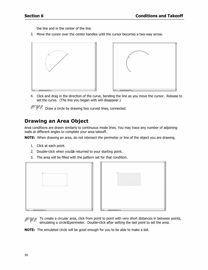
Section 6 Conditions and Takeoff
39
the line and in the center of the line
3 Move the cursor over the center handles until the cursor becomes a two-way arrow
4 Click and drag in the direction of the curve bending the line as you move the cursor Release to set the curve (The line you began with will disappear)
Draw a circle by drawing two curved lines connected
Drawing an Area Object Area conditions are drawn similarly to continuous mode lines You may trace any number of adjoining walls at different angles to complete your area takeoff
NOTE When drawing an area do not intersect the perimeter or line of the object you are drawing
1 Click at each point
2 Double-click when yoursquove returned to your starting point
3 The area will be filled with the pattern set for that condition
NOTE The simulated circle will be good enough for you to be able to make a bid
To create a circular area click from point to point with very short distances in between points simulating a circlersquos perimeter Double-click after setting the last point to set the area
Section 6 Conditions and Takeoff
40
Grid Options Grids give you an added advantage when installing materials such as tiles Use this feature to get a count for how many tiles are needed for an area
1 Double-click on an area condition in the Takeoff dock bar to open its Condition dialog
2 Click on the Advanced tab to show its options
3 Check the box next to Grid by clicking in it
4 Indicate the dimensions of the cell matrix in inches (For example 200 x 400)
5 Under Results tab choose each (EA) for one of the results fields This will tabulate a number of grid cells (including partial grid cells) in area
6 Click to save your settings
7 Use the Move Grid and Rotate Grid features in the Tools menu to manipulate the grid as desired
Grid Calculation
1 Go to Tools gt Options menu
1 Specify if On-Screen Takeoff automatically should Calculate Grid Position
2 If AreaGrid Size is selected On-Screen Takeoff will calculate the number of items needed to fill the grid based on grid demintions
3 Click to accept and close the dialog
To move a line at any angle (regardless of default setting) press the Shift key while moving the mouse
Section 6 Conditions and Takeoff
41
Backout Mode This feature allows you to take out part of an area and deduct that amount of square footage
1 Select Tools gt Backout Mode
2 Outline the are you want backed out as you would when drawing a regular area object (see Drawing an Area Object)
3 The outlined area will clear and quantities will be recalculated
NOTE The perimeter of the backout area will be added to the LF quantity for that condition
Drawing a Count Object Square triangle rectangle and circle shaped count objects can easily be placed on images
1 Select the condition
2 Click in the location where you want the object to appear
3 To place an opening-shaped count item like a door or window you must click over an existing linear object such as a wall
4 On the Results tab you can change the height properties to give you the result you need
5 If Backout is checked on the advanced tab for each count opening the opening-shaped count item will back out a corresponding section of the linear object
Opening shaped count items are sized at 3rsquo0rdquo by default
Drawing a Zone Zones are drawn in the same way as area objects and may be any polygonal shape You may trace any number of adjoining walls at different angles to complete the zone perimeter
1 Click at each point
2 Double-click when yoursquove returned to your starting point
Section 6 Conditions and Takeoff
42
Selecting Objects
1 Use the Select Tool to select objects
You can also select all objects that correspond to a condition
1 Click on a condition to select it
2 Right-click and choose Select All
3 All objects with this condition will be highlighted with squares as an outline
Moving and Resizing Objects Linear
1 To move or resize a linear object click anywhere on the line to select it
2 To move the line position your pointer over the center handles When the mouse is positioned over the handles you will see a two-way arrow You will only be able to move the line in the direction of the arrows
3 Drag the line to a new position
4 Clicking and dragging the handles on the ends of the line will allow you to lengthen or shorten your line
Area and Zone
1 To move an area object or zone in its entirety click and drag it to its new position
2 Grabbing a handle at a corner or intersection of the object will allow you to adjust and change its perimeter
Section 6 Conditions and Takeoff
43
Count 1 To move a square circle rectangle or triangle shaped count object click and drag
2 Click and drag an opening shaped count object along the length of the linear object to the desired position then release
NOTE An opening shaped count object may not be moved from its associated linear condition object however it may be moved up and down the length of the linear object
Layers On-Screen Takeoff allows you to sort and separate your takeoff objects within the same job and on the same page On-Screen Takeoff gives you this flexibility through the use of layers
By assigning different conditions to different layers (for example differentiating between floors ceilings and walls) you can choose to view all layers or turn off certain layers to display and print the remaining groups of conditions only You may also remove the background image of electronic plans add text and hot link symbols or print only your condition takeoffs
Layers are only available in Full Mode If you are in View or Lite Mode and would like to use this
feature click from the main toolbar to purchase the upgrade Default Layers
On-Screen Takeoff begins every project with three default layers Image Annotation and Default The Image layer holds the electronic plan files you may have in your project The Annotation layer possesses all text notations highlighting and hot links in the project The Default layer will appear in the Condition dialog when creating or editing a condition (listed in the takeoff dock bar) Conditions are assigned to the Default layer unless otherwise specified by the user
Creating Layers To assign a condition to a layer other than the default layer you must first create additional layers for your project
1 Select View gt Layers to open the Layers dialog
2 Click An unnamed layer will be added
3 Click within the empty box and type a name for your layer (for example Wall)
4 New layers are added as active layers The adjacent box under the Show column will be checked
Section 6 Conditions and Takeoff
44
Assigning a Layer to a Condition 1 Open the Condition dialog box by creating a new condition or editing an existing condition
2 Under the General tab click on the down arrow in the Layer field to display optional layers
3 Select the desired layer for the condition Only the Default layer and layers you have added will be displayed
4 Click
View and Hide Layers
1 Select View gt Layers
2 Under the Show column check the box to view or remove the check (by clicking on it) to hide the specific layer
3 Click to accept and close the Layers dialog
Section 6 Conditions and Takeoff
45
Assigning Text to a Layer When adding text to an image On-Screen Takeoff has the capability to assign the text to a specified layer
1 Select the Text Tool
2 Click at the point you want to place your text
3 Type in your text using the Enter key for line breaks
4 Click the drop down arrow next to the Layer field and select the desired layer
Section 7
46
Printing and Exporting
This section will
Printing options and procedures
Exporting data by copying and pasting
Exporting quantity results to Excel spreadsheets
Section 7 Printing and Exporting
47
Print Setup On-Screen Takeoff allows the user to print the image takeoff list and worksheet
1 Select File gt Print Setup The Print Setup dialog will open
2 Select a printer or leave the default selection listed (change from the default printer displayed by clicking on the down arrow at the right of the field)
3 Indicate page size and printer tray option (Source) Access page size options by clicking on the
down arrow at the right of the field
4 Choose Portrait or Landscape orientation
5 Click to accept and close the dialog
Printing Images The image area can include the electronic plans the takeoff objects added text and hot links To print a subset of these (for example just the takeoffs without the plans or the added text and hot link symbols) hide layers that you do not want to print (see Section 6 View and Hide Layers) When you are printing your images every page will show the scale of the takeoff you are printing
1 Click on the Image tab to display the area of your project
2 Select File gt Print (or Ctrl + P)
Section 7 Printing and Exporting
48
3 Select the desired view (What to print) and the Image Range
4 Click The second Print dialog will open
5 Change settings accordingly or click if you accept the default settings
Printing Takeoff Lists and Worksheets In Takeoff Lists and Worksheets you may hide columns to print only certain results or adjust column widths to fit the report within the page size selected
1 In Takeoff List or Worksheet view move your cursor to the right side of the columnrsquos title bar the cursor will display as a two-way arrow
Section 7 Printing and Exporting
49
2 Click and drag to adjust the width of the column Holding the mouse button you may
slide the title bar under the title bar to its left to hide the column completely
3 Select File gt Print or press Ctrl + P to access the Print dialog
4 Indicate desired printer and choose the number of copies
5 Click to print and close the dialog
When printing the condition list we suggest printing in landscape
To reset to the default column widths double-click on the right border of a column heading will reset the column to its right (or previously to its right before being hidden)
Print Preview 1 Select File gt Print Preview
2 Use and to vary your view 3 If viewing an image choose current full or scale view to see how it displays
4 For printed outputs that cover more than one page use and to view adjacent pages or click on the down arrow next to Page field and select the page you want displayed
Exporting Using the CopyPaste Feature You may copy all the data or sections from the worksheet and the takeoff list view in On-Screen Takeoff and paste it into another application When pasting into Excel the cell layout will be maintained
1 Highlight the areas you wish to paste Click and hold the left mouse button down as you drag the cursor over the area to be selected then releasing the mouse button
OR
2 Select the entire takeoff list quickly click on the left On-Screen Takeoff column header and hold and drag the cursor across the remaining column headings
The number of pages for the view selected will display in the lower left-hand corner The zoom percentage that applies to the view will be displayed in the lower right-hand corner next to page size of the drawing
Section 7 Printing and Exporting
50
3 In the worksheet view you may highlight rows by clicking on the numbered buttons to the left of each row clicking and dragging across column headings or clicking and dragging over individual cells in the worksheet
Click anywhere in the appropriate view to deselect the area
4 Once your selection is highlighted you may select Edit gt Copy or Ctrl C from the keyboard 5 On your monitor switch to the application into which you want to paste your selection 6 Select Edit gt Paste in the new application or simply press Ctrl + V to paste
The colored keys for conditions cannot be pasted
Using the Export Feature You may export condition quantities to specified cell location within an Excel worksheet file Cell target locations are assigned in the Results tab of the condition dialogs on the Export line relating to each quantity measurement type
On-Screen Takeoff will export takeoff quantity results for up to three different quantity types that you specify For instance you may want to know the number of square feet in a ceiling area as well as the number of linear feet in its perimeter
Section 7 Printing and Exporting
51
1 Bring up the Condition dialog by double-clicking on a condition in the takeoff dock bar or by
selecting the condition and clicking
2 Click on the Results tab to access its fields The default quantities for the condition type will display
3 For each results field click on the arrow to access the pull-down menu and select the appropriate quantity (for example SF LF EA etchellip)
4 Have your Excel spreadsheet opened and saved in a file
5 Specify the Excel spreadsheet cell locations where you want the results to go
6 For a cell in the first sheet of your spreadsheet type in the cell address (eg a1) Case is not important
7 For a cell on a successive sheet of your spreadsheet type in sheet the number followed by a comma and the cell address without any spaces (eg sheet2a1) Case is not important
8 Click
9 Select File gt Export gt Condition Qty to Excel
Section 7 Printing and Exporting
52
10 Browse to the location of the Excel spreadsheet file click file to select it
11 Click to export On-Screen Takeoff results to specified cell locations in the Excel file When you return to the Excel application you will see the values have been added to the specified cell locations in your spreadsheet
12 Save your Excel file
Exporting Worksheet to Excel
1 Assign condition quantities you want to export
2 Open saved Excel spreadsheet file to which you will be exporting
3 From On-Screen Takeoff Select File gt Export gt Worksheet to Excel
4 Browse to the location of the Excel spreadsheet file click file to select it
5 Click When you return to the Excel application you will see the values from the Worksheet Tab have been added to your spreadsheet
6 Save your Excel file
Exporting Takeoff to CVS 1 Assign condition quantities you want to export
2 Open saved Excel spreadsheet file to which you will be exporting
3 Click the Takeoff Tab in the project you want to export the information
4 Select File gt Export gt Takeoff to CSV
5 Browse to the location of the CSV spreadsheet file click file to select it
6 Click the Save
NOTE CSV files can be opened in Excel Lotus Access etc One may consider this option more of a ldquodumprdquo into a file
The Excel application must be active (it may be minimized on the application bar) with the target spreadsheet open in the application Otherwise an error will occur with the export operation that will affect both the On-Screen Takeofftrade file and the Excel spreadsheet
Section 8
53
Advanced Features
This section will
Some special features of working with condition objects in the takeoff area
Details of advanced options for conditions
Advanced features of the Project Properties dialog
Section 8 Advanced Features
54
Features to Use with Objects Roping Feature You can move copy or delete using this feature Using the Select tool (the pointer) you may select several objects at once by clicking and dragging an outline around the objects then releasing the mouse button Roping may select either objects completely within the outlined area (inclusive) or objects both within and touched by the outlined area (touching) Specify your roping preference under Tools gt Options
1 Click and hold the mouse button at a point on the screen near the objects to be selected and drag to surround the objects with an outline
2 Release the mouse button The objects will be selected
3 You may now
Move the group around on the page by clicking within the group dragging the mouse and releasing the button to place the objects
Delete the group of objects by clicking the Delete key or
Copy and paste by pressing Ctrl C to copy the group then Ctrl V to paste it The pasted copy of the grouped objects will appear slightly offset from the original objects
Section 8 Advanced Features
55
Applying a DropRun Count
Use the droprun feature when calculating quantities to take into account the drop or run of a linear condition such as electrical lines or plumbing pipes Drop or run lengths may be added separately to any linear condition on screen while a default droprun length may be indicated for a condition as a whole
1 Select the desired linear condition from the Condition List in the Takeoff Dock bar
2 Click the Change button in the toolbar to open the Change Condition dialog
3 Click the Advanced tab to access the advanced options and click inside the DropRun check box
4 Enter a default length to be applied to all of this condition Entering 800 will be interpreted as 8 0 (You must enter both place markers for inches) You can leave the length blank and manually enter drop run on each segment drawn
5 Click the OK button to accept and close the dialog
Edit DropRun Count
1 With the related linear condition in the Takeoff Dock bar highlighted or with the pointer tool selected
2 click on the desired linear object in the image takeoff area The Count button will become active
3 Click on the Count button (alternatively select Tools gt Count) The default droprun amount will show in the pop-up Count dialog (Default length will be zero if droprun has not been selected in this conditionrsquos properties)
4 Type in the desired length Entering 800 will be interpreted as 8 0 (You must enter both place markers for inches)
5 Click the OK button The additional amount will be reflected in the corresponding quantity The new DropRun count will apply only to the object edited
Adding Text in Image View
On-Screen Takeoff allows you to place text comments around your quantity takeoffs that may be printed along with plan images and objects Text is automatically placed within the Annotation Layer (that includes text and hot links)
1 To place text on the image select the Text Tool and click at the point you want to place your text opening a text box
2 Type in your information clicking Enter for line breaks
3 When you are finished click the OK button to exit the text box
4 To reposition text simply click on the text (with the Text Tool active) to select it
5 Move the cursor over the text the cursor will now display as a four-way arrow
6 Click and drag the mouse to position the text as desired
Section 8 Advanced Features
56
1 To edit existing text use the Text Tool to double-click on the text to open the editing box
2 Enter additional text or use the Backspace key to delete text as necessary
Formatting Text Once created you may format the font size type style and color of your text
1 Click on the text to select it and select Tools gt Font or click on the Font button in the Takeoff Toolbar
2 Select the desired features (color options are disabled) and click the OK button
3 Click on the text to select it and select Tools gt Color or click on the Color button in the Takeoff Toolbar The Color dialog will open
4 Click on a color in the Basic Color palette or create a color and add to the Custom Colors palette (Be sure to click on the color in the Custom Colors palette to select it)
5 Click the OK button
Object Properties
Linear Objects
Linear objects may be set to connect at corners
A linear object may be set to trim automatically when crossing another linear object (Check the trim option under the advanced tab of the Condition dialog)
When you move a connected linear object objects automatically move and resize connected lines accordingly (quantities are then recalculated)
This feature requires that the connected linear object be moved using the center handles (does not apply when resizing the line from the ends)
Objects constrain to snap increments defined in the Tools gt Options menu (with the mouse 15deg by default incremental when shift key is held down)
Objects are measured from centerline to centerline
Section 8 Advanced Features
57
Area Objects When drawing an area use your escape key to undo the last line drawn You may reverse your
drawing of an area using the escape key
The area will not fill with color and pattern until the user double-clicks after the last line is set
Lines drawn to delineate an area object constrain to snap increments defined in the Tools gt Options menu (with the mouse 15deg by default incremental when shift key is held down)
After selecting an area to move or adjust position the mouse in the center to move the entire area position the mouse at the sides or corners to adjust the perimeter
Count Objects
All count objects are quantified by the physical number of objects per page and reported as EA for the UOM The quantity for the current Image View is (displayed in the Condition List) and the total quantity in your project is displayed in the Takeoff View and Worksheet View)
Square circle rectangle and triangle shaped count objects do not displace or subtract from other object quantities when placed on top of them However on the Advanced Tab for the count condition a connect property can be set (this is a check box) so that when a count object of this shape is put on top of a Linear type takeoff object it will move with the linear if said linear is moved
An opened-shaped count object must be placed within a linear object Opening shaped count objects may also be measured by linear foot or linear yard (EA SF and SY are also options) Opening shaped count items default to a width of 3rsquo 0rdquo at the time of creation This size can be changed The small medium and large size are not options on this type of condition anymore Check Backout on the Advanced tab for each Count object back out the footage (or yardage) of opening-shaped count objects in which they are placed
NOTE In order to see this Backout functionality (in quantity) for SY or SF deductions at least one of the
results for the Linear(s) this object will be placed on must be set to SY or SF and the count object must have a height quantity
Advanced Features of Conditions The Round Feature Under the Advanced tab of the linear and area Condition dialogues you may specify quantity rounding (in inches) For linear objects rounding applies to each linear object drawn For area objects rounding will apply to each segment of the area perimeter adjusting the perimeter and area calculations For example With a linear condition entering 12 in the Round field will round up each related linear object to the nearest 12 inches or one foot With this setting two walls of 1 4 would each round to 2 0 totaling 4 0
NOTE In the Takeoff Dock bar condition list and in the On-Screen Takeoff reports quantities will be displayed in whole numbers rounded up to the nearest foot However calculations are based on true quantities without rounding unless the Round Feature is engaged
Pitch Pitch may apply either to linear or area conditions It is measured in rise per linear foot Entering 12 indicates a 12 rise per 12 of linear distance (a pitch of 12 over 12) or an angle of 45deg
Section 8 Advanced Features
58
Advanced Features of Project Properties Selecting Multiple Pages
1 Select a single page entry by clicking on the numbered gray button to the left of the entry
2 Drag the cursor down the column of numbers to select consecutive pages
3 Click on the blank button at the top of this column to select all pages in the Properties dialog
Section 8 Advanced Features
59
Changing Image Assigned to a Drawing 1 Select the page entry by clicking on the numbered gray button to the left of the entry 2 Click the Change Image button The Change Image dialog box will appear
3 Navigate to the desired file and select by clicking on it
4 Click the Open button The electronic file assigned to the page will have been changed to reflect the new file choice
Changing Image File Path 1 Select pages as described above
2 Choose Change Folder
3 In the Change Folder dialog navigate to the appropriate folder
4 Click the OK button The file path will have been changed for the selected page entries
Delete a Page from Project Properties 1 Select the page you want to delete by clicking on its associated number (in the gray box at the
left of the entry)
2 Choose Delete Page
All Takeoff on the page will be deleted immediately and permanently
Section 8 Advanced Features
60
Advanced Features of Tool Options
Calculation Method On-Screen Takeoff has built-in calculation options to allow for faster work and faster saves until your takeoff is complete Calculation options are found by selecting Tools gt Options then clicking on the Calculation tab
Calculation method can be set to Automatic Automatic except Grids and Manual Manual will allow the program to operate more quickly while Automatic or Automatic except Grids allows the user to see quantity changes as takeoffs are made
In any mode you may press F9 to recalculate quantities for the On-Screen Takeoff current totals
Configuration Tab
When the ldquoPage Label (A01)rdquo radial button is chosen On-Screen Takeoff puts the numbered label on all the pages of in your current page indicator in your Navigate Toolbar If the Page Descriptionrdquo radial button is chosen then a description of what takeoff is on that specific page will be shown in your current page indicator in your Navigate Toolbar
This section of the configuration tab gives you options on how you want to export your information When the ldquoFolderSubfolder Namesrdquo radial button is chosen than on your file that you are exporting to will have all the conditions folders and subfolders In the Delimiter box you can choose the symbol that is needed to separate the information you are exporting Some files need semicolons () or colons () to make sure the information comes exported in is separated it the appropriate places
Section 8 Advanced Features
61
In previous versions of On-Screen Takeoff there are views that users need to have in order for them to display their information By either choosing ldquoOST 1xrdquo or ldquoOST 2xrdquo it will let the program know you want your columns of information exported in that specific format
When you have the Confirm Deletions radial button of ldquoYesrdquo chosen than every time you delete anything you will get a dialog box confirming your intentions of deletion
While working with your takeoff you have a choice to either view the legend of your conditions or hide it Choose whichever radial button that suits your needs
For those who prefer to use the Enter key to navigate in dialog boxes this option is just for that
Font Tab The Font tab is designed for you to make your own look and feel for the application At the bottom of this tab it will show you sample of the fonts and colors you have chosen
Renaming the Current Page You may change the name of the current page in the takeoff area of On-Screen Takeoff by selecting Edit gt Rename Page
This opens the Name Page dialog and you may simply type in a new name and click the Enter button The new name for the file will be reflected on the title bar for the page and in Project Properties
You also may access the Rename Page function by right-clicking in the takeoff area while in Image View and selecting the option from the pop-up menu that appears
Section 9
62
Saving and Exiting
This section will
Explain how to save projects
Show you how to safely exit the program
Section 9 Saving and Exiting
63
Saving Your Project
1 Select File gt Save 2 If your project has not previously been saved a Save dialog box will open to allow you to name
the file and choose the directory and folder in which to save your file 3 Once saved File gt Save will simply save the current version of the file
OR
4 Select File gt Save As then type in a new name for the file and save to the desired file path
The Auto-save Feature With the Auto-save feature On-Screen Takeoff automatically backs up your open project You may choose to have more than one level of backup files The first backup copy will have the extension b00 and successive files will be b01 b02 and so on If you have designated four levels of backup files after the fourth backup copy has been created (b03) the next file will be saved over the file with extension b00 Further backup saves will then rotate through the four backup files in the same way
1 Select Tools gt Options 2 In the Auto-save area (under the General tab) select the frequency of backup file creation (in
minutes) and the number of levels for the feature 3 You also may disengage the feature by clicking in the check box to clear it
The Auto-save feature automatically saves backup copies to the directory of the current project If you are working from a write-protected area such as a CD-ROM On-Screen Takeoff will place backup files in the On-Screen Takeoff folder
Exiting When you are finished using On-Screen Takeoff it is very easy to exit Exiting is very important because of security reasons If someone were to use your computer they could enter the application and view and manipulate information
Section 9 Saving and Exiting
64
On-Screen Takeoff closes the open project when you open another or create a new project or when you exit the program
1 Select File gt Exit
OR
2 You also may click at the upper right-hand corner of the application to exit
NOTE If your latest changes to a project file have not been saved On-Screen Takeoff will ask you whether you would like to save the file and gives you the option of canceling the operation
Appendix I Installing Your Digitizer
65
Appendix I Installing Your Digitizer When you get your digitizer from GTCO you will need to connect it to your computer Follow the instructions outlined below to do this
Note For rollup digitizers the metal bar must be oriented to the top or right hand side
Connecting the Digitizer 1 Lay the digitizer out flat 2 Connect the Stylus to the digitizer 3 Plug in the power adapter 4 Plug the interface (IO) cable into the digitizer 5 Plug the other end of the interface cable into an open serial port on computer
Note GTCO Technical support phone number is 410-381-6688 The electronic manual (on diskette) from GTCO contains more detailed installation and operation instructions for the GTCO digitizer model you have
Installing other Digitizer Drivers If you are using a GTCO Digitizer you will need to install the GTCO TabletWorks Drivers
If you are using a Digitizer not supported by GTCO Tablet Works 10 please contact the manufacturer of your digitizer for assistance with installation
Installing GTCO TabletWorks Drivers 1 Insert the On Center CD into the CD-ROM drive The CD Startup screen will open 2 Click on Install Software 3 Select Additional Software and Drivers 4 Select Digitizer Driver 5 Follow the instructions for installing TabletWorks 10
Adhering the Template The template is a small plastic sticker used to enable mouse function when using the digitizer with On-Screen Takeoff Place your template on your digitizer We suggest placing it in the bottom right corner of the digitizer about one inch inside the takeoff area
Note You may either peel off the back of the template and use the adhesive surface or you can tape the template down
Appendix I Installing Your Digitizer
66
Testing the Digitizer Drivers Before running OST you may test the digitizer by moving the stylus around on the digitizer pad it should move the mouse cursor (if mouse emulation is enabled)
If the digitizer does not move the mouse cursor on the screen
The superset codes may need to be reset Reset the superset codes by touching on the border of the digitizer with the stylus The digitizer should beep several times
The digitizer may not be communicating with the computer Be sure the COM port selected is correct Be sure the COM port selected is correct If you are not able to get the digitizer to move the mouse cursor you need to call GTCO technical support for help
Note The Mouse Emulation is not required for On-Screen Takeoff to work properly It is used only for the Template functionality if the digitizer is moving the cursor the wrong direction (up instead of sideways or vice-versa)
Click the L-shaped arrow symbol on the digitizer with the stylus
Appendix II Toolbar Item Details
67
Appendix II Toolbar Items Main Toolbar
Appendix II Toolbar Item Details
68
Tool Toolbar
Appendix II Toolbar Item Details
69
Zoom Toolbar
View Toolbar
Navigate Toolbar
Appendix II Toolbar Item Details
70
Navigate Toolbar (Continued)
Takeoff Toolbar
Appendix II Toolbar Item Details
71
Takeoff Toolbar (Continued)
Image Toolbar
Appendix III Loading Plans from a Dodge CD
72
Appendix III Loading Plans from a Dodge CD
This section will detail how to load plans from a F W Dodge CD-ROM into an On-Screen Takeoff project file ready for takeoffs
Dodge files may be added to the Project Properties dialog However loading the files in that way will load the files by number rather than name description If you want to load one page only from your Dodge CD You will have to rename the page to display the name rather than number of the file
To load plan files from a Dodge CD so that the files load sequentially by file number but are displayed by name rather than by number within your project follow the instructions below
Opening a Dodge project from a CD-ROM 1 Insert the CD into the drive 2 Choose File gt Custom 3 Choose Dodge Plans Project (plansdat) as the file type 4 Select the appropriate file type by clicking on the down arrow at the right of the Files of type
field 5 In the Look in field access your drive paths by clicking on the down arrow at the right of the
field then
Navigate to your CD-ROM drive Open the data folder and Open the Projects folder
6 Select the desired project and open its folder 7 Open the plansdat file 8 All the images will come in sequenced correctly for that job along with the full descriptions
(names) of each page If there is not a plans folder in the project folder then plans do not exist for that project on the CD Opening the plansdat file will yield an empty project
Appendix IV Using the Plan Viewer
73
Appendix IV Using On-Screen Takeoff Plan Viewer The On-Screen Takeoff Plan Viewer is a limited version of On Center Softwarersquos commercial takeoff software If your status bar located at the very bottom of the main window says View Mode in the lower left-hand corner then you are using the Plan Viewer You can use the plan viewer to
View CD-based amp converted CAD drawings
View a previously created OST file and associated drawings
Download electronic plans online
Navigate through drawings
Quickly Takeoff linearsareas and counts
Zoom in to view the plan better
Print drawings directly from the viewer
Viewing an On-Screen Takeoff Project File
1 To open an OST file that was previously created with of On-Screen Takeoff 2 Select File gt Open 3 An Open dialog will appear if you do not see the OST file you are looking for select the
Look In drop down arrow 4 A drop down menu will appear listing the various folders drives and mapped drives located
on your computer select the correct drive or folder location and continue to browse to the location of your OST file
5 When you see your OST file double-click it to open it 6 Any takeoff and drawings should appear on the Image tab view
If you do not see the drawings but do see the colored takeoff layer the drawings may
not be located in the same place they were originally saved at Go to File gt Project Properties and check the Image File path for each listed page If the image file path is pointing to a CD drive make sure the CD is inside the CR-ROM
Downloading Electronic Plans If your Online Plan Service provides a special file format (OSX) required to use this feature of our plan viewer you can immediately downloaded all electronic plans of a project directly from our viewer
Most Plan Room web sites will automatically open On-Screen Takeoff when a request to download plans is made Your particular Plan Room may differ in operation so please contact the provider directly with questions on using the site
Appendix IV Using the Plan Viewer
74
When you request to download or open a project file from a Plan Room you will usually have the open to open or save an OSX file Choosing open will automatically open On-Screen Takeoff Alternately you may choose to save the file to a local hard drive After you have saved the file either double-click it to launch On-Screen Takeoff or open the OSX file using On-Screen Takeoff by clicking File then Open and locating the file on your hard drive You will need to change the file type to OSX
After the OSX file is opened you will see an additional tab appear in the Conditions List window called Pages
The Pages tab shows the hierarchy of your project Gray file icons represent pages that have not been downloaded and blue icons represents pages that have been downloaded
To download a page simply double-click the page icon
If you wish to select a group of pages to download you can use the Ctrl or Shift key to multiple select them then click the Download button
If you wish to download all pages at once click the Download All button
Downloaded pages will now appear in the Project Properties dialog in the same order in which they appear in the Pages tab
Creating Quick Takeoffs With On-Screen Takeoff you can create quick takeoffs to measure quantities even if you dont have the full version of our program However using the Quick Takeoff functionality shows you just a fraction of what the full version can do
The Quick Takeoff Toolbar is located at the top of the image view It has three buttons designated for three types of takeoffs Linear Area and Count The Quantity drop down list will show secondary quantities for Linears and Areas The Units drop down allows you to select how you want your quantities displayed Feet Inches Yards Millimeters and Meters
NOTE Every time change the type of takeoff you are performing (switching from Area to Linear for example) the previous quantities and takeoff objects will disappear They will also disappear when you changes pages
NOTE You can use the Dimension Tool to basically measure the distance between two points or linears The distance will display on the status bar at the bottom of the application
The Quick Takeoff Toolbar
Appendix V Frequently Asked Questions
75
Appendix V Frequently Asked Questions General
Where is On-Screen Takeoff installed on my computer
Typically it is installed in CProgram FilesOn-Screen Takeoff
In Explorer how do I recognize On-Screen Takeoff file types
On-Screen Takeoff data is stored in a single file per job lsquojob name OSTrsquo On-Screen Takeoff templates are stored as lsquotemplate nameTPOrsquo
Can only one project at a time be open
Yes For that reason opening another project automatically closes the project on screen You will be asked to save any changes
Is only one scale allowed per page What about on drawings that have multiple detail sections on a page and each of those drawings have different scales
Yes For pages with drawings of different scales copy the drawing to another project page and set the appropriate scale
I cannot perform backout on an area that is along a linear
As a workaround use the On-Screen Takeoff layers feature to help you with this issue Electronic Images
How do I start a project from drawings that have been scanned and written to a CD-ROM
Open a new project Select File gt Project Properties and select Auto Add Navigate to your CD and the appropriate folder and select any image file in that location Click Open All files in the location will load into your project Recommended that images are copied from CD to hard drive for performance
If I get a disk of drawings in AutoCAD format (R13 or R14) can I read them in On-Screen Takeoff
Yes On-Screen Takeoff now reads DWG DXF and many other format that are saved with AutoCAD
Appendix V Frequently Asked Questions
76
When I click on the all pages button what is supposed to happen Currently nothing seems to change when I click on that button
The All Pages button is used to apply the Darken and Enhance Plans feature to all pages in the project (as opposed to only the current page on screen)
Is there a way to deduct a large skylight from an area condition
Yes with the related area condition selected in the Takeoff Dock bar unselect the Backout button on the Takeoff Toolbar then draw the Backout area The area quantity will be deducted from the related condition object and the linear measurement of the Backout perimeter will be added
Digitizer Issues
How do I connect a Digitizer to the computer
See Appendix I Connecting a Digitizer
The Place Template menu choice is disabled
On-Screen Takeoff may need to be authorized or the digitizer or the digitzer drivers are not installed
It wonrsquot let me select the Set Takeoff Area menu choice
On-Screen Takeoff may need to be authorized or no job is open a digitizer is not installed or the drivers are not installed
The digitizer stylus is not moving the cursor or crosshairs
Click S-0-1 superset on the digitizer
How do I convert my old GTCO Digitizer to work with On- Screen Takeofftrade
Call GTCO and they may be able to reconfigure your digitizer to be compatible with On-Screen Takeoff
Printing Issues Which Printers work with On-Screen Takeoff
Compatible printers include On-Screen Takeoff Hewlett Packard Epson and Canon printers If you are having printer difficulties please contact support and specify the type of printer along with other pertinent information Contact support at wwwoncentercomsupport or email supportoncentercom
Which Plotters work with On-Screen Takeoff
Compatible Plotters include Hewlett Packard DesignJet plotters and the EnCAD Cadjet II If you are having plotter difficulties please contact support and specify the type of plotter concerned
ViewingDisplay I can no longer see my condition list How do I get it back
The toolbars and Dock bars can be turned on and off through the View gt Toolbars menu options
Appendix V Frequently Asked Questions
77
This is also accessible by right-clicking in the toolbar area and selecting (or deselecting) a toolbar listed
I cannot view my folders in the condition list
Right-click in the Takeoff Dock barcondition list area and select Show Tree to display your folders
My Status Bar reads Viewer Mode and I am unable to draw conditions
On-Screen Takeoff needs to be Authorized Or you need to purchase an upgrade Click the Perform Advanced Takeoff button on the main toolbar
I hid a Dock bar and when I selected to view it again it appeared alongside the other Dock
bar instead of stacked on top of it How do I fix it
Pick up the Dock bar by clicking on the bar at the top and continuing to hold down the mouse button drag the Dock bar over the other one It will resize and appear stacked with the other
When I open image files from a CD the images are all upside down How do I get them right
side up
To flip pages from top to bottom follow the steps below 1 Click the All Pages button on the Image Toolbar (All Pages is engaged when the button
is not clicked) 2 Click the Flip Horizontal button on the Image Toolbar 3 Click the All Pages button again to disengage
Templates How do I create a Template
Follow the steps below 1 Create a typical project 2 Choose File gt Save As 3 Choose On-Screen Takeoff Template Files as the file type to save 4 Name the file This will save all of the condition setups as well as the layers for the
project
How do I create a new project from a template
Follow the steps below 1 Choose File gt New 2 Select a template from those listed in the New dialog This will open a new project with
conditions and layers saved from a previous project but no pages or takeoff
78
INDEX
Area Conditions 32
Area Objects 57
Auto Scrolling 20
Auto-save 63
Backout Mode 41
Calculation Method 60
Conditions 29
Configuration 60
Contents Tab 6
Continuous Mode 38
Count Conditions 33
Count Objects 57
Digitizer 10 65 76
Docking Toolbars 13
Dodge CD 72
Drawing 27 37
DropRun Count 55
Environment 18
Exiting 63
Exporting 49
Features 16
Font 61
Frequently Asked Questions 75
Grid 40
Help File 5
Hiding Toolbars 13
Hot Links 21
Image 19 59
Image files 9
Image Toolbar 12 71
Images 75
Index Tab 6
Layers 43
Linear Conditions 31
Linear Objects 56
Main Toolbar 12 67
Menus 14
Moving Toolbars 13
Navigate Toolbar 12 69
Navigating 20
On-Screen Takeofftrade 2
Page 59 61
Pages 20 25 28
Plan Viewer 73
Plans 26
Printing 47 76
Project Properties 25
Projects 22
Quick Start Video 18
Resizing Toolbars 13
Roping 54
Saving 63
Scale 28
Search Tab 7
Selecting Objects 42
Setup 8
Start On-Screen Takeofftrade 17
System Requirements 9
Takeoff 19 27
Takeoff Toolbar 70 71
Takeoff Toolbar 12
Template Files 23
TIF (Group4) 9
Tool Toolbar 12 68
Toolbar 67
Toolbars 12
View Toolbar 12 69
Viewing Toolbars 12
Worksheet 20
Zone Conditions 33
Zoom Toolbar 12 69
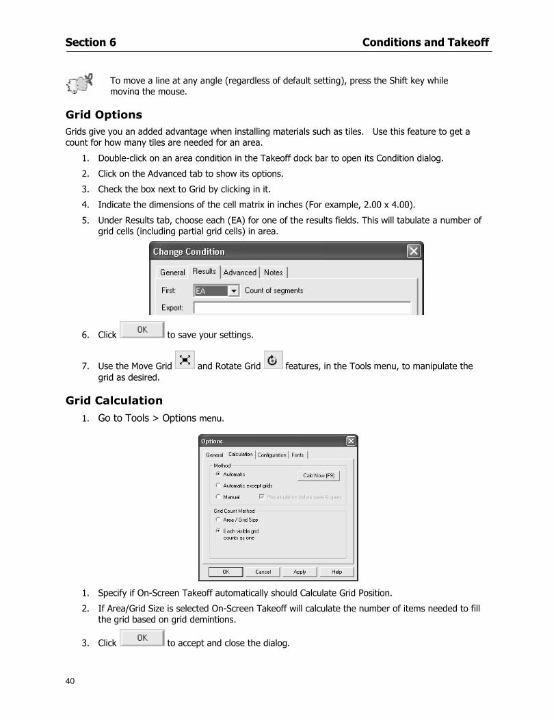
Section 6 Conditions and Takeoff
40
Grid Options Grids give you an added advantage when installing materials such as tiles Use this feature to get a count for how many tiles are needed for an area
1 Double-click on an area condition in the Takeoff dock bar to open its Condition dialog
2 Click on the Advanced tab to show its options
3 Check the box next to Grid by clicking in it
4 Indicate the dimensions of the cell matrix in inches (For example 200 x 400)
5 Under Results tab choose each (EA) for one of the results fields This will tabulate a number of grid cells (including partial grid cells) in area
6 Click to save your settings
7 Use the Move Grid and Rotate Grid features in the Tools menu to manipulate the grid as desired
Grid Calculation
1 Go to Tools gt Options menu
1 Specify if On-Screen Takeoff automatically should Calculate Grid Position
2 If AreaGrid Size is selected On-Screen Takeoff will calculate the number of items needed to fill the grid based on grid demintions
3 Click to accept and close the dialog
To move a line at any angle (regardless of default setting) press the Shift key while moving the mouse
Section 6 Conditions and Takeoff
41
Backout Mode This feature allows you to take out part of an area and deduct that amount of square footage
1 Select Tools gt Backout Mode
2 Outline the are you want backed out as you would when drawing a regular area object (see Drawing an Area Object)
3 The outlined area will clear and quantities will be recalculated
NOTE The perimeter of the backout area will be added to the LF quantity for that condition
Drawing a Count Object Square triangle rectangle and circle shaped count objects can easily be placed on images
1 Select the condition
2 Click in the location where you want the object to appear
3 To place an opening-shaped count item like a door or window you must click over an existing linear object such as a wall
4 On the Results tab you can change the height properties to give you the result you need
5 If Backout is checked on the advanced tab for each count opening the opening-shaped count item will back out a corresponding section of the linear object
Opening shaped count items are sized at 3rsquo0rdquo by default
Drawing a Zone Zones are drawn in the same way as area objects and may be any polygonal shape You may trace any number of adjoining walls at different angles to complete the zone perimeter
1 Click at each point
2 Double-click when yoursquove returned to your starting point
Section 6 Conditions and Takeoff
42
Selecting Objects
1 Use the Select Tool to select objects
You can also select all objects that correspond to a condition
1 Click on a condition to select it
2 Right-click and choose Select All
3 All objects with this condition will be highlighted with squares as an outline
Moving and Resizing Objects Linear
1 To move or resize a linear object click anywhere on the line to select it
2 To move the line position your pointer over the center handles When the mouse is positioned over the handles you will see a two-way arrow You will only be able to move the line in the direction of the arrows
3 Drag the line to a new position
4 Clicking and dragging the handles on the ends of the line will allow you to lengthen or shorten your line
Area and Zone
1 To move an area object or zone in its entirety click and drag it to its new position
2 Grabbing a handle at a corner or intersection of the object will allow you to adjust and change its perimeter
Section 6 Conditions and Takeoff
43
Count 1 To move a square circle rectangle or triangle shaped count object click and drag
2 Click and drag an opening shaped count object along the length of the linear object to the desired position then release
NOTE An opening shaped count object may not be moved from its associated linear condition object however it may be moved up and down the length of the linear object
Layers On-Screen Takeoff allows you to sort and separate your takeoff objects within the same job and on the same page On-Screen Takeoff gives you this flexibility through the use of layers
By assigning different conditions to different layers (for example differentiating between floors ceilings and walls) you can choose to view all layers or turn off certain layers to display and print the remaining groups of conditions only You may also remove the background image of electronic plans add text and hot link symbols or print only your condition takeoffs
Layers are only available in Full Mode If you are in View or Lite Mode and would like to use this
feature click from the main toolbar to purchase the upgrade Default Layers
On-Screen Takeoff begins every project with three default layers Image Annotation and Default The Image layer holds the electronic plan files you may have in your project The Annotation layer possesses all text notations highlighting and hot links in the project The Default layer will appear in the Condition dialog when creating or editing a condition (listed in the takeoff dock bar) Conditions are assigned to the Default layer unless otherwise specified by the user
Creating Layers To assign a condition to a layer other than the default layer you must first create additional layers for your project
1 Select View gt Layers to open the Layers dialog
2 Click An unnamed layer will be added
3 Click within the empty box and type a name for your layer (for example Wall)
4 New layers are added as active layers The adjacent box under the Show column will be checked
Section 6 Conditions and Takeoff
44
Assigning a Layer to a Condition 1 Open the Condition dialog box by creating a new condition or editing an existing condition
2 Under the General tab click on the down arrow in the Layer field to display optional layers
3 Select the desired layer for the condition Only the Default layer and layers you have added will be displayed
4 Click
View and Hide Layers
1 Select View gt Layers
2 Under the Show column check the box to view or remove the check (by clicking on it) to hide the specific layer
3 Click to accept and close the Layers dialog
Section 6 Conditions and Takeoff
45
Assigning Text to a Layer When adding text to an image On-Screen Takeoff has the capability to assign the text to a specified layer
1 Select the Text Tool
2 Click at the point you want to place your text
3 Type in your text using the Enter key for line breaks
4 Click the drop down arrow next to the Layer field and select the desired layer
Section 7
46
Printing and Exporting
This section will
Printing options and procedures
Exporting data by copying and pasting
Exporting quantity results to Excel spreadsheets
Section 7 Printing and Exporting
47
Print Setup On-Screen Takeoff allows the user to print the image takeoff list and worksheet
1 Select File gt Print Setup The Print Setup dialog will open
2 Select a printer or leave the default selection listed (change from the default printer displayed by clicking on the down arrow at the right of the field)
3 Indicate page size and printer tray option (Source) Access page size options by clicking on the
down arrow at the right of the field
4 Choose Portrait or Landscape orientation
5 Click to accept and close the dialog
Printing Images The image area can include the electronic plans the takeoff objects added text and hot links To print a subset of these (for example just the takeoffs without the plans or the added text and hot link symbols) hide layers that you do not want to print (see Section 6 View and Hide Layers) When you are printing your images every page will show the scale of the takeoff you are printing
1 Click on the Image tab to display the area of your project
2 Select File gt Print (or Ctrl + P)
Section 7 Printing and Exporting
48
3 Select the desired view (What to print) and the Image Range
4 Click The second Print dialog will open
5 Change settings accordingly or click if you accept the default settings
Printing Takeoff Lists and Worksheets In Takeoff Lists and Worksheets you may hide columns to print only certain results or adjust column widths to fit the report within the page size selected
1 In Takeoff List or Worksheet view move your cursor to the right side of the columnrsquos title bar the cursor will display as a two-way arrow
Section 7 Printing and Exporting
49
2 Click and drag to adjust the width of the column Holding the mouse button you may
slide the title bar under the title bar to its left to hide the column completely
3 Select File gt Print or press Ctrl + P to access the Print dialog
4 Indicate desired printer and choose the number of copies
5 Click to print and close the dialog
When printing the condition list we suggest printing in landscape
To reset to the default column widths double-click on the right border of a column heading will reset the column to its right (or previously to its right before being hidden)
Print Preview 1 Select File gt Print Preview
2 Use and to vary your view 3 If viewing an image choose current full or scale view to see how it displays
4 For printed outputs that cover more than one page use and to view adjacent pages or click on the down arrow next to Page field and select the page you want displayed
Exporting Using the CopyPaste Feature You may copy all the data or sections from the worksheet and the takeoff list view in On-Screen Takeoff and paste it into another application When pasting into Excel the cell layout will be maintained
1 Highlight the areas you wish to paste Click and hold the left mouse button down as you drag the cursor over the area to be selected then releasing the mouse button
OR
2 Select the entire takeoff list quickly click on the left On-Screen Takeoff column header and hold and drag the cursor across the remaining column headings
The number of pages for the view selected will display in the lower left-hand corner The zoom percentage that applies to the view will be displayed in the lower right-hand corner next to page size of the drawing
Section 7 Printing and Exporting
50
3 In the worksheet view you may highlight rows by clicking on the numbered buttons to the left of each row clicking and dragging across column headings or clicking and dragging over individual cells in the worksheet
Click anywhere in the appropriate view to deselect the area
4 Once your selection is highlighted you may select Edit gt Copy or Ctrl C from the keyboard 5 On your monitor switch to the application into which you want to paste your selection 6 Select Edit gt Paste in the new application or simply press Ctrl + V to paste
The colored keys for conditions cannot be pasted
Using the Export Feature You may export condition quantities to specified cell location within an Excel worksheet file Cell target locations are assigned in the Results tab of the condition dialogs on the Export line relating to each quantity measurement type
On-Screen Takeoff will export takeoff quantity results for up to three different quantity types that you specify For instance you may want to know the number of square feet in a ceiling area as well as the number of linear feet in its perimeter
Section 7 Printing and Exporting
51
1 Bring up the Condition dialog by double-clicking on a condition in the takeoff dock bar or by
selecting the condition and clicking
2 Click on the Results tab to access its fields The default quantities for the condition type will display
3 For each results field click on the arrow to access the pull-down menu and select the appropriate quantity (for example SF LF EA etchellip)
4 Have your Excel spreadsheet opened and saved in a file
5 Specify the Excel spreadsheet cell locations where you want the results to go
6 For a cell in the first sheet of your spreadsheet type in the cell address (eg a1) Case is not important
7 For a cell on a successive sheet of your spreadsheet type in sheet the number followed by a comma and the cell address without any spaces (eg sheet2a1) Case is not important
8 Click
9 Select File gt Export gt Condition Qty to Excel
Section 7 Printing and Exporting
52
10 Browse to the location of the Excel spreadsheet file click file to select it
11 Click to export On-Screen Takeoff results to specified cell locations in the Excel file When you return to the Excel application you will see the values have been added to the specified cell locations in your spreadsheet
12 Save your Excel file
Exporting Worksheet to Excel
1 Assign condition quantities you want to export
2 Open saved Excel spreadsheet file to which you will be exporting
3 From On-Screen Takeoff Select File gt Export gt Worksheet to Excel
4 Browse to the location of the Excel spreadsheet file click file to select it
5 Click When you return to the Excel application you will see the values from the Worksheet Tab have been added to your spreadsheet
6 Save your Excel file
Exporting Takeoff to CVS 1 Assign condition quantities you want to export
2 Open saved Excel spreadsheet file to which you will be exporting
3 Click the Takeoff Tab in the project you want to export the information
4 Select File gt Export gt Takeoff to CSV
5 Browse to the location of the CSV spreadsheet file click file to select it
6 Click the Save
NOTE CSV files can be opened in Excel Lotus Access etc One may consider this option more of a ldquodumprdquo into a file
The Excel application must be active (it may be minimized on the application bar) with the target spreadsheet open in the application Otherwise an error will occur with the export operation that will affect both the On-Screen Takeofftrade file and the Excel spreadsheet
Section 8
53
Advanced Features
This section will
Some special features of working with condition objects in the takeoff area
Details of advanced options for conditions
Advanced features of the Project Properties dialog
Section 8 Advanced Features
54
Features to Use with Objects Roping Feature You can move copy or delete using this feature Using the Select tool (the pointer) you may select several objects at once by clicking and dragging an outline around the objects then releasing the mouse button Roping may select either objects completely within the outlined area (inclusive) or objects both within and touched by the outlined area (touching) Specify your roping preference under Tools gt Options
1 Click and hold the mouse button at a point on the screen near the objects to be selected and drag to surround the objects with an outline
2 Release the mouse button The objects will be selected
3 You may now
Move the group around on the page by clicking within the group dragging the mouse and releasing the button to place the objects
Delete the group of objects by clicking the Delete key or
Copy and paste by pressing Ctrl C to copy the group then Ctrl V to paste it The pasted copy of the grouped objects will appear slightly offset from the original objects
Section 8 Advanced Features
55
Applying a DropRun Count
Use the droprun feature when calculating quantities to take into account the drop or run of a linear condition such as electrical lines or plumbing pipes Drop or run lengths may be added separately to any linear condition on screen while a default droprun length may be indicated for a condition as a whole
1 Select the desired linear condition from the Condition List in the Takeoff Dock bar
2 Click the Change button in the toolbar to open the Change Condition dialog
3 Click the Advanced tab to access the advanced options and click inside the DropRun check box
4 Enter a default length to be applied to all of this condition Entering 800 will be interpreted as 8 0 (You must enter both place markers for inches) You can leave the length blank and manually enter drop run on each segment drawn
5 Click the OK button to accept and close the dialog
Edit DropRun Count
1 With the related linear condition in the Takeoff Dock bar highlighted or with the pointer tool selected
2 click on the desired linear object in the image takeoff area The Count button will become active
3 Click on the Count button (alternatively select Tools gt Count) The default droprun amount will show in the pop-up Count dialog (Default length will be zero if droprun has not been selected in this conditionrsquos properties)
4 Type in the desired length Entering 800 will be interpreted as 8 0 (You must enter both place markers for inches)
5 Click the OK button The additional amount will be reflected in the corresponding quantity The new DropRun count will apply only to the object edited
Adding Text in Image View
On-Screen Takeoff allows you to place text comments around your quantity takeoffs that may be printed along with plan images and objects Text is automatically placed within the Annotation Layer (that includes text and hot links)
1 To place text on the image select the Text Tool and click at the point you want to place your text opening a text box
2 Type in your information clicking Enter for line breaks
3 When you are finished click the OK button to exit the text box
4 To reposition text simply click on the text (with the Text Tool active) to select it
5 Move the cursor over the text the cursor will now display as a four-way arrow
6 Click and drag the mouse to position the text as desired
Section 8 Advanced Features
56
1 To edit existing text use the Text Tool to double-click on the text to open the editing box
2 Enter additional text or use the Backspace key to delete text as necessary
Formatting Text Once created you may format the font size type style and color of your text
1 Click on the text to select it and select Tools gt Font or click on the Font button in the Takeoff Toolbar
2 Select the desired features (color options are disabled) and click the OK button
3 Click on the text to select it and select Tools gt Color or click on the Color button in the Takeoff Toolbar The Color dialog will open
4 Click on a color in the Basic Color palette or create a color and add to the Custom Colors palette (Be sure to click on the color in the Custom Colors palette to select it)
5 Click the OK button
Object Properties
Linear Objects
Linear objects may be set to connect at corners
A linear object may be set to trim automatically when crossing another linear object (Check the trim option under the advanced tab of the Condition dialog)
When you move a connected linear object objects automatically move and resize connected lines accordingly (quantities are then recalculated)
This feature requires that the connected linear object be moved using the center handles (does not apply when resizing the line from the ends)
Objects constrain to snap increments defined in the Tools gt Options menu (with the mouse 15deg by default incremental when shift key is held down)
Objects are measured from centerline to centerline
Section 8 Advanced Features
57
Area Objects When drawing an area use your escape key to undo the last line drawn You may reverse your
drawing of an area using the escape key
The area will not fill with color and pattern until the user double-clicks after the last line is set
Lines drawn to delineate an area object constrain to snap increments defined in the Tools gt Options menu (with the mouse 15deg by default incremental when shift key is held down)
After selecting an area to move or adjust position the mouse in the center to move the entire area position the mouse at the sides or corners to adjust the perimeter
Count Objects
All count objects are quantified by the physical number of objects per page and reported as EA for the UOM The quantity for the current Image View is (displayed in the Condition List) and the total quantity in your project is displayed in the Takeoff View and Worksheet View)
Square circle rectangle and triangle shaped count objects do not displace or subtract from other object quantities when placed on top of them However on the Advanced Tab for the count condition a connect property can be set (this is a check box) so that when a count object of this shape is put on top of a Linear type takeoff object it will move with the linear if said linear is moved
An opened-shaped count object must be placed within a linear object Opening shaped count objects may also be measured by linear foot or linear yard (EA SF and SY are also options) Opening shaped count items default to a width of 3rsquo 0rdquo at the time of creation This size can be changed The small medium and large size are not options on this type of condition anymore Check Backout on the Advanced tab for each Count object back out the footage (or yardage) of opening-shaped count objects in which they are placed
NOTE In order to see this Backout functionality (in quantity) for SY or SF deductions at least one of the
results for the Linear(s) this object will be placed on must be set to SY or SF and the count object must have a height quantity
Advanced Features of Conditions The Round Feature Under the Advanced tab of the linear and area Condition dialogues you may specify quantity rounding (in inches) For linear objects rounding applies to each linear object drawn For area objects rounding will apply to each segment of the area perimeter adjusting the perimeter and area calculations For example With a linear condition entering 12 in the Round field will round up each related linear object to the nearest 12 inches or one foot With this setting two walls of 1 4 would each round to 2 0 totaling 4 0
NOTE In the Takeoff Dock bar condition list and in the On-Screen Takeoff reports quantities will be displayed in whole numbers rounded up to the nearest foot However calculations are based on true quantities without rounding unless the Round Feature is engaged
Pitch Pitch may apply either to linear or area conditions It is measured in rise per linear foot Entering 12 indicates a 12 rise per 12 of linear distance (a pitch of 12 over 12) or an angle of 45deg
Section 8 Advanced Features
58
Advanced Features of Project Properties Selecting Multiple Pages
1 Select a single page entry by clicking on the numbered gray button to the left of the entry
2 Drag the cursor down the column of numbers to select consecutive pages
3 Click on the blank button at the top of this column to select all pages in the Properties dialog
Section 8 Advanced Features
59
Changing Image Assigned to a Drawing 1 Select the page entry by clicking on the numbered gray button to the left of the entry 2 Click the Change Image button The Change Image dialog box will appear
3 Navigate to the desired file and select by clicking on it
4 Click the Open button The electronic file assigned to the page will have been changed to reflect the new file choice
Changing Image File Path 1 Select pages as described above
2 Choose Change Folder
3 In the Change Folder dialog navigate to the appropriate folder
4 Click the OK button The file path will have been changed for the selected page entries
Delete a Page from Project Properties 1 Select the page you want to delete by clicking on its associated number (in the gray box at the
left of the entry)
2 Choose Delete Page
All Takeoff on the page will be deleted immediately and permanently
Section 8 Advanced Features
60
Advanced Features of Tool Options
Calculation Method On-Screen Takeoff has built-in calculation options to allow for faster work and faster saves until your takeoff is complete Calculation options are found by selecting Tools gt Options then clicking on the Calculation tab
Calculation method can be set to Automatic Automatic except Grids and Manual Manual will allow the program to operate more quickly while Automatic or Automatic except Grids allows the user to see quantity changes as takeoffs are made
In any mode you may press F9 to recalculate quantities for the On-Screen Takeoff current totals
Configuration Tab
When the ldquoPage Label (A01)rdquo radial button is chosen On-Screen Takeoff puts the numbered label on all the pages of in your current page indicator in your Navigate Toolbar If the Page Descriptionrdquo radial button is chosen then a description of what takeoff is on that specific page will be shown in your current page indicator in your Navigate Toolbar
This section of the configuration tab gives you options on how you want to export your information When the ldquoFolderSubfolder Namesrdquo radial button is chosen than on your file that you are exporting to will have all the conditions folders and subfolders In the Delimiter box you can choose the symbol that is needed to separate the information you are exporting Some files need semicolons () or colons () to make sure the information comes exported in is separated it the appropriate places
Section 8 Advanced Features
61
In previous versions of On-Screen Takeoff there are views that users need to have in order for them to display their information By either choosing ldquoOST 1xrdquo or ldquoOST 2xrdquo it will let the program know you want your columns of information exported in that specific format
When you have the Confirm Deletions radial button of ldquoYesrdquo chosen than every time you delete anything you will get a dialog box confirming your intentions of deletion
While working with your takeoff you have a choice to either view the legend of your conditions or hide it Choose whichever radial button that suits your needs
For those who prefer to use the Enter key to navigate in dialog boxes this option is just for that
Font Tab The Font tab is designed for you to make your own look and feel for the application At the bottom of this tab it will show you sample of the fonts and colors you have chosen
Renaming the Current Page You may change the name of the current page in the takeoff area of On-Screen Takeoff by selecting Edit gt Rename Page
This opens the Name Page dialog and you may simply type in a new name and click the Enter button The new name for the file will be reflected on the title bar for the page and in Project Properties
You also may access the Rename Page function by right-clicking in the takeoff area while in Image View and selecting the option from the pop-up menu that appears
Section 9
62
Saving and Exiting
This section will
Explain how to save projects
Show you how to safely exit the program
Section 9 Saving and Exiting
63
Saving Your Project
1 Select File gt Save 2 If your project has not previously been saved a Save dialog box will open to allow you to name
the file and choose the directory and folder in which to save your file 3 Once saved File gt Save will simply save the current version of the file
OR
4 Select File gt Save As then type in a new name for the file and save to the desired file path
The Auto-save Feature With the Auto-save feature On-Screen Takeoff automatically backs up your open project You may choose to have more than one level of backup files The first backup copy will have the extension b00 and successive files will be b01 b02 and so on If you have designated four levels of backup files after the fourth backup copy has been created (b03) the next file will be saved over the file with extension b00 Further backup saves will then rotate through the four backup files in the same way
1 Select Tools gt Options 2 In the Auto-save area (under the General tab) select the frequency of backup file creation (in
minutes) and the number of levels for the feature 3 You also may disengage the feature by clicking in the check box to clear it
The Auto-save feature automatically saves backup copies to the directory of the current project If you are working from a write-protected area such as a CD-ROM On-Screen Takeoff will place backup files in the On-Screen Takeoff folder
Exiting When you are finished using On-Screen Takeoff it is very easy to exit Exiting is very important because of security reasons If someone were to use your computer they could enter the application and view and manipulate information
Section 9 Saving and Exiting
64
On-Screen Takeoff closes the open project when you open another or create a new project or when you exit the program
1 Select File gt Exit
OR
2 You also may click at the upper right-hand corner of the application to exit
NOTE If your latest changes to a project file have not been saved On-Screen Takeoff will ask you whether you would like to save the file and gives you the option of canceling the operation
Appendix I Installing Your Digitizer
65
Appendix I Installing Your Digitizer When you get your digitizer from GTCO you will need to connect it to your computer Follow the instructions outlined below to do this
Note For rollup digitizers the metal bar must be oriented to the top or right hand side
Connecting the Digitizer 1 Lay the digitizer out flat 2 Connect the Stylus to the digitizer 3 Plug in the power adapter 4 Plug the interface (IO) cable into the digitizer 5 Plug the other end of the interface cable into an open serial port on computer
Note GTCO Technical support phone number is 410-381-6688 The electronic manual (on diskette) from GTCO contains more detailed installation and operation instructions for the GTCO digitizer model you have
Installing other Digitizer Drivers If you are using a GTCO Digitizer you will need to install the GTCO TabletWorks Drivers
If you are using a Digitizer not supported by GTCO Tablet Works 10 please contact the manufacturer of your digitizer for assistance with installation
Installing GTCO TabletWorks Drivers 1 Insert the On Center CD into the CD-ROM drive The CD Startup screen will open 2 Click on Install Software 3 Select Additional Software and Drivers 4 Select Digitizer Driver 5 Follow the instructions for installing TabletWorks 10
Adhering the Template The template is a small plastic sticker used to enable mouse function when using the digitizer with On-Screen Takeoff Place your template on your digitizer We suggest placing it in the bottom right corner of the digitizer about one inch inside the takeoff area
Note You may either peel off the back of the template and use the adhesive surface or you can tape the template down
Appendix I Installing Your Digitizer
66
Testing the Digitizer Drivers Before running OST you may test the digitizer by moving the stylus around on the digitizer pad it should move the mouse cursor (if mouse emulation is enabled)
If the digitizer does not move the mouse cursor on the screen
The superset codes may need to be reset Reset the superset codes by touching on the border of the digitizer with the stylus The digitizer should beep several times
The digitizer may not be communicating with the computer Be sure the COM port selected is correct Be sure the COM port selected is correct If you are not able to get the digitizer to move the mouse cursor you need to call GTCO technical support for help
Note The Mouse Emulation is not required for On-Screen Takeoff to work properly It is used only for the Template functionality if the digitizer is moving the cursor the wrong direction (up instead of sideways or vice-versa)
Click the L-shaped arrow symbol on the digitizer with the stylus
Appendix II Toolbar Item Details
67
Appendix II Toolbar Items Main Toolbar
Appendix II Toolbar Item Details
68
Tool Toolbar
Appendix II Toolbar Item Details
69
Zoom Toolbar
View Toolbar
Navigate Toolbar
Appendix II Toolbar Item Details
70
Navigate Toolbar (Continued)
Takeoff Toolbar
Appendix II Toolbar Item Details
71
Takeoff Toolbar (Continued)
Image Toolbar
Appendix III Loading Plans from a Dodge CD
72
Appendix III Loading Plans from a Dodge CD
This section will detail how to load plans from a F W Dodge CD-ROM into an On-Screen Takeoff project file ready for takeoffs
Dodge files may be added to the Project Properties dialog However loading the files in that way will load the files by number rather than name description If you want to load one page only from your Dodge CD You will have to rename the page to display the name rather than number of the file
To load plan files from a Dodge CD so that the files load sequentially by file number but are displayed by name rather than by number within your project follow the instructions below
Opening a Dodge project from a CD-ROM 1 Insert the CD into the drive 2 Choose File gt Custom 3 Choose Dodge Plans Project (plansdat) as the file type 4 Select the appropriate file type by clicking on the down arrow at the right of the Files of type
field 5 In the Look in field access your drive paths by clicking on the down arrow at the right of the
field then
Navigate to your CD-ROM drive Open the data folder and Open the Projects folder
6 Select the desired project and open its folder 7 Open the plansdat file 8 All the images will come in sequenced correctly for that job along with the full descriptions
(names) of each page If there is not a plans folder in the project folder then plans do not exist for that project on the CD Opening the plansdat file will yield an empty project
Appendix IV Using the Plan Viewer
73
Appendix IV Using On-Screen Takeoff Plan Viewer The On-Screen Takeoff Plan Viewer is a limited version of On Center Softwarersquos commercial takeoff software If your status bar located at the very bottom of the main window says View Mode in the lower left-hand corner then you are using the Plan Viewer You can use the plan viewer to
View CD-based amp converted CAD drawings
View a previously created OST file and associated drawings
Download electronic plans online
Navigate through drawings
Quickly Takeoff linearsareas and counts
Zoom in to view the plan better
Print drawings directly from the viewer
Viewing an On-Screen Takeoff Project File
1 To open an OST file that was previously created with of On-Screen Takeoff 2 Select File gt Open 3 An Open dialog will appear if you do not see the OST file you are looking for select the
Look In drop down arrow 4 A drop down menu will appear listing the various folders drives and mapped drives located
on your computer select the correct drive or folder location and continue to browse to the location of your OST file
5 When you see your OST file double-click it to open it 6 Any takeoff and drawings should appear on the Image tab view
If you do not see the drawings but do see the colored takeoff layer the drawings may
not be located in the same place they were originally saved at Go to File gt Project Properties and check the Image File path for each listed page If the image file path is pointing to a CD drive make sure the CD is inside the CR-ROM
Downloading Electronic Plans If your Online Plan Service provides a special file format (OSX) required to use this feature of our plan viewer you can immediately downloaded all electronic plans of a project directly from our viewer
Most Plan Room web sites will automatically open On-Screen Takeoff when a request to download plans is made Your particular Plan Room may differ in operation so please contact the provider directly with questions on using the site
Appendix IV Using the Plan Viewer
74
When you request to download or open a project file from a Plan Room you will usually have the open to open or save an OSX file Choosing open will automatically open On-Screen Takeoff Alternately you may choose to save the file to a local hard drive After you have saved the file either double-click it to launch On-Screen Takeoff or open the OSX file using On-Screen Takeoff by clicking File then Open and locating the file on your hard drive You will need to change the file type to OSX
After the OSX file is opened you will see an additional tab appear in the Conditions List window called Pages
The Pages tab shows the hierarchy of your project Gray file icons represent pages that have not been downloaded and blue icons represents pages that have been downloaded
To download a page simply double-click the page icon
If you wish to select a group of pages to download you can use the Ctrl or Shift key to multiple select them then click the Download button
If you wish to download all pages at once click the Download All button
Downloaded pages will now appear in the Project Properties dialog in the same order in which they appear in the Pages tab
Creating Quick Takeoffs With On-Screen Takeoff you can create quick takeoffs to measure quantities even if you dont have the full version of our program However using the Quick Takeoff functionality shows you just a fraction of what the full version can do
The Quick Takeoff Toolbar is located at the top of the image view It has three buttons designated for three types of takeoffs Linear Area and Count The Quantity drop down list will show secondary quantities for Linears and Areas The Units drop down allows you to select how you want your quantities displayed Feet Inches Yards Millimeters and Meters
NOTE Every time change the type of takeoff you are performing (switching from Area to Linear for example) the previous quantities and takeoff objects will disappear They will also disappear when you changes pages
NOTE You can use the Dimension Tool to basically measure the distance between two points or linears The distance will display on the status bar at the bottom of the application
The Quick Takeoff Toolbar
Appendix V Frequently Asked Questions
75
Appendix V Frequently Asked Questions General
Where is On-Screen Takeoff installed on my computer
Typically it is installed in CProgram FilesOn-Screen Takeoff
In Explorer how do I recognize On-Screen Takeoff file types
On-Screen Takeoff data is stored in a single file per job lsquojob name OSTrsquo On-Screen Takeoff templates are stored as lsquotemplate nameTPOrsquo
Can only one project at a time be open
Yes For that reason opening another project automatically closes the project on screen You will be asked to save any changes
Is only one scale allowed per page What about on drawings that have multiple detail sections on a page and each of those drawings have different scales
Yes For pages with drawings of different scales copy the drawing to another project page and set the appropriate scale
I cannot perform backout on an area that is along a linear
As a workaround use the On-Screen Takeoff layers feature to help you with this issue Electronic Images
How do I start a project from drawings that have been scanned and written to a CD-ROM
Open a new project Select File gt Project Properties and select Auto Add Navigate to your CD and the appropriate folder and select any image file in that location Click Open All files in the location will load into your project Recommended that images are copied from CD to hard drive for performance
If I get a disk of drawings in AutoCAD format (R13 or R14) can I read them in On-Screen Takeoff
Yes On-Screen Takeoff now reads DWG DXF and many other format that are saved with AutoCAD
Appendix V Frequently Asked Questions
76
When I click on the all pages button what is supposed to happen Currently nothing seems to change when I click on that button
The All Pages button is used to apply the Darken and Enhance Plans feature to all pages in the project (as opposed to only the current page on screen)
Is there a way to deduct a large skylight from an area condition
Yes with the related area condition selected in the Takeoff Dock bar unselect the Backout button on the Takeoff Toolbar then draw the Backout area The area quantity will be deducted from the related condition object and the linear measurement of the Backout perimeter will be added
Digitizer Issues
How do I connect a Digitizer to the computer
See Appendix I Connecting a Digitizer
The Place Template menu choice is disabled
On-Screen Takeoff may need to be authorized or the digitizer or the digitzer drivers are not installed
It wonrsquot let me select the Set Takeoff Area menu choice
On-Screen Takeoff may need to be authorized or no job is open a digitizer is not installed or the drivers are not installed
The digitizer stylus is not moving the cursor or crosshairs
Click S-0-1 superset on the digitizer
How do I convert my old GTCO Digitizer to work with On- Screen Takeofftrade
Call GTCO and they may be able to reconfigure your digitizer to be compatible with On-Screen Takeoff
Printing Issues Which Printers work with On-Screen Takeoff
Compatible printers include On-Screen Takeoff Hewlett Packard Epson and Canon printers If you are having printer difficulties please contact support and specify the type of printer along with other pertinent information Contact support at wwwoncentercomsupport or email supportoncentercom
Which Plotters work with On-Screen Takeoff
Compatible Plotters include Hewlett Packard DesignJet plotters and the EnCAD Cadjet II If you are having plotter difficulties please contact support and specify the type of plotter concerned
ViewingDisplay I can no longer see my condition list How do I get it back
The toolbars and Dock bars can be turned on and off through the View gt Toolbars menu options
Appendix V Frequently Asked Questions
77
This is also accessible by right-clicking in the toolbar area and selecting (or deselecting) a toolbar listed
I cannot view my folders in the condition list
Right-click in the Takeoff Dock barcondition list area and select Show Tree to display your folders
My Status Bar reads Viewer Mode and I am unable to draw conditions
On-Screen Takeoff needs to be Authorized Or you need to purchase an upgrade Click the Perform Advanced Takeoff button on the main toolbar
I hid a Dock bar and when I selected to view it again it appeared alongside the other Dock
bar instead of stacked on top of it How do I fix it
Pick up the Dock bar by clicking on the bar at the top and continuing to hold down the mouse button drag the Dock bar over the other one It will resize and appear stacked with the other
When I open image files from a CD the images are all upside down How do I get them right
side up
To flip pages from top to bottom follow the steps below 1 Click the All Pages button on the Image Toolbar (All Pages is engaged when the button
is not clicked) 2 Click the Flip Horizontal button on the Image Toolbar 3 Click the All Pages button again to disengage
Templates How do I create a Template
Follow the steps below 1 Create a typical project 2 Choose File gt Save As 3 Choose On-Screen Takeoff Template Files as the file type to save 4 Name the file This will save all of the condition setups as well as the layers for the
project
How do I create a new project from a template
Follow the steps below 1 Choose File gt New 2 Select a template from those listed in the New dialog This will open a new project with
conditions and layers saved from a previous project but no pages or takeoff
78
INDEX
Area Conditions 32
Area Objects 57
Auto Scrolling 20
Auto-save 63
Backout Mode 41
Calculation Method 60
Conditions 29
Configuration 60
Contents Tab 6
Continuous Mode 38
Count Conditions 33
Count Objects 57
Digitizer 10 65 76
Docking Toolbars 13
Dodge CD 72
Drawing 27 37
DropRun Count 55
Environment 18
Exiting 63
Exporting 49
Features 16
Font 61
Frequently Asked Questions 75
Grid 40
Help File 5
Hiding Toolbars 13
Hot Links 21
Image 19 59
Image files 9
Image Toolbar 12 71
Images 75
Index Tab 6
Layers 43
Linear Conditions 31
Linear Objects 56
Main Toolbar 12 67
Menus 14
Moving Toolbars 13
Navigate Toolbar 12 69
Navigating 20
On-Screen Takeofftrade 2
Page 59 61
Pages 20 25 28
Plan Viewer 73
Plans 26
Printing 47 76
Project Properties 25
Projects 22
Quick Start Video 18
Resizing Toolbars 13
Roping 54
Saving 63
Scale 28
Search Tab 7
Selecting Objects 42
Setup 8
Start On-Screen Takeofftrade 17
System Requirements 9
Takeoff 19 27
Takeoff Toolbar 70 71
Takeoff Toolbar 12
Template Files 23
TIF (Group4) 9
Tool Toolbar 12 68
Toolbar 67
Toolbars 12
View Toolbar 12 69
Viewing Toolbars 12
Worksheet 20
Zone Conditions 33
Zoom Toolbar 12 69
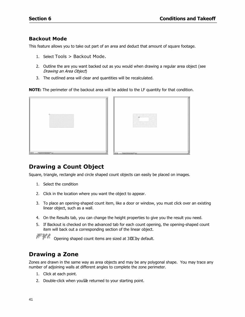
Section 6 Conditions and Takeoff
41
Backout Mode This feature allows you to take out part of an area and deduct that amount of square footage
1 Select Tools gt Backout Mode
2 Outline the are you want backed out as you would when drawing a regular area object (see Drawing an Area Object)
3 The outlined area will clear and quantities will be recalculated
NOTE The perimeter of the backout area will be added to the LF quantity for that condition
Drawing a Count Object Square triangle rectangle and circle shaped count objects can easily be placed on images
1 Select the condition
2 Click in the location where you want the object to appear
3 To place an opening-shaped count item like a door or window you must click over an existing linear object such as a wall
4 On the Results tab you can change the height properties to give you the result you need
5 If Backout is checked on the advanced tab for each count opening the opening-shaped count item will back out a corresponding section of the linear object
Opening shaped count items are sized at 3rsquo0rdquo by default
Drawing a Zone Zones are drawn in the same way as area objects and may be any polygonal shape You may trace any number of adjoining walls at different angles to complete the zone perimeter
1 Click at each point
2 Double-click when yoursquove returned to your starting point
Section 6 Conditions and Takeoff
42
Selecting Objects
1 Use the Select Tool to select objects
You can also select all objects that correspond to a condition
1 Click on a condition to select it
2 Right-click and choose Select All
3 All objects with this condition will be highlighted with squares as an outline
Moving and Resizing Objects Linear
1 To move or resize a linear object click anywhere on the line to select it
2 To move the line position your pointer over the center handles When the mouse is positioned over the handles you will see a two-way arrow You will only be able to move the line in the direction of the arrows
3 Drag the line to a new position
4 Clicking and dragging the handles on the ends of the line will allow you to lengthen or shorten your line
Area and Zone
1 To move an area object or zone in its entirety click and drag it to its new position
2 Grabbing a handle at a corner or intersection of the object will allow you to adjust and change its perimeter
Section 6 Conditions and Takeoff
43
Count 1 To move a square circle rectangle or triangle shaped count object click and drag
2 Click and drag an opening shaped count object along the length of the linear object to the desired position then release
NOTE An opening shaped count object may not be moved from its associated linear condition object however it may be moved up and down the length of the linear object
Layers On-Screen Takeoff allows you to sort and separate your takeoff objects within the same job and on the same page On-Screen Takeoff gives you this flexibility through the use of layers
By assigning different conditions to different layers (for example differentiating between floors ceilings and walls) you can choose to view all layers or turn off certain layers to display and print the remaining groups of conditions only You may also remove the background image of electronic plans add text and hot link symbols or print only your condition takeoffs
Layers are only available in Full Mode If you are in View or Lite Mode and would like to use this
feature click from the main toolbar to purchase the upgrade Default Layers
On-Screen Takeoff begins every project with three default layers Image Annotation and Default The Image layer holds the electronic plan files you may have in your project The Annotation layer possesses all text notations highlighting and hot links in the project The Default layer will appear in the Condition dialog when creating or editing a condition (listed in the takeoff dock bar) Conditions are assigned to the Default layer unless otherwise specified by the user
Creating Layers To assign a condition to a layer other than the default layer you must first create additional layers for your project
1 Select View gt Layers to open the Layers dialog
2 Click An unnamed layer will be added
3 Click within the empty box and type a name for your layer (for example Wall)
4 New layers are added as active layers The adjacent box under the Show column will be checked
Section 6 Conditions and Takeoff
44
Assigning a Layer to a Condition 1 Open the Condition dialog box by creating a new condition or editing an existing condition
2 Under the General tab click on the down arrow in the Layer field to display optional layers
3 Select the desired layer for the condition Only the Default layer and layers you have added will be displayed
4 Click
View and Hide Layers
1 Select View gt Layers
2 Under the Show column check the box to view or remove the check (by clicking on it) to hide the specific layer
3 Click to accept and close the Layers dialog
Section 6 Conditions and Takeoff
45
Assigning Text to a Layer When adding text to an image On-Screen Takeoff has the capability to assign the text to a specified layer
1 Select the Text Tool
2 Click at the point you want to place your text
3 Type in your text using the Enter key for line breaks
4 Click the drop down arrow next to the Layer field and select the desired layer
Section 7
46
Printing and Exporting
This section will
Printing options and procedures
Exporting data by copying and pasting
Exporting quantity results to Excel spreadsheets
Section 7 Printing and Exporting
47
Print Setup On-Screen Takeoff allows the user to print the image takeoff list and worksheet
1 Select File gt Print Setup The Print Setup dialog will open
2 Select a printer or leave the default selection listed (change from the default printer displayed by clicking on the down arrow at the right of the field)
3 Indicate page size and printer tray option (Source) Access page size options by clicking on the
down arrow at the right of the field
4 Choose Portrait or Landscape orientation
5 Click to accept and close the dialog
Printing Images The image area can include the electronic plans the takeoff objects added text and hot links To print a subset of these (for example just the takeoffs without the plans or the added text and hot link symbols) hide layers that you do not want to print (see Section 6 View and Hide Layers) When you are printing your images every page will show the scale of the takeoff you are printing
1 Click on the Image tab to display the area of your project
2 Select File gt Print (or Ctrl + P)
Section 7 Printing and Exporting
48
3 Select the desired view (What to print) and the Image Range
4 Click The second Print dialog will open
5 Change settings accordingly or click if you accept the default settings
Printing Takeoff Lists and Worksheets In Takeoff Lists and Worksheets you may hide columns to print only certain results or adjust column widths to fit the report within the page size selected
1 In Takeoff List or Worksheet view move your cursor to the right side of the columnrsquos title bar the cursor will display as a two-way arrow
Section 7 Printing and Exporting
49
2 Click and drag to adjust the width of the column Holding the mouse button you may
slide the title bar under the title bar to its left to hide the column completely
3 Select File gt Print or press Ctrl + P to access the Print dialog
4 Indicate desired printer and choose the number of copies
5 Click to print and close the dialog
When printing the condition list we suggest printing in landscape
To reset to the default column widths double-click on the right border of a column heading will reset the column to its right (or previously to its right before being hidden)
Print Preview 1 Select File gt Print Preview
2 Use and to vary your view 3 If viewing an image choose current full or scale view to see how it displays
4 For printed outputs that cover more than one page use and to view adjacent pages or click on the down arrow next to Page field and select the page you want displayed
Exporting Using the CopyPaste Feature You may copy all the data or sections from the worksheet and the takeoff list view in On-Screen Takeoff and paste it into another application When pasting into Excel the cell layout will be maintained
1 Highlight the areas you wish to paste Click and hold the left mouse button down as you drag the cursor over the area to be selected then releasing the mouse button
OR
2 Select the entire takeoff list quickly click on the left On-Screen Takeoff column header and hold and drag the cursor across the remaining column headings
The number of pages for the view selected will display in the lower left-hand corner The zoom percentage that applies to the view will be displayed in the lower right-hand corner next to page size of the drawing
Section 7 Printing and Exporting
50
3 In the worksheet view you may highlight rows by clicking on the numbered buttons to the left of each row clicking and dragging across column headings or clicking and dragging over individual cells in the worksheet
Click anywhere in the appropriate view to deselect the area
4 Once your selection is highlighted you may select Edit gt Copy or Ctrl C from the keyboard 5 On your monitor switch to the application into which you want to paste your selection 6 Select Edit gt Paste in the new application or simply press Ctrl + V to paste
The colored keys for conditions cannot be pasted
Using the Export Feature You may export condition quantities to specified cell location within an Excel worksheet file Cell target locations are assigned in the Results tab of the condition dialogs on the Export line relating to each quantity measurement type
On-Screen Takeoff will export takeoff quantity results for up to three different quantity types that you specify For instance you may want to know the number of square feet in a ceiling area as well as the number of linear feet in its perimeter
Section 7 Printing and Exporting
51
1 Bring up the Condition dialog by double-clicking on a condition in the takeoff dock bar or by
selecting the condition and clicking
2 Click on the Results tab to access its fields The default quantities for the condition type will display
3 For each results field click on the arrow to access the pull-down menu and select the appropriate quantity (for example SF LF EA etchellip)
4 Have your Excel spreadsheet opened and saved in a file
5 Specify the Excel spreadsheet cell locations where you want the results to go
6 For a cell in the first sheet of your spreadsheet type in the cell address (eg a1) Case is not important
7 For a cell on a successive sheet of your spreadsheet type in sheet the number followed by a comma and the cell address without any spaces (eg sheet2a1) Case is not important
8 Click
9 Select File gt Export gt Condition Qty to Excel
Section 7 Printing and Exporting
52
10 Browse to the location of the Excel spreadsheet file click file to select it
11 Click to export On-Screen Takeoff results to specified cell locations in the Excel file When you return to the Excel application you will see the values have been added to the specified cell locations in your spreadsheet
12 Save your Excel file
Exporting Worksheet to Excel
1 Assign condition quantities you want to export
2 Open saved Excel spreadsheet file to which you will be exporting
3 From On-Screen Takeoff Select File gt Export gt Worksheet to Excel
4 Browse to the location of the Excel spreadsheet file click file to select it
5 Click When you return to the Excel application you will see the values from the Worksheet Tab have been added to your spreadsheet
6 Save your Excel file
Exporting Takeoff to CVS 1 Assign condition quantities you want to export
2 Open saved Excel spreadsheet file to which you will be exporting
3 Click the Takeoff Tab in the project you want to export the information
4 Select File gt Export gt Takeoff to CSV
5 Browse to the location of the CSV spreadsheet file click file to select it
6 Click the Save
NOTE CSV files can be opened in Excel Lotus Access etc One may consider this option more of a ldquodumprdquo into a file
The Excel application must be active (it may be minimized on the application bar) with the target spreadsheet open in the application Otherwise an error will occur with the export operation that will affect both the On-Screen Takeofftrade file and the Excel spreadsheet
Section 8
53
Advanced Features
This section will
Some special features of working with condition objects in the takeoff area
Details of advanced options for conditions
Advanced features of the Project Properties dialog
Section 8 Advanced Features
54
Features to Use with Objects Roping Feature You can move copy or delete using this feature Using the Select tool (the pointer) you may select several objects at once by clicking and dragging an outline around the objects then releasing the mouse button Roping may select either objects completely within the outlined area (inclusive) or objects both within and touched by the outlined area (touching) Specify your roping preference under Tools gt Options
1 Click and hold the mouse button at a point on the screen near the objects to be selected and drag to surround the objects with an outline
2 Release the mouse button The objects will be selected
3 You may now
Move the group around on the page by clicking within the group dragging the mouse and releasing the button to place the objects
Delete the group of objects by clicking the Delete key or
Copy and paste by pressing Ctrl C to copy the group then Ctrl V to paste it The pasted copy of the grouped objects will appear slightly offset from the original objects
Section 8 Advanced Features
55
Applying a DropRun Count
Use the droprun feature when calculating quantities to take into account the drop or run of a linear condition such as electrical lines or plumbing pipes Drop or run lengths may be added separately to any linear condition on screen while a default droprun length may be indicated for a condition as a whole
1 Select the desired linear condition from the Condition List in the Takeoff Dock bar
2 Click the Change button in the toolbar to open the Change Condition dialog
3 Click the Advanced tab to access the advanced options and click inside the DropRun check box
4 Enter a default length to be applied to all of this condition Entering 800 will be interpreted as 8 0 (You must enter both place markers for inches) You can leave the length blank and manually enter drop run on each segment drawn
5 Click the OK button to accept and close the dialog
Edit DropRun Count
1 With the related linear condition in the Takeoff Dock bar highlighted or with the pointer tool selected
2 click on the desired linear object in the image takeoff area The Count button will become active
3 Click on the Count button (alternatively select Tools gt Count) The default droprun amount will show in the pop-up Count dialog (Default length will be zero if droprun has not been selected in this conditionrsquos properties)
4 Type in the desired length Entering 800 will be interpreted as 8 0 (You must enter both place markers for inches)
5 Click the OK button The additional amount will be reflected in the corresponding quantity The new DropRun count will apply only to the object edited
Adding Text in Image View
On-Screen Takeoff allows you to place text comments around your quantity takeoffs that may be printed along with plan images and objects Text is automatically placed within the Annotation Layer (that includes text and hot links)
1 To place text on the image select the Text Tool and click at the point you want to place your text opening a text box
2 Type in your information clicking Enter for line breaks
3 When you are finished click the OK button to exit the text box
4 To reposition text simply click on the text (with the Text Tool active) to select it
5 Move the cursor over the text the cursor will now display as a four-way arrow
6 Click and drag the mouse to position the text as desired
Section 8 Advanced Features
56
1 To edit existing text use the Text Tool to double-click on the text to open the editing box
2 Enter additional text or use the Backspace key to delete text as necessary
Formatting Text Once created you may format the font size type style and color of your text
1 Click on the text to select it and select Tools gt Font or click on the Font button in the Takeoff Toolbar
2 Select the desired features (color options are disabled) and click the OK button
3 Click on the text to select it and select Tools gt Color or click on the Color button in the Takeoff Toolbar The Color dialog will open
4 Click on a color in the Basic Color palette or create a color and add to the Custom Colors palette (Be sure to click on the color in the Custom Colors palette to select it)
5 Click the OK button
Object Properties
Linear Objects
Linear objects may be set to connect at corners
A linear object may be set to trim automatically when crossing another linear object (Check the trim option under the advanced tab of the Condition dialog)
When you move a connected linear object objects automatically move and resize connected lines accordingly (quantities are then recalculated)
This feature requires that the connected linear object be moved using the center handles (does not apply when resizing the line from the ends)
Objects constrain to snap increments defined in the Tools gt Options menu (with the mouse 15deg by default incremental when shift key is held down)
Objects are measured from centerline to centerline
Section 8 Advanced Features
57
Area Objects When drawing an area use your escape key to undo the last line drawn You may reverse your
drawing of an area using the escape key
The area will not fill with color and pattern until the user double-clicks after the last line is set
Lines drawn to delineate an area object constrain to snap increments defined in the Tools gt Options menu (with the mouse 15deg by default incremental when shift key is held down)
After selecting an area to move or adjust position the mouse in the center to move the entire area position the mouse at the sides or corners to adjust the perimeter
Count Objects
All count objects are quantified by the physical number of objects per page and reported as EA for the UOM The quantity for the current Image View is (displayed in the Condition List) and the total quantity in your project is displayed in the Takeoff View and Worksheet View)
Square circle rectangle and triangle shaped count objects do not displace or subtract from other object quantities when placed on top of them However on the Advanced Tab for the count condition a connect property can be set (this is a check box) so that when a count object of this shape is put on top of a Linear type takeoff object it will move with the linear if said linear is moved
An opened-shaped count object must be placed within a linear object Opening shaped count objects may also be measured by linear foot or linear yard (EA SF and SY are also options) Opening shaped count items default to a width of 3rsquo 0rdquo at the time of creation This size can be changed The small medium and large size are not options on this type of condition anymore Check Backout on the Advanced tab for each Count object back out the footage (or yardage) of opening-shaped count objects in which they are placed
NOTE In order to see this Backout functionality (in quantity) for SY or SF deductions at least one of the
results for the Linear(s) this object will be placed on must be set to SY or SF and the count object must have a height quantity
Advanced Features of Conditions The Round Feature Under the Advanced tab of the linear and area Condition dialogues you may specify quantity rounding (in inches) For linear objects rounding applies to each linear object drawn For area objects rounding will apply to each segment of the area perimeter adjusting the perimeter and area calculations For example With a linear condition entering 12 in the Round field will round up each related linear object to the nearest 12 inches or one foot With this setting two walls of 1 4 would each round to 2 0 totaling 4 0
NOTE In the Takeoff Dock bar condition list and in the On-Screen Takeoff reports quantities will be displayed in whole numbers rounded up to the nearest foot However calculations are based on true quantities without rounding unless the Round Feature is engaged
Pitch Pitch may apply either to linear or area conditions It is measured in rise per linear foot Entering 12 indicates a 12 rise per 12 of linear distance (a pitch of 12 over 12) or an angle of 45deg
Section 8 Advanced Features
58
Advanced Features of Project Properties Selecting Multiple Pages
1 Select a single page entry by clicking on the numbered gray button to the left of the entry
2 Drag the cursor down the column of numbers to select consecutive pages
3 Click on the blank button at the top of this column to select all pages in the Properties dialog
Section 8 Advanced Features
59
Changing Image Assigned to a Drawing 1 Select the page entry by clicking on the numbered gray button to the left of the entry 2 Click the Change Image button The Change Image dialog box will appear
3 Navigate to the desired file and select by clicking on it
4 Click the Open button The electronic file assigned to the page will have been changed to reflect the new file choice
Changing Image File Path 1 Select pages as described above
2 Choose Change Folder
3 In the Change Folder dialog navigate to the appropriate folder
4 Click the OK button The file path will have been changed for the selected page entries
Delete a Page from Project Properties 1 Select the page you want to delete by clicking on its associated number (in the gray box at the
left of the entry)
2 Choose Delete Page
All Takeoff on the page will be deleted immediately and permanently
Section 8 Advanced Features
60
Advanced Features of Tool Options
Calculation Method On-Screen Takeoff has built-in calculation options to allow for faster work and faster saves until your takeoff is complete Calculation options are found by selecting Tools gt Options then clicking on the Calculation tab
Calculation method can be set to Automatic Automatic except Grids and Manual Manual will allow the program to operate more quickly while Automatic or Automatic except Grids allows the user to see quantity changes as takeoffs are made
In any mode you may press F9 to recalculate quantities for the On-Screen Takeoff current totals
Configuration Tab
When the ldquoPage Label (A01)rdquo radial button is chosen On-Screen Takeoff puts the numbered label on all the pages of in your current page indicator in your Navigate Toolbar If the Page Descriptionrdquo radial button is chosen then a description of what takeoff is on that specific page will be shown in your current page indicator in your Navigate Toolbar
This section of the configuration tab gives you options on how you want to export your information When the ldquoFolderSubfolder Namesrdquo radial button is chosen than on your file that you are exporting to will have all the conditions folders and subfolders In the Delimiter box you can choose the symbol that is needed to separate the information you are exporting Some files need semicolons () or colons () to make sure the information comes exported in is separated it the appropriate places
Section 8 Advanced Features
61
In previous versions of On-Screen Takeoff there are views that users need to have in order for them to display their information By either choosing ldquoOST 1xrdquo or ldquoOST 2xrdquo it will let the program know you want your columns of information exported in that specific format
When you have the Confirm Deletions radial button of ldquoYesrdquo chosen than every time you delete anything you will get a dialog box confirming your intentions of deletion
While working with your takeoff you have a choice to either view the legend of your conditions or hide it Choose whichever radial button that suits your needs
For those who prefer to use the Enter key to navigate in dialog boxes this option is just for that
Font Tab The Font tab is designed for you to make your own look and feel for the application At the bottom of this tab it will show you sample of the fonts and colors you have chosen
Renaming the Current Page You may change the name of the current page in the takeoff area of On-Screen Takeoff by selecting Edit gt Rename Page
This opens the Name Page dialog and you may simply type in a new name and click the Enter button The new name for the file will be reflected on the title bar for the page and in Project Properties
You also may access the Rename Page function by right-clicking in the takeoff area while in Image View and selecting the option from the pop-up menu that appears
Section 9
62
Saving and Exiting
This section will
Explain how to save projects
Show you how to safely exit the program
Section 9 Saving and Exiting
63
Saving Your Project
1 Select File gt Save 2 If your project has not previously been saved a Save dialog box will open to allow you to name
the file and choose the directory and folder in which to save your file 3 Once saved File gt Save will simply save the current version of the file
OR
4 Select File gt Save As then type in a new name for the file and save to the desired file path
The Auto-save Feature With the Auto-save feature On-Screen Takeoff automatically backs up your open project You may choose to have more than one level of backup files The first backup copy will have the extension b00 and successive files will be b01 b02 and so on If you have designated four levels of backup files after the fourth backup copy has been created (b03) the next file will be saved over the file with extension b00 Further backup saves will then rotate through the four backup files in the same way
1 Select Tools gt Options 2 In the Auto-save area (under the General tab) select the frequency of backup file creation (in
minutes) and the number of levels for the feature 3 You also may disengage the feature by clicking in the check box to clear it
The Auto-save feature automatically saves backup copies to the directory of the current project If you are working from a write-protected area such as a CD-ROM On-Screen Takeoff will place backup files in the On-Screen Takeoff folder
Exiting When you are finished using On-Screen Takeoff it is very easy to exit Exiting is very important because of security reasons If someone were to use your computer they could enter the application and view and manipulate information
Section 9 Saving and Exiting
64
On-Screen Takeoff closes the open project when you open another or create a new project or when you exit the program
1 Select File gt Exit
OR
2 You also may click at the upper right-hand corner of the application to exit
NOTE If your latest changes to a project file have not been saved On-Screen Takeoff will ask you whether you would like to save the file and gives you the option of canceling the operation
Appendix I Installing Your Digitizer
65
Appendix I Installing Your Digitizer When you get your digitizer from GTCO you will need to connect it to your computer Follow the instructions outlined below to do this
Note For rollup digitizers the metal bar must be oriented to the top or right hand side
Connecting the Digitizer 1 Lay the digitizer out flat 2 Connect the Stylus to the digitizer 3 Plug in the power adapter 4 Plug the interface (IO) cable into the digitizer 5 Plug the other end of the interface cable into an open serial port on computer
Note GTCO Technical support phone number is 410-381-6688 The electronic manual (on diskette) from GTCO contains more detailed installation and operation instructions for the GTCO digitizer model you have
Installing other Digitizer Drivers If you are using a GTCO Digitizer you will need to install the GTCO TabletWorks Drivers
If you are using a Digitizer not supported by GTCO Tablet Works 10 please contact the manufacturer of your digitizer for assistance with installation
Installing GTCO TabletWorks Drivers 1 Insert the On Center CD into the CD-ROM drive The CD Startup screen will open 2 Click on Install Software 3 Select Additional Software and Drivers 4 Select Digitizer Driver 5 Follow the instructions for installing TabletWorks 10
Adhering the Template The template is a small plastic sticker used to enable mouse function when using the digitizer with On-Screen Takeoff Place your template on your digitizer We suggest placing it in the bottom right corner of the digitizer about one inch inside the takeoff area
Note You may either peel off the back of the template and use the adhesive surface or you can tape the template down
Appendix I Installing Your Digitizer
66
Testing the Digitizer Drivers Before running OST you may test the digitizer by moving the stylus around on the digitizer pad it should move the mouse cursor (if mouse emulation is enabled)
If the digitizer does not move the mouse cursor on the screen
The superset codes may need to be reset Reset the superset codes by touching on the border of the digitizer with the stylus The digitizer should beep several times
The digitizer may not be communicating with the computer Be sure the COM port selected is correct Be sure the COM port selected is correct If you are not able to get the digitizer to move the mouse cursor you need to call GTCO technical support for help
Note The Mouse Emulation is not required for On-Screen Takeoff to work properly It is used only for the Template functionality if the digitizer is moving the cursor the wrong direction (up instead of sideways or vice-versa)
Click the L-shaped arrow symbol on the digitizer with the stylus
Appendix II Toolbar Item Details
67
Appendix II Toolbar Items Main Toolbar
Appendix II Toolbar Item Details
68
Tool Toolbar
Appendix II Toolbar Item Details
69
Zoom Toolbar
View Toolbar
Navigate Toolbar
Appendix II Toolbar Item Details
70
Navigate Toolbar (Continued)
Takeoff Toolbar
Appendix II Toolbar Item Details
71
Takeoff Toolbar (Continued)
Image Toolbar
Appendix III Loading Plans from a Dodge CD
72
Appendix III Loading Plans from a Dodge CD
This section will detail how to load plans from a F W Dodge CD-ROM into an On-Screen Takeoff project file ready for takeoffs
Dodge files may be added to the Project Properties dialog However loading the files in that way will load the files by number rather than name description If you want to load one page only from your Dodge CD You will have to rename the page to display the name rather than number of the file
To load plan files from a Dodge CD so that the files load sequentially by file number but are displayed by name rather than by number within your project follow the instructions below
Opening a Dodge project from a CD-ROM 1 Insert the CD into the drive 2 Choose File gt Custom 3 Choose Dodge Plans Project (plansdat) as the file type 4 Select the appropriate file type by clicking on the down arrow at the right of the Files of type
field 5 In the Look in field access your drive paths by clicking on the down arrow at the right of the
field then
Navigate to your CD-ROM drive Open the data folder and Open the Projects folder
6 Select the desired project and open its folder 7 Open the plansdat file 8 All the images will come in sequenced correctly for that job along with the full descriptions
(names) of each page If there is not a plans folder in the project folder then plans do not exist for that project on the CD Opening the plansdat file will yield an empty project
Appendix IV Using the Plan Viewer
73
Appendix IV Using On-Screen Takeoff Plan Viewer The On-Screen Takeoff Plan Viewer is a limited version of On Center Softwarersquos commercial takeoff software If your status bar located at the very bottom of the main window says View Mode in the lower left-hand corner then you are using the Plan Viewer You can use the plan viewer to
View CD-based amp converted CAD drawings
View a previously created OST file and associated drawings
Download electronic plans online
Navigate through drawings
Quickly Takeoff linearsareas and counts
Zoom in to view the plan better
Print drawings directly from the viewer
Viewing an On-Screen Takeoff Project File
1 To open an OST file that was previously created with of On-Screen Takeoff 2 Select File gt Open 3 An Open dialog will appear if you do not see the OST file you are looking for select the
Look In drop down arrow 4 A drop down menu will appear listing the various folders drives and mapped drives located
on your computer select the correct drive or folder location and continue to browse to the location of your OST file
5 When you see your OST file double-click it to open it 6 Any takeoff and drawings should appear on the Image tab view
If you do not see the drawings but do see the colored takeoff layer the drawings may
not be located in the same place they were originally saved at Go to File gt Project Properties and check the Image File path for each listed page If the image file path is pointing to a CD drive make sure the CD is inside the CR-ROM
Downloading Electronic Plans If your Online Plan Service provides a special file format (OSX) required to use this feature of our plan viewer you can immediately downloaded all electronic plans of a project directly from our viewer
Most Plan Room web sites will automatically open On-Screen Takeoff when a request to download plans is made Your particular Plan Room may differ in operation so please contact the provider directly with questions on using the site
Appendix IV Using the Plan Viewer
74
When you request to download or open a project file from a Plan Room you will usually have the open to open or save an OSX file Choosing open will automatically open On-Screen Takeoff Alternately you may choose to save the file to a local hard drive After you have saved the file either double-click it to launch On-Screen Takeoff or open the OSX file using On-Screen Takeoff by clicking File then Open and locating the file on your hard drive You will need to change the file type to OSX
After the OSX file is opened you will see an additional tab appear in the Conditions List window called Pages
The Pages tab shows the hierarchy of your project Gray file icons represent pages that have not been downloaded and blue icons represents pages that have been downloaded
To download a page simply double-click the page icon
If you wish to select a group of pages to download you can use the Ctrl or Shift key to multiple select them then click the Download button
If you wish to download all pages at once click the Download All button
Downloaded pages will now appear in the Project Properties dialog in the same order in which they appear in the Pages tab
Creating Quick Takeoffs With On-Screen Takeoff you can create quick takeoffs to measure quantities even if you dont have the full version of our program However using the Quick Takeoff functionality shows you just a fraction of what the full version can do
The Quick Takeoff Toolbar is located at the top of the image view It has three buttons designated for three types of takeoffs Linear Area and Count The Quantity drop down list will show secondary quantities for Linears and Areas The Units drop down allows you to select how you want your quantities displayed Feet Inches Yards Millimeters and Meters
NOTE Every time change the type of takeoff you are performing (switching from Area to Linear for example) the previous quantities and takeoff objects will disappear They will also disappear when you changes pages
NOTE You can use the Dimension Tool to basically measure the distance between two points or linears The distance will display on the status bar at the bottom of the application
The Quick Takeoff Toolbar
Appendix V Frequently Asked Questions
75
Appendix V Frequently Asked Questions General
Where is On-Screen Takeoff installed on my computer
Typically it is installed in CProgram FilesOn-Screen Takeoff
In Explorer how do I recognize On-Screen Takeoff file types
On-Screen Takeoff data is stored in a single file per job lsquojob name OSTrsquo On-Screen Takeoff templates are stored as lsquotemplate nameTPOrsquo
Can only one project at a time be open
Yes For that reason opening another project automatically closes the project on screen You will be asked to save any changes
Is only one scale allowed per page What about on drawings that have multiple detail sections on a page and each of those drawings have different scales
Yes For pages with drawings of different scales copy the drawing to another project page and set the appropriate scale
I cannot perform backout on an area that is along a linear
As a workaround use the On-Screen Takeoff layers feature to help you with this issue Electronic Images
How do I start a project from drawings that have been scanned and written to a CD-ROM
Open a new project Select File gt Project Properties and select Auto Add Navigate to your CD and the appropriate folder and select any image file in that location Click Open All files in the location will load into your project Recommended that images are copied from CD to hard drive for performance
If I get a disk of drawings in AutoCAD format (R13 or R14) can I read them in On-Screen Takeoff
Yes On-Screen Takeoff now reads DWG DXF and many other format that are saved with AutoCAD
Appendix V Frequently Asked Questions
76
When I click on the all pages button what is supposed to happen Currently nothing seems to change when I click on that button
The All Pages button is used to apply the Darken and Enhance Plans feature to all pages in the project (as opposed to only the current page on screen)
Is there a way to deduct a large skylight from an area condition
Yes with the related area condition selected in the Takeoff Dock bar unselect the Backout button on the Takeoff Toolbar then draw the Backout area The area quantity will be deducted from the related condition object and the linear measurement of the Backout perimeter will be added
Digitizer Issues
How do I connect a Digitizer to the computer
See Appendix I Connecting a Digitizer
The Place Template menu choice is disabled
On-Screen Takeoff may need to be authorized or the digitizer or the digitzer drivers are not installed
It wonrsquot let me select the Set Takeoff Area menu choice
On-Screen Takeoff may need to be authorized or no job is open a digitizer is not installed or the drivers are not installed
The digitizer stylus is not moving the cursor or crosshairs
Click S-0-1 superset on the digitizer
How do I convert my old GTCO Digitizer to work with On- Screen Takeofftrade
Call GTCO and they may be able to reconfigure your digitizer to be compatible with On-Screen Takeoff
Printing Issues Which Printers work with On-Screen Takeoff
Compatible printers include On-Screen Takeoff Hewlett Packard Epson and Canon printers If you are having printer difficulties please contact support and specify the type of printer along with other pertinent information Contact support at wwwoncentercomsupport or email supportoncentercom
Which Plotters work with On-Screen Takeoff
Compatible Plotters include Hewlett Packard DesignJet plotters and the EnCAD Cadjet II If you are having plotter difficulties please contact support and specify the type of plotter concerned
ViewingDisplay I can no longer see my condition list How do I get it back
The toolbars and Dock bars can be turned on and off through the View gt Toolbars menu options
Appendix V Frequently Asked Questions
77
This is also accessible by right-clicking in the toolbar area and selecting (or deselecting) a toolbar listed
I cannot view my folders in the condition list
Right-click in the Takeoff Dock barcondition list area and select Show Tree to display your folders
My Status Bar reads Viewer Mode and I am unable to draw conditions
On-Screen Takeoff needs to be Authorized Or you need to purchase an upgrade Click the Perform Advanced Takeoff button on the main toolbar
I hid a Dock bar and when I selected to view it again it appeared alongside the other Dock
bar instead of stacked on top of it How do I fix it
Pick up the Dock bar by clicking on the bar at the top and continuing to hold down the mouse button drag the Dock bar over the other one It will resize and appear stacked with the other
When I open image files from a CD the images are all upside down How do I get them right
side up
To flip pages from top to bottom follow the steps below 1 Click the All Pages button on the Image Toolbar (All Pages is engaged when the button
is not clicked) 2 Click the Flip Horizontal button on the Image Toolbar 3 Click the All Pages button again to disengage
Templates How do I create a Template
Follow the steps below 1 Create a typical project 2 Choose File gt Save As 3 Choose On-Screen Takeoff Template Files as the file type to save 4 Name the file This will save all of the condition setups as well as the layers for the
project
How do I create a new project from a template
Follow the steps below 1 Choose File gt New 2 Select a template from those listed in the New dialog This will open a new project with
conditions and layers saved from a previous project but no pages or takeoff
78
INDEX
Area Conditions 32
Area Objects 57
Auto Scrolling 20
Auto-save 63
Backout Mode 41
Calculation Method 60
Conditions 29
Configuration 60
Contents Tab 6
Continuous Mode 38
Count Conditions 33
Count Objects 57
Digitizer 10 65 76
Docking Toolbars 13
Dodge CD 72
Drawing 27 37
DropRun Count 55
Environment 18
Exiting 63
Exporting 49
Features 16
Font 61
Frequently Asked Questions 75
Grid 40
Help File 5
Hiding Toolbars 13
Hot Links 21
Image 19 59
Image files 9
Image Toolbar 12 71
Images 75
Index Tab 6
Layers 43
Linear Conditions 31
Linear Objects 56
Main Toolbar 12 67
Menus 14
Moving Toolbars 13
Navigate Toolbar 12 69
Navigating 20
On-Screen Takeofftrade 2
Page 59 61
Pages 20 25 28
Plan Viewer 73
Plans 26
Printing 47 76
Project Properties 25
Projects 22
Quick Start Video 18
Resizing Toolbars 13
Roping 54
Saving 63
Scale 28
Search Tab 7
Selecting Objects 42
Setup 8
Start On-Screen Takeofftrade 17
System Requirements 9
Takeoff 19 27
Takeoff Toolbar 70 71
Takeoff Toolbar 12
Template Files 23
TIF (Group4) 9
Tool Toolbar 12 68
Toolbar 67
Toolbars 12
View Toolbar 12 69
Viewing Toolbars 12
Worksheet 20
Zone Conditions 33
Zoom Toolbar 12 69
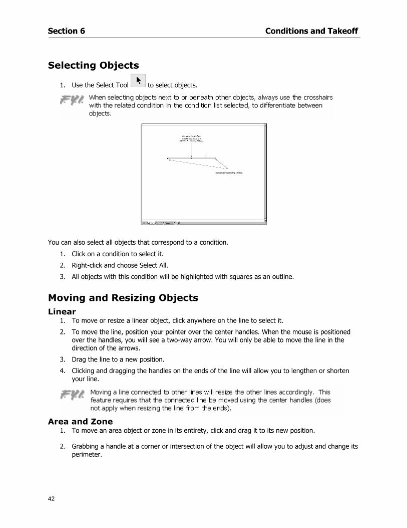
Section 6 Conditions and Takeoff
42
Selecting Objects
1 Use the Select Tool to select objects
You can also select all objects that correspond to a condition
1 Click on a condition to select it
2 Right-click and choose Select All
3 All objects with this condition will be highlighted with squares as an outline
Moving and Resizing Objects Linear
1 To move or resize a linear object click anywhere on the line to select it
2 To move the line position your pointer over the center handles When the mouse is positioned over the handles you will see a two-way arrow You will only be able to move the line in the direction of the arrows
3 Drag the line to a new position
4 Clicking and dragging the handles on the ends of the line will allow you to lengthen or shorten your line
Area and Zone
1 To move an area object or zone in its entirety click and drag it to its new position
2 Grabbing a handle at a corner or intersection of the object will allow you to adjust and change its perimeter
Section 6 Conditions and Takeoff
43
Count 1 To move a square circle rectangle or triangle shaped count object click and drag
2 Click and drag an opening shaped count object along the length of the linear object to the desired position then release
NOTE An opening shaped count object may not be moved from its associated linear condition object however it may be moved up and down the length of the linear object
Layers On-Screen Takeoff allows you to sort and separate your takeoff objects within the same job and on the same page On-Screen Takeoff gives you this flexibility through the use of layers
By assigning different conditions to different layers (for example differentiating between floors ceilings and walls) you can choose to view all layers or turn off certain layers to display and print the remaining groups of conditions only You may also remove the background image of electronic plans add text and hot link symbols or print only your condition takeoffs
Layers are only available in Full Mode If you are in View or Lite Mode and would like to use this
feature click from the main toolbar to purchase the upgrade Default Layers
On-Screen Takeoff begins every project with three default layers Image Annotation and Default The Image layer holds the electronic plan files you may have in your project The Annotation layer possesses all text notations highlighting and hot links in the project The Default layer will appear in the Condition dialog when creating or editing a condition (listed in the takeoff dock bar) Conditions are assigned to the Default layer unless otherwise specified by the user
Creating Layers To assign a condition to a layer other than the default layer you must first create additional layers for your project
1 Select View gt Layers to open the Layers dialog
2 Click An unnamed layer will be added
3 Click within the empty box and type a name for your layer (for example Wall)
4 New layers are added as active layers The adjacent box under the Show column will be checked
Section 6 Conditions and Takeoff
44
Assigning a Layer to a Condition 1 Open the Condition dialog box by creating a new condition or editing an existing condition
2 Under the General tab click on the down arrow in the Layer field to display optional layers
3 Select the desired layer for the condition Only the Default layer and layers you have added will be displayed
4 Click
View and Hide Layers
1 Select View gt Layers
2 Under the Show column check the box to view or remove the check (by clicking on it) to hide the specific layer
3 Click to accept and close the Layers dialog
Section 6 Conditions and Takeoff
45
Assigning Text to a Layer When adding text to an image On-Screen Takeoff has the capability to assign the text to a specified layer
1 Select the Text Tool
2 Click at the point you want to place your text
3 Type in your text using the Enter key for line breaks
4 Click the drop down arrow next to the Layer field and select the desired layer
Section 7
46
Printing and Exporting
This section will
Printing options and procedures
Exporting data by copying and pasting
Exporting quantity results to Excel spreadsheets
Section 7 Printing and Exporting
47
Print Setup On-Screen Takeoff allows the user to print the image takeoff list and worksheet
1 Select File gt Print Setup The Print Setup dialog will open
2 Select a printer or leave the default selection listed (change from the default printer displayed by clicking on the down arrow at the right of the field)
3 Indicate page size and printer tray option (Source) Access page size options by clicking on the
down arrow at the right of the field
4 Choose Portrait or Landscape orientation
5 Click to accept and close the dialog
Printing Images The image area can include the electronic plans the takeoff objects added text and hot links To print a subset of these (for example just the takeoffs without the plans or the added text and hot link symbols) hide layers that you do not want to print (see Section 6 View and Hide Layers) When you are printing your images every page will show the scale of the takeoff you are printing
1 Click on the Image tab to display the area of your project
2 Select File gt Print (or Ctrl + P)
Section 7 Printing and Exporting
48
3 Select the desired view (What to print) and the Image Range
4 Click The second Print dialog will open
5 Change settings accordingly or click if you accept the default settings
Printing Takeoff Lists and Worksheets In Takeoff Lists and Worksheets you may hide columns to print only certain results or adjust column widths to fit the report within the page size selected
1 In Takeoff List or Worksheet view move your cursor to the right side of the columnrsquos title bar the cursor will display as a two-way arrow
Section 7 Printing and Exporting
49
2 Click and drag to adjust the width of the column Holding the mouse button you may
slide the title bar under the title bar to its left to hide the column completely
3 Select File gt Print or press Ctrl + P to access the Print dialog
4 Indicate desired printer and choose the number of copies
5 Click to print and close the dialog
When printing the condition list we suggest printing in landscape
To reset to the default column widths double-click on the right border of a column heading will reset the column to its right (or previously to its right before being hidden)
Print Preview 1 Select File gt Print Preview
2 Use and to vary your view 3 If viewing an image choose current full or scale view to see how it displays
4 For printed outputs that cover more than one page use and to view adjacent pages or click on the down arrow next to Page field and select the page you want displayed
Exporting Using the CopyPaste Feature You may copy all the data or sections from the worksheet and the takeoff list view in On-Screen Takeoff and paste it into another application When pasting into Excel the cell layout will be maintained
1 Highlight the areas you wish to paste Click and hold the left mouse button down as you drag the cursor over the area to be selected then releasing the mouse button
OR
2 Select the entire takeoff list quickly click on the left On-Screen Takeoff column header and hold and drag the cursor across the remaining column headings
The number of pages for the view selected will display in the lower left-hand corner The zoom percentage that applies to the view will be displayed in the lower right-hand corner next to page size of the drawing
Section 7 Printing and Exporting
50
3 In the worksheet view you may highlight rows by clicking on the numbered buttons to the left of each row clicking and dragging across column headings or clicking and dragging over individual cells in the worksheet
Click anywhere in the appropriate view to deselect the area
4 Once your selection is highlighted you may select Edit gt Copy or Ctrl C from the keyboard 5 On your monitor switch to the application into which you want to paste your selection 6 Select Edit gt Paste in the new application or simply press Ctrl + V to paste
The colored keys for conditions cannot be pasted
Using the Export Feature You may export condition quantities to specified cell location within an Excel worksheet file Cell target locations are assigned in the Results tab of the condition dialogs on the Export line relating to each quantity measurement type
On-Screen Takeoff will export takeoff quantity results for up to three different quantity types that you specify For instance you may want to know the number of square feet in a ceiling area as well as the number of linear feet in its perimeter
Section 7 Printing and Exporting
51
1 Bring up the Condition dialog by double-clicking on a condition in the takeoff dock bar or by
selecting the condition and clicking
2 Click on the Results tab to access its fields The default quantities for the condition type will display
3 For each results field click on the arrow to access the pull-down menu and select the appropriate quantity (for example SF LF EA etchellip)
4 Have your Excel spreadsheet opened and saved in a file
5 Specify the Excel spreadsheet cell locations where you want the results to go
6 For a cell in the first sheet of your spreadsheet type in the cell address (eg a1) Case is not important
7 For a cell on a successive sheet of your spreadsheet type in sheet the number followed by a comma and the cell address without any spaces (eg sheet2a1) Case is not important
8 Click
9 Select File gt Export gt Condition Qty to Excel
Section 7 Printing and Exporting
52
10 Browse to the location of the Excel spreadsheet file click file to select it
11 Click to export On-Screen Takeoff results to specified cell locations in the Excel file When you return to the Excel application you will see the values have been added to the specified cell locations in your spreadsheet
12 Save your Excel file
Exporting Worksheet to Excel
1 Assign condition quantities you want to export
2 Open saved Excel spreadsheet file to which you will be exporting
3 From On-Screen Takeoff Select File gt Export gt Worksheet to Excel
4 Browse to the location of the Excel spreadsheet file click file to select it
5 Click When you return to the Excel application you will see the values from the Worksheet Tab have been added to your spreadsheet
6 Save your Excel file
Exporting Takeoff to CVS 1 Assign condition quantities you want to export
2 Open saved Excel spreadsheet file to which you will be exporting
3 Click the Takeoff Tab in the project you want to export the information
4 Select File gt Export gt Takeoff to CSV
5 Browse to the location of the CSV spreadsheet file click file to select it
6 Click the Save
NOTE CSV files can be opened in Excel Lotus Access etc One may consider this option more of a ldquodumprdquo into a file
The Excel application must be active (it may be minimized on the application bar) with the target spreadsheet open in the application Otherwise an error will occur with the export operation that will affect both the On-Screen Takeofftrade file and the Excel spreadsheet
Section 8
53
Advanced Features
This section will
Some special features of working with condition objects in the takeoff area
Details of advanced options for conditions
Advanced features of the Project Properties dialog
Section 8 Advanced Features
54
Features to Use with Objects Roping Feature You can move copy or delete using this feature Using the Select tool (the pointer) you may select several objects at once by clicking and dragging an outline around the objects then releasing the mouse button Roping may select either objects completely within the outlined area (inclusive) or objects both within and touched by the outlined area (touching) Specify your roping preference under Tools gt Options
1 Click and hold the mouse button at a point on the screen near the objects to be selected and drag to surround the objects with an outline
2 Release the mouse button The objects will be selected
3 You may now
Move the group around on the page by clicking within the group dragging the mouse and releasing the button to place the objects
Delete the group of objects by clicking the Delete key or
Copy and paste by pressing Ctrl C to copy the group then Ctrl V to paste it The pasted copy of the grouped objects will appear slightly offset from the original objects
Section 8 Advanced Features
55
Applying a DropRun Count
Use the droprun feature when calculating quantities to take into account the drop or run of a linear condition such as electrical lines or plumbing pipes Drop or run lengths may be added separately to any linear condition on screen while a default droprun length may be indicated for a condition as a whole
1 Select the desired linear condition from the Condition List in the Takeoff Dock bar
2 Click the Change button in the toolbar to open the Change Condition dialog
3 Click the Advanced tab to access the advanced options and click inside the DropRun check box
4 Enter a default length to be applied to all of this condition Entering 800 will be interpreted as 8 0 (You must enter both place markers for inches) You can leave the length blank and manually enter drop run on each segment drawn
5 Click the OK button to accept and close the dialog
Edit DropRun Count
1 With the related linear condition in the Takeoff Dock bar highlighted or with the pointer tool selected
2 click on the desired linear object in the image takeoff area The Count button will become active
3 Click on the Count button (alternatively select Tools gt Count) The default droprun amount will show in the pop-up Count dialog (Default length will be zero if droprun has not been selected in this conditionrsquos properties)
4 Type in the desired length Entering 800 will be interpreted as 8 0 (You must enter both place markers for inches)
5 Click the OK button The additional amount will be reflected in the corresponding quantity The new DropRun count will apply only to the object edited
Adding Text in Image View
On-Screen Takeoff allows you to place text comments around your quantity takeoffs that may be printed along with plan images and objects Text is automatically placed within the Annotation Layer (that includes text and hot links)
1 To place text on the image select the Text Tool and click at the point you want to place your text opening a text box
2 Type in your information clicking Enter for line breaks
3 When you are finished click the OK button to exit the text box
4 To reposition text simply click on the text (with the Text Tool active) to select it
5 Move the cursor over the text the cursor will now display as a four-way arrow
6 Click and drag the mouse to position the text as desired
Section 8 Advanced Features
56
1 To edit existing text use the Text Tool to double-click on the text to open the editing box
2 Enter additional text or use the Backspace key to delete text as necessary
Formatting Text Once created you may format the font size type style and color of your text
1 Click on the text to select it and select Tools gt Font or click on the Font button in the Takeoff Toolbar
2 Select the desired features (color options are disabled) and click the OK button
3 Click on the text to select it and select Tools gt Color or click on the Color button in the Takeoff Toolbar The Color dialog will open
4 Click on a color in the Basic Color palette or create a color and add to the Custom Colors palette (Be sure to click on the color in the Custom Colors palette to select it)
5 Click the OK button
Object Properties
Linear Objects
Linear objects may be set to connect at corners
A linear object may be set to trim automatically when crossing another linear object (Check the trim option under the advanced tab of the Condition dialog)
When you move a connected linear object objects automatically move and resize connected lines accordingly (quantities are then recalculated)
This feature requires that the connected linear object be moved using the center handles (does not apply when resizing the line from the ends)
Objects constrain to snap increments defined in the Tools gt Options menu (with the mouse 15deg by default incremental when shift key is held down)
Objects are measured from centerline to centerline
Section 8 Advanced Features
57
Area Objects When drawing an area use your escape key to undo the last line drawn You may reverse your
drawing of an area using the escape key
The area will not fill with color and pattern until the user double-clicks after the last line is set
Lines drawn to delineate an area object constrain to snap increments defined in the Tools gt Options menu (with the mouse 15deg by default incremental when shift key is held down)
After selecting an area to move or adjust position the mouse in the center to move the entire area position the mouse at the sides or corners to adjust the perimeter
Count Objects
All count objects are quantified by the physical number of objects per page and reported as EA for the UOM The quantity for the current Image View is (displayed in the Condition List) and the total quantity in your project is displayed in the Takeoff View and Worksheet View)
Square circle rectangle and triangle shaped count objects do not displace or subtract from other object quantities when placed on top of them However on the Advanced Tab for the count condition a connect property can be set (this is a check box) so that when a count object of this shape is put on top of a Linear type takeoff object it will move with the linear if said linear is moved
An opened-shaped count object must be placed within a linear object Opening shaped count objects may also be measured by linear foot or linear yard (EA SF and SY are also options) Opening shaped count items default to a width of 3rsquo 0rdquo at the time of creation This size can be changed The small medium and large size are not options on this type of condition anymore Check Backout on the Advanced tab for each Count object back out the footage (or yardage) of opening-shaped count objects in which they are placed
NOTE In order to see this Backout functionality (in quantity) for SY or SF deductions at least one of the
results for the Linear(s) this object will be placed on must be set to SY or SF and the count object must have a height quantity
Advanced Features of Conditions The Round Feature Under the Advanced tab of the linear and area Condition dialogues you may specify quantity rounding (in inches) For linear objects rounding applies to each linear object drawn For area objects rounding will apply to each segment of the area perimeter adjusting the perimeter and area calculations For example With a linear condition entering 12 in the Round field will round up each related linear object to the nearest 12 inches or one foot With this setting two walls of 1 4 would each round to 2 0 totaling 4 0
NOTE In the Takeoff Dock bar condition list and in the On-Screen Takeoff reports quantities will be displayed in whole numbers rounded up to the nearest foot However calculations are based on true quantities without rounding unless the Round Feature is engaged
Pitch Pitch may apply either to linear or area conditions It is measured in rise per linear foot Entering 12 indicates a 12 rise per 12 of linear distance (a pitch of 12 over 12) or an angle of 45deg
Section 8 Advanced Features
58
Advanced Features of Project Properties Selecting Multiple Pages
1 Select a single page entry by clicking on the numbered gray button to the left of the entry
2 Drag the cursor down the column of numbers to select consecutive pages
3 Click on the blank button at the top of this column to select all pages in the Properties dialog
Section 8 Advanced Features
59
Changing Image Assigned to a Drawing 1 Select the page entry by clicking on the numbered gray button to the left of the entry 2 Click the Change Image button The Change Image dialog box will appear
3 Navigate to the desired file and select by clicking on it
4 Click the Open button The electronic file assigned to the page will have been changed to reflect the new file choice
Changing Image File Path 1 Select pages as described above
2 Choose Change Folder
3 In the Change Folder dialog navigate to the appropriate folder
4 Click the OK button The file path will have been changed for the selected page entries
Delete a Page from Project Properties 1 Select the page you want to delete by clicking on its associated number (in the gray box at the
left of the entry)
2 Choose Delete Page
All Takeoff on the page will be deleted immediately and permanently
Section 8 Advanced Features
60
Advanced Features of Tool Options
Calculation Method On-Screen Takeoff has built-in calculation options to allow for faster work and faster saves until your takeoff is complete Calculation options are found by selecting Tools gt Options then clicking on the Calculation tab
Calculation method can be set to Automatic Automatic except Grids and Manual Manual will allow the program to operate more quickly while Automatic or Automatic except Grids allows the user to see quantity changes as takeoffs are made
In any mode you may press F9 to recalculate quantities for the On-Screen Takeoff current totals
Configuration Tab
When the ldquoPage Label (A01)rdquo radial button is chosen On-Screen Takeoff puts the numbered label on all the pages of in your current page indicator in your Navigate Toolbar If the Page Descriptionrdquo radial button is chosen then a description of what takeoff is on that specific page will be shown in your current page indicator in your Navigate Toolbar
This section of the configuration tab gives you options on how you want to export your information When the ldquoFolderSubfolder Namesrdquo radial button is chosen than on your file that you are exporting to will have all the conditions folders and subfolders In the Delimiter box you can choose the symbol that is needed to separate the information you are exporting Some files need semicolons () or colons () to make sure the information comes exported in is separated it the appropriate places
Section 8 Advanced Features
61
In previous versions of On-Screen Takeoff there are views that users need to have in order for them to display their information By either choosing ldquoOST 1xrdquo or ldquoOST 2xrdquo it will let the program know you want your columns of information exported in that specific format
When you have the Confirm Deletions radial button of ldquoYesrdquo chosen than every time you delete anything you will get a dialog box confirming your intentions of deletion
While working with your takeoff you have a choice to either view the legend of your conditions or hide it Choose whichever radial button that suits your needs
For those who prefer to use the Enter key to navigate in dialog boxes this option is just for that
Font Tab The Font tab is designed for you to make your own look and feel for the application At the bottom of this tab it will show you sample of the fonts and colors you have chosen
Renaming the Current Page You may change the name of the current page in the takeoff area of On-Screen Takeoff by selecting Edit gt Rename Page
This opens the Name Page dialog and you may simply type in a new name and click the Enter button The new name for the file will be reflected on the title bar for the page and in Project Properties
You also may access the Rename Page function by right-clicking in the takeoff area while in Image View and selecting the option from the pop-up menu that appears
Section 9
62
Saving and Exiting
This section will
Explain how to save projects
Show you how to safely exit the program
Section 9 Saving and Exiting
63
Saving Your Project
1 Select File gt Save 2 If your project has not previously been saved a Save dialog box will open to allow you to name
the file and choose the directory and folder in which to save your file 3 Once saved File gt Save will simply save the current version of the file
OR
4 Select File gt Save As then type in a new name for the file and save to the desired file path
The Auto-save Feature With the Auto-save feature On-Screen Takeoff automatically backs up your open project You may choose to have more than one level of backup files The first backup copy will have the extension b00 and successive files will be b01 b02 and so on If you have designated four levels of backup files after the fourth backup copy has been created (b03) the next file will be saved over the file with extension b00 Further backup saves will then rotate through the four backup files in the same way
1 Select Tools gt Options 2 In the Auto-save area (under the General tab) select the frequency of backup file creation (in
minutes) and the number of levels for the feature 3 You also may disengage the feature by clicking in the check box to clear it
The Auto-save feature automatically saves backup copies to the directory of the current project If you are working from a write-protected area such as a CD-ROM On-Screen Takeoff will place backup files in the On-Screen Takeoff folder
Exiting When you are finished using On-Screen Takeoff it is very easy to exit Exiting is very important because of security reasons If someone were to use your computer they could enter the application and view and manipulate information
Section 9 Saving and Exiting
64
On-Screen Takeoff closes the open project when you open another or create a new project or when you exit the program
1 Select File gt Exit
OR
2 You also may click at the upper right-hand corner of the application to exit
NOTE If your latest changes to a project file have not been saved On-Screen Takeoff will ask you whether you would like to save the file and gives you the option of canceling the operation
Appendix I Installing Your Digitizer
65
Appendix I Installing Your Digitizer When you get your digitizer from GTCO you will need to connect it to your computer Follow the instructions outlined below to do this
Note For rollup digitizers the metal bar must be oriented to the top or right hand side
Connecting the Digitizer 1 Lay the digitizer out flat 2 Connect the Stylus to the digitizer 3 Plug in the power adapter 4 Plug the interface (IO) cable into the digitizer 5 Plug the other end of the interface cable into an open serial port on computer
Note GTCO Technical support phone number is 410-381-6688 The electronic manual (on diskette) from GTCO contains more detailed installation and operation instructions for the GTCO digitizer model you have
Installing other Digitizer Drivers If you are using a GTCO Digitizer you will need to install the GTCO TabletWorks Drivers
If you are using a Digitizer not supported by GTCO Tablet Works 10 please contact the manufacturer of your digitizer for assistance with installation
Installing GTCO TabletWorks Drivers 1 Insert the On Center CD into the CD-ROM drive The CD Startup screen will open 2 Click on Install Software 3 Select Additional Software and Drivers 4 Select Digitizer Driver 5 Follow the instructions for installing TabletWorks 10
Adhering the Template The template is a small plastic sticker used to enable mouse function when using the digitizer with On-Screen Takeoff Place your template on your digitizer We suggest placing it in the bottom right corner of the digitizer about one inch inside the takeoff area
Note You may either peel off the back of the template and use the adhesive surface or you can tape the template down
Appendix I Installing Your Digitizer
66
Testing the Digitizer Drivers Before running OST you may test the digitizer by moving the stylus around on the digitizer pad it should move the mouse cursor (if mouse emulation is enabled)
If the digitizer does not move the mouse cursor on the screen
The superset codes may need to be reset Reset the superset codes by touching on the border of the digitizer with the stylus The digitizer should beep several times
The digitizer may not be communicating with the computer Be sure the COM port selected is correct Be sure the COM port selected is correct If you are not able to get the digitizer to move the mouse cursor you need to call GTCO technical support for help
Note The Mouse Emulation is not required for On-Screen Takeoff to work properly It is used only for the Template functionality if the digitizer is moving the cursor the wrong direction (up instead of sideways or vice-versa)
Click the L-shaped arrow symbol on the digitizer with the stylus
Appendix II Toolbar Item Details
67
Appendix II Toolbar Items Main Toolbar
Appendix II Toolbar Item Details
68
Tool Toolbar
Appendix II Toolbar Item Details
69
Zoom Toolbar
View Toolbar
Navigate Toolbar
Appendix II Toolbar Item Details
70
Navigate Toolbar (Continued)
Takeoff Toolbar
Appendix II Toolbar Item Details
71
Takeoff Toolbar (Continued)
Image Toolbar
Appendix III Loading Plans from a Dodge CD
72
Appendix III Loading Plans from a Dodge CD
This section will detail how to load plans from a F W Dodge CD-ROM into an On-Screen Takeoff project file ready for takeoffs
Dodge files may be added to the Project Properties dialog However loading the files in that way will load the files by number rather than name description If you want to load one page only from your Dodge CD You will have to rename the page to display the name rather than number of the file
To load plan files from a Dodge CD so that the files load sequentially by file number but are displayed by name rather than by number within your project follow the instructions below
Opening a Dodge project from a CD-ROM 1 Insert the CD into the drive 2 Choose File gt Custom 3 Choose Dodge Plans Project (plansdat) as the file type 4 Select the appropriate file type by clicking on the down arrow at the right of the Files of type
field 5 In the Look in field access your drive paths by clicking on the down arrow at the right of the
field then
Navigate to your CD-ROM drive Open the data folder and Open the Projects folder
6 Select the desired project and open its folder 7 Open the plansdat file 8 All the images will come in sequenced correctly for that job along with the full descriptions
(names) of each page If there is not a plans folder in the project folder then plans do not exist for that project on the CD Opening the plansdat file will yield an empty project
Appendix IV Using the Plan Viewer
73
Appendix IV Using On-Screen Takeoff Plan Viewer The On-Screen Takeoff Plan Viewer is a limited version of On Center Softwarersquos commercial takeoff software If your status bar located at the very bottom of the main window says View Mode in the lower left-hand corner then you are using the Plan Viewer You can use the plan viewer to
View CD-based amp converted CAD drawings
View a previously created OST file and associated drawings
Download electronic plans online
Navigate through drawings
Quickly Takeoff linearsareas and counts
Zoom in to view the plan better
Print drawings directly from the viewer
Viewing an On-Screen Takeoff Project File
1 To open an OST file that was previously created with of On-Screen Takeoff 2 Select File gt Open 3 An Open dialog will appear if you do not see the OST file you are looking for select the
Look In drop down arrow 4 A drop down menu will appear listing the various folders drives and mapped drives located
on your computer select the correct drive or folder location and continue to browse to the location of your OST file
5 When you see your OST file double-click it to open it 6 Any takeoff and drawings should appear on the Image tab view
If you do not see the drawings but do see the colored takeoff layer the drawings may
not be located in the same place they were originally saved at Go to File gt Project Properties and check the Image File path for each listed page If the image file path is pointing to a CD drive make sure the CD is inside the CR-ROM
Downloading Electronic Plans If your Online Plan Service provides a special file format (OSX) required to use this feature of our plan viewer you can immediately downloaded all electronic plans of a project directly from our viewer
Most Plan Room web sites will automatically open On-Screen Takeoff when a request to download plans is made Your particular Plan Room may differ in operation so please contact the provider directly with questions on using the site
Appendix IV Using the Plan Viewer
74
When you request to download or open a project file from a Plan Room you will usually have the open to open or save an OSX file Choosing open will automatically open On-Screen Takeoff Alternately you may choose to save the file to a local hard drive After you have saved the file either double-click it to launch On-Screen Takeoff or open the OSX file using On-Screen Takeoff by clicking File then Open and locating the file on your hard drive You will need to change the file type to OSX
After the OSX file is opened you will see an additional tab appear in the Conditions List window called Pages
The Pages tab shows the hierarchy of your project Gray file icons represent pages that have not been downloaded and blue icons represents pages that have been downloaded
To download a page simply double-click the page icon
If you wish to select a group of pages to download you can use the Ctrl or Shift key to multiple select them then click the Download button
If you wish to download all pages at once click the Download All button
Downloaded pages will now appear in the Project Properties dialog in the same order in which they appear in the Pages tab
Creating Quick Takeoffs With On-Screen Takeoff you can create quick takeoffs to measure quantities even if you dont have the full version of our program However using the Quick Takeoff functionality shows you just a fraction of what the full version can do
The Quick Takeoff Toolbar is located at the top of the image view It has three buttons designated for three types of takeoffs Linear Area and Count The Quantity drop down list will show secondary quantities for Linears and Areas The Units drop down allows you to select how you want your quantities displayed Feet Inches Yards Millimeters and Meters
NOTE Every time change the type of takeoff you are performing (switching from Area to Linear for example) the previous quantities and takeoff objects will disappear They will also disappear when you changes pages
NOTE You can use the Dimension Tool to basically measure the distance between two points or linears The distance will display on the status bar at the bottom of the application
The Quick Takeoff Toolbar
Appendix V Frequently Asked Questions
75
Appendix V Frequently Asked Questions General
Where is On-Screen Takeoff installed on my computer
Typically it is installed in CProgram FilesOn-Screen Takeoff
In Explorer how do I recognize On-Screen Takeoff file types
On-Screen Takeoff data is stored in a single file per job lsquojob name OSTrsquo On-Screen Takeoff templates are stored as lsquotemplate nameTPOrsquo
Can only one project at a time be open
Yes For that reason opening another project automatically closes the project on screen You will be asked to save any changes
Is only one scale allowed per page What about on drawings that have multiple detail sections on a page and each of those drawings have different scales
Yes For pages with drawings of different scales copy the drawing to another project page and set the appropriate scale
I cannot perform backout on an area that is along a linear
As a workaround use the On-Screen Takeoff layers feature to help you with this issue Electronic Images
How do I start a project from drawings that have been scanned and written to a CD-ROM
Open a new project Select File gt Project Properties and select Auto Add Navigate to your CD and the appropriate folder and select any image file in that location Click Open All files in the location will load into your project Recommended that images are copied from CD to hard drive for performance
If I get a disk of drawings in AutoCAD format (R13 or R14) can I read them in On-Screen Takeoff
Yes On-Screen Takeoff now reads DWG DXF and many other format that are saved with AutoCAD
Appendix V Frequently Asked Questions
76
When I click on the all pages button what is supposed to happen Currently nothing seems to change when I click on that button
The All Pages button is used to apply the Darken and Enhance Plans feature to all pages in the project (as opposed to only the current page on screen)
Is there a way to deduct a large skylight from an area condition
Yes with the related area condition selected in the Takeoff Dock bar unselect the Backout button on the Takeoff Toolbar then draw the Backout area The area quantity will be deducted from the related condition object and the linear measurement of the Backout perimeter will be added
Digitizer Issues
How do I connect a Digitizer to the computer
See Appendix I Connecting a Digitizer
The Place Template menu choice is disabled
On-Screen Takeoff may need to be authorized or the digitizer or the digitzer drivers are not installed
It wonrsquot let me select the Set Takeoff Area menu choice
On-Screen Takeoff may need to be authorized or no job is open a digitizer is not installed or the drivers are not installed
The digitizer stylus is not moving the cursor or crosshairs
Click S-0-1 superset on the digitizer
How do I convert my old GTCO Digitizer to work with On- Screen Takeofftrade
Call GTCO and they may be able to reconfigure your digitizer to be compatible with On-Screen Takeoff
Printing Issues Which Printers work with On-Screen Takeoff
Compatible printers include On-Screen Takeoff Hewlett Packard Epson and Canon printers If you are having printer difficulties please contact support and specify the type of printer along with other pertinent information Contact support at wwwoncentercomsupport or email supportoncentercom
Which Plotters work with On-Screen Takeoff
Compatible Plotters include Hewlett Packard DesignJet plotters and the EnCAD Cadjet II If you are having plotter difficulties please contact support and specify the type of plotter concerned
ViewingDisplay I can no longer see my condition list How do I get it back
The toolbars and Dock bars can be turned on and off through the View gt Toolbars menu options
Appendix V Frequently Asked Questions
77
This is also accessible by right-clicking in the toolbar area and selecting (or deselecting) a toolbar listed
I cannot view my folders in the condition list
Right-click in the Takeoff Dock barcondition list area and select Show Tree to display your folders
My Status Bar reads Viewer Mode and I am unable to draw conditions
On-Screen Takeoff needs to be Authorized Or you need to purchase an upgrade Click the Perform Advanced Takeoff button on the main toolbar
I hid a Dock bar and when I selected to view it again it appeared alongside the other Dock
bar instead of stacked on top of it How do I fix it
Pick up the Dock bar by clicking on the bar at the top and continuing to hold down the mouse button drag the Dock bar over the other one It will resize and appear stacked with the other
When I open image files from a CD the images are all upside down How do I get them right
side up
To flip pages from top to bottom follow the steps below 1 Click the All Pages button on the Image Toolbar (All Pages is engaged when the button
is not clicked) 2 Click the Flip Horizontal button on the Image Toolbar 3 Click the All Pages button again to disengage
Templates How do I create a Template
Follow the steps below 1 Create a typical project 2 Choose File gt Save As 3 Choose On-Screen Takeoff Template Files as the file type to save 4 Name the file This will save all of the condition setups as well as the layers for the
project
How do I create a new project from a template
Follow the steps below 1 Choose File gt New 2 Select a template from those listed in the New dialog This will open a new project with
conditions and layers saved from a previous project but no pages or takeoff
78
INDEX
Area Conditions 32
Area Objects 57
Auto Scrolling 20
Auto-save 63
Backout Mode 41
Calculation Method 60
Conditions 29
Configuration 60
Contents Tab 6
Continuous Mode 38
Count Conditions 33
Count Objects 57
Digitizer 10 65 76
Docking Toolbars 13
Dodge CD 72
Drawing 27 37
DropRun Count 55
Environment 18
Exiting 63
Exporting 49
Features 16
Font 61
Frequently Asked Questions 75
Grid 40
Help File 5
Hiding Toolbars 13
Hot Links 21
Image 19 59
Image files 9
Image Toolbar 12 71
Images 75
Index Tab 6
Layers 43
Linear Conditions 31
Linear Objects 56
Main Toolbar 12 67
Menus 14
Moving Toolbars 13
Navigate Toolbar 12 69
Navigating 20
On-Screen Takeofftrade 2
Page 59 61
Pages 20 25 28
Plan Viewer 73
Plans 26
Printing 47 76
Project Properties 25
Projects 22
Quick Start Video 18
Resizing Toolbars 13
Roping 54
Saving 63
Scale 28
Search Tab 7
Selecting Objects 42
Setup 8
Start On-Screen Takeofftrade 17
System Requirements 9
Takeoff 19 27
Takeoff Toolbar 70 71
Takeoff Toolbar 12
Template Files 23
TIF (Group4) 9
Tool Toolbar 12 68
Toolbar 67
Toolbars 12
View Toolbar 12 69
Viewing Toolbars 12
Worksheet 20
Zone Conditions 33
Zoom Toolbar 12 69
Section 6 Conditions and Takeoff
43
Count 1 To move a square circle rectangle or triangle shaped count object click and drag
2 Click and drag an opening shaped count object along the length of the linear object to the desired position then release
NOTE An opening shaped count object may not be moved from its associated linear condition object however it may be moved up and down the length of the linear object
Layers On-Screen Takeoff allows you to sort and separate your takeoff objects within the same job and on the same page On-Screen Takeoff gives you this flexibility through the use of layers
By assigning different conditions to different layers (for example differentiating between floors ceilings and walls) you can choose to view all layers or turn off certain layers to display and print the remaining groups of conditions only You may also remove the background image of electronic plans add text and hot link symbols or print only your condition takeoffs
Layers are only available in Full Mode If you are in View or Lite Mode and would like to use this
feature click from the main toolbar to purchase the upgrade Default Layers
On-Screen Takeoff begins every project with three default layers Image Annotation and Default The Image layer holds the electronic plan files you may have in your project The Annotation layer possesses all text notations highlighting and hot links in the project The Default layer will appear in the Condition dialog when creating or editing a condition (listed in the takeoff dock bar) Conditions are assigned to the Default layer unless otherwise specified by the user
Creating Layers To assign a condition to a layer other than the default layer you must first create additional layers for your project
1 Select View gt Layers to open the Layers dialog
2 Click An unnamed layer will be added
3 Click within the empty box and type a name for your layer (for example Wall)
4 New layers are added as active layers The adjacent box under the Show column will be checked
Section 6 Conditions and Takeoff
44
Assigning a Layer to a Condition 1 Open the Condition dialog box by creating a new condition or editing an existing condition
2 Under the General tab click on the down arrow in the Layer field to display optional layers
3 Select the desired layer for the condition Only the Default layer and layers you have added will be displayed
4 Click
View and Hide Layers
1 Select View gt Layers
2 Under the Show column check the box to view or remove the check (by clicking on it) to hide the specific layer
3 Click to accept and close the Layers dialog
Section 6 Conditions and Takeoff
45
Assigning Text to a Layer When adding text to an image On-Screen Takeoff has the capability to assign the text to a specified layer
1 Select the Text Tool
2 Click at the point you want to place your text
3 Type in your text using the Enter key for line breaks
4 Click the drop down arrow next to the Layer field and select the desired layer
Section 7
46
Printing and Exporting
This section will
Printing options and procedures
Exporting data by copying and pasting
Exporting quantity results to Excel spreadsheets
Section 7 Printing and Exporting
47
Print Setup On-Screen Takeoff allows the user to print the image takeoff list and worksheet
1 Select File gt Print Setup The Print Setup dialog will open
2 Select a printer or leave the default selection listed (change from the default printer displayed by clicking on the down arrow at the right of the field)
3 Indicate page size and printer tray option (Source) Access page size options by clicking on the
down arrow at the right of the field
4 Choose Portrait or Landscape orientation
5 Click to accept and close the dialog
Printing Images The image area can include the electronic plans the takeoff objects added text and hot links To print a subset of these (for example just the takeoffs without the plans or the added text and hot link symbols) hide layers that you do not want to print (see Section 6 View and Hide Layers) When you are printing your images every page will show the scale of the takeoff you are printing
1 Click on the Image tab to display the area of your project
2 Select File gt Print (or Ctrl + P)
Section 7 Printing and Exporting
48
3 Select the desired view (What to print) and the Image Range
4 Click The second Print dialog will open
5 Change settings accordingly or click if you accept the default settings
Printing Takeoff Lists and Worksheets In Takeoff Lists and Worksheets you may hide columns to print only certain results or adjust column widths to fit the report within the page size selected
1 In Takeoff List or Worksheet view move your cursor to the right side of the columnrsquos title bar the cursor will display as a two-way arrow
Section 7 Printing and Exporting
49
2 Click and drag to adjust the width of the column Holding the mouse button you may
slide the title bar under the title bar to its left to hide the column completely
3 Select File gt Print or press Ctrl + P to access the Print dialog
4 Indicate desired printer and choose the number of copies
5 Click to print and close the dialog
When printing the condition list we suggest printing in landscape
To reset to the default column widths double-click on the right border of a column heading will reset the column to its right (or previously to its right before being hidden)
Print Preview 1 Select File gt Print Preview
2 Use and to vary your view 3 If viewing an image choose current full or scale view to see how it displays
4 For printed outputs that cover more than one page use and to view adjacent pages or click on the down arrow next to Page field and select the page you want displayed
Exporting Using the CopyPaste Feature You may copy all the data or sections from the worksheet and the takeoff list view in On-Screen Takeoff and paste it into another application When pasting into Excel the cell layout will be maintained
1 Highlight the areas you wish to paste Click and hold the left mouse button down as you drag the cursor over the area to be selected then releasing the mouse button
OR
2 Select the entire takeoff list quickly click on the left On-Screen Takeoff column header and hold and drag the cursor across the remaining column headings
The number of pages for the view selected will display in the lower left-hand corner The zoom percentage that applies to the view will be displayed in the lower right-hand corner next to page size of the drawing
Section 7 Printing and Exporting
50
3 In the worksheet view you may highlight rows by clicking on the numbered buttons to the left of each row clicking and dragging across column headings or clicking and dragging over individual cells in the worksheet
Click anywhere in the appropriate view to deselect the area
4 Once your selection is highlighted you may select Edit gt Copy or Ctrl C from the keyboard 5 On your monitor switch to the application into which you want to paste your selection 6 Select Edit gt Paste in the new application or simply press Ctrl + V to paste
The colored keys for conditions cannot be pasted
Using the Export Feature You may export condition quantities to specified cell location within an Excel worksheet file Cell target locations are assigned in the Results tab of the condition dialogs on the Export line relating to each quantity measurement type
On-Screen Takeoff will export takeoff quantity results for up to three different quantity types that you specify For instance you may want to know the number of square feet in a ceiling area as well as the number of linear feet in its perimeter
Section 7 Printing and Exporting
51
1 Bring up the Condition dialog by double-clicking on a condition in the takeoff dock bar or by
selecting the condition and clicking
2 Click on the Results tab to access its fields The default quantities for the condition type will display
3 For each results field click on the arrow to access the pull-down menu and select the appropriate quantity (for example SF LF EA etchellip)
4 Have your Excel spreadsheet opened and saved in a file
5 Specify the Excel spreadsheet cell locations where you want the results to go
6 For a cell in the first sheet of your spreadsheet type in the cell address (eg a1) Case is not important
7 For a cell on a successive sheet of your spreadsheet type in sheet the number followed by a comma and the cell address without any spaces (eg sheet2a1) Case is not important
8 Click
9 Select File gt Export gt Condition Qty to Excel
Section 7 Printing and Exporting
52
10 Browse to the location of the Excel spreadsheet file click file to select it
11 Click to export On-Screen Takeoff results to specified cell locations in the Excel file When you return to the Excel application you will see the values have been added to the specified cell locations in your spreadsheet
12 Save your Excel file
Exporting Worksheet to Excel
1 Assign condition quantities you want to export
2 Open saved Excel spreadsheet file to which you will be exporting
3 From On-Screen Takeoff Select File gt Export gt Worksheet to Excel
4 Browse to the location of the Excel spreadsheet file click file to select it
5 Click When you return to the Excel application you will see the values from the Worksheet Tab have been added to your spreadsheet
6 Save your Excel file
Exporting Takeoff to CVS 1 Assign condition quantities you want to export
2 Open saved Excel spreadsheet file to which you will be exporting
3 Click the Takeoff Tab in the project you want to export the information
4 Select File gt Export gt Takeoff to CSV
5 Browse to the location of the CSV spreadsheet file click file to select it
6 Click the Save
NOTE CSV files can be opened in Excel Lotus Access etc One may consider this option more of a ldquodumprdquo into a file
The Excel application must be active (it may be minimized on the application bar) with the target spreadsheet open in the application Otherwise an error will occur with the export operation that will affect both the On-Screen Takeofftrade file and the Excel spreadsheet
Section 8
53
Advanced Features
This section will
Some special features of working with condition objects in the takeoff area
Details of advanced options for conditions
Advanced features of the Project Properties dialog
Section 8 Advanced Features
54
Features to Use with Objects Roping Feature You can move copy or delete using this feature Using the Select tool (the pointer) you may select several objects at once by clicking and dragging an outline around the objects then releasing the mouse button Roping may select either objects completely within the outlined area (inclusive) or objects both within and touched by the outlined area (touching) Specify your roping preference under Tools gt Options
1 Click and hold the mouse button at a point on the screen near the objects to be selected and drag to surround the objects with an outline
2 Release the mouse button The objects will be selected
3 You may now
Move the group around on the page by clicking within the group dragging the mouse and releasing the button to place the objects
Delete the group of objects by clicking the Delete key or
Copy and paste by pressing Ctrl C to copy the group then Ctrl V to paste it The pasted copy of the grouped objects will appear slightly offset from the original objects
Section 8 Advanced Features
55
Applying a DropRun Count
Use the droprun feature when calculating quantities to take into account the drop or run of a linear condition such as electrical lines or plumbing pipes Drop or run lengths may be added separately to any linear condition on screen while a default droprun length may be indicated for a condition as a whole
1 Select the desired linear condition from the Condition List in the Takeoff Dock bar
2 Click the Change button in the toolbar to open the Change Condition dialog
3 Click the Advanced tab to access the advanced options and click inside the DropRun check box
4 Enter a default length to be applied to all of this condition Entering 800 will be interpreted as 8 0 (You must enter both place markers for inches) You can leave the length blank and manually enter drop run on each segment drawn
5 Click the OK button to accept and close the dialog
Edit DropRun Count
1 With the related linear condition in the Takeoff Dock bar highlighted or with the pointer tool selected
2 click on the desired linear object in the image takeoff area The Count button will become active
3 Click on the Count button (alternatively select Tools gt Count) The default droprun amount will show in the pop-up Count dialog (Default length will be zero if droprun has not been selected in this conditionrsquos properties)
4 Type in the desired length Entering 800 will be interpreted as 8 0 (You must enter both place markers for inches)
5 Click the OK button The additional amount will be reflected in the corresponding quantity The new DropRun count will apply only to the object edited
Adding Text in Image View
On-Screen Takeoff allows you to place text comments around your quantity takeoffs that may be printed along with plan images and objects Text is automatically placed within the Annotation Layer (that includes text and hot links)
1 To place text on the image select the Text Tool and click at the point you want to place your text opening a text box
2 Type in your information clicking Enter for line breaks
3 When you are finished click the OK button to exit the text box
4 To reposition text simply click on the text (with the Text Tool active) to select it
5 Move the cursor over the text the cursor will now display as a four-way arrow
6 Click and drag the mouse to position the text as desired
Section 8 Advanced Features
56
1 To edit existing text use the Text Tool to double-click on the text to open the editing box
2 Enter additional text or use the Backspace key to delete text as necessary
Formatting Text Once created you may format the font size type style and color of your text
1 Click on the text to select it and select Tools gt Font or click on the Font button in the Takeoff Toolbar
2 Select the desired features (color options are disabled) and click the OK button
3 Click on the text to select it and select Tools gt Color or click on the Color button in the Takeoff Toolbar The Color dialog will open
4 Click on a color in the Basic Color palette or create a color and add to the Custom Colors palette (Be sure to click on the color in the Custom Colors palette to select it)
5 Click the OK button
Object Properties
Linear Objects
Linear objects may be set to connect at corners
A linear object may be set to trim automatically when crossing another linear object (Check the trim option under the advanced tab of the Condition dialog)
When you move a connected linear object objects automatically move and resize connected lines accordingly (quantities are then recalculated)
This feature requires that the connected linear object be moved using the center handles (does not apply when resizing the line from the ends)
Objects constrain to snap increments defined in the Tools gt Options menu (with the mouse 15deg by default incremental when shift key is held down)
Objects are measured from centerline to centerline
Section 8 Advanced Features
57
Area Objects When drawing an area use your escape key to undo the last line drawn You may reverse your
drawing of an area using the escape key
The area will not fill with color and pattern until the user double-clicks after the last line is set
Lines drawn to delineate an area object constrain to snap increments defined in the Tools gt Options menu (with the mouse 15deg by default incremental when shift key is held down)
After selecting an area to move or adjust position the mouse in the center to move the entire area position the mouse at the sides or corners to adjust the perimeter
Count Objects
All count objects are quantified by the physical number of objects per page and reported as EA for the UOM The quantity for the current Image View is (displayed in the Condition List) and the total quantity in your project is displayed in the Takeoff View and Worksheet View)
Square circle rectangle and triangle shaped count objects do not displace or subtract from other object quantities when placed on top of them However on the Advanced Tab for the count condition a connect property can be set (this is a check box) so that when a count object of this shape is put on top of a Linear type takeoff object it will move with the linear if said linear is moved
An opened-shaped count object must be placed within a linear object Opening shaped count objects may also be measured by linear foot or linear yard (EA SF and SY are also options) Opening shaped count items default to a width of 3rsquo 0rdquo at the time of creation This size can be changed The small medium and large size are not options on this type of condition anymore Check Backout on the Advanced tab for each Count object back out the footage (or yardage) of opening-shaped count objects in which they are placed
NOTE In order to see this Backout functionality (in quantity) for SY or SF deductions at least one of the
results for the Linear(s) this object will be placed on must be set to SY or SF and the count object must have a height quantity
Advanced Features of Conditions The Round Feature Under the Advanced tab of the linear and area Condition dialogues you may specify quantity rounding (in inches) For linear objects rounding applies to each linear object drawn For area objects rounding will apply to each segment of the area perimeter adjusting the perimeter and area calculations For example With a linear condition entering 12 in the Round field will round up each related linear object to the nearest 12 inches or one foot With this setting two walls of 1 4 would each round to 2 0 totaling 4 0
NOTE In the Takeoff Dock bar condition list and in the On-Screen Takeoff reports quantities will be displayed in whole numbers rounded up to the nearest foot However calculations are based on true quantities without rounding unless the Round Feature is engaged
Pitch Pitch may apply either to linear or area conditions It is measured in rise per linear foot Entering 12 indicates a 12 rise per 12 of linear distance (a pitch of 12 over 12) or an angle of 45deg
Section 8 Advanced Features
58
Advanced Features of Project Properties Selecting Multiple Pages
1 Select a single page entry by clicking on the numbered gray button to the left of the entry
2 Drag the cursor down the column of numbers to select consecutive pages
3 Click on the blank button at the top of this column to select all pages in the Properties dialog
Section 8 Advanced Features
59
Changing Image Assigned to a Drawing 1 Select the page entry by clicking on the numbered gray button to the left of the entry 2 Click the Change Image button The Change Image dialog box will appear
3 Navigate to the desired file and select by clicking on it
4 Click the Open button The electronic file assigned to the page will have been changed to reflect the new file choice
Changing Image File Path 1 Select pages as described above
2 Choose Change Folder
3 In the Change Folder dialog navigate to the appropriate folder
4 Click the OK button The file path will have been changed for the selected page entries
Delete a Page from Project Properties 1 Select the page you want to delete by clicking on its associated number (in the gray box at the
left of the entry)
2 Choose Delete Page
All Takeoff on the page will be deleted immediately and permanently
Section 8 Advanced Features
60
Advanced Features of Tool Options
Calculation Method On-Screen Takeoff has built-in calculation options to allow for faster work and faster saves until your takeoff is complete Calculation options are found by selecting Tools gt Options then clicking on the Calculation tab
Calculation method can be set to Automatic Automatic except Grids and Manual Manual will allow the program to operate more quickly while Automatic or Automatic except Grids allows the user to see quantity changes as takeoffs are made
In any mode you may press F9 to recalculate quantities for the On-Screen Takeoff current totals
Configuration Tab
When the ldquoPage Label (A01)rdquo radial button is chosen On-Screen Takeoff puts the numbered label on all the pages of in your current page indicator in your Navigate Toolbar If the Page Descriptionrdquo radial button is chosen then a description of what takeoff is on that specific page will be shown in your current page indicator in your Navigate Toolbar
This section of the configuration tab gives you options on how you want to export your information When the ldquoFolderSubfolder Namesrdquo radial button is chosen than on your file that you are exporting to will have all the conditions folders and subfolders In the Delimiter box you can choose the symbol that is needed to separate the information you are exporting Some files need semicolons () or colons () to make sure the information comes exported in is separated it the appropriate places
Section 8 Advanced Features
61
In previous versions of On-Screen Takeoff there are views that users need to have in order for them to display their information By either choosing ldquoOST 1xrdquo or ldquoOST 2xrdquo it will let the program know you want your columns of information exported in that specific format
When you have the Confirm Deletions radial button of ldquoYesrdquo chosen than every time you delete anything you will get a dialog box confirming your intentions of deletion
While working with your takeoff you have a choice to either view the legend of your conditions or hide it Choose whichever radial button that suits your needs
For those who prefer to use the Enter key to navigate in dialog boxes this option is just for that
Font Tab The Font tab is designed for you to make your own look and feel for the application At the bottom of this tab it will show you sample of the fonts and colors you have chosen
Renaming the Current Page You may change the name of the current page in the takeoff area of On-Screen Takeoff by selecting Edit gt Rename Page
This opens the Name Page dialog and you may simply type in a new name and click the Enter button The new name for the file will be reflected on the title bar for the page and in Project Properties
You also may access the Rename Page function by right-clicking in the takeoff area while in Image View and selecting the option from the pop-up menu that appears
Section 9
62
Saving and Exiting
This section will
Explain how to save projects
Show you how to safely exit the program
Section 9 Saving and Exiting
63
Saving Your Project
1 Select File gt Save 2 If your project has not previously been saved a Save dialog box will open to allow you to name
the file and choose the directory and folder in which to save your file 3 Once saved File gt Save will simply save the current version of the file
OR
4 Select File gt Save As then type in a new name for the file and save to the desired file path
The Auto-save Feature With the Auto-save feature On-Screen Takeoff automatically backs up your open project You may choose to have more than one level of backup files The first backup copy will have the extension b00 and successive files will be b01 b02 and so on If you have designated four levels of backup files after the fourth backup copy has been created (b03) the next file will be saved over the file with extension b00 Further backup saves will then rotate through the four backup files in the same way
1 Select Tools gt Options 2 In the Auto-save area (under the General tab) select the frequency of backup file creation (in
minutes) and the number of levels for the feature 3 You also may disengage the feature by clicking in the check box to clear it
The Auto-save feature automatically saves backup copies to the directory of the current project If you are working from a write-protected area such as a CD-ROM On-Screen Takeoff will place backup files in the On-Screen Takeoff folder
Exiting When you are finished using On-Screen Takeoff it is very easy to exit Exiting is very important because of security reasons If someone were to use your computer they could enter the application and view and manipulate information
Section 9 Saving and Exiting
64
On-Screen Takeoff closes the open project when you open another or create a new project or when you exit the program
1 Select File gt Exit
OR
2 You also may click at the upper right-hand corner of the application to exit
NOTE If your latest changes to a project file have not been saved On-Screen Takeoff will ask you whether you would like to save the file and gives you the option of canceling the operation
Appendix I Installing Your Digitizer
65
Appendix I Installing Your Digitizer When you get your digitizer from GTCO you will need to connect it to your computer Follow the instructions outlined below to do this
Note For rollup digitizers the metal bar must be oriented to the top or right hand side
Connecting the Digitizer 1 Lay the digitizer out flat 2 Connect the Stylus to the digitizer 3 Plug in the power adapter 4 Plug the interface (IO) cable into the digitizer 5 Plug the other end of the interface cable into an open serial port on computer
Note GTCO Technical support phone number is 410-381-6688 The electronic manual (on diskette) from GTCO contains more detailed installation and operation instructions for the GTCO digitizer model you have
Installing other Digitizer Drivers If you are using a GTCO Digitizer you will need to install the GTCO TabletWorks Drivers
If you are using a Digitizer not supported by GTCO Tablet Works 10 please contact the manufacturer of your digitizer for assistance with installation
Installing GTCO TabletWorks Drivers 1 Insert the On Center CD into the CD-ROM drive The CD Startup screen will open 2 Click on Install Software 3 Select Additional Software and Drivers 4 Select Digitizer Driver 5 Follow the instructions for installing TabletWorks 10
Adhering the Template The template is a small plastic sticker used to enable mouse function when using the digitizer with On-Screen Takeoff Place your template on your digitizer We suggest placing it in the bottom right corner of the digitizer about one inch inside the takeoff area
Note You may either peel off the back of the template and use the adhesive surface or you can tape the template down
Appendix I Installing Your Digitizer
66
Testing the Digitizer Drivers Before running OST you may test the digitizer by moving the stylus around on the digitizer pad it should move the mouse cursor (if mouse emulation is enabled)
If the digitizer does not move the mouse cursor on the screen
The superset codes may need to be reset Reset the superset codes by touching on the border of the digitizer with the stylus The digitizer should beep several times
The digitizer may not be communicating with the computer Be sure the COM port selected is correct Be sure the COM port selected is correct If you are not able to get the digitizer to move the mouse cursor you need to call GTCO technical support for help
Note The Mouse Emulation is not required for On-Screen Takeoff to work properly It is used only for the Template functionality if the digitizer is moving the cursor the wrong direction (up instead of sideways or vice-versa)
Click the L-shaped arrow symbol on the digitizer with the stylus
Appendix II Toolbar Item Details
67
Appendix II Toolbar Items Main Toolbar
Appendix II Toolbar Item Details
68
Tool Toolbar
Appendix II Toolbar Item Details
69
Zoom Toolbar
View Toolbar
Navigate Toolbar
Appendix II Toolbar Item Details
70
Navigate Toolbar (Continued)
Takeoff Toolbar
Appendix II Toolbar Item Details
71
Takeoff Toolbar (Continued)
Image Toolbar
Appendix III Loading Plans from a Dodge CD
72
Appendix III Loading Plans from a Dodge CD
This section will detail how to load plans from a F W Dodge CD-ROM into an On-Screen Takeoff project file ready for takeoffs
Dodge files may be added to the Project Properties dialog However loading the files in that way will load the files by number rather than name description If you want to load one page only from your Dodge CD You will have to rename the page to display the name rather than number of the file
To load plan files from a Dodge CD so that the files load sequentially by file number but are displayed by name rather than by number within your project follow the instructions below
Opening a Dodge project from a CD-ROM 1 Insert the CD into the drive 2 Choose File gt Custom 3 Choose Dodge Plans Project (plansdat) as the file type 4 Select the appropriate file type by clicking on the down arrow at the right of the Files of type
field 5 In the Look in field access your drive paths by clicking on the down arrow at the right of the
field then
Navigate to your CD-ROM drive Open the data folder and Open the Projects folder
6 Select the desired project and open its folder 7 Open the plansdat file 8 All the images will come in sequenced correctly for that job along with the full descriptions
(names) of each page If there is not a plans folder in the project folder then plans do not exist for that project on the CD Opening the plansdat file will yield an empty project
Appendix IV Using the Plan Viewer
73
Appendix IV Using On-Screen Takeoff Plan Viewer The On-Screen Takeoff Plan Viewer is a limited version of On Center Softwarersquos commercial takeoff software If your status bar located at the very bottom of the main window says View Mode in the lower left-hand corner then you are using the Plan Viewer You can use the plan viewer to
View CD-based amp converted CAD drawings
View a previously created OST file and associated drawings
Download electronic plans online
Navigate through drawings
Quickly Takeoff linearsareas and counts
Zoom in to view the plan better
Print drawings directly from the viewer
Viewing an On-Screen Takeoff Project File
1 To open an OST file that was previously created with of On-Screen Takeoff 2 Select File gt Open 3 An Open dialog will appear if you do not see the OST file you are looking for select the
Look In drop down arrow 4 A drop down menu will appear listing the various folders drives and mapped drives located
on your computer select the correct drive or folder location and continue to browse to the location of your OST file
5 When you see your OST file double-click it to open it 6 Any takeoff and drawings should appear on the Image tab view
If you do not see the drawings but do see the colored takeoff layer the drawings may
not be located in the same place they were originally saved at Go to File gt Project Properties and check the Image File path for each listed page If the image file path is pointing to a CD drive make sure the CD is inside the CR-ROM
Downloading Electronic Plans If your Online Plan Service provides a special file format (OSX) required to use this feature of our plan viewer you can immediately downloaded all electronic plans of a project directly from our viewer
Most Plan Room web sites will automatically open On-Screen Takeoff when a request to download plans is made Your particular Plan Room may differ in operation so please contact the provider directly with questions on using the site
Appendix IV Using the Plan Viewer
74
When you request to download or open a project file from a Plan Room you will usually have the open to open or save an OSX file Choosing open will automatically open On-Screen Takeoff Alternately you may choose to save the file to a local hard drive After you have saved the file either double-click it to launch On-Screen Takeoff or open the OSX file using On-Screen Takeoff by clicking File then Open and locating the file on your hard drive You will need to change the file type to OSX
After the OSX file is opened you will see an additional tab appear in the Conditions List window called Pages
The Pages tab shows the hierarchy of your project Gray file icons represent pages that have not been downloaded and blue icons represents pages that have been downloaded
To download a page simply double-click the page icon
If you wish to select a group of pages to download you can use the Ctrl or Shift key to multiple select them then click the Download button
If you wish to download all pages at once click the Download All button
Downloaded pages will now appear in the Project Properties dialog in the same order in which they appear in the Pages tab
Creating Quick Takeoffs With On-Screen Takeoff you can create quick takeoffs to measure quantities even if you dont have the full version of our program However using the Quick Takeoff functionality shows you just a fraction of what the full version can do
The Quick Takeoff Toolbar is located at the top of the image view It has three buttons designated for three types of takeoffs Linear Area and Count The Quantity drop down list will show secondary quantities for Linears and Areas The Units drop down allows you to select how you want your quantities displayed Feet Inches Yards Millimeters and Meters
NOTE Every time change the type of takeoff you are performing (switching from Area to Linear for example) the previous quantities and takeoff objects will disappear They will also disappear when you changes pages
NOTE You can use the Dimension Tool to basically measure the distance between two points or linears The distance will display on the status bar at the bottom of the application
The Quick Takeoff Toolbar
Appendix V Frequently Asked Questions
75
Appendix V Frequently Asked Questions General
Where is On-Screen Takeoff installed on my computer
Typically it is installed in CProgram FilesOn-Screen Takeoff
In Explorer how do I recognize On-Screen Takeoff file types
On-Screen Takeoff data is stored in a single file per job lsquojob name OSTrsquo On-Screen Takeoff templates are stored as lsquotemplate nameTPOrsquo
Can only one project at a time be open
Yes For that reason opening another project automatically closes the project on screen You will be asked to save any changes
Is only one scale allowed per page What about on drawings that have multiple detail sections on a page and each of those drawings have different scales
Yes For pages with drawings of different scales copy the drawing to another project page and set the appropriate scale
I cannot perform backout on an area that is along a linear
As a workaround use the On-Screen Takeoff layers feature to help you with this issue Electronic Images
How do I start a project from drawings that have been scanned and written to a CD-ROM
Open a new project Select File gt Project Properties and select Auto Add Navigate to your CD and the appropriate folder and select any image file in that location Click Open All files in the location will load into your project Recommended that images are copied from CD to hard drive for performance
If I get a disk of drawings in AutoCAD format (R13 or R14) can I read them in On-Screen Takeoff
Yes On-Screen Takeoff now reads DWG DXF and many other format that are saved with AutoCAD
Appendix V Frequently Asked Questions
76
When I click on the all pages button what is supposed to happen Currently nothing seems to change when I click on that button
The All Pages button is used to apply the Darken and Enhance Plans feature to all pages in the project (as opposed to only the current page on screen)
Is there a way to deduct a large skylight from an area condition
Yes with the related area condition selected in the Takeoff Dock bar unselect the Backout button on the Takeoff Toolbar then draw the Backout area The area quantity will be deducted from the related condition object and the linear measurement of the Backout perimeter will be added
Digitizer Issues
How do I connect a Digitizer to the computer
See Appendix I Connecting a Digitizer
The Place Template menu choice is disabled
On-Screen Takeoff may need to be authorized or the digitizer or the digitzer drivers are not installed
It wonrsquot let me select the Set Takeoff Area menu choice
On-Screen Takeoff may need to be authorized or no job is open a digitizer is not installed or the drivers are not installed
The digitizer stylus is not moving the cursor or crosshairs
Click S-0-1 superset on the digitizer
How do I convert my old GTCO Digitizer to work with On- Screen Takeofftrade
Call GTCO and they may be able to reconfigure your digitizer to be compatible with On-Screen Takeoff
Printing Issues Which Printers work with On-Screen Takeoff
Compatible printers include On-Screen Takeoff Hewlett Packard Epson and Canon printers If you are having printer difficulties please contact support and specify the type of printer along with other pertinent information Contact support at wwwoncentercomsupport or email supportoncentercom
Which Plotters work with On-Screen Takeoff
Compatible Plotters include Hewlett Packard DesignJet plotters and the EnCAD Cadjet II If you are having plotter difficulties please contact support and specify the type of plotter concerned
ViewingDisplay I can no longer see my condition list How do I get it back
The toolbars and Dock bars can be turned on and off through the View gt Toolbars menu options
Appendix V Frequently Asked Questions
77
This is also accessible by right-clicking in the toolbar area and selecting (or deselecting) a toolbar listed
I cannot view my folders in the condition list
Right-click in the Takeoff Dock barcondition list area and select Show Tree to display your folders
My Status Bar reads Viewer Mode and I am unable to draw conditions
On-Screen Takeoff needs to be Authorized Or you need to purchase an upgrade Click the Perform Advanced Takeoff button on the main toolbar
I hid a Dock bar and when I selected to view it again it appeared alongside the other Dock
bar instead of stacked on top of it How do I fix it
Pick up the Dock bar by clicking on the bar at the top and continuing to hold down the mouse button drag the Dock bar over the other one It will resize and appear stacked with the other
When I open image files from a CD the images are all upside down How do I get them right
side up
To flip pages from top to bottom follow the steps below 1 Click the All Pages button on the Image Toolbar (All Pages is engaged when the button
is not clicked) 2 Click the Flip Horizontal button on the Image Toolbar 3 Click the All Pages button again to disengage
Templates How do I create a Template
Follow the steps below 1 Create a typical project 2 Choose File gt Save As 3 Choose On-Screen Takeoff Template Files as the file type to save 4 Name the file This will save all of the condition setups as well as the layers for the
project
How do I create a new project from a template
Follow the steps below 1 Choose File gt New 2 Select a template from those listed in the New dialog This will open a new project with
conditions and layers saved from a previous project but no pages or takeoff
78
INDEX
Area Conditions 32
Area Objects 57
Auto Scrolling 20
Auto-save 63
Backout Mode 41
Calculation Method 60
Conditions 29
Configuration 60
Contents Tab 6
Continuous Mode 38
Count Conditions 33
Count Objects 57
Digitizer 10 65 76
Docking Toolbars 13
Dodge CD 72
Drawing 27 37
DropRun Count 55
Environment 18
Exiting 63
Exporting 49
Features 16
Font 61
Frequently Asked Questions 75
Grid 40
Help File 5
Hiding Toolbars 13
Hot Links 21
Image 19 59
Image files 9
Image Toolbar 12 71
Images 75
Index Tab 6
Layers 43
Linear Conditions 31
Linear Objects 56
Main Toolbar 12 67
Menus 14
Moving Toolbars 13
Navigate Toolbar 12 69
Navigating 20
On-Screen Takeofftrade 2
Page 59 61
Pages 20 25 28
Plan Viewer 73
Plans 26
Printing 47 76
Project Properties 25
Projects 22
Quick Start Video 18
Resizing Toolbars 13
Roping 54
Saving 63
Scale 28
Search Tab 7
Selecting Objects 42
Setup 8
Start On-Screen Takeofftrade 17
System Requirements 9
Takeoff 19 27
Takeoff Toolbar 70 71
Takeoff Toolbar 12
Template Files 23
TIF (Group4) 9
Tool Toolbar 12 68
Toolbar 67
Toolbars 12
View Toolbar 12 69
Viewing Toolbars 12
Worksheet 20
Zone Conditions 33
Zoom Toolbar 12 69
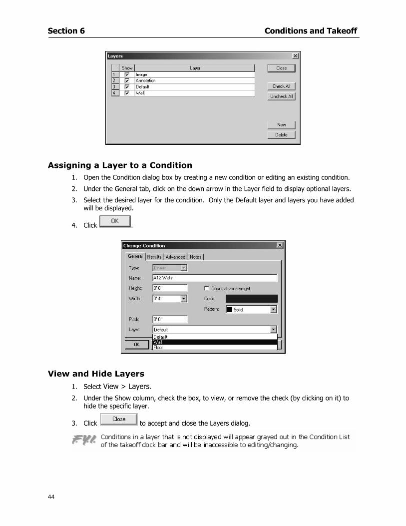
Section 6 Conditions and Takeoff
44
Assigning a Layer to a Condition 1 Open the Condition dialog box by creating a new condition or editing an existing condition
2 Under the General tab click on the down arrow in the Layer field to display optional layers
3 Select the desired layer for the condition Only the Default layer and layers you have added will be displayed
4 Click
View and Hide Layers
1 Select View gt Layers
2 Under the Show column check the box to view or remove the check (by clicking on it) to hide the specific layer
3 Click to accept and close the Layers dialog
Section 6 Conditions and Takeoff
45
Assigning Text to a Layer When adding text to an image On-Screen Takeoff has the capability to assign the text to a specified layer
1 Select the Text Tool
2 Click at the point you want to place your text
3 Type in your text using the Enter key for line breaks
4 Click the drop down arrow next to the Layer field and select the desired layer
Section 7
46
Printing and Exporting
This section will
Printing options and procedures
Exporting data by copying and pasting
Exporting quantity results to Excel spreadsheets
Section 7 Printing and Exporting
47
Print Setup On-Screen Takeoff allows the user to print the image takeoff list and worksheet
1 Select File gt Print Setup The Print Setup dialog will open
2 Select a printer or leave the default selection listed (change from the default printer displayed by clicking on the down arrow at the right of the field)
3 Indicate page size and printer tray option (Source) Access page size options by clicking on the
down arrow at the right of the field
4 Choose Portrait or Landscape orientation
5 Click to accept and close the dialog
Printing Images The image area can include the electronic plans the takeoff objects added text and hot links To print a subset of these (for example just the takeoffs without the plans or the added text and hot link symbols) hide layers that you do not want to print (see Section 6 View and Hide Layers) When you are printing your images every page will show the scale of the takeoff you are printing
1 Click on the Image tab to display the area of your project
2 Select File gt Print (or Ctrl + P)
Section 7 Printing and Exporting
48
3 Select the desired view (What to print) and the Image Range
4 Click The second Print dialog will open
5 Change settings accordingly or click if you accept the default settings
Printing Takeoff Lists and Worksheets In Takeoff Lists and Worksheets you may hide columns to print only certain results or adjust column widths to fit the report within the page size selected
1 In Takeoff List or Worksheet view move your cursor to the right side of the columnrsquos title bar the cursor will display as a two-way arrow
Section 7 Printing and Exporting
49
2 Click and drag to adjust the width of the column Holding the mouse button you may
slide the title bar under the title bar to its left to hide the column completely
3 Select File gt Print or press Ctrl + P to access the Print dialog
4 Indicate desired printer and choose the number of copies
5 Click to print and close the dialog
When printing the condition list we suggest printing in landscape
To reset to the default column widths double-click on the right border of a column heading will reset the column to its right (or previously to its right before being hidden)
Print Preview 1 Select File gt Print Preview
2 Use and to vary your view 3 If viewing an image choose current full or scale view to see how it displays
4 For printed outputs that cover more than one page use and to view adjacent pages or click on the down arrow next to Page field and select the page you want displayed
Exporting Using the CopyPaste Feature You may copy all the data or sections from the worksheet and the takeoff list view in On-Screen Takeoff and paste it into another application When pasting into Excel the cell layout will be maintained
1 Highlight the areas you wish to paste Click and hold the left mouse button down as you drag the cursor over the area to be selected then releasing the mouse button
OR
2 Select the entire takeoff list quickly click on the left On-Screen Takeoff column header and hold and drag the cursor across the remaining column headings
The number of pages for the view selected will display in the lower left-hand corner The zoom percentage that applies to the view will be displayed in the lower right-hand corner next to page size of the drawing
Section 7 Printing and Exporting
50
3 In the worksheet view you may highlight rows by clicking on the numbered buttons to the left of each row clicking and dragging across column headings or clicking and dragging over individual cells in the worksheet
Click anywhere in the appropriate view to deselect the area
4 Once your selection is highlighted you may select Edit gt Copy or Ctrl C from the keyboard 5 On your monitor switch to the application into which you want to paste your selection 6 Select Edit gt Paste in the new application or simply press Ctrl + V to paste
The colored keys for conditions cannot be pasted
Using the Export Feature You may export condition quantities to specified cell location within an Excel worksheet file Cell target locations are assigned in the Results tab of the condition dialogs on the Export line relating to each quantity measurement type
On-Screen Takeoff will export takeoff quantity results for up to three different quantity types that you specify For instance you may want to know the number of square feet in a ceiling area as well as the number of linear feet in its perimeter
Section 7 Printing and Exporting
51
1 Bring up the Condition dialog by double-clicking on a condition in the takeoff dock bar or by
selecting the condition and clicking
2 Click on the Results tab to access its fields The default quantities for the condition type will display
3 For each results field click on the arrow to access the pull-down menu and select the appropriate quantity (for example SF LF EA etchellip)
4 Have your Excel spreadsheet opened and saved in a file
5 Specify the Excel spreadsheet cell locations where you want the results to go
6 For a cell in the first sheet of your spreadsheet type in the cell address (eg a1) Case is not important
7 For a cell on a successive sheet of your spreadsheet type in sheet the number followed by a comma and the cell address without any spaces (eg sheet2a1) Case is not important
8 Click
9 Select File gt Export gt Condition Qty to Excel
Section 7 Printing and Exporting
52
10 Browse to the location of the Excel spreadsheet file click file to select it
11 Click to export On-Screen Takeoff results to specified cell locations in the Excel file When you return to the Excel application you will see the values have been added to the specified cell locations in your spreadsheet
12 Save your Excel file
Exporting Worksheet to Excel
1 Assign condition quantities you want to export
2 Open saved Excel spreadsheet file to which you will be exporting
3 From On-Screen Takeoff Select File gt Export gt Worksheet to Excel
4 Browse to the location of the Excel spreadsheet file click file to select it
5 Click When you return to the Excel application you will see the values from the Worksheet Tab have been added to your spreadsheet
6 Save your Excel file
Exporting Takeoff to CVS 1 Assign condition quantities you want to export
2 Open saved Excel spreadsheet file to which you will be exporting
3 Click the Takeoff Tab in the project you want to export the information
4 Select File gt Export gt Takeoff to CSV
5 Browse to the location of the CSV spreadsheet file click file to select it
6 Click the Save
NOTE CSV files can be opened in Excel Lotus Access etc One may consider this option more of a ldquodumprdquo into a file
The Excel application must be active (it may be minimized on the application bar) with the target spreadsheet open in the application Otherwise an error will occur with the export operation that will affect both the On-Screen Takeofftrade file and the Excel spreadsheet
Section 8
53
Advanced Features
This section will
Some special features of working with condition objects in the takeoff area
Details of advanced options for conditions
Advanced features of the Project Properties dialog
Section 8 Advanced Features
54
Features to Use with Objects Roping Feature You can move copy or delete using this feature Using the Select tool (the pointer) you may select several objects at once by clicking and dragging an outline around the objects then releasing the mouse button Roping may select either objects completely within the outlined area (inclusive) or objects both within and touched by the outlined area (touching) Specify your roping preference under Tools gt Options
1 Click and hold the mouse button at a point on the screen near the objects to be selected and drag to surround the objects with an outline
2 Release the mouse button The objects will be selected
3 You may now
Move the group around on the page by clicking within the group dragging the mouse and releasing the button to place the objects
Delete the group of objects by clicking the Delete key or
Copy and paste by pressing Ctrl C to copy the group then Ctrl V to paste it The pasted copy of the grouped objects will appear slightly offset from the original objects
Section 8 Advanced Features
55
Applying a DropRun Count
Use the droprun feature when calculating quantities to take into account the drop or run of a linear condition such as electrical lines or plumbing pipes Drop or run lengths may be added separately to any linear condition on screen while a default droprun length may be indicated for a condition as a whole
1 Select the desired linear condition from the Condition List in the Takeoff Dock bar
2 Click the Change button in the toolbar to open the Change Condition dialog
3 Click the Advanced tab to access the advanced options and click inside the DropRun check box
4 Enter a default length to be applied to all of this condition Entering 800 will be interpreted as 8 0 (You must enter both place markers for inches) You can leave the length blank and manually enter drop run on each segment drawn
5 Click the OK button to accept and close the dialog
Edit DropRun Count
1 With the related linear condition in the Takeoff Dock bar highlighted or with the pointer tool selected
2 click on the desired linear object in the image takeoff area The Count button will become active
3 Click on the Count button (alternatively select Tools gt Count) The default droprun amount will show in the pop-up Count dialog (Default length will be zero if droprun has not been selected in this conditionrsquos properties)
4 Type in the desired length Entering 800 will be interpreted as 8 0 (You must enter both place markers for inches)
5 Click the OK button The additional amount will be reflected in the corresponding quantity The new DropRun count will apply only to the object edited
Adding Text in Image View
On-Screen Takeoff allows you to place text comments around your quantity takeoffs that may be printed along with plan images and objects Text is automatically placed within the Annotation Layer (that includes text and hot links)
1 To place text on the image select the Text Tool and click at the point you want to place your text opening a text box
2 Type in your information clicking Enter for line breaks
3 When you are finished click the OK button to exit the text box
4 To reposition text simply click on the text (with the Text Tool active) to select it
5 Move the cursor over the text the cursor will now display as a four-way arrow
6 Click and drag the mouse to position the text as desired
Section 8 Advanced Features
56
1 To edit existing text use the Text Tool to double-click on the text to open the editing box
2 Enter additional text or use the Backspace key to delete text as necessary
Formatting Text Once created you may format the font size type style and color of your text
1 Click on the text to select it and select Tools gt Font or click on the Font button in the Takeoff Toolbar
2 Select the desired features (color options are disabled) and click the OK button
3 Click on the text to select it and select Tools gt Color or click on the Color button in the Takeoff Toolbar The Color dialog will open
4 Click on a color in the Basic Color palette or create a color and add to the Custom Colors palette (Be sure to click on the color in the Custom Colors palette to select it)
5 Click the OK button
Object Properties
Linear Objects
Linear objects may be set to connect at corners
A linear object may be set to trim automatically when crossing another linear object (Check the trim option under the advanced tab of the Condition dialog)
When you move a connected linear object objects automatically move and resize connected lines accordingly (quantities are then recalculated)
This feature requires that the connected linear object be moved using the center handles (does not apply when resizing the line from the ends)
Objects constrain to snap increments defined in the Tools gt Options menu (with the mouse 15deg by default incremental when shift key is held down)
Objects are measured from centerline to centerline
Section 8 Advanced Features
57
Area Objects When drawing an area use your escape key to undo the last line drawn You may reverse your
drawing of an area using the escape key
The area will not fill with color and pattern until the user double-clicks after the last line is set
Lines drawn to delineate an area object constrain to snap increments defined in the Tools gt Options menu (with the mouse 15deg by default incremental when shift key is held down)
After selecting an area to move or adjust position the mouse in the center to move the entire area position the mouse at the sides or corners to adjust the perimeter
Count Objects
All count objects are quantified by the physical number of objects per page and reported as EA for the UOM The quantity for the current Image View is (displayed in the Condition List) and the total quantity in your project is displayed in the Takeoff View and Worksheet View)
Square circle rectangle and triangle shaped count objects do not displace or subtract from other object quantities when placed on top of them However on the Advanced Tab for the count condition a connect property can be set (this is a check box) so that when a count object of this shape is put on top of a Linear type takeoff object it will move with the linear if said linear is moved
An opened-shaped count object must be placed within a linear object Opening shaped count objects may also be measured by linear foot or linear yard (EA SF and SY are also options) Opening shaped count items default to a width of 3rsquo 0rdquo at the time of creation This size can be changed The small medium and large size are not options on this type of condition anymore Check Backout on the Advanced tab for each Count object back out the footage (or yardage) of opening-shaped count objects in which they are placed
NOTE In order to see this Backout functionality (in quantity) for SY or SF deductions at least one of the
results for the Linear(s) this object will be placed on must be set to SY or SF and the count object must have a height quantity
Advanced Features of Conditions The Round Feature Under the Advanced tab of the linear and area Condition dialogues you may specify quantity rounding (in inches) For linear objects rounding applies to each linear object drawn For area objects rounding will apply to each segment of the area perimeter adjusting the perimeter and area calculations For example With a linear condition entering 12 in the Round field will round up each related linear object to the nearest 12 inches or one foot With this setting two walls of 1 4 would each round to 2 0 totaling 4 0
NOTE In the Takeoff Dock bar condition list and in the On-Screen Takeoff reports quantities will be displayed in whole numbers rounded up to the nearest foot However calculations are based on true quantities without rounding unless the Round Feature is engaged
Pitch Pitch may apply either to linear or area conditions It is measured in rise per linear foot Entering 12 indicates a 12 rise per 12 of linear distance (a pitch of 12 over 12) or an angle of 45deg
Section 8 Advanced Features
58
Advanced Features of Project Properties Selecting Multiple Pages
1 Select a single page entry by clicking on the numbered gray button to the left of the entry
2 Drag the cursor down the column of numbers to select consecutive pages
3 Click on the blank button at the top of this column to select all pages in the Properties dialog
Section 8 Advanced Features
59
Changing Image Assigned to a Drawing 1 Select the page entry by clicking on the numbered gray button to the left of the entry 2 Click the Change Image button The Change Image dialog box will appear
3 Navigate to the desired file and select by clicking on it
4 Click the Open button The electronic file assigned to the page will have been changed to reflect the new file choice
Changing Image File Path 1 Select pages as described above
2 Choose Change Folder
3 In the Change Folder dialog navigate to the appropriate folder
4 Click the OK button The file path will have been changed for the selected page entries
Delete a Page from Project Properties 1 Select the page you want to delete by clicking on its associated number (in the gray box at the
left of the entry)
2 Choose Delete Page
All Takeoff on the page will be deleted immediately and permanently
Section 8 Advanced Features
60
Advanced Features of Tool Options
Calculation Method On-Screen Takeoff has built-in calculation options to allow for faster work and faster saves until your takeoff is complete Calculation options are found by selecting Tools gt Options then clicking on the Calculation tab
Calculation method can be set to Automatic Automatic except Grids and Manual Manual will allow the program to operate more quickly while Automatic or Automatic except Grids allows the user to see quantity changes as takeoffs are made
In any mode you may press F9 to recalculate quantities for the On-Screen Takeoff current totals
Configuration Tab
When the ldquoPage Label (A01)rdquo radial button is chosen On-Screen Takeoff puts the numbered label on all the pages of in your current page indicator in your Navigate Toolbar If the Page Descriptionrdquo radial button is chosen then a description of what takeoff is on that specific page will be shown in your current page indicator in your Navigate Toolbar
This section of the configuration tab gives you options on how you want to export your information When the ldquoFolderSubfolder Namesrdquo radial button is chosen than on your file that you are exporting to will have all the conditions folders and subfolders In the Delimiter box you can choose the symbol that is needed to separate the information you are exporting Some files need semicolons () or colons () to make sure the information comes exported in is separated it the appropriate places
Section 8 Advanced Features
61
In previous versions of On-Screen Takeoff there are views that users need to have in order for them to display their information By either choosing ldquoOST 1xrdquo or ldquoOST 2xrdquo it will let the program know you want your columns of information exported in that specific format
When you have the Confirm Deletions radial button of ldquoYesrdquo chosen than every time you delete anything you will get a dialog box confirming your intentions of deletion
While working with your takeoff you have a choice to either view the legend of your conditions or hide it Choose whichever radial button that suits your needs
For those who prefer to use the Enter key to navigate in dialog boxes this option is just for that
Font Tab The Font tab is designed for you to make your own look and feel for the application At the bottom of this tab it will show you sample of the fonts and colors you have chosen
Renaming the Current Page You may change the name of the current page in the takeoff area of On-Screen Takeoff by selecting Edit gt Rename Page
This opens the Name Page dialog and you may simply type in a new name and click the Enter button The new name for the file will be reflected on the title bar for the page and in Project Properties
You also may access the Rename Page function by right-clicking in the takeoff area while in Image View and selecting the option from the pop-up menu that appears
Section 9
62
Saving and Exiting
This section will
Explain how to save projects
Show you how to safely exit the program
Section 9 Saving and Exiting
63
Saving Your Project
1 Select File gt Save 2 If your project has not previously been saved a Save dialog box will open to allow you to name
the file and choose the directory and folder in which to save your file 3 Once saved File gt Save will simply save the current version of the file
OR
4 Select File gt Save As then type in a new name for the file and save to the desired file path
The Auto-save Feature With the Auto-save feature On-Screen Takeoff automatically backs up your open project You may choose to have more than one level of backup files The first backup copy will have the extension b00 and successive files will be b01 b02 and so on If you have designated four levels of backup files after the fourth backup copy has been created (b03) the next file will be saved over the file with extension b00 Further backup saves will then rotate through the four backup files in the same way
1 Select Tools gt Options 2 In the Auto-save area (under the General tab) select the frequency of backup file creation (in
minutes) and the number of levels for the feature 3 You also may disengage the feature by clicking in the check box to clear it
The Auto-save feature automatically saves backup copies to the directory of the current project If you are working from a write-protected area such as a CD-ROM On-Screen Takeoff will place backup files in the On-Screen Takeoff folder
Exiting When you are finished using On-Screen Takeoff it is very easy to exit Exiting is very important because of security reasons If someone were to use your computer they could enter the application and view and manipulate information
Section 9 Saving and Exiting
64
On-Screen Takeoff closes the open project when you open another or create a new project or when you exit the program
1 Select File gt Exit
OR
2 You also may click at the upper right-hand corner of the application to exit
NOTE If your latest changes to a project file have not been saved On-Screen Takeoff will ask you whether you would like to save the file and gives you the option of canceling the operation
Appendix I Installing Your Digitizer
65
Appendix I Installing Your Digitizer When you get your digitizer from GTCO you will need to connect it to your computer Follow the instructions outlined below to do this
Note For rollup digitizers the metal bar must be oriented to the top or right hand side
Connecting the Digitizer 1 Lay the digitizer out flat 2 Connect the Stylus to the digitizer 3 Plug in the power adapter 4 Plug the interface (IO) cable into the digitizer 5 Plug the other end of the interface cable into an open serial port on computer
Note GTCO Technical support phone number is 410-381-6688 The electronic manual (on diskette) from GTCO contains more detailed installation and operation instructions for the GTCO digitizer model you have
Installing other Digitizer Drivers If you are using a GTCO Digitizer you will need to install the GTCO TabletWorks Drivers
If you are using a Digitizer not supported by GTCO Tablet Works 10 please contact the manufacturer of your digitizer for assistance with installation
Installing GTCO TabletWorks Drivers 1 Insert the On Center CD into the CD-ROM drive The CD Startup screen will open 2 Click on Install Software 3 Select Additional Software and Drivers 4 Select Digitizer Driver 5 Follow the instructions for installing TabletWorks 10
Adhering the Template The template is a small plastic sticker used to enable mouse function when using the digitizer with On-Screen Takeoff Place your template on your digitizer We suggest placing it in the bottom right corner of the digitizer about one inch inside the takeoff area
Note You may either peel off the back of the template and use the adhesive surface or you can tape the template down
Appendix I Installing Your Digitizer
66
Testing the Digitizer Drivers Before running OST you may test the digitizer by moving the stylus around on the digitizer pad it should move the mouse cursor (if mouse emulation is enabled)
If the digitizer does not move the mouse cursor on the screen
The superset codes may need to be reset Reset the superset codes by touching on the border of the digitizer with the stylus The digitizer should beep several times
The digitizer may not be communicating with the computer Be sure the COM port selected is correct Be sure the COM port selected is correct If you are not able to get the digitizer to move the mouse cursor you need to call GTCO technical support for help
Note The Mouse Emulation is not required for On-Screen Takeoff to work properly It is used only for the Template functionality if the digitizer is moving the cursor the wrong direction (up instead of sideways or vice-versa)
Click the L-shaped arrow symbol on the digitizer with the stylus
Appendix II Toolbar Item Details
67
Appendix II Toolbar Items Main Toolbar
Appendix II Toolbar Item Details
68
Tool Toolbar
Appendix II Toolbar Item Details
69
Zoom Toolbar
View Toolbar
Navigate Toolbar
Appendix II Toolbar Item Details
70
Navigate Toolbar (Continued)
Takeoff Toolbar
Appendix II Toolbar Item Details
71
Takeoff Toolbar (Continued)
Image Toolbar
Appendix III Loading Plans from a Dodge CD
72
Appendix III Loading Plans from a Dodge CD
This section will detail how to load plans from a F W Dodge CD-ROM into an On-Screen Takeoff project file ready for takeoffs
Dodge files may be added to the Project Properties dialog However loading the files in that way will load the files by number rather than name description If you want to load one page only from your Dodge CD You will have to rename the page to display the name rather than number of the file
To load plan files from a Dodge CD so that the files load sequentially by file number but are displayed by name rather than by number within your project follow the instructions below
Opening a Dodge project from a CD-ROM 1 Insert the CD into the drive 2 Choose File gt Custom 3 Choose Dodge Plans Project (plansdat) as the file type 4 Select the appropriate file type by clicking on the down arrow at the right of the Files of type
field 5 In the Look in field access your drive paths by clicking on the down arrow at the right of the
field then
Navigate to your CD-ROM drive Open the data folder and Open the Projects folder
6 Select the desired project and open its folder 7 Open the plansdat file 8 All the images will come in sequenced correctly for that job along with the full descriptions
(names) of each page If there is not a plans folder in the project folder then plans do not exist for that project on the CD Opening the plansdat file will yield an empty project
Appendix IV Using the Plan Viewer
73
Appendix IV Using On-Screen Takeoff Plan Viewer The On-Screen Takeoff Plan Viewer is a limited version of On Center Softwarersquos commercial takeoff software If your status bar located at the very bottom of the main window says View Mode in the lower left-hand corner then you are using the Plan Viewer You can use the plan viewer to
View CD-based amp converted CAD drawings
View a previously created OST file and associated drawings
Download electronic plans online
Navigate through drawings
Quickly Takeoff linearsareas and counts
Zoom in to view the plan better
Print drawings directly from the viewer
Viewing an On-Screen Takeoff Project File
1 To open an OST file that was previously created with of On-Screen Takeoff 2 Select File gt Open 3 An Open dialog will appear if you do not see the OST file you are looking for select the
Look In drop down arrow 4 A drop down menu will appear listing the various folders drives and mapped drives located
on your computer select the correct drive or folder location and continue to browse to the location of your OST file
5 When you see your OST file double-click it to open it 6 Any takeoff and drawings should appear on the Image tab view
If you do not see the drawings but do see the colored takeoff layer the drawings may
not be located in the same place they were originally saved at Go to File gt Project Properties and check the Image File path for each listed page If the image file path is pointing to a CD drive make sure the CD is inside the CR-ROM
Downloading Electronic Plans If your Online Plan Service provides a special file format (OSX) required to use this feature of our plan viewer you can immediately downloaded all electronic plans of a project directly from our viewer
Most Plan Room web sites will automatically open On-Screen Takeoff when a request to download plans is made Your particular Plan Room may differ in operation so please contact the provider directly with questions on using the site
Appendix IV Using the Plan Viewer
74
When you request to download or open a project file from a Plan Room you will usually have the open to open or save an OSX file Choosing open will automatically open On-Screen Takeoff Alternately you may choose to save the file to a local hard drive After you have saved the file either double-click it to launch On-Screen Takeoff or open the OSX file using On-Screen Takeoff by clicking File then Open and locating the file on your hard drive You will need to change the file type to OSX
After the OSX file is opened you will see an additional tab appear in the Conditions List window called Pages
The Pages tab shows the hierarchy of your project Gray file icons represent pages that have not been downloaded and blue icons represents pages that have been downloaded
To download a page simply double-click the page icon
If you wish to select a group of pages to download you can use the Ctrl or Shift key to multiple select them then click the Download button
If you wish to download all pages at once click the Download All button
Downloaded pages will now appear in the Project Properties dialog in the same order in which they appear in the Pages tab
Creating Quick Takeoffs With On-Screen Takeoff you can create quick takeoffs to measure quantities even if you dont have the full version of our program However using the Quick Takeoff functionality shows you just a fraction of what the full version can do
The Quick Takeoff Toolbar is located at the top of the image view It has three buttons designated for three types of takeoffs Linear Area and Count The Quantity drop down list will show secondary quantities for Linears and Areas The Units drop down allows you to select how you want your quantities displayed Feet Inches Yards Millimeters and Meters
NOTE Every time change the type of takeoff you are performing (switching from Area to Linear for example) the previous quantities and takeoff objects will disappear They will also disappear when you changes pages
NOTE You can use the Dimension Tool to basically measure the distance between two points or linears The distance will display on the status bar at the bottom of the application
The Quick Takeoff Toolbar
Appendix V Frequently Asked Questions
75
Appendix V Frequently Asked Questions General
Where is On-Screen Takeoff installed on my computer
Typically it is installed in CProgram FilesOn-Screen Takeoff
In Explorer how do I recognize On-Screen Takeoff file types
On-Screen Takeoff data is stored in a single file per job lsquojob name OSTrsquo On-Screen Takeoff templates are stored as lsquotemplate nameTPOrsquo
Can only one project at a time be open
Yes For that reason opening another project automatically closes the project on screen You will be asked to save any changes
Is only one scale allowed per page What about on drawings that have multiple detail sections on a page and each of those drawings have different scales
Yes For pages with drawings of different scales copy the drawing to another project page and set the appropriate scale
I cannot perform backout on an area that is along a linear
As a workaround use the On-Screen Takeoff layers feature to help you with this issue Electronic Images
How do I start a project from drawings that have been scanned and written to a CD-ROM
Open a new project Select File gt Project Properties and select Auto Add Navigate to your CD and the appropriate folder and select any image file in that location Click Open All files in the location will load into your project Recommended that images are copied from CD to hard drive for performance
If I get a disk of drawings in AutoCAD format (R13 or R14) can I read them in On-Screen Takeoff
Yes On-Screen Takeoff now reads DWG DXF and many other format that are saved with AutoCAD
Appendix V Frequently Asked Questions
76
When I click on the all pages button what is supposed to happen Currently nothing seems to change when I click on that button
The All Pages button is used to apply the Darken and Enhance Plans feature to all pages in the project (as opposed to only the current page on screen)
Is there a way to deduct a large skylight from an area condition
Yes with the related area condition selected in the Takeoff Dock bar unselect the Backout button on the Takeoff Toolbar then draw the Backout area The area quantity will be deducted from the related condition object and the linear measurement of the Backout perimeter will be added
Digitizer Issues
How do I connect a Digitizer to the computer
See Appendix I Connecting a Digitizer
The Place Template menu choice is disabled
On-Screen Takeoff may need to be authorized or the digitizer or the digitzer drivers are not installed
It wonrsquot let me select the Set Takeoff Area menu choice
On-Screen Takeoff may need to be authorized or no job is open a digitizer is not installed or the drivers are not installed
The digitizer stylus is not moving the cursor or crosshairs
Click S-0-1 superset on the digitizer
How do I convert my old GTCO Digitizer to work with On- Screen Takeofftrade
Call GTCO and they may be able to reconfigure your digitizer to be compatible with On-Screen Takeoff
Printing Issues Which Printers work with On-Screen Takeoff
Compatible printers include On-Screen Takeoff Hewlett Packard Epson and Canon printers If you are having printer difficulties please contact support and specify the type of printer along with other pertinent information Contact support at wwwoncentercomsupport or email supportoncentercom
Which Plotters work with On-Screen Takeoff
Compatible Plotters include Hewlett Packard DesignJet plotters and the EnCAD Cadjet II If you are having plotter difficulties please contact support and specify the type of plotter concerned
ViewingDisplay I can no longer see my condition list How do I get it back
The toolbars and Dock bars can be turned on and off through the View gt Toolbars menu options
Appendix V Frequently Asked Questions
77
This is also accessible by right-clicking in the toolbar area and selecting (or deselecting) a toolbar listed
I cannot view my folders in the condition list
Right-click in the Takeoff Dock barcondition list area and select Show Tree to display your folders
My Status Bar reads Viewer Mode and I am unable to draw conditions
On-Screen Takeoff needs to be Authorized Or you need to purchase an upgrade Click the Perform Advanced Takeoff button on the main toolbar
I hid a Dock bar and when I selected to view it again it appeared alongside the other Dock
bar instead of stacked on top of it How do I fix it
Pick up the Dock bar by clicking on the bar at the top and continuing to hold down the mouse button drag the Dock bar over the other one It will resize and appear stacked with the other
When I open image files from a CD the images are all upside down How do I get them right
side up
To flip pages from top to bottom follow the steps below 1 Click the All Pages button on the Image Toolbar (All Pages is engaged when the button
is not clicked) 2 Click the Flip Horizontal button on the Image Toolbar 3 Click the All Pages button again to disengage
Templates How do I create a Template
Follow the steps below 1 Create a typical project 2 Choose File gt Save As 3 Choose On-Screen Takeoff Template Files as the file type to save 4 Name the file This will save all of the condition setups as well as the layers for the
project
How do I create a new project from a template
Follow the steps below 1 Choose File gt New 2 Select a template from those listed in the New dialog This will open a new project with
conditions and layers saved from a previous project but no pages or takeoff
78
INDEX
Area Conditions 32
Area Objects 57
Auto Scrolling 20
Auto-save 63
Backout Mode 41
Calculation Method 60
Conditions 29
Configuration 60
Contents Tab 6
Continuous Mode 38
Count Conditions 33
Count Objects 57
Digitizer 10 65 76
Docking Toolbars 13
Dodge CD 72
Drawing 27 37
DropRun Count 55
Environment 18
Exiting 63
Exporting 49
Features 16
Font 61
Frequently Asked Questions 75
Grid 40
Help File 5
Hiding Toolbars 13
Hot Links 21
Image 19 59
Image files 9
Image Toolbar 12 71
Images 75
Index Tab 6
Layers 43
Linear Conditions 31
Linear Objects 56
Main Toolbar 12 67
Menus 14
Moving Toolbars 13
Navigate Toolbar 12 69
Navigating 20
On-Screen Takeofftrade 2
Page 59 61
Pages 20 25 28
Plan Viewer 73
Plans 26
Printing 47 76
Project Properties 25
Projects 22
Quick Start Video 18
Resizing Toolbars 13
Roping 54
Saving 63
Scale 28
Search Tab 7
Selecting Objects 42
Setup 8
Start On-Screen Takeofftrade 17
System Requirements 9
Takeoff 19 27
Takeoff Toolbar 70 71
Takeoff Toolbar 12
Template Files 23
TIF (Group4) 9
Tool Toolbar 12 68
Toolbar 67
Toolbars 12
View Toolbar 12 69
Viewing Toolbars 12
Worksheet 20
Zone Conditions 33
Zoom Toolbar 12 69
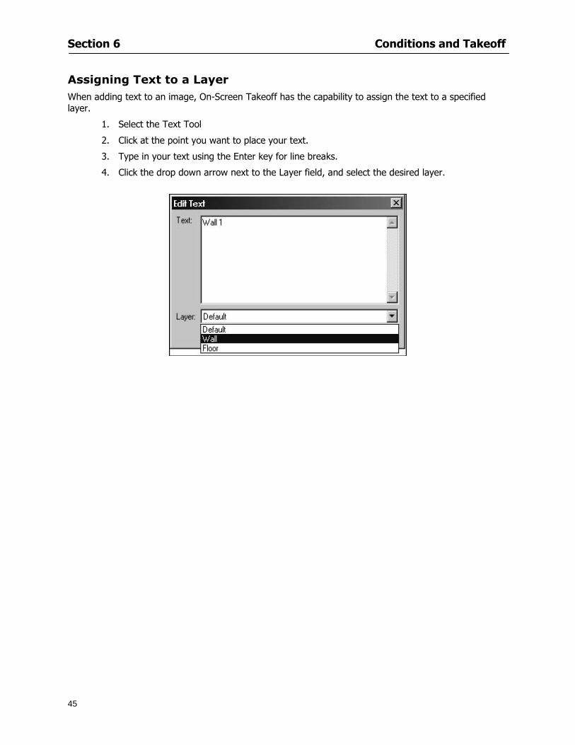
Section 6 Conditions and Takeoff
45
Assigning Text to a Layer When adding text to an image On-Screen Takeoff has the capability to assign the text to a specified layer
1 Select the Text Tool
2 Click at the point you want to place your text
3 Type in your text using the Enter key for line breaks
4 Click the drop down arrow next to the Layer field and select the desired layer
Section 7
46
Printing and Exporting
This section will
Printing options and procedures
Exporting data by copying and pasting
Exporting quantity results to Excel spreadsheets
Section 7 Printing and Exporting
47
Print Setup On-Screen Takeoff allows the user to print the image takeoff list and worksheet
1 Select File gt Print Setup The Print Setup dialog will open
2 Select a printer or leave the default selection listed (change from the default printer displayed by clicking on the down arrow at the right of the field)
3 Indicate page size and printer tray option (Source) Access page size options by clicking on the
down arrow at the right of the field
4 Choose Portrait or Landscape orientation
5 Click to accept and close the dialog
Printing Images The image area can include the electronic plans the takeoff objects added text and hot links To print a subset of these (for example just the takeoffs without the plans or the added text and hot link symbols) hide layers that you do not want to print (see Section 6 View and Hide Layers) When you are printing your images every page will show the scale of the takeoff you are printing
1 Click on the Image tab to display the area of your project
2 Select File gt Print (or Ctrl + P)
Section 7 Printing and Exporting
48
3 Select the desired view (What to print) and the Image Range
4 Click The second Print dialog will open
5 Change settings accordingly or click if you accept the default settings
Printing Takeoff Lists and Worksheets In Takeoff Lists and Worksheets you may hide columns to print only certain results or adjust column widths to fit the report within the page size selected
1 In Takeoff List or Worksheet view move your cursor to the right side of the columnrsquos title bar the cursor will display as a two-way arrow
Section 7 Printing and Exporting
49
2 Click and drag to adjust the width of the column Holding the mouse button you may
slide the title bar under the title bar to its left to hide the column completely
3 Select File gt Print or press Ctrl + P to access the Print dialog
4 Indicate desired printer and choose the number of copies
5 Click to print and close the dialog
When printing the condition list we suggest printing in landscape
To reset to the default column widths double-click on the right border of a column heading will reset the column to its right (or previously to its right before being hidden)
Print Preview 1 Select File gt Print Preview
2 Use and to vary your view 3 If viewing an image choose current full or scale view to see how it displays
4 For printed outputs that cover more than one page use and to view adjacent pages or click on the down arrow next to Page field and select the page you want displayed
Exporting Using the CopyPaste Feature You may copy all the data or sections from the worksheet and the takeoff list view in On-Screen Takeoff and paste it into another application When pasting into Excel the cell layout will be maintained
1 Highlight the areas you wish to paste Click and hold the left mouse button down as you drag the cursor over the area to be selected then releasing the mouse button
OR
2 Select the entire takeoff list quickly click on the left On-Screen Takeoff column header and hold and drag the cursor across the remaining column headings
The number of pages for the view selected will display in the lower left-hand corner The zoom percentage that applies to the view will be displayed in the lower right-hand corner next to page size of the drawing
Section 7 Printing and Exporting
50
3 In the worksheet view you may highlight rows by clicking on the numbered buttons to the left of each row clicking and dragging across column headings or clicking and dragging over individual cells in the worksheet
Click anywhere in the appropriate view to deselect the area
4 Once your selection is highlighted you may select Edit gt Copy or Ctrl C from the keyboard 5 On your monitor switch to the application into which you want to paste your selection 6 Select Edit gt Paste in the new application or simply press Ctrl + V to paste
The colored keys for conditions cannot be pasted
Using the Export Feature You may export condition quantities to specified cell location within an Excel worksheet file Cell target locations are assigned in the Results tab of the condition dialogs on the Export line relating to each quantity measurement type
On-Screen Takeoff will export takeoff quantity results for up to three different quantity types that you specify For instance you may want to know the number of square feet in a ceiling area as well as the number of linear feet in its perimeter
Section 7 Printing and Exporting
51
1 Bring up the Condition dialog by double-clicking on a condition in the takeoff dock bar or by
selecting the condition and clicking
2 Click on the Results tab to access its fields The default quantities for the condition type will display
3 For each results field click on the arrow to access the pull-down menu and select the appropriate quantity (for example SF LF EA etchellip)
4 Have your Excel spreadsheet opened and saved in a file
5 Specify the Excel spreadsheet cell locations where you want the results to go
6 For a cell in the first sheet of your spreadsheet type in the cell address (eg a1) Case is not important
7 For a cell on a successive sheet of your spreadsheet type in sheet the number followed by a comma and the cell address without any spaces (eg sheet2a1) Case is not important
8 Click
9 Select File gt Export gt Condition Qty to Excel
Section 7 Printing and Exporting
52
10 Browse to the location of the Excel spreadsheet file click file to select it
11 Click to export On-Screen Takeoff results to specified cell locations in the Excel file When you return to the Excel application you will see the values have been added to the specified cell locations in your spreadsheet
12 Save your Excel file
Exporting Worksheet to Excel
1 Assign condition quantities you want to export
2 Open saved Excel spreadsheet file to which you will be exporting
3 From On-Screen Takeoff Select File gt Export gt Worksheet to Excel
4 Browse to the location of the Excel spreadsheet file click file to select it
5 Click When you return to the Excel application you will see the values from the Worksheet Tab have been added to your spreadsheet
6 Save your Excel file
Exporting Takeoff to CVS 1 Assign condition quantities you want to export
2 Open saved Excel spreadsheet file to which you will be exporting
3 Click the Takeoff Tab in the project you want to export the information
4 Select File gt Export gt Takeoff to CSV
5 Browse to the location of the CSV spreadsheet file click file to select it
6 Click the Save
NOTE CSV files can be opened in Excel Lotus Access etc One may consider this option more of a ldquodumprdquo into a file
The Excel application must be active (it may be minimized on the application bar) with the target spreadsheet open in the application Otherwise an error will occur with the export operation that will affect both the On-Screen Takeofftrade file and the Excel spreadsheet
Section 8
53
Advanced Features
This section will
Some special features of working with condition objects in the takeoff area
Details of advanced options for conditions
Advanced features of the Project Properties dialog
Section 8 Advanced Features
54
Features to Use with Objects Roping Feature You can move copy or delete using this feature Using the Select tool (the pointer) you may select several objects at once by clicking and dragging an outline around the objects then releasing the mouse button Roping may select either objects completely within the outlined area (inclusive) or objects both within and touched by the outlined area (touching) Specify your roping preference under Tools gt Options
1 Click and hold the mouse button at a point on the screen near the objects to be selected and drag to surround the objects with an outline
2 Release the mouse button The objects will be selected
3 You may now
Move the group around on the page by clicking within the group dragging the mouse and releasing the button to place the objects
Delete the group of objects by clicking the Delete key or
Copy and paste by pressing Ctrl C to copy the group then Ctrl V to paste it The pasted copy of the grouped objects will appear slightly offset from the original objects
Section 8 Advanced Features
55
Applying a DropRun Count
Use the droprun feature when calculating quantities to take into account the drop or run of a linear condition such as electrical lines or plumbing pipes Drop or run lengths may be added separately to any linear condition on screen while a default droprun length may be indicated for a condition as a whole
1 Select the desired linear condition from the Condition List in the Takeoff Dock bar
2 Click the Change button in the toolbar to open the Change Condition dialog
3 Click the Advanced tab to access the advanced options and click inside the DropRun check box
4 Enter a default length to be applied to all of this condition Entering 800 will be interpreted as 8 0 (You must enter both place markers for inches) You can leave the length blank and manually enter drop run on each segment drawn
5 Click the OK button to accept and close the dialog
Edit DropRun Count
1 With the related linear condition in the Takeoff Dock bar highlighted or with the pointer tool selected
2 click on the desired linear object in the image takeoff area The Count button will become active
3 Click on the Count button (alternatively select Tools gt Count) The default droprun amount will show in the pop-up Count dialog (Default length will be zero if droprun has not been selected in this conditionrsquos properties)
4 Type in the desired length Entering 800 will be interpreted as 8 0 (You must enter both place markers for inches)
5 Click the OK button The additional amount will be reflected in the corresponding quantity The new DropRun count will apply only to the object edited
Adding Text in Image View
On-Screen Takeoff allows you to place text comments around your quantity takeoffs that may be printed along with plan images and objects Text is automatically placed within the Annotation Layer (that includes text and hot links)
1 To place text on the image select the Text Tool and click at the point you want to place your text opening a text box
2 Type in your information clicking Enter for line breaks
3 When you are finished click the OK button to exit the text box
4 To reposition text simply click on the text (with the Text Tool active) to select it
5 Move the cursor over the text the cursor will now display as a four-way arrow
6 Click and drag the mouse to position the text as desired
Section 8 Advanced Features
56
1 To edit existing text use the Text Tool to double-click on the text to open the editing box
2 Enter additional text or use the Backspace key to delete text as necessary
Formatting Text Once created you may format the font size type style and color of your text
1 Click on the text to select it and select Tools gt Font or click on the Font button in the Takeoff Toolbar
2 Select the desired features (color options are disabled) and click the OK button
3 Click on the text to select it and select Tools gt Color or click on the Color button in the Takeoff Toolbar The Color dialog will open
4 Click on a color in the Basic Color palette or create a color and add to the Custom Colors palette (Be sure to click on the color in the Custom Colors palette to select it)
5 Click the OK button
Object Properties
Linear Objects
Linear objects may be set to connect at corners
A linear object may be set to trim automatically when crossing another linear object (Check the trim option under the advanced tab of the Condition dialog)
When you move a connected linear object objects automatically move and resize connected lines accordingly (quantities are then recalculated)
This feature requires that the connected linear object be moved using the center handles (does not apply when resizing the line from the ends)
Objects constrain to snap increments defined in the Tools gt Options menu (with the mouse 15deg by default incremental when shift key is held down)
Objects are measured from centerline to centerline
Section 8 Advanced Features
57
Area Objects When drawing an area use your escape key to undo the last line drawn You may reverse your
drawing of an area using the escape key
The area will not fill with color and pattern until the user double-clicks after the last line is set
Lines drawn to delineate an area object constrain to snap increments defined in the Tools gt Options menu (with the mouse 15deg by default incremental when shift key is held down)
After selecting an area to move or adjust position the mouse in the center to move the entire area position the mouse at the sides or corners to adjust the perimeter
Count Objects
All count objects are quantified by the physical number of objects per page and reported as EA for the UOM The quantity for the current Image View is (displayed in the Condition List) and the total quantity in your project is displayed in the Takeoff View and Worksheet View)
Square circle rectangle and triangle shaped count objects do not displace or subtract from other object quantities when placed on top of them However on the Advanced Tab for the count condition a connect property can be set (this is a check box) so that when a count object of this shape is put on top of a Linear type takeoff object it will move with the linear if said linear is moved
An opened-shaped count object must be placed within a linear object Opening shaped count objects may also be measured by linear foot or linear yard (EA SF and SY are also options) Opening shaped count items default to a width of 3rsquo 0rdquo at the time of creation This size can be changed The small medium and large size are not options on this type of condition anymore Check Backout on the Advanced tab for each Count object back out the footage (or yardage) of opening-shaped count objects in which they are placed
NOTE In order to see this Backout functionality (in quantity) for SY or SF deductions at least one of the
results for the Linear(s) this object will be placed on must be set to SY or SF and the count object must have a height quantity
Advanced Features of Conditions The Round Feature Under the Advanced tab of the linear and area Condition dialogues you may specify quantity rounding (in inches) For linear objects rounding applies to each linear object drawn For area objects rounding will apply to each segment of the area perimeter adjusting the perimeter and area calculations For example With a linear condition entering 12 in the Round field will round up each related linear object to the nearest 12 inches or one foot With this setting two walls of 1 4 would each round to 2 0 totaling 4 0
NOTE In the Takeoff Dock bar condition list and in the On-Screen Takeoff reports quantities will be displayed in whole numbers rounded up to the nearest foot However calculations are based on true quantities without rounding unless the Round Feature is engaged
Pitch Pitch may apply either to linear or area conditions It is measured in rise per linear foot Entering 12 indicates a 12 rise per 12 of linear distance (a pitch of 12 over 12) or an angle of 45deg
Section 8 Advanced Features
58
Advanced Features of Project Properties Selecting Multiple Pages
1 Select a single page entry by clicking on the numbered gray button to the left of the entry
2 Drag the cursor down the column of numbers to select consecutive pages
3 Click on the blank button at the top of this column to select all pages in the Properties dialog
Section 8 Advanced Features
59
Changing Image Assigned to a Drawing 1 Select the page entry by clicking on the numbered gray button to the left of the entry 2 Click the Change Image button The Change Image dialog box will appear
3 Navigate to the desired file and select by clicking on it
4 Click the Open button The electronic file assigned to the page will have been changed to reflect the new file choice
Changing Image File Path 1 Select pages as described above
2 Choose Change Folder
3 In the Change Folder dialog navigate to the appropriate folder
4 Click the OK button The file path will have been changed for the selected page entries
Delete a Page from Project Properties 1 Select the page you want to delete by clicking on its associated number (in the gray box at the
left of the entry)
2 Choose Delete Page
All Takeoff on the page will be deleted immediately and permanently
Section 8 Advanced Features
60
Advanced Features of Tool Options
Calculation Method On-Screen Takeoff has built-in calculation options to allow for faster work and faster saves until your takeoff is complete Calculation options are found by selecting Tools gt Options then clicking on the Calculation tab
Calculation method can be set to Automatic Automatic except Grids and Manual Manual will allow the program to operate more quickly while Automatic or Automatic except Grids allows the user to see quantity changes as takeoffs are made
In any mode you may press F9 to recalculate quantities for the On-Screen Takeoff current totals
Configuration Tab
When the ldquoPage Label (A01)rdquo radial button is chosen On-Screen Takeoff puts the numbered label on all the pages of in your current page indicator in your Navigate Toolbar If the Page Descriptionrdquo radial button is chosen then a description of what takeoff is on that specific page will be shown in your current page indicator in your Navigate Toolbar
This section of the configuration tab gives you options on how you want to export your information When the ldquoFolderSubfolder Namesrdquo radial button is chosen than on your file that you are exporting to will have all the conditions folders and subfolders In the Delimiter box you can choose the symbol that is needed to separate the information you are exporting Some files need semicolons () or colons () to make sure the information comes exported in is separated it the appropriate places
Section 8 Advanced Features
61
In previous versions of On-Screen Takeoff there are views that users need to have in order for them to display their information By either choosing ldquoOST 1xrdquo or ldquoOST 2xrdquo it will let the program know you want your columns of information exported in that specific format
When you have the Confirm Deletions radial button of ldquoYesrdquo chosen than every time you delete anything you will get a dialog box confirming your intentions of deletion
While working with your takeoff you have a choice to either view the legend of your conditions or hide it Choose whichever radial button that suits your needs
For those who prefer to use the Enter key to navigate in dialog boxes this option is just for that
Font Tab The Font tab is designed for you to make your own look and feel for the application At the bottom of this tab it will show you sample of the fonts and colors you have chosen
Renaming the Current Page You may change the name of the current page in the takeoff area of On-Screen Takeoff by selecting Edit gt Rename Page
This opens the Name Page dialog and you may simply type in a new name and click the Enter button The new name for the file will be reflected on the title bar for the page and in Project Properties
You also may access the Rename Page function by right-clicking in the takeoff area while in Image View and selecting the option from the pop-up menu that appears
Section 9
62
Saving and Exiting
This section will
Explain how to save projects
Show you how to safely exit the program
Section 9 Saving and Exiting
63
Saving Your Project
1 Select File gt Save 2 If your project has not previously been saved a Save dialog box will open to allow you to name
the file and choose the directory and folder in which to save your file 3 Once saved File gt Save will simply save the current version of the file
OR
4 Select File gt Save As then type in a new name for the file and save to the desired file path
The Auto-save Feature With the Auto-save feature On-Screen Takeoff automatically backs up your open project You may choose to have more than one level of backup files The first backup copy will have the extension b00 and successive files will be b01 b02 and so on If you have designated four levels of backup files after the fourth backup copy has been created (b03) the next file will be saved over the file with extension b00 Further backup saves will then rotate through the four backup files in the same way
1 Select Tools gt Options 2 In the Auto-save area (under the General tab) select the frequency of backup file creation (in
minutes) and the number of levels for the feature 3 You also may disengage the feature by clicking in the check box to clear it
The Auto-save feature automatically saves backup copies to the directory of the current project If you are working from a write-protected area such as a CD-ROM On-Screen Takeoff will place backup files in the On-Screen Takeoff folder
Exiting When you are finished using On-Screen Takeoff it is very easy to exit Exiting is very important because of security reasons If someone were to use your computer they could enter the application and view and manipulate information
Section 9 Saving and Exiting
64
On-Screen Takeoff closes the open project when you open another or create a new project or when you exit the program
1 Select File gt Exit
OR
2 You also may click at the upper right-hand corner of the application to exit
NOTE If your latest changes to a project file have not been saved On-Screen Takeoff will ask you whether you would like to save the file and gives you the option of canceling the operation
Appendix I Installing Your Digitizer
65
Appendix I Installing Your Digitizer When you get your digitizer from GTCO you will need to connect it to your computer Follow the instructions outlined below to do this
Note For rollup digitizers the metal bar must be oriented to the top or right hand side
Connecting the Digitizer 1 Lay the digitizer out flat 2 Connect the Stylus to the digitizer 3 Plug in the power adapter 4 Plug the interface (IO) cable into the digitizer 5 Plug the other end of the interface cable into an open serial port on computer
Note GTCO Technical support phone number is 410-381-6688 The electronic manual (on diskette) from GTCO contains more detailed installation and operation instructions for the GTCO digitizer model you have
Installing other Digitizer Drivers If you are using a GTCO Digitizer you will need to install the GTCO TabletWorks Drivers
If you are using a Digitizer not supported by GTCO Tablet Works 10 please contact the manufacturer of your digitizer for assistance with installation
Installing GTCO TabletWorks Drivers 1 Insert the On Center CD into the CD-ROM drive The CD Startup screen will open 2 Click on Install Software 3 Select Additional Software and Drivers 4 Select Digitizer Driver 5 Follow the instructions for installing TabletWorks 10
Adhering the Template The template is a small plastic sticker used to enable mouse function when using the digitizer with On-Screen Takeoff Place your template on your digitizer We suggest placing it in the bottom right corner of the digitizer about one inch inside the takeoff area
Note You may either peel off the back of the template and use the adhesive surface or you can tape the template down
Appendix I Installing Your Digitizer
66
Testing the Digitizer Drivers Before running OST you may test the digitizer by moving the stylus around on the digitizer pad it should move the mouse cursor (if mouse emulation is enabled)
If the digitizer does not move the mouse cursor on the screen
The superset codes may need to be reset Reset the superset codes by touching on the border of the digitizer with the stylus The digitizer should beep several times
The digitizer may not be communicating with the computer Be sure the COM port selected is correct Be sure the COM port selected is correct If you are not able to get the digitizer to move the mouse cursor you need to call GTCO technical support for help
Note The Mouse Emulation is not required for On-Screen Takeoff to work properly It is used only for the Template functionality if the digitizer is moving the cursor the wrong direction (up instead of sideways or vice-versa)
Click the L-shaped arrow symbol on the digitizer with the stylus
Appendix II Toolbar Item Details
67
Appendix II Toolbar Items Main Toolbar
Appendix II Toolbar Item Details
68
Tool Toolbar
Appendix II Toolbar Item Details
69
Zoom Toolbar
View Toolbar
Navigate Toolbar
Appendix II Toolbar Item Details
70
Navigate Toolbar (Continued)
Takeoff Toolbar
Appendix II Toolbar Item Details
71
Takeoff Toolbar (Continued)
Image Toolbar
Appendix III Loading Plans from a Dodge CD
72
Appendix III Loading Plans from a Dodge CD
This section will detail how to load plans from a F W Dodge CD-ROM into an On-Screen Takeoff project file ready for takeoffs
Dodge files may be added to the Project Properties dialog However loading the files in that way will load the files by number rather than name description If you want to load one page only from your Dodge CD You will have to rename the page to display the name rather than number of the file
To load plan files from a Dodge CD so that the files load sequentially by file number but are displayed by name rather than by number within your project follow the instructions below
Opening a Dodge project from a CD-ROM 1 Insert the CD into the drive 2 Choose File gt Custom 3 Choose Dodge Plans Project (plansdat) as the file type 4 Select the appropriate file type by clicking on the down arrow at the right of the Files of type
field 5 In the Look in field access your drive paths by clicking on the down arrow at the right of the
field then
Navigate to your CD-ROM drive Open the data folder and Open the Projects folder
6 Select the desired project and open its folder 7 Open the plansdat file 8 All the images will come in sequenced correctly for that job along with the full descriptions
(names) of each page If there is not a plans folder in the project folder then plans do not exist for that project on the CD Opening the plansdat file will yield an empty project
Appendix IV Using the Plan Viewer
73
Appendix IV Using On-Screen Takeoff Plan Viewer The On-Screen Takeoff Plan Viewer is a limited version of On Center Softwarersquos commercial takeoff software If your status bar located at the very bottom of the main window says View Mode in the lower left-hand corner then you are using the Plan Viewer You can use the plan viewer to
View CD-based amp converted CAD drawings
View a previously created OST file and associated drawings
Download electronic plans online
Navigate through drawings
Quickly Takeoff linearsareas and counts
Zoom in to view the plan better
Print drawings directly from the viewer
Viewing an On-Screen Takeoff Project File
1 To open an OST file that was previously created with of On-Screen Takeoff 2 Select File gt Open 3 An Open dialog will appear if you do not see the OST file you are looking for select the
Look In drop down arrow 4 A drop down menu will appear listing the various folders drives and mapped drives located
on your computer select the correct drive or folder location and continue to browse to the location of your OST file
5 When you see your OST file double-click it to open it 6 Any takeoff and drawings should appear on the Image tab view
If you do not see the drawings but do see the colored takeoff layer the drawings may
not be located in the same place they were originally saved at Go to File gt Project Properties and check the Image File path for each listed page If the image file path is pointing to a CD drive make sure the CD is inside the CR-ROM
Downloading Electronic Plans If your Online Plan Service provides a special file format (OSX) required to use this feature of our plan viewer you can immediately downloaded all electronic plans of a project directly from our viewer
Most Plan Room web sites will automatically open On-Screen Takeoff when a request to download plans is made Your particular Plan Room may differ in operation so please contact the provider directly with questions on using the site
Appendix IV Using the Plan Viewer
74
When you request to download or open a project file from a Plan Room you will usually have the open to open or save an OSX file Choosing open will automatically open On-Screen Takeoff Alternately you may choose to save the file to a local hard drive After you have saved the file either double-click it to launch On-Screen Takeoff or open the OSX file using On-Screen Takeoff by clicking File then Open and locating the file on your hard drive You will need to change the file type to OSX
After the OSX file is opened you will see an additional tab appear in the Conditions List window called Pages
The Pages tab shows the hierarchy of your project Gray file icons represent pages that have not been downloaded and blue icons represents pages that have been downloaded
To download a page simply double-click the page icon
If you wish to select a group of pages to download you can use the Ctrl or Shift key to multiple select them then click the Download button
If you wish to download all pages at once click the Download All button
Downloaded pages will now appear in the Project Properties dialog in the same order in which they appear in the Pages tab
Creating Quick Takeoffs With On-Screen Takeoff you can create quick takeoffs to measure quantities even if you dont have the full version of our program However using the Quick Takeoff functionality shows you just a fraction of what the full version can do
The Quick Takeoff Toolbar is located at the top of the image view It has three buttons designated for three types of takeoffs Linear Area and Count The Quantity drop down list will show secondary quantities for Linears and Areas The Units drop down allows you to select how you want your quantities displayed Feet Inches Yards Millimeters and Meters
NOTE Every time change the type of takeoff you are performing (switching from Area to Linear for example) the previous quantities and takeoff objects will disappear They will also disappear when you changes pages
NOTE You can use the Dimension Tool to basically measure the distance between two points or linears The distance will display on the status bar at the bottom of the application
The Quick Takeoff Toolbar
Appendix V Frequently Asked Questions
75
Appendix V Frequently Asked Questions General
Where is On-Screen Takeoff installed on my computer
Typically it is installed in CProgram FilesOn-Screen Takeoff
In Explorer how do I recognize On-Screen Takeoff file types
On-Screen Takeoff data is stored in a single file per job lsquojob name OSTrsquo On-Screen Takeoff templates are stored as lsquotemplate nameTPOrsquo
Can only one project at a time be open
Yes For that reason opening another project automatically closes the project on screen You will be asked to save any changes
Is only one scale allowed per page What about on drawings that have multiple detail sections on a page and each of those drawings have different scales
Yes For pages with drawings of different scales copy the drawing to another project page and set the appropriate scale
I cannot perform backout on an area that is along a linear
As a workaround use the On-Screen Takeoff layers feature to help you with this issue Electronic Images
How do I start a project from drawings that have been scanned and written to a CD-ROM
Open a new project Select File gt Project Properties and select Auto Add Navigate to your CD and the appropriate folder and select any image file in that location Click Open All files in the location will load into your project Recommended that images are copied from CD to hard drive for performance
If I get a disk of drawings in AutoCAD format (R13 or R14) can I read them in On-Screen Takeoff
Yes On-Screen Takeoff now reads DWG DXF and many other format that are saved with AutoCAD
Appendix V Frequently Asked Questions
76
When I click on the all pages button what is supposed to happen Currently nothing seems to change when I click on that button
The All Pages button is used to apply the Darken and Enhance Plans feature to all pages in the project (as opposed to only the current page on screen)
Is there a way to deduct a large skylight from an area condition
Yes with the related area condition selected in the Takeoff Dock bar unselect the Backout button on the Takeoff Toolbar then draw the Backout area The area quantity will be deducted from the related condition object and the linear measurement of the Backout perimeter will be added
Digitizer Issues
How do I connect a Digitizer to the computer
See Appendix I Connecting a Digitizer
The Place Template menu choice is disabled
On-Screen Takeoff may need to be authorized or the digitizer or the digitzer drivers are not installed
It wonrsquot let me select the Set Takeoff Area menu choice
On-Screen Takeoff may need to be authorized or no job is open a digitizer is not installed or the drivers are not installed
The digitizer stylus is not moving the cursor or crosshairs
Click S-0-1 superset on the digitizer
How do I convert my old GTCO Digitizer to work with On- Screen Takeofftrade
Call GTCO and they may be able to reconfigure your digitizer to be compatible with On-Screen Takeoff
Printing Issues Which Printers work with On-Screen Takeoff
Compatible printers include On-Screen Takeoff Hewlett Packard Epson and Canon printers If you are having printer difficulties please contact support and specify the type of printer along with other pertinent information Contact support at wwwoncentercomsupport or email supportoncentercom
Which Plotters work with On-Screen Takeoff
Compatible Plotters include Hewlett Packard DesignJet plotters and the EnCAD Cadjet II If you are having plotter difficulties please contact support and specify the type of plotter concerned
ViewingDisplay I can no longer see my condition list How do I get it back
The toolbars and Dock bars can be turned on and off through the View gt Toolbars menu options
Appendix V Frequently Asked Questions
77
This is also accessible by right-clicking in the toolbar area and selecting (or deselecting) a toolbar listed
I cannot view my folders in the condition list
Right-click in the Takeoff Dock barcondition list area and select Show Tree to display your folders
My Status Bar reads Viewer Mode and I am unable to draw conditions
On-Screen Takeoff needs to be Authorized Or you need to purchase an upgrade Click the Perform Advanced Takeoff button on the main toolbar
I hid a Dock bar and when I selected to view it again it appeared alongside the other Dock
bar instead of stacked on top of it How do I fix it
Pick up the Dock bar by clicking on the bar at the top and continuing to hold down the mouse button drag the Dock bar over the other one It will resize and appear stacked with the other
When I open image files from a CD the images are all upside down How do I get them right
side up
To flip pages from top to bottom follow the steps below 1 Click the All Pages button on the Image Toolbar (All Pages is engaged when the button
is not clicked) 2 Click the Flip Horizontal button on the Image Toolbar 3 Click the All Pages button again to disengage
Templates How do I create a Template
Follow the steps below 1 Create a typical project 2 Choose File gt Save As 3 Choose On-Screen Takeoff Template Files as the file type to save 4 Name the file This will save all of the condition setups as well as the layers for the
project
How do I create a new project from a template
Follow the steps below 1 Choose File gt New 2 Select a template from those listed in the New dialog This will open a new project with
conditions and layers saved from a previous project but no pages or takeoff
78
INDEX
Area Conditions 32
Area Objects 57
Auto Scrolling 20
Auto-save 63
Backout Mode 41
Calculation Method 60
Conditions 29
Configuration 60
Contents Tab 6
Continuous Mode 38
Count Conditions 33
Count Objects 57
Digitizer 10 65 76
Docking Toolbars 13
Dodge CD 72
Drawing 27 37
DropRun Count 55
Environment 18
Exiting 63
Exporting 49
Features 16
Font 61
Frequently Asked Questions 75
Grid 40
Help File 5
Hiding Toolbars 13
Hot Links 21
Image 19 59
Image files 9
Image Toolbar 12 71
Images 75
Index Tab 6
Layers 43
Linear Conditions 31
Linear Objects 56
Main Toolbar 12 67
Menus 14
Moving Toolbars 13
Navigate Toolbar 12 69
Navigating 20
On-Screen Takeofftrade 2
Page 59 61
Pages 20 25 28
Plan Viewer 73
Plans 26
Printing 47 76
Project Properties 25
Projects 22
Quick Start Video 18
Resizing Toolbars 13
Roping 54
Saving 63
Scale 28
Search Tab 7
Selecting Objects 42
Setup 8
Start On-Screen Takeofftrade 17
System Requirements 9
Takeoff 19 27
Takeoff Toolbar 70 71
Takeoff Toolbar 12
Template Files 23
TIF (Group4) 9
Tool Toolbar 12 68
Toolbar 67
Toolbars 12
View Toolbar 12 69
Viewing Toolbars 12
Worksheet 20
Zone Conditions 33
Zoom Toolbar 12 69
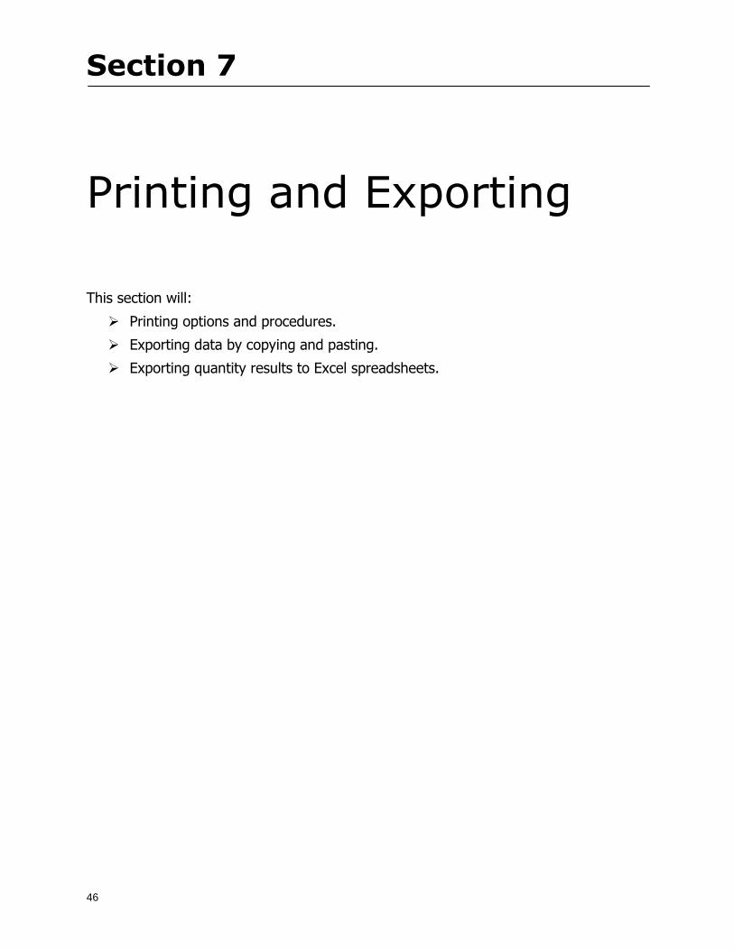
Section 7 Printing and Exporting
47
Print Setup On-Screen Takeoff allows the user to print the image takeoff list and worksheet
1 Select File gt Print Setup The Print Setup dialog will open
2 Select a printer or leave the default selection listed (change from the default printer displayed by clicking on the down arrow at the right of the field)
3 Indicate page size and printer tray option (Source) Access page size options by clicking on the
down arrow at the right of the field
4 Choose Portrait or Landscape orientation
5 Click to accept and close the dialog
Printing Images The image area can include the electronic plans the takeoff objects added text and hot links To print a subset of these (for example just the takeoffs without the plans or the added text and hot link symbols) hide layers that you do not want to print (see Section 6 View and Hide Layers) When you are printing your images every page will show the scale of the takeoff you are printing
1 Click on the Image tab to display the area of your project
2 Select File gt Print (or Ctrl + P)
Section 7 Printing and Exporting
48
3 Select the desired view (What to print) and the Image Range
4 Click The second Print dialog will open
5 Change settings accordingly or click if you accept the default settings
Printing Takeoff Lists and Worksheets In Takeoff Lists and Worksheets you may hide columns to print only certain results or adjust column widths to fit the report within the page size selected
1 In Takeoff List or Worksheet view move your cursor to the right side of the columnrsquos title bar the cursor will display as a two-way arrow
Section 7 Printing and Exporting
49
2 Click and drag to adjust the width of the column Holding the mouse button you may
slide the title bar under the title bar to its left to hide the column completely
3 Select File gt Print or press Ctrl + P to access the Print dialog
4 Indicate desired printer and choose the number of copies
5 Click to print and close the dialog
When printing the condition list we suggest printing in landscape
To reset to the default column widths double-click on the right border of a column heading will reset the column to its right (or previously to its right before being hidden)
Print Preview 1 Select File gt Print Preview
2 Use and to vary your view 3 If viewing an image choose current full or scale view to see how it displays
4 For printed outputs that cover more than one page use and to view adjacent pages or click on the down arrow next to Page field and select the page you want displayed
Exporting Using the CopyPaste Feature You may copy all the data or sections from the worksheet and the takeoff list view in On-Screen Takeoff and paste it into another application When pasting into Excel the cell layout will be maintained
1 Highlight the areas you wish to paste Click and hold the left mouse button down as you drag the cursor over the area to be selected then releasing the mouse button
OR
2 Select the entire takeoff list quickly click on the left On-Screen Takeoff column header and hold and drag the cursor across the remaining column headings
The number of pages for the view selected will display in the lower left-hand corner The zoom percentage that applies to the view will be displayed in the lower right-hand corner next to page size of the drawing
Section 7 Printing and Exporting
50
3 In the worksheet view you may highlight rows by clicking on the numbered buttons to the left of each row clicking and dragging across column headings or clicking and dragging over individual cells in the worksheet
Click anywhere in the appropriate view to deselect the area
4 Once your selection is highlighted you may select Edit gt Copy or Ctrl C from the keyboard 5 On your monitor switch to the application into which you want to paste your selection 6 Select Edit gt Paste in the new application or simply press Ctrl + V to paste
The colored keys for conditions cannot be pasted
Using the Export Feature You may export condition quantities to specified cell location within an Excel worksheet file Cell target locations are assigned in the Results tab of the condition dialogs on the Export line relating to each quantity measurement type
On-Screen Takeoff will export takeoff quantity results for up to three different quantity types that you specify For instance you may want to know the number of square feet in a ceiling area as well as the number of linear feet in its perimeter
Section 7 Printing and Exporting
51
1 Bring up the Condition dialog by double-clicking on a condition in the takeoff dock bar or by
selecting the condition and clicking
2 Click on the Results tab to access its fields The default quantities for the condition type will display
3 For each results field click on the arrow to access the pull-down menu and select the appropriate quantity (for example SF LF EA etchellip)
4 Have your Excel spreadsheet opened and saved in a file
5 Specify the Excel spreadsheet cell locations where you want the results to go
6 For a cell in the first sheet of your spreadsheet type in the cell address (eg a1) Case is not important
7 For a cell on a successive sheet of your spreadsheet type in sheet the number followed by a comma and the cell address without any spaces (eg sheet2a1) Case is not important
8 Click
9 Select File gt Export gt Condition Qty to Excel
Section 7 Printing and Exporting
52
10 Browse to the location of the Excel spreadsheet file click file to select it
11 Click to export On-Screen Takeoff results to specified cell locations in the Excel file When you return to the Excel application you will see the values have been added to the specified cell locations in your spreadsheet
12 Save your Excel file
Exporting Worksheet to Excel
1 Assign condition quantities you want to export
2 Open saved Excel spreadsheet file to which you will be exporting
3 From On-Screen Takeoff Select File gt Export gt Worksheet to Excel
4 Browse to the location of the Excel spreadsheet file click file to select it
5 Click When you return to the Excel application you will see the values from the Worksheet Tab have been added to your spreadsheet
6 Save your Excel file
Exporting Takeoff to CVS 1 Assign condition quantities you want to export
2 Open saved Excel spreadsheet file to which you will be exporting
3 Click the Takeoff Tab in the project you want to export the information
4 Select File gt Export gt Takeoff to CSV
5 Browse to the location of the CSV spreadsheet file click file to select it
6 Click the Save
NOTE CSV files can be opened in Excel Lotus Access etc One may consider this option more of a ldquodumprdquo into a file
The Excel application must be active (it may be minimized on the application bar) with the target spreadsheet open in the application Otherwise an error will occur with the export operation that will affect both the On-Screen Takeofftrade file and the Excel spreadsheet
Section 8
53
Advanced Features
This section will
Some special features of working with condition objects in the takeoff area
Details of advanced options for conditions
Advanced features of the Project Properties dialog
Section 8 Advanced Features
54
Features to Use with Objects Roping Feature You can move copy or delete using this feature Using the Select tool (the pointer) you may select several objects at once by clicking and dragging an outline around the objects then releasing the mouse button Roping may select either objects completely within the outlined area (inclusive) or objects both within and touched by the outlined area (touching) Specify your roping preference under Tools gt Options
1 Click and hold the mouse button at a point on the screen near the objects to be selected and drag to surround the objects with an outline
2 Release the mouse button The objects will be selected
3 You may now
Move the group around on the page by clicking within the group dragging the mouse and releasing the button to place the objects
Delete the group of objects by clicking the Delete key or
Copy and paste by pressing Ctrl C to copy the group then Ctrl V to paste it The pasted copy of the grouped objects will appear slightly offset from the original objects
Section 8 Advanced Features
55
Applying a DropRun Count
Use the droprun feature when calculating quantities to take into account the drop or run of a linear condition such as electrical lines or plumbing pipes Drop or run lengths may be added separately to any linear condition on screen while a default droprun length may be indicated for a condition as a whole
1 Select the desired linear condition from the Condition List in the Takeoff Dock bar
2 Click the Change button in the toolbar to open the Change Condition dialog
3 Click the Advanced tab to access the advanced options and click inside the DropRun check box
4 Enter a default length to be applied to all of this condition Entering 800 will be interpreted as 8 0 (You must enter both place markers for inches) You can leave the length blank and manually enter drop run on each segment drawn
5 Click the OK button to accept and close the dialog
Edit DropRun Count
1 With the related linear condition in the Takeoff Dock bar highlighted or with the pointer tool selected
2 click on the desired linear object in the image takeoff area The Count button will become active
3 Click on the Count button (alternatively select Tools gt Count) The default droprun amount will show in the pop-up Count dialog (Default length will be zero if droprun has not been selected in this conditionrsquos properties)
4 Type in the desired length Entering 800 will be interpreted as 8 0 (You must enter both place markers for inches)
5 Click the OK button The additional amount will be reflected in the corresponding quantity The new DropRun count will apply only to the object edited
Adding Text in Image View
On-Screen Takeoff allows you to place text comments around your quantity takeoffs that may be printed along with plan images and objects Text is automatically placed within the Annotation Layer (that includes text and hot links)
1 To place text on the image select the Text Tool and click at the point you want to place your text opening a text box
2 Type in your information clicking Enter for line breaks
3 When you are finished click the OK button to exit the text box
4 To reposition text simply click on the text (with the Text Tool active) to select it
5 Move the cursor over the text the cursor will now display as a four-way arrow
6 Click and drag the mouse to position the text as desired
Section 8 Advanced Features
56
1 To edit existing text use the Text Tool to double-click on the text to open the editing box
2 Enter additional text or use the Backspace key to delete text as necessary
Formatting Text Once created you may format the font size type style and color of your text
1 Click on the text to select it and select Tools gt Font or click on the Font button in the Takeoff Toolbar
2 Select the desired features (color options are disabled) and click the OK button
3 Click on the text to select it and select Tools gt Color or click on the Color button in the Takeoff Toolbar The Color dialog will open
4 Click on a color in the Basic Color palette or create a color and add to the Custom Colors palette (Be sure to click on the color in the Custom Colors palette to select it)
5 Click the OK button
Object Properties
Linear Objects
Linear objects may be set to connect at corners
A linear object may be set to trim automatically when crossing another linear object (Check the trim option under the advanced tab of the Condition dialog)
When you move a connected linear object objects automatically move and resize connected lines accordingly (quantities are then recalculated)
This feature requires that the connected linear object be moved using the center handles (does not apply when resizing the line from the ends)
Objects constrain to snap increments defined in the Tools gt Options menu (with the mouse 15deg by default incremental when shift key is held down)
Objects are measured from centerline to centerline
Section 8 Advanced Features
57
Area Objects When drawing an area use your escape key to undo the last line drawn You may reverse your
drawing of an area using the escape key
The area will not fill with color and pattern until the user double-clicks after the last line is set
Lines drawn to delineate an area object constrain to snap increments defined in the Tools gt Options menu (with the mouse 15deg by default incremental when shift key is held down)
After selecting an area to move or adjust position the mouse in the center to move the entire area position the mouse at the sides or corners to adjust the perimeter
Count Objects
All count objects are quantified by the physical number of objects per page and reported as EA for the UOM The quantity for the current Image View is (displayed in the Condition List) and the total quantity in your project is displayed in the Takeoff View and Worksheet View)
Square circle rectangle and triangle shaped count objects do not displace or subtract from other object quantities when placed on top of them However on the Advanced Tab for the count condition a connect property can be set (this is a check box) so that when a count object of this shape is put on top of a Linear type takeoff object it will move with the linear if said linear is moved
An opened-shaped count object must be placed within a linear object Opening shaped count objects may also be measured by linear foot or linear yard (EA SF and SY are also options) Opening shaped count items default to a width of 3rsquo 0rdquo at the time of creation This size can be changed The small medium and large size are not options on this type of condition anymore Check Backout on the Advanced tab for each Count object back out the footage (or yardage) of opening-shaped count objects in which they are placed
NOTE In order to see this Backout functionality (in quantity) for SY or SF deductions at least one of the
results for the Linear(s) this object will be placed on must be set to SY or SF and the count object must have a height quantity
Advanced Features of Conditions The Round Feature Under the Advanced tab of the linear and area Condition dialogues you may specify quantity rounding (in inches) For linear objects rounding applies to each linear object drawn For area objects rounding will apply to each segment of the area perimeter adjusting the perimeter and area calculations For example With a linear condition entering 12 in the Round field will round up each related linear object to the nearest 12 inches or one foot With this setting two walls of 1 4 would each round to 2 0 totaling 4 0
NOTE In the Takeoff Dock bar condition list and in the On-Screen Takeoff reports quantities will be displayed in whole numbers rounded up to the nearest foot However calculations are based on true quantities without rounding unless the Round Feature is engaged
Pitch Pitch may apply either to linear or area conditions It is measured in rise per linear foot Entering 12 indicates a 12 rise per 12 of linear distance (a pitch of 12 over 12) or an angle of 45deg
Section 8 Advanced Features
58
Advanced Features of Project Properties Selecting Multiple Pages
1 Select a single page entry by clicking on the numbered gray button to the left of the entry
2 Drag the cursor down the column of numbers to select consecutive pages
3 Click on the blank button at the top of this column to select all pages in the Properties dialog
Section 8 Advanced Features
59
Changing Image Assigned to a Drawing 1 Select the page entry by clicking on the numbered gray button to the left of the entry 2 Click the Change Image button The Change Image dialog box will appear
3 Navigate to the desired file and select by clicking on it
4 Click the Open button The electronic file assigned to the page will have been changed to reflect the new file choice
Changing Image File Path 1 Select pages as described above
2 Choose Change Folder
3 In the Change Folder dialog navigate to the appropriate folder
4 Click the OK button The file path will have been changed for the selected page entries
Delete a Page from Project Properties 1 Select the page you want to delete by clicking on its associated number (in the gray box at the
left of the entry)
2 Choose Delete Page
All Takeoff on the page will be deleted immediately and permanently
Section 8 Advanced Features
60
Advanced Features of Tool Options
Calculation Method On-Screen Takeoff has built-in calculation options to allow for faster work and faster saves until your takeoff is complete Calculation options are found by selecting Tools gt Options then clicking on the Calculation tab
Calculation method can be set to Automatic Automatic except Grids and Manual Manual will allow the program to operate more quickly while Automatic or Automatic except Grids allows the user to see quantity changes as takeoffs are made
In any mode you may press F9 to recalculate quantities for the On-Screen Takeoff current totals
Configuration Tab
When the ldquoPage Label (A01)rdquo radial button is chosen On-Screen Takeoff puts the numbered label on all the pages of in your current page indicator in your Navigate Toolbar If the Page Descriptionrdquo radial button is chosen then a description of what takeoff is on that specific page will be shown in your current page indicator in your Navigate Toolbar
This section of the configuration tab gives you options on how you want to export your information When the ldquoFolderSubfolder Namesrdquo radial button is chosen than on your file that you are exporting to will have all the conditions folders and subfolders In the Delimiter box you can choose the symbol that is needed to separate the information you are exporting Some files need semicolons () or colons () to make sure the information comes exported in is separated it the appropriate places
Section 8 Advanced Features
61
In previous versions of On-Screen Takeoff there are views that users need to have in order for them to display their information By either choosing ldquoOST 1xrdquo or ldquoOST 2xrdquo it will let the program know you want your columns of information exported in that specific format
When you have the Confirm Deletions radial button of ldquoYesrdquo chosen than every time you delete anything you will get a dialog box confirming your intentions of deletion
While working with your takeoff you have a choice to either view the legend of your conditions or hide it Choose whichever radial button that suits your needs
For those who prefer to use the Enter key to navigate in dialog boxes this option is just for that
Font Tab The Font tab is designed for you to make your own look and feel for the application At the bottom of this tab it will show you sample of the fonts and colors you have chosen
Renaming the Current Page You may change the name of the current page in the takeoff area of On-Screen Takeoff by selecting Edit gt Rename Page
This opens the Name Page dialog and you may simply type in a new name and click the Enter button The new name for the file will be reflected on the title bar for the page and in Project Properties
You also may access the Rename Page function by right-clicking in the takeoff area while in Image View and selecting the option from the pop-up menu that appears
Section 9
62
Saving and Exiting
This section will
Explain how to save projects
Show you how to safely exit the program
Section 9 Saving and Exiting
63
Saving Your Project
1 Select File gt Save 2 If your project has not previously been saved a Save dialog box will open to allow you to name
the file and choose the directory and folder in which to save your file 3 Once saved File gt Save will simply save the current version of the file
OR
4 Select File gt Save As then type in a new name for the file and save to the desired file path
The Auto-save Feature With the Auto-save feature On-Screen Takeoff automatically backs up your open project You may choose to have more than one level of backup files The first backup copy will have the extension b00 and successive files will be b01 b02 and so on If you have designated four levels of backup files after the fourth backup copy has been created (b03) the next file will be saved over the file with extension b00 Further backup saves will then rotate through the four backup files in the same way
1 Select Tools gt Options 2 In the Auto-save area (under the General tab) select the frequency of backup file creation (in
minutes) and the number of levels for the feature 3 You also may disengage the feature by clicking in the check box to clear it
The Auto-save feature automatically saves backup copies to the directory of the current project If you are working from a write-protected area such as a CD-ROM On-Screen Takeoff will place backup files in the On-Screen Takeoff folder
Exiting When you are finished using On-Screen Takeoff it is very easy to exit Exiting is very important because of security reasons If someone were to use your computer they could enter the application and view and manipulate information
Section 9 Saving and Exiting
64
On-Screen Takeoff closes the open project when you open another or create a new project or when you exit the program
1 Select File gt Exit
OR
2 You also may click at the upper right-hand corner of the application to exit
NOTE If your latest changes to a project file have not been saved On-Screen Takeoff will ask you whether you would like to save the file and gives you the option of canceling the operation
Appendix I Installing Your Digitizer
65
Appendix I Installing Your Digitizer When you get your digitizer from GTCO you will need to connect it to your computer Follow the instructions outlined below to do this
Note For rollup digitizers the metal bar must be oriented to the top or right hand side
Connecting the Digitizer 1 Lay the digitizer out flat 2 Connect the Stylus to the digitizer 3 Plug in the power adapter 4 Plug the interface (IO) cable into the digitizer 5 Plug the other end of the interface cable into an open serial port on computer
Note GTCO Technical support phone number is 410-381-6688 The electronic manual (on diskette) from GTCO contains more detailed installation and operation instructions for the GTCO digitizer model you have
Installing other Digitizer Drivers If you are using a GTCO Digitizer you will need to install the GTCO TabletWorks Drivers
If you are using a Digitizer not supported by GTCO Tablet Works 10 please contact the manufacturer of your digitizer for assistance with installation
Installing GTCO TabletWorks Drivers 1 Insert the On Center CD into the CD-ROM drive The CD Startup screen will open 2 Click on Install Software 3 Select Additional Software and Drivers 4 Select Digitizer Driver 5 Follow the instructions for installing TabletWorks 10
Adhering the Template The template is a small plastic sticker used to enable mouse function when using the digitizer with On-Screen Takeoff Place your template on your digitizer We suggest placing it in the bottom right corner of the digitizer about one inch inside the takeoff area
Note You may either peel off the back of the template and use the adhesive surface or you can tape the template down
Appendix I Installing Your Digitizer
66
Testing the Digitizer Drivers Before running OST you may test the digitizer by moving the stylus around on the digitizer pad it should move the mouse cursor (if mouse emulation is enabled)
If the digitizer does not move the mouse cursor on the screen
The superset codes may need to be reset Reset the superset codes by touching on the border of the digitizer with the stylus The digitizer should beep several times
The digitizer may not be communicating with the computer Be sure the COM port selected is correct Be sure the COM port selected is correct If you are not able to get the digitizer to move the mouse cursor you need to call GTCO technical support for help
Note The Mouse Emulation is not required for On-Screen Takeoff to work properly It is used only for the Template functionality if the digitizer is moving the cursor the wrong direction (up instead of sideways or vice-versa)
Click the L-shaped arrow symbol on the digitizer with the stylus
Appendix II Toolbar Item Details
67
Appendix II Toolbar Items Main Toolbar
Appendix II Toolbar Item Details
68
Tool Toolbar
Appendix II Toolbar Item Details
69
Zoom Toolbar
View Toolbar
Navigate Toolbar
Appendix II Toolbar Item Details
70
Navigate Toolbar (Continued)
Takeoff Toolbar
Appendix II Toolbar Item Details
71
Takeoff Toolbar (Continued)
Image Toolbar
Appendix III Loading Plans from a Dodge CD
72
Appendix III Loading Plans from a Dodge CD
This section will detail how to load plans from a F W Dodge CD-ROM into an On-Screen Takeoff project file ready for takeoffs
Dodge files may be added to the Project Properties dialog However loading the files in that way will load the files by number rather than name description If you want to load one page only from your Dodge CD You will have to rename the page to display the name rather than number of the file
To load plan files from a Dodge CD so that the files load sequentially by file number but are displayed by name rather than by number within your project follow the instructions below
Opening a Dodge project from a CD-ROM 1 Insert the CD into the drive 2 Choose File gt Custom 3 Choose Dodge Plans Project (plansdat) as the file type 4 Select the appropriate file type by clicking on the down arrow at the right of the Files of type
field 5 In the Look in field access your drive paths by clicking on the down arrow at the right of the
field then
Navigate to your CD-ROM drive Open the data folder and Open the Projects folder
6 Select the desired project and open its folder 7 Open the plansdat file 8 All the images will come in sequenced correctly for that job along with the full descriptions
(names) of each page If there is not a plans folder in the project folder then plans do not exist for that project on the CD Opening the plansdat file will yield an empty project
Appendix IV Using the Plan Viewer
73
Appendix IV Using On-Screen Takeoff Plan Viewer The On-Screen Takeoff Plan Viewer is a limited version of On Center Softwarersquos commercial takeoff software If your status bar located at the very bottom of the main window says View Mode in the lower left-hand corner then you are using the Plan Viewer You can use the plan viewer to
View CD-based amp converted CAD drawings
View a previously created OST file and associated drawings
Download electronic plans online
Navigate through drawings
Quickly Takeoff linearsareas and counts
Zoom in to view the plan better
Print drawings directly from the viewer
Viewing an On-Screen Takeoff Project File
1 To open an OST file that was previously created with of On-Screen Takeoff 2 Select File gt Open 3 An Open dialog will appear if you do not see the OST file you are looking for select the
Look In drop down arrow 4 A drop down menu will appear listing the various folders drives and mapped drives located
on your computer select the correct drive or folder location and continue to browse to the location of your OST file
5 When you see your OST file double-click it to open it 6 Any takeoff and drawings should appear on the Image tab view
If you do not see the drawings but do see the colored takeoff layer the drawings may
not be located in the same place they were originally saved at Go to File gt Project Properties and check the Image File path for each listed page If the image file path is pointing to a CD drive make sure the CD is inside the CR-ROM
Downloading Electronic Plans If your Online Plan Service provides a special file format (OSX) required to use this feature of our plan viewer you can immediately downloaded all electronic plans of a project directly from our viewer
Most Plan Room web sites will automatically open On-Screen Takeoff when a request to download plans is made Your particular Plan Room may differ in operation so please contact the provider directly with questions on using the site
Appendix IV Using the Plan Viewer
74
When you request to download or open a project file from a Plan Room you will usually have the open to open or save an OSX file Choosing open will automatically open On-Screen Takeoff Alternately you may choose to save the file to a local hard drive After you have saved the file either double-click it to launch On-Screen Takeoff or open the OSX file using On-Screen Takeoff by clicking File then Open and locating the file on your hard drive You will need to change the file type to OSX
After the OSX file is opened you will see an additional tab appear in the Conditions List window called Pages
The Pages tab shows the hierarchy of your project Gray file icons represent pages that have not been downloaded and blue icons represents pages that have been downloaded
To download a page simply double-click the page icon
If you wish to select a group of pages to download you can use the Ctrl or Shift key to multiple select them then click the Download button
If you wish to download all pages at once click the Download All button
Downloaded pages will now appear in the Project Properties dialog in the same order in which they appear in the Pages tab
Creating Quick Takeoffs With On-Screen Takeoff you can create quick takeoffs to measure quantities even if you dont have the full version of our program However using the Quick Takeoff functionality shows you just a fraction of what the full version can do
The Quick Takeoff Toolbar is located at the top of the image view It has three buttons designated for three types of takeoffs Linear Area and Count The Quantity drop down list will show secondary quantities for Linears and Areas The Units drop down allows you to select how you want your quantities displayed Feet Inches Yards Millimeters and Meters
NOTE Every time change the type of takeoff you are performing (switching from Area to Linear for example) the previous quantities and takeoff objects will disappear They will also disappear when you changes pages
NOTE You can use the Dimension Tool to basically measure the distance between two points or linears The distance will display on the status bar at the bottom of the application
The Quick Takeoff Toolbar
Appendix V Frequently Asked Questions
75
Appendix V Frequently Asked Questions General
Where is On-Screen Takeoff installed on my computer
Typically it is installed in CProgram FilesOn-Screen Takeoff
In Explorer how do I recognize On-Screen Takeoff file types
On-Screen Takeoff data is stored in a single file per job lsquojob name OSTrsquo On-Screen Takeoff templates are stored as lsquotemplate nameTPOrsquo
Can only one project at a time be open
Yes For that reason opening another project automatically closes the project on screen You will be asked to save any changes
Is only one scale allowed per page What about on drawings that have multiple detail sections on a page and each of those drawings have different scales
Yes For pages with drawings of different scales copy the drawing to another project page and set the appropriate scale
I cannot perform backout on an area that is along a linear
As a workaround use the On-Screen Takeoff layers feature to help you with this issue Electronic Images
How do I start a project from drawings that have been scanned and written to a CD-ROM
Open a new project Select File gt Project Properties and select Auto Add Navigate to your CD and the appropriate folder and select any image file in that location Click Open All files in the location will load into your project Recommended that images are copied from CD to hard drive for performance
If I get a disk of drawings in AutoCAD format (R13 or R14) can I read them in On-Screen Takeoff
Yes On-Screen Takeoff now reads DWG DXF and many other format that are saved with AutoCAD
Appendix V Frequently Asked Questions
76
When I click on the all pages button what is supposed to happen Currently nothing seems to change when I click on that button
The All Pages button is used to apply the Darken and Enhance Plans feature to all pages in the project (as opposed to only the current page on screen)
Is there a way to deduct a large skylight from an area condition
Yes with the related area condition selected in the Takeoff Dock bar unselect the Backout button on the Takeoff Toolbar then draw the Backout area The area quantity will be deducted from the related condition object and the linear measurement of the Backout perimeter will be added
Digitizer Issues
How do I connect a Digitizer to the computer
See Appendix I Connecting a Digitizer
The Place Template menu choice is disabled
On-Screen Takeoff may need to be authorized or the digitizer or the digitzer drivers are not installed
It wonrsquot let me select the Set Takeoff Area menu choice
On-Screen Takeoff may need to be authorized or no job is open a digitizer is not installed or the drivers are not installed
The digitizer stylus is not moving the cursor or crosshairs
Click S-0-1 superset on the digitizer
How do I convert my old GTCO Digitizer to work with On- Screen Takeofftrade
Call GTCO and they may be able to reconfigure your digitizer to be compatible with On-Screen Takeoff
Printing Issues Which Printers work with On-Screen Takeoff
Compatible printers include On-Screen Takeoff Hewlett Packard Epson and Canon printers If you are having printer difficulties please contact support and specify the type of printer along with other pertinent information Contact support at wwwoncentercomsupport or email supportoncentercom
Which Plotters work with On-Screen Takeoff
Compatible Plotters include Hewlett Packard DesignJet plotters and the EnCAD Cadjet II If you are having plotter difficulties please contact support and specify the type of plotter concerned
ViewingDisplay I can no longer see my condition list How do I get it back
The toolbars and Dock bars can be turned on and off through the View gt Toolbars menu options
Appendix V Frequently Asked Questions
77
This is also accessible by right-clicking in the toolbar area and selecting (or deselecting) a toolbar listed
I cannot view my folders in the condition list
Right-click in the Takeoff Dock barcondition list area and select Show Tree to display your folders
My Status Bar reads Viewer Mode and I am unable to draw conditions
On-Screen Takeoff needs to be Authorized Or you need to purchase an upgrade Click the Perform Advanced Takeoff button on the main toolbar
I hid a Dock bar and when I selected to view it again it appeared alongside the other Dock
bar instead of stacked on top of it How do I fix it
Pick up the Dock bar by clicking on the bar at the top and continuing to hold down the mouse button drag the Dock bar over the other one It will resize and appear stacked with the other
When I open image files from a CD the images are all upside down How do I get them right
side up
To flip pages from top to bottom follow the steps below 1 Click the All Pages button on the Image Toolbar (All Pages is engaged when the button
is not clicked) 2 Click the Flip Horizontal button on the Image Toolbar 3 Click the All Pages button again to disengage
Templates How do I create a Template
Follow the steps below 1 Create a typical project 2 Choose File gt Save As 3 Choose On-Screen Takeoff Template Files as the file type to save 4 Name the file This will save all of the condition setups as well as the layers for the
project
How do I create a new project from a template
Follow the steps below 1 Choose File gt New 2 Select a template from those listed in the New dialog This will open a new project with
conditions and layers saved from a previous project but no pages or takeoff
78
INDEX
Area Conditions 32
Area Objects 57
Auto Scrolling 20
Auto-save 63
Backout Mode 41
Calculation Method 60
Conditions 29
Configuration 60
Contents Tab 6
Continuous Mode 38
Count Conditions 33
Count Objects 57
Digitizer 10 65 76
Docking Toolbars 13
Dodge CD 72
Drawing 27 37
DropRun Count 55
Environment 18
Exiting 63
Exporting 49
Features 16
Font 61
Frequently Asked Questions 75
Grid 40
Help File 5
Hiding Toolbars 13
Hot Links 21
Image 19 59
Image files 9
Image Toolbar 12 71
Images 75
Index Tab 6
Layers 43
Linear Conditions 31
Linear Objects 56
Main Toolbar 12 67
Menus 14
Moving Toolbars 13
Navigate Toolbar 12 69
Navigating 20
On-Screen Takeofftrade 2
Page 59 61
Pages 20 25 28
Plan Viewer 73
Plans 26
Printing 47 76
Project Properties 25
Projects 22
Quick Start Video 18
Resizing Toolbars 13
Roping 54
Saving 63
Scale 28
Search Tab 7
Selecting Objects 42
Setup 8
Start On-Screen Takeofftrade 17
System Requirements 9
Takeoff 19 27
Takeoff Toolbar 70 71
Takeoff Toolbar 12
Template Files 23
TIF (Group4) 9
Tool Toolbar 12 68
Toolbar 67
Toolbars 12
View Toolbar 12 69
Viewing Toolbars 12
Worksheet 20
Zone Conditions 33
Zoom Toolbar 12 69
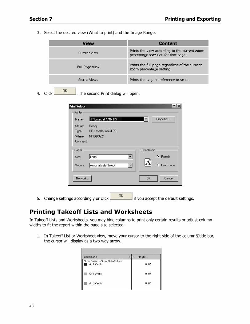
Section 7 Printing and Exporting
48
3 Select the desired view (What to print) and the Image Range
4 Click The second Print dialog will open
5 Change settings accordingly or click if you accept the default settings
Printing Takeoff Lists and Worksheets In Takeoff Lists and Worksheets you may hide columns to print only certain results or adjust column widths to fit the report within the page size selected
1 In Takeoff List or Worksheet view move your cursor to the right side of the columnrsquos title bar the cursor will display as a two-way arrow
Section 7 Printing and Exporting
49
2 Click and drag to adjust the width of the column Holding the mouse button you may
slide the title bar under the title bar to its left to hide the column completely
3 Select File gt Print or press Ctrl + P to access the Print dialog
4 Indicate desired printer and choose the number of copies
5 Click to print and close the dialog
When printing the condition list we suggest printing in landscape
To reset to the default column widths double-click on the right border of a column heading will reset the column to its right (or previously to its right before being hidden)
Print Preview 1 Select File gt Print Preview
2 Use and to vary your view 3 If viewing an image choose current full or scale view to see how it displays
4 For printed outputs that cover more than one page use and to view adjacent pages or click on the down arrow next to Page field and select the page you want displayed
Exporting Using the CopyPaste Feature You may copy all the data or sections from the worksheet and the takeoff list view in On-Screen Takeoff and paste it into another application When pasting into Excel the cell layout will be maintained
1 Highlight the areas you wish to paste Click and hold the left mouse button down as you drag the cursor over the area to be selected then releasing the mouse button
OR
2 Select the entire takeoff list quickly click on the left On-Screen Takeoff column header and hold and drag the cursor across the remaining column headings
The number of pages for the view selected will display in the lower left-hand corner The zoom percentage that applies to the view will be displayed in the lower right-hand corner next to page size of the drawing
Section 7 Printing and Exporting
50
3 In the worksheet view you may highlight rows by clicking on the numbered buttons to the left of each row clicking and dragging across column headings or clicking and dragging over individual cells in the worksheet
Click anywhere in the appropriate view to deselect the area
4 Once your selection is highlighted you may select Edit gt Copy or Ctrl C from the keyboard 5 On your monitor switch to the application into which you want to paste your selection 6 Select Edit gt Paste in the new application or simply press Ctrl + V to paste
The colored keys for conditions cannot be pasted
Using the Export Feature You may export condition quantities to specified cell location within an Excel worksheet file Cell target locations are assigned in the Results tab of the condition dialogs on the Export line relating to each quantity measurement type
On-Screen Takeoff will export takeoff quantity results for up to three different quantity types that you specify For instance you may want to know the number of square feet in a ceiling area as well as the number of linear feet in its perimeter
Section 7 Printing and Exporting
51
1 Bring up the Condition dialog by double-clicking on a condition in the takeoff dock bar or by
selecting the condition and clicking
2 Click on the Results tab to access its fields The default quantities for the condition type will display
3 For each results field click on the arrow to access the pull-down menu and select the appropriate quantity (for example SF LF EA etchellip)
4 Have your Excel spreadsheet opened and saved in a file
5 Specify the Excel spreadsheet cell locations where you want the results to go
6 For a cell in the first sheet of your spreadsheet type in the cell address (eg a1) Case is not important
7 For a cell on a successive sheet of your spreadsheet type in sheet the number followed by a comma and the cell address without any spaces (eg sheet2a1) Case is not important
8 Click
9 Select File gt Export gt Condition Qty to Excel
Section 7 Printing and Exporting
52
10 Browse to the location of the Excel spreadsheet file click file to select it
11 Click to export On-Screen Takeoff results to specified cell locations in the Excel file When you return to the Excel application you will see the values have been added to the specified cell locations in your spreadsheet
12 Save your Excel file
Exporting Worksheet to Excel
1 Assign condition quantities you want to export
2 Open saved Excel spreadsheet file to which you will be exporting
3 From On-Screen Takeoff Select File gt Export gt Worksheet to Excel
4 Browse to the location of the Excel spreadsheet file click file to select it
5 Click When you return to the Excel application you will see the values from the Worksheet Tab have been added to your spreadsheet
6 Save your Excel file
Exporting Takeoff to CVS 1 Assign condition quantities you want to export
2 Open saved Excel spreadsheet file to which you will be exporting
3 Click the Takeoff Tab in the project you want to export the information
4 Select File gt Export gt Takeoff to CSV
5 Browse to the location of the CSV spreadsheet file click file to select it
6 Click the Save
NOTE CSV files can be opened in Excel Lotus Access etc One may consider this option more of a ldquodumprdquo into a file
The Excel application must be active (it may be minimized on the application bar) with the target spreadsheet open in the application Otherwise an error will occur with the export operation that will affect both the On-Screen Takeofftrade file and the Excel spreadsheet
Section 8
53
Advanced Features
This section will
Some special features of working with condition objects in the takeoff area
Details of advanced options for conditions
Advanced features of the Project Properties dialog
Section 8 Advanced Features
54
Features to Use with Objects Roping Feature You can move copy or delete using this feature Using the Select tool (the pointer) you may select several objects at once by clicking and dragging an outline around the objects then releasing the mouse button Roping may select either objects completely within the outlined area (inclusive) or objects both within and touched by the outlined area (touching) Specify your roping preference under Tools gt Options
1 Click and hold the mouse button at a point on the screen near the objects to be selected and drag to surround the objects with an outline
2 Release the mouse button The objects will be selected
3 You may now
Move the group around on the page by clicking within the group dragging the mouse and releasing the button to place the objects
Delete the group of objects by clicking the Delete key or
Copy and paste by pressing Ctrl C to copy the group then Ctrl V to paste it The pasted copy of the grouped objects will appear slightly offset from the original objects
Section 8 Advanced Features
55
Applying a DropRun Count
Use the droprun feature when calculating quantities to take into account the drop or run of a linear condition such as electrical lines or plumbing pipes Drop or run lengths may be added separately to any linear condition on screen while a default droprun length may be indicated for a condition as a whole
1 Select the desired linear condition from the Condition List in the Takeoff Dock bar
2 Click the Change button in the toolbar to open the Change Condition dialog
3 Click the Advanced tab to access the advanced options and click inside the DropRun check box
4 Enter a default length to be applied to all of this condition Entering 800 will be interpreted as 8 0 (You must enter both place markers for inches) You can leave the length blank and manually enter drop run on each segment drawn
5 Click the OK button to accept and close the dialog
Edit DropRun Count
1 With the related linear condition in the Takeoff Dock bar highlighted or with the pointer tool selected
2 click on the desired linear object in the image takeoff area The Count button will become active
3 Click on the Count button (alternatively select Tools gt Count) The default droprun amount will show in the pop-up Count dialog (Default length will be zero if droprun has not been selected in this conditionrsquos properties)
4 Type in the desired length Entering 800 will be interpreted as 8 0 (You must enter both place markers for inches)
5 Click the OK button The additional amount will be reflected in the corresponding quantity The new DropRun count will apply only to the object edited
Adding Text in Image View
On-Screen Takeoff allows you to place text comments around your quantity takeoffs that may be printed along with plan images and objects Text is automatically placed within the Annotation Layer (that includes text and hot links)
1 To place text on the image select the Text Tool and click at the point you want to place your text opening a text box
2 Type in your information clicking Enter for line breaks
3 When you are finished click the OK button to exit the text box
4 To reposition text simply click on the text (with the Text Tool active) to select it
5 Move the cursor over the text the cursor will now display as a four-way arrow
6 Click and drag the mouse to position the text as desired
Section 8 Advanced Features
56
1 To edit existing text use the Text Tool to double-click on the text to open the editing box
2 Enter additional text or use the Backspace key to delete text as necessary
Formatting Text Once created you may format the font size type style and color of your text
1 Click on the text to select it and select Tools gt Font or click on the Font button in the Takeoff Toolbar
2 Select the desired features (color options are disabled) and click the OK button
3 Click on the text to select it and select Tools gt Color or click on the Color button in the Takeoff Toolbar The Color dialog will open
4 Click on a color in the Basic Color palette or create a color and add to the Custom Colors palette (Be sure to click on the color in the Custom Colors palette to select it)
5 Click the OK button
Object Properties
Linear Objects
Linear objects may be set to connect at corners
A linear object may be set to trim automatically when crossing another linear object (Check the trim option under the advanced tab of the Condition dialog)
When you move a connected linear object objects automatically move and resize connected lines accordingly (quantities are then recalculated)
This feature requires that the connected linear object be moved using the center handles (does not apply when resizing the line from the ends)
Objects constrain to snap increments defined in the Tools gt Options menu (with the mouse 15deg by default incremental when shift key is held down)
Objects are measured from centerline to centerline
Section 8 Advanced Features
57
Area Objects When drawing an area use your escape key to undo the last line drawn You may reverse your
drawing of an area using the escape key
The area will not fill with color and pattern until the user double-clicks after the last line is set
Lines drawn to delineate an area object constrain to snap increments defined in the Tools gt Options menu (with the mouse 15deg by default incremental when shift key is held down)
After selecting an area to move or adjust position the mouse in the center to move the entire area position the mouse at the sides or corners to adjust the perimeter
Count Objects
All count objects are quantified by the physical number of objects per page and reported as EA for the UOM The quantity for the current Image View is (displayed in the Condition List) and the total quantity in your project is displayed in the Takeoff View and Worksheet View)
Square circle rectangle and triangle shaped count objects do not displace or subtract from other object quantities when placed on top of them However on the Advanced Tab for the count condition a connect property can be set (this is a check box) so that when a count object of this shape is put on top of a Linear type takeoff object it will move with the linear if said linear is moved
An opened-shaped count object must be placed within a linear object Opening shaped count objects may also be measured by linear foot or linear yard (EA SF and SY are also options) Opening shaped count items default to a width of 3rsquo 0rdquo at the time of creation This size can be changed The small medium and large size are not options on this type of condition anymore Check Backout on the Advanced tab for each Count object back out the footage (or yardage) of opening-shaped count objects in which they are placed
NOTE In order to see this Backout functionality (in quantity) for SY or SF deductions at least one of the
results for the Linear(s) this object will be placed on must be set to SY or SF and the count object must have a height quantity
Advanced Features of Conditions The Round Feature Under the Advanced tab of the linear and area Condition dialogues you may specify quantity rounding (in inches) For linear objects rounding applies to each linear object drawn For area objects rounding will apply to each segment of the area perimeter adjusting the perimeter and area calculations For example With a linear condition entering 12 in the Round field will round up each related linear object to the nearest 12 inches or one foot With this setting two walls of 1 4 would each round to 2 0 totaling 4 0
NOTE In the Takeoff Dock bar condition list and in the On-Screen Takeoff reports quantities will be displayed in whole numbers rounded up to the nearest foot However calculations are based on true quantities without rounding unless the Round Feature is engaged
Pitch Pitch may apply either to linear or area conditions It is measured in rise per linear foot Entering 12 indicates a 12 rise per 12 of linear distance (a pitch of 12 over 12) or an angle of 45deg
Section 8 Advanced Features
58
Advanced Features of Project Properties Selecting Multiple Pages
1 Select a single page entry by clicking on the numbered gray button to the left of the entry
2 Drag the cursor down the column of numbers to select consecutive pages
3 Click on the blank button at the top of this column to select all pages in the Properties dialog
Section 8 Advanced Features
59
Changing Image Assigned to a Drawing 1 Select the page entry by clicking on the numbered gray button to the left of the entry 2 Click the Change Image button The Change Image dialog box will appear
3 Navigate to the desired file and select by clicking on it
4 Click the Open button The electronic file assigned to the page will have been changed to reflect the new file choice
Changing Image File Path 1 Select pages as described above
2 Choose Change Folder
3 In the Change Folder dialog navigate to the appropriate folder
4 Click the OK button The file path will have been changed for the selected page entries
Delete a Page from Project Properties 1 Select the page you want to delete by clicking on its associated number (in the gray box at the
left of the entry)
2 Choose Delete Page
All Takeoff on the page will be deleted immediately and permanently
Section 8 Advanced Features
60
Advanced Features of Tool Options
Calculation Method On-Screen Takeoff has built-in calculation options to allow for faster work and faster saves until your takeoff is complete Calculation options are found by selecting Tools gt Options then clicking on the Calculation tab
Calculation method can be set to Automatic Automatic except Grids and Manual Manual will allow the program to operate more quickly while Automatic or Automatic except Grids allows the user to see quantity changes as takeoffs are made
In any mode you may press F9 to recalculate quantities for the On-Screen Takeoff current totals
Configuration Tab
When the ldquoPage Label (A01)rdquo radial button is chosen On-Screen Takeoff puts the numbered label on all the pages of in your current page indicator in your Navigate Toolbar If the Page Descriptionrdquo radial button is chosen then a description of what takeoff is on that specific page will be shown in your current page indicator in your Navigate Toolbar
This section of the configuration tab gives you options on how you want to export your information When the ldquoFolderSubfolder Namesrdquo radial button is chosen than on your file that you are exporting to will have all the conditions folders and subfolders In the Delimiter box you can choose the symbol that is needed to separate the information you are exporting Some files need semicolons () or colons () to make sure the information comes exported in is separated it the appropriate places
Section 8 Advanced Features
61
In previous versions of On-Screen Takeoff there are views that users need to have in order for them to display their information By either choosing ldquoOST 1xrdquo or ldquoOST 2xrdquo it will let the program know you want your columns of information exported in that specific format
When you have the Confirm Deletions radial button of ldquoYesrdquo chosen than every time you delete anything you will get a dialog box confirming your intentions of deletion
While working with your takeoff you have a choice to either view the legend of your conditions or hide it Choose whichever radial button that suits your needs
For those who prefer to use the Enter key to navigate in dialog boxes this option is just for that
Font Tab The Font tab is designed for you to make your own look and feel for the application At the bottom of this tab it will show you sample of the fonts and colors you have chosen
Renaming the Current Page You may change the name of the current page in the takeoff area of On-Screen Takeoff by selecting Edit gt Rename Page
This opens the Name Page dialog and you may simply type in a new name and click the Enter button The new name for the file will be reflected on the title bar for the page and in Project Properties
You also may access the Rename Page function by right-clicking in the takeoff area while in Image View and selecting the option from the pop-up menu that appears
Section 9
62
Saving and Exiting
This section will
Explain how to save projects
Show you how to safely exit the program
Section 9 Saving and Exiting
63
Saving Your Project
1 Select File gt Save 2 If your project has not previously been saved a Save dialog box will open to allow you to name
the file and choose the directory and folder in which to save your file 3 Once saved File gt Save will simply save the current version of the file
OR
4 Select File gt Save As then type in a new name for the file and save to the desired file path
The Auto-save Feature With the Auto-save feature On-Screen Takeoff automatically backs up your open project You may choose to have more than one level of backup files The first backup copy will have the extension b00 and successive files will be b01 b02 and so on If you have designated four levels of backup files after the fourth backup copy has been created (b03) the next file will be saved over the file with extension b00 Further backup saves will then rotate through the four backup files in the same way
1 Select Tools gt Options 2 In the Auto-save area (under the General tab) select the frequency of backup file creation (in
minutes) and the number of levels for the feature 3 You also may disengage the feature by clicking in the check box to clear it
The Auto-save feature automatically saves backup copies to the directory of the current project If you are working from a write-protected area such as a CD-ROM On-Screen Takeoff will place backup files in the On-Screen Takeoff folder
Exiting When you are finished using On-Screen Takeoff it is very easy to exit Exiting is very important because of security reasons If someone were to use your computer they could enter the application and view and manipulate information
Section 9 Saving and Exiting
64
On-Screen Takeoff closes the open project when you open another or create a new project or when you exit the program
1 Select File gt Exit
OR
2 You also may click at the upper right-hand corner of the application to exit
NOTE If your latest changes to a project file have not been saved On-Screen Takeoff will ask you whether you would like to save the file and gives you the option of canceling the operation
Appendix I Installing Your Digitizer
65
Appendix I Installing Your Digitizer When you get your digitizer from GTCO you will need to connect it to your computer Follow the instructions outlined below to do this
Note For rollup digitizers the metal bar must be oriented to the top or right hand side
Connecting the Digitizer 1 Lay the digitizer out flat 2 Connect the Stylus to the digitizer 3 Plug in the power adapter 4 Plug the interface (IO) cable into the digitizer 5 Plug the other end of the interface cable into an open serial port on computer
Note GTCO Technical support phone number is 410-381-6688 The electronic manual (on diskette) from GTCO contains more detailed installation and operation instructions for the GTCO digitizer model you have
Installing other Digitizer Drivers If you are using a GTCO Digitizer you will need to install the GTCO TabletWorks Drivers
If you are using a Digitizer not supported by GTCO Tablet Works 10 please contact the manufacturer of your digitizer for assistance with installation
Installing GTCO TabletWorks Drivers 1 Insert the On Center CD into the CD-ROM drive The CD Startup screen will open 2 Click on Install Software 3 Select Additional Software and Drivers 4 Select Digitizer Driver 5 Follow the instructions for installing TabletWorks 10
Adhering the Template The template is a small plastic sticker used to enable mouse function when using the digitizer with On-Screen Takeoff Place your template on your digitizer We suggest placing it in the bottom right corner of the digitizer about one inch inside the takeoff area
Note You may either peel off the back of the template and use the adhesive surface or you can tape the template down
Appendix I Installing Your Digitizer
66
Testing the Digitizer Drivers Before running OST you may test the digitizer by moving the stylus around on the digitizer pad it should move the mouse cursor (if mouse emulation is enabled)
If the digitizer does not move the mouse cursor on the screen
The superset codes may need to be reset Reset the superset codes by touching on the border of the digitizer with the stylus The digitizer should beep several times
The digitizer may not be communicating with the computer Be sure the COM port selected is correct Be sure the COM port selected is correct If you are not able to get the digitizer to move the mouse cursor you need to call GTCO technical support for help
Note The Mouse Emulation is not required for On-Screen Takeoff to work properly It is used only for the Template functionality if the digitizer is moving the cursor the wrong direction (up instead of sideways or vice-versa)
Click the L-shaped arrow symbol on the digitizer with the stylus
Appendix II Toolbar Item Details
67
Appendix II Toolbar Items Main Toolbar
Appendix II Toolbar Item Details
68
Tool Toolbar
Appendix II Toolbar Item Details
69
Zoom Toolbar
View Toolbar
Navigate Toolbar
Appendix II Toolbar Item Details
70
Navigate Toolbar (Continued)
Takeoff Toolbar
Appendix II Toolbar Item Details
71
Takeoff Toolbar (Continued)
Image Toolbar
Appendix III Loading Plans from a Dodge CD
72
Appendix III Loading Plans from a Dodge CD
This section will detail how to load plans from a F W Dodge CD-ROM into an On-Screen Takeoff project file ready for takeoffs
Dodge files may be added to the Project Properties dialog However loading the files in that way will load the files by number rather than name description If you want to load one page only from your Dodge CD You will have to rename the page to display the name rather than number of the file
To load plan files from a Dodge CD so that the files load sequentially by file number but are displayed by name rather than by number within your project follow the instructions below
Opening a Dodge project from a CD-ROM 1 Insert the CD into the drive 2 Choose File gt Custom 3 Choose Dodge Plans Project (plansdat) as the file type 4 Select the appropriate file type by clicking on the down arrow at the right of the Files of type
field 5 In the Look in field access your drive paths by clicking on the down arrow at the right of the
field then
Navigate to your CD-ROM drive Open the data folder and Open the Projects folder
6 Select the desired project and open its folder 7 Open the plansdat file 8 All the images will come in sequenced correctly for that job along with the full descriptions
(names) of each page If there is not a plans folder in the project folder then plans do not exist for that project on the CD Opening the plansdat file will yield an empty project
Appendix IV Using the Plan Viewer
73
Appendix IV Using On-Screen Takeoff Plan Viewer The On-Screen Takeoff Plan Viewer is a limited version of On Center Softwarersquos commercial takeoff software If your status bar located at the very bottom of the main window says View Mode in the lower left-hand corner then you are using the Plan Viewer You can use the plan viewer to
View CD-based amp converted CAD drawings
View a previously created OST file and associated drawings
Download electronic plans online
Navigate through drawings
Quickly Takeoff linearsareas and counts
Zoom in to view the plan better
Print drawings directly from the viewer
Viewing an On-Screen Takeoff Project File
1 To open an OST file that was previously created with of On-Screen Takeoff 2 Select File gt Open 3 An Open dialog will appear if you do not see the OST file you are looking for select the
Look In drop down arrow 4 A drop down menu will appear listing the various folders drives and mapped drives located
on your computer select the correct drive or folder location and continue to browse to the location of your OST file
5 When you see your OST file double-click it to open it 6 Any takeoff and drawings should appear on the Image tab view
If you do not see the drawings but do see the colored takeoff layer the drawings may
not be located in the same place they were originally saved at Go to File gt Project Properties and check the Image File path for each listed page If the image file path is pointing to a CD drive make sure the CD is inside the CR-ROM
Downloading Electronic Plans If your Online Plan Service provides a special file format (OSX) required to use this feature of our plan viewer you can immediately downloaded all electronic plans of a project directly from our viewer
Most Plan Room web sites will automatically open On-Screen Takeoff when a request to download plans is made Your particular Plan Room may differ in operation so please contact the provider directly with questions on using the site
Appendix IV Using the Plan Viewer
74
When you request to download or open a project file from a Plan Room you will usually have the open to open or save an OSX file Choosing open will automatically open On-Screen Takeoff Alternately you may choose to save the file to a local hard drive After you have saved the file either double-click it to launch On-Screen Takeoff or open the OSX file using On-Screen Takeoff by clicking File then Open and locating the file on your hard drive You will need to change the file type to OSX
After the OSX file is opened you will see an additional tab appear in the Conditions List window called Pages
The Pages tab shows the hierarchy of your project Gray file icons represent pages that have not been downloaded and blue icons represents pages that have been downloaded
To download a page simply double-click the page icon
If you wish to select a group of pages to download you can use the Ctrl or Shift key to multiple select them then click the Download button
If you wish to download all pages at once click the Download All button
Downloaded pages will now appear in the Project Properties dialog in the same order in which they appear in the Pages tab
Creating Quick Takeoffs With On-Screen Takeoff you can create quick takeoffs to measure quantities even if you dont have the full version of our program However using the Quick Takeoff functionality shows you just a fraction of what the full version can do
The Quick Takeoff Toolbar is located at the top of the image view It has three buttons designated for three types of takeoffs Linear Area and Count The Quantity drop down list will show secondary quantities for Linears and Areas The Units drop down allows you to select how you want your quantities displayed Feet Inches Yards Millimeters and Meters
NOTE Every time change the type of takeoff you are performing (switching from Area to Linear for example) the previous quantities and takeoff objects will disappear They will also disappear when you changes pages
NOTE You can use the Dimension Tool to basically measure the distance between two points or linears The distance will display on the status bar at the bottom of the application
The Quick Takeoff Toolbar
Appendix V Frequently Asked Questions
75
Appendix V Frequently Asked Questions General
Where is On-Screen Takeoff installed on my computer
Typically it is installed in CProgram FilesOn-Screen Takeoff
In Explorer how do I recognize On-Screen Takeoff file types
On-Screen Takeoff data is stored in a single file per job lsquojob name OSTrsquo On-Screen Takeoff templates are stored as lsquotemplate nameTPOrsquo
Can only one project at a time be open
Yes For that reason opening another project automatically closes the project on screen You will be asked to save any changes
Is only one scale allowed per page What about on drawings that have multiple detail sections on a page and each of those drawings have different scales
Yes For pages with drawings of different scales copy the drawing to another project page and set the appropriate scale
I cannot perform backout on an area that is along a linear
As a workaround use the On-Screen Takeoff layers feature to help you with this issue Electronic Images
How do I start a project from drawings that have been scanned and written to a CD-ROM
Open a new project Select File gt Project Properties and select Auto Add Navigate to your CD and the appropriate folder and select any image file in that location Click Open All files in the location will load into your project Recommended that images are copied from CD to hard drive for performance
If I get a disk of drawings in AutoCAD format (R13 or R14) can I read them in On-Screen Takeoff
Yes On-Screen Takeoff now reads DWG DXF and many other format that are saved with AutoCAD
Appendix V Frequently Asked Questions
76
When I click on the all pages button what is supposed to happen Currently nothing seems to change when I click on that button
The All Pages button is used to apply the Darken and Enhance Plans feature to all pages in the project (as opposed to only the current page on screen)
Is there a way to deduct a large skylight from an area condition
Yes with the related area condition selected in the Takeoff Dock bar unselect the Backout button on the Takeoff Toolbar then draw the Backout area The area quantity will be deducted from the related condition object and the linear measurement of the Backout perimeter will be added
Digitizer Issues
How do I connect a Digitizer to the computer
See Appendix I Connecting a Digitizer
The Place Template menu choice is disabled
On-Screen Takeoff may need to be authorized or the digitizer or the digitzer drivers are not installed
It wonrsquot let me select the Set Takeoff Area menu choice
On-Screen Takeoff may need to be authorized or no job is open a digitizer is not installed or the drivers are not installed
The digitizer stylus is not moving the cursor or crosshairs
Click S-0-1 superset on the digitizer
How do I convert my old GTCO Digitizer to work with On- Screen Takeofftrade
Call GTCO and they may be able to reconfigure your digitizer to be compatible with On-Screen Takeoff
Printing Issues Which Printers work with On-Screen Takeoff
Compatible printers include On-Screen Takeoff Hewlett Packard Epson and Canon printers If you are having printer difficulties please contact support and specify the type of printer along with other pertinent information Contact support at wwwoncentercomsupport or email supportoncentercom
Which Plotters work with On-Screen Takeoff
Compatible Plotters include Hewlett Packard DesignJet plotters and the EnCAD Cadjet II If you are having plotter difficulties please contact support and specify the type of plotter concerned
ViewingDisplay I can no longer see my condition list How do I get it back
The toolbars and Dock bars can be turned on and off through the View gt Toolbars menu options
Appendix V Frequently Asked Questions
77
This is also accessible by right-clicking in the toolbar area and selecting (or deselecting) a toolbar listed
I cannot view my folders in the condition list
Right-click in the Takeoff Dock barcondition list area and select Show Tree to display your folders
My Status Bar reads Viewer Mode and I am unable to draw conditions
On-Screen Takeoff needs to be Authorized Or you need to purchase an upgrade Click the Perform Advanced Takeoff button on the main toolbar
I hid a Dock bar and when I selected to view it again it appeared alongside the other Dock
bar instead of stacked on top of it How do I fix it
Pick up the Dock bar by clicking on the bar at the top and continuing to hold down the mouse button drag the Dock bar over the other one It will resize and appear stacked with the other
When I open image files from a CD the images are all upside down How do I get them right
side up
To flip pages from top to bottom follow the steps below 1 Click the All Pages button on the Image Toolbar (All Pages is engaged when the button
is not clicked) 2 Click the Flip Horizontal button on the Image Toolbar 3 Click the All Pages button again to disengage
Templates How do I create a Template
Follow the steps below 1 Create a typical project 2 Choose File gt Save As 3 Choose On-Screen Takeoff Template Files as the file type to save 4 Name the file This will save all of the condition setups as well as the layers for the
project
How do I create a new project from a template
Follow the steps below 1 Choose File gt New 2 Select a template from those listed in the New dialog This will open a new project with
conditions and layers saved from a previous project but no pages or takeoff
78
INDEX
Area Conditions 32
Area Objects 57
Auto Scrolling 20
Auto-save 63
Backout Mode 41
Calculation Method 60
Conditions 29
Configuration 60
Contents Tab 6
Continuous Mode 38
Count Conditions 33
Count Objects 57
Digitizer 10 65 76
Docking Toolbars 13
Dodge CD 72
Drawing 27 37
DropRun Count 55
Environment 18
Exiting 63
Exporting 49
Features 16
Font 61
Frequently Asked Questions 75
Grid 40
Help File 5
Hiding Toolbars 13
Hot Links 21
Image 19 59
Image files 9
Image Toolbar 12 71
Images 75
Index Tab 6
Layers 43
Linear Conditions 31
Linear Objects 56
Main Toolbar 12 67
Menus 14
Moving Toolbars 13
Navigate Toolbar 12 69
Navigating 20
On-Screen Takeofftrade 2
Page 59 61
Pages 20 25 28
Plan Viewer 73
Plans 26
Printing 47 76
Project Properties 25
Projects 22
Quick Start Video 18
Resizing Toolbars 13
Roping 54
Saving 63
Scale 28
Search Tab 7
Selecting Objects 42
Setup 8
Start On-Screen Takeofftrade 17
System Requirements 9
Takeoff 19 27
Takeoff Toolbar 70 71
Takeoff Toolbar 12
Template Files 23
TIF (Group4) 9
Tool Toolbar 12 68
Toolbar 67
Toolbars 12
View Toolbar 12 69
Viewing Toolbars 12
Worksheet 20
Zone Conditions 33
Zoom Toolbar 12 69
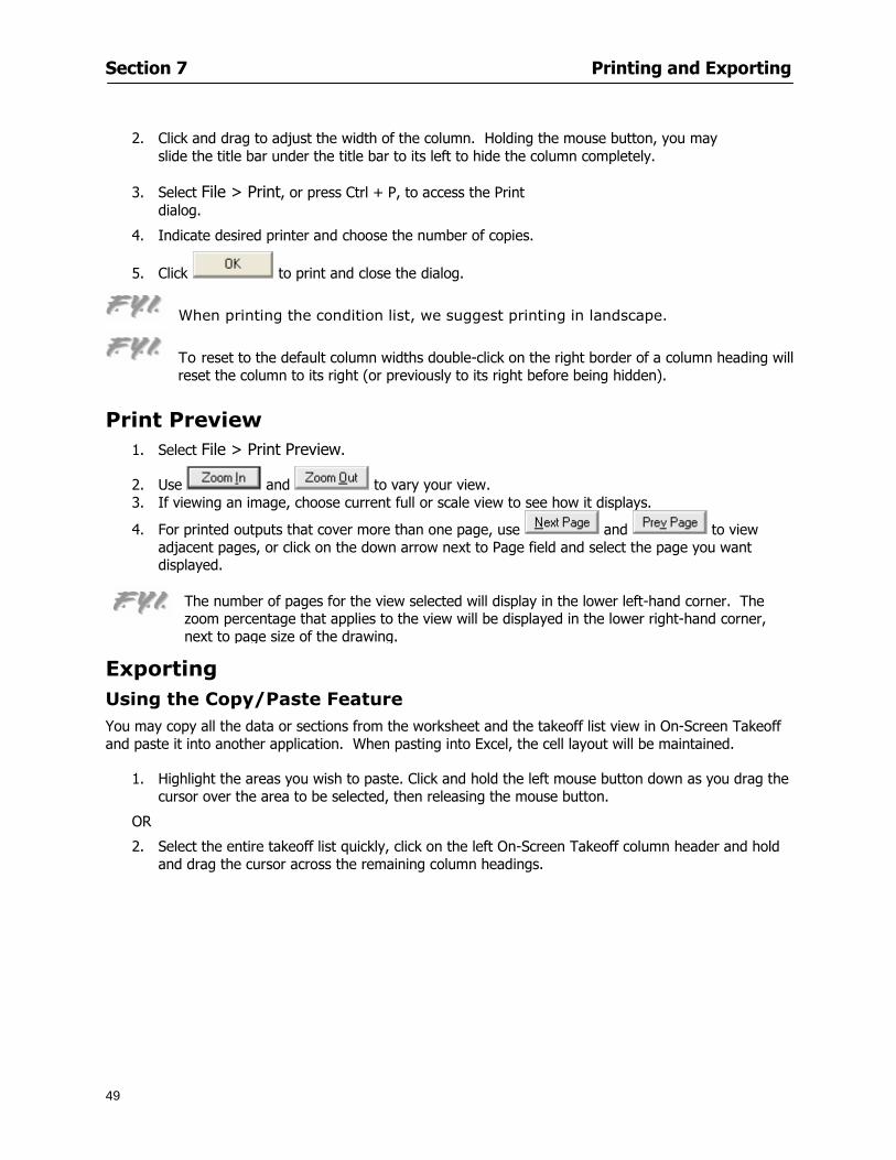
Section 7 Printing and Exporting
49
2 Click and drag to adjust the width of the column Holding the mouse button you may
slide the title bar under the title bar to its left to hide the column completely
3 Select File gt Print or press Ctrl + P to access the Print dialog
4 Indicate desired printer and choose the number of copies
5 Click to print and close the dialog
When printing the condition list we suggest printing in landscape
To reset to the default column widths double-click on the right border of a column heading will reset the column to its right (or previously to its right before being hidden)
Print Preview 1 Select File gt Print Preview
2 Use and to vary your view 3 If viewing an image choose current full or scale view to see how it displays
4 For printed outputs that cover more than one page use and to view adjacent pages or click on the down arrow next to Page field and select the page you want displayed
Exporting Using the CopyPaste Feature You may copy all the data or sections from the worksheet and the takeoff list view in On-Screen Takeoff and paste it into another application When pasting into Excel the cell layout will be maintained
1 Highlight the areas you wish to paste Click and hold the left mouse button down as you drag the cursor over the area to be selected then releasing the mouse button
OR
2 Select the entire takeoff list quickly click on the left On-Screen Takeoff column header and hold and drag the cursor across the remaining column headings
The number of pages for the view selected will display in the lower left-hand corner The zoom percentage that applies to the view will be displayed in the lower right-hand corner next to page size of the drawing
Section 7 Printing and Exporting
50
3 In the worksheet view you may highlight rows by clicking on the numbered buttons to the left of each row clicking and dragging across column headings or clicking and dragging over individual cells in the worksheet
Click anywhere in the appropriate view to deselect the area
4 Once your selection is highlighted you may select Edit gt Copy or Ctrl C from the keyboard 5 On your monitor switch to the application into which you want to paste your selection 6 Select Edit gt Paste in the new application or simply press Ctrl + V to paste
The colored keys for conditions cannot be pasted
Using the Export Feature You may export condition quantities to specified cell location within an Excel worksheet file Cell target locations are assigned in the Results tab of the condition dialogs on the Export line relating to each quantity measurement type
On-Screen Takeoff will export takeoff quantity results for up to three different quantity types that you specify For instance you may want to know the number of square feet in a ceiling area as well as the number of linear feet in its perimeter
Section 7 Printing and Exporting
51
1 Bring up the Condition dialog by double-clicking on a condition in the takeoff dock bar or by
selecting the condition and clicking
2 Click on the Results tab to access its fields The default quantities for the condition type will display
3 For each results field click on the arrow to access the pull-down menu and select the appropriate quantity (for example SF LF EA etchellip)
4 Have your Excel spreadsheet opened and saved in a file
5 Specify the Excel spreadsheet cell locations where you want the results to go
6 For a cell in the first sheet of your spreadsheet type in the cell address (eg a1) Case is not important
7 For a cell on a successive sheet of your spreadsheet type in sheet the number followed by a comma and the cell address without any spaces (eg sheet2a1) Case is not important
8 Click
9 Select File gt Export gt Condition Qty to Excel
Section 7 Printing and Exporting
52
10 Browse to the location of the Excel spreadsheet file click file to select it
11 Click to export On-Screen Takeoff results to specified cell locations in the Excel file When you return to the Excel application you will see the values have been added to the specified cell locations in your spreadsheet
12 Save your Excel file
Exporting Worksheet to Excel
1 Assign condition quantities you want to export
2 Open saved Excel spreadsheet file to which you will be exporting
3 From On-Screen Takeoff Select File gt Export gt Worksheet to Excel
4 Browse to the location of the Excel spreadsheet file click file to select it
5 Click When you return to the Excel application you will see the values from the Worksheet Tab have been added to your spreadsheet
6 Save your Excel file
Exporting Takeoff to CVS 1 Assign condition quantities you want to export
2 Open saved Excel spreadsheet file to which you will be exporting
3 Click the Takeoff Tab in the project you want to export the information
4 Select File gt Export gt Takeoff to CSV
5 Browse to the location of the CSV spreadsheet file click file to select it
6 Click the Save
NOTE CSV files can be opened in Excel Lotus Access etc One may consider this option more of a ldquodumprdquo into a file
The Excel application must be active (it may be minimized on the application bar) with the target spreadsheet open in the application Otherwise an error will occur with the export operation that will affect both the On-Screen Takeofftrade file and the Excel spreadsheet
Section 8
53
Advanced Features
This section will
Some special features of working with condition objects in the takeoff area
Details of advanced options for conditions
Advanced features of the Project Properties dialog
Section 8 Advanced Features
54
Features to Use with Objects Roping Feature You can move copy or delete using this feature Using the Select tool (the pointer) you may select several objects at once by clicking and dragging an outline around the objects then releasing the mouse button Roping may select either objects completely within the outlined area (inclusive) or objects both within and touched by the outlined area (touching) Specify your roping preference under Tools gt Options
1 Click and hold the mouse button at a point on the screen near the objects to be selected and drag to surround the objects with an outline
2 Release the mouse button The objects will be selected
3 You may now
Move the group around on the page by clicking within the group dragging the mouse and releasing the button to place the objects
Delete the group of objects by clicking the Delete key or
Copy and paste by pressing Ctrl C to copy the group then Ctrl V to paste it The pasted copy of the grouped objects will appear slightly offset from the original objects
Section 8 Advanced Features
55
Applying a DropRun Count
Use the droprun feature when calculating quantities to take into account the drop or run of a linear condition such as electrical lines or plumbing pipes Drop or run lengths may be added separately to any linear condition on screen while a default droprun length may be indicated for a condition as a whole
1 Select the desired linear condition from the Condition List in the Takeoff Dock bar
2 Click the Change button in the toolbar to open the Change Condition dialog
3 Click the Advanced tab to access the advanced options and click inside the DropRun check box
4 Enter a default length to be applied to all of this condition Entering 800 will be interpreted as 8 0 (You must enter both place markers for inches) You can leave the length blank and manually enter drop run on each segment drawn
5 Click the OK button to accept and close the dialog
Edit DropRun Count
1 With the related linear condition in the Takeoff Dock bar highlighted or with the pointer tool selected
2 click on the desired linear object in the image takeoff area The Count button will become active
3 Click on the Count button (alternatively select Tools gt Count) The default droprun amount will show in the pop-up Count dialog (Default length will be zero if droprun has not been selected in this conditionrsquos properties)
4 Type in the desired length Entering 800 will be interpreted as 8 0 (You must enter both place markers for inches)
5 Click the OK button The additional amount will be reflected in the corresponding quantity The new DropRun count will apply only to the object edited
Adding Text in Image View
On-Screen Takeoff allows you to place text comments around your quantity takeoffs that may be printed along with plan images and objects Text is automatically placed within the Annotation Layer (that includes text and hot links)
1 To place text on the image select the Text Tool and click at the point you want to place your text opening a text box
2 Type in your information clicking Enter for line breaks
3 When you are finished click the OK button to exit the text box
4 To reposition text simply click on the text (with the Text Tool active) to select it
5 Move the cursor over the text the cursor will now display as a four-way arrow
6 Click and drag the mouse to position the text as desired
Section 8 Advanced Features
56
1 To edit existing text use the Text Tool to double-click on the text to open the editing box
2 Enter additional text or use the Backspace key to delete text as necessary
Formatting Text Once created you may format the font size type style and color of your text
1 Click on the text to select it and select Tools gt Font or click on the Font button in the Takeoff Toolbar
2 Select the desired features (color options are disabled) and click the OK button
3 Click on the text to select it and select Tools gt Color or click on the Color button in the Takeoff Toolbar The Color dialog will open
4 Click on a color in the Basic Color palette or create a color and add to the Custom Colors palette (Be sure to click on the color in the Custom Colors palette to select it)
5 Click the OK button
Object Properties
Linear Objects
Linear objects may be set to connect at corners
A linear object may be set to trim automatically when crossing another linear object (Check the trim option under the advanced tab of the Condition dialog)
When you move a connected linear object objects automatically move and resize connected lines accordingly (quantities are then recalculated)
This feature requires that the connected linear object be moved using the center handles (does not apply when resizing the line from the ends)
Objects constrain to snap increments defined in the Tools gt Options menu (with the mouse 15deg by default incremental when shift key is held down)
Objects are measured from centerline to centerline
Section 8 Advanced Features
57
Area Objects When drawing an area use your escape key to undo the last line drawn You may reverse your
drawing of an area using the escape key
The area will not fill with color and pattern until the user double-clicks after the last line is set
Lines drawn to delineate an area object constrain to snap increments defined in the Tools gt Options menu (with the mouse 15deg by default incremental when shift key is held down)
After selecting an area to move or adjust position the mouse in the center to move the entire area position the mouse at the sides or corners to adjust the perimeter
Count Objects
All count objects are quantified by the physical number of objects per page and reported as EA for the UOM The quantity for the current Image View is (displayed in the Condition List) and the total quantity in your project is displayed in the Takeoff View and Worksheet View)
Square circle rectangle and triangle shaped count objects do not displace or subtract from other object quantities when placed on top of them However on the Advanced Tab for the count condition a connect property can be set (this is a check box) so that when a count object of this shape is put on top of a Linear type takeoff object it will move with the linear if said linear is moved
An opened-shaped count object must be placed within a linear object Opening shaped count objects may also be measured by linear foot or linear yard (EA SF and SY are also options) Opening shaped count items default to a width of 3rsquo 0rdquo at the time of creation This size can be changed The small medium and large size are not options on this type of condition anymore Check Backout on the Advanced tab for each Count object back out the footage (or yardage) of opening-shaped count objects in which they are placed
NOTE In order to see this Backout functionality (in quantity) for SY or SF deductions at least one of the
results for the Linear(s) this object will be placed on must be set to SY or SF and the count object must have a height quantity
Advanced Features of Conditions The Round Feature Under the Advanced tab of the linear and area Condition dialogues you may specify quantity rounding (in inches) For linear objects rounding applies to each linear object drawn For area objects rounding will apply to each segment of the area perimeter adjusting the perimeter and area calculations For example With a linear condition entering 12 in the Round field will round up each related linear object to the nearest 12 inches or one foot With this setting two walls of 1 4 would each round to 2 0 totaling 4 0
NOTE In the Takeoff Dock bar condition list and in the On-Screen Takeoff reports quantities will be displayed in whole numbers rounded up to the nearest foot However calculations are based on true quantities without rounding unless the Round Feature is engaged
Pitch Pitch may apply either to linear or area conditions It is measured in rise per linear foot Entering 12 indicates a 12 rise per 12 of linear distance (a pitch of 12 over 12) or an angle of 45deg
Section 8 Advanced Features
58
Advanced Features of Project Properties Selecting Multiple Pages
1 Select a single page entry by clicking on the numbered gray button to the left of the entry
2 Drag the cursor down the column of numbers to select consecutive pages
3 Click on the blank button at the top of this column to select all pages in the Properties dialog
Section 8 Advanced Features
59
Changing Image Assigned to a Drawing 1 Select the page entry by clicking on the numbered gray button to the left of the entry 2 Click the Change Image button The Change Image dialog box will appear
3 Navigate to the desired file and select by clicking on it
4 Click the Open button The electronic file assigned to the page will have been changed to reflect the new file choice
Changing Image File Path 1 Select pages as described above
2 Choose Change Folder
3 In the Change Folder dialog navigate to the appropriate folder
4 Click the OK button The file path will have been changed for the selected page entries
Delete a Page from Project Properties 1 Select the page you want to delete by clicking on its associated number (in the gray box at the
left of the entry)
2 Choose Delete Page
All Takeoff on the page will be deleted immediately and permanently
Section 8 Advanced Features
60
Advanced Features of Tool Options
Calculation Method On-Screen Takeoff has built-in calculation options to allow for faster work and faster saves until your takeoff is complete Calculation options are found by selecting Tools gt Options then clicking on the Calculation tab
Calculation method can be set to Automatic Automatic except Grids and Manual Manual will allow the program to operate more quickly while Automatic or Automatic except Grids allows the user to see quantity changes as takeoffs are made
In any mode you may press F9 to recalculate quantities for the On-Screen Takeoff current totals
Configuration Tab
When the ldquoPage Label (A01)rdquo radial button is chosen On-Screen Takeoff puts the numbered label on all the pages of in your current page indicator in your Navigate Toolbar If the Page Descriptionrdquo radial button is chosen then a description of what takeoff is on that specific page will be shown in your current page indicator in your Navigate Toolbar
This section of the configuration tab gives you options on how you want to export your information When the ldquoFolderSubfolder Namesrdquo radial button is chosen than on your file that you are exporting to will have all the conditions folders and subfolders In the Delimiter box you can choose the symbol that is needed to separate the information you are exporting Some files need semicolons () or colons () to make sure the information comes exported in is separated it the appropriate places
Section 8 Advanced Features
61
In previous versions of On-Screen Takeoff there are views that users need to have in order for them to display their information By either choosing ldquoOST 1xrdquo or ldquoOST 2xrdquo it will let the program know you want your columns of information exported in that specific format
When you have the Confirm Deletions radial button of ldquoYesrdquo chosen than every time you delete anything you will get a dialog box confirming your intentions of deletion
While working with your takeoff you have a choice to either view the legend of your conditions or hide it Choose whichever radial button that suits your needs
For those who prefer to use the Enter key to navigate in dialog boxes this option is just for that
Font Tab The Font tab is designed for you to make your own look and feel for the application At the bottom of this tab it will show you sample of the fonts and colors you have chosen
Renaming the Current Page You may change the name of the current page in the takeoff area of On-Screen Takeoff by selecting Edit gt Rename Page
This opens the Name Page dialog and you may simply type in a new name and click the Enter button The new name for the file will be reflected on the title bar for the page and in Project Properties
You also may access the Rename Page function by right-clicking in the takeoff area while in Image View and selecting the option from the pop-up menu that appears
Section 9
62
Saving and Exiting
This section will
Explain how to save projects
Show you how to safely exit the program
Section 9 Saving and Exiting
63
Saving Your Project
1 Select File gt Save 2 If your project has not previously been saved a Save dialog box will open to allow you to name
the file and choose the directory and folder in which to save your file 3 Once saved File gt Save will simply save the current version of the file
OR
4 Select File gt Save As then type in a new name for the file and save to the desired file path
The Auto-save Feature With the Auto-save feature On-Screen Takeoff automatically backs up your open project You may choose to have more than one level of backup files The first backup copy will have the extension b00 and successive files will be b01 b02 and so on If you have designated four levels of backup files after the fourth backup copy has been created (b03) the next file will be saved over the file with extension b00 Further backup saves will then rotate through the four backup files in the same way
1 Select Tools gt Options 2 In the Auto-save area (under the General tab) select the frequency of backup file creation (in
minutes) and the number of levels for the feature 3 You also may disengage the feature by clicking in the check box to clear it
The Auto-save feature automatically saves backup copies to the directory of the current project If you are working from a write-protected area such as a CD-ROM On-Screen Takeoff will place backup files in the On-Screen Takeoff folder
Exiting When you are finished using On-Screen Takeoff it is very easy to exit Exiting is very important because of security reasons If someone were to use your computer they could enter the application and view and manipulate information
Section 9 Saving and Exiting
64
On-Screen Takeoff closes the open project when you open another or create a new project or when you exit the program
1 Select File gt Exit
OR
2 You also may click at the upper right-hand corner of the application to exit
NOTE If your latest changes to a project file have not been saved On-Screen Takeoff will ask you whether you would like to save the file and gives you the option of canceling the operation
Appendix I Installing Your Digitizer
65
Appendix I Installing Your Digitizer When you get your digitizer from GTCO you will need to connect it to your computer Follow the instructions outlined below to do this
Note For rollup digitizers the metal bar must be oriented to the top or right hand side
Connecting the Digitizer 1 Lay the digitizer out flat 2 Connect the Stylus to the digitizer 3 Plug in the power adapter 4 Plug the interface (IO) cable into the digitizer 5 Plug the other end of the interface cable into an open serial port on computer
Note GTCO Technical support phone number is 410-381-6688 The electronic manual (on diskette) from GTCO contains more detailed installation and operation instructions for the GTCO digitizer model you have
Installing other Digitizer Drivers If you are using a GTCO Digitizer you will need to install the GTCO TabletWorks Drivers
If you are using a Digitizer not supported by GTCO Tablet Works 10 please contact the manufacturer of your digitizer for assistance with installation
Installing GTCO TabletWorks Drivers 1 Insert the On Center CD into the CD-ROM drive The CD Startup screen will open 2 Click on Install Software 3 Select Additional Software and Drivers 4 Select Digitizer Driver 5 Follow the instructions for installing TabletWorks 10
Adhering the Template The template is a small plastic sticker used to enable mouse function when using the digitizer with On-Screen Takeoff Place your template on your digitizer We suggest placing it in the bottom right corner of the digitizer about one inch inside the takeoff area
Note You may either peel off the back of the template and use the adhesive surface or you can tape the template down
Appendix I Installing Your Digitizer
66
Testing the Digitizer Drivers Before running OST you may test the digitizer by moving the stylus around on the digitizer pad it should move the mouse cursor (if mouse emulation is enabled)
If the digitizer does not move the mouse cursor on the screen
The superset codes may need to be reset Reset the superset codes by touching on the border of the digitizer with the stylus The digitizer should beep several times
The digitizer may not be communicating with the computer Be sure the COM port selected is correct Be sure the COM port selected is correct If you are not able to get the digitizer to move the mouse cursor you need to call GTCO technical support for help
Note The Mouse Emulation is not required for On-Screen Takeoff to work properly It is used only for the Template functionality if the digitizer is moving the cursor the wrong direction (up instead of sideways or vice-versa)
Click the L-shaped arrow symbol on the digitizer with the stylus
Appendix II Toolbar Item Details
67
Appendix II Toolbar Items Main Toolbar
Appendix II Toolbar Item Details
68
Tool Toolbar
Appendix II Toolbar Item Details
69
Zoom Toolbar
View Toolbar
Navigate Toolbar
Appendix II Toolbar Item Details
70
Navigate Toolbar (Continued)
Takeoff Toolbar
Appendix II Toolbar Item Details
71
Takeoff Toolbar (Continued)
Image Toolbar
Appendix III Loading Plans from a Dodge CD
72
Appendix III Loading Plans from a Dodge CD
This section will detail how to load plans from a F W Dodge CD-ROM into an On-Screen Takeoff project file ready for takeoffs
Dodge files may be added to the Project Properties dialog However loading the files in that way will load the files by number rather than name description If you want to load one page only from your Dodge CD You will have to rename the page to display the name rather than number of the file
To load plan files from a Dodge CD so that the files load sequentially by file number but are displayed by name rather than by number within your project follow the instructions below
Opening a Dodge project from a CD-ROM 1 Insert the CD into the drive 2 Choose File gt Custom 3 Choose Dodge Plans Project (plansdat) as the file type 4 Select the appropriate file type by clicking on the down arrow at the right of the Files of type
field 5 In the Look in field access your drive paths by clicking on the down arrow at the right of the
field then
Navigate to your CD-ROM drive Open the data folder and Open the Projects folder
6 Select the desired project and open its folder 7 Open the plansdat file 8 All the images will come in sequenced correctly for that job along with the full descriptions
(names) of each page If there is not a plans folder in the project folder then plans do not exist for that project on the CD Opening the plansdat file will yield an empty project
Appendix IV Using the Plan Viewer
73
Appendix IV Using On-Screen Takeoff Plan Viewer The On-Screen Takeoff Plan Viewer is a limited version of On Center Softwarersquos commercial takeoff software If your status bar located at the very bottom of the main window says View Mode in the lower left-hand corner then you are using the Plan Viewer You can use the plan viewer to
View CD-based amp converted CAD drawings
View a previously created OST file and associated drawings
Download electronic plans online
Navigate through drawings
Quickly Takeoff linearsareas and counts
Zoom in to view the plan better
Print drawings directly from the viewer
Viewing an On-Screen Takeoff Project File
1 To open an OST file that was previously created with of On-Screen Takeoff 2 Select File gt Open 3 An Open dialog will appear if you do not see the OST file you are looking for select the
Look In drop down arrow 4 A drop down menu will appear listing the various folders drives and mapped drives located
on your computer select the correct drive or folder location and continue to browse to the location of your OST file
5 When you see your OST file double-click it to open it 6 Any takeoff and drawings should appear on the Image tab view
If you do not see the drawings but do see the colored takeoff layer the drawings may
not be located in the same place they were originally saved at Go to File gt Project Properties and check the Image File path for each listed page If the image file path is pointing to a CD drive make sure the CD is inside the CR-ROM
Downloading Electronic Plans If your Online Plan Service provides a special file format (OSX) required to use this feature of our plan viewer you can immediately downloaded all electronic plans of a project directly from our viewer
Most Plan Room web sites will automatically open On-Screen Takeoff when a request to download plans is made Your particular Plan Room may differ in operation so please contact the provider directly with questions on using the site
Appendix IV Using the Plan Viewer
74
When you request to download or open a project file from a Plan Room you will usually have the open to open or save an OSX file Choosing open will automatically open On-Screen Takeoff Alternately you may choose to save the file to a local hard drive After you have saved the file either double-click it to launch On-Screen Takeoff or open the OSX file using On-Screen Takeoff by clicking File then Open and locating the file on your hard drive You will need to change the file type to OSX
After the OSX file is opened you will see an additional tab appear in the Conditions List window called Pages
The Pages tab shows the hierarchy of your project Gray file icons represent pages that have not been downloaded and blue icons represents pages that have been downloaded
To download a page simply double-click the page icon
If you wish to select a group of pages to download you can use the Ctrl or Shift key to multiple select them then click the Download button
If you wish to download all pages at once click the Download All button
Downloaded pages will now appear in the Project Properties dialog in the same order in which they appear in the Pages tab
Creating Quick Takeoffs With On-Screen Takeoff you can create quick takeoffs to measure quantities even if you dont have the full version of our program However using the Quick Takeoff functionality shows you just a fraction of what the full version can do
The Quick Takeoff Toolbar is located at the top of the image view It has three buttons designated for three types of takeoffs Linear Area and Count The Quantity drop down list will show secondary quantities for Linears and Areas The Units drop down allows you to select how you want your quantities displayed Feet Inches Yards Millimeters and Meters
NOTE Every time change the type of takeoff you are performing (switching from Area to Linear for example) the previous quantities and takeoff objects will disappear They will also disappear when you changes pages
NOTE You can use the Dimension Tool to basically measure the distance between two points or linears The distance will display on the status bar at the bottom of the application
The Quick Takeoff Toolbar
Appendix V Frequently Asked Questions
75
Appendix V Frequently Asked Questions General
Where is On-Screen Takeoff installed on my computer
Typically it is installed in CProgram FilesOn-Screen Takeoff
In Explorer how do I recognize On-Screen Takeoff file types
On-Screen Takeoff data is stored in a single file per job lsquojob name OSTrsquo On-Screen Takeoff templates are stored as lsquotemplate nameTPOrsquo
Can only one project at a time be open
Yes For that reason opening another project automatically closes the project on screen You will be asked to save any changes
Is only one scale allowed per page What about on drawings that have multiple detail sections on a page and each of those drawings have different scales
Yes For pages with drawings of different scales copy the drawing to another project page and set the appropriate scale
I cannot perform backout on an area that is along a linear
As a workaround use the On-Screen Takeoff layers feature to help you with this issue Electronic Images
How do I start a project from drawings that have been scanned and written to a CD-ROM
Open a new project Select File gt Project Properties and select Auto Add Navigate to your CD and the appropriate folder and select any image file in that location Click Open All files in the location will load into your project Recommended that images are copied from CD to hard drive for performance
If I get a disk of drawings in AutoCAD format (R13 or R14) can I read them in On-Screen Takeoff
Yes On-Screen Takeoff now reads DWG DXF and many other format that are saved with AutoCAD
Appendix V Frequently Asked Questions
76
When I click on the all pages button what is supposed to happen Currently nothing seems to change when I click on that button
The All Pages button is used to apply the Darken and Enhance Plans feature to all pages in the project (as opposed to only the current page on screen)
Is there a way to deduct a large skylight from an area condition
Yes with the related area condition selected in the Takeoff Dock bar unselect the Backout button on the Takeoff Toolbar then draw the Backout area The area quantity will be deducted from the related condition object and the linear measurement of the Backout perimeter will be added
Digitizer Issues
How do I connect a Digitizer to the computer
See Appendix I Connecting a Digitizer
The Place Template menu choice is disabled
On-Screen Takeoff may need to be authorized or the digitizer or the digitzer drivers are not installed
It wonrsquot let me select the Set Takeoff Area menu choice
On-Screen Takeoff may need to be authorized or no job is open a digitizer is not installed or the drivers are not installed
The digitizer stylus is not moving the cursor or crosshairs
Click S-0-1 superset on the digitizer
How do I convert my old GTCO Digitizer to work with On- Screen Takeofftrade
Call GTCO and they may be able to reconfigure your digitizer to be compatible with On-Screen Takeoff
Printing Issues Which Printers work with On-Screen Takeoff
Compatible printers include On-Screen Takeoff Hewlett Packard Epson and Canon printers If you are having printer difficulties please contact support and specify the type of printer along with other pertinent information Contact support at wwwoncentercomsupport or email supportoncentercom
Which Plotters work with On-Screen Takeoff
Compatible Plotters include Hewlett Packard DesignJet plotters and the EnCAD Cadjet II If you are having plotter difficulties please contact support and specify the type of plotter concerned
ViewingDisplay I can no longer see my condition list How do I get it back
The toolbars and Dock bars can be turned on and off through the View gt Toolbars menu options
Appendix V Frequently Asked Questions
77
This is also accessible by right-clicking in the toolbar area and selecting (or deselecting) a toolbar listed
I cannot view my folders in the condition list
Right-click in the Takeoff Dock barcondition list area and select Show Tree to display your folders
My Status Bar reads Viewer Mode and I am unable to draw conditions
On-Screen Takeoff needs to be Authorized Or you need to purchase an upgrade Click the Perform Advanced Takeoff button on the main toolbar
I hid a Dock bar and when I selected to view it again it appeared alongside the other Dock
bar instead of stacked on top of it How do I fix it
Pick up the Dock bar by clicking on the bar at the top and continuing to hold down the mouse button drag the Dock bar over the other one It will resize and appear stacked with the other
When I open image files from a CD the images are all upside down How do I get them right
side up
To flip pages from top to bottom follow the steps below 1 Click the All Pages button on the Image Toolbar (All Pages is engaged when the button
is not clicked) 2 Click the Flip Horizontal button on the Image Toolbar 3 Click the All Pages button again to disengage
Templates How do I create a Template
Follow the steps below 1 Create a typical project 2 Choose File gt Save As 3 Choose On-Screen Takeoff Template Files as the file type to save 4 Name the file This will save all of the condition setups as well as the layers for the
project
How do I create a new project from a template
Follow the steps below 1 Choose File gt New 2 Select a template from those listed in the New dialog This will open a new project with
conditions and layers saved from a previous project but no pages or takeoff
78
INDEX
Area Conditions 32
Area Objects 57
Auto Scrolling 20
Auto-save 63
Backout Mode 41
Calculation Method 60
Conditions 29
Configuration 60
Contents Tab 6
Continuous Mode 38
Count Conditions 33
Count Objects 57
Digitizer 10 65 76
Docking Toolbars 13
Dodge CD 72
Drawing 27 37
DropRun Count 55
Environment 18
Exiting 63
Exporting 49
Features 16
Font 61
Frequently Asked Questions 75
Grid 40
Help File 5
Hiding Toolbars 13
Hot Links 21
Image 19 59
Image files 9
Image Toolbar 12 71
Images 75
Index Tab 6
Layers 43
Linear Conditions 31
Linear Objects 56
Main Toolbar 12 67
Menus 14
Moving Toolbars 13
Navigate Toolbar 12 69
Navigating 20
On-Screen Takeofftrade 2
Page 59 61
Pages 20 25 28
Plan Viewer 73
Plans 26
Printing 47 76
Project Properties 25
Projects 22
Quick Start Video 18
Resizing Toolbars 13
Roping 54
Saving 63
Scale 28
Search Tab 7
Selecting Objects 42
Setup 8
Start On-Screen Takeofftrade 17
System Requirements 9
Takeoff 19 27
Takeoff Toolbar 70 71
Takeoff Toolbar 12
Template Files 23
TIF (Group4) 9
Tool Toolbar 12 68
Toolbar 67
Toolbars 12
View Toolbar 12 69
Viewing Toolbars 12
Worksheet 20
Zone Conditions 33
Zoom Toolbar 12 69
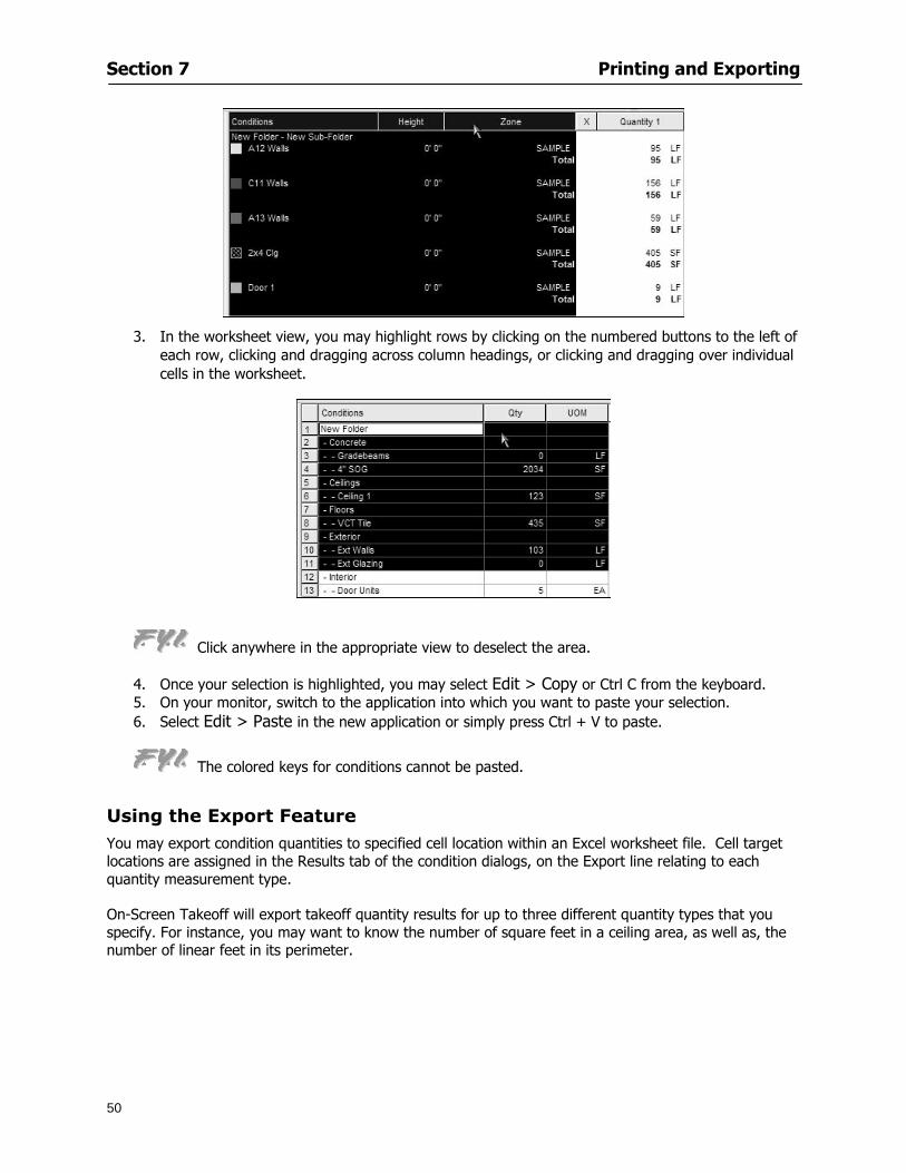
Section 7 Printing and Exporting
50
3 In the worksheet view you may highlight rows by clicking on the numbered buttons to the left of each row clicking and dragging across column headings or clicking and dragging over individual cells in the worksheet
Click anywhere in the appropriate view to deselect the area
4 Once your selection is highlighted you may select Edit gt Copy or Ctrl C from the keyboard 5 On your monitor switch to the application into which you want to paste your selection 6 Select Edit gt Paste in the new application or simply press Ctrl + V to paste
The colored keys for conditions cannot be pasted
Using the Export Feature You may export condition quantities to specified cell location within an Excel worksheet file Cell target locations are assigned in the Results tab of the condition dialogs on the Export line relating to each quantity measurement type
On-Screen Takeoff will export takeoff quantity results for up to three different quantity types that you specify For instance you may want to know the number of square feet in a ceiling area as well as the number of linear feet in its perimeter
Section 7 Printing and Exporting
51
1 Bring up the Condition dialog by double-clicking on a condition in the takeoff dock bar or by
selecting the condition and clicking
2 Click on the Results tab to access its fields The default quantities for the condition type will display
3 For each results field click on the arrow to access the pull-down menu and select the appropriate quantity (for example SF LF EA etchellip)
4 Have your Excel spreadsheet opened and saved in a file
5 Specify the Excel spreadsheet cell locations where you want the results to go
6 For a cell in the first sheet of your spreadsheet type in the cell address (eg a1) Case is not important
7 For a cell on a successive sheet of your spreadsheet type in sheet the number followed by a comma and the cell address without any spaces (eg sheet2a1) Case is not important
8 Click
9 Select File gt Export gt Condition Qty to Excel
Section 7 Printing and Exporting
52
10 Browse to the location of the Excel spreadsheet file click file to select it
11 Click to export On-Screen Takeoff results to specified cell locations in the Excel file When you return to the Excel application you will see the values have been added to the specified cell locations in your spreadsheet
12 Save your Excel file
Exporting Worksheet to Excel
1 Assign condition quantities you want to export
2 Open saved Excel spreadsheet file to which you will be exporting
3 From On-Screen Takeoff Select File gt Export gt Worksheet to Excel
4 Browse to the location of the Excel spreadsheet file click file to select it
5 Click When you return to the Excel application you will see the values from the Worksheet Tab have been added to your spreadsheet
6 Save your Excel file
Exporting Takeoff to CVS 1 Assign condition quantities you want to export
2 Open saved Excel spreadsheet file to which you will be exporting
3 Click the Takeoff Tab in the project you want to export the information
4 Select File gt Export gt Takeoff to CSV
5 Browse to the location of the CSV spreadsheet file click file to select it
6 Click the Save
NOTE CSV files can be opened in Excel Lotus Access etc One may consider this option more of a ldquodumprdquo into a file
The Excel application must be active (it may be minimized on the application bar) with the target spreadsheet open in the application Otherwise an error will occur with the export operation that will affect both the On-Screen Takeofftrade file and the Excel spreadsheet
Section 8
53
Advanced Features
This section will
Some special features of working with condition objects in the takeoff area
Details of advanced options for conditions
Advanced features of the Project Properties dialog
Section 8 Advanced Features
54
Features to Use with Objects Roping Feature You can move copy or delete using this feature Using the Select tool (the pointer) you may select several objects at once by clicking and dragging an outline around the objects then releasing the mouse button Roping may select either objects completely within the outlined area (inclusive) or objects both within and touched by the outlined area (touching) Specify your roping preference under Tools gt Options
1 Click and hold the mouse button at a point on the screen near the objects to be selected and drag to surround the objects with an outline
2 Release the mouse button The objects will be selected
3 You may now
Move the group around on the page by clicking within the group dragging the mouse and releasing the button to place the objects
Delete the group of objects by clicking the Delete key or
Copy and paste by pressing Ctrl C to copy the group then Ctrl V to paste it The pasted copy of the grouped objects will appear slightly offset from the original objects
Section 8 Advanced Features
55
Applying a DropRun Count
Use the droprun feature when calculating quantities to take into account the drop or run of a linear condition such as electrical lines or plumbing pipes Drop or run lengths may be added separately to any linear condition on screen while a default droprun length may be indicated for a condition as a whole
1 Select the desired linear condition from the Condition List in the Takeoff Dock bar
2 Click the Change button in the toolbar to open the Change Condition dialog
3 Click the Advanced tab to access the advanced options and click inside the DropRun check box
4 Enter a default length to be applied to all of this condition Entering 800 will be interpreted as 8 0 (You must enter both place markers for inches) You can leave the length blank and manually enter drop run on each segment drawn
5 Click the OK button to accept and close the dialog
Edit DropRun Count
1 With the related linear condition in the Takeoff Dock bar highlighted or with the pointer tool selected
2 click on the desired linear object in the image takeoff area The Count button will become active
3 Click on the Count button (alternatively select Tools gt Count) The default droprun amount will show in the pop-up Count dialog (Default length will be zero if droprun has not been selected in this conditionrsquos properties)
4 Type in the desired length Entering 800 will be interpreted as 8 0 (You must enter both place markers for inches)
5 Click the OK button The additional amount will be reflected in the corresponding quantity The new DropRun count will apply only to the object edited
Adding Text in Image View
On-Screen Takeoff allows you to place text comments around your quantity takeoffs that may be printed along with plan images and objects Text is automatically placed within the Annotation Layer (that includes text and hot links)
1 To place text on the image select the Text Tool and click at the point you want to place your text opening a text box
2 Type in your information clicking Enter for line breaks
3 When you are finished click the OK button to exit the text box
4 To reposition text simply click on the text (with the Text Tool active) to select it
5 Move the cursor over the text the cursor will now display as a four-way arrow
6 Click and drag the mouse to position the text as desired
Section 8 Advanced Features
56
1 To edit existing text use the Text Tool to double-click on the text to open the editing box
2 Enter additional text or use the Backspace key to delete text as necessary
Formatting Text Once created you may format the font size type style and color of your text
1 Click on the text to select it and select Tools gt Font or click on the Font button in the Takeoff Toolbar
2 Select the desired features (color options are disabled) and click the OK button
3 Click on the text to select it and select Tools gt Color or click on the Color button in the Takeoff Toolbar The Color dialog will open
4 Click on a color in the Basic Color palette or create a color and add to the Custom Colors palette (Be sure to click on the color in the Custom Colors palette to select it)
5 Click the OK button
Object Properties
Linear Objects
Linear objects may be set to connect at corners
A linear object may be set to trim automatically when crossing another linear object (Check the trim option under the advanced tab of the Condition dialog)
When you move a connected linear object objects automatically move and resize connected lines accordingly (quantities are then recalculated)
This feature requires that the connected linear object be moved using the center handles (does not apply when resizing the line from the ends)
Objects constrain to snap increments defined in the Tools gt Options menu (with the mouse 15deg by default incremental when shift key is held down)
Objects are measured from centerline to centerline
Section 8 Advanced Features
57
Area Objects When drawing an area use your escape key to undo the last line drawn You may reverse your
drawing of an area using the escape key
The area will not fill with color and pattern until the user double-clicks after the last line is set
Lines drawn to delineate an area object constrain to snap increments defined in the Tools gt Options menu (with the mouse 15deg by default incremental when shift key is held down)
After selecting an area to move or adjust position the mouse in the center to move the entire area position the mouse at the sides or corners to adjust the perimeter
Count Objects
All count objects are quantified by the physical number of objects per page and reported as EA for the UOM The quantity for the current Image View is (displayed in the Condition List) and the total quantity in your project is displayed in the Takeoff View and Worksheet View)
Square circle rectangle and triangle shaped count objects do not displace or subtract from other object quantities when placed on top of them However on the Advanced Tab for the count condition a connect property can be set (this is a check box) so that when a count object of this shape is put on top of a Linear type takeoff object it will move with the linear if said linear is moved
An opened-shaped count object must be placed within a linear object Opening shaped count objects may also be measured by linear foot or linear yard (EA SF and SY are also options) Opening shaped count items default to a width of 3rsquo 0rdquo at the time of creation This size can be changed The small medium and large size are not options on this type of condition anymore Check Backout on the Advanced tab for each Count object back out the footage (or yardage) of opening-shaped count objects in which they are placed
NOTE In order to see this Backout functionality (in quantity) for SY or SF deductions at least one of the
results for the Linear(s) this object will be placed on must be set to SY or SF and the count object must have a height quantity
Advanced Features of Conditions The Round Feature Under the Advanced tab of the linear and area Condition dialogues you may specify quantity rounding (in inches) For linear objects rounding applies to each linear object drawn For area objects rounding will apply to each segment of the area perimeter adjusting the perimeter and area calculations For example With a linear condition entering 12 in the Round field will round up each related linear object to the nearest 12 inches or one foot With this setting two walls of 1 4 would each round to 2 0 totaling 4 0
NOTE In the Takeoff Dock bar condition list and in the On-Screen Takeoff reports quantities will be displayed in whole numbers rounded up to the nearest foot However calculations are based on true quantities without rounding unless the Round Feature is engaged
Pitch Pitch may apply either to linear or area conditions It is measured in rise per linear foot Entering 12 indicates a 12 rise per 12 of linear distance (a pitch of 12 over 12) or an angle of 45deg
Section 8 Advanced Features
58
Advanced Features of Project Properties Selecting Multiple Pages
1 Select a single page entry by clicking on the numbered gray button to the left of the entry
2 Drag the cursor down the column of numbers to select consecutive pages
3 Click on the blank button at the top of this column to select all pages in the Properties dialog
Section 8 Advanced Features
59
Changing Image Assigned to a Drawing 1 Select the page entry by clicking on the numbered gray button to the left of the entry 2 Click the Change Image button The Change Image dialog box will appear
3 Navigate to the desired file and select by clicking on it
4 Click the Open button The electronic file assigned to the page will have been changed to reflect the new file choice
Changing Image File Path 1 Select pages as described above
2 Choose Change Folder
3 In the Change Folder dialog navigate to the appropriate folder
4 Click the OK button The file path will have been changed for the selected page entries
Delete a Page from Project Properties 1 Select the page you want to delete by clicking on its associated number (in the gray box at the
left of the entry)
2 Choose Delete Page
All Takeoff on the page will be deleted immediately and permanently
Section 8 Advanced Features
60
Advanced Features of Tool Options
Calculation Method On-Screen Takeoff has built-in calculation options to allow for faster work and faster saves until your takeoff is complete Calculation options are found by selecting Tools gt Options then clicking on the Calculation tab
Calculation method can be set to Automatic Automatic except Grids and Manual Manual will allow the program to operate more quickly while Automatic or Automatic except Grids allows the user to see quantity changes as takeoffs are made
In any mode you may press F9 to recalculate quantities for the On-Screen Takeoff current totals
Configuration Tab
When the ldquoPage Label (A01)rdquo radial button is chosen On-Screen Takeoff puts the numbered label on all the pages of in your current page indicator in your Navigate Toolbar If the Page Descriptionrdquo radial button is chosen then a description of what takeoff is on that specific page will be shown in your current page indicator in your Navigate Toolbar
This section of the configuration tab gives you options on how you want to export your information When the ldquoFolderSubfolder Namesrdquo radial button is chosen than on your file that you are exporting to will have all the conditions folders and subfolders In the Delimiter box you can choose the symbol that is needed to separate the information you are exporting Some files need semicolons () or colons () to make sure the information comes exported in is separated it the appropriate places
Section 8 Advanced Features
61
In previous versions of On-Screen Takeoff there are views that users need to have in order for them to display their information By either choosing ldquoOST 1xrdquo or ldquoOST 2xrdquo it will let the program know you want your columns of information exported in that specific format
When you have the Confirm Deletions radial button of ldquoYesrdquo chosen than every time you delete anything you will get a dialog box confirming your intentions of deletion
While working with your takeoff you have a choice to either view the legend of your conditions or hide it Choose whichever radial button that suits your needs
For those who prefer to use the Enter key to navigate in dialog boxes this option is just for that
Font Tab The Font tab is designed for you to make your own look and feel for the application At the bottom of this tab it will show you sample of the fonts and colors you have chosen
Renaming the Current Page You may change the name of the current page in the takeoff area of On-Screen Takeoff by selecting Edit gt Rename Page
This opens the Name Page dialog and you may simply type in a new name and click the Enter button The new name for the file will be reflected on the title bar for the page and in Project Properties
You also may access the Rename Page function by right-clicking in the takeoff area while in Image View and selecting the option from the pop-up menu that appears
Section 9
62
Saving and Exiting
This section will
Explain how to save projects
Show you how to safely exit the program
Section 9 Saving and Exiting
63
Saving Your Project
1 Select File gt Save 2 If your project has not previously been saved a Save dialog box will open to allow you to name
the file and choose the directory and folder in which to save your file 3 Once saved File gt Save will simply save the current version of the file
OR
4 Select File gt Save As then type in a new name for the file and save to the desired file path
The Auto-save Feature With the Auto-save feature On-Screen Takeoff automatically backs up your open project You may choose to have more than one level of backup files The first backup copy will have the extension b00 and successive files will be b01 b02 and so on If you have designated four levels of backup files after the fourth backup copy has been created (b03) the next file will be saved over the file with extension b00 Further backup saves will then rotate through the four backup files in the same way
1 Select Tools gt Options 2 In the Auto-save area (under the General tab) select the frequency of backup file creation (in
minutes) and the number of levels for the feature 3 You also may disengage the feature by clicking in the check box to clear it
The Auto-save feature automatically saves backup copies to the directory of the current project If you are working from a write-protected area such as a CD-ROM On-Screen Takeoff will place backup files in the On-Screen Takeoff folder
Exiting When you are finished using On-Screen Takeoff it is very easy to exit Exiting is very important because of security reasons If someone were to use your computer they could enter the application and view and manipulate information
Section 9 Saving and Exiting
64
On-Screen Takeoff closes the open project when you open another or create a new project or when you exit the program
1 Select File gt Exit
OR
2 You also may click at the upper right-hand corner of the application to exit
NOTE If your latest changes to a project file have not been saved On-Screen Takeoff will ask you whether you would like to save the file and gives you the option of canceling the operation
Appendix I Installing Your Digitizer
65
Appendix I Installing Your Digitizer When you get your digitizer from GTCO you will need to connect it to your computer Follow the instructions outlined below to do this
Note For rollup digitizers the metal bar must be oriented to the top or right hand side
Connecting the Digitizer 1 Lay the digitizer out flat 2 Connect the Stylus to the digitizer 3 Plug in the power adapter 4 Plug the interface (IO) cable into the digitizer 5 Plug the other end of the interface cable into an open serial port on computer
Note GTCO Technical support phone number is 410-381-6688 The electronic manual (on diskette) from GTCO contains more detailed installation and operation instructions for the GTCO digitizer model you have
Installing other Digitizer Drivers If you are using a GTCO Digitizer you will need to install the GTCO TabletWorks Drivers
If you are using a Digitizer not supported by GTCO Tablet Works 10 please contact the manufacturer of your digitizer for assistance with installation
Installing GTCO TabletWorks Drivers 1 Insert the On Center CD into the CD-ROM drive The CD Startup screen will open 2 Click on Install Software 3 Select Additional Software and Drivers 4 Select Digitizer Driver 5 Follow the instructions for installing TabletWorks 10
Adhering the Template The template is a small plastic sticker used to enable mouse function when using the digitizer with On-Screen Takeoff Place your template on your digitizer We suggest placing it in the bottom right corner of the digitizer about one inch inside the takeoff area
Note You may either peel off the back of the template and use the adhesive surface or you can tape the template down
Appendix I Installing Your Digitizer
66
Testing the Digitizer Drivers Before running OST you may test the digitizer by moving the stylus around on the digitizer pad it should move the mouse cursor (if mouse emulation is enabled)
If the digitizer does not move the mouse cursor on the screen
The superset codes may need to be reset Reset the superset codes by touching on the border of the digitizer with the stylus The digitizer should beep several times
The digitizer may not be communicating with the computer Be sure the COM port selected is correct Be sure the COM port selected is correct If you are not able to get the digitizer to move the mouse cursor you need to call GTCO technical support for help
Note The Mouse Emulation is not required for On-Screen Takeoff to work properly It is used only for the Template functionality if the digitizer is moving the cursor the wrong direction (up instead of sideways or vice-versa)
Click the L-shaped arrow symbol on the digitizer with the stylus
Appendix II Toolbar Item Details
67
Appendix II Toolbar Items Main Toolbar
Appendix II Toolbar Item Details
68
Tool Toolbar
Appendix II Toolbar Item Details
69
Zoom Toolbar
View Toolbar
Navigate Toolbar
Appendix II Toolbar Item Details
70
Navigate Toolbar (Continued)
Takeoff Toolbar
Appendix II Toolbar Item Details
71
Takeoff Toolbar (Continued)
Image Toolbar
Appendix III Loading Plans from a Dodge CD
72
Appendix III Loading Plans from a Dodge CD
This section will detail how to load plans from a F W Dodge CD-ROM into an On-Screen Takeoff project file ready for takeoffs
Dodge files may be added to the Project Properties dialog However loading the files in that way will load the files by number rather than name description If you want to load one page only from your Dodge CD You will have to rename the page to display the name rather than number of the file
To load plan files from a Dodge CD so that the files load sequentially by file number but are displayed by name rather than by number within your project follow the instructions below
Opening a Dodge project from a CD-ROM 1 Insert the CD into the drive 2 Choose File gt Custom 3 Choose Dodge Plans Project (plansdat) as the file type 4 Select the appropriate file type by clicking on the down arrow at the right of the Files of type
field 5 In the Look in field access your drive paths by clicking on the down arrow at the right of the
field then
Navigate to your CD-ROM drive Open the data folder and Open the Projects folder
6 Select the desired project and open its folder 7 Open the plansdat file 8 All the images will come in sequenced correctly for that job along with the full descriptions
(names) of each page If there is not a plans folder in the project folder then plans do not exist for that project on the CD Opening the plansdat file will yield an empty project
Appendix IV Using the Plan Viewer
73
Appendix IV Using On-Screen Takeoff Plan Viewer The On-Screen Takeoff Plan Viewer is a limited version of On Center Softwarersquos commercial takeoff software If your status bar located at the very bottom of the main window says View Mode in the lower left-hand corner then you are using the Plan Viewer You can use the plan viewer to
View CD-based amp converted CAD drawings
View a previously created OST file and associated drawings
Download electronic plans online
Navigate through drawings
Quickly Takeoff linearsareas and counts
Zoom in to view the plan better
Print drawings directly from the viewer
Viewing an On-Screen Takeoff Project File
1 To open an OST file that was previously created with of On-Screen Takeoff 2 Select File gt Open 3 An Open dialog will appear if you do not see the OST file you are looking for select the
Look In drop down arrow 4 A drop down menu will appear listing the various folders drives and mapped drives located
on your computer select the correct drive or folder location and continue to browse to the location of your OST file
5 When you see your OST file double-click it to open it 6 Any takeoff and drawings should appear on the Image tab view
If you do not see the drawings but do see the colored takeoff layer the drawings may
not be located in the same place they were originally saved at Go to File gt Project Properties and check the Image File path for each listed page If the image file path is pointing to a CD drive make sure the CD is inside the CR-ROM
Downloading Electronic Plans If your Online Plan Service provides a special file format (OSX) required to use this feature of our plan viewer you can immediately downloaded all electronic plans of a project directly from our viewer
Most Plan Room web sites will automatically open On-Screen Takeoff when a request to download plans is made Your particular Plan Room may differ in operation so please contact the provider directly with questions on using the site
Appendix IV Using the Plan Viewer
74
When you request to download or open a project file from a Plan Room you will usually have the open to open or save an OSX file Choosing open will automatically open On-Screen Takeoff Alternately you may choose to save the file to a local hard drive After you have saved the file either double-click it to launch On-Screen Takeoff or open the OSX file using On-Screen Takeoff by clicking File then Open and locating the file on your hard drive You will need to change the file type to OSX
After the OSX file is opened you will see an additional tab appear in the Conditions List window called Pages
The Pages tab shows the hierarchy of your project Gray file icons represent pages that have not been downloaded and blue icons represents pages that have been downloaded
To download a page simply double-click the page icon
If you wish to select a group of pages to download you can use the Ctrl or Shift key to multiple select them then click the Download button
If you wish to download all pages at once click the Download All button
Downloaded pages will now appear in the Project Properties dialog in the same order in which they appear in the Pages tab
Creating Quick Takeoffs With On-Screen Takeoff you can create quick takeoffs to measure quantities even if you dont have the full version of our program However using the Quick Takeoff functionality shows you just a fraction of what the full version can do
The Quick Takeoff Toolbar is located at the top of the image view It has three buttons designated for three types of takeoffs Linear Area and Count The Quantity drop down list will show secondary quantities for Linears and Areas The Units drop down allows you to select how you want your quantities displayed Feet Inches Yards Millimeters and Meters
NOTE Every time change the type of takeoff you are performing (switching from Area to Linear for example) the previous quantities and takeoff objects will disappear They will also disappear when you changes pages
NOTE You can use the Dimension Tool to basically measure the distance between two points or linears The distance will display on the status bar at the bottom of the application
The Quick Takeoff Toolbar
Appendix V Frequently Asked Questions
75
Appendix V Frequently Asked Questions General
Where is On-Screen Takeoff installed on my computer
Typically it is installed in CProgram FilesOn-Screen Takeoff
In Explorer how do I recognize On-Screen Takeoff file types
On-Screen Takeoff data is stored in a single file per job lsquojob name OSTrsquo On-Screen Takeoff templates are stored as lsquotemplate nameTPOrsquo
Can only one project at a time be open
Yes For that reason opening another project automatically closes the project on screen You will be asked to save any changes
Is only one scale allowed per page What about on drawings that have multiple detail sections on a page and each of those drawings have different scales
Yes For pages with drawings of different scales copy the drawing to another project page and set the appropriate scale
I cannot perform backout on an area that is along a linear
As a workaround use the On-Screen Takeoff layers feature to help you with this issue Electronic Images
How do I start a project from drawings that have been scanned and written to a CD-ROM
Open a new project Select File gt Project Properties and select Auto Add Navigate to your CD and the appropriate folder and select any image file in that location Click Open All files in the location will load into your project Recommended that images are copied from CD to hard drive for performance
If I get a disk of drawings in AutoCAD format (R13 or R14) can I read them in On-Screen Takeoff
Yes On-Screen Takeoff now reads DWG DXF and many other format that are saved with AutoCAD
Appendix V Frequently Asked Questions
76
When I click on the all pages button what is supposed to happen Currently nothing seems to change when I click on that button
The All Pages button is used to apply the Darken and Enhance Plans feature to all pages in the project (as opposed to only the current page on screen)
Is there a way to deduct a large skylight from an area condition
Yes with the related area condition selected in the Takeoff Dock bar unselect the Backout button on the Takeoff Toolbar then draw the Backout area The area quantity will be deducted from the related condition object and the linear measurement of the Backout perimeter will be added
Digitizer Issues
How do I connect a Digitizer to the computer
See Appendix I Connecting a Digitizer
The Place Template menu choice is disabled
On-Screen Takeoff may need to be authorized or the digitizer or the digitzer drivers are not installed
It wonrsquot let me select the Set Takeoff Area menu choice
On-Screen Takeoff may need to be authorized or no job is open a digitizer is not installed or the drivers are not installed
The digitizer stylus is not moving the cursor or crosshairs
Click S-0-1 superset on the digitizer
How do I convert my old GTCO Digitizer to work with On- Screen Takeofftrade
Call GTCO and they may be able to reconfigure your digitizer to be compatible with On-Screen Takeoff
Printing Issues Which Printers work with On-Screen Takeoff
Compatible printers include On-Screen Takeoff Hewlett Packard Epson and Canon printers If you are having printer difficulties please contact support and specify the type of printer along with other pertinent information Contact support at wwwoncentercomsupport or email supportoncentercom
Which Plotters work with On-Screen Takeoff
Compatible Plotters include Hewlett Packard DesignJet plotters and the EnCAD Cadjet II If you are having plotter difficulties please contact support and specify the type of plotter concerned
ViewingDisplay I can no longer see my condition list How do I get it back
The toolbars and Dock bars can be turned on and off through the View gt Toolbars menu options
Appendix V Frequently Asked Questions
77
This is also accessible by right-clicking in the toolbar area and selecting (or deselecting) a toolbar listed
I cannot view my folders in the condition list
Right-click in the Takeoff Dock barcondition list area and select Show Tree to display your folders
My Status Bar reads Viewer Mode and I am unable to draw conditions
On-Screen Takeoff needs to be Authorized Or you need to purchase an upgrade Click the Perform Advanced Takeoff button on the main toolbar
I hid a Dock bar and when I selected to view it again it appeared alongside the other Dock
bar instead of stacked on top of it How do I fix it
Pick up the Dock bar by clicking on the bar at the top and continuing to hold down the mouse button drag the Dock bar over the other one It will resize and appear stacked with the other
When I open image files from a CD the images are all upside down How do I get them right
side up
To flip pages from top to bottom follow the steps below 1 Click the All Pages button on the Image Toolbar (All Pages is engaged when the button
is not clicked) 2 Click the Flip Horizontal button on the Image Toolbar 3 Click the All Pages button again to disengage
Templates How do I create a Template
Follow the steps below 1 Create a typical project 2 Choose File gt Save As 3 Choose On-Screen Takeoff Template Files as the file type to save 4 Name the file This will save all of the condition setups as well as the layers for the
project
How do I create a new project from a template
Follow the steps below 1 Choose File gt New 2 Select a template from those listed in the New dialog This will open a new project with
conditions and layers saved from a previous project but no pages or takeoff
78
INDEX
Area Conditions 32
Area Objects 57
Auto Scrolling 20
Auto-save 63
Backout Mode 41
Calculation Method 60
Conditions 29
Configuration 60
Contents Tab 6
Continuous Mode 38
Count Conditions 33
Count Objects 57
Digitizer 10 65 76
Docking Toolbars 13
Dodge CD 72
Drawing 27 37
DropRun Count 55
Environment 18
Exiting 63
Exporting 49
Features 16
Font 61
Frequently Asked Questions 75
Grid 40
Help File 5
Hiding Toolbars 13
Hot Links 21
Image 19 59
Image files 9
Image Toolbar 12 71
Images 75
Index Tab 6
Layers 43
Linear Conditions 31
Linear Objects 56
Main Toolbar 12 67
Menus 14
Moving Toolbars 13
Navigate Toolbar 12 69
Navigating 20
On-Screen Takeofftrade 2
Page 59 61
Pages 20 25 28
Plan Viewer 73
Plans 26
Printing 47 76
Project Properties 25
Projects 22
Quick Start Video 18
Resizing Toolbars 13
Roping 54
Saving 63
Scale 28
Search Tab 7
Selecting Objects 42
Setup 8
Start On-Screen Takeofftrade 17
System Requirements 9
Takeoff 19 27
Takeoff Toolbar 70 71
Takeoff Toolbar 12
Template Files 23
TIF (Group4) 9
Tool Toolbar 12 68
Toolbar 67
Toolbars 12
View Toolbar 12 69
Viewing Toolbars 12
Worksheet 20
Zone Conditions 33
Zoom Toolbar 12 69
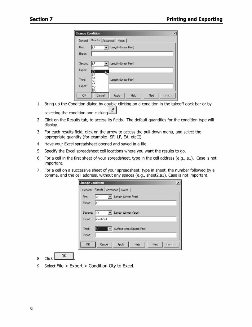
Section 7 Printing and Exporting
51
1 Bring up the Condition dialog by double-clicking on a condition in the takeoff dock bar or by
selecting the condition and clicking
2 Click on the Results tab to access its fields The default quantities for the condition type will display
3 For each results field click on the arrow to access the pull-down menu and select the appropriate quantity (for example SF LF EA etchellip)
4 Have your Excel spreadsheet opened and saved in a file
5 Specify the Excel spreadsheet cell locations where you want the results to go
6 For a cell in the first sheet of your spreadsheet type in the cell address (eg a1) Case is not important
7 For a cell on a successive sheet of your spreadsheet type in sheet the number followed by a comma and the cell address without any spaces (eg sheet2a1) Case is not important
8 Click
9 Select File gt Export gt Condition Qty to Excel
Section 7 Printing and Exporting
52
10 Browse to the location of the Excel spreadsheet file click file to select it
11 Click to export On-Screen Takeoff results to specified cell locations in the Excel file When you return to the Excel application you will see the values have been added to the specified cell locations in your spreadsheet
12 Save your Excel file
Exporting Worksheet to Excel
1 Assign condition quantities you want to export
2 Open saved Excel spreadsheet file to which you will be exporting
3 From On-Screen Takeoff Select File gt Export gt Worksheet to Excel
4 Browse to the location of the Excel spreadsheet file click file to select it
5 Click When you return to the Excel application you will see the values from the Worksheet Tab have been added to your spreadsheet
6 Save your Excel file
Exporting Takeoff to CVS 1 Assign condition quantities you want to export
2 Open saved Excel spreadsheet file to which you will be exporting
3 Click the Takeoff Tab in the project you want to export the information
4 Select File gt Export gt Takeoff to CSV
5 Browse to the location of the CSV spreadsheet file click file to select it
6 Click the Save
NOTE CSV files can be opened in Excel Lotus Access etc One may consider this option more of a ldquodumprdquo into a file
The Excel application must be active (it may be minimized on the application bar) with the target spreadsheet open in the application Otherwise an error will occur with the export operation that will affect both the On-Screen Takeofftrade file and the Excel spreadsheet
Section 8
53
Advanced Features
This section will
Some special features of working with condition objects in the takeoff area
Details of advanced options for conditions
Advanced features of the Project Properties dialog
Section 8 Advanced Features
54
Features to Use with Objects Roping Feature You can move copy or delete using this feature Using the Select tool (the pointer) you may select several objects at once by clicking and dragging an outline around the objects then releasing the mouse button Roping may select either objects completely within the outlined area (inclusive) or objects both within and touched by the outlined area (touching) Specify your roping preference under Tools gt Options
1 Click and hold the mouse button at a point on the screen near the objects to be selected and drag to surround the objects with an outline
2 Release the mouse button The objects will be selected
3 You may now
Move the group around on the page by clicking within the group dragging the mouse and releasing the button to place the objects
Delete the group of objects by clicking the Delete key or
Copy and paste by pressing Ctrl C to copy the group then Ctrl V to paste it The pasted copy of the grouped objects will appear slightly offset from the original objects
Section 8 Advanced Features
55
Applying a DropRun Count
Use the droprun feature when calculating quantities to take into account the drop or run of a linear condition such as electrical lines or plumbing pipes Drop or run lengths may be added separately to any linear condition on screen while a default droprun length may be indicated for a condition as a whole
1 Select the desired linear condition from the Condition List in the Takeoff Dock bar
2 Click the Change button in the toolbar to open the Change Condition dialog
3 Click the Advanced tab to access the advanced options and click inside the DropRun check box
4 Enter a default length to be applied to all of this condition Entering 800 will be interpreted as 8 0 (You must enter both place markers for inches) You can leave the length blank and manually enter drop run on each segment drawn
5 Click the OK button to accept and close the dialog
Edit DropRun Count
1 With the related linear condition in the Takeoff Dock bar highlighted or with the pointer tool selected
2 click on the desired linear object in the image takeoff area The Count button will become active
3 Click on the Count button (alternatively select Tools gt Count) The default droprun amount will show in the pop-up Count dialog (Default length will be zero if droprun has not been selected in this conditionrsquos properties)
4 Type in the desired length Entering 800 will be interpreted as 8 0 (You must enter both place markers for inches)
5 Click the OK button The additional amount will be reflected in the corresponding quantity The new DropRun count will apply only to the object edited
Adding Text in Image View
On-Screen Takeoff allows you to place text comments around your quantity takeoffs that may be printed along with plan images and objects Text is automatically placed within the Annotation Layer (that includes text and hot links)
1 To place text on the image select the Text Tool and click at the point you want to place your text opening a text box
2 Type in your information clicking Enter for line breaks
3 When you are finished click the OK button to exit the text box
4 To reposition text simply click on the text (with the Text Tool active) to select it
5 Move the cursor over the text the cursor will now display as a four-way arrow
6 Click and drag the mouse to position the text as desired
Section 8 Advanced Features
56
1 To edit existing text use the Text Tool to double-click on the text to open the editing box
2 Enter additional text or use the Backspace key to delete text as necessary
Formatting Text Once created you may format the font size type style and color of your text
1 Click on the text to select it and select Tools gt Font or click on the Font button in the Takeoff Toolbar
2 Select the desired features (color options are disabled) and click the OK button
3 Click on the text to select it and select Tools gt Color or click on the Color button in the Takeoff Toolbar The Color dialog will open
4 Click on a color in the Basic Color palette or create a color and add to the Custom Colors palette (Be sure to click on the color in the Custom Colors palette to select it)
5 Click the OK button
Object Properties
Linear Objects
Linear objects may be set to connect at corners
A linear object may be set to trim automatically when crossing another linear object (Check the trim option under the advanced tab of the Condition dialog)
When you move a connected linear object objects automatically move and resize connected lines accordingly (quantities are then recalculated)
This feature requires that the connected linear object be moved using the center handles (does not apply when resizing the line from the ends)
Objects constrain to snap increments defined in the Tools gt Options menu (with the mouse 15deg by default incremental when shift key is held down)
Objects are measured from centerline to centerline
Section 8 Advanced Features
57
Area Objects When drawing an area use your escape key to undo the last line drawn You may reverse your
drawing of an area using the escape key
The area will not fill with color and pattern until the user double-clicks after the last line is set
Lines drawn to delineate an area object constrain to snap increments defined in the Tools gt Options menu (with the mouse 15deg by default incremental when shift key is held down)
After selecting an area to move or adjust position the mouse in the center to move the entire area position the mouse at the sides or corners to adjust the perimeter
Count Objects
All count objects are quantified by the physical number of objects per page and reported as EA for the UOM The quantity for the current Image View is (displayed in the Condition List) and the total quantity in your project is displayed in the Takeoff View and Worksheet View)
Square circle rectangle and triangle shaped count objects do not displace or subtract from other object quantities when placed on top of them However on the Advanced Tab for the count condition a connect property can be set (this is a check box) so that when a count object of this shape is put on top of a Linear type takeoff object it will move with the linear if said linear is moved
An opened-shaped count object must be placed within a linear object Opening shaped count objects may also be measured by linear foot or linear yard (EA SF and SY are also options) Opening shaped count items default to a width of 3rsquo 0rdquo at the time of creation This size can be changed The small medium and large size are not options on this type of condition anymore Check Backout on the Advanced tab for each Count object back out the footage (or yardage) of opening-shaped count objects in which they are placed
NOTE In order to see this Backout functionality (in quantity) for SY or SF deductions at least one of the
results for the Linear(s) this object will be placed on must be set to SY or SF and the count object must have a height quantity
Advanced Features of Conditions The Round Feature Under the Advanced tab of the linear and area Condition dialogues you may specify quantity rounding (in inches) For linear objects rounding applies to each linear object drawn For area objects rounding will apply to each segment of the area perimeter adjusting the perimeter and area calculations For example With a linear condition entering 12 in the Round field will round up each related linear object to the nearest 12 inches or one foot With this setting two walls of 1 4 would each round to 2 0 totaling 4 0
NOTE In the Takeoff Dock bar condition list and in the On-Screen Takeoff reports quantities will be displayed in whole numbers rounded up to the nearest foot However calculations are based on true quantities without rounding unless the Round Feature is engaged
Pitch Pitch may apply either to linear or area conditions It is measured in rise per linear foot Entering 12 indicates a 12 rise per 12 of linear distance (a pitch of 12 over 12) or an angle of 45deg
Section 8 Advanced Features
58
Advanced Features of Project Properties Selecting Multiple Pages
1 Select a single page entry by clicking on the numbered gray button to the left of the entry
2 Drag the cursor down the column of numbers to select consecutive pages
3 Click on the blank button at the top of this column to select all pages in the Properties dialog
Section 8 Advanced Features
59
Changing Image Assigned to a Drawing 1 Select the page entry by clicking on the numbered gray button to the left of the entry 2 Click the Change Image button The Change Image dialog box will appear
3 Navigate to the desired file and select by clicking on it
4 Click the Open button The electronic file assigned to the page will have been changed to reflect the new file choice
Changing Image File Path 1 Select pages as described above
2 Choose Change Folder
3 In the Change Folder dialog navigate to the appropriate folder
4 Click the OK button The file path will have been changed for the selected page entries
Delete a Page from Project Properties 1 Select the page you want to delete by clicking on its associated number (in the gray box at the
left of the entry)
2 Choose Delete Page
All Takeoff on the page will be deleted immediately and permanently
Section 8 Advanced Features
60
Advanced Features of Tool Options
Calculation Method On-Screen Takeoff has built-in calculation options to allow for faster work and faster saves until your takeoff is complete Calculation options are found by selecting Tools gt Options then clicking on the Calculation tab
Calculation method can be set to Automatic Automatic except Grids and Manual Manual will allow the program to operate more quickly while Automatic or Automatic except Grids allows the user to see quantity changes as takeoffs are made
In any mode you may press F9 to recalculate quantities for the On-Screen Takeoff current totals
Configuration Tab
When the ldquoPage Label (A01)rdquo radial button is chosen On-Screen Takeoff puts the numbered label on all the pages of in your current page indicator in your Navigate Toolbar If the Page Descriptionrdquo radial button is chosen then a description of what takeoff is on that specific page will be shown in your current page indicator in your Navigate Toolbar
This section of the configuration tab gives you options on how you want to export your information When the ldquoFolderSubfolder Namesrdquo radial button is chosen than on your file that you are exporting to will have all the conditions folders and subfolders In the Delimiter box you can choose the symbol that is needed to separate the information you are exporting Some files need semicolons () or colons () to make sure the information comes exported in is separated it the appropriate places
Section 8 Advanced Features
61
In previous versions of On-Screen Takeoff there are views that users need to have in order for them to display their information By either choosing ldquoOST 1xrdquo or ldquoOST 2xrdquo it will let the program know you want your columns of information exported in that specific format
When you have the Confirm Deletions radial button of ldquoYesrdquo chosen than every time you delete anything you will get a dialog box confirming your intentions of deletion
While working with your takeoff you have a choice to either view the legend of your conditions or hide it Choose whichever radial button that suits your needs
For those who prefer to use the Enter key to navigate in dialog boxes this option is just for that
Font Tab The Font tab is designed for you to make your own look and feel for the application At the bottom of this tab it will show you sample of the fonts and colors you have chosen
Renaming the Current Page You may change the name of the current page in the takeoff area of On-Screen Takeoff by selecting Edit gt Rename Page
This opens the Name Page dialog and you may simply type in a new name and click the Enter button The new name for the file will be reflected on the title bar for the page and in Project Properties
You also may access the Rename Page function by right-clicking in the takeoff area while in Image View and selecting the option from the pop-up menu that appears
Section 9
62
Saving and Exiting
This section will
Explain how to save projects
Show you how to safely exit the program
Section 9 Saving and Exiting
63
Saving Your Project
1 Select File gt Save 2 If your project has not previously been saved a Save dialog box will open to allow you to name
the file and choose the directory and folder in which to save your file 3 Once saved File gt Save will simply save the current version of the file
OR
4 Select File gt Save As then type in a new name for the file and save to the desired file path
The Auto-save Feature With the Auto-save feature On-Screen Takeoff automatically backs up your open project You may choose to have more than one level of backup files The first backup copy will have the extension b00 and successive files will be b01 b02 and so on If you have designated four levels of backup files after the fourth backup copy has been created (b03) the next file will be saved over the file with extension b00 Further backup saves will then rotate through the four backup files in the same way
1 Select Tools gt Options 2 In the Auto-save area (under the General tab) select the frequency of backup file creation (in
minutes) and the number of levels for the feature 3 You also may disengage the feature by clicking in the check box to clear it
The Auto-save feature automatically saves backup copies to the directory of the current project If you are working from a write-protected area such as a CD-ROM On-Screen Takeoff will place backup files in the On-Screen Takeoff folder
Exiting When you are finished using On-Screen Takeoff it is very easy to exit Exiting is very important because of security reasons If someone were to use your computer they could enter the application and view and manipulate information
Section 9 Saving and Exiting
64
On-Screen Takeoff closes the open project when you open another or create a new project or when you exit the program
1 Select File gt Exit
OR
2 You also may click at the upper right-hand corner of the application to exit
NOTE If your latest changes to a project file have not been saved On-Screen Takeoff will ask you whether you would like to save the file and gives you the option of canceling the operation
Appendix I Installing Your Digitizer
65
Appendix I Installing Your Digitizer When you get your digitizer from GTCO you will need to connect it to your computer Follow the instructions outlined below to do this
Note For rollup digitizers the metal bar must be oriented to the top or right hand side
Connecting the Digitizer 1 Lay the digitizer out flat 2 Connect the Stylus to the digitizer 3 Plug in the power adapter 4 Plug the interface (IO) cable into the digitizer 5 Plug the other end of the interface cable into an open serial port on computer
Note GTCO Technical support phone number is 410-381-6688 The electronic manual (on diskette) from GTCO contains more detailed installation and operation instructions for the GTCO digitizer model you have
Installing other Digitizer Drivers If you are using a GTCO Digitizer you will need to install the GTCO TabletWorks Drivers
If you are using a Digitizer not supported by GTCO Tablet Works 10 please contact the manufacturer of your digitizer for assistance with installation
Installing GTCO TabletWorks Drivers 1 Insert the On Center CD into the CD-ROM drive The CD Startup screen will open 2 Click on Install Software 3 Select Additional Software and Drivers 4 Select Digitizer Driver 5 Follow the instructions for installing TabletWorks 10
Adhering the Template The template is a small plastic sticker used to enable mouse function when using the digitizer with On-Screen Takeoff Place your template on your digitizer We suggest placing it in the bottom right corner of the digitizer about one inch inside the takeoff area
Note You may either peel off the back of the template and use the adhesive surface or you can tape the template down
Appendix I Installing Your Digitizer
66
Testing the Digitizer Drivers Before running OST you may test the digitizer by moving the stylus around on the digitizer pad it should move the mouse cursor (if mouse emulation is enabled)
If the digitizer does not move the mouse cursor on the screen
The superset codes may need to be reset Reset the superset codes by touching on the border of the digitizer with the stylus The digitizer should beep several times
The digitizer may not be communicating with the computer Be sure the COM port selected is correct Be sure the COM port selected is correct If you are not able to get the digitizer to move the mouse cursor you need to call GTCO technical support for help
Note The Mouse Emulation is not required for On-Screen Takeoff to work properly It is used only for the Template functionality if the digitizer is moving the cursor the wrong direction (up instead of sideways or vice-versa)
Click the L-shaped arrow symbol on the digitizer with the stylus
Appendix II Toolbar Item Details
67
Appendix II Toolbar Items Main Toolbar
Appendix II Toolbar Item Details
68
Tool Toolbar
Appendix II Toolbar Item Details
69
Zoom Toolbar
View Toolbar
Navigate Toolbar
Appendix II Toolbar Item Details
70
Navigate Toolbar (Continued)
Takeoff Toolbar
Appendix II Toolbar Item Details
71
Takeoff Toolbar (Continued)
Image Toolbar
Appendix III Loading Plans from a Dodge CD
72
Appendix III Loading Plans from a Dodge CD
This section will detail how to load plans from a F W Dodge CD-ROM into an On-Screen Takeoff project file ready for takeoffs
Dodge files may be added to the Project Properties dialog However loading the files in that way will load the files by number rather than name description If you want to load one page only from your Dodge CD You will have to rename the page to display the name rather than number of the file
To load plan files from a Dodge CD so that the files load sequentially by file number but are displayed by name rather than by number within your project follow the instructions below
Opening a Dodge project from a CD-ROM 1 Insert the CD into the drive 2 Choose File gt Custom 3 Choose Dodge Plans Project (plansdat) as the file type 4 Select the appropriate file type by clicking on the down arrow at the right of the Files of type
field 5 In the Look in field access your drive paths by clicking on the down arrow at the right of the
field then
Navigate to your CD-ROM drive Open the data folder and Open the Projects folder
6 Select the desired project and open its folder 7 Open the plansdat file 8 All the images will come in sequenced correctly for that job along with the full descriptions
(names) of each page If there is not a plans folder in the project folder then plans do not exist for that project on the CD Opening the plansdat file will yield an empty project
Appendix IV Using the Plan Viewer
73
Appendix IV Using On-Screen Takeoff Plan Viewer The On-Screen Takeoff Plan Viewer is a limited version of On Center Softwarersquos commercial takeoff software If your status bar located at the very bottom of the main window says View Mode in the lower left-hand corner then you are using the Plan Viewer You can use the plan viewer to
View CD-based amp converted CAD drawings
View a previously created OST file and associated drawings
Download electronic plans online
Navigate through drawings
Quickly Takeoff linearsareas and counts
Zoom in to view the plan better
Print drawings directly from the viewer
Viewing an On-Screen Takeoff Project File
1 To open an OST file that was previously created with of On-Screen Takeoff 2 Select File gt Open 3 An Open dialog will appear if you do not see the OST file you are looking for select the
Look In drop down arrow 4 A drop down menu will appear listing the various folders drives and mapped drives located
on your computer select the correct drive or folder location and continue to browse to the location of your OST file
5 When you see your OST file double-click it to open it 6 Any takeoff and drawings should appear on the Image tab view
If you do not see the drawings but do see the colored takeoff layer the drawings may
not be located in the same place they were originally saved at Go to File gt Project Properties and check the Image File path for each listed page If the image file path is pointing to a CD drive make sure the CD is inside the CR-ROM
Downloading Electronic Plans If your Online Plan Service provides a special file format (OSX) required to use this feature of our plan viewer you can immediately downloaded all electronic plans of a project directly from our viewer
Most Plan Room web sites will automatically open On-Screen Takeoff when a request to download plans is made Your particular Plan Room may differ in operation so please contact the provider directly with questions on using the site
Appendix IV Using the Plan Viewer
74
When you request to download or open a project file from a Plan Room you will usually have the open to open or save an OSX file Choosing open will automatically open On-Screen Takeoff Alternately you may choose to save the file to a local hard drive After you have saved the file either double-click it to launch On-Screen Takeoff or open the OSX file using On-Screen Takeoff by clicking File then Open and locating the file on your hard drive You will need to change the file type to OSX
After the OSX file is opened you will see an additional tab appear in the Conditions List window called Pages
The Pages tab shows the hierarchy of your project Gray file icons represent pages that have not been downloaded and blue icons represents pages that have been downloaded
To download a page simply double-click the page icon
If you wish to select a group of pages to download you can use the Ctrl or Shift key to multiple select them then click the Download button
If you wish to download all pages at once click the Download All button
Downloaded pages will now appear in the Project Properties dialog in the same order in which they appear in the Pages tab
Creating Quick Takeoffs With On-Screen Takeoff you can create quick takeoffs to measure quantities even if you dont have the full version of our program However using the Quick Takeoff functionality shows you just a fraction of what the full version can do
The Quick Takeoff Toolbar is located at the top of the image view It has three buttons designated for three types of takeoffs Linear Area and Count The Quantity drop down list will show secondary quantities for Linears and Areas The Units drop down allows you to select how you want your quantities displayed Feet Inches Yards Millimeters and Meters
NOTE Every time change the type of takeoff you are performing (switching from Area to Linear for example) the previous quantities and takeoff objects will disappear They will also disappear when you changes pages
NOTE You can use the Dimension Tool to basically measure the distance between two points or linears The distance will display on the status bar at the bottom of the application
The Quick Takeoff Toolbar
Appendix V Frequently Asked Questions
75
Appendix V Frequently Asked Questions General
Where is On-Screen Takeoff installed on my computer
Typically it is installed in CProgram FilesOn-Screen Takeoff
In Explorer how do I recognize On-Screen Takeoff file types
On-Screen Takeoff data is stored in a single file per job lsquojob name OSTrsquo On-Screen Takeoff templates are stored as lsquotemplate nameTPOrsquo
Can only one project at a time be open
Yes For that reason opening another project automatically closes the project on screen You will be asked to save any changes
Is only one scale allowed per page What about on drawings that have multiple detail sections on a page and each of those drawings have different scales
Yes For pages with drawings of different scales copy the drawing to another project page and set the appropriate scale
I cannot perform backout on an area that is along a linear
As a workaround use the On-Screen Takeoff layers feature to help you with this issue Electronic Images
How do I start a project from drawings that have been scanned and written to a CD-ROM
Open a new project Select File gt Project Properties and select Auto Add Navigate to your CD and the appropriate folder and select any image file in that location Click Open All files in the location will load into your project Recommended that images are copied from CD to hard drive for performance
If I get a disk of drawings in AutoCAD format (R13 or R14) can I read them in On-Screen Takeoff
Yes On-Screen Takeoff now reads DWG DXF and many other format that are saved with AutoCAD
Appendix V Frequently Asked Questions
76
When I click on the all pages button what is supposed to happen Currently nothing seems to change when I click on that button
The All Pages button is used to apply the Darken and Enhance Plans feature to all pages in the project (as opposed to only the current page on screen)
Is there a way to deduct a large skylight from an area condition
Yes with the related area condition selected in the Takeoff Dock bar unselect the Backout button on the Takeoff Toolbar then draw the Backout area The area quantity will be deducted from the related condition object and the linear measurement of the Backout perimeter will be added
Digitizer Issues
How do I connect a Digitizer to the computer
See Appendix I Connecting a Digitizer
The Place Template menu choice is disabled
On-Screen Takeoff may need to be authorized or the digitizer or the digitzer drivers are not installed
It wonrsquot let me select the Set Takeoff Area menu choice
On-Screen Takeoff may need to be authorized or no job is open a digitizer is not installed or the drivers are not installed
The digitizer stylus is not moving the cursor or crosshairs
Click S-0-1 superset on the digitizer
How do I convert my old GTCO Digitizer to work with On- Screen Takeofftrade
Call GTCO and they may be able to reconfigure your digitizer to be compatible with On-Screen Takeoff
Printing Issues Which Printers work with On-Screen Takeoff
Compatible printers include On-Screen Takeoff Hewlett Packard Epson and Canon printers If you are having printer difficulties please contact support and specify the type of printer along with other pertinent information Contact support at wwwoncentercomsupport or email supportoncentercom
Which Plotters work with On-Screen Takeoff
Compatible Plotters include Hewlett Packard DesignJet plotters and the EnCAD Cadjet II If you are having plotter difficulties please contact support and specify the type of plotter concerned
ViewingDisplay I can no longer see my condition list How do I get it back
The toolbars and Dock bars can be turned on and off through the View gt Toolbars menu options
Appendix V Frequently Asked Questions
77
This is also accessible by right-clicking in the toolbar area and selecting (or deselecting) a toolbar listed
I cannot view my folders in the condition list
Right-click in the Takeoff Dock barcondition list area and select Show Tree to display your folders
My Status Bar reads Viewer Mode and I am unable to draw conditions
On-Screen Takeoff needs to be Authorized Or you need to purchase an upgrade Click the Perform Advanced Takeoff button on the main toolbar
I hid a Dock bar and when I selected to view it again it appeared alongside the other Dock
bar instead of stacked on top of it How do I fix it
Pick up the Dock bar by clicking on the bar at the top and continuing to hold down the mouse button drag the Dock bar over the other one It will resize and appear stacked with the other
When I open image files from a CD the images are all upside down How do I get them right
side up
To flip pages from top to bottom follow the steps below 1 Click the All Pages button on the Image Toolbar (All Pages is engaged when the button
is not clicked) 2 Click the Flip Horizontal button on the Image Toolbar 3 Click the All Pages button again to disengage
Templates How do I create a Template
Follow the steps below 1 Create a typical project 2 Choose File gt Save As 3 Choose On-Screen Takeoff Template Files as the file type to save 4 Name the file This will save all of the condition setups as well as the layers for the
project
How do I create a new project from a template
Follow the steps below 1 Choose File gt New 2 Select a template from those listed in the New dialog This will open a new project with
conditions and layers saved from a previous project but no pages or takeoff
78
INDEX
Area Conditions 32
Area Objects 57
Auto Scrolling 20
Auto-save 63
Backout Mode 41
Calculation Method 60
Conditions 29
Configuration 60
Contents Tab 6
Continuous Mode 38
Count Conditions 33
Count Objects 57
Digitizer 10 65 76
Docking Toolbars 13
Dodge CD 72
Drawing 27 37
DropRun Count 55
Environment 18
Exiting 63
Exporting 49
Features 16
Font 61
Frequently Asked Questions 75
Grid 40
Help File 5
Hiding Toolbars 13
Hot Links 21
Image 19 59
Image files 9
Image Toolbar 12 71
Images 75
Index Tab 6
Layers 43
Linear Conditions 31
Linear Objects 56
Main Toolbar 12 67
Menus 14
Moving Toolbars 13
Navigate Toolbar 12 69
Navigating 20
On-Screen Takeofftrade 2
Page 59 61
Pages 20 25 28
Plan Viewer 73
Plans 26
Printing 47 76
Project Properties 25
Projects 22
Quick Start Video 18
Resizing Toolbars 13
Roping 54
Saving 63
Scale 28
Search Tab 7
Selecting Objects 42
Setup 8
Start On-Screen Takeofftrade 17
System Requirements 9
Takeoff 19 27
Takeoff Toolbar 70 71
Takeoff Toolbar 12
Template Files 23
TIF (Group4) 9
Tool Toolbar 12 68
Toolbar 67
Toolbars 12
View Toolbar 12 69
Viewing Toolbars 12
Worksheet 20
Zone Conditions 33
Zoom Toolbar 12 69
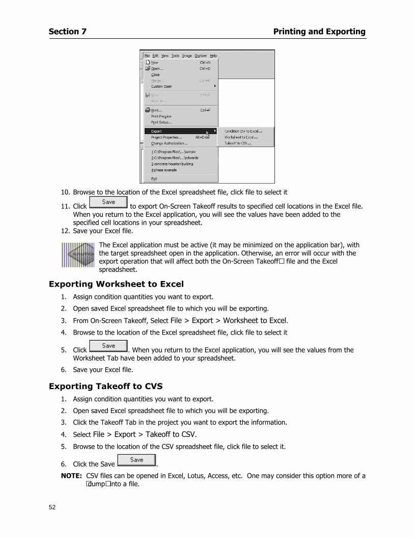
Section 7 Printing and Exporting
52
10 Browse to the location of the Excel spreadsheet file click file to select it
11 Click to export On-Screen Takeoff results to specified cell locations in the Excel file When you return to the Excel application you will see the values have been added to the specified cell locations in your spreadsheet
12 Save your Excel file
Exporting Worksheet to Excel
1 Assign condition quantities you want to export
2 Open saved Excel spreadsheet file to which you will be exporting
3 From On-Screen Takeoff Select File gt Export gt Worksheet to Excel
4 Browse to the location of the Excel spreadsheet file click file to select it
5 Click When you return to the Excel application you will see the values from the Worksheet Tab have been added to your spreadsheet
6 Save your Excel file
Exporting Takeoff to CVS 1 Assign condition quantities you want to export
2 Open saved Excel spreadsheet file to which you will be exporting
3 Click the Takeoff Tab in the project you want to export the information
4 Select File gt Export gt Takeoff to CSV
5 Browse to the location of the CSV spreadsheet file click file to select it
6 Click the Save
NOTE CSV files can be opened in Excel Lotus Access etc One may consider this option more of a ldquodumprdquo into a file
The Excel application must be active (it may be minimized on the application bar) with the target spreadsheet open in the application Otherwise an error will occur with the export operation that will affect both the On-Screen Takeofftrade file and the Excel spreadsheet
Section 8
53
Advanced Features
This section will
Some special features of working with condition objects in the takeoff area
Details of advanced options for conditions
Advanced features of the Project Properties dialog
Section 8 Advanced Features
54
Features to Use with Objects Roping Feature You can move copy or delete using this feature Using the Select tool (the pointer) you may select several objects at once by clicking and dragging an outline around the objects then releasing the mouse button Roping may select either objects completely within the outlined area (inclusive) or objects both within and touched by the outlined area (touching) Specify your roping preference under Tools gt Options
1 Click and hold the mouse button at a point on the screen near the objects to be selected and drag to surround the objects with an outline
2 Release the mouse button The objects will be selected
3 You may now
Move the group around on the page by clicking within the group dragging the mouse and releasing the button to place the objects
Delete the group of objects by clicking the Delete key or
Copy and paste by pressing Ctrl C to copy the group then Ctrl V to paste it The pasted copy of the grouped objects will appear slightly offset from the original objects
Section 8 Advanced Features
55
Applying a DropRun Count
Use the droprun feature when calculating quantities to take into account the drop or run of a linear condition such as electrical lines or plumbing pipes Drop or run lengths may be added separately to any linear condition on screen while a default droprun length may be indicated for a condition as a whole
1 Select the desired linear condition from the Condition List in the Takeoff Dock bar
2 Click the Change button in the toolbar to open the Change Condition dialog
3 Click the Advanced tab to access the advanced options and click inside the DropRun check box
4 Enter a default length to be applied to all of this condition Entering 800 will be interpreted as 8 0 (You must enter both place markers for inches) You can leave the length blank and manually enter drop run on each segment drawn
5 Click the OK button to accept and close the dialog
Edit DropRun Count
1 With the related linear condition in the Takeoff Dock bar highlighted or with the pointer tool selected
2 click on the desired linear object in the image takeoff area The Count button will become active
3 Click on the Count button (alternatively select Tools gt Count) The default droprun amount will show in the pop-up Count dialog (Default length will be zero if droprun has not been selected in this conditionrsquos properties)
4 Type in the desired length Entering 800 will be interpreted as 8 0 (You must enter both place markers for inches)
5 Click the OK button The additional amount will be reflected in the corresponding quantity The new DropRun count will apply only to the object edited
Adding Text in Image View
On-Screen Takeoff allows you to place text comments around your quantity takeoffs that may be printed along with plan images and objects Text is automatically placed within the Annotation Layer (that includes text and hot links)
1 To place text on the image select the Text Tool and click at the point you want to place your text opening a text box
2 Type in your information clicking Enter for line breaks
3 When you are finished click the OK button to exit the text box
4 To reposition text simply click on the text (with the Text Tool active) to select it
5 Move the cursor over the text the cursor will now display as a four-way arrow
6 Click and drag the mouse to position the text as desired
Section 8 Advanced Features
56
1 To edit existing text use the Text Tool to double-click on the text to open the editing box
2 Enter additional text or use the Backspace key to delete text as necessary
Formatting Text Once created you may format the font size type style and color of your text
1 Click on the text to select it and select Tools gt Font or click on the Font button in the Takeoff Toolbar
2 Select the desired features (color options are disabled) and click the OK button
3 Click on the text to select it and select Tools gt Color or click on the Color button in the Takeoff Toolbar The Color dialog will open
4 Click on a color in the Basic Color palette or create a color and add to the Custom Colors palette (Be sure to click on the color in the Custom Colors palette to select it)
5 Click the OK button
Object Properties
Linear Objects
Linear objects may be set to connect at corners
A linear object may be set to trim automatically when crossing another linear object (Check the trim option under the advanced tab of the Condition dialog)
When you move a connected linear object objects automatically move and resize connected lines accordingly (quantities are then recalculated)
This feature requires that the connected linear object be moved using the center handles (does not apply when resizing the line from the ends)
Objects constrain to snap increments defined in the Tools gt Options menu (with the mouse 15deg by default incremental when shift key is held down)
Objects are measured from centerline to centerline
Section 8 Advanced Features
57
Area Objects When drawing an area use your escape key to undo the last line drawn You may reverse your
drawing of an area using the escape key
The area will not fill with color and pattern until the user double-clicks after the last line is set
Lines drawn to delineate an area object constrain to snap increments defined in the Tools gt Options menu (with the mouse 15deg by default incremental when shift key is held down)
After selecting an area to move or adjust position the mouse in the center to move the entire area position the mouse at the sides or corners to adjust the perimeter
Count Objects
All count objects are quantified by the physical number of objects per page and reported as EA for the UOM The quantity for the current Image View is (displayed in the Condition List) and the total quantity in your project is displayed in the Takeoff View and Worksheet View)
Square circle rectangle and triangle shaped count objects do not displace or subtract from other object quantities when placed on top of them However on the Advanced Tab for the count condition a connect property can be set (this is a check box) so that when a count object of this shape is put on top of a Linear type takeoff object it will move with the linear if said linear is moved
An opened-shaped count object must be placed within a linear object Opening shaped count objects may also be measured by linear foot or linear yard (EA SF and SY are also options) Opening shaped count items default to a width of 3rsquo 0rdquo at the time of creation This size can be changed The small medium and large size are not options on this type of condition anymore Check Backout on the Advanced tab for each Count object back out the footage (or yardage) of opening-shaped count objects in which they are placed
NOTE In order to see this Backout functionality (in quantity) for SY or SF deductions at least one of the
results for the Linear(s) this object will be placed on must be set to SY or SF and the count object must have a height quantity
Advanced Features of Conditions The Round Feature Under the Advanced tab of the linear and area Condition dialogues you may specify quantity rounding (in inches) For linear objects rounding applies to each linear object drawn For area objects rounding will apply to each segment of the area perimeter adjusting the perimeter and area calculations For example With a linear condition entering 12 in the Round field will round up each related linear object to the nearest 12 inches or one foot With this setting two walls of 1 4 would each round to 2 0 totaling 4 0
NOTE In the Takeoff Dock bar condition list and in the On-Screen Takeoff reports quantities will be displayed in whole numbers rounded up to the nearest foot However calculations are based on true quantities without rounding unless the Round Feature is engaged
Pitch Pitch may apply either to linear or area conditions It is measured in rise per linear foot Entering 12 indicates a 12 rise per 12 of linear distance (a pitch of 12 over 12) or an angle of 45deg
Section 8 Advanced Features
58
Advanced Features of Project Properties Selecting Multiple Pages
1 Select a single page entry by clicking on the numbered gray button to the left of the entry
2 Drag the cursor down the column of numbers to select consecutive pages
3 Click on the blank button at the top of this column to select all pages in the Properties dialog
Section 8 Advanced Features
59
Changing Image Assigned to a Drawing 1 Select the page entry by clicking on the numbered gray button to the left of the entry 2 Click the Change Image button The Change Image dialog box will appear
3 Navigate to the desired file and select by clicking on it
4 Click the Open button The electronic file assigned to the page will have been changed to reflect the new file choice
Changing Image File Path 1 Select pages as described above
2 Choose Change Folder
3 In the Change Folder dialog navigate to the appropriate folder
4 Click the OK button The file path will have been changed for the selected page entries
Delete a Page from Project Properties 1 Select the page you want to delete by clicking on its associated number (in the gray box at the
left of the entry)
2 Choose Delete Page
All Takeoff on the page will be deleted immediately and permanently
Section 8 Advanced Features
60
Advanced Features of Tool Options
Calculation Method On-Screen Takeoff has built-in calculation options to allow for faster work and faster saves until your takeoff is complete Calculation options are found by selecting Tools gt Options then clicking on the Calculation tab
Calculation method can be set to Automatic Automatic except Grids and Manual Manual will allow the program to operate more quickly while Automatic or Automatic except Grids allows the user to see quantity changes as takeoffs are made
In any mode you may press F9 to recalculate quantities for the On-Screen Takeoff current totals
Configuration Tab
When the ldquoPage Label (A01)rdquo radial button is chosen On-Screen Takeoff puts the numbered label on all the pages of in your current page indicator in your Navigate Toolbar If the Page Descriptionrdquo radial button is chosen then a description of what takeoff is on that specific page will be shown in your current page indicator in your Navigate Toolbar
This section of the configuration tab gives you options on how you want to export your information When the ldquoFolderSubfolder Namesrdquo radial button is chosen than on your file that you are exporting to will have all the conditions folders and subfolders In the Delimiter box you can choose the symbol that is needed to separate the information you are exporting Some files need semicolons () or colons () to make sure the information comes exported in is separated it the appropriate places
Section 8 Advanced Features
61
In previous versions of On-Screen Takeoff there are views that users need to have in order for them to display their information By either choosing ldquoOST 1xrdquo or ldquoOST 2xrdquo it will let the program know you want your columns of information exported in that specific format
When you have the Confirm Deletions radial button of ldquoYesrdquo chosen than every time you delete anything you will get a dialog box confirming your intentions of deletion
While working with your takeoff you have a choice to either view the legend of your conditions or hide it Choose whichever radial button that suits your needs
For those who prefer to use the Enter key to navigate in dialog boxes this option is just for that
Font Tab The Font tab is designed for you to make your own look and feel for the application At the bottom of this tab it will show you sample of the fonts and colors you have chosen
Renaming the Current Page You may change the name of the current page in the takeoff area of On-Screen Takeoff by selecting Edit gt Rename Page
This opens the Name Page dialog and you may simply type in a new name and click the Enter button The new name for the file will be reflected on the title bar for the page and in Project Properties
You also may access the Rename Page function by right-clicking in the takeoff area while in Image View and selecting the option from the pop-up menu that appears
Section 9
62
Saving and Exiting
This section will
Explain how to save projects
Show you how to safely exit the program
Section 9 Saving and Exiting
63
Saving Your Project
1 Select File gt Save 2 If your project has not previously been saved a Save dialog box will open to allow you to name
the file and choose the directory and folder in which to save your file 3 Once saved File gt Save will simply save the current version of the file
OR
4 Select File gt Save As then type in a new name for the file and save to the desired file path
The Auto-save Feature With the Auto-save feature On-Screen Takeoff automatically backs up your open project You may choose to have more than one level of backup files The first backup copy will have the extension b00 and successive files will be b01 b02 and so on If you have designated four levels of backup files after the fourth backup copy has been created (b03) the next file will be saved over the file with extension b00 Further backup saves will then rotate through the four backup files in the same way
1 Select Tools gt Options 2 In the Auto-save area (under the General tab) select the frequency of backup file creation (in
minutes) and the number of levels for the feature 3 You also may disengage the feature by clicking in the check box to clear it
The Auto-save feature automatically saves backup copies to the directory of the current project If you are working from a write-protected area such as a CD-ROM On-Screen Takeoff will place backup files in the On-Screen Takeoff folder
Exiting When you are finished using On-Screen Takeoff it is very easy to exit Exiting is very important because of security reasons If someone were to use your computer they could enter the application and view and manipulate information
Section 9 Saving and Exiting
64
On-Screen Takeoff closes the open project when you open another or create a new project or when you exit the program
1 Select File gt Exit
OR
2 You also may click at the upper right-hand corner of the application to exit
NOTE If your latest changes to a project file have not been saved On-Screen Takeoff will ask you whether you would like to save the file and gives you the option of canceling the operation
Appendix I Installing Your Digitizer
65
Appendix I Installing Your Digitizer When you get your digitizer from GTCO you will need to connect it to your computer Follow the instructions outlined below to do this
Note For rollup digitizers the metal bar must be oriented to the top or right hand side
Connecting the Digitizer 1 Lay the digitizer out flat 2 Connect the Stylus to the digitizer 3 Plug in the power adapter 4 Plug the interface (IO) cable into the digitizer 5 Plug the other end of the interface cable into an open serial port on computer
Note GTCO Technical support phone number is 410-381-6688 The electronic manual (on diskette) from GTCO contains more detailed installation and operation instructions for the GTCO digitizer model you have
Installing other Digitizer Drivers If you are using a GTCO Digitizer you will need to install the GTCO TabletWorks Drivers
If you are using a Digitizer not supported by GTCO Tablet Works 10 please contact the manufacturer of your digitizer for assistance with installation
Installing GTCO TabletWorks Drivers 1 Insert the On Center CD into the CD-ROM drive The CD Startup screen will open 2 Click on Install Software 3 Select Additional Software and Drivers 4 Select Digitizer Driver 5 Follow the instructions for installing TabletWorks 10
Adhering the Template The template is a small plastic sticker used to enable mouse function when using the digitizer with On-Screen Takeoff Place your template on your digitizer We suggest placing it in the bottom right corner of the digitizer about one inch inside the takeoff area
Note You may either peel off the back of the template and use the adhesive surface or you can tape the template down
Appendix I Installing Your Digitizer
66
Testing the Digitizer Drivers Before running OST you may test the digitizer by moving the stylus around on the digitizer pad it should move the mouse cursor (if mouse emulation is enabled)
If the digitizer does not move the mouse cursor on the screen
The superset codes may need to be reset Reset the superset codes by touching on the border of the digitizer with the stylus The digitizer should beep several times
The digitizer may not be communicating with the computer Be sure the COM port selected is correct Be sure the COM port selected is correct If you are not able to get the digitizer to move the mouse cursor you need to call GTCO technical support for help
Note The Mouse Emulation is not required for On-Screen Takeoff to work properly It is used only for the Template functionality if the digitizer is moving the cursor the wrong direction (up instead of sideways or vice-versa)
Click the L-shaped arrow symbol on the digitizer with the stylus
Appendix II Toolbar Item Details
67
Appendix II Toolbar Items Main Toolbar
Appendix II Toolbar Item Details
68
Tool Toolbar
Appendix II Toolbar Item Details
69
Zoom Toolbar
View Toolbar
Navigate Toolbar
Appendix II Toolbar Item Details
70
Navigate Toolbar (Continued)
Takeoff Toolbar
Appendix II Toolbar Item Details
71
Takeoff Toolbar (Continued)
Image Toolbar
Appendix III Loading Plans from a Dodge CD
72
Appendix III Loading Plans from a Dodge CD
This section will detail how to load plans from a F W Dodge CD-ROM into an On-Screen Takeoff project file ready for takeoffs
Dodge files may be added to the Project Properties dialog However loading the files in that way will load the files by number rather than name description If you want to load one page only from your Dodge CD You will have to rename the page to display the name rather than number of the file
To load plan files from a Dodge CD so that the files load sequentially by file number but are displayed by name rather than by number within your project follow the instructions below
Opening a Dodge project from a CD-ROM 1 Insert the CD into the drive 2 Choose File gt Custom 3 Choose Dodge Plans Project (plansdat) as the file type 4 Select the appropriate file type by clicking on the down arrow at the right of the Files of type
field 5 In the Look in field access your drive paths by clicking on the down arrow at the right of the
field then
Navigate to your CD-ROM drive Open the data folder and Open the Projects folder
6 Select the desired project and open its folder 7 Open the plansdat file 8 All the images will come in sequenced correctly for that job along with the full descriptions
(names) of each page If there is not a plans folder in the project folder then plans do not exist for that project on the CD Opening the plansdat file will yield an empty project
Appendix IV Using the Plan Viewer
73
Appendix IV Using On-Screen Takeoff Plan Viewer The On-Screen Takeoff Plan Viewer is a limited version of On Center Softwarersquos commercial takeoff software If your status bar located at the very bottom of the main window says View Mode in the lower left-hand corner then you are using the Plan Viewer You can use the plan viewer to
View CD-based amp converted CAD drawings
View a previously created OST file and associated drawings
Download electronic plans online
Navigate through drawings
Quickly Takeoff linearsareas and counts
Zoom in to view the plan better
Print drawings directly from the viewer
Viewing an On-Screen Takeoff Project File
1 To open an OST file that was previously created with of On-Screen Takeoff 2 Select File gt Open 3 An Open dialog will appear if you do not see the OST file you are looking for select the
Look In drop down arrow 4 A drop down menu will appear listing the various folders drives and mapped drives located
on your computer select the correct drive or folder location and continue to browse to the location of your OST file
5 When you see your OST file double-click it to open it 6 Any takeoff and drawings should appear on the Image tab view
If you do not see the drawings but do see the colored takeoff layer the drawings may
not be located in the same place they were originally saved at Go to File gt Project Properties and check the Image File path for each listed page If the image file path is pointing to a CD drive make sure the CD is inside the CR-ROM
Downloading Electronic Plans If your Online Plan Service provides a special file format (OSX) required to use this feature of our plan viewer you can immediately downloaded all electronic plans of a project directly from our viewer
Most Plan Room web sites will automatically open On-Screen Takeoff when a request to download plans is made Your particular Plan Room may differ in operation so please contact the provider directly with questions on using the site
Appendix IV Using the Plan Viewer
74
When you request to download or open a project file from a Plan Room you will usually have the open to open or save an OSX file Choosing open will automatically open On-Screen Takeoff Alternately you may choose to save the file to a local hard drive After you have saved the file either double-click it to launch On-Screen Takeoff or open the OSX file using On-Screen Takeoff by clicking File then Open and locating the file on your hard drive You will need to change the file type to OSX
After the OSX file is opened you will see an additional tab appear in the Conditions List window called Pages
The Pages tab shows the hierarchy of your project Gray file icons represent pages that have not been downloaded and blue icons represents pages that have been downloaded
To download a page simply double-click the page icon
If you wish to select a group of pages to download you can use the Ctrl or Shift key to multiple select them then click the Download button
If you wish to download all pages at once click the Download All button
Downloaded pages will now appear in the Project Properties dialog in the same order in which they appear in the Pages tab
Creating Quick Takeoffs With On-Screen Takeoff you can create quick takeoffs to measure quantities even if you dont have the full version of our program However using the Quick Takeoff functionality shows you just a fraction of what the full version can do
The Quick Takeoff Toolbar is located at the top of the image view It has three buttons designated for three types of takeoffs Linear Area and Count The Quantity drop down list will show secondary quantities for Linears and Areas The Units drop down allows you to select how you want your quantities displayed Feet Inches Yards Millimeters and Meters
NOTE Every time change the type of takeoff you are performing (switching from Area to Linear for example) the previous quantities and takeoff objects will disappear They will also disappear when you changes pages
NOTE You can use the Dimension Tool to basically measure the distance between two points or linears The distance will display on the status bar at the bottom of the application
The Quick Takeoff Toolbar
Appendix V Frequently Asked Questions
75
Appendix V Frequently Asked Questions General
Where is On-Screen Takeoff installed on my computer
Typically it is installed in CProgram FilesOn-Screen Takeoff
In Explorer how do I recognize On-Screen Takeoff file types
On-Screen Takeoff data is stored in a single file per job lsquojob name OSTrsquo On-Screen Takeoff templates are stored as lsquotemplate nameTPOrsquo
Can only one project at a time be open
Yes For that reason opening another project automatically closes the project on screen You will be asked to save any changes
Is only one scale allowed per page What about on drawings that have multiple detail sections on a page and each of those drawings have different scales
Yes For pages with drawings of different scales copy the drawing to another project page and set the appropriate scale
I cannot perform backout on an area that is along a linear
As a workaround use the On-Screen Takeoff layers feature to help you with this issue Electronic Images
How do I start a project from drawings that have been scanned and written to a CD-ROM
Open a new project Select File gt Project Properties and select Auto Add Navigate to your CD and the appropriate folder and select any image file in that location Click Open All files in the location will load into your project Recommended that images are copied from CD to hard drive for performance
If I get a disk of drawings in AutoCAD format (R13 or R14) can I read them in On-Screen Takeoff
Yes On-Screen Takeoff now reads DWG DXF and many other format that are saved with AutoCAD
Appendix V Frequently Asked Questions
76
When I click on the all pages button what is supposed to happen Currently nothing seems to change when I click on that button
The All Pages button is used to apply the Darken and Enhance Plans feature to all pages in the project (as opposed to only the current page on screen)
Is there a way to deduct a large skylight from an area condition
Yes with the related area condition selected in the Takeoff Dock bar unselect the Backout button on the Takeoff Toolbar then draw the Backout area The area quantity will be deducted from the related condition object and the linear measurement of the Backout perimeter will be added
Digitizer Issues
How do I connect a Digitizer to the computer
See Appendix I Connecting a Digitizer
The Place Template menu choice is disabled
On-Screen Takeoff may need to be authorized or the digitizer or the digitzer drivers are not installed
It wonrsquot let me select the Set Takeoff Area menu choice
On-Screen Takeoff may need to be authorized or no job is open a digitizer is not installed or the drivers are not installed
The digitizer stylus is not moving the cursor or crosshairs
Click S-0-1 superset on the digitizer
How do I convert my old GTCO Digitizer to work with On- Screen Takeofftrade
Call GTCO and they may be able to reconfigure your digitizer to be compatible with On-Screen Takeoff
Printing Issues Which Printers work with On-Screen Takeoff
Compatible printers include On-Screen Takeoff Hewlett Packard Epson and Canon printers If you are having printer difficulties please contact support and specify the type of printer along with other pertinent information Contact support at wwwoncentercomsupport or email supportoncentercom
Which Plotters work with On-Screen Takeoff
Compatible Plotters include Hewlett Packard DesignJet plotters and the EnCAD Cadjet II If you are having plotter difficulties please contact support and specify the type of plotter concerned
ViewingDisplay I can no longer see my condition list How do I get it back
The toolbars and Dock bars can be turned on and off through the View gt Toolbars menu options
Appendix V Frequently Asked Questions
77
This is also accessible by right-clicking in the toolbar area and selecting (or deselecting) a toolbar listed
I cannot view my folders in the condition list
Right-click in the Takeoff Dock barcondition list area and select Show Tree to display your folders
My Status Bar reads Viewer Mode and I am unable to draw conditions
On-Screen Takeoff needs to be Authorized Or you need to purchase an upgrade Click the Perform Advanced Takeoff button on the main toolbar
I hid a Dock bar and when I selected to view it again it appeared alongside the other Dock
bar instead of stacked on top of it How do I fix it
Pick up the Dock bar by clicking on the bar at the top and continuing to hold down the mouse button drag the Dock bar over the other one It will resize and appear stacked with the other
When I open image files from a CD the images are all upside down How do I get them right
side up
To flip pages from top to bottom follow the steps below 1 Click the All Pages button on the Image Toolbar (All Pages is engaged when the button
is not clicked) 2 Click the Flip Horizontal button on the Image Toolbar 3 Click the All Pages button again to disengage
Templates How do I create a Template
Follow the steps below 1 Create a typical project 2 Choose File gt Save As 3 Choose On-Screen Takeoff Template Files as the file type to save 4 Name the file This will save all of the condition setups as well as the layers for the
project
How do I create a new project from a template
Follow the steps below 1 Choose File gt New 2 Select a template from those listed in the New dialog This will open a new project with
conditions and layers saved from a previous project but no pages or takeoff
78
INDEX
Area Conditions 32
Area Objects 57
Auto Scrolling 20
Auto-save 63
Backout Mode 41
Calculation Method 60
Conditions 29
Configuration 60
Contents Tab 6
Continuous Mode 38
Count Conditions 33
Count Objects 57
Digitizer 10 65 76
Docking Toolbars 13
Dodge CD 72
Drawing 27 37
DropRun Count 55
Environment 18
Exiting 63
Exporting 49
Features 16
Font 61
Frequently Asked Questions 75
Grid 40
Help File 5
Hiding Toolbars 13
Hot Links 21
Image 19 59
Image files 9
Image Toolbar 12 71
Images 75
Index Tab 6
Layers 43
Linear Conditions 31
Linear Objects 56
Main Toolbar 12 67
Menus 14
Moving Toolbars 13
Navigate Toolbar 12 69
Navigating 20
On-Screen Takeofftrade 2
Page 59 61
Pages 20 25 28
Plan Viewer 73
Plans 26
Printing 47 76
Project Properties 25
Projects 22
Quick Start Video 18
Resizing Toolbars 13
Roping 54
Saving 63
Scale 28
Search Tab 7
Selecting Objects 42
Setup 8
Start On-Screen Takeofftrade 17
System Requirements 9
Takeoff 19 27
Takeoff Toolbar 70 71
Takeoff Toolbar 12
Template Files 23
TIF (Group4) 9
Tool Toolbar 12 68
Toolbar 67
Toolbars 12
View Toolbar 12 69
Viewing Toolbars 12
Worksheet 20
Zone Conditions 33
Zoom Toolbar 12 69
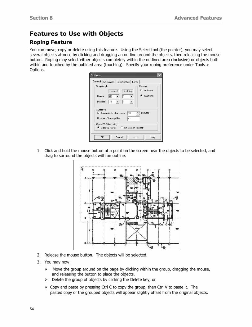
Section 8 Advanced Features
54
Features to Use with Objects Roping Feature You can move copy or delete using this feature Using the Select tool (the pointer) you may select several objects at once by clicking and dragging an outline around the objects then releasing the mouse button Roping may select either objects completely within the outlined area (inclusive) or objects both within and touched by the outlined area (touching) Specify your roping preference under Tools gt Options
1 Click and hold the mouse button at a point on the screen near the objects to be selected and drag to surround the objects with an outline
2 Release the mouse button The objects will be selected
3 You may now
Move the group around on the page by clicking within the group dragging the mouse and releasing the button to place the objects
Delete the group of objects by clicking the Delete key or
Copy and paste by pressing Ctrl C to copy the group then Ctrl V to paste it The pasted copy of the grouped objects will appear slightly offset from the original objects
Section 8 Advanced Features
55
Applying a DropRun Count
Use the droprun feature when calculating quantities to take into account the drop or run of a linear condition such as electrical lines or plumbing pipes Drop or run lengths may be added separately to any linear condition on screen while a default droprun length may be indicated for a condition as a whole
1 Select the desired linear condition from the Condition List in the Takeoff Dock bar
2 Click the Change button in the toolbar to open the Change Condition dialog
3 Click the Advanced tab to access the advanced options and click inside the DropRun check box
4 Enter a default length to be applied to all of this condition Entering 800 will be interpreted as 8 0 (You must enter both place markers for inches) You can leave the length blank and manually enter drop run on each segment drawn
5 Click the OK button to accept and close the dialog
Edit DropRun Count
1 With the related linear condition in the Takeoff Dock bar highlighted or with the pointer tool selected
2 click on the desired linear object in the image takeoff area The Count button will become active
3 Click on the Count button (alternatively select Tools gt Count) The default droprun amount will show in the pop-up Count dialog (Default length will be zero if droprun has not been selected in this conditionrsquos properties)
4 Type in the desired length Entering 800 will be interpreted as 8 0 (You must enter both place markers for inches)
5 Click the OK button The additional amount will be reflected in the corresponding quantity The new DropRun count will apply only to the object edited
Adding Text in Image View
On-Screen Takeoff allows you to place text comments around your quantity takeoffs that may be printed along with plan images and objects Text is automatically placed within the Annotation Layer (that includes text and hot links)
1 To place text on the image select the Text Tool and click at the point you want to place your text opening a text box
2 Type in your information clicking Enter for line breaks
3 When you are finished click the OK button to exit the text box
4 To reposition text simply click on the text (with the Text Tool active) to select it
5 Move the cursor over the text the cursor will now display as a four-way arrow
6 Click and drag the mouse to position the text as desired
Section 8 Advanced Features
56
1 To edit existing text use the Text Tool to double-click on the text to open the editing box
2 Enter additional text or use the Backspace key to delete text as necessary
Formatting Text Once created you may format the font size type style and color of your text
1 Click on the text to select it and select Tools gt Font or click on the Font button in the Takeoff Toolbar
2 Select the desired features (color options are disabled) and click the OK button
3 Click on the text to select it and select Tools gt Color or click on the Color button in the Takeoff Toolbar The Color dialog will open
4 Click on a color in the Basic Color palette or create a color and add to the Custom Colors palette (Be sure to click on the color in the Custom Colors palette to select it)
5 Click the OK button
Object Properties
Linear Objects
Linear objects may be set to connect at corners
A linear object may be set to trim automatically when crossing another linear object (Check the trim option under the advanced tab of the Condition dialog)
When you move a connected linear object objects automatically move and resize connected lines accordingly (quantities are then recalculated)
This feature requires that the connected linear object be moved using the center handles (does not apply when resizing the line from the ends)
Objects constrain to snap increments defined in the Tools gt Options menu (with the mouse 15deg by default incremental when shift key is held down)
Objects are measured from centerline to centerline
Section 8 Advanced Features
57
Area Objects When drawing an area use your escape key to undo the last line drawn You may reverse your
drawing of an area using the escape key
The area will not fill with color and pattern until the user double-clicks after the last line is set
Lines drawn to delineate an area object constrain to snap increments defined in the Tools gt Options menu (with the mouse 15deg by default incremental when shift key is held down)
After selecting an area to move or adjust position the mouse in the center to move the entire area position the mouse at the sides or corners to adjust the perimeter
Count Objects
All count objects are quantified by the physical number of objects per page and reported as EA for the UOM The quantity for the current Image View is (displayed in the Condition List) and the total quantity in your project is displayed in the Takeoff View and Worksheet View)
Square circle rectangle and triangle shaped count objects do not displace or subtract from other object quantities when placed on top of them However on the Advanced Tab for the count condition a connect property can be set (this is a check box) so that when a count object of this shape is put on top of a Linear type takeoff object it will move with the linear if said linear is moved
An opened-shaped count object must be placed within a linear object Opening shaped count objects may also be measured by linear foot or linear yard (EA SF and SY are also options) Opening shaped count items default to a width of 3rsquo 0rdquo at the time of creation This size can be changed The small medium and large size are not options on this type of condition anymore Check Backout on the Advanced tab for each Count object back out the footage (or yardage) of opening-shaped count objects in which they are placed
NOTE In order to see this Backout functionality (in quantity) for SY or SF deductions at least one of the
results for the Linear(s) this object will be placed on must be set to SY or SF and the count object must have a height quantity
Advanced Features of Conditions The Round Feature Under the Advanced tab of the linear and area Condition dialogues you may specify quantity rounding (in inches) For linear objects rounding applies to each linear object drawn For area objects rounding will apply to each segment of the area perimeter adjusting the perimeter and area calculations For example With a linear condition entering 12 in the Round field will round up each related linear object to the nearest 12 inches or one foot With this setting two walls of 1 4 would each round to 2 0 totaling 4 0
NOTE In the Takeoff Dock bar condition list and in the On-Screen Takeoff reports quantities will be displayed in whole numbers rounded up to the nearest foot However calculations are based on true quantities without rounding unless the Round Feature is engaged
Pitch Pitch may apply either to linear or area conditions It is measured in rise per linear foot Entering 12 indicates a 12 rise per 12 of linear distance (a pitch of 12 over 12) or an angle of 45deg
Section 8 Advanced Features
58
Advanced Features of Project Properties Selecting Multiple Pages
1 Select a single page entry by clicking on the numbered gray button to the left of the entry
2 Drag the cursor down the column of numbers to select consecutive pages
3 Click on the blank button at the top of this column to select all pages in the Properties dialog
Section 8 Advanced Features
59
Changing Image Assigned to a Drawing 1 Select the page entry by clicking on the numbered gray button to the left of the entry 2 Click the Change Image button The Change Image dialog box will appear
3 Navigate to the desired file and select by clicking on it
4 Click the Open button The electronic file assigned to the page will have been changed to reflect the new file choice
Changing Image File Path 1 Select pages as described above
2 Choose Change Folder
3 In the Change Folder dialog navigate to the appropriate folder
4 Click the OK button The file path will have been changed for the selected page entries
Delete a Page from Project Properties 1 Select the page you want to delete by clicking on its associated number (in the gray box at the
left of the entry)
2 Choose Delete Page
All Takeoff on the page will be deleted immediately and permanently
Section 8 Advanced Features
60
Advanced Features of Tool Options
Calculation Method On-Screen Takeoff has built-in calculation options to allow for faster work and faster saves until your takeoff is complete Calculation options are found by selecting Tools gt Options then clicking on the Calculation tab
Calculation method can be set to Automatic Automatic except Grids and Manual Manual will allow the program to operate more quickly while Automatic or Automatic except Grids allows the user to see quantity changes as takeoffs are made
In any mode you may press F9 to recalculate quantities for the On-Screen Takeoff current totals
Configuration Tab
When the ldquoPage Label (A01)rdquo radial button is chosen On-Screen Takeoff puts the numbered label on all the pages of in your current page indicator in your Navigate Toolbar If the Page Descriptionrdquo radial button is chosen then a description of what takeoff is on that specific page will be shown in your current page indicator in your Navigate Toolbar
This section of the configuration tab gives you options on how you want to export your information When the ldquoFolderSubfolder Namesrdquo radial button is chosen than on your file that you are exporting to will have all the conditions folders and subfolders In the Delimiter box you can choose the symbol that is needed to separate the information you are exporting Some files need semicolons () or colons () to make sure the information comes exported in is separated it the appropriate places
Section 8 Advanced Features
61
In previous versions of On-Screen Takeoff there are views that users need to have in order for them to display their information By either choosing ldquoOST 1xrdquo or ldquoOST 2xrdquo it will let the program know you want your columns of information exported in that specific format
When you have the Confirm Deletions radial button of ldquoYesrdquo chosen than every time you delete anything you will get a dialog box confirming your intentions of deletion
While working with your takeoff you have a choice to either view the legend of your conditions or hide it Choose whichever radial button that suits your needs
For those who prefer to use the Enter key to navigate in dialog boxes this option is just for that
Font Tab The Font tab is designed for you to make your own look and feel for the application At the bottom of this tab it will show you sample of the fonts and colors you have chosen
Renaming the Current Page You may change the name of the current page in the takeoff area of On-Screen Takeoff by selecting Edit gt Rename Page
This opens the Name Page dialog and you may simply type in a new name and click the Enter button The new name for the file will be reflected on the title bar for the page and in Project Properties
You also may access the Rename Page function by right-clicking in the takeoff area while in Image View and selecting the option from the pop-up menu that appears
Section 9
62
Saving and Exiting
This section will
Explain how to save projects
Show you how to safely exit the program
Section 9 Saving and Exiting
63
Saving Your Project
1 Select File gt Save 2 If your project has not previously been saved a Save dialog box will open to allow you to name
the file and choose the directory and folder in which to save your file 3 Once saved File gt Save will simply save the current version of the file
OR
4 Select File gt Save As then type in a new name for the file and save to the desired file path
The Auto-save Feature With the Auto-save feature On-Screen Takeoff automatically backs up your open project You may choose to have more than one level of backup files The first backup copy will have the extension b00 and successive files will be b01 b02 and so on If you have designated four levels of backup files after the fourth backup copy has been created (b03) the next file will be saved over the file with extension b00 Further backup saves will then rotate through the four backup files in the same way
1 Select Tools gt Options 2 In the Auto-save area (under the General tab) select the frequency of backup file creation (in
minutes) and the number of levels for the feature 3 You also may disengage the feature by clicking in the check box to clear it
The Auto-save feature automatically saves backup copies to the directory of the current project If you are working from a write-protected area such as a CD-ROM On-Screen Takeoff will place backup files in the On-Screen Takeoff folder
Exiting When you are finished using On-Screen Takeoff it is very easy to exit Exiting is very important because of security reasons If someone were to use your computer they could enter the application and view and manipulate information
Section 9 Saving and Exiting
64
On-Screen Takeoff closes the open project when you open another or create a new project or when you exit the program
1 Select File gt Exit
OR
2 You also may click at the upper right-hand corner of the application to exit
NOTE If your latest changes to a project file have not been saved On-Screen Takeoff will ask you whether you would like to save the file and gives you the option of canceling the operation
Appendix I Installing Your Digitizer
65
Appendix I Installing Your Digitizer When you get your digitizer from GTCO you will need to connect it to your computer Follow the instructions outlined below to do this
Note For rollup digitizers the metal bar must be oriented to the top or right hand side
Connecting the Digitizer 1 Lay the digitizer out flat 2 Connect the Stylus to the digitizer 3 Plug in the power adapter 4 Plug the interface (IO) cable into the digitizer 5 Plug the other end of the interface cable into an open serial port on computer
Note GTCO Technical support phone number is 410-381-6688 The electronic manual (on diskette) from GTCO contains more detailed installation and operation instructions for the GTCO digitizer model you have
Installing other Digitizer Drivers If you are using a GTCO Digitizer you will need to install the GTCO TabletWorks Drivers
If you are using a Digitizer not supported by GTCO Tablet Works 10 please contact the manufacturer of your digitizer for assistance with installation
Installing GTCO TabletWorks Drivers 1 Insert the On Center CD into the CD-ROM drive The CD Startup screen will open 2 Click on Install Software 3 Select Additional Software and Drivers 4 Select Digitizer Driver 5 Follow the instructions for installing TabletWorks 10
Adhering the Template The template is a small plastic sticker used to enable mouse function when using the digitizer with On-Screen Takeoff Place your template on your digitizer We suggest placing it in the bottom right corner of the digitizer about one inch inside the takeoff area
Note You may either peel off the back of the template and use the adhesive surface or you can tape the template down
Appendix I Installing Your Digitizer
66
Testing the Digitizer Drivers Before running OST you may test the digitizer by moving the stylus around on the digitizer pad it should move the mouse cursor (if mouse emulation is enabled)
If the digitizer does not move the mouse cursor on the screen
The superset codes may need to be reset Reset the superset codes by touching on the border of the digitizer with the stylus The digitizer should beep several times
The digitizer may not be communicating with the computer Be sure the COM port selected is correct Be sure the COM port selected is correct If you are not able to get the digitizer to move the mouse cursor you need to call GTCO technical support for help
Note The Mouse Emulation is not required for On-Screen Takeoff to work properly It is used only for the Template functionality if the digitizer is moving the cursor the wrong direction (up instead of sideways or vice-versa)
Click the L-shaped arrow symbol on the digitizer with the stylus
Appendix II Toolbar Item Details
67
Appendix II Toolbar Items Main Toolbar
Appendix II Toolbar Item Details
68
Tool Toolbar
Appendix II Toolbar Item Details
69
Zoom Toolbar
View Toolbar
Navigate Toolbar
Appendix II Toolbar Item Details
70
Navigate Toolbar (Continued)
Takeoff Toolbar
Appendix II Toolbar Item Details
71
Takeoff Toolbar (Continued)
Image Toolbar
Appendix III Loading Plans from a Dodge CD
72
Appendix III Loading Plans from a Dodge CD
This section will detail how to load plans from a F W Dodge CD-ROM into an On-Screen Takeoff project file ready for takeoffs
Dodge files may be added to the Project Properties dialog However loading the files in that way will load the files by number rather than name description If you want to load one page only from your Dodge CD You will have to rename the page to display the name rather than number of the file
To load plan files from a Dodge CD so that the files load sequentially by file number but are displayed by name rather than by number within your project follow the instructions below
Opening a Dodge project from a CD-ROM 1 Insert the CD into the drive 2 Choose File gt Custom 3 Choose Dodge Plans Project (plansdat) as the file type 4 Select the appropriate file type by clicking on the down arrow at the right of the Files of type
field 5 In the Look in field access your drive paths by clicking on the down arrow at the right of the
field then
Navigate to your CD-ROM drive Open the data folder and Open the Projects folder
6 Select the desired project and open its folder 7 Open the plansdat file 8 All the images will come in sequenced correctly for that job along with the full descriptions
(names) of each page If there is not a plans folder in the project folder then plans do not exist for that project on the CD Opening the plansdat file will yield an empty project
Appendix IV Using the Plan Viewer
73
Appendix IV Using On-Screen Takeoff Plan Viewer The On-Screen Takeoff Plan Viewer is a limited version of On Center Softwarersquos commercial takeoff software If your status bar located at the very bottom of the main window says View Mode in the lower left-hand corner then you are using the Plan Viewer You can use the plan viewer to
View CD-based amp converted CAD drawings
View a previously created OST file and associated drawings
Download electronic plans online
Navigate through drawings
Quickly Takeoff linearsareas and counts
Zoom in to view the plan better
Print drawings directly from the viewer
Viewing an On-Screen Takeoff Project File
1 To open an OST file that was previously created with of On-Screen Takeoff 2 Select File gt Open 3 An Open dialog will appear if you do not see the OST file you are looking for select the
Look In drop down arrow 4 A drop down menu will appear listing the various folders drives and mapped drives located
on your computer select the correct drive or folder location and continue to browse to the location of your OST file
5 When you see your OST file double-click it to open it 6 Any takeoff and drawings should appear on the Image tab view
If you do not see the drawings but do see the colored takeoff layer the drawings may
not be located in the same place they were originally saved at Go to File gt Project Properties and check the Image File path for each listed page If the image file path is pointing to a CD drive make sure the CD is inside the CR-ROM
Downloading Electronic Plans If your Online Plan Service provides a special file format (OSX) required to use this feature of our plan viewer you can immediately downloaded all electronic plans of a project directly from our viewer
Most Plan Room web sites will automatically open On-Screen Takeoff when a request to download plans is made Your particular Plan Room may differ in operation so please contact the provider directly with questions on using the site
Appendix IV Using the Plan Viewer
74
When you request to download or open a project file from a Plan Room you will usually have the open to open or save an OSX file Choosing open will automatically open On-Screen Takeoff Alternately you may choose to save the file to a local hard drive After you have saved the file either double-click it to launch On-Screen Takeoff or open the OSX file using On-Screen Takeoff by clicking File then Open and locating the file on your hard drive You will need to change the file type to OSX
After the OSX file is opened you will see an additional tab appear in the Conditions List window called Pages
The Pages tab shows the hierarchy of your project Gray file icons represent pages that have not been downloaded and blue icons represents pages that have been downloaded
To download a page simply double-click the page icon
If you wish to select a group of pages to download you can use the Ctrl or Shift key to multiple select them then click the Download button
If you wish to download all pages at once click the Download All button
Downloaded pages will now appear in the Project Properties dialog in the same order in which they appear in the Pages tab
Creating Quick Takeoffs With On-Screen Takeoff you can create quick takeoffs to measure quantities even if you dont have the full version of our program However using the Quick Takeoff functionality shows you just a fraction of what the full version can do
The Quick Takeoff Toolbar is located at the top of the image view It has three buttons designated for three types of takeoffs Linear Area and Count The Quantity drop down list will show secondary quantities for Linears and Areas The Units drop down allows you to select how you want your quantities displayed Feet Inches Yards Millimeters and Meters
NOTE Every time change the type of takeoff you are performing (switching from Area to Linear for example) the previous quantities and takeoff objects will disappear They will also disappear when you changes pages
NOTE You can use the Dimension Tool to basically measure the distance between two points or linears The distance will display on the status bar at the bottom of the application
The Quick Takeoff Toolbar
Appendix V Frequently Asked Questions
75
Appendix V Frequently Asked Questions General
Where is On-Screen Takeoff installed on my computer
Typically it is installed in CProgram FilesOn-Screen Takeoff
In Explorer how do I recognize On-Screen Takeoff file types
On-Screen Takeoff data is stored in a single file per job lsquojob name OSTrsquo On-Screen Takeoff templates are stored as lsquotemplate nameTPOrsquo
Can only one project at a time be open
Yes For that reason opening another project automatically closes the project on screen You will be asked to save any changes
Is only one scale allowed per page What about on drawings that have multiple detail sections on a page and each of those drawings have different scales
Yes For pages with drawings of different scales copy the drawing to another project page and set the appropriate scale
I cannot perform backout on an area that is along a linear
As a workaround use the On-Screen Takeoff layers feature to help you with this issue Electronic Images
How do I start a project from drawings that have been scanned and written to a CD-ROM
Open a new project Select File gt Project Properties and select Auto Add Navigate to your CD and the appropriate folder and select any image file in that location Click Open All files in the location will load into your project Recommended that images are copied from CD to hard drive for performance
If I get a disk of drawings in AutoCAD format (R13 or R14) can I read them in On-Screen Takeoff
Yes On-Screen Takeoff now reads DWG DXF and many other format that are saved with AutoCAD
Appendix V Frequently Asked Questions
76
When I click on the all pages button what is supposed to happen Currently nothing seems to change when I click on that button
The All Pages button is used to apply the Darken and Enhance Plans feature to all pages in the project (as opposed to only the current page on screen)
Is there a way to deduct a large skylight from an area condition
Yes with the related area condition selected in the Takeoff Dock bar unselect the Backout button on the Takeoff Toolbar then draw the Backout area The area quantity will be deducted from the related condition object and the linear measurement of the Backout perimeter will be added
Digitizer Issues
How do I connect a Digitizer to the computer
See Appendix I Connecting a Digitizer
The Place Template menu choice is disabled
On-Screen Takeoff may need to be authorized or the digitizer or the digitzer drivers are not installed
It wonrsquot let me select the Set Takeoff Area menu choice
On-Screen Takeoff may need to be authorized or no job is open a digitizer is not installed or the drivers are not installed
The digitizer stylus is not moving the cursor or crosshairs
Click S-0-1 superset on the digitizer
How do I convert my old GTCO Digitizer to work with On- Screen Takeofftrade
Call GTCO and they may be able to reconfigure your digitizer to be compatible with On-Screen Takeoff
Printing Issues Which Printers work with On-Screen Takeoff
Compatible printers include On-Screen Takeoff Hewlett Packard Epson and Canon printers If you are having printer difficulties please contact support and specify the type of printer along with other pertinent information Contact support at wwwoncentercomsupport or email supportoncentercom
Which Plotters work with On-Screen Takeoff
Compatible Plotters include Hewlett Packard DesignJet plotters and the EnCAD Cadjet II If you are having plotter difficulties please contact support and specify the type of plotter concerned
ViewingDisplay I can no longer see my condition list How do I get it back
The toolbars and Dock bars can be turned on and off through the View gt Toolbars menu options
Appendix V Frequently Asked Questions
77
This is also accessible by right-clicking in the toolbar area and selecting (or deselecting) a toolbar listed
I cannot view my folders in the condition list
Right-click in the Takeoff Dock barcondition list area and select Show Tree to display your folders
My Status Bar reads Viewer Mode and I am unable to draw conditions
On-Screen Takeoff needs to be Authorized Or you need to purchase an upgrade Click the Perform Advanced Takeoff button on the main toolbar
I hid a Dock bar and when I selected to view it again it appeared alongside the other Dock
bar instead of stacked on top of it How do I fix it
Pick up the Dock bar by clicking on the bar at the top and continuing to hold down the mouse button drag the Dock bar over the other one It will resize and appear stacked with the other
When I open image files from a CD the images are all upside down How do I get them right
side up
To flip pages from top to bottom follow the steps below 1 Click the All Pages button on the Image Toolbar (All Pages is engaged when the button
is not clicked) 2 Click the Flip Horizontal button on the Image Toolbar 3 Click the All Pages button again to disengage
Templates How do I create a Template
Follow the steps below 1 Create a typical project 2 Choose File gt Save As 3 Choose On-Screen Takeoff Template Files as the file type to save 4 Name the file This will save all of the condition setups as well as the layers for the
project
How do I create a new project from a template
Follow the steps below 1 Choose File gt New 2 Select a template from those listed in the New dialog This will open a new project with
conditions and layers saved from a previous project but no pages or takeoff
78
INDEX
Area Conditions 32
Area Objects 57
Auto Scrolling 20
Auto-save 63
Backout Mode 41
Calculation Method 60
Conditions 29
Configuration 60
Contents Tab 6
Continuous Mode 38
Count Conditions 33
Count Objects 57
Digitizer 10 65 76
Docking Toolbars 13
Dodge CD 72
Drawing 27 37
DropRun Count 55
Environment 18
Exiting 63
Exporting 49
Features 16
Font 61
Frequently Asked Questions 75
Grid 40
Help File 5
Hiding Toolbars 13
Hot Links 21
Image 19 59
Image files 9
Image Toolbar 12 71
Images 75
Index Tab 6
Layers 43
Linear Conditions 31
Linear Objects 56
Main Toolbar 12 67
Menus 14
Moving Toolbars 13
Navigate Toolbar 12 69
Navigating 20
On-Screen Takeofftrade 2
Page 59 61
Pages 20 25 28
Plan Viewer 73
Plans 26
Printing 47 76
Project Properties 25
Projects 22
Quick Start Video 18
Resizing Toolbars 13
Roping 54
Saving 63
Scale 28
Search Tab 7
Selecting Objects 42
Setup 8
Start On-Screen Takeofftrade 17
System Requirements 9
Takeoff 19 27
Takeoff Toolbar 70 71
Takeoff Toolbar 12
Template Files 23
TIF (Group4) 9
Tool Toolbar 12 68
Toolbar 67
Toolbars 12
View Toolbar 12 69
Viewing Toolbars 12
Worksheet 20
Zone Conditions 33
Zoom Toolbar 12 69
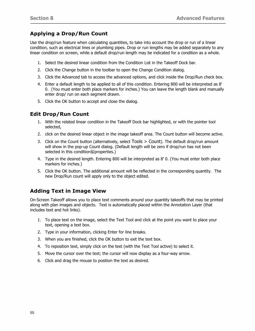
Section 8 Advanced Features
55
Applying a DropRun Count
Use the droprun feature when calculating quantities to take into account the drop or run of a linear condition such as electrical lines or plumbing pipes Drop or run lengths may be added separately to any linear condition on screen while a default droprun length may be indicated for a condition as a whole
1 Select the desired linear condition from the Condition List in the Takeoff Dock bar
2 Click the Change button in the toolbar to open the Change Condition dialog
3 Click the Advanced tab to access the advanced options and click inside the DropRun check box
4 Enter a default length to be applied to all of this condition Entering 800 will be interpreted as 8 0 (You must enter both place markers for inches) You can leave the length blank and manually enter drop run on each segment drawn
5 Click the OK button to accept and close the dialog
Edit DropRun Count
1 With the related linear condition in the Takeoff Dock bar highlighted or with the pointer tool selected
2 click on the desired linear object in the image takeoff area The Count button will become active
3 Click on the Count button (alternatively select Tools gt Count) The default droprun amount will show in the pop-up Count dialog (Default length will be zero if droprun has not been selected in this conditionrsquos properties)
4 Type in the desired length Entering 800 will be interpreted as 8 0 (You must enter both place markers for inches)
5 Click the OK button The additional amount will be reflected in the corresponding quantity The new DropRun count will apply only to the object edited
Adding Text in Image View
On-Screen Takeoff allows you to place text comments around your quantity takeoffs that may be printed along with plan images and objects Text is automatically placed within the Annotation Layer (that includes text and hot links)
1 To place text on the image select the Text Tool and click at the point you want to place your text opening a text box
2 Type in your information clicking Enter for line breaks
3 When you are finished click the OK button to exit the text box
4 To reposition text simply click on the text (with the Text Tool active) to select it
5 Move the cursor over the text the cursor will now display as a four-way arrow
6 Click and drag the mouse to position the text as desired
Section 8 Advanced Features
56
1 To edit existing text use the Text Tool to double-click on the text to open the editing box
2 Enter additional text or use the Backspace key to delete text as necessary
Formatting Text Once created you may format the font size type style and color of your text
1 Click on the text to select it and select Tools gt Font or click on the Font button in the Takeoff Toolbar
2 Select the desired features (color options are disabled) and click the OK button
3 Click on the text to select it and select Tools gt Color or click on the Color button in the Takeoff Toolbar The Color dialog will open
4 Click on a color in the Basic Color palette or create a color and add to the Custom Colors palette (Be sure to click on the color in the Custom Colors palette to select it)
5 Click the OK button
Object Properties
Linear Objects
Linear objects may be set to connect at corners
A linear object may be set to trim automatically when crossing another linear object (Check the trim option under the advanced tab of the Condition dialog)
When you move a connected linear object objects automatically move and resize connected lines accordingly (quantities are then recalculated)
This feature requires that the connected linear object be moved using the center handles (does not apply when resizing the line from the ends)
Objects constrain to snap increments defined in the Tools gt Options menu (with the mouse 15deg by default incremental when shift key is held down)
Objects are measured from centerline to centerline
Section 8 Advanced Features
57
Area Objects When drawing an area use your escape key to undo the last line drawn You may reverse your
drawing of an area using the escape key
The area will not fill with color and pattern until the user double-clicks after the last line is set
Lines drawn to delineate an area object constrain to snap increments defined in the Tools gt Options menu (with the mouse 15deg by default incremental when shift key is held down)
After selecting an area to move or adjust position the mouse in the center to move the entire area position the mouse at the sides or corners to adjust the perimeter
Count Objects
All count objects are quantified by the physical number of objects per page and reported as EA for the UOM The quantity for the current Image View is (displayed in the Condition List) and the total quantity in your project is displayed in the Takeoff View and Worksheet View)
Square circle rectangle and triangle shaped count objects do not displace or subtract from other object quantities when placed on top of them However on the Advanced Tab for the count condition a connect property can be set (this is a check box) so that when a count object of this shape is put on top of a Linear type takeoff object it will move with the linear if said linear is moved
An opened-shaped count object must be placed within a linear object Opening shaped count objects may also be measured by linear foot or linear yard (EA SF and SY are also options) Opening shaped count items default to a width of 3rsquo 0rdquo at the time of creation This size can be changed The small medium and large size are not options on this type of condition anymore Check Backout on the Advanced tab for each Count object back out the footage (or yardage) of opening-shaped count objects in which they are placed
NOTE In order to see this Backout functionality (in quantity) for SY or SF deductions at least one of the
results for the Linear(s) this object will be placed on must be set to SY or SF and the count object must have a height quantity
Advanced Features of Conditions The Round Feature Under the Advanced tab of the linear and area Condition dialogues you may specify quantity rounding (in inches) For linear objects rounding applies to each linear object drawn For area objects rounding will apply to each segment of the area perimeter adjusting the perimeter and area calculations For example With a linear condition entering 12 in the Round field will round up each related linear object to the nearest 12 inches or one foot With this setting two walls of 1 4 would each round to 2 0 totaling 4 0
NOTE In the Takeoff Dock bar condition list and in the On-Screen Takeoff reports quantities will be displayed in whole numbers rounded up to the nearest foot However calculations are based on true quantities without rounding unless the Round Feature is engaged
Pitch Pitch may apply either to linear or area conditions It is measured in rise per linear foot Entering 12 indicates a 12 rise per 12 of linear distance (a pitch of 12 over 12) or an angle of 45deg
Section 8 Advanced Features
58
Advanced Features of Project Properties Selecting Multiple Pages
1 Select a single page entry by clicking on the numbered gray button to the left of the entry
2 Drag the cursor down the column of numbers to select consecutive pages
3 Click on the blank button at the top of this column to select all pages in the Properties dialog
Section 8 Advanced Features
59
Changing Image Assigned to a Drawing 1 Select the page entry by clicking on the numbered gray button to the left of the entry 2 Click the Change Image button The Change Image dialog box will appear
3 Navigate to the desired file and select by clicking on it
4 Click the Open button The electronic file assigned to the page will have been changed to reflect the new file choice
Changing Image File Path 1 Select pages as described above
2 Choose Change Folder
3 In the Change Folder dialog navigate to the appropriate folder
4 Click the OK button The file path will have been changed for the selected page entries
Delete a Page from Project Properties 1 Select the page you want to delete by clicking on its associated number (in the gray box at the
left of the entry)
2 Choose Delete Page
All Takeoff on the page will be deleted immediately and permanently
Section 8 Advanced Features
60
Advanced Features of Tool Options
Calculation Method On-Screen Takeoff has built-in calculation options to allow for faster work and faster saves until your takeoff is complete Calculation options are found by selecting Tools gt Options then clicking on the Calculation tab
Calculation method can be set to Automatic Automatic except Grids and Manual Manual will allow the program to operate more quickly while Automatic or Automatic except Grids allows the user to see quantity changes as takeoffs are made
In any mode you may press F9 to recalculate quantities for the On-Screen Takeoff current totals
Configuration Tab
When the ldquoPage Label (A01)rdquo radial button is chosen On-Screen Takeoff puts the numbered label on all the pages of in your current page indicator in your Navigate Toolbar If the Page Descriptionrdquo radial button is chosen then a description of what takeoff is on that specific page will be shown in your current page indicator in your Navigate Toolbar
This section of the configuration tab gives you options on how you want to export your information When the ldquoFolderSubfolder Namesrdquo radial button is chosen than on your file that you are exporting to will have all the conditions folders and subfolders In the Delimiter box you can choose the symbol that is needed to separate the information you are exporting Some files need semicolons () or colons () to make sure the information comes exported in is separated it the appropriate places
Section 8 Advanced Features
61
In previous versions of On-Screen Takeoff there are views that users need to have in order for them to display their information By either choosing ldquoOST 1xrdquo or ldquoOST 2xrdquo it will let the program know you want your columns of information exported in that specific format
When you have the Confirm Deletions radial button of ldquoYesrdquo chosen than every time you delete anything you will get a dialog box confirming your intentions of deletion
While working with your takeoff you have a choice to either view the legend of your conditions or hide it Choose whichever radial button that suits your needs
For those who prefer to use the Enter key to navigate in dialog boxes this option is just for that
Font Tab The Font tab is designed for you to make your own look and feel for the application At the bottom of this tab it will show you sample of the fonts and colors you have chosen
Renaming the Current Page You may change the name of the current page in the takeoff area of On-Screen Takeoff by selecting Edit gt Rename Page
This opens the Name Page dialog and you may simply type in a new name and click the Enter button The new name for the file will be reflected on the title bar for the page and in Project Properties
You also may access the Rename Page function by right-clicking in the takeoff area while in Image View and selecting the option from the pop-up menu that appears
Section 9
62
Saving and Exiting
This section will
Explain how to save projects
Show you how to safely exit the program
Section 9 Saving and Exiting
63
Saving Your Project
1 Select File gt Save 2 If your project has not previously been saved a Save dialog box will open to allow you to name
the file and choose the directory and folder in which to save your file 3 Once saved File gt Save will simply save the current version of the file
OR
4 Select File gt Save As then type in a new name for the file and save to the desired file path
The Auto-save Feature With the Auto-save feature On-Screen Takeoff automatically backs up your open project You may choose to have more than one level of backup files The first backup copy will have the extension b00 and successive files will be b01 b02 and so on If you have designated four levels of backup files after the fourth backup copy has been created (b03) the next file will be saved over the file with extension b00 Further backup saves will then rotate through the four backup files in the same way
1 Select Tools gt Options 2 In the Auto-save area (under the General tab) select the frequency of backup file creation (in
minutes) and the number of levels for the feature 3 You also may disengage the feature by clicking in the check box to clear it
The Auto-save feature automatically saves backup copies to the directory of the current project If you are working from a write-protected area such as a CD-ROM On-Screen Takeoff will place backup files in the On-Screen Takeoff folder
Exiting When you are finished using On-Screen Takeoff it is very easy to exit Exiting is very important because of security reasons If someone were to use your computer they could enter the application and view and manipulate information
Section 9 Saving and Exiting
64
On-Screen Takeoff closes the open project when you open another or create a new project or when you exit the program
1 Select File gt Exit
OR
2 You also may click at the upper right-hand corner of the application to exit
NOTE If your latest changes to a project file have not been saved On-Screen Takeoff will ask you whether you would like to save the file and gives you the option of canceling the operation
Appendix I Installing Your Digitizer
65
Appendix I Installing Your Digitizer When you get your digitizer from GTCO you will need to connect it to your computer Follow the instructions outlined below to do this
Note For rollup digitizers the metal bar must be oriented to the top or right hand side
Connecting the Digitizer 1 Lay the digitizer out flat 2 Connect the Stylus to the digitizer 3 Plug in the power adapter 4 Plug the interface (IO) cable into the digitizer 5 Plug the other end of the interface cable into an open serial port on computer
Note GTCO Technical support phone number is 410-381-6688 The electronic manual (on diskette) from GTCO contains more detailed installation and operation instructions for the GTCO digitizer model you have
Installing other Digitizer Drivers If you are using a GTCO Digitizer you will need to install the GTCO TabletWorks Drivers
If you are using a Digitizer not supported by GTCO Tablet Works 10 please contact the manufacturer of your digitizer for assistance with installation
Installing GTCO TabletWorks Drivers 1 Insert the On Center CD into the CD-ROM drive The CD Startup screen will open 2 Click on Install Software 3 Select Additional Software and Drivers 4 Select Digitizer Driver 5 Follow the instructions for installing TabletWorks 10
Adhering the Template The template is a small plastic sticker used to enable mouse function when using the digitizer with On-Screen Takeoff Place your template on your digitizer We suggest placing it in the bottom right corner of the digitizer about one inch inside the takeoff area
Note You may either peel off the back of the template and use the adhesive surface or you can tape the template down
Appendix I Installing Your Digitizer
66
Testing the Digitizer Drivers Before running OST you may test the digitizer by moving the stylus around on the digitizer pad it should move the mouse cursor (if mouse emulation is enabled)
If the digitizer does not move the mouse cursor on the screen
The superset codes may need to be reset Reset the superset codes by touching on the border of the digitizer with the stylus The digitizer should beep several times
The digitizer may not be communicating with the computer Be sure the COM port selected is correct Be sure the COM port selected is correct If you are not able to get the digitizer to move the mouse cursor you need to call GTCO technical support for help
Note The Mouse Emulation is not required for On-Screen Takeoff to work properly It is used only for the Template functionality if the digitizer is moving the cursor the wrong direction (up instead of sideways or vice-versa)
Click the L-shaped arrow symbol on the digitizer with the stylus
Appendix II Toolbar Item Details
67
Appendix II Toolbar Items Main Toolbar
Appendix II Toolbar Item Details
68
Tool Toolbar
Appendix II Toolbar Item Details
69
Zoom Toolbar
View Toolbar
Navigate Toolbar
Appendix II Toolbar Item Details
70
Navigate Toolbar (Continued)
Takeoff Toolbar
Appendix II Toolbar Item Details
71
Takeoff Toolbar (Continued)
Image Toolbar
Appendix III Loading Plans from a Dodge CD
72
Appendix III Loading Plans from a Dodge CD
This section will detail how to load plans from a F W Dodge CD-ROM into an On-Screen Takeoff project file ready for takeoffs
Dodge files may be added to the Project Properties dialog However loading the files in that way will load the files by number rather than name description If you want to load one page only from your Dodge CD You will have to rename the page to display the name rather than number of the file
To load plan files from a Dodge CD so that the files load sequentially by file number but are displayed by name rather than by number within your project follow the instructions below
Opening a Dodge project from a CD-ROM 1 Insert the CD into the drive 2 Choose File gt Custom 3 Choose Dodge Plans Project (plansdat) as the file type 4 Select the appropriate file type by clicking on the down arrow at the right of the Files of type
field 5 In the Look in field access your drive paths by clicking on the down arrow at the right of the
field then
Navigate to your CD-ROM drive Open the data folder and Open the Projects folder
6 Select the desired project and open its folder 7 Open the plansdat file 8 All the images will come in sequenced correctly for that job along with the full descriptions
(names) of each page If there is not a plans folder in the project folder then plans do not exist for that project on the CD Opening the plansdat file will yield an empty project
Appendix IV Using the Plan Viewer
73
Appendix IV Using On-Screen Takeoff Plan Viewer The On-Screen Takeoff Plan Viewer is a limited version of On Center Softwarersquos commercial takeoff software If your status bar located at the very bottom of the main window says View Mode in the lower left-hand corner then you are using the Plan Viewer You can use the plan viewer to
View CD-based amp converted CAD drawings
View a previously created OST file and associated drawings
Download electronic plans online
Navigate through drawings
Quickly Takeoff linearsareas and counts
Zoom in to view the plan better
Print drawings directly from the viewer
Viewing an On-Screen Takeoff Project File
1 To open an OST file that was previously created with of On-Screen Takeoff 2 Select File gt Open 3 An Open dialog will appear if you do not see the OST file you are looking for select the
Look In drop down arrow 4 A drop down menu will appear listing the various folders drives and mapped drives located
on your computer select the correct drive or folder location and continue to browse to the location of your OST file
5 When you see your OST file double-click it to open it 6 Any takeoff and drawings should appear on the Image tab view
If you do not see the drawings but do see the colored takeoff layer the drawings may
not be located in the same place they were originally saved at Go to File gt Project Properties and check the Image File path for each listed page If the image file path is pointing to a CD drive make sure the CD is inside the CR-ROM
Downloading Electronic Plans If your Online Plan Service provides a special file format (OSX) required to use this feature of our plan viewer you can immediately downloaded all electronic plans of a project directly from our viewer
Most Plan Room web sites will automatically open On-Screen Takeoff when a request to download plans is made Your particular Plan Room may differ in operation so please contact the provider directly with questions on using the site
Appendix IV Using the Plan Viewer
74
When you request to download or open a project file from a Plan Room you will usually have the open to open or save an OSX file Choosing open will automatically open On-Screen Takeoff Alternately you may choose to save the file to a local hard drive After you have saved the file either double-click it to launch On-Screen Takeoff or open the OSX file using On-Screen Takeoff by clicking File then Open and locating the file on your hard drive You will need to change the file type to OSX
After the OSX file is opened you will see an additional tab appear in the Conditions List window called Pages
The Pages tab shows the hierarchy of your project Gray file icons represent pages that have not been downloaded and blue icons represents pages that have been downloaded
To download a page simply double-click the page icon
If you wish to select a group of pages to download you can use the Ctrl or Shift key to multiple select them then click the Download button
If you wish to download all pages at once click the Download All button
Downloaded pages will now appear in the Project Properties dialog in the same order in which they appear in the Pages tab
Creating Quick Takeoffs With On-Screen Takeoff you can create quick takeoffs to measure quantities even if you dont have the full version of our program However using the Quick Takeoff functionality shows you just a fraction of what the full version can do
The Quick Takeoff Toolbar is located at the top of the image view It has three buttons designated for three types of takeoffs Linear Area and Count The Quantity drop down list will show secondary quantities for Linears and Areas The Units drop down allows you to select how you want your quantities displayed Feet Inches Yards Millimeters and Meters
NOTE Every time change the type of takeoff you are performing (switching from Area to Linear for example) the previous quantities and takeoff objects will disappear They will also disappear when you changes pages
NOTE You can use the Dimension Tool to basically measure the distance between two points or linears The distance will display on the status bar at the bottom of the application
The Quick Takeoff Toolbar
Appendix V Frequently Asked Questions
75
Appendix V Frequently Asked Questions General
Where is On-Screen Takeoff installed on my computer
Typically it is installed in CProgram FilesOn-Screen Takeoff
In Explorer how do I recognize On-Screen Takeoff file types
On-Screen Takeoff data is stored in a single file per job lsquojob name OSTrsquo On-Screen Takeoff templates are stored as lsquotemplate nameTPOrsquo
Can only one project at a time be open
Yes For that reason opening another project automatically closes the project on screen You will be asked to save any changes
Is only one scale allowed per page What about on drawings that have multiple detail sections on a page and each of those drawings have different scales
Yes For pages with drawings of different scales copy the drawing to another project page and set the appropriate scale
I cannot perform backout on an area that is along a linear
As a workaround use the On-Screen Takeoff layers feature to help you with this issue Electronic Images
How do I start a project from drawings that have been scanned and written to a CD-ROM
Open a new project Select File gt Project Properties and select Auto Add Navigate to your CD and the appropriate folder and select any image file in that location Click Open All files in the location will load into your project Recommended that images are copied from CD to hard drive for performance
If I get a disk of drawings in AutoCAD format (R13 or R14) can I read them in On-Screen Takeoff
Yes On-Screen Takeoff now reads DWG DXF and many other format that are saved with AutoCAD
Appendix V Frequently Asked Questions
76
When I click on the all pages button what is supposed to happen Currently nothing seems to change when I click on that button
The All Pages button is used to apply the Darken and Enhance Plans feature to all pages in the project (as opposed to only the current page on screen)
Is there a way to deduct a large skylight from an area condition
Yes with the related area condition selected in the Takeoff Dock bar unselect the Backout button on the Takeoff Toolbar then draw the Backout area The area quantity will be deducted from the related condition object and the linear measurement of the Backout perimeter will be added
Digitizer Issues
How do I connect a Digitizer to the computer
See Appendix I Connecting a Digitizer
The Place Template menu choice is disabled
On-Screen Takeoff may need to be authorized or the digitizer or the digitzer drivers are not installed
It wonrsquot let me select the Set Takeoff Area menu choice
On-Screen Takeoff may need to be authorized or no job is open a digitizer is not installed or the drivers are not installed
The digitizer stylus is not moving the cursor or crosshairs
Click S-0-1 superset on the digitizer
How do I convert my old GTCO Digitizer to work with On- Screen Takeofftrade
Call GTCO and they may be able to reconfigure your digitizer to be compatible with On-Screen Takeoff
Printing Issues Which Printers work with On-Screen Takeoff
Compatible printers include On-Screen Takeoff Hewlett Packard Epson and Canon printers If you are having printer difficulties please contact support and specify the type of printer along with other pertinent information Contact support at wwwoncentercomsupport or email supportoncentercom
Which Plotters work with On-Screen Takeoff
Compatible Plotters include Hewlett Packard DesignJet plotters and the EnCAD Cadjet II If you are having plotter difficulties please contact support and specify the type of plotter concerned
ViewingDisplay I can no longer see my condition list How do I get it back
The toolbars and Dock bars can be turned on and off through the View gt Toolbars menu options
Appendix V Frequently Asked Questions
77
This is also accessible by right-clicking in the toolbar area and selecting (or deselecting) a toolbar listed
I cannot view my folders in the condition list
Right-click in the Takeoff Dock barcondition list area and select Show Tree to display your folders
My Status Bar reads Viewer Mode and I am unable to draw conditions
On-Screen Takeoff needs to be Authorized Or you need to purchase an upgrade Click the Perform Advanced Takeoff button on the main toolbar
I hid a Dock bar and when I selected to view it again it appeared alongside the other Dock
bar instead of stacked on top of it How do I fix it
Pick up the Dock bar by clicking on the bar at the top and continuing to hold down the mouse button drag the Dock bar over the other one It will resize and appear stacked with the other
When I open image files from a CD the images are all upside down How do I get them right
side up
To flip pages from top to bottom follow the steps below 1 Click the All Pages button on the Image Toolbar (All Pages is engaged when the button
is not clicked) 2 Click the Flip Horizontal button on the Image Toolbar 3 Click the All Pages button again to disengage
Templates How do I create a Template
Follow the steps below 1 Create a typical project 2 Choose File gt Save As 3 Choose On-Screen Takeoff Template Files as the file type to save 4 Name the file This will save all of the condition setups as well as the layers for the
project
How do I create a new project from a template
Follow the steps below 1 Choose File gt New 2 Select a template from those listed in the New dialog This will open a new project with
conditions and layers saved from a previous project but no pages or takeoff
78
INDEX
Area Conditions 32
Area Objects 57
Auto Scrolling 20
Auto-save 63
Backout Mode 41
Calculation Method 60
Conditions 29
Configuration 60
Contents Tab 6
Continuous Mode 38
Count Conditions 33
Count Objects 57
Digitizer 10 65 76
Docking Toolbars 13
Dodge CD 72
Drawing 27 37
DropRun Count 55
Environment 18
Exiting 63
Exporting 49
Features 16
Font 61
Frequently Asked Questions 75
Grid 40
Help File 5
Hiding Toolbars 13
Hot Links 21
Image 19 59
Image files 9
Image Toolbar 12 71
Images 75
Index Tab 6
Layers 43
Linear Conditions 31
Linear Objects 56
Main Toolbar 12 67
Menus 14
Moving Toolbars 13
Navigate Toolbar 12 69
Navigating 20
On-Screen Takeofftrade 2
Page 59 61
Pages 20 25 28
Plan Viewer 73
Plans 26
Printing 47 76
Project Properties 25
Projects 22
Quick Start Video 18
Resizing Toolbars 13
Roping 54
Saving 63
Scale 28
Search Tab 7
Selecting Objects 42
Setup 8
Start On-Screen Takeofftrade 17
System Requirements 9
Takeoff 19 27
Takeoff Toolbar 70 71
Takeoff Toolbar 12
Template Files 23
TIF (Group4) 9
Tool Toolbar 12 68
Toolbar 67
Toolbars 12
View Toolbar 12 69
Viewing Toolbars 12
Worksheet 20
Zone Conditions 33
Zoom Toolbar 12 69
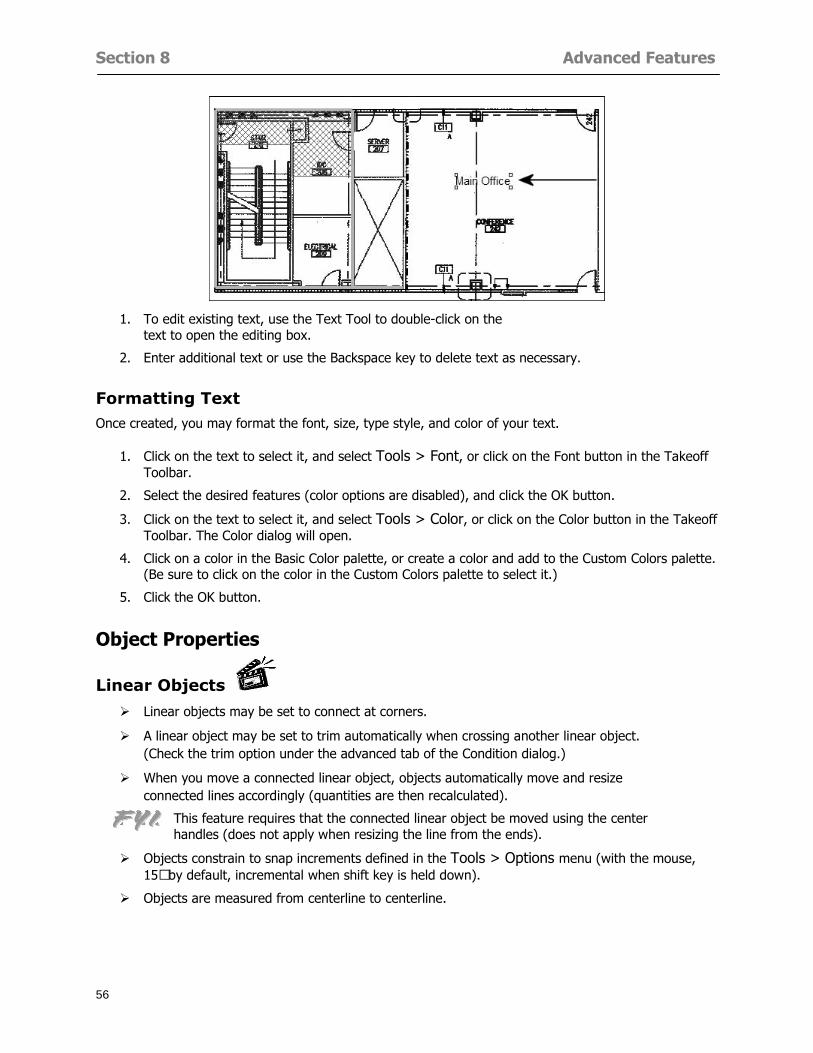
Section 8 Advanced Features
56
1 To edit existing text use the Text Tool to double-click on the text to open the editing box
2 Enter additional text or use the Backspace key to delete text as necessary
Formatting Text Once created you may format the font size type style and color of your text
1 Click on the text to select it and select Tools gt Font or click on the Font button in the Takeoff Toolbar
2 Select the desired features (color options are disabled) and click the OK button
3 Click on the text to select it and select Tools gt Color or click on the Color button in the Takeoff Toolbar The Color dialog will open
4 Click on a color in the Basic Color palette or create a color and add to the Custom Colors palette (Be sure to click on the color in the Custom Colors palette to select it)
5 Click the OK button
Object Properties
Linear Objects
Linear objects may be set to connect at corners
A linear object may be set to trim automatically when crossing another linear object (Check the trim option under the advanced tab of the Condition dialog)
When you move a connected linear object objects automatically move and resize connected lines accordingly (quantities are then recalculated)
This feature requires that the connected linear object be moved using the center handles (does not apply when resizing the line from the ends)
Objects constrain to snap increments defined in the Tools gt Options menu (with the mouse 15deg by default incremental when shift key is held down)
Objects are measured from centerline to centerline
Section 8 Advanced Features
57
Area Objects When drawing an area use your escape key to undo the last line drawn You may reverse your
drawing of an area using the escape key
The area will not fill with color and pattern until the user double-clicks after the last line is set
Lines drawn to delineate an area object constrain to snap increments defined in the Tools gt Options menu (with the mouse 15deg by default incremental when shift key is held down)
After selecting an area to move or adjust position the mouse in the center to move the entire area position the mouse at the sides or corners to adjust the perimeter
Count Objects
All count objects are quantified by the physical number of objects per page and reported as EA for the UOM The quantity for the current Image View is (displayed in the Condition List) and the total quantity in your project is displayed in the Takeoff View and Worksheet View)
Square circle rectangle and triangle shaped count objects do not displace or subtract from other object quantities when placed on top of them However on the Advanced Tab for the count condition a connect property can be set (this is a check box) so that when a count object of this shape is put on top of a Linear type takeoff object it will move with the linear if said linear is moved
An opened-shaped count object must be placed within a linear object Opening shaped count objects may also be measured by linear foot or linear yard (EA SF and SY are also options) Opening shaped count items default to a width of 3rsquo 0rdquo at the time of creation This size can be changed The small medium and large size are not options on this type of condition anymore Check Backout on the Advanced tab for each Count object back out the footage (or yardage) of opening-shaped count objects in which they are placed
NOTE In order to see this Backout functionality (in quantity) for SY or SF deductions at least one of the
results for the Linear(s) this object will be placed on must be set to SY or SF and the count object must have a height quantity
Advanced Features of Conditions The Round Feature Under the Advanced tab of the linear and area Condition dialogues you may specify quantity rounding (in inches) For linear objects rounding applies to each linear object drawn For area objects rounding will apply to each segment of the area perimeter adjusting the perimeter and area calculations For example With a linear condition entering 12 in the Round field will round up each related linear object to the nearest 12 inches or one foot With this setting two walls of 1 4 would each round to 2 0 totaling 4 0
NOTE In the Takeoff Dock bar condition list and in the On-Screen Takeoff reports quantities will be displayed in whole numbers rounded up to the nearest foot However calculations are based on true quantities without rounding unless the Round Feature is engaged
Pitch Pitch may apply either to linear or area conditions It is measured in rise per linear foot Entering 12 indicates a 12 rise per 12 of linear distance (a pitch of 12 over 12) or an angle of 45deg
Section 8 Advanced Features
58
Advanced Features of Project Properties Selecting Multiple Pages
1 Select a single page entry by clicking on the numbered gray button to the left of the entry
2 Drag the cursor down the column of numbers to select consecutive pages
3 Click on the blank button at the top of this column to select all pages in the Properties dialog
Section 8 Advanced Features
59
Changing Image Assigned to a Drawing 1 Select the page entry by clicking on the numbered gray button to the left of the entry 2 Click the Change Image button The Change Image dialog box will appear
3 Navigate to the desired file and select by clicking on it
4 Click the Open button The electronic file assigned to the page will have been changed to reflect the new file choice
Changing Image File Path 1 Select pages as described above
2 Choose Change Folder
3 In the Change Folder dialog navigate to the appropriate folder
4 Click the OK button The file path will have been changed for the selected page entries
Delete a Page from Project Properties 1 Select the page you want to delete by clicking on its associated number (in the gray box at the
left of the entry)
2 Choose Delete Page
All Takeoff on the page will be deleted immediately and permanently
Section 8 Advanced Features
60
Advanced Features of Tool Options
Calculation Method On-Screen Takeoff has built-in calculation options to allow for faster work and faster saves until your takeoff is complete Calculation options are found by selecting Tools gt Options then clicking on the Calculation tab
Calculation method can be set to Automatic Automatic except Grids and Manual Manual will allow the program to operate more quickly while Automatic or Automatic except Grids allows the user to see quantity changes as takeoffs are made
In any mode you may press F9 to recalculate quantities for the On-Screen Takeoff current totals
Configuration Tab
When the ldquoPage Label (A01)rdquo radial button is chosen On-Screen Takeoff puts the numbered label on all the pages of in your current page indicator in your Navigate Toolbar If the Page Descriptionrdquo radial button is chosen then a description of what takeoff is on that specific page will be shown in your current page indicator in your Navigate Toolbar
This section of the configuration tab gives you options on how you want to export your information When the ldquoFolderSubfolder Namesrdquo radial button is chosen than on your file that you are exporting to will have all the conditions folders and subfolders In the Delimiter box you can choose the symbol that is needed to separate the information you are exporting Some files need semicolons () or colons () to make sure the information comes exported in is separated it the appropriate places
Section 8 Advanced Features
61
In previous versions of On-Screen Takeoff there are views that users need to have in order for them to display their information By either choosing ldquoOST 1xrdquo or ldquoOST 2xrdquo it will let the program know you want your columns of information exported in that specific format
When you have the Confirm Deletions radial button of ldquoYesrdquo chosen than every time you delete anything you will get a dialog box confirming your intentions of deletion
While working with your takeoff you have a choice to either view the legend of your conditions or hide it Choose whichever radial button that suits your needs
For those who prefer to use the Enter key to navigate in dialog boxes this option is just for that
Font Tab The Font tab is designed for you to make your own look and feel for the application At the bottom of this tab it will show you sample of the fonts and colors you have chosen
Renaming the Current Page You may change the name of the current page in the takeoff area of On-Screen Takeoff by selecting Edit gt Rename Page
This opens the Name Page dialog and you may simply type in a new name and click the Enter button The new name for the file will be reflected on the title bar for the page and in Project Properties
You also may access the Rename Page function by right-clicking in the takeoff area while in Image View and selecting the option from the pop-up menu that appears
Section 9
62
Saving and Exiting
This section will
Explain how to save projects
Show you how to safely exit the program
Section 9 Saving and Exiting
63
Saving Your Project
1 Select File gt Save 2 If your project has not previously been saved a Save dialog box will open to allow you to name
the file and choose the directory and folder in which to save your file 3 Once saved File gt Save will simply save the current version of the file
OR
4 Select File gt Save As then type in a new name for the file and save to the desired file path
The Auto-save Feature With the Auto-save feature On-Screen Takeoff automatically backs up your open project You may choose to have more than one level of backup files The first backup copy will have the extension b00 and successive files will be b01 b02 and so on If you have designated four levels of backup files after the fourth backup copy has been created (b03) the next file will be saved over the file with extension b00 Further backup saves will then rotate through the four backup files in the same way
1 Select Tools gt Options 2 In the Auto-save area (under the General tab) select the frequency of backup file creation (in
minutes) and the number of levels for the feature 3 You also may disengage the feature by clicking in the check box to clear it
The Auto-save feature automatically saves backup copies to the directory of the current project If you are working from a write-protected area such as a CD-ROM On-Screen Takeoff will place backup files in the On-Screen Takeoff folder
Exiting When you are finished using On-Screen Takeoff it is very easy to exit Exiting is very important because of security reasons If someone were to use your computer they could enter the application and view and manipulate information
Section 9 Saving and Exiting
64
On-Screen Takeoff closes the open project when you open another or create a new project or when you exit the program
1 Select File gt Exit
OR
2 You also may click at the upper right-hand corner of the application to exit
NOTE If your latest changes to a project file have not been saved On-Screen Takeoff will ask you whether you would like to save the file and gives you the option of canceling the operation
Appendix I Installing Your Digitizer
65
Appendix I Installing Your Digitizer When you get your digitizer from GTCO you will need to connect it to your computer Follow the instructions outlined below to do this
Note For rollup digitizers the metal bar must be oriented to the top or right hand side
Connecting the Digitizer 1 Lay the digitizer out flat 2 Connect the Stylus to the digitizer 3 Plug in the power adapter 4 Plug the interface (IO) cable into the digitizer 5 Plug the other end of the interface cable into an open serial port on computer
Note GTCO Technical support phone number is 410-381-6688 The electronic manual (on diskette) from GTCO contains more detailed installation and operation instructions for the GTCO digitizer model you have
Installing other Digitizer Drivers If you are using a GTCO Digitizer you will need to install the GTCO TabletWorks Drivers
If you are using a Digitizer not supported by GTCO Tablet Works 10 please contact the manufacturer of your digitizer for assistance with installation
Installing GTCO TabletWorks Drivers 1 Insert the On Center CD into the CD-ROM drive The CD Startup screen will open 2 Click on Install Software 3 Select Additional Software and Drivers 4 Select Digitizer Driver 5 Follow the instructions for installing TabletWorks 10
Adhering the Template The template is a small plastic sticker used to enable mouse function when using the digitizer with On-Screen Takeoff Place your template on your digitizer We suggest placing it in the bottom right corner of the digitizer about one inch inside the takeoff area
Note You may either peel off the back of the template and use the adhesive surface or you can tape the template down
Appendix I Installing Your Digitizer
66
Testing the Digitizer Drivers Before running OST you may test the digitizer by moving the stylus around on the digitizer pad it should move the mouse cursor (if mouse emulation is enabled)
If the digitizer does not move the mouse cursor on the screen
The superset codes may need to be reset Reset the superset codes by touching on the border of the digitizer with the stylus The digitizer should beep several times
The digitizer may not be communicating with the computer Be sure the COM port selected is correct Be sure the COM port selected is correct If you are not able to get the digitizer to move the mouse cursor you need to call GTCO technical support for help
Note The Mouse Emulation is not required for On-Screen Takeoff to work properly It is used only for the Template functionality if the digitizer is moving the cursor the wrong direction (up instead of sideways or vice-versa)
Click the L-shaped arrow symbol on the digitizer with the stylus
Appendix II Toolbar Item Details
67
Appendix II Toolbar Items Main Toolbar
Appendix II Toolbar Item Details
68
Tool Toolbar
Appendix II Toolbar Item Details
69
Zoom Toolbar
View Toolbar
Navigate Toolbar
Appendix II Toolbar Item Details
70
Navigate Toolbar (Continued)
Takeoff Toolbar
Appendix II Toolbar Item Details
71
Takeoff Toolbar (Continued)
Image Toolbar
Appendix III Loading Plans from a Dodge CD
72
Appendix III Loading Plans from a Dodge CD
This section will detail how to load plans from a F W Dodge CD-ROM into an On-Screen Takeoff project file ready for takeoffs
Dodge files may be added to the Project Properties dialog However loading the files in that way will load the files by number rather than name description If you want to load one page only from your Dodge CD You will have to rename the page to display the name rather than number of the file
To load plan files from a Dodge CD so that the files load sequentially by file number but are displayed by name rather than by number within your project follow the instructions below
Opening a Dodge project from a CD-ROM 1 Insert the CD into the drive 2 Choose File gt Custom 3 Choose Dodge Plans Project (plansdat) as the file type 4 Select the appropriate file type by clicking on the down arrow at the right of the Files of type
field 5 In the Look in field access your drive paths by clicking on the down arrow at the right of the
field then
Navigate to your CD-ROM drive Open the data folder and Open the Projects folder
6 Select the desired project and open its folder 7 Open the plansdat file 8 All the images will come in sequenced correctly for that job along with the full descriptions
(names) of each page If there is not a plans folder in the project folder then plans do not exist for that project on the CD Opening the plansdat file will yield an empty project
Appendix IV Using the Plan Viewer
73
Appendix IV Using On-Screen Takeoff Plan Viewer The On-Screen Takeoff Plan Viewer is a limited version of On Center Softwarersquos commercial takeoff software If your status bar located at the very bottom of the main window says View Mode in the lower left-hand corner then you are using the Plan Viewer You can use the plan viewer to
View CD-based amp converted CAD drawings
View a previously created OST file and associated drawings
Download electronic plans online
Navigate through drawings
Quickly Takeoff linearsareas and counts
Zoom in to view the plan better
Print drawings directly from the viewer
Viewing an On-Screen Takeoff Project File
1 To open an OST file that was previously created with of On-Screen Takeoff 2 Select File gt Open 3 An Open dialog will appear if you do not see the OST file you are looking for select the
Look In drop down arrow 4 A drop down menu will appear listing the various folders drives and mapped drives located
on your computer select the correct drive or folder location and continue to browse to the location of your OST file
5 When you see your OST file double-click it to open it 6 Any takeoff and drawings should appear on the Image tab view
If you do not see the drawings but do see the colored takeoff layer the drawings may
not be located in the same place they were originally saved at Go to File gt Project Properties and check the Image File path for each listed page If the image file path is pointing to a CD drive make sure the CD is inside the CR-ROM
Downloading Electronic Plans If your Online Plan Service provides a special file format (OSX) required to use this feature of our plan viewer you can immediately downloaded all electronic plans of a project directly from our viewer
Most Plan Room web sites will automatically open On-Screen Takeoff when a request to download plans is made Your particular Plan Room may differ in operation so please contact the provider directly with questions on using the site
Appendix IV Using the Plan Viewer
74
When you request to download or open a project file from a Plan Room you will usually have the open to open or save an OSX file Choosing open will automatically open On-Screen Takeoff Alternately you may choose to save the file to a local hard drive After you have saved the file either double-click it to launch On-Screen Takeoff or open the OSX file using On-Screen Takeoff by clicking File then Open and locating the file on your hard drive You will need to change the file type to OSX
After the OSX file is opened you will see an additional tab appear in the Conditions List window called Pages
The Pages tab shows the hierarchy of your project Gray file icons represent pages that have not been downloaded and blue icons represents pages that have been downloaded
To download a page simply double-click the page icon
If you wish to select a group of pages to download you can use the Ctrl or Shift key to multiple select them then click the Download button
If you wish to download all pages at once click the Download All button
Downloaded pages will now appear in the Project Properties dialog in the same order in which they appear in the Pages tab
Creating Quick Takeoffs With On-Screen Takeoff you can create quick takeoffs to measure quantities even if you dont have the full version of our program However using the Quick Takeoff functionality shows you just a fraction of what the full version can do
The Quick Takeoff Toolbar is located at the top of the image view It has three buttons designated for three types of takeoffs Linear Area and Count The Quantity drop down list will show secondary quantities for Linears and Areas The Units drop down allows you to select how you want your quantities displayed Feet Inches Yards Millimeters and Meters
NOTE Every time change the type of takeoff you are performing (switching from Area to Linear for example) the previous quantities and takeoff objects will disappear They will also disappear when you changes pages
NOTE You can use the Dimension Tool to basically measure the distance between two points or linears The distance will display on the status bar at the bottom of the application
The Quick Takeoff Toolbar
Appendix V Frequently Asked Questions
75
Appendix V Frequently Asked Questions General
Where is On-Screen Takeoff installed on my computer
Typically it is installed in CProgram FilesOn-Screen Takeoff
In Explorer how do I recognize On-Screen Takeoff file types
On-Screen Takeoff data is stored in a single file per job lsquojob name OSTrsquo On-Screen Takeoff templates are stored as lsquotemplate nameTPOrsquo
Can only one project at a time be open
Yes For that reason opening another project automatically closes the project on screen You will be asked to save any changes
Is only one scale allowed per page What about on drawings that have multiple detail sections on a page and each of those drawings have different scales
Yes For pages with drawings of different scales copy the drawing to another project page and set the appropriate scale
I cannot perform backout on an area that is along a linear
As a workaround use the On-Screen Takeoff layers feature to help you with this issue Electronic Images
How do I start a project from drawings that have been scanned and written to a CD-ROM
Open a new project Select File gt Project Properties and select Auto Add Navigate to your CD and the appropriate folder and select any image file in that location Click Open All files in the location will load into your project Recommended that images are copied from CD to hard drive for performance
If I get a disk of drawings in AutoCAD format (R13 or R14) can I read them in On-Screen Takeoff
Yes On-Screen Takeoff now reads DWG DXF and many other format that are saved with AutoCAD
Appendix V Frequently Asked Questions
76
When I click on the all pages button what is supposed to happen Currently nothing seems to change when I click on that button
The All Pages button is used to apply the Darken and Enhance Plans feature to all pages in the project (as opposed to only the current page on screen)
Is there a way to deduct a large skylight from an area condition
Yes with the related area condition selected in the Takeoff Dock bar unselect the Backout button on the Takeoff Toolbar then draw the Backout area The area quantity will be deducted from the related condition object and the linear measurement of the Backout perimeter will be added
Digitizer Issues
How do I connect a Digitizer to the computer
See Appendix I Connecting a Digitizer
The Place Template menu choice is disabled
On-Screen Takeoff may need to be authorized or the digitizer or the digitzer drivers are not installed
It wonrsquot let me select the Set Takeoff Area menu choice
On-Screen Takeoff may need to be authorized or no job is open a digitizer is not installed or the drivers are not installed
The digitizer stylus is not moving the cursor or crosshairs
Click S-0-1 superset on the digitizer
How do I convert my old GTCO Digitizer to work with On- Screen Takeofftrade
Call GTCO and they may be able to reconfigure your digitizer to be compatible with On-Screen Takeoff
Printing Issues Which Printers work with On-Screen Takeoff
Compatible printers include On-Screen Takeoff Hewlett Packard Epson and Canon printers If you are having printer difficulties please contact support and specify the type of printer along with other pertinent information Contact support at wwwoncentercomsupport or email supportoncentercom
Which Plotters work with On-Screen Takeoff
Compatible Plotters include Hewlett Packard DesignJet plotters and the EnCAD Cadjet II If you are having plotter difficulties please contact support and specify the type of plotter concerned
ViewingDisplay I can no longer see my condition list How do I get it back
The toolbars and Dock bars can be turned on and off through the View gt Toolbars menu options
Appendix V Frequently Asked Questions
77
This is also accessible by right-clicking in the toolbar area and selecting (or deselecting) a toolbar listed
I cannot view my folders in the condition list
Right-click in the Takeoff Dock barcondition list area and select Show Tree to display your folders
My Status Bar reads Viewer Mode and I am unable to draw conditions
On-Screen Takeoff needs to be Authorized Or you need to purchase an upgrade Click the Perform Advanced Takeoff button on the main toolbar
I hid a Dock bar and when I selected to view it again it appeared alongside the other Dock
bar instead of stacked on top of it How do I fix it
Pick up the Dock bar by clicking on the bar at the top and continuing to hold down the mouse button drag the Dock bar over the other one It will resize and appear stacked with the other
When I open image files from a CD the images are all upside down How do I get them right
side up
To flip pages from top to bottom follow the steps below 1 Click the All Pages button on the Image Toolbar (All Pages is engaged when the button
is not clicked) 2 Click the Flip Horizontal button on the Image Toolbar 3 Click the All Pages button again to disengage
Templates How do I create a Template
Follow the steps below 1 Create a typical project 2 Choose File gt Save As 3 Choose On-Screen Takeoff Template Files as the file type to save 4 Name the file This will save all of the condition setups as well as the layers for the
project
How do I create a new project from a template
Follow the steps below 1 Choose File gt New 2 Select a template from those listed in the New dialog This will open a new project with
conditions and layers saved from a previous project but no pages or takeoff
78
INDEX
Area Conditions 32
Area Objects 57
Auto Scrolling 20
Auto-save 63
Backout Mode 41
Calculation Method 60
Conditions 29
Configuration 60
Contents Tab 6
Continuous Mode 38
Count Conditions 33
Count Objects 57
Digitizer 10 65 76
Docking Toolbars 13
Dodge CD 72
Drawing 27 37
DropRun Count 55
Environment 18
Exiting 63
Exporting 49
Features 16
Font 61
Frequently Asked Questions 75
Grid 40
Help File 5
Hiding Toolbars 13
Hot Links 21
Image 19 59
Image files 9
Image Toolbar 12 71
Images 75
Index Tab 6
Layers 43
Linear Conditions 31
Linear Objects 56
Main Toolbar 12 67
Menus 14
Moving Toolbars 13
Navigate Toolbar 12 69
Navigating 20
On-Screen Takeofftrade 2
Page 59 61
Pages 20 25 28
Plan Viewer 73
Plans 26
Printing 47 76
Project Properties 25
Projects 22
Quick Start Video 18
Resizing Toolbars 13
Roping 54
Saving 63
Scale 28
Search Tab 7
Selecting Objects 42
Setup 8
Start On-Screen Takeofftrade 17
System Requirements 9
Takeoff 19 27
Takeoff Toolbar 70 71
Takeoff Toolbar 12
Template Files 23
TIF (Group4) 9
Tool Toolbar 12 68
Toolbar 67
Toolbars 12
View Toolbar 12 69
Viewing Toolbars 12
Worksheet 20
Zone Conditions 33
Zoom Toolbar 12 69
Section 8 Advanced Features
57
Area Objects When drawing an area use your escape key to undo the last line drawn You may reverse your
drawing of an area using the escape key
The area will not fill with color and pattern until the user double-clicks after the last line is set
Lines drawn to delineate an area object constrain to snap increments defined in the Tools gt Options menu (with the mouse 15deg by default incremental when shift key is held down)
After selecting an area to move or adjust position the mouse in the center to move the entire area position the mouse at the sides or corners to adjust the perimeter
Count Objects
All count objects are quantified by the physical number of objects per page and reported as EA for the UOM The quantity for the current Image View is (displayed in the Condition List) and the total quantity in your project is displayed in the Takeoff View and Worksheet View)
Square circle rectangle and triangle shaped count objects do not displace or subtract from other object quantities when placed on top of them However on the Advanced Tab for the count condition a connect property can be set (this is a check box) so that when a count object of this shape is put on top of a Linear type takeoff object it will move with the linear if said linear is moved
An opened-shaped count object must be placed within a linear object Opening shaped count objects may also be measured by linear foot or linear yard (EA SF and SY are also options) Opening shaped count items default to a width of 3rsquo 0rdquo at the time of creation This size can be changed The small medium and large size are not options on this type of condition anymore Check Backout on the Advanced tab for each Count object back out the footage (or yardage) of opening-shaped count objects in which they are placed
NOTE In order to see this Backout functionality (in quantity) for SY or SF deductions at least one of the
results for the Linear(s) this object will be placed on must be set to SY or SF and the count object must have a height quantity
Advanced Features of Conditions The Round Feature Under the Advanced tab of the linear and area Condition dialogues you may specify quantity rounding (in inches) For linear objects rounding applies to each linear object drawn For area objects rounding will apply to each segment of the area perimeter adjusting the perimeter and area calculations For example With a linear condition entering 12 in the Round field will round up each related linear object to the nearest 12 inches or one foot With this setting two walls of 1 4 would each round to 2 0 totaling 4 0
NOTE In the Takeoff Dock bar condition list and in the On-Screen Takeoff reports quantities will be displayed in whole numbers rounded up to the nearest foot However calculations are based on true quantities without rounding unless the Round Feature is engaged
Pitch Pitch may apply either to linear or area conditions It is measured in rise per linear foot Entering 12 indicates a 12 rise per 12 of linear distance (a pitch of 12 over 12) or an angle of 45deg
Section 8 Advanced Features
58
Advanced Features of Project Properties Selecting Multiple Pages
1 Select a single page entry by clicking on the numbered gray button to the left of the entry
2 Drag the cursor down the column of numbers to select consecutive pages
3 Click on the blank button at the top of this column to select all pages in the Properties dialog
Section 8 Advanced Features
59
Changing Image Assigned to a Drawing 1 Select the page entry by clicking on the numbered gray button to the left of the entry 2 Click the Change Image button The Change Image dialog box will appear
3 Navigate to the desired file and select by clicking on it
4 Click the Open button The electronic file assigned to the page will have been changed to reflect the new file choice
Changing Image File Path 1 Select pages as described above
2 Choose Change Folder
3 In the Change Folder dialog navigate to the appropriate folder
4 Click the OK button The file path will have been changed for the selected page entries
Delete a Page from Project Properties 1 Select the page you want to delete by clicking on its associated number (in the gray box at the
left of the entry)
2 Choose Delete Page
All Takeoff on the page will be deleted immediately and permanently
Section 8 Advanced Features
60
Advanced Features of Tool Options
Calculation Method On-Screen Takeoff has built-in calculation options to allow for faster work and faster saves until your takeoff is complete Calculation options are found by selecting Tools gt Options then clicking on the Calculation tab
Calculation method can be set to Automatic Automatic except Grids and Manual Manual will allow the program to operate more quickly while Automatic or Automatic except Grids allows the user to see quantity changes as takeoffs are made
In any mode you may press F9 to recalculate quantities for the On-Screen Takeoff current totals
Configuration Tab
When the ldquoPage Label (A01)rdquo radial button is chosen On-Screen Takeoff puts the numbered label on all the pages of in your current page indicator in your Navigate Toolbar If the Page Descriptionrdquo radial button is chosen then a description of what takeoff is on that specific page will be shown in your current page indicator in your Navigate Toolbar
This section of the configuration tab gives you options on how you want to export your information When the ldquoFolderSubfolder Namesrdquo radial button is chosen than on your file that you are exporting to will have all the conditions folders and subfolders In the Delimiter box you can choose the symbol that is needed to separate the information you are exporting Some files need semicolons () or colons () to make sure the information comes exported in is separated it the appropriate places
Section 8 Advanced Features
61
In previous versions of On-Screen Takeoff there are views that users need to have in order for them to display their information By either choosing ldquoOST 1xrdquo or ldquoOST 2xrdquo it will let the program know you want your columns of information exported in that specific format
When you have the Confirm Deletions radial button of ldquoYesrdquo chosen than every time you delete anything you will get a dialog box confirming your intentions of deletion
While working with your takeoff you have a choice to either view the legend of your conditions or hide it Choose whichever radial button that suits your needs
For those who prefer to use the Enter key to navigate in dialog boxes this option is just for that
Font Tab The Font tab is designed for you to make your own look and feel for the application At the bottom of this tab it will show you sample of the fonts and colors you have chosen
Renaming the Current Page You may change the name of the current page in the takeoff area of On-Screen Takeoff by selecting Edit gt Rename Page
This opens the Name Page dialog and you may simply type in a new name and click the Enter button The new name for the file will be reflected on the title bar for the page and in Project Properties
You also may access the Rename Page function by right-clicking in the takeoff area while in Image View and selecting the option from the pop-up menu that appears
Section 9
62
Saving and Exiting
This section will
Explain how to save projects
Show you how to safely exit the program
Section 9 Saving and Exiting
63
Saving Your Project
1 Select File gt Save 2 If your project has not previously been saved a Save dialog box will open to allow you to name
the file and choose the directory and folder in which to save your file 3 Once saved File gt Save will simply save the current version of the file
OR
4 Select File gt Save As then type in a new name for the file and save to the desired file path
The Auto-save Feature With the Auto-save feature On-Screen Takeoff automatically backs up your open project You may choose to have more than one level of backup files The first backup copy will have the extension b00 and successive files will be b01 b02 and so on If you have designated four levels of backup files after the fourth backup copy has been created (b03) the next file will be saved over the file with extension b00 Further backup saves will then rotate through the four backup files in the same way
1 Select Tools gt Options 2 In the Auto-save area (under the General tab) select the frequency of backup file creation (in
minutes) and the number of levels for the feature 3 You also may disengage the feature by clicking in the check box to clear it
The Auto-save feature automatically saves backup copies to the directory of the current project If you are working from a write-protected area such as a CD-ROM On-Screen Takeoff will place backup files in the On-Screen Takeoff folder
Exiting When you are finished using On-Screen Takeoff it is very easy to exit Exiting is very important because of security reasons If someone were to use your computer they could enter the application and view and manipulate information
Section 9 Saving and Exiting
64
On-Screen Takeoff closes the open project when you open another or create a new project or when you exit the program
1 Select File gt Exit
OR
2 You also may click at the upper right-hand corner of the application to exit
NOTE If your latest changes to a project file have not been saved On-Screen Takeoff will ask you whether you would like to save the file and gives you the option of canceling the operation
Appendix I Installing Your Digitizer
65
Appendix I Installing Your Digitizer When you get your digitizer from GTCO you will need to connect it to your computer Follow the instructions outlined below to do this
Note For rollup digitizers the metal bar must be oriented to the top or right hand side
Connecting the Digitizer 1 Lay the digitizer out flat 2 Connect the Stylus to the digitizer 3 Plug in the power adapter 4 Plug the interface (IO) cable into the digitizer 5 Plug the other end of the interface cable into an open serial port on computer
Note GTCO Technical support phone number is 410-381-6688 The electronic manual (on diskette) from GTCO contains more detailed installation and operation instructions for the GTCO digitizer model you have
Installing other Digitizer Drivers If you are using a GTCO Digitizer you will need to install the GTCO TabletWorks Drivers
If you are using a Digitizer not supported by GTCO Tablet Works 10 please contact the manufacturer of your digitizer for assistance with installation
Installing GTCO TabletWorks Drivers 1 Insert the On Center CD into the CD-ROM drive The CD Startup screen will open 2 Click on Install Software 3 Select Additional Software and Drivers 4 Select Digitizer Driver 5 Follow the instructions for installing TabletWorks 10
Adhering the Template The template is a small plastic sticker used to enable mouse function when using the digitizer with On-Screen Takeoff Place your template on your digitizer We suggest placing it in the bottom right corner of the digitizer about one inch inside the takeoff area
Note You may either peel off the back of the template and use the adhesive surface or you can tape the template down
Appendix I Installing Your Digitizer
66
Testing the Digitizer Drivers Before running OST you may test the digitizer by moving the stylus around on the digitizer pad it should move the mouse cursor (if mouse emulation is enabled)
If the digitizer does not move the mouse cursor on the screen
The superset codes may need to be reset Reset the superset codes by touching on the border of the digitizer with the stylus The digitizer should beep several times
The digitizer may not be communicating with the computer Be sure the COM port selected is correct Be sure the COM port selected is correct If you are not able to get the digitizer to move the mouse cursor you need to call GTCO technical support for help
Note The Mouse Emulation is not required for On-Screen Takeoff to work properly It is used only for the Template functionality if the digitizer is moving the cursor the wrong direction (up instead of sideways or vice-versa)
Click the L-shaped arrow symbol on the digitizer with the stylus
Appendix II Toolbar Item Details
67
Appendix II Toolbar Items Main Toolbar
Appendix II Toolbar Item Details
68
Tool Toolbar
Appendix II Toolbar Item Details
69
Zoom Toolbar
View Toolbar
Navigate Toolbar
Appendix II Toolbar Item Details
70
Navigate Toolbar (Continued)
Takeoff Toolbar
Appendix II Toolbar Item Details
71
Takeoff Toolbar (Continued)
Image Toolbar
Appendix III Loading Plans from a Dodge CD
72
Appendix III Loading Plans from a Dodge CD
This section will detail how to load plans from a F W Dodge CD-ROM into an On-Screen Takeoff project file ready for takeoffs
Dodge files may be added to the Project Properties dialog However loading the files in that way will load the files by number rather than name description If you want to load one page only from your Dodge CD You will have to rename the page to display the name rather than number of the file
To load plan files from a Dodge CD so that the files load sequentially by file number but are displayed by name rather than by number within your project follow the instructions below
Opening a Dodge project from a CD-ROM 1 Insert the CD into the drive 2 Choose File gt Custom 3 Choose Dodge Plans Project (plansdat) as the file type 4 Select the appropriate file type by clicking on the down arrow at the right of the Files of type
field 5 In the Look in field access your drive paths by clicking on the down arrow at the right of the
field then
Navigate to your CD-ROM drive Open the data folder and Open the Projects folder
6 Select the desired project and open its folder 7 Open the plansdat file 8 All the images will come in sequenced correctly for that job along with the full descriptions
(names) of each page If there is not a plans folder in the project folder then plans do not exist for that project on the CD Opening the plansdat file will yield an empty project
Appendix IV Using the Plan Viewer
73
Appendix IV Using On-Screen Takeoff Plan Viewer The On-Screen Takeoff Plan Viewer is a limited version of On Center Softwarersquos commercial takeoff software If your status bar located at the very bottom of the main window says View Mode in the lower left-hand corner then you are using the Plan Viewer You can use the plan viewer to
View CD-based amp converted CAD drawings
View a previously created OST file and associated drawings
Download electronic plans online
Navigate through drawings
Quickly Takeoff linearsareas and counts
Zoom in to view the plan better
Print drawings directly from the viewer
Viewing an On-Screen Takeoff Project File
1 To open an OST file that was previously created with of On-Screen Takeoff 2 Select File gt Open 3 An Open dialog will appear if you do not see the OST file you are looking for select the
Look In drop down arrow 4 A drop down menu will appear listing the various folders drives and mapped drives located
on your computer select the correct drive or folder location and continue to browse to the location of your OST file
5 When you see your OST file double-click it to open it 6 Any takeoff and drawings should appear on the Image tab view
If you do not see the drawings but do see the colored takeoff layer the drawings may
not be located in the same place they were originally saved at Go to File gt Project Properties and check the Image File path for each listed page If the image file path is pointing to a CD drive make sure the CD is inside the CR-ROM
Downloading Electronic Plans If your Online Plan Service provides a special file format (OSX) required to use this feature of our plan viewer you can immediately downloaded all electronic plans of a project directly from our viewer
Most Plan Room web sites will automatically open On-Screen Takeoff when a request to download plans is made Your particular Plan Room may differ in operation so please contact the provider directly with questions on using the site
Appendix IV Using the Plan Viewer
74
When you request to download or open a project file from a Plan Room you will usually have the open to open or save an OSX file Choosing open will automatically open On-Screen Takeoff Alternately you may choose to save the file to a local hard drive After you have saved the file either double-click it to launch On-Screen Takeoff or open the OSX file using On-Screen Takeoff by clicking File then Open and locating the file on your hard drive You will need to change the file type to OSX
After the OSX file is opened you will see an additional tab appear in the Conditions List window called Pages
The Pages tab shows the hierarchy of your project Gray file icons represent pages that have not been downloaded and blue icons represents pages that have been downloaded
To download a page simply double-click the page icon
If you wish to select a group of pages to download you can use the Ctrl or Shift key to multiple select them then click the Download button
If you wish to download all pages at once click the Download All button
Downloaded pages will now appear in the Project Properties dialog in the same order in which they appear in the Pages tab
Creating Quick Takeoffs With On-Screen Takeoff you can create quick takeoffs to measure quantities even if you dont have the full version of our program However using the Quick Takeoff functionality shows you just a fraction of what the full version can do
The Quick Takeoff Toolbar is located at the top of the image view It has three buttons designated for three types of takeoffs Linear Area and Count The Quantity drop down list will show secondary quantities for Linears and Areas The Units drop down allows you to select how you want your quantities displayed Feet Inches Yards Millimeters and Meters
NOTE Every time change the type of takeoff you are performing (switching from Area to Linear for example) the previous quantities and takeoff objects will disappear They will also disappear when you changes pages
NOTE You can use the Dimension Tool to basically measure the distance between two points or linears The distance will display on the status bar at the bottom of the application
The Quick Takeoff Toolbar
Appendix V Frequently Asked Questions
75
Appendix V Frequently Asked Questions General
Where is On-Screen Takeoff installed on my computer
Typically it is installed in CProgram FilesOn-Screen Takeoff
In Explorer how do I recognize On-Screen Takeoff file types
On-Screen Takeoff data is stored in a single file per job lsquojob name OSTrsquo On-Screen Takeoff templates are stored as lsquotemplate nameTPOrsquo
Can only one project at a time be open
Yes For that reason opening another project automatically closes the project on screen You will be asked to save any changes
Is only one scale allowed per page What about on drawings that have multiple detail sections on a page and each of those drawings have different scales
Yes For pages with drawings of different scales copy the drawing to another project page and set the appropriate scale
I cannot perform backout on an area that is along a linear
As a workaround use the On-Screen Takeoff layers feature to help you with this issue Electronic Images
How do I start a project from drawings that have been scanned and written to a CD-ROM
Open a new project Select File gt Project Properties and select Auto Add Navigate to your CD and the appropriate folder and select any image file in that location Click Open All files in the location will load into your project Recommended that images are copied from CD to hard drive for performance
If I get a disk of drawings in AutoCAD format (R13 or R14) can I read them in On-Screen Takeoff
Yes On-Screen Takeoff now reads DWG DXF and many other format that are saved with AutoCAD
Appendix V Frequently Asked Questions
76
When I click on the all pages button what is supposed to happen Currently nothing seems to change when I click on that button
The All Pages button is used to apply the Darken and Enhance Plans feature to all pages in the project (as opposed to only the current page on screen)
Is there a way to deduct a large skylight from an area condition
Yes with the related area condition selected in the Takeoff Dock bar unselect the Backout button on the Takeoff Toolbar then draw the Backout area The area quantity will be deducted from the related condition object and the linear measurement of the Backout perimeter will be added
Digitizer Issues
How do I connect a Digitizer to the computer
See Appendix I Connecting a Digitizer
The Place Template menu choice is disabled
On-Screen Takeoff may need to be authorized or the digitizer or the digitzer drivers are not installed
It wonrsquot let me select the Set Takeoff Area menu choice
On-Screen Takeoff may need to be authorized or no job is open a digitizer is not installed or the drivers are not installed
The digitizer stylus is not moving the cursor or crosshairs
Click S-0-1 superset on the digitizer
How do I convert my old GTCO Digitizer to work with On- Screen Takeofftrade
Call GTCO and they may be able to reconfigure your digitizer to be compatible with On-Screen Takeoff
Printing Issues Which Printers work with On-Screen Takeoff
Compatible printers include On-Screen Takeoff Hewlett Packard Epson and Canon printers If you are having printer difficulties please contact support and specify the type of printer along with other pertinent information Contact support at wwwoncentercomsupport or email supportoncentercom
Which Plotters work with On-Screen Takeoff
Compatible Plotters include Hewlett Packard DesignJet plotters and the EnCAD Cadjet II If you are having plotter difficulties please contact support and specify the type of plotter concerned
ViewingDisplay I can no longer see my condition list How do I get it back
The toolbars and Dock bars can be turned on and off through the View gt Toolbars menu options
Appendix V Frequently Asked Questions
77
This is also accessible by right-clicking in the toolbar area and selecting (or deselecting) a toolbar listed
I cannot view my folders in the condition list
Right-click in the Takeoff Dock barcondition list area and select Show Tree to display your folders
My Status Bar reads Viewer Mode and I am unable to draw conditions
On-Screen Takeoff needs to be Authorized Or you need to purchase an upgrade Click the Perform Advanced Takeoff button on the main toolbar
I hid a Dock bar and when I selected to view it again it appeared alongside the other Dock
bar instead of stacked on top of it How do I fix it
Pick up the Dock bar by clicking on the bar at the top and continuing to hold down the mouse button drag the Dock bar over the other one It will resize and appear stacked with the other
When I open image files from a CD the images are all upside down How do I get them right
side up
To flip pages from top to bottom follow the steps below 1 Click the All Pages button on the Image Toolbar (All Pages is engaged when the button
is not clicked) 2 Click the Flip Horizontal button on the Image Toolbar 3 Click the All Pages button again to disengage
Templates How do I create a Template
Follow the steps below 1 Create a typical project 2 Choose File gt Save As 3 Choose On-Screen Takeoff Template Files as the file type to save 4 Name the file This will save all of the condition setups as well as the layers for the
project
How do I create a new project from a template
Follow the steps below 1 Choose File gt New 2 Select a template from those listed in the New dialog This will open a new project with
conditions and layers saved from a previous project but no pages or takeoff
78
INDEX
Area Conditions 32
Area Objects 57
Auto Scrolling 20
Auto-save 63
Backout Mode 41
Calculation Method 60
Conditions 29
Configuration 60
Contents Tab 6
Continuous Mode 38
Count Conditions 33
Count Objects 57
Digitizer 10 65 76
Docking Toolbars 13
Dodge CD 72
Drawing 27 37
DropRun Count 55
Environment 18
Exiting 63
Exporting 49
Features 16
Font 61
Frequently Asked Questions 75
Grid 40
Help File 5
Hiding Toolbars 13
Hot Links 21
Image 19 59
Image files 9
Image Toolbar 12 71
Images 75
Index Tab 6
Layers 43
Linear Conditions 31
Linear Objects 56
Main Toolbar 12 67
Menus 14
Moving Toolbars 13
Navigate Toolbar 12 69
Navigating 20
On-Screen Takeofftrade 2
Page 59 61
Pages 20 25 28
Plan Viewer 73
Plans 26
Printing 47 76
Project Properties 25
Projects 22
Quick Start Video 18
Resizing Toolbars 13
Roping 54
Saving 63
Scale 28
Search Tab 7
Selecting Objects 42
Setup 8
Start On-Screen Takeofftrade 17
System Requirements 9
Takeoff 19 27
Takeoff Toolbar 70 71
Takeoff Toolbar 12
Template Files 23
TIF (Group4) 9
Tool Toolbar 12 68
Toolbar 67
Toolbars 12
View Toolbar 12 69
Viewing Toolbars 12
Worksheet 20
Zone Conditions 33
Zoom Toolbar 12 69
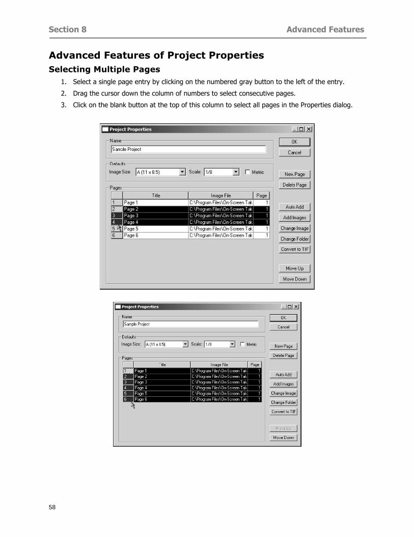
Section 8 Advanced Features
58
Advanced Features of Project Properties Selecting Multiple Pages
1 Select a single page entry by clicking on the numbered gray button to the left of the entry
2 Drag the cursor down the column of numbers to select consecutive pages
3 Click on the blank button at the top of this column to select all pages in the Properties dialog
Section 8 Advanced Features
59
Changing Image Assigned to a Drawing 1 Select the page entry by clicking on the numbered gray button to the left of the entry 2 Click the Change Image button The Change Image dialog box will appear
3 Navigate to the desired file and select by clicking on it
4 Click the Open button The electronic file assigned to the page will have been changed to reflect the new file choice
Changing Image File Path 1 Select pages as described above
2 Choose Change Folder
3 In the Change Folder dialog navigate to the appropriate folder
4 Click the OK button The file path will have been changed for the selected page entries
Delete a Page from Project Properties 1 Select the page you want to delete by clicking on its associated number (in the gray box at the
left of the entry)
2 Choose Delete Page
All Takeoff on the page will be deleted immediately and permanently
Section 8 Advanced Features
60
Advanced Features of Tool Options
Calculation Method On-Screen Takeoff has built-in calculation options to allow for faster work and faster saves until your takeoff is complete Calculation options are found by selecting Tools gt Options then clicking on the Calculation tab
Calculation method can be set to Automatic Automatic except Grids and Manual Manual will allow the program to operate more quickly while Automatic or Automatic except Grids allows the user to see quantity changes as takeoffs are made
In any mode you may press F9 to recalculate quantities for the On-Screen Takeoff current totals
Configuration Tab
When the ldquoPage Label (A01)rdquo radial button is chosen On-Screen Takeoff puts the numbered label on all the pages of in your current page indicator in your Navigate Toolbar If the Page Descriptionrdquo radial button is chosen then a description of what takeoff is on that specific page will be shown in your current page indicator in your Navigate Toolbar
This section of the configuration tab gives you options on how you want to export your information When the ldquoFolderSubfolder Namesrdquo radial button is chosen than on your file that you are exporting to will have all the conditions folders and subfolders In the Delimiter box you can choose the symbol that is needed to separate the information you are exporting Some files need semicolons () or colons () to make sure the information comes exported in is separated it the appropriate places
Section 8 Advanced Features
61
In previous versions of On-Screen Takeoff there are views that users need to have in order for them to display their information By either choosing ldquoOST 1xrdquo or ldquoOST 2xrdquo it will let the program know you want your columns of information exported in that specific format
When you have the Confirm Deletions radial button of ldquoYesrdquo chosen than every time you delete anything you will get a dialog box confirming your intentions of deletion
While working with your takeoff you have a choice to either view the legend of your conditions or hide it Choose whichever radial button that suits your needs
For those who prefer to use the Enter key to navigate in dialog boxes this option is just for that
Font Tab The Font tab is designed for you to make your own look and feel for the application At the bottom of this tab it will show you sample of the fonts and colors you have chosen
Renaming the Current Page You may change the name of the current page in the takeoff area of On-Screen Takeoff by selecting Edit gt Rename Page
This opens the Name Page dialog and you may simply type in a new name and click the Enter button The new name for the file will be reflected on the title bar for the page and in Project Properties
You also may access the Rename Page function by right-clicking in the takeoff area while in Image View and selecting the option from the pop-up menu that appears
Section 9
62
Saving and Exiting
This section will
Explain how to save projects
Show you how to safely exit the program
Section 9 Saving and Exiting
63
Saving Your Project
1 Select File gt Save 2 If your project has not previously been saved a Save dialog box will open to allow you to name
the file and choose the directory and folder in which to save your file 3 Once saved File gt Save will simply save the current version of the file
OR
4 Select File gt Save As then type in a new name for the file and save to the desired file path
The Auto-save Feature With the Auto-save feature On-Screen Takeoff automatically backs up your open project You may choose to have more than one level of backup files The first backup copy will have the extension b00 and successive files will be b01 b02 and so on If you have designated four levels of backup files after the fourth backup copy has been created (b03) the next file will be saved over the file with extension b00 Further backup saves will then rotate through the four backup files in the same way
1 Select Tools gt Options 2 In the Auto-save area (under the General tab) select the frequency of backup file creation (in
minutes) and the number of levels for the feature 3 You also may disengage the feature by clicking in the check box to clear it
The Auto-save feature automatically saves backup copies to the directory of the current project If you are working from a write-protected area such as a CD-ROM On-Screen Takeoff will place backup files in the On-Screen Takeoff folder
Exiting When you are finished using On-Screen Takeoff it is very easy to exit Exiting is very important because of security reasons If someone were to use your computer they could enter the application and view and manipulate information
Section 9 Saving and Exiting
64
On-Screen Takeoff closes the open project when you open another or create a new project or when you exit the program
1 Select File gt Exit
OR
2 You also may click at the upper right-hand corner of the application to exit
NOTE If your latest changes to a project file have not been saved On-Screen Takeoff will ask you whether you would like to save the file and gives you the option of canceling the operation
Appendix I Installing Your Digitizer
65
Appendix I Installing Your Digitizer When you get your digitizer from GTCO you will need to connect it to your computer Follow the instructions outlined below to do this
Note For rollup digitizers the metal bar must be oriented to the top or right hand side
Connecting the Digitizer 1 Lay the digitizer out flat 2 Connect the Stylus to the digitizer 3 Plug in the power adapter 4 Plug the interface (IO) cable into the digitizer 5 Plug the other end of the interface cable into an open serial port on computer
Note GTCO Technical support phone number is 410-381-6688 The electronic manual (on diskette) from GTCO contains more detailed installation and operation instructions for the GTCO digitizer model you have
Installing other Digitizer Drivers If you are using a GTCO Digitizer you will need to install the GTCO TabletWorks Drivers
If you are using a Digitizer not supported by GTCO Tablet Works 10 please contact the manufacturer of your digitizer for assistance with installation
Installing GTCO TabletWorks Drivers 1 Insert the On Center CD into the CD-ROM drive The CD Startup screen will open 2 Click on Install Software 3 Select Additional Software and Drivers 4 Select Digitizer Driver 5 Follow the instructions for installing TabletWorks 10
Adhering the Template The template is a small plastic sticker used to enable mouse function when using the digitizer with On-Screen Takeoff Place your template on your digitizer We suggest placing it in the bottom right corner of the digitizer about one inch inside the takeoff area
Note You may either peel off the back of the template and use the adhesive surface or you can tape the template down
Appendix I Installing Your Digitizer
66
Testing the Digitizer Drivers Before running OST you may test the digitizer by moving the stylus around on the digitizer pad it should move the mouse cursor (if mouse emulation is enabled)
If the digitizer does not move the mouse cursor on the screen
The superset codes may need to be reset Reset the superset codes by touching on the border of the digitizer with the stylus The digitizer should beep several times
The digitizer may not be communicating with the computer Be sure the COM port selected is correct Be sure the COM port selected is correct If you are not able to get the digitizer to move the mouse cursor you need to call GTCO technical support for help
Note The Mouse Emulation is not required for On-Screen Takeoff to work properly It is used only for the Template functionality if the digitizer is moving the cursor the wrong direction (up instead of sideways or vice-versa)
Click the L-shaped arrow symbol on the digitizer with the stylus
Appendix II Toolbar Item Details
67
Appendix II Toolbar Items Main Toolbar
Appendix II Toolbar Item Details
68
Tool Toolbar
Appendix II Toolbar Item Details
69
Zoom Toolbar
View Toolbar
Navigate Toolbar
Appendix II Toolbar Item Details
70
Navigate Toolbar (Continued)
Takeoff Toolbar
Appendix II Toolbar Item Details
71
Takeoff Toolbar (Continued)
Image Toolbar
Appendix III Loading Plans from a Dodge CD
72
Appendix III Loading Plans from a Dodge CD
This section will detail how to load plans from a F W Dodge CD-ROM into an On-Screen Takeoff project file ready for takeoffs
Dodge files may be added to the Project Properties dialog However loading the files in that way will load the files by number rather than name description If you want to load one page only from your Dodge CD You will have to rename the page to display the name rather than number of the file
To load plan files from a Dodge CD so that the files load sequentially by file number but are displayed by name rather than by number within your project follow the instructions below
Opening a Dodge project from a CD-ROM 1 Insert the CD into the drive 2 Choose File gt Custom 3 Choose Dodge Plans Project (plansdat) as the file type 4 Select the appropriate file type by clicking on the down arrow at the right of the Files of type
field 5 In the Look in field access your drive paths by clicking on the down arrow at the right of the
field then
Navigate to your CD-ROM drive Open the data folder and Open the Projects folder
6 Select the desired project and open its folder 7 Open the plansdat file 8 All the images will come in sequenced correctly for that job along with the full descriptions
(names) of each page If there is not a plans folder in the project folder then plans do not exist for that project on the CD Opening the plansdat file will yield an empty project
Appendix IV Using the Plan Viewer
73
Appendix IV Using On-Screen Takeoff Plan Viewer The On-Screen Takeoff Plan Viewer is a limited version of On Center Softwarersquos commercial takeoff software If your status bar located at the very bottom of the main window says View Mode in the lower left-hand corner then you are using the Plan Viewer You can use the plan viewer to
View CD-based amp converted CAD drawings
View a previously created OST file and associated drawings
Download electronic plans online
Navigate through drawings
Quickly Takeoff linearsareas and counts
Zoom in to view the plan better
Print drawings directly from the viewer
Viewing an On-Screen Takeoff Project File
1 To open an OST file that was previously created with of On-Screen Takeoff 2 Select File gt Open 3 An Open dialog will appear if you do not see the OST file you are looking for select the
Look In drop down arrow 4 A drop down menu will appear listing the various folders drives and mapped drives located
on your computer select the correct drive or folder location and continue to browse to the location of your OST file
5 When you see your OST file double-click it to open it 6 Any takeoff and drawings should appear on the Image tab view
If you do not see the drawings but do see the colored takeoff layer the drawings may
not be located in the same place they were originally saved at Go to File gt Project Properties and check the Image File path for each listed page If the image file path is pointing to a CD drive make sure the CD is inside the CR-ROM
Downloading Electronic Plans If your Online Plan Service provides a special file format (OSX) required to use this feature of our plan viewer you can immediately downloaded all electronic plans of a project directly from our viewer
Most Plan Room web sites will automatically open On-Screen Takeoff when a request to download plans is made Your particular Plan Room may differ in operation so please contact the provider directly with questions on using the site
Appendix IV Using the Plan Viewer
74
When you request to download or open a project file from a Plan Room you will usually have the open to open or save an OSX file Choosing open will automatically open On-Screen Takeoff Alternately you may choose to save the file to a local hard drive After you have saved the file either double-click it to launch On-Screen Takeoff or open the OSX file using On-Screen Takeoff by clicking File then Open and locating the file on your hard drive You will need to change the file type to OSX
After the OSX file is opened you will see an additional tab appear in the Conditions List window called Pages
The Pages tab shows the hierarchy of your project Gray file icons represent pages that have not been downloaded and blue icons represents pages that have been downloaded
To download a page simply double-click the page icon
If you wish to select a group of pages to download you can use the Ctrl or Shift key to multiple select them then click the Download button
If you wish to download all pages at once click the Download All button
Downloaded pages will now appear in the Project Properties dialog in the same order in which they appear in the Pages tab
Creating Quick Takeoffs With On-Screen Takeoff you can create quick takeoffs to measure quantities even if you dont have the full version of our program However using the Quick Takeoff functionality shows you just a fraction of what the full version can do
The Quick Takeoff Toolbar is located at the top of the image view It has three buttons designated for three types of takeoffs Linear Area and Count The Quantity drop down list will show secondary quantities for Linears and Areas The Units drop down allows you to select how you want your quantities displayed Feet Inches Yards Millimeters and Meters
NOTE Every time change the type of takeoff you are performing (switching from Area to Linear for example) the previous quantities and takeoff objects will disappear They will also disappear when you changes pages
NOTE You can use the Dimension Tool to basically measure the distance between two points or linears The distance will display on the status bar at the bottom of the application
The Quick Takeoff Toolbar
Appendix V Frequently Asked Questions
75
Appendix V Frequently Asked Questions General
Where is On-Screen Takeoff installed on my computer
Typically it is installed in CProgram FilesOn-Screen Takeoff
In Explorer how do I recognize On-Screen Takeoff file types
On-Screen Takeoff data is stored in a single file per job lsquojob name OSTrsquo On-Screen Takeoff templates are stored as lsquotemplate nameTPOrsquo
Can only one project at a time be open
Yes For that reason opening another project automatically closes the project on screen You will be asked to save any changes
Is only one scale allowed per page What about on drawings that have multiple detail sections on a page and each of those drawings have different scales
Yes For pages with drawings of different scales copy the drawing to another project page and set the appropriate scale
I cannot perform backout on an area that is along a linear
As a workaround use the On-Screen Takeoff layers feature to help you with this issue Electronic Images
How do I start a project from drawings that have been scanned and written to a CD-ROM
Open a new project Select File gt Project Properties and select Auto Add Navigate to your CD and the appropriate folder and select any image file in that location Click Open All files in the location will load into your project Recommended that images are copied from CD to hard drive for performance
If I get a disk of drawings in AutoCAD format (R13 or R14) can I read them in On-Screen Takeoff
Yes On-Screen Takeoff now reads DWG DXF and many other format that are saved with AutoCAD
Appendix V Frequently Asked Questions
76
When I click on the all pages button what is supposed to happen Currently nothing seems to change when I click on that button
The All Pages button is used to apply the Darken and Enhance Plans feature to all pages in the project (as opposed to only the current page on screen)
Is there a way to deduct a large skylight from an area condition
Yes with the related area condition selected in the Takeoff Dock bar unselect the Backout button on the Takeoff Toolbar then draw the Backout area The area quantity will be deducted from the related condition object and the linear measurement of the Backout perimeter will be added
Digitizer Issues
How do I connect a Digitizer to the computer
See Appendix I Connecting a Digitizer
The Place Template menu choice is disabled
On-Screen Takeoff may need to be authorized or the digitizer or the digitzer drivers are not installed
It wonrsquot let me select the Set Takeoff Area menu choice
On-Screen Takeoff may need to be authorized or no job is open a digitizer is not installed or the drivers are not installed
The digitizer stylus is not moving the cursor or crosshairs
Click S-0-1 superset on the digitizer
How do I convert my old GTCO Digitizer to work with On- Screen Takeofftrade
Call GTCO and they may be able to reconfigure your digitizer to be compatible with On-Screen Takeoff
Printing Issues Which Printers work with On-Screen Takeoff
Compatible printers include On-Screen Takeoff Hewlett Packard Epson and Canon printers If you are having printer difficulties please contact support and specify the type of printer along with other pertinent information Contact support at wwwoncentercomsupport or email supportoncentercom
Which Plotters work with On-Screen Takeoff
Compatible Plotters include Hewlett Packard DesignJet plotters and the EnCAD Cadjet II If you are having plotter difficulties please contact support and specify the type of plotter concerned
ViewingDisplay I can no longer see my condition list How do I get it back
The toolbars and Dock bars can be turned on and off through the View gt Toolbars menu options
Appendix V Frequently Asked Questions
77
This is also accessible by right-clicking in the toolbar area and selecting (or deselecting) a toolbar listed
I cannot view my folders in the condition list
Right-click in the Takeoff Dock barcondition list area and select Show Tree to display your folders
My Status Bar reads Viewer Mode and I am unable to draw conditions
On-Screen Takeoff needs to be Authorized Or you need to purchase an upgrade Click the Perform Advanced Takeoff button on the main toolbar
I hid a Dock bar and when I selected to view it again it appeared alongside the other Dock
bar instead of stacked on top of it How do I fix it
Pick up the Dock bar by clicking on the bar at the top and continuing to hold down the mouse button drag the Dock bar over the other one It will resize and appear stacked with the other
When I open image files from a CD the images are all upside down How do I get them right
side up
To flip pages from top to bottom follow the steps below 1 Click the All Pages button on the Image Toolbar (All Pages is engaged when the button
is not clicked) 2 Click the Flip Horizontal button on the Image Toolbar 3 Click the All Pages button again to disengage
Templates How do I create a Template
Follow the steps below 1 Create a typical project 2 Choose File gt Save As 3 Choose On-Screen Takeoff Template Files as the file type to save 4 Name the file This will save all of the condition setups as well as the layers for the
project
How do I create a new project from a template
Follow the steps below 1 Choose File gt New 2 Select a template from those listed in the New dialog This will open a new project with
conditions and layers saved from a previous project but no pages or takeoff
78
INDEX
Area Conditions 32
Area Objects 57
Auto Scrolling 20
Auto-save 63
Backout Mode 41
Calculation Method 60
Conditions 29
Configuration 60
Contents Tab 6
Continuous Mode 38
Count Conditions 33
Count Objects 57
Digitizer 10 65 76
Docking Toolbars 13
Dodge CD 72
Drawing 27 37
DropRun Count 55
Environment 18
Exiting 63
Exporting 49
Features 16
Font 61
Frequently Asked Questions 75
Grid 40
Help File 5
Hiding Toolbars 13
Hot Links 21
Image 19 59
Image files 9
Image Toolbar 12 71
Images 75
Index Tab 6
Layers 43
Linear Conditions 31
Linear Objects 56
Main Toolbar 12 67
Menus 14
Moving Toolbars 13
Navigate Toolbar 12 69
Navigating 20
On-Screen Takeofftrade 2
Page 59 61
Pages 20 25 28
Plan Viewer 73
Plans 26
Printing 47 76
Project Properties 25
Projects 22
Quick Start Video 18
Resizing Toolbars 13
Roping 54
Saving 63
Scale 28
Search Tab 7
Selecting Objects 42
Setup 8
Start On-Screen Takeofftrade 17
System Requirements 9
Takeoff 19 27
Takeoff Toolbar 70 71
Takeoff Toolbar 12
Template Files 23
TIF (Group4) 9
Tool Toolbar 12 68
Toolbar 67
Toolbars 12
View Toolbar 12 69
Viewing Toolbars 12
Worksheet 20
Zone Conditions 33
Zoom Toolbar 12 69
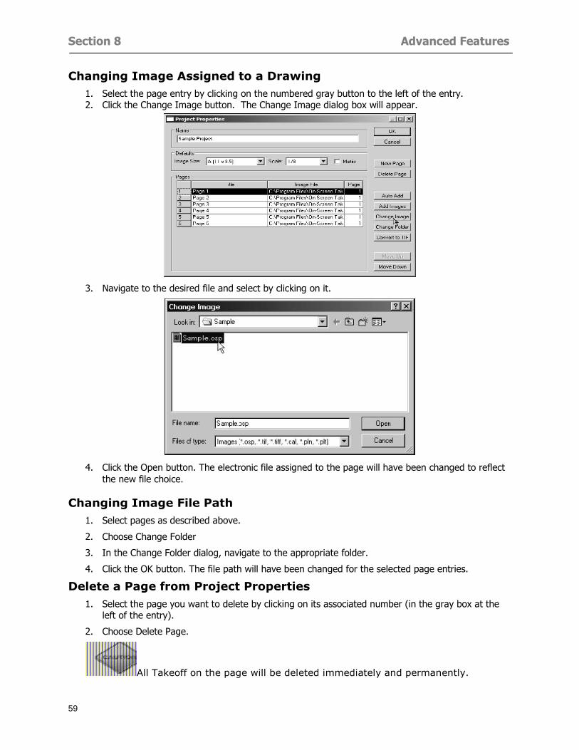
Section 8 Advanced Features
59
Changing Image Assigned to a Drawing 1 Select the page entry by clicking on the numbered gray button to the left of the entry 2 Click the Change Image button The Change Image dialog box will appear
3 Navigate to the desired file and select by clicking on it
4 Click the Open button The electronic file assigned to the page will have been changed to reflect the new file choice
Changing Image File Path 1 Select pages as described above
2 Choose Change Folder
3 In the Change Folder dialog navigate to the appropriate folder
4 Click the OK button The file path will have been changed for the selected page entries
Delete a Page from Project Properties 1 Select the page you want to delete by clicking on its associated number (in the gray box at the
left of the entry)
2 Choose Delete Page
All Takeoff on the page will be deleted immediately and permanently
Section 8 Advanced Features
60
Advanced Features of Tool Options
Calculation Method On-Screen Takeoff has built-in calculation options to allow for faster work and faster saves until your takeoff is complete Calculation options are found by selecting Tools gt Options then clicking on the Calculation tab
Calculation method can be set to Automatic Automatic except Grids and Manual Manual will allow the program to operate more quickly while Automatic or Automatic except Grids allows the user to see quantity changes as takeoffs are made
In any mode you may press F9 to recalculate quantities for the On-Screen Takeoff current totals
Configuration Tab
When the ldquoPage Label (A01)rdquo radial button is chosen On-Screen Takeoff puts the numbered label on all the pages of in your current page indicator in your Navigate Toolbar If the Page Descriptionrdquo radial button is chosen then a description of what takeoff is on that specific page will be shown in your current page indicator in your Navigate Toolbar
This section of the configuration tab gives you options on how you want to export your information When the ldquoFolderSubfolder Namesrdquo radial button is chosen than on your file that you are exporting to will have all the conditions folders and subfolders In the Delimiter box you can choose the symbol that is needed to separate the information you are exporting Some files need semicolons () or colons () to make sure the information comes exported in is separated it the appropriate places
Section 8 Advanced Features
61
In previous versions of On-Screen Takeoff there are views that users need to have in order for them to display their information By either choosing ldquoOST 1xrdquo or ldquoOST 2xrdquo it will let the program know you want your columns of information exported in that specific format
When you have the Confirm Deletions radial button of ldquoYesrdquo chosen than every time you delete anything you will get a dialog box confirming your intentions of deletion
While working with your takeoff you have a choice to either view the legend of your conditions or hide it Choose whichever radial button that suits your needs
For those who prefer to use the Enter key to navigate in dialog boxes this option is just for that
Font Tab The Font tab is designed for you to make your own look and feel for the application At the bottom of this tab it will show you sample of the fonts and colors you have chosen
Renaming the Current Page You may change the name of the current page in the takeoff area of On-Screen Takeoff by selecting Edit gt Rename Page
This opens the Name Page dialog and you may simply type in a new name and click the Enter button The new name for the file will be reflected on the title bar for the page and in Project Properties
You also may access the Rename Page function by right-clicking in the takeoff area while in Image View and selecting the option from the pop-up menu that appears
Section 9
62
Saving and Exiting
This section will
Explain how to save projects
Show you how to safely exit the program
Section 9 Saving and Exiting
63
Saving Your Project
1 Select File gt Save 2 If your project has not previously been saved a Save dialog box will open to allow you to name
the file and choose the directory and folder in which to save your file 3 Once saved File gt Save will simply save the current version of the file
OR
4 Select File gt Save As then type in a new name for the file and save to the desired file path
The Auto-save Feature With the Auto-save feature On-Screen Takeoff automatically backs up your open project You may choose to have more than one level of backup files The first backup copy will have the extension b00 and successive files will be b01 b02 and so on If you have designated four levels of backup files after the fourth backup copy has been created (b03) the next file will be saved over the file with extension b00 Further backup saves will then rotate through the four backup files in the same way
1 Select Tools gt Options 2 In the Auto-save area (under the General tab) select the frequency of backup file creation (in
minutes) and the number of levels for the feature 3 You also may disengage the feature by clicking in the check box to clear it
The Auto-save feature automatically saves backup copies to the directory of the current project If you are working from a write-protected area such as a CD-ROM On-Screen Takeoff will place backup files in the On-Screen Takeoff folder
Exiting When you are finished using On-Screen Takeoff it is very easy to exit Exiting is very important because of security reasons If someone were to use your computer they could enter the application and view and manipulate information
Section 9 Saving and Exiting
64
On-Screen Takeoff closes the open project when you open another or create a new project or when you exit the program
1 Select File gt Exit
OR
2 You also may click at the upper right-hand corner of the application to exit
NOTE If your latest changes to a project file have not been saved On-Screen Takeoff will ask you whether you would like to save the file and gives you the option of canceling the operation
Appendix I Installing Your Digitizer
65
Appendix I Installing Your Digitizer When you get your digitizer from GTCO you will need to connect it to your computer Follow the instructions outlined below to do this
Note For rollup digitizers the metal bar must be oriented to the top or right hand side
Connecting the Digitizer 1 Lay the digitizer out flat 2 Connect the Stylus to the digitizer 3 Plug in the power adapter 4 Plug the interface (IO) cable into the digitizer 5 Plug the other end of the interface cable into an open serial port on computer
Note GTCO Technical support phone number is 410-381-6688 The electronic manual (on diskette) from GTCO contains more detailed installation and operation instructions for the GTCO digitizer model you have
Installing other Digitizer Drivers If you are using a GTCO Digitizer you will need to install the GTCO TabletWorks Drivers
If you are using a Digitizer not supported by GTCO Tablet Works 10 please contact the manufacturer of your digitizer for assistance with installation
Installing GTCO TabletWorks Drivers 1 Insert the On Center CD into the CD-ROM drive The CD Startup screen will open 2 Click on Install Software 3 Select Additional Software and Drivers 4 Select Digitizer Driver 5 Follow the instructions for installing TabletWorks 10
Adhering the Template The template is a small plastic sticker used to enable mouse function when using the digitizer with On-Screen Takeoff Place your template on your digitizer We suggest placing it in the bottom right corner of the digitizer about one inch inside the takeoff area
Note You may either peel off the back of the template and use the adhesive surface or you can tape the template down
Appendix I Installing Your Digitizer
66
Testing the Digitizer Drivers Before running OST you may test the digitizer by moving the stylus around on the digitizer pad it should move the mouse cursor (if mouse emulation is enabled)
If the digitizer does not move the mouse cursor on the screen
The superset codes may need to be reset Reset the superset codes by touching on the border of the digitizer with the stylus The digitizer should beep several times
The digitizer may not be communicating with the computer Be sure the COM port selected is correct Be sure the COM port selected is correct If you are not able to get the digitizer to move the mouse cursor you need to call GTCO technical support for help
Note The Mouse Emulation is not required for On-Screen Takeoff to work properly It is used only for the Template functionality if the digitizer is moving the cursor the wrong direction (up instead of sideways or vice-versa)
Click the L-shaped arrow symbol on the digitizer with the stylus
Appendix II Toolbar Item Details
67
Appendix II Toolbar Items Main Toolbar
Appendix II Toolbar Item Details
68
Tool Toolbar
Appendix II Toolbar Item Details
69
Zoom Toolbar
View Toolbar
Navigate Toolbar
Appendix II Toolbar Item Details
70
Navigate Toolbar (Continued)
Takeoff Toolbar
Appendix II Toolbar Item Details
71
Takeoff Toolbar (Continued)
Image Toolbar
Appendix III Loading Plans from a Dodge CD
72
Appendix III Loading Plans from a Dodge CD
This section will detail how to load plans from a F W Dodge CD-ROM into an On-Screen Takeoff project file ready for takeoffs
Dodge files may be added to the Project Properties dialog However loading the files in that way will load the files by number rather than name description If you want to load one page only from your Dodge CD You will have to rename the page to display the name rather than number of the file
To load plan files from a Dodge CD so that the files load sequentially by file number but are displayed by name rather than by number within your project follow the instructions below
Opening a Dodge project from a CD-ROM 1 Insert the CD into the drive 2 Choose File gt Custom 3 Choose Dodge Plans Project (plansdat) as the file type 4 Select the appropriate file type by clicking on the down arrow at the right of the Files of type
field 5 In the Look in field access your drive paths by clicking on the down arrow at the right of the
field then
Navigate to your CD-ROM drive Open the data folder and Open the Projects folder
6 Select the desired project and open its folder 7 Open the plansdat file 8 All the images will come in sequenced correctly for that job along with the full descriptions
(names) of each page If there is not a plans folder in the project folder then plans do not exist for that project on the CD Opening the plansdat file will yield an empty project
Appendix IV Using the Plan Viewer
73
Appendix IV Using On-Screen Takeoff Plan Viewer The On-Screen Takeoff Plan Viewer is a limited version of On Center Softwarersquos commercial takeoff software If your status bar located at the very bottom of the main window says View Mode in the lower left-hand corner then you are using the Plan Viewer You can use the plan viewer to
View CD-based amp converted CAD drawings
View a previously created OST file and associated drawings
Download electronic plans online
Navigate through drawings
Quickly Takeoff linearsareas and counts
Zoom in to view the plan better
Print drawings directly from the viewer
Viewing an On-Screen Takeoff Project File
1 To open an OST file that was previously created with of On-Screen Takeoff 2 Select File gt Open 3 An Open dialog will appear if you do not see the OST file you are looking for select the
Look In drop down arrow 4 A drop down menu will appear listing the various folders drives and mapped drives located
on your computer select the correct drive or folder location and continue to browse to the location of your OST file
5 When you see your OST file double-click it to open it 6 Any takeoff and drawings should appear on the Image tab view
If you do not see the drawings but do see the colored takeoff layer the drawings may
not be located in the same place they were originally saved at Go to File gt Project Properties and check the Image File path for each listed page If the image file path is pointing to a CD drive make sure the CD is inside the CR-ROM
Downloading Electronic Plans If your Online Plan Service provides a special file format (OSX) required to use this feature of our plan viewer you can immediately downloaded all electronic plans of a project directly from our viewer
Most Plan Room web sites will automatically open On-Screen Takeoff when a request to download plans is made Your particular Plan Room may differ in operation so please contact the provider directly with questions on using the site
Appendix IV Using the Plan Viewer
74
When you request to download or open a project file from a Plan Room you will usually have the open to open or save an OSX file Choosing open will automatically open On-Screen Takeoff Alternately you may choose to save the file to a local hard drive After you have saved the file either double-click it to launch On-Screen Takeoff or open the OSX file using On-Screen Takeoff by clicking File then Open and locating the file on your hard drive You will need to change the file type to OSX
After the OSX file is opened you will see an additional tab appear in the Conditions List window called Pages
The Pages tab shows the hierarchy of your project Gray file icons represent pages that have not been downloaded and blue icons represents pages that have been downloaded
To download a page simply double-click the page icon
If you wish to select a group of pages to download you can use the Ctrl or Shift key to multiple select them then click the Download button
If you wish to download all pages at once click the Download All button
Downloaded pages will now appear in the Project Properties dialog in the same order in which they appear in the Pages tab
Creating Quick Takeoffs With On-Screen Takeoff you can create quick takeoffs to measure quantities even if you dont have the full version of our program However using the Quick Takeoff functionality shows you just a fraction of what the full version can do
The Quick Takeoff Toolbar is located at the top of the image view It has three buttons designated for three types of takeoffs Linear Area and Count The Quantity drop down list will show secondary quantities for Linears and Areas The Units drop down allows you to select how you want your quantities displayed Feet Inches Yards Millimeters and Meters
NOTE Every time change the type of takeoff you are performing (switching from Area to Linear for example) the previous quantities and takeoff objects will disappear They will also disappear when you changes pages
NOTE You can use the Dimension Tool to basically measure the distance between two points or linears The distance will display on the status bar at the bottom of the application
The Quick Takeoff Toolbar
Appendix V Frequently Asked Questions
75
Appendix V Frequently Asked Questions General
Where is On-Screen Takeoff installed on my computer
Typically it is installed in CProgram FilesOn-Screen Takeoff
In Explorer how do I recognize On-Screen Takeoff file types
On-Screen Takeoff data is stored in a single file per job lsquojob name OSTrsquo On-Screen Takeoff templates are stored as lsquotemplate nameTPOrsquo
Can only one project at a time be open
Yes For that reason opening another project automatically closes the project on screen You will be asked to save any changes
Is only one scale allowed per page What about on drawings that have multiple detail sections on a page and each of those drawings have different scales
Yes For pages with drawings of different scales copy the drawing to another project page and set the appropriate scale
I cannot perform backout on an area that is along a linear
As a workaround use the On-Screen Takeoff layers feature to help you with this issue Electronic Images
How do I start a project from drawings that have been scanned and written to a CD-ROM
Open a new project Select File gt Project Properties and select Auto Add Navigate to your CD and the appropriate folder and select any image file in that location Click Open All files in the location will load into your project Recommended that images are copied from CD to hard drive for performance
If I get a disk of drawings in AutoCAD format (R13 or R14) can I read them in On-Screen Takeoff
Yes On-Screen Takeoff now reads DWG DXF and many other format that are saved with AutoCAD
Appendix V Frequently Asked Questions
76
When I click on the all pages button what is supposed to happen Currently nothing seems to change when I click on that button
The All Pages button is used to apply the Darken and Enhance Plans feature to all pages in the project (as opposed to only the current page on screen)
Is there a way to deduct a large skylight from an area condition
Yes with the related area condition selected in the Takeoff Dock bar unselect the Backout button on the Takeoff Toolbar then draw the Backout area The area quantity will be deducted from the related condition object and the linear measurement of the Backout perimeter will be added
Digitizer Issues
How do I connect a Digitizer to the computer
See Appendix I Connecting a Digitizer
The Place Template menu choice is disabled
On-Screen Takeoff may need to be authorized or the digitizer or the digitzer drivers are not installed
It wonrsquot let me select the Set Takeoff Area menu choice
On-Screen Takeoff may need to be authorized or no job is open a digitizer is not installed or the drivers are not installed
The digitizer stylus is not moving the cursor or crosshairs
Click S-0-1 superset on the digitizer
How do I convert my old GTCO Digitizer to work with On- Screen Takeofftrade
Call GTCO and they may be able to reconfigure your digitizer to be compatible with On-Screen Takeoff
Printing Issues Which Printers work with On-Screen Takeoff
Compatible printers include On-Screen Takeoff Hewlett Packard Epson and Canon printers If you are having printer difficulties please contact support and specify the type of printer along with other pertinent information Contact support at wwwoncentercomsupport or email supportoncentercom
Which Plotters work with On-Screen Takeoff
Compatible Plotters include Hewlett Packard DesignJet plotters and the EnCAD Cadjet II If you are having plotter difficulties please contact support and specify the type of plotter concerned
ViewingDisplay I can no longer see my condition list How do I get it back
The toolbars and Dock bars can be turned on and off through the View gt Toolbars menu options
Appendix V Frequently Asked Questions
77
This is also accessible by right-clicking in the toolbar area and selecting (or deselecting) a toolbar listed
I cannot view my folders in the condition list
Right-click in the Takeoff Dock barcondition list area and select Show Tree to display your folders
My Status Bar reads Viewer Mode and I am unable to draw conditions
On-Screen Takeoff needs to be Authorized Or you need to purchase an upgrade Click the Perform Advanced Takeoff button on the main toolbar
I hid a Dock bar and when I selected to view it again it appeared alongside the other Dock
bar instead of stacked on top of it How do I fix it
Pick up the Dock bar by clicking on the bar at the top and continuing to hold down the mouse button drag the Dock bar over the other one It will resize and appear stacked with the other
When I open image files from a CD the images are all upside down How do I get them right
side up
To flip pages from top to bottom follow the steps below 1 Click the All Pages button on the Image Toolbar (All Pages is engaged when the button
is not clicked) 2 Click the Flip Horizontal button on the Image Toolbar 3 Click the All Pages button again to disengage
Templates How do I create a Template
Follow the steps below 1 Create a typical project 2 Choose File gt Save As 3 Choose On-Screen Takeoff Template Files as the file type to save 4 Name the file This will save all of the condition setups as well as the layers for the
project
How do I create a new project from a template
Follow the steps below 1 Choose File gt New 2 Select a template from those listed in the New dialog This will open a new project with
conditions and layers saved from a previous project but no pages or takeoff
78
INDEX
Area Conditions 32
Area Objects 57
Auto Scrolling 20
Auto-save 63
Backout Mode 41
Calculation Method 60
Conditions 29
Configuration 60
Contents Tab 6
Continuous Mode 38
Count Conditions 33
Count Objects 57
Digitizer 10 65 76
Docking Toolbars 13
Dodge CD 72
Drawing 27 37
DropRun Count 55
Environment 18
Exiting 63
Exporting 49
Features 16
Font 61
Frequently Asked Questions 75
Grid 40
Help File 5
Hiding Toolbars 13
Hot Links 21
Image 19 59
Image files 9
Image Toolbar 12 71
Images 75
Index Tab 6
Layers 43
Linear Conditions 31
Linear Objects 56
Main Toolbar 12 67
Menus 14
Moving Toolbars 13
Navigate Toolbar 12 69
Navigating 20
On-Screen Takeofftrade 2
Page 59 61
Pages 20 25 28
Plan Viewer 73
Plans 26
Printing 47 76
Project Properties 25
Projects 22
Quick Start Video 18
Resizing Toolbars 13
Roping 54
Saving 63
Scale 28
Search Tab 7
Selecting Objects 42
Setup 8
Start On-Screen Takeofftrade 17
System Requirements 9
Takeoff 19 27
Takeoff Toolbar 70 71
Takeoff Toolbar 12
Template Files 23
TIF (Group4) 9
Tool Toolbar 12 68
Toolbar 67
Toolbars 12
View Toolbar 12 69
Viewing Toolbars 12
Worksheet 20
Zone Conditions 33
Zoom Toolbar 12 69
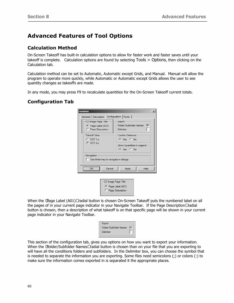
Section 8 Advanced Features
60
Advanced Features of Tool Options
Calculation Method On-Screen Takeoff has built-in calculation options to allow for faster work and faster saves until your takeoff is complete Calculation options are found by selecting Tools gt Options then clicking on the Calculation tab
Calculation method can be set to Automatic Automatic except Grids and Manual Manual will allow the program to operate more quickly while Automatic or Automatic except Grids allows the user to see quantity changes as takeoffs are made
In any mode you may press F9 to recalculate quantities for the On-Screen Takeoff current totals
Configuration Tab
When the ldquoPage Label (A01)rdquo radial button is chosen On-Screen Takeoff puts the numbered label on all the pages of in your current page indicator in your Navigate Toolbar If the Page Descriptionrdquo radial button is chosen then a description of what takeoff is on that specific page will be shown in your current page indicator in your Navigate Toolbar
This section of the configuration tab gives you options on how you want to export your information When the ldquoFolderSubfolder Namesrdquo radial button is chosen than on your file that you are exporting to will have all the conditions folders and subfolders In the Delimiter box you can choose the symbol that is needed to separate the information you are exporting Some files need semicolons () or colons () to make sure the information comes exported in is separated it the appropriate places
Section 8 Advanced Features
61
In previous versions of On-Screen Takeoff there are views that users need to have in order for them to display their information By either choosing ldquoOST 1xrdquo or ldquoOST 2xrdquo it will let the program know you want your columns of information exported in that specific format
When you have the Confirm Deletions radial button of ldquoYesrdquo chosen than every time you delete anything you will get a dialog box confirming your intentions of deletion
While working with your takeoff you have a choice to either view the legend of your conditions or hide it Choose whichever radial button that suits your needs
For those who prefer to use the Enter key to navigate in dialog boxes this option is just for that
Font Tab The Font tab is designed for you to make your own look and feel for the application At the bottom of this tab it will show you sample of the fonts and colors you have chosen
Renaming the Current Page You may change the name of the current page in the takeoff area of On-Screen Takeoff by selecting Edit gt Rename Page
This opens the Name Page dialog and you may simply type in a new name and click the Enter button The new name for the file will be reflected on the title bar for the page and in Project Properties
You also may access the Rename Page function by right-clicking in the takeoff area while in Image View and selecting the option from the pop-up menu that appears
Section 9
62
Saving and Exiting
This section will
Explain how to save projects
Show you how to safely exit the program
Section 9 Saving and Exiting
63
Saving Your Project
1 Select File gt Save 2 If your project has not previously been saved a Save dialog box will open to allow you to name
the file and choose the directory and folder in which to save your file 3 Once saved File gt Save will simply save the current version of the file
OR
4 Select File gt Save As then type in a new name for the file and save to the desired file path
The Auto-save Feature With the Auto-save feature On-Screen Takeoff automatically backs up your open project You may choose to have more than one level of backup files The first backup copy will have the extension b00 and successive files will be b01 b02 and so on If you have designated four levels of backup files after the fourth backup copy has been created (b03) the next file will be saved over the file with extension b00 Further backup saves will then rotate through the four backup files in the same way
1 Select Tools gt Options 2 In the Auto-save area (under the General tab) select the frequency of backup file creation (in
minutes) and the number of levels for the feature 3 You also may disengage the feature by clicking in the check box to clear it
The Auto-save feature automatically saves backup copies to the directory of the current project If you are working from a write-protected area such as a CD-ROM On-Screen Takeoff will place backup files in the On-Screen Takeoff folder
Exiting When you are finished using On-Screen Takeoff it is very easy to exit Exiting is very important because of security reasons If someone were to use your computer they could enter the application and view and manipulate information
Section 9 Saving and Exiting
64
On-Screen Takeoff closes the open project when you open another or create a new project or when you exit the program
1 Select File gt Exit
OR
2 You also may click at the upper right-hand corner of the application to exit
NOTE If your latest changes to a project file have not been saved On-Screen Takeoff will ask you whether you would like to save the file and gives you the option of canceling the operation
Appendix I Installing Your Digitizer
65
Appendix I Installing Your Digitizer When you get your digitizer from GTCO you will need to connect it to your computer Follow the instructions outlined below to do this
Note For rollup digitizers the metal bar must be oriented to the top or right hand side
Connecting the Digitizer 1 Lay the digitizer out flat 2 Connect the Stylus to the digitizer 3 Plug in the power adapter 4 Plug the interface (IO) cable into the digitizer 5 Plug the other end of the interface cable into an open serial port on computer
Note GTCO Technical support phone number is 410-381-6688 The electronic manual (on diskette) from GTCO contains more detailed installation and operation instructions for the GTCO digitizer model you have
Installing other Digitizer Drivers If you are using a GTCO Digitizer you will need to install the GTCO TabletWorks Drivers
If you are using a Digitizer not supported by GTCO Tablet Works 10 please contact the manufacturer of your digitizer for assistance with installation
Installing GTCO TabletWorks Drivers 1 Insert the On Center CD into the CD-ROM drive The CD Startup screen will open 2 Click on Install Software 3 Select Additional Software and Drivers 4 Select Digitizer Driver 5 Follow the instructions for installing TabletWorks 10
Adhering the Template The template is a small plastic sticker used to enable mouse function when using the digitizer with On-Screen Takeoff Place your template on your digitizer We suggest placing it in the bottom right corner of the digitizer about one inch inside the takeoff area
Note You may either peel off the back of the template and use the adhesive surface or you can tape the template down
Appendix I Installing Your Digitizer
66
Testing the Digitizer Drivers Before running OST you may test the digitizer by moving the stylus around on the digitizer pad it should move the mouse cursor (if mouse emulation is enabled)
If the digitizer does not move the mouse cursor on the screen
The superset codes may need to be reset Reset the superset codes by touching on the border of the digitizer with the stylus The digitizer should beep several times
The digitizer may not be communicating with the computer Be sure the COM port selected is correct Be sure the COM port selected is correct If you are not able to get the digitizer to move the mouse cursor you need to call GTCO technical support for help
Note The Mouse Emulation is not required for On-Screen Takeoff to work properly It is used only for the Template functionality if the digitizer is moving the cursor the wrong direction (up instead of sideways or vice-versa)
Click the L-shaped arrow symbol on the digitizer with the stylus
Appendix II Toolbar Item Details
67
Appendix II Toolbar Items Main Toolbar
Appendix II Toolbar Item Details
68
Tool Toolbar
Appendix II Toolbar Item Details
69
Zoom Toolbar
View Toolbar
Navigate Toolbar
Appendix II Toolbar Item Details
70
Navigate Toolbar (Continued)
Takeoff Toolbar
Appendix II Toolbar Item Details
71
Takeoff Toolbar (Continued)
Image Toolbar
Appendix III Loading Plans from a Dodge CD
72
Appendix III Loading Plans from a Dodge CD
This section will detail how to load plans from a F W Dodge CD-ROM into an On-Screen Takeoff project file ready for takeoffs
Dodge files may be added to the Project Properties dialog However loading the files in that way will load the files by number rather than name description If you want to load one page only from your Dodge CD You will have to rename the page to display the name rather than number of the file
To load plan files from a Dodge CD so that the files load sequentially by file number but are displayed by name rather than by number within your project follow the instructions below
Opening a Dodge project from a CD-ROM 1 Insert the CD into the drive 2 Choose File gt Custom 3 Choose Dodge Plans Project (plansdat) as the file type 4 Select the appropriate file type by clicking on the down arrow at the right of the Files of type
field 5 In the Look in field access your drive paths by clicking on the down arrow at the right of the
field then
Navigate to your CD-ROM drive Open the data folder and Open the Projects folder
6 Select the desired project and open its folder 7 Open the plansdat file 8 All the images will come in sequenced correctly for that job along with the full descriptions
(names) of each page If there is not a plans folder in the project folder then plans do not exist for that project on the CD Opening the plansdat file will yield an empty project
Appendix IV Using the Plan Viewer
73
Appendix IV Using On-Screen Takeoff Plan Viewer The On-Screen Takeoff Plan Viewer is a limited version of On Center Softwarersquos commercial takeoff software If your status bar located at the very bottom of the main window says View Mode in the lower left-hand corner then you are using the Plan Viewer You can use the plan viewer to
View CD-based amp converted CAD drawings
View a previously created OST file and associated drawings
Download electronic plans online
Navigate through drawings
Quickly Takeoff linearsareas and counts
Zoom in to view the plan better
Print drawings directly from the viewer
Viewing an On-Screen Takeoff Project File
1 To open an OST file that was previously created with of On-Screen Takeoff 2 Select File gt Open 3 An Open dialog will appear if you do not see the OST file you are looking for select the
Look In drop down arrow 4 A drop down menu will appear listing the various folders drives and mapped drives located
on your computer select the correct drive or folder location and continue to browse to the location of your OST file
5 When you see your OST file double-click it to open it 6 Any takeoff and drawings should appear on the Image tab view
If you do not see the drawings but do see the colored takeoff layer the drawings may
not be located in the same place they were originally saved at Go to File gt Project Properties and check the Image File path for each listed page If the image file path is pointing to a CD drive make sure the CD is inside the CR-ROM
Downloading Electronic Plans If your Online Plan Service provides a special file format (OSX) required to use this feature of our plan viewer you can immediately downloaded all electronic plans of a project directly from our viewer
Most Plan Room web sites will automatically open On-Screen Takeoff when a request to download plans is made Your particular Plan Room may differ in operation so please contact the provider directly with questions on using the site
Appendix IV Using the Plan Viewer
74
When you request to download or open a project file from a Plan Room you will usually have the open to open or save an OSX file Choosing open will automatically open On-Screen Takeoff Alternately you may choose to save the file to a local hard drive After you have saved the file either double-click it to launch On-Screen Takeoff or open the OSX file using On-Screen Takeoff by clicking File then Open and locating the file on your hard drive You will need to change the file type to OSX
After the OSX file is opened you will see an additional tab appear in the Conditions List window called Pages
The Pages tab shows the hierarchy of your project Gray file icons represent pages that have not been downloaded and blue icons represents pages that have been downloaded
To download a page simply double-click the page icon
If you wish to select a group of pages to download you can use the Ctrl or Shift key to multiple select them then click the Download button
If you wish to download all pages at once click the Download All button
Downloaded pages will now appear in the Project Properties dialog in the same order in which they appear in the Pages tab
Creating Quick Takeoffs With On-Screen Takeoff you can create quick takeoffs to measure quantities even if you dont have the full version of our program However using the Quick Takeoff functionality shows you just a fraction of what the full version can do
The Quick Takeoff Toolbar is located at the top of the image view It has three buttons designated for three types of takeoffs Linear Area and Count The Quantity drop down list will show secondary quantities for Linears and Areas The Units drop down allows you to select how you want your quantities displayed Feet Inches Yards Millimeters and Meters
NOTE Every time change the type of takeoff you are performing (switching from Area to Linear for example) the previous quantities and takeoff objects will disappear They will also disappear when you changes pages
NOTE You can use the Dimension Tool to basically measure the distance between two points or linears The distance will display on the status bar at the bottom of the application
The Quick Takeoff Toolbar
Appendix V Frequently Asked Questions
75
Appendix V Frequently Asked Questions General
Where is On-Screen Takeoff installed on my computer
Typically it is installed in CProgram FilesOn-Screen Takeoff
In Explorer how do I recognize On-Screen Takeoff file types
On-Screen Takeoff data is stored in a single file per job lsquojob name OSTrsquo On-Screen Takeoff templates are stored as lsquotemplate nameTPOrsquo
Can only one project at a time be open
Yes For that reason opening another project automatically closes the project on screen You will be asked to save any changes
Is only one scale allowed per page What about on drawings that have multiple detail sections on a page and each of those drawings have different scales
Yes For pages with drawings of different scales copy the drawing to another project page and set the appropriate scale
I cannot perform backout on an area that is along a linear
As a workaround use the On-Screen Takeoff layers feature to help you with this issue Electronic Images
How do I start a project from drawings that have been scanned and written to a CD-ROM
Open a new project Select File gt Project Properties and select Auto Add Navigate to your CD and the appropriate folder and select any image file in that location Click Open All files in the location will load into your project Recommended that images are copied from CD to hard drive for performance
If I get a disk of drawings in AutoCAD format (R13 or R14) can I read them in On-Screen Takeoff
Yes On-Screen Takeoff now reads DWG DXF and many other format that are saved with AutoCAD
Appendix V Frequently Asked Questions
76
When I click on the all pages button what is supposed to happen Currently nothing seems to change when I click on that button
The All Pages button is used to apply the Darken and Enhance Plans feature to all pages in the project (as opposed to only the current page on screen)
Is there a way to deduct a large skylight from an area condition
Yes with the related area condition selected in the Takeoff Dock bar unselect the Backout button on the Takeoff Toolbar then draw the Backout area The area quantity will be deducted from the related condition object and the linear measurement of the Backout perimeter will be added
Digitizer Issues
How do I connect a Digitizer to the computer
See Appendix I Connecting a Digitizer
The Place Template menu choice is disabled
On-Screen Takeoff may need to be authorized or the digitizer or the digitzer drivers are not installed
It wonrsquot let me select the Set Takeoff Area menu choice
On-Screen Takeoff may need to be authorized or no job is open a digitizer is not installed or the drivers are not installed
The digitizer stylus is not moving the cursor or crosshairs
Click S-0-1 superset on the digitizer
How do I convert my old GTCO Digitizer to work with On- Screen Takeofftrade
Call GTCO and they may be able to reconfigure your digitizer to be compatible with On-Screen Takeoff
Printing Issues Which Printers work with On-Screen Takeoff
Compatible printers include On-Screen Takeoff Hewlett Packard Epson and Canon printers If you are having printer difficulties please contact support and specify the type of printer along with other pertinent information Contact support at wwwoncentercomsupport or email supportoncentercom
Which Plotters work with On-Screen Takeoff
Compatible Plotters include Hewlett Packard DesignJet plotters and the EnCAD Cadjet II If you are having plotter difficulties please contact support and specify the type of plotter concerned
ViewingDisplay I can no longer see my condition list How do I get it back
The toolbars and Dock bars can be turned on and off through the View gt Toolbars menu options
Appendix V Frequently Asked Questions
77
This is also accessible by right-clicking in the toolbar area and selecting (or deselecting) a toolbar listed
I cannot view my folders in the condition list
Right-click in the Takeoff Dock barcondition list area and select Show Tree to display your folders
My Status Bar reads Viewer Mode and I am unable to draw conditions
On-Screen Takeoff needs to be Authorized Or you need to purchase an upgrade Click the Perform Advanced Takeoff button on the main toolbar
I hid a Dock bar and when I selected to view it again it appeared alongside the other Dock
bar instead of stacked on top of it How do I fix it
Pick up the Dock bar by clicking on the bar at the top and continuing to hold down the mouse button drag the Dock bar over the other one It will resize and appear stacked with the other
When I open image files from a CD the images are all upside down How do I get them right
side up
To flip pages from top to bottom follow the steps below 1 Click the All Pages button on the Image Toolbar (All Pages is engaged when the button
is not clicked) 2 Click the Flip Horizontal button on the Image Toolbar 3 Click the All Pages button again to disengage
Templates How do I create a Template
Follow the steps below 1 Create a typical project 2 Choose File gt Save As 3 Choose On-Screen Takeoff Template Files as the file type to save 4 Name the file This will save all of the condition setups as well as the layers for the
project
How do I create a new project from a template
Follow the steps below 1 Choose File gt New 2 Select a template from those listed in the New dialog This will open a new project with
conditions and layers saved from a previous project but no pages or takeoff
78
INDEX
Area Conditions 32
Area Objects 57
Auto Scrolling 20
Auto-save 63
Backout Mode 41
Calculation Method 60
Conditions 29
Configuration 60
Contents Tab 6
Continuous Mode 38
Count Conditions 33
Count Objects 57
Digitizer 10 65 76
Docking Toolbars 13
Dodge CD 72
Drawing 27 37
DropRun Count 55
Environment 18
Exiting 63
Exporting 49
Features 16
Font 61
Frequently Asked Questions 75
Grid 40
Help File 5
Hiding Toolbars 13
Hot Links 21
Image 19 59
Image files 9
Image Toolbar 12 71
Images 75
Index Tab 6
Layers 43
Linear Conditions 31
Linear Objects 56
Main Toolbar 12 67
Menus 14
Moving Toolbars 13
Navigate Toolbar 12 69
Navigating 20
On-Screen Takeofftrade 2
Page 59 61
Pages 20 25 28
Plan Viewer 73
Plans 26
Printing 47 76
Project Properties 25
Projects 22
Quick Start Video 18
Resizing Toolbars 13
Roping 54
Saving 63
Scale 28
Search Tab 7
Selecting Objects 42
Setup 8
Start On-Screen Takeofftrade 17
System Requirements 9
Takeoff 19 27
Takeoff Toolbar 70 71
Takeoff Toolbar 12
Template Files 23
TIF (Group4) 9
Tool Toolbar 12 68
Toolbar 67
Toolbars 12
View Toolbar 12 69
Viewing Toolbars 12
Worksheet 20
Zone Conditions 33
Zoom Toolbar 12 69
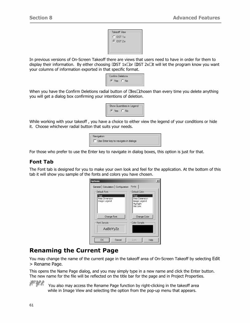
Section 8 Advanced Features
61
In previous versions of On-Screen Takeoff there are views that users need to have in order for them to display their information By either choosing ldquoOST 1xrdquo or ldquoOST 2xrdquo it will let the program know you want your columns of information exported in that specific format
When you have the Confirm Deletions radial button of ldquoYesrdquo chosen than every time you delete anything you will get a dialog box confirming your intentions of deletion
While working with your takeoff you have a choice to either view the legend of your conditions or hide it Choose whichever radial button that suits your needs
For those who prefer to use the Enter key to navigate in dialog boxes this option is just for that
Font Tab The Font tab is designed for you to make your own look and feel for the application At the bottom of this tab it will show you sample of the fonts and colors you have chosen
Renaming the Current Page You may change the name of the current page in the takeoff area of On-Screen Takeoff by selecting Edit gt Rename Page
This opens the Name Page dialog and you may simply type in a new name and click the Enter button The new name for the file will be reflected on the title bar for the page and in Project Properties
You also may access the Rename Page function by right-clicking in the takeoff area while in Image View and selecting the option from the pop-up menu that appears
Section 9
62
Saving and Exiting
This section will
Explain how to save projects
Show you how to safely exit the program
Section 9 Saving and Exiting
63
Saving Your Project
1 Select File gt Save 2 If your project has not previously been saved a Save dialog box will open to allow you to name
the file and choose the directory and folder in which to save your file 3 Once saved File gt Save will simply save the current version of the file
OR
4 Select File gt Save As then type in a new name for the file and save to the desired file path
The Auto-save Feature With the Auto-save feature On-Screen Takeoff automatically backs up your open project You may choose to have more than one level of backup files The first backup copy will have the extension b00 and successive files will be b01 b02 and so on If you have designated four levels of backup files after the fourth backup copy has been created (b03) the next file will be saved over the file with extension b00 Further backup saves will then rotate through the four backup files in the same way
1 Select Tools gt Options 2 In the Auto-save area (under the General tab) select the frequency of backup file creation (in
minutes) and the number of levels for the feature 3 You also may disengage the feature by clicking in the check box to clear it
The Auto-save feature automatically saves backup copies to the directory of the current project If you are working from a write-protected area such as a CD-ROM On-Screen Takeoff will place backup files in the On-Screen Takeoff folder
Exiting When you are finished using On-Screen Takeoff it is very easy to exit Exiting is very important because of security reasons If someone were to use your computer they could enter the application and view and manipulate information
Section 9 Saving and Exiting
64
On-Screen Takeoff closes the open project when you open another or create a new project or when you exit the program
1 Select File gt Exit
OR
2 You also may click at the upper right-hand corner of the application to exit
NOTE If your latest changes to a project file have not been saved On-Screen Takeoff will ask you whether you would like to save the file and gives you the option of canceling the operation
Appendix I Installing Your Digitizer
65
Appendix I Installing Your Digitizer When you get your digitizer from GTCO you will need to connect it to your computer Follow the instructions outlined below to do this
Note For rollup digitizers the metal bar must be oriented to the top or right hand side
Connecting the Digitizer 1 Lay the digitizer out flat 2 Connect the Stylus to the digitizer 3 Plug in the power adapter 4 Plug the interface (IO) cable into the digitizer 5 Plug the other end of the interface cable into an open serial port on computer
Note GTCO Technical support phone number is 410-381-6688 The electronic manual (on diskette) from GTCO contains more detailed installation and operation instructions for the GTCO digitizer model you have
Installing other Digitizer Drivers If you are using a GTCO Digitizer you will need to install the GTCO TabletWorks Drivers
If you are using a Digitizer not supported by GTCO Tablet Works 10 please contact the manufacturer of your digitizer for assistance with installation
Installing GTCO TabletWorks Drivers 1 Insert the On Center CD into the CD-ROM drive The CD Startup screen will open 2 Click on Install Software 3 Select Additional Software and Drivers 4 Select Digitizer Driver 5 Follow the instructions for installing TabletWorks 10
Adhering the Template The template is a small plastic sticker used to enable mouse function when using the digitizer with On-Screen Takeoff Place your template on your digitizer We suggest placing it in the bottom right corner of the digitizer about one inch inside the takeoff area
Note You may either peel off the back of the template and use the adhesive surface or you can tape the template down
Appendix I Installing Your Digitizer
66
Testing the Digitizer Drivers Before running OST you may test the digitizer by moving the stylus around on the digitizer pad it should move the mouse cursor (if mouse emulation is enabled)
If the digitizer does not move the mouse cursor on the screen
The superset codes may need to be reset Reset the superset codes by touching on the border of the digitizer with the stylus The digitizer should beep several times
The digitizer may not be communicating with the computer Be sure the COM port selected is correct Be sure the COM port selected is correct If you are not able to get the digitizer to move the mouse cursor you need to call GTCO technical support for help
Note The Mouse Emulation is not required for On-Screen Takeoff to work properly It is used only for the Template functionality if the digitizer is moving the cursor the wrong direction (up instead of sideways or vice-versa)
Click the L-shaped arrow symbol on the digitizer with the stylus
Appendix II Toolbar Item Details
67
Appendix II Toolbar Items Main Toolbar
Appendix II Toolbar Item Details
68
Tool Toolbar
Appendix II Toolbar Item Details
69
Zoom Toolbar
View Toolbar
Navigate Toolbar
Appendix II Toolbar Item Details
70
Navigate Toolbar (Continued)
Takeoff Toolbar
Appendix II Toolbar Item Details
71
Takeoff Toolbar (Continued)
Image Toolbar
Appendix III Loading Plans from a Dodge CD
72
Appendix III Loading Plans from a Dodge CD
This section will detail how to load plans from a F W Dodge CD-ROM into an On-Screen Takeoff project file ready for takeoffs
Dodge files may be added to the Project Properties dialog However loading the files in that way will load the files by number rather than name description If you want to load one page only from your Dodge CD You will have to rename the page to display the name rather than number of the file
To load plan files from a Dodge CD so that the files load sequentially by file number but are displayed by name rather than by number within your project follow the instructions below
Opening a Dodge project from a CD-ROM 1 Insert the CD into the drive 2 Choose File gt Custom 3 Choose Dodge Plans Project (plansdat) as the file type 4 Select the appropriate file type by clicking on the down arrow at the right of the Files of type
field 5 In the Look in field access your drive paths by clicking on the down arrow at the right of the
field then
Navigate to your CD-ROM drive Open the data folder and Open the Projects folder
6 Select the desired project and open its folder 7 Open the plansdat file 8 All the images will come in sequenced correctly for that job along with the full descriptions
(names) of each page If there is not a plans folder in the project folder then plans do not exist for that project on the CD Opening the plansdat file will yield an empty project
Appendix IV Using the Plan Viewer
73
Appendix IV Using On-Screen Takeoff Plan Viewer The On-Screen Takeoff Plan Viewer is a limited version of On Center Softwarersquos commercial takeoff software If your status bar located at the very bottom of the main window says View Mode in the lower left-hand corner then you are using the Plan Viewer You can use the plan viewer to
View CD-based amp converted CAD drawings
View a previously created OST file and associated drawings
Download electronic plans online
Navigate through drawings
Quickly Takeoff linearsareas and counts
Zoom in to view the plan better
Print drawings directly from the viewer
Viewing an On-Screen Takeoff Project File
1 To open an OST file that was previously created with of On-Screen Takeoff 2 Select File gt Open 3 An Open dialog will appear if you do not see the OST file you are looking for select the
Look In drop down arrow 4 A drop down menu will appear listing the various folders drives and mapped drives located
on your computer select the correct drive or folder location and continue to browse to the location of your OST file
5 When you see your OST file double-click it to open it 6 Any takeoff and drawings should appear on the Image tab view
If you do not see the drawings but do see the colored takeoff layer the drawings may
not be located in the same place they were originally saved at Go to File gt Project Properties and check the Image File path for each listed page If the image file path is pointing to a CD drive make sure the CD is inside the CR-ROM
Downloading Electronic Plans If your Online Plan Service provides a special file format (OSX) required to use this feature of our plan viewer you can immediately downloaded all electronic plans of a project directly from our viewer
Most Plan Room web sites will automatically open On-Screen Takeoff when a request to download plans is made Your particular Plan Room may differ in operation so please contact the provider directly with questions on using the site
Appendix IV Using the Plan Viewer
74
When you request to download or open a project file from a Plan Room you will usually have the open to open or save an OSX file Choosing open will automatically open On-Screen Takeoff Alternately you may choose to save the file to a local hard drive After you have saved the file either double-click it to launch On-Screen Takeoff or open the OSX file using On-Screen Takeoff by clicking File then Open and locating the file on your hard drive You will need to change the file type to OSX
After the OSX file is opened you will see an additional tab appear in the Conditions List window called Pages
The Pages tab shows the hierarchy of your project Gray file icons represent pages that have not been downloaded and blue icons represents pages that have been downloaded
To download a page simply double-click the page icon
If you wish to select a group of pages to download you can use the Ctrl or Shift key to multiple select them then click the Download button
If you wish to download all pages at once click the Download All button
Downloaded pages will now appear in the Project Properties dialog in the same order in which they appear in the Pages tab
Creating Quick Takeoffs With On-Screen Takeoff you can create quick takeoffs to measure quantities even if you dont have the full version of our program However using the Quick Takeoff functionality shows you just a fraction of what the full version can do
The Quick Takeoff Toolbar is located at the top of the image view It has three buttons designated for three types of takeoffs Linear Area and Count The Quantity drop down list will show secondary quantities for Linears and Areas The Units drop down allows you to select how you want your quantities displayed Feet Inches Yards Millimeters and Meters
NOTE Every time change the type of takeoff you are performing (switching from Area to Linear for example) the previous quantities and takeoff objects will disappear They will also disappear when you changes pages
NOTE You can use the Dimension Tool to basically measure the distance between two points or linears The distance will display on the status bar at the bottom of the application
The Quick Takeoff Toolbar
Appendix V Frequently Asked Questions
75
Appendix V Frequently Asked Questions General
Where is On-Screen Takeoff installed on my computer
Typically it is installed in CProgram FilesOn-Screen Takeoff
In Explorer how do I recognize On-Screen Takeoff file types
On-Screen Takeoff data is stored in a single file per job lsquojob name OSTrsquo On-Screen Takeoff templates are stored as lsquotemplate nameTPOrsquo
Can only one project at a time be open
Yes For that reason opening another project automatically closes the project on screen You will be asked to save any changes
Is only one scale allowed per page What about on drawings that have multiple detail sections on a page and each of those drawings have different scales
Yes For pages with drawings of different scales copy the drawing to another project page and set the appropriate scale
I cannot perform backout on an area that is along a linear
As a workaround use the On-Screen Takeoff layers feature to help you with this issue Electronic Images
How do I start a project from drawings that have been scanned and written to a CD-ROM
Open a new project Select File gt Project Properties and select Auto Add Navigate to your CD and the appropriate folder and select any image file in that location Click Open All files in the location will load into your project Recommended that images are copied from CD to hard drive for performance
If I get a disk of drawings in AutoCAD format (R13 or R14) can I read them in On-Screen Takeoff
Yes On-Screen Takeoff now reads DWG DXF and many other format that are saved with AutoCAD
Appendix V Frequently Asked Questions
76
When I click on the all pages button what is supposed to happen Currently nothing seems to change when I click on that button
The All Pages button is used to apply the Darken and Enhance Plans feature to all pages in the project (as opposed to only the current page on screen)
Is there a way to deduct a large skylight from an area condition
Yes with the related area condition selected in the Takeoff Dock bar unselect the Backout button on the Takeoff Toolbar then draw the Backout area The area quantity will be deducted from the related condition object and the linear measurement of the Backout perimeter will be added
Digitizer Issues
How do I connect a Digitizer to the computer
See Appendix I Connecting a Digitizer
The Place Template menu choice is disabled
On-Screen Takeoff may need to be authorized or the digitizer or the digitzer drivers are not installed
It wonrsquot let me select the Set Takeoff Area menu choice
On-Screen Takeoff may need to be authorized or no job is open a digitizer is not installed or the drivers are not installed
The digitizer stylus is not moving the cursor or crosshairs
Click S-0-1 superset on the digitizer
How do I convert my old GTCO Digitizer to work with On- Screen Takeofftrade
Call GTCO and they may be able to reconfigure your digitizer to be compatible with On-Screen Takeoff
Printing Issues Which Printers work with On-Screen Takeoff
Compatible printers include On-Screen Takeoff Hewlett Packard Epson and Canon printers If you are having printer difficulties please contact support and specify the type of printer along with other pertinent information Contact support at wwwoncentercomsupport or email supportoncentercom
Which Plotters work with On-Screen Takeoff
Compatible Plotters include Hewlett Packard DesignJet plotters and the EnCAD Cadjet II If you are having plotter difficulties please contact support and specify the type of plotter concerned
ViewingDisplay I can no longer see my condition list How do I get it back
The toolbars and Dock bars can be turned on and off through the View gt Toolbars menu options
Appendix V Frequently Asked Questions
77
This is also accessible by right-clicking in the toolbar area and selecting (or deselecting) a toolbar listed
I cannot view my folders in the condition list
Right-click in the Takeoff Dock barcondition list area and select Show Tree to display your folders
My Status Bar reads Viewer Mode and I am unable to draw conditions
On-Screen Takeoff needs to be Authorized Or you need to purchase an upgrade Click the Perform Advanced Takeoff button on the main toolbar
I hid a Dock bar and when I selected to view it again it appeared alongside the other Dock
bar instead of stacked on top of it How do I fix it
Pick up the Dock bar by clicking on the bar at the top and continuing to hold down the mouse button drag the Dock bar over the other one It will resize and appear stacked with the other
When I open image files from a CD the images are all upside down How do I get them right
side up
To flip pages from top to bottom follow the steps below 1 Click the All Pages button on the Image Toolbar (All Pages is engaged when the button
is not clicked) 2 Click the Flip Horizontal button on the Image Toolbar 3 Click the All Pages button again to disengage
Templates How do I create a Template
Follow the steps below 1 Create a typical project 2 Choose File gt Save As 3 Choose On-Screen Takeoff Template Files as the file type to save 4 Name the file This will save all of the condition setups as well as the layers for the
project
How do I create a new project from a template
Follow the steps below 1 Choose File gt New 2 Select a template from those listed in the New dialog This will open a new project with
conditions and layers saved from a previous project but no pages or takeoff
78
INDEX
Area Conditions 32
Area Objects 57
Auto Scrolling 20
Auto-save 63
Backout Mode 41
Calculation Method 60
Conditions 29
Configuration 60
Contents Tab 6
Continuous Mode 38
Count Conditions 33
Count Objects 57
Digitizer 10 65 76
Docking Toolbars 13
Dodge CD 72
Drawing 27 37
DropRun Count 55
Environment 18
Exiting 63
Exporting 49
Features 16
Font 61
Frequently Asked Questions 75
Grid 40
Help File 5
Hiding Toolbars 13
Hot Links 21
Image 19 59
Image files 9
Image Toolbar 12 71
Images 75
Index Tab 6
Layers 43
Linear Conditions 31
Linear Objects 56
Main Toolbar 12 67
Menus 14
Moving Toolbars 13
Navigate Toolbar 12 69
Navigating 20
On-Screen Takeofftrade 2
Page 59 61
Pages 20 25 28
Plan Viewer 73
Plans 26
Printing 47 76
Project Properties 25
Projects 22
Quick Start Video 18
Resizing Toolbars 13
Roping 54
Saving 63
Scale 28
Search Tab 7
Selecting Objects 42
Setup 8
Start On-Screen Takeofftrade 17
System Requirements 9
Takeoff 19 27
Takeoff Toolbar 70 71
Takeoff Toolbar 12
Template Files 23
TIF (Group4) 9
Tool Toolbar 12 68
Toolbar 67
Toolbars 12
View Toolbar 12 69
Viewing Toolbars 12
Worksheet 20
Zone Conditions 33
Zoom Toolbar 12 69
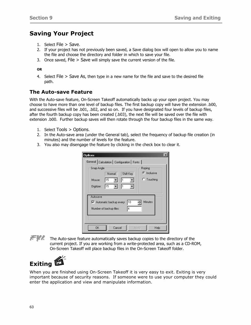
Section 9 Saving and Exiting
63
Saving Your Project
1 Select File gt Save 2 If your project has not previously been saved a Save dialog box will open to allow you to name
the file and choose the directory and folder in which to save your file 3 Once saved File gt Save will simply save the current version of the file
OR
4 Select File gt Save As then type in a new name for the file and save to the desired file path
The Auto-save Feature With the Auto-save feature On-Screen Takeoff automatically backs up your open project You may choose to have more than one level of backup files The first backup copy will have the extension b00 and successive files will be b01 b02 and so on If you have designated four levels of backup files after the fourth backup copy has been created (b03) the next file will be saved over the file with extension b00 Further backup saves will then rotate through the four backup files in the same way
1 Select Tools gt Options 2 In the Auto-save area (under the General tab) select the frequency of backup file creation (in
minutes) and the number of levels for the feature 3 You also may disengage the feature by clicking in the check box to clear it
The Auto-save feature automatically saves backup copies to the directory of the current project If you are working from a write-protected area such as a CD-ROM On-Screen Takeoff will place backup files in the On-Screen Takeoff folder
Exiting When you are finished using On-Screen Takeoff it is very easy to exit Exiting is very important because of security reasons If someone were to use your computer they could enter the application and view and manipulate information
Section 9 Saving and Exiting
64
On-Screen Takeoff closes the open project when you open another or create a new project or when you exit the program
1 Select File gt Exit
OR
2 You also may click at the upper right-hand corner of the application to exit
NOTE If your latest changes to a project file have not been saved On-Screen Takeoff will ask you whether you would like to save the file and gives you the option of canceling the operation
Appendix I Installing Your Digitizer
65
Appendix I Installing Your Digitizer When you get your digitizer from GTCO you will need to connect it to your computer Follow the instructions outlined below to do this
Note For rollup digitizers the metal bar must be oriented to the top or right hand side
Connecting the Digitizer 1 Lay the digitizer out flat 2 Connect the Stylus to the digitizer 3 Plug in the power adapter 4 Plug the interface (IO) cable into the digitizer 5 Plug the other end of the interface cable into an open serial port on computer
Note GTCO Technical support phone number is 410-381-6688 The electronic manual (on diskette) from GTCO contains more detailed installation and operation instructions for the GTCO digitizer model you have
Installing other Digitizer Drivers If you are using a GTCO Digitizer you will need to install the GTCO TabletWorks Drivers
If you are using a Digitizer not supported by GTCO Tablet Works 10 please contact the manufacturer of your digitizer for assistance with installation
Installing GTCO TabletWorks Drivers 1 Insert the On Center CD into the CD-ROM drive The CD Startup screen will open 2 Click on Install Software 3 Select Additional Software and Drivers 4 Select Digitizer Driver 5 Follow the instructions for installing TabletWorks 10
Adhering the Template The template is a small plastic sticker used to enable mouse function when using the digitizer with On-Screen Takeoff Place your template on your digitizer We suggest placing it in the bottom right corner of the digitizer about one inch inside the takeoff area
Note You may either peel off the back of the template and use the adhesive surface or you can tape the template down
Appendix I Installing Your Digitizer
66
Testing the Digitizer Drivers Before running OST you may test the digitizer by moving the stylus around on the digitizer pad it should move the mouse cursor (if mouse emulation is enabled)
If the digitizer does not move the mouse cursor on the screen
The superset codes may need to be reset Reset the superset codes by touching on the border of the digitizer with the stylus The digitizer should beep several times
The digitizer may not be communicating with the computer Be sure the COM port selected is correct Be sure the COM port selected is correct If you are not able to get the digitizer to move the mouse cursor you need to call GTCO technical support for help
Note The Mouse Emulation is not required for On-Screen Takeoff to work properly It is used only for the Template functionality if the digitizer is moving the cursor the wrong direction (up instead of sideways or vice-versa)
Click the L-shaped arrow symbol on the digitizer with the stylus
Appendix II Toolbar Item Details
67
Appendix II Toolbar Items Main Toolbar
Appendix II Toolbar Item Details
68
Tool Toolbar
Appendix II Toolbar Item Details
69
Zoom Toolbar
View Toolbar
Navigate Toolbar
Appendix II Toolbar Item Details
70
Navigate Toolbar (Continued)
Takeoff Toolbar
Appendix II Toolbar Item Details
71
Takeoff Toolbar (Continued)
Image Toolbar
Appendix III Loading Plans from a Dodge CD
72
Appendix III Loading Plans from a Dodge CD
This section will detail how to load plans from a F W Dodge CD-ROM into an On-Screen Takeoff project file ready for takeoffs
Dodge files may be added to the Project Properties dialog However loading the files in that way will load the files by number rather than name description If you want to load one page only from your Dodge CD You will have to rename the page to display the name rather than number of the file
To load plan files from a Dodge CD so that the files load sequentially by file number but are displayed by name rather than by number within your project follow the instructions below
Opening a Dodge project from a CD-ROM 1 Insert the CD into the drive 2 Choose File gt Custom 3 Choose Dodge Plans Project (plansdat) as the file type 4 Select the appropriate file type by clicking on the down arrow at the right of the Files of type
field 5 In the Look in field access your drive paths by clicking on the down arrow at the right of the
field then
Navigate to your CD-ROM drive Open the data folder and Open the Projects folder
6 Select the desired project and open its folder 7 Open the plansdat file 8 All the images will come in sequenced correctly for that job along with the full descriptions
(names) of each page If there is not a plans folder in the project folder then plans do not exist for that project on the CD Opening the plansdat file will yield an empty project
Appendix IV Using the Plan Viewer
73
Appendix IV Using On-Screen Takeoff Plan Viewer The On-Screen Takeoff Plan Viewer is a limited version of On Center Softwarersquos commercial takeoff software If your status bar located at the very bottom of the main window says View Mode in the lower left-hand corner then you are using the Plan Viewer You can use the plan viewer to
View CD-based amp converted CAD drawings
View a previously created OST file and associated drawings
Download electronic plans online
Navigate through drawings
Quickly Takeoff linearsareas and counts
Zoom in to view the plan better
Print drawings directly from the viewer
Viewing an On-Screen Takeoff Project File
1 To open an OST file that was previously created with of On-Screen Takeoff 2 Select File gt Open 3 An Open dialog will appear if you do not see the OST file you are looking for select the
Look In drop down arrow 4 A drop down menu will appear listing the various folders drives and mapped drives located
on your computer select the correct drive or folder location and continue to browse to the location of your OST file
5 When you see your OST file double-click it to open it 6 Any takeoff and drawings should appear on the Image tab view
If you do not see the drawings but do see the colored takeoff layer the drawings may
not be located in the same place they were originally saved at Go to File gt Project Properties and check the Image File path for each listed page If the image file path is pointing to a CD drive make sure the CD is inside the CR-ROM
Downloading Electronic Plans If your Online Plan Service provides a special file format (OSX) required to use this feature of our plan viewer you can immediately downloaded all electronic plans of a project directly from our viewer
Most Plan Room web sites will automatically open On-Screen Takeoff when a request to download plans is made Your particular Plan Room may differ in operation so please contact the provider directly with questions on using the site
Appendix IV Using the Plan Viewer
74
When you request to download or open a project file from a Plan Room you will usually have the open to open or save an OSX file Choosing open will automatically open On-Screen Takeoff Alternately you may choose to save the file to a local hard drive After you have saved the file either double-click it to launch On-Screen Takeoff or open the OSX file using On-Screen Takeoff by clicking File then Open and locating the file on your hard drive You will need to change the file type to OSX
After the OSX file is opened you will see an additional tab appear in the Conditions List window called Pages
The Pages tab shows the hierarchy of your project Gray file icons represent pages that have not been downloaded and blue icons represents pages that have been downloaded
To download a page simply double-click the page icon
If you wish to select a group of pages to download you can use the Ctrl or Shift key to multiple select them then click the Download button
If you wish to download all pages at once click the Download All button
Downloaded pages will now appear in the Project Properties dialog in the same order in which they appear in the Pages tab
Creating Quick Takeoffs With On-Screen Takeoff you can create quick takeoffs to measure quantities even if you dont have the full version of our program However using the Quick Takeoff functionality shows you just a fraction of what the full version can do
The Quick Takeoff Toolbar is located at the top of the image view It has three buttons designated for three types of takeoffs Linear Area and Count The Quantity drop down list will show secondary quantities for Linears and Areas The Units drop down allows you to select how you want your quantities displayed Feet Inches Yards Millimeters and Meters
NOTE Every time change the type of takeoff you are performing (switching from Area to Linear for example) the previous quantities and takeoff objects will disappear They will also disappear when you changes pages
NOTE You can use the Dimension Tool to basically measure the distance between two points or linears The distance will display on the status bar at the bottom of the application
The Quick Takeoff Toolbar
Appendix V Frequently Asked Questions
75
Appendix V Frequently Asked Questions General
Where is On-Screen Takeoff installed on my computer
Typically it is installed in CProgram FilesOn-Screen Takeoff
In Explorer how do I recognize On-Screen Takeoff file types
On-Screen Takeoff data is stored in a single file per job lsquojob name OSTrsquo On-Screen Takeoff templates are stored as lsquotemplate nameTPOrsquo
Can only one project at a time be open
Yes For that reason opening another project automatically closes the project on screen You will be asked to save any changes
Is only one scale allowed per page What about on drawings that have multiple detail sections on a page and each of those drawings have different scales
Yes For pages with drawings of different scales copy the drawing to another project page and set the appropriate scale
I cannot perform backout on an area that is along a linear
As a workaround use the On-Screen Takeoff layers feature to help you with this issue Electronic Images
How do I start a project from drawings that have been scanned and written to a CD-ROM
Open a new project Select File gt Project Properties and select Auto Add Navigate to your CD and the appropriate folder and select any image file in that location Click Open All files in the location will load into your project Recommended that images are copied from CD to hard drive for performance
If I get a disk of drawings in AutoCAD format (R13 or R14) can I read them in On-Screen Takeoff
Yes On-Screen Takeoff now reads DWG DXF and many other format that are saved with AutoCAD
Appendix V Frequently Asked Questions
76
When I click on the all pages button what is supposed to happen Currently nothing seems to change when I click on that button
The All Pages button is used to apply the Darken and Enhance Plans feature to all pages in the project (as opposed to only the current page on screen)
Is there a way to deduct a large skylight from an area condition
Yes with the related area condition selected in the Takeoff Dock bar unselect the Backout button on the Takeoff Toolbar then draw the Backout area The area quantity will be deducted from the related condition object and the linear measurement of the Backout perimeter will be added
Digitizer Issues
How do I connect a Digitizer to the computer
See Appendix I Connecting a Digitizer
The Place Template menu choice is disabled
On-Screen Takeoff may need to be authorized or the digitizer or the digitzer drivers are not installed
It wonrsquot let me select the Set Takeoff Area menu choice
On-Screen Takeoff may need to be authorized or no job is open a digitizer is not installed or the drivers are not installed
The digitizer stylus is not moving the cursor or crosshairs
Click S-0-1 superset on the digitizer
How do I convert my old GTCO Digitizer to work with On- Screen Takeofftrade
Call GTCO and they may be able to reconfigure your digitizer to be compatible with On-Screen Takeoff
Printing Issues Which Printers work with On-Screen Takeoff
Compatible printers include On-Screen Takeoff Hewlett Packard Epson and Canon printers If you are having printer difficulties please contact support and specify the type of printer along with other pertinent information Contact support at wwwoncentercomsupport or email supportoncentercom
Which Plotters work with On-Screen Takeoff
Compatible Plotters include Hewlett Packard DesignJet plotters and the EnCAD Cadjet II If you are having plotter difficulties please contact support and specify the type of plotter concerned
ViewingDisplay I can no longer see my condition list How do I get it back
The toolbars and Dock bars can be turned on and off through the View gt Toolbars menu options
Appendix V Frequently Asked Questions
77
This is also accessible by right-clicking in the toolbar area and selecting (or deselecting) a toolbar listed
I cannot view my folders in the condition list
Right-click in the Takeoff Dock barcondition list area and select Show Tree to display your folders
My Status Bar reads Viewer Mode and I am unable to draw conditions
On-Screen Takeoff needs to be Authorized Or you need to purchase an upgrade Click the Perform Advanced Takeoff button on the main toolbar
I hid a Dock bar and when I selected to view it again it appeared alongside the other Dock
bar instead of stacked on top of it How do I fix it
Pick up the Dock bar by clicking on the bar at the top and continuing to hold down the mouse button drag the Dock bar over the other one It will resize and appear stacked with the other
When I open image files from a CD the images are all upside down How do I get them right
side up
To flip pages from top to bottom follow the steps below 1 Click the All Pages button on the Image Toolbar (All Pages is engaged when the button
is not clicked) 2 Click the Flip Horizontal button on the Image Toolbar 3 Click the All Pages button again to disengage
Templates How do I create a Template
Follow the steps below 1 Create a typical project 2 Choose File gt Save As 3 Choose On-Screen Takeoff Template Files as the file type to save 4 Name the file This will save all of the condition setups as well as the layers for the
project
How do I create a new project from a template
Follow the steps below 1 Choose File gt New 2 Select a template from those listed in the New dialog This will open a new project with
conditions and layers saved from a previous project but no pages or takeoff
78
INDEX
Area Conditions 32
Area Objects 57
Auto Scrolling 20
Auto-save 63
Backout Mode 41
Calculation Method 60
Conditions 29
Configuration 60
Contents Tab 6
Continuous Mode 38
Count Conditions 33
Count Objects 57
Digitizer 10 65 76
Docking Toolbars 13
Dodge CD 72
Drawing 27 37
DropRun Count 55
Environment 18
Exiting 63
Exporting 49
Features 16
Font 61
Frequently Asked Questions 75
Grid 40
Help File 5
Hiding Toolbars 13
Hot Links 21
Image 19 59
Image files 9
Image Toolbar 12 71
Images 75
Index Tab 6
Layers 43
Linear Conditions 31
Linear Objects 56
Main Toolbar 12 67
Menus 14
Moving Toolbars 13
Navigate Toolbar 12 69
Navigating 20
On-Screen Takeofftrade 2
Page 59 61
Pages 20 25 28
Plan Viewer 73
Plans 26
Printing 47 76
Project Properties 25
Projects 22
Quick Start Video 18
Resizing Toolbars 13
Roping 54
Saving 63
Scale 28
Search Tab 7
Selecting Objects 42
Setup 8
Start On-Screen Takeofftrade 17
System Requirements 9
Takeoff 19 27
Takeoff Toolbar 70 71
Takeoff Toolbar 12
Template Files 23
TIF (Group4) 9
Tool Toolbar 12 68
Toolbar 67
Toolbars 12
View Toolbar 12 69
Viewing Toolbars 12
Worksheet 20
Zone Conditions 33
Zoom Toolbar 12 69
Appendix I Installing Your Digitizer
66
Testing the Digitizer Drivers Before running OST you may test the digitizer by moving the stylus around on the digitizer pad it should move the mouse cursor (if mouse emulation is enabled)
If the digitizer does not move the mouse cursor on the screen
The superset codes may need to be reset Reset the superset codes by touching on the border of the digitizer with the stylus The digitizer should beep several times
The digitizer may not be communicating with the computer Be sure the COM port selected is correct Be sure the COM port selected is correct If you are not able to get the digitizer to move the mouse cursor you need to call GTCO technical support for help
Note The Mouse Emulation is not required for On-Screen Takeoff to work properly It is used only for the Template functionality if the digitizer is moving the cursor the wrong direction (up instead of sideways or vice-versa)
Click the L-shaped arrow symbol on the digitizer with the stylus
Appendix II Toolbar Item Details
67
Appendix II Toolbar Items Main Toolbar
Appendix II Toolbar Item Details
68
Tool Toolbar
Appendix II Toolbar Item Details
69
Zoom Toolbar
View Toolbar
Navigate Toolbar
Appendix II Toolbar Item Details
70
Navigate Toolbar (Continued)
Takeoff Toolbar
Appendix II Toolbar Item Details
71
Takeoff Toolbar (Continued)
Image Toolbar
Appendix III Loading Plans from a Dodge CD
72
Appendix III Loading Plans from a Dodge CD
This section will detail how to load plans from a F W Dodge CD-ROM into an On-Screen Takeoff project file ready for takeoffs
Dodge files may be added to the Project Properties dialog However loading the files in that way will load the files by number rather than name description If you want to load one page only from your Dodge CD You will have to rename the page to display the name rather than number of the file
To load plan files from a Dodge CD so that the files load sequentially by file number but are displayed by name rather than by number within your project follow the instructions below
Opening a Dodge project from a CD-ROM 1 Insert the CD into the drive 2 Choose File gt Custom 3 Choose Dodge Plans Project (plansdat) as the file type 4 Select the appropriate file type by clicking on the down arrow at the right of the Files of type
field 5 In the Look in field access your drive paths by clicking on the down arrow at the right of the
field then
Navigate to your CD-ROM drive Open the data folder and Open the Projects folder
6 Select the desired project and open its folder 7 Open the plansdat file 8 All the images will come in sequenced correctly for that job along with the full descriptions
(names) of each page If there is not a plans folder in the project folder then plans do not exist for that project on the CD Opening the plansdat file will yield an empty project
Appendix IV Using the Plan Viewer
73
Appendix IV Using On-Screen Takeoff Plan Viewer The On-Screen Takeoff Plan Viewer is a limited version of On Center Softwarersquos commercial takeoff software If your status bar located at the very bottom of the main window says View Mode in the lower left-hand corner then you are using the Plan Viewer You can use the plan viewer to
View CD-based amp converted CAD drawings
View a previously created OST file and associated drawings
Download electronic plans online
Navigate through drawings
Quickly Takeoff linearsareas and counts
Zoom in to view the plan better
Print drawings directly from the viewer
Viewing an On-Screen Takeoff Project File
1 To open an OST file that was previously created with of On-Screen Takeoff 2 Select File gt Open 3 An Open dialog will appear if you do not see the OST file you are looking for select the
Look In drop down arrow 4 A drop down menu will appear listing the various folders drives and mapped drives located
on your computer select the correct drive or folder location and continue to browse to the location of your OST file
5 When you see your OST file double-click it to open it 6 Any takeoff and drawings should appear on the Image tab view
If you do not see the drawings but do see the colored takeoff layer the drawings may
not be located in the same place they were originally saved at Go to File gt Project Properties and check the Image File path for each listed page If the image file path is pointing to a CD drive make sure the CD is inside the CR-ROM
Downloading Electronic Plans If your Online Plan Service provides a special file format (OSX) required to use this feature of our plan viewer you can immediately downloaded all electronic plans of a project directly from our viewer
Most Plan Room web sites will automatically open On-Screen Takeoff when a request to download plans is made Your particular Plan Room may differ in operation so please contact the provider directly with questions on using the site
Appendix IV Using the Plan Viewer
74
When you request to download or open a project file from a Plan Room you will usually have the open to open or save an OSX file Choosing open will automatically open On-Screen Takeoff Alternately you may choose to save the file to a local hard drive After you have saved the file either double-click it to launch On-Screen Takeoff or open the OSX file using On-Screen Takeoff by clicking File then Open and locating the file on your hard drive You will need to change the file type to OSX
After the OSX file is opened you will see an additional tab appear in the Conditions List window called Pages
The Pages tab shows the hierarchy of your project Gray file icons represent pages that have not been downloaded and blue icons represents pages that have been downloaded
To download a page simply double-click the page icon
If you wish to select a group of pages to download you can use the Ctrl or Shift key to multiple select them then click the Download button
If you wish to download all pages at once click the Download All button
Downloaded pages will now appear in the Project Properties dialog in the same order in which they appear in the Pages tab
Creating Quick Takeoffs With On-Screen Takeoff you can create quick takeoffs to measure quantities even if you dont have the full version of our program However using the Quick Takeoff functionality shows you just a fraction of what the full version can do
The Quick Takeoff Toolbar is located at the top of the image view It has three buttons designated for three types of takeoffs Linear Area and Count The Quantity drop down list will show secondary quantities for Linears and Areas The Units drop down allows you to select how you want your quantities displayed Feet Inches Yards Millimeters and Meters
NOTE Every time change the type of takeoff you are performing (switching from Area to Linear for example) the previous quantities and takeoff objects will disappear They will also disappear when you changes pages
NOTE You can use the Dimension Tool to basically measure the distance between two points or linears The distance will display on the status bar at the bottom of the application
The Quick Takeoff Toolbar
Appendix V Frequently Asked Questions
75
Appendix V Frequently Asked Questions General
Where is On-Screen Takeoff installed on my computer
Typically it is installed in CProgram FilesOn-Screen Takeoff
In Explorer how do I recognize On-Screen Takeoff file types
On-Screen Takeoff data is stored in a single file per job lsquojob name OSTrsquo On-Screen Takeoff templates are stored as lsquotemplate nameTPOrsquo
Can only one project at a time be open
Yes For that reason opening another project automatically closes the project on screen You will be asked to save any changes
Is only one scale allowed per page What about on drawings that have multiple detail sections on a page and each of those drawings have different scales
Yes For pages with drawings of different scales copy the drawing to another project page and set the appropriate scale
I cannot perform backout on an area that is along a linear
As a workaround use the On-Screen Takeoff layers feature to help you with this issue Electronic Images
How do I start a project from drawings that have been scanned and written to a CD-ROM
Open a new project Select File gt Project Properties and select Auto Add Navigate to your CD and the appropriate folder and select any image file in that location Click Open All files in the location will load into your project Recommended that images are copied from CD to hard drive for performance
If I get a disk of drawings in AutoCAD format (R13 or R14) can I read them in On-Screen Takeoff
Yes On-Screen Takeoff now reads DWG DXF and many other format that are saved with AutoCAD
Appendix V Frequently Asked Questions
76
When I click on the all pages button what is supposed to happen Currently nothing seems to change when I click on that button
The All Pages button is used to apply the Darken and Enhance Plans feature to all pages in the project (as opposed to only the current page on screen)
Is there a way to deduct a large skylight from an area condition
Yes with the related area condition selected in the Takeoff Dock bar unselect the Backout button on the Takeoff Toolbar then draw the Backout area The area quantity will be deducted from the related condition object and the linear measurement of the Backout perimeter will be added
Digitizer Issues
How do I connect a Digitizer to the computer
See Appendix I Connecting a Digitizer
The Place Template menu choice is disabled
On-Screen Takeoff may need to be authorized or the digitizer or the digitzer drivers are not installed
It wonrsquot let me select the Set Takeoff Area menu choice
On-Screen Takeoff may need to be authorized or no job is open a digitizer is not installed or the drivers are not installed
The digitizer stylus is not moving the cursor or crosshairs
Click S-0-1 superset on the digitizer
How do I convert my old GTCO Digitizer to work with On- Screen Takeofftrade
Call GTCO and they may be able to reconfigure your digitizer to be compatible with On-Screen Takeoff
Printing Issues Which Printers work with On-Screen Takeoff
Compatible printers include On-Screen Takeoff Hewlett Packard Epson and Canon printers If you are having printer difficulties please contact support and specify the type of printer along with other pertinent information Contact support at wwwoncentercomsupport or email supportoncentercom
Which Plotters work with On-Screen Takeoff
Compatible Plotters include Hewlett Packard DesignJet plotters and the EnCAD Cadjet II If you are having plotter difficulties please contact support and specify the type of plotter concerned
ViewingDisplay I can no longer see my condition list How do I get it back
The toolbars and Dock bars can be turned on and off through the View gt Toolbars menu options
Appendix V Frequently Asked Questions
77
This is also accessible by right-clicking in the toolbar area and selecting (or deselecting) a toolbar listed
I cannot view my folders in the condition list
Right-click in the Takeoff Dock barcondition list area and select Show Tree to display your folders
My Status Bar reads Viewer Mode and I am unable to draw conditions
On-Screen Takeoff needs to be Authorized Or you need to purchase an upgrade Click the Perform Advanced Takeoff button on the main toolbar
I hid a Dock bar and when I selected to view it again it appeared alongside the other Dock
bar instead of stacked on top of it How do I fix it
Pick up the Dock bar by clicking on the bar at the top and continuing to hold down the mouse button drag the Dock bar over the other one It will resize and appear stacked with the other
When I open image files from a CD the images are all upside down How do I get them right
side up
To flip pages from top to bottom follow the steps below 1 Click the All Pages button on the Image Toolbar (All Pages is engaged when the button
is not clicked) 2 Click the Flip Horizontal button on the Image Toolbar 3 Click the All Pages button again to disengage
Templates How do I create a Template
Follow the steps below 1 Create a typical project 2 Choose File gt Save As 3 Choose On-Screen Takeoff Template Files as the file type to save 4 Name the file This will save all of the condition setups as well as the layers for the
project
How do I create a new project from a template
Follow the steps below 1 Choose File gt New 2 Select a template from those listed in the New dialog This will open a new project with
conditions and layers saved from a previous project but no pages or takeoff
78
INDEX
Area Conditions 32
Area Objects 57
Auto Scrolling 20
Auto-save 63
Backout Mode 41
Calculation Method 60
Conditions 29
Configuration 60
Contents Tab 6
Continuous Mode 38
Count Conditions 33
Count Objects 57
Digitizer 10 65 76
Docking Toolbars 13
Dodge CD 72
Drawing 27 37
DropRun Count 55
Environment 18
Exiting 63
Exporting 49
Features 16
Font 61
Frequently Asked Questions 75
Grid 40
Help File 5
Hiding Toolbars 13
Hot Links 21
Image 19 59
Image files 9
Image Toolbar 12 71
Images 75
Index Tab 6
Layers 43
Linear Conditions 31
Linear Objects 56
Main Toolbar 12 67
Menus 14
Moving Toolbars 13
Navigate Toolbar 12 69
Navigating 20
On-Screen Takeofftrade 2
Page 59 61
Pages 20 25 28
Plan Viewer 73
Plans 26
Printing 47 76
Project Properties 25
Projects 22
Quick Start Video 18
Resizing Toolbars 13
Roping 54
Saving 63
Scale 28
Search Tab 7
Selecting Objects 42
Setup 8
Start On-Screen Takeofftrade 17
System Requirements 9
Takeoff 19 27
Takeoff Toolbar 70 71
Takeoff Toolbar 12
Template Files 23
TIF (Group4) 9
Tool Toolbar 12 68
Toolbar 67
Toolbars 12
View Toolbar 12 69
Viewing Toolbars 12
Worksheet 20
Zone Conditions 33
Zoom Toolbar 12 69
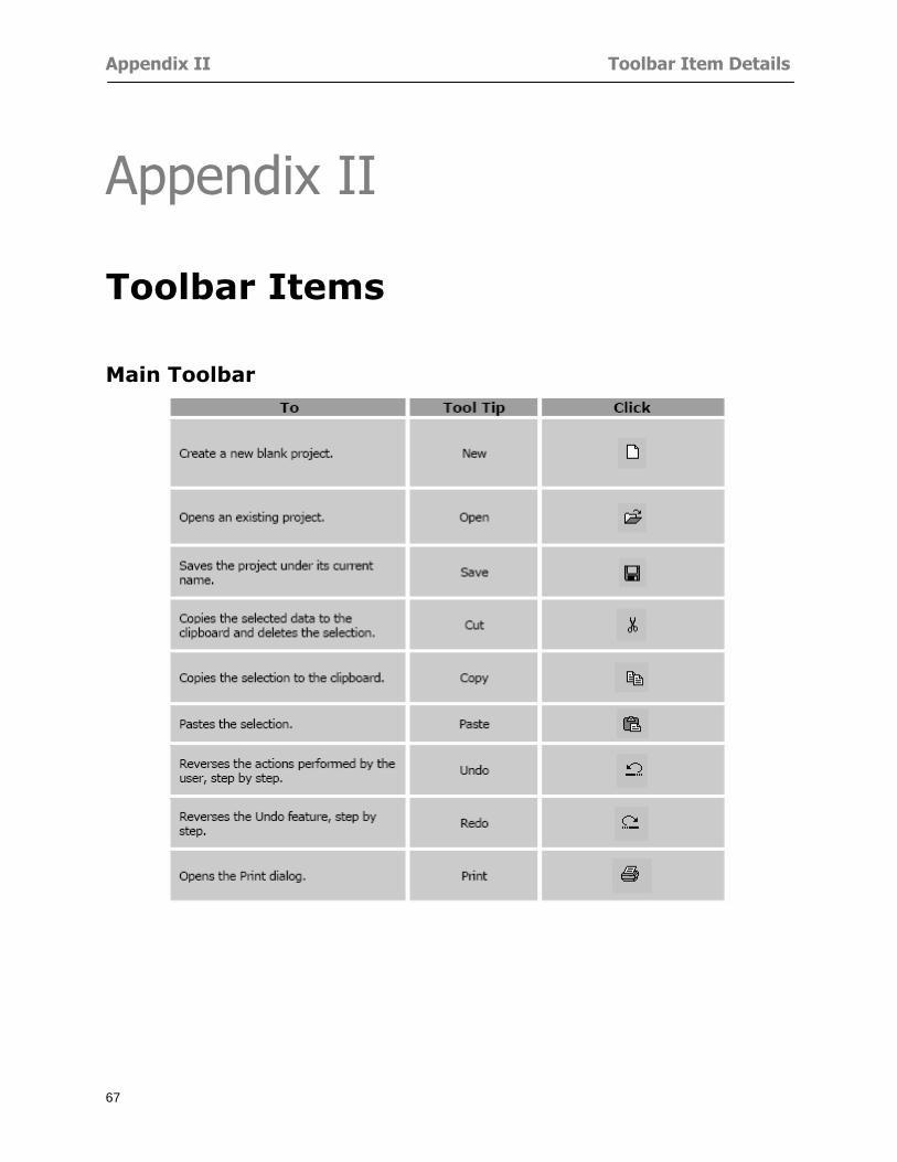
Appendix II Toolbar Item Details
67
Appendix II Toolbar Items Main Toolbar
Appendix II Toolbar Item Details
68
Tool Toolbar
Appendix II Toolbar Item Details
69
Zoom Toolbar
View Toolbar
Navigate Toolbar
Appendix II Toolbar Item Details
70
Navigate Toolbar (Continued)
Takeoff Toolbar
Appendix II Toolbar Item Details
71
Takeoff Toolbar (Continued)
Image Toolbar
Appendix III Loading Plans from a Dodge CD
72
Appendix III Loading Plans from a Dodge CD
This section will detail how to load plans from a F W Dodge CD-ROM into an On-Screen Takeoff project file ready for takeoffs
Dodge files may be added to the Project Properties dialog However loading the files in that way will load the files by number rather than name description If you want to load one page only from your Dodge CD You will have to rename the page to display the name rather than number of the file
To load plan files from a Dodge CD so that the files load sequentially by file number but are displayed by name rather than by number within your project follow the instructions below
Opening a Dodge project from a CD-ROM 1 Insert the CD into the drive 2 Choose File gt Custom 3 Choose Dodge Plans Project (plansdat) as the file type 4 Select the appropriate file type by clicking on the down arrow at the right of the Files of type
field 5 In the Look in field access your drive paths by clicking on the down arrow at the right of the
field then
Navigate to your CD-ROM drive Open the data folder and Open the Projects folder
6 Select the desired project and open its folder 7 Open the plansdat file 8 All the images will come in sequenced correctly for that job along with the full descriptions
(names) of each page If there is not a plans folder in the project folder then plans do not exist for that project on the CD Opening the plansdat file will yield an empty project
Appendix IV Using the Plan Viewer
73
Appendix IV Using On-Screen Takeoff Plan Viewer The On-Screen Takeoff Plan Viewer is a limited version of On Center Softwarersquos commercial takeoff software If your status bar located at the very bottom of the main window says View Mode in the lower left-hand corner then you are using the Plan Viewer You can use the plan viewer to
View CD-based amp converted CAD drawings
View a previously created OST file and associated drawings
Download electronic plans online
Navigate through drawings
Quickly Takeoff linearsareas and counts
Zoom in to view the plan better
Print drawings directly from the viewer
Viewing an On-Screen Takeoff Project File
1 To open an OST file that was previously created with of On-Screen Takeoff 2 Select File gt Open 3 An Open dialog will appear if you do not see the OST file you are looking for select the
Look In drop down arrow 4 A drop down menu will appear listing the various folders drives and mapped drives located
on your computer select the correct drive or folder location and continue to browse to the location of your OST file
5 When you see your OST file double-click it to open it 6 Any takeoff and drawings should appear on the Image tab view
If you do not see the drawings but do see the colored takeoff layer the drawings may
not be located in the same place they were originally saved at Go to File gt Project Properties and check the Image File path for each listed page If the image file path is pointing to a CD drive make sure the CD is inside the CR-ROM
Downloading Electronic Plans If your Online Plan Service provides a special file format (OSX) required to use this feature of our plan viewer you can immediately downloaded all electronic plans of a project directly from our viewer
Most Plan Room web sites will automatically open On-Screen Takeoff when a request to download plans is made Your particular Plan Room may differ in operation so please contact the provider directly with questions on using the site
Appendix IV Using the Plan Viewer
74
When you request to download or open a project file from a Plan Room you will usually have the open to open or save an OSX file Choosing open will automatically open On-Screen Takeoff Alternately you may choose to save the file to a local hard drive After you have saved the file either double-click it to launch On-Screen Takeoff or open the OSX file using On-Screen Takeoff by clicking File then Open and locating the file on your hard drive You will need to change the file type to OSX
After the OSX file is opened you will see an additional tab appear in the Conditions List window called Pages
The Pages tab shows the hierarchy of your project Gray file icons represent pages that have not been downloaded and blue icons represents pages that have been downloaded
To download a page simply double-click the page icon
If you wish to select a group of pages to download you can use the Ctrl or Shift key to multiple select them then click the Download button
If you wish to download all pages at once click the Download All button
Downloaded pages will now appear in the Project Properties dialog in the same order in which they appear in the Pages tab
Creating Quick Takeoffs With On-Screen Takeoff you can create quick takeoffs to measure quantities even if you dont have the full version of our program However using the Quick Takeoff functionality shows you just a fraction of what the full version can do
The Quick Takeoff Toolbar is located at the top of the image view It has three buttons designated for three types of takeoffs Linear Area and Count The Quantity drop down list will show secondary quantities for Linears and Areas The Units drop down allows you to select how you want your quantities displayed Feet Inches Yards Millimeters and Meters
NOTE Every time change the type of takeoff you are performing (switching from Area to Linear for example) the previous quantities and takeoff objects will disappear They will also disappear when you changes pages
NOTE You can use the Dimension Tool to basically measure the distance between two points or linears The distance will display on the status bar at the bottom of the application
The Quick Takeoff Toolbar
Appendix V Frequently Asked Questions
75
Appendix V Frequently Asked Questions General
Where is On-Screen Takeoff installed on my computer
Typically it is installed in CProgram FilesOn-Screen Takeoff
In Explorer how do I recognize On-Screen Takeoff file types
On-Screen Takeoff data is stored in a single file per job lsquojob name OSTrsquo On-Screen Takeoff templates are stored as lsquotemplate nameTPOrsquo
Can only one project at a time be open
Yes For that reason opening another project automatically closes the project on screen You will be asked to save any changes
Is only one scale allowed per page What about on drawings that have multiple detail sections on a page and each of those drawings have different scales
Yes For pages with drawings of different scales copy the drawing to another project page and set the appropriate scale
I cannot perform backout on an area that is along a linear
As a workaround use the On-Screen Takeoff layers feature to help you with this issue Electronic Images
How do I start a project from drawings that have been scanned and written to a CD-ROM
Open a new project Select File gt Project Properties and select Auto Add Navigate to your CD and the appropriate folder and select any image file in that location Click Open All files in the location will load into your project Recommended that images are copied from CD to hard drive for performance
If I get a disk of drawings in AutoCAD format (R13 or R14) can I read them in On-Screen Takeoff
Yes On-Screen Takeoff now reads DWG DXF and many other format that are saved with AutoCAD
Appendix V Frequently Asked Questions
76
When I click on the all pages button what is supposed to happen Currently nothing seems to change when I click on that button
The All Pages button is used to apply the Darken and Enhance Plans feature to all pages in the project (as opposed to only the current page on screen)
Is there a way to deduct a large skylight from an area condition
Yes with the related area condition selected in the Takeoff Dock bar unselect the Backout button on the Takeoff Toolbar then draw the Backout area The area quantity will be deducted from the related condition object and the linear measurement of the Backout perimeter will be added
Digitizer Issues
How do I connect a Digitizer to the computer
See Appendix I Connecting a Digitizer
The Place Template menu choice is disabled
On-Screen Takeoff may need to be authorized or the digitizer or the digitzer drivers are not installed
It wonrsquot let me select the Set Takeoff Area menu choice
On-Screen Takeoff may need to be authorized or no job is open a digitizer is not installed or the drivers are not installed
The digitizer stylus is not moving the cursor or crosshairs
Click S-0-1 superset on the digitizer
How do I convert my old GTCO Digitizer to work with On- Screen Takeofftrade
Call GTCO and they may be able to reconfigure your digitizer to be compatible with On-Screen Takeoff
Printing Issues Which Printers work with On-Screen Takeoff
Compatible printers include On-Screen Takeoff Hewlett Packard Epson and Canon printers If you are having printer difficulties please contact support and specify the type of printer along with other pertinent information Contact support at wwwoncentercomsupport or email supportoncentercom
Which Plotters work with On-Screen Takeoff
Compatible Plotters include Hewlett Packard DesignJet plotters and the EnCAD Cadjet II If you are having plotter difficulties please contact support and specify the type of plotter concerned
ViewingDisplay I can no longer see my condition list How do I get it back
The toolbars and Dock bars can be turned on and off through the View gt Toolbars menu options
Appendix V Frequently Asked Questions
77
This is also accessible by right-clicking in the toolbar area and selecting (or deselecting) a toolbar listed
I cannot view my folders in the condition list
Right-click in the Takeoff Dock barcondition list area and select Show Tree to display your folders
My Status Bar reads Viewer Mode and I am unable to draw conditions
On-Screen Takeoff needs to be Authorized Or you need to purchase an upgrade Click the Perform Advanced Takeoff button on the main toolbar
I hid a Dock bar and when I selected to view it again it appeared alongside the other Dock
bar instead of stacked on top of it How do I fix it
Pick up the Dock bar by clicking on the bar at the top and continuing to hold down the mouse button drag the Dock bar over the other one It will resize and appear stacked with the other
When I open image files from a CD the images are all upside down How do I get them right
side up
To flip pages from top to bottom follow the steps below 1 Click the All Pages button on the Image Toolbar (All Pages is engaged when the button
is not clicked) 2 Click the Flip Horizontal button on the Image Toolbar 3 Click the All Pages button again to disengage
Templates How do I create a Template
Follow the steps below 1 Create a typical project 2 Choose File gt Save As 3 Choose On-Screen Takeoff Template Files as the file type to save 4 Name the file This will save all of the condition setups as well as the layers for the
project
How do I create a new project from a template
Follow the steps below 1 Choose File gt New 2 Select a template from those listed in the New dialog This will open a new project with
conditions and layers saved from a previous project but no pages or takeoff
78
INDEX
Area Conditions 32
Area Objects 57
Auto Scrolling 20
Auto-save 63
Backout Mode 41
Calculation Method 60
Conditions 29
Configuration 60
Contents Tab 6
Continuous Mode 38
Count Conditions 33
Count Objects 57
Digitizer 10 65 76
Docking Toolbars 13
Dodge CD 72
Drawing 27 37
DropRun Count 55
Environment 18
Exiting 63
Exporting 49
Features 16
Font 61
Frequently Asked Questions 75
Grid 40
Help File 5
Hiding Toolbars 13
Hot Links 21
Image 19 59
Image files 9
Image Toolbar 12 71
Images 75
Index Tab 6
Layers 43
Linear Conditions 31
Linear Objects 56
Main Toolbar 12 67
Menus 14
Moving Toolbars 13
Navigate Toolbar 12 69
Navigating 20
On-Screen Takeofftrade 2
Page 59 61
Pages 20 25 28
Plan Viewer 73
Plans 26
Printing 47 76
Project Properties 25
Projects 22
Quick Start Video 18
Resizing Toolbars 13
Roping 54
Saving 63
Scale 28
Search Tab 7
Selecting Objects 42
Setup 8
Start On-Screen Takeofftrade 17
System Requirements 9
Takeoff 19 27
Takeoff Toolbar 70 71
Takeoff Toolbar 12
Template Files 23
TIF (Group4) 9
Tool Toolbar 12 68
Toolbar 67
Toolbars 12
View Toolbar 12 69
Viewing Toolbars 12
Worksheet 20
Zone Conditions 33
Zoom Toolbar 12 69
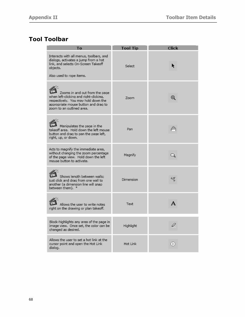
Appendix II Toolbar Item Details
68
Tool Toolbar
Appendix II Toolbar Item Details
69
Zoom Toolbar
View Toolbar
Navigate Toolbar
Appendix II Toolbar Item Details
70
Navigate Toolbar (Continued)
Takeoff Toolbar
Appendix II Toolbar Item Details
71
Takeoff Toolbar (Continued)
Image Toolbar
Appendix III Loading Plans from a Dodge CD
72
Appendix III Loading Plans from a Dodge CD
This section will detail how to load plans from a F W Dodge CD-ROM into an On-Screen Takeoff project file ready for takeoffs
Dodge files may be added to the Project Properties dialog However loading the files in that way will load the files by number rather than name description If you want to load one page only from your Dodge CD You will have to rename the page to display the name rather than number of the file
To load plan files from a Dodge CD so that the files load sequentially by file number but are displayed by name rather than by number within your project follow the instructions below
Opening a Dodge project from a CD-ROM 1 Insert the CD into the drive 2 Choose File gt Custom 3 Choose Dodge Plans Project (plansdat) as the file type 4 Select the appropriate file type by clicking on the down arrow at the right of the Files of type
field 5 In the Look in field access your drive paths by clicking on the down arrow at the right of the
field then
Navigate to your CD-ROM drive Open the data folder and Open the Projects folder
6 Select the desired project and open its folder 7 Open the plansdat file 8 All the images will come in sequenced correctly for that job along with the full descriptions
(names) of each page If there is not a plans folder in the project folder then plans do not exist for that project on the CD Opening the plansdat file will yield an empty project
Appendix IV Using the Plan Viewer
73
Appendix IV Using On-Screen Takeoff Plan Viewer The On-Screen Takeoff Plan Viewer is a limited version of On Center Softwarersquos commercial takeoff software If your status bar located at the very bottom of the main window says View Mode in the lower left-hand corner then you are using the Plan Viewer You can use the plan viewer to
View CD-based amp converted CAD drawings
View a previously created OST file and associated drawings
Download electronic plans online
Navigate through drawings
Quickly Takeoff linearsareas and counts
Zoom in to view the plan better
Print drawings directly from the viewer
Viewing an On-Screen Takeoff Project File
1 To open an OST file that was previously created with of On-Screen Takeoff 2 Select File gt Open 3 An Open dialog will appear if you do not see the OST file you are looking for select the
Look In drop down arrow 4 A drop down menu will appear listing the various folders drives and mapped drives located
on your computer select the correct drive or folder location and continue to browse to the location of your OST file
5 When you see your OST file double-click it to open it 6 Any takeoff and drawings should appear on the Image tab view
If you do not see the drawings but do see the colored takeoff layer the drawings may
not be located in the same place they were originally saved at Go to File gt Project Properties and check the Image File path for each listed page If the image file path is pointing to a CD drive make sure the CD is inside the CR-ROM
Downloading Electronic Plans If your Online Plan Service provides a special file format (OSX) required to use this feature of our plan viewer you can immediately downloaded all electronic plans of a project directly from our viewer
Most Plan Room web sites will automatically open On-Screen Takeoff when a request to download plans is made Your particular Plan Room may differ in operation so please contact the provider directly with questions on using the site
Appendix IV Using the Plan Viewer
74
When you request to download or open a project file from a Plan Room you will usually have the open to open or save an OSX file Choosing open will automatically open On-Screen Takeoff Alternately you may choose to save the file to a local hard drive After you have saved the file either double-click it to launch On-Screen Takeoff or open the OSX file using On-Screen Takeoff by clicking File then Open and locating the file on your hard drive You will need to change the file type to OSX
After the OSX file is opened you will see an additional tab appear in the Conditions List window called Pages
The Pages tab shows the hierarchy of your project Gray file icons represent pages that have not been downloaded and blue icons represents pages that have been downloaded
To download a page simply double-click the page icon
If you wish to select a group of pages to download you can use the Ctrl or Shift key to multiple select them then click the Download button
If you wish to download all pages at once click the Download All button
Downloaded pages will now appear in the Project Properties dialog in the same order in which they appear in the Pages tab
Creating Quick Takeoffs With On-Screen Takeoff you can create quick takeoffs to measure quantities even if you dont have the full version of our program However using the Quick Takeoff functionality shows you just a fraction of what the full version can do
The Quick Takeoff Toolbar is located at the top of the image view It has three buttons designated for three types of takeoffs Linear Area and Count The Quantity drop down list will show secondary quantities for Linears and Areas The Units drop down allows you to select how you want your quantities displayed Feet Inches Yards Millimeters and Meters
NOTE Every time change the type of takeoff you are performing (switching from Area to Linear for example) the previous quantities and takeoff objects will disappear They will also disappear when you changes pages
NOTE You can use the Dimension Tool to basically measure the distance between two points or linears The distance will display on the status bar at the bottom of the application
The Quick Takeoff Toolbar
Appendix V Frequently Asked Questions
75
Appendix V Frequently Asked Questions General
Where is On-Screen Takeoff installed on my computer
Typically it is installed in CProgram FilesOn-Screen Takeoff
In Explorer how do I recognize On-Screen Takeoff file types
On-Screen Takeoff data is stored in a single file per job lsquojob name OSTrsquo On-Screen Takeoff templates are stored as lsquotemplate nameTPOrsquo
Can only one project at a time be open
Yes For that reason opening another project automatically closes the project on screen You will be asked to save any changes
Is only one scale allowed per page What about on drawings that have multiple detail sections on a page and each of those drawings have different scales
Yes For pages with drawings of different scales copy the drawing to another project page and set the appropriate scale
I cannot perform backout on an area that is along a linear
As a workaround use the On-Screen Takeoff layers feature to help you with this issue Electronic Images
How do I start a project from drawings that have been scanned and written to a CD-ROM
Open a new project Select File gt Project Properties and select Auto Add Navigate to your CD and the appropriate folder and select any image file in that location Click Open All files in the location will load into your project Recommended that images are copied from CD to hard drive for performance
If I get a disk of drawings in AutoCAD format (R13 or R14) can I read them in On-Screen Takeoff
Yes On-Screen Takeoff now reads DWG DXF and many other format that are saved with AutoCAD
Appendix V Frequently Asked Questions
76
When I click on the all pages button what is supposed to happen Currently nothing seems to change when I click on that button
The All Pages button is used to apply the Darken and Enhance Plans feature to all pages in the project (as opposed to only the current page on screen)
Is there a way to deduct a large skylight from an area condition
Yes with the related area condition selected in the Takeoff Dock bar unselect the Backout button on the Takeoff Toolbar then draw the Backout area The area quantity will be deducted from the related condition object and the linear measurement of the Backout perimeter will be added
Digitizer Issues
How do I connect a Digitizer to the computer
See Appendix I Connecting a Digitizer
The Place Template menu choice is disabled
On-Screen Takeoff may need to be authorized or the digitizer or the digitzer drivers are not installed
It wonrsquot let me select the Set Takeoff Area menu choice
On-Screen Takeoff may need to be authorized or no job is open a digitizer is not installed or the drivers are not installed
The digitizer stylus is not moving the cursor or crosshairs
Click S-0-1 superset on the digitizer
How do I convert my old GTCO Digitizer to work with On- Screen Takeofftrade
Call GTCO and they may be able to reconfigure your digitizer to be compatible with On-Screen Takeoff
Printing Issues Which Printers work with On-Screen Takeoff
Compatible printers include On-Screen Takeoff Hewlett Packard Epson and Canon printers If you are having printer difficulties please contact support and specify the type of printer along with other pertinent information Contact support at wwwoncentercomsupport or email supportoncentercom
Which Plotters work with On-Screen Takeoff
Compatible Plotters include Hewlett Packard DesignJet plotters and the EnCAD Cadjet II If you are having plotter difficulties please contact support and specify the type of plotter concerned
ViewingDisplay I can no longer see my condition list How do I get it back
The toolbars and Dock bars can be turned on and off through the View gt Toolbars menu options
Appendix V Frequently Asked Questions
77
This is also accessible by right-clicking in the toolbar area and selecting (or deselecting) a toolbar listed
I cannot view my folders in the condition list
Right-click in the Takeoff Dock barcondition list area and select Show Tree to display your folders
My Status Bar reads Viewer Mode and I am unable to draw conditions
On-Screen Takeoff needs to be Authorized Or you need to purchase an upgrade Click the Perform Advanced Takeoff button on the main toolbar
I hid a Dock bar and when I selected to view it again it appeared alongside the other Dock
bar instead of stacked on top of it How do I fix it
Pick up the Dock bar by clicking on the bar at the top and continuing to hold down the mouse button drag the Dock bar over the other one It will resize and appear stacked with the other
When I open image files from a CD the images are all upside down How do I get them right
side up
To flip pages from top to bottom follow the steps below 1 Click the All Pages button on the Image Toolbar (All Pages is engaged when the button
is not clicked) 2 Click the Flip Horizontal button on the Image Toolbar 3 Click the All Pages button again to disengage
Templates How do I create a Template
Follow the steps below 1 Create a typical project 2 Choose File gt Save As 3 Choose On-Screen Takeoff Template Files as the file type to save 4 Name the file This will save all of the condition setups as well as the layers for the
project
How do I create a new project from a template
Follow the steps below 1 Choose File gt New 2 Select a template from those listed in the New dialog This will open a new project with
conditions and layers saved from a previous project but no pages or takeoff
78
INDEX
Area Conditions 32
Area Objects 57
Auto Scrolling 20
Auto-save 63
Backout Mode 41
Calculation Method 60
Conditions 29
Configuration 60
Contents Tab 6
Continuous Mode 38
Count Conditions 33
Count Objects 57
Digitizer 10 65 76
Docking Toolbars 13
Dodge CD 72
Drawing 27 37
DropRun Count 55
Environment 18
Exiting 63
Exporting 49
Features 16
Font 61
Frequently Asked Questions 75
Grid 40
Help File 5
Hiding Toolbars 13
Hot Links 21
Image 19 59
Image files 9
Image Toolbar 12 71
Images 75
Index Tab 6
Layers 43
Linear Conditions 31
Linear Objects 56
Main Toolbar 12 67
Menus 14
Moving Toolbars 13
Navigate Toolbar 12 69
Navigating 20
On-Screen Takeofftrade 2
Page 59 61
Pages 20 25 28
Plan Viewer 73
Plans 26
Printing 47 76
Project Properties 25
Projects 22
Quick Start Video 18
Resizing Toolbars 13
Roping 54
Saving 63
Scale 28
Search Tab 7
Selecting Objects 42
Setup 8
Start On-Screen Takeofftrade 17
System Requirements 9
Takeoff 19 27
Takeoff Toolbar 70 71
Takeoff Toolbar 12
Template Files 23
TIF (Group4) 9
Tool Toolbar 12 68
Toolbar 67
Toolbars 12
View Toolbar 12 69
Viewing Toolbars 12
Worksheet 20
Zone Conditions 33
Zoom Toolbar 12 69
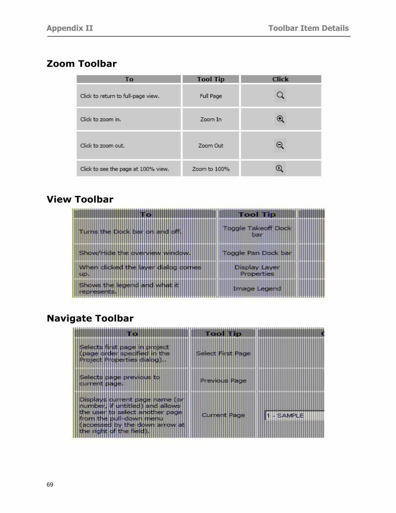
Appendix II Toolbar Item Details
69
Zoom Toolbar
View Toolbar
Navigate Toolbar
Appendix II Toolbar Item Details
70
Navigate Toolbar (Continued)
Takeoff Toolbar
Appendix II Toolbar Item Details
71
Takeoff Toolbar (Continued)
Image Toolbar
Appendix III Loading Plans from a Dodge CD
72
Appendix III Loading Plans from a Dodge CD
This section will detail how to load plans from a F W Dodge CD-ROM into an On-Screen Takeoff project file ready for takeoffs
Dodge files may be added to the Project Properties dialog However loading the files in that way will load the files by number rather than name description If you want to load one page only from your Dodge CD You will have to rename the page to display the name rather than number of the file
To load plan files from a Dodge CD so that the files load sequentially by file number but are displayed by name rather than by number within your project follow the instructions below
Opening a Dodge project from a CD-ROM 1 Insert the CD into the drive 2 Choose File gt Custom 3 Choose Dodge Plans Project (plansdat) as the file type 4 Select the appropriate file type by clicking on the down arrow at the right of the Files of type
field 5 In the Look in field access your drive paths by clicking on the down arrow at the right of the
field then
Navigate to your CD-ROM drive Open the data folder and Open the Projects folder
6 Select the desired project and open its folder 7 Open the plansdat file 8 All the images will come in sequenced correctly for that job along with the full descriptions
(names) of each page If there is not a plans folder in the project folder then plans do not exist for that project on the CD Opening the plansdat file will yield an empty project
Appendix IV Using the Plan Viewer
73
Appendix IV Using On-Screen Takeoff Plan Viewer The On-Screen Takeoff Plan Viewer is a limited version of On Center Softwarersquos commercial takeoff software If your status bar located at the very bottom of the main window says View Mode in the lower left-hand corner then you are using the Plan Viewer You can use the plan viewer to
View CD-based amp converted CAD drawings
View a previously created OST file and associated drawings
Download electronic plans online
Navigate through drawings
Quickly Takeoff linearsareas and counts
Zoom in to view the plan better
Print drawings directly from the viewer
Viewing an On-Screen Takeoff Project File
1 To open an OST file that was previously created with of On-Screen Takeoff 2 Select File gt Open 3 An Open dialog will appear if you do not see the OST file you are looking for select the
Look In drop down arrow 4 A drop down menu will appear listing the various folders drives and mapped drives located
on your computer select the correct drive or folder location and continue to browse to the location of your OST file
5 When you see your OST file double-click it to open it 6 Any takeoff and drawings should appear on the Image tab view
If you do not see the drawings but do see the colored takeoff layer the drawings may
not be located in the same place they were originally saved at Go to File gt Project Properties and check the Image File path for each listed page If the image file path is pointing to a CD drive make sure the CD is inside the CR-ROM
Downloading Electronic Plans If your Online Plan Service provides a special file format (OSX) required to use this feature of our plan viewer you can immediately downloaded all electronic plans of a project directly from our viewer
Most Plan Room web sites will automatically open On-Screen Takeoff when a request to download plans is made Your particular Plan Room may differ in operation so please contact the provider directly with questions on using the site
Appendix IV Using the Plan Viewer
74
When you request to download or open a project file from a Plan Room you will usually have the open to open or save an OSX file Choosing open will automatically open On-Screen Takeoff Alternately you may choose to save the file to a local hard drive After you have saved the file either double-click it to launch On-Screen Takeoff or open the OSX file using On-Screen Takeoff by clicking File then Open and locating the file on your hard drive You will need to change the file type to OSX
After the OSX file is opened you will see an additional tab appear in the Conditions List window called Pages
The Pages tab shows the hierarchy of your project Gray file icons represent pages that have not been downloaded and blue icons represents pages that have been downloaded
To download a page simply double-click the page icon
If you wish to select a group of pages to download you can use the Ctrl or Shift key to multiple select them then click the Download button
If you wish to download all pages at once click the Download All button
Downloaded pages will now appear in the Project Properties dialog in the same order in which they appear in the Pages tab
Creating Quick Takeoffs With On-Screen Takeoff you can create quick takeoffs to measure quantities even if you dont have the full version of our program However using the Quick Takeoff functionality shows you just a fraction of what the full version can do
The Quick Takeoff Toolbar is located at the top of the image view It has three buttons designated for three types of takeoffs Linear Area and Count The Quantity drop down list will show secondary quantities for Linears and Areas The Units drop down allows you to select how you want your quantities displayed Feet Inches Yards Millimeters and Meters
NOTE Every time change the type of takeoff you are performing (switching from Area to Linear for example) the previous quantities and takeoff objects will disappear They will also disappear when you changes pages
NOTE You can use the Dimension Tool to basically measure the distance between two points or linears The distance will display on the status bar at the bottom of the application
The Quick Takeoff Toolbar
Appendix V Frequently Asked Questions
75
Appendix V Frequently Asked Questions General
Where is On-Screen Takeoff installed on my computer
Typically it is installed in CProgram FilesOn-Screen Takeoff
In Explorer how do I recognize On-Screen Takeoff file types
On-Screen Takeoff data is stored in a single file per job lsquojob name OSTrsquo On-Screen Takeoff templates are stored as lsquotemplate nameTPOrsquo
Can only one project at a time be open
Yes For that reason opening another project automatically closes the project on screen You will be asked to save any changes
Is only one scale allowed per page What about on drawings that have multiple detail sections on a page and each of those drawings have different scales
Yes For pages with drawings of different scales copy the drawing to another project page and set the appropriate scale
I cannot perform backout on an area that is along a linear
As a workaround use the On-Screen Takeoff layers feature to help you with this issue Electronic Images
How do I start a project from drawings that have been scanned and written to a CD-ROM
Open a new project Select File gt Project Properties and select Auto Add Navigate to your CD and the appropriate folder and select any image file in that location Click Open All files in the location will load into your project Recommended that images are copied from CD to hard drive for performance
If I get a disk of drawings in AutoCAD format (R13 or R14) can I read them in On-Screen Takeoff
Yes On-Screen Takeoff now reads DWG DXF and many other format that are saved with AutoCAD
Appendix V Frequently Asked Questions
76
When I click on the all pages button what is supposed to happen Currently nothing seems to change when I click on that button
The All Pages button is used to apply the Darken and Enhance Plans feature to all pages in the project (as opposed to only the current page on screen)
Is there a way to deduct a large skylight from an area condition
Yes with the related area condition selected in the Takeoff Dock bar unselect the Backout button on the Takeoff Toolbar then draw the Backout area The area quantity will be deducted from the related condition object and the linear measurement of the Backout perimeter will be added
Digitizer Issues
How do I connect a Digitizer to the computer
See Appendix I Connecting a Digitizer
The Place Template menu choice is disabled
On-Screen Takeoff may need to be authorized or the digitizer or the digitzer drivers are not installed
It wonrsquot let me select the Set Takeoff Area menu choice
On-Screen Takeoff may need to be authorized or no job is open a digitizer is not installed or the drivers are not installed
The digitizer stylus is not moving the cursor or crosshairs
Click S-0-1 superset on the digitizer
How do I convert my old GTCO Digitizer to work with On- Screen Takeofftrade
Call GTCO and they may be able to reconfigure your digitizer to be compatible with On-Screen Takeoff
Printing Issues Which Printers work with On-Screen Takeoff
Compatible printers include On-Screen Takeoff Hewlett Packard Epson and Canon printers If you are having printer difficulties please contact support and specify the type of printer along with other pertinent information Contact support at wwwoncentercomsupport or email supportoncentercom
Which Plotters work with On-Screen Takeoff
Compatible Plotters include Hewlett Packard DesignJet plotters and the EnCAD Cadjet II If you are having plotter difficulties please contact support and specify the type of plotter concerned
ViewingDisplay I can no longer see my condition list How do I get it back
The toolbars and Dock bars can be turned on and off through the View gt Toolbars menu options
Appendix V Frequently Asked Questions
77
This is also accessible by right-clicking in the toolbar area and selecting (or deselecting) a toolbar listed
I cannot view my folders in the condition list
Right-click in the Takeoff Dock barcondition list area and select Show Tree to display your folders
My Status Bar reads Viewer Mode and I am unable to draw conditions
On-Screen Takeoff needs to be Authorized Or you need to purchase an upgrade Click the Perform Advanced Takeoff button on the main toolbar
I hid a Dock bar and when I selected to view it again it appeared alongside the other Dock
bar instead of stacked on top of it How do I fix it
Pick up the Dock bar by clicking on the bar at the top and continuing to hold down the mouse button drag the Dock bar over the other one It will resize and appear stacked with the other
When I open image files from a CD the images are all upside down How do I get them right
side up
To flip pages from top to bottom follow the steps below 1 Click the All Pages button on the Image Toolbar (All Pages is engaged when the button
is not clicked) 2 Click the Flip Horizontal button on the Image Toolbar 3 Click the All Pages button again to disengage
Templates How do I create a Template
Follow the steps below 1 Create a typical project 2 Choose File gt Save As 3 Choose On-Screen Takeoff Template Files as the file type to save 4 Name the file This will save all of the condition setups as well as the layers for the
project
How do I create a new project from a template
Follow the steps below 1 Choose File gt New 2 Select a template from those listed in the New dialog This will open a new project with
conditions and layers saved from a previous project but no pages or takeoff
78
INDEX
Area Conditions 32
Area Objects 57
Auto Scrolling 20
Auto-save 63
Backout Mode 41
Calculation Method 60
Conditions 29
Configuration 60
Contents Tab 6
Continuous Mode 38
Count Conditions 33
Count Objects 57
Digitizer 10 65 76
Docking Toolbars 13
Dodge CD 72
Drawing 27 37
DropRun Count 55
Environment 18
Exiting 63
Exporting 49
Features 16
Font 61
Frequently Asked Questions 75
Grid 40
Help File 5
Hiding Toolbars 13
Hot Links 21
Image 19 59
Image files 9
Image Toolbar 12 71
Images 75
Index Tab 6
Layers 43
Linear Conditions 31
Linear Objects 56
Main Toolbar 12 67
Menus 14
Moving Toolbars 13
Navigate Toolbar 12 69
Navigating 20
On-Screen Takeofftrade 2
Page 59 61
Pages 20 25 28
Plan Viewer 73
Plans 26
Printing 47 76
Project Properties 25
Projects 22
Quick Start Video 18
Resizing Toolbars 13
Roping 54
Saving 63
Scale 28
Search Tab 7
Selecting Objects 42
Setup 8
Start On-Screen Takeofftrade 17
System Requirements 9
Takeoff 19 27
Takeoff Toolbar 70 71
Takeoff Toolbar 12
Template Files 23
TIF (Group4) 9
Tool Toolbar 12 68
Toolbar 67
Toolbars 12
View Toolbar 12 69
Viewing Toolbars 12
Worksheet 20
Zone Conditions 33
Zoom Toolbar 12 69
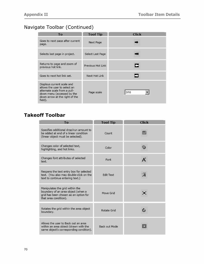
Appendix II Toolbar Item Details
70
Navigate Toolbar (Continued)
Takeoff Toolbar
Appendix II Toolbar Item Details
71
Takeoff Toolbar (Continued)
Image Toolbar
Appendix III Loading Plans from a Dodge CD
72
Appendix III Loading Plans from a Dodge CD
This section will detail how to load plans from a F W Dodge CD-ROM into an On-Screen Takeoff project file ready for takeoffs
Dodge files may be added to the Project Properties dialog However loading the files in that way will load the files by number rather than name description If you want to load one page only from your Dodge CD You will have to rename the page to display the name rather than number of the file
To load plan files from a Dodge CD so that the files load sequentially by file number but are displayed by name rather than by number within your project follow the instructions below
Opening a Dodge project from a CD-ROM 1 Insert the CD into the drive 2 Choose File gt Custom 3 Choose Dodge Plans Project (plansdat) as the file type 4 Select the appropriate file type by clicking on the down arrow at the right of the Files of type
field 5 In the Look in field access your drive paths by clicking on the down arrow at the right of the
field then
Navigate to your CD-ROM drive Open the data folder and Open the Projects folder
6 Select the desired project and open its folder 7 Open the plansdat file 8 All the images will come in sequenced correctly for that job along with the full descriptions
(names) of each page If there is not a plans folder in the project folder then plans do not exist for that project on the CD Opening the plansdat file will yield an empty project
Appendix IV Using the Plan Viewer
73
Appendix IV Using On-Screen Takeoff Plan Viewer The On-Screen Takeoff Plan Viewer is a limited version of On Center Softwarersquos commercial takeoff software If your status bar located at the very bottom of the main window says View Mode in the lower left-hand corner then you are using the Plan Viewer You can use the plan viewer to
View CD-based amp converted CAD drawings
View a previously created OST file and associated drawings
Download electronic plans online
Navigate through drawings
Quickly Takeoff linearsareas and counts
Zoom in to view the plan better
Print drawings directly from the viewer
Viewing an On-Screen Takeoff Project File
1 To open an OST file that was previously created with of On-Screen Takeoff 2 Select File gt Open 3 An Open dialog will appear if you do not see the OST file you are looking for select the
Look In drop down arrow 4 A drop down menu will appear listing the various folders drives and mapped drives located
on your computer select the correct drive or folder location and continue to browse to the location of your OST file
5 When you see your OST file double-click it to open it 6 Any takeoff and drawings should appear on the Image tab view
If you do not see the drawings but do see the colored takeoff layer the drawings may
not be located in the same place they were originally saved at Go to File gt Project Properties and check the Image File path for each listed page If the image file path is pointing to a CD drive make sure the CD is inside the CR-ROM
Downloading Electronic Plans If your Online Plan Service provides a special file format (OSX) required to use this feature of our plan viewer you can immediately downloaded all electronic plans of a project directly from our viewer
Most Plan Room web sites will automatically open On-Screen Takeoff when a request to download plans is made Your particular Plan Room may differ in operation so please contact the provider directly with questions on using the site
Appendix IV Using the Plan Viewer
74
When you request to download or open a project file from a Plan Room you will usually have the open to open or save an OSX file Choosing open will automatically open On-Screen Takeoff Alternately you may choose to save the file to a local hard drive After you have saved the file either double-click it to launch On-Screen Takeoff or open the OSX file using On-Screen Takeoff by clicking File then Open and locating the file on your hard drive You will need to change the file type to OSX
After the OSX file is opened you will see an additional tab appear in the Conditions List window called Pages
The Pages tab shows the hierarchy of your project Gray file icons represent pages that have not been downloaded and blue icons represents pages that have been downloaded
To download a page simply double-click the page icon
If you wish to select a group of pages to download you can use the Ctrl or Shift key to multiple select them then click the Download button
If you wish to download all pages at once click the Download All button
Downloaded pages will now appear in the Project Properties dialog in the same order in which they appear in the Pages tab
Creating Quick Takeoffs With On-Screen Takeoff you can create quick takeoffs to measure quantities even if you dont have the full version of our program However using the Quick Takeoff functionality shows you just a fraction of what the full version can do
The Quick Takeoff Toolbar is located at the top of the image view It has three buttons designated for three types of takeoffs Linear Area and Count The Quantity drop down list will show secondary quantities for Linears and Areas The Units drop down allows you to select how you want your quantities displayed Feet Inches Yards Millimeters and Meters
NOTE Every time change the type of takeoff you are performing (switching from Area to Linear for example) the previous quantities and takeoff objects will disappear They will also disappear when you changes pages
NOTE You can use the Dimension Tool to basically measure the distance between two points or linears The distance will display on the status bar at the bottom of the application
The Quick Takeoff Toolbar
Appendix V Frequently Asked Questions
75
Appendix V Frequently Asked Questions General
Where is On-Screen Takeoff installed on my computer
Typically it is installed in CProgram FilesOn-Screen Takeoff
In Explorer how do I recognize On-Screen Takeoff file types
On-Screen Takeoff data is stored in a single file per job lsquojob name OSTrsquo On-Screen Takeoff templates are stored as lsquotemplate nameTPOrsquo
Can only one project at a time be open
Yes For that reason opening another project automatically closes the project on screen You will be asked to save any changes
Is only one scale allowed per page What about on drawings that have multiple detail sections on a page and each of those drawings have different scales
Yes For pages with drawings of different scales copy the drawing to another project page and set the appropriate scale
I cannot perform backout on an area that is along a linear
As a workaround use the On-Screen Takeoff layers feature to help you with this issue Electronic Images
How do I start a project from drawings that have been scanned and written to a CD-ROM
Open a new project Select File gt Project Properties and select Auto Add Navigate to your CD and the appropriate folder and select any image file in that location Click Open All files in the location will load into your project Recommended that images are copied from CD to hard drive for performance
If I get a disk of drawings in AutoCAD format (R13 or R14) can I read them in On-Screen Takeoff
Yes On-Screen Takeoff now reads DWG DXF and many other format that are saved with AutoCAD
Appendix V Frequently Asked Questions
76
When I click on the all pages button what is supposed to happen Currently nothing seems to change when I click on that button
The All Pages button is used to apply the Darken and Enhance Plans feature to all pages in the project (as opposed to only the current page on screen)
Is there a way to deduct a large skylight from an area condition
Yes with the related area condition selected in the Takeoff Dock bar unselect the Backout button on the Takeoff Toolbar then draw the Backout area The area quantity will be deducted from the related condition object and the linear measurement of the Backout perimeter will be added
Digitizer Issues
How do I connect a Digitizer to the computer
See Appendix I Connecting a Digitizer
The Place Template menu choice is disabled
On-Screen Takeoff may need to be authorized or the digitizer or the digitzer drivers are not installed
It wonrsquot let me select the Set Takeoff Area menu choice
On-Screen Takeoff may need to be authorized or no job is open a digitizer is not installed or the drivers are not installed
The digitizer stylus is not moving the cursor or crosshairs
Click S-0-1 superset on the digitizer
How do I convert my old GTCO Digitizer to work with On- Screen Takeofftrade
Call GTCO and they may be able to reconfigure your digitizer to be compatible with On-Screen Takeoff
Printing Issues Which Printers work with On-Screen Takeoff
Compatible printers include On-Screen Takeoff Hewlett Packard Epson and Canon printers If you are having printer difficulties please contact support and specify the type of printer along with other pertinent information Contact support at wwwoncentercomsupport or email supportoncentercom
Which Plotters work with On-Screen Takeoff
Compatible Plotters include Hewlett Packard DesignJet plotters and the EnCAD Cadjet II If you are having plotter difficulties please contact support and specify the type of plotter concerned
ViewingDisplay I can no longer see my condition list How do I get it back
The toolbars and Dock bars can be turned on and off through the View gt Toolbars menu options
Appendix V Frequently Asked Questions
77
This is also accessible by right-clicking in the toolbar area and selecting (or deselecting) a toolbar listed
I cannot view my folders in the condition list
Right-click in the Takeoff Dock barcondition list area and select Show Tree to display your folders
My Status Bar reads Viewer Mode and I am unable to draw conditions
On-Screen Takeoff needs to be Authorized Or you need to purchase an upgrade Click the Perform Advanced Takeoff button on the main toolbar
I hid a Dock bar and when I selected to view it again it appeared alongside the other Dock
bar instead of stacked on top of it How do I fix it
Pick up the Dock bar by clicking on the bar at the top and continuing to hold down the mouse button drag the Dock bar over the other one It will resize and appear stacked with the other
When I open image files from a CD the images are all upside down How do I get them right
side up
To flip pages from top to bottom follow the steps below 1 Click the All Pages button on the Image Toolbar (All Pages is engaged when the button
is not clicked) 2 Click the Flip Horizontal button on the Image Toolbar 3 Click the All Pages button again to disengage
Templates How do I create a Template
Follow the steps below 1 Create a typical project 2 Choose File gt Save As 3 Choose On-Screen Takeoff Template Files as the file type to save 4 Name the file This will save all of the condition setups as well as the layers for the
project
How do I create a new project from a template
Follow the steps below 1 Choose File gt New 2 Select a template from those listed in the New dialog This will open a new project with
conditions and layers saved from a previous project but no pages or takeoff
78
INDEX
Area Conditions 32
Area Objects 57
Auto Scrolling 20
Auto-save 63
Backout Mode 41
Calculation Method 60
Conditions 29
Configuration 60
Contents Tab 6
Continuous Mode 38
Count Conditions 33
Count Objects 57
Digitizer 10 65 76
Docking Toolbars 13
Dodge CD 72
Drawing 27 37
DropRun Count 55
Environment 18
Exiting 63
Exporting 49
Features 16
Font 61
Frequently Asked Questions 75
Grid 40
Help File 5
Hiding Toolbars 13
Hot Links 21
Image 19 59
Image files 9
Image Toolbar 12 71
Images 75
Index Tab 6
Layers 43
Linear Conditions 31
Linear Objects 56
Main Toolbar 12 67
Menus 14
Moving Toolbars 13
Navigate Toolbar 12 69
Navigating 20
On-Screen Takeofftrade 2
Page 59 61
Pages 20 25 28
Plan Viewer 73
Plans 26
Printing 47 76
Project Properties 25
Projects 22
Quick Start Video 18
Resizing Toolbars 13
Roping 54
Saving 63
Scale 28
Search Tab 7
Selecting Objects 42
Setup 8
Start On-Screen Takeofftrade 17
System Requirements 9
Takeoff 19 27
Takeoff Toolbar 70 71
Takeoff Toolbar 12
Template Files 23
TIF (Group4) 9
Tool Toolbar 12 68
Toolbar 67
Toolbars 12
View Toolbar 12 69
Viewing Toolbars 12
Worksheet 20
Zone Conditions 33
Zoom Toolbar 12 69
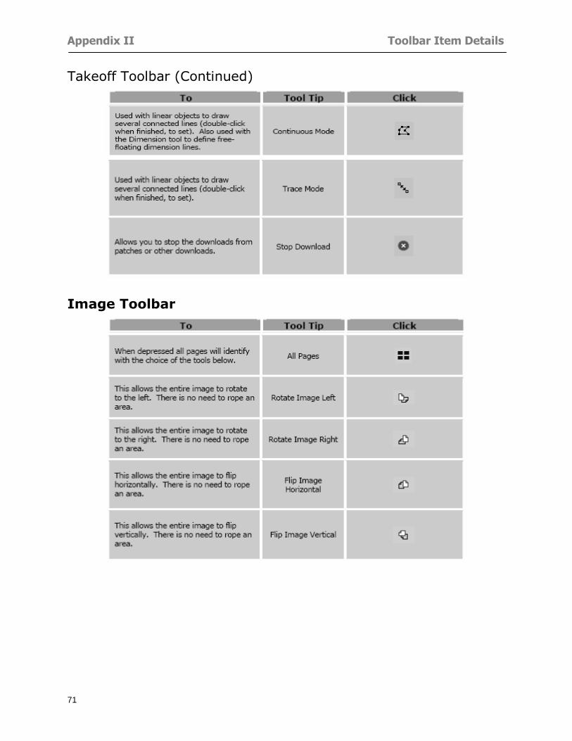
Appendix II Toolbar Item Details
71
Takeoff Toolbar (Continued)
Image Toolbar
Appendix III Loading Plans from a Dodge CD
72
Appendix III Loading Plans from a Dodge CD
This section will detail how to load plans from a F W Dodge CD-ROM into an On-Screen Takeoff project file ready for takeoffs
Dodge files may be added to the Project Properties dialog However loading the files in that way will load the files by number rather than name description If you want to load one page only from your Dodge CD You will have to rename the page to display the name rather than number of the file
To load plan files from a Dodge CD so that the files load sequentially by file number but are displayed by name rather than by number within your project follow the instructions below
Opening a Dodge project from a CD-ROM 1 Insert the CD into the drive 2 Choose File gt Custom 3 Choose Dodge Plans Project (plansdat) as the file type 4 Select the appropriate file type by clicking on the down arrow at the right of the Files of type
field 5 In the Look in field access your drive paths by clicking on the down arrow at the right of the
field then
Navigate to your CD-ROM drive Open the data folder and Open the Projects folder
6 Select the desired project and open its folder 7 Open the plansdat file 8 All the images will come in sequenced correctly for that job along with the full descriptions
(names) of each page If there is not a plans folder in the project folder then plans do not exist for that project on the CD Opening the plansdat file will yield an empty project
Appendix IV Using the Plan Viewer
73
Appendix IV Using On-Screen Takeoff Plan Viewer The On-Screen Takeoff Plan Viewer is a limited version of On Center Softwarersquos commercial takeoff software If your status bar located at the very bottom of the main window says View Mode in the lower left-hand corner then you are using the Plan Viewer You can use the plan viewer to
View CD-based amp converted CAD drawings
View a previously created OST file and associated drawings
Download electronic plans online
Navigate through drawings
Quickly Takeoff linearsareas and counts
Zoom in to view the plan better
Print drawings directly from the viewer
Viewing an On-Screen Takeoff Project File
1 To open an OST file that was previously created with of On-Screen Takeoff 2 Select File gt Open 3 An Open dialog will appear if you do not see the OST file you are looking for select the
Look In drop down arrow 4 A drop down menu will appear listing the various folders drives and mapped drives located
on your computer select the correct drive or folder location and continue to browse to the location of your OST file
5 When you see your OST file double-click it to open it 6 Any takeoff and drawings should appear on the Image tab view
If you do not see the drawings but do see the colored takeoff layer the drawings may
not be located in the same place they were originally saved at Go to File gt Project Properties and check the Image File path for each listed page If the image file path is pointing to a CD drive make sure the CD is inside the CR-ROM
Downloading Electronic Plans If your Online Plan Service provides a special file format (OSX) required to use this feature of our plan viewer you can immediately downloaded all electronic plans of a project directly from our viewer
Most Plan Room web sites will automatically open On-Screen Takeoff when a request to download plans is made Your particular Plan Room may differ in operation so please contact the provider directly with questions on using the site
Appendix IV Using the Plan Viewer
74
When you request to download or open a project file from a Plan Room you will usually have the open to open or save an OSX file Choosing open will automatically open On-Screen Takeoff Alternately you may choose to save the file to a local hard drive After you have saved the file either double-click it to launch On-Screen Takeoff or open the OSX file using On-Screen Takeoff by clicking File then Open and locating the file on your hard drive You will need to change the file type to OSX
After the OSX file is opened you will see an additional tab appear in the Conditions List window called Pages
The Pages tab shows the hierarchy of your project Gray file icons represent pages that have not been downloaded and blue icons represents pages that have been downloaded
To download a page simply double-click the page icon
If you wish to select a group of pages to download you can use the Ctrl or Shift key to multiple select them then click the Download button
If you wish to download all pages at once click the Download All button
Downloaded pages will now appear in the Project Properties dialog in the same order in which they appear in the Pages tab
Creating Quick Takeoffs With On-Screen Takeoff you can create quick takeoffs to measure quantities even if you dont have the full version of our program However using the Quick Takeoff functionality shows you just a fraction of what the full version can do
The Quick Takeoff Toolbar is located at the top of the image view It has three buttons designated for three types of takeoffs Linear Area and Count The Quantity drop down list will show secondary quantities for Linears and Areas The Units drop down allows you to select how you want your quantities displayed Feet Inches Yards Millimeters and Meters
NOTE Every time change the type of takeoff you are performing (switching from Area to Linear for example) the previous quantities and takeoff objects will disappear They will also disappear when you changes pages
NOTE You can use the Dimension Tool to basically measure the distance between two points or linears The distance will display on the status bar at the bottom of the application
The Quick Takeoff Toolbar
Appendix V Frequently Asked Questions
75
Appendix V Frequently Asked Questions General
Where is On-Screen Takeoff installed on my computer
Typically it is installed in CProgram FilesOn-Screen Takeoff
In Explorer how do I recognize On-Screen Takeoff file types
On-Screen Takeoff data is stored in a single file per job lsquojob name OSTrsquo On-Screen Takeoff templates are stored as lsquotemplate nameTPOrsquo
Can only one project at a time be open
Yes For that reason opening another project automatically closes the project on screen You will be asked to save any changes
Is only one scale allowed per page What about on drawings that have multiple detail sections on a page and each of those drawings have different scales
Yes For pages with drawings of different scales copy the drawing to another project page and set the appropriate scale
I cannot perform backout on an area that is along a linear
As a workaround use the On-Screen Takeoff layers feature to help you with this issue Electronic Images
How do I start a project from drawings that have been scanned and written to a CD-ROM
Open a new project Select File gt Project Properties and select Auto Add Navigate to your CD and the appropriate folder and select any image file in that location Click Open All files in the location will load into your project Recommended that images are copied from CD to hard drive for performance
If I get a disk of drawings in AutoCAD format (R13 or R14) can I read them in On-Screen Takeoff
Yes On-Screen Takeoff now reads DWG DXF and many other format that are saved with AutoCAD
Appendix V Frequently Asked Questions
76
When I click on the all pages button what is supposed to happen Currently nothing seems to change when I click on that button
The All Pages button is used to apply the Darken and Enhance Plans feature to all pages in the project (as opposed to only the current page on screen)
Is there a way to deduct a large skylight from an area condition
Yes with the related area condition selected in the Takeoff Dock bar unselect the Backout button on the Takeoff Toolbar then draw the Backout area The area quantity will be deducted from the related condition object and the linear measurement of the Backout perimeter will be added
Digitizer Issues
How do I connect a Digitizer to the computer
See Appendix I Connecting a Digitizer
The Place Template menu choice is disabled
On-Screen Takeoff may need to be authorized or the digitizer or the digitzer drivers are not installed
It wonrsquot let me select the Set Takeoff Area menu choice
On-Screen Takeoff may need to be authorized or no job is open a digitizer is not installed or the drivers are not installed
The digitizer stylus is not moving the cursor or crosshairs
Click S-0-1 superset on the digitizer
How do I convert my old GTCO Digitizer to work with On- Screen Takeofftrade
Call GTCO and they may be able to reconfigure your digitizer to be compatible with On-Screen Takeoff
Printing Issues Which Printers work with On-Screen Takeoff
Compatible printers include On-Screen Takeoff Hewlett Packard Epson and Canon printers If you are having printer difficulties please contact support and specify the type of printer along with other pertinent information Contact support at wwwoncentercomsupport or email supportoncentercom
Which Plotters work with On-Screen Takeoff
Compatible Plotters include Hewlett Packard DesignJet plotters and the EnCAD Cadjet II If you are having plotter difficulties please contact support and specify the type of plotter concerned
ViewingDisplay I can no longer see my condition list How do I get it back
The toolbars and Dock bars can be turned on and off through the View gt Toolbars menu options
Appendix V Frequently Asked Questions
77
This is also accessible by right-clicking in the toolbar area and selecting (or deselecting) a toolbar listed
I cannot view my folders in the condition list
Right-click in the Takeoff Dock barcondition list area and select Show Tree to display your folders
My Status Bar reads Viewer Mode and I am unable to draw conditions
On-Screen Takeoff needs to be Authorized Or you need to purchase an upgrade Click the Perform Advanced Takeoff button on the main toolbar
I hid a Dock bar and when I selected to view it again it appeared alongside the other Dock
bar instead of stacked on top of it How do I fix it
Pick up the Dock bar by clicking on the bar at the top and continuing to hold down the mouse button drag the Dock bar over the other one It will resize and appear stacked with the other
When I open image files from a CD the images are all upside down How do I get them right
side up
To flip pages from top to bottom follow the steps below 1 Click the All Pages button on the Image Toolbar (All Pages is engaged when the button
is not clicked) 2 Click the Flip Horizontal button on the Image Toolbar 3 Click the All Pages button again to disengage
Templates How do I create a Template
Follow the steps below 1 Create a typical project 2 Choose File gt Save As 3 Choose On-Screen Takeoff Template Files as the file type to save 4 Name the file This will save all of the condition setups as well as the layers for the
project
How do I create a new project from a template
Follow the steps below 1 Choose File gt New 2 Select a template from those listed in the New dialog This will open a new project with
conditions and layers saved from a previous project but no pages or takeoff
78
INDEX
Area Conditions 32
Area Objects 57
Auto Scrolling 20
Auto-save 63
Backout Mode 41
Calculation Method 60
Conditions 29
Configuration 60
Contents Tab 6
Continuous Mode 38
Count Conditions 33
Count Objects 57
Digitizer 10 65 76
Docking Toolbars 13
Dodge CD 72
Drawing 27 37
DropRun Count 55
Environment 18
Exiting 63
Exporting 49
Features 16
Font 61
Frequently Asked Questions 75
Grid 40
Help File 5
Hiding Toolbars 13
Hot Links 21
Image 19 59
Image files 9
Image Toolbar 12 71
Images 75
Index Tab 6
Layers 43
Linear Conditions 31
Linear Objects 56
Main Toolbar 12 67
Menus 14
Moving Toolbars 13
Navigate Toolbar 12 69
Navigating 20
On-Screen Takeofftrade 2
Page 59 61
Pages 20 25 28
Plan Viewer 73
Plans 26
Printing 47 76
Project Properties 25
Projects 22
Quick Start Video 18
Resizing Toolbars 13
Roping 54
Saving 63
Scale 28
Search Tab 7
Selecting Objects 42
Setup 8
Start On-Screen Takeofftrade 17
System Requirements 9
Takeoff 19 27
Takeoff Toolbar 70 71
Takeoff Toolbar 12
Template Files 23
TIF (Group4) 9
Tool Toolbar 12 68
Toolbar 67
Toolbars 12
View Toolbar 12 69
Viewing Toolbars 12
Worksheet 20
Zone Conditions 33
Zoom Toolbar 12 69
Appendix III Loading Plans from a Dodge CD
72
Appendix III Loading Plans from a Dodge CD
This section will detail how to load plans from a F W Dodge CD-ROM into an On-Screen Takeoff project file ready for takeoffs
Dodge files may be added to the Project Properties dialog However loading the files in that way will load the files by number rather than name description If you want to load one page only from your Dodge CD You will have to rename the page to display the name rather than number of the file
To load plan files from a Dodge CD so that the files load sequentially by file number but are displayed by name rather than by number within your project follow the instructions below
Opening a Dodge project from a CD-ROM 1 Insert the CD into the drive 2 Choose File gt Custom 3 Choose Dodge Plans Project (plansdat) as the file type 4 Select the appropriate file type by clicking on the down arrow at the right of the Files of type
field 5 In the Look in field access your drive paths by clicking on the down arrow at the right of the
field then
Navigate to your CD-ROM drive Open the data folder and Open the Projects folder
6 Select the desired project and open its folder 7 Open the plansdat file 8 All the images will come in sequenced correctly for that job along with the full descriptions
(names) of each page If there is not a plans folder in the project folder then plans do not exist for that project on the CD Opening the plansdat file will yield an empty project
Appendix IV Using the Plan Viewer
73
Appendix IV Using On-Screen Takeoff Plan Viewer The On-Screen Takeoff Plan Viewer is a limited version of On Center Softwarersquos commercial takeoff software If your status bar located at the very bottom of the main window says View Mode in the lower left-hand corner then you are using the Plan Viewer You can use the plan viewer to
View CD-based amp converted CAD drawings
View a previously created OST file and associated drawings
Download electronic plans online
Navigate through drawings
Quickly Takeoff linearsareas and counts
Zoom in to view the plan better
Print drawings directly from the viewer
Viewing an On-Screen Takeoff Project File
1 To open an OST file that was previously created with of On-Screen Takeoff 2 Select File gt Open 3 An Open dialog will appear if you do not see the OST file you are looking for select the
Look In drop down arrow 4 A drop down menu will appear listing the various folders drives and mapped drives located
on your computer select the correct drive or folder location and continue to browse to the location of your OST file
5 When you see your OST file double-click it to open it 6 Any takeoff and drawings should appear on the Image tab view
If you do not see the drawings but do see the colored takeoff layer the drawings may
not be located in the same place they were originally saved at Go to File gt Project Properties and check the Image File path for each listed page If the image file path is pointing to a CD drive make sure the CD is inside the CR-ROM
Downloading Electronic Plans If your Online Plan Service provides a special file format (OSX) required to use this feature of our plan viewer you can immediately downloaded all electronic plans of a project directly from our viewer
Most Plan Room web sites will automatically open On-Screen Takeoff when a request to download plans is made Your particular Plan Room may differ in operation so please contact the provider directly with questions on using the site
Appendix IV Using the Plan Viewer
74
When you request to download or open a project file from a Plan Room you will usually have the open to open or save an OSX file Choosing open will automatically open On-Screen Takeoff Alternately you may choose to save the file to a local hard drive After you have saved the file either double-click it to launch On-Screen Takeoff or open the OSX file using On-Screen Takeoff by clicking File then Open and locating the file on your hard drive You will need to change the file type to OSX
After the OSX file is opened you will see an additional tab appear in the Conditions List window called Pages
The Pages tab shows the hierarchy of your project Gray file icons represent pages that have not been downloaded and blue icons represents pages that have been downloaded
To download a page simply double-click the page icon
If you wish to select a group of pages to download you can use the Ctrl or Shift key to multiple select them then click the Download button
If you wish to download all pages at once click the Download All button
Downloaded pages will now appear in the Project Properties dialog in the same order in which they appear in the Pages tab
Creating Quick Takeoffs With On-Screen Takeoff you can create quick takeoffs to measure quantities even if you dont have the full version of our program However using the Quick Takeoff functionality shows you just a fraction of what the full version can do
The Quick Takeoff Toolbar is located at the top of the image view It has three buttons designated for three types of takeoffs Linear Area and Count The Quantity drop down list will show secondary quantities for Linears and Areas The Units drop down allows you to select how you want your quantities displayed Feet Inches Yards Millimeters and Meters
NOTE Every time change the type of takeoff you are performing (switching from Area to Linear for example) the previous quantities and takeoff objects will disappear They will also disappear when you changes pages
NOTE You can use the Dimension Tool to basically measure the distance between two points or linears The distance will display on the status bar at the bottom of the application
The Quick Takeoff Toolbar
Appendix V Frequently Asked Questions
75
Appendix V Frequently Asked Questions General
Where is On-Screen Takeoff installed on my computer
Typically it is installed in CProgram FilesOn-Screen Takeoff
In Explorer how do I recognize On-Screen Takeoff file types
On-Screen Takeoff data is stored in a single file per job lsquojob name OSTrsquo On-Screen Takeoff templates are stored as lsquotemplate nameTPOrsquo
Can only one project at a time be open
Yes For that reason opening another project automatically closes the project on screen You will be asked to save any changes
Is only one scale allowed per page What about on drawings that have multiple detail sections on a page and each of those drawings have different scales
Yes For pages with drawings of different scales copy the drawing to another project page and set the appropriate scale
I cannot perform backout on an area that is along a linear
As a workaround use the On-Screen Takeoff layers feature to help you with this issue Electronic Images
How do I start a project from drawings that have been scanned and written to a CD-ROM
Open a new project Select File gt Project Properties and select Auto Add Navigate to your CD and the appropriate folder and select any image file in that location Click Open All files in the location will load into your project Recommended that images are copied from CD to hard drive for performance
If I get a disk of drawings in AutoCAD format (R13 or R14) can I read them in On-Screen Takeoff
Yes On-Screen Takeoff now reads DWG DXF and many other format that are saved with AutoCAD
Appendix V Frequently Asked Questions
76
When I click on the all pages button what is supposed to happen Currently nothing seems to change when I click on that button
The All Pages button is used to apply the Darken and Enhance Plans feature to all pages in the project (as opposed to only the current page on screen)
Is there a way to deduct a large skylight from an area condition
Yes with the related area condition selected in the Takeoff Dock bar unselect the Backout button on the Takeoff Toolbar then draw the Backout area The area quantity will be deducted from the related condition object and the linear measurement of the Backout perimeter will be added
Digitizer Issues
How do I connect a Digitizer to the computer
See Appendix I Connecting a Digitizer
The Place Template menu choice is disabled
On-Screen Takeoff may need to be authorized or the digitizer or the digitzer drivers are not installed
It wonrsquot let me select the Set Takeoff Area menu choice
On-Screen Takeoff may need to be authorized or no job is open a digitizer is not installed or the drivers are not installed
The digitizer stylus is not moving the cursor or crosshairs
Click S-0-1 superset on the digitizer
How do I convert my old GTCO Digitizer to work with On- Screen Takeofftrade
Call GTCO and they may be able to reconfigure your digitizer to be compatible with On-Screen Takeoff
Printing Issues Which Printers work with On-Screen Takeoff
Compatible printers include On-Screen Takeoff Hewlett Packard Epson and Canon printers If you are having printer difficulties please contact support and specify the type of printer along with other pertinent information Contact support at wwwoncentercomsupport or email supportoncentercom
Which Plotters work with On-Screen Takeoff
Compatible Plotters include Hewlett Packard DesignJet plotters and the EnCAD Cadjet II If you are having plotter difficulties please contact support and specify the type of plotter concerned
ViewingDisplay I can no longer see my condition list How do I get it back
The toolbars and Dock bars can be turned on and off through the View gt Toolbars menu options
Appendix V Frequently Asked Questions
77
This is also accessible by right-clicking in the toolbar area and selecting (or deselecting) a toolbar listed
I cannot view my folders in the condition list
Right-click in the Takeoff Dock barcondition list area and select Show Tree to display your folders
My Status Bar reads Viewer Mode and I am unable to draw conditions
On-Screen Takeoff needs to be Authorized Or you need to purchase an upgrade Click the Perform Advanced Takeoff button on the main toolbar
I hid a Dock bar and when I selected to view it again it appeared alongside the other Dock
bar instead of stacked on top of it How do I fix it
Pick up the Dock bar by clicking on the bar at the top and continuing to hold down the mouse button drag the Dock bar over the other one It will resize and appear stacked with the other
When I open image files from a CD the images are all upside down How do I get them right
side up
To flip pages from top to bottom follow the steps below 1 Click the All Pages button on the Image Toolbar (All Pages is engaged when the button
is not clicked) 2 Click the Flip Horizontal button on the Image Toolbar 3 Click the All Pages button again to disengage
Templates How do I create a Template
Follow the steps below 1 Create a typical project 2 Choose File gt Save As 3 Choose On-Screen Takeoff Template Files as the file type to save 4 Name the file This will save all of the condition setups as well as the layers for the
project
How do I create a new project from a template
Follow the steps below 1 Choose File gt New 2 Select a template from those listed in the New dialog This will open a new project with
conditions and layers saved from a previous project but no pages or takeoff
78
INDEX
Area Conditions 32
Area Objects 57
Auto Scrolling 20
Auto-save 63
Backout Mode 41
Calculation Method 60
Conditions 29
Configuration 60
Contents Tab 6
Continuous Mode 38
Count Conditions 33
Count Objects 57
Digitizer 10 65 76
Docking Toolbars 13
Dodge CD 72
Drawing 27 37
DropRun Count 55
Environment 18
Exiting 63
Exporting 49
Features 16
Font 61
Frequently Asked Questions 75
Grid 40
Help File 5
Hiding Toolbars 13
Hot Links 21
Image 19 59
Image files 9
Image Toolbar 12 71
Images 75
Index Tab 6
Layers 43
Linear Conditions 31
Linear Objects 56
Main Toolbar 12 67
Menus 14
Moving Toolbars 13
Navigate Toolbar 12 69
Navigating 20
On-Screen Takeofftrade 2
Page 59 61
Pages 20 25 28
Plan Viewer 73
Plans 26
Printing 47 76
Project Properties 25
Projects 22
Quick Start Video 18
Resizing Toolbars 13
Roping 54
Saving 63
Scale 28
Search Tab 7
Selecting Objects 42
Setup 8
Start On-Screen Takeofftrade 17
System Requirements 9
Takeoff 19 27
Takeoff Toolbar 70 71
Takeoff Toolbar 12
Template Files 23
TIF (Group4) 9
Tool Toolbar 12 68
Toolbar 67
Toolbars 12
View Toolbar 12 69
Viewing Toolbars 12
Worksheet 20
Zone Conditions 33
Zoom Toolbar 12 69
Appendix IV Using the Plan Viewer
73
Appendix IV Using On-Screen Takeoff Plan Viewer The On-Screen Takeoff Plan Viewer is a limited version of On Center Softwarersquos commercial takeoff software If your status bar located at the very bottom of the main window says View Mode in the lower left-hand corner then you are using the Plan Viewer You can use the plan viewer to
View CD-based amp converted CAD drawings
View a previously created OST file and associated drawings
Download electronic plans online
Navigate through drawings
Quickly Takeoff linearsareas and counts
Zoom in to view the plan better
Print drawings directly from the viewer
Viewing an On-Screen Takeoff Project File
1 To open an OST file that was previously created with of On-Screen Takeoff 2 Select File gt Open 3 An Open dialog will appear if you do not see the OST file you are looking for select the
Look In drop down arrow 4 A drop down menu will appear listing the various folders drives and mapped drives located
on your computer select the correct drive or folder location and continue to browse to the location of your OST file
5 When you see your OST file double-click it to open it 6 Any takeoff and drawings should appear on the Image tab view
If you do not see the drawings but do see the colored takeoff layer the drawings may
not be located in the same place they were originally saved at Go to File gt Project Properties and check the Image File path for each listed page If the image file path is pointing to a CD drive make sure the CD is inside the CR-ROM
Downloading Electronic Plans If your Online Plan Service provides a special file format (OSX) required to use this feature of our plan viewer you can immediately downloaded all electronic plans of a project directly from our viewer
Most Plan Room web sites will automatically open On-Screen Takeoff when a request to download plans is made Your particular Plan Room may differ in operation so please contact the provider directly with questions on using the site
Appendix IV Using the Plan Viewer
74
When you request to download or open a project file from a Plan Room you will usually have the open to open or save an OSX file Choosing open will automatically open On-Screen Takeoff Alternately you may choose to save the file to a local hard drive After you have saved the file either double-click it to launch On-Screen Takeoff or open the OSX file using On-Screen Takeoff by clicking File then Open and locating the file on your hard drive You will need to change the file type to OSX
After the OSX file is opened you will see an additional tab appear in the Conditions List window called Pages
The Pages tab shows the hierarchy of your project Gray file icons represent pages that have not been downloaded and blue icons represents pages that have been downloaded
To download a page simply double-click the page icon
If you wish to select a group of pages to download you can use the Ctrl or Shift key to multiple select them then click the Download button
If you wish to download all pages at once click the Download All button
Downloaded pages will now appear in the Project Properties dialog in the same order in which they appear in the Pages tab
Creating Quick Takeoffs With On-Screen Takeoff you can create quick takeoffs to measure quantities even if you dont have the full version of our program However using the Quick Takeoff functionality shows you just a fraction of what the full version can do
The Quick Takeoff Toolbar is located at the top of the image view It has three buttons designated for three types of takeoffs Linear Area and Count The Quantity drop down list will show secondary quantities for Linears and Areas The Units drop down allows you to select how you want your quantities displayed Feet Inches Yards Millimeters and Meters
NOTE Every time change the type of takeoff you are performing (switching from Area to Linear for example) the previous quantities and takeoff objects will disappear They will also disappear when you changes pages
NOTE You can use the Dimension Tool to basically measure the distance between two points or linears The distance will display on the status bar at the bottom of the application
The Quick Takeoff Toolbar
Appendix V Frequently Asked Questions
75
Appendix V Frequently Asked Questions General
Where is On-Screen Takeoff installed on my computer
Typically it is installed in CProgram FilesOn-Screen Takeoff
In Explorer how do I recognize On-Screen Takeoff file types
On-Screen Takeoff data is stored in a single file per job lsquojob name OSTrsquo On-Screen Takeoff templates are stored as lsquotemplate nameTPOrsquo
Can only one project at a time be open
Yes For that reason opening another project automatically closes the project on screen You will be asked to save any changes
Is only one scale allowed per page What about on drawings that have multiple detail sections on a page and each of those drawings have different scales
Yes For pages with drawings of different scales copy the drawing to another project page and set the appropriate scale
I cannot perform backout on an area that is along a linear
As a workaround use the On-Screen Takeoff layers feature to help you with this issue Electronic Images
How do I start a project from drawings that have been scanned and written to a CD-ROM
Open a new project Select File gt Project Properties and select Auto Add Navigate to your CD and the appropriate folder and select any image file in that location Click Open All files in the location will load into your project Recommended that images are copied from CD to hard drive for performance
If I get a disk of drawings in AutoCAD format (R13 or R14) can I read them in On-Screen Takeoff
Yes On-Screen Takeoff now reads DWG DXF and many other format that are saved with AutoCAD
Appendix V Frequently Asked Questions
76
When I click on the all pages button what is supposed to happen Currently nothing seems to change when I click on that button
The All Pages button is used to apply the Darken and Enhance Plans feature to all pages in the project (as opposed to only the current page on screen)
Is there a way to deduct a large skylight from an area condition
Yes with the related area condition selected in the Takeoff Dock bar unselect the Backout button on the Takeoff Toolbar then draw the Backout area The area quantity will be deducted from the related condition object and the linear measurement of the Backout perimeter will be added
Digitizer Issues
How do I connect a Digitizer to the computer
See Appendix I Connecting a Digitizer
The Place Template menu choice is disabled
On-Screen Takeoff may need to be authorized or the digitizer or the digitzer drivers are not installed
It wonrsquot let me select the Set Takeoff Area menu choice
On-Screen Takeoff may need to be authorized or no job is open a digitizer is not installed or the drivers are not installed
The digitizer stylus is not moving the cursor or crosshairs
Click S-0-1 superset on the digitizer
How do I convert my old GTCO Digitizer to work with On- Screen Takeofftrade
Call GTCO and they may be able to reconfigure your digitizer to be compatible with On-Screen Takeoff
Printing Issues Which Printers work with On-Screen Takeoff
Compatible printers include On-Screen Takeoff Hewlett Packard Epson and Canon printers If you are having printer difficulties please contact support and specify the type of printer along with other pertinent information Contact support at wwwoncentercomsupport or email supportoncentercom
Which Plotters work with On-Screen Takeoff
Compatible Plotters include Hewlett Packard DesignJet plotters and the EnCAD Cadjet II If you are having plotter difficulties please contact support and specify the type of plotter concerned
ViewingDisplay I can no longer see my condition list How do I get it back
The toolbars and Dock bars can be turned on and off through the View gt Toolbars menu options
Appendix V Frequently Asked Questions
77
This is also accessible by right-clicking in the toolbar area and selecting (or deselecting) a toolbar listed
I cannot view my folders in the condition list
Right-click in the Takeoff Dock barcondition list area and select Show Tree to display your folders
My Status Bar reads Viewer Mode and I am unable to draw conditions
On-Screen Takeoff needs to be Authorized Or you need to purchase an upgrade Click the Perform Advanced Takeoff button on the main toolbar
I hid a Dock bar and when I selected to view it again it appeared alongside the other Dock
bar instead of stacked on top of it How do I fix it
Pick up the Dock bar by clicking on the bar at the top and continuing to hold down the mouse button drag the Dock bar over the other one It will resize and appear stacked with the other
When I open image files from a CD the images are all upside down How do I get them right
side up
To flip pages from top to bottom follow the steps below 1 Click the All Pages button on the Image Toolbar (All Pages is engaged when the button
is not clicked) 2 Click the Flip Horizontal button on the Image Toolbar 3 Click the All Pages button again to disengage
Templates How do I create a Template
Follow the steps below 1 Create a typical project 2 Choose File gt Save As 3 Choose On-Screen Takeoff Template Files as the file type to save 4 Name the file This will save all of the condition setups as well as the layers for the
project
How do I create a new project from a template
Follow the steps below 1 Choose File gt New 2 Select a template from those listed in the New dialog This will open a new project with
conditions and layers saved from a previous project but no pages or takeoff
78
INDEX
Area Conditions 32
Area Objects 57
Auto Scrolling 20
Auto-save 63
Backout Mode 41
Calculation Method 60
Conditions 29
Configuration 60
Contents Tab 6
Continuous Mode 38
Count Conditions 33
Count Objects 57
Digitizer 10 65 76
Docking Toolbars 13
Dodge CD 72
Drawing 27 37
DropRun Count 55
Environment 18
Exiting 63
Exporting 49
Features 16
Font 61
Frequently Asked Questions 75
Grid 40
Help File 5
Hiding Toolbars 13
Hot Links 21
Image 19 59
Image files 9
Image Toolbar 12 71
Images 75
Index Tab 6
Layers 43
Linear Conditions 31
Linear Objects 56
Main Toolbar 12 67
Menus 14
Moving Toolbars 13
Navigate Toolbar 12 69
Navigating 20
On-Screen Takeofftrade 2
Page 59 61
Pages 20 25 28
Plan Viewer 73
Plans 26
Printing 47 76
Project Properties 25
Projects 22
Quick Start Video 18
Resizing Toolbars 13
Roping 54
Saving 63
Scale 28
Search Tab 7
Selecting Objects 42
Setup 8
Start On-Screen Takeofftrade 17
System Requirements 9
Takeoff 19 27
Takeoff Toolbar 70 71
Takeoff Toolbar 12
Template Files 23
TIF (Group4) 9
Tool Toolbar 12 68
Toolbar 67
Toolbars 12
View Toolbar 12 69
Viewing Toolbars 12
Worksheet 20
Zone Conditions 33
Zoom Toolbar 12 69
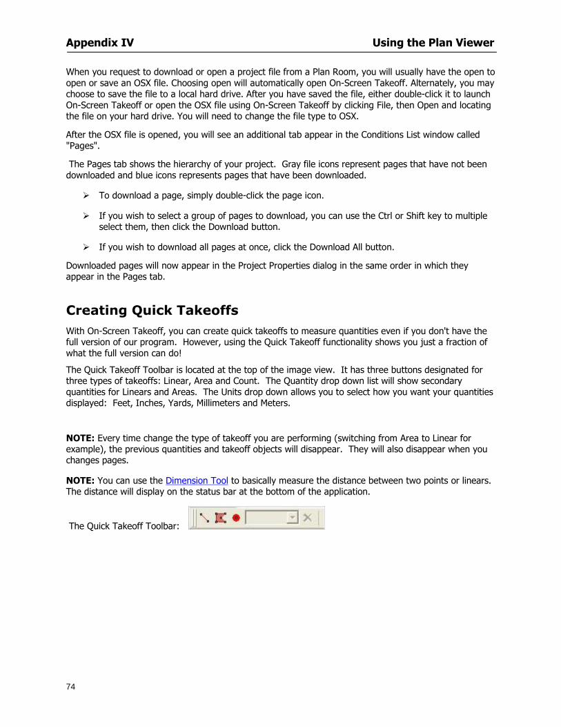
Appendix V Frequently Asked Questions
77
This is also accessible by right-clicking in the toolbar area and selecting (or deselecting) a toolbar listed
I cannot view my folders in the condition list
Right-click in the Takeoff Dock barcondition list area and select Show Tree to display your folders
My Status Bar reads Viewer Mode and I am unable to draw conditions
On-Screen Takeoff needs to be Authorized Or you need to purchase an upgrade Click the Perform Advanced Takeoff button on the main toolbar
I hid a Dock bar and when I selected to view it again it appeared alongside the other Dock
bar instead of stacked on top of it How do I fix it
Pick up the Dock bar by clicking on the bar at the top and continuing to hold down the mouse button drag the Dock bar over the other one It will resize and appear stacked with the other
When I open image files from a CD the images are all upside down How do I get them right
side up
To flip pages from top to bottom follow the steps below 1 Click the All Pages button on the Image Toolbar (All Pages is engaged when the button
is not clicked) 2 Click the Flip Horizontal button on the Image Toolbar 3 Click the All Pages button again to disengage
Templates How do I create a Template
Follow the steps below 1 Create a typical project 2 Choose File gt Save As 3 Choose On-Screen Takeoff Template Files as the file type to save 4 Name the file This will save all of the condition setups as well as the layers for the
project
How do I create a new project from a template
Follow the steps below 1 Choose File gt New 2 Select a template from those listed in the New dialog This will open a new project with
conditions and layers saved from a previous project but no pages or takeoff
78
INDEX
Area Conditions 32
Area Objects 57
Auto Scrolling 20
Auto-save 63
Backout Mode 41
Calculation Method 60
Conditions 29
Configuration 60
Contents Tab 6
Continuous Mode 38
Count Conditions 33
Count Objects 57
Digitizer 10 65 76
Docking Toolbars 13
Dodge CD 72
Drawing 27 37
DropRun Count 55
Environment 18
Exiting 63
Exporting 49
Features 16
Font 61
Frequently Asked Questions 75
Grid 40
Help File 5
Hiding Toolbars 13
Hot Links 21
Image 19 59
Image files 9
Image Toolbar 12 71
Images 75
Index Tab 6
Layers 43
Linear Conditions 31
Linear Objects 56
Main Toolbar 12 67
Menus 14
Moving Toolbars 13
Navigate Toolbar 12 69
Navigating 20
On-Screen Takeofftrade 2
Page 59 61
Pages 20 25 28
Plan Viewer 73
Plans 26
Printing 47 76
Project Properties 25
Projects 22
Quick Start Video 18
Resizing Toolbars 13
Roping 54
Saving 63
Scale 28
Search Tab 7
Selecting Objects 42
Setup 8
Start On-Screen Takeofftrade 17
System Requirements 9
Takeoff 19 27
Takeoff Toolbar 70 71
Takeoff Toolbar 12
Template Files 23
TIF (Group4) 9
Tool Toolbar 12 68
Toolbar 67
Toolbars 12
View Toolbar 12 69
Viewing Toolbars 12
Worksheet 20
Zone Conditions 33
Zoom Toolbar 12 69