Embed Size (px)
Citation preview
OLYMPUS SYSTEM MICROSCOPE
MOdCI BHT
This instruct ion manual has been wri t ten for the use of theOlympus System Microscope Model
BHT. l t is recommended thatyou read the manual careful ly in orderto fami l iar ize yoursel f fu l ly
with the use of the microscope, so that you can obtain optimum performance from it.
IMPORTANT
Observe the fol lowing points careful ly:
I Operation
1. Always handle the microscope with the care i t deserves, and avoid abrupt motions.
2. Avo id the use and maintenance of the microscope in d i rect sun l ight , h igh temperature and
humid i ty , dust and v ibrat ion.
Only use the tension adjustment r ing for a l ter ing the tension of the coarse adjustment
knobs. (Do not twist the two coarse adjustment knobs in opposi te direct ions s imultaneous-
ly , as th is w i l l cause damage. )
Make sure that the voltage selector switch on the base plate is set to conform with the local
mains vol tage.
Make i t a point of grounding the microscope to prevent electr ic accidents.
I Maintenance
1. Lenses must always be kept c lean. Careful ly wipe of f o i l or f ingerpr ints deposi ted on the
lens surfaces with gauze moistened with a smal l amount of xylene, alcohol or ether.
2. Do not use organic solut ions to wipe the surfaces of var ious components. Plast ic parts,
especial ly, should be cleaned with neutral detergent.
3. Never disassemble the microscope for repair . Only author ized Olympus service personnel
should make repairs.
4. The microscope should be covered with the vinyl dust cover provided and stored in a place
free from humidity and fungi. For extended storage i t is recommended to keep objectives
and eyepieces in des iccators , conta in ing des iccants such as s i l i ca ge l .
3 .
4.
5 .
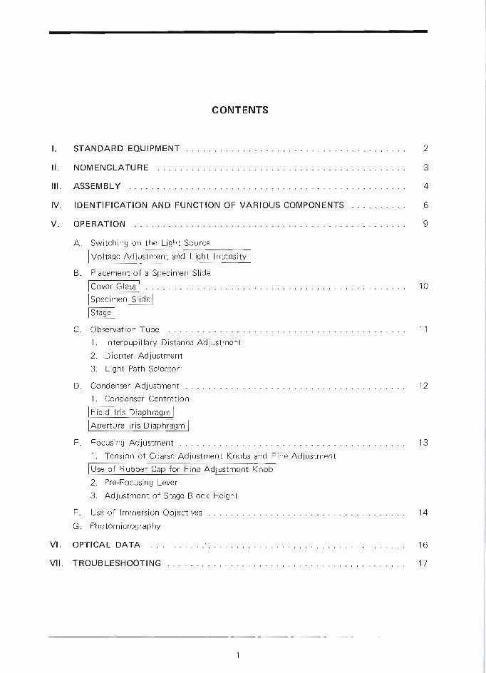
I . STANDARD EOUIPMENT
II . NOM ENCLATU R E
II I . ASSEM BLY
IV. IDENTIFICATION AND FUNCTION
V. OPE RATION
A. Switching on the Light Source
CONTENTS
VARIOUS COMPONENTS
r'* ooir;.r;;;
O F
2
3
4
6
9
Voltage Adjustment and Light Intensity
Placement of a Specimen Slide
la"""r classl
fStadlObservation Tube
1. Interpupi l lary Distance Adjustment
2. Diopter Adjustment
3. Light Path Selector
Condenser Adjustment
1. Condenser Centration
F ie ld l r i s D i m
Aperture lris Diaphragm
Focusing Adjustment
1. Tension of Coarse Adjustment Knobs and
Use of Rubber Cap for Fine Adjustment Knob
2. Pre-Focusing Lever
3. Adjustment of Stage Block Height
F. Use of lmmersion Objectives
G. Photomicrography
VI. OPTICAL DATA . . ' . .
V I I . TROUBLESHOOTING
B .1 0
1 1C .
1 2D .
1 3E .
1 4
1 6
1 7
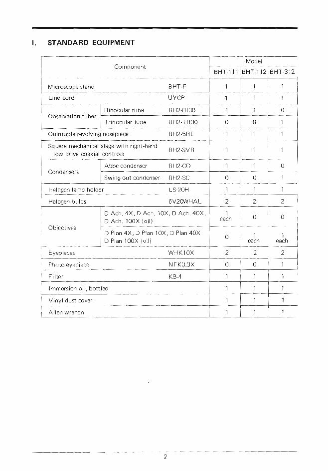
t . STANDARD EOUIPMENT
ComponentModel
B H T - 1 1 1 BHT-112BHT-312
Microscope stand BHT-F 1 1 1
Line cord UYCP 1 1 1
Observation tubesBinocular tube BH2-8130 1 1 0
Trinocular tube BH2-TR30 0 0 1
Ouintuple revolving nosepiece BH2-5RE 1 1 1
Square mechanical stage with right-hand BH2-SVR
low drive coaxial controls1 1 1
CondensersAbbe condenser BH2-CD 1 1 0
Swing-outcondenser BH2-SC 0 0 1
Halogen lamP holder LS-20H 1 1 1
Halogen bulbs 6V20WHAL 2 2 2
Objectives
D Ach. 4X, D Ach. 10X, D Ach. 40X,
D Ach. 100X (oi l )1
each 0 0
D Plan 4X, D Plan 10X, D Plan 40X
D Plan 100X (oi l )0 1
each1
each
Eyepieces WHK1OX 2 2 2
Photo eyepiece NFKS'3X
Filter KB-4
0 0 1
1 1 1
lmmersion oi l , bot t led
Vinyl dust cover
Allen wrench
1 1 1
1 1 1
1 1 1
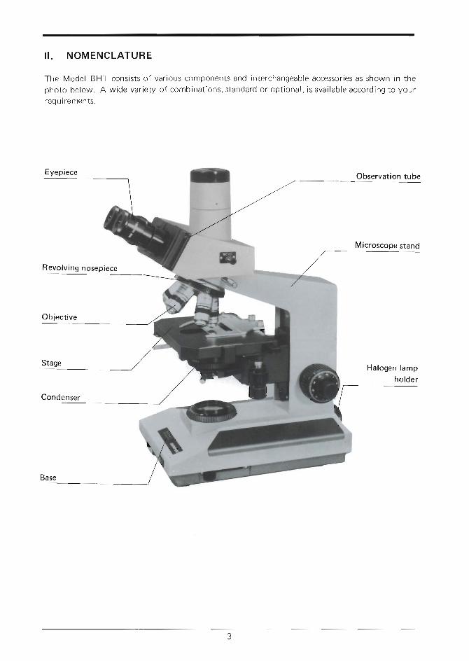
I I . NOM ENCLATURE
The Model BHT cons is ts o f var ious components and in terchangeable accessor ies as shown in thepho to be low . A w ide va r i e t y o f comb ina t i ons , s tanda rd o r op t i ona l , i sava i l ab le acco rd ing t o you rreq u i re men ts.
Eyepiece
Halogen lamp
ho lde r
Observation tube
Microscope stand
Revolv ing nosepiece
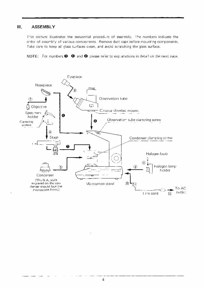
III. ASSEMBLY
This picture i l lustrates the sequential procedure of assembly. The numbers indicate the
order of assembly of various components. Remove dust caps before mounting components'
Take care to keep all glass surfaces clean, and avoid scratching the glass surface'
NoTE: For numbers @ @ and @ please refer to explanations in detail on the next page'
Specimenholder Observation tube clamping screw
Clampingscre\n s
Condenser clamPi ng screw
NosePiece
%
I8..,,Halogen bulb0
r i r i
@ -5l
Halogen lamp
- +l holcier
Condenser(The N-A- scale
engraved on the con-denser shou ld face the
microscoPe front.)
Microscope stand ;r--4--Ta- To AC
t-inercorO -
@ outlet
Observation tube
Circular dovetai I mount

@
Explanations in detai l
Mount ing the s tage
1) Loosen the s tage c lamping screw O Ovro ta t i ng coun te rc l ockw ise . (F ig . 1 )
2) Inser t the s tage in to the mount ing dove-
ta i l o f t he m ic roscope s tand s l ow ly andlock w i t h c l amp ing sc rew .
Mount ing the revo lv ing nosepiece
1) L-oosen the nosepiece c lamping screw O.( F i g . 2 )
2) A l ign ing the nosepiece doveta i l s l ide tot h e m o u n t i n g b l o c k @ , p u s h i n t h e n o s e -p iece s l ow ly a l l t he way .
NOTE: Do no t t i l t o r r ock t he nose -p iece wh i l e i nse r t i ng i n to t hem o u n t i n q b l o c k .
Mount ing the observat ion tube
1 ) L o o s e n t h e c l a m p i n g k n o b e t u t t y . p u l l
sp r i ng - l oaded c l amp ing knob O . Th i sw i l l cause t he l oca t i ng p in @ to w i t hd raw .(F ig . 3 ) l f t he p in does no t , l oosen t hescrew fur ther unt i l the p in wi thoraws.
2 ) W i t f r c l amp ing knob e pu l l ed ou t , i nse r tthe c i rcu lar doveta i l o f the observat iontube i n to t he r i ng dove ta i l .
3 ) T igh ten t he c l amp ing knob .
F is . 1
@
@
Fig .2
F i g . 3
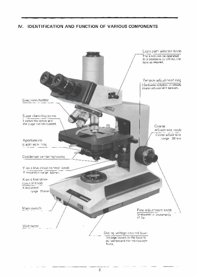
IV . IDENTIFICATION AND FUNCTION OF VARIOUS COMPONENTS
Sl id i ng vo l t age con t ro l l eve r
Vol tug" lowers as the lever ispul led toward the microscopef ron t .
&
Light path selector knob
The knob can be operatedin 3 posi t ions to def lect thel ight as desired.
Tens ion ad justment r lng
Clockwise rotat ion increasescoarse adjustment tension'
Coarseadjustment knob
Coarse adjustmentrange : 26mm
F ine ad jus tmen t knob
Stage c lamPing screw
Loosen the screw anothe stage can be rotated.
Condenser center ing knobs
Y-ax i s l ow d r i ve con t ro l knob
Y excurs ion range : 50mm
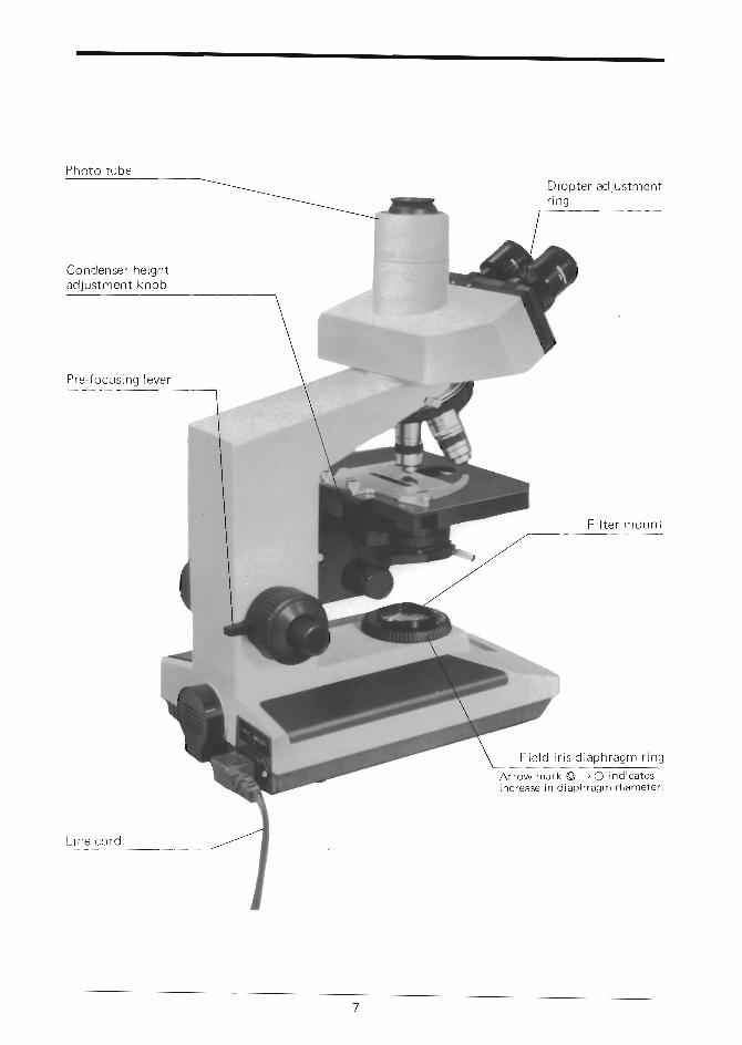
_nDiop te r ad jus tmen tf lng
F i e l d i r i s d i a P h r a g m r i n g
A r r o w m a r k O + Q i n d i c a t e s
i n c r e a s e i n d i a P h r a g m d i a m e t e r '
Condense r he igh tad jus tmen t knob
Pre- focus ing lever
L ine co rd
I<
\,\.
c)l-
o)-P
:lC)
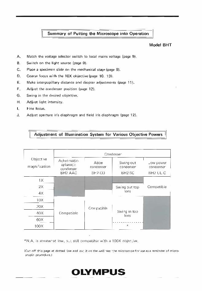
Summary of Putting dre Microscope into Operation
Model BHT
A. Match the voltage selector switch to local mains voltage (page g).
B. Switch on the l ight source (page 9).
C. Place a specimen slide on the mechanical stage (page 9).
D. Coarse focus with the 10X objective (page 10. 13).
E. Make interpupil lary distance and diopter adjustments (page 1l ).
F. Adjust the condenser position (page 12).
G. Swing in the desired objective.
H. Adjust l ight intensity.
l . Fine focus.
J. Adjust aperture iris diaphragm and field iris diaphragm (page 12).
Adjustment of lllumination System for Various objective Powers
*N.A. is somewhat low, but st i l l compat ib le wi th a 100X object ive.
(Cut of f th is page at dot ted l ine and put i t on the wal l near the microscopefor useasa reminder of micro-scopic procedure.)
Objective
magnif icat ion
Achromatic-aplanat iccondenserBH2.AAC
Swing-outcondenser
BH2-SC
Low powercondenser
BH2-UL-C
Compat ib le
Compat ib leCompat ib le Swing in top
lens
oL:yMPus
'-t
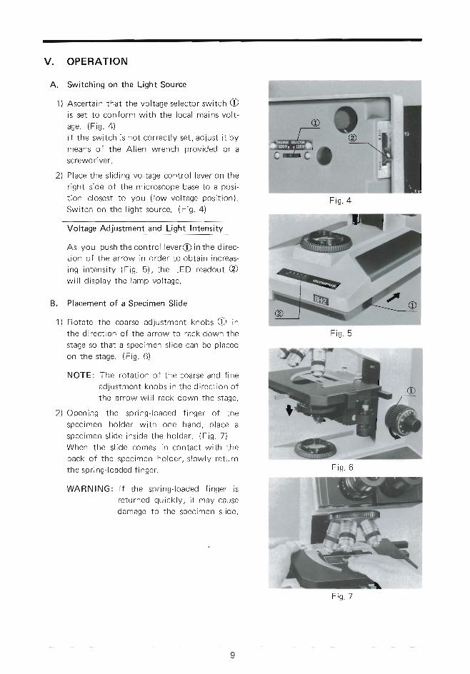
V . OPERATION
- A. Switching on the Light Source
1) Ascer ta in that the vo l tage se lector swi tch Ois set to conform wi th the loca l mains vo l t -ase . (F ig . a )l f the swi tch is not cor rect ly set , ad just i t bymeans of the A l len wrench prov ided or a
i screwdriver.T
2) P lace the s l id ing vo l tage cont ro l lever on theI r ight s ide o f the microscope base to a pos i -
t ion c losest to you ( low vo l tage pos i t ion) .Swi tch on the l ight source. (F ig . )
Voltage Adjustment and Light Intensity
As you push the cont ro l lever@ in the d i rec-t ion o f the ar row in order to obta in increas-i ng i n tens i t y (F ig . 5 ) , t he LED readou t @wi l l d i sp lay t he l amp vo l t age .
B. P lacement o f a Spec imen Sl ide
1) Rotate the coarse ad justment knobs O inthe d i rect ion o f the ar row to rack down thestage so that a spec imen s l ide can be p laced
on the s tage. (F ig . 6)
NOTE: The ro ta t ion o f the coarse and f ineadjustment knobs in the d i rect ion o fthe ar row wi l l rack down the s tage.
2) Opening the spr ing- loaded f inger o f thespec imen ho lde r w i t h one hand , p l ace aspec imen s l i de i ns i de t he ho lde r . (F ig . 7 )When the s l ide comes in contact w i th theback of the spec imen ho lder , s lowly re turnthe spr ing- loaded f inger .
WARNING: l f t he sp r i ng - l oaded f i nge r i sre turned qu ick ly , i t may causedamage to the spec imen s l ide.
)}..J
F i s . 5
1 I '
F i g . 4
F i s . 6
F i g . 7
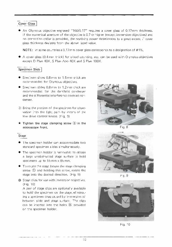
a An Olympus object ive engraved " i60/0.17" requires a cover glass of 0.17mm thickness.
l f the numerical aperture of the object ive is 0.7 or higher (except immersion object ives) and
no correction collar is provided, the resolving power deteriorates to a great extent if cover
glass thickness deviates from the above listed value'
NOTE: In some countr ies aO.17 mm cover glass corresponds to a designat ion of #1%.
o A cover glass (O.4mm thick) for b lood count ing, etc. can be used with Olympusobject ives
except D Plan 40X, S Plan Apo 40X and S Plan 100X'
I Spec imen s l i des 0 .8 mm to 1 .5 mm th i ck a re
recommended for Olympus ob ject ives.
o Spec imen s l i des 0 .8 mm to 1 .2 mm th i ck a re
recommended for the dark f ie ld condenser
and the dif ferential interference contrast con-
denser .
3) Br ing the por t ion o f the spec imen for obser-
vat ion in to the l ight path by means of the
low d r i ve con t ro l knobs . (F ig . B )
* Tighten the stage clamping screw O in the
microscoPe front.
r-----------.'l
I Stage I
I The specimen holder can accommodate two
standard specimen sl ides s imultaneously.
o The specimen holder is removable to obtain
a large unobstructed stage surface to hold
specimens uP to 55 mm x 85 mm.
o To rotate the stage loosen the stage clamping
screw O and holding this screw, rotate the
stage into the desired direci ton. (Fig. 9)
@ Stage cl ips for use with immersion object ives.( F i s . i 0 )A pair of stage cl ips are opt ional ly avai lable
to hold the specimen on the stage, el iminat-
ing a specimen drag caused by immersion oi l
between slide and stage surface. T'he clips
can be inserted into the holes O provided
on the specimen holder.
F i g . 9
1 0
F i g . 1 0
F
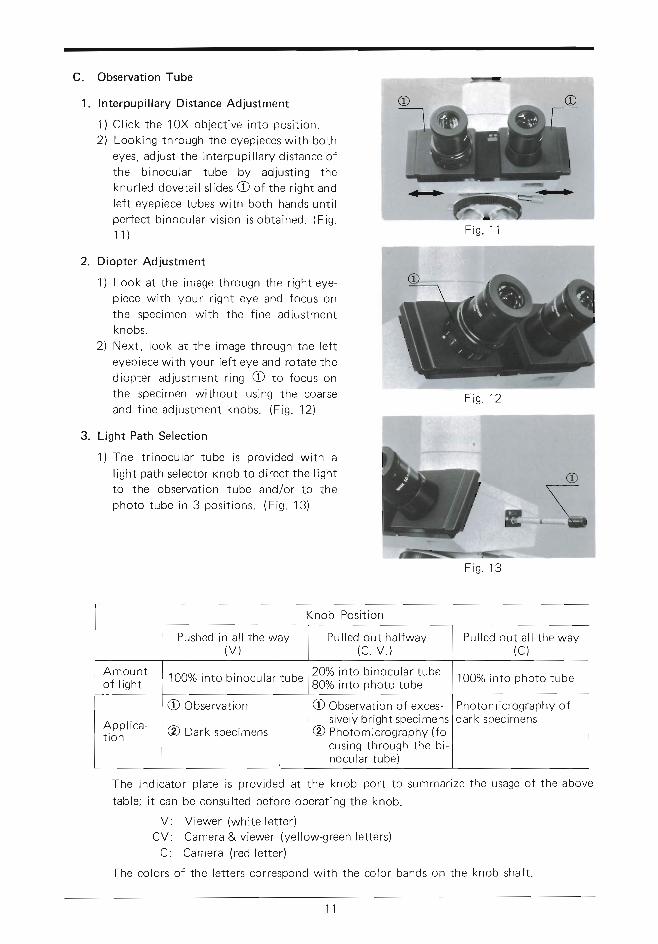
c. Observation Tube
Interpupi l la ry Dis tance Adjustment
1 ) C l i c k t he i 0X ob jec t i ve i n to pos i t i on .
2) Look ing through the eyepieces wi th botheyes, ad just the in terpupi l la ry d is tance ofthe b inocular tube by ad just ing theknur led doveta i l s l ides O of the r ight andle f t eyepiece tubes wi th both hands unt i lper fect b inocu lar v is ion is obta ined. (F ig .
1 1 )
Diopter Adjustment
1) Look at the image through the r ight eye-p iece wi th your r ight eye and focus onthe spec imen wi th the f ine ad justmentknobs.
2) Next , look a t the image through the le f teyepiece wi th your le f t eye and ro ta te thed iopter ad justment r ing O to focus onthe spec imen wi thout us ing the coarseand f ine ad justment knobs. (F ig . 12)
L ight Path Select ion
1 ) The t r i nocu la r t ube i s p rov ided w i t h al ight path se lector knob to d i rect the l ightto the observation tube and/or to thepho to t ube i n 3 pos i t i ons . (F ig . 13 )
1 .
2.
3.
F i g . i 1
F is . 12
o
E \ffilrF--s,*
F i s . 1 3
The indicator plate is provided at the knob port to summarize the usage of the abovetable; i t can be consul ted before operat ing the knob.
V: Viewer (whi te let ter)CV: Camera & viewer (yel low-green let ters)
C: Camera (red let ter)
The colors of the let ters correspond with the color bands on the knob shaft .
Knob Posi t ion
Pushed in a l l the way(v )
Pul led out ha l fway(c . v . )
Pu l l ed ou t a l l t he way(c )
Amoun to f l i gh t 1O0o/o in to b inocular tube
20%BO%o
nto b inocu la r t ubento photo tube
lOO% in to pho to t ube
App l i ca -t i on
O Observat ion
@ Dark spec imens
O Observat ion o f exces-
^ s i ve l y b r i gh t spec imens€) Photo m ic rography ( fo-
cus ing t h rough the b i -nocu l a r t ube )
Photomicrography ofda rk spec imens
1 1
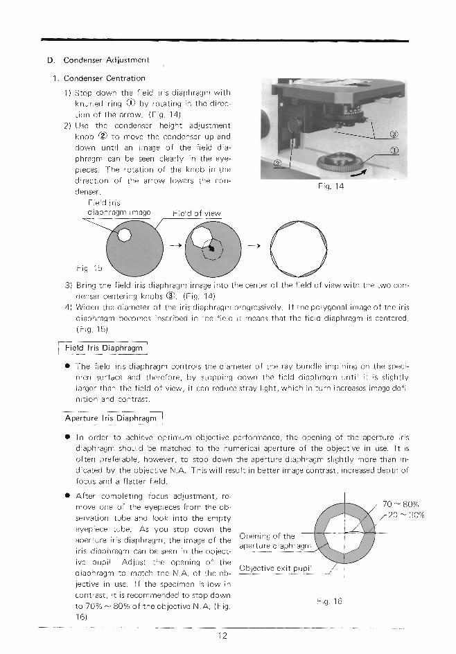
D. CondenserAdjustment
1. Condenser Centration
1) Stop down the f ie ld i r is d iaphragm with
knur led r ing O by rotat ing in the direc-
t ion o f the ar row. (F ig ' 14)
2) Use the condenser height adjustment
knob @ to move the condenser uP and
down unt i l an image of the f ie ld dia-
phragm can be seen clear ly in the eye-
oieces. The rotat ion of the knob in the
direct ion of the arrow lowers the con-
F ie ld o f v i ew
l f t he po l ygona l image o f t he i r i s
the f ie ld d iaphragm is centered.
o The f ie ld i r is d iaphragm controts the diameter of the ray bundle impining on the speci-
men surface and therefore, by stopping down the f ierd diaphragm unt i l i t is s l ight ly
larger than the f ie ld of v iew, i t can reduce stray l ight , which in turn increases image def i -
n i t ion and contrast .
Fig. 14denser.
F i e l d i r i sdiaphragm
ffi+oBring the f ie ld i r i s d iaphragm image in to
denser center ing knobs @. (Fig. 1a)the center o f the f ie ld o f v iew wi th the two con-
4 ) W i d e n t h e d i a m e t e r o f t h e i r i s d i a p h r a g m p r o g r e s s i v e | y 'd i a p h r a g m b e c o m e s i n s c r i b e d i n t h e f i e | d i t m e a n s t h a t( F i g . 1 5 )
F ie ld l r is D iaPhragm
Aperture l r is DiaPhragm
o rn order to ach ieve opt imum object ive per formance, the opening of the aper ture r rs
d iaphragm should be matched to the numer ica l aper ture o f the ob ject ive in use ' l t i s
o f ten preferab le , however , to s top down the aper ture d iaphragm s l ight ly more than in-
d icated by the ob ject ive N.A. Th iswi l l resu l t in bet ter image cont rast , increased depth o f
focus and a f la t ter f ie ld .
Af ter complet ing focus ad justment , re-
move one of the eyepieces from the ob-
servat ion tube and look in to the empty
eyepiece tube. As You stoP down the
aper ture i r is d iaphragm, the image of the
i r is d iaphragm can be seen in the ob ject -
ive pupi l . Ad just the opening of the
d iaphragm to match the N 'A. o f the ob-
jec t ive in use. l f the spec imen is low in
contrast, i t is recommended to stop down
lo 70% - 8O%o of the ob ject ive N.R' (F ig '
1 6 )
Open ing o f t heaper ture d iaPhragm
Ob jec t i ve ex i t PuP i l
1 2
F i g . 1 6
-.
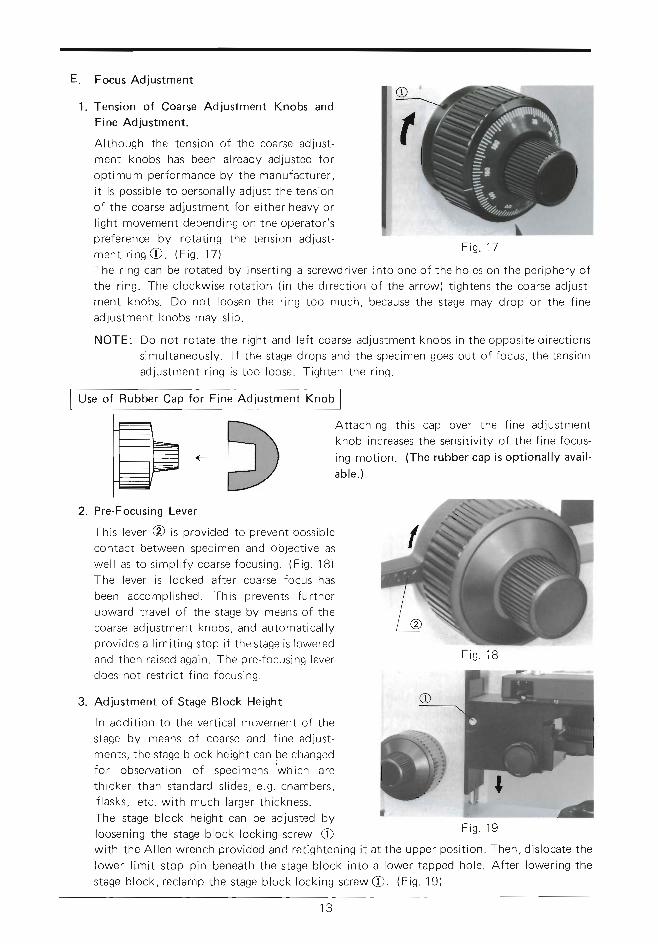
. Focus Adjustment
1. Tens ion of Coarse Ad jus tment Knobs and
Fine Adjustment .
A l though the tens ion of the coarse ad just -
ment knobs has been a l ready ad justed for
opt imum per formance by the manufacturer ,
i t is poss ib le to personal ly ad just the tens ion
of the coarse ad justment for e i ther heavy or
l ight movement depending on the operator 's
preference by ro ta t ing the tens ion ad just -
m e n t r i n s e . ( F i g . 1 7 )
The r ing can be ro ta ted by inser t ing a screwdr iver in to one of the ho les on the per iphery o f
the r ing. The c lockwise ro ta t ion ( in the d i rect ion o f the ar row) t ightens the coarse ad just -
ment knobs. Do not loosen the r ing too much, because the s tage may drop or the f ine
adjustment knobs may s l ip .
NOTE: Do not ro ta te the r ight and le f t coarse ad justment knobs in the oppos i te d i rect ions
s imul taneous ly . l f the s tage drops and the spec imen goes out o f focus, the tens ion
adjustment r ing is too loose. T ighten the r ing.
Use of Rubber Cap for F ine Adjustment Knob
At tach ing th is cap over the f ine ad justment
knob increases the sens i t iv i ty o f the f ine focus-
ing mot ion. (The rubber cap is opt iona l ly ava i l -
ab le . )
2. Pre-Focusing Lever
This lever @ is prov ided to prevent poss ib le
contact between spec imen and ob ject ive as
we l l as t o s imp l i f y coa rse f ocus ing . (F ig . 1B )
The lever is locked af ter coarse focus has
been accompl ished. Th is prevents fur ther
upward t rave l o f the s tage by means of the
coa rse ad jus tmen t knobs , and au toma t i ca l l yprov ides a l imi t ing s top l f the s tage is lowered
and then ra ised again . The pre- focus ing lever
does not rest r ic t f ine focus ing.
3. Ad justment o f Stage Block Height
l n add i t i on t o t he ve r t i ca l movemen t o f t he
stage by means of coarse and f ine ad just -
ments , the s tage b lock he ight can be changed
fo r obse rva t i on o f spec imens 'wh i ch a re
th i cke r t han s tanda rd s l i des , e .g . chambers ,
f l asks , e t c . w i t h much l a rge r t h i ckness .
The s tage b lock he ight can be ad justed by
loosening the s tage b lock lock ing screw O'19
Then, d is locate the
Af ter lower ing thewi th the A l len wrench prov ided and re t ighten ing i t a t the upper pos i t ion.
lower l imi t s top p in beneath the s tage b lock in to a lower tapped ho le .
s tage b lock , r ec lamp the s tage b lock l ock ing sc rew @. (F ig . 19 )
t -t: t\..Er r \I t----ll l ---r i--- | | |I t - - - : | | t
l.: l/
F i g . 1 7
F i s . 1 8
1 3

F. Use of lmmersion Objectives
1) Focus the spec imen wi th a low power ob ject ive.
2 ) pu t a d rop o f immers ion o i l on t he spec imen s l i de and t he f r on t l ens o f t he immers ion
objective.
3) Turn the revo lv ing nosepiece to br ing the immers ion ob ject ive in to the l ight path, and focus
wi th the f ine ad justment knobs.
NOTE: O For immers ion condensers such as an achromat ic -ap lanat ic condenser or Abbe
condenser , remove the spec imen f rom the mechanica l s tage and p lace a drop of
immers ion o i l on the f ront lens o f the condenser . Then, p lace the spec imen on
the s tage and s lowly ra ise the condenser unt i l f i rm contact w i th the unders ide of
the sPec imen s l ide is made.
@ Care shouid be taken to prevent o i l bubbles f rom forming in the o i l f i lm between
condense r and spec imen s l i de . l f any , r e -app l y immers ion o i l , f o r t hese bubb les
great ly deter iora te the lens per formance.
@ Af ter use carefu l ly wipe of f the immers ion o i l depos i ted on the lens sur faces
wi th gauze mois tened wi th xy lene. Never leave o i l on the lens sur faces af ter use
as o i l remnants wi l l ser ious ly impai r the per formance of the lens system.
G. PhotomicrograPhY
The O lympus pho tom ic rog raph i c Equ ipmen t Mode l PM-1OAD i s un ique l y qua l i f i ed t o be
used wi th the BHT microscope for rout ine and advanced photomicrography. A separate ,
deta i led ins t ruct ion manual is ava i lab le for the PM-1OAD camera system'
For qu ick re ference, however , you may want to re fer to the fo l lowing po in terswhen us ing
the PM-104D-
1. Photographic EYePiece
Use N F K photo eyepieces for photomicro-
graPhY.
Inser t the eyepiece in to the eyepiece tube of
t he pho to t ube . (F ig . 20 )
F ig . 20
2. Mount ing the PhotograPhic Uni t
S l ip the body of the photographic un i t over the
photo tube. A l ign the dots on photo tube and
the PM- iOAD body and c l amp the camera un i t
to the photo tube. (F ig . 21)
3. Sett ing the Light Path Selector
Refer to sect ion C.3. on Page 1 1 . F i s .21
1 4
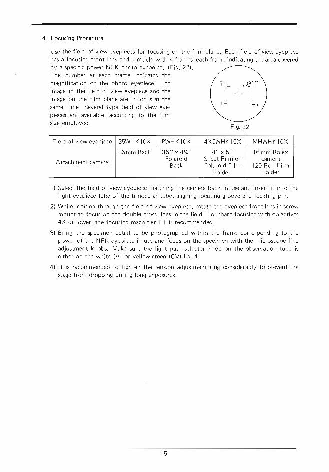
4. Focusing Procedure
Use the field of view eyepieces for focusing on the fi lm plane. Each field of vieweyepiecehas a focusing front lens and a reticle with 4 frames, each frame indicating the area coveredby a specif ic power N F K photo eyepeice. (Fig. 22!-.The number at each frame indicates themagnification of the photo eyepiece. Theimage in the field of view eyepiece and theimage on the fi lm plane are in focus at thesame time. Several type field of view eye-pieces are available, according to the fi lmsize employed.
Field of view eyepiece 35WH Kl OX PWH Kl OX 4X5WH K 1OX MHWH Kl OX
Attachment camera
35mm Back 3T+" x 4Y+"Polaroid
Back
4" x5"Sheet Fi lm orPolaroid Fi lm
Holder
16 mm Bo lexcamera
1 2 0 R o l l F i l mHolder
1) Select the field of view eyepiece matching the camera back in use and insert it into theright eyepiece tube of the trinocular tube, aligning locating groove and locating pin.
2) While looking through the field of view eyepiece, rotate the eyepiece front lens in screwmount to focus on the double cross l ines in the field. For sharp focusing with objectives4X or lower, the focusing magnifier FT is recommended.
3) Bring the specimen detail to be photographed within the frame corresponding to thepower of the NFK eyepiece in use and focus on the specimen with the microscope fineadjustment knobs. Make sure the l ight path selector knob on the observation tube iseither on the white (V) or yellowgreen (CV) band.
4) lt is recommended to tighten the tension adjustment ring considerably to prevent thestage from dropping during long exposures.
Fig.22
1 5

J*j.=1"' ti
VI. OPTICAL DATA
o Resolving power:
o Focal depth:
o F ie ld number :
* lmmersion objectives
The resolving Power and
Technical terms:
o Working distance:
o Numerical aperture:
focal depth are obtained with fully opened aperture diaphragm'
The distance from the cover glass to the nearest point of the
objective.
The N.A. represents a performance number which can be com-
pared to the relative aperture (f-number) of a camera lens. The
N.A. values can be used for directly comparing the resolving
powers of all types of objectives. The larger the N.A., the higher
resolving power.
The abi l i ty of a lens to register smal ldetai ls. The resolv ing power
of a lens is measured by its abil ity to separate two points.
The distance between the upper and lower l imits of sharpness in
the image formed by an optical system. As you stop down the
aperture iris diaphragm, the focal depth becomes larger. The
larger the N.A. of an objective the shallower the focal depth.
A number that represents the diameter in mm of the image of
the field diaphragm that is formed by the lens in front of it.
o Field of view diameter: The actual size of the f ield of view in mm on the object surface.
i.il
tiil r l1 , ,
Objective
Eyepiece
Type D Achromat D Plan Ach.
Magni f i -cation
4X 1 0 x 40x 100x* 4X 1 0 x 40x 100x*
N.A. 0 . 1 0 o.25 0.65 1.30 0 . 1 0 o.25 0.65 1 .25
W.D. (mm) 18.2 7.2 0.6 o.20 7.03 7.4 o.27 o . 1 7
Focal length(mm) 30.03 16.9 4.58 1 . 9 1 34.23 17.5 4.67 1 . 7 5
Resolvingpower (r)
3.36 1.34 o.52 o.26 3.36 1 .34 o.52 o.27
W H K l O X(Fieldnumber201
Total mag. 40x 100x 400x 1000x 40x 100x 400x 1000x
Focaldepth (p) 171.6 27.45 3.0 o.7 171.6 27.45 3.0 o.7
Field ofview (mm) 5 2 0.5 o.2 5 2 0.5 o.2
1 6
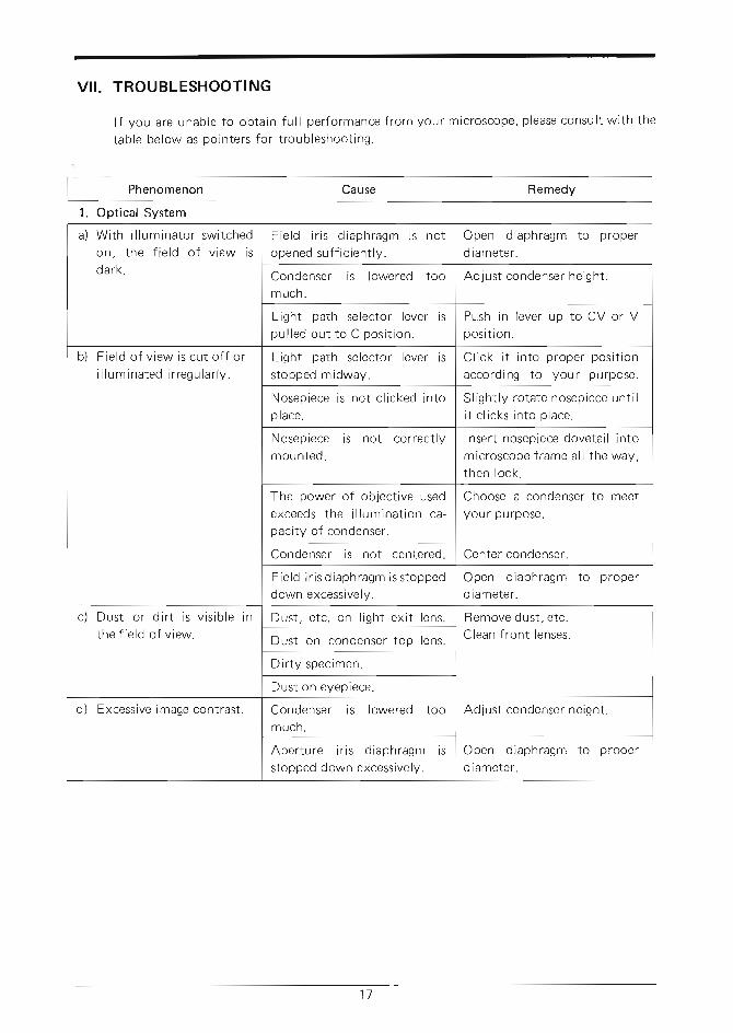
VII . TROUBLESHOOTING
lf you are unable to obtaintable below as pointers for
full performance from your microscope, please consult with thetroubleshooting.
Phenomenon Cause Remedy
1. Optical System
a) With i l luminator switchedon, the f ie ld of v iew isdark.
Field i r is d iaphragm is notopened sufficiently.
Open diaphragm to properdiameter.
Condenser is lowered toomuch.
Adjust condenser height.
Light path selector lever ispul led out to C posi t ion.
Push in lever up to CV or Vposi t ion.
b) Field of view is cut off ori I lum inated i r regular ly.
Light path selector lever isstopped midway.
Ct ick i t into proper posi t ionaccording to your purpose.
Nosepiece is not clicked intoplace.
Slightly rotate nosepiece unti li t c l icks into place.
Nosepiece is not correctlymounted.
Insert nosepiece dovetail intomicroscope frame all the way,then lock.
The power of objective usedexceeds the i l luminat ion ca-pacity of condenser.
Choose a condenser to meetyour purpose.
Condenser is not centered. Center condenser.
Field i r is d iaphragm is stoppeddown excessively.
Open diaphragm to properdiameter.
c) Dust or di r t is v is ib le inthe f ield of view.
Dust, etc. on l ight exit lens. Remove dust, etc.Clean front lenses.Dust on condenser top lens.
Dirty specimen.
Dust on eyepiece.
d) Excessive image contrast. Condenser is lowered toomuch.
Adjust condenser height.
Aperture iris diaphragm isstopped down excessively.
Open diaphragrn to properdiameter.
1 7
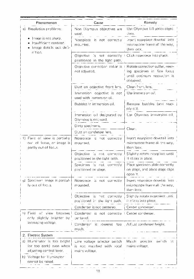
e) Resolut ion Problems:
o lmage is not sharP.o Insufficient contrast.o lmage details lack defi-
n i t ion .
Insert nosePiece dovetail into
microscope frame all the waY,
then lock.
Nosepiece is not correctlY
mounted.
Click nosePiece into Place.Objective is not correctlYpositioned in the l ight Path.
R otate correction col lar, keep-
ing specimen in fine focus
unt i l oPt imum resolut ion is
obtained.
Objective correction collar is
not adjusted.
Clean front lens.Dust on objective front lens'
Use immersion oi l .lmmersion objective is not
used with immersion oi l .
Remove bubbles (and reap-p l y o i l ) .
Bubb les in immers ion o i l '
Use OlymPus immersion oi l .lmmersion oil designated bY
Olympus is not used.
Dir ty specimens.
Dust on condenser lens.
lnsert nosePiece dovetail into
microscope frame all the waY,
then lock.
Nosepiece is not correctlY
mounted.f ) Field of v iew is Part ia l lY
out of focus, or image is
PartlY out of focus.Slightly rotate nosePiece unti l
i t c l icks in place.Objective is not correctlYpositioned in the l ight Path.
Place specimen slide correctlY
on stage, and Place stage cliPs
open it.
Specimen is not correctlYpositioned on stage.
Insert nosePiece dovetail into
microscope frame all the waY,
then lock.
Nosepiece is not correctlY
mounted.g) Specimen image is Partial-
ly out of focus.
SlightlY rotate nosePiece unti l
i t c l icks into Place.Objective is not correctlYposi t ioned in the l ight Path.
Center condenser.Condenser is not centered.
h) Field of view becomes
only s l ight lY br ighter bY
increasing voltage. Adjust condenser height.Condenser is lowered too
much.
2. Electric SystemMatch selector switch to
mains voltage.Line voltage selector switch
is not matched with local
mains voltage.
a) l l luminator is too br ight(or too dark) even when
adjusting control lever.
b) Vol tage for i l luminatorcannot be raised.

Phenomenon Cause Remedy
c) Lamp goes off and on. Bulb f i lament is l ikely toburn out.
Replace bulb.
Loose electric connections. Check all connections.
d) Bulb burns out f requent ly. Line voltage selector switch isnot matched with local mainsvoltage.
Match selector switch tomains voltage.
Bulb is not standard one. Use standard bulb.
3. Coarse and Fine Adjustments
a) Coarse adjustment knob istoo t ight .
Tension adjustment ring istightened too much.
Loosen ring properly.
User is trying to raise stageabove the focusing l imit im-posed by the engaged pre-focusing lever.
Unlock lever.
b) Stage drops or specimengoes out of focus duringobservation due to slippingfine adjustment knobs.
Tension adjustment ring istoo loose.
Tighten ring properly.
c) Stage cannot be raised tothe upper l imi t .
Pre-focusing lever is engagedin lower than focusing posi-t ion.
Unlock lever.
d) Stage cannot be lowered
to the lower l imi t .Stage is mounted too low. Raise stage mount with Allen
wrench.
e) Objective front lens hitsspecimen before cominginto focus.
Specimen is placed on stageupside down.
Reverse specimen.
4. Observation Tubes
a) Incomplete binocular v i -s ion.
I nterpupil lary d istance is notcorrectly adjusted.
Correct the interpupil lary dis-tance.
Diopter adjustment is incom-plete.
Complete the diopter adjust-ment.
Right and left eyepieces arenot matched.
Use a pair of matched eye-pieces.
User is unaccustomed to bi-nocular v is ion.
Pr ior to looking into the bi-nocular observation tube, lookat a far away object.
5. Stage
a) lmage easily goes out offocus when you touch thestage.
Stage is not correctly locked. Clamp stage securely.
b) Specimen stops midwayon the east-west traverse.
Specimen is not correctly po-si t ioned.
Adjust specimen position.