Embed Size (px)
Citation preview
INSTRUCTIONS
CK30/CK40CULTURE MICROSCOPE
This instruction manual is for the Olympus Culture Microscope Model CK30/CK40. To ensure thesafety, obtain optimum performance, and to familiarize yourself fully with the use of this microscope,we recommend that you study this manual thoroughly before operating the microscope. Retain thisinstruction manual in an easily accessible place near the work desk for future reference.
A X 7 1 6 2
i
The CK30 and CK40 Culture Microscopes have different system configurations. The differences are shown in the table below.
CK30 CK40
Observation tube Built-in binocular tube Interchangeable*
Stage plate – Interchangeable**
CK40-RFL reflected lightfluorescence attachment Not mountable Mountable
* The CH3-BI45 binocular tube, CH3-TR45 trinocular tube, and CK40-TBI Tilting binocular tube are all
mountable. The CK40-EPA eyepoint adjuster can also be used, but not in combination with the CK40-
TBI. The only usable intermediate observation tube is the CK40-EPA. Relief phase contrast observa-
tion is not available when the CK40-EPA is used.
** In addition to the standard stage plate, you can mount the CK40-CPG glass stage plate or IX-CP50
stage plate ( 50). Only 20X-or-less objectives should be used with the CK40-CPG.
SAFETY PRECAUTIONS
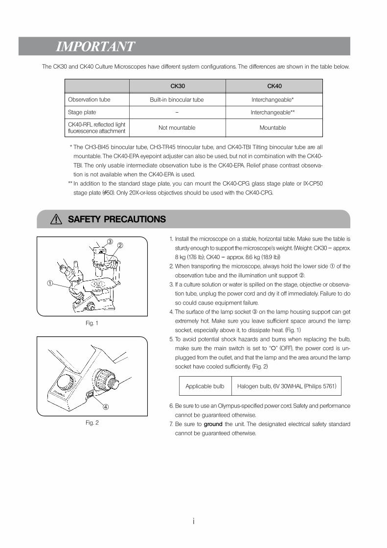
1. Install the microscope on a stable, horizontal table. Make sure the table is
sturdy enough to support the microscope’s weight. (Weight: CK30 –– approx.
8 kg (17.6 lb); CK40 –– approx. 8.6 kg (18.9 lb))
2. When transporting the microscope, always hold the lower side @ of the
observation tube and the illumination unit support ².
3. If a culture solution or water is spilled on the stage, objective or observa-
tion tube, unplug the power cord and dry it off immediately. Failure to do
so could cause equipment failure.
4. The surface of the lamp socket ³ on the lamp housing support can get
extremely hot. Make sure you leave sufficient space around the lamp
socket, especially above it, to dissipate heat. (Fig. 1)
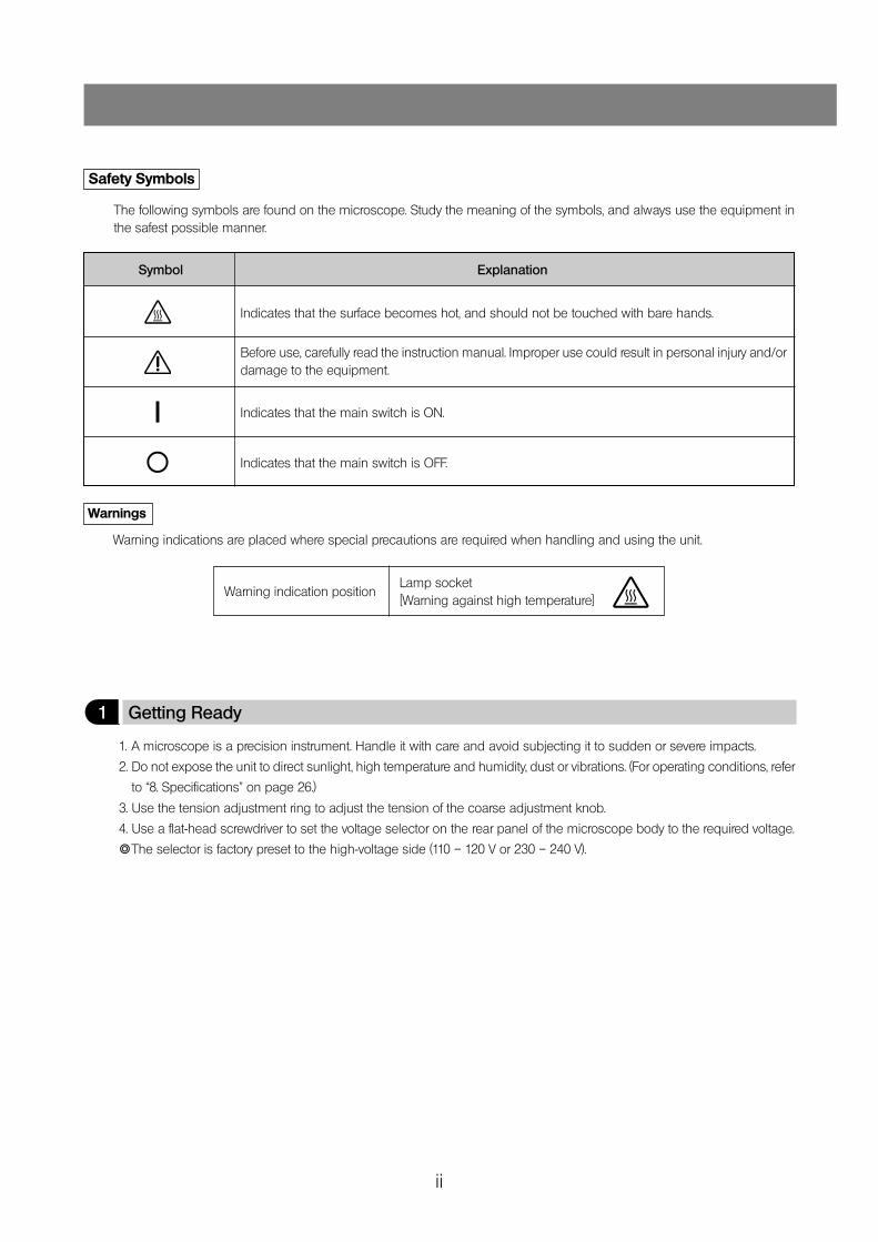
5. To avoid potential shock hazards and burns when replacing the bulb,
make sure the main switch is set to “\” (OFF), the power cord is un-
plugged from the outlet, and that the lamp and the area around the lamp
socket have cooled sufficiently. (Fig. 2)
Applicable bulb Halogen bulb, 6V 30WHAL (Philips 5761)
6. Be sure to use an Olympus-specified power cord. Safety and performance
cannot be guaranteed otherwise.
7. Be sure to ground the unit. The designated electrical safety standard
cannot be guaranteed otherwise.
Fig. 1
Fig. 2
@
²³
|
ii
Safety Symbols
The following symbols are found on the microscope. Study the meaning of the symbols, and always use the equipment inthe safest possible manner.
Symbol Explanation
Indicates that the surface becomes hot, and should not be touched with bare hands.
Before use, carefully read the instruction manual. Improper use could result in personal injury and/ordamage to the equipment.
Indicates that the main switch is ON.
Indicates that the main switch is OFF.
l
\
Warnings
Warning indications are placed where special precautions are required when handling and using the unit.
Warning indication positionLamp socket[Warning against high temperature]
1 Getting Ready
1. A microscope is a precision instrument. Handle it with care and avoid subjecting it to sudden or severe impacts.
2. Do not expose the unit to direct sunlight, high temperature and humidity, dust or vibrations. (For operating conditions, refer
to “8. Specifications” on page 26.)
3. Use the tension adjustment ring to adjust the tension of the coarse adjustment knob.
4. Use a flat-head screwdriver to set the voltage selector on the rear panel of the microscope body to the required voltage.
}The selector is factory preset to the high-voltage side (110 – 120 V or 230 – 240 V).
iii
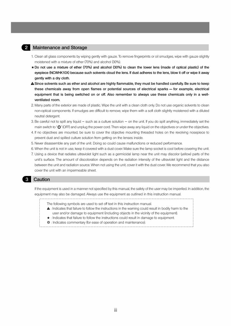
2 Maintenance and Storage
1. Clean all glass components by wiping gently with gauze. To remove fingerprints or oil smudges, wipe with gauze slightly
moistened with a mixture of ether (70%) and alcohol (30%).
#Do not use a mixture of ether (70%) and alcohol (30%) to clean the lower lens (made of optical plastic) of the
eyepiece (NCWHK10X) because such solvents cloud the lens. If dust adheres to the lens, blow it off or wipe it away
gently with a dry cloth.
Since solvents such as ether and alcohol are highly flammable, they must be handled carefully. Be sure to keep
these chemicals away from open flames or potential sources of electrical sparks —— for example, electrical
equipment that is being switched on or off. Also remember to always use these chemicals only in a well-
ventilated room.
2. Many parts of the exterior are made of plastic. Wipe the unit with a clean cloth only. Do not use organic solvents to clean
non-optical components. If smudges are difficult to remove, wipe them with a soft cloth slightly moistened with a diluted
neutral detergent.
3. Be careful not to spill any liquid –– such as a culture solution –– on the unit. If you do spill anything, immediately set the
main switch to “ ” (OFF) and unplug the power cord. Then wipe away any liquid on the objectives or under the objectives.
4. If no objectives are mounted, be sure to cover the objective mounting threaded holes on the revolving nosepiece to
prevent dust and spilled culture solution from getting on the lenses inside.
5. Never disassemble any part of the unit. Doing so could cause malfunctions or reduced performance.
6. When the unit is not in use, keep it covered with a dust cover. Make sure the lamp socket is cool before covering the unit.
7. Using a device that radiates ultraviolet light such as a germicidal lamp near the unit may discolor (yellow) parts of the
unit´s surface. The amount of discoloration depends on the radiation intensity of the ultraviolet light and the distance
between the unit and radiation source. When not using the unit, cover it with the dust cover. We recommend that you also
cover the unit with an impermeable sheet.
3 Caution
If the equipment is used in a manner not specified by this manual, the safety of the user may be imperiled. In addition, the
equipment may also be damaged. Always use the equipment as outlined in this instruction manual.
The following symbols are used to set off text in this instruction manual.: Indicates that failure to follow the instructions in the warning could result in bodily harm to theuser and/or damage to equipment (including objects in the vicinity of the equipment).
# : Indicates that failure to follow the instructions could result in damage to equipment.} : Indicates commentary (for ease of operation and maintenance).
CK30/CK40
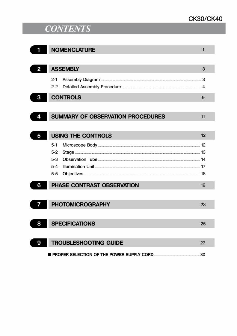
1 NOMENCLATURE
2 ASSEMBLY
3 CONTROLS
4 SUMMARY OF OBSERVATION PROCEDURES
5 USING THE CONTROLS
6 PHASE CONTRAST OBSERVATION
7 PHOTOMICROGRAPHY
8 SPECIFICATIONS
9 TROUBLESHOOTING GUIDE
PROPER SELECTION OF THE POWER SUPPLY CORD .............................................................................30
1
3
9
11
12
19
23
25
27
2-1 Assembly Diagram ................................................................................................................................................................... 3
2-2 Detailed Assembly Procedure ................................................................................................................................. 4
5-1 Microscope Body ...................................................................................................................................................................... 12
5-2 Stage ........................................................................................................................................................................................................... 13
5-3 Observation Tube ..................................................................................................................................................................... 14
5-4 Illumination Unit .......................................................................................................................................................................... 17
5-5 Objectives ............................................................................................................................................................................................ 18
1
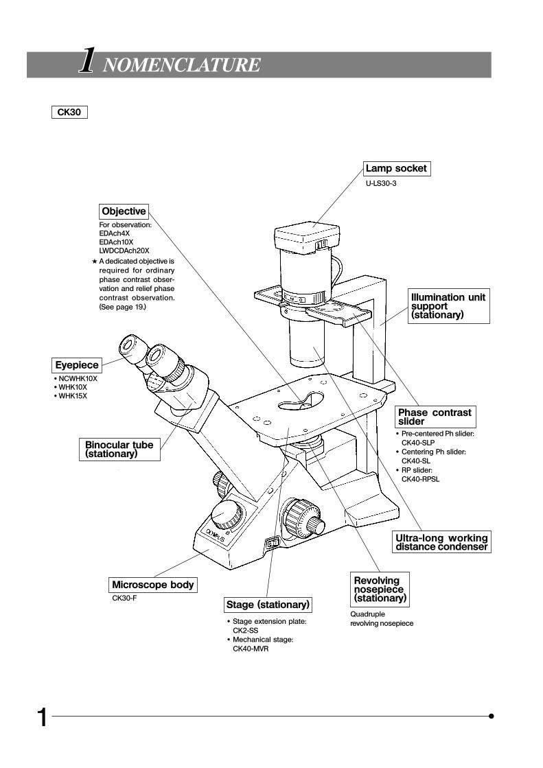
1 NOMENCLATURE
CK30
ObjectiveFor observation:EDAch4XEDAch10XLWDCDAch20X
# A dedicated objective isrequired for ordinaryphase contrast obser-vation and relief phasecontrast observation.(See page 19.)
Eyepiece· NCWHK10X· WHK10X· WHK15X
Binocular tube(stationary)
Microscope bodyCK30-F
Stage (stationary)
· Stage extension plate:CK2-SS
· Mechanical stage:CK40-MVR
Revolvingnosepiece(stationary)
Quadruplerevolving nosepiece
Ultra-long workingdistance condenser
Phase contrastslider
· Pre-centered Ph slider:CK40-SLP
· Centering Ph slider:CK40-SL
· RP slider:CK40-RPSL
Illumination unitsupport(stationary)
Lamp socketU-LS30-3
CK30/CK40
2
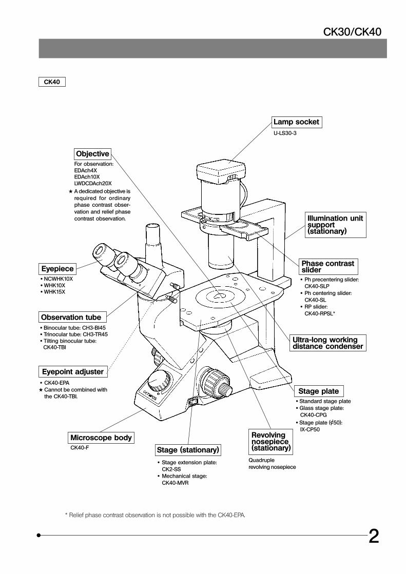
CK40
ObjectiveFor observation:EDAch4XEDAch10XLWDCDAch20X
# A dedicated objective isrequired for ordinaryphase contrast obser-vation and relief phasecontrast observation.
Eyepiece· NCWHK10X· WHK10X· WHK15X
Microscope bodyCK40-F Stage (stationary)
· Stage extension plate:CK2-SS
· Mechanical stage:CK40-MVR
Revolvingnosepiece(stationary)
Quadruplerevolving nosepiece
Phase contrastslider
· Ph precentering slider:CK40-SLP
· Ph centering slider:CK40-SL
· RP slider:CK40-RPSL *
Illumination unitsupport(stationary)
Lamp socketU-LS30-3
Observation tube · Binocular tube: CH3-BI45 · Trinocular tube: CH3-TR45 · Tilting binocular tube: CK40-TBI
Eyepoint adjuster · CK40-EPA# Cannot be combined with
the CK40-TBI.Stage plate
· Standard stage plate · Glass stage plate:
CK40-CPG · Stage plate ( 50):
IX-CP50
Ultra-long workingdistance condenser
* Relief phase contrast observation is not possible with the CK40-EPA.
3
ASSEMBLY
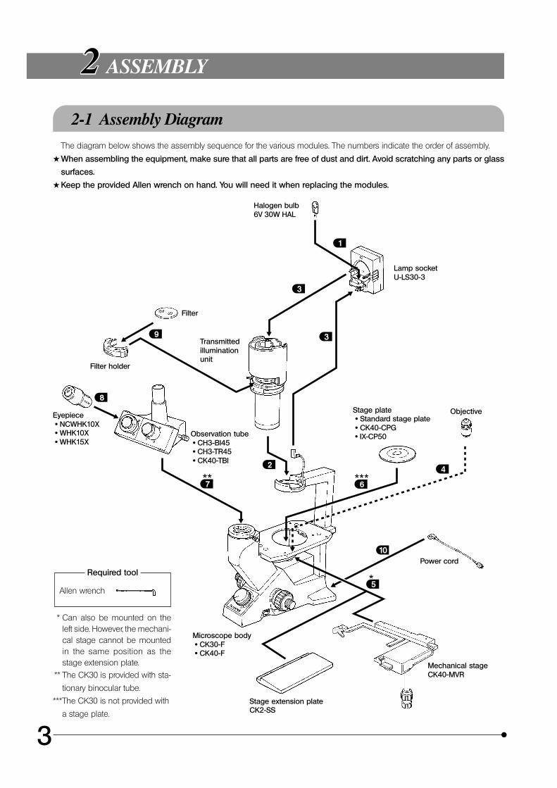
2-1 Assembly DiagramThe diagram below shows the assembly sequence for the various modules. The numbers indicate the order of assembly.
#When assembling the equipment, make sure that all parts are free of dust and dirt. Avoid scratching any parts or glass
surfaces.
#Keep the provided Allen wrench on hand. You will need it when replacing the modules.
Allen wrench
Required tool
* Can also be mounted on theleft side. However, the mechani-cal stage cannot be mountedin the same position as thestage extension plate.
** The CK30 is provided with sta-
tionary binocular tube.
Halogen bulb6V 30W HAL
Lamp socketU-LS30-3
Filter
Filter holder
Transmittedilluminationunit
Stage plate · Standard stage plate · CK40-CPG · IX-CP50
ObjectiveEyepiece · NCWHK10X · WHK10X · WHK15X
Observation tube · CH3-BI45 · CH3-TR45 · CK40-TBI
Power cord
Microscope body · CK30-F · CK40-F
Stage extension plateCK2-SS
Mechanical stageCK40-MVR
***The CK30 is not provided with
a stage plate.
CK30/CK40
4
2-2 Detailed Assembly Procedure
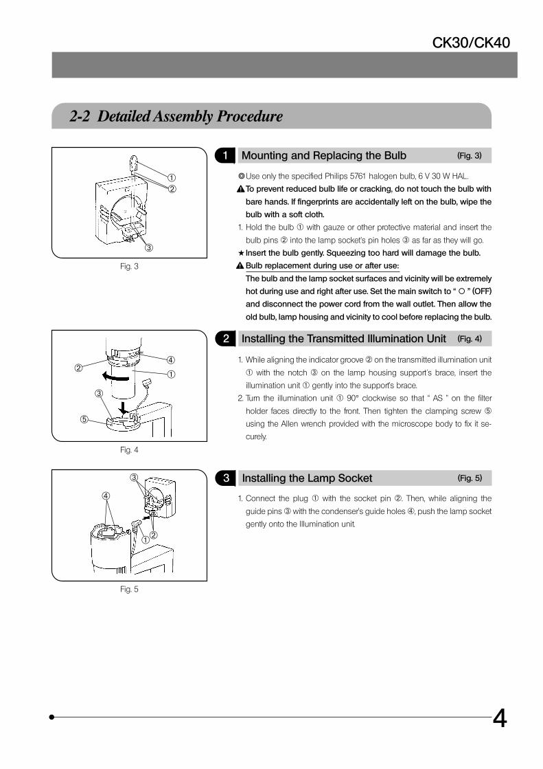
1 Mounting and Replacing the Bulb (Fig. 3)
}Use only the specified Philips 5761 halogen bulb, 6 V 30 W HAL .
To prevent reduced bulb life or cracking, do not touch the bulb with
bare hands. If fingerprints are accidentally left on the bulb, wipe the
bulb with a soft cloth.
1. Hold the bulb @ with gauze or other protective material and insert the
bulb pins ² into the lamp socket’s pin holes ³ as far as they will go.
#Insert the bulb gently. Squeezing too hard will damage the bulb.
Bulb replacement during use or after use:
The bulb and the lamp socket surfaces and vicinity will be extremely
hot during use and right after use. Set the main switch to “ \ ” (OFF)
and disconnect the power cord from the wall outlet. Then allow the
old bulb, lamp housing and vicinity to cool before replacing the bulb.
2 Installing the Transmitted Illumination Unit (Fig. 4)
1. While aligning the indicator groove ² on the transmitted illumination unit
@ with the notch ³ on the lamp housing support´s brace, insert the
illumination unit @ gently into the support’s brace.
2. Turn the illumination unit @ 90° clockwise so that “ AS ” on the filter
holder faces directly to the front. Then tighten the clamping screw ƒ
using the Allen wrench provided with the microscope body to fix it se-
curely.
3 Installing the Lamp Socket (Fig. 5)
1. Connect the plug @ with the socket pin ². Then, while aligning the
guide pins ³ with the condenser’s guide holes |, push the lamp socket
gently onto the Illumination unit.
Fig. 3
Fig. 4
Fig. 5
@²
³
@²
³
|
ƒ
@²
³
|
5
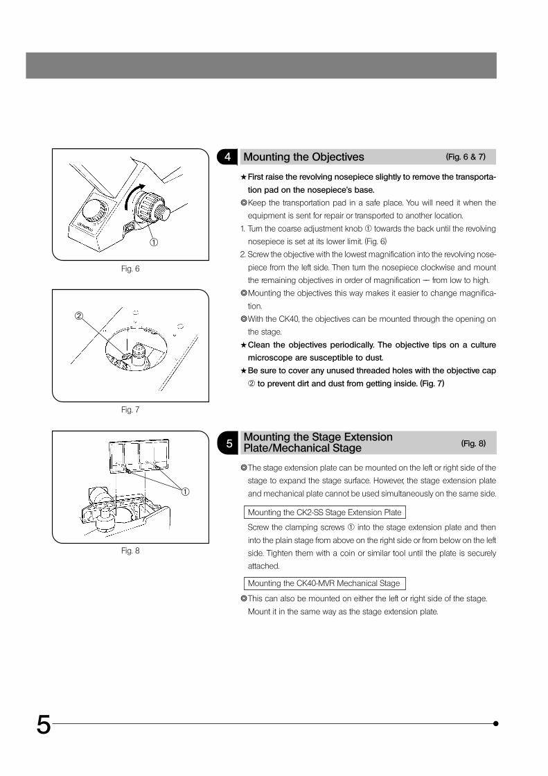
4 Mounting the Objectives (Fig. 6 & 7)
#First raise the revolving nosepiece slightly to remove the transporta-
tion pad on the nosepiece’s base.
}Keep the transportation pad in a safe place. You will need it when the
equipment is sent for repair or transported to another location.
1. Turn the coarse adjustment knob @ towards the back until the revolving
nosepiece is set at its lower limit. (Fig. 6)
2. Screw the objective with the lowest magnification into the revolving nose-
piece from the left side. Then turn the nosepiece clockwise and mount
the remaining objectives in order of magnification –– from low to high.
}Mounting the objectives this way makes it easier to change magnifica-
tion.
}With the CK40, the objectives can be mounted through the opening on
the stage.
#Clean the objectives periodically. The objective tips on a culture
microscope are susceptible to dust.
#Be sure to cover any unused threaded holes with the objective cap
² to prevent dirt and dust from getting inside. (Fig. 7)
5Mounting the Stage ExtensionPlate/Mechanical Stage (Fig. 8)
}The stage extension plate can be mounted on the left or right side of the
stage to expand the stage surface. However, the stage extension plate
and mechanical plate cannot be used simultaneously on the same side.
Mounting the CK2-SS Stage Extension Plate
Screw the clamping screws @ into the stage extension plate and then
into the plain stage from above on the right side or from below on the left
side. Tighten them with a coin or similar tool until the plate is securely
attached.
Mounting the CK40-MVR Mechanical Stage
}This can also be mounted on either the left or right side of the stage.
Mount it in the same way as the stage extension plate.
Fig. 6
Fig. 7
Fig. 8
@
²
@
CK30/CK40
6
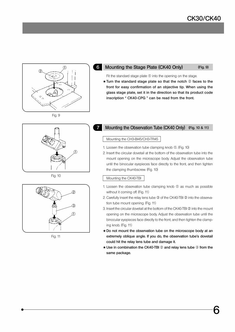
6 Mounting the Stage Plate (CK40 Only) (Fig. 9)
Fit the standard stage plate @ into the opening on the stage.
#Turn the standard stage plate so that the notch ² faces to the
front for easy confirmation of an objective tip. When using the
glass stage plate, set it in the direction so that its product code
inscription “ CK40-CPG ” can be read from the front.
7 Mounting the Observation Tube (CK40 Only) (Fig. 10 & 11)
Mounting the CH3-BI45/CH3-TR45
1. Loosen the observation tube clamping knob @. (Fig. 10)
2. Insert the circular dovetail at the bottom of the observation tube into the
mount opening on the microscope body. Adjust the observation tube
until the binocular eyepieces face directly to the front, and then tighten
the clamping thumbscrew. (Fig. 10)
Mounting the CK40-TBI
1. Loosen the observation tube clamping knob @ as much as possible
without it coming off. (Fig. 11)
2. Carefully insert the relay lens tube ³ of the CK40-TBI ² into the observa-
tion tube mount opening. (Fig. 11)
3. Insert the circular dovetail at the bottom of the CK40-TBI ² into the mount
opening on the microscope body. Adjust the observation tube until the
binocular eyepieces face directly to the front, and then tighten the clamp-
ing knob. (Fig. 11)
#Do not mount the observation tube on the microscope body at an
extremely oblique angle. If you do, the observation tube’s dovetail
could hit the relay lens tube and damage it.
#Use in combination the CK40-TBI ² and relay lens tube ³ from the
same package.
Fig. 9
Fig. 10
Fig. 11
@²
@
@
²
³
7
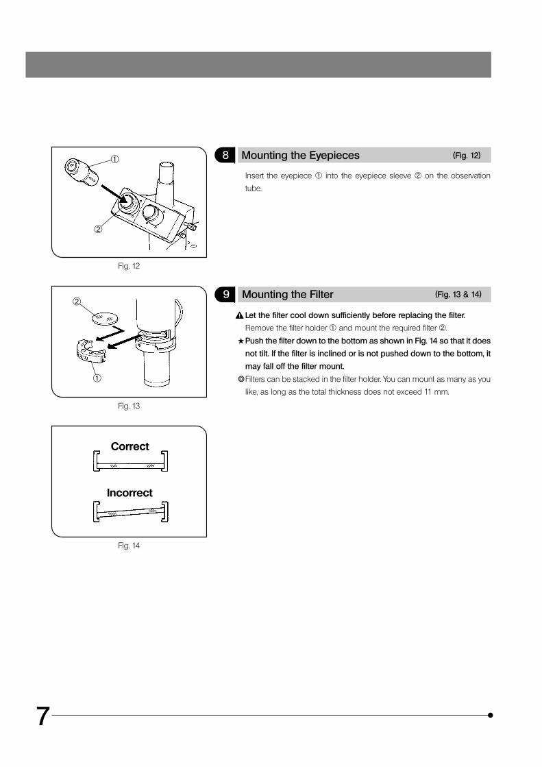
8 Mounting the Eyepieces (Fig. 12)
Insert the eyepiece @ into the eyepiece sleeve ² on the observation
tube.
9 Mounting the Filter (Fig. 13 & 14)
Let the filter cool down sufficiently before replacing the filter.
Remove the filter holder @ and mount the required filter ².
#Push the filter down to the bottom as shown in Fig. 14 so that it does
not tilt. If the filter is inclined or is not pushed down to the bottom, it
may fall off the filter mount.
}Filters can be stacked in the filter holder. You can mount as many as you
like, as long as the total thickness does not exceed 11 mm.
Fig. 12
Fig. 13
Fig. 14
@
@
²
Incorrect
Correct
²
CK30/CK40
8
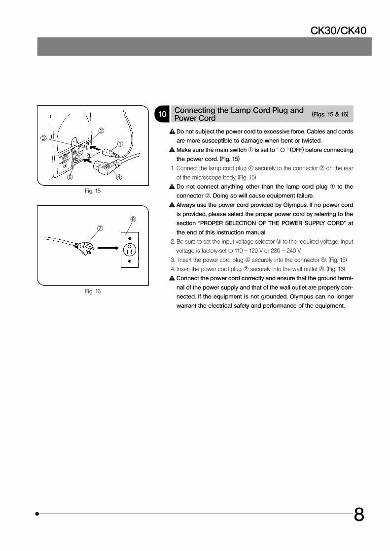
10 Connecting the Lamp Cord Plug andPower Cord (Figs. 15 & 16)
Do not subject the power cord to excessive force. Cables and cords
are more susceptible to damage when bent or twisted.
Make sure the main switch @ is set to “ \ ” (OFF) before connecting
the power cord. (Fig. 15)
1. Connect the lamp cord plug @ securely to the connector ² on the rear
of the microscope body. (Fig. 15)
Do not connect anything other than the lamp cord plug @ to the
connector ². Doing so will cause equipment failure.
Always use the power cord provided by Olympus. If no power cord
is provided, please select the proper power cord by referring to the
section “PROPER SELECTION OF THE POWER SUPPLY CORD” at
the end of this instruction manual.
2. Be sure to set the input voltage selector ³ to the required voltage. Input
voltage is factory-set to 110 – 120 V or 230 – 240 V.
3. Insert the power cord plug | securely into the connector ƒ. (Fig. 15)
4. Insert the power cord plug † securely into the wall outlet ‡. (Fig. 16)
Connect the power cord correctly and ensure that the ground termi-
nal of the power supply and that of the wall outlet are properly con-
nected. If the equipment is not grounded, Olympus can no longer
warrant the electrical safety and performance of the equipment.
Fig. 15
Fig. 16
@
²³
|ƒ
†‡
9
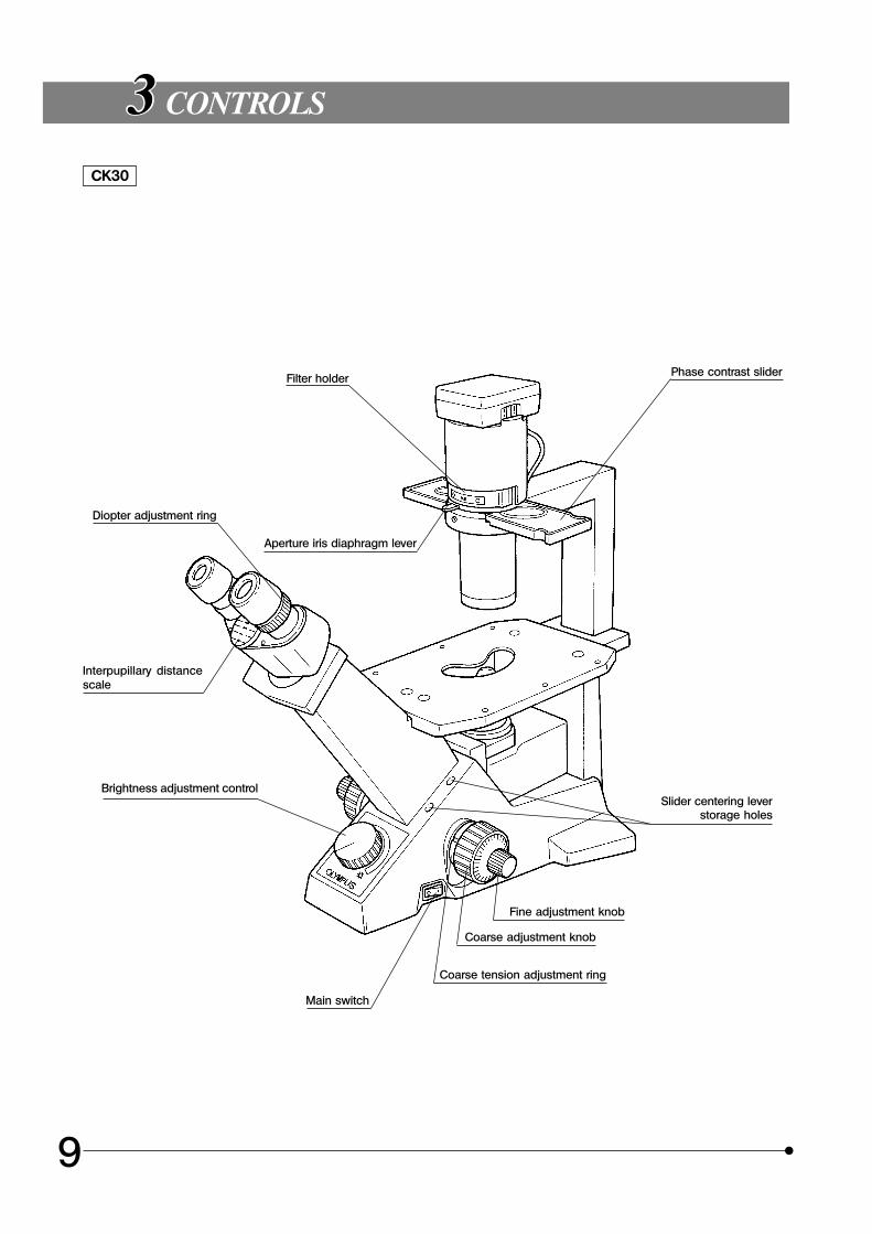
CONTROLS
CK30
Filter holder
Aperture iris diaphragm lever
Diopter adjustment ring
Interpupillary distancescale
Brightness adjustment control
Main switch
Coarse tension adjustment ring
Coarse adjustment knob
Fine adjustment knob
Slider centering leverstorage holes
Phase contrast slider
CK30/CK40
10
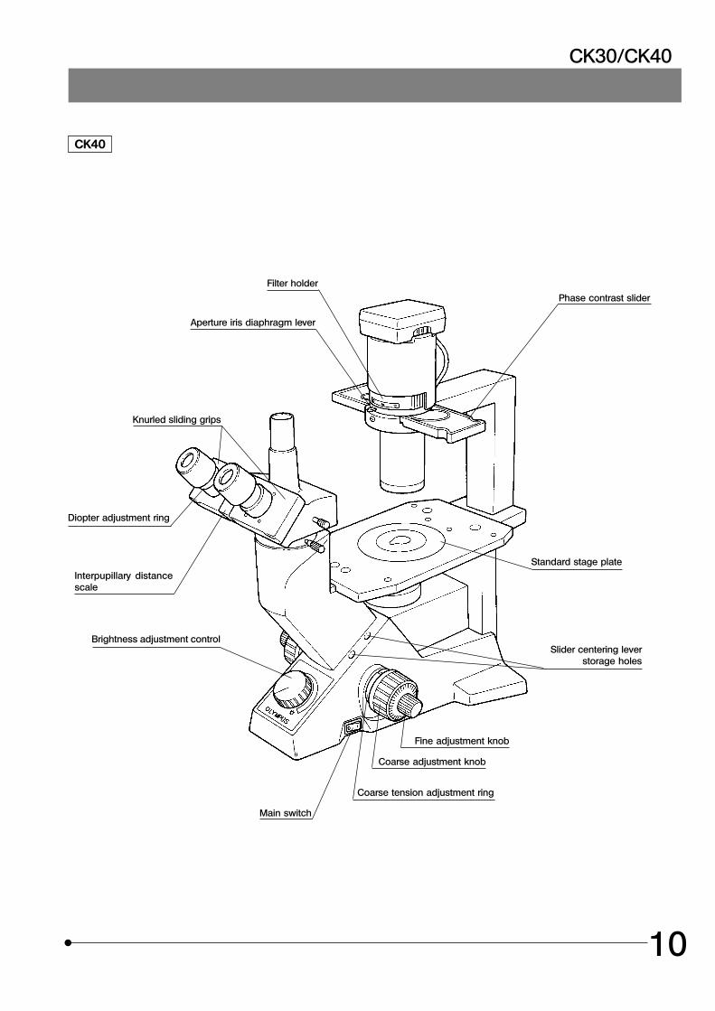
CK40
Filter holder
Aperture iris diaphragm lever
Diopter adjustment ring
Interpupillary distancescale
Brightness adjustment control
Main switch
Coarse tension adjustment ring
Coarse adjustment knob
Fine adjustment knob
Slider centering leverstorage holes
Phase contrast slider
Knurled sliding grips
Standard stage plate
11
SUMMARY OF OBSERVATION PROCEDURES
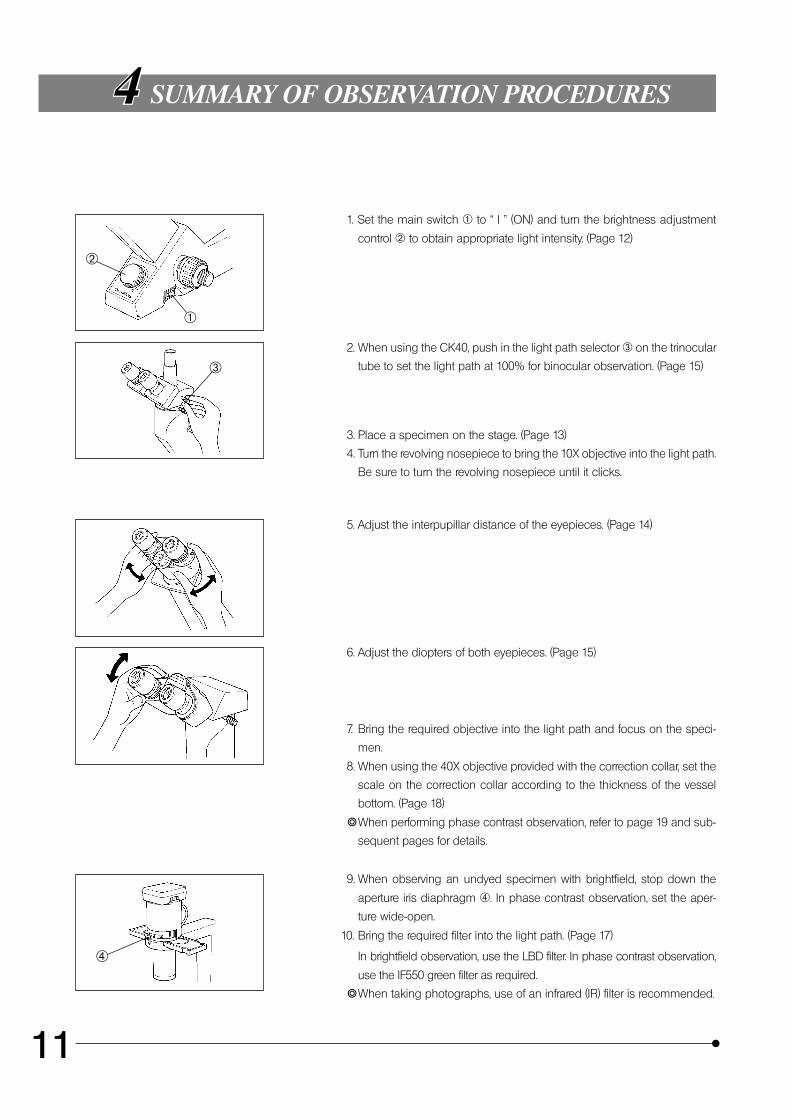
1. Set the main switch @ to “ I ” (ON) and turn the brightness adjustment
control ² to obtain appropriate light intensity. (Page 12)
2. When using the CK40, push in the light path selector ³ on the trinocular
tube to set the light path at 100% for binocular observation. (Page 15)
3. Place a specimen on the stage. (Page 13)
4. Turn the revolving nosepiece to bring the 10X objective into the light path.
Be sure to turn the revolving nosepiece until it clicks.
5. Adjust the interpupillar distance of the eyepieces. (Page 14)
6. Adjust the diopters of both eyepieces. (Page 15)
7. Bring the required objective into the light path and focus on the speci-
men.
8. When using the 40X objective provided with the correction collar, set the
scale on the correction collar according to the thickness of the vessel
bottom. (Page 18)
}When performing phase contrast observation, refer to page 19 and sub-
sequent pages for details.
9. When observing an undyed specimen with brightfield, stop down the
aperture iris diaphragm |. In phase contrast observation, set the aper-
ture wide-open.
10. Bring the required filter into the light path. (Page 17)
In brightfield observation, use the LBD filter. In phase contrast observation,
use the IF550 green filter as required.
}When taking photographs, use of an infrared (IR) filter is recommended.
@
²
³
|
CK30/CK40
12
USING THE CONTROLS
5-1 Microscope Body
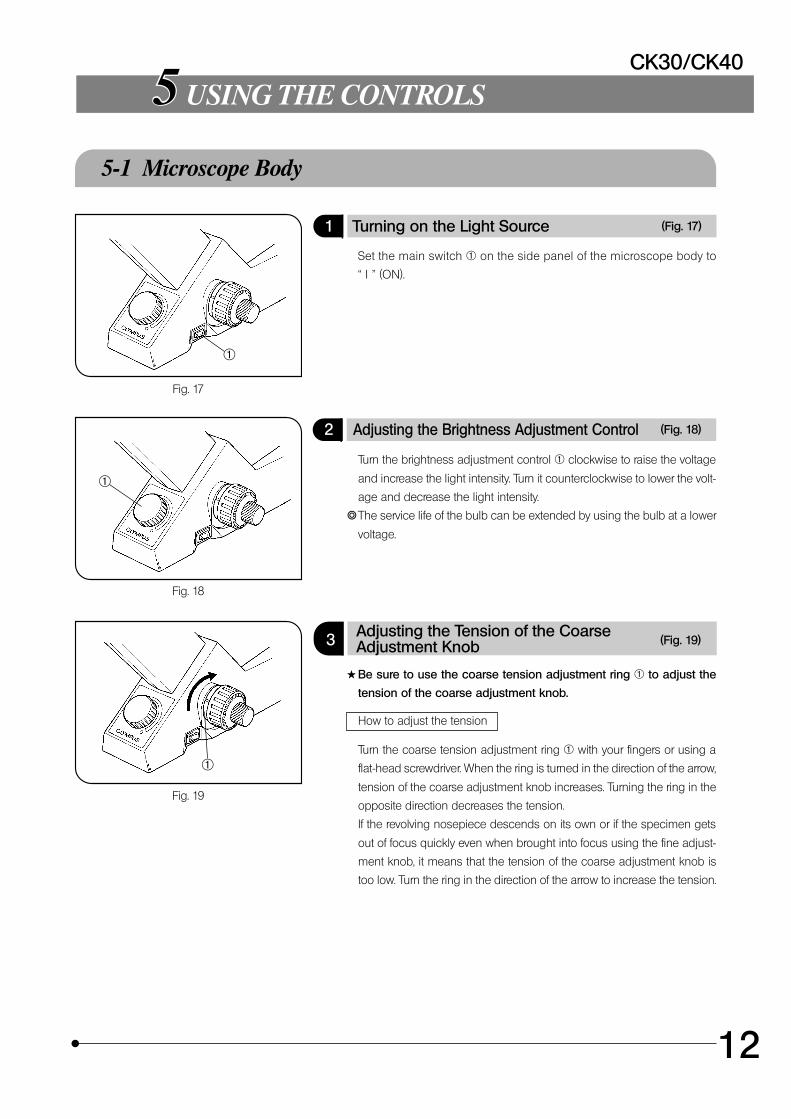
1 Turning on the Light Source (Fig. 17)
Set the main switch @ on the side panel of the microscope body to
“ I ” (ON).
2 Adjusting the Brightness Adjustment Control (Fig. 18)
Turn the brightness adjustment control @ clockwise to raise the voltage
and increase the light intensity. Turn it counterclockwise to lower the volt-
age and decrease the light intensity.
}The service life of the bulb can be extended by using the bulb at a lower
voltage.
3 Adjusting the Tension of the CoarseAdjustment Knob (Fig. 19)
#Be sure to use the coarse tension adjustment ring @ to adjust the
tension of the coarse adjustment knob.
How to adjust the tension
Turn the coarse tension adjustment ring @ with your fingers or using a
flat-head screwdriver. When the ring is turned in the direction of the arrow,
tension of the coarse adjustment knob increases. Turning the ring in the
opposite direction decreases the tension.
If the revolving nosepiece descends on its own or if the specimen gets
out of focus quickly even when brought into focus using the fine adjust-
ment knob, it means that the tension of the coarse adjustment knob is
too low. Turn the ring in the direction of the arrow to increase the tension.
Fig. 17
Fig. 18
Fig. 19
@
@
@
13
5-2 Stage
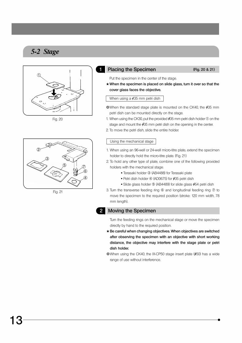
1 Placing the Specimen (Fig. 20 & 21)
Put the specimen in the center of the stage.
#When the specimen is placed on slide glass, turn it over so that the
cover glass faces the objective.
When using a 35 mm petri dish
}When the standard stage plate is mounted on the CK40, the 35 mm
petri dish can be mounted directly on the stage.
1. When using the CK30, put the provided 35 mm petri dish holder @ on the
stage and mount the 35 mm petri dish on the opening in the center.
2. To move the petri dish, slide the entire holder.
Using the mechanical stage
1. When using an 96-well or 24-well micro-titre plate, extend the specimen
holder to directly hold the micro-titre plate. (Fig. 21)
2. To hold any other type of plate, combine one of the following provided
holders with the mechanical stage:
· Terasaki holder ³ (AB4488) for Terasaki plate
· Petri dish holder | (AD0675) for 35 petri dish
· Slide glass holder ƒ (AB4489) for slide glass 54 petri dish
3. Turn the transverse feeding ring … and longitudinal feeding ring † to
move the specimen to the required position (stroke: 120 mm width, 78
mm length).
2 Moving the Specimen
Turn the feeding rings on the mechanical stage or move the specimen
directly by hand to the required position.
#Be careful when changing objectives. When objectives are switched
after observing the specimen with an objective with short working
distance, the objective may interfere with the stage plate or petri
dish holder.
}When using the CK40, the IX-CP50 stage insert plate ( 50) has a wide
range of use without interference.
Fig. 20
Fig. 21
@
…
²
ƒ
|
³
†
CK30/CK40
14
5-3 Observation Tube
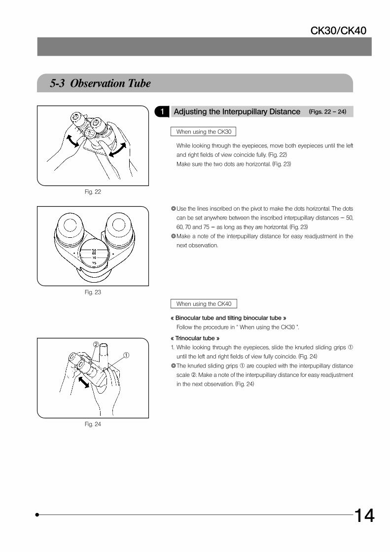
1 Adjusting the Interpupillary Distance (Figs. 22 – 24)
When using the CK30
While looking through the eyepieces, move both eyepieces until the left
and right fields of view coincide fully. (Fig. 22)
Make sure the two dots are horizontal. (Fig. 23)
}Use the lines inscribed on the pivot to make the dots horizontal. The dots
can be set anywhere between the inscribed interpupillary distances –– 50,
60, 70 and 75 –– as long as they are horizontal. (Fig. 23)
}Make a note of the interpupillary distance for easy readjustment in the
next observation.
When using the CK40
þ Binocular tube and tilting binocular tube ý
Follow the procedure in “ When using the CK30 ”.
þ Trinocular tube ý
1. While looking through the eyepieces, slide the knurled sliding grips @
until the left and right fields of view fully coincide. (Fig. 24)
}The knurled sliding grips @ are coupled with the interpupillary distance
scale ². Make a note of the interpupillary distance for easy readjustment
in the next observation. (Fig. 24)
Fig. 22
Fig. 23
Fig. 24
@
²
15
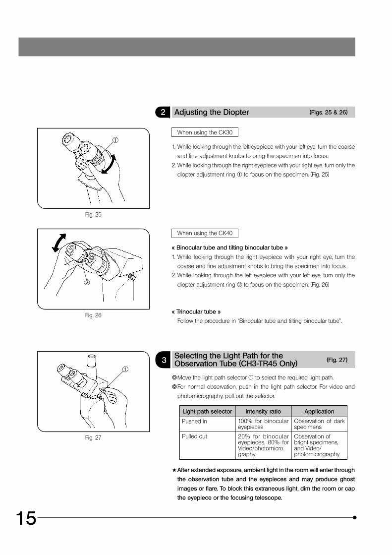
2 Adjusting the Diopter (Figs. 25 & 26)
When using the CK30
1. While looking through the left eyepiece with your left eye, turn the coarse
and fine adjustment knobs to bring the specimen into focus.
2. While looking through the right eyepiece with your right eye, turn only the
diopter adjustment ring @ to focus on the specimen. (Fig. 25)
When using the CK40
þ Binocular tube and tilting binocular tube ý
1. While looking through the right eyepiece with your right eye, turn the
coarse and fine adjustment knobs to bring the specimen into focus.
2. While looking through the left eyepiece with your left eye, turn only the
diopter adjustment ring ² to focus on the specimen. (Fig. 26)
þ Trinocular tube ý
Follow the procedure in “Binocular tube and tilting binocular tube”.
3 Selecting the Light Path for theObservation Tube (CH3-TR45 Only) (Fig. 27)
}Move the light path selector @ to select the required light path.
}For normal observation, push in the light path selector. For video and
photomicrography, pull out the selector.
Light path selector Intensity ratio Application
Pushed in 100% for binoculareyepieces
Observation of darkspecimens
Pulled out 20% for binoculareyepieces, 80% forVideo/photomicrography
Observation ofbright specimens,and Video/photomicrography
#After extended exposure, ambient light in the room will enter through
the observation tube and the eyepieces and may produce ghost
images or flare. To block this extraneous light, dim the room or cap
the eyepiece or the focusing telescope.
Fig. 25
Fig. 26
Fig. 27
@
²
@
CK30/CK40
16
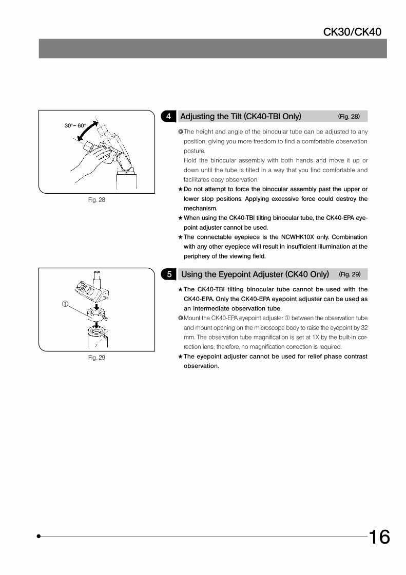
4 Adjusting the Tilt (CK40-TBI Only) (Fig. 28)
}The height and angle of the binocular tube can be adjusted to any
position, giving you more freedom to find a comfortable observation
posture.
Hold the binocular assembly with both hands and move it up or
down until the tube is tilted in a way that you find comfortable and
facilitates easy observation.
#Do not attempt to force the binocular assembly past the upper or
lower stop positions. Applying excessive force could destroy the
mechanism.
#When using the CK40-TBI tilting binocular tube, the CK40-EPA eye-
point adjuster cannot be used.
#The connectable eyepiece is the NCWHK10X only. Combination
with any other eyepiece will result in insufficient illumination at the
periphery of the viewing field.
5 Using the Eyepoint Adjuster (CK40 Only) (Fig. 29)
#The CK40-TBI tilting binocular tube cannot be used with the
CK40-EPA. Only the CK40-EPA eyepoint adjuster can be used as
an intermediate observation tube.
}Mount the CK40-EPA eyepoint adjuster @ between the observation tube
and mount opening on the microscope body to raise the eyepoint by 32
mm. The observation tube magnification is set at 1X by the built-in cor-
rection lens; therefore, no magnification correction is required.
#The eyepoint adjuster cannot be used for relief phase contrast
observation.
Fig. 28
Fig. 29
30°– 60°
@
17
5-4 Illumination Unit
1 Using the Filter
}Use filters as needed to increase the accuracy of observation and photo-
micrography. The LBD filter is especially recommended for observation
and photomicrography since it achieves more neutral colors.
}Filters can be stacked in the filter holder. (Maximum thickness: 11 mm)
Filter Purpose
IF550 Monochrome contrast filter (green)
ND6, ND25 Light intensity adjustment filter(transmittance: 6%/25%)
LBD Color temperature conversion filter(for observation/photomicrography)
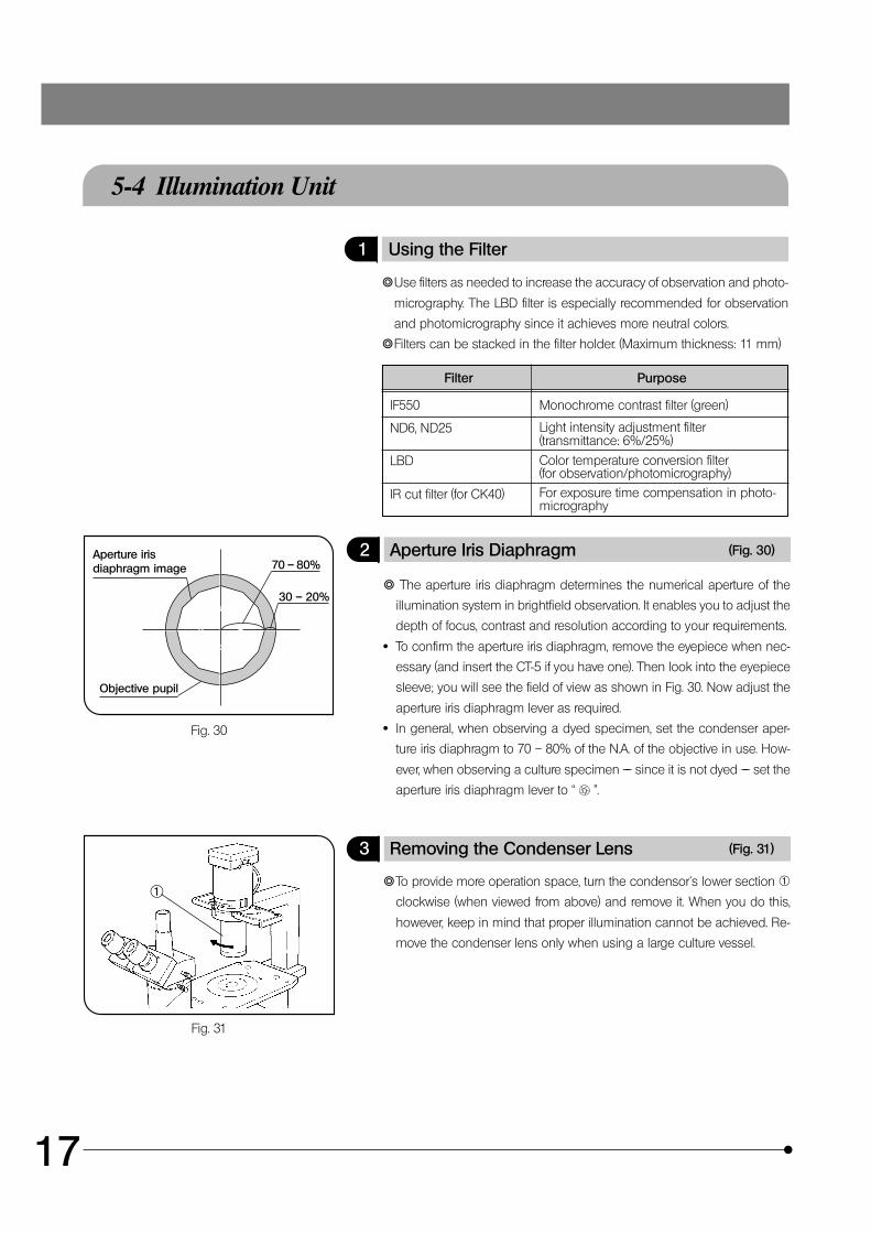
2 Aperture Iris Diaphragm (Fig. 30)
} The aperture iris diaphragm determines the numerical aperture of the
illumination system in brightfield observation. It enables you to adjust the
depth of focus, contrast and resolution according to your requirements.
· To confirm the aperture iris diaphragm, remove the eyepiece when nec-
essary (and insert the CT-5 if you have one). Then look into the eyepiece
sleeve; you will see the field of view as shown in Fig. 30. Now adjust the
aperture iris diaphragm lever as required.
· In general, when observing a dyed specimen, set the condenser aper-
ture iris diaphragm to 70 – 80% of the N.A. of the objective in use. How-
ever, when observing a culture specimen –– since it is not dyed –– set the
aperture iris diaphragm lever to “ ”.
3 Removing the Condenser Lens (Fig. 31)
}To provide more operation space, turn the condensor´s lower section @
clockwise (when viewed from above) and remove it. When you do this,
however, keep in mind that proper illumination cannot be achieved. Re-
move the condenser lens only when using a large culture vessel.
Fig. 30
Fig. 31
@
Aperture irisdiaphragm image
Objective pupil
70 – 80%
30 – 20%
IR cut filter (for CK40) For exposure time compensation in photo-micrography
CK30/CK40
18
5-5 Objectives
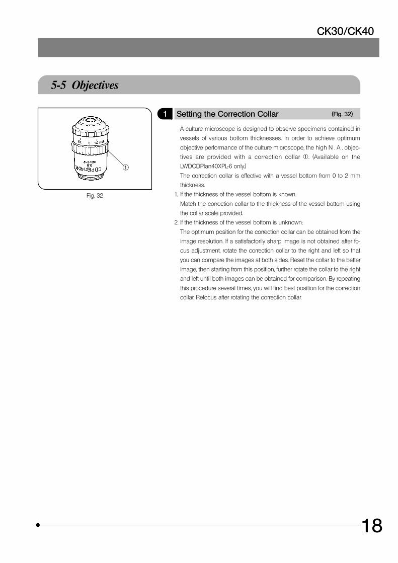
1 Setting the Correction Collar (Fig. 32)
A culture microscope is designed to observe specimens contained in
vessels of various bottom thicknesses. In order to achieve optimum
objective performance of the culture microscope, the high N . A . objec-
tives are provided with a correction collar @. (Available on the
LWDCDPlan40XPL-6 only.)
The correction collar is effective with a vessel bottom from 0 to 2 mm
thickness.
1. If the thickness of the vessel bottom is known:
Match the correction collar to the thickness of the vessel bottom using
the collar scale provided.
2. If the thickness of the vessel bottom is unknown:
The optimum position for the correction collar can be obtained from the
image resolution. If a satisfactorily sharp image is not obtained after fo-
cus adjustment, rotate the correction collar to the right and left so that
you can compare the images at both sides. Reset the collar to the better
image, then starting from this position, further rotate the collar to the right
and left until both images can be obtained for comparison. By repeating
this procedure several times, you will find best position for the correction
collar. Refocus after rotating the correction collar.
Fig. 32
@
19
PHASE CONTRAST OBSERVATION
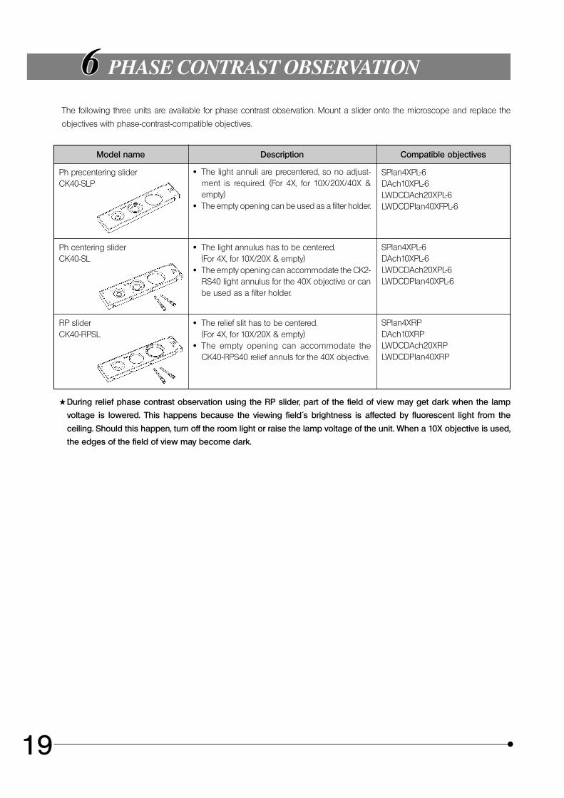
The following three units are available for phase contrast observation. Mount a slider onto the microscope and replace the
objectives with phase-contrast-compatible objectives.
Model name Description Compatible objectives
Ph precentering sliderCK40-SLP
· The light annuli are precentered, so no adjust-ment is required. (For 4X, for 10X/20X/40X &empty)
· The empty opening can be used as a filter holder.
SPlan4XPL-6DAch10XPL-6LWDCDAch20XPL-6LWDCDPlan40XFPL-6
Ph centering sliderCK40-SL
· The light annulus has to be centered.(For 4X, for 10X/20X & empty)
· The empty opening can accommodate the CK2-RS40 light annulus for the 40X objective or canbe used as a filter holder.
SPlan4XPL-6DAch10XPL-6LWDCDAch20XPL-6LWDCDPlan40XPL-6
RP sliderCK40-RPSL
· The relief slit has to be centered.(For 4X, for 10X/20X & empty)
· The empty opening can accommodate theCK40-RPS40 relief annuls for the 40X objective.
SPlan4XRPDAch10XRPLWDCDAch20XRPLWDCDPlan40XRP
#During relief phase contrast observation using the RP slider, part of the field of view may get dark when the lamp
voltage is lowered. This happens because the viewing field´s brightness is affected by fluorescent light from the
ceiling. Should this happen, turn off the room light or raise the lamp voltage of the unit. When a 10X objective is used,
the edges of the field of view may become dark.
CK30/CK40
20
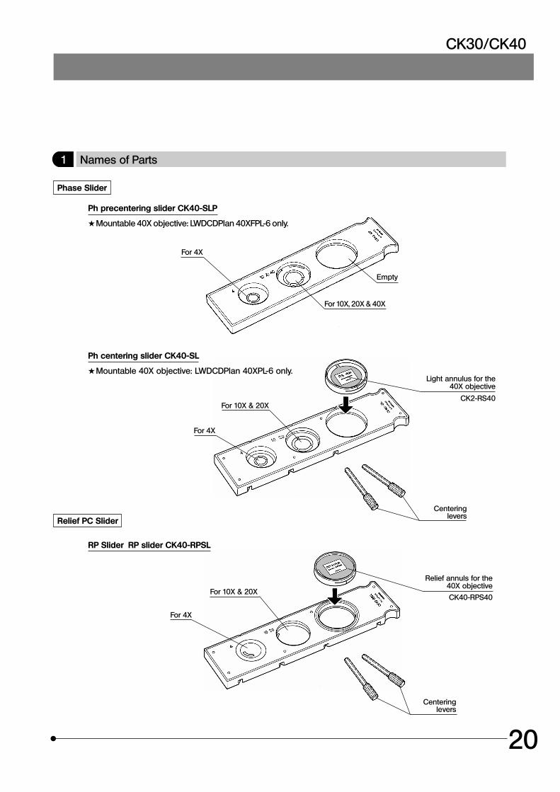
1 Names of Parts
Phase Slider
For 4X
Relief PC Slider
RP Slider RP slider CK40-RPSL
For 10X & 20X
Ph precentering slider CK40-SLP
#Mountable 40X objective: LWDCDPlan 40XFPL-6 only.
For 10X, 20X & 40X
Empty
Ph centering slider CK40-SL
#Mountable 40X objective: LWDCDPlan 40XPL-6 only.
For 10X & 20X
Light annulus for the40X objective
CK2-RS40
Centeringlevers
Relief annuls for the40X objective
CK40-RPS40
Centeringlevers
For 4X
For 4X
21
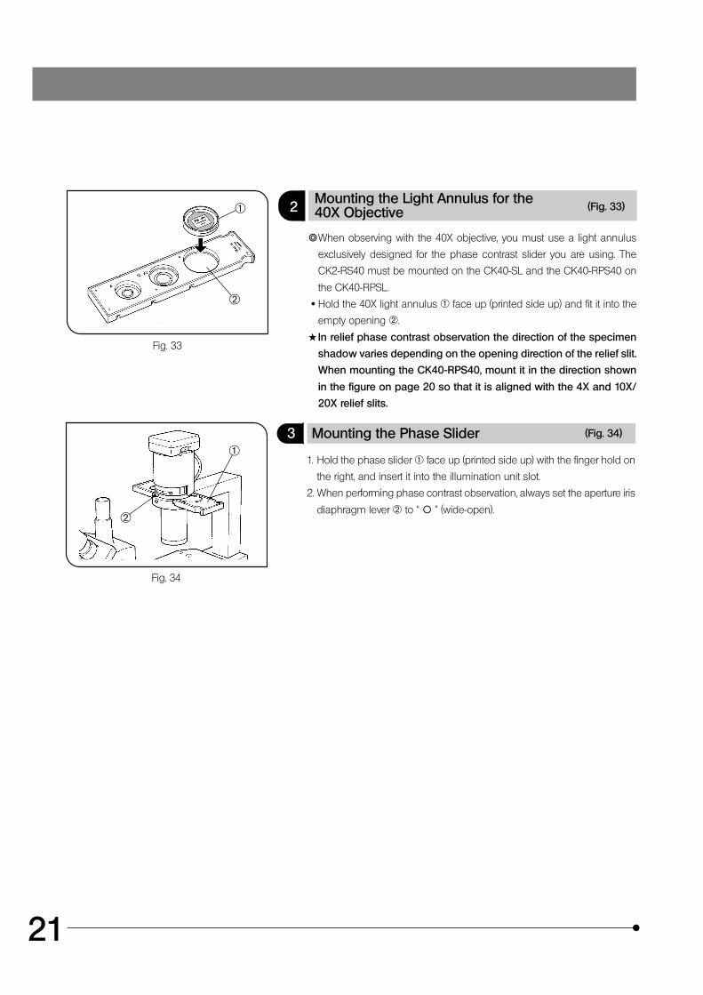
2Mounting the Light Annulus for the40X Objective (Fig. 33)
}When observing with the 40X objective, you must use a light annulus
exclusively designed for the phase contrast slider you are using. The
CK2-RS40 must be mounted on the CK40-SL and the CK40-RPS40 on
the CK40-RPSL.
· Hold the 40X light annulus @ face up (printed side up) and fit it into the
empty opening ².
#In relief phase contrast observation the direction of the specimen
shadow varies depending on the opening direction of the relief slit.
When mounting the CK40-RPS40, mount it in the direction shown
in the figure on page 20 so that it is aligned with the 4X and 10X/
20X relief slits.
3 Mounting the Phase Slider (Fig. 34)
1. Hold the phase slider @ face up (printed side up) with the finger hold on
the right, and insert it into the illumination unit slot.
2. When performing phase contrast observation, always set the aperture iris
diaphragm lever ² to “ \ ” (wide-open).
Fig. 33
Fig. 34
@
²
@
²
CK30/CK40
22
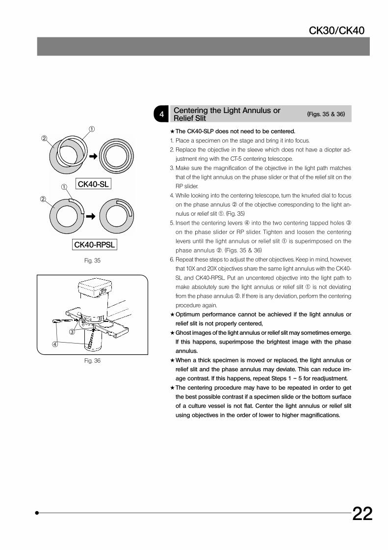
4 Centering the Light Annulus orRelief Slit
(Figs. 35 & 36)
#The CK40-SLP does not need to be centered.
1. Place a specimen on the stage and bring it into focus.
2. Replace the objective in the sleeve which does not have a diopter ad-
justment ring with the CT-5 centering telescope.
3. Make sure the magnification of the objective in the light path matches
that of the light annulus on the phase slider or that of the relief slit on the
RP slider.
4. While looking into the centering telescope, turn the knurled dial to focus
on the phase annulus ² of the objective corresponding to the light an-
nulus or relief slit @. (Fig. 35)
5. Insert the centering levers | into the two centering tapped holes ³
on the phase slider or RP slider. Tighten and loosen the centering
levers until the light annulus or relief slit @ is superimposed on the
phase annulus ². (Figs. 35 & 36)
6. Repeat these steps to adjust the other objectives. Keep in mind, however,
that 10X and 20X objectives share the same light annulus with the CK40-
SL and CK40-RPSL. Put an uncentered objective into the light path to
make absolutely sure the light annulus or relief slit @ is not deviating
from the phase annulus ². If there is any deviation, perform the centering
procedure again.
#Optimum performance cannot be achieved if the light annulus or
relief slit is not properly centered,
#Ghost images of the light annulus or relief slit may sometimes emerge.
If this happens, superimpose the brightest image with the phase
annulus.
#When a thick specimen is moved or replaced, the light annulus or
relief slit and the phase annulus may deviate. This can reduce im-
age contrast. If this happens, repeat Steps 1 – 5 for readjustment.
#The centering procedure may have to be repeated in order to get
the best possible contrast if a specimen slide or the bottom surface
of a culture vessel is not flat. Center the light annulus or relief slit
using objectives in the order of lower to higher magnifications.
Fig. 35
Fig. 36
³
|
CK40-RPSL
@²
@
²
CK40-SL
23
PHOTOMICROGRAPHY
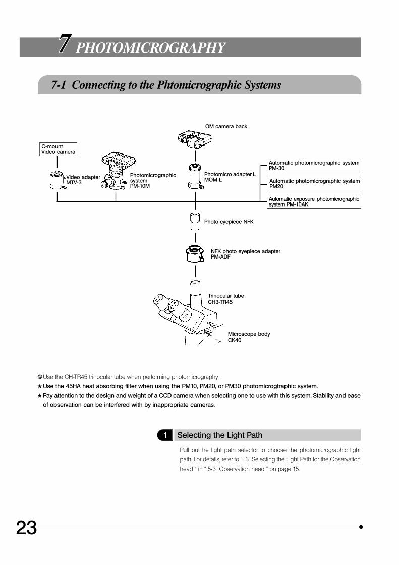
7-1 Connecting to the Phtomicrographic Systems
}Use the CH-TR45 trinocular tube when performing photomicrography.
#Use the 45HA heat absorbing filter when using the PM10, PM20, or PM30 photomicrogtraphic system.
#Pay attention to the design and weight of a CCD camera when selecting one to use with this system. Stability and ease
of observation can be interfered with by inappropriate cameras.
1 Selecting the Light Path
Pull out he light path selector to choose the photomicrographic light
path. For details, refer to “ 3 Selecting the Light Path for the Observation
head ” in “ 5-3 Observation head ” on page 15.
C-mountVideo camera
Video adapterMTV-3
PhotomicrographicsystemPM-10M
OM camera back
Photomicro adapter LMOM-L
Automatic photomicrographic systemPM-30
Automatic photomicrographic systemPM20
Automatic exposure photomicrographicsystem PM-10AK
Photo eyepiece NFK
NFK photo eyepiece adapterPM-ADF
Trinocular tubeCH3-TR45
Microscope bodyCK40
CK30/CK40
24
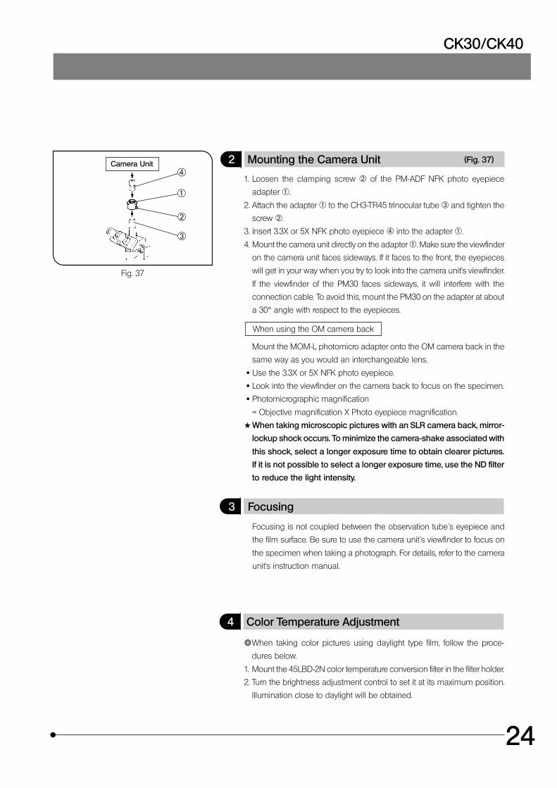
2 Mounting the Camera Unit (Fig. 37)
1. Loosen the clamping screw ² of the PM-ADF NFK photo eyepiece
adapter @.
2. Attach the adapter @ to the CH3-TR45 trinocular tube ³ and tighten the
screw ².
3. Insert 3.3X or 5X NFK photo eyepiece | into the adapter @.
4. Mount the camera unit directly on the adapter @. Make sure the viewfinder
on the camera unit faces sideways. If it faces to the front, the eyepieces
will get in your way when you try to look into the camera unit’s viewfinder.
If the viewfinder of the PM30 faces sideways, it will interfere with the
connection cable. To avoid this, mount the PM30 on the adapter at about
a 30° angle with respect to the eyepieces.
When using the OM camera back
Mount the MOM-L photomicro adapter onto the OM camera back in the
same way as you would an interchangeable lens.
· Use the 3.3X or 5X NFK photo eyepiece.
· Look into the viewfinder on the camera back to focus on the specimen.
· Photomicrographic magnification
= Objective magnification X Photo eyepiece magnification.
#When taking microscopic pictures with an SLR camera back, mirror-
lockup shock occurs. To minimize the camera-shake associated with
this shock, select a longer exposure time to obtain clearer pictures.
If it is not possible to select a longer exposure time, use the ND filter
to reduce the light intensity.
3 Focusing
4 Color Temperature Adjustment
}When taking color pictures using daylight type film, follow the proce-
dures below.
1. Mount the 45LBD-2N color temperature conversion filter in the filter holder.
2. Turn the brightness adjustment control to set it at its maximum position.
Illumination close to daylight will be obtained.
Focusing is not coupled between the observation tube´s eyepiece and
the film surface. Be sure to use the camera unit´s viewfinder to focus on
the specimen when taking a photograph. For details, refer to the camera
unit’s instruction manual.
Fig. 37
Camera Unit
@
²
³
|
25
SPECIFICATIONS
ItemSpecifications
CK30 CK40
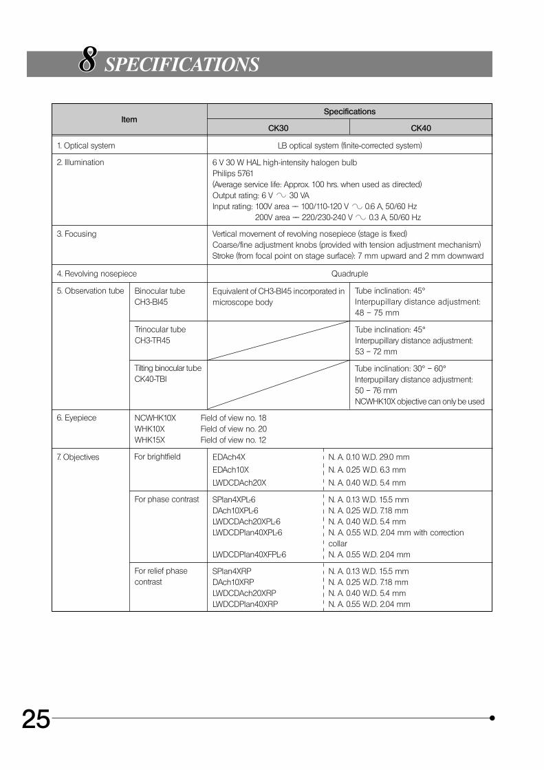
1. Optical system LB optical system (finite-corrected system)
2. Illumination 6 V 30 W HAL high-intensity halogen bulbPhilips 5761(Average service life: Approx. 100 hrs. when used as directed)Output rating: 6 V 30 VAInput rating: 100V area –– 100/110-120 V 0.6 A, 50/60 Hz
200V area –– 220/230-240 V 0.3 A, 50/60 Hz
3. Focusing Vertical movement of revolving nosepiece (stage is fixed)Coarse/fine adjustment knobs (provided with tension adjustment mechanism)Stroke (from focal point on stage surface): 7 mm upward and 2 mm downward
4. Revolving nosepiece Quadruple
5. Observation tube Binocular tubeCH3-BI45
Equivalent of CH3-BI45 incorporated inmicroscope body
Tube inclination: 45°Interpupillary distance adjustment:48 – 75 mm
Trinocular tubeCH3-TR45
Tube inclination: 45°Interpupillary distance adjustment:53 – 72 mm
Tilting binocular tubeCK40-TBI
Tube inclination: 30° – 60°Interpupillary distance adjustment:50 – 76 mmNCWHK10X objective can only be used
6. Eyepiece NCWHK10X Field of view no. 18WHK10X Field of view no. 20WHK15X Field of view no. 12
7. Objectives For brightfield EDAch4X
EDAch10X
LWDCDAch20X
N. A. 0.10 W.D. 29.0 mm
N. A. 0.25 W.D. 6.3 mm
N. A. 0.40 W.D. 5.4 mm
For phase contrast SPlan4XPL-6DAch10XPL-6LWDCDAch20XPL-6LWDCDPlan40XPL-6
LWDCDPlan40XFPL-6
N. A. 0.13 W.D. 15.5 mmN. A. 0.25 W.D. 7.18 mmN. A. 0.40 W.D. 5.4 mmN. A. 0.55 W.D. 2.04 mm with correctioncollarN. A. 0.55 W.D. 2.04 mm
For relief phasecontrast
SPlan4XRPDAch10XRPLWDCDAch20XRPLWDCDPlan40XRP
N. A. 0.13 W.D. 15.5 mmN. A. 0.25 W.D. 7.18 mmN. A. 0.40 W.D. 5.4 mmN. A. 0.55 W.D. 2.04 mm
CK30/CK40
26
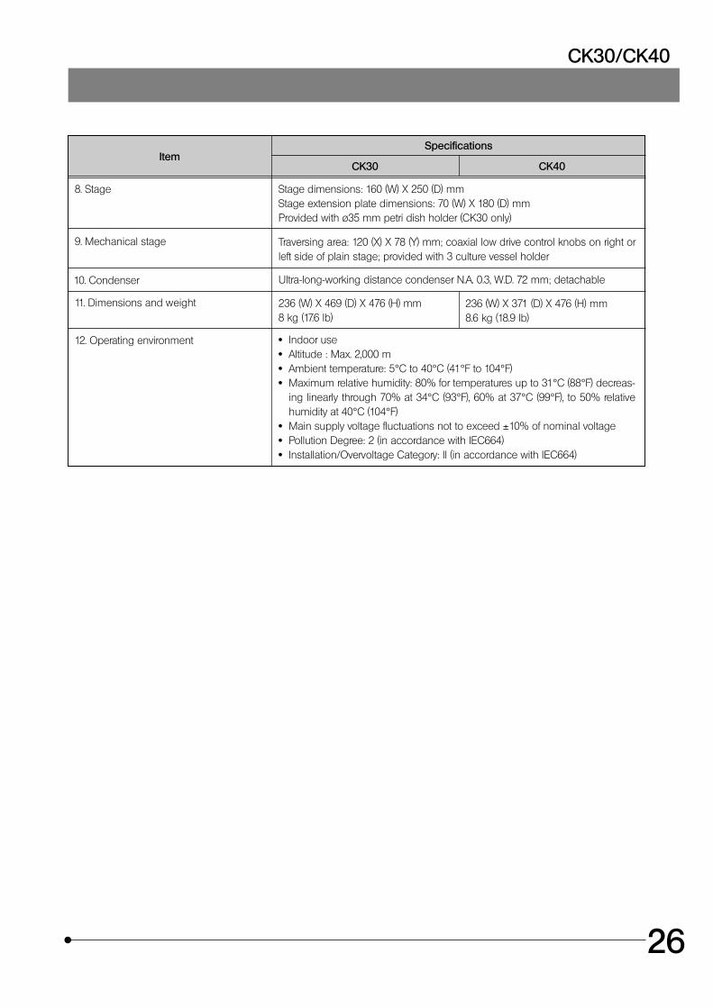
ItemSpecifications
CK30 CK40
8. Stage Stage dimensions: 160 (W) X 250 (D) mmStage extension plate dimensions: 70 (W) X 180 (D) mmProvided with ø35 mm petri dish holder (CK30 only)
9. Mechanical stage Traversing area: 120 (X) X 78 (Y) mm; coaxial low drive control knobs on right orleft side of plain stage; provided with 3 culture vessel holder
10. Condenser Ultra-long-working distance condenser N.A. 0.3, W.D. 72 mm; detachable
11. Dimensions and weight 236 (W) X 469 (D) X 476 (H) mm8 kg (17.6 lb)
12. Operating environment · Indoor use· Altitude : Max. 2,000 m· Ambient temperature: 5°C to 40°C (41°F to 104°F)· Maximum relative humidity: 80% for temperatures up to 31°C (88°F) decreas-
ing linearly through 70% at 34°C (93°F), 60% at 37°C (99°F), to 50% relativehumidity at 40°C (104°F)
· Main supply voltage fluctuations not to exceed ±10% of nominal voltage· Pollution Degree: 2 (in accordance with IEC664)· Installation/Overvoltage Category: II (in accordance with IEC664)
236 (W) X 371 (D) X 476 (H) mm8.6 kg (18.9 lb)
27
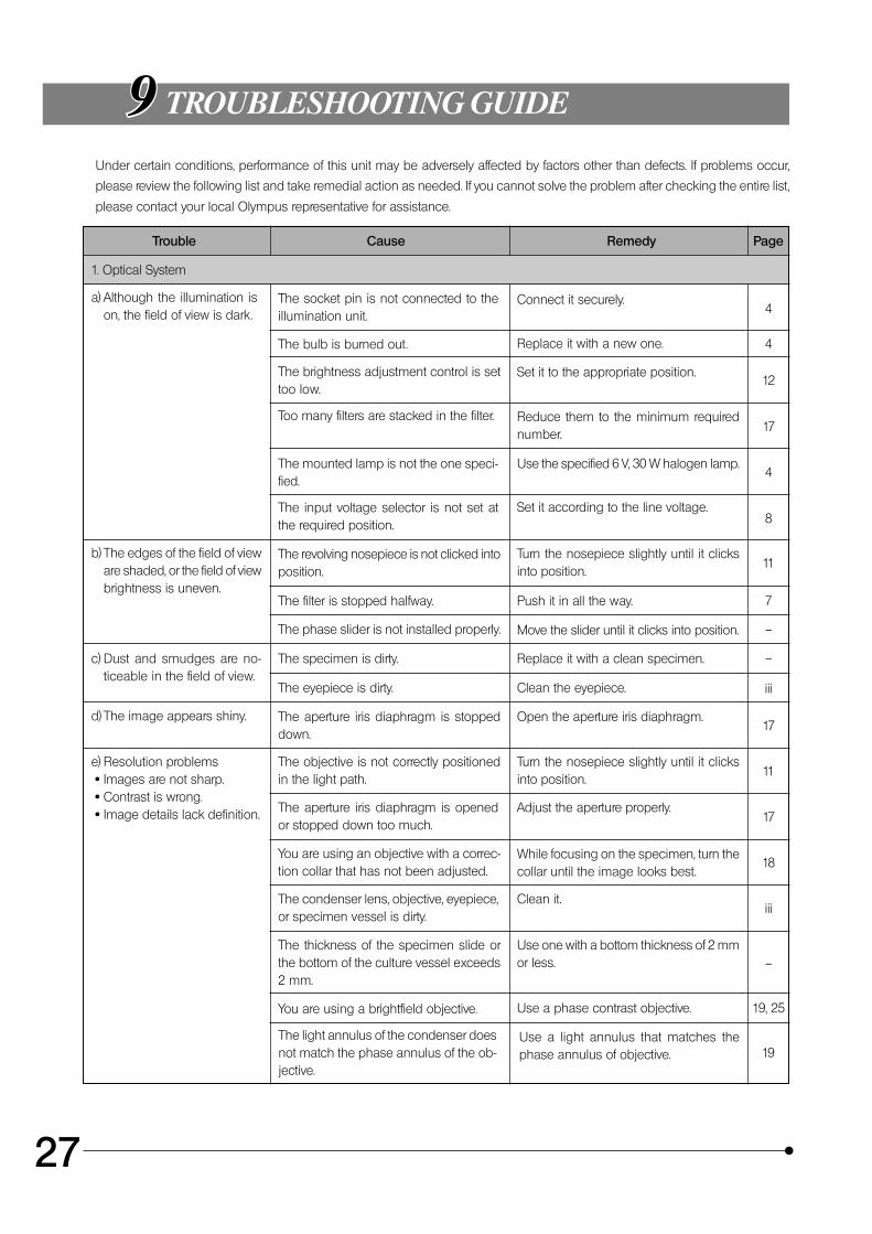
9 TROUBLESHOOTING GUIDE
Under certain conditions, performance of this unit may be adversely affected by factors other than defects. If problems occur,
please review the following list and take remedial action as needed. If you cannot solve the problem after checking the entire list,
please contact your local Olympus representative for assistance.
Trouble Cause Remedy Page
1. Optical System
a) Although the illumination ison, the field of view is dark.
The socket pin is not connected to theillumination unit.
Connect it securely.
The bulb is burned out. Replace it with a new one.
The brightness adjustment control is settoo low.
Set it to the appropriate position.
Too many filters are stacked in the filter. Reduce them to the minimum requirednumber.
The mounted lamp is not the one speci-fied.
Use the specified 6 V, 30 W halogen lamp.
The input voltage selector is not set atthe required position.
Set it according to the line voltage.
b) The edges of the field of vieware shaded, or the field of viewbrightness is uneven.
The revolving nosepiece is not clicked intoposition.
Turn the nosepiece slightly until it clicksinto position.
The filter is stopped halfway. Push it in all the way.
The phase slider is not installed properly. Move the slider until it clicks into position.
c) Dust and smudges are no-ticeable in the field of view.
The specimen is dirty. Replace it with a clean specimen.
The eyepiece is dirty. Clean the eyepiece.
d) The image appears shiny. The aperture iris diaphragm is stoppeddown.
Open the aperture iris diaphragm.
e) Resolution problems · Images are not sharp. · Contrast is wrong. · Image details lack definition.
The objective is not correctly positionedin the light path.
Turn the nosepiece slightly until it clicksinto position.
The aperture iris diaphragm is openedor stopped down too much.
Adjust the aperture properly.
You are using an objective with a correc-tion collar that has not been adjusted.
While focusing on the specimen, turn thecollar until the image looks best.
The condenser lens, objective, eyepiece,or specimen vessel is dirty.
Clean it.
The thickness of the specimen slide orthe bottom of the culture vessel exceeds2 mm.
Use one with a bottom thickness of 2 mmor less.
You are using a brightfield objective. Use a phase contrast objective.
The light annulus of the condenser doesnot match the phase annulus of the ob-jective.
Use a light annulus that matches thephase annulus of objective.
4
4
12
17
4
8
11
7
–
–
iii
17
11
17
18
iii
–
19, 25
19
CK30/CK40
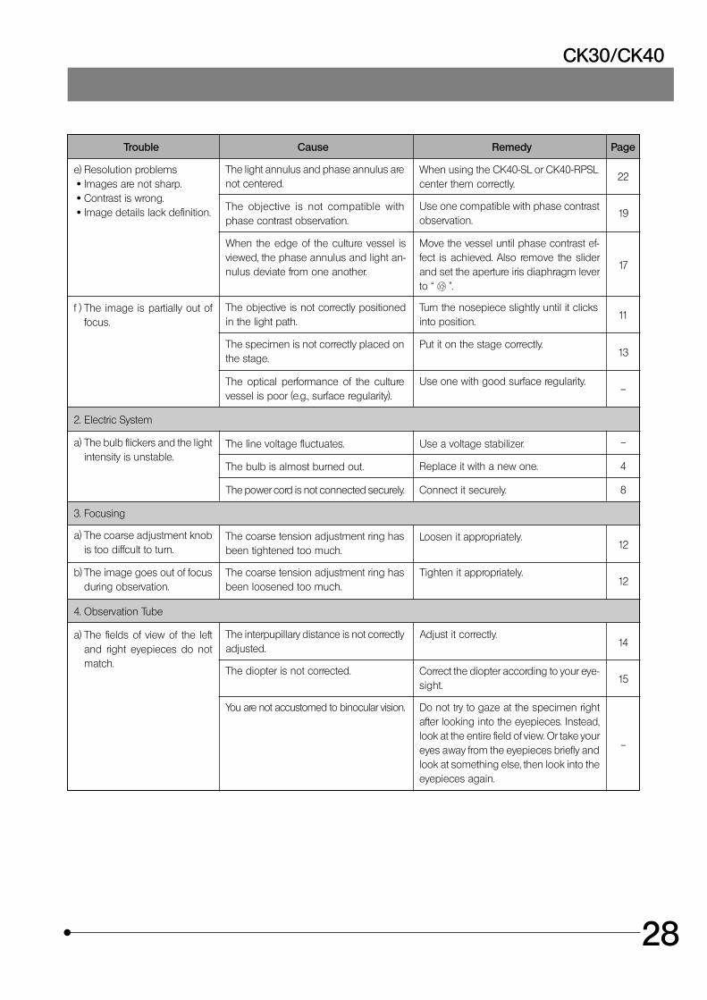
28
Trouble Cause Remedy Page
22
19
17
11
13
–
–
4
8
12
12
14
15
–
The light annulus and phase annulus arenot centered.
When using the CK40-SL or CK40-RPSLcenter them correctly.
The objective is not compatible withphase contrast observation.
Use one compatible with phase contrastobservation.
When the edge of the culture vessel isviewed, the phase annulus and light an-nulus deviate from one another.
Move the vessel until phase contrast ef-fect is achieved. Also remove the sliderand set the aperture iris diaphragm leverto “ ”.
e) Resolution problems · Images are not sharp. · Contrast is wrong. · Image details lack definition.
f ) The image is partially out offocus.
The objective is not correctly positionedin the light path.
Turn the nosepiece slightly until it clicksinto position.
The specimen is not correctly placed onthe stage.
Put it on the stage correctly.
The optical performance of the culturevessel is poor (e.g., surface regularity).
Use one with good surface regularity.
2. Electric System
a) The bulb flickers and the lightintensity is unstable.
The line voltage fluctuates. Use a voltage stabilizer.
The bulb is almost burned out. Replace it with a new one.
The power cord is not connected securely. Connect it securely.
3. Focusing
a) The coarse adjustment knobis too diffcult to turn.
The coarse tension adjustment ring hasbeen tightened too much.
Loosen it appropriately.
b) The image goes out of focusduring observation.
The coarse tension adjustment ring hasbeen loosened too much.
Tighten it appropriately.
4. Observation Tube
a) The fields of view of the leftand right eyepieces do notmatch.
The interpupillary distance is not correctlyadjusted.
Adjust it correctly.
The diopter is not corrected. Correct the diopter according to your eye-sight.
You are not accustomed to binocular vision. Do not try to gaze at the specimen rightafter looking into the eyepieces. Instead,look at the entire field of view. Or take youreyes away from the eyepieces briefly andlook at something else, then look into theeyepieces again.
29
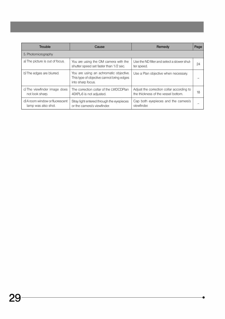
Trouble Cause Remedy Page
5. Photomicrography
a) The picture is out of focus. You are using the OM camera with theshutter speed set faster than 1/2 sec.
Use the ND filter and select a slower shut-ter speed.
b) The edges are blurred. You are using an achromatic objective.This type of objective cannot bring edgesinto sharp focus.
Use a Plan objective when necessary.
c) The viewfinder image doesnot look sharp.
The correction collar of the LWDCDPlan40XPL-6 is not adjusted.
Adjust the correction collar according tothe thickness of the vessel bottom.
d) A room window or fluorescentlamp was also shot.
Stray light entered through the eyepiecesor the camera’s viewfinder.
Cap both eyepieces and the camera’sviewfinder.
24
–
18
–
CK30/CK40
30
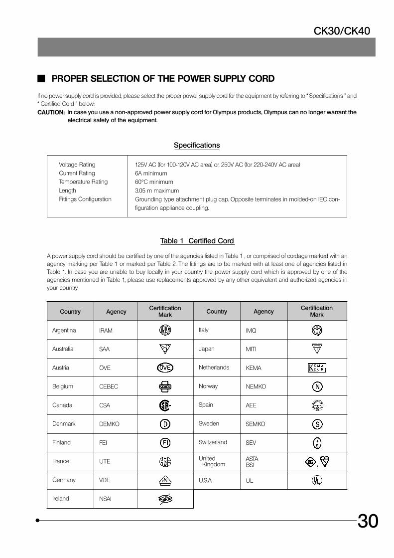
PROPER SELECTION OF THE POWER SUPPLY CORD
If no power supply cord is provided, please select the proper power supply cord for the equipment by referring to “ Specifications ” and“ Certified Cord ” below:CAUTION: In case you use a non-approved power supply cord for Olympus products, Olympus can no longer warrant the
electrical safety of the equipment.
Specifications
Voltage RatingCurrent RatingTemperature Rating
LengthFittings Configuration
125V AC (for 100-120V AC area) or, 250V AC (for 220-240V AC area)6A minimum60°C minimum
3.05 m maximumGrounding type attachment plug cap. Opposite terminates in molded-on IEC con-figuration appliance coupling.
Table 1 Certified Cord
A power supply cord should be certified by one of the agencies listed in Table 1 , or comprised of cordage marked with anagency marking per Table 1 or marked per Table 2. The fittings are to be marked with at least one of agencies listed inTable 1. In case you are unable to buy locally in your country the power supply cord which is approved by one of theagencies mentioned in Table 1, please use replacements approved by any other equivalent and authorized agencies inyour country.
Country Agency CertificationMark Country Agency Certification
Mark
Argentina
Australia
Austria
Belgium
Canada
Denmark
Finland
France
Germany
Ireland
IRAM
SAA
ÖVE
CEBEC
CSA
DEMKO
FEI
UTE
VDE
NSAI
Italy
Japan
Netherlands
Norway
Spain
Sweden
Switzerland
United Kingdom
U.S.A.
IMQ
MITI
KEMA
NEMKO
AEE
SEMKO
SEV
ASTABSI
UL
31
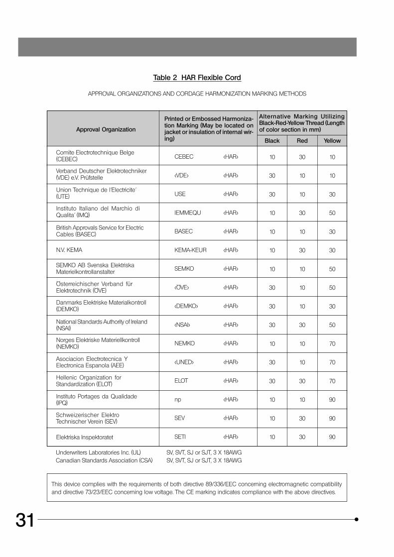
Table 2 HAR Flexible Cord
APPROVAL ORGANIZATIONS AND CORDAGE HARMONIZATION MARKING METHODS
Approval Organization
Printed or Embossed Harmoniza-tion Marking (May be located onjacket or insulation of internal wir-ing)
Alternative Marking UtilizingBlack-Red-Yellow Thread (Lengthof color section in mm)
Black Red Yellow
Comite Electrotechnique Belge(CEBEC)
Verband Deutscher Elektrotechniker(VDE) e.V. Prüfstelle
Union Technique de l´Electricite´(UTE)
Instituto Italiano del Marchio diQualita´ (IMQ)
British Approvals Service for ElectricCables (BASEC)
N.V. KEMA
SEMKO AB Svenska ElektriskaMaterielkontrollanstalter
Österreichischer Verband fürElektrotechnik (ÖVE)
Danmarks Elektriske Materialkontroll(DEMKO)
National Standards Authority of Ireland(NSAI)
Norges Elektriske Materiellkontroll(NEMKO)
Asociacion Electrotecnica YElectronica Espanola (AEE)
Hellenic Organization forStandardization (ELOT)
Instituto Portages da Qualidade(IPQ)
Schweizerischer ElektroTechnischer Verein (SEV)
Elektriska Inspektoratet
CEBEC <HAR>
<VDE> <HAR>
USE <HAR>
IEMMEQU <HAR>
BASEC <HAR>
KEMA-KEUR <HAR>
SEMKO <HAR>
<ÖVE> <HAR>
<DEMKO> <HAR>
<NSAI> <HAR>
NEMKO <HAR>
<UNED> <HAR>
ELOT <HAR>
np <HAR>
SEV <HAR>
SETI <HAR>
10 30 10
30 10 10
30 10 30
10 30 50
10 10 30
10 30 30
10 10 50
30 10 50
30 10 30
30 30 50
10 10 70
30 10 70
30 30 70
10 10 90
10 30 90
10 30 90
Underwriters Laboratories Inc. (UL) SV, SVT, SJ or SJT, 3 X 18AWGCanadian Standards Association (CSA) SV, SVT, SJ or SJT, 3 X 18AWG
This device complies with the requirements of both directive 89/336/EEC concerning electromagnetic compatibilityand directive 73/23/EEC concerning low voltage. The CE marking indicates compliance with the above directives.

MEMO

MEMO
This publication is printed on recycled paper.
Printed in Japan 2001 11 M 030–@
2-43-2,Hatagaya, Shibuya-ku, Tokyo, Japan
Postfach 10 49 08, 20034, Hamburg, Germany
2 Corporate Center Drive, Melville, NY 11747-3157, U.S.A.
491B River Valley Road, #12-01/04 Valley Point Office Tower, Singapore 248373
2-8 Honduras Street, London EC1Y OTX, United Kingdom.
104 Ferntree Gully Road, Oakleigh, Victoria, 3166, Australia