Embed Size (px)
Citation preview

RAPID RISK ANALYSIS
OF
PIPELINE EXPANSION PROJECT FROM NUMALIGARH TO SILIGURI
OIL INDIA LIMITED
(JULY 2004)

RAPID RISK ANALYSIS
OF
PIPELINE EXPANSION PROJECT FROM NUMALIGARH TO SILIGURI
0 19.07.2004 ISSUED AS FINAL A 22.06.2004 ISSUED AS DRAFT FOR COMMENTS SK KGM KGM
REV DATE REVISIONS BY CHECKED APPROVED
EIL-04-0441-4002 REV 0. A4 210 X 297
EIL DOC. NO: 2185 REV
LIMITED NEW DELHI
PIPELINE EXPANSION PROJECT FROM NUMALIGARH TO SILIGURI EIL JOB NO. 6487
Page 1 of 54 0
ENGINEERS INDIA RAPID RISK ANALYSIS OF

PREFACE Engineers India Limited, New Delhi was appointed by M/s Oil India Limited (OIL), for undertaking the Rapid Analysis Study of the Pipeline Expansion Project from Numaligarh to Siliguri and the associated Terminal facilities at Numaligarh & Siliguri. Qualified professionals having adequate industrial and design experience undertook the entire study. The study identifies the hazard and analyses the consequences of the credible and noncredible incidents.
EIL-04-0441-4002 REV 0. A4 210 X 297
EIL DOC. NO: 2185 REV
LIMITED NEW DELHI
PIPELINE EXPANSION PROJECT FROM NUMALIGARH TO SILIGURI EIL JOB NO. 6487
Page 2 of 54 0
ENGINEERS INDIA RAPID RISK ANALYSIS OF
The above study and recommendations are based on the information made available to EIL at the time of this study. EIL has exercised all reasonable skills, care and diligence in carrying out the study. However, this report is not deemed to be any undertaking, warrantee or certification.

TABLE OF CONTENTS
SECTION DESCRIPTION PAGE NO.
1.0 SUMMARY 5 1.1 INTRODUCTION 5
1.2 OBJECTIVE OF THE STUDY 5 1.3 PRINCIPAL CONCLUSIONS & RECOMMENDATIONS 6 2.0 FACILITIES DESCRITPION 9 2.1 INTRODUCTION 9 2.2 PROJECT FACILITIES 9 2.3 PIPELINE BATTERY LIMIT CONDITIONS 10 2.4 PIPELINE BASIC PARAMETERS 11
2.5 NEW PIPELINE PARAMETERS 11 2.6 EXISTING PIPELINE PARAMETERS 12
3.0 GENERAL 13 3.1 METEOROLOGICAL CONDITIONS 13
3.2 HAZARDS ASSOCIATED WITH HANDLING OF PETROLEUM PRODUCTS 15
4.0 RISK ANALYSIS 16 4.1 APPROACH TO THE STUDY 16 4.2 ACCEPTABILITY CRITERIA 16 4.3 SELECTED FAILURE SCENARIOS 19 4.4 ANALYSIS OF FAILURE FREQUENCIES 20
EIL-04-0441-4002 REV 0. A4 210 X 297
EIL DOC. NO: 2185 REV
LIMITED NEW DELHI
PIPELINE EXPANSION PROJECT FROM NUMALIGARH TO SILIGURI EIL JOB NO. 6487
Page 3 of 54 0
ENGINEERS INDIA RAPID RISK ANALYSIS OF

4.5 CONSEQUENCE ANALYSIS 23 4.5.1 NUMALIGARH DISPATCH TERMINAL 24 4.5.2 PIPELINE 31 4.5.3 SILIGURI RECEIPT TERMINAL 34 4.6 RISK ASSESSMENT 38 4.7 PRINCIPAL CONCLUSION & RECOMMENDATIONS 41
REFERENCES 46 GLOSSARY 47
ANNEXURE-I METEOROLOGICAL TABLES 48 ANNEXURE-II LAYOUTS 55
EIL-04-0441-4002 REV 0. A4 210 X 297
EIL DOC. NO: 2185 REV
LIMITED NEW DELHI
PIPELINE EXPANSION PROJECT FROM NUMALIGARH TO SILIGURI EIL JOB NO. 6487
Page 4 of 54 0
ENGINEERS INDIA RAPID RISK ANALYSIS OF

SECTION-1.0
SUMMARY 1.1 INTRODUCTION
M/s. Oil India Limited (OIL) and Numaligarh Refineries Ltd (NRL) propose a pipeline expansion project from Numaligarh to Siliguri to evacuate the product (viz; MS, SKO and HSD) of NRL and establish terminal facilities at Numaligarh and Siliguri. The pipeline & pump station will be constructed by OIL and NRL will construct the terminals. M/s. OIL have engaged M/s. Engineers India Ltd. to carry out Rapid Risk Analysis study of the pipeline expansion project from Numaligarh to Siliguri including terminals. The study involved selection of probable failure scenarios, carrying out consequence analysis of selected scenarios, determination of hazard distances and suggestions on mitigating methods.
1.2 OBJECTIVE OF THE STUDY
The principal objective of the study is to identify the potential hazards from the product pipeline facilities and estimate the effects. The consequences resulting due to accidental release of hydrocarbons will provide data for developing strategies for prevention of accidents right from design to operational phase.
EIL-04-0441-4002 REV 0. A4 210 X 297
EIL DOC. NO: 2185 REV
LIMITED NEW DELHI
PIPELINE EXPANSION PROJECT FROM NUMALIGARH TO SILIGURI EIL JOB NO. 6487
Page 5 of 54 0
ENGINEERS INDIA RAPID RISK ANALYSIS OF
1.3 PRINCIPAL CONCLUSIONS AND RECOMMENDATIONS
Risk Analysis of the proposed Pipeline Expansion Project from Numaligarh to Siliguri is carried out with the objective to identify the potential hazards from the pipeline and Terminal facilities. Certain important conclusions and recommendation arising out of the study are mentioned below. The relevant sections should be referred to for detailed discussion of items of interest. 1. Hazard distances due to credible scenario like gasket failure at the Numaligarh
despatch terminal and Siliguri Receipt terminal is confined to the terminal boundary. Thermal radiation intensity due to Jet fire is confined to the terminal process area only. Thermal radiation intensity of 12.5 kw/m2 is confined to the small area and does not reach control room. Thermal radiation intensity of 8 kw/m2 and 5 kw/m2 is also confined to the small area. Any person meeting this failure scenario shall be able to get away from the zone in short duration.
2. Hazard distances due to small hole leaks are also confined to the terminal area
and does not cross the terminal boundary in Numaligarh Despatch terminal and Siliguri Receipt terminal. Hazard distances pertaining to thermal radiation intensity of 12.5, 8 and 5 kw/m2 due to jet fire and pool fire in Numaligarh Despatch terminal and Siliguri Receipt terminal due to leakage through small hole is confined to process area only and does not cover any control room or building. To prevent hazards like flash fire, it is recommended that the terminal should be a made a well-guarded area and activities like smoking should not be allowed.
3. The individual risk for the 16” diameter multiproduct pipeline is gradually
reducing with distance from the center of the pipeline on either side. The individual risk value for the pipeline is less than 1x10⁻⁶/yr from the pipeline centre. The UK Health and Safety Executive (HSE) suggests that an individual risk criteria of 10-6/year (lower limit) is trivial for average populations (reference: Major hazards Onshore and Offshore, published by The institution of Chemical Engineers, Symposium series no.130)
4. It is recommended to install gas detectors to detect seal leaks, provide automatic
water sprinklers and remote stopping of booster pumps and mainline pumps at Numaligarh Despatch terminal. It is recommended to do regular preventive maintenance of gas detectors to enable to raise alarm and facilitate quick attendance to leaks detected.
5. The proposed pipeline shall be laid in the same ROW of existing crude oil
pipeline presently under operation. OISD 141 recommends a separation distance of 5 meters but not less than 3 meters between two buried pipelines. It is suggested that guideline provided in OISD-141 should be adopted.
6. Leak detections system is envisaged for the pipeline to detect leaks. Action can
then be initiated to stop pumping and isolate the affected section by closing the sectionalising valves.
EIL-04-0441-4002 REV 0. A4 210 X 297
EIL DOC. NO: 2185 REV
LIMITED NEW DELHI
PIPELINE EXPANSION PROJECT FROM NUMALIGARH TO SILIGURI EIL JOB NO. 6487
Page 6 of 54 0
ENGINEERS INDIA RAPID RISK ANALYSIS OF
7. It is recommended that habitation should be discouraged adjacent to the pipeline. Most incidents affecting the pipeline are noticed early by the community residing

nearby the pipeline. OIL should make efforts to educate the community living nearby to report the pipeline incidents to the master control center. Suitable communication links to be ensured for such this purpose.
8. A Majority of pipeline incidents is caused by external interference. This external
interference is a result of digging, drilling etc. in the vicinity of the pipeline. Frequent patrolling and pipeline inspection will enable to detect activities near or at the pipeline as early as possible. The following measures are suggested for reducing the risk involved in pipeline systems.
Line patrolling: Line patrolling is a visual inspection of the pipeline along its entire route, some of the important aspects to be checked during patrolling are: - General condition of the pipeline, wherever it is above ground. - Any breaches and soil erosion along the route of the pipeline especially earth
wash out at the road and channel crossing.
- Vegetation to be controlled to the extent of ensuring free movement of vehicles to tackle any incident.
- Condition of warning signs, road and channel crossing markers and mile post
markers.
- If there is any digging, ploughing and dredging etc. in the vicinity of the pipeline which may result in damage to the pipeline due to mechanical interference.
- General condition of the cathodic protection station.
- Any leakage, wet patches, smell etc.
Preventive Maintenance: Routine inspection and preventive maintenance of equipment/facilities at terminal stations. Instruments: All the instruments like pressure, temperature transmitters/ gauges and alarms switches and safety interlocks should be tested for their intended application as per the preventive maintenance schedule. Similarly, the emergency shutdown system should be tested as per the preventive maintenance schedule.
EIL-04-0441-4002 REV 0. A4 210 X 297
EIL DOC. NO: 2185 REV
LIMITED NEW DELHI
PIPELINE EXPANSION PROJECT FROM NUMALIGARH TO SILIGURI EIL JOB NO. 6487
Page 7 of 54 0
ENGINEERS INDIA RAPID RISK ANALYSIS OF

Cathodic Protection: The most important measures to protect the pipeline from corrosion are: - Cathodic protection. - External inspection of coating on a regular basis. - Internal inspection of pipeline by intelligent pigging. Maintenance of adequate cathodic protection is the most important single item in preventive maintenance of pipelines.
EIL-04-0441-4002 REV 0. A4 210 X 297
EIL DOC. NO: 2185 REV
LIMITED NEW DELHI
PIPELINE EXPANSION PROJECT FROM NUMALIGARH TO SILIGURI EIL JOB NO. 6487
Page 8 of 54 0
ENGINEERS INDIA RAPID RISK ANALYSIS OF

SECTION – 2
FACILITIES DESCRIPTION
2.1 INTRODUCTION
Oil India Ltd (OIL) and Numaligarh Refineries Ltd (NRL) propose a pipeline expansion project from Numaligarh to Siliguri to transfer the products (viz. MS, SKO and HSD) of NRL and establish terminal facilities at Numaligarh and Siliguri. The pipeline and pump station will be constructed by OIL, and NRL will construct the terminals. This pipeline shall have a throughput of 1.72 million metric tons per annum (MMTPA)
2.2 PROJECT FACILITIES
The pipeline length from Numaligarh to Siliguri will be about 660 KM and shall be laid parallel to OIL’s existing crude oil pipeline in the same existing ROW (Right of way). As per OISD 141, a separation distance of 5m but not less than 3m between two buried pipeline shall be maintained. M/s OIL intends to use the existing 16” dia loop line of approx. 212 Km and 16” dia 47 Km pipeline section between two repeater stations in Assam, as a part of the proposed pipeline. Thus, the length of the new pipeline (16” dia) to be constructed will be 401 Km (197 Km in Assam and 204 Km in West Bengal). Refer the picture on next page for more details. The pipeline shall be of carbon steel material and shall conform to API specification 5L. The pipeline shall be provided with external corrosion coating, Cathodic Protection System, corrosion inhibitor dozing and corrosion monitoring system.
EIL-04-0441-4002 REV 0. A4 210 X 297
EIL DOC. NO: 2185 REV
LIMITED NEW DELHI
PIPELINE EXPANSION PROJECT FROM NUMALIGARH TO SILIGURI EIL JOB NO. 6487
Page 9 of 54 0
ENGINEERS INDIA RAPID RISK ANALYSIS OF

For a reliable health check and operational control of the system including leak detection, a SCADA & APPS system shall be provided.
OIL shall be providing an optical fiber cable based Telecommunication System for the pipeline. This network shall be available for the SCADA and APPS requirement of the pipeline. In addition to the pipeline, following pipeline terminals and intermediate stations shall be provided: - Dispatch Terminal at Numaligarh comprising of piping manifolds, mainline and
booster pumps, filters, meters, scraper launcher, control building, substation, administrative building and other utilities.
- Receipt terminal at Siliguri comprising of scraper Receiver, Filters, Meters, control building, substation, administrative building and other utilities.
- Intermediate Pigging stations at Sekoni, Noonmati, Bongaigaon and Madarihat comprising of Scraper Launcher & Receiver, Filters, Meters, control building etc.
- Sectionalising valve stations and CP stations.
Figure:- Picture showing the route map of the proposed pipeline to be in the existing ROW of OIL pipelines.
2.3 PIPELINE BATTERY LIMIT CONDITIONS
EIL-04-0441-4002 REV 0. A4 210 X 297
EIL DOC. NO: 2185 REV
LIMITED NEW DELHI
PIPELINE EXPANSION PROJECT FROM NUMALIGARH TO SILIGURI EIL JOB NO. 6487
Page 10 of 54 0
ENGINEERS INDIA RAPID RISK ANALYSIS OF
Upstream - Pressure : from atmospheric storage tank - Temperature : 35°C
Downstream - Pressure : 2.5 kg/cm²g - Temperature : subsoil

2.4 PIPELINE BASIC PARAMETERS
1 Products to be transported (1) MS (2) SKO (3) HSD
2 Design Throughput, MMTPA MS 0.135 SKO 0.219 HSD 1.367 TOTAL 1.721
3 Design codes ASME B31.4 and OISD-141 will be followed as applicable.
4 Design capacity of pumps Pumps will be specified for 10% extra flow (265 x 1.1 m3/hr).
5 Sparing philosophy for pumps 100% for Single pump (1W+1S) for product transfer pumps and corrosion inhibitor pumps Nil for sump pump and slop transfer pumps
6 Type of pump driver Electric motor driven pumps 7 Valve actuation Electric motor
2.5 NEW PIPELINE PARAMETERS
1 Operating Hours 8000 Hrs/Annum 2 Pipeline operating life 35 Years 3 Total Pipeline Length 660 kms 4 Pipeline Diameter 16” 5 Pipeline roughness 45 microns 6 Material of Construction for
Pipeline Carbon Steel
7 Pipeline Corrosion Allowance 0.5 mm 8 Pigging Facilities Permanent Pigging facilities suitable
for “Intelligent Pigs” shall be provided at suitable distances.
9 Subsoil temperature (1m below ground)
25°C throughout the entire length of the pipeline.
10 Design Pressure & Temperature 84kg/cm²g 65°C, above ground 45°C, buried potion
11 Surge control Suitable surge control/surge relief system will be provided as per requirement. The surge analysis will be done during detailed engineering.
12 Pipeline laying Buried 13 Pipeline corrosion protection
system For external corrosion protection, suitable coating shall be provided.
EIL-04-0441-4002 REV 0. A4 210 X 297
EIL DOC. NO: 2185 REV
LIMITED NEW DELHI
PIPELINE EXPANSION PROJECT FROM NUMALIGARH TO SILIGURI EIL JOB NO. 6487
Page 11 of 54 0
ENGINEERS INDIA RAPID RISK ANALYSIS OF

Further, impressed current cathodic protection system will be provided for the total pipeline. Internal corrosion protection shall be provided through injection of corrosion inhibitor.
14 Corrosion Monitoring System Corrosion monitoring system will be provided as required.
2.6 EXISTING PIPELINE PARAMETERS
1 Existing Pipeline Length 259 kms (total) 2 Pipeline Diameter 16” 3 Pipeline roughness 45 microns (used for hydraulic
calculation purpose) 5 Pipeline thickness 7.9 mm 6 Pipeline Corrosion Allowance 0.5 mm (for design pressure
calculation) 7 Design Pressure & Temperature 84.8 kg/cm²g
65°C, above ground 45°C, buried portion
EIL-04-0441-4002 REV 0. A4 210 X 297
EIL DOC. NO: 2185 REV
LIMITED NEW DELHI
PIPELINE EXPANSION PROJECT FROM NUMALIGARH TO SILIGURI EIL JOB NO. 6487
Page 12 of 54 0
ENGINEERS INDIA RAPID RISK ANALYSIS OF

SECTION – 3
GENERAL 3.1 METEOROLOGICAL CONDITIONS
Meteorological data required for the risk analysis study are taken from the Climatological Tables of Observatories in India (1931-1960), of Golaghat for Numaligarh Despatch Station, Guwahati (Bhorjar) for the pipeline and Jalpaiguri for Siliguri receipt terminal as published by Indian meteorological Department (Ref. Annexure I). One of the important characteristics of atmosphere is its stability i.e. its tendency to resist vertical motion or to suppress existing turbulence. This tendency directly influences the ability of atmosphere to disperse pollutants emitted into it from the facilities. Variation in both thermal and mechanical turbulence and in wind velocity is greatest in the layer in contact with the surface. Turbulence, induced by buoyancy forces in the atmosphere, is closely related to the vertical temperature structure. Temperature normally decreases with increasing height in the atmosphere. The rate at which the temperature of air decreases with height is called Environment Lapse Rate (ELR). It will vary from time to time and from place to place. The atmosphere is said to be stable, neutral or unstable according to ELR is less than, equal to or greater than Dry Adiabatic Lapse Rate (DALR), which is a constant value of 0.98°C per 100 metres. Pasquill has defined six stability classes, as indicated in table 2.2, ranging from ‘A’ (Extremely unstable), to ‘F’ (Moderately stable). Surface wind, intensity of solar radiation (daytime insolation) and night time sky cover has been identified as prime factors defining these stability categories.
EIL-04-0441-4002 REV 0. A4 210 X 297
EIL DOC. NO: 2185 REV
LIMITED NEW DELHI
PIPELINE EXPANSION PROJECT FROM NUMALIGARH TO SILIGURI EIL JOB NO. 6487
Page 13 of 54 0
ENGINEERS INDIA RAPID RISK ANALYSIS OF

When the atmosphere is unstable and wind speeds are moderate or high or gusty, rapid dispersion of pollutants will occur. Under these conditions, air concentrations will be moderate or low and the material will be dispersed rapidly. When the atmosphere is stable and wind speed is low, dispersion of material will be limited and air concentration will be high. Analysis of the climatological tables reveals that 1. At Numaligarh Despatch terminal the wind blows predominantly at the average speed
of 1m/s for 90% time of the year. 10% being 2 m/s and above. The wind blows from NW and SE direction at 26% of the time each. 20 % of the time it blows from NE direction and rest of the time it blows from other directions.
2. For pipeline, the weather at Guwahati was studied. It reveals that the wind blows predominantly at the average speed of 1m/s for 54% time of the year. 45% being 2m/s and 1% is 3m/s. The wind blows predominantly from NE direction.
3. At Siliguri receipt terminal it is found that the wind blows predominantly at the average speed of 1m/s for 43% time of the year. 38% being 2m/s and 21% is 3m/s. The wind blows predominantly from East direction.
4. All the three stations have average ambient temperature as 25°C. Therefore this temperature has been used for the study.
5. All the three stations have average relative humidity of 75%. Therefore this relative humidity has been used for the study.
Extremely stable weather category (Pasquill stability 'F’) at wind speed 1 m/s and 2 m/s and neutral category (Pasquill stability `D’) at wind speed 3 m/s have been considered for the risk analysis study. However, for pictorial depiction and analysis of the results the most predominant weather category of 1F has been selected.
TABLE-2.2
PASQUILL STABILITY CLASSES
Day Time Insolation Night Time Insolation Surface Wind Speed (Meter/Sec
Strong Moderate Slight Thin Overcast or >4/8 Low cloud
< 3/8 Cloudiness
< 2 A A – B B E F 2 – 3 A – B B C E F 3 – 5 B B – C C D E 5 – 6 C C – D D D D > 6 C D D D D
A - Extremely unstable D - Neutral B - Moderately unstable E - Slightly stable C - Slightly unstable F - Moderately stable
EIL-04-0441-4002 REV 0. A4 210 X 297
EIL DOC. NO: 2185 REV
LIMITED NEW DELHI
PIPELINE EXPANSION PROJECT FROM NUMALIGARH TO SILIGURI EIL JOB NO. 6487
Page 14 of 54 0
ENGINEERS INDIA RAPID RISK ANALYSIS OF

3.2 HAZARDS ASSOCIATED WITH HANDLING OF PETROLEUM PRODUCTS The petroleum products being handled are: • MS • SKO • HSD The above petroleum products are flammable in nature. Some of the above products viz. MS exhibit a tendency to evaporate. The rate and extent of evaporation is determined primarily by the volatility of the oil. The initial spreading rate of the oil also affects evaporation since larger the surface area, the faster the lighter components would evaporate. In contrast, the other products undergo relatively lesser evaporation. Hazards of flash fire occur if there is a spillage of hydrocarbon liquids, which generates sufficient vapours to reach an ignition source. Volatile oils such as MS are prone to generate enough vapour to cause a flash fire. These vapours will then travel with the wind till it encounters an ignition source (which would then result in a flash fire) or till it is safely dispersed below its Lower Flammability Limit (LFL). Any person caught in the flash fire is likely to suffer fatal burn injury. The distance to LFL is usually taken to indicate the area, which may be affected by flash fire, and this distance is determined by the vapour release rate and the dispersion characteristics of the released vapour at the prevailing atmospheric conditions. The other hazard associated with release of all of the above petroleum products is thermal radiation hazard due to ignition of the pool formed in the event of release and liquid accumulation. The flame from a pool fire is influenced by the wind speed and the direction of wind. Due to wind, the flame is blown to the periphery of the pool and is also tilted in the wind direction. Thus, more area is affected in the direction of wind than in the opposite direction. The other hazard associated with release of all of the above petroleum products is Jet fire when released at high pressure. Thermal radiation hazards due to jet fire are influenced by the wind speed and the direction of wind.
EIL-04-0441-4002 REV 0. A4 210 X 297
EIL DOC. NO: 2185 REV
LIMITED NEW DELHI
PIPELINE EXPANSION PROJECT FROM NUMALIGARH TO SILIGURI EIL JOB NO. 6487
Page 15 of 54 0
ENGINEERS INDIA RAPID RISK ANALYSIS OF

SECTION – 4
RISK ANALYSIS
4.1 APPROACH TO THE STUDY
The facilities under the scope of this study include the pipeline from Numaligarh despatch station to Siliguri receipt station and facilities related to terminals at Numaligarh and Siliguri. The hazard posed by these facilities and the pipeline is mainly in the form of fire in the event of hydrocarbon release. The chances of explosion are rather remote and hence not considered. However, there is a possibility of flash fire taking place in the event of large spill of hydrocarbons.
4.2 DAMAGE CRITERIA
The products handled in pipeline project are MS, SKO and HSD. These products are flammable in nature. These products would form a liquid pool, on its release to atmosphere from a pressurized source. MS is more volatile in nature as compared to SKO & HSD and would vaporize when released to atmosphere. The vapourisation rate, and consequently, the hazard distances would significantly reduce with passage of time due to cooling effects. FLASH FIRE:
EIL-04-0441-4002 REV 0. A4 210 X 297
EIL DOC. NO: 2185 REV
LIMITED NEW DELHI
PIPELINE EXPANSION PROJECT FROM NUMALIGARH TO SILIGURI EIL JOB NO. 6487
Page 16 of 54 0
ENGINEERS INDIA RAPID RISK ANALYSIS OF
Hydrocarbon vapour released accidentally will normally spread out in the direction of wind. If it finds an ignition source before being dispersed below lower flammability limit (LFL), a flash fire is likely to occur and the flame may travel back to the source of leak. For the present study, such a scenario could occur if there is a large spill from the pipeline; the vapour that is produced by evaporation from this spill is carried by wind and if ignited by a source of ignition available in the flow path. Any person caught in the flash fire is likely to suffer fatal burn injury. Therefore, in consequence analysis, the

distance of LFL value is usually taken to indicate the area, which may be affected by the flash fire. Any other combustible material within flash fire is also likely to catch fire and a secondary fire may ensue. In the area close to source of hydrocarbon leak there is possibility of oxygen depletion. For human lives, a minimum of 16% oxygen in air is considered essential. JET FIRE Accidental release of MS from a high pressure source shall result in a turbulent jet. If ignited, this would form a jet flame. Such flame impingement causes structural weakness and in turn can cause extensive damage and failure. Thermal radiation due to jet fire can pose potential radiation hazard. POOL FIRE Ignition of the pool formed due to release of liquid hydrocarbons would result in a pool fire with associated thermal radiation hazards. The flame from a pool fire is influenced by the wind speed and the direction of wind. Due to wind, the flame is blown to the periphery of the pool and is also tilted in the wind direction. Thus, more area is affected in the direction of wind than in the opposite direction. Thermal radiation due to pool fire may cause varied degrees of burns on human bodies. Study of the effects of thermal radiation on plant equipment and buildings may also assume importance in critical cases. The Institute of Petroleum has in its publication on Model code of safe practice (Volume –I, Part 9), provided the limits of sustained thermal radiation flux that could be subjected on facilities surrounding the source of thermal radiation. This is provided in Table – 4.1. The criteria is applicable to thermal radiation levels subjected on targets due to sustained fires such as that from storage tanks storing flammable hydrocarbons. BLAST OVERPRESSURE MS vapour may explode if ignited in enclosed area (reference: Hazardous chemicals data book, G.Weiss, Noyes Data Corporation). The facilities within the terminals and the pipeline route are open and the degree of confinement is low. There is no area in the open tract within which the released vapor mass could be confined. The open area would also promote rapid dispersion of the released vapor. Hence, the possibility of an explosion due to release of hydrocarbons from the facilities is remote.
EIL-04-0441-4002 REV 0. A4 210 X 297
EIL DOC. NO: 2185 REV
LIMITED NEW DELHI
PIPELINE EXPANSION PROJECT FROM NUMALIGARH TO SILIGURI EIL JOB NO. 6487
Page 17 of 54 0
ENGINEERS INDIA RAPID RISK ANALYSIS OF

TABLE – 4.1
Limits of thermal radiation flux on surrounding facilities
Site Incident Radiation intensity (kw/m2)
Equipment
The outer surfaces of adjacent pressure storage vessels • Thermally protected (1) • Unprotected (2)
44 8
Equipment
The outer surfaces of adjacent storage tanks containingflammable products and process facilities • Thermally protected (1) • Unprotected (2)
32 8
Filling / discharge points 8
Personnel inside boundary
• Process area (3) • Protected work area (4) • Work area (5)
8 8 5
Plant boundary
• Remote area (6) • Urban area (7) • Critical area (8)
13 5 1.5
Notes: 1. Such facilities / areas are protected by means of water sprays, insulation, radiation
screens or similar systems.
2. Protection is provided by spacing alone.
3. A normally unoccupied area occasionally manned by trained and suitably clothed persons familiar both with escape routes and opportunities for temporary shelter afforded by the process plant.
4. A permanent building where personnel inside are shielded and/or have shielded means of escape.
5. An open area or small (e.g. temporary) building without shielded means of escape.
6. An area only infrequently occupied by small numbers or persons, e.g. moor land, farmland, desert.
7. An area, which is neither a remote area nor a critical area.
8. This is either an unshielded area of critical importance where people without protective clothing may be required at all times including emergencies or a place difficult or dangerous to evacuate at short notice (e.g. a sports stadium).
EIL-04-0441-4002 REV 0. A4 210 X 297
EIL DOC. NO: 2185 REV
LIMITED NEW DELHI
PIPELINE EXPANSION PROJECT FROM NUMALIGARH TO SILIGURI EIL JOB NO. 6487
Page 18 of 54 0
ENGINEERS INDIA RAPID RISK ANALYSIS OF
For fires with shorter durations, such as that due to instrument tapping failures, the following additional damage criteria provided in Table – 4.2 would be applicable.
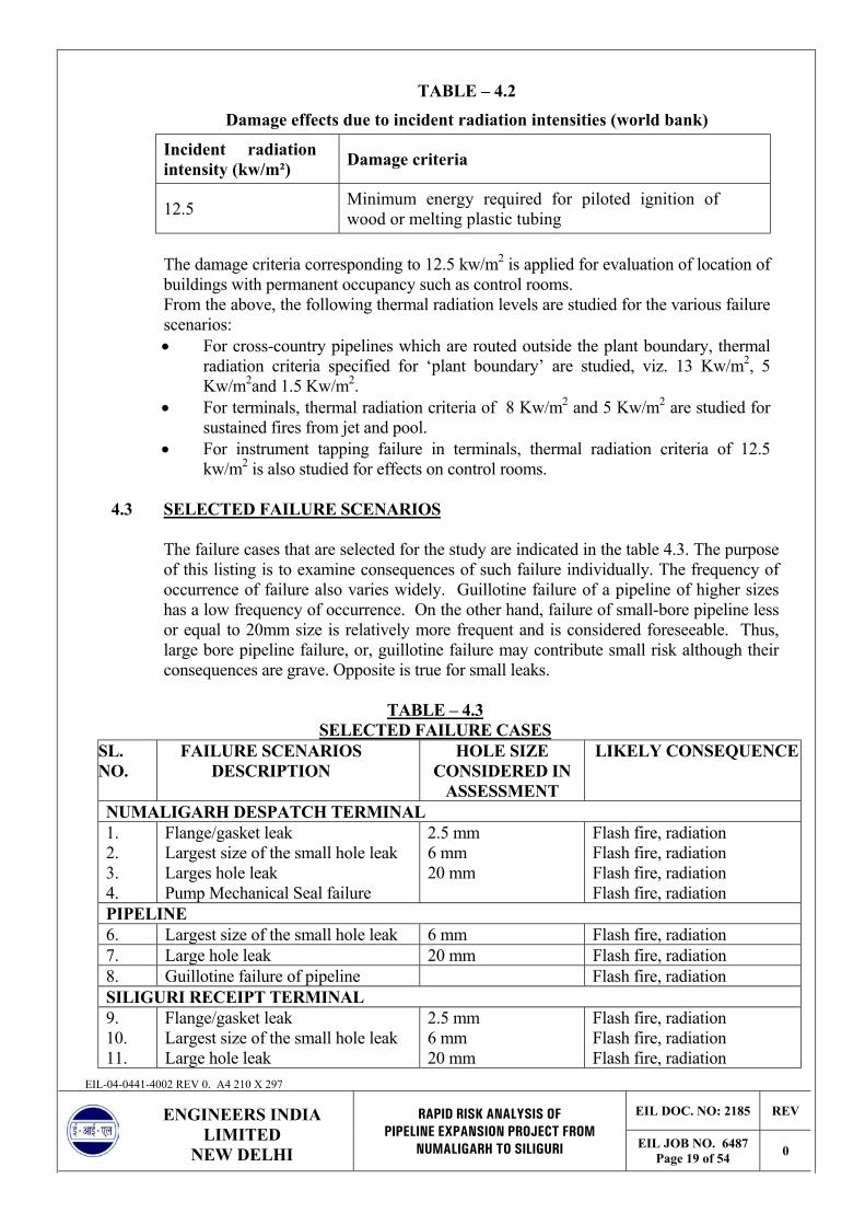
TABLE – 4.2
Damage effects due to incident radiation intensities (world bank)
Incident radiation intensity (kw/m²) Damage criteria
12.5 Minimum energy required for piloted ignition of wood or melting plastic tubing
The damage criteria corresponding to 12.5 kw/m2 is applied for evaluation of location of buildings with permanent occupancy such as control rooms. From the above, the following thermal radiation levels are studied for the various failure scenarios: • For cross-country pipelines which are routed outside the plant boundary, thermal
radiation criteria specified for ‘plant boundary’ are studied, viz. 13 Kw/m2, 5 Kw/m2and 1.5 Kw/m2.
• For terminals, thermal radiation criteria of 8 Kw/m2 and 5 Kw/m2 are studied for sustained fires from jet and pool.
• For instrument tapping failure in terminals, thermal radiation criteria of 12.5 kw/m2 is also studied for effects on control rooms.
4.3 SELECTED FAILURE SCENARIOS
The failure cases that are selected for the study are indicated in the table 4.3. The purpose of this listing is to examine consequences of such failure individually. The frequency of occurrence of failure also varies widely. Guillotine failure of a pipeline of higher sizes has a low frequency of occurrence. On the other hand, failure of small-bore pipeline less or equal to 20mm size is relatively more frequent and is considered foreseeable. Thus, large bore pipeline failure, or, guillotine failure may contribute small risk although their consequences are grave. Opposite is true for small leaks.
TABLE – 4.3
SELECTED FAILURE CASES
EIL-04-0441-4002 REV 0. A4 210 X 297
EIL DOC. NO: 2185 REV
LIMITED NEW DELHI
PIPELINE EXPANSION PROJECT FROM NUMALIGARH TO SILIGURI EIL JOB NO. 6487
Page 19 of 54 0
ENGINEERS INDIA RAPID RISK ANALYSIS OF
SL. NO.
FAILURE SCENARIOS DESCRIPTION
HOLE SIZE CONSIDERED IN
ASSESSMENT
LIKELY CONSEQUENCE
NUMALIGARH DESPATCH TERMINAL 1. 2. 3. 4.
Flange/gasket leak Largest size of the small hole leak Larges hole leak Pump Mechanical Seal failure
2.5 mm 6 mm 20 mm
Flash fire, radiation Flash fire, radiation Flash fire, radiation Flash fire, radiation
PIPELINE 6. Largest size of the small hole leak 6 mm Flash fire, radiation 7. Large hole leak 20 mm Flash fire, radiation 8. Guillotine failure of pipeline Flash fire, radiation SILIGURI RECEIPT TERMINAL 9. 10. 11.
Flange/gasket leak Largest size of the small hole leak Large hole leak
2.5 mm 6 mm 20 mm
Flash fire, radiation Flash fire, radiation Flash fire, radiation

CONSIDERATIONS • Liquids pumped in the pipelines are incompressible fluids. Hence, the estimated
leak rate through the leak would increase with the leak area and the pumping pressure till the pumping rate. Thereafter, the pumping rate would govern.
• Reference-2 quoted in Section-4.4 provides statistics of detection of product loss incidents by equivalent hole diameter. It is observed that a great proportion of small leaks (corresponding to 6 mm hole in the present study) are detected mostly by physical observation.
• Large leaks (20 mm) result in fairly high release rates, which can be detected by a leak detection system. A leak detection system is considered for the pipelines under this project. Conservative release duration of 15 minutes is considered as duration of leak wherein the leak is detected, pumps are stopped and leaky section is isolated by means of closing the respective SVs. With the implementation of the above actions, the residual liquid would flow out into the surroundings based on the liquid head contributed by the ground profile. From pipeline where the terrain is flat, the residual liquid is expected to be released at a very slow rate once the affected pipeline section is isolated.
4.4 ANALYSIS OF FAILURE FREQUENCIES Pipework, Gasket and Centrigugal Pump Seal Leak Failure Frequency Pipework Failure Frequencies
LEAK FREQUENCY (PER M YEAR) BY PIPE DIAMETER in MM HOLESIZE 25 50 100 300
Full Bore 10-6 10-6 3x10⁻⁷ 10-7
10% CSA* 10-5 10-5 6x10⁻⁶ 3x10⁻⁶
1% CSA 10-4 10-4 3x10⁻⁵ 10-5 Gasket Failure Frequencies Adjacent Bolt section leak 1x10⁻⁴/year Centrifugal Pump Seal Leak Gland/Seal failure 0.9/year
*Cross Sectional Area The source of the above listed failure frequencies is Cox, A.W, Lees, F.P and Ang, M.L, Classification of Hazardous Locations, IchemE, 1990. Pipeline Failure Frequency
EIL-04-0441-4002 REV 0. A4 210 X 297
EIL DOC. NO: 2185 REV
LIMITED NEW DELHI
PIPELINE EXPANSION PROJECT FROM NUMALIGARH TO SILIGURI EIL JOB NO. 6487
Page 20 of 54 0
ENGINEERS INDIA RAPID RISK ANALYSIS OF
The failure frequencies provided in the following reference literature have been utilized as inputs for the risk assessment study.

1. Performance of European cross-country oil pipelines; • Statistical summary of reported spillages – 1999 (Report no.3/00) • Statistical summary of reported spillages – 2000 (Report no.4/01) • Statistical summary of reported spillages – 2001 (Report no.1/03)
prepared by the CONCAWE oil pipelines Management Group’s special Task force on oil pipeline spillages.
2. Report on UKOPA pipeline fault database on pipeline product loss incidents (Advantica Report no.R 4798), published in the year 2002.
3. Loss Prevention in the Process Industries, Hazard Identification, Assessment and Control, Frank.P.Lees, 2nd Edition, Published by Butterworth-Heinemann, U.K.
4. Classification of Hazardous Locations, A.W.Cox, F.P.Lees and M.L.Ang, Published by the Institution of Chemical Engineers, U.K.
Underground pipelines
Reference (1) above provides data (by cause) relating to number of incidents for underground cross-country oil pipelines for the corresponding five-year periods. Data is therefore available for years 1995 through 2001. Extracts of this data are provided in Table-4.4 below.
Table-4.4
Incident data 1995 1996 1997 1998 1999 2000 2001 1995-2001 Combined length
(km x 103) 30.6 30.2 30.8 30.0 29.9 30.8 35.6 217.9
Number of incidents Mechanical failure Construction Material
2 2
- -
- 1
- -
- 1
- 1
2 3
4 8
Operational System Human
- 1
- -
- 2
- 1
- 1
- -
- -
- 5
Corrosion External Internal
1 -
3 1
1 -
4 -
1 -
- 1
2 1
12 3
Natural Hazard Subsidence Flooding Others
- - -
- - -
- - -
- - -
- - -
- - -
- - -
- - -
Third party activity Accidental Malicious Incidental
4 - -
1 - 1
5 - -
3 2 1
2 - 1
3 - 1
3 4 -
21 6 4
Net Spillage Incidents 0 – 10 m3 11 – 100 m3 101 – 1000 m3 In excess of 1000 m3
2 6 2 -
4 0 2 -
4 3 2 -
5 6 0 -
1 3 2 -
4 0 2 -
11 4 - -
31 22 10 -
EIL-04-0441-4002 REV 0. A4 210 X 297
EIL DOC. NO: 2185 REV
LIMITED NEW DELHI
PIPELINE EXPANSION PROJECT FROM NUMALIGARH TO SILIGURI EIL JOB NO. 6487
Page 21 of 54 0
ENGINEERS INDIA RAPID RISK ANALYSIS OF

63 cases of incidents were recorded for 217,900 km.yr. of pipeline. This translates to an overall failure frequency of 2.891 x 10⁻⁴ per km per year. This figure compares well with the overall incident frequency provided by Reference (2) for the period 1960 – 2000 which is 0.289 per 1000 km.yr for failures ranging from small holes to full bore failures of pipelines. The break-up of this frequency figure based on the size of the leak is provided in Table-4.5 below.
Table-4.5
Overall Incident frequency by hole size
Hole Size Class Frequency (incidents per 1000 km.yr.)
0 – 6 mm 0.183
6 – 20 mm 0.045
20 – 50 mm 0.034
50 + mm 0.027 (1)
Notes: (1) This includes full-bore frequency of 0.012 incidents per 1000 Km.yr. The range of 0 – 6 mm can be classified as small holes in the pipeline. The range of 6 – 20 mm can be classified as large holes in the pipeline. The release rates from the pipeline system would progressively increase as the aperture of release increases till the release rate is equal to the pumping rate. Thereafter the release would be governed by the pumping rate. Considering this, the failure frequencies associated with hole size class 20mm – 50 mm can be clubbed with the 6 – 20 mm hole class resulting in the following the hole size classes with the corresponding failure frequencies. For the purpose of representative selection of leak diameter in the corresponding hole size class, the highest hole size is selected. This would result in conservative estimates of hazard distances in the corresponding hole size class.
Table-4.6
Overall Incident frequency by hole size class and representative hole size
Hole Size Class Representative Hole Size
Frequency (incidents per 1000 km.yr.)
0 - 6 mm 6 mm 0.183
6 - 20 mm 20 mm 0.079
50 + mm 50 + mm 0.027
EIL-04-0441-4002 REV 0. A4 210 X 297
EIL DOC. NO: 2185 REV
LIMITED NEW DELHI
PIPELINE EXPANSION PROJECT FROM NUMALIGARH TO SILIGURI EIL JOB NO. 6487
Page 22 of 54 0
ENGINEERS INDIA RAPID RISK ANALYSIS OF
From Table-4.4 it is observed that 31 out of 63 accidents (49.2%) are contributed to by third party activity (including those attributed to malicious intent). As per the DFR of the report, 61.7 km of the pipeline passes through reserve forest. Also the pipelines route is in the existing ROW therefore it is also expected that any construction related activity by third party in the vicinity of the pipelines corridor would be in the knowledge of COMPANY.

Reference (2) also indicates that damage of pipelines due to third party interference is mostly applicable to areas, which are extensively developed with residential properties (these areas are classified as suburban + semi-rural in the reference report). Considering the above the overall incident frequency would be as provided in Table-4.7.
Table-4.7
Overall Incident frequency by representative hole size
Hole Size Class Frequency (incidents per yr.)
6 mm 0.120
20 mm 0.05214
50 + mm 0.0178
The possible causes for failure are projected in Table 4.8. Such small holes may occur due to construction failure, material failure, corrosion, and mechanical damage when working close to the pipeline and dredging. Hence, leak through different diameter holes in the pipeline is considered for assessing the hazard distances.
TABLE – 4.8
POSSIBLE CAUSES FOR PIPELINE FAILURE
Class of Incident Possible Causes Design/Construction Faults Incorrect specification or quality for
pressure, temperature or contents. Material Defect Failure to detect crack by NDT/line
inspection. Third Party Damage 1) Construction/repair operations.
2) Deliberate interference. Corrosion – Internal Failure to completely dry the pipeline or
water in product. Corrosion – External 1) Inadequate protection (faulty design or
construction). 2) Failure of external protection measures.
Environmental Loading 1) Earthquakes 2) Landslide 3) Temperature fluctuations
Mechanical Impact 1) Construction 2) Falling objects, aircraft, aircraft
components, meteors, etc.
EIL-04-0441-4002 REV 0. A4 210 X 297
EIL DOC. NO: 2185 REV
LIMITED NEW DELHI
PIPELINE EXPANSION PROJECT FROM NUMALIGARH TO SILIGURI EIL JOB NO. 6487
Page 23 of 54 0
ENGINEERS INDIA RAPID RISK ANALYSIS OF

4.5 CONSEQUENCE ANALYSIS
Consequence analysis of various scenarios will yield a range of hazard distances. With the help of damage criteria, it is possible to judge the type of damage to man and material due to realisation of any of the accident scenarios.
4.5.1 NUMALIGARH DESPATCH TERMINAL
1. Gasket Failure on discharge piping of Main line Pump. There are number of flange connections provided in piping in the discharge of the mainline pump. For consequence analysis, failure of gasket in the discharge of mainline pump piping has been considered. It is considered that for 3 mm gasket, size for leak would be equivalent to 2.5 mm diameter hole. The failure frequency of a sectional flange leak is reported in various literatures as 1 X 10⁻⁴ per flange year. The failure of a full gasket is not a common phenomenon. Leaks are generally due to partial failure of gasket, through a sector between two bolt holes. Hence, hole size considered for the study to model the flange leak scenario is that of 2.5 mm and MS release scenario has been modelled as horizontal impingement for conservative estimates. This failure scenario would result into a flash fire and then jet fire if the vapour cloud finds an ignition source. Following table list the hazard distances due to the above failure scenario for weather category of 1F, 2F & 3D. The results for most predominant weather category has been depicted pictorially in Figure-1&2
Weather Category HAZARD DISTANCES (M) 1F 2F 3D LFL (1.266%) 17 17 14 Jet flame length (m) 20 17 15 12.5 kw/m2 9 8 8 8 kw/m2 10 10 9 5 kw/m2 11 11 10
EIL-04-0441-4002 REV 0. A4 210 X 297
EIL DOC. NO: 2185 REV
LIMITED NEW DELHI
PIPELINE EXPANSION PROJECT FROM NUMALIGARH TO SILIGURI EIL JOB NO. 6487
Page 24 of 54 0
ENGINEERS INDIA RAPID RISK ANALYSIS OF

Figure: 1 Flash fire (LFL) distance due to 2.5 mm hole release From the above figure above it can be seen that in case of predominant weather category of 1F the LFL distance is 17m and does not cross the terminal process area. There may not be any possibility of vapour reaching an ignition source since the terminal shall be a well protected area and no smoking zone.
Figure-2: Hazard distances due to jet fire thermal radiation.
EIL-04-0441-4002 REV 0. A4 210 X 297
EIL DOC. NO: 2185 REV
LIMITED NEW DELHI
PIPELINE EXPANSION PROJECT FROM NUMALIGARH TO SILIGURI EIL JOB NO. 6487
Page 25 of 54 0
ENGINEERS INDIA RAPID RISK ANALYSIS OF
If the released hydrocarbon catches fire then jet fire will ensue. Thermal radiation effects due to jet fire as depicted in figure-2 are limited to plant boundary and does not extend outside the plant battery limit. Also, It may be noted that this may be realised in case of

MS only and for HSD/SKO this hazard is not applicable. Thermal radiation intensity of 8 kw/m2 does not reach beyond the mainline pump area. Thermal radiation intensity of 12.5 kw/m2 does not reach control room building. The thermal radiation intensity of 5 kw/m2 is also limited to the process area.
2. 6 MM Hole Leak in Discharge Piping of Main line Pump. This is the largest size of the small holes and has been analysed for hazard distances in the despatch terminal because small bore fitting or instrument tubing damage can occur during maintenance activity in the pig launcher or the adjoining area. MS release scenario has been modelled as horizontal impingement for conservative estimates. This failure scenario would result into flash fire and then jet fire if the vapour cloud finds an ignition source. Following table list the hazard distances due to the above failure scenario for weather category of 1F, 2F & 3D. The results for most predominant weather category of 1F has been depicted pictorially in Figure-3&4
Weather Category HAZARD DISTANCES (M) 1F 2F 3D LFL (1.266%) 42 48 50 Jet flame length (m) 42 36 32 12.5 kw/m2 20 19 17 8 kw/m2 21 23 21 5 kw/m2 26 24 22
Figure: 3 Flash fire (LFL) distance due to 6 mm hole release
EIL-04-0441-4002 REV 0. A4 210 X 297
EIL DOC. NO: 2185 REV
LIMITED NEW DELHI
PIPELINE EXPANSION PROJECT FROM NUMALIGARH TO SILIGURI EIL JOB NO. 6487
Page 26 of 54 0
ENGINEERS INDIA RAPID RISK ANALYSIS OF

From the figure, it can be seen that in case of predominant weather category of 1F the LFL distance is 42m and is limited to the terminal area. Possibility of vapour reaching an ignition source is remote as the terminal shall be a well protected area and no smoking zone.
Figure: 4 Hazard distances due to jet fire thermal radiation. Thermal radiation effect due to jet fire is limited to plant boundary. The hazard is limited within the terminal area and does not extend outside the plant battery limit. Also, It may be noted that this may be realised in case of MS only and for HSD/SKO this hazard is not applicable. Thermal radiation intensity of 8 kw/m2 does not reach beyond the terminal process area. Thermal radiation intensity of 12.5 kw/m2 does not reach any control room. The thermal radiation intensity of 5 kw/m2 is also limited to the terminal process area. Persons working inside the plant boundary would not be caught in the hazard zone and shall be able to find temporary shelter with in short time.
3. 20 MM Hole Leak in Discharge Piping of Main line Pump.
EIL-04-0441-4002 REV 0. A4 210 X 297
EIL DOC. NO: 2185 REV
LIMITED NEW DELHI
PIPELINE EXPANSION PROJECT FROM NUMALIGARH TO SILIGURI EIL JOB NO. 6487
Page 27 of 54 0
ENGINEERS INDIA RAPID RISK ANALYSIS OF
This is the largest size of the large holes and has been analysed for hazard distances in the despatch terminal because this kind of release can occur due to defective pipe material/fittings, construction defects or instrument tapping failure. This can also occur due to incorrect operation or installation of temporary pigging facilities. MS release scenario has been modelled as horizontal impingement for conservative estimates. This failure scenario would result into formation of jet. If the vapours generated, find an ignition source, flash fire and then jet fire will ensue resulting in thermal radiation.

Following table list the hazard distances due to the above failure scenario for weather category of 1F, 2F & 3D. The results due to predominant weather category has been depicted pictorially in Figure-5 &6
Weather Category HAZARD DISTANCES (M) 1F 2F 3D LFL (1.266%) 133 182 172 Jet flame length (m) 119 103 92 12.5 kw/m2 65 58 51 8 kw/m2 73 66 61 5 kw/m2 77 71 67
Figure: 5 Flash fire (LFL) distance due to 20 mm hole release From the above table it can be seen that in case of predominant weather category of 1F the LFL distance is 133 m. There may be possibility of vapour reaching an ignition source thereby resulting in a flash fire. However, the operators would detect this kind of release immediately and system will be isolated. Failure frequency for leaks of this dimension is less as compared to small hole leaks as listed in failure frequency table in section 4.7. Possibility of vapours reaching the ignition source is less because of the reason that this terminal shall be coming adjacent to NRL, which is a well protected area, prohibited of smoking and surrounded by greenery.
EIL-04-0441-4002 REV 0. A4 210 X 297
EIL DOC. NO: 2185 REV
LIMITED NEW DELHI
PIPELINE EXPANSION PROJECT FROM NUMALIGARH TO SILIGURI EIL JOB NO. 6487
Page 28 of 54 0
ENGINEERS INDIA RAPID RISK ANALYSIS OF

Figure: 6 Hazard distances due to jet fire thermal radiation. Thermal radiation effect due to jet fire is limited to plant boundary. The hazard is limited within the terminal area and does not extend outside the plant battery limit. Thermal radiation intensity of 8 kw/m2 does not reach beyond the terminal boundary significantly. Thermal radiation intensity of 12.5 kw/m2 does not reach any control room. The thermal radiation intensity of 5 kw/m2 covers the terminal but in case a person encounters this failure scenario, he would be able to run away from the zone or would be able to find shelter with in short duration.
4. Pump Mechanical Seal Failure
Discharge pressure and temperature of mainline pump are approximately 76 Kg/cm2g and 25oC respectively. Pump mechanical seal failure has an estimated failure frequency of 0.9/year. Failure of a seal can take place in case of dry running of a liquid type mechanical seal. Thus maintenance of flow of seal liquid in the seal is very important. Improper alignment of seal and shaft will also lead to breakage of seal with release of liquid handled by the pump. Presence of solid particles in liquid due to malfunctioning of suction strainer or seals exposed to conditions for which they are not designed for could lead to their failure. For studying the consequences of release of hydrocarbons from pump seal, a typical shaft diameter of 2” and a seal gap of 1 mm between seal and shaft is assumed and release duration considered is 15 minutes before a remedial action is taken.
EIL-04-0441-4002 REV 0. A4 210 X 297
EIL DOC. NO: 2185 REV
LIMITED NEW DELHI
PIPELINE EXPANSION PROJECT FROM NUMALIGARH TO SILIGURI EIL JOB NO. 6487
Page 29 of 54 0
ENGINEERS INDIA RAPID RISK ANALYSIS OF

Incase of failure of mainline pump mechanical seal, hydrocarbon liquid will be released to atmosphere and flash. In case of available ignition source, this flashing liquid can catch fire resulting in flash fire and then jet fire. The radiation distances from the jet fire are indicated in following table. The flash fire distance is depicted in Figure-7. The area likely to be affected by radiation due to jet fire corresponding to weather category 1F is depicted in Figure-.8.
Weather Category HAZARD DISTANCES (M) 1F 2F 3D LFL (1.266%) 105 151 130 Jet flame length (m) 89 77 69 12.5 kw/m2 51 46 42 8 kw/m2 54 49 45 5 kw/m2 57 52 49
Figure-7: Flash fire (LFL) distance due to pump mechanical seal failure.
From figure above it is seen that the LFL distance is reaching beyond the process area. The possibility of vapour reaching an ignition source and creating flash fire is low because the dispatch pumps are proposed to put up in NRL premises which is a well protected and prohibited of smoking. Provision of gas detectors around the pumps along with remote stopping of running pumps are some of the measures that should be considered for controlling such type of hazard. It is also recommended to do regular preventive maintenance of gas detectors to enable to raise alarm and facilitate quick attendance to leak detected. Adequate fixed fire-fighting facilities are to be considered.
EIL-04-0441-4002 REV 0. A4 210 X 297
EIL DOC. NO: 2185 REV
LIMITED NEW DELHI
PIPELINE EXPANSION PROJECT FROM NUMALIGARH TO SILIGURI EIL JOB NO. 6487
Page 30 of 54 0
ENGINEERS INDIA RAPID RISK ANALYSIS OF

Figure-8: Hazard distance due to jet fire thermal radiation.
It is observed that the radiation intensity of 12.5 kw/m2 is not reaching control room and is within the plant B/L. Thermal radiation intensity of 8 kw/m2 does not reach much beyond the process area. The thermal radiation intensity of 5 kw/m2 is also limited to the process area. Persons working in the process area would not be caught in the hazard zone and shall be able to find temporary shelter with in short time.
4.5.2 PIPELINE This Multiproduct pipeline of size 16” dia. is proposed to transport white oil products viz, MS, SKO, and HSD from Numaligarh to Siliguri. The length of the pipeline is approximately 660 km and it shall be laid parallel to OIL’s existing crude oil pipeline in the existing ROW. The existing 16” dia. Loop line of approx. 212 km and 16” dia 47 km pipeline section between two repeater stations shall be used as part of this pipeline project. The pipeline shall have a booster & mainline pump located at Numaligarh Despatch terminal and no other booster pumps shall be provided in between. The pressure at Numaligarh Despatch terminal and Siliguri receipt terminal shall be 76 & 2 kg/cm2g respectively. The sudden release of hydrocarbon from pipeline under pressure can cause physical explosion with material in the vicinity of the burst (soil, paving material) and pieces of pipe itself being hurled in all directions. Escape of hydrocarbon from buried pipeline will form a crater and escaped hydrocarbon is likely to impinge on the crater walls. The momentum of the released jet is thus lost due to the impingement and hydrocarbon like MS are more likely to form a liquid pool.
EIL-04-0441-4002 REV 0. A4 210 X 297
EIL DOC. NO: 2185 REV
LIMITED NEW DELHI
PIPELINE EXPANSION PROJECT FROM NUMALIGARH TO SILIGURI EIL JOB NO. 6487
Page 31 of 54 0
ENGINEERS INDIA RAPID RISK ANALYSIS OF

1. 6 MM & 20 MM Hole Leak in pipeline. 6 mm hole is the largest size of the small holes and 20 mm is the largest size of the large hole leak and has been analysed for hazard distances in the pipeline. Sudden development of 6 mm hole/20 mm hole is not expected. Usually a small leak would be initiated due to corrosion. MS release scenario has been modelled as Down- impinged on the ground. This failure scenario would result into formation of pool. Ignition of vapours generated shall lead to pool fire. Following table list the hazard distances due to the above failure scenario for weather category of 1F, 2F & 3D.
Weather Category HAZARD DISTANCES (M) 1F 2F 3D Hazard distances due to 6 MM hole leak LFL (1.266%) 41 26 - Max. Pool radii (m) 3.6 3.7 - 13 kw/m2 12 14 - 5 kw/m2 22 24 - 1.5 kw/m2 39 40 - Hazard distances due to 20 MM hole leak LFL (1.266%) 151 68 38 Max. Pool radii (m) 12 13 13 13 kw/m2 15 15 16 5 kw/m2 32 37 41 1.5 kw/m2 69 75 78 Pipeline failure can result from a hole or a crack of a large variety of shapes and sizes. Leak detections system in the pipeline will detect the leak within 15 minutes and shutdown the pumping system in the pipeline and close the sectionalising valves (SVs) to isolate the leaky segment of the pipeline. SCADA leak detection system will detect immediately a leak through holes on the pipeline. Material released from a pipeline can take a number of forms. Release from high pressure pipelines usually result in directional jets of material, which can blow off the cover from the buried pipeline and form a large crater. When oil leak spills on ground, it forms a pool. In case of MS, it starts evaporating slowly by taking heat from the ground. Flash fire occurs when MS vapour is carried by wind to a source of ignition resulting in an immediate flare-up and flame travels back to the source of hydrocarbon release. Any person who happens to be caught in the path of the flame travel is likely to suffer fatal burn injury. Pool fire from HSD, and SKO can pose a radiation hazard.
Sudden development of 6 mm hole is not expected. Usually a small leak would be initiated through corrosion. The pipeline is envisaged with Cathodic Protection to prevent external corrosion, which would considerably lower chances of this scenario. This is in addition to suitable external coating. Further, the pipeline shall have corrosion allowance as an abundant precaution.
EIL-04-0441-4002 REV 0. A4 210 X 297
EIL DOC. NO: 2185 REV
LIMITED NEW DELHI
PIPELINE EXPANSION PROJECT FROM NUMALIGARH TO SILIGURI EIL JOB NO. 6487
Page 32 of 54 0
ENGINEERS INDIA RAPID RISK ANALYSIS OF
Pipeline leak generally start with very small holes (due to corrosion) which if undetected may lead to large holes in the pipeline. Hence, the large hole scenario case (wherein the LFL distance would be larger when compared to small holes) can be

averted if the leak is found in the initial stage itself when the leak size is small and the pipeline is isolated immediately on detection of the leak. Once the piping is isolated, the leak rate would tend to decrease as the internal pressure of the piping. This would further lead to a reduction of the hazard distances. Further, the pipeline is proposed to be put in the existing ROW of OIL. It is recommended that any kind of habitation should be discouraged in the vicinity of the pipeline.
2. Pipeline Guillotine failure.
The guillotine failure of the pipeline has been considered for analysis. The failure of the pipeline becomes a possible scenario as a result of sabotage. Guillotine failure can also occur during natural calamity like earthquake. The release rate for the discharge pressure with 16” dia. hole is more than the pumping flow rate. Therefore pumping flow rate as release rate has been analysed for the damage effects. This case has been modelled for MS release as Down- impingement touching the ground. This failure scenario would result into formation of pool. If the vapours generated, find an ignition source, pool fire will ensue resulting in thermal radiation. Following table list the hazard distances due to the above failure scenario for weather category of 1F, 2F & 3D.
Weather Category HAZARD DISTANCES (M) 1F 2F 3D LFL (1.266%) 280 157 114 Max pool radii (m) 21.4 21.2 21 13 kw/m2 24 24 24 5 kw/m2 45 49 52 1.5 kw/m2 97 104 107
The pipeline has been envisaged with leak detections system, which will detect the leak. It is considered that within 15 minutes the pumping shall be stopped and the sectionalising valves (SVs) shall be closed to isolate the leaky segment of the pipeline. For the most predominant weather category of 1F the LFL distance is 280 m. If the released vapour finds a source of ignition, flash fire will ensue. Any person caught in flash fire is likely to get fatal burn injuries. The guillotine failure of the pipeline has a lower probability of occurrence. However, the results should be used for emergency planning. Further, it may be noted that sabotage due to use of any kind of explosive etc. would result in immediate ignition and hence flash fire hazard would not be there under such situation.
3. Cascading Effect of Proposed Pipeline on Existing Crude Oil pipeline and vice-versa.
EIL-04-0441-4002 REV 0. A4 210 X 297
EIL DOC. NO: 2185 REV
LIMITED NEW DELHI
PIPELINE EXPANSION PROJECT FROM NUMALIGARH TO SILIGURI EIL JOB NO. 6487
Page 33 of 54 0
ENGINEERS INDIA RAPID RISK ANALYSIS OF
The proposed pipeline shall be laid parallel to the existing crude oil pipeline in the same ROW. Sudden release of liquid under pressure from one pipeline can cause a crater with soil in the vicinity of the leak being hurled in all directions. This could result in exposure of the adjacent pipelines laid in the same ROW. The released liquid from the

affected pipeline would initially form a pool within the crater and then over top the crater once it is filled. In case of a pool fire due to hydrocarbon release from the proposed pipeline, the fire would be restricted to the pool surface. The liquid pool would cover the adjacent pipelines in case they are exposed to the atmosphere within the formed crater. Hence, the possibility of failure of the adjacent pipelines in the event of release of product from one pipeline and consequent ignition of the formed pool is remote (since direct flame impingement from the ignited pool onto the adjacent exposed pipeline is not feasible). However, OISD 141 recommends a separation distance of 5 meters but not less than 3m between two buried pipelines. It is suggested that guideline provided in OISD-141 should be adopted.
4.5.3 SILIGURI RECEIPT TERMINAL
1. Gasket Failure at Siliguri Receipt terminal. There are number of flange connections provided in piping at Siliguri receipt terminal. For consequence analysis, failure of gasket in the piping at Siliguri receipt terminal has been considered. It is considered that for 3 mm gasket, size for leak would be equivalent to 2.5 mm diameter hole. The failure frequency of a sectional flange leak is reported in various literatures as 1 x 10⁻⁴ per flange year. The failure of a full gasket is not a common phenomenon. Leaks are generally due to partial failure of gasket, through a sector between two bolt holes. Hence, hole size considered for the study to model the flange leak scenario is that of 2.5 mm and MS release scenario has been modelled as horizontal impingement for conservative estimates. The pressure at Siliguri receipt terminal will be in the range of 4-5 kg/cm2g. Therefore the scenario has been analysed at the pressure of 5 kg/cm2g. This failure scenario would result into flash fire and then jet fire in case the vapour cloud finds an ignition source. Following table list the hazard distances due to the above failure scenario for weather category of 1F, 2F & 3D. The results for most predominant weather category has been depicted pictorially in Figure-9 & 10
Weather Category HAZARD DISTANCES (M) 1F 2F 3D LFL (1.266%) 15 13 10 Jet flame length (m) 13 11.6 10 12.5 kw/m2 4.7 4.5 4.2 8 kw/m2 6.5 6.0 5.6 5 kw/m2 7 6.6 6.0
EIL-04-0441-4002 REV 0. A4 210 X 297
EIL DOC. NO: 2185 REV
LIMITED NEW DELHI
PIPELINE EXPANSION PROJECT FROM NUMALIGARH TO SILIGURI EIL JOB NO. 6487
Page 34 of 54 0
ENGINEERS INDIA RAPID RISK ANALYSIS OF

Figure: 9 Flash fire (LFL) distance due to Flange/gasket release of 2.5 mm hole From the figure it can be seen that the flash fire distance is confined to the terminal process area and covers very small region. In case of predominant weather category of 1F the LFL distance is 15m. There may not be any possibility of vapour reaching an ignition source since the terminal is well protected and no smoking zone area.
Figure: 10 Hazard distances due to jet fire thermal radiation.
EIL-04-0441-4002 REV 0. A4 210 X 297
EIL DOC. NO: 2185 REV
LIMITED NEW DELHI
PIPELINE EXPANSION PROJECT FROM NUMALIGARH TO SILIGURI EIL JOB NO. 6487
Page 35 of 54 0
ENGINEERS INDIA RAPID RISK ANALYSIS OF

From the figure above it is seen that the Hazard distances due to thermal radiation from jet fire are limited to very small area inside the terminal and do not pose any major hazard to the facilities around.
2. 6 MM Hole Leak in Piping at Siliguri Receipt Terminal. This is the largest size of the small holes and has been analysed for hazard distances in the receipt terminal because small bore fitting or instrument tubing damage can occur during maintenance activity in the pig receiver, basket filters or the adjoining area. MS release scenario has been modelled as horizontal impingement for conservative estimates. This failure scenario would result into formation of pool. Ignition of vapours formed would result in to flash fire and then pool fire. Following table list the hazard distances due to the above failure scenario for weather category of 1F, 2F & 3D. The results for most predominant weather category of 1F has been depicted pictorially in Figure-11 &12
Weather Category HAZARD DISTANCES (M) 1F 2F 3D LFL (1.266%) 50 34 30 Max pool radii (m) 2.6 2.3 1.7 12.5 kw/m2 12 11 10 8 kw/m2 17 17 15 5 kw/m2 21 20 17
Figure: 11 Flash fire (LFL) distance due to 6 mm hole leak
EIL-04-0441-4002 REV 0. A4 210 X 297
EIL DOC. NO: 2185 REV
LIMITED NEW DELHI
PIPELINE EXPANSION PROJECT FROM NUMALIGARH TO SILIGURI EIL JOB NO. 6487
Page 36 of 54 0
ENGINEERS INDIA RAPID RISK ANALYSIS OF
From figure-11, it can be seen that the flash fire distance covers significant portion of the receipt terminal. However, the receipt terminal shall be a well-guarded area and prohibited of smoking, chance of any ignition source will be very less. Therefore chances of flash fire and flash fire leading to pool fire are very less.

Figure: 12 Hazard distances due to pool fire thermal radiation. From figure-13, it can be seen that the hazard distances due to thermal radiation are contained with in the terminal boundary. The chance of flash fire as explained earlier are less therefore chance of pool fire are also less. Thermal radiation intensity of 12.5 kw/m2 does not reach any control room area. Thermal radiation intensity of 8 kw/m2 and 5 kw/m2 is confined to the terminal process area only. Any person caught in this scenario will be able to run away from the zone or will be able to find shelter in short time.
3. 20 MM Hole Leak in Piping at Siliguri Receipt Terminal This is the largest size of the large holes and has been analysed for hazard distances in the receipt terminal because this kind of release can occur due to defective pipe material/fittings or construction defects. This can also occur due to incorrect operation or installation of temporary pigging facilities. MS release scenario has been modelled as horizontal impingement for conservative estimates. This failure scenario would result into formation of pool. If the generated vapours find an ignition source, flash fire and then pool fire will ensue resulting in thermal radiation. Following table list the hazard distances due to the above failure scenario for weather category of 1F, 2F & 3D. The results due to predominant weather category has been depicted pictorially in Figure-13
Weather Category HAZARD DISTANCES (M) 1F 2F 3D LFL (1.266%) 168 104 82 Max Pool radii (m) 13 12 11.6 12.5 kw/m2 32 28 27 8 kw/m2 27 29 44 5 kw/m2 38 42 38
EIL-04-0441-4002 REV 0. A4 210 X 297
EIL DOC. NO: 2185 REV
LIMITED NEW DELHI
PIPELINE EXPANSION PROJECT FROM NUMALIGARH TO SILIGURI EIL JOB NO. 6487
Page 37 of 54 0
ENGINEERS INDIA RAPID RISK ANALYSIS OF
Flash fire distances for predominant weather category of 1F reaches beyond the plant boundary and has not been depicted. The receipt terminal shall be a well-guarded are and

prohibited of smoking. Therefore chances of any ignition source well be very less. Leak of sizes of the order of 20 mm shall be detected immediately and system shall be isolated. Therefore chances of flash fire and flash fire leading to pool fire are very less. Also the failure frequency of the 20 mm hole as depicted in section 4.4 is less.
Figure: 13 Hazard distances due to pool fire thermal radiation. From Figure-13, it can be seen that the hazard distances due to thermal radiation are contained with in the terminal boundary. The chance of flash fire as explained earlier are less therefore chance of pool fire are also less.
4.6 RISK ASSESSMENT – INDIVIDUAL RISK DUE TO FAILURE OF PIPELINE (TRANSACT)
Based on the consequences of selected failure scenarios and the corresponding failure frequencies, individual risk is estimated for the proposed pipeline, taking into consideration the detailed weather conditions and probable ignition sources identified in the near vicinity of the facilities under the scope of the study.
EIL-04-0441-4002 REV 0. A4 210 X 297
EIL DOC. NO: 2185 REV
LIMITED NEW DELHI
PIPELINE EXPANSION PROJECT FROM NUMALIGARH TO SILIGURI EIL JOB NO. 6487
Page 38 of 54 0
ENGINEERS INDIA RAPID RISK ANALYSIS OF
Individual risk transact is the logarithmic plots of individual risk with distance from the centerline of the pipeline on either side of the pipeline. It represents the pattern of variation of individual risk level on either side of the pipeline with increase in distance from the pipeline in a perpendicular direction to the pipeline. Three different types of failure scenarios for the pipeline viz. Full bore failure, 20 mm hole leak and 6 mm hole in the pipeline has been considered in determination of the individual risk transacts with due consideration to the corresponding failure frequencies.

Ignition Probabilities of released vapour / liquid pool The governing factor for occurrence of a flash fire or a pool fire is the probability of the released hydrocarbon to ignite. Cox, Lees and Ang have estimated the probability of ignition for leaks of flammable fluids (reference: Loss Prevention in the Process Industries by Frank.P.Lees; Published by Butterworth – Heinemann, UK) and this is provided in the following table
Probability of ignition
Probability of ignition Leak Gas Liquid
Minor (< 1 Kg/sec) 0.01 0.01 Major (1 – 50 Kg/sec) 0.07 0.03 Massive (> 50 Kg/sec) 0.3 0.08 The probability of ignition is dependent on the size of the leak; the greater the size of the leak, greater is the probability of ignition of the released material. The above probabilities of ignition are considered as inputs for risk estimation. The individual risk has been assessed for the pipeline. It may be noted that flash fire hazard is primarily during MS flow in the pipeline. In case of SKO & HSD, the flash fire hazard shall not be realised due to low vapour pressure of these products. MS flows in the pipeline approximately 7% of the time in a year.
Individual risk transacts for the 16” diameter multiproduct pipeline is presented in the Figure- 14. The individual risk gradually reduces with distance from the center of the pipeline on either side. The individual risk value for the pipeline is less than the accepted level of level of 1 x 10⁻⁶ /yr. The UK Health and Safety Executive (HSE) suggests that an individual risk criteria of 10-6/year (lower limit) is trivial for average populations (reference: Major hazards Onshore and Offshore, published by The institution of Chemical Engineers, Symposium series no.130)
EIL-04-0441-4002 REV 0. A4 210 X 297
EIL DOC. NO: 2185 REV
LIMITED NEW DELHI
PIPELINE EXPANSION PROJECT FROM NUMALIGARH TO SILIGURI EIL JOB NO. 6487
Page 39 of 54 0
ENGINEERS INDIA RAPID RISK ANALYSIS OF

INDIVIDUAL RISK TRANSECT FOR 16” MULTIPRODUCT PIPELINE
Figure-14: Individual risk value is less than the acceptable level of 1X10⁻⁶/yr measured from the pipeline centre.
EIL-04-0441-4002 REV 0. A4 210 X 297
EIL DOC. NO: 2185 REV
LIMITED NEW DELHI
PIPELINE EXPANSION PROJECT FROM NUMALIGARH TO SILIGURI EIL JOB NO. 6487
Page 40 of 54 0
ENGINEERS INDIA RAPID RISK ANALYSIS OF

4.7 PRINCIPAL CONCLUSIONS AND RECOMMENDATIONS
Risk Analysis of the proposed Pipeline Expansion Project from Numaligarh to Siliguri is carried out with the objective to identify the potential hazards from the pipeline and Terminal facilities. Certain important conclusions and recommendation arising out of the study are mentioned below. The relevant sections should be referred to for detailed discussion of items of interest. 1. Hazard distances due to credible scenario like gasket failure at the Numaligarh
Thermal radiation intensity due to Jet fire is confined to the terminal process area only. Thermal radiation intensity of 12.5 kw/m2 is confined to the small area and does not reach control room. Thermal radiation intensity of 8 kw/m2 and 5 kw/m2 is also confined to the small area. Any person meeting this failure scenario shall be able to get away from the zone in short duration.
2. Hazard distances due to small hole leaks are also confined to the terminal area and
does not cross the terminal boundary in Numaligarh Despatch terminal and Siliguri Receipt terminal. Hazard distances pertaining to thermal radiation intensity of 12.5, 8 and 5 kw/m2 due to jet fire and pool fire in Numaligarh Despatch terminal and Siliguri Receipt terminal due to leakage through small hole is confined to process area only and does not cover any control room or building. To prevent hazards like flash fire, it is recommended that the terminal should be a made a well-guarded area and activities like smoking should not be allowed.
3. The individual risk for the 16” diameter multiproduct pipeline is gradually reducing
with distance from the center of the pipeline on either side. The individual risk value for the pipelines is less than 1 X 10⁻⁶/yr from the pipeline centre. The UK Health and Safety Executive (HSE) suggests that an individual risk criteria of 10-
6/year (lower limit) is trivial for average populations (reference: Major hazards Onshore and Offshore, published by The institution of Chemical Engineers, Symposium series no.130)
4. It is recommended to install gas detectors to detect seal leaks, provide automatic
water sprinklers and remote stopping of booster pumps and mainline pumps at Numaligarh Despatch terminal. It is recommended to do regular preventive maintenance of gas detectors to enable to raise alarm and facilitate quick attendance to leaks detected.
5. The proposed pipeline shall be laid in the same ROW of existing crude oil
pipeline presently under operation. OISD 141 recommends a separation distance of 5 meters but not less than 3m between two buried pipelines. It is suggested that guideline provided in OISD-141 should be adopted.
6. Leak detections system is envisaged for the pipeline to detect leaks. Action can then
be initiated to stop pumping and isolate the affected section by closing the sectionalising valves.
EIL-04-0441-4002 REV 0. A4 210 X 297
EIL DOC. NO: 2185 REV
LIMITED NEW DELHI
PIPELINE EXPANSION PROJECT FROM NUMALIGARH TO SILIGURI EIL JOB NO. 6487
Page 41 of 54 0
ENGINEERS INDIA RAPID RISK ANALYSIS OF
7. It is recommended that habitation should be discouraged adjacent to the pipeline. Most incidents affecting the pipeline are noticed early by the community residing

nearby the pipeline. OIL should make efforts to educate the community living nearby to report the pipeline incidents to the master control center. Suitable communication links to be ensured for such this purpose.
8. A Majority of pipeline incidents is caused by external interference. This external
interference is a result of digging, drilling etc. in the vicinity of the pipeline. Frequent patrolling and pipeline inspection will enable to detect activities near or at the pipeline as early as possible. The following measures are suggested for reducing the risk involved in pipeline systems.
Line patrolling: Line patrolling is a visual inspection of the pipeline along its entire route, some of the important aspects to be checked during patrolling are: - General condition of the pipeline, wherever it is above ground. - Any breaches and soil erosion along the route of the pipeline especially earth
wash out at the road and channel crossing.
- Vegetation to be controlled to the extent of ensuring free movement of vehicles to tackle any incident.
- Condition of warning signs, road and channel crossing markers and mile post
markers.
- If there is any digging, ploughing and dredging etc. in the vicinity of the pipeline which may result in damage to the pipeline due to mechanical interference.
- General condition of the cathodic protection station.
- Any leakage, wet patches, smell etc.
Preventive Maintenance: Routine inspection and preventive maintenance of equipment/facilities at terminal stations. Instruments: All the instruments like pressure, temperature transmitters/ gauges and alarms switches and safety interlocks should be tested for their intended application as per the preventive maintenance schedule. Similarly, the emergency shutdown system should be tested as per the preventive maintenance schedule.
EIL-04-0441-4002 REV 0. A4 210 X 297
EIL DOC. NO: 2185 REV
LIMITED NEW DELHI
PIPELINE EXPANSION PROJECT FROM NUMALIGARH TO SILIGURI EIL JOB NO. 6487
Page 42 of 54 0
ENGINEERS INDIA RAPID RISK ANALYSIS OF

Cathodic Protection: The most important measures to protect the pipeline from corrosion are: - Cathodic protection. - External inspection of coating on a regular basis. - Internal inspection of pipeline by intelligent pigging. Maintenance of adequate cathodic protection is the most important single item in preventive maintenance of pipelines.
EIL-04-0441-4002 REV 0. A4 210 X 297
EIL DOC. NO: 2185 REV
LIMITED NEW DELHI
PIPELINE EXPANSION PROJECT FROM NUMALIGARH TO SILIGURI EIL JOB NO. 6487
Page 43 of 54 0
ENGINEERS INDIA RAPID RISK ANALYSIS OF

REFERENCES
1. Loss Prevention in the Process Industries-Vol. II and I. Frank.P.Lees, 2nd Edition, Published by Butterworth-Heinemann, U.K.
2. Cremer & Warner, 1982 - `Risk Analysis of six Potentially Hazardous Industrial Objects
in the Rijmond Area. A Pilot Study’. Published by D. Reidel.
3. Cremer & Warner - `Hazard Analysis & Risk Assessment Programmes’. Vol I & II.
4. Major hazards Onshore and Offshore, published by The institution of Chemical Engineers, Symposium series no.130
5. Climatological Tables of Observatories in India (1931-1960) published by Indian
Meteorological Department.
6. Performance of European cross-country oil pipelines; • Statistical summary of reported spillages – 1999 (Report no.3/00) • Statistical summary of reported spillages – 2000 (Report no.4/01) • Statistical summary of reported spillages – 2001 (Report no.1/03)
prepared by the CONCAWE oil pipelines Management Group’s special Task force on oil pipeline spillages.
7. Report on UKOPA pipeline fault database on pipeline product loss incidents (Advantica
Report no.R 4798), published in the year 2002. 8. Classification of Hazardous Locations, A.W.Cox, F.P.Lees and M.L.Ang, Published by
the Institution of Chemical Engineers, U.K.
EIL-04-0441-4002 REV 0. A4 210 X 297
EIL DOC. NO: 2185 REV
LIMITED NEW DELHI
PIPELINE EXPANSION PROJECT FROM NUMALIGARH TO SILIGURI EIL JOB NO. 6487
Page 44 of 54 0
ENGINEERS INDIA RAPID RISK ANALYSIS OF

GLOSSARY FLAMMABILITY LIMITS In fuel – air systems, a range of compositions exists (with a maximum fuel :air ratio and a
minimum fuel : air ratio ), beyond which a flame will not propagate a substantial distance from an ignition source, when it comes in contact with one. This means that a fuel-air mixture having composition below the lowest limit or exceeding upper limit of fuel-air composition will not ignite. The limiting fuel concentrations are termed the upper flammable limit for the higher side, abbreviated as UFL ( fuel concentration exceeding this are too rich) and the lower flammability limit for the lower side, abbreviated as LFL (LFL – fuel concentrations below this are too lean).
FLASH FIRE
The burning of a flammable vapour cloud at very low flame propagation speed. Combustion products are generated at a rate low enough for expansion to take place easily without significant overpressure ahead or behind the flame front. VAPOUR CLOUD Airborne dispersing hazardous vapour, which may or may not be visible as a cloud. POOLFIRE A Pool of flammable liquid burning with a stationary diffusion flame. CASUALTY Some one who suffers serious injury or worse i.e. is including fatal injuries. As a rough guide, fatalities are likely to be half the total casualties, but this will vary depending on the nature of the particular event. ROW Right of Way. It is the land acquired by the owner to lay the facilities as per the requirements of a particular project.
EIL-04-0441-4002 REV 0. A4 210 X 297
EIL DOC. NO: 2185 REV
LIMITED NEW DELHI
PIPELINE EXPANSION PROJECT FROM NUMALIGARH TO SILIGURI EIL JOB NO. 6487
Page 45 of 54 0
ENGINEERS INDIA RAPID RISK ANALYSIS OF

ANNEXURE-I
METEOROLOGICAL DATA
EIL-04-0441-4002 REV 0. A4 210 X 297
EIL DOC. NO: 2185 REV
LIMITED NEW DELHI
PIPELINE EXPANSION PROJECT FROM NUMALIGARH TO SILIGURI EIL JOB NO. 6487
Page 46 of 54 0
ENGINEERS INDIA RAPID RISK ANALYSIS OF

EIL-04-0441-4002 REV 0. A4 210 X 297
EIL DOC. NO: 2185 REV
LIMITED NEW DELHI
PIPELINE EXPANSION PROJECT FROM NUMALIGARH TO SILIGURI EIL JOB NO. 6487
Page 47 of 54 0
ENGINEERS INDIA RAPID RISK ANALYSIS OF

EIL-04-0441-4002 REV 0. A4 210 X 297
EIL DOC. NO: 2185 REV
LIMITED NEW DELHI
PIPELINE EXPANSION PROJECT FROM NUMALIGARH TO SILIGURI EIL JOB NO. 6487
Page 48 of 54 0
ENGINEERS INDIA RAPID RISK ANALYSIS OF

EIL-04-0441-4002 REV 0. A4 210 X 297
EIL DOC. NO: 2185 REV
LIMITED NEW DELHI
PIPELINE EXPANSION PROJECT FROM NUMALIGARH TO SILIGURI EIL JOB NO. 6487
Page 49 of 54 0
ENGINEERS INDIA RAPID RISK ANALYSIS OF

EIL-04-0441-4002 REV 0. A4 210 X 297
EIL DOC. NO: 2185 REV
LIMITED NEW DELHI
PIPELINE EXPANSION PROJECT FROM NUMALIGARH TO SILIGURI EIL JOB NO. 6487
Page 50 of 54 0
ENGINEERS INDIA RAPID RISK ANALYSIS OF

EIL-04-0441-4002 REV 0. A4 210 X 297
EIL DOC. NO: 2185 REV
LIMITED NEW DELHI
PIPELINE EXPANSION PROJECT FROM NUMALIGARH TO SILIGURI EIL JOB NO. 6487
Page 51 of 54 0
ENGINEERS INDIA RAPID RISK ANALYSIS OF

EIL-04-0441-4002 REV 0. A4 210 X 297
EIL DOC. NO: 2185 REV
LIMITED NEW DELHI
PIPELINE EXPANSION PROJECT FROM NUMALIGARH TO SILIGURI EIL JOB NO. 6487
Page 52 of 54 0
ENGINEERS INDIA RAPID RISK ANALYSIS OF

ANNEXURE-II
LAYOUTS
EIL-04-0441-4002 REV 0. A4 210 X 297
EIL DOC. NO: 2185 REV
LIMITED NEW DELHI
PIPELINE EXPANSION PROJECT FROM NUMALIGARH TO SILIGURI EIL JOB NO. 6487
Page 53 of 54 0
ENGINEERS INDIA RAPID RISK ANALYSIS OF