Embed Size (px)
DESCRIPTION
-
Citation preview
2001 Mars Odyssey Scale Model Assembly Instructions Page 1
2001 Mars Odyssey 1/24 Scale Model Assembly Instructions This scale model of the 2001 Mars Odyssey spacecraft is designed for anyone interested, although it might be inappropriate for children younger than about ten years of age. Children should have adult supervision to assemble the model. Copyright (C) 2002 Jet Propulsion Laboratory, California Institute of Technology. All rights reserved. Permission for commercial reproduction other than for single-school in-classroom use must be obtained from JPL Commercial Programs Office.
1 SETUP
1.1 DOWNLOAD AND PRINT o You'll need Adobe Acrobat Reader software to read the Parts Sheet file. You'll
find instructions for downloading the software free of charge from Adobe on the web page where you found this model.
o Download the Parts file from the web page to your computer. It contains paper
model parts on several pages of annotated graphics. o Print the Parts file with a black & white printer; a laser printer gives best results. It
is highly recommended to print onto card stock (such as 110 pound cover paper). If you can't print onto card stock, regular paper will do, but assembly will be more difficult, and the model will be much more fragile. In any case, the card stock or paper should be white. The Parts file is designed for either 8.5x11-inch or A4 sheet sizes.
o Check the "PRINTING CALIBRATION" on each Parts Sheet with a ruler, to be
sure the cm or inch scale is full size. If it isn't, adjust the printout size in your printing software.
o Print out these instructions, too. 1.2 YOU WILL NEED THE FOLLOWING TOOLS o A good pair or scissors. o An art knife, such as X-ACTO #11, with a sharp new blade. Children must have
adult supervision, of course, to use an art knife. You'll also need a cutting surface such as a linoleum pad, or thick chipboard, when using the art knife. Use caution: one can hurt oneself, or the furniture, with an art knife.

2001 Mars Odyssey Scale Model Assembly Instructions Page 2
o Glue. Use regular white glue (Elmer’s Glue-All® or equivalent). You might also
try a thick white glue, sold in art and fabric stores, called “TACKY GLUE” (Aleen’s or equivalent).
o Low Moisture Glue, such as a glue stick. o A round pencil or dowel to warp curvature into some parts. o A metal ruler to use as a straight edge. o A BLACK wide tip marker to use for coloring some parts. o A YELLOW wide tip highlighter to use for coloring some parts. o A BLUE wide tip highlighter to use for coloring some parts. o OPTIONAL: Flat Black spray paint. o Space. Set up a well lighted, comfortable work area, with room to set glued parts
to dry. o Time. Don't hurry. Plan to spend several hours for assembly. About 6 hours would
probably be minimum if you concentrate solely on assembly. It can easily be done in shorter steps, however, over a period of several days.
o Patience. There may be trying times. But remember that extra care, and time, will
pay off with a surprisingly accurate representation of the spacecraft. 1.3 BEFORE BEGINNING ASSEMBLY o Read all of these instructions. Compare model parts with images. Examine the
Parts Sheets and read the names of all the parts. o Get your bearings: During assembly, you'll notice that the spacecraft's axes are
indicated. These three imaginary lines pass through the center of mass of the spacecraft, and are labeled X, Y, and Z. The Z axis goes up and down. The general directions for the X and Y axes are indicated on the parts. The axis directions can also be used to point to a side of the spacecraft. INBOARD means toward the center, OUTBOARD means outward from center.
1.4 OTHER NOTES
2001 Mars Odyssey Scale Model Assembly Instructions Page 3
o Sections marked with a • may be accomplished at the same time if two or more people are working on assembly, or if you wish to work on one section while glue dries on another. In fact these steps were performed separately while building the actual spacecraft.
o What to cut out? Each part is drawn against a shaded background. This shading
appears gray when printed on a black & white printer. Each part should be completely cut away from its shaded background. Some parts have areas within them of shaded gray. These areas should be cut out of the part. Spacecraft details are printed on most of the parts. Don’t confuse these with background shading. If there's any question, look at it on a color computer monitor: all the background shading appears blue: if it isn't blue, don't cut it away.
o When you finish cutting out a part, flatten it. o If an instruction doesn't say which way to fold something, then fold with the
printed side on the inside of the part. o When instructed to fold a part, consider scoring it first. To do this, line up a metal
ruler or straight edge along the line to be folded, and very lightly scratch it with an art knife, only breaking the surface of the card stock. You have to be very careful not to cut through if you do this. While this is more time consuming, it will result in much neater folds, and will help the parts fit together properly.
o If you cannot print the model parts onto card stock (such as 110 pound cover
paper), then skip over the steps which indicate to “VERY lightly score using a modeling knife.” It is highly recommended to print onto card stock.
o When instructed to roll a part, wrap the part around a dowel or round pencil. This
will make a more even curvature in the part. Alternatively, try “drawing” the part between your finger and the sharp edge of a table of desk to warp curvature into the part.
2001 Mars Odyssey Scale Model Assembly Instructions Page 4
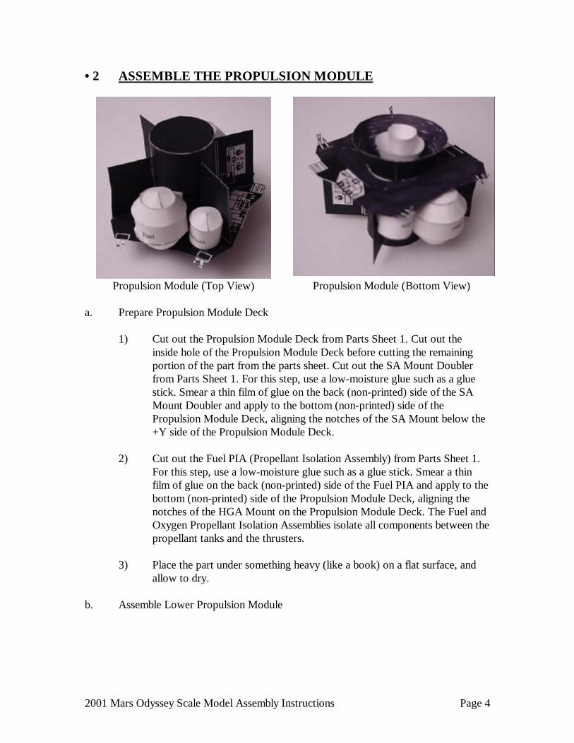
• 2 ASSEMBLE THE PROPULSION MODULE
Propulsion Module (Top View) Propulsion Module (Bottom View)
a. Prepare Propulsion Module Deck
1) Cut out the Propulsion Module Deck from Parts Sheet 1. Cut out the inside hole of the Propulsion Module Deck before cutting the remaining portion of the part from the parts sheet. Cut out the SA Mount Doubler from Parts Sheet 1. For this step, use a low-moisture glue such as a glue stick. Smear a thin film of glue on the back (non-printed) side of the SA Mount Doubler and apply to the bottom (non-printed) side of the Propulsion Module Deck, aligning the notches of the SA Mount below the +Y side of the Propulsion Module Deck.
2) Cut out the Fuel PIA (Propellant Isolation Assembly) from Parts Sheet 1.
For this step, use a low-moisture glue such as a glue stick. Smear a thin film of glue on the back (non-printed) side of the Fuel PIA and apply to the bottom (non-printed) side of the Propulsion Module Deck, aligning the notches of the HGA Mount on the Propulsion Module Deck. The Fuel and Oxygen Propellant Isolation Assemblies isolate all components between the propellant tanks and the thrusters.
3) Place the part under something heavy (like a book) on a flat surface, and
allow to dry. b. Assemble Lower Propulsion Module
2001 Mars Odyssey Scale Model Assembly Instructions Page 5
1) Cut out the L/V (Launch Vehicle) Interface Ring from Parts Sheet 1. Using a BLACK marker, color the unprinted side black. Using a pencil or dowel, form the part into cone by rolling the part to impart a curved shape with the printed shading on the outside. Smear a thin film of glue on the uncolored tab, overlap the opposite edge onto the glue, and adjust as necessary to make an even conic section.
2) Cut out the Main Engine Lower Mount from Parts Sheet 1. Form the part
into cone by rolling the part to impart a curved shape with the printed shading on the INSIDE. Smear a thin film of glue on the uncolored tab, overlap the opposite edge onto the glue, and adjust as necessary to make an even conic section.
3) Apply a thin bead of glue to the smaller opening of the L/V Interface Ring,
and place the larger opening of the L/V Interface Ring on the work surface. Place the larger opening of the Main Engine Lower Mount onto the L/V Interface Ring, centering the part over the Interface Ring.
4) Cut out the Main Engine Upper Mount from Parts Sheet 1. Apply a thin
bead of glue to the smaller opening of the Main Engine Lower Mount, and place the printed side of the Main Engine Upper Mount onto the Main Engine Lower Mount. This will build a set of parts with black printing on the inside of the conic sections.
c. Assemble the Main Engine
1) Cut out the Main Engine Heatshield from Parts Sheet 1. Form the part into cone by rolling the part to impart a curved shape. Smear a thin film of glue on the tab marked GLUE, overlap the opposite edge onto the glue, and adjust as necessary to make an even conic section.
2) Cut out the Main Engine Lower Bell from Parts Sheet 1. Form the part
into cone by rolling the part to impart a curved shape. Smear a thin film of glue on the tab marked GLUE, overlap the opposite edge onto the glue, and adjust as necessary to make an even conic section.
3) Cut out the Main Engine Upper Bell from Parts Sheet 1. Form the part into
cone by rolling the part to impart a curved shape. Smear a thin film of glue on the tab marked GLUE, overlap the opposite edge onto the glue, and adjust as necessary to make an even cone. Apply glue to the edge of the Main Engine Upper Bell, and glue the part to the smaller opening of the Main Engine Lower Bell, stacking the two parts together.

2001 Mars Odyssey Scale Model Assembly Instructions Page 6
4) Cut out the Main Engine Nozzle from Parts Sheet 1. Form the part into a cylinder by rolling the part to impart a curved shape. Smear a thin film of glue on the tab marked G, overlap the opposite edge onto the glue, and adjust as necessary to make an even cylinder. Apply glue to the point of the Main Engine Upper Bell, and glue the nozzle to the Main Engine Upper Bell by placing one opening of the nozzle over the point of the Main Engine Upper Bell.
5) Apply a thin bead of glue to the smaller opening of the Main Engine
Heatshield, and place the part into the inside of the Main Engine Upper Mount. Center the Main Engine Heatshield around the thin light colored circle inside the Main Engine Mount.
6) Apply a drop of glue to the Main Engine Nozzle, and place the Main
Engine into the inside of the Main Engine Upper Mount. Center the Main Engine Heatshield around the small light colored circle inside the Main Engine Mount. The Main Engine should be inside the Main Engine Heatshield.
d. Assemble the Propulsion Module (PM) Core
1) Cut out the Propulsion Module Core from Parts Sheet 1. Form the part into a cylinder by rolling the part to impart a curved shape with the printed side on the outside. Smear a thin film of glue on the tab marked GLUE, overlap the opposite edge onto the glue, and adjust as necessary to make an even cylinder.
2) Cut out the Propulsion Module Top from Parts Sheet 1. Apply a thin bead
of glue along the top of the Propulsion Module Core, and attach the PM Top.
3) Apply a thin bead of glue along the bottom of the Propulsion Module Core,
and attach core to the L/V Interface Ring, covering the Main Engine Mount. Adjust the core so it is vertical when the L/V Interface Ring is resting on a flat level surface.
e. Assemble the Propulsion Module Deck and Gussets
1) Using a BLACK marker, color the bottom (non-printed) side of the Propulsion Module Deck black (don’t color the SA Mount Doubler and Fuel PIA).

2001 Mars Odyssey Scale Model Assembly Instructions Page 7
2) Cut out the four Thruster assemblies from Parts Sheet 1. Each thruster assembly has a 0.2 pound roll thruster, and a 5 pound pitch/yaw thruster. The 0.2 pound thrusters have a small “pointed” gas exit, and the larger 5 pound thrusters have a conic opening. Apply glue to the rectangular portion on the non-printed side of the thruster assembly and glue the assembly to the bottom side of the Propulsion Module Deck, directly below the equal sized rectangles on each corner of the deck. Each thruster assembly should be mounted with the 5 pound thrusters oriented closest toward the X axis. Repeat for all four thruster assemblies, and allow the glue to dry. Bend each of the four 5 pound thrusters 90 degrees toward the printed side of the thruster assembly (down toward the Main Engine).
3) Apply a thin bead of glue along the edges of the circular cutout in the
Propulsion Module Deck and slide the Deck down onto the Propulsion Module Core. The PM Deck should rest on the L/V interface Ring. Align the +Y on the Deck with the +Y on the Propulsion Module Core. Adjust the Deck so it is flat and level when the L/V Interface Ring is resting on a flat level surface.
4) Cut out the four Propulsion Module Gussets from Parts Sheet 1. Using a
BLACK marker, color the non-printed side of each gusset all black. 5) Select the Gusset with the Ox PIA and apply glue along the two edges
nearest the corner with the small 45 degree notch. Place the two glued edges of this gusset along the thin white lines of the Propulsion Module Core and the Propulsion Module Deck nearest the HGA Mount.
6) Select the Gusset with the “He” marking and apply glue along the two
edges nearest the corner with the small 45 degree notch. Place the two glued edges of this gusset along the thin white lines of the Propulsion Module Core and the Propulsion Module Deck nearest the small “h” on the Deck (opposite of the Pressurant Control Assembly (PCA) Plate). The PCA isolates all components between the Gaseous Helium (GHe) tank and the propellant tanks.
7) Glue the two remaining gussets to the Propulsion Module using the same
method as above. • f. Assemble the Propulsion Tanks
1) OPTIONAL STEP (easier method): Two different sets of propulsion tanks are provided. The easier assembly method uses the parts marked “Optional”, and are assembled in the following two steps.

2001 Mars Odyssey Scale Model Assembly Instructions Page 8
a) Cut out the Fuel Tank Assembly (FTA) halves marked “Optional” from Parts Sheet 2. Fit them together at right angles, slot into slot, and secure with glue. Repeat with the other set of FUEL TANK Assembly (FTA) halves. These intersecting pieces represent two domed cylindrical tanks.
b) Cut out the Helium Tank Assembly (HTA) halves marked
“Optional” from Parts Sheet 2. Fit them together at right angles, slot into slot, and secure with glue. These intersecting pieces represent a domed cylindrical tank.
c) Skip the steps in the following section which build solid body tanks.
2) Assemble Solid Body Propulsion Tanks
a) Cut out one set of Fuel Tank Assembly (FTA) parts from Parts Sheet 2 (there are five parts per tank). Form the long part marked “Fuel” into a cylinder by rolling the part to impart a curved shape. Smear a thin film of glue on the tab marked G, overlap the opposite edge onto the glue, and adjust as necessary to make an even cylinder.
b) Form one of the small parts into cone by rolling the part to impart a
curved shape. Smear a thin film of glue on the tab marked “g”, overlap the opposite edge onto the glue, and adjust as necessary to make an even cone. Repeat with the other small part.
c) Form the larger circular part into cone by rolling the part to impart
a curved shape. Smear a thin film of glue on the tab marked “glue”, overlap the opposite edge onto the glue, and adjust as necessary to make an even conic section. Apply glue to the edges of the smaller opening on the conic section. Attach the edges of the small cone to the smaller opening on the conic section. Adjust as necessary to make an even dome. Hint: align overlap edges of each part to be co-located on the same side of the part. Repeat with the other larger circular part.
d) Apply glue along the edge of one of the domed parts and attach the
cylindrical part marked “Fuel” to the domed part. Hint: align overlap edges of each part to be co-located on the same side of the part. Repeat with the other domed part.
e) Repeat the above steps using the other set of Fuel Tank Assembly
(FTA) parts from Parts Sheet 2 (there are five parts per tank).

2001 Mars Odyssey Scale Model Assembly Instructions Page 9
f) Cut out the Helium Tank Assembly (HTA) parts from Parts Sheet 2 (there are three parts). Form the long part marked “Helium” into a cylinder by rolling the part to impart a curved shape. Smear a thin film of glue on the tab marked “G”, overlap the opposite edge onto the glue, and adjust as necessary to make an even cylinder.
g) Form one of the small parts into cone by rolling the part to impart a
curved shape. Smear a thin film of glue on the tab marked “g”, overlap the opposite edge onto the glue, and adjust as necessary to make an even cone. Repeat with the other small part.
h) Apply glue along the one of the edges of the cylindrical part marked
“Helium” and attach one of the small cone parts. Hint: align overlap edges of each part to be co-located on the same side of the part. Repeat with the other small cone part.
3) Apply a small drop of glue to one of the Fuel Tank mounts marked “FTA”
on the side of the Propulsion Module Core, and on the bottom of one of the Fuel Tanks. Attach the Fuel Tank to the Propulsion Module Core with one edge of the Fuel Tank touching the “FTA” and the bottom resting on the Propulsion Module Deck. Adjust as necessary to make the tank even with the Propulsion Module structure. Repeat with the other Fuel Tank.
4) Apply a small drop of glue to the Helium Tank mount marked “He” on the
Propulsion Module Gusset, and on the bottom of one of the Helium Tank. Attach the Helium Tank to the Propulsion Module Core with one edge of the Helium Tank touching the “He” and the bottom resting on the Propulsion Module Deck marked “h”. Adjust as necessary to make the tank even with the Propulsion Module structure.
Note: The Oxidizer Tank is not represented for this model. The Oxidizer Tank is
located inside the Propulsion Module Core, above the Main Engine.
2001 Mars Odyssey Scale Model Assembly Instructions Page 10
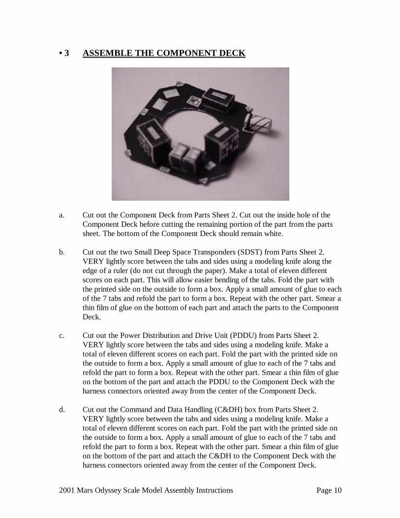
• 3 ASSEMBLE THE COMPONENT DECK
a. Cut out the Component Deck from Parts Sheet 2. Cut out the inside hole of the
Component Deck before cutting the remaining portion of the part from the parts sheet. The bottom of the Component Deck should remain white.
b. Cut out the two Small Deep Space Transponders (SDST) from Parts Sheet 2.
VERY lightly score between the tabs and sides using a modeling knife along the edge of a ruler (do not cut through the paper). Make a total of eleven different scores on each part. This will allow easier bending of the tabs. Fold the part with the printed side on the outside to form a box. Apply a small amount of glue to each of the 7 tabs and refold the part to form a box. Repeat with the other part. Smear a thin film of glue on the bottom of each part and attach the parts to the Component Deck.
c. Cut out the Power Distribution and Drive Unit (PDDU) from Parts Sheet 2.
VERY lightly score between the tabs and sides using a modeling knife. Make a total of eleven different scores on each part. Fold the part with the printed side on the outside to form a box. Apply a small amount of glue to each of the 7 tabs and refold the part to form a box. Repeat with the other part. Smear a thin film of glue on the bottom of the part and attach the PDDU to the Component Deck with the harness connectors oriented away from the center of the Component Deck.
d. Cut out the Command and Data Handling (C&DH) box from Parts Sheet 2.
VERY lightly score between the tabs and sides using a modeling knife. Make a total of eleven different scores on each part. Fold the part with the printed side on the outside to form a box. Apply a small amount of glue to each of the 7 tabs and refold the part to form a box. Repeat with the other part. Smear a thin film of glue on the bottom of the part and attach the C&DH to the Component Deck with the harness connectors oriented away from the center of the Component Deck.

2001 Mars Odyssey Scale Model Assembly Instructions Page 11
e. Cut out the Martian Radiation Environment Experiment (MARIE) box from Parts Sheet 5. VERY lightly score between the tabs and sides using a modeling knife. Make a total of eleven different scores on each part. Fold the part with the printed side on the outside to form a box. Apply a small amount of glue to each of the 7 tabs and refold the part to form a box. Repeat with the other part. Smear a thin film of glue on the bottom of the part and attach the MARIE to the Component Deck.
f. Cut out the UHF Antenna from Parts Sheet 3. Roll the part to make an even
cylinder with the printing on the outside. Smear a thin film of glue on the tabs marked “glue”, overlap the opposite edge onto the glue, and adjust as necessary to make an even cylinder. Apply glue to the side of the cylinder (near the end closest to the thick line), and attach the part horizontally to the Component Deck over the square marked “UHF”. The thick line end should be in toward the center of the deck.
f. Apply a thin bead of glue to the top edges of the four Propulsion Module Gussets
and slide the Component Deck down onto the Propulsion Module Core. Align the +Y on the Deck with the +Y on the Propulsion Module Core. Adjust the Deck so it is flat and level when the L/V Interface Ring is resting on a flat level surface.

2001 Mars Odyssey Scale Model Assembly Instructions Page 12
• 4 ASSEMBLE THE SCIENCE DECK
Science Deck Top Science Deck Bottom
SCIENCE DECK ASSEMBLY: BOTTOM a. Cut out the two Science Deck parts (top and bottom) from Parts Sheet 3. For this
step, use a low-moisture glue such as a glue stick. Smear a thin film of glue on the back (non-printed) side of the Science Deck Top and apply to the bottom (non-printed) side of the Science Deck Bottom, aligning the notches of the two parts. Place the part under something heavy (like a book) on a flat surface, and allow to dry.
b. Assemble the Reaction Wheels
1) Cut out the twelve Reaction Wheel Assembly (RWA) parts from Parts Sheet 3. Be sure not to cut into the small uncolored edge along the outside of each round part.
2) Form the long part into a cylinder with the dark printing on the outside of
the part. Smear a thin film of glue on the tab marked “glue”, overlap the opposite edge onto the glue, and adjust as necessary to make an even cylinder.

2001 Mars Odyssey Scale Model Assembly Instructions Page 13
3) Apply glue along one of the edges of the cylinder and attach one of the
light colored round pieces with the printed ring on the outside. The round piece should be a larger diameter than the cylinder, and evenly overlap the edges of the cylinder.
4) Apply glue along other edge of the cylinder and attach one of the dark
colored round pieces with the printed letters “RWA” on the outside. 5) Repeat with the other three sets of RWA parts to complete a set of four
Reaction Wheel Assemblies. 6) Cut out the RWA Bracket from Parts Sheet 5. VERY lightly score
between the tabs (marked with “g”) and sides using a modeling knife along the edge of a ruler (do not cut through the paper). This will allow easier bending of the tabs. Fold the tabs away from the printed side of the part. Smear a thin film of glue to the light colored side of the Skew RWA (RWA-S) and attach the part to the corresponding location on the RWA Bracket.
7) Apply glue to the edge of the X-axis RWA and attach the part to the
Science Deck with the lettering facing out. Repeat for the Y-axis RWA. 8) Apply glue to the bottom edge of the RWA Bracket and to the two tabs
marked “g”. Attach the part to the Science Deck, allowing the tabs to attach to the back surface of the X- and Y-axis RWAs
9) Smear a thin film of glue to the light colored side of the Z axis RWA and
attach the part to the corresponding location on the Science Deck. c. Assemble the IMUs
1) Cut out the six Inertial Measurement Unit (IMU) parts from Parts Sheet 3. 2) Form the long part into a cylinder with the dark printing on the outside of
the part. Smear a thin film of glue on the tab marked “glue”, overlap the opposite edge onto the glue, and adjust as necessary to make an even cylinder.
2001 Mars Odyssey Scale Model Assembly Instructions Page 14
3) Apply glue along the top edge of the cylinder and attach the part marked
“IMU” with the printed ring on the outside. The round piece should be the same diameter as the cylinder, and evenly touch the edges of the cylinder.
4) Apply glue along other edge of the cylinder and attach the round part
marked “bottom”. 5) Repeat with the other sets of IMU parts to complete a set of two Inertial
Measurement Units. 6) Smear a thin film of glue to the bottom of one of the IMUs and attach the
part to the corresponding location on the Science Deck. Repeat with the other IMU.
d. Cut out the Charge Control Unit (CCU) box from Parts Sheet 5. VERY lightly
score between the tabs and sides using a modeling knife. Make a total of eleven different scores on each part. Fold the part with the printed side on the outside to form a box. Apply a small amount of glue to each of the 7 tabs and refold the part to form a box. Repeat with the other part. Smear a thin film of glue on the bottom of the part and attach the CCU to the Science Deck.
e. Cut out the Component Electronics Box (CEB) from Parts Sheet 5. VERY lightly
score between the tabs and sides using a modeling knife. Make a total of eleven different scores on each part. Fold the part with the printed side on the outside to form a box. Apply a small amount of glue to each of the 7 tabs and refold the part to form a box. Repeat with the other part. Smear a thin film of glue on the bottom of the part and attach the CEB to the Science Deck.
f. Cut out the Reaction Wheel Electronics (RWE) box from Parts Sheet 5. VERY
lightly score between the tabs and sides using a modeling knife. Make a total of eleven different scores on each part. Fold the part with the printed side on the outside to form a box. Apply a small amount of glue to each of the 7 tabs and refold the part to form a box. Repeat with the other part. Smear a thin film of glue on the bottom of the part and attach the RWE to the Science Deck.

2001 Mars Odyssey Scale Model Assembly Instructions Page 15
SCIENCE DECK ASSEMBLY: TOP a. Assemble the Star Cameras
1) On Parts Sheet 3, VERY lightly score the two STAR CAMERAS between the tabs and sides using a modeling knife along the edge of a ruler. Make a total of eight different scores on each Star Camera Body. Cut out the four STAR CAMERA parts from Parts Sheet 3 (two camera bodies and two lens hoods).
2) Fold the 6 tabs away from the printed sides of the Star Camera Body, and
fold along the two lines between the top and bottom of the camera body. Apply a small drop of glue to the three tabs marked GLUE and overlap the other opposing three tabs onto the glue tabs. This should make a small box with a dark circle on one side and an “S” on the other side. Repeat with the other Star Camera Body.
3) Roll the square shaped piece into a small cylinder with the dark printing on
the inside, allowing the sides to overlap along the edge marked GLUE. Roll the piece around a pencil or dowel to make a smooth cylinder. Smear some glue along the tab of this piece marked GLUE, overlap the opposite end onto the glue, press together, and allow the glue to dry.
4) Apply glue to the edges on one end of the small cylinder, and glue the
cylinder to the side of the camera body with the round dark spot, and let the glue dry. Repeat with the other small cylinder and camera body.
5) Cut out the two small donut shaped lens hood parts from Parts Sheet 3.
Cut out the inside hole of the lens hood before cutting the remaining portion of the part from the parts sheet. Apply glue to the edges of the small lens hood cylinder, and glue the donut shaped lens hood to the cylinder. Repeat with the other small cylinder and camera body.
2001 Mars Odyssey Scale Model Assembly Instructions Page 16
6) Cut out the Star Camera Bracket from Parts Sheet. VERY lightly score the bracket along the dark lines using a modeling knife along the edge of a ruler. There are a total of three places to score. Smear a thin film of glue to the back of each of the Star Camera bodies, and attach the star cameras to the bracket. Fold the long parallelogram away from the cameras until the bracket forms an angle of approximately 30 degrees. Fold the two glue tabs inward and smear a thin film of glue on them. Mount the bracket to the Science Deck in the labeled area so that the star cameras are pointing in the +X direction.
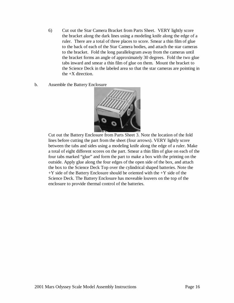
b. Assemble the Battery Enclosure
Cut out the Battery Enclosure from Parts Sheet 3. Note the location of the fold lines before cutting the part from the sheet (four arrows). VERY lightly score between the tabs and sides using a modeling knife along the edge of a ruler. Make a total of eight different scores on the part. Smear a thin film of glue on each of the four tabs marked “glue” and form the part to make a box with the printing on the outside. Apply glue along the four edges of the open side of the box, and attach the box to the Science Deck Top over the cylindrical shaped batteries. Note the +Y side of the Battery Enclosure should be oriented with the +Y side of the Science Deck. The Battery Enclosure has moveable louvers on the top of the enclosure to provide thermal control of the batteries.
2001 Mars Odyssey Scale Model Assembly Instructions Page 17
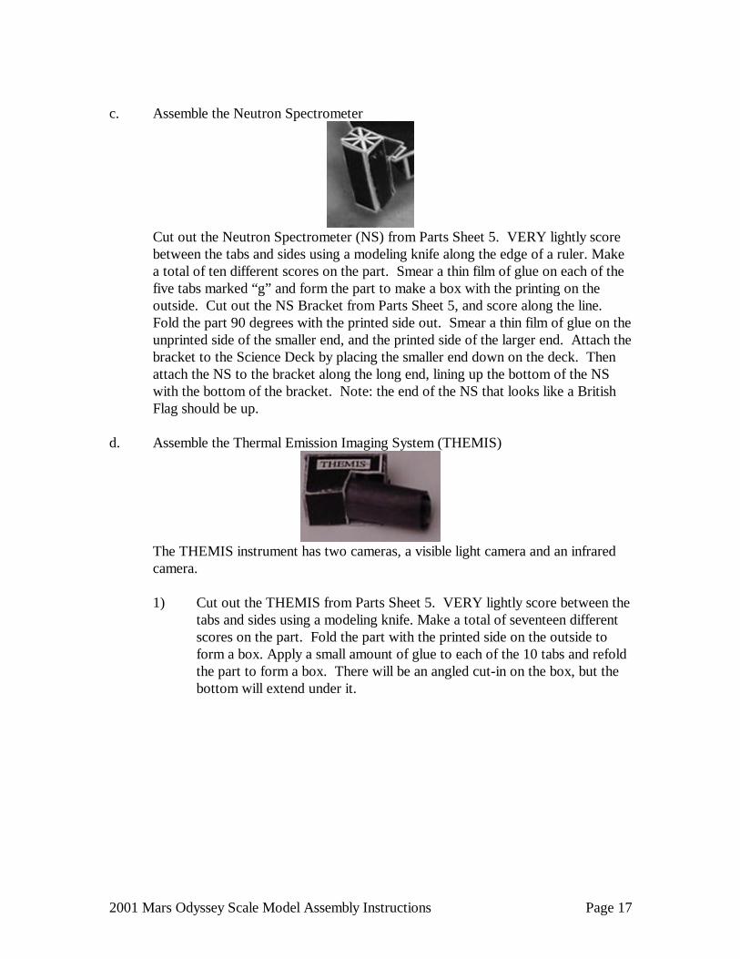
c. Assemble the Neutron Spectrometer
Cut out the Neutron Spectrometer (NS) from Parts Sheet 5. VERY lightly score between the tabs and sides using a modeling knife along the edge of a ruler. Make a total of ten different scores on the part. Smear a thin film of glue on each of the five tabs marked “g” and form the part to make a box with the printing on the outside. Cut out the NS Bracket from Parts Sheet 5, and score along the line. Fold the part 90 degrees with the printed side out. Smear a thin film of glue on the unprinted side of the smaller end, and the printed side of the larger end. Attach the bracket to the Science Deck by placing the smaller end down on the deck. Then attach the NS to the bracket along the long end, lining up the bottom of the NS with the bottom of the bracket. Note: the end of the NS that looks like a British Flag should be up.
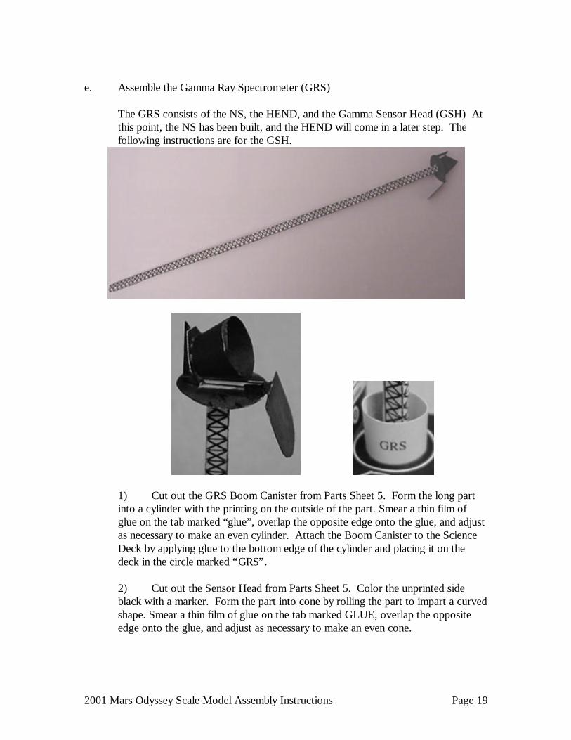
d. Assemble the Thermal Emission Imaging System (THEMIS)
The THEMIS instrument has two cameras, a visible light camera and an infrared
camera.
1) Cut out the THEMIS from Parts Sheet 5. VERY lightly score between the tabs and sides using a modeling knife. Make a total of seventeen different scores on the part. Fold the part with the printed side on the outside to form a box. Apply a small amount of glue to each of the 10 tabs and refold the part to form a box. There will be an angled cut-in on the box, but the bottom will extend under it.

2001 Mars Odyssey Scale Model Assembly Instructions Page 18
2) Cut out the Baffle from Parts Sheet 5. Color the unprinted side black with a marker. Roll the square shaped piece into a small cylinder with the dark printing on the inside, allowing the sides to overlap along the edge marked GLUE. Roll the piece around a pencil or dowel to make a smooth cylinder. Smear some glue along the tab of this piece marked GLUE, overlap the opposite end onto the glue, press together, and allow the glue to dry. Once dry, partially flatten the cylinder out so that it is oval shaped rather than circular. Apply glue to one edge of the cylinder, as well as the inside the cut-in on the THEMIS. Attach the baffle horizontally in the cut-in and allow the glue to dry. Then apply a thin film of glue to the Science Deck marked “THEMIS”. Place the THEMIS on the Science Deck with the Baffle pointing outward.
3) Cut out the two mounts from Parts Sheet 5. Apply a small bead of glue to
both ends of each mount, and place at an angle from the inboard top corners of the THEMIS to the Science Deck.
2001 Mars Odyssey Scale Model Assembly Instructions Page 19
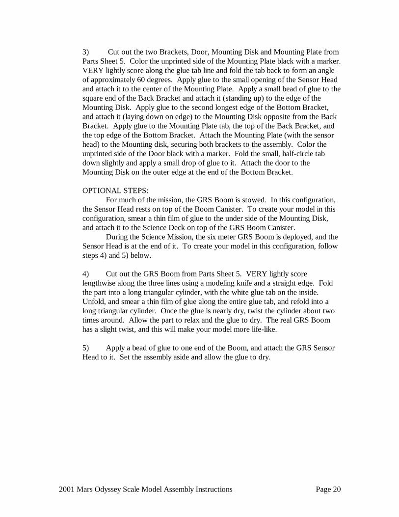
e. Assemble the Gamma Ray Spectrometer (GRS) The GRS consists of the NS, the HEND, and the Gamma Sensor Head (GSH) At
this point, the NS has been built, and the HEND will come in a later step. The following instructions are for the GSH.
1) Cut out the GRS Boom Canister from Parts Sheet 5. Form the long part into a cylinder with the printing on the outside of the part. Smear a thin film of glue on the tab marked “glue”, overlap the opposite edge onto the glue, and adjust as necessary to make an even cylinder. Attach the Boom Canister to the Science Deck by applying glue to the bottom edge of the cylinder and placing it on the deck in the circle marked “GRS”. 2) Cut out the Sensor Head from Parts Sheet 5. Color the unprinted side black with a marker. Form the part into cone by rolling the part to impart a curved shape. Smear a thin film of glue on the tab marked GLUE, overlap the opposite edge onto the glue, and adjust as necessary to make an even cone.
2001 Mars Odyssey Scale Model Assembly Instructions Page 20
3) Cut out the two Brackets, Door, Mounting Disk and Mounting Plate from Parts Sheet 5. Color the unprinted side of the Mounting Plate black with a marker. VERY lightly score along the glue tab line and fold the tab back to form an angle of approximately 60 degrees. Apply glue to the small opening of the Sensor Head and attach it to the center of the Mounting Plate. Apply a small bead of glue to the square end of the Back Bracket and attach it (standing up) to the edge of the Mounting Disk. Apply glue to the second longest edge of the Bottom Bracket, and attach it (laying down on edge) to the Mounting Disk opposite from the Back Bracket. Apply glue to the Mounting Plate tab, the top of the Back Bracket, and the top edge of the Bottom Bracket. Attach the Mounting Plate (with the sensor head) to the Mounting disk, securing both brackets to the assembly. Color the unprinted side of the Door black with a marker. Fold the small, half-circle tab down slightly and apply a small drop of glue to it. Attach the door to the Mounting Disk on the outer edge at the end of the Bottom Bracket. OPTIONAL STEPS:
For much of the mission, the GRS Boom is stowed. In this configuration, the Sensor Head rests on top of the Boom Canister. To create your model in this configuration, smear a thin film of glue to the under side of the Mounting Disk, and attach it to the Science Deck on top of the GRS Boom Canister. During the Science Mission, the six meter GRS Boom is deployed, and the Sensor Head is at the end of it. To create your model in this configuration, follow steps 4) and 5) below. 4) Cut out the GRS Boom from Parts Sheet 5. VERY lightly score lengthwise along the three lines using a modeling knife and a straight edge. Fold the part into a long triangular cylinder, with the white glue tab on the inside. Unfold, and smear a thin film of glue along the entire glue tab, and refold into a long triangular cylinder. Once the glue is nearly dry, twist the cylinder about two times around. Allow the part to relax and the glue to dry. The real GRS Boom has a slight twist, and this will make your model more life-like.
5) Apply a bead of glue to one end of the Boom, and attach the GRS Sensor Head to it. Set the assembly aside and allow the glue to dry.

2001 Mars Odyssey Scale Model Assembly Instructions Page 21
f. Assemble the High Energy Neutron Detector (HEND)
NOTE: This is the most difficult part of the model – YOU CAN DO IT! Have patience,
and be careful. Cut out the HEND from Parts Sheet 5, and also cut along the dotted lines. Using
a modeling knife and a straight edge, VERY lightly score along every solid line on the part. Fold the part into a box – it is in the shape of an “L” in three different directions, as pictured. Unfold the part, and smear a thin film of glue on all the small glue tabs. There are thirteen all together. Refold the part into a box and hold, allowing the glue to dry. You may need to reposition your fingers several times to make sure all the sides are positioned correctly. Once the glue is dry, attach the part to the Science Deck as shown, in the box labeled “HEND”. WAY TO GO – YOU DID IT!
g. Final Science Deck Assembly
1) Cut out the Science Deck Struts from Parts Sheet 3. Consider using a
sharp modeling knife and metal ruler to cut the parts from the sheet, being careful not to cut into the uncolored strut “brackets”. Color the unprinted side of each strut with a Black marker to match the printed side. VERY lightly score the two small fold lines near the “B” and “D” brackets using a modeling knife, and fold the struts marked “3” and “4” away from the printed side. Make a 90 degree bend at the fold line.
2) Apply a small drop of glue to the bottom edge of the strut brackets marked
“A” and “B” and attach the part to the corresponding locations on top of the Component Deck. Repeat with the strut brackets marked “C” and “D” and attach the part to the corresponding locations on top of the Component Deck. Tilt the upper portion each of the Science Deck Strut toward each other until the struts marked “3” touch and the struts marked “4” touch. Apply a small drop of glue the two struts marked “3” and glue them together. Repeat with the two struts marked “4”. Adjust the struts so the top edges are parallel with the Component Deck top AND edges. Allow the glue to dry before proceeding.

2001 Mars Odyssey Scale Model Assembly Instructions Page 22
3) Apply a drop of glue to the top edge of each of the 6 struts, marked “1” through “6”. Attach the corresponding locations on the bottom of the Science Deck to the 6 struts. Adjust the Science Deck to be parallel with the Component Deck top AND edges. Be sure to align the +X of the Science Deck with +X of the Component Deck. Do the same for +Y on both decks. Allow the glue to dry before proceeding.
4) If your model is in the GRS Boom Deployed Configuration, apply a bead
of glue to the end of the Boom opposite the Sensor Head. Attach the Boom to Science Deck in the center of the GRS Boom Canister. Hold the Boom down and allow the glue to dry.
At this point, the Spacecraft Bus is complete. The only parts left to do now are the two deployable appendages – the High Gain Antenna, and the Solar Array. YOU’RE ALMOST DONE!

2001 Mars Odyssey Scale Model Assembly Instructions Page 23
• 5 ASSEMBLE THE HIGH GAIN ANTENNA
HGA and SSPA (Back View) HGA and SSPA (Front View)
a. Assemble the HGA and SSPA
1) Cut out the High Gain Antenna (HGA) from Parts Sheet 4. Form the circle into cone by rolling the part to impart a curved shape with the printed circles on the inside. For this step, use a low-moisture glue such as a glue stick. Smear a thin film of glue on the tab marked GLUE. Overlap the opposite edge onto the glue, bringing the circle up into a cone, with the printing on the inside. Adjust so the edge aligns with, and just overlaps the line which separates the glue tab. Using a Black Marker, color the unprinted side of the antenna black. Once the glue is thoroughly dry, set the cone on your work surface with the point facing down, and crush the point by pressing the cone down onto the work surface. Crush the cone to make the center point flat, about 1/4 inch diameter.
2) Cut out the HGA Feed from Parts Sheet 4. Use a sharp modeling knife and
metal ruler to cut the part from the sheet, being careful not to cut into the uncolored strut “brackets”. Color the unprinted side of each strut with a Black marker to match the printed side. Bend the three struts of the antenna HGA Feed about 80 degrees at the point where they meet the unprinted circle, away from the printed side. Apply a small drop of glue to the ends of the three struts and attach the struts to the three small dots on the HGA.

2001 Mars Odyssey Scale Model Assembly Instructions Page 24
3) On Parts Sheet 4, note the locations of the arrows indicating fold lines on
the Solid State Power Amplifier (SSPA) Enclosure. Using a modeling knife and ruler, VERY lightly score between the points of the corresponding arrows (do not cut through the paper). Also, VERY lightly score the 8 lines which separate the 3 sides and glue tabs near the “SSPA” marking. This will allow easier bending of the tabs. Cut out the SSPA Enclosure from Parts Sheet 4. Fold the glue tabs and 3 sides of the enclosure away from the printed side. Make 4 more folds AWAY from the printed side along the edges with the small “•” holes. Apply glue to the 5 glue tabs and overlap the sides to make a box. The top of the SSPA Enclosure has thermally controlled louvers to provide thermal control of the two SSPAs inside the SSPA Enclosure.
4) Bend the small tab marked “g” on the SSPA Enclosure struts about 160
degrees away from the printed side. Make two more bends where the SSPA Enclosure struts attach to the enclosure, away from the printed side. Apply a small drop of glue to the tab marked “g”, and glue to strut to the unprinted side of the “T” shaped HGA Mount.
5) Apply glue to the center of the circle marked “HGA” on the “T” shaped
HGA Mount, and attached the crushed point of the HGA. The small rectangle marked “MGA” (Medium Gain Antenna) should be oriented toward the bottom of the “T” shaped HGA Mount. Adjust the HGA as necessary to make it sit even on the SSPA Enclosure.
b. Assemble the HGA Boom
1) Cut out the HGA Mount from Parts Sheet 2. Cut out the two small holes before cutting out the part from the parts sheet. VERY lightly score the each of the dark lines using a modeling knife. Fold the sides and glue tabs forming a box with a square cut-in on one corner. On that corner, there are two flaps, each with a small hole. Smear glue on the ten glue tabs and overlap the sides onto the tabs.
2) Apply glue to the bottom (opposite the cut-in corner) on the HGA Mount
and attach the part to the Propulsion Deck. The small holes should be facing outboard.

2001 Mars Odyssey Scale Model Assembly Instructions Page 25
3) Cut out the HGA Boom from Parts Sheet 2. Cut out the two small holes before cutting out the part from the parts sheet. VERY lightly score the each of the dark lines using a modeling knife. Make a total of 12 different score lines. Fold the sides and glue tabs of the AWAY from the printed side. The circles represent Inner and Outer Gimbal motors. Smear a thin film of glue on the tabs marked “glue”, overlap the opposite edges onto the glue, and adjust as necessary to make an even boom and gimbal assembly.
4) Apply glue to the side marked “SS” on the HGA Boom, and attach the part
to the corresponding location on the SSPA Enclosure, aligning the parts using the alignment mark near the “SS”. Allow the glue to dry before proceeding.

2001 Mars Odyssey Scale Model Assembly Instructions Page 26
• 6 ASSEMBLE THE SOLAR ARRAY
Solar Array Gimbal attached to Bottom of Propulsion Deck
a. Assemble the Solar Array Inner Gimbal
1) Cut out the two Inner Gimbal Gussets from Parts Sheet 4. Using a Black Marker, color the unprinted side of each part black. Apply a thin bead of glue along the long straight edge of each part and glue them to the bottom of the Propulsion Deck on the SA Mount Doubler. The long edge of the Inner Gimbal Gussets should be glued along the corresponding lines centered over the “SA” marking. The Inner Gimbal Gussets hang down from the Propulsion Deck.
2) Cut out the two Inner Gimbal parts from Parts Sheet 4; “inner gimbal-o”
and “inner gimbal-i”. Form each part into a cylinder by rolling the part to impart a curved shape, with the printing on the inside of the cylinder. Note each part is a different length and width. The part marked “inner gimbal-i” will slide inside the part marked “inner gimbal-o”. On the part marked “inner gimbal-i”, smear a thin film of glue on the tab marked “glue”, overlap the opposite edge onto the glue, and adjust as necessary to make an even cylinder. Repeat with the part marked “inner gimbal-o”, adjusting the cylinder snugly around the inner part. Separate the two parts and allow to dry.
3) Cut out the Outer Gimbal Mount from Parts Sheet 4. Apply glue to the
edges on ONE end of the narrower cylinder marked “inner gimbal-i” and attach it to the center of the unprinted side of the Outer Gimbal Mount. The small rectangle marked “glue” should be opposite of the cylinder. Allow the glue to dry.

2001 Mars Odyssey Scale Model Assembly Instructions Page 27
4) OPTIONAL STEP: If you want to have the ability to detach the solar array
(for storage), then do not perform the following step:
a) Cut out the Inner Gimbal Retainer from Parts Sheet 4. Fit the “inner gimbal-i” inside the wider part, “inner gimbal-o”. The parts should be snug, but not difficult to slide. Slide the outside cylinder toward the Outer Gimbal Mount to expose the end of the inside cylinder. Apply glue to the edges on the end of the INSIDE cylinder and attach the printed side of the Inner Gimbal Retainer. Be careful not to allow any glue to touch the outside cylinder.
b. Assemble the Solar Array Outer Gimbal
1) Cut out the two Outer Gimbal parts from Parts Sheet 4; “outer gimbal-o” and “outer gimbal-i”. Form each part into a cylinder by rolling the part to impart a curved shape, with the printing on the inside of the cylinder. Note each part is a different length and width. The part marked “outer gimbal-i” will slide inside the part marked “outer gimbal-o”. On the part marked “outer gimbal-o”, smear a thin film of glue on the tab marked “glue”, overlap the opposite edge onto the glue, and adjust as necessary to make an even cylinder. Repeat with the part marked “outer gimbal-i”, adjusting the cylinder snugly inside the outer part. Separate the two parts and allow to dry.
3) Cut out the Outer Gimbal Clamp from Parts Sheet 4. VERY lightly score
the two lines using a modeling knife (do not cut through the paper). Fold each scored edge of the part 90 degrees toward the unprinted side. Apply glue to the edges on ONE end of the narrower cylinder marked “outer gimbal-i” and attach it to the center of the circle on the unprinted side of the Outer Gimbal Clamp. Allow the glue to dry.
4) Fit the “outer gimbal-i” inside the wider part, “outer gimbal-o”. The parts
should be snug, but not difficult to slide. Slide the outside cylinder toward the end glued to the Outer Gimbal Clamp to expose the end of the inside cylinder. Apply glue to the edges on the end of the inside cylinder and attach the other end of the Outer Gimbal Clamp. Be careful not to allow any glue to touch the outside cylinder. Allow the glue to dry.
c. Apply a SMALL drop of glue to the small rectangle marked “glue” on the Outer
Gimbal Mount and attach the outside cylinder of the Inner Gimbal. Be careful not to allow any glue to touch the Outer Gimbal Clamp. Allow the glue to dry. Do not be concerned if the gimbal feels too snug; some amount of stiffness is desired.

2001 Mars Odyssey Scale Model Assembly Instructions Page 28
d. Apply glue along the circumference of each Inner Gimbal Gusset attached to the bottom of the Propulsion Deck. Attach the outside cylinder of the Solar Array Inner Gimbal to the gussets, with the Outer Gimbal Mount flush with the edge of the Propulsion Deck. Be very careful not to allow any glue to touch the moving parts.
e. Solar Array Preparation
1) OPTIONAL STEP: Using a modeling knife and ruler, cut out the 11 gray rectangular cut-outs from the Solar Array on Parts Sheet 4. These cut-outs are covered with fabric on the spacecraft to provide more aerodynamic drag during the aerobraking mission phase. Using a modeling knife and ruler, cut out the two small gray areas between the three Solar Array panels.
2) Using a BLUE highlighter, color the three large uncolored panels on the
Solar Array (on the printed side of the array). Best results will be obtained by using the highlighter along the edge of a ruler. Do not color the hinges or space between each panel.
3) Cut out the Solar Array from Parts Sheet 4. Cut out the Solar Array
Gimbal Stiffener from Parts Sheet 4. For this step, use a low-moisture glue such as a glue stick. Smear a thin film of glue on the back (non-printed) side of the Solar Array Gimbal Stiffener and apply to the back (non-printed) side of the Propulsion Module Deck, aligning the notches of the Solar Array Gimbal Mount.
4) OPTIONAL STEP: Spray black spray paint on the unprinted side of the
Solar Array panels. 5) Using a Modeling knife and ruler, VERY lightly score along the lightly
colored line near edge of all three Solar Array panels. Fold the long skinny printed strip along the top edges of the Solar Array Panels 90 degrees away from the printed side to make a stiffener.

2001 Mars Odyssey Scale Model Assembly Instructions Page 29
7 FINAL ASSEMBLY a. Cut out the HGA Boom Hinge Pin from Parts Sheet 4. Roll the part into a small
cylinder (do not use any glue). Position the HGA Boom into the HGA Mount with the SSPA near the “+X” edge of the Science Deck. The tabs with two small holes in the HGA Boom should fit between the tabs of the HGA Mount. Insert the HGA Boom Hinge Pin through the tabs. This will allow the HGA to swing from the stowed position to the deployed position.
b. Apply glue to the two lines marked “gimbal” on each side of the Solar Array and
slide the array onto the Outer Gimbal Clamp. The “out” marking on the Outer Gimbal Clamp should be on the printed side of the Solar Array (the blue solar cell substrate (printed side) of the solar panel should be oriented away from the spacecraft). Be careful not to allow any glue to touch the moving parts.
c. The Odyssey model can be configured for several different spacecraft
configurations. Pick one of the following configurations:
1) Cruise Configuration - The HGA remains stowed in the Launch and Cruise mission phases. The spacecraft will be oriented with the HGA pointed at Earth, and the Solar Array +X panel rotated toward the top of the spacecraft and out, away from the +Y axis of the spacecraft. The GRS Boom is stowed during this mission phase.
2) Mars Orbit Insertion (MOI) and Aerobraking Configuration - The HGA
remains stowed in the MOI and Aerobraking mission phases. The Solar Array will moved to the “stowed” position with the blue solar cell substrate (printed side) of the solar panel oriented away from the spacecraft. During an aerobraking pass, the direction of travel will be toward the -Y axis of the spacecraft. The GRS Boom remains stowed in these mission phases.
3) Mapping Configuration - The HGA will be deployed after the MOI event
(the HGA cannot be un-deployed). The Science Deck of the spacecraft will be Nadir pointing throughout each orbit (Science Deck pointed toward the center of the planet). The Solar Array will be gimbaled to follow the Sun throughout the Mars orbit. The HGA will be gimbaled to track the Earth during communication sessions. The GRS Boom is deployed during the Mapping mission phase.
THIS COMPLETES YOUR MODEL

2001 Mars Odyssey Scale Model Assembly Instructions Page 30
8 ABOUT YOUR MODEL The 2001 Mars Odyssey is 3-axis stabilized in all mission phases following separation from the launch vehicle. The primary attitude determination is via star camera and ring laser gyro inertial measurement unit, and is backed up by analog sun sensors. Reaction wheels provide primary attitude control during most mission phases, and are desaturated via RCS thrusters. The RCS thrusters also provide attitude control during Trajectory Correction Maneuvers, Mars Orbit Insertion, aerobraking drag pass, Orbital Trim Maneuvers, and safe mode [until rates are damped, at which point RW control is used]. In all, four 5-pound thrusters are used for Trajectory Correction Maneuvers and pitch/yaw control. Four 0.2-pound thrusters are used for roll control. The Spacecraft Computer (C&DH) uses the RAD6000 processor (predecessor to the PowerPC). The X-band link with Earth employs Small Deep Space Transponders, 15 W RF solid state power amplifiers (SSPA's), one 1.3 meter transmit/receive high gain antenna (HGA), one transmit-only medium gain antenna (MGA), and one receive-only low gain antenna. A 10 Watt RF UHF system supports the 2-way link with future Mars Landers. The 3-panel, single wing solar array (SA) uses GaAs/Ge solar cells and also functions as the primary drag brake during aerobraking. The batteries are NiH2 CPV batteries, while the electrical power electronics are somewhat based on the Mars 98 spacecraft electronics, with some new designs. The thermal control subsystem is passive, with louvers to control the temperature of the batteries and SSPA's and combinations of MLI, Kapton, paints, and dedicated radiators for certain other components. Both thermostatically controlled and computer controlled heater circuits are used. The Odyssey equipment module (EM) is a composite truss structure with titanium end fittings and two Aluminum honeycomb panels with composite face sheets. The solar array and HGA track the Sun and Earth, respectively, with 2-axis gimbals. The propulsion subsystem is dual mode, employing a bipropellant main engine for Mars Orbit Insertion (MOI) and TCM (hydrazine) thrusters for all other propulsive events. Most subsystem components are redundant, with critical items cross strapped. The Mars Surveyor Spacecraft was designed and manufactured at Lockheed Martin Astronautics, Denver, Colorado, under contract with the Jet Propulsion Laboratory. This is the first edition of this model design, completed 20 February 2002 by Rob Chambers, 2001 Mars Odyssey Power Lead, Spectrum Astro, Inc. An after-hours project based on the Mars Climate Orbiter Paper Model, designed by Greg Bollendonk of Lockheed Martin. Copyright (C) 2002 Jet Propulsion Laboratory, California Institute of Technology. All rights reserved. Permission for commercial reproduction other than for single-school in-classroom use must be obtained from JPL Commercial Programs Office.