Embed Size (px)
Citation preview
www.octoscope.com
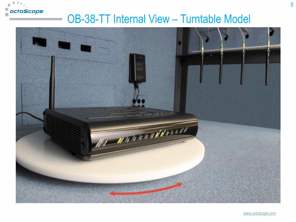
Introduction - Multipath Emulator
• Wi-Fi manufacturers and evaluators test throughput performance in
open air ‘real-life’ environment (e.g. a typical house or office) or using
channel emulators.
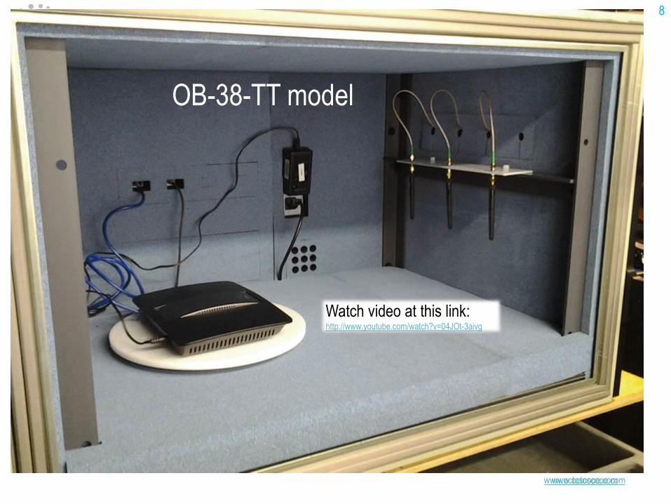
• octoScope has developed an octoBoxTM based testbed that creates
multipath closely approaching the IEEE 802.11n/ac Models B or C [1],
emulating home and small office environment.
• octoBox MPE (multipath emulator) creates multipath inside octoBox
small anechoic chamber by generating reflections with stubs of coaxial
cable. A quad multipath emulator fixture supports up to 4-stream
MIMO.
• octoBox-MPE has been simulated, prototyped, measured and
compared to the IEEE models.
• Data throughput tests have been performed by
www.smallnetbuilder.com on a 2x2 and a 3x3 802.11ac MIMO
configuration demonstrating MIMO gains inside octoBox with
equivalent or higher throughput to that measured in a representative
home environment.
• See SmallNetBuilder.com test results at this link:
http://www.smallnetbuilder.com/wireless/wireless-howto/32082-how-we-test-
wireless-products-revison-7
2
octoBox-MPE module (stacked in the
middle) emulates IEEE 802.11n/ac
Models B or C [1] corresponding to
home and small office environment.
Patents pending
MPE module
www.octoscope.com
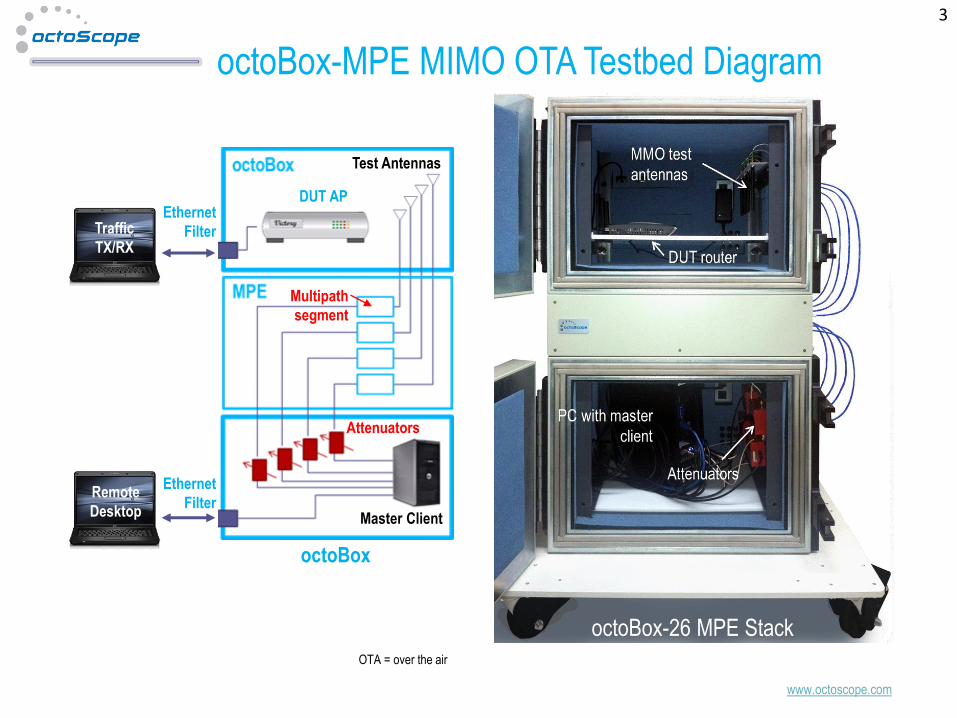
octoBox-MPE MIMO OTA Testbed Diagram
3
OTA = over the air
octoBox
DUT AP
Test Antennas
Master Client
Traffic
TX/RX
Remote
Desktop
Attenuators
Ethernet
Filter
Ethernet
Filter
Multipath
segment
octoBox-26 MPE Stack
www.octoscope.com
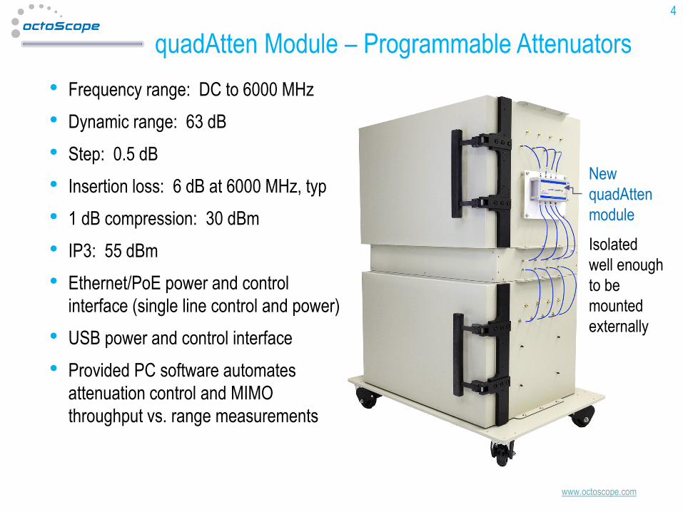
quadAtten Module – Programmable Attenuators
• Frequency range: DC to 6000 MHz
• Dynamic range: 63 dB
• Step: 0.5 dB
• Insertion loss: 6 dB at 6000 MHz, typ
• 1 dB compression: 30 dBm
• IP3: 55 dBm
• Ethernet/PoE power and control
interface (single line control and power)
• USB power and control interface
• Provided PC software automates
attenuation control and MIMO
throughput vs. range measurements
4
New
quadAtten
module
Isolated
well enough
to be
mounted
externally
www.octoscope.com
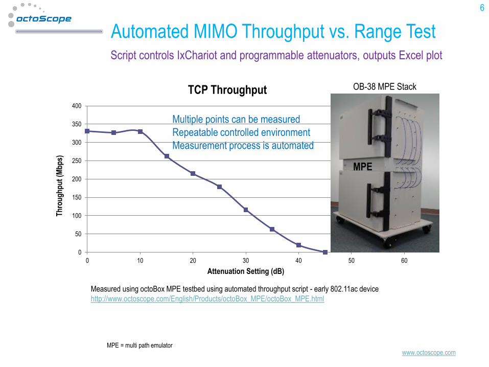
Automated MIMO Throughput vs. Range Test
6
0
50
100
150
200
250
300
350
400
0 10 20 30 40 50 60
Th
rou
gh
pu
t (M
bp
s)
Attenuation Setting (dB)
TCP Throughput
Measured using octoBox MPE testbed using automated throughput script - early 802.11ac device
http://www.octoscope.com/English/Products/octoBox_MPE/octoBox_MPE.html
Multiple points can be measured
Repeatable controlled environment
Measurement process is automated
Script controls IxChariot and programmable attenuators, outputs Excel plot
OB-38 MPE Stack
MPE
MPE = multi path emulator
www.octoscope.com
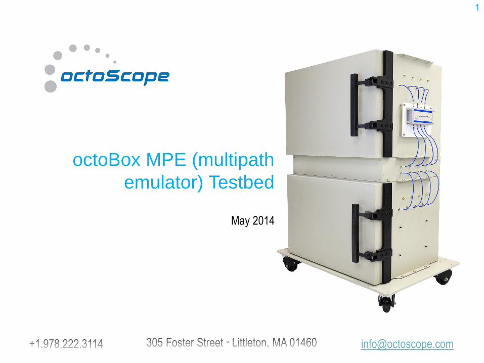
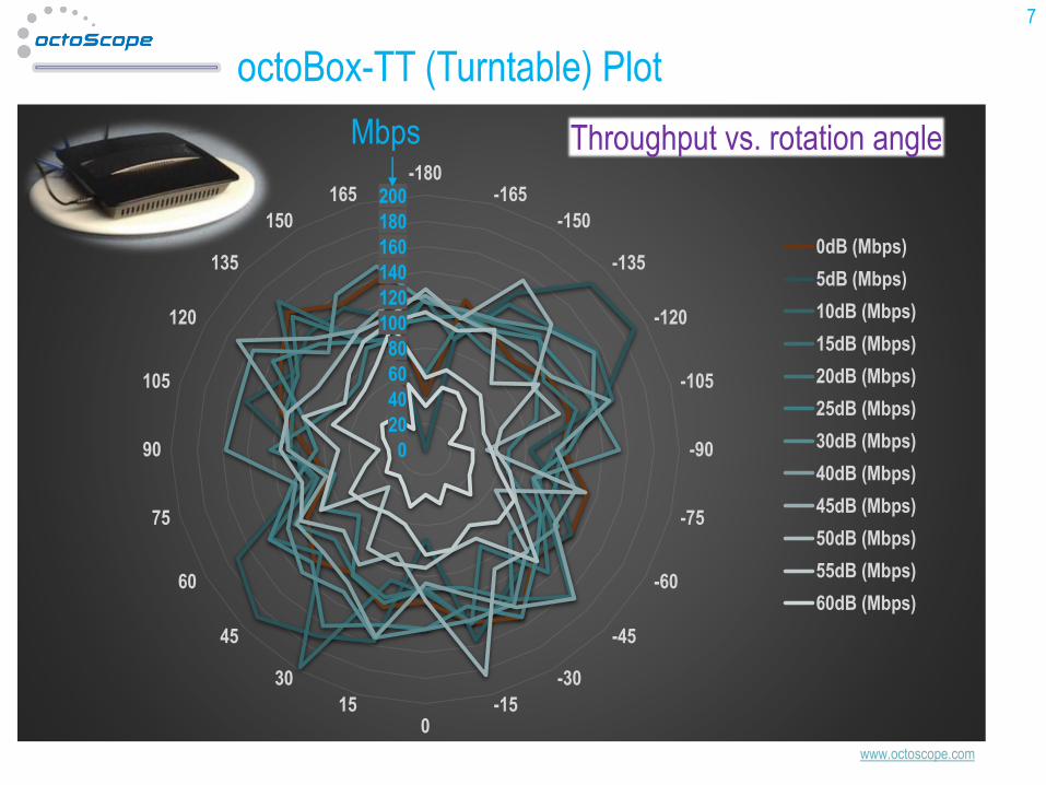
octoBox-TT (Turntable) Plot
7
0
20
40
60
80
100
120
140
160
180
200-180
-165
-150
-135
-120
-105
-90
-75
-60
-45
-30
-150
15
30
45
60
75
90
105
120
135
150
165
Throughput vs. rotation angle
0dB (Mbps)
5dB (Mbps)
10dB (Mbps)
15dB (Mbps)
20dB (Mbps)
25dB (Mbps)
30dB (Mbps)
40dB (Mbps)
45dB (Mbps)
50dB (Mbps)
55dB (Mbps)
60dB (Mbps)
Mbps
www.octoscope.com
CONFIDENTIALCONFIDENTIAL
www.octoscope.com
CONFIDENTIAL 8
Watch video at this link: http://www.youtube.com/watch?v=04JOt-3aivg
OB-38-TT model
www.octoscope.com
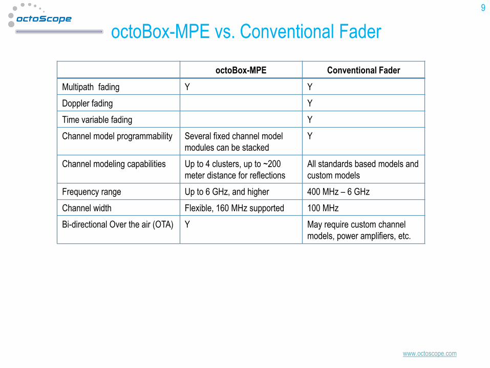
octoBox-MPE vs. Conventional Fader
octoBox-MPE Conventional Fader
Multipath fading Y Y
Doppler fading Y
Time variable fading Y
Channel model programmability Several fixed channel model
modules can be stacked
Y
Channel modeling capabilities Up to 4 clusters, up to ~200
meter distance for reflections
All standards based models and
custom models
Frequency range Up to 6 GHz, and higher 400 MHz – 6 GHz
Channel width Flexible, 160 MHz supported 100 MHz
Bi-directional Over the air (OTA) Y May require custom channel
models, power amplifiers, etc.
9
www.octoscope.com
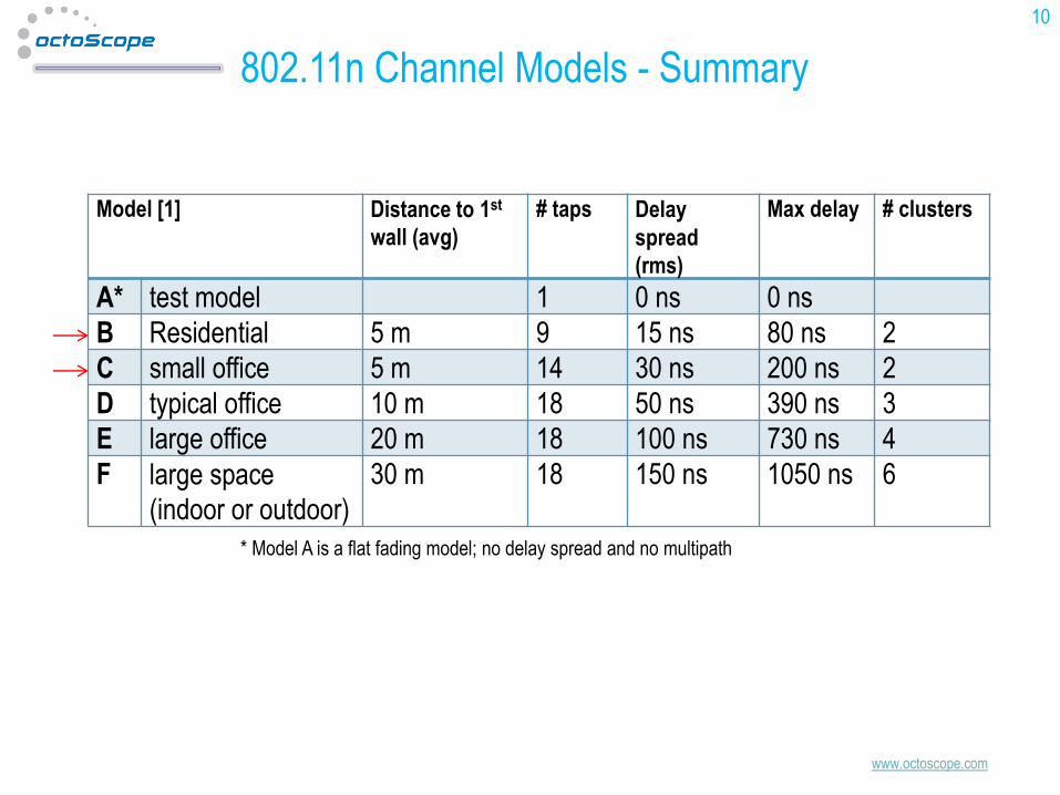
802.11n Channel Models - Summary
10
Model [1] Distance to 1st
wall (avg)
# taps Delay
spread
(rms)
Max delay # clusters
A* test model 1 0 ns 0 ns
B Residential 5 m 9 15 ns 80 ns 2
C small office 5 m 14 30 ns 200 ns 2
D typical office 10 m 18 50 ns 390 ns 3
E large office 20 m 18 100 ns 730 ns 4
F large space
(indoor or outdoor)
30 m 18 150 ns 1050 ns 6
* Model A is a flat fading model; no delay spread and no multipath
www.octoscope.com
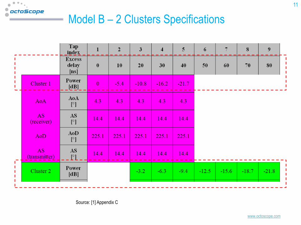
Model B – 2 Clusters Specifications
11
Source: [1] Appendix C
www.octoscope.com
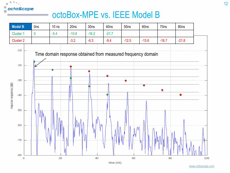
octoBox-MPE vs. IEEE Model B
12
Model B 0ns 10 ns 20ns 30ns 40ns 50ns 60ns 70ns 80ns
Cluster 1 0 -5.4 -10.8 -16.2 -21.7
Cluster 2 -3.2 -6.3 -9.4 -12.5 -15.6 -18.7 -21.8
Time domain response obtained from measured frequency domain
www.octoscope.com
Background
13
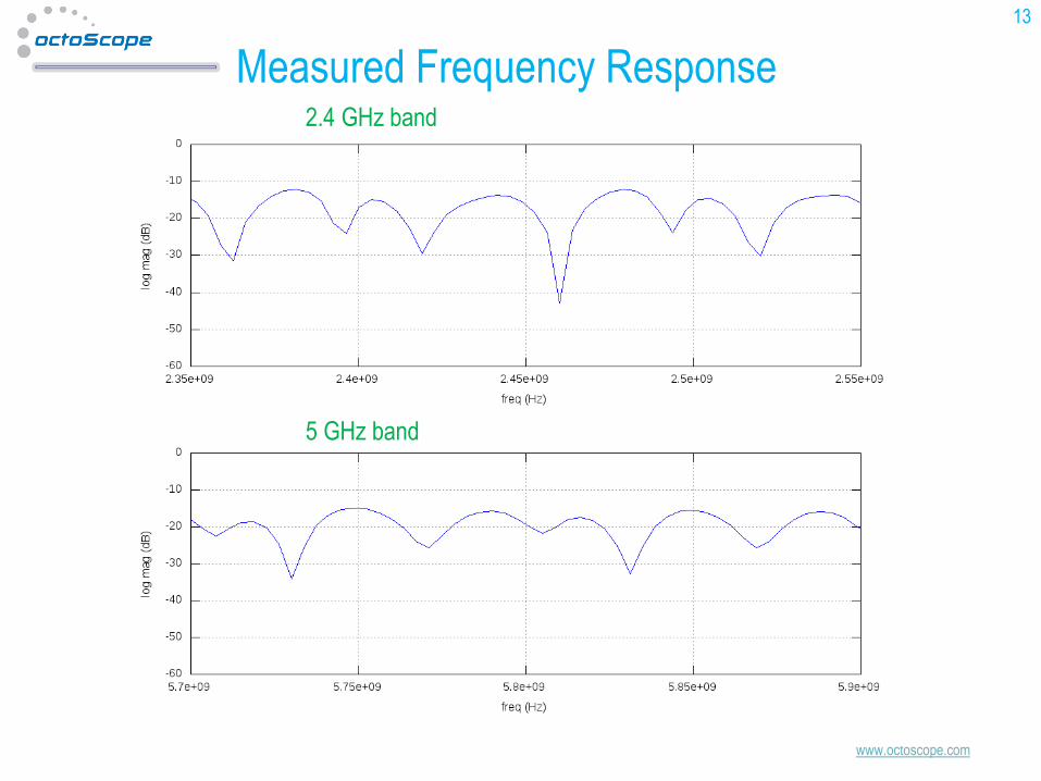
Measured Frequency Response2.4 GHz band
5 GHz band
www.octoscope.com
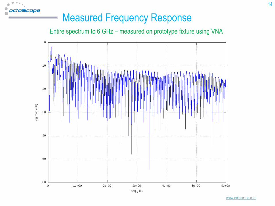
Measured Frequency Response
14
Entire spectrum to 6 GHz – measured on prototype fixture using VNA
www.octoscope.com
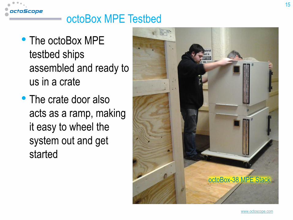
octoBox MPE Testbed
• The octoBox MPE
testbed ships
assembled and ready to
us in a crate
• The crate door also
acts as a ramp, making
it easy to wheel the
system out and get
started
15
octoBox-38 MPE Stack
www.octoscope.com
References1. IEEE, 802.11-03/940r4: TGn Channel Models; May 10, 2004
2. IEEE, 11-09-0569 , “TGac Channel Model Addendum Supporting Material”, May 2009
3. Schumacher et al, "Description of a MATLAB® implementation of the Indoor MIMO WLAN channel model proposed
by the IEEE 802.11 TGn Channel Model Special Committee", May 2004
4. IEEE 802.11-09/0308r12, “TGac Channel Model Addendum”, March 18, 2010
5. IEEE, 11-09-0334-08-00ad-channel-models-for-60-ghz-wlan-systems
6. Schumacher et al, "From antenna spacings to theoretical capacities - guidelines for simulating MIMO systems"
7. Schumacher reference software for implementing and verifying 802.11n models -
http://www.info.fundp.ac.be/~lsc/Research/IEEE_80211_HTSG_CMSC/distribution_terms.html
8. 3GPP 36-521, UE Conformance Specification, Annex B
9. 3GPP TR 25.996, "3rd Generation Partnership Project; technical specification group radio access networks; Spatial
channel model for MIMO simulations“
10. IST-WINNER II Deliverable 1.1.2 v.1.2, “WINNER II Channel Models”, IST-WINNER2, Tech. Rep., 2008
(http://projects.celtic-initiative.org/winner+/deliverables.html)
11. 3GPP TR37.976, MIMO OTA channel models
12. 3GPP TS 34.114: “User Equipment (UE) / Mobile Station (MS) Over The Air (OTA) Antenna Performance
Conformance Testing”
13. CTIA, “Test Plan for Mobile Station Over the Air Performance - Method of Measurement for Radiated RF Power and
Receiver Performance”, Revision 3.1, January 2011
16

www.octoscope.com
Contact
Tel: +1.222.3114
• Visit our website at www.octoscope.com
17
Thank you!