Embed Size (px)
Citation preview
UNITED STATES DEPARTMENT OF THE INTERIOR /o5" f :7
GEOLOGICAL SURVEY
GEOTHERMAL POTENTIAL OF THE ALID VOLCANIC CENTER,
DANAKIL DEPRESSION, ERITREA
By: Wendell A. ~uffield ' Thomas D. ~u l l en l Michael A. Clynnel Robert 0. Fournier' Cathy J. Janikl Marvin A. ~anphere' Jacob ow en stem' James G. Smith1
U.S. Geological Survey, USA
Leake W/Giorgis2 Gabreab Kahsai2 Kidane W/Mariam2 Theoderos Tesfai2
2 Ministry of Energy, Mines and Water Resources, Eritrea
Open-File Report 97-291
This report is preliminary and has not been reviewed for conformity with U.S. Geological Survey editorial standards and stratigraphic nomenclature. Any use of trade names is for
descriptive purposes only and does not imply endorsement by the U.S. Geological Survey.
Prepared in cooperation with U.S. Agency for International Development under the terms of PASA Number AOT-0002-P-00-5033-00.
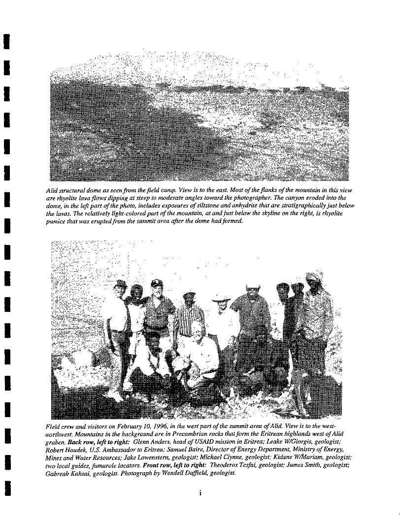
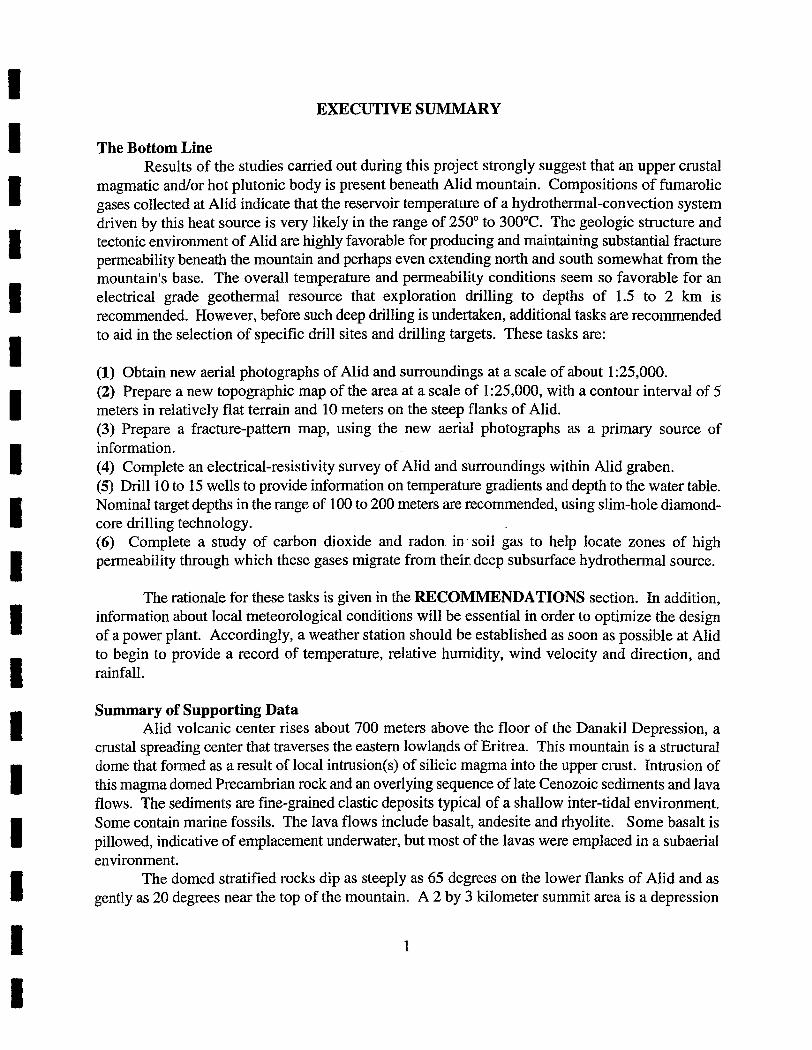
Alid structural dome as seenfrom thefield camp. View is to the east. Most of thefinks of the mountain in this view are rhyolite lava$ows dipping at steep to moderate angles toward the photographer. The canyon eroded into the dome, in the left part of the photo, includes exposures of siltstone and anhydrite that are stratigraphically just below the lavas. The relatively light-colored part of the mountain, at and just below the skyline on the right, is rhyolite pumice that was eruptedfrom the summit area afer the dome had formed.
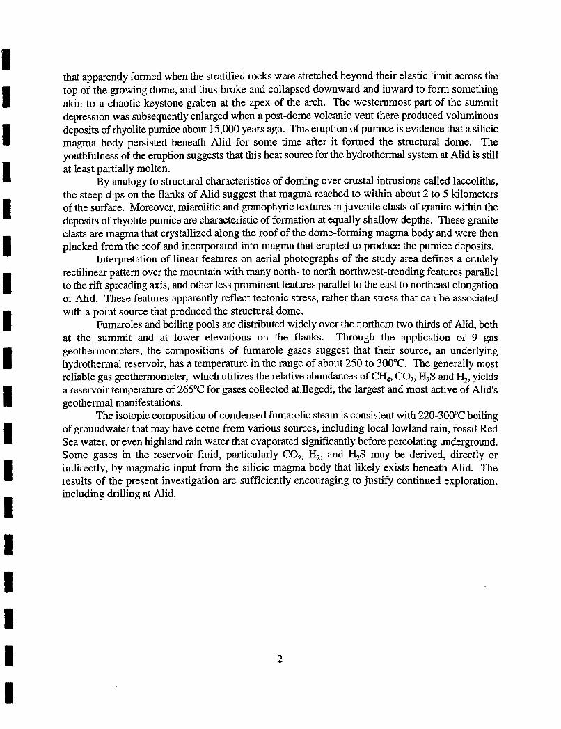
Field crew and visitors on February 10, 1996, in the west part of the summit area of Alid. View is to the west- northwest. Mountains in the background are in Precambrian rocks that f o m the Eritrean highlands west of Alid graben. Back row, left to right: Glenn Anders, head of USAID mission in Eritrea; Leake W/Giorgis, geologist; Robert Houdek, U.S. Ambassador to Eritrea; Samuel Baire, Director of Energy Department, Ministry of Energy, Mines and Water Resources; Jake Lowenstern, geologist; Michael Clynne, geologist; Kidane W&ariam, geologist; two local guides, fumarole locators. Front row, left to right: Theoderos Tesfai, geologist; James Smith, geologist; Gabreab Kahsai, geologist. Photograph by Wendell Dufield, geologist.
TABLE OF CONTENTS
. . . . . . . . . . . . . . . . . . . . . . . . . . . . . . . . . . . . . . . . . . . . . . . . . . . . . EXECUTIVESUMMARY 1 . . . . . . . . . . . . . . . . . . . . . . . . . . . . . . . . . . . . . . . . . . . . . . . . . . . . . . . TheBottomLine 1
. . . . . . . . . . . . . . . . . . . . . . . . . . . . . . . . . . . . . . . . . . . . . Summary of Supporting Data 1
INTRODUCTION . . . . . . . . . . . . . . . . . . . . . . . . . . . . . . . . . . . . . . . . . . . . . . . . . . . . . . . . . . . . 3
. . . . . . . . . . . . . . . . . . . . . . . . . . . . . . . . . . LOGISTICS AND FIELD METHODS AT ALID 3
. . . . . . . . . . . . . . . . . . . . . . . . . . . . . . . . . . . . . . . . . . . REGIONAL GEOLOGIC SETTING 12
. . . . . . . . . . . . . . . . . . . . LOCAL GEOLOGIC SETTING AND STRUCTURE OF ALID 19
. . . . . . . . . . . . . . . . . . . . . . . . . . . . . THE DOME-FORMING MAGMATIC INTRUSION 21
. . . . . . . . . . . . . . . . . . . . . . . PHOTOGEOLOGIC ANALYSIS OF LINEAR FEATURES 22
. . . . . . . . . . . . . . . . . . . . . . . . . . . . . . . . . . . . . . . . . . . . . . DESCRIPTIONOFMAPUNITS 24 . . . . . . . . . . . . . . . . . . . . . . . . . . . . . . . . . . . . Alluvium and Alluvial Fans (al. af. oaf) : 25
Oss Basalt Fields (yb) . . . . . . . . . . . . . . . . . . . . . . . . . . . . . . . . . . . . . . . . . . . . . . . . . . . 25 . . . . . . . . . . . . . . . . . . . . . . . . . . . . . . . . . . . . . . Silicic Lavas in the Oss Basalt Fields ; 25
Basaltic Spatter (bs) . . . . . . . . . . . . . . . . . . . . . . . . . . . . . . . . . . . . . . . . . . . . . . . . . . . . . 25 Pyroxene Rhyolite Flow in Alid Crater (pxrhy) . . . . . . . . . . . . . . . . . . . . . . . . . . . . . 26
. . . . . . . . . . . . Pyroxene Rhyolite Pumice Deposits Erupted from Alid Crater @fj 26 . . . . . . Flanking Pyroxene Rhyolite Lavas and Associated Pumice Deposits (frhy) 27
LavaShell(1s) . . . . . . . . . . . . . . . . . . . . . . . . . . . . . . . . . . . . . . . . . . . . . . . . . . . . . . . . . 28 Sedimentary Sequence (ss) . . . . . . . . . . . . . . . . . . . . . . . . . . . . . . . . . . . . . . . . . . . . . -28 Stratoid Basalt (str) . . . . . . . . . . . . . . . . . . . . . . . . . . . . . . . . . . . . . . . . . . . . . . . . . . . -29 Precambrian Basement @c) . . . . . . . . . . . . . . . . . . . . . . . . . . . . . . . . . . . . . . . . . . . . . 29
. . . . . . . . . . . . . . . . . PETROLOGY AND GEOCHEMISTRY OF VOLCANIC ROCKS -30 Bulk-Rockchemistry . . . . . . . . . . . . . . . . . . . . . . . . . . . . . . . . . . . . . . . . . . . . . . . . . . 30
. . . . . . . . . . . . . . . . . . . . . . . . . . . . . . . . . . . . . . Petrography and Crystal Chemistry 30 . . . . . . . . . . . . . . . . . . . . . . . . . . . . . . . . . . . . . . . . . Isotope Chemistry of Bulk Rocks 34
Discussion . . . . . . . . . . . . . . . . . . . . . . . . . . . . . . . . . . . . . . . . . . . . . . . . . . . . . . . . . . . 35
GEOCHRONOLOGY . . . . . . . . . . . . . . . . . . . . . . . . . . . . . . . . . . . . . . . . . . . . . . . . . . . . . . . . 36
. . . . . . . . . . . . . . . . . . . . . . . . . . . . REGIONAL HYDROLOGY AND GEOCHEMISTRY 40 Introduction . . . . . . . . . . . . . . . . . . . . . . . . . . . . . . . . . . . . . . . . . . . . . . . . . . . . . . . . . . 40
. . . . . . . . . . . . . . . . . . . . . . . . . . . . . . . . . . . . . . . . . . . . . Meteorological Information 40
Sample Collection . . . . . . . . . . . . . . . . . . . . . . . . . . . . . . . . . . . . . . . . . . . . . . . . . . . . . . 41 . . . . . . . . . . . . . . . . . . . . . . . . . . . . . . . . Isotope Geochemistry of Meteoric Waters - 4 1 . . . . . . . . . . . . . . . . . . . . . . . . . . . . . . . . Chemical Compositions of Meteoric Waters 44
GEOTHERMAL MANIFESTATIONS . . . . . . . . . . . . . . . . . . . . . . . . . . . . . . . . . . . . . . . . . . 48 Collection of Gas Samples . . . . . . . . . . . . . . . . . . . . . . . . . . . . . . . . . . . . . . . . . . . . . . . 48
. . . . . . . . . . . . . . . . . . . . . . . . . . . . Laboratory Analysis of Gas and Water Samples 49 . . . . . . . . . . . . . . . . . . . . . . Characteristics of Alid Fumaroles and Thermal Waters 49
. . . . . . . . . . . . . . . . . . . . . . . . . . . . . . . . . . . . . . . . . . . Fumarolic Encrustations 49 . . . . . . . . . . . . . . . . . . . . . . . . . . . . . . . . . . . . . . . . . . . . . . . . Gas Compositions 49
Gas Geothennometry . . . . . . . . . . . . . . . . . . . . . . . . . . . . . . . . . . . . . . . . . . . . . . 51 . . . . . . . . . . . . . . . . . . . . . . . . . . . . . . . . . . . . . . . . . . . . . . . . . . . ThemuzlPools 53
. . . . . . . . . . . . . . . . . . . . . . . . . . . . . . . . . Isotopic Compositions of Thermal Fluids -54 Summary of Geochemical Data on Fluids . . . . . . . . . . . . . . . . . . . . . . . . . . . . . . . . . . 56
. . . . . . . . . . . . . WORKING MODEL OF THE MAGMA/HYDROTHERMAL SYSTEM 56
. . . . . . . . . . . . . . . . . . . . . . . . . . . . . . . . . . . . . . . . . . . . . . . . . . . . . RECOMMENDATIONS 57
ACKNOWLEDGEMENTS . . . . . . . . . . . . . . . . . . . . . . . . . . . . . . . . . . . . . . . . . . . . . . . . . . . 60
REFERENCES CITED . . . . . . . . . . . . . . . . . . . . . . . . . . . . . . . . . . . . : .. . . . . . . . . . . . . . . . . -60
FIGURES . . . . . . . . . . . . . . . . . . . . . . . . 1 Simplified plate-tectonic map of the Afar Triangle region 13
. . . . . . . . . . . . . . . . . . . . . . . . . . . . . . 2 Generalized geologic map of Alid volcanic center 14 . . . . . . . . . . . . . . . . . . . . . . . . . . . . . . . . . 3 Schematic NE-SW cross-section through Alid 15
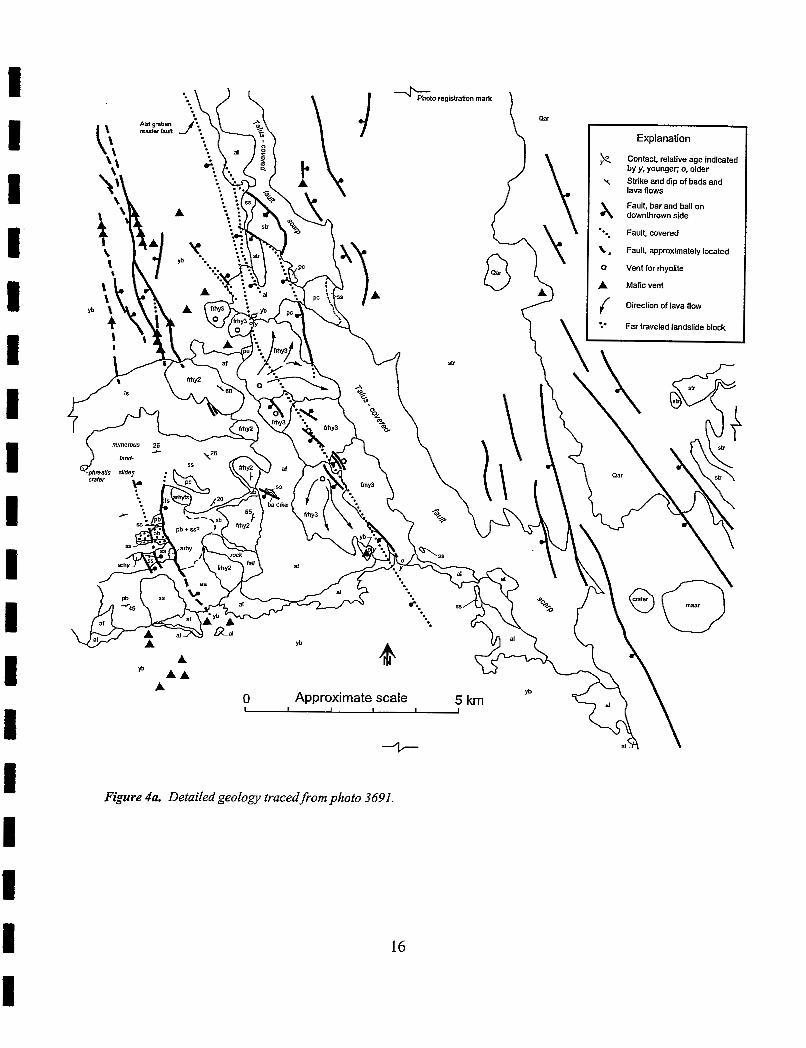
. . . . . . . . . . . . . . . . . . . . . . . . . . . . . . . . . . . 4a . Detailed geology traced from photo 3691 16
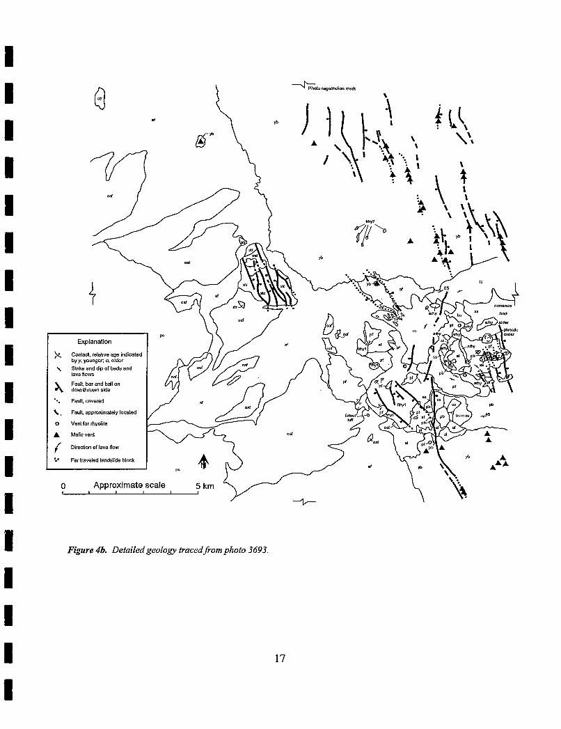
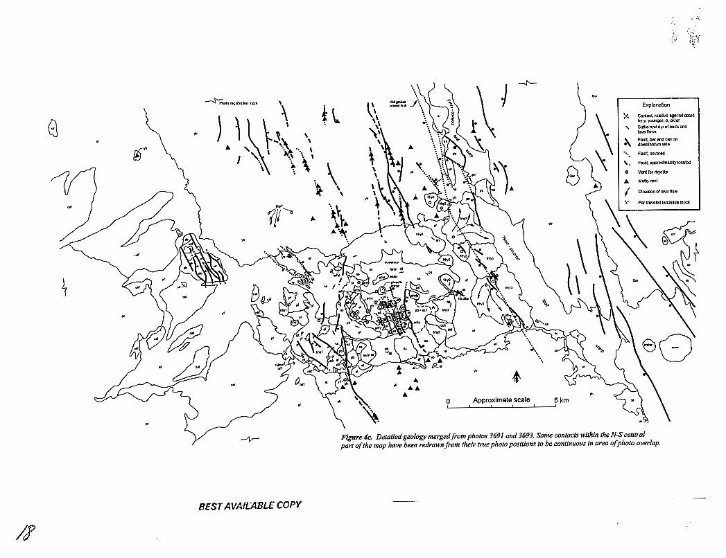
. . . . . . . . . . . . . . . . . . . . . . . . . . . . . . . . . . . 4b . Detailed geology traced from photo 3693 17 . . . . . . . . . . . . . . . . . . . . . . . . . 4c . Detailed geology merged from photos 3691 and 3693 18 . . . . . . . . . . . . . . . . . . . . . . . . . 5 Landsat thematic mapper image of Alid volcanic center 19
. . . . . . . . . . . . . . . . . . . . . . . . . . . 6 Photogeologic compilation of linear features at Alid 23 . . . . . . . . . . . . . . . . . . . . . . . . . . . . 7 Correlation of map units and map unit designations 24 . . . . . . . . . . . . . . . . . . . . . . . . . . 8- Total alkali-silica diagram for volcanic rocks of Alid 34
. . . . . . . . . . . . . . . . . . . . . . . . . . . . . . . . . 9 Plots of bulk-rock Sr and Pb isotope analyses 35 . . . . . . . . . . . . . . . . . . . . . . . . . . . . . . . . . . . . . . . . . . 10 . Argon age spectra for Alid basalt 39
. . . . . . . . . . . . . . . . . . . . . . . . . . . . . . . . . . . . . . . . . . . . . . 1 1 . Water sample location map 42 . . . . . . . . . . . . . . . . . . . . . . . . . . . . . . . . 12 . GD versus 6180 for groundwaters and streams 42
. . . . . . . . . . . . . . . . . . . . . . . . . . . . 13 . Triangular diagram for ground and surface waters 44 . . . . . . . . . . . . . . . . . . . . . . . . . . . . . . 14 C1- versus HCO,- for groundwaters and streams 47
. . . . . . . . . . . . . . . . . . . . . . . . . . . . . . . 15 . Cl- versus SO4- for groundwaters and streams 47 . . . . . . . . . . . . . . . . . . . . . . . . . . . . 16 . HC03- versus SO,- for groundwaters and streams 47
. . . . . . . . . . . . . . . . . . . . . . . . . . . . . . . . 17 . Triangular diagram for fumarole gas samples 51 . . . . . . . . . . . . . . . . . . . . 18 Histogram of calculated hydrothermal-reservoir temperatures 53
19.6D versus 6I8O for Alid thermal waters and surface and shallow groundwaters . . . . . . 54
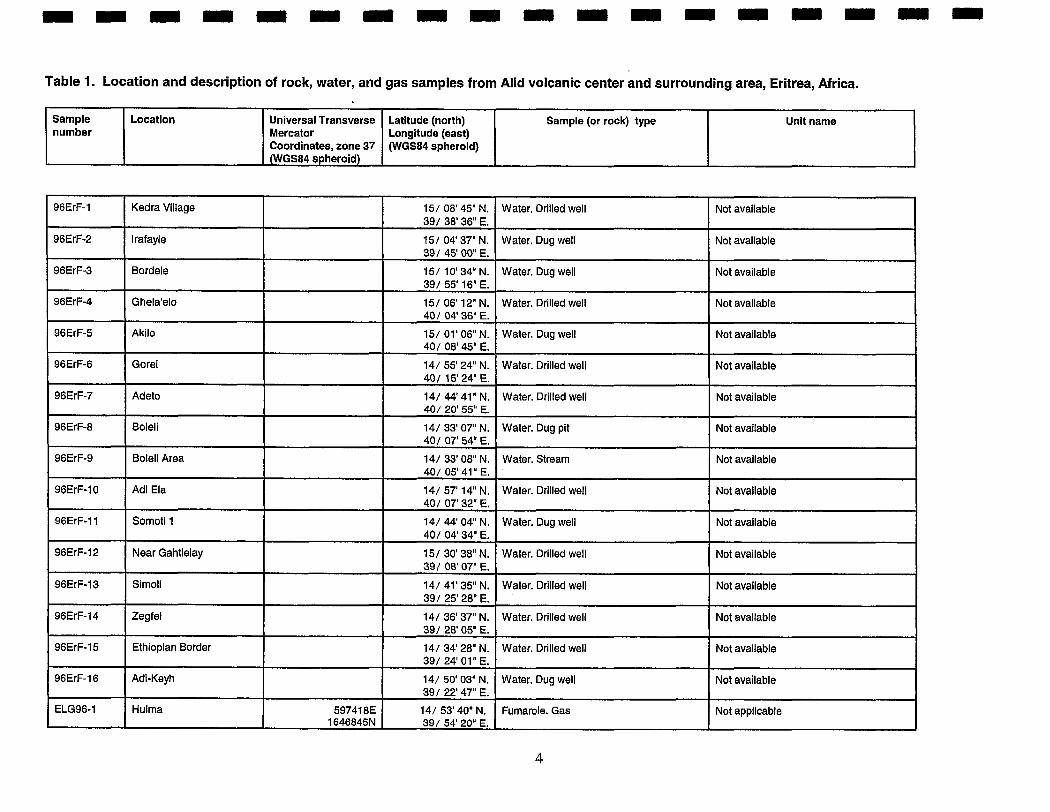
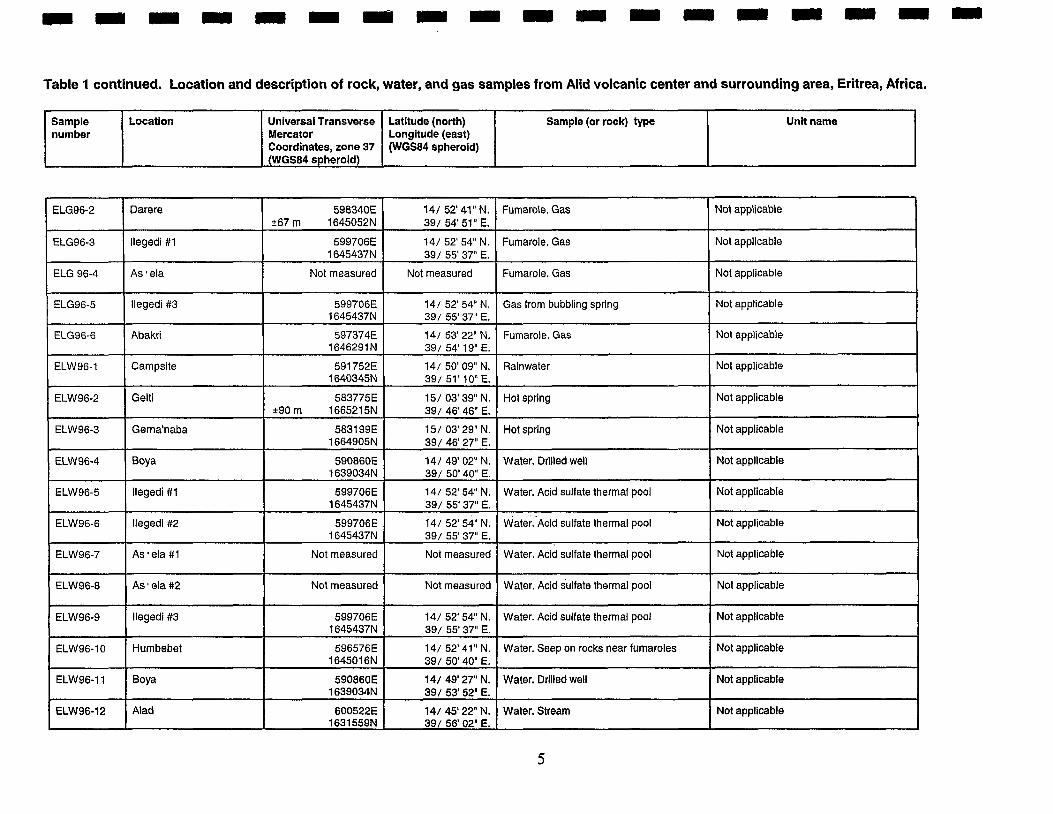
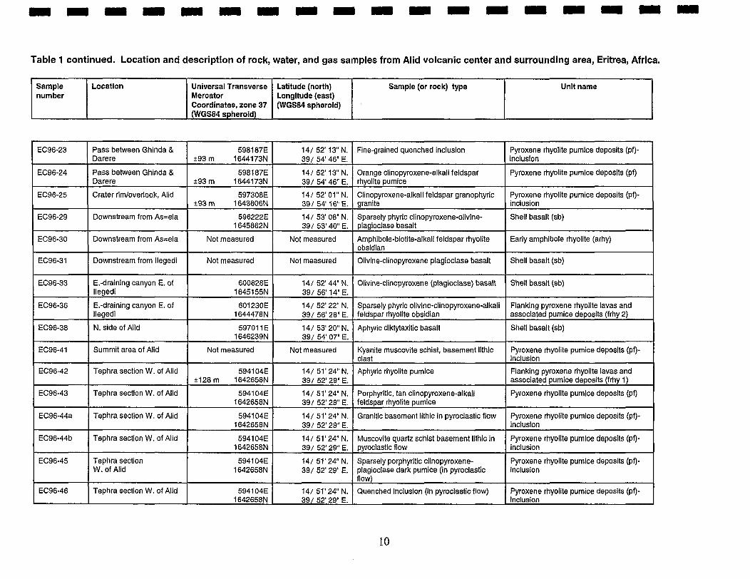
TABLES 1 . Location and description of rock. water. and gas samples from Alid volcanic center . . . 4
. . . . . . . . . . . . . . . . . . . . 2 . Major- and trace-element chemical composition of Alid rocks 31 . . . . . . . . . . . . . . . . . . . . . . . . . . . . . . . . 3 . Sr and Pb isotopic compositions of Alid rocks 33
. . . . . . . . . . . . . . . . . 4 . Analytical data and 40Ar/39Ar ages for volcanic rocks of Alid area 38 . . . . . . . . . 5 . Sample locations and stable isotope analyses of surface and groundwaters -43
. . . . . . . . . . . . . . . . . . . . . . . . . . . . . . . 6 . Chemical analyses of surface and groundwaters 45 . . . . . . . . . . . . . . . . . . . . . . . . . . . . . . . . . . . . . . . . 7 . Gas geochemistry of Alid fumaroles 50
. . . . . . . . . . . . . . . . . . . . . . . . . . . . . . . . . . . . . . . . . . 8 . Calculated reservoir temperatures 52 . . . . . . . . . . . . . . 9 . Isotopic compositions of fumarolic steam and pools of thermal water 55
EXECUTIVE SUMMARY
The Bottom Line Results of the studies carried out during this project strongly suggest that an upper crustal
magmatic and/or hot plutonic body is present beneath Alid mountain. Compositions of fumarolic gases collected at Alid indicate that the reservoir temperature of a hydrothermal-convection system driven by this heat source is very likely in the range of 250" to 300°C. The geologic structure and tectonic environment of Alid are highly favorable for producing and maintaining substantial fracture permeability beneath the mountain and perhaps even extending north and south somewhat from the mountain's base. The overall temperature and permeability conditions seem so favorable for an electrical grade geothermal resource that exploration drilling to depths of 1.5 to 2 km is recommended. However, before such deep drilling is undertaken, additional tasks are recommended to aid in the selection of specific drill sites and drilling targets. These tasks are:
(1) Obtain new aerial photographs of Alid and surroundings at a scale of about 1:25,000. (2) Prepare a new topographic map of the area at a scale of 1 :25,000, with a contour interval of 5 meters in relatively flat terrain and 10 meters on the steep flanks of Alid. (3) Prepare a fracture-pattern map, using the new aerial photographs as a primary source of information. (4) Complete an electrical-resistivity survey of AIid and surroundings within Alid graben. (5) Drill 10 to 15 wells to provide information on temperature gradients and depth to the water table. Nominal target depths in the range of 100 to 200 meters are recommended, using slim-hole diamond- core drilling technology. (6) Complete a study of carbon dioxide and radon in.soil gas to help locate zones of high permeability through which these gases migrate from their. deep subsurface hydrothermal source.
The rationale for these tasks is given in the RECOMMENDATIONS section. In addition, information about local meteorological conditions will be essential in order to optimize the design of a power plant. Accordingly, a weather station should be established as soon as possible at Alid to begin to provide a record of temperature, relative humidity, wind velocity and direction, and rainfall.
Summary of Supporting Data Alid volcanic center rises about 700 meters above the floor of the Danakil Depression, a
crustal spreading center that traverses the eastern lowlands of Eritrea. This mountain is a structural dome that formed as a result of local intrusion(s) of silicic magma into the upper crust. Intrusion of this magma domed Precambrian rock and an overlying sequence of late Cenozoic sediments and lava flows. The sediments are fine-grained clastic deposits typical of a shallow inter-tidal environment. Some contain marine fossils. The lava flows include basalt, andesite and rhyolite. Some basalt is pillowed, indicative of emplacement underwater, but most of the lavas were emplaced in a subaerial environment.
The domed stratified rocks dip as steeply as 65 degrees on the lower flanks of AIid and as gently as 20 degrees near the top of the mountain. A 2 by 3 kilometer summit area is a depression
that apparently formed when the stratified rocks were stretched beyond their elastic limit across the top of the growing dome, and thus broke and collapsed downward and inward to form something akin to a chaotic keystone graben at the apex of the arch. The westernmost part of the summit depression was subsequently enlarged when a post-dome volcanic vent there produced voluminous deposits of rhyolite pumice about 15,000 years ago. This eruption of pumice is evidence that a silicic magma body persisted beneath Alid for some time after it formed the structural dome. The youthfulness of the eruption suggests that this heat source for the hydrothermal system at Alid is still at least partially molten.
By analogy to structural characteristics of doming over crustal intrusions called laccoliths, the steep dips on the flanks of Alid suggest that magma reached to within about 2 to 5 kilometers of the surface. Moreover, miarolitic and granophyric textures in juvenile clasts of granite within the deposits of rhyolite pumice are characteristic of formation at equally shallow depths. These granite clasts are magma that crystallized along the roof of the dome-forming magma body and were then plucked from the roof and incorporated into magma that erupted to produce the pumice deposits.
Interpretation of linear features on aerial photographs of the study area defines a crudely rectilinear pattern over the mountain with many north- to north northwest-trending features parallel to the rift spreading axis, and other less prominent features parallel to the east to northeast elongation of Alid. These features apparently reflect tectonic stress, rather than stress that can be associated with a point source that produced the structural dome.
Fumaroles and boiling pools are distributed widely over the northern two thirds of Alid. both at the summit and at lower elevations on the flanks. Through the application of 9 gas geothermometers, the compositions of fumarole gases suggest that their source, an underlying hydrothermal reservoir, has a temperature in the range of about 250 to 300°C. The generally most reliable gas geothennometer, which utilizes the relative abundances of CH,, CO,, H2S and H,, yields a reservoir temperature of 265°C for gases collected at-Ilegedi, the largest and most active of Alid's geothermal manifestations.
The isotopic composition of condensed fumarolic steam is consistent with 220-300°C boiling of groundwater that may have come from various sources, including local lowland rain, fossil Red Sea water, or even highland rain water that evaporated significantly before percolating underground. Some gases in the reservoir fluid, particularly CO,, H,, and H,S may be derived, directly or indirectly, by magmatic input from the silicic magma body that likely exists beneath Alid. The results of the present investigation are sufficiently encouraging to justify continued exploration, including drilling at Alid.
INTRODUCTION There is an urgent need to develop new domestic sources of energy to foster expansion of the
Eritrean economy while minimizing the costly importation of fossil fuels. To help address this need, USAID implemented a PASA with the USGS to provide technical advisory services to address the possible use of geothermal resources as a source of energy for Eritrea. It has long been recognized that Eritrea may have significant exploitable geothermal resources (U.N.D.P., 1973). The present geothermal project, funded by USAID, is an outgrowth of early proposals made as a result of work by the late professor G. Marinelli and the staff of the Eritrean Ministry of Energy, Mines and Water Resources (MEMWR).
As a first step in implementing the USGS project, R.O. Fournier visited Eritrea in June, 1995 to: (1) observe the extent of surface expressions of hydrothermal activity in the region, (2) assess the logistical problems that would be encountered in carrying out field work, and (3) meet with members of the MEMWR to formulate a specific strategy for carrying out the USGS investigations. At that time it was mutually agreed that the project should focus on high enthalpy geothermal resources for the production of electricity, and that the best use of the available funds would be to carry out detailed geologic and geochemical investigations at the Alid volcanic center. AIid has long been recognized as a potential high enthalpy geothermal resource, because it is the focus of geologically young rhyolitic volcanism within a background of spreading-related basaltic volcanism and it is the site of many fumaroles (U.N.D.P., 1973; Beyth, 1994).
In addition to the specific site study of Alid, it was decided to collect groundwater samples in the surrounding lowlands and adjacent highlands to determine regionaI stable isotope and chemical variations that might provide clues to sources of recharge for the Alid hydrothermal system. The main field campaign was carried out in February, 1996. Samples of the various volcanic rocks exposed at Alid were collected for chemical analyses and radiometric age determinations. .
An important objective of the project was to provide technology transfer. Accordingly, all of the field work was carried out in close cooperation with Eritrean counterparts.
LOGISTICS AND FIELD METHODS AT ALID The field party that carried out geologic mapping at Alid consisted of 8 geologists (4 Eritrean and
4 American), a driver for each of two 4-wheel-drive vehicles, and a cook. Camp was established on the surface of an old alluvial fan west of Alid, about 2 km from Boya well, the principal source of water for local residents from a large surrounding area.
A total of 18 days was spent in the field. For the first two days, both vehicles and all geologists stayed together for reconnaissance of the study area and planning the rest of the work. Thereafter, a field day typically consisted of one party devoted to examining and sampling thermal manifestations and one to three parties devoted to mapping geologic structures and the distributions of rock types. Each night at camp, the field parties briefed each other on what they had found that day, and plans were then made for the following day's traverses.
A total of 87 rock, 13 water, and 6 gas samples were collected at and adjacent to Alid (Table 1). In addition, 16 water samples from wells and a stream were collected regionally. Duplicate samples of the rocks were collected so that the Eritrean members of the team have a reference set in country. The set that went to the USA was analyzed in various ways in laboratories at the U. S. Geological Survey.
I m r -
Table 1. Location and description of rock, water, and gas samples from Alid volcanic center and surrounding area, Eritrea, Africa.
Sample number
96ErF-1
96ErF-2
96ErF-3
96ErF-4
96ErF-5
96ErF-6
96ErF-7
96ErF-8
96ErF-9
96ErF-10
96ErF-11
96ErF-12
96ErF-13
96ErF-14
96ErF-15
96ErF-16
ELG96-1
Location
Kedra Village
lrafayle
Bordele
Ghela'elo
Akilo
Gorei
Adeto
Boleli
Boleli Area
Adi Ela
Somoti 1
Near Gahtielay
Simoli
Zegfel
Ethiopian Border
Adi-Keyh
Hulma
Universal Transverse Mercator Coordinates, zone 37 (WGS84 spheroid)
~p --
597418E 1646845N
Latitude (north) Longitude (east) (WGS84 spheroid)
15/ 08' 45" N. 39/ 38' 36" E.
15/ 04' 37" N. 391 45' 00" E.
15/ 10' 34" N. 39/ 55' 16" E.
15/ 06' 12" N. 401 04' 36" E.
15/ 01' 06" N. 40/ 08' 45" E.
14/ 55' 24" N. 401 15'24" E.
14/ 44' 41" N. 40/ 20' 55" E.
14/ 33' 07" N. 40 1 07' 54" E.
14/ 33' 08" N. 40/ 05' 41' E.
14/ 57' 14" N. 401 07' 32" E.
14/ 44' 04" N. 40/ 04' 34" E.
15/ 30' 38'' N. 39 I 08' 07" E.
14/ 41' 35" N. 39/ 25' 28" E.
14/ 36' 37" N. 39/ 28' 05" E.
14/ 34' 28" N. 39/ 24' 01" E.
14/ 50' 03" N. 39/ 22' 47" E.
14/ 53' 40" N. 39/ 54' 20".
Sample (or rock) type Unit name
Water. Drilled well
Water. Dug well
Water. Dug well
Water. Drilled well
Water. Dug well
Water. Drilled well
Water. Drilled well
Water. Dug pit
Water. Stream
Water. Drilled well
Water. Dug well
Water. Drilled well
Water. Drilled well
Water. Drilled well
Water. Drilled well
Water. Dug well
Fumarole. Gas
Not available
Not available
Not available
Not avallable
Not available
Not available
Not available
Not available
Not available
Not available
Not available
Not available
Not available
Not available
Not available
Not available
Not appllcable
I u n R R ~ R - - -
Table 1 continued. Location and description of rock, water, and gas samples from Alid volcanic center and surrounding area, Eritrea, Africa.
Sample number
ELG96-2
ELG96-3
ELG 96-4
ELG96-5
ELG96-6
ELW96-1
ELW96-2
ELW96-3
ELW96-4
ELW96-5
ELW96-6
ELW96-7
ELW96-8
ELW96-9
ELW96-10
ELW96-11
ELW96-12
Location Universal Transverse Mercator Coordinates, zone 37 (WGS84 spheroid)
Darere
llegedi # I
As ela
lleged~ #3
Abakri
Campsite
Gelti
Gerna'naba
Boya
- --
llegedi # I
llegedi #2
As ela #1
As ' ela #2
llegedi #3
Humbebet
Boya
Alad
Fumarole. Gas
Fumarole. Gas
Fumarole. Gas
Gas from bubbling spring
Fumarole. Gas
Rainwater
Hot spring
Hot spring
Water. Drilled well
--- -
Water. Acid sulfate thermal pool
~ a t e r . ' ~ c i d sulfate thermal pool
Water. ~ c i d sulfate thermal pool
Water. Acid sulfate thermal pool
Water. Acid sulfate thermal pool
Water. Seep on rocks near fumaroles
Water. Drilled well
Water. Stream
Latitude (north) Longitude (east) (WGS84 spheroid)
Not applicable
Not applicable
Not applicable
Not applicable
Not applicable
Not applicable
Not applicable
Not applicable
Not applicable
Not applicable
Not applicable
Not applicable
Not applicable
Not applicable
Not applicable
Not applicable
Not applicable
598340E *67 m 1645052N
599706E 1645437N
Not measured
599706E 1645437N
597374E 1 646291 N
591752E 1640345N
583775E *90 m 1665215N
5831 99E 1664905N
590860E 1639034N
-
599706E 1645437N
599706E 1645437N
Not measured
Not measured
599706E 1645437N
596576E 1645016N
590860E 1639034N
600522E 1631559N
141 52' 41" N. 39/ 54' 51" E.
141 52' 54" N. 39/ 55' 37" E.
Not measured
14/ 52' 54" N 39/ 55' 37" E.
141 53' 22" N. 39/ 54' 19" E.
14/ 50' 09" N. 39/ 51' 10" E.
15/ 03' 39" N. 39/ 46' 46" E.
15/ 03' 29" N. 39/ 46' 27" E.
141 49' 02" N. 39/ 50' 40" E.
14/ 52' 54" N. 39/ 55' 37" E.
14/ 52' 54" N. 39/ 55' 37" E.
Not measured
Not measured
14/ 52' 54" N. 39/ 55' 37" E.
14/ 52' 41" N. 39/ 50' 40" E.
141 49' 27" N. 39/ 53' 52".
141 45' 22" N. 39/ 56' 02' E.
Sample (or rock) type Unit name
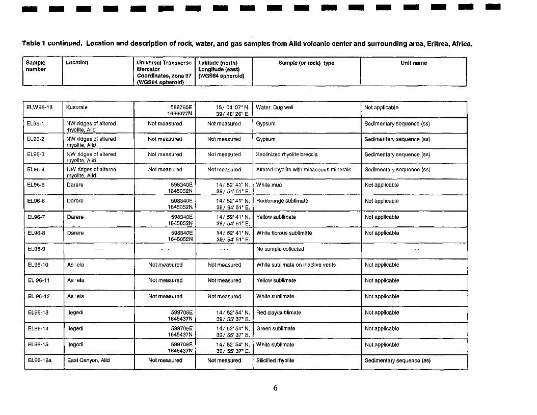
Table 1 continued. Location and description of rock, water, and gas samples from lid volcanic center and surrounding area, Eritrea, Africa.
Sample number
ELW96-13
EL96-1
EL96-2
EL96-3
EL96-4
EL96-5
EL96-6
EL96-7
EL96-8
EL96-9
EL96-10
EL 96-1 1
EL 96-1 2
EL96-13
EL96-14
EL96-15
EL96-16a
Location
Kusurale
NW ridges of altered rhyolite, Alid
NW ridges of altered rhyolite, Alid
NW ridges of altered rhyolite, Alid
NW ridges of altered rhyolite, Alid
Darere
Darere
Darere
Darere
- - -
As ' ela
As ' ela
AS ela
llegedi
llegedi
llegedi
East Canyon, Alid
Universal Transverse Mercator Coordinates, zone 37 (WGS84 spheroid)
586765E 1666077N
Not measured
Not measured
Not measured
Not measured
598340E 1645052N
598340E 1645052N
598340E 1645052N
598340E 1645052N
- - -
Not measured
Not measured
Not measured
599706E 1645437N
599706E 1645437N
599706E 1645437N
Not measured
Latitude (north) Longitude (east) (WGS84 spheroid)
151 04' 07" N. 39/ 48' 26" E.
Not measured
Not measured
Not measured
Not measured
14/ 52' 41" N. 39/ 54' 51" E.
14/ 52' 41" N. 39/ 54' 51" E.
14/ 52' 41 " N. 39/ 54' 51 YE.
14/ 52' 41" N. 39/ 54' 51" E.
--.
Not measured
Not measured
Not measured
14/ 52' 54" N. 39/ 55' 37" E.
141 52' 54" N. 39/ 55'37" E.
14/ 52' 54" N. 39/ 55' 37".
Not measured
Sample (or rock) type Unit name
Water. Dug well
Gypsum
Gypsum
Kaolinized rhyolite breccia
Altered rhyolite with micaceous minerals
White mud
Redlorange sublimate
Yellow sublimate
White fibrous sublimate
No sample collected
White sublimate on inactive vents
Yellow sublimate
White sublimate
Red clayisublimate
Green sublimate
White sublimate
Silicified rhyolite
Not applicable
Sedimentary sequence (ss)
Sedimentary sequence (ss)
Sedimentary sequence (ss)
Sedimentary sequence (ss)
Not applicable
Not applicable
Not applicable
Not applicable
- - -
Not applicable
Not applicable
Not applicable
Not applicable
Not applicable
Not applicable
Sedimentary sequence (ss)
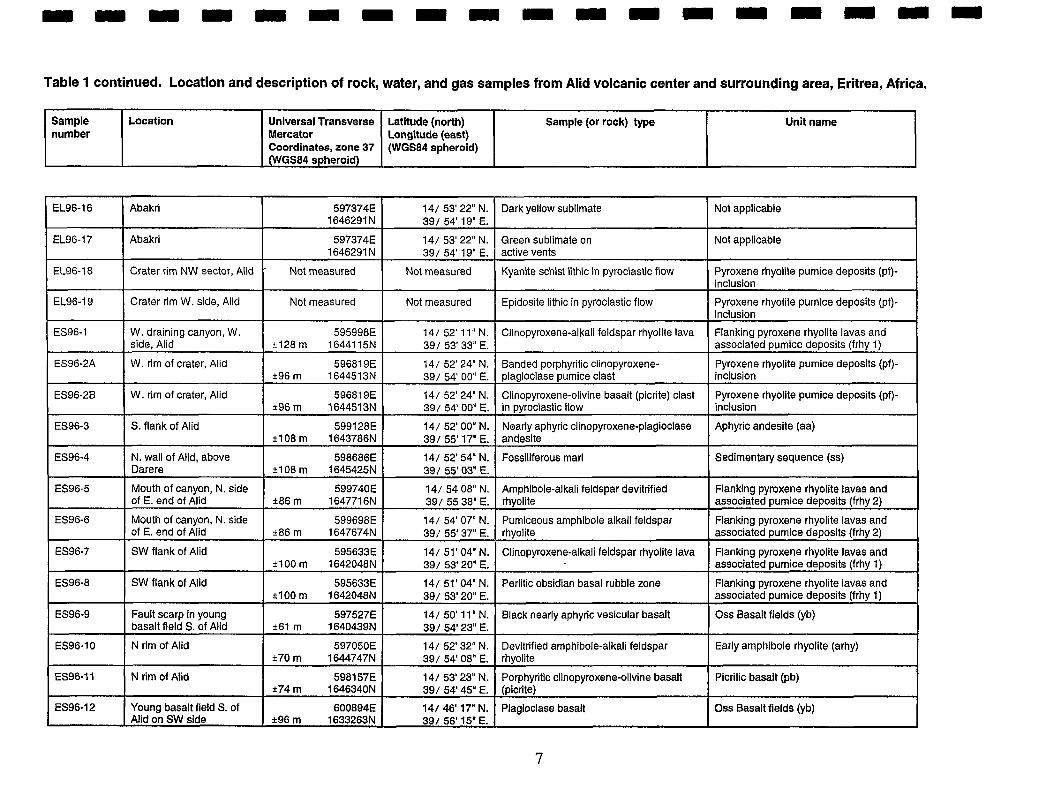
Table 1 continued. Location and description of rock, water, and gas samples from Alid volcanic center and surrounding area, Eritrea, Africa.
-- -
Sample number
EL96-16
EL96-17
EL96-18
EL96-19
ES96-1
ES96-2A
ES96-2B
ES96-3
ES96-4
ES96-5
ES96-6
ES96-7
ES96-8
ES96-9
ES96-10
ES96-11
ES96-12
Location
Abakri
Abakri
Crater rim NW sector, Alid
Crater rim W. side, Alid
W. draining canyon, W. side, Alid
W. rim of crater, Aiid
W. rim of crater, Alid
S. flank of Alid
N. wall of Alid, above Darere
Mouth of canyon, N. side of E. end of Alid
Mouth of canyon, N. side of E. end of Alid
SW flank of Alid
SW flank of Alid
Fault scarp in young basalt field S. of Alid
N rim of Alid
N rim of Aiid
Young basalt field S. of Alid on SW slde
Universal Transverse Mercator Coordinates, zone 37 (WGS84 spheroid)
597374E 1646291 N
597374E 1646291 N
- Not measured
Not measured
595998E +I28 m 1644115N
59681 9E +96 m 1644513N
596819E t96 m 1644513N
599128E t 108 m 1643786N
598686E i 1 08 m 1645425N
599740E *86 m 1647716N
599698E -c86 m 1647674N
595633E ? lo0 m 1642048N
595633E + 100 m 1642048N
597527E *61 m 1640439N
597050E *70 m 1644747N
598157E +74 m 1646340N
600894E *96 m 1633263N
Latitude (north) Longitude (east) (WGS84 spheroid)
14/ 53' 22" N. 39/ 54' 19" E.
14/ 53' 22" N. 391 54' 19" E.
Not measured
Not measured
14/ 52' 11" N. 39/ 53' 33" E.
14/ 52' 24" N. 391 54' 00" E.
141 52' 24" N. 391 54' 00" E.
14/ 52' 00" N. 391 55' 17" E.
14/ 52' 54" N. 39/ 55' 03" E.
I
141 54 08" N. 391 55 38" E.
14/ 54' 07" N. 391 55' 37" E.
141 51' 04" N. 391 53' 20" E.
14/ 51' 04" N. 39/ 53' 20" E.
14/ 50' 11" N. 39/ 54' 23" E.
141 52' 32" N. 391 54' 08".
14/ 53' 23" N. 391 54' 45" E.
14/ 46' 17" N. 39/ 56' 15" E.
Sample (or rock) type Unit name
Dark yellow sublimate
Green sublimate on active vents
Kyanite schist lithic in pyroclastic flow
Epidosite lithic in pyroclastic flow
Clinopyroxene-alkali feldspar rhyolite lava
Banded porphyritic clinopyroxene- plagioclase pumice clast
Clinopyroxene-olivine basalt (picrite) clast in pyrociastic flow
Nearly aphyric clinopyroxene-plagioclase andesite
Fossiliferous marl
Amphibole-alkali feldspar devitrified rhyolite
Pumiceous amphibole alkali feldspar , rhyolite
Clinopyroxene-alkali feldspar rhyolite lava
Perlitic obsidian basal rubble zone
Black nearly aphyric vesicular basalt
Devitrified amphibole-alkali feldspar rhyolite
Porphyritic clinopyroxene-olivine basalt (picrite)
Plagioclase basalt
Not applicable
Not applicable
Pyroxene rhyolite pumice deposits (pf)- inclusion
Pyroxene rhyolite pumice deposits (pf)- inclusion
Flanking pyroxene rhyolite lavas and associated pumice deposits (frhy 1)
Pyroxene rhyolite pumice deposits (pf)- inclusion
Pyroxene rhyolite pumice deposits (pf)- inclusion
Aphyric andesite (aa)
Sedimentary sequence (ss)
Flanking pyroxene rhyolite lavas and associated pumice deposits (frhy 2)
Flanking pyroxene rhyolite lavas and associated pumice deposits (frhy 2)
Flanking pyroxene rhyolite lavas and associated pumice deposits (frhy 1)
Flanking pyroxene rhyolite lavas and associated pumice deposits (frhy 1)
Oss Basalt fields (yb)
Early amphibole rhyolite (arhy)
Picritic basalt (pb)
Oss Basalt fields (yb)
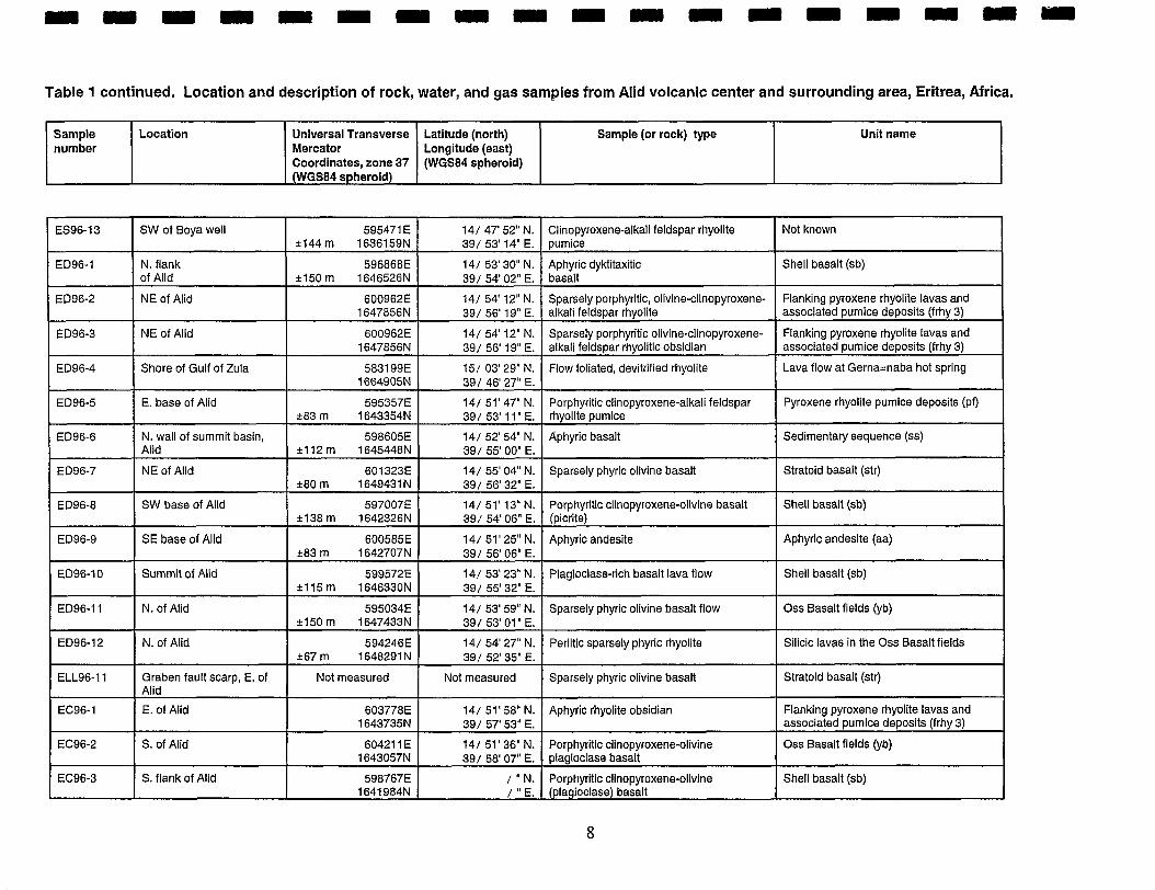
Table 1 continued. Location and description of rock, water, and gas samples from Alid volcanic center and surrounding area, Eritrea, Africa.
Sample number
Location
Not known
Shell basalt (sb)
Flanking pyroxene rhyolite lavas and associated pumice deposits (frhy 3)
Flanking pyroxene rhyolite lavas and associated pumice deposits (frhy 3)
Lava flow at Gerna=naba hot spring
Pyroxene rhyolite pumice deposits (pf)
Sedimentary sequence (ss)
Stratoid basalt (str)
Shell basalt (sb)
Aphyric andesite (aa)
Shell basalt (sb)
Oss Basalt fields (yb)
Silicic lavas in the Oss Basalt fields
Stratoid basalt (str)
Flanking pyroxene rhyolite lavas and associated pumice deposits (frhy 3)
Oss Basalt fields (yb)
Shell basalt (sb)
ES96-13
ED96-1
ED96-2
ED96-3
ED96-4
ED96-5
ED96-6
ED96-7
ED96-8
ED96-9
ED96-10
ED96-11
ED96-12
ELL96-11
EC96-1
EC96-2
EC96-3
SW of Boya well
N. flank of Alid
NE of Alid
NE of Alid
Shore of Gulf of Zula
E. base of Alid
N, wall of summit basin, Alid
NE of Alid
SW base of Alid
SE base of Alid
Summit of Alid
N. of Alid
N. of Alid
Graben fault scarp, E. of Alid
E. of Alid
S, of Alid
S. flank of Alid
Unit name Universal Transverse Mercator Coordinates, zone 37 (WGS84 spheroid)
595471 E i 1 4 4 m 1636159N
596868E i150 m 1646526N
600962E 1647856N
600962E 1647856N
5831 99E 1664905N
595357E *83 rn 1643354N
598605E *112m 1645448N
601323E *80m 1649431N
597007E *I38 m 1642326N
600585E i 8 3 m 1642707N
599572E +1 15 m 1646330N
595034E i150 m 1647433N
594246E k67 m 1648291 N
Not measured
603778E 1643735N
60421 1 E 1643057N
598767E 1641 984N
Latitude (north) Longitude (east) (WGS84 spheroid)
Sample (or rock) type
14/ 47' 52" N. 391 53' 14" E.
14/ 53' 30" N. 391 54' 02" E.
141 54' 12" N. 391 56' 19" E.
14/ 54' 12" N. 391 56' 19" E.
15/ 03' 29" N. 39 / 46' 27" E.
141 51' 47" N. 391 53' 11" E,
14/ 52' 54" N. 39/ 55' 00" E.
14/ 55' 04" N. 39/ 56' 32" E.
14/ 51' 13" N. 391 54' 06" E.
14/ 51' 25" N. 39/ 56' 06" E.
141 53' 23" N. 39/ 55' 32" E.
14/ 53' 59" N. 39/ 53' 01 " E.
14/ 54' 27" N. 39/ 52' 35" E.
Not measured
14/ 51' 58" N. 39/ 57' 53" E.
14/ 51' 36" N. 391 58' 07" E.
/ " N. / " E.
Clinopyroxene-alkali feldspar rhyolite pumice
Aphyric dyktitaxitic basalt
Sparsely porphyritic, olivine-clinopyroxene- alkali feldspar rhyolite
Sparsely porphyritic olivine-clinopyroxene- alkali feldspar rhyolitic obsidian
Flow foliated, devitrified rhyolite
Porphyritic clinopyroxene-alkali feldspar rhyolite pumice
Aphyric basalt
Sparsely phyric olivine basalt
Porphyritic clinopyroxene-olivine basalt (picrite)
Aphyric andesite
Plagioclase-rich basalt lava flow
Sparsely phyric olivine basalt flow
Perlitic sparsely phyric rhyolite
Sparsely phyric olivine basalt
Aphyric rhyolite obsidian
Porphyritic clinopyroxene-olivine . plagioclase basalt
Porphyritic clinopyroxene-olivine (plagioclase) basalt
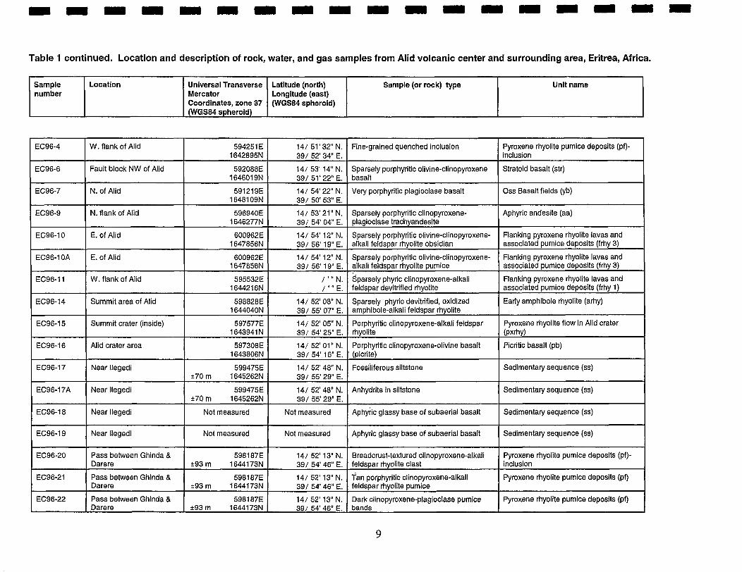
Table 1 continued. Location and description of rock, water, and gas samples from Alid volcanic center and surrounding area, Eritrea, Africa.
Sample number
Location
EC96-4
EC96-6
EC96-7
EC96-9
EC96-10
EC96-10A
EC96-11
EC96-14
EC96-15
EC96-16
EC96-17
EC96-17A
EC96-18
EC96-19
EC96-20
EC96-21
EC96-22
W. flank of Alid
Fault block NW of Alid
N. of Alid
N. flank of Aiid
E. of Alid
E. of Alid
W. flank of Alid
Summit area of Alid
Summit crater (inside)
Alid crater area
Near llegedi
Near llegedi
Near llegedi
Near llegedi
Pass between Ghinda & Darere
Pass between Ghinda & Darere
Pass between Ghinda & Darere
594251 E 1642895N
592088E 164601 9N
591219E 16481 09N
596940E 1646277N
600962E 1647856N
600962E 1647856N
595532E 1644216N
598828E 1644040N
597577E 1643941 N
597308E 1643806N
599475E k70 m 1645262N
599475E k70 m 1645262N
Not measured
Not measured
598187E i 9 3 m 1644173N
5981 87E %93 m 1644173N
5981 87E i 9 3 m 1644173N
Universal Transverse Mercator Coordinates, zone 37 (WGS84 spheroid)
Pyroxene rhyolite pumice deposits (pf)- inclusion
Stratoid basalt (str)
Oss Basalt fields (yb)
Aphyric andesite (aa)
Flanking pyroxene rhyolite lavas and associated pumice deposits (frhy 3)
Flanking pyroxene rhyolite lavas and associated pumice deposits (frhy 3)
Flanking pyroxene rhyolite lavas and associated pumice deposits (frhy 1)
Early amphibole rhyolite (arhy)
Pyroxene rhyolite flow in Alid crater (pxrhy)
Picritic basalt (pb)
Sedimentary sequence (ss)
Sedimentary sequence (ss)
Sedimentary sequence (ss)
Sedimentary sequence (ss)
Pyroxene rhyolite pumice deposits (pf)- inclusion
Pyroxene rhyolite pumice deposits (pf)
Pyroxene rhyollte pumice deposits (pf)
14/ 51' 32" N. 39/ 52' 34" E.
141 53' 14" N. 391 51' 22" E, 14/ 54' 22" N. 39/ 50' 53" E.
14/ 53' 21" N. 391 54' 04" E.
141 54' 12" N. 391 56' 19" E.
14/ 54' 12" N. 391 56' 19" E.
/ ' " N. / ' " E.
14/ 52' 08" N. 391 55' 07" E.
141 52' 05" N. 391 54' 25" E.
141 52' 01" N. 391 54' 16" E.
141 52' 48" N. 39/ 55' 29" E.
14/ 52' 48" N. 39/ 55' 29" E.
Not measured
Not measured
141 52' 13" N. 391 54' 46" E.
14/ 52' 13" N, 39/ 54' 46" E.
14/ 52' 13" N. 391 54' 46" E.
Unit name Latitude (north) Longitude (east) (WGS84 spheroid)
Fine-grained quenched inclusion
Sparsely porphyritic olivine-clinopyroxene basalt
Very porphyritic plagioclase basalt
Sparsely porphyritic clinopyroxene- plagioclase trachyandesite
Sparsely porphyritic olivine-clinopyroxene- alkali feldspar rhyolite obsidian
Sparsely porphyritic olivine-clinopyroxene- alkali feldspar rhyolite pumice
$arsely phyric clinopyroxene-alkali feldspar devitrified rhyolite
Sparsely phyric devitrified, oxidized amphibole-alkali feldspar rhyolite
Porphyritic clinopyroxene-alkali feldspar rhyolite
Porphyritic clinopyroxene-olivine basalt ' (picrlte)
~ossiiiferous siltstone
Anhydrite in siltstone
~ ~ h y r i c glassy base of subaerial basalt
Aphyric glassy base of subaerial basalt
Breadcrust-textured clinopyroxene-alkali feldspar rhyolite clast
an porphyritic clinopyroxene-alkali feldspar rhyolite pumice
Dark clinopyroxene-plagloclase pumice bands
Sample (or rock) type
= m = . = - - m w -
Table 1 continued. Location and description of rock, water, and gas samples from Alid volcanic center and surrounding area, Eritrea, Africa.
Sample number
EC96-23
EC96-24
EC96-25
EC96-29
EC96-30
EC96-31
EC96-33
EC96-36
EC96-38
EC96-41
EC96-42
EC96-43
EC96-44a
EC96-44b
EC96-45
EC96-46
Location
Pass between Ghinda & Darere
Pass between Ghinda & Darere
Crater rimfoveriook, Alid
Downstream from As=ela
Downstream from As=eia
Downstream from llegedi
E.-draining canyon E. of llegedi
E.-draining canyon E. of llegedi
N. side of Alid
Summit area of Alid
Tephra section W. of Alid
Tephra section W, of Alid
Tephra section W. of Alid
Tephra section W. of Alid
Tephra section W. of Alid
Tephra section W, of Alid
Universal Transverse Mercator Coordinates, zone 37 (WGS84 spheroid)
598187E +93 m 1644173N
5981 87E 193 m 1644173N
597308E *93 m 1643806N
596222E 1645862N
Not measured
Not measured
600828E 16451 55N
601230E 1644478N
59701 1 E 1646239N
Not measured
5941 04E * I28 m 1642658N
5941 04E 1642658N
5941 04E 1642658N
5941 04E 1642658N
5941 04E 1642658N
5941 04E 1642658N
Latitude (north) Longitude (east) (WGSfl4 spheroid)
14/ 52' 13" N. 39/ 54' 46" E.
141 52' 13" N. 391 54' 46" E.
14/ 52' 01" N. 391 54' 16" E.
14/ 53' 08" N. 39/ 53' 40" E.
Not measured
Not measured
14/ 52' 44" N. 39/ 56' 14" E.
14/ 52' 22" N. 391 56' 28" E.
14/ 53' 20" N. 39/ 54' 07" E.
Not measured
14/ 51' 24" N. 39/ 52' 29" E.
14/ 51' 24" N. 391 52' 29" E.
14/ 51' 24" N. 39/ 52' 29" E.
141 51' 24" N. 391 52' 29" E.
14/ 51' 24" N. 391 52' 29" E.
14/ 51' 2 4 N. 39/ 52' 29" E.
Sample (or rock) type
,
Unit name
Fine-grained quenched inclusion
Orange clinopyroxene-alkali feldspar rhyolite pumice
Clinopyroxene-alkali feldspar granophyric granite
Sparsely phyric clinopyroxene-olivine- plagioclase basalt
Amphibole-biotite-alkali feldspar rhyolite obsidian
Olivine-clinopyroxene plagioclase basalt
Olivine-clinopyroxene (plagioclase) basalt
Sparsely phyric olivine-clinopyroxene-alkali feldspar rhyolite obsidian
Aphyric diktytaxitic basalt
Kyanite muscovite schist, basement lithic clast
Aphyric rhyolite pumice
Porphyritic, tan clinopyroxene-alkali feldspar rhyolite pumice
hranitic basement lithic in pyroclastic flow
Muscovite quartz schist basement lithlc in pyroclastic flow
- Sparsely porphyritic clinopyroxene- . plagioclase dark pumice (in pyroclastic flow)
Quenched inclusion (in pyroclastic flow)
Pyroxene rhyolite pumice deposits (pf)- inclusion
Pyroxene rhyolite pumice deposits (pf)
Pyroxene rhyolite pumice deposits (pf)- inclusion
Shell basalt (sb)
Early amphibole rhyolite (arhy)
Shell basalt (sb)
Shell basalt (sb)
Flanking pyroxene rhyolite lavas and associated pumice deposits (frhy 2)
Shell basalt (sb)
Pyroxene rhyolite pumice deposits (pf)- inclusion
Flanking pyroxene rhyolite lavas and associated pumice deposits (frhy 1)
Pyroxene rhyolite pumice deposits (pf)
Pyroxene rhyolite pumice deposits (pf)- inclusion
Pyroxene rhyolite pumice deposits (p9- inclusion
Pyroxene rhyolite pumice deposits (pf). inclusion
Pyroxene rhyolite pumice deposits (pf)- inclusion
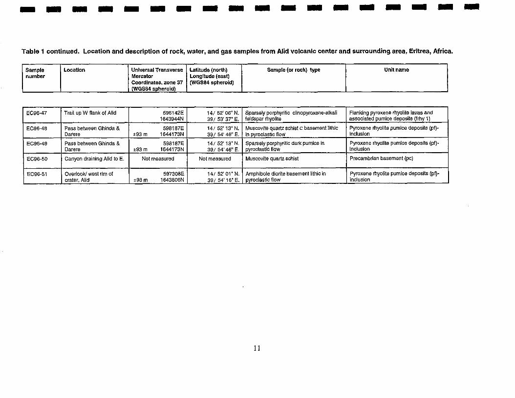
Table 1 continued. Location and description of rock, water, and gas samples from Alid volcanic center and surrounding area, Eritrea, Africa.
Unit name Sample number
Flanking pyroxene rhyolite lavas and associated pumice deposits (frhy 1)
Pyroxene rhyolite pumice deposits (pf)- inclusion
Pyroxene rhyolite pumice deposits (pf)- inclusion
Precambrian basement (pc)
Pyroxene rhyolite pumice deposits (pi)- inclusion
EC96-47
EC96-48
EC96-49
EC96-50
EC96-51
Location
Trail up W flank of Alid
Pass between Ghinda & Darere
Pass between Ghinda & Darere
Canyon draining Alid to E.
OverlooW west rim of crater, Alid
Universal Transverse Mercator Coordinates, zone 37 (WGS84 spheroid)
596142E 1643944N
5981 87E k93 m 1644173N
5981 87E *93 m 1644173N
Not measured
597308E k93 m 1643806N
Latitude (north) Longitude (east) (WGS84 spheroid)
Sample (or rock) type
14/ 52' 06" N. 391 53' 37" E.
141 5 2 13" N. 39/ 54' 46" E.
141 52' 13" N. 391 54' 46" E.
Not measured
141 52' 01" N. 391 54' 16" E.
Sparsely porphyritic clinopyroxene-alkali feldspar rhyolite
Muscovite quartz schist c basement lithic in pyroclastic flow
Sparsely porphyritic dark pumice in pyroclastic flow
Muscovite quartz schist
Amphibole diorite basement lithic in pyroclastic flow
Hand-held Global Positioning System (GPS) receivers were used to determine the Universal Transverse Mercator (UTM) coordinates, and longitude/latitude (see Table 1) of most sample- collection sites. Four GPS receivers were available for use by the geologic mapping team. Each was programmed to use WGS-84 as the horizontal datum in order to make future recovery of sample sites possible. A fifth GPS receiver was used to determine locations of the wells and stream that were sampled to provide information about regional isotopic characteristics of groundwater.
The largest scale (1:100,000) topographic map of the area was published by the USSR military in 1977, but information about the horizontal datum used is not indicated on that map. We made GPS measurements using our hand-held instruments (generally accurate to +loom) at Boya Well, a point easily identified on the Soviet map, to determine if the datum used for the Soviet map is one of the several programmed into our GPS receivers. No matches were identified. Comparison of UTM coordinates for Boya Well by GPS receiver with those measured directly from the Soviet map indicates that no correction is needed to WGS-84 eastings but that 1000 m should be added to WGS-84 northings to plot GPS-determined locations on the Soviet map.
Geologic mapping was done in the field and compiled daily on aerial photographs. Photographs at scales of about 1:30,000 and 1 :60,000 were used. The 1 :60,000 scale set proved to be most useful. Rather than recording field information directly on these photographs, data were penciled (and later inked) on Mylar plastic overlays accurately registered to the photos. The geologic maps that accompany this report were made directly from the overlays and therefore include the distortion of scale inherent in such photos.
The contour map made by the Soviets was inadequate as a base for our field work. Contours on the Soviet map are generalized and details of topography and stream locations are incorrect.
REGIONAL GEOLOGIC SETTING The Alid volcanic center is located along the axis of the Danakil Depression which is the
graben trace of a crustal spreading center. This spreading center radiates north-northwestward from a plate-tectonic triple junction situated within a complexly rifted ahd faulted basaltic lowland called the Afar Triangle (Figure 1). The Danakil Depression is a subaerial segment of the spreading system that is opening to form the Red Sea. Crustal spreading along the axis of the Red Sea is transferred to spreading along the Danakil segment in a right-stepping en echelon pattern (Barberi and Varet, 1977). The Danakil segment shows increased opening southeastward to the Afar triple junction. Kinematically, this configuration is consistent with spreading about a pivot point near the Gulf of Zula, about 40 kilometers north-northwest of Alid, and can account for the triangular shape of the Afar lowland and anti-clockwise rotation of a horst of basement rock (the Danakil Alps) within the zone of en echelon overlap between the Red Sea and Danakil spreading centers (Souriot and Brun, 1992).
A once-continuous basement terrain of Precambrian granitic and metamorphic crust was rifted apart when the Arabian Peninsula separated from Africa to form the Red Sea. Parts of this basement complex are widely exposed in a belt near and parallel to the Red Sea coast of the Arabian Peninsula and in the Eritrean and Ethiopian highlands southwest and adjacent to the Danakil Depression (Figure 1). Precambrian rocks also crop out in the Danakil Alps. The broad distribution of Precambrian exposures provides a framework for structural reconstructions of the region. Of local significance, a hydrothermal-convection system beneath Alid may be mostly within Precambrian
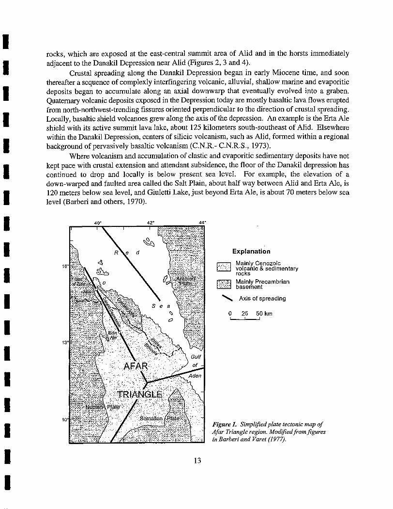
rocks, which are exposed at the east-central summit area of Alid and in the horsts immediately adjacent to the Danakil Depression near Alid (Figures 2, 3 and 4).
Crustal spreading along the Danakil Depression began in early Miocene time, and soon thereafter a sequence of complexly interfingering volcanic, alluvial, shallow marine and evaporitic deposits began to accumulate along an axial downwarp that eventually evolved into a graben. Quaternary volcanic deposits exposed in the Depression today are mostly basaltic lava flows erupted from north-northwest-trending fissures oriented perpendicular to the direction of crustal spreading. Locally, basaltic shield volcanoes grew along the axis of the depression. An example is the Erta Ale shield with its active summit lava lake, about 125 kilometers south-southeast of Alid. Elsewhere within the Danakil Depression, centers of silicic volcanism, such as Alid, formed within a regional background of pervasively basaltic volcanism (C.N.R.- C.N.R.S., 1973).
Where volcanism and accumulation of clastic and evaporitic sedimentary deposits have not kept pace with crustal extension and attendant subsidence, the floor of the Danakil depression has continued to drop and locally is below present sea level. For example, the elevation of a down-warped and faulted area called the Salt Plain, about half way between Alid and Erta Ale, is 120 meters below sea level, and Giuletti Lake, just beyond Erta Ale, is about 70 meters below sea level (Barberi and others, 1970).
An' 44-
Explanation
Mainly Cenozoic volcanic & sedimentary rocks Mainly Precambrian
??l"',.
---.G basement
\ Axis of spreading
Figure I. Simplzj?edplate tectonic map of Afar Triangle region. Modzfiedfrom$gures in Barberi and Varet (1977).
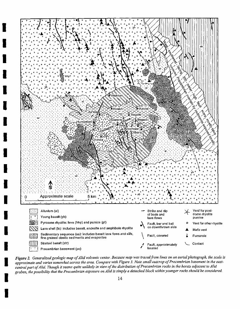
Alluvium (al) - Strike and dip
I., Young basalt (yb) of beds and lava flows pumice
Pyroxene rhyolite: lava (frhy) and pumice (pf) Fault, bar and ball 0 Vent for other rhyolite
Lava shell (Is): includes basalt, andesite and amphibole rhyolite on downthrown side A Maficvent
Sedimentary sequence (ss): includes basalt lava flows and sills, Fault, covered fine grained clastic sediments and evaporites
5 Fumarole
Stratoid basalt (str)
Precambrian basement (pc) / Fault, approximately Contact
located
Figure 2. Generalized geologic map of Alid volcanic center. Because map was traced from lines on an aerial photograph, the scale is approximate and varies somewhat across the area. Compare with Figure 3. Note small outcrop of Precambrian basement in the east- central part ofAlid. Though it seems quite unlikely in view of the distribution of Precambrian rocks in the horsts adjocent to Alid graben, the possibility that the Precambrian exposure on Alid is simply a detached block within younger rocks should be considered.
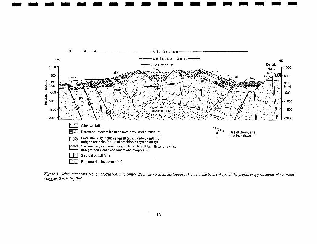
-t--t A l i d G r a b e n b
SW - C o l l a p s e Z o n e -
0 Alluvium (al)
Pyroxene rhyolite: includes lava (frhy) and pumice (pf)
Lava shell (Is): includes basalt (sb), picrite basalt (pb), aphyric andesite (aa), and amphibole rhyolite (arhy) Sedimentary sequence (ss): includes basalt lava flows and sills, fine grained clastic sediments and evaporites
Stratoid basalt (str) rJ ... Precambrian basement (pc)
Basalt dikes, sills, and lava flows
Figure 3. Schematic cross section ofAlid volcanic center. Because ndhtcurate topographic map exists, the shape of the profile is approximate. No vertical exaggeration is implied.
Explanation
Contact, relative age indicated by y, younger: o. older
\ Strike and dip of beds and lava flows
Fault, bar and ball on downthrown side
".- Fault, covered
. Fault, approximately located
0 Vent for rhyolite
A Mafic vent
f Direction of lava flow
Far traveled landslide block
Figure 4a. Detailed geology tracedfi-om photo 3691.
?Q Contad. relabve age indicated by y, younger: 0. older
Fault, bar and ball on
'.. Fault, covered
\ , Fault, approximately located
0 Vent for rhyolite
Fartraveled landslide block
0 Approximate scale
Figure 4b. Detailed geoIogy tracedkom photo 3693.
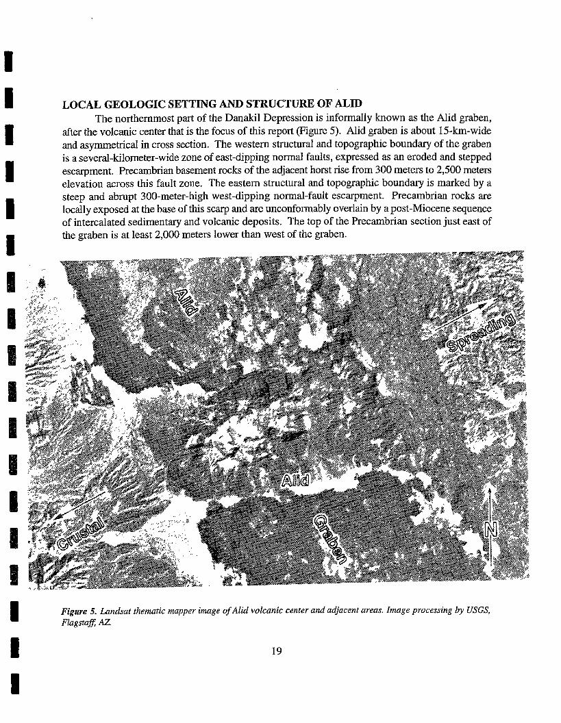
I LOCAL GEOLOGIC SETTING AND STRUCTURE OF ALID The northernmost part of the Danakil Depression is informally known as the Mid graben,
I after the volcanic center that is the focus of this report (Figure 5). Alid graben is about 15-krn-wide and asymmetrical in cross section. The western structural and topographic boundary of the graben
I is a several-kilometer-wide zone of east-dipping normal faults, expressed as an eroded and stepped escarpment. Precambrian basement rocks of the adjacent horst rise from 300 meters to 2,500 meters elevation across this fault zone. The eastern structural and topographic boundary is marked by a
I steep and abrupt 300-meter-high west-dipping normal-fault escarpment. Precambrian rocks are locally exposed at the base of this scarp and are unconformably overlain by a post-Miocene sequence of intercalated sedimentary and volcanic deposits. The top of the Precambrian section just east of
1 the graben is at least 2,000 meters lower than west of the graben.
Figure 5. Landsat thematic mapper image of Alid volcanic center and adjacent areas. Image processing by USGS, I figs,,
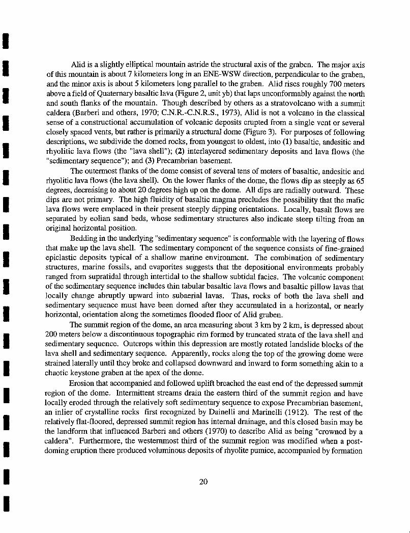
Alid is a slightly elliptical mountain astride the structural axis of the graben. The major axis of this mountain is about 7 kilometers long in an ENE-WSW direction, perpendicular to the graben, and the minor axis is about 5 kilometers long parallel to the graben. Alid rises roughly 700 meters above a field of Quaternary basaltic lava (Figure 2, unit yb) that laps unconfonnably against the north and south flanks of the mountain. Though described by others as a stratovolcano with a summit caldera (Barberi and others, 1970; C.N.R.C.N.R.S., 1973), Alid is not a volcano in the classical sense of a constructional accumulation of volcanic deposits erupted from a single vent or several closely spaced vents, but rather is primarily a structural dome (Figure 3). For purposes of following descriptions, we subdivide the domed rocks, from youngest to oldest, into (1) basaltic, andesitic and rhyolitic lava flows (the "lava shell"); (2) interlayered sedimentary deposits and lava flows (the "sedimentary sequence"); and (3) Precambrian basement.
The outermost flanks of the dome consist of several tens of meters of basaltic, andesitic and rhyolitic lava flows (the lava shell). On the lower flanks of the dome, the flows dip as steeply as 65 degrees, decreking to about 20 degrees high up on the dome. All dips are radially outward. These dips are not primary. The high fluidity of basaltic magma precludes the possibility that the mafic lava flows were emplaced in their present steeply dipping orientations. Locally, basalt flows are separated by eolian sand beds, whose sedimentary structures also indicate steep tilting from an original horizontal position.
Bedding in the underlying "sedimentary sequence" is conformable with the layering of flows that make up the lava shell. The sedimentary component of the sequence consists of fine-grained epiclastic deposits typical of a shallow marine environment. The combination of sedimentary structures, marine fossils, and evaporites suggests that the depositional environments probably ranged from supratidal through intertidal to the shallow subtidal facies. The volcanic component of the sedimentary sequence includes thin tabular basaltic lava flows and basaltic pillow lavas that locally change abruptly upward into subaerial lavas. Thus, rocks of both the lava shell and sedimentary sequence must have been domed after they accumulated in a horizontal, or nearly horizontal, orientation along the sometimes flooded floor of Alid graben.
The summit region of the dome, an area measuring about 3 km by 2 km, is depressed about 200 meters below a discontinuous topographic rim formed by truncated strata of the lava shell and sedimentary sequence. Outcrops within this depression are mostly rotated landslide blocks of the lava shell and sedimentary sequence. Apparently, rocks along the top of the growing dome were strained laterally until they broke and collapsed downward and inward to form something akin to a chaotic keystone graben at the apex of the dome.
Erosion that accompanied and followed uplift breached the east end of the depressed summit region of the dome. Intermittent streams drain the eastern third of the summit region and have locally eroded through the relatively soft sedimentary sequence to expose Precambrian basement, an inlier of crystalline rocks first recognized by Dainelli and Marinelli (1912). The rest of the relatively flat-floored, depressed summit region has internal drainage, and this closed basin may be the landform that influenced Barberi and others (1970) to describe Alid as being "crowned by a caldera". Furthermore, the westernmost third of the summit region was modified when a post- doming eruption there produced voluminous deposits of rhyolite pumice, accompanied by formation
of a circum-vent closed basin within the larger closed basin. Informally, we call this vent basin Alid crater (Figure 3).
How does a structural dome form in an environment of crustal extension? A likely answer is that a body of silicic magma intruded and collected within the upper crust and domed overlying rocks to form Mid. We interpret rhyolite (unit arhy) that appears to be in the lava-shell part of the dome as evidence that a reservoir of silicic magma was present beneath the domed area somewhat before doming began. Moreover, the youngest volcanic rocks that we recognize as having been erupted from within the area of the dome are erosional remnants of rhyolitic pumice deposits (unit pf) that once covered much, or perhaps all, of the structural dome and extended outward hlometers from the dome's base. As mentioned above, the vent for these pyroclastic deposits is within the closed-drainage westernmost part of the depressed summit region, Alid crater. The rhyolite pumice unconformably overlies all dome-forming rock units. Moreover, canyons eroded into the flanks of the dome, down through the lava shell and into the sedimentary sequence, are partly occupied by primary deposits of the pumice. These relations indicate that the structural dome existed as an eroded landform at the time of the pumice eruption.
Blocks of pyroxene granite with abundant granophyric and minor miarolitic textures are present as lithic fragments in the pumice deposits. The granite is chemically and isotopically indistinguishable from the host pumice and is interpreted as the uppermost part of a shallow magma body (the intrusion that formed Alid dome) that crystallized just prior to eruption of the pumice.
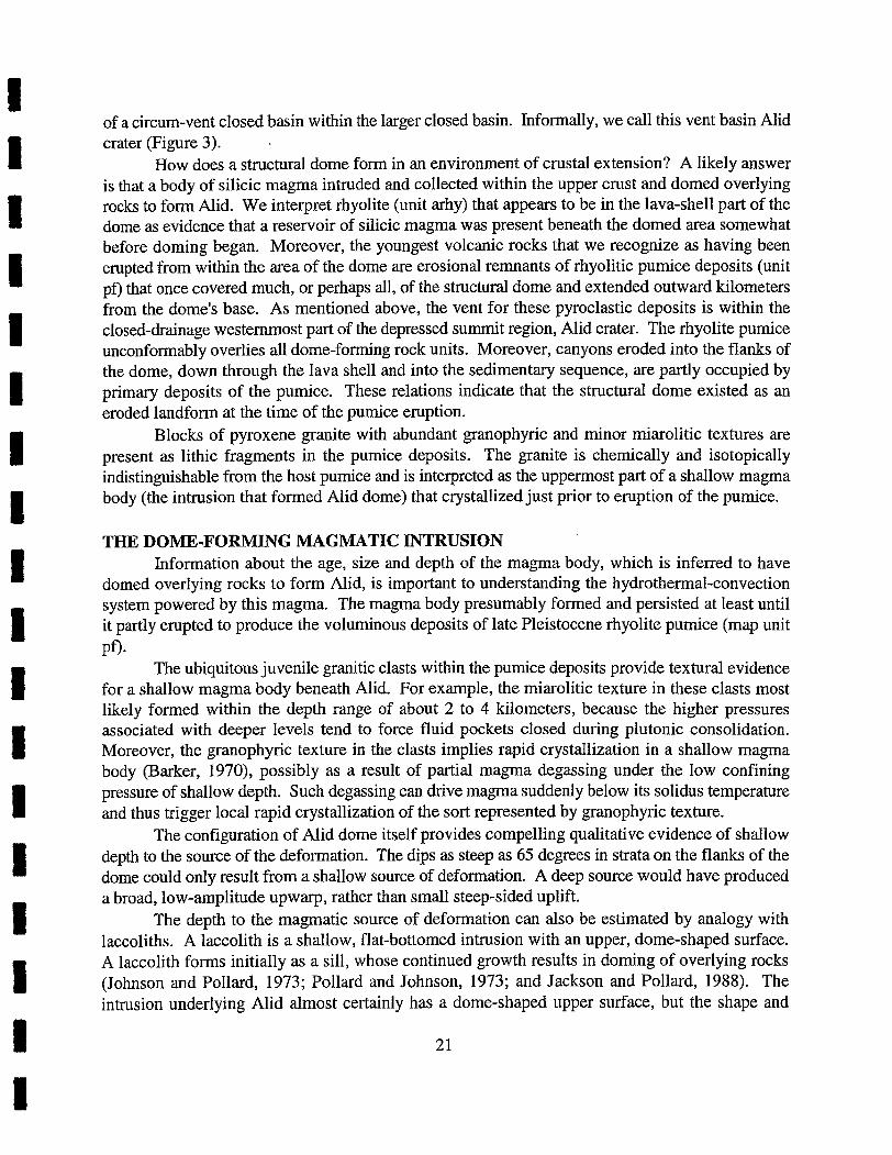
THE DOME-FORMING MAGMATIC INTRUSION Information about the age, size and depth of the magma body, which is inferred to have
domed overlying rocks to form Alid, is important to understanding the hydrothermal-convection system powered by this magma. The magma body presumably formed and persisted at least until it partly erupted to produce the voluminous deposits of late Pleistocene rhyolite pumice (map unit
PO. The ubiquitous juvenile granitic clasts within the pumice deposits provide textural evidence
for a shallow magma body beneath Alid. For example, the miarolitic texture in these clasts most likely formed within the depth range of about 2 to 4 kilometers, because the higher pressures associated with deeper levels tend to force fluid pockets closed during plutonic consolidation. Moreover, the granophyric texture in the clasts implies rapid crystallization in a shallow magma body (Barker, 1970), possibly as a result of partial magma degassing under the low confining pressure of shallow depth. Such degassing can drive magma suddenly below its solidus temperature and thus trigger local rapid crystallization of the sort represented by granophyric texture.
The configuration of Alid dome itself provides compelling qualitative evidence of shallow depth to the source of the deformation. The dips as steep as 65 degrees in strata on the flanks of the dome could only result from a shallow source of deformation. A deep source would have produced a broad, low-amplitude upwarp, rather than small steep-sided uplift.
The depth to the magmatic source of deformation can also be estimated by analogy with laccoliths. A laccolith is a shallow, flat-bottomed intrusion with an upper, dome-shaped surface. A laccolith forms initially as a sill, whose continued growth results in doming of overlying rocks (Johnson and Pollard, 1973; Pollard and Johnson, 1973; and Jackson and Pollard, 1988). The intrusion underlying Alid almost certainly has a dome-shaped upper surface, but the shape and
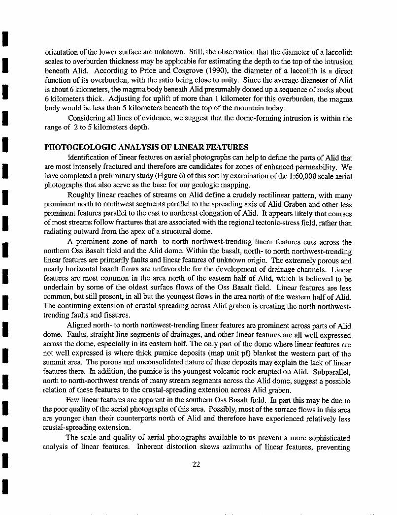
orientation of the lower surface are unknown. Still, the observation that the diameter of a laccolith scales to overburden thickness may be applicable for estimating the depth to the top of the intrusion beneath Alid. According to Price and Cosgrove (1990), the diameter of a laccolith is a direct function of its overburden, with the ratio being close to unity. Since the average diameter of Alid is about 6 kilometers, the magma body beneath Alid presumably domed up a sequence of rocks about 6 kilometers thick. Adjusting for uplift of more than 1 kilometer for this overburden, the magma body would be less than 5 kilometers beneath the top of the mountain today.
Considering all lines of evidence, we suggest that the dome-forming intrusion is within the range of 2 to 5 kilometers depth.
PHOTOGEOLOGIC ANALYSIS OF LINEAR FEATURES Identification of linear features on aerial photographs can help to define the parts of Alid that
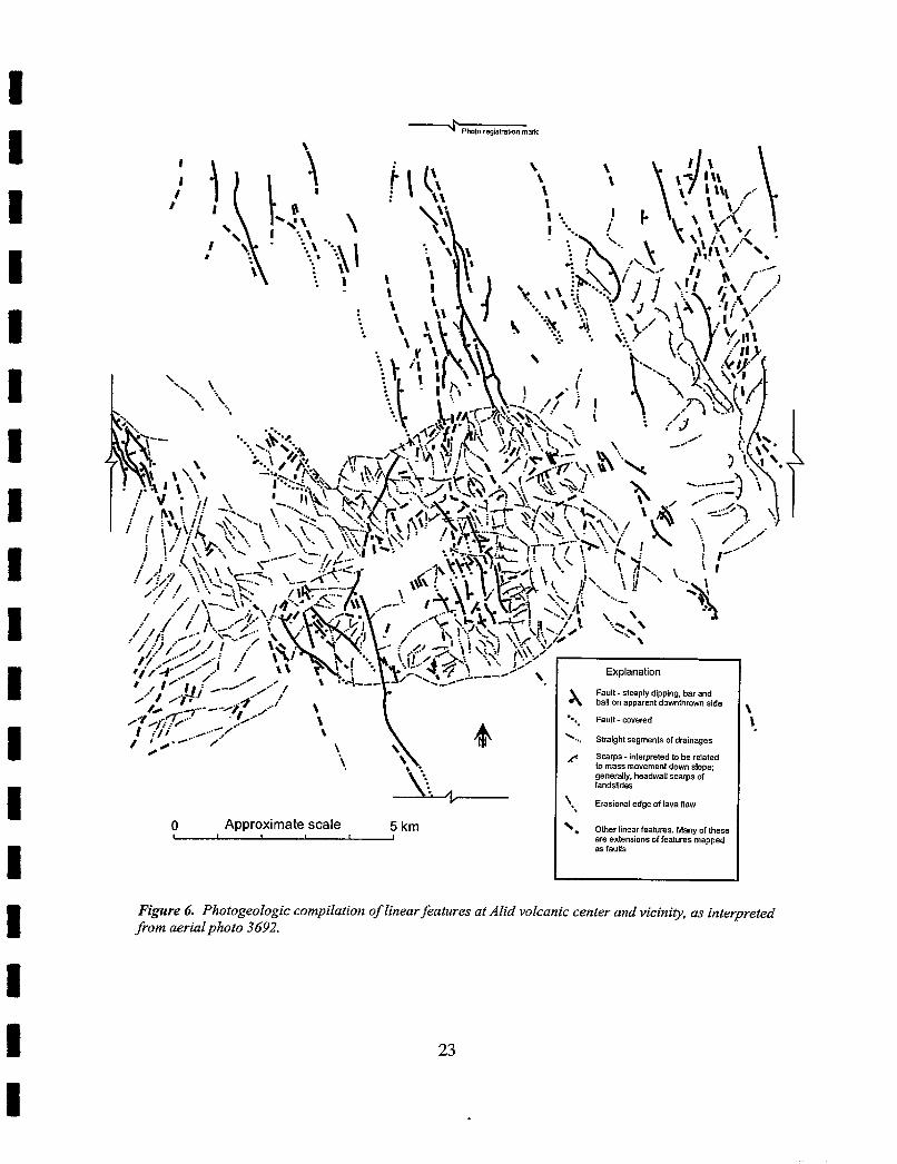
are most intensely fractured and therefore are candidates for zones of enhanced permeability. We have completed a preliminary study (Figure 6) of this sort by examination of the 1 :60,000 scale aerial photographs that also serve as the base for our geologic mapping.
Roughly linear reaches of streams on Alid define a crudely rectilinear pattern, with many prominent north to northwest segments paralIel to the spreading axis of Alid Graben and other less prominent features parallel to the east to northeast elongation of Alid. It appears likely that courses of most streams follow fractures that are associated with the regional tectonic-stress field, rather than radiating outward from the apex of a structural dome.
A prominent zone of north- to north northwest-trending linear features cuts across the northern Oss Basalt field and the Alid dome. Within the basalt, north- to north northwest-trending linear features are primarily faults and linear features of unknown origin. The extremely porous and nearly horizontal basalt flows are unfavorable for the development of drainage channels. Linear features are most common in the area north of the eastern half of Alid, which is believed to be underlain by some of the oldest surface flows of the Oss Basalt field. Linear features are less common, but still present, in all but the youngest flows in the area north of the western half of Alid. The continuing extension of crustal spreading across Alid graben is creating the north northwest- trending faults and fissures.
Aligned north- to north northwest-trending linear features are prominent across parts of Alid dome. Faults, straight line segments of drainages, and other linear features are all well expressed across the dome, especially in its eastern half. The only part of the dome where linear features are not well expressed is where thick pumice deposits (map unit pf) blanket the western part of the summit area. The porous and unconsolidated nature of these deposits may explain the lack of linear features there. In addition, the pumice is the youngest volcanic rock erupted on Alid. Subparallel, north to north-northwest trends of many stream segments across the Alid dome, suggest a possible relation of these features to the crustal-spreading extension across Alid graben.
Few linear features are apparent in the southern Oss Basalt field. In part this may be due to the poor quality of the aerial photographs of this area. Possibly, most of the surface flows in this area are younger than their counterparts north of Alid and therefore have experienced relatively less crustal-spreading extension.
The scale and quality of aerial photographs available to us prevent a more sophisticated analysis of linear features. Inherent distortion skews azimuths of linear features, preventing
'269s OJOL~~/V!J~V WO.$
paa~dralu! su '4u!3!n puv laws3 ~pvqon pqy ID sa~~uaJ~wau~~Jo uo!~vpd~o3 3!Soloa3o;royd p arn8?d
qlnq se paddetu saJnleaj jo suo!suawa aJe
esaq jo Aue~ 'sa~nleai Jeau!l raw0 \
MOB me1 $0 a6pa leua!srug '' \
sap!lspuel jo sLeDs Ilennpeaq 'Al[waua6
:ado[s umoplua~uamw sselu q palelaJ aq 01 pela~dmtu! - sd~ws 2
safieu!e~p jo sluatufias )q6!wls '.., paJanoa - llnej -.-
apjs u~o~lgumop lUaJEdde uo lleq pue Jeq '6u!dd!p Aldaajs - jlnej \C
uo!leueldq
quantitative analysis of parameters such as variation in average trend or density of linear features across different sectors of the volcano or average length of linear features per unit area in different parts of Alid. The results of this preliminary study should be refined using new large-scale aerial photographs and an accurate large-scale contour map.
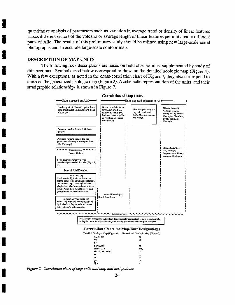
DESCRIPTION OF MAP UNITS The following rock descriptions are based on field observations, supplemented by study of
thin sections. Symbols used below correspond to those on the detailed geologic map (Figure 4). With a few exceptions, as noted in the cross-correlation chart of Figure 7, they also correspond to those on the generalized geologic map (Figure 2). A schematic representation of the units and their stratigraphic relationships is shown in Figure 7.
e t s exposed on Alid-
north Oss basalt field andlor north flank of Alid @s)
Pyroxene rhyollte flow in Alid Crater Why).
I Pymxene rhyolite pumice-fall and mclastlc-flow derrosits erupted fmm I 21d Crater @f). -
Uncoformi(y
Dome Exists
Flank~ng pyroxene rhyolite and associated pumice-fall deposits (frhy l ,2,
Start o f Alid Doming
Shell basalt (sb), includes distinctive plcrite basalt (pb), aphyric andesite (aa). and other 01-, cpx- bearing basalts + plagimlase. May be correlative with str basalt Amphibole rhyolite + pyroxene (ahy) late in lava-shell sequence.
P~llow and subaerial basalt associated hyaloclastites. Supra-, sub- and Inter- tidal sediments and anhydrite.
Correlation of Map Units U n i t s exposed adjacent to Alid-
Noxthem and Southern Oss basalt lava fields and scoria cones (yb). Includes mioor rhyolite in Northern Oss basalt field (fhy?).
Alluvium (al). Includes clay, all, sand, and gravel of active streams and valleys.
Adjacent to Mid, mostly locally denved lithologies. Elsewhere, mostly basement lithologies.
I I I I
I I
I Older alluvial fans I I (oaf). Includes I I fanglomerates. Mostly I I basement l~tholog~es. I
I I I I I I I I I I 1 I I
I I
Precambrian basement on Mid @c). Predominantly mica schist, locally includes mafic and aplite dlkes. In adjacent arcas, dominantly granitic and metamorphic complex.
Correlation Chart for Map-Unit Designations Detailed Gealogtc Map (Figure 4)
al, af, oaf yb bs pxrhy, pf fihy1.2.3 sb, pb, aa, arhy SS
str PC Qar
- Generalized Geologic Map (Figure 2)
a1 yb
P f f i y Is SS
S k
PC
Figure 7. CorreIation chart of map units and map unit designations.
Alluvium and Alluvial Pans (al, af, oaf) Three types of alluvium and alluvial fans were mapped: recent alluvium (al), younger alluvial
fans (af) and older alluvial fans (oaf). Alluvium includes both fluvial and eolian deposits. Younger alluvial fans are those that are actively growing. Those surrounding Alid contain predominantly volcanic lithologies from the Alid volcanic center, whereas those in adjacent areas have mostly basement lithologies. Older alluvial fans were deposited when the drainage base level was higher than today and are now being eroded.
Oss Basalt Fields (yb) Extensive fields of basaltic lava flows are present both to the north and south of Alid. Many
or most of the flows are younger than Alid dome and lap unconformably against the north and south lower flanks of the mountain. Vents of these basalts are marked by cinder cones commonly aligned on north northwest-trending fissures. The map unit includes basaltic tephra layers, especially near vents. A wide variety of lithologies, from nearly aphyric to abundantly porphyritic, are present. Phenocryst assemblages in sparsely phyric basalt include olivine, olivine + plagioclase, olivine + clinopyroxene, and olivine + clinopyroxene + plagioclase. Porphyritic varieties generally contain olivine + clinopyroxene -t plagioclase, often with abundant large plagioclase phenocrysts. Phenocrysts are generally from 1 to 5 rnrn in maximum dimension, although megacrysts exceeding 1 cm are occasionally present. The groundmasses of these flows are very fresh with textures that range from glassy to aphanitic and rarely holocrystalline. The lava of the basalt fields are flat lying and deformed only by north northwest-trending dilational fissures generally with less than 1 meter opening, and normal faults generally with vertical offset of less than a few meters. These structures reflect ongoing crustal extension across Alid graben, and likely help provide permeability to the Alid hydrothermal-convection system. Eolian sand and fluvial deposits bury the margins of many of the youngest basalt flows, and partly bury the surfaces of older flows in this sequence.
Silicic Lavas in the Oss Basalt Fields Several small exposures of pumiceous rhyolite lava (e.g. ED96-12) are surrounded and nearly
buried by Oss basalt northwest of AIid (Figures 2 and 4). The location of the vent(s?) and the total volume of this rhyolite are unknown. The mineralogy and chemistry are similar to Alid rhyolitic lavas. The rhyolite contains sparse phenocrysts of Fe-Ti oxides and clinopyroxene. Alkali feldspar is the most abundant phenocryst. The groundmass consists of abundant feldspar microlites in nearly colorless glass. Brownish carbonate caliche is common along fractures, and most mafic phenocrysts are oxidized. This rhyolite is tentatively correlated with map unit frhy.
Basaltic Spatter (bs) The youngest volcanic unit on Alid is agglutinated basaltic spatter ranging up to 2 m in
thickness and containing very sparse plagioclase phenocrysts 0.5-2 mm in maximum dimension. The vent location of this spatter is unknown and could be either on Alid or nearby within the northern Oss basalt field. Basaltic spatter crops out in small scattered patches over much of the northwest quadrant of Alid, but is mapped only on the north flank west of the summit peak.
Pyroxene Rhyolite Flow in Alid Crater (pxrhy) A single lava flow, which postdates the pumice deposits described next, is present in Alid
crater. This flow is probably only slightly younger than the pumice deposits, and both lava and pumice probably are products of a single eruption. The flow is porphyritic pyroxene rhyolite containing abundant alkali feldspar and sparse phenocrysts of clinopyroxene and quartz; it also contains abundant spherulites in a devitrified groundmass. The lava flow is almost unaffected by erosion and displays a well-preserved pumiceous carapace and flow features. Areas of red oxidation and devitrification, indications of prolonged escape of hot gases, are common on the top and margins of the flow. Scallop-shaped indentations that define the present eastern extent of the flow may be related to late phreatic events that blasted away some of the original lava. A thin pyroclastic deposit of oxidized and devitrified lava blocks and lapilli is present on the lava flow, and probably is related to phreatic or hydrothermal explosions that produced the scalloped margins of the lava flow.
Pyroxene Rhyolite Pumice Deposits Erupted from Alid Crater (pf) Moderately porphyritic, pyroxene-rhyolite pumice was erupted during the formation of Alid
crater and emplaced as fallout (proximal) and pyroclastic flows (distal). The pumice contains moderately abundant phenocrysts of alkali feldspar approximately 1 mm in maximum dimension, lesser amounts of clinopyroxene up to 0.5 rnm in maximum dimension, and sparse small quartz phenocrysts. This large-volume (tentatively estimated at less than 5 and more than 1 cubic kilometer) pyroclastic unit is the product of the youngest silicic volcanism at Alid and is thus the most important rock unit for constraining the present-day status of the probable magmatic heat source for the hydrothermal system.
Two other pumice types were produced in small volume during the eruption. The first occurs as a distinct 2-meter-thick layer in the wall of the crater in the Ghinda Pass area. It contains small streaks of mafic material and orange-colored glass, but is only slightly more mafic than the normal pumice. The second pumice type (EC96-22, EC96-25, and EC96-49) occurs as dark bands and blobs mixed with the silicic pumice and contains sparse plagioclase and magnesian clinopyroxene phenocrysts 1 to 2 mm in maximum dimension. The dark pumice is andesitic to dacitic in bulk composition and indicates that mafic magma had access to the silicic magma r e s e ~ o i r prior to or during the eruption.
Proximal deposits of the rhyolite pumice contain a minor fine-ash component and are vaguely bedded and lenticular in cross section. They probably were emplaced mostly by fall and secondarily by flow processes. Distal deposits of the pumice are poorly sorted pyroclastic flows although some of the upper flows are pumice-rich and clast-supported or nearly clast-supported. Some pumice deposits on the flanks of Alid and around the base of the mountain display double grading with Iithic fragments concentrated at the bottom of flows and large pumice blocks accumulated at the tops of individual flows. Such grading in deposits on the steep flanks may have formed during gravity- driven slumping as pumice accumulated at inclinations exceeding the angle of repose (Duffield and others, 1979). Approximately 10-12 flow units are exposed at EC96-4 with an aggregate thickness of about 25 meters, but the original top of the section is not present.
A variety of xenoliths are present in the pumice deposits. The most abundant (about 80% of all lithics) are fragments of amphibole rhyolite (arhy) and picritic basalt (pb), which are the rock
types that were present at the surface in the area of the vent when eruption began. Basement lithologies are also present; most abundant are quartz-muscovite and kyanite schists similar to those found in outcrop near llegedi. Granitic rocks derived from the Precambrian basement and ranging from granite to diorite to epidosite are also present but not abundant. Hydrothermally altered xenoliths are rare.
One other type of xenolith that deserves mention occurs in the pumice deposits. Rounded, rnicrovesicular to dense blocks 10 to 50 cm in size, consisting of intergrown acicular crystals with or without interstitial glass are sparsely present (EC96-4, EC96-23, and EC96-46). Their texture and intermediate compositions indicate that they are undercooled blobs of magma formed by mixing of mafic magma into the silicic magmatic system (Bacon, 1986).
Granite blocks, up to 1 meter in size, of a medium-grained quartz-anorthoclase-clinopyroxene rock (k quartz, minor biotite and zircon), with a granophyric texture and miarolitic cavities are present as lithic fragments in the upper part of the pumice section. Beyth (1994) called this rock "microgranite", but we prefer the term pyroxene granite. The pyroxene granite is compositionally and isotopically nearly identical to its host rhyolite pumice but differs substantially from granitic rocks in the Precambrian basement. The composition and zoning patterns of the clinopyroxene and alkali feldspar phenocrysts in the pf pumice and in the pyroxene granite are identical. The pyroxene granite contains about 40-50 % granophyric intergrowths of quartz and anorthoclase, that in combination with the miarolitic cavities indicate relatively rapid crystallization at shallow depth. We interpret the pyroxene granite to be the crystallized equivalent of the pf pumice magma, and thus juvenile rather than xenolithic.
Flanking Pyroxene Rhyolite Lavas and Associated Pumice Deposits (frhy) Pyroxene rhyolite domes, lava flows, and associated pumice-fall deposits are present at both
the east and west base of Alid. These also overlie some shell basalts (sb) on the east and west flanks of the dome. Based on their petrography and location these are divided into 3 groups of approximately equal age and composition: frhyl, frhy2, and frhy3. Relative ages of the groups are unknown. Frhyl is locally overlain by the pyroxene rhyolite pumice (unit pf), and some field relations suggest that frhy2 is also older than the pf pumice. The relative age relationship of the pf pumice and frhy3 is unknown. All three groups of rhyolites are very sparsely porphyritic with 0.5 to 1 mm phenocrysts of alkali feldspar and less abundant clinopyroxene. Frhy2 and frhy3 also contain sparse 0.5 to 1 rnrn phenocrysts of fayalite. All flows display well-preserved flow morphology with intact pumiceous carapaces and fresh obsidian basal zones.
Outcrops of frhyl are confined to the western base and flank of Alid where lava domes and flows overlie a widespread initial pumice-fall deposit. These rocks appear to have been moderately tilted during doming of Alid. Frhy 2 lava flows appear to have been erupted from vents on the eastern flank of the dome prior to or during doming and have been subsequently tilted somewhat. A few kilometers east of the eastern base of Aid, seven vents (frhy3) are marked by lava domes, and the lavas flows from these vents were preceded by pumice fall deposits that built pumice cones. Vents of frhy3 are aligned along, or very near the trace of, the large normal fault that forms the eastern structural boundary of Alid graben.
Lava Shell (Is): Locally subdivided into: Shell Basalt (sb), Picritic Basalt (pb), Aphyric Andesite (aa) and Amphibole Rhyolite (arhy)
The lava shell unit consists primarily of interbedded basalt and andesite lavas with local rhyolite flows, domes and possible shallow intrusive necks. Thin tephra layers and eolian sand bodies are minor constituents of the unit. On the generalized geologic map (Figure 2), all of these units are grouped together as lava shell unit (1s). On the detailed geologic maps (Figure 4), the unit is locally subdivided into shell basalt (sb), picritic basalt (pb), aphyric andesite (aa) and amphibole rhyolite (arhy) .
Shell basalt is the most abundant constituent of the lava shell. Is occurs as a series of lava flows with thin interbeds of basaltic tephra and, locally, thin eolian sand deposits. The shell basalts are fresh rocks, with groundmass textures ranging from glassy to aphanitic to holocrystalline. A variety of lithologies similar to those of the Oss basalts are present. Some of the shell basalt may be equivalent in age to the oldest Oss basalt flows.
Shell basalt also includes a variety rich in olivine phenocrysts. Some of these flows contain as much as 20% olivine phenocrysts from 5 mm to 1 cm in diameter and about 10% of similar size pyroxene phenocrysts. These distinctive lavas are called picrites (pb).
A third component of the lava shell is aphyric andesite (aa). This andesite forms gray lava flows up to several meters thick.
All of the mafic flows of the lava shell must have been emplaced as horizontal, or nearly horizontal, bodies. They are tabular flows of uniform thickness, and the relatively low viscosity of mafic melt precludes the formation of such geometry on an inclined surface. Thus, the present steep dips of the rocks on the flanks of Alid dome indicate that doming occurred after the mafic lava shell flows had been emplaced.
The fourth component of the lava shell unit is a group of amphibole-bearing rhyolite domes and flows. Vents for these rocks crop out as plug-like necks distributed roughly around the rim of the western part of the depressed summit area of Alid (Figure 2). This rhyolite generally is devimed, oxidized, and vapor-phase altered. Any pumiceous and glassy carapace material that may originally have been present has been eroded away. Phenocrysts are sparse but ubiquitous and include alkali feldspar, hornblende, and sometimes biotite. All other rhyolites at Alid lack volatile- bearing mafic phenocryst phases and instead contain pyroxene.
Small remnants of sparsely phyric rhyolite (ED96-12) are present in the northern Oss basalt field (yb). Though nearly buried by these basalt lavas, the stratigraphic relation of this rhyolite to other frhy rhyolite is unknown. We tentatively correlate with the frhy based on petrography.
Our mapping suggests that eruption of rhyolite of the lava shell began just before, or concurrent with, initial growth of Alid structural dome. Possibly, the dome-forming silicic magma body in the upper crust leaked a bit of magma to the surface as doming began.
Sedimentary Sequence (ss) Intercalated volcanic and sedimentary rocks that underlie the lava shell are informally called
the sedimentary sequence. This sequence overlies the Precambrian basement exposed in the core of Alid dome. The sedimentary sequence consists of three main rock associations: (1) pillow basalt, hyaloclastite, and minor submarine debris flows, (2) shallow marine sediments, and (3) subaerial
basalt and interbedded tephra and eolian sand deposits. Although these three subunits are intercalated, the sedimentary sequence is dominated by pillow basalt and hyaloclastite in its lower parts, shallow marine sediment in the middle part, and subaerial basalt in its upper part. The sedimentary sequence displays considerable internal deformation; landslide blocks, small faults, block rotation and folding are common, both within the "collapsed" depressed summit area of Alid dome and in the steeply dipping dome flanks.
Shallow marine sediments are thin-bedded, red- to greenish-gray micaceous siltstone and very fine-grained sandstone. They are well-sorted, display ripple cross bedding and small channel- fill structures. Trace fossils include worms trails and filled burrows. Gastropod and mollusc fragments are also present. Thin beds of evaporite (gypsum andfor anhydrite) are intermittently common in approximately 1-m-thick zones. The sediments accumulated in shallow marine (subtidal) through intertidal to supratidal settings.
Pillow basalt ranges from sparsely phyric to notably porphyritic. Phenocrysts occur in various proportions of olivine, clinopyroxene, and plagioclase. Pillow basalt and associated hyaloclastite are usually arnygdaloidal and altered or deeply weathered. Fresh rock is confined to glassy pillow margins. Some pillow basalt changes abruptly upward to non-pillowed subaerial lava, indicative of eruption into water so shallow that the lava flow grew upward through water into a subaerial environment.
Some eruptive units of basalt lava are entirely subaerial. Flows are typically 2-to 5-m-thick and commonly have flow breccia at their bases and vesicular tops. Basaltic tephra and eolian sand are sparse but widely distributed between flows. Most vesicular flow tops are amygdaloidal, and massive flow interiors are partly replaced by iron hydroxides and clay minerals. Fresh glass is occasionally found at the base of some flows.
Stratoid Basalt (str) Volcanism in the Afar Triangle region is represented mainly by extensive sequences of basalt
lavas named stratoid by the C.N.R.-C.N.R.S. team (1973). Some of these lavas cap the horst along the east side of Alid graben and fault blocks within the horst-bounding fault zone (Figures 2 and 4). Relatively small remnants of basalt lavas that we correlate with the stratoid flows crop out a few kilometers to the northwest of Alid, as a faulted block partly buried by old alluvium. Subaerial basalt flows in the upper part of the sedimentary sequence (Figure 2, unit ss) may be stratigraphically equivalent to stratoid basalt.
The stratoid basalts at AIid are sparsely to moderately phyric, containing olivine with or without plagioclase and clinopyroxene; groundmass is commonly holocrystalline. Barberi and others (1972) reported K-Ar ages for stratoid basalts from about 24 Ma to 0.4 Ma within the northwest sector of the Afar region. The stratoid basalts near Alid may be about 1.2 Ma (Barberi and others, 1972; Zumbo and others, 1995).
Precambrian Basement (pc) Precambrian basement rocks crop out in the negedi area of Alid (Figure 2). These rocks are
dominantly quartz-muscovite schist and minor kyanite schist. Aplite and amphibolite dikes are common. Nonamphibolitized (Tertiary?) mafic dikes intrude the schists. Precambrian rocks within
and adjacent to the fault scarp that forms the east side of the Danakil Depression at Alid graben are mostly granitic lithologies intruded by arnphibolitized mafic dikes.
PETROLOGY AND GEOCHEMISTRY OF VOLCANIC ROCKS Major-element chemical analyses were made of 54 rock samples that are representative of
all mapped units of the M d volcanic center and surroundings. In addition, trace-element analyses of 20 rocks from the project area were obtained by ICP-MS techniques. These analyses are reported in Tables 2 and 3. A plot of total alkalis versus silica is shown as Figure 8. Most of these samples define a bimodal suite of basaltic and rhyolitic rocks. The basaltic rocks are from map units str, ss, sb, pb, aa, and yb. Petrographic and chemical differences among these rocks are relatively minor. The silicic rocks come from map units arhy, frhy, pxrhy and pf, including pyroxene granite that occurs as inclusions in pf. These, too, exhibit little petrographic and chemical variation as a group, although field relations and minor differences in mineralogy and chemistry suggest that the amphibole-bearing rhyolites (arhy) are the first silicic lavas erupted at Alid. The few intermediate compositions (Table 2, Figure 8) represent rocks that formed through partial mixing of basaltic and rhyolitic magmas. These rocks are volumetrically very minor at Alid and occur only as inclusions in other eruptive units. Such mixed rocks demonstrate the contemporaneity of the two principal magma compositions during the history of volcanism at Alid.
Bulk-Rock Chemistry The basaltic rocks are subalkaline and quartz normative, and they display a tholeiitic
differentiation trend. These rocks range from 48.5 to 55 wt.% SiO,, and are transitional into the field of andesitic compositions (Figure 8). There are no systematic chemical differences between samples from the map units sb and yb. In contrast, samples from map units str and ss tend to be less and more chemically evolved, respectively, than yb and sb. At 50 wt % SiO,, TiO, K20 and incompatible trace elements range by approximately a factor of 2, which suggests some variability of magma compositions derived from mantle sources beneath Alid.
The rhyolites range from 72 to 74 weight % SiO,. They are subaluminous, and quartz and feldspar normative. Amphibole rhyolites differ in TiO,, FeO, A1203 and some incompatible trace elements from the other rhyolites, though the differences are small. The pyroxene granite inclusions in map unit pf are nearly identical in composition to that of their host rhyolite pumice.
Petrography and Crystal Chemistry The lavas of the mafic group range from nearly aphyric through sparsely phyric to porphyritic.
Mineral assemblages are combinations of olivine, clinopyroxene, and plagioclase; porphyritic rocks tend to be plagioclase-dominated, but olivine- and pyroxene-rich varieties are also present. The sparsely porphyritic lavas generally contain simple phenocryst assemblages and phenocrysts displaying equilibrium growth textures. However, the phenocrysts in some of the more porphyritic lavas (especially those from the shell basalt unit) display disequilibrium features including multiple phenocryst populations, strongly resorbed crystals, reverse zoning, and crystals with overgrowth rims. Clinopyroxene compositions in mafic lavas range from diopside and endiopside to augite (terminology of Poldervaart and Hess, 1951). More evolved samples contain less magnesian clinopyroxenes.
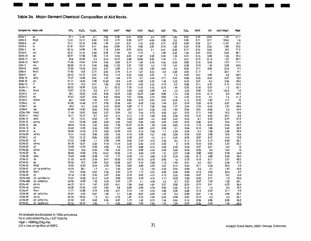
Table 2a. Major-Element Chemical Composition of Alid Rocks.
Sample No. Map unit 5102 A120, FelOI FeO FeO' MgO COO Na,O KIO 110, P20, MnO LO1 FeO'IMg0 Mg#
ED96-1 sb 51.1 16.39 2.1 7.56 9.45 6.67 10.58 2.9 0.97 1.26 0.29 0.18 -0.24 1.42 611 ED96-3 ffhy3 73.31 13.17 0.62 2.23 2.79 0.02 0.77 4.94 4.58 0.2 0.03 0.11 0.71 136.8 1.6 ED96-5 p f 73.11 13.12 055 1.99 2.49 0.21 1.22 4.28 5.17 0.23 0.04 0.07 2.71 11.97 15.7 ED964 ss 51.81 15.81 2.41 8.66 10.83 5.76 9.88 2.87 0.75 1.53 0.34 0.18 2.26 1.88 54.2 ED96-7 str 50.16 1499 1.99 7.15 8.94 9.95 12.06 2.1 0.41 0.85 0.17 0.16 0.62 0.9 71.3 ED96-9 OO 53.31 14.16 2.65 9.55 11.94 3.3 7.19 4 1.69 2.62 1.26 0.27 -0.04 3.62 38 1 ED96-10 sb 50.91 17.88 1.98 7.13 8.92 5.83 11.57 2.59 0.68 1.05 0.21 0.16 0.09 1.53 59.3 ED96-l l yb 50.8 15.09 2.4 8.63 10.79 6.88 10.05 2.82 104 1.71 0.37 0.19 -0.14 1.57 58.7 ED9612 frhy? 71.52 13.69 0.74 2.66 3.33 0.19 1.38 4.78 4.62 0.25 0.05 0.12 2.45 17.9 11.1 ES96-3 a o 55.29 15 12 2.45 8.83 11.03 3.81 7.23 3.4 1.74 1.61 0.35 0.18 1.43 2.89 43.5 ES96-5 frhy2 72.55 13.26 0.64 2.31 2.89 013 1.35 4.87 4.53 0.2 0.04 0.11 086 21.8 9 3 ES96-8 ffhyl 71.93 13.8 0.71 2.54 3.18 0.14 1.21 4.83 4.4 0.28 0.05 0.12 1 22.2 9.1 ES96-9 yb 54.73 14.73 2.51 9.M 11.3 3.23 6.83 3.97 2 2 2 0.55 0.21 0.09 3.5 38.9 ES96-10 arhy 73.37 13.95 0.41 1.47 1.84 0.19 0.7 4.68 4 71 0.41 0.06 0.05 0.65 9.57 18.9 ES96-12 yb 51.11 14.63 2.85 10.24 12.8 4 . 4 8.85 3.53 1.38 2.33 0.43 0.21 0.6 2.88 43.6 ES96-13 7 70.19 13.2 0.51 1.82 2.28 0.73 4.02 4.32 4.74 0.3 0.05 0.11 6.47 3.12 41.6 ELL96-1 l str 50.22 15.09 2.25 8.1 10.12 7.78 11.27 2.62 0.73 1.44 0.33 0.18 0.07 1.3 63.1 EC96-1 frhy3 73.91 12.76 0.6 2.17 2.71 0.02 0.62 4.99 4.6 0.2 0.03 0.09 0.51 133.2 1.6 EC96-2 yb 50.1 18.24 2.23 8.02 10.03 4.36 10.99 2.89 0.88 1.73 0.38 0.18 -0.14 2.3 49.2 EC96-3 Sb 49.67 15.27 2.36 8.51 10.63 7.57 10.86 2.74 0.86 1.6 0.37 0.18 0.1 1.4 61.3 EC96-4 pf-inc 66.1 14.82 1.36 4.91 6.14 0.53 2.79 4.94 357 0.68 0.13 0.18 1.29 11.7 16 EC96-6 str 51.02 14.65 2.77 9.96 12.45 4.67 8.68 3.53 1.44 2.31 0.74 0.23 -0.16 2.67 45.5 EC96-7 yb 49.8 16.1 2.44 8.79 10.99 5.89 1111 2.69 0.86 1.77 0.34 0.19 -0.23 1.87 54.4 EC96-9 a a 52.89 14.87 2.62 9.43 11.78 4.21 8.51 3.28 1.63 1.93 0.43 0.21 0.46 2.8 44.3 EC96-IOA frhy3 7145 12.97 0.63 2.27 2.84 0.2 2.66 4.75 4.69 0.21 0.05 0.11 4.65 14.2 13.6 EC96-11 frhyl 72.11 13.77 0.7 2.51 3.14 0.13 1.13 4.85 4.36 0.26 0.05 0.12 0.24 23.7 8.6 EC96-14 arhy 73 14.01 0.42 1.51 1.88 0.33 0.84 4.6 4.69 0.43 0.06 0.1 0.33 5.79 27.8 EC96-15 px rhy 732 13.45 0.56 2.02 2.53 0.23 0.85 4.64 4.69 0.23 0.05 0.06 0.72 10.8 17.2 EC96-16 p b 48.64 12.34 1.66 5.96 745 15.47 12.75 1.49 0.54 0.83 0.18 014 -0.06 0.48 82.2 EC96-18 ss 52.68 14.95 2.66 9.58 11.97 4.56 8.38 3.37 0.98 2.1 0.56 0.19 1.88 2.63 45.9 EC96-19 ss 52.65 14.76 2.73 9.83 12.28 4.31 8.16 3.44 1.1 2.24 0.59 0.2 1.55 2.85 43.9 EC96-20 pf-lnc 73.31 13.36 0.56 2.02 2.53 0.13 0.83 4.61 4.82 0.24 0.04 0.07 2.38 18.8 10.6 EC96-21 p f 73.5 13.12 0.56 2.02 2.52 0.18 0.97 4.2 5.11 0.23 0.M 0.07 2.47 14.3 13.5 EC96-22 p f 67.31 14.88 1.1 3.95 4.94 0.56 2.24 4.72 4.36 0.6 0.13 0.16 2.19 8.83 20.1 EC96-23 pf-lnc 54.78 15.21 2.54 9.15 11.44 2.62 6.56 4.13 2.02 2 0.76 0.24 0.04 4.37 33.7 EC96-24 p f 73.09 13.39 0.58 2.08 2.6 0.18 0.88 4.76 4.69 025 0.05 0.07 2.21 14.9 13 EC96-25 pf-inc 73.63 13.2 0.54 1.93 2.42 0.16 0.98 454 4.69 0.23 0.04 0.06 0.6 14.9 13 EC96-29 Sb 50.86 14.53 295 10.61 13.26 4.76 8.84 327 1.21 2.27 0.48 0.22 -0.03 2.78 44.5 EC96-30 orhy 73.69 14.08 0.38 1.37 1.71 0.34 1.01 4.83 3.73 0.39 0.06 0.12 4.59 5.06 30.6 EC96-31 sb 51.53 16.78 2.34 8.4) 10.52 4.75 10.15 2.95 0.96 1.6 0.35 0.18 0.11 2.21 50.2 EC96-33 sb 50.66 15.7 2.69 9.67 12.08 4.87 9.74 2.98 1.14 1.95 0.41 0.2 -0.31 2.48 47.3 EC96-36 frhyZ 73.02 13.33 0.64 2.29 2.86 0.03 0.85 4.95 4.57 0.19 0.03 0.11 0.36 93.3 2.3 EC96-41 p f - ky schist inc. 42.54 38.1 1.7 6.1 7.63 4.07 1.3 1.93 2.26 0.96 0.84 0.2 3.1 1.87 54.3 EC96-42 hhyl 72.5 13.56 0.65 236 2.94 0.13 1.17 4.67 4.55 0.26 0.M 0.12 3.58 23.4 8.7 EC96-43 p f 73.14 13.33 056 2.01 2.52 0.18 0.95 4.77 473 0.23 0.04 0.07 2.41 14.2 13.5 EC9644A p f - granite inc. 74.21 15.22 0.13 0.47 0.58 0.08 0.99 4.62 4.17 0.03 0.05 0.03 0.71 7.2 23.6 EC96-448 p f - schist inc. 63.96 15.59 1.33 4.78 5.97 4.79 2 1 4.08 2.4 0.7 0.21 0.07 1.57 1.25 64.1 EC96-45 pf-inc 64.12 15.11 1.47 5.29 6.61 1.06 3.65 4.59 3.37 0.92 0.24 0.19 2.41 6.22 26.4 EC96-46 pf-inc 66.09 15.53 1.07 3.84 4.8 0.89 2.94 4.76 3.93 0.68 0.16 0.11 I .6 5.4 29.2 EC96-47 frhyl 71.71 13.85 0.74 2.65 3.31 0.15 1.24 4.92 4.28 0.28 0.05 0.12 0.39 217 9.3 EC96-48 p f - schist inc. 87.97 6.92 0.47 1.68 2.1 0.46 0.07 0.29 1.69 0.4 0.05 0.01 1.16 4 58 32.7 EC96-49 pf-inc 6376 15.06 1.5 5.4 675 1.07 3.76 4.59 3.42 0.98 0.27 0.19 2.3 6.3 26.1 EC96-50 p f - schist inc. 81.94 9.31 0.68 2.46 3.07 1.19 1.42 0.72 1.54 0.53 0.14 0.06 2.88 2.58 46.3
5476 18.63 1.39
All analyses recalculated to 100% anhydrous Fe In calculated Fe203 = 0.2' total Fe Mg# = lOO#Mgl(Mg+Fe) LO1 = Loss on Ignition at 900% Analyst: Dave Slems, USGS. Denver, Colorado
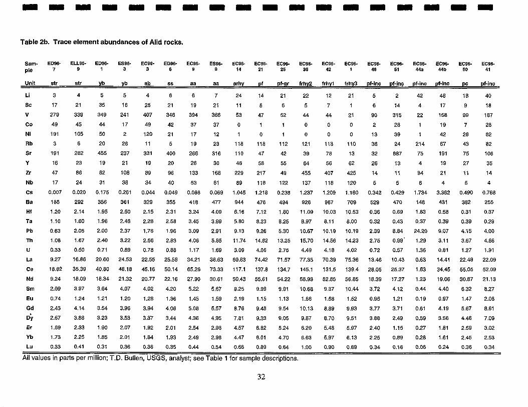
Table 2b. Trace element abundances of Alid rocks.
Sam- ED96- ELL96- ED96- ES96- EC96- ED96- EC96- ES96- EC96- EC96- EC96- EC96- EC96- EC96- EC96- EC96- EC96- EC96- EC96- EC96-
Pie 7 9 1 3 3 6 9 9 14 21 25 36 42 1 48 51 44a 44b 50 41
Unit str str yb yb sb ss aa aa arhy p f pf-gr frhy2 frhyl frhy3 pf-inc pf-inc pf-inc pf-inc pc pf-inc
Li 3 4 5 5 4 6 6 7 24 14 21 22 12 21 5 2 42 48 18 40
SC 17 21 35 16 25 21 19 2 1 11 5 6 5 7 1 6 14 4 17 9 18
V 279 339 349 241 407 346 394 366 53 47 52 44 44 21 90 315 22 158 99 187
CO 49 45 44 17 49 42 37 37 0 1 1 0 0 0 2 28 1 19 7 28
Ni 191 105 50 2 120 21 17 12 1 0 1 0 0 0 13 39 1 42 28 82
Rb 3 6 20 26 11 5 19 23 118 118 112 121 113 110 36 43 82 24 214 67
Sr 191 282 455 237 331 400 266 316 110 47 42 39 78 13 32 887 75 191 75 106
Y 16 23 19 21 19 20 26 30 46 58 55 64 56 62 26 13 4 19 27 35
Zr 47 86 82 108 89 96 133 168 229 217 49 455 407 425 14 11 34 21 11 14
Nb 17 24 31 38 34 40 53 61 89 118 122 137 118 120 5 5 6 4 5 4
Cs 0.007 0.020 0.175 0.261 0.044 0.049 0.086 0.069 1.045 1.218 0.238 1.237 1.209 1.160 0.342 0.429 1.734 3.362 0.490 0.768
Ba 185 292 356 361 329 355 418 477 944 476 494 926 967 709 529 470 148 431 382 255
H f 1.20 2.14 1.95 2.50 2.15 2.31 3.24 4.09 6.16 7.12 1.80 11.09 10.03 10.53 0.36 0.69 1.83 0.58 0.31 0.37
Ta 1.10 1.60 1.96 2.46 2.28 2.58 3.45 3.99 5.80 8.23 8.25 8.97 8.11 8.00 0.32 0.43 0.37 0.39 0.39 0.29
Pb 0.63 2.05 2.00 2.37 1.76 1.96 3.09 2.91 9.13 9.26 5.30 10.67 10.19 10.19 2.39 8.84 24.20 9.07 4.15 4.00
Th 1.08 1.67 2.40 3.22 2.56 2.83 4.06 5.85 11.74 14.82 13.25 15.70 14.56 14.23 2.75 0.99' 1.29 3.11 3.67 4.66
U 0.33 0.50 0.71 0.89 0.78 0.88 1.17 1.69 3.09 4.06 2.75 4.49 4.18 4.02 0.72 0.57 1.36 0.81 1.27 1.91
~a 9.27 16.86 20.60 24.53 22.55 25.58 34.21 38.63 60.83 74.42 71.57 77.35 70.39 75.36 13.46 10.43 0.63 14.41 22.49 22.09
Ce 18.82 35.39 40.80 48.18 45.16 50.14 65.26 73.33 117.1 137.8 134.7 145.1 131.5 139.4 28.05 25.37 1.63 34.45 55.05 52.09
Nd 9.24 18.09 18.34 21.32 20.77 22.16 27.90 30.61 50.43 55.61 54.22 58.93 52.85 56.85 18.39 17.27 1.23 19.06 30.87 21.13
Sm 2.09 3.97 3.64 4.07 4.02 4.20 5.22 5.67 9.25 9.99 9.91 10.68 9.37 10.44 3.72 4.12 0.44 4.40 6.32 8.27
EU 0.74 1.24 1.21 1.20 1.28 1.36 1.45 1.59 2.19 1.15 1.13 1.66 1.58 1.52 0.95 1.21 0.19 0.97 1.47 2.08
Gd 2.43 4.14 3.54 3.96 3.94 4.06 5.08 5.57 8.76 9.48 9.54 10.13 8.89 9.93 3.77 3.71 0.61 4.19 5.67 8.61
0) 2.67 3.88 3.23 3.53 3.37 3.44 4.36 4.95 7.81 9.33 9.05 9.87 8.70 9.51 3.88 2.49 0.59 3.56 4.46 7.09
Er 1.69 2.33 1.90 2.07 1.92 2.01 2.54 2.98 4.57 8.82 5.24 6.20 5.48 5.97 2.40 1.15 0.27 1.81 2.59 3.02
Y b 1.73 2.25 1.85 2.01 1.84 1.93 2.49 2.98 4.47 6.01 4.70 6.63 5.97 6.13 2.25 0.89 0.28 1.61 2.45 2.53
Lu 0.33 0.41 0.31 0.36 0.36 0.35 0.44 0.54 0.66 0.89 0.64 1.00 0.90 0.89 0.34 0.16 0.06 0.24 0.36 0.34
All values in parts per million; T.D. Bullen, USGS, analyst; see Table 1 for sample descriptions.
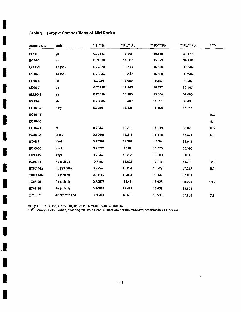
Table 3. Isotopic Compositions of Alid Rocks.
Sample No. Unit B7Srf6Sr 206Pbf04Pb 2mPbp4Pb 208Pb/ZMP b 6 "0
ED96-1 Yb 0.70323 19.608 15.659 39.412
EC96-3 sb 0.70336 19.567 15.673 39.318
EC96-9 sb (aa) 0.70338 19.513 15.649 39.244
ES96-3 sb (aa) 0.70344 19.542 15.639 39.244
ED96-6 ss 0.7034 19.605 15.697 39.38
ED96-7 str 0.70335 19.345 15.677 39.067
ELL96-11 str 0.70356 19.166 15.664 39.006
ES96-9 ~b 0.70338 19.409 15.621 39.086
EC96-14 arhy 0.70501 19.106 15.595 38.745
EC96-17
EC96-18
EC96-21 P f 0.70441 19.214 15.618 38.879
EC96-25 pf-inc 0.70468 19.213 15.616 38.871
EC96-1 f rhY3 0.70395 19.268 15.26 38.916
EC96-36 f W 2 0.70526 19.32 15.626 38.998
EC96-42 frhyl 0.70443 19.256 15.609 38.88
EC96-41 PC (schist) 0.7107 21.028 15.715 39.739
EC96-44a PC (granite) 0.77545 18.251 15.522 37.227
EC96-44b PC (schist) 0.71 167 18.351 15.55 37.991
EC96-48 PC (schist) 0.72975 19.43 15.625 39.21 4
EC96-50 PC (schist) 0.70959 19.483 15.633 38.895
EC96-51 diorite of ? age 0.70404 18.626 15.536 37.966
Analyst - T.D. Bullen, US Geological Survey, Menlo Park, California. 60'' - Analyst Peter Larson, Washington State Univ.; all data are per mil, VSMOW; precision is k0.2 per mil.
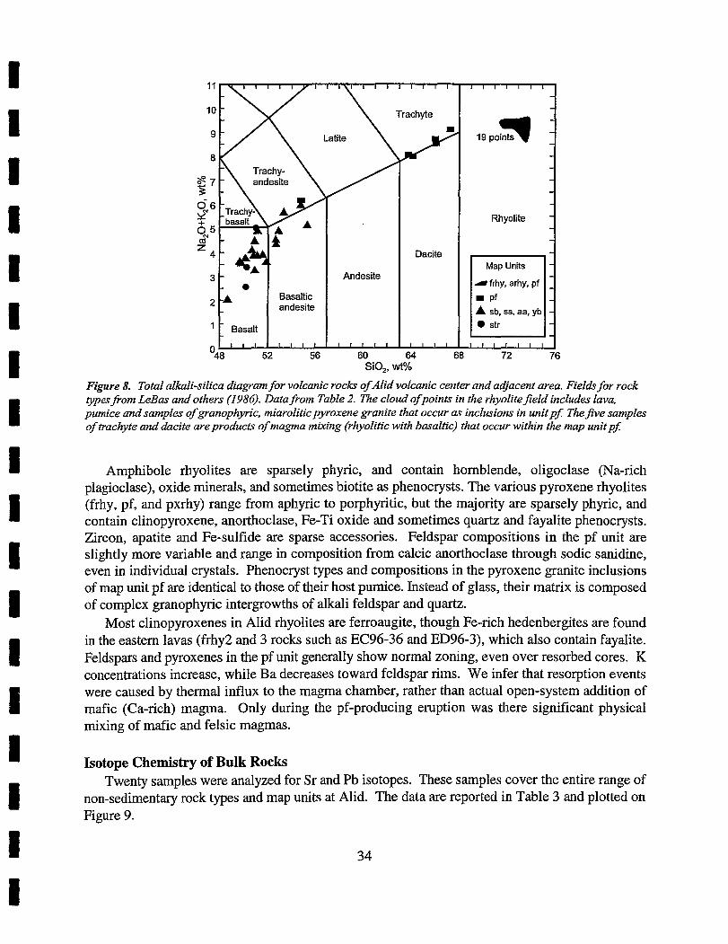
I I 1 I I I I - -
- - - - - - Rhyolite - -
Dacite - Map Units
Andesite - r frhy, arhy, pf
2 -A Basaltic andesite A sb, ss, aa, yb
' - Basalt -
'48 I l l 1 I I I I I I I I I I I I I I I I
52 56 60 64 68 72 76
Figure 8. Total alkali-silica diagram for volcanic rocks ofAlid volcanic center and adjacent area. Fieldr for rock typesfLom LeBas and others (1986). Data from Table 2. The cloud ofpoints in the rhyolite$eld includes lava, pumice and samples of granophyric, miarolitic pyroxene granite that occur as inclusions in unit pf: The$ve samples of trachyte and dacite are products of magma mixing (rhyolitic with basaltic) that occur within the map unitpf:
Amphibole rhyolites are sparsely phyric, and contain hornblende, oligoclase (Na-rich plagioclase), oxide minerals, and sometimes biotite as phenocrysts. The various pyroxene rhyolites (frhy, pf, and pxrhy) range from aphyric to porphyritic, but the majority are sparsely phyric, and contain clinopyroxene, anorthoclase, Fe-Ti oxide and sometimes quartz and fayalite phenocrysts. Zircon, apatite and Fe-sulfide are sparse accessories. Feldspar compositions in the pf unit are slightly more variable and range in composition from calcic anorthoclase through sodic sanidine, even in individual crystals. Phenocryst types and compositions in the pyroxene granite inclusions of map unit pf are identical to those of their host pumice. Instead of glass, their matrix is composed of complex granophyric intergrowths of alkali feldspar and quartz.
Most clinopyroxenes in Alid rhyolites are ferroaugite, though Fe-rich hedenbergites are found in the eastern lavas (frhy2 and 3 rocks such as EC96-36 and ED96-3), which also contain fayalite. Feldspars and pyroxenes in the pf unit generally show normal zoning, even over resorbed cores. K concentrations increase, while Ba decreases toward feldspar rims. We infer that resorption events were caused by thermal influx to the magma chamber, rather than actual open-system addition of mafic (Ca-rich) magma. Only during the pf-producing eruption was there significant physical mixing of mafic and felsic magmas.
Isotope Chemistry of Bulk Rocks Twenty samples were analyzed for Sr and Pb isotopes. These samples cover the entire range of
non-sedimentary rock types and map units at Alid. The data are reported in Table 3 and plotted on Figure 9.
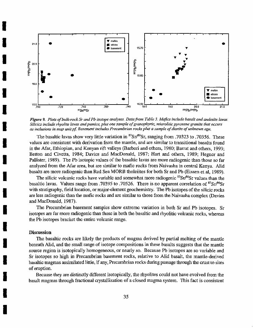
Figure 9. Plots of bulk-rock Sr and Pb isotope anabses. DatafLom Table 3. Ma$cs include basalt and andesite lavas. Silicics include rhyolite lavas andpumice, plus one sample of granophyric, miarolitic pyroxene granite that occurs as inclusions in map unitpJ Basement includes Precambrian roch plus a sample of diorite of unknown age.
The basaltic lavas show very little variation in 87Sr/86Sr, ranging from -70323 to .70356. These values are consistent with derivation from the mantle, and are similar to transitional basalts found in the Afar, Ethiopian, and Kenyan rift valleys (Barberi and others, 1980; Barrat and others, 1993; Betton and Civetta, 1984; Davies and MacDonald, 1987; Hart and others, 1989; Hegner and Pallister, 1989). The Pb isotopic values of the basaltic lavas are more radiogenic than those so far analyzed from the Afar area, but are similar to mafic rocks from Naivasha in central Kenya. Alid basalts are more radiogenic than Red Sea MORB tholeiites for both Sr and Pb (Eissen et al, 1989).
The silicic volcanic rocks have variable and somewhat more radiogenic 87Sr/86Sr values than the basaltic lavas. Values range from .70395 to .70526. There is no apparent correlation of 87Sr/86Sr with stratigraphy, field location, or major-element geochemistry. The Pb isotopes of the silicic rocks are less radiogenic than the mafic rocks and are similar to those from the Naivasha complex pavies and MacDonald, 1987).
The Precambrian basement samples show extreme variation in both Sr and Pb isotopes. Sr isotopes are far more radiogenic than those in both the basaltic and rhyolitic volcanic rocks, whereas the Pb isotopes bracket the entire volcanic range.
Discussion The basaltic rocks are likely the products of magma derived by partial melting of the mantle
beneath Alid, and the small range of isotope compositions in these basalts suggests that the mantle source region is isotopically homogeneous, or nearly so. Because Pb isotopes are so variable and Sr isotopes so high in Precambrian basement rocks, relative to Alid basalt, the mantle-derived basaltic magmas assimilated little, if any, Precambrian rocks during passage through the crust to sites of eruption.
Because they are distinctly different isotopically, the rhyolites could not have evolved from the basalt magmas through fractional crystallization of a closed magma system. This fact is consistent
with the lack of a continuum of intermediate lava compositions that would be expectable if the rhyolites were products of such a fractionation process. Production of the rhyolite magmas through fractional crystallization of basaltic magma, accompanied by assimilation of some Precambrian crustal rock is possible, given the extreme range of isotopic compositions in the Precambrian rocks. However, the rhyolite magmas can not have formed by partial melting of Precambrian granites and schists, because these rocks are much more radiogenic in Sr isotopes than any Alid rhyolite.
Though they are measurably different in detail, a broad similarity between the Sr and Pb isotopic compositions of both basalt and rhyolite at Alid, suggests the possibility that the rhyolite magmas were produced by partial melting of a mid Tertiary or younger basaltic source rock in the lower crust, followed by minor assimilation of upper crustal Precambrian rocks as the magmas rose to sites of eruption. Intrusive equivalents of the basalts at Alid could have provided the thermal energy for such lower-crustal melting. Recent experimental studies have demonstrated the feasibility of this melting process, and similar scenarios have been proposed to explain bimodal volcanism elsewhere (e.g. Bullen and Clynne, 1991; Guffanti and others, 1996). The subaluminous and quartz-normative nature of Alid rhyolite is consistent with an origin by partial melting of mafic rocks.
Whatever the details of rhyolite magmagenesis at Alid, the key factors insofar as they impact our assessment of geothermal potential, are the lines of evidence indicative that a body of rhyolite magma accumulated in the upper crust and is therefore almost certainly the heat engine that drives the Alid hydrothermal-convection system.
GEOCHRONOLOGY Bonatti and others (1971) reported U-Th and 14C ages of about 32,000 years old for marine
fossils in rocks that they interpret as the youngest deposits of the most recent invasion of the Red Sea into the Danakil Depression. And because these workers believed that Alid was constructed entirely in a subaerial environment, following retreat of the Red Sea from the Depression, they concluded that the mountain is younger than 32,000 years.
On the other hand, Beyth (1994) reported that Alid itself, and a similar-sized volcano-related highland called Jallua, near the present-day foot of the Gulf of Zula, acted as dams that blocked the Red Sea from the Danakil Depression. Thus, he concluded that Alid is older than 32,000 years, presumably by a period equivalent to how long it took Red Sea water in the Depression to dry up. Bonatti and others (1971) calculated that this period of desiccation required a few thousand years.
Whether Alid postdates or predates the most recent exclusion of Red Sea water from the Danakil Depression, the isotopic ages reported by Bonatti and others (1971) may be incorrect, because the dated materials (marine corals and mollusks) are known to be poor materials for U-Th age dating. The original aragonite of such materials commonly recrystallizes to calcite and in so doing partly or completely resets the isotopic clock. Moreover, marine carbonates commonly do not yield 14C ages greater than about 30,000 years, because of carbon exchange with the atmosphere or ground water that has equilibrated with the atmosphere.
Barberi and others (1972) and Zumbo and others (1995) suggested that stratoid basalt (map unit str) in the vicinity of Alid is about 1.2 Ma. Stratoid basalt is offset vertically at least 300 meters across the normal fault that defines the east side of Alid graben. Rocks that have accumulated within Alid graben are younger than these faulted stratoid basalts, but just how much younger is difficult to judge from field characteristics alone. As a mappable group, the youngest volcanic rocks in the
study area are the Oss basalt flows (map unit yb) that lap unconformably against the north and south flanks of Alid. Some of these lavas are cut by north-northwest-trending dilational fissures up to a meter or so wide and normal faults with up to several meters vertical offset, which are the tectonic expression of ongoing crustal spreading distributed across Alid graben. Though not carefully documented, we speculate that total dilation as recorded by open fractures of Alid graben is on the order of a few tens of meters. If the average rate of crustal spreading across Alid graben is only 2 centimeters a yeas, at the lower end of rates for well documented divergent plate-tectonic environments, total dilation would be 200 meters in 10,000 years. Thus, we infer that the Oss basalt flows may be Holocene in age. The radiometric ages produced during our study are consistent with this inference.
We had seven samples of volcanic rocks processed in the U.S. Geological Survey geochronology laboratory in Menlo Park, California (Table 4). These samples span almost the entire mapped volcanic stratigraphic range. Stratoid basalt collected from atop the horst immediately east of Alid yielded an age of 1.1 million years (Table 4, Figure lo), which is nearly identical to the 1.2-million- year age inferred earlier by Barberi and others (1972) and measured by Zumbo and others (1995) on lavas interpreted to be age equivalents in the Republic of Djibouti. Basalt lava from within the sedimentary sequence of Alid contains considerable non-radiogenic argon, which results in a very poorly constrained age in the probable range of 200,000 to 300,000 years old. By contrast, a sample of basalt lava from high in the lava shell of Alid yields a well constrained age of 36,000 years (Table 4) -
The stratigraphically oldest rhyolite (map unit arhy) yields an age of about 212,000 years. Since field relations indicate that this rhyolite is younger than the sedimentary sequence, the basalt dated from that sequence is perhaps toward the older end of the 200,000 to 300,000 year range mentioned above. Map units frhyl, 2, and 3 yield ages of about 18,000, 29,000, and 34,000 years old, respectively. Finally, the stratigraphically youngest rhyolite lava (map unit pxrhy) yields an average age of about 24,000 years old. We interpret this lava to be the closing phase of the eruption that produced map unit pf, and thus essentially coeval with this pyroclastic deposit.
The 24,000 year age for map unit pxrhy is the weighted average (see Table 4) of two determinations on anorthoclase phenocrysts that are just denser than 2.59 and two on anorthoclase phenocrysts that are less dense than 2.59. The denser fraction is relatively K-poor and yields ages of about 29,000 years, whereas the lighter, K-rich fraction yields ages of about 15,000 years (Table 4). We interpret the K-rich fraction of crystals to be phenocrysts that began to grow late relative to the K-poor crystals, and thus speculate that the time of eruption of map units pxrhy and pf is closer to 15,000 than to 29,000 years ago. This is consistent with our conclusion that the Oss basalt, the youngest volcanic unit in the study area, probably is Holocene.
We recognize overlap in numerical ages for different map units, within the ranges of analytical uncertainties. Still, remarkable agreement is apparent between mapped stratigraphy and numerical- age stratigraphy.
The isotopic ages help constrain the timing of tectonic events in the Mid area. The onset of normal faulting along the east side of Alid graben must postdate about 1.1 Ma, the age of stratoid basalt that is offset there. On the floor of Alid graben, normal faults and dilational fissures that cut Oss basalt indicate that crustal spreading and graben growth continue into the Holocene. The onset of structural doming at Alid postdates about 36,000, the age of a basalt flow stratigraphically high
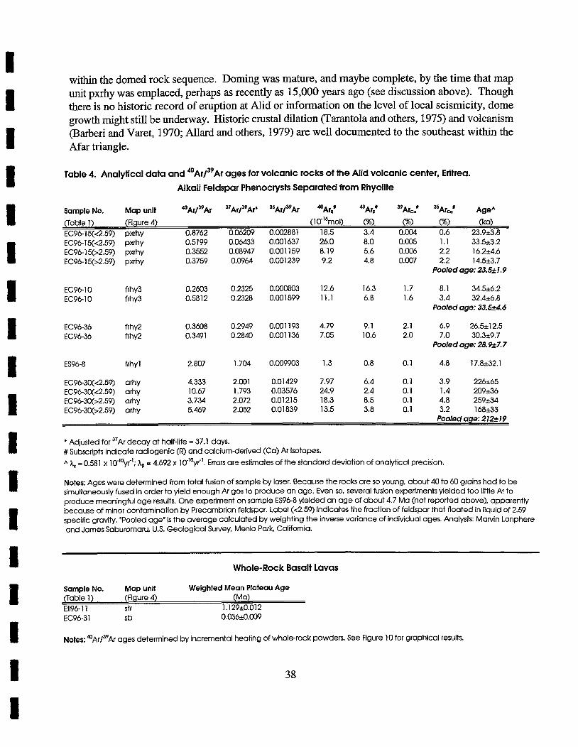
within the domed rock sequence. Doming was mature, and maybe complete, by the time that map unit pxrhy was emplaced, perhaps as recently as 15,000 years ago (see discussion above). Though there is no historic record of eruption at Alid or information on the level of local seismicity, dome growth might still be underway. Historic crustal dilation (Tarantola and others, 1975) and volcanism (l3arberi and Varet, 1970; AZlard and others, 1979) are well documented to the southeast within the Afar triangle.
Table 4. Analytical data and 4 0 ~ r / 3 9 ~ r ages for volcanic rocks of the Alid volcanic center, Eritrea. Alkali Feldspar Phenocrysts Separated from Rhyolite
Sample No. Map unit 4 0 ~ r / 3 9 ~ r 37~r /39~r * 36~r/39Ar % r t 39 Arc: % ~ r ~ ' AgeA (Table 1) (Figure 4) (10"~mol) (%I ("A) (ka) EC96-15(<2.59) pxrhy 0.8762 0.06209 0.002881 18.5 3.4 0.004 0.6 23.923.8 EC96-15(<2.59) pxrhy 0.5199 0.06433 0.001637 26.0 8.0 0.005 1.1 33.5k3.2 EC96-15b2.59) pxrhy 0.3552 0.08947 0.001 159 8.19 5.6 0.006 2.2 16.2k4.6 ~~96-15(>2.59) bxrhy 0.3759 0.0964 0.001239 9.2 4.8 O.GU7 2.2 14.5k3.7
Pooled age: 23.52 1.9
EC96-10 frhy3 0.2603 0.2325 0.000803 12.6 16.3 1.7 8.1 3456.2 EC96-10 frhy3 0.5812 0.2328 0.001899 11.1 6.8 1.6 3.4 32.4k6.8
Pooled age: 33.524.6
EC96-36 frhy2 0.3608 0.2949 0.001 193 4.79 9.1 2.1 6.9 26.5k12.5 EC96-36 0.3491 0.2840 0.001 136 7.05 10.6 2.0 7.0 30.3k9.7
Pooled age: 28.927.7
ES96-8 frhyl 2.807 1.704 0.009903 1.3 0.8 0.1 4.8 17.8k32.1
EC96-30(<2.59) arhy 4.333 2.001 0.01429 7.97 6.4 0.1 3.9 226565 EC9630(.c2.59) arhy 10.67 1.793 0.03576 24.9 2.4 0.1 1.4 20946 EC96-30(>2.59) arhy 3.734 2.072 0.01 21 5 18.3 8.5 0.1 4.8 259k34 EC96-30(>2.59) arh y 5.469 2.052 0.01 839 13.5 3.8 0.1 3.2 168k33
Pooled age: 212219
+ Adjusted for 3 7 ~ r decay at half-life = 37.1 days. # Subscripts indicate radiogenic (R) and calcium-derived (Ca) Ar isotopes.
h, = 0.581 x 10- '~~ i ' ; hB = 4.692 x 10"Oyi'. Errors are estimates of the standard deviation of analytical precision.
Notes: Ages were determined from total fusion of sample by laser. Because the rocks are so young, about 40 to 60 grains had to be simultaneously fused in order to yield enough Ar gas to produce an age. Even so, several fusion experiments yielded too little Ar to produce meaningful age results. One experiment on sample ES96-8 yielded an age of about 4.7 Ma (not reported above), apparently because of minor contamination by Precambrian feldspar. Label (<2.59) indicates the fraction of feldspar that floated in liquid of 2.59 specific gravity. "Pooled age" is the average calculated by weighting the inverse variance of individual ages. Analysts: Marvin Lanphere and James Saburomaru. U.S. Geological Survey, Menlo Park, California.
Whole-Rock Basalt Lavas
Sample No. Map unit Weighted Mean Plateau Age (Table 1) (Figure 4) (Ma) E1196-11 st( 1.129i0.012
Notes: 4 0 ~ r / 3 9 ~ r ages determined by incremental heating of whole-rock powders. See Figure 10 for graphical results.
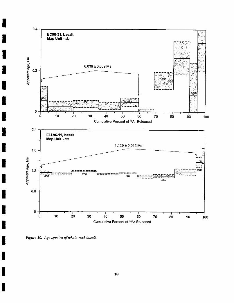
, ,"". . . 2 . , I .
EC96-31, basalt , .. . :: '!.. $ ? . . .
Map Unit - sb i. . ' . I ... .. , + ,,',.;.
-
0.036 + 0.009 Ma
. ,, ;. , " ~
: I ". ,. s . , ,
, . ': ' , . , , - _ . . , .. '3 ., . ):> I I I I I I I I 1 1 I I I I
0 I
10 I
20 I
30 40 50 60 70 80 90 100 I
Cumulative Percent of 39Ar Released
2.4 ELL96-I I, basalt
- Map Unit - str
0 ; I I I 1 I I 1 I I 1 1 I I I I I I
0 I
I 0 20 30 40 50 60 70 80 90 I
Cumulative Percent of =9Ar Released
Figure 10. Age spectra of whole-rock basalt.
REGIONAL HYDROLOGY AND GEOCHEMISTRY Introduction
An evaluation of regional hydrologic characteristics is a common subject for any evaluation of a geothermal energy prospect. Under favorable circumstances, such an evaluation provides information about (1) the origin of fluid within the target geothermal reservoir, and (2) the likely source of recharge after a reservoir has been put into production. Ideally, one would use data from wells that can be used to delineate the groundwater potentiometric surface, rates of flow and variations in water salinity, both laterally and with depth. At Alid, the hydrologic setting is complex and available hydrologic information is limited mostly to rainfall and temperature data collected at a few widely spaced stations. Moreover, there are few data from wells, with which to construct a reliable hydrologic model.
A field campaign aimed at correcting the hydrologic data deficiencies was far beyond the scope of the present geothermal assessment, because this would be far too time consuming and costly. A conventional hydrologic assessment would include the drilling of new observation wells, carrying out pumping tests, and sampling and analyses of waters from different well depths. Many wells throughout the region would be monitored over at least one, and preferably several yearly hydrologic cycles, to record water levels, estimate rates of water usage, and identify water quality variations. In addition, it would be highly desirable to install new meteorological stations and upgrade existing stations to obtain automated data for rainfall, relative humidity, maximum and minimum temperatures, and wind direction and velocity throughout the lowland region.
Based on Alid's topographic and geologic setting, potential sources of water that could enter any associated geothermal reservoir would be: (1) fossil Red Sea water that may be present at relatively shallow depths beneath thin fresh-water lenses throughout much of the Danakil Depression. Such waters would have entered the groundwater system the last time that the Red Sea invaded the Danakil Depression, (2) local rain that falls on and around Alid, (3) meteoric water that falls on the Ethiopian plateau and flows as surface and ground waters toward the eastern lowlands, (4) highly evaporated, high-density brine that accumulates by evaporation of waters that flow into closed basins 15-25 kilometers to the south of Alid, and (5) fluids released from crystallizing magma. To determine which of these possible water sources is most likely, we sought to compare stable isotope compositions of geothermal steam with those of different types of water in the Alid graben as well as adjacent highland and lowland areas. We sought to determine systematic regional variations in isotopic composition that are expected to occur as a result of rain falling at different elevations and from storms traveling in different directions. Previously available meteorological information about rainfall and storm directions, discussed below, provide a framework in which the isotopic data can be understood.
Meteorological Information The regional meteorological characteristics of northeastern Africa, including Eritrea and the
Danakil region, have been described in various publications and reports, including Food and Agricultural Organization (1983) Kasahun (1986), Michael (1986), Eklundh and Pilesji* (1990) and Beltrando and Camberlin (1993). A concise summary of available rainfall and temperature information is part of the National Map of Eritrea that was published in 1995, with compilation and cartography by representatives of the Eritrean Government Offices, and the Institute of Geography,
Group for Development and Environment, University of Bern, Switzerland. This National Map also shows contours of average annual rainfall throughout Eritrea, and graphs of average temperature and monthly rainfall at meteorological stations at Teseney in the western lowlands, at Asmara on the central highlands, at Mrara on the eastern escarpment, and at Massawa on the Red Sea coast.
Of primary importance to this study is that the annual rainfall on the central highlands is generally 500-700 mm, and comes from storms propelled by monsoonal winds blowing from the southwest toward the northeast. This rain occurs mostly in July and August. Little, if any, rain falls on the central highlands December through February. In contrast, less than 300 mm per year of rain generally falls in the eastern lowlands. Most of this rain falls in December and January from storms propelled by monsoonal winds blowing from the northeast toward the southwest. Note that the above are long-term average rainfa11 values. Seasonal and annual variations in rainfall can be very great, particularly in the desert lowland regions. There, rainfall may be very spotty with no rain falling for a year or more on parts of the lowland region while other parts are subjected to brief, torrential down-pourings of rain.
Another very important factor in the eastern lowlands is that rivers and streams entering the lowlands from the high plateau disappear into alluvial fan deposits, or pond in closed-basin lakes where the water evaporates. In some places salt is depositing from such evaporating waters. There is the potential for lenses of relatively fresh and non-evaporated water to pond in the subsurface over deeper bodies of denser brine.
Sample Collection We used standard collection procedures as outlined in Trujillo and others (1987). Waters for
isotopic analyses were collected in glass bottles. Waters for chemical analyses were filtered in the field through a 0.45 micron filter and saved in plastic bottles. The water in one bottle that was used for anion analyses was not further treated. The water in a second bottle that was used for cation analyses was acidified with one to ten drops of chemically pure nitric acid. A separate bottle of water was collected for dissolved silica analysis. This sample was not filtered, but was diluted with silica-free water to prevent polymerization of dissolved silica and precipitation of amorphous silica. Temperature, pH, and water conductivity were measured in the field and then again in the laboratory.
Isotope Geochemistry of Meteoric Waters Figure 11 and Table 5 give sample locality information and results of isotopic analyses for
meteoric waters collected from shallow wells and streams in the eastern lowland and central highland regions of Eritrea. Isotopic values are reported relative to Vienna Standard Mean Ocean Water (VSMOW) in units of per mil, where:
8l8O = ((180/1600,1e - (18~/16~)vsMow) 1 (180/160)vsMow)) x 1 O3 and
= ( P ~ S a m p ~ e - (D/H)vsMow)/ (Dm) vsMod x lo3
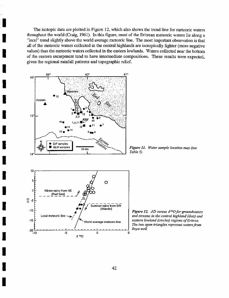
The isotopic data are plotted in Figure 12, which also shows the trend line for meteoric waters throughout the world (Craig, 1961). In this figure, most of the Eritrean meteoric waters lie along a "local" trend slightly above the world average meteoric line. The most important observation is that all of the meteoric waters collected in the central highlands are isotopically lighter (more negative values) than the meteoric waters collected in the eastern lowlands. Waters collected near the bottom of the eastern escarpment tend to have intermediate compositions. These results were expected, given the regional rainfall patterns and topographic relief.
Figure 11. Water sample location map (see
14"
0 '1 Winter (Red rains seal from NE f 6d - - - - - - - - - -
Figure 12. dD versus 6180 for groundwaters and streams in the central highland (dots) and eastern lowland (circles) regions of Eritrea. The two open triangles represent waters@om Boya well.
I
a -5
-10
-15
-20
1 - - - - - - - - - - Summer rains from SW
- (Atlantic)
Local meteoric line %; -
World average meteoric line
' " " " " " -1 0 -5 T , , 0 , , , , , , , , , , 5
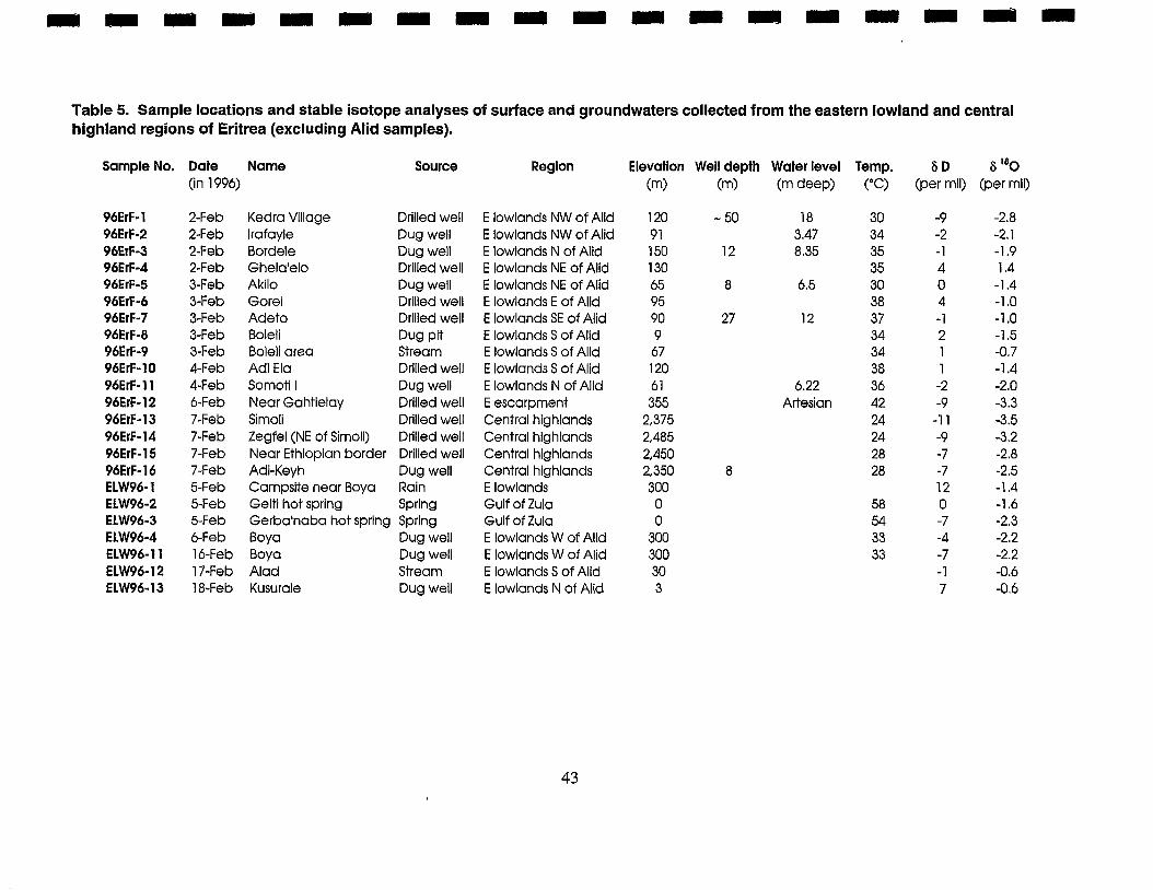
Table 5. Sample locations and stable isotope analyses of surface and groundwaters collected from the eastern lowland and central highland regions of Eritrea (excluding Alid samples).
Sample No. Date Name (in 1996)
Source Region Elevation Well depth Water level Temp. 6 D S 180 (m) (m) (m deep) ("C) (per mil) (per mil)
Kedra Village Drilled well lrafayle Dug well Bordele Dug well Ghela'elo Drilled well Akilo Dug well Gorei Drilled well Adeto Drilled well Bolell Dug pit Boleli area Stream Adi Ela Drilled well Somotl I Dug well Near Gahtielay Drilled well Simoli Drilled well Zegfel (NE of Simoli) Drilled well Near Ethiopian border Drilled well Adi-Keyh Dug well Campsite near Boya Rain Gelti hot spring Spring Gerba'naba hot sprlng Spring Boya Dug well Boya Dug well Alad Stream Kusurale Dug well
E lowlands NW of Alid E lowlands NW of Alid E lowlands N of Alid E lowlands NE of Alid E lowlands NE of Alid E lowlands E of Alld E lowlands SE of Alid E lowlands S of Alid E lowlands S of Alid E lowlands S of Alid E lowlands N of Alid E escarpment Central highlands Central highlands Central highlands Central highlands E lowlands Gulf of Zulu Gulf of Zulu E lowlands W of Alid E lowlands W of Alid E lowlands S of Alid E lowlands N of Alid
6.22 Artesian
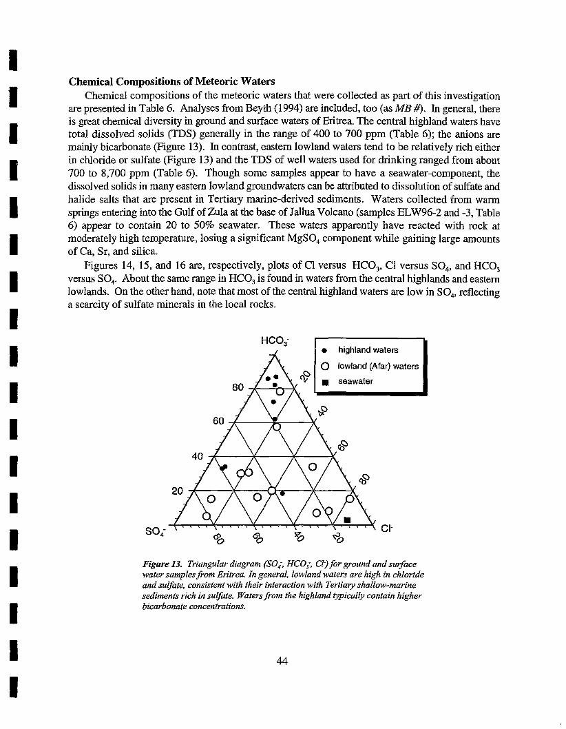
Chemical Compositions of Meteoric Waters Chemical compositions of the meteoric waters that were collected as part of this investigation
are presented in Table 6. Analyses from Beyth (1994) are included, too (as MB #). In generaI, there is great chemical diversity in ground and surface waters of Eritrea. The central highland waters have total dissolved solids (TDS) generally in the range of 400 to 700 ppm (Table 6); the anions are mainly bicarbonate (Figure 13). In contrast, eastern lowland waters tend to be relatively rich either in chloride or sulfate (Figure 13) and the TDS of well waters used for drinking ranged from about 700 to 8,700 ppm (Table 6). Though some samples appear to have a seawater-component, the dissolved solids in many eastern lowland groundwaters can be attributed to dissolution of sulfate and halide salts that are present in Tertiary marine-derived sediments. Waters collected from warm springs entering into the Gulf of Zula at the base of Jallua Volcano (samples ELW96-2 and -3, Table 6) appear to contain 20 to 50% seawater. These waters apparently have reacted with rock at moderately high temperature, losing a significant MgSO, component while gaining large amounts of Ca, Sr, and silica.
Figures 14, 15, and 16 are, respectively, plots of C1 versus HCO,, CI versus SO,, and HCO, versus SO,. About the same range in HCO, is found in waters from the central highlands and eastern lowlands. On the other hand, note that most of the central highland waters are low in SO,, reflecting a scarcity of sulfate minerals in the local rocks.
SO,
Figure 13. Triangular diagram (SO,; HCO,; Cl;) for ground and surface water samplesfiom Eritrea. In general, lowland waters are high in chloride and sulfate, consistent with their interaction with Tertiaty shallow-marine sediments rich in sulfate. Waters fiom the highland typically contain higher bicarbonate concentrations.
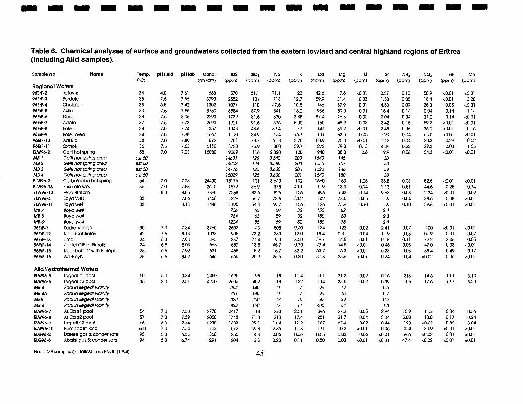
Table 6. Chemical analyses of surface and groundwaters collected from the eastern lowland and central highland regions of Eritrea (including Alid samples).
Sample No. Name
Regional Waters 96ErF-2 lrafayle 96ErF-3 Bordele 96ErF-4 Ghela'elo 96ErF-5 Akllo 96ErF-6 Gore1 96ErF-7 Adeto 96ErF-8 Bole11 96ErF-9 Boleli area 96ErF-10 Ad1 E l 0 96ErF-I1 Sornoti ELW96-2 Geltl hot sprlng MB 1 Geltl hot spring area MB 2 Gelti hot sprlng area MB 3 Geltl hot sprlng area MB 4 Gelff hot sprlng area ELW96-3 Gerba'naba hot sprlng ELW96-13 Kusurale well ~ 1 ~ 9 6 - 1 2 ad Stream ELW96-4 Boya Well ELW96-l l Boy0 well MB 7 Boya well MB 8 ~ o y a we11 MB-9 Boya well 96ErF-I Kedra Village 96ErF-12 Near Gahtlelay 96~1~-13 Slmoll 96ErF-14 Zegfel (NE of Slmoll) 96ErF-15 Near border with Ethlopla 96ErF-16 Adl-Keyh
Alid Hydrothermal Waters ELW96-5 Ilegedi # l pool ELW96-6 Ilegedl#2 pool MB 4 Pool in llegedl vlclnlty MB 4A Pool In llegedl vlclnlfy MB5 Pool In llegedl vicln/ty MB 6 Pool In llegedl vlclnlfy ELW96-7 As'Ela #l pool ELW96-8 As'Eia #2 Pool ELW96-9 Ilegedl#3 pool ELW96-10 Hurnbebet drip ELG96-2 Darere gas &condensate ELG96-6 Abakrl gas &condensate
Temp. PC)
34 35 35 30 38 37 34 34 38 36 58
est 60 est 60 est 60 est 60
54 36
33 33
30 42 24 24 28 28
pH field
4.0 7.5 6.8 7.5 7.5 7.5 7.0 7.0 7.0 7.5 7.0
pH lab Cond. (rnslcm)
TDS ( P P ~ )
570 2552 1077 5584 1739 1921 1048 11 10 701
3730 9089
14633 14802 14776 15029 15176 1572 7258 1229 1195 766 764
1224 2602 905 337 552 468 560
Note: ME samples (in itallcs) from Beyth (1994) 45
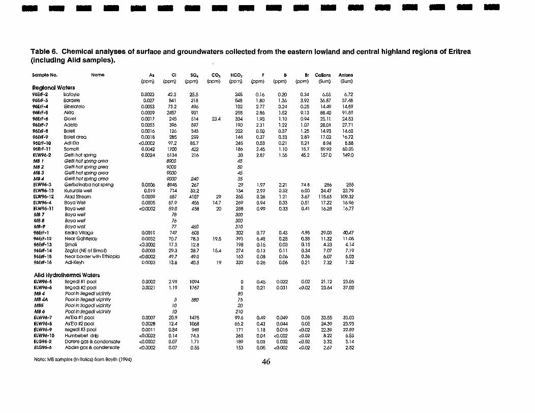
Table 6. Chemical analyses of surface and groundwaters collected from the eastern lowland and central highland regions of Eritrea (including Alid samples).
Sample No. Name
Regional Waters 96ErF-2 lrafayle 96ErF-3 Bordele 96ErF-4 Ghela'elo 96ErF-5 Akllo 96ErF-6 Gorel 96ErF-7 Adeto 96ErF-8 Boleli 96ErF-9 Bolell area 96ErF-10 Ad1 Ela 96ErF-11 Somotl ELW96-2 Gelti hot spring MB 1 Gelti hot spring area MB 2 Geltl hot spring area MB 3 Geltl hot spring area MB 4 Geltl hot sphg area ELW96-3 Gerba'naba hot sprlng ELW96-13 Kusurale well ELW96-12 Alad Stream ELW96-4 Boya Well ELW96-11 Boya well M8 7 Boya well MB 8 Boya well MB-9 Boya well 96ErF-1 Kedra Vlllage 96ErF-12 Near Gahtielay 96ErF-13 Sirnoll 96ErF-14 Zegfel (NE of Slmoll) 96ErF-15 Near border with Ethlopla 96ErF-16 Adi-Kevh
Alid Hydrothermal Waters ELW96-5 llegedl#l pool ELW96-6 llegedi #2 pool MB 4 Pool In llegedl vlclnlty MB 4A Pool h llegedl vicinity MB5 Pool In llegedl vlclnlty MB 6 Pool ln llegedl vicinity ELW96-7 As'Ela #l pool ELW96-8 As'EIo #2 pool ELW96-9 llegedl#3 pool ELW96-10 Humbebet drlp ELG96-2 Darere gas &condensate ELG96-6 Abakrl gas & condensate
Note: MB samples (In Italics) from Beyth (1994) 46
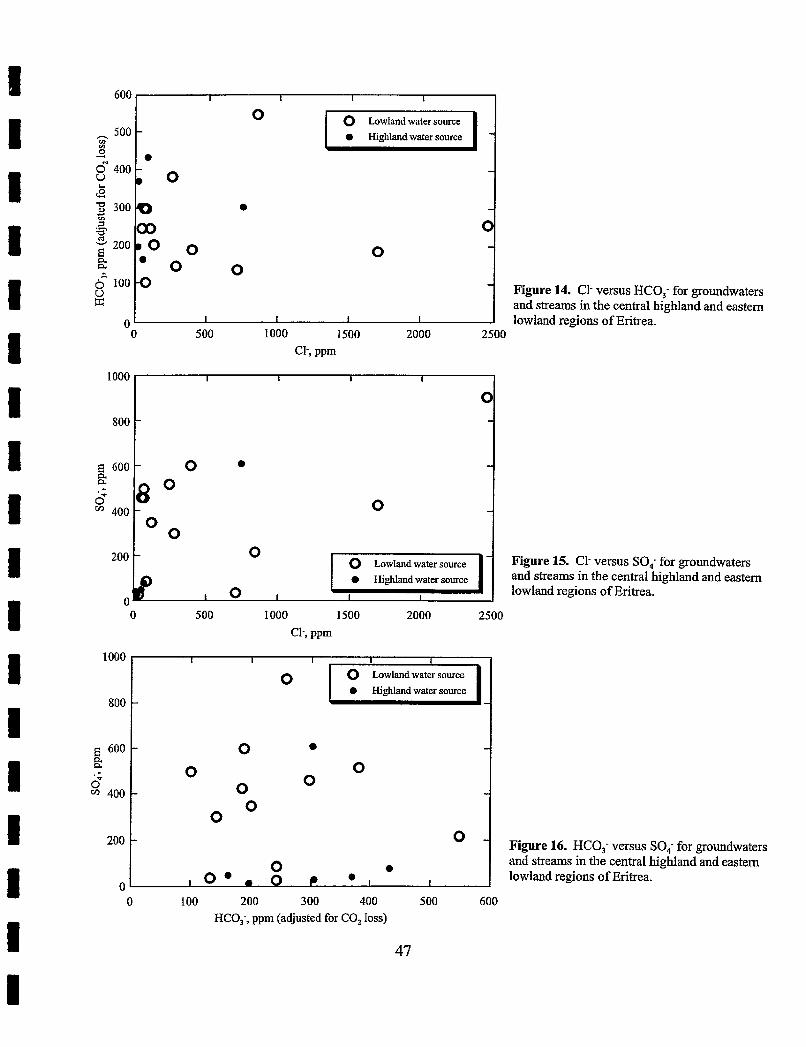
600
500 0) z 4 8 400 h e
300
200. a a
6 loo 2
0
1000
800
E 600
6 " 400
200
0 500 1000 1500 2000 2500
C1-, ppm
I I I I
0 - -
- -
Q - 00 0 0
0 - 0
. O o 0 -
I I I I
I I I I
0 - -
- 0 -
"0 - 0 -
O 0 - -
Figure 15. C1- versus SO,. for groundwaters
0 and streams in the central highland and eastern l o lowland regions of Eritrea.
1000
800
E 600 a a
6 " 400
200
0
Figure 14. C1- versus HC0,- for groundwaters and streams in the central highland and eastern lowland regions of Eritrea.
0 4 0 500 1000 1500 2000 2500
C1-, ppm
0 100 200 300 400 500 600 HC0,-, ppm (adjusted for CO, loss)
Figure 16. HC0,- versus SO,- for groundwaters and streams in the central highland and eastern lowland regions of Eritrea.
I I I I I
0 0 Lowland water source
Highland water source - 4 -
- 0 - 0 0
- 0 0 -
0 0
- O -
0 a I 0.. 0 C I
GEOTHERMAL MANIFESTATIONS With the help of local inhabitants, we identified 11 geothermal areas on Alid. Of these, we
visited nine and selected six as being suitable for sampling of gas and water emanations (Tables 6 and 7). Darere, Ilegedi and As'ela are the most prominent vent areas, and samples of thermal fluids were obtained from each, as well as Abakri and Humbebet. All vent areas contain fumaroles at temperatures near the boiling point for their elevation. The physical nature and geochemical environment of the hot springs and pools at these sites strongly suggest that the waters consist of mixtures of condensate of fumarolic steam mixed with cooler, shallow groundwater.
Fumaroles and boiling pools are distributed widely on the north half of Alid, suggesting that a hydrothermal system underlies much of the volcanic center (Figure 2). The presently identified area of this high heat flow is at least 10 square kilometers. High heat flow may extend over a wider area, particularly adjacent to the north side of Alid, though no visible thermal manifestations are known there.
Fumaroles vent through rhyolite breccia (Abakri, As'ela, Darere), the sedimentary sequence (Humbebet), and Precambrian basement rocks (Ilegedi). Therefore, location of these thermal features does not appear to be controlled by lithologic type or contacts of different lithologic units. Most of the thermal manifestations are located at elevations between about 460 and 600 meters, though hot rock and steaming vents also are present as low as 230 meters (Hulma) and slightly higher than 760 meters (Airole). Some fumaroles are aligned, suggestive of fault control. For example, several areas of alteration, including the one at Hulma, lie in a N50E zone, parallel to the north base of Alid. Abakri, As'ela and Humbebet are present in adjacent drainages on the north'flank of Alid along a roughly N45E trend. Thermal areas do not occur within the flat pumice-covered areas in the Alid crater part of the summit depression, presumably because the ascending fluids are absorbed by the porous, reactive pumice. Similarly, they do not emanate to the north of Alid through the porous Oss basalts (yb). The lack of thermal features in these areas should not be interpreted as indicative of low heat flow, but instead as due to the lack of appropriate lithologies for transmission of fumarolic fluids to the surface.
Collection of Gas Samples Fumarole samples were collected for steam and non-condensable gases including CO,, H,, CH,,
H,S, NH,, N,, 0, and Ar. A 1-meter-long titanium tube was placed in the fumarole and the surrounding crack was packed with mud to insure good steam and gas flow and minimal air contamination. An evacuated bottle partly filled with a caustic (NaOH) solution was then attached to the titanium tube using temperature-resistant, silica-plastic tubing. The length of the plastic tubing varied from 2 to 5 meters. Steam condensate and soluble gases condensed within the tube and flowed into the bottle along with bubbles of non-condensable gas that became entrained in the flowing condensate. In the collection bottle, CO, and H2S reacted with the caustic solution, yielding the dissolved species CO," and HS-. Gases such as CH,, H,, N, and Ar do not condense or react with the caustic solution and make up the "head space" of the then partly evacuated bottle. The gas collection bottle was full when the pressure in the head space approached atmospheric pressure and the bottle ceased to draw steam and gas from the vent. The collection process was also stopped when condensation of steam produced enough water to reduce the head space to less than half its
original volume. More information on collection methods are available in Giggenbach and Goguel (1989) and Fahlquist and Janik (1992).
Condensed steam from fumaroles also was collected separately for study of its isotopic composition (180/160 and Dm. Steam condensate from Darere and Abakri also was collected in 175 rnl bottles for a study of trace components (Li, By Hg, As, C1, F, etc.) soluble in steam.
Laboratory Analysis of Gas and Water Samples Constituents of the gas bottles were measured by gas chromatography (H,, He, N,, Ar, CH,),
manometry (CO,), gravimetry (H,S) and gas-sensing electrodes (NH,) at the USGS geothermal laboratory in Menlo Park, California, according to procedures outlined in Fahlquist and Janik (1 992). Carbon dioxide was separated and isolated for isotopic analysis at Menlo Park. In addition, steam condensates were analyzed for their H and 0 isotopic compositions by mass spectrometry in the Water Resources Laboratory of Carol Kendall at Menlo Park.
Water chemistry of ground and surface water samples and two steam condensates were analyzed at Los Alamos National Laboratory according to methods outlined in the appendices of Trujillo and others (1987). Chemical analyses are reported in units of mglkg of sampIe.
Characteristics of Alid Fumaroles and Thermal Waters Fumarolic Encrustations
All of the fumarolic vent areas appeared to contain similar alteration and sublimate mineralogies. White and red clays, white and yellow crustose sublimates, and fine-grained white and green sublimates are ubiquitous. Beyth (1994) found that some of the sublimate minerals are ammonium hydrates and sulfates. We identified anhydrite (CaSO,), kalinite/alum (KAl(SO,), 1 lH,O), tschermigite ((NH,)Al(SO,), 12H20), montmorillonite and illite among the alteration minerals present at the fumarole sites. Tschermigite and alum are salts that form where ammonium- and sulfate-bearing waters react with crustal rocks at sub-boiling temperatures and oxidizing atmospheric conditions. These minerals precipitate as solutions evaporate, leaving crustose deposits or efflorescences. Anhydrite forms under similar conditions in fumarolic areas. As shown in Table 6, the primary dissolved anion within the thermal pools is sulfate, and the main dissolved cations are ammonium, calcium, and potassium. Thus, efflorescent salts containing these constituents are likely to precipitate as the solutions evaporate.
Gas Compositions Complete analyses of gas samples from Alid fumaroles are listed in Table 7. All of the samples
contained over 95% steam, with the exception of the boiling pool of llegedi 3 where the steam condensed in the pool and consequently could not be collected. However, because the fumarole samples were not superheated with respect to their atmospheric venting temperatures (all about 95°C or less), steam may have condensed as the vapors rose through the mountain causing the vapor to become richer in non-condensable gas. Stearnlgas ratios shown in Table 7 therefore do not necessarily reflect the compositions of deeper, hotter parent fluids.
With the exception of Hulma, most of the Alid fumaroles have roughly similar compositions of vented gas (Table 7) and insignificant air contamination, shown by oxygen concentrations generally
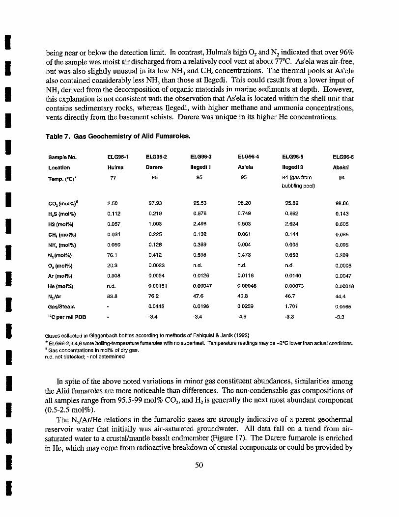
being near or below the detection limit. In contrast, Hulma's high 0, and N2 indicated that over 96% of the sample was moist air discharged from a relatively cool vent at about 77°C. As'ela was air-free, but was also slightly unusual in its low NH, and CH, concentrations. The thermal pools at As'ela also contained considerably less NH, than those at Ilegedi. This could result from a lower input of NH, derived from the decomposition of organic materials in marine sediments at depth. However, this explanation is not consistent with the observation that As'ela is located within the shell unit that contains sedimentary rocks, whereas Ilegedi, with higher methane and ammonia concentrations, vents directly from the basement schists. Darere was unique in its higher He concentrations.
Table 7. Gas Geochemistry of Alid Fumaroles.
Sample No. ELG96-1 ELG96-2 ELG96-3 ELG96-4
Location Hulma Darere llegedi 1 As'ela
Temp. ("c)* n 95 95 95
CO, (rno~%)#
H,S (mot%)
H2 (mol%)
CH, (mol%)
NH, (mol%)
N2(mol%)
0, (mol%)
Ar (mol%)
He (molY0)
N, IAr
Gasisteam
I3C per mil PDB
ELG96-5
llegedi 3
84 (gas from
bubbling pool)
ELG96-6
Abakri
94
Gases collected in Giggenbach bottles according to methods of Fahlquist & Janik (1 992) * ELG96-2,3,4,6 were boiling-temperature fumaroles with no superheat Temperature readings may be -2°C lower than actual conditions. as concentrations in mol% of dly gas. n.d. not detected; - not determined
In spite of the above noted variations in minor gas constituent abundances, similarities among the Alid fumaroles are more noticeable than differences. The non-condensable gas compositions of all samples range from 95.5-99 mol% CO,, and H2 is generally the next most abundant component (0.5-2.5 mol%).
The N,/Ar/He relations in the fumarolic gases are strongly indicative of a parent geothermal reservoir water that initially was air-saturated groundwater. All data fall on a trend from air- saturated water to a crustaVmantle basalt endmember (Figure 17). The Darere fumarole is enriched in He, which may come from radioactive breakdown of crustal components or could be provided by
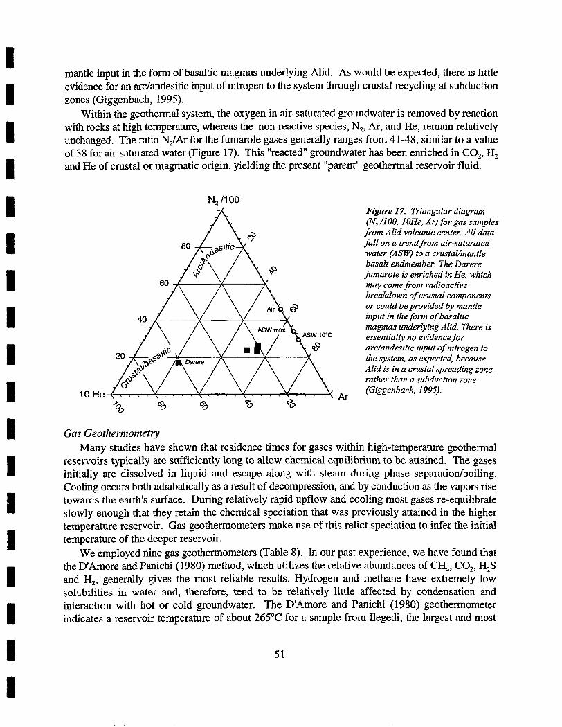
mantle input in the form of basaltic magmas underlying Alid. As would be expected, there is little evidence for an archndesitic input of nitrogen to the system through crustal recycling at subduction zones (Giggenbach, 1995).
Within the geothermal system, the oxygen in air-saturated groundwater is removed by reaction with rocks at high temperature, whereas the non-reactive species, N,, Ar, and He, remain relatively unchanged. The ratio NJAr for the fumarole gases generally ranges from 41-48, similar to a value of 38 for air-saturated water (Figure 17). This "reacted" groundwater has been enriched in CO,, H, and He of crustal or magmatic origin, yielding the present "parent" geothermal reservoir fluid.
N, 11 00 Figure 17. Triangular diagram (N, /I 00. I OHe, AAr) for gas samples porn Alid volcanic center. All data fall on a trendporn air-saturated water (Am to a crustal/mantle basalt endmember. The Darere fumarole is enriched in He, which may come from radioactive breakdown of crustal components or could be provided by mantle input in the form of basaltic magmas underlying Alid. There is essentially no evidence for arc/andesitic input of nitrogen to the system, as expected, because Alid is in a crustal spreading zone, rather than a subduction zone (Giggenbach. 1995).
2 Ar
00 % 8 73 %
Gas Geothennometry Many studies have shown that residence times for gases within high-temperature geothermal
reservoirs typically are sufficiently long to allow chemical equilibrium to be attained. The gases initially are dissolved in liquid and escape along with steam during phase separation/boiling. Cooling occurs both adiabatically as a result of decompression, and by conduction as the vapors rise towards the earth's surface. During relatively rapid upflow and cooling most gases re-equilibrate slowly enough that they retain the chemical speciation that was previously attained in the higher temperature reservoir. Gas geothermometers make use of this relict speciation to infer the initial temperature of the deeper reservoir.
We employed nine gas geothermometers (Table 8). In our past experience, we have found that the D'Arnore and Panichi (1980) method, which utilizes the relative abundances of CH,, CO,, H,S and H,, generally gives the most reliable results. Hydrogen and methane have extremely low solubilities in water and, therefore, tend to be relatively little affected by condensation and interaction with hot or cold groundwater. The D'Amore and Panichi (1980) geothermometer indicates a reservoir temperature of about 265°C for a sample from llegedi, the largest and most
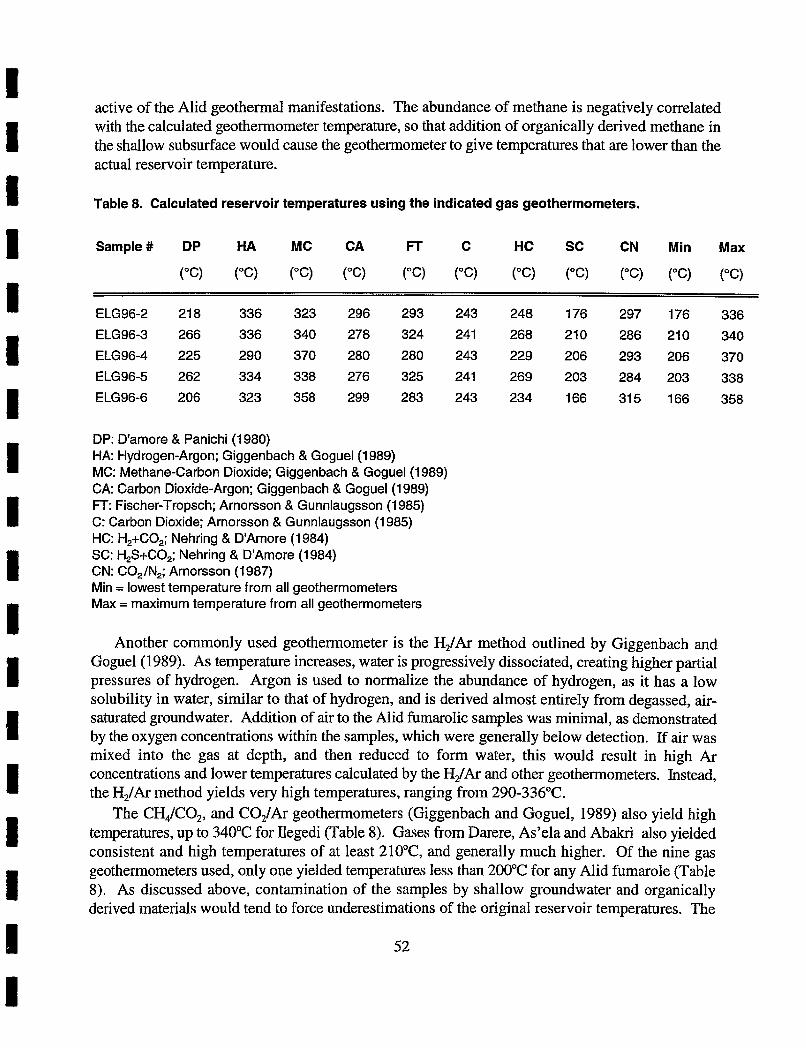
active of the Alid geothermal manifestations. The abundance of methane is negatively correlated with the calculated geothermometer temperature, so that addition of organically derived methane in the shallow subsurface would cause the geothermometer to give temperatures that are lower than the actual reservoir temperature.
Table 8. Calculated reservoir temperatures using the indicated gas geothermorneters.
Sample# DP HA MC CA FT C HC SC CN Min Max
DP: D'amore & Panichi (1 980) HA: Hydrogen-Argon; Giggenbach & Goguel(1989) MC: Methane-Carbon Dioxide; Giggenbach & Goguel(1989) CA: Carbon Dioxide-Argon; Giggenbach & Goguel(1989) FT: Fischer-Tropsch; Arnorsson & Gunnlaugsson (1985) C: Carbon Dioxide; Arnorsson & Gunnlaugsson (1985) HC: H,+CO,; Nehring & D'Amore (1 984) SC: H,S+CO,; Nehring & D'Amore (1 984) CN: CO,/N,; Arnorsson (1 987) Min = lowest temperature from all geothermorneters Max = maximum temperature from all geothermorneters
Another commonly used geothermometer is the H2/Ar method outlined by Giggenbach and Goguel(1989). As temperature increases, water is progressively dissociated, creating higher partial pressures of hydrogen. Argon is used to normalize the abundance of hydrogen, as it has a low solubility in water, similar to that of hydrogen, and is derived almost entirely from degassed, air- saturated groundwater. Addition of air to the Alid fumarolic samples was minimal, as demonstrated by the oxygen concentrations within the samples, which were generally below detection. If air was mixed into the gas at depth, and then reduced to form water, this would result in high Ar concentrations and lower temperatures calculated by the H,/Ar and other geothermometers. Instead, the H2/Ar method yields very high temperatures, ranging from 290-336°C.
The CH&O,, and C02/Ar geothermometers (Giggenbach and Goguel, 1989) also yield high temperatures, up to 340°C for Ilegedi (Table 8). Gases from Darere, As'ela and Abakri also yielded consistent and high temperatures of at least 210°C, and generally much higher. Of the nine gas geothermometers used, only one yielded temperatures less than 200°C for any Alid fumarole (Table 8). As discussed above, contamination of the samples by shallow groundwater and organically derived materials would tend to force underestimations of the original reservoir temperatures. The
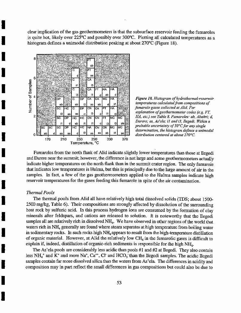
clear implication of the gas geothermometers is that the subsurface reservoir feeding the fumaroles is quite hot, likely over 225°C and possibly over 300°C. Plotting all calculated temperatures as a histogram defines a unimodal distribution peaking at about 270°C (Figure 18).
Figure 18. Histogram of hydrothermal-reservoir temperatures calculatedfi-om compositions of fumarole gases collected at Alid. For explanation of geothermometer codes (e.g. FT, HA, etc.) see Table 8. Fumaroles: ab. Abakri; d, Darere; as, As'ela; i l and i3, Ilegedi. Within a probable uncertainty of 50°C for any single determination, the histogram defines a unimodal distribution centered at about 270°C.
170 21 0 250 290 330 370 Temperature, "C
Fumaroles from the north flank of Alid indicate slightly lower temperatures than those at llegedi and Darere near the summit; however, the difference is not large and some geothemometers actually indicate higher temperatures on the north flank than in the summit crater region. The only fumarole that indicates low temperatures is Hulma, but this is principally due to the large amount of air in the samples. In fact, a few of the gas geothermometers applied to the Hulma samples indicate high reservoir temperatures for the gases feeding this fumarole in spite of the air contamination.
Thermal Pools The thermal pools from Alid all have relatively high total dissolved solids (TDS; about 1500-
2500 mgfkg, Table 6). Their compositions are strongly affected by dissolution of the surrounding host rock by sulfuric acid. In this process hydrogen ions are consumed by the formation of clay minerals after feldspars, and cations are released to solution. It is noteworthy that the llegedi samples all are relatively rich in dissolved NH,. We have observed in other regions of the world that waters rich in NH, generally are found where steam separates at high temperature from boiling water in sedimentary rocks. In such rocks high NH,appears to result from the high-temperature distillation of organic material. However, at Alid the relatively low CH, in the fumarolic gases is difficult to explain if, indeed, distillation of organic-rich sediments is responsible for the high NH,.
The As'ela pools are considerably less acidic than pools #1 and #2 at Ilegedi. They also contain less NH,' and K+ and more Na+, Ca", C1- and HCO, than the Ilegedi samples. The acidic Ilegedi samples contain far more dissolved silica than the waters from As'ela. The differences in acidity and composition may in part reflect the small differences in gas compositions but could also be due to
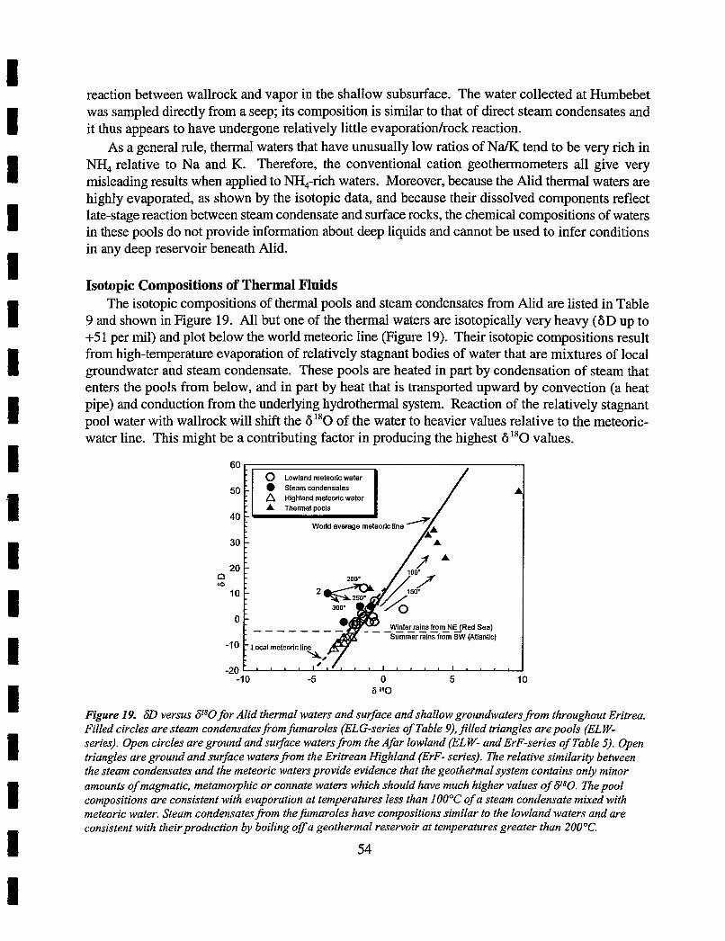
reaction between wallrock and vapor in the shallow subsurface. The water collected at Humbebet was sampled directly from a seep; its composition is similar to that of direct steam condensates and it thus appears to have undergone relatively little evaporation/rock reaction.
As a general rule, thermal waters that have unusually low ratios of NaiK tend to be very rich in NH, relative to Na and K. Therefore, the conventional cation geothermometers all give very misleading results when applied to NH4-rich waters. Moreover, because the Alid thermal waters are highly evaporated, as shown by the isotopic data, and because their dissolved components reflect late-stage reaction between steam condensate and surface rocks, the chemical compositions of waters in these pools do not provide information about deep liquids and cannot be used to infer conditions in any deep reservoir beneath Alid.
Isotopic Compositions of Thermal Fluids The isotopic compositions of thermal pools and steam condensates from Alid are listed in Table
9 and shown in Figure 19. All but one of the thermal waters are isotopically very heavy (6D up to +5 1 per mil) and plot below the world meteoric line (Figure 19). Their isotopic compositions result from high-temperature evaporation of relatively stagnant bodies of water that are mixtures of local groundwater and steam condensate. These pools are heated in part by condensation of steam that enters the pools from below, and in part by heat that is transported upward by convection (a heat pipe) and conduction from the underlying hydrothermal system. Reaction of the relatively stagnant pool water with wallrock will shift the 6 180 of the water to heavier values relative to the meteoric- water line. This might be a contributing factor in producing the highest 6 ''0 values.
World average meteoric line
n La
Winter rains fmm NE (Red Sea) ------- Summer rains fmm S W (Atlantic]
Figure 19. 6D versus 6180 for Alid thermal waters and surface and shallow groundwaters from throughout Eritrea. Filled circles are steam condensates from fumaroles (ELG-series of Table 9),filled triangles are pooIs (EL W- series). Open circles are ground and suface waters from the Afar lowland (EL W- and ErF-series of Table 5). Open triangles are ground and surface waters from the Eritrean Highland (ErF- series). The relative similarity between the steam condensates and the meteoric waters provide evidence that the geothermal system contains only minor amounts of magmatic, metamolphic or connate waters which should have much higher values of B80. The pool compositions are consistent with evaporation at temperatures less than 100°C of a steam condensate mixed with meteoric water. Steam condensatesfiom the fumaroles have compositions similar to the lowland waters and are consistent with theirproduction by boiling o f a geothermal reservoir at temperatures greater than 200°C.
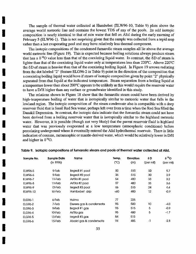
The sample of thermal water collected at Humbebet (ELW96-10, Table 9) plots above the average world meteoric line and contains the lowest TDS of any of the pools. Its odd isotopic composition is nearly identical to that of rain water that fell on Alid during the early morning of February 5 (ELW96-1). This is not surprising given that the sample was collected from a tepid seep rather than a hot evaporating pool and may have relatively less thermal component.
The isotopic compositions of the condensed fumarolic steam samples all lie above the average world meteoric line (Figure 19). This is expected because boiling solutions always produce steam that has a 6 ''0 value less than that of the coexisting liquid water. In contrast, the 6D of steam is lighter than that of the coexisting liquid water only at temperatures less than 220°C. Above 220°C the 6D of steam is heavier than that of the coexisting boiling liquid. In Figure 19 arrows radiating from the dot labeled "2" (feature ELG96-2 in Table 9) point in the direction of the composition that a coexisting boiling liquid would have if steam of isotopic composition given by point "2" physically separated from that liqui% at the indicated temperature. Steam separation from a boiling liquid at a temperature lower than about 200°C appears to be unlikely as this would require the reservoir water to have a D/H higher than any surface or groundwater identified in this study.
The relations shown in Figure 18 show that the fumarolic steam could have been derived by high-temperature boiling of water that is isotopically similar to meteoric water that falls in the lowland region. The isotopic composition of the steam condensate also is compatible with a deep reservoir fluid that is fossil Red Sea water, perhaps left over from a time when the Red Sea filled the Danakil Depression. In contrast, the isotopic data indicate that the fumarolic steam could not have been derived from a boiling reservoir water that is isotopically similar to the highland meteoric water. However, it is possible (though not very likely) that the parent reservoir fluid is highland water that was previously evaporated at a low temperature (atmospheric conditions) before percolating underground where it eventually entered the Alid hydrothermal reservoir. There is little indication of connate, metamorphic or mantle-derived water, which would be relatively lower in D/H and higher in 6 180.
Table 9. Isotopic compositions of fumarolic steam and pools of thermal water collected at Alid.
Sample No. Sample Date Name (in 1996)
ELW96-5 9-Feb llegedi #1 pool ELW96-6 9-Feb llegedi #2 pool ELW96-7 I 1 -Feb As'Ela #1 pool ELW96-8 1 1 -Feb As'Ela #2 pool ELW96-9 13-Feb llegedi #3 pool ELW96-10 16-Feb Humbebet drip
Temp. Elevation 6 D S 180
c"3 (m> (per mil) (per mil)
ELG96-1 6Feb Hulma 77 225
ELG96-2 7-Feb Derere gas & condensate 95 580 10 -4.0 ELG96-3 9-Feb llegedi #1 gas 95 51 5 5 -0.9
ELG96-4 10-Feb As'Ela gas 95 480 5 -1.7
ELG96-5 13-Feb llegedi #3 gas 84 515
ELG96-6 15-Feb Abakri gas & condensate 94 485 - 1 -2.8
At this time it appears most likely that the reservoir waters within the Alid hydrothermal system are groundwater that are recharged either by winter rains that fall in the lowlands, or by fossil Red Sea water that may pervasively underlie freshwater lenses in the Danakil lowland region. This does not mean that post-development recharge to the geothermal system would necessarily be limited to these two sources. Tapping of the geothermal system could induce new hydrologic gradients that would draw groundwater from western, highland-recharged aquifers toward the magmatic heat source underlying Alid.
The 813C of C0, in the Alid hydrothermal features varies from -3.3 to -4.9 per mil PDB, consistent with a magmatic source of CO,, possibly mixed with carbon from marine carbonate. It is likely that much of the CO,, S, and He emitted from Alid fumaroles are produced by degassing of the igneous body underlying Alid and its geothermal system.
Summary of Geochemical Data on Fluids The isotopic and chemical data indicate that a hot (250-300°C) hydrothermal reservoir underlies
Mid. The isotopic composition of the steam is consistent with boiling at temperatures of 220-300°C of groundwater from various possible sources, including local lowland rain, fossil Red Sea water, or conceivably, highland rain water that evaporated significantly before percolating underground. Some gases in the reservoir fluid, particularly CO,, H,, and H2S may be derived, directly or indirectly, by magmatic input from a subsurface granitic intrusion that likely exists beneath Mid.
WORKING MODEL OF THE MAGMAtHYDROTHERMAL SYSTEM Basaltic magma erupts along the Danakil Depression as ENE-WSW oriented horizontal
extension attenuates and breaks the crust. This plate-tectonic regime has been active since Miocene time in the Afar region. During part of this late Cenozoic history, the Danakil Depression was below sea level and connected with the Red Sea. Thus, the rocks that accumulated within the Depression include marine deposits (some fossiliferous), nonmarine clastic sedimentary deposits shed from adjacent horsts, and basaltic flows, sills and pyroclastic materials.
By processes yet poorly defined, a reservoir of rhyolitic magma accumulated in the upper crust beneath the part of the Danakil Depression that would later become Alid. Perhaps magma accumulated in a "structural trap", formed by a zone of intersections between the system of north- northwest-trending, crustal-spreading fissures and cross structures present in Precambrian crustal rocks. By whatever processes it formed, this relatively low-density body of silicic magma rose upward into, and partly through, the crust and domed overlying rocks to form Alid. The sharp flexuring recorded in steep dips on the flanks of the dome suggests that the depth to the magmatic source of doming is relatively shallow.
Somewhat before, and perhaps partly concurrent with doming, some of the silicic magma of this intrusion made its way to the surface as rhyolite that is part of the lava-shell unit (Figure 4: arhy and possibly frhy) of the dome. After the dome was fully developed and canyons were eroded in its flanks, a substantial pyroclastic eruption from the magma reservoir produced a blanket of rhyolite pumice (Figures 2 and 4: pf) that partly, or perhaps completely, buried the dome and spread outward several kilometers over the adjacent landscape.
The isotopic ages of the rhyolite lavas and pumice suggest that the youngest of these rocks were erupted from a reservoir recently enough for any magma left behind in the crust to still be near or
above solidification temperature. Gas geothermometry indicates a heat source able to power a broad field of fumaroles that are fed from a hydrothermal reservoir at 250-300°C or possibly hotter.
The absence of post-pumice basalt vents on Alid supports the suggestion that the magma reservoir still contains silicic melt, because basaltic melt is not likely to penetrate upward through silicic melt that has a lower density and higher viscosity. And although basalt vents that postdate the eruption of the rhyolite pumice are absent on Alid, they are common both north and south of the dome. Several of these vents are within a few hundred meters of the dome's base (Figures 2 and 4). Presumably, post-doming basalt has been able to reach the surface there because conduits bringing basaltic magma to the surface are beyond any "shadow effect" caused by a body of still-molten silicic melt directly under the structural dome. These post-dome eruptions of basalt near Alid indicate that crustal spreading and associated magmatism remain active in Alid graben.
In conclusion, evidence to date offers multiple reasons to entertain an increasingly favorable outlook for the geothermal potential of Alid. An upper-crustal magmatic and/or hot plutonic heat source seems likely. Certainly some crustal heat source is present to power the field of fumaroles distributed over the northern part of Alid. The compositions of fumarole gases suggest that the temperature of the underlying hydrothermal reservoir is 250-300°C or possibly more. Formation of the structural dome must have produced many permeable fractures in the deformed crustal rocks of the geothermal reservoir. Ongoing crustal spreading helps create additional fracture permeability. All of these positive indicators lead us to recommend the following additional studies.
RECOMMENDATIONS I ) New Aerial Photographs
Obtain new aerial photographs, at a scale of about 1:25,000, of Alid and surroundings. These will be used to prepare a topographic map (item 2) and a detailed fracture pattern and lineation map (item 3).
2) New Topographic Map and Benchmarks Produce a topographic map of Alid and surroundings, at a scale of 1:25,000, from the new aerial
photographs. The contour interval should be about 5 m in relatively flat terrain and about 10 m on the steep flanks of Alid. This map is essential if a development project is to go forward. It will serve as a base for plotting well and sample locations. It will be used to accurately locate a power-plant site and to design road and steam-collection systems. It will be used for calculating topographic adjustments to gravity surveys. As part of the map production, a network of benchmarks should be established. These benchmarks should be distributed such that regional deformation (that associated with crustal spreading and continued growth of Alid Graben) and deformation of Alid itself can both be documented with reference to the benchmark locations.
3) Fracture Pattern and Lineation Map Prepare a map of fractures and lineations, using the new aerial photographs. This map will be
of great value in helping to identify zones of possible enhanced permeability, and therefore potential drill sites.
4) Electrical Resistivity Survey Complete an electrical-resistivity survey of Alid and surroundings within Alid graben.
Information for the areas immediately north and south of the mountain might help define the depth to water and the subsurface distribution of hydrothermal alteration products (particularly clay minerals). In many geothermal systems, the target reservoir has been found to be in somewhat resistive rock just below the most conductive layer. However, the situation at Alid is complicated by the fact that clay and salt-bearing sediments are present in the sedimentary sequence (map unit ss), which could contain conductive zones that are not related to hydrothermal processes. A specialist in electrical techniques should be consulted to determine which, if any, of the various electrical techniques are appropriate for use at Alid. The magnetotelluric method may be the only technique that can be used where the topography is very steep. Making effective electrical contact with the earth may be a problem for any electrical technique in the areas of young lava flows lacking a soil cover. Because of the many site-specific problems with conducting electrical surveys at Alid, a specialist should visit the area before decisions for surveys are made.
5) Shallow Drilling Drill 10 to 15 holes, to nominal depths in the range of 100 to 200 meters, to obtain information
about temperature gradients and depths to the water table. Use slim-hole, diamond-coring technology. At least four of these holes should be drilled in the summit region to determine if subsurface conditions are different in the northern part of the structure where thermal manifestations are present, as compared to the southern part of the structure where no surface thermal manifestations have been identified. The other holes should be drilled near the base of Alid to gain information about the possible extension of a geothermal reservoir beyond the structural dome itself. Extension of a geothermal reservoir is particularly likely to the north and south along dilational fractures that are opening in response to regional extensional tectonics.
As drilling progresses, care should be taken to identify the depth at which ground water is first encountered. When encountered, ground water should be sampled, for later analysis, from as deep in the hole as possible. In order to obtain reliable temperature-gradient information, the holes should be completed with a plastic liner cemented in place. As part of this shallow drilling campaign, consideration should be given to first drilling a water well near the base of Alid to supply water for use in drilling other shallow wells and for the deep drilling that will follow.
6) Soil Gas Survey Complete a survey of carbon dioxide and radon in soil gas, to help locate zones of deeply
penetrating fractures, which carry gases rising from subsurface boiling of the hydrothermal- convection system.
7) Deep Exploration Drilling After tasks 1 through 6 have been completed, drill a minimum of three exploration wells to
depths in the range of 1500 to 2000 meters, to document subsurface temperatures, pressures, and permeabilities associated with the Alid hydrothermal system. These wells should be designed to reach depths in the range of 750 to 1000 meters below sea level. Thus, the target depth of a
particular well will depend on the elevation of its collar. Based on our current state of knowledge, drilling from the summit region of Alid has the best chance of encountering a high-temperature reservoir. However, the flanks of Alid and lowland regions extending to the north and south of the mountain might prove to be productive areas. Recommendations 3 to 6 above were made primarily to provide additional information about the possibility of there being an extension of a hydrothermal reservoir in these directions.
It may be quite expensive to deploy a large drill rig, and ancillary equipment and supplies, at the summit of Alid. In addition, drilling from the top of Alid adds up to 700 meters of "additional" drilling to reach a particular depth below sea level. Thus, it may prove more expedient to reach a specific target beneath the flank of Alid by drilling a deviated (slanted) hole(s) from the base of the mountain. Also, if the hydrothermal-water table beneath Alid is relatively deep, a vertical well at the top or on the flank of the mountain could be more difficult to put into production than a directionally drilled well located near the base of the mountain. Directionally drilled slanted wells have another advantage in geothermal exploration in that they are more likely than vertical holes to intersect steeply dipping fractures.
We recommend the use of slim-hole diamond-coring methods in drilling, because this technique can produce a wealth of information on the rock sequence and the hydrothermal reservoir, even when there is a total loss of circulation during drilling. Another advantage is that a dedicated diarnond- core drill rig is much smaller and lighter than a rotary rig so it can be deployed at sites not generally accessible to a rotary rig.
8) Establish A Weather Station on A lid Begin the systematic gathering of meteorological information. Data on average and extreme
local meteoroIogical conditions are needed to optimize the design of a power plant. Local variations in air temperature, pressure, and humidity affect the design of turbines, and wind velocity and direction affect the design and location of cooling towers relative to the power plant. Rainfall is of interest in assessing possible local contributions to recharge during production. Thus, if the geothermal development is to go forward, a meteoroIogica1 station should be established as soon as possible to start recording these types of data so that some information will be available when needed.
9) Gravity and Magnetic Surveys Gravity and magnetic surveys are unlikely to be cost effective at this stage of the exploration
program. Moreover, the lack of an accurate topographic map hinders completion of an accurate gravity survey. Gravity and magnetic surveys may, however, be useful later in siting production wells, after exploration drilling has produced core from which rock properties can be measured and thus provide data to constrain gravity and magnetic modelling.

ACKNOWLEDGEMENTS Development of the original project proposal, identification of funding and successful planning
and carrying out of project tasks are the accomplishments of many people. For their contributions, we thank Anne Gartner, Carol Kendall, Peter Lipman, Paul Morgan, Manuel Nathenson, Susan S. Priest, John Sass, Dave Siems, Fred Simon, and Doug White of the U.S. Geological Survey. Dale Counce and Fraser Goff of the Los Alarnos National Laboratory, New Mexico, analyzed water samples for us. Teklehaimanot Debretsion of the Eritrean Ministry of Energy, Mines and Water Resources solved a host of logistical problems related to the field expedition and provides continuing encouragement for our efforts. Habteab Zerai of this Ministry located water wells and helped collect samples for the regional water study. The U.S. Agency For International Development has funded most of the project, and we are especially grateful for the help of Glenn Anders and his staff at the USAID office in Eritrea. Finally, we thank Samuel Baire, Director of the Energy Department of the Eritrean Ministry of Energy, Mines and Water Resources, and Robert Houdek, U.S. Ambassador to Eritrea, for their active interest in the project.
REFERENCES CITED Allard, P., ~ a z i e f f ~ k . , and Dajlevic, D., 1979, Observations of sea floor spreading in Afar during
the November 1978 fissure eruption: Nature, v. 279, p. 30-33. Arndrsson S . and Gunnlaugsson, E.,1985, New gas geothermometers for geothermal exploration-
Calibration and application: Geochimica Cosmochirnica Acta, v. 49, p. 1307- 1325. Bacon, C.R., 1986, Magmatic inclusions in intermediate and silicic volcanic rocks: Journal of
Geophysical Research, v. 91, p. 609 1-61 12. Barberi, F., and Varet, J., 1970, The Erta Ale Volcanic range (Danakil Depression), Northern Afar,
Ethiopia: Bulletin Volcanologique, v. 34, p. 848-917. Barberi, F., and Varet, J., 1977, Volcanism of Afar: Small-scale plate tectonics implications:
Geological Society of America Bulletin, v. 88, p. 125 1-1 266. Barberi, F., Borsi, S., Ferrara, G., Marinelli, G., Santacroce, R., Tazieff, H., and Varet, J., 1972,
Evolution of the Danakil Depression (Afar, Ethiopia) in light of radiometric age determinations: Journal of Geology, v. 80, p. 720-729.
Barberi, F., Borsi, S., Ferrara, G., Marinelli, G., and Varet, J., 1970, Relations between tectonics and magrnatology in the northern Danakil Depression (Ethiopia): Phil. Transactions of the Royal Society of London, A, 267, p. 293-31 1.
Barberi, F., Civetta, L., and Varet, J, 1980, Sr-isotopic composition of Afar volcanics and its implications for mantle evolution: Earth and Planetary Science Letters, v. 50, p. 247-259.
Barker, D.S., 1970, Compositions of granophyre, rnyrmekite and graphic granite: Geological Society of America Bulletin, v. 8 1, p. 3339-3350.
Barrat, J.-A., Jahn, B.M., Fourcade, S., and Joron, J.L., 1993, Magma genesis in an ongoing rifting zone: The Tadjoura Gulf (Afar area): Geochimica et Cosmochirnica Acta, v. 57, p. 2291 -2302.
Beltrando, G., and Camberlin, P., 1993, Interannual variability of rainfall in the Eastern Horn of Africa and indications of atmospheric circulation: International Journal of Climatology, v. 13, p. 533-546.
Betton, P.J., and Civetta, L., 1984, Strontium and neodymium isotopic evidence for heterogeneous nature and development of the mantle beneath Afar (Ethiopia): Earth and Planetary Science Letters, v. 7 1, p. 59-70.
Beyth, M., 1994, A brief assessment of the Alid geothermal field: Report ES-10-94 of the Israel Ministry of Energy and Infrastructure, 1 lp.
Bonatti, E., Erniliani, C., Ostlund, G., and Rydell, H., 1971, Final desiccation of the Afar Rift, Ethiopia: Science, v. 172, p. 468-469.
Bullen, T.D., and Clynne, M.A., 1991, Trace element and isotopic constraints on magmatic evolution at Lassen volcanic center, California: Journal of Geophysical Research, v. 95, p. 19671-1969 1.
C.N.R.-C.N.R.S., 1973, Geology of northern Afar (Ethiopia): Revue de Geographie Physique et de Geologie Dynarnique, v. 15, Fasc. 4, p. 443-490.
Craig, H., 1961, Isotopic variations in meteoric waters: Science, v. 133, p. 1702-1703. Craig, H., 1966, Isotopic composition and origin of the Red Sea and Salton Sea geothermal brines:
Science, v. 154, p. 1544-1548. Dainelli, G., and Marinelli, O., 1912, Resulti scientifici di un viaggio nella Colonia Eritrea: Pubbl.
del R. Ist di St. Super e di Perfez. di Firenze. D'Amore, F., and Panichi, C., 1980, Evaluation of deep temperatures of hydrothermal systems by
a new gas geothermometer: Geochimica et Cosmochimica Acta, v. 44, p. 549-556. Davies, G.R., and MacDonald, R., 1987, Crustal influences in the petrogenesis of the Naivasha
basalt-comendite complex: Combined trace element and Sr-Nd-Pb isotope constraints: Journal of Petrology, v. 28, p. 1009-103 1.
Duffield, W.A., Bacon, C.R., and Roquemore, G.R., 1979, Origin of reverse-graded bedding in air- fall pumice, Coso Range, California: Journal of Volcanology and Geothermal Research, v. 5, p. 35-48.
Eissen, J.-P., Juteau, T., Joron, J.-L., Dupre, B., Humler, E., and M'Mukhamedov, A., 1989, Petrology and geochemistry of basalts from the Red Sea axial rift at 18ONorth: Journal of Petrology, v. 30, p. 791-839.
Eklundh, L., and Pilesji; P., 1990, Regionalization and spatid estimation of Ethiopian mean annual rainfall: International Journal of Climatology, v. 10, p. 473-494.
Fahlquist, L., and Janik, C.J., 1992, Procedures for collecting and analyzing gas samples from geothermal systems: U.S. Geological Survey Open-File Report 92-21 1, 19p.
Food and Agricultural Organization, 1983, Assistance to land-use planning, Ethiopia: Agroclimatic resources inventory for land-use planning, FAO, AG:DP/ETW78/003, Technical Report 2.
Giggenbach, W.F., 1995, Composition of magmatic components in hydrothermal fluid: i ~ , J.F.H. Thompson (ed.) Magmas, Fluids, and Ore Deposits, Mineralogical Association of Canada Short Course v. 23, p. 247-261.
Giggenbach, W.F., and Goguel, R.L., 1989, Collection and analysis of geothermal and volcanic water and gas discharges: Report CD2401, New Zealand Department of Scientific and Industrial Research, 8 1p.
Guffanti, M., Clynne, M.A., and Muffler, L.J.P., 1996, Thermal and mass implications of magmatic evolution in the Lassen volcanic region, California, and minimum constraints on basalt influx to the lower crust: Journal of Geophysical Research, v. 101, no. B2, p. 3003-3013.
Hart, W.K., WoldeGabriel, G., Walter, R.C., and Mertzman, S.A., 1989, Basaltic volcanism in Ethiopia: Constraints on continental rifting and mantle interactions: Journal of Geophysical Research, v. 94, p. 773 1-7748.
Hegner, E., and Pallister, J.S., 1989, Pb, Sr, and Nd isotopic characteristics of Tertiary Red Sea volcanics from the Central Saudi Arabian coastal plain: Journal of Geophysical Research, v. 94, p. 7749-7755.
Jackson, M.D., and Pollard, D.D., 1988, The laccolith-stock controversy: New results from the southern Henry Mountains, Utah: Geological Society of America Bulletin, v. 100, p. 117-139.
Johnson, A.M., and Pollard, D.D., 1973, Mechanics of growth of some laccolithic intrusions in the Henry Mountains, Utah, I: Tectonophysics, v. 18, p. 26 1-309.
Kasahun, B., 1986, Local weather systems over the Red Sea area, Local Weather Prediction for the Red Sea Countries, WMO Tropical Meteorology Research Progress Report No. 29, p. 1- 18.
LeBas, M.J., LeMaitre, R.W., Streckeisen, A., and Zanettin, B., 1986, A chemical classification of volcanic rocks based on the total alkali-silica diagram: Journal of Petrology, v. 27, p. 745-750.
Michael, A. H., 1986, The weather over Eritrea: h Local Weather Prediction for the Red Sea Countries, WMO Tropical Meteorology Research Progress Report No. 29, p. 45-55.
Nehring, N.L., and D'Arnore, F., 1984, Gas chemistry and thermometry of the Cerro Prieto, Mexico, geothermal field: Geothermics, v. 13, p. 75-89.
Poldervaart, A., and Hess, H.H., 1951, Pyroxenes in the crystallization of basaltic magma: Journal of Geology, v. 59, p. 472-489.
Pollard, D.D., and Johnson, A.M., 1973, Mechanics of growth of some laccolithic intrusions in the Henry Mountains, Utah, II: Tectonophysics, v. 18, p. 3 1 1-354.
Price, N.J., Cosgrove, J.V.,1990, Analysis of Geological Structures. Cambridge University Press, Cambridge England.
Souriot, T., Brun, J.-P., 1992, Faulting and block rotation in the Afar triangle, East Africa: The Danakil "crank-arm" model: Geology, v. 20, p. 9 1 1-9 14.
Tatantola, A., Ruegg, J.C., and Lepine, J.C., 1975, Geodetic evidence for rifting in Afar: A brittle- elastic model of the behavior of the lithosphere: Earth and Planetary Science Letters, v. 45, p. 435-444.
Trujillo, P.E., Counce, D., Grigsby, C.O., Goff, F., and Shevenell, L., 1987, Chemical analysis and sampling techniques for geothermal fluids and gases at the Fenton Hill Laboratory: Los Alamos National Laboratory Publication LA- 1 1006-MS, 84p.
U.N.D.P., 1973, Investigations of the geothermal resources for power development, Ethiopia: Imperial Ethiopian Government, 275p.
Zumbo, V., Feraud, G., Vellutini, P., Piguet, P., and Vincent, J., 1995, First 40Ar/39~r dating on early Pliocene to Plio-Pleistocene magmatic events of the Afar Republic of Djibouti: Journal of Volcanology and Geothermal Research, v. 65, p. 28 1-295.