Embed Size (px)
Citation preview
NASA-CR-1 971 92NASw-4435
A MAGNETIC SHIELD/
DUAL PURPOSE
oO O
tOI ,-- ,O
u_ U r_0', t'- 0Z _ 0
MISSION
FINAL REPORT: 1993-1994
NASA/USRA Advanced Design Program
by
Duke UniversityDepartment of Mechanical Engineering and Materials Science
Durham, North Carolina 27708-0300
July, 1994
Professor Franklin H.Seth Watkins
Cocks _--
https://ntrs.nasa.gov/search.jsp?R=19950006593 2018-05-30T12:16:32+00:00Z
ACKNOWLEDGMENTS
The assistance provided by Eric Smith and Rich Hines at the Vesic
Engineering Library at Duke University is gratefully acknowledged. The
enormously helpful input from our mentor, Don Carson, at Goddard Space Flight
Center, is also gratefully acknowledged. The support of the USRA Advanced
Design Program and the North Carolina Space Grant Consortium has beenessential in this academic endeavor.
The following students have contributed to this design effort and to the
writing of this report: Jamil Albertelli, R. Braden Copeland, Eric Correll, ChrisDales, Dana Davis, Nechole Davis, Rob Duck, Sandi Feaster, Patrick Grant, Mack
Haynes, Douglas Jarrard, Andrew Konop, John Koon, Stu Levy, Dwight Lowie,
Scott Miller, John Murnane, Howard Nelson, Matt Pangaro, Jack Perkins,
Malcolm Peverley, Audra Plenys, Michael Reams, George Robbins, Christopher
Salter, Bobby Santos, Glen Schumacher, Kara Slade, Jon Slagel, Mark Slominski,
Marcus Smith, Terence Sobolewski, Tim Sovich, Hermes Soyez, Martin Stalheim,
Matt Swecker, David Zavelson
2
Table of Contents
Abstract ................................................................................................. 4
Overview ............................................................................................... 5
Payload Design ........................................................................................ 6
Cryostat Design ....................................................................................... 6
Coil Design ............................................................................................ 8
Coil Charging .......................................................................................... 10
Instruments ............................................................................................ 11
Telemetry .............................................................................................. 12
Power ................................................................................................... 13
Predicting Orbital Effects of the Ship's Field ...................................................... 13
Scientific Experiment ................................................................................. 14
Coil Orientation ....................................................................................... 16
Mass Shielding for the Payload ..................................................................... 17
Conclusion ............................................................................................ 19
Appendix A ........................................................................................... 22
3

Abstract
The objective of this work is to design, build, and fly a dual-purpose payload whose
function is to produce a large volume, low intensity magnetic field and to test the concept of using
such a magnetic field to protect manned spacecraft against particle radiation. An additional mission
objective is to study the effect of this moving field on upper atmosphere plasmas. Both mission
objectives appear to be capable of being tested using the same superconducting coil. The potential
benefits of this magnetic shield concept apply directly to both earth-orbital and interplanetary
missions. This payload would be a first step in assessing the true potential of large volume
magnetic fields in the U.S. space program. Either converted launch systems or piggyback payload
opportunities may be appropriate for this mission.
The use of superconducting coils for magnetic shielding against solar flare radiation during
manned interplanetary missions has long been contemplated and was considered in detail in the
years preceding the Apollo mission. With the advent of new superconductors, it has now become
realistic to reconsider this concept for a Mars mission. Even in near-earth orbits, large volume
magnetic fields produced using conventional metallic superconductors allow novel plasma physics
experiments to be contemplated. Both deployed field-coil and non-deployed field-coil shielding
arrangements have been investigated, with the latter being most suitable for an initial test payload in
a polar orbit.
4
Overview
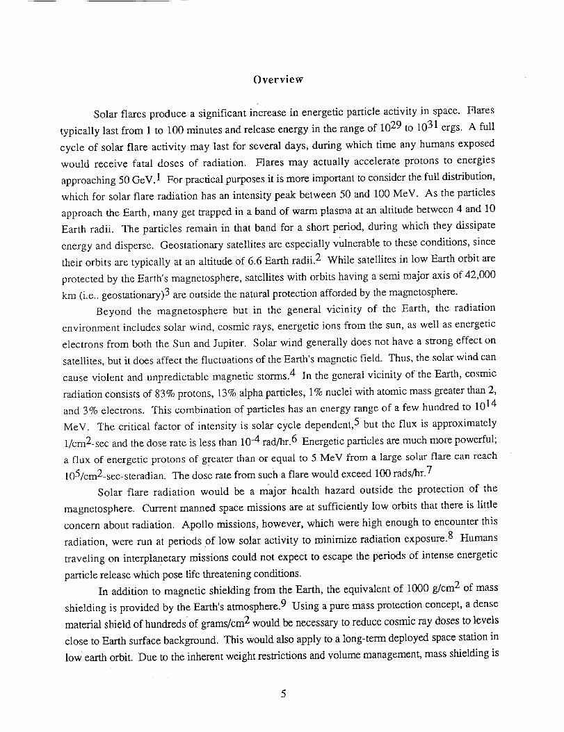
Solar flares produce a significant increase in energetic particle activity in space. Flares
typically last from 1 to 100 minutes and release energy in the range of 1029 to 1031 ergs. A full
cycle of solar flare activity may last for several days, during which time any humans exposed
would receive fatal doses of radiation. Flares may actually accelerate protons to energies
approaching 50 GeV. 1 For practical purposes it is more important to consider the full distribution,
which for solar flare radiation has an intensity peak between 50 and 100 MeV. As the particles
approach the Earth, many get trapped in a band of warm plasma at an altitude between 4 and 10
Earth radii. The particles remain in that band for a short period, during which they dissipate
energy and disperse. Geostationary satellites are especially vulnerable to these conditions, since
their orbits are typically at an altitude of 6.6 Earth radii. 2 While satellites in low Earth orbit are
protected by the Earth's magnetosphere, satellites with orbits having a semi major axis of 42,000
km (i.e.. geostationary) 3 are outside the natural protection afforded by the magnetosphere.
Beyond the magnetosphere but in the general vicinity of the Earth, the radiation
environment includes solar wind, cosmic rays, energetic ions from the sun, as well as energetic
electrons from both the Sun and Jupiter. Solar wind generally does not have a strong effect on
satellites, but it does affect the fluctuations of the Earth's magnetic field. Thus, the solar wind can
cause violent and unpredictable magnetic storms. 4 In the general vicinity of the Earth, cosmic
radiation consists of 83% protons, 13% alpha particles, 1% nuclei with atomic mass greater than 2,
and 3% electrons. This combination of particles has an energy range of a few hundred to 1014
MeV. The critical factor of intensity is solar cycle dependent, 5 but the flux is approximately
1/cm2-sec and the dose rate is less than 10 -4 rad/hr.6 Energetic particles are much more powerful;
a flux of energetic protons of greater than or equal to 5 MeV from a large solar flare can reach
105/cm2-sec-steradian. The dose rate from such a flare would exceed 100 rads/hr.7
Solar flare radiation would be a major health hazard outside the protection of the
magnetosphere. Current manned space missions are at sufficiently low orbits that there is little
concern about radiation. Apollo missions, however, which were high enough to encounter this
radiation, were run at periods of low solar activity to minimize radiation exposure. 8 Humans
traveling on interplanetary missions could not expect to escape the periods of intense energetic
particle release which pose life threatening conditions.
In addition to magnetic shielding from the Earth, the equivalent of 1000 g/cm 2 of mass
shielding is provided by the Earth's atmosphere. 9 Using a pure mass protection concept, a dense
material shield of hundredsof grams/cm 2 would be necessary to reduce cosmic ray doses to levels
close to Earth surface background. This would also apply to a long-term deployed space station in
low earth orbit. Due to the inherent weight restrictions and volume management, mass shielding is

clearly impractical for protection against cosmic and galactic proton radiation during interstellar
travel.
Payload Design
The intent of this design project is to develop a feasibility study of a magnetic shielding
experiment using a low temperature superconducting coil. The coil will be stationary (i.e.. not
deployed), and will be used (1) to protect a given payload volume from incident charged particles,
(2) to examine the effects of a magnetic field on radio interference, (3) to examine the
microcirculatory effects of passing a large magnet through a terrestrial charged particle
environment, and (4) to use the earth's magnetic field to generate a voltage when the
superconducting coil goes normal.
The basic payload limitations include a maximum weight of 480 pounds, launch into a 100
km earth orbit, and coil superconductivity for sufficient time to achieve the aforementioned
experimental objectives.
Cryostat Design
The cryostat is an essential part of the overall design of the proposed experimental system.
In order for the coil to operate at a superconducting state, the temperature of the coil must be
maintained at 4.2 K. It is expected that superconductivity will be required for a minimum of 40
hours. The function of the liquid helium cryostat is simply to maintain that temperature for the
operational lifetime of the superconducting coil, which would be launched in the persistent field
mode. The main limitation for the proposed experiment will be the allowable mass, which imposes
considerable design restrictions on cryostat size and concomitant helium capacity. The cryostat
will be fabricated from Type 304 stainless steel, with internal insulating layers. The cryostat
completely surrounds the coil, which is surrounded by the liquid helium. An outer layer of liquid
nitrogen has been considered, but is unnecessary due to the short mission duration. More helium,
rather than nitrogen, can thus be used. Additionally, the nitrogen is significantly heavier than the
helium. The inner radius of the cryostat will be approximately 5 cm. The cryostat is expected to
have a mass of approximately 70 kg. The overall cryostat design is shown in Figure 1, and the
cross-section is shown in Figure 2. The mounting and securing hardware is especially important
due to the tremendous stresses experienced during launch, as well as the vibrational effects. The
use of several mounting plates with "feed-through" design has been chosen for mounting
purposes, as shown in Appendix A.

,w,
s2°1i5I _ 264,67 cm130.117 cm
F31,8 cm
, _Circumference = 546,2 cm
Figure 1 Overall Cryostat Design
cm
Figure 2 Cryostat Cross-section

Coil Design
A number of assumptions have been made regarding the design parameters of the coil. Due
to the poor mechanical and electrical properties of current high temperature superconductor Wires,
low temperature superconducting wire has been chosen for use in this experiment. Niobium
titanium superconducting wire will be employed, which requires cooling to liquid helium
temperature. Coil sizing requirements are such that the cross-sectional area ratio of copper
sheathing to NbTi be 1.8 to 1, the overall wire diameter is 28 mils, the design current is 320
amperes per wire (as viewed through the cross section), and it is assumed that the wire will weigh
3.77 kg per kilometer. Conservatively, the wire critical current is estimated at 200,000 A/cm 2.
For design considerations, it is assumed that the coils will be packed in a hexagonal close packed
bundle, with a packing factor of 0.74 (74% of the available space is utilized). One coil is required
for the experiment. Due to potential magnetic flux interactions, it is anticipated that the best
configuration for the coil design will be a twisted format, with the average twist density being 2
twists per inch. This ensures that eddy currents will not prevail in the coil, causing significant flux
difficulty.
The intent of the experiment is to protect as much of the payload enclosure as possible from
incident radiation, within the design constraints of weight and size. It should be noted that the
effective St6rmer radius is actually 40 percent of that calculated using the St/3maer equation.
A computer code has been constructed to optimize the coil design based on known
parameters. The mathematical basis for the design relies on the St6rmer equation for protected
' dimension, Cst, known as the St6rmer radius. This dimension measures the magnetically
protected region, although as previously mentioned complete protection is only afforded to
approximately 40% of that characteristic length. The dimension, measured in meters, is found as
follows:
c_, =J_oM (1)4_zP
whereq
go =
P =
M =
the particle charge
1.9 x 10 -19 C
the permeability of free space
4_ x 10 -7 H/m
the relativistic particle momentum (kg.m/s)
the magnetic moment (ampere turns, m 2)
Given a desired StOrmer radius and momentum of particle to protect from, the magnetic moment
can be found from equation 1.
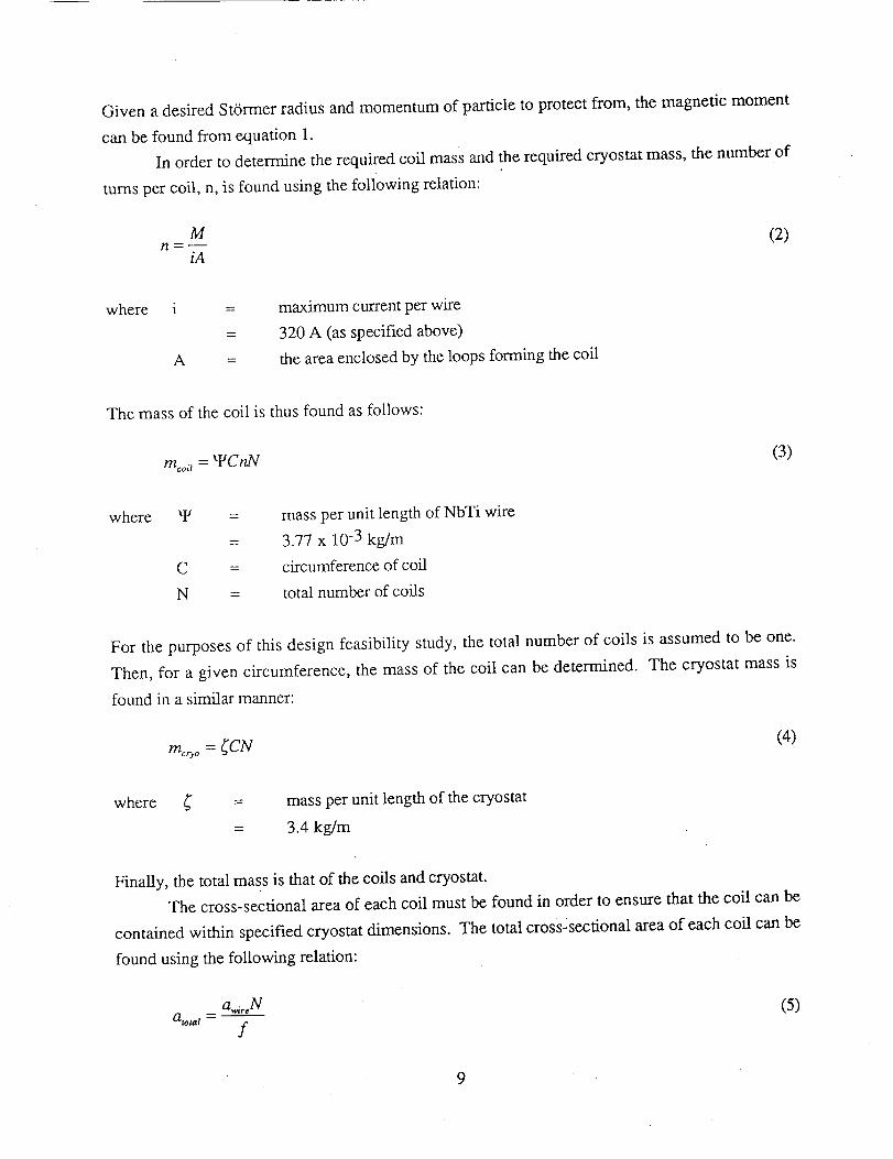
In order to determine the required coil mass and the required cryostat mass, the number of
turns per coil, n, is found using the following relation:
Mn = -- (2)
iA
where i
A
maximum current per wire
320 A (as specified above)
the area enclosed by the loops forming the coil
The mass of the coil is thus found as follows:
moo. = WCnN (3)
where W
C =
N =
mass per unit length of NbTi wire
3.77 x 10 -3 kg/m
circumference of coil
total number of coils
For the purposes of this design feasibility study, the total number of coils is assumed to be one.
Then, for a given circumference, the mass of the coil can be determined. The cryostat mass is
found in a similar manner:
rn_,_o = _CN (4)
where _" mass per unit iength of the cryostat
3.4 kg/m
Finally, the total mass is that of the coils and cryostat.
The cross-sectional area of each coil must be found in order to ensure that the coil can be
contained within specified cryostat dimensions. The total cross-sectional area of each coil can be
found using the following relation:
a_,ireNa,o,at - (5)
f
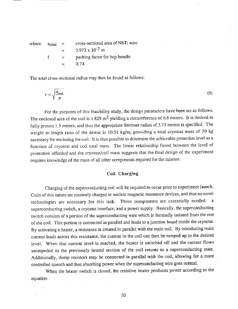
where atotal =
f =
cross-sectional area of NbTi wire
3.972 x 10 -7 m
packing factor for hcp bundle
0.74
The total cross-sectional radius may then be found as follows:
r = _ a'°'o'n (6)
For the purposes of this feasibility study, the design parameters have been set as follows.
The enclosed area of the coil is 1.829 m 2 yielding a circumference of 6.6 meters. It is desired to
fully protect 1.5 meters, and thus the appropriate StOrmer radius of 3.75 meters is specified. The
weight to length ratio of the dewar is 10.51 kg/m, providing a total cryostat mass of 70 kg
necessary for enclosing the coil. It is thus possible to determine the achievable protection level as a
function of cryostat and coil total mass. The linear relationship found between the level of
protection afforded and the cryostat/coil mass suggests that the final design of the experiment
requires knowledge of the mass of all other components required for the mission.
Coil Charging
Charging of the superconducting coil will be required to occur prior to experiment launch.
Coils of this nature are routinely charged in nuclear magnetic resonance devices, and thus no novel
technologies are necessary for this task. Three components are essentially needed: a
superconducting switch, a cryostat interface, and a power supply. Basically, the superconducting
switch consists of a portion of the superconducting wire which is thermally isolated from the rest
of the coil. This portion is connected in parallel and leads to a junction board inside the cryostat.
By activating a heater, a resistance is Created in parallel with the main coil. By introducing main
current leads across this resistance, the current in the coil can then be ramped up to the desired
level. When that current level is reached, the heater is switched off and the current flows
unimpeded as the previously heated section of the coil returns to a superconducting state.
Additionally, dump resistors may be connected in parallel with the coil, allowing for a more
controlled quench and thus absorbing power when the superconducting wire goes normal.
When the heater switch is closed, the resistive heater produces power according to the
equation
10

P = I2R (7)
Given a current in the heater of 60 mA and a resistance of 100 ohms, the power would be 0.36 W.
With the switch in the open setting (heater on), a small resistance of approximately 10 ohms is
created in parallel with the coil. It is then possible to begin introducing current into the coil.
Field instability is an issue that still must be considered in experimental design. The
magnetic field induced by the coil will not stay at a constant level, and this problem is not easily
rectified within the volume and weight restrictions of the payload. In principle, as the amount of
current in each turn of the wire is increased, the tendency of the magnetic field to become unstable
increases. In industry, these instabilities are managed by employing shim coils, which are smaller
superconducting coils placed orthogonally to the main coil. 10 While effective, these shim coils
require sizable control electronics assemblies, and thus appear impractical for use in this
experimental design.
Charging the coil can only be accomplished if the coil is accessible through the cryostat.
Simply, an extended and capped bore protruding from the cryostat would provide a buffer zone
between the room temperature probe and the coil. The charging procedure would require that the
cap be removed from the bore, and the charging lead inserted quickly to avoid loss of significant
amounts of liquid helium. The lead is inserted halfway into the bore and allowed to cool for a
short period of time. It is then fully inserted and plugged into the receptor socket, which connects
to the junction board where the coil terminals are located. 11 One potential design could make use
of an actively cooled baffle for the charging bore. This device utilizes an actively cooled heat sink
to transfer heat away from the coil and inner cryostat to helium vapor which is vented to the
environment. 12
The power supply required for the charging will not affect the size or weight of the
experimental payload, since charging will occur prior to launch. The required amperage is 320 A.
Instruments
Three primary types of instruments are required for the experiment: radiation detectors, a
gaussmeter (magnetometer), and a voltmeter. Additionally, temperature data will berequired and
thus thermocouples will be employed.
11

Radiation detection presents a design challenge, both in the choice of instruments and
instrument layout within the experimental design. The use of a dosimeter was first considered, and
space-proven instruments have already been demonstrated by several companies in this area.
Dosimeters measures accumulated radiation dose, through the use of solid state detectors. A
standard space-proven dosimeter can provide the following data: electron dose, electron flux,
proton dose, proton flux, and nuclear star flux. The dosimeter has a field of view of 2g
steradians. However, the instantaneous radiation flux is most important experimentally.
Therefore, alternatively, radiation detectors with the ability to measure both the accumulation and
rate of radiation dose can be employed. At least three detectors would be required, with at least
one mounted outside the magnetically protected region. Space-proven energetic particle detectors
are also available, but may add unnecessary complexity to the data collection. Such instruments
typically consist of a special telescope for sensing low energy protons and alphas, a dome-shaped
detector for sensing medium energy protons and alphas in addition to electrons above 2 MeV, and
a high-energy proton-alpha detector. These sensors are tied together with a signal analyzer
unit/data processing unit which manages the various sensor outputs and routes them to telemetry
devices.
A magnetometer is required for measuring the direction and magnitude of the magnetic field
created by the superconducting coil. Once the coil goes normal, the magnetometer will measure the
magnitude of the Earth's paleomagnetic field. The main function of the magnetometer is to
quantify the size of the field produced and confirm that the coil is operational as designed. For
low-earth orbital missions, fluxgate magnetometers with field ranges of +55,000 nT have been
employed. Satellites placed in synchronous orbits have included magnetometers with field ranges
of +1,00 nT, since the total field is much lower in this type of orbit. The final design
characteristics of this instrument have not been established.
Finally, a voltmeter is required for measuring the voltage potential across the leads of the
coil once the coil goes normal. A standard voltmeter with a 700 VAC range with a resolution of
0.1 V is acceptable.
Telemetry
The onboard telemetry package should be capable of handling 112 KB/s with a self-
contained power supply. A single-channel transponder is needed to relay data collected on
radiation dosage, thermocouple readings, magnetometer output, and coil orientation. It is expected
12
that an S-band transponder will be used, with a downlink operating frequency of 2200 to 2300
MHz. A minimum of 5 watts is required for the transmission RF output.
Power
Lithium thionyl chloride batteries have been chosen, which have a power density of
approximately 150 watt.hours/kg. A major advantage of these batteries is that a weight savings of
over 40% over commonly used silver-zinc batteries is realized, with similar performance
characteristics. Typical power-to-weight ratios for various batteries are as follows: 350 W-hr/kg
for lithium thionyl chloride, 140 Wohr/kg for silver-zinc, and 120 W°hr/kg for nickel metal
hydride. This battery is space-qualified, with the ability to withstand the shock and vibrational
stressing of launch. The battery has an operating temperature range of-55°C to 85 ° C. 13 Based
on projected experimental requirements, it is expected that the battery will have a mass of no more
than 20 kg, with a design life of 50 hours.
Predicting Orbital Effects of the Ship's Field
The superconducting coil will interact with the earth's paleomagnetic field. If the
interaction could be controlled, magnetic lift could potentially be created such that orbital
maneuvering could be accomplished without fuel-based, energy and mass intensive thrusters. In
the case of this coil, however, it should be noted that the coil will always align itself such that it's
dipoles will be oriented parallel to the local magnetic field. This, in effect, is a magnetic torque
which forces a predictable alignment. The earth's magnetic field, approximately 0.5 Gauss, will
impart a force of attraction on the coil in the radial direction, with the net effect being orbital decay
rather than rift.
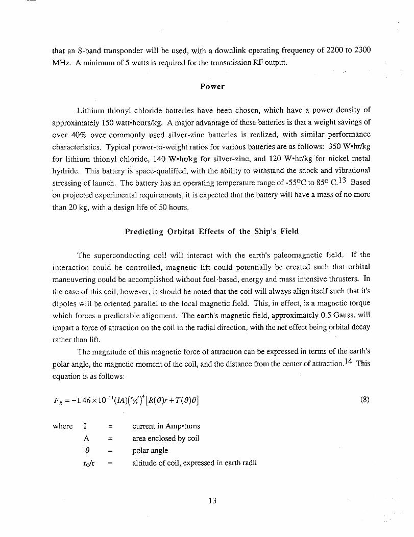
The magnitude of this magnetic force of attraction can be expressed in terms of the earth's
polar angle, the magnetic moment of the coil, and the distance from the center of attraction. 14 This
equation is as follows:
e R =-1.46 x IO-I'(IA)('_)4[R(O)r + T(O)O] (8)
where
A =
0 =
ro/r =
current in Amp-tums
area enclosed by coil
polar angle
altitude of coil, expressed in earth radii
13
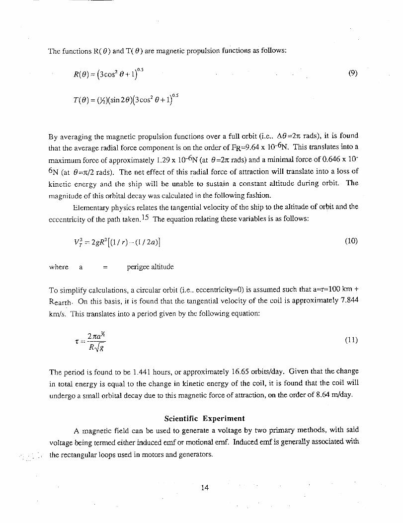
ThefunctionsR(0) andT(0) aremagneticpropulsionfunctionsasfollows:
R(O) = (3cos 2 0 + 1) 0.5
T(0) = 04)(sin 20)(3cos 2 0 + 1)°5
(9)
By averaging the magnetic propulsion functions over a full orbit (i.e.. A0=27t rads), it is found
that the average radial force component is on the order of FR=9.64 x 10⁻⁶N. This translates into a
maximum force of approximately 1.29 x 10⁻⁶N (at 0=2re rads) and a minimal force of 0.646 x 10-
6N (at 0=7t/2 rads). The net effect of this radial force of attraction will translate into a loss of
kinetic energy and the ship will be unable to sustain a constant altitude during orbit. The
magnitude of this orbital decay was calculated in the following fashion.
Elementary physics relates the tangential velocity of the ship to the altitude of orbit and the
eccentricity of the path taken. 15 The equation relating these variables is as follows:
Vrz = 2gR2[(1/r)-(1/2a)] (I0)
where a = perigee altitude
To simplify calculations, a circular orbit (i.e.. eccentricity=0) is assumed such that a=r=100 km +
Rearth. On this basis, it is found that the tangential velocity of the coil is approximately 7.844
km/s. This translates into a period given by the following equation:
(11)
The period is found to be 1.441 hours, or approximately 16.65 orbits/day. Given that the change
in total energy is equal to the change in kinetic energy of the coil, it is found that the coil will
undergo a small orbital decay due to this magnetic force of attraction, on the order of 8.64 m/day.
Scientific Experiment
A magnetic field can be used to generate a voltage by two primary methods, with said
voltage being termed either induced emf or motional emf. Induced emf is generally associated with
the rectangular loops used in motors and generators.
14
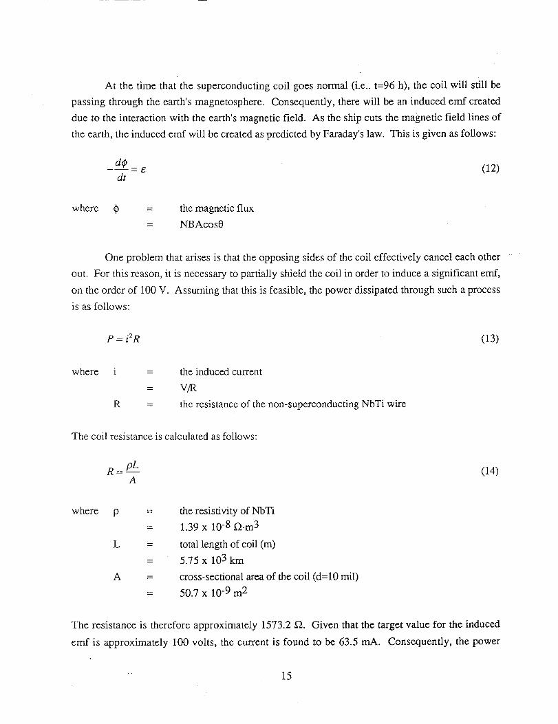
At thetime that thesuperconductingcoil goesnormal(i.e.. t=96 h), thecoil will still bepassingthroughtheearth'smagnetosphere.Consequently,therewill bean inducedemf created
dueto theinteractionwith theearth'smagneticfield. As theshipcutsthemagneticfield linesoftheearth,the inducedemf will becreatedaspredictedbyFaraday'slaw. This is givenasfollows:
- e (12)dt
where qb = the magnetic flux
= NBAcos0
One problem that arises is that the opposing sides of the coil effectively cancel each other
out. For this reason, it is necessary to partially shield the coil in order to induce a significant emf,
on the order of 100 V. Assuming that this is feasible, the power dissipated through such a process
is as follows:
P = i2R (13)
where i
R
the induced current
V/R
the resistance of the non-superconducting NbTi wire
The coil resistance is calculated as follows:
(14)
wherep
L =
A =
the resistivity of NbTi
1.39 x 10 -8 f2.m 3
total length of coil (m)
5.75 x 10³ km
cross-sectional area of the coil (d=10 mil)
50.7 x 10 -9 m 2
The resistance is therefore approximately 1573.2 f2. Given that the target value for the induced
emf is approximately 100 volts, the current is found to be 63.5 mA. Consequently, the power
15

dissipatedin thecoil is approximately6.36watts. The total energydissipationcanbefound asfollows:
AE = PAt (15)
Over the course of two weeks (after the coil goes normal), this will be approximately 7.6 x 10⁶
joules. Relative to the kinetic energy of the ship at a 100 km orbit (-3.03 x 10¹⁰ J), this change in
energy is negligible and will not affect the orbital decay rate significantly.
Coil Orientation
During orbit, the coil and its associated magnetic dipole will be constantly interacting with the
natural paleomagnetic field of the earth. Without the aid of torquer bars, an intricate arrangement
of three independent gyroscopes, or some other orientation devices, the coil will undergo changes
in orientation due to the interaction between the two magnetic fields. Thus, there is a torque
imposed on the coil by this magnetic interaction which always tends to orient the dipole parallel to
the local field. The most stable position tends to be one of polar attraction in which the induced
south pole of the coil is oriented towards the north pole of the earth.
As the coil orbits the earth, there will be a magnetic torque imposed on the coil which will
advantageously orient the coil with respect to the earth's paleomagnetic field. This torque is
expressed as follows:
T = M x B (16)
where W
M =
B =
the magnetic torque acting on the coil (N-m)
the coil magnetic dipole moment (A-m 2)
the magnetic field (webers/m 2)
In the specific case of the coil studied herein, the magnetic dipole moment is 4.767 x 10⁵
ampere-turns-m 2, and the magnetic field of the earth is approximately 0.5 Gauss (5 x 10 -5 T). It
should be noted that the magnetic torque acting on the coil will be a vector quantity. However, the
maximum torque will occur when the dipoles of the coil and the earth's magnetic poles are
orthogonal (i.e.. the axis of each loop is perpendicular to the magnetic field). In this case, the
maximum torque can be expressed as the scalar product of the magnetic dipole moment and the
magnetic field. The maximum torque is found to be 23.835 Newton.m.
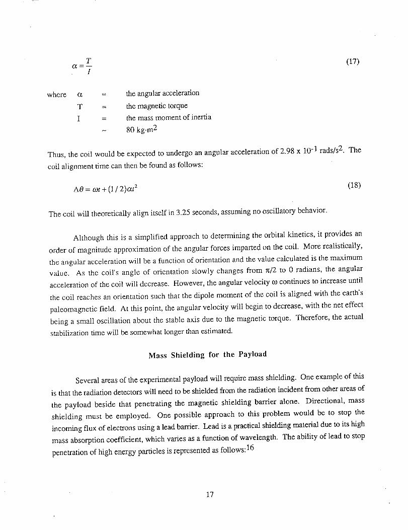
The magnetic torque will impose an angular acceleration on the coil, given as follows:
16
T
I(17)
where
T =
I =
N
the angular acceleration
the magnetic torque
the mass moment of inertia
80 kg.m 2
Thus, the coil would be expected to undergo an angular acceleration of 2.98 x 10 -1 rads/s 2. The
coil alignment time can then be found as follows:
A0 = cot + (1 / 2)at 2 (18)
The coil will theoretically align itself in 3.25 seconds, assuming no oscillatory behavior.
Although this is a simplified approach to determining the orbital kinetics, it provides an
order of magnitude approximation of the angular forces imparted on the coil. More realistically,
the angular acceleration will be a function of orientation and the value calculated is the maximum
value. As the coil's angle of orientation slowly changes from _/2 to 0 radians, the angular
acceleration of the coil will decrease. However, the angular velocity co continues to increase until
the coil reaches an orientation such that the dipole moment of the coil is aligned with the earth's
paleomagnetic field. At this point, the angular velocity will begin to decrease, with the net effect
being a small oscillation about the stable axis due to the magnetic torque. Therefore, the actual
stabilization time will be somewhat longer than estimated.
Mass Shielding for the Payload
Several areas of the experimental payload will require mass shielding. One example of this
is that the radiation detectors will need to be shielded from the radiation incident from other areas of
the payload beside that penetrating the magnetic shielding barrier alone. Directional, mass
shielding must be employed. One possible approach to this problem would be to stop the
incoming flux of electrons using a lead barrier. Lead is a practical shielding material due to its high
mass absorption coefficient, which varies as a function of wavelength. The ability of lead to stop
penetration of high energy particles is represented as follows: 16
17

(19)
where 1/I o =
g =
p =
N
X =
the proportion of high energy particles stopped
mass absorption coefficient
100 cm -I
density of lead
11.34 g/cm 3
thickness of lead barrier (cm)
It is also true that the wavelength of the incoming radiation is inversely proportional to the
particle's maximum cut-off energy such that: 17
KE[KeV] (20)
Assuming that the incoming radiation will have a maximum cut-off energy on the order of 1 MeV,
this radiation will have a wavelength of 0.0124 .,_. The mass absorption coefficient for lead is
tabulated as a function of this wavelength in Table 1. Using a linear regression analysis, a function
relating the mass absorption coefficient to the wavelength has been detemained:
l_]= 28.23,,1, 3 +122.24,,1, 2 -266.40,_ +257.9 (21)
where _, = wavelength (A)
Table 1 Mass Absorption
Coefficient for Lead
3_. (_) g/). (cm2/s)
0.7 141,°
1.4 202
1.7 297
2.1 499
18
Though this mathematical model works well for relatively large wavelengths radiation (i.e..
low energy), it predicts large mass absorption coefficients at small wavelengths (_. < 1,_). The
actual plot of mass absorption coefficient as a function of wavelength includes a number of
inflection points. In fact, the mass absorption function undergoes a number of significant jumps at
these "absorption edges" denoted by the subscripts K, L, and M. The wavelength of the radiation
for which the shield is designed, approximately 0.01/_, places it just below the K absorption edge
(which occurs at approximately 0.05/_ for lead). A logarithmic approximation can thus be used to
predict the mass absorption in this range. By studying the transition at the K absorption edge of
other metals, it is found that the slope of the mass absorption coefficient as a function of
wavelength plot is approximately 0.125 x 10 "12 cm2/g'nm. Thus, it is found that the mass
absorption coefficient at 0.01 ,/_ is approximately 0.236 cm2/g. It is finally found that the
minimum lead thickness for shielding the payload from 99% of the incoming radiation ([3 particles)
is approximately 1.7 cm. Thus, only select regions can be fully mass-shielded.
Conclusion
An experimental magnetic shielding payload launched into polar orbit is feasible within the
design size and weight constraints. This payload can be design, constructed, and tested at
remarkably low cost using many of the technologies developed for lightsats. The scientific
experiments offer interdisciplinary research involving the atmospheric and high-energy physics
communities, the aerospace community, and the engineering community with the potential for
major contributions to our understanding of active radiation shielding techniques, microcirculation
in the auroral zones of the atmosphere, as well as other electrical and physical phenomena
involving large magnetic fields.
1 Adolph S. Jursa, Ed., Handbook of Geophysics and the Space Environment, United States Air Force (Virginia,1985), 1, 18-19.2 Peter Berlin, The Geostafi0nary Applications Satellite, Cambridge University Press (New York, 1988), 71.3 Ibid, 3.
4 A.L. Vampola, "Radiation Effects on Space Systems and Their Modeling", Space Systems and Their Interactions..withEarth's Space Environment, Eds. Henry B. Garrettt and Charles P. Pike, American Institute of Aeronautics andAstronautics (New York, 1980), 240.5 Jursa, 3-6.
6 Vampola, 341.7Ibid.
19
8R.A. English, R.E. Benson, J.V. Basley and C.M. Barnes, Apqll0 Experience Report - Protection Against
Radiation, NASA, Washington, D.C. NASA TN D-7080, 2, 1973.9 Gordon R. Woodcock, Space Stations and Platforms, Orbit Book Company (Malabar, Florida, 1986), 64.
10 Superconducting Magnet System, Oxford Instruments Ltd., manual.
11 Ibid.
12 William C. Chen and Daniel C. Woods, Actively Cooled Baffle for Superconducting Magnet Penetration Wall,U.S. Patent No. 5,265,430, November 30, 1993.
13 Pinakin M. Shah, "A high power lithium thionyl chloride battery for space applications", Journal of PowerSources, 43-44 (1993) 317-326.
14 Robert M. Zubrin, "The Use of Magnetic Sails to Escape from Low Earth Orbit", Journal of the BritishInterplanetary Society, Vol. 46 (1993), pp. 3-10.15 j. L. Meriam and L. Kraige, Engineering Mech_nic_: Dynamics, John Wiley & Sons, Inc., New York, NY,
1992, pp. 230-236.16 B. D. Cullity, Elements of X-ray Diffraction, 2nd Ed., Addison-Wesley Publishing Company, Inc. (Reading,
MA, 1978) p. 13.17 Ibid., 18.
20
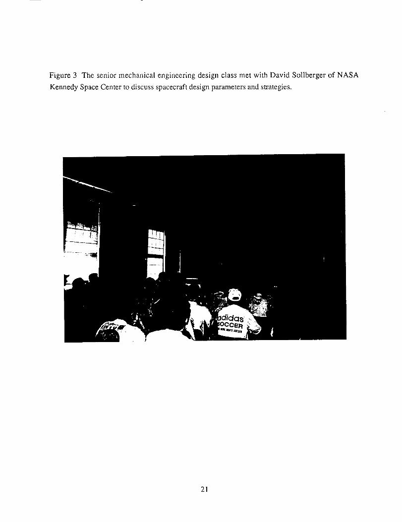
Figure 3 The senior mechanical engineering design class met with David Sollberger of NASA
Kennedy Space Center to discuss spacecraft design parameters and strategies.
21
Appendix A
Payload Diagrams
22
SUPER-
CONDUCTINGCOILS
HONEYCOMBPLATES
TELEMETRY
UNIT
VOLTMETER
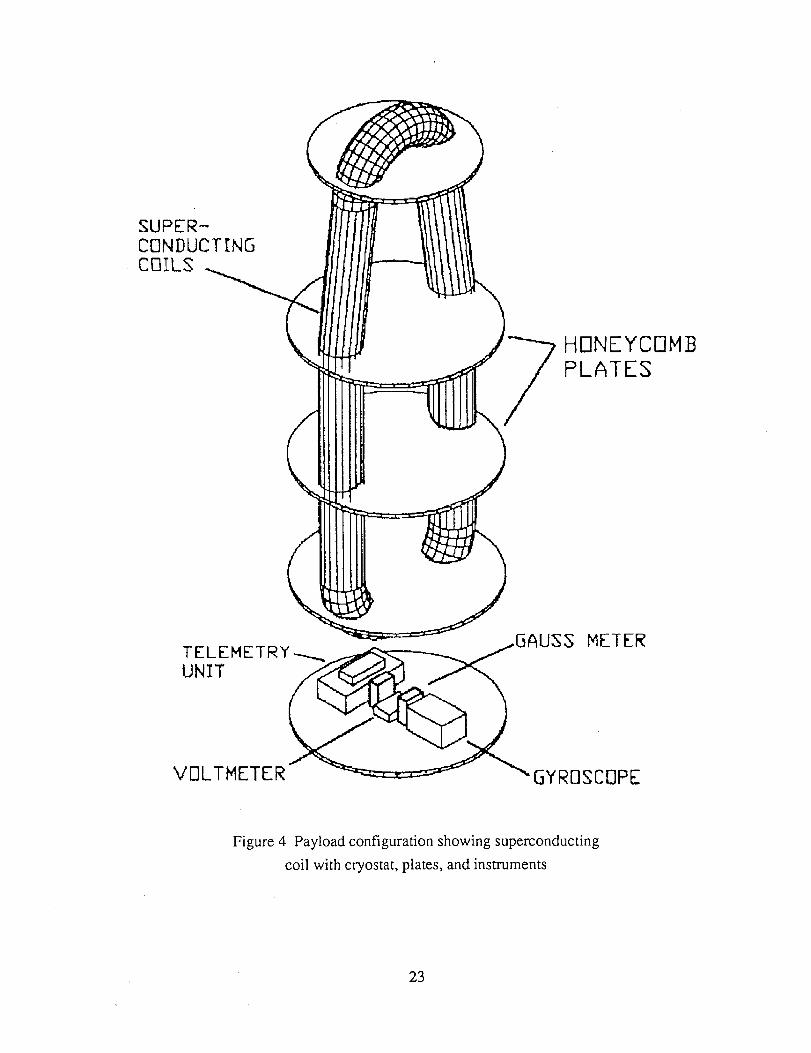
Figure 4 Payload configuration showing superconducting
coil with cryostat, plates, and instruments
23

RADIATIONDETEC
BATTERYARRAY
_SHIELD
Figure 5 Payload configuration showing shield, battery array,
and radiation detectors
24
HARD HDUNT!N_ ATTACH PDINTS
o!!o/SECTION
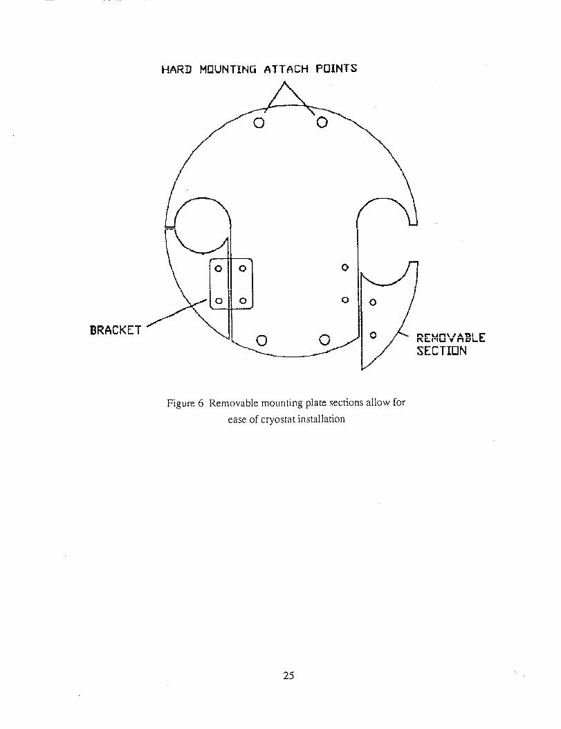
Figure 6 Removable mounting plate sections allow for
ease of cryostat installation
25

Figure 7 Mounting plate details
6 :


![Optimal Magnetic Shield Design with Second–Order … · Optimal design of static magnetic shielding arises naturally in several areas including ... [A2] Ferromagnetic material has](https://img.dokumen.tips/doc/110x75/5b5a61b27f8b9a885b8bd3b3/optimal-magnetic-shield-design-with-secondorder-optimal-design-of-static.jpg)