Embed Size (px)
Citation preview
NYL***33-25P
NZL***33-40P
NXL-NYL-NZL-CXL2020-DYL-HXL
N.M.S.STOCK N° 4.095.763/Ed.5-09/10
***
NXL***33-25P
INSTALLATION ET MISE EN SERVICEDES CIRCULATEURS DOMESTIQUES
INSTALLATION AND STARTING INSTRUCTIONSFOR DOMESTIC CIRCULATORS
FRANÇAIS
ENGLISH
INSTALLAZIONE E MESSA IN SERVIZIO DELLE POMPE DI CIRCOLAZIONE DOMESTICHE
ITALIANO
INSTALACION Y PUESTA EN SERVICIO DE LOS CIRCULADORES DOMESTICOS
ESPAÑOL
2
3
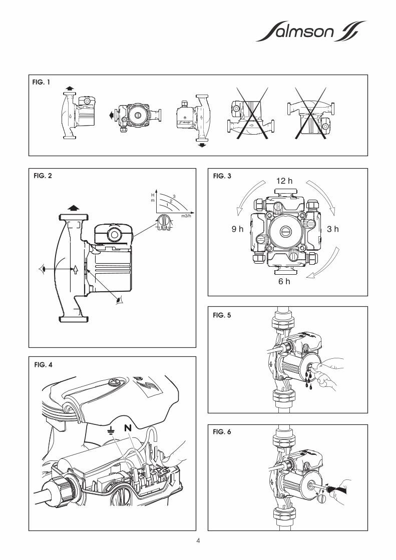
FIG. 1
FIG. 2
FIG. 4
FIG. 3
FIG. 6
FIG. 5
4
5
1. GÉNÉRALITÉS1.1 ApplicationsPour la circulation accélérée de l'eau dans les circuitsouverts ou fermés de chauffage central domestique(individuel), et de climatisation.
1.2 Caractéristiques techniques•Plage de température : - 10° à + 110°C•Température ambiante : maxi + 40 °C•Pression de service maxi : 106 Pa (10 bars)•Pression mini : 1,5.104 Pa (1.5 m ; 0.15 bar)à l’aspiration (m CE*) à + 82 °C
: 3.104 Pa (3 m ; 0.3 bar) à 95°C: 105 Pa (10 m ; 1 bar) à +110°C
•Antigel (eau + glycol) : jusqu’à 50%(A l’exclusion de tout autre liquide sans accordpréalable).•Débit maxi (50 Hz) :•Débit maxi (50 Hz) : HXL57 - HXL63 : 2 m3/h
NXL-NYL13 : 2,5 m3/hNXL-NYL33 : 3 m3/h
NZL13 - CXL2020 - DYL53 - NXL-NYL43 : 3,5 m3/hNZL33 - NXL-NYL53 : 4 m3/h
NXL-NYL63 : 4,5 m3/h*10,2 mCE = 1 bar = 105 Pa
2. SECURITÉLa présente notice devra être lue avec attentionavant installation et mise en service. On veillera enparticulier, au respect des points concernant lasécurité du matériel vis à vis de l’uti l isateurintermédiaire ou final.Cet appareil n'est pas prévu pour être utilisé par despersonnes (y compris des enfants) dont les capacitésphysiques, sensorielles ou mentales sont réduites, oudes personnes dénuées d'expérience ou deconnaissance, sauf si elles ont pu bénéficier, parl'intermédiaire d'une personne responsable de leursécurité, d'une surveillance ou d'instructions préalablesconcernant l'utilisation de l'appareil.Il convient de surveiller les enfants pour s'assurer qu'ilsne jouent pas avec l'appareil.
2.1 Symboles des consignes du manuelRisque potentiel mettant en danger la sécuritédes personnes.
Risque potentiel relatif à l’électricité mettant endanger la sécurité des personnes.
Consigne de sécurité dont le non respectpeut engendrer un dommage pour lematériel et son fonctionnement.
3. TRANSPORT ET STOCKAGEDès réception du matériel, vérifier s’il n’a pas subi dedommages durant son transport. En cas de défautconstaté, prendre dans les délais prévus toutesdispositions nécessaires auprès du transporteur.
Si le matériel l ivré devait êtreinstallé ultérieu-rement, stockez-le dans
un endroit sec et protégez-le contre les chocs ettoutes influences extérieures (humidité, gel, etc...).
4. PRODUITS ET ACCESSOIRES4.1 La pompeA orifices filetés ou brides ovales selon modèle.Le moteur est à rotor noyé, les coussinets sont auto-lubrifiés.A 3 vitesses, sélection manuelle par sélecteur.•Conformité : TF110•Classe d'isolation : F (155 °C)•Protection : IP42Le moteur est auto-protégé, il ne nécessite aucuneprotection extérieure.Fréquence 50 Hz 60 HzTension* (monophasé) 230 V 220/240 V* Tension standard : 50 Hz : tolérance (±10%)* Tension standard : 60 Hz : tolérance (±6%)
4.2 AccessoiresFournis : joints de raccords union ou de brides.Conseillés : • Raccords-union ou contre-brides ovalesà visser • Dégommeur pour le déblocage facile del’arbre moteur • Vannes d’isolement...
5. INSTALLATION5.1 Montage (voir FIG. 1)- Veiller à l’accessibilité du circulateur.- Montage direct sur tuyauterie, de préférence verticale,et si possible sur le circuit retour chaudière ; jamais aupoint le plus bas afin de le protéger contre les dépôts.
Pour le raccordement au réseau d’eau,l’usage d’accessoires neufs est requis.
- L’axe du moteur doit être obligatoirement horizontal.- La flèche située sur le corps de pompe indique lesens de circulation de l’eau (voir FIG. 2).- Prévoir de part et d’autre du circulateur des vannesd’isolement pour faciliter son démontage ou touteintervention.
Si le circulateur doit être calorifugé , nousrecommandons de ne pas obstruer les
encoches situées sur la bride moteur (voir FIG. 2)ATTENTION !
ATTENTION !
ATTENTION !
ATTENTION !
FRANÇAIS
la vitesse de rotation moteur à l’aide du sélecteur.Risques de brûlure au contact du moteur. Enfonctionnement, sa température peut êtresupérieure à 100 °C.
7. ENTRETIENLe circulateur ne nécessite aucun entretien particulieren cours de fonctionnement.Les coussinets moteur sont lubrifiés par le liquidevéhiculé.Au début de chaque période de chauffe, ou après unarrêt prolongé, s’assurer que le circulateur tournelibrement.
5.2 Orientation de la boîte à bornes (voir FIG 3)Si nécessaire, il est possible de changer l'orientation dumoteur, donc de la boîte à bornes.(NZL*** : 12 h et 6 h seulement).- Retirer les vis de fixation du moteur sur le corps ettourner le moteur dans la position souhaitée.
Prendre soin de ne pas endommager lejoint de corps et de le replacercorrectement.Position de la boîte à bornes à 3 et 6 h(appareil installé) à proscrire enutilisation sur circuit eau glacée.
5.3 Raccordement électriqueLe raccordement électrique doit être effectuépar un électricien agréé et conformément auxnormes locales en vigueur.
Toutes les informations électriques du circulateurfigurent sur la plaque signalétique.
Réseau d’alimentationUtiliser un câble à 3 conducteurs (3 x 1,5 mm2 H05 VVF)pour raccorder le réseau aux bornes correspondantesdu circulateur : PHASE (L) - NEUTRE (N) - TERRE ( ) (voir FIG. 4).
Le câble d’alimentation ne doit pas être encontact avec la tuyauterie ni toucher la pompe ;s’assurer qu’il soit à l’abri de toute humidité.
Contrôler la protection de la l igne, la tensiond’alimentation requise et la fréquence du réseau.Le circulateur doit être raccordé au réseau électrique àl’aide d’un interrupteur ayant une distance d’ouverturepour chaque pôle d’au moins 3 mm.La prise de courant doit être équipée impérativementd’une borne terre (norme NFC 15-100).Après raccordement électrique, remettre le couverclede la boîte à bornes.
6. MISE EN ROUTE6.1 Remplissage - Dégazage
Ne jamais faire fonctionner lecirculateur SANS EAU.
- Ouvrir les vannes de part et d’autre du circulateur etremplir complètement l’installation.- Purger le circuit au point haut.- Procéder à la purge d’air manuelle du circulateur endévissant de quelques tours le bouchon (voir FIG. 5),le refermer après sortie d’eau et complète disparitiondes bulles d’air.
Risques de brûlure par l’eau. Utiliser untournevis pour devisser le bouchon.
- Mettre sous tension le moteur pour mettre en servicele circulateur.- Le réglage du débit s’effectue par changement de
ATTENTION !
6
FRANÇAIS
ATTENTION !
ATTENTION !
7
FRANÇAIS
INCIDENTS
8.1LE CIRCULATEUREST BRUYANT
8.2LE CIRCULATEURNE DÉMARREPAS
CAUSES
a) Présence d’air :
b) La pression à l’aspirationest trop faible :
c) Bruits importants decirculation d’eau :
d)Corps étrangers dans laroue :
a) Blocage de l’arbre parencrassement après unarrêt prolongé :
b) Le circulateur n’est pasalimenté électriquement :
c)Corps étrangers dans laroue :
REMÈDES
a) Purger le circulateur : desserrer le bouchon arrière,prolonger jusqu’à complète disparition des bulles d’air puisrevisser le bouchon.
b) Augmenter la pression dans le circuit.
c) Possibilités d’utiliser une vitesse inférieure.
d) Démonter le moteur et nettoyer la roue.
a) Débloquer l’arbre : ôter le bouchon arrière. Au moyen d’untournevis à lame plate, faire tourner l’arbre moteur, remonter lebouchon arrière (voir FIG. 6) ou actionner le dégommeur (siéquipé) en poussant sur la partie centrale à l’aide d’un tournevis.
b) - Vérifier le raccordement du moteur.- Vérifier les fusibles de l’installation.
c) Démonter le moteur et nettoyer la roue.
8. INCIDENTS DE FONCTIONNEMENT
Avant toute intervention METTRE HORS TENSIONle circulateur.
Si un incident de fonctionnement venait à persister, nous vousrecommandons de vous adresser au SAV SALMSON, seuls habilitéspendant la période de garantie à procéder au démontage-remontage de nos matériels.
HOTLINE TECHNIQUE 0 820 0000 44
8
1 GENERAL1.1. ApplicationsFor faster circulation of water in open- and closed-circuit domestic (individual) central heating and air-conditioning systems.
1.2. Specifications• Temperature range : -10° to +110°C• Ambient temperature : up to 40°C• Max. service pressure : 106 Pa (10 bar)• Min. suction pressure : 1,5.104 Pa (1.5 m; 0.15 bar)(m w.g.*) at + 82°C;
: 3.104 Pa (3 m; 0.3 bar)at +95°C; : 105 Pa (10 m; 1bar) at +110°C
• Antifreeze (Water + glycol) : up to 50 %(whith the exclusion of all other liquids without first obtaining the agreement).
•Max. flowrate (50 Hz) NXL*** - NYL*** 13 : 2.5 m3/hNXL*** - NYL*** 33 : 3 m3/h
CXL 2020 and NXL*** - NYL*** 43 : 3.5 m3/hNXL*** - NYL*** 53 : 4 m3/hNXL*** - NYL*** 63 : 4.5 m3/h
* 10,2 m w.g. = 1 bar = 105 Pa
2. SAFETYRead this data sheet carefully before installing andstarting up. Pay special attention to the pointsconcerning the safety of the equipment for theintermediate or end user.This appliance is not intended for use by persons(including children) with reduced physical, sensory ormental capabil it ies, or lack of experience andknowledge, unless they have been given supervisionor instruction concerning use of the appliance by aperson responsible for their safety.Children should be supervised to ensure that they donot play with the appliance.
2.1. Symbols used in the manualPotential risk that might endanger the safety ofthe persons.
Safety instructions relating to electric risks.
If you do not consider this instruction, itmay involve a damage for the materialand its functioning.
3. TRANSPORT AND STORAGEWhen taking delivery of the equipment, check that ithas not been damaged in transit. If anything is foundwrong, take the necessary steps with the carrier withinthe allowed time.
If the equipment delivered is to beinstalled at a later time, store it in a dry
place and protect it from impacts and outsideinfluences (moisture, frost, etc.).
4. PRODUCTS AND ACCESSORIES4.1. The pumpWith threaded ports or ovales flange according tomodel.The motor has a wet rotor and the bushings are self-lubricating.Three-speed or multi-speed, according to model;manual selection by selector switch.• Compliance : TF110 • Insulation class : F (155°C)• Protection : IP42The motor is self-protected and needs no externalprotection.
Frequency 50 Hz 60 HzVoltage * (1-phase) 230 V 220/240 V* standard voltage : tolerance 50 Hz ± 10 % - 60 Hz ± 6 %
4.2. Accessoriessupplied : Union’s gasket or flange’s gasketRecommended :• Unions or screw-on oval counter-f langes • Unjamming plug device for motor shaft • Isolatingvalves.
5. INSTALLATION5.1. Assembly (see FIG. 1)- Make sure that the circulator is accessible.- Assemble directly on a pipe, preferably vertical, andif possible on the boiler return circuit; never at the lowpoint (to protect against deposits).
For connection with the water supplynetwork, the use of new accessories isnecessary.
- The motor shaft axis must always be horizontal.- The arrow on the pump casing indicates thedirection of water flow (see FIG. 2).- Install isolating valves on both sides of the circulatorto facilitate removal and other work on it.
If the circulator must be insulated, weadvise against obstructing the
evacuation notches in the motor flange (see FIG. 2).
5.2. Orientation of terminal box (see FIG. 3)If necessary, the orientation of the motor, and with itthat of the terminal box, can be changed.(12 h and 6 h only for NZL***)- Remove the motor attachment screws and turn themotor to the desired position.
ATTENTION !
ATTENTION !
ATTENTION !
ATTENTION !
ENGLISH
9
Take care not to damage the casinggasket, and reinstall it correctly.The terminal box should not be placedat 3 and 6 o’clock on an ice watercircuit.
5.3. Electrical connectionThe electrical connection must be made by aqualif ied electrician and comply withapplicable local standards.
Complete electrical information about the circulator isgiven on the data plate.Power supply networkUse a three-conductor cable (3 x 1,5 mm2 H05 VVF) toconnect mains power to the corresponding terminalsof the circulator: phase (L), neutral (N), and earth ( )(see FIG. 4).
The power cable must not touch the pipe or thepump; make sure that it is away from anymoisture.
Check line protection and the mains voltage andfrequency.The circulator must be connected to the mains via aswitch with an opening distance, on each pole, of atleast 3 mm.The power outlet must have an earthing contact.After making the connections, put the cover back onthe terminal box.
6. STARTING UP6.1. Filling, degassing
Never operate the circulator WITHOUTWATER.
- Open the valves on both sides of the circulator andfill the installation completely.
- Bleed the circuit at the high point.- Bleed air from the circuit by hand by unscrewing theplug (see FIG. 5) a few turns; close it when water runsout and when there are no more air bubbles.
Risks of scald. Use a screw-driver for unscrewingthe tap.
- Power up the motor to start the circulator.- The flowrate is adjusted by changing the speed ofrotation of the motor using the selector switch.
Risk of burning. In operation, the motor casingmay be hotter than 100°C.
7. SERVICINGThe circulator needs no special servicing in operation.The motor bushings are lubricated by the liquidpumped.At the beginning of each heating season, or after aprolonged shutdown, make sure that the circulatorturns freely.
ATTENTION !
ATTENTION !
ATTENTION !
ENGLISH
INCIDENTS
8.1THE CIRCULATORIS NOISY
8.2THE CIRCULATORFAILS TO START
CAUSES
a)Air in circulator :
b) The suction pressure is toolow :
c) Considerable flowingwater noise :
d) Foreign bodies in impeller :
a) Shaft stalled by foulingafter a prolongedshutdown :
b)No power supply tocirculator :
c) Foreign bodies in impeller :
REMÈDES
a) Bleed the circulator: loosen the rear plug; continue untilthere are no more air bubbles, then screw the plug back in.
b) Raise the pressure in the circuit.
c) Consider a slower speed.
d) Remove the motor and clean the impeller.
a) -Free the shaft: remove the rear plug. Use a flat-bladedscrewdriver to turn the motor shaft. Then reinsert the rearplug (see FIG. 6). Or operate the unjamming plug device(if one is fitted) by pushing on its centre with a screwdriver.
b) - Check that the motor is connected.- Check the fuses of the installation.
c) Remove the motor and clean the impeller.
8. OPERATING TROUBLE
Switch the circulator OFF before doing anywork on it.
10
1. GENERALITA’1.1. ApplicazioniPer la circolazione accelerata dell’acqua nei circuitiaperti o chiusi di riscaldamento centrale domestico(individuale) e di climatizzazione.
1.2. Caratteristiche tecniche• Campo di temperatura : -10° a +110°C• Temperatura ambientale : 40°C al massimo• Pressione di servizio massima : 106 Pa (10 bar)• Pressione minima all’ : 1,5.104 Pa (1.5 m; 0.15 bar)aspirazione (m/Col. Acqua)* a +82°C
: 3.104 Pa (3m; 0.3 bar)a +95°C: 105 Pa (10m ; 1bar)a +110°C
• Miscela acqua + glicol : fino a 50%(Ad ecclusare di altri liquiali se non richiesto preventivamente).
• Portata massima (50 HZ) NXL*** - NYL*** 13 : 2,5 m3/hNXL*** - NYL*** 33 : 3 m3/h
CXL 2020 e NXL*** - NYL*** 43 : 3,5 m3/hNXL*** - NYL*** 53 : 4 m3/hNXL*** - NYL*** 63 : 4,5 m3/h
* (10,2 m/Col. Acqua = 1 bar = 105 Pa)
2. SICUREZZALe presenti istruzioni vanno lette attentamente primadi procedere all’installazione ed alla messa in servizio.Verificare in particolare il rispetto dei punti relativi allasicurezza del materiale nei confronti dell’utenteintermedio o finale.Questo apparecchio non è destinato a essereutilizzato da persone (compresi i bambini) con limitatecapacità fisiche, sensoriali o mentali oppure mancantidi esperienza e/o conoscenza, a meno che nonvengano sorvegliate da una persona responsabiledella loro sicurezza o abbiano ricevuto da quest'ultimaistruzioni su come utilizzare l'apparecchio.I bambini devono essere sorvegliati al fine di garantireche non giochino con l'apparecchio.
2.1. Simboli delle consegne del manualeRischio potenziale che può mettere in pericolo lasicurezza delle persone.
Avvertenze relative ai rischi elettrici.
Segnala un'istruzione la cui mancataosservanza può provocare un danno
al materiale o comprometterne il funzionamento.
3. TRASPORTO E STOCCAGGIOAl ricevimento del materiale, verificare che esso nonabbia subito eventuali danni durante il trasporto. In
caso venga constatato un difetto, prendere nei debititempi le misure utili nei confronti del vettore.
Se il materiale consegnato è destinatoad essere installato ulteriormente,
immagazzinarlo in un locale asciutto e proteggerlo dagliurti e da ogni influenza esterna (umidità, gelo, ecc.).
4. PRODOTTI ED ACCESSORI4.1. La pompaA orifizi filettati o flange ovale secondo i modelli.Motore a rotore inondato. Cuscinetti autolubrificati.A 3 velocità, selezione manuale a selettore.• Conformità : TF110 • Classe d’isolamento : F (155°C)• protezione : IP42Il motore è autoprotetto e non richiede nessunaprotezione esterna.Frecuenza 50 Hz 60 HzTensione * (mono) 230 V 220/240 V* Tensione standard : tolleranza 50 Hz ± 10 % - 60 Hz ± 6 %
4.2. AccessoriConsegnati : Garnizone bocchettoni o di flange.Acconsigliati :• Bocchettoni o controflange ovali da avvitare.• Sgommatore per sbloccare facilmente l’albero motore.• Valvole di isolamento.
5. INSTALLAZIONE5.1. Montaggio (vedi FIG. 1)- Assicurarsi che la pompa sia accessibile.- Montaggio diretto sulle tubazioni preferibilmente verticalie possibilmente sul circuito di ritorno caldaia; in nessuncaso nel punto più basso per proteggerlo dai depositi.
Per il collegamento alla rete d'acqua,l'impiego di accessori nuovi ènecessario.
- L’asse del motore deve essere tassativamenteorizzontale.
- Il senso della circolazione dell’acqua è indicato dauna freccia sul corpo della pompa (vedi FIG. 2).
- Prevedere su entrambi i lati della pompa di circolazionedelle valvole di isolamento per agevolare losmontaggio della pompa e qualsiasi altro intervento.
Se la pompa va coibentata, si racco-manda di non ostruire le tacche
praticate sulla flangia motore (vedi FIG. 2).
5.2 Orientamento della morsettiera (vedi FIG. 3)Se occorre, si può modificare l’orientamento delmotore e conseguentemente della morsettiera (NZL*** : 12 h e 6 h).- Rimuovere le viti di fissaggio del motore sul corpo della
ATTENZIONE !
ATTENZIONE !
ATTENZIONE !
ATTENZIONE !
ITALIANO
11
pompa e girare il motore nella posizione desiderata.Fare attenzione a non danneggiare laguarnizione del corpo e a reinserirlacorrettamente.La posizione della morsettiera sulle 3 e6 è vietata se utilizzata su circuito diacqua refrigerata.
5.3. Collegamento elettricoIl collegamento elettrico va eseguito da unelettricista autorizzato in conformità alle vigentinorme locali.
Tutte le informazioni elettr iche della pompa dicircolazione figurano sulla piastrina segnaletica.Rete di alimentazioneUtilizzare un cavo a 3 conduttori (3 x 1,5 mm2 H05 VVF)per collegare la rete ai relativi morsetti della pompa :FASE (L) - NEUTRO (N) - TERRA ( ) (vedi FIG. 4).
Il cavo di alimentazione non deve entrare incontatto con la tubazione né toccare la pompa:verificare che sia al riparo dall’umidità.
Verificare la protezione della linea, la tensione dialimentazione richiesta e la frequenza della rete. La pompa di circolazione va collegata alla reteelettrica mediante un interruttore la cui distanza diapertura per ogni polo è di almeno 3 mm.La presa di corrente deve comportare tassativamenteun morsetto di terra.Dopo il collegamento elettrico, rimettere il coperchiodella morsettiera.
6. MESSA IN SERVIZIO6.1. Riempimento - Degasaggio
Non far funzionare mai la pompa dicircolazione SENZ’ACQUA.
- Aprire le valvole su entrambi i lati della pompa eriempire completamente l’impianto.- Spurgare il circuito al punto superiore.- Procedere allo spurgo dell’aria manuale della pompasvitando il tappo di qualche giro (vedi FIG. 5), quindirichiuderlo dopo l’uscita dell’acqua e la scomparsacompleta di qualsiasi bolla d’aria.
Rischio di scottature con l’acqua. Utilittare uncacciavite per svitare il tappo.
- Mettere in tensione il motore per mettere in servizio lapompa di circolazione.La regolazione della portata della pompa vieneeseguita cambiando la velocità di rotazione delmotore mediante il selettore.
Ai rischi di bruciatura. In esercizio, latemperatura della carcassa del motore puòsuperare i 100°C.
7. MANUTENZIONELa pompa di circolazione non richiede nessunamanutenzione particolare durante il funzionamento.I cuscinetti motore sono lubrif icati dal l iquidoconvogliato. All’inizio di ogni periodo di riscaldamento, o dopoun’interruzione prolungata, verificare che la pompagiri liberamente.
ATTENZIONE !
ATTENZIONE !
ATTENZIONE !
ITALIANO
12
ITALIANO
INCIDENTI
8.1LA POMPA DICIRCOLAZIONEÈ RUMOROSA
8.2LA POMPA DICIRCOLAZIONENON SI AVVIA
CAUSE
a) Presenza d’aria :
b) La pressione diaspirazione è troppobassa :
c) Forti rumori di circolazioned’acqua :
d) Presenza di corpi estraneinella girante :
a) Blocco dell’albero perintasamento dopoun’interruzione prolungata :
b)Mancanza dialimentazione elettrica :
c)Corpi estranei nella ruota :
RIMÈDI
a) Spurgare la pompa di circolazione: svitare il tappoposteriore, prolungare fino alla scomparsa completa dellebolle d’aria, quindi riavvitare il tappo.
b) Aumentare la pressione nel circuito.
c) E’ possibile utilizzare una velocità inferiore.
d) Smontare il motore e pulire la girante.
a) -Sbloccare l’albero: togliere il tappo posteriore, servendosidi un cacciavite piatto, far ruotare l’albero motore,rimontare il tappo posteriore (vedi FIG. 6) o servirsi dellosgommatore (se disponibile) spingendone la parte centralecon un cacciavite.
b) - Verificare il collegamento del motore.- Verificare i fusibili dell’impianto.
c) Smontare il motore e pulire la girante.
8. INCIDENTI DI FUNZIONAMENTO
Prima di ogni intervento, METTERE FUORITENSIONE LA POMPA.
13
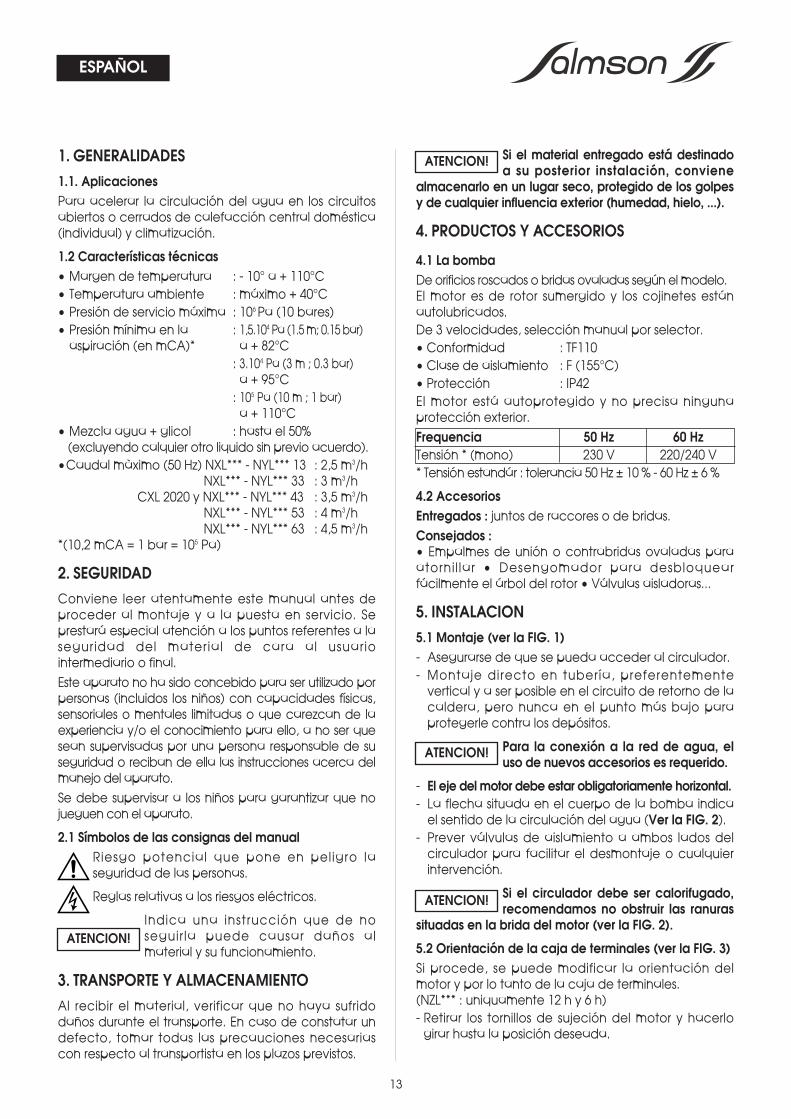
1. GENERALIDADES1.1. AplicacionesPara acelerar la circulación del agua en los circuitosabiertos o cerrados de calefacción central doméstica(individual) y climatización.
1.2 Características técnicas• Margen de temperatura : - 10° a + 110°C• Temperatura ambiente : máximo + 40°C• Presión de servicio máxima : 106 Pa (10 bares)• Presión mínima en la : 1,5.104 Pa (1.5 m; 0.15 bar)aspiración (en mCA)* a + 82°C
: 3.104 Pa (3 m ; 0.3 bar)a + 95°C: 105 Pa (10 m ; 1 bar)a + 110°C
• Mezcla agua + glicol : hasta el 50%(excluyendo calquier otro liquido sin previo acuerdo).
•Caudal màximo (50 Hz) NXL*** - NYL*** 13 : 2,5 m3/hNXL*** - NYL*** 33 : 3 m3/h
CXL 2020 y NXL*** - NYL*** 43 : 3,5 m3/hNXL*** - NYL*** 53 : 4 m3/hNXL*** - NYL*** 63 : 4,5 m3/h
*(10,2 mCA = 1 bar = 105 Pa)
2. SEGURIDADConviene leer atentamente este manual antes deproceder al montaje y a la puesta en servicio. Seprestará especial atención a los puntos referentes a laseguridad del material de cara al usuariointermediario o final.Este aparato no ha sido concebido para ser utilizado porpersonas (incluidos los niños) con capacidades físicas,sensoriales o mentales limitadas o que carezcan de laexperiencia y/o el conocimiento para ello, a no ser quesean supervisadas por una persona responsable de suseguridad o reciban de ella las instrucciones acerca delmanejo del aparato.Se debe supervisar a los niños para garantizar que nojueguen con el aparato.
2.1 Símbolos de las consignas del manualRiesgo potencial que pone en peligro laseguridad de las personas.
Reglas relativas a los riesgos eléctricos.
Indica una instrucción que de noseguirla puede causar daños almaterial y su funcionamiento.
3. TRANSPORTE Y ALMACENAMIENTOAl recibir el material, verificar que no haya sufridodaños durante el transporte. En caso de constatar undefecto, tomar todas las precauciones necesariascon respecto al transportista en los plazos previstos.
Si el material entregado está destinadoa su posterior instalación, conviene
almacenarlo en un lugar seco, protegido de los golpesy de cualquier influencia exterior (humedad, hielo, ...).
4. PRODUCTOS Y ACCESORIOS
4.1 La bombaDe orificios roscados o bridas ovaladas según el modelo.El motor es de rotor sumergido y los cojinetes estánautolubricados.De 3 velocidades, selección manual por selector.• Conformidad : TF110• Clase de aislamiento : F (155°C)• Protección : IP42El motor está autoprotegido y no precisa ningunaprotección exterior.Frequencia 50 Hz 60 HzTensión * (mono) 230 V 220/240 V* Tensión estandár : tolerancia 50 Hz ± 10 % - 60 Hz ± 6 %
4.2 AccesoriosEntregados : juntos de raccores o de bridas.Consejados :• Empalmes de unión o contrabridas ovaladas paraatornil lar • Desengomador para desbloquearfácilmente el árbol del rotor • Válvulas aisladoras...
5. INSTALACION5.1 Montaje (ver la FIG. 1)- Asegurarse de que se pueda acceder al circulador.- Montaje directo en tubería, preferentementevertical y a ser posible en el circuito de retorno de lacaldera, pero nunca en el punto más bajo paraprotegerle contra los depósitos.
Para la conexión a la red de agua, eluso de nuevos accesorios es requerido.
- El eje del motor debe estar obligatoriamente horizontal.- La flecha situada en el cuerpo de la bomba indicael sentido de la circulación del agua (Ver la FIG. 2).
- Prever válvulas de aislamiento a ambos lados delcirculador para facilitar el desmontaje o cualquierintervención.
Si el circulador debe ser calorifugado,recomendamos no obstruir las ranuras
situadas en la brida del motor (ver la FIG. 2).
5.2 Orientación de la caja de terminales (ver la FIG. 3)Si procede, se puede modificar la orientación delmotor y por lo tanto de la caja de terminales.(NZL*** : uniquamente 12 h y 6 h)- Retirar los tornillos de sujeción del motor y hacerlogirar hasta la posición deseada.
ATENCION!
ATENCION!
ATENCION!
ATENCION!
ESPAÑOL
14
ESPAÑOL
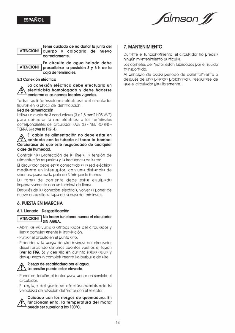
Tener cuidado de no dañar la junta delcuerpo y colocarla de nuevocorrectamente.
En circuito de agua helada debeproscribirse la posición 3 y 6 h de lacaja de terminales.
5.3 Conexión eléctricaLa conexión eléctrica debe efectuarla unelectricista homologado y debe hacerseconforme a las normas locales vigentes.
Todas las informaciones eléctricas del circuladorfiguran en la placa de identificación.Red de alimentaciónUtilizar un cable de 3 conductores (3 x 1,5 mm2 H05 VVF)para conectar la red eléctrica a los terminalescorrespondientes del circulador: FASE (L) - NEUTRO (N) -TIERRA ( ) (ver la FIG. 4).
El cable de alimentación no debe estar encontacto con la tubería ni tocar la bomba.
Cerciorarse de que esté resguardado de cualquierclase de humedad.Controlar la protección de la línea, la tensión dealimentación requerida y la frecuencia de la red.El circulador debe estar conectado a la red eléctricamediante un interruptor, con una distancia deabertura para cada polo de 3 mm por lo menos.La toma de corriente debe estar equipadaimperativamente con un terminal de tierra .Después de la conexión eléctrica, volver a poner denuevo en su sitio la tapa de la caja de terminales.
6. PUESTA EN MARCHA6.1. Llenado - Desgasificación
No hacer funcionar nunca el circuladorSIN AGUA.
- Abrir las válvulas a ambos lados del circulador yllenar completamente la instalación.- Purgar el circuito en el punto alto.- Proceder a la purga de aire manual del circuladordesenroscando de unas cuantas vueltas el tapón(ver la FIG. 5) y cerrarlo en cuanto salga agua ydesaparezcan completamente las burbujas de aire.
Riesgo de escaldadura por el agua.La presión puede estar elevada.
- Poner en tensión el motor para poner en servicio elcirculador.- El reglaje del gasto se efectúa cambiando lavelocidad de rotación del motor con el selector.
Cuidado con los riesgos de quemadura. Enfuncionamiento, la temperatura del motorpuede ser superior a los 100°C.
7. MANTENIMIENTODurante el funcionamiento, el circulador no precisaningún mantenimiento particular.Los cojinetes del motor están lubricados por el líquidotransportado.Al principio de cada periodo de calentamiento odespués de una parada prolongada, asegurarse deque el circulador gira libremente.
ATENCION!
ATENCION!
ATENCION!
15
ESPAÑOL
INCIDENTES
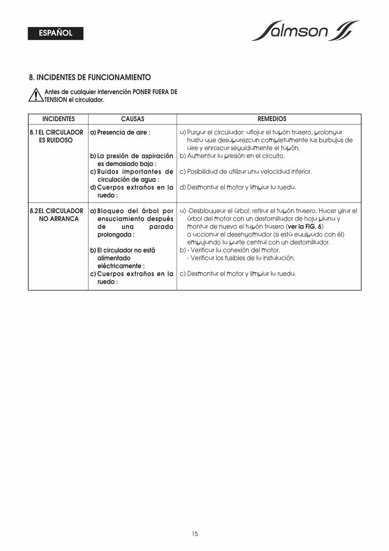
8.1EL CIRCULADORES RUIDOSO
8.2EL CIRCULADORNO ARRANCA
CAUSAS
a) Presencia de aire :
b) La presión de aspiraciónes demasiado baja :
c) Ruidos importantes decirculación de agua :
d)Cuerpos extraños en larueda :
a) Bloqueo del árbol porensuciamiento despuésde una paradaprolongada :
b) El circulador no estáalimentadoeléctricamente :
c)Cuerpos extraños en larueda :
REMEDIOS
a) Purgar el circulador: aflojar el tapón trasero, prolongarhasta que desaparezcan completamente las burbujas deaire y enroscar seguidamente el tapón.
b) Aumentar la presión en el circuito.
c) Posibilidad de utilizar una velocidad inferior.
d) Desmontar el motor y limpiar la rueda.
a) -Desbloquear el árbol: retirar el tapón trasero. Hacer girar elárbol del motor con un destornillador de hoja plana ymontar de nuevo el tapón trasero (ver la FIG. 6) o accionar el desengomador (si está equipado con él)empujando la parte central con un destornillador.
b) - Verificar la conexión del motor.- Verificar los fusibles de la instalación.
c) Desmontar el motor y limpiar la rueda.
8. INCIDENTES DE FUNCIONAMIENTO
Antes de cualquier intervención PONER FUERA DETENSION el circulador.
QUESTO LIBRETTO D'USO DEVE ESSERERIMESSO ALL'UTILIZZATORE FINALE E
RIMANERE SEMPRE DISPONIBILE SUL POSTO.
ESTE MANUAL HA DE SER ENTREGADO ALUTILIZADOR FINAL Y SIEMPRE DISPONIBLE
EN SU EMPLAZAMIENTO.
CE MANUEL DOIT ETRE REMIS AL'UTILISATEUR FINAL ET ETRE TOUJOURS
DISPONIBLE SUR SITE.
FRANÇAIS
ENGLISH
THIS LEAFLET HAS TO BE GIVEN TO THE END USER AND MUST BE LEFT ON SITE.
ESPAÑOL
ITALIANO
SERVICE CONSOMMATEUR
[email protected]él. 0820 0000 44
Espace Louis Lumière - Bâtiment 653, boulevard de la République - 78403 Chatou Cedex
www.salmson.comPOMPES SALMSON - SAS AU CAPITAL DE 16.775.000 € SIREN 313 986 838 RCS VERSAILLES - APE 291C
PORTUGALRua Alvarez Cabral, 250/2554050 - 040 PortoPORTUGAL
TEL. : (351) 22 208 0350TEL. : (351) 22 207 6910FAX : (351) 22 200 [email protected]
SALMSON SOUTH AFRICAUnit 1, 9 Entreprise Close, Linbro Business Park - PO Box 52EDENVALE, 1610Republic of SOUTH AFRICA
TEL. : (27) 11 608 27 80/ 1/2/3FAX : (27) 11 608 27 [email protected]
SALMSON ITALIAVia J. PeriI 80 I41100 MODENAITALIA
TEL. : (39) 059 280 380FAX : (39) 059 280 [email protected]
W.S.L. LEBANONBou Khater building - Mazda CenterJal El Dib Highway - PO Box 90-281Djeideh El Metn 1202 2030 - BeiruthLEBANON
TEL. : (961) 4 722 280FAX : (961) 4 722 [email protected]
SALMSON ARGENTINA S.A.Av. Montes de Oca 1771/75C1270AABE Ciudad Autonoma de Buenos AiresARGENTINA
TEL.: (54) 11 4301 5955FAX : (54) 11 4303 [email protected]
SALMSON VIETNAME-TOWN - Unit 3-1C364 CONG HOA - TAN BINH Dist.Hochi minh-ville VIETNAM
TEL. : (84-8) 810 99 75FAX : (84-8) 810 99 [email protected]