Embed Size (px)
Citation preview
A N A M E R I C A N N A T I O N A L S T A N D A R D
ASME B18.2.2-2015(Revision of ASME B18.2.2-2010)
Nuts for General Applications: Machine Screw Nuts, Hex, Square, Hex Flange, and Coupling Nuts (Inch Series)
falatghareh.irfalatghareh.ir
ASME B18.2.2-2015(Revision of ASME B18.2.2-2010)
Nuts for GeneralApplications: MachineScrew Nuts, Hex,Square, Hex Flange,and Coupling Nuts(Inch Series)
A N A M E R I C A N N A T I O N A L S T A N D A R D
Two Park Avenue • New York, NY • 10016 USA
falatghareh.irfalatghareh.ir

Date of Issuance: November 30, 2015
This Standard will be revised when the Society approves the issuance of a new edition.
ASME issues written replies to inquiries concerning interpretations of technical aspectsof this Standard. Interpretations are published on the Committee Web page and undergo.asme.org/InterpsDatabase. Periodically certain actions of the ASME B18 Committee may bepublished as Cases. Cases are published on the ASME Web site under the B18 Committee Page atgo.asme.org/B18committee as they are issued.
Errata to codes and standards may be posted on the ASME Web site under the Committee Pages toprovide corrections to incorrectly published items, or to correct typographical or grammatical errorsin codes and standards. Such errata shall be used on the date posted.
The B18 Committee Page can be found at go.asme.org/B18committee. There is an option availableto automatically receive an e-mail notification when errata are posted to a particular code or standard.This option can be found on the appropriate Committee Page after selecting “Errata" in the "PublicationInformation" section.
ASME is the registered trademark of The American Society of Mechanical Engineers.
This code or standard was developed under procedures accredited as meeting the criteria for American National
Standards. The Standards Committee that approved the code or standard was balanced to assure that individuals from
competent and concerned interests have had an opportunity to participate. The proposed code or standard was made
available for public review and comment that provides an opportunity for additional public input from industry, academia,
regulatory agencies, and the public-at-large.
ASME does not “approve,” “rate,” or “endorse” any item, construction, proprietary device, or activity.
ASME does not take any position with respect to the validity of any patent rights asserted in connection with any
items mentioned in this document, and does not undertake to insure anyone utilizing a standard against liability for
infringement of any applicable letters patent, nor assumes any such liability. Users of a code or standard are expressly
advised that determination of the validity of any such patent rights, and the risk of infringement of such rights, is
entirely their own responsibility.
Participation by federal agency representative(s) or person(s) affiliated with industry is not to be interpreted as
government or industry endorsement of this code or standard.
ASME accepts responsibility for only those interpretations of this document issued in accordance with the established
ASME procedures and policies, which precludes the issuance of interpretations by individuals.
No part of this document may be reproduced in any form,
in an electronic retrieval system or otherwise,
without the prior written permission of the publisher.
The American Society of Mechanical Engineers
Two Park Avenue, New York, NY 10016-5990
Copyright © 2015 by
THE AMERICAN SOCIETY OF MECHANICAL ENGINEERS
All rights reserved
Printed in U.S.A.
falatghareh.irfalatghareh.ir
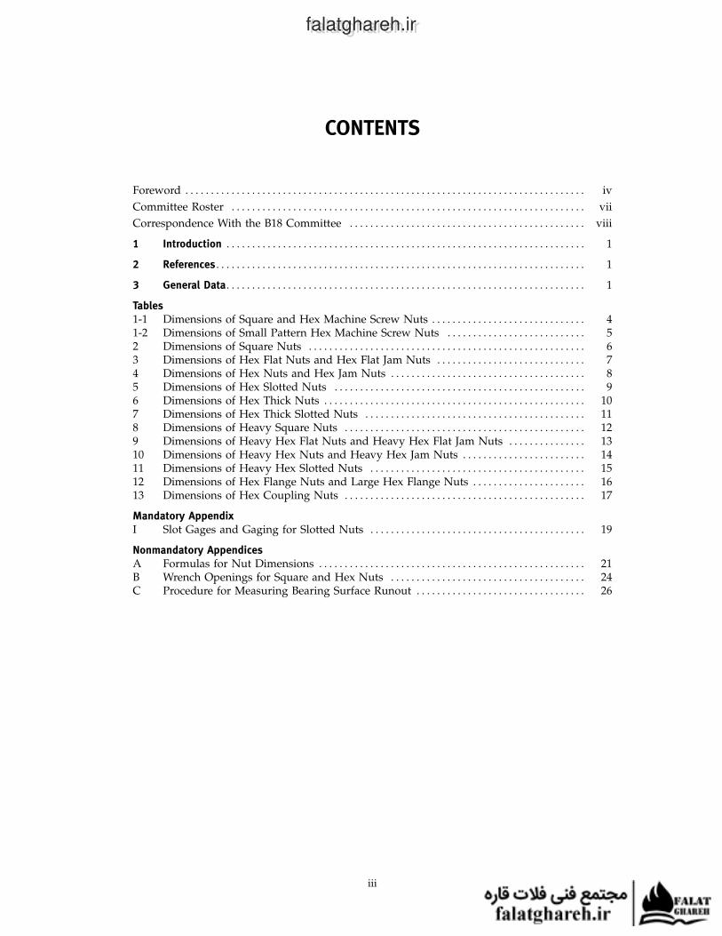
CONTENTS
Foreword . . . . . . . . . . . . . . . . . . . . . . . . . . . . . . . . . . . . . . . . . . . . . . . . . . . . . . . . . . . . . . . . . . . . . . . . . . . . . . iv
Committee Roster . . . . . . . . . . . . . . . . . . . . . . . . . . . . . . . . . . . . . . . . . . . . . . . . . . . . . . . . . . . . . . . . . . . . . vii
Correspondence With the B18 Committee . . . . . . . . . . . . . . . . . . . . . . . . . . . . . . . . . . . . . . . . . . . . . . viii
1 Introduction . . . . . . . . . . . . . . . . . . . . . . . . . . . . . . . . . . . . . . . . . . . . . . . . . . . . . . . . . . . . . . . . . . . . . . 1
2 References . . . . . . . . . . . . . . . . . . . . . . . . . . . . . . . . . . . . . . . . . . . . . . . . . . . . . . . . . . . . . . . . . . . . . . . . 1
3 General Data. . . . . . . . . . . . . . . . . . . . . . . . . . . . . . . . . . . . . . . . . . . . . . . . . . . . . . . . . . . . . . . . . . . . . . 1
Tables1-1 Dimensions of Square and Hex Machine Screw Nuts . . . . . . . . . . . . . . . . . . . . . . . . . . . . . . 41-2 Dimensions of Small Pattern Hex Machine Screw Nuts . . . . . . . . . . . . . . . . . . . . . . . . . . . 52 Dimensions of Square Nuts . . . . . . . . . . . . . . . . . . . . . . . . . . . . . . . . . . . . . . . . . . . . . . . . . . . . . . 63 Dimensions of Hex Flat Nuts and Hex Flat Jam Nuts . . . . . . . . . . . . . . . . . . . . . . . . . . . . . 74 Dimensions of Hex Nuts and Hex Jam Nuts . . . . . . . . . . . . . . . . . . . . . . . . . . . . . . . . . . . . . . 85 Dimensions of Hex Slotted Nuts . . . . . . . . . . . . . . . . . . . . . . . . . . . . . . . . . . . . . . . . . . . . . . . . . 96 Dimensions of Hex Thick Nuts . . . . . . . . . . . . . . . . . . . . . . . . . . . . . . . . . . . . . . . . . . . . . . . . . . . 107 Dimensions of Hex Thick Slotted Nuts . . . . . . . . . . . . . . . . . . . . . . . . . . . . . . . . . . . . . . . . . . . 118 Dimensions of Heavy Square Nuts . . . . . . . . . . . . . . . . . . . . . . . . . . . . . . . . . . . . . . . . . . . . . . . 129 Dimensions of Heavy Hex Flat Nuts and Heavy Hex Flat Jam Nuts . . . . . . . . . . . . . . . 1310 Dimensions of Heavy Hex Nuts and Heavy Hex Jam Nuts . . . . . . . . . . . . . . . . . . . . . . . . 1411 Dimensions of Heavy Hex Slotted Nuts . . . . . . . . . . . . . . . . . . . . . . . . . . . . . . . . . . . . . . . . . . 1512 Dimensions of Hex Flange Nuts and Large Hex Flange Nuts . . . . . . . . . . . . . . . . . . . . . . 1613 Dimensions of Hex Coupling Nuts . . . . . . . . . . . . . . . . . . . . . . . . . . . . . . . . . . . . . . . . . . . . . . . 17
Mandatory AppendixI Slot Gages and Gaging for Slotted Nuts . . . . . . . . . . . . . . . . . . . . . . . . . . . . . . . . . . . . . . . . . . 19
Nonmandatory AppendicesA Formulas for Nut Dimensions . . . . . . . . . . . . . . . . . . . . . . . . . . . . . . . . . . . . . . . . . . . . . . . . . . . . 21B Wrench Openings for Square and Hex Nuts . . . . . . . . . . . . . . . . . . . . . . . . . . . . . . . . . . . . . . 24C Procedure for Measuring Bearing Surface Runout . . . . . . . . . . . . . . . . . . . . . . . . . . . . . . . . . 26
iii
falatghareh.irfalatghareh.ir

FOREWORD
American National Standards Committee B18 for the standardization of bolts, screws, nuts,rivets, and similar fasteners was organized in March 1922 as Sectional Committee B18 underthe aegis of the American Engineering Standards Committee (later the American StandardsAssociation, then the United States of America Standards Institute, Inc.) with the Society ofAutomotive Engineers and the American Society of Mechanical Engineers as joint sponsors.Subcommittee 2 was subsequently established and charged with the responsibility for technicalcontent of standards covering wrench head bolts and nuts.
Subcommittee 2, after appraisal of the requirements of industry, developed a proposed standardseries of bolt head and nut dimensions. This proposal was finally approved and designated aTentative American Standard in February 1927.
A first revision of the document was designated as an American Standard in March 1933 andwas followed by a second revision that was granted approval as an American Standard inJanuary 1941.
Following reorganization of the B18 Committee in 1947, Subcommittee 2 was asked to expandthe standard on head proportions into a complete product standard. A proposal covering squareand hexagon head bolts and nuts, hexagon head cap screws, and automotive hexagon head boltswas prepared and submitted to the B18 Committee in April 1950. While this draft was underconsideration, the B18 Committee received a proposal from the British Standards Institutionfor unification of dimensions on products incorporating unified screw threads. The Committeewelcomed the opportunity of discussing the proposals and an American-British-CanadianConference was held in New York on June 1 and 2, 1950.
It was agreed in the conference that the essentials of unification could be accomplished byselection of mutually satisfactory across-the-flats dimensions, since this would permit the use ofthe same wrenches and because other features would rarely affect interchangeability. After dueconsideration, suitable existing across-the-flats dimensions were selected for the hexagon productsaffected.
In its meeting of October 13, 1950, Subcommittee 2 agreed to incorporate into the proposedstandard the conference recommendations on 1⁄4 in. hexagon head bolts, 5⁄8 in. hexagon head capscrews and automotive hexagon head bolts, and 7⁄16 in. light and regular hexagon and squarenuts. At a subsequent meeting of Subcommittee 2, further changes were adopted in order tocombine the light and regular series of nuts, and to combine the automotive hexagon head bolt,hexagon head cap screw, and regular hexagon head close tolerance bolt.
In view of the progress made in the United States and the urgency of standardization formutual defense, the British Standards Institution sponsored a second conference in London inApril 1951 to complete the unification of certain hexagon bolts and nuts.
At a meeting on June 8, 1951, Subcommittee 2 reaffirmed its acceptance of the unified dimensionsthat correspond with those in the March 1951 draft, but attempted to select better nomenclaturefor the unified products. A final draft incorporating the nomenclature “Finished Hexagon Boltsand Nuts” and containing numerous editorial changes was submitted for letter ballot inSeptember 1951. Following approval by the B18 Committee and the sponsors, the proposal waspresented to the American Standards Association for approval and designation as an AmericanStandard. This was granted on March 24, 1952.
It was recognized that the standard was in need of additional refinements, thereforeSubcommittee 2 began work immediately to eliminate these shortcomings. A proposed revisionremoving inconsistencies with respect to fillets, improving the length tolerances on heavy hexagonbolts, and incorporating numerous other corrections and clarifications of an editorial natureresulted. The most noteworthy editorial change was a decision to combine the coverage forhexagon cap screws and square head set screws from the B18.2 standard with the coverage forslotted head cap screws and slotted headless set screws from the B18.6 standard for publicationin a separate document. The requirements for the unified hexagon cap screws and finished
iv
falatghareh.irfalatghareh.ir

hexagon bolts being identical in the overlapping sizes, the data would now be available in twopublications. Following approvals by the B18 Committee and sponsor organizations, the proposalwas submitted to the American Standards Association and declared an American Standard onFebruary 2, 1955.
A revision of this Standard comprised of numerous editorial corrections and inclusion of anappendix for grade markings was duly approved and designated an American Standard onApril 18, 1960.
At a meeting in February 1960, Subcommittee 2 approved a recommendation to reduce the headheights for heavy, heavy semifinished, and heavy finished hexagon bolt, which was subsequentlyapproved by letter ballot of the B18 Committee on August 16, 1960. A proposed standard forheavy hexagon structural bolts submitted and accepted by Subcommittee 2 at its October 17, 1960meeting was approved by letter ballot of the B18 Committee on May 9, 1961. To meet the urgentneeds of the steel construction industry, it was considered necessary to publish the standard forthe structural bolts immediately. Consequently, Appendix IV to ASA B18.2-1960 containing cover-age for the revised heavy hexagon bolts and the new heavy hexagon structural bolts was releasedin 1962.
In October 1961, Subcommittee 2 appointed a subgroup to review all product standards forsquare and hexagon bolts, screws, and nuts, and to recommend simplifications that would becompatible with technical, production, and distribution advances that had occurred over the priorseveral years. The subgroup presented its recommendations at a meeting of Subcommittee 2 inOctober 1962. It was agreed that the internally and externally threaded products should bepublished in separate documents as suggested, and draft proposals for each were completed.
The proposed revision for square and hex nuts incorporated the following subgroup recommen-dations: discontinuation of regular semifinished nuts; elimination of regular hexagon and heavyhexagon nuts in sizes 1⁄4 in. through 1 in.; elimination of finished hexagon nuts in sizes largerthan 11⁄2 in.; elimination of the washer face semifinished style on finished series nuts in sizes 5⁄8 in.and smaller and heavy series nuts in sizes 7⁄16 in. and smaller; removal of machine screw nuts(these nuts are now contained in B18.6.3); and adoption of an abbreviated product nomenclature.Letter ballot of this proposal to the B18 Committee resulted in approval. Following acceptanceby the sponsor organizations the revision was submitted to the American Standards Associationand designated ASA B18.2.2 on September 8, 1965.
Subcommittee 2 continued to further develop refinements initiated by the simplification sub-group and to study changes suggested by consumer interests. This work culminated inSubcommittee acceptance of a 1970 proposal incorporating, in addition to numerous editorialchanges, revisions to the requirements on angularity of bearing face and countersink diametersfor the various hex nuts and heavy hex nuts, and inclusion of an appendix covering the gagingof slots in slotted nuts.
The proposed revision, after approval by letter ballot of the B18 Committee in March 1970,was subsequently approved by the sponsors and submitted to the American National StandardsInstitute for designation as an American National Standard. This was granted on January 18, 1972.
A proposed revision of this Standard agreed upon by Subcommittee 2 incorporated a provisionto enable consumers to specify heavy hex nuts and heavy hex jam nuts with close bearing faceangularity, when required; clarified intent with regard to width across flats on nuts producedfrom bar stock; deleted coverage for hex castle nuts from the appendices; and included numerouseditorial refinements. This proposal was formally approved by letter ballot of the subcommitteeand the B18 Committee. Following its acceptance by the sponsor organizations the revision wasreferred to the American National Standards Institute and granted approval as an AmericanNational Standard on February 27, 1987.
In March 2009 the B18.2 Subcommittee undertook a revision of this Standard. The format hasbeen updated to meet the requirements of ASME B18.12.1. Regular pattern machine screw nutshave been moved from ASME B18.6.3, and the small pattern machine screw nuts have beenadded to this Standard. The hex flange nut that was previously referred to as IFI-145 has beenadded. Coupling nuts have been added. Many of the sizes came from the IFI-128 and otherswere based on what has been used for many years by industry. This proposal was formallyapproved by letter ballot of the subcommittee and the B18 Committee. Following its acceptanceby the sponsor organizations, the revision was referred to the American National StandardsInstitute and granted approval as an American National Standard on August 24, 2010.
v
falatghareh.irfalatghareh.ir

In September 2014 the B18.2 Subcommittee agreed to revise this Standard. Updates to thestandard include correcting and expanding tabulated dimensions of small pattern hex machinescrew nuts, revising washer face diameter tolerancing to be consistent with cap screws, a revisedprocedure for thread acceptance gaging of jam nuts, and a nonmandatory appendix with aprocedure for measuring bearing surface runout. This revision was approved as an AmericanNational Standard on August 12, 2015.
vi
falatghareh.irfalatghareh.ir
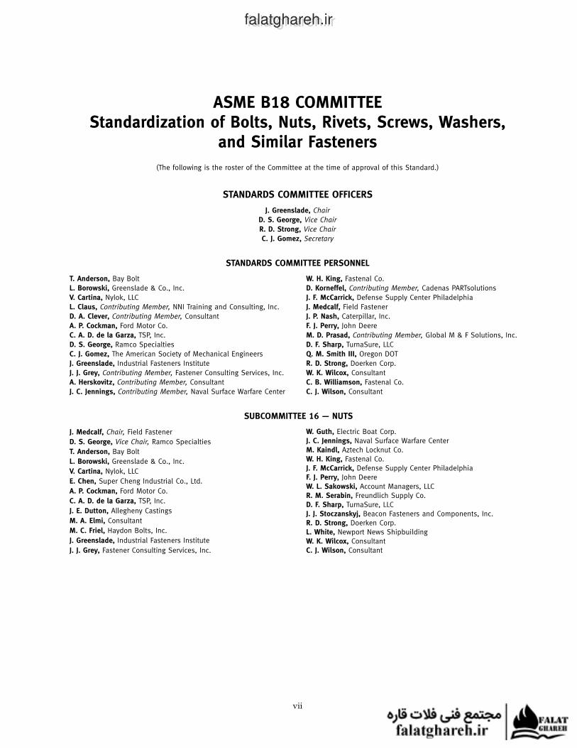
ASME B18 COMMITTEEStandardization of Bolts, Nuts, Rivets, Screws, Washers,
and Similar Fasteners
(The following is the roster of the Committee at the time of approval of this Standard.)
STANDARDS COMMITTEE OFFICERS
J. Greenslade, Chair
D. S. George, Vice Chair
R. D. Strong, Vice Chair
C. J. Gomez, Secretary
STANDARDS COMMITTEE PERSONNEL
T. Anderson, Bay Bolt
L. Borowski, Greenslade & Co., Inc.
V. Cartina, Nylok, LLC
L. Claus, Contributing Member, NNI Training and Consulting, Inc.
D. A. Clever, Contributing Member, Consultant
A. P. Cockman, Ford Motor Co.
C. A. D. de la Garza, TSP, Inc.
D. S. George, Ramco Specialties
C. J. Gomez, The American Society of Mechanical Engineers
J. Greenslade, Industrial Fasteners Institute
J. J. Grey, Contributing Member, Fastener Consulting Services, Inc.
A. Herskovitz, Contributing Member, Consultant
J. C. Jennings, Contributing Member, Naval Surface Warfare Center
SUBCOMMITTEE 16 — NUTS
J. Medcalf, Chair, Field Fastener
D. S. George, Vice Chair, Ramco Specialties
T. Anderson, Bay Bolt
L. Borowski, Greenslade & Co., Inc.
V. Cartina, Nylok, LLC
E. Chen, Super Cheng Industrial Co., Ltd.
A. P. Cockman, Ford Motor Co.
C. A. D. de la Garza, TSP, Inc.
J. E. Dutton, Allegheny Castings
M. A. Elmi, Consultant
M. C. Friel, Haydon Bolts, Inc.
J. Greenslade, Industrial Fasteners Institute
J. J. Grey, Fastener Consulting Services, Inc.
vii
W. H. King, Fastenal Co.
D. Korneffel, Contributing Member, Cadenas PARTsolutions
J. F. McCarrick, Defense Supply Center Philadelphia
J. Medcalf, Field Fastener
J. P. Nash, Caterpillar, Inc.
F. J. Perry, John Deere
M. D. Prasad, Contributing Member, Global M & F Solutions, Inc.
D. F. Sharp, TurnaSure, LLC
Q. M. Smith III, Oregon DOT
R. D. Strong, Doerken Corp.
W. K. Wilcox, Consultant
C. B. Williamson, Fastenal Co.
C. J. Wilson, Consultant
W. Guth, Electric Boat Corp.J. C. Jennings, Naval Surface Warfare CenterM. Kaindl, Aztech Locknut Co.W. H. King, Fastenal Co.J. F. McCarrick, Defense Supply Center PhiladelphiaF. J. Perry, John DeereW. L. Sakowski, Account Managers, LLCR. M. Serabin, Freundlich Supply Co.D. F. Sharp, TurnaSure, LLCJ. J. Stoczanskyj, Beacon Fasteners and Components, Inc.R. D. Strong, Doerken Corp.L. White, Newport News ShipbuildingW. K. Wilcox, ConsultantC. J. Wilson, Consultant
falatghareh.irfalatghareh.ir
CORRESPONDENCE WITH THE B18 COMMITTEE
General. ASME Standards are developed and maintained with the intent to represent theconsensus of concerned interests. As such, users of this Standard may interact with the Committeeby requesting interpretations, proposing revisions or a Case, and attending Committee meetings.Correspondence should be addressed to:
Secretary, B18 Standards CommitteeThe American Society of Mechanical EngineersTwo Park AvenueNew York, NY 10016-5990http://go.asme.org/Inquiry
Proposing Revisions. Revisions are made periodically to the Standard to incorporate changesthat appear necessary or desirable, as demonstrated by the experience gained from the applicationof the Standard. Approved revisions will be published periodically.
The Committee welcomes proposals for revisions to this Standard. Such proposals should beas specific as possible, citing the paragraph number(s), the proposed wording, and a detaileddescription of the reasons for the proposal, including any pertinent documentation.
Proposing a Case. Cases may be issued for the purpose of providing alternative rules whenjustified, to permit early implementation of an approved revision when the need is urgent, or toprovide rules not covered by existing provisions. Cases are effective immediately upon ASMEapproval and shall be posted on the ASME Committee Web page.
Requests for Cases shall provide a Statement of Need and Background Information. The requestshould identify the Standard and the paragraph, figure, or table number(s), and be written as aQuestion and Reply in the same format as existing Cases. Requests for Cases should also indicatethe applicable edition(s) of the Standard to which the proposed Case applies.
Interpretations. Upon request, the B18 Standards Committee will render an interpretation ofany requirement of the Standard. Interpretations can only be rendered in response to a writtenrequest sent to the Secretary of the B18 Standards Committee at go.asme.org/Inquiry.
The request for an interpretation should be clear and unambiguous. It is further recommendedthat the inquirer submit his/her request in the following format:
Subject: Cite the applicable paragraph number(s) and the topic of the inquiry.Edition: Cite the applicable edition of the Standard for which the interpretation is
being requested.Question: Phrase the question as a request for an interpretation of a specific requirement
suitable for general understanding and use, not as a request for an approvalof a proprietary design or situation. The inquirer may also include any plansor drawings that are necessary to explain the question; however, they shouldnot contain proprietary names or information.
Requests that are not in this format may be rewritten in the appropriate format by the Committeeprior to being answered, which may inadvertently change the intent of the original request.
ASME procedures provide for reconsideration of any interpretation when or if additionalinformation that might affect an interpretation is available. Further, persons aggrieved by aninterpretation may appeal to the cognizant ASME Committee or Subcommittee. ASME does not“approve,” “certify,” “rate,” or “endorse” any item, construction, proprietary device, or activity.
Attending Committee Meetings. The B18 Standards Committee regularly holds meetingsand/or telephone conferences that are open to the public. Persons wishing to attend any meetingand/or telephone conference should contact the Secretary of the B18 Standards Committee.Future Committee meeting dates and locations can be found on the Committee Page atgo.asme.org/B18committee.
viii
falatghareh.irfalatghareh.ir
ASME B18.2.2-2015
Nuts for General Applications: Machine Screw Nuts, Hex,Square, Hex Flange, and Coupling Nuts (Inch Series)
1 INTRODUCTION
1.1 Scope
1.1.1 This Standard is intended to cover the com-plete general and dimensional data for the various typesof inch series square and hex nuts, including machinescrew nuts and coupling nuts, addressed by this Stan-dard. Also included are appendices covering gaging ofslots in slotted nuts, wrench openings for nuts, formulason which dimensional data are based, and measurementof bearing surface runout. It should be understood thatwhere questions arise concerning acceptance of product,the dimensions in the tables shall govern over recalcula-tion by formula.
1.1.2 The inclusion of dimensional data in thisStandard is not intended to imply that all of the productsdescribed herein are stock production sizes. Consumersare requested to consult with manufacturers concerninglists of stock production sizes.
1.2 Comparison to ISO Standards
There are no comparable ISO inch fastener standards.
1.3 Dimensions
Unless otherwise indicated, units of measurement areexpressed in inches.
1.4 Options
Where options are allowed, they shall be selected atthe manufacturer’s discretion unless otherwise specifiedby the purchaser.
1.5 Terminology References
For definitions of terminology not specifically definedin this Standard, refer to ASME B18.12.
2 REFERENCES
Unless otherwise specified, the standards referencedshall be the latest edition at the time of order placement.
ASME B1.1, Unified Inch Screw Threads (UN and UNRThread Form)
ASME B1.3, Screw Thread Gaging Systems forAcceptability: Inch and Metric Screw Threads (UN,UNR, UNJ, M, and MJ)
1
ASME B18.12, Glossary of Terms for MechanicalFasteners
ASME B18.18, Quality Assurance for FastenersASME B18.24, Part Identifying Number (PIN) Code
System for B18 Fastener ProductsASME B107 Series, Standards for Hand Tools
Publisher: The American Society of MechanicalEngineers (ASME), Two Park Avenue, New York, NY10016-5990 (www.asme.org)
ASTM A563, Standard Specification for Carbon andAlloy Steel Nuts
ASTM F467, Standard Specification for Nonferrous Nutsfor General Use
ASTM F594, Standard Specification for Stainless SteelNuts
ASTM F1941, Specification for ElectrodepositedCoatings on Threaded Fasteners [Unified Inch ScrewThreads (UN/UNR)]
Publisher: American Society for Testing and Materials(ASTM International), 100 Barr Harbor Drive,P.O. Box C700, West Conshohocken, PA 19428-2959(www.astm.org)
SAE J995, Mechanical and Material Requirements forSteel Nuts
Publisher: SAE International, 400 Commonwealth Drive,Warrendale, PA 15096 (www.sae.org)
3 GENERAL DATA
3.1 Width Across Flats
The width across flats of nut shall be the overall dis-tance measured, perpendicular to the axis of nut,between two opposite sides of the nut in accordancewith the notes on respective dimensional tables.
Maximum width across flats shall not be exceeded,except as stated below. No transverse section throughthe nut between 25% and 75% of the actual nut thicknessas measured from the bearing surface shall be less thanthe minimum width across flats.
NOTE: Nonferrous milled-from-bar hex nuts: The minimumacross flats dimensions of nonferrous milled-from-bar hex nutsshall not be less than the values tabulated in Tables 1-1 through13. The maximum across flats size may be greater than the tabu-lated values in Tables 1-1 through 13, but shall not be equal to or
falatghareh.irfalatghareh.ir
ASME B18.2.2-2015
greater than the minimum wrench opening shown in Table B-1,Nonmandatory Appendix B.
3.2 Corner Fill
A rounding or lack of fill at junction of hex cornerswith chamfer shall be permissible, provided the widthacross corners is within specified limits at and beyonda distance equal to 17.5% of the basic thread diameterfrom the chamfered face.
3.3 Tops of Nuts and Chamfers
Tops of nuts shall be flat and chamfered. Unless other-wise specified by the purchaser or in this Standard, nutsin sizes 5⁄8 in. nominal size and smaller shall be double-chamfered. Larger size nuts shall be double-chamferedor have washer-faced bearing surface and chamferedtop.
3.3.1 Single-Chamfered Nuts and Washer-FacedNuts. Diameter of the chamfer circle shall be equal tothe maximum width across flats within a tolerance of−15%. The length of chamfer at hex corners shall befrom 5% to 15% of the basic thread diameter. The surfaceof the chamfer may be slightly convex or rounded.
3.3.2 Double-Chamfered Nuts. Diameter of thechamfer circle shall be equal to the maximum widthacross flats with a −10% tolerance.
3.4 Countersink
Unless otherwise specified in this Standard, tappedholes shall be countersunk on the bearing faces. Themaximum countersink diameter shall be the thread basic(nominal) major diameter plus 0.030 in. for 3⁄8 in. nominalsize nuts and smaller, and 1.08 times the basic majordiameter for nuts larger than 3⁄8 in. No part of thethreaded portion shall project beyond the bearingsurface.
3.5 Nut Thickness
The nut thickness shall be the overall distance, mea-sured parallel to the axis of nut, from the top of the nutto the bearing surface and shall include the thicknessof the washer face where provided.
3.6 Washer Face Diameter
Unless otherwise specified, the outside diameter ofwasher face shall be equal to the maximum width acrossflats with a −10% tolerance.
3.7 Slots
When specified in the respective dimensional table,slots shall be normal to nut flats. Contour of bottom ofslots shall be at manufacturer’s option. Requirementsfor gaging slots are specified in Mandatory Appendix I.
3.8 True Position of Tapped Hole
3.8.1 Hex Nuts. The axis of tapped hole in hex nutsshall be located at true position with respect to the axis
2
of nut body within a tolerance zone having a diameterequivalent to 4% of the maximum width across flatsfor 11⁄2 in. nominal size nuts or smaller and 6% of themaximum width across flats for nuts larger than 11⁄2 in.,regardless of feature size.
3.8.2 Square Nuts. The axis of tapped hole in squarenuts shall be located at true position with respect tothe axis of nut body within a tolerance zone having adiameter equivalent to 10% of the maximum widthacross flats, regardless of feature size.
3.9 Bearing Surface Perpendicularity
Bearing surface shall be flat and perpendicular to theaxis of the threaded hole within the specified full indica-tor measurement (FIM) limit indicated in the tables. SeeNonmandatory Appendix C for measurementprocedure.
3.10 Threads
3.10.1 Thread Standard. Threads shall meet therequirements of ASME B1.1.
3.10.2 Thread Class. Unless otherwise specified,threads shall be Unified Standard, Class 2B.
3.10.3 Thread Series. Thread series on nuts maybe coarse (UNC), fine (UNF), or 8 thread series (8UN).
3.10.4 Thread Gaging. Unless otherwise specifiedby the purchaser, gaging for screw thread dimensionalacceptability shall be in accordance with GagingSystem 21 as specified in ASME B1.3, Screw ThreadGaging Systems for Acceptability.
3.10.4.1 Thread Gaging of Jam Nuts. Due to thethree turn allowance and limited number of threads injam nuts, NOT GO thread plug gages are not a reliablemethod for thread acceptance. Unless otherwise speci-fied by the purchaser, jam nut thread acceptablity shallbe based on acceptance of the GO thread plug gage andnonacceptance of the NOT GO cylindrical plug gage toinspect minor diameter.
3.11 Material
Unless otherwise specified by the purchaser or else-where in this Standard, chemical and mechanical prop-erties of steel nuts shall conform to Grade A ofASTM A563, Carbon and Alloy Steel Nuts or Grade 2(square nuts only) of SAE J995. Nuts of other materialssuch as corrosion resistant (stainless) steel, brass, bronze,and aluminum alloys shall have properties as agreedupon between the manufacturer and purchaser. Referto ASTM F594 for information on corrosion resistantalloy steel requirements and ASTM F467 for informationon nonferrous materials.
3.12 Finish
Unless otherwise specified, nuts shall be suppliedwith a natural (as-processed) finish, unplated or
falatghareh.irfalatghareh.ir
ASME B18.2.2-2015
uncoated. If electroplated finishes are required, referenceASTM F1941. Other finishes may be specified as indi-cated in the applicable mechanical and performancestandards.
3.13 Designation
3.13.1 Nuts shall be designated by the followingdata in the sequence shown: product name; dimensionalstandard, nominal size (fraction or decimal); threads perinch; basic width across flats (when applicable); mechan-ical and performance standard, and grade protectivefinish (including specification and thickness), ifrequired.
EXAMPLES:
(1) Square Nut, ASME B18.2.2, 1⁄2-13, ASTM A563 Grade A, ZincPlated per ASTM F1941 Fe/Zn 3A
(2) Hex Nut, ASME B18.2.2, 3⁄4-16, SAE J995 Grade 5, Steel
3
(3) Hex Thick Slotted Nut, ASME B18.2.2, 1.000-8, ASTM F594(Alloy Group 1) Corrosion Resistant Steel
(4) Small Pattern Hex Machine Screw Nut, ASME B18.2.2, #10-32,5⁄16 Across Flats, Steel, Plain
3.13.2 For part identification numbers (PIN), referto ASME B18.24.
3.14 Grade and Manufacturer’s IdentificationMarking
Grade and manufacturer’s markings shall be appliedas required by the applicable mechanical and perform-ance standard except that markings are not required forthe machine screw nuts per Tables 1-1 and 1-2.
3.15 Inspection and Quality Assurance
Unless otherwise specified, product quality shall bedetermined according to ASME B18.18.
falatghareh.irfalatghareh.ir
ASME B18.2.2-2015
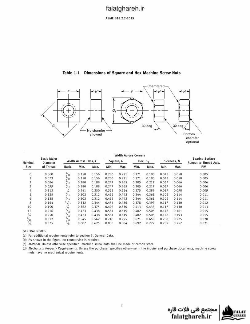
Table 1-1 Dimensions of Square and Hex Machine Screw Nuts
F F
G1
H H H
G
No chamfer
allowed Bottom
chamfer
optional
Chamfered
30 deg 30 deg
Width Across CornersBasic Major Bearing Surface
Width Across Flats, F Square, G Hex, G1 Thickness, HNominal Diameter Runout to Thread Axis,
Size of Thread Basic Min. Max. Min. Max. Min. Max. Min. Max. FIM
0 0.060 5⁄32 0.150 0.156 0.206 0.221 0.171 0.180 0.043 0.050 0.005
1 0.073 5⁄32 0.150 0.156 0.206 0.221 0.171 0.180 0.043 0.050 0.005
2 0.086 3⁄16 0.180 0.188 0.247 0.265 0.205 0.217 0.057 0.066 0.006
3 0.099 3⁄16 0.180 0.188 0.247 0.265 0.205 0.217 0.057 0.066 0.006
4 0.112 1⁄4 0.241 0.250 0.331 0.354 0.275 0.289 0.087 0.098 0.009
5 0.125 5⁄16 0.302 0.312 0.415 0.442 0.344 0.361 0.102 0.114 0.011
6 0.138 5⁄16 0.302 0.312 0.415 0.442 0.344 0.361 0.102 0.114 0.011
8 0.164 11⁄32 0.332 0.344 0.456 0.486 0.378 0.397 0.117 0.130 0.012
10 0.190 3⁄8 0.362 0.375 0.497 0.530 0.413 0.433 0.117 0.130 0.013
12 0.216 7⁄16 0.423 0.438 0.581 0.619 0.482 0.505 0.148 0.161 0.0151⁄4 0.250 7⁄16 0.423 0.438 0.581 0.619 0.482 0.505 0.178 0.193 0.015
5⁄16 0.312 9⁄16 0.545 0.562 0.748 0.795 0.621 0.650 0.208 0.225 0.0203⁄8 0.375 5⁄8 0.607 0.625 0.833 0.884 0.692 0.722 0.239 0.257 0.021
GENERAL NOTES:
(a) For additional requirements refer to section 3, General Data.
(b) As shown in the figure, no countersink is required.
(c) Material. Unless otherwise specified, machine screw nuts shall be made of carbon steel.
(d) Mechanical Property Requirements. Unless the purchaser specifies otherwise in the inquiry and purchase documents, machine screw
nuts have no mechanical requirements.
4
falatghareh.irfalatghareh.ir
ASME B18.2.2-2015
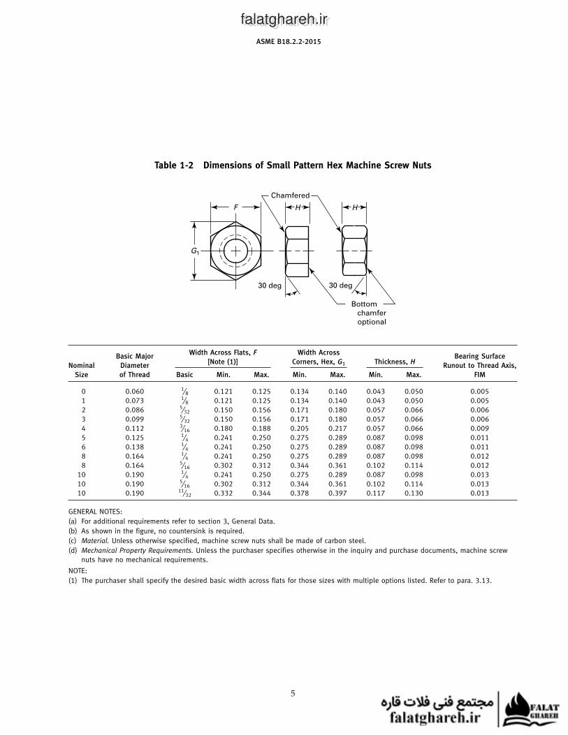
Table 1-2 Dimensions of Small Pattern Hex Machine Screw Nuts
F
G1
H H
Bottom
chamfer
optional
Chamfered
30 deg 30 deg
Width Across Flats, F Width AcrossBasic Major Bearing Surface
[Note (1)] Corners, Hex, G1 Thickness, HNominal Diameter Runout to Thread Axis,
Size of Thread Basic Min. Max. Min. Max. Min. Max. FIM
0 0.060 1⁄8 0.121 0.125 0.134 0.140 0.043 0.050 0.005
1 0.073 1⁄8 0.121 0.125 0.134 0.140 0.043 0.050 0.005
2 0.086 5⁄32 0.150 0.156 0.171 0.180 0.057 0.066 0.006
3 0.099 5⁄32 0.150 0.156 0.171 0.180 0.057 0.066 0.006
4 0.112 3⁄16 0.180 0.188 0.205 0.217 0.057 0.066 0.009
5 0.125 1⁄4 0.241 0.250 0.275 0.289 0.087 0.098 0.011
6 0.138 1⁄4 0.241 0.250 0.275 0.289 0.087 0.098 0.011
8 0.164 1⁄4 0.241 0.250 0.275 0.289 0.087 0.098 0.012
8 0.164 5⁄16 0.302 0.312 0.344 0.361 0.102 0.114 0.012
10 0.190 1⁄4 0.241 0.250 0.275 0.289 0.087 0.098 0.013
10 0.190 5⁄16 0.302 0.312 0.344 0.361 0.102 0.114 0.013
10 0.190 11⁄32 0.332 0.344 0.378 0.397 0.117 0.130 0.013
GENERAL NOTES:
(a) For additional requirements refer to section 3, General Data.
(b) As shown in the figure, no countersink is required.
(c) Material. Unless otherwise specified, machine screw nuts shall be made of carbon steel.
(d) Mechanical Property Requirements. Unless the purchaser specifies otherwise in the inquiry and purchase documents, machine screw
nuts have no mechanical requirements.
NOTE:
(1) The purchaser shall specify the desired basic width across flats for those sizes with multiple options listed. Refer to para. 3.13.
5
falatghareh.irfalatghareh.ir
ASME B18.2.2-2015
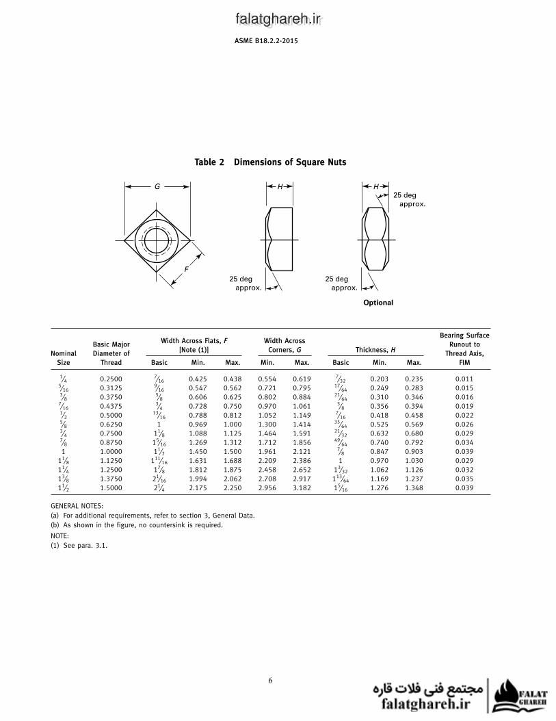
Table 2 Dimensions of Square Nuts
F
G
25 deg
approx.
25 deg
approx.
Optional
25 deg
approx.
H H
Bearing SurfaceWidth Across Flats, F Width Across
Basic Major Runout to[Note (1)] Corners, G Thickness, H
Nominal Diameter of Thread Axis,
Size Thread Basic Min. Max. Min. Max. Basic Min. Max. FIM
1⁄4 0.2500 7⁄16 0.425 0.438 0.554 0.619 7⁄32 0.203 0.235 0.0115⁄16 0.3125 9⁄16 0.547 0.562 0.721 0.795 17⁄64 0.249 0.283 0.0153⁄8 0.3750 5⁄8 0.606 0.625 0.802 0.884 21⁄64 0.310 0.346 0.016
7⁄16 0.4375 3⁄4 0.728 0.750 0.970 1.061 3⁄8 0.356 0.394 0.0191⁄2 0.5000 13⁄16 0.788 0.812 1.052 1.149 7⁄16 0.418 0.458 0.0225⁄8 0.6250 1 0.969 1.000 1.300 1.414 35⁄64 0.525 0.569 0.0263⁄4 0.7500 11⁄8 1.088 1.125 1.464 1.591 21⁄32 0.632 0.680 0.0297⁄8 0.8750 15⁄16 1.269 1.312 1.712 1.856 49⁄64 0.740 0.792 0.034
1 1.0000 11⁄2 1.450 1.500 1.961 2.121 7⁄8 0.847 0.903 0.039
11⁄8 1.1250 111⁄16 1.631 1.688 2.209 2.386 1 0.970 1.030 0.029
11⁄4 1.2500 17⁄8 1.812 1.875 2.458 2.652 13⁄32 1.062 1.126 0.032
13⁄8 1.3750 21⁄16 1.994 2.062 2.708 2.917 113⁄64 1.169 1.237 0.035
11⁄2 1.5000 21⁄4 2.175 2.250 2.956 3.182 15⁄16 1.276 1.348 0.039
GENERAL NOTES:
(a) For additional requirements, refer to section 3, General Data.
(b) As shown in the figure, no countersink is required.
NOTE:
(1) See para. 3.1.
6
falatghareh.irfalatghareh.ir
ASME B18.2.2-2015
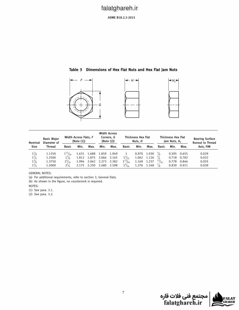
Table 3 Dimensions of Hex Flat Nuts and Hex Flat Jam Nuts
F
G
H H1
Width Across
Width Across Flats, F Corners, G Thickness Hex Flat Thickness Hex FlatBasic Major Bearing Surface
[Note (1)] [Note (2)] Nuts, H Jam Nuts, H1Nominal Diameter of Runout to Thread
Size Thread Basic Min. Max. Min. Max. Basic Min. Max. Basic Min. Max. Axis, FIM
11⁄8 1.1250 111⁄16 1.631 1.688 1.859 1.949 1 0.970 1.030 5⁄8 0.595 0.655 0.029
11⁄4 1.2500 17⁄8 1.812 1.875 2.066 2.165 13⁄32 1.062 1.126 3⁄4 0.718 0.782 0.032
13⁄8 1.3750 21⁄16 1.994 2.062 2.273 2.382 113⁄64 1.169 1.237 13⁄16 0.778 0.846 0.035
11⁄2 1.5000 21⁄4 2.175 2.250 2.480 2.598 15⁄16 1.276 1.348 7⁄8 0.839 0.911 0.039
GENERAL NOTES:
(a) For additional requirements, refer to section 3, General Data.
(b) As shown in the figure, no countersink is required.
NOTES:
(1) See para. 3.1.
(2) See para. 3.2.
7
falatghareh.irfalatghareh.ir
ASME B18.2.2-2015
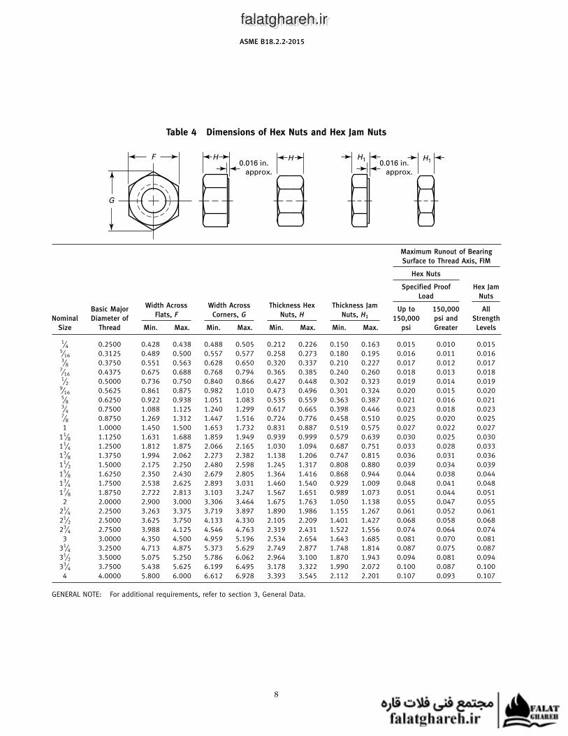
Table 4 Dimensions of Hex Nuts and Hex Jam Nuts
F
G
H0.016 in.
approx.
H H1H1
0.016 in.
approx.
Maximum Runout of Bearing
Surface to Thread Axis, FIM
Hex Nuts
Specified Proof Hex Jam
Load Nuts
Width Across Width Across Thickness Hex Thickness JamBasic Major Up to 150,000 All
Flats, F Corners, G Nuts, H Nuts, H1Nominal Diameter of 150,000 psi and Strength
Size Thread Min. Max. Min. Max. Min. Max. Min. Max. psi Greater Levels
1⁄4 0.2500 0.428 0.438 0.488 0.505 0.212 0.226 0.150 0.163 0.015 0.010 0.0155⁄16 0.3125 0.489 0.500 0.557 0.577 0.258 0.273 0.180 0.195 0.016 0.011 0.0163⁄8 0.3750 0.551 0.563 0.628 0.650 0.320 0.337 0.210 0.227 0.017 0.012 0.017
7⁄16 0.4375 0.675 0.688 0.768 0.794 0.365 0.385 0.240 0.260 0.018 0.013 0.0181⁄2 0.5000 0.736 0.750 0.840 0.866 0.427 0.448 0.302 0.323 0.019 0.014 0.019
9⁄16 0.5625 0.861 0.875 0.982 1.010 0.473 0.496 0.301 0.324 0.020 0.015 0.0205⁄8 0.6250 0.922 0.938 1.051 1.083 0.535 0.559 0.363 0.387 0.021 0.016 0.0213⁄4 0.7500 1.088 1.125 1.240 1.299 0.617 0.665 0.398 0.446 0.023 0.018 0.0237⁄8 0.8750 1.269 1.312 1.447 1.516 0.724 0.776 0.458 0.510 0.025 0.020 0.025
1 1.0000 1.450 1.500 1.653 1.732 0.831 0.887 0.519 0.575 0.027 0.022 0.027
11⁄8 1.1250 1.631 1.688 1.859 1.949 0.939 0.999 0.579 0.639 0.030 0.025 0.030
11⁄4 1.2500 1.812 1.875 2.066 2.165 1.030 1.094 0.687 0.751 0.033 0.028 0.033
13⁄8 1.3750 1.994 2.062 2.273 2.382 1.138 1.206 0.747 0.815 0.036 0.031 0.036
11⁄2 1.5000 2.175 2.250 2.480 2.598 1.245 1.317 0.808 0.880 0.039 0.034 0.039
15⁄8 1.6250 2.350 2.430 2.679 2.805 1.364 1.416 0.868 0.944 0.044 0.038 0.044
13⁄4 1.7500 2.538 2.625 2.893 3.031 1.460 1.540 0.929 1.009 0.048 0.041 0.048
17⁄8 1.8750 2.722 2.813 3.103 3.247 1.567 1.651 0.989 1.073 0.051 0.044 0.051
2 2.0000 2.900 3.000 3.306 3.464 1.675 1.763 1.050 1.138 0.055 0.047 0.055
21⁄4 2.2500 3.263 3.375 3.719 3.897 1.890 1.986 1.155 1.267 0.061 0.052 0.061
21⁄2 2.5000 3.625 3.750 4.133 4.330 2.105 2.209 1.401 1.427 0.068 0.058 0.068
23⁄4 2.7500 3.988 4.125 4.546 4.763 2.319 2.431 1.522 1.556 0.074 0.064 0.074
3 3.0000 4.350 4.500 4.959 5.196 2.534 2.654 1.643 1.685 0.081 0.070 0.081
31⁄4 3.2500 4.713 4.875 5.373 5.629 2.749 2.877 1.748 1.814 0.087 0.075 0.087
31⁄2 3.5000 5.075 5.250 5.786 6.062 2.964 3.100 1.870 1.943 0.094 0.081 0.094
33⁄4 3.7500 5.438 5.625 6.199 6.495 3.178 3.322 1.990 2.072 0.100 0.087 0.100
4 4.0000 5.800 6.000 6.612 6.928 3.393 3.545 2.112 2.201 0.107 0.093 0.107
GENERAL NOTE: For additional requirements, refer to section 3, General Data.
8
falatghareh.irfalatghareh.ir
ASME B18.2.2-2015
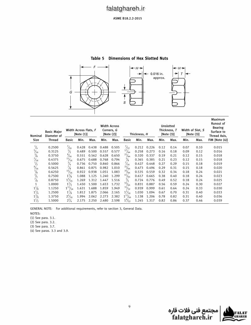
Table 5 Dimensions of Hex Slotted Nuts
F
G
0.016 in.
approx.
H H
T
S
Maximum
Runout ofWidth Across Unslotted
BearingWidth Across Flats, F Corners, G Thickness, T Width of Slot, S
Basic Major Surface to[Note (1)] [Note (2)] Thickness, H [Note (3)] [Note (3)]
Nominal Diameter of Thread Axis,
Size Thread Basic Min. Max. Min. Max. Basic Min. Max. Min. Max. Min. Max. FIM [Note (4)]
1⁄4 0.2500 7⁄16 0.428 0.438 0.488 0.505 7⁄32 0.212 0.226 0.12 0.14 0.07 0.10 0.0155⁄16 0.3125 1⁄2 0.489 0.500 0.557 0.577 17⁄64 0.258 0.273 0.16 0.18 0.09 0.12 0.0163⁄8 0.3750 9⁄16 0.551 0.562 0.628 0.650 21⁄64 0.320 0.337 0.19 0.21 0.12 0.15 0.018
7⁄16 0.4375 11⁄16 0.675 0.688 0.768 0.794 3⁄8 0.365 0.385 0.21 0.23 0.12 0.15 0.0181⁄2 0.5000 3⁄4 0.736 0.750 0.840 0.866 7⁄16 0.427 0.448 0.27 0.29 0.15 0.18 0.019
9⁄16 0.5625 7⁄8 0.861 0.875 0.982 1.010 31⁄64 0.473 0.496 0.29 0.31 0.15 0.18 0.0205⁄8 0.6250 15⁄16 0.922 0.938 1.051 1.083 35⁄64 0.535 0.559 0.32 0.34 0.18 0.24 0.0213⁄4 0.7500 11⁄8 1.088 1.125 1.240 1.299 41⁄64 0.617 0.665 0.38 0.40 0.18 0.24 0.0237⁄8 0.8750 15⁄16 1.269 1.312 1.447 1.516 3⁄4 0.724 0.776 0.49 0.52 0.18 0.24 0.025
1 1.0000 11⁄2 1.450 1.500 1.653 1.732 55⁄64 0.831 0.887 0.56 0.59 0.24 0.30 0.027
11⁄8 1.1250 111⁄16 1.631 1.688 1.859 1.949 31⁄32 0.939 0.999 0.61 0.64 0.24 0.33 0.030
11⁄4 1.2500 17⁄8 1.812 1.875 2.066 2.165 11⁄16 1.030 1.094 0.67 0.70 0.31 0.40 0.033
13⁄8 1.3750 21⁄16 1.994 2.062 2.273 2.382 111⁄64 1.138 1.206 0.78 0.82 0.31 0.40 0.036
11⁄2 1.5000 21⁄4 2.175 2.250 2.480 2.598 19⁄32 1.245 1.317 0.82 0.86 0.37 0.46 0.039
GENERAL NOTE: For additional requirements, refer to section 3, General Data.
NOTES:
(1) See para. 3.1.
(2) See para. 3.2.
(3) See para. 3.7.
(4) See paras. 3.3 and 3.9.
9
falatghareh.irfalatghareh.ir
ASME B18.2.2-2015
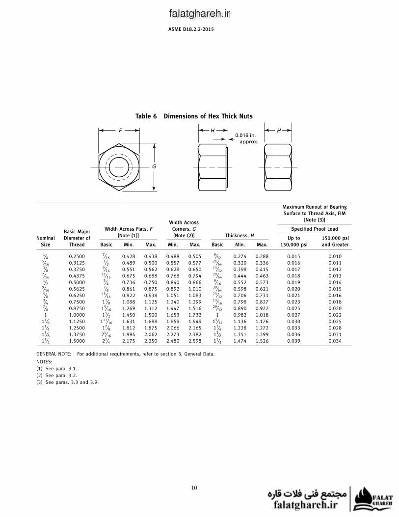
Table 6 Dimensions of Hex Thick Nuts
F
G
H H0.016 in.
approx.
Maximum Runout of Bearing
Surface to Thread Axis, FIM
[Note (3)]Width Across
Width Across Flats, F Corners, G Specified Proof LoadBasic Major
[Note (1)] [Note (2)] Thickness, HNominal Diameter of Up to 150,000 psi
Size Thread Basic Min. Max. Min. Max. Basic Min. Max. 150,000 psi and Greater
1⁄4 0.2500 7⁄16 0.428 0.438 0.488 0.505 9⁄32 0.274 0.288 0.015 0.0105⁄16 0.3125 1⁄2 0.489 0.500 0.557 0.577 21⁄64 0.320 0.336 0.016 0.0113⁄8 0.3750 9⁄16 0.551 0.562 0.628 0.650 13⁄32 0.398 0.415 0.017 0.012
7⁄16 0.4375 11⁄16 0.675 0.688 0.768 0.794 29⁄64 0.444 0.463 0.018 0.0131⁄2 0.5000 3⁄4 0.736 0.750 0.840 0.866 9⁄16 0.552 0.573 0.019 0.014
9⁄16 0.5625 7⁄8 0.861 0.875 0.892 1.010 39⁄64 0.598 0.621 0.020 0.0155⁄8 0.6250 15⁄16 0.922 0.938 1.051 1.083 23⁄32 0.706 0.731 0.021 0.0163⁄4 0.7500 11⁄8 1.088 1.125 1.240 1.299 13⁄16 0.798 0.827 0.023 0.0187⁄8 0.8750 15⁄16 1.269 1.312 1.447 1.516 29⁄32 0.890 0.922 0.025 0.020
1 1.0000 11⁄2 1.450 1.500 1.653 1.732 1 0.982 1.018 0.027 0.022
11⁄8 1.1250 111⁄16 1.631 1.688 1.859 1.949 15⁄32 1.136 1.176 0.030 0.025
11⁄4 1.2500 17⁄8 1.812 1.875 2.066 2.165 11⁄4 1.228 1.272 0.033 0.028
13⁄8 1.3750 21⁄16 1.994 2.062 2.273 2.382 13⁄8 1.351 1.399 0.036 0.031
11⁄2 1.5000 21⁄4 2.175 2.250 2.480 2.598 11⁄2 1.474 1.526 0.039 0.034
GENERAL NOTE: For additional requirements, refer to section 3, General Data.
NOTES:
(1) See para. 3.1.
(2) See para. 3.2.
(3) See paras. 3.3 and 3.9.
10
falatghareh.irfalatghareh.ir

ASME B18.2.2-2015
Table 7 Dimensions of Hex Thick Slotted Nuts
F
G
S
0.016 in.
approx.
H H
T
Maximum
Runout ofWidth Across Unslotted
BearingWidth Across Flats, F Corners, G Thickness, T Width of Slot, S
Basic Major Surface to[Note (1)] [Note (2)] Thickness, H [Note (3)] [Note (3)]
Nominal Diameter of Thread Axis,
Size Thread Basic Min. Max. Min. Max. Basic Min. Max. Min. Max. Min. Max. FIM [Note (4)]
1⁄4 0.2500 7⁄16 0.428 0.438 0.488 0.505 9⁄32 0.274 0.288 0.18 0.20 0.07 0.10 0.0155⁄16 0.3125 1⁄2 0.489 0.500 0.557 0.577 21⁄64 0.320 0.336 0.22 0.24 0.09 0.12 0.0163⁄8 0.3750 9⁄16 0.551 0.562 0.628 0.650 13⁄32 0.398 0.415 0.27 0.29 0.12 0.15 0.017
7⁄16 0.4375 11⁄16 0.675 0.688 0.768 0.794 29⁄64 0.444 0.463 0.29 0.31 0.12 0.15 0.0181⁄2 0.5000 3⁄4 0.736 0.750 0.840 0.866 9⁄16 0.552 0.573 0.40 0.42 0.15 0.18 0.019
9⁄16 0.5625 7⁄8 0.861 0.875 0.982 1.010 39⁄64 0.598 0.621 0.41 0.43 0.15 0.18 0.0205⁄8 0.6250 15⁄16 0.922 0.938 1.051 1.083 23⁄32 0.706 0.731 0.49 0.51 0.18 0.24 0.0213⁄4 0.7500 11⁄8 1.088 1.125 1.240 1.299 13⁄16 0.798 0.827 0.55 0.57 0.18 0.24 0.0237⁄8 0.8750 15⁄16 1.269 1.312 1.447 1.516 29⁄32 0.890 0.922 0.64 0.67 0.18 0.24 0.025
1 1.0000 11⁄2 1.450 1.500 1.653 1.732 1 0.982 1.018 0.70 0.73 0.24 0.30 0.027
11⁄8 1.1250 111⁄16 1.631 1.688 1.859 1.949 15⁄32 1.136 1.176 0.80 0.83 0.24 0.33 0.030
11⁄4 1.2500 17⁄8 1.812 1.875 2.066 2.165 11⁄4 1.228 1.272 0.86 0.89 0.31 0.40 0.033
13⁄8 1.3750 21⁄16 1.994 2.062 2.273 2.382 13⁄8 1.351 1.399 0.98 1.02 0.31 0.40 0.036
11⁄2 1.5000 21⁄4 2.175 2.250 2.480 2.598 11⁄2 1.474 1.526 1.04 1.08 0.37 0.46 0.039
GENERAL NOTE: For additional requirements, refer to section 3, General Data.
NOTES:
(1) See para. 3.1.
(2) See para. 3.2.
(3) See para. 3.7.
(4) See paras. 3.3 and 3.9.
11
falatghareh.irfalatghareh.ir
ASME B18.2.2-2015
Table 8 Dimensions of Heavy Square Nuts
F
G
25 deg
approx.
25 deg
approx.
25 deg
approx.
Optional
H H
Bearing
SurfaceWidth Across Flats, F Width Across
Basic Major Runout to[Note (1)] Corners, G Thickness, H
Nominal Diameter of Thread
Size Thread Basic Min. Max. Min. Max. Basic Min. Max. Axis, FIM
1⁄4 0.2500 1⁄2 0.488 0.500 0.640 0.707 1⁄4 0.218 0.266 0.0265⁄16 0.3125 9⁄16 0.546 0.562 0.720 0.795 5⁄16 0.280 0.330 0.0303⁄8 0.3750 11⁄16 0.669 0.688 0.889 0.973 3⁄8 0.341 0.393 0.036
7⁄16 0.4375 3⁄4 0.728 0.750 0.970 1.060 7⁄16 0.403 0.456 0.0391⁄2 0.5000 7⁄8 0.850 0.875 1.137 1.237 1⁄2 0.464 0.520 0.0465⁄8 0.6250 11⁄16 1.031 1.062 1.386 1.503 5⁄8 0.587 0.647 0.0563⁄4 0.7500 11⁄4 1.212 1.250 1.635 1.768 3⁄4 0.710 0.774 0.0657⁄8 0.8750 17⁄16 1.394 1.438 1.884 2.033 7⁄8 0.833 0.901 0.075
1 1.0000 15⁄8 1.575 1.625 2.132 2.298 1 0.956 1.028 0.082
11⁄8 1.1250 113⁄16 1.756 1.812 2.381 2.563 11⁄8 1.079 1.155 0.063
11⁄4 1.2500 2 1.938 2.000 2.631 2.828 11⁄4 1.187 1.282 0.070
13⁄8 1.3750 23⁄16 2.119 2.188 2.879 3.094 13⁄8 1.310 1.409 0.076
11⁄2 1.5000 23⁄8 2.300 2.375 3.128 3.359 11⁄2 1.433 1.536 0.082
GENERAL NOTES:
(a) For additional requirements, refer to section 3, General Data.
(b) As shown in the figure, no countersink is required.
NOTE:
(1) See para. 3.1.
12
falatghareh.irfalatghareh.ir
ASME B18.2.2-2015
Table 9 Dimensions of Heavy Hex Flat Nuts and Heavy Hex Flat Jam Nuts
F
G
H H1
BearingWidth Across
SurfaceWidth Across Flats, F Corners, G Thickness Heavy Hex Thickness Heavy Hex
Basic Major Runout to[Note (1)] [Note (2)] Flat Nuts, H Flat Jam Nuts, H1Nominal Diameter of Thread Axis,
Size Thread Basic Min. Max. Min. Max. Basic Min. Max. Basic Min. Max. FIM
11⁄8 1.1250 113⁄16 1.756 1.812 2.002 2.093 11⁄8 1.079 1.155 5⁄8 0.579 0.655 0.032
11⁄4 1.2500 2 1.938 2.000 2.209 2.309 11⁄4 1.187 1.282 3⁄4 0.687 0.782 0.034
13⁄8 1.3750 23⁄16 2.119 2.188 2.416 2.526 13⁄8 1.310 1.409 13⁄16 0.747 0.846 0.038
11⁄2 1.5000 23⁄8 2.300 2.375 2.622 2.742 11⁄2 1.433 1.536 7⁄8 0.808 0.911 0.041
13⁄4 1.7500 23⁄4 2.662 2.750 3.035 3.175 13⁄4 1.679 1.790 1 0.929 1.040 0.048
2 2.0000 31⁄8 3.025 3.125 3.449 3.608 2 1.925 2.044 11⁄8 1.050 1.169 0.054
21⁄4 2.2500 31⁄2 3.388 3.500 3.862 4.041 21⁄4 2.155 2.298 11⁄4 1.155 1.298 0.061
21⁄2 2.5000 37⁄8 3.750 3.875 4.275 4.474 21⁄2 2.401 2.552 11⁄2 1.401 1.552 0.067
23⁄4 2.7500 41⁄4 4.112 4.250 4.688 4.907 23⁄4 2.647 2.806 15⁄8 1.522 1.681 0.074
3 3.0000 45⁄8 4.475 4.625 5.102 5.340 3 2.893 3.060 13⁄4 1.643 1.810 0.080
31⁄4 3.2500 5 4.838 5.000 5.515 5.774 31⁄4 3.124 3.314 17⁄8 1.748 1.939 0.087
31⁄2 3.5000 53⁄8 5.200 5.375 5.928 6.207 31⁄2 3.370 3.568 2 1.870 2.068 0.093
33⁄4 3.7500 53⁄4 5.562 5.750 6.341 6.640 33⁄4 3.616 3.822 21⁄8 1.990 2.197 0.100
4 4.0000 61⁄8 5.925 6.125 6.755 7.073 4 3.862 4.076 21⁄4 2.112 2.326 0.107
GENERAL NOTES:
(a) For additional requirements, refer to section 3, General Data.
)b) As shown in the figure, no countersink is required.
NOTES:
(1) See para. 3.1.
(2) See para. 3.2.
13
falatghareh.irfalatghareh.ir
ASME B18.2.2-2015
Table 10 Dimensions of Heavy Hex Nuts and Heavy Hex Jam Nuts
F
G
H0.016 in.
approx.
H H1H1
0.016 in.
approx.
Maximum Runout of Bearing
Surface to Thread Axis, FIM
[Note (3)]
Heavy Hex NutsHeavy
Specified Proof Hex Jam
Width Across Load Nuts
Width Across Flats, F Corners, G Thickness Heavy Hex Thickness HeavyBasic Major Up to 150,000 All
[Note (1)] [Note (2)] Nuts, H Hex Jam Nuts, H1Nominal Diameter 150,000 psi and Strength
Size of Thread Basic Min. Max. Min. Max. Basic Min. Max. Basic Min. Max. psi Greater Levels
1⁄4 0.2500 1⁄2 0.488 0.500 0.556 0.577 15⁄64 0.218 0.250 11⁄64 0.156 0.188 0.017 0.011 0.0175⁄16 0.3125 9⁄16 0.546 0.562 0.622 0.650 19⁄64 0.280 0.314 13⁄64 0.186 0.220 0.020 0.012 0.0203⁄8 0.3750 11⁄16 0.669 0.688 0.763 0.794 23⁄64 0.341 0.377 15⁄64 0.216 0.252 0.021 0.014 0.021
7⁄16 0.4375 3⁄4 0.728 0.750 0.830 0.866 27⁄64 0.403 0.441 17⁄64 0.247 0.285 0.022 0.015 0.0221⁄2 0.5000 7⁄8 0.850 0.875 0.969 1.010 31⁄64 0.464 0.504 19⁄64 0.277 0.317 0.023 0.016 0.023
9⁄16 0.5625 15⁄16 0.909 0.938 1.037 1.083 35⁄64 0.526 0.568 21⁄64 0.307 0.349 0.024 0.017 0.0245⁄8 0.6250 11⁄16 1.031 1.062 1.175 1.227 39⁄64 0.587 0.631 23⁄64 0.337 0.381 0.025 0.018 0.0253⁄4 0.7500 11⁄4 1.212 1.250 1.382 1.443 47⁄64 0.710 0.758 27⁄64 0.398 0.446 0.027 0.020 0.0277⁄8 0.8750 17⁄16 1.394 1.438 1.589 1.660 55⁄64 0.833 0.885 31⁄64 0.458 0.510 0.029 0.022 0.029
1 1.0000 15⁄8 1.575 1.625 1.796 1.876 63⁄64 0.956 1.012 35⁄64 0.519 0.575 0.031 0.024 0.031
11⁄8 1.1250 113⁄16 1.756 1.812 2.002 2.093 17⁄64 1.079 1.139 39⁄64 0.579 0.639 0.033 0.027 0.033
11⁄4 1.2500 2 1.938 2.000 2.209 2.309 17⁄32 1.187 1.251 23⁄32 0.687 0.751 0.035 0.030 0.035
13⁄8 1.3750 23⁄16 2.119 2.188 2.416 2.526 111⁄32 1.310 1.378 25⁄32 0.747 0.815 0.038 0.033 0.038
11⁄2 1.5000 23⁄8 2.300 2.375 2.622 2.742 115⁄32 1.433 1.505 27⁄32 0.808 0.880 0.041 0.036 0.041
15⁄8 1.6250 29⁄16 2.481 2.562 2.828 2.959 119⁄32 1.556 1.632 29⁄32 0.868 0.944 0.044 0.038 0.044
13⁄4 1.7500 23⁄4 2.662 2.750 3.035 3.175 123⁄32 1.679 1.759 31⁄32 0.929 1.009 0.048 0.041 0.048
17⁄8 1.8750 215⁄16 2.844 2.938 3.242 3.392 127⁄32 1.802 1.886 11⁄32 0.989 1.073 0.051 0.044 0.051
2 2.0000 31⁄8 3.025 3.125 3.449 3.608 131⁄32 1.925 2.013 13⁄32 1.050 1.138 0.055 0.047 0.055
21⁄4 2.2500 31⁄2 3.388 3.500 3.862 4.041 213⁄64 2.155 2.251 113⁄64 1.155 1.251 0.061 0.052 0.061
21⁄2 2.5000 37⁄8 3.750 3.875 4.275 4.474 229⁄64 2.401 2.505 129⁄64 1.401 1.505 0.068 0.058 0.068
23⁄4 2.7500 41⁄4 4.112 4.250 4.688 4.907 245⁄64 2.647 2.759 137⁄64 1.522 1.634 0.074 0.064 0.074
3 3.0000 45⁄8 4.475 4.625 5.102 5.340 261⁄64 2.893 3.013 145⁄64 1.643 1.763 0.081 0.070 0.081
31⁄4 3.2500 5 4.838 5.000 5.515 5.774 33⁄16 3.124 3.252 113⁄16 1.748 1.876 0.087 0.075 0.087
31⁄2 3.5000 53⁄8 5.200 5.375 5.928 6.207 37⁄16 3.370 3.506 115⁄16 1.870 2.006 0.094 0.081 0.094
33⁄4 3.7500 53⁄4 5.562 5.750 6.341 6.640 311⁄16 3.616 3.760 21⁄16 1.990 2.134 0.100 0.087 0.100
4 4.0000 61⁄8 5.925 6.125 6.755 7.073 315⁄16 3.862 4.014 23⁄16 2.112 2.264 0.107 0.093 0.107
GENERAL NOTES:
(a) For additional requirements refer to section 3, General Data.
(b) Chamfers and Washer Faces. Nuts in sizes 7⁄16 in. nominal size and smaller shall be double-chamfered. Larger size nuts shall be dou-
ble-chamfered or have washer-faced bearing surface and chamfered top.
(c) Optional Bearing Surface Runout. Where purchaser specifies close runout of bearing face style heavy hex or heavy hex jam nuts in nom-
inal sizes 2 in. to 4 in., nuts shall be so processed as to have a maximum bearing face runout of 0.010 in. FIM.
NOTES:
(1) See para. 3.1.
(2) See para. 3.2.
(3) See paras. 3.3 and 3.9.
14
falatghareh.irfalatghareh.ir
ASME B18.2.2-2015
Table 11 Dimensions of Heavy Hex Slotted Nuts
F
G
S
0.016 in.
approx.
H H
T
Maximum
Runout of
BearingWidth Across Unslotted Width of
SurfaceWidth Across Flats, F Corners, G Thickness, T Slot, S
Basic Major to Thread[Note (1)] [Note (2)] Thickness, H [Note (3)] [Note (3)]
Nominal Diameter of Axis, FIM
Size Thread Basic Min. Max. Min. Max. Basic Min. Max. Min. Max. Min. Max. [Note (4)]
1⁄4 0.2500 1⁄2 0.488 0.500 0.556 0.577 15⁄64 0.218 0.250 0.13 0.15 0.07 0.10 0.0175⁄16 0.3125 9⁄16 0.546 0.562 0.622 0.650 19⁄64 0.280 0.314 0.19 0.21 0.09 0.12 0.0203⁄8 0.3750 11⁄16 0.669 0.688 0.763 0.794 23⁄64 0.341 0.377 0.22 0.24 0.12 0.15 0.021
7⁄16 0.4375 3⁄4 0.728 0.750 0.830 0.866 27⁄64 0.403 0.441 0.26 0.28 0.12 0.15 0.0221⁄2 0.5000 7⁄8 0.850 0.875 0.969 1.010 31⁄64 0.464 0.504 0.32 0.34 0.15 0.18 0.023
9⁄16 0.5625 15⁄16 0.909 0.938 1.037 1.083 35⁄64 0.526 0.568 0.35 0.37 0.15 0.18 0.0245⁄8 0.6250 11⁄16 1.031 1.062 1.175 1.227 39⁄64 0.587 0.631 0.38 0.40 0.18 0.24 0.0253⁄4 0.7500 11⁄4 1.212 1.250 1.382 1.443 47⁄64 0.710 0.758 0.47 0.49 0.18 0.24 0.0277⁄8 0.8750 17⁄16 1.394 1.438 1.589 1.660 55⁄64 0.833 0.885 0.59 0.62 0.18 0.24 0.029
1 1.0000 15⁄8 1.575 1.625 1.796 1.876 63⁄64 0.956 1.012 0.69 0.72 0.24 0.30 0.031
11⁄8 1.1250 113⁄16 1.756 1.812 2.002 2.093 17⁄64 1.079 1.139 0.75 0.78 0.24 0.33 0.033
11⁄4 1.2500 2 1.938 2.000 2.209 2.309 17⁄32 1.187 1.251 0.83 0.86 0.31 0.40 0.035
13⁄8 1.3750 23⁄16 2.119 2.188 2.416 2.526 111⁄32 1.310 1.378 0.95 0.99 0.31 0.40 0.038
11⁄2 1.5000 23⁄8 2.300 2.375 2.622 2.742 115⁄32 1.433 1.505 1.01 1.05 0.37 0.46 0.041
13⁄4 1.7500 23⁄4 2.662 2.750 3.035 3.175 123⁄32 1.679 1.759 1.20 1.24 0.43 0.52 0.048
2 2.0000 31⁄8 3.025 3.125 3.449 3.608 131⁄32 1.925 2.013 1.38 1.43 0.43 0.52 0.055
21⁄4 2.2500 31⁄2 3.388 3.500 3.862 4.041 213⁄64 2.155 2.251 1.62 1.67 0.43 0.52 0.061
21⁄2 2.5000 37⁄8 3.750 3.875 4.275 4.474 229⁄64 2.401 2.505 1.74 1.79 0.55 0.64 0.068
23⁄4 2.7500 41⁄4 4.112 4.250 4.688 4.907 245⁄64 2.647 2.759 1.99 2.05 0.55 0.64 0.074
3 3.0000 45⁄8 4.475 4.625 5.102 5.340 261⁄64 2.893 3.013 2.17 2.23 0.62 0.71 0.081
31⁄4 3.2500 5 4.838 5.000 5.515 5.774 33⁄16 3.124 3.252 2.41 2.47 0.62 0.71 0.087
31⁄2 3.5000 53⁄8 5.200 5.375 5.928 6.207 37⁄16 3.370 3.506 2.65 2.72 0.62 0.71 0.094
33⁄4 3.7500 53⁄4 5.562 5.750 6.341 6.640 311⁄16 3.616 3.760 2.90 2.97 0.62 0.71 0.100
4 4.0000 61⁄8 5.925 6.125 6.755 7.073 315⁄16 3.862 4.014 3.15 3.22 0.62 0.71 0.107
GENERAL NOTES:
(a) For additional requirements, refer to section 3, General Data.
(b) Chamfers and Washer Faces. Nuts in sizes 7⁄16 in. nominal size and smaller shall be double-chamfered. Larger size nuts shall be
double-chamfered or have washer-faced bearing surface and chamfered top.
NOTES:
(1) See para. 3.1.
(2) See para. 3.2.
(3) See para. 3.7.
(4) See paras. 3.3 and 3.9.
15
falatghareh.irfalatghareh.ir
ASME B18.2.2-2015
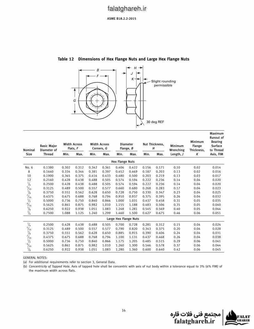
Table 12 Dimensions of Hex Flange Nuts and Large Hex Flange Nuts
FK
Slight rounding
permissible
30 deg REF
J
HB
G
Maximum
Runout of
Minimum BearingWidth Across Width Across Diameter Nut Thickness,
Basic Major Minimum Flange SurfaceFlats, F Corners, G Flange, B H
Nominal Diameter of Wrenching Thickness, to Thread
Size Thread Min. Max. Min. Max. Min. Max. Min. Max. Length, J K Axis, FIM
Hex Flange Nuts
No. 6 0.1380 0.302 0.312 0.342 0.361 0.406 0.422 0.156 0.171 0.10 0.02 0.014
8 0.1640 0.334 0.344 0.381 0.397 0.452 0.469 0.187 0.203 0.13 0.02 0.016
10 0.1900 0.365 0.375 0.416 0.433 0.480 0.500 0.203 0.219 0.13 0.03 0.017
12 0.2160 0.428 0.438 0.488 0.505 0.574 0.594 0.222 0.236 0.14 0.04 0.0201⁄4 0.2500 0.428 0.438 0.488 0.505 0.574 0.594 0.222 0.236 0.14 0.04 0.020
5⁄16 0.3125 0.489 0.500 0.557 0.577 0.660 0.680 0.268 0.283 0.17 0.04 0.0233⁄8 0.3750 0.551 0.562 0.628 0.650 0.728 0.750 0.330 0.347 0.23 0.04 0.025
7⁄16 0.4375 0.675 0.688 0.768 0.794 0.910 0.937 0.375 0.395 0.26 0.04 0.0321⁄2 0.5000 0.736 0.750 0.840 0.866 1.000 1.031 0.437 0.458 0.31 0.05 0.035
9⁄16 0.5625 0.861 0.875 0.982 1.010 1.155 1.188 0.483 0.506 0.35 0.05 0.0405⁄8 0.6250 0.922 0.938 1.051 1.083 1.248 1.281 0.545 0.569 0.40 0.05 0.0443⁄4 0.7500 1.088 1.125 1.240 1.299 1.460 1.500 0.627 0.675 0.46 0.06 0.051
Large Hex Flange Nuts
1⁄4 0.2500 0.428 0.438 0.488 0.505 0.700 0.728 0.281 0.312 0.15 0.04 0.0245⁄16 0.3125 0.489 0.500 0.557 0.577 0.790 0.820 0.343 0.375 0.20 0.04 0.0283⁄8 0.3750 0.551 0.562 0.628 0.650 0.885 0.915 0.390 0.406 0.24 0.04 0.031
7⁄16 0.4375 0.675 0.688 0.768 0.794 1.100 1.131 0.437 0.468 0.26 0.04 0.0381⁄2 0.5000 0.736 0.750 0.840 0.866 1.175 1.205 0.485 0.515 0.29 0.06 0.041
9⁄16 0.5625 0.861 0.875 0.982 1.010 1.260 1.300 0.546 0.578 0.37 0.06 0.0445⁄8 0.6250 0.922 0.938 1.051 1.083 1.280 1.360 0.600 0.640 0.42 0.06 0.045
GENERAL NOTES:
(a) For additional requirements refer to section 3, General Data.
(b) Concentricity of Tapped Hole. Axis of tapped hole shall be concentric with axis of nut body within a tolerance equal to 3% (6% FIM) of
the maximum width across flats.
16
falatghareh.irfalatghareh.ir
ASME B18.2.2-2015
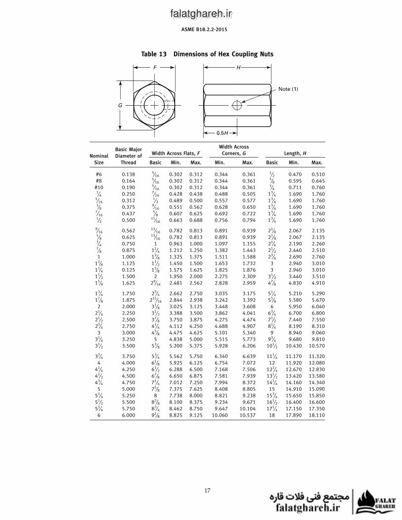
Table 13 Dimensions of Hex Coupling Nuts
F
G
H
0.5H
Note (1)
Width AcrossBasic Major
Width Across Flats, F Corners, G Length, HNominal Diameter of
Size Thread Basic Min. Max. Min. Max. Basic Min. Max.
#6 0.138 5⁄16 0.302 0.312 0.344 0.361 1⁄2 0.470 0.510
#8 0.164 5⁄16 0.302 0.312 0.344 0.361 5⁄8 0.595 0.645
#10 0.190 5⁄16 0.302 0.312 0.344 0.361 3⁄4 0.711 0.7601⁄4 0.250 7⁄16 0.428 0.438 0.488 0.505 13⁄4 1.690 1.760
5⁄16 0.312 1⁄2 0.489 0.500 0.557 0.577 13⁄4 1.690 1.7603⁄8 0.375 9⁄16 0.551 0.562 0.628 0.650 13⁄4 1.690 1.760
7⁄16 0.437 5⁄8 0.607 0.625 0.692 0.722 13⁄4 1.690 1.7601⁄2 0.500 11⁄16 0.663 0.688 0.756 0.794 13⁄4 1.690 1.760
9⁄16 0.562 13⁄16 0.782 0.813 0.891 0.939 21⁄8 2.067 2.1355⁄8 0.625 13⁄16 0.782 0.813 0.891 0.939 21⁄8 2.067 2.1353⁄4 0.750 1 0.963 1.000 1.097 1.155 21⁄4 2.190 2.2607⁄8 0.875 11⁄4 1.212 1.250 1.382 1.443 21⁄2 2.440 2.510
1 1.000 13⁄8 1.325 1.375 1.511 1.588 23⁄4 2.690 2.760
11⁄8 1.125 11⁄2 1.450 1.500 1.653 1.732 3 2.940 3.010
11⁄4 0.125 15⁄8 1.575 1.625 1.825 1.876 3 2.940 3.010
11⁄2 1.500 2 1.950 2.000 2.275 2.309 31⁄2 3.440 3.510
15⁄8 1.625 29⁄16 2.481 2.562 2.828 2.959 47⁄8 4.830 4.910
13⁄4 1.750 23⁄4 2.662 2.750 3.035 3.175 51⁄4 5.210 5.290
17⁄8 1.875 215⁄16 2.844 2.938 3.242 3.392 55⁄8 5.580 5.670
2 2.000 31⁄8 3.025 3.125 3.448 3.608 6 5.950 6.040
21⁄4 2.250 31⁄2 3.388 3.500 3.862 4.041 63⁄4 6.700 6.800
21⁄2 2.500 37⁄8 3.750 3.875 4.275 4.474 71⁄2 7.440 7.550
23⁄4 2.750 41⁄4 4.112 4.250 4.688 4.907 81⁄4 8.190 8.310
3 3.000 45⁄8 4.475 4.625 5.101 5.340 9 8.940 9.060
31⁄4 3.250 5 4.838 5.000 5.515 5.773 93⁄4 9.680 9.810
31⁄2 3.500 53⁄8 5.200 5.375 5.928 6.206 101⁄2 10.430 10.570
33⁄4 3.750 53⁄4 5.562 5.750 6.340 6.639 111⁄4 11.170 11.320
4 4.000 61⁄8 5.925 6.125 6.754 7.072 12 11.920 12.080
41⁄4 4.250 61⁄2 6.288 6.500 7.168 7.506 123⁄4 12.670 12.830
41⁄2 4.500 67⁄8 6.650 6.875 7.581 7.939 131⁄2 13.420 13.580
43⁄4 4.750 71⁄4 7.012 7.250 7.994 8.372 141⁄4 14.160 14.340
5 5.000 75⁄8 7.375 7.625 8.408 8.805 15 14.910 15.090
51⁄4 5.250 8 7.738 8.000 8.821 9.238 153⁄4 15.650 15.850
51⁄2 5.500 83⁄8 8.100 8.375 9.234 9.671 161⁄2 16.400 16.600
53⁄4 5.750 83⁄4 8.462 8.750 9.647 10.104 171⁄4 17.150 17.350
6 6.000 91⁄8 8.825 9.125 10.060 10.537 18 17.890 18.110
17
falatghareh.irfalatghareh.ir
ASME B18.2.2-2015
Table 13 Dimensions of Hex Coupling Nuts (Cont‘d)
GENERAL NOTES:
(a) For additional requirements, refer to section 3, General Data.
(b) Concentricity of Tapped Hole. Axis of tapped hole shall be concentric with axis of nut body within a
tolerance equal to 3% (6% FIM) of the maximum width across flats.
(c) Countersink. Tapped hole may be countersunk on both faces.
(d) When specified by the purchaser, different thread sizes or series shall be tapped into the nut from
opposite ends with each thread extending to approximately 0.5H. All other nut dimensions shall
comply with Table 13 unless otherwise agreed to by the supplier and purchaser.
(e) The dimensions in Table 13 are considered standard, but purchasers may specify across flats sizes
and/or lengths that differ from this Table.
(f) Hex coupling nuts must conform to the proof load requirements of ASTM A563, Grade A for heavy
hex nuts.
NOTE:
(1) Nuts shall be furnished without a hole, unless specially ordered by the purchaser. In some
applications it may be desirable to assure that the threaded parts joined by a coupling nut are
each engaged to approximately one-half nut thickness. As a visual inspection aid, a hole drilled
through one side of the nut is recommended. The hole should be located at mid-nut thickness,
and have a diameter of 0.2 to 0.4 times nominal nut size for sizes 21⁄2 in. and smaller, and 1 in.
for sizes 23⁄4 in. and larger.
18
falatghareh.irfalatghareh.ir
ASME B18.2.2-2015
MANDATORY APPENDIX ISLOT GAGES AND GAGING FOR SLOTTED NUTS
The gages specified in Table I-1 shall be used to deter-mine the acceptability of the alignment and bottom con-tours of the slots in slotted nuts in accordance with thefollowing procedure.
The gaging for slot alignment provides for equal varia-tions in the location of the cotter pinhole in the bolt andthe location of the slots in the nut.
To inspect the nut, the slotted end of the gage shallbe inserted through the threaded hole from the bearingsurface of the nut. The gage pin shall then be insertedinto both the gage slot and the nut slots through three
19
adjacent faces of the nut, consecutively. Slot alignmentshall be considered satisfactory if the gage pin fits intothe slots without interference at all three gaging posi-tions. The bottom contour shall be acceptable if the gagepin contacts the bottom surfaces of opposite slots duringthe alignment gaging at all three positions.
Some deviations from the specified gage plug diame-ters, D, may be necessary to compensate for variationsin the nut thread minor diameter due to differences inmanufacturing practices. To ensure adequate service life,gages and gage pins shall be suitably hardened.
falatghareh.irfalatghareh.ir
ASME B18.2.2-2015
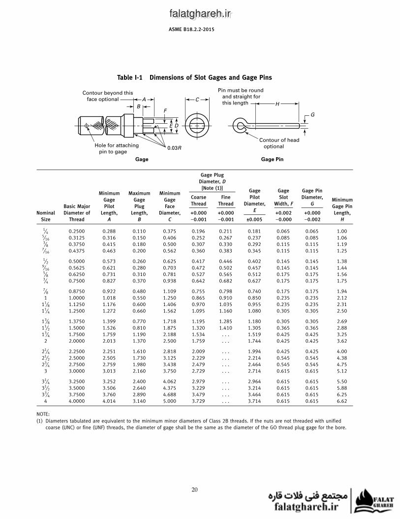
Table I-1 Dimensions of Slot Gages and Gage Pins
HC
F
E D
A
0.03R
Contour of head
optional
Pin must be round
and straight for
this length
Contour beyond this
face optional
Hole for attaching
pin to gage
Gage Gage Pin
B
G
Gage Plug
Diameter, D
[Note (1)]Gage Gage Gage Pin
Minimum Maximum MinimumCoarse Fine Pilot Slot Diameter,
Gage Gage Gage MinimumThread Thread Diameter, Width, F G
Basic Major Pilot Plug Face Gage PinE
Nominal Diameter of Length, Length, Diameter, +0.000 +0.000 +0.002 +0.000 Length,
Size Thread A B C −0.001 −0.001 ±0.005 −0.000 −0.002 H
1⁄4 0.2500 0.288 0.110 0.375 0.196 0.211 0.181 0.065 0.065 1.005⁄16 0.3125 0.316 0.150 0.406 0.252 0.267 0.237 0.085 0.085 1.063⁄8 0.3750 0.415 0.180 0.500 0.307 0.330 0.292 0.115 0.115 1.19
7⁄16 0.4375 0.463 0.200 0.562 0.360 0.383 0.345 0.115 0.115 1.25
1⁄2 0.5000 0.573 0.260 0.625 0.417 0.446 0.402 0.145 0.145 1.389⁄16 0.5625 0.621 0.280 0.703 0.472 0.502 0.457 0.145 0.145 1.445⁄8 0.6250 0.731 0.310 0.781 0.527 0.565 0.512 0.175 0.175 1.563⁄4 0.7500 0.827 0.370 0.938 0.642 0.682 0.627 0.175 0.175 1.75
7⁄8 0.8750 0.922 0.480 1.109 0.755 0.798 0.740 0.175 0.175 1.94
1 1.0000 1.018 0.550 1.250 0.865 0.910 0.850 0.235 0.235 2.12
11⁄8 1.1250 1.176 0.600 1.406 0.970 1.035 0.955 0.235 0.235 2.31
11⁄4 1.2500 1.272 0.660 1.562 1.095 1.160 1.080 0.305 0.305 2.50
13⁄8 1.3750 1.399 0.770 1.718 1.195 1.285 1.180 0.305 0.305 2.69
11⁄2 1.5000 1.526 0.810 1.875 1.320 1.410 1.305 0.365 0.365 2.88
13⁄4 1.7500 1.759 1.190 2.188 1.534 . . . 1.519 0.425 0.425 3.25
2 2.0000 2.013 1.370 2.500 1.759 . . . 1.744 0.425 0.425 3.62
21⁄4 2.2500 2.251 1.610 2.818 2.009 . . . 1.994 0.425 0.425 4.00
21⁄2 2.5000 2.505 1.730 3.125 2.229 . . . 2.214 0.545 0.545 4.38
23⁄4 2.7500 2.759 1.980 3.438 2.479 . . . 2.464 0.545 0.545 4.75
3 3.0000 3.013 2.160 3.750 2.729 . . . 2.714 0.615 0.615 5.12
31⁄4 3.2500 3.252 2.400 4.062 2.979 . . . 2.964 0.615 0.615 5.50
31⁄2 3.5000 3.506 2.640 4.375 3.229 . . . 3.214 0.615 0.615 5.88
33⁄4 3.7500 3.760 2.890 4.688 3.479 . . . 3.464 0.615 0.615 6.25
4 4.0000 4.014 3.140 5.000 3.729 . . . 3.714 0.615 0.615 6.62
NOTE:
(1) Diameters tabulated are equivalent to the minimum minor diameters of Class 2B threads. If the nuts are not threaded with unified
coarse (UNC) or fine (UNF) threads, the diameter of gage shall be the same as the diameter of the GO thread plug gage for the bore.
20
falatghareh.irfalatghareh.ir
ASME B18.2.2-2015
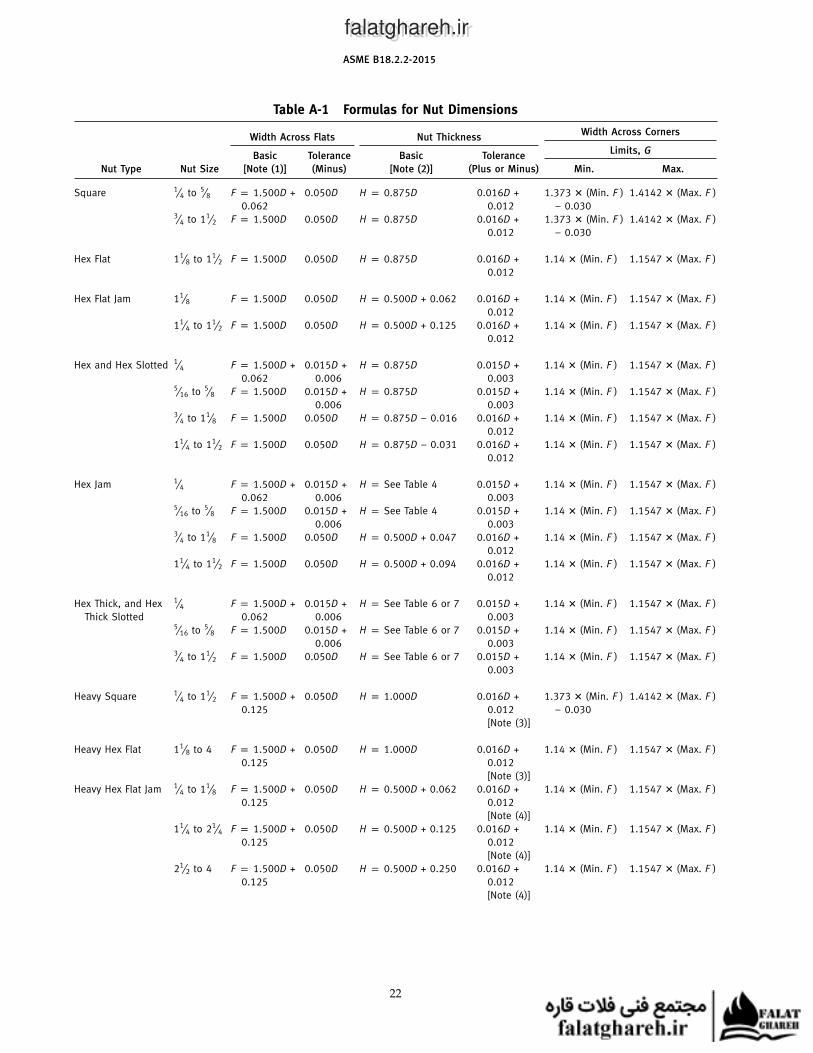
NONMANDATORY APPENDIX AFORMULAS FOR NUT DIMENSIONS
Table A-1 specif ies formulas for various nutdimensions.
21
falatghareh.irfalatghareh.ir
ASME B18.2.2-2015
Table A-1 Formulas for Nut Dimensions
Width Across CornersWidth Across Flats Nut Thickness
Limits, GBasic Tolerance Basic Tolerance
Nut Type Nut Size [Note (1)] (Minus) [Note (2)] (Plus or Minus) Min. Max.
Square 1⁄4 to 5⁄8 F p 1.500D + 0.050D H p 0.875D 0.016D + 1.373 � (Min. F ) 1.4142 � (Max. F )
0.062 0.012 − 0.0303⁄4 to 11⁄2 F p 1.500D 0.050D H p 0.875D 0.016D + 1.373 � (Min. F ) 1.4142 � (Max. F )
0.012 − 0.030
Hex Flat 11⁄8 to 11⁄2 F p 1.500D 0.050D H p 0.875D 0.016D + 1.14 � (Min. F ) 1.1547 � (Max. F )
0.012
Hex Flat Jam 11⁄8 F p 1.500D 0.050D H p 0.500D + 0.062 0.016D + 1.14 � (Min. F ) 1.1547 � (Max. F )
0.012
11⁄4 to 11⁄2 F p 1.500D 0.050D H p 0.500D + 0.125 0.016D + 1.14 � (Min. F ) 1.1547 � (Max. F )
0.012
Hex and Hex Slotted 1⁄4 F p 1.500D + 0.015D + H p 0.875D 0.015D + 1.14 � (Min. F ) 1.1547 � (Max. F )
0.062 0.006 0.0035⁄16 to 5⁄8 F p 1.500D 0.015D + H p 0.875D 0.015D + 1.14 � (Min. F ) 1.1547 � (Max. F )
0.006 0.0033⁄4 to 11⁄8 F p 1.500D 0.050D H p 0.875D − 0.016 0.016D + 1.14 � (Min. F ) 1.1547 � (Max. F )
0.012
11⁄4 to 11⁄2 F p 1.500D 0.050D H p 0.875D − 0.031 0.016D + 1.14 � (Min. F ) 1.1547 � (Max. F )
0.012
Hex Jam 1⁄4 F p 1.500D + 0.015D + H p See Table 4 0.015D + 1.14 � (Min. F ) 1.1547 � (Max. F )
0.062 0.006 0.0035⁄16 to 5⁄8 F p 1.500D 0.015D + H p See Table 4 0.015D + 1.14 � (Min. F ) 1.1547 � (Max. F )
0.006 0.0033⁄4 to 11⁄8 F p 1.500D 0.050D H p 0.500D + 0.047 0.016D + 1.14 � (Min. F ) 1.1547 � (Max. F )
0.012
11⁄4 to 11⁄2 F p 1.500D 0.050D H p 0.500D + 0.094 0.016D + 1.14 � (Min. F ) 1.1547 � (Max. F )
0.012
Hex Thick, and Hex 1⁄4 F p 1.500D + 0.015D + H p See Table 6 or 7 0.015D + 1.14 � (Min. F ) 1.1547 � (Max. F )
Thick Slotted 0.062 0.006 0.0035⁄16 to 5⁄8 F p 1.500D 0.015D + H p See Table 6 or 7 0.015D + 1.14 � (Min. F ) 1.1547 � (Max. F )
0.006 0.0033⁄4 to 11⁄2 F p 1.500D 0.050D H p See Table 6 or 7 0.015D + 1.14 � (Min. F ) 1.1547 � (Max. F )
0.003
Heavy Square 1⁄4 to 11⁄2 F p 1.500D + 0.050D H p 1.000D 0.016D + 1.373 � (Min. F ) 1.4142 � (Max. F )
0.125 0.012 − 0.030
[Note (3)]
Heavy Hex Flat 11⁄8 to 4 F p 1.500D + 0.050D H p 1.000D 0.016D + 1.14 � (Min. F ) 1.1547 � (Max. F )
0.125 0.012
[Note (3)]
Heavy Hex Flat Jam 1⁄4 to 11⁄8 F p 1.500D + 0.050D H p 0.500D + 0.062 0.016D + 1.14 � (Min. F ) 1.1547 � (Max. F )
0.125 0.012
[Note (4)]
11⁄4 to 21⁄4 F p 1.500D + 0.050D H p 0.500D + 0.125 0.016D + 1.14 � (Min. F ) 1.1547 � (Max. F )
0.125 0.012
[Note (4)]
21⁄2 to 4 F p 1.500D + 0.050D H p 0.500D + 0.250 0.016D + 1.14 � (Min. F ) 1.1547 � (Max. F )
0.125 0.012
[Note (4)]
22
falatghareh.irfalatghareh.ir
ASME B18.2.2-2015
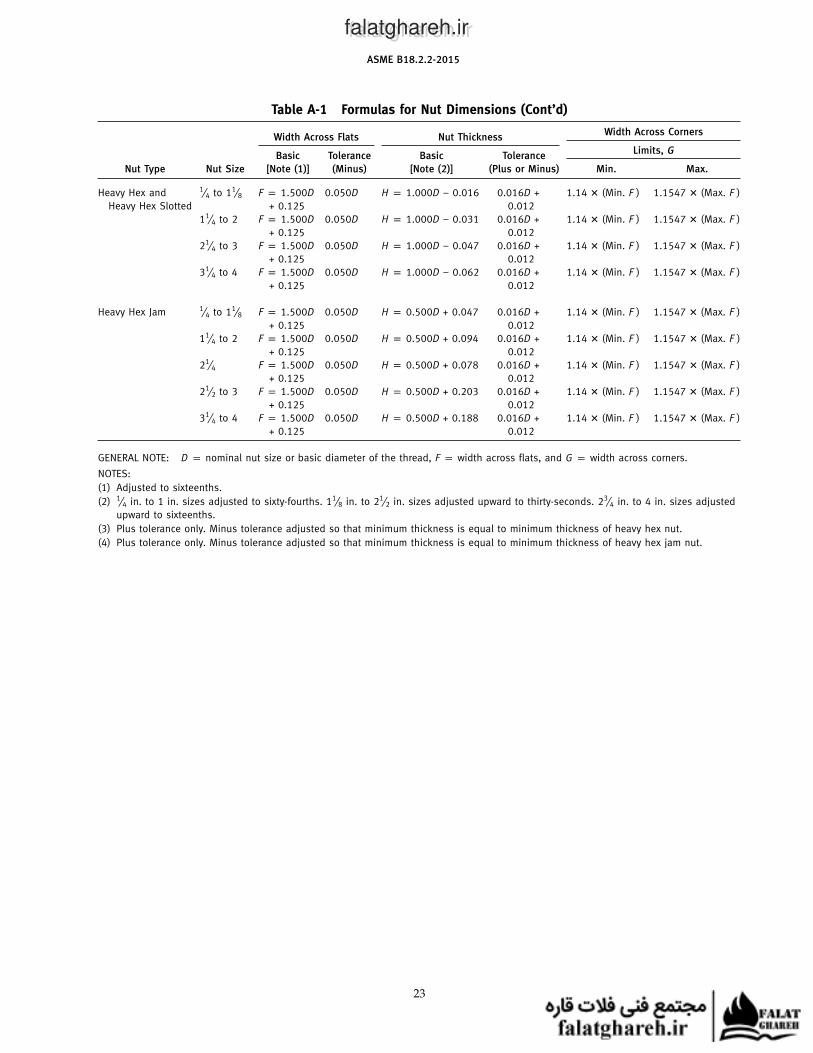
Table A-1 Formulas for Nut Dimensions (Cont’d)
Width Across CornersWidth Across Flats Nut Thickness
Limits, GBasic Tolerance Basic Tolerance
Nut Type Nut Size [Note (1)] (Minus) [Note (2)] (Plus or Minus) Min. Max.
Heavy Hex and 1⁄4 to 11⁄8 F p 1.500D 0.050D H p 1.000D − 0.016 0.016D + 1.14 � (Min. F ) 1.1547 � (Max. F )
Heavy Hex Slotted + 0.125 0.012
11⁄4 to 2 F p 1.500D 0.050D H p 1.000D − 0.031 0.016D + 1.14 � (Min. F ) 1.1547 � (Max. F )
+ 0.125 0.012
21⁄4 to 3 F p 1.500D 0.050D H p 1.000D − 0.047 0.016D + 1.14 � (Min. F ) 1.1547 � (Max. F )
+ 0.125 0.012
31⁄4 to 4 F p 1.500D 0.050D H p 1.000D − 0.062 0.016D + 1.14 � (Min. F ) 1.1547 � (Max. F )
+ 0.125 0.012
Heavy Hex Jam 1⁄4 to 11⁄8 F p 1.500D 0.050D H p 0.500D + 0.047 0.016D + 1.14 � (Min. F ) 1.1547 � (Max. F )
+ 0.125 0.012
11⁄4 to 2 F p 1.500D 0.050D H p 0.500D + 0.094 0.016D + 1.14 � (Min. F ) 1.1547 � (Max. F )
+ 0.125 0.012
21⁄4 F p 1.500D 0.050D H p 0.500D + 0.078 0.016D + 1.14 � (Min. F ) 1.1547 � (Max. F )
+ 0.125 0.012
21⁄2 to 3 F p 1.500D 0.050D H p 0.500D + 0.203 0.016D + 1.14 � (Min. F ) 1.1547 � (Max. F )
+ 0.125 0.012
31⁄4 to 4 F p 1.500D 0.050D H p 0.500D + 0.188 0.016D + 1.14 � (Min. F ) 1.1547 � (Max. F )
+ 0.125 0.012
GENERAL NOTE: D p nominal nut size or basic diameter of the thread, F p width across flats, and G p width across corners.
NOTES:
(1) Adjusted to sixteenths.
(2) 1⁄4 in. to 1 in. sizes adjusted to sixty-fourths. 11⁄8 in. to 21⁄2 in. sizes adjusted upward to thirty-seconds. 23⁄4 in. to 4 in. sizes adjusted
upward to sixteenths.
(3) Plus tolerance only. Minus tolerance adjusted so that minimum thickness is equal to minimum thickness of heavy hex nut.
(4) Plus tolerance only. Minus tolerance adjusted so that minimum thickness is equal to minimum thickness of heavy hex jam nut.
23
falatghareh.irfalatghareh.ir
ASME B18.2.2-2015
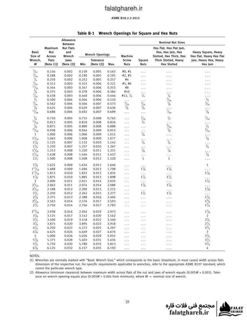
NONMANDATORY APPENDIX BWRENCH OPENINGS FOR SQUARE AND HEX NUTS
Table B-1 specifies wrench openings for square andhex nuts.
24
falatghareh.irfalatghareh.ir
ASME B18.2.2-2015
Table B-1 Wrench Openings for Square and Hex Nuts
AllowanceNominal Nut Sizes
Between
Maximum Nut Flats Hex Flat, Hex Flat Jam,
Basic Nut and Hex, Hex Jam, Hex Heavy Square, HeavyWrench Openings
Size of Across Wrench Machine Slotted, Hex Thick, Hex Hex Flat, Heavy Hex Flat
Wrench, Flats Jaws Tolerance Screw Square Thick Slotted, Heavy Jam, Heavy Hex, Heavy
W [Note (1)] [Note (2)] Min. [Note (2)] Max. Nuts Nuts Hex Slotted Hex Jam
5⁄32 0.156 0.002 0.158 0.005 0.163 #0, #1 . . . . . . . . .3⁄16 0.188 0.002 0.190 0.005 0.195 #2, #3 . . . . . . . . .1⁄4 0.250 0.002 0.252 0.005 0.257 #4 . . . . . . . . .
5⁄16 0.312 0.003 0.315 0.006 0.321 #5, #6 . . . . . . . . .11⁄32 0.344 0.003 0.347 0.006 0.353 #8 . . . . . . . . .
3⁄8 0.375 0.003 0.378 0.006 0.384 #10 . . . . . . . . .7⁄16 0.438 0.003 0.440 0.006 0.446 #12, 1⁄4
1⁄41⁄4 . . .
1⁄2 0.500 0.004 0.504 0.006 0.510 . . . . . . 5⁄161⁄4
9⁄16 0.562 0.004 0.566 0.007 0.573 5⁄165⁄16
3⁄85⁄16
5⁄8 0.625 0.004 0.629 0.007 0.636 3⁄83⁄8 . . . . . .
11⁄16 0.688 0.004 0.692 0.007 0.699 . . . . . . 7⁄163⁄8
3⁄4 0.750 0.005 0.755 0.008 0.763 . . . 7⁄161⁄2
7⁄1613⁄16 0.813 0.005 0.818 0.008 0.826 . . . 1⁄2 . . . . . .
7⁄8 0.875 0.005 0.880 0.008 0.888 . . . . . . 9⁄161⁄2
15⁄16 0.938 0.006 0.944 0.009 0.953 . . . . . . 5⁄89⁄16
1 1.000 0.006 1.006 0.009 1.015 . . . 5⁄8 . . . . . .
11⁄16 1.063 0.006 1.068 0.009 1.077 . . . . . . . . . 5⁄811⁄8 1.125 0.007 1.132 0.010 1.142 . . . 3⁄4
3⁄4 . . .
11⁄4 1.250 0.007 1.257 0.010 1.267 . . . . . . . . . 3⁄415⁄16 1.313 0.008 1.320 0.011 1.331 . . . 7⁄8
7⁄8 . . .
17⁄16 1.438 0.008 1.446 0.011 1.457 . . . . . . . . . 7⁄811⁄2 1.500 0.008 1.508 0.012 1.520 . . . 1 1 . . .
15⁄8 1.625 0.009 1.634 0.012 1.646 . . . . . . . . . 1
111⁄16 1.688 0.009 1.696 0.012 1.708 . . . 11⁄8 11⁄8 . . .
113⁄16 1.813 0.010 1.822 0.013 1.835 . . . . . . . . . 11⁄817⁄8 1.875 0.010 1.885 0.013 1.898 . . . 11⁄4 11⁄4 . . .
2 2.000 0.011 2.011 0.014 2.025 . . . . . . . . . 11⁄421⁄16 2.063 0.011 2.074 0.014 2.088 . . . 13⁄8 13⁄8 . . .
23⁄16 2.188 0.012 2.200 0.015 2.215 . . . . . . . . . 13⁄821⁄4 2.250 0.012 2.262 0.015 2.277 . . . 11⁄2 11⁄2 . . .
23⁄8 2.375 0.013 2.388 0.016 2.404 . . . . . . . . . 11⁄229⁄16 2.563 0.014 2.576 0.017 2.593 . . . . . . . . . 15⁄823⁄4 2.750 0.014 2.766 0.017 2.783 . . . . . . . . . 13⁄4
215⁄16 2.938 0.016 2.954 0.019 2.973 . . . . . . . . . 17⁄831⁄8 3.125 0.017 3.142 0.020 3.162 . . . . . . . . . 2
31⁄2 3.500 0.019 3.518 0.022 3.540 . . . . . . . . . 21⁄437⁄8 3.875 0.020 3.895 0.023 3.918 . . . . . . . . . 21⁄241⁄4 4.250 0.022 4.272 0.025 4.297 . . . . . . . . . 23⁄445⁄8 4.625 0.024 4.649 0.027 4.676 . . . . . . . . . 3
5 5.000 0.026 5.026 0.029 5.055 . . . . . . . . . 31⁄453⁄8 5.375 0.028 5.403 0.031 5.434 . . . . . . . . . 31⁄253⁄4 5.750 0.030 5.780 0.033 5.813 . . . . . . . . . 33⁄461⁄8 6.125 0.032 6.157 0.035 6.192 . . . . . . . . . 4
NOTES:
(1) Wrenches are normally marked with “Basic Wrench Size,” which corresponds to the basic (maximum, in most cases) width across flats
dimension of the respective nut. For specific requirements applicable to wrenches, refer to the appropriate ASME B107 standard, which
covers the particular wrench type.
(2) Allowance (minimum clearance) between maximum width across flats of the nut and jaws of wrench equals (0.005W + 0.001). Toler-
ance on wrench opening equals plus (0.005W + 0.004 from minimum), where W p nominal size of wrench.
25
falatghareh.irfalatghareh.ir
ASME B18.2.2-2015
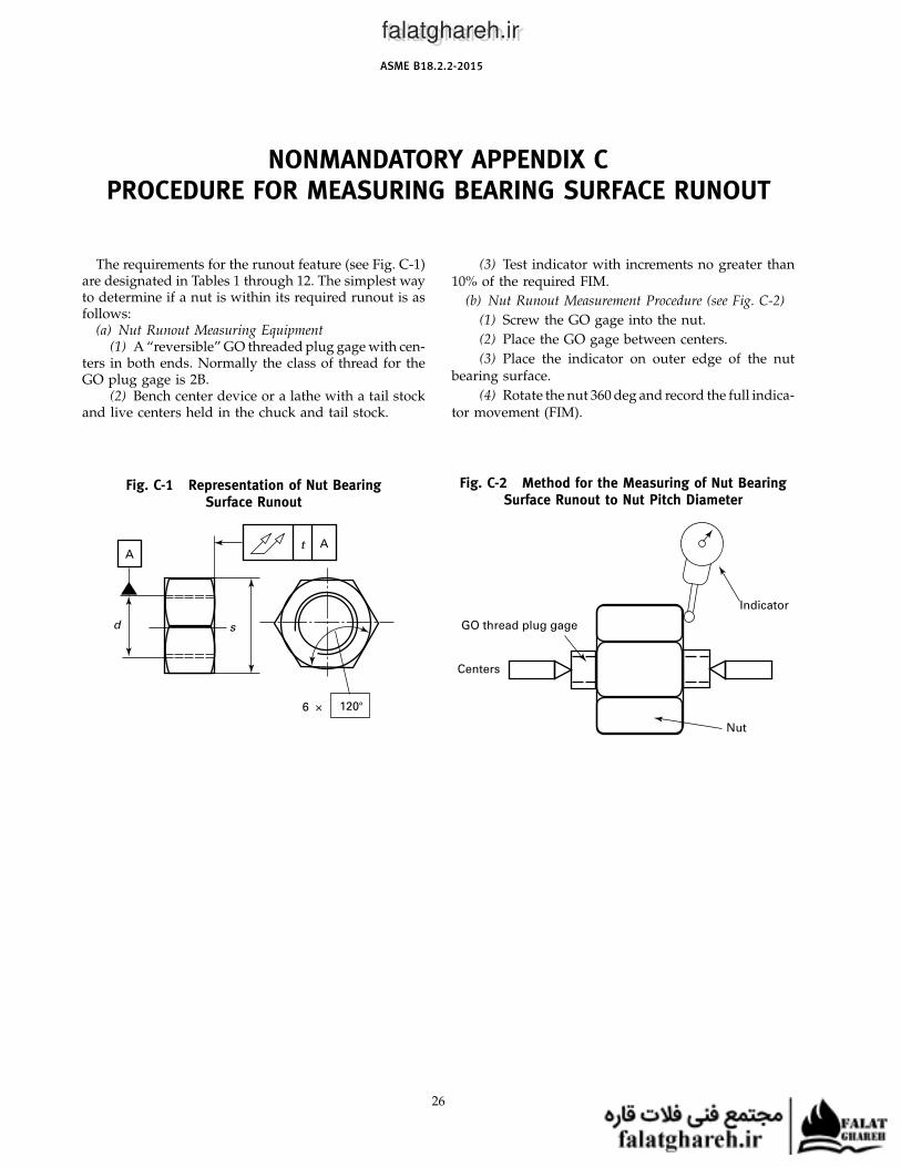
NONMANDATORY APPENDIX CPROCEDURE FOR MEASURING BEARING SURFACE RUNOUT
The requirements for the runout feature (see Fig. C-1)are designated in Tables 1 through 12. The simplest wayto determine if a nut is within its required runout is asfollows:
(a) Nut Runout Measuring Equipment(1) A “reversible” GO threaded plug gage with cen-
ters in both ends. Normally the class of thread for theGO plug gage is 2B.
(2) Bench center device or a lathe with a tail stockand live centers held in the chuck and tail stock.
Fig. C-1 Representation of Nut BearingSurface Runout
6 × 120°
d s
AAt
26
(3) Test indicator with increments no greater than10% of the required FIM.
(b) Nut Runout Measurement Procedure (see Fig. C-2)
(1) Screw the GO gage into the nut.
(2) Place the GO gage between centers.
(3) Place the indicator on outer edge of the nutbearing surface.
(4) Rotate the nut 360 deg and record the full indica-tor movement (FIM).
Fig. C-2 Method for the Measuring of Nut BearingSurface Runout to Nut Pitch Diameter
Indicator
GO thread plug gage
Centers
Nut
falatghareh.irfalatghareh.ir
B18 AMERICAN NATIONAL STANDARDS FOR BOLTS, NUTS, RIVETS, SCREWS,WASHERS, AND SIMILAR FASTENERS
Small Solid Rivets . . . . . . . . . . . . . . . . . . . . . . . . . . . . . . . . . . . . . . . . . . . . . . . . . . . . . . . . . . . . . . . . . . . . . . . . . . . . . . . . . . B18.1.1-1972 (R2011)
Large Rivets . . . . . . . . . . . . . . . . . . . . . . . . . . . . . . . . . . . . . . . . . . . . . . . . . . . . . . . . . . . . . . . . . . . . . . . . . . . . . . . . . . . . . . . B18.1.2-1972 (R2011)
Metric Small Solid Rivets . . . . . . . . . . . . . . . . . . . . . . . . . . . . . . . . . . . . . . . . . . . . . . . . . . . . . . . . . . . . . . . . . . . . . . . . . . .B18.1.3M-1983 (R2011)
Square, Hex, Heavy Hex, and Askew Head Bolts and Hex, Heavy Hex, Hex Flange,
Lobed Head, and Lag Screws (Inch Series) . . . . . . . . . . . . . . . . . . . . . . . . . . . . . . . . . . . . . . . . . . . . . . . . . . . . . . . . . . . . . . . . . . . B18.2.1-2012
Nuts for General Applications: Machine Screw Nuts, Hex, Square, Hex Flange,
and Coupling Nuts (Inch Series) . . . . . . . . . . . . . . . . . . . . . . . . . . . . . . . . . . . . . . . . . . . . . . . . . . . . . . . . . . . . . . . . . . . . . . . . . . . . B18.2.2-2015
Metric Heavy Hex Screws . . . . . . . . . . . . . . . . . . . . . . . . . . . . . . . . . . . . . . . . . . . . . . . . . . . . . . . . . . . . . . . . . . . . . . . . . B18.2.3.3M-2007 (R2014)
Metric Hex Flange Screws . . . . . . . . . . . . . . . . . . . . . . . . . . . . . . . . . . . . . . . . . . . . . . . . . . . . . . . . . . . . . . . . . . . . . . . . . B18.2.3.4M-2001 (R2011)
Metric Hex Bolts . . . . . . . . . . . . . . . . . . . . . . . . . . . . . . . . . . . . . . . . . . . . . . . . . . . . . . . . . . . . . . . . . . . . . . . . . . . . . . . . B18.2.3.5M-1979 (R2011)
Metric Heavy Hex Flange Screws . . . . . . . . . . . . . . . . . . . . . . . . . . . . . . . . . . . . . . . . . . . . . . . . . . . . . . . . . . . . . . . . . . . B18.2.3.9M-2001 (R2014)
Metric Slotted Hex Nuts . . . . . . . . . . . . . . . . . . . . . . . . . . . . . . . . . . . . . . . . . . . . . . . . . . . . . . . . . . . . . . . . . . . . . . . . . . B18.2.4.3M-1979 (R2012)
Metric 12-Point Flange Head Screws . . . . . . . . . . . . . . . . . . . . . . . . . . . . . . . . . . . . . . . . . . . . . . . . . . . . . . . . . . . . . . . . . . . . . . . . .B18.2.5M-2013
Metric Fasteners for Use in Structural Applications . . . . . . . . . . . . . . . . . . . . . . . . . . . . . . . . . . . . . . . . . . . . . . . . . . . . . . . . . . . . .B18.2.6M-2012
Clearance Holes for Bolt, Screws, and Studs. . . . . . . . . . . . . . . . . . . . . . . . . . . . . . . . . . . . . . . . . . . . . . . . . . . . . . . . . . . . . B18.2.8-1999 (R2010)
Straightness Gage and Gaging for Bolts and Screws . . . . . . . . . . . . . . . . . . . . . . . . . . . . . . . . . . . . . . . . . . . . . . . . . . . . . . . . . . . . . B18.2.9-2010
Socket Cap, Shoulder, Set Screws, and Hex Keys (Inch Series) . . . . . . . . . . . . . . . . . . . . . . . . . . . . . . . . . . . . . . . . . . . . . . . . . . . . . . . B18.3-2012
Round Head Bolts (Inch Series) . . . . . . . . . . . . . . . . . . . . . . . . . . . . . . . . . . . . . . . . . . . . . . . . . . . . . . . . . . . . . . . . . . . . . . . . . . . . . . . . B18.5-2012
Metric Round Head Short Square Neck Bolts . . . . . . . . . . . . . . . . . . . . . . . . . . . . . . . . . . . . . . . . . . . . . . . . . . . . . . . . . B18.5.2.1M-2006 (R2011)
Wood Screws (Inch Series) . . . . . . . . . . . . . . . . . . . . . . . . . . . . . . . . . . . . . . . . . . . . . . . . . . . . . . . . . . . . . . . . . . . . . . . . . . . B18.6.1-1981 (R2008)
Slotted Head Cap Screws, Square Head Set Screws, and Slotted Headless Set Screws (Inch Series) . . . . . . . . . . . . . . . B18.6.2-1998 (R2010)
Machine Screws, Tapping Screws, and Metallic Drive Screws (Inch Series) . . . . . . . . . . . . . . . . . . . . . . . . . . . . . . . . . . . . . . . . . . . B18.6.3-2013
Metric Thread-Forming and Thread-Cutting Tapping Screws . . . . . . . . . . . . . . . . . . . . . . . . . . . . . . . . . . . . . . . . . . . . . . . .B18.6.5M-2000 (R2010)
Metric Machine Screws . . . . . . . . . . . . . . . . . . . . . . . . . . . . . . . . . . . . . . . . . . . . . . . . . . . . . . . . . . . . . . . . . . . . . . . . . . . . .B18.6.7M-1999 (R2010)
Thumb Screws and Wing Screws (Inch Series) . . . . . . . . . . . . . . . . . . . . . . . . . . . . . . . . . . . . . . . . . . . . . . . . . . . . . . . . . . . . . . . . . . B18.6.8-2010
Wing Nuts (Inch Series). . . . . . . . . . . . . . . . . . . . . . . . . . . . . . . . . . . . . . . . . . . . . . . . . . . . . . . . . . . . . . . . . . . . . . . . . . . . . . . . . . . . . B18.6.9-2010
General Purpose Semi-Tubular Rivets, Full Tubular Rivets, Split Rivets and Rivet Caps . . . . . . . . . . . . . . . . . . . . . . . . . . . . .B18.7-2007 (R2012)
Metric General Purpose Semi-Tubular Rivets . . . . . . . . . . . . . . . . . . . . . . . . . . . . . . . . . . . . . . . . . . . . . . . . . . . . . . . . . . . .B18.7.1M-2007 (R2012)
Clevis Pins and Cotter Pins (Inch Series) . . . . . . . . . . . . . . . . . . . . . . . . . . . . . . . . . . . . . . . . . . . . . . . . . . . . . . . . . . . . . . . . . . . . . . . B18.8.1-2014
Taper Pins, Dowel Pins, Straight Pins, Grooved Pins, and Spring Pins (Inch Series) . . . . . . . . . . . . . . . . . . . . . . . . . . . . . B18.8.2-2000 (R2010)
Plow Bolts . . . . . . . . . . . . . . . . . . . . . . . . . . . . . . . . . . . . . . . . . . . . . . . . . . . . . . . . . . . . . . . . . . . . . . . . . . . . . . . . . . . . . . . . . . . . . . . . . B18.9-2012
Track Bolts and Nuts . . . . . . . . . . . . . . . . . . . . . . . . . . . . . . . . . . . . . . . . . . . . . . . . . . . . . . . . . . . . . . . . . . . . . . . . . . . . . . . . .B18.10-2006 (R2011)
Miniature Screws . . . . . . . . . . . . . . . . . . . . . . . . . . . . . . . . . . . . . . . . . . . . . . . . . . . . . . . . . . . . . . . . . . . . . . . . . . . . . . . . . . . .B18.11-1961 (R2010)
Glossary of Terms for Mechanical Fasteners . . . . . . . . . . . . . . . . . . . . . . . . . . . . . . . . . . . . . . . . . . . . . . . . . . . . . . . . . . . . . . . . . . . . . B18.12-2012
Screw and Washer Assemblies — Sems (Inch Series). . . . . . . . . . . . . . . . . . . . . . . . . . . . . . . . . . . . . . . . . . . . . . . . . . . . . . .B18.13-1996 (R2013)
Screw and Washer Assemblies: SEMS (Metric Series) . . . . . . . . . . . . . . . . . . . . . . . . . . . . . . . . . . . . . . . . . . . . . . . . . . . . . . . . . .B18.13.1M-2011
Forged Eyebolts . . . . . . . . . . . . . . . . . . . . . . . . . . . . . . . . . . . . . . . . . . . . . . . . . . . . . . . . . . . . . . . . . . . . . . . . . . . . . . . . . . . . . . . . . . . . B18.15-2015
Prevailing-Torque Type Steel Metric Hex Nuts and Hex Flange Nuts . . . . . . . . . . . . . . . . . . . . . . . . . . . . . . . . . . . . . . . . . B18.16M-2004 (R2009)
Serrated Hex Flange Locknuts 90,000 psi (Inch Series) . . . . . . . . . . . . . . . . . . . . . . . . . . . . . . . . . . . . . . . . . . . . . . . . . . . B18.16.4-2008 (R2013)
Prevailing Torque Locknuts (Inch Series) . . . . . . . . . . . . . . . . . . . . . . . . . . . . . . . . . . . . . . . . . . . . . . . . . . . . . . . . . . . . . . . . . . . . . . B18.16.6-2014
Quality Assurance for Fasteners . . . . . . . . . . . . . . . . . . . . . . . . . . . . . . . . . . . . . . . . . . . . . . . . . . . . . . . . . . . . . . . . . . . . . . . . . . . . . . . B18.18-2011
Washers: Helical Spring-Lock, Tooth Lock, and Plain Washers (Inch Series) . . . . . . . . . . . . . . . . . . . . . . . . . . . . . . . . . . . . . . . . . . B18.21.1-2009
Lock Washers (Metric Series) . . . . . . . . . . . . . . . . . . . . . . . . . . . . . . . . . . . . . . . . . . . . . . . . . . . . . . . . . . . . . . . . . . . . . . B18.21.2M-1999 (R2014)
Double Coil Helical Spring Lock Washers for Wood Structures . . . . . . . . . . . . . . . . . . . . . . . . . . . . . . . . . . . . . . . . . . . . . B18.21.3-2008 (R2013)
Metric Plain Washers. . . . . . . . . . . . . . . . . . . . . . . . . . . . . . . . . . . . . . . . . . . . . . . . . . . . . . . . . . . . . . . . . . . . . . . . . . . . . . . B18.22M-1981 (R2010)
Part Identifying Number (PIN) Code System for B18 Fastener Products . . . . . . . . . . . . . . . . . . . . . . . . . . . . . . . . . . . . . . . . . . . . . . . B18.24-2015
Tapered and Reduced Cross Section Retaining Rings (Inch Series) . . . . . . . . . . . . . . . . . . . . . . . . . . . . . . . . . . . . . . . . . . . .B18.27-1998 (R2011)
Helical Coil Screw Thread Inserts — Free Running and Screw Locking (Inch Series). . . . . . . . . . . . . . . . . . . . . . . . . . . . . . . . . . . . B18.29.1-2010
Helical Coil Screw Thread Inserts: Free Running and Screw Locking (Metric Series) . . . . . . . . . . . . . . . . . . . . . . . . . . B18.29.2M-2005 (R2010)
Metric Continuous and Double-End Studs . . . . . . . . . . . . . . . . . . . . . . . . . . . . . . . . . . . . . . . . . . . . . . . . . . . . . . . . . . . . . . . . . . . .B18.31.1M-2008
Continuous Thread Stud, Double-End Stud, and Flange Bolting Stud (Stud Bolt) (Inch Series). . . . . . . . . . . . . . . . . . . . . . . . . . . B18.31.2-2014
Threaded Rods (Inch Series). . . . . . . . . . . . . . . . . . . . . . . . . . . . . . . . . . . . . . . . . . . . . . . . . . . . . . . . . . . . . . . . . . . . . . . . . . . . . . . . B18.31.3-2014
Threaded Rod (Metric Series) . . . . . . . . . . . . . . . . . . . . . . . . . . . . . . . . . . . . . . . . . . . . . . . . . . . . . . . . . . . . . . . . . . . . . . . . . . . . . .B18.31.4M-2009
Bent Bolts (Inch Series) . . . . . . . . . . . . . . . . . . . . . . . . . . . . . . . . . . . . . . . . . . . . . . . . . . . . . . . . . . . . . . . . . . . . . . . . . . . . . . . . . . . B18.31.5-2011
The ASME Publications Catalog shows a complete list of all the Standards published by the Society. For a complimentary catalog, or the latest
information about our publications, call 1-800-THE-ASME (1-800-843-2763).
falatghareh.irfalatghareh.ir

ASME Services
ASME is committed to developing and delivering technical information. At ASME’s Customer Care, we make every effort to answer your questions
and expedite your orders. Our representatives are ready to assist you in the following areas:
ASME Press Member Services & Benefits Public InformationCodes & Standards Other ASME Programs Self-Study CoursesCredit Card Orders Payment Inquiries Shipping InformationIMechE Publications Professional Development Subscriptions/Journals/MagazinesMeetings & Conferences Short Courses Symposia VolumesMember Dues Status Publications Technical Papers
How can you reach us? It’s easier than ever!
There are four options for making inquiries* or placing orders. Simply mail, phone, fax, or E-mail us and a Customer Care representative will
handle your request.
Mail Call Toll Free Fax—24 hours E-Mail—24 hours
ASME US & Canada: 800-THE-ASME 973-882-1717 [email protected] Clove Road, 6th Floor (800-843-2763) 973-882-5155Little Falls, New Jersey Mexico: 95-800-THE-ASME07424-2138 (95-800-843-2763)
* Customer Care staff are not permitted to answer inquiries about the technical content of this code or standard. Information as to whether
or not technical inquiries are issued to this code or standard is shown on the copyright page. All technical inquiries must be submitted in
writing to the staff secretary. Additional procedures for inquiries may be listed within.
falatghareh.irfalatghareh.ir

ASME B18.2.2-2015
M04315
falatghareh.irfalatghareh.ir