Embed Size (px)
Citation preview

Numerical simulation of vortex-induced vibration of a pivoted cylinder using the spectral element method
H. Gun Sung1, H. Baek2, S. Hong1 & J.-S. Choi1 1Maritime and Ocean Engineering Research Institute (MOERI; formerly KRISO), KORDI, Daejeon, Korea 2Department of Mathematics, MIT, Cambridge, USA
Abstract
The present paper describes preliminary results of numerical simulation of VIV (vortex-induced-vibration) phenomenon around a pivoted circular cylinder subject to steady flow. The present flow model is based upon the Navier-Stokes equations with velocity-pressure formulation. The governing equations are solved through the Spectral Element Method (SEM), which possesses the property of high-order spatial accuracy as proposed by Karniadakis and Sherwin in their book Spectral/hp Element Methods for CFD. The solution procedure and characteristic aspects of the present modelling and numerical method are briefly stated. The coupling method of the body motion with the flow problem is restated from the viewpoint of the present problem. A series of numerical estimation of VIV flow characteristics have been carried out for varying parameters of the problem such as the reduced velocity and damping parameter, etc. Keywords: vortex-induced vibration, pivoted cylinder, spectral element method, coupling of body motion with flow.
1 Introduction
In general, VIV (vortex-induced-vibration) problem is focused upon reduction and suppression of VIV as noted in Blevins [2] and Sarpkaya [3]. As indicated by Raghavan [4], and Bernitsas and Raghavan [5], however, it seems to be probable to extract considerable energy from VIV phenomena. For example, Professor Bernitsas has developed an energy extraction device known as
www.witpress.com, ISSN 1743-3533 (on-line) WIT Transactions on Engineering Sciences, Vol 74, © 201 WIT Press2
doi:10.2495/AFM120151
Advances in Fluid Mechanics IX 163

VIVACE (Vortex Induced Vibration Aquatic Clean Energy) which converts ocean and river current energy to electricity (Bernitsas et al. [6]). MOERI/KORDI is also developing its own energy extraction device which utilizes a pivoted circular cylinder subject to background current flows. The present paper consists as follows. The physical problem under consideration is introduced. Flow model and governing equation are briefly explained. Numerical method and solution procedure are addressed. Some of numerical results of a specified configuration are presented.
2 Physical problem under consideration
As shown in Fig. 1, a submerged cylindrical body is pivoted to a column and exposed to VIV due to background fluid flow such as ocean currents. As stated above, the present device is conceptually associated with the earlier development done by Prof. Bernitsas’ group in the University of Michigan.
Figure 1: A schematic diagram of the VIV problem of a pivoted circular cylinder subject to steady flow.
3 Flow model and governing equation
Coordinate system and modeling of present problem is shown in Fig. 2. Rotation
vector of the body can be denoted by = for the present case of
2D. So, the angular velocity and acceleration can be obtained by time derivative
of the rotation vector as and , respectively. We also assume the flow
domain has rectangular shape, and there is no free surface. We describe the present flow problem by using the viscous incompressible flow model. For the present problem in which we need to describe the grid movement due to vortex induced body motion, we can apply ALE (Arbitrary Lagrangian-Eulerian) framework. Hence, the corresponding set of governing equations can be modified as follows.
)(t
))(,0,0( t
)(t
)(t
www.witpress.com, ISSN 1743-3533 (on-line) WIT Transactions on Engineering Sciences, Vol 74, © 201 WIT Press2
164 Advances in Fluid Mechanics IX

)(1
, tVinfuLpwuNt
u
(1)
)(0 tVinu
(2)
where is the velocity vector, the ALE mesh velocity
vector, the pressure field, the density of the fluid, the kinematic
viscosity of the fluid, and the body force that can include the effect of non-
inertial reference frame. The underlying Cartesian coordinates is denoted by the spatial coordinates and by the time coordinate . We can define as
and . So, the partial time
derivative of the velocity is taken for a given fluid particle or a pseudo-particle in general. It is also assumed that the fluid domain, can be time-varying for
generality of the formulation. With ALE concept, the partial time derivative in the above is taken on the mesh frame under consideration.
Figure 2: Coordinate system and modeling of the problem.
For the body boundary condition, we specify the impermeable condition as follows.
(3)
where with to denote the position
vector of the center of rotation, i.e. the pinned position of the rod. In the present paper, we apply the boundary conditions at truncation boundaries as follows.
(4)
),,(),( wvutxu
),( txw
),( txp
f
x
t
uwuwuN
)(),( TuuuL )()(
)(tV
)(tinuu bb
)()( CRb rrtu
),,( CRCRCRCR zyxr
LxxinwUu 0,
www.witpress.com, ISSN 1743-3533 (on-line) WIT Transactions on Engineering Sciences, Vol 74, © 201 WIT Press2
Advances in Fluid Mechanics IX 165

(5)
(6)
where denotes the outflow velocity, and , , , mean
the left, right side and low, high side of the truncated rectangle of the flow domain. The vectors and (pointing to z-axis in 2D problems) are an ortho-normal vector pair lying on the tangent plane, and related to the unit normal vector as . Hence, the vector pair, constitutes the ortho-
normal curvilinear coordinates.
With the ALE methodology, the motion of the mesh nodes, is described as
(7)
with an operator equation for the mesh velocity vector,
(8) where stands for the elliptic operator which governs the grid motion. Its type is chosen depending upon the problem in consideration. For example, the Laplace equation was utilized by Ho and Patera [7], and Robertson et al. [8]. On the other hand, Rabier and Medale [9] adopted a Lagrangian-Eulerian kinematic method by the way of an elastic problem for the mesh displacement field rather than a standard ALE formulation. A similar approach can be found in Bouffanais and Deville [10]. The boundary condition on the ALE mesh motion is also to be carefully specified. On the free-slip boundary, ALE mesh nodes move with the fluid particle as follows.
(9)
This guarantees the velocity compatibility on the free-slip boundary. The Dirichlet-type boundary specifies the velocity vector and the corresponding boundary is stationary in space and time. So, we may apply the following constraint.
(10)
4 Equation of body motion
In the case of 2D problem, the equation of body motion can be written as follows.
(11a)
where denotes the angle of rotation of the body. The coefficients , ,
are the moment of inertia, damping factor, and stiffness of rotation, respectively. The external moment, can be obtained from the equation.
(12)
HLT zzzinnuusw ,0)(,0
LT xxinnuusUu 0)(,
U Lxx Rxx Lzz Hzz
s
m
msn
),,( nms
X
wdt
Xd
0w
Ε
Ε
sinmmussunnuuw
)()()(
Dinw 0
)(tTKCJ extbbb
bJ bC bK
extT
)(
3)(tS
TCGext
b
dsnuunprretT
www.witpress.com, ISSN 1743-3533 (on-line) WIT Transactions on Engineering Sciences, Vol 74, © 201 WIT Press2
166 Advances in Fluid Mechanics IX
where means the position vector of the center of rotation, i.e. the pinned
position of the rod, and for the present case. For simplicity of the
derivation and notation, the equation (1 a) can be normalized as follows:
(11b)
with definitions such as , , .
Based upon the proposed values of preliminary design, some variations of the parameters such as the length of the connection rod, mass moment of inertia, damping factor, and stiffness are compared with in this study by numerical simulation. In order to couple the body motion with the fluid flow, we need to transfer the velocity and acceleration on the body surface to the flow solver. Thus, we can use the following relationship.
(13)
where we use . The acceleration is written as follows.
(14)
Thus, in the present case we have
(15)
For the present case of rotating circular cylinder, the body boundary can be defined as
(16)
means the distance from the center of rotation and center of the cylinder, and
the cylinder radius.
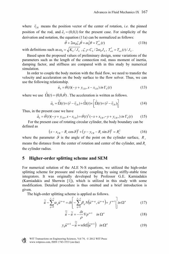
5 Higher-order splitting scheme and SEM
For numerical solution of the ALE N-S equations, we utilized the high-order splitting scheme for pressure and velocity coupling by using stiffly-stable time integrators. It was originally developed by Professor G.E. Karniadakis (Karniadakis and Sherwin [1]), which is utilized in this study with some modification. Detailed procedure is thus omitted and a brief introduction is given. The high-order splitting scheme is applied as follows.
(17)
(18)
(19)
CRr
)1,0,0(3 e
)(2 *200 tTextb
bb JK /0 bbb JC 02/ bextext JtTT /)(*
)(),)(( tinxxyytu bCRCRb
),0,0()( t
)()()()()( CRCRb rrttrrta
)(),,()(),)(( 2 tinyyxxtxxyyta bCRCRCRCRb
222 sincos crCRrCR RRyyRxx rR
cR
nnJ
q
qnqnq
J
q
qnq infwuNtuu
ii
11
0
1
0
,~
nn inpt
uu 1~~~
nnn inutLuu 110
~~
1
where the parameter is the angle of the point on the cylinder surface,
www.witpress.com, ISSN 1743-3533 (on-line) WIT Transactions on Engineering Sciences, Vol 74, © 201 WIT Press2
Advances in Fluid Mechanics IX 167

The superscript refers to the time level index, and the order of the time
integration, and , and the coefficients for stiffly stable time integration.
Readers are referred to Karniadakis and Sherwin [1] for values of the integration coefficients for different orders. The time step size, is fixed throughout the
time marching in this study. The primary reason for using the present time integration scheme is due to necessity of attaining the high-order accuracy and robustness in time. The stiffly-stable time integration scheme is known to be very accurate and stable. Particularly in SEM, the condition number is very large compared with other discretization schemes and so the conventional time integration scheme such as the Adams-Bashforth and Runge-Kutta methods may give rise to numerical instability. The present study is based upon the previous development known as Nektar which was originally due to Prof. Karniadakis at Brown University, USA. Thus in this paper, we can skip most of the details and just cite relevant references such as Karniadakis and Sherwin [1]. Etc. It should be noted that the grid motion is directly obtained by using ALE concept which is implemented on the framework of NEKTAR.
6 Coupling method of FSI (fluid-structure-interaction)
Coupling of the flow dynamics with body motion is realized mainly through time marching procedure. In the above, we mentioned the type of time-stepping for fluid flow. So, the remaining part is the equation of body’s rotational motion, and data transfer and connection between fluid part and structure part, which are discussed below. The conventional method is based upon the Newmark-family time marching as in Papaioannou et al. [11] and Placzek et al. [12], etc. When we are interested in explicit time marching, any type of time integration scheme can be utilized in principle only if it guarantees numerical stability. However, the practical issue seems to be efficiency and accuracy as well; i.e. a choice is preferred when the type of time marching algorithm for structure part does not deteriorate the level of accuracy of solution method of fluid part, particularly in time-axis. The present method for this FSI problem is briefly explained in the below. At first, the angular motion of the pivoted cylinder can be described by
(20)
where the superscript denotes the time step, while the subscript means sub-
iteration step. Hence, stands for the hydrodynamic torque that can be
calculated by using the previous time step.
Within this framework, the way to describe and can construct the time integration scheme and also can determine its temporal accuracy and stability. The present choice for time discretization is a Newmark scheme which can be written as
iJ
0 q q
t
n
ext
n
b
n
b
n
b TKCJ 111
n
extT
n n
www.witpress.com, ISSN 1743-3533 (on-line) WIT Transactions on Engineering Sciences, Vol 74, © 201 WIT Press2
168 Advances in Fluid Mechanics IX

(21a)
(21b)
It is known that the accuracy of the scheme is dependent upon the parameter set of . In this study, is used.
The whole process for each time step can be summarized as follows. i) Solve the equation for the solid part with the last solutions of the fluid
part. ii) Obtain the angular displacement, velocity, and acceleration using Eqs.
(21a) and (21b). iii) Calculate the translational velocity and acceleration for the next time-
step on the body boundary and transfer those values to fluid flow solver. iv) Solve the governing equation of fluid motion, and the corresponding
mesh field. v) Compute the traction on the interface between and the solid and the
fluid and find the torque acting upon the body. vi) Repeat the processes i) to v) up to the termination time.
7 Numerical results and discussion
In this section, we discuss the numerical results of the present VIV problem of a pivoted circular cylinder for varying parameters with the developed numerical method. A typical grid system for present VIV simulation is shown in Fig. 3. As shown, rectangular grids are utilized, and the order of the interpolation of spectral elements was 5 or 6 for most of the cases of simulation.
Figure 3: A typical grid system for present VIV simulation.
We restrict ourselves to the case of for preliminary test
simulation for which we have experimental data. In this case, the flow is incident from the upstream side and the pivoting point is located downstream. The normalized mass moment of inertia was 9.089 for the present case.
12
1 2)21(2
nnnnn tt
11 )1( nnnn t
),( )5.0,25.0(),(
x
y
-5 0 5 10 15 20
-4
-2
0
2
4
3/ cr RR
www.witpress.com, ISSN 1743-3533 (on-line) WIT Transactions on Engineering Sciences, Vol 74, © 201 WIT Press2
Advances in Fluid Mechanics IX 169

In the first place, an example of computational time series data of angular displacement, velocity, acceleration, and hydrodynamic torque of the cylinder is shown in Fig. 4. The Reynolds number was 200, the reduced velocity was 5, and the damping factor was 0.07 for this case. Figure 5 depicts how the cylinder is moving in the plane for the same case. Figure 6 and 7 correspond to pressure and vorticity contour plots for this case at a specified time instant. It is noted that the vorticity contour plot shows some discontinuities around mesh boundary because of relatively coarse grid density in the downstream side.
Figure 4: Time series of variables such as angular displacement, velocity, acceleration, and hydrodynamic torque of the cylinder ( , , =5, ).
Figure 5: Trajectory of the cylinder ( 0.3/ cr RR , 200Re ,
cr RUU 0/ =5, 07.0b ).
0 10 20 30 40 50
-1.2
-0.8
-0.4
0
0.4
0.8
angular displacementAngular velocityAngular accelerationHydrdynamic torque
Nondim. time
0.3/ cr RR 200Re cr RUU 0/ 07.0b
www.witpress.com, ISSN 1743-3533 (on-line) WIT Transactions on Engineering Sciences, Vol 74, © 201 WIT Press2
170 Advances in Fluid Mechanics IX

Figure 6: Pressure contour plot ( 4.49t , 0.3/ cr RR , 200Re ,
cr RUU 0/ =5, 07.0b ).
Figure 7: Vorticity contour plot ( , , ,
=5, ).
We compared the present numerical results in Fig. 8 with the experiment performed by Choi et al. [13]. It is noted that in the experiment the cylinder is connected to the multi-hinged bars which is also guided to a generator unit. The detailed features of the experiment are referred to the paper cited in the above. The figure indicates that the present numerical method under-predicts the performance of the rotational VIV motion of the cylinder. We note that the present value of damping factor in simulation was found by some series of decay test in the experiment. We suppose that the present numerical method contains appreciable level of numerical damping because the numerical results is similar to the no load case rather than to the zero resistance case.
4.49t 0.3/ cr RR 200Re
cr RUU 0/ 07.0b
www.witpress.com, ISSN 1743-3533 (on-line) WIT Transactions on Engineering Sciences, Vol 74, © 201 WIT Press2
Advances in Fluid Mechanics IX 171

Figure 8: VIV response for various reduced velocity ( , for the
computation, the damping factor was chosen as ).
The actual range of Reynolds number of the experiment was
, while for present simulations we tested the case of. Since the higher Reynolds numbers cause the present numerical
method to show an unstable motion in time. As an intermediate conclusion, it is required to utilize the strong coupling scheme as noted in Baek [14], and Baek and Karniadakis [15]. By resorting to this robust method, it is expected that we can go up to a very high Reynolds number case without unstable solutions. Another reason for this discrepancy is attributed to the one dimensional simplification to the experimental arrangement of multi-hinge connection. A significant feature to be addressed further is the effect of the generator unit on the VIV motion of the cylinder. These three aspects will be studied further.
2 4 6 8 10 12
0.00
0.10
0.20
0.30
0.40
0.50Experiment (Resistance = 0 Ohm)Experiment (No load)Computation (Navier-Stokes; Re=200)Computation (Navier-Stokes; Re=2,000)
U/fD
0.3/ cr RR
07.0b
41074.4 Re 510625.1 200 Re 000,2
www.witpress.com, ISSN 1743-3533 (on-line) WIT Transactions on Engineering Sciences, Vol 74, © 201 WIT Press2
172 Advances in Fluid Mechanics IX

8 Summary and conclusion
The present paper described some preliminary results of numerical simulation of VIV phenomenon around a pivoted circular cylinder subject to steady flow. The present flow model and method utilized an SEM-based N-S solver, which are originally developed by Professor G.E. Karniadakis’ group. Numerical treatment for movement of the body was done by using ALE approach. The solution procedure and characteristic aspects of the present modeling and numerical method were briefly stated. The present method of coupling of the body motion with the flow problem is based upon a kind of weak coupling scheme. A series of numerical estimation of VIV flow characteristics were carried out for a given parameter set. By comparing with experimental results, it has been found out that there is a great need to utilize a strong coupling scheme and to refine the modeling of the multi-hinge connection of the system, which will be sought sincerely for the forthcoming paper.
Acknowledgements
The present study is supported by the “Development of key-technology of ocean renewable energy using Vortex-Induced Vibration (VIV) in water flow” granted by Ministry of Knowledge Economy of Korea and the principal R&D program of KORDI: “Performance Evaluation Technologies of Offshore Operability for Transport and Installation of Deep-sea Offshore Structures” granted by Korea Research Council of Public Science and Technology. The authors express deep gratitude to Professor Karniadakis for permission of the computer code, known as NEKTAR.
References
[1] Karniadakis, D., and S.J. Sherwin, Spectral/hp Element Methods for CFD, Oxford University Press, 2nd Ed., London, 2005.
[2] Blevins, R. D. Flow-Induced Vibration, Malabar, FL Krieger Publishing Company, 1994.
[3] Sarpkaya, T. A critical review of the intrinsic nature of vortex-induced vibrations, Journal of Fluids and Structures, Vol. 19, pp. 389–447, 2004.
[4] Raghavan, K, “Energy Extraction from a Steady Flow Using Vortex Induced Vibration”, Ph.D. Dissertation, The University of Michigan, 2007.
[5] Bernitsas, M.M. and Raghavan, K. “Reduction/Suppression of VIV of Circular Cylinders through Roughness Distribution at 8×10³< Re<1.5×10⁵”, Proc. OMAE Conference, pp. 1-5, 2008.
[6] Bernitsas, M.M., Raghavan, K., Ben-Simon, Y. and Garcia, E.M.H. “VIVACE (Vortex Induced Vibration for Aquatic Clean Energy): A New Concept in Generation of Clean and Renewable Energy from Fluid Flow”, Proc. OMAE Conference, pp. 1-18, 2006.
[7] Ho, L.-W., and Patera, A.T., “A Legendre Spectral Element Method for Simulation of Unsteady Incompressible Viscous Free-Surface Flows,”
www.witpress.com, ISSN 1743-3533 (on-line) WIT Transactions on Engineering Sciences, Vol 74, © 201 WIT Press2
Advances in Fluid Mechanics IX 173

Computer Methods in Applied Mechanics and Engineering, Vol. 80, No. 1/3, pp. 355-366, 1990.
[8] Robertson, I., Sherwin, S.J., and Graham, J.M.R., “Comparison of Wall Boundary Conditions for Numerical Viscous Free Surface Flow Simulation,” Journal of Fluids and Structures, Vol. 19, No.4, pp. 525-542, 2004.
[9] Rabier, S., and Medale, M., “Computation of Free Surface Flows with a Projection FEM in a Moving Mesh Framework,” Computer Methods in Applied Mechanics and Engineering, Vol. 192, No. 41/42, pp. 4703-4721, 2003.
[10] Bouffanais, R., and Deville, M.O., “Mesh Update Techniques for Free-Surface Flow Solvers Using Spectral Element Method,” Journal of Scientific Computing, Vol. 27, No.1/3, pp.137-149, 2006.
[11] Papaioannou, G.V., D.K.P. Yue, M.S. Triantafyllou, G.E. Karniadakis, On the effect of spacing on the vortex-induced vibrations of two tandem cylinders, Journal of Fluids and Structures 24, pp. 833–854, 2008.
[12] Placzek A., Sigrist J.-F., Hamdouni A. Numerical simulation of an oscillating cylinder in a cross-flow at low Reynolds number: Forced and free oscillations, Computers & Fluids 38, pp. 80–100, 2009.
[13] Jong-Su Choi, Sup Hong, Tae-Kyeong Yeu and Hyung-Woo Kim, 2010, “Experimental Study on Vortex-Induced Vibration Clean Energy Extraction Device Model using Circular Cylinder Pivoted with a Lever (in Korean)”, Proc. KSOE Spring conference, pp. 2516 – 2519, 2010.
[14] Baek, H. 2010, A spectral element method for fluid-structure interaction: new algorithm and application to intracranial aneurysms. Ph.D. Thesis, Brown University.
[15] Baek, H. and G.E. Karniadakis, 2010, Stabilization of fluid-structure interactions via fictitious added mass and damping in physical and biological applications, submitted to Elsevier.
www.witpress.com, ISSN 1743-3533 (on-line) WIT Transactions on Engineering Sciences, Vol 74, © 201 WIT Press2
174 Advances in Fluid Mechanics IX

![EXPERIMENTS ON VORTEX-INDUCED VIBRATION …ijame.ump.edu.my/images/Volume_11 June 2015/31_Rahman and... · EXPERIMENTS ON VORTEX-INDUCED VIBRATION OF A VERTICAL ... Blevins [10],](https://img.dokumen.tips/doc/110x75/5b83b77d7f8b9a31608def8f/experiments-on-vortex-induced-vibration-ijameumpedumyimagesvolume11-june-201531rahman.jpg)