Embed Size (px)
Citation preview
26
International Journal of Structural and Civil Engineering Research Vol. 5, No. 1, February 2016
© 2016 Int. J. Struct. Civ. Eng. Res.doi: 10.18178/ijscer.5.1.26-30
Numerical Analysis of RC Beam Subjected to
Blast Load
Gang-Kyu Park and Hyo-Gyoung Kwak Korea Advanced Institute of Science and Technology, Daejeon, Korea
Email: {naksa, kwakhg}@kaist.ac.kr
Abstract—Behavior of structure subjected to blast and
impact loads has to be analyzed with considering the effect
of high strain rate. Material behavior will be changed under
the condition that loads are applied to structures during a
short period of time, which must be taken into account. In
this paper, the nonlinear behavior of RC beams subjected to
blast loads is analyzed by means of the layered-section
approach. Using the proposed numerical method, the
tendencies of numerical analysis are figured out with the
number of element and time interval. Finally, correlation
studies between analytical and experimental results are
carried out in order to testify the validity of proposed
numerical method. Then, it has been found that the
numerical results show very good agreement with the
experimental result.
Index Terms—blast loads, high strain rate, layered section
approach
I. INTRODUCTION
There has been increasing interest in the effect of blast
on structures because of close relation with lives.
Especially in case of protection structures for military
purpose, it is very important to figure out the effect of
blast load especially in case of protection structures
which has to have enough strength and ductility.
Recently, there has been increasing interest in these
protective structures due to a series of recent terror attack.
Therefore, several studies have been made on this subject
as experimentally and numerically. Marais experiment
identified properties of a variety of materials using the
SHPB (Split Hopkinson Pressure Bar) test [1]. A
numerical analysis for structures subjected to impact
loading was conducted by Georgin et al. [2]. These
obtained results have been used in commercialized
programs including LS-DYNA [3] and ABAQUS [4].
The commercial programs ware used in tracing the
nonlinear behavior of structures subjected to blast and
impact loading.
Unfortunately, in case of blast loads, it is hard to carry
out research because of national security reasons and
substantial costs. However, with recent increasing need
for study on this case, the body of experiments and
numerical analyses subjected to blast loads has increased
for concrete structures such as beams and columns and so
on [5]-[7].
Manuscript received July 31, 2015; revised October 27, 2015.
This paper introduced RC beam model which can
show the behavior of structures subjected to blast loads.
Behavior of structures under blast loads is quite different
from static condition and even general dynamic condition.
Strain rate effect induced by blast loadings must be taken
into consideration. Then, correlation study between
analysis results and experimental results are conducted to
compare the two results and then check the validity of the
analysis procedure.
II. THEORETICAL BACKGROUND
A. Material Properties of Concerete
In order to define the behavior of structures subjected
to blast load, strain rate effect must be considered.
Material properties of concrete and steel are changed
under blast loading with accompanying high strain rate
[8]. In case of concrete, larger deformation is developed
because of the widely distributed micro-cracks [9]. Also,
concrete appears very sensitive material behavior to the
strain rate dependent deformation. Therefore, nonlinearity
of concrete material according to high strain rate which
occurs under short duration loads should be taken into
account to evaluate the behavior of concrete structures
under blast and impact loading. Concrete subjected to
rapid load does not have enough time to make distributed
internal cracks, which produce confining stress at core of
the specimen [8]. This lateral inertia confinement makes
the strength of materials increase and this phenomenon is
referred to as Inertial Resistance Effect. With this
phenomenon, the strength of concrete increase by
DIF(Dynamic Increase Factor) which can account for
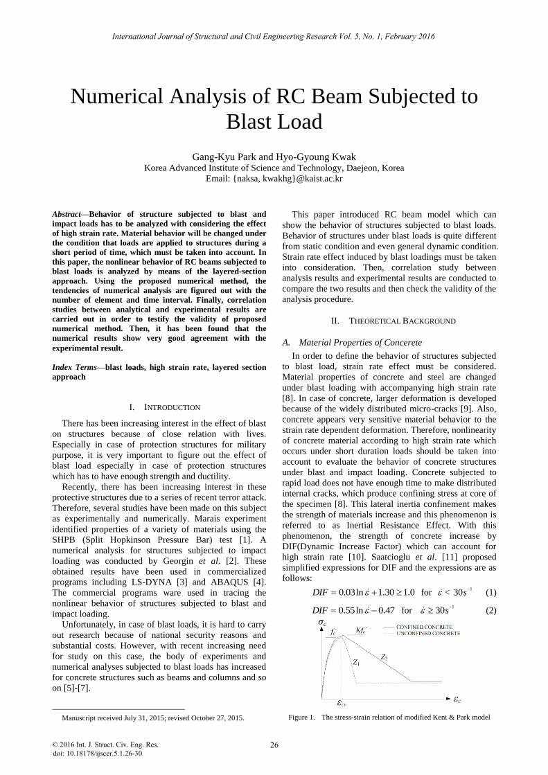
high strain rate [10]. Saatcioglu et al. [11] proposed
simplified expressions for DIF and the expressions are as
follows:
0.03ln 1.30 1.0DIF for < 1
30s
(1)
0.55ln 0.47DIF for 1
30s
(2)
Figure 1. The stress-strain relation of modified Kent & Park model
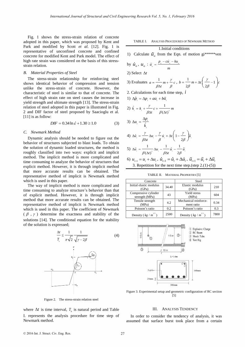
TABLE I. ANALYSIS PROCEDURES OF NEWMARK METHOD
1.Initial conditions
1) Calculate ou from the Eqn. of motion gi*****ven
by ou ,
ou : o o o
o
p cu kuu
m
2) Select t
3) Evaluates 1
a m ct
,
11
2 2b m t c
2. Calculations for each time step, i
1) ˆi i i i
p p au bu
2) 2
1ˆ
( )i i
k k c mt t
3) ˆ
i
i
i
pu
k
4) 12
i i i iu u u t u
t
5) 2
1 1 1
( ) 2i i i i
u u u ut t
6) 1i i i
u u u ,
1i i iu u u , 1i i iu u u
3. Repetition for the next time step.(step 2.(1)-(5))
TABLE II. MATERIAL PROPERTIES [5]
Concrete Steel
Initial elastic modulus
(GPa) 34.40
Elastic modulus
(GPa) 210
Compressive cylinder strength (MPa)
43 Yield stress
(MPa) 604
Tensile strength (MPa)
4.2 Mechanical reinforce-
ment ratio 0.34
Poisson’s ratio 0.2 Poisson’s ratio 0.3
Density (1/ 3
/kg m ) 2500 Density (1/ 3
/kg m ) 7800
Figure 3. Experimental setup and geometric configuration of RC section [5]
III. ANALYSIS TENDENCY
27
International Journal of Structural and Civil Engineering Research Vol. 5, No. 1, February 2016
© 2016 Int. J. Struct. Civ. Eng. Res.
Fig. 1 shows the stress-strain relation of concrete
adopted in this paper, which was proposed by Kent and
Park and modified by Scott et al. [12]. Fig. 1 is
representative of unconfined concrete and confined
concrete for modified Kent and Park model. The effect of
high rate strain was considered on the basis of this stress-
strain relation.
B. Material Properties of Steel
The stress-strain relationship for reinforcing steel
shows identical behavior of compression and tension
unlike the stress-strain of concrete. However, the
characteristic of steel is similar to that of concrete. The
effect of high strain rate on steel causes the increase in
yield strength and ultimate strength [13]. The stress-strain
relation of steel adopted in this paper is illustrated in Fig.
2 and DIF factor of steel proposed by Saacioglu et al.
[11] is as follow:
0.34ln 1.30 1.0DIF (3)
C. Newmark Method
Dynamic analysis should be needed to figure out the
behavior of structures subjected to blast loads. To obtain
the solution of dynamic loaded structures, the method is
roughly classified into two ways: explicit and implicit
method. The implicit method is more complicated and
time consuming to analyze the behavior of structures that
explicit method. However, it is through implicit method
that more accurate results can be obtained. The
representative method of implicit is Newmark method
which is used in this paper.
The way of implicit method is more complicated and
time consuming to analyze structure’s behavior than that
of explicit method. However, it is through implicit
method that more accurate results can be obtained. The
representative method of implicit is Newmark method
which is used in this paper. The coefficient of Newmark
( , ) determine the exactness and stability of the
solutions [14]. The conditional equation for the stability
of the solution is expressed;
1 1
2 2n
t
T
(4)
Figure 2. The stress-strain relation steel
where t is time interval, n
T is natural period and Table
I. represents the analysis procedure for time step of
Newmark method. In order to consider the tendency of analysis, it was
assumed that surface burst took place from a certain
28
International Journal of Structural and Civil Engineering Research Vol. 5, No. 1, February 2016
© 2016 Int. J. Struct. Civ. Eng. Res.
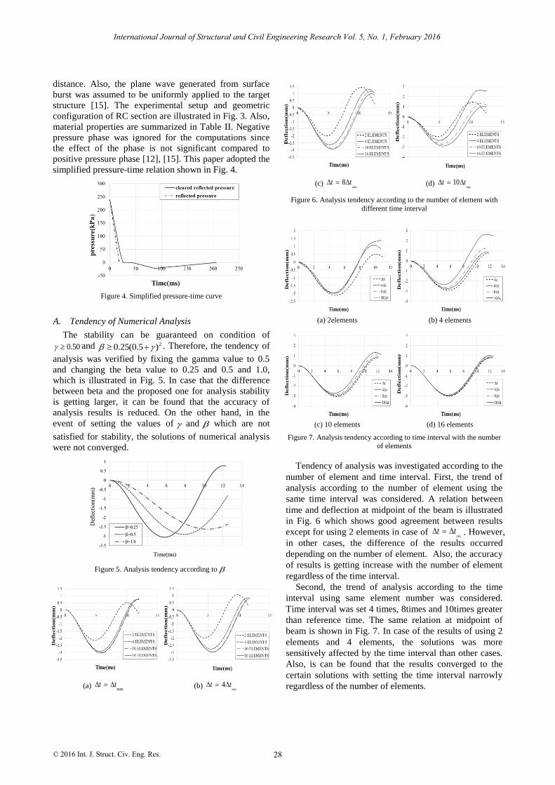
distance. Also, the plane wave generated from surface
burst was assumed to be uniformly applied to the target
structure [15]. The experimental setup and geometric
configuration of RC section are illustrated in Fig. 3. Also,
material properties are summarized in Table II. Negative
pressure phase was ignored for the computations since
the effect of the phase is not significant compared to
positive pressure phase [12], [15]. This paper adopted the
simplified pressure-time relation shown in Fig. 4.
Figure 4. Simplified pressure-time curve
A. Tendency of Numerical Analysis
The stability can be guaranteed on condition of
0.50 and 20.25(0.5 ) . Therefore, the tendency of
analysis was verified by fixing the gamma value to 0.5
and changing the beta value to 0.25 and 0.5 and 1.0,
which is illustrated in Fig. 5. In case that the difference
between beta and the proposed one for analysis stability
is getting larger, it can be found that the accuracy of
analysis results is reduced. On the other hand, in the
event of setting the values of and which are not
satisfied for stability, the solutions of numerical analysis
were not converged.
Figure 5. Analysis tendency according to
(a) max
t t
(b) max
4t t
(c) max
8t t (d) max
10t t
Figure 6. Analysis tendency according to the number of element with
different time interval
(a) 2elements (b) 4 elements
(c) 10 elements (d) 16 elements
Figure 7. Analysis tendency according to time interval with the number of elements
Tendency of analysis was investigated according to the
number of element and time interval. First, the trend of
analysis according to the number of element using the
same time interval was considered. A relation between
time and deflection at midpoint of the beam is illustrated
in Fig. 6 which shows good agreement between results
except for using 2 elements in case of max
t t . However,
in other cases, the difference of the results occurred
depending on the number of element. Also, the accuracy
of results is getting increase with the number of element
regardless of the time interval.
Second, the trend of analysis according to the time
interval using same element number was considered.
Time interval was set 4 times, 8times and 10times greater
than reference time. The same relation at midpoint of
beam is shown in Fig. 7. In case of the results of using 2
elements and 4 elements, the solutions was more
sensitively affected by the time interval than other cases.
Also, is can be found that the results converged to the
certain solutions with setting the time interval narrowly
regardless of the number of elements.
29
International Journal of Structural and Civil Engineering Research Vol. 5, No. 1, February 2016
© 2016 Int. J. Struct. Civ. Eng. Res.
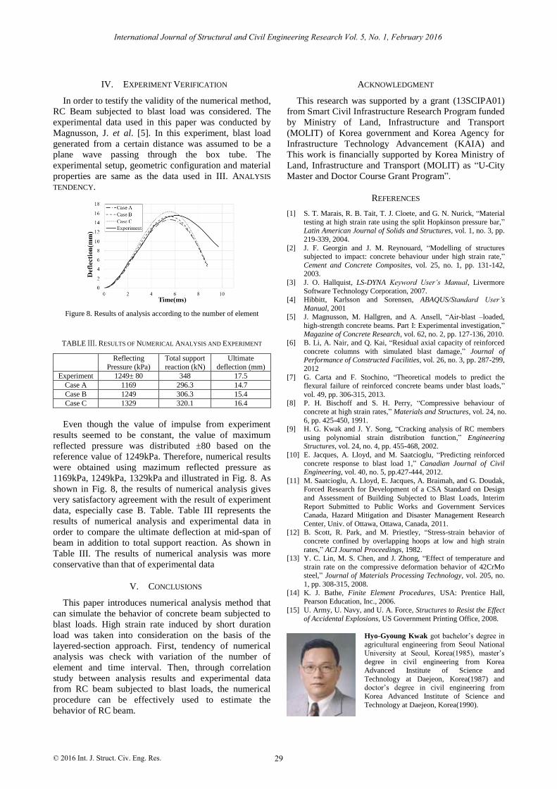
IV. EXPERIMENT VERIFICATION
In order to testify the validity of the numerical method,
RC Beam subjected to blast load was considered. The
experimental data used in this paper was conducted by
Magnusson, J. et al. [5]. In this experiment, blast load
generated from a certain distance was assumed to be a
plane wave passing through the box tube. The
experimental setup, geometric configuration and material
properties are same as the data used in III. ANALYSIS
TENDENCY.
Figure 8. Results of analysis according to the number of element
TABLE Ⅲ. RESULTS OF NUMERICAL ANALYSIS AND EXPERIMENT
Reflecting
Pressure (kPa)
Total support
reaction (kN)
Ultimate
deflection (mm)
Experiment 1249± 80 348 17.5
Case A 1169 296.3 14.7
Case B 1249 306.3 15.4
Case C 1329 320.1 16.4
Even though the value of impulse from experiment
results seemed to be constant, the value of maximum
reflected pressure was distributed ±80 based on the
reference value of 1249kPa. Therefore, numerical results
were obtained using mazimum reflected pressure as
1169kPa, 1249kPa, 1329kPa and illustrated in Fig. 8. As
shown in Fig. 8, the results of numerical analysis gives
very satisfactory agreement with the result of experiment
data, especially case B. Table. Table III represents the
results of numerical analysis and experimental data in
order to compare the ultimate deflection at mid-span of
beam in addition to total support reaction. As shown in
Table III. The results of numerical analysis was more
conservative than that of experimental data
V. CONCLUSIONS
This paper introduces numerical analysis method that
can simulate the behavior of concrete beam subjected to
blast loads. High strain rate induced by short duration
load was taken into consideration on the basis of the
layered-section approach. First, tendency of numerical
analysis was check with variation of the number of
element and time interval. Then, through correlation
study between analysis results and experimental data
from RC beam subjected to blast loads, the numerical
procedure can be effectively used to estimate the
behavior of RC beam.
ACKNOWLEDGMENT
This research was supported by a grant (13SCIPA01)
from Smart Civil Infrastructure Research Program funded
by Ministry of Land, Infrastructure and Transport
(MOLIT) of Korea government and Korea Agency for
Infrastructure Technology Advancement (KAIA) and
This work is financially supported by Korea Ministry of
Land, Infrastructure and Transport (MOLIT) as “U-City
Master and Doctor Course Grant Program”.
REFERENCES
[1] S. T. Marais, R. B. Tait, T. J. Cloete, and G. N. Nurick, “Material
testing at high strain rate using the split Hopkinson pressure bar,”
Latin American Journal of Solids and Structures, vol. 1, no. 3, pp.
219-339, 2004.
[2] J. F. Georgin and J. M. Reynouard, “Modelling of structures subjected to impact: concrete behaviour under high strain rate,”
Cement and Concrete Composites, vol. 25, no. 1, pp. 131-142, 2003.
[3] J. O. Hallquist, LS-DYNA Keyword User’s Manual, Livermore
Software Technology Corporation, 2007. [4] Hibbitt, Karlsson and Sorensen, ABAQUS/Standard User’s
Manual, 2001 [5] J. Magnusson, M. Hallgren, and A. Ansell, “Air-blast –loaded,
high-strength concrete beams. Part I: Experimental investigation,”
Magazine of Concrete Research, vol. 62, no. 2, pp. 127-136, 2010. [6] B. Li, A. Nair, and Q. Kai, “Residual axial capacity of reinforced
concrete columns with simulated blast damage,” Journal of Performance of Constructed Facilities, vol. 26, no. 3, pp. 287-299,
2012
[7] G. Carta and F. Stochino, “Theoretical models to predict the
flexural failure of reinforced concrete beams under blast loads,”
vol. 49, pp. 306-315, 2013. [8] P. H. Bischoff and S. H. Perry, “Compressive behaviour of
concrete at high strain rates,” Materials and Structures, vol. 24, no.
6, pp. 425-450, 1991. [9] H. G. Kwak and J. Y. Song, “Cracking analysis of RC members
using polynomial strain distribution function,” Engineering Structures, vol. 24, no. 4, pp. 455-468, 2002.
[10] E. Jacques, A. Lloyd, and M. Saatcioglu, “Predicting reinforced
concrete response to blast load 1,” Canadian Journal of Civil Engineering, vol. 40, no. 5, pp.427-444, 2012.
[11] M. Saatcioglu, A. Lloyd, E. Jacques, A. Braimah, and G. Doudak, Forced Research for Development of a CSA Standard on Design
and Assessment of Building Subjected to Blast Loads, Interim
Report Submitted to Public Works and Government Services Canada, Hazard Mitigation and Disaster Management Research
Center, Univ. of Ottawa, Ottawa, Canada, 2011. [12] B. Scott, R. Park, and M. Priestley, “Stress-strain behavior of
concrete confined by overlapping hoops at low and high strain
rates,” ACI Journal Proceedings, 1982. [13] Y. C. Lin, M. S. Chen, and J. Zhong, “Effect of temperature and
strain rate on the compressive deformation behavior of 42CrMo steel,” Journal of Materials Processing Technology, vol. 205, no.
1, pp. 308-315, 2008.
[14] K. J. Bathe, Finite Element Procedures, USA: Prentice Hall, Pearson Education, Inc., 2006.
[15] U. Army, U. Navy, and U. A. Force, Structures to Resist the Effect
of Accidental Explosions, US Government Printing Office, 2008.
Hyo-Gyoung Kwak got bachelor’s degree in agricultural engineering from Seoul National
University at Seoul, Korea(1985), master’s
degree in civil engineering from Korea Advanced Institute of Science and
Technology at Daejeon, Korea(1987) and doctor’s degree in civil engineering from
Korea Advanced Institute of Science and
Technology at Daejeon, Korea(1990).

He is Professor at Korea Advanced Institute of Science and Technology, Daejeon, Korea. He was Senior Researcher at Samsung Engineering
Company
Prof. Kwak is Senior Member in Korean Academy of Science and Technology and member in Korean Society of Civil Engineers.
Gang-Kyu Park got bachelor’s degree in civil engineering from Seoul National Uni-
versity of Science and Technology at Seoul
(2011) and master’s degree in civil and envi-ronmental engineering from Korea Advanced
Institute of Science and Technology at Dae-jeon, Korea (2014).
He is Doctral Candidate in Civil and Envi-
ronmental engineering at Korea Advanced Institute of Science and Technology, Daejeon,
Korea.
30
International Journal of Structural and Civil Engineering Research Vol. 5, No. 1, February 2016
© 2016 Int. J. Struct. Civ. Eng. Res.