Embed Size (px)
Citation preview
© The Authors, published by EDP Sciences. This is an open access article distributed under the terms of the Creative Commons Attribution License 4.0 (http://creativecommons.org/licenses/by/4.0/).
MATEC Web of Conferences 195, 02008 (2018) https://doi.org/10.1051/matecconf/201819502008ICRMCE 2018
Numerical analysis of castellated beams with oval openings
1Universitas Islam Indonesia, Faculty of Civil Engineering and Planning, Yogyakarta, Indonesia 2Diponegoro University, Civil Engineering Department, Semarang, Indonesia 3Nihon University, College of Engineering, Department of Architecture, Koriyama, Japan 4Atmajaya University, Civil Engineering Department, Yogyakarta, Indonesia
Abstract. The use of castellated beams has become more popular in the last two decades. The main idea for the use of these types of steel beams is to reduce their self-weight by providing openings in the web of wide flange (WF) or I sections. Numerous research on castellated beams has been conducted, the majority of the studies aimed to optimize the opening size and the shape configuration of the openings. A numerical analysis of castellated beams with oval openings was performed in this study. The sections under investigation had variations in the height-to-length ratios of the beam. The Do to D and b to Do ratios were kept at a constant. The D value was defined as the height of the beam, while Do is the height of the opening, and b is the width of the opening. The numerical analysis was performed by the finite element analysis using the STRAND7 software. The numerical model was further validated to the experimental data. The results showed that the developed finite element model resulted in a very good representation to the actual behavior of the sections.
1 Introduction Castellated beam use has shown an increasing pattern worldwide due to its potentials in reducing the self-weight of the member by adjusting the configuration of voids or openings throughout the length of the members. This technique is mostly applied on wide-flange (WF) and I sections in bending. The use of castellated beams has become more popular in the last two decades. The main idea for the use of these types of steel beams is to reduce the self-weight by providing openings in the web of wide flange (WF), or I sections and re-arranging the cut section so that it result in an increase of height. The castellated beam’s theoretical background lies in the attempt of increasing the profile height of the beam while creating openings in the web of the profile, thus enhancing its moment of inertia, but reducing its self-weight. Modifications applied on the castellated beam have an impact on the failure mode of the structure. The modes of failure that can occur included the formation of a vierendeel mechanism, lateral torsional buckling of the web post, rupture of a welded joint in a web post, lateral torsional buckling of the entire span, formation of a flexure mechanism, and buckling of the web post [1, 2]. *Corresponding author: [email protected]
Yanuar Setiawan1,*, Ay Lie Han2, Buntara Sthenly Gan3, and Junaedi Utomo4
2
MATEC Web of Conferences 195, 02008 (2018) https://doi.org/10.1051/matecconf/201819502008ICRMCE 2018
Numerous research on castellated beams has been conducted, the majority of the studies aimed to optimize the opening size and the shape configuration of the openings. Suharjanto [3] conducted a study on the horizontal shear strength of circular castellated beams with and without adding plates. Bedi and Pachpor [4] examined the moment and shear analysis of castellated beams with various openings, i.e., square, hexagonal, and circular. Wakchaure and Sagade [5] undertook numerical studies using the finite element analysis method on hexagonal castellated beams with height variations of the castellated beam. Jamadar and Khumbar [6] carried out a review on the finite element analysis of castellated beams with hexagonal openings, while Jamadar and Khumbar [7] performed a parametric study of castellated beams with circular and diamond openings.
The accomplished studies indicated that the stress concentration occurs in the corners of the openings leading to initial yielding in the section at the hexagonal opening. Continuing research work was focused on the circular openings by adjusting the angular orientation of the openings to minimize the formation of cracks [8]. The modification of these oval openings for castellated beams certainly requires further study on the stress concentration and failure mechanism due to the presence of the openings. It is expected that the development can provide structural optimization for the castellated beams itself. The optimization techniques could be implemented experimentally [9] or by numerical modeling of the specimen. The second option is far less more economical and fast. To ensure that the numerical or finite element model is accurate, a validation process should be performed.
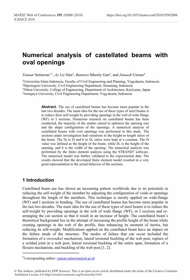
Previous research on oval openings indicate that this form provides a greater load capacity compared to the hexagonal forms [7]. The shape manufacturing of an oval castellated beam can be seen in Fig.1.
Fig.1. Manufacturing of castellated beam with oval openings.
2 Experimental programme and results The experimental tests conducted in the laboratory were utilized to examine the material properties of the steel material used for assembling the beam-sections. The full-scale beam specimens were tested for validation purposes to substantiate the numerical model using the finite element analysis (FEM).
`
`
h oD
`
`
3
MATEC Web of Conferences 195, 02008 (2018) https://doi.org/10.1051/matecconf/201819502008ICRMCE 2018
Numerous research on castellated beams has been conducted, the majority of the studies aimed to optimize the opening size and the shape configuration of the openings. Suharjanto [3] conducted a study on the horizontal shear strength of circular castellated beams with and without adding plates. Bedi and Pachpor [4] examined the moment and shear analysis of castellated beams with various openings, i.e., square, hexagonal, and circular. Wakchaure and Sagade [5] undertook numerical studies using the finite element analysis method on hexagonal castellated beams with height variations of the castellated beam. Jamadar and Khumbar [6] carried out a review on the finite element analysis of castellated beams with hexagonal openings, while Jamadar and Khumbar [7] performed a parametric study of castellated beams with circular and diamond openings.
The accomplished studies indicated that the stress concentration occurs in the corners of the openings leading to initial yielding in the section at the hexagonal opening. Continuing research work was focused on the circular openings by adjusting the angular orientation of the openings to minimize the formation of cracks [8]. The modification of these oval openings for castellated beams certainly requires further study on the stress concentration and failure mechanism due to the presence of the openings. It is expected that the development can provide structural optimization for the castellated beams itself. The optimization techniques could be implemented experimentally [9] or by numerical modeling of the specimen. The second option is far less more economical and fast. To ensure that the numerical or finite element model is accurate, a validation process should be performed.
Previous research on oval openings indicate that this form provides a greater load capacity compared to the hexagonal forms [7]. The shape manufacturing of an oval castellated beam can be seen in Fig.1.
Fig.1. Manufacturing of castellated beam with oval openings.
2 Experimental programme and results The experimental tests conducted in the laboratory were utilized to examine the material properties of the steel material used for assembling the beam-sections. The full-scale beam specimens were tested for validation purposes to substantiate the numerical model using the finite element analysis (FEM).
`
`
h oD
`
`
2.1 Steel properties test
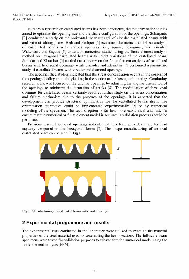
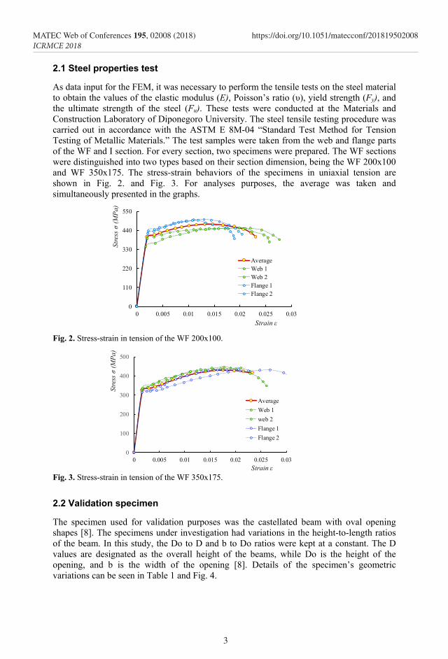
As data input for the FEM, it was necessary to perform the tensile tests on the steel material to obtain the values of the elastic modulus (E), Poisson’s ratio (υ), yield strength (Fy), and the ultimate strength of the steel (Fu). These tests were conducted at the Materials and Construction Laboratory of Diponegoro University. The steel tensile testing procedure was carried out in accordance with the ASTM E 8M-04 “Standard Test Method for Tension Testing of Metallic Materials.” The test samples were taken from the web and flange parts of the WF and I section. For every section, two specimens were prepared. The WF sections were distinguished into two types based on their section dimension, being the WF 200x100 and WF 350x175. The stress-strain behaviors of the specimens in uniaxial tension are shown in Fig. 2. and Fig. 3. For analyses purposes, the average was taken and simultaneously presented in the graphs.
Fig. 2. Stress-strain in tension of the WF 200x100.
Fig. 3. Stress-strain in tension of the WF 350x175.
2.2 Validation specimen
The specimen used for validation purposes was the castellated beam with oval opening shapes [8]. The specimens under investigation had variations in the height-to-length ratios of the beam. In this study, the Do to D and b to Do ratios were kept at a constant. The D values are designated as the overall height of the beams, while Do is the height of the opening, and b is the width of the opening [8]. Details of the specimen’s geometric variations can be seen in Table 1 and Fig. 4.
0
110
220
330
440
550
0 0.005 0.01 0.015 0.02 0.025 0.03
Stre
ss σ
(MPa
)
Strain ε
AverageWeb 1Web 2Flange 1Flange 2
0
100
200
300
400
500
0 0.005 0.01 0.015 0.02 0.025 0.03
Stre
ss σ
(MPa
)
Strain ε
AverageWeb 1web 2Flange 1Flange 2
4
MATEC Web of Conferences 195, 02008 (2018) https://doi.org/10.1051/matecconf/201819502008ICRMCE 2018
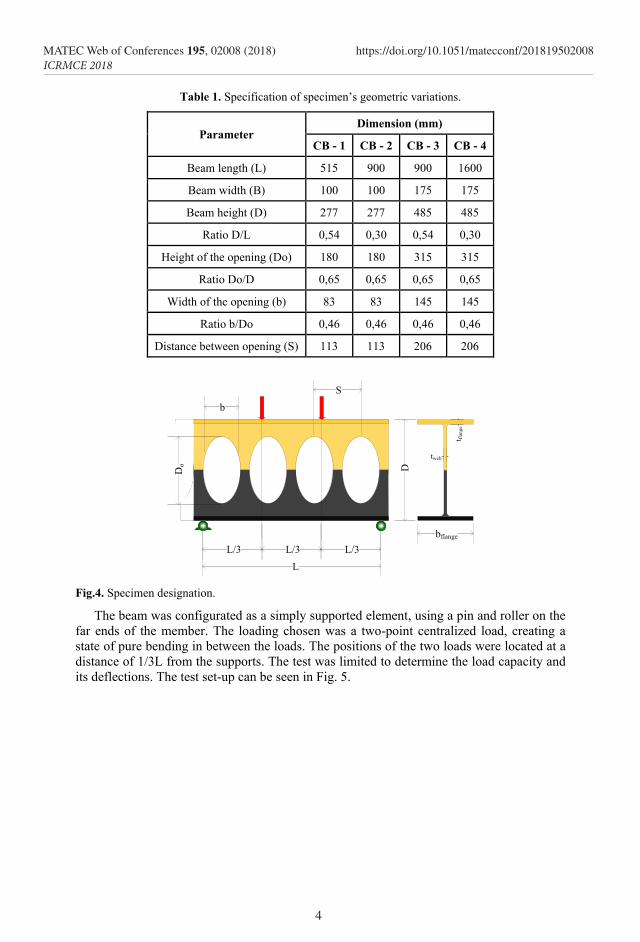
Table 1. Specification of specimen’s geometric variations.
Parameter Dimension (mm)
CB - 1 CB - 2 CB - 3 CB - 4
Beam length (L) 515 900 900 1600
Beam width (B) 100 100 175 175
Beam height (D) 277 277 485 485
Ratio D/L 0,54 0,30 0,54 0,30
Height of the opening (Do) 180 180 315 315
Ratio Do/D 0,65 0,65 0,65 0,65
Width of the opening (b) 83 83 145 145
Ratio b/Do 0,46 0,46 0,46 0,46
Distance between opening (S) 113 113 206 206
Fig.4. Specimen designation.
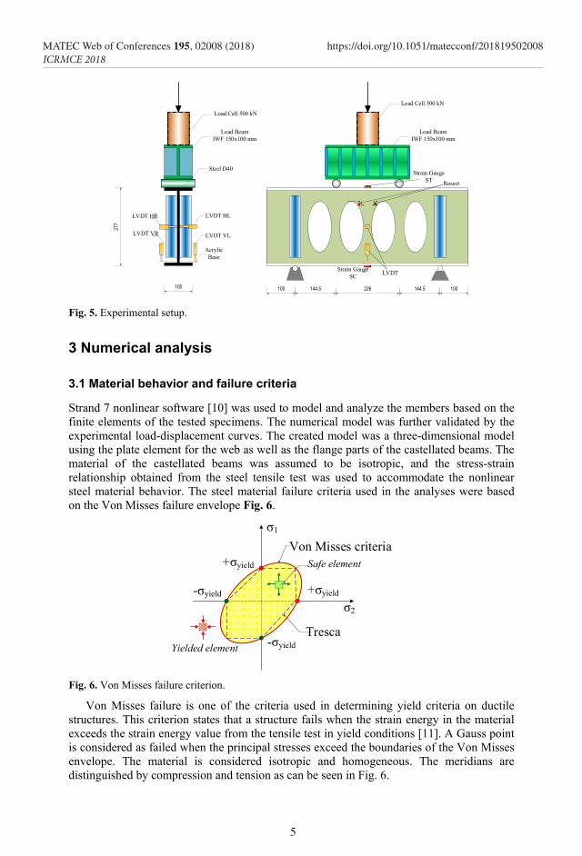
The beam was configurated as a simply supported element, using a pin and roller on the far ends of the member. The loading chosen was a two-point centralized load, creating a state of pure bending in between the loads. The positions of the two loads were located at a distance of 1/3L from the supports. The test was limited to determine the load capacity and its deflections. The test set-up can be seen in Fig. 5.
D
`
`
LL/3 L/3
bflange
t flan
getweb
b
5
MATEC Web of Conferences 195, 02008 (2018) https://doi.org/10.1051/matecconf/201819502008ICRMCE 2018
Table 1. Specification of specimen’s geometric variations.
Parameter Dimension (mm)
CB - 1 CB - 2 CB - 3 CB - 4
Beam length (L) 515 900 900 1600
Beam width (B) 100 100 175 175
Beam height (D) 277 277 485 485
Ratio D/L 0,54 0,30 0,54 0,30
Height of the opening (Do) 180 180 315 315
Ratio Do/D 0,65 0,65 0,65 0,65
Width of the opening (b) 83 83 145 145
Ratio b/Do 0,46 0,46 0,46 0,46
Distance between opening (S) 113 113 206 206
Fig.4. Specimen designation.
The beam was configurated as a simply supported element, using a pin and roller on the far ends of the member. The loading chosen was a two-point centralized load, creating a state of pure bending in between the loads. The positions of the two loads were located at a distance of 1/3L from the supports. The test was limited to determine the load capacity and its deflections. The test set-up can be seen in Fig. 5.
D
`
`
LL/3 L/3
bflange
t flan
ge
tweb
b
100 144.5 100226 144.5
Load Beam IWF 150x100 mm
Load Cell 500 kN
Strain GaugeST
LVDTStrain Gauge SC
277
Load Cell 500 kN
Load Beam IWF 150x100 mm
Steel D40
LVDT HL
LVDT VL
Acrylic Base
100
LVDT HR
LVDT VR
Rosset
Fig. 5. Experimental setup.
3 Numerical analysis
3.1 Material behavior and failure criteria
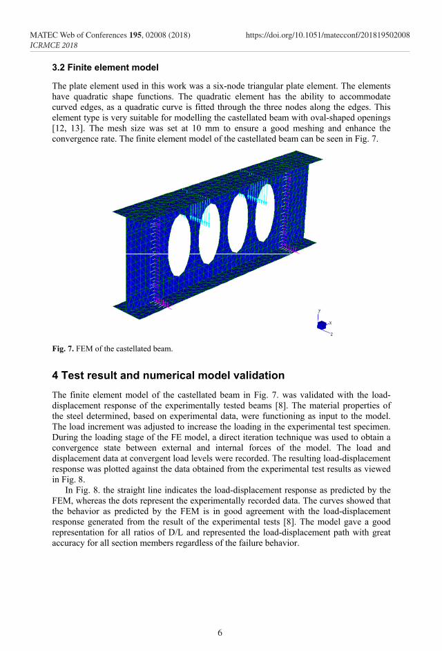
Strand 7 nonlinear software [10] was used to model and analyze the members based on the finite elements of the tested specimens. The numerical model was further validated by the experimental load-displacement curves. The created model was a three-dimensional model using the plate element for the web as well as the flange parts of the castellated beams. The material of the castellated beams was assumed to be isotropic, and the stress-strain relationship obtained from the steel tensile test was used to accommodate the nonlinear steel material behavior. The steel material failure criteria used in the analyses were based on the Von Misses failure envelope Fig. 6.
Fig. 6. Von Misses failure criterion.
Von Misses failure is one of the criteria used in determining yield criteria on ductile structures. This criterion states that a structure fails when the strain energy in the material exceeds the strain energy value from the tensile test in yield conditions [11]. A Gauss point is considered as failed when the principal stresses exceed the boundaries of the Von Misses envelope. The material is considered isotropic and homogeneous. The meridians are distinguished by compression and tension as can be seen in Fig. 6.
+σyield
+σyield
-σyield
-σyield
σ1
σ2
Von Misses criteria
Tresca
Safe element
Yielded element
6
MATEC Web of Conferences 195, 02008 (2018) https://doi.org/10.1051/matecconf/201819502008ICRMCE 2018
3.2 Finite element model
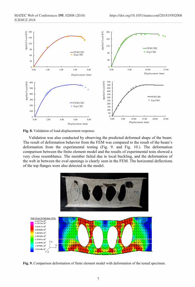
The plate element used in this work was a six-node triangular plate element. The elements have quadratic shape functions. The quadratic element has the ability to accommodate curved edges, as a quadratic curve is fitted through the three nodes along the edges. This element type is very suitable for modelling the castellated beam with oval-shaped openings [12, 13]. The mesh size was set at 10 mm to ensure a good meshing and enhance the convergence rate. The finite element model of the castellated beam can be seen in Fig. 7.
Fig. 7. FEM of the castellated beam.
4 Test result and numerical model validation The finite element model of the castellated beam in Fig. 7. was validated with the load-displacement response of the experimentally tested beams [8]. The material properties of the steel determined, based on experimental data, were functioning as input to the model. The load increment was adjusted to increase the loading in the experimental test specimen. During the loading stage of the FE model, a direct iteration technique was used to obtain a convergence state between external and internal forces of the model. The load and displacement data at convergent load levels were recorded. The resulting load-displacement response was plotted against the data obtained from the experimental test results as viewed in Fig. 8.
In Fig. 8. the straight line indicates the load-displacement response as predicted by the FEM, whereas the dots represent the experimentally recorded data. The curves showed that the behavior as predicted by the FEM is in good agreement with the load-displacement response generated from the result of the experimental tests [8]. The model gave a good representation for all ratios of D/L and represented the load-displacement path with great accuracy for all section members regardless of the failure behavior.
7
MATEC Web of Conferences 195, 02008 (2018) https://doi.org/10.1051/matecconf/201819502008ICRMCE 2018
3.2 Finite element model
The plate element used in this work was a six-node triangular plate element. The elements have quadratic shape functions. The quadratic element has the ability to accommodate curved edges, as a quadratic curve is fitted through the three nodes along the edges. This element type is very suitable for modelling the castellated beam with oval-shaped openings [12, 13]. The mesh size was set at 10 mm to ensure a good meshing and enhance the convergence rate. The finite element model of the castellated beam can be seen in Fig. 7.
Fig. 7. FEM of the castellated beam.
4 Test result and numerical model validation The finite element model of the castellated beam in Fig. 7. was validated with the load-displacement response of the experimentally tested beams [8]. The material properties of the steel determined, based on experimental data, were functioning as input to the model. The load increment was adjusted to increase the loading in the experimental test specimen. During the loading stage of the FE model, a direct iteration technique was used to obtain a convergence state between external and internal forces of the model. The load and displacement data at convergent load levels were recorded. The resulting load-displacement response was plotted against the data obtained from the experimental test results as viewed in Fig. 8.
In Fig. 8. the straight line indicates the load-displacement response as predicted by the FEM, whereas the dots represent the experimentally recorded data. The curves showed that the behavior as predicted by the FEM is in good agreement with the load-displacement response generated from the result of the experimental tests [8]. The model gave a good representation for all ratios of D/L and represented the load-displacement path with great accuracy for all section members regardless of the failure behavior.
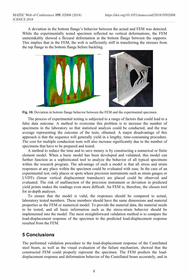
Fig. 8. Validation of load-displacement response. Validation was also conducted by observing the predicted deformed shape of the beam.
The result of deformation behavior from the FEM was compared to the result of the beam’s deformation from the experimental testing (Fig. 9. and Fig. 10.). The deformation comparison between the finite element model and the results of experimental tests showed a very close resemblance. The member failed due to local buckling, and the deformation of the web in between the oval openings is clearly seen in the FEM. The horizontal deflections of the top flanges were also detected in the model.
Fig. 9. Comparison deformation of finite element model with deformation of the tested specimen.
0
30
60
90
120
150
180
0.00 1.00 2.00 3.00 4.00
Appl
ied
Load
(kN
)
Displacement (mm)
FEM CB1Exp CB1
0
40
80
120
160
200
0.00 5.00 10.00 15.00
Appl
ied
Load
(kN
)
Displacement (mm)
FEM CB2Exp CB2
0
100
200
300
400
500
600
0.00 2.00 4.00 6.00 8.00
Appl
ied
Load
(kN)
Displacement (mm)
FEM CB3Exp CB3
050
100150200250300350400450500550
0.00 5.00 10.00 15.00 20.00 25.00
Appl
ied
Load
(kN
)
Displacement (mm)
FEM CB4Exp CB4
XY
Z
8
MATEC Web of Conferences 195, 02008 (2018) https://doi.org/10.1051/matecconf/201819502008ICRMCE 2018
A deviation in the bottom flange’s behavior between the actual and FEM was detected. While the experimentally tested specimen reflected no vertical deformations, the FEM unmistakably showed a flexural deformation at the bottom flange between the supports. This implies that in the FEM, the web is sufficiently stiff in transferring the stresses from the top flange to the bottom flange before buckling.
Fig. 10. Deviation in bottom flange behavior between the FEM and the experimental specimen.
The process of experimental testing is subjected to a range of factors that could lead to a false data outcome. A method to overcome this problem is to increase the number of specimens in the laboratory so that statistical analysis could be conducted, and the true average representing the outcome of the tests, obtained. A major disadvantage of this approach is that the sequence will generally yield in a lengthy, time-consuming procedure. The cost for multiple conduction tests will also increase significantly due to the number of specimens that have to be prepared and tested.
A method to reduce the time and to save money is by constructing a numerical or finite element model. When a basic model has been developed and validated, this model can further function as a sophisticated tool to analyze the behavior of all typical specimens within the research program. The advantage of such a model is that all stress and strain responses at any place within the specimen could be evaluated with ease. In the case of an experimental test, only places or spots where precision instruments such as strain gauges or LVDTs (linear vertical displacement transducer) are placed could be observed and evaluated. The risk of malfunction of the precision instrument or deviation in predicted yield points makes the readings even more difficult. An FEM is, therefore, the chosen tool for in-depth analyses.
To ensure that the model is valid, the responses should be compared to actual, laboratory tested members. These members should have the same dimensions and material properties as the FEM or numerical model. To provide the material data, the material needs to be tested, and all basic information such as the stress-strain behavior should be implemented into the model. The most straightforward validation method is to compare the load-displacement response of the specimen to the predicted load-displacement response resulted from the FEM.
5 Conclusions The performed validation procedure to the load-displacement response of the Castellated steel beam, as well as the visual evaluation of the failure mechanism, showed that the constructed FEM could properly represent the specimen. The FEM predicts the load-displacement response and deformation behavior of the Castellated beam accurately, and in
9
MATEC Web of Conferences 195, 02008 (2018) https://doi.org/10.1051/matecconf/201819502008ICRMCE 2018
A deviation in the bottom flange’s behavior between the actual and FEM was detected. While the experimentally tested specimen reflected no vertical deformations, the FEM unmistakably showed a flexural deformation at the bottom flange between the supports. This implies that in the FEM, the web is sufficiently stiff in transferring the stresses from the top flange to the bottom flange before buckling.
Fig. 10. Deviation in bottom flange behavior between the FEM and the experimental specimen.
The process of experimental testing is subjected to a range of factors that could lead to a false data outcome. A method to overcome this problem is to increase the number of specimens in the laboratory so that statistical analysis could be conducted, and the true average representing the outcome of the tests, obtained. A major disadvantage of this approach is that the sequence will generally yield in a lengthy, time-consuming procedure. The cost for multiple conduction tests will also increase significantly due to the number of specimens that have to be prepared and tested.
A method to reduce the time and to save money is by constructing a numerical or finite element model. When a basic model has been developed and validated, this model can further function as a sophisticated tool to analyze the behavior of all typical specimens within the research program. The advantage of such a model is that all stress and strain responses at any place within the specimen could be evaluated with ease. In the case of an experimental test, only places or spots where precision instruments such as strain gauges or LVDTs (linear vertical displacement transducer) are placed could be observed and evaluated. The risk of malfunction of the precision instrument or deviation in predicted yield points makes the readings even more difficult. An FEM is, therefore, the chosen tool for in-depth analyses.
To ensure that the model is valid, the responses should be compared to actual, laboratory tested members. These members should have the same dimensions and material properties as the FEM or numerical model. To provide the material data, the material needs to be tested, and all basic information such as the stress-strain behavior should be implemented into the model. The most straightforward validation method is to compare the load-displacement response of the specimen to the predicted load-displacement response resulted from the FEM.
5 Conclusions The performed validation procedure to the load-displacement response of the Castellated steel beam, as well as the visual evaluation of the failure mechanism, showed that the constructed FEM could properly represent the specimen. The FEM predicts the load-displacement response and deformation behavior of the Castellated beam accurately, and in
great detail. The post-peak, as well as the progress of the non-linear stiffness behavior, was very closely foreseen by the FEM as shown by the comparison of results in the load-displacement curves.
A deviation between the FEM and the experimentally tested specimen was distinguished at the bottom flange. The cause of this deviation probably originates from imperfections of the welding between the web sections during fabrication. The cutting and welding of the assembled section resulted in a less stiff web. In the FEM, a perfectly straight and homogeneously solid web was assumed. This hypothesis allowed the stresses from the top flanges to reach the bottom flange, before buckling of the web between the oval openings took place. Due to the imperfections, the buckling of the web occurred prior to the stress flow reaching the bottom part of the beam. The ultimate load carrying capacity however, remained unchanged since the member failed due to local buckling for both the FEM and the experimentally tested section.
This highlights the importance of finite element analyses in complimenting a research work into the behavior of structural elements. A FEM model could easily be modified based on the observation of the laboratory tested specimens. Adjustments to the model could then be applied, and the result of these modifications compared to the actual behavior. At further stages, this FEM will function to optimize the opening’s configuration, size and distance as well as be used to evaluate the principal stress flow and strain responses at every loading stage. The model will also be used to evaluate stress concentrations in the web.
References 1. D. Kerdal, D.A. Nethercot, J. C. S. R. 4, 295-315 (1984) 2. E. Ellobody, J. Constr. Steel Res. 67(5). 814-825 (2011) 3. J. T, Suharjanto, S.1, 2 (2011) 4. K.S. Bedi, P.D.Pachpor, I. J. E. R. A. 1, 1917-1921 (2011) 5. M.R. Wakchaure, A.V. Sagade, I. J. E. I. T.2, 1 (2012) 6. A.M. Jamadar, P.D.Khumbar, I. J. I. R. A. E.1, 125-129 (2014) 7. A.M. Jamadar, P.D. Khumbar, I. J. I. R. A. E. 2, 715-722 (2015) 8. S. Tudjono, Sunarto, A. L. Han, IOP Conf. Ser. Mater. Sci. Eng 271, (2017) 9. L. Budi, Sukamta, W. Partono, Procedia Eng. 171, 1092-1099 (2017) 10. STRAND7, Reference Manual, Rel 2.4 (2015) 11. F.P. Beer, E.R. Johnston, J.T. DeWolf, D.F. Mazurek, Mechanics of Materials, Sixth
Edition, New York: McGraw-Hill Companies (2012) 12. M. R. Soltani, A. Bouchair, M. Mimoune, Steel Res. 70, 101-114 (2012) 13. R. Frans, H. Parung, D. Sandy, S. Tonapa, Procedia Eng. 171, 781-788 (2017)


![Numerical analysis of castellated beams with oval openings · of castellated beams with various openings, i.e., square, hexagonal, and circular. Wakchaure and Sagade [5] undertook](https://img.dokumen.tips/doc/110x75/6065a854826ddc2c1d7fe375/numerical-analysis-of-castellated-beams-with-oval-openings-of-castellated-beams.jpg)


![Desing of Beams [Uyumluluk Modu]kisi.deu.edu.tr/ozgur.ozcelik/Ekonomi/ARCH 206/ARCH-205_2014-2015... · Castellated Beams . ... PRISMATIC BEAM DESIGN (cont) • Shear Stress ... EXAMPLE](https://img.dokumen.tips/doc/110x75/5af895747f8b9abd588bc6c3/desing-of-beams-uyumluluk-modukisideuedutrozgurozcelikekonomiarch-206arch-2052014-2015castellated.jpg)

![3 Desing of Beams [Uyumluluk Modu] - Ki??isel Sayfalarkisi.deu.edu.tr/ozgur.ozcelik/Ekonomi/ARCH 206/3_Desing of Beams... · Castellated Beams . ... PRISMATIC BEAM DESIGN (cont) •](https://img.dokumen.tips/doc/110x75/5af895747f8b9abd588bc6c6/3-desing-of-beams-uyumluluk-modu-kiisel-2063desing-of-beamscastellated.jpg)