Embed Size (px)
Citation preview
Copyright © 2014 Tech Science Press CMES, vol.102, no.2, pp.149-168, 2014
Numerical Analysis for the Mooring System withNonlinear Elastic Mooring Cables
Z.W. Wu1, J.K. Liu1, Z.Q. Liu1,2 and Z.R. Lu1
Abstract: This paper presents numerical analysis for the mooring system withnonlinear elastic mooring cables. The equation of motion for nonlinear elasticmooring cable is established by utilizing finite element method. A marine moor-ing system of floating rectangular box with nonlinear elastic cables is taken as anillustrative example. The dynamic analysis, static analysis, and uniformity analysisare carried out for the polyester mooring system and the results are compared withthose of the steel wire and the chain mooring system. Results from the presentstudy can provide valuable recommendations for the design and construction of themooring system with nonlinear elastic mooring cables.
Keywords: nonlinear elastic mooring cables, finite element method, numericalmodel, polyester mooring system, dynamic analysis.
1 Introduction
Compared with the steel wire or chain, the polyester cable has lighter mass andhigher corrosion resistance. Currently, trends aim at station-keeping of floatingstructure via mooring in deeper water. Polyester cable is considered to be an attrac-tive option for deepwater mooring systems. Polyester cable has many advantagesover steel wire and chain, however one of the major challenges lies in an accu-rate understanding of the full-scale physical properties. Other than the steel wireor chain, the mechanical properties of polyester cable are generally nonlinear andtime- dependent and exhibit viscoelasticity and viscoplasticity.
The nonlinear elastic mooring cable has significant effects on the performances ofthe mooring system and the calculations are more complicated than the linear ones,and they are related to dynamic responses and mooring forces of the mooring sys-tem. Therefore, it is necessary and significant to make research about for mooringsystem with nonlinear elastic mooring cables.
1 Department of Mechanics, Sun Yat-sen University, Guangzhou 510006, PR China.2 Corresponding author. E-mail: [email protected]

150 Copyright © 2014 Tech Science Press CMES, vol.102, no.2, pp.149-168, 2014
The nonlinear elastic mooring cable has been an interest topic in marine hydro-dynamics research in the past few decades. Various methods have been presentedfor obtaining material property of nonlinear elastic. Del Vecchio (1992) proposeda method for determining the modulus of the polyester rope at constant tempera-ture. Francois and Davies (2008) carried out experiments on the characterizationof polyester mooring cables. Liu et al. (2014) made experimental investigation onnonlinear behaviors of synthetic fiber ropes. Some researchers [Yuan et al. (2010);Huang et al. (2013); Beltrán and Williamson (2011); Catipovic et al. (2011)] pre-sented various computational methods for nonlinear elastic mooring cables. And,the finite element methods have been developed to solve nonlinear dynamics prob-lems of flexible structure, nonlinear elastic-plastic material and catenary structure[Okamoto and Omura (2003); Nishioka et al. (2007); Kim et al. (2010)].
However, those methods still need to be further improved to enable easier numericalimplementation utilizing classical finite element method codes, and the researchesabout the comparison of dynamic and static analysis between steel wire, chain andthe polyester mooring system has not been seen.
In the present study, the equation of motion for a nonlinear elastic mooring cableof a mooring system is built and the finite element method is used to obtain thedynamic responses of the system. A mooring system of floating rectangular boxwith nonlinear elastic cable is taken as the numerical model. The dynamic analysis,static analysis, and uniformity analysis are made for the polyester mooring system.
2 Methodology
2.1 Equation of motion for the mooring system
In Fig. 1, two coordinate systems are defined to describe the motions of floatingstructure, i.e. the fixed reference coordinate system O−XY Z with origin in the freesurface and the body fixed coordinate system o− xyz with origin at the centre ofgravity of floating structure.
To carry out calculation of the coupled model the force and the moment of eachmooring cable should be included into dynamics of a floating body. Considering thecombined effects of current, wind and wave, the equation of motion for a mooringsystem with nonlinear elastic cable can be written as [Buchner et al. (2001)]
([Mm]+ [M∞a ]){x(t)}+
∫ t0 [K(t− τ)]{x(t)}dτ+
+[C]{x(t)}= {FWA(t)}+{FM(t)}+{FWI(t)}+{FCU(t)}(1)
where [Mm] and [M∞a ] are the mass and added mass matrices, respectively,
[K(t− τ)] is the delay function matrix, [C] is the hydrostatic resilience matrix,{x(t)}, {x(t)} and {x(t)} are the acceleration, velocity and displacement matrices,

Numerical Analysis for the Mooring System 151
Original Figure 1
Revised Figure 2
The start point of the blue line should be located in the point of o . And, the blue arc
should be slightly moved in the Figure 1.
Figure 3: Definition of the coordinate systems of the mooring system.
X
Y Z
O
Positive angle x
y
o
z
Wave direction (or current, wind)
Figure 1: Definition of the coordinate systems of the mooring system.
respectively, and {FWA(t)}, {FM(t)}, {FWI(t)} and {FCU(t)} are the wave force,cable tension, wind force and current force, respectively.
The wind force provided by Ref. [OCIMF (1994)] is expressed as
FWI = 0.5v2kChCsA (2)
where vk is the wind speed, Ch is the pressure and height coefficient, Cs is the shapefactor, and A is the windward area.
The current force in Eq. (1) can be given as
FCU = 0.5ρCDu2ACU (3)
where ρ is the density of water, CD is the hydraulic drag coefficient, u is the flowvelocity, and ACU is the incident flow area.
The linear three-dimensional potential theory is used to calculate the wave forces.The first order wave force, the second order wave force are defined by linear transferfunction and quadratic transfer function, respectively, which is the most commonmethod for calculating wave forces of wet surfaces.
The irregular wave conditions can be expressed by the Pierson-Moskowitz wavespectrum [Pillai and Prasad (2008)]
S(ω) =1
2π
H2s
4πT 4z(2π
ω)5 exp
[− 1
πT 4z(2π
ω)4]
(4)
where Hs is the significant wave height, Tz is the zero crossing period, and ω is thewave frequency.
2.2 Equation of motion of the mooring cable
In Fig. 2, nonlinear elastic mooring cable is modeled as a space curve, which isdefined by a position vector r. Any point at the curve is defined by an arc length of

152 Copyright © 2014 Tech Science Press CMES, vol.102, no.2, pp.149-168, 2014
extended mooring line s. Within dynamic analysis the position vector r is also thefunction of time t.
Figure 2: Definition of the mooring cable element.
The equation of motion is established by force equilibrium on an equivalent seg-ment of the mooring line based on Newton’s Second Law
dFE
ds+qE = mr (5)
where qE is the effective distributed load vector, m is the distributed mass of theextended mooring line, r is the acceleration vector of the segment, and FE is thecross section effective force vector expressed as
FE = TEdrds
(6)
where TE is the effective tension force.
Combining Eq. (5) and Eq. (6) leads to
dds
(TEdrds
)+qE = mr (7)

Numerical Analysis for the Mooring System 153
The elongation strain ε is defined as
ε =ds−ds
ds(8)
where s is the arc length related to non-extended case.
From Eqs. (8) and (7), we have
dds
(TE
1+ ε
drds
)+(1+ ε)qE = (1+ ε)mr (9)
The effective distributed load vector qE is the summation of gravity, buoyancy, andthe hydrodynamic force vector qH of the cable. And qH can be expressed by theMorison equation.
Thus, qE can be expressed as
qE =−ρAg+ mg+qH (10)
with
A =A
1+ ε, m =
m1+ ε
(11)
where A and m are the cross-sectional area and distributed mass variables relatedto the extended case, respectively, while A and m are related to the non-extendedcase, ρ is the density of water, g is the gravitational acceleration vector.
Substituting Eq. (10) and Eq. (11) in to Eq. (9), we have
dds
(TE
1+ ε
drds
)+mg−ρAg+qH = mr (12)
With classical form of the elongation strain and the Lame formula, the elongationstrain ε of the cable submerged in water, can be written as
ε =1E
[TE
A− (1−2ν)p
](13)
where E is the Young’s modulus, p is hydrostatic pressure of the sea water, and ν
is the Poisson’s ratio.
For simplicity, the conserved Poisson’s ratio is adopted, i.e. the synthetic cable ν
is assumed to be 0.5 [Tjavaras et al. (1998)]. Thus, Eq. (13) can be expressed as
ε =TE
AE(14)
154 Copyright © 2014 Tech Science Press CMES, vol.102, no.2, pp.149-168, 2014
An empirical formulation in Ref. [Tahar et al. (2008)] is used to represent the axialstiffness AE of the polyester cable
AE = RHOL(α +βTR
Bs) ·106 (15)
where Bs is the minimum breaking strength, TR is the time dependant real tension,α and β are the material constants depending on the type of polyester materialand their values usually come from the experimental results, and RHOL is the dryweight per unit length of the cable.
From Eq. (8) and considering the symmetric set, the axial elongation condition canbe obtained by an approximate form
11+ ε
(drds· dr
ds)−1− ε = 0 (16)
2.3 Finite element model for the mooring cable
From Eqs. (12), (14) and (16), the final form of governing equations of the cablecan be written as[(TE −TE
TE
AE+TE(
TE
AE)2)r′i
]′+mgi−ρAgi +qH
i = mri (17)
[1− TE
AE+(
TE
AE)2)
]r′jr′j−1− TE
AE= 0 (18)
with i, j = 1,2,3. It is noted that qHi using new label to avoid confusion.
Based on Galerkin’s method [Zienkiewicz et al. (2005); Tahar et al. (2008);Catipovic et al. (2011)], the finite element discretization of the equation of mo-tion Eq. (17) can be written as
(Mi jkl +MAi jkl)U jk +(K0
ni jkl +λmK1nmi jkl +λmλpK2
nmi jkl)λnU jk +Fil +FHil = 0 (19)
in which,
Mi jkl =−∫ L
0mAlAkδi jds (20)
MAi jkl =−
∫ L
0(CAρA)Alei f gA′veg jhAkA′zU f vUhzds (21)
K0ni jkl =−
∫ L
0PnA′kA′lδi jds (22)

Numerical Analysis for the Mooring System 155
K1ni jkl =−
∫ L
0
1AE
PnPmA′kA′lδi jds (23)
K2ni jkl =−
∫ L
0
1(AE)2 PnPmPpA′kA′lδi jds (24)
Fil = FCil +
∫ L
0mgids−
∫ L
0(ρA)giAlds (25)
FHil =
∫ L
0(CMρA)Alei f gA′veg jhA′zv jU f vUhzds+
+∫ L
0(12
CDρA)√[eabc(vb−ArUbrA′sUcs)][eade(vd−AtUdtA′uUeu)]·
· [Alei f gA′veg jh(v j−AkU jk)A′zU f vUhz]ds
(26)
with a,b,c,d,e, f ,g,h,m,n, p = 1,2,3, k,r, t,u,v,z = 1,2,3,4, where L is the lengthof each element, Mi jkl is the mass matrix due to the own mass, MA
i jkl is the addedmass matrix, K0
ni jkl , K1nmi jkl , K2
nmi jkl is the geometric stiffness matrix and additionalstiffness matrix, respectively, δi j is the Kronecker delta, ei f g is the Levi-Civita sym-bol, Al and Pn are the shape functions with Hermitian polynomials, CA, CM and CD
are the added mass, inertial and drag coefficients, Fil , FHil and FC
il are the total nodalforce, hydrodynamic nodal force and external nodal force vector, and λm, λp, U jkare unknown coefficients of time dependent.
Similarly, Eq. (18) can be written as
(B0mkl +λnB1
nmkl +λnλpB2nmpkl)U jlU jk +Cnmλn−Cm = 0 (27)
with the detailed coefficients expressed as
B0mkl =
∫ L
0PmA′kA′lds (28)
B1nmkl =−
∫ L
0
1AE
PnPmA′kA′lds (29)
B2nmpkl =−
∫ L
0
1(AE)2 PnPmPpA′kA′lds (30)
Cnm =−∫ L
0
1AE
PnPmds (31)
Cm =−∫ L
0Pmds (32)
where B0mkl , B1
nmkl , B2nmpkl is the geometric coefficient matrix and additional coeffi-
cient matrix, respectively, and Cm, Cnm are the vectors related to shape and stiffness.
156 Copyright © 2014 Tech Science Press CMES, vol.102, no.2, pp.149-168, 2014
The Newton-Raphson iterative method [Kreyszig (1993)] is used to solve Eq. (19)and Eq. (27) as follows(
J11(n+1,k)i jkl J12(n+1,k)
nil
J21(n+1,k)m jk J22(n+1,k)
mn
)(∆U jk∆λn
)=−
(R1(n+1,k)
il
R2(n+1,k)m
)(33)
with
J11(n+1,k)i jkl =
4∆t2 M(n+1,k)
i jkl + K(n+1,k)ni jkl λn (34)
J12(n+1,k)nil = K(n+1,k)
ni jkl U (n+1,k)jk (35)
J21(n+1,k)m jk =−(B0
mkl +λnB1nmkl +λnλpB2
nmpkl)(n+1,k)U (n+1,k)
jl (36)
J22(n+1,k)mn =−1
2Cmn−
12(B1
nmkl +2λpB2nmpkl)
(n+1,k)U (n+1,k)jl U (n+1,k)
jk (37)
R1(n+1,k)il =(
4∆t2 M(n+1,k)
i jkl + K(n+1,k)ni jkl λn)U
(n+1,k)jk + F(n+1,k)
il
− M(n+1,k)i jkl (
4∆t2Un
jk +4∆t
V njk +V n
jk)
(38)
R2(n+1,k)m =−1
2
((B0
mkl +λnB1nmkl +λnλpB2
nmpkl)(n+1,k)
U (n+1,k)jl U (n+1,k)
jk +Cmnλ(n+1,k)n −Cm
)(39)
where J11i jkl , J12
nil , J21m jk and J22
mn compose a Jacobian matrix while R1il and R2
m are partsof a residual vector, and k in superscripts denotes the iteration number within a timestep.
For a singe finite element, Eq. (33) is written as
(J)(n+1,k)
(∆y) =−(R)(n+1,k) (40)
where J, ∆y, R are the corresponding terms in the Eq. (33).
Iterative calculation is written as
(y)(n+1,k+1) =
{(y)(n)+(∆y) f or f irst iteration(y)(n+1,k)+(∆y) f or other iteration
(41)
Numerical Analysis for the Mooring System 157
Cable 1
Cable 3 Cable 2
Cable 4
45m
45m
Cable 2 Cable 3
27.5m
Sea bed
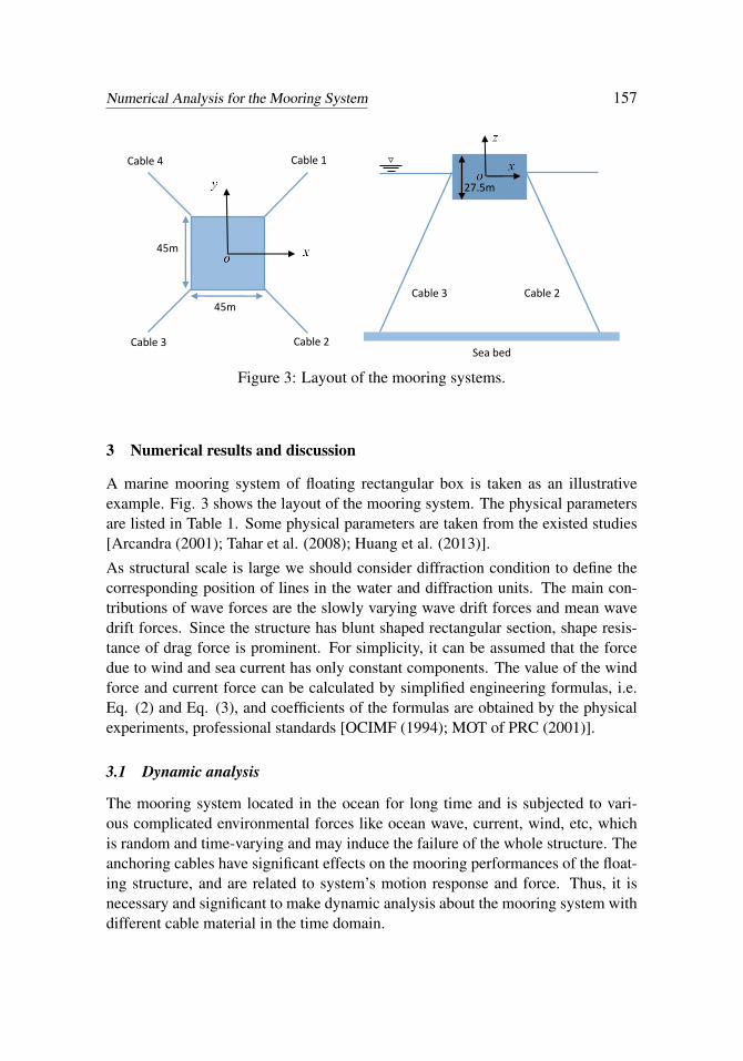
Figure 3: Layout of the mooring systems.
3 Numerical results and discussion
A marine mooring system of floating rectangular box is taken as an illustrativeexample. Fig. 3 shows the layout of the mooring system. The physical parametersare listed in Table 1. Some physical parameters are taken from the existed studies[Arcandra (2001); Tahar et al. (2008); Huang et al. (2013)].
As structural scale is large we should consider diffraction condition to define thecorresponding position of lines in the water and diffraction units. The main con-tributions of wave forces are the slowly varying wave drift forces and mean wavedrift forces. Since the structure has blunt shaped rectangular section, shape resis-tance of drag force is prominent. For simplicity, it can be assumed that the forcedue to wind and sea current has only constant components. The value of the windforce and current force can be calculated by simplified engineering formulas, i.e.Eq. (2) and Eq. (3), and coefficients of the formulas are obtained by the physicalexperiments, professional standards [OCIMF (1994); MOT of PRC (2001)].
3.1 Dynamic analysis
The mooring system located in the ocean for long time and is subjected to vari-ous complicated environmental forces like ocean wave, current, wind, etc, whichis random and time-varying and may induce the failure of the whole structure. Theanchoring cables have significant effects on the mooring performances of the float-ing structure, and are related to system’s motion response and force. Thus, it isnecessary and significant to make dynamic analysis about the mooring system withdifferent cable material in the time domain.

158 Copyright © 2014 Tech Science Press CMES, vol.102, no.2, pp.149-168, 2014
Table 1: Basic parameters of the numerical model.
Designation Parameter ValueLength (m) 45Width (m) 45Height (m) 27.5
Structural Draft (m) 20parameters Mass (t) 41512
Mass moment of inertia (kgm2) Ixx 4.5316E10Mass moment of inertia (kgm2) Iyy 4.2748E10Mass moment of inertia (kgm2) Izz 4.8877E10
Density of water (kg/m3) 1025Depth of water (m) 80
Environmental Maximum wave zero crossing period (s) 60parameters Maximum significant wave height (m) 2
Maximum current velocity (m/s) 4Maximum wind velocity (m/s) 13.8
Direction (◦) 60Pretension (kN) 20
Numbers of cable 4Mooring Length of mooring cable (m) 110
parameters Diameter of mooring cable (m) 0.12Minimum breaking load (N) Steel wire 7.250E6,
Chain 2.155E6,Polyester 2.70E6
Dry weight (kg/m) Steel wire 70.37, Chain88.22, Polyester 10.8
Stiffness (N) Steel wire 1.36E8, Chain3.06E8, Polyester
(dynamic, linearizedstiffness 1.50E8,α = 2.5,β = 2.0)
Fig. 4 shows the effect of cable length on mean dynamic mooring force of mooringsystem, the variational laws of curves of cable 1 and cable 3 are similar, with theincrease of the cable in the range of 106∼116 m, the mean dynamic mooring forceis decreased. Due to the effect of dynamic stiffness of the polyester, the variationallaws of curves are not linear. With the increase of the cable length, there is a fractionof cable lying on the seabed, and it does not have any influence on the cable tensionbecause its weight is counteracted by the seabed reaction. Thus, it can be seen that,

Numerical Analysis for the Mooring System 159
the dynamic mooring force of the two cables do change abruptly from 110 m to112 m, and the decrease slows down thereafter.
Figure 4: Mean dynamic mooring force of the polyester mooring system.
Figure 5: Dynamic mooring tension force of the cable 3.

160 Copyright © 2014 Tech Science Press CMES, vol.102, no.2, pp.149-168, 2014
In Fig. 5, comparing with chain and steel wire, when with same pretension, thepolyester has smallest value of dynamic tension force and fastest rate of decay. Themaximum value of the dynamic tension force of polyester is only about 67.72%and 91.58% of those in chain and steel wire, respectively. Due to the capacity inabsorbing dynamic tension force energy and little weight in water, the polyestercan effectively suppress the dynamic tension force of the mooring system, whilechain and steel wire need to enhance their minimum breaking load to avoiding bebroken in extreme environmental conditions.
Figs. 6-9 shows examples of the dynamic motion response time history signal ofmooring system with three kinds of mooring cables. In the present case, the surgemotion dominates over sway motion due to the upstream direction of the environ-mental force more close to surge direction. The value of surge and sway motionresponse of polyester mooring system is largest, while the value of roll and pitchmotion response is smallest in the three kind of mooring cables. It appears that thepolyester has significant suppression effect on the rotational degree of freedom ofthe roll and pitch motion, while the suppression effect on the translational degreesof freedom of the surge and sway motion is limited. The reason is that the dynamictension force is mainly provided by the horizontal dynamic motion response, gen-erally speaking, smaller dynamic tension force lead to larger horizontal dynamicmotion response.
Figure 6: Dynamic surge motions of the mooing system.

Numerical Analysis for the Mooring System 161
Figure 7: Dynamic sway motions of the mooing system.
Figure 8: Dynamic roll motions of the mooing system.

162 Copyright © 2014 Tech Science Press CMES, vol.102, no.2, pp.149-168, 2014
Figure 9: Dynamic pitch motions of the mooing system.
The axial stiffness AE of the polyester is no longer constant but varies with themagnitude of dynamics tension force, and the dynamics tension force is time vary-ing in irregular wave conditions. Thus, complicated nonlinear coupling effect canbe occurred between the mooring cable and its mooring system. The Ref. [Tahar etal. (2008)] noted that the heave motion and roll/pitch angles are little affected byboth the polyester mooring stiffness and tension, but the horizontal offset of surgeand sway motions are affected signally.
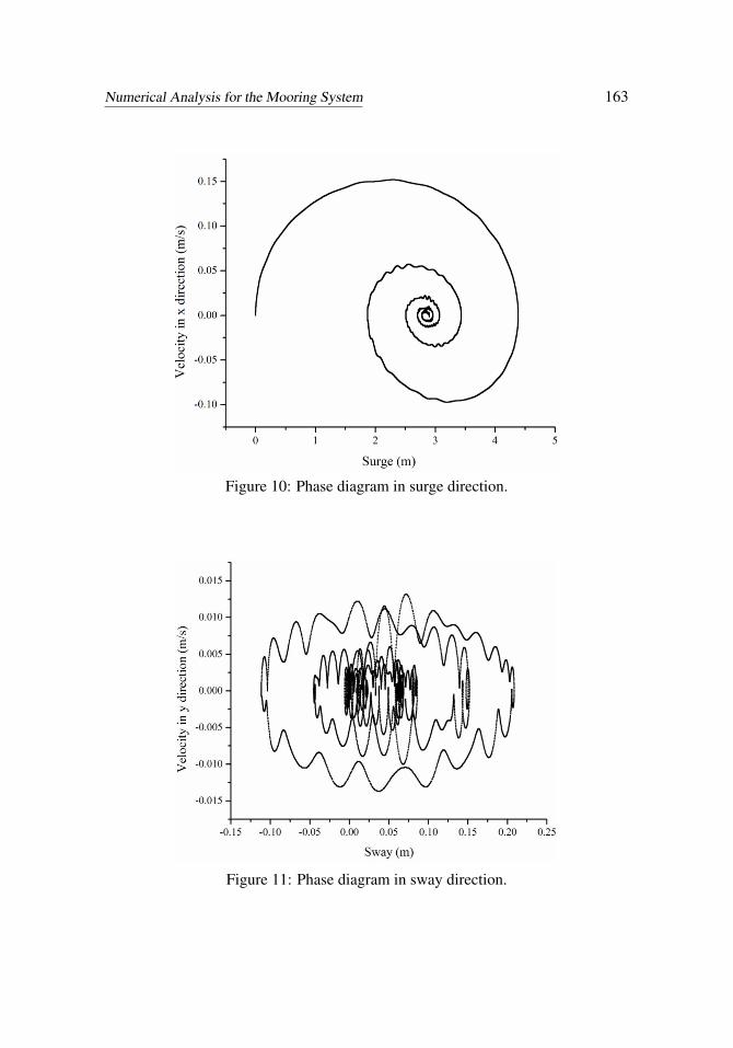
Figs. 10-12 shows examples of the phase diagram in surge, sway, and heave direc-tion, respectively. Due to little effects by the polyester cable, there is no nonlineardamping added in the heave direction, Fig. 12 shows the low frequency motionin heave direction. The motional characteristic is of periodic cycle, and the heavemotion goes around at centre-of-gravity position of floating structure, and the mag-nitude value is roughly constant. The surge motion dominates over sway motionleads to prominent mooring-induced damping due to the significant effects of thepolyester. Fig. 10 shows characteristic of surge motions in damping decay, and thestationary focal point is around at the point of 3 m. In Fig. 11, the phase diagramin sway direction shows motional characteristic of chaos, the periodic motion isbroken by the nonlinear coupling effect of the polyester cable with the mooringsystem.
Numerical Analysis for the Mooring System 163
Figure 10: Phase diagram in surge direction.
Figure 11: Phase diagram in sway direction.

164 Copyright © 2014 Tech Science Press CMES, vol.102, no.2, pp.149-168, 2014
Figure 12: Phase diagram in heave direction.
3.2 Static analysis
Horizontal restoring stiffness plays very important role in global performance ofthe mooring system, and its values depends on the stiffness, self-weight, and meanminimum breaking load of the mooring cable, which necessitates careful consider-ation during the early stage of design.
In the present study, a static cable analysis is conducted in order to obtain thetension-displacement characteristics of the mooring system. In Fig. 13, in both ca-ble cases, the restoring force increases with the static surge offset Comparing withthe steel wire and the chain mooring system, the static-offset curve of polyestershows hardening effect, it is observed that the restoring force provided by thepolyester mooring system is medium when the surge offset is below 0.7m and sig-nificantly greater than the other two one when the offset above 0.7m. The differencevalue of the restoring force between provided by the polyester and steel wire is -13000 N in the point of 0.2 m, while is larger than 54000 N in the points of 1.0m, and it can expect that the difference value huge when the surge offset increases.This is expected because the modulus of a polyester cable increases with the in-crease in tension, while the modulus of steel wire and the chain remain unchanged.
The result shows that the polyester mooring line system provides larger nonlinearhorizontal stiffness to the mooring system, which can enhance the global perfor-

Numerical Analysis for the Mooring System 165
Figure 13: Static surge offset curve with same pretension of the mooring system.
mance of the mooring system located in complex ocean environmental conditions,especially in deeper water.
3.3 Uniformity analysis
In mooring system, if there are huge discrepancies between mooring cables, slackin one or more cables could be encountered, while taut in the other cables whichundertake most of the force of the mooring system. The slack of cable might inducethe temporary dynamic instability of the floating structure for loss of restraint. Be-sides, when the cable transits alternatively between the states of slack and taut, theinstant tension force of a large value i.e. impulse force might occur, which mightcause a sudden breakage of the cable, beside, the fatigue failure can be producedeasier.
Uniformity analysis is made for reduce the risk of the slack phenomenon. Thestandard deviations of peak mooring force and mean mooring force of each fourcables are taken to make analysis about the uniformity of the mooring forces. 100computational cases with variational environmental parameters are calculated. Andthe mean values of those cases are taken to make comparisons about the three kindof cable.
In Fig. 14, the standard deviation of peak value and mean value of polyester is onlyabout 48.89%, 23.12% of those in chain, respectively. The polyester has minimum

166 Copyright © 2014 Tech Science Press CMES, vol.102, no.2, pp.149-168, 2014
Figure 14: Uniformity of the mooring forces.
standard deviation which implies polyester has higher uniformity of mooring forcethan steel wire and chain, indicating that polyester has the lowest risk of causing asudden breakage of the cable. Zhang (2008) noted that, for different cable material,when with some pretension, smaller density and larger modulus can suppress slackphenomenon better, it can be used to explain the aforementioned results.
3.4 Discussion
To keep the safety of the mooring system, the numerical simulation in the de-sign stage for the mooring system located in complicated marine environment isnecessary and significant, while physical model experiments are generally expen-sive and time consuming. The polyester mooring cable has a highly non-linearload-extension curve complicating the mooring system design, thus the numericalmethod has been seen less as set, and this disadvantage restricted its wide practicalapplication.
The numerical model and methodology based on the finite element method has beensuccessfully developed in this present study. Thus, the engineers can easily use thepresent method to make the numerical simulation to get more knowledge of thestatic and dynamic behavior of the mooring system with nonlinear elastic mooringcables. Steel wire or chain produce a nearly linear load-extension curve over therange of loading involved in most mooring designs, and their mechanical properties

Numerical Analysis for the Mooring System 167
are simple and have mature use and experience, thus, make the comparison withthem, the polyester mooring system can get the useful design consults. Overall,the present study can promote widely practical application of the nonlinear elasticmooring cables.
4 Conclusions
A mathematical method for dynamics motion of nonlinear elastic mooring cableis built utilizing finite element method. The marine mooring system of floatingrectangular box with nonlinear elastic cables is taken as an illustrative numericalexample. The dynamic analysis, static analysis, and uniformity analysis are madefor the polyester mooring system while comparing with the steel wire and the chainmooring system. The presented study can be used to obtained valuable recommen-dations for the design and construction of the mooring system with nonlinear elasticmooring cables.
Acknowledgement: This work is supported by the National Natural ScienceFoundation of China (11272361, 11172333). Such financial aids are gratefullyacknowledged.
References
Del Vecchio, C. J. M. (1992): Light weight materials for deep water moorings.Dissertation, University of Reading, UK.
Francois, M.; Davies, P. (2008): Characterization of polyester mooring lines. Pro-ceedings of the ASME 27th International Conference on Offshore Mechanics andArctic Engineering, Estoril, Portugal, OMAE, pp. 169-177.
Liu, H.; Huang, W.; Lian, Y.; Li, L. (2014): An experimental investigation onnonlinear behaviors of synthetic fiber ropes for deepwater moorings under cyclicloading. Applied Ocean Research, vol. 45, pp. 22-32.
Yuan, M.; Fan, J.; Miao, G. P.; Zhu, R. C. (2010): Mooring performance ofnonlinear Elastic mooring Lines. Port & Waterway Engineering, vol. 44, no. 6, pp.820-827. (in Chinese)
Huang, W.; Liu, H.; Lian, Y.; Li, L. (2013): Modeling nonlinear creep and re-covery behaviors of synthetic fiber ropes for deepwater moorings. Applied OceanResearch, vol. 39, pp. 113-120.
Beltrán, J. F.; Williamson, E. B. (2011): Numerical procedure for the analysis ofdamaged polyester ropes. Engineering Structures, vol. 33, no. 5, pp. 1698-1709.
Catipovic, I.; Coric, V.; Radanovic, J. (2011): An Improved Stiffness Model for

168 Copyright © 2014 Tech Science Press CMES, vol.102, no.2, pp.149-168, 2014
Polyester Mooring Lines. Journal of Naval Architecture and Shipbuilding Industry,vol. 62, no. 3, pp. 235-248.
Okamoto, S.; Omura, Y. (2003): Finite-element nonlinear dynamics of flexiblestructures in three dimensions. Computer Modeling in Engineering and Sciences,vol. 4, no. 2, pp. 287-300.
Nishioka, T.; Kobayashi, Y.; Fujimoto, T. (2007): The moving finite elementmethod based on delaunay automatic triangulation for fracture path prediction sim-ulations in nonlinear elastic-plastic materials. Computer Modeling in Engineeringand Sciences, vol. 17, no. 3, pp. 231-238.
Kim, B. W.; Sung, H. G.; Hong, S. Y.; Jung, H. J. (2010): Finite element non-linear analysis for catenary structure considering elastic deformation. ComputerModeling in Engineering & Sciences, vol. 63, no. 1, pp. 29-45.
Buchner, B.; Dijk, A.; Wilde, J. (2001): Numerical multiple-body simulation ofside-by-side mooring to an FPSO. Proceedings of 11th ISOPE, vol. 1, pp. 343–353.
OCIMF (1994): Prediction of wind and current loads on VLCCs, 2nd edition.London: Wither by and Co Ltd.
Pillai, T. M. M.; Prasad, A. M. (2008): Fatigue reliability analysis in time domainfor inspection strategy of fixed offshore structures. Ocean Engineering, vol. 27,pp. 167–186.
Tjavaras, A. A.; Zhu, Q.; Liu, Y.; Triantafyllou, M. S.; Yue, D. K. P. (1998):The Mechanics of Highly-extensible Cables. Journal of Sound and Vibration, Vol.213, No. 4, pp. 709-737.
Tahar, A.; Kim, M. H. (2008): Coupled-dynamic analysis of floating structureswith polyester mooring lines. Ocean Engineering, vol. 35, pp. 1676–1685.
Zienkiewicz, O. C.; Taylor, R. L. (2005): The finite element method for solid andstructural mechanics, McGraw-Hill, London.
Kreyszig, E. (1993): Advanced Engineering Mathematics, Seventh edition, JohnWiley & Sons, Inc., New York.
Arcandra (2001): Hull/Mooring/Riser Coupled Dynamic Analysis of a DeepwaterFloating Platform with Polyester Lines, Dissertation, Texas A&M University.
Ministry of Transport of the People’s Republic of China (2010): The Load Codefor Harbor Engineering, JTJ144-1-2010. ( in Chinese)
Zhang, S. X. (2008): Study on snap tension of taut-slack mooring lines in deepwater. Dissertation, Tianjin University. ( in Chinese)