Embed Size (px)
Citation preview
TEST SYSTEM FOR CONDUCTED AND RADIATED IMMUNITY
NSG 4070C
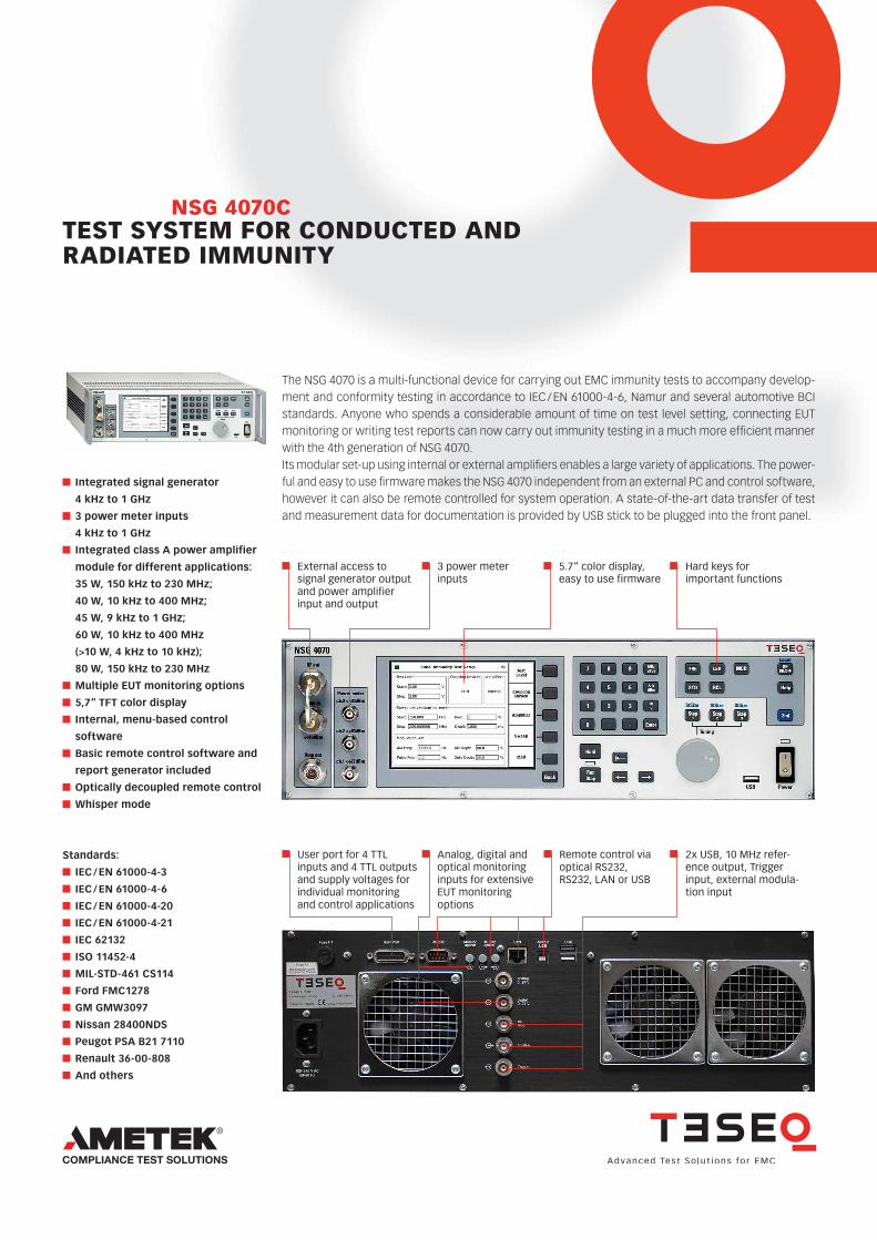
The NSG 4070 is a multi-functional device for carrying out EMC immunity tests to accompany develop-ment and conformity testing in accordance to IEC / EN 61000-4-6, Namur and several automotive BCI standards. Anyone who spends a considerable amount of time on test level setting, connecting EUT monitoring or writing test reports can now carry out immunity testing in a much more efficient manner with the 4th generation of NSG 4070. Its modular set-up using internal or external amplifiers enables a large variety of applications. The power-ful and easy to use firmware makes the NSG 4070 independent from an external PC and control software, however it can also be remote controlled for system operation. A state-of-the-art data transfer of test and measurement data for documentation is provided by USB stick to be plugged into the front panel.
External access to signal generator output and power amplifierinput and output
3 power meter inputs
5.7“ color display,easy to use firmware
Hard keys forimportant functions
Integrated signal generator
4 kHz to 1 GHz
3 power meter inputs
4 kHz to 1 GHz
Integrated class A power amplifier
module for different applications:
35 W, 150 kHz to 230 MHz;
40 W, 10 kHz to 400 MHz;
45 W, 9 kHz to 1 GHz;
60 W, 10 kHz to 400 MHz
(>10 W, 4 kHz to 10 kHz);
80 W, 150 kHz to 230 MHz
Multiple EUT monitoring options
5,7“ TFT color display
Internal, menu-based control
software
Basic remote control software and
report generator included
Optically decoupled remote control
Whisper mode
Standards:
IEC / EN 61000-4-3
IEC / EN 61000-4-6
IEC / EN 61000-4-20
IEC / EN 61000-4-21
IEC 62132
ISO 11452-4
MIL-STD-461 CS114
Ford FMC1278
GM GMW3097
Nissan 28400NDS
Peugot PSA B21 7110
Renault 36-00-808
And others
User port for 4 TTL inputs and 4 TTL outputs and supply voltages for individual monitoring and control applications
Analog, digital and optical monitoring inputs for extensive EUT monitoring options
2x USB, 10 MHz refer-ence output, Trigger input, external modula-tion input
Remote control viaoptical RS232, RS232, LAN or USB
TEST SYSTEM FOR CONDUCTED AND RADIATED IMMUNITYNSG 4070C
Immunity testing
IEC / EN 61000-4-6 )1
150 kHz to 230 MHz
Immunity testing
Namur )1
10 kHz to 80 MHz
Automotive BCI
testing )2
ISO 11452-4: 2011
Automotive BCI testing
Ford FMC1278 )2
MIL-STD-
461G
CS114 )2
RTCA
DO-160G
CS Test )2
Pro
du
ct
Pow
er a
mp
lifier
n
om
inal
pow
er
Pow
er a
mp
lifier
fr
equ
ency
ran
ge
CD
N
EM c
lam
p
Cu
rren
t in
ject
ion
pro
be
CD
N
EM c
lam
p
Cu
rren
t in
ject
ion
pro
be
Su
bst
itu
tio
n
Clo
sed
loo
p w
ith
k =
4
Su
bst
itu
tio
n
Clo
sed
loo
p w
ith
k =
4
Su
bst
itu
tio
n
Clo
sed
loo
p w
ith
k =
4
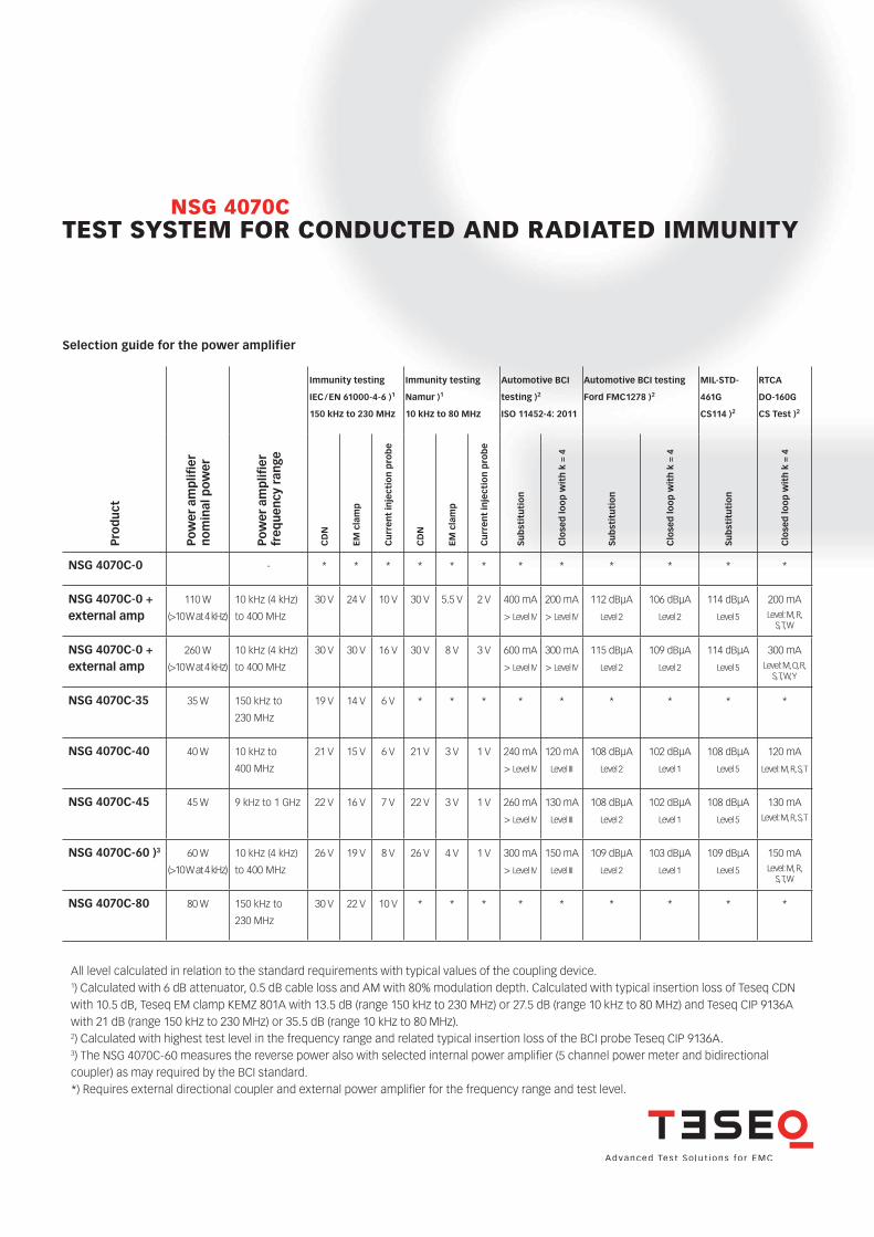
NSG 4070C-0 - * * * * * * * * * * * *
NSG 4070C-0 + external amp
110 W
(>10 W at 4 kHz)
10 kHz (4 kHz)
to 400 MHz
30 V 24 V 10 V 30 V 5.5 V 2 V 400 mA
> Level IV
200 mA
> Level IV
112 dBµA
Level 2
106 dBµA
Level 2
114 dBµA
Level 5
200 mALevel: M, R,
S, T, W
NSG 4070C-0 + external amp
260 W
(>10 W at 4 kHz)
10 kHz (4 kHz)
to 400 MHz
30 V 30 V 16 V 30 V 8 V 3 V 600 mA
> Level IV
300 mA
> Level IV
115 dBµA
Level 2
109 dBµA
Level 2
114 dBµA
Level 5
300 mALevel: M, O, R,
S, T, W, Y
NSG 4070C-35 35 W 150 kHz to
230 MHz
19 V 14 V 6 V * * * * * * * * *
NSG 4070C-40 40 W 10 kHz to
400 MHz
21 V 15 V 6 V 21 V 3 V 1 V 240 mA
> Level IV
120 mA
Level III
108 dBµA
Level 2
102 dBµA
Level 1
108 dBµA
Level 5
120 mA
Level: M, R, S, T
NSG 4070C-45 45 W 9 kHz to 1 GHz 22 V 16 V 7 V 22 V 3 V 1 V 260 mA
> Level IV
130 mA
Level III
108 dBµA
Level 2
102 dBµA
Level 1
108 dBµA
Level 5
130 mALevel: M, R, S, T
NSG 4070C-60 )3 60 W
(>10 W at 4 kHz)
10 kHz (4 kHz)
to 400 MHz
26 V 19 V 8 V 26 V 4 V 1 V 300 mA
> Level IV
150 mA
Level III
109 dBµA
Level 2
103 dBµA
Level 1
109 dBµA
Level 5
150 mALevel: M, R,
S, T, W
NSG 4070C-80 80 W 150 kHz to
230 MHz
30 V 22 V 10 V * * * * * * * * *
All level calculated in relation to the standard requirements with typical values of the coupling device.1) Calculated with 6 dB attenuator, 0.5 dB cable loss and AM with 80% modulation depth. Calculated with typical insertion loss of Teseq CDN with 10.5 dB, Teseq EM clamp KEMZ 801A with 13.5 dB (range 150 kHz to 230 MHz) or 27.5 dB (range 10 kHz to 80 MHz) and Teseq CIP 9136A with 21 dB (range 150 kHz to 230 MHz) or 35.5 dB (range 10 kHz to 80 MHz).2) Calculated with highest test level in the frequency range and related typical insertion loss of the BCI probe Teseq CIP 9136A.3) The NSG 4070C-60 measures the reverse power also with selected internal power amplifier (5 channel power meter and bidirectional coupler) as may required by the BCI standard.*) Requires external directional coupler and external power amplifier for the frequency range and test level.
Selection guide for the power amplifier
TEST SYSTEM FOR CONDUCTED AND RADIATED IMMUNITYNSG 4070C
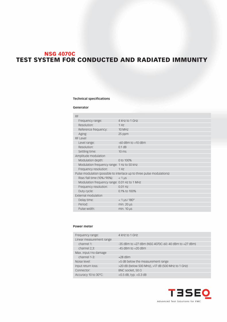
Technical specifications
Generator
RF Frequency range: 4 kHz to 1 GHz Resolution: 1 Hz Reference frequency: 10 MHz Aging: 25 ppm RF Level Level range: -60 dBm to +10 dBm Resolution: 0.1 dB Settling time: 10 msAmplitude modulation Modulation depth: 0 to 100% Modulation frequency range: 1 Hz to 50 kHz Frequency resolution: 1 HzPulse modulation (possible to interlace up to three pulse modulations) Rise / fall time (10% / 90%): < 1 µs Modulation frequency range: 0.01 Hz to 1 MHz Frequency resolution: 0.01 Hz Duty cycle: 0.1% to 100%External modulation Delay time: < 1 µs / 180° Period: min. 20 µs Pulse width: min. 10 µs
Power meter
Frequency range: 4 kHz to 1 GHzLinear measurement range channel 1: -35 dBm to +27 dBm (NSG 4070C-60:-40 dBm to +27 dBm) channel 2,3: -45 dBm to +20 dBm Max. input / no damage channel 1-3: +28 dBm Noise level: >5 dB below the measurement range Input return loss: >20 dB (below 500 MHz), >17 dB (500 MHz to 1 GHz)Connector: BNC socket, 50 ΩAccuracy 10 to 30°C: <0.5 dB, typ. <0.3 dB
TEST SYSTEM FOR CONDUCTED AND RADIATED IMMUNITYNSG 4070C
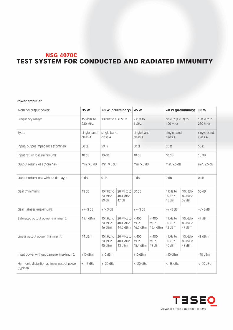
Power amplifier
Nominal output power: 35 W 40 W (preliminary) 45 W 60 W (preliminary) 80 W
Frequency range: 150 kHz to 230 MHz
10 kHz to 400 MHz 9 kHz to 1 GHz
10 kHz (4 kHz) to 400 MHz
150 kHz to 230 MHz
Type: single band, class A
single band, class A
single band, class A
single band, class A
single band, class A
Input / output impedance (nominal): 50 Ω 50 Ω 50 Ω 50 Ω 50 Ω
Input return loss (minimum): 10 dB 10 dB 10 dB 10 dB 10 dB
Output return loss (nominal): min. 9.5 dB min. 9.5 dB min. 9.5 dB min. 9.5 dB min. 9.5 dB
Output return loss without damage: 0 dB 0 dB 0 dB 0 dB 0 dB
Gain (minimum): 48 dB 10 kHz to 20 MHz 50 dB
20 MHz to 400 MHz 47 dB
50 dB 4 kHz to 10 kHz 45 dB
10 kHz to 400 MHz 53 dB
50 dB
Gain flatness (maximum): + / - 3 dB + / - 3 dB + / - 3 dB + / - 3 dB + / - 3 dB
Saturated output power (minimum): 45.4 dBm 10 kHz to 20 MHz 46 dBm
20 MHz to 400 MHz 44.5 dBm
< 400 MHz 46.5 dBm
> 400 MHz45.4 dBm
4 kHz to 10 kHz 42 dBm
10 kHz to 400 MHz 49 dBm
49 dBm
Linear output power (minimum): 44 dBm 10 kHz to 20 MHz 45 dBm
20 MHz to 400 MHz 43 dBm
< 400 MHz 45.4 dBm
> 400 MHz 43 dBm
4 kHz to 10 kHz 40 dBm
10 kHz to 400 MHz 48 dBm
48 dBm
Input power without damage (maximum): +10 dBm +10 dBm +10 dBm +10 dBm +10 dBm
Harmonic distortion at linear output power (typical):
< -17 dBc < -20 dBc < -20 dBc < -18 dBc < -20 dBc
TEST SYSTEM FOR CONDUCTED AND RADIATED IMMUNITYNSG 4070C
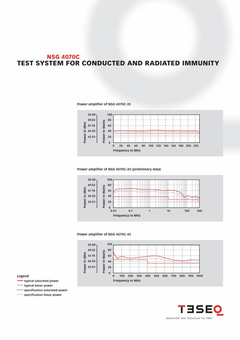
Power amplifier of NSG 4070C-35
Legend typical saturated power
typical linear power
specification saturated power
specification linear power
Power amplifier of NSG 4070C-40 (preliminary data)
Po
we
r in
Wat
ts
100
80
60
40
20
00 20 40 60 80 100 140 180 200 220
Frequency in MHz
120 160
Po
we
r in
dB
m
50.00
49.03
47.78
46.02
43.01
Po
we
r in
Wat
ts
100
80
60
40
20
00.01
Frequency in MHz
0.1 1 10 500100
Po
we
r in
dB
m
50.00
49.03
47.78
46.02
43.01
Power amplifier of NSG 4070C-45
Po
we
r in
Wat
ts
100
80
60
40
20
00
Frequency in MHz
100 200 300 400 500 700 900 1000600 800
Po
we
r in
dB
m
50.00
49.03
47.78
46.02
43.01
TEST SYSTEM FOR CONDUCTED AND RADIATED IMMUNITYNSG 4070C
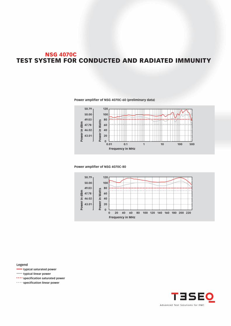
Power amplifier of NSG 4070C-80
Legend typical saturated power
typical linear power
specification saturated power
specification linear power
Frequency in MHz
Po
we
r in
Wat
ts
100
80
120
60
40
20
00 20 40 60 80 100 140 180 200 220120 160
Po
we
r in
dB
m
50.00
50.79
49.03
47.78
46.02
43.01
Power amplifier of NSG 4070C-60 (preliminary data)P
ow
er
in W
atts
100
80
120
60
40
20
0Po
we
r in
dB
m
50.00
50.79
49.03
47.78
46.02
43.01
0.01
Frequency in MHz
0.1 1 10 500100
TEST SYSTEM FOR CONDUCTED AND RADIATED IMMUNITYNSG 4070C
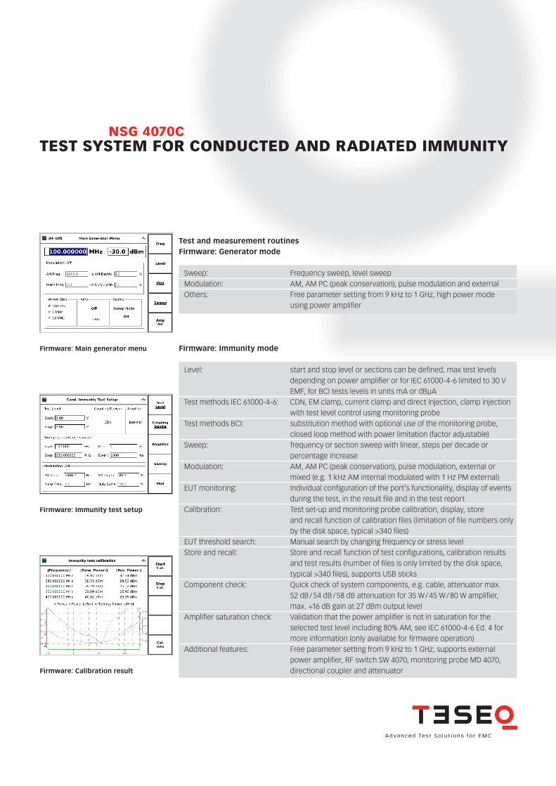
Test and measurement routinesFirmware: Generator mode
Firmware: Immunity mode
Sweep: Frequency sweep, level sweepModulation: AM, AM PC (peak conservation), pulse modulation and externalOthers: Free parameter setting from 9 kHz to 1 GHz, high power mode using power amplifier
Level: start and stop level or sections can be defined, max test levels depending on power amplifier or for IEC 61000-4-6 limited to 30 V EMF, for BCI tests levels in units mA or dBµATest methods IEC 61000-4-6: CDN, EM clamp, current clamp and direct injection, clamp injection with test level control using monitoring probeTest methods BCI: substitution method with optional use of the monitoring probe, closed loop method with power limitation (factor adjustable)Sweep: frequency or section sweep with linear, steps per decade or percentage increaseModulation: AM, AM PC (peak conservation), pulse modulation, external or mixed (e.g. 1 kHz AM internal modulated with 1 Hz PM external) EUT monitoring: Individual configuration of the port’s functionality, display of events during the test, in the result file and in the test reportCalibration: Test set-up and monitoring probe calibration, display, store and recall function of calibration files (limitation of file numbers only by the disk space, typical >340 files) EUT threshold search: Manual search by changing frequency or stress levelStore and recall: Store and recall function of test configurations, calibration results and test results (number of files is only limited by the disk space, typical >340 files), supports USB sticksComponent check: Quick check of system components, e.g. cable, attenuator max. 52 dB / 54 dB / 58 dB attenuation for 35 W / 45 W / 80 W amplifier, max. +16 dB gain at 27 dBm output level Amplifier saturation check: Validation that the power amplifier is not in saturation for the selected test level including 80% AM, see IEC 61000-4-6 Ed. 4 for more information (only available for firmware operation)Additional features: Free parameter setting from 9 kHz to 1 GHz, supports external power amplifier, RF switch SW 4070, monitoring probe MD 4070, directional coupler and attenuator
Firmware: Main generator menu
Firmware: Immunity test setup
Firmware: Calibration result
TEST SYSTEM FOR CONDUCTED AND RADIATED IMMUNITYNSG 4070C
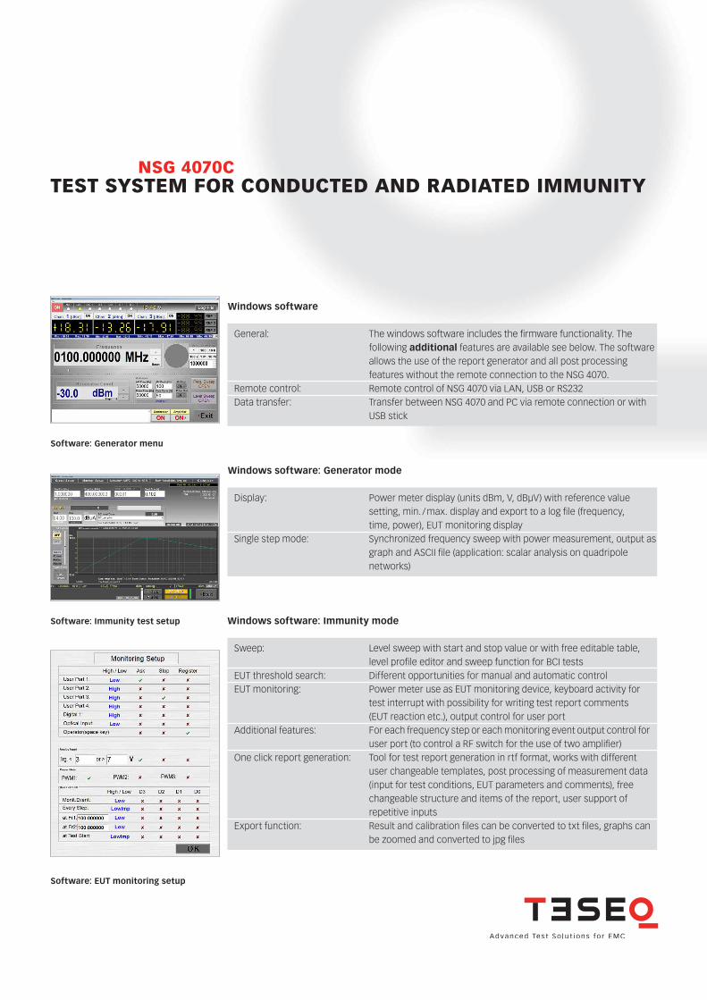
Windows software
Windows software: Generator mode
Windows software: Immunity mode
General: The windows software includes the firmware functionality. The following additional features are available see below. The software allows the use of the report generator and all post processing features without the remote connection to the NSG 4070.Remote control: Remote control of NSG 4070 via LAN, USB or RS232 Data transfer: Transfer between NSG 4070 and PC via remote connection or with USB stick
Display: Power meter display (units dBm, V, dBµV) with reference value setting, min. / max. display and export to a log file (frequency, time, power), EUT monitoring displaySingle step mode: Synchronized frequency sweep with power measurement, output as graph and ASCII file (application: scalar analysis on quadripole networks)
Sweep: Level sweep with start and stop value or with free editable table, level profile editor and sweep function for BCI testsEUT threshold search: Different opportunities for manual and automatic controlEUT monitoring: Power meter use as EUT monitoring device, keyboard activity for test interrupt with possibility for writing test report comments (EUT reaction etc.), output control for user port Additional features: For each frequency step or each monitoring event output control for user port (to control a RF switch for the use of two amplifier)One click report generation: Tool for test report generation in rtf format, works with different user changeable templates, post processing of measurement data (input for test conditions, EUT parameters and comments), free changeable structure and items of the report, user support of repetitive inputsExport function: Result and calibration files can be converted to txt files, graphs can be zoomed and converted to jpg files
Software: Generator menu
Software: Immunity test setup
Software: EUT monitoring setup
TEST SYSTEM FOR CONDUCTED AND RADIATED IMMUNITYNSG 4070C
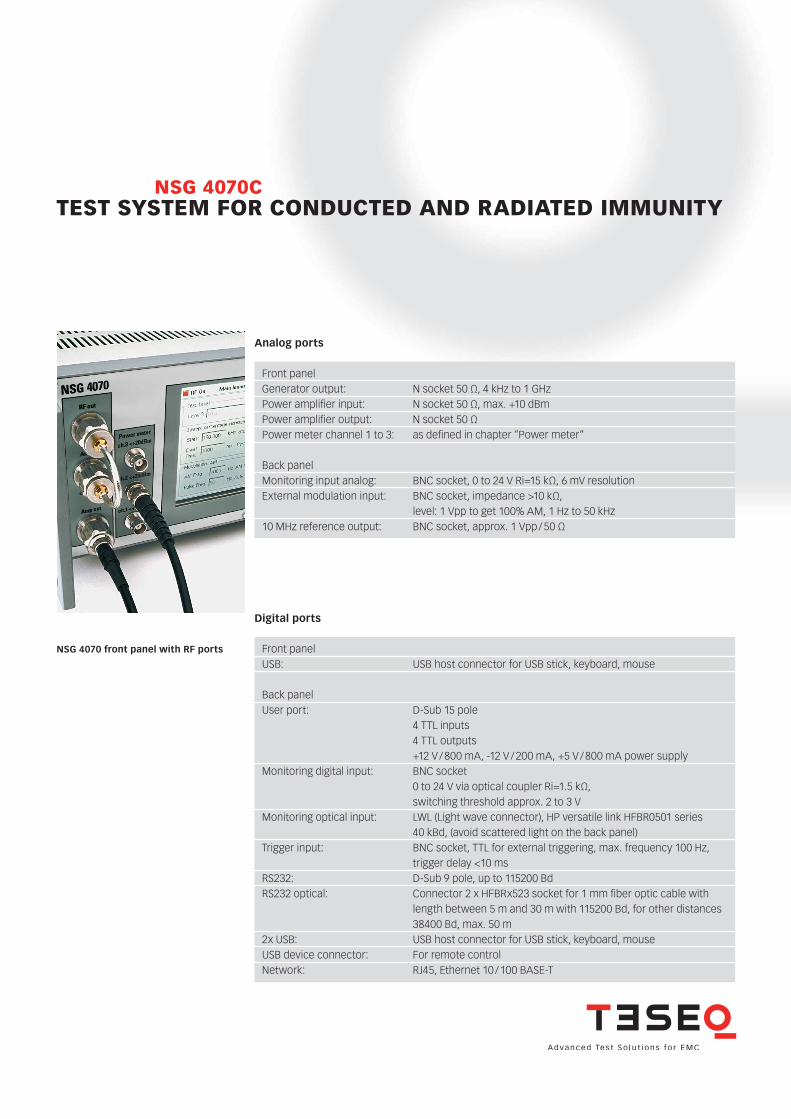
Analog ports
Digital ports
NSG 4070 front panel with RF ports
Front panel Generator output: N socket 50 Ω, 4 kHz to 1 GHzPower amplifier input: N socket 50 Ω, max. +10 dBmPower amplifier output: N socket 50 ΩPower meter channel 1 to 3: as defined in chapter “Power meter“ Back panel Monitoring input analog: BNC socket, 0 to 24 V Ri=15 kΩ, 6 mV resolutionExternal modulation input: BNC socket, impedance >10 kΩ, level: 1 Vpp to get 100% AM, 1 Hz to 50 kHz10 MHz reference output: BNC socket, approx. 1 Vpp / 50 Ω
Front panel USB: USB host connector for USB stick, keyboard, mouse Back panel User port: D-Sub 15 pole 4 TTL inputs 4 TTL outputs +12 V / 800 mA, -12 V / 200 mA, +5 V / 800 mA power supplyMonitoring digital input: BNC socket 0 to 24 V via optical coupler Ri=1.5 kΩ, switching threshold approx. 2 to 3 VMonitoring optical input: LWL (Light wave connector), HP versatile link HFBR0501 series 40 kBd, (avoid scattered light on the back panel)Trigger input: BNC socket, TTL for external triggering, max. frequency 100 Hz, trigger delay <10 msRS232: D-Sub 9 pole, up to 115200 BdRS232 optical: Connector 2 x HFBRx523 socket for 1 mm fiber optic cable with length between 5 m and 30 m with 115200 Bd, for other distances 38400 Bd, max. 50 m2x USB: USB host connector for USB stick, keyboard, mouseUSB device connector: For remote controlNetwork: RJ45, Ethernet 10 / 100 BASE-T
TEST SYSTEM FOR CONDUCTED AND RADIATED IMMUNITYNSG 4070C
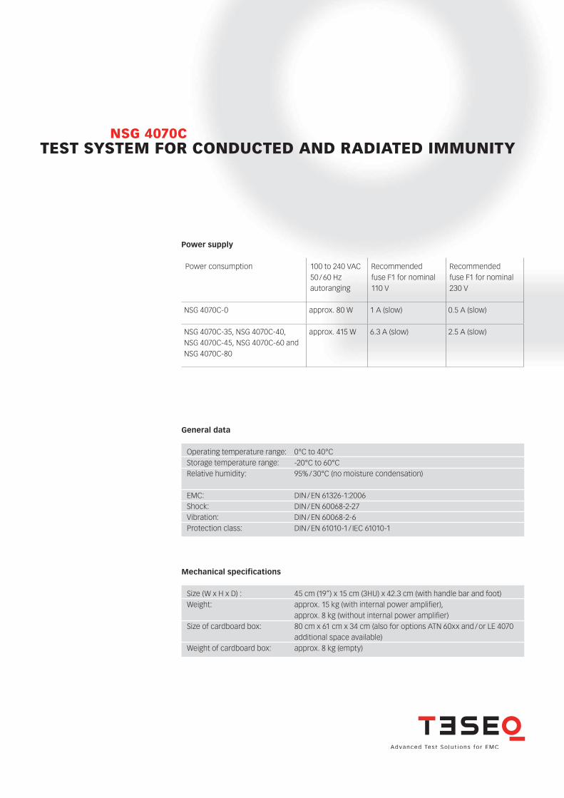
Power supply
General data
Operating temperature range: 0°C to 40°CStorage temperature range: -20°C to 60°CRelative humidity: 95% / 30°C (no moisture condensation) EMC: DIN / EN 61326-1:2006Shock: DIN / EN 60068-2-27Vibration: DIN / EN 60068-2-6Protection class: DIN / EN 61010-1 / IEC 61010-1
Mechanical specifications
Size (W x H x D) : 45 cm (19“) x 15 cm (3HU) x 42.3 cm (with handle bar and foot)Weight: approx. 15 kg (with internal power amplifier), approx. 8 kg (without internal power amplifier) Size of cardboard box: 80 cm x 61 cm x 34 cm (also for options ATN 60xx and / or LE 4070 additional space available) Weight of cardboard box: approx. 8 kg (empty)
Power consumption 100 to 240 VAC 50 / 60 Hzautoranging
Recommended fuse F1 for nominal 110 V
Recommended fuse F1 for nominal 230 V
NSG 4070C-0 approx. 80 W 1 A (slow) 0.5 A (slow)
NSG 4070C-35, NSG 4070C-40, NSG 4070C-45, NSG 4070C-60 and NSG 4070C-80
approx. 415 W 6.3 A (slow) 2.5 A (slow)
TEST SYSTEM FOR CONDUCTED AND RADIATED IMMUNITYNSG 4070C
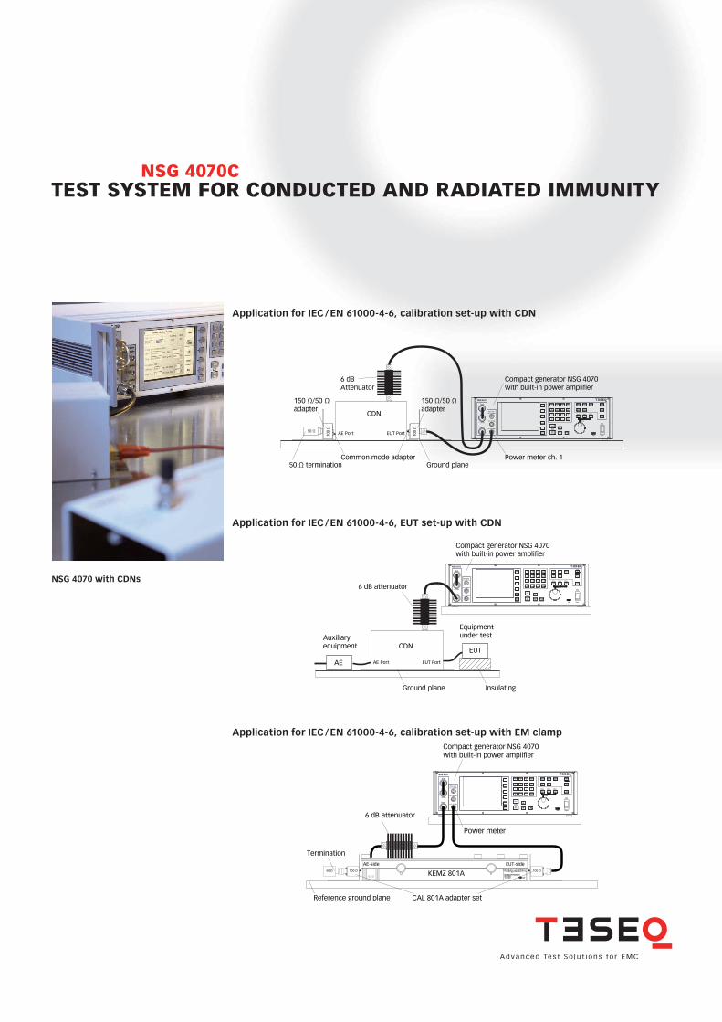
Application for IEC / EN 61000-4-6, calibration set-up with CDN
Application for IEC / EN 61000-4-6, calibration set-up with EM clamp
Application for IEC / EN 61000-4-6, EUT set-up with CDN
Compact generator NSG 4070with built-in power amplifier
Auxiliaryequipment
EUT
AE
Equipmentunder test
Ground plane Insulating
AE Port EUT Port
CDN
6 dB attenuator
RF out
Amp in
< +10 dBm
Amp outch.1 < +27 dBm
ch.2 < +20 dBm
ch.3 < +20 dBmPower meter
NSG 4070
PowerUSB
Tuning
StSizeStSize StSize
Local
Back StopRun
Hold
0 .
1
4
7 8
5
2 3
kHzdBm6
9 MHzdBµV
HzV
Enter
Step1
STO
FRQ LVL
RCL
Step2
Step3
MOD
2nd
Help
RFON/OFF
Compact generator NSG 4070with built-in power amplifier
AE-side EUT-side
CAL 801A adapter setReference ground plane
6 dB attenuator
Termination
Power meter
RF out
Amp in
< +10 dBm
Amp outch.1 < +27 dBm
ch.2 < +20 dBm
ch.3 < +20 dBmPower meter
NSG 4070
PowerUSB
Tuning
StSizeStSize StSize
Local
Back StopRun
Hold
0 .
1
4
7 8
5
2 3
kHzdBm6
9 MHzdBµV
HzV
Enter
Step1
STO
FRQ LVL
RCL
Step2
Step3
MOD
2nd
Help
RFON/OFF
100 Ω100 Ω50 Ω KEMZ 801A10 kHz ... 1000 MHz
EM clamp / EM-KoppelzangeKEMZ 801A
EUT
CDN
RF out
Amp in
< +10 dBm
Amp outch.1 < +27 dBm
ch.2 < +20 dBm
ch.3 < +20 dBmPower meter
NSG 4070
PowerUSB
Tuning
StSizeStSize StSize
Local
Back StopRun
Hold
0 .
1
4
7 8
5
2 3
kHzdBm6
9 MHzdBµV
HzV
Enter
Step1
STO
FRQ LVL
RCL
Step2
Step3
MOD
2nd
Help
RFON/OFF
6 dBAttenuator
AE Port EUT Port
150 Ω/50 Ω adapter
150 Ω/50 Ω adapter
50 Ω
100
Ω
100
Ω
50 Ω terminationCommon mode adapter Power meter ch. 1
Ground plane
Compact generator NSG 4070with built-in power amplifier
NSG 4070 with CDNs
TEST SYSTEM FOR CONDUCTED AND RADIATED IMMUNITYNSG 4070C
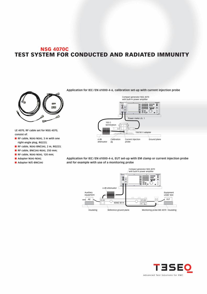
Application for IEC / EN 61000-4-6, calibration set-up with current injection probe
Application for IEC / EN 61000-4-6, EUT set-up with EM clamp or current injection probe and for example with use of a monitoring probe
RF out
Amp in
< +10 dBm
Amp outch.1 < +27 dBm
ch.2 < +20 dBm
ch.3 < +20 dBmPower meter
NSG 4070
PowerUSB
Tuning
StSizeStSize StSize
Local
Back StopRun
Hold
0 .
1
4
7 8
5
2 3
kHzdBm6
9 MHzdBµV
HzV
Enter
Step1
STO
FRQ LVL
RCL
Step2
Step3
MOD
2nd
Help
RFON/OFF
AE
KEMZ 801A10 kHz ... 1000 MHz
EM clamp / EM-KoppelzangeKEMZ 801A
EUT
EUTAE-side EUT-side
Auxiliaryequipment
Equipmentunder test
Insulating Reference ground plane InsulatingMonitoring probe MD 4070
6 dB attenuator
Compact generator NSG 4070with built-in power amplifier
Calibrationjig
Current injection probe
Power meter ch. 1
Ground plane
RF out
Amp in
< +10 dBm
Amp outch.1 < +27 dBm
ch.2 < +20 dBm
ch.3 < +20 dBmPower meter
NSG 4070
PowerUSB
Tuning
StSizeStSize StSize
Local
Back StopRun
Hold
0 .
1
4
7 8
5
2 3
kHzdBm6
9 MHzdBµV
HzV
Enter
Step1
STO
FRQ LVL
RCL
Step2
Step3
MOD
2nd
Help
RFON/OFF
Compact generator NSG 4070with built-in power amplifier
150 Ω termination
150/50 Ω adapter
6 dB attenuator
LE 4070, RF cable set for NSG 4070,
consist of:
RF cable, N(m)-N(m), 3 m with one
right-angle plug, RG223;
RF cable, N(m)-BNC(m), 2 m, RG223;
RF cable, BNC(m)-N(m), 250 mm;
RF cable, N(m)-N(m), 120 mm;
Adapter N(m)-N(m);
Adapter N(f)-BNC(m)
TEST SYSTEM FOR CONDUCTED AND RADIATED IMMUNITYNSG 4070C
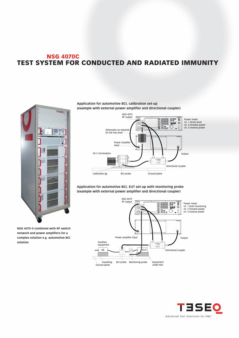
Application for automotive BCI, calibration set-up (example with external power amplifier and directional coupler)
Application for automotive BCI, EUT set-up with monitoring probe (example with external power amplifier and directional coupler)
RF out
Amp in
< +10 dBm
Amp outch.1 < +27 dBm
ch.2 < +20 dBm
ch.3 < +20 dBmPower meter
NSG 4070
PowerUSB
Tuning
StSizeStSize StSize
Local
Back StopRun
Hold
0 .
1
4
7 8
5
2 3
kHzdBm6
9 MHzdBµV
HzV
Enter
Step1
STO
FRQ LVL
RCL
Step2
Step3
MOD
2nd
Help
RFON/OFF Power meter
ch. 1 stress levelch. 2 forward powerch. 3 reverse power
Amp in Amp out
0.01 ...
DCP 0100
1000 MHz
DIRECTIONAL COUPLER
Output
Power amplifierinput
50 Ω Termination
Directional coupler
NSG 4070RF output
Calibration jig BCI probe Ground plane
Attenuator as required for the test level
RF out
Amp in
< +10 dBm
Amp outch.1 < +27 dBm
ch.2 < +20 dBm
ch.3 < +20 dBmPower meter
NSG 4070
PowerUSB
Tuning
StSizeStSize StSize
Local
Back StopRun
Hold
0 .
1
4
7 8
5
2 3
kHzdBm6
9 MHzdBµV
HzV
Enter
Step1
STO
FRQ LVL
RCL
Step2
Step3
MOD
2nd
Help
RFON/OFF Power meter
ch. 1 level monitoringch. 2 forward powerch. 3 reverse power
Amp in Amp out
OutputPower amplifier input
Directional coupler
NSG 4070RF output
Auxiliaryequipment
EUTAE
Equipmentunder test
Insulating BCI probe Monitoring probeGround plane
0.01 ...
DCP 0100
1000 MHz
DIRECTIONAL COUPLER
NSG 4070-0 combined with RF switch
network and power amplifiers for a
complex solution e.g. automotive BCI
solution
TEST SYSTEM FOR CONDUCTED AND RADIATED IMMUNITYNSG 4070C
RF out
Amp in
< +10 dBm
Amp outch.1 < +27 dBm
ch.2 < +20 dBm
ch.3 < +20 dBmPower meter
NSG 4070
PowerUSB
Tuning
StSizeStSize StSize
Local
Back StopRun
Hold
0 .
1
4
7 8
5
2 3
kHzdBm6
9 MHzdBµV
HzV
Enter
Step1
STO
FRQ LVL
RCL
Step2
Step3
MOD
2nd
Help
RFON/OFF
Ground plane
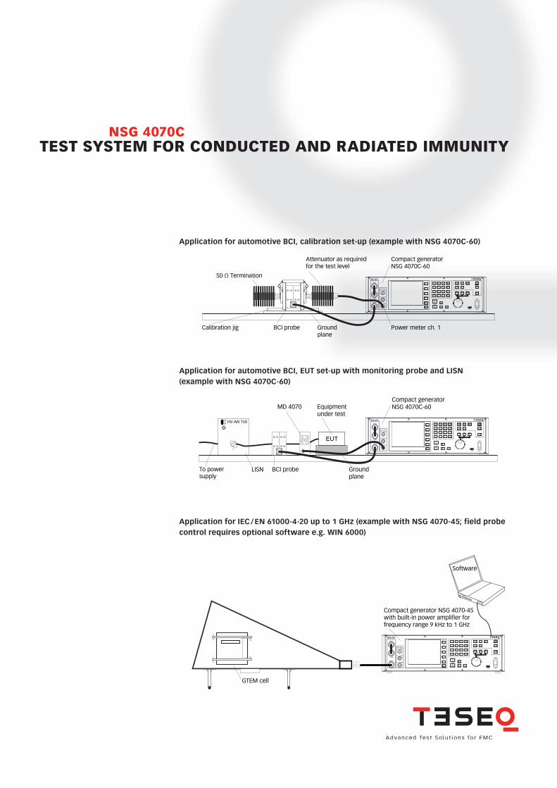
Attenuator as required for the test level
Calibration jig BCI probe Power meter ch. 1
Compact generator NSG 4070C-60
50 Ω Termination
Application for automotive BCI, calibration set-up (example with NSG 4070C-60)
Application for IEC / EN 61000-4-20 up to 1 GHz (example with NSG 4070-45; field probe control requires optional software e.g. WIN 6000)
RF out
Amp in
< +10 dBm
Amp outch.1 < +27 dBm
ch.2 < +20 dBm
ch.3 < +20 dBmPower meter
NSG 4070
PowerUSB
Tuning
StSizeStSize StSize
Local
Back StopRun
Hold
0 .
1
4
7 8
5
2 3
kHzdBm6
9 MHzdBµV
HzV
Enter
Step1
STO
FRQ LVL
RCL
Step2
Step3
MOD
2nd
Help
RFON/OFF
Software
Compact generator NSG 4070-45with built-in power amplifier forfrequency range 9 kHz to 1 GHz
GTEM cell
Application for automotive BCI, EUT set-up with monitoring probe and LISN (example with NSG 4070C-60)
RF out
Amp in
< +10 dBm
Amp outch.1 < +27 dBm
ch.2 < +20 dBm
ch.3 < +20 dBmPower meter
NSG 4070
PowerUSB
Tuning
StSizeStSize StSize
Local
Back StopRun
Hold
0 .
1
4
7 8
5
2 3
kHzdBm6
9 MHzdBµV
HzV
Enter
Step1
STO
FRQ LVL
RCL
Step2
Step3
MOD
2nd
Help
RFON/OFF
EUT
HV-AN 150RF Output
EUT
Ground plane
BCI probe
Compact generator NSG 4070C-60Equipment
under test
LISNTo power supply
MD 4070
TEST SYSTEM FOR CONDUCTED AND RADIATED IMMUNITYNSG 4070C
82-257492 E02 August 2017
Teseq GmbH Landsberger Str. 255 · 12623 Berlin · Germany T + 49 30 56 59 88 35 F + 49 30 56 59 88 [email protected] www.teseq.com
© August 2017 Teseq® Specifications subject to change without notice. Teseq® is an ISO-registered company. Its products are designed and manufactured under the strict quality and environmental requirements of the ISO 9001. This document has been carefully checked. However, Teseq® does not assume any liability for errors or inaccuracies.
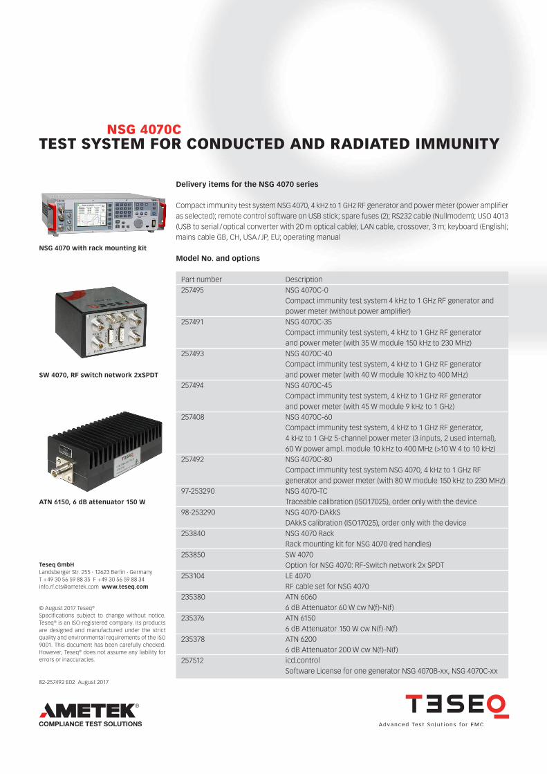
Model No. and options
Delivery items for the NSG 4070 series
NSG 4070 with rack mounting kit
ATN 6150, 6 dB attenuator 150 W
SW 4070, RF switch network 2xSPDT
Part number Description257495 NSG 4070C-0 Compact immunity test system 4 kHz to 1 GHz RF generator and power meter (without power amplifier)257491 NSG 4070C-35 Compact immunity test system, 4 kHz to 1 GHz RF generator and power meter (with 35 W module 150 kHz to 230 MHz)257493 NSG 4070C-40 Compact immunity test system, 4 kHz to 1 GHz RF generator and power meter (with 40 W module 10 kHz to 400 MHz)257494 NSG 4070C-45 Compact immunity test system, 4 kHz to 1 GHz RF generator and power meter (with 45 W module 9 kHz to 1 GHz)257408 NSG 4070C-60 Compact immunity test system, 4 kHz to 1 GHz RF generator, 4 kHz to 1 GHz 5-channel power meter (3 inputs, 2 used internal), 60 W power ampl. module 10 kHz to 400 MHz (>10 W 4 to 10 kHz)257492 NSG 4070C-80 Compact immunity test system NSG 4070, 4 kHz to 1 GHz RF generator and power meter (with 80 W module 150 kHz to 230 MHz)97-253290 NSG 4070-TC Traceable calibration (ISO17025), order only with the device98-253290 NSG 4070-DAkkS DAkkS calibration (ISO17025), order only with the device253840 NSG 4070 Rack Rack mounting kit for NSG 4070 (red handles) 253850 SW 4070 Option for NSG 4070: RF-Switch network 2x SPDT 253104 LE 4070 RF cable set for NSG 4070235380 ATN 6060 6 dB Attenuator 60 W cw N(f)-N(f)235376 ATN 6150 6 dB Attenuator 150 W cw N(f)-N(f)235378 ATN 6200 6 dB Attenuator 200 W cw N(f)-N(f) 257512 icd.control Software License for one generator NSG 4070B-xx, NSG 4070C-xx
Compact immunity test system NSG 4070, 4 kHz to 1 GHz RF generator and power meter (power amplifier as selected); remote control software on USB stick; spare fuses (2); RS232 cable (Nullmodem); USO 4013 (USB to serial / optical converter with 20 m optical cable); LAN cable, crossover, 3 m; keyboard (English); mains cable GB, CH, USA / JP, EU; operating manual