Embed Size (px)
Citation preview
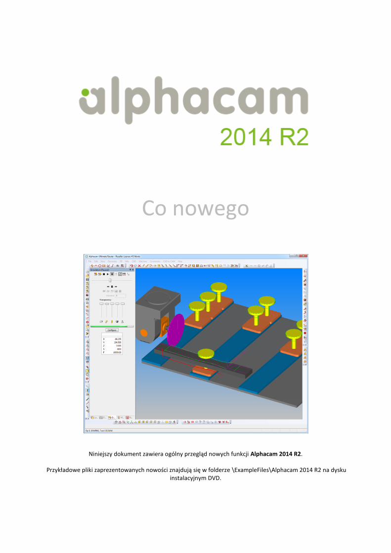
Co nowego
Niniejszy dokument zawiera ogólny przegląd nowych funkcji Alphacam 2014 R2.
Przykładowe pliki zaprezentowanych nowości znajdują się w folderze \ExampleFiles\Alphacam 2014 R2 na dysku instalacyjnym DVD.
: 2014 R2 what’s new
Vero Software Limited www.alphacam.com 2 of 32
Sps treści
..................................................................................................................................................................................................................... 1 Sps treści ...................................................................................................................................................................................................... 2 Ważne Informacje ......................................................................................................................................................................................... 4
Wsparcie Windows XP .............................................................................................................................................................................. 4
Termin ważności licencji Alphacam ........................................................................................................................................................... 4
Licencjonowanie ........................................................................................................................................................................................... 4
Licencja Sieciowa – Szczegóły Licencjonowania ...................................................................................................................................... 4
Dodatek BiessePrint Labels ...................................................................................................................................................................... 4
Rozpoznawanie cech modelu ........................................................................................................................................................................ 5
Nowy wygląd okna dialogowego ............................................................................................................................................................... 5
Główne usprawnienia w Rozpoznawaniu cech modelu ............................................................................................................................. 5
Obróbka 5-osiowa ......................................................................................................................................................................................... 6
Analizator ścieżki narzędzia w obróbkach 5-osiowych .............................................................................................................................. 6
Zaciski i uchwyty ........................................................................................................................................................................................... 7
Ulepszone zaciski i uchwyty ...................................................................................................................................................................... 7
Interfejs użytkownika ..................................................................................................................................................................................... 8
Więzy ........................................................................................................................................................................................................ 8
Podświetlanie operacji wymagającej zaktualizowania ............................................................................................................................... 8
Lista ostatnio używanych plików zawiera teraz wszystkie typy plików CAD ............................................................................................... 9
Zdefiniowane widoki na pasku skrótów ..................................................................................................................................................... 9
Inne ulepszenia interfejsu użytkownika ..................................................................................................................................................... 9
Nowe obrazy przy definicji narzędzi skrawających oraz magazynów narzędzi ........................................................................................ 10
Nesting........................................................................................................................................................................................................ 11
Usprawnienia .......................................................................................................................................................................................... 11
Arkusze I obszar wolny od nakładania .................................................................................................................................................... 11
Nesting w otworach ................................................................................................................................................................................ 12
Mostki Nesting’u ..................................................................................................................................................................................... 12
Toczenie ..................................................................................................................................................................................................... 13
Ulepszenia operacji Cyklu Toczenia Zgrubnego ...................................................................................................................................... 13
Ulepszenia Wejścia\Wyjścia z materiału ................................................................................................................................................. 13
Dodatkowa szybka edycja....................................................................................................................................................................... 13
Symulacja Toczenia – wartość przesunięcia przeciw-wrzeciona ............................................................................................................. 13
Symulator .................................................................................................................................................................................................... 14
: 2014 R2 what’s new
Vero Software Limited www.alphacam.com 3 of 32
Ulepszenia 'Symuluj' oraz 'Szybka weryfikacja' ....................................................................................................................................... 14
CAD to CAM ............................................................................................................................................................................................... 15
Usprawnienia .......................................................................................................................................................................................... 15
Alphacam Art .............................................................................................................................................................................................. 16
Aspire Ver. 4.5 ........................................................................................................................................................................................ 16
Automated Parametric Manufacturing (APM) .............................................................................................................................................. 17
Usprawnienia .......................................................................................................................................................................................... 17
Translator BTL ............................................................................................................................................................................................ 18
Nowa funkcjonalność BTL....................................................................................................................................................................... 18
Nowe Procesy BTL ................................................................................................................................................................................. 18
Translacja plików CAD ................................................................................................................................................................................ 19
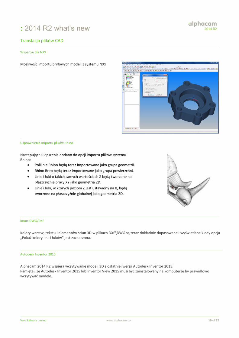
Wsparcie dla NX9 ................................................................................................................................................................................... 19
Usprawnienia Importu plików Rhino ........................................................................................................................................................ 19
Imort DWG/DXF ...................................................................................................................................................................................... 19
Autodesk Inventor 2015 .......................................................................................................................................................................... 19
Obsługiwane wersje plików CAD ................................................................................................................................................................. 20 Part Modeler ............................................................................................................................................................................................... 21
Nowe techniki tworzenia modeli 2D-3D ................................................................................................................................................... 21
Rozbudowa API .......................................................................................................................................................................................... 22
Usprawnienia API ................................................................................................................................................................................... 22
Maintenance Report .................................................................................................................................................................................... 23 Appendix A - API improvements in Alphacam 2014 R2. ......................................................................................................................... 29
API - Lead-in/Out - Possibility to use "Multiple Lines In" through API ...................................................................................................... 29
API: Add a Close method to ViewWindow ............................................................................................................................................... 29
API - New method for STL.ChopIntoSections to include section geometry .............................................................................................. 29
API - New Output NC Method That Gives Feedback On Errors Produced ............................................................................................... 30
API - Rapids Manager - method Drawing.SetRapidManager, properties Drawing.RapidManagerEnable, Drawing.RapidManagerSafeRapidLevel ................................................................................................................................................. 30
API: new TurnData properties DrillRapidApproachDistance and DrillPeckRetractDistance ..................................................................... 31
API New Method - SolidFace.MakeGeometries ...................................................................................................................................... 32
API - Editable add-ins - The possibility to stop the suppression of toolpaths that happens when updating. ............................................. 32
: 2014 R2 what’s new
Vero Software Limited www.alphacam.com 4 of 32
Ważne Informacje
Wsparcie Windows XP
Alphacam 2014 R2 może być zainstalowany i uruchommiony na Windows XP. Natomiast ten system operacyjny nie jest wspierany od kwietnia 2014 (ref: http://windows.microsoft.com/en-GB/windows/products/lifecycle), nie gwarantujemy, że wszystkie problemy wynikające z działania Alphacam na Windows XP będą rozwiązane. Alphacam 2014 R2 jest ostatnią wersją która może być zainstalowana na Windows XP.
Termin ważności licencji Alphacam
Aby uruchomić Alphacam 2014 R2, data ważności licencji musi być od marca 2014
Licencjonowanie
Licencja Sieciowa – Szczegóły Licencjonowania
Nowa opcja User Specific Configuration w menu narzędzia CLS License Manager umożliwia określenie specyficznych ustawień użytkownika lub zdefiniowanie opcji dla wszystkich użytkowników logujących się do komputera. Kiedy opcja User Specific Configuration jest odznaczona, konfiguracja licencji ustawiona w Konfiguracji Licencji Sieciowej zapisywana jest do pliku w folderze przechowywania licencji. Kiedy użytkownicy komputera logują się do systemu specyficzne ustawienia użytkownika są wczytywane. Patrz Zaawansowane opcje licencjonowania sieciowego w pliku pomocy CLS.
Dodatek BiessePrint Labels
Nowy dodatek BiessePrint Labels jako opcja dodatkowo płatna. BiessePrint Labels Macro jest prostym rozwiązaniem, które umożliwia użytkownikowi stworzenie etykiet zgodnych z oprogramowaniem BiessePrint™.
: 2014 R2 what’s new
Vero Software Limited www.alphacam.com 5 of 32
Rozpoznawanie cech modelu
Nowy wygląd okna dialogowego
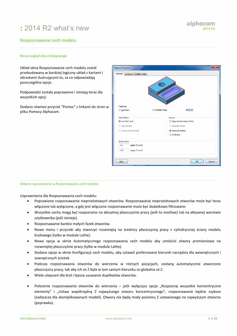
Układ okna Rozpoznawanie cech modelu został przebudowany w bardziej logiczny układ z kartami i obrazkami ilustrującymi to, za co odpowiadają poszczególne opcje. Podpowiedzi zostały poprawione i istnieją teraz dla wszystkich opcji. Dodano również przycisk "Pomoc" z linkami do stron w pliku Pomocy Alphacam.
Główne usprawnienia w Rozpoznawaniu cech modelu
Usprawnienia dla Rozpoznawania cech modelu:
Poprawione rozpoznawanie nieprzelotowych otworów. Rozpoznawanie nieprzelotowych otworów może być teraz
włączone lub wyłączone, a gdy jest włączone rozpoznawanie może być dodatkowo filtrowane.
Wszystkie cechy mogą być rozpoznane na aktualnej płaszczyźnie pracy (jeśli to możliwe) lub na aktywnej warstwie
użytkownika (jeśli istnieje).
Rozpoznawanie bardzo małych fazek otworów.
Nowe menu i przyciski aby stworzyć rozwiniętą na średnicy płaszczyznę pracy z cylindrycznej ściany modelu
bryłowego (tylko w module Lathe).
Nowa opcja w oknie Automatycznego rozpoznawania cech modelu aby umieścić otwory promieniowo na
rozwiniętej płaszczyźnie pracy (tylko w module Lathe).
Dodano opcje w oknie Konfiguracji cech modelu, aby ustawić preferowane kierunki narzędzia dla wewnętrznych i
zewnętrznych ścieżek.
Podczas rozpoznawania otworów do wiercenia w różnych pozycjach, zostaną automatycznie utworzone
płaszczyzny pracy, tak aby ich oś Z była w tym samym kierunku co globalna oś Z.
Wiele ulepszeń dla brył i lepsze usuwanie duplikatów otworów.
Polecenie rozpoznawania otworów do wiercenia – jeśli wyłączysz opcje „Rozpoznaj wszystkie koncentryczne
elementy” i „Ustaw współrzędną Z najwyższego otworu koncentrycznego”, rozpoznawanie będzie szybsze
(zwłaszcza dla skomplikowanych modeli). Otwory nie będą miały poziomu Z ustawionego na najwyższym otworze
(poprawka).
: 2014 R2 what’s new
Vero Software Limited www.alphacam.com 6 of 32
Nowa opcja „Ustaw poziom Z ręcznie” w okienku rozpoznawania otworów do wiercenia.
Dodano nową opcję pozwalająca ograniczyć głębokość otworów przelotowych przy automatycznym
rozpoznawaniu cech.
Resetowanie geometrii poziomów Z – dolny poziom Z będzie ustawiony na najniższym, a nie na najwyższym
punkcie zaznaczonej krawędzi.
Opcje Otwór promieniowy i Ograniczenie otworu przelotowego dodane do API.
Obróbka 5-osiowa
Analizator ścieżki narzędzia w obróbkach 5-osiowych
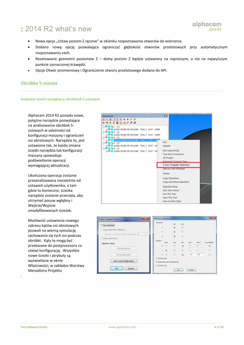
Alphacam 2014 R2 posiada nowe, potężne narzędzie pozwalające na analizowanie obróbek 5-osiowych w zależności od konfiguracji maszyny i ograniczeń osi obrotowych. Narzędzie to, jest ustawione tak, że każda zmiana ścieżki narzędzia lub konfiguracji maszyny spowoduje podświetlenie operacji wymagającej aktualizacji. Ukończona operacja zostanie przeanalizowana niezależnie od ustawień użytkownika, a tam gdzie to konieczne, ścieżka narzędzie zostanie przecięta, aby utrzymać posuw wgłębny i Wejście/Wyjście zmodyfikowanych ścieżek. Możliwość ustawienia nowego zakresu kątów osi obrotowych pozwoli na wierną symulację zachowania się tych osi podczas obróbki. Kąty te mogą być przekazane do postprocesora co ułatwi konfigurację. Wszystkie nowe ścieżki i atrybuty są wyświetlane w oknie Właściwości, w zakładce Warstwy Menadżera Projektu
.
: 2014 R2 what’s new
Vero Software Limited www.alphacam.com 7 of 32
Zaciski i uchwyty
Ulepszone zaciski i uchwyty
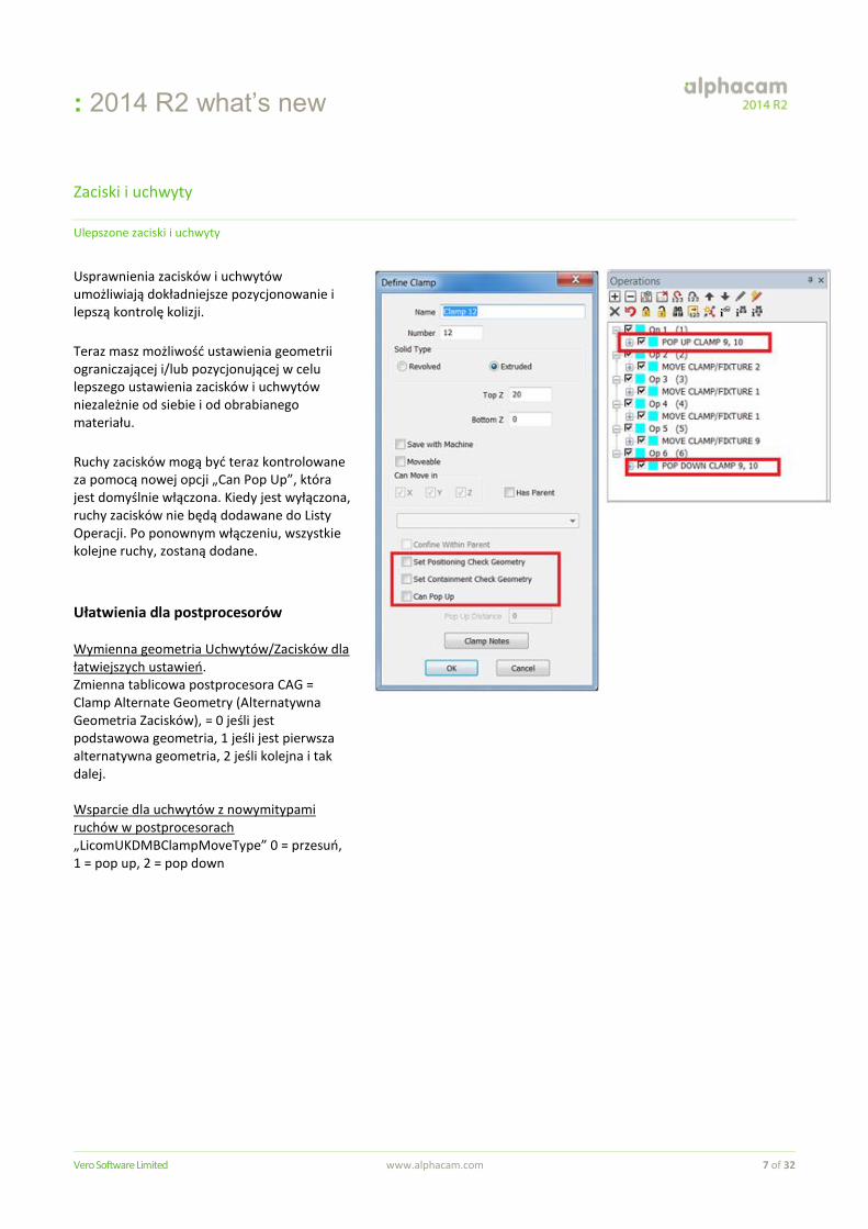
Usprawnienia zacisków i uchwytów umożliwiają dokładniejsze pozycjonowanie i lepszą kontrolę kolizji.
Teraz masz możliwość ustawienia geometrii ograniczającej i/lub pozycjonującej w celu lepszego ustawienia zacisków i uchwytów niezależnie od siebie i od obrabianego materiału.
Ruchy zacisków mogą być teraz kontrolowane za pomocą nowej opcji „Can Pop Up”, która jest domyślnie włączona. Kiedy jest wyłączona, ruchy zacisków nie będą dodawane do Listy Operacji. Po ponownym włączeniu, wszystkie kolejne ruchy, zostaną dodane. Ułatwienia dla postprocesorów Wymienna geometria Uchwytów/Zacisków dla łatwiejszych ustawień. Zmienna tablicowa postprocesora CAG = Clamp Alternate Geometry (Alternatywna Geometria Zacisków), = 0 jeśli jest podstawowa geometria, 1 jeśli jest pierwsza alternatywna geometria, 2 jeśli kolejna i tak dalej.
Wsparcie dla uchwytów z nowymitypami ruchów w postprocesorach „LicomUKDMBClampMoveType” 0 = przesuń, 1 = pop up, 2 = pop down
: 2014 R2 what’s new
Vero Software Limited www.alphacam.com 8 of 32
Interfejs użytkownika
Więzy
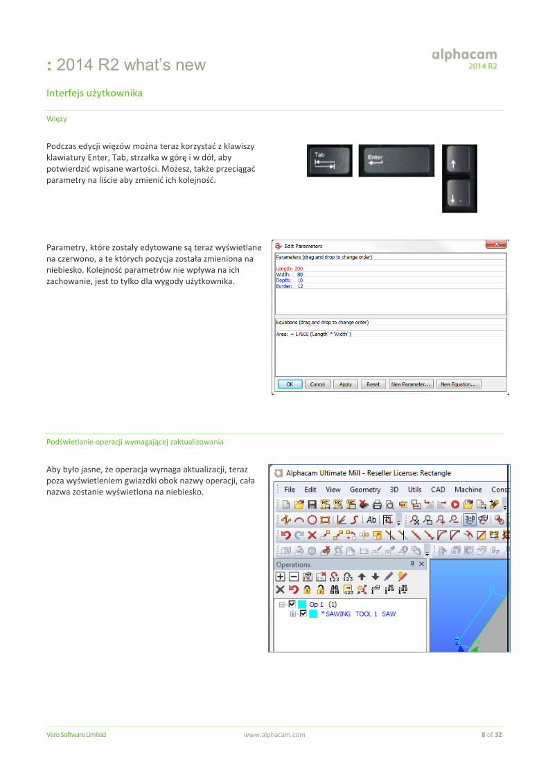
Podczas edycji więzów można teraz korzystać z klawiszy klawiatury Enter, Tab, strzałka w górę i w dół, aby potwierdzić wpisane wartości. Możesz, także przeciągać parametry na liście aby zmienić ich kolejność. Parametry, które zostały edytowane są teraz wyświetlane na czerwono, a te których pozycja została zmieniona na niebiesko. Kolejność parametrów nie wpływa na ich zachowanie, jest to tylko dla wygody użytkownika.
Podświetlanie operacji wymagającej zaktualizowania
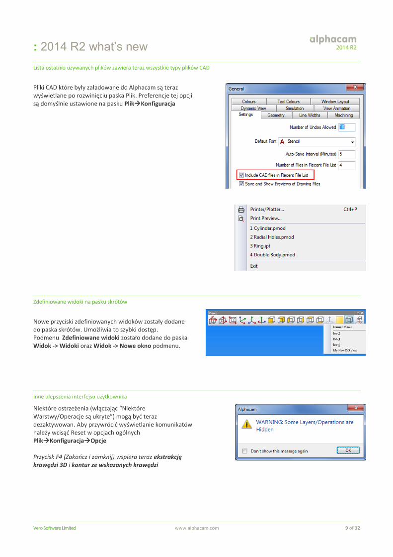
Aby było jasne, że operacja wymaga aktualizacji, teraz poza wyświetleniem gwiazdki obok nazwy operacji, cała nazwa zostanie wyświetlona na niebiesko.
: 2014 R2 what’s new
Vero Software Limited www.alphacam.com 9 of 32
Lista ostatnio używanych plików zawiera teraz wszystkie typy plików CAD
Pliki CAD które były załadowane do Alphacam są teraz wyświetlane po rozwinięciu paska Plik. Preferencje tej opcji są domyślnie ustawione na pasku PlikKonfiguracja
Zdefiniowane widoki na pasku skrótów
Nowe przyciski zdefiniowanych widoków zostały dodane do paska skrótów. Umożliwia to szybki dostęp. Podmenu Zdefiniowane widoki zostało dodane do paska Widok -> Widoki oraz Widok -> Nowe okno podmenu.
Inne ulepszenia interfejsu użytkownika
Niektóre ostrzeżenia (włączając “Niektóre Warstwy/Operacje są ukryte”) mogą być teraz dezaktywowan. Aby przywrócić wyświetlanie komunikatów należy wcisąć Reset w opcjach ogólnych PlikKonfiguracjaOpcje Przycisk F4 (Zakończ i zamknij) wspiera teraz ekstrakcję krawędzi 3D i kontur ze wskazanych krawędzi
: 2014 R2 what’s new
Vero Software Limited www.alphacam.com 10 of 32
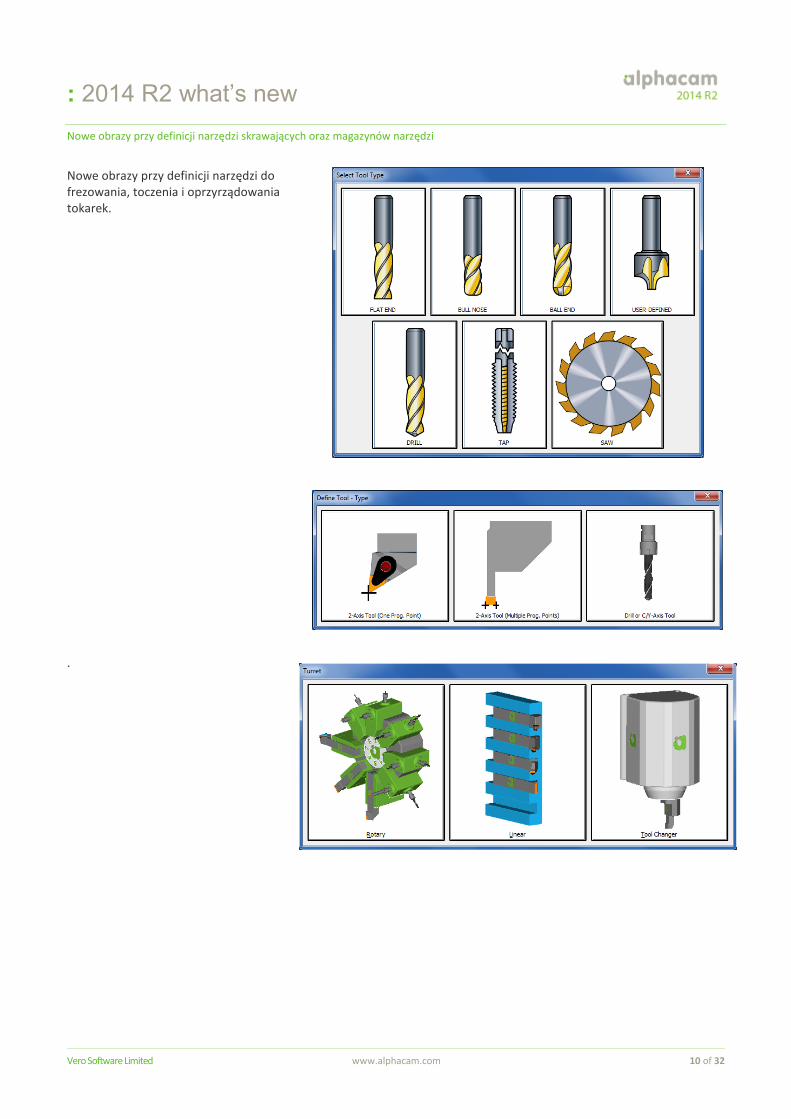
Nowe obrazy przy definicji narzędzi skrawających oraz magazynów narzędzi
Nowe obrazy przy definicji narzędzi do frezowania, toczenia i oprzyrządowania tokarek. .
: 2014 R2 what’s new
Vero Software Limited www.alphacam.com 11 of 32
Nesting
Usprawnienia
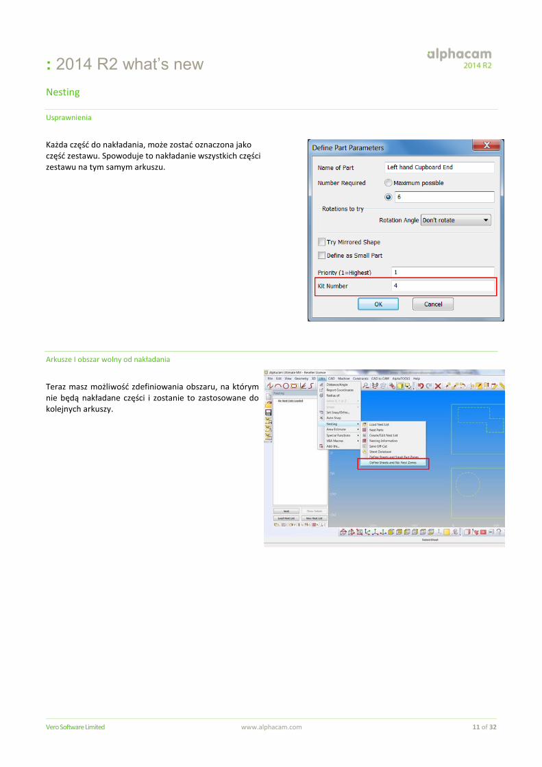
Każda część do nakładania, może zostać oznaczona jako część zestawu. Spowoduje to nakładanie wszystkich części zestawu na tym samym arkuszu.
Arkusze I obszar wolny od nakładania
Teraz masz możliwość zdefiniowania obszaru, na którym nie będą nakładane części i zostanie to zastosowane do kolejnych arkuszy.
: 2014 R2 what’s new
Vero Software Limited www.alphacam.com 12 of 32
Nesting w otworach
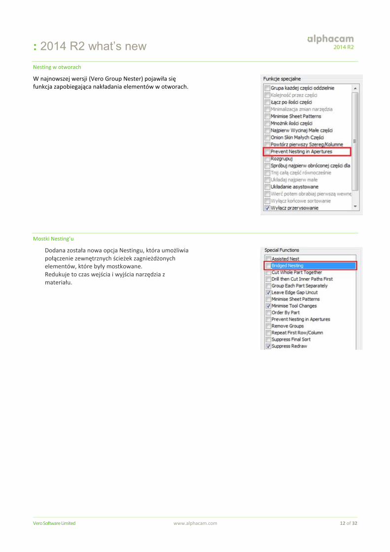
W najnowszej wersji (Vero Group Nester) pojawiła się funkcja zapobiegająca nakładania elementów w otworach.
Mostki Nesting’u
Dodana została nowa opcja Nestingu, która umożliwia połączenie zewnętrznych ścieżek zagnieżdżonych elementów, które były mostkowane. Redukuje to czas wejścia i wyjścia narzędzia z materiału.
: 2014 R2 what’s new
Vero Software Limited www.alphacam.com 13 of 32
Toczenie
Ulepszenia operacji Cyklu Toczenia Zgrubnego
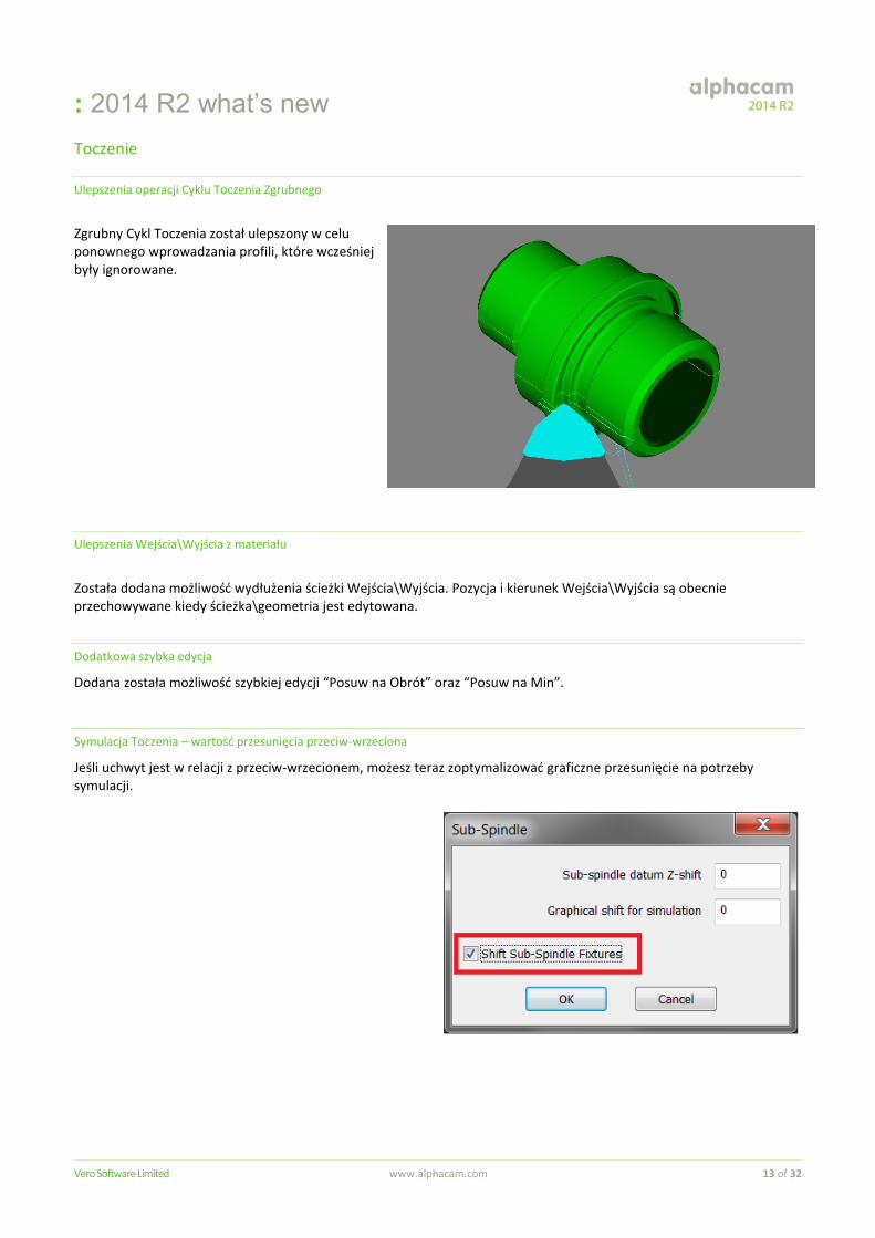
Zgrubny Cykl Toczenia został ulepszony w celu ponownego wprowadzania profili, które wcześniej były ignorowane.
Ulepszenia Wejścia\Wyjścia z materiału
Została dodana możliwość wydłużenia ścieżki Wejścia\Wyjścia. Pozycja i kierunek Wejścia\Wyjścia są obecnie przechowywane kiedy ścieżka\geometria jest edytowana.
Dodatkowa szybka edycja
Dodana została możliwość szybkiej edycji “Posuw na Obrót” oraz “Posuw na Min”.
Symulacja Toczenia – wartość przesunięcia przeciw-wrzeciona
Jeśli uchwyt jest w relacji z przeciw-wrzecionem, możesz teraz zoptymalizować graficzne przesunięcie na potrzeby symulacji.
: 2014 R2 what’s new
Vero Software Limited www.alphacam.com 14 of 32
Symulator
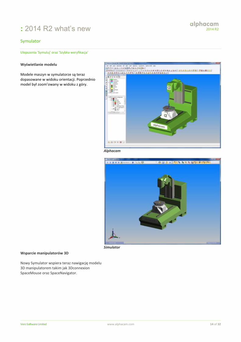
Ulepszenia 'Symuluj' oraz 'Szybka weryfikacja'
Wyświetlanie modelu Modele maszyn w symulatorze są teraz dopasowane w widoku orientacji. Poprzednio model był zoom’owany w widoku z góry.
Wsparcie manipulatorów 3D
Nowy Symulator wspiera teraz nawigację modelu 3D manipulatorem takim jak 3Dconnexion SpaceMouse oraz SpaceNavigator.
Alphacam
Simulator
: 2014 R2 what’s new
Vero Software Limited www.alphacam.com 15 of 32
CAD to CAM
Usprawnienia
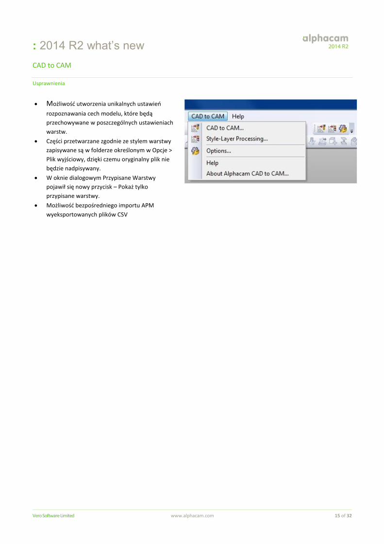
Możliwość utworzenia unikalnych ustawień
rozpoznawania cech modelu, które będą
przechowywane w poszczególnych ustawieniach
warstw.
Części przetwarzane zgodnie ze stylem warstwy
zapisywane są w folderze określonym w Opcje >
Plik wyjściowy, dzięki czemu oryginalny plik nie
będzie nadpisywany.
W oknie dialogowym Przypisane Warstwy
pojawił się nowy przycisk – Pokaż tylko
przypisane warstwy.
Możliwość bezpośredniego importu APM
wyeksportowanych plików CSV

: 2014 R2 what’s new
Vero Software Limited www.alphacam.com 16 of 32
Alphacam Art
Aspire Ver. 4.5
Usprawnienia funkcji Aspire V4.5:
Nowe ulepszone narzędzia do rysowania,
Nowe rozszerzone narzędzia do modelowania
Nowe klawisze skrótów
Wsparcie dla języka Czeskiego Aby zobaczyć dokument ‘What’s New for Aspire V4.5’ Klinkij tutaj Pamiętaj żeby uruchomić ‘Aspire for Alphacam’ wymagana jest licencja.
: 2014 R2 what’s new
Vero Software Limited www.alphacam.com 17 of 32
Automated Parametric Manufacturing (APM)
Usprawnienia
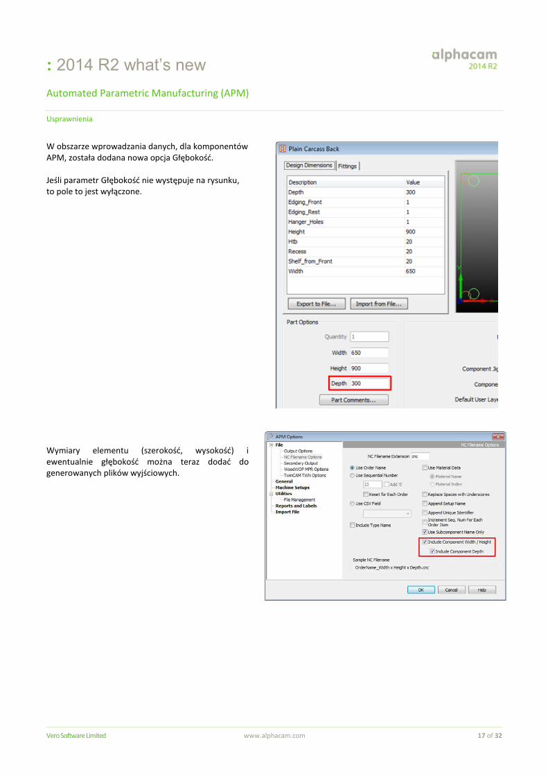
W obszarze wprowadzania danych, dla komponentów APM, została dodana nowa opcja Głębokość. Jeśli parametr Głębokość nie występuje na rysunku, to pole to jest wyłączone. Wymiary elementu (szerokość, wysokość) i ewentualnie głębokość można teraz dodać do generowanych plików wyjściowych.
: 2014 R2 what’s new
Vero Software Limited www.alphacam.com 18 of 32
Translator BTL
Nowa funkcjonalność BTL
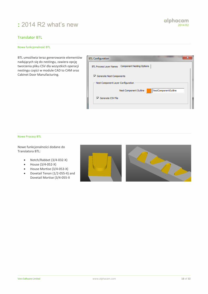
BTL umożliwia teraz generowanie elementów nadających się do nestingu, zawiera opcję tworzenia pliku CSV dla wszystkich operacji nestingu części w module CAD to CAM oraz Cabinet Door Manufacturing.
Nowe Procesy BTL
Nowe funkcjonalności dodane do Translatora BTL:
Notch/Rabbet (3/4-032-X)
House (3/4-052-X)
House Mortise (3/4-053-X)
Dovetail Tenon (1/2-055-X) and Dovetail Mortise (3/4-055-X
: 2014 R2 what’s new
Vero Software Limited www.alphacam.com 19 of 32
Translacja plików CAD
Wsparcie dla NX9
Możliwość importu bryłowych modeli z systemu NX9
Usprawnienia Importu plików Rhino
Następujące ulepszenia dodano do opcji importu plików systemu Rhino:
Polilinie Rhino będą teraz importowane jako grupa geometrii.
Rhino Brep będą teraz importowane jako grupa powierzchni.
Linie i łuki o takich samych wartościach Z będą tworzone na
płaszczyźnie pracy XY jako geometria 2D.
Linie i łuki, w których poziom Z jest ustawiony na 0, będą
tworzone na płaszczyźnie globalnej jako geometria 2D.
Imort DWG/DXF
Kolory warstw, tekstu i elementów ścian 3D w plikach DXF\DWG są teraz dokładnie dopasowane i wyświetlane kiedy opcja „Pokaż kolory linii i łuków” jest zaznaczona.
Autodesk Inventor 2015
Alphacam 2014 R2 wspiera wczytywanie modeli 3D z ostatniej wersji Autodesk Inventor 2015. Pamiętaj, że Autodesk Inventor 2015 lub Inventor View 2015 musi być zainstalowany na komputerze by prawidłowo wczytywać modele.
: 2014 R2 what’s new
Vero Software Limited www.alphacam.com 20 of 32
Obsługiwane wersje plików CAD
Alphacam umożliwia import następujących plików CAD do odpowiednich poziomów modułu E = Essential S = Standard A = Advanced U = Ultimate
Translator and Version Lathe Mill Wire Router Stone Profiling
DXF/DWG (AutoCAD 2014) E S A U E S A U S A E S A U E S A U A U
IGES (not version specific) E S A U E S A U S A E S A U E S A U A U
Rhino 5.0 S A U S A U S A S A U S A U A U
STL (not version specific) S A U S A U A S A U S A U A U
Postscript (Free Add-In) (not version specific) - S A U S A S A U S A U A U
STEP AP214/AP203 (preferred Schemas) A U A U A A U A U U
Part Modeler (current) A U A U A A U A U U
VISI Version 20 A U A U A A U A U U
Autodesk Inventor 2015 (current, IPT & IAM files) A U A U A A U A U U
ACIS R23 (Kernel) A U A U A A U A U U
Parasolid 25.0.187 (Kernel) A U A U A A U A U U
SolidWorks 2014 (SLDPRT files only) A U A U A A U A U U
SolidEdge ST5 (PAR & PSM files) A U A U A A U A U U
Spaceclaim 2012+ A U A U A A U A U U
Extra Cost
Catia V4 A U A U A A U A U U
Catia V5 R22 A U A U A A U A U U
Creo Parametrics 2.0 (formerly Pro/E Wildfire) A U A U A A U A U U
NX9 (formerly Unigraphics NX) A U A U A A U A U U
Jeśli chcesz importować pliki Autodesk Inventor, musisz mieć zainstalowane oprogramowanie Autodesk Inventor lub Inventor View. Inventor View możesz pobrać ze strony internetowej Autodesk.
: 2014 R2 what’s new
Vero Software Limited www.alphacam.com 21 of 32
Part Modeler
Nowe techniki tworzenia modeli 2D-3D
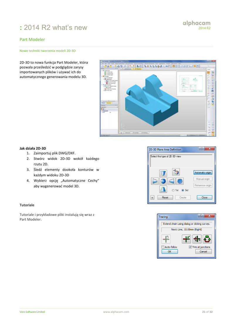
2D-3D to nowa funkcja Part Modeler, która pozwala prześledzić w podglądzie zarysy importowanych plików i używać ich do automatycznego generowania modelu 3D. Jak działa 2D-3D
1. Zaimportuj plik DWG/DXF.
2. Stwórz widok 2D-3D wokół każdego
rzutu 2D.
3. Śledź elementy dookoła konturów w
każdym widoku 2D-3D
4. Wybierz opcję „Automatyczne Cechy”
aby wygenerować model 3D.
Tutoriale Tutoriale i przykładowe pliki instalują się wraz z Part Modeler.
: 2014 R2 what’s new
Vero Software Limited www.alphacam.com 22 of 32
Rozbudowa API
Usprawnienia API
The following improvements have been made to the API in 2014 R2:
API - Lead-in/Out - Possibility to use "Multiple Lines In" through API.
API: Add a Close method to ViewWindow.
API - New method for STL.ChopIntoSections to include section geometry.
API - New Output NC Method That Gives Feedback On Errors Produced.
API - Rapids Manager - The addition of a Method relating to the Rapids Manager.
API Method - SolidFace.MakeGeometries.
API - Editable add-ins - The possibility to stop the suppression of toolpaths that happens when updating.
Feature Extraction API: Radial hole options added.
Feature Extraction API: Limit through holes added.
Feature Extraction API - Ability to Auto Align SolidBodies added.
For more detailed information about these improvements please see Appendix A
Please refer to the Maintenance Report for details of API bug fixes.
: 2014 R2 what’s new
Vero Software Limited www.alphacam.com 23 of 32
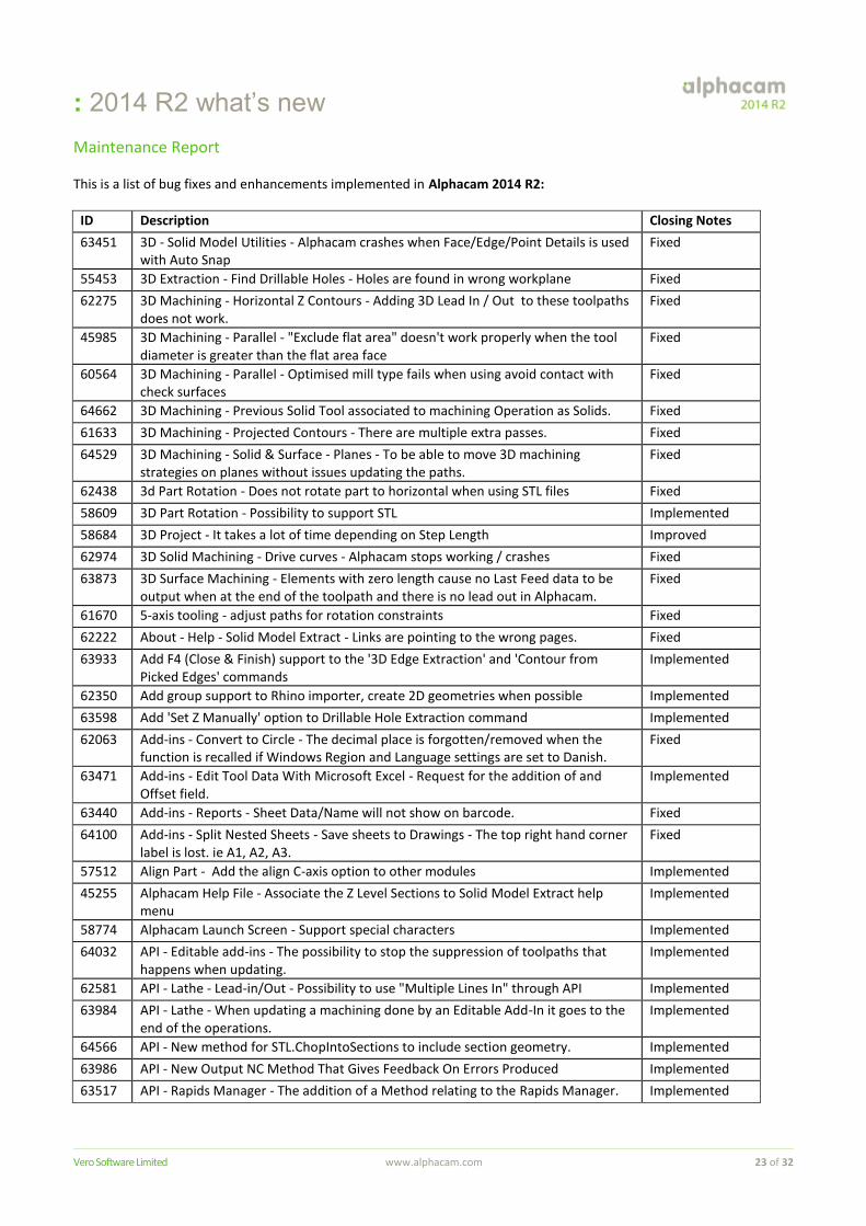
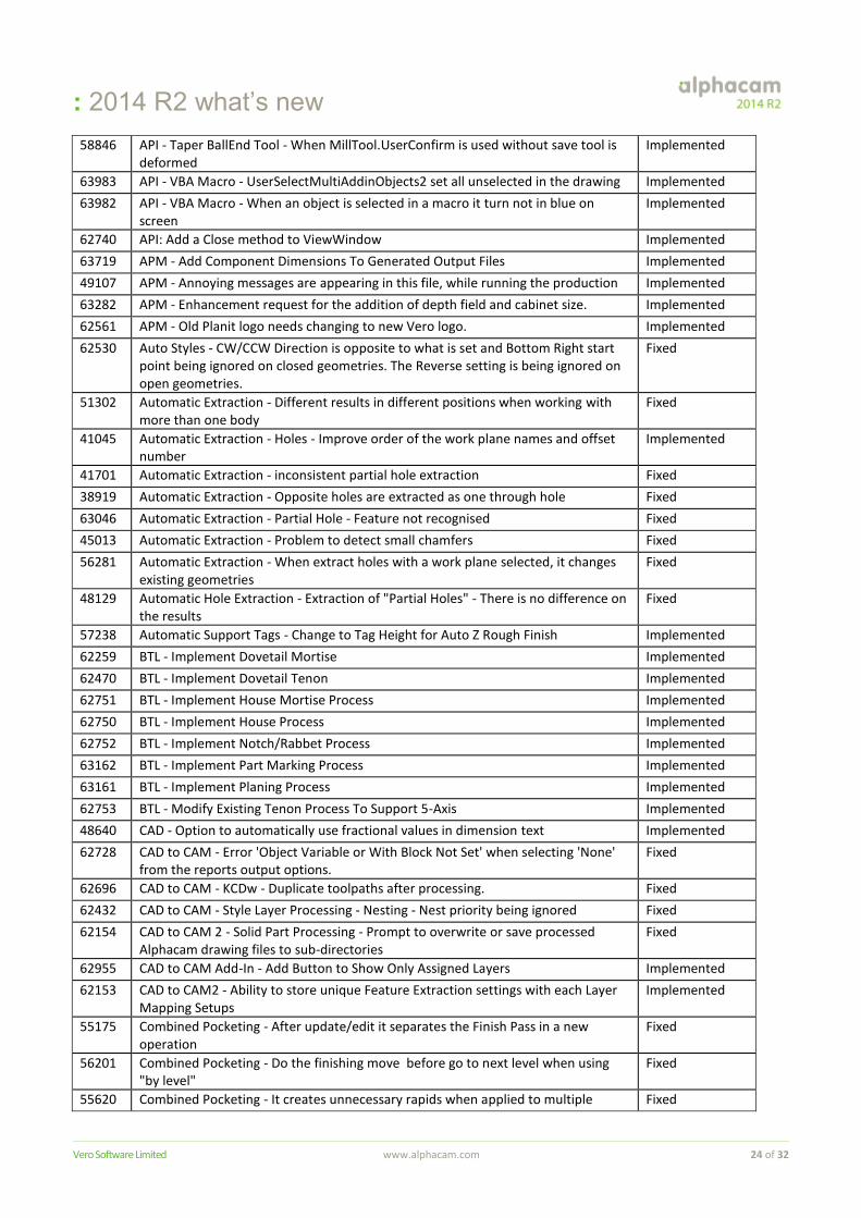
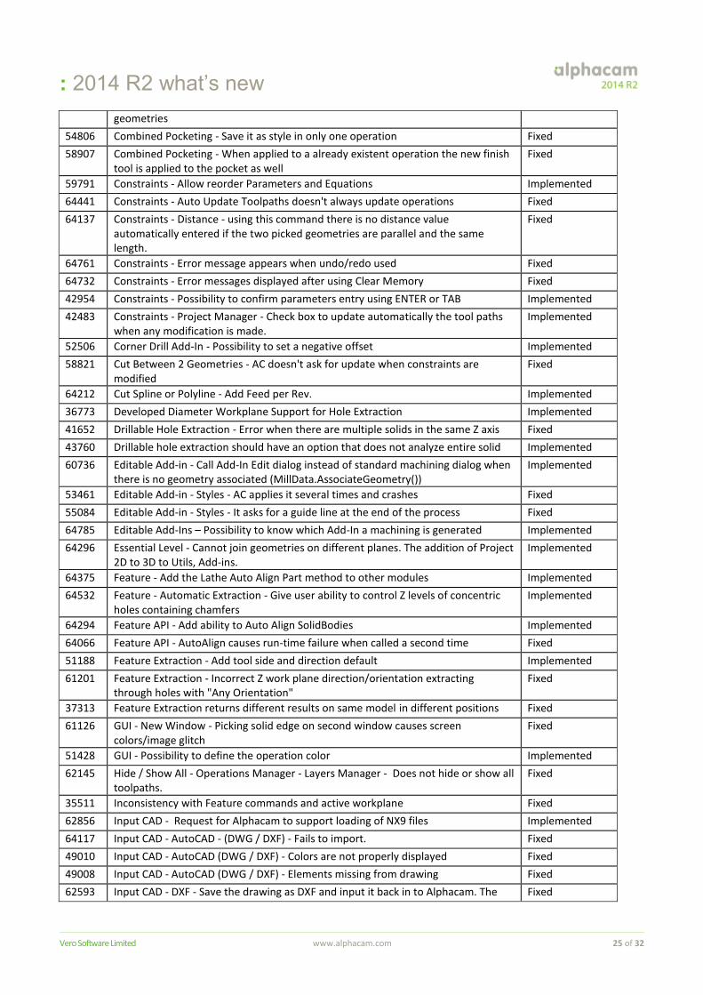
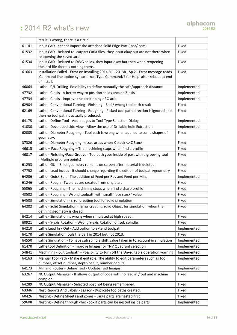
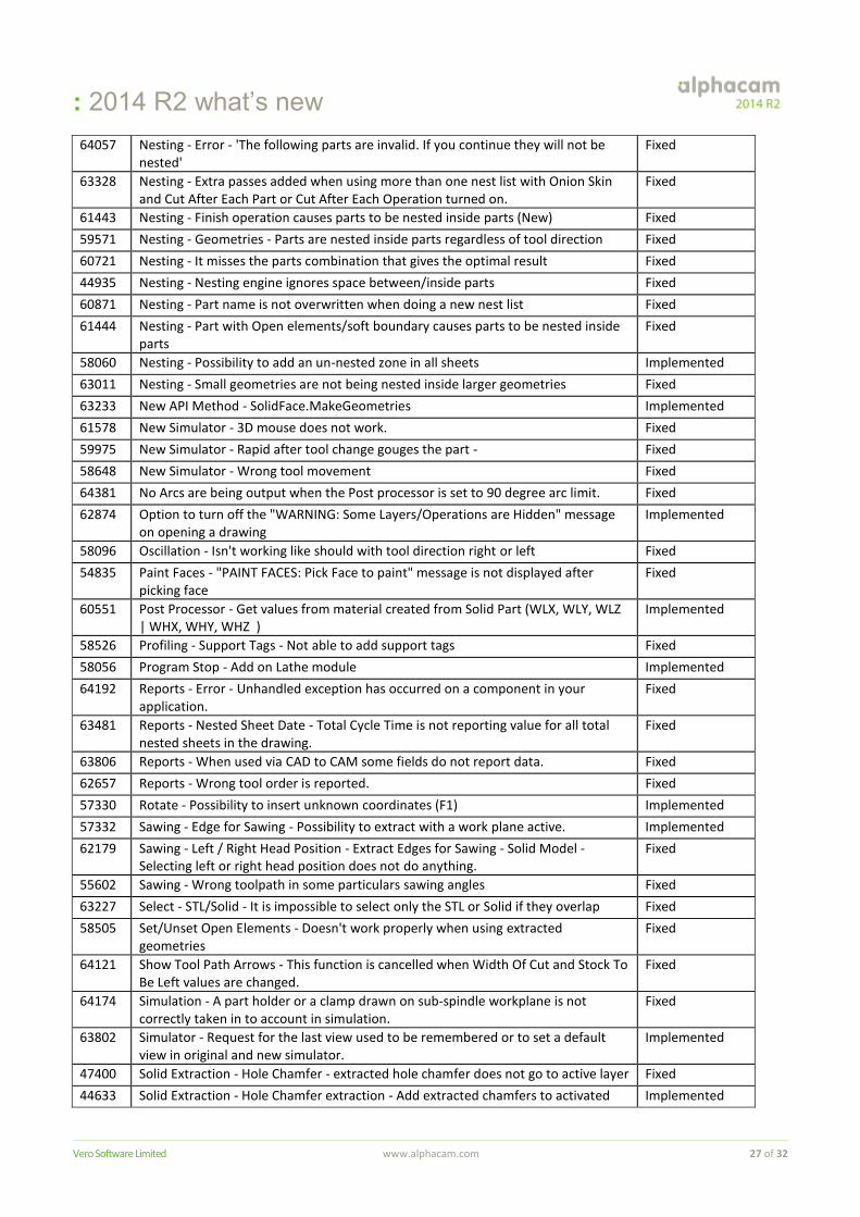
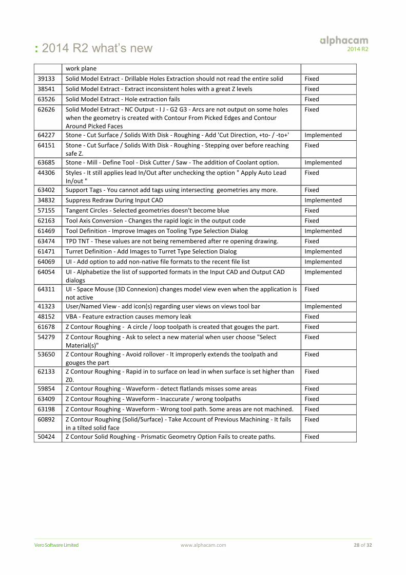
Maintenance Report
This is a list of bug fixes and enhancements implemented in Alphacam 2014 R2:
ID Description Closing Notes
63451 3D - Solid Model Utilities - Alphacam crashes when Face/Edge/Point Details is used with Auto Snap
Fixed
55453 3D Extraction - Find Drillable Holes - Holes are found in wrong workplane Fixed
62275 3D Machining - Horizontal Z Contours - Adding 3D Lead In / Out to these toolpaths does not work.
Fixed
45985 3D Machining - Parallel - "Exclude flat area" doesn't work properly when the tool diameter is greater than the flat area face
Fixed
60564 3D Machining - Parallel - Optimised mill type fails when using avoid contact with check surfaces
Fixed
64662 3D Machining - Previous Solid Tool associated to machining Operation as Solids. Fixed
61633 3D Machining - Projected Contours - There are multiple extra passes. Fixed
64529 3D Machining - Solid & Surface - Planes - To be able to move 3D machining strategies on planes without issues updating the paths.
Fixed
62438 3d Part Rotation - Does not rotate part to horizontal when using STL files Fixed
58609 3D Part Rotation - Possibility to support STL Implemented
58684 3D Project - It takes a lot of time depending on Step Length Improved
62974 3D Solid Machining - Drive curves - Alphacam stops working / crashes Fixed
63873 3D Surface Machining - Elements with zero length cause no Last Feed data to be output when at the end of the toolpath and there is no lead out in Alphacam.
Fixed
61670 5-axis tooling - adjust paths for rotation constraints Fixed
62222 About - Help - Solid Model Extract - Links are pointing to the wrong pages. Fixed
63933 Add F4 (Close & Finish) support to the '3D Edge Extraction' and 'Contour from Picked Edges' commands
Implemented
62350 Add group support to Rhino importer, create 2D geometries when possible Implemented
63598 Add 'Set Z Manually' option to Drillable Hole Extraction command Implemented
62063 Add-ins - Convert to Circle - The decimal place is forgotten/removed when the function is recalled if Windows Region and Language settings are set to Danish.
Fixed
63471 Add-ins - Edit Tool Data With Microsoft Excel - Request for the addition of and Offset field.
Implemented
63440 Add-ins - Reports - Sheet Data/Name will not show on barcode. Fixed
64100 Add-ins - Split Nested Sheets - Save sheets to Drawings - The top right hand corner label is lost. ie A1, A2, A3.
Fixed
57512 Align Part - Add the align C-axis option to other modules Implemented
45255 Alphacam Help File - Associate the Z Level Sections to Solid Model Extract help menu
Implemented
58774 Alphacam Launch Screen - Support special characters Implemented
64032 API - Editable add-ins - The possibility to stop the suppression of toolpaths that happens when updating.
Implemented
62581 API - Lathe - Lead-in/Out - Possibility to use "Multiple Lines In" through API Implemented
63984 API - Lathe - When updating a machining done by an Editable Add-In it goes to the end of the operations.
Implemented
64566 API - New method for STL.ChopIntoSections to include section geometry. Implemented
63986 API - New Output NC Method That Gives Feedback On Errors Produced Implemented
63517 API - Rapids Manager - The addition of a Method relating to the Rapids Manager. Implemented
: 2014 R2 what’s new
Vero Software Limited www.alphacam.com 24 of 32
58846 API - Taper BallEnd Tool - When MillTool.UserConfirm is used without save tool is deformed
Implemented
63983 API - VBA Macro - UserSelectMultiAddinObjects2 set all unselected in the drawing Implemented
63982 API - VBA Macro - When an object is selected in a macro it turn not in blue on screen
Implemented
62740 API: Add a Close method to ViewWindow Implemented
63719 APM - Add Component Dimensions To Generated Output Files Implemented
49107 APM - Annoying messages are appearing in this file, while running the production Implemented
63282 APM - Enhancement request for the addition of depth field and cabinet size. Implemented
62561 APM - Old Planit logo needs changing to new Vero logo. Implemented
62530 Auto Styles - CW/CCW Direction is opposite to what is set and Bottom Right start point being ignored on closed geometries. The Reverse setting is being ignored on open geometries.
Fixed
51302 Automatic Extraction - Different results in different positions when working with more than one body
Fixed
41045 Automatic Extraction - Holes - Improve order of the work plane names and offset number
Implemented
41701 Automatic Extraction - inconsistent partial hole extraction Fixed
38919 Automatic Extraction - Opposite holes are extracted as one through hole Fixed
63046 Automatic Extraction - Partial Hole - Feature not recognised Fixed
45013 Automatic Extraction - Problem to detect small chamfers Fixed
56281 Automatic Extraction - When extract holes with a work plane selected, it changes existing geometries
Fixed
48129 Automatic Hole Extraction - Extraction of "Partial Holes" - There is no difference on the results
Fixed
57238 Automatic Support Tags - Change to Tag Height for Auto Z Rough Finish Implemented
62259 BTL - Implement Dovetail Mortise Implemented
62470 BTL - Implement Dovetail Tenon Implemented
62751 BTL - Implement House Mortise Process Implemented
62750 BTL - Implement House Process Implemented
62752 BTL - Implement Notch/Rabbet Process Implemented
63162 BTL - Implement Part Marking Process Implemented
63161 BTL - Implement Planing Process Implemented
62753 BTL - Modify Existing Tenon Process To Support 5-Axis Implemented
48640 CAD - Option to automatically use fractional values in dimension text Implemented
62728 CAD to CAM - Error 'Object Variable or With Block Not Set' when selecting 'None' from the reports output options.
Fixed
62696 CAD to CAM - KCDw - Duplicate toolpaths after processing. Fixed
62432 CAD to CAM - Style Layer Processing - Nesting - Nest priority being ignored Fixed
62154 CAD to CAM 2 - Solid Part Processing - Prompt to overwrite or save processed Alphacam drawing files to sub-directories
Fixed
62955 CAD to CAM Add-In - Add Button to Show Only Assigned Layers Implemented
62153 CAD to CAM2 - Ability to store unique Feature Extraction settings with each Layer Mapping Setups
Implemented
55175 Combined Pocketing - After update/edit it separates the Finish Pass in a new operation
Fixed
56201 Combined Pocketing - Do the finishing move before go to next level when using "by level"
Fixed
55620 Combined Pocketing - It creates unnecessary rapids when applied to multiple Fixed
: 2014 R2 what’s new
Vero Software Limited www.alphacam.com 25 of 32
geometries
54806 Combined Pocketing - Save it as style in only one operation Fixed
58907 Combined Pocketing - When applied to a already existent operation the new finish tool is applied to the pocket as well
Fixed
59791 Constraints - Allow reorder Parameters and Equations Implemented
64441 Constraints - Auto Update Toolpaths doesn't always update operations Fixed
64137 Constraints - Distance - using this command there is no distance value automatically entered if the two picked geometries are parallel and the same length.
Fixed
64761 Constraints - Error message appears when undo/redo used Fixed
64732 Constraints - Error messages displayed after using Clear Memory Fixed
42954 Constraints - Possibility to confirm parameters entry using ENTER or TAB Implemented
42483 Constraints - Project Manager - Check box to update automatically the tool paths when any modification is made.
Implemented
52506 Corner Drill Add-In - Possibility to set a negative offset Implemented
58821 Cut Between 2 Geometries - AC doesn't ask for update when constraints are modified
Fixed
64212 Cut Spline or Polyline - Add Feed per Rev. Implemented
36773 Developed Diameter Workplane Support for Hole Extraction Implemented
41652 Drillable Hole Extraction - Error when there are multiple solids in the same Z axis Fixed
43760 Drillable hole extraction should have an option that does not analyze entire solid Implemented
60736 Editable Add-in - Call Add-In Edit dialog instead of standard machining dialog when there is no geometry associated (MillData.AssociateGeometry())
Implemented
53461 Editable Add-in - Styles - AC applies it several times and crashes Fixed
55084 Editable Add-in - Styles - It asks for a guide line at the end of the process Fixed
64785 Editable Add-Ins – Possibility to know which Add-In a machining is generated Implemented
64296 Essential Level - Cannot join geometries on different planes. The addition of Project 2D to 3D to Utils, Add-ins.
Implemented
64375 Feature - Add the Lathe Auto Align Part method to other modules Implemented
64532 Feature - Automatic Extraction - Give user ability to control Z levels of concentric holes containing chamfers
Implemented
64294 Feature API - Add ability to Auto Align SolidBodies Implemented
64066 Feature API - AutoAlign causes run-time failure when called a second time Fixed
51188 Feature Extraction - Add tool side and direction default Implemented
61201 Feature Extraction - Incorrect Z work plane direction/orientation extracting through holes with "Any Orientation"
Fixed
37313 Feature Extraction returns different results on same model in different positions Fixed
61126 GUI - New Window - Picking solid edge on second window causes screen colors/image glitch
Fixed
51428 GUI - Possibility to define the operation color Implemented
62145 Hide / Show All - Operations Manager - Layers Manager - Does not hide or show all toolpaths.
Fixed
35511 Inconsistency with Feature commands and active workplane Fixed
62856 Input CAD - Request for Alphacam to support loading of NX9 files Implemented
64117 Input CAD - AutoCAD - (DWG / DXF) - Fails to import. Fixed
49010 Input CAD - AutoCAD (DWG / DXF) - Colors are not properly displayed Fixed
49008 Input CAD - AutoCAD (DWG / DXF) - Elements missing from drawing Fixed
62593 Input CAD - DXF - Save the drawing as DXF and input it back in to Alphacam. The Fixed
: 2014 R2 what’s new
Vero Software Limited www.alphacam.com 26 of 32
result is wrong, there is a circle.
61141 Input CAD - cannot import the attached Solid Edge Part (.par/.psm) Fixed
61532 Input CAD - Related to .catpart Catia files, they input okay but are not there when re opening the saved .ard.
Fixed
61534 Input CAD - Related to DWG solids, they input okay but then when reopening the .ard file there is nothing there.
Fixed
61663 Installation Failed - Error on installing 2014 R1 - 2013R1 Sp 2 - Error message reads 'Command line option syntax error. Type Command/? for Help' after reboot at end of install.
Fixed
46064 Lathe - C/L Drilling- Possibility to define manually the safe/approach distance Implemented
47732 Lathe - C-axis - A better way to position solids around Z-axis Implemented
47734 Lathe - C-axis - Improve the positioning of C-axis Implemented
62904 Lathe - Conventional Turning - Finishing - Bad / wrong tool path result Fixed
62169 Lathe - Conventional Turning - Roughing - Picked tool path direction is ignored and then no tool path is actually produced.
Fixed
64175 Lathe - Define Tool - Add Images to Tool Type Selection Dialog Implemented
41030 Lathe - Developed side view - Allow the use of Drillable hole Extraction Implemented
62005 Lathe - Diameter Roughing - Tool path is wrong when applied to some shapes of geometry.
Fixed
37326 Lathe - Diameter Roughing misses areas when X stock <> Z Stock Fixed
46615 Lathe – Face Roughing – The machining stops when find a profile Fixed
46017 Lathe - Finishing/Face Groove - Toolpath goes inside of part with a grooving tool ( Multiple program points)
Fixed
61253 Lathe - GUI - Billet geometry remains on screen after material is deleted Fixed
47752 Lathe - Lead in/out - It should change regarding the edition of toolpath/geometry Fixed
64206 Lathe - Quick Edit - The addition of Feed per Rev and Feed per Min. Implemented
61246 Lathe - Rough - Two arcs are created from single arc Fixed
55065 Lathe - Roughing - The machining stops when find a sharp profile Fixed
43502 Lathe - Roughing - Wrong toolpath with small "face stock" value Fixed
64503 Lathe - Simulation - Error creating tool for solid simulation Fixed
64202 Lathe - Solid Simulation - 'Error creating Solid Object for simulation' when the defining geometry is closed.
Fixed
64214 Lathe - Simulation is wrong when simulated at high speed. Fixed
60921 Lathe - Y-axis Rotation - Wrong Y-axis Rotation on sub spindle Fixed
64210 Lathe Lead In / Out - Add option to extend toolpath. Implemented
64170 Lathe Simulation fouls the part in 2014 but not 2013. Fixed
64550 Lathe Simulation - To have sub spindle shift value taken in to account in simulation Implemented
61470 Lathe tool Definition - Improve Images for TNV Quadrant selection Implemented
54841 Machining - Edit toolpath - Possibility to turn off the Un-editable operation warning Implemented
64163 Manual Tool Path - Make it editable. The ability to edit parameters such as tool number, offset number, depth of cut, number of cuts.
Implemented
64173 Mill and Router - Define Tool - Update Tool Images Implemented
63267 NC Output Manager - It allows output of code with no lead in / out and machine comp on.
Fixed
64289 NC Output Manager - Selected post not being remembered. Fixed
63346 Nest Reports And Labels - Legacy - Duplicate toolpaths created. Fixed
60426 Nesting - Define Sheets and Zones - Large parts are nested first Fixed
59608 Nesting - Define through checkbox if parts can be nested inside parts Implemented
: 2014 R2 what’s new
Vero Software Limited www.alphacam.com 27 of 32
64057 Nesting - Error - 'The following parts are invalid. If you continue they will not be nested'
Fixed
63328 Nesting - Extra passes added when using more than one nest list with Onion Skin and Cut After Each Part or Cut After Each Operation turned on.
Fixed
61443 Nesting - Finish operation causes parts to be nested inside parts (New) Fixed
59571 Nesting - Geometries - Parts are nested inside parts regardless of tool direction Fixed
60721 Nesting - It misses the parts combination that gives the optimal result Fixed
44935 Nesting - Nesting engine ignores space between/inside parts Fixed
60871 Nesting - Part name is not overwritten when doing a new nest list Fixed
61444 Nesting - Part with Open elements/soft boundary causes parts to be nested inside parts
Fixed
58060 Nesting - Possibility to add an un-nested zone in all sheets Implemented
63011 Nesting - Small geometries are not being nested inside larger geometries Fixed
63233 New API Method - SolidFace.MakeGeometries Implemented
61578 New Simulator - 3D mouse does not work. Fixed
59975 New Simulator - Rapid after tool change gouges the part - Fixed
58648 New Simulator - Wrong tool movement Fixed
64381 No Arcs are being output when the Post processor is set to 90 degree arc limit. Fixed
62874 Option to turn off the "WARNING: Some Layers/Operations are Hidden" message on opening a drawing
Implemented
58096 Oscillation - Isn't working like should with tool direction right or left Fixed
54835 Paint Faces - "PAINT FACES: Pick Face to paint" message is not displayed after picking face
Fixed
60551 Post Processor - Get values from material created from Solid Part (WLX, WLY, WLZ | WHX, WHY, WHZ )
Implemented
58526 Profiling - Support Tags - Not able to add support tags Fixed
58056 Program Stop - Add on Lathe module Implemented
64192 Reports - Error - Unhandled exception has occurred on a component in your application.
Fixed
63481 Reports - Nested Sheet Date - Total Cycle Time is not reporting value for all total nested sheets in the drawing.
Fixed
63806 Reports - When used via CAD to CAM some fields do not report data. Fixed
62657 Reports - Wrong tool order is reported. Fixed
57330 Rotate - Possibility to insert unknown coordinates (F1) Implemented
57332 Sawing - Edge for Sawing - Possibility to extract with a work plane active. Implemented
62179 Sawing - Left / Right Head Position - Extract Edges for Sawing - Solid Model - Selecting left or right head position does not do anything.
Fixed
55602 Sawing - Wrong toolpath in some particulars sawing angles Fixed
63227 Select - STL/Solid - It is impossible to select only the STL or Solid if they overlap Fixed
58505 Set/Unset Open Elements - Doesn't work properly when using extracted geometries
Fixed
64121 Show Tool Path Arrows - This function is cancelled when Width Of Cut and Stock To Be Left values are changed.
Fixed
64174 Simulation - A part holder or a clamp drawn on sub-spindle workplane is not correctly taken in to account in simulation.
Fixed
63802 Simulator - Request for the last view used to be remembered or to set a default view in original and new simulator.
Implemented
47400 Solid Extraction - Hole Chamfer - extracted hole chamfer does not go to active layer Fixed
44633 Solid Extraction - Hole Chamfer extraction - Add extracted chamfers to activated Implemented
: 2014 R2 what’s new
Vero Software Limited www.alphacam.com 28 of 32
work plane
39133 Solid Model Extract - Drillable Holes Extraction should not read the entire solid Fixed
38541 Solid Model Extract - Extract inconsistent holes with a great Z levels Fixed
63526 Solid Model Extract - Hole extraction fails Fixed
62626 Solid Model Extract - NC Output - I J - G2 G3 - Arcs are not output on some holes when the geometry is created with Contour From Picked Edges and Contour Around Picked Faces
Fixed
64227 Stone - Cut Surface / Solids With Disk - Roughing - Add 'Cut Direction, +to- / -to+' Implemented
64151 Stone - Cut Surface / Solids With Disk - Roughing - Stepping over before reaching safe Z.
Fixed
63685 Stone - Mill - Define Tool - Disk Cutter / Saw - The addition of Coolant option. Implemented
44306 Styles - It still applies lead In/Out after unchecking the option " Apply Auto Lead In/out "
Fixed
63402 Support Tags - You cannot add tags using intersecting geometries any more. Fixed
34832 Suppress Redraw During Input CAD Implemented
57155 Tangent Circles - Selected geometries doesn't become blue Fixed
62163 Tool Axis Conversion - Changes the rapid logic in the output code Fixed
61469 Tool Definition - Improve Images on Tooling Type Selection Dialog Implemented
63474 TPD TNT - These values are not being remembered after re opening drawing. Fixed
61471 Turret Definition - Add Images to Turret Type Selection Dialog Implemented
64069 UI - Add option to add non-native file formats to the recent file list Implemented
64054 UI - Alphabetize the list of supported formats in the Input CAD and Output CAD dialogs
Implemented
64311 UI - Space Mouse (3D Connexion) changes model view even when the application is not active
Fixed
41323 User/Named View - add icon(s) regarding user views on views tool bar Implemented
48152 VBA - Feature extraction causes memory leak Fixed
61678 Z Contour Roughing - A circle / loop toolpath is created that gouges the part. Fixed
54279 Z Contour Roughing - Ask to select a new material when user choose "Select Material(s)"
Fixed
53650 Z Contour Roughing - Avoid rollover - It improperly extends the toolpath and gouges the part
Fixed
62133 Z Contour Roughing - Rapid in to surface on lead in when surface is set higher than Z0.
Fixed
59854 Z Contour Roughing - Waveform - detect flatlands misses some areas Fixed
63409 Z Contour Roughing - Waveform - Inaccurate / wrong toolpaths Fixed
63198 Z Contour Roughing - Waveform - Wrong tool path. Some areas are not machined. Fixed
60892 Z Contour Roughing (Solid/Surface) - Take Account of Previous Machining - It fails in a tilted solid face
Fixed
50424 Z Contour Solid Roughing - Prismatic Geometry Option Fails to create paths. Fixed
: 2014 R2 what’s new
Vero Software Limited www.alphacam.com 29 of 32
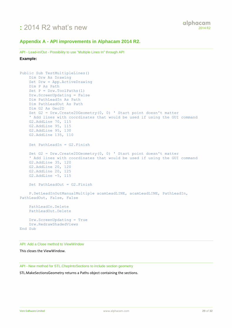
Appendix A - API improvements in Alphacam 2014 R2.
API - Lead-in/Out - Possibility to use "Multiple Lines In" through API
Example:
Public Sub TestMultipleLines()
Dim Drw As Drawing
Set Drw = App.ActiveDrawing
Dim P As Path
Set P = Drw.ToolPaths(1)
Drw.ScreenUpdating = False
Dim PathLeadIn As Path
Dim PathLeadOut As Path
Dim G2 As Geo2D
Set G2 = Drw.Create2DGeometry(0, 0) ' Start point doesn't matter
' Add lines with coordinates that would be used if using the GUI command
G2.AddLine 70, 115
G2.AddLine 95, 115
G2.AddLine 95, 130
G2.AddLine 135, 110
Set PathLeadIn = G2.Finish
Set G2 = Drw.Create2DGeometry(0, 0) ' Start point doesn't matter
' Add lines with coordinates that would be used if using the GUI command
G2.AddLine 35, 120
G2.AddLine 20, 120
G2.AddLine 20, 125
G2.AddLine -5, 115
Set PathLeadOut = G2.Finish
P.SetLeadInOutManualMultiple acamLeadLINE, acamLeadLINE, PathLeadIn,
PathLeadOut, False, False
PathLeadIn.Delete
PathLeadOut.Delete
Drw.ScreenUpdating = True
Drw.RedrawShadedViews
End Sub
API: Add a Close method to ViewWindow
This closes the ViewWindow.
API - New method for STL.ChopIntoSections to include section geometry
STL.MakeSectionsGeometry returns a Paths object containing the sections.
: 2014 R2 what’s new
Vero Software Limited www.alphacam.com 30 of 32
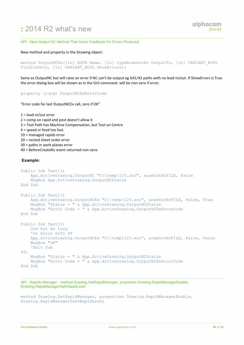
API - New Output NC Method That Gives Feedback On Errors Produced
New method and property in the Drawing object:
method OutputNCEx([in] BSTR Name, [in] typeAcamOutNc OutputTo, [in] VARIANT_BOOL
VisibleOnly, [in] VARIANT_BOOL ShowErrors);
Same as OutputNC but will raise an error if NC can't be output eg G41/42 paths with no lead-in/out. If ShowErrors is True the error dialog box will be shown as in the GUI command. will be non-zero if error.
property (long) OutputNCExErrorCode
"Error code for last OutputNCEx call, zero if OK"
1 = lead-in/out error 2 = comp on rapid and post doesn't allow it 3 = Tool Path has Machine Compensation, but Tool on Centre 4 = speed or feed too fast. 10 = managed rapids error 20 = nested sheet order error 30 = paths in work planes error 40 = BeforeCreateNc event returned non-zero
Example:
Public Sub Test1()
App.ActiveDrawing.OutputNC "C:\temp\123.anc", acamOutNcFILE, False
MsgBox App.ActiveDrawing.OutputNCStatus
End Sub
Public Sub Test2()
App.ActiveDrawing.OutputNCEx "C:\temp\123.anc", acamOutNcFILE, False, True
MsgBox "Status = " & App.ActiveDrawing.OutputNCStatus
MsgBox "Error Code = " & App.ActiveDrawing.OutputNCExErrorCode
End Sub
Public Sub Test3()
Dim Ret As Long
'On Error GoTo 99
App.ActiveDrawing.OutputNCEx "C:\temp\123.anc", acamOutNcFILE, False, False
MsgBox "OK"
'Exit Sub
99:
MsgBox "Status = " & App.ActiveDrawing.OutputNCStatus
MsgBox "Error Code = " & App.ActiveDrawing.OutputNCExErrorCode
End Sub
API - Rapids Manager - method Drawing.SetRapidManager, properties Drawing.RapidManagerEnable, Drawing.RapidManagerSafeRapidLevel
method Drawing.SetRapidManager, properties Drawing.RapidManagerEnable,
Drawing.RapidManagerSafeRapidLevel
: 2014 R2 what’s new
Vero Software Limited www.alphacam.com 31 of 32
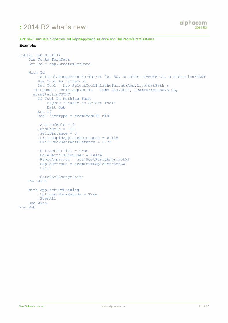
API: new TurnData properties DrillRapidApproachDistance and DrillPeckRetractDistance
Example:
Public Sub Drill()
Dim Td As TurnData
Set Td = App.CreateTurnData
With Td
.SetToolChangePointForTurret 20, 50, acamTurretABOVE_CL, acamStationFRONT
Dim Tool As LatheTool
Set Tool = App.SelectToolInLatheTurret(App.LicomdatPath &
"licomdat\ttools.alp\Drill - 10mm dia.att", acamTurretABOVE_CL,
acamStationFRONT)
If Tool Is Nothing Then
MsgBox "Unable to Select Tool"
Exit Sub
End If
Tool.FeedType = acamFeedPER_MIN
.StartOfHole = 0
.EndOfHole = -10
.PeckDistance = 3
.DrillRapidApproachDistance = 0.125
.DrillPeckRetractDistance = 0.25
.RetractPartial = True
.HoleDepthIsShoulder = False
.RapidApproach = acamPostRapidApproachXZ
.RapidRetract = acamPostRapidRetractZX
.Drill
.GotoToolChangePoint
End With
With App.ActiveDrawing
.Options.ShowRapids = True
.ZoomAll
End With
End Sub
: 2014 R2 what’s new
Vero Software Limited www.alphacam.com 32 of 32
API New Method - SolidFace.MakeGeometries
Public Sub RedFaceToGeometry()
Dim SF As SolidFeatures
Set SF = App.ActiveDrawing.SolidInterface
Dim F As SolidFace
For Each F In SF.Bodies(1).Faces
If F.Color = RGB(255, 0, 0) Then
Dim Geos As AlphacamObjects
Set Geos = F.MakeGeometries
Debug.Print Geos.Count
Dim O As Object
For Each O In Geos
On Error Resume Next
Dim P As Path
Set P = Nothing
Set P = O
If Not P Is Nothing Then
Debug.Print "Path"
'P.MoveG 0, 0, 99
Else
Dim S As Spline
Set S = Nothing
Set S = O
If Not S Is Nothing Then
Debug.Print "Spline"
'S.MoveG 0, 0, 99
End If
End If
Next O
End If
Next F
End Sub
API - Editable add-ins - The possibility to stop the suppression of toolpaths that happens when updating.
Example:
Const ATTR_OP_DONT_DELETE_FIRST As String = "LicomUKDMBOpDontDeleteFirst" ' 1 to
delete tool paths only if new ones created
MDForAssociate.AttributeOp(ATTR_OP_DONT_DELETE_FIRST) = 1
The tool paths will only be deleted if new ones are created.


![(QFRQWUR GH 8WLOL]DGRUHV $OSKDFDP¶ - … 2017 - Demo.pdf · alphacam 2017 R2 . Paus . Title: Microsoft PowerPoint - 03-ALPHACAM2017-DEMO.pptx Author: psousa Created Date: 5/18/2017](https://img.dokumen.tips/doc/110x75/5ba4df4d09d3f2ee718bd7e7/qfrqwur-gh-8wloldgruhv-oskdfdp-2017-demopdf-alphacam-2017-r2-paus.jpg)