Embed Size (px)
Citation preview
Abstract—Since its invention in the turn of 20th century,
semiconductors have always riddled the minds of contemporary science. The various properties of the semiconductors have been studied using spectroscopy, Hall Effect experiment or simple measurement methods under different conditions. The behavior observed has led to a different aspect and hence a different application. The aim of this paper is to study the properties of a semi-conductor bar specially the magneto-resistance, carrier concentration, Energy band gap and the effect of magnetic field on Hall coefficient using a new experimental setup and also discuss its application. Another objective of this paper has been validating the Drude’s Model and proposing a solution to the Hall Effect drawback. The design can be used as a replacement to the Hall Effect experiment where as it incorporates the magnetic field’s effect for the Hall co-efficient. This experiment employs only magnetic field to determine the magneto resistance unlike Hall Effect where along with magnetic field electric field is also used.
Index Terms—Experimental set-up, hall-effect, drude’s model, magneto-resistance
I. INTRODUCTION The independent electron model or the free electron model
has been the cornerstone for semiconductor studies [1] and applying the concepts of those models the various phenomenons of semi-conductors [1], [2] like Hall Effect, carrier density, band gap measurement is being studied. Hall Effect experiment had been another very significant contribution to studies of semiconductor. Employing the Hall Effect, magneto-resistance [3] of materials is analyzed and inferred as only dependent on carrier density of the material, whereas, it is experimentally observed, that not only carrier concentration but it depends on temperature and the magnetic field also [1]. This paper discusses a new experimental setup which takes into account the behavior of a semiconductor under a magnetic field when it is subjected to a mechanical force. Unlike Hall Effect experiment where applied electric field and applied magnetic field are perpendicular to each other, in this experimental set-up we are not applying any electric field, thereby employing only one source of electrical field, i.e. the electrical field produced due to the motion of free electrons. Thus, any other force on electrons is avoided, but the applied external magnetic and the internal atomic and molecular forces. This concept can not only measure the most important aspect of semiconductor, like, number of conduction band electrons, energy band gap, but
Manuscript received April 15, 2012; revised May 31, 2012. Rourav Basak is with National Institute Technology, Durgapur (e-mail:
magneto-resistance and dependence of it on the factors of external magnetic field also. Drude’s model has been used to analyze the system so far.
II. DESIGN OF EXPERIMENTAL SETUP The experimental setup consists of a semiconductor bar (of
length ‘2L’ and cross-sectional area ‘A’) mounted on the shaft of a motor, a grounded metal ring supported on tripod stand and a magnetic field. Fig (1a) and Fig (1b) shows the front view and the top view of the experimental setup. The electric motor has a metal shaft on which the semiconductor bar is mounted. The metal shaft acts as a point for measuring the voltage. The other point for measuring the voltage is the grounded metal ring. The semiconductor bar is rotated in a magnetic field (B) pointing downwards in Fig (1a).
Fig. 1a. Front view of the experimental setup
Fig. 1b. Top view of the experimental setup
III. CALCULATION AND ANALYSIS
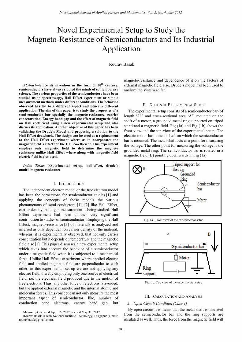
A. Open Circuit Condition (Case 1) By open circuit it is meant that the metal shaft is insulated
from the semiconductor bar and the ring supports are insulated as well. Thus, the force from the magnetic field will
Novel Experimental Setup to Study the Magneto-Resistance of Semiconductors and Its Industrial
Application
Rourav Basak
International Journal of Applied Physics and Mathematics, Vol. 2, No. 4, July 2012
281
drive the electrons to generate an electric field internally and an emf can be observed with the help of figure shown.
Fig. 2. Open circuit condition
The open circuit condition can be equivalent to a chemical
cell where the emf is generated from the chemical energy. Similar to the Hall Effect where the components of velocity of electrons due to random motion cancel each other over a period of time [3], [4], here also we employ the consideration
[8]. Thus the electrons have velocity due to angular motion. If the angular velocity is ω, then the velocity of an electron at a distance x is
|v| = ωx;
The electrons will start to move from the end (due to highest velocity) and as they vacate their position there will be ions which will attract the next layer of electrons. Thus, the next layer of electrons are pushed by the magnetic force and pulled by the local electric field.
-e (dV/dx) = eωxB î
Ei = (-dV/dx) = -ωxB î
The force on one electron will be due to this local electric field (Ei) and external magnetic field (B)
|Fx| = 2eωxB
We have two possibilities now- SUBCASE 1: If the valance band electrons do not come to
the conduction band then the central position gradually will be left out of electrons and only ions will be there. These ions will be positively charged and hence will pull the electrons which were moving outward previously. Due to this new electric field all the electrons will cease their motion and come to equilibrium.
At the beginning let the voltage be Vi
e(dV/dx) = eωxB
or, dV = ωxB dx
And finally when all the electrons cease their motion it can be considered equivalent to an equipotential wire where at each point the voltage is Vf. This final potential rise Vf is due to the work done by the magnetic field and the internal electric field. Thus the work done by the force Fx , if carrier density is n-
This is equal to the voltage rise, thus-
eωnABL3/3= en(AL)Vf
or, Vf = ωBL2/3
SUBCASE 2: If n’ number of electrons per unit volume get energy from the magnetic field and jump from valance band to conduction band then in that case the initial voltage will be exactly like previous case but the final voltage will be different. In this case the work done by Fx is –
n’Eg = en [(ωBL2/3)- Vf]
if n’=0 then Vf = ωBL2/3 else Vf = ωBL2/3- (n’Eg/ ne) Thus the final voltage will be less by a factor (n’Eg/ ne)
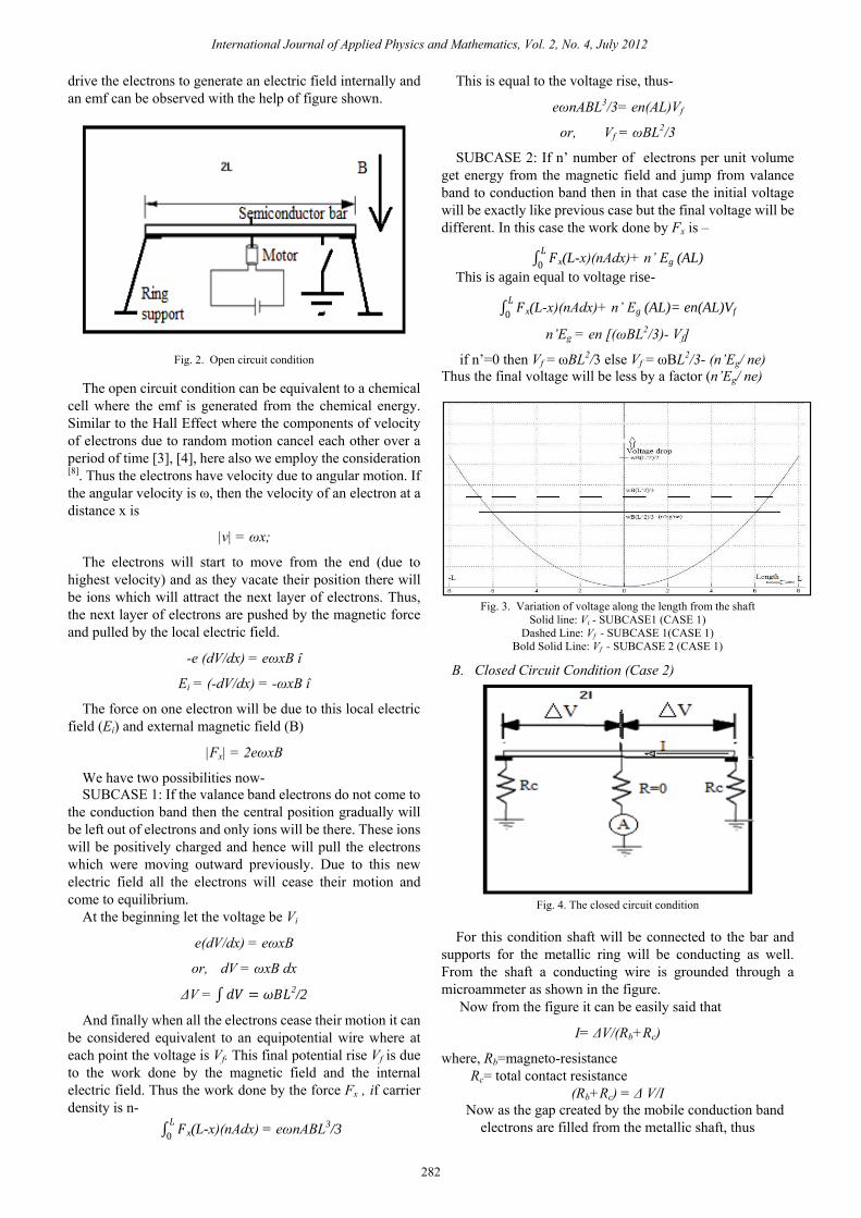
Fig. 3. Variation of voltage along the length from the shaft
Solid line: Vi - SUBCASE1 (CASE 1) Dashed Line: Vf - SUBCASE 1(CASE 1)
Bold Solid Line: Vf - SUBCASE 2 (CASE 1)
B. Closed Circuit Condition (Case 2)
Fig. 4. The closed circuit condition
For this condition shaft will be connected to the bar and
supports for the metallic ring will be conducting as well. From the shaft a conducting wire is grounded through a microammeter as shown in the figure.
Now from the figure it can be easily said that
I= ΔV/(Rb+Rc)
where, Rb=magneto-resistance Rc= total contact resistance
(Rb+Rc) = Δ V/I Now as the gap created by the mobile conduction band
electrons are filled from the metallic shaft, thus
International Journal of Applied Physics and Mathematics, Vol. 2, No. 4, July 2012
282
ΔV = 𝑑𝑉 = 𝜔𝐵𝐿2/2
𝐹𝐿
0 x(L-x)(nAdx) = eωnABL3/3
𝐹𝐿
0 x(L-x)(nAdx)+ n’ Eg (AL)
This is again equal to voltage rise-
𝐹𝐿
0 x(L-x)(nAdx)+ n’ Eg (AL)= en(AL)Vf
ΔV= ωBL2/2 And the current will be
I= n(AL)e/t where t is the time over which the bar has been rotated. Thus,-
(Rb+Rc) = ωBLt/(2nAe)
Or, Hall Co-efficient is proportional to ωBt/2ne Now it can be seen that magneto-resistance not only
depends on the carrier concentration n but also the magnetic field B. The magnetic field affects the resistance along with ω. Thus if angular momentum is associated along with Drude’s linear motion then the effect of magnetic field on Hall co-efficient can be analysed.
IV. APPLICATION
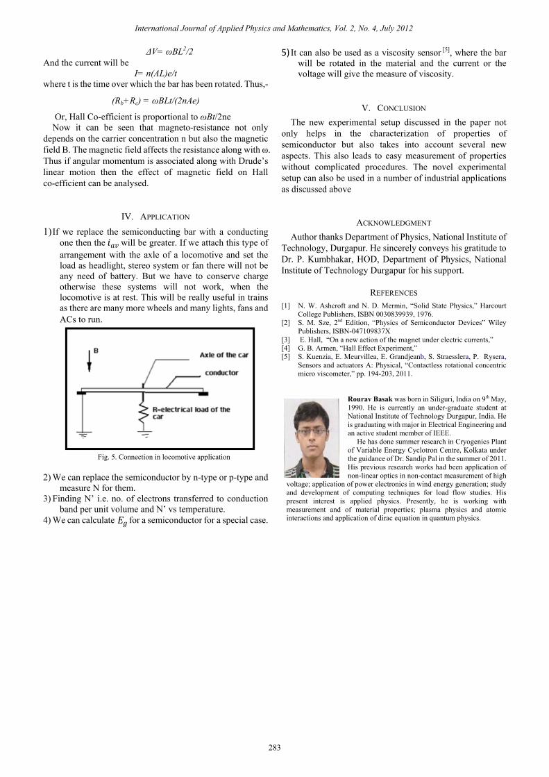
1) If we replace the semiconducting bar with a conducting one then the will be greater. If we attach this type of arrangement with the axle of a locomotive and set the load as headlight, stereo system or fan there will not be any need of battery. But we have to conserve charge otherwise these systems will not work, when the locomotive is at rest. This will be really useful in trains as there are many more wheels and many lights, fans and ACs to run.
Fig. 5. Connection in locomotive application
2) We can replace the semiconductor by n-type or p-type and
measure N for them. 3) Finding N’ i.e. no. of electrons transferred to conduction
band per unit volume and N’ vs temperature. 4) We can calculate for a semiconductor for a special case.
5) It can also be used as a viscosity sensor [5], where the bar will be rotated in the material and the current or the voltage will give the measure of viscosity.
V. CONCLUSION The new experimental setup discussed in the paper not
only helps in the characterization of properties of semiconductor but also takes into account several new aspects. This also leads to easy measurement of properties without complicated procedures. The novel experimental setup can also be used in a number of industrial applications as discussed above
ACKNOWLEDGMENT Author thanks Department of Physics, National Institute of
Technology, Durgapur. He sincerely conveys his gratitude to Dr. P. Kumbhakar, HOD, Department of Physics, National Institute of Technology Durgapur for his support.
REFERENCES [1] N. W. Ashcroft and N. D. Mermin, “Solid State Physics,” Harcourt
College Publishers, ISBN 0030839939, 1976. [2] S. M. Sze, 2nd Edition, “Physics of Semiconductor Devices” Wiley
Publishers, ISBN-047109837X [3] E. Hall, “On a new action of the magnet under electric currents,” [4] G. B. Armen, “Hall Effect Experiment,” [5] S. Kuenzia, E. Meurvillea, E. Grandjeanb, S. Straesslera, P. Rysera,
Sensors and actuators A: Physical, “Contactless rotational concentric micro viscometer,” pp. 194-203, 2011.
Rourav Basak was born in Siliguri, India on 9th May, 1990. He is currently an under-graduate student at National Institute of Technology Durgapur, India. He is graduating with major in Electrical Engineering and an active student member of IEEE. He has done summer research in Cryogenics Plant of Variable Energy Cyclotron Centre, Kolkata under the guidance of Dr. Sandip Pal in the summer of 2011. His previous research works had been application of non-linear optics in non-contact measurement of high
voltage; application of power electronics in wind energy generation; study and development of computing techniques for load flow studies. His present interest is applied physics. Presently, he is working with measurement and of material properties; plasma physics and atomic interactions and application of dirac equation in quantum physics.
International Journal of Applied Physics and Mathematics, Vol. 2, No. 4, July 2012
283
𝐸𝑔
𝑖𝑎𝑣