Embed Size (px)
Citation preview

NOVASTAR BURNER NS75 – NS150
TABLE OF CONTENTS Subject Page A. General Information…………………………………………………………… 2 B. Receiving & Inspection………………………………………………………… 2 C. Burner Capacities……………………………………………………………… 3 D. Dimensions…………………………………………………………………….. 7 E. Component Identification……………………………………………………… 11 F. Combustion Flighting…………………………………………………………… 12 G Burner Mounting………………………………………………………………. 12 H. Fuel Gas Piping System……………………………………………………… 13 I. Burner Pilot System…………………………………………………………… 20 J. Burner Setup…………………………………………………………………… 21 K. Operation……………………………………………………………………….. 23 L. Adjustments……………………………………………………………………… 23 M. Maintenance…………………………………………………………………… 24 N. Recommended Spare Parts………………………………………………… 25 Appendix: Field Installation Weld-In Type Flights, Y7100……………… 26 GJ73 Dryer Drum Gas Analysis APV-9
INSTRUCTIONS
WARNING These instructions are intended for use only by experienced, qualified combustion start-up personnel. Adjustment of this equipment by unqualified personnel can result in fire, explosion, severe personal injury or even death. To make changes to the burner or adjust firing inputs:
1. Shut the burner down 2. Make changes 3. Restart the burner.
STAND CLEAR OF THE BURNER UNDER ANY FIRING CONDITIONS.
These instructions are intended to serve as guidelines covering the installation, operation, and maintenance of Hauck equipment. While every attempt has been made to ensure completeness, unforeseen or unspecified applications, details, and variations may preclude covering every possible contingency. WARNING: TO PREVENT THE POSSIBILITY OF SERIOUS BODILY INJURY, DO NOT USE OR OPERATE ANY EQUIPMENT OR COMPONENT WITH ANY PARTS REMOVED OR ANY PARTS NOT APPROVED BY THE MANUFACTURER. Should further information be required or desired or should particular problems arise which are not covered sufficiently for the purchaser's purpose, contact Hauck Mfg. Co.
HAUCK MANUFACTURING CO., P.O. Box 90 Lebanon, PA 17042-0090 717-272-3051 3/13 www.hauckburner.com Fax: 717-273-9882 NS-9
Page 2 NS-9
A. GENERAL INFORMATION
The NovaStar Burner is Hauck’s premier product for ultra-low NOx emissions in the aggregate drying industry. Reliable performance, quiet operation, and low operating costs are additional benefits that result from the NovaStar’s patented lean premix technology. Because of the combustion technology involved, the burner generates a short and compact flame, with no adjustability required. The NovaStar is designed to burn clean gaseous fuels such as Natural Gas or Gaseous Propane, with ultra-low emissions performance. The NovaStar is available with a stand-alone gas manifold for a more versatile installation. The compact and sleek burner design allows for simplified installation and low maintenance. The NovaStar is coupled with Hauck’s BCS 6000 control panel. The BCS 6000 panel supervises burner operation and provides control for burner air and fuel flows, material temperature, stack temperature and dryer draft. The NovaStar’s air flow is provided by a single combustion air fan that is controlled by an energy saving, variable frequency drive (VFD). The precise air/fuel ratio required for optimal emissions is carefully maintained with mass-flow measuring and metering technology in the BCS 6000 panel. The PLC based BCS 6000 uses a touchscreen display to supply the operator with system status, fault annunciation, as well as an interface for burner setup and tuning. The BCS 6000 panel guarantees that the burner is operating under ideal conditions, with optimal emissions and efficient plant operation. B. RECEIVING AND INSPECTION Upon receipt, check each item on the bill of lading and/or invoice to determine that all equipment has been received. An immediate and careful examination of all parts should be made to ascertain if there has been any damage in shipment.
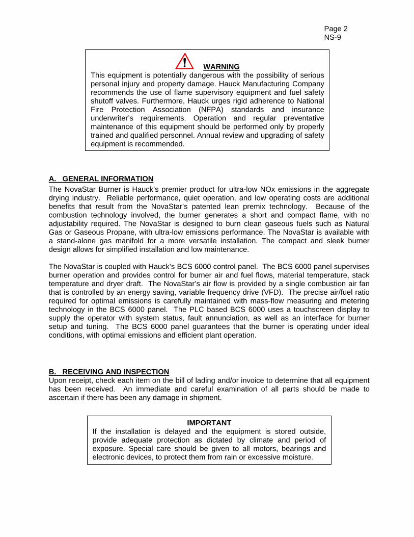
WARNING This equipment is potentially dangerous with the possibility of serious personal injury and property damage. Hauck Manufacturing Company recommends the use of flame supervisory equipment and fuel safety shutoff valves. Furthermore, Hauck urges rigid adherence to National Fire Protection Association (NFPA) standards and insurance underwriter’s requirements. Operation and regular preventative maintenance of this equipment should be performed only by properly trained and qualified personnel. Annual review and upgrading of safety equipment is recommended.
IMPORTANT If the installation is delayed and the equipment is stored outside, provide adequate protection as dictated by climate and period of exposure. Special care should be given to all motors, bearings and electronic devices, to protect them from rain or excessive moisture.
Page 3 NS-9
C. BURNER CAPACITIES
NovaStar-75 (Natural Gas) Output Combustion
Air Flow Burner Air Pressure
Natural Gas Flow
Burner Gas Pressure
Flame
VFD Burner Length Diameter
(Hz) (MMBTU/h) (SCFH) (in.w.c.) (SCFH) (in.w.c.) (ft) (ft)
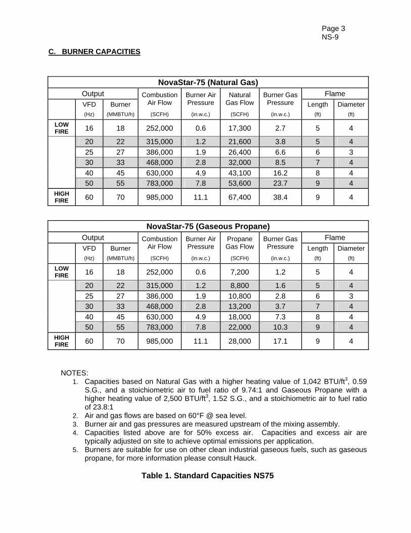
LOW FIRE 16 18 252,000 0.6 17,300 2.7 5 4
20 22 315,000 1.2 21,600 3.8 5 4 25 27 386,000 1.9 26,400 6.6 6 3 30 33 468,000 2.8 32,000 8.5 7 4 40 45 630,000 4.9 43,100 16.2 8 4 50 55 783,000 7.8 53,600 23.7 9 4
HIGH FIRE 60 70 985,000 11.1 67,400 38.4 9 4
NovaStar-75 (Gaseous Propane) Output Combustion
Air Flow Burner Air Pressure
Propane Gas Flow
Burner Gas Pressure
Flame VFD Burner Length Diameter
(Hz) (MMBTU/h) (SCFH) (in.w.c.) (SCFH) (in.w.c.) (ft) (ft)
LOW FIRE 16 18 252,000 0.6 7,200 1.2 5 4
20 22 315,000 1.2 8,800 1.6 5 4 25 27 386,000 1.9 10,800 2.8 6 3 30 33 468,000 2.8 13,200 3.7 7 4 40 45 630,000 4.9 18,000 7.3 8 4 50 55 783,000 7.8 22,000 10.3 9 4
HIGH FIRE 60 70 985,000 11.1 28,000 17.1 9 4
NOTES:
1. Capacities based on Natural Gas with a higher heating value of 1,042 BTU/ft3, 0.59 S.G., and a stoichiometric air to fuel ratio of 9.74:1 and Gaseous Propane with a higher heating value of 2,500 BTU/ft3, 1.52 S.G., and a stoichiometric air to fuel ratio of 23.8:1
2. Air and gas flows are based on 60°F @ sea level. 3. Burner air and gas pressures are measured upstream of the mixing assembly. 4. Capacities listed above are for 50% excess air. Capacities and excess air are
typically adjusted on site to achieve optimal emissions per application. 5. Burners are suitable for use on other clean industrial gaseous fuels, such as gaseous
propane, for more information please consult Hauck.
Table 1. Standard Capacities NS75
Page 4 NS-9
C. BURNER CAPACITIES
NovaStar-100 (Natural Gas) Output Combustion
Air Flow Burner Air Pressure
Natural Gas Flow
Burner Gas Pressure
Flame
VFD Burner Length Diameter
(Hz) (MMBTU/h) (SCFH) (in.w.c.) (SCFH) (in.w.c.) (ft) (ft)
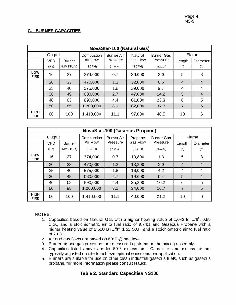
LOW FIRE 16 27 374,000 0.7 26,000 3.0 5 3
20 33 470,000 1.2 32,000 6.6 4 4 25 40 575,000 1.8 39,000 9.7 4 4 30 49 680,000 2.7 47,000 14.2 5 4 40 63 890,000 4.4 61,000 23.3 6 5 50 85 1,200,000 8.1 82,000 37.7 7 5
HIGH FIRE 60 100 1,410,000 11.1 97,000 48.5 10 6
NovaStar-100 (Gaseous Propane) Output Combustion
Air Flow Burner Air Pressure
Propane Gas Flow
Burner Gas Pressure
Flame VFD Burner Length Diameter
(Hz) (MMBTU/h) (SCFH) (in.w.c.) (SCFH) (in.w.c.) (ft) (ft)
LOW FIRE 16 27 374,000 0.7 10,800 1.3 5 3
20 33 470,000 1.2 13,200 2.9 4 4 25 40 575,000 1.8 16,000 4.2 4 4 30 49 680,000 2.7 19,600 6.4 5 4 40 63 890,000 4.4 25,200 10.2 6 5 50 85 1,200,000 8.1 34,000 16.7 7 5
HIGH FIRE 60 100 1,410,000 11.1 40,000 21.2 10 6
NOTES:
1. Capacities based on Natural Gas with a higher heating value of 1,042 BTU/ft3, 0.59 S.G., and a stoichiometric air to fuel ratio of 9.74:1 and Gaseous Propane with a higher heating value of 2,500 BTU/ft3, 1.52 S.G., and a stoichiometric air to fuel ratio of 23.8:1
2. Air and gas flows are based on 60°F @ sea level. 3. Burner air and gas pressures are measured upstream of the mixing assembly. 4. Capacities listed above are for 50% excess air. Capacities and excess air are
typically adjusted on site to achieve optimal emissions per application. 5. Burners are suitable for use on other clean industrial gaseous fuels, such as gaseous
propane, for more information please consult Hauck.
Table 2. Standard Capacities NS100
Page 5 NS-9
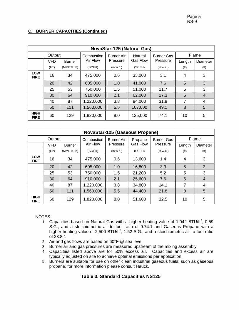
C. BURNER CAPACITIES (Continued)
NovaStar-125 (Natural Gas) Output Combustion
Air Flow Burner Air Pressure
Natural Gas Flow
Burner Gas Pressure
Flame
VFD Burner Length Diameter
(Hz) (MMBTU/h) (SCFH) (in.w.c.) (SCFH) (in.w.c.) (ft) (ft)
LOW FIRE 16 34 475,000 0.6 33,000 3.1 4 3
20 42 605,000 1.0 41,000 7.6 5 3 25 53 750,000 1.5 51,000 11.7 5 3 30 64 910,000 2.1 62,000 17.3 6 4 40 87 1,220,000 3.8 84,000 31.9 7 4 50 111 1,560,000 5.5 107,000 49.1 8 5
HIGH FIRE 60 129 1,820,000 8.0 125,000 74.1 10 5
NovaStar-125 (Gaseous Propane) Output Combustion
Air Flow Burner Air Pressure
Propane Gas Flow
Burner Gas Pressure
Flame VFD Burner Length Diameter
(Hz) (MMBTU/h) (SCFH) (in.w.c.) (SCFH) (in.w.c.) (ft) (ft)
LOW FIRE 16 34 475,000 0.6 13,600 1.4 4 3
20 42 605,000 1.0 16,800 3.3 5 3 25 53 750,000 1.5 21,200 5.2 5 3 30 64 910,000 2.1 25,600 7.6 6 4 40 87 1,220,000 3.8 34,800 14.1 7 4 50 111 1,560,000 5.5 44,400 21.8 8 5
HIGH FIRE 60 129 1,820,000 8.0 51,600 32.5 10 5
NOTES:
1. Capacities based on Natural Gas with a higher heating value of 1,042 BTU/ft3, 0.59 S.G., and a stoichiometric air to fuel ratio of 9.74:1 and Gaseous Propane with a higher heating value of 2,500 BTU/ft3, 1.52 S.G., and a stoichiometric air to fuel ratio of 23.8:1
2. Air and gas flows are based on 60°F @ sea level. 3. Burner air and gas pressures are measured upstream of the mixing assembly. 4. Capacities listed above are for 50% excess air. Capacities and excess air are
typically adjusted on site to achieve optimal emissions per application. 5. Burners are suitable for use on other clean industrial gaseous fuels, such as gaseous
propane, for more information please consult Hauck.
Table 3. Standard Capacities NS125
Page 6 NS-9
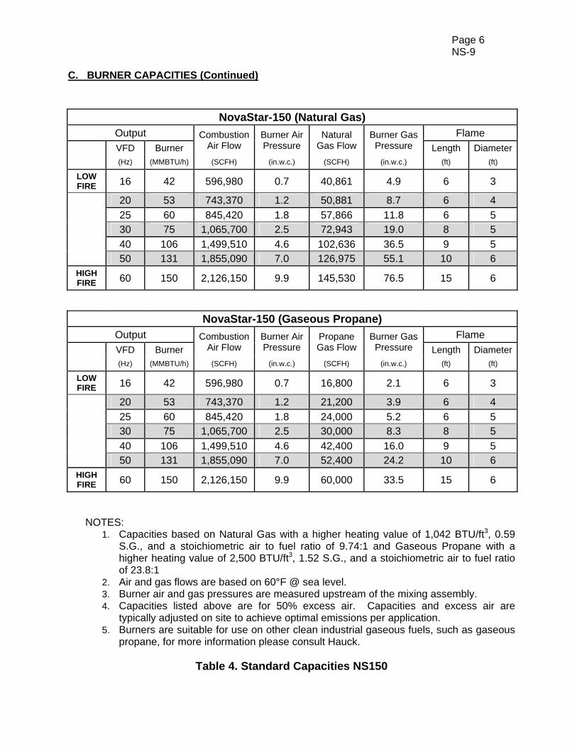
C. BURNER CAPACITIES (Continued)
NovaStar-150 (Natural Gas) Output Combustion
Air Flow Burner Air Pressure
Natural Gas Flow
Burner Gas Pressure
Flame
VFD Burner Length Diameter
(Hz) (MMBTU/h) (SCFH) (in.w.c.) (SCFH) (in.w.c.) (ft) (ft)
LOW FIRE 16 42 596,980 0.7 40,861 4.9 6 3
20 53 743,370 1.2 50,881 8.7 6 4 25 60 845,420 1.8 57,866 11.8 6 5 30 75 1,065,700 2.5 72,943 19.0 8 5 40 106 1,499,510 4.6 102,636 36.5 9 5 50 131 1,855,090 7.0 126,975 55.1 10 6
HIGH FIRE 60 150 2,126,150 9.9 145,530 76.5 15 6
NovaStar-150 (Gaseous Propane) Output Combustion
Air Flow Burner Air Pressure
Propane Gas Flow
Burner Gas Pressure
Flame VFD Burner Length Diameter
(Hz) (MMBTU/h) (SCFH) (in.w.c.) (SCFH) (in.w.c.) (ft) (ft)
LOW FIRE 16 42 596,980 0.7 16,800 2.1 6 3
20 53 743,370 1.2 21,200 3.9 6 4 25 60 845,420 1.8 24,000 5.2 6 5 30 75 1,065,700 2.5 30,000 8.3 8 5 40 106 1,499,510 4.6 42,400 16.0 9 5 50 131 1,855,090 7.0 52,400 24.2 10 6
HIGH FIRE 60 150 2,126,150 9.9 60,000 33.5 15 6
NOTES:
1. Capacities based on Natural Gas with a higher heating value of 1,042 BTU/ft3, 0.59 S.G., and a stoichiometric air to fuel ratio of 9.74:1 and Gaseous Propane with a higher heating value of 2,500 BTU/ft3, 1.52 S.G., and a stoichiometric air to fuel ratio of 23.8:1
2. Air and gas flows are based on 60°F @ sea level. 3. Burner air and gas pressures are measured upstream of the mixing assembly. 4. Capacities listed above are for 50% excess air. Capacities and excess air are
typically adjusted on site to achieve optimal emissions per application. 5. Burners are suitable for use on other clean industrial gaseous fuels, such as gaseous
propane, for more information please consult Hauck.
Table 4. Standard Capacities NS150

Page 7 NS-9
D. DIMENSIONS
Figure 1. Dimensions NovaStar 75
Y83
58
(NO
T T
O S
CA
LE
)
Page 8 NS-9
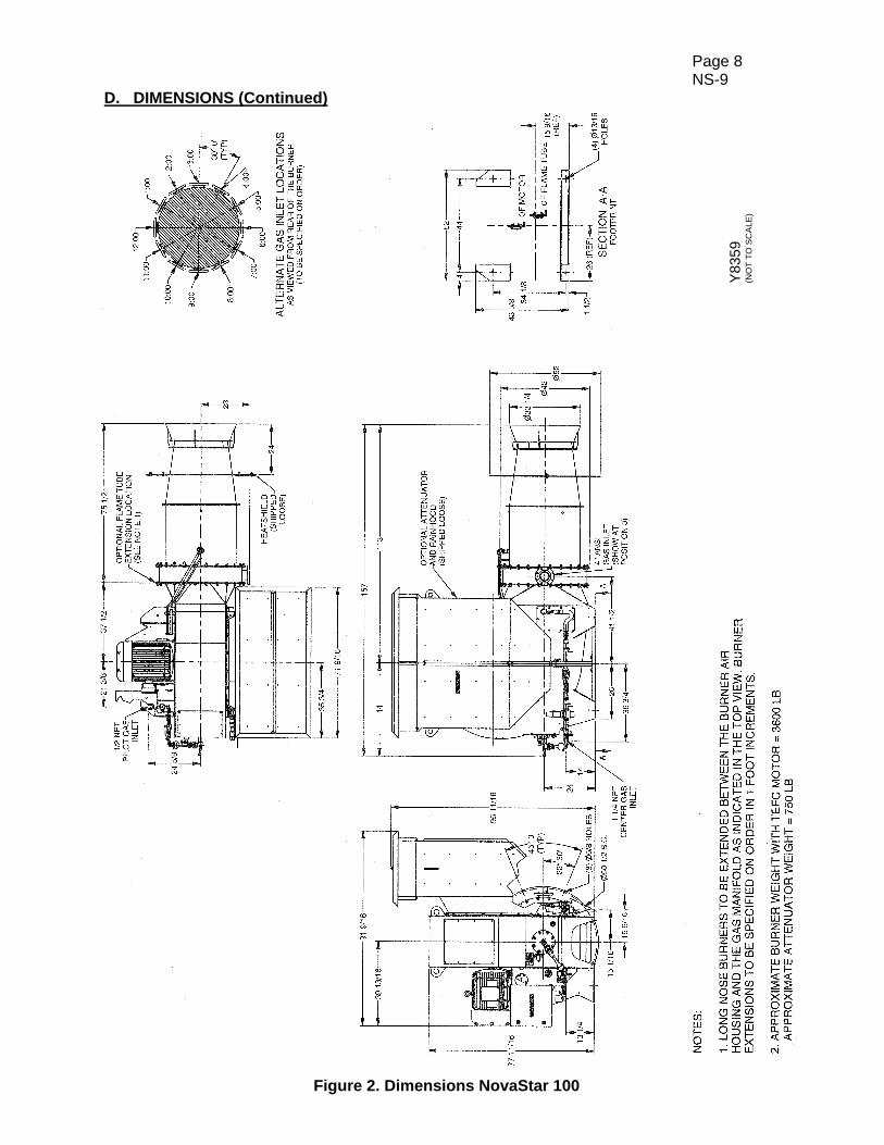
D. DIMENSIONS (Continued)
Figure 2. Dimensions NovaStar 100
Y83
59
(NO
T T
O S
CA
LE
)
Page 9 NS-9
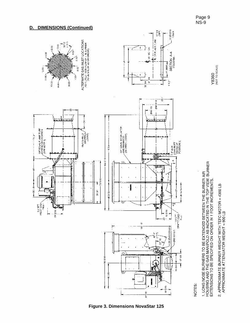
D. DIMENSIONS (Continued)
Figure 3. Dimensions NovaStar 125
Y83
60
(NO
T T
O S
CA
LE
)
Page 10 NS-9
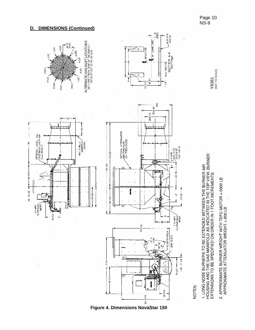
D. DIMENSIONS (Continued)
Figure 4. Dimensions NovaStar 150
Y83
61
(NO
T T
O S
CA
LE
)
Page 11 NS-9
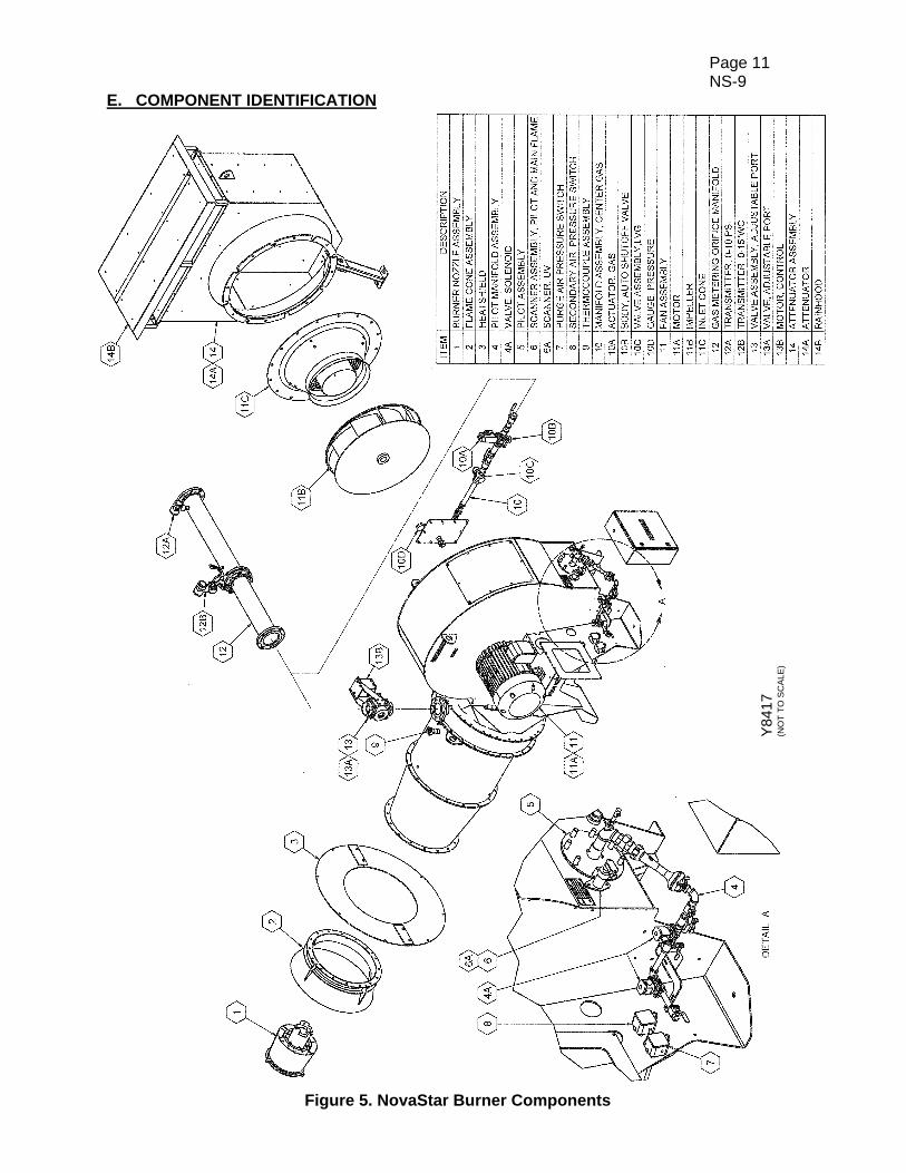
E. COMPONENT IDENTIFICATION
Figure 5. NovaStar Burner Components
Y84
17
(NO
T T
O S
CA
LE
)
Page 12 NS-9
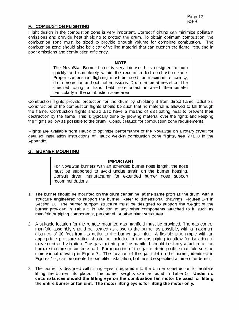
F. COMBUSTION FLIGHTING Flight design in the combustion zone is very important. Correct flighting can minimize pollutant emissions and provide heat shielding to protect the drum. To obtain optimum combustion, the combustion zone must be sized to provide enough volume for complete combustion. The combustion zone should also be clear of veiling material that can quench the flame, resulting in poor emissions and combustion efficiency.
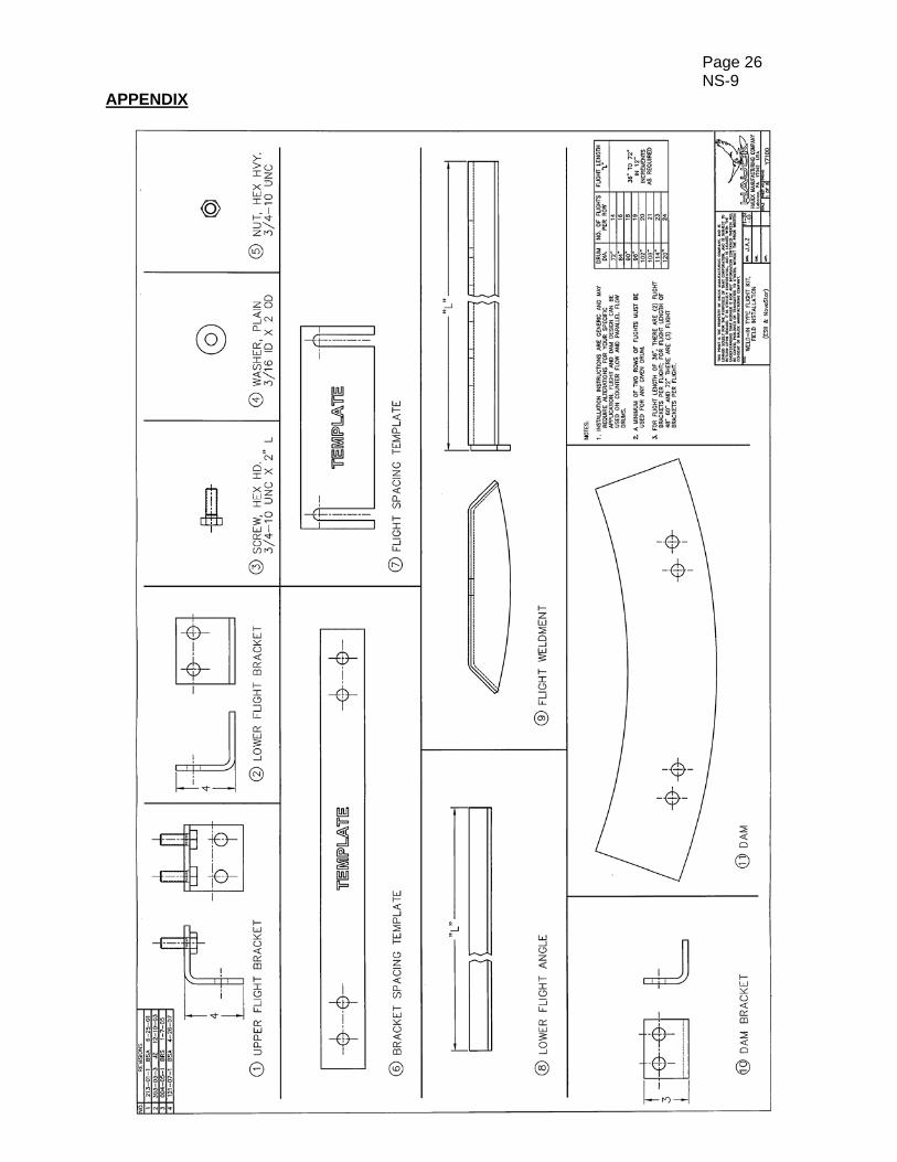
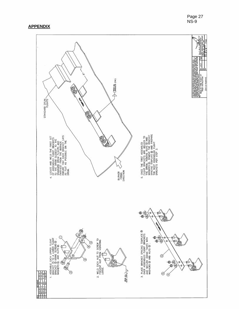
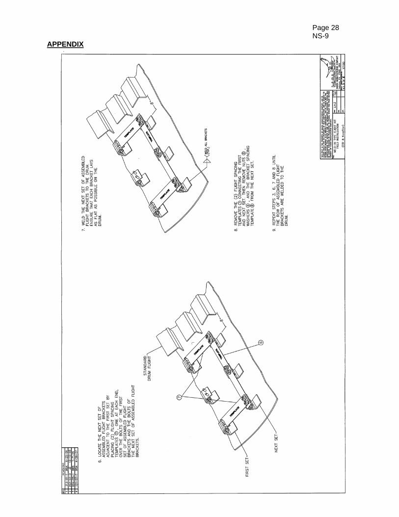
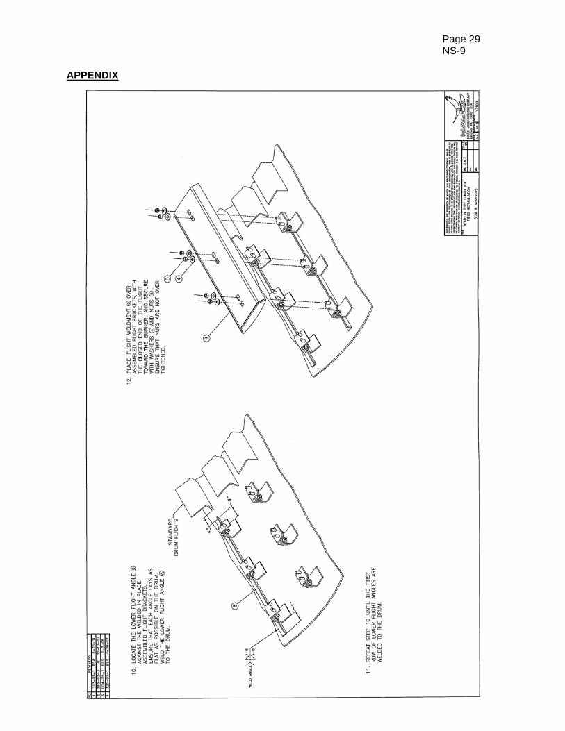
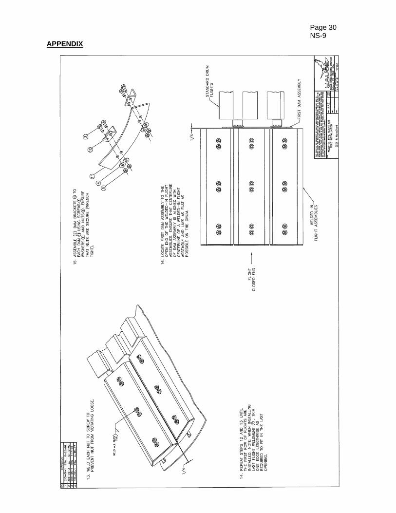
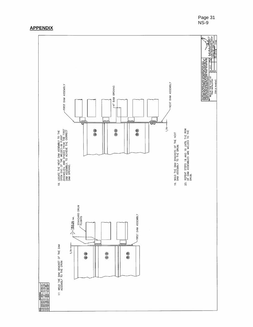
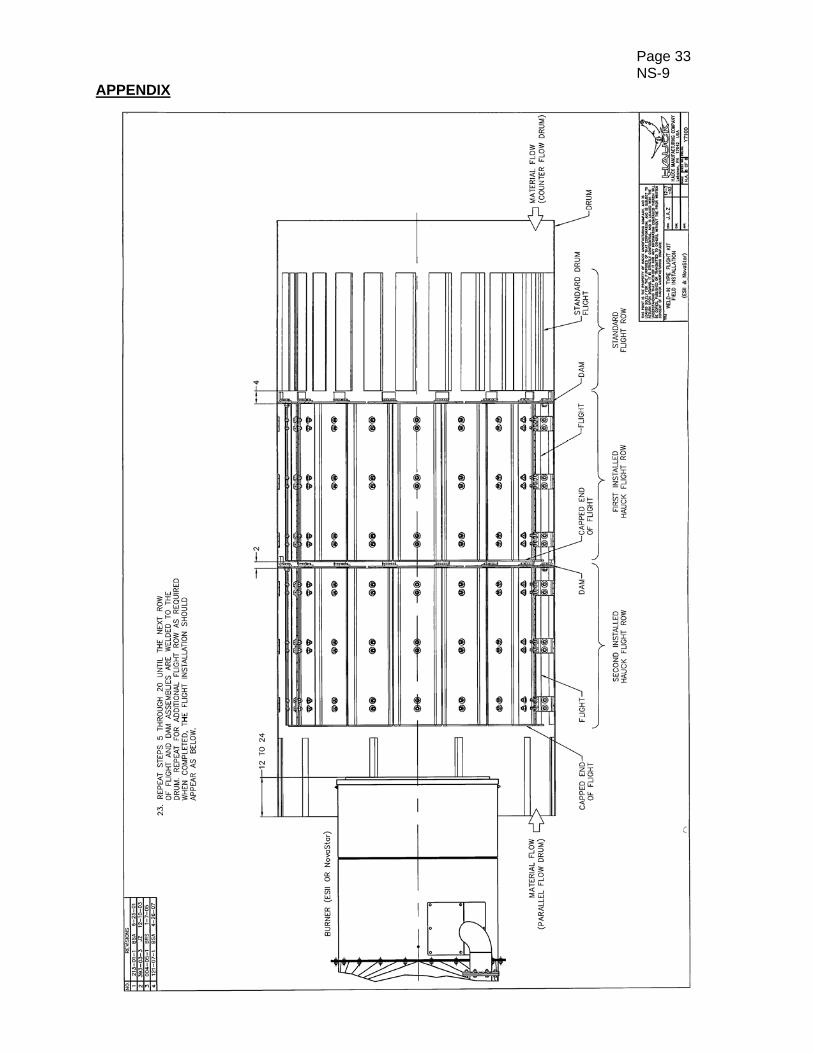
Combustion flights provide protection for the drum by shielding it from direct flame radiation. Construction of the combustion flights should be such that no material is allowed to fall through the flame. Combustion flights should also have a means of dissipating heat to prevent their destruction by the flame. This is typically done by plowing material over the fights and keeping the flights as low as possible to the drum. Consult Hauck for combustion zone requirements. Flights are available from Hauck to optimize performance of the NovaStar on a rotary dryer; for detailed installation instructions of Hauck weld-in combustion zone flights, see Y7100 in the Appendix. G. BURNER MOUNTING 1. The burner should be mounted on the drum centerline, at the same pitch as the drum, with a
structure engineered to support the burner. Refer to dimensional drawings, Figures 1-4 in Section D. The burner support structure must be designed to support the weight of the burner provided in Table 5 in addition to any other components attached to it, such as manifold or piping components, personnel, or other plant structures.
2. A suitable location for the remote mounted gas manifold must be provided. The gas control manifold assembly should be located as close to the burner as possible, with a maximum distance of 10 feet from its outlet to the burner gas inlet. A flexible pipe nipple with an appropriate pressure rating should be included in the gas piping to allow for isolation of movement and vibration. The gas metering orifice manifold should be firmly attached to the burner structure or concrete pad. For mounting of the gas metering orifice manifold see the dimensional drawing in Figure 7. The location of the gas inlet on the burner, identified in Figures 1-4, can be oriented to simplify installation, but must be specified at time of ordering.
3. The burner is designed with lifting eyes integrated into the burner construction to facilitate
lifting the burner into place. The burner weights can be found in Table 5. Under no circumstances should the lifting eye on the combustion fan motor be used for lifting the entire burner or fan unit. The motor lifting eye is for lifting the motor only.
IMPORTANT For NovaStar burners with an extended burner nose length, the nose must be supported to avoid undue strain on the burner housing. Consult dryer manufacturer for extended burner nose support recommendations.
NOTE The NovaStar Burner flame is very intense. It is designed to burn quickly and completely within the recommended combustion zone. Proper combustion flighting must be used for maximum efficiency, drum protection and optimal emissions. Drum temperatures should be checked using a hand held non-contact infra-red thermometer particularly in the combustion zone area.
Page 13 NS-9
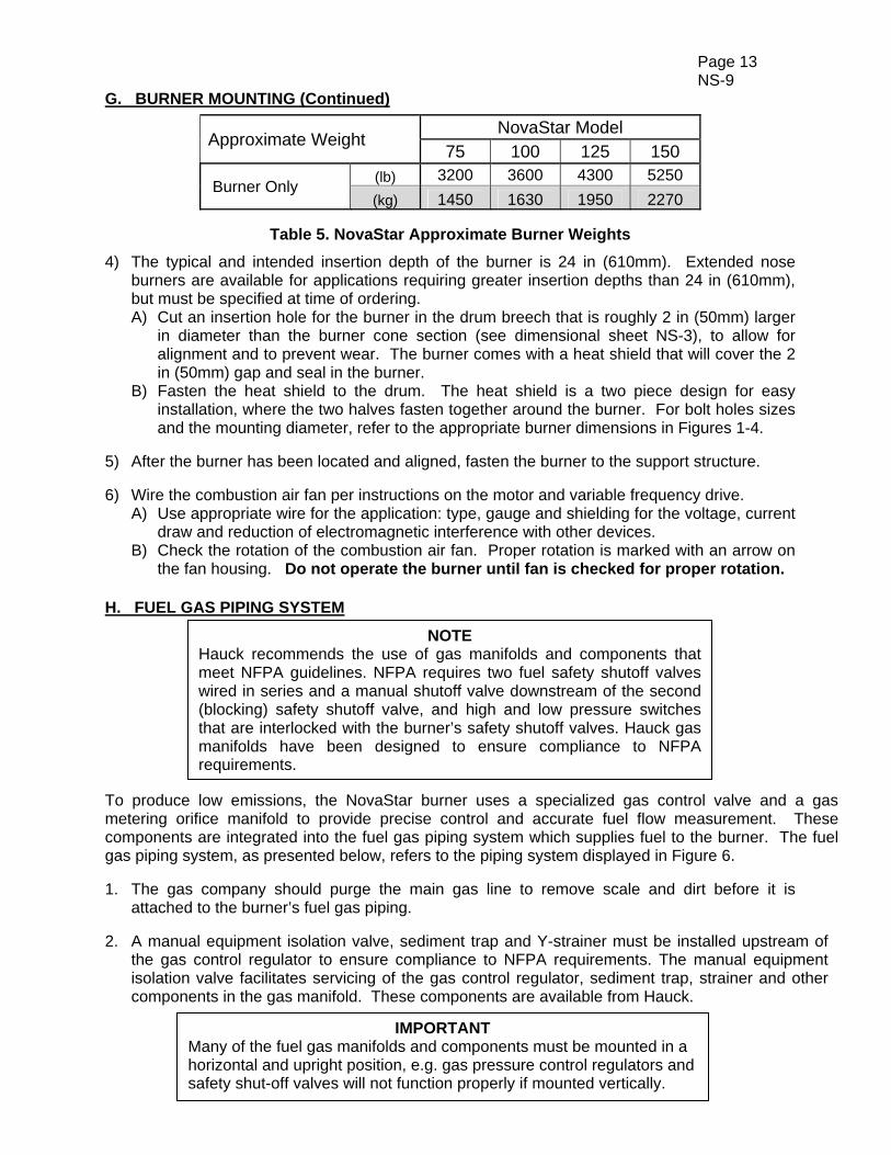
G. BURNER MOUNTING (Continued)
Approximate Weight NovaStar Model
75 100 125 150
Burner Only (lb) 3200 3600 4300 5250
(kg) 1450 1630 1950 2270
Table 5. NovaStar Approximate Burner Weights
4) The typical and intended insertion depth of the burner is 24 in (610mm). Extended nose burners are available for applications requiring greater insertion depths than 24 in (610mm), but must be specified at time of ordering. A) Cut an insertion hole for the burner in the drum breech that is roughly 2 in (50mm) larger
in diameter than the burner cone section (see dimensional sheet NS-3), to allow for alignment and to prevent wear. The burner comes with a heat shield that will cover the 2 in (50mm) gap and seal in the burner.
B) Fasten the heat shield to the drum. The heat shield is a two piece design for easy installation, where the two halves fasten together around the burner. For bolt holes sizes and the mounting diameter, refer to the appropriate burner dimensions in Figures 1-4.
5) After the burner has been located and aligned, fasten the burner to the support structure. 6) Wire the combustion air fan per instructions on the motor and variable frequency drive.
A) Use appropriate wire for the application: type, gauge and shielding for the voltage, current draw and reduction of electromagnetic interference with other devices.
B) Check the rotation of the combustion air fan. Proper rotation is marked with an arrow on the fan housing. Do not operate the burner until fan is checked for proper rotation.
H. FUEL GAS PIPING SYSTEM
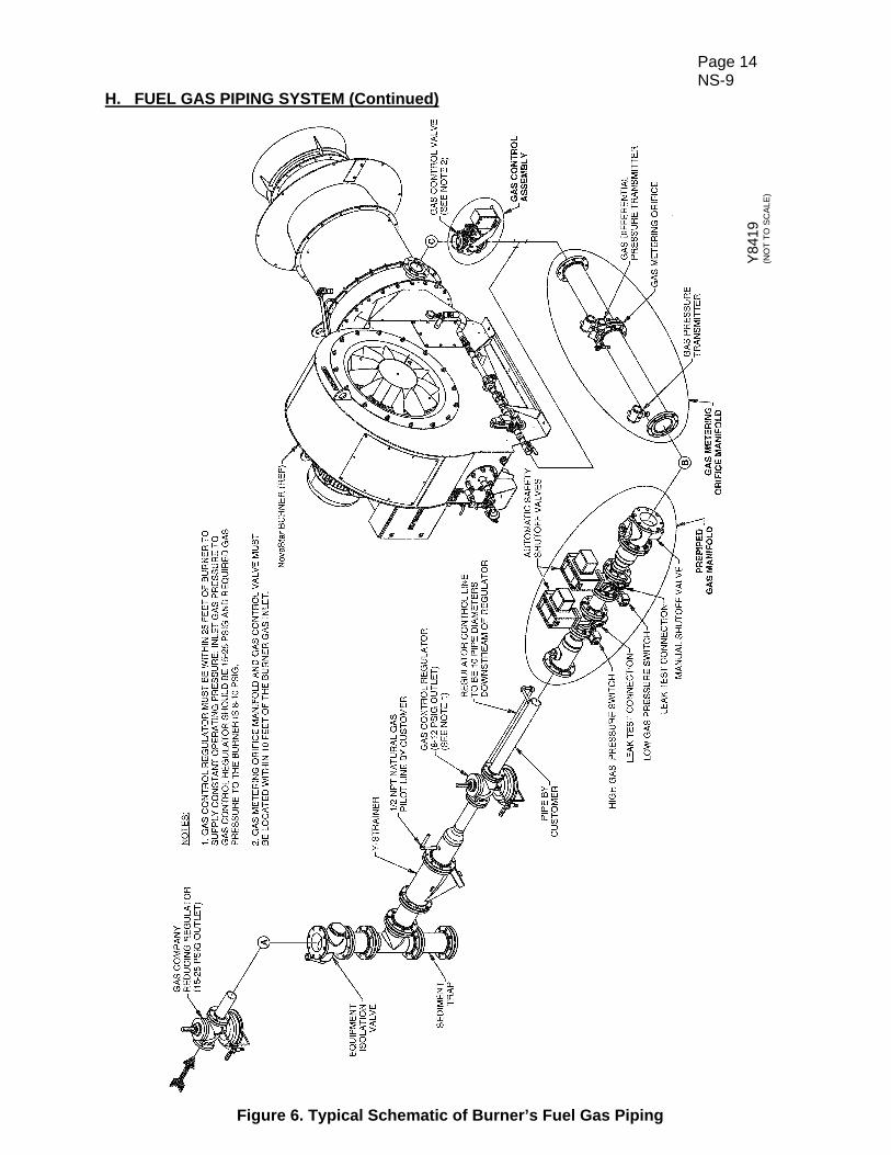
To produce low emissions, the NovaStar burner uses a specialized gas control valve and a gas metering orifice manifold to provide precise control and accurate fuel flow measurement. These components are integrated into the fuel gas piping system which supplies fuel to the burner. The fuel gas piping system, as presented below, refers to the piping system displayed in Figure 6. 1. The gas company should purge the main gas line to remove scale and dirt before it is
attached to the burner’s fuel gas piping.
2. A manual equipment isolation valve, sediment trap and Y-strainer must be installed upstream of the gas control regulator to ensure compliance to NFPA requirements. The manual equipment isolation valve facilitates servicing of the gas control regulator, sediment trap, strainer and other components in the gas manifold. These components are available from Hauck.
NOTE Hauck recommends the use of gas manifolds and components that meet NFPA guidelines. NFPA requires two fuel safety shutoff valves wired in series and a manual shutoff valve downstream of the second (blocking) safety shutoff valve, and high and low pressure switches that are interlocked with the burner’s safety shutoff valves. Hauck gas manifolds have been designed to ensure compliance to NFPA requirements.
IMPORTANT Many of the fuel gas manifolds and components must be mounted in a horizontal and upright position, e.g. gas pressure control regulators and safety shut-off valves will not function properly if mounted vertically.
Page 14 NS-9
H. FUEL GAS PIPING SYSTEM (Continued)
Figure 6. Typical Schematic of Burner’s Fuel Gas Piping
Y84
19
(NO
T T
O S
CA
LE
)
Page 15 NS-9
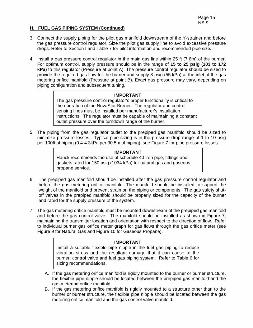
H. FUEL GAS PIPING SYSTEM (Continued) 3. Connect the supply piping for the pilot gas manifold downstream of the Y-strainer and before
the gas pressure control regulator. Size the pilot gas supply line to avoid excessive pressure drops. Refer to Section I and Table 7 for pilot information and recommended pipe size.
4. Install a gas pressure control regulator in the main gas line within 25 ft (7.6m) of the burner.
For optimum control, supply pressure should be in the range of 15 to 25 psig (103 to 172 kPa) to this regulator (Pressure at point A). The pressure control regulator should be sized to provide the required gas flow for the burner and supply 8 psig (55 kPa) at the inlet of the gas metering orifice manifold (Pressure at point B). Exact gas pressure may vary, depending on piping configuration and subsequent tuning.
5. The piping from the gas regulator outlet to the prepiped gas manifold should be sized to
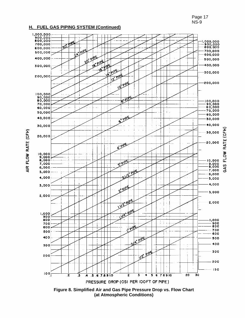
minimize pressure losses. Typical pipe sizing is in the pressure drop range of 1 to 10 osig per 100ft of piping (0.4-4.3kPa per 30.5m of piping); see Figure 7 for pipe pressure losses.
6. The prepiped gas manifold should be installed after the gas pressure control regulator and before the gas metering orifice manifold. The manifold should be installed to support the weight of the manifold and prevent strain on the piping or components. The gas safety shut-off valves in the prepiped manifold should be properly sized for the capacity of the burner and rated for the supply pressure of the system.
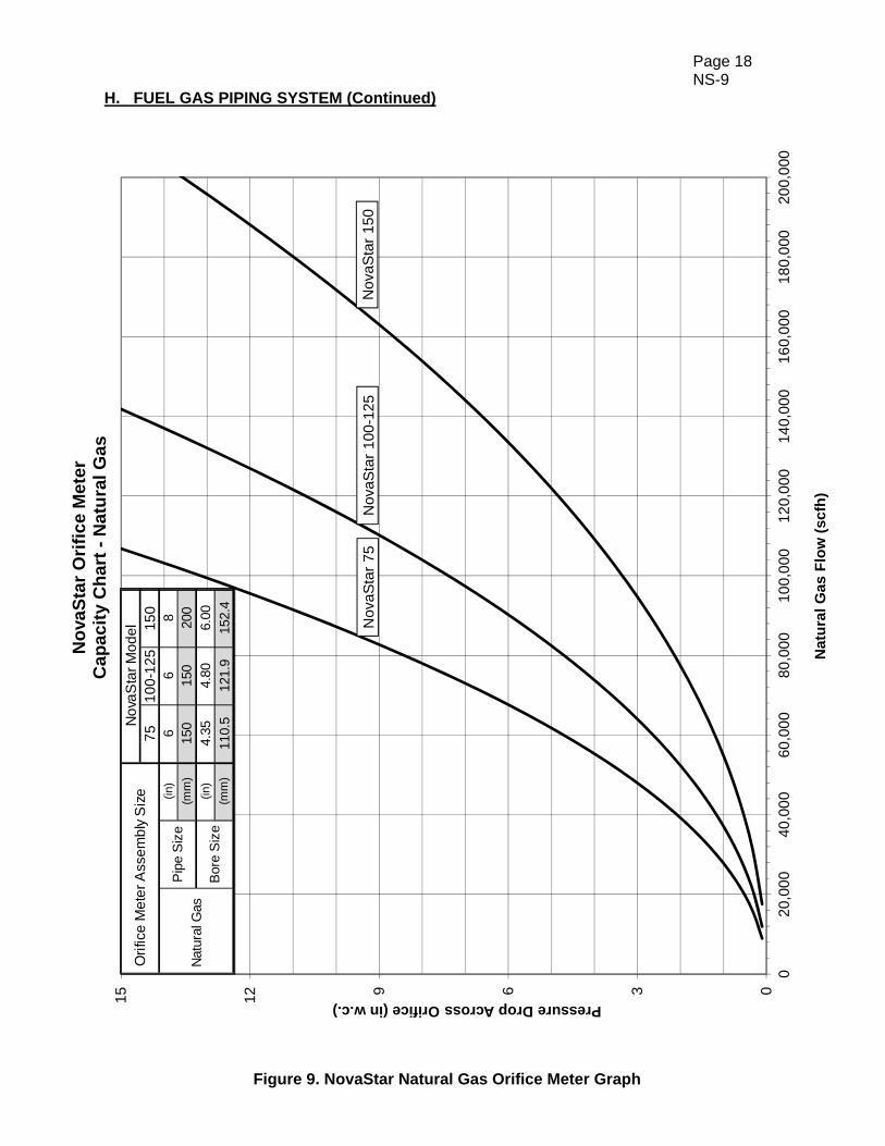
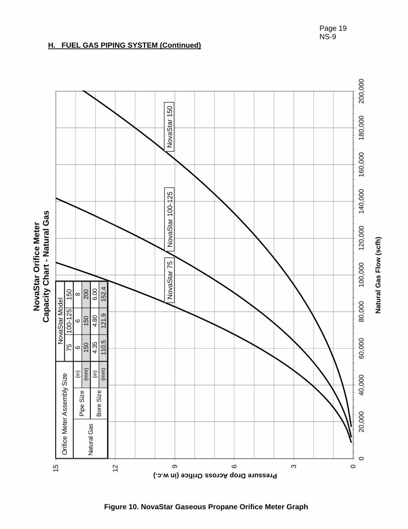
7. The gas metering orifice manifold must be mounted downstream of the prepiped gas manifold
and before the gas control valve. The manifold should be installed as shown in Figure 7, maintaining the transmitter location and orientation with respect to the direction of flow. Refer to individual burner gas orifice meter graph for gas flows through the gas orifice meter (see Figure 9 for Natural Gas and Figure 10 for Gaseous Propane).
A. If the gas metering orifice manifold is rigidly mounted to the burner or burner structure, the flexible pipe nipple should be located between the prepiped gas manifold and the gas metering orifice manifold.
B. If the gas metering orifice manifold is rigidly mounted to a structure other than to the burner or burner structure, the flexible pipe nipple should be located between the gas metering orifice manifold and the gas control valve manifold.
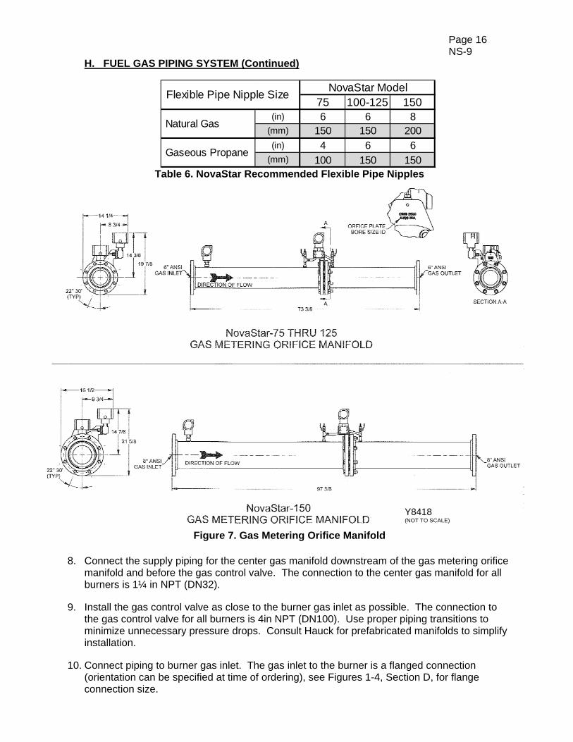
IMPORTANT Install a suitable flexible pipe nipple in the fuel gas piping to reduce vibration stress and the resultant damage that it can cause to the burner, control valve and fuel gas piping system. Refer to Table 6 for sizing recommendations.
IMPORTANT Hauck recommends the use of schedule 40 iron pipe, fittings and gaskets rated for 150 psig (1034 kPa) for natural gas and gaseous propane service.
IMPORTANT The gas pressure control regulator’s proper functionality is critical to the operation of the NovaStar Burner. The regulator and control sensing lines must be installed per manufacturer’s installation instructions. The regulator must be capable of maintaining a constant outlet pressure over the turndown range of the burner.
Page 16 NS-9
H. FUEL GAS PIPING SYSTEM (Continued)
75 100-125 150(in) 6 6 8
(mm) 150 150 200(in) 4 6 6
(mm) 100 150 150
NovaStar Model
Natural Gas
Gaseous Propane
Flexible Pipe Nipple Size
Table 6. NovaStar Recommended Flexible Pipe Nipples
Figure 7. Gas Metering Orifice Manifold
8. Connect the supply piping for the center gas manifold downstream of the gas metering orifice manifold and before the gas control valve. The connection to the center gas manifold for all burners is 1¼ in NPT (DN32).
9. Install the gas control valve as close to the burner gas inlet as possible. The connection to the gas control valve for all burners is 4in NPT (DN100). Use proper piping transitions to minimize unnecessary pressure drops. Consult Hauck for prefabricated manifolds to simplify installation.
10. Connect piping to burner gas inlet. The gas inlet to the burner is a flanged connection
(orientation can be specified at time of ordering), see Figures 1-4, Section D, for flange connection size.
Y8418 (NOT TO SCALE)
Page 17 NS-9
H. FUEL GAS PIPING SYSTEM (Continued)
Figure 8. Simplified Air and Gas Pipe Pressure Drop vs. Flow Chart (at Atmospheric Conditions)
Page 18 NS-9
H. FUEL GAS PIPING SYSTEM (Continued)
Figure 9. NovaStar Natural Gas Orifice Meter Graph
0369
1215
020
,00
040
,00
060
,00
080
,00
010
0,0
0012
0,0
0014
0,0
0016
0,0
0018
0,0
0020
0,0
00
Pressure Drop Across Orifice (in w.c.)
Nat
ura
l G
as F
low
(sc
fh)
No
vaS
tar
Ori
fic
e M
ete
rC
ap
ac
ity
Ch
art
-N
atu
ral G
as
Nov
aSta
r 75
Nov
aSta
r 15
0N
ovaS
tar
100-
125
75
10
0-1
25
150
(in)
66
8(m
m)
150
150
200
(in)
4.35
4.80
6.00
(mm
)11
0.5
121.
915
2.4
Nat
ural
Gas
Ori
fice
Met
er A
ssem
bly
Siz
eN
ova
Sta
r M
ode
l
Bor
e S
ize
Pip
e S
ize
Page 19 NS-9
H. FUEL GAS PIPING SYSTEM (Continued)
Figure 10. NovaStar Gaseous Propane Orifice Meter Graph
0369
1215
020
,00
040
,00
060
,00
080
,00
010
0,0
0012
0,0
0014
0,0
0016
0,0
0018
0,0
0020
0,0
00
Pressure Drop Across Orifice (in w.c.)
Nat
ura
l G
as F
low
(sc
fh)
No
vaS
tar
Ori
fic
e M
ete
rC
ap
ac
ity
Ch
art
-N
atu
ral G
as
Nov
aSta
r 75
Nov
aSta
r 15
0N
ovaS
tar
100-
125
75
10
0-1
25
150
(in)
66
8(m
m)
150
150
200
(in)
4.35
4.80
6.00
(mm
)11
0.5
121.
915
2.4
Nat
ural
Gas
Ori
fice
Met
er A
ssem
bly
Siz
eN
ova
Sta
r M
ode
l
Bor
e S
ize
Pip
e S
ize

Page 20 NS-9
I. BURNER PILOT SYSTEM The NovaStar incorporates an air-inspirated gas pilot, manifold shown in Figure 11). The pilot and UV scanner are factory installed and wired. Under normal conditions, no re-positioning or realignment should be necessary. The pilot air is inspirated (drawn in) from the atmosphere, the air inspirator should be clear of any obstructions for proper functionality. The nominal fuel pressure for the pilot is 20psi (138hPa). Pilot capacity should not exceed 150,000 Btu/hr (44hW).
Figure 11. Gas Pilot Manifold
1. Before connecting to the pilot assembly, the gas supply line should be purged to remove any
dirt. Pipe the pilot gas supply line to the inlet of the pilot gas shutoff valve and check for leaks. Size the pilot gas supply line to avoid excessive pressure drops. See Table 7 for recommended pipe size.
0 - 25 (ft) 0.5 (in)0 - 7.6 (m) 15 (DN)
25 - 100 (ft) 0.75 (in)7.6 - 30 (m) 20 (DN)
Pipe Length Pipe SizePilot Gas Supply Line
Table 7. Recommended Pilot Gas Supply Line Size
2. Constant gas pressure at a minimum of 15 psig (103 kPa) not to exceed 25 psig (172 kPa)
must be available at the inlet of the Hauck gas pilot manifold. 3. The pilot is located internal to the burner. The spark wire gap is factory set at 0.125 in (3mm).
To inspect the pilot or spark wire gap, the following procedure should be followed. A. Loosen and separate the pipe union, shown in Figure 11. B. Loosen the nuts on the rear of the burner housing connection flange C. Separate the connection flange from the burner housing, avoid damaging the gasket. D. The pilot may now be pulled from the back of the burner. E. After inspection or gap adjustment make sure the spark wire is securely tightened into position. F. The pilot may now be inserted into the back of the burner. G. Tighten the nuts on the rear of the burner housing connection flange. H. Reconnect and tighten the pipe union, shown in Figure 11. I. Check piping for leaks.
W8420 (NOT TO SCALE)

Page 21 NS-9
I. BURNER PILOT SYSTEM (Continued) 4. Complete the pilot adjustment as follows, referencing Figure 11:
A. Ensure the spark igniter is connected via high voltage ignition cable to the ignition transformer. B. Loosen the locking thumbscrew on the adjustable air shutter of the air gas inspiratory. C. Adjust the air shutter for 0.25 in (6.35mm) gap. Typical gap range is 0.125-0.375 in (3.2-9.5mm). D. Attempt to ignite the pilot, adjusting the air shutter until the desired flame is achieved. E. Securely tighten the locking thumbscrew on the adjustable air shutter.
5. An increase or decrease in the gas operating pressure may require the readjustment of the
air shutter.
J. BURNER SETUP
Use of a variable frequency drive to control the combustion air fan, and a gas control valve with a directly-coupled actuator allows for precise control of air and gas flows via the Hauck BCS 6000 panel. The BCS 6000 is able to calculate exact fuel and combustion air flows from the specialized metering orifice manifold and the frequency output to the combustion air fan, respectively. Such measurement and control makes operating within the burner’s operating range an automatic process. Setup is only required to adjust the burner’s low fire settings, draft controls, and range settings for the analog inputs (Pressure Transmitters and VFD). 1. Set the low gas pressure switch to an initial setting of 5 psig (345 mbar). 2. Set the high gas pressure switch to an initial setting of 12 psig (830 mbar).
3. Set the combustion air switch to a setting of 0.2 in.w.c. (0.5 mbar). The NovaStar operates as an ultra-low NOx system in conjunction with the asphalt plant. In order to maintain the operating conditions needed for the burner to function properly, several control parameters have been incorporated to the BCS 6000 panel. These control parameters include control of the plant exhaust such that it does not interfere with the operation of the burner. The three primary control parameters are explained below. 1. Low Fire Setpoint is the draft suction pressure at the burner-end of the dryer. The setpoint
controls how much suction pressure is called for when the burner is at its lowest heat input.
2. High Fire Setpoint is the draft suction pressure that is called for when the burner is at its highest heat input. The BCS 6000 uses the low fire and high fire setpoints create a ramp for the draft suction to increase as the burner heat input is increased.
3. Low Fire % is the gas control motor position at low fire.
CAUTION The pilot ignition transformer can cause an electric shock - use care around the ignition cable and spark plug boot. When test firing the pilot, leave pilot gas on briefly. If pilot does not ignite, quickly shut it off. Repurge the system before attempting to reignite the pilot.
WARNING Adjustment of this equipment by unqualified personnel can result in fire, explosion, severe personal injury, or even death.
Page 22 NS-9
J. BURNER SETUP (Continued)
Recommended settings for the NovaStar are programmed from the factory into the BCS 6000 panel. The factor settings may need to be refined during startup and subsequent tuning. In order to drive the gas control motor, combustion air fan’s variable frequency drive, or adjust the exhaust damper, consult Hauck’s BCS 6000 NovaStar burner control panel instructions. Low-Fire Settings 1. Low Fire Setpoint: The exhaust damper should be set to provide a nominal 0.15 in.w.c. of
suction pressure at the burner end of the drum. A low draft limit should be established at this damper position for operation.
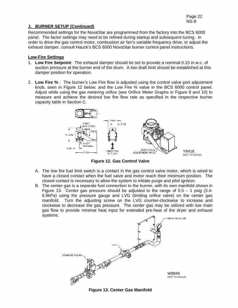
2. Low Fire % : The burner’s Low Fire flow is adjusted using the control valve port adjustment
knob, seen in Figure 12 below, and the Low Fire % value in the BCS 6000 control panel. Adjust while using the gas metering orifice (see Orifice Meter Graphs in Figure 9 and 10) to measure and achieve the desired low fire flow rate as specified in the respective burner capacity table in Section C.
Figure 12. Gas Control Valve
A. The low fire fuel limit switch is a contact in the gas control valve motor, which is wired to have a closed contact when the fuel valve and motor reach their minimum position. The closed contact is necessary to allow the system to initiate purge and pilot ignition.
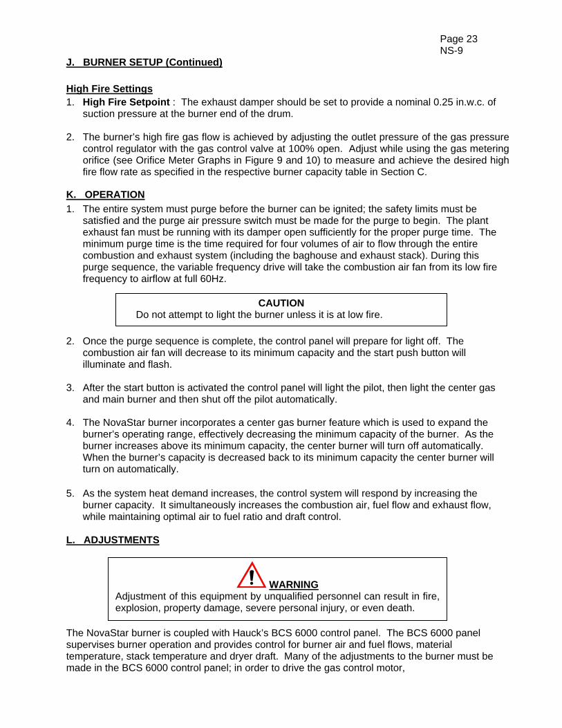
B. The center gas is a separate fuel connection to the burner, with its own manifold shown in Figure 13. Center gas pressure should be adjusted to the range of 0.5 – 1 psig (3.4-6.9kPa) using the pressure gauge and LVG (limiting orifice valve) on the center gas manifold. Turn the adjusting screw on the LVG counter-clockwise to increase and clockwise to decrease the gas pressure. The center gas may be utilized with low main gas flow to provide minimal heat input for extended pre-heat of the dryer and exhaust systems.
Figure 13. Center Gas Manifold
W8849 (NOT TO SCALE)
Y8418 (NOT TO SCALE)
Page 23 NS-9
J. BURNER SETUP (Continued)
High Fire Settings 1. High Fire Setpoint : The exhaust damper should be set to provide a nominal 0.25 in.w.c. of
suction pressure at the burner end of the drum. 2. The burner’s high fire gas flow is achieved by adjusting the outlet pressure of the gas pressure
control regulator with the gas control valve at 100% open. Adjust while using the gas metering orifice (see Orifice Meter Graphs in Figure 9 and 10) to measure and achieve the desired high fire flow rate as specified in the respective burner capacity table in Section C.
K. OPERATION
1. The entire system must purge before the burner can be ignited; the safety limits must be satisfied and the purge air pressure switch must be made for the purge to begin. The plant exhaust fan must be running with its damper open sufficiently for the proper purge time. The minimum purge time is the time required for four volumes of air to flow through the entire combustion and exhaust system (including the baghouse and exhaust stack). During this purge sequence, the variable frequency drive will take the combustion air fan from its low fire frequency to airflow at full 60Hz.
2. Once the purge sequence is complete, the control panel will prepare for light off. The combustion air fan will decrease to its minimum capacity and the start push button will illuminate and flash.
3. After the start button is activated the control panel will light the pilot, then light the center gas and main burner and then shut off the pilot automatically.
4. The NovaStar burner incorporates a center gas burner feature which is used to expand the burner’s operating range, effectively decreasing the minimum capacity of the burner. As the burner increases above its minimum capacity, the center burner will turn off automatically. When the burner’s capacity is decreased back to its minimum capacity the center burner will turn on automatically.
5. As the system heat demand increases, the control system will respond by increasing the
burner capacity. It simultaneously increases the combustion air, fuel flow and exhaust flow, while maintaining optimal air to fuel ratio and draft control.
L. ADJUSTMENTS The NovaStar burner is coupled with Hauck’s BCS 6000 control panel. The BCS 6000 panel supervises burner operation and provides control for burner air and fuel flows, material temperature, stack temperature and dryer draft. Many of the adjustments to the burner must be made in the BCS 6000 control panel; in order to drive the gas control motor,
WARNING Adjustment of this equipment by unqualified personnel can result in fire, explosion, property damage, severe personal injury, or even death.
CAUTION Do not attempt to light the burner unless it is at low fire.

Page 24 NS-9
L. ADJUSTMENTS (Continued) the combustion air fan’s variable frequency drive, or adjust the exhaust damper, consult Hauck’s BCS 6000 NovaStar burner control panel instructions. 1. As the system heat demand increases or decreases the control panel will simultaneously
increase or decrease the combustion air, fuel flow and exhaust flow, maintaining optimal air to fuel ratio and draft control, consult control panel instructions. A. The air to fuel ratio setting can be adjusted to optimize burner emissions. B. Draft control setting can be adjusted to optimize draft response and plant efficiency.
2. The NovaStar burner incorporates a center gas burner feature which is used to expand the
burner’s operating range. The center burner turn on/off point can be adjusted, consult control panel instructions.
3. The gas control valve uses a Hauck PVS2B40. The valve may need to be adjusted in order to accommodate flow requirements. To make adjustments, see instructions APV-9.
M. MAINTENANCE
With exception to the combustion air fan, the Hauck NovaStar burner has no internal moving parts and is relatively maintenance free. However, there are a few items that should be checked as part of a regular preventative maintenance program.
1. Regularly check all safety equipment, such as pressure switches, solenoid valves and safety
shutoff valves to ensure they are not clogged with dirt, or in any way inoperative.
2. While the burner is off, check and clean UV scanner lens as conditions dictate to keep it clean of dirt and dust.
3. While the burner is off, check and purge the impulse lines to the pressure transmitters located
on the metering orifice manifold with low pressure air. To further ensure that the burner is operating with accurate gas flow, check the transmitter impulse lines for leaks.
4. Check the thermocouple in the burner body for signs of wear, damage, or inaccuracy.
5. Check and purge the impulse line to the draft control pressure transmitters to ensure that the burner and draft system are operating with accurate draft control.
6. A periodic inspection of the burner nozzle and internals should be conducted to ensure the
integrity of the components. Components clogged with dirt or debris should be thoroughly cleaned and worn components should be replaced.
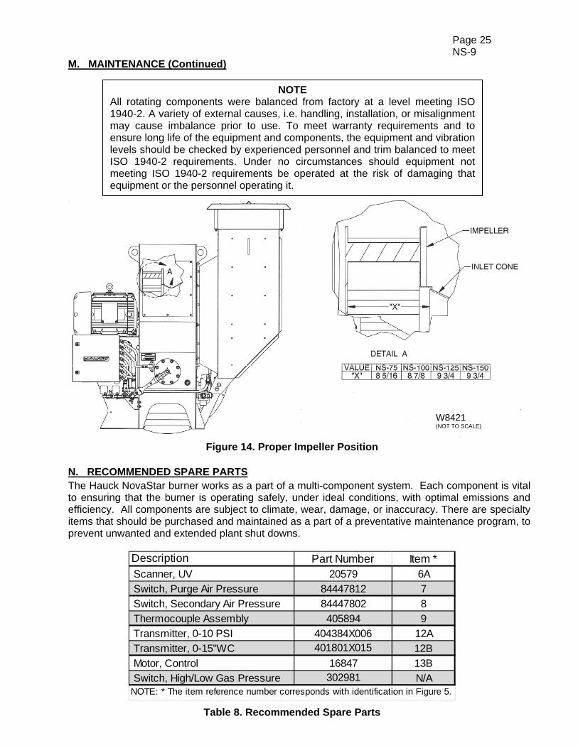
7. A periodic check of the fan (impeller/motor) vibration, measured in the vertical and horizontal directions at the motor bearings, is required. Should it be necessary to remove the fan impeller from the motor shaft, it is important to replace the fan impeller in the proper position. Consult Figure 14 for the impeller location, consult Hauck for installation instructions. A vibration check is required.
WARNING If any of the items listed below are in an unacceptable or unsafe state of operation, do no operate the burner and/or combustion system and replace immediately.
Page 25 NS-9
M. MAINTENANCE (Continued)
Figure 14. Proper Impeller Position N. RECOMMENDED SPARE PARTS The Hauck NovaStar burner works as a part of a multi-component system. Each component is vital to ensuring that the burner is operating safely, under ideal conditions, with optimal emissions and efficiency. All components are subject to climate, wear, damage, or inaccuracy. There are specialty items that should be purchased and maintained as a part of a preventative maintenance program, to prevent unwanted and extended plant shut downs.
Description Part Number Item * Scanner, UV 20579 6A
Switch, Purge Air Pressure 84447812 7
Switch, Secondary Air Pressure 84447802 8
Thermocouple Assembly 405894 9
Transmitter, 0-10 PSI 404384X006 12A
Transmitter, 0-15"WC 401801X015 12B
Motor, Control 16847 13B
Switch, High/Low Gas Pressure 302981 N/ANOTE: * The item reference number corresponds with identification in Figure 5.
Table 8. Recommended Spare Parts
W8421 (NOT TO SCALE)
NOTE All rotating components were balanced from factory at a level meeting ISO 1940-2. A variety of external causes, i.e. handling, installation, or misalignment may cause imbalance prior to use. To meet warranty requirements and to ensure long life of the equipment and components, the equipment and vibration levels should be checked by experienced personnel and trim balanced to meet ISO 1940-2 requirements. Under no circumstances should equipment not meeting ISO 1940-2 requirements be operated at the risk of damaging that equipment or the personnel operating it.
Page 26 NS-9
APPENDIX
Page 27 NS-9
APPENDIX
Page 28 NS-9
APPENDIX
Page 29 NS-9
APPENDIX
Page 30 NS-9
APPENDIX
Page 31 NS-9
APPENDIX

Page 32 NS-9
APPENDIX
Page 33 NS-9
APPENDIX

This page left intentionally blank.
HAUCK MANUFACTURING CO., P.O. Box 90 Lebanon, PA 17042-0090 717-272-3051
www.hauckburner.com Fax: 717-273-9882
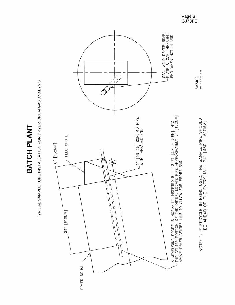
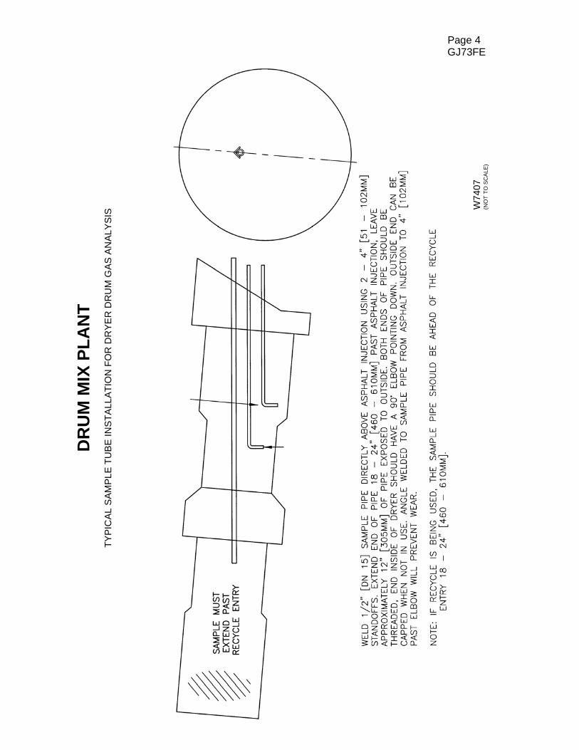
Gas analyses are used to indicate the air/fuel ratio and to indicate the degree of completeness of combustion. If the mixing is poor, an excess of air must be supplied so that every particle of fuel will contact some air and burn. Unburned fuel is simply wasted since it does not contribute heat to the process. A critical step in every dryer drum gas analysis is the placement of the sample tube. The appli- cability of the readings depends directly on the location from which the sample is drawn. To give you an idea of the recommended placement, we have included a drawing in this section. Refer to “Typical Sample Tube Installation for Dryer Drum Gas Analysis”. The procedures used to make an accurate gas analysis vary not only with the method employed but also with the manufacturer of the equipment. In most instances good readings require that the manufacturers instructions be adhered to rigidly. Conditions to perform a good analysis. 1. Use a reliable gas analyzer. 2. Sample pipe must be installed in the dryer drum to eliminate reading stray O2, overheated
RAP, or overheated AC. 3. Sample should be taken with average tonnage, moisture and firing rates. 4. Allow at least 10 to 15 minutes running time at production rates before taking readings. 5. Sample tubing from the sample pipe to the analyzer should be as short as possible. Tubing
should be approximately 1/4 inch (6.4 mm) I.D. rubber, plastic, or silicone. 6. Gases should be sampled until instrument settles out, normally a few minutes depending on
sample line size, length, and pump volume.
APPLICATION SHEET
GJ73FE
DRYER DRUM GAS ANALYSIS FOR NATURAL GAS, OIL AND LP
HAUCK MANUFACTURING CO., P.O. Box 90 Lebanon, PA 17042-0090 717-272-3051 12/04 www.hauckburner.com Fax: 717-273-9882
Page 2 GJ73FE
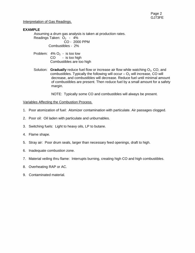
Interpretation of Gas Readings. EXAMPLE Assuming a drum gas analysis is taken at production rates. Readings Taken: O2 - 4% CO - 2000 PPM Combustibles - 2% Problem: 4% O2 - is too low CO - is too high Combustibles are too high Solution: Gradually reduce fuel flow or increase air flow while watching O2, CO, and combustibles. Typically the following will occur – O2 will increase, CO will decrease, and combustibles will decrease. Reduce fuel until minimal amount of combustibles are present. Then reduce fuel by a small amount for a safety margin. NOTE: Typically some CO and combustibles will always be present. Variables Affecting the Combustion Process. 1. Poor atomization of fuel: Atomizer contamination with particulate. Air passages clogged. 2. Poor oil: Oil laden with particulate and unburnables. 3. Switching fuels: Light to heavy oils, LP to butane. 4. Flame shape. 5. Stray air: Poor drum seals, larger than necessary feed openings, draft to high. 6. Inadequate combustion zone. 7. Material veiling thru flame: Interrupts burning, creating high CO and high combustibles. 8. Overheating RAP or AC. 9. Contaminated material.
Page 3 GJ73FE
BA
TC
H P
LA
NT
TY
PIC
AL
SA
MP
LE
TU
BE
IN
ST
ALL
AT
ION
FO
R D
RY
ER
DR
UM
GA
S A
NA
LY
SIS
W74
06
(NO
T T
O S
CA
LE
)
Page 4 GJ73FE
DR
UM
MIX
PL
AN
T
TY
PIC
AL
SA
MP
LE
TU
BE
IN
ST
ALL
AT
ION
FO
R D
RY
ER
DR
UM
GA
S A
NA
LY
SIS
W74
07
(NO
T T
O S
CA
LE
)
ADJUSTABLE PORT VALVES Table Of Contents Subject Page A. General Information ……………………………………………………….…..….……. 2 B. Receiving and Inspection ………………………………………….…….…...…….….. 2 C. Capacities ………….……………………………………………………………………. 3 D. Dimensions …………….………………………………………………………………... 4 E. Installation ………….……………………………………………………………….…… 4 F. Operation…………………………………………………………………………………. 5 G. Maintenance …………………………………………………………………..………… 7
INSTRUCTIONS
WARNING These instructions are intended for use only by experienced, qualified combustion start-up personnel. Adjustment of this equipment and its components, by unqualified personnel, can result in fire, explosion, severe personal injury, or even death.
These instructions are intended to serve as guidelines covering the installation, operation, and maintenance of Hauck equipment. While every attempt has been made to ensure completeness, unforeseen or unspecified applications, details, and variations may preclude covering every possible contingency. WARNING: TO PREVENT THE POSSIBILITY OF SERIOUS BODILY INJURY, DO NOT USE OR OPERATE ANY EQUIPMENT OR COMPONENT WITH ANY PARTS REMOVED OR ANY PARTS NOT APPROVED BY THE MANUFACTURER. Should further information be required or desired or should particular problems arise which are not covered sufficiently for the purchaser's purpose, contact Hauck Mfg. Co.
APV-9 HAUCK MANUFACTURING CO., P.O. Box 90 Lebanon, PA 17042-0090 717-272-3051 3/13 www.hauckburner.com Fax: 717-273-9882
Page 2 APV-9
A. GENERAL INFORMATION The Hauck Adjustable Air and Gas Port Valves are a dependable, accurate means of controlling the flow of air or gas to any variable pressure type of burner or system. Flow control may be either manual or automatic. These valves are easily adjustable and designed to hold the desired setting in either mode of operation. Each side of the valve is equipped with four drilled and tapped mounting pads. This facilitates the installation of multiple valve units or an automatic control system. These units are designed to be used as efficient control systems, not as shutoff valves. B. RECEIVING AND INSPECTION Upon receipt, check each item on the bill of lading and/or invoice to determine that all equipment has been received. A careful examination of all parts should be made to ascertain if there has been any damage in shipment.
WARNING This equipment is potentially dangerous with the possibility of serious personal injury and property damage. Hauck Manufacturing Company recommends the use of flame supervisory equipment and fuel safety shutoff valves. Furthermore, Hauck urges rigid adherence to National Fire Protection Association (NFPA) standards and insurance underwriter’s requirements. Operation and regular preventative maintenance of this equipment should be performed only by properly trained and qualified personnel. Annual review and upgrading of safety equipment is recommended.
IMPORTANT If the installation is delayed and the equipment is stored outside, provide adequate protection as dictated by climate and period of exposure. Special care should be given to all motors and bearings, if applicable, to protect them from rain or excessive moisture.
Page 3 APV-9
C. CAPACITIES
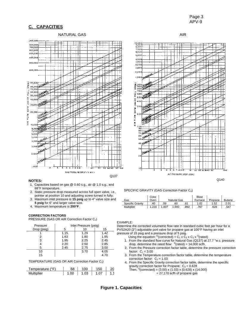
NATURAL GAS AIR NOTES: 1. Capacities based on gas @ 0.60 s.g., air @ 1.0 s.g., and 68°F temperature. 2. Static pressure drop measured across full open valve, i.e., pointer at position 10 and adjusting screw turned in fully. 3. Maximum inlet pressure is 15 psig up to 4" valve size and 5 psig for 6" and larger valve size. 4. Maximum temperature is 200°F.
CORRECTION FACTORS PRESSURE (GAS OR AIR Correction Factor C1)
Pressure Inlet Pressure (psig) Drop (psig) 5 10 15
1 1.15 1.29 1.42 2 1.63 1.80 1.95 3 1.95 2.25 2.45 4 2.20 2.50 2.85 5 2.45 2.75 3.00
10 3.70 4.05 15 4.70
TEMPERATURE (GAS OR AIR Correction Factor C2)
Figure 1. Capacities
Temperature (°F) 68 100 150 200 Multiplier 1.00 1.03 1.07 1.12
Q137 Q140
SPECIFIC GRAVITY (GAS Correction Factor C3) Coke Blast Gas Oven Natural Gas Furnace Propane Butane Specific Gravity .40 .59 .60 .61 1.02 1.52 2.01 Multiplier 1.224 1.007 1.000 .992 .767 .628 .547
EXAMPLE: Determine the corrected volumetric flow rate in standard cubic feet per hour for a PVS2A20 (2") adjustable port valve for propane gas at 100°F having an inlet pressure of 15 psig and a pressure drop of 5 psig. Using the equation: Q(corrected) = C1 x C2 x C3 x Q(rated) 1. From the standard flow curve for Natural Gas (Q137) at 27.7 "w.c. pressure drop, determine the rated flow: Q(rated) = 14,000 scfh. 2. From the Pressure correction factor table, determine the pressure correction factor: C1 = 3.00 3. From the Temperature correction factor table, determine the temperature correction factor: C2 = 1.03 4. From the Specific Gravity correction factor table, determine the specific gravity correction factor for Propane: C3 = 0.628 Then, Q(corrected) = (3.00) x (1.03) x (0.628) x (14,000) = 27,170 scfh of propane gas

Page 4 APV-9
D. DIMENSIONS See appropriate Dimension sheet for detailed dimensional information. E. INSTALLATION 1. The port valve can be installed in any position, at any convenient location in the air or gas line. When installing this valve, provide a means for measuring the line pressure downstream of the valve. These valves are designed to operate with pressures up to 15 psig (103 kPa) for 1" through 4" valve size, and 5 psig (34 kPa) for 6" and larger valve size. The 1" to 4" valves are designed with female connections threaded for standard pipe. The 6" and larger valves have ANSI 125lb flange connections. These valves should not be used when the temperature exceeds 200°F (93°C). Ensure that all piping both to and from the valve is properly aligned and supported to prevent undue strain on the valve.
Figure 2. Adjustable Port Valve Cutaway Diagram
2. When an automatic operation is to be used, a control motor should be mounted to the valve or some other nearby rigid support. Recommended motor torque requirement for the 1" to 4" valves is 20 in-lbs (2.3Nm); 40 in-lbs (4.5Nm) for the 6" or larger valves. The valves operating arm moves in a clockwise direction to open the valve over an arc of about 90° at an adjust- able radius from 2-5/8" to 4-3/8" (67 to 111mm). A. Connect the valve lever to the control motor arm by a 3/8" (9.5mm) rod through the snap connection pin on the valve lever. A setscrew is provided on the snap pin to secure the rod at the proper point. B. Loosen the locking screw located on the base of the dial indicator. This will allow easy movement of the valve pointer. C. Adjust the two limit stops until they allow movement of the pointer over the entire range of dial positions. D. Adjust the length of the control motor arm so that the valve pointer moves through the desired range on the valve dial. Be sure that the control motor does not move the valve lever beyond the stops on the dial as this can damage the valve if sufficient force is applied.
Page 5 APV-9
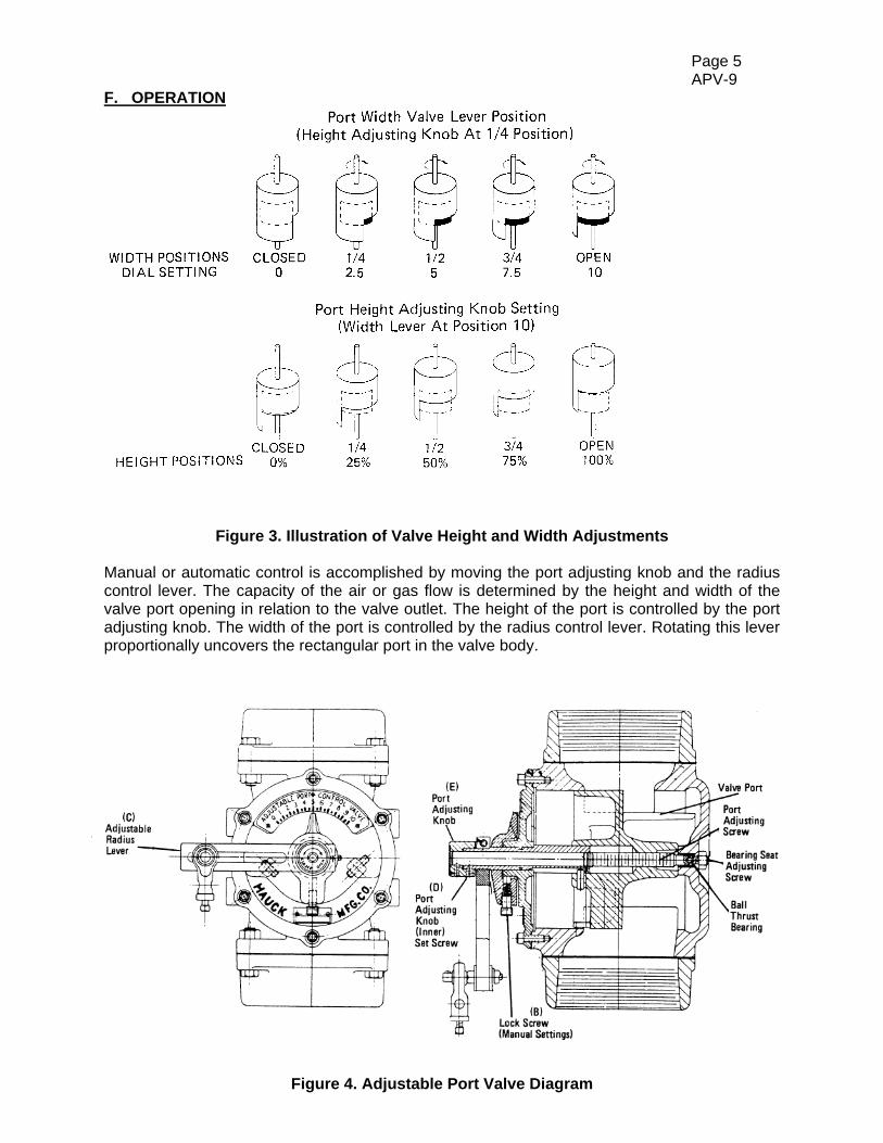
F. OPERATION
Figure 3. Illustration of Valve Height and Width Adjustments Manual or automatic control is accomplished by moving the port adjusting knob and the radius control lever. The capacity of the air or gas flow is determined by the height and width of the valve port opening in relation to the valve outlet. The height of the port is controlled by the port adjusting knob. The width of the port is controlled by the radius control lever. Rotating this lever proportionally uncovers the rectangular port in the valve body.
Figure 4. Adjustable Port Valve Diagram

Page 6 APV-9
Once installed, adjustments of the port adjusting knob and the radius control lever are achieved by accomplishing the following:
A. Disconnect the automatic linkage (if present). B. Loosen the dial pointer locking screw. C. Rotate the radius control lever to position 10. D. Loosen the setscrew which holds the port adjusting knob at the proper setting. Exercise care since two setscrews exist on the knob. The inner setscrew maintains the setting while the outer setscrew fastens the knob to the stem. Only the inner setscrew should be loosened. E. Turn the adjusting control knob counterclockwise until the FULLY CLOSED position is reached. F. Initiate the flow of air or gas through the line. G. Rotate the adjusting knob clockwise until the pressure gauge(s) indicates the maximum Pressure required. The pressure needed will vary depending on the burner, the piping,
and the application. The table given below gives the approximate number of turns from FULL CLOSED TO FULL OPEN.
H. Tighten the inner setscrew on the port adjusting knob. I. Connect the linkage for automatic control. The vibration-proof locking screw, located at the base of the dial pointer, should be used to lock any manual setting of the valve pointer. When operating automatically, this locking screw must be loosened to facilitate the movement of the pointer. Hauck adjustable port valves are designed for efficient flow control; they are not intended for use as complete shut-off valves.
APPROXIMATE NO. OF TURNS FROMVALVE MODEL FULL CLOSED TO FULL OPEN
PVS 2A10 & PVS 2A12 18 PVS 2A15 & PVS 2A20 22 PVS 2A30 & PVS 2B40 29 PVS 2A60 & PVS 2B60 43
Page 7 APV-9
G. MAINTENANCE All port valves are designed and constructed for maintenance free operation. Under normal usage no service should be necessary. If should become necessary to clean the valve, the entire port assembly can be easily removed, in one piece, by accomplishing the following:
A. Disconnect the automatic linkage (if present). B. Loosen and remove all of the screws, and the nut on the guide bolt, holding the dial
plate cover to the valve body. C. Extract the entire port assembly. D. Wipe the port cylinder clean of any particles or residue. If scarring of the cylinder has
occurred, use an emery cloth to restore a smooth surface. E. Lubricate the port cylinder with Molykote or some other suitable high temperature, non-
gumming lubricant. F. Reinsert the port assembly. Use the location of the guide bolt to ensure proper
alignment. Ensure that the stem is properly seated in the bushing at the back of the valve body.
G. Replace and properly seat the dial plate cover gaskets. H. Replace and tighten all of the screws in the dial plate cover. I. Move the radius control lever through its full range of movement. If the movement is
either binding or too free moving, adjust the bearing seat adjusting setscrew on the valve back by accomplishing the following:
a. Loosen the locknut which secures the setscrew. b. Slowly tighten the setscrew (clockwise rotation) until there is resistance to the
movement of the lever. c. Rotate the setscrew 1/8 to 1/4 turn in a counterclockwise direction. d. Tighten the lock nut.
J. Reconnect the automatic linkage (if used).

Page 8 APV-9
This page left intentionally blank.
HAUCK MANUFACTURING CO., P.O. Box 90 Lebanon, PA 17042-0090 717-272-3051 www.hauckburner.com Fax: 717-273-9882