Embed Size (px)
Citation preview

THIS IS
A
NE
W
DR
AWIN
G
4�
"
4�"
9"
UNC Heavy Hex Nut
with hardened round washer and
1�" dia. 13" Long Threaded Rod
UNC heavy hex nut
hardened round washer, and
�" dia. UNC11" long threaded rod,
UNC heavy hex nut
hardened round washer, and
�" dia. UNC 7" long threaded rod,
UNC heavy hex nut
hardened round washer, and
�" dia. UNC 7" long threaded rod,
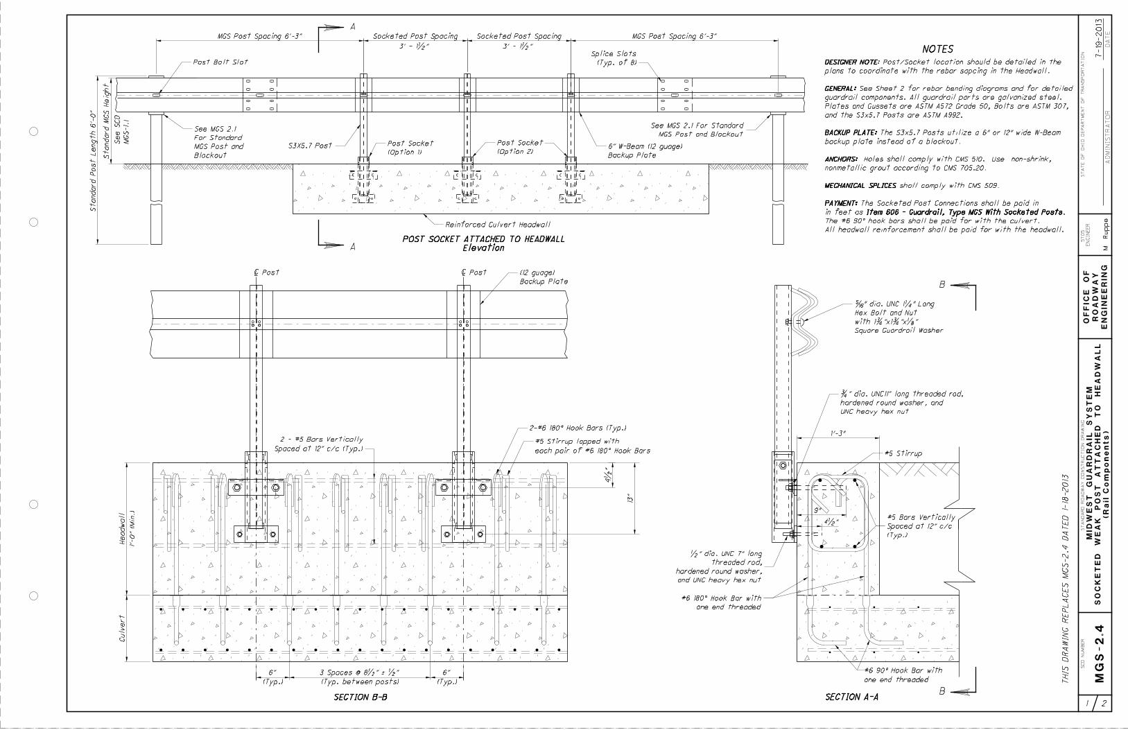
Standard Post Length 6’-
0"
Standard
MG
S
Heig
ht
Post Bolt Slot
MGS Post Spacing 6’-3"
MG
S-1.
1
See S
CD
MGS Post Spacing 6’-3"
(Typ. of 8)
Splice Slots
Backup Plate
6" W-Beam (12 guage)S3X5.7 Post
(Option 1)
Post SocketMGS Post and Blockout
For Standard
See MGS 2.1
MGS Post and Blockout
For Standard
See MGS 2.1
(Option 2)
Post Socket
Backup Plate
6" W-Beam (12 guage)
Backup Plate
6" W-Beam (12 guage)
Standard W-Beam
(OPTION 1)
POST SOCKET ATTACHED TO HEADWALL
(OPTION 2)
POST SOCKET ATTACHED TO HEADWALL
NOTES
Elevation
POST SOCKET ATTACHED TO HEADWALL
4�"
10"
13"
7"
13"
Item 606 - Guardrail, Type MGS With Socketed Posts
Socketed Post SpacingSocketed Post Spacing
3’ - 1�" 3’ - 1�"
with 1�"x1�"x�" Square Guardrail Washer
�" dia. UNC 1�" Long Hex Bolt and Nut
Reinforced Culvert Headwall
PAYMENT:
ANCHORS:
BACKUP PLATE:
GENERAL:
in feet as Item 606 - Guardrail, Type MGS With Socketed Posts.
PAYMENT: The Socketed Post Connections shall be paid in
nonmetallic grout according to CMS 705.20.
ANCHORS: Holes shall comply with CMS 510. Use non-shrink,
backup plate instead of a blockout.
BACKUP PLATE: The S3x5.7 Posts utilize a 6 inch wide W-Beam
options.
Contractor may choose either of the socketed attachment
Bolts are ASTM 307, and the S3x5.7 Posts are ASTM A992.
galvanized Steel. Plates and Gussets are ASTM A572 Grade 50,
GENERAL: See Sheet 2 for detailed components. All parts are
@ 12" c/c (Typ.)
#5 Bar Vertically Spaced
1’-6"
#6 Bar @ 12" c/c
EN
GIN
EE
RIN
G
RO
AD
WA
Y
OF
FIC
E
OF
ST
AT
E
OF
OHIO
DEP
AR
TM
EN
T
OF T
RA
NSP
OR
TA
TIO
N
DA
TE
1 2
MID
WE
ST
GU
AR
DR
AIL
SY
ST
EM
SO
CK
ET
ED
WE
AK
PO
ST
AT
TA
CH
ED
TO
HE
AD
WA
LL
1-18-2013
ST
AN
DA
RD R
OA
DW
AY C
ON
ST
RU
CTIO
N
DR
AWIN
G
EN
GIN
EE
R
ST
DS.
AD
MINIS
TR
AT
OR
M. Ruppe
SC
D
NU
MB
ER
MG
S-2.4
(La
yo
ut)

THIS IS
A
NE
W
DR
AWIN
G
2" 2"
3" 3"
16�
"
2"
8�
"
2�
"
4"
4"
�"
�" dia.
3"
3"
8"
10"
1�"
1�"
�"
�"
1�" 7"
1" 6"
�" dia.
�" dia.
2�"
2�
"
�"
SIDE VIEW
FRONT VIEW
TOP VIEWA
A
A
B
C
D
B
B
C
D
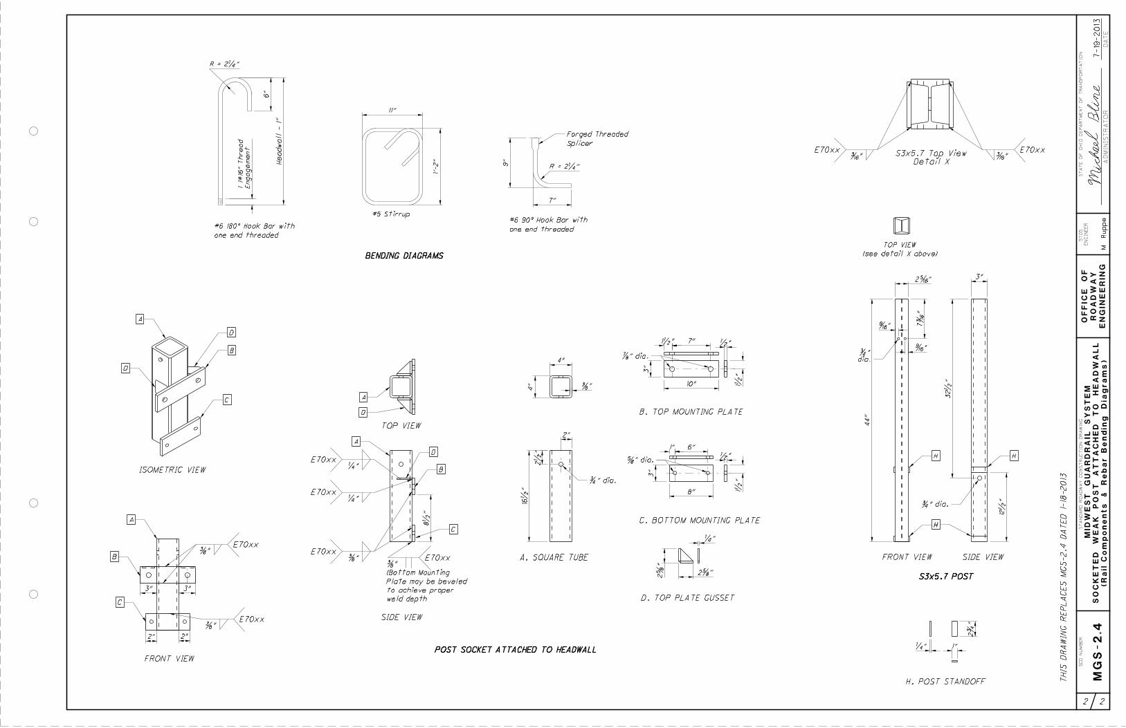
A. SQUARE TUBE
B. TOP MOUNTING PLATE
C. BOTTOM MOUNTING PLATE
D. TOP PLATE GUSSET
�"E70xx
�"E70xx
�"E70xx
E70xx�"
E70xx�"
A
C
D
D
3"
9�"
1�"2"
�"
3"
2"
�"
�"
�"
�"E70xx
A
8"
3"
1�" 1"
�" dia.
E70xx
�"E70xx
4" 2"
2"
�"E70xx
2" 2"
F. BOTTOM MOUNTING PLATE
E. TOP MOUNTING PLATE
G. MOUNTING PLATE GUSSET
E
F
G
A A
F
F
EG
F
SIDE VIEW
FRONT VIEW
TOP VIEW
ISOMETRIC VIEW
OPTION 1
ISOMETRIC VIEW
OPTION 1
44"
3"2�"
7�
"
�"
�"
dia.
�"
�" dia.
�"E70xx
SIDE VIEWFRONT VIEW
(OPTION 1)
POST SOCKET ATTACHED TO HEADWALL
(OPTION 2)
POST SOCKET ATTACHED TO HEADWALL
�"E70xx
(see detail X below)
TOP VIEW
S3x5.7 POST
H. POST STANDOFF
2�
"
1"�"
H
H
H
H
Detail X
S3x5.7 Top View
12�
"
32�
"
achieve proper weld depth
may be beveled to
(Bottom Mounting Plate
�"
E70xx
weld depth
to achieve proper
Plate may be beveled
(Bottom Mounting
�"
EN
GIN
EE
RIN
G
RO
AD
WA
Y
OF
FIC
E
OF
ST
AT
E
OF
OHIO
DEP
AR
TM
EN
T
OF T
RA
NSP
OR
TA
TIO
N
DA
TE
2 2
MID
WE
ST
GU
AR
DR
AIL
SY
ST
EM
SO
CK
ET
ED
WE
AK
PO
ST
AT
TA
CH
ED
TO
HE
AD
WA
LL
1-18-2013
ST
AN
DA
RD R
OA
DW
AY C
ON
ST
RU
CTIO
N
DR
AWIN
G
EN
GIN
EE
R
ST
DS.
AD
MINIS
TR
AT
OR
M. Ruppe
SC
D
NU
MB
ER
MG
S-2.4
(R
ail C
om
po
ne
nts)
Standard Post Length 6’-
0"
Standard
MG
S
Heig
ht
Post Bolt Slot
MGS Post Spacing 6’-3"
MG
S-1.
1
See S
CD
MGS Post Spacing 6’-3"
(Typ. of 8)
Splice Slots
Backup Plate
6" W-Beam (12 guage)S3X5.7 Post
(Option 1)
Post Socket
(Option 2)
Post Socket
NOTES
Elevation
POST SOCKET ATTACHED TO HEADWALL
Item 606 - Guardrail, Type MGS With Socketed Posts
Socketed Post SpacingSocketed Post Spacing
3’ - 1�" 3’ - 1�"
Reinforced Culvert Headwall
9"
UNC heavy hex nut
hardened round washer, and
�" dia. UNC11" long threaded rod,
1’-3"
13"
(Typ.)
6"
(Typ. between posts)
3 Spaces @ 8�" ‘ �"
one end threaded
#6 90° Hook Bar with
(Typ.)
6"
| Post | Post
SECTION A-ASECTION B-B
Square Guardrail Washer
with 1�"x1�"x�"
Hex Bolt and Nut
�" dia. UNC 1�" Long
EN
GIN
EE
RIN
G
RO
AD
WA
Y
OF
FIC
E
OF
ST
AT
E
OF
OHIO
DEP
AR
TM
EN
T
OF T
RA
NSP
OR
TA
TIO
N
DA
TE
1 2
MID
WE
ST
GU
AR
DR
AIL
SY
ST
EM
SO
CK
ET
ED
WE
AK
PO
ST
AT
TA
CH
ED
TO
HE
AD
WA
LL
7-19-2013
ST
AN
DA
RD R
OA
DW
AY C
ON
ST
RU
CTIO
N
DR
AWIN
G
EN
GIN
EE
R
ST
DS.
AD
MINIS
TR
AT
OR
M. Ruppe
SC
D
NU
MB
ER
MG
S-2.4
(R
ail C
om
po
ne
nts)
THIS
DR
AWIN
G R
EP
LA
CES
MG
S-2.4
DA
TE
D 1-
18-20134�
"
each pair of #6 180° Hook Bars
#5 Stirrup lapped with
2-#6 180° Hook Bars (Typ.)
#5 StirrupSpaced at 12" c/c (Typ.)
2 - #5 Bars Vertically
Head
wall
Culvert
1’-0" (Min.)
and UNC heavy hex nut
hardened round washer,
threaded rod,
�" dia. UNC 7" long
4�"
(Typ.)
Spaced at 12" c/c
#5 Bars Vertically
one end threaded
#6 180° Hook Bar with
MGS Post and Blockout
See MGS 2.1 For Standard
Blockout
MGS Post and
For Standard
See MGS 2.1
Backup Plate
(12 guage)
All headwall reinforcement shall be paid for with the headwall.
The #6 90° hook bars shall be paid for with the culvert.
in feet as Item 606 - Guardrail, Type MGS With Socketed Posts.
PAYMENT: The Socketed Post Connections shall be paid in
MECHANICAL SPLICES shall comply with CMS 509.
nonmetallic grout according to CMS 705.20.
ANCHORS: Holes shall comply with CMS 510. Use non-shrink,
backup plate instead of a blockout.
BACKUP PLATE: The S3x5.7 Posts utilize a 6" or 12" wide W-Beam
and the S3x5.7 Posts are ASTM A992.
Plates and Gussets are ASTM A572 Grade 50, Bolts are ASTM 307,
guardrail components. All guardrail parts are galvanized steel.
GENERAL: See Sheet 2 for rebar bending diagrams and for detailed
plans to coordinate with the rebar sapcing in the Headwall.
DESIGNER NOTE: Post/Socket location should be detailed in the
PAYMENT:
MECHANICAL SPLICES
ANCHORS:
BACKUP PLATE:
GENERAL:
DESIGNER NOTE
B
B
A
A
2" 2"
3" 3"
16�
"
2"
8�
"
2�
"
4"
4"
�"
�" dia.
3"
3"
8"
10"
1�"
1�"
�"
�"
1�" 7"
1" 6"
�" dia.
�" dia.
2�"
2�
"
�"
SIDE VIEW
FRONT VIEW
TOP VIEW
A
A
A
B
C
D
B
B
C
D
A. SQUARE TUBE
B. TOP MOUNTING PLATE
C. BOTTOM MOUNTING PLATE
D. TOP PLATE GUSSET
�"E70xx
�"E70xx
�"E70xx
E70xx�"
E70xx�"
A
C
D
D
44"
3"2�"
7�
"
�"
�"
dia.
�"
�" dia.
�"E70xx
SIDE VIEWFRONT VIEW
�"E70xx
(see detail X above)
TOP VIEW
S3x5.7 POST
H. POST STANDOFF
2�
"
1"�"
H
H
H
H
Detail X
S3x5.7 Top View
12�
"
32�
"
E70xx
weld depth
to achieve proper
Plate may be beveled
(Bottom Mounting
�"
THIS
DR
AWIN
G R
EP
LA
CES
MG
S-2.4
DA
TE
D 1-
18-2013
POST SOCKET ATTACHED TO HEADWALL
R = 2�"
R = 2�"
one end threaded
#6 180° Hook Bar with
#5 Stirrup
one end threaded
#6 90° Hook Bar with
6"
Head
wall - 1"
Engage
ment
1 1#
16"
Thread
11"
1’-2"
Splicer
Forged Threaded
9"
7"
ISOMETRIC VIEW
BENDING DIAGRAMS
EN
GIN
EE
RIN
G
RO
AD
WA
Y
OF
FIC
E
OF
ST
AT
E
OF
OHIO
DEP
AR
TM
EN
T
OF T
RA
NSP
OR
TA
TIO
N
DA
TE
2 2
MID
WE
ST
GU
AR
DR
AIL
SY
ST
EM
SO
CK
ET
ED
WE
AK
PO
ST
AT
TA
CH
ED
TO
HE
AD
WA
LL
7-19-2013
ST
AN
DA
RD R
OA
DW
AY C
ON
ST
RU
CTIO
N
DR
AWIN
G
EN
GIN
EE
R
ST
DS.
AD
MINIS
TR
AT
OR
M. Ruppe
SC
D
NU
MB
ER
MG
S-2.4
(R
ail C
om
po
ne
nts
&
Re
bar
Be
ndin
g
Dia
gra
ms)

Standard Post Length 6’-
0"
Standard
MG
S
Heig
ht
Post Bolt Slot
MGS Post Spacing 6’-3"
MG
S-1.
1
See S
CD
MGS Post Spacing 6’-3"
(Typ. of 8)
Splice Slots
Backup Plate
6" W-Beam (12 guage)S3X5.7 Post
NOTES
Elevation
POST SOCKET ATTACHED TO HEADWALL
Item 606 - Guardrail, Type MGS With Socketed Posts
Socketed Post SpacingSocketed Post Spacing
3’ - 1�" 3’ - 1�"
Reinforced Culvert Headwall
9"
UNC heavy hex nut
hardened round washer, and
�" dia. UNC11" long threaded rod,
1’-3"
13"
(Typ.)
6"
(Typ. between posts)
3 Spaces @ 8�" ‘ �"
one end threaded
#6 90° Hook Bar with
(Typ.)
6"
| Post | Post
SECTION A-ASECTION B-B
Square Guardrail Washer
with 1�"x1�"x�"
Hex Bolt and Nut
�" dia. UNC 1�" Long
EN
GIN
EE
RIN
G
RO
AD
WA
Y
OF
FIC
E
OF
ST
AT
E
OF
OHIO
DEP
AR
TM
EN
T
OF T
RA
NSP
OR
TA
TIO
N
DA
TE
1 2
MID
WE
ST
GU
AR
DR
AIL
SY
ST
EM
SO
CK
ET
ED
WE
AK
PO
ST
AT
TA
CH
ED
TO
HE
AD
WA
LL
7-18-2014
ST
AN
DA
RD R
OA
DW
AY C
ON
ST
RU
CTIO
N
DR
AWIN
G
EN
GIN
EE
R
ST
DS.
AD
MINIS
TR
AT
OR
M. Ruppe
SC
D
NU
MB
ER
MG
S-2.4
(R
ail C
om
po
ne
nts)
THIS
DR
AWIN
G R
EP
LA
CES
MG
S-2.4
DA
TE
D 7-19-2013
4�
"
each pair of #6 180° Hook Bars
#5 Stirrup lapped with
2-#6 180° Hook Bars (Typ.)
#5 StirrupSpaced at 12" c/c (Typ.)
2 - #5 Bars Vertically
Head
wall
Culvert
1’-3" (Min.)
and UNC heavy hex nut
hardened round washer,
threaded rod,
�" dia. UNC 7" long
4�"
(Typ.)
Spaced at 12" c/c
#5 Bars Vertically
one end threaded
#6 180° Hook Bar with
MGS Post and Blockout
See MGS 2.1 For Standard
Blockout
MGS Post and
For Standard
See MGS 2.1
Backup Plate
(12 guage)
All headwall reinforcement shall be paid for with the headwall.
The #6 90° hook bars shall be paid for with the culvert.
in feet as Item 606 - Guardrail, Type MGS With Socketed Posts.
PAYMENT: The Socketed Post Connections shall be paid in
MECHANICAL SPLICES shall comply with CMS 509.
nonmetallic grout according to CMS 705.20.
ANCHORS: Holes shall comply with CMS 510. Use non-shrink,
backup plate instead of a blockout.
BACKUP PLATE: The S3x5.7 Posts utilize a 6" or 12" wide W-Beam
and the S3x5.7 Posts are ASTM A992.
Plates and Gussets are ASTM A572 Grade 50, Bolts are ASTM 307,
guardrail components. All guardrail parts are galvanized steel.
GENERAL: See Sheet 2 for rebar bending diagrams and for detailed
plans to coordinate with the rebar spacing in the Headwall.
DESIGNER NOTE: Post/Socket location should be detailed in the
PAYMENT:
MECHANICAL SPLICES
ANCHORS:
BACKUP PLATE:
GENERAL:
DESIGNER NOTE
B
B
(Typ.)
Post Socket
A
A

2" 2"
3" 3"
16�
"
2"
8�
"
2�
"
4"
4"
�"
�" dia.
3"
3"
8"
10"
1�"
1�"
�"
�"
1�" 7"
1" 6"
�" dia.
�" dia.
2�"
2�
"
�"
SIDE VIEW
FRONT VIEW
TOP VIEW
A
A
A
B
C
D
B
B
C
D
A. SQUARE TUBE
B. TOP MOUNTING PLATE
C. BOTTOM MOUNTING PLATE
D. TOP PLATE GUSSET
�"E70xx
�"E70xx
�"E70xx
E70xx�"
E70xx�"
A
C
D
D
44"
3"2�"
7�
"
�"
�"
dia.
�"
�" dia.
�"E70xx
SIDE VIEWFRONT VIEW
�"E70xx
(see detail X above)
TOP VIEW
S3x5.7 POST
H. POST STANDOFF
2�
"
1"�"
H
H
H
H
Detail X
S3x5.7 Top View
12�
"
32�
"
E70xx
weld depth
to achieve proper
Plate may be beveled
(Bottom Mounting
�"
THIS
DR
AWIN
G R
EP
LA
CES
MG
S-2.4
DA
TE
D 7-19-2013
POST SOCKET ATTACHED TO HEADWALL
R = 2�"
R = 2�"
one end threaded
#6 180° Hook Bar with
#5 Stirrup
one end threaded
#6 90° Hook Bar with
6"
Head
wall - 1"
Engage
ment
1 1#
16"
Thread
11"
1’-2"
Splicer
Forged Threaded
9"
7"
ISOMETRIC VIEW
BENDING DIAGRAMS
EN
GIN
EE
RIN
G
RO
AD
WA
Y
OF
FIC
E
OF
ST
AT
E
OF
OHIO
DEP
AR
TM
EN
T
OF T
RA
NSP
OR
TA
TIO
N
DA
TE
2 2
MID
WE
ST
GU
AR
DR
AIL
SY
ST
EM
SO
CK
ET
ED
WE
AK
PO
ST
AT
TA
CH
ED
TO
HE
AD
WA
LL
7-18-2014
ST
AN
DA
RD R
OA
DW
AY C
ON
ST
RU
CTIO
N
DR
AWIN
G
EN
GIN
EE
R
ST
DS.
AD
MINIS
TR
AT
OR
M. Ruppe
SC
D
NU
MB
ER
MG
S-2.4
(R
ail C
om
po
ne
nts
&
Re
bar
Be
ndin
g
Dia
gra
ms)

EN
GIN
EE
RIN
G
RO
AD
WA
Y
OF
FIC
E
OF
ST
AT
E
OF
OHIO
DEP
AR
TM
EN
T
OF T
RA
NSP
OR
TA
TIO
N
DA
TE
1 2
MID
WE
ST
GU
AR
DR
AIL
SY
ST
EM
SO
CK
ET
ED
WE
AK
PO
ST
AT
TA
CH
ED
TO
HE
AD
WA
LL
01-
15-2016
ST
AN
DA
RD R
OA
DW
AY C
ON
ST
RU
CTIO
N
DR
AWIN
G
EN
GIN
EE
R
ST
DS.
AD
MINIS
TR
AT
OR
D. Fis
her
SC
D
NU
MB
ER
MG
S-2.4
(R
ail C
om
po
ne
nts)
Standard Post Length 6'-
0"
Post Bolt Slot
MGS Post Spacing 6'-3"
MG
S-1.
1
See S
CD
MGS Post Spacing 6'-3"
(Typ. of 8)
Splice Slots
Backup Plate
6" W-Beam (12 guage)S3X5.7 Post
NOTES
Elevation
POST SOCKET ATTACHED TO HEADWALL
Item 606 - Guardrail, Type MGS With Socketed Posts
Socketed Post SpacingSocketed Post Spacing
3' - 1•" 3' - 1•"
Reinforced Culvert Headwall
9"
UNC heavy hex nut
hardened round washer, and
ƒ" dia. UNC11" long threaded rod,
1'-3"
13"
(Typ.)
6"
(Typ. between posts)
3 Spaces @ 8•" ` •"
one end threaded
#6 90° Hook Bar with
(Typ.)
6"
| Post | Post
SECTION A-ASECTION B-B
Square Guardrail Washer
with 1ƒ"x1ƒ"x„"
Hex Bolt and Nut
Š" dia. UNC 1‚" Long
THIS
DR
AWIN
G R
EP
LA
CES
MG
S-2.4
DA
TE
D 7-18-2014
4•
"
each pair of #6 180° Hook Bars
#5 Stirrup lapped with
2-#6 180° Hook Bars (Typ.)
#5 StirrupSpaced at 12" c/c (Typ.)
2 - #5 Bars Vertically
Head
wall
Culvert
1'-3" (Min.)
and UNC heavy hex nut
hardened round washer,
threaded rod,
•" dia. UNC 7" long
4•"
(Typ.)
Spaced at 12" c/c
#5 Bars Vertically
one end threaded
#6 180° Hook Bar with
MGS Post and Blockout
See MGS 2.1 For Standard
Blockout
MGS Post and
For Standard
See MGS 2.1
Backup Plate
(12 guage)
All headwall reinforcement shall be paid for with the headwall.
The #6 90° hook bars shall be paid for with the culvert.
in feet as Item 606 - Guardrail, Type MGS With Socketed Posts.
PAYMENT: The Socketed Post Connections shall be paid in
MECHANICAL SPLICES shall comply with CMS 509.
nonmetallic grout according to CMS 705.20.
ANCHORS: Holes shall comply with CMS 510. Use non-shrink,
backup plate instead of a blockout.
BACKUP PLATE: The S3x5.7 Posts utilize a 6" or 12" wide W-Beam
and the S3x5.7 Posts are ASTM A992.
Plates and Gussets are ASTM A572 Grade 50, Bolts are ASTM 307,
guardrail components. All guardrail parts are galvanized steel.
GENERAL: See Sheet 2 for rebar bending diagrams and for detailed
plans to coordinate with the rebar spacing in the Headwall.
DESIGNER NOTE: Post/Socket location should be detailed in the
PAYMENT:
MECHANICAL SPLICES
ANCHORS:
BACKUP PLATE:
GENERAL:
DESIGNER NOTE
B
B
(Typ.)
Post Socket
A
A
DH Hex Nut
with a 5/8" Dia. A563
5" Long A325 Hex Bolt
5/8" dia. UNC
Standard
MG
S
Heig
ht

EN
GIN
EE
RIN
G
RO
AD
WA
Y
OF
FIC
E
OF
ST
AT
E
OF
OHIO
DEP
AR
TM
EN
T
OF T
RA
NSP
OR
TA
TIO
N
DA
TE
2 2
MID
WE
ST
GU
AR
DR
AIL
SY
ST
EM
SO
CK
ET
ED
WE
AK
PO
ST
AT
TA
CH
ED
TO
HE
AD
WA
LL
01-
15-2016
ST
AN
DA
RD R
OA
DW
AY C
ON
ST
RU
CTIO
N
DR
AWIN
G
EN
GIN
EE
R
ST
DS.
AD
MINIS
TR
AT
OR
D. Fis
her
SC
D
NU
MB
ER
MG
S-2.4
(R
ail C
om
po
ne
nts
&
Re
bar
Be
ndin
g
Dia
gra
ms)
2" 2"
3" 3"
16•
"
2"
8•
"
2•
"
4"
4"
…"
ƒ" dia.
3"
3"
8"
10"
1•"
1•"
•"
•"
1•" 7"
1" 6"
†" dia.
‡" dia.
2†"
2†
"
‚"
SIDE VIEW
FRONT VIEW
TOP VIEW
A
A
A
B
C
D
B
B
C
D
A. SQUARE TUBE
B. TOP MOUNTING PLATE
C. BOTTOM MOUNTING PLATE
D. TOP PLATE GUSSET
…"E70xx
…"E70xx
…"E70xx
E70xx‚"
E70xx‚"
A
C
D
D
44"
3"2Š"
7‰
"
Œ"
Œ"
dia.
…"
ƒ" dia.
‰"E70xx
SIDE VIEWFRONT VIEW
‰"E70xx
(see detail X above)
TOP VIEW
S3x5.7 POST
H. POST STANDOFF
2ƒ
"
1"‚"
H
H
H
H
Detail X
S3x5.7 Top View
12•
"
32•
"
E70xx
weld depth
to achieve proper
Plate may be beveled
(Bottom Mounting
…"
THIS
DR
AWIN
G R
EP
LA
CES
MG
S-2.4
DA
TE
D 7-18-2014
POST SOCKET ATTACHED TO HEADWALL
R = 2‚"
R = 2‚"
one end threaded
#6 180° Hook Bar with
#5 Stirrup
one end threaded
#6 90° Hook Bar with
6"
Head
wall - 1"
Engage
ment
1 1#
16"
Thread
11"
1'-2"
Splicer
Forged Threaded
9"
7"
ISOMETRIC VIEW
BENDING DIAGRAMS


![TOPN Messages - Cisco · %TR-2-PANICINF: Unit [dec], PI [hex] [hex] [hex] [hex] [hex] [hex] Explanation This message is similar to the (Jeanine check source.) Recommended Action Copy](https://img.dokumen.tips/doc/110x75/5f96ea0c176ab92a087a6e14/topn-messages-cisco-tr-2-panicinf-unit-dec-pi-hex-hex-hex-hex-hex.jpg)