Embed Size (px)
Citation preview
Nondestructive monitoring of aircraft composites usingterahertz radiation
Nikolay S. Balbekina, Evgenii V. Novoselovb, Pavel V. Pavlovc, Victor G. Bespalova,Nikolay V. Petrova
aDepartment of photonics and optical informatics, ITMO University, Kadetskaya Linia 3,St. Petersburg, Russia, 199004.
bChalmers Univ. of Technology, Chalmersplatsen 4, Gothenburg, Sweden, 41296.cMilitary Aviation Engineering University, Starih Bolshevikov st. 54-a, Voronezh, Russia,
394064.
ABSTRACT
In this paper we consider using the terahertz (THz) time domain spectroscopy (TDS) for non destructive testingand determining the chemical composition of the vanes and rotor-blade spars. A versatile terahertz spectrometerfor reflection and transmission has been used for experiments. We consider the features of measured terahertzsignal in temporal and spectral domains during propagation through and reflecting from various defects ininvestigated objects, such as voids and foliation. We discuss requirements are applicable to the setup and arenecessary to produce an image of these defects, such as signal-to-noise ratio and a method for registration THzradiation. Obtained results indicated the prospects of the THz TDS method for the inspection of defects anddetermination of the particularities of chemical composition of aircraft parts.
Keywords: Terahertz radiation, terahertz spectroscopy, terahertz imaging, nondestructive testing, aircraft.
1. INTRODUCTION
The qualitatively new technologies are implemented in a global aircraft industry to ensure not only flight safetybut also maximum efficiency of aircraft operation. Substantially it is achieved by increasing use of compositematerials for aircraft. The composition and therefore the properties of these materials may varied depending ondesired values of strength, heat resistance, modulus, abrasion resistance, and moreover differ in their magnetic,dielectric, radio and other properties. Glass fiber, epoxy resin and carbon fiber composite materials are increas-ingly used as structural airframe elements, due to their high strength to weight ratio, improved aerodynamicperformance, reliability, and reduced corrosiveness compare to other construction materials. However, compositestructure modifications during the exploitation are possible due to the strong thermal influence (e.g., from tur-bines) or various material strains due to external influences (such as unsuccessful plane landing or bullet hits).Also material deterioration is possible caused by a prolonged operation period. The widespread use of compos-ites requires a new approaches both for aircraft design and manufacture, and maintenance and repair servicesincluding the high-quality diagnostics. The most common methods for non-destructive testing are ultrasonictechniques,1,2 thermography3,4, 5 and shearography,4,6 but all of them have some disadvantages as expensive-ness, insufficient sensitivity, a problem with the detection of subsurface defects and suitability not for all kindsof defects.7
During the past few years THz spectroscopy has been applied as a technic for non-contact composite materialdiagnostics. THz radiation is located between infrared and microwave bands of electromagnetic spectrum. Hightransparency of smoke, clothing , paper, wood, plastic, ceramic surfaces and other materials for THz radiationprovides a great potential for intravision with high signal to noise ratio. THz radiation is non-ionizing unlike X-rays and has less scattering and greater penetration depth in comparison with optical and infrared radiation. Byuse of the electro-optical detection in THz TDS it is possible to register real part of THz field complex amplitude,that can provide us information both on amplitude and phase radiation and yield to fuller measurement of optical
E-mail: [email protected]
Saratov Fall Meeting 2014: Optical Technologies in Biophysics and Medicine XVI; Laser Physics and Photonics XVI;and Computational Biophysics, E. A. Genina, V. L. Derbov, K. V. Larin, D. E. Postnov, V. V. Tuchin, Eds., Proc. of SPIE
Vol. 9448, 94482D · © 2015 SPIE · CCC code: 1605-7422/15/$18 · doi: 10.1117/12.2180021
Proc. of SPIE Vol. 9448 94482D-1
characteristics. Several papers describing the scattering of THz radiation in composites8,9, 10,11 and modeling oftheir dielectric properties using the effective medium theory (EMT)8,9, 10 were published. Since the compositeis a nonhomogeneous solid material consisting of matrix (binder element) and the reinforcing element, onecan determine using EMT its physical properties knowing the properties of components. Application of theTHz imaging methods for monitoring CM showed the possibility of visualization of the spatial distribution ofinternal defects.11 THz holography and phase retrieval methods12,13,14 reveal complete wavefront informationboth amplitude and phase and provides more complete information about the object under investigation. It isexpected to be a more prospective to diagnose composites.
THz radiation can penetrate into composites and identify defects such as air cavities, delaminations, mechan-ical damage and thermal damage. In,11 results of such thin composite materials defects studies (∝0.1-2.0 mm)using transmission THz TDS were presented. Due to the high THz radiation reflection from relatively polishedcomposite material surface of 30-40% and both substantial refractive index (∝2) and the absorption coefficient,this method has a limitation in application associated with the sample thickness.
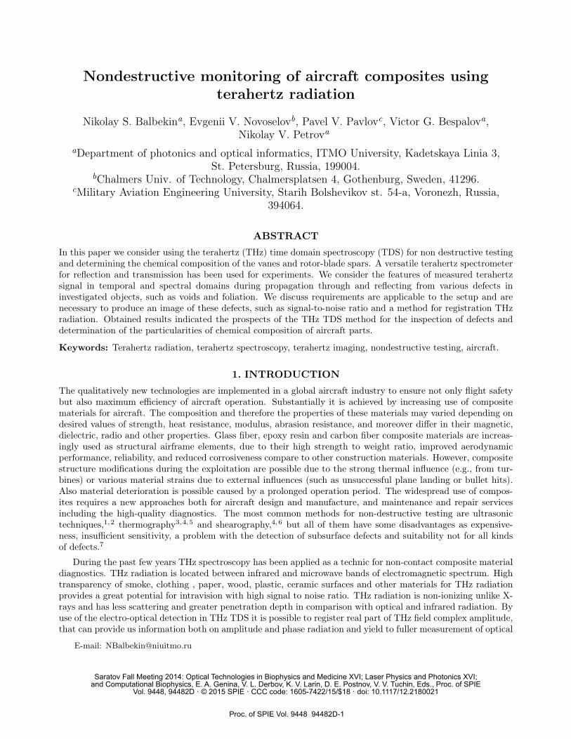
In this paper we consider using reflection and transmission THz TDS for non-destructive monitoring ofcomposites. Reflection and transmission of broadband THz radiation from composite materials were studiedusing this method (see Fig. 1). Possibility of physical properties determination, various defects identifying andmaterial properties changes were shown due to the harmful effects.
(a) (b) (c)Figure 1. Studied samples of composite materials. Photograph showing the three samples: (a) burned sample “16a”, (b)“17B” sample after mechanical stress, and (c) sample with delamination “1B”.
2. THE EXPERIMENTAL SETUPTo generate broadband pulsed THz radiation we used the experimental setup. Photoconductive antenna (un-doped InAs)15,16 was placed in a constant magnetic field of 2.4 T.17 Antenna was exposed by radiation offemtosecond laser FL -1 (the active medium - Yb: KYW; λ = 1040nm, tp = 46 fs, ν = 70 MHz, P = 1,2W).It allowed to obtain THz radiation in conical form with the following parameters: spectral range from 0.05 to1.6 THz, average power 30 µW, pulse duration 2.7 ps. The uppermost energy was distributed between 0.12 and1.10 THz. The scheme of the versatile THz spectrometer is shown on Fig. 2.
THz radiation from the source passed through a teflon filter to cut off the wavelength range less than 50microns. Then first PM collimated it and second PM focused it to the sample having a certain amplitude andphase transmittance. The sample was fixed perpendicularly to the optical axis in the focal plane using two axismotorized translation stage. EO detection was carried out using18 quarter-wave plate, Wollaston prism, balancedphotodetector and lock-in amplifier. Filtered and amplified signal was transmitted to a computer via a digitalvoltmeter. Spectral resolution during measurements was about 7 GHz for the transmission mode and 15 GHzfor reflection mode.19 Operation of the setup was realized by means of software environment NI LabVIEW.
Proc. of SPIE Vol. 9448 94482D-2
BS M
ADC
PC
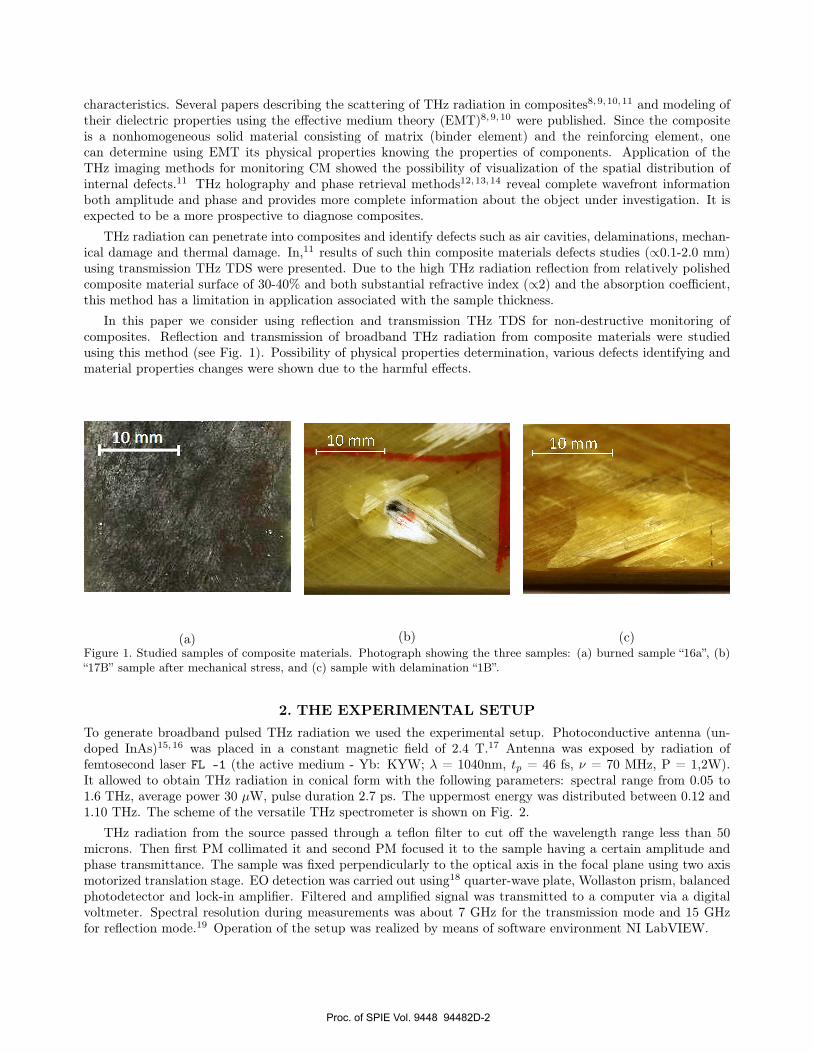
Figure 2. The scheme of versatile THz spectrometer. FL-1 is the femtosecond laser; M are mirrors; BS - beam spleaters;DL - optic delay line; G - THz radiation generator in InAs; PM - parabolic mirrors; ch - chopper; EODS - electro-opticaldetecting system; lock-in - lock-in amplifier; ADC - analog-digital converter; PC - personal computer.
3. OBTAINED RESULTSData processing and transmission/reflection spectra preparation were made using a standard procedure appliedin THz TDS. Refractive index and dispersion of studied medium was calculated using two complex spectra.20By means of this technique presence of stratification in the composite structure was demonstrate. The changeof frequency spectra obtained using FFT in composite structure after heat exposure was shown. Finally, defectvisualization due to deformation cause of physical impact was presented.
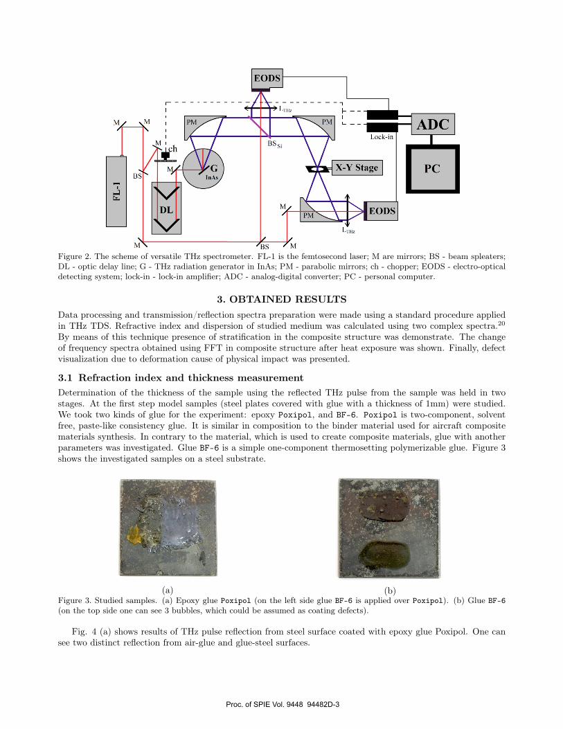
3.1 Refraction index and thickness measurementDetermination of the thickness of the sample using the reflected THz pulse from the sample was held in twostages. At the first step model samples (steel plates covered with glue with a thickness of 1mm) were studied.We took two kinds of glue for the experiment: epoxy Poxipol, and BF-6. Poxipol is two-component, solventfree, paste-like consistency glue. It is similar in composition to the binder material used for aircraft compositematerials synthesis. In contrary to the material, which is used to create composite materials, glue with anotherparameters was investigated. Glue BF-6 is a simple one-component thermosetting polymerizable glue. Figure 3shows the investigated samples on a steel substrate.
(a) (b)Figure 3. Studied samples. (a) Epoxy glue Poxipol (on the left side glue BF-6 is applied over Poxipol). (b) Glue BF-6(on the top side one can see 3 bubbles, which could be assumed as coating defects).
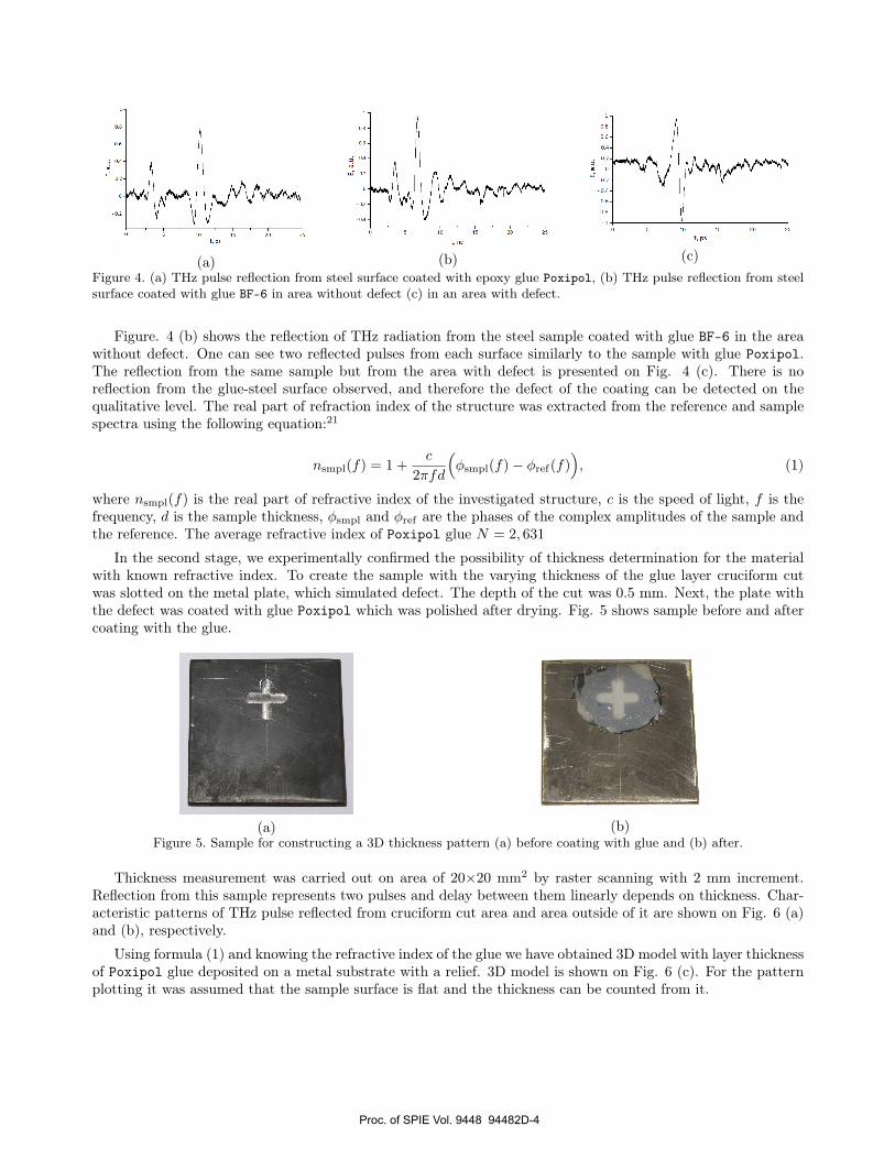
Fig. 4 (a) shows results of THz pulse reflection from steel surface coated with epoxy glue Poxipol. One cansee two distinct reflection from air-glue and glue-steel surfaces.
Proc. of SPIE Vol. 9448 94482D-3
0.8 -
0.6 -
0.a-
w 0.2-
- 0.2 -
ist, ps t, nc
1
0.8
0.6
0.4
0.2
ni
-0.2
- 0.4
- 0.6
- 0.8
1
t, ps
(a) (b) (c)Figure 4. (a) THz pulse reflection from steel surface coated with epoxy glue Poxipol, (b) THz pulse reflection from steelsurface coated with glue BF-6 in area without defect (c) in an area with defect.
Figure. 4 (b) shows the reflection of THz radiation from the steel sample coated with glue BF-6 in the areawithout defect. One can see two reflected pulses from each surface similarly to the sample with glue Poxipol.The reflection from the same sample but from the area with defect is presented on Fig. 4 (c). There is noreflection from the glue-steel surface observed, and therefore the defect of the coating can be detected on thequalitative level. The real part of refraction index of the structure was extracted from the reference and samplespectra using the following equation:21
nsmpl(f) = 1 +c
2πfd
(φsmpl(f)− φref(f)
), (1)
where nsmpl(f) is the real part of refractive index of the investigated structure, c is the speed of light, f is thefrequency, d is the sample thickness, φsmpl and φref are the phases of the complex amplitudes of the sample andthe reference. The average refractive index of Poxipol glue N = 2, 631
In the second stage, we experimentally confirmed the possibility of thickness determination for the materialwith known refractive index. To create the sample with the varying thickness of the glue layer cruciform cutwas slotted on the metal plate, which simulated defect. The depth of the cut was 0.5 mm. Next, the plate withthe defect was coated with glue Poxipol which was polished after drying. Fig. 5 shows sample before and aftercoating with the glue.
(a) (b)Figure 5. Sample for constructing a 3D thickness pattern (a) before coating with glue and (b) after.
Thickness measurement was carried out on area of 20×20 mm2 by raster scanning with 2 mm increment.Reflection from this sample represents two pulses and delay between them linearly depends on thickness. Char-acteristic patterns of THz pulse reflected from cruciform cut area and area outside of it are shown on Fig. 6 (a)and (b), respectively.
Using formula (1) and knowing the refractive index of the glue we have obtained 3D model with layer thicknessof Poxipol glue deposited on a metal substrate with a relief. 3D model is shown on Fig. 6 (c). For the patternplotting it was assumed that the sample surface is flat and the thickness can be counted from it.
Proc. of SPIE Vol. 9448 94482D-4

0.8
0.6
0.4
0.2
,'a ow
-0.2
-0.6
-0.8
ió
t, ps
0.8
0.6
o.
j 0.2
iù o
-0.2
a
t, ps
1u
111 F+
i
1,0 -
0,8 -
0,6 -
0,4 -
0,2 -
0,0
-0,2-
-0,4-
-0,6 -
o
"1 B" with no lamination----^18^ with lamination
/
m 1023xo10
/ /
510 60
t. pa
(a)(b)
(c)Figure 6. Characteristic patterns of THz pulse reflected from (a) cross area and (b) area outside the cross, (c) 3D thicknesspattern of epoxy glue Poxipol coated on a relief steel plate.
3.2 Delamination of composite materialNext, we investigated the reflection of THz radiation from the region of the composite with the bundle structure.As the object was selected composite "1B" (Fig. 1c). Obtained time profiles were compared with the timeprofiles of the THz radiation reflected from the same composite in an area without bundles (Fig. 7).
Figure 7. Temporal profiles of the THz radiation reflected from the area of the 1B composite without bundle (dotted line)and with the bundle (solid line).
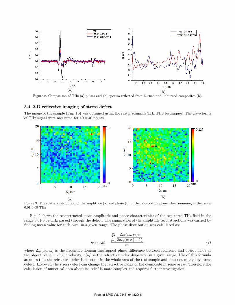
3.3 Burn diagnostics using material property measurementsComposite "16a" (Fig. 1a) was selected as the object of investigation. Time profiles of the THz pulse wereobtained in the area, where the most visually noticeable difference.
It is noticeable that the amplitude of the THz pulse reflected from burned composite greater than theamplitude of THz pulse reflected from unburned (Fig. 8a). There are also changes in the spectrum at 0.56 THz,0.6 THz, 0.68 THz (Fig. 8b).
Proc. of SPIE Vol. 9448 94482D-5
1,0 -
0,8 -
0,6 -
0,4 -
0,2 -
0,0 -
-0,2 -
-0,4 -
0,6
- ref-"16a" burned-"16a" not burned
1 1 1 1 1 1 15 10 15 20 25 30 35 40
t, P.S.
1,0 -
0,9 -
0,8 -
0,7
0,6 -
-
(p 0,5
0,4 -
0,3 -
0,2 -
0,1 -
0,0
"16a" burned-"16a" not burned
I I I I I I I I I I
0,1 0,2 0,3 0,4 0,5 0,6 0,7 0,8 0,9 1,0
F, THz
20-
15-
10-
5-
o
1 ON
i r'
1 1'4'T'V1:
dE r i-
0 5 10
X, mm15
1
020 au'
20
15-
10-
5-
0-0 5
o a- a r I .Er . ..
. R°10
X, mm
15
0.223
o20mm
(a) (b)Figure 8. Comparison of THz (a) pulses and (b) spectra reflected from burned and unburned composites (b).
3.4 2-D reflective imaging of stress defectThe image of the sample (Fig. 1b) was obtained using the raster scanning THz TDS techniques. The wave formsof THz signal were measured for 40× 40 points.
(a) (b)
Figure 9. The spatial distribution of the amplitude (a) and phase (b) in the registration plane when summing in the range0.01-0.09 THz
Fig. 9 shows the reconstructed mean amplitude and phase characteristics of the registered THz field in therange 0.01-0.09 THz passed through the defect. The summation of the amplitude reconstructions was carried byfinding mean value for each pixel in a given range. The phase distribution was calculated as:
h(x0, y0) =
m∑i=1
∆ϕ(x0, y0)c
2πνi(n(νi)− 1)
m, (2)
where ∆ϕ(x0, y0) is the frequency-domain unwrapped phase difference between reference and object fields atthe object plane, c - light velocity, n(νi) is the refractive index dispersion in a given range. Use of this formulaassumes that the refractive index is constant in the whole area of the test sample and does not change by stressdefect. However, the stress defect can change the refractive index of the composite in some areas. Therefore thecalculation of numerical data about its relief is more complex and requires further investigation.
Proc. of SPIE Vol. 9448 94482D-6
4. CONCLUSIONTHz TDS in reflection and transmission mode has several potential advantages over other nondestructive eval-uation methods for inspection of aircraft glass fiber composites. Ultrasound technique require that the sourceand detector remain in contact with the aircraft. THz radiation can penetrate glass fiber without contacting itand detect surface defects, hidden voids and delaminations in composites.
An aircraft glass fiber composite with various forms of damage was examined using THz TDS system. Indexof refraction and absorption coefficient in the terahertz frequency range were measured using THz TDS intransmission configuration for comparison of damaged and undamaged material states. Results showed thatheat damage (843 K during 20 minutes) did not noticeably change the material properties of the compositesample.
5. ACKNOWLEDGMENTThis work was partially financially supported by Government of Russian Federation, Grant 074-U01.Nikolay Petrov acknowledges financial support from Russian Ministry of Education and Science project withinthe state mission for institutions of higher education (Agreement No 2014/190).
REFERENCES[1] Blitz, J. and Simpson, G., [Ultrasonic methods of non-destructive testing ], Springer, London. (1996).[2] Castaings, M., Cawley, P., Farlow, R., and Hayward, G., “Single sided inspection of composite materials
using air coupled ultrasound,” J. Nondestruct. Eval. 17(1), 37–45 (1998).[3] Avdelidis, N. P., Almond, D. P., and Hawtin, B. C., “Transient thermography in the assessment of defects
of aircraft composites,” NDT & E Int 36(6), 433–439 (2003).[4] Hung, Y., Chen, Y., Ng, S., Liu, L., Huang, Y., Luk, B., Ip, R., Wu, C., and Chung, P., “Review and
comparison of shearography and active thermography for nondestructive evaluation,” Mater. Sci. Eng.: R:Rep. 64(5-6), 73 – 112 (2009).
[5] Almond, D. P. and Peng, W., “Thermal imaging of composites,” J. Microsc. 201(2), 163–170 (2001).[6] Hung, Y., “Applications of digital shearography for testing of composite structures,” Compos. Part B-
Eng 30(7), 765 – 773 (1999).[7] Katnam, K., Silva, L. D., and Young, T., “Bonded repair of composite aircraft structures: A review of
scientific challenges and opportunities,” Prog. Aerosp. Sci. 61(0), 26 – 42 (2013).[8] Shen, Y. C., Taday, P. F., and Pepper, M., “Elimination of scattering effects in spectral measurement of
granulated materials using terahertz pulsed spectroscopy,” Appl. Phys. Lett. 92(5), 051103–051103–3 (2008).[9] Fletcher, J. R., Swift, G. P., Dai, D. C., Levitt, J. A., and Chamberlain, J. M., “Propagation of terahertz
radiation through random structures: An alternative theoretical approach and experimental validation,” J.Appl. Phys. 101(1), – (2007).
[10] Wietzke, S., Jansen, C., Rutz, F., Mittleman, D., and Koch, M., “Determination of additive content inpolymeric compounds with terahertz time-domain spectroscopy,” Polym. Test. 26(5), 614 – 618 (2007).
[11] Stoik, C. D., Bohn, M. J., and Blackshire, J. L., “Nondestructive evaluation of aircraft composites usingtransmissive terahertz time domain spectroscopy,” Opt. Express 16(21), 17039–17051 (2008).
[12] Petrov, N. V., Gorodetsky, A. A., and Bespalov, V. G., “Holography and phase retrieval in terahertzimaging,” Proc. SPIE 8846, 88460S–88460S–7 (2013).
[13] Petrov, N. V., Bespalov, V. G., and Volkov, M. V., “Phase retrieval of thz radiation using set of 2d spatialintensity measurements with different wavelengths,” Proc. SPIE 8281, 82810J–82810J–7 (2012).
[14] Petrov, N. V., Galiaskarov, A. N., Nikolaeva, T. Y., and Bespalov, V. G., “The features of optimization ofa phase retrieval technique in THz frequency range,” Proc. SPIE 8413, 84131T–84131T–5 (2012).
[15] Gürtler, A., Winnewisser, C., Helm, H., and Jepsen, P. U., “Terahertz pulse propagation in the near fieldand the far field,” J. Opt. Soc. Am. A 17(1), 74–83 (2000).
[16] Izumida, S., Ono, S., Liu, Z., Ohtake, H., and Sarukura, N., “Spectrum control of thz radiation from inas ina magnetic field by duration and frequency chirp of the excitation pulses,” Appl. Phys. Lett. 75(4), 451–453(1999).
Proc. of SPIE Vol. 9448 94482D-7

[17] Mittleman, D. M., Cunningham, J., Nuss, M. C., and Geva, M., “Noncontact semiconductor wafer charac-terization with the terahertz hall effect,” Appl. Phys. Lett. 71(1), 16–18 (1997).
[18] Lee, Y.-S., [Principles of terahertz science and technology ], Springer Science+Business Media, New York.(2009).
[19] Chan, W. L., Deibel, J., and Mittleman, D. M., “Imaging with terahertz radiation,” Rep. Prog. Phys. 70(8),1325 (2007).
[20] Grischkowsky, D., Keiding, S., van Exter, M., and Fattinger, C., “Far-infrared time-domain spectroscopywith terahertz beams of dielectrics and semiconductors,” J. Opt. Soc. Am. B 7, 2006–2015 (Oct 1990).
[21] Zhang, X.-C. and Xu, J., [Introduction to THz Wave Photonics ], Springer, New York. (2010).
Proc. of SPIE Vol. 9448 94482D-8


![Research and Applications of AE on Advanced Composites · volumes of ASNT Nondestructive Testing Handbooks [12], six-volume conference proceed-ings of AECM [13a-f], several review](https://img.dokumen.tips/doc/110x75/5e83935afa1e0a611c3f1e95/research-and-applications-of-ae-on-advanced-composites-volumes-of-asnt-nondestructive.jpg)