Embed Size (px)
Citation preview

NVM Express 1.0e
1
NVM Express
Revision 1.0e January 23, 2013
Please send comments to Amber Huffman [email protected]
Incorporates ECNs 001 – 033.

NVM Express 1.0e
2
NVM Express revision 1.0e specification available for download at http://nvmexpress.org. NVM Express revision 1.0 ratified on March 1, 2011. NVM Express revision 1.0e incorporates ECNs 001 – 033.
SPECIFICATION DISCLAIMER
THIS SPECIFICATION IS PROVIDED TO YOU “AS IS” WITH NO WARRANTIES WHATSOEVER, INCLUDING ANY WARRANTY OF MERCHANTABILITY, NON-INFRINGEMENT, OR FITNESS FOR ANY PARTICULAR PURPOSE. THE AUTHORS OF THIS SPECIFICATION DISCLAIM ALL LIABILITY, INCLUDING LIABILITY FOR INFRINGEMENT OF ANY PROPRIETARY RIGHTS, RELATING TO USE OR IMPLEMENTATION OF INFORMATION IN THIS SPECIFICATION. THE AUTHORS DO NOT WARRANT OR REPRESENT THAT SUCH USE WILL NOT INFRINGE ANY SUCH RIGHTS. THE PROVISION OF THIS SPECIFICATION TO YOU DOES NOT PROVIDE YOU WITH ANY LICENSE, EXPRESS OR IMPLIED, BY ESTOPPEL OR OTHERWISE, TO ANY INTELLECTUAL PROPERTY RIGHTS.
Copyright 2007-2013, Intel Corporation. All rights reserved.
All product names, trademarks, registered trademarks, and/or servicemarks may be claimed as the property of their respective owners.
NVMHCI Workgroup Chair:
Amber Huffman Intel Corporation MS: JF5-371 2111 NE 25th Avenue Hillsboro, OR 97124 [email protected]
NVM Express 1.0e
3
Table of Contents
1 INTRODUCTION ............................................................................................................. 8
1.1 Overview ......................................................................................................................................... 8 1.2 Scope .............................................................................................................................................. 8 1.3 Outside of Scope ............................................................................................................................ 8 1.4 Theory of Operation ........................................................................................................................ 8 1.5 Conventions .................................................................................................................................. 10 1.6 Definitions ..................................................................................................................................... 11
1.6.1 Admin Queue ....................................................................................................................................... 11 1.6.2 arbitration burst .................................................................................................................................... 11 1.6.3 arbitration mechanism .......................................................................................................................... 11 1.6.4 candidate command ............................................................................................................................. 11 1.6.5 command completion ........................................................................................................................... 11 1.6.6 command submission ........................................................................................................................... 11 1.6.7 controller .............................................................................................................................................. 11 1.6.8 extended LBA ....................................................................................................................................... 12 1.6.9 firmware slot ......................................................................................................................................... 12 1.6.10 I/O Completion Queue .......................................................................................................................... 12 1.6.11 I/O Submission Queue ......................................................................................................................... 12 1.6.12 LBA range ............................................................................................................................................ 12 1.6.13 logical block .......................................................................................................................................... 12 1.6.14 logical block address (LBA) .................................................................................................................. 12 1.6.15 metadata .............................................................................................................................................. 12 1.6.16 namespace ........................................................................................................................................... 12 1.6.17 NVM ..................................................................................................................................................... 12 1.6.18 NVM subsystem ................................................................................................................................... 12
1.7 Keywords ...................................................................................................................................... 12 1.7.1 mandatory ............................................................................................................................................ 12 1.7.2 may ...................................................................................................................................................... 12 1.7.3 optional ................................................................................................................................................. 13 1.7.4 R ........................................................................................................................................................... 13 1.7.5 reserved ............................................................................................................................................... 13 1.7.6 shall ...................................................................................................................................................... 13 1.7.7 should ................................................................................................................................................... 13
1.8 Conventions .................................................................................................................................. 13 1.9 Byte, word and Dword Relationships ............................................................................................ 14 1.10 References ................................................................................................................................ 14 1.11 References Under Development ............................................................................................... 15
2 SYSTEM BUS (PCI EXPRESS) REGISTERS ....................................................................... 16
2.1 PCI Header ................................................................................................................................... 16 2.1.1 Offset 00h: ID - Identifiers .................................................................................................................... 17 2.1.2 Offset 04h: CMD - Command ............................................................................................................... 17 2.1.3 Offset 06h: STS - Device Status........................................................................................................... 17 2.1.4 Offset 08h: RID - Revision ID ............................................................................................................... 17 2.1.5 Offset 09h: CC - Class Code ................................................................................................................ 18 2.1.6 Offset 0Ch: CLS – Cache Line Size ..................................................................................................... 18 2.1.7 Offset 0Dh: MLT – Master Latency Timer ............................................................................................ 18 2.1.8 Offset 0Eh: HTYPE – Header Type ...................................................................................................... 18 2.1.9 Offset 0Fh: BIST – Built In Self Test (Optional) .................................................................................... 18 2.1.10 Offset 10h: MLBAR (BAR0) – Memory Register Base Address, lower 32-bits ..................................... 18 2.1.11 Offset 14h: MUBAR (BAR1) – Memory Register Base Address, upper 32-bits .................................... 18 2.1.12 Offset 18h: IDBAR (BAR2) – Index/Data Pair Register Base Address (Optional) ................................ 19 2.1.13 Offset 1Ch – 20h: BAR3 –Reserved..................................................................................................... 19 2.1.14 Offset 20h – 23h: BAR4 – Vendor Specific .......................................................................................... 19 2.1.15 Offset 24h – 27h: BAR5 – Vendor Specific .......................................................................................... 19 2.1.16 Offset 28h: CCPTR – CardBus CIS Pointer ......................................................................................... 19 2.1.17 Offset 2Ch: SS - Sub System Identifiers .............................................................................................. 19
NVM Express 1.0e
4
2.1.18 Offset 30h: EROM – Expansion ROM (Optional) ................................................................................. 19 2.1.19 Offset 34h: CAP – Capabilities Pointer ................................................................................................. 19 2.1.20 Offset 3Ch: INTR - Interrupt Information .............................................................................................. 19 2.1.21 Offset 3Eh: MGNT – Minimum Grant ................................................................................................... 19 2.1.22 Offset 3Fh: MLAT – Maximum Latency ................................................................................................ 20
2.2 PCI Power Management Capabilities ........................................................................................... 20 2.2.1 Offset PMCAP: PID - PCI Power Management Capability ID ............................................................... 20 2.2.2 Offset PMCAP + 2h: PC – PCI Power Management Capabilities ......................................................... 20 2.2.3 Offset PMCAP + 4h: PMCS – PCI Power Management Control and Status ........................................ 20
2.3 Message Signaled Interrupt Capability (Optional) ........................................................................ 21 2.3.1 Offset MSICAP: MID – Message Signaled Interrupt Identifiers ............................................................ 21 2.3.2 Offset MSICAP + 2h: MC – Message Signaled Interrupt Message Control .......................................... 21 2.3.3 Offset MSICAP + 4h: MA – Message Signaled Interrupt Message Address ........................................ 21 2.3.4 Offset MSICAP + 8h: MUA – Message Signaled Interrupt Upper Address........................................... 21 2.3.5 Offset MSICAP + Ch: MD – Message Signaled Interrupt Message Data ............................................. 21 2.3.6 Offset MSICAP + 10h: MMASK – Message Signaled Interrupt Mask Bits (Optional) ........................... 21 2.3.7 Offset MSICAP + 14h: MPEND – Message Signaled Interrupt Pending Bits (Optional) ....................... 21
2.4 MSI-X Capability (Optional) .......................................................................................................... 22 2.4.1 Offset MSIXCAP: MXID – MSI-X Identifiers ......................................................................................... 22 2.4.2 Offset MSIXCAP + 2h: MXC – MSI-X Message Control ....................................................................... 22 2.4.3 Offset MSIXCAP + 4h: MTAB – MSI-X Table Offset / Table BIR ......................................................... 22 2.4.4 Offset MSIXCAP + 8h: MPBA – MSI-X PBA Offset / PBA BIR ............................................................. 23
2.5 PCI Express Capability (Optional) ................................................................................................ 23 2.5.1 Offset PXCAP: PXID – PCI Express Capability ID ............................................................................... 23 2.5.2 Offset PXCAP + 2h: PXCAP – PCI Express Capabilities ..................................................................... 24 2.5.3 Offset PXCAP + 4h: PXDCAP – PCI Express Device Capabilities ....................................................... 24 2.5.4 Offset PXCAP + 8h: PXDC – PCI Express Device Control .................................................................. 24 2.5.5 Offset PXCAP + Ah: PXDS – PCI Express Device Status.................................................................... 25 2.5.6 Offset PXCAP + Ch: PXLCAP – PCI Express Link Capabilities ........................................................... 25 2.5.7 Offset PXCAP + 10h: PXLC – PCI Express Link Control ..................................................................... 26 2.5.8 Offset PXCAP + 12h: PXLS – PCI Express Link Status ....................................................................... 26 2.5.9 Offset PXCAP + 24h: PXDCAP2 – PCI Express Device Capabilities 2 ................................................ 26 2.5.10 Offset PXCAP + 28h: PXDC2 – PCI Express Device Control 2 ........................................................... 27
2.6 Advanced Error Reporting Capability (Optional) .......................................................................... 27 2.6.1 Offset AERCAP: AERID – AER Capability ID ...................................................................................... 28 2.6.2 Offset AERCAP + 4: AERUCES – AER Uncorrectable Error Status Register ...................................... 28 2.6.3 Offset AERCAP + 8: AERUCEM – AER Uncorrectable Error Mask Register ....................................... 28 2.6.4 Offset AERCAP + Ch: AERUCESEV – AER Uncorrectable Error Severity Register ............................ 29 2.6.5 Offset AERCAP + 10h: AERCS – AER Correctable Error Status Register........................................... 29 2.6.6 Offset AERCAP + 14h: AERCEM – AER Correctable Error Mask Register ......................................... 30 2.6.7 Offset AERCAP + 18h: AERCC – AER Capabilities and Control Register ........................................... 30 2.6.8 Offset AERCAP + 1Ch: AERHL – AER Header Log Register .............................................................. 31 2.6.9 Offset AERCAP + 38h: AERTLP – AER TLP Prefix Log Register (Optional) ....................................... 31
2.7 Other Capability Pointers .............................................................................................................. 31
3 CONTROLLER REGISTERS ............................................................................................. 32
3.1 Register Definition ........................................................................................................................ 32 3.1.1 Offset 00h: CAP – Controller Capabilities ............................................................................................ 34 3.1.2 Offset 08h: VS – Version ...................................................................................................................... 35 3.1.3 Offset 0Ch: INTMS – Interrupt Mask Set .............................................................................................. 35 3.1.4 Offset 10h: INTMC – Interrupt Mask Clear ........................................................................................... 35 3.1.5 Offset 14h: CC – Controller Configuration ............................................................................................ 35 3.1.6 Offset 1Ch: CSTS – Controller Status .................................................................................................. 37 3.1.7 Offset 24h: AQA – Admin Queue Attributes ......................................................................................... 38 3.1.8 Offset 28h: ASQ – Admin Submission Queue Base Address ............................................................... 38 3.1.9 Offset 30h: ACQ – Admin Completion Queue Base Address ............................................................... 38 3.1.10 Offset (1000h + ((2y) * (4 << CAP.DSTRD))): SQyTDBL – Submission Queue y Tail Doorbell ........... 38 3.1.11 Offset (1000h + ((2y + 1) * (4 << CAP.DSTRD))): CQyHDBL – Completion Queue y Head Doorbell .. 39
3.2 Index/Data Pair registers (Optional) ............................................................................................. 39 3.2.1 Restrictions .......................................................................................................................................... 39 3.2.2 Register Definition ................................................................................................................................ 39
NVM Express 1.0e
5
3.2.3 Offset 00h: IDX – Index Register .......................................................................................................... 40 3.2.4 Offset 04h: DAT – Data Register .......................................................................................................... 40
4 SYSTEM MEMORY STRUCTURES .................................................................................... 41
4.1 Submission Queue & Completion Queue Definition ..................................................................... 41 4.1.1 Empty Queue ....................................................................................................................................... 41 4.1.2 Full Queue ............................................................................................................................................ 42 4.1.3 Queue Size .......................................................................................................................................... 42 4.1.4 Queue Identifier .................................................................................................................................... 42 4.1.5 Queue Priority ...................................................................................................................................... 43
4.2 Submission Queue Entry – Command Format ............................................................................. 43 4.3 Physical Region Page Entry and List ........................................................................................... 45 4.4 Metadata Region (MR) ................................................................................................................. 46 4.5 Completion Queue Entry .............................................................................................................. 46
4.5.1 Status Field Definition .......................................................................................................................... 47 4.6 Fused Operations ......................................................................................................................... 50 4.7 Command Arbitration .................................................................................................................... 51
4.7.1 Round Robin Arbitration ....................................................................................................................... 51 4.7.2 Weighted Round Robin with Urgent Priority Class Arbitration .............................................................. 52 4.7.3 Vendor Specific Arbitration ................................................................................................................... 53
5 ADMIN COMMAND SET ................................................................................................. 54
5.1 Abort command ............................................................................................................................ 55 5.1.1 Command Completion .......................................................................................................................... 55
5.2 Asynchronous Event Request command ..................................................................................... 56 5.2.1 Command Completion .......................................................................................................................... 56
5.3 Create I/O Completion Queue command ..................................................................................... 58 5.3.1 Command Completion .......................................................................................................................... 59
5.4 Create I/O Submission Queue command ..................................................................................... 59 5.4.1 Command Completion .......................................................................................................................... 60
5.5 Delete I/O Completion Queue command ..................................................................................... 60 5.5.1 Command Completion .......................................................................................................................... 61
5.6 Delete I/O Submission Queue command ..................................................................................... 61 5.6.1 Command Completion .......................................................................................................................... 62
5.7 Firmware Activate command ........................................................................................................ 62 5.7.1 Command Completion .......................................................................................................................... 62
5.8 Firmware Image Download command .......................................................................................... 63 5.8.1 Command Completion .......................................................................................................................... 64
5.9 Get Features command ................................................................................................................ 64 5.9.1 Command Completion .......................................................................................................................... 65
5.10 Get Log Page command ........................................................................................................... 65 5.10.1 Log Specific Information ....................................................................................................................... 66 5.10.2 Command Completion .......................................................................................................................... 70
5.11 Identify command ...................................................................................................................... 70 5.11.1 Command Completion .......................................................................................................................... 79
5.12 Set Features command ............................................................................................................. 79 5.12.1 Feature Specific Information ................................................................................................................ 80 5.12.2 Command Completion .......................................................................................................................... 86
5.13 Format NVM command – NVM Command Set Specific ........................................................... 86 5.13.1 Command Completion .......................................................................................................................... 87
5.14 Security Receive command – NVM Command Set Specific .................................................... 88 5.14.1 Command Completion .......................................................................................................................... 89 5.14.2 Security Protocol 00h ........................................................................................................................... 89
5.15 Security Send command – NVM Command Set Specific ......................................................... 89 5.15.1 Command Completion .......................................................................................................................... 90
6 NVM COMMAND SET ................................................................................................... 91
6.1 Namespaces ................................................................................................................................. 91

NVM Express 1.0e
6
6.2 Fused Operations ......................................................................................................................... 92 6.2.1 Compare and Write .............................................................................................................................. 92
6.3 Command Ordering Requirements and Atomic Write Unit ........................................................... 92 6.4 End-to-end Protection Information ................................................................................................ 93 6.5 Compare command ...................................................................................................................... 93
6.5.1 Command Completion .......................................................................................................................... 94 6.6 Dataset Management command .................................................................................................. 95
6.6.2 Command Completion .......................................................................................................................... 97 6.7 Flush command ............................................................................................................................ 98
6.7.1 Command Completion .......................................................................................................................... 98 6.8 Read command ............................................................................................................................ 98
6.8.1 Command Completion ........................................................................................................................ 100 6.9 Write command ........................................................................................................................... 100
6.9.1 Command Completion ........................................................................................................................ 103 6.10 Write Uncorrectable command ............................................................................................... 103
6.10.1 Command Completion ........................................................................................................................ 103
7 CONTROLLER ARCHITECTURE ..................................................................................... 104
7.1 Introduction ................................................................................................................................. 104 7.2 Command Submission and Completion Mechanism (Informative) ............................................ 104 7.2.1 Command Processing ............................................................................................................. 104
7.2.2 Basic Steps when Building a Command ............................................................................................. 105 7.2.3 Processing Completed Commands .................................................................................................... 106 7.2.4 Command Related Resource Retirement ........................................................................................... 106 7.2.5 Command Examples .......................................................................................................................... 106
7.3 Resets ......................................................................................................................................... 110 7.3.1 Controller Level .................................................................................................................................. 110 7.3.2 Queue Level ....................................................................................................................................... 111
7.4 Queue Management ................................................................................................................... 111 7.4.1 Queue Allocation ..................................................................................................................... 111 7.4.2 Queue Coordination ................................................................................................................ 111 7.4.3 Queue Abort ............................................................................................................................ 112 7.5 Interrupts ..................................................................................................................................... 112
7.5.1 Pin Based, Single MSI, and Multiple MSI Behavior ............................................................................ 112 7.5.1.1 Host Software Interrupt Handling ....................................................................................................... 113 7.5.1.1.1 Interrupt Example (Informative) ...................................................................................................... 114 7.5.1.2 Differences Between Pin Based and MSI Interrupts........................................................................... 114 7.5.2 MSI-X Based Behavior ....................................................................................................................... 114
7.6 Controller Initialization and Shutdown Processing ..................................................................... 115 7.6.1 Initialization ........................................................................................................................................ 115 7.6.1.1 Software Progress Marker .................................................................................................................. 116 7.6.2 Shutdown ........................................................................................................................................... 116
7.7 Unique Identifier .......................................................................................................................... 116
8 FEATURES ................................................................................................................ 118
8.1 Firmware Update Process .......................................................................................................... 118 8.2 Metadata Handling...................................................................................................................... 118 8.3 End-to-end Data Protection (Optional) ....................................................................................... 119 8.4 Power Management.................................................................................................................... 123 8.5 Single Root I/O Virtualization and Sharing (SR-IOV) ................................................................. 124 8.6 Doorbell Stride for Software Emulation ...................................................................................... 125 8.7 Standard Vendor Specific Command Format ............................................................................. 125
9 ERROR REPORTING AND RECOVERY ............................................................................. 126
9.1 Command and Queue Error Handling ........................................................................................ 126 9.2 Media and Data Error Handling .................................................................................................. 126 9.3 System Memory Error Handling ................................................................................................. 126

NVM Express 1.0e
7
9.4 Internal Device Error Handling ................................................................................................... 126 9.5 Controller Fatal Status Condition ................................................................................................ 126

NVM Express 1.0e
8
1 Introduction 1.1 Overview NVM Express (NVMe) is a register level interface that allows host software to communicate with a non-volatile memory subsystem. This interface is optimized for Enterprise and Client solid state drives, typically attached to the PCI Express interface.
Note: During development, this specification was referred to as Enterprise NVMHCI. However, the name was modified to NVM Express prior to specification completion. This interface is targeted for use in both Client and Enterprise systems.
1.2 Scope The specification defines a register interface for communication with a non-volatile memory subsystem. It also defines a standard command set for use with the NVM subsystem.
1.3 Outside of Scope The register interface and command set are specified apart from any usage model for the NVM, but rather only specifies the communication interface to the NVM subsystem. Thus, this specification does not specify whether the non-volatile memory system is used as a solid state drive, a main memory, a cache memory, a backup memory, a redundant memory, etc. Specific usage models are outside the scope, optional, and not licensed.
This interface is specified above any non-volatile memory management, like wear leveling. Erases and other management tasks for NVM technologies like NAND are abstracted.
This specification does not contain any information on caching algorithms or techniques.
The implementation or use of other published specifications referred to in this specification, even if required for compliance with the specification, are outside the scope of this specification (for example, PCI, PCI Express and PCI-X).
1.4 Theory of Operation NVM Express is a scalable host controller interface designed to address the needs of Enterprise and Client systems that utilize PCI Express based solid state drives. The interface provides optimized command submission and completion paths. It includes support for parallel operation by supporting up to 64K I/O Queues with up to 64K commands per I/O Queue. Additionally, support has been added for many Enterprise capabilities like end-to-end data protection (compatible with T10 DIF and SNIA DIX standards), enhanced error reporting, and virtualization.
The interface has the following key attributes:
Does not require uncacheable / MMIO register reads in the command submission or completion path.
A maximum of one MMIO register write is necessary in the command submission path. Support for up to 64K I/O queues, with each I/O queue supporting up to 64K commands. Priority associated with each I/O queue with well-defined arbitration mechanism. All information to complete a 4KB read request is included in the 64B command itself, ensuring
efficient small I/O operation. Efficient and streamlined command set. Support for MSI/MSI-X and interrupt aggregation. Support for multiple namespaces. Efficient support for I/O virtualization architectures like SR-IOV. Robust error reporting and management capabilities.
This specification defines a streamlined set of registers whose functionality includes:
Indication of controller capabilities
NVM Express 1.0e
9
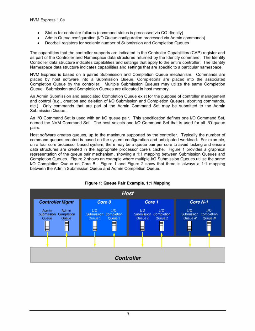
Status for controller failures (command status is processed via CQ directly) Admin Queue configuration (I/O Queue configuration processed via Admin commands) Doorbell registers for scalable number of Submission and Completion Queues
The capabilities that the controller supports are indicated in the Controller Capabilities (CAP) register and as part of the Controller and Namespace data structures returned by the Identify command. The Identify Controller data structure indicates capabilities and settings that apply to the entire controller. The Identify Namespace data structure indicates capabilities and settings that are specific to a particular namespace.
NVM Express is based on a paired Submission and Completion Queue mechanism. Commands are placed by host software into a Submission Queue. Completions are placed into the associated Completion Queue by the controller. Multiple Submission Queues may utilize the same Completion Queue. Submission and Completion Queues are allocated in host memory.
An Admin Submission and associated Completion Queue exist for the purpose of controller management and control (e.g., creation and deletion of I/O Submission and Completion Queues, aborting commands, etc.) Only commands that are part of the Admin Command Set may be submitted to the Admin Submission Queue.
An I/O Command Set is used with an I/O queue pair. This specification defines one I/O Command Set, named the NVM Command Set. The host selects one I/O Command Set that is used for all I/O queue pairs.
Host software creates queues, up to the maximum supported by the controller. Typically the number of command queues created is based on the system configuration and anticipated workload. For example, on a four core processor based system, there may be a queue pair per core to avoid locking and ensure data structures are created in the appropriate processor core’s cache. Figure 1 provides a graphical representation of the queue pair mechanism, showing a 1:1 mapping between Submission Queues and Completion Queues. Figure 2 shows an example where multiple I/O Submission Queues utilize the same I/O Completion Queue on Core B. Figure 1 and Figure 2 show that there is always a 1:1 mapping between the Admin Submission Queue and Admin Completion Queue.
Figure 1: Queue Pair Example, 1:1 Mapping
Host
Controller
Controller Mgmt Core 0 Core 1 Core N-1Admin
SubmissionQueue
AdminCompletion
Queue
I/OSubmission
Queue 1
I/OCompletion
Queue 1
I/OSubmission
Queue 2
I/OCompletion
Queue 2
I/OSubmissionQueue N
I/OCompletionQueue N

NVM Express 1.0e
10
Figure 2: Queue Pair Example, n:1 Mapping
A Submission Queue (SQ) is a circular buffer with a fixed slot size that the host software uses to submit commands for execution by the controller. The host software updates the appropriate SQ Tail doorbell register when there are one to n new commands to execute. The previous SQ Tail value is overwritten in the controller when there is a new doorbell register write. The controller fetches SQ entries in order from the Submission Queue, however, it may then execute those commands in any order.
Each Submission Queue entry is a command. Commands are 64 bytes in size. The physical memory locations in host memory to use for data transfers are specified using Physical Region Page (PRP) entries. Each command may include two PRP entries. If more than two PRP entries are necessary to describe the data buffer, then a pointer to a PRP List that describes a list of PRP entries is provided.
A Completion Queue (CQ) is a circular buffer with a fixed slot size used to post status for completed commands. A completed command is uniquely identified by a combination of the associated SQ identifier and command identifier that is assigned by host software. Multiple Submission Queues may be associated with a single Completion Queue. This feature may be used where a single worker thread processes all command completions via one Completion Queue even when those commands originated from multiple Submission Queues. The CQ Head pointer is updated by host software after it has processed completion queue entries indicating the last free CQ entry. A Phase (P) bit is defined in the completion queue entry to indicate whether an entry has been newly posted without consulting a register. This enables host software to determine whether the new entry was posted as part of the previous or current round of completion notifications. Specifically, each round through the Completion Queue entries, the controller inverts the Phase bit.
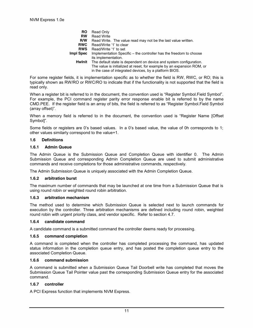
1.5 Conventions Hardware shall return ‘0’ for all bits and registers that are marked as reserved, and host software shall write all reserved bits and registers with the value of ‘0’.
Inside the register section, the following abbreviations are used:
Host
Controller
Core BCore AI/O
SubmissionQueue X
I/OCompletionQueue W
I/OSubmissionQueue M
I/OCompletionQueue N
I/OSubmissionQueue Y
I/OSubmissionQueue Z
Controller MgmtAdmin
SubmissionQueue
AdminCompletion
Queue
NVM Express 1.0e
11
RO Read Only RW Read Write
R/W Read Write. The value read may not be the last value written. RWC Read/Write ‘1’ to clear RWS Read/Write ‘1’ to set
Impl Spec Implementation Specific – the controller has the freedom to choose its implementation.
HwInit The default state is dependent on device and system configuration. The value is initialized at reset, for example by an expansion ROM, or in the case of integrated devices, by a platform BIOS.
For some register fields, it is implementation specific as to whether the field is RW, RWC, or RO; this is typically shown as RW/RO or RWC/RO to indicate that if the functionality is not supported that the field is read only.
When a register bit is referred to in the document, the convention used is “Register Symbol.Field Symbol”. For example, the PCI command register parity error response enable bit is referred to by the name CMD.PEE. If the register field is an array of bits, the field is referred to as “Register Symbol.Field Symbol (array offset)”.
When a memory field is referred to in the document, the convention used is “Register Name [Offset Symbol]”.
Some fields or registers are 0’s based values. In a 0’s based value, the value of 0h corresponds to 1;; other values similarly correspond to the value+1.
1.6 Definitions 1.6.1 Admin Queue The Admin Queue is the Submission Queue and Completion Queue with identifier 0. The Admin Submission Queue and corresponding Admin Completion Queue are used to submit administrative commands and receive completions for those administrative commands, respectively.
The Admin Submission Queue is uniquely associated with the Admin Completion Queue.
1.6.2 arbitration burst The maximum number of commands that may be launched at one time from a Submission Queue that is using round robin or weighted round robin arbitration.
1.6.3 arbitration mechanism The method used to determine which Submission Queue is selected next to launch commands for execution by the controller. Three arbitration mechanisms are defined including round robin, weighted round robin with urgent priority class, and vendor specific. Refer to section 4.7.
1.6.4 candidate command A candidate command is a submitted command the controller deems ready for processing.
1.6.5 command completion A command is completed when the controller has completed processing the command, has updated status information in the completion queue entry, and has posted the completion queue entry to the associated Completion Queue.
1.6.6 command submission A command is submitted when a Submission Queue Tail Doorbell write has completed that moves the Submission Queue Tail Pointer value past the corresponding Submission Queue entry for the associated command.
1.6.7 controller A PCI Express function that implements NVM Express.

NVM Express 1.0e
12
1.6.8 extended LBA An extended LBA is a larger LBA that is created when metadata associated with the LBA is transferred contiguously with the LBA data. Refer to Figure 140.
1.6.9 firmware slot A firmware slot is a location in the controller used to store a firmware image. The controller stores between one and seven firmware images. When downloading new firmware to the controller, host software has the option of specifying which image is replaced by indicating the firmware slot number.
1.6.10 I/O Completion Queue An I/O Completion Queue is a Completion Queue that is used to indicate command completions and is associated with one or more I/O Submission Queues. I/O Completion Queue identifiers are from 1 to 65535.
1.6.11 I/O Submission Queue An I/O Submission Queue is a Submission Queue that is used to submit I/O commands for execution by the controller (e.g. Read, Write for the NVM command set). I/O Submission Queue identifiers are from 1 to 65535.
1.6.12 LBA range A collection of contiguous logical blocks specified by a starting LBA and number of logical blocks.
1.6.13 logical block The smallest addressable data unit for Read and Write commands.
1.6.14 logical block address (LBA) The address of a logical block, referred to commonly as LBA.
1.6.15 metadata Metadata is contextual information about a particular LBA of data. The host may include metadata to be stored by the NVM subsystem if storage space is provided by the controller.
1.6.16 namespace A namespace is a collection of logical blocks that range from 0 to the capacity of the namespace – 1. A namespace may or may not have a relationship to a Submission Queue; this relationship is determined by the host software implementation. The controller supports access to any valid namespace from any I/O Submission Queue.
1.6.17 NVM NVM is an acronym for non-volatile memory.
1.6.18 NVM subsystem The NVM subsystem includes the controller, a non-volatile memory storage medium, and an interface between the controller and non-volatile memory storage medium.
1.7 Keywords Several keywords are used to differentiate between different levels of requirements.
1.7.1 mandatory A keyword indicating items to be implemented as defined by this specification.
1.7.2 may A keyword that indicates flexibility of choice with no implied preference.

NVM Express 1.0e
13
1.7.3 optional A keyword that describes features that are not required by this specification. However, if any optional feature defined by the specification is implemented, the feature shall be implemented in the way defined by the specification.
1.7.4 R “R” is used as an abbreviation for “reserved” when the figure or table does not provide sufficient space for the full word “reserved”.
1.7.5 reserved A keyword indicating reserved bits, bytes, words, fields, and opcode values that are set-aside for future standardization. Their use and interpretation may be specified by future extensions to this or other specifications. A reserved bit, byte, word, field, or register shall be cleared to zero, or in accordance with a future extension to this specification. The recipient shall not check reserved bits, bytes, words, or fields.
1.7.6 shall A keyword indicating a mandatory requirement. Designers are required to implement all such mandatory requirements to ensure interoperability with other products that conform to the specification.
1.7.7 should A keyword indicating flexibility of choice with a strongly preferred alternative. Equivalent to the phrase “it is recommended”.
1.8 Conventions A 0-based value is a numbering scheme for which the number 0h actually corresponds to a value of 1h and thus produces the pattern of 0h = 1h, 1h = 2h, 2h = 3h, etc. In this numbering scheme, there is not a method for specifying the value of 0h.
Some parameters are defined as a string of ASCII characters. ASCII data fields shall contain only code values 20h through 7Eh. For the string “Copyright”, the character “C” is the first byte, the character “o” is the second byte, etc. The string is left justified and shall be padded with spaces (ASCII character 20h) to the right if necessary.

NVM Express 1.0e
14
1.9 Byte, word and Dword Relationships Figure 3 illustrates the relationship between bytes, words and Dwords. A Qword (quadruple word) is a unit of data that is four times the size of a word; it is not illustrated due to space constraints. This specification specifies data in a little endian format.
Figure 3: Byte, word and Dword Relationships
7
6
5
4
3
2
1
0
byte
15
14
13
12
11
10
9
8
7
6
5
4
3
2
1
0
word
byte 1 byte 0
31
30
29
28
27
26
25
24
23
22
21
20
19
18
17
16
15
14
13
12
11
10
9
8
7
6
5
4
3
2
1
0
Dword
word 1 word 0
byte 3 byte 2 byte 1 byte 0
1.10 References
PCI specification, revision 3.0. Available from http://www.pcisig.com.
PCI Express specification, revision 2.1. Available from http://www.pcisig.com.

NVM Express 1.0e
15
PCI Power Management specification. Available from http://www.pcisig.com. PCI Single Root I/O Virtualization, revision 1.1. Available from
http://www.pcisig.com/specifications/iov/single_root/. PCI Firmware 3.0 specification. Available from http://www.pcisig.com. UEFI 2.3.1 specification. Available from http://www.uefi.org. Trusted Computing Group Storage Architecture Core specification. Available from
http://www.trustedcomputinggroup.org. JEDEC JESD218: Solid State Drive (SSD) Requirements and Endurance Test Method standard.
Available from http://www.jedec.org.
1.11 References Under Development ATA/ATAPI Command Set - 2 (ACS-2) [INCITS T13/2015-D]. Available from http://www.t13.org.
ISO/IEC 14776-323, SCSI Block Commands - 3 (SBC-3) [T10/1799-D]. Available from http://www.t10.org.
ISO/IEC 14776-454, SCSI Primary Commands - 4 (SPC-4) [T10/1731-D] Available from http://www.t10.org.
Trusted Computing Group Storage Interface Interactions Specification (SIIS). Available from http://www.trustedcomputinggroup.org.

NVM Express 1.0e
16
2 System Bus (PCI Express) Registers This section describes the PCI Express register values when the PCI Express is the system bus used. Other system buses may be used in an implementation. If a system bus is used that is not a derivative of PCI, then this section is not applicable.
This section details how the PCI Header, PCI Capabilities, and PCI Express Extended Capabilities should be constructed for an NVM Express device. The fields shown are duplicated from the appropriate PCI or PCI Express specifications. The PCI documents are the normative specifications for these registers and this section details additional requirements for an NVM Express device.
Start End Name Type 00h 3Fh PCI Header
PMCAP PMCAP+7h PCI Power Management Capability PCI Capability MSICAP MSICAP+9h Message Signaled Interrupt Capability PCI Capability
MSIXCAP MSIXCAP+Bh MSI-X Capability PCI Capability PXCAP PXCAP+29h PCI Express Capability PCI Capability
AERCAP AERCAP+47h Advanced Error Reporting Capability PCI Express Extended Capability
MSI-X is the recommended interrupt mechanism to use. However, some systems do not support MSI-X, thus devices should support both the MSI Capability and the MSI-X Capability.
It is recommended that implementations support the Advanced Error Reporting Capability to enable more robust error handling.
2.1 PCI Header Start End Symbol Name 00h 03h ID Identifiers 04h 05h CMD Command Register 06h 07h STS Device Status 08h 08h RID Revision ID 09h 0Bh CC Class Codes 0Ch 0Ch CLS Cache Line Size 0Dh 0Dh MLT Master Latency Timer 0Eh 0Eh HTYPE Header Type 0Fh 0Fh BIST Built In Self Test (Optional)
10h 13h MLBAR (BAR0) Memory Register Base Address, lower 32-bits <BAR0>
14h 17h MUBAR (BAR1) Memory Register Base Address, upper 32-bits <BAR1>
18h 1Bh IDBAR (BAR2)
Index/Data Pair Register Base Address <BAR2> (Optional)
1Ch 1Fh BAR3 Reserved <BAR3> 20h 23h BAR4 Vendor Specific 24h 27h BAR5 Vendor Specific 28h 2Bh CCPTR CardBus CIS Pointer 2Ch 2Fh SS Subsystem Identifiers 30h 33h EROM Expansion ROM Base Address (Optional) 34h 34h CAP Capabilities Pointer 35h 3Bh R Reserved 3Ch 3Dh INTR Interrupt Information 3Eh 3Eh MGNT Minimum Grant (Optional) 3Fh 3Fh MLAT Maximum Latency (Optional)
NVM Express 1.0e
17
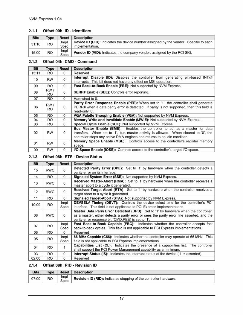
2.1.1 Offset 00h: ID - Identifiers Bits Type Reset Description
31:16 RO Impl Spec
Device ID (DID): Indicates the device number assigned by the vendor. Specific to each implementation.
15:00 RO Impl Spec Vendor ID (VID): Indicates the company vendor, assigned by the PCI SIG.
2.1.2 Offset 04h: CMD - Command Bit Type Reset Description
15:11 RO 0 Reserved
10 RW 0 Interrupt Disable (ID): Disables the controller from generating pin-based INTx# interrupts. This bit does not have any effect on MSI operation.
09 RO 0 Fast Back-to-Back Enable (FBE): Not supported by NVM Express.
08 RW / RO 0 SERR# Enable (SEE): Controls error reporting.
07 RO 0 Hardwired to 0.
06 RW / RO 0
Parity Error Response Enable (PEE): When set to ‘1’, the controller shall generate PERR# when a data parity error is detected. If parity is not supported, then this field is read-only ‘0’.
05 RO 0 VGA Palette Snooping Enable (VGA): Not supported by NVM Express. 04 RO 0 Memory Write and Invalidate Enable (MWIE): Not supported by NVM Express. 03 RO 0 Special Cycle Enable (SCE): Not supported by NVM Express.
02 RW 0 Bus Master Enable (BME): Enables the controller to act as a master for data transfers. When set to ‘1’, bus master activity is allowed. When cleared to ‘0’, the controller stops any active DMA engines and returns to an idle condition.
01 RW 0 Memory Space Enable (MSE): Controls access to the controller’s register memory space.
00 RW 0 I/O Space Enable (IOSE): Controls access to the controller’s target I/O space.
2.1.3 Offset 06h: STS - Device Status Bit Type Reset Description
15 RWC 0 Detected Parity Error (DPE): Set to ‘1’ by hardware when the controller detects a parity error on its interface.
14 RO 0 Signaled System Error (SSE): Not supported by NVM Express.
13 RWC 0 Received Master-Abort (RMA): Set to ‘1’ by hardware when the controller receives a master abort to a cycle it generated.
12 RWC 0 Received Target Abort (RTA): Set to ‘1’ by hardware when the controller receives a target abort to a cycle it generated.
11 RO 0 Signaled Target-Abort (STA): Not supported by NVM Express.
10:09 RO Impl Spec
DEVSEL# Timing (DEVT): Controls the device select time for the controller’s PCI interface. This field is not applicable to PCI Express implementations.
08 RWC 0 Master Data Pariy Error Detected (DPD): Set to ‘1’ by hardware when the controller, as a master, either detects a parity error or sees the parity error line asserted, and the parity error response bit (CMD.PEE) is set to ‘1’.
07 RO Impl Spec
Fast Back-to-Back Capable (FBC): Indicates whether the controller accepts fast back-to-back cycles. This field is not applicable to PCI Express implementations.
06 RO 0 Reserved
05 RO Impl Spec
66 MHz Capable (C66): Indicates whether the controller may operate at 66 MHz. This field is not applicable to PCI Express implementations.
04 RO 1 Capabilities List (CL): Indicates the presence of a capabilities list. The controller shall support the PCI Power Management capability as a minimum.
03 RO 0 Interrupt Status (IS): Indicates the interrupt status of the device (‘1’ = asserted). 02:00 RO 0 Reserved
2.1.4 Offset 08h: RID - Revision ID Bits Type Reset Description
07:00 RO Impl Spec Revision ID (RID): Indicates stepping of the controller hardware.

NVM Express 1.0e
18
2.1.5 Offset 09h: CC - Class Code Bits Type Reset Description
23:16 RO 01h Base Class Code (BCC): Indicates the base class code as a mass storage controller.
15:08 RO 08h Sub Class Code (SCC): Indicates the sub class code as a Non-Volatile Memory controller.
07:00 RO 02h Programming Interface (PI): This field specifies the programming interface of the controller is NVM Express. (Note: The PCI SIG documentation refers to this as Enterprise NVMHCI.)
2.1.6 Offset 0Ch: CLS – Cache Line Size Bits Type Reset Description
07:00 RW 00h Cache Line Size (CLS): Cache Line Size register is set by the system firmware or operating system to the system cache size.
2.1.7 Offset 0Dh: MLT – Master Latency Timer Bits Type Reset Description
07:00 RO 00h Master Latency Timer (MLT): Indicates the number of clocks the controller is allowed to act as a master on PCI. For a PCI Express device, this register does not apply and shall be hardwired to ‘0’.
2.1.8 Offset 0Eh: HTYPE – Header Type Bits Type Reset Description 07 RO Impl
Spec Multi-Function Device (MFD): Indicates whether the controller is part of a multi-function device.
06:00 RO 00h Header Layout (HL): Indicates that the controller uses a target device layout.
2.1.9 Offset 0Fh: BIST – Built In Self Test (Optional) The following register is optional, but if implemented, shall look as follows. When not implemented, it shall be read-only 00h.
Bits Type Reset Description
07 RO Impl Spec BIST Capable (BC): Indicates whether the controller has a BIST function.
06 RW 0 Start BIST (SB): Host software sets this bit to ‘1’ to invoke BIST. The controller clears this bit to ‘0’ when BIST is complete.
05:04 RO 00 Reserved
03:00 RO 0h Completion Code (CC): Indicates the completion code status of BIST. A non-zero value indicates a failure.
2.1.10 Offset 10h: MLBAR (BAR0) – Memory Register Base Address, lower 32-bits This register allocates space for the memory registers defined in section 3.
Bit Type Reset Description
31:14 RW 0
Base Address (BA): Base address of register memory space. For controllers that support a larger number of doorbell registers or have vendor specific space following the doorbell registers, more bits are allowed to be RO such that more memory space is consumed.
13:04 RO 0 Reserved 03 RO 0 Prefetchable (PF): Indicates that this range is not pre-fetchable
02:01 RO 10 Type (TP): Indicates that this range may be mapped anywhere in 64-bit address space and that the register is 64-bits wide.
00 RO 0 Resource Type Indicator (RTE): Indicates a request for register memory space.
2.1.11 Offset 14h: MUBAR (BAR1) – Memory Register Base Address, upper 32-bits This register specifies the upper 32-bit address of the memory registers defined in section 3.
Bit Type Reset Description 31:00 RW 0 Base Address (BA): Upper 32-bits (bits 63:32) of the memory register base address.

NVM Express 1.0e
19
NOTE: NVM Express implementations that reside behind PCI compliant bridges, such as PCI Express Endpoints, are restricted to having 32-bit assigned base address registers due to limitations on the maximum address that may be specified in the bridge for non-prefetchable memory. See the PCI Bridge 1.2 specification for more information on this restriction.
2.1.12 Offset 18h: IDBAR (BAR2) – Index/Data Pair Register Base Address (Optional) This register specifies the Index/Data Pair base address. These registers are used to access the memory registers defined in section 3 using I/O based accesses. If Index/Data Pair is not supported, then the IDBAR shall be read only 0h.
Bit Type Reset Description 31:03 RW 0 Base Address (BA): Base address of Index/Data Pair registers that is 8 bytes in size. 02:01 RO 0 Reserved
00 RO 1 Resource Type Indicator (RTE): Indicates a request for register I/O space.
2.1.13 Offset 1Ch – 20h: BAR3 –Reserved The BAR3 register allocates memory or an I/O space. BAR3 is reserved for future use.
2.1.14 Offset 20h – 23h: BAR4 – Vendor Specific The BAR4 register is vendor specific. Vendor specific space may also be allocated at the end of the memory registers defined in section 3.
2.1.15 Offset 24h – 27h: BAR5 – Vendor Specific The BAR5 register is vendor specific. Vendor specific space may also be allocated at the end of the memory registers defined in section 3.
2.1.16 Offset 28h: CCPTR – CardBus CIS Pointer Bit Type Reset Description
31:00 RO 0 Not supported by NVM Express.
2.1.17 Offset 2Ch: SS - Sub System Identifiers Bits Type Reset Description
31:16 RO HwInit Subsystem ID (SSID): Indicates the sub-system identifier. 15:00 RO HwInit Subsystem Vendor ID (SSVID): Indicates the sub-system vendor identifier
2.1.18 Offset 30h: EROM – Expansion ROM (Optional) If the register is not implemented, it shall be read-only 00h.
Bit Type Reset Description
31:00 RW Impl Spec
ROM Base Address (RBA): Indicates the base address of the controller’s expansion ROM. Not supported for integrated implementations.
2.1.19 Offset 34h: CAP – Capabilities Pointer Bit Type Reset Description
7:0 RO PMCAP Capability Pointer (CP): Indicates the first capability pointer offset. It points to the PCI Power Management capability offset.
2.1.20 Offset 3Ch: INTR - Interrupt Information Bits Type Reset Description
15:08 RO Impl Spec Interrupt Pin (IPIN): This indicates the interrupt pin the controller uses.
07:00 RW 00h Interrupt Line (ILINE): Host software written value to indicate which interrupt line (vector) the interrupt is connected to. No hardware action is taken on this register.
2.1.21 Offset 3Eh: MGNT – Minimum Grant Bits Type Reset Description
07:00 RO 00h Grant (GNT): Not supported by NVM Express.

NVM Express 1.0e
20
2.1.22 Offset 3Fh: MLAT – Maximum Latency Bits Type Reset Description
07:00 RO 00h Latency (LAT): Not supported by NVM Express.
2.2 PCI Power Management Capabilities See section 3.1.5 for requirements when the PCI power management state changes.
Start (hex) End (hex) Symbol Name
PMCAP PMCAP+1 PID PCI Power Management Capability ID PMCAP+2 PMCAP+3 PC PCI Power Management Capabilities PMCAP+4 PMCAP+5 PMCS PCI Power Management Control and Status
2.2.1 Offset PMCAP: PID - PCI Power Management Capability ID Bit Type Reset Description
15:08 RO Impl Spec
Next Capability (NEXT): Indicates the location of the next capability item in the list. This may be other capability pointers (such as Message Signaled Interrupts) or it may be the last item in the list.
07:00 RO 01h Cap ID (CID): Indicates that this pointer is a PCI Power Management capability.
2.2.2 Offset PMCAP + 2h: PC – PCI Power Management Capabilities Bit Type Reset Description
15:11 RO 0h PME_Support (PSUP): Not supported by NVM Express.
10 RO 0 D2_Support (D2S): Indicates support for the D2 power management state. Not recommended for implementation.
09 RO 0 D1_Support (D1S): Indicates support for the D1 power management state. Not recommended for implementation.
08:06 RO 000 Aux_Current (AUXC): Not supported by NVM Express.
05 RO Impl Spec
Device Specific Initialization (DSI): Indicates whether device specific initialization is required.
04 RO 0 Reserved 03 RO 0 PME Clock (PMEC): Indicates that PCI clock is not required to generate PME#.
02:00 RO Impl Spec
Version (VS): Indicates support for revision 1.2 or higher revisions of the PCI Power Management Specification.
2.2.3 Offset PMCAP + 4h: PMCS – PCI Power Management Control and Status Bit Type Reset Description 15 RO 0 PME Status (PMES): Not supported by NVM Express.
14:13 RO 0 Data Scale (DSC): Not supported by NVM Express. 12:09 RO 0 Data Select (DSE): Not supported by NVM Express.
08 RO 0 PME Enable (PMEE): Not supported by NVM Express. 07:04 RO 0 Reserved
03 RO 1 No Soft Reset (NSFRST): A value of ‘1’ indicates that the controller transitioning from D3hot to D0 because of a power state command does not perform an internal reset.
02 RO 0 Reserved
01:00 R/W 00
Power State (PS): This field is used both to determine the current power state of the controller and to set a new power state. The values are:
00 – D0 state 01 – D1 state 10 – D2 state 11 – D3HOT state
When in the D3HOT state, the controller’s configuration space is available, but the register I/O and memory spaces are not. Additionally, interrupts are blocked.

NVM Express 1.0e
21
2.3 Message Signaled Interrupt Capability (Optional) Start (hex) End (hex) Symbol Name MSICAP MSICAP+1 MID Message Signaled Interrupt Capability ID
MSICAP+2 MSICAP+3 MC Message Signaled Interrupt Message Control MSICAP+4 MSICAP+7 MA Message Signaled Interrupt Message Address MSICAP+8 MSICAP+B MUA Message Signaled Interrupt Upper Address MSICAP+C MSICAP+D MD Message Signaled Interrupt Message Data
MSICAP+10h MSICAP+13h MMASK Message Signaled Interrupt Mask Bits (Optional) MSICAP+14h MSICAP+17h MPEND Message Signaled Interrupt Pending Bits (Optional)
2.3.1 Offset MSICAP: MID – Message Signaled Interrupt Identifiers Bits Type Reset Description
15:08 RO Impl Spec
Next Pointer (NEXT): Indicates the next item in the list. This may be other capability pointers or it may be the last item in the list.
07:00 RO 05h Capability ID (CID): Capabilities ID indicates this is a Message Signaled Interrupt (MSI) capability.
2.3.2 Offset MSICAP + 2h: MC – Message Signaled Interrupt Message Control Bits Type Reset Description
15:09 RO 0 Reserved
08 RO Impl Spec
Per-Vector Masking Capable (PVM): Specifies whether controller supports MSI per-vector masking.
07 RO 1 64 Bit Address Capable (C64): Specifies whether the controller is capable of generating 64-bit messages. NVM Express controllers shall be 64-bit capable.
06:04 RW 000 Multiple Message Enable (MME): Indicates the number of messages the controller should assert. Controllers that only support single message MSI may implement this field as read-only.
03:01 RO Impl Spec
Multiple Message Capable (MMC): Indicates the number of messages the controller wants to assert.
00 RW 0 MSI Enable (MSIE): If set to ‘1’, MSI is enabled and the traditional interrupt pins are not used to generate interrupts. If cleared to ‘0’, MSI operation is disabled and the traditional interrupt pins are used.
2.3.3 Offset MSICAP + 4h: MA – Message Signaled Interrupt Message Address Bits Type Reset Description
31:02 RW 0 Address (ADDR): Lower 32 bits of the system specified message address, always Dword aligned.
01:00 RO 00 Reserved
2.3.4 Offset MSICAP + 8h: MUA – Message Signaled Interrupt Upper Address Bits Type Reset Description
31:00 RW 0 Upper Address (UADDR): Upper 32 bits of the system specified message address. This register is required when the MSI Capability is supported by the controller.
2.3.5 Offset MSICAP + Ch: MD – Message Signaled Interrupt Message Data Bits Type Reset Description
15:00 RW 0 Data (DATA): This 16-bit field is programmed by system software if MSI is enabled. Its content is driven onto the lower word (PCI AD[15:0]) during the data phase of the MSI memory write transaction.
2.3.6 Offset MSICAP + 10h: MMASK – Message Signaled Interrupt Mask Bits (Optional) Bits Type Reset Description
31:00 RW 0 Mask Bits (MASK): For each Mask bit that is set to ‘1’, the function is prohibited from sending the associated message.
2.3.7 Offset MSICAP + 14h: MPEND – Message Signaled Interrupt Pending Bits (Optional) Bits Type Reset Description
31:00 RW 0 Pending Bits (PEND): For each Pending bit that is set to ‘1’, the function has a

NVM Express 1.0e
22
pending associated message.
2.4 MSI-X Capability (Optional) Start (hex) End (hex) Symbol Name MSIXCAP MSIXCAP+1 MXID MSI-X Capability ID
MSIXCAP+2 MSIXCAP+3 MXC MSI-X Message Control MSIXCAP+4 MSIXCAP+7 MTAB MSI-X Table Offset and Table BIR MSIXCAP+8 MSIXCAP+B MPBA MSI-X PBA Offset and PBA BIR
Note: It is recommended that the controller allocate a unique MSI-X vector for each Completion Queue.
The Table BIR and PBA BIR data structures may be allocated in either BAR0-1 or BAR4-5 in implementations. These tables should be 4KB aligned. The memory page(s) that comprise the Table BIR and PBA BIR shall not include other registers/structures. It is recommended that these structures be allocated in BAR0-1 following the Submission Queue and Completion Queue Doorbell registers. Refer to the PCI reference for more information on allocation requirements for these data structures.
2.4.1 Offset MSIXCAP: MXID – MSI-X Identifiers
Bits Type Reset Description
15:08 RO Impl Spec
Next Pointer (NEXT): Indicates the next item in the list. This may be other capability pointers or it may be the last item in the list.
07:00 RO 11h Capability ID (CID): Capabilities ID indicates this is an MSI-X capability.
2.4.2 Offset MSIXCAP + 2h: MXC – MSI-X Message Control Bits Type Reset Description
15 RW 0
MSI-X Enable (MXE): If set to ‘1’ and the MSI Enable bit in the MSI Message Control register is cleared to ‘0’, the function is permitted to use MSI-X to request service and is prohibited from using its INTx# pin (if implemented). If cleared to ‘0’, the function is prohibited from using MSI-X to request service.
14 RW 0
Function Mask (FM): If set to ‘1’, all of the vectors associated with the function are masked, regardless of their per vector Mask bit states. If cleared to ‘0’, each vector’s Mask bit determines whether the vector is masked or not. Setting or clearing the MSI-X Function Mask bit has no effect on the state of the per vector Mask bits.
13:11 RO 0h Reserved
10:00 RO Impl Spec
Table Size (TS): This value indicates the size of the MSI-X Table as the value n, which is encoded as n - 1. For example, a returned value of 3h corresponds to a table size of 4.
2.4.3 Offset MSIXCAP + 4h: MTAB – MSI-X Table Offset / Table BIR Bits Type Reset Description
31:03 RO Impl Spec
Table Offset (TO): Used as an offset from the address contained by one of the function’s Base Address registers to point to the base of the MSI-X Table. The lower three Table BIR bits are masked off (cleared to 000b) by system software to form a 32-bit Qword-aligned offset.
02:00 RO Impl Spec
Table BIR (TBIR): This field indicates which one of a function’s Base Address registers, located beginning at 10h in Configuration Space, is used to map the function’s MSI-X Table into system memory.
BIR Value BAR Offset 0 10h 1 na 2 na 3 Reserved 4 20h 5 24h 6 Reserved

NVM Express 1.0e
23
7 Reserved For a 64-bit Base Address register, the Table BIR indicates the lower Dword. With PCI-to-PCI bridges, BIR values 2 through 5 are also reserved.
2.4.4 Offset MSIXCAP + 8h: MPBA – MSI-X PBA Offset / PBA BIR Bits Type Reset Description
31:03 RO Impl Spec
PBA Offset (PBAO): Used as an offset from the address contained by one of the function’s Base Address registers to point to the base of the MSI-X PBA. The lower three PBA BIR bits are masked off (cleared to 000b) by software to form a 32-bit Qword-aligned offset.
02:00 RO Impl Spec
PBA BIR (PBIR): This field indicates which one of a function’s Base Address registers, located beginning at 10h in Configuration Space, is used to map the function’s MSI-X PBA into system memory.
BIR Value BAR Offset 0 10h 1 na 2 na 3 Reserved 4 20h 5 24h 6 Reserved 7 Reserved
2.5 PCI Express Capability (Optional) The PCI Express Capability definitions below are based on the PCI Express 2.1 Base specification. Implementations may choose to base the device on a specification beyond the PCI Express 2.1 Base specification. In all cases, the PCI Express Base specification is the normative reference for the PCI Express Capability registers.
Note: TLP poisoning is a mandatory capability for PCI Express implementations. There are optional features of TLP poisoning, such as TLP poisoning for a transmitter. When an NVM Express device has an error on a transmission to the host (e.g., error for a Read command), the error should be indicated as part of the NVM Express command status and not via TLP poisoning.
Start (hex) End (hex) Symbol Name
PXCAP PXCAP+1 PXID PCI Express Capability ID PXCAP+2 PXCAP+3 PXCAP PCI Express Capabilities PXCAP+4 PXCAP+7 PXDCAP PCI Express Device Capabilities PXCAP+8 PXCAP+9 PXDC PCI Express Device Control PXCAP+A PXCAP+B PXDS PCI Express Device Status PXCAP+C PXCAP+F PXLCAP PCI Express Link Capabilities
PXCAP+10h PXCAP+11h PXLC PCI Express Link Control PXCAP+12h PXCAP+13h PXLS PCI Express Link Status PXCAP+24h PXCAP+27h PXDCAP2 PCI Express Device Capabilities 2 PXCAP+28h PXCAP+29h PXDC2 PCI Express Device Control 2
2.5.1 Offset PXCAP: PXID – PCI Express Capability ID Bits Type Reset Description
15:8 RO Impl Spec
Next Pointer (NEXT): Indicates the next item in the list. This may be other capability pointers or it may be the last item in the list.
7:0 RO 10h Capability ID (CID): Indicates that this capability structure is a PCI Express capability.

NVM Express 1.0e
24
2.5.2 Offset PXCAP + 2h: PXCAP – PCI Express Capabilities Bits Type Reset Description
15:14 RO 00b Reserved
13:9 RO Impl Spec
Interrupt Message Number (IMN): This field indicates the MSI/MSI-X vector that is used for the interrupt message generated in association with any of the status bits of this Capability structure. There are no status bits that generate interrupts defined in this capability within this specification, thus this field is not used.
8 RO 0h Slot Implemented (SI): Not applicable for PCIe Express Endpoint devices.
7:4 RO 0h Device/Port Type (DPT): Indicates the specific type of this PCI Express function. This device shall be indicated as a PCI Express Endpoint.
3:0 RO 2h Capability Version (VER): Indicates that this capability structure is a PCI Express capability structure.
2.5.3 Offset PXCAP + 4h: PXDCAP – PCI Express Device Capabilities Bits Type Reset Description
31:29 RO 000b Reserved
28 RO 1b Function Level Reset Capability (FLRC): A value of ‘1’ indicates the Function supports the optional Function Level Reset mechanism. NVM Express devices shall support Function Level Reset.
27:26 RO 00b Captured Slot Power Limit Scale (CSPLS): Specifies the scale used for the Slot Power Limit Value.
25:18 RO 0h
Captured Slot Power Limit Value (CSPLV): In combination with the Slot Power Limit Scale value, specifies the upper limit on power supplied by the slot. Power limit (in Watts) is calculated by multiplying the value in this field by the value in the Slot Power Limit Scale field.
17:16 RO 00b Reserved
15 RO 1b Role-based Error Reporting (RER): When set to ‘1’, indicates that the Function implements role-based error reporting. This functionality is required.
14:12 RO 000b Reserved
11:9 RO Impl Spec
Endpoint L1 Acceptable Latency (L1L): This field indicates the acceptable latency that the Endpoint is able to withstand due to a transition from the L1 state to the L0 state.
08:06 RO Impl Spec
Endpoint L0s Acceptable Latency (L0SL): This field indicates the acceptable total latency that the Endpoint is able to withstand due to the transition from L0s state to the L0 state.
05 RO Impl Spec
Extended Tag Field Supported (ETFS): This field indicates the maximum supported size of the Tag field as a Requester.
04:03 RO Impl Spec
Phantom Functions Supported (PFS): This field indicates the support for use of unclaimed Function Numbers to extend the number of outstanding transactions allowed by logically combining unclaimed Function Numbers with the Tag identifier.
02:00 RO Impl Spec
Max_Payload_Size Supported (MPS): This field indicates the maximum payload size that the function may support for TLPs.
2.5.4 Offset PXCAP + 8h: PXDC – PCI Express Device Control Bits Type Reset Description 15 R/W 0b Initiate Function Level Reset – A write of ‘1’ initiates Function Level Reset to the
Function. The value read by software from this bit shall always ‘0’.
14:12 RW/ RO
Impl Spec
Max_Read_Request_Size (MRRS): This field sets the maximum Read Request size for the Function as a Requester. The Function shall not generate Read Requests with size exceeding the set value.
11 RW/ RO 0
Enable No Snoop (ENS): If this field is set to ‘1’, the Function is permitted to set the No Snoop bit in the Requestor Attributes of transactions it initiates that do not require hardware enforced cache coherency. This field may be hardwired to ‘0’ if a Function would never set the No Snoop attribute in transactions it initiates.
10 RW/ RO 0
AUX Power PM Enable (APPME): If this field is set to ‘1’, enables a Function to draw AUX power independent of PME AUX power. Functions that do not implement this capability hardware this bit to 0b.
09 RW/ RO 0 Phantom Functions Enable (PFE): If this field is set to ‘1’, enables a Function to use
unclaimed Functions as Phantom Functions to extend the number of outstanding

NVM Express 1.0e
25
transaction identifiers. If this field is cleared to ‘0’, the Function is not allowed to use Phantom Functions.
08 RW/ RO 0
Extended Tag Enable (ETE): If this field is set to ‘1’, enables a Function to use an 8-bit Tag field as a Requester. If this field is cleared to ‘0’, the Function is restricted to a 5-bit Tag field.
07:05 RW/ RO 000b
Max_Payload_Size (MPS): This field sets the maximum TLP payload size for the Function. As a receiver, the Function shall handle TLPs as large as the set value. As a transmitter, the Function shall not generate TLPs exceeding the set value. Functions that support only the 128 byte max payload size are permitted to hardwire this field to 0h.
04 RW/ RO
Impl Spec
Enable Relaxed Ordering (ERO): If this field is set to ‘1’, the Function is permitted to set the Relaxed Ordering bit in the Attributes field of transactions it initiates that do not require strong write ordering.
03 RW 0 Unsupported Request Reporting Enable (URRE): This bit, in conjunction with other bits, controls the signaling of Unsupported Requests by sending error messages.
02 RW 0 Fatal Error Reporting Enable (FERE): This bit, in conjunction with other bits, controls the signaling of Unsupported Requests by sending ERR_FATAL messages.
01 RW 0 Non-Fatal Error Reporting Enable (NFERE): This bit, in conjunction with other bits, controls the signaling of Unsupported Requests by sending ERR_NONFATAL messages.
00 RW 0 Correctable Error Reporting Enable (CERE): This bit, in conjunction with other bits, controls the signaling of Unsupported Requests by sending ERR_COR messages.
2.5.5 Offset PXCAP + Ah: PXDS – PCI Express Device Status Bits Type Reset Description
15:06 RO 0h Reserved
05 RO 0
Transactions Pending (TP): When set to ‘1’ this bit indicates that the Function has issued non-posted requests that have not been completed. This bit is cleared to ‘0’ only when all outstanding non-posted requests have completed or have been terminated by the completion timeout mechanism. This bit shall also be cleared to ‘0’ upon completion of a Function Level Reset.
04 RO Impl Spec
AUX Power Detected (APD): Functions that require AUX power report this field as set to ‘1’ if AUX power is detected by the Function.
03 RWC 0 Unsupported Request Detected (URD): When set to ‘1’ this bit indicates that the function received an Unsupported Request. Errors are logged in this register regardless of whether error reporting is enabled in the Device Control register.
02 RWC 0 Fatal Error Detected (FED): When set to ‘1’ this bit indicates that the status of fatal errors detected. Errors are logged in this register regardless of whether error reporting is enabled in the Device Control register.
01 RWC 0 Non-Fatal Error Detected (NFED): When set to ‘1’ this bit indicates that the status of non-fatal errors detected. Errors are logged in this register regardless of whether error reporting is enabled in the Device Control register.
00 RWC 0 Correctable Error Detected (CED): When set to ‘1’ this bit indicates status of correctable errors detected. Errors are logged in this register regardless of whether error reporting is enabled in the Device Control register.
2.5.6 Offset PXCAP + Ch: PXLCAP – PCI Express Link Capabilities Bits Type Reset Description
31:24 RO HwInit Port Number (PN): This field specifies the PCI Express port number for this device. 23 RO 0h Reserved
22 RO HwInit ASPM Optionality Compliance (AOC): This field specifies Active State Power Management (ASPM) support.
21 RO 0 Link Bandwidth Notification Capability (LBNC): Not applicable to Endpoints.
20 RO 0 Data Link Layer Link Active Reporting Capable (DLLLA): Not applicable to Endpoints.
19 RO 0 Surprise Down Error Reporting Capable (SDERC): Not applicable to Endpoints.
18 RO Impl Spec
Clock Power Management (CPM): If this field is set to ‘1’, the component tolerates the removal of any reference clock(s) via the “clock request” (CLKREQ#) mechanism when the Link is in the L1 and L2/L3 Ready Link states. If this field is cleared to ‘0’, the component does not have this capability and that reference clock(s) shall not be

NVM Express 1.0e
26
removed in these Link states.
17:15 RO Impl Spec
L1 Exit Latency (L1EL): This field indicates the L1 exit latency for the given PCI Express Link. The value reported indicates the length of time this port requires to complete transition from L1 to L0.
14:12 RO Impl Spec
L0s Exit Latency (L0SEL): This field indicates the L0s exit latency for the given PCI Express Link. The value reported indicates the length of time this port requires to complete transition from L0s to L0.
11:10 RO Impl Spec
Active State Power Management Support (ASPMS): This field indicates the level of ASPM supported on the given PCI Express Link.
09:04 RO Impl Spec
Maximum Link Width (MLW): This field indicates the maximum Link width (xn – corresponding to n lanes) implemented by the component.
03:00 RO Impl Spec
Supported Link Speeds (SLS): This field indicates the supported Link speed(s) of the associated port.
2.5.7 Offset PXCAP + 10h: PXLC – PCI Express Link Control Bits Type Reset Description
15:10 RO 0h Reserved
09 RW/ RO 0h
Hardware Autonomous Width Disable (HAWD): When set to ‘1’, disables hardware from changing the Link width for reasons other than attempting to correct unreliable Link operation by reducing Link width. Components that do not implement the ability autonomously to change Link width are permitted to hardwire this bit to ‘0’.
08 RW 0
Enable Clock Power Management (ECPM): When cleared to ‘0’, clock power management is disabled and the device shall hold the CLKREQ# signal low. When set to ‘1’, the device is permitted to use the CLKREQ# signal to power manage the Link clock according to the protocol defined for mini PCI Express.
07 RW 0
Extended Synch (ES): When set to ‘1’, this bit forces the transmission of additional Ordered Sets when exiting the L0s state and when in the Recovery state. This mode provides external devices (e.g. logic analyzers) monitoring the Link time to achieve bit and symbol lock before the Link enters the L0 state and resumes communication.
06 RW 0
Common Clock Configuration (CCC): When set to ‘1’, this bit indicates that this component and the component at the opposite end of this Link are operating with a distributed common reference clock. When cleared to ‘0’ this component and the component at the opposite end of this Link are operating with asynchronous reference clocks.
05:04 RO 0h Reserved: These bits are reserved on Endpoints. 03 RW 0 Read Completion Boundary (RCB): Indicate the RCB value of the root port. 02 RO 0 Reserved
01:00 RW 0h Active State Power Management Control (ASPMC): This field controls the level of ASPM executed on the PCI Express Link.
2.5.8 Offset PXCAP + 12h: PXLS – PCI Express Link Status Bits Type Reset Description
15:13 RO 0h Reserved
12 RO Impl Spec
Slot Clock Configuration: If this bit is set to ‘1’, it indicates that the component uses the same physical reference clock that the platform provides on the connector. If the device uses an independent clock irrespective of a reference on the connector, this bit shall be cleared to ‘0’.
11:10 RO 0h Reserved
09:04 RO na Negotiated Link Width (NLW): This field indicates the negotiated Link width. This field is undefined when the Link is not up.
03:00 RO na Current Link Speed (CLS): This field indicates the negotiated Link speed. This field is undefined when the Link is not up.
2.5.9 Offset PXCAP + 24h: PXDCAP2 – PCI Express Device Capabilities 2 Bits Type Reset Description
31:24 RO 0h Reserved
23:22 RO Impl Spec
Max End-End TLP Prefixes (MEETP): Indicates the maximum number of End-End TLP Prefixes supported by this Function. TLPs received by this Function that contain more End-End TLP Prefixes than are supported shall be handled as Malformed TLPs.
21 RO Impl End-End TLP Prefix Supported (EETPS): Indicates whether End-End TLP Prefix

NVM Express 1.0e
27
Spec support is offered by a Function. If cleared to ‘0’, there is no support. If set to ‘1’, the Function supports receiving TLPs containing End-End TLP Prefixes.
20 RO Impl Spec
Extended Fmt Field Supported (EFFS): If set to ‘1’, the Function supports the 3-bit definition of the Fmt field. If cleared to ‘0’, the Function supports a 2-bit definition of the Fmt field.
19:18 RO Impl Spec OBFF Supported (OBFFS): This field indicates the level of support for OBFF.
17:14 RO 0h Reserved
13:12 RO Impl Spec
TPH Completer Supported (TPHCS): Defined encodings are listed in the following table.
Value Definition 00b TPH and Extended TPH Completer not supported
01b TPH Completer supported; Extended TPH Completer not supported
10b Reserved 11b Both TPH and Extended TPH Completer supported
11 RO Impl Spec
Latency Tolerance Reporting Supported (LTRS): If set to ‘1’, then the latency tolerance reporting mechanism is supported.
10 RO 0 No RO-enabled PR-PR Passing (NPRPR): Not applicable to NVM Express.
09 RO Impl Spec
128-bit CAS Completer Supported (128CCS): This bit shall be set to ‘1’ if the Function supports this optional capability.
08 RO Impl Spec
64-bit AtomicOp Completer Supported (64AOCS): Includes FetchAdd, Swap, and CAS AtomicOps. This bit shall be set to ‘1’ if the Function supports this optional capability.
07 RO Impl Spec
32-bit AtomicOp Completer Supported (32AOCS): Includes FetchAdd, Swap, and CAS AtomicOps. This bit shall be set to ‘1’ if the Function supports this optional capability.
06 RO 0 AtomicOp Routing Supported (AORS): Not applicable to NVM Express. 05 RO 0 ARI Forwarding Supported (ARIFS): Not applicable for NVM Express.
04 RO 1 Completion Timeout Disable Supported (CTDS): A value of ‘1’ indicates support for the Completion Timeout Disable mechanism. The Completion Timeout Disable mechanism is required for Endpoints that issue requests on their own behalf.
03:00 RO Impl Spec
Completion Timeout Ranges Supported (CTRS): This field indicates device function support for the optional Completion Timeout programmability mechanism.
2.5.10 Offset PXCAP + 28h: PXDC2 – PCI Express Device Control 2 Bits Type Reset Description
31:15 RO 0h Reserved
14:13 RW Impl Spec OBFF Enable (OBFFE): This field controls the capabilities enabled for OBFF.
12:11 RO 00b Reserved
10 RW 0 Latency Tolerance Reporting Mechanism Enable (LTRME): When set to ‘1’, enables the LTR mechanism. When cleared to ‘0’, the LTR mechanism is disabled.
09:05 RO 0h Reserved
04 RW 0 Completion Timeout Disable (CTD): When set to ‘1’, this bit disables the Completion Timeout mechanism.
03:00 RW/RO Impl Spec
Completion Timeout Value: Specifies the completion timeout value. If this feature is not supported in PXDCAP2, then this field is read only 0h.
2.6 Advanced Error Reporting Capability (Optional) The Advanced Error Reporting definitions below are based on the PCI Express 2.1 Base specification. Implementations may choose to base the device on a specification beyond the PCI Express 2.1 Base specification. In all cases, the PCI Express Base specification is the normative reference for the Advanced Error Reporting registers.
Start (hex) End (hex) Symbol Name
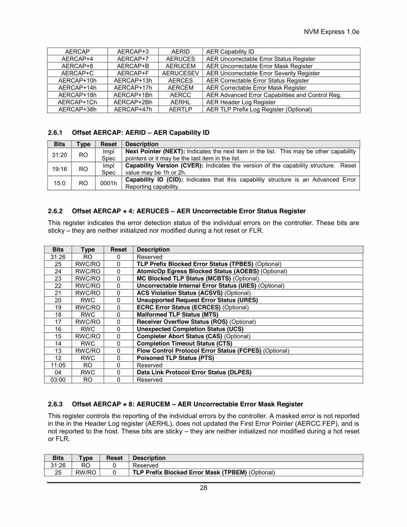
NVM Express 1.0e
28
AERCAP AERCAP+3 AERID AER Capability ID AERCAP+4 AERCAP+7 AERUCES AER Uncorrectable Error Status Register AERCAP+8 AERCAP+B AERUCEM AER Uncorrectable Error Mask Register AERCAP+C AERCAP+F AERUCESEV AER Uncorrectable Error Severity Register
AERCAP+10h AERCAP+13h AERCES AER Correctable Error Status Register AERCAP+14h AERCAP+17h AERCEM AER Correctable Error Mask Register AERCAP+18h AERCAP+1Bh AERCC AER Advanced Error Capabilities and Control Reg. AERCAP+1Ch AERCAP+2Bh AERHL AER Header Log Register AERCAP+38h AERCAP+47h AERTLP AER TLP Prefix Log Register (Optional)
2.6.1 Offset AERCAP: AERID – AER Capability ID Bits Type Reset Description
31:20 RO Impl Spec
Next Pointer (NEXT): Indicates the next item in the list. This may be other capability pointers or it may be the last item in the list.
19:16 RO Impl Spec
Capability Version (CVER): Indicates the version of the capability structure. Reset value may be 1h or 2h.
15:0 RO 0001h Capability ID (CID): Indicates that this capability structure is an Advanced Error Reporting capability.
2.6.2 Offset AERCAP + 4: AERUCES – AER Uncorrectable Error Status Register This register indicates the error detection status of the individual errors on the controller. These bits are sticky – they are neither initialized nor modified during a hot reset or FLR.
Bits Type Reset Description
31:26 RO 0 Reserved 25 RWC/RO 0 TLP Prefix Blocked Error Status (TPBES) (Optional) 24 RWC/RO 0 AtomicOp Egress Blocked Status (AOEBS) (Optional) 23 RWC/RO 0 MC Blocked TLP Status (MCBTS) (Optional) 22 RWC/RO 0 Uncorrectable Internal Error Status (UIES) (Optional) 21 RWC/RO 0 ACS Violation Status (ACSVS) (Optional) 20 RWC 0 Unsupported Request Error Status (URES) 19 RWC/RO 0 ECRC Error Status (ECRCES) (Optional) 18 RWC 0 Malformed TLP Status (MTS) 17 RWC/RO 0 Receiver Overflow Status (ROS) (Optional) 16 RWC 0 Unexpected Completion Status (UCS) 15 RWC/RO 0 Completer Abort Status (CAS) (Optional) 14 RWC 0 Completion Timeout Status (CTS) 13 RWC/RO 0 Flow Control Protocol Error Status (FCPES) (Optional) 12 RWC 0 Poisoned TLP Status (PTS)
11:05 RO 0 Reserved 04 RWC 0 Data Link Protocol Error Status (DLPES)
03:00 RO 0 Reserved
2.6.3 Offset AERCAP + 8: AERUCEM – AER Uncorrectable Error Mask Register This register controls the reporting of the individual errors by the controller. A masked error is not reported in the in the Header Log register (AERHL), does not updated the First Error Pointer (AERCC.FEP), and is not reported to the host. These bits are sticky – they are neither initialized nor modified during a hot reset or FLR.
Bits Type Reset Description
31:26 RO 0 Reserved 25 RW/RO 0 TLP Prefix Blocked Error Mask (TPBEM) (Optional)

NVM Express 1.0e
29
24 RW/RO 0 AtomicOp Egress Blocked Mask (AOEBM) (Optional) 23 RW/RO 0 MC Blocked TLP Mask (MCBTM) (Optional) 22 RW/RO 1 Uncorrectable Internal Error Mask (UIEM) (Optional) 21 RW/RO 0 ACS Violation Mask (ACSVM) (Optional) 20 RW 0 Unsupported Request Error Mask (UREM) 19 RW/RO 0 ECRC Error Mask (ECRCEM) (Optional) 18 RW 0 Malformed TLP Mask (MTM) 17 RW/RO 0 Receiver Overflow Mask (ROM) (Optional) 16 RW 0 Unexpected Completion Mask (UCM) 15 RW/RO 0 Completer Abort Mask (CAM) (Optional) 14 RW 0 Completion Timeout Mask (CTM) 13 RW/RO 0 Flow Control Protocol Error Mask (FCPEM) (Optional) 12 RW 0 Poisoned TLP Mask (PTM)
11:05 RO 0 Reserved 04 RW 0 Data Link Protocol Error Mask (DLPEM)
03:00 RO 0 Reserved
2.6.4 Offset AERCAP + Ch: AERUCESEV – AER Uncorrectable Error Severity Register This register controls whether an individual error is reported as a non-fatal or a fatal error. An error is reported as fatal when the corresponding error bit in the severity register is set (‘1’). If the bit is cleared (‘0’), the corresponding error is considered non-fatal. These bits are sticky – they are neither initialized nor modified during a hot reset or FLR.
Bits Type Reset Description
31:26 RO 0 Reserved 25 RW/RO 0 TLP Prefix Blocked Error Severity (TPBESEV) (Optional) 24 RW/RO 0 AtomicOp Egress Blocked Severity (AOEBSEV) (Optional) 23 RW/RO 0 MC Blocked TLP Severity (MCBTSEV) (Optional) 22 RW/RO 1 Uncorrectable Internal Error Severity (UIESEV) (Optional) 21 RW/RO 0 ACS Violation Severity (ACSVSEV) (Optional) 20 RW 0 Unsupported Request Error Severity (URESEV) 19 RW/RO 0 ECRC Error Severity (ECRCESEV) (Optional) 18 RW 1 Malformed TLP Severity (MTSEV) 17 RW/RO 1 Receiver Overflow Severity (ROSEV) (Optional) 16 RW 0 Unexpected Completion Severity (UCSEV) 15 RW/RO 0 Completer Abort Severity (CASEV) (Optional) 14 RW 0 Completion Timeout Severity (CTSEV) 13 RW/RO 1 Flow Control Protocol Error Severity (FCPESEV) (Optional) 12 RW 0 Poisoned TLP Severity (PTSEV)
11:05 RO 0 Reserved 04 RW 1 Data Link Protocol Error Severity (DLPESEV)
03:00 RO 0 Reserved
2.6.5 Offset AERCAP + 10h: AERCS – AER Correctable Error Status Register This register reports error status of individual correctable error sources from the controller. These bits are sticky – they are neither initialized nor modified during a hot reset or FLR.
Bits Type Reset Description
31:16 RO 0 Reserved 15 RWC/RO 0 Header Log Overflow Status (HLOS) (Optional) 14 RWC/RO 0 Corrected Internal Error Status (CIES) (Optional) 13 RWC 0 Advisory Non-Fatal Error Status (ANFES) 12 RWC 0 Replay Timer Timeout Status (RTS)
11:09 RO 0 Reserved

NVM Express 1.0e
30
08 RWC 0 REPLAY_NUM Rollover Status (RRS) 07 RWC 0 Bad DLLP Status (BDS) 06 RWC 0 Bad TLP Status (BTS)
05:01 RO 0 Reserved 00 RWC 0 Receiver Error Status (RES)
2.6.6 Offset AERCAP + 14h: AERCEM – AER Correctable Error Mask Register This register controls the reporting of the individual correctable errors by the controller. A masked error is not reported to the host. These bits are sticky – they are neither initialized nor modified during a hot reset or FLR.
Bits Type Reset Description
31:16 RO 0 Reserved 15 RW/RO 0 Header Log Overflow Mask (HLOM) (Optional) 14 RW/RO 0 Corrected Internal Error Mask (CIEM) (Optional) 13 RW 0 Advisory Non-Fatal Error Mask ANFEM) 12 RW 0 Replay Timer Timeout Mask (RTM)
11:09 RO 0 Reserved 08 RW 0 REPLAY_NUM Rollover Mask (RRM) 07 RW 0 Bad DLLP Mask (BDM) 06 RW 0 Bad TLP Mask (BTM)
05:01 RO 0 Reserved 00 RW 0 Receiver Error Mask (REM)
2.6.7 Offset AERCAP + 18h: AERCC – AER Capabilities and Control Register Bits Type Reset Description
31:12 RO 0 Reserved
11 RO 0 TLP Prefix Log Present (TPLP) : If set to ‘1’ and FEP is valid, this indicates that the TLP Prefix Log register contains valid information. This field is sticky – it is neither initialized nor modified during a hot reset or FLR.
10 RW/RO 0
Multiple Header Recording Enable (MHRE): If this field is set to ‘1’, this enables the controller to generate more than one error header. This field is sticky – it is neither initialized nor modified during a hot reset or FLR. If the controller does not implement the associated mechanism, then this field is cleared to ‘0’.
09 RW/RO Impl Spec
Multiple Header Recording Capable (MHRC): If this field is set to ‘1’, indicates that the controller is capable of generating more than one error header.
08 RW/RO 0
ECRC Check Enable (ECE): If this field is set to ‘1’, indicates that the ECRC checking is enabled. This field is sticky – it is neither initialized nor modified during a hot reset or FLR. If the controller does not implement the associated mechanism, then this field is cleared to ‘0’.
07 RO Impl Spec
ECRC Check Capable (ECC): If this field is set to ‘1’, indicates that the controller is capable of checking ECRC.
06 RW/RO 0
ECRC Generation Enable (EGE): If this field is set to ‘1’, indicates that the ECRC generation is enabled. This field is sticky – it is neither initialized nor modified during a hot reset or FLR. If the controller does not implement the associated mechanism, then this field is cleared to ‘0’.
05 RO Impl Spec
ECRC Generation Capable (EGC): If this field is set to ‘1’, indicates that the controller is capable of generating ECRC.
04:00 RO 0 First Error Pointer (FEP): This field identifies the bit position of the first error reported in the AERUCES register. This field is sticky – it is neither initialized nor modified during a hot reset or FLR.

NVM Express 1.0e
31
2.6.8 Offset AERCAP + 1Ch: AERHL – AER Header Log Register This register contains the header for the TLP corresponding to a detected error. This register is sticky – it is neither initialized nor modified during a hot reset or FLR.
Byte Type Reset Description
0 RO 0 Header Byte 3 (HB3) 1 RO 0 Header Byte 2 (HB2) 2 RO 0 Header Byte 1 (HB1) 3 RO 0 Header Byte 0 (HB0) 4 RO 0 Header Byte 7 (HB7) 5 RO 0 Header Byte 6 (HB6) 6 RO 0 Header Byte 5 (HB5) 7 RO 0 Header Byte 4 (HB4) 8 RO 0 Header Byte 11 (HB11) 9 RO 0 Header Byte 10 (HB10)
10 RO 0 Header Byte 9 (HB9) 11 RO 0 Header Byte 8 (HB8) 12 RO 0 Header Byte 15 (HB15) 13 RO 0 Header Byte 14 (HB14) 14 RO 0 Header Byte 13 (HB13) 15 RO 0 Header Byte 12 (HB12)
2.6.9 Offset AERCAP + 38h: AERTLP – AER TLP Prefix Log Register (Optional) This register contains the End-End TLP prefix(es) for the TLP corresponding to a detected error. This register is sticky – it is neither initialized nor modified during a hot reset or FLR.
Byte Type Reset Description
0 RO 0 First TLP Prefix Log Byte 3 (TPL1B3) 1 RO 0 First TLP Prefix Log Byte 2 (TPL1B2) 2 RO 0 First TLP Prefix Log Byte 1 (TPL1B1) 3 RO 0 First TLP Prefix Log Byte 0 (TPL1B0) 4 RO 0 Second TLP Prefix Log Byte 3 (TPL2B3) 5 RO 0 Second TLP Prefix Log Byte 2 (TPL2B2) 6 RO 0 Second TLP Prefix Log Byte 1 (TPL2B1) 7 RO 0 Second TLP Prefix Log Byte 0 (TPL2B0) 8 RO 0 Third TLP Prefix Log Byte 3 (TPL3B3) 9 RO 0 Third TLP Prefix Log Byte 2 (TPL3B2)
10 RO 0 Third TLP Prefix Log Byte 1 (TPL3B1) 11 RO 0 Third TLP Prefix Log Byte 0 (TPL3B0) 12 RO 0 Fourth TLP Prefix Log Byte 3 (TPL4B3) 13 RO 0 Fourth TLP Prefix Log Byte 2 (TPL4B2) 14 RO 0 Fourth TLP Prefix Log Byte 1 (TPL4B1) 15 RO 0 Fourth TLP Prefix Log Byte 0 (TPL4B0)
2.7 Other Capability Pointers Though not mentioned in this specification, other capability pointers may be necessary, depending upon the implementation. Examples would be the PCI-X capability for PCI-X implementations, and potentially the vendor specific capability pointer.
These capabilities are beyond the scope of this specification.

NVM Express 1.0e
32
3 Controller Registers Controller registers are located in the MLBAR/MUBAR registers (PCI BAR0 and BAR1) that shall be mapped to a memory space that supports in-order access and variable access widths. For many computer architectures, specifying the memory space as uncacheable produces this behavior. Locked accesses are not supported and registers shall be accessed in their native width (16-bit registers should be accessed as a 16-bit value, 32-bit registers should be accessed as a 32-bit value, and 64-bit registers should be accessed as a 64-bit value). For example, the 32-bit Submission Queue 0 Tail Doorbell register should be accessed as a 32-bit value. If software cannot access the register in its native width due to limitations of the platform, then it should access the register in order starting with lower bytes first. For example, accessing a 64-bit register using 16-bit accesses would result in an access for bits 15:00, following by an access for bits 31:16, followed by an access for bits 47:32, and concluded with an access for bits 63:48.
Unaligned register accesses are not supported and are handled at the PCI Express layer with a PCI Express completer abort status, indicating a violation of the programming model.
All registers not defined and all reserved bits within registers are read-only and return 0h when read. Software shall not rely on 0h being returned.
3.1 Register Definition The following table describes the register map for the controller.
Start End Symbol Description 00h 07h CAP Controller Capabilities 08h 0Bh VS Version 0Ch 0Fh INTMS Interrupt Mask Set 10h 13h INTMC Interrupt Mask Clear 14h 17h CC Controller Configuration 18h 1Bh Reserved Reserved 1Ch 1Fh CSTS Controller Status 20h 23h Reserved Reserved 24h 27h AQA Admin Queue Attributes 28h 2Fh ASQ Admin Submission Queue Base Address 30h 37h ACQ Admin Completion Queue Base Address 38h EFFh Reserved Reserved
F00h FFFh Reserved Command Set Specific 1000h 1003h SQ0TDBL Submission Queue 0 Tail Doorbell (Admin)
1000h + (1 * (4 << CAP.DSTRD))
1003h + (1 * (4 << CAP.DSTRD))
CQ0HDBL Completion Queue 0 Head Doorbell (Admin)
1000h + (2 * (4 << CAP.DSTRD))
1003h + (2 * (4 << CAP.DSTRD))
SQ1TDBL Submission Queue 1 Tail Doorbell
1000h + (3 * (4 << CAP.DSTRD))
1003h + (3 * (4 << CAP.DSTRD))
CQ1HDBL Completion Queue 1 Head Doorbell
1000h + (4 * (4 << CAP.DSTRD))
1003h + (4 * (4 << CAP.DSTRD))
SQ2TDBL Submission Queue 2 Tail Doorbell
1000h + (5 * (4 << CAP.DSTRD))
1003h + (5 * (4 << CAP.DSTRD))
CQ2HDBL Completion Queue 2 Head Doorbell
… … … …
1000h+ (2y * (4 << CAP.DSTRD))
1003h + (2y * (4 << CAP.DSTRD))
SQyTDBL Submission Queue y Tail Doorbell
1000h + ((2y + 1) * (4 <<
1003h + ((2y + 1) * (4 <<
CQyHDBL Completion Queue y Head Doorbell

NVM Express 1.0e
33
CAP.DSTRD)) CAP.DSTRD)) Vendor Specific (Optional)

NVM Express 1.0e
34
3.1.1 Offset 00h: CAP – Controller Capabilities This register indicates basic capabilities of the controller to host software.
Bit Type Reset Description 63:56 RO 0h Reserved
55:52 RO Impl Spec
Memory Page Size Maximum (MPSMAX): This field indicates the maximum host memory page size that the controller supports. The maximum memory page size is (2 ^ (12 + MPSMAX)). The host shall not configure a memory page size in CC.MPS that is larger than this value.
51:48 RO Impl Spec
Memory Page Size Minimum (MPSMIN): This field indicates the minimum host memory page size that the controller supports. The minimum memory page size is (2 ^ (12 + MPSMIN)). The host shall not configure a memory page size in CC.MPS that is smaller than this value.
47:45 RO 0h Reserved
44:37 RO Impl Spec
Command Sets Supported (CSS): This field indicates the I/O Command Set(s) that the controller supports. A minimum of one command set shall be supported. The field is bit significant. If a bit is set to ‘1’, then the corresponding I/O Command Set is supported. If a bit is cleared to ‘0’, then the corresponding I/O Command Set is not supported.
Bit Definition 37 NVM command set 38 Reserved 39 Reserved 40 Reserved 41 Reserved 42 Reserved 43 Reserved 44 Reserved
36 RO 0 Reserved
35:32 RO Impl Spec
Doorbell Stride (DSTRD): Each Submission Queue and Completion Queue Doorbell register is 32-bits in size. This register indicates the stride between doorbell registers. The stride is specified as (2 ^ (2 + DSTRD)) in bytes. A value of 0h indicates a stride of 4 bytes, where the doorbell registers are packed without reserved space between each register. Refer to section 8.6.
31:24 RO Impl Spec
Timeout (TO): This is the worst case time that host software shall wait for the controller to become ready (the larger of the time required when CSTS.RDY is set to ‘1’ or CSTS.RDY is cleared to ‘0’) after a power-on or reset (section 7.3). This worst case time may be experienced after an unclean shutdown; typical times are expected to be much shorter. This field is in 500 millisecond units.
23:19 RO 0h Reserved
18:17 RO Impl Spec
Arbitration Mechanism Supported (AMS): This field is bit significant and indicates the optional arbitration mechanisms supported by the controller. If a bit is set to ‘1’, then the corresponding arbitration mechanism is supported by the controller. Refer to section 4.7 for arbitration details.
Bit Definition 17 Weighted Round Robin with
Urgent 18 Vendor Specific
The round robin arbitration mechanism is not listed since all controllers shall support this arbitration mechanism.
16 RO Impl Spec
Contiguous Queues Required (CQR): This field is set to ‘1’ if the controller requires that I/O Submission Queues and I/O Completion Queues are required to be physically contiguous. This field is cleared to ‘0’ if the controller supports I/O Submission Queues and I/O Completion Queues that are not physically contiguous. If this field is set to ‘1’, then the Physically Contiguous bit (CDW11.PC) in the Create I/O Submission Queue and Create I/O Completion Queue commands shall be set to ‘1’.

NVM Express 1.0e
35
Bit Type Reset Description
15:00 RO Impl Spec
Maximum Queue Entries Supported (MQES): This field indicates the maximum individual queue size that the controller supports. This value applies to each of the I/O Submission Queues and I/O Completion Queues that host software may create. This is a 0’s based value. The minimum value is 1h, indicating two entries.
3.1.2 Offset 08h: VS – Version This register indicates the major and minor version of the NVM Express specification that the controller implementation supports. The upper two bytes represent the major version number, and the lower two bytes represent the minor version number. Example: Version 3.12 would be represented as 00030102h. Valid versions of the specification are: 1.0.
3.1.2.1 VS Value for 1.0 Compliant Controllers Bit Type Reset Description
31:16 RO 0001h Major Version Number (MJR): Indicates the major version is “1” 15:00 RO 0000h Minor Version Number (MNR): Indicates the minor version is “0”.
3.1.3 Offset 0Ch: INTMS – Interrupt Mask Set This register is used to mask interrupts when using pin-based interrupts, single message MSI, or multiple message MSI. When using MSI-X, the interrupt mask table defined as part of MSI-X should be used to mask interrupts. Host software shall not access this register when configured for MSI-X; any accesses when configured for MSI-X is undefined. For interrupt behavior requirements, refer to section 7.5.
Bit Type Reset Description
31:00 RW1S 0h
Interrupt Vector Mask Set (IVMS): This field is bit significant. If a ‘1’ is written to a bit, then the corresponding interrupt vector is masked. Writing a ‘0’ to a bit has no effect. When read, this field returns the current interrupt mask value within the controller (not the value of this register). If a bit has a value of a ‘1’, then the corresponding interrupt vector is masked. If a bit has a value of ‘0’, then the corresponding interrupt vector is not masked.
3.1.4 Offset 10h: INTMC – Interrupt Mask Clear This register is used to unmask interrupts when using pin-based interrupts, single message MSI, or multiple message MSI. When using MSI-X, the interrupt mask table defined as part of MSI-X should be used to unmask interrupts. Host software shall not access this register when configured for MSI-X; any accesses when configured for MSI-X is undefined. For interrupt behavior requirements, refer to section 7.5.
Bit Type Reset Description
31:00 RW1C 0h
Interrupt Vector Mask Clear (IVMC): This field is bit significant. If a ‘1’ is written to a bit, then the corresponding interrupt vector is unmasked. Writing a ‘0’ to a bit has no effect. When read, this field returns the current interrupt mask value within the controller (not the value of this register). If a bit has a value of a ‘1’, then the corresponding interrupt vector is masked, If a bit has a value of ‘0’, then the corresponding interrupt vector is not masked.
3.1.5 Offset 14h: CC – Controller Configuration This register modifies settings for the controller. Host software shall set the Arbitration Mechanism (CC.AMS), the Memory Page Size (CC.MPS), and the Command Set (CC.CSS) to valid values prior to enabling the controller by setting CC.EN to ‘1’.
Bit Type Reset Description
31:24 RO 0 Reserved
23:20 RW 0
I/O Completion Queue Entry Size (IOCQES): This field defines the I/O Completion Queue entry size that is used for the selected I/O Command Set. The required and maximum values for this field are specified in the Identify Controller data structure in Figure 66 for each I/O Command Set. The value is in bytes and is specified as a power of two (2^n).
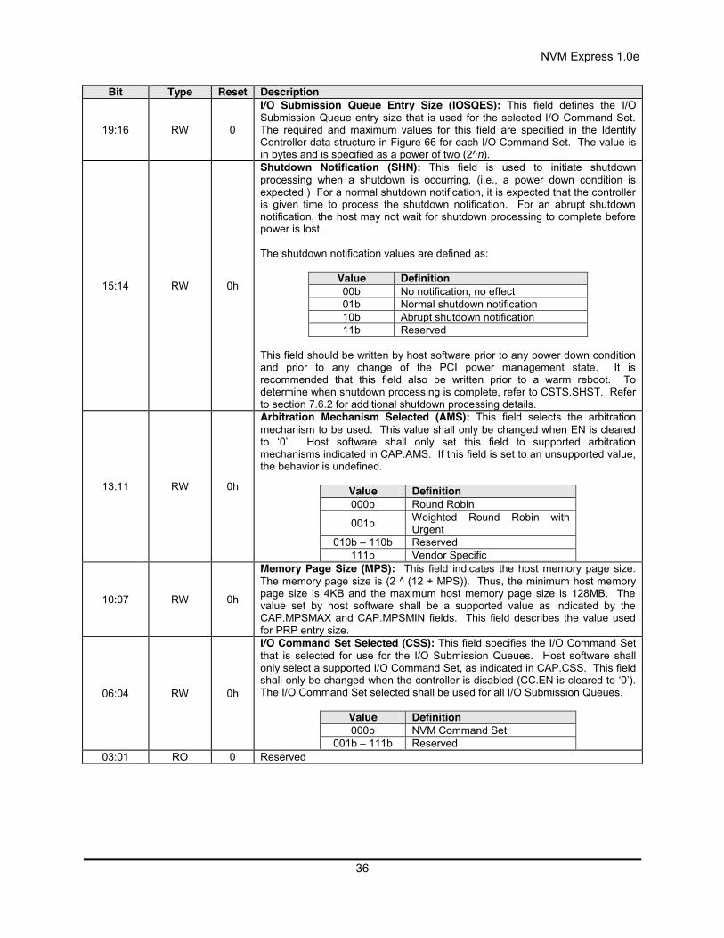
NVM Express 1.0e
36
Bit Type Reset Description
19:16 RW 0
I/O Submission Queue Entry Size (IOSQES): This field defines the I/O Submission Queue entry size that is used for the selected I/O Command Set. The required and maximum values for this field are specified in the Identify Controller data structure in Figure 66 for each I/O Command Set. The value is in bytes and is specified as a power of two (2^n).
15:14 RW 0h
Shutdown Notification (SHN): This field is used to initiate shutdown processing when a shutdown is occurring, (i.e., a power down condition is expected.) For a normal shutdown notification, it is expected that the controller is given time to process the shutdown notification. For an abrupt shutdown notification, the host may not wait for shutdown processing to complete before power is lost. The shutdown notification values are defined as:
Value Definition 00b No notification; no effect 01b Normal shutdown notification 10b Abrupt shutdown notification 11b Reserved
This field should be written by host software prior to any power down condition and prior to any change of the PCI power management state. It is recommended that this field also be written prior to a warm reboot. To determine when shutdown processing is complete, refer to CSTS.SHST. Refer to section 7.6.2 for additional shutdown processing details.
13:11 RW 0h
Arbitration Mechanism Selected (AMS): This field selects the arbitration mechanism to be used. This value shall only be changed when EN is cleared to ‘0’. Host software shall only set this field to supported arbitration mechanisms indicated in CAP.AMS. If this field is set to an unsupported value, the behavior is undefined.
Value Definition 000b Round Robin
001b Weighted Round Robin with Urgent
010b – 110b Reserved 111b Vendor Specific
10:07 RW 0h
Memory Page Size (MPS): This field indicates the host memory page size. The memory page size is (2 ^ (12 + MPS)). Thus, the minimum host memory page size is 4KB and the maximum host memory page size is 128MB. The value set by host software shall be a supported value as indicated by the CAP.MPSMAX and CAP.MPSMIN fields. This field describes the value used for PRP entry size.
06:04 RW 0h
I/O Command Set Selected (CSS): This field specifies the I/O Command Set that is selected for use for the I/O Submission Queues. Host software shall only select a supported I/O Command Set, as indicated in CAP.CSS. This field shall only be changed when the controller is disabled (CC.EN is cleared to ‘0’). The I/O Command Set selected shall be used for all I/O Submission Queues.
Value Definition 000b NVM Command Set
001b – 111b Reserved
03:01 RO 0 Reserved

NVM Express 1.0e
37
Bit Type Reset Description
00 RW 0
Enable (EN): When set to ‘1’, then the controller shall process commands based on Submission Queue Tail doorbell writes. When cleared to ‘0’, then the controller shall not process commands nor post completion queue entries to Completion Queues. When this field transitions from ‘1’ to ‘0’, the controller is reset (referred to as a Controller Reset). The reset deletes all I/O Submission Queues and I/O Completion Queues, resets the Admin Submission Queue and Completion Queue, and brings the hardware to an idle state. The reset does not affect PCI Express registers nor the Admin Queue registers (AQA, ASQ, or ACQ). All other controller registers defined in this section and internal controller state (e.g., Feature values defined in section 5.12.1that are not persistent across power states) are reset to their default values. The controller shall ensure that there is no data loss for commands that have had corresponding completion queue entries posted to an I/O Completion Queue prior to the reset operation. Refer to section 7.3 for reset details. When this field is cleared to ‘0’, the CSTS.RDY bit is cleared to ‘0’ by the controller once the controller is ready to be re-enabled. When this field is set to ‘1’, the controller sets CSTS.RDY to ‘1’ when it is ready to process commands. Setting this field from a ‘0’ to a ‘1’ when CSTS.RDY is a ‘1,’ or setting this field from a '1' to a '0' when CSTS.RDY is a '0,' has undefined results. The Admin Queue registers (AQA, ASQ, and ACQ) shall only be modified when EN is cleared to ‘0’.
3.1.6 Offset 1Ch: CSTS – Controller Status Bit Type Reset Description
31:04 RO 0 Reserved
03:02 RO 0
Shutdown Status (SHST): This field indicates the status of shutdown processing that is initiated by the host setting the CC.SHN field. The shutdown status values are defined as:
Value Definition 00b Normal operation (no shutdown has been requested) 01b Shutdown processing occurring 10b Shutdown processing complete 11b Reserved
To start executing commands on the controller after a shutdown operation (CSTS.SHST set to 10b), a reset (CC.EN cleared to ‘0’) is required. If host software submits commands to the controller without issuing a reset, the behavior is undefined.
01 RO 0
Controller Fatal Status (CFS): This field is set to ’1’ when a fatal controller error occurred that could not be communicated in the appropriate Completion Queue. This field is cleared to ‘0’ when a fatal controller error has not occurred. Refer to section 9.5.
00 RO 0
Ready (RDY): This field is set to ‘1’ when the controller is ready to accept Submission Queue Tail doorbell writes after CC.EN is set to ‘1’. This field shall be cleared to ‘0’ when CC.EN is cleared to ‘0’. Commands shall not be submitted to the controller until this field is set to ‘1’ after the CC.EN bit is set to ‘1’. Failure to follow this requirement produces undefined results. Host software shall wait a minimum of CAP.TO seconds for this field to be set to ‘1’ after setting CC.EN to ‘1’ from a previous value of ‘0’.

NVM Express 1.0e
38
3.1.7 Offset 24h: AQA – Admin Queue Attributes This register defines the attributes for the Admin Submission Queue and Admin Completion Queue. The Queue Identifier for the Admin Submission Queue and Admin Completion Queue is 0h. The Admin Submission Queue’s priority is determined by the arbitration mechanism selected, refer to section 4.7. The Admin Submission Queue and Admin Completion Queue are required to be in physically contiguous memory.
Note: It is recommended that UEFI be used during boot operations. In low memory environments (like Option ROMs in legacy BIOS environments) there may not be sufficient available memory to allocate the necessary Submission and Completion Queues. In these types of conditions, low memory operation of the controller is vendor specific.
Bit Type Reset Description 31:28 RO 0h Reserved
27:16 RW 0h
Admin Completion Queue Size (ACQS): Defines the size of the Admin Completion Queue in entries. Refer to section 4.1.3. The minimum size of the Admin Completion Queue is two entries. The maximum size of the Admin Completion Queue is 4096 entries. This is a 0’s based value.
15:12 RO 0h Reserved
11:00 RW 0h
Admin Submission Queue Size (ASQS): Defines the size of the Admin Submission Queue in entries. Refer to section 4.1.3. The minimum size of the Admin Submission Queue is two entries. The maximum size of the Admin Submission Queue is 4096 entries. This is a 0’s based value.
3.1.8 Offset 28h: ASQ – Admin Submission Queue Base Address This register defines the base memory address of the Admin Submission Queue.
Bit Type Reset Description
63:12 RW Impl Spec
Admin Submission Queue Base (ASQB): Indicates the 64-bit physical address for the Admin Submission Queue. This address shall be memory page aligned (based on the value in CC.MPS). All Admin commands, including creation of I/O Submission Queues and I/O Completions Queues shall be submitted to this queue. For the definition of Submission Queues, refer to section 4.1.
11:00 RO 0h Reserved
3.1.9 Offset 30h: ACQ – Admin Completion Queue Base Address This register defines the base memory address of the Admin Completion Queue.
Bit Type Reset Description
63:12 RW Impl Spec
Admin Completion Queue Base (ACQB): Indicates the 64-bit physical address for the Admin Completion Queue. This address shall be memory page aligned (based on the value in CC.MPS). All completion queue entries for the commands submitted to the Admin Submission Queue shall be posted to this Completion Queue. This queue is always associated with interrupt vector 0. For the definition of Completion Queues, refer to section 4.1.
11:00 RO 0h Reserved
3.1.10 Offset (1000h + ((2y) * (4 << CAP.DSTRD))): SQyTDBL – Submission Queue y Tail Doorbell This register defines the doorbell register that updates the Tail entry pointer for Submission Queue y. The value of y is equivalent to the Queue Identifier. This indicates to the controller that new commands have been submitted for processing.
The host should not read the doorbell registers. If a doorbell register is read, the value returned is vendor specific. Writing a non-existent or unallocated Submission Queue Tail Doorbell has undefined results.
Bit Type Reset Description 31:16 RO 0 Reserved
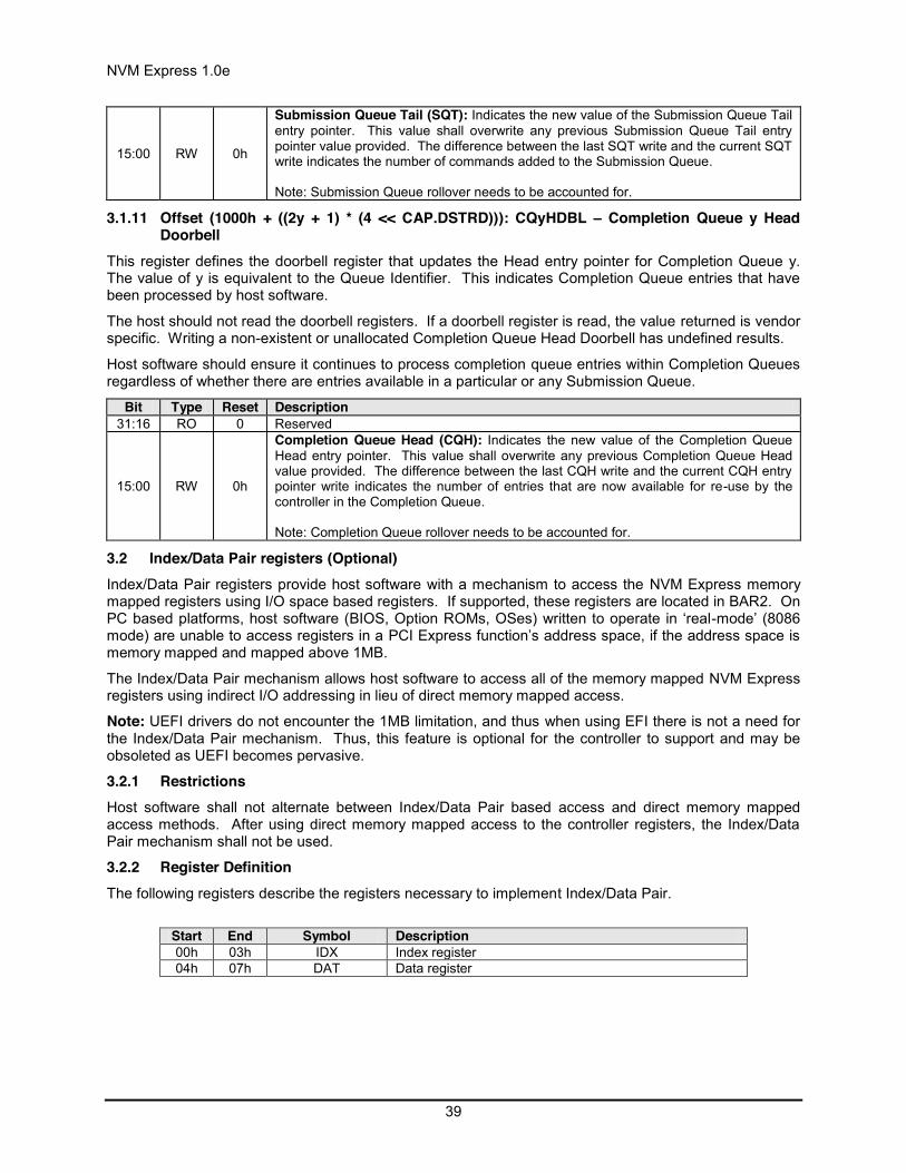
NVM Express 1.0e
39
15:00 RW 0h
Submission Queue Tail (SQT): Indicates the new value of the Submission Queue Tail entry pointer. This value shall overwrite any previous Submission Queue Tail entry pointer value provided. The difference between the last SQT write and the current SQT write indicates the number of commands added to the Submission Queue. Note: Submission Queue rollover needs to be accounted for.
3.1.11 Offset (1000h + ((2y + 1) * (4 << CAP.DSTRD))): CQyHDBL – Completion Queue y Head Doorbell
This register defines the doorbell register that updates the Head entry pointer for Completion Queue y. The value of y is equivalent to the Queue Identifier. This indicates Completion Queue entries that have been processed by host software.
The host should not read the doorbell registers. If a doorbell register is read, the value returned is vendor specific. Writing a non-existent or unallocated Completion Queue Head Doorbell has undefined results.
Host software should ensure it continues to process completion queue entries within Completion Queues regardless of whether there are entries available in a particular or any Submission Queue.
Bit Type Reset Description 31:16 RO 0 Reserved
15:00 RW 0h
Completion Queue Head (CQH): Indicates the new value of the Completion Queue Head entry pointer. This value shall overwrite any previous Completion Queue Head value provided. The difference between the last CQH write and the current CQH entry pointer write indicates the number of entries that are now available for re-use by the controller in the Completion Queue. Note: Completion Queue rollover needs to be accounted for.
3.2 Index/Data Pair registers (Optional) Index/Data Pair registers provide host software with a mechanism to access the NVM Express memory mapped registers using I/O space based registers. If supported, these registers are located in BAR2. On PC based platforms, host software (BIOS, Option ROMs, OSes) written to operate in ‘real-mode’ (8086 mode) are unable to access registers in a PCI Express function’s address space, if the address space is memory mapped and mapped above 1MB.
The Index/Data Pair mechanism allows host software to access all of the memory mapped NVM Express registers using indirect I/O addressing in lieu of direct memory mapped access.
Note: UEFI drivers do not encounter the 1MB limitation, and thus when using EFI there is not a need for the Index/Data Pair mechanism. Thus, this feature is optional for the controller to support and may be obsoleted as UEFI becomes pervasive.
3.2.1 Restrictions Host software shall not alternate between Index/Data Pair based access and direct memory mapped access methods. After using direct memory mapped access to the controller registers, the Index/Data Pair mechanism shall not be used.
3.2.2 Register Definition The following registers describe the registers necessary to implement Index/Data Pair.
Start End Symbol Description 00h 03h IDX Index register 04h 07h DAT Data register

NVM Express 1.0e
40
3.2.3 Offset 00h: IDX – Index Register Bit Type Reset Description
31:02 RW 0h
Index (IDX): This register selects the Dword offset of the memory mapped NVM Express register to be accessed within the MLBAR/MUBAR registers (PCI BAR0 and BAR1). Host software shall not set this to a value beyond the maximum register offset implemented.
01:00 RO 0h Reserved
3.2.4 Offset 04h: DAT – Data Register Bit Type Reset Description
31:00 RW na
Data (DAT): This register is a “window” through which data is read or written to the memory mapped register pointed to by the Index register. A physical register is not implemented as the data is actually stored in the memory mapped registers. Since this is not a physical register, the reset value is the same as the reset value of the register that the Index register is currently pointing to.

NVM Express 1.0e
41
4 System Memory Structures This section describes system memory structures used by NVM Express.
4.1 Submission Queue & Completion Queue Definition The Head and Tail entry pointers correspond to the Completion Queue Head Doorbells and the Submission Queue Tail Doorbells defined in section 3.1.11 and 3.1.10. The doorbell registers are updated by host software.
The submitter of entries to a queue uses the current Tail entry pointer to identify the next open queue entry space. The submitter increments the Tail entry pointer after submitting the new entry to the open queue entry space. If the Tail entry pointer increment exceeds the queue size, the Tail entry shall roll to zero. The submitter may continue to submit entries to the queue as long as the Full queue condition is not met (refer to section 4.1.2).
Note: The submitter shall take queue wrap conditions into account.
The consumer of entries on a queue uses the current Head entry pointer to identify the next entry to be pulled off the queue. The consumer increments the Head entry pointer after retrieving the next entry from the queue. If the Head entry pointer increment exceeds the queue size, the Head entry pointer shall roll to zero. The consumer may continue to remove entries from the queue as long as the Empty queue condition is not met (refer to section 4.1.1).
Note: The consumer shall take queue wrap conditions into account.
Creation and deletion of Submission Queue and associated Completion Queues need to be ordered correctly by host software. Host software shall create the Completion Queue before creating any associated Submission Queue. Submission Queues may be created at any time after the associated Completion Queue is created. Host software shall delete all associated Submission Queues prior to deleting a Completion Queue. Host software should only delete a Submission Queue after it has been brought to an idle condition with no outstanding commands.
If host software writes an invalid value to the Submission Queue Tail Doorbell or Completion Queue Head Doorbell register and an Asynchronous Event Request command is outstanding, then an asynchronous event is posted to the Admin Completion Queue with a status code of Invalid Doorbell Write Value. The associated queue should be deleted and recreated by host software. For a Submission Queue that experiences this error, the controller may complete previously fetched commands; no additional commands are fetched. This condition may be caused by host software attempting to add an entry to a full Submission Queue or remove an entry from an empty Completion Queue.
The behavior if a command is overwritten is undefined.
If there are no free completion queue entries in a Completion Queue, then the controller shall not post status to that Completion Queue until completion queue entries become available. In this case, the controller may stop processing additional Submission Queue entries associated with the affected Completion Queue until completion queue entries become available. The controller shall continue processing for other queues.
4.1.1 Empty Queue The queue is Empty when the Head entry pointer equals the Tail entry pointer. Figure 4 defines the Empty Queue condition.

NVM Express 1.0e
42
Figure 4: Empty Queue Definition
4.1.2 Full Queue The queue is Full when the Head equals one more than the Tail. The number of entries in a queue when full is one less than the queue size. Figure 5 defines the Full Queue condition.
Note: Queue wrap conditions shall be taken into account when determining whether a queue is Full.
Figure 5: Full Queue Definition
4.1.3 Queue Size The Queue Size is indicated in a 16-bit 0’s based field that indicates the number of entries in the queue. The minimum size for a queue is two entries. The maximum size for either an I/O Submission Queue or an I/O Completion Queue is defined as 64K entries, limited by the maximum queue size supported by the controller that is reported in the CAP.MQES field. The maximum size for the Admin Submission and Admin Completion Queue is defined as 4K entries. One entry in each queue is not available for use due to Head and Tail entry pointer definition.
4.1.4 Queue Identifier Each queue is identified through a 16-bit ID value that is assigned to the queue when it is created.
emptyempty
emptyempty
Queue Base Address
Head (Consumer) Tail (Producer)emptyempty
emptyempty
emptyempty
……
emptyempty
emptyempty
emptyempty
emptyempty
emptyempty
Queue Base Address
Head (Consumer) Tail (Producer)emptyempty
emptyempty
emptyempty
……
emptyempty
emptyempty
emptyempty
occupiedoccupied
occupiedoccupied
Queue Base Address
Head (Consumer)
Tail (Producer)
emptyempty
occupiedoccupied
occupiedoccupied
……
occupiedoccupied
occupiedoccupied
occupiedoccupied
occupiedoccupied
occupiedoccupied
Queue Base Address
Head (Consumer)
Tail (Producer)
emptyempty
occupiedoccupied
occupiedoccupied
……
occupiedoccupied
occupiedoccupied
occupiedoccupied

NVM Express 1.0e
43
4.1.5 Queue Priority If the weighted round robin with urgent priority class arbitration mechanism is supported, then host software may assign a queue priority service class of Urgent, High, Medium or Low. If the weighted round robin with urgent priority class arbitration mechanism is not supported, then the priority setting is not used and is ignored by the controller.
4.2 Submission Queue Entry – Command Format Each command is 64 bytes in size.
Command Dword 0, Namespace Identifier, Metadata Pointer, PRP Entry 1, and PRP Entry 2 have common definitions for all Admin commands and NVM commands. Metadata Pointer, PRP Entry 1, and PRP Entry 2 are not be used by all commands. Command Dword 0 is defined in Figure 6 .
Figure 6: Command Dword 0 Bit Description
31:16 Command Identifier (CID): This field specifies a unique identifier for the command when combined with the Submission Queue identifier.
15:10 Reserved
09:08
Fused Operation (FUSE): In a fused operation, a complex command is created by “fusing” together two simpler commands. Refer to section 6.1. This field specifies whether this command is part of a fused operation and if so, which command it is in the sequence.
Bits Definition 00b Normal operation 01b Fused operation, first command 10b Fused operation, second command 11b Reserved
07:00 Opcode (OPC): This field specifies the opcode of the command to be executed.
The 64 byte command format for the Admin Command Set and NVM Command Set is defined in Figure 7. Any additional I/O Command Set defined in the future may use an alternate command size or format.

NVM Express 1.0e
44
Figure 7: Command Format – Admin and NVM Command Set Bytes Description 63:60 Command Dword 15 (CDW15): This field is command specific Dword 15. 59:56 Command Dword 14 (CDW14): This field is command specific Dword 14. 55:52 Command Dword 13 (CDW13): This field is command specific Dword 13. 51:48 Command Dword 12 (CDW12): This field is command specific Dword 12. 47:44 Command Dword 11 (CDW11): This field is command specific Dword 11. 43:40 Command Dword 10 (CDW10): This field is command specific Dword 10.
39:32 PRP Entry 2 (PRP2): This field contains the second PRP entry for the command or if the data transfer spans more than two memory pages, then this field is a PRP List pointer.
31:24 PRP Entry 1 (PRP1): This field contains the first PRP entry for the command or a PRP List pointer depending on the command.
23:16 Metadata Pointer (MPTR): This field contains the address of a contiguous physical buffer of metadata. This field is only used if metadata is not interleaved with the logical block data, as specified in the Format NVM command. This field shall be Dword aligned.
15:08 Reserved
07:04
Namespace Identifier (NSID): This field specifies the namespace that this command applies to. If the namespace is not used for the command, then this field shall be cleared to 0h. If a command shall be applied to all namespaces on the device, then this value shall be set to FFFFFFFFh.
03:00 Command Dword 0 (CDW0): This field is common to all commands and is defined in Figure 6.
In addition to the fields commonly defined for all Admin and NVM commands, Admin and NVM Vendor Specific commands may support the Number of Dwords in PRP and Number of Dwords in MPTR fields. If supported, the command format for the Admin Vendor Specific Command and NVM Vendor Specific Commands are defined in Figure 8. For more details, refer to section 8.7.
Figure 8: Command Format – Admin and NVM Vendor Specific Commands (Optional) Bytes Description 63:60 Command Dword 15 (CDW15): This field is command specific Dword 15. 59:56 Command Dword 14 (CDW14): This field is command specific Dword 14. 55:52 Command Dword 13 (CDW13): This field is command specific Dword 13. 51:48 Command Dword 12 (CDW12): This field is command specific Dword 12.
47:44 Number of Dwords in MPTR (NDM): This field indicates the number of Dwords in the metadata transfer.
43:40 Number of Dwords in PRP (NDP): This field indicates the number of Dwords in the data transfer.
39:32 PRP Entry 2 (PRP2): This field contains the second PRP entry for the command. If the data transfer spans more than two memory pages, then this field is a PRP List pointer.
31:24 PRP Entry 1 (PRP1): This field contains the first PRP entry for the command.
23:16 Metadata Pointer (MPTR): This field contains the address of a contiguous physical buffer of metadata. This field is only used if metadata is not interleaved with the LBA data, as specified in the Format NVM command. This field shall be Dword aligned.
15:08 Reserved
07:04
Namespace Identifier (NSID): This field indicates the namespace that this command applies to. If the namespace is not used for the command, then this field shall be cleared to 0h. If a command shall be applied to all namespaces on the device, then this value shall be set to FFFFFFFFh.
03:00 Command Dword 0 (CDW0): This field is common to all commands and is defined in Figure 6.

NVM Express 1.0e
45
4.3 Physical Region Page Entry and List A physical region page (PRP) entry is a pointer to a physical memory page. PRPs are used as a scatter/gather mechanism for data transfers between the controller and system memory. To enable efficient out of order data transfers between the device and the host, PRP entries are a fixed size.
The size of the physical memory page is configured by host software in CC.MPS. Figure 9 shows the layout of a PRP entry that consists of a Page Base Address and an Offset. The size of the Offset field is determined by the physical memory page size configured in CC.MPS.
Figure 9: PRP Entry Layout
The definition of a PRP entry is described in Figure 10.
Figure 10: PRP Entry – Page Base Address and Offset Bit Description
63:02
Page Base Address and Offset (PBAO): This field indicates the 64-bit physical memory page address. The lower bits (n:2) of this field indicate the offset within the memory page. If the memory page size is 4KB, then bits 11:02 form the Offset; if the memory page size is 8KB, then bits 12:02 form the Offset, etc. If this entry is not the first PRP entry in the command or in the PRP List then the Offset portion of this field shall be cleared to 0h.
01:00 Reserved
A physical region page list (PRP List) is a set of PRP entries in a single page of contiguous memory. A PRP List describes additional PRP entries that could not be described within the command itself. Any PRP entries described within the command are not duplicated in a PRP List. If the amount of data to transfer requires multiple PRP List memory pages, then the last PRP entry before the end of the memory page shall be a pointer to the next PRP List, indicating the next segment of the PRP List. Figure 11 shows the layout of a PRP List.
Figure 11: PRP List Layout
The first PRP entry contained within the command may have a non-zero offset within the memory page. The first PRP List entry (i.e. the first pointer to a memory page containing additional PRP entries) that if present is contained in the PRP Entry 2 location within the command, shall be Qword aligned and may also have a non-zero offset within the memory page. All other PRP and PRP List entries shall have a memory page offset of 0h, i.e. the entries are memory page aligned based on the value in CC.MPS. The
OffsetPage Base Address
63 0n0 0
n+1
Page Base Address k
63 0n
0hPage Base Address k+1
…
0hPage Base Address k+m
0hPage Base Address k+m+1
0h
n+1

NVM Express 1.0e
46
last entry within a memory page, as indicated by the memory page size in the CC.MPS field, shall be a PRP List pointer if there is more than a single memory page of data to be transferred.
PRP Lists shall be minimally sized with packed entries starting with entry 0. If more PRP List pages are required, then the last entry of the PRP List page is a pointer to the next PRP List page. The total number of PRP entries is implied by the command parameters and memory page size.
4.4 Metadata Region (MR) Metadata may be supported for a namespace as either part of the logical block (creating an extended logical block which is a larger logical block that is exposed to the application) or it may be transferred as a separate contiguous buffer of data. The metadata shall not be split between the logical block and a separate metadata buffer. For writes, the metadata shall be written atomically with its associated logical block. Refer to section 8.2.
In the case where the namespace is formatted to transfer the metadata as a separate contiguous buffer of data, then the Metadata Region is used. In this case, the location of the Metadata Region is indicated by the Metadata Pointer within the command. The Metadata Pointer within the command shall be Dword aligned.
The controller may support several physical formats of logical block size and associated metadata size. There may be performance differences between different physical formats. This is indicated as part of the Identify Namespace data structure.
If the namespace is formatted to use end-to-end data protection, then the first eight bytes or last eight bytes of the metadata is used for protection information (specified as part of the NVM Format operation).
4.5 Completion Queue Entry An entry in the Completion Queue is 16 bytes in size. Figure 12 describes the layout of the Completion Queue Entry data structure. The contents of Dword 0 is command specific. If a command uses Dword 0, then the definition of this Dword is contained within the associated command definition. If a command does not use Dword 0, then the field is reserved. Dword 1 is reserved. Dword 2 is defined in Figure 13 and Dword 3 is defined in Figure 14. Any additional I/O Command Set defined in the future may use an alternate Completion Queue entry size or format.
Figure 12: Completion Queue Entry Layout – Admin and NVM Command Set
1531 023 7
SQ Identifier
Reserved
Command SpecificDW0
DW3DW2DW1
SQ Head Pointer
Command IdentifierStatus Field P
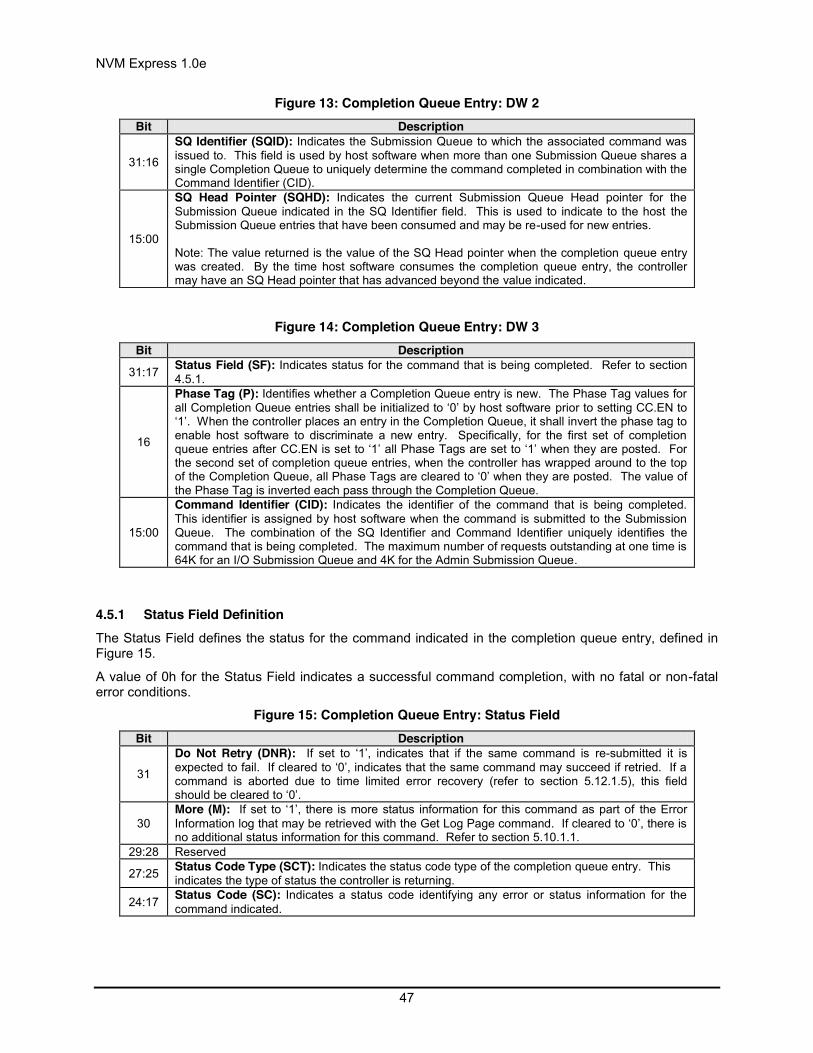
NVM Express 1.0e
47
Figure 13: Completion Queue Entry: DW 2 Bit Description
31:16
SQ Identifier (SQID): Indicates the Submission Queue to which the associated command was issued to. This field is used by host software when more than one Submission Queue shares a single Completion Queue to uniquely determine the command completed in combination with the Command Identifier (CID).
15:00
SQ Head Pointer (SQHD): Indicates the current Submission Queue Head pointer for the Submission Queue indicated in the SQ Identifier field. This is used to indicate to the host the Submission Queue entries that have been consumed and may be re-used for new entries. Note: The value returned is the value of the SQ Head pointer when the completion queue entry was created. By the time host software consumes the completion queue entry, the controller may have an SQ Head pointer that has advanced beyond the value indicated.
Figure 14: Completion Queue Entry: DW 3 Bit Description
31:17 Status Field (SF): Indicates status for the command that is being completed. Refer to section 4.5.1.
16
Phase Tag (P): Identifies whether a Completion Queue entry is new. The Phase Tag values for all Completion Queue entries shall be initialized to ‘0’ by host software prior to setting CC.EN to ‘1’. When the controller places an entry in the Completion Queue, it shall invert the phase tag to enable host software to discriminate a new entry. Specifically, for the first set of completion queue entries after CC.EN is set to ‘1’ all Phase Tags are set to ‘1’ when they are posted. For the second set of completion queue entries, when the controller has wrapped around to the top of the Completion Queue, all Phase Tags are cleared to ‘0’ when they are posted. The value of the Phase Tag is inverted each pass through the Completion Queue.
15:00
Command Identifier (CID): Indicates the identifier of the command that is being completed. This identifier is assigned by host software when the command is submitted to the Submission Queue. The combination of the SQ Identifier and Command Identifier uniquely identifies the command that is being completed. The maximum number of requests outstanding at one time is 64K for an I/O Submission Queue and 4K for the Admin Submission Queue.
4.5.1 Status Field Definition The Status Field defines the status for the command indicated in the completion queue entry, defined in Figure 15.
A value of 0h for the Status Field indicates a successful command completion, with no fatal or non-fatal error conditions.
Figure 15: Completion Queue Entry: Status Field Bit Description
31
Do Not Retry (DNR): If set to ‘1’, indicates that if the same command is re-submitted it is expected to fail. If cleared to ‘0’, indicates that the same command may succeed if retried. If a command is aborted due to time limited error recovery (refer to section 5.12.1.5), this field should be cleared to ‘0’.
30 More (M): If set to ‘1’, there is more status information for this command as part of the Error Information log that may be retrieved with the Get Log Page command. If cleared to ‘0’, there is no additional status information for this command. Refer to section 5.10.1.1.
29:28 Reserved
27:25 Status Code Type (SCT): Indicates the status code type of the completion queue entry. This indicates the type of status the controller is returning.
24:17 Status Code (SC): Indicates a status code identifying any error or status information for the command indicated.

NVM Express 1.0e
48
4.5.1.1 Status Code Type (SCT) Completion queue entries indicate a status code type for the type of completion being reported. Figure 16 specifies the status code type values and descriptions.
Figure 16: Status Code – Status Code Type Values Value Description
0h
Generic Command Status: Indicates that the command specified by the Command and Submission Queue identifiers in the completion queue entry has completed. These status values are generic across all command types, and include such conditions as success, opcode not supported, and invalid field.
1h Command Specific Status: Indicates a status value that is specific to a particular command opcode. These values may indicate additional processing is required. Status values such as invalid firmware image or exceeded maximum number of queues is reported with this type.
2h Media Errors: Any media specific errors that occur in the NVM or data integrity type errors shall be of this type.
3h – 6h Reserved 7h Vendor Specific
4.5.1.2 Status Code (SC) The Status Code (SC) field in the completion queue entry indicates more detailed status information about the completion being reported.
Each Status Code set of values is split into three ranges:
00h – 7Fh: Applicable to Admin Command Set, or across multiple command sets. 80h – BFh: I/O Command Set Specific status codes. C0h – FFh: Vendor Specific status codes.
If there are multiple status codes that apply to a particular command failure, the controller shall report the status code with the lowest numerical value.
4.5.1.2.1 Generic Command Status Definition Completion queue entries with a Status Code type of Generic Command Status indicate a status value associated with the command that is generic across many different types of commands.
Figure 17: Status Code – Generic Command Status Values Value Description 00h Successful Completion: The command completed successfully. 01h Invalid Command Opcode: The associated command opcode field is not valid. 02h Invalid Field in Command: An invalid field specified in the command parameters. 03h Command ID Conflict: The command identifier is already in use. Note: It is implementation
specific how many commands are searched for a conflict. 04h Data Transfer Error: Transferring the data or metadata associated with a command had an error. 05h Commands Aborted due to Power Loss Notification: Indicates that the command was aborted
due to a power loss notification. 06h Internal Device Error: The command was not completed successfully due to an internal device
error. Details on the internal device error are returned as an asynchronous event. Refer to section 5.2.
07h Command Abort Requested: The command was aborted due to a Command Abort command being received that specified the Submission Queue Identifier and Command Identifier of this command.
08h Command Aborted due to SQ Deletion: The command was aborted due to a Delete I/O

NVM Express 1.0e
49
Submission Queue request received for the Submission Queue to which the command was submitted.
09h Command Aborted due to Failed Fused Command: The command was aborted due to the other command in a fused operation failing.
0Ah Command Aborted due to Missing Fused Command: The command was aborted due to the companion fused command not being found as the subsequent Submission Queue entry.
0Bh Invalid Namespace or Format: The namespace or the format of that namespace is invalid. 0Ch Command Sequence Error: The command was aborted due to a protocol violation in a multi-
command sequence (e.g. a violation of the Security Send and Security Receive sequencing rules in the TCG Storage Synchronous Interface Communications protocol).
0Dh – 7Fh Reserved 80h – BFh I/O Command Set Specific C0h – FFh Vendor Specific
Figure 18: Status Code – Generic Command Status Values, NVM Command Set Value Description 80h LBA Out of Range: The command references an LBA that exceeds the size of the namespace. 81h Capacity Exceeded: Execution of the command has caused the capacity of the namespace to be
exceeded. This error occurs when the Namespace Utilization exceeds the Namespace Capacity, as reported in Figure 68.
82h Namespace Not Ready: The namespace is not ready to be accessed. The Do Not Retry bit indicates whether re-issuing the command at a later time may succeed.
83h – BFh Reserved
4.5.1.2.2 Command Specific Errors Definition Completion queue entries with a Status Code Type of Command Specific Errors indicate an error that is specific to a particular command opcode. Status codes of 0h to 7Fh are for Admin command errors. Status codes of 80h – BFh are specific to the selected I/O command set.
Figure 19: Status Code – Command Specific Status Values Value Description Commands Affected 00h Completion Queue Invalid Create I/O Submission Queue 01h Invalid Queue Identifier Create I/O Submission Queue, Create I/O
Completion Queue, Delete I/O Completion Queue, Delete I/O Submission Queue
02h Maximum Queue Size Exceeded Create I/O Submission Queue, Create I/O Completion Queue
03h Abort Command Limit Exceeded Abort 04h Reserved Reserved 05h Asynchronous Event Request Limit Exceeded Asynchronous Event Request 06h Invalid Firmware Slot Firmware Activate 07h Invalid Firmware Image Firmware Activate 08h Invalid Interrupt Vector Create I/O Completion Queue 09h Invalid Log Page Get Log Page 0Ah Invalid Format Format NVM 0Bh Firmware Application Requires Conventional Reset Firmware Activate 0Ch Invalid Queue Deletion Delete I/O Completion Queue
0Dh – 7Fh Reserved 80h - BFh I/O Command Set Specific C0 - FFh Vendor Specific

NVM Express 1.0e
50
Figure 20: Status Code – Command Specific Status Values, NVM Command Set Value Description Commands Affected 80h Conflicting Attributes Dataset Management, Read, Write 81h Invalid Protection Information Compare, Read, Write 82h Attempted Write to Read Only Range Write
83h - BFh Reserved
4.5.1.2.3 Media Errors Definition Completion queue entries with a Status Code Type of Media Errors indicate an error associated with the command that is due to an error associated with the NVM media.
Figure 21: Status Code – Media Errors Values Value Description
00h – 7Fh Reserved 80h – BFh I/O Command Set Specific C0h – FFh Vendor Specific
Figure 22: Status Code – Media Errors Values, NVM Command Set Value Description 80h Write Fault: The write data could not be committed to the media. This may be due to the lack of
available spare locations that may be reported as an asynchronous event. 81h Unrecovered Read Error: The read data could not be recovered from the media. 82h End-to-end Guard Check Error: The command was aborted due to an end-to-end guard check
failure. 83h End-to-end Application Tag Check Error: The command was aborted due to an end-to-end
application tag check failure. 84h End-to-end Reference Tag Check Error: The command was aborted due to an end-to-end
reference tag check failure. 85h Compare Failure: The command failed due to a miscompare during a Compare command. 86h Access Denied: Access to the namespace and/or LBA range is denied due to lack of access
rights. Refer to TCG SIIS. 87h – BFh Reserved
4.6 Fused Operations Fused operations enable a more complex command by “fusing” together two simpler commands. This feature is optional; support for this feature is indicated in the Identify Controller data structure in Figure 66. In a fused operation, the requirements are:
The commands shall be executed in sequence as an atomic unit. The controller shall behave as if no other operations have been executed between these two commands.
The operation ends at the point an error is encountered in either command. If the first command in the sequence failed, then the second command shall be aborted. If the second command in the sequence failed, then the completion status of the first command is sequence specific.
The LBA range, if used, shall be the same for the two commands. If the LBA ranges do not match, the commands should be aborted with status of Invalid Field in Command.
The commands shall be inserted next to each other in the same Submission Queue. If the first command is the last entry in the Submission Queue, then the second command shall be the first entry in the Submission Queue as part of wrapping around. The Submission Queue Tail doorbell pointer update shall indicate both commands as part of one doorbell update.

NVM Express 1.0e
51
If the host desires to abort the fused operation, the host shall submit an Abort command separately for each of the commands.
A completion queue entry is posted by the controller for each of the commands.
Whether a command is part of a fused operation is indicated in the Fused Operation field of Command Dword 0 in Figure 6. The Fused Operation field also indicates whether this is the first or second command in the operation.
4.7 Command Arbitration A command is submitted when a Submission Queue Tail Doorbell write moves the Submission Queue Tail Pointer past the corresponding Submission Queue entry. The controller transfers submitted commands to the controller’s local memory for subsequent processing using a vendor specific algorithm.
A command is being processed when the controller and/or namespace state is being accessed or modified by the command (e.g., a Feature setting is being accessed or modified or a logical block is being accessed or modified).
A command is complete when a Completion Queue entry for the command has been posted to the corresponding Completion Queue. Upon completion, all controller state and/or namespace state modifications made by that command are globally visible to all subsequently submitted commands.
A candidate command is a submitted command the controller deems ready for processing. The controller selects command(s) for processing from the pool of submitted commands for each Submission Queue. The commands that comprise a fused operation shall be processed together and in order by the controller. The controller may select candidate commands for processing in any order. The order in which commands are selected for processing does not imply the order in which commands are completed.
Arbitration is the method used to determine the Submission Queue from which the controller will start processing the next candidate command(s). Once a Submission Queue is selected using arbitration, the Arbitration Burst setting determines the maximum number of commands that the controller may start processing from that Submission Queue before arbitration shall again take place. A fused operation may be considered as one or two commands by the controller.
All controllers shall support the round robin command arbitration mechanism. A controller may optionally implement weighted round robin with urgent priority class and/or a vendor specific arbitration mechanism. The Arbitration Mechanism Supported field in the Controller Capabilities register (CC.AMS) indicates optional arbitration mechanisms supported by the controller.
In order to make efficient use of the non-volatile memory, it is often advantageous to execute multiple commands from a Submission Queue in parallel. For Submission Queues that are using weighted round robin with urgent priority class or round robin arbitration, host software may configure an Arbitration Burst setting. The Arbitration Burst setting indicates the maximum number of commands that the controller may launch at one time from a particular Submission Queue. It is recommended that host software configure the Arbitration Burst setting as close to the recommended value by the controller as possible (specified in the Recommended Arbitration Burst field of the Identify Controller data structure in Figure 66), taking into consideration any latency requirements. Refer to section 5.12.1.1.
4.7.1 Round Robin Arbitration If the round robin arbitration mechanism is selected, the controller shall implement round robin command arbitration amongst all Submission Queues, including the Admin Submission Queue. In this case, all Submission Queues are treated with equal priority. The controller may select multiple candidate commands for processing from each Submission Queue per round based on the Arbitration Burst setting.
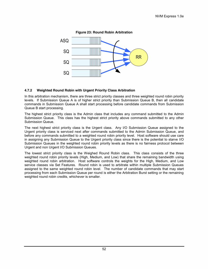
NVM Express 1.0e
52
Figure 23: Round Robin Arbitration
4.7.2 Weighted Round Robin with Urgent Priority Class Arbitration In this arbitration mechanism, there are three strict priority classes and three weighted round robin priority levels. If Submission Queue A is of higher strict priority than Submission Queue B, then all candidate commands in Submission Queue A shall start processing before candidate commands from Submission Queue B start processing.
The highest strict priority class is the Admin class that includes any command submitted to the Admin Submission Queue. This class has the highest strict priority above commands submitted to any other Submission Queue.
The next highest strict priority class is the Urgent class. Any I/O Submission Queue assigned to the Urgent priority class is serviced next after commands submitted to the Admin Submission Queue, and before any commands submitted to a weighted round robin priority level. Host software should use care in assigning any Submission Queue to the Urgent priority class since there is the potential to starve I/O Submission Queues in the weighted round robin priority levels as there is no fairness protocol between Urgent and non Urgent I/O Submission Queues.
The lowest strict priority class is the Weighed Round Robin class. This class consists of the three weighted round robin priority levels (High, Medium, and Low) that share the remaining bandwidth using weighted round robin arbitration. Host software controls the weights for the High, Medium, and Low service classes via Set Features. Round robin is used to arbitrate within multiple Submission Queues assigned to the same weighted round robin level. The number of candidate commands that may start processing from each Submission Queue per round is either the Arbitration Burst setting or the remaining weighted round robin credits, whichever is smaller.
ASQ
SQ
SQ
SQ
RR

NVM Express 1.0e
53
Figure 24: Weighted Round Robin with Urgent Priority Class Arbitration
In Figure 24, the Priority decision point selects the highest priority candidate command selected next to start processing.
4.7.3 Vendor Specific Arbitration A vendor may choose to implement a vendor specific arbitration mechanism. The mechanism(s) are outside the scope of this specification.
ASQ
SQ
SQ
SQ
RR
SQ
SQ
SQ
RR
SQ
SQ
SQ
RR
WRR
Priority
Weight(High)
Admin
HighPriority
MediumPriority
LowPriority
Weight(Medium)
Weight(Low)
Strict Priority 2
SQ
SQRRUrgent
Strict Priority 3
Strict Priority 1
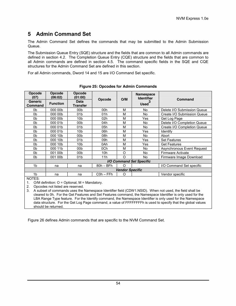
NVM Express 1.0e
54
5 Admin Command Set The Admin Command Set defines the commands that may be submitted to the Admin Submission Queue.
The Submission Queue Entry (SQE) structure and the fields that are common to all Admin commands are defined in section 4.2. The Completion Queue Entry (CQE) structure and the fields that are common to all Admin commands are defined in section 4.5. The command specific fields in the SQE and CQE structures for the Admin Command Set are defined in this section.
For all Admin commands, Dword 14 and 15 are I/O Command Set specific.
Figure 25: Opcodes for Admin Commands Opcode
(07) Opcode (06:02)
Opcode (01:00) Opcode O/M
Namespace Identifier
Used3 Command Generic
Command Function Data Transfer
0b 000 00b 00b 00h M No Delete I/O Submission Queue 0b 000 00b 01b 01h M No Create I/O Submission Queue 0b 000 00b 10b 02h M Yes Get Log Page 0b 000 01b 00b 04h M No Delete I/O Completion Queue 0b 000 01b 01b 05h M No Create I/O Completion Queue 0b 000 01b 10b 06h M Yes Identify 0b 000 10b 00b 08h M No Abort 0b 000 10b 01b 09h M Yes Set Features 0b 000 10b 10b 0Ah M Yes Get Features 0b 000 11b 00b 0Ch M No Asynchronous Event Request 0b 001 00b 00b 10h O No Firmware Activate 0b 001 00b 01b 11h O No Firmware Image Download
I/O Command Set Specific 1b na na 80h – BFh O I/O Command Set specific
Vendor Specific 1b na na C0h – FFh O Vendor specific
NOTES: 1. O/M definition: O = Optional, M = Mandatory. 2. Opcodes not listed are reserved. 3. A subset of commands uses the Namespace Identifier field (CDW1.NSID). When not used, the field shall be
cleared to 0h. For the Get Features and Set Features command, the Namespace Identifier is only used for the LBA Range Type feature. For the Identify command, the Namespace Identifier is only used for the Namespace data structure. For the Get Log Page command, a value of FFFFFFFFh is used to specify that the global values should be returned.
Figure 26 defines Admin commands that are specific to the NVM Command Set.

NVM Express 1.0e
55
Figure 26: Opcodes for Admin Commands – NVM Command Set Specific Opcode
(07) Opcode (06:02)
Opcode (01:00) Opcode O/M
Namespace Identifier
Used3 Command Generic
Command Function Data Transfer
1b 000 00b 00b 80h O Yes Format NVM 1b 000 00b 01b 81h O Yes Security Send 1b 000 00b 10b 82h O Yes Security Receive
NOTES: 1. O/M definition: O = Optional, M = Mandatory. 2. Opcodes not listed are reserved. 3. A subset of commands uses the Namespace Identifier field (CDW1.NSID). When not used, the field shall be
cleared to 0h.
5.1 Abort command The Abort command is used to abort a specific command previously submitted to the Admin Submission Queue or an I/O Submission Queue. Host software may have multiple Abort commands outstanding, subject to the constraints of the Abort Command Limit indicated in the Identify Controller data structure in Figure 66. An Abort command is a best effort command; the command to abort may have already completed, currently be in execution, or may be deeply queued. It is implementation specific if/when a controller chooses to complete the command when the command to abort is not found.
The Abort command uses the Command Dword 10 field. All other command specific fields are reserved.
Figure 27: Abort – Command Dword 10 Bit Description
31:16 Command Identifier (CID): This field specifies the command identifier of the command to be aborted, that was specified in the CDW0.CID field within the command itself.
15:00 Submission Queue Identifier (SQID): This field specifies the identifier of the Submission Queue that the command to be aborted is associated with.
5.1.1 Command Completion A completion queue entry is posted to the Admin Completion Queue if the command has been completed and a corresponding completion queue entry has been posted to the appropriate Admin or I/O Completion Queue. Dword 0 of the completion queue entry indicates whether the command was aborted. If the command was successfully aborted, then bit 0 of Dword 0 is cleared to ‘0’. If the command was not aborted, then bit 0 of Dword 0 is set to ‘1’.
Command specific status values associated with the Abort command are defined in Figure 28.
Figure 28: Abort – Command Specific Status Values Value Description
3h Abort Command Limit Exceeded: The number of concurrently outstanding Abort commands has exceeded the limit indicated in the Identify Controller data structure.

NVM Express 1.0e
56
5.2 Asynchronous Event Request command Asynchronous events are used to notify host software of error and health information as these events occur. To enable asynchronous events to be reported by the controller, host software needs to submit one or more Asynchronous Event Request commands to the controller. The controller specifies an event to the host by completing an Asynchronous Event Request command. Host software should expect that the controller may not execute the command immediately; the command should be completed when there is an event to be reported.
The Asynchronous Event Request command is submitted by host software to enable the reporting of asynchronous events from the controller. This command has no timeout. The controller posts a completion queue entry for this command when there is an asynchronous event to report to the host. If Asynchronous Event Request commands are outstanding when the controller is reset, the commands are aborted.
All command specific fields are reserved.
Host software may submit multiple Asynchronous Event Request commands to reduce event reporting latency. The total number of simultaneously outstanding Asynchronous Event Request commands is limited by the Asynchronous Event Request Limit specified in the Identify Controller data structure in Figure 66.
Asynchronous events are grouped into event types. The event type information is indicated in Dword 0 of the completion queue entry for the Asynchronous Event Request command. When the controller posts a completion queue entry for an outstanding Asynchronous Event Request command and thus reports an asynchronous event, subsequent events of that event type are automatically masked by the controller until the host clears that event. An event is cleared by reading the log page associated with that event using the Get Log Page command (see section 5.10).
The following event types are defined: Error event: Indicates a general error that is not associated with a specific command. To clear
this event, host software reads the Error Information log using the Get Log Page command. SMART / Health Status event: Indicates a SMART or health status event. To clear this event,
host software reads the SMART / Health Information log using Get Log Page. The SMART / Health conditions that trigger asynchronous events may be configured in the Asynchronous Event Configuration feature using the Set Features command (see section 5.12).
Vendor Specific event: Indicates a vendor specific event. To clear this event, host software reads the indicated vendor specific log page using Get Log Page.
When the controller needs to report an event and there are no outstanding Asynchronous Event Request commands, the controller queues the event internal to the controller and reports it when an Asynchronous Event Request command is received.
5.2.1 Command Completion A completion queue entry is posted to the Admin Completion Queue if there is an asynchronous event to report to the host. Command specific status values associated with Asynchronous Event Request are defined in Figure 29.
Figure 29: Status Code – Command Specific Status Values Value Description
5h Asynchronous Event Request Limit Exceeded: The number of concurrently outstanding Asynchronous Event Request commands has been exceeded.

NVM Express 1.0e
57
Dword 0 of the completion queue entry contains information about the asynchronous event. The definition of Dword 0 of the completion queue entry is in Figure 30.
Figure 30: Asynchronous Event Request – Completion Queue Entry Dword 0 Bit Description
31:24 Reserved
23:16 Associated Log Page: Indicates the log page associated with the asynchronous event. This log page needs to be read by the host to clear the event.
15:08 Asynchronous Event Information: Refer to Figure 31 and Figure 32 for detailed information regarding the asynchronous event.
07:03 Reserved
02:00
Asynchronous Event Type: Indicates the type of the asynchronous event. More specific information on the event is provided in the Asynchronous Event Information field.
Value Definition 0h Error status 1h SMART / Health status
2h – 6h Reserved 7h Vendor specific
The information in either Figure 31 or Figure 32 is returned in the Asynchronous Event Information field, depending on the Asynchronous Event Type.
Figure 31: Asynchronous Event Information – Error Status Value Description
0h Invalid Submission Queue: Host software wrote the doorbell of a queue that was not created. 1h Invalid Doorbell Write Value: Host software attempted to write an invalid doorbell value. Some
possible causes of this error are: the value written was out of range of the corresponding queue’s base address and size, the value written is the same as the previously written doorbell value, host software attempts to add a command to a full Submission Queue, and host software attempts to remove a completion queue entry from an empty Completion
Queue. 2h Diagnostic Failure: A diagnostic failure was detected. This may include a self test operation. 3h Persistent Internal Device Error: A failure occurred within the device that is persistent or the
device is unable to isolate to a specific set of commands. If this error is indicated, then the CSTS.CFS bit may be set to ‘1’ and the host should perform a reset as described in section 7.3.
4h Transient Internal Device Error: A transient error occurred within the device that is specific to a particular set of commands and operation may continue.
5h Firmware Image Load Error: The firmware image could not be loaded. The controller reverted to the previously active firmware image or a baseline read-only firmware image.
6h - FFh Reserved
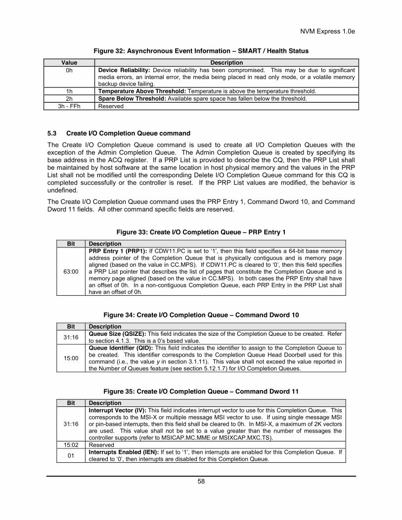
NVM Express 1.0e
58
Figure 32: Asynchronous Event Information – SMART / Health Status Value Description
0h Device Reliability: Device reliability has been compromised. This may be due to significant media errors, an internal error, the media being placed in read only mode, or a volatile memory backup device failing.
1h Temperature Above Threshold: Temperature is above the temperature threshold. 2h Spare Below Threshold: Available spare space has fallen below the threshold.
3h - FFh Reserved
5.3 Create I/O Completion Queue command The Create I/O Completion Queue command is used to create all I/O Completion Queues with the exception of the Admin Completion Queue. The Admin Completion Queue is created by specifying its base address in the ACQ register. If a PRP List is provided to describe the CQ, then the PRP List shall be maintained by host software at the same location in host physical memory and the values in the PRP List shall not be modified until the corresponding Delete I/O Completion Queue command for this CQ is completed successfully or the controller is reset. If the PRP List values are modified, the behavior is undefined.
The Create I/O Completion Queue command uses the PRP Entry 1, Command Dword 10, and Command Dword 11 fields. All other command specific fields are reserved.
Figure 33: Create I/O Completion Queue – PRP Entry 1 Bit Description
63:00
PRP Entry 1 (PRP1): If CDW11.PC is set to ‘1’, then this field specifies a 64-bit base memory address pointer of the Completion Queue that is physically contiguous and is memory page aligned (based on the value in CC.MPS). If CDW11.PC is cleared to ‘0’, then this field specifies a PRP List pointer that describes the list of pages that constitute the Completion Queue and is memory page aligned (based on the value in CC.MPS). In both cases the PRP Entry shall have an offset of 0h. In a non-contiguous Completion Queue, each PRP Entry in the PRP List shall have an offset of 0h.
Figure 34: Create I/O Completion Queue – Command Dword 10 Bit Description
31:16 Queue Size (QSIZE): This field indicates the size of the Completion Queue to be created. Refer to section 4.1.3. This is a 0’s based value.
15:00
Queue Identifier (QID): This field indicates the identifier to assign to the Completion Queue to be created. This identifier corresponds to the Completion Queue Head Doorbell used for this command (i.e., the value y in section 3.1.11). This value shall not exceed the value reported in the Number of Queues feature (see section 5.12.1.7) for I/O Completion Queues.
Figure 35: Create I/O Completion Queue – Command Dword 11 Bit Description
31:16
Interrupt Vector (IV): This field indicates interrupt vector to use for this Completion Queue. This corresponds to the MSI-X or multiple message MSI vector to use. If using single message MSI or pin-based interrupts, then this field shall be cleared to 0h. In MSI-X, a maximum of 2K vectors are used. This value shall not be set to a value greater than the number of messages the controller supports (refer to MSICAP.MC.MME or MSIXCAP.MXC.TS).
15:02 Reserved
01 Interrupts Enabled (IEN): If set to ‘1’, then interrupts are enabled for this Completion Queue. If cleared to ‘0’, then interrupts are disabled for this Completion Queue.
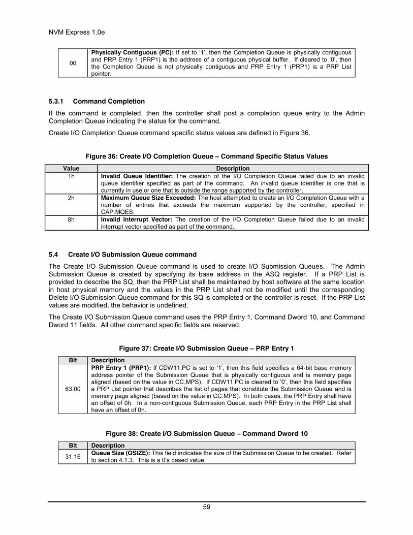
NVM Express 1.0e
59
00
Physically Contiguous (PC): If set to ‘1’, then the Completion Queue is physically contiguous and PRP Entry 1 (PRP1) is the address of a contiguous physical buffer. If cleared to ‘0’, then the Completion Queue is not physically contiguous and PRP Entry 1 (PRP1) is a PRP List pointer.
5.3.1 Command Completion If the command is completed, then the controller shall post a completion queue entry to the Admin Completion Queue indicating the status for the command.
Create I/O Completion Queue command specific status values are defined in Figure 36.
Figure 36: Create I/O Completion Queue – Command Specific Status Values Value Description
1h Invalid Queue Identifier: The creation of the I/O Completion Queue failed due to an invalid queue identifier specified as part of the command. An invalid queue identifier is one that is currently in use or one that is outside the range supported by the controller.
2h Maximum Queue Size Exceeded: The host attempted to create an I/O Completion Queue with a number of entries that exceeds the maximum supported by the controller, specified in CAP.MQES.
8h Invalid Interrupt Vector: The creation of the I/O Completion Queue failed due to an invalid interrupt vector specified as part of the command.
5.4 Create I/O Submission Queue command The Create I/O Submission Queue command is used to create I/O Submission Queues. The Admin Submission Queue is created by specifying its base address in the ASQ register. If a PRP List is provided to describe the SQ, then the PRP List shall be maintained by host software at the same location in host physical memory and the values in the PRP List shall not be modified until the corresponding Delete I/O Submission Queue command for this SQ is completed or the controller is reset. If the PRP List values are modified, the behavior is undefined.
The Create I/O Submission Queue command uses the PRP Entry 1, Command Dword 10, and Command Dword 11 fields. All other command specific fields are reserved.
Figure 37: Create I/O Submission Queue – PRP Entry 1 Bit Description
63:00
PRP Entry 1 (PRP1): If CDW11.PC is set to ‘1’, then this field specifies a 64-bit base memory address pointer of the Submission Queue that is physically contiguous and is memory page aligned (based on the value in CC.MPS). If CDW11.PC is cleared to ‘0’, then this field specifies a PRP List pointer that describes the list of pages that constitute the Submission Queue and is memory page aligned (based on the value in CC.MPS). In both cases, the PRP Entry shall have an offset of 0h. In a non-contiguous Submission Queue, each PRP Entry in the PRP List shall have an offset of 0h.
Figure 38: Create I/O Submission Queue – Command Dword 10 Bit Description
31:16 Queue Size (QSIZE): This field indicates the size of the Submission Queue to be created. Refer to section 4.1.3. This is a 0’s based value.

NVM Express 1.0e
60
15:00
Queue Identifier (QID): This field indicates the identifier to assign to the Submission Queue to be created. This identifier corresponds to the Submission Queue Tail Doorbell used for this command (i.e., the value y in section 3.1.10). This value shall not exceed the value reported in the Number of Queues feature (see section 5.12.1.7) for I/O Submission Queues.
Figure 39: Create I/O Submission Queue – Command Dword 11 Bit Description
31:16 Completion Queue Identifier (CQID): This field indicates the identifier of the Completion Queue to utilize for any command completions entries associated with this Submission Queue. The value of 0h (Admin Completion Queue) shall not be specified.
15:03 Reserved
02:01
Queue Priority (QPRIO): This field indicates the priority service class to use for commands within this Submission Queue. This field is only used when the weighted round robin with an urgent priority service class is the arbitration mechanism is selected, the field is ignored if weighted round robin with an urgent priority service class is not used. Refer to section 4.7.
Value Definition 00b Urgent 01b High 10b Medium 11b Low
00
Physically Contiguous (PC): If set to ‘1’, then the Submission Queue is physically contiguous and PRP Entry 1 (PRP1) is the address of a contiguous physical buffer. If cleared to ‘0’, then the Submission Queue is not physically contiguous and PRP Entry 1 (PRP1) is a PRP List pointer.
5.4.1 Command Completion When the command is completed, the controller posts a completion queue entry to the Admin Completion Queue indicating the status for the command.
Create I/O Submission Queue command specific status values are defined in Figure 40.
Figure 40: Create I/O Submission Queue – Command Specific Status Values Value Description
0h Completion Queue Invalid: The Completion Queue identifier specified in the command does not exist.
1h Invalid Queue Identifier: The creation of the I/O Submission Queue failed due an invalid queue identifier specified as part of the command. An invalid queue identifier is one that is currently in use or one that is outside the range supported by the controller.
2h Maximum Queue Size Exceeded: Host software attempted to create an I/O Submission Queue with a number of entries that exceeds the maximum supported by the controller, specified in CAP.MQES.
5.5 Delete I/O Completion Queue command The Delete I/O Completion Queue command is used to delete an I/O Completion Queue. The Delete I/O Completion Queue command uses the Command Dword 10 field. All other command specific fields are reserved. After this command has completed, the PRP List that describes the Completion Queue may be deallocated by host software.

NVM Express 1.0e
61
Host software shall ensure that any associated I/O Submission Queue is deleted prior to deleting a Completion Queue. If there are any associated I/O Submission Queues present, then the Delete I/O Completion Queue command shall fail with a status value of Invalid Queue Deletion.
Note: It is not possible to delete the Admin Completion Queue.
Figure 41: Delete I/O Completion Queue – Command Dword 10 Bit Description
31:16 Reserved
15:00 Queue Identifier (QID): This field indicates the identifier of the Completion Queue to be deleted. The value of 0h (Admin Completion Queue) shall not be specified.
5.5.1 Command Completion A completion queue entry is posted to the Admin Completion Queue when the indicated I/O Completion Queue has been deleted. Delete I/O Completion Queue command specific status values are defined in Figure 42.
Figure 42: Delete I/O Completion Queue – Command Specific Status Values Value Description
1h Invalid Queue Identifier: The Queue Identifier specified in the command is invalid. This error is also indicated if the Admin Completion Queue identifier is specified.
0Ch Invalid Queue Deletion: This error indicates that it is invalid to delete the I/O Completion Queue specified. The typical reason for this error condition is that there is an associated I/O Submission Queue that has not been deleted.
5.6 Delete I/O Submission Queue command The Delete I/O Submission Queue command is used to delete an I/O Submission Queue. The Delete I/O Submission Queue command uses the Command Dword 10 field. All other command specific fields are reserved. After this command has completed, the PRP List that describes the Submission Queue may be deallocated by host software.
The command causes all commands submitted to the indicated Submission Queue that are still in progress to be aborted. The controller may post individual completion status of Command Aborted due to SQ Deletion for commands that have been aborted. Commands that are not able to be aborted should be completed with appropriate completion status.
Note: It is not possible to delete the Admin Submission Queue.
Figure 43: Delete I/O Submission Queue – Command Dword 10 Bit Description
31:16 Reserved
15:00 Queue Identifier (QID): This field indicates the identifier of the Submission Queue to be deleted. The value of 0h (Admin Submission Queue) shall not be specified.

NVM Express 1.0e
62
5.6.1 Command Completion After all commands submitted to the indicated I/O Submission Queue are either completed or aborted, a completion queue entry is posted to the Admin Completion Queue when the queue has been deleted. Delete I/O Submission Queue command specific status values are defined in Figure 44.
Figure 44: Delete I/O Submission Queue – Command Specific Status Values Value Description
1h Invalid Queue Identifier: The Queue Identifier specified in the command is invalid. This error is also indicated if the Admin Submission Queue identifier is specified.
5.7 Firmware Activate command The Firmware Activate command is used to verify that a valid firmware image has been downloaded and to commit that revision to a specific firmware slot. The host may select the firmware image to activate on the next controller reset (CC.EN transitions from ‘1’ to ‘0’, a PCI function level reset, and/or other controller reset) as part of this command. The currently executing firmware revision may be determined from the Firmware Revision field of the Identify Controller data structure in Figure 66 or as indicated in the Firmware Slot Information log page.
The Firmware Activate command uses the Command Dword 10 field. All other command specific fields are reserved.
Figure 45: Firmware Activate – Command Dword 10 Bit Description
31:05 Reserved
04:03
Activate Action (AA): This field specifies the action that is taken on the image downloaded with the Firmware Image Download command or on a previously downloaded and placed image. The actions are indicated in the following table.
Value Definition
00b Downloaded image replaces the image indicated by the Firmware Slot field. This image is not activated.
01b Downloaded image replaces the image indicated by the Firmware Slot field. This image is activated at the next reset.
10b The image indicated by the Firmware Slot field is activated at the next reset.
11b Reserved
02:00 Firmware Slot (FS): Specifies the firmware slot that shall be used for the Activate Action, if applicable. If the value specified is 0h, then the controller shall choose the firmware slot (slot 1 – 7) to use for the operation.
5.7.1 Command Completion A completion queue entry is posted to the Admin Completion Queue if the controller has completed the requested action (specified in the Activate Action field). For requests that specify activation of a new firmware image and return with status code value of 00h, any controller level reset defined in section 7.3.1 activates the specified firmware. Firmware Activate command specific status values are defined in Figure 46.
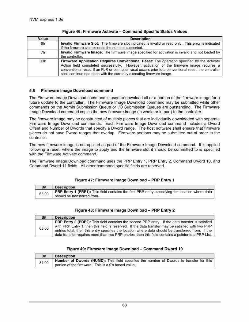
NVM Express 1.0e
63
Figure 46: Firmware Activate – Command Specific Status Values Value Description
6h Invalid Firmware Slot: The firmware slot indicated is invalid or read only. This error is indicated if the firmware slot exceeds the number supported.
7h Invalid Firmware Image: The firmware image specified for activation is invalid and not loaded by the controller.
0Bh Firmware Application Requires Conventional Reset: The operation specified by the Activate Action field completed successfully. However, activation of the firmware image requires a conventional reset. If an FLR or controller reset occurs prior to a conventional reset, the controller shall continue operation with the currently executing firmware image.
5.8 Firmware Image Download command The Firmware Image Download command is used to download all or a portion of the firmware image for a future update to the controller. The Firmware Image Download command may be submitted while other commands on the Admin Submission Queue or I/O Submission Queues are outstanding. The Firmware Image Download command copies the new firmware image (in whole or in part) to the controller.
The firmware image may be constructed of multiple pieces that are individually downloaded with separate Firmware Image Download commands. Each Firmware Image Download command includes a Dword Offset and Number of Dwords that specify a Dword range. The host software shall ensure that firmware pieces do not have Dword ranges that overlap. Firmware portions may be submitted out of order to the controller.
The new firmware image is not applied as part of the Firmware Image Download command. It is applied following a reset, where the image to apply and the firmware slot it should be committed to is specified with the Firmware Activate command.
The Firmware Image Download command uses the PRP Entry 1, PRP Entry 2, Command Dword 10, and Command Dword 11 fields. All other command specific fields are reserved.
Figure 47: Firmware Image Download – PRP Entry 1 Bit Description
63:00 PRP Entry 1 (PRP1): This field contains the first PRP entry, specifying the location where data should be transferred from.
Figure 48: Firmware Image Download – PRP Entry 2 Bit Description
63:00
PRP Entry 2 (PRP2): This field contains the second PRP entry. If the data transfer is satisfied with PRP Entry 1, then this field is reserved. If the data transfer may be satisifed with two PRP entries total, then this entry specifies the location where data should be transferred from. If the data transfer requires more than two PRP entries, then this field contains a pointer to a PRP List.
Figure 49: Firmware Image Download – Command Dword 10 Bit Description
31:00 Number of Dwords (NUMD): This field specifies the number of Dwords to transfer for this portion of the firmware. This is a 0’s based value.
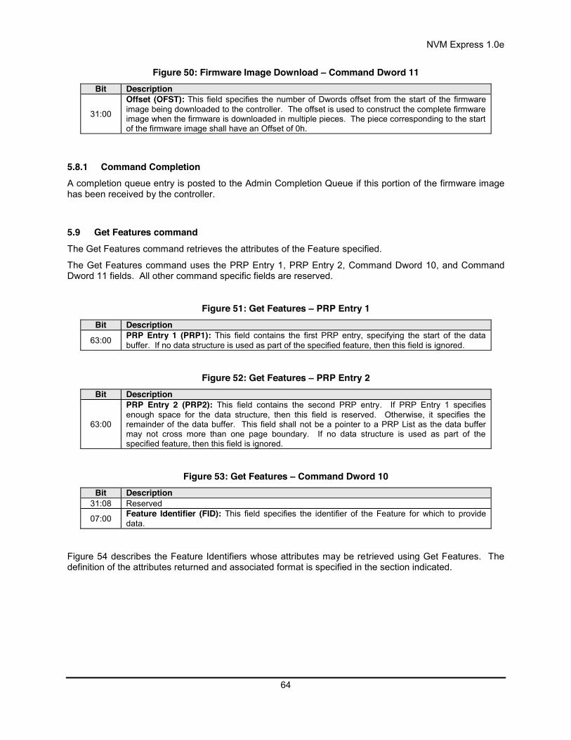
NVM Express 1.0e
64
Figure 50: Firmware Image Download – Command Dword 11 Bit Description
31:00
Offset (OFST): This field specifies the number of Dwords offset from the start of the firmware image being downloaded to the controller. The offset is used to construct the complete firmware image when the firmware is downloaded in multiple pieces. The piece corresponding to the start of the firmware image shall have an Offset of 0h.
5.8.1 Command Completion A completion queue entry is posted to the Admin Completion Queue if this portion of the firmware image has been received by the controller.
5.9 Get Features command The Get Features command retrieves the attributes of the Feature specified.
The Get Features command uses the PRP Entry 1, PRP Entry 2, Command Dword 10, and Command Dword 11 fields. All other command specific fields are reserved.
Figure 51: Get Features – PRP Entry 1 Bit Description
63:00 PRP Entry 1 (PRP1): This field contains the first PRP entry, specifying the start of the data buffer. If no data structure is used as part of the specified feature, then this field is ignored.
Figure 52: Get Features – PRP Entry 2 Bit Description
63:00
PRP Entry 2 (PRP2): This field contains the second PRP entry. If PRP Entry 1 specifies enough space for the data structure, then this field is reserved. Otherwise, it specifies the remainder of the data buffer. This field shall not be a pointer to a PRP List as the data buffer may not cross more than one page boundary. If no data structure is used as part of the specified feature, then this field is ignored.
Figure 53: Get Features – Command Dword 10 Bit Description
31:08 Reserved
07:00 Feature Identifier (FID): This field specifies the identifier of the Feature for which to provide data.
Figure 54 describes the Feature Identifiers whose attributes may be retrieved using Get Features. The definition of the attributes returned and associated format is specified in the section indicated.

NVM Express 1.0e
65
Figure 54: Get Features – Feature Identifiers
Description Section Defining
Format of Attributes Returned
Arbitration Section 5.12.1.1 Power Management Section 5.12.1.2 LBA Range Type Section 5.12.1.3 Temperature Threshold Section 5.12.1.4 Error Recovery Section 5.12.1.5 Volatile Write Cache Section 5.12.1.6 Number of Queues Section 5.12.1.7 Interrupt Coalescing Section 5.12.1.8 Interrupt Vector Configuration Section 5.12.1.9 Write Atomicity Section 5.12.1.10 Asynchronous Event Configuration Section 5.12.1.11
NVM Command Set Specific Software Progress Marker Section 5.12.1.12
5.9.1 Command Completion A completion queue entry is posted to the Admin Completion Queue if the controller has completed returning any attributes associated with the Feature. Depending on the Feature Identifier, Dword 0 of the completion queue entry may contain feature information (refer to section 5.12.1).
5.10 Get Log Page command The Get Log Page command returns a data buffer containing the log page requested.
The Get Log Page command uses the PRP Entry 1, PRP Entry 2, and Command Dword 10 fields. All other command specific fields are reserved.
Figure 55: Get Log Page – PRP Entry 1 Bit Description
63:00 PRP Entry 1 (PRP1): This field contains the first PRP entry, specifying the start of the data buffer.
Figure 56: Get Log Page – PRP Entry 2 Bit Description
63:00
PRP Entry 2 (PRP2): This field contains the second PRP entry. If PRP Entry 1 specifies enough space for the data structure, then this field is reserved. Otherwise, it specifies the remainder of the data buffer. This field shall not be a pointer to a PRP List as the data buffer may not cross more than one page boundary.
Figure 57: Get Log Page – Command Dword 10 Bit Description
31:28 Reserved
27:16 Number of Dwords (NUMD): This field specifies the number of Dwords to return. If host software specifies a size larger than the log page requested, the results are undefined. This is a 0’s based value.
15:08 Reserved

NVM Express 1.0e
66
07:00 Log Page Identifier (LID): This field specifies the identifier of the log page to retrieve.
5.10.1 Log Specific Information Figure 58 defines the Log pages that may be retrieved with the Get Log Page command.
Figure 58: Get Log Page – Log Page Identifiers Log Identifier O/M Description
00h Reserved 01h M Error Information 02h M SMART / Health Information 03h M Firmware Slot Information
04h – 7Fh Reserved 80h – BFh I/O Command Set Specific C0h – FFh Vendor specific
O/M: O = Optional, M = Mandatory
5.10.1.1 Error Information (Log Identifier 01h) This log page is used to describe extended error information for a command that completed with error. Extended error information is provided when the More (M) bit is set to ‘1’ in the Status Field for the completion queue entry associated with the command that completed with error or as part of an asynchronous event with an Error status type. This log page is global to the device.
This error log may return the last n errors. If host software specifies a data transfer of the size of n error logs, then the error logs for the last n errors is returned. The ordering of the entries is based on the time when the error occurred, with the most recent error being returned as the first log.
Each entry in the log page returned is defined in Figure 59. The log page is a set of 64 byte entries; the number of entries supported is indicated in the Identify Controller data structure in Figure 66.
Figure 59: Get Log Page – Error Information Log Entry (Log Identifier 01h) Bytes Description
07:00
Error Count: This is a 64-bit incrementing error count, indicating a unique identifier for this error. The error count starts at 1h, is incremented for each unique error log entry, and is retained across power off conditions. A value of 0h indicates an invalid entry; this value may be used when there are lost entries or when there are fewer errors than the maximum number of entries the controller supports.
09:08 Submission Queue ID: This field indicates the Submission Queue Identifier of the command that the error information is associated with.
11:10 Command ID: This field indicates the Command Identifier of the command that the error is assocated with.
13:12 Status Field: This field indicates the Status Field for the command that completed. The Status Field is located in bits 15:01, bit 00 corresponds to the Phase Tag posted for the command.

NVM Express 1.0e
67
15:14
Parameter Error Location: This field indicates the byte and bit of the command parameter that the error is associated with, if applicable. If the parameter spans multiple bytes or bits, then the location indicates the first byte and bit of the parameter.
Bits Description
7:0 Byte in command that contained the error. Valid values are 0 to 63.
10:8 Bit in command that contained the error. Valid values are 0 to7.
15:11 Reserved
23:16 LBA: This field indicates the first LBA that experienced the error condition, if applicable. 27:24 Namespace: This field indicates the namespace that the error is associated with, if applicable.
28 Vendor Specific Information Available: If there is additional vendor specific error information available, this field provides the log page identifier associated with that page. A value of 00h indicates that no additional information is available. Valid values are in the range of 80h to FFh.
63:29 Reserved
5.10.1.2 SMART / Health Information (Log Identifier 02h) This log page is used to provide SMART and general health information. The information provided is over the life of the controller and is retained across power cycles. The log page shall be supported on a global basis. The log page may be supported on a per namespace basis, as indicated in the Identify Controller data structure in Figure 66. To request the global log page, the namespace specified is FFFFFFFFh.
Critical warnings regarding the health of the device may be indicated via an asynchronous event notification to the host. The warnings that results in an asynchronous event notification to the host are configured using the Set Features command; refer to section 5.12.1.11.
Performance of the device may be calculated using parameters returned as part of the SMART / Health Information log. Specifically, the number of Read or Write commands, the amount of data read or written, and the amount of controller busy time enables both I/Os per second and bandwidth to be calculated.
The log page returned is defined in Figure 60.
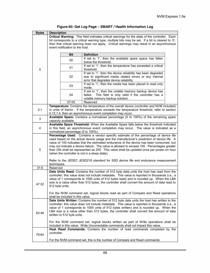
NVM Express 1.0e
68
Figure 60: Get Log Page – SMART / Health Information Log Bytes Description
0
Critical Warning: This field indicates critical warnings for the state of the controller. Each bit corresponds to a critical warning type;; multiple bits may be set. If a bit is cleared to ‘0’, then that critical warning does not apply. Critical warnings may result in an asynchronous event notification to the host.
Bit Definition 00 If set to ‘1’, then the available spare space has fallen
below the threshold.
01 If set to ‘1’, then the temperature has exceeded a critical threshold.
02 If set to ‘1’, then the device reliability has been degraded due to significant media related errors or any internal error that degrades device reliability.
03 If set to ‘1’, then the media has been placed in read only mode.
04 If set to ‘1’, then the volatile memory backup device has failed. This field is only valid if the controller has a volatile memory backup solution.
07:05 Reserved
2:1 Temperature: Contains the temperature of the overall device (controller and NVM included) in units of Kelvin. If the temperature exceeds the temperature threshold, refer to section 5.12.1.4, then an asynchronous event completion may occur.
3 Available Spare: Contains a normalized percentage (0 to 100%) of the remaining spare capacity available.
4 Available Spare Threshold: When the Available Spare falls below the threshold indicated in this field, an asynchronous event completion may occur. The value is indicated as a normalized percentage (0 to 100%).
5
Percentage Used: Contains a vendor specific estimate of the percentage of device life used based on the actual device usage and the manufacturer’s prediction of device life. A value of 100 indicates that the estimated endurance of the device has been consumed, but may not indicate a device failure. The value is allowed to exceed 100. Percentages greater than 254 shall be represented as 255. This value shall be updated once per power-on hour (when the controller is not in a sleep state). Refer to the JEDEC JESD218 standard for SSD device life and endurance measurement techniques.
31:6 Reserved
47:32
Data Units Read: Contains the number of 512 byte data units the host has read from the controller; this value does not include metadata. This value is reported in thousands (i.e., a value of 1 corresponds to 1000 units of 512 bytes read) and is rounded up. When the LBA size is a value other than 512 bytes, the controller shall convert the amount of data read to 512 byte units. For the NVM command set, logical blocks read as part of Compare and Read operations shall be included in this value.
63:48
Data Units Written: Contains the number of 512 byte data units the host has written to the controller; this value does not include metadata. This value is reported in thousands (i.e., a value of 1 corresponds to 1000 units of 512 bytes written) and is rounded up. When the LBA size is a value other than 512 bytes, the controller shall convert the amount of data written to 512 byte units. For the NVM command set, logical blocks written as part of Write operations shall be included in this value. Write Uncorrectable commands shall not impact this value.
79:64
Host Read Commands: Contains the number of read commands completed by the controller. For the NVM command set, this is the number of Compare and Read commands.
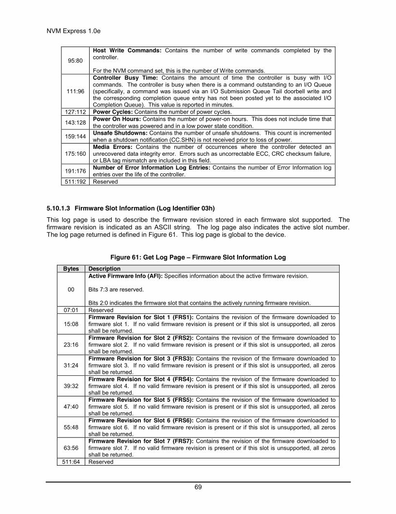
NVM Express 1.0e
69
95:80
Host Write Commands: Contains the number of write commands completed by the controller. For the NVM command set, this is the number of Write commands.
111:96
Controller Busy Time: Contains the amount of time the controller is busy with I/O commands. The controller is busy when there is a command outstanding to an I/O Queue (specifically, a command was issued via an I/O Submission Queue Tail doorbell write and the corresponding completion queue entry has not been posted yet to the associated I/O Completion Queue). This value is reported in minutes.
127:112 Power Cycles: Contains the number of power cycles.
143:128 Power On Hours: Contains the number of power-on hours. This does not include time that the controller was powered and in a low power state condition.
159:144 Unsafe Shutdowns: Contains the number of unsafe shutdowns. This count is incremented when a shutdown notification (CC.SHN) is not received prior to loss of power.
175:160 Media Errors: Contains the number of occurrences where the controller detected an unrecovered data integrity error. Errors such as uncorrectable ECC, CRC checksum failure, or LBA tag mismatch are included in this field.
191:176 Number of Error Information Log Entries: Contains the number of Error Information log entries over the life of the controller.
511:192 Reserved
5.10.1.3 Firmware Slot Information (Log Identifier 03h) This log page is used to describe the firmware revision stored in each firmware slot supported. The firmware revision is indicated as an ASCII string. The log page also indicates the active slot number. The log page returned is defined in Figure 61. This log page is global to the device.
Figure 61: Get Log Page – Firmware Slot Information Log Bytes Description
00
Active Firmware Info (AFI): Specifies information about the active firmware revision. Bits 7:3 are reserved. Bits 2:0 indicates the firmware slot that contains the actively running firmware revision.
07:01 Reserved
15:08 Firmware Revision for Slot 1 (FRS1): Contains the revision of the firmware downloaded to firmware slot 1. If no valid firmware revision is present or if this slot is unsupported, all zeros shall be returned.
23:16 Firmware Revision for Slot 2 (FRS2): Contains the revision of the firmware downloaded to firmware slot 2. If no valid firmware revision is present or if this slot is unsupported, all zeros shall be returned.
31:24 Firmware Revision for Slot 3 (FRS3): Contains the revision of the firmware downloaded to firmware slot 3. If no valid firmware revision is present or if this slot is unsupported, all zeros shall be returned.
39:32 Firmware Revision for Slot 4 (FRS4): Contains the revision of the firmware downloaded to firmware slot 4. If no valid firmware revision is present or if this slot is unsupported, all zeros shall be returned.
47:40 Firmware Revision for Slot 5 (FRS5): Contains the revision of the firmware downloaded to firmware slot 5. If no valid firmware revision is present or if this slot is unsupported, all zeros shall be returned.
55:48 Firmware Revision for Slot 6 (FRS6): Contains the revision of the firmware downloaded to firmware slot 6. If no valid firmware revision is present or if this slot is unsupported, all zeros shall be returned.
63:56 Firmware Revision for Slot 7 (FRS7): Contains the revision of the firmware downloaded to firmware slot 7. If no valid firmware revision is present or if this slot is unsupported, all zeros shall be returned.
511:64 Reserved

NVM Express 1.0e
70
5.10.2 Command Completion A completion queue entry is posted to the Admin Completion Queue if the log has been transferred to the memory buffer indicated in PRP Entry 1. Get Log Page command specific status values are defined in Figure 62.
Figure 62: Get Log Page – Command Specific Status Values Value Description
9h Invalid Log Page: The log page indicated is invalid. This error condition is also returned if a reserved log page is requested.
5.11 Identify command The Identify command returns a data buffer that describes the controller or namespace capabilities and status. The data structure is 4096 bytes in size. The host specifies as a command parameter whether to return the controller or namespace specific data structure. For the namespace data structure, the definition of the structure is specific to the I/O Command Set selected for use.
The Identify command uses the PRP Entry 1, PRP Entry 2, and Command Dword 10 fields. All other command specific fields are reserved.
Figure 63: Identify – PRP Entry 1 Bit Description
63:00 PRP Entry 1 (PRP1): This field contains the first PRP entry, specifying the start of the data buffer.
Figure 64: Identify – PRP Entry 2 Bit Description
63:00
PRP Entry 2 (PRP2): This field contains the second PRP entry. If PRP Entry 1 specifies enough space for the data structure, then this field is reserved. Otherwise, it specifies the remainder of the data buffer. This field shall not be a pointer to a PRP List as the data buffer may not cross more than one page boundary.
Figure 65: Identify – Command Dword 10 Bit Description
31:01 Reserved
00
Controller or Namespace Structure (CNS): If set to ‘1’, then the Identify Controller data structure is returned to the host. If cleared to ‘0’, then the Identify Namespace data structure is returned to the host for the namespace specified in the Namespace Identifier (CDW1.NSID) field.
Figure 66: Identify – Identify Controller Data Structure Bytes O/M Description
Controller Capabilities and Features
01:00 M PCI Vendor ID (VID): Contains the company vendor identifier that is assigned by the PCI SIG. This is the same value as reported in the ID register in section 2.1.1.
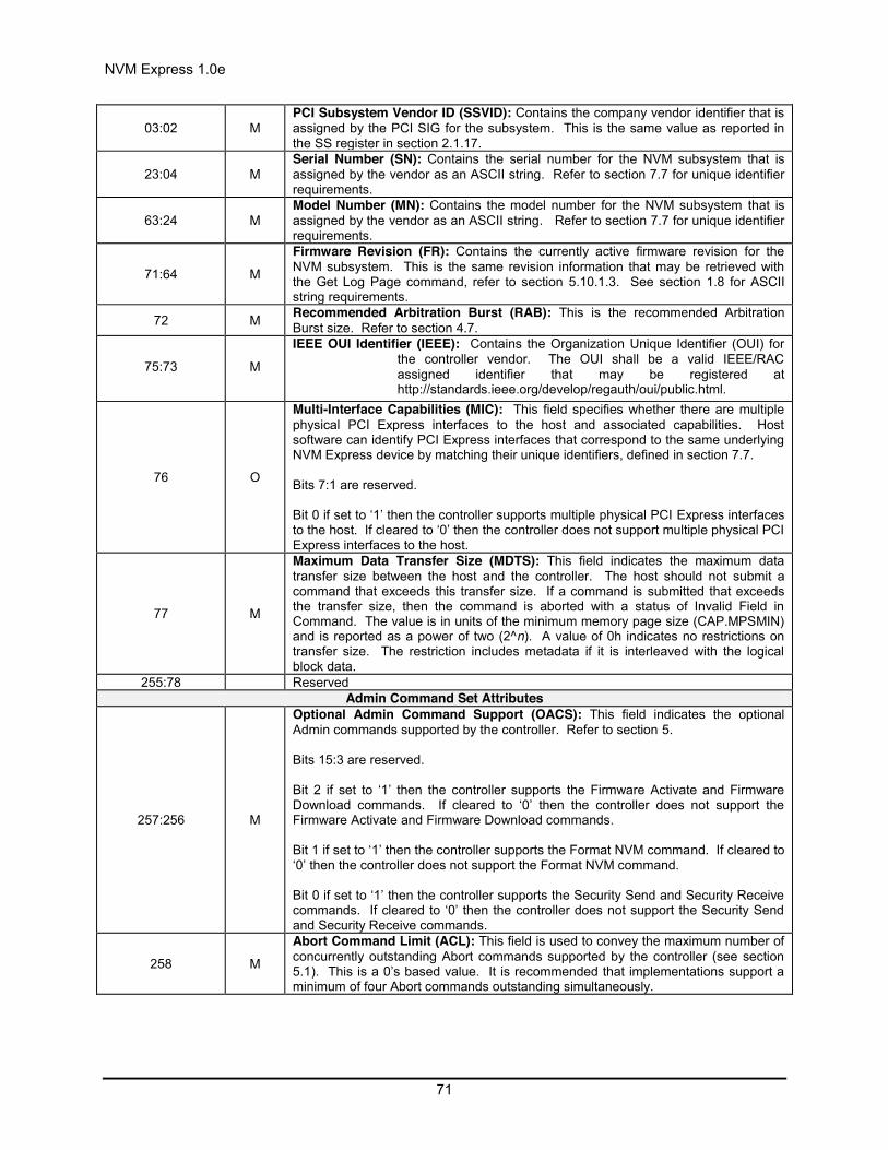
NVM Express 1.0e
71
03:02 M PCI Subsystem Vendor ID (SSVID): Contains the company vendor identifier that is assigned by the PCI SIG for the subsystem. This is the same value as reported in the SS register in section 2.1.17.
23:04 M Serial Number (SN): Contains the serial number for the NVM subsystem that is assigned by the vendor as an ASCII string. Refer to section 7.7 for unique identifier requirements.
63:24 M Model Number (MN): Contains the model number for the NVM subsystem that is assigned by the vendor as an ASCII string. Refer to section 7.7 for unique identifier requirements.
71:64 M
Firmware Revision (FR): Contains the currently active firmware revision for the NVM subsystem. This is the same revision information that may be retrieved with the Get Log Page command, refer to section 5.10.1.3. See section 1.8 for ASCII string requirements.
72 M Recommended Arbitration Burst (RAB): This is the recommended Arbitration Burst size. Refer to section 4.7.
75:73 M
IEEE OUI Identifier (IEEE): Contains the Organization Unique Identifier (OUI) for the controller vendor. The OUI shall be a valid IEEE/RAC assigned identifier that may be registered at http://standards.ieee.org/develop/regauth/oui/public.html.
76 O
Multi-Interface Capabilities (MIC): This field specifies whether there are multiple physical PCI Express interfaces to the host and associated capabilities. Host software can identify PCI Express interfaces that correspond to the same underlying NVM Express device by matching their unique identifiers, defined in section 7.7. Bits 7:1 are reserved. Bit 0 if set to ‘1’ then the controller supports multiple physical PCI Express interfaces to the host. If cleared to ‘0’ then the controller does not support multiple physical PCI Express interfaces to the host.
77 M
Maximum Data Transfer Size (MDTS): This field indicates the maximum data transfer size between the host and the controller. The host should not submit a command that exceeds this transfer size. If a command is submitted that exceeds the transfer size, then the command is aborted with a status of Invalid Field in Command. The value is in units of the minimum memory page size (CAP.MPSMIN) and is reported as a power of two (2^n). A value of 0h indicates no restrictions on transfer size. The restriction includes metadata if it is interleaved with the logical block data.
255:78 Reserved Admin Command Set Attributes
257:256 M
Optional Admin Command Support (OACS): This field indicates the optional Admin commands supported by the controller. Refer to section 5. Bits 15:3 are reserved. Bit 2 if set to ‘1’ then the controller supports the Firmware Activate and Firmware Download commands. If cleared to ‘0’ then the controller does not support the Firmware Activate and Firmware Download commands. Bit 1 if set to ‘1’ then the controller supports the Format NVM command. If cleared to ‘0’ then the controller does not support the Format NVM command. Bit 0 if set to ‘1’ then the controller supports the Security Send and Security Receive commands. If cleared to ‘0’ then the controller does not support the Security Send and Security Receive commands.
258 M
Abort Command Limit (ACL): This field is used to convey the maximum number of concurrently outstanding Abort commands supported by the controller (see section 5.1). This is a 0’s based value. It is recommended that implementations support a minimum of four Abort commands outstanding simultaneously.
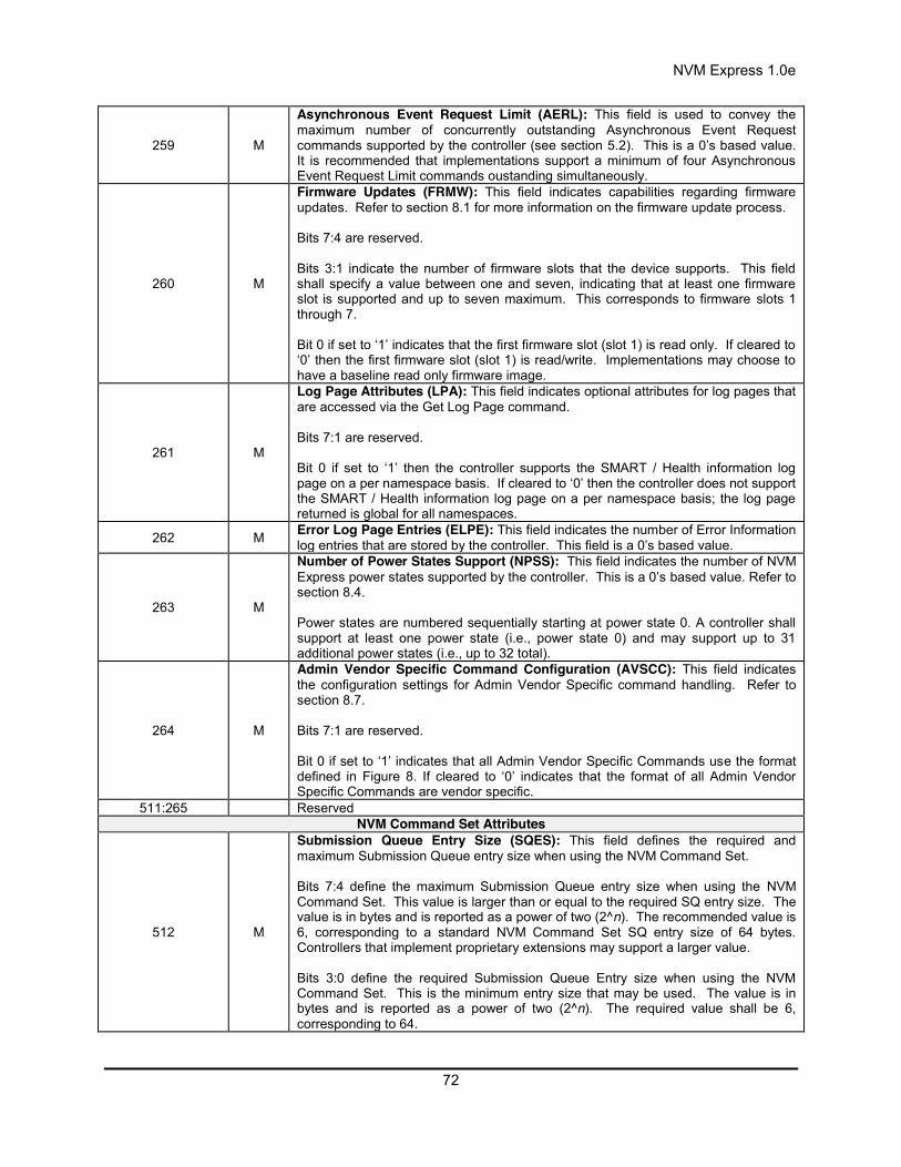
NVM Express 1.0e
72
259 M
Asynchronous Event Request Limit (AERL): This field is used to convey the maximum number of concurrently outstanding Asynchronous Event Request commands supported by the controller (see section 5.2). This is a 0’s based value. It is recommended that implementations support a minimum of four Asynchronous Event Request Limit commands oustanding simultaneously.
260 M
Firmware Updates (FRMW): This field indicates capabilities regarding firmware updates. Refer to section 8.1 for more information on the firmware update process. Bits 7:4 are reserved. Bits 3:1 indicate the number of firmware slots that the device supports. This field shall specify a value between one and seven, indicating that at least one firmware slot is supported and up to seven maximum. This corresponds to firmware slots 1 through 7. Bit 0 if set to ‘1’ indicates that the first firmware slot (slot 1) is read only. If cleared to ‘0’ then the first firmware slot (slot 1) is read/write. Implementations may choose to have a baseline read only firmware image.
261 M
Log Page Attributes (LPA): This field indicates optional attributes for log pages that are accessed via the Get Log Page command. Bits 7:1 are reserved. Bit 0 if set to ‘1’ then the controller supports the SMART / Health information log page on a per namespace basis. If cleared to ‘0’ then the controller does not support the SMART / Health information log page on a per namespace basis; the log page returned is global for all namespaces.
262 M Error Log Page Entries (ELPE): This field indicates the number of Error Information log entries that are stored by the controller. This field is a 0’s based value.
263 M
Number of Power States Support (NPSS): This field indicates the number of NVM Express power states supported by the controller. This is a 0’s based value. Refer to section 8.4. Power states are numbered sequentially starting at power state 0. A controller shall support at least one power state (i.e., power state 0) and may support up to 31 additional power states (i.e., up to 32 total).
264 M
Admin Vendor Specific Command Configuration (AVSCC): This field indicates the configuration settings for Admin Vendor Specific command handling. Refer to section 8.7. Bits 7:1 are reserved. Bit 0 if set to ‘1’ indicates that all Admin Vendor Specific Commands use the format defined in Figure 8. If cleared to ‘0’ indicates that the format of all Admin Vendor Specific Commands are vendor specific.
511:265 Reserved NVM Command Set Attributes
512 M
Submission Queue Entry Size (SQES): This field defines the required and maximum Submission Queue entry size when using the NVM Command Set. Bits 7:4 define the maximum Submission Queue entry size when using the NVM Command Set. This value is larger than or equal to the required SQ entry size. The value is in bytes and is reported as a power of two (2^n). The recommended value is 6, corresponding to a standard NVM Command Set SQ entry size of 64 bytes. Controllers that implement proprietary extensions may support a larger value. Bits 3:0 define the required Submission Queue Entry size when using the NVM Command Set. This is the minimum entry size that may be used. The value is in bytes and is reported as a power of two (2^n). The required value shall be 6, corresponding to 64.

NVM Express 1.0e
73
513 M
Completion Queue Entry Size (CQES): This field defines the required and maximum Completion Queue entry size when using the NVM Command Set. Bits 7:4 define the maximum Completion Queue entry size when using the NVM Command Set. This value is larger than or equal to the required CQ entry size. The value is in bytes and is reported as a power of two (2^n). The recommended value is 4, corresponding to a standard NVM Command Set CQ entry size of 16 bytes. Controllers that implement proprietary extensions may support a larger value. Bits 3:0 define the required Completion Queue entry size when using the NVM Command Set. This is the minimum entry size that may be used. The value is in bytes and is reported as a power of two (2^n). The required value shall be 4, corresponding to 16.
515:514 Reserved
519:516 M Number of Namespaces (NN): This field defines the number of valid namespaces present for the controller. Namespaces shall be allocated in order (starting with 1) and packed sequentially.
521:520 M
Optional NVM Command Support (ONCS): This field indicates the optional NVM commands supported by the controller. Refer to section 6. Bits 15:3 are reserved. Bit 2 if set to ‘1’ then the controller supports the Dataset Management command. If cleared to ‘0’ then the controller does not support the Dataset Management command. Bit 1 if set to ‘1’ then the controller supports the Write Uncorrectable command. If cleared to ‘0’ then the controller does not support the Write Uncorrectable command. Bit 0 if set to ‘1’ then the controller supports the Compare command. If cleared to ‘0’ then the controller does not support the Compare command.
523:522 M
Fused Operation Support (FUSES): This field indicates the fused operations that the controller supports. Refer to section 6.1. Bits 15:1 are reserved. Bit 0 if set to ‘1’ then the controller supports the Compare and Write fused operation. If cleared to ‘0’ then the controller does not support the Compare and Write fused operation. Compare shall be the first command in the sequence.
524 M
Format NVM Attributes (FNA): This field indicates attributes for the Format NVM command. Bits 7:3 are reserved. Bit 2 indicates whether cryptographic erase is supported as part of the secure erase functionality. If set to ‘1’, then cryptographic erase is supported. If cleared to ‘0’, then cryptographic erase is not supported. Bit 1 indicates whether secure erase functionality applies to all namespaces or is specific to a particular namespace. If set to’1’, then a secure erase of a particular namespace as part of a format results in a secure erase of all namespaces. If cleared to ‘0’, then a secure erase as part of a format is performed on a per namespace basis. Bit 0 indicates whether the format operation applies to all namespaces or is specific to a particular namespace. If set to ‘1’, then all namespaces shall be configured with the same attributes and a format of any namespace results in a format of all namespaces. If cleared to ‘0’, then the controller supports format on a per namespace basis.

NVM Express 1.0e
74
525 M
Volatile Write Cache (VWC): This field indicates attributes related to the presence of a volatile write cache in the implementation. Bits 7:1 are reserved. Bit 0 if set to ‘1’ indicates that a volatile write cache is present. If cleared to ‘0’, a volatile write cache is not present. If a volatile write cache is present, then the host may issue Flush commands and control whether it is enabled with Set Features specifying the Volatile Write Cache feature identifier. If a volatile write cache is not present, Flush commands complete successfully and have no effect, and Set Features commands Set Features with the Volatile Write Cache identifier field set shall fail with Invalid Field status.
527:526 M
Atomic Write Unit Normal (AWUN): This field indicates the atomic write size for the controller during normal operation. This field is specified in logical blocks and is a 0’s based value. If a write is submitted of this size or less, the host is guaranteed that the write is atomic to the NVM with respect to other read or write operations. A value of FFFFh indicates all commands are atomic as this is the largest command size. It is recommended that implementations support a minimum of 128KB (appropriately scaled based on LBA size).
529:528 M
Atomic Write Unit Power Fail (AWUPF): This field indicates the atomic write size for the controller during a power fail condition. This field is specified in logical blocks and is a 0’s based value. If a write is submitted of this size or less, the host is guaranteed that the write is atomic to the NVM with respect to other read or write operations.
530 M
NVM Vendor Specific Command Configuration (NVSCC): This field indicates the configuration settings for NVM Vendor Specific command handling. Refer to section 8.7. Bits 7:1 are reserved. Bit 0 if set to ‘1’ indicates that all NVM Vendor Specific Commands use the format defined in Figure 8. If cleared to ‘0’ indicates that the format of all NVM Vendor Specific Commands are vendor specific.
703:531 M Reserved I/O Command Set Attributes
2047:704 Reserved Power State Descriptors
2079:2048 M Power State 0 Descriptor (PSD0): This field indicates the characteristics of power state 0. The format of this field is defined in Figure 67.
2111:2080 O Power State 1 Descriptor (PSD1): This field indicates the characteristics of power state 1. The format of this field is defined in Figure 67.
2143:2112 O Power State 2 Descriptor (PSD2): This field indicates the characteristics of power state 2. The format of this field is defined in Figure 67.
2175:2144 O Power State 3 Descriptor (PSD3): This field indicates the characteristics of power state 3. The format of this field is defined in Figure 67.
2207:2176 O Power State 4 Descriptor (PSD4): This field indicates the characteristics of power state 4. The format of this field is defined in Figure 67.
2239:2208 O Power State 5 Descriptor (PSD5): This field indicates the characteristics of power state 5. The format of this field is defined in Figure 67.
2271:2240 O Power State 6 Descriptor (PSD6): This field indicates the characteristics of power state 6. The format of this field is defined in Figure 67.
2303:2272 O Power State 7 Descriptor (PSD7): This field indicates the characteristics of power state 7. The format of this field is defined in Figure 67.
2335:2304 O Power State 8 Descriptor (PSD8): This field indicates the characteristics of power state 8. The format of this field is defined in Figure 67.
2367:2336 O Power State 9 Descriptor (PSD9): This field indicates the characteristics of power state 9. The format of this field is defined in Figure 67.
2399:2368 O Power State 10 Descriptor (PSD10): This field indicates the characteristics of power state 10. The format of this field is defined in Figure 67.
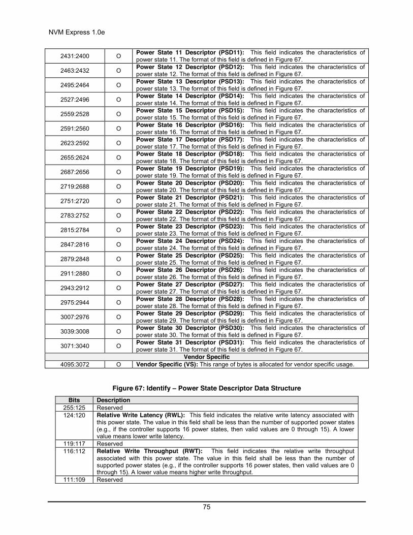
NVM Express 1.0e
75
2431:2400 O Power State 11 Descriptor (PSD11): This field indicates the characteristics of power state 11. The format of this field is defined in Figure 67.
2463:2432 O Power State 12 Descriptor (PSD12): This field indicates the characteristics of power state 12. The format of this field is defined in Figure 67.
2495:2464 O Power State 13 Descriptor (PSD13): This field indicates the characteristics of power state 13. The format of this field is defined in Figure 67.
2527:2496 O Power State 14 Descriptor (PSD14): This field indicates the characteristics of power state 14. The format of this field is defined in Figure 67.
2559:2528 O Power State 15 Descriptor (PSD15): This field indicates the characteristics of power state 15. The format of this field is defined in Figure 67.
2591:2560 O Power State 16 Descriptor (PSD16): This field indicates the characteristics of power state 16. The format of this field is defined in Figure 67.
2623:2592 O Power State 17 Descriptor (PSD17): This field indicates the characteristics of power state 17. The format of this field is defined in Figure 67.
2655:2624 O Power State 18 Descriptor (PSD18): This field indicates the characteristics of power state 18. The format of this field is defined in Figure 67.
2687:2656 O Power State 19 Descriptor (PSD19): This field indicates the characteristics of power state 19. The format of this field is defined in Figure 67.
2719:2688 O Power State 20 Descriptor (PSD20): This field indicates the characteristics of power state 20. The format of this field is defined in Figure 67.
2751:2720 O Power State 21 Descriptor (PSD21): This field indicates the characteristics of power state 21. The format of this field is defined in Figure 67.
2783:2752 O Power State 22 Descriptor (PSD22): This field indicates the characteristics of power state 22. The format of this field is defined in Figure 67.
2815:2784 O Power State 23 Descriptor (PSD23): This field indicates the characteristics of power state 23. The format of this field is defined in Figure 67.
2847:2816 O Power State 24 Descriptor (PSD24): This field indicates the characteristics of power state 24. The format of this field is defined in Figure 67.
2879:2848 O Power State 25 Descriptor (PSD25): This field indicates the characteristics of power state 25. The format of this field is defined in Figure 67.
2911:2880 O Power State 26 Descriptor (PSD26): This field indicates the characteristics of power state 26. The format of this field is defined in Figure 67.
2943:2912 O Power State 27 Descriptor (PSD27): This field indicates the characteristics of power state 27. The format of this field is defined in Figure 67.
2975:2944 O Power State 28 Descriptor (PSD28): This field indicates the characteristics of power state 28. The format of this field is defined in Figure 67.
3007:2976 O Power State 29 Descriptor (PSD29): This field indicates the characteristics of power state 29. The format of this field is defined in Figure 67.
3039:3008 O Power State 30 Descriptor (PSD30): This field indicates the characteristics of power state 30. The format of this field is defined in Figure 67.
3071:3040 O Power State 31 Descriptor (PSD31): This field indicates the characteristics of power state 31. The format of this field is defined in Figure 67.
Vendor Specific 4095:3072 O Vendor Specific (VS): This range of bytes is allocated for vendor specific usage.
Figure 67: Identify – Power State Descriptor Data Structure Bits Description
255:125 Reserved 124:120 Relative Write Latency (RWL): This field indicates the relative write latency associated with
this power state. The value in this field shall be less than the number of supported power states (e.g., if the controller supports 16 power states, then valid values are 0 through 15). A lower value means lower write latency.
119:117 Reserved 116:112 Relative Write Throughput (RWT): This field indicates the relative write throughput
associated with this power state. The value in this field shall be less than the number of supported power states (e.g., if the controller supports 16 power states, then valid values are 0 through 15). A lower value means higher write throughput.
111:109 Reserved
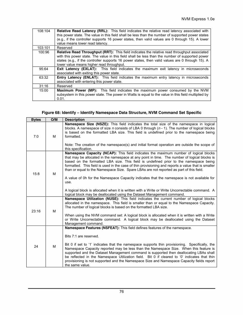
NVM Express 1.0e
76
108:104 Relative Read Latency (RRL): This field indicates the relative read latency associated with this power state. The value in this field shall be less than the number of supported power states (e.g., if the controller supports 16 power states, then valid values are 0 through 15). A lower value means lower read latency.
103:101 Reserved 100:96 Relative Read Throughput (RRT): This field indicates the relative read throughput associated
with this power state. The value in this field shall be less than the number of supported power states (e.g., if the controller supports 16 power states, then valid values are 0 through 15). A lower value means higher read throughput.
95:64 Exit Latency (EXLAT): This field indicates the maximum exit latency in microseconds associated with exiting this power state.
63:32 Entry Latency (ENLAT): This field indicates the maximum entry latency in microseconds associated with entering this power state.
31:16 Reserved 15:00 Maximum Power (MP): This field indicates the maximum power consumed by the NVM
subsystem in this power state. The power in Watts is equal to the value in this field multiplied by 0.01.
Figure 68: Identify – Identify Namespace Data Structure, NVM Command Set Specific Bytes O/M Description
7:0 M
Namespace Size (NSZE): This field indicates the total size of the namespace in logical blocks. A namespace of size n consists of LBA 0 through (n - 1). The number of logical blocks is based on the formatted LBA size. This field is undefined prior to the namespace being formatted. Note: The creation of the namespace(s) and initial format operation are outside the scope of this specification.
15:8 M
Namespace Capacity (NCAP): This field indicates the maximum number of logical blocks that may be allocated in the namespace at any point in time. The number of logical blocks is based on the formatted LBA size. This field is undefined prior to the namespace being formatted. This field is used in the case of thin provisioning and reports a value that is smaller than or equal to the Namespace Size. Spare LBAs are not reported as part of this field. A value of 0h for the Namespace Capacity indicates that the namespace is not available for use. A logical block is allocated when it is written with a Write or Write Uncorrectable command. A logical block may be deallocated using the Dataset Management command.
23:16 M
Namespace Utilization (NUSE): This field indicates the current number of logical blocks allocated in the namespace. This field is smaller than or equal to the Namespace Capacity. The number of logical blocks is based on the formatted LBA size. When using the NVM command set: A logical block is allocated when it is written with a Write or Write Uncorrectable command. A logical block may be deallocated using the Dataset Management command.
24 M
Namespace Features (NSFEAT): This field defines features of the namespace. Bits 7:1 are reserved. Bit 0 if set to ‘1’ indicates that the namespace supports thin provisioning. Specifically, the Namespace Capacity reported may be less than the Namespace Size. When this feature is supported and the Dataset Management command is supported then deallocating LBAs shall be reflected in the Namespace Utilization field. Bit 0 if cleared to ‘0’ indicates that thin provisioning is not supported and the Namespace Size and Namespace Capacity fields report the same value.
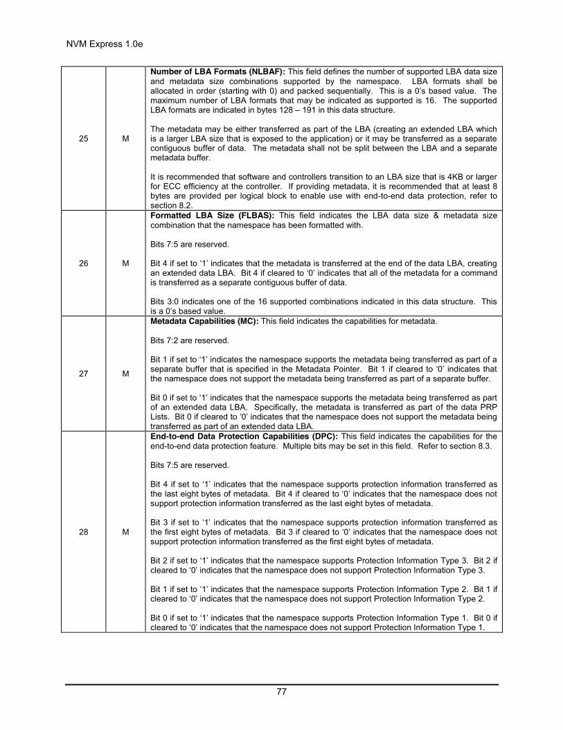
NVM Express 1.0e
77
25 M
Number of LBA Formats (NLBAF): This field defines the number of supported LBA data size and metadata size combinations supported by the namespace. LBA formats shall be allocated in order (starting with 0) and packed sequentially. This is a 0’s based value. The maximum number of LBA formats that may be indicated as supported is 16. The supported LBA formats are indicated in bytes 128 – 191 in this data structure. The metadata may be either transferred as part of the LBA (creating an extended LBA which is a larger LBA size that is exposed to the application) or it may be transferred as a separate contiguous buffer of data. The metadata shall not be split between the LBA and a separate metadata buffer. It is recommended that software and controllers transition to an LBA size that is 4KB or larger for ECC efficiency at the controller. If providing metadata, it is recommended that at least 8 bytes are provided per logical block to enable use with end-to-end data protection, refer to section 8.2.
26 M
Formatted LBA Size (FLBAS): This field indicates the LBA data size & metadata size combination that the namespace has been formatted with. Bits 7:5 are reserved. Bit 4 if set to ‘1’ indicates that the metadata is transferred at the end of the data LBA, creating an extended data LBA. Bit 4 if cleared to ‘0’ indicates that all of the metadata for a command is transferred as a separate contiguous buffer of data. Bits 3:0 indicates one of the 16 supported combinations indicated in this data structure. This is a 0’s based value.
27 M
Metadata Capabilities (MC): This field indicates the capabilities for metadata. Bits 7:2 are reserved. Bit 1 if set to ‘1’ indicates the namespace supports the metadata being transferred as part of a separate buffer that is specified in the Metadata Pointer. Bit 1 if cleared to ‘0’ indicates that the namespace does not support the metadata being transferred as part of a separate buffer. Bit 0 if set to ‘1’ indicates that the namespace supports the metadata being transferred as part of an extended data LBA. Specifically, the metadata is transferred as part of the data PRP Lists. Bit 0 if cleared to ‘0’ indicates that the namespace does not support the metadata being transferred as part of an extended data LBA.
28 M
End-to-end Data Protection Capabilities (DPC): This field indicates the capabilities for the end-to-end data protection feature. Multiple bits may be set in this field. Refer to section 8.3. Bits 7:5 are reserved. Bit 4 if set to ‘1’ indicates that the namespace supports protection information transferred as the last eight bytes of metadata. Bit 4 if cleared to ‘0’ indicates that the namespace does not support protection information transferred as the last eight bytes of metadata. Bit 3 if set to ‘1’ indicates that the namespace supports protection information transferred as the first eight bytes of metadata. Bit 3 if cleared to ‘0’ indicates that the namespace does not support protection information transferred as the first eight bytes of metadata. Bit 2 if set to ‘1’ indicates that the namespace supports Protection Information Type 3. Bit 2 if cleared to ‘0’ indicates that the namespace does not support Protection Information Type 3. Bit 1 if set to ‘1’ indicates that the namespace supports Protection Information Type 2. Bit 1 if cleared to ‘0’ indicates that the namespace does not support Protection Information Type 2. Bit 0 if set to ‘1’ indicates that the namespace supports Protection Information Type 1. Bit 0 if cleared to ‘0’ indicates that the namespace does not support Protection Information Type 1.

NVM Express 1.0e
78
29 M
End-to-end Data Protection Type Settings (DPS): This field indicates the Type settings for the end-to-end data protection feature. Refer to section 8.3. Bits 7:4 are reserved. Bit 3 if set to ‘1’ indicates that the protection information, if enabled, is transferred as the first eight bytes of metadata. Bit 3 if cleared to ‘0’ indicates that the protection information, if enabled, is transferred as the last eight bytes of metadata. Bits 2:0 indicate whether Protection Information is enabled and the type of Protection Information enabled. The values for this field have the following meanings:
Value Definition 000b Protection information is not enabled 001b Protection information is enabled, Type 1 010b Protection information is enabled, Type 2 011b Protection information is enabled, Type 3
100b – 111b Reserved
127:30 Reserved
131:128 M LBA Format 0 Support (LBAF0): This field indicates the LBA format 0 that is supported by the controller. The LBA format field is defined in Figure 69.
135:132 O LBA Format 1 Support (LBAF1): This field indicates the LBA format 1 that is supported by the controller. The LBA format field is defined in Figure 69.
139:136 O LBA Format 2 Support (LBAF2): This field indicates the LBA format 2 that is supported by the controller. The LBA format field is defined in Figure 69.
143:140 O LBA Format 3 Support (LBAF3): This field indicates the LBA format 3 that is supported by the controller. The LBA format field is defined in Figure 69.
147:144 O LBA Format 4 Support (LBAF4): This field indicates the LBA format 4 that is supported by the controller. The LBA format field is defined in Figure 69.
151:148 O LBA Format 5 Support (LBAF5): This field indicates the LBA format 5 that is supported by the controller. The LBA format field is defined in Figure 69.
155:152 O LBA Format 6 Support (LBAF6): This field indicates the LBA format 6 that is supported by the controller. The LBA format field is defined in Figure 69.
159:156 O LBA Format 7 Support (LBAF7): This field indicates the LBA format 7 that is supported by the controller. The LBA format field is defined in Figure 69.
163:160 O LBA Format 8 Support (LBAF8): This field indicates the LBA format 8 that is supported by the controller. The LBA format field is defined in Figure 69.
167:164 O LBA Format 9 Support (LBAF9): This field indicates the LBA format 9 that is supported by the controller. The LBA format field is defined in Figure 69.
171:168 O LBA Format 10 Support (LBAF10): This field indicates the LBA format 10 that is supported by the controller. The LBA format field is defined in Figure 69.
175:172 O LBA Format 11 Support (LBAF11): This field indicates the LBA format 11 that is supported by the controller. The LBA format field is defined in Figure 69.
179:176 O LBA Format 12 Support (LBAF12): This field indicates the LBA format 12 that is supported by the controller. The LBA format field is defined in Figure 69.
183:180 O LBA Format 13 Support (LBAF13): This field indicates the LBA format 13 that is supported by the controller. The LBA format field is defined in Figure 69.
187:184 O LBA Format 14 Support (LBAF14): This field indicates the LBA format 14 that is supported by the controller. The LBA format field is defined in Figure 69.
191:188 O LBA Format 15 Support (LBAF15): This field indicates the LBA format 15 that is supported by the controller. The LBA format field is defined in Figure 69.
383:192 Reserved 4095:384 O Vendor Specific (VS): This range of bytes is allocated for vendor specific usage.
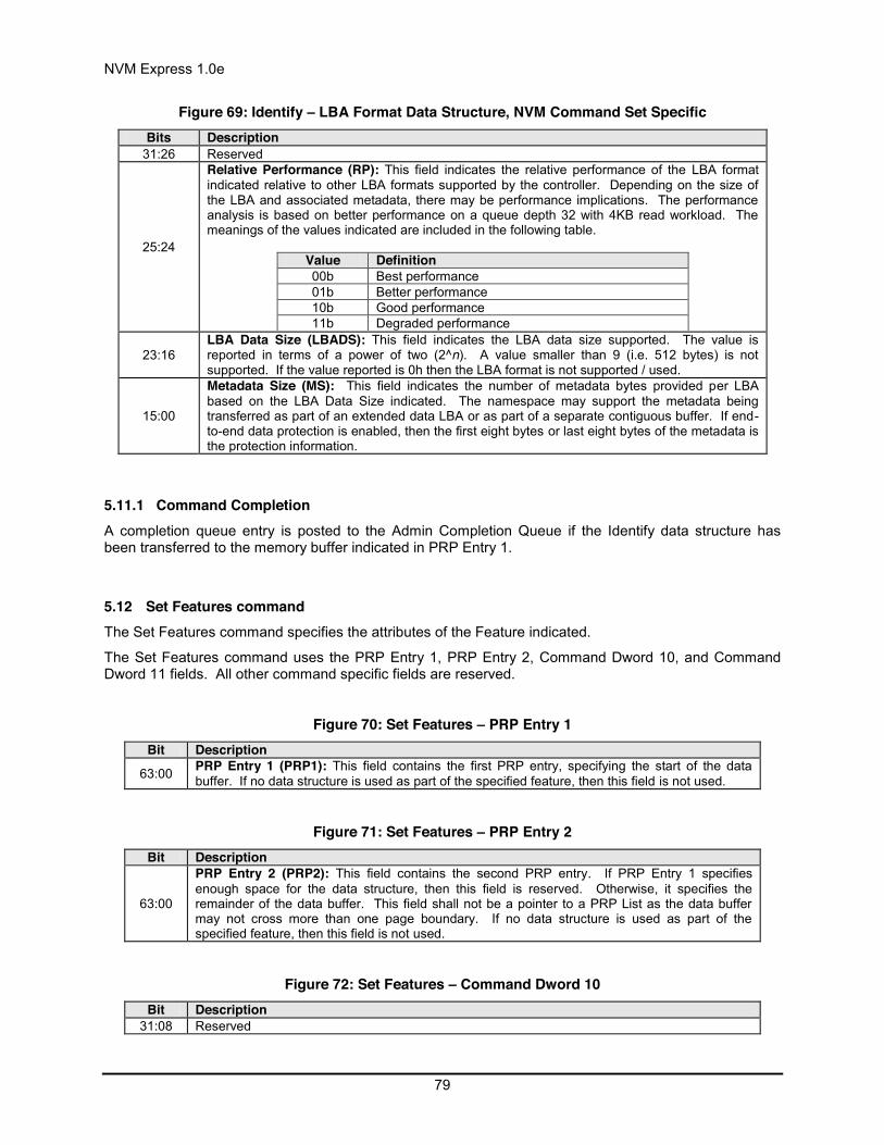
NVM Express 1.0e
79
Figure 69: Identify – LBA Format Data Structure, NVM Command Set Specific Bits Description
31:26 Reserved
25:24
Relative Performance (RP): This field indicates the relative performance of the LBA format indicated relative to other LBA formats supported by the controller. Depending on the size of the LBA and associated metadata, there may be performance implications. The performance analysis is based on better performance on a queue depth 32 with 4KB read workload. The meanings of the values indicated are included in the following table.
Value Definition 00b Best performance 01b Better performance 10b Good performance 11b Degraded performance
23:16 LBA Data Size (LBADS): This field indicates the LBA data size supported. The value is reported in terms of a power of two (2^n). A value smaller than 9 (i.e. 512 bytes) is not supported. If the value reported is 0h then the LBA format is not supported / used.
15:00
Metadata Size (MS): This field indicates the number of metadata bytes provided per LBA based on the LBA Data Size indicated. The namespace may support the metadata being transferred as part of an extended data LBA or as part of a separate contiguous buffer. If end-to-end data protection is enabled, then the first eight bytes or last eight bytes of the metadata is the protection information.
5.11.1 Command Completion A completion queue entry is posted to the Admin Completion Queue if the Identify data structure has been transferred to the memory buffer indicated in PRP Entry 1.
5.12 Set Features command The Set Features command specifies the attributes of the Feature indicated.
The Set Features command uses the PRP Entry 1, PRP Entry 2, Command Dword 10, and Command Dword 11 fields. All other command specific fields are reserved.
Figure 70: Set Features – PRP Entry 1 Bit Description
63:00 PRP Entry 1 (PRP1): This field contains the first PRP entry, specifying the start of the data buffer. If no data structure is used as part of the specified feature, then this field is not used.
Figure 71: Set Features – PRP Entry 2 Bit Description
63:00
PRP Entry 2 (PRP2): This field contains the second PRP entry. If PRP Entry 1 specifies enough space for the data structure, then this field is reserved. Otherwise, it specifies the remainder of the data buffer. This field shall not be a pointer to a PRP List as the data buffer may not cross more than one page boundary. If no data structure is used as part of the specified feature, then this field is not used.
Figure 72: Set Features – Command Dword 10 Bit Description
31:08 Reserved
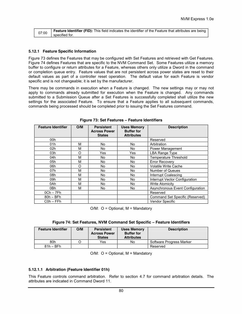
NVM Express 1.0e
80
07:00 Feature Identifier (FID): This field indicates the identifier of the Feature that attributes are being specified for.
5.12.1 Feature Specific Information Figure 73 defines the Features that may be configured with Set Features and retrieved with Get Features. Figure 74 defines Features that are specific to the NVM Command Set. Some Features utilize a memory buffer to configure or return attributes for a Feature, whereas others only utilize a Dword in the command or completion queue entry. Feature values that are not persistent across power states are reset to their default values as part of a controller reset operation. The default value for each Feature is vendor specific and is not changeable; it is set by the manufacturer.
There may be commands in execution when a Feature is changed. The new settings may or may not apply to commands already submitted for execution when the Feature is changed. Any commands submitted to a Submission Queue after a Set Features is successfully completed shall utilize the new settings for the associated Feature. To ensure that a Feature applies to all subsequent commands, commands being processed should be completed prior to issuing the Set Features command.
Figure 73: Set Features – Feature Identifiers Feature Identifier O/M Persistent
Across Power States
Uses Memory Buffer for Attributes
Description
00h Reserved 01h M No No Arbitration 02h M No No Power Management 03h O Yes Yes LBA Range Type 04h M No No Temperature Threshold 05h M No No Error Recovery 06h O No No Volatile Write Cache 07h M No No Number of Queues 08h M No No Interrupt Coalescing 09h M No No Interrupt Vector Configuration 0Ah M No No Write Atomicity 0Bh M No No Asynchronous Event Configuration
0Ch – 7Fh Reserved 80h – BFh Command Set Specific (Reserved) C0h – FFh Vendor Specific
O/M: O = Optional, M = Mandatory
Figure 74: Set Features, NVM Command Set Specific – Feature Identifiers Feature Identifier O/M Persistent
Across Power States
Uses Memory Buffer for Attributes
Description
80h O Yes No Software Progress Marker 81h – BFh Reserved
O/M: O = Optional, M = Mandatory
5.12.1.1 Arbitration (Feature Identifier 01h) This Feature controls command arbitration. Refer to section 4.7 for command arbitration details. The attributes are indicated in Command Dword 11.

NVM Express 1.0e
81
If a Get Features command is submitted for this Feature, the attributes specified in Figure 75 are returned in Dword 0 of the completion queue entry for that command.
Figure 75: Arbitration & Command Processing – Command Dword 11 Bit Description
31:24 High Priority Weight (HPW): This field defines the number of commands that may be executed from the high priority service class in each arbitration round. This is a 0’s based value.
23:16 Medium Priority Weight (MPW): This field defines the number of commands that may be executed from the medium priority service class in each arbitration round. This is a 0’s based value.
15:08 Low Priority Weight (LPW): This field defines the number of commands that may be executed from the low priority service class in each arbitration round. This is a 0’s based value.
07:03 Reserved
02:00 Arbitration Burst (AB): Indicates the maximum number of commands that the controller may launch at one time from a particular Submission Queue. This value is specified as 2^n. A value of 111b indicates no limit. Thus, the possible settings are 1, 2, 4, 8, 16, 32, 64, or no limit.
5.12.1.2 Power Management (Feature Identifier 02h) This Feature allows the host to configure the power state. The attributes are indicated in Command Dword 11.
If a Get Features command is submitted for this Feature, the attributes specified in Figure 76 are returned in Dword 0 of the completion queue entry for that command.
Figure 76: Power Management – Command Dword 11 Bit Description
31:05 Reserved
04:00
Power State (PS): This field indicates the new power state into which the controller should transition. This power state shall be one supported by the controller as indicated in the Number of Power States Supported (NPSS) field in the Indentify Controller data structure. The behavior of transitioning to a power state not supported by the controller is undefined.
5.12.1.3 LBA Range Type (Feature Identifier 03h), (Optional) This feature indicates the type and attributes of LBA ranges that are part of the specified namespace. The LBA range information may be used by a driver to determine if it may utilize a particular LBA range; the information is not exposed to higher level software.
This is optional information that is not required for proper behavior of the system. However, it may be utilized to avoid unintended software issues. For example, if the LBA range indicates that it is a RAID volume then a driver that does not have RAID functionality should not utilize that LBA range (including not overwriting the LBA range). The optional information may be utilized by the driver to determine whether the LBA Range should be exposed to higher level software.
The LBA Range Type uses Command Dword 11 and specifies the type and attribute information in the data structure indicated in Figure 78. The data structure is 4096 bytes in size and shall be physically contiguous.
If a Get Features command is submitted for this Feature, the attributes specified in Figure 77 are returned in Dword 0 of the completion queue entry and the LBA Range Type data structure specified in Figure 78 is returned in the data buffer for that command.

NVM Express 1.0e
82
Figure 77: LBA Range Type – Command Dword 11 Bit Description
31:06 Reserved
05:00 Number of LBA Ranges (NUM): This field specifies the number of LBA ranges specified in this command. This is a 0’s based value.
Each entry in the LBA Range Type data structure is defined in Figure 78. The LBA Range feature is a set of 64 byte entries; the number of entries is indicated as a command parameter, the maximum number of entries is 64. The LBA ranges shall not overlap. All unused entries in the LBA Range Type data structure shall be cleared to all zeroes.
Figure 78: LBA Range Type – Data Structure Entry Byte Description
00
Type (Type): Specifies the Type of the LBA range. The Types are listed below.
Value Description 00h Reserved 01h Filesystem 02h RAID 03h Cache 04h Page / swap file
05h – 7Fh Reserved 80h - FFh Vendor Specific
01
Attributes: Specifies attributes of the LBA range. Each bit defines an attribute.
Bit Description
0 If set to ‘1’, the LBA range may be overwritten. If cleared to ‘0’, the area should not be overwritten.
1 If set to ‘1’, the LBA range should be hidden from the OS / EFI / BIOS. If cleared to ‘0’, the area should be visible to the OS / EFI / BIOS.
2 – 7 Reserved
15:02 Reserved
23:16 Starting LBA (SLBA): This field specifies the 64-bit address of the first logical block that is part of this LBA range.
31:24 Number of Logical Blocks (NLB): This field specifies the number of logical blocks that are part of this LBA range. This is a 0’s based value.
47:32 Unique Identifier (GUID): This field is a global unique identifier that uniquely specifies the type of this LBA range. Well known Types may be defined and are published on the NVM Express website.
63:48 Reserved
The host storage driver should expose all LBA ranges that are not set to be hidden from the OS / EFI / BIOS in the Attributes field. All LBA ranges that follow a hidden range shall also be hidden; the host storage driver should not expose subsequent LBA ranges that follow a hidden LBA range.
5.12.1.4 Temperature Threshold (Feature Identifier 04h) This Feature indicates the threshold for the temperature of the overall device (controller and NVM included) in units of Kelvin. If this temperature is exceeded, then an asynchronous event may be issued to the host. The host should configure this feature prior to enabling asynchronous event notification for the temperature exceeding the threshold. The attributes are indicated in Command Dword 11.
If a Get Features command is submitted for this Feature, the attributes specified in Figure 79 are returned in Dword 0 of the completion queue entry for that command.
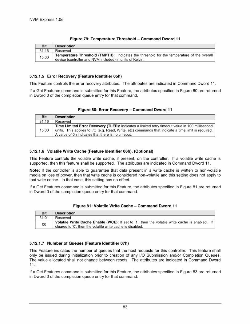
NVM Express 1.0e
83
Figure 79: Temperature Threshold – Command Dword 11 Bit Description
31:16 Reserved
15:00 Temperature Threshold (TMPTH): Indicates the threshold for the temperature of the overall device (controller and NVM included) in units of Kelvin.
5.12.1.5 Error Recovery (Feature Identifier 05h) This Feature controls the error recovery attributes. The attributes are indicated in Command Dword 11.
If a Get Features command is submitted for this Feature, the attributes specified in Figure 80 are returned in Dword 0 of the completion queue entry for that command.
Figure 80: Error Recovery – Command Dword 11 Bit Description
31:16 Reserved
15:00 Time Limited Error Recovery (TLER): Indicates a limited retry timeout value in 100 millisecond units. This applies to I/O (e.g. Read, Write, etc) commands that indicate a time limit is required. A value of 0h indicates that there is no timeout.
5.12.1.6 Volatile Write Cache (Feature Identifier 06h), (Optional) This Feature controls the volatile write cache, if present, on the controller. If a volatile write cache is supported, then this feature shall be supported. The attributes are indicated in Command Dword 11.
Note: If the controller is able to guarantee that data present in a write cache is written to non-volatile media on loss of power, then that write cache is considered non-volatile and this setting does not apply to that write cache. In that case, this setting has no effect.
If a Get Features command is submitted for this Feature, the attributes specified in Figure 81 are returned in Dword 0 of the completion queue entry for that command.
Figure 81: Volatile Write Cache – Command Dword 11 Bit Description
31:01 Reserved
00 Volatile Write Cache Enable (WCE): If set to ‘1’, then the volatile write cache is enabled. If cleared to ‘0’, then the volatile write cache is disabled.
5.12.1.7 Number of Queues (Feature Identifier 07h) This Feature indicates the number of queues that the host requests for this controller. This feature shall only be issued during initialization prior to creation of any I/O Submission and/or Completion Queues. The value allocated shall not change between resets. The attributes are indicated in Command Dword 11.
If a Get Features command is submitted for this Feature, the attributes specified in Figure 83 are returned in Dword 0 of the completion queue entry for that command.
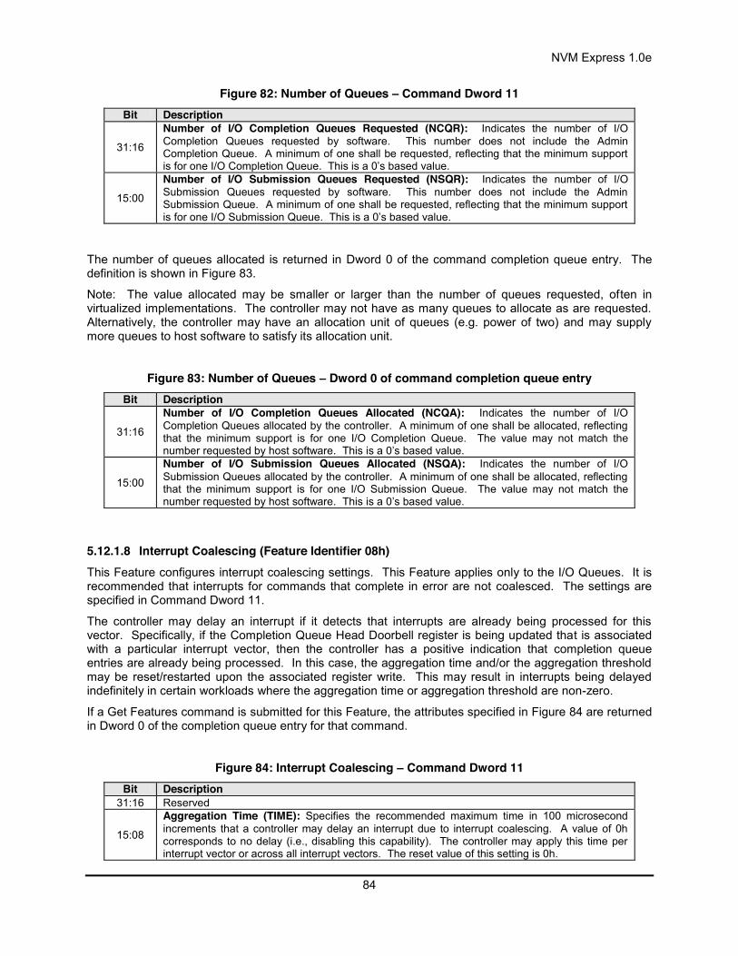
NVM Express 1.0e
84
Figure 82: Number of Queues – Command Dword 11 Bit Description
31:16
Number of I/O Completion Queues Requested (NCQR): Indicates the number of I/O Completion Queues requested by software. This number does not include the Admin Completion Queue. A minimum of one shall be requested, reflecting that the minimum support is for one I/O Completion Queue. This is a 0’s based value.
15:00
Number of I/O Submission Queues Requested (NSQR): Indicates the number of I/O Submission Queues requested by software. This number does not include the Admin Submission Queue. A minimum of one shall be requested, reflecting that the minimum support is for one I/O Submission Queue. This is a 0’s based value.
The number of queues allocated is returned in Dword 0 of the command completion queue entry. The definition is shown in Figure 83.
Note: The value allocated may be smaller or larger than the number of queues requested, often in virtualized implementations. The controller may not have as many queues to allocate as are requested. Alternatively, the controller may have an allocation unit of queues (e.g. power of two) and may supply more queues to host software to satisfy its allocation unit.
Figure 83: Number of Queues – Dword 0 of command completion queue entry Bit Description
31:16
Number of I/O Completion Queues Allocated (NCQA): Indicates the number of I/O Completion Queues allocated by the controller. A minimum of one shall be allocated, reflecting that the minimum support is for one I/O Completion Queue. The value may not match the number requested by host software. This is a 0’s based value.
15:00
Number of I/O Submission Queues Allocated (NSQA): Indicates the number of I/O Submission Queues allocated by the controller. A minimum of one shall be allocated, reflecting that the minimum support is for one I/O Submission Queue. The value may not match the number requested by host software. This is a 0’s based value.
5.12.1.8 Interrupt Coalescing (Feature Identifier 08h) This Feature configures interrupt coalescing settings. This Feature applies only to the I/O Queues. It is recommended that interrupts for commands that complete in error are not coalesced. The settings are specified in Command Dword 11.
The controller may delay an interrupt if it detects that interrupts are already being processed for this vector. Specifically, if the Completion Queue Head Doorbell register is being updated that is associated with a particular interrupt vector, then the controller has a positive indication that completion queue entries are already being processed. In this case, the aggregation time and/or the aggregation threshold may be reset/restarted upon the associated register write. This may result in interrupts being delayed indefinitely in certain workloads where the aggregation time or aggregation threshold are non-zero.
If a Get Features command is submitted for this Feature, the attributes specified in Figure 84 are returned in Dword 0 of the completion queue entry for that command.
Figure 84: Interrupt Coalescing – Command Dword 11 Bit Description
31:16 Reserved
15:08
Aggregation Time (TIME): Specifies the recommended maximum time in 100 microsecond increments that a controller may delay an interrupt due to interrupt coalescing. A value of 0h corresponds to no delay (i.e., disabling this capability). The controller may apply this time per interrupt vector or across all interrupt vectors. The reset value of this setting is 0h.

NVM Express 1.0e
85
07:00 Aggregation Threshold (THR): Specifies the desired minimum number of completion queue entries to aggregate per interrupt vector before signaling an interrupt to the host. This is a 0’s based value. The reset value of this setting is 0h.
5.12.1.9 Interrupt Vector Configuration (Feature Identifier 09h) This Feature configures settings specific to a particular interrupt vector. The settings are specified in Command Dword 11.
By default, coalescing settings are enabled for each interrupt vector. Interrupt coalescing is not supported for the Admin Completion Queue.
If a Get Features command is submitted for this Feature, the attributes specified in Figure 85 are returned in Dword 0 of the completion queue entry for that command for the Interrupt Vector specified in Command Dword 11.
Figure 85: Interrupt Vector Configuration – Command Dword 11 Bit Description
31:17 Reserved
16 Coalescing Disable (CD): If set to ‘1’, then any interrupt coalescing settings shall not be applied for this interrupt vector. If cleared to ‘0’, then interrupt coalescing settings apply for this interrupt vector.
15:00 Interrupt Vector (IV): This field specifies the interrupt vector for which the configuration settings are applied.
5.12.1.10 Write Atomicity (Feature Identifier 0Ah) This Feature controls write atomicity. The attributes are indicated in Command Dword 11.
If a Get Features command is submitted for this Feature, the attributes specified in Figure 86 are returned in Dword 0 of the completion queue entry for that command.
Figure 86: Write Atomicity – Command Dword 11 Bit Description
31:01 Reserved
00
Disable Normal (DN): If set to ‘1’, then the host specifies that the atomic write unit for normal operation is not required and that the controller shall only honor the atomic write unit for power fail operations. If cleared to ‘0’, the atomic write unit for normal operation shall be honored by the controller.
5.12.1.11 Asynchronous Event Configuration (Feature Identifier 0Bh) This Feature controls the events that trigger an asynchronous event notification to the host. The attributes are indicated in Command Dword 11.
If a Get Features command is submitted for this Feature, the attributes specified in Figure 87 are returned in Dword 0 of the completion queue entry for that command.
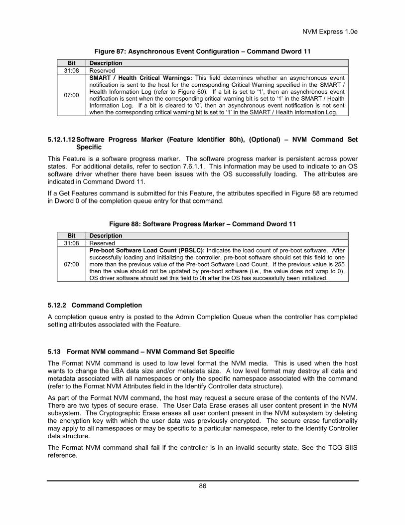
NVM Express 1.0e
86
Figure 87: Asynchronous Event Configuration – Command Dword 11 Bit Description
31:08 Reserved
07:00
SMART / Health Critical Warnings: This field determines whether an asynchronous event notification is sent to the host for the corresponding Critical Warning specified in the SMART / Health Information Log (refer to Figure 60). If a bit is set to ‘1’, then an asynchronous event notification is sent when the corresponding critical warning bit is set to ‘1’ in the SMART / Health Information Log. If a bit is cleared to ‘0’, then an asynchronous event notification is not sent when the corresponding critical warning bit is set to ‘1’ in the SMART / Health Information Log.
5.12.1.12 Software Progress Marker (Feature Identifier 80h), (Optional) – NVM Command Set Specific
This Feature is a software progress marker. The software progress marker is persistent across power states. For additional details, refer to section 7.6.1.1. This information may be used to indicate to an OS software driver whether there have been issues with the OS successfully loading. The attributes are indicated in Command Dword 11.
If a Get Features command is submitted for this Feature, the attributes specified in Figure 88 are returned in Dword 0 of the completion queue entry for that command.
Figure 88: Software Progress Marker – Command Dword 11 Bit Description
31:08 Reserved
07:00
Pre-boot Software Load Count (PBSLC): Indicates the load count of pre-boot software. After successfully loading and initializing the controller, pre-boot software should set this field to one more than the previous value of the Pre-boot Software Load Count. If the previous value is 255 then the value should not be updated by pre-boot software (i.e., the value does not wrap to 0). OS driver software should set this field to 0h after the OS has successfully been initialized.
5.12.2 Command Completion A completion queue entry is posted to the Admin Completion Queue when the controller has completed setting attributes associated with the Feature.
5.13 Format NVM command – NVM Command Set Specific The Format NVM command is used to low level format the NVM media. This is used when the host wants to change the LBA data size and/or metadata size. A low level format may destroy all data and metadata associated with all namespaces or only the specific namespace associated with the command (refer to the Format NVM Attributes field in the Identify Controller data structure).
As part of the Format NVM command, the host may request a secure erase of the contents of the NVM. There are two types of secure erase. The User Data Erase erases all user content present in the NVM subsystem. The Cryptographic Erase erases all user content present in the NVM subsystem by deleting the encryption key with which the user data was previously encrypted. The secure erase functionality may apply to all namespaces or may be specific to a particular namespace, refer to the Identify Controller data structure.
The Format NVM command shall fail if the controller is in an invalid security state. See the TCG SIIS reference.
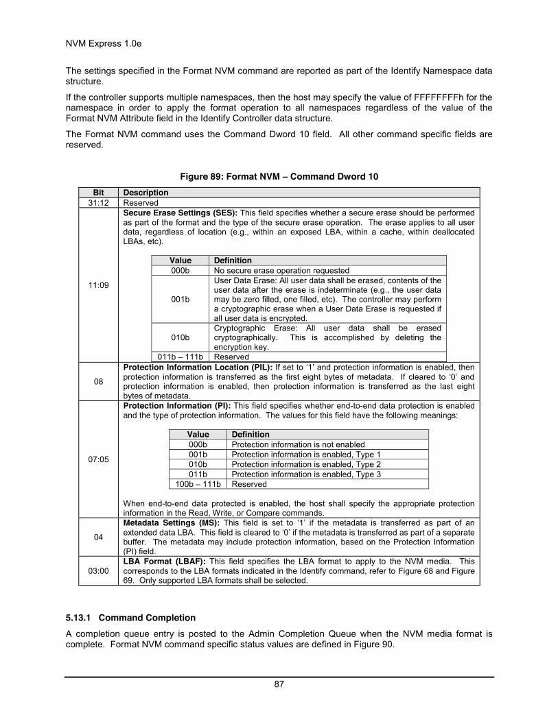
NVM Express 1.0e
87
The settings specified in the Format NVM command are reported as part of the Identify Namespace data structure.
If the controller supports multiple namespaces, then the host may specify the value of FFFFFFFFh for the namespace in order to apply the format operation to all namespaces regardless of the value of the Format NVM Attribute field in the Identify Controller data structure.
The Format NVM command uses the Command Dword 10 field. All other command specific fields are reserved.
Figure 89: Format NVM – Command Dword 10 Bit Description
31:12 Reserved
11:09
Secure Erase Settings (SES): This field specifies whether a secure erase should be performed as part of the format and the type of the secure erase operation. The erase applies to all user data, regardless of location (e.g., within an exposed LBA, within a cache, within deallocated LBAs, etc).
Value Definition 000b No secure erase operation requested
001b
User Data Erase: All user data shall be erased, contents of the user data after the erase is indeterminate (e.g., the user data may be zero filled, one filled, etc). The controller may perform a cryptographic erase when a User Data Erase is requested if all user data is encrypted.
010b Cryptographic Erase: All user data shall be erased cryptographically. This is accomplished by deleting the encryption key.
011b – 111b Reserved
08
Protection Information Location (PIL): If set to ‘1’ and protection information is enabled, then protection information is transferred as the first eight bytes of metadata. If cleared to ‘0’ and protection information is enabled, then protection information is transferred as the last eight bytes of metadata.
07:05
Protection Information (PI): This field specifies whether end-to-end data protection is enabled and the type of protection information. The values for this field have the following meanings:
Value Definition 000b Protection information is not enabled 001b Protection information is enabled, Type 1 010b Protection information is enabled, Type 2 011b Protection information is enabled, Type 3
100b – 111b Reserved When end-to-end data protected is enabled, the host shall specify the appropriate protection information in the Read, Write, or Compare commands.
04
Metadata Settings (MS): This field is set to ‘1’ if the metadata is transferred as part of an extended data LBA. This field is cleared to ‘0’ if the metadata is transferred as part of a separate buffer. The metadata may include protection information, based on the Protection Information (PI) field.
03:00 LBA Format (LBAF): This field specifies the LBA format to apply to the NVM media. This corresponds to the LBA formats indicated in the Identify command, refer to Figure 68 and Figure 69. Only supported LBA formats shall be selected.
5.13.1 Command Completion A completion queue entry is posted to the Admin Completion Queue when the NVM media format is complete. Format NVM command specific status values are defined in Figure 90.

NVM Express 1.0e
88
Figure 90: Format NVM – Command Specific Status Values Value Description
Ah Invalid Format: The format specified is invalid. This may be due to various conditions, including: 1) specifying an invalid LBA Format number, or 2) enabling protection information when there is not sufficient metadata per LBA, or 3) enabling metadata to be transferred as part of a separate buffer when there is no
metadata supported as part of the format selected, or 4) invalid security state (refer to TCG SIIS), etc.
5.14 Security Receive command – NVM Command Set Specific The Security Receive command transfers the status and data result of one or more Security Send commands that were previously submitted to the controller.
The association between a Security Receive command and previous Security Send commands is dependent on the Security Protocol. The format of the data to be transferred is dependent on the Security Protocol. Refer to SPC-4 for Security Protocol details.
Each Security Receive command returns the appropriate data corresponding to a Security Send command as defined by the rules of the Security Protocol. The Security Receive command data may not be retained if there is a loss of communication between the controller and host, or if a controller reset occurs.
The fields used are PRP Entry 1, PRP Entry 2, Command Dword 10, and Command Dword 11 fields. All other command specific fields are reserved.
Figure 91: Security Receive – PRP Entry 1 Bit Description
63:00 PRP Entry 1 (PRP1): This field contains the first PRP entry, specifying the start of the data buffer.
Figure 92: Security Receive – PRP Entry 2 Bit Description
63:00
PRP Entry 2 (PRP2): This field contains the second PRP entry. If PRP Entry 1 specifies enough space for the data structure, then this field is reserved. Otherwise, it specifies the remainder of the data buffer. This field shall not be a pointer to a PRP List as the data buffer may not cross more than one page boundary.
Figure 93: Security Receive – Command Dword 10 Bit Description
31:24 Security Protocol (SECP): This field specifies the security protocol as defined in SPC-4. The controller shall fail the command with Invalid Parameter indicated if an unsupported value of the Security Protocol is specified.
23:08 SP Specific (SPSP): The value of this field is specific to the Security Protocol as defined in SPC-4.
07:00 Reserved
Figure 94: Security Receive – Command Dword 11 Bit Description

NVM Express 1.0e
89
31:00 Allocation Length (AL): The value of this field is specific to the Security Protocol as defined in SPC-4.
5.14.1 Command Completion If the command is completed, then the controller shall post a completion queue entry to the Admin Completion Queue indicating the status for the command.
5.14.2 Security Protocol 00h A Security Receive command with the Security Protocol field set to 00h shall return information about the security protocols supported by the controller. This command is used in the security discovery process and is not associated with a Security Send command. Refer to SPC-4 for the details of Security Protocol 00h and the SP Specific field.
5.15 Security Send command – NVM Command Set Specific The Security Send command is used to transfer security protocol data to the controller. The data structure transferred to the controller as part of this command contains security protocol specific commands to be performed by the controller. The data structure transferred may also contain data or parameters associated with the security protocol commands. Status and data that is to be returned to the host for the security protocol commands submitted by a Security Send command are retrieved with the Security Receive command defined in section 5.14.
The association between a Security Send command and subsequent Security Receive command is Security Protocol field dependent as defined in SPC-4.
The fields used are PRP Entry 1, PRP Entry 2, Command Dword 10, and Command Dword 11 fields. All other command specific fields are reserved.
Figure 95: Security Send – PRP Entry 1 Bit Description
63:00 PRP Entry 1 (PRP1): This field contains the first PRP entry, specifying the start of the data buffer.
Figure 96: Security Send – PRP Entry 2 Bit Description
63:00
PRP Entry 2 (PRP2): This field contains the second PRP entry. If PRP Entry 1 specifies enough space for the data structure, then this field is reserved. Otherwise, it specifies the remainder of the data buffer. This field shall not be a pointer to a PRP List as the data buffer may not cross more than one page boundary.
Figure 97: Security Send – Command Dword 10 Bit Description
31:24 Security Protocol (SECP): This field specifies the security protocol as defined in SPC-4. The controller shall fail the command with Invalid Parameter indicated if a reserved value of the Security Protocol is specified.
23:08 SP Specific (SPSP): The value of this field is specific to the Security Protocol as defined in SPC-4.
07:00 Reserved

NVM Express 1.0e
90
Figure 98: Security Send – Command Dword 11 Bit Description
31:00 Transfer Length (TL): The value of this field is specific to the Security Protocol as defined in SPC-4.
5.15.1 Command Completion If the command is completed, then the controller shall post a completion queue entry to the Admin Completion Queue indicating the status for the command.

NVM Express 1.0e
91
6 NVM Command Set The device is comprised of some number of controllers, where each controller is comprised of some number of namespaces, where each namespace is comprised of some number of logical blocks. A logical block is the smallest unit of data that may be read or written from the controller. The logical block data size, reported in bytes, is always a power of two. Logical block sizes may be 512 bytes, 1KB, 2KB, 4KB, 8KB, etc. Supported logical block sizes are reported in the Identify Namespace data structure.
The NVM Command Set includes the commands listed in Figure 99. The following subsections describe the definition for each of these commands. Commands shall only be submitted by the host when the controller is ready as indicated in the Controller Status register (CSTS.RDY) and after appropriate I/O Submission Queue(s) and I/O Completion Queue(s) have been created.
The Submission Queue Entry (SQE) structure and the fields that are common to all NVM commands are defined in section 4.2. The Completion Queue Entry (CQE) structure and the fields that are common to all NVM commands are defined in section 4.5. The command specific fields in the SQE and CQE structures for the NVM Command Set are defined in this section.
In the case of Compare, Read, and Write commands, the host may indicate whether a time limit should be applied to the operation by setting the Limited Retry (LR) field in the command. The time limit is specified in the Error Recovery feature, specified in section 5.12.1.5. If the host does not specify a time limit should be applied, then the controller should apply all error recovery means to complete the operation.
Figure 99: Opcodes for NVM Commands Opcode (07) Opcode (06:02) Opcode (01:00)
Opcode2 O/M1 Command3 Standard Command Function Data Transfer
0b 000 00b 00b 00h M Flush 0b 000 00b 01b 01h M Write 0b 000 00b 10b 02h M Read 0b 000 01b 00b 04h O Write Uncorrectable 0b 000 01b 01b 05h O Compare 0b 000 10b 01b 09h O Dataset Management
Vendor Specific 1b na na 80h – FFh O Vendor specific
NOTES: 1. O/M definition: O = Optional, M = Mandatory. 2. Opcodes not listed are reserved. 3. All NVM commands use the Namespace Identifier field (CDW1.NSID).
6.1 Namespaces A namespace is a collection of logical blocks that range from 0 to the capacity of the namespace – 1. The number of namespaces present is reported in the Identify Controller data structure. The namespaces are allocated in order (starting with 1) and packed sequentially. Namespaces identifiers may change across power off conditions. However, it is recommended that namespace identifiers remain static in order to avoid issues with EFI or OS drivers fast discovery processes. The management (creation, deletion) of namespaces is outside the scope of this specification.
The Namespace Size field in the Identify Namespace data structure defines the total size of the namespace in logical blocks (LBA 0 through n-1). The Namespace Utilization field in the Identify Namespace data structure defines the number of logical blocks currently allocated in the namespace. The Namespace Capacity field in the Identify data structure defines the maximum number of logical

NVM Express 1.0e
92
blocks that may be allocated at one time as part of the namespace in a thin provisioning usage model. The following relationship holds: Namespace Size >= Namespace Capacity >= Namespace Utilization.
A namespace may or may not have a relationship to a Submission Queue; this relationship is determined by the host software implementation. The controller shall support access to any valid namespace from any I/O Submission Queue.
6.2 Fused Operations The command sequences that may be used in a fused operation for the NVM Command Set are defined in Figure 100. Refer to section 4.6 for details on fused operations.
Figure 100: Supported Fused Operations
Command 1 Command 2 Fused Operation Compare Write Compare and Write
6.2.1 Compare and Write The Compare and Write fused operation compares the contents of the logical block(s) specified in the Compare command to the data stored at the indicated LBA range. If the compare is successful, then the LBA range is updated with the data provided in the Write command. If the Compare operation is not successful, then the Write operation is aborted with a status of Command Aborted due to Failed Fused Command and the contents in the LBA range are not modified. If the Write operation is not successful, the Compare operation completion status is unaffected.
Note: To ensure the Compare and Write is an atomic operation in a multi-host environment, host software should ensure that the size of a Compare and Write fused operation is no larger than the atomic write unit size. Controllers may abort a Compare and Write fused operation that is larger than the atomic write unit size.
6.3 Command Ordering Requirements and Atomic Write Unit Except for commands that are part of a fused operation, each command is processed as an independent entity without reference to other commands submitted to the same I/O Submission Queue or to commands submitted to other I/O Submission Queues. Specifically, the controller is not responsible for checking the LBA of a Read or Write command to ensure any type of ordering between commands. For example, if a Read is submitted for LBA x and there is a Write also submitted for LBA x, there is no guarantee of the order of completion for those commands (the Read may finish first or the Write may finish first).
If there are ordering requirements between commands, host software or the associated application is required to enforce that ordering above the level of the controller.
The controller supports an atomic write unit. The atomic write unit is the size of write operation guaranteed to be written atomically to the medium with respect to other read or write operations. The controller supports a value for normal operation that is potentially different than during a power fail condition, as reported in the Identify Controller data structure. The host may indicate that the atomic write unit beyond a logical block size is not necessary by configuring the Write Atomicity feature, which may result in higher performance in some implementations.
After a write has completed, reads for that location which are subsequently submitted shall return the data from that write and not an older version of the data from a previous write.

NVM Express 1.0e
93
6.4 End-to-end Protection Information The commands that include data transfer may utilize end-to-end data protection. Within these commands, the protection information action and protection information check field is specified as defined in Figure 101.
Figure 101: Protection Information Field Definition Bit Description
03
Protection Information Action (PRACT): The protection information action field indicates the action to take for the protection information. If this field is set to ‘1’, the protection information is stripped (read) or inserted (write). If this field is cleared to ‘0’, the protection information is passed. This field is only used if the namespace is formatted to use end-to-end protection information. Refer to section 8.3.
02:00
Protection Information Check (PRCHK): The protection information check field indicates the fields that need to be checked as part of end-to-end data protection processing. This field is only used if the namespace is formatted to use end-to-end protection information. Refer to section 8.3.
Bit Definition
02 If set to ‘1’ enables protection information checking of the Guard field. If cleared to ‘0’, the Guard field is not checked.
01 If set to ‘1’ enables protection information checking of the Application Tag field. If cleared to ‘0’, the Application Tag field is not checked.
00
If set to ‘1’ enables protection information checking of the Logical Block Reference Tag field. If cleared to ‘0’, the Logical Block Reference Tag field is not checked.
6.5 Compare command The Compare command reads the logical blocks specified by the command from the medium and compares the data read to a comparison data buffer transferred as part of the command. If the data read from the controller and the comparison data buffer are equivalent with no miscompares, then the command completes successfully. If there is any miscompare, the command completes with error. If metadata is provided, then a comparison is also performed for the metadata.
The fields used are Metadata Pointer, PRP Entry 1, PRP Entry 2, Command Dword 10, Command Dword 11, Command Dword 12, Command Dword 14, and Command Dword 15. All other command specific fields are reserved.
Figure 102: Compare – Metadata Pointer Bit Description
63:00 Metadata Pointer (MD): This field contains the address of a contiguous physical buffer of metadata, if applicable. This field shall be Dword aligned.
Figure 103: Compare – PRP Entry 1 Bit Description
63:00 PRP Entry 1 (PRP1): This field contains the first PRP entry, indicating the location of data that should be used for comparison.
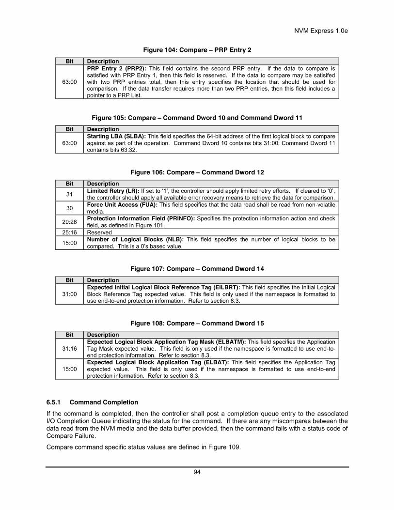
NVM Express 1.0e
94
Figure 104: Compare – PRP Entry 2 Bit Description
63:00
PRP Entry 2 (PRP2): This field contains the second PRP entry. If the data to compare is satisfied with PRP Entry 1, then this field is reserved. If the data to compare may be satisifed with two PRP entries total, then this entry specifies the location that should be used for comparison. If the data transfer requires more than two PRP entries, then this field includes a pointer to a PRP List.
Figure 105: Compare – Command Dword 10 and Command Dword 11 Bit Description
63:00 Starting LBA (SLBA): This field specifies the 64-bit address of the first logical block to compare against as part of the operation. Command Dword 10 contains bits 31:00; Command Dword 11 contains bits 63:32.
Figure 106: Compare – Command Dword 12 Bit Description
31 Limited Retry (LR): If set to ‘1’, the controller should apply limited retry efforts. If cleared to ‘0’, the controller should apply all available error recovery means to retrieve the data for comparison.
30 Force Unit Access (FUA): This field specifies that the data read shall be read from non-volatile media.
29:26 Protection Information Field (PRINFO): Specifies the protection information action and check field, as defined in Figure 101.
25:16 Reserved
15:00 Number of Logical Blocks (NLB): This field specifies the number of logical blocks to be compared. This is a 0’s based value.
Figure 107: Compare – Command Dword 14 Bit Description
31:00 Expected Initial Logical Block Reference Tag (EILBRT): This field specifies the Initial Logical Block Reference Tag expected value. This field is only used if the namespace is formatted to use end-to-end protection information. Refer to section 8.3.
Figure 108: Compare – Command Dword 15 Bit Description
31:16 Expected Logical Block Application Tag Mask (ELBATM): This field specifies the Application Tag Mask expected value. This field is only used if the namespace is formatted to use end-to-end protection information. Refer to section 8.3.
15:00 Expected Logical Block Application Tag (ELBAT): This field specifies the Application Tag expected value. This field is only used if the namespace is formatted to use end-to-end protection information. Refer to section 8.3.
6.5.1 Command Completion If the command is completed, then the controller shall post a completion queue entry to the associated I/O Completion Queue indicating the status for the command. If there are any miscompares between the data read from the NVM media and the data buffer provided, then the command fails with a status code of Compare Failure.
Compare command specific status values are defined in Figure 109.
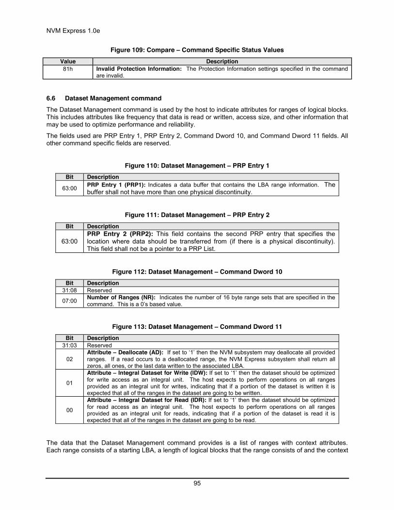
NVM Express 1.0e
95
Figure 109: Compare – Command Specific Status Values Value Description 81h Invalid Protection Information: The Protection Information settings specified in the command
are invalid.
6.6 Dataset Management command The Dataset Management command is used by the host to indicate attributes for ranges of logical blocks. This includes attributes like frequency that data is read or written, access size, and other information that may be used to optimize performance and reliability.
The fields used are PRP Entry 1, PRP Entry 2, Command Dword 10, and Command Dword 11 fields. All other command specific fields are reserved.
Figure 110: Dataset Management – PRP Entry 1 Bit Description
63:00 PRP Entry 1 (PRP1): Indicates a data buffer that contains the LBA range information. The buffer shall not have more than one physical discontinuity.
Figure 111: Dataset Management – PRP Entry 2
Bit Description
63:00 PRP Entry 2 (PRP2): This field contains the second PRP entry that specifies the location where data should be transferred from (if there is a physical discontinuity). This field shall not be a pointer to a PRP List.
Figure 112: Dataset Management – Command Dword 10
Bit Description 31:08 Reserved
07:00 Number of Ranges (NR): Indicates the number of 16 byte range sets that are specified in the command. This is a 0’s based value.
Figure 113: Dataset Management – Command Dword 11 Bit Description
31:03 Reserved
02 Attribute – Deallocate (AD): If set to ‘1’ then the NVM subsystem may deallocate all provided ranges. If a read occurs to a deallocated range, the NVM Express subsystem shall return all zeros, all ones, or the last data written to the associated LBA.
01
Attribute – Integral Dataset for Write (IDW): If set to ‘1’ then the dataset should be optimized for write access as an integral unit. The host expects to perform operations on all ranges provided as an integral unit for writes, indicating that if a portion of the dataset is written it is expected that all of the ranges in the dataset are going to be written.
00
Attribute – Integral Dataset for Read (IDR): If set to ‘1’ then the dataset should be optimized for read access as an integral unit. The host expects to perform operations on all ranges provided as an integral unit for reads, indicating that if a portion of the dataset is read it is expected that all of the ranges in the dataset are going to be read.
The data that the Dataset Management command provides is a list of ranges with context attributes. Each range consists of a starting LBA, a length of logical blocks that the range consists of and the context
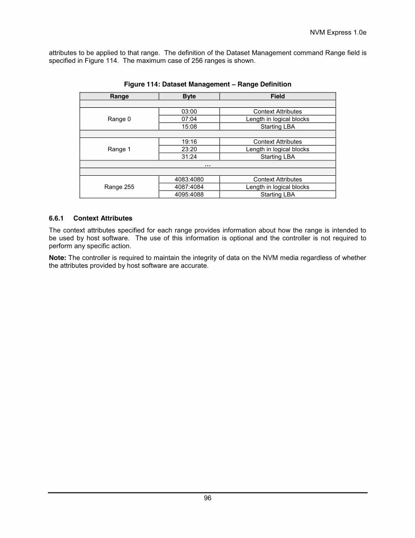
NVM Express 1.0e
96
attributes to be applied to that range. The definition of the Dataset Management command Range field is specified in Figure 114. The maximum case of 256 ranges is shown.
Figure 114: Dataset Management – Range Definition Range Byte Field
Range 0 03:00 Context Attributes 07:04 Length in logical blocks 15:08 Starting LBA
Range 1 19:16 Context Attributes 23:20 Length in logical blocks 31:24 Starting LBA
…
Range 255 4083:4080 Context Attributes 4087:4084 Length in logical blocks 4095:4088 Starting LBA
6.6.1 Context Attributes The context attributes specified for each range provides information about how the range is intended to be used by host software. The use of this information is optional and the controller is not required to perform any specific action.
Note: The controller is required to maintain the integrity of data on the NVM media regardless of whether the attributes provided by host software are accurate.

NVM Express 1.0e
97
Figure 115: Dataset Management – Context Attributes Attribute Bits Description
Command Access Size 31:24 Number of logical blocks expected to be transferred in a single Read or Write command from this dataset. A value of 0h indicates no Command Access Size is provided.
Reserved 23:11 Reserved WP: Write Prepare 10 If set to ‘1’ then the provided range is expected to be written in the near future.
SW: Sequential Write Range 09 If set to ‘1’ then the dataset should be optimized for sequential write access. The
host expects to perform operations on the dataset as a single object for writes. SR: Sequential Read
Range 08 If set to ‘1’ then the dataset should be optimized for sequential read access. The host expects to perform operations on the dataset as a single object for reads.
Reserved 07:06 Reserved
AL: Access Latency 05:04
Value Definition 00b None. No latency information provided. 01b Idle. Longer latency acceptable. 10b Normal. Typical latency. 11b Low. Smallest possible latency.
AF: Access Frequency 03:00
Value Definition 0000b No frequency information provided. 0001b Typical number of reads and writes expected for this LBA range. 0010b Infrequent writes and infrequent reads to the LBA range indicated. 0011b Infrequent writes and frequent reads to the LBA range indicated. 0100b Frequent writes and infrequent reads to the LBA range indicated. 0101b Frequent writes and frequent reads to the LBA range indicated. 0110b –
1111b Reserved
6.6.1.1 Deallocate An LBA that has been deallocated using the Dataset Management command is no longer deallocated when the LBA is written. Read operations do not affect the deallocation status of an LBA. The value read from a deallocated LBA shall be deterministic; specifically, the value returned by subsequent reads of that LBA shall be the same until a write occurs to that LBA. The values read from a deallocated LBA and its metadata (excluding protection information) shall be all zeros, all ones, or the last data written to the associated LBA and its metadata. The values read from an unwritten or deallocated LBA’s protection information field shall be all ones (indicating the protection information shall not be checked).
Note: The operation of the Deallocate function is similar to the ATA DATA SET MANAGEMENT with Trim feature described in ACS-2 and SCSI UNMAP command described in SBC-3.
6.6.2 Command Completion When the command is completed, the controller shall post a completion queue entry to the associated I/O Completion Queue indicating the status for the command.
Dataset Management command specific status values are defined in Figure 116.
Figure 116: Dataset Management – Command Specific Status Values Value Description 80h Conflicting Attributes: The attributes specified in the command are conflicting.

NVM Express 1.0e
98
6.7 Flush command The Flush command shall commit data and metadata associated with the specified namespace(s) to non-volatile media. The flush applies to all commands completed prior to the submission of the Flush command. The controller may also flush additional data and/or metadata from any namespace.
All command specific fields are reserved.
6.7.1 Command Completion If the command is completed, then the controller shall post a completion queue entry to the associated I/O Completion Queue indicating the status for the command.
6.8 Read command The Read command reads data and metadata, if applicable, from the NVM controller for the LBAs indicated. The command may specify protection information to be checked as part of the read operation.
The fields used are Metadata Pointer, PRP Entry 1, PRP Entry 2, Command Dword 10, Command Dword 11, Command Dword 12, Command Dword 13, Command Dword 14, and Command Dword 15 fields.
Figure 117: Read – Metadata Pointer Bit Description
63:00 Metadata Pointer (MD): This field contains the address of a contiguous physical buffer of metadata, if applicable. This field shall be Dword aligned.
Figure 118: Read – PRP Entry 1 Bit Description
63:00 PRP Entry 1 (PRP1): This field contains the first PRP entry, indicating the location where data should be transferred to.
Figure 119: Read – PRP Entry 2 Bit Description
63:00
PRP Entry 2 (PRP2): This field contains the second PRP entry. If the data transfer is satisfied with PRP Entry 1, then this field is reserved. If the data transfer may be satisifed with two PRP entries total, then this entry specifies the location where data should be transferred to. If the data transfer requires more than two PRP entries, then this field includes a pointer to a PRP List.
Figure 120: Read – Command Dword 10 and Command Dword 11 Bit Description
63:00 Starting LBA (SLBA): This field indicates the 64-bit address of the first logical block to be read as part of the operation. Command Dword 10 contains bits 31:00; Command Dword 11 contains bits 63: 32.
Figure 121: Read – Command Dword 12 Bit Description
31 Limited Retry (LR): If set to ‘1’, the controller should apply limited retry efforts. If cleared to ‘0’, the controller should apply all available error recovery means to return the data to the host.
30 Force Unit Access (FUA): This field indicates that the data read shall be returned from non-volatile media. There is no implied ordering with other commands.

NVM Express 1.0e
99
29:26 Protection Information Field (PRINFO): Specifies the protection information action and check field, as defined in Figure 101.
25:16 Reserved
15:00 Number of Logical Blocks (NLB): This field indicates the number of logical blocks to be read. This is a 0’s based value.
Figure 122: Read – Command Dword 13 Bit Description
31:08 Reserved
07:00
Dataset Management (DSM): This field indicates attributes for the dataset that the LBA(s) being read are associated with.
Bits Attribute Definition
07 Incompressible If set to ‘1’, then data is not compressible for the logical blocks indicated. If cleared to ‘0’, then no information on compression is provided.
06 Sequential Request
If set to ‘1’, then this command is part of a sequential read that includes multiple Read commands. If cleared to ‘0’, then no information on sequential access is provided.
05:04 Access Latency
Value Definition
00b None. No latency information provided.
01b Idle. Longer latency acceptable. 10b Normal. Typical latency. 11b Low. Smallest possible latency.
03:00 Access Frequency
Value Definition 0000b No frequency information provided.
0001b Typical number of reads and writes expected for this LBA range.
0010b Infrequent writes and infrequent reads to the LBA range indicated.
0011b Infrequent writes and frequent reads to the LBA range indicated.
0100b Frequent writes and infrequent reads to the LBA range indicated.
0101b Frequent writes and frequent reads to the LBA range indicated.
0110b One time read. E.g. command is due to virus scan, backup, file copy, or archive.
0111b Speculative read. The command is part of a prefetch operation.
1000b The LBA range is going to be overwritten in the near future.
1001b – 1111b Reserved
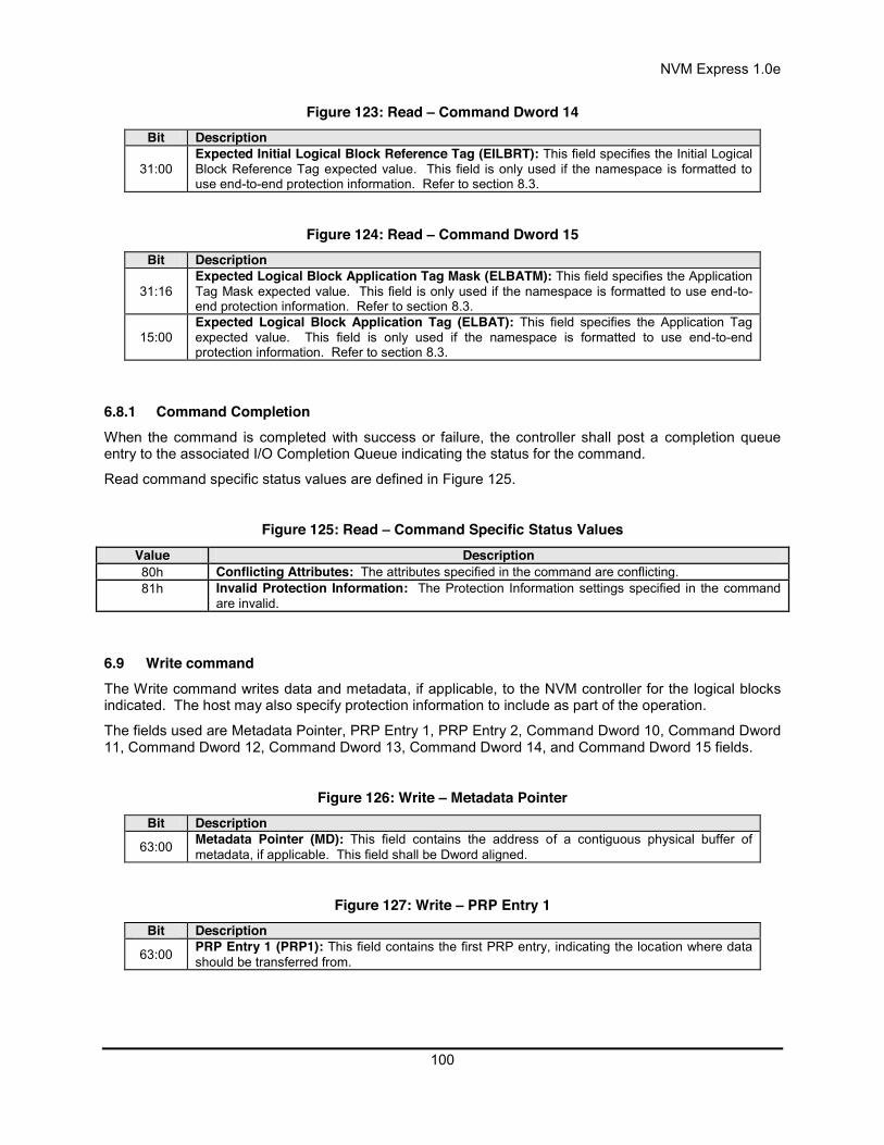
NVM Express 1.0e
100
Figure 123: Read – Command Dword 14 Bit Description
31:00 Expected Initial Logical Block Reference Tag (EILBRT): This field specifies the Initial Logical Block Reference Tag expected value. This field is only used if the namespace is formatted to use end-to-end protection information. Refer to section 8.3.
Figure 124: Read – Command Dword 15 Bit Description
31:16 Expected Logical Block Application Tag Mask (ELBATM): This field specifies the Application Tag Mask expected value. This field is only used if the namespace is formatted to use end-to-end protection information. Refer to section 8.3.
15:00 Expected Logical Block Application Tag (ELBAT): This field specifies the Application Tag expected value. This field is only used if the namespace is formatted to use end-to-end protection information. Refer to section 8.3.
6.8.1 Command Completion When the command is completed with success or failure, the controller shall post a completion queue entry to the associated I/O Completion Queue indicating the status for the command.
Read command specific status values are defined in Figure 125.
Figure 125: Read – Command Specific Status Values Value Description 80h Conflicting Attributes: The attributes specified in the command are conflicting. 81h Invalid Protection Information: The Protection Information settings specified in the command
are invalid.
6.9 Write command The Write command writes data and metadata, if applicable, to the NVM controller for the logical blocks indicated. The host may also specify protection information to include as part of the operation.
The fields used are Metadata Pointer, PRP Entry 1, PRP Entry 2, Command Dword 10, Command Dword 11, Command Dword 12, Command Dword 13, Command Dword 14, and Command Dword 15 fields.
Figure 126: Write – Metadata Pointer Bit Description
63:00 Metadata Pointer (MD): This field contains the address of a contiguous physical buffer of metadata, if applicable. This field shall be Dword aligned.
Figure 127: Write – PRP Entry 1 Bit Description
63:00 PRP Entry 1 (PRP1): This field contains the first PRP entry, indicating the location where data should be transferred from.
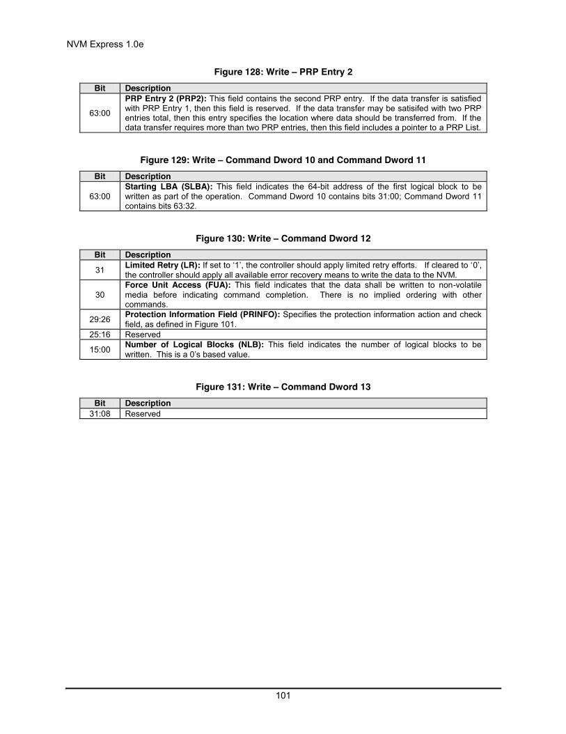
NVM Express 1.0e
101
Figure 128: Write – PRP Entry 2 Bit Description
63:00
PRP Entry 2 (PRP2): This field contains the second PRP entry. If the data transfer is satisfied with PRP Entry 1, then this field is reserved. If the data transfer may be satisifed with two PRP entries total, then this entry specifies the location where data should be transferred from. If the data transfer requires more than two PRP entries, then this field includes a pointer to a PRP List.
Figure 129: Write – Command Dword 10 and Command Dword 11 Bit Description
63:00 Starting LBA (SLBA): This field indicates the 64-bit address of the first logical block to be written as part of the operation. Command Dword 10 contains bits 31:00; Command Dword 11 contains bits 63:32.
Figure 130: Write – Command Dword 12 Bit Description
31 Limited Retry (LR): If set to ‘1’, the controller should apply limited retry efforts. If cleared to ‘0’, the controller should apply all available error recovery means to write the data to the NVM.
30 Force Unit Access (FUA): This field indicates that the data shall be written to non-volatile media before indicating command completion. There is no implied ordering with other commands.
29:26 Protection Information Field (PRINFO): Specifies the protection information action and check field, as defined in Figure 101.
25:16 Reserved
15:00 Number of Logical Blocks (NLB): This field indicates the number of logical blocks to be written. This is a 0’s based value.
Figure 131: Write – Command Dword 13 Bit Description
31:08 Reserved

NVM Express 1.0e
102
07:00
Dataset Management (DSM): This field indicates attributes for the dataset that the LBA(s) being read are associated with.
Bits Attribute Definition
07 Incompressible If set to ‘1’, then data is not compressible for the logical blocks indicated. If cleared to ‘0’, then no information on compression is provided.
06 Sequential Request
If set to ‘1’, then this command is part of a sequential write that includes multiple Write commands. If cleared to ‘0’, then no information on sequential access is provided.
05:04 Access Latency
Value Definition
00b None. No latency information provided.
01b Idle. Longer latency acceptable. 10b Normal. Typical latency. 11b Low. Smallest possible latency.
03:00 Access Frequency
Value Definition 0000b No frequency information provided.
0001b Typical number of reads and writes expected for this LBA range.
0010b Infrequent writes and infrequent reads to the LBA range indicated.
0011b Infrequent writes and frequent reads to the LBA range indicated.
0100b Frequent writes and infrequent reads to the LBA range indicated.
0101b Frequent writes and frequent reads to the LBA range indicated.
0110b One time write. E.g. command is due to virus scan, backup, file copy, or archive.
0111b – 1111b Reserved
Figure 132: Write – Command Dword 14 Bit Description
31:00 Initial Logical Block Reference Tag (ILBRT): This field specifies the Initial Logical Block Reference Tag value. This field is only used if the namespace is formatted to use end-to-end protection information. Refer to section 8.3.
Figure 133: Write – Command Dword 15 Bit Description
31:16 Logical Block Application Tag Mask (LBATM): This field specifies the Application Tag Mask value. This field is only used if the namespace is formatted to use end-to-end protection information. Refer to section 8.3.
15:00 Logical Block Application Tag (LBAT): This field specifies the Application Tag value. This field is only used if the namespace is formatted to use end-to-end protection information. Refer to section 8.3.

NVM Express 1.0e
103
6.9.1 Command Completion When the command is completed with success or failure, the controller shall post a completion queue entry to the associated I/O Completion Queue indicating the status for the command.
Write command specific errors are defined in Figure 134.
Figure 134: Write – Command Specific Errors Values Value Description 80h Conflicting Attributes: The attributes specified in the command are conflicting. 81h Invalid Protection Information: The Protection Information settings specified in the command
are invalid.
6.10 Write Uncorrectable command The Write Uncorrectable command is used to mark a logical block as invalid. When the specified logical block(s) are read after this operation, a failure is returned with Unrecovered Read Error status. To clear the invalid logical block status, a write operation is performed on those logical blocks.
The fields used are Command Dword 10, Command Dword 11, and Command Dword 12 fields. All other command specific fields are reserved.
Figure 135: Write Uncorrectable – Command Dword 10 and Command Dword 11 Bit Description
63:00 Starting LBA (SLBA): This field specifies the 64-bit address of the first logical block to be marked as invalid as part of the operation. Command Dword 10 contains bits 31:00; Command Dword 11 contains bits 63: 32.
Figure 136: Write Uncorrectable – Command Dword 12 Bit Description
31:16 Reserved
15:00 Number of Logical Blocks (NLB): This field specifies the number of logical blocks to be marked as invalid. This is a 0’s based value.
6.10.1 Command Completion If the command is completed, then the controller shall post a completion queue entry to the associated I/O Completion Queue indicating the status for the command.

NVM Express 1.0e
104
7 Controller Architecture 7.1 Introduction Host software submits commands to the controller through pre-allocated Submission Queues. The controller is alerted to newly submitted commands through SQ Tail Doorbell register writes. The difference between the previous doorbell register value and the current register write indicates the number of commands that were submitted.
The controller fetches the commands from the Submission Queue(s) and transmits them to the NVM subsystem for processing. Except for fused operations, there are no ordering restrictions for processing of the commands within or across Submission Queues. Host software should not place commands in the list that may not be re-ordered arbitrarily. Data may or may not be committed to the NVM media in the order that commands are received.
Host software submits commands of higher priorities to the appropriate Submission Queues. Priority is associated with the Submission Queue itself, thus the priority of the command is based on the Submission Queue it is issued through. The controller arbitrates across the Submission Queues based on fairness and priority according to the arbitration scheme specified in section 4.7.
Upon completion of the commands by the NVM subsystem, the controller presents completion queue entries to the host through the appropriate Completion Queues. If MSI-X or multiple message MSI is in use, then the interrupt vector indicates the Completion Queue(s) with possible new command completions for the host to process. If pin-based interrupts or single message MSI interrupts are used, host software interrogates the Completion Queue(s) for new completion queue entries. The host updates the CQ Head doorbell register to release Completion Queue entries to the controller and clear the associated interrupt.
There are no ordering restrictions for completions to the host. Each completion queue entry identifies the Submission Queue Identifier and Command Identifier of the associated command. Host software uses this information to correlate the completions with the commands submitted to the Submission Queue(s).
Host software is responsible for creating all required Submission and Completion Queues prior to submitting commands to the controller. I/O Submission and Completion Queues are created using Admin commands defined in section 5.
7.2 Command Submission and Completion Mechanism (Informative) This section describes the command issue and completion mechanism. It also describes how commands are built by host software and command completion processing.
7.2.1 Command Processing This section describes command submission and completion processing. Figure 137 shows the steps that are followed to issue and complete a command. The steps are:
1. The host creates a command for execution within the appropriate Submission Queue in host memory.
2. The host updates the Submission Queue Tail Doorbell register with the new value of the Submission Queue Tail entry pointer. This indicates to the controller that a new command(s) is submitted for processing.
3. The controller fetches the command(s) in the Submission Queue from host memory for future execution.
4. The controller performs command arbitration. The controller may execute commands out of order. The command arbitration mechanism selects the next command to execute from commands that have been previously fetched. The controller then proceeds with execution of the command.

NVM Express 1.0e
105
5. After the command has completed execution, the controller writes a completion queue entry to the associated Completion Queue. As part of the completion queue entry, the controller indicates the most recent SQ entry that has been fetched.
6. The controller optionally generates an interrupt to the host to indicate that there is a completion queue entry to process. In the figure, this is shown as an MSI-X interrupt, however, it could also be a pin-based or MSI interrupt. Note that based on interrupt coalescing settings, an interrupt may or may not be indicated for the command.
7. The host processes the completion queue entry in the Completion Queue. This includes taking any actions based on error conditions indicated.
8. The host writes the Completion Queue Head Doorbell register to indicate that the completion queue entry has been processed. The host may process many entries before updating the associated CQHDBL register.
Figure 137: Command Processing
7.2.2 Basic Steps when Building a Command When host software builds a command for the controller to execute, it first checks to make sure that the appropriate Submission Queue (SQx) is not full. The Submission Queue is full when the number of entries in the queue is one less than the queue size. Once an empty slot (pFreeSlot) is available:
1. Host software builds a command at SQx[pFreeSlot] with: a. CDW0.OPC is set to the appropriate command to be executed by the controller. b. CDW0.FUSE is set to the appropriate value, depending on whether the command is
a fused operation. c. CDW0.CID is set to a unique identifier for the command when combined with the
Submission Queue identifier. d. The Namespace Identifier, CDW1.NSID, is set to the namespace the command
applies to.

NVM Express 1.0e
106
e. MPTR shall be filled in with the offset to the beginning of the Metadata Region, if there is a data transfer and the namespace format contains metadata as a separate buffer.
f. PRP1 and/or PRP2 are set to the source/destination of data transfer, if there is a data transfer.
g. CDW10 – CDW15 are set to any command specific information. 2. Host software shall write the corresponding Submission Queue doorbell register
(SQxTDBL) to submit one or more commands for processing.
The write to the Submission Queue doorbell register triggers the controller to fetch and process the command contained in the Submission Queue entry. The controller indicates the most recent SQ entry that has been fetched as part of reporting completions. Host software may use this information to determine when SQ locations may be re-used for new commands.
7.2.3 Processing Completed Commands Host software processes the interrupt generated by the controller for command completion(s). If MSI-X or multiple message MSI is in use, then the interrupt vector implies the Completion Queue(s) with new command completions for the host to process. If pin-based interrupts or single message MSI interrupts are used, then host software interrogates the Completion Queue(s) to determine if new completion queue entries are present for the host to process.
Once the host software determines the Completion Queue (CQy) that generated the interrupt: 1. Host software reads a completion queue entry from the specified Completion Queue. 2. Host software processes the CQ entry to identify the Submission Queue entry that
generated this completion. DW2.SQID indicates the Submission Queue ID and DW3.CID indicates the command that generated the completion.
3. DW3.SF indicates the status of the completion. 4. Host software indicates available Completion Queue slots by updating the
corresponding Completion Queue Head doorbell register (CQyHDBL). By updating CQyHDBL, the associated interrupt is cleared.
5. If there were errors, noted in the DW3.SF field, host software performs error recovery actions (refer to section 9.1).
7.2.4 Command Related Resource Retirement As part of reporting completions, the controller indicates the most recent Submission Queue entry that has been fetched. Any Submission Queue entries that are indicated as being fetched may be re-used by host software.
If a completion queue entry is posted for a command, then host software may re-use the associated PRP List(s) for that command and other resources (an exception is the PRP List for I/O Submission Queues and I/O Completion Queues).
7.2.5 Command Examples 7.2.5.1 Creating an I/O Submission Queue This example describes how host software creates an I/O Submission Queue that utilizes non-contiguous PRP entries. Creating an I/O Submission Queue that utilizes a PRP List is only valid if the controller supports non-contiguous queues as indicated in CAP.CQR.
Prior to creating an I/O Submission Queue, host software shall create the I/O Completion Queue that the SQ uses with the Create I/O Completion Queue command.

NVM Express 1.0e
107
To create an I/O Submission Queue, host software builds a Create I/O Submission Queue command for the Admin Submission Queue. Host software builds the Create I/O Submission Queue command in the next free Admin Submission Queue command location. The attributes of the command are:
CDW0.OPC is set to 01h. CDW0.FUSE is set to 00b indicating that this is not a fused operation. CDW0.CID is set to a free command identifier. CDW1.NSID is set to 0h; Submission Queues are not specific to a namespace. MPTR is cleared to 0h; metadata is not used for this command. PRP1 is set to the physical address of the PRP List. The PRP List is shown in Figure 138 for a
PRP List with three entries. PRP2 is cleared to 0h; PRP Entry 2 is not used for this command. CDW10.QSIZE is set to the size of queue to create. In this case, it is set to a value of 191,
indicating a queue size of 192 entries. The queue size shall not exceed the maximum queue entries supported, indicated in the CAP.MQES field.
CDW10.QID is set to the Submission Queue identifier. CDW11.CQID is set to the I/O Completion Queue identifier where command completions are
posted. CDW11.QPRIO is set to 10b, indicating a Medium priority queue. CDW11.PC is cleared to ‘0’ indicating that the data buffer indicated by PRP1 is not physically
contiguously.
After the command is built, host software submits the command for execution by writing the Admin Submission Queue doorbell (SQ0TDBL) to indicate to the controller that this command is available for processing.
Host software shall maintain the PRP List unmodified in host memory until the Submission Queue is deleted.

NVM Express 1.0e
108
Figure 138: PRP List Describing I/O Submission Queue
7.2.5.2 Executing a Fused Operation This example describes how host software creates and executes a fused command, specifically Compare and Write for a total of 16KB of data. In this case, there are two commands that are created. The first command is the Compare, referred to as CMD0. The second command is the Write, referred to as CMD1. In this case, end-to-end data protection is not enabled and the size of each LBA is 4KB.
To build commands for a fused operation, host software utilizes the next two available adjacent command locations in the appropriate I/O Submission Queue.
The attributes of the Compare command are:
CMD0.CDW0.OPC is set to 05h for Compare. CMD0.CDW0.FUSE is set to 01b indicating that this is the first command of a fused operation. CMD0.CDW0.CID is set to a free command identifier. CMD0.CDW1.NSID is set to the appropriate namespace.
4KB Memory Page k
4KB Memory Page j
4KB Memory Page i
Cmd#0 (64Bytes)Cmd#1 (64Bytes)Cmd#2 (64Bytes)
Cmd#63 (64Bytes)
Cmd#64 (64Bytes)Cmd#65 (64Bytes)Cmd#66 (64Bytes)
Cmd#127 (64Bytes)
Cmd#128 (64Bytes)Cmd#129 (64Bytes)Cmd#130 (64Bytes)
Cmd#191 (64Bytes)
Non-Contiguous
PRP Entry#0 (offset of 0h)PRP Entry#1 (offset of 0h)PRP Entry#2 (offset of 0h)
PRP ListPRP1

NVM Express 1.0e
109
CMD0.MPTR is set to the address of the metadata buffer, if metadata is being used in a separate buffer.
CMD0.PRP1 is set to the physical address of the first page of the data to compare. CMD0.PRP2 is set to the physical address of the PRP List. The PRP List is shown in Figure 139
for a PRP List with three entries. CMD0.CDW10.SLBA is set to the first LBA to compare against. Note that this field also spans
Command Dword 11. CMD0.CDW12.LR is set to ‘0’ to indicate that the controller should apply all available error
recovery means to retrieve the data for comparison. CMD0.CDW12.FUA is cleared to ‘0’, indicating that the data may be read from any location,
including a DRAM cache, on the device. CMD0.CDW12.PRINFO is cleared to 0h since end-to-end protection is not enabled. CMD0.CDW12.NLB is set to 3h, indicating that four logical blocks of a size of 4KB each are to be
compared against. CMD0.CDW14 is cleared to 0h since end-to-end protection is not enabled. CMD0.CDW15 is cleared to 0h since end-to-end protection is not enabled.
Figure 139: PRP List Describing Data to Compare
The attributes of the Write command are:
CMD1.CDW0.OPC is set to 01h for Write. CMD1.CDW0.FUSE is set to 10b indicating that this is the second command of a fused operation. CMD1.CDW0.CID is set to a free command identifier.
Page #0
PRP Entry#0 (offset of 0h)PRP Entry#1 (offset of 0h)
PRP List
LBA #0 (4KB)
Page #1
LBA #1 (4KB)
Command
PRP 1 (offset of xxh)31:24PRP 2 (offset of xxh)39:32
PRP Entry#2 (offset of 0h) Page #2
LBA #2 (4KB)
Page #3
LBA #3 (4KB)

NVM Express 1.0e
110
CMD1.CDW1.NSID is set to the appropriate namespace. This value shall be the same as CMD0.CDW1.NSID.
CMD1.MPTR is set to the address of the metadata buffer, if metadata is being used in a separate buffer.
CMD1.PRP1 is set to the physical address of the first page of the data to write. CMD1.PRP2 is set to the physical address of the PRP List. The PRP List includes three entries. CMD1.CDW10.SLBA is set to the first LBA to compare against. Note that this field also spans
Command Dword 11. This value shall be the same as CMD0.CDW10.SLBA. CMD1.CDW12.LR is set to ‘0’ to indicate that the controller should apply all available error
recovery means to write the data to the NVM. CMD1.CDW12.FUA is cleared to ‘0’, indicating that the data may be written to any location,
including a DRAM cache, on the device. CMD1.CDW12.PRINFO is cleared to 0h since end-to-end protection is not enabled. CMD1.CDW12.NLB is set to 3h, indicating that four logical blocks of a size of 4KB each are to be
compared against. This value shall be the same as CMD0.CDW12.NLB. CMD1.CDW14 is cleared to 0h since end-to-end protection is not enabled. CMD1.CDW15 is cleared to 0h since end-to-end protection is not enabled.
After the commands are built, host software submits the commands for execution by writing the appropriate I/O Submission Queue doorbell (SQxTDBL) to indicate to the controller that these commands are submitted. Note that the doorbell write shall indicate both commands have been submitted at one time.
7.3 Resets 7.3.1 Controller Level There are three primary controller level reset mechanisms:
Conventional Reset (PCI Express Hot, Warm, or Cold reset) Function Level Reset (PCI reset) Controller Reset (CC.EN transitions from ‘1’ to ‘0’)
When any of the above resets occur, the following actions are performed:
All I/O Submission Queues are deleted. All I/O Completion Queues are deleted. All outstanding I/O commands shall be processed as aborted by host software. All outstanding Admin commands shall be processed as aborted by host software. The controller is brought to an Idle state. When this is complete, CSTS.RDY is cleared to ‘0’. The Admin Queue registers (AQA, ASQ, or ACQ) are not reset as part of a controller reset. All
other controller registers defined in section 3 and internal controller state are reset.
In the case of a Conventional or Function Level Reset, the PCI register space is reset as defined by the PCI Express base specification. Refer to the PCI Express specification for further details.
To continue after a reset, the host shall:
Update register state as appropriate. Set CC.EN to ‘1’. Wait for CSTS.RDY to be set to ‘1’. Configure the controller using Admin commands as needed. Create I/O Completion Queues and I/O Submission Queues as needed. Proceed with normal I/O operations.

NVM Express 1.0e
111
Note that a reset due to a hot reset or PCI Express Link down results in the controller immediately losing communication with the host. In these cases, the controller is unable to indicate any aborts or update any completion queue entries.
7.3.2 Queue Level The host may reset and/or reconfigure the Submission and Completion Queues by resetting them. A queue level reset is performed by deleting and then recreating the queue. In this process, the host should wait for all pending commands to the appropriate Submission Queue(s) to complete. To perform the reset, the host submits the Delete I/O Submission Queue or Delete I/O Completion Queue command to the Admin Queue specifying the identifier of the queue to be deleted. After successful command completion of the queue delete operation, the host then recreates the queue by submitting the Create I/O Submission Queue or Create I/O Completion Queue command. As part of the creation operation, the host may modify the attributes of the queue if desired.
The host should ensure that the appropriate Submission Queue or Completion Queue is idle before deleting it. Submitting a queue deletion command causes any pending commands to be aborted by the controller; this may or may not result in a completion queue entry being posted for the aborted command(s). Note that if a queue level reset is performed on a Completion Queue, the Submission Queues that are utilizing the Completion Queue should be reset as part of the same operation. The behavior of a Submission Queue without a corresponding Completion Queue is undefined.
7.4 Queue Management 7.4.1 Queue Allocation To allocate I/O Submission Queues and I/O Completion Queues, host software follows these steps:
1. Allocates the Admin Submission and Completion Queues by configuring the Admin Queue Attributes (AQA), Admin Submission Queue Base Address (ASQ), and Admin Completion Queue Base Address (ACQ) registers appropriately.
2. Submits a Set Features command for the Number of Queues attribute in order to request the number of I/O Submission Queues and I/O Completion Queues desired. The completion of this Set Features command indicates the number of I/O Submission Queues and I/O Completion Queues allocated.
3. Determines the maximum number of entries supported per queue (CAP.MQES) and whether the queues are required to be physically contiguous (CAP.CQR).
4. Allocates the desired I/O Completion Queues within the limitations of the number allocated by the controller and the queue attributes supported (maximum entries and physically contiguous requirements) by using the Create I/O Completion Queue command.
5. Allocates the desired I/O Submission Queues within the limitations of the number allocated by the controller and the queue attributes supported (maximum entries and physically contiguous requirements) by using the Create I/O Submission Queue command.
At the end of this process, the desired I/O Submission Queues and I/O Completion Queues have been allocated and may be used to complete I/O commands.
7.4.2 Queue Coordination There is one Admin queue pair associated with multiple I/O queue pairs. The Admin Submission Queue and Completion Queue are used to carry out functions that impact the entire controller. An I/O Submission Queue and Completion Queue may be used to carry out I/O (read/write) operations and may be distributed across CPU cores and threads.
An Admin command may impact one or more I/O queue pairs. The host should ensure that Admin actions are coordinated with threads that are responsible for the I/O queue pairs to avoid unnecessary error conditions. The details of this coordination are outside the scope of this specification.
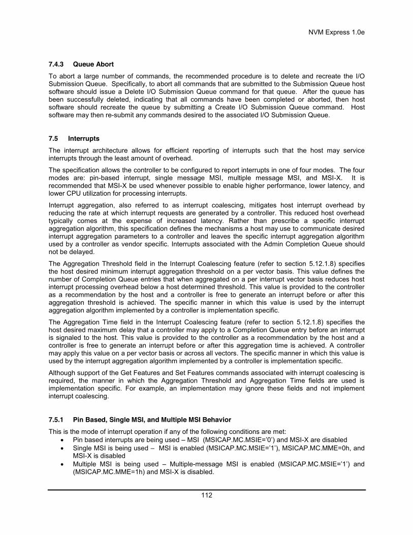
NVM Express 1.0e
112
7.4.3 Queue Abort To abort a large number of commands, the recommended procedure is to delete and recreate the I/O Submission Queue. Specifically, to abort all commands that are submitted to the Submission Queue host software should issue a Delete I/O Submission Queue command for that queue. After the queue has been successfully deleted, indicating that all commands have been completed or aborted, then host software should recreate the queue by submitting a Create I/O Submission Queue command. Host software may then re-submit any commands desired to the associated I/O Submission Queue.
7.5 Interrupts The interrupt architecture allows for efficient reporting of interrupts such that the host may service interrupts through the least amount of overhead.
The specification allows the controller to be configured to report interrupts in one of four modes. The four modes are: pin-based interrupt, single message MSI, multiple message MSI, and MSI-X. It is recommended that MSI-X be used whenever possible to enable higher performance, lower latency, and lower CPU utilization for processing interrupts.
Interrupt aggregation, also referred to as interrupt coalescing, mitigates host interrupt overhead by reducing the rate at which interrupt requests are generated by a controller. This reduced host overhead typically comes at the expense of increased latency. Rather than prescribe a specific interrupt aggregation algorithm, this specification defines the mechanisms a host may use to communicate desired interrupt aggregation parameters to a controller and leaves the specific interrupt aggregation algorithm used by a controller as vendor specific. Interrupts associated with the Admin Completion Queue should not be delayed.
The Aggregation Threshold field in the Interrupt Coalescing feature (refer to section 5.12.1.8) specifies the host desired minimum interrupt aggregation threshold on a per vector basis. This value defines the number of Completion Queue entries that when aggregated on a per interrupt vector basis reduces host interrupt processing overhead below a host determined threshold. This value is provided to the controller as a recommendation by the host and a controller is free to generate an interrupt before or after this aggregation threshold is achieved. The specific manner in which this value is used by the interrupt aggregation algorithm implemented by a controller is implementation specific.
The Aggregation Time field in the Interrupt Coalescing feature (refer to section 5.12.1.8) specifies the host desired maximum delay that a controller may apply to a Completion Queue entry before an interrupt is signaled to the host. This value is provided to the controller as a recommendation by the host and a controller is free to generate an interrupt before or after this aggregation time is achieved. A controller may apply this value on a per vector basis or across all vectors. The specific manner in which this value is used by the interrupt aggregation algorithm implemented by a controller is implementation specific.
Although support of the Get Features and Set Features commands associated with interrupt coalescing is required, the manner in which the Aggregation Threshold and Aggregation Time fields are used is implementation specific. For example, an implementation may ignore these fields and not implement interrupt coalescing.
7.5.1 Pin Based, Single MSI, and Multiple MSI Behavior This is the mode of interrupt operation if any of the following conditions are met:
Pin based interrupts are being used – MSI (MSICAP.MC.MSIE=’0’) and MSI-X are disabled Single MSI is being used – MSI is enabled (MSICAP.MC.MSIE=’1’), MSICAP.MC.MME=0h, and
MSI-X is disabled Multiple MSI is being used – Multiple-message MSI is enabled (MSICAP.MC.MSIE=’1’) and
(MSICAP.MC.MME=1h) and MSI-X is disabled.

NVM Express 1.0e
113
Within the controller there is an interrupt status register (IS) that is not visible to the host. In this mode, the IS register determines whether the PCI interrupt line shall be driven active or an MSI message shall be sent. Each bit in the IS register corresponds to an interrupt vector. The IS bit is set to ‘1’ when the AND of the following conditions is true:
There is one or more unacknowledged completion queue entries in a Completion Queue that utilizes this interrupt vector;
The Completion Queue(s) with unacknowledged completion queue entries has interrupts enabled in the “Create I/O Completion Queue” command;;
The corresponding INTM bit exposed to the host is cleared to ‘0’, indicating that the interrupt is not masked.
If MSIs are not enabled, IS[0] being a one causes the PCI interrupt line to be active (electrical ‘0’). If MSIs are enabled, any change to the IS register that causes an unmasked status bit to transition from zero to one or clearing of a mask bit whose corresponding status bit is set shall cause an MSI to be sent. Therefore, while in wire mode, a single wire remains active, while in MSI mode, several messages may be sent, as each edge triggered event on a port shall cause a new message.
In order to clear an interrupt for a particular interrupt vector, host software shall acknowledge all completion queue entries for Completion Queues associated with the interrupt vector.
Status of IS Register Pin-based Action MSI Action All bits ‘0’ Note: May be caused by corresponding bit(s) in the INTM register being set to ‘1’, masking the corresponding interrupt.
Wire inactive No action
One or more bits set to ‘1’ Note: May be caused by corresponding bit(s) in the INTM register being cleared to ‘0’, unmasking the corresponding interrupt.
Wire active New message sent
One or more bits set to ‘1’, new bit gets set to ‘1’ Wire active New message sent One or more bits set to ‘1’, some (but not all) bits in the IS register are cleared (i.e., host software acknowledges some of the associated completion queue entries)
Wire active New message sent
One or more bits set to ‘1’, all bits in the IS register are cleared (i.e., host software acknowledges all associated completion queue entries)
Wire inactive No action
7.5.1.1 Host Software Interrupt Handling It is recommended that host software utilize the Interrupt Mask Set and Interrupt Mask Clear (INTMS/INTMC) registers to efficiently handle interrupts when configured to use pin based or MSI messages. Specifically, within the interrupt service routine, host software should set the appropriate mask register bits to ‘1’ to mask interrupts via the INTMS register. In the deferred procedure call, host software should process all completion queue entries and acknowledge the completion queue entries have been processed by writing the associated CQyHDBL doorbell registers. When all completion queue entries have been processed, host software should unmask interrupts by clearing the appropriate mask register bits to ‘0 via the INTMC register.
It is recommended that the MSI interrupt vector associated with the CQ(s) being processed be masked during processing of completion queue entries within the CQ(s) to avoid spurious and/or lost interrupts. For single message or multiple message MSI, the INTMS and INTMC registers should be used to appropriately mask interrupts during completion queue entry processing.

NVM Express 1.0e
114
7.5.1.1.1 Interrupt Example (Informative) An example of the host software flow for processing interrupts is described in this section. This example assumes multiple message MSI is used and that interrupt vector 3 is associated with I/O Completion Queue 3.
1. The controller posts a completion queue entry to I/O Completion Queue 3. The controller sets IS[3] to ‘1’ in its internal IS register. The controller asserts an interrupt to the host.
2. The interrupt service routine (ISR) is triggered. 3. Host software scans all I/O Completion Queues associated with the asserted MSI vector to
determine the location of new completion queue entries. In this case, a new completion queue entry has been posted to I/O Completion Queue 3.
4. Host software writes 08h to the INTMS register to mask interrupts for interrupt vector 3, which is associated with I/O Completion Queue 3.
5. The controller masks interrupt vector 3, based on the host write to the INTMS register. 6. Host software schedules a deferred procedure call (DPC) to process the completed command. 7. The deferred procedure call (DPC) is triggered. 8. Host software processes new completion queue entries for I/O Completion Queue 3, completing
the associated commands to the OS. Host software updates CQyHDBL to acknowledge the processed completion queue entries and clear the interrupt associated with those completion queue entries. If all completion queue entries have been acknowledged by host software, the controller de-asserts interrupt vector 3.
9. Host software unmasks interrupt vector 3 by writing 08h to the INTMC register.
7.5.1.2 Differences Between Pin Based and MSI Interrupts Single MSI is similar to the pin based interrupt behavior mode. The primary difference is the method of reporting the interrupt. Instead of a communicating the interrupt through an INTx virtual wire, an MSI message is generated to the host. Unlike INTx virtual wire interrupts which are level sensitive, MSI interrupts are edge sensitive.
Pin based and single MSI only use one interrupt vector. Multiple MSI may use up to 32 interrupt vectors.
For multiple MSI, the controller advertises the number of MSI interrupt vectors it requests in the Multiple Message Capable (MMC) field in the Message Signaled Interrupt Message Control (MC) register. The MSICAP.MC.MMC field represents a power-of-2 wrapper on the number of requested vectors. For example, if three vectors are requested, then the MSICAP.MC.MMC field shall be ‘010’ (four vectors).
Multiple-message MSI allows completions to be aggregated on a per vector basis. If sufficient MSI vectors are allocated, each Completion Queue(s) may send its own interrupt message, as opposed to a single message for all completions.
7.5.2 MSI-X Based Behavior This is the mode of interrupt operation if the MSI-X is being used – (multiple-message) MSI is disabled (MSICAP.MC.MSIE=’0’) and (MSICAP.MC.MME=0h) and MSI-X is enabled. This is the preferred interrupt behavior to use.
MSI-X, similar to multiple-message MSI, allows completions to be aggregated on a per vector basis. However, the maximum number of vectors is 2K. MSI-X also allows each interrupt to send a unique message data corresponding to the vector.
MSI-X allows completions to be aggregated on a per vector basis. Each Completion Queue(s) may send its own interrupt message, as opposed to a single message for all completions.
When generating an MSI-X message, the following checks occur before generating the message: The function mask bit in the MSI-X Message Control register is not set to ‘1’ The corresponding vector mask in the MSI-X table structure is not set to ‘1’
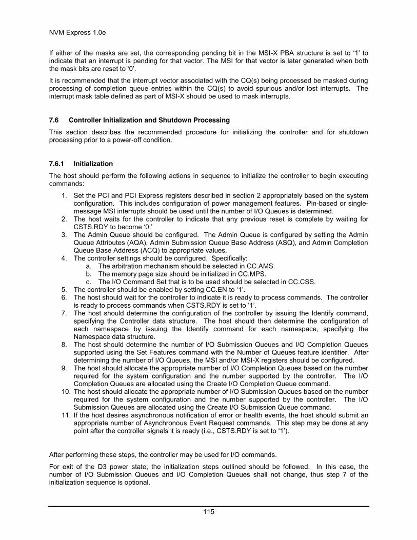
NVM Express 1.0e
115
If either of the masks are set, the corresponding pending bit in the MSI-X PBA structure is set to ‘1’ to indicate that an interrupt is pending for that vector. The MSI for that vector is later generated when both the mask bits are reset to ‘0’.
It is recommended that the interrupt vector associated with the CQ(s) being processed be masked during processing of completion queue entries within the CQ(s) to avoid spurious and/or lost interrupts. The interrupt mask table defined as part of MSI-X should be used to mask interrupts.
7.6 Controller Initialization and Shutdown Processing This section describes the recommended procedure for initializing the controller and for shutdown processing prior to a power-off condition.
7.6.1 Initialization The host should perform the following actions in sequence to initialize the controller to begin executing commands:
1. Set the PCI and PCI Express registers described in section 2 appropriately based on the system configuration. This includes configuration of power management features. Pin-based or single-message MSI interrupts should be used until the number of I/O Queues is determined.
2. The host waits for the controller to indicate that any previous reset is complete by waiting for CSTS.RDY to become ‘0.’
3. The Admin Queue should be configured. The Admin Queue is configured by setting the Admin Queue Attributes (AQA), Admin Submission Queue Base Address (ASQ), and Admin Completion Queue Base Address (ACQ) to appropriate values.
4. The controller settings should be configured. Specifically: a. The arbitration mechanism should be selected in CC.AMS. b. The memory page size should be initialized in CC.MPS. c. The I/O Command Set that is to be used should be selected in CC.CSS.
5. The controller should be enabled by setting CC.EN to ‘1’. 6. The host should wait for the controller to indicate it is ready to process commands. The controller
is ready to process commands when CSTS.RDY is set to ‘1’. 7. The host should determine the configuration of the controller by issuing the Identify command,
specifying the Controller data structure. The host should then determine the configuration of each namespace by issuing the Identify command for each namespace, specifying the Namespace data structure.
8. The host should determine the number of I/O Submission Queues and I/O Completion Queues supported using the Set Features command with the Number of Queues feature identifier. After determining the number of I/O Queues, the MSI and/or MSI-X registers should be configured.
9. The host should allocate the appropriate number of I/O Completion Queues based on the number required for the system configuration and the number supported by the controller. The I/O Completion Queues are allocated using the Create I/O Completion Queue command.
10. The host should allocate the appropriate number of I/O Submission Queues based on the number required for the system configuration and the number supported by the controller. The I/O Submission Queues are allocated using the Create I/O Submission Queue command.
11. If the host desires asynchronous notification of error or health events, the host should submit an appropriate number of Asynchronous Event Request commands. This step may be done at any point after the controller signals it is ready (i.e., CSTS.RDY is set to ‘1’).
After performing these steps, the controller may be used for I/O commands.
For exit of the D3 power state, the initialization steps outlined should be followed. In this case, the number of I/O Submission Queues and I/O Completion Queues shall not change, thus step 7 of the initialization sequence is optional.

NVM Express 1.0e
116
7.6.1.1 Software Progress Marker The Software Progress Marker feature, defined in section 5.12.1.12, indicates the number of times pre-boot software has loaded prior to the OS successfully loading. If the pre-boot software load count becomes large, it may indicate there are issues with cached data within the NVM since the OS driver software has not set this field to 0h recently. In this case, the OS driver software may choose to use the NVM more conservatively (e.g., not utilize cached data).
The Software Progress Marker should be updated by both Pre-boot and OS driver software as part of completing initialization.
7.6.2 Shutdown It is recommended that the host perform an orderly shutdown of the controller by following the procedure in this section when a power-off or shutdown condition is imminent.
The host should perform the following actions in sequence for a normal shutdown:
1. Stop submitting any new I/O commands to the controller and allow any outstanding commands to complete.
2. The host should delete all I/O Submission Queues, using the Delete I/O Submission Queue command. A result of the successful completion of the Delete I/O Submission Queue command is that any remaining commands outstanding are aborted.
3. The host should delete all I/O Completion Queues, using the Delete I/O Completion Queue command.
4. The host should set the Shutdown Notification (CC.SHN) field to 01b to indicate a normal shutdown operation. The controller indicates when shutdown processing is completed by updating the Shutdown Status (CSTS.SHST) field to 10b.
For entry to the D3 power state, the shutdown steps outlined for a normal shutdown should be followed.
The host should perform the following actions in sequence for an abrupt shutdown:
1. Stop submitting any new I/O commands to the controller. 2. The host should set the Shutdown Notification (CC.SHN) field to 10b to indicate an abrupt
shutdown operation. The controller indicates when shutdown processing is completed by updating the Shutdown Status (CSTS.SHST) field to 10b.
It is recommended that the host wait a minimum of one second for the shutdown operations to complete. It is not recommended to disable the controller via the CC.EN field. This causes a controller reset condition which may impact the time required to complete shutdown processing.
To start executing commands on the controller after a shutdown operation, a reset (CC.EN cleared from ‘1’ to ‘0’) is required. The initialization sequence should then be executed.
It is an implementation choice whether the host aborts all outstanding commands to the Admin Queue prior to the shutdown. The only commands that should be outstanding to the Admin Queue at shutdown are Asynchronous Event Request commands.
7.7 Unique Identifier Information is returned in the Identify Controller data structure that may be used to construct a unique identifier. Specifically, the PCI Vendor ID, Serial Number, and Model Number fields when combined shall form a unique value. It is outside the scope of this specification the mechanism used by the vendor to assign Serial Number and Model Number values to ensure uniqueness.

NVM Express 1.0e
117
NVM Express 1.0e
118
8 Features 8.1 Firmware Update Process A firmware update is a four step process.
1. The firmware is downloaded to the controller. This is accomplished by using the Firmware Image Download command. There may be multiple portions of the firmware image to download, thus the offset for each portion of the firmware image being downloaded is specified in the Firmware Image Download command.
2. After the firmware is downloaded to the controller, the next step is for the host to submit a Firmware Activate command. The Firmware Activate command verifies that the last firmware image downloaded is valid and commits that image to the firmware slot indicated for future use. A firmware image that does not start at offset zero, contains gaps, or contains overlapping regions is considered invalid. A controller may employ additional vendor specific means (e.g., checksum, CRC, cryptographic hash or a digital signature) to determine the validity of a firmware image.
a. The Firmware Activate command may also be used to activate a firmware image associated with a previously activated firmware slot.
3. The last step is to perform a reset that then causes the firmware image specified in the Firmware Activate command to be applied. The reset may be a Conventional Reset, Function Level Reset, Controller Reset (CC.EN transitions from ‘1’ to ‘0’), or a power cycle of the controller.
4. After the reset has completed, host software re-initializes the controller. This includes re-allocating I/O Submission and Completion Queues. Refer to section 7.6.1.
If a D3 cold condition occurs during the firmware activation process, the controller may resume operation with either the old or new firmware.
If the firmware is not able to be successfully loaded following a reset, then the controller shall revert to the previously active firmware image or the baseline read-only firmware image, if available, and indicate the failure as an asynchronous event with a Firmware Image Load Error.
Host software shall not update multiple firmware images simultaneously. A firmware image shall be committed to the firmware slot using Firmware Activate before downloading additional firmware images. If the controller does not receive a Firmware Activate command, then it shall delete the portion(s) of the new image in the case of a reset.
8.2 Metadata Handling The controller may support metadata per logical block. Metadata is additional data allocated on a per logical block basis. There is no requirement for how the host makes use of the metadata area. One of the most common usages for metadata is to convey end-to-end protection information.
The metadata may be transferred by the controller to or from the host in one of two ways. The mechanism used is selected as part of the Format NVM command.
The first mechanism for transferring the metadata is as a contiguous part of the logical block that it is associated with. The metadata is transferred at the end of the associated logical block, forming an extended logical block. This mechanism is illustrated in Figure 140. In this case, both the logical block data and logical block metadata are pointed to by the PRP1 and PRP2 pointers.

NVM Express 1.0e
119
Figure 140: Metadata – Contiguous with LBA Data, Forming Extended LBA
The second mechanism for transferring the metadata is as a separate contiguous buffer of data. This mechanism is illustrated in Figure 141. In this case, the metadata is pointed to with the Metadata Pointer, while the logical block data is pointed to by the PRP1 and PRP2 pointers. The metadata is required to be physically contiguous in this case since there is only one Metadata Pointer.
Figure 141: Metadata – Transferred as Separate Buffer
One of the transfer mechanisms shall be selected for each namespace when it is formatted; transferring a portion of metadata with one mechanism and a portion with the other mechanism is not supported.
If end-to-end data protection is used, then the Protection Information field for each logical block is contained in the metadata.
8.3 End-to-end Data Protection (Optional) To provide robust data protection from the application to the NVM media and back to the application itself, end-to-end data protection may be used. If this optional mechanism is enabled, then additional protection information (e.g. CRC) is added to the logical block that may be evaluated by the controller and/or host software to determine the integrity of the logical block. This additional protection information, if present, is either the first eight bytes of metadata or the last eight bytes of metadata, based on the format of the namespace. For metadata formats with more than eight bytes, if the protection information is contained within the first eight bytes of metadata, then the CRC does not cover any metadata bytes. For metadata formats with more than eight bytes, if the protection information is contained within the last eight bytes of metadata, then the CRC covers all metadata bytes up to but excluding these last eight bytes. As described in section 8.2, metadata and hence this protection information may be configured to be contiguous with the logical block data or stored in a separate buffer.
The most commonly used data protection mechanisms in Enterprise implementations are Data Integrity Field (DIF), defined in the SCSI Block Commands – 3 reference (SBC-3), and the Data Integrity Extension (DIX). The primary difference between these two mechanisms is the location of the protection information. In DIF the protection information is contiguous with the logical block data and creates an extended logical block, while in DIX the protection information is stored in a separate buffer. The end-to-end data protection mechanism defined by this specification is functionally compatible with both DIF and DIX. DIF functionality is achieved by configuring the metadata to be contiguous with logical block data (as shown in Figure 140, while DIX functionality is achieved by configuring the metadata and data to be in separate buffers (as shown in Figure 141).
LBA n Data LBA n+1 DataSector NMetadata
Sector N+2Metadata
Sector NMetadata
Sector N+2Metadata
Sector NMetadata
LBA n+2Metadata
LBA nMetadata
Host…
Data Buffer (PRP1 & PRP2)
Sector N Data
Sector NMetadata
Sector N+1Metadata
Sector N+2Metadata
LBA n+1 Data LBA n+2 Data
Sector NMetadata
Sector N+1Metadata
Sector N+2Metadata
Sector NMetadata
Sector N+1Metadata
Sector N+2Metadata
Sector NMetadata
Sector N+1Metadata
Sector N+2Metadata
Sector NMetadata
Sector N+1Metadata
Sector N+2Metadata
LBA n+1Metadata
LBA n+2Metadata
Host
…
…
Data Buffer (PRP1 & PRP2)
Metadata Buffer (MD)
LBA n Data
LBA nMetadata

NVM Express 1.0e
120
NVM Express supports the same end-to-end protection types as DIF. The type of end-to-end data protection (Type 1, Type 2, or Type 3) is selected when a namespace is formatted and is reported in the Identify Namespace data structure.
The Protection Information format is shown in Figure 142 and is contained in the metadata associated with each logical block. The Guard field contains a CRC-16 computed over the logical block data. In addition to a CRC-16, DIX also specifies an optional IP checksum that is not supported by NVM Express. The Application Tag is an opaque data field not interpreted by the controller and that may be used to disable checking of protection information. The Reference Tag associates logical block data with an address and protects against misdirected or out-of-order logical block transfer. Like the Application Tag, the Reference Tag may also be used to disable checking of protection information.
Figure 142: Protection Information Format
The protection information processing performed as a side effect of Read and Write commands is controlled by the Protection Information Action (PRACT) bit in the command. Figure 143 illustrates the protection information processing that may occur as a side effect of a Write command. If the namespace is not formatted with end-to-end data protection, then logical block data and any optional metadata is transferred from the host to the NVM with no processing. If the namespace was formatted with protection information and the PRACT bit is cleared to ‘0’, then logical block data and metadata containing protection information are transferred from the host to NVM. As the logical block and metadata passes through the controller, the protection information is checked. If a protection information check error is detected, the command completes with the status code of the error detected (i.e., End-to-end Guard Check, End-to-end Application Tag Check or End-to-end Reference Tag Check). If the namespace was formatted with protection information and the PRACT bit is set to ‘1’, then logical block data is transferred from the host to the controller. The controller inserts protection information and the logical block data and metadata containing protection information are written to NVM.
When there is additional metadata, the protection information may be transferred as the first eight bytes of metadata or the last eight bytes of metadata. The location of the protection information is configured when the namespace is formatted. In this case, the protection information replaces the first eight or last eight bytes of metadata (i.e., the metadata field remains the same size in NVM as that in the host).
0
1
2
3
4
5
6
7
MSB
LSBGuard
MSB
LSBApplication Tag
MSB
MSB
Reference Tag
Byte
7 6 5 4 3 2 1 0Bit
LSB
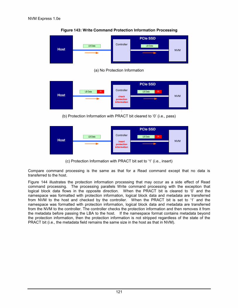
NVM Express 1.0e
121
Figure 143: Write Command Protection Information Processing
HostController
NVM
PCIe SSD
LB Data
(a) No Protection Information
HostLB Data PI Controller
checkprotection
information
NVM
PCIe SSD
LB Data PI
(b) Protection Information with PRACT bit cleared to ‘0’ (i.e., pass)
HostLB Data Controller
insertprotection
information
NVM
PCIe SSD
LB Data PI
(c) Protection Information with PRACT bit set to ‘1’ (i.e., insert)
LB Data
Compare command processing is the same as that for a Read command except that no data is transferred to the host.
Figure 144 illustrates the protection information processing that may occur as a side effect of Read command processing. The processing parallels Write command processing with the exception that logical block data flows in the opposite direction. When the PRACT bit is cleared to ‘0’ and the namespace was formatted with protection information, logical block data and metadata are transferred from NVM to the host and checked by the controller. When the PRACT bit is set to ‘1’ and the namespace was formatted with protection information, logical block data and metadata are transferred from the NVM to the controller. The controller checks the protection information and then removes it from the metadata before passing the LBA to the host. If the namespace format contains metadata beyond the protection information, then the protection information is not stripped regardless of the state of the PRACT bit (i.e., the metadata field remains the same size in the host as that in NVM).

NVM Express 1.0e
122
Figure 144: Read Command Protection Information Processing
HostController
NVM
PCIe SSD
LB Data
(a) No Protection Information
HostLB Data PI Controller
checkprotection
information
NVM
PCIe SSD
LB Data PI
(b) Protection Information with PRACT bit cleared to ‘0’ (i.e., pass)
(c) Protection Information with PRACT bit set to ‘1’ (i.e., strip)
LB Data
HostLB Data
Controller
check & strip
protectioninformation
NVM
PCIe SSD
LB Data PI
Protection processing for fused operations is the same as those for the individual commands that make up the fused operation.
Checking of protection information consists of the following operations performed by the controller. If bit 2 of the Protection Information Check (PRCHK) field of the command is set to ‘1’, then the controller compares the protection information Guard field to the CRC-16 computed over the logical block data. If bit 1 of the PRCHK field is set to ‘1’, then the controller compares unmasked bits in the protection information Application Tag field to the Logical Block Application Tag (LBAT) field in the command. A bit in the protection information Application Tag field is masked if the corresponding bit is cleared to ‘0’ in the Logical Block Application Tag Mask (LBATM) field of the command. If bit 0 of the PRCHK field is set to ‘1’, then the controller compares the protection information Reference Tag field to the computed reference tag. The value of the computed reference tag for the first LBA of the command is the value contained in the Initial Logical Block Reference Tag (ILBRT) field in the command. The computed reference tag is incremented for each subsequent logical block. Unlike DIF Type 1 protection which implicitly uses the least significant four bytes of the LBA, The controller always uses the ILBRT field and requires host software to initialize the ILBRT field to the least significant four bytes of the LBA when Type 1 protection is used.
Protection checking may be disabled as a side effect of the value of the protection information Application Tag and Reference Tag fields regardless of the state of the PRCHK field in the command. If the namespace is formatted for Type 1 or Type 2 protection, then all protection information checks are disabled regardless of the state of the PRCHK field when the protection information Application Tag has a value of FFFFh. If the namespace is formatted for Type 3 protection, then all protection information checks are disabled regardless of the state of the PRCHK field when the protection information

NVM Express 1.0e
123
Application Tag has a value of FFFFh and the protection information Reference Tag has a value of FFFF_FFFFh.
Inserted protection information consists of the computed CRC-16 in the Guard field, the LBAT field value in the Application Tag, and the computed reference tag in the Reference Tag field.
8.4 Power Management The power management capability allows the host to manage NVM subsystem power statically or dynamically. Static power management consists of the host determining the maximum power that may be allocated to an NVM subsystem and setting the NVM Express power state to one that consumes this amount of power or less. Dynamic power management is illustrated in Figure 145 and consists of the host modifying the NVM Express power state to best satisfy changing power and performance objectives. This power management mechanism is meant to complement and not replace autonomous power management performed by a controller.
Figure 145: Dynamic Power Management
PowerManager
(Host Software)Performance
Objective
Controller
PowerObjective NVM Express
Power State
-
Performance Statistics
The number of power states implemented by a controller is returned in the Number of Power States Supported (NPSS) field in the Identify Controller data structure. A controller shall support at least one power state and may optionally support up to a total of 32 power states. Power states are contiguously numbered starting with zero such that each subsequent power state consumes less or equal power than the previous state. Thus, power state zero indicates the maximum power that the NVM subsystem is capable of consuming.
Associated with each power state is a Power State Descriptor in the Identify Controller data structure (see Figure 67). The descriptors for all implemented power states may be viewed as forming a table as shown in Figure 146 for a controller with seven implemented power states. The Maximum Power (MP) field indicates the instantaneous maximum power that may be consumed in that state. The controller may employ autonomous power management techniques to reduce power consumption below this level, but under no circumstances is power allowed to exceed this level.
Figure 146: Example Power State Descriptor Table
Power State
Maximum Power (MP)
Entry Latency
(ENTLAT)
Exit Latency (EXLAT)
Relative Read
Throughput (RRT)
Relative Read
Latency (RRL)
Relative Write
Throughput (RWT)
Relative Write
Latency (RWL)
0 25 W 5 µs 5 µs 0 0 0 0 1 18 W 5 µs 7 µs 0 0 1 0

NVM Express 1.0e
124
2 18 W 5 µs 8 µs 1 0 0 0 3 15 W 20 µs 15 µs 2 0 2 0 4 10 W 20 µs 30 µs 1 1 3 0 5 8 W 50 µs 50 µs 2 2 4 0 6 5 W 20 µs 5000 µs 4 3 5 1
The host may dynamically modify the power state using the Set Features command and determine the current power state using the Get Features command. The host may directly transition between any two supported power states. The Entry Latency (ENTLAT) field in the power management descriptor indicates the maximum amount of time in microseconds that it takes to enter that power state and the Exit Latency (EXTLAT) field indicates that maximum amount of time in microseconds that it takes to exit that state. The maximum amount of time to transition between any two power states is equal to the sum of the old state’s exit latency and the new state’s entry latency. The host is not required to wait for a previously submitted power state transition to complete before initiating a new transition. The maximum amount of time for a sequence of power state transitions to complete is equal to the sum of transition times for each individual power state transition in the sequence. Associated with each power state descriptor are Relative Read Throughput (RRT), Relative Write Throughput (RWT), Relative Read Latency (RRL) and Relative Write Latency (RWL) fields that provide the host with an indication of relative performance in that power state. Relative performance values provide an ordering of performance characteristics between power states. Relative performance values may repeat, may be skipped, and may be assigned in any order (i.e., increasing power states need not have increasing relative performance values). A lower relative performance value indicates better performance (e.g., higher throughput or lower latency). For example, in Figure 145 power state 1 has higher read throughput than power state 2, and power states 0 through 3 all have the same read latency. Relative performance ordering is only with respect to a single performance characteristic. Thus, although the relative read throughput value of one power state may equal the relative write throughput value of another power state, this does not imply that the actual read and write performance of these two power states are equal. The default NVM Express power state is implementation specific and shall correspond to a state that does not consume more power than the lowest value specified in the form factor specification used by the PCI Express SSD. The host shall never select a power state that consumes more power than the PCI Express slot power limit control value expressed by the Captured Slot Power Limit Value (CSPLV) and Captured Slot Power Limit Scale (CSPLS) fields of the PCI Express Device Capabilities (PXDCAP) register. Hosts that do not dynamically manage power should set the power state to the lowest numbered state that satisfies the PCI Express slot power limit control value. If a controller implements the PCI Express Dynamic Power Allocation (DPA) capability and it is enabled (i.e., the Substate Control Enable bit is set), then the maximum power that may be consumed by the NVM subsystem is equal to the minimum value specified by the DPA substate or the NVM Express power state, whichever is lower.
8.5 Single Root I/O Virtualization and Sharing (SR-IOV) The PCI-SIG Single Root I/O Virtualization and Sharing Specification (SR-IOV) defines extensions to PCI Express that allow multiple System Images (SI), such as virtual machines running on a hypervisor, to share PCI hardware resources. The primary benefit of SR-IOV is that it eliminates the hypervisor from participating in I/O operations which may be a significant factor limiting storage performance in some virtualized environments and allows direct SI access to PCI hardware resources.
While the details associated with implementing a controller that supports SR-IOV are outside the scope of this specification, such a controller shall implement fully compliant NVM Express Virtual Functions (VFs). This ensures that the same host software developed for non-virtualized environments is capable of running unmodified within an SI. No such requirement exists for the Physical Function (PF).

NVM Express 1.0e
125
Note: Some settings for features specified with Set Features for a VF may be overridden by the value specified for the associated feature in the PF.
All other aspects associated with SR-IOV such as the architecture of the PF, mapping of namespaces to VFs, and sharing of namespaces between VFs are outside the scope of this specification.
8.6 Doorbell Stride for Software Emulation The doorbell stride, specified in CAP.DSTRD, may be used to separate doorbells by a number of bytes in memory space. The doorbell stride is a number of bytes equal to (2 ^ (2 + CAP.DSTRD)). This is useful in software emulation of an NVM Express controller. In this case, a software thread is monitoring doorbell notifications. The software thread may be made more efficient by monitoring one doorbell per discrete cacheline or utilize the monitor/mwait CPU instructions. For hardware implementations of NVM Express, the expected doorbell stride value is 0h.
8.7 Standard Vendor Specific Command Format Controllers may support the standard Vendor Specific command format defined in Figure 8. Host storage drivers may use the Number of Dwords fields to ensure that the application is not corrupting physical memory (e.g. overflowing a data buffer). The controller indicates support of this format in the Identify Controller data structure in Figure 66; refer to Admin Vendor Specific Command Configuration and NVM Vendor Specific Command Configuration.
NVM Express 1.0e
126
9 Error Reporting and Recovery 9.1 Command and Queue Error Handling In the case of serious error conditions, like Completion Queue Invalid, the operation of the associated Submission Queue or Completion Queue may be compromised. In this case, host software should delete the associated Completion Queue and/or Submission Queue. The delete of a Submission Queue aborts all outstanding commands, and deletion of either queue type releases resources associated with that queue. Host software should recreate the Completion Queue and/or Submission Queue to then continue with operation.
In the case of serious error conditions for Admin commands, the entire controller should be reset using a Controller Reset. The entire controller should also be reset if a completion is not received for the deletion of a Submission Queue or Completion Queue.
For most command errors, there is not an issue with the Submission Queue and/or Completion Queue itself. Thus, host software and the controller should continue to process commands. It is at the discretion of host software whether to retry the failed command; the Retry bit in the Completion Queue Entry indicates whether a retry of the failed command may succeed.
9.2 Media and Data Error Handling In the event that the requested operation could not be performed to the NVM media, the particular command is completed with a media error indicating the type of failure using the appropriate status code. During a read error within a command, (e.g. End-to-end Guard Check failure, Unrecovered Read Error, etc), the controller may choose to either stop the DMA transfer into the system memory or transfer the erroneous data to the system memory. The host shall ignore the data in the system memory locations for commands that complete with such error conditions.
Based on the value of the Limited Retry bit, the controller may apply all available error recovery means to complete the command.
9.3 System Memory Error Handling System memory errors such as target abort, master abort, and parity may cause the controller to stop processing the currently executing command. These are serious errors that cannot be recovered from without host software intervention.
A master/target abort error occurs when host software has given a pointer to the host controller that does not exist in system memory. When this occurs, the host controller aborts the command with a Data Transfer Error status code.
9.4 Internal Device Error Handling Device specific errors such as a DRAM failure or power loss notification errors indicate that a controller level failure has occurred during the processing of a command. The status code of the completion queue entry should indicate an Internal Device Error status code (if multiple error conditions exist, the lowest numerical value is returned). Host software shall ignore any data transfer associated with the command. The host may choose to re-submit the command or indicate an error to the higher level software.
9.5 Controller Fatal Status Condition If the controller has a serious error condition and is unable to communicate with host software via completion queue entries in the Admin or I/O Completion Queues, then the controller may set the Controller Fatal Status (CSTS.CFS) field to ‘1’. This indicates to host software that a serious error

NVM Express 1.0e
127
condition has occurred. When this condition occurs, host software should reset and then re-initialize the controller.
The Controller Fatal Status condition is not indicated with an interrupt. If host software experiences timeout conditions and/or repeated errors, then host software should consult the Controller Fatal Status (CSTS.CFS) field to determine if a more serious error has occurred.