Embed Size (px)
Citation preview
Non-orthogonal Multiple Access and Massive MIMO for Improved Spectrum Efficiency
To cope with the expected 1000x increase in mobile traffic over the next 10 years, key requirements are making more efficient use of the available frequency spectrum, increasing network speeds and opening-up more of the frequency spectrum for wireless applications. OFDMA used by LTE, etc., is being extended and superposition of signals for multiple users using a new power domain are being investigated as methods for increasing spectrum efficiency. In addition, high-directivity adaptive antennas with 100 or more elements offering good compatibility with higher frequencies, interference suppression, and simultaneous multi-user access are other potential ways to improve spectrum efficiency. This paper examines 5G wireless access systems and outlines non-orthogonal access and MIMO technologies along with some issues to resolve.
1 - Introduction
Next-generation 5G access systems are being investigated as a solution to the explosive increase (a factor of 1000x compared to 2010) in wireless data traffic forecast for the 2020s and the rapid appearance of various new services1,2).
Three approaches are being taken towards supporting these huge traffic increases: making more efficient use of available frequencies, increasing network speeds, and opening-up new frequency bands. Making more efficient use of available frequencies is closely related to speeding-up the physical layer for multi-access and wireless access technologies. For example, increases of from 2.5 to 10 times have been proposed as targets for increasing the efficiency of 5G frequencies3).
Conventional mobile communications systems are moving towards faster digital wireless technologies based on advances in semiconductor devices as described below. The first generation (1G) used Frequency Division Multiple Access (FDMA), the second generation (2G) used Time Division Multiple Access (TDMA), the third generation (3G) is using Code Division Multiple Access (CDMA), and the 3.9G and fourth (4G) generations are using Orthogonal Frequency Division Multiple Access (OFDMA) supporting efficient frequency usage and good resistance to fading. The proposals for 5G systems aim to increase spectrum efficiency even further by speeding-up existing technologies, using newly opened frequency bands, and increasing network density, and support for the expected required conditions is being examined. The non-orthogonal multiple-access (NOMA) and higher-order multiple-input and multiple-output (MIMO) technologies described in this paper require huge processing power to implement these functions, which will be difficult to achieve using the performance of conventional semiconductor devices. Rapid developments in CPU processing power are expected to be a key element in deployment of 5G services.
This paper describes the principles of each method related to these technologies and the problems to be resolved.
19 (1)
2 - Non-orthogonal Multiple Access (NOMA)
Multiple access is a basic function of cellular systems, which are usually divided into two types: orthogonal and non-orthogonal. In orthogonal access systems such as TDMA, FDMA, and OFDMA, signals for different users are orthogonal to each other. On the other hand, in non-orthogonal access systems, such as CDMA, TCMA (Trellis Coded Multiple Access), IDMA (Interleave Division Multiple Access)4), the cross-correlation of signals for different users is not 0.
The commonly used NOMA incorporates the above-described non-orthogonal multiple access but this section discusses a specified NOMA implementation for 5G systems. NOMA under discussion for 5G systems has a new extension of the user multiplex domain to improve the spectrum efficiency. Intentionally introducing non-orthogonality aims to increase the spectrum efficiency further. As a result, technologies such as new encodings and an interference canceler are required to correct the non-orthogonality, which has been considered difficult to implement until now. However, development is pushing forward with the expectation of introduction as key 5G technology following recent remarkable improvements in CPU performance 5,6,7).
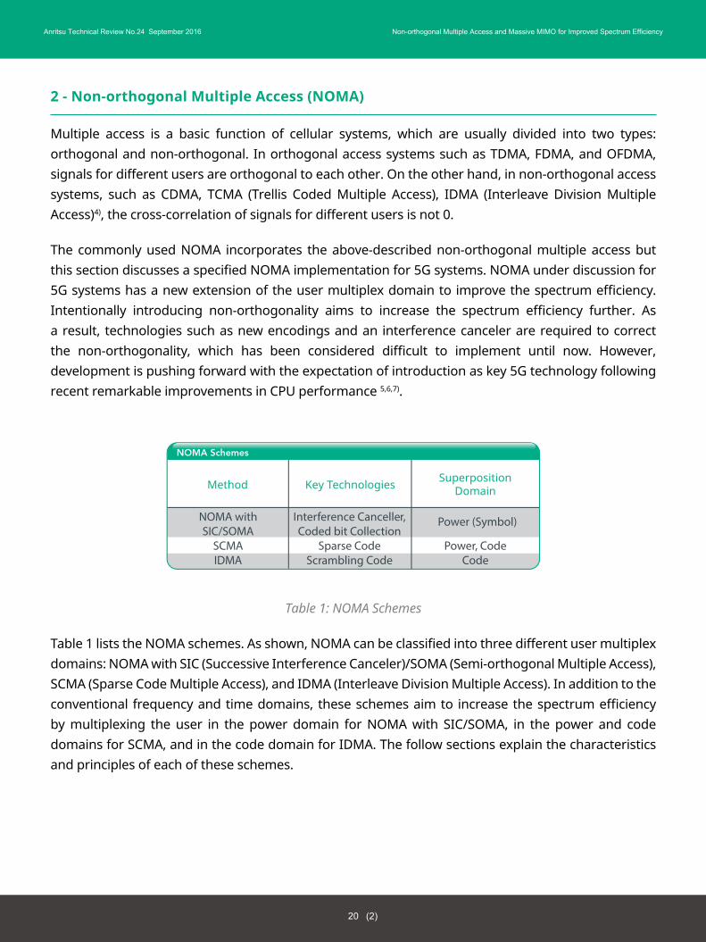
Table 1: NOMA Schemes
Table 1 lists the NOMA schemes. As shown, NOMA can be classified into three different user multiplex domains: NOMA with SIC (Successive Interference Canceler)/SOMA (Semi-orthogonal Multiple Access), SCMA (Sparse Code Multiple Access), and IDMA (Interleave Division Multiple Access). In addition to the conventional frequency and time domains, these schemes aim to increase the spectrum efficiency by multiplexing the user in the power domain for NOMA with SIC/SOMA, in the power and code domains for SCMA, and in the code domain for IDMA. The follow sections explain the characteristics and principles of each of these schemes.
Method
NOMA withSIC/SOMA
SCMAIDMA
Interference Canceller,Coded bit Collection
Sparse CodeScrambling Code
Power, CodeCode
Key Technologies SuperpositionDomain
NOMA Schemes
Power (Symbol)
20 (2)
Anritsu Technical Review No.24 September 2016 Non-orthogonal Multiple Access and Massive MIMO for Improved Spectrum Efficiency
2.1 NOMA with SIC/SOMA
NOMA with SIC (NOMA hereafter)/SOMA expands the radio resource allocation for the frequency and time domains used by LTE, etc. By superposing multiple user signals using the new power domain, it becomes possible to increase the spectrum efficiency even further and to increase the throughput. The NOMA and SOMA methods both make positive use of power and loss differences by modulation processing and multiplexing8,9,10,11).
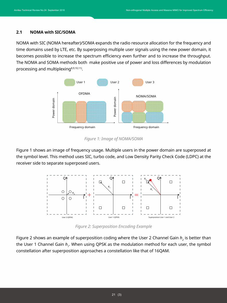
Figure 1: Image of NOMA/SOMA
Figure 1 shows an image of frequency usage. Multiple users in the power domain are superposed at the symbol level. This method uses SIC, turbo code, and Low Density Parity Check Code (LDPC) at the receiver side to separate superposed users.
Figure 2: Superposition Encoding Example
Figure 2 shows an example of superposition coding where the User 2 Channel Gain h2 is better than the User 1 Channel Gain h1. When using QPSK as the modulation method for each user, the symbol constellation after superposition approaches a constellation like that of 16QAM.
Pow
er d
omai
n
Frequency domain
User 1 User 2 User 3
OFDMANOMA/SOMA
Frequency domain
Pow
er d
omai
n
Q
x2
User 2 (QPSK)
Q
II
x1
User 1 (QPSK)
Q
I
x1
x2
Superposition User 1 and User 2
21 (3)
Anritsu Technical Review No.24 September 2016 Non-orthogonal Multiple Access and Massive MIMO for Improved Spectrum Efficiency
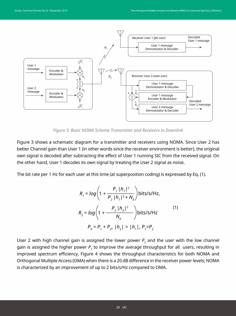
Figure 3: Basic NOMA Scheme Transmitter and Receivers in Downlink
Figure 3 shows a schematic diagram for a transmitter and receivers using NOMA. Since User 2 has better Channel gain than User 1 (in other words since the receiver environment is better), the original own signal is decoded after subtracting the effect of User 1 running SIC from the received signal. On the other hand, User 1 decodes its own signal by treating the User 2 signal as noise.
The bit rate per 1 Hz for each user at this time (at superposition coding) is expressed by Eq. (1).
User 2 with high channel gain is assigned the lower power P2 and the user with the low channel gain is assigned the higher power P1 to improve the average throughput for all users, resulting in improved spectrum efficiency. Figure 4 shows the throughput characteristics for both NOMA and Orthogonal Multiple Access (OMA) when there is a 20 dB difference in the receiver power levels; NOMA is characterized by an improvement of up to 2 bits/s/Hz compared to OMA.
R1 = log
P0 = P1 + P2, |h2| > |h1|, P1>P2
bits/s/Hz,1 +P1 |h1|2
P2 |h1|2 + N0
R2 = log bits/s/Hz1 +P2 |h2|2
N0
(1)
Encoder &Modulator
Encoder &Modulator
User 1message
User 2message
P1
P2
∑
x1
x2
x2
+
+
User 1 messageDemodulator & Decoder
DecodedUser 1 message
Receiver User 1 (far user)
User 1 messageDemodulator & Decoder
User 1 messageEncoder & Modulator
User 2 messageDemodulator & Decoder
DecodedUser 2 message
Receiver User 2 (near user)
∑x1
x2
h2
h1
+ ^
^
22 (4)
Anritsu Technical Review No.24 September 2016 Non-orthogonal Multiple Access and Massive MIMO for Improved Spectrum Efficiency
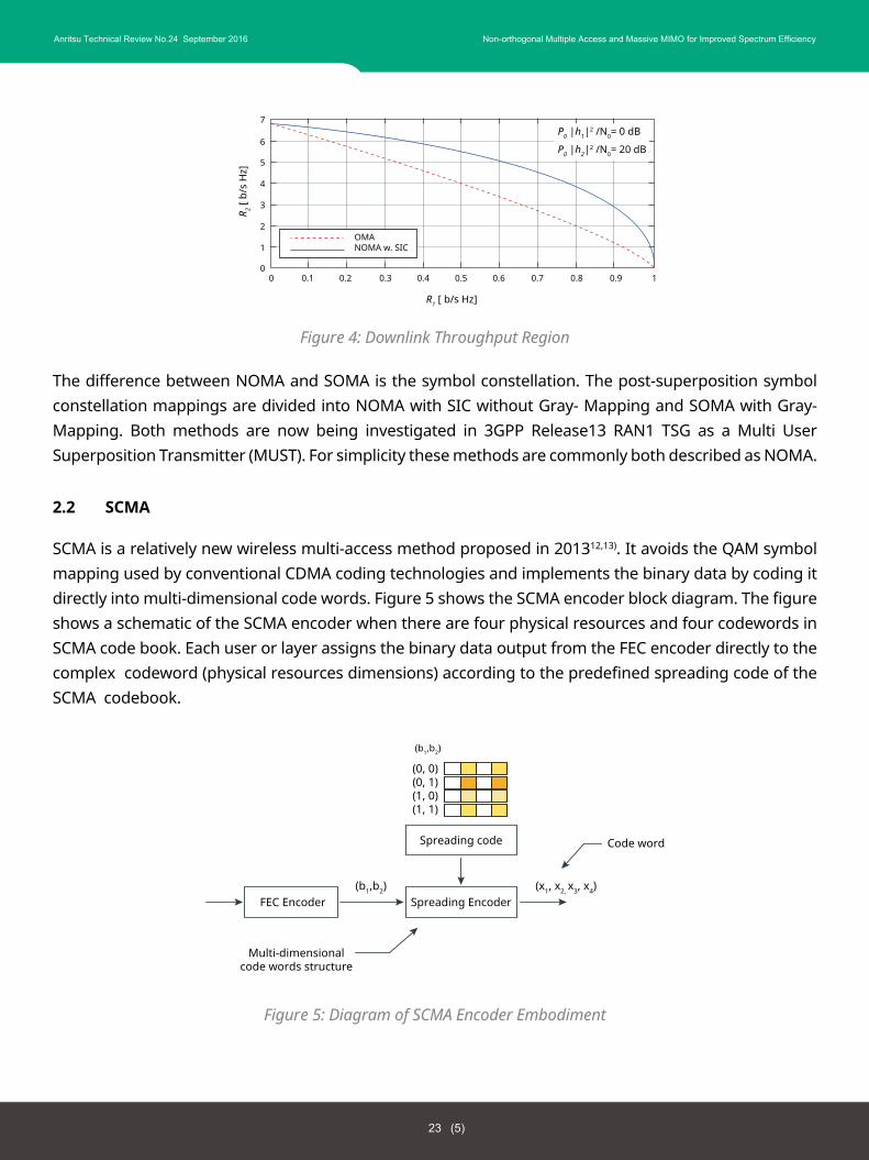
Figure 4: Downlink Throughput Region
The difference between NOMA and SOMA is the symbol constellation. The post-superposition symbol constellation mappings are divided into NOMA with SIC without Gray- Mapping and SOMA with Gray-Mapping. Both methods are now being investigated in 3GPP Release13 RAN1 TSG as a Multi User Superposition Transmitter (MUST). For simplicity these methods are commonly both described as NOMA.
2.2 SCMA
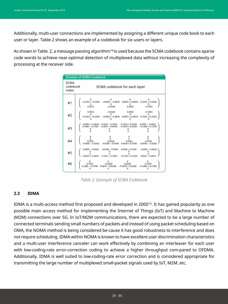
SCMA is a relatively new wireless multi-access method proposed in 201312,13). It avoids the QAM symbol mapping used by conventional CDMA coding technologies and implements the binary data by coding it directly into multi-dimensional code words. Figure 5 shows the SCMA encoder block diagram. The figure shows a schematic of the SCMA encoder when there are four physical resources and four codewords in SCMA code book. Each user or layer assigns the binary data output from the FEC encoder directly to the complex codeword (physical resources dimensions) according to the predefined spreading code of the SCMA codebook.
Figure 5: Diagram of SCMA Encoder Embodiment
0 0.1 0.2 0.3 0.4 0.5 0.6 0.7 0.8 0.9 10
1
2
3
4
5
6
7
OMANOMA w. SIC
R1 [ b/s Hz]
P0 |h1|2 /N0= 0 dB
P0 |h2|2 /N0= 20 dB
R 2 [ b
/s H
z]
FEC Encoder
Multi-dimensionalcode words structure
(0, 0)(0, 1)(1, 0)(1, 1)
Spreading Encoder
Code wordSpreading code
(b1,b2)
(b1,b2)
(x1, x2, x3, x4)
23 (5)
Anritsu Technical Review No.24 September 2016 Non-orthogonal Multiple Access and Massive MIMO for Improved Spectrum Efficiency
Additionally, multi-user connections are implemented by assigning a different unique code book to each user or layer. Table 2 shows an example of a codebook for six users or layers.
As shown in Table 2, a message passing algorithm14) is used because the SCMA codebook contains sparse code words to achieve near-optimal detection of multiplexed data without increasing the complexity of processing at the receiver side.
Table 2: Example of SCMA Codebook
2.3 IDMA
IDMA is a multi-access method first proposed and developed in 200015). It has gained popularity as one possible main access method for implementing the Internet of Things (IoT) and Machine to Machine (M2M) connections over 5G. In IoT/M2M communications, there are expected to be a large number of connected terminals sending small numbers of packets and instead of using packet scheduling based on OMA, the NOMA method is being considered be-cause it has good robustness to interference and does not require scheduling. IDMA within NOMA is known to have excellent user discrimination characteristics and a multi-user interference canceler can work effectively by combining an interleaver for each user with low-coding-rate error-correction coding to achieve a higher throughput com-pared to OFDMA. Additionally, IDMA is well suited to low-coding-rate error correction and is considered appropriate for transmitting the large number of multiplexed small-packet signals used by IoT, M2M, etc.
Example of SCMA Codebook
SCMAcodebookindex
#1
#2
#3
#4
#5
#6
SCMA codebook for each layer
24 (6)
Anritsu Technical Review No.24 September 2016 Non-orthogonal Multiple Access and Massive MIMO for Improved Spectrum Efficiency
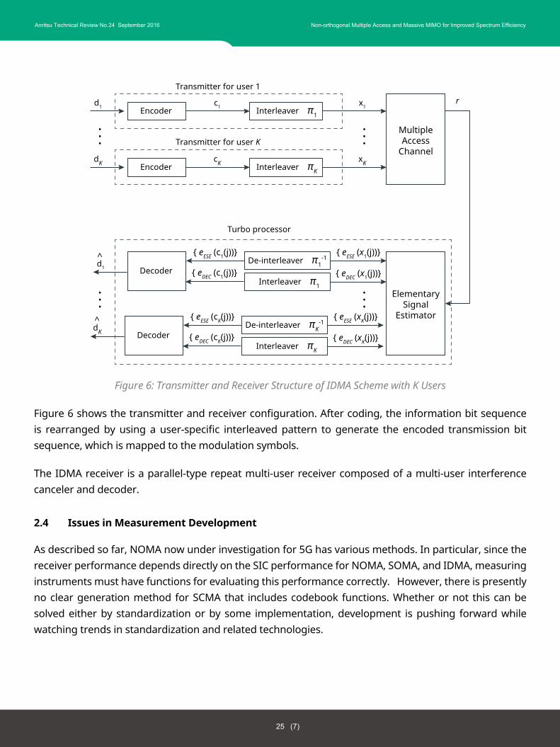
Figure 6: Transmitter and Receiver Structure of IDMA Scheme with K Users
Figure 6 shows the transmitter and receiver configuration. After coding, the information bit sequence is rearranged by using a user-specific interleaved pattern to generate the encoded transmission bit sequence, which is mapped to the modulation symbols.
The IDMA receiver is a parallel-type repeat multi-user receiver composed of a multi-user interference canceler and decoder.
2.4 Issues in Measurement Development
As described so far, NOMA now under investigation for 5G has various methods. In particular, since the receiver performance depends directly on the SIC performance for NOMA, SOMA, and IDMA, measuring instruments must have functions for evaluating this performance correctly. However, there is presently no clear generation method for SCMA that includes codebook functions. Whether or not this can be solved either by standardization or by some implementation, development is pushing forward while watching trends in standardization and related technologies.
Encoder
Transmitter for user 1
MultipleAccess
Channel
x1c1d1r
Interleaver π1
ElementarySignal
Estimator
Encoder
Transmitter for user K
xKcKdK
dK
Interleaver πK
······
Decoder
Turbo processor
{ eESE (c1(j))} { eESE (x1(j))}
{ eDEC (c1(j))}d1
De-interleaver π1-1
Interleaver π1
{ eDEC (x1(j))}
····
Decoder
{ eESE (cK(j))} { eESE (xK(j))}
{ eDEC (cK(j))}De-interleaver πK
-1
Interleaver πK
{ eDEC (xK(j))}
··
^
^
25 (7)
Anritsu Technical Review No.24 September 2016 Non-orthogonal Multiple Access and Massive MIMO for Improved Spectrum Efficiency
3 - Massive-MIMO
3.1 MIMO Evolution
MIMO achieves high throughput and high reliability by using multiple antennas for transmitter and receiver (Figure 7) and it is a key technology in today’s wireless communications systems. Furthermore, IEEE802.11ac and LTE-Advanced have adopted multi-user MIMO for simultaneous communications between base station with multiple antennas and multiple mobile terminals.
Figure 7: MIMO Principle
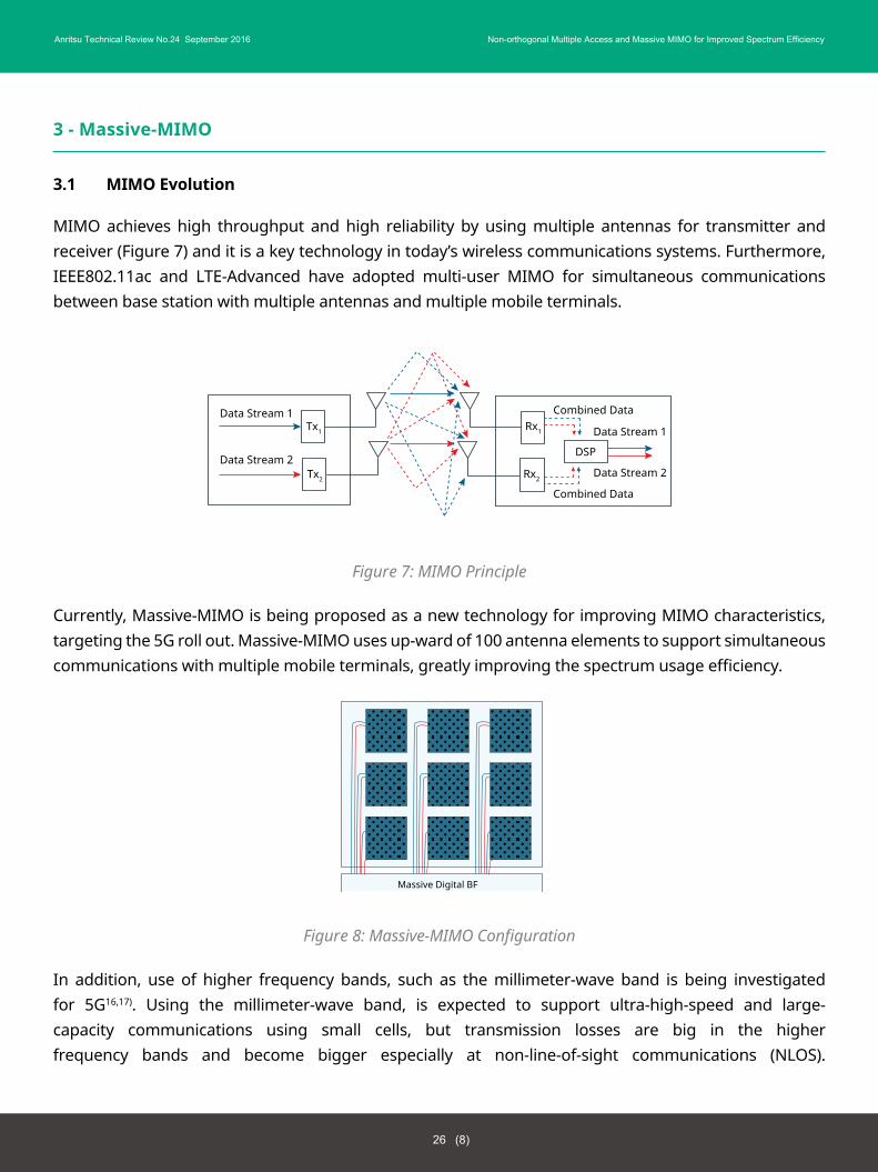
Currently, Massive-MIMO is being proposed as a new technology for improving MIMO characteristics, targeting the 5G roll out. Massive-MIMO uses up-ward of 100 antenna elements to support simultaneous communications with multiple mobile terminals, greatly improving the spectrum usage efficiency.
Figure 8: Massive-MIMO Configuration
In addition, use of higher frequency bands, such as the millimeter-wave band is being investigated for 5G16,17). Using the millimeter-wave band, is expected to support ultra-high-speed and large-capacity communications using small cells, but transmission losses are big in the higher frequency bands and become bigger especially at non-line-of-sight communications (NLOS).
Data Stream 1
Data Stream 2
Data Stream 1
Data Stream 2
Combined Data
Combined Data
DSP
Tx1
Tx2
Rx1
Rx2
Massive Digital BF
26 (8)
Anritsu Technical Review No.24 September 2016 Non-orthogonal Multiple Access and Massive MIMO for Improved Spectrum Efficiency
Beam forming (BF) using Massive-MIMO antenna configurations (Figure 8) is thought to be effective in countering these increases in transmission losses. Since the antenna elements can be made small in proportion to the wavelength, the overall antenna size can be reduced even when using 100 or more antenna elements. Moreover, using Massive-MIMO can focus the energy to the mobile as a very tight beam, which not only improves the energy efficiency but is also expected to reduce interference between users.
With 5G, in addition to conventional voice and internet services, video streaming, wireless Cloud, and M2M applications will become ubiquitous, re-quiring good service quality. In addition, these data communications will experience much higher variations in traffic levels with region and time, making it important to be able to accommodate bursts of user traffic in space and time.
3.2 Sub-Array Massive-MIMO
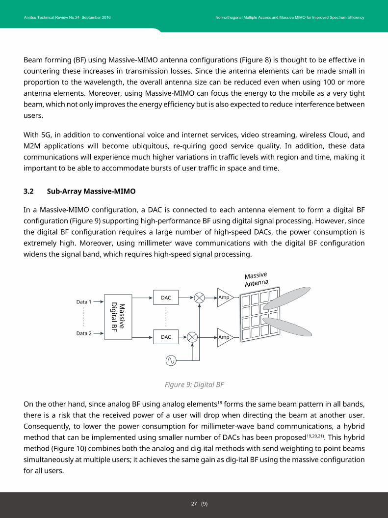
In a Massive-MIMO configuration, a DAC is connected to each antenna element to form a digital BF configuration (Figure 9) supporting high-performance BF using digital signal processing. However, since the digital BF configuration requires a large number of high-speed DACs, the power consumption is extremely high. Moreover, using millimeter wave communications with the digital BF configuration widens the signal band, which requires high-speed signal processing.
Figure 9: Digital BF
On the other hand, since analog BF using analog elements18 forms the same beam pattern in all bands, there is a risk that the received power of a user will drop when directing the beam at another user. Consequently, to lower the power consumption for millimeter-wave band communications, a hybrid method that can be implemented using smaller number of DACs has been proposed19,20,21). This hybrid method (Figure 10) combines both the analog and dig-ital methods with send weighting to point beams simultaneously at multiple users; it achieves the same gain as dig-ital BF using the massive configuration for all users.
DAC
DAC
Amp
Amp
Data 1
Data 2
Massive
Digital BF
27 (9)
Anritsu Technical Review No.24 September 2016 Non-orthogonal Multiple Access and Massive MIMO for Improved Spectrum Efficiency
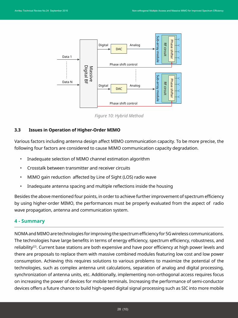
Figure 10: Hybrid Method
3.3 Issues in Operation of Higher-Order MIMO
Various factors including antenna design affect MIMO communication capacity. To be more precise, the following four factors are considered to cause MIMO communication capacity degradation.
• Inadequate selection of MIMO channel estimation algorithm
• Crosstalk between transmitter and receiver circuits
• MIMO gain reduction affected by Line of Sight (LOS) radio wave
• Inadequate antenna spacing and multiple reflections inside the housing
Besides the above mentioned four points, in order to achieve further improvement of spectrum efficiency by using higher-order MIMO, the performances must be properly evaluated from the aspect of radio wave propagation, antenna and communication system.
4 - Summary
NOMA and MIMO are technologies for improving the spectrum efficiency for 5G wireless communications. The technologies have large benefits in terms of energy efficiency, spectrum efficiency, robustness, and reliability22). Current base stations are both expensive and have poor efficiency at high power levels and there are proposals to replace them with massive combined modules featuring low cost and low power consumption. Achieving this requires solutions to various problems to maximize the potential of the technologies, such as complex antenna unit calculations, separation of analog and digital processing, synchronization of antenna units, etc. Additionally, implementing non-orthogonal access requires focus on increasing the power of devices for mobile terminals. Increasing the performance of semi-conductor devices offers a future chance to build high-speed digital signal processing such as SIC into more mobile
DACDigital Analog
Phase shift control
DigitalDAC
Data 1
Data N
Massive
Digital BF
Analog
Sub-array module
RF circuit
Phase shifter
Sub-array module
RF circuit
Phase shifter
Phase shift control
28 (10)
Anritsu Technical Review No.24 September 2016 Non-orthogonal Multiple Access and Massive MIMO for Improved Spectrum Efficiency
terminals. Network Assisted Interference Cancellation and Suppression (NAICS) using SIC is already being discussed by 3GPP for future introduction, and introduction of non-orthogonal access technologies such as NOMA is being proposed to ex-tend NAICS6). Continuing active cooperation between industry and universities is required to solve the problems and assure future commercial roll outs. Anritsu has a wide range of measurement solutions for evaluating complex radio infrastructure and is continuing research in this field.
5 - References
1. S. Sampei, ”A Study on Technical Directions of Wireless Access and Networking for 5G CellularSystems,” IEICE Technical Report RCS2014-183 (2014-10).
2. T. Ohtsuki, ”Future Wireless Communications and Their Technologies,” IEICE Technical ReportRCS2014-173 (2014-10).
3. Y. Han, ”Some Thoughts on Wireless Communication Systems,” Invited Talk, IEEE VTC APWCS2014,August 2014.
4. Peng Wang, Jun Xiao, Li Ping, “Comparison of orthogonal and non-orthogonal approaches to futurewireless cellular systems,” IEEE Vehicular Technology Magazine, Vol. 1, No. 3, September 2006.
5. METIS.Deliverable D2.3, “Components of a new air interface - building blocks and performance,”April 2014.
6. White Paper, ”DOCOMO 5G White Paper,” NTT Docomo R&D, July 2014.
7. Huawei Technologies Co., Ltd. “5G: New Air Interface and Radio Access Virtualization,” April 2015.
8. M. N. Khormuji, “Generalized Semi-Orthogonal Multiple-Access for Massive MIMO,” 81th IEEEVehicular Technology Conference, May 2015.
9. D. Tse, P. Viswanath, ”Fundamentals of Wireless Communication,” Cambridge University Press, 2005.
10. Y. Saito, Y. Kishiyama, A. Benjebbour, T. Nakamura, L. Anxin, K. Higuchi, “Non-orthogonal multipleaccess (NO-MA) for cellular future radio access,” 77th IEEE Vehicular Technology Conference, June 2013.
11. “Superposition Coding Strategies: Design and Experimental Evaluation,” IEEE Transactions onWireless Communications, Vol. 11, No. 7, July 2012.
12. H. Nikopour, H. Baligh, “Sparse code multiple access,” Personal Indoor and Mobile RadioCommunications, IEEE 24th International Symposium, pp. 332-336, September 2013.
29 (11)
Anritsu Technical Review No.24 September 2016 Non-orthogonal Multiple Access and Massive MIMO for Improved Spectrum Efficiency
13. M. Taherzadeh, H. Nikopour, A. Bayesteh, H. Baligh, “SCMA Codebook Design,” 80th IEEE VehicularTechnology Conference, September 2014.
14. R. Hoshyar, F. P. Wathan, R. Tafazolli, “Novel Low-Density Signature for Synchronous CDMA SystemsOver AWGN Channel,” IEEE Transactions on Signal Processing, Vol. 56, No. 4, pp. 1616-1626, April 2008.
15. Li Ping, Lihai Liu, Keying Wu, W. K. Leung, “Interleave division multiple-access,” IEEE Transactionson Wireless Communications, Vol. 5, pp. 938-974, April 2006.
16. ”Working document towards a preliminary draft new report ITU-R M[IMT.ABOVE 6GHz], ITU-R/WP5D
17. METIS II.Deliverable R3.1, ”Report R3.1 Preliminary spec-trum scenarios and justification for WRCAgenda Item for 5G bands above 6 GHz”, October 2015.
18. H. Iu-ra, A.Okazaki, K.Kihira,N.Fukui,K.Take,A.Okamura ,“A study on Antenna Configurations forMIMO system using Analog Beamforming,” IEICE Technical Report RCS2014-227 (December 2014).
19. J. Shen, S.Suyama, T.Obara,Y.Okumura, ”PAPR Reducuion Method for Super High Bit Rate MassiveMIMO OFDM Transmissions Using Higher Frequency Bands,” IEICE Technical Report RCS2014-228(December 2014).
20. D. Kimura, H.Seki, T.Kubo, ”Wireless Network Technologies towards 5G,” IEICE Technical ReportRCS2014-237 (December 2014).
21. S. Suyama,T.Obara, J.Shen,Y.Okumura , ”Influence of Channel Estimation on Massive MIMO withJoint Analog Beamforming and Digital Precoding in High Frequency Bands,” IEICE Technical ReportRCS2014-166 (October 2014).
22. E. G. Larsson, O.Edfors, F.Tufvesson, T.L.Marzetta, ”Massive MIMO for next generation wirelesssystems,” IEEE Communications Magazine, February 2014.
6 - Authors
Masaaki Fuse
Ken Shioiri
Technical HeadquartersAdvanced Technology Development Center
Technical HeadquartersAdvanced Technology Development Center
30 (12)
Publicly available
Anritsu Technical Review No.24 September 2016 Non-orthogonal Multiple Access and Massive MIMO for Improved Spectrum Efficiency