Embed Size (px)
Citation preview

Non-nuclear Gauging Alternatives Offer Enhanced Performance with Simplified Use Mr Hector Marchand Vice President, Marketing NDC Infrared Engineering ABSTRACT This paper considers the role non-nuclear Infrared backscatter and X-Ray transmission sensors can play in the measurement of coatings and laminate layers online. For a long time, Beta transmission sensors and gamma backscatter sensors have been the preferred choice, due to their design simplicity, and ability to be used on a wide range of materials and applications with fairly predictable results. However, radioactive source regulations and disposal requirements are getting increasingly tougher, and many countries and companies are adopting “green” initiatives to reduce or eliminate the use of hazardous materials in the workplace. In this new environment, the possibilities and advantages that Infrared and X-Ray sensor technologies can deliver are starting to be realized in a number of applications including the converting industry, particularly where high performance is demanded, such as extrusion coating and lamination. The acceptance of Infrared and X-Ray sensors for the use in measurement of converted materials has come about due to a change in attitudes and philosophies while the advancement of the hardware technology has also promoted its use. Some of these advances have been made at the sensor level, and some at the system level, where use of such tools as same spot measurement, more robust calibration techniques, and improved sensor management have resulted in significant performance gains. This paper aims to assess the role for these new Infrared and X-Ray sensors and the advantages they can deliver. Please note:
Beta Transmission will be denoted by “Beta” throughout this paper Gamma Backscatter will be denoted by “GBS” throughout this paper Infrared will be denoted by “IR” throughout this paper X-ray transmission will be denoted by “X-Ray” throughout this paper

SENSOR TECHNOLOGY – BACKGROUND Fundamentals of Infrared Measurement Most converting materials have a chemical structure based on bonded atoms (C-H bonds in polymers, H-O in water, etc.). Infrared energy is absorbed as a direct result of the bonds being excited and hence vibrating, and just like Beta, gamma, X-Ray, etc., the energy absorbed/transmitted by the material is such that it can be correlated to the material’s mass (basis weight). Unlike these other energy sources, however, Infrared absorption is selective – that is, it only occurs at specific wavelengths, as a function of the material type. This selective behavior is especially true of organic materials (see Figure 1).
Figure 1: This IR Spectrograph of Low Density Polyethylene (@ 50 gsm basis
weight) exhibits its unique absorption characteristics, which can be used to make a selective measurement of PE in the presence of other materials
Historically Infrared was only used for such measurements as this part of the spectrum exhibits most of the strong C-H energy absorption. However, due to the necessity to make more complex measurements and to differentiate between very similar materials, the Infrared spectrum we use today stretches from the near to the mid bands. NIR also holds a powerful and unique property over all other measurement principles in that it offers discriminative measurement capabilities. This means that it can be used uniquely for such applications as:
• Measuring individual layers in multi-layer (complex, barrier) films • Measuring coatings directly (one sensor / scanner) without having to use a differential
measurement technique • Measuring components within materials (moisture in paper, etc)

The challenge facing the Infrared gauging manufacturer is to select the appropriate wavelengths to monitor to make the measurement. For most normal applications, one predominant wavelength where an appropriate amount of absorption occurs is selected as the measured wavelength (M), and at least two other wavelengths (on either side of the measured band, called reference (R) bands) are also monitored to compensate for spectral shifts that can be caused by a range of factors. These reference wavelengths are used to provide stability to the measurement. By applying the Beer-Lambert law to the ratio of the measured wavelength M to its corresponding reference wavelengths R1 and R2, a direct calculation of the coat weight can be measured, based on the fundamental calculation: Coat Weight α Log (R/M) There are a number of different online sensor design approaches to collect the necessary data to make the coating measurement. The three common sensor designs used in the industry are the Beam Splitter, the “Full Spectrum” array gauge and the High Speed Filter Wheel instrument. Each of these gauge designs has its advocates, as well as its technical advantages and disadvantages. The manufacturers of these devices are eager to emphasize the advantages of their preferred design and emphasize the weaknesses of the competitive devices. Of great importance when evaluating IR technology in comparison to differential gauges is to carefully consider the product mix of both coatings and base substrates. Infrared gauges are pseudo-optical devices in that they depend on their ability to “see” through the measured variable in order to make a proper calculation of weight. The devices usually come in two variants – backscatter gauges, where the IR energy passes through the coating, reflects off of the substrate, and then returns to be collected and detected, and transmission gauges, in which IR light passes through both the coating and the substrate, and the collection / detection system is located on the opposing side of the web. Typical challenges to be on the alert for with Infrared:
• Black or dark colors tend to absorb all IR energy present, rendering the gauge inoperable on these products • A mix of opaque and transparent substrates will require the presence of both backscatter and transmission
sensors to make the respective measurements • Printed substrates can present unique measurement challenges • A wide mix of coating formulations can create a significant calibration challenge • Laminations that encapsulate the coating between opaque substrates most likely cannot be measured with
IR These limitations considered, a good rule of thumb is, “If it can be done with IR, do it with IR”. The main reason for this, is that Infrared, by measuring coat weight directly, provides a simpler design (one sensor / scanner vs. multiple) at lower cost, and with better accuracy. The IR gauge accuracy is dependent on one device, measuring just the coating. The differential approach frequently depends on the accuracies of a subtractive measurement involving much heavier base stocks. The cumulative errors in a differential measurement thus tend to be far greater, thus the reason to select IR when it is viable.

Fundamentals of X-Ray Measurement X-ray is now a more accessible technology because X-Ray tubes and their (now) digital power supplies have become for more stable and robust. Also, the price of X-Ray tubes has reached a level that makes them more viable to use in industrial processes. Today X-ray sensors are not particularly common in the plastics and converting industries and compared to Beta sensors they could be considered as rare species. However, this balance is set to change as the benefits and advantages of this technology start to be fully realized and introduced to industry. Added to this the external factor of government legislation and user preferences means the demand for low energy or non-isotope technologies is set to grow and grow rapidly. Because X-Ray is not so widely known, it is worth considering the technology in relation to the more widely known Beta sensor: The two sensors use a similar detector (Ion chamber); the prime difference is in the energy source. The principle of energy absorption being correlated to the web basis weight (gsm) is the same. Where Beta gauges emit a more random stream of Beta particles (electrons), X-Ray gauges emit a tighter, higher flux stream of photons.
DETECTOR
I
SOURCE
Radioactive Isotope
(Krypton 85) (Promethium 147)
(Strontium 90)
BETA SENSOR
DETECTOR
SOURCE
X-ray tube
+High Voltage power supply
X-RAY SENSOR
WebWeb

The Principal Components of an X-ray Sensor The X-Ray tube is a fairly simple device that is used in lots of everyday situations, especially in the medical and dental fields. Electrons are “burnt off” a cathode plate and accelerated towards a heavy-metal anode by means of a high voltage applied between the two. The X-Ray tube is a vacuum capsule. When the “highly energized” electrons strike the anode they release energy which is part of the electromagnetic spectrum in the form of X-Rays.
Power Supply
Detector
X-Ray Tube
Collimator
Shutter
Preamp
X-Rays
- +
Anode (+)
Cathode (-)
Electrons
Window

Applying X-Ray Technology on the coating process One challenge to deal with in using X-Ray sensors is the fact that the device is more sensitive to material composition than nucleonic gauges. Fortunately, on most coating processes, it is the base substrate composition that changes frequently, not the coating composition. New differential X-Ray measurement algorithms completely account for base substrate effects to assure that only the coat weight is measured, without base substrate composition sensitivity. This greatly improves the measurement capabilities and accuracy of X-Ray transmission sensors. Three things can affect the performance of a differential coat weight gauging system:
• Variability in basis weight of the substrate (if the base gauge measures the substrate at a different spot than the final gauge)
• Differences in signal outputs of the two sensors • How the coating weight calculations are made (to separate base composition effects from coating
composition effects) Simple differential gauging systems don't account for these variances, and as a result, their measurement accuracies suffer tremendously. Accounting for the variances in substrate weight can be handled through a process called same spot measurement. With same spot, the two scanning sensors are carefully coordinated through high-resolution digital pulse encoders, so that the second gauge waits until the precise moment that the material that was scanned by the base gauge reaches it, and then it takes its measurement on the exact same spot of the web. Scan speed is locked digitally to line speed to insure that same spot is maintained even if web speed changes. Most modern gauging systems employ this important feature, whether the gauge used is GBS, Beta or X-Ray. Regarding the second bullet point above, it turns out that accounting for the differences in signal output of nucleonic gauges is problematic. No two nuclear sources are identical, and since they are sealed passive devices, the only option is to try to compensate for the signal differences through software modeling. There are always significant compromises with this approach, as the devices may have different activity levels, for example. With X-Ray sensors, the energy output of the transmitter can be precisely regulated via a digitally-controlled power supply. This offers two key advantages over the Beta gauge: first, the signal does not deteriorate over time as a Beta gauge does due to half-life, and second, the substrate and total gauge outputs can be exactly matched to insure that no errors occur from this source. Finally, with these matched sensors in place and measuring the exact same substrate, base stock effects can be "zeroed" via computer modeling, and a very accurate coat weight calibration can be applied, completely independent of base substrate composition. The new X-Ray coat weight algorithm includes these three key features: digitally controlled same spot measurement; digitally matched sensor output; and a coat weight algorithm that is completely insensitive to the base substrate. This model has been tested on several coating lines, including an adhesive coater used for conversion of film and paper substrates, as well as an extrusion board coater used for the manufacture of liquid packaging products. All of these diverse installations enjoyed superior coat weight measurement and control performance when compared to differential Beta gauges.

APPLICATION CONSIDERATION Let’s consider a basic extrusion coater: The Alternative Technologies
a) Beta transmission sensors [Beta] The Beta sensor is a very established technology when it comes to extrusion coating measurements. Typically it is used as a differential measurement technology (M2 – M1) or it may simply be used to provide a total basis weight measurement (M2). The Beta sensor has a number of benefits including the fact that it is widely used and hence its capabilities are widely known and accepted. The Beta sensor provides a fast and reliable measurement, while it is fairly simple to use. However, there are a number of drawbacks that other sensors do not suffer from. The main ones are:
• As Beta energy is technically a stream of electrons they readily diverge from the source. This results in a poor spatial resolution.
• Beta energy is also readily scattered thus sensor is sensitive to web (pass-line) movement - called “flutter”, which looks like a weight change to the system.
• Beta sensor energy comes from a nucleonic isotope, thus is subject to source decay. The measurement stats thus degrade over the life of the sensor. This is a noticeable problem for Promethium 147 which has an extremely short half-life, and can bear significance on Krypton 85 sensors, the most common Beta type, as well.
• Beta sensors require air gap temperature compensation.
Unwind Rewind
M1 M2
Unwind Rewind

• Beta gauges are characteristically noisy. For a number of companies the solution to this is to use high source activities but this naturally has drawbacks as the trend in industry is to lower energy or completely non-nuclear solutions.
• If the measurement range is large then it may be necessary to utilize more than one type of isotope. This is not so desirable when using the sensors for a differential measurement.
• Beta sensors are nucleonic gauges and hence are subject to importation and usage legislation which in some countries can be a significant disadvantage.
b) Gamma backscatter sensors [GBS]
The GBS sensor has a place in this discussion because for certain lines it may be the only solution. For wide, high speed extrusion coating lines running with Automatic Profile Control the GBS would not be a viable solution due to its slow measurement speed. However, the GBS may be a viable solution when it comes to the opposite: namely, narrow, slow lines running with manual dies. The GBS does offer some advantages:
• Being a singled sided measurement and very compact it may be the only viable solution for small and compact lines
• Very simple technology that is easy to calibrate and is largely unaffected by changes in product composition.
• A very stable, robust measurement – half-life is very long thus drifting is not an issue. • Uninfluenced by temperature variations. • Can be used in conjunction with other sensors to measure secondary foil unwinds on lamination lines
(where a big O-frame scanner cannot be mounted).
Unwind Rewind
M1 M2
GBS

c) Infrared backscatter sensors [IR]
An IR backscatter sensor measurement would in many cases be the primary choice for such an application because it offers numerous advantages over all other technologies. The principal benefits being:
• Direct coat weight measurement – measures the coating independent of the substrate • Excellent measurement precision • No consideration needs to be made for paper conditioning (drying or moisturizing) • 100% safe no ionizing radiation. • Simple to use • Low cost of operation and ownership • Unique ability to measure individual layers such as:
Measure the adhesive layer and polyolefin layer in extrusion coating applications on aluminum foil
Measure barrier layers (polyamides, etc) when co-extruded with a polyolefin onto paper substrates.
• Less hardware o Simpler to install – more compact o Less hardware maintenance issues o Simpler to maintain the measurement accuracy (does not require same spot scanning function)
However, as with all technologies while there are positives there are potential drawbacks. The noticeable ones being:
• IR can not penetrate through very thick paperboards or aluminum foils so this needs to be considered if the line is a laminator
• IR can not measure on black substrates or polymer coatings that contain carbon black. • IR may not be the best sensor if the line is to be used as a pilot facility or as a “jobbing” facility. • IR may not be the best sensor if the product is very variable. Such as a multitude of print designs and
colors, or different surface finishes (clay, etc).
Unwind Rewind
M1

SO WHAT ABOUT X-RAY? So if we consider the same extrusion coating as we did for the other sensor technologies what can we achieve by using X-Ray? Like the other basis weight sensors (Beta and GBS) the X-Ray sensor can be used as a differential measurement technology (M2 – M1) or it may simply be used to provide a total basis weight measurement (M2). As a single sensor for measuring total basis weight (M2) it may not be as useful as say the Beta sensor especially if there is a great variation of product structures (laminates) being produced. However, as a differential measurement (M2 – M1) it demonstrates a number of significant advantages.
• X-ray sensors have excellent precision o They exhibit significantly better noise characteristics than say a Beta (Kr85) sensor - very good
precision • The output of an X-Ray is constant during the life of the sensor – it does not suffer from decay • X-ray energy does not deviate or diverge (scatter) readily and hence demonstrates excellent spatial resolution
meaning it can be used to give very good profile definition and edge measurement resolution. • The X-Ray sensor also demonstrates significantly better stats when we consider web flutter (the change in
height of the measured web in relation to the sensor heads). • While a drawback for X-Ray when trying to measure total basis weight an advantage for differential coat
weights is that the X-Ray sees a significant signal change when it sees a polymer coated paper then when just measuring uncoated paper. This big signal change enables an accurate coat weight to be calculated.
• A single X-Ray sensor can measure over a wide range. When doing a differential measurement it is important for both sensors to behave and react the same and to give the same signal output. Hence if you need to use different Beta isotope to give a differential measurement on an extrusion coating line then this may cause complications and potential for measurement error.
• As with above the output of an X-Ray sensor is fairly well matched from tube to tube. With a Beta sensor the outputs can vary significantly (depends on age of sources, etc) thus “matching” Beta sensors is not so simple.
• At the end of its life an X-Ray tube can be readily disposed of (albeit as hazardous material, analogous to alkaline or lithium batteries), where as isotope sources require professional disposal that may be costly and disruptive to the use of the gauging system.
• X-ray sensors can be switched off hence during maintenance shutdowns they can be rendered totally safe allowing for maintenance crews to work on or around them.
Unwind Rewind
M1 M2

So what are the potential drawbacks with the X-Ray:
• If it is to be used for a TOTAL basis weight measurement then for certain products/applications it may not be as good as Beta.
• The initial purchase cost of X-Ray is more than Beta but this could be offset when one considers the additional costs (licensing, training, etc) associated with using a nucleonic gauge.
• The X-Ray tube requires forced air cooling so a clean air supply needs to be provided. • The X-Ray head is fairly large and so may be a problem on certain compact lines. • While the X-Ray does not using an isotope and the energy is relatively low for certain countries X-Ray still
may need licensing as it is categorized as a ionizing radiation producing unit.. CONCLUSIONS For years, the great majority of coating and laminating process have used nucleonic devices for weight control due to simplicity, accuracy and reliability. However, the picture is changing now as environmental pressures continue to grow making the implementation, maintenance, and disposal of nuclear devices more challenging. At the same time, new non-nuclear technologies have emerged that supplant nucleonic gauges, and in many cases combine superior performance without the regulatory headaches. Infrared Sensors have seen significant advances in terms of speed of operation, range of operation, stability and robustness. When the substrates and coatings will permit, it is the most accurate and cost-effective method to perform coat weight measurement and control. X-ray sensors offer a vast arrange of advantages for many applications and for the extrusion coating/lamination business the advantages are significant. These advantages are the result of recent enhancements to the fundamental sensor design as well as the differential coat weight algorithms. However, it must always be considered that each process and line must be viewed as a separate project and the specifications and requirements ultimately will define which is the most appropriate measurement solution. Ultimately there are always a number of alternative sensor technologies and there is also the potential to using several types on one lines, such as a combination of GBS, X-Ray and IR backscatter. Selecting the correct gauging solution is of critical importance as the costs of getting it wrong and having poor measurements can be alarming especially on the new high speed coating/lamination lines of today.

1
Non-Nuclear Gauging Alternatives Offer Enhanced Performance with
Simplified Use
H. MarchandNDC Infrared Engineering
A New Concern with Nucleonic Devices
• For both environmental and safety reasons, tougher standards are emerging for nucleonic devices– Tougher Licensing Regulations in Japan, France, Canada,
Brazil, Mexico, China, some U.S. states– January, 2003 - EU issues a Proposal for a COUNCIL
DIRECTIVE on the control of sealed radioactive sources– February, 2003 – U.S. EPA enlists Product Stewardship
Institute to manage funded programs to find non-nuclear alternatives to nucleonic gauges
• www.productstewardship.us• Project funding awarded in July, 2005
Why not just put up with the red tape?
• Because New Non-nuclear Sensors offer:– Greater Accuracy with Better Resolution– In Some Cases, Reduced Hardware
Requirements– No or Minimized Government Regulatory
Requirements– No Disposal Costs– Self-maintenance– Lower Lifetime Cost with Greater Lifetime
Benefit

2
Direct Measurement Technique Using Selective Gauge
• Sensor has the ability to read coat weight directly via a “selective” technique
• Examples:– Infrared, X-Ray
Fluorescence• Frequently combined with a
total weight gauge so that substrate weight can be determined by subtraction
Differential Measurement Technique Using Multiple Total Weight Gauges
• First sensor reads substrate weight
• Second sensor reads total weight
• Gauge readings are “subtracted” to obtain coat weight
Gamma Backscatter (GBS) Sensor
• Small, Simple– 1Kg – size of a flashlight– Fits in tight spaces
• Accurate• Wide measurement range
– To 25000 gsm• One-sided measurement
– Low cost scanner• No standardization required• Total weight gauge• Typical repeatability: 0.5%

3
Beta Transmission
• Larger sensor size• Isotope-based source
generates beta particles of required energy
• Measurement range– Up to 6000 gsm– Dependant on isotope
• Some sensitivity to composition, presence of mineral / metal additives
• Total Weight Gauge• Typical Repeatability: 0.25%
One Problem with Differential Approach: Accuracy is Function of TOTAL Mass
• Differential Technique is viable when coat weight is a significant percentage of base weight
• Otherwise, cumulative errors render gauging system useless
Example using differential beta gauges with 0.25% accuracy:
• Base substrate = 100 gsm• Coating = 3 gsm• Coat error = SQRT (Base error2 + Total error2)• Coat error = SQRT ((100*.0025)2 + (103*.0025)2)• Coat error = SQRT (0.0625 + 0.0663)• Coat weight error = 0.36 gsm• Coat weight error = 12% of 3 gsm
• RULE OF THUMB: COATING WEIGHT MUST BE AT LEAST 10% OF SUBSTRATE WEIGHT TO ACHIEVE ACCEPTABLE ACCURACY

4
Other Challenges with Differential Technique
• Substrate has basis weight variation, both CD and MD– Need to prevent this variability from creating coat weight
measurement errors• Composition effect
– Coating and substrate can have different gauge absorption characteristics
• How to Calibrate System to Measure Coating?• Total Weight Range (Base + Coat)
– Specifically with Beta Gauge, must select gauge design carefully
Solution 1: Position Based, DigitalSame Spot Measurement
Result: Scanner 2 sees exact same section of base product as Scanner 1, regardless of speed change
Launch Distance
Web travels at speed A
Line Speed (A)
Scanner 1 travels at speed B – slaved to speed A
Scan
Spe
ed (B
)
Scanner 2 maintains launch sequence and speed to mirror function of A and B
Resultant Scan Path C is a function of A and BScan Path (C)
Sca
nner
1
Sca
nner
2
2nd Challenge – Dealing with Substrates and Coatings of Different Composition
• PET Coating• PET with additives base• 100 gsm base / 100 gsm
coating• Each material responds
differently to beta• Gross gauge sees a
“compromise” curve – half base / half coating
• How do we deal with this?– TRUE NET COAT
Algorithm
0
1
2
3
4
5
6
7
8
9
10
0.0 200.0 400.0 600.0 800.0 1000.0 1200.0 1400.0 1600.0
MYLARMylar+TiO2+Ba50/50

5
True Net Coat Approach Eliminates Base Composition Effects
• Match the readouts of the two sensors so that they respond exactly to the same sample sets
• Linearize and calibrate both the base and the gross gauge using the COATING material response curve– Since we have same spot measurement and two
gauges that respond exactly, the base material contributes predictably to the signal magnitude of both the base and gross sensors
Traditional vs. True Net Coat approach
• Traditional approach uses “Gross” curve to calculate Gross weight. Gross curve is in flux, changing as base to coat ratio changes
• With TNC, to calculate coat, both Gross and Base gauges are calibrated against coat response curve. No compromise! BASE CURVE
GROSS CURVENET CURVE
Let’s Look At Non-Nuclear Measurement Alternatives

6
X-Ray Transmission
• Non-nuclear• Generates photon stream
through X-Ray tube, digital power supply
• Large sensor size• Requires standardization• Measurement range
– Up to 10,000 gsm• Some sensitivity to
composition, presence of mineral / metal additives
• Total Weight Gauge• Typical Repeatability: 0.1%
Photon Stream
Power Supply
Detector
X-Ray Tube
Collimator
Shutter
Preamp
Why X-Ray Technology Now?
• The cost of X-Ray tubes used to be prohibitive– Now more affordable
• The tubes that are used to generate soft x-rays are now far more stable and robust
• Low Cost, Digitally-Controlled Power Supplies are now available that maintain constant flux output over time
X-Ray Offers Several Advantages over Nucleonic Gauges
• Better Streak Resolution• Higher Precision, Lower Noise• Reduced Web Flutter
Sensitivity• Constant Output Over Time
– Signal Does Not Deteriorate– Nuclear Gauges Suffer Source
Decay• In Coating Applications, Gauge
Readouts Can Be Easily Matched– Important for Improved True
Net Coat• With Power removed, gauge is
completely safe to work on
BetaFootprint
X-RayFootprint

7
X-ray Sensor Geometry Provides Greater Profile Detail
Magnification of ½” strip coating between ½” uncoated areas
X-ray Sensor Edge Measurement Resolution
• Edge measurement a critical concern for most board coaters and laminators
• The spatial resolution of x-ray helps to scan closer to the web edge, and thus enable tighter control
X-Ray Sensor Advantages: Insensitivity to Web Flutter / Pass-line
0.5gsm or
0.3%
0.1gsm or
0.1%
Beta (Kr85)(Special design)
3.3gsm or
3.0%
0.1gsm or
0.2%
Error (+/-) for a full gap movement
0.4gsm or
0.3%
0.05gsm or
0.08%
Error (+/-) for a +/-3mm movement from the mid gap position
Beta (Kr85)(Standard design)
X-ray Sensor
8
X-Ray Transmission is a Total Weight Gauge
• Uses differential technique to provide coat weight measurement
• As with Nucleonic gauges, the use of differential X-Ray gauges has challenges
Effect of Fillers on an X-Ray Measurement
• Effect is greater than for Beta or GBS
• However, on most coating lines, coating composition is consistent– It’s the Base Substrate
that changes• True Net Coat
algorithm makes X-Ray a viable technology
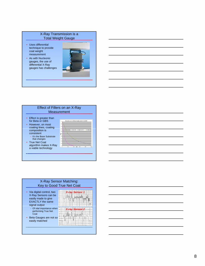
X-ray Sensor 2
X-ray Sensor 1
X-Ray Sensor Matching:Key to Good True Net Coat
• Via digital control, two X-Ray Sensors can be easily made to give EXACTLY the same signal output– Of vital importance when
performing True Net Coat
• Beta Gauges are not so easily matched

9
X-Ray versus Beta
• With Good True Net Coat Algorithm in Place, X-Ray Offers Superior:– Streak Detection– Precision– Accuracy– Edge Measurement– Pass-line and Flutter Insensitivity– Long Term Performance
Another Non-Nuclear Alternative: Direct (IR) Measurement of Coat Weight
• Direct, selective approach requires only one gauge after the coating station– Less expensive– More accurate– Potential to measure
moisture– Potential to measure
coextrusion coating components
Infrared is a Selective Technique
%Tr
ansm
issi
on
Wavelength (micrometers)
100-
0-
50-
1.0 3.0
1.72µ
1.94µ
2.32µ 2.40µ
1.45µ
1.2 1.4 1.6 1.8 2.0 2.2 2.4 2.6 2.8
WaterPolyethylene
Key
Application example:Thin water based coating on PE film is trivial for IR

10
Typical IR Backscatter Gauge on Coating Application
• Accuracies:• Moisture
– Range: 0 – 90% moisture
– Accuracy: 0.1%• Coating Weight
– Range: 0 – 1000 gsm– Accuracy: 0.1 gsm
• Note that these values are product / substrate dependent
IR Sensor Advantages
• Better Accuracy than Differential Gauges• Good Streak Resolution
– Equivalent to Beta Gauge• Excellent Pass-line / Web Flutter Insensitivity• Less Expensive Solution
– One Sensor / Scanner versus Multiple Sensors / Scanners• No Ionizing Radiation• Completely User-Serviceable• Easy to Implement
– No Same Spot or True Net Coat Logistics
For some applications, direct IR measurement is not available
• No practical sensor technology may be available that can discern one material from another
• IR technique does have limitations:– cannot measure opaque materials– Materials might be similar in composition, not
allowing for selective coating measurement• In these situations, a differential
measurement may be the only solution

11
Comparison of Sensor Precision: Direct Measurement of 20 gsm Film
+/- 0.1gsm+/- 0.1%
=+/- 0.02 g
+/- 0.25%=
+/- 0.05 g
+/- 0.5%=
+/- 0.1 gRepeatability:
IR BackscatterX-RayBetaGBSSensor
Type:
Comparison of Sensor Precision: 20 gsm Coating on 100 gsm Base
+/- 0.1gsm+/- 0.8%
=+/- 0.16 g
+/- 2%=
+/- 0.4 g
+/- 4%=
+/- 0.8 gRepeatability:
IR BackscatterX-RayBetaGBSSensor
Type:
Conclusions
• When possible, IR offers the best accuracy at lowest cost for many coating applications
• If a differential system is required, X-Ray offers significant performance advantages as compared to Nucleonic gauges
• New “Rule of Thumb”: With X-Ray, Coat weight can be as little as 3 to 5% of Total Weight with acceptable measurement results

12
Questions?