Embed Size (px)
Citation preview
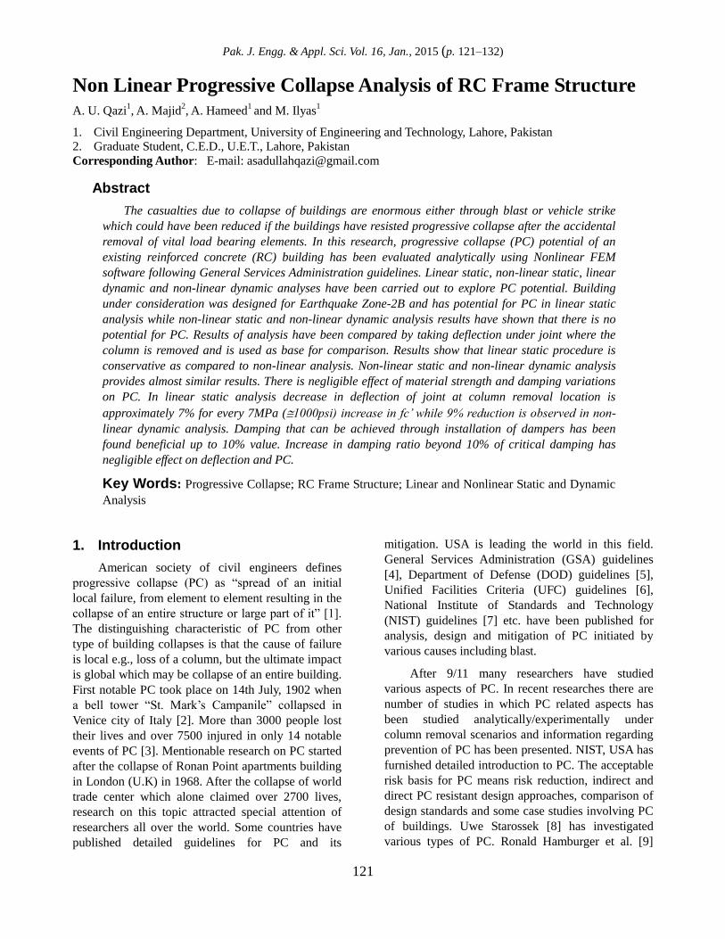
Pak. J. Engg. & Appl. Sci. Vol. 16, Jan., 2015 (p. 121–132)
121
Non Linear Progressive Collapse Analysis of RC Frame Structure A. U. Qazi
1, A. Majid
2, A. Hameed
1 and M. Ilyas
1
1. Civil Engineering Department, University of Engineering and Technology, Lahore, Pakistan
2. Graduate Student, C.E.D., U.E.T., Lahore, Pakistan
Corresponding Author: E-mail: [email protected]
Abstract
The casualties due to collapse of buildings are enormous either through blast or vehicle strike
which could have been reduced if the buildings have resisted progressive collapse after the accidental
removal of vital load bearing elements. In this research, progressive collapse (PC) potential of an
existing reinforced concrete (RC) building has been evaluated analytically using Nonlinear FEM
software following General Services Administration guidelines. Linear static, non-linear static, linear
dynamic and non-linear dynamic analyses have been carried out to explore PC potential. Building
under consideration was designed for Earthquake Zone-2B and has potential for PC in linear static
analysis while non-linear static and non-linear dynamic analysis results have shown that there is no
potential for PC. Results of analysis have been compared by taking deflection under joint where the
column is removed and is used as base for comparison. Results show that linear static procedure is
conservative as compared to non-linear analysis. Non-linear static and non-linear dynamic analysis
provides almost similar results. There is negligible effect of material strength and damping variations
on PC. In linear static analysis decrease in deflection of joint at column removal location is
approximately 7% for every 7MPa (1000psi) increase in fc’ while 9% reduction is observed in non-
linear dynamic analysis. Damping that can be achieved through installation of dampers has been
found beneficial up to 10% value. Increase in damping ratio beyond 10% of critical damping has
negligible effect on deflection and PC.
Key Words: Progressive Collapse; RC Frame Structure; Linear and Nonlinear Static and Dynamic
Analysis
1. Introduction
American society of civil engineers defines
progressive collapse (PC) as “spread of an initial
local failure, from element to element resulting in the
collapse of an entire structure or large part of it” [1].
The distinguishing characteristic of PC from other
type of building collapses is that the cause of failure
is local e.g., loss of a column, but the ultimate impact
is global which may be collapse of an entire building.
First notable PC took place on 14th July, 1902 when
a bell tower “St. Mark’s Campanile” collapsed in
Venice city of Italy [2]. More than 3000 people lost
their lives and over 7500 injured in only 14 notable
events of PC [3]. Mentionable research on PC started
after the collapse of Ronan Point apartments building
in London (U.K) in 1968. After the collapse of world
trade center which alone claimed over 2700 lives,
research on this topic attracted special attention of
researchers all over the world. Some countries have
published detailed guidelines for PC and its
mitigation. USA is leading the world in this field.
General Services Administration (GSA) guidelines
[4], Department of Defense (DOD) guidelines [5],
Unified Facilities Criteria (UFC) guidelines [6],
National Institute of Standards and Technology
(NIST) guidelines [7] etc. have been published for
analysis, design and mitigation of PC initiated by
various causes including blast.
After 9/11 many researchers have studied
various aspects of PC. In recent researches there are
number of studies in which PC related aspects has
been studied analytically/experimentally under
column removal scenarios and information regarding
prevention of PC has been presented. NIST, USA has
furnished detailed introduction to PC. The acceptable
risk basis for PC means risk reduction, indirect and
direct PC resistant design approaches, comparison of
design standards and some case studies involving PC
of buildings. Uwe Starossek [8] has investigated
various types of PC. Ronald Hamburger et al. [9]
Pak. J. Engg. & Appl. Sci. Vol.16, Jan., 2015
122
carried out a performance study for WTC buildings
after their collapse in USA. Matthew Giles [10] has
explained the causes of collapse of the same
buildings. Meng-Hao Tsai and Bing-Hui Lin [11]
studied the PC potential of earthquake resistant
reinforced concrete building following GSA [4]
guidelines. They carried out two types of analysis:
Non-linear static along with non-linear dynamic for
estimation of PC potential under column removal
scenarios. Feng Fu [12] investigated the behavior of a
multistory composite frame structure experimentally
as well as analytically under the column removal
scenario. PC potential has been determined following
GSA and DOD guidelines [4, 5]. Feng Fu [13] also
performed PC analysis for high rise steel buildings by
constructing 3-D FEM models using ABAQUS and
ETABS software packages. Both geometry and
material nonlinearity was considered in the research.
Behavior of structures under sudden column loss
scenarios was studied considering structural systems
of different types following GSA and DOD
guidelines. Elizabeth Agnew and Shalva
Marjanishvili [14] carried out dynamic analysis for a
2D building using SAP-2000 following GSA
guidelines. D.G. Lu et al. [15] performed a pushdown
analysis for assessment of PC resistance of RC frame
structure using Open Sees software. In this study the
effect of instant column removal as well as column
removal duration has been investigated. Taewan Kim
et al. [16] evaluated the PC resisting capacity of steel
frames using Pushdown method. Steven M. Baldridge
and Francis K. Humay [17] evaluated a 12 storey RC
building for PC using ETABS in Zone-4 following
UBC-91 guidelines. While, column removal
scenarios was investigated following GSA guidelines.
Mehmet Inel and Hayri Baytan Ozmen [18]
investigated the effects of user-defined plastic hinges.
Jinkoo Kim and Taewan Kim (2008) [19] studied PC
potential for steel frame buildings possessing
different structural systems. Methodology of alternate
path has been adopted as per DOD and GSA
guidelines. M. Lupoae et al. [20]
carried out
nonlinear static and nonlinear dynamic analysis for
PC potential of RC buildings containing infill walls.
In this study a 3-D model of an existing building
designed for mild seismicity is studied for PC
potential. Furthermore, the effect of damping,
concrete strength and steel grade on PC potential is
also investigated.
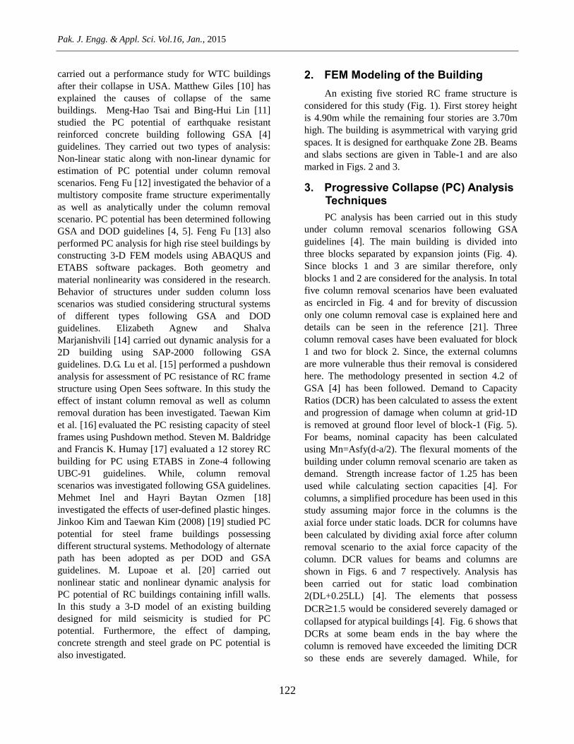
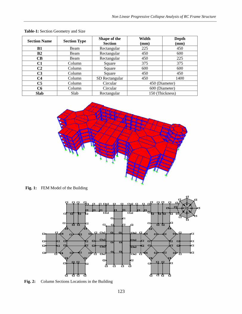
2. FEM Modeling of the Building
An existing five storied RC frame structure is
considered for this study (Fig. 1). First storey height
is 4.90m while the remaining four stories are 3.70m
high. The building is asymmetrical with varying grid
spaces. It is designed for earthquake Zone 2B. Beams
and slabs sections are given in Table-1 and are also
marked in Figs. 2 and 3.
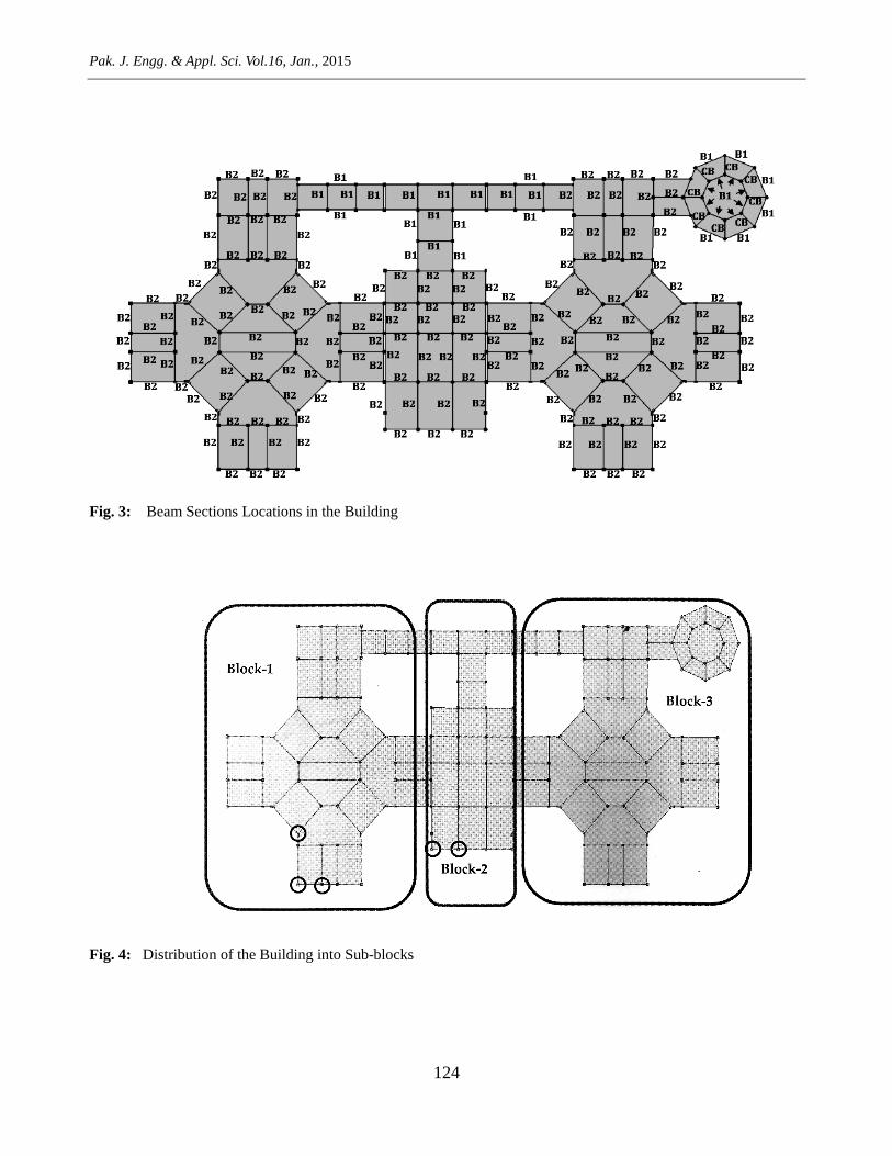
3. Progressive Collapse (PC) Analysis Techniques
PC analysis has been carried out in this study
under column removal scenarios following GSA
guidelines [4]. The main building is divided into
three blocks separated by expansion joints (Fig. 4).
Since blocks 1 and 3 are similar therefore, only
blocks 1 and 2 are considered for the analysis. In total
five column removal scenarios have been evaluated
as encircled in Fig. 4 and for brevity of discussion
only one column removal case is explained here and
details can be seen in the reference [21]. Three
column removal cases have been evaluated for block
1 and two for block 2. Since, the external columns
are more vulnerable thus their removal is considered
here. The methodology presented in section 4.2 of
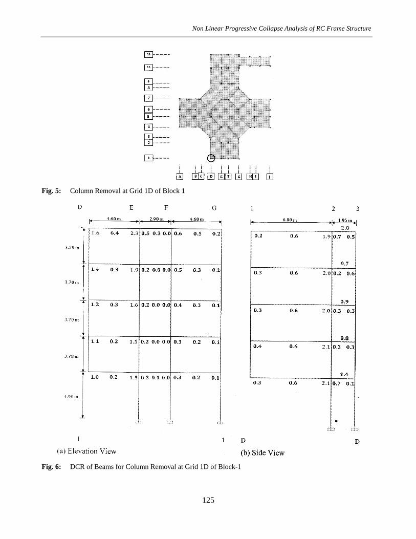
GSA [4] has been followed. Demand to Capacity
Ratios (DCR) has been calculated to assess the extent
and progression of damage when column at grid-1D
is removed at ground floor level of block-1 (Fig. 5).
For beams, nominal capacity has been calculated
using Mn=Asfy(d-a/2). The flexural moments of the
building under column removal scenario are taken as
demand. Strength increase factor of 1.25 has been
used while calculating section capacities [4]. For
columns, a simplified procedure has been used in this
study assuming major force in the columns is the
axial force under static loads. DCR for columns have
been calculated by dividing axial force after column
removal scenario to the axial force capacity of the
column. DCR values for beams and columns are
shown in Figs. 6 and 7 respectively. Analysis has
been carried out for static load combination
2(DL+0.25LL) [4]. The elements that possess
DCR 1.5 would be considered severely damaged or
collapsed for atypical buildings [4]. Fig. 6 shows that
DCRs at some beam ends in the bay where the
column is removed have exceeded the limiting DCR
so these ends are severely damaged. While, for
Non Linear Progressive Collapse Analysis of RC Frame Structure
123
Table-1: Section Geometry and Size
Section Name Section Type Shape of the
Section
Width
(mm)
Depth
(mm)
B1 Beam Rectangular 225 450
B2 Beam Rectangular 450 600
CB Beam Rectangular 450 225
C1 Column Square 375 375
C2 Column Square 600 600
C3 Column Square 450 450
C4 Column SD Rectangular 450 1400
C5 Column Circular 450 (Diameter)
C6 Column Circular 600 (Diameter)
Slab Slab Rectangular 150 (Thickness)
Fig. 1: FEM Model of the Building
Fig. 2: Column Sections Locations in the Building
Pak. J. Engg. & Appl. Sci. Vol.16, Jan., 2015
124
Fig. 3: Beam Sections Locations in the Building
Fig. 4: Distribution of the Building into Sub-blocks
Non Linear Progressive Collapse Analysis of RC Frame Structure
125
Fig. 5: Column Removal at Grid 1D of Block 1
Fig. 6: DCR of Beams for Column Removal at Grid 1D of Block-1
Pak. J. Engg. & Appl. Sci. Vol.16, Jan., 2015
126
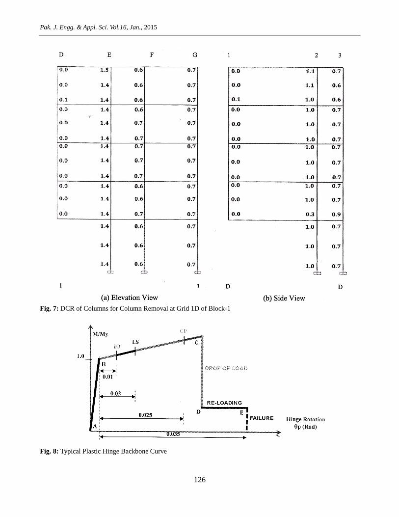
Fig. 7: DCR of Columns for Column Removal at Grid 1D of Block-1
Fig. 8: Typical Plastic Hinge Backbone Curve
Non Linear Progressive Collapse Analysis of RC Frame Structure
127
columns DCR limit is reached only in one section at
roof level (Fig. 7). So, the probability of partial
collapse exists only in corner bay for this particular
column removal scenario and complete collapse of
the building is not anticipated. Nonlinear analysis can
simulate the damage more exactly. Three auto hinges
have been assigned to each beam and column; two at
the ends and one at center. Beam hinges are flexural
hinges while column hinges are interaction hinges
(Auto P-M2-M3). RC beam hinge properties from
tables 6-7 and for RC column hinge properties from
tables 6-8 of FEMA-356 are used [21]. All the
elements are considered strong in shear and no shear
hinge is assigned. The non-linear analysis has been
carried out under “full load” application. To compare
results of different analyses, deflection under the joint
where the column is removed in LS analysis is
considered as control deflection for comparison. The
control deflection observed in the LS analysis at the
column removal joint has been considered as target
deflection in NLSA by varying GSA specified load,
i.e., 2(DL+0. 25LL). The typical backbone curve for
the plastic hinge is shown in Fig. 8. The result of the
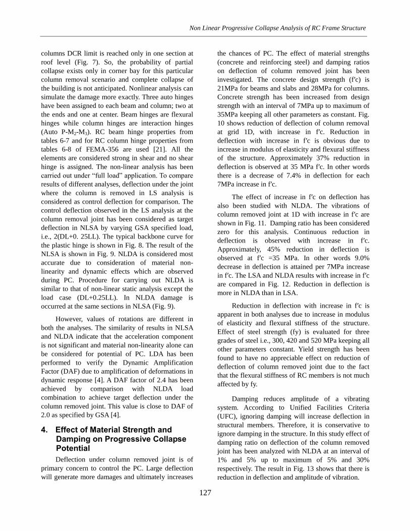
NLSA is shown in Fig. 9. NLDA is considered most
accurate due to consideration of material non-
linearity and dynamic effects which are observed
during PC. Procedure for carrying out NLDA is
similar to that of non-linear static analysis except the
load case (DL+0.25LL). In NLDA damage is
occurred at the same sections in NLSA (Fig. 9).
However, values of rotations are different in
both the analyses. The similarity of results in NLSA
and NLDA indicate that the acceleration component
is not significant and material non-linearity alone can
be considered for potential of PC. LDA has been
performed to verify the Dynamic Amplification
Factor (DAF) due to amplification of deformations in
dynamic response [4]. A DAF factor of 2.4 has been
achieved by comparison with NLDA load
combination to achieve target deflection under the
column removed joint. This value is close to DAF of
2.0 as specified by GSA [4].
4. Effect of Material Strength and Damping on Progressive Collapse Potential
Deflection under column removed joint is of
primary concern to control the PC. Large deflection
will generate more damages and ultimately increases
the chances of PC. The effect of material strengths
(concrete and reinforcing steel) and damping ratios
on deflection of column removed joint has been
investigated. The concrete design strength (f′c) is
21MPa for beams and slabs and 28MPa for columns.
Concrete strength has been increased from design
strength with an interval of 7MPa up to maximum of
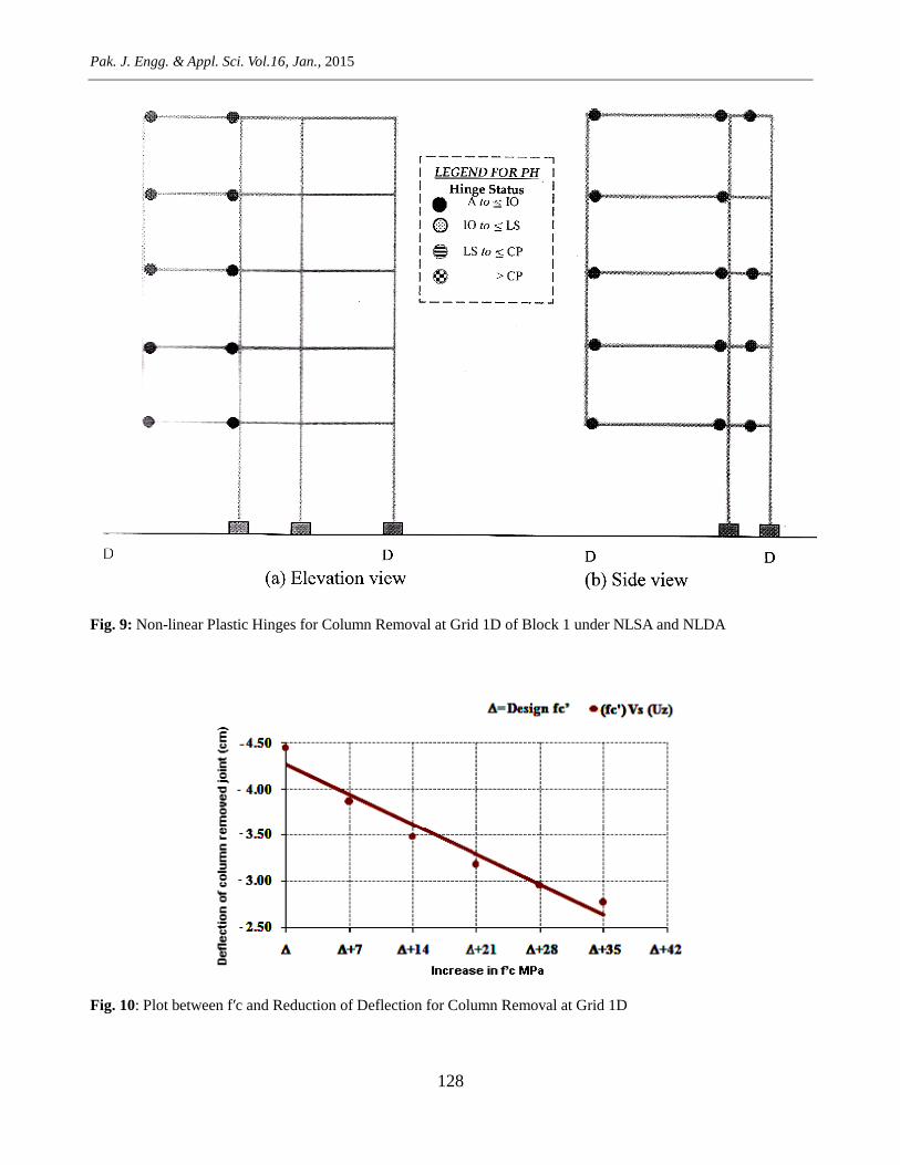
35MPa keeping all other parameters as constant. Fig.
10 shows reduction of deflection of column removal
at grid 1D, with increase in f′c. Reduction in
deflection with increase in f′c is obvious due to
increase in modulus of elasticity and flexural stiffness
of the structure. Approximately 37% reduction in
deflection is observed at 35 MPa f′c. In other words
there is a decrease of 7.4% in deflection for each
7MPa increase in f′c.
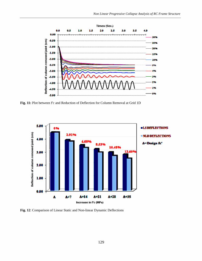
The effect of increase in f′c on deflection has
also been studied with NLDA. The vibrations of
column removed joint at 1D with increase in f′c are
shown in Fig. 11. Damping ratio has been considered
zero for this analysis. Continuous reduction in
deflection is observed with increase in f′c.
Approximately, 45% reduction in deflection is
observed at f′c =35 MPa. In other words 9.0%
decrease in deflection is attained per 7MPa increase
in f′c. The LSA and NLDA results with increase in f′c
are compared in Fig. 12. Reduction in deflection is
more in NLDA than in LSA.
Reduction in deflection with increase in f′c is
apparent in both analyses due to increase in modulus
of elasticity and flexural stiffness of the structure.
Effect of steel strength (fy) is evaluated for three
grades of steel i.e., 300, 420 and 520 MPa keeping all
other parameters constant. Yield strength has been
found to have no appreciable effect on reduction of
deflection of column removed joint due to the fact
that the flexural stiffness of RC members is not much
affected by fy.
Damping reduces amplitude of a vibrating
system. According to Unified Facilities Criteria
(UFC), ignoring damping will increase deflection in
structural members. Therefore, it is conservative to
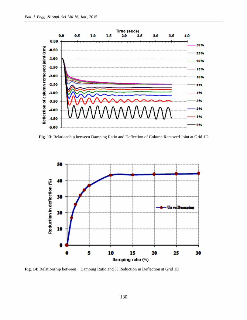
ignore damping in the structure. In this study effect of
damping ratio on deflection of the column removed
joint has been analyzed with NLDA at an interval of
1% and 5% up to maximum of 5% and 30%
respectively. The result in Fig. 13 shows that there is
reduction in deflection and amplitude of vibration.
Pak. J. Engg. & Appl. Sci. Vol.16, Jan., 2015
128
Fig. 9: Non-linear Plastic Hinges for Column Removal at Grid 1D of Block 1 under NLSA and NLDA
Fig. 10: Plot between f′c and Reduction of Deflection for Column Removal at Grid 1D
Non Linear Progressive Collapse Analysis of RC Frame Structure
129
Fig. 11: Plot between f′c and Reduction of Deflection for Column Removal at Grid 1D
Fig. 12: Comparison of Linear Static and Non-linear Dynamic Deflections
Pak. J. Engg. & Appl. Sci. Vol.16, Jan., 2015
130
Fig. 13: Relationship between Damping Ratio and Deflection of Column Removed Joint at Grid 1D
Fig. 14: Relationship between Damping Ratio and % Reduction in Deflection at Grid 1D
Non Linear Progressive Collapse Analysis of RC Frame Structure
131
with the increase in damping ratio due to increase in
stiffness of the system. Initially the impact of
damping ratio on deflection of column removed joint
is significant (Fig. 14). At 10% damping ratio, 43%
reduction occurred. Increase in damping ratio beyond
10% is observed to have no significant impact on
reduction of deflection. Therefore, 10% damping
ratio may be considered an optimum value for this
structure.
5. Conclusions
In this study Progressive Collapse analysis of an
existing RC frame structure has been carried
analytically under column removal scenario
following GSA (2003) guidelines. The effect of
variation in material strengths and damping ratio on
progressive collapse potential has been investigated.
Following are the conclusions:
1. Linear static analysis procedure of GSA (2003)
guidelines is relatively more conservative than
non-linear static and non-linear dynamic
analyses.
2. In nonlinear dynamic analysis there is reduction
in deflection of the column removed joint with
the increase in compressive strength of concrete.
However, steel strength (fy) has negligible effect
on deflection.
3. Increase in damping ratio reduces deflection of
the column removed joint. Up to 10% increase in
damping ratio, reduction is prominent
(approximately 43% reduction has been achieved
with 10% damping ratio). Increase in damping
ratio beyond 10%, has negligible influence on the
reduction of deflection.
4. For atypical building due to its complex
geometrical configuration and load re-
distribution corner column removal case may not
be considered critical directly. Moreover, for
atypical building demand may exceed many
times the available capacity.
References
[1] ACSE, (2005) Minimum design loads for
buildings and other structures, American Society
of Civil Engineers ASCE7/SEI-05.
[2] Maria L. Beconcini, Stefano B., Walter S.,
(2001) Structural characterization of a medieval
bell tower: first historical, experimental and
numerical investigations, University of Pisa,
Department of Structural Engineering, Pisa,
Italy.
[3] http://www.wikipedia.com viewed on 15th
Dec,
2011.
[4] GSA, (2003). Progressive collapse analysis and
design guidelines for new federal office
buildings and major modernization projects, The
US General Services Administration.
[5] DOD; DOD ammunition and explosive safety
standards, The US Department of Defense
(1999).
[6] UFC; (2008). Structures to resist the effects of
accidental explosions, The Unified Facilities
Criteria-Department of Defense USA.
[7] NIST; (2007). Best practices for reducing the
potential for progressive collapse in buildings,
National Institute of Standards and Technology-
USA.
[8] Starossek U., (2007). Typology of progressive
collapse, Journal of Engineering Structures; 29:
2302-07.
[9] Ronald H, William B, Jonathan B, Christopher
M, James M, and Harold B N, (2002) World
trade center building performance study, Federal
Emergency Management Agency (FEMA)-403,
USA.
[10] Matthew Giles; (2011) Total Progressive
Collapse: why, precisely, the towers fell, New
York Magazine.
[11] Meng-Hao T and Bing H., and Lin; (2008)
Investigation of progressive collapse resistance
and inelastic response for an earthquake-
resistant RC building subjected to column
failure, Journal of Engineering Structures;
30:3619-28.
[12] Feng Fu; (2010) 3-D nonlinear dynamic
progressive collapse analysis of multi-storey
steel composite frame buildings — Parametric
study, Journal of Engineering Structures;
32:3974-80.
Pak. J. Engg. & Appl. Sci. Vol.16, Jan., 2015
132
[13] Feng F., (2009) Progressive collapse analysis of
high-rise building with 3-D finite element
modeling method, Journal of Engineering
Structures; 65:1269-78.
[14] Elizabeth A. and Shalva M.; (2006) Dynamic
analysis procedure for progressive collapse,
Structure Magazine.
[15] Lu D. G., Cui S. S., Song P. Y., Chen Z. H.;
(2010) Robustness assessment for progressive
collapse of framed structures using pushdown
analysis method, Research Publishing Services;
doi: 10.3850/978-981-08-5118-7-063.
[16] Taewan K., Jinkoo K., and Junhee P., (2009).
Investigation of progressive collapse-resisting
capability of steel moment frames using push-
down analysis, Journal of Performance of
Constructed Facilities; Vol. 23, No. 5.
[17] Steven M. B. and Francis K. H., (2003).
Preventing progressive collapse in concrete
buildings, Journal of Concrete International.
[18] Mehmet I, and Hayri B O, (2006). Effects of
plastic hinge properties in nonlinear analysis of
reinforced concrete buildings, Journal of
Engineering Structures; 28:1494-1502.
[19] Jinkoo Kim and Taewan Kim; (2008)
Assessment of progressive collapse-resisting
capacity of steel moment frames, Journal of
Engineering Structures; 65:169-79.
[20] Lupoae M., Baciu C., Constantin D., Puscau H.;
(2011). Aspects concerning progressive collapse
of a reinforced concrete structure with infill
walls, Proceedings of the World Congress on
Engineering 2011Vol III, London U.K.
[21] Majid A.; (2013). Non-linear dynamic
progressive collapse analysis of RC frame
structure, M.Sc. Thesis, CED, UET, Lahore.
[22] ASTM; (2004). Standard Specifications for
deformed and plain billet-steel bars for concrete
reinforcement, American Association State
Highway and Transportation Officials (ASTM);
A 615/A 615M – 00.