Embed Size (px)
Citation preview
Non Domestic EPC Conventions for England & Wales Issue 6.0
Page 1 of 38
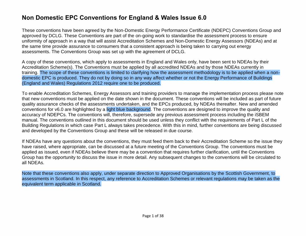
These conventions have been agreed by the Non-Domestic Energy Performance Certificate (NDEPC) Conventions Group and approved by DCLG. These Conventions are part of the on-going work to standardise the assessment process to ensure uniformity of approach in a way that will assist Accreditation Schemes and Non-Domestic Energy Assessors (NDEAs) and at the same time provide assurance to consumers that a consistent approach is being taken to carrying out energy assessments. The Conventions Group was set up with the agreement of DCLG. A copy of these conventions, which apply to assessments in England and Wales only, have been sent to NDEAs by their Accreditation Scheme(s). The Conventions must be applied by all accredited NDEAs and by those NDEAs currently in training. The scope of these conventions is limited to clarifying how the assessment methodology is to be applied when a non-domestic EPC is produced. They do not by doing so in any way affect whether or not the Energy Performance of Buildings (England and Wales) Regulations 2012 require one to be produced.
To enable Accreditation Schemes, Energy Assessors and training providers to manage the implementation process please note that new conventions must be applied on the date shown in the document. These conventions will be included as part of future quality assurance checks of the assessments undertaken, and the EPCs produced, by NDEAs thereafter. New and amended conventions for v6.0 are highlighted by a light blue background. The conventions are designed to improve the quality and accuracy of NDEPCs. The conventions will, therefore, supersede any previous assessment process including the iSBEM manual. The conventions outlined in this document should be used unless they conflict with the requirements of Part L of the Building Regulations in which case Part L always takes precedence. With this in mind, further conventions are being discussed and developed by the Conventions Group and these will be released in due course. If NDEAs have any questions about the conventions, they must feed them back to their Accreditation Scheme so the issue they have raised, where appropriate, can be discussed at a future meeting of the Conventions Group. The conventions must be applied as issued, even if NDEAs believe there may be a convention that requires further clarification, until the Conventions Group has the opportunity to discuss the issue in more detail. Any subsequent changes to the conventions will be circulated to all NDEAs. Note that these conventions also apply, under separate direction to Approved Organisations by the Scottish Government, to assessments in Scotland. In this respect, any reference to Accreditation Schemes or relevant regulations may be taken as the equivalent term applicable in Scotland.
Non Domestic EPC Conventions for England & Wales Issue 6.0
Page 2 of 38
Ref Issue Convention Implementation date
1. Fundamentals
1.01 Single Metering with Multiple Renewables (Apportionment of PV)
Apportionment
of On-site
Renewable
(OSR)
Electricity
Generation
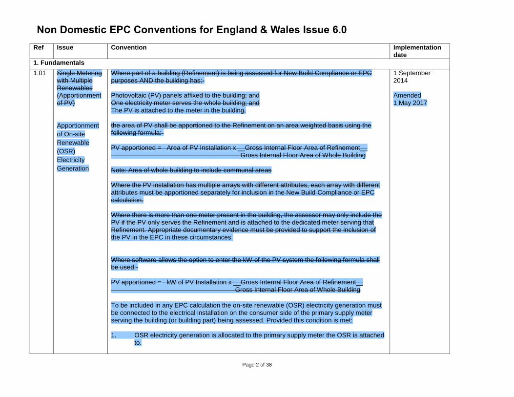
Where part of a building (Refinement) is being assessed for New Build Compliance or EPC purposes AND the building has:- Photovoltaic (PV) panels affixed to the building; and One electricity meter serves the whole building; and The PV is attached to the meter in the building. the area of PV shall be apportioned to the Refinement on an area weighted basis using the following formula:- PV apportioned = Area of PV Installation x __Gross Internal Floor Area of Refinement__ Gross Internal Floor Area of Whole Building Note: Area of whole building to include communal areas Where the PV installation has multiple arrays with different attributes, each array with different attributes must be apportioned separately for inclusion in the New Build Compliance or EPC calculation. Where there is more than one meter present in the building, the assessor may only include the PV if the PV only serves the Refinement and is attached to the dedicated meter serving that Refinement. Appropriate documentary evidence must be provided to support the inclusion of the PV in the EPC in these circumstances. Where software allows the option to enter the kW of the PV system the following formula shall be used:- PV apportioned = kW of PV Installation x __Gross Internal Floor Area of Refinement__ Gross Internal Floor Area of Whole Building
To be included in any EPC calculation the on-site renewable (OSR) electricity generation must be connected to the electrical installation on the consumer side of the primary supply meter serving the building (or building part) being assessed. Provided this condition is met: 1. OSR electricity generation is allocated to the primary supply meter the OSR is attached
to.
1 September 2014 Amended 1 May 2017
Non Domestic EPC Conventions for England & Wales Issue 6.0
Page 3 of 38
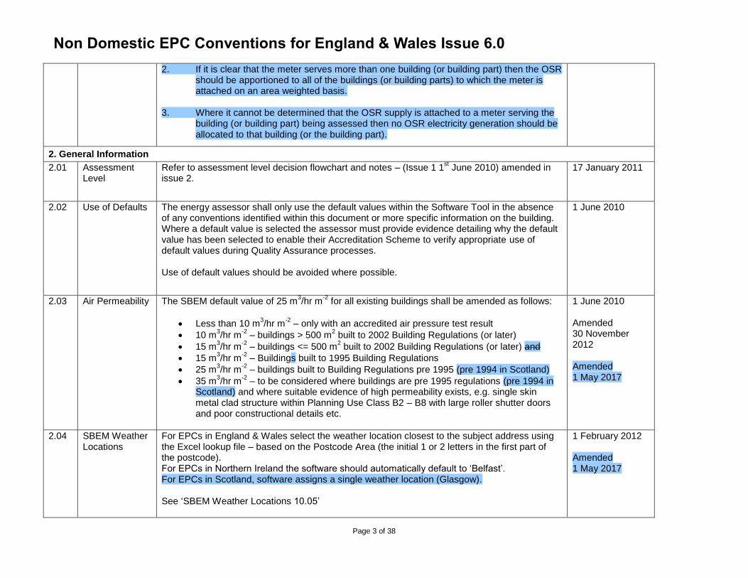
2. If it is clear that the meter serves more than one building (or building part) then the OSR should be apportioned to all of the buildings (or building parts) to which the meter is attached on an area weighted basis.
3. Where it cannot be determined that the OSR supply is attached to a meter serving the
building (or building part) being assessed then no OSR electricity generation should be allocated to that building (or the building part).
2. General Information
2.01 Assessment Level
Refer to assessment level decision flowchart and notes – (Issue 1 1st June 2010) amended in
issue 2.
17 January 2011
2.02 Use of Defaults The energy assessor shall only use the default values within the Software Tool in the absence of any conventions identified within this document or more specific information on the building. Where a default value is selected the assessor must provide evidence detailing why the default value has been selected to enable their Accreditation Scheme to verify appropriate use of default values during Quality Assurance processes. Use of default values should be avoided where possible.
1 June 2010
2.03 Air Permeability The SBEM default value of 25 m3/hr m
-2 for all existing buildings shall be amended as follows:
Less than 10 m3/hr m
-2 – only with an accredited air pressure test result
10 m3/hr m
-2 – buildings > 500 m
2 built to 2002 Building Regulations (or later)
15 m3/hr m
-2 – buildings <= 500 m
2 built to 2002 Building Regulations (or later) and
15 m3/hr m
-2 – Buildings built to 1995 Building Regulations
25 m3/hr m
-2 – buildings built to Building Regulations pre 1995 (pre 1994 in Scotland)
35 m3/hr m
-2 – to be considered where buildings are pre 1995 regulations (pre 1994 in
Scotland) and where suitable evidence of high permeability exists, e.g. single skin metal clad structure within Planning Use Class B2 – B8 with large roller shutter doors and poor constructional details etc.
1 June 2010 Amended 30 November 2012 Amended 1 May 2017
2.04 SBEM Weather Locations
For EPCs in England & Wales select the weather location closest to the subject address using the Excel lookup file – based on the Postcode Area (the initial 1 or 2 letters in the first part of the postcode). For EPCs in Northern Ireland the software should automatically default to ‘Belfast’. For EPCs in Scotland, software assigns a single weather location (Glasgow). See ‘SBEM Weather Locations 10.05’
1 February 2012 Amended 1 May 2017
Non Domestic EPC Conventions for England & Wales Issue 6.0
Page 4 of 38
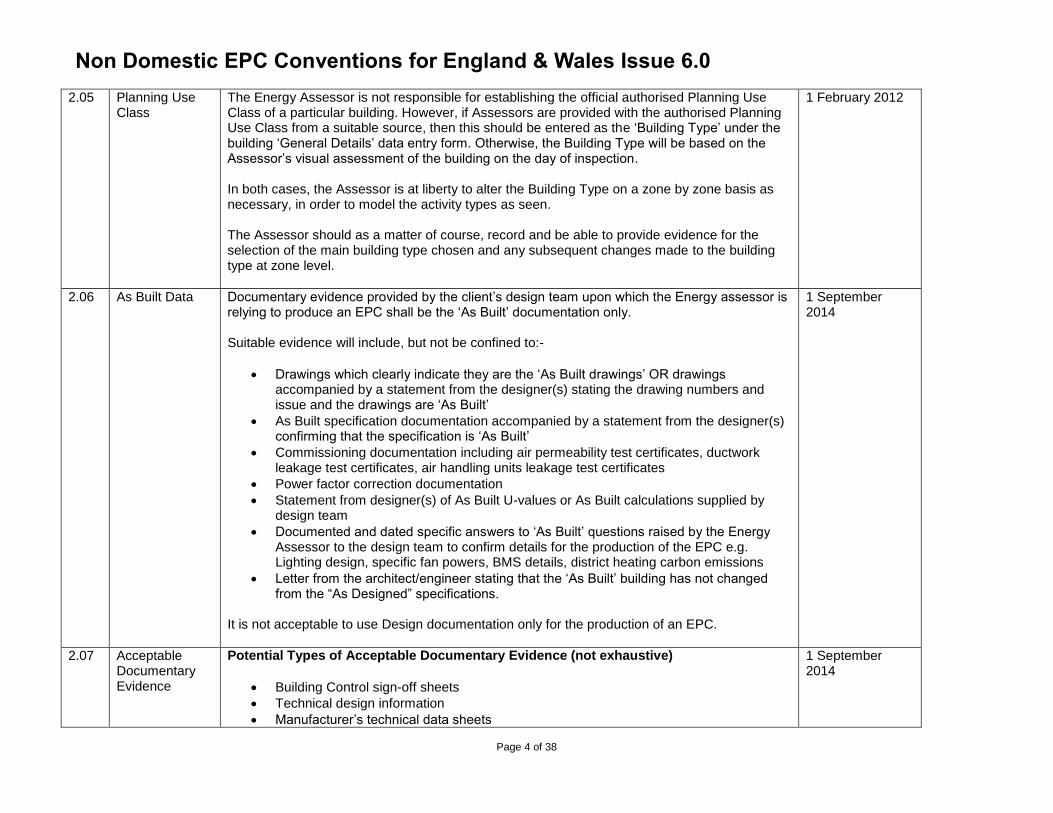
2.05 Planning Use Class
The Energy Assessor is not responsible for establishing the official authorised Planning Use Class of a particular building. However, if Assessors are provided with the authorised Planning Use Class from a suitable source, then this should be entered as the ‘Building Type’ under the building ‘General Details’ data entry form. Otherwise, the Building Type will be based on the Assessor’s visual assessment of the building on the day of inspection. In both cases, the Assessor is at liberty to alter the Building Type on a zone by zone basis as necessary, in order to model the activity types as seen. The Assessor should as a matter of course, record and be able to provide evidence for the selection of the main building type chosen and any subsequent changes made to the building type at zone level.
1 February 2012
2.06 As Built Data Documentary evidence provided by the client’s design team upon which the Energy assessor is relying to produce an EPC shall be the ‘As Built’ documentation only. Suitable evidence will include, but not be confined to:-
Drawings which clearly indicate they are the ‘As Built drawings’ OR drawings accompanied by a statement from the designer(s) stating the drawing numbers and issue and the drawings are ‘As Built’
As Built specification documentation accompanied by a statement from the designer(s) confirming that the specification is ‘As Built’
Commissioning documentation including air permeability test certificates, ductwork leakage test certificates, air handling units leakage test certificates
Power factor correction documentation
Statement from designer(s) of As Built U-values or As Built calculations supplied by design team
Documented and dated specific answers to ‘As Built’ questions raised by the Energy Assessor to the design team to confirm details for the production of the EPC e.g. Lighting design, specific fan powers, BMS details, district heating carbon emissions
Letter from the architect/engineer stating that the ‘As Built’ building has not changed from the “As Designed” specifications.
It is not acceptable to use Design documentation only for the production of an EPC.
1 September 2014
2.07 Acceptable Documentary Evidence
Potential Types of Acceptable Documentary Evidence (not exhaustive)
Building Control sign-off sheets
Technical design information
Manufacturer’s technical data sheets
1 September 2014
Non Domestic EPC Conventions for England & Wales Issue 6.0
Page 5 of 38
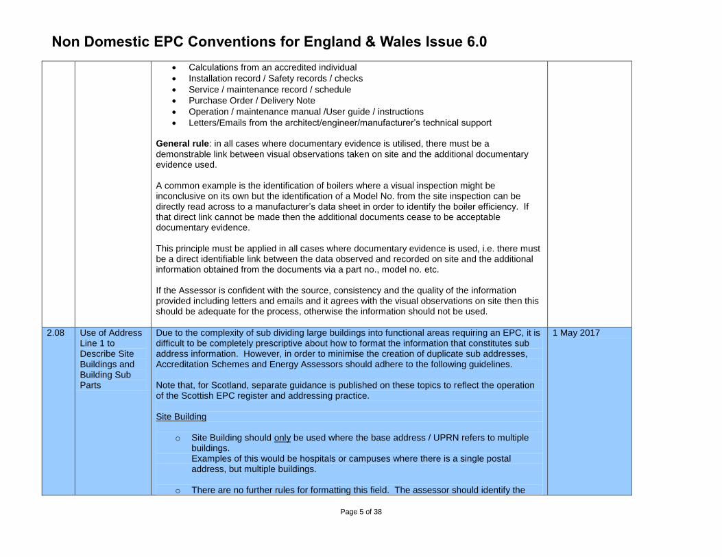
Calculations from an accredited individual
Installation record / Safety records / checks
Service / maintenance record / schedule
Purchase Order / Delivery Note
Operation / maintenance manual /User guide / instructions
Letters/Emails from the architect/engineer/manufacturer’s technical support General rule: in all cases where documentary evidence is utilised, there must be a demonstrable link between visual observations taken on site and the additional documentary evidence used. A common example is the identification of boilers where a visual inspection might be inconclusive on its own but the identification of a Model No. from the site inspection can be directly read across to a manufacturer’s data sheet in order to identify the boiler efficiency. If that direct link cannot be made then the additional documents cease to be acceptable documentary evidence. This principle must be applied in all cases where documentary evidence is used, i.e. there must be a direct identifiable link between the data observed and recorded on site and the additional information obtained from the documents via a part no., model no. etc. If the Assessor is confident with the source, consistency and the quality of the information provided including letters and emails and it agrees with the visual observations on site then this should be adequate for the process, otherwise the information should not be used.
2.08 Use of Address Line 1 to Describe Site Buildings and Building Sub Parts
Due to the complexity of sub dividing large buildings into functional areas requiring an EPC, it is difficult to be completely prescriptive about how to format the information that constitutes sub address information. However, in order to minimise the creation of duplicate sub addresses, Accreditation Schemes and Energy Assessors should adhere to the following guidelines. Note that, for Scotland, separate guidance is published on these topics to reflect the operation of the Scottish EPC register and addressing practice. Site Building
o Site Building should only be used where the base address / UPRN refers to multiple buildings. Examples of this would be hospitals or campuses where there is a single postal address, but multiple buildings.
o There are no further rules for formatting this field. The assessor should identify the
1 May 2017
Non Domestic EPC Conventions for England & Wales Issue 6.0
Page 6 of 38
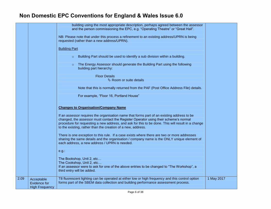
building using the most appropriate description, perhaps agreed between the assessor and the person commissioning the EPC, e.g. “Operating Theatre” or “Great Hall”.
NB: Please note that under this process a refinement to an existing address/UPRN is being requested (rather than a new address/UPRN). Building Part
o Building Part should be used to identify a sub division within a building.
o The Energy Assessor should generate the Building Part using the following building part hierarchy:
Floor Details Room or suite details
Note that this is normally returned from the PAF (Post Office Address File) details. For example, “Floor 16, Portland House”
Changes to Organisation/Company Name If an assessor requires the organisation name that forms part of an existing address to be changed, the assessor must contact the Register Operator using their scheme’s normal procedure for requesting a new address, and ask for this to be done. This will result in a change to the existing, rather than the creation of a new, address. There is one exception to this rule. If a case exists where there are two or more addresses sharing the same details and the organisation / company name is the ONLY unique element of each address, a new address / UPRN is needed. e.g.: The Bookshop, Unit 2, etc… The Cookshop, Unit 2, etc… If an assessor were to ask for one of the above entries to be changed to “The Workshop”, a third entry will be added.
2.09 Acceptable Evidence for High Frequency
T8 fluorescent lighting can be operated at either low or high frequency and this control option forms part of the SBEM data collection and building performance assessment process.
1 May 2017
Non Domestic EPC Conventions for England & Wales Issue 6.0
Page 7 of 38
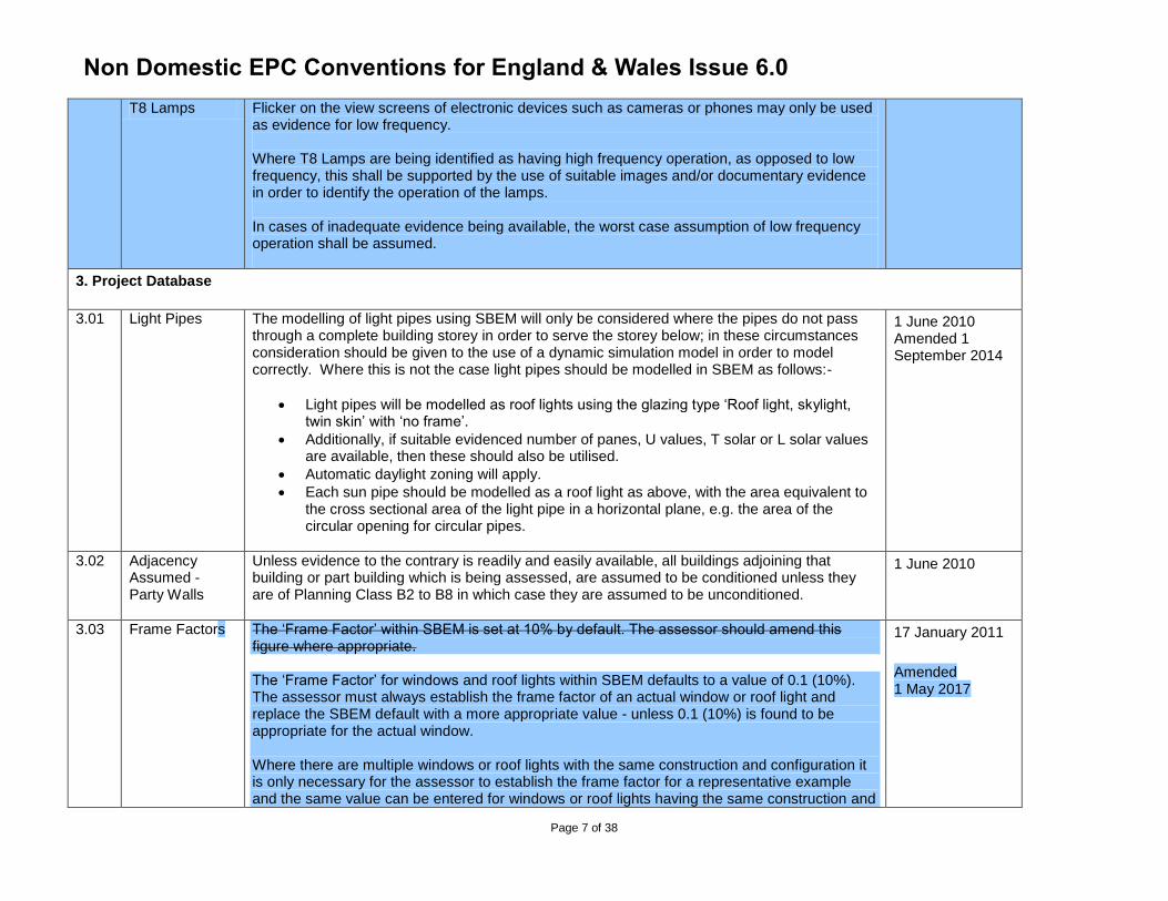
T8 Lamps Flicker on the view screens of electronic devices such as cameras or phones may only be used as evidence for low frequency. Where T8 Lamps are being identified as having high frequency operation, as opposed to low frequency, this shall be supported by the use of suitable images and/or documentary evidence in order to identify the operation of the lamps. In cases of inadequate evidence being available, the worst case assumption of low frequency operation shall be assumed.
3. Project Database
3.01 Light Pipes The modelling of light pipes using SBEM will only be considered where the pipes do not pass through a complete building storey in order to serve the storey below; in these circumstances consideration should be given to the use of a dynamic simulation model in order to model correctly. Where this is not the case light pipes should be modelled in SBEM as follows:-
Light pipes will be modelled as roof lights using the glazing type ‘Roof light, skylight, twin skin’ with ‘no frame’.
Additionally, if suitable evidenced number of panes, U values, T solar or L solar values are available, then these should also be utilised.
Automatic daylight zoning will apply.
Each sun pipe should be modelled as a roof light as above, with the area equivalent to the cross sectional area of the light pipe in a horizontal plane, e.g. the area of the circular opening for circular pipes.
1 June 2010 Amended 1 September 2014
3.02 Adjacency Assumed - Party Walls
Unless evidence to the contrary is readily and easily available, all buildings adjoining that building or part building which is being assessed, are assumed to be conditioned unless they are of Planning Class B2 to B8 in which case they are assumed to be unconditioned.
1 June 2010
3.03 Frame Factors The ‘Frame Factor’ within SBEM is set at 10% by default. The assessor should amend this figure where appropriate. The ‘Frame Factor’ for windows and roof lights within SBEM defaults to a value of 0.1 (10%). The assessor must always establish the frame factor of an actual window or roof light and replace the SBEM default with a more appropriate value - unless 0.1 (10%) is found to be appropriate for the actual window. Where there are multiple windows or roof lights with the same construction and configuration it is only necessary for the assessor to establish the frame factor for a representative example and the same value can be entered for windows or roof lights having the same construction and
17 January 2011
Amended 1 May 2017
Non Domestic EPC Conventions for England & Wales Issue 6.0
Page 8 of 38
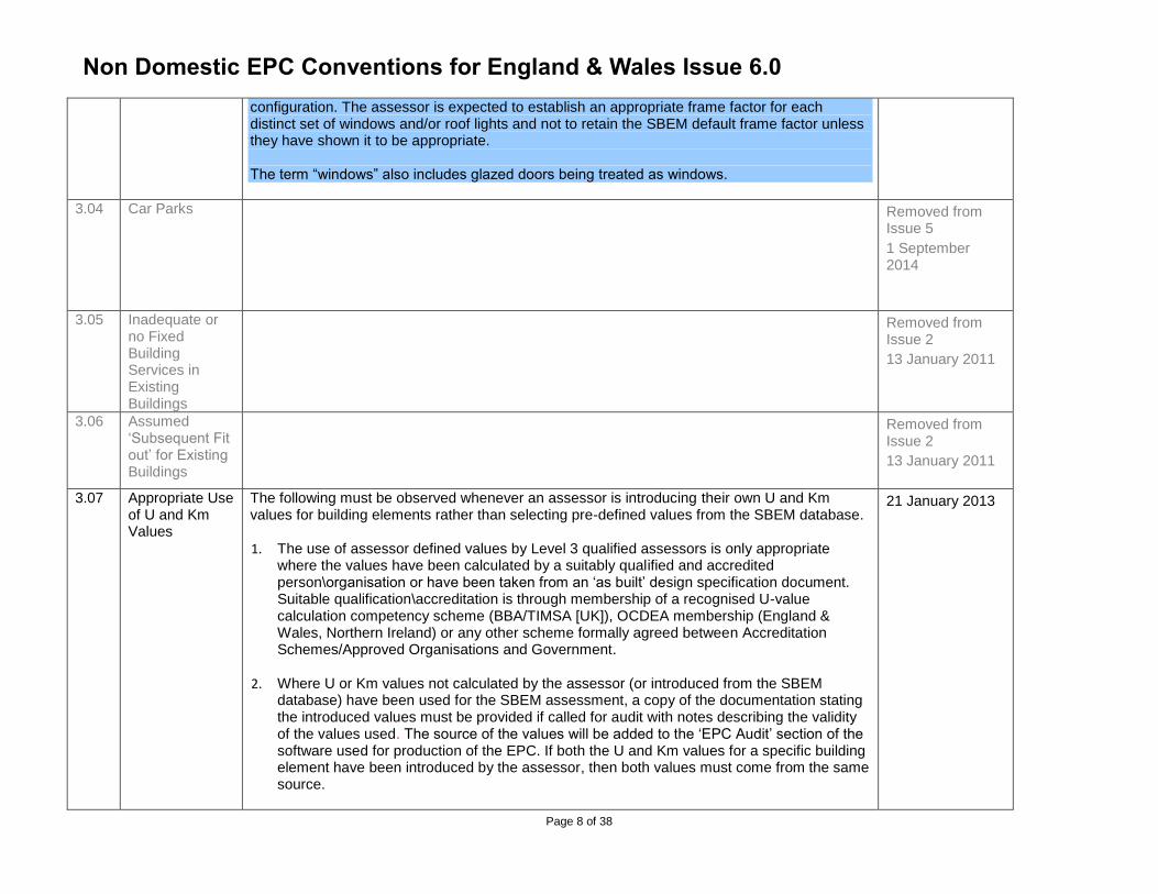
configuration. The assessor is expected to establish an appropriate frame factor for each distinct set of windows and/or roof lights and not to retain the SBEM default frame factor unless they have shown it to be appropriate. The term “windows” also includes glazed doors being treated as windows.
3.04 Car Parks Removed from Issue 5
1 September 2014
3.05 Inadequate or no Fixed Building Services in Existing Buildings
Removed from Issue 2
13 January 2011
3.06 Assumed ‘Subsequent Fit out’ for Existing Buildings
Removed from Issue 2
13 January 2011
3.07 Appropriate Use of U and Km Values
The following must be observed whenever an assessor is introducing their own U and Km values for building elements rather than selecting pre-defined values from the SBEM database.
1. The use of assessor defined values by Level 3 qualified assessors is only appropriate where the values have been calculated by a suitably qualified and accredited person\organisation or have been taken from an ‘as built’ design specification document. Suitable qualification\accreditation is through membership of a recognised U-value calculation competency scheme (BBA/TIMSA [UK]), OCDEA membership (England & Wales, Northern Ireland) or any other scheme formally agreed between Accreditation Schemes/Approved Organisations and Government.
2. Where U or Km values not calculated by the assessor (or introduced from the SBEM database) have been used for the SBEM assessment, a copy of the documentation stating the introduced values must be provided if called for audit with notes describing the validity of the values used. The source of the values will be added to the ‘EPC Audit’ section of the software used for production of the EPC. If both the U and Km values for a specific building element have been introduced by the assessor, then both values must come from the same source.
21 January 2013
Non Domestic EPC Conventions for England & Wales Issue 6.0
Page 9 of 38
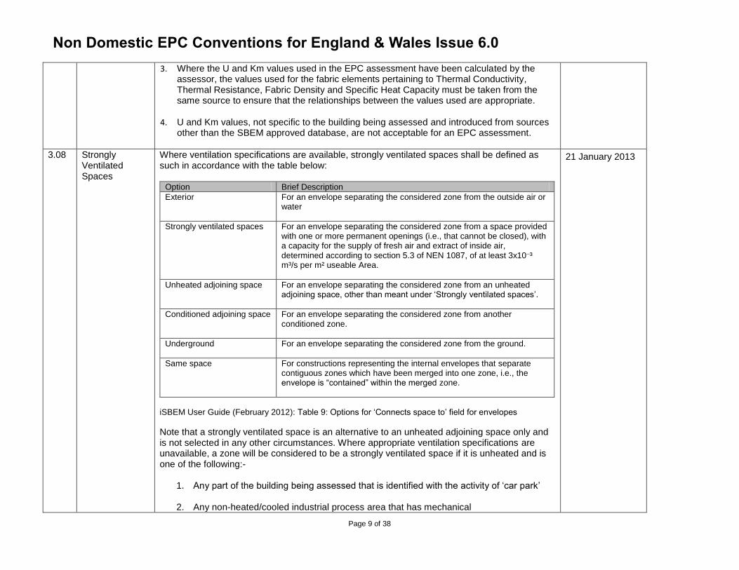
3. Where the U and Km values used in the EPC assessment have been calculated by the assessor, the values used for the fabric elements pertaining to Thermal Conductivity, Thermal Resistance, Fabric Density and Specific Heat Capacity must be taken from the same source to ensure that the relationships between the values used are appropriate.
4. U and Km values, not specific to the building being assessed and introduced from sources other than the SBEM approved database, are not acceptable for an EPC assessment.
3.08 Strongly Ventilated Spaces
Where ventilation specifications are available, strongly ventilated spaces shall be defined as such in accordance with the table below:
Option Brief Description
Exterior For an envelope separating the considered zone from the outside air or water
Strongly ventilated spaces For an envelope separating the considered zone from a space provided with one or more permanent openings (i.e., that cannot be closed), with a capacity for the supply of fresh air and extract of inside air, determined according to section 5.3 of NEN 1087, of at least 3x10¯³ m³/s per m² useable Area.
Unheated adjoining space For an envelope separating the considered zone from an unheated adjoining space, other than meant under ‘Strongly ventilated spaces’.
Conditioned adjoining space For an envelope separating the considered zone from another conditioned zone.
Underground For an envelope separating the considered zone from the ground.
Same space For constructions representing the internal envelopes that separate contiguous zones which have been merged into one zone, i.e., the envelope is “contained” within the merged zone.
iSBEM User Guide (February 2012): Table 9: Options for ‘Connects space to’ field for envelopes
Note that a strongly ventilated space is an alternative to an unheated adjoining space only and is not selected in any other circumstances. Where appropriate ventilation specifications are unavailable, a zone will be considered to be a strongly ventilated space if it is unheated and is one of the following:-
1. Any part of the building being assessed that is identified with the activity of ‘car park’
2. Any non-heated/cooled industrial process area that has mechanical
21 January 2013
Non Domestic EPC Conventions for England & Wales Issue 6.0
Page 10 of 38
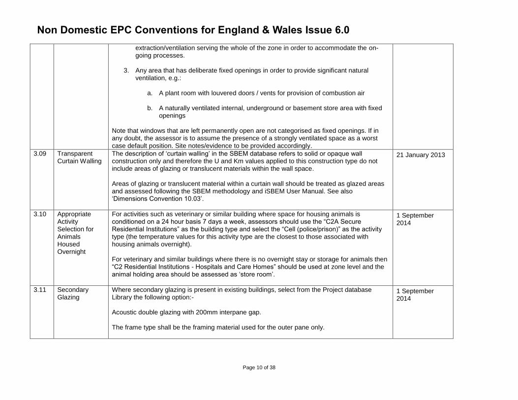
extraction/ventilation serving the whole of the zone in order to accommodate the on-going processes.
3. Any area that has deliberate fixed openings in order to provide significant natural
ventilation, e.g.:
a. A plant room with louvered doors / vents for provision of combustion air
b. A naturally ventilated internal, underground or basement store area with fixed openings
Note that windows that are left permanently open are not categorised as fixed openings. If in any doubt, the assessor is to assume the presence of a strongly ventilated space as a worst case default position. Site notes/evidence to be provided accordingly.
3.09 Transparent Curtain Walling
The description of ‘curtain walling’ in the SBEM database refers to solid or opaque wall construction only and therefore the U and Km values applied to this construction type do not include areas of glazing or translucent materials within the wall space. Areas of glazing or translucent material within a curtain wall should be treated as glazed areas and assessed following the SBEM methodology and iSBEM User Manual. See also ‘Dimensions Convention 10.03’.
21 January 2013
3.10 Appropriate Activity Selection for Animals Housed Overnight
For activities such as veterinary or similar building where space for housing animals is conditioned on a 24 hour basis 7 days a week, assessors should use the “C2A Secure Residential Institutions” as the building type and select the “Cell (police/prison)” as the activity type (the temperature values for this activity type are the closest to those associated with housing animals overnight). For veterinary and similar buildings where there is no overnight stay or storage for animals then “C2 Residential Institutions - Hospitals and Care Homes” should be used at zone level and the animal holding area should be assessed as ‘store room’.
1 September 2014
3.11 Secondary Glazing
Where secondary glazing is present in existing buildings, select from the Project database Library the following option:- Acoustic double glazing with 200mm interpane gap. The frame type shall be the framing material used for the outer pane only.
1 September 2014
Non Domestic EPC Conventions for England & Wales Issue 6.0
Page 11 of 38
3.12 Multiple Window Frame Types
Where any window has frames made of multiple frame types, e.g. timber outer frame and metal intermediate frames, the assessor shall select the frame type for the material that is in direct contact with the structural opening.
1 September 2014
3.13 Sales vs Eating & Drinking Activity Selection
As a first step Assessors should work to the descriptions provided by BRE in the iSBEM interface. The following statements provide additional guidance for specific circumstances:-
1. For small food outlets and hot food takeaways in Classes A3, A4 & A5, the Eating/drinking activity should only be applied to areas that are designated for the purpose of eating and drinking i.e. that include tables (or counters) and chairs and are located inside the premises, otherwise the zone will be classified as a sales area. An example would be a pizza outlet that is predominantly take away and delivery but which provides a small designated area with tables and chairs in the shop area which could be designated as an eating/drinking area.
2. Generic Office Areas should include any tea room / tea making facilities, kitchenettes and staff lounges. These areas should not, therefore, be identified as eating and drinking areas.
Please see the glossary section (10.08) for the list of all building types with the activity of ‘Eating/drinking area’ and their description.
1 May 2017
3.14 Block Glazing Exteriors
Glass Blocks should be entered in accordance with the following hierarchy:-
(1) Where any external walls or parts thereof, are constructed of Glass Blocks they should be entered as Windows.
(2) Where the specification for the building refers to specific glass blocks and the supporting technical information of the glass blocks are available then the U-Values, T-Solar and L-Solar values should be entered as User defined Values. The specification and technical information must be provided as part of the evidence to support the use of this option.
(3) Where the specification and/or the technical information is not available then the following user defined U-Values, T-Solar and L- Solar values should be entered.
Build Date U- Value W/m2K T Solar L Solar Frame Factor
1 May 2017
Non Domestic EPC Conventions for England & Wales Issue 6.0
Page 12 of 38
Buildings Built pre 2002
3.2 (4)
0.83 (2)
0.8
(1) 0.00
Buildings Built post 2002
2.2
(5)
0.71
(2)
0.8
(1)
0.00
4. Geometry
4.01 Light Wells Light wells to be treated as external envelopes.
1 June 2010
4.02 Atria All atria to be treated as Level 5 NDEPC assessment feature. Refer to accompanying Level 3, Level 4 and Level 5 decision flowchart and notes (Issue 1 – 15 March 2010).
1 June 2010
4.03 Dimensions Horizontal and vertical (inc. zone height) measurements to be carried out in accordance with diagrams and notes in ‘CEPC Dimension Conventions’ documentation.
1 June 2010
4.04 Measurement Accuracy (for Distance, Area and Volume)
Calculated values entered into the software for the purpose of an EPC calculation must be provided with supporting calculations presented for audit. The minimum level of accuracy for calculated values entered into the software for the purpose of an EPC calculation is 2 decimal places i.e. 2 places after the decimal point for any given value. All measurements entered into the software must be recorded to at least 2 decimal places on site notes. Where the required level of measurement accuracy is not possible the reason must be recorded.
21 January 2013
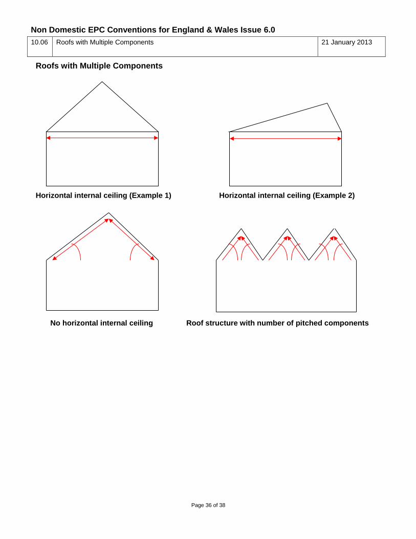
4.05 Roofs with Multiple Components
Where the external roof of a zone or an individual component has a horizontal internal ceiling, the roof shall be entered as having a horizontal orientation and the area of the roof shall be the total horizontal internal surface area exposed to the conditioned space. The roof pitch angle shall be entered as the SBEM default of 45 degrees. See ‘Roofs with Multiple Components 10.06: Horizontal internal ceiling (Examples 1 and 2)’. Where a horizontal internal ceiling is not present, the roof area shall be that of the internal surface area exposed to the conditioned space and the orientation shall be the compass position that is ‘faced’ by the pitched component. The pitch angle shall be the angle of the component to the horizontal. See ‘Roofs with Multiple Components 10.06: No horizontal internal ceiling’.
21 January 2013
Non Domestic EPC Conventions for England & Wales Issue 6.0
Page 13 of 38
Where a roof structure is constructed of a number of pitched components then each shall be addressed individually and entered as separate components as part of the model, however if individual components have exactly the same set of properties they can be entered as one envelope comprising of the sum area of the components. See ‘Roofs with Multiple Components 10.06: Roof structure with number of pitched components’.
4.06 Same Space Adjacency
Internal wall envelope areas, of the same or similar construction, within merged zones may be added together and entered as a single envelope area, attached to the merged zone, with the adjacency of “Same space”. The orientation of the envelope is not relevant to the EPC results and calculations for the ‘Same space’ envelope should be documented for audit purposes.
1 May 2017
4.07 Zoning for Day Lit Spaces
All zones must be evaluated for ‘day lit’ spaces which will need to be identified and entered into the software model as separate zones. In many circumstances approved software tools offer an option for day lit zones to be calculated automatically which requires no subdivision of the spaces by the assessor. The method below must be used to subdivide zones for day lit areas where the option for automatic calculation is not selected, not available or where manual day lit zoning is prescribed as required within conventions. Divide building areas, already identified as ‘zones’, to account for areas receiving significantly different amounts of daylight, defined by boundaries which are:
At a distance of 6m from an external wall containing at least 20% glazing
At a distance of 1.5 room heights beyond the edge of an array of roof-lights if the overall area of the roof-lights is at least 10% of the zone floor area
Note:
1) If any resulting zone is less than 3m wide, absorb it within surrounding zones with the same HVAC, lighting and activity
2) If any resulting zones overlap, use your discretion to allocate the overlap to one or more of the zones
3) In all cases where a zone is sub-divided to identify day lit spaces all other zone features such as HVAC, activity and lighting will be applied to each of the subdivided zones
1 May 2017
4.08 Modelling a Zone Within a
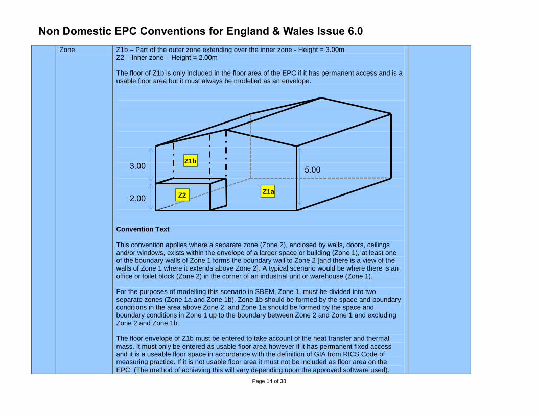
Notes to Support Diagram Below Z1a – Full height part of the outer zone – Height = 5.00m
1 May 2017
Non Domestic EPC Conventions for England & Wales Issue 6.0
Page 14 of 38
Zone Z1b – Part of the outer zone extending over the inner zone - Height = 3.00m Z2 – Inner zone – Height = 2.00m The floor of Z1b is only included in the floor area of the EPC if it has permanent access and is a usable floor area but it must always be modelled as an envelope. Convention Text This convention applies where a separate zone (Zone 2), enclosed by walls, doors, ceilings and/or windows, exists within the envelope of a larger space or building (Zone 1), at least one of the boundary walls of Zone 1 forms the boundary wall to Zone 2 [and there is a view of the walls of Zone 1 where it extends above Zone 2]. A typical scenario would be where there is an office or toilet block (Zone 2) in the corner of an industrial unit or warehouse (Zone 1). For the purposes of modelling this scenario in SBEM, Zone 1, must be divided into two separate zones (Zone 1a and Zone 1b). Zone 1b should be formed by the space and boundary conditions in the area above Zone 2, and Zone 1a should be formed by the space and boundary conditions in Zone 1 up to the boundary between Zone 2 and Zone 1 and excluding Zone 2 and Zone 1b. The floor envelope of Z1b must be entered to take account of the heat transfer and thermal mass. It must only be entered as usable floor area however if it has permanent fixed access and it is a useable floor space in accordance with the definition of GIA from RICS Code of measuring practice. If it is not usable floor area it must not be included as floor area on the EPC. (The method of achieving this will vary depending upon the approved software used).
3.00
2.00
5.00
Z1a
Z1b
Z2
Non Domestic EPC Conventions for England & Wales Issue 6.0
Page 15 of 38
If the whole area has suspended ceiling panels that are at the same height as the ceiling of Z2 or the ceiling of Z2 is at eaves height, normal conventions apply and the same zone height will be given to both zones (5 metres in this example). Both parts of the outer zone (Z1a and Z1b) are conditioned by whatever conditions Z1a unless there is different fixed conditioning present in Z1b. Z1b will have the same activity assigned as Z1a unless there is evidence to the contrary. All envelopes are entered in the zone that they are physically exposed to and are adjacent to whatever is on the opposite side of them. The inner zone (Z2) has a ceiling envelope as well as wall envelopes with adjacency to Z1 and it does not have any roof envelope. The wall envelopes of Z2 do not extend beyond the zone height of Z2 which is the height to the top surface of the ceiling envelope (2.00m in the example). The outer zone has a floor envelope (Z1a) which excludes the floor area of Z2 and another floor envelope which is an intermediate floor envelope with adjacency to Z2 and having the area of Z2 (the floor of Z1b). The internal wall envelopes with adjacency to Z2 and the wall envelopes above Z2 are treated as part of the outer zone. The entire roof envelope is treated as part of the outer zone (Z1a and Z1b). The example shows a pitched roof but the same principles apply to a flat roof or to when there is another storey above (in which case the roof envelope becomes a ceiling envelope).
Non Domestic EPC Conventions for England & Wales Issue 6.0
Page 16 of 38
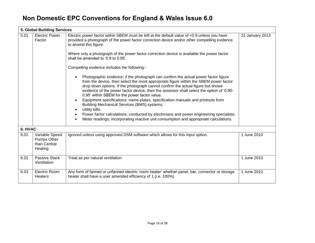
5. Global Building Services
5.01 Electric Power Factor
Electric power factor within SBEM must be left at the default value of <0.9 unless you have provided a photograph of the power factor correction device and/or other compelling evidence to amend this figure. Where only a photograph of the power factor correction device is available the power factor shall be amended to ‘0.9 to 0.95’. Compelling evidence includes the following:-
Photographic evidence; if the photograph can confirm the actual power factor figure from the device, then select the most appropriate figure within the SBEM power factor drop down options. If the photograph cannot confirm the actual figure but shows evidence of the power factor device, then the assessor shall select the option of ‘0.90-0.95’ within SBEM for the power factor value.
Equipment specifications; name-plates, specification manuals and printouts from Building Mechanical Services (BMS) systems.
Utility bills.
Power factor calculations; conducted by electricians and power engineering specialists.
Meter readings; incorporating reactive unit consumption and appropriate calculations.
21 January 2013
6. HVAC
6.01 Variable Speed Pumps Other than Central Heating
Ignored unless using approved DSM software which allows for this input option. 1 June 2010
6.02 Passive Stack Ventilation
Treat as per natural ventilation 1 June 2010
6.03 Electric Room Heaters
Any form of fanned or unfanned electric ‘room heater’ whether panel, bar, convector or storage heater shall have a user amended efficiency of 1 (i.e. 100%).
1 June 2010
Non Domestic EPC Conventions for England & Wales Issue 6.0
Page 17 of 38
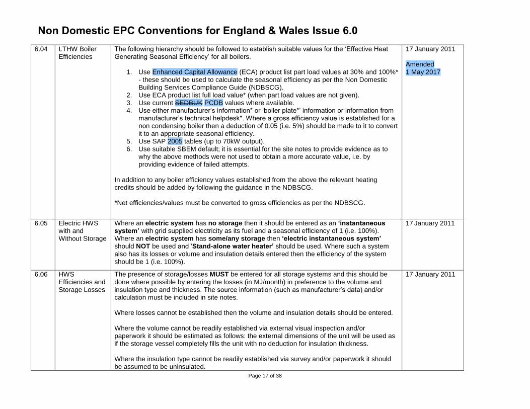
6.04 LTHW Boiler Efficiencies
The following hierarchy should be followed to establish suitable values for the ‘Effective Heat Generating Seasonal Efficiency’ for all boilers.
1. Use Enhanced Capital Allowance (ECA) product list part load values at 30% and 100%* - these should be used to calculate the seasonal efficiency as per the Non Domestic Building Services Compliance Guide (NDBSCG).
2. Use ECA product list full load value* (when part load values are not given). 3. Use current SEDBUK PCDB values where available. 4. Use either manufacturer’s information* or ‘boiler plate*’ information or information from
manufacturer’s technical helpdesk*. Where a gross efficiency value is established for a non condensing boiler then a deduction of 0.05 (i.e. 5%) should be made to it to convert it to an appropriate seasonal efficiency.
5. Use SAP 2005 tables (up to 70kW output). 6. Use suitable SBEM default; it is essential for the site notes to provide evidence as to
why the above methods were not used to obtain a more accurate value, i.e. by providing evidence of failed attempts.
In addition to any boiler efficiency values established from the above the relevant heating credits should be added by following the guidance in the NDBSCG. *Net efficiencies/values must be converted to gross efficiencies as per the NDBSCG.
17 January 2011 Amended 1 May 2017
6.05 Electric HWS with and Without Storage
Where an electric system has no storage then it should be entered as an ‘instantaneous system’ with grid supplied electricity as its fuel and a seasonal efficiency of 1 (i.e. 100%). Where an electric system has some/any storage then ‘electric instantaneous system’ should NOT be used and ‘Stand-alone water heater’ should be used. Where such a system also has its losses or volume and insulation details entered then the efficiency of the system should be 1 (i.e. 100%).
17 January 2011
6.06 HWS Efficiencies and Storage Losses
The presence of storage/losses MUST be entered for all storage systems and this should be done where possible by entering the losses (in MJ/month) in preference to the volume and insulation type and thickness. The source information (such as manufacturer’s data) and/or calculation must be included in site notes. Where losses cannot be established then the volume and insulation details should be entered. Where the volume cannot be readily established via external visual inspection and/or paperwork it should be estimated as follows: the external dimensions of the unit will be used as if the storage vessel completely fills the unit with no deduction for insulation thickness. Where the insulation type cannot be readily established via survey and/or paperwork it should be assumed to be uninsulated.
17 January 2011
Non Domestic EPC Conventions for England & Wales Issue 6.0
Page 18 of 38
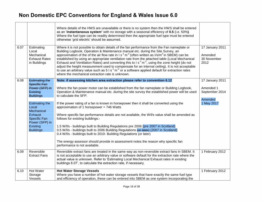
Where details of the HWS are unavailable or there is no system then the HWS shall be entered as an ‘instantaneous system’ with no storage with a seasonal efficiency of 0.5 (i.e. 50%). Where the fuel type can be readily determined then the appropriate fuel type must be entered otherwise ‘grid electric’ should be assumed.
6.07 Estimating Local Mechanical Exhaust Rates in Buildings
Where it is not possible to obtain details of the fan performance from the Fan nameplate or Building Logbook, Operation & Maintenance manual etc. during the Site Survey, an approximation of the of the air flow rate in I s
-1 m
-2 (often written as I/s/m
2 in SBEM) can be
established by using an appropriate ventilation rate from the attached table (Local Mechanical Exhaust and Ventilation Rates) and converting this to I s
-1 m
-2, using the zone height (do not
adjust the height measurement used to compensate for an internal ceiling). It is not acceptable to use an arbitrary value such as 5 I s
-1 m
-2 or a software applied default for extraction rates
where the mechanical extraction rate is unknown.
17 January 2011 Amended 30 November 2012
6.08 Estimating the Specific Fan Power (SFP) in Existing Buildings Estimating the Local Mechanical Exhaust Specific Fan Power (SFP) in Existing Buildings
Note: if assessing kitchen area extraction please refer to convention 6.12 Where the fan power motor can be established from the fan nameplate or Building Logbook, Operation & Maintenance manual etc. during the site survey the established power will be used to calculate the SFP. If the power rating of a fan is known in horsepower then it shall be converted using the approximation of 1 horsepower = 746 Watts Where specific fan performance details are not available, the W/l/s value shall be amended as follows for existing buildings:- 1.5 W/l/s - buildings built to Building Regulations pre 2006 (pre 2007 in Scotland) 0.5 W/l/s - buildings built to 2006 Building Regulations (or later) (2007 in Scotland) 0.4 W/l/s - buildings built to 2010- Building Regulations (or later) The energy assessor should provide in assessment notes the reason why specific fan performance is not available.
17 January 2011 Amended 1 September 2014 Amended 1 May 2017
6.09 Reversible Extract Fans
Reversible extract fans are treated in the same way as non-reversible extract fans in SBEM. It is not acceptable to use an arbitrary value or software default for the extraction rate where the actual value is unknown. Refer to ‘Estimating Local Mechanical Exhaust rates in existing buildings 6.07’, to calculate the extraction rate, if necessary.
1 February 2012
6.10 Hot Water Storage Vessels
Hot Water Storage Vessels Where you have a number of hot water storage vessels that have exactly the same fuel type and efficiency of operation, these can be entered into SBEM as one system incorporating the
1 February 2012
Non Domestic EPC Conventions for England & Wales Issue 6.0
Page 19 of 38
sum total of the storage losses of the individual storage vessels. In these circumstances it is permissible to aggregate vessels of different sizes as long as the storage losses are known for all individual vessels. Storage vessels that are identified by the insulation type cannot be aggregated as the SBEM model derives an assumption for the storage losses based upon insulation type and vessel size in these circumstances. Individual systems that vary by way of recirculation systems or by the use of CHP or solar energy cannot be aggregated and should be entered separately. Instantaneous Hot Water Systems Multiple instantaneous systems having the same fuel type and assumed efficiency can simply be entered as one system and allocated to all zones as appropriate.
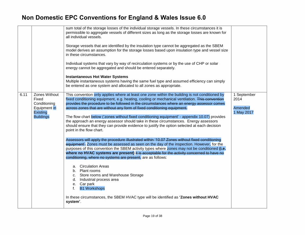
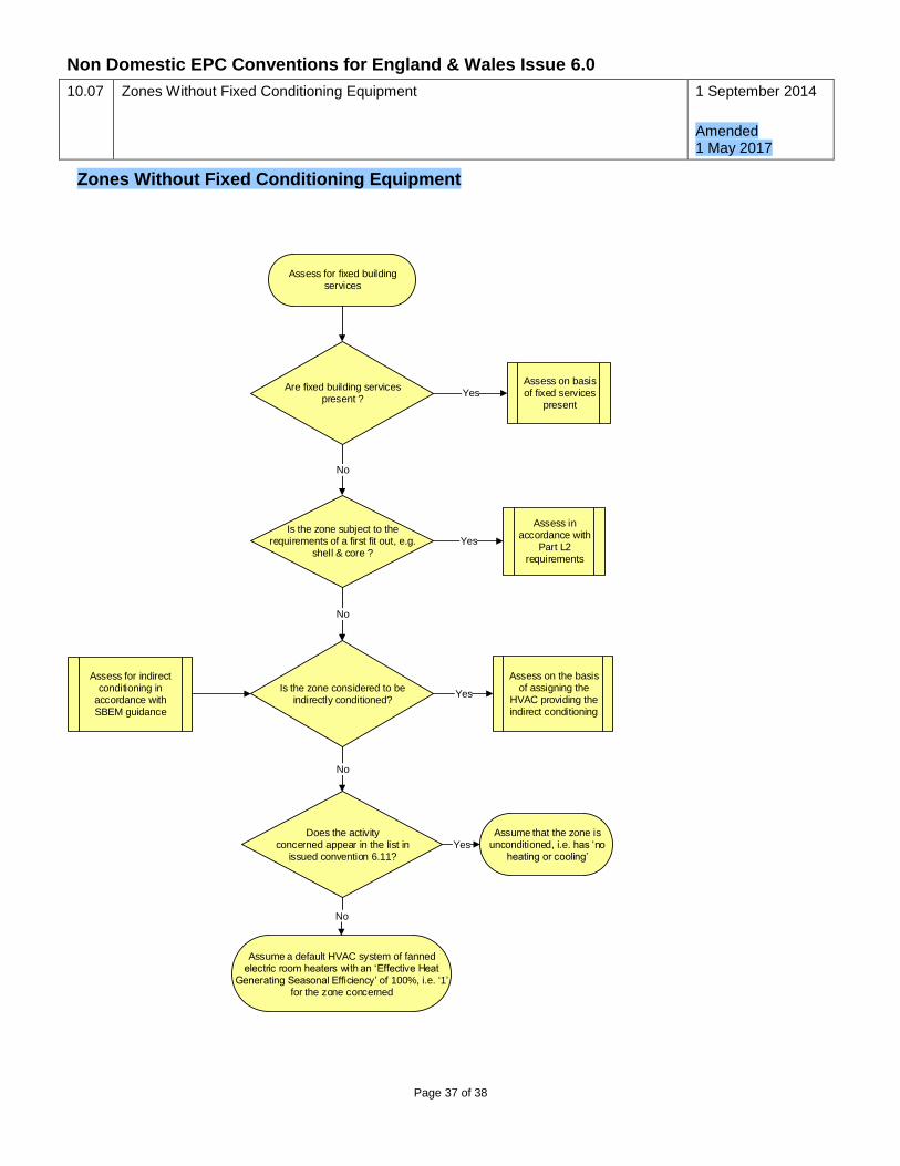
6.11 Zones Without Fixed Conditioning Equipment in Existing Buildings
This convention only applies where at least one zone within the building is not conditioned by fixed conditioning equipment, e.g. heating, cooling or mechanical ventilation. This convention provides the procedure to be followed in the circumstances where an energy assessor comes across zones that are without any form of fixed conditioning equipment. The flow chart below (‘zones without fixed conditioning equipment’ - appendix 10.07) provides the approach an energy assessor should take in these circumstances. Energy assessors should ensure that they can provide evidence to justify the option selected at each decision point in the flow chart.
Assessors will apply the procedure illustrated within ‘10.07 Zones without fixed conditioning equipment’. Zones must be assessed as seen on the day of the inspection. However, for the purposes of this convention the SBEM activity types where zones may not be conditioned (i.e. where no HVAC systems are present) it is acceptable for the activity concerned to have no conditioning, where no systems are present, are as follows:
a. Circulation Areas b. Plant rooms c. Store rooms and Warehouse Storage d. Industrial process area e. Car park f. B1 Workshops
In these circumstances, the SBEM HVAC type will be identified as ‘Zones without HVAC system’.
1 September 2014 Amended 1 May 2017
Non Domestic EPC Conventions for England & Wales Issue 6.0
Page 20 of 38
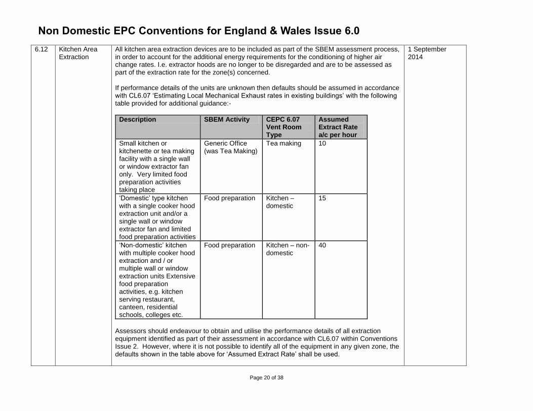
6.12 Kitchen Area Extraction
All kitchen area extraction devices are to be included as part of the SBEM assessment process, in order to account for the additional energy requirements for the conditioning of higher air change rates. I.e. extractor hoods are no longer to be disregarded and are to be assessed as part of the extraction rate for the zone(s) concerned. If performance details of the units are unknown then defaults should be assumed in accordance with CL6.07 ‘Estimating Local Mechanical Exhaust rates in existing buildings’ with the following table provided for additional guidance:-
Description SBEM Activity CEPC 6.07 Vent Room Type
Assumed Extract Rate a/c per hour
Small kitchen or kitchenette or tea making facility with a single wall or window extractor fan only. Very limited food preparation activities taking place
Generic Office (was Tea Making)
Tea making 10
‘Domestic’ type kitchen with a single cooker hood extraction unit and/or a single wall or window extractor fan and limited food preparation activities
Food preparation Kitchen – domestic
15
‘Non-domestic’ kitchen with multiple cooker hood extraction and / or multiple wall or window extraction units Extensive food preparation activities, e.g. kitchen serving restaurant, canteen, residential schools, colleges etc.
Food preparation Kitchen – non-domestic
40
Assessors should endeavour to obtain and utilise the performance details of all extraction equipment identified as part of their assessment in accordance with CL6.07 within Conventions Issue 2. However, where it is not possible to identify all of the equipment in any given zone, the defaults shown in the table above for ‘Assumed Extract Rate’ shall be used.
1 September 2014
Non Domestic EPC Conventions for England & Wales Issue 6.0
Page 21 of 38
In addition, in order to remove a degree of the process power of the fan itself, the assessor should select the following additional default exhaust specific fan power values:-
SFP = 0.4 for the circumstance where the fan is within the zone
SFP = 0.6 where the fan is outside the zone.
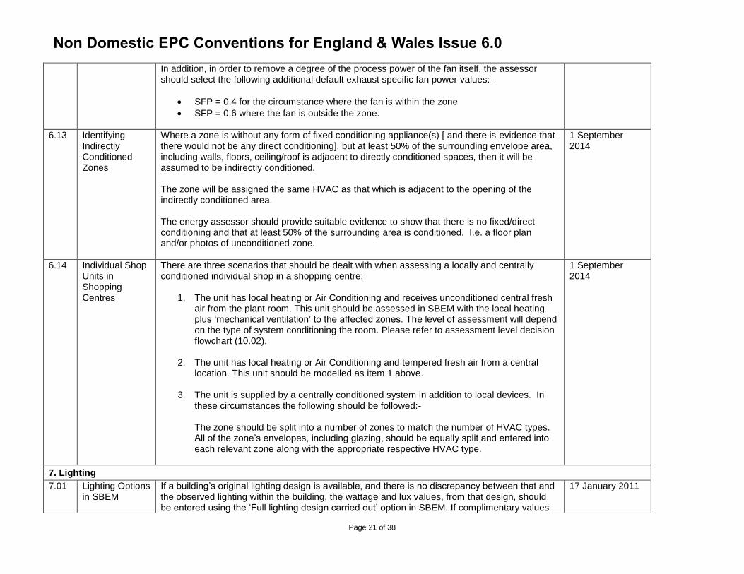
6.13 Identifying Indirectly Conditioned Zones
Where a zone is without any form of fixed conditioning appliance(s) [ and there is evidence that there would not be any direct conditioning], but at least 50% of the surrounding envelope area, including walls, floors, ceiling/roof is adjacent to directly conditioned spaces, then it will be assumed to be indirectly conditioned. The zone will be assigned the same HVAC as that which is adjacent to the opening of the indirectly conditioned area. The energy assessor should provide suitable evidence to show that there is no fixed/direct conditioning and that at least 50% of the surrounding area is conditioned. I.e. a floor plan and/or photos of unconditioned zone.
1 September 2014
6.14 Individual Shop Units in Shopping Centres
There are three scenarios that should be dealt with when assessing a locally and centrally conditioned individual shop in a shopping centre:
1. The unit has local heating or Air Conditioning and receives unconditioned central fresh air from the plant room. This unit should be assessed in SBEM with the local heating plus ‘mechanical ventilation’ to the affected zones. The level of assessment will depend on the type of system conditioning the room. Please refer to assessment level decision flowchart (10.02).
2. The unit has local heating or Air Conditioning and tempered fresh air from a central location. This unit should be modelled as item 1 above.
3. The unit is supplied by a centrally conditioned system in addition to local devices. In these circumstances the following should be followed:- The zone should be split into a number of zones to match the number of HVAC types. All of the zone’s envelopes, including glazing, should be equally split and entered into each relevant zone along with the appropriate respective HVAC type.
1 September 2014
7. Lighting
7.01 Lighting Options in SBEM
If a building’s original lighting design is available, and there is no discrepancy between that and the observed lighting within the building, the wattage and lux values, from that design, should be entered using the ‘Full lighting design carried out’ option in SBEM. If complimentary values
17 January 2011
Non Domestic EPC Conventions for England & Wales Issue 6.0
Page 22 of 38
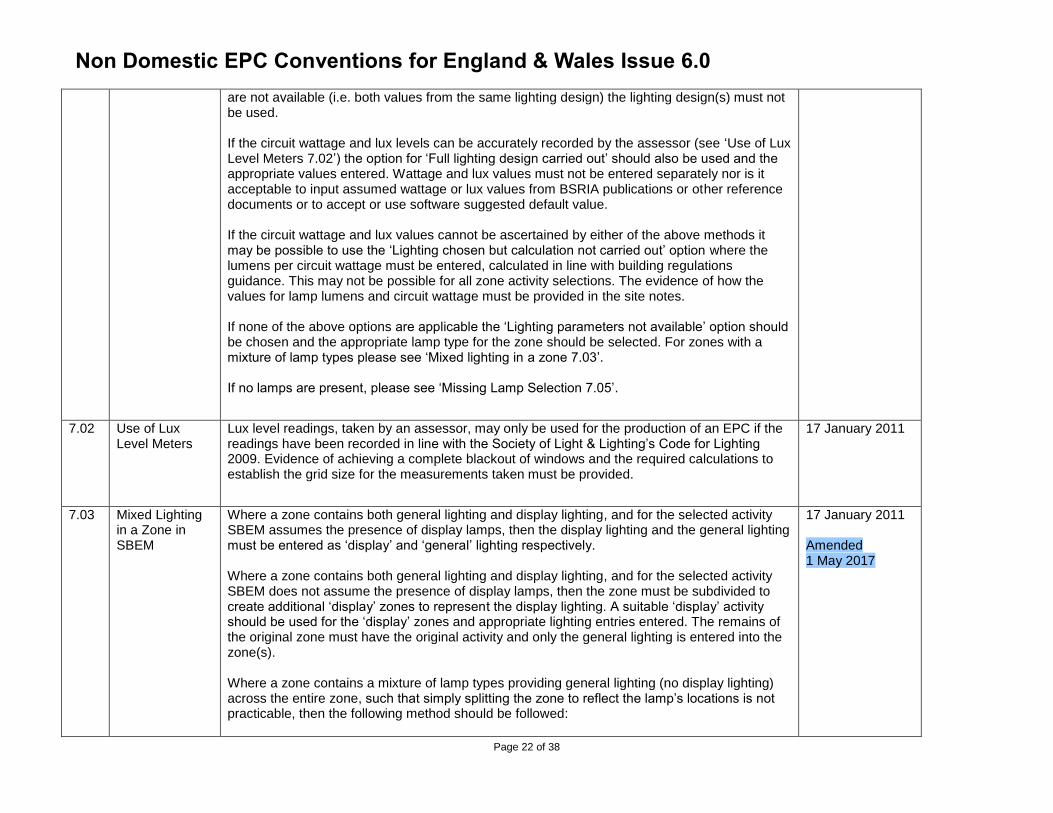
are not available (i.e. both values from the same lighting design) the lighting design(s) must not be used. If the circuit wattage and lux levels can be accurately recorded by the assessor (see ‘Use of Lux Level Meters 7.02’) the option for ‘Full lighting design carried out’ should also be used and the appropriate values entered. Wattage and lux values must not be entered separately nor is it acceptable to input assumed wattage or lux values from BSRIA publications or other reference documents or to accept or use software suggested default value. If the circuit wattage and lux values cannot be ascertained by either of the above methods it may be possible to use the ‘Lighting chosen but calculation not carried out’ option where the lumens per circuit wattage must be entered, calculated in line with building regulations guidance. This may not be possible for all zone activity selections. The evidence of how the values for lamp lumens and circuit wattage must be provided in the site notes. If none of the above options are applicable the ‘Lighting parameters not available’ option should be chosen and the appropriate lamp type for the zone should be selected. For zones with a mixture of lamp types please see ‘Mixed lighting in a zone 7.03’. If no lamps are present, please see ‘Missing Lamp Selection 7.05’.
7.02 Use of Lux Level Meters
Lux level readings, taken by an assessor, may only be used for the production of an EPC if the readings have been recorded in line with the Society of Light & Lighting’s Code for Lighting 2009. Evidence of achieving a complete blackout of windows and the required calculations to establish the grid size for the measurements taken must be provided.
17 January 2011
7.03 Mixed Lighting in a Zone in SBEM
Where a zone contains both general lighting and display lighting, and for the selected activity SBEM assumes the presence of display lamps, then the display lighting and the general lighting must be entered as ‘display’ and ‘general’ lighting respectively. Where a zone contains both general lighting and display lighting, and for the selected activity SBEM does not assume the presence of display lamps, then the zone must be subdivided to create additional ‘display’ zones to represent the display lighting. A suitable ‘display’ activity should be used for the ‘display’ zones and appropriate lighting entries entered. The remains of the original zone must have the original activity and only the general lighting is entered into the zone(s). Where a zone contains a mixture of lamp types providing general lighting (no display lighting) across the entire zone, such that simply splitting the zone to reflect the lamp’s locations is not practicable, then the following method should be followed:
17 January 2011 Amended 1 May 2017
Non Domestic EPC Conventions for England & Wales Issue 6.0
Page 23 of 38
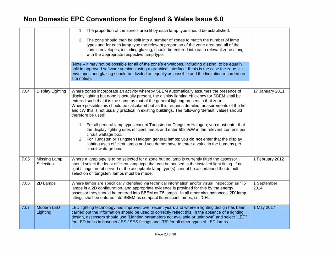
1. The proportion of the zone’s area lit by each lamp type should be established.
2. The zone should then be split into a number of zones to match the number of lamp types and for each lamp type the relevant proportion of the zone area and all of the zone’s envelopes, including glazing, should be entered into each relevant zone along with the appropriate respective lamp type.
(Note – it may not be possible for all of the zone’s envelopes, including glazing, to be equally split in approved software versions using a graphical interface. If this is the case the zone, its envelopes and glazing should be divided as equally as possible and the limitation recorded on site notes).
7.04 Display Lighting Where zones incorporate an activity whereby SBEM automatically assumes the presence of display lighting but none is actually present, the display lighting efficiency for SBEM shall be entered such that it is the same as that of the general lighting present in that zone. Where possible this should be calculated but as this requires detailed measurements of the lm and cW this is not usually practical in existing buildings. The following ‘default’ values should therefore be used:
1. For all general lamp types except Tungsten or Tungsten Halogen; you must enter that the display lighting uses efficient lamps and enter 50lm/cW in the relevant Lumens per circuit wattage box.
2. For Tungsten or Tungsten Halogen general lamps; you do not enter that the display lighting uses efficient lamps and you do not have to enter a value in the Lumens per circuit wattage box.
17 January 2011
7.05 Missing Lamp Selection
Where a lamp type is to be selected for a zone but no lamp is currently fitted the assessor should select the least efficient lamp type that can be housed in the installed light fitting. If no light fittings are observed or the acceptable lamp type(s) cannot be ascertained the default selection of ‘tungsten’ lamps must be made.
1 February 2012
7.06 2D Lamps Where lamps are specifically identified via technical information and/or visual inspection as ‘T5’ lamps in a 2D configuration, and appropriate evidence is provided for this by the energy assessor they should be entered into SBEM as T5 lamps. In all other circumstances ‘2D’ lamp fittings shall be entered into SBEM as compact fluorescent lamps, i.e. ‘CFL’.
1 September 2014
7.07 Modern LED Lighting
LED lighting technology has improved over recent years and where a lighting design has been carried out the information should be used to correctly reflect this. In the absence of a lighting design, assessors should use “Lighting parameters not available or unknown” and select “LED” for LED bulbs in bayonet / ES / SES fittings and “T5” for all other types of LED lamps.
1 May 2017
Non Domestic EPC Conventions for England & Wales Issue 6.0
Page 24 of 38
8. EPBD Audit Trail
9. Recommendations
10. Appendices
10.01 Commercial EPC Conventions
Glossary of Terms – Issue 1
Updated Glossary of Terms – Issue 2
Updated Glossary of Terms – Issue 4
Updated Glossary of Terms – Issue 5
1 June 2010
17 January 2011
30 November 2012
1 September 2014
Non Domestic EPC Conventions for England & Wales Issue 6.0
Page 25 of 38
Glossary of Terms
Air Permeability
Air permeability is expressed as volume flow per hour (m3 h) of air supplied to the space per square metre (m2) of envelope area for an internal to external pressure difference of 50 Pa i.e. 25 m3 hr-1 m-2 at 50Pa.
Atrium
In this context, a non-continuously occupied interior space within a building, often several stories high, bounded on at least one side by occupied spaces set to the conditions determined from the activity database. There may or may not be building elements (such as glazing) surrounding the atrium (although there may need to be something for smoke control in case of fire). The atrium itself is not maintained to the conditions set by the activity database for adjoining spaces. The technical purpose of the atrium can be one or more of the following:-
Providing a buffer between the thermal conditions in the adjoining spaces and the exterior, to reduce the direct impact of the exterior on those zones. In this case it should not be maintained to conditions as though it is occupied. (If it is conditioned and the features below do not apply, in this context it is not considered to be an atrium.)
Providing a means for daylight to reach the middle of deep plan spaces that would otherwise not receive it
Encouraging stack effect or other passive ventilation to draw extract air from the adjoining spaces.
Automatic Blind Control
In this context internal or inter-pane (but not exterior) blinds that are motorised so that the position can be modified to control solar heat gain and/or glare, controlled by automatic sensors. The control regime must also open the blinds as the heat gain and or daylight levels decrease, so that the use of these natural resources can be optimised for each zone. Note that exterior shading devices can be modelled using iSBEM in the definition of each window; however SBEM currently does not model the re-radiation effects of blinds where solar gain has entered the space before it is modulated by the shading device.
Demand Controlled Ventilation
Is defined as supply and/or extract ventilation that is modulated to match the needs of the actual occupation level of each zone, rather than operating at a constant level defined by the activity database. Thus the energy required to adjust the condition of the supply air and that required to move the air can be reduced. The rate of ventilation would typically be controlled by presence detectors, CO2 sensors or another device that senses the varying requirement.
Fixed Building Services
Are those which are directly attached or connected to the building and cannot be removed/disconnected without the use of tools. A portable electric heater with a plug allowing it to be removed from the building without the use of tools is not considered a fixed building service. Although the presence of such a system clearly shows there is an expectation of conditioning and an EPC is required.
Light Pipes
A light pipe is a tube/pipe, consisting of internal reflective surfaces, which channels daylight to an internal area.
Lightwell
A lightwell is a space surrounded by the walls of a building but that has no roof or glazing above it. It is therefore similar to a courtyard in appearance. The walls that surround the lightwell are exposed to external air.
Mixed Use building
A building that incorporates both commercial areas and residential spaces.
Night Ventilation Strategy
Non Domestic EPC Conventions for England & Wales Issue 6.0
Page 26 of 38
Can be defined as the presence of suitable systems, controls and operating strategy such that overnight ventilation (passive and/or mechanical) is used to cool down the exposed building mass and thereby offset daytime cooling demands. If no such operation and subsequent offset is possible through the automatic operation of systems and controls then night ventilation strategy is deemed to be not present as part of the building energy asset rating.
Self-contained dwelling
A unit designed to accommodate a single household. This would imply it has its own kitchen and bathroom.
Significant Alteration
Alterations that are covered by the Building Regulations.
Ventilation with Enhanced Thermal Coupling to Structure
This is a further development of the Night Ventilation strategy such that significant components of the building structure in addition to its ordinary surfaces are exposed to night ventilation, in order to enhance the building's capability of offsetting daytime cooling demands. An example of this procedure is the TermoDeck system where night ventilation is passed through ducts in the solid floors of the building, thereby increasing the 'coolth' contained in the thermal capacity of the building structure available to offset subsequent summertime daytime cooling loads.
Variable Speed Drive systems
HVAC system designs are increasingly incorporating variable speed drives (VSDs) to provide control, and reduce the energy consumption of, the motors on fans and pumps.
The term Variable-Speed Drive describes the equipment used to control the speed of pumps, fans and compressors. Variable speed drives may be purely mechanical, electromechanical, hydraulic, or electronic. It is generally accepted that variable speed pumping systems offer significant benefits compared to constant flow systems.
For alternating current (AC) electric motors this is achieved by controlling the frequency and/or voltage of the electrical power supplied to the motor. As the motor reduces the operating speed of the fan, pump or compressor the power required to operate the system is greatly reduced.
Non Domestic EPC Conventions for England & Wales Issue 6.0
Page 27 of 38
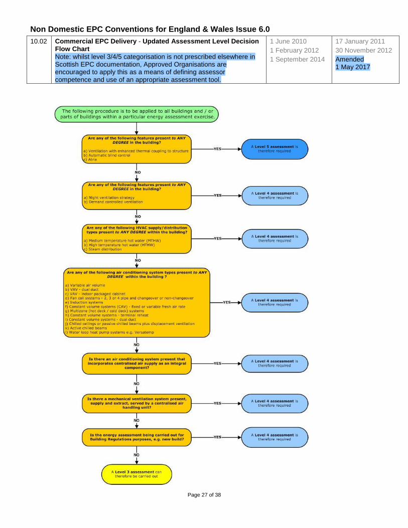
10.02
Commercial EPC Delivery - Updated Assessment Level Decision Flow Chart Note: whilst level 3/4/5 categorisation is not prescribed elsewhere in Scottish EPC documentation, Approved Organisations are encouraged to apply this as a means of defining assessor competence and use of an appropriate assessment tool.
1 June 2010
1 February 2012
1 September 2014
17 January 2011
30 November 2012
Amended 1 May 2017
Non Domestic EPC Conventions for England & Wales Issue 6.0
Page 28 of 38
Assessment Level Decision Flow Chart: Accompanying Notes
Ventilation with Enhanced Thermal Coupling to Structure
This is a further development of the Night Ventilation strategy such that significant components of the building structure in addition to its ordinary surfaces are exposed to night ventilation, in order to enhance the building's capability of offsetting daytime cooling demands. An example of this procedure is the TermoDeck system where night ventilation is passed through ducts in the solid floors of the building, thereby increasing the 'coolth' contained in the thermal capacity of the building structure available to offset subsequent summertime daytime cooling loads.
Night Ventilation Strategy
Can be defined as the presence of suitable systems, controls and operating strategy such that overnight ventilation (passive and/or mechanical) is used to cool down the exposed building mass and thereby offset daytime cooling demands. If no such operation and subsequent offset is possible through the automatic operation of systems and controls then night ventilation strategy is deemed to be not present as part of the building energy asset rating.
Demand Controlled Ventilation
Is defined as supply and/or extract ventilation that is modulated to match the needs of the actual occupation level of each zone, rather than operating at a constant level defined by the activity database. Thus the energy required to adjust the condition of the supply air and that required to move the air can be reduced. The rate of ventilation would typically be controlled by presence detectors, CO2 sensors or another device that senses the varying requirement.
Automatic Blind Control
In this context internal or inter-pane (but not exterior) blinds that are motorised so that the position can be modified to control solar heat gain and/or glare, controlled by automatic sensors. The control regime must also open the blinds as the heat gain and or daylight levels decrease, so that the use of these natural resources can be optimised for each zone. Note that exterior shading devices can be modelled using iSBEM in the definition of each window; however SBEM currently does not model the re-radiation effects of blinds where solar gain has entered the space before it is modulated by the shading device.
Atrium
In this context, a non-continuously occupied interior space within a building, often several stories high, bounded on at least one side by occupied spaces set to the conditions determined from the activity database. There may or may not be building elements (such as glazing) surrounding the atrium (although there may need to be something for smoke control in case of fire). The atrium itself is not maintained to the conditions set by the activity database for adjoining spaces. The technical purpose of the atrium can be one or more of the following :-
providing a buffer between the thermal conditions in the adjoining spaces and the exterior, to reduce the direct impact of the exterior on those zones. In this case it should not be maintained to conditions as though it is occupied. (If it is conditioned and the features below do not apply, in this context it is not considered to be an atrium.)
providing a means for daylight to reach the middle of deep plan spaces that would otherwise not receive it
encouraging stack effect or other passive ventilation to draw extract air from the adjoining spaces.
Non Domestic EPC Conventions for England & Wales Issue 6.0
Page 29 of 38
10.03
Dimensions Convention 1st June 2010
17th January 2011
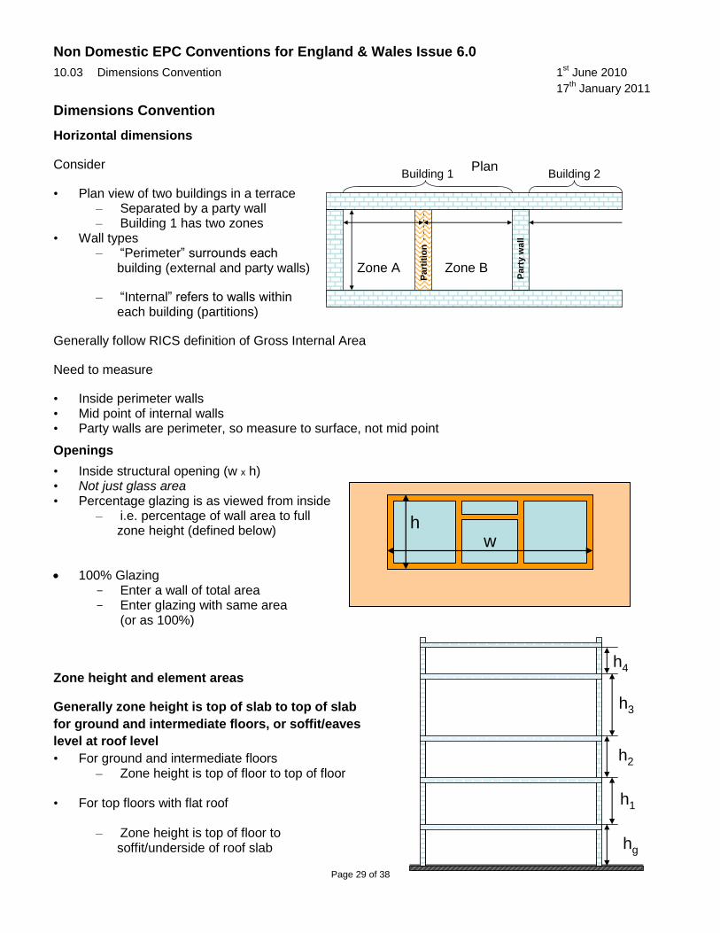
Dimensions Convention
Horizontal dimensions
Consider
• Plan view of two buildings in a terrace – Separated by a party wall – Building 1 has two zones
• Wall types – “Perimeter” surrounds each
building (external and party walls)
– “Internal” refers to walls within each building (partitions)
Generally follow RICS definition of Gross Internal Area
Need to measure
• Inside perimeter walls • Mid point of internal walls • Party walls are perimeter, so measure to surface, not mid point
Openings
• Inside structural opening (w x h) • Not just glass area • Percentage glazing is as viewed from inside
– i.e. percentage of wall area to full zone height (defined below)
100% Glazing - Enter a wall of total area - Enter glazing with same area
(or as 100%)
Zone height and element areas
Generally zone height is top of slab to top of slab
for ground and intermediate floors, or soffit/eaves
level at roof level
• For ground and intermediate floors – Zone height is top of floor to top of floor
• For top floors with flat roof – Zone height is top of floor to
soffit/underside of roof slab
Plan
Zone A Zone B
Building 1 Building 2
Part
y w
all
Part
itio
n
hg
h1
h2
h3
h4
wh
Non Domestic EPC Conventions for England & Wales Issue 6.0
Page 30 of 38
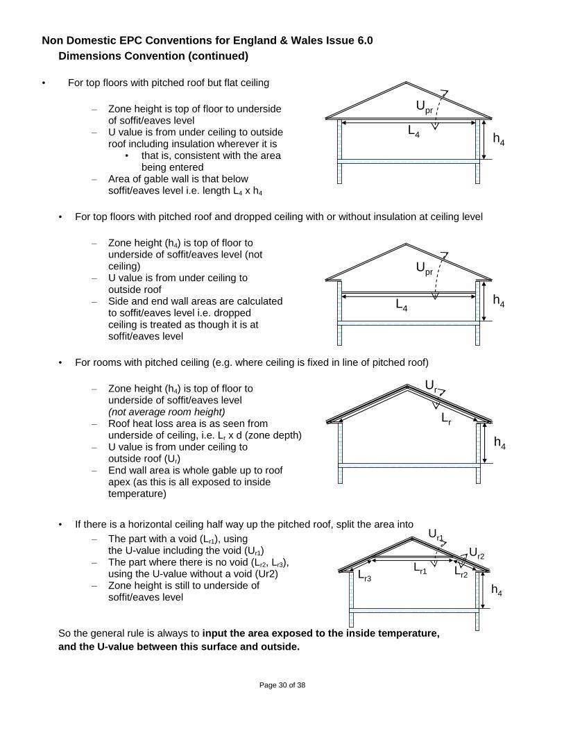
Dimensions Convention (continued)
• For top floors with pitched roof but flat ceiling
– Zone height is top of floor to underside of soffit/eaves level
– U value is from under ceiling to outside roof including insulation wherever it is
• that is, consistent with the area being entered
– Area of gable wall is that below soffit/eaves level i.e. length L4 x h4
• For top floors with pitched roof and dropped ceiling with or without insulation at ceiling level
– Zone height (h4) is top of floor to underside of soffit/eaves level (not ceiling)
– U value is from under ceiling to outside roof
– Side and end wall areas are calculated to soffit/eaves level i.e. dropped ceiling is treated as though it is at soffit/eaves level
• For rooms with pitched ceiling (e.g. where ceiling is fixed in line of pitched roof)
– Zone height (h4) is top of floor to underside of soffit/eaves level (not average room height)
– Roof heat loss area is as seen from underside of ceiling, i.e. Lr x d (zone depth)
– U value is from under ceiling to outside roof (Ur)
– End wall area is whole gable up to roof apex (as this is all exposed to inside temperature)
• If there is a horizontal ceiling half way up the pitched roof, split the area into
– The part with a void (Lr1), using the U-value including the void (Ur1)
– The part where there is no void (Lr2, Lr3), using the U-value without a void (Ur2)
– Zone height is still to underside of soffit/eaves level
So the general rule is always to input the area exposed to the inside temperature,
and the U-value between this surface and outside.
h4
Upr
L4
h4
Upr
L4
h4
Ur1
Lr1
Ur2
Lr2Lr3
h4
Ur
Lr
Non Domestic EPC Conventions for England & Wales Issue 6.0
Page 31 of 38
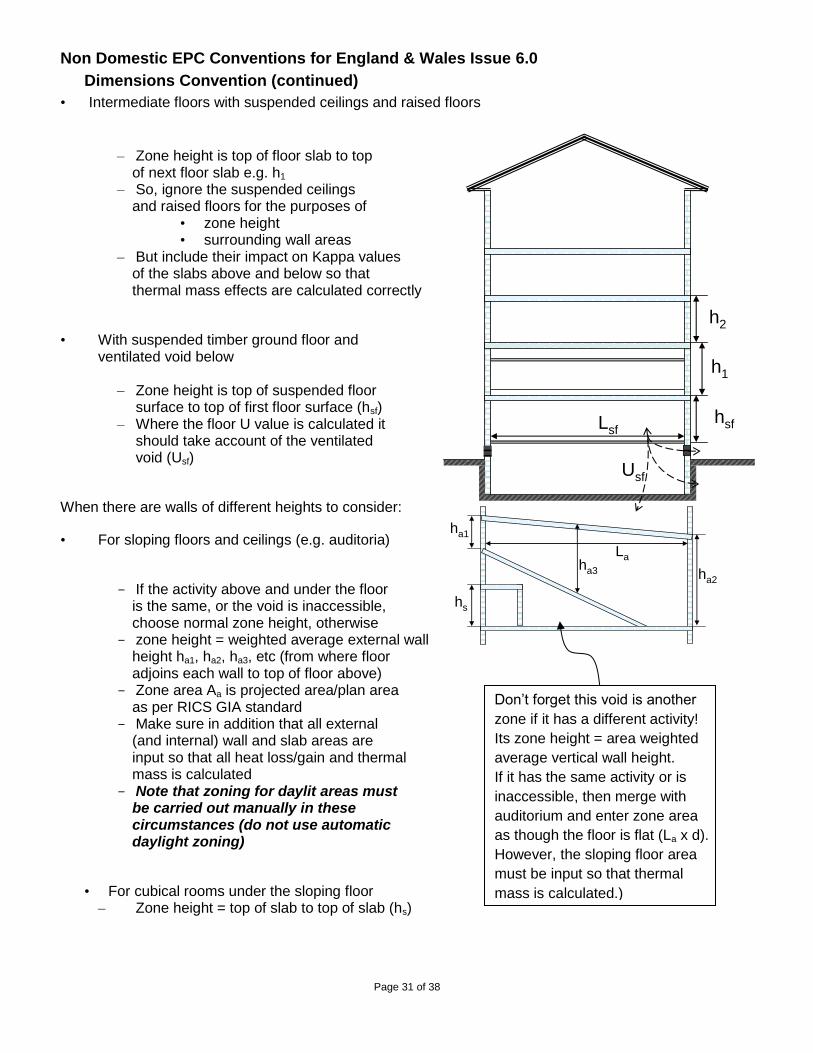
Dimensions Convention (continued)
• Intermediate floors with suspended ceilings and raised floors
– Zone height is top of floor slab to top of next floor slab e.g. h1
– So, ignore the suspended ceilings and raised floors for the purposes of
• zone height • surrounding wall areas
– But include their impact on Kappa values of the slabs above and below so that thermal mass effects are calculated correctly
• With suspended timber ground floor and ventilated void below
– Zone height is top of suspended floor surface to top of first floor surface (hsf) – Where the floor U value is calculated it should take account of the ventilated void (Usf)
When there are walls of different heights to consider:
• For sloping floors and ceilings (e.g. auditoria)
- If the activity above and under the floor is the same, or the void is inaccessible, choose normal zone height, otherwise
- zone height = weighted average external wall height ha1, ha2, ha3, etc (from where floor
adjoins each wall to top of floor above) - Zone area Aa is projected area/plan area
as per RICS GIA standard - Make sure in addition that all external
(and internal) wall and slab areas are input so that all heat loss/gain and thermal mass is calculated
- Note that zoning for daylit areas must be carried out manually in these circumstances (do not use automatic daylight zoning)
• For cubical rooms under the sloping floor – Zone height = top of slab to top of slab (hs)
hsf
h1
h2
Usf
Lsf
ha1
ha2
ha3
La
hs
Don’t forget this void is another
zone if it has a different activity!
Its zone height = area weighted
average vertical wall height.
If it has the same activity or is
inaccessible, then merge with
auditorium and enter zone area
as though the floor is flat (La x d).
However, the sloping floor area
must be input so that thermal
mass is calculated.)
Non Domestic EPC Conventions for England & Wales Issue 6.0
Page 32 of 38
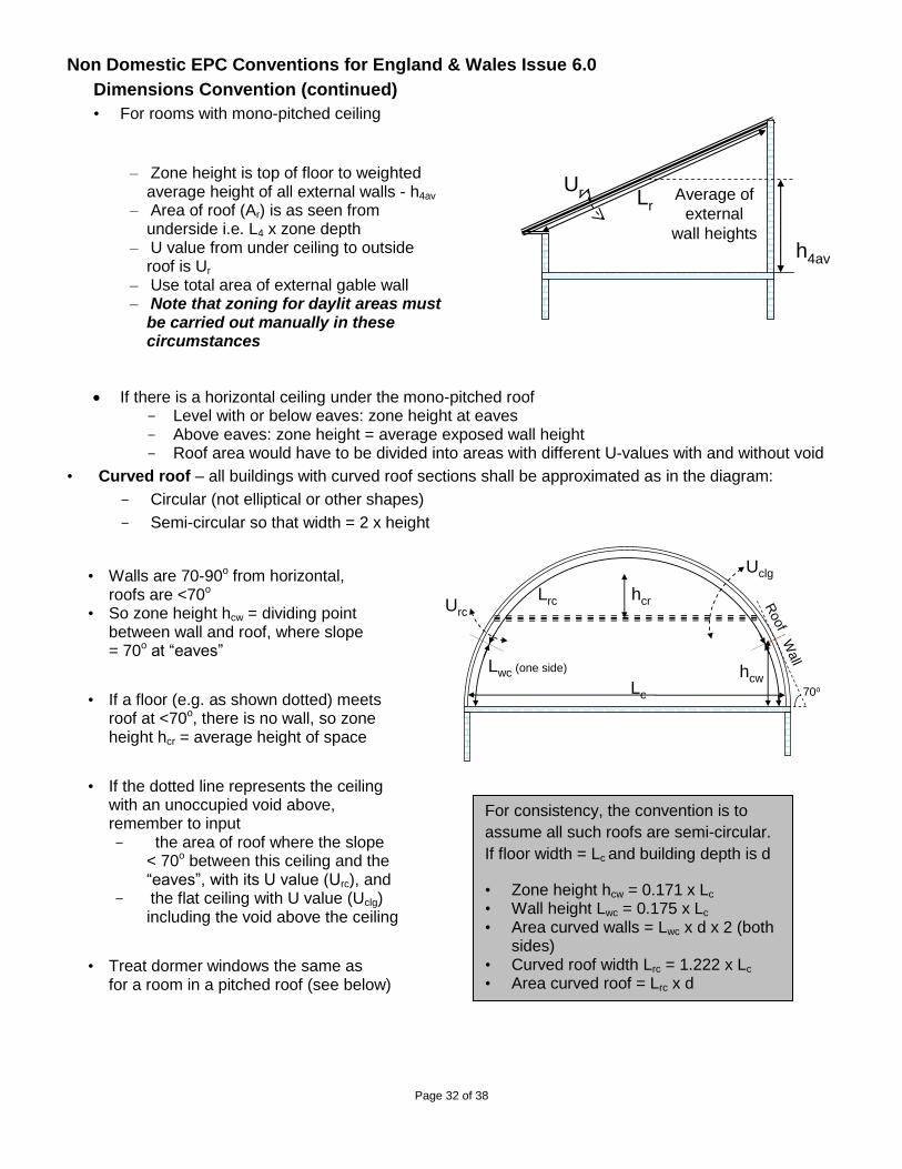
Dimensions Convention (continued)
• For rooms with mono-pitched ceiling
– Zone height is top of floor to weighted average height of all external walls - h4av
– Area of roof (Ar) is as seen from underside i.e. L4 x zone depth
– U value from under ceiling to outside roof is Ur
– Use total area of external gable wall – Note that zoning for daylit areas must
be carried out manually in these circumstances
If there is a horizontal ceiling under the mono-pitched roof - Level with or below eaves: zone height at eaves - Above eaves: zone height = average exposed wall height - Roof area would have to be divided into areas with different U-values with and without void
• Curved roof – all buildings with curved roof sections shall be approximated as in the diagram:
- Circular (not elliptical or other shapes)
- Semi-circular so that width = 2 x height
• Walls are 70-90o from horizontal, roofs are <70o
• So zone height hcw = dividing point between wall and roof, where slope = 70o at “eaves”
• If a floor (e.g. as shown dotted) meets roof at <70o, there is no wall, so zone height hcr = average height of space
• If the dotted line represents the ceiling with an unoccupied void above,
remember to input - the area of roof where the slope
< 70o between this ceiling and the “eaves”, with its U value (Urc), and
- the flat ceiling with U value (Uclg) including the void above the ceiling
• Treat dormer windows the same as for a room in a pitched roof (see below)
For consistency, the convention is to
assume all such roofs are semi-circular.
If floor width = Lc and building depth is d
• Zone height hcw = 0.171 x Lc • Wall height Lwc = 0.175 x Lc • Area curved walls = Lwc x d x 2 (both
sides) • Curved roof width Lrc = 1.222 x Lc • Area curved roof = Lrc x d
Roof
Wall
70o
hcwLc
Lwc (one side)
Lrc hcr
Uclg
Urc
h4av
Average of
external
wall heights
Ur Lr
Non Domestic EPC Conventions for England & Wales Issue 6.0
Page 33 of 38
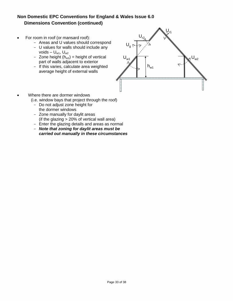
Dimensions Convention (continued)
For room in roof (or mansard roof): - Areas and U values should correspond - U values for walls should include any
voids – Uw1, Uw2 - Zone height (hw1) = height of vertical
part of walls adjacent to exterior - If this varies, calculate area weighted
average height of external walls
Where there are dormer windows (i.e. window bays that project through the roof) - Do not adjust zone height for
the dormer windows - Zone manually for daylit areas
(if the glazing > 20% of vertical wall area) - Enter the glazing details and areas as normal - Note that zoning for daylit areas must be
carried out manually in these circumstances
Ur1
Uw1 Uw2
Ur2
Ug
hw1
Non Domestic EPC Conventions for England & Wales Issue 6.0
Page 34 of 38
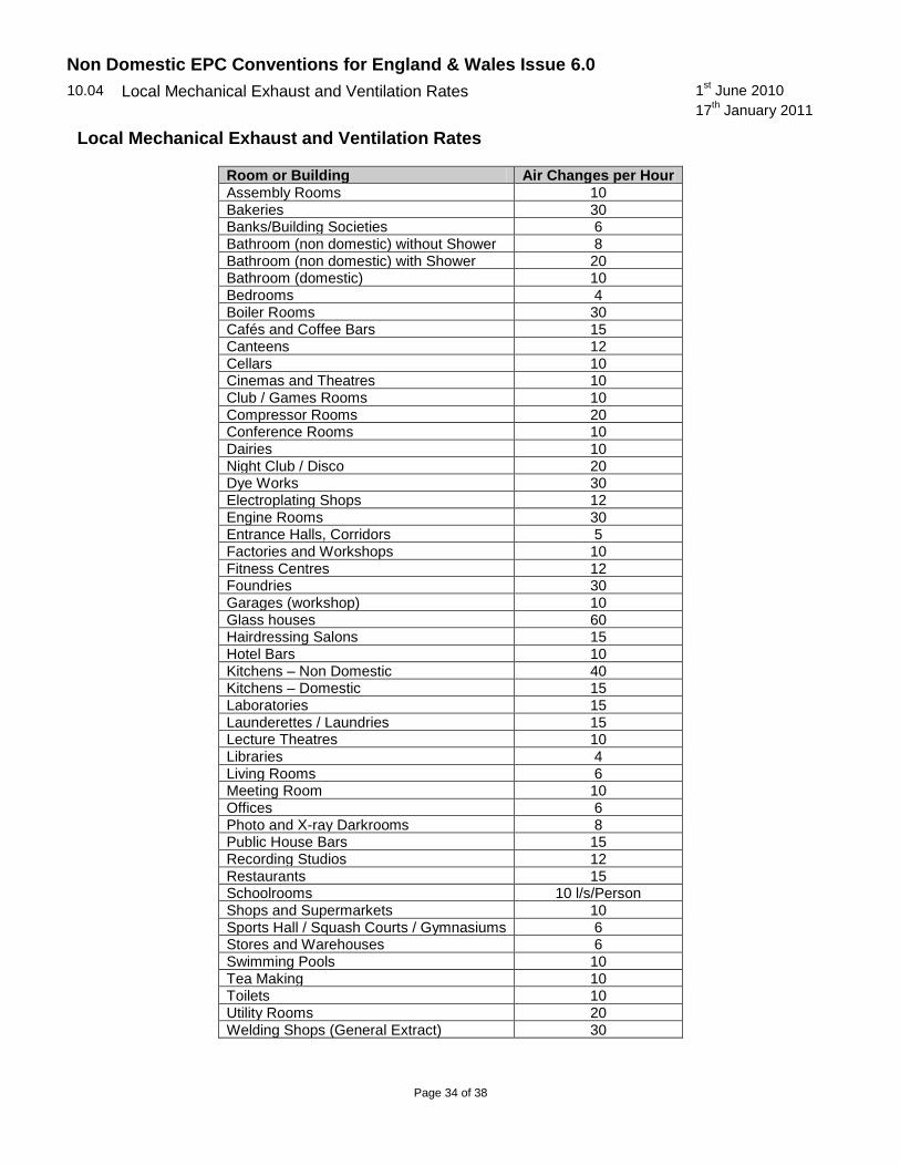
10.04
Local Mechanical Exhaust and Ventilation Rates
1st June 2010
17th January 2011
Local Mechanical Exhaust and Ventilation Rates
Room or Building Air Changes per Hour
Assembly Rooms 10 Bakeries 30 Banks/Building Societies 6 Bathroom (non domestic) without Shower 8 Bathroom (non domestic) with Shower 20 Bathroom (domestic) 10 Bedrooms 4 Boiler Rooms 30 Cafés and Coffee Bars 15 Canteens 12 Cellars 10 Cinemas and Theatres 10 Club / Games Rooms 10 Compressor Rooms 20 Conference Rooms 10 Dairies 10 Night Club / Disco 20 Dye Works 30 Electroplating Shops 12 Engine Rooms 30 Entrance Halls, Corridors 5 Factories and Workshops 10 Fitness Centres 12 Foundries 30 Garages (workshop) 10 Glass houses 60 Hairdressing Salons 15 Hotel Bars 10 Kitchens – Non Domestic 40 Kitchens – Domestic 15 Laboratories 15 Launderettes / Laundries 15 Lecture Theatres 10 Libraries 4 Living Rooms 6 Meeting Room 10 Offices 6 Photo and X-ray Darkrooms 8 Public House Bars 15 Recording Studios 12 Restaurants 15 Schoolrooms 10 l/s/Person Shops and Supermarkets 10 Sports Hall / Squash Courts / Gymnasiums 6 Stores and Warehouses 6 Swimming Pools 10 Tea Making 10 Toilets 10 Utility Rooms 20 Welding Shops (General Extract) 30

Non Domestic EPC Conventions for England & Wales Issue 6.0
Page 35 of 38
10.05
SBEM Weather Locations
1st February 2012
CL2_1 SBEM Weather Locations Lookup (v1).xls
CEPC CL2.1 SBEM Weather Locations+Post Areas.jpg
CL2_1 SBEM Weather Locations Lookup Password.xlsx
Non Domestic EPC Conventions for England & Wales Issue 6.0
Page 36 of 38
10.06
Roofs with Multiple Components 21 January 2013
Roofs with Multiple Components
Horizontal internal ceiling (Example 1) Horizontal internal ceiling (Example 2)
No horizontal internal ceiling Roof structure with number of pitched components
Non Domestic EPC Conventions for England & Wales Issue 6.0
Page 37 of 38
10.07
Zones Without Fixed Conditioning Equipment 1 September 2014
Amended 1 May 2017
Zones Without Fixed Conditioning Equipment
Is the zone subject to the requirements of a first fit out, e.g.
shell & core ?
Are fixed building services present ?
Assess on basis of fixed services
present
Assess in accordance with
Part L2 requirements
Assume a default HVAC system of fanned electric room heaters with an ‘Effective Heat
Generating Seasonal Efficiency’ of 100%, i.e. ‘1’ for the zone concerned
Yes
No
Yes
YesIs the zone considered to be
indirectly conditioned?
No
Assess on the basis of assigning the
HVAC providing the indirect conditioning
Assess for indirect conditioning in
accordance with SBEM guidance
Assess for fixed building services
Does the activity concerned appear in the list in
issued convention 6.11?
No
No
Assume that the zone is unconditioned, i.e. has ‘no
heating or cooling’Yes
Non Domestic EPC Conventions for England & Wales Issue 6.0
Page 38 of 38
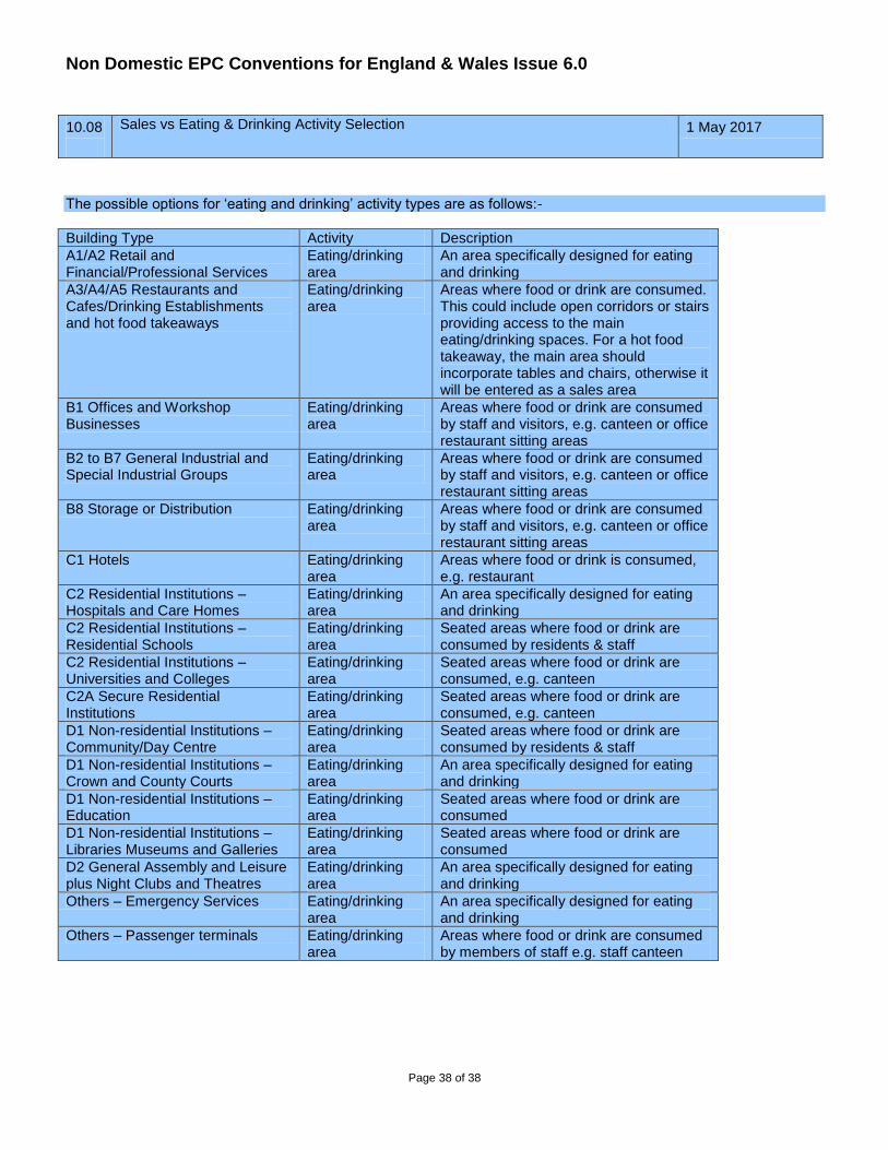
10.08
Sales vs Eating & Drinking Activity Selection 1 May 2017
The possible options for ‘eating and drinking’ activity types are as follows:-
Building Type Activity Description
A1/A2 Retail and Financial/Professional Services
Eating/drinking area
An area specifically designed for eating and drinking
A3/A4/A5 Restaurants and Cafes/Drinking Establishments and hot food takeaways
Eating/drinking area
Areas where food or drink are consumed. This could include open corridors or stairs providing access to the main eating/drinking spaces. For a hot food takeaway, the main area should incorporate tables and chairs, otherwise it will be entered as a sales area
B1 Offices and Workshop Businesses
Eating/drinking area
Areas where food or drink are consumed by staff and visitors, e.g. canteen or office restaurant sitting areas
B2 to B7 General Industrial and Special Industrial Groups
Eating/drinking area
Areas where food or drink are consumed by staff and visitors, e.g. canteen or office restaurant sitting areas
B8 Storage or Distribution Eating/drinking area
Areas where food or drink are consumed by staff and visitors, e.g. canteen or office restaurant sitting areas
C1 Hotels Eating/drinking area
Areas where food or drink is consumed, e.g. restaurant
C2 Residential Institutions – Hospitals and Care Homes
Eating/drinking area
An area specifically designed for eating and drinking
C2 Residential Institutions – Residential Schools
Eating/drinking area
Seated areas where food or drink are consumed by residents & staff
C2 Residential Institutions – Universities and Colleges
Eating/drinking area
Seated areas where food or drink are consumed, e.g. canteen
C2A Secure Residential Institutions
Eating/drinking area
Seated areas where food or drink are consumed, e.g. canteen
D1 Non-residential Institutions – Community/Day Centre
Eating/drinking area
Seated areas where food or drink are consumed by residents & staff
D1 Non-residential Institutions – Crown and County Courts
Eating/drinking area
An area specifically designed for eating and drinking
D1 Non-residential Institutions – Education
Eating/drinking area
Seated areas where food or drink are consumed
D1 Non-residential Institutions – Libraries Museums and Galleries
Eating/drinking area
Seated areas where food or drink are consumed
D2 General Assembly and Leisure plus Night Clubs and Theatres
Eating/drinking area
An area specifically designed for eating and drinking
Others – Emergency Services Eating/drinking area
An area specifically designed for eating and drinking
Others – Passenger terminals Eating/drinking area
Areas where food or drink are consumed by members of staff e.g. staff canteen