Embed Size (px)
Citation preview
2013 edition – for use in England*
Non-domestic Building Services Compliance Guide
O N L I N E V E R S I O N
O N L I N E V E R S I O N
* Note: Any reference to the Building Regulations in this guide is to the Building Regulations 2010 in England (as amended). These Regulations also apply to the following building work in Wales:
(a) work on an excepted energy building as defined in the Schedule to the Welsh Ministers (Transfer of functions) (No 2) Order 2009 (SI 2009/3019); and
(b) work that is subject to provisions of the regulations relating to energy efficiency specified in regulation 34 of the Regulations and is carried out to educational buildings, buildings of statutory undertakers and Crown buildings, or carried out by Crown authorities.
This guidance comes into effect on 6 April 2014. Work started before this date remains subject to the earlier edition of the guidance. Work subject to a building notice, full plans application or initial notice submitted before this date will also remain subject to the earlier edition of the guidance, provided it is started before 6 April 2015.
For other jurisdictions in the UK, it will be necessary to consult their own building regulations and guidance.
O N L I N E V E R S I O N
O N L I N E V E R S I O N
1
Contents
Contents
Section 1: Introduction 51.1 Scope 5
1.2 Innovative systems 6
1.3 European directives 6
1.4 Status of guide 7
1.5 How to use the guide 8
1.6 Key terms for space heating and domestic hot water systems 8
1.7 Summary of recommended minimum energy efficiency standards 9
Section 2: Gas, oil and biomass-fired boilers 142.1 Introduction 14
2.2 Scope of guidance 14
2.3 Key terms 14
2.4 Determining boiler seasonal efficiency 16
2.5 Boilers in new buildings 19
2.6 Boilers in existing buildings 20
2.7 Heating efficiency credits for replacement boilers 21
2.8 Biomass boilers 24
Section 3: Heat pumps 253.1 Introduction 25
3.2 Scope of guidance 25
3.3 Key terms 26
3.4 Heat pumps in new and existing buildings 26
3.5 Heating efficiency credits for heat pump systems in existing buildings 28
3.6 Supplementary information 30
Section 4: Gas and oil-fired warm air heaters 314.1 Introduction 31
4.2 Scope of guidance 31
4.3 Key terms 31
4.4 Warm air heaters in new and existing buildings 32
4.5 Heating efficiency credits for warm air heaters in new and existing buildings 32
O N L I N E V E R S I O N
O N L I N E V E R S I O N
2
Non-domestic Building Services Compliance Guide: 2013 Edition
Section 5: Gas and oil-fired radiant heaters 345.1 Introduction 34
5.2 Scope of guidance 34
5.3 Key terms 34
5.4 Radiant heaters 35
5.5 Heating efficiency credits for radiant heaters in existing buildings 35
Section 6: Combined heat and power and community heating 376.1 Introduction 37
6.2 Scope of guidance 37
6.3 Key terms 37
6.4 CHP in new and existing buildings 38
6.5 Supplementary information 39
Section 7: Direct electric space heating 407.1 Introduction 40
7.2 Scope of guidance 40
7.3 Electric space heating in new and existing buildings 40
Section 8: Domestic hot water 438.1 Introduction 43
8.2 Scope of guidance 43
8.3 Key terms 44
8.4 Domestic hot water systems in new and existing buildings 46
8.5 Supplementary information on electric water heaters 48
8.6 Heating efficiency credits for domestic hot water systems in new and existing buildings 49
Section 9: Comfort cooling 519.1 Introduction 51
9.2 Scope of guidance 51
9.3 Key terms 51
9.4 Comfort cooling in new and existing buildings 52
9.5 Calculating the seasonal energy efficiency ratio for SBEM 53
9.6 Supplementary information 55
O N L I N E V E R S I O N
O N L I N E V E R S I O N
3
Contents
Section 10: Air distribution 5610.1 Introduction 56
10.2 Scope of guidance 56
10.3 Key terms 56
10.4 Air distribution systems in new and existing buildings 57
10.5 Heat recovery in air distribution systems in new and existing buildings 61
10.6 Calculating the specific fan power for SBEM 61
Section 11: Pipework and ductwork insulation 6211.1 Introduction 62
11.2 Scope of guidance 62
11.3 Insulation of pipes and ducts in new and existing buildings 62
Section 12: Lighting 6512.1 Introduction 65
12.2 Scope of guidance 65
12.3 Key terms 65
12.4 Lighting in new and existing buildings 66
12.5 Lighting Energy Numerical Indicator (LENI) 68
Section 13: Heating and cooling system circulators and water pumps 7113.1 Introduction 71
13.2 Scope of guidance 71
13.3 Key terms 71
13.4 Glandless circulators and water pumps in new and existing buildings 71
13.5 Supplementary information 72
Appendix A: Abbreviations 73
O N L I N E V E R S I O N
O N L I N E V E R S I O N

4
Non-domestic Building Services Compliance Guide: 2013 EditionO N L I N E V E R S I O N
O N L I N E V E R S I O N
5
Section 1: Introduction
Section 1: Introduction
1.1 ScopeThis guide provides detailed guidance for the installation of fixed building services in new and existing non-domestic buildings to help compliance with the energy efficiency requirements of the Building Regulations.
This edition covers the design, installation and commissioning of:
• conventional means of providing primary space heating, domestic hot water, mechanical ventilation, comfort cooling and interior lighting
• low carbon generation of heat by heat pumps and combined heat and power systems.
The guide sets out recommended minimum energy efficiency standards for components of building services systems, including the use of controls. For systems installed in new buildings, the standards are design limits (or back-stop values). For new or replacement systems and components installed in existing buildings, the standards represent reasonable provision for complying with the Building Regulations.
It is important to note that standards higher than many of these recommended minimum standards will need to be achieved if:
• new buildings are to meet the the Building Regulations target carbon dioxide emission rate (TER) calculated using National Calculation Methodology (NCM) tools such as SBEM1
• systems (up to 45 kW heat output) are to comply with the Microgeneration Certification Scheme standards that enable building owners to receive payments under the Renewable Heat Incentive (RHI) and qualify for Green Deal funding
• products are to be recognised as renewable technologies under the Renewable Energy Directive.
The guide includes some supplementary information that identifies good practice design and installation standards that exceed the minimum standards in this guide. Microgeneration Certification Scheme standards2 are an example of good practice standards.
In relevant sections, the guide identifies additional non-prescriptive measures (for example additional controls) that can improve plant efficiency. These may be used to gain ‘heating efficiency credits’ to help meet the carbon dioxide emission targets for new buildings, or the recommended minimum energy efficiency standards set out in this guide for work in existing buildings.
A summary of recommended minimum energy efficiency standards is presented in Table 1 at the end of this section.
1 The National Calculation Methodology (NCM) modelling guide and the Simplified Building Energy Model (SBEM) tool can be downloaded from www.2013ncm.bre.co.uk.2 http://www.microgenerationcertification.org/mcs-standards
O N L I N E V E R S I O N
O N L I N E V E R S I O N
6
Non-domestic Building Services Compliance Guide: 2013 Edition
1.2 Innovative systemsIt is also important to note that this guide covers a range of frequently occurring situations. It deals with the most commonly used fixed building services technologies. In doing so it neither endorses these methods and technologies nor excludes other more innovative technologies that may offer an alternative means of meeting the functional requirements of the Building Regulations.
Where the alternative technology has been the subject of a recognised testing procedure that assesses its energy performance, this may be used to indicate that the system is adequately efficient. In the event that there is no recognised testing standard, suitable calculations or modelling methods may be used to show the carbon performance of the system.
1.3 European directivesThe design and installation of fixed building services products, such as boilers, circulators and heat pumps, shall at the appropriate time comply with all relevant requirements of EU directives as implemented in the United Kingdom. There are a number of directives with requirements that directly or indirectly control the energy efficiency of building services.
The Ecodesign Directive 2009/125/EC provides a framework for establishing requirements for ‘energy-related’ products placed on the EU market. Current requirements cover ‘energy-using’ products such as boilers, light bulbs and washing machines. In the future, requirements will also cover products such as windows, insulation material and shower heads whose use has an impact on energy consumption.
The requirements are set out in Commission Regulations listed in the document http://ec.europa.eu/energy/efficiency/ecodesign/doc/overview_legislation_eco-design.pdf. Products covered by the regulations can only be CE-marked and placed on the market if they meet the ecodesign standards specified.
At the time of preparation of this guide, Commission Regulations existed or were being developed for:
• space heaters and combination heaters
• water heaters and hot water storage tanks
• glandless standalone circulators and glandless circulators integrated in products
• water pumps
• air conditioners and comfort fans
• industrial fan motors
• lighting products in the domestic and tertiary sectors
• electric motors.
The intention is that the recommended minimum product standards in this guide should at least match the energy efficiency standards set out in Commission Regulations as they come into force. For example, although the implementing regulations for hot water storage tanks were published in September 2013, the standards do not come into force until September 2017.
If in any doubt as to whether a product is subject to minimum ecodesign standards, check the Commission document above.
The Energy Labelling Directive 2010/30/EU complements the Ecodesign Directive by providing a framework for labelling of energy-related products including lamps, luminaires, household air conditioners and washing machines. The Energy Label classifies products on an A to G scale, ‘pulling’ the market towards more efficient products by better informing consumers. The Ecodesign Directive, by contrast, uses regulation to ‘push’ the market away from the worst performing products.
O N L I N E V E R S I O N
O N L I N E V E R S I O N
7
Section 1: Introduction
The Renewable Energy Directive 2009/28/EC provides a framework for the promotion of energy from renewable resources. It sets a mandatory UK target of 15% energy generation from renewable sources by 2020 – the ‘renewable energy obligation’ – as a contribution to meeting the EU’s overall target of 20%. Of relevance to building services is that it includes criteria for training and certification of installers of renewables. The directive also specifies in Annex VII the standards that heat pumps must achieve to be recognised as renewable technologies by the directive.
The Energy Efficiency Directive 2012/27/EU establishes a common framework of measures for the promotion of energy efficiency within the EU in order to ensure that the EU meets its target of a 20% reduction in primary energy consumption by 2020. Legislation to implement the directive in the UK will be published by 5 June 2014. Included will be requirements for public authorities to purchase only energy-efficient products, services and buildings; and requirements for heat meters to be fitted in apartments and buildings connected to a central source of heating or district heating network. For more information on the specific requirements and technical standards, see the DECC website3.
The Energy Performance of Buildings Directive 2010/31/EU is a recast of the original 2002/91/EC directive, which in 2002 introduced requirements for:
• the establishment of a methodology for calculating the integrated energy performance of buildings
• minimum energy performance requirements for new buildings, and, where feasible, for larger buildings undergoing major renovation
• energy performance certification of buildings, and
• inspections of heating and air conditioning systems.
The recast directive includes a new requirement to consider, in the design of new buildings, the feasibility of using renewables and other ‘high-efficiency alternative systems’. There is no mandatory format for this assessment, but it will now be necessary to declare (through a new field in the energy performance calculation software) that it has been carried out.
The Building Regulations, which already met the original requirements in many ways (for example by setting standards for new buildings), have been amended in some places to reflect the new requirements of the directive. For guidance on the changes affecting new buildings, see Approved Document L2A. For guidance on the changes affecting major renovations, see Approved Document L2B. For guidance on other requirements relating to building certification and inspection of heating and air conditioning systems, see the DCLG website4.
1.4 Status of guideThe Building Regulations contain functional requirements, such as requirements that buildings must be structurally stable, constructed and fitted to ensure fire protection, and energy efficient. These functional requirements are often drafted in broad terms, and so it may not always be immediately clear to a person carrying out work how to comply with the relevant requirements. Consequently, the Department for Communities and Local Government issues documents, known as Approved Documents, which provide practical guidance on ways of complying with specific aspects of the Building Regulations in some of the more common building situations.
Approved Documents are not always comprehensive and may contain references to other documents which will provide more detailed information and assistance on parts of the guidance. This guide is one of those documents: it provides more detailed information on the guidance contained in Approved
3 https://www.gov.uk/government/organisations/department-of-energy-climate-change4 https://www.gov.uk/government/policies/improving-the-energy-efficiency-of-buildings-and-using-planning-to-protect-the-environment/supporting-pages/energy-performance-of-
buildings
O N L I N E V E R S I O N
O N L I N E V E R S I O N
8
Non-domestic Building Services Compliance Guide: 2013 Edition
Documents L2A and L2B about compliance with the energy efficiency requirements which apply when installing fixed building services in new and existing buildings.
If you follow the relevant guidance in an Approved Document, and in any document referred to in the Approved Document (such as this guide) which provides additional information to help you follow that guidance, there is a legal presumption that you have complied with the Building Regulations. However, in each case it is for the building control body (local authority or approved inspector) to decide whether work complies with the requirements of the Building Regulations. It is therefore sensible that you check with the building control body before starting work what they consider it is necessary for you to do to comply with the requirements of the Building Regulations.
1.5 How to use the guideThe guide is divided into the following sections:
Section 1: Introduction and summary of energy efficiency standards
Section 2: Gas, oil and biomass-fired boilers
Section 3: Heat pumps
Section 4: Gas and oil-fired warm air heaters
Section 5: Gas and oil-fired radiant heaters
Section 6: Combined heat and power and community heating
Section 7: Direct electric space heating
Section 8: Domestic hot water
Section 9: Comfort cooling
Section 10: Air distribution
Section 11: Pipework and ductwork insulation
Section 12: Interior lighting
Section 13: Heating and cooling system circulators and water pumps
Supplementary information is shown against a blue background. This may be further information to help with interpreting the minimum energy efficiency provisions needed to comply with the Building Regulations. Or it may be guidance on best practice that goes beyond the recommended minimum standards.
Key terms are printed in blue and are defined at appropriate points throughout the guide.
1.6 Key terms for space heating and domestic hot water systemsThe following general definitions are applicable to the sections that deal with space heating and hot water. Further definitions are included in later sections as appropriate.
Heat generator means a device for converting fuel or electricity into heat – e.g. a boiler or radiant heater.
Heat generator efficiency means the useful heat output divided by the energy input in the fuel (based on gross calorific value) or electricity delivered to the heat generator, as determined by the appropriate test methods for that type of heat generator.
Heat generator seasonal efficiency means the estimated seasonal heat output from the heat generator divided by the heat input. This will depend on the heat generator efficiency and the operating mode of
O N L I N E V E R S I O N
O N L I N E V E R S I O N
9
Section 1: Introduction
the heat generator over the heating season. For example, in the case of boilers it is a ‘weighted’ average of the efficiencies of the boiler at 30% and 100% of the boiler output. For other technologies the heat generator seasonal efficiency may be the same as the heat generator efficiency.
Minimum controls package means a package of controls specific to each technology that represents the recommended minimum provision necessary to meet the Building Regulations energy efficiency requirements.
Additional measures means additional controls or other measures that go beyond the recommended minimum controls package and for which heating efficiency credits are available.
Heating efficiency credits are awarded for the provision of additional measures, such as additional controls, that raise the energy efficiency of the system and go beyond recommended minimum standards. Different credits apply to the different measures that are available for heating and hot water technologies.
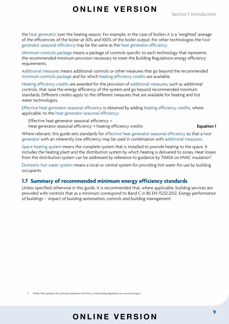
Effective heat generator seasonal efficiency is obtained by adding heating efficiency credits, where applicable, to the heat generator seasonal efficiency:
Effective heat generator seasonal efficiency =Heat generator seasonal efficiencyheating efficiency credits Equation 1
Where relevant, this guide sets standards for effective heat generator seasonal efficiency so that a heat generator with an inherently low efficiency may be used in combination with additional measures.
Space heating system means the complete system that is installed to provide heating to the space. It includes the heating plant and the distribution system by which heating is delivered to zones. Heat losses from the distribution system can be addressed by reference to guidance by TIMSA on HVAC insulation5.
Domestic hot water system means a local or central system for providing hot water for use by building occupants.
1.7 Summary of recommended minimum energy efficiency standardsUnless specified otherwise in this guide, it is recommended that, where applicable, building services are provided with controls that as a minimum correspond to Band C in BS EN 15232:2012, Energy performance of buildings – impact of building automation, controls and building management.
5 TIMSA HVAC guidance for achieving compliance with Part L of the Building Regulations at www.timsa.org.uk
O N L I N E V E R S I O N
O N L I N E V E R S I O N
10
Non-domestic Building Services Compliance Guide: 2013 Edition
6 Emerging European regulations implementing the Ecodesign Directive set minimum standards for the efficiency of energy-using products that can be placed on the market. Products should also comply with these standards as they come into effect. Current regulations are listed at http://ec.europa.eu/energy/efficiency/ecodesign/doc/overview_legislation_eco-design.pdf.
7 Efficiency is heat output divided by calorific value of fuel. The net calorific value of a fuel excludes the latent heat of water vapour in the exhaust, and so is lower than the gross calorific value. Efficiency test results and European standards normally use net calorific values.
8 Seasonal coefficient of performance (SCOP) is the current Ecodesign Directive measure for space heating air-to-air heat pumps with an output of up to 12 kW. Eventually, the measure used will be the seasonal primary energy efficiency ratio (SPEER), with testing and rating to EN 14825, Air conditioners, liquid chilling packages and heat pumps with electrically driven compressors for space heating and cooling – Testing and rating at part load conditions and calculation of seasonal performance. Energy labelling with the SPEER rating will be mandatory from 2015.
9 Rating conditions are standardised conditions provided for the determination of data presented in BS EN 14511:2007 Air conditioners, liquid chilling packages and heat pumps with electrically driven compressors for space heating and cooling.
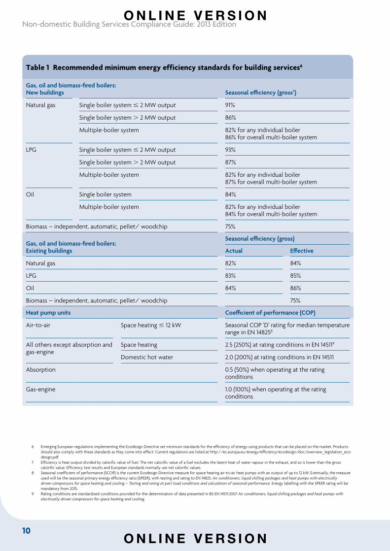
Table 1 Recommended minimum energy efficiency standards for building services6
Gas, oil and biomass-fired boilers:New buildings Seasonal efficiency (gross7)
Natural gas Single boiler system 2 MW output 91%
Single boiler system 2 MW output 86%
Multiple-boiler system 82% for any individual boiler86% for overall multi-boiler system
LPG Single boiler system 2 MW output 93%
Single boiler system 2 MW output 87%
Multiple-boiler system 82% for any individual boiler87% for overall multi-boiler system
Oil Single boiler system 84%
Multiple-boiler system 82% for any individual boiler84% for overall multi-boiler system
Biomass – independent, automatic, pellet/ woodchip 75%
Gas, oil and biomass-fired boilers:Existing buildings
Seasonal efficiency (gross)
Actual Effective
Natural gas 82% 84%
LPG 83% 85%
Oil 84% 86%
Biomass – independent, automatic, pellet/ woodchip 75%
Heat pump units Coefficient of performance (COP)
Air-to-air Space heating 12 kW Seasonal COP ‘D’ rating for median temperature range in EN 148258
All others except absorption and gas-engine
Space heating 2.5 (250%) at rating conditions in EN 145119
Domestic hot water 2.0 (200%) at rating conditions in EN 14511
Absorption 0.5 (50%) when operating at the rating conditions
Gas-engine 1.0 (100%) when operating at the rating conditions
O N L I N E V E R S I O N
O N L I N E V E R S I O N
11
Section 1: Introduction
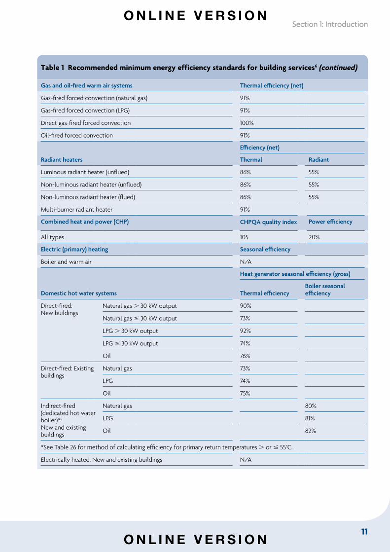
Table 1 Recommended minimum energy efficiency standards for building services6 (continued)
Gas and oil-fired warm air systems Thermal efficiency (net)
Gas-fired forced convection (natural gas) 91%
Gas-fired forced convection (LPG) 91%
Direct gas-fired forced convection 100%
Oil-fired forced convection 91%
Radiant heaters
Efficiency (net)
Thermal Radiant
Luminous radiant heater (unflued) 86% 55%
Non-luminous radiant heater (unflued) 86% 55%
Non-luminous radiant heater (flued) 86% 55%
Multi-burner radiant heater 91%
Combined heat and power (CHP) CHPQA quality index Power efficiency
All types 105 20%
Electric (primary) heating Seasonal efficiency
Boiler and warm air N/A
Domestic hot water systems
Heat generator seasonal efficiency (gross)
Thermal efficiencyBoiler seasonal efficiency
Direct-fired:New buildings
Natural gas 30 kW output 90%
Natural gas 30 kW output 73%
LPG 30 kW output 92%
LPG 30 kW output 74%
Oil 76%
Direct-fired: Existing buildings
Natural gas 73%
LPG 74%
Oil 75%
Indirect-fired (dedicated hot water boiler)*:New and existing buildings
Natural gas 80%
LPG 81%
Oil 82%
*See Table 26 for method of calculating efficiency for primary return temperatures or 55°C.
Electrically heated: New and existing buildings N/A
O N L I N E V E R S I O N
O N L I N E V E R S I O N
12
Non-domestic Building Services Compliance Guide: 2013 Edition
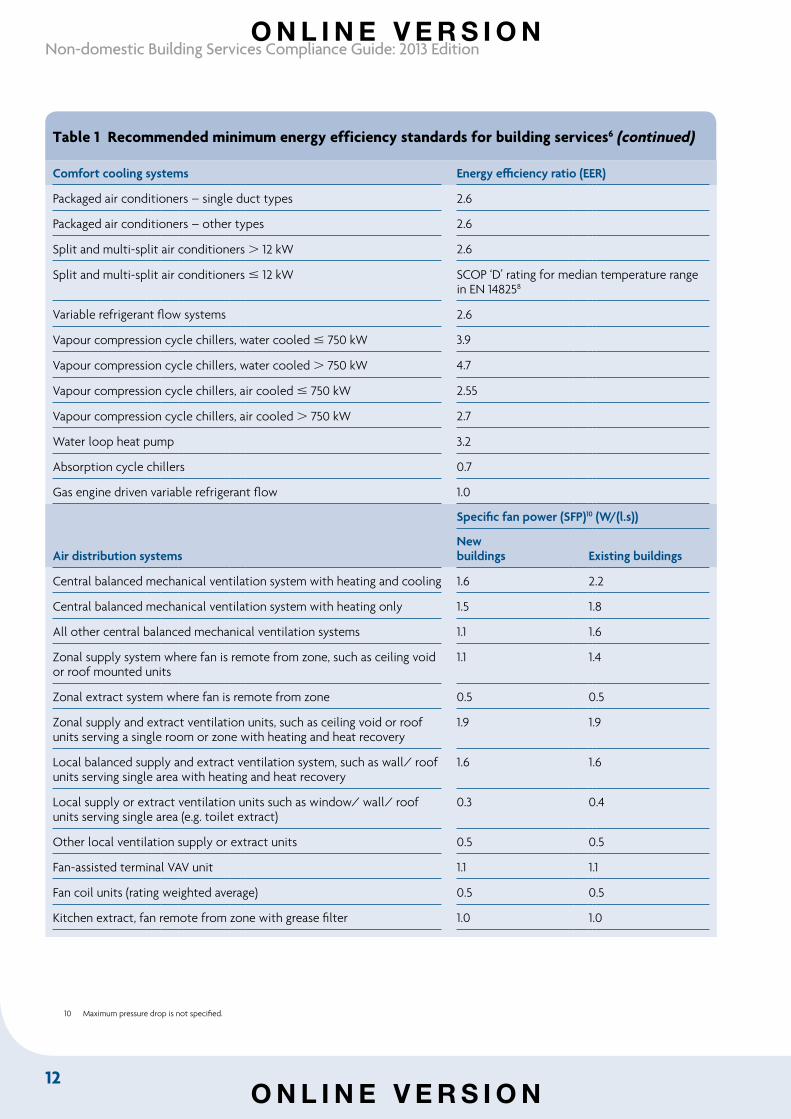
Table 1 Recommended minimum energy efficiency standards for building services6 (continued)
Comfort cooling systems Energy efficiency ratio (EER)
Packaged air conditioners – single duct types 2.6
Packaged air conditioners – other types 2.6
Split and multi-split air conditioners 12 kW 2.6
Split and multi-split air conditioners 12 kW SCOP ‘D’ rating for median temperature range in EN 148258
Variable refrigerant flow systems 2.6
Vapour compression cycle chillers, water cooled 750 kW 3.9
Vapour compression cycle chillers, water cooled 750 kW 4.7
Vapour compression cycle chillers, air cooled 750 kW 2.55
Vapour compression cycle chillers, air cooled 750 kW 2.7
Water loop heat pump 3.2
Absorption cycle chillers 0.7
Gas engine driven variable refrigerant flow 1.0
Air distribution systems
Specific fan power (SFP)10 (W/(l.s))
Newbuildings Existing buildings
Central balanced mechanical ventilation system with heating and cooling 1.6 2.2
Central balanced mechanical ventilation system with heating only 1.5 1.8
All other central balanced mechanical ventilation systems 1.1 1.6
Zonal supply system where fan is remote from zone, such as ceiling void or roof mounted units
1.1 1.4
Zonal extract system where fan is remote from zone 0.5 0.5
Zonal supply and extract ventilation units, such as ceiling void or roof units serving a single room or zone with heating and heat recovery
1.9 1.9
Local balanced supply and extract ventilation system, such as wall/ roof units serving single area with heating and heat recovery
1.6 1.6
Local supply or extract ventilation units such as window/ wall/ roof units serving single area (e.g. toilet extract)
0.3 0.4
Other local ventilation supply or extract units 0.5 0.5
Fan-assisted terminal VAV unit 1.1 1.1
Fan coil units (rating weighted average) 0.5 0.5
Kitchen extract, fan remote from zone with grease filter 1.0 1.0
10 Maximum pressure drop is not specified.
O N L I N E V E R S I O N
O N L I N E V E R S I O N
13
Section 1: Introduction
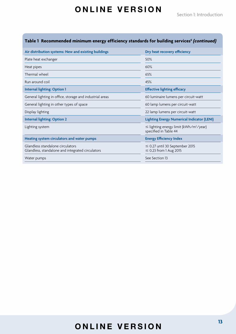
Table 1 Recommended minimum energy efficiency standards for building services6 (continued)
Air distribution systems: New and existing buildings Dry heat recovery efficiency
Plate heat exchanger 50%
Heat pipes 60%
Thermal wheel 65%
Run around coil 45%
Internal lighting: Option 1 Effective lighting efficacy
General lighting in office, storage and industrial areas 60 luminaire lumens per circuit-watt
General lighting in other types of space 60 lamp lumens per circuit-watt
Display lighting 22 lamp lumens per circuit-watt
Internal lighting: Option 2 Lighting Energy Numerical Indicator (LENI)
Lighting system lighting energy limit (kWh/m2/year) specified in Table 44
Heating system circulators and water pumps Energy Efficiency Index
Glandless standalone circulatorsGlandless, standalone and integrated circulators
0.27 until 30 September 2015 0.23 from 1 Aug 2015
Water pumps See Section 13
O N L I N E V E R S I O N
O N L I N E V E R S I O N
14
Non-domestic Building Services Compliance Guide: 2013 Edition
Section 2: Gas, oil and biomass-fired boilers
2.1 IntroductionThis section provides guidance on specifying gas, oil and biomass-fired space heating systems for new and existing buildings to meet relevant energy efficiency requirements in the Building Regulations. It covers relevant boiler types, and describes measures, such as additional controls, that can be used to gain heating efficiency credits to improve the heat generator seasonal efficiency.
2.2 Scope of guidanceThe guidance applies to wet central heating systems using commercial boilers fired by:
• natural gas
• liquid petroleum gas (LPG)
• oil, and
• biomass.
The guidance in this section does not cover:
• steam boilers (as these are used primarily for processes rather than provision of space heating), or
• electric boilers (for which see Section 7).
2.3 Key terms The terminology used to describe efficiencies for boiler systems is detailed below. In this section the heat generator is a boiler.
Biomass means all material of biological origin, excluding material embedded in geological formations and transformed to fossil fuel.
Boiler efficiency means the energy delivered by the water as it leaves the boiler (or boilers in multi-boiler installations) to supply the heat emitters, divided by the energy (based on gross calorific value) in the fuel delivered to the boiler, expressed as a percentage. It is an expression of the boiler’s performance and excludes energy used by boiler auxiliary controls, pumps, boiler room ventilation fans, mechanical flue extraction fans and fan dilution systems. The boiler efficiency is measured according to the standards that are used to demonstrate compliance with the Boiler Efficiency Directive11.
Effective boiler seasonal efficiency is the boiler seasonal efficiency (as calculated by Equation 2 below for individual boilers, or by Equation 3.1 for multiple boilers), plus any applicable heating efficiency credits.
Economiser means a device, including a secondary heat exchanger fitted on or near to a boiler, which provides additional heat transfer capacity. For the purposes of this guide, any boiler which will be supplied with an economiser should have the economiser fitted when the boiler efficiency is tested according to the standards that are used to demonstrate compliance with the Boiler Efficiency Directive. The effect of this on the boiler efficiency at 30% and 100% of the boiler output may be taken into
11 Council Directive 92/42/EEC (the Boiler Efficiency Directive) relates to the efficiency requirements for new hot water boilers fired with liquid or gaseous fuels. The associated UK legislation is the Boiler (Efficiency) Regulations 1993 (SI 1993/3083), amended by the Boiler (Efficiency) (Amendment) Regulations 1994 (SI 1994/3083).
O N L I N E V E R S I O N
O N L I N E V E R S I O N
15
Section 2: Gas, oil and biomass-fired boilers
account in the values used for the calculation of the boiler seasonal efficiency using Equations 2 or 3.1, or the three-step method and Equations 3.2 and 3.3, as appropriate.
Condensing boiler means a boiler that offers a higher energy efficiency by recovering heat from the flue gases. This is achieved by increasing the heat exchanger surface area, which recovers extra sensible heat whenever the boiler fires. The boiler becomes even more efficient when system water temperatures are low because the larger heat exchanger area promotes condensation, allowing much of the latent heat to be recaptured. Standing losses (when the boiler is not firing) are low, and part load performance is very good. In multiple-boiler systems, condensing boilers can be used as the lead boiler.
Standard boiler means, in the context of this document, a non-condensing boiler.
Zone control means independent control of rooms or areas within buildings that need to be heated to different temperatures at different times. Where several rooms or areas of a building behave in a similar manner, they can be grouped together as a ‘zone’ and put on the same circuit and controller.
Sequence control enables two or more heating boilers to be switched on or off in sequence when the heating load changes. This maximises the efficiency of the boilers, so reducing fuel consumption, and reduces wear and tear on the boilers.
Direct acting weather compensation is a type of control that enables a heat generator to work at its optimum efficiency. The control allows the boiler to vary its operating flow temperature to suit the external temperature conditions and the temperatures inside the building. Weather compensation relies on communication between an external sensor and one inside the boiler. The boiler’s water flow temperature is varied accordingly, so that energy is not wasted by the boiler turning on and off.
Weather compensation via a mixing valve is similar to direct acting weather compensation, except that the outside temperature is used to control the temperature of water supplied to the heat emitters by mixing the boiler flow and return rather than by altering the boiler temperature.
Optimum start is a control system or algorithm which starts plant operation at the latest time possible to achieve specified conditions at the start of the occupancy period.
Optimiser is a control system employing an optimum start algorithm.
Optimum stop is a control system or algorithm which stops plant operation at the earliest possible time such that internal conditions will not deteriorate beyond preset limits by the end of the occupancy period.
Two-stage burner control is a type of control that offers two distinct boiler firing rates.
Multi-stage burner control is a type of control that offers more than two distinct firing rates, but without continuous adjustment between firing rates.
Modulating burner control is a type of control that provides a continuously variable firing rate, which is altered to match the boiler load over the whole turndown ratio.
Decentralisation means the replacement of centralised boiler plant and its associated distribution pipework with several smaller, more accurately sized boiler plants, installed within or adjacent to the buildings or systems they serve. This eliminates long pipe runs between buildings or through unheated areas, so reducing heat losses.
Building management system (BMS) means a building wide network which allows communication with and control of items of HVAC plant (and other building systems) from a single control centre, which may be local or remote. More advanced (‘full’) building management systems offer a wide range of functions, including sequential control, zone control, weather compensation, frost protection and night set-back, as well as monitoring and targeting.
O N L I N E V E R S I O N
O N L I N E V E R S I O N
16
Non-domestic Building Services Compliance Guide: 2013 Edition
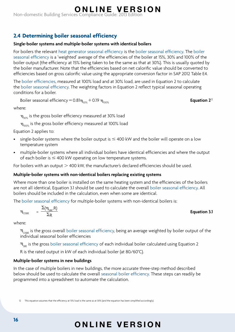
2.4 Determining boiler seasonal efficiencySingle-boiler systems and multiple-boiler systems with identical boilers
For boilers the relevant heat generator seasonal efficiency is the boiler seasonal efficiency. The boiler seasonal efficiency is a ‘weighted’ average of the efficiencies of the boiler at 15%, 30% and 100% of the boiler output (the efficiency at 15% being taken to be the same as that at 30%). This is usually quoted by the boiler manufacturer. Note that the efficiencies based on net calorific value should be converted to efficiencies based on gross calorific value using the appropriate conversion factor in SAP 2012 Table E4.
The boiler efficiencies, measured at 100% load and at 30% load, are used in Equation 2 to calculate the boiler seasonal efficiency. The weighting factors in Equation 2 reflect typical seasonal operating conditions for a boiler.
Boiler seasonal efficiency0.8130%0.19
100% Equation 212
where:
30%
is the gross boiler efficiency measured at 30% load
100%
is the gross boiler efficiency measured at 100% load
Equation 2 applies to:
• single-boiler systems where the boiler output is 400 kW and the boiler will operate on a low temperature system
• multiple-boiler systems where all individual boilers have identical efficiencies and where the output of each boiler is 400 kW operating on low temperature systems.
For boilers with an output 400 kW, the manufacturer’s declared efficiencies should be used.
Multiple-boiler systems with non-identical boilers replacing existing systems
Where more than one boiler is installed on the same heating system and the efficiencies of the boilers are not all identical, Equation 3.1 should be used to calculate the overall boiler seasonal efficiency. All boilers should be included in the calculation, even when some are identical.
The boiler seasonal efficiency for multiple-boiler systems with non-identical boilers is:
OSBE =
S(SBE
.R)Equation 3.1
SR
where:
OSBE
is the gross overall boiler seasonal efficiency, being an average weighted by boiler output of the individual seasonal boiler efficiencies
SBE
is the gross boiler seasonal efficiency of each individual boiler calculated using Equation 2
R is the rated output in kW of each individual boiler (at 80/60°C).
Multiple-boiler systems in new buildings
In the case of multiple boilers in new buildings, the more accurate three-step method described below should be used to calculate the overall seasonal boiler efficiency. These steps can readily be programmed into a spreadsheet to automate the calculation.
12 This equation assumes that the efficiency at 15% load is the same as at 30% (and the equation has been simplified accordingly).
O N L I N E V E R S I O N
O N L I N E V E R S I O N
17
Section 2: Gas, oil and biomass-fired boilers
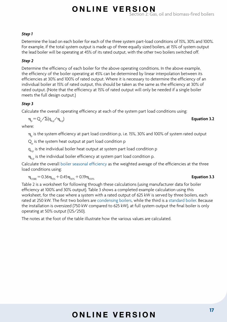
Step 1
Determine the load on each boiler for each of the three system part-load conditions of 15%, 30% and 100%. For example, if the total system output is made up of three equally sized boilers, at 15% of system output the lead boiler will be operating at 45% of its rated output, with the other two boilers switched off.
Step 2
Determine the efficiency of each boiler for the above operating conditions. In the above example, the efficiency of the boiler operating at 45% can be determined by linear interpolation between its efficiencies at 30% and 100% of rated output. Where it is necessary to determine the efficiency of an individual boiler at 15% of rated output, this should be taken as the same as the efficiency at 30% of rated output. (Note that the efficiency at 15% of rated output will only be needed if a single boiler meets the full design output.)
Step 3
Calculate the overall operating efficiency at each of the system part load conditions using:
pQ
p/S(q
b,p/
b,p) Equation 3.2
where:
p is the system efficiency at part load condition p, i.e. 15%, 30% and 100% of system rated output
Qp is the system heat output at part load condition p
qb,p
is the individual boiler heat output at system part load condition p
b,p
is the individual boiler efficiency at system part load condition p.
Calculate the overall boiler seasonal efficiency as the weighted average of the efficiencies at the three load conditions using:
OSBE
0.3615%
0.4530%
0.19100%
Equation 3.3
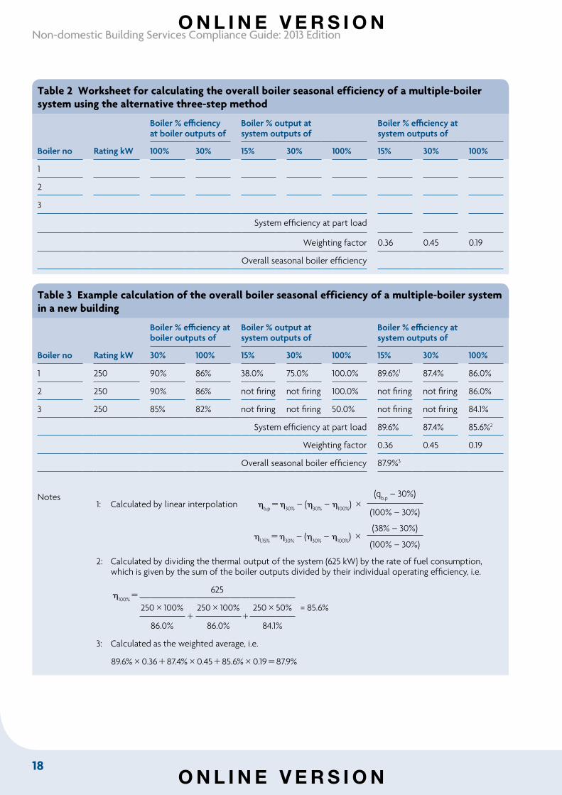
Table 2 is a worksheet for following through these calculations (using manufacturer data for boiler efficiency at 100% and 30% output). Table 3 shows a completed example calculation using this worksheet, for the case where a system with a rated output of 625 kW is served by three boilers, each rated at 250 kW. The first two boilers are condensing boilers, while the third is a standard boiler. Because the installation is oversized (750 kW compared to 625 kW), at full system output the final boiler is only operating at 50% output (125/250).
The notes at the foot of the table illustrate how the various values are calculated.
O N L I N E V E R S I O N
O N L I N E V E R S I O N
18
Non-domestic Building Services Compliance Guide: 2013 Edition
Table 2 Worksheet for calculating the overall boiler seasonal efficiency of a multiple-boiler system using the alternative three-step method
Boiler % efficiency at boiler outputs of
Boiler % output at system outputs of
Boiler % efficiency at system outputs of
Boiler no Rating kW 100% 30% 15% 30% 100% 15% 30% 100%
1
2
3
System efficiency at part load
Weighting factor 0.36 0.45 0.19
Overall seasonal boiler efficiency
Table 3 Example calculation of the overall boiler seasonal efficiency of a multiple-boiler system in a new building
Boiler % efficiency at boiler outputs of
Boiler % output at system outputs of
Boiler % efficiency at system outputs of
Boiler no Rating kW 30% 100% 15% 30% 100% 15% 30% 100%
1 250 90% 86% 38.0% 75.0% 100.0% 89.6%1 87.4% 86.0%
2 250 90% 86% not firing not firing 100.0% not firing not firing 86.0%
3 250 85% 82% not firing not firing 50.0% not firing not firing 84.1%
System efficiency at part load 89.6% 87.4% 85.6%2
Weighting factor 0.36 0.45 0.19
Overall seasonal boiler efficiency 87.9%3
Notes 1: Calculated by linear interpolation
b,p
30% – (
30% –
100%)
(qb,p
– 30%)
(100% – 30%)
1,15%
30%
– (30%
– 100%
) (38% – 30%)
(100% – 30%)
2: Calculated by dividing the thermal output of the system (625 kW) by the rate of fuel consumption, which is given by the sum of the boiler outputs divided by their individual operating efficiency, i.e.
100%
625
250100%
250100%
25050% = 85.6%
86.0% 86.0% 84.1%
3: Calculated as the weighted average, i.e.
89.6%0.3687.4%0.4585.6%0.1987.9%
O N L I N E V E R S I O N
O N L I N E V E R S I O N
19
Section 2: Gas, oil and biomass-fired boilers
2.5 Boilers in new buildingsBackground
New buildings should be provided with high efficiency condensing or non-condensing boilers that meet the recommended minimum standards for heat generator seasonal efficiency in this guide.
Commercial heating systems are inherently more complicated than domestic systems with a wider range of temperatures and heat emitters. The selection of condensing or non-condensing boilers will be determined by application and physical constraints.
Note: Water quality can have a major impact on system efficiency. It is important that designers take appropriate measures to ensure that the system water is of good quality.
Condensing boilers will meet projected efficiencies only when they operate with a system return temperature between 30°C and 40°C for 80% of the annual operating hours. With a return temperature of 55°C and above, condensing boilers will not produce condensate and will have similar efficiencies to non-condensing high efficiency boilers. Some systems are suitable for weather compensation, which allows return temperatures to fall into the condensing range for some periods of the heating season, and they may be best served by a mixture of condensing and non-condensing boilers.
The efficiency value that should be entered into accredited NCM tools to calculate the carbon dioxide emission rate is the effective heat generator seasonal efficiency. For boilers in new buildings, no heating efficiency credits can be gained and the effective heat generator seasonal efficiency is therefore the same as the heat generator seasonal efficiency.
Recommended minimum standards
To meet relevant energy efficiency requirements in the Building Regulations when installing boiler plant in new buildings:
a. where a single boiler is used to meet the heat demand, its boiler seasonal efficiency (gross calorific value) calculated using Equation 2 should be not less than the value in Table 4
b. for multiple-boiler systems, the boiler seasonal efficiency of each boiler should be not less than 82% (gross calorific value), as calculated using Equation 2; and the overall boiler seasonal efficiency of the multiple-boiler system, as defined by the three-step method and calculated using Equations 3.2 and 3.3, should be not less than the value in Table 4
c. the relevant minimum controls package in Table 5 should be adopted.
O N L I N E V E R S I O N
O N L I N E V E R S I O N
20
Non-domestic Building Services Compliance Guide: 2013 Edition
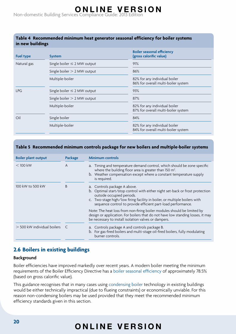
Table 4 Recommended minimum heat generator seasonal efficiency for boiler systems in new buildings
Fuel type SystemBoiler seasonal efficiency(gross calorific value)
Natural gas Single boiler 2 MW output 91%
Single boiler 2 MW output 86%
Multiple-boiler 82% for any individual boiler86% for overall multi-boiler system
LPG Single boiler 2 MW output 93%
Single boiler 2 MW output 87%
Multiple-boiler 82% for any individual boiler87% for overall multi-boiler system
Oil Single boiler 84%
Multiple-boiler 82% for any individual boiler84% for overall multi-boiler system
Table 5 Recommended minimum controls package for new boilers and multiple-boiler systems
Boiler plant output Package Minimum controls
100 kW A a. Timing and temperature demand control, which should be zone specific where the building floor area is greater than 150 m2.
b. Weather compensation except where a constant temperature supply is required.
100 kW to 500 kW B a. Controls package A above.b. Optimal start/stop control with either night set-back or frost protection
outside occupied periods.c. Two-stage high/low firing facility in boiler, or multiple boilers with
sequence control to provide efficient part-load performance.
Note: The heat loss from non-firing boiler modules should be limited by design or application. For boilers that do not have low standing losses, it may be necessary to install isolation valves or dampers.
500 kW individual boilers C a. Controls package A and controls package B.b. For gas-fired boilers and multi-stage oil-fired boilers, fully modulating
burner controls.
2.6 Boilers in existing buildingsBackground
Boiler efficiencies have improved markedly over recent years. A modern boiler meeting the minimum requirements of the Boiler Efficiency Directive has a boiler seasonal efficiency of approximately 78.5% (based on gross calorific value).
This guidance recognises that in many cases using condensing boiler technology in existing buildings would be either technically impractical (due to flueing constraints) or economically unviable. For this reason non-condensing boilers may be used provided that they meet the recommended minimum efficiency standards given in this section.
O N L I N E V E R S I O N
O N L I N E V E R S I O N
21
Section 2: Gas, oil and biomass-fired boilers
Replacement boilers
To meet relevant energy efficiency requirements in the Building Regulations when installing boiler plant in existing buildings:
a. the boiler seasonal efficiency of each boiler (in a single-boiler system or a multiple-boiler system with identical boilers) calculated using Equation 2 should be not less than the value in Table 6
b. for multiple-boiler systems using non-identical boilers, the overall boiler seasonal efficiency calculated using Equation 3.1 should be not less than the value in Table 6
c. the controls package in Table 7 should be adopted – i.e. zone control, demand control and time control
d. the effective boiler seasonal efficiency should be not less than the value in Table 6. To meet the standard, it may be necessary to adopt additional measures from Table 8 in order to gain heating efficiency credits (see below).
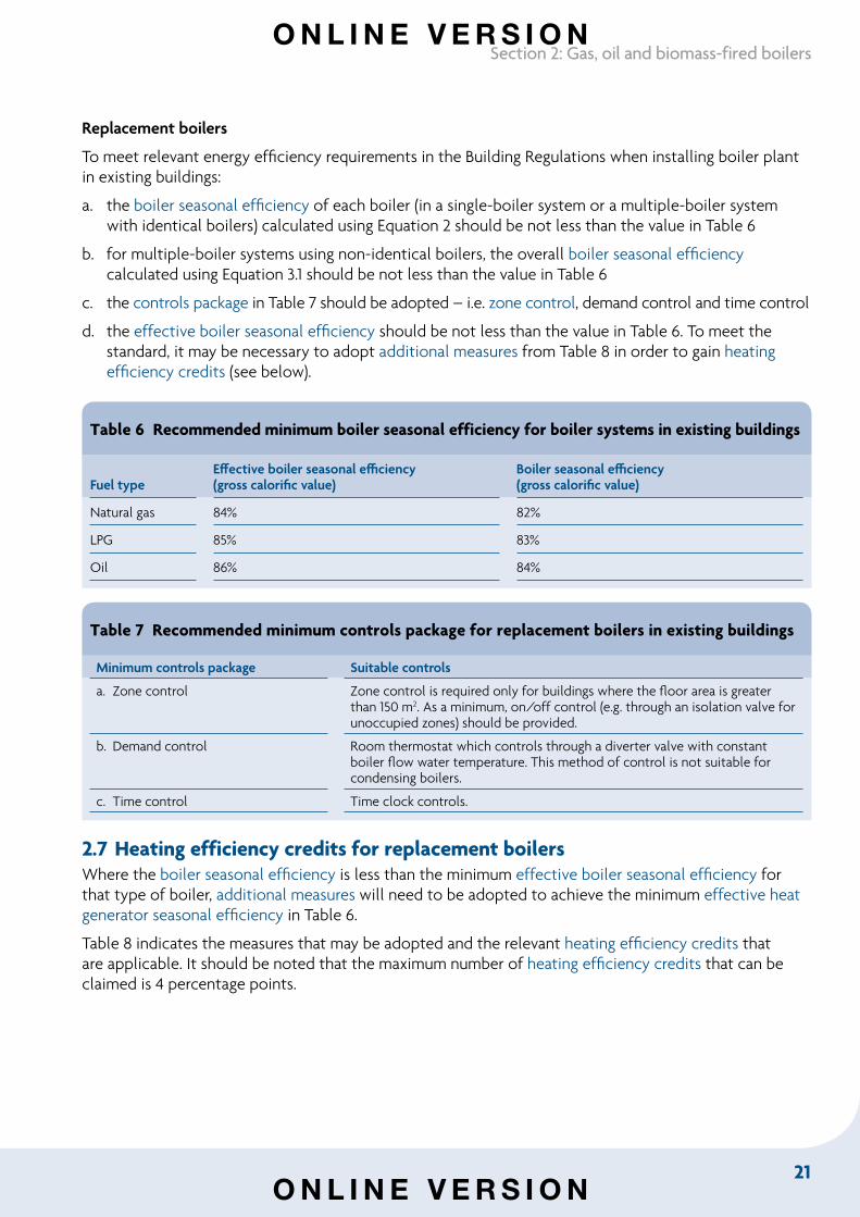
Table 6 Recommended minimum boiler seasonal efficiency for boiler systems in existing buildings
Fuel typeEffective boiler seasonal efficiency(gross calorific value)
Boiler seasonal efficiency(gross calorific value)
Natural gas 84% 82%
LPG 85% 83%
Oil 86% 84%
Table 7 Recommended minimum controls package for replacement boilers in existing buildings
Minimum controls package Suitable controls
a. Zone control Zone control is required only for buildings where the floor area is greater than 150 m2. As a minimum, on/off control (e.g. through an isolation valve for unoccupied zones) should be provided.
b. Demand control Room thermostat which controls through a diverter valve with constant boiler flow water temperature. This method of control is not suitable for condensing boilers.
c. Time control Time clock controls.
2.7 Heating efficiency credits for replacement boilersWhere the boiler seasonal efficiency is less than the minimum effective boiler seasonal efficiency for that type of boiler, additional measures will need to be adopted to achieve the minimum effective heat generator seasonal efficiency in Table 6.
Table 8 indicates the measures that may be adopted and the relevant heating efficiency credits that are applicable. It should be noted that the maximum number of heating efficiency credits that can be claimed is 4 percentage points.
O N L I N E V E R S I O N
O N L I N E V E R S I O N
22
Non-domestic Building Services Compliance Guide: 2013 Edition
13 The maximum that can be claimed is 4 points.
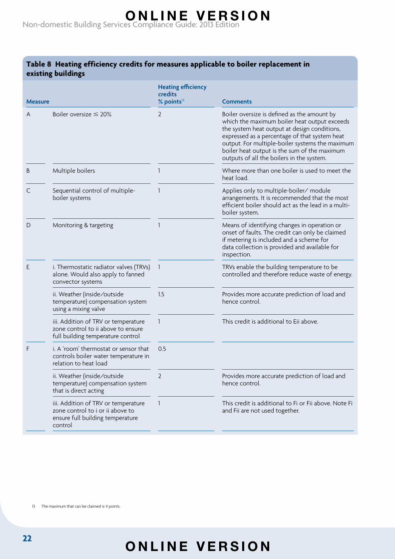
Table 8 Heating efficiency credits for measures applicable to boiler replacement in existing buildings
Measure
Heating efficiency credits% points13 Comments
A Boiler oversize 20% 2 Boiler oversize is defined as the amount by which the maximum boiler heat output exceeds the system heat output at design conditions, expressed as a percentage of that system heat output. For multiple-boiler systems the maximum boiler heat output is the sum of the maximum outputs of all the boilers in the system.
B Multiple boilers 1 Where more than one boiler is used to meet the heat load.
C Sequential control of multiple-boiler systems
1 Applies only to multiple-boiler/ module arrangements. It is recommended that the most efficient boiler should act as the lead in a multi-boiler system.
D Monitoring & targeting 1 Means of identifying changes in operation or onset of faults. The credit can only be claimed if metering is included and a scheme for data collection is provided and available for inspection.
E i. Thermostatic radiator valves (TRVs) alone. Would also apply to fanned convector systems
1 TRVs enable the building temperature to be controlled and therefore reduce waste of energy.
ii. Weather (inside/outside temperature) compensation system using a mixing valve
1.5 Provides more accurate prediction of load and hence control.
iii. Addition of TRV or temperature zone control to ii above to ensure full building temperature control
1 This credit is additional to Eii above.
F i. A ‘room’ thermostat or sensor that controls boiler water temperature in relation to heat load
0.5
ii. Weather (inside/outside temperature) compensation system that is direct acting
2 Provides more accurate prediction of load and hence control.
iii. Addition of TRV or temperature zone control to i or ii above to ensure full building temperature control
1 This credit is additional to Fi or Fii above. Note Fi and Fii are not used together.
O N L I N E V E R S I O N
O N L I N E V E R S I O N
23
Section 2: Gas, oil and biomass-fired boilers
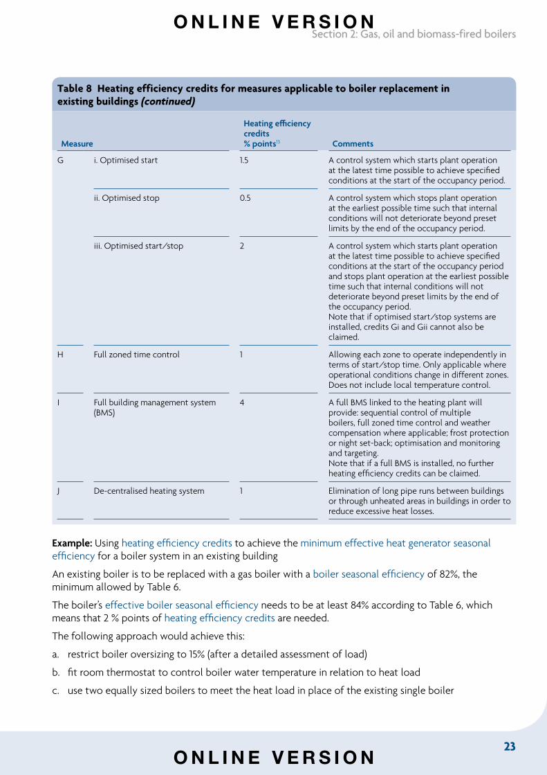
Table 8 Heating efficiency credits for measures applicable to boiler replacement in existing buildings (continued)
Measure
Heating efficiency credits% points13 Comments
G i. Optimised start 1.5 A control system which starts plant operation at the latest time possible to achieve specified conditions at the start of the occupancy period.
ii. Optimised stop 0.5 A control system which stops plant operation at the earliest possible time such that internal conditions will not deteriorate beyond preset limits by the end of the occupancy period.
iii. Optimised start/stop 2 A control system which starts plant operation at the latest time possible to achieve specified conditions at the start of the occupancy period and stops plant operation at the earliest possible time such that internal conditions will not deteriorate beyond preset limits by the end of the occupancy period. Note that if optimised start/stop systems are installed, credits Gi and Gii cannot also be claimed.
H Full zoned time control 1 Allowing each zone to operate independently in terms of start/stop time. Only applicable where operational conditions change in different zones. Does not include local temperature control.
I Full building management system (BMS)
4 A full BMS linked to the heating plant will provide: sequential control of multiple boilers, full zoned time control and weather compensation where applicable; frost protection or night set-back; optimisation and monitoring and targeting. Note that if a full BMS is installed, no further heating efficiency credits can be claimed.
J De-centralised heating system 1 Elimination of long pipe runs between buildings or through unheated areas in buildings in order to reduce excessive heat losses.
Example: Using heating efficiency credits to achieve the minimum effective heat generator seasonal efficiency for a boiler system in an existing building
An existing boiler is to be replaced with a gas boiler with a boiler seasonal efficiency of 82%, the minimum allowed by Table 6.
The boiler’s effective boiler seasonal efficiency needs to be at least 84% according to Table 6, which means that 2 % points of heating efficiency credits are needed.
The following approach would achieve this:
a. restrict boiler oversizing to 15% (after a detailed assessment of load)
b. fit room thermostat to control boiler water temperature in relation to heat load
c. use two equally sized boilers to meet the heat load in place of the existing single boiler
O N L I N E V E R S I O N
O N L I N E V E R S I O N
24
Non-domestic Building Services Compliance Guide: 2013 Edition
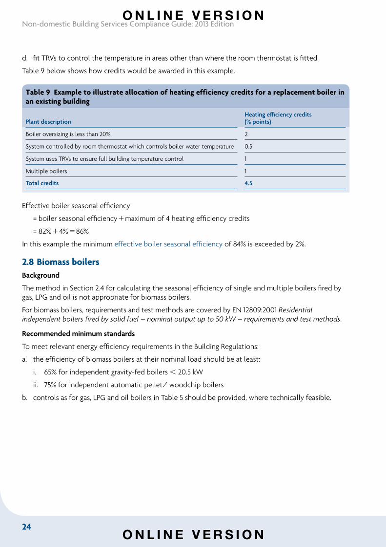
d. fit TRVs to control the temperature in areas other than where the room thermostat is fitted.
Table 9 below shows how credits would be awarded in this example.
Table 9 Example to illustrate allocation of heating efficiency credits for a replacement boiler in an existing building
Plant descriptionHeating efficiency credits(% points)
Boiler oversizing is less than 20% 2
System controlled by room thermostat which controls boiler water temperature 0.5
System uses TRVs to ensure full building temperature control 1
Multiple boilers 1
Total credits 4.5
Effective boiler seasonal efficiency
= boiler seasonal efficiencymaximum of 4 heating efficiency credits
= 82%4%86%
In this example the minimum effective boiler seasonal efficiency of 84% is exceeded by 2%.
2.8 Biomass boilersBackground
The method in Section 2.4 for calculating the seasonal efficiency of single and multiple boilers fired by gas, LPG and oil is not appropriate for biomass boilers.
For biomass boilers, requirements and test methods are covered by EN 12809:2001 Residential independent boilers fired by solid fuel – nominal output up to 50 kW – requirements and test methods.
Recommended minimum standards
To meet relevant energy efficiency requirements in the Building Regulations:
a. the efficiency of biomass boilers at their nominal load should be at least:
i. 65% for independent gravity-fed boilers 20.5 kW
ii. 75% for independent automatic pellet/ woodchip boilers
b. controls as for gas, LPG and oil boilers in Table 5 should be provided, where technically feasible.
O N L I N E V E R S I O N
O N L I N E V E R S I O N
25
Section 3: Heat pumps
Section 3: Heat pumps
3.1 IntroductionThis section gives guidance on specifying heat pumps to provide space heating and domestic hot water in new and existing buildings to meet relevant energy efficiency requirements in the Building Regulations.
The heat pumps covered in this section take heat energy from a low temperature source and upgrade it to a higher temperature at which it can be usefully employed for heating.
The guidance covers measures, such as additional controls, that can be used to gain heating efficiency credits to improve the coefficient of performance of heat pumps.
For guidance on reverse cycle heat pumps that also provide cooling, see Section 9 of this guide.
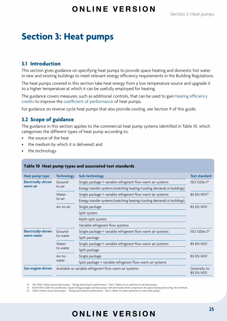
3.2 Scope of guidanceThe guidance in this section applies to the commercial heat pump systems identified in Table 10, which categorises the different types of heat pump according to:• the source of the heat• the medium by which it is delivered, and• the technology.
Table 10 Heat pump types and associated test standards
Heat pump type Technology Sub-technology Test standard
Electrically-driven warm air
Ground- to-air
Single packagevariable refrigerant flow warm air systems ISO 13256-114
Energy transfer systems (matching heating/cooling demands in buildings)
Water- to-air
Single packagevariable refrigerant flow warm air systems BS EN 1451115
Energy transfer systems (matching heating/cooling demands in buildings)
Air-to-air Single package BS EN 14511
Split system
Multi-split system
Variable refrigerant flow systems
Electrically-driven warm water
Ground- to-water
Single packagevariable refrigerant flow warm air systems ISO 13256-216
Split package
Water- to-water
Single packagevariable refrigerant flow warm air systems BS EN 14511
Split package
Air-to-water
Single package BS EN 14511
Split packagevariable refrigerant flow warm air systems
Gas engine-driven Available as variable refrigerant flow warm air systems Generally to BS EN 14511
14 ISO 13256-1 Water-source heat pumps – Testing and rating for performance – Part 1: Water-to-air and brine-to-air heat pumps.15 BS EN 14511-3:2007 Air conditioners, liquid chilling packages and heat pumps with electrically driven compressors for space heating and cooling. Test methods.16 13256-2 Water-source heat pumps – Testing and rating for performance – Part 2: Water-to-water and brine-to-water heat pumps.
O N L I N E V E R S I O N
O N L I N E V E R S I O N
26
Non-domestic Building Services Compliance Guide: 2013 Edition
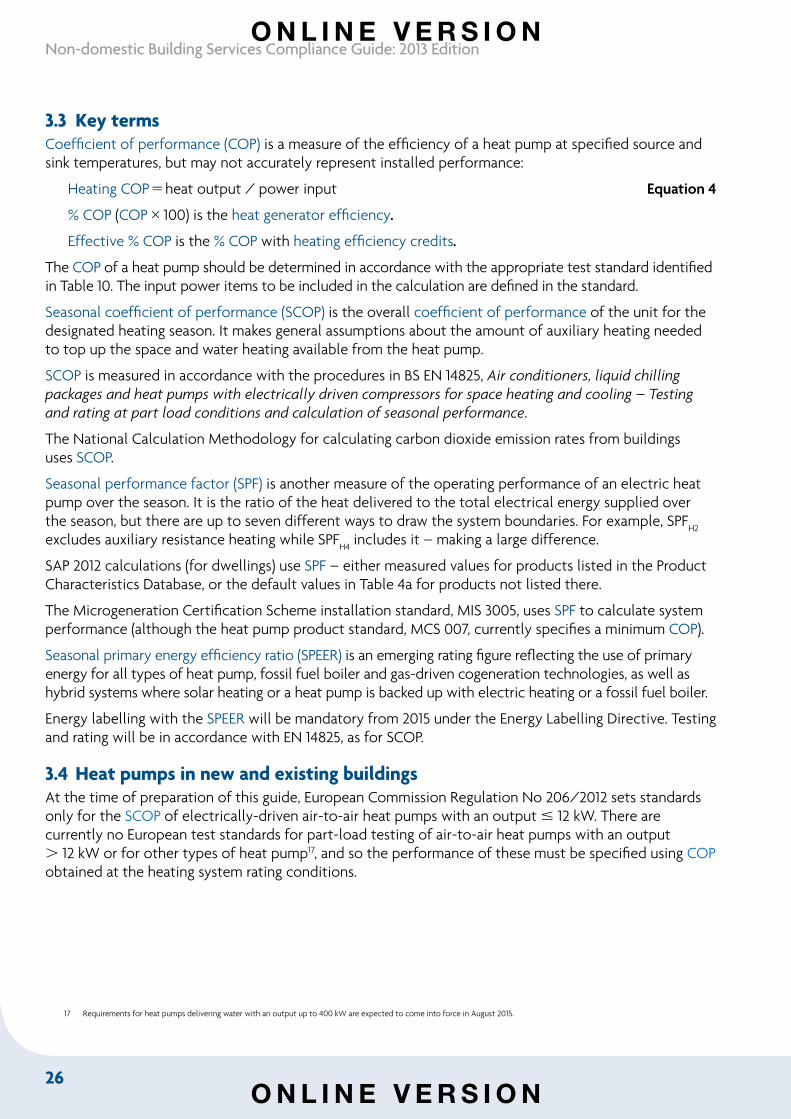
3.3 Key termsCoefficient of performance (COP) is a measure of the efficiency of a heat pump at specified source and sink temperatures, but may not accurately represent installed performance:
Heating COPheat output / power input Equation 4
% COP (COP100) is the heat generator efficiency.
Effective % COP is the % COP with heating efficiency credits.
The COP of a heat pump should be determined in accordance with the appropriate test standard identified in Table 10. The input power items to be included in the calculation are defined in the standard.
Seasonal coefficient of performance (SCOP) is the overall coefficient of performance of the unit for the designated heating season. It makes general assumptions about the amount of auxiliary heating needed to top up the space and water heating available from the heat pump.
SCOP is measured in accordance with the procedures in BS EN 14825, Air conditioners, liquid chilling packages and heat pumps with electrically driven compressors for space heating and cooling – Testing and rating at part load conditions and calculation of seasonal performance.
The National Calculation Methodology for calculating carbon dioxide emission rates from buildings uses SCOP.
Seasonal performance factor (SPF) is another measure of the operating performance of an electric heat pump over the season. It is the ratio of the heat delivered to the total electrical energy supplied over the season, but there are up to seven different ways to draw the system boundaries. For example, SPFH2
excludes auxiliary resistance heating while SPF
H4 includes it – making a large difference.
SAP 2012 calculations (for dwellings) use SPF – either measured values for products listed in the Product Characteristics Database, or the default values in Table 4a for products not listed there.
The Microgeneration Certification Scheme installation standard, MIS 3005, uses SPF to calculate system performance (although the heat pump product standard, MCS 007, currently specifies a minimum COP).
Seasonal primary energy efficiency ratio (SPEER) is an emerging rating figure reflecting the use of primary energy for all types of heat pump, fossil fuel boiler and gas-driven cogeneration technologies, as well as hybrid systems where solar heating or a heat pump is backed up with electric heating or a fossil fuel boiler.
Energy labelling with the SPEER will be mandatory from 2015 under the Energy Labelling Directive. Testing and rating will be in accordance with EN 14825, as for SCOP.
3.4 Heat pumps in new and existing buildingsAt the time of preparation of this guide, European Commission Regulation No 206/2012 sets standards only for the SCOP of electrically-driven air-to-air heat pumps with an output 12 kW. There are currently no European test standards for part-load testing of air-to-air heat pumps with an output 12 kW or for other types of heat pump17, and so the performance of these must be specified using COP obtained at the heating system rating conditions.
17 Requirements for heat pumps delivering water with an output up to 400 kW are expected to come into force in August 2015.
O N L I N E V E R S I O N
O N L I N E V E R S I O N
27
Section 3: Heat pumps
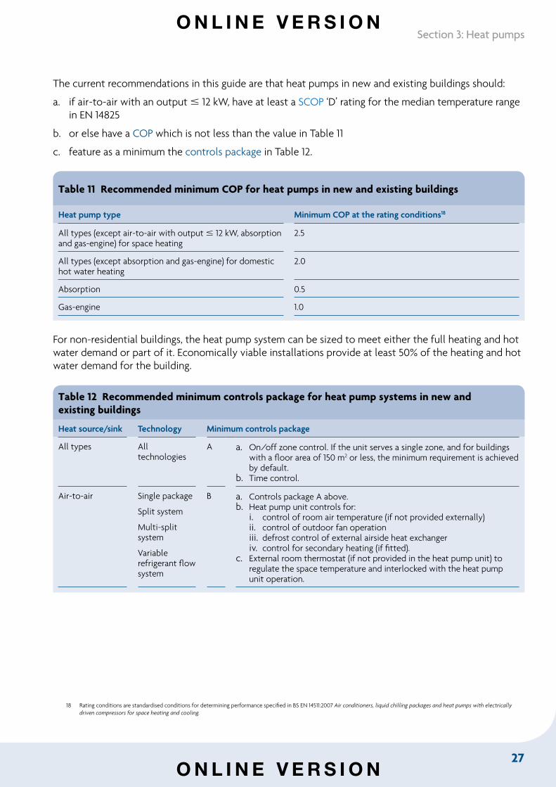
The current recommendations in this guide are that heat pumps in new and existing buildings should:
a. if air-to-air with an output 12 kW, have at least a SCOP ‘D’ rating for the median temperature range in EN 14825
b. or else have a COP which is not less than the value in Table 11
c. feature as a minimum the controls package in Table 12.
Table 11 Recommended minimum COP for heat pumps in new and existing buildings
Heat pump type Minimum COP at the rating conditions18
All types (except air-to-air with output 12 kW, absorption and gas-engine) for space heating
2.5
All types (except absorption and gas-engine) for domestic hot water heating
2.0
Absorption 0.5
Gas-engine 1.0
For non-residential buildings, the heat pump system can be sized to meet either the full heating and hot water demand or part of it. Economically viable installations provide at least 50% of the heating and hot water demand for the building.
Table 12 Recommended minimum controls package for heat pump systems in new and existing buildings
Heat source/sink Technology Minimum controls package
All types All technologies
A a. On/off zone control. If the unit serves a single zone, and for buildings with a floor area of 150 m2 or less, the minimum requirement is achieved by default.
b. Time control.
Air-to-air Single package
Split system
Multi-split system
Variable refrigerant flow system
B a. Controls package A above.b. Heat pump unit controls for:
i. control of room air temperature (if not provided externally)ii. control of outdoor fan operationiii. defrost control of external airside heat exchangeriv. control for secondary heating (if fitted).
c. External room thermostat (if not provided in the heat pump unit) to regulate the space temperature and interlocked with the heat pump unit operation.
18 Rating conditions are standardised conditions for determining performance specified in BS EN 14511:2007 Air conditioners, liquid chilling packages and heat pumps with electrically driven compressors for space heating and cooling.
O N L I N E V E R S I O N
O N L I N E V E R S I O N
28
Non-domestic Building Services Compliance Guide: 2013 Edition
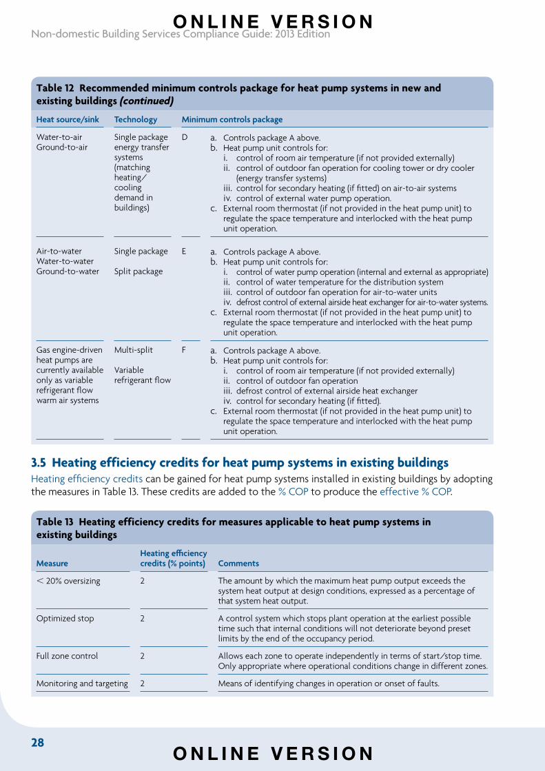
Table 12 Recommended minimum controls package for heat pump systems in new and existing buildings (continued)
Heat source/sink Technology Minimum controls package
Water-to-airGround-to-air
Single packageenergy transfer systems (matching heating/cooling demand in buildings)
D a. Controls package A above.b. Heat pump unit controls for:
i. control of room air temperature (if not provided externally)ii. control of outdoor fan operation for cooling tower or dry cooler
(energy transfer systems)iii. control for secondary heating (if fitted) on air-to-air systemsiv. control of external water pump operation.
c. External room thermostat (if not provided in the heat pump unit) to regulate the space temperature and interlocked with the heat pump unit operation.
Air-to-waterWater-to-waterGround-to-water
Single package
Split package
E a. Controls package A above.b. Heat pump unit controls for:
i. control of water pump operation (internal and external as appropriate)ii. control of water temperature for the distribution systemiii. control of outdoor fan operation for air-to-water unitsiv. defrost control of external airside heat exchanger for air-to-water systems.
c. External room thermostat (if not provided in the heat pump unit) to regulate the space temperature and interlocked with the heat pump unit operation.
Gas engine-driven heat pumps are currently available only as variable refrigerant flow warm air systems
Multi-split
Variable refrigerant flow
F a. Controls package A above.b. Heat pump unit controls for:
i. control of room air temperature (if not provided externally)ii. control of outdoor fan operationiii. defrost control of external airside heat exchangeriv. control for secondary heating (if fitted).
c. External room thermostat (if not provided in the heat pump unit) to regulate the space temperature and interlocked with the heat pump unit operation.
3.5 Heating efficiency credits for heat pump systems in existing buildingsHeating efficiency credits can be gained for heat pump systems installed in existing buildings by adopting the measures in Table 13. These credits are added to the % COP to produce the effective % COP.
Table 13 Heating efficiency credits for measures applicable to heat pump systems inexisting buildings
Measure Heating efficiency credits (% points) Comments
20% oversizing 2 The amount by which the maximum heat pump output exceeds the system heat output at design conditions, expressed as a percentage of that system heat output.
Optimized stop 2 A control system which stops plant operation at the earliest possible time such that internal conditions will not deteriorate beyond preset limits by the end of the occupancy period.
Full zone control 2 Allows each zone to operate independently in terms of start/stop time. Only appropriate where operational conditions change in different zones.
Monitoring and targeting 2 Means of identifying changes in operation or onset of faults.
O N L I N E V E R S I O N
O N L I N E V E R S I O N
29
Section 3: Heat pumps
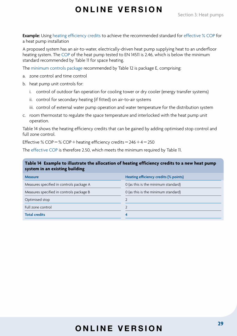
Example: Using heating efficiency credits to achieve the recommended standard for effective % COP for a heat pump installation
A proposed system has an air-to-water, electrically-driven heat pump supplying heat to an underfloor heating system. The COP of the heat pump tested to EN 14511 is 2.46, which is below the minimum standard recommended by Table 11 for space heating.
The minimum controls package recommended by Table 12 is package E, comprising:
a. zone control and time control
b. heat pump unit controls for:
i. control of outdoor fan operation for cooling tower or dry cooler (energy transfer systems)
ii. control for secondary heating (if fitted) on air-to-air systems
iii. control of external water pump operation and water temperature for the distribution system
c. room thermostat to regulate the space temperature and interlocked with the heat pump unit operation.
Table 14 shows the heating efficiency credits that can be gained by adding optimised stop control and full zone control.
Effective % COP% COPheating efficiency credits2464250
The effective COP is therefore 2.50, which meets the minimum required by Table 11.
Table 14 Example to illustrate the allocation of heating efficiency credits to a new heat pump system in an existing building
Measure Heating efficiency credits (% points)
Measures specified in controls package A 0 (as this is the minimum standard)
Measures specified in controls package B 0 (as this is the minimum standard)
Optimised stop 2
Full zone control 2
Total credits 4
O N L I N E V E R S I O N
O N L I N E V E R S I O N
30
Non-domestic Building Services Compliance Guide: 2013 Edition
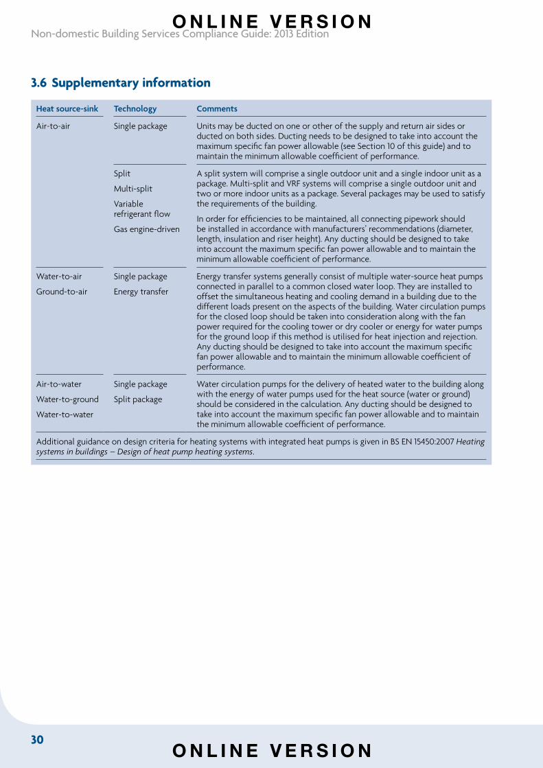
3.6 Supplementary information
Heat source-sink Technology Comments
Air-to-air Single package Units may be ducted on one or other of the supply and return air sides or ducted on both sides. Ducting needs to be designed to take into account the maximum specific fan power allowable (see Section 10 of this guide) and to maintain the minimum allowable coefficient of performance.
Split
Multi-split
Variable refrigerant flow
Gas engine-driven
A split system will comprise a single outdoor unit and a single indoor unit as a package. Multi-split and VRF systems will comprise a single outdoor unit and two or more indoor units as a package. Several packages may be used to satisfy the requirements of the building.
In order for efficiencies to be maintained, all connecting pipework should be installed in accordance with manufacturers’ recommendations (diameter, length, insulation and riser height). Any ducting should be designed to take into account the maximum specific fan power allowable and to maintain the minimum allowable coefficient of performance.
Water-to-air
Ground-to-air
Single package
Energy transfer
Energy transfer systems generally consist of multiple water-source heat pumps connected in parallel to a common closed water loop. They are installed to offset the simultaneous heating and cooling demand in a building due to the different loads present on the aspects of the building. Water circulation pumps for the closed loop should be taken into consideration along with the fan power required for the cooling tower or dry cooler or energy for water pumps for the ground loop if this method is utilised for heat injection and rejection. Any ducting should be designed to take into account the maximum specific fan power allowable and to maintain the minimum allowable coefficient of performance.
Air-to-water
Water-to-ground
Water-to-water
Single package
Split package
Water circulation pumps for the delivery of heated water to the building along with the energy of water pumps used for the heat source (water or ground) should be considered in the calculation. Any ducting should be designed to take into account the maximum specific fan power allowable and to maintain the minimum allowable coefficient of performance.
Additional guidance on design criteria for heating systems with integrated heat pumps is given in BS EN 15450:2007 Heating systems in buildings – Design of heat pump heating systems.
O N L I N E V E R S I O N
O N L I N E V E R S I O N
31
Section 4: Gas and oil-fired warm air heaters
Section 4: Gas and oil-fired warm air heaters
4.1 Introduction This section gives guidance on specifying gas and oil-fired warm air heaters for space heating in new and existing buildings to meet relevant energy efficiency requirements in the Building Regulations. It includes guidance on measures, such as additional controls, that can be used to gain heating efficiency credits to improve the heat generator seasonal efficiency.
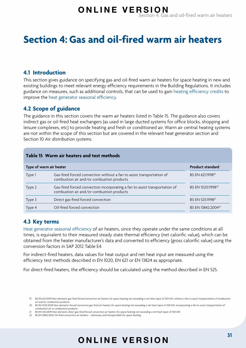
4.2 Scope of guidanceThe guidance in this section covers the warm air heaters listed in Table 15. The guidance also covers indirect gas or oil-fired heat exchangers (as used in large ducted systems for office blocks, shopping and leisure complexes, etc) to provide heating and fresh or conditioned air. Warm air central heating systems are not within the scope of this section but are covered in the relevant heat generator section and Section 10 Air distribution systems.
Table 15 Warm air heaters and test methods
Type of warm air heater Product standard
Type 1 Gas-fired forced convection without a fan to assist transportation of combustion air and/or combustion products
BS EN 621:199819
Type 2 Gas-fired forced convection incorporating a fan to assist transportation of combustion air and/or combustion products
BS EN 1020:199820
Type 3 Direct gas-fired forced convection BS EN 525:199821
Type 4 Oil-fired forced convection BS EN 13842:200422
4.3 Key termsHeat generator seasonal efficiency of air heaters, since they operate under the same conditions at all times, is equivalent to their measured steady state thermal efficiency (net calorific value), which can be obtained from the heater manufacturer’s data and converted to efficiency (gross calorific value) using the conversion factors in SAP 2012 Table E4.
For indirect-fired heaters, data values for heat output and net heat input are measured using the efficiency test methods described in EN 1020, EN 621 or EN 13824 as appropriate.
For direct-fired heaters, the efficiency should be calculated using the method described in EN 525. 19202122
19 BS EN 621:2009 Non-domestic gas-fired forced convection air heaters for space heating not exceeding a net heat input of 300 kW, without a fan to assist transportation of combustion air and/or combustion products.
20 BS EN 1020:2009 Non-domestic forced convection gas-fired air heaters for space heating not exceeding a net heat input of 300 kW, incorporating a fan to assist transportation of combustion air or combustion products.
21 BS EN 525:2009 Non-domestic direct gas-fired forced convection air heaters for space heating not exceeding a net heat input of 300 kW.22 BS EN 13842:2004 Oil-fired convection air heaters – stationary and transportable for space heating.
O N L I N E V E R S I O N
O N L I N E V E R S I O N
32
Non-domestic Building Services Compliance Guide: 2013 Edition
The calculation of the thermal efficiency (net) should:
• take account of the heater and the exhaust chimney within the building envelope
• exclude fans.
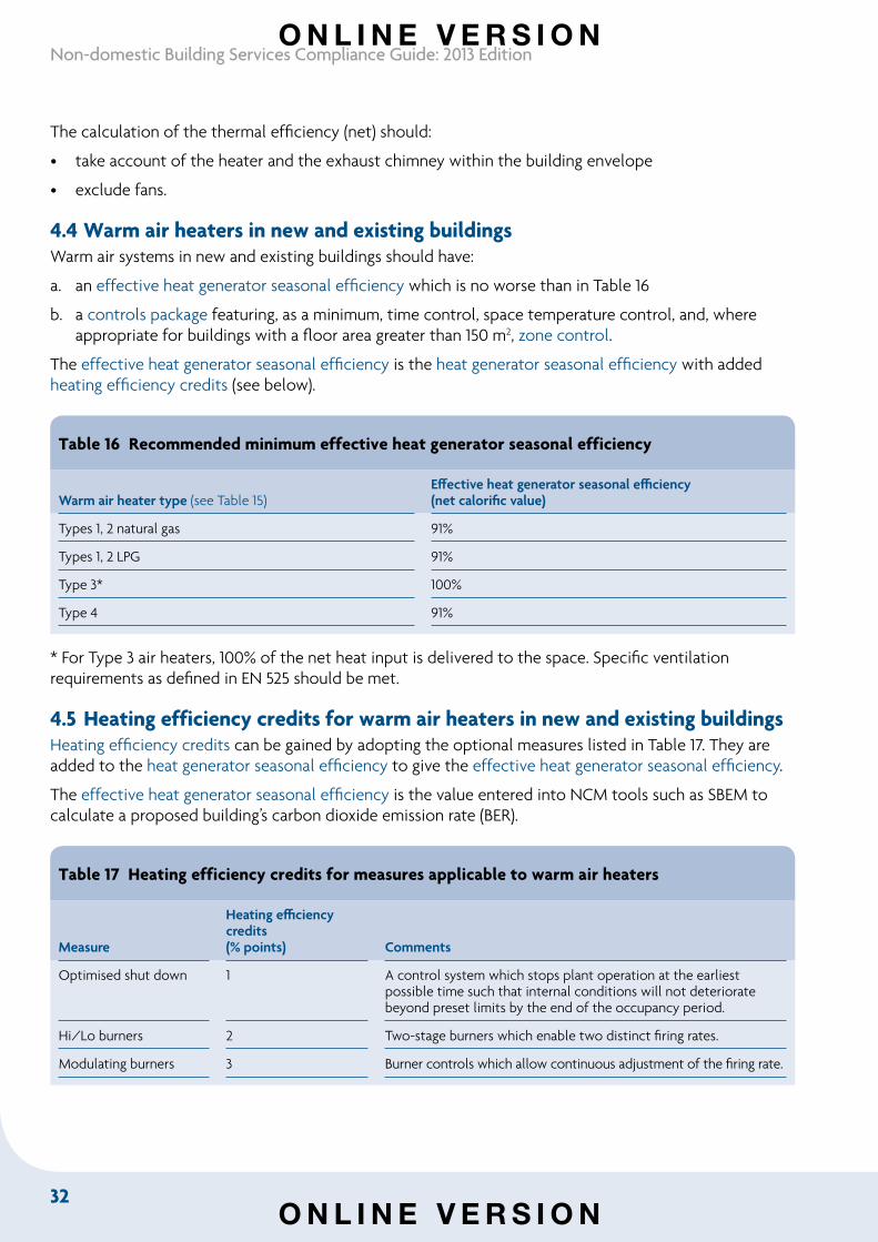
4.4 Warm air heaters in new and existing buildings Warm air systems in new and existing buildings should have:
a. an effective heat generator seasonal efficiency which is no worse than in Table 16
b. a controls package featuring, as a minimum, time control, space temperature control, and, where appropriate for buildings with a floor area greater than 150 m2, zone control.
The effective heat generator seasonal efficiency is the heat generator seasonal efficiency with added heating efficiency credits (see below).
Table 16 Recommended minimum effective heat generator seasonal efficiency
Warm air heater type (see Table 15)Effective heat generator seasonal efficiency(net calorific value)
Types 1, 2 natural gas 91%
Types 1, 2 LPG 91%
Type 3* 100%
Type 4 91%
* For Type 3 air heaters, 100% of the net heat input is delivered to the space. Specific ventilation requirements as defined in EN 525 should be met.
4.5 Heating efficiency credits for warm air heaters in new and existing buildings Heating efficiency credits can be gained by adopting the optional measures listed in Table 17. They are added to the heat generator seasonal efficiency to give the effective heat generator seasonal efficiency.
The effective heat generator seasonal efficiency is the value entered into NCM tools such as SBEM to calculate a proposed building’s carbon dioxide emission rate (BER).
Table 17 Heating efficiency credits for measures applicable to warm air heaters
Measure
Heating efficiency credits(% points) Comments
Optimised shut down 1 A control system which stops plant operation at the earliest possible time such that internal conditions will not deteriorate beyond preset limits by the end of the occupancy period.
Hi/Lo burners 2 Two-stage burners which enable two distinct firing rates.
Modulating burners 3 Burner controls which allow continuous adjustment of the firing rate.
O N L I N E V E R S I O N
O N L I N E V E R S I O N
33
Section 4: Gas and oil-fired warm air heaters
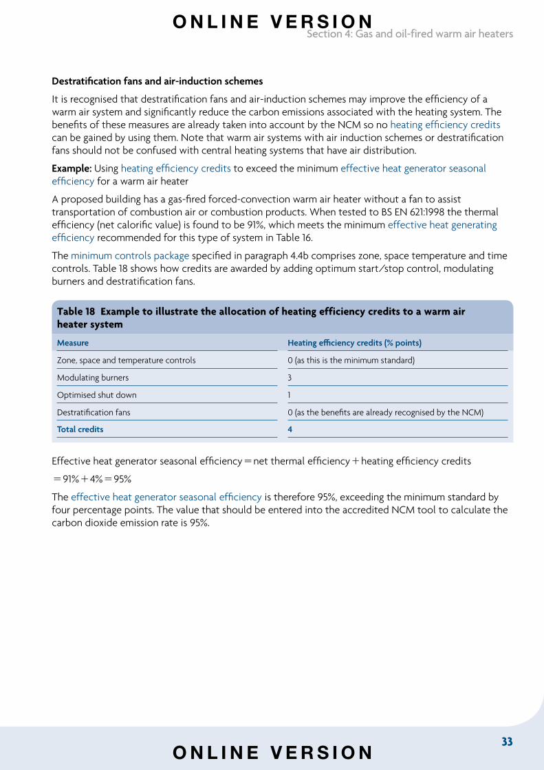
Destratification fans and air-induction schemes
It is recognised that destratification fans and air-induction schemes may improve the efficiency of a warm air system and significantly reduce the carbon emissions associated with the heating system. The benefits of these measures are already taken into account by the NCM so no heating efficiency credits can be gained by using them. Note that warm air systems with air induction schemes or destratification fans should not be confused with central heating systems that have air distribution.
Example: Using heating efficiency credits to exceed the minimum effective heat generator seasonal efficiency for a warm air heater
A proposed building has a gas-fired forced-convection warm air heater without a fan to assist transportation of combustion air or combustion products. When tested to BS EN 621:1998 the thermal efficiency (net calorific value) is found to be 91%, which meets the minimum effective heat generating efficiency recommended for this type of system in Table 16.
The minimum controls package specified in paragraph 4.4b comprises zone, space temperature and time controls. Table 18 shows how credits are awarded by adding optimum start/stop control, modulating burners and destratification fans.
Table 18 Example to illustrate the allocation of heating efficiency credits to a warm airheater system
Measure Heating efficiency credits (% points)
Zone, space and temperature controls 0 (as this is the minimum standard)
Modulating burners 3
Optimised shut down 1
Destratification fans 0 (as the benefits are already recognised by the NCM)
Total credits 4
Effective heat generator seasonal efficiencynet thermal efficiencyheating efficiency credits
91%4%95%
The effective heat generator seasonal efficiency is therefore 95%, exceeding the minimum standard by four percentage points. The value that should be entered into the accredited NCM tool to calculate the carbon dioxide emission rate is 95%.
O N L I N E V E R S I O N
O N L I N E V E R S I O N
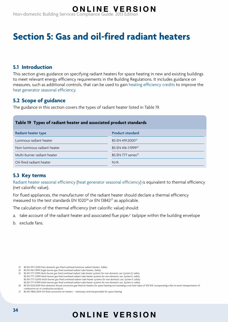
34
Non-domestic Building Services Compliance Guide: 2013 Edition
Section 5: Gas and oil-fired radiant heaters
5.1 IntroductionThis section gives guidance on specifying radiant heaters for space heating in new and existing buildings to meet relevant energy efficiency requirements in the Building Regulations. It includes guidance on measures, such as additional controls, that can be used to gain heating efficiency credits to improve the heat generator seasonal efficiency.
5.2 Scope of guidanceThe guidance in this section covers the types of radiant heater listed in Table 19.
Table 19 Types of radiant heater and associated product standards
Radiant heater type Product standard
Luminous radiant heater BS EN 419:200023
Non-luminous radiant heater BS EN 416-1:199924
Multi-burner radiant heater BS EN 777 series25
Oil-fired radiant heater N/A
5.3 Key termsRadiant heater seasonal efficiency (heat generator seasonal efficiency) is equivalent to thermal efficiency (net calorific value).232425 For flued appliances, the manufacturer of the radiant heater should declare a thermal efficiency measured to the test standards EN 102026 or EN 1384227 as applicable.
The calculation of the thermal efficiency (net calorific value) should:
a. take account of the radiant heater and associated flue pipe/ tailpipe within the building envelope
b. exclude fans.
23 BS EN 419-1:2000 Non-domestic gas-fired overhead luminous radiant heaters. Safety. 24 BS EN 416-1:1999 Single-burner gas-fired overhead radiant tube heaters. Safety. 25 BS EN 777-1:1999 Multi-burner gas-fired overhead radiant tube heater systems for non-domestic use. System D, safety.
BS EN 777-2:1999 Multi-burner gas-fired overhead radiant tube heater systems for non-domestic use. System E, safety. BS EN 777-3:2000 Multi-burner gas-fired overhead radiant tube heater systems for non-domestic use. System F, safety. BS EN 777-4:1999 Multi-burner gas-fired overhead radiant tube heater systems for non-domestic use. System H, safety.
26 BS EN 1020:2009 Non-domestic forced convection gas-fired air heaters for space heating not exceeding a net heat input of 300 kW, incorporating a fan to assist transportation of combustion air or combustion products.
27 BS EN 13842:2004 Oil-fired convection air heaters – stationary and transportable for space heating.
O N L I N E V E R S I O N
O N L I N E V E R S I O N
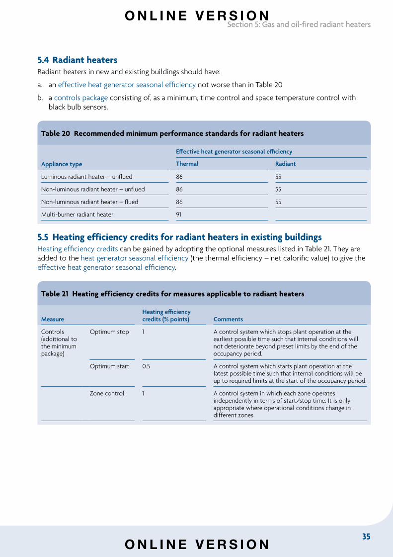
35
Section 5: Gas and oil-fired radiant heaters
5.4 Radiant heatersRadiant heaters in new and existing buildings should have:
a. an effective heat generator seasonal efficiency not worse than in Table 20
b. a controls package consisting of, as a minimum, time control and space temperature control with black bulb sensors.
Table 20 Recommended minimum performance standards for radiant heaters
Appliance type
Effective heat generator seasonal efficiency
Thermal Radiant
Luminous radiant heater – unflued 86 55
Non-luminous radiant heater – unflued 86 55
Non-luminous radiant heater – flued 86 55
Multi-burner radiant heater 91
5.5 Heating efficiency credits for radiant heaters in existing buildings Heating efficiency credits can be gained by adopting the optional measures listed in Table 21. They are added to the heat generator seasonal efficiency (the thermal efficiency – net calorific value) to give the effective heat generator seasonal efficiency.
Table 21 Heating efficiency credits for measures applicable to radiant heaters
MeasureHeating efficiency credits (% points) Comments
Controls (additional to the minimum package)
Optimum stop 1 A control system which stops plant operation at the earliest possible time such that internal conditions will not deteriorate beyond preset limits by the end of the occupancy period.
Optimum start 0.5 A control system which starts plant operation at the latest possible time such that internal conditions will be up to required limits at the start of the occupancy period.
Zone control 1 A control system in which each zone operates independently in terms of start/stop time. It is only appropriate where operational conditions change in different zones.
O N L I N E V E R S I O N
O N L I N E V E R S I O N
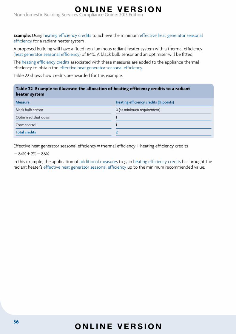
36
Non-domestic Building Services Compliance Guide: 2013 Edition
Example: Using heating efficiency credits to achieve the minimum effective heat generator seasonal efficiency for a radiant heater system
A proposed building will have a flued non-luminous radiant heater system with a thermal efficiency (heat generator seasonal efficiency) of 84%. A black bulb sensor and an optimiser will be fitted.
The heating efficiency credits associated with these measures are added to the appliance thermal efficiency to obtain the effective heat generator seasonal efficiency.
Table 22 shows how credits are awarded for this example.
Table 22 Example to illustrate the allocation of heating efficiency credits to a radiantheater system
Measure Heating efficiency credits (% points)
Black bulb sensor 0 (as minimum requirement)
Optimised shut down 1
Zone control 1
Total credits 2
Effective heat generator seasonal efficiencythermal efficiencyheating efficiency credits
84%2%86%
In this example, the application of additional measures to gain heating efficiency credits has brought the radiant heater’s effective heat generator seasonal efficiency up to the minimum recommended value.
O N L I N E V E R S I O N
O N L I N E V E R S I O N
37
Section 6: Combined heat and power and community heating
Section 6: Combined heat and power and community heating
6.1 IntroductionThis section gives guidance on specifying combined heat and power (CHP) systems for space heating, hot water and chilled water (via absorption chillers) in new and existing buildings to meet relevant energy efficiency requirements in the Building Regulations. It includes guidance on measures, such as additional controls, that can be used to gain heating efficiency credits to improve the heat generator seasonal efficiency. Guidance on the design of community heating systems can be found in Section 6 of the Domestic building services compliance guide.
CHP units are normally used in conjunction with boilers. The majority of the annual heat demand is usually provided by the CHP plant, while the boilers are used to meet peak demand and in periods when the CHP unit is not operating (for example at night or when undergoing maintenance).
CHP units may on a relatively small scale supply single buildings, or on a larger scale supply a number of buildings through a community heating system. The most common fuel is natural gas, which can be used in spark-ignition gas engines, micro-turbines, or gas turbines in open cycle or combined cycle.
6.2 Scope of guidanceThe guidance in this section covers CHP systems with a total power capacity less than 5 MWe used in commercial applications. The CHP units may or may not supply community heating.
Guidance on community heating systems with micro-CHP (having a total power capacity less than 5 kWe) and other heat generators is available in the Domestic building services compliance guide.
6.3 Key terms Combined heat and power (CHP) means the simultaneous generation of heat and power in a single process. The power output is usually electricity, but may include mechanical power. Heat outputs can include steam, hot water or hot air for process heating, space heating or absorption cooling.
Combined heat and power quality assurance (CHPQA) is a scheme28 under which registration and certification of CHP systems is carried out according to defined quality criteria.
CHPQA quality index is an indicator of the energy efficiency and environmental performance of a CHP scheme relative to generation of the same amounts of heat and power by alternative means.
Power efficiency is the total annual power output divided by the total annual fuel input of a CHP unit.
28 Further information about the CHPQA programme is available at www.chpqa.com.
O N L I N E V E R S I O N
O N L I N E V E R S I O N
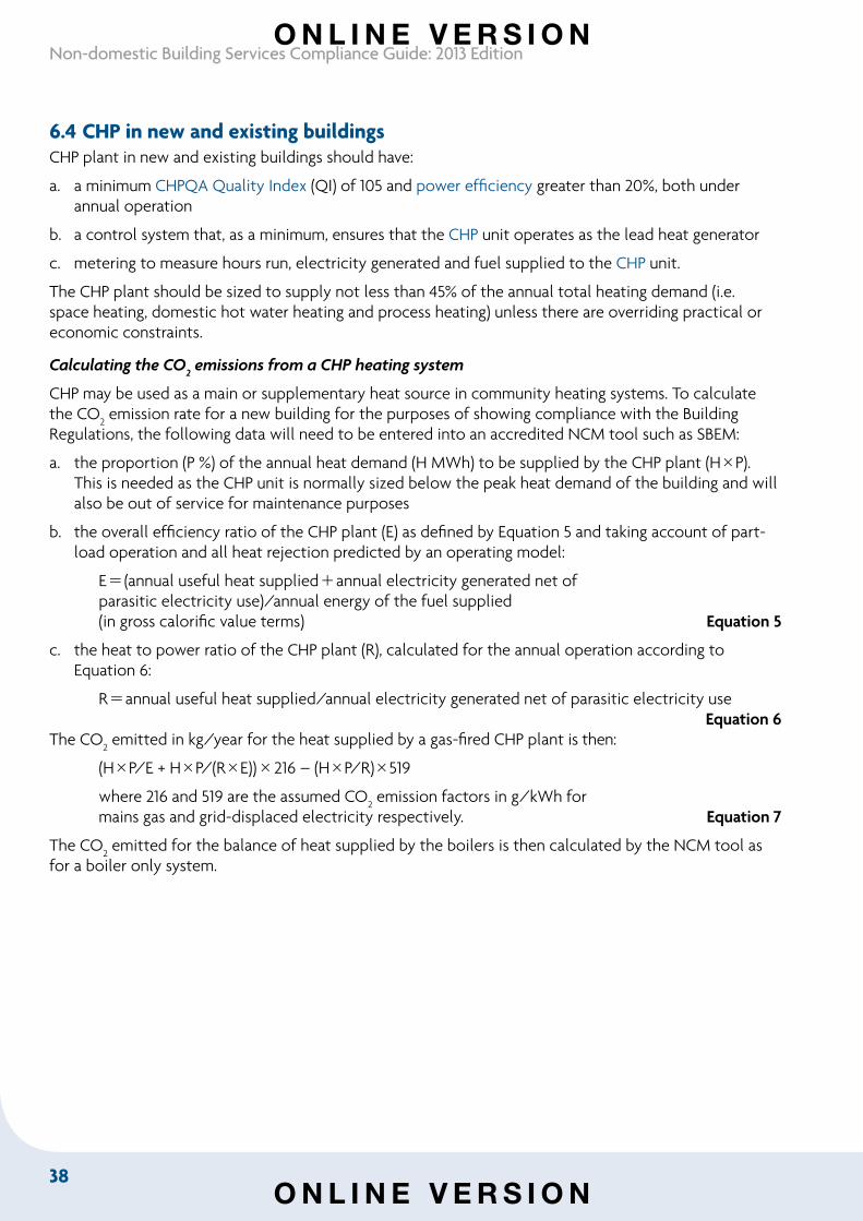
38
Non-domestic Building Services Compliance Guide: 2013 Edition
6.4 CHP in new and existing buildings CHP plant in new and existing buildings should have:
a. a minimum CHPQA Quality Index (QI) of 105 and power efficiency greater than 20%, both under annual operation
b. a control system that, as a minimum, ensures that the CHP unit operates as the lead heat generator
c. metering to measure hours run, electricity generated and fuel supplied to the CHP unit.
The CHP plant should be sized to supply not less than 45% of the annual total heating demand (i.e. space heating, domestic hot water heating and process heating) unless there are overriding practical or economic constraints.
Calculating the CO2 emissions from a CHP heating system
CHP may be used as a main or supplementary heat source in community heating systems. To calculate the CO
2 emission rate for a new building for the purposes of showing compliance with the Building
Regulations, the following data will need to be entered into an accredited NCM tool such as SBEM:
a. the proportion (P %) of the annual heat demand (H MWh) to be supplied by the CHP plant (HP). This is needed as the CHP unit is normally sized below the peak heat demand of the building and will also be out of service for maintenance purposes
b. the overall efficiency ratio of the CHP plant (E) as defined by Equation 5 and taking account of part-load operation and all heat rejection predicted by an operating model:
E(annual useful heat suppliedannual electricity generated net of parasitic electricity use)/annual energy of the fuel supplied (in gross calorific value terms) Equation 5
c. the heat to power ratio of the CHP plant (R), calculated for the annual operation according to Equation 6:
Rannual useful heat supplied/annual electricity generated net of parasitic electricity use Equation 6
The CO2 emitted in kg/year for the heat supplied by a gas-fired CHP plant is then:
(HP/E + HP/(RE))216 – (HP/R)519
where 216 and 519 are the assumed CO2 emission factors in g/kWh for
mains gas and grid-displaced electricity respectively. Equation 7
The CO2 emitted for the balance of heat supplied by the boilers is then calculated by the NCM tool as
for a boiler only system.
O N L I N E V E R S I O N
O N L I N E V E R S I O N
39
Section 6: Combined heat and power and community heating
6.5 Supplementary information
Community heating systems may include other low and zero carbon sources of energy such as biomass heating. Emission factors should be determined based on the particular details of the scheme, but should take account of the annual average performance of the whole system – that is, of the distribution circuits and all the heat generating plant, including any CHP and any waste heat recovery or heat dumping. The calculation of the building CO2
emission rate should be carried out by a suitably qualified person, who should explain how the emission factors were derived.
The design of the community heating connection and the building’s heating control system should take account of the requirements of the community heating organisation with respect to maintaining low return temperatures at part-load and limiting the maximum flow rate to be supplied by the community heating system to the agreed level. A heat meter should be installed to measure the heat energy supplied and to monitor the maximum heat demand, the maximum community heating flow rate and the return temperatures into the community heating network.
Further guidance can be found in the following documents:
• Carbon Trust GPG 234 Community heating and CHP
• CIBSE AM12 Small-scale CHP for buildings
• HVCA TR/30 Guide to good practice – Heat pumps.
O N L I N E V E R S I O N
O N L I N E V E R S I O N
40
Non-domestic Building Services Compliance Guide: 2013 Edition
Section 7: Direct electric space heating
7.1 Introduction This section gives guidance on specifying direct electric heaters for space heating in new and existing buildings. It addresses the relevant electric heater types and the minimum provision of controls.
7.2 Scope of guidanceThe guidance given in this section covers the following types of electric heating systems, which may be used to provide primary or secondary space heating:
• electric boilers
• electric warm air systems
• electric panel heaters
• electric storage systems, including integrated storage/ direct systems
• electric fan heaters and fan convector heaters
• electric radiant heaters, including quartz and ceramic types.
The guidance does not cover electric heat pumps or portable electric heating devices.
7.3 Electric space heating in new and existing buildings It is assumed that electric heating devices convert electricity to heat within a building with an efficiency of 100%. A minimum heat generator seasonal efficiency is therefore not specified.
Electric space heating systems in new and existing buildings should meet the minimum standards for:
a. controls for electric boilers in Table 23
b. controls for electric heating systems other than boilers in Table 24.
O N L I N E V E R S I O N
O N L I N E V E R S I O N
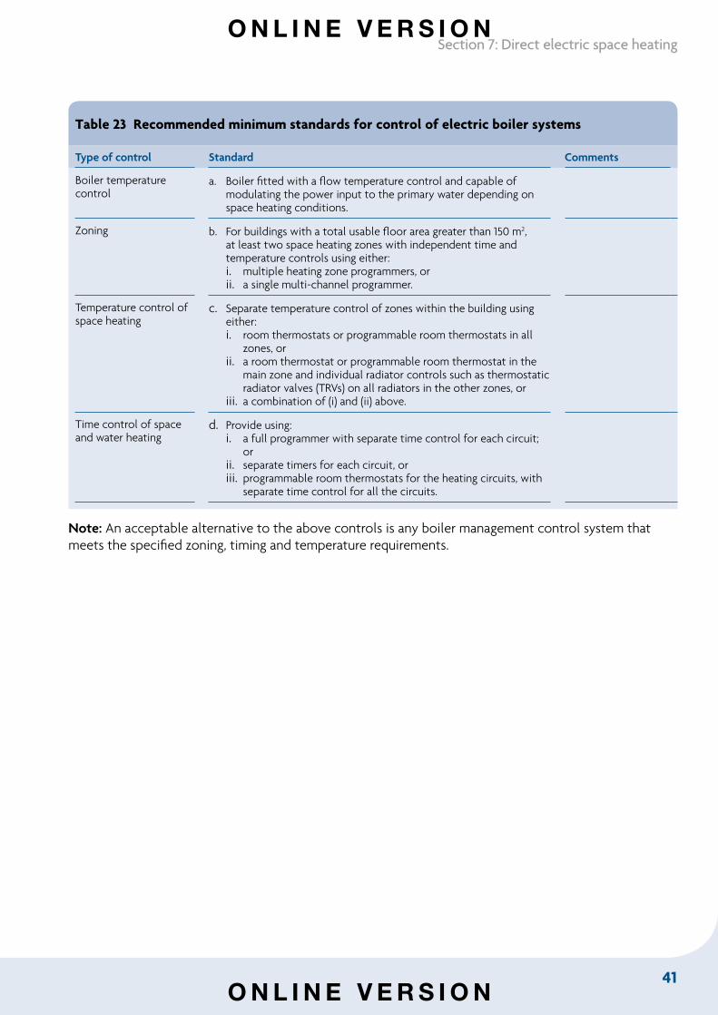
41
Section 7: Direct electric space heating
Table 23 Recommended minimum standards for control of electric boiler systems
Type of control Standard Comments
Boiler temperature control
a. Boiler fitted with a flow temperature control and capable of modulating the power input to the primary water depending on space heating conditions.
Zoning b. For buildings with a total usable floor area greater than 150 m2, at least two space heating zones with independent time and temperature controls using either: i. multiple heating zone programmers, or ii. a single multi-channel programmer.
Temperature control of space heating
c. Separate temperature control of zones within the building using either: i. room thermostats or programmable room thermostats in all
zones, or ii. a room thermostat or programmable room thermostat in the
main zone and individual radiator controls such as thermostatic radiator valves (TRVs) on all radiators in the other zones, or
iii. a combination of (i) and (ii) above.
Time control of space and water heating
d. Provide using: i. a full programmer with separate time control for each circuit;
or ii. separate timers for each circuit, or iii. programmable room thermostats for the heating circuits, with
separate time control for all the circuits.
Note: An acceptable alternative to the above controls is any boiler management control system that meets the specified zoning, timing and temperature requirements.
O N L I N E V E R S I O N
O N L I N E V E R S I O N
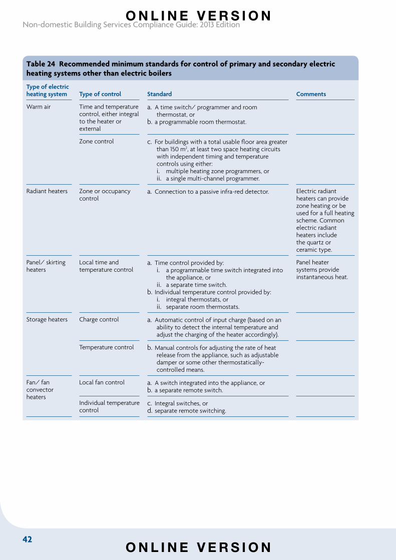
42
Non-domestic Building Services Compliance Guide: 2013 Edition
Table 24 Recommended minimum standards for control of primary and secondary electric heating systems other than electric boilers
Type of electric heating system Type of control Standard Comments
Warm air Time and temperature control, either integral to the heater or external
a. A time switch/ programmer and room thermostat, or
b. a programmable room thermostat.
Zone control c. For buildings with a total usable floor area greater than 150 m2, at least two space heating circuits with independent timing and temperature controls using either:i. multiple heating zone programmers, orii. a single multi-channel programmer.
Radiant heaters Zone or occupancy control
a. Connection to a passive infra-red detector. Electric radiant heaters can provide zone heating or be used for a full heating scheme. Common electric radiant heaters include the quartz or ceramic type.
Panel/ skirting heaters
Local time and temperature control
a. Time control provided by:i. a programmable time switch integrated into
the appliance, orii. a separate time switch.
b. Individual temperature control provided by:i. integral thermostats, orii. separate room thermostats.
Panel heater systems provide instantaneous heat.
Storage heaters Charge control a. Automatic control of input charge (based on an ability to detect the internal temperature and adjust the charging of the heater accordingly).
Temperature control b. Manual controls for adjusting the rate of heat release from the appliance, such as adjustable damper or some other thermostatically-controlled means.
Fan/ fan convector heaters
Local fan control a. A switch integrated into the appliance, orb. a separate remote switch.
Individual temperature control
c. Integral switches, ord. separate remote switching.
O N L I N E V E R S I O N
O N L I N E V E R S I O N
43
Section 8: Domestic hot water
Section 8: Domestic hot water
8.1 Introduction This section gives guidance on specifying domestic hot water (DHW) systems for new and existing buildings to meet relevant energy efficiency requirements in the Building Regulations. It includes guidance on measures, such as additional controls, that can be used to gain heating efficiency credits to improve the heat generator seasonal efficiency.
Note: Water quality can have a major impact on system efficiency. It is important that designers take appropriate measures to ensure that the system water is of good quality.
As well as the Building Regulations, other regulations apply to the provision of domestic hot water. Energy-saving measures should not compromise the safety of people or the ability of the system to achieve approved regimes for the control of legionella.
Domestic hot water systems are referred to as hot water service systems in SBEM.
8.2 Scope of guidanceThe guidance in this section covers the conventional direct and indirect gas-fired, oil-fired and electrically-heated domestic hot water systems shown in Table 25.
The recommended minimum standards set out in this section apply only to dedicated water heaters. Central heating boilers which provide space heating and domestic hot water should meet the minimum standards in Section 2; and heat pumps which provide domestic hot water should meet the minimum standards in Section 3.
The guidance in this section applies to back-up gas and electric systems used with solar thermal hot water systems, but not to solar thermal systems themselves. For solar systems with a cylinder capacity of less than 440 litres or collector surface area less than 20 sq metres, consult the DCLG Domestic building services compliance guide, or for larger systems, the CIBSE Solar heating design and installation guide.
O N L I N E V E R S I O N
O N L I N E V E R S I O N
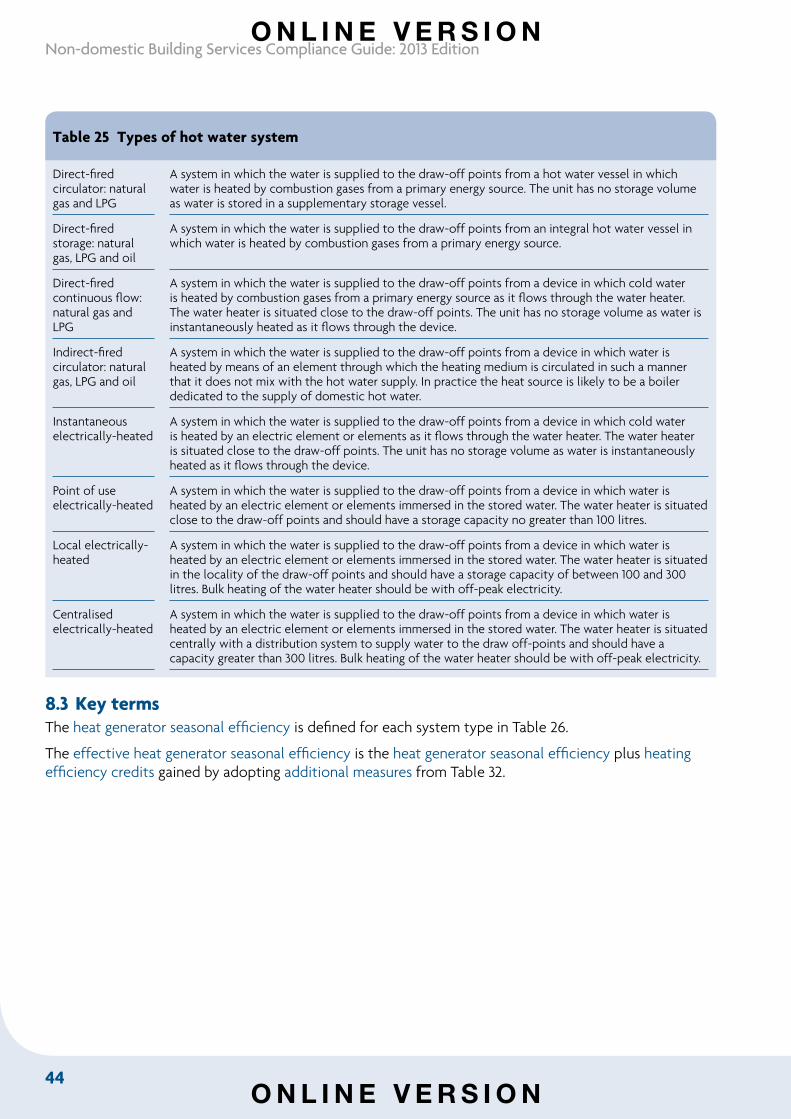
44
Non-domestic Building Services Compliance Guide: 2013 Edition
Table 25 Types of hot water system
Direct-fired circulator: natural gas and LPG
A system in which the water is supplied to the draw-off points from a hot water vessel in which water is heated by combustion gases from a primary energy source. The unit has no storage volume as water is stored in a supplementary storage vessel.
Direct-fired storage: natural gas, LPG and oil
A system in which the water is supplied to the draw-off points from an integral hot water vessel in which water is heated by combustion gases from a primary energy source.
Direct-fired continuous flow: natural gas and LPG
A system in which the water is supplied to the draw-off points from a device in which cold water is heated by combustion gases from a primary energy source as it flows through the water heater. The water heater is situated close to the draw-off points. The unit has no storage volume as water is instantaneously heated as it flows through the device.
Indirect-fired circulator: natural gas, LPG and oil
A system in which the water is supplied to the draw-off points from a device in which water is heated by means of an element through which the heating medium is circulated in such a manner that it does not mix with the hot water supply. In practice the heat source is likely to be a boiler dedicated to the supply of domestic hot water.
Instantaneous electrically-heated
A system in which the water is supplied to the draw-off points from a device in which cold water is heated by an electric element or elements as it flows through the water heater. The water heater is situated close to the draw-off points. The unit has no storage volume as water is instantaneously heated as it flows through the device.
Point of use electrically-heated
A system in which the water is supplied to the draw-off points from a device in which water is heated by an electric element or elements immersed in the stored water. The water heater is situated close to the draw-off points and should have a storage capacity no greater than 100 litres.
Local electrically-heated
A system in which the water is supplied to the draw-off points from a device in which water is heated by an electric element or elements immersed in the stored water. The water heater is situated in the locality of the draw-off points and should have a storage capacity of between 100 and 300 litres. Bulk heating of the water heater should be with off-peak electricity.
Centralised electrically-heated
A system in which the water is supplied to the draw-off points from a device in which water is heated by an electric element or elements immersed in the stored water. The water heater is situated centrally with a distribution system to supply water to the draw off-points and should have a capacity greater than 300 litres. Bulk heating of the water heater should be with off-peak electricity.
8.3 Key termsThe heat generator seasonal efficiency is defined for each system type in Table 26.
The effective heat generator seasonal efficiency is the heat generator seasonal efficiency plus heating efficiency credits gained by adopting additional measures from Table 32.
O N L I N E V E R S I O N
O N L I N E V E R S I O N
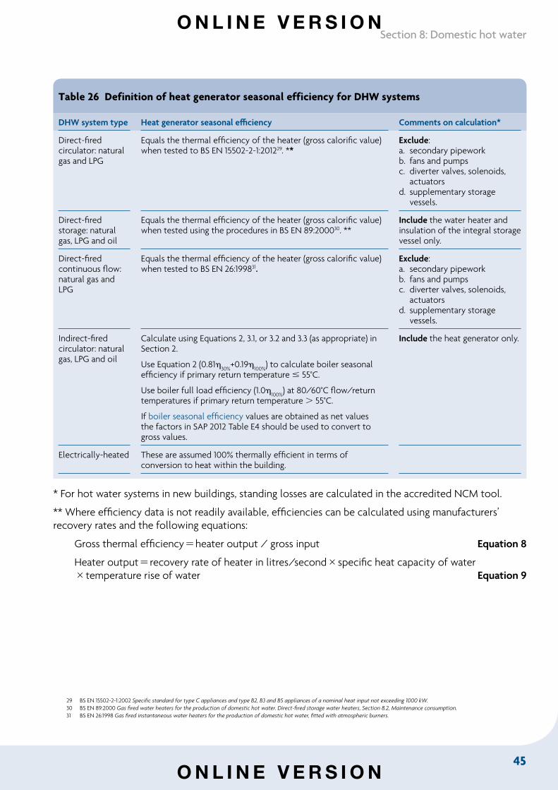
45
Section 8: Domestic hot water
Table 26 Definition of heat generator seasonal efficiency for DHW systems
DHW system type Heat generator seasonal efficiency Comments on calculation*
Direct-fired circulator: natural gas and LPG
Equals the thermal efficiency of the heater (gross calorific value) when tested to BS EN 15502-2-1:201229. **
Exclude: a. secondary pipeworkb. fans and pumpsc. diverter valves, solenoids,
actuatorsd. supplementary storage
vessels.
Direct-fired storage: natural gas, LPG and oil
Equals the thermal efficiency of the heater (gross calorific value) when tested using the procedures in BS EN 89:200030. **
Include the water heater and insulation of the integral storage vessel only.
Direct-fired continuous flow: natural gas and LPG
Equals the thermal efficiency of the heater (gross calorific value) when tested to BS EN 26:199831.
Exclude: a. secondary pipeworkb. fans and pumpsc. diverter valves, solenoids,
actuatorsd. supplementary storage
vessels.
Indirect-fired circulator: natural gas, LPG and oil
Calculate using Equations 2, 3.1, or 3.2 and 3.3 (as appropriate) in Section 2.
Use Equation 2 (0.8130%
+0.19100%
) to calculate boiler seasonal efficiency if primary return temperature 55°C.
Use boiler full load efficiency (1.0100%
) at 80/60°C flow/return temperatures if primary return temperature 55°C.
If boiler seasonal efficiency values are obtained as net values the factors in SAP 2012 Table E4 should be used to convert to gross values.
Include the heat generator only.
Electrically-heated These are assumed 100% thermally efficient in terms of conversion to heat within the building.
* For hot water systems in new buildings, standing losses are calculated in the accredited NCM tool.
** Where efficiency data is not readily available, efficiencies can be calculated using manufacturers’ recovery rates and the following equations:
Gross thermal efficiencyheater output / gross input Equation 8
Heater outputrecovery rate of heater in litres/secondspecific heat capacity of watertemperature rise of water Equation 9
29 BS EN 15502-2-1:2002 Specific standard for type C appliances and type B2, B3 and B5 appliances of a nominal heat input not exceeding 1000 kW.30 BS EN 89:2000 Gas fired water heaters for the production of domestic hot water. Direct-fired storage water heaters, Section 8.2, Maintenance consumption.31 BS EN 26:1998 Gas fired instantaneous water heaters for the production of domestic hot water, fitted with atmospheric burners.
O N L I N E V E R S I O N
O N L I N E V E R S I O N
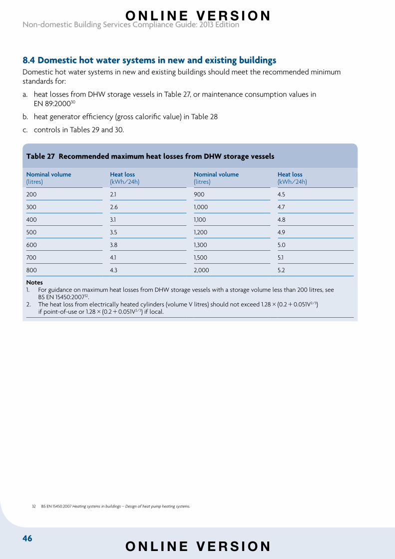
46
Non-domestic Building Services Compliance Guide: 2013 Edition
8.4 Domestic hot water systems in new and existing buildingsDomestic hot water systems in new and existing buildings should meet the recommended minimum standards for:
a. heat losses from DHW storage vessels in Table 27, or maintenance consumption values in EN 89:200030
b. heat generator efficiency (gross calorific value) in Table 28
c. controls in Tables 29 and 30.
Table 27 Recommended maximum heat losses from DHW storage vessels
Nominal volume(litres)
Heat loss(kWh/24h)
Nominal volume (litres)
Heat loss(kWh/24h)
200 2.1 900 4.5
300 2.6 1,000 4.7
400 3.1 1,100 4.8
500 3.5 1,200 4.9
600 3.8 1,300 5.0
700 4.1 1,500 5.1
800 4.3 2,000 5.2
Notes1. For guidance on maximum heat losses from DHW storage vessels with a storage volume less than 200 litres, see
BS EN 15450:200732.2. The heat loss from electrically heated cylinders (volume V litres) should not exceed 1.28(0.20.051V2/3)
if point-of-use or 1.28(0.20.051V2/3) if local.
32 BS EN 15450:2007 Heating systems in buildings – Design of heat pump heating systems.
O N L I N E V E R S I O N
O N L I N E V E R S I O N
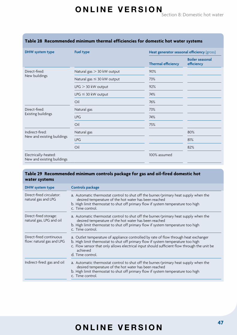
47
Section 8: Domestic hot water
Table 28 Recommended minimum thermal efficiencies for domestic hot water systems
DHW system type Fuel type Heat generator seasonal efficiency (gross)
Thermal efficiencyBoiler seasonal efficiency
Direct-fired:New buildings
Natural gas 30 kW output 90%
Natural gas 30 kW output 73%
LPG 30 kW output 92%
LPG 30 kW output 74%
Oil 76%
Direct-fired:Existing buildings
Natural gas 73%
LPG 74%
Oil 75%
Indirect-fired:New and existing buildings
Natural gas 80%
LPG 81%
Oil 82%
Electrically-heated:New and existing buildings
100% assumed
Table 29 Recommended minimum controls package for gas and oil-fired domestic hotwater systems
DHW system type Controls package
Direct-fired circulator: natural gas and LPG
a. Automatic thermostat control to shut off the burner/primary heat supply when the desired temperature of the hot water has been reached
b. High limit thermostat to shut off primary flow if system temperature too highc. Time control.
Direct-fired storage: natural gas, LPG and oil
a. Automatic thermostat control to shut off the burner/primary heat supply when the desired temperature of the hot water has been reached
b. High limit thermostat to shut off primary flow if system temperature too highc. Time control.
Direct-fired continuous flow: natural gas and LPG
a. Outlet temperature of appliance controlled by rate of flow through heat exchangerb. High limit thermostat to shut off primary flow if system temperature too highc. Flow sensor that only allows electrical input should sufficient flow through the unit be
achievedd. Time control.
Indirect-fired: gas and oil a. Automatic thermostat control to shut off the burner/primary heat supply when the desired temperature of the hot water has been reached
b. High limit thermostat to shut off primary flow if system temperature too highc. Time control.
O N L I N E V E R S I O N
O N L I N E V E R S I O N
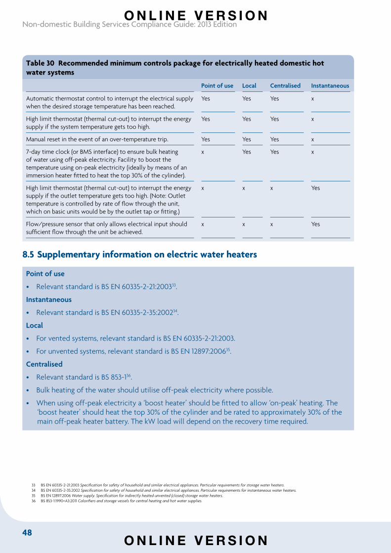
48
Non-domestic Building Services Compliance Guide: 2013 Edition
Table 30 Recommended minimum controls package for electrically heated domestic hotwater systems
Point of use Local Centralised Instantaneous
Automatic thermostat control to interrupt the electrical supply when the desired storage temperature has been reached.
Yes Yes Yes x
High limit thermostat (thermal cut-out) to interrupt the energy supply if the system temperature gets too high.
Yes Yes Yes x
Manual reset in the event of an over-temperature trip. Yes Yes Yes x
7-day time clock (or BMS interface) to ensure bulk heating of water using off-peak electricity. Facility to boost the temperature using on-peak electricity (ideally by means of an immersion heater fitted to heat the top 30% of the cylinder).
x Yes Yes x
High limit thermostat (thermal cut-out) to interrupt the energy supply if the outlet temperature gets too high. (Note: Outlet temperature is controlled by rate of flow through the unit, which on basic units would be by the outlet tap or fitting.)
x x x Yes
Flow/pressure sensor that only allows electrical input should sufficient flow through the unit be achieved.
x x x Yes
8.5 Supplementary information on electric water heaters
Point of use
• Relevant standard is BS EN 60335-2-21:200333.
Instantaneous
• Relevant standard is BS EN 60335-2-35:200234.
Local
• For vented systems, relevant standard is BS EN 60335-2-21:2003.
• For unvented systems, relevant standard is BS EN 12897:200635.
Centralised
• Relevant standard is BS 853-136.
• Bulk heating of the water should utilise off-peak electricity where possible.
• When using off-peak electricity a ‘boost heater’ should be fitted to allow ‘on-peak’ heating. The ‘boost heater’ should heat the top 30% of the cylinder and be rated to approximately 30% of the main off-peak heater battery. The kW load will depend on the recovery time required.
33 BS EN 60335-2-21:2003 Specification for safety of household and similar electrical appliances. Particular requirements for storage water heaters.34 BS EN 60335-2-35:2002 Specification for safety of household and similar electrical appliances. Particular requirements for instantaneous water heaters.35 BS EN 12897:2006 Water supply. Specification for indirectly heated unvented (closed) storage water heaters.36 BS 853-1:1990+A3:2011 Calorifiers and storage vessels for central heating and hot water supplies.
O N L I N E V E R S I O N
O N L I N E V E R S I O N
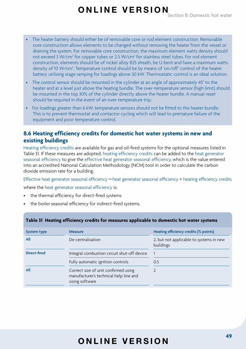
49
Section 8: Domestic hot water
• The heater battery should either be of removable core or rod element construction. Removable core construction allows elements to be changed without removing the heater from the vessel or draining the system. For removable core construction, the maximum element watts density should not exceed 3 W/cm2 for copper tubes or 2.5 W/cm2 for stainless steel tubes. For rod element construction, elements should be of nickel alloy 825 sheath, be U-bent and have a maximum watts density of 10 W/cm2. Temperature control should be by means of ‘on/off’ control of the heater battery utilising stage ramping for loadings above 30 kW. Thermostatic control is an ideal solution.
• The control sensor should be mounted in the cylinder at an angle of approximately 45° to the heater and at a level just above the heating bundle. The over-temperature sensor (high limit) should be mounted in the top 30% of the cylinder directly above the heater bundle. A manual reset should be required in the event of an over-temperature trip.
• For loadings greater than 6 kW, temperature sensors should not be fitted to the heater bundle. This is to prevent thermostat and contactor cycling which will lead to premature failure of the equipment and poor temperature control.
8.6 Heating efficiency credits for domestic hot water systems in new and existing buildingsHeating efficiency credits are available for gas and oil-fired systems for the optional measures listed in Table 31. If these measures are adopted, heating efficiency credits can be added to the heat generator seasonal efficiency to give the effective heat generator seasonal efficiency, which is the value entered into an accredited National Calculation Methodology (NCM) tool in order to calculate the carbon dioxide emission rate for a building.
Effective heat generator seasonal efficiencyheat generator seasonal efficiencyheating efficiency credits
where the heat generator seasonal efficiency is:
• the thermal efficiency for direct-fired systems
• the boiler seasonal efficiency for indirect-fired systems.
Table 31 Heating efficiency credits for measures applicable to domestic hot water systems
System type Measure Heating efficiency credits (% points)
All De-centralisation 2, but not applicable to systems in new buildings
Direct-fired Integral combustion circuit shut-off device 1
Fully automatic ignition controls 0.5
All Correct size of unit confirmed using manufacturer’s technical help line and sizing software
2
O N L I N E V E R S I O N
O N L I N E V E R S I O N
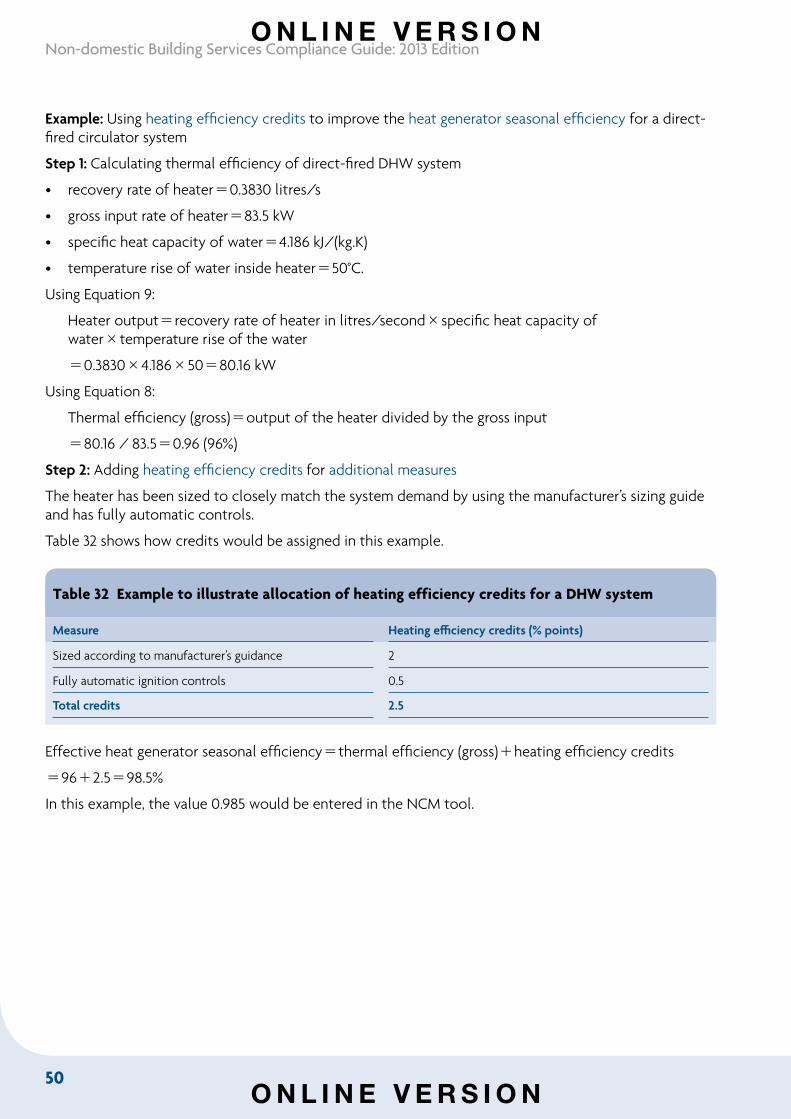
50
Non-domestic Building Services Compliance Guide: 2013 Edition
Example: Using heating efficiency credits to improve the heat generator seasonal efficiency for a direct-fired circulator system
Step 1: Calculating thermal efficiency of direct-fired DHW system
• recovery rate of heater0.3830 litres/s
• gross input rate of heater83.5 kW
• specific heat capacity of water4.186 kJ/(kg.K)
• temperature rise of water inside heater50°C.
Using Equation 9:
Heater outputrecovery rate of heater in litres/secondspecific heat capacity of watertemperature rise of the water
0.38304.1865080.16 kW
Using Equation 8:
Thermal efficiency (gross)output of the heater divided by the gross input
• 80.16 / 83.50.96 (96%)
Step 2: Adding heating efficiency credits for additional measures
The heater has been sized to closely match the system demand by using the manufacturer’s sizing guide and has fully automatic controls.
Table 32 shows how credits would be assigned in this example.
Table 32 Example to illustrate allocation of heating efficiency credits for a DHW system
Measure Heating efficiency credits (% points)
Sized according to manufacturer’s guidance 2
Fully automatic ignition controls 0.5
Total credits 2.5
Effective heat generator seasonal efficiencythermal efficiency (gross)heating efficiency credits
962.598.5%
In this example, the value 0.985 would be entered in the NCM tool.
O N L I N E V E R S I O N
O N L I N E V E R S I O N
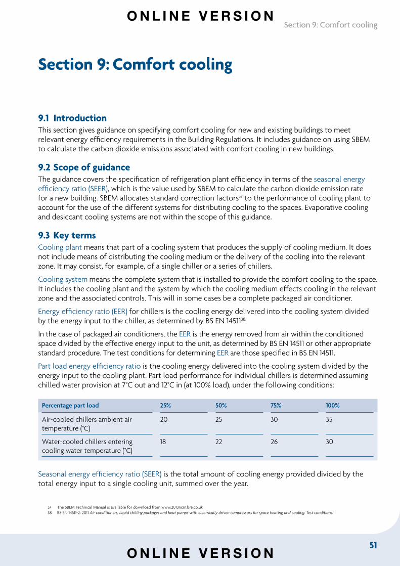
51
Section 9: Comfort cooling
Section 9: Comfort cooling
9.1 Introduction This section gives guidance on specifying comfort cooling for new and existing buildings to meet relevant energy efficiency requirements in the Building Regulations. It includes guidance on using SBEM to calculate the carbon dioxide emissions associated with comfort cooling in new buildings.
9.2 Scope of guidance The guidance covers the specification of refrigeration plant efficiency in terms of the seasonal energy efficiency ratio (SEER), which is the value used by SBEM to calculate the carbon dioxide emission rate for a new building. SBEM allocates standard correction factors37 to the performance of cooling plant to account for the use of the different systems for distributing cooling to the spaces. Evaporative cooling and desiccant cooling systems are not within the scope of this guidance.
9.3 Key termsCooling plant means that part of a cooling system that produces the supply of cooling medium. It does not include means of distributing the cooling medium or the delivery of the cooling into the relevant zone. It may consist, for example, of a single chiller or a series of chillers.
Cooling system means the complete system that is installed to provide the comfort cooling to the space. It includes the cooling plant and the system by which the cooling medium effects cooling in the relevant zone and the associated controls. This will in some cases be a complete packaged air conditioner.
Energy efficiency ratio (EER) for chillers is the cooling energy delivered into the cooling system divided by the energy input to the chiller, as determined by BS EN 1451138.
In the case of packaged air conditioners, the EER is the energy removed from air within the conditioned space divided by the effective energy input to the unit, as determined by BS EN 14511 or other appropriate standard procedure. The test conditions for determining EER are those specified in BS EN 14511.
Part load energy efficiency ratio is the cooling energy delivered into the cooling system divided by the energy input to the cooling plant. Part load performance for individual chillers is determined assuming chilled water provision at 7°C out and 12°C in (at 100% load), under the following conditions:
Percentage part load 25% 50% 75% 100%
Air-cooled chillers ambient air temperature (°C)
20 25 30 35
Water-cooled chillers entering cooling water temperature (°C)
18 22 26 30
Seasonal energy efficiency ratio (SEER) is the total amount of cooling energy provided divided by the total energy input to a single cooling unit, summed over the year.
37 The SBEM Technical Manual is available for download from www.2013ncm.bre.co.uk38 BS EN 14511-2: 2011 Air conditioners, liquid chilling packages and heat pumps with electrically driven compressors for space heating and cooling. Test conditions.
O N L I N E V E R S I O N
O N L I N E V E R S I O N
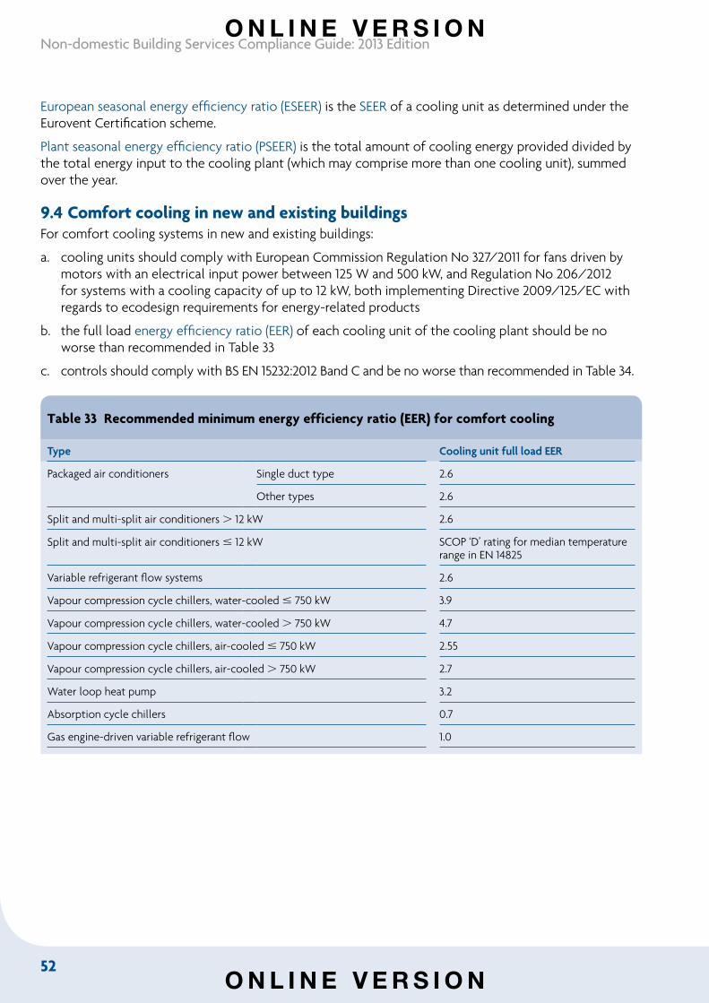
52
Non-domestic Building Services Compliance Guide: 2013 Edition
European seasonal energy efficiency ratio (ESEER) is the SEER of a cooling unit as determined under the Eurovent Certification scheme.
Plant seasonal energy efficiency ratio (PSEER) is the total amount of cooling energy provided divided by the total energy input to the cooling plant (which may comprise more than one cooling unit), summed over the year.
9.4 Comfort cooling in new and existing buildingsFor comfort cooling systems in new and existing buildings:
a. cooling units should comply with European Commission Regulation No 327/2011 for fans driven by motors with an electrical input power between 125 W and 500 kW, and Regulation No 206/2012 for systems with a cooling capacity of up to 12 kW, both implementing Directive 2009/125/EC with regards to ecodesign requirements for energy-related products
b. the full load energy efficiency ratio (EER) of each cooling unit of the cooling plant should be no worse than recommended in Table 33
c. controls should comply with BS EN 15232:2012 Band C and be no worse than recommended in Table 34.
Table 33 Recommended minimum energy efficiency ratio (EER) for comfort cooling
Type Cooling unit full load EER
Packaged air conditioners Single duct type 2.6
Other types 2.6
Split and multi-split air conditioners 12 kW 2.6
Split and multi-split air conditioners 12 kW SCOP ‘D’ rating for median temperature range in EN 14825
Variable refrigerant flow systems 2.6
Vapour compression cycle chillers, water-cooled 750 kW 3.9
Vapour compression cycle chillers, water-cooled 750 kW 4.7
Vapour compression cycle chillers, air-cooled 750 kW 2.55
Vapour compression cycle chillers, air-cooled 750 kW 2.7
Water loop heat pump 3.2
Absorption cycle chillers 0.7
Gas engine-driven variable refrigerant flow 1.0
O N L I N E V E R S I O N
O N L I N E V E R S I O N
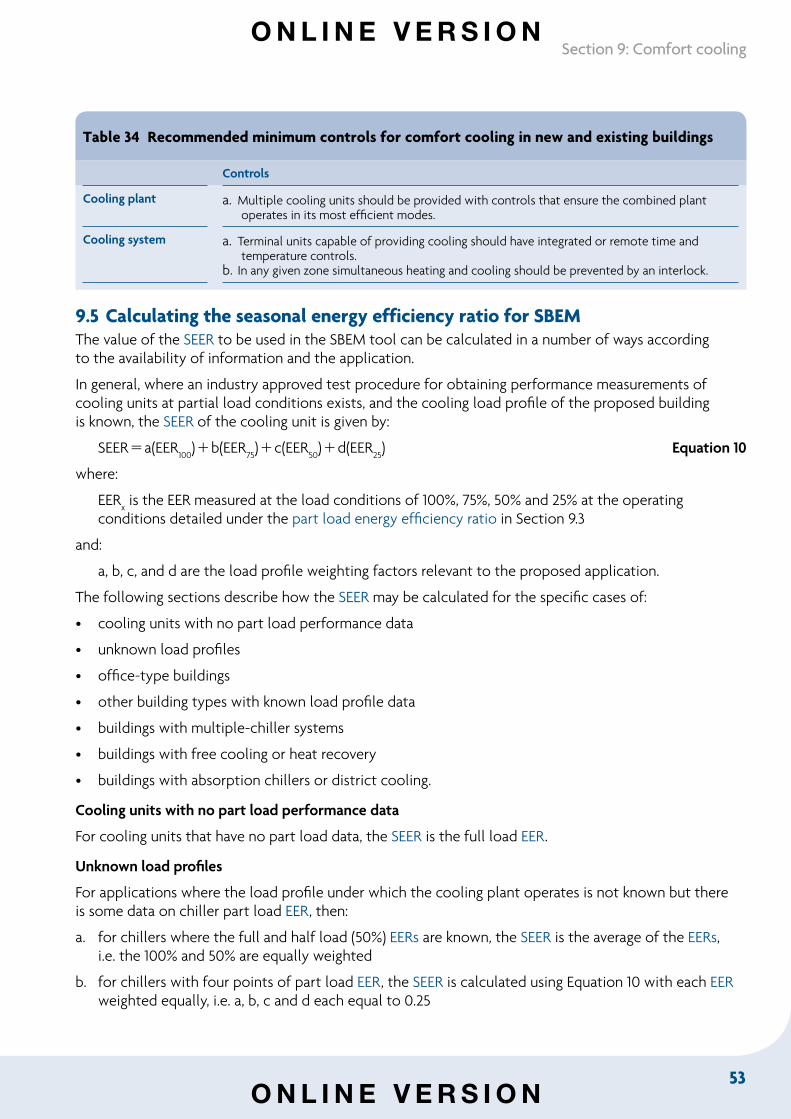
53
Section 9: Comfort cooling
Table 34 Recommended minimum controls for comfort cooling in new and existing buildings
Controls
Cooling plant a. Multiple cooling units should be provided with controls that ensure the combined plant operates in its most efficient modes.
Cooling system a. Terminal units capable of providing cooling should have integrated or remote time and temperature controls.
b. In any given zone simultaneous heating and cooling should be prevented by an interlock.
9.5 Calculating the seasonal energy efficiency ratio for SBEM The value of the SEER to be used in the SBEM tool can be calculated in a number of ways according to the availability of information and the application.
In general, where an industry approved test procedure for obtaining performance measurements of cooling units at partial load conditions exists, and the cooling load profile of the proposed building is known, the SEER of the cooling unit is given by:
SEERa(EER100)b(EER
75)c(EER
50)d(EER
25) Equation 10
where:
EERx is the EER measured at the load conditions of 100%, 75%, 50% and 25% at the operating
conditions detailed under the part load energy efficiency ratio in Section 9.3
and:
a, b, c, and d are the load profile weighting factors relevant to the proposed application.
The following sections describe how the SEER may be calculated for the specific cases of:
• cooling units with no part load performance data
• unknown load profiles
• office-type buildings
• other building types with known load profile data
• buildings with multiple-chiller systems
• buildings with free cooling or heat recovery
• buildings with absorption chillers or district cooling.
Cooling units with no part load performance data
For cooling units that have no part load data, the SEER is the full load EER.
Unknown load profiles
For applications where the load profile under which the cooling plant operates is not known but there is some data on chiller part load EER, then:
a. for chillers where the full and half load (50%) EERs are known, the SEER is the average of the EERs, i.e. the 100% and 50% are equally weighted
b. for chillers with four points of part load EER, the SEER is calculated using Equation 10 with each EER weighted equally, i.e. a, b, c and d each equal to 0.25
O N L I N E V E R S I O N
O N L I N E V E R S I O N
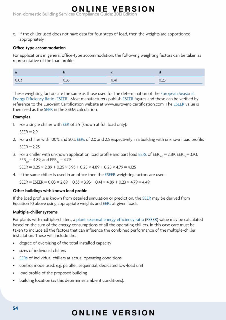
54
Non-domestic Building Services Compliance Guide: 2013 Edition
c. if the chiller used does not have data for four steps of load, then the weights are apportioned appropriately.
Office-type accommodation
For applications in general office-type accommodation, the following weighting factors can be taken as representative of the load profile:
a b c d
0.03 0.33 0.41 0.23
These weighting factors are the same as those used for the determination of the European Seasonal Energy Efficiency Ratio (ESEER). Most manufacturers publish ESEER figures and these can be verified by reference to the Eurovent Certification website at www.eurovent-certification.com. The ESEER value is then used as the SEER in the SBEM calculation.
Examples
1. For a single chiller with EER of 2.9 (known at full load only):
SEER2.9
2. For a chiller with 100% and 50% EERs of 2.0 and 2.5 respectively in a building with unknown load profile:
SEER2.25
3. For a chiller with unknown application load profile and part load EERs of EER100
2.89, EER753.93,
EER504.89, and EER
254.79:
SEER0.252.890.253.930.254.890.254.794.125
4. If the same chiller is used in an office then the ESEER weighting factors are used:
SEERESEER0.032.890.333.930.414.890.234.794.49
Other buildings with known load profile
If the load profile is known from detailed simulation or prediction, the SEER may be derived from Equation 10 above using appropriate weights and EERs at given loads.
Multiple-chiller systems
For plants with multiple-chillers, a plant seasonal energy efficiency ratio (PSEER) value may be calculated based on the sum of the energy consumptions of all the operating chillers. In this case care must be taken to include all the factors that can influence the combined performance of the multiple-chiller installation. These will include the:
• degree of oversizing of the total installed capacity
• sizes of individual chillers
• EERs of individual chillers at actual operating conditions
• control mode used: e.g. parallel, sequential, dedicated low-load unit
• load profile of the proposed building
• building location (as this determines ambient conditions).
O N L I N E V E R S I O N
O N L I N E V E R S I O N
55
Section 9: Comfort cooling
When these are known it may be possible to calculate a PSEER which matches the proposed installation more closely than by applying the simplifications described earlier. This PSEER value is then used as the SEER in the SBEM calculation.
Systems with free cooling or heat recovery
Systems that have the ability to use free cooling or heat recovery can achieve a greater SEER than more conventional systems. In these cases the SEER must be derived for the specific application under consideration.
Absorption chillers and district cooling
Absorption chillers may be used in conjunction with on-site CHP or a community or district heating system. The carbon dioxide emissions are calculated in the same way as when using CHP for heating. The control system should ensure as far as possible that heat from boilers is not used to supply the absorption chiller. The minimum full load EER of the absorption chillers should be no worse than 0.7.
Where a district cooling scheme exists, lower carbon dioxide emissions may result if the cooling is produced centrally from CHP/ absorption chillers, heat pumps or high efficiency vapour compression chillers. The district cooling company will provide information on the carbon dioxide content of the cooling energy supplied, and this figure can then be used to calculate the carbon dioxide emission rate for the building.
9.6 Supplementary information
BS EN 15243:200739 provides additional guidance on calculating the seasonal efficiency of cold generators and chillers in air conditioning systems. The guidance does not need to be followed to meet relevant energy efficiency requirements in the Building Regulations.
39 BS EN 15243:2007 Ventilation for buildings – Calculation of room temperatures and of load and energy for buildings with room conditioning systems.
O N L I N E V E R S I O N
O N L I N E V E R S I O N
56
Non-domestic Building Services Compliance Guide: 2013 Edition
Section 10: Air distribution
10.1 IntroductionThis section gives guidance on specifying air distribution systems for new and existing buildings to meet relevant energy efficiency requirements in the Building Regulations.
10.2 Scope of guidanceThe guidance applies to the following types of air distribution system:
• central air conditioning systems
• central mechanical ventilation systems with heating, cooling or heat recovery
• all central systems not covered by the above two types
• zonal supply systems where the fan is remote from the zone, such as ceiling void or roof-mounted units
• zonal extract systems where the fan is remote from the zone
• local supply and extract ventilation units such as window, wall or roof units serving a single area (e.g. toilet extract)
• other local ventilation units, e.g. fan coil units and fan assisted terminal VAV units
• kitchen extract, fan remote from zone with grease filter.
Gas and oil-fired air heaters installed within the area to be heated are not within the scope of this section.
10.3 Key termsAir conditioning system means a combination of components required to provide a form of air treatment in which temperature is controlled or can be lowered, possibly in combination with the control of ventilation, humidity and air cleanliness.
Ventilation system means a combination of components required to provide air treatment in which temperature, ventilation and air cleanliness are controlled.
Central system means a supply and extract system which serves the whole or major zones of the building.
Local unit means an unducted ventilation unit serving a single area.
Zonal system means a system which serves a group of rooms forming part of a building, i.e. a zone where ducting is required.
O N L I N E V E R S I O N
O N L I N E V E R S I O N
57
Section 10: Air distribution
Demand control is a type of control where the ventilation rate is controlled by air quality, moisture, occupancy or some other indicator of the need for ventilation.
Specific fan power (SFP) of an air distribution system means the sum of the design circuit-watts of the system fans that supply air and exhaust it back outdoors, including losses through switchgear and controls such as inverters (i.e. the total circuit-watts for the supply and extract fans), divided by the design air flow rate through that system.
For the purposes of this guide, the specific fan power of an air distribution system should be calculated according to the procedure set out in BS EN 13779:200740 Annex D Calculation and application of specific fan power – Calculating and checking the SFP, SFP
E and SFP
V.
SFP P
sfP
ef Equation 11q
where:
SFP is the specific fan power demand of the air distribution system (W/(l.s))
Psf is the total fan power of all supply air fans at the design air flow rate, including power losses
through switchgear and controls associated with powering and controlling the fans (W)
Pef is the total fan power of all exhaust air fans at the design air flow rate including power losses
through switchgear and controls associated with powering and controlling the fans (W)
q is the design air flow rate through the system, which should be the greater of either the supply or exhaust air flow (l/s). Note that for an air handling unit, q is the largest supply or extract air flow through the unit.
External system pressure drop means the total system pressure drop excluding the pressure drop across the air handling unit (AHU).
10.4 Air distribution systems in new and existing buildings Air distribution systems in new and existing buildings should meet the following recommended minimum standards:
a. Air handling systems should be capable of achieving a specific fan power at 25% of design flow rate no greater than that achieved at 100% design flow rate.
b. In order to aid commissioning and to provide flexibility for future changes of use, reasonable provision would be to equip with variable speed drives those fans that are rated at more than 1100 W and which form part of the environmental control systems, including smoke control fans used for control of overheating. The provision is not applicable to smoke control fans and similar ventilation systems only used in abnormal circumstances.
40 BS EN 13779:2007 Ventilation for non-residential buildings – Performance requirements for ventilation and room-conditioning systems.
O N L I N E V E R S I O N
O N L I N E V E R S I O N
58
Non-domestic Building Services Compliance Guide: 2013 Edition
c. In order to limit air leakage, ventilation ductwork should be made and assembled so as to be reasonably airtight. Ways of meeting this requirement would be to comply with the specifications given in:
i. B&ES DW14441. Membership of the B&ES specialist ductwork group or the Association of Ductwork Contractors and Allied Services is one way of demonstrating suitable qualifications; or
ii. British Standards such as BS EN 1507:200642, BS EN 12237:200343 and BS EN 13403:200344.
d. In order to limit air leakage, air handling units should be made and assembled so as to be reasonably airtight. Ways of meeting this requirement would be to comply with Class L2 air leakage given in BS EN 1886:200745.
e. The specific fan power of air distribution systems at the design air flow rate should be no worse than in Table 35 for new and existing buildings. Specific fan power is a function of the system resistance that the fan has to overcome to provide the required flow rate. BS EN 1377940 Table A8 provides guidance on system pressure drop. To minimise specific fan power it is recommended that the ‘low range’ is used as a design target.
f. Where the primary air and cooling is provided by central plant and by an air distribution system that includes the additional components listed in Table 36, the allowed specific fan powers may be increased by the amounts shown in Table 36 to account for the additional resistance.
g. A minimum controls package should be provided in new and existing buildings as in Table 37.
h. Ventilation fans driven by electric motors should comply with European Commission Regulation No 327/2011 implementing Directive 2009/125/EC with regard to ecodesign requirements for fans driven by motors with an electric input power between 125 W and 500 kW.
41 Ductwork Specification DW/144 Specifications for sheet metal ductwork – Low, medium and high pressure/velocity air system, B&ES, 2013.42 BS EN 1507:2006 Ventilation for buildings – Sheet metal air ducts with rectangular section – Requirements for strength and leakage.43 BS EN 12237:2003 Ventilation for buildings – Ductwork – Strength and leakage of circular sheet metal ducts.44 BS EN 13403:2003 Ventilation for buildings – Non-metallic ducts – Ductwork made from insulation ductboards.45 BS EN 1886:2007 Ventilation for buildings – Air handling units – Mechanical performance.
O N L I N E V E R S I O N
O N L I N E V E R S I O N
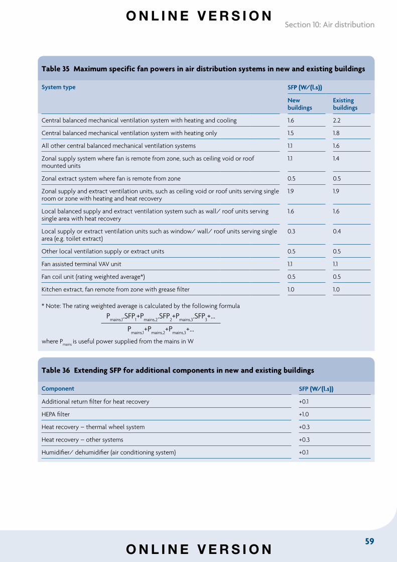
59
Section 10: Air distribution
Table 35 Maximum specific fan powers in air distribution systems in new and existing buildings
System type SFP (W/(l.s))
New buildings
Existing buildings
Central balanced mechanical ventilation system with heating and cooling 1.6 2.2
Central balanced mechanical ventilation system with heating only 1.5 1.8
All other central balanced mechanical ventilation systems 1.1 1.6
Zonal supply system where fan is remote from zone, such as ceiling void or roof mounted units
1.1 1.4
Zonal extract system where fan is remote from zone 0.5 0.5
Zonal supply and extract ventilation units, such as ceiling void or roof units serving single room or zone with heating and heat recovery
1.9 1.9
Local balanced supply and extract ventilation system such as wall/ roof units serving single area with heat recovery
1.6 1.6
Local supply or extract ventilation units such as window/ wall/ roof units serving single area (e.g. toilet extract)
0.3 0.4
Other local ventilation supply or extract units 0.5 0.5
Fan assisted terminal VAV unit 1.1 1.1
Fan coil unit (rating weighted average*) 0.5 0.5
Kitchen extract, fan remote from zone with grease filter 1.0 1.0
* Note: The rating weighted average is calculated by the following formula
Pmains,1
.SFP1+P
mains,2.SFP
2+P
mains,3.SFP
3+...
Pmains,1
+Pmains,2
+Pmains,3
+...
where Pmains
is useful power supplied from the mains in W
Table 36 Extending SFP for additional components in new and existing buildings
Component SFP (W/(l.s))
Additional return filter for heat recovery +0.1
HEPA filter +1.0
Heat recovery – thermal wheel system +0.3
Heat recovery – other systems +0.3
Humidifier/ dehumidifier (air conditioning system) +0.1
O N L I N E V E R S I O N
O N L I N E V E R S I O N
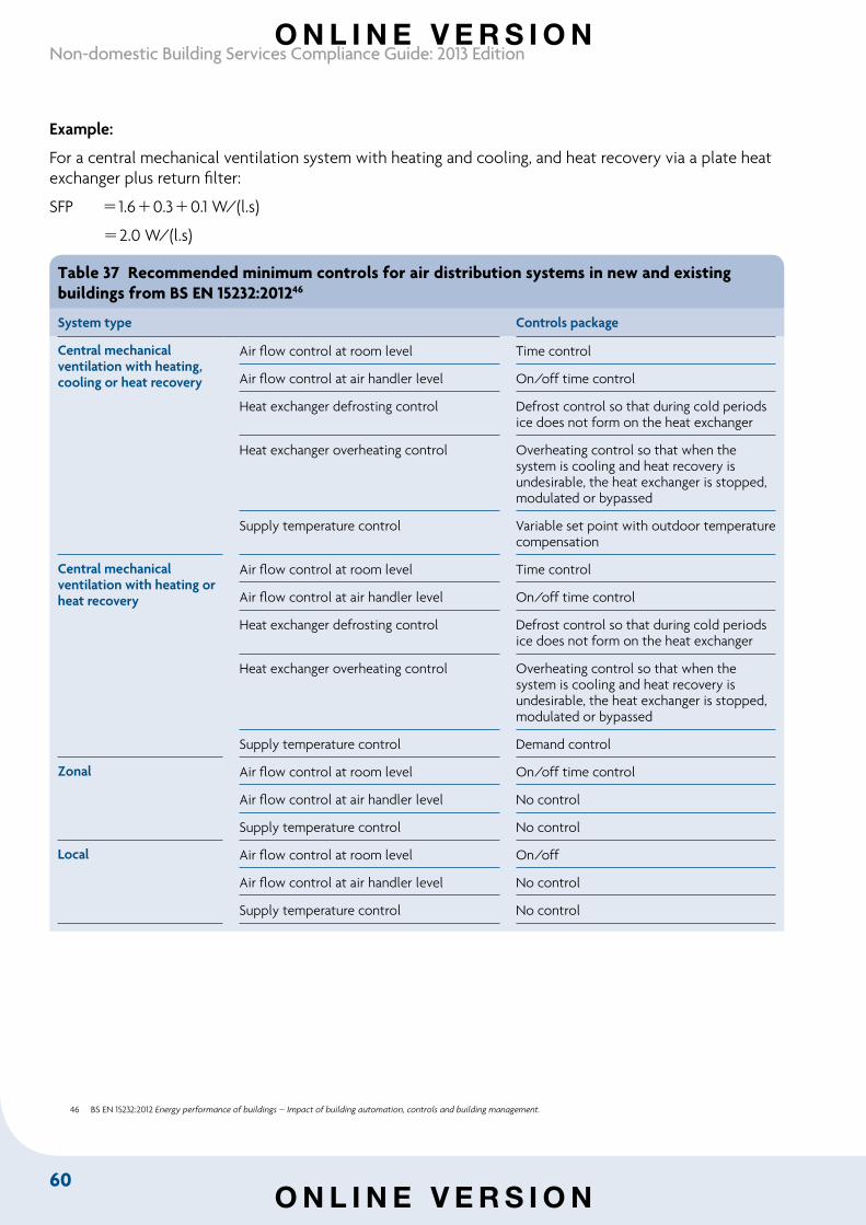
60
Non-domestic Building Services Compliance Guide: 2013 Edition
Example:
For a central mechanical ventilation system with heating and cooling, and heat recovery via a plate heat exchanger plus return filter:
SFP 1.60.30.1 W/(l.s)
2.0 W/(l.s)
Table 37 Recommended minimum controls for air distribution systems in new and existing buildings from BS EN 15232:201246
System type Controls package
Central mechanical ventilation with heating, cooling or heat recovery
Air flow control at room level Time control
Air flow control at air handler level On/off time control
Heat exchanger defrosting control Defrost control so that during cold periods ice does not form on the heat exchanger
Heat exchanger overheating control Overheating control so that when the system is cooling and heat recovery is undesirable, the heat exchanger is stopped, modulated or bypassed
Supply temperature control Variable set point with outdoor temperature compensation
Central mechanical ventilation with heating or heat recovery
Air flow control at room level Time control
Air flow control at air handler level On/off time control
Heat exchanger defrosting control Defrost control so that during cold periods ice does not form on the heat exchanger
Heat exchanger overheating control Overheating control so that when the system is cooling and heat recovery is undesirable, the heat exchanger is stopped, modulated or bypassed
Supply temperature control Demand control
Zonal Air flow control at room level On/off time control
Air flow control at air handler level No control
Supply temperature control No control
Local Air flow control at room level On/off
Air flow control at air handler level No control
Supply temperature control No control
46 BS EN 15232:2012 Energy performance of buildings – Impact of building automation, controls and building management.
O N L I N E V E R S I O N
O N L I N E V E R S I O N
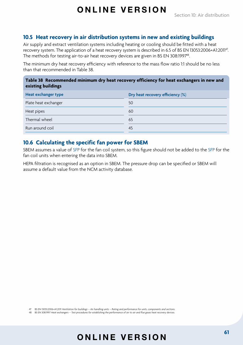
61
Section 10: Air distribution
10.5 Heat recovery in air distribution systems in new and existing buildings Air supply and extract ventilation systems including heating or cooling should be fitted with a heat recovery system. The application of a heat recovery system is described in 6.5 of BS EN 13053:2006+A1:201147. The methods for testing air-to-air heat recovery devices are given in BS EN 308:199748.
The minimum dry heat recovery efficiency with reference to the mass flow ratio 1:1 should be no less than that recommended in Table 38.
Table 38 Recommended minimum dry heat recovery efficiency for heat exchangers in new and existing buildings
Heat exchanger type Dry heat recovery efficiency (%)
Plate heat exchanger 50
Heat pipes 60
Thermal wheel 65
Run around coil 45
10.6 Calculating the specific fan power for SBEMSBEM assumes a value of SFP for the fan coil system, so this figure should not be added to the SFP for the fan coil units when entering the data into SBEM.
HEPA filtration is recognised as an option in SBEM. The pressure drop can be specified or SBEM will assume a default value from the NCM activity database.
47 BS EN 13053:2006+A1:2011 Ventilation for buildings – Air handling units – Rating and performance for units, components and sections. 48 BS EN 308:1997 Heat exchangers – Test procedures for establishing the performance of air to air and flue gases heat recovery devices.
O N L I N E V E R S I O N
O N L I N E V E R S I O N
62
Non-domestic Building Services Compliance Guide: 2013 Edition
Section 11: Pipework and ductwork insulation
11.1 IntroductionThis section gives guidance on insulating pipework and ducting serving space heating, hot water and cooling systems in new and existing buildings to meet relevant energy efficiency requirements in the Building Regulations.
The insulation of pipework and ducting is essential to minimise heating system heat losses and cooling system heat gains. For cooling systems, it is also important to ensure that the risk of condensation is adequately controlled.
11.2 Scope of guidance The guidance in this section covers insulation for the following types of pipework and ductwork serving space heating, domestic hot water and cooling systems:
• pipework: direct hot water, low, medium and high temperature heating, and cooled
• ductwork: heated, cooled and dual-purpose heated and cooled.
11.3 Insulation of pipes and ducts in new and existing buildings Insulation of pipes and ducts serving heating and cooling systems should meet the following recommended minimum standards:
a. Direct hot water and heating pipework
i. Pipework serving space heating and hot water systems should be insulated in all areas outside of the heated building envelope. In addition, pipes should be insulated in all voids within the building envelope and within spaces which will normally be heated, if there is a possibility that those spaces might be maintained at temperatures different to those maintained in other zones. The guiding principles are that control should be maximised and that heat loss from uninsulated pipes should only be permitted where the heat can be demonstrated as ‘always useful’.
ii. In order to demonstrate compliance, the heat losses shown in Table 39 for different pipe sizes and temperatures should not be exceeded.
b. Cooled pipework
i. Cooled pipework should be insulated along its whole length in order to provide the necessary means of limiting heat gain. Control should be maximised and heat gain to uninsulated pipes should only be permitted where the proportion of the cooling load relating to distribution pipework is proven to be less than 1% of total load.
ii. In order to demonstrate compliance, the heat gains in Table 40 for different pipe sizes and temperatures should not be exceeded.
iii. Although unrelated to meeting relevant energy efficiency requirements in the Building Regulations, provision should also be made for control of condensation by following TIMSA guidance49.
49 TIMSA HVAC guidance for achieving compliance with Part L of the Building Regulations.
O N L I N E V E R S I O N
O N L I N E V E R S I O N
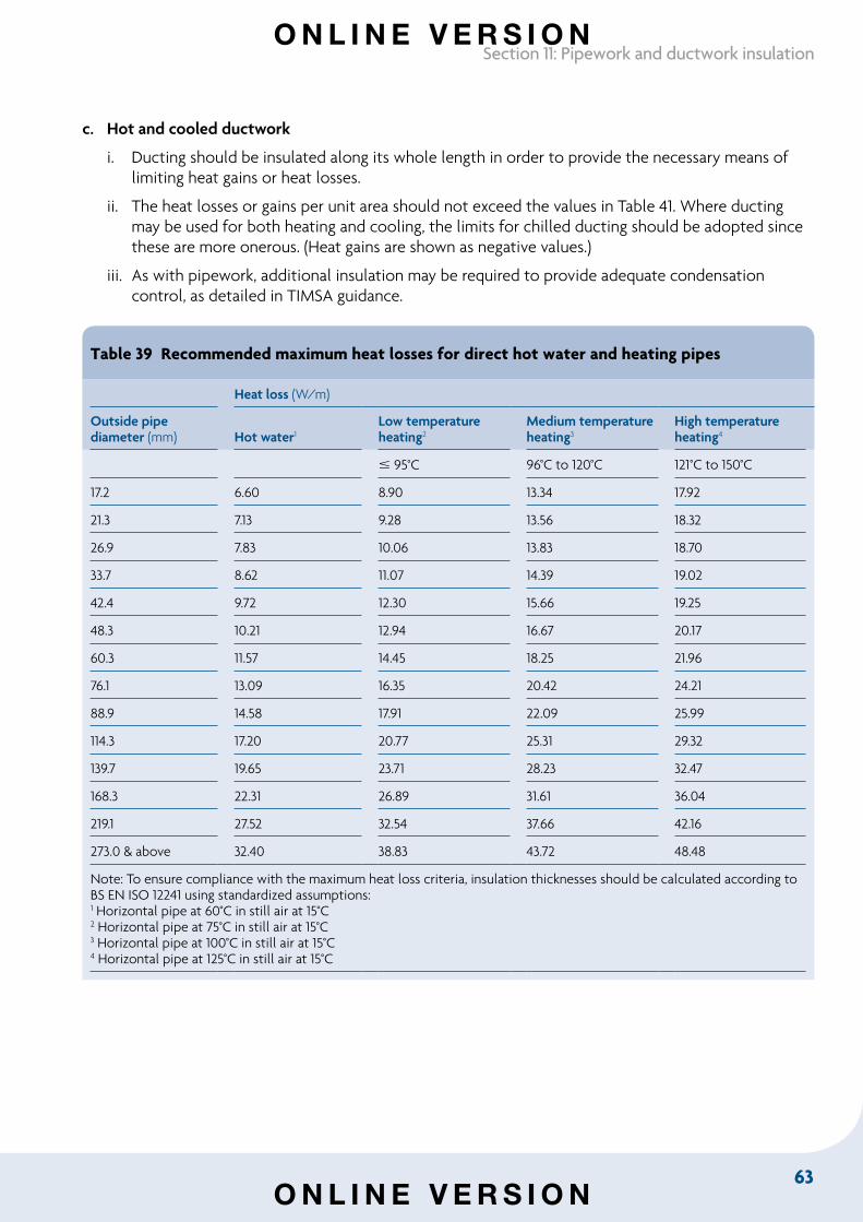
63
Section 11: Pipework and ductwork insulation
c. Hot and cooled ductwork
i. Ducting should be insulated along its whole length in order to provide the necessary means of limiting heat gains or heat losses.
ii. The heat losses or gains per unit area should not exceed the values in Table 41. Where ducting may be used for both heating and cooling, the limits for chilled ducting should be adopted since these are more onerous. (Heat gains are shown as negative values.)
iii. As with pipework, additional insulation may be required to provide adequate condensation control, as detailed in TIMSA guidance.
Table 39 Recommended maximum heat losses for direct hot water and heating pipes
Heat loss (W/m)
Outside pipe diameter (mm) Hot water1
Low temperature heating2
Medium temperature heating3
High temperature heating4
95°C 96°C to 120°C 121°C to 150°C
17.2 6.60 8.90 13.34 17.92
21.3 7.13 9.28 13.56 18.32
26.9 7.83 10.06 13.83 18.70
33.7 8.62 11.07 14.39 19.02
42.4 9.72 12.30 15.66 19.25
48.3 10.21 12.94 16.67 20.17
60.3 11.57 14.45 18.25 21.96
76.1 13.09 16.35 20.42 24.21
88.9 14.58 17.91 22.09 25.99
114.3 17.20 20.77 25.31 29.32
139.7 19.65 23.71 28.23 32.47
168.3 22.31 26.89 31.61 36.04
219.1 27.52 32.54 37.66 42.16
273.0 & above 32.40 38.83 43.72 48.48
Note: To ensure compliance with the maximum heat loss criteria, insulation thicknesses should be calculated according to BS EN ISO 12241 using standardized assumptions:1 Horizontal pipe at 60°C in still air at 15°C2 Horizontal pipe at 75°C in still air at 15°C 3 Horizontal pipe at 100°C in still air at 15°C 4 Horizontal pipe at 125°C in still air at 15°C
O N L I N E V E R S I O N
O N L I N E V E R S I O N
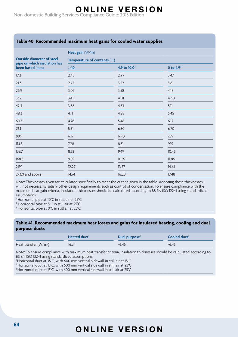
64
Non-domestic Building Services Compliance Guide: 2013 Edition
Table 40 Recommended maximum heat gains for cooled water supplies
Outside diameter of steel pipe on which insulation has been based (mm)
Heat gain (W/m)
Temperature of contents (°C)
101 4.9 to 10.02 0 to 4.93
17.2 2.48 2.97 3.47
21.3 2.72 3.27 3.81
26.9 3.05 3.58 4.18
33.7 3.41 4.01 4.60
42.4 3.86 4.53 5.11
48.3 4.11 4.82 5.45
60.3 4.78 5.48 6.17
76.1 5.51 6.30 6.70
88.9 6.17 6.90 7.77
114.3 7.28 8.31 9.15
139.7 8.52 9.49 10.45
168.3 9.89 10.97 11.86
219.1 12.27 13.57 14.61
273.0 and above 14.74 16.28 17.48
Note: Thicknesses given are calculated specifically to meet the criteria given in the table. Adopting these thicknesses will not necessarily satisfy other design requirements such as control of condensation. To ensure compliance with the maximum heat gain criteria, insulation thicknesses should be calculated according to BS EN ISO 12241 using standardized assumptions: 1 Horizontal pipe at 10°C in still air at 25°C2 Horizontal pipe at 5°C in still air at 25°C3 Horizontal pipe at 0°C in still air at 25°C
Table 41 Recommended maximum heat losses and gains for insulated heating, cooling and dual purpose ducts
Heated duct1 Dual purpose2 Cooled duct3
Heat transfer (W/m2) 16.34 -6.45 -6.45
Note: To ensure compliance with maximum heat transfer criteria, insulation thicknesses should be calculated according to BS EN ISO 12241 using standardized assumptions: 1 Horizontal duct at 35°C, with 600 mm vertical sidewall in still air at 15°C2 Horizontal duct at 13°C, with 600 mm vertical sidewall in still air at 25°C 3 Horizontal duct at 13°C, with 600 mm vertical sidewall in still air at 25°C
O N L I N E V E R S I O N
O N L I N E V E R S I O N
65
Section 12: Lighting
Section 12: Lighting
12.1 IntroductionThis section provides guidance on specifying lighting for new and existing non-domestic buildings to meet relevant energy efficiency requirements in the Building Regulations. There are two alternative approaches, applicable both to systems in new buildings and to replacement systems in existing buildings.
12.2 Scope of guidanceThe guidance in this section applies to the following types of lighting:
• general interior lighting
• display lighting.
12.3 Key termsOffice area means a space that involves predominantly desk-based tasks – e.g. a classroom, seminar or conference room.
Daylit space means any space:
a. within 6 m of a window wall, provided that the glazing area is at least 20% of the internal area of the window wall
b. below rooflights, provided that the glazing area is at least 10% of the floor area.
The normal light transmittance of the glazing should be at least 70%; if the light transmittance is below 70%, the glazing area should be increased proportionately for the space to be defined as daylit.
Space classification for control purposes50:
Owned space means a space such as a small room for one or two people who control the lighting – e.g. a cellular office or consulting room.
Shared space means a multi-occupied area – e.g. an open-plan office or factory production area.
Temporarily owned space means a space where people are expected to operate the lighting controls while they are there – e.g. a hotel room or meeting room.
Occasionally visited space means a space where people generally stay for a relatively short period of time when they visit the space – e.g. a storeroom or toilet.
Unowned space means a space where individual users require lighting but are not expected to operate the lighting controls – e.g. a corridor or atrium.
Managed space means a space where lighting is under the control of a responsible person – e.g. a hotel lounge, restaurant or shop.
Local manual switching means that the distance on plan from any local switch to the luminaire it controls should generally be not more than six metres, or twice the height of the light fitting above the floor if this is greater. Where the space is a daylit space served by side windows, the perimeter row of lighting should in general be separately switched.
50 These definitions are given in more detail in BRE Information Paper IP6/96 People and lighting controls and BRE Digest 498 Selecting lighting controls.
O N L I N E V E R S I O N
O N L I N E V E R S I O N
66
Non-domestic Building Services Compliance Guide: 2013 Edition
Photoelectric control is a type of control which switches or dims lighting in response to the amount of incoming daylight.
Presence detection is a type of control which switches the lighting on when someone enters a space, and switches it off, or dims it down, after the space becomes unoccupied.
Absence detection is a type of control which switches the lighting off, or dims it down, after the space becomes unoccupied, but where switching on is done manually.
Lamp lumens means the sum of the average initial (100 hour) lumen output of all the lamps in the luminaire.
Circuit-watt is the power consumed in lighting circuits by lamps and, where applicable, their associated control gear (including transformers and drivers) and power factor correction equipment.
Lamp lumens per circuit-watt is the total lamp lumens summed for all luminaires in the relevant areas of the building, divided by the total circuit-watts for all the luminaires.
LOR is the light output ratio of the luminaire, which means the ratio of the total light output of the luminaire under stated practical conditions to that of the lamp or lamps contained in the luminaire under reference conditions.
Luminaire lumens per circuit-watt is the (lamp lumens x LOR) summed for all luminaires in the relevant areas of the building, divided by the total circuit-watts for all the luminaires.
LENI (Lighting Energy Numerical Indicator) is a measure of the performance of lighting in terms of energy per square metre per year (kWh/m2/year), based on BS EN 15193:2007, Energy performance of buildings.
12.4 Lighting in new and existing buildingsa. Lighting in new and existing buildings should meet the recommended minimum standards for:
i. efficacy (averaged over the whole area of the applicable type of space in the building) and controls in Table 42
OR
ii. the LENI in Table 44. The LENI should be calculated using the procedure described in Section 12.5.
b. The lighting should be metered to record its energy consumption in accordance with the minimum standards in Table 43.
c. Lighting controls in new and existing buildings should follow the guidance in BRE Digest 498 Selecting lighting controls. Display lighting, where provided, should be controlled on dedicated circuits that can be switched off at times when people will not be inspecting exhibits or merchandise, or being entertained.
O N L I N E V E R S I O N
O N L I N E V E R S I O N
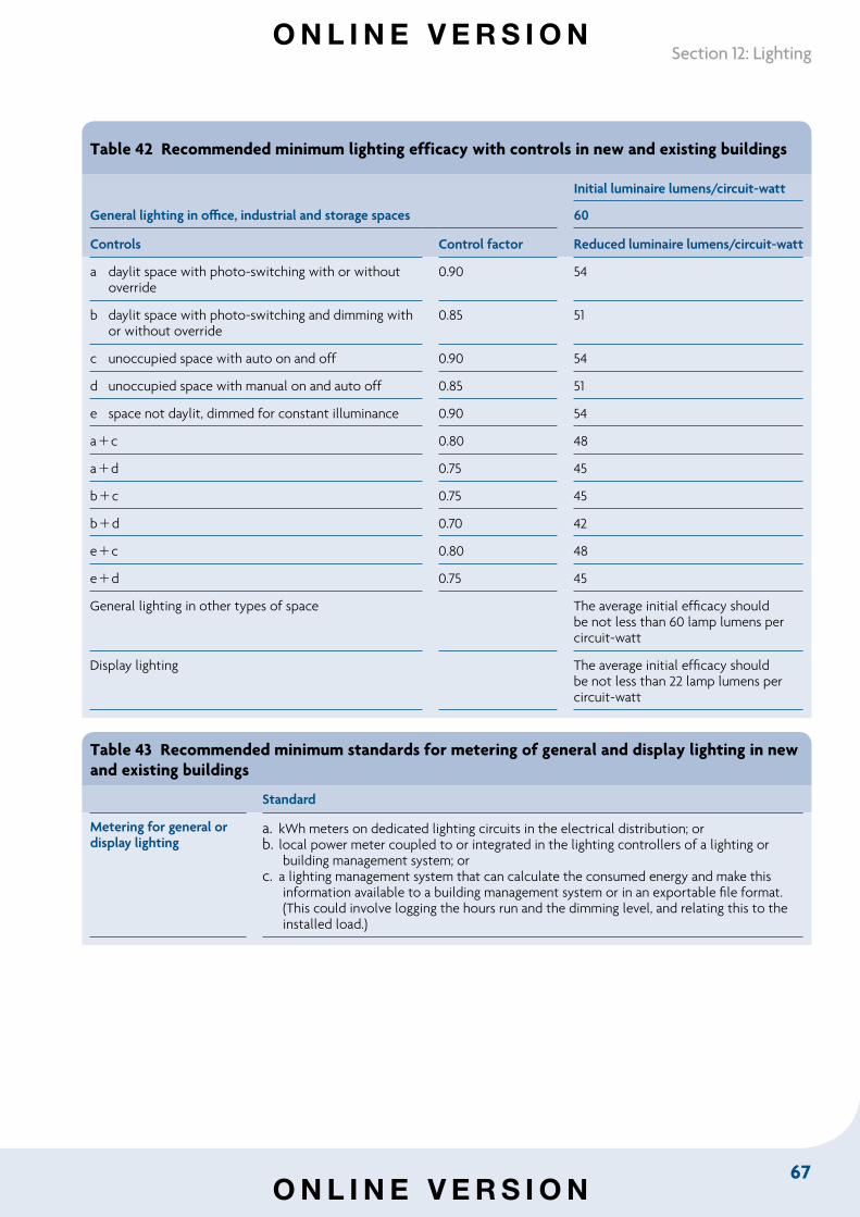
67
Section 12: Lighting
Table 42 Recommended minimum lighting efficacy with controls in new and existing buildings
General lighting in office, industrial and storage spaces
Initial luminaire lumens/circuit-watt
60
Controls Control factor Reduced luminaire lumens/circuit-watt
a daylit space with photo-switching with or without override
0.90 54
b daylit space with photo-switching and dimming with or without override
0.85 51
c unoccupied space with auto on and off 0.90 54
d unoccupied space with manual on and auto off 0.85 51
e space not daylit, dimmed for constant illuminance 0.90 54
ac 0.80 48
ad 0.75 45
bc 0.75 45
bd 0.70 42
ec 0.80 48
ed 0.75 45
General lighting in other types of space The average initial efficacy should be not less than 60 lamp lumens per circuit-watt
Display lighting The average initial efficacy should be not less than 22 lamp lumens per circuit-watt
Table 43 Recommended minimum standards for metering of general and display lighting in new and existing buildings
Standard
Metering for general or display lighting
a. kWh meters on dedicated lighting circuits in the electrical distribution; orb. local power meter coupled to or integrated in the lighting controllers of a lighting or
building management system; orc. a lighting management system that can calculate the consumed energy and make this
information available to a building management system or in an exportable file format. (This could involve logging the hours run and the dimming level, and relating this to the installed load.)
O N L I N E V E R S I O N
O N L I N E V E R S I O N
68
Non-domestic Building Services Compliance Guide: 2013 Edition
12.5 Lighting Energy Numerical Indicator (LENI)An alternative to complying with the efficacy standards in Table 42 is to follow the Lighting Energy Numerical Indicator (LENI) method.
The LENI method calculates the performance of lighting in terms of energy per square metre per year. The approach described below must be followed in calculating the LENI for a lighting scheme. The LENI should not exceed the lighting energy limit specified in Table 44 for a given illuminance and hours run51.
Design the lighting
The first step to energy efficient lighting is to design the lighting installation in a way that meets all of the users’ needs for the space under consideration. Recommendations for appropriate illuminance values and other lighting requirements may be found in BS EN 12464-1:2011, Light and lighting – Lighting of work places – Indoor work places, and in the Society of Light and Lighting (SLL) Code for Lighting. The SLL Handbook provides practical advice on how to design lighting for a number of different applications.
Look up the lighting energy limit
In designing the lighting, a level of illuminance will have been selected as necessary for the tasks being done in a particular area. It is also necessary to determine how many hours per year the lighting will be needed. Once both the illuminance and the hours are known it is possible to look up the lighting energy limit in Table 44. For example, a classroom in a school may be lit to 300 lux and used for 40 hours per week for 39 weeks of the year, giving a total of 1560 hours per year. Values of 1500 hours and 300 lux give a lighting energy limit of 7.70. Table 44 also gives day time (Td) and night time (Tn) hour values which are used in the calculation of energy consumption.
If display lighting is used, then the lighting energy limit may be increased by the value given for normal display lighting for the area of the room where display lighting is used. For example, in an entrance area for a building there may be some display lighting in a small area around the reception desk but not in the rest of the area.
Shop windows use a lot of display lighting and may use up to 192.72 kWh/m2/yr if the window faces a public road, and 96.8 kWh/m2/yr if the window is in a shopping centre that is closed during the night.
Calculate the parasitic energy use (Ep)
If some form of lighting control system is used, then an allowance needs to be made for the energy used by the control system, and the fact that the luminaires take a little power even if they are dimmed down to give no light. An allowance of 0.3 W/m2 should be made for power used in this way. If the whole lighting system is switched off when the room is not in use, then the power loss is only during the hours of use. If the system is left on all the time then the power loss occurs for 8760 hours per year.
If no lighting control system is used, then the parasitic energy use is zero.
Determine the total power of lighting (Pl)
This is the total power in watts consumed by the luminaires within a space.
51 For further information, see www.sll.org.uk/resources/partl
O N L I N E V E R S I O N
O N L I N E V E R S I O N
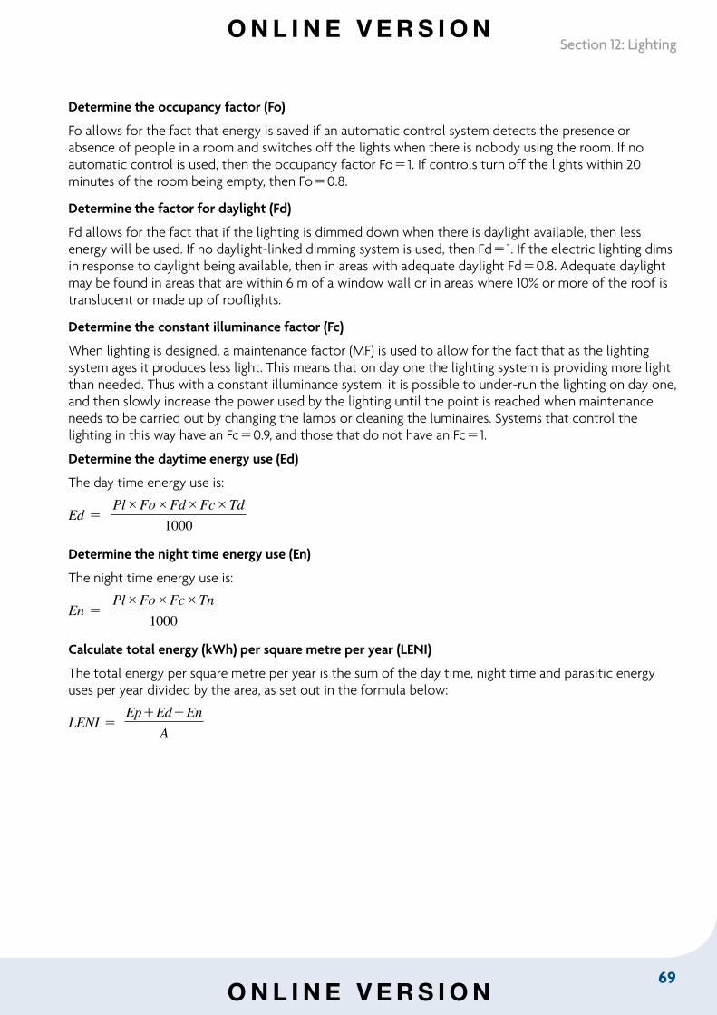
69
Section 12: Lighting
Determine the occupancy factor (Fo)
Fo allows for the fact that energy is saved if an automatic control system detects the presence or absence of people in a room and switches off the lights when there is nobody using the room. If no automatic control is used, then the occupancy factor Fo1. If controls turn off the lights within 20 minutes of the room being empty, then Fo0.8.
Determine the factor for daylight (Fd)
Fd allows for the fact that if the lighting is dimmed down when there is daylight available, then less energy will be used. If no daylight-linked dimming system is used, then Fd1. If the electric lighting dims in response to daylight being available, then in areas with adequate daylight Fd0.8. Adequate daylight may be found in areas that are within 6 m of a window wall or in areas where 10% or more of the roof is translucent or made up of rooflights.
Determine the constant illuminance factor (Fc)
When lighting is designed, a maintenance factor (MF) is used to allow for the fact that as the lighting system ages it produces less light. This means that on day one the lighting system is providing more light than needed. Thus with a constant illuminance system, it is possible to under-run the lighting on day one, and then slowly increase the power used by the lighting until the point is reached when maintenance needs to be carried out by changing the lamps or cleaning the luminaires. Systems that control the lighting in this way have an Fc0.9, and those that do not have an Fc1.
Determine the daytime energy use (Ed)
The day time energy use is:
Ed PlFoFdFcTd
1000
Determine the night time energy use (En)
The night time energy use is:
En PlFoFcTn
1000
Calculate total energy (kWh) per square metre per year (LENI)
The total energy per square metre per year is the sum of the day time, night time and parasitic energy uses per year divided by the area, as set out in the formula below:
LENI EpEdEn
A
O N L I N E V E R S I O N
O N L I N E V E R S I O N
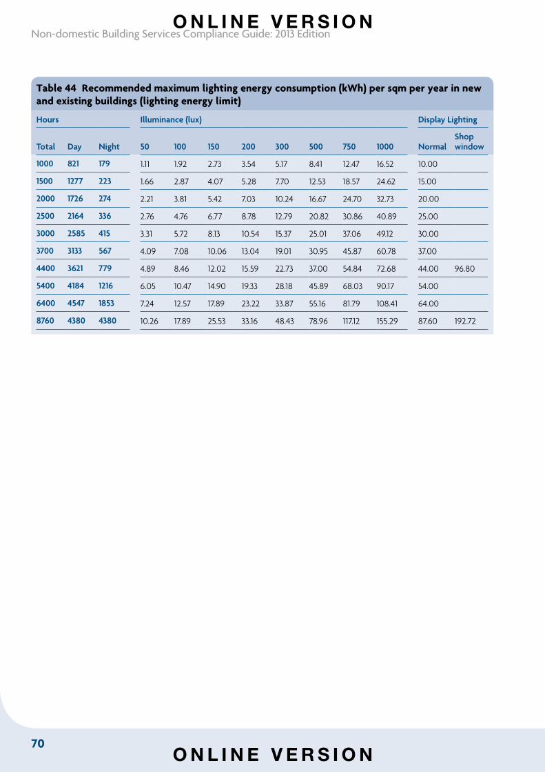
70
Non-domestic Building Services Compliance Guide: 2013 Edition
Table 44 Recommended maximum lighting energy consumption (kWh) per sqm per year in new and existing buildings (lighting energy limit)
Hours Illuminance (lux) Display Lighting
Total Day Night 50 100 150 200 300 500 750 1000 NormalShopwindow
1000 821 179 1.11 1.92 2.73 3.54 5.17 8.41 12.47 16.52 10.00
1500 1277 223 1.66 2.87 4.07 5.28 7.70 12.53 18.57 24.62 15.00
2000 1726 274 2.21 3.81 5.42 7.03 10.24 16.67 24.70 32.73 20.00
2500 2164 336 2.76 4.76 6.77 8.78 12.79 20.82 30.86 40.89 25.00
3000 2585 415 3.31 5.72 8.13 10.54 15.37 25.01 37.06 49.12 30.00
3700 3133 567 4.09 7.08 10.06 13.04 19.01 30.95 45.87 60.78 37.00
4400 3621 779 4.89 8.46 12.02 15.59 22.73 37.00 54.84 72.68 44.00 96.80
5400 4184 1216 6.05 10.47 14.90 19.33 28.18 45.89 68.03 90.17 54.00
6400 4547 1853 7.24 12.57 17.89 23.22 33.87 55.16 81.79 108.41 64.00
8760 4380 4380 10.26 17.89 25.53 33.16 48.43 78.96 117.12 155.29 87.60 192.72
O N L I N E V E R S I O N
O N L I N E V E R S I O N
71
Section 13: Heating and cooling system circulators and water pumps
Section 13: Heating and cooling system circulators and water pumps
13.1 IntroductionHeating and cooling water in HVAC systems of non-domestic buildings can circulate for extensive periods and be responsible for considerable energy use.
13.2 Scope of guidanceThis section provides guidance on specifying:
• heating system glandless circulators, both standalone and integrated in products
• heating and cooling system water pumps
to limit their energy consumption and meet relevant energy efficiency requirements in the Building Regulations. The guidance covers circulators and water pumps when used in closed systems.
13.3 Key termsHeating system glandless circulator means a pump used to circulate hot water in closed circuit heating systems. The glandless (or wet rotor) circulator is a centrifugal pump with an integral motor and no mechanical seal. It can have an integrated motor drive unit for variable speed operation.
Water pump (also known as ‘dry rotor’ or ‘direct coupled’ pump) means a centrifugal pump driven by an electric motor and generally having mechanical seals. Common pump types include in-line, end suction and vertical multi-stage. The first two are usually single-stage pumps having single-entry volute. By design they can all be used as circulators for all HVAC applications depending on configuration and duty.
13.4 Glandless circulators and water pumps in new and existing buildingsHeating and cooling system glandless circulators and water pumps in new and existing buildings should meet the recommended minimum standards in Table 45.
O N L I N E V E R S I O N
O N L I N E V E R S I O N
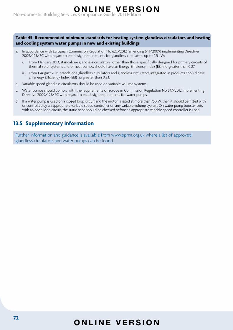
72
Non-domestic Building Services Compliance Guide: 2013 Edition
Table 45 Recommended minimum standards for heating system glandless circulators and heating and cooling system water pumps in new and existing buildings
a. In accordance with European Commission Regulation No 622/2012 (amending 641/2009) implementing Directive 2009/125/EC with regard to ecodesign requirements for glandless circulators up to 2.5 kW:
i. From 1 January 2013, standalone glandless circulators, other than those specifically designed for primary circuits of thermal solar systems and of heat pumps, should have an Energy Efficiency Index (EEI) no greater than 0.27.
ii. From 1 August 2015, standalone glandless circulators and glandless circulators integrated in products should have an Energy Efficiency Index (EEI) no greater than 0.23.
b. Variable speed glandless circulators should be used on variable volume systems.
c. Water pumps should comply with the requirements of European Commission Regulation No 547/2012 implementing Directive 2009/125/EC with regard to ecodesign requirements for water pumps.
d. If a water pump is used on a closed loop circuit and the motor is rated at more than 750 W, then it should be fitted with or controlled by an appropriate variable speed controller on any variable volume system. On water pump booster sets with an open loop circuit, the static head should be checked before an appropriate variable speed controller is used.
13.5 Supplementary information
Further information and guidance is available from www.bpma.org.uk where a list of approved glandless circulators and water pumps can be found.
O N L I N E V E R S I O N
O N L I N E V E R S I O N
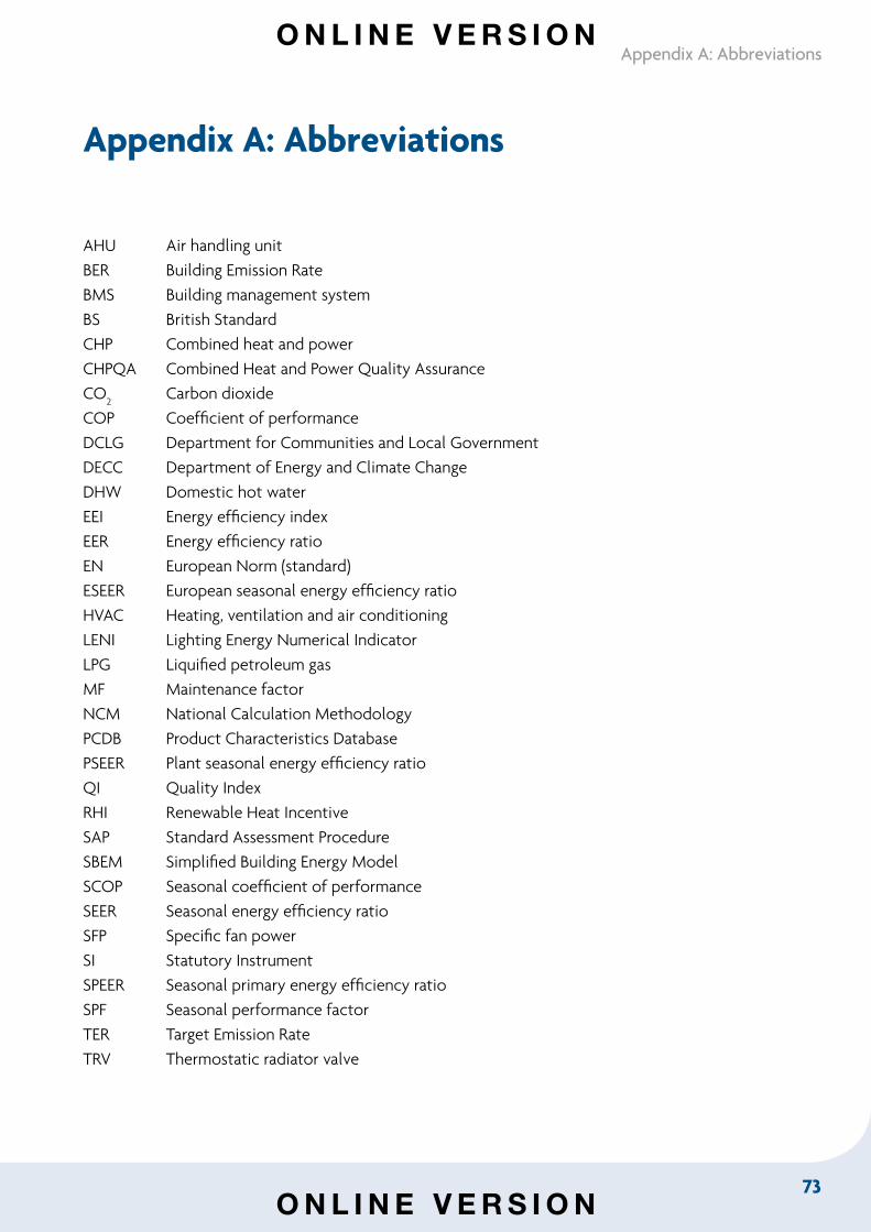
73
Appendix A: Abbreviations
Appendix A: Abbreviations
AHU Air handling unitBER Building Emission RateBMS Building management systemBS British StandardCHP Combined heat and powerCHPQA Combined Heat and Power Quality AssuranceCO
2 Carbon dioxide
COP Coefficient of performanceDCLG Department for Communities and Local GovernmentDECC Department of Energy and Climate ChangeDHW Domestic hot waterEEI Energy efficiency indexEER Energy efficiency ratioEN European Norm (standard)ESEER European seasonal energy efficiency ratioHVAC Heating, ventilation and air conditioningLENI Lighting Energy Numerical IndicatorLPG Liquified petroleum gasMF Maintenance factorNCM National Calculation MethodologyPCDB Product Characteristics DatabasePSEER Plant seasonal energy efficiency ratioQI Quality IndexRHI Renewable Heat IncentiveSAP Standard Assessment ProcedureSBEM Simplified Building Energy ModelSCOP Seasonal coefficient of performanceSEER Seasonal energy efficiency ratioSFP Specific fan powerSI Statutory InstrumentSPEER Seasonal primary energy efficiency ratioSPF Seasonal performance factorTER Target Emission RateTRV Thermostatic radiator valve
O N L I N E V E R S I O N
O N L I N E V E R S I O N
www.thenbs.com
Published by NBS, part of RIBA Enterprises Ltd, and available from:
RIBA Bookshops Mail Order The Old Post Office, St Nicholas Street Newcastle Upon Tyne, NE1 1RH
Telephone orders/General enquiries: +44 (0)191 244 5557 Fax orders: +44 (0)191 244 5533 Email orders: [email protected] Or order online at: www.ribabookshops.com
RIBA Bookshops
RIBA Bookshops, 66 Portland Place, London W1B 1AD. Tel +44 (0)20 7307 3753
The Building Centre Bookshop, 26 Store Street, London WC1E 7BT. Tel +44 (0)20 7692 4040
ISBN 978 1 85946 535 6 Stock code 82079
© Crown Copyright 2013
The content of this publication, excluding logos, may be reproduced free of charge in any format or medium for research, private study or for internal circulation within an organisation. This is subject to it being reproduced accurately and not used in a misleading context. The material must be acknowledged as Crown copyright and the title and edition of the publication specified. This document/publication is value added. You may re-use the content (not including logos) free of charge in any format or medium, under the terms of the Open Government Licence. To view this licence, visit: http://www.nationalarchives.gov.uk/doc/open-government-licence/ or write to the Information Policy Team, The National Archives, Kew, London TW9 4DU, or e-mail: [email protected].
If you require this publication in an alternative format, please email: [email protected].
Copyright in the typographical arrangement, excluding logos, of the cover and internal page layouts of this publication rest with the Publisher.
O N L I N E V E R S I O N
O N L I N E V E R S I O N


![Management of domestic swimming pools and compliance levels · Management of domestic swimming pools and compliance levels [iii] Contents Executive summary 1.1 Management processes](https://img.dokumen.tips/doc/110x75/5e69c8ec75bbe90e6b5e618f/management-of-domestic-swimming-pools-and-compliance-management-of-domestic-swimming.jpg)