Embed Size (px)
Citation preview
No.68
Page 1 of 24 IACS Rec. 2000/Rev.1 2021
No. 68 (cont)
Guidelines for non-destructive testing examination of hull and machinery steel forgings
TABLE OF CONTENTS
1. General1.1 Scope and Qualification of Personnel involved in NDT
2. Surface Inspections2.1 General 2.2 Products 2.3 Zones for Surface Inspections 2.4 Surface Condition 2.5 Surface Inspection 2.6 Acceptance Criteria and Rectification of Defects 2.7 Record Reporting
3. Volumetric Inspection3.1 General 3.2 Products 3.3 Zones for Volumetric Inspection 3.4 Surface Condition 3.5 Acceptance Criteria 3.6 Record Reporting
No. 68 (June 2000) (Rev.1) Apr 2021)
No.68
Page 2 of 24 IACS Rec. 2000/Rev.1 2021
No. 68 (cont)
1. General 1.1 Scope and Qualification of Personnel involved in NDT 1.1.1 These guidelines This Recommendation complements complement the requirements
for steel forgings in of the URs - UR W7, "Hull and machinery steel forgings":, and UR M72 and UR M68 M19 "Parts of internal combustion engines for which non-destructive tests are required", and contains general guidance for the non-destructive examination testing (NDT) methods, the extent of examination testing and the minimum recommended quality levels to be complied with unless otherwise approved or specified. The requirements contained herein may be also applied to the testing of austenitic stainless steel and ferritic-austenitic (duplex) stainless steel forgings.
1.1.2 This document contains guidelines on "Surface Inspections" (Section 2) by visual
examination, magnetic particle testing and liquid penetrant testing and "Volumetric Inspection" (Section 3) by ultrasonic testing.
1.1.3 For steel forgings (e.g. components for couplings, gears, boilers and pressure
vessels) other than those specified in these guidelines, the requirements in these guidelines may apply correspondingly considering their materials, kinds, shapes and stress conditions being subjected.
1.1.4 Forgings should be examined in the final delivery condition. For specific requirements
see paragraphs 2.5.2 and 3.4.2. 1.1.5 Where intermediate inspections have been performed the manufacturer shall should
furnish provide a documentation reports of the results upon the request of the Surveyor.
1.1.6 Where a forging is supplied in semi-finished condition, the manufacturer shall should
take into consideration the quality level of final finished machined components. 1.1.7 Where advanced ultrasonic testing methods are applied, e.g. PAUT or TOFD,
reference is made to UR W34 for general approach in adopting and application of these advanced methods. Acceptance levels regarding accept/reject criteria should be as per the applicable section in this Recommendation.
1.1.8 Personnel carrying out NDT should be certified to a recognised national or
international certification scheme, e.g. ISO 9712:2012. Personnel qualification to an employer based qualification scheme such as SNT-TC-1A, 2016 or ANSI/ASNT CP-189, 2016. Where employer based schemes are applied, personnel qualification to these schemes may be accepted if the written practice is reviewed and found acceptable by the Society. The written practice should align with the main requirements with those of ISO 9712 (apart from the impartiality requirements of a certification body).
1.1.9 The NDT personnel’s certificates and competence should comprise all industrial
sectors and techniques being applied by the manufacturer or its subcontractors. 1.1.10 Certificates should be made available to the Society for verification, when requested. 1.1.11 Procedures should be approved by level III personnel for the appropriate NDT
method.
No.68
Page 3 of 24 IACS Rec. 2000/Rev.1 2021
No. 68 (cont)
1.1.12 The operator carrying out the NDT and interpreting indications, should as a minimum, be qualified and certified to Level II in the NDT method(s) concerned. However, operators only undertaking the gathering of data using any NDT method and not performing data interpretation or data analysis may be qualified and certified as appropriate, at level I. The operator should have adequate knowledge of materials, weld, structures or components, NDT equipment and limitations that are sufficient to apply the relevant NDT method for each application appropriately.
2. Surface Inspections 2.1 General 2.1.1 Surface inspections in these guidelines are to should be carried out by visual
examination and magnetic particle testing or liquid penetrant testing, for the purpose of detecting relevant indications and assessing them against accept/reject criteria stated herein. Personnel engaged in visual examination are to should have sufficient knowledge and experience, however, may be exempted from formal qualification requirements in this Recommendation.
2.1.2 The testing procedures, apparatus and conditions of magnetic particle testing and
liquid penetrant testing are to should comply with the recognized national or international standards.
2.1.3 Personnel engaged in visual examination is to have sufficient knowledge and
experience. Personnel engaged in magnetic particle testing or liquid penetrant testing is to be qualified in accordance with the Society’s Rules. The qualification is to be verified by certificates.
2.1.3 Other surface inspection methods e.g. eddy current testing, may be required by the
Classification Society as a supplementary method, e.g. for confirming the presence of indications, or for detecting the presence of undocumented weld repairs. This Recommendation does not include accept/reject criteria for this purpose and is mentioned here for information only.
2.2 Products 2.2.1 The steel forgings specified in W7 shall should be subjected to a 100% visual
examination of all accessible surfaces by the manufacturer and made available to by the Surveyor. For mass produced forgings the extent of examination is to be established at the discretion of the individual Society.
2.2.2. It is noted that W7 does not include every forged component type that may be subject
to Classification (for example, forged slewing rings). In such cases where the particular component or type is not included, either in W7 or this Recommendation, appropriate national/international standards, or Societies Rules may be applied, to determine the appropriate testing regime and defect acceptance criteria.
2.2.3 Austenitic stainless steel and ferritic-austenitic (duplex) stainless steel forgings
acceptance criteria details are included in the appropriate sections for surface and volumetric inspections, however, other acceptance criteria and national or
No.68
Page 4 of 24 IACS Rec. 2000/Rev.1 2021
No. 68 (cont)
international standards may be applied, upon agreement with the Classification Society.
2.2.4 Where such standards are used or referenced as a basis for accept and reject criteria,
the quality level should provide reasonable equivalence to the allowable criteria stated in the appropriate tables within this Recommendation. The quality levels would normally be the highest or most stringent, to provide reasonable equivalence with this Recommendation.
2.2.25 Surface inspections by magnetic particle and/or liquid penetrant methods generally apply to the following steel forgings:
(1) All crankshafts with minimum crankpin diameter not less than 100 mm; (2) Propeller propeller shafts, intermediate shafts, thrust shafts and rudder stocks with minimum diameter not less than 100 mm; (3) Cylinder heads, connecting rods, piston rods and crosshead with minimum diameter not less than 75 mm or equivalent cross section, as per the engine type and size requirements in UR M72. (4) Bolts bolts with minimum diameter not less than 50 mm, which are subjected to dynamic stresses such as cylinder cover bolts, coupling bolts for crankshafts, tie rods, crankpin bolts, main bearing bolts, propeller blade fastening bolts and other items as per the engine type and size requirements in UR M72.
(5) Propeller blade fastening bolts which are subjected to dynamic stresses.
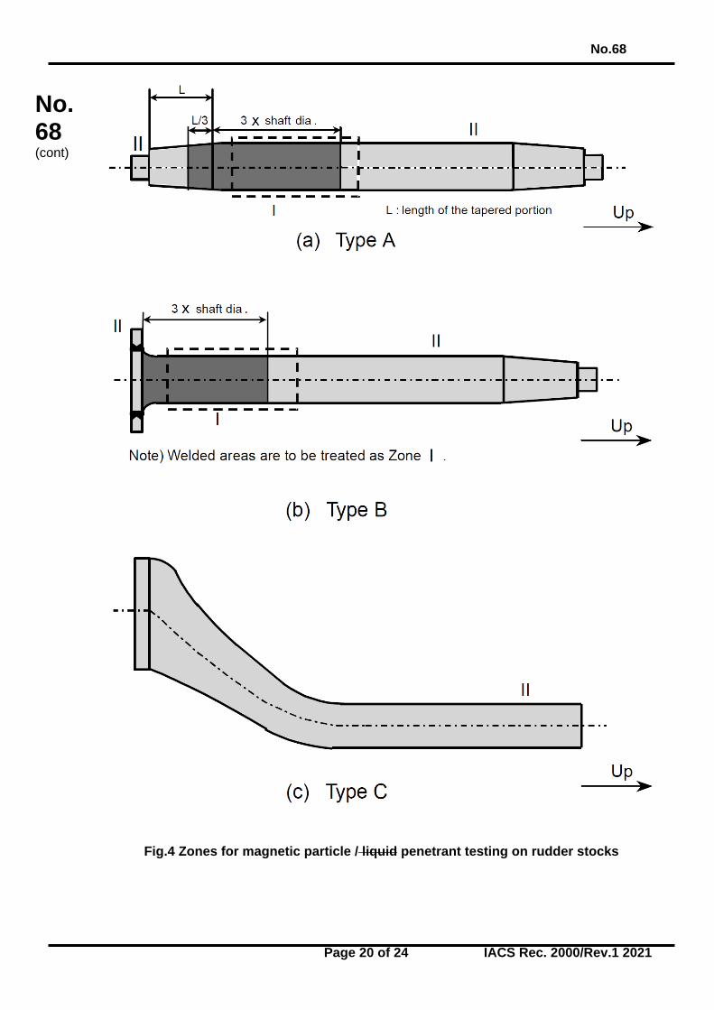
2.3 Zones for Surface Inspections 2.3.1 Magnetic particle, or where permitted liquid penetrant testing, shall should be carried
out in the zones I, II and II III (as applicable), as indicated in Figures 1 to 4. 2.4 Surface Condition 2.4.1 The surfaces of forgings to be examined are to should be free from scale, dirt, grease
or paint. 2.5 Surface Inspection 2.5.1 Where indicated by Figures 1 to 4, magnetic particle inspection will should be carried
out with the following exceptions, when liquid penetrant testing will would be permitted:
- austenitic and ferritic-austenitic (duplex) stainless steels; - Interpretation of open visual or magnetic particle indications, - at the instruction of the Surveyor.
2.5.2 Unless otherwise specified detailed in the order specification, the magnetic particle
test shall should be performed on a forging in the final machined surface condition and final thermally treated condition. or within 0.3 mm of the final machined surface condition for AC techniques (0.8mm for DC techniques).
No.68
Page 5 of 24 IACS Rec. 2000/Rev.1 2021
No. 68 (cont)
2.5.3 Unless otherwise agreed, the surface inspection is to should be carried out in the presence of the Surveyor. The surface inspection is to should be carried out before the shrink fitting, where applicable.
2.5.4 For magnetic particle testing, attention is to should be paid to the contact between the
forging and the clamping devices of stationary magnetization benches in order to avoid local overheating or burning damage in its surface. Prods shall should not be permitted on finished machined items.
2.5.5 When indications were are detected as a result of the surface inspection, acceptance
or rejection is to be decided in accordance with clause 2.6. 2.6 Acceptance Criteria and Rectification of Defects 2.6.1 Acceptance Criteria Visual Inspection 2.6.1.1 All forgings shall should be free of cracks, crack-like indications, laps, seams, folds,
or other injurious detrimental indications. At the request of the Surveyor, additional magnetic particle, liquid penetrant and ultrasonic testing may be required for a more detailed evaluation of surface irregularities.
2.6.1.2 The bores of hollow propeller shafts are to should be visually examined for
imperfections uncovered by the machining operation. Machining marks are to be ground to a smooth profile.
2.6.2 Acceptance Criteria Magnetic Particle Testing and Liquid Penetrant Testing 2.6.2.1 The following definitions relevant to indications apply: Linear indication - an indication in which the length is at least three times the width;
an indication with a largest dimension three or more times its smallest dimension (i.e. l ≥ 3 w).
Nonlinear indication - an indication of circular or elliptical shape with a length less than
three times the width; an indication with a largest dimension less than three times its smallest dimension (i.e. l < 3w).
Aligned indication - three or more indications in a line, separated by 2mm or less edge-
to-edge; a) Non-linear indications form an alignment when the distance between indications is less than 2mm and at least three indications are aligned. An alignment of indications is considered to be a unique indication and its length is equal to the overall length of the alignment.
b) Linear indications form an alignment when the distance between two indications is smaller than the length of the longest indication.
Open indication - an indication visible after removal of the magnetic particles or that
can be detected by the use of contrast dye penetrant testing;
No.68
Page 6 of 24 IACS Rec. 2000/Rev.1 2021
No. 68 (cont)
Non-open indication - an indication that is not visually detectable after removal of the
magnetic particles or that cannot be detected by the use of contrast dye penetrant testing,
Relevant indication - an indication that is caused by a condition or type of discontinuity
that requires evaluation. Only indications which have any dimension greater than 1.5mm shall be considered relevant for the categorization of indications.
2.6.2.2 For the purpose of evaluating indications, the surface is to should be divided into
reference areas of 225cm2. The area shall be taken in the most unfavorable unfavourable location relative to the indication being evaluated.
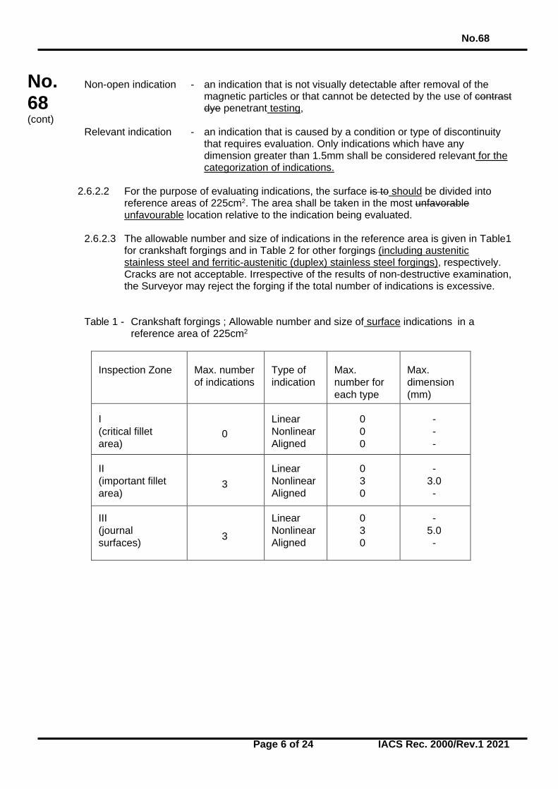
2.6.2.3 The allowable number and size of indications in the reference area is given in Table1
for crankshaft forgings and in Table 2 for other forgings (including austenitic stainless steel and ferritic-austenitic (duplex) stainless steel forgings), respectively. Cracks are not acceptable. Irrespective of the results of non-destructive examination, the Surveyor may reject the forging if the total number of indications is excessive.
Table 1 - Crankshaft forgings ; Allowable number and size of surface indications in a
reference area of 225cm2
Inspection Zone
Max. number of indications
Type of indication
Max. number for each type
Max. dimension (mm)
I (critical fillet area)
0 Linear Nonlinear Aligned
0 0 0
- - -
II (important fillet area)
3 Linear Nonlinear Aligned
0 3 0
- 3.0 -
III (journal surfaces) 3
Linear Nonlinear Aligned
0 3 0
- 5.0 -
No.68
Page 7 of 24 IACS Rec. 2000/Rev.1 2021
No. 68 (cont)
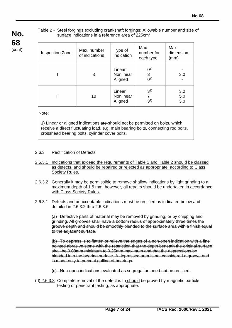
Table 2 - Steel forgings excluding crankshaft forgings; Allowable number and size of surface indications in a reference area of 225cm2
Inspection Zone Max. number of indications
Type of indication
Max. number for each type
Max. dimension (mm)
I 3 Linear Nonlinear Aligned
01) 3
01)
- 3.0 -
II 10 Linear Nonlinear Aligned
31) 7
31)
3.0 5.0 3.0
Note:
1) Linear or aligned indications are should not be permitted on bolts, which receive a direct fluctuating load, e.g. main bearing bolts, connecting rod bolts, crosshead bearing bolts, cylinder cover bolts.
2.6.3 Rectification of Defects 2.6.3.1 Indications that exceed the requirements of Table 1 and Table 2 should be classed
as defects, and should be repaired or rejected as appropriate, according to Class Society Rules.
2.6.3.2 Generally it may be permissible to remove shallow indications by light grinding to a
maximum depth of 1.5 mm, however, all repairs should be undertaken in accordance with Class Society Rules.
2.6.3.1. Defects and unacceptable indications must be rectified as indicated below and
detailed in 2.6.3.2 thru 2.6.3.6.
(a) Defective parts of material may be removed by grinding, or by chipping and grinding. All grooves shall have a bottom radius of approximately three times the groove depth and should be smoothly blended to the surface area with a finish equal to the adjacent surface. (b) To depress is to flatten or relieve the edges of a non-open indication with a fine pointed abrasive stone with the restriction that the depth beneath the original surface shall be 0.08mm minimum to 0.25mm maximum and that the depressions be blended into the bearing surface. A depressed area is not considered a groove and is made only to prevent galling of bearings. (c) Non-open indications evaluated as segregation need not be rectified.
(d) 2.6.3.3 Complete removal of the defect is to should be proved by magnetic particle testing or penetrant testing, as appropriate.
No.68
Page 8 of 24 IACS Rec. 2000/Rev.1 2021
No. 68 (cont)
(e) 2.6.3.4 Repair welding is should not be permitted for crankshafts or rotating items subjected to torsional fatigue (such as propeller shafts). Repair welding of other forgings is should be subjected subject to prior approval of the individual Class Society.
2.6.3.2 Zone I in crankshaft forgings
Neither indications nor repair are permitted in this zone. 2.6.3.3 Zone II in crankshaft forgings
Indications must be removed by grinding to a depth no greater than 1.5mm.
Indications detected in the journal bearing surfaces must be removed by grind- ing to a depth no greater than 3.0mm. The total ground area shall be less than 1% of the total bearing surface area concerned. Non-open indications, except those evaluated as segregation, shall be depressed but need not be removed.
2.6.3.5 2.6.3.4 Zone I in other forgings
Indications must be removed by grinding to a depth no greater than 1.5mm. However, grinding Grinding is not permitted in way of finished machined threads.
2.6.3.5 Zone II in other forgings
Indications must be removed by grinding to a depth no greater than 2% of the diameter or 4.0mm, whichever is smaller.
2.6.3.6 Zones other than I and II in all forgings
Defects detected by visual inspection must be removed by grinding to a depth no greater than 5% of the diameter or 10mm, whichever is smaller. The total ground area shall be less than 2% of the forging surface area.
No.68
Page 9 of 24 IACS Rec. 2000/Rev.1 2021
No. 68 (cont)
2.7 Record Reporting 2.7.1 Test results of surface inspections are to should be recorded at least with the following
items:
(1) Date of testing; (2) Name(s), signature(s) and qualification level of inspection personnel; (3) Kind of testing Testing method and testing details, including procedure number;
- for liquid penetrant testing: test media combination the penetrant system used and viewing conditions (as appropriate to the penetrant technique and media used)
- for magnetic particle testing: method of magnetizing, test media, and magnetic
field strength, magnetic flux indicators (where appropriate), and viewing conditions (as appropriate to the magnetizing technique and media used)
(4) Kind Type of product; (5) Product number for and unique identification; (6) Grade of steel; (7) Heat treatment; (8) Stage of testing; (9) Position (zone) of testing; (10) Surface condition; (11) Test standards used, including reference to the appropriate tables for acceptance
purposes; (12) Testing condition; (13) Results, including documentation regarding the repair and testing history (as
appropriate); (14) Statement of acceptance/non acceptance; (15) Details of weld repair including sketch (where applicable);
No.68
Page 10 of 24 IACS Rec. 2000/Rev.1 2021
No. 68 (cont)
3. Volumetric Inspection 3.1 General 3.1.1 Volumetric inspection in these guidelines is to should be carried out by ultrasonic
testing using the contact method with straight beam and/or angle beam technique. Advanced UT methods (such as PAUT or TOFD) should meet the general requirements of UR W34.
3.1.2 The testing procedures, apparatus and conditions of ultrasonic testing are to should
comply with the recognized national or international standards. Generally, the methods of setting test sensitivity and testing evaluation utilise the DAC (distance amplitude correction) or DGS (distance-gain size) methods. DGS (distance-gain size) procedure is to be The applied methodology using should use 2 to 4 MHz straight beam (or normal) probes and/or angle beam probes. with 2 to 4 MHz and inspection should be carried out using a For near surface testing (up to a depth of 25 mm) twin crystal 0o probe for near surface scans (25mm) should be used, plus an a 0o probe (usually single crystal beyond a depth of 25 mm) for the remaining volume. The appropriate acceptance criteria tables should be used, depending on the sensitivity method selected. Fillet radii should be examined using 45o, 60o or 70o probes.
3.1.3 Fillet radii should be examined using 45o, 60o or 70o probes, primarily to determine the
presence of any cracks within the radiused areas, and as an additional scan to confirm any indications that may have been detected with 0° probe(s) within this area.
3.1.4 For fabricated forgings and weld repairs, weld testing should be carried out to the
appropriate standard, and the acceptance tables contained herein should not be used as a basis for acceptance criteria of welds.
3.1.3 Personnel engaged in ultrasonic testing is to be qualified in accordance with the
Society’s Rules. The qualification is to be verified by certificates. 3.1.65 Construction of DAC curves for normal probes should be performed using reference
blocks containing suitably sized Flat Bottom Holes (FBH) spaced over the inspection thickness. Reference blocks should be manufactured from similar material, with similar surface condition to that being inspected. Where necessary, allowances should be made for attenuation losses by performing a transfer correction and adjusting the DAC curve as required. The applied transfer correction (measured in decibels (dB)) should become the new reference sensitivity, to which indications are evaluated against, according to the appropriate table contained herein.
3.2 Products 3.2.1 Volumetric inspections by ultrasonic testing generally apply to the following steel
forgings:
(1) All crankshafts with minimum crankpin diameter not less than 150mm; (2) propeller Propeller shafts, intermediate shafts, thrust shafts and rudder stocks
with minimum diameter not less than 200 mm, (3) Cylinder heads, connecting rods, piston rods, and crosshead, coupling bolts and
studs with minimum diameter not less than 200mm or equivalent cross section. as per the engine type and size requirements in UR M72.
No.68
Page 11 of 24 IACS Rec. 2000/Rev.1 2021
No. 68 (cont)
3.2.2. It is noted that W7 does not include every forged component type that may be subject
to Classification (for example, forged slewing rings). In such cases where the particular component or type is not included, either in W7 or this Recommendation, appropriate national/international standards, or Societies Rules may be applied, to determine the appropriate testing regime and defect acceptance criteria.
3.2.3 Where such standards are used or referenced as a basis for accept and reject criteria,
the quality level should provide reasonable equivalence to the allowable criteria stated in the appropriate tables within this Recommendation. The quality levels would normally be the highest or most stringent, to provide reasonable equivalence with this Recommendation.
3.2.4 Ultrasonic acceptance criteria detailed in Tables 3 to 6 are intended for C, C-Mn, and
alloy steel forgings, and do not apply to austenitic stainless steel or ferritic-austenitic (duplex) stainless steel forgings. Examples of standards for acceptance criteria for stainless steel or duplex stainless steel forgings are detailed below, and quality levels should be agreed with the Classification Society. Other national or international standards may be used, as agreed with the Classification Society.
(i) ASTM A745 / A745M – 20 (ii) EN 10228-4:2016
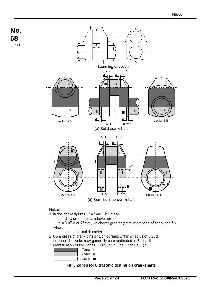
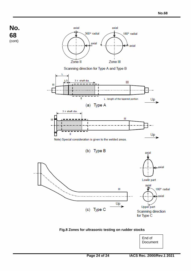
3.3 Zones for Volumetric Inspection 3.3.1 Ultrasonic testing shall should be carried out in the zones I to III as indicated in
Figures 5 to 8. Areas may be upgraded to a higher zone at the discretion of the Surveyors.
3.4 Surface Condition 3.4.1 The surfaces of forgings to be examined are to should be such that adequate coupling
can be established between the probe and the forging and that excessive wear of the probe can should be avoided. The surfaces are to be free from scale, dirt, grease or paint.
3.4.2 The ultrasonic testing is to should be carried out after the steel forgings have been
machined to a condition suitable for this type of testing and after the final heat treatment , but prior to the drilling of the oil bores, and prior to surface hardening and the machining of bolt threads. Black (or ‘as forged’) forgings shall should be inspected after removal of the oxide scale by either flame descaling or shot blasting methods.
3.5 Acceptance Criteria 3.5.1 Acceptance criteria of volumetric inspection by ultrasonic testing are shown in Tables
3 and 4 to 6.
No.68
Page 12 of 24 IACS Rec. 2000/Rev.1 2021
No. 68 (cont)
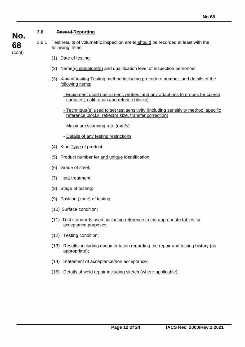
3.6 Record Reporting 3.6.1 Test results of volumetric inspection are to should be recorded at least with the
following items:
(1) Date of testing; (2) Name(s) signature(s) and qualification level of inspection personnel; (3) Kind of testing Testing method including procedure number, and details of the
following items;
- Equipment used (instrument, probes [and any adaptions to probes for curved surfaces], calibration and refence blocks)
- Technique(s) used to set test sensitivity (including sensitivity method, specific
reference blocks, reflector size, transfer correction) - Maximum scanning rate (mm/s) - Details of any testing restrictions
(4) Kind Type of product; (5) Product number for and unique identification; (6) Grade of steel; (7) Heat treatment; (8) Stage of testing; (9) Position (zone) of testing; (10) Surface condition; (11) Test standards used; including reference to the appropriate tables for
acceptance purposes; (12) Testing condition; (13) Results; including documentation regarding the repair and testing history (as
appropriate); (14) Statement of acceptance/non acceptance; (15) Details of weld repair including sketch (where applicable).
No.68
Page 13 of 24 IACS Rec. 2000/Rev.1 2021
No. 68 (cont)
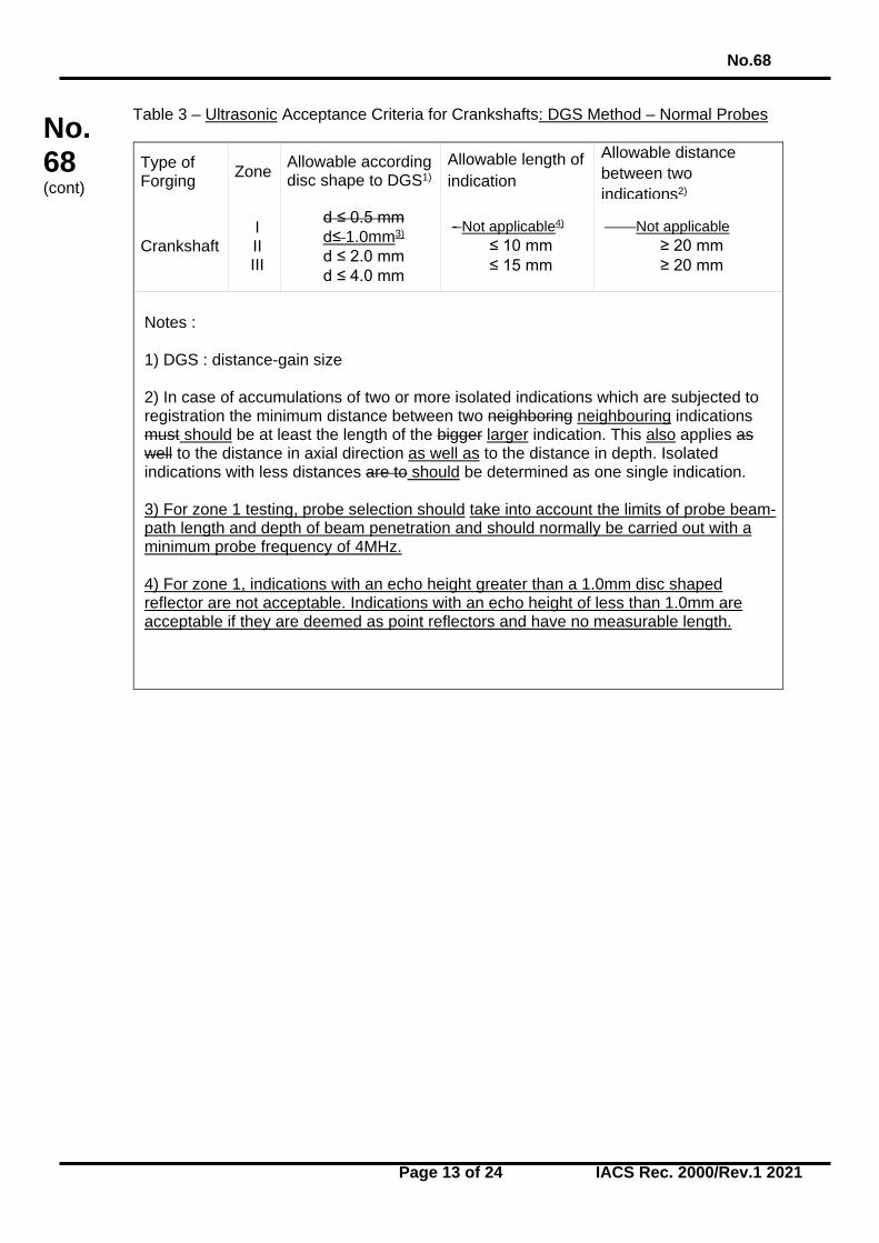
Table 3 – Ultrasonic Acceptance Criteria for Crankshafts: DGS Method – Normal Probes
Type of Forging Zone Allowable according
disc shape to DGS1) Allowable length of indication
Allowable distance between two indications2)
Crankshaft I II III
d ≤ 0.5 mm d≤ 1.0mm3) d ≤ 2.0 mm d ≤ 4.0 mm
- Not applicable4) ≤ 10 mm ≤ 15 mm
Not applicable ≥ 20 mm ≥ 20 mm
Notes : 1) DGS : distance-gain size 2) In case of accumulations of two or more isolated indications which are subjected to registration the minimum distance between two neighboring neighbouring indications must should be at least the length of the bigger larger indication. This also applies as well to the distance in axial direction as well as to the distance in depth. Isolated indications with less distances are to should be determined as one single indication. 3) For zone 1 testing, probe selection should take into account the limits of probe beam-path length and depth of beam penetration and should normally be carried out with a minimum probe frequency of 4MHz. 4) For zone 1, indications with an echo height greater than a 1.0mm disc shaped reflector are not acceptable. Indications with an echo height of less than 1.0mm are acceptable if they are deemed as point reflectors and have no measurable length.
No.68
Page 14 of 24 IACS Rec. 2000/Rev.1 2021
No. 68 (cont)
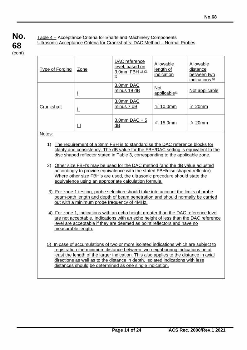
Table 4 – Acceptance Criteria for Shafts and Machinery Components Ultrasonic Acceptance Criteria for Crankshafts: DAC Method – Normal Probes
Type of Forging Zone
DAC reference level, based on 3.0mm FBH 1) 2),
3)
Allowable length of indication
Allowable distance between two indications 5)
Crankshaft
I
3.0mm DAC minus 19 dB
Not applicable4) Not applicable
II
3.0mm DAC minus 7 dB
≤ 10.0mm ≥ 20mm
III
3.0mm DAC + 5 dB
≤ 15.0mm
≥ 20mm
Notes:
1) The requirement of a 3mm FBH is to standardise the DAC reference blocks for clarity and consistency. The dB value for the FBH/DAC setting is equivalent to the disc shaped reflector stated in Table 3, corresponding to the applicable zone.
2) Other size FBH’s may be used for the DAC method (and the dB value adjusted accordingly to provide equivalence with the stated FBH/disc shaped reflector). Where other size FBH’s are used, the ultrasonic procedure should state the equivalence using an appropriate calculation formula.
3) For zone 1 testing, probe selection should take into account the limits of probe
beam-path length and depth of beam penetration and should normally be carried out with a minimum probe frequency of 4MHz.
4) For zone 1, indications with an echo height greater than the DAC reference level
are not acceptable. Indications with an echo height of less than the DAC reference level are acceptable if they are deemed as point reflectors and have no measurable length.
5) In case of accumulations of two or more isolated indications which are subject to registration the minimum distance between two neighbouring indications be at least the length of the larger indication. This also applies to the distance in axial directions as well as to the distance in depth. Isolated indications with less distances should be determined as one single indication.
No.68
Page 15 of 24 IACS Rec. 2000/Rev.1 2021
No. 68 (cont)
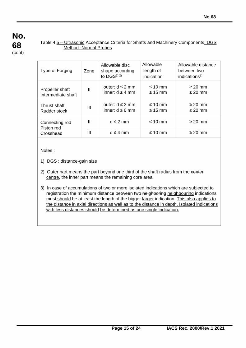
Table 4 5 – Ultrasonic Acceptance Criteria for Shafts and Machinery Components: DGS Method -Normal Probes
Type of Forging Zone Allowable disc shape according to DGS1) 2)
Allowable length of indication
Allowable distance between two indications3)
Propeller shaft Intermediate shaft Thrust shaft Rudder stock
II outer: d ≤ 2 mm inner: d ≤ 4 mm
≤ 10 mm ≤ 15 mm
≥ 20 mm ≥ 20 mm
III outer: d ≤ 3 mm inner: d ≤ 6 mm
≤ 10 mm ≤ 15 mm
≥ 20 mm ≥ 20 mm
Connecting rod Piston rod Crosshead
II d ≤ 2 mm ≤ 10 mm ≥ 20 mm
III d ≤ 4 mm ≤ 10 mm ≥ 20 mm
Notes : 1) DGS : distance-gain size 2) Outer part means the part beyond one third of the shaft radius from the center
centre, the inner part means the remaining core area. 3) In case of accumulations of two or more isolated indications which are subjected to
registration the minimum distance between two neighboring neighbouring indications must should be at least the length of the bigger larger indication. This also applies to the distance in axial directions as well as to the distance in depth. Isolated indications with less distances should be determined as one single indication.
No.68
Page 16 of 24 IACS Rec. 2000/Rev.1 2021
No. 68 (cont)
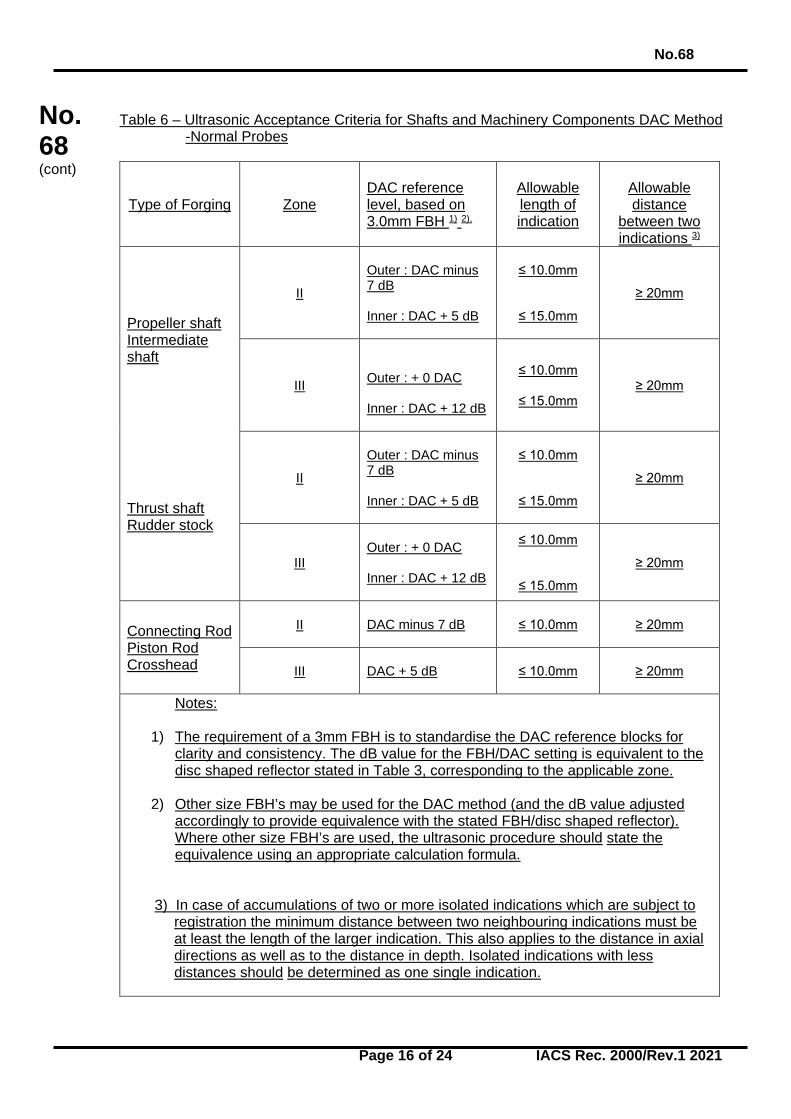
Table 6 – Ultrasonic Acceptance Criteria for Shafts and Machinery Components DAC Method
-Normal Probes
Type of Forging Zone DAC reference level, based on 3.0mm FBH 1) 2),
Allowable length of indication
Allowable distance
between two indications 3)
Propeller shaft Intermediate shaft Thrust shaft Rudder stock
II
Outer : DAC minus 7 dB Inner : DAC + 5 dB
≤ 10.0mm
≤ 15.0mm
≥ 20mm
III
Outer : + 0 DAC Inner : DAC + 12 dB
≤ 10.0mm
≤ 15.0mm ≥ 20mm
II
Outer : DAC minus 7 dB Inner : DAC + 5 dB
≤ 10.0mm
≤ 15.0mm
≥ 20mm
III
Outer : + 0 DAC Inner : DAC + 12 dB
≤ 10.0mm
≤ 15.0mm
≥ 20mm
Connecting Rod Piston Rod Crosshead
II
DAC minus 7 dB ≤ 10.0mm ≥ 20mm
III
DAC + 5 dB ≤ 10.0mm ≥ 20mm
Notes:
1) The requirement of a 3mm FBH is to standardise the DAC reference blocks for clarity and consistency. The dB value for the FBH/DAC setting is equivalent to the disc shaped reflector stated in Table 3, corresponding to the applicable zone.
2) Other size FBH’s may be used for the DAC method (and the dB value adjusted accordingly to provide equivalence with the stated FBH/disc shaped reflector). Where other size FBH’s are used, the ultrasonic procedure should state the equivalence using an appropriate calculation formula.
3) In case of accumulations of two or more isolated indications which are subject to registration the minimum distance between two neighbouring indications must be at least the length of the larger indication. This also applies to the distance in axial directions as well as to the distance in depth. Isolated indications with less distances should be determined as one single indication.
No.68
Page 17 of 24 IACS Rec. 2000/Rev.1 2021
No. 68 (cont)
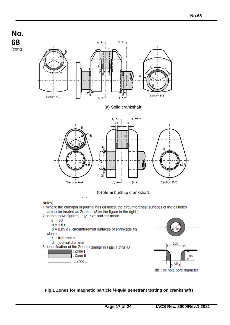
(a) Solid crankshaft
(b) Semi built-up crankshaft
Fig.1 Zones for magnetic particle / liquid penetrant testing on crankshafts
: Zone III
No.68
Page 18 of 24 IACS Rec. 2000/Rev.1 2021
No. 68 (cont)
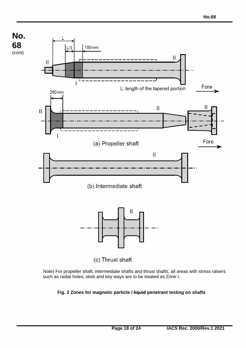
Note) For propeller shaft, intermediate shafts and thrust shafts, all areas with stress raisers such as radial holes, slots and key ways are to be treated as Zone I.
Fig. 2 Zones for magnetic particle / liquid penetrant testing on shafts
No.68
Page 19 of 24 IACS Rec. 2000/Rev.1 2021
No. 68 (cont)
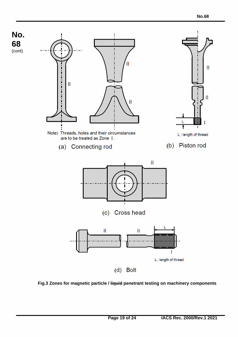
Fig.3 Zones for magnetic particle / liquid penetrant testing on machinery components
No.68
Page 20 of 24 IACS Rec. 2000/Rev.1 2021
No. 68 (cont)
Fig.4 Zones for magnetic particle / liquid penetrant testing on rudder stocks
No.68
Page 21 of 24 IACS Rec. 2000/Rev.1 2021
No. 68 (cont)
(a) Solid crankshaft
(b) Semi built-up crankshaft
Fig.5 Zones for ultrasonic testing on crankshafts
No.68
Page 22 of 24 IACS Rec. 2000/Rev.1 2021
No. 68 (cont)
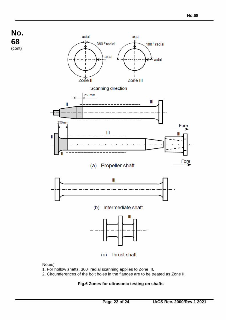
Notes) 1. For hollow shafts, 360o radial scanning applies to Zone III. 2. Circumferences of the bolt holes in the flanges are to be treated as Zone II.
Fig.6 Zones for ultrasonic testing on shafts
No.68
Page 23 of 24 IACS Rec. 2000/Rev.1 2021
No. 68 (cont)
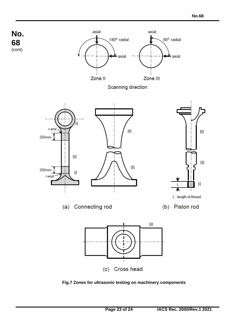
Fig.7 Zones for ultrasonic testing on machinery components
No.68
Page 24 of 24 IACS Rec. 2000/Rev.1 2021
No. 68 (cont)
Fig.8 Zones for ultrasonic testing on rudder stocks End of
Document