Embed Size (px)
Citation preview

Report No. CG-D-62-77
FIRE PERFORMANCE OF INTERMODAL SHIPPINIG COrNTAINERS
Randall EberlyMerchant Marine Technical DivisionOffice of Merchant Marine Safety
U.S. Coast Guard HeadquartersWashington, DC 205900
October 1977
Final Report
Document is available to the U.S. public through theNational Technical Information- Service,
Springfield, Virginia 22161
Prepared for pF1 foU
DEPAITMENT OF TIANSPORTATION DEC 12 ivy"UNITED STATES COAST GUARIOffice of Research and Development - • A *•
Washingten, D.C. 20590C.2
•s

NOTICE
This document is disseminated under the sponsorship of theDepartment of Transportation in the interest of informationexchange. The United States Government assumes no liabilityfor its contents or use thereof.
The United States Government does not endorse products ormanufacturers. Trade or manufacturers' names appear hereinsolely because they are considered essential to the objectof this report.
The contents of this report reflect the views of the CoastGuard Research and Development Center, which is responsiblefor the facts and accuracy of data presented. This reportdoes not constitute a standard, specification or regulation.
DONALD L. BIRKIMER, Ph.D., P.E.Technical Director
U.S. Coast Guard Research and Development CenterAvery Point, Groton, Connecticut 06340
Technical Report Documentation Page
2.R i Government Accirssooc. No. T3. Recipionts Catalog No.
.,I. and SuC
FIRE PERFORMANCE OF INTERMODAL SHIPPING CONTAINERS, 6.ero ..m.ng Ugoanzoaon Code
8. _ ong Organisation Report No
!R:.: -ad:l/be. ý1 CCA-'23/7
Research and Development Center I I Contract or Grant No.Avery PointGroton, CT 06340 13 Type of Report and Period Covered
12. Sponsoring Agency Nome.ad Address __ -- )- ---- -- - -,-
Department of Transportation• FialRpailte
United States Coast Guard
Office of Research and Development 14. Sponsoring Agency CodeWashington, DC 20590
15. Supplementary Notes
Performed at the Research and Development Center's Fire and Safety TestDetachment, Mobile, Alabama.
16. Abstract
VkDuring the week of 19 July 1976, a full-scale fire test series was performed atthe U. S. Coast Guard Fire and Safety Test Detachment to examine the potentialfire hazards of intermodal shipping containers. The three-part test series wasconducted on Little Sand Island in Mobile Bay, Alabama. The first sequence oftests were planned to evaluate whether a fire originating within a sealedintermodal container could burn through the container shell. The second taskof the test series was to determine the effects of an exterior pool fire exposureon a single level of containers, and the final task was to evaluate the effectsof an exterior pool fire exposure on a stack of containers."
(Standard 8 foot by 8 foot by 20 foot steel, aluminum and fiberglass-reinforcedplywood shipping containers were tested.
(The interior fire tests utilized two 30-pound wood cribs constructed of whitefir and 2 gallons of naptha as a fuel source. For the exterior fire tests, a29 x 24 foot steel test pan containing JP-5 was constructed beneath the containerstack. Standard container stacking and lashing arrangements were used for alltests.
17. Key Werds 11. Distribution Statement
fire hazards, container, intermodal Document is available to Tcontainer, fire endurance the U. S. public through the r
National Technical Information t
Service, Springfield, Virginia 22161
"19. Security cle'"if. (of We 6.zý"z 20. Security Cl"'e"f. (of " .:s p"e) 21. No. of Pages 22. Price,-. ,;
UNCLAS SI FIED UNCLAS SIFIED 61 ',.*
Fern DOT F 17M-7 (1-7) Reproduction of form and -completed page is authorized
S730 J IO .. .7i

--0 0
0 0.
- 00
010
U '" I i 0
ai ,
Im"1"" ""' oil" 1.1r.1. 1.r1 111 111' 11 111r
6 _ I IE I2 0 2 1 31 I0 ,0
FA
= 0 0 0
ato I
° W•N 'U go.; o

ACKNOWLEDGEMENTS
This test series is one facet of an on-going research and development programconducted by the United States Coast Guard. The ultimate mission of thisprogram is to implement newly developed technology and progressive engineeringtechniques into the Commercial Vessel Safety Program, thereby providing anriptimum means to insure the safety of life at sea.
The following individuals, representing a highly qualified group of expertsfr-m the container shipping industry, provided invaluable assistance in thisparticular test series:
M. H. ALLEN, U. S. Coast Guard
CAPT M. W. ALLEN, Marine Container Equipment Certification Corporation
P. W. SHAPANI, Sea-Land Service, Incorporated
RADM C. P. MURPHY (U.S.C.G. RET), Sea-Land Service, Incorporated
0,
gITII whir etoUNIANNtOUNtlCED 13JUJSTIFIC:AT153 . ....... ... . ... .,
V: ....... ... .......... •
pis' l, ,'MIGAVAILASILITY too
I. .........-
11LI/M Coo.at
TABLE OF CONTENTS
Page
1.0 INTRODUCTION 1
1.1 Background 11.2 Purpose 2
2.0 TEST PROCEDURE 3
2.1 Test Facility 32.2 Fuel Source 32.3 Ignition Method 32.4 Instrumentation 3
3.0 CONTAINERS 7
4.0 INTERIOR FIRE TEST 10
4.1 Theory 104.2 Thermocouple Locations 104.3 Discussion 10
5.0 EXTERIOR FIRE TESTS 15
5.1 Single-Level Exposure - Theory 155.2 Single-Level Exposure - Discussion of Test Results 155.3 Multi-Level Exposure - Theory 155.4 Discussion of Tests 4, 5, and 6 19
6.0 CONCLUSIONS 24
7.0 SUMMARY 25
REFERENCES 26
APPENDIX A - INTERIOR FIRE TEST DATA A-1
APPENDIX B - EXTERIOR FIRE TEST DATA B-1
LIST OF ILLUSTRATIONS
Figure Page
1 Container Stack Base Fittings 4
2 Wood Crib Fuel Source 4
3 Instrumentation Lead-Ins 5
v-o

Figure Page
4 Intermodal Shipping Container Typical Van Type 8
5 Typical Container Panel Construction (Cross-Section) 9
6 Natural Venting on Steel Container 12
7 Charring of Plywood Liner, Test 3a 12
8 Single-Level Array of Containers 16
9 Test Number Four 17
10 Condition of Container Doors After Test Exposure 17
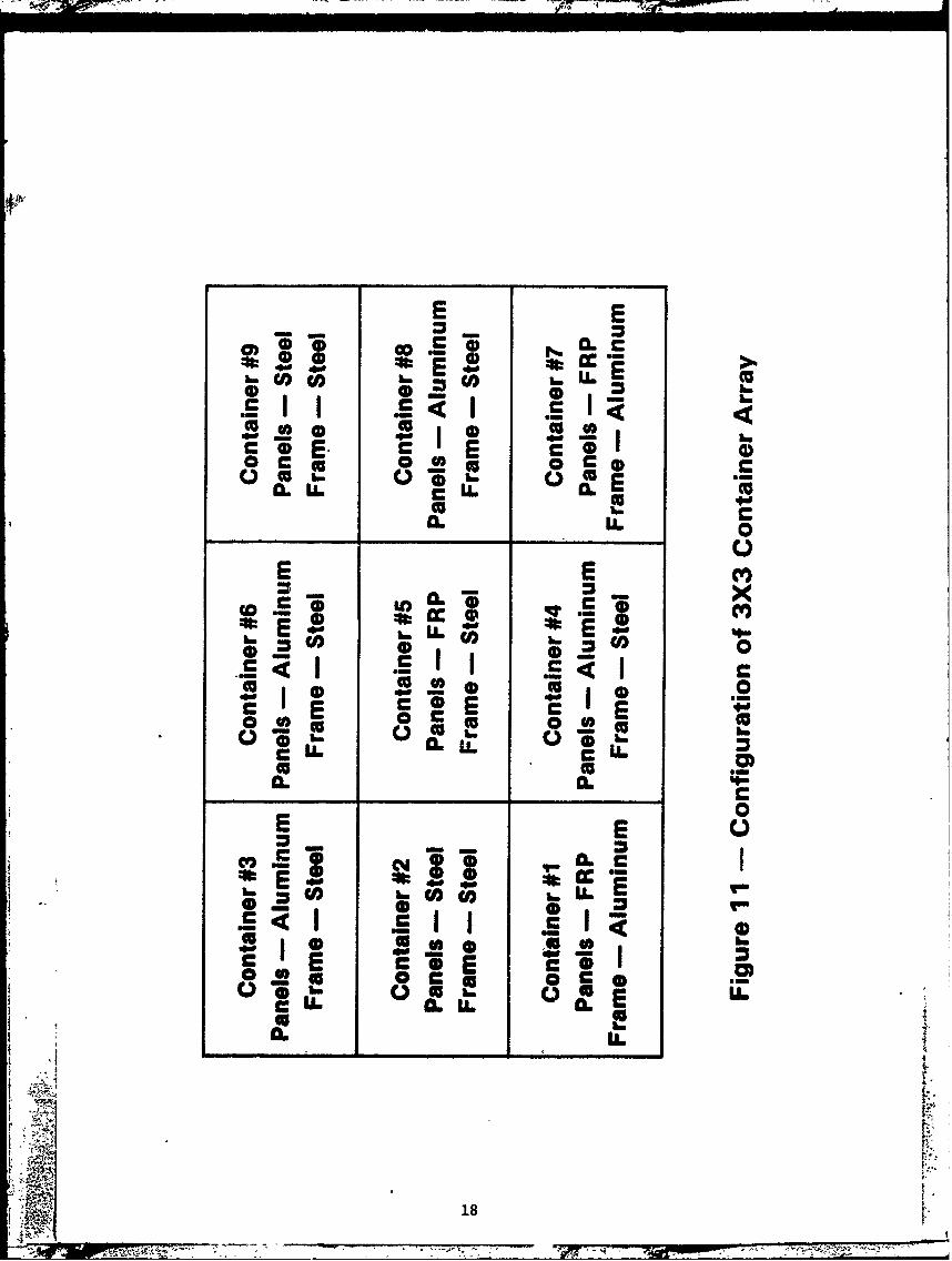
11 Configuration of 3x3 Container Array 18
12 Three-by-Three Array Test Six 21
13 Melted Aluminum Components 22
14 Buckled Aluminum Top Rail 22
15 Containers Held in Place by Bridge Fittings 23
16 Collapse of Container #5 23
LIST OF TABLES
Table Page
I Interior Fire Tests, Summary of Data 11
2 Thermocouple Tree Temperatures 13
3 Exterior Fire Tests, Multi-Level Array 20
v i
vi.
1.0 INTRODUCTION
1.1 Background
The transport of commodities stowed in intermodal shipping containersis a technique adopted by the merchant marine industry well over two decades
ago. It differs from the break bulk shipment of cargo in one important aspect.Containerized cargo stowed in dry van containers can be rapidly transferred from
truck to rail or from truck to container vessel and, while being transported,the cargo requires no addi':ional protection from the weather. This permits the
rail shipment of containers in trailer-on-flat-car or container-on-flat-car
configurations, and also permits the on-deck stowage of containers aboard con-
tainer vessels.
From a fire protection consideration, the on-deck stowage of con-tainerized cargo is a unique situation. The large quantity of cargo that is
stowed on the deck of a container vessel increases the amount of combustibles
that the installed fire protection systems must contend with, and the containersalso form a barrier which may prevent the effective application of fire-fighting
agents. If a cargo fire occurs within a container stack, an accurate predictionof the resulting scenario cannot be made on the basis of shipboard containerfire experience to date. Since the advent of container shipping, there has been
only one major casualty aboard an American flag container vessel. The collision
of the SS C.V. SEA WiTCH with the SS ESSO BRUSSELS on 2 June 1973 resulted in the
near total destruction of all 285 containers and cargo stowed on the deck of theSEA WITCH. This fire did not initiate within the container stack, but spread from
the pool fire of more than one million gallons of Nigerian crude oil surroundingthe container vessel which had leaked from the ruptured cargo tanks of the SSESSO BRUSSELS. The heat flux the containers experienced from this exposure was
in excess of that normally produced in laboratory furnace tests used to deter-
mine the fire endurance of shipboard materials. It is doubtful that a radiationlevel of this extremne could ever be produced in a casualty involving only a deckstow of containerized cargo. Because of the lack of past experience, it isessential that the containerized freight concept be evaluated from a full-scale
experimental viewpoint to determine credible fire situations which may be directly
caused or influenced by some particular aspect of containerization. Because ofthe variety of cargo types and configurations stowed within intermodal containers,it is not practical to also evaluate the effects of various cargos on flame spreadin this study. It is realized that incompatible or oxygen-generating materials
will add undesirable aspects to a fire situation.
By evaluating routine transport configurations used for intermodalcontainer shipping, several potential fire scenarios can be predicted. Typical
container stowage arrangements indicate that an interior fire may occur as aresult of shifting cargo within a lashed container. A second scenario can be
visualized, where due to a flammable fluid leak or other source, a containerstack is exposed to a limited exterior fire source. If a container stack isexposed to either of these two credible fire situations, an estimation of thepotential flame spread through the remainder of the container load is necessary.
1

1.2 Purpose
The purpose of this test series is to evaluate intermodal shippingcontainers to ietermine their potential effects on flame spread. This evalu-ation i, comprised of the following specific tasks:
a. Comparison of steel, aluminum, and fiberglass-reinforcedplywood container panels to determine if greater fireresistance is offered by one particular means of con-struction.
b. Determination of any general feature of construction ofcontainer frames or hardware that may affect the overallfire resistance of a container.
c. Determination of whether a credible interior fire iscapable of burning through a closed intermodal shippingcontainer.
d. Determination of the effects of a limited exterior poolfire exposure on intermodal shipping containers.
e. Determination of whether the wooden floorboards used inintermodal shipping containers adversely affect the spreadof flame in a container stack.
f. Determination of whether typical container stackingand lashing arrangements offer adequate container stackstability under fire conditions.
2
"4A:54"P-

2.0 TEST PROCEDURE
2.1 Test Facility
The container test series was conducted at the Coast Guard Fire and
Safety Test Detachment in Mobile, Alabama. Because gantry cranes or otherappropriate container-lifting apparatus could not be practically erected, the
tests were not conducted aboard one of the Test Detachment vessels. A graveltest pad of approximately 3600 square feet was constructed on Little Sand
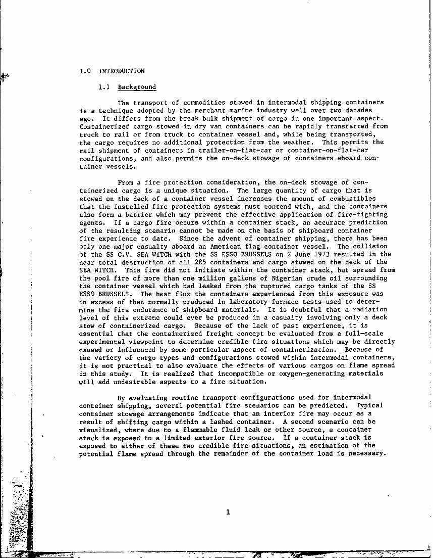
Island, adjacent to the T/V ALBERT E. WATTS. A 29 by 25 foot simulated hatchcover was constructed on the test pad consisting of welded steel plates. Steelcoamings were also welded along the perimeter of the mock-up hatch cover toform a ten-inch deep fuel pan for use during the pool fires. Two steel I-beamswith six-inch flanges were fitted with bottom-stacking fittings and pad eyes(Figure 1) and centered in the fuel pan to act as a base for the containerstack.
2.2 Fuel Source
a. Internal Fire Tests - Standard wood cribs weighing 30 pounds +5
percent constructed of 45 2-inch by 2-inch by 15--inch pieces of white fir wereused as Class A fuel source. Two wood cribs were stacked vertically over a 13-
inch by 13-inch by 4-inch steel pan (Figure 2) containing two gallons of naptha.In Tests 1 through 3, the fuel source was located at the center point of thecontainer floor. Test Number 3a was conducted with the wood crib and naptha
plan located five inches from the starboard or curbside rear corner of thealuminum container.
b. External Fire Tests - JP-5 was used as a fuel source for allexternal exposure tests. Several gallons of naptha were used to prime the JP-5
for easier ignition.
2.3 Ignition Method
For the internal tests, sufficient lengths of fuse cord were run fromthe naptha pan at the base of the wood crib to the exterior of the container.The fuse cord was then manually ignited from a safe distance.
2.4 Instrumentation
The Fire and Safety Test Detachment instrumentation van was used forthis test series. To facilitate the connection of all necessary wiring andelectrical power supply circuits, the van was loaded on one of the Test Detach-ment LCM's which was then moored on the island adjacent to the test site.
For all of the interior fire tests, internal temperatures, oxygen,carbon monoxide, and carbon dioxide levels were measured and recorded. On theexternal exposure tests, only interior air temperatures were recorded. Specificlocations of thermocouples and gas sensors are listed in Section 4.2. The
thermocouples and gas sensor tubes were led into each container through small
holes drilled in each container door. The openings were then sealed with a high-temperature caulking material (Figure 3). Type K, ungrounded, inconel-sheathed1/8-inch diameter thermocouples were used for all tests.
I 3
Nam
Figure 1 - Container Stack Base Fittings
Figure 2 - Wood Crib Fuel Source
-, .-.-- ---

PARa II.R
Figure 3 ~~~~InsrmnainLa-n
Oxygen concentrations were measured using a thermomagnetic oxygenanalyzer with a range of 0 to 25 percent 02 ± 0.4 percent. Carbon monoxide con-centrations were measured with a Luft-type infrared analyzer with a range of 0to 10 percent CO + 0.2 percent. Carbon dioxide concentrations were also measuredwith a Luft-type infrared analyzer with a range of 0 to 50 percent C02 + 1.0percent. All instrumentation was fed into an analog-to-digital converter. Theoutput of this machine was recorded on both printed paper tape and paper punchtape. The punch tape was used as input for a computer which plotted all dataas engineering units versus time.
' i
r1
Vt
,6 V
4 -!

3.0 CONTAINERS
Figure 4 shows an exploded view of a typical intermodal van-type container.Containers are structurally supported by frame components, consisting of twobottom rails, two top rails, and two end frames. The frame components areusually high tensile strength steel or extruded aluminum alloy. Constructedabout the container frame are two side panels, a front end panel, rear doors, abase floor, and roof. Side and end panels consist of varying materials, usuallyspecified by purchaser's requirements. The containers evaluated in this seriesinvolved four basic types of panels. Figure 5 shows a cutaway view of steelfiberglass-reinforced plywood (commonly called FRP), exterior post-aluminum, andinterior post-aluminum panels. Container doors are constructed of the samematerials as the :ontainer side panels, or they may be a composite materialcalled "plymetal." Plymetal doors are constructed of a plywood core with aluminumor galvanized steel sheeting on both exposed surfaces. Container floors aregenerally constructed of laminated hardwood floorboards supported by cross-members which join the bottom siderails. The floorboards are generally butted toone another by either tongue or groove or ship lap constructions. Containerroofs are generally constructed of materials similar to the container sidepanels.
All joints formed by the connection of a frame member to a panel are sealedby caulking or a gasket to provide water tightness and corrosion resistance.
I
ro

Roof FlorBord
1. Ed FrmeFitting
Figure 4- Intermodal Shipping Container Van Type
8
* - - ~ IS

FiberglassSandwich
S*FRP
ZPlywood Core
AluminumSheet
S]Aluminum -Exterior Post
Plywood Liner.
AluminumSheet
/ //Air GapAluminum -Interior Post
Plywood Linerl--ý
Figure 5 - Typical Container Panel Constructions(Cross Section)
IV
~ ~ 9
4.0 INTERIOR FIRE TESTS
4.1 Theory
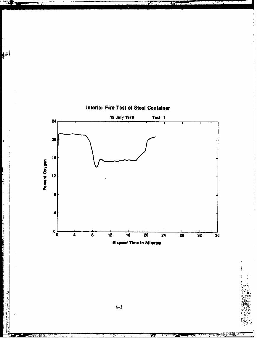
The single factor capable of regulating combustion of fuels within asealed container is the amount of available oxygen. Assuming no leakage, themaximum quantity of air in one of the 20-foot test containers is approximately1,280 cubic feet. A loaded container will naturally have less than 1,280 cubicfeet of air available for combustion. Therefore, to simulate a maximum or worstcase test situation, it was decided to test containers filled with as littlecargo as possible. Because of the variety of cargo normally stowed in containers,it was also decided to utilize both a Class A and a Class B fuel.
Calculations using a combustion engineering formula1 indicated thatthe wood cribs to be used as a fuel source would require 92 cubic feet of airfor the complete combustion of each pound of wood. Therefore, an approximate14-pound weight loss could be expected. Because the airtightness of the testcontainers could not be guaranteed, it was decided to use two 30-pound wood cribsper test. The conglomerate fuel source including a steel pan containing twogallons of naptha occupied a volume of approximately three cubic feet.
The containers used for the interior fire tests were containers whichwere removed from service because of their overall deteriorated condition; how-ever, they were determined to be structurally adequate for these tests. Minordefects such as broken hinges, torn door gaskets, and dented frame rails werenoted on the containers. No special repairs or sealing materials were employedto render the containers overly airtight. In fact, because of their condition,these containers were probably less airtight than containers in normal service.Table 1 is a summary of data for the interior fire tests.
4.2 Thermocouple Locations
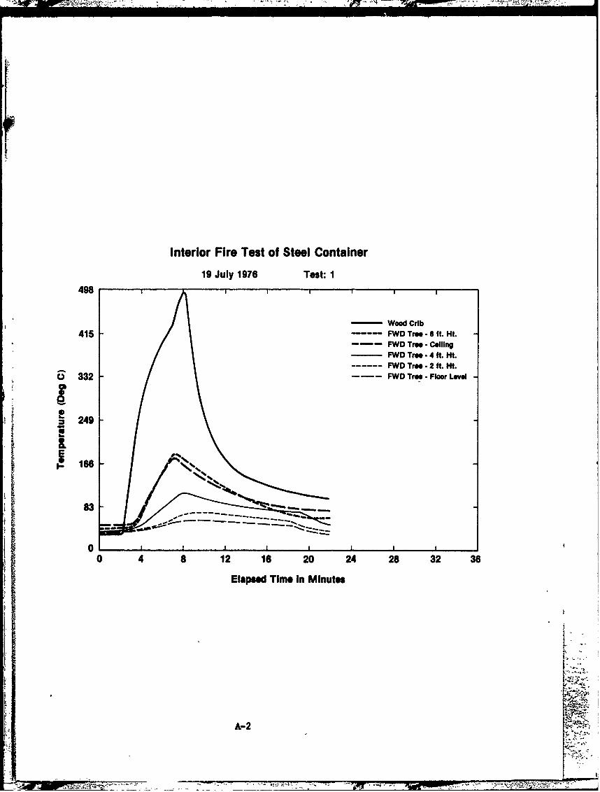
For Tests 1 through 3a, 15 thermocouples were placed at various levelsthroughout each container. Two thermocouple "trees" were spaced approximatelyten feet apart on the centerline of the container. Five thermocouples weremounted on each tree; one on the floor, one on the ceiling, and one every twofeet in between. One thermocouple was placed in the center of the wood cribs,and one thermocouple was placed at the approximate midpoint of each side panel.
4.3 Discussion of Interior Fire Tests
Detailed test data for Tests 1, 2, 3, and 3a are listed in Appendix A.All four interior fire tests produced similar results. Before flame spread toadjacent containers could occur, the interior fires became oxygen regulated,thereby ceasing combustion.
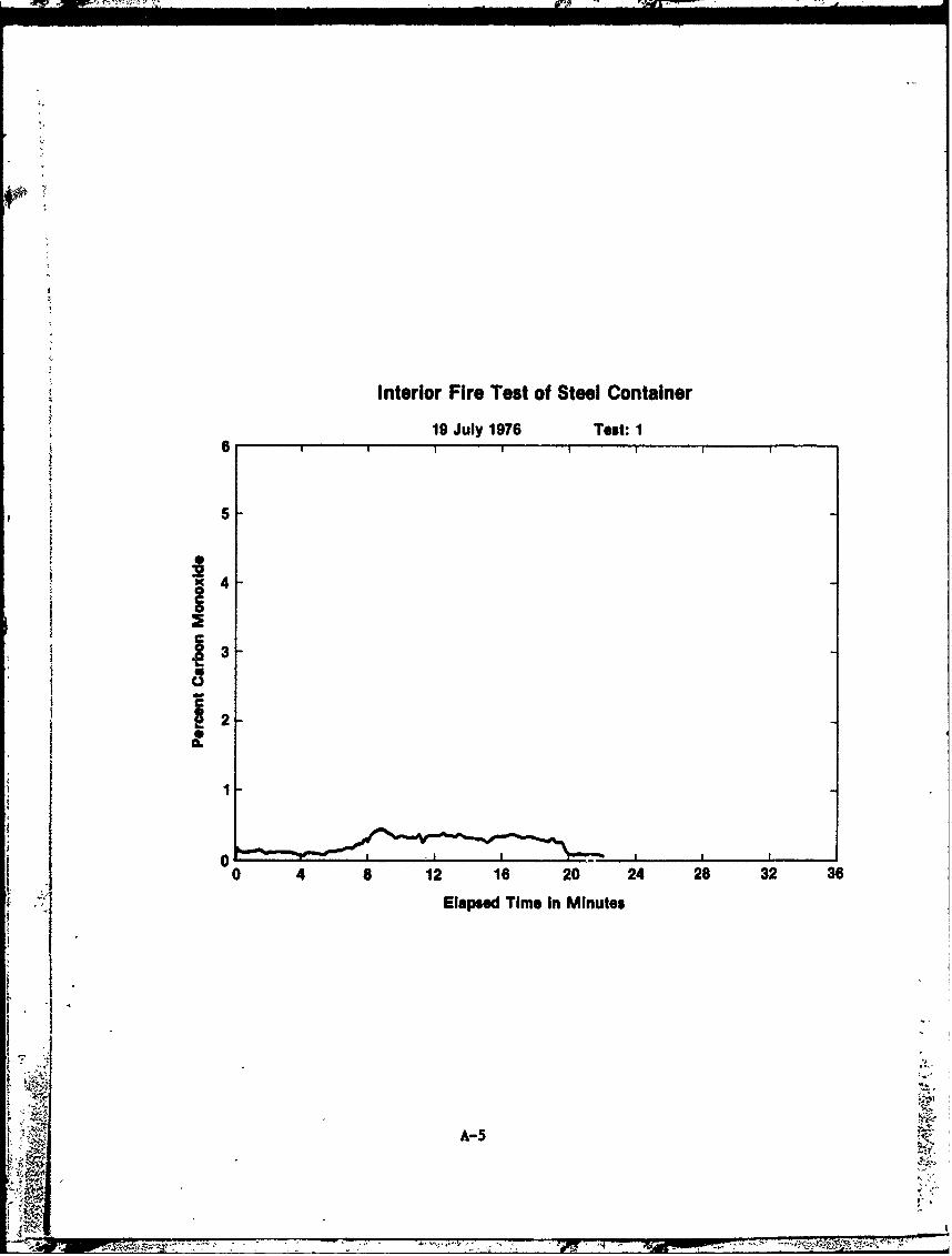
As noted in Section 4.1, the amount of available air in a sealed testcontainer is theoretically sufficient for the combustion of a maximum of 14pounds of wood. Test 1 involved a steel container with four high-level vents(Figure 6). With this additional natural venting, it was predicted that com-bustion of more than 14 pounds of wood might occur. A 13-pound weight loss of
10

.0
E .0 fl C.00 00000 a
CnA
U u U JLL) UL)L U)CL) U ()U U UQ)QE 0 0 000 0 (0 0 00 0 0 0 00 0 000 0
d) I- to IL~O COO tn M c ~ ; C " D4Tf ~ 0 OO) clic)U3
C)C
cn V)) LO IX) u-1- .- a- t-i CMJ (I100*C)0C r. nn
I-- CM
C3C
C.> fl~flCJm0crw0 CJ CM Cn 00 m 000 0!'tLn LO
() (i0 0LflU %D o.0 - - C'l4D Ln r- '* IL P- . MLO tDWM W~ C..)Cir-r- CJC% -r - Mr -r
w Co
- ~0 C.) 0 0 Q Q a CJCQJa\I) 0 C) 0JC~~ C C) COLA 0
4J 4- 0 A.
44 4J C-)I- hv n c
4) c

Figure 6 - Natural Venting on Steel Container
Figure 7 - Charring of Plywood Liner, Test 3a
12

the wood crib was observed in the test. During the test very little evidcncewas seen to indicate the container contents were burning. Very minute traces ofsmoke were noted emanating from various points of the container. The onlyapparent effects of the wood crib fire on the container was a circle of approxi-mately 18 inches in diameter on the ceiling of the container where the paint hadburned off.
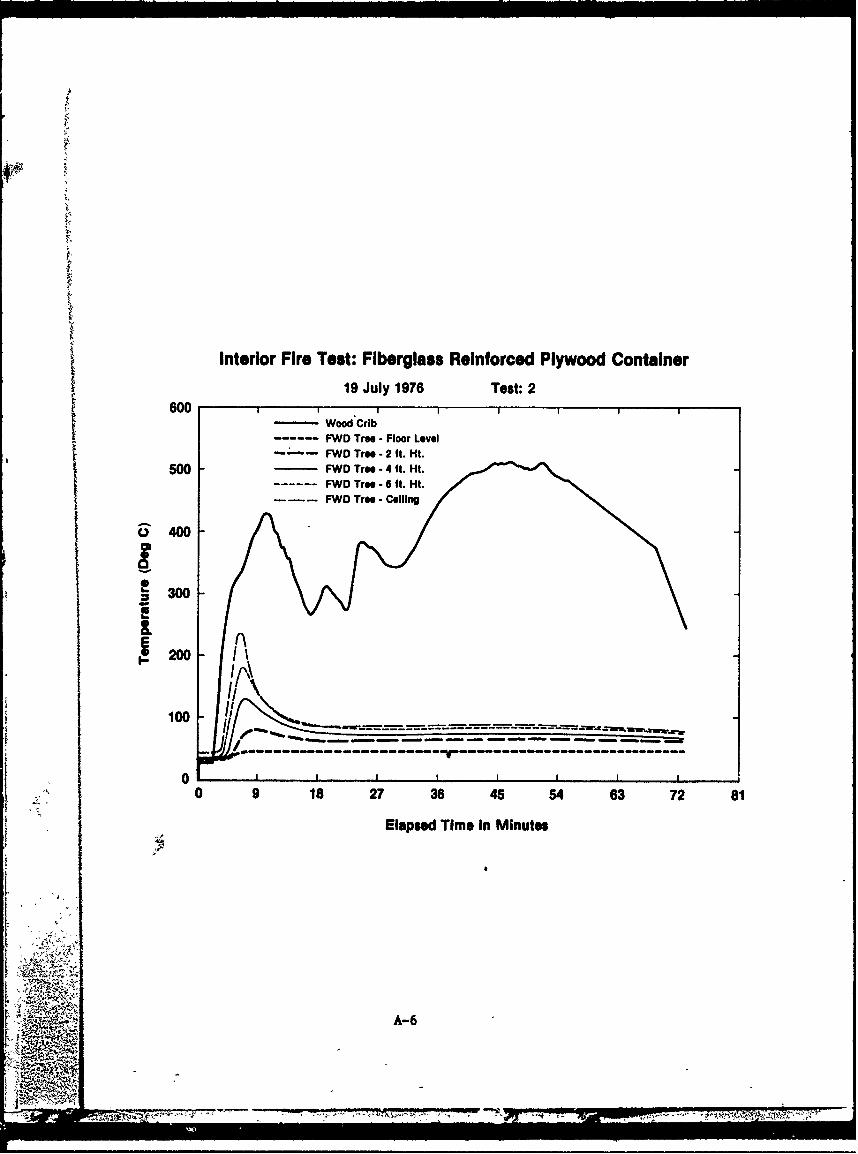
The FRP container used for Test 2 was not vented. In the test, aweight loss of 25 pounds occurred. It is felt that warped floorboards allowedthe leakage of sufficient quantities of air to permit glowing or deep-seatedcombustion of the wood crib. Additionally, it was noted that the FRP paneljoints were sealed with a caulking material which decomposed from the heat of"the fire. The deterioration of this material may have allowed additional airleakage. There were two noted effects of the test fire on the FRP container.As in Test 1, a slight darkening of the ceiling occurred directly above thewood crib, and secondly, the heat of the fire caused styrene boil-out from the
M woven roving on the container roof panel during the test.
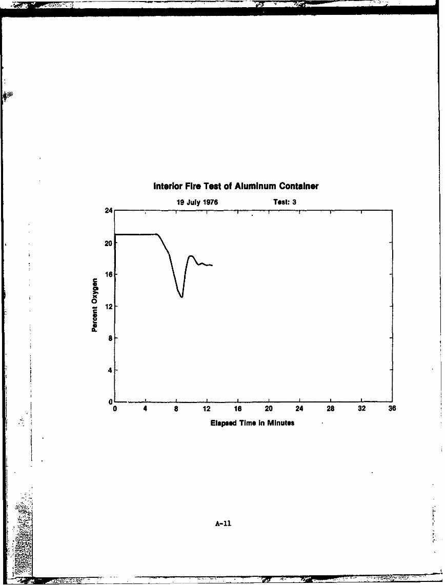
Test 3, involving an aluminum container, produced similar results to Test 1.Prior to this test, it was predicted that the heat flux from the wood crib testfire would be sufficient to cause melting of the aluminum roof panel. During thetest, the roof panel deformed inwardly approximately one and one-half inchesdirectly over the wood crib. Apparently, the thermal conductivity of the aluminumroof panel greatly helped to dissipate the heat to the atmosphere thereby prevent-4 aag its melting. Table 2 is a comparison of temperatures of the roof panels foreach type of container measured at t.e peak of combustion.
T!hBLE 2
ROOF PANEL TEMPERATURES
FWD THERMOCOUPLE TREE AFT THERMOCOUPLE TREE
Aluminum 140%C 140 0 C
FRP 240 0 C 240 0 C
Steel 170 0 C 180 0 C
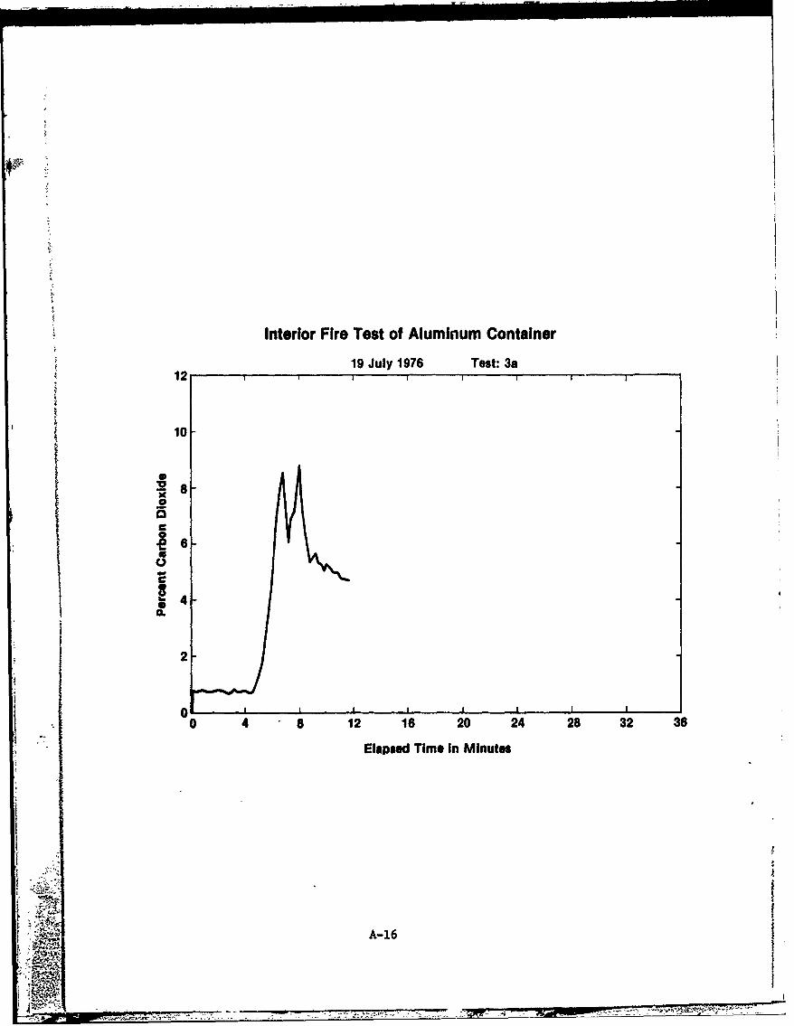
Test 3a was conducted to determine if moving the wood crib to a cornerof the container would produce any effects not observed in Test 3. The relativelyundamaged container used for Test 3 was again used for this test. The wood cribwas situated five inches from the curbside rear corner of the container. Theonly additional effects noted in this test were charring of the plywood liner andmelting of the overhead door gasket. Figure 7 shows the extent of charring onthe plywood liner.
13
7 N

2In a report dated April 1973,2 the Netherlands Ship Research Centrereported on a similar test series conducted in the Netherlands. In those tests,almost identical results to those produced in this study were obtained for aventilated steel container and an FRP container. In the Netherlands ShipResearch Centre tests, wood crib weight loss of approximately 12 pounds wererecorded in all cases. A second report dated November 19743 discusses theresults of tests conducted on aluminum containers. As a result of both testseries, the Netherlands Ship Research Centre concluded that, "a fire inside acontainer (regardless of the cause) will not inflict very much harm on thecontainer in question and certainly not on adjacent containers."
I.
I
14
4 A'g-'. '4____________________________- 7

5.0 EXTERIOR FIRE TESTS
5.1 Single-Level Exposure - Theory
In Section 1.1 it was stated that the two credible fire scenariosdeveloped for intermodal container transport included exposure from an exteriorfire source, either a flammable liquid leak or possibly another source such as afire in the container vessel's superstructure. Tests 4 and 5 were designed tosimulate the exposure of the top level of a container stack in such a manner thatthe underside of the containers would have no effect on the test results. Thiswas accomplished by flooding the test fuel pan with water to raise the fuel levelabove the container floors. Originally, several tests of varying duration wereplanned. The burning time could be regulated by the amount of fuel floated onthe water surface. Previous test experience has shown that the JP-5 will burnoff at a rate of approximately one-tenth of an inch per minute.
Since little damage was incurred in the internal fire tests, theoriginal three containers used for Tests 1 through 3a were stacked as shown inFigure 8 and used for Tests 4 and 5.
5.2 Sinsle-Level Exposure - Discussion of Test Results
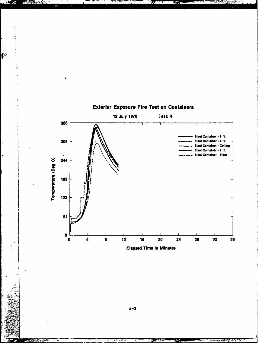
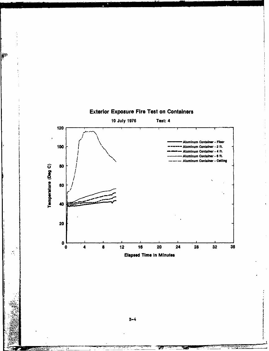
Detailed test data for Test 4 is contained in Appendix B. Test 4 wasplanned as a one-minute exposure. Unfortunately, immediately after ignition, awind shift caused most of the fuel to move to the rear side of the test pan.Because of this, a ten-minute exposure of the container doors occurred. Althoughnot part of the test plan, Test 4 provided an opportunity to evaluate the container
K doors and locking systems. Post-test examination revealed all doors to be stilloperable; however, extra effort was required to secure the locking rod cams intheir keepers because the locking rods had bowed outward. No failure of hingesoccurred and all door gaskets were charred but not totally destroyed, therefore,leakage of flame into the containers did not occur. The aluminum container'splymetal door outer panel of aluminum sheet had melted off and the plywood corewas charred.
The interiors of the containers were examined after Test 4 to evaluatethe effects of the test fire. No major damage to the container was noted. Sincethis test prevented the controlled escalation of fire exposure periods, andbecause the containers remained fairly intact, it was decided to fuel the test pansufficiently to permit Test 5 to burn until complete destruction of the containersoccurred. For this purpose, approximately 1-1/4 inches of JP-5 was floated onthe water surface which resulted in an exposure of approximately fifteen minutes.Discussion of Test 5 is contained in Section 5.4.
5.3 Multi-Level Exposure - Theory
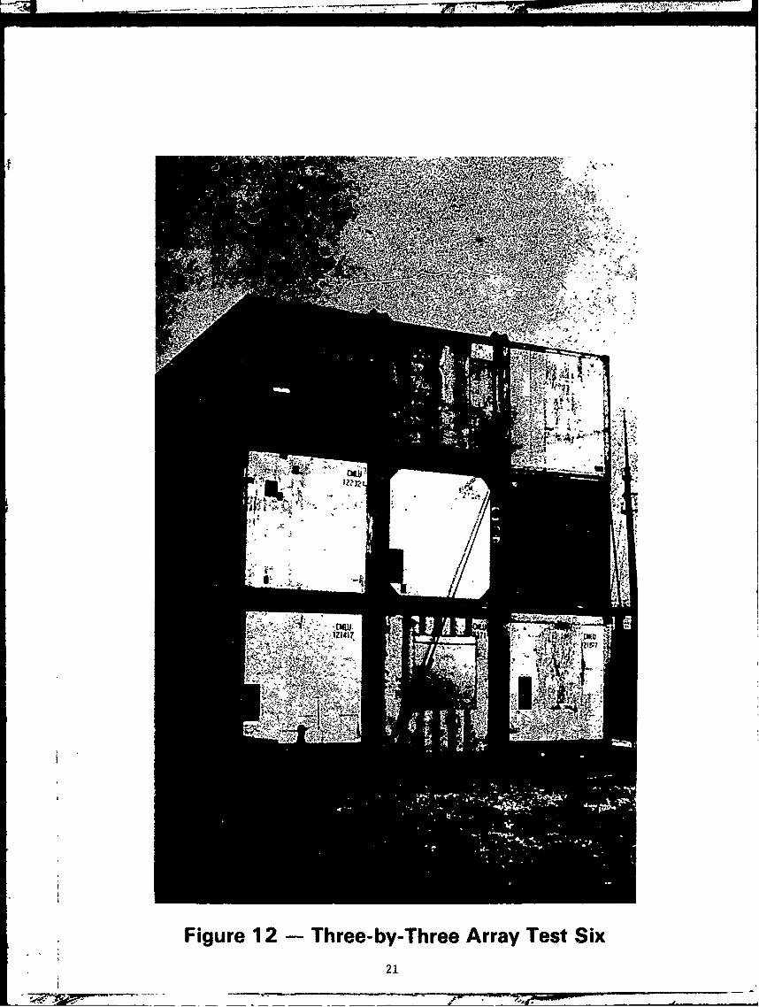
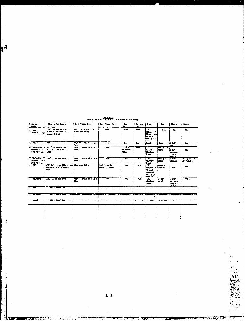
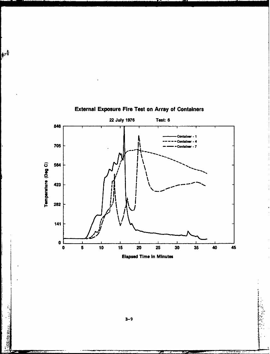
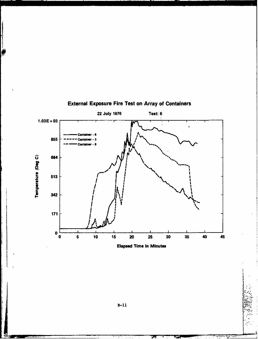
Test 6 was intended to simulate a full-scale container stack exposurewith the wooden floors of the containers exposed to the pool fire. Nine con- ,itainers were stacked in a three-by-three array shown in Figures 11 and 12. Thewater level in the test pan was lowered to approximately nine inches below thefloorboards of the first row of containers. Sufficient fuel was then added toallow an exposure of approximately twenty-five minutes. The containers, theirrespective materials of construction, and time-temperature graphs for Test 6are listed in Appendix B.
15
4-

Figure 8 - Single Level Array of Containers
16

<T-"Pj, '.
Figure 9 -Test Number Four
Figure 10 - Condition of Container Doors
17
.Oc Co CO (
ai _ 0 a4
cci 0 .0
0L
E EC.cv
E0. E~Iio 0
C'E Oc E
0 C a0ECc &. Cw
E E0
~E Eha0U.
0 1c
.54a CI C 96U. if L
CIE ~iE 187-;. aC C

5.4 Discussion of Tests 4, 5, and 6
450-F (232-C) is the approximate temperature above which aluminumloses its structural integrity. It is also the approximate kindling point formany types of Class A materials. Therefore, it is at this temperature that thespread of fire in a container stack occurs; either by structural failure ofaluminum container frame and panel components or by radiant or conducted heatenergy to Class A materials. In Test 5, 450*F was reached in approximately fourminutes in the interior of both the steel and aluminum containers, while theinterior temperature of the FRP container did not reach this temperature fornine minutes. The frame and side panels of the aluminum container began to meltafter four minutes of test exposure (Figure 13). The aluminum top frame rail ofthe FRP container did not melt during the test. It was noted, however, that thetop rail had begun to deform where it was connected to the steel end frame (Figure14). It is felt that the thermal insulating properties of the FRP side panelshelped to limit the transfer of heat to these components.
Table 3 is a comparison of the relative heat absorption rates of thecontainers tested in the multi-level configuration. As can be noted from thistable and from the detailed time-temperature data in Appendix B, the temperaturerise to 450*F in all containers occurred at approximately the same rate. In thetop row of containers, with the exception of Container 9, this temperature risewas delayed for approximately five minutes. Container 9 was directly exposed tothe effects of the pool fire when the collapse of Containers 7 and 8 occurred atapproximately ten minutes.
In Tests 4 and 5, the containers were free-standing on the hatch cover.In Test 6, the containers were stacked and lashed which imposed a load upon thebottom row of containers not experienced in previous tests. Additionally, theundersides of the container floorboards were exposed to the fire in Test 6.These two factors could account for the differing test results between Tests 5and 6. The bottom level of containers used in the one-level array for Test 5reached this temperature in approximately four minutes. The bottom row of con-tainers in the three-level configuration used for Test 6 did not reach 450*F fornearly ten minutes. However, when this temperature was reached, the collapse ofContainers 1 and 7, which had aluminum frames, occurred. The remainder of thecontainers had steel frames except Container 5 which had an alurinum front end-frame. Throughout Test 6, the middle column of containers remained in place withContainers 3 and 9 also being held in place by the bridge fittings (Figure 15).It was the eventual failure of the aluminum front end-frame of Container 5 thatcaused the total collapse of the container stack.
19

*1 C. EC
.10
w J II
cri
~,0
EI E F:U
I= I- V 9.N-yl o 0<
~ C C cl Cj enC C
Lai
02
I r-
Figure 12 -Three-by-Three Array Test Six21

-. * �* * A. .�
$
Figure i3- Melted Aluminum Components
Jr -� -� t *.
4 � �'" 'Lk
U �. '.. ;%�'�-x'nfl�;t' .4.
r
1.
Figure 14 - Buckled Aluminum Top Rail
22C
a - - .. -.-- 4 4

Figure 15- Containers Held in Placeby Bridge Fittings
Figure 16-- Collapse of Container #5 523
.--. • m,• = I.,•._I. ,L• ""•,•,•',,1 •-,-,,-- _ . - - ,-,•,.;= -- ,,•-4 -Now-

6.0 CONCLUSIONS
A. Steel containers do not act as a barrier to prevent the spread offlame through a container stack. The failure of steel container panels did notoccur in any of the tests. Additionally, steel containers are non-combustibleand do not add to the fuel load of the cargo.
However, as a result of these tests, it can be shown that the transferof a fixed amount of heat to the interior of a container from an external heatsource will occur in approximately equal time period for both steel and plywood-lined aluminum containers. A JP-5 pool fire source of approximately 30,000BTU/FT2 -hour as used for these tests could cause the potential ignition orcharring of Class A materials inside a sealed steel or aluminum container inapproximately five minutes. If a steel container were placed in a container
k • stack to act as a barrier, it would merely delay the transfer of heat toadjacent containers for several minutes.
B. Extruded aluminum alloy frames do not provide an equivalent amount ofstructural integrity as high tensile strength steel frames during fire exposure.In Test 6, the eventual collapse of the container stack was caused by the failureof aluminum frame components (Figure 16). Containers 1 and 7, whicr. failedinitially, utilized total aluminum frame hardware. The spread of flame througha container stack is caused by the transfer of radiant heat energy to intact con-tainers. Aluminum frame components or side panels will wielt under fire exposure,causing the spread of flame to the container contents and, consequently, toadjacent containers.
C. An interior fire in a sealed, non-damaged container will become enregulated before any of the container panels are breached. All interior testfires were self-extinguished from oxygen depletion. Similar results were notedin a test series conducted by the Netherlands Ship Research Centre (Section 4.3).
D. The wooden floorboards used in container construction do not add to therapid spread of fire through a container stack. As discussed above, an externalfire will cause the transfer of a sufficient amount of heat through all threetypes of container panels to ignite Class A materials within approximately fiveminutes and, within a short time thereafter, melt aluminum frame components.Laboratory tests 4 of double thicknesses of nominal one-inch tongue and groovelaminated hardwood flooring show that twelve to eighteen minutes is required toreach 250*F (132*C) on the unexposed side of the floor when exposed to the ASTME-119 test furnace. It follows that the transfer of heat through 1-1/8'or 1-1/41container floorboards will require from six to nine minutes to reach a pointwhere the unexposed surface temperature will approach the higher temperature of450*F. This is equal to or greater than the time required for this amount ofheat to be transferred through the container roof or side panels to the aluminumframe components,._
E. The stacking and lashing fittings currently used provide an adequateamount of structural stability under fire conditions. In Test 6, the bridge
fittings maintained the top row of containers in position even though the bottomaend containers had collapsed (Figure 15).
r24
-WAVTNMW-

7.0 SUMMARY
The findings of this study indicate several important aspects of containershipping. An incident resulting in the ignition of cargo within a sealed, non-damaged container would not endanger adjacent containers. However, a typicalcontainer stack exposed to an exterior fire source for more than appLoximatelyfive minutes can structurally fail, melt, or transfer radiant heat to cause thespread of flame to adjacent container stacks. External fire exposure will pro-duce nearly identical results, after a certain amount of time, in all three typesof containers. For this reason it is felt that, unless restrictive economicalmeasures are taken, no changes in basic container construction or materials canprovide a substantial gain in fire protection capability. The typical containersin use today do not act to intensify a deck cargo fire nor do they impede thespread of flame for more than several minutes. An exterior fire in a containerstow can spread unless controlled by the installed fire protection system. Itis essential that fixed fire-fighting systems be capable of rapid activation andapplication. It is also necessary to insure adequate capacity for the installedfire-fighting system.
If not initially controlled, an on-deck container fire could progress untilit exceeds the design application rate of the installed fire-fighting system,and at such time, the entire on-deck container load will be jeopardized.
25
APPENDIX A
INTERIOR FIRE TEST DATA
A-1
* *2' - .ý
REFERENCES
1. National Fire Protection Association, "Fire Protection Handbook," 13thedition, 1969, Boston, MA, page 5-9.
2. Souer, H. J., "Marine Transportation of Containerized Cargo," Part III,Netherlands Ship Research Centre TNO, Report Number 202M, November 1974.
3. Souer, H. J., "Marine Transportation of Containerized Cargo," Part V,Netherlands Ship Research Centre TNO, Report Number 202M, November 1974.
4. Underwriters' Laboratories, Inc., "Fire Resistance Directory," 1977,Northbrook, IL, Sections L and M.
IiII
26
-7- pil 777t
- - ~ -
Interior Fire Test of Steel Container19 July 1976 Test: 1
498
-Wood Crib415 FWD Tree 6 ft. Ht.
FWD Tree- CoilingFWD Tree -4 ft. Mit.FWD Tree- 2ft.Ht.
& 332 FWD Tree -Floor Level
S249
18830 4 8 12 16 20 24 28 32 36
I. Elapsedl Time In Minutes
A-2
- _4ur .4
Interior Fire Test of Steel Container19 July 1976 Test: 1
24
20
16
x0
~12
*8
4
0 4 8 12 16 20 24 28 32 36
Elapsed Time In Minutes
A-3 L~

Interior Fire Test of Steel Container119 July 1976 Test: 1
10
8-
4-
0 4 8 12 16 20 24 28 32 36
° Elapsed Time In Minutes
;• A-4
'I w"
A.OPON0--7
Interior Fire Test of Steel Container
19 July 1976 Test: 16
5
14
0
0I -I .
0 4 8 12 16 20 24 28 32 36
Elapsed Time In Minutes
A-5
03
Interior Fire Test: Fiberglass Reinforced Plywood Container19 July 1976 Test: 2
600-Wood Crib------------------------FWD Tree.- Floor Level
-FWD Tree -2ft. Ht.
6NF1 5re004f. t
S300
100
00 9 18 27 38 45 54 63 72 81
Elapsed Time In Minutes
- A-6

interior Fire Teat: Fiberglass Reinforced Plywood Container
24 19 July 1976 Test: 2
I I I
20
20
�12
0.
8
' S 4
0 I I I
0 9 18 27 36 45 54 63 72 81ElaPsed Tim. In Minuteb
�
A-7
.� �
'I
-

II
Interior Fire Test: Fiberglass Reinforced Plywood Container
19 July 1976 Test: 2
!43 6
C
2_
II
0 9 18 27 38 45 54 63 72 81
Elapsed Time In Minutes
AA-8
1!

Interior Fire Test: Fiberglass Reinforced Plywood Container
19 July 1976 Test: 26 I I
5-
4-
0
0 I 18 27 36 45 54 63 72 81
Elapsed Time In Minutes
A-9
S. ..

Interior Fire Test of Aluminum Container
19 July 1976 Test: 3582
-- Wood Crib
485 FWD Tree - Floor LevelFWD Tree. 2 ft. Ht.FWD Tree- 6 ft. Ht.FWD Tree - Ceiling
3118 FWD Tre - 4 ft. HIt.
291
~194
97 //
0 I I I , , I
0 4 a 12 16 20 24 28 32 36
Elapsed Time In Minutes
A-1O
T T-
Interior Fire Test of Aluminum Container
19 July 1976 Test: 324
20
16
x
0o 12
8
4
0 I I I ,S0 4 8 12 16 20 24 28 32 36
Elapsed Time In Minutes
A-11*
ENV •• u • • • . .. °. . .. •' " "' • " -••'- ;,.-• _ . '• '& ''r .•o_ _••- . • '"

Interior Fire Test of Aluminum Container1219 July 1976 Test: 3
12I
10
I8 U
i~i.•4.
2
0 I I I IIIIII
0 4 a 12 16 20 24 28 32 36
Elapsed Time In Minutes
A-12
Yt

Interior Fire Test of Aluminum Container
619 July 1978 Test: 3
5
3 r
2
0
*0 4 8 12 16 20 24 *28 32 36
Elapsed Time In Minutes
A-13
-9 uy 9'6Tst- - - - - - - -- - - - - - - - - - - - - - - - - - - - - -

P77 1 , ! .... .,-JjfN ---- ---..-
Interior Fire Test of Aluminum Container
19 July 1976 Test: 3a
600I
Wood Crib
FWD Tree. 6 ft. Ht.FWD Tree, 4 ft. Ht.FWD Tree - 2 ft. Ht.
A I400 FWD Tree, Floor Level
1010
0 I , I ... III I
0 4 $ 12 16 20 24 28 32 36
Elapsed Time In Minutes
A-14

Interior Fire Test of Aluminum Container
19 July 1976 Test: 3a24 ,, ,
20
16
12
8
4
10
0 4 8 12 16 20 24 28 32 36
"Elapsed Time In Minutes
A-15
. . .. . . . . ... .. ..
Interior Fire Test of Aluminum Container
19 July 1976 Test: 3a12 , , ,
10
Io0
6-°1 S
a.
2
0 i . ,i I i ,i . I
00 4 8 12 16 20 24 28 32 36
Elapsed Time In Minutes
A-16

Interior Fire Test of Aluminum Container
619 July 1976 Test: 3a
5-
4.
0
00 4 a 12 16 20 24 28 32 36
Elapsed Time In Minutes
A1
A... I II II ,+ t J2 + •• - • .;; "+• '' '• '11"• ...... .. ....4- .,. 12-- 16- 20..... 24....+ 28 32 36 •.••+++•-
APPENDIX B
EXTERIOR FIRE TEST DATA
B-1
~ ~ i
Approdl.Container Conotructlon Data - Three Level Array
Container side 4 End Pe-.le I End Free.. Front Fnd Fro e, Rear Too Notton Roof Doors rloors Lining
".*od~r I6-tor66-T lal, Re te
.06" Polyester fiber- •646 or 6S)a62 Nail .06" N/A N/A N/A
1, uIoneandwich-3S/" Alusnm Alloy I polyastor1466 Vintagae nlwod core l.sfiberlyis
1 5/8" ply-Wood Mors
. i a. -I Steel HIth Tensile StenDth ae .S.ae Sam Stool Steel TIN - N/A•tool Oak
poT .063" Al "n-o Sheet ;Htth Tensile Strength Sme 6061-S teel Stee" P la-"-tenror Post 1 3/1n" Poet. on JA" Stte Ai a1 .I3-H14 'ntal 1 1/4" W/A1o66 violate Core. I Alloy Alo•nee fhard°ood
I Shet 10010. &Interiorn !ontSt ren" '3th I l"'T nI/A" 75
riT
6. Aluminm .051" Aluminum Shoot ih Tonsil. StrengthN/A /A .0= 1/4" plywoodBxtorfor ot Steol Aluminum tal hardwood 48" height1066 Vnatia I - Sheet I
5. PR? 0.6" Polyester fibargloonAlumino. Alloy hhigh Tensile NIA N/A .01" ply" tIN/eaodwich-3/4" olood oStrnAth Stool polyester Type 8;2 N/Acore. fiberglass
aantlch-5/8" ply-wood Mor.
6. Aluminus .063" Al~inum Sheet High Tensile Strength Sam A / O" ply 8 N/A,Steel 2 Al mlnr' oetal hardwood
Sheet tongue &7.. M SEE Ifm elt OKo , --.-------- ------.-.-.. -------- -----.-.---.----------.I.------ --.-.-.-.-..-.-.-.-.----- a Too
7. %toot Sim W41rq TWO .....-
:B-2
7
Exterior Exposure Fire Test on Containers
19 July 1976 Test: 4366
- Steel Container -6 ft.5 "------- Steel Container - C ft.305-Steel Container - CilingSiSteel Container - 2 ft.------. Steel Container- Floor0 244 I- "K,
244 I \
IIS ~ I'~183 lot
Eij- 122
61
!0 0IO I i I I I,,
0 4 8 12 16 20 24 28 32 36
Elapsed Time In Minutes
B-3
A.Ri
0
two
Exterior Exposure Fire Test on Containers
10 July 1976 Test: 4
120
- Aluminum Container- Floor
100 I Aluminum Container -2 ft.
I -'- Aluminum Container * 4 ft.Aluminum Container- -S ft.Aluminum Container - Ceiling
&80 I/6 ..
20
0I , I | , tI . i
20
0 4 8 12 16 20 24 28 32 36
"Elapsed Time In Minutes
B-4 I
l'1__-

Exterior Exposure Fire Test on Containers
19 July 1976 Test: 4252 , , I
-- FRP Container - Ceiling
210 FRP Container - FloorFRP Container - 2 ft.
FRP Container - 4 ft.FRPContalner-6ft.
126
42
0 , I I i I I
0 4 8 12 16 20 24 28 32 36
Elapsed Time In MInuies
B-5
7--5-7

Exterior Exposure Fire Test on Containers
20 July 1976 Test: 5570
- Steel Container - 6 ft.
475 ------ Steel Container - 4 ft.Steel Container - Ceiling
- Steel Container - 2 ft.-" •-- Steel Container- Floor
&380
S285
,190
95
0 , p ,
0 4 8 12 16 20 24 28 32 36
Elapsed Time In Minutes
-6
I4

Exterior Exposure Fire Test on Containers
20 July 1976 Test: 5
342 , ,
- FRP Container - Cailing285 ------ FRP Container -6 ft.
-''----FRP Container - 4 ft.SFRP Container - Floor
__228
I%%
e 171 %% -
E 114 //1-
57 /
0 4 8 12 16 20 24 28 32 36
Elapsed Time in Minutes
B-

Exterior Exposure Fire Test on Containers
20 July 1976 Test: 51026 ,r
-- Aluminum Container. 4 ft.855 -.... Aluminum Conteraer- Coiling
Aluminum Container -6 ft.
Aluminum Containlr. Floor
6I 1
6 513I ~ IU
& II U.. 342
I171
0 4 a 12 16 20 24 28 32 36
Elapsed Time In Minutes
B-8
77 I7
External Exposure Fire Test on Array of Containers
22 July 1976 Test: 6846
Contain - I
-Container -4705 --- ContaIner. -
JI ..- ý "' . ..& 6 I '\
141/0V
0 ., I IiI , I
141 10 15 20 25 30 35 40 45
Elapsed Time in Minutes
4
B-9

External Exposure Fire Test on Array of Containers
22 July 1976 Test: 61.06 E + 03
4 -Container - 5..---- Container- 2
885 --- Container. -
LL0II x!t Ii
35 10 i 20 25 30 35 40 45
Elapsed Time In MinutesB-10
External Exposure Fire Test on Array of Containers
22 July 1976 Test: 6
1.03E+03
-5 .. Container - 6855 ------- (io.rI3
--- Container - 9
& 684
/ 44S513 X
E / \342 34
171
171 I I aJ I
0 5 10 15 20 25 30 35 40 45
Elapsed Time In Minutes
B-1l


![FPCD-77-62 Benefits from Flexible Work Schedules--Legal … · DCCUMENT RESUME 03531 - (12723940] Benefits frcm Flexible Work Schedules--Legal Limitations Remain. FPCD-77-62; E-179810](https://img.dokumen.tips/doc/110x75/5f802c11a09b4f733d34aa21/fpcd-77-62-benefits-from-flexible-work-schedules-legal-dccument-resume-03531-.jpg)