Embed Size (px)
Citation preview
1
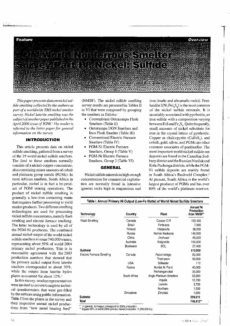
Table I. Annual Primary Ni Output (Low-Fe Matte) of World Nickel Sulfide Smelters
Annual NiProduction
Technology Country Plant from NMBF*
Flash Smelting Canada Copper Cliff 133,400Brazil Fortaleza 7,000
Finland Harjavalta 38,000Russia Norilsk Nadezda 140,000China Jinchuan~ 65,000
Australia Kalgoorlie 100,000Bostwana BCl 27,400
Subtotal 510,800Electric Furnace Smelting Canada Falconbridge 63,000
Thompson 50,000USA Stillwater 112
Russia Norilsk Ni Plant 40,000Pechenganickel 35,000
South Africa Anglo Platinum Smelters 22,000Impala 12,700lonmin 3,700
Northam 1,500Zimbabwe Zimplats 1,600
Subtotal 229,612Total 740,412**
• In general, tonnagescorrespond to 2004 production.•• Equals 59% of world 2004 primary nickel production (1,260,000 tly).
Thispaperpresents data on nickel sulfide smelting collected by the authors aspart ofa worldwide TMS nickel smeltersurvey. Nickellaterite smelting was thesubjectofanotherpaperpublished in theApril 2006 issue of JOM.] The reader isreferred to the latter paper for generalinformation on the survey.
INTRODUCTION
This article presents data on nickelsulfide smelting, gathered from a surveyof the 19 world nickel sulfide smelters.The feed to these smelters normallyconsists of a nickel-copper concentrate,also containing minor amounts ofcobaltand platinum group metals (PGMs). Inmost African smelters, South Africa inparticular, nickel is in fact a by-product of PGM mining operations. Theproduct of nickel sulfide smelting isgenerally a low-iron containing mattethat requires further processing to yieldmarket products. Two different smeltingtechnologies are used for processingnickel sulfide concentrates, namely flashsmelting and electric furnace smelting.The latter technology is used by all ofthe PGM-Ni producers. The combinedannual nickel output of the world nickelsulfide smelters is some 740,000 tonnes,representing about 59% of world 2004primary nickel production. This is inreasonable agreement with the 2003production numbers that showed thatthe primary nickel output from lateritesmelters corresponded to about 30%,while the output from laterite hydroplants accounted for about 12%.1
In this survey, smelterrepresentativeswere invited to review/complete technical questionnaires that were pre-filledby the authors using public information.Table I lists the plants in the survey andtheir respective annual nickel productions from "new metal bearing feed"
(NMBF). The nickel sulfide smeltingsurvey results are presented in Tables IIto VI that were composed by groupingthe smelters as follows:
• Conventional Outokumpu FlashSmelters (Table II)
• Outokumpu DON Smelters andInco Flash Smelter (Table III)
• Conventional Electric FurnaceSmelters (Table IV)
• PGM-Ni Electric FurnaceSmelters, Group 1 (Table V)
• PGM-NiElectric FurnaceSmelters, Group 2 (Table VI)
GENERAL
Nickel sulfide minerals inhigh enoughconcentration for commercialexploitation are normally found in intrusiveigneous rocks high in magnesium and
iron (mafic and ultramafic rocks). Pentlandite [(Ni,Fe)9S8] is the most commonof the nickel sulfide minerals. It isinvariably associated with pyrrhotite, aniron sulfide with a composition varyingbetweenFeS andFe
7S8.Quitefrequently,
small amounts of nickel substitute foriron in the crystal lattice of pyrrhotite.Copper as chalcopyrite (CuFeS), andcobalt, gold, silver, and PGMs <l!e othercommon associates of pentlandite. Themost important world nickel sulfide oredeposits are found in the Canadian Sudbury district and the Russian Norilsk andKola-Pechenga districts, while thePGMNi sulfide deposits are mainly foundin South Africa's Bushveld Complex.2
At present, South Africa is the world'slargest producer of PGMs and has over80% of the world's platinum reserves.
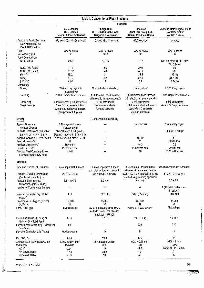
Table 11. Conventional Flash Smelters
Producer
low Fe matte low Fe matte low Fe matte low Fe matte90 95.8 95 94
8.68 15-16 13.2 Ni 10.3-12.3, Cu 4.2-6.2,Co 0.3-0.4
1.12 50 2.04 2.223.32 40 43.6 3243.03 34 38.3 36-4830.57 32 27.1 31.5-34.58.97 7 6.7 1.8-2.0
2 Niro spray dryers & Concentrate received dry 1 rotary dryer 2 Niro spray dryers1steam dryer
1 Outokumpu flash furnace 1 Outokumpu flash furnace 1Outokumpu flash furnace 2 Outokumpu flash furnaceswith electric furnace appendix with electric furnace appendix
3 Peirce Smith (PS) converters 3 PS converters 3 PS converters 6 PS converters2 electric furnaces + 1 tilting Flash furnace electric Flash furnace electric furnace 4 circular Krupp furnaces
cylindrical, horizontal furnace. furnace appendix appendix + 2 separateequipped with tuyeres electric furnace s
Annual Ni Production fromNew Metal-BearingFeed (NMBF) (Vy)
FormNi Recovery (%)Feed Composition
NiCuCo (%)
Ni/Cu (WI. Ratio)Ni/Co (WI. Ratio)Fe (%)S(%)Si02 (%)
TechnologyDrying
Smelting
ConvertingSlag Cleaning
Drying
Type of Dryer andNumber of Units
Outside Dimensions (dia. x I ordia. x h or Ix w x h) (m)
Nominal Capacity-Dry t Feed/hFeed Moisture (%)Product Moisture (%)Fossil Fuel-TypeAverage Fuel Consumption
l or kg or Nm3 /t Dry Feed
BCLSmelterBCl Limited
Selebi Phikwe, Botswana
27,400 (2003, Ni+Cu 51,000)
2 Niro spray dryers +1steam dryer
Niro 10 mx 10 mhigh (ID)Steam 3.1 (w) x 8.15 (I) x 4 (h)Niro: 55 t/h/unit; steam: 50 t/h
28Bone dry
Pulverized coal43.64
KalgoorlieBHP Billiton Nickel West
Kalgoorlie, Australia
-100,000 Mt/y Ni in matte
Concentrate received dry
JinchuanJinchuan Group Ltd.
Gansu Province, China
65,000 (2004)
Rotary dryer
60-8011
<0.3Pulverized coal
16
Nadezda Metallurgical PlantNorilsky NickelNorilsk, Russia
140,000
2 Niro spray dryers
14mx18mhigh
6150 (slurry)
0.2Natural gas
100 Nm3/Dry t feed
Smelting
Type and Number of Furnaces
Furnace Outside Dimensions(Settler) (I x w x h) (m)
Reaction Shaft InternalDimensions (dia. x h) (m)
Number of Concentrate Burners
Nominal Capacity (Dry t SolidFeed/h)
Reaction Air + Oxygen (Nm3/h)
°2 Vol.%Fossil Fuel Type
Fuel Consumption (l or kg orNm3/t of Dry Solid Feed)
Furnace Area Availability - OperatingDayslYear
Furnace Campaign Life (Years)
1Outokumpu flash furnace
22 x8.2 x4.0
8.5 x 10.73
4
115
150,00031
Pulverized coal
52.6
356
Previous was 9
1Outokumpu flash furnacewith electric furnace appendix
37 mlong x 8 mwide
6.9 x 6
4
130-140
85,00035
NG for preheating air to 500°Cand NG or oil in the reaction
shaft (oil is RF80)11L
-10
1 Outokumpu flash furnacewith electric furnace appendix
32.5 x 7.2 x 3.4 (includes settlingpool and slag cleaning appendix)
6.4 x 6
4
50 (dry t con/h)
32,60042
Heavy oil + coal powder
25l + 16 kg
330
8
2 Outokumpu flash furnaces
31.2 x 10 x 4.5-6.4
8.0 x 8.91
1 (18 fossil fuel burnersin settler)110-150
34,00070
Natural gas
40 Nm3
330
5
Flux 8i02 (%)Average Size (wl.% Below Xmm)Matte (t/d)
NiCuCo (%)NVCu (WI. Ratio)Ni/Co (WI. Ratio)
82.8100% below 4 mm
400-70032.41.1441.9
75.645% passing 75 Ilm
630-4930.258
92.790% < 0.25 mm
36044.81.952
7899%<2 mm
1,300Ni 32; Cu 15; Co 0.8
2.140
~ 2_00_7_A_p_r_il_._JO_M _59

Table 11. Conventional Flash Smelters (cont.)
Producer
BClSmelterBCl Limited
Selebi Phikwe, Botswana
KalgoorlieBHP Billiton Nickel West
Kalgoorlie, Australia
JinchuanJinchuan Group Ltd.
Gansu Province, China
Nadezda Metallurgical PlantNorilsky NickelNorilsk, Russia
Smelting (cont.)
Fe(%) 33.0 19.8 29 23S(%) 24.68 26.7 23 27
Matte Tapping Temperature (QC) 1,164 -1,170 1,200-1,240 1,150
Slag (t/d) 2,608 1,650 1,100 3,100Si02(%) 28.05 33 35.6 34Fe(%) 40 40 40.8 40Fep. (%) 8.16 6.3 <2 7MgO(%) 1.92 7.1
Slag Skimming Temperature (QC) 1,244 1,290-1 ,350 1,380 1,250
Value Metal Partitions (Matte/Slag) (%)Ni 11.5 70 116 52Cu 11.20 33 65 43Co 2.55 4.5 7.6 4.7
Furnace Off-GasTemperature CC) 1,400 1,350-1,400 1,380 (uptake) 1,150Volume (Nm3/h) 87,152 60,000 (ESP) 56,000S02 Dry Basis (vol. %) 7.2 8 (acid plant) 30-35
Off-Gas Cooling and Cleaning System WHB (67 bar 125 t/h WHB and ESP WHB and ESP WHB and ESPsteaming rate), 2 parallel
lurgi ESPsDust (Sludge) Disposition Recycled to flash furnace Dry dust back to flash furnace Recycled to flash furnace Recycled to flash furnaceOff-Gas Disposition Atmosphere Acid plant Acid plant Atmosphere
Converting
Type and Number of Converters 2 PSCs (2 hot, 1 repair) 3 PS converters 3 PS converters 6 PS convertersOutside Dimensions (dia. x I) (m) 3.96x9.14 3.6 x 7.3 3.6 x 8.2 4x9No. and Dia. ofTuyeres (mm) 44 @ 38 28 @ 63.5 34 @ 48 52 @ 50Average Blowing Rate (Nm3/h) 32,000 19,000 18,000-22,000 36,000Blast Oxygen Content (vol.%) 21 21 21 21Reverts Addition of Primary Matte (wt.%) 25 10 25-30Converting Flux (S02 %) 82.8 98.7 95.4 76Average Size (wt.% Below X mm) 100% below 4 100% passing 25 90% 30-50 100% <50
Matte CompositionNiCuCo (%) 80.82 69 73 Ni 40-52; Cu 18-30;
Co 0.2-0.3Ni/Cu (Wt. Ratio) 1.12 37 1.93 1.9Ni/Co (Wt. Ratio) 95.34 74 56 180Fe(%) 1.49 4.2 4.2 3.4S(%) 16.66 24 22.4 22-23
Matte Pouring Temperature (QC) 1,250 1,280 1,250 1,200Matte Processing Technology Matte granulated and shipped to Controlled cooling, milling, Controlled cooling, milling,
Kwinana refinery and other separation of Cu2S, Ni3S2, flotation
overseas refineries metallicsSlag Composition
Si02 25.92 21 24-28 20Fe 44.14 55 48 52Fep. 17.63 32 14-18 25
Slag Skimming Temperature (QC) 1,250 1,280 1,250-1 ,300 1,250Slag Disposition Slag cleaning vessel and slag 100% recycled to flash furnace Slag cleaning furnaces Slag cleaning furnaces
cleaning electric furnacesConverter Off-Gas
Hood Dilution Factor 2.5 1:1 to acid plant; 2:1 to stack 2.5 to 3 3t04Diluted Volume (Nm3/h) 80,000 one converter; 41,000 to acid plant; 50,000-60,000 140,000
160,000 two converters in stack -60,000 to stackS02 Dry Basis (vol.%) 5.2 -4% to acid plant, -2.7% to stack 2.5-3.5 2.5
Off-Gas Cooling and Collection in balloon flue Spray cooler (air and WHB and ESP WHB and ESPCleaning System dust system water)Dust (Sludge) Disposition Captured and mixed with Recycled to flash furnace Recycled to flash furnace
flash furnace flux
hO JOM· /\f1111 :'()()('
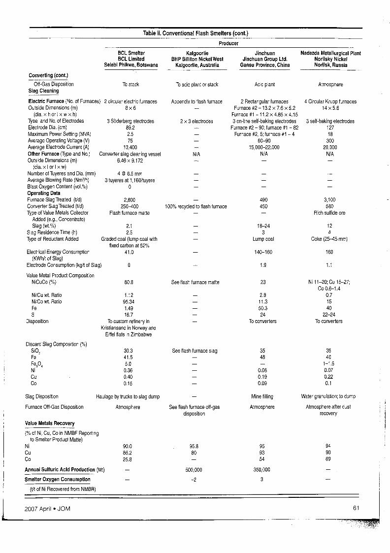
Table 11. Conventional Flash Smelters (cont.)
Producer
BCL SmelterBeL Limited
Selebi Phikwe, Botswana
KalgoorlieBHP Billiton Nickel West
Kalgoorlie, Australia
JinchuanJinchuan Group Ltd.
Gansu Province, China
Nadezda Metallurgical PlantNorilsky NickelNorilsk, Russia
Converting (cont.)
OH-Gas DispositionSlag Cleaning
To stack To acid plant or stack Acid plant Atmosphere
3 self-baking electrodes12718
30020,000
N/A
4 Circular Krupp furnaces14x5.6
490 3,100450 580
Rich sulfide ore
18-24 123 4
Lump coal Coke (25--45 mm)
140-160 160
1.9 1.1
23 Ni 11-20;Cu 15-27;Co 0.6-1.4
2.8 0.711.3 1550.3 4024 22-24
To converters To converters
See flash furnace matte
Appendix to flash furnace 2 Rectangular furnacesFurnace #2 - 13.2 x 7.6 x 5.2
Furnace #1 - 11.2 x 4.85 x 4.152x 3 electrodes 3 on-line self-baking electrodes
Furnace #2 - 90; furnace #1 - 82Furnace #2, 5; furnace #1 - 4
60-9015,000-22,000
N~ N~
100% recycled to flash furnace
o
80.8
2,600250--400
Flash furnace matte
4 @ 6.5mm3 tuyeres at 1,160/tuyere
o
2 circular electric furnaces8x6
2.12.5
Graded coal (lump coal withfixed carbon at 52%
41.0
1.1295.341.4916.7
To custom refinery inKristiansand in Norway and
EiHel flats in Zimbabwe
3 Siiderberg electrodes89.22.575
13,400Converter slag cleaning vessel
6.46 x 9.172
Electric Furnace (No. of Furnaces)Outside Dimensions (m)
(dia. x hor I x wx h)Type and No. of ElectrodesElectrode Dia. (cm)Maximum Power Setting (MVA)Average Operating Voltage (V)Average Electrode Current (A)Other Furnace (Type and No.)Outside Dimensions (m)
(dia. x Ior I x w)Number of Tuyeres and Dia. (mm)Average Blowing Rate (Nm3/h)Blast Oxygen Content (vol.%)Operating DataFurnace Slag Treated (Vd)Converter Slag Treated (Vd)Type of Value Metals Collector
Added (e.g., Concentrate)Slag (wt.%)
Slag Residence Time (h)Type of Reductant Added
Electrical Energy Consumption(KWh/t of Slag)
Electrode Consumption (kg/t of Slag)
Value Metal Product CompositionNiCuCo (%)
NifCu wt. RatioNi/Co wt. RatioFeS
Disposition
Discard Slag Composition (%)Si02FeFep,NiCuCo
30.341.55.00.360.400.15
See flash furnace slag 3548
0.080.190.09
3540
1-1.50.070.220.1
Slag Disposition
Furnace Off-Gas Disposition
Haulage by trucks to slag dump
Atmosphere See flash furnace oH-gasdisposition
Mine filling
Atmosphere
Water granulation; to dump
Atmosphere after dustrecovery
95.8 95 9480 93 90
54 69
500,000 350,000
-2 3
Value Metals Recovery
(% of Ni, Cu, Co in NMBF Reportingto Smelter Product Matte)
Ni 90.0Cu 86.2~ ~B
Annual Sulfuric Acid Production (Mt)
Smelter Oxygen Consumption
(Vt of Ni Recovered from NMBR)I!
l 20_0_7_A_p_r_il_e
_J_O_M _61
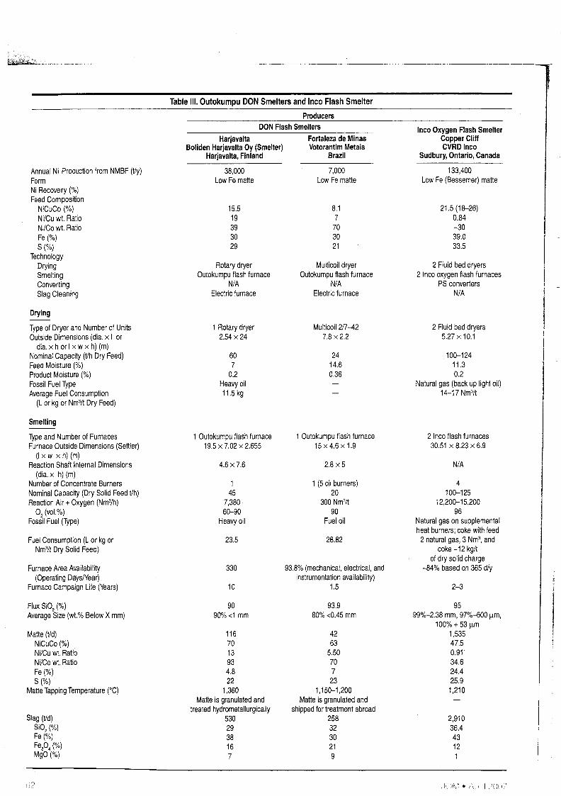
ProducersDON Flash Smelters
Table Ill. Outokumpu DON Smelters and Inco Flash Smelter
21.5 (18-26)0.84-3039.033.5
2 Fluid bed dryers2 Inco oxygen flash furnaces
PS convertersN/A
Inco Oxygen Flash SmelterCopper CliffCVRD Inco
Sudbury, Ontario, Canada
133,400Low Fe (Bessemer) matte
Fortaleza de MinasVotorantim Metais
Brazil
Multicoil dryerOutokumpu flash furnace
N/AElectric furnace
8.17
703021
7,000Low Fe matte
Rotary dryerOutokumpu flash furnace
N/AElectric furnace
15.519393029
38,000Low Fe matte
HarjavaltaBoliden Harjavalta Oy (Smelter)
Harjavalta, Finland
Annual Ni Production from NMBF (Vy)FormNi Recovery (%)Feed Composition
NiCuCo (%)Ni/Cu wt. RatioNi/Co wt. RatioFe(%)S(%)
TechnologyDryingSmeltingConvertingSlag Cleaning
Drying
Type of Dryer and Number of UnitsOutside Dimensions (dia. x I or
dia. x h or I x w x h) (m)Nominal Capacity (Vh Dry Feed)Feed Moisture (%)Product Moisture (%)Fossil Fuel TypeAverage Fuel Consumption
(L or kg or Nm3/t Dry Feed)
1Rotary dryer2.54 x 24
607
0.2Heavy oil11.5 kg
Multicoil2/7-427.8 x 2.2
2414.60.36
2 Fluid bed dryers5.27 x 10.1
100-12411.30.2
Natural gas (back up light oil)14-17 Nm3/t
Smelting
Type and Number of FurnacesFurnace Outside Dimensions (Settler)
(I xw x h)(m)Reaction Shaft Internal Dimensions
(dia. x h) (m)Number of Concentrate BurnersNominal Capacity (Dry Solid Feed Vh)Reaction Air + Oxygen (Nm3/h)
02 (vol.%)Fossil Fuel (Type)
Fuel Consumption (L or kg orNm3/t Dry Solid Feed)
Furnace Area Availability(Operating Days/Year)
Furnace Campaign Life (Years)
1Outokumpu flash furnace19.5 x 7.02 x 2.655
4.6 x 7.6
145
7,38060-90
Heavy oil
23.5
330
10
1Outokumpu flash furnace15x4.6x1.9
2.8 x 5
1 (5 oil burners)20
300 Nm3/t90
Fuel oil
28.82
93.8% (mechanical, electrical, andinstrumentation availability)
1.5
2 Inco flash furnaces30.51 x 8.23 x 6.9
N/A
4100-125
12,200-15,20096
Natural gas on supplementalheat burners; coke with feed2 natural gas, 3 Nm3, and
coke -12 kg/lof dry solid charge
-84% based on 365 d/y
2-3
Flux Si02(%)Average Size (wt.% Below X mm)
Matte (Vd)NiCuCo(%)Ni/Cu wt. RatioNi/Co wt. RatioFe(%)S(%)
Matte Tapping Temperature (0C)
Slag (t/d)Si0
2(%)
Fe(%)Fep. (%)MgO(%)
9090% <1 mm
1167013934.822
1,360Matte is granulated and
treated hydrometallurgically5302938167
93.980% <0.45 mm
4263
5.5070723
1,150-1,200Matte is granulated and
shipped for treatment abroad2583230219
9599%-2.38 mm, 97%-600 llm,
100% + 5311m1,53547.50.91'34.624.425.91,210
2,91036.443121
(i?
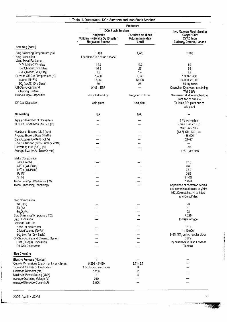
Table Ill. Outokumpu DON Smelters and Inco Flash Smelter
Producers
DON Flash SmeltersHarjavalta Fortaleza de Minas
Boliden Harjavalta Oy (Smelter) Votorantim MetaisHarjavalta, Finland Brazil
Inca Oxygen Flash SmelterCopper CliffCVRD Inca
Sudbury, Ontario, Canada
Smelting (cont.)
Slag Skimming Temperature ('C)Slag DispositionValue Metal Partitions
(Ni%)Matte/(Ni%)Slag(Cu%)Matte/(Cu%)Slag(Co%)Matte/(Co%)Slag
Furnace Off-Gas Temperature ('C)Volume (Nm3/h)S02 (vol.%) (Dry Basis)
Off-Gas Cooling andCleaning System
Dust (Sludge) Disposition
Off-Gas Disposition
Converting
Type and Number of ConvertersOutside Dimensions (dia. x I) (m)
Number of Tuyeres (dia.) (mm)Average Blowing Rate (Nm3/h)Blast Oxygen Content (vol.%)Reverts Addition (wt.% Primary Matte)Converting Flux (SiO) (%)Average Size (wt.% Below X mm)
Matte CompositionNiCuCo (%)Ni/Cu (Wt. Ratio)Ni/Co (Wt. Ratio)Fe (%)S(%)
Matte Pouring Temperature ('C)Matte Processing Technology
Slag CompositionSi02(%)Fe(%)Fep4 (%)
Slag Skimming Temperature ('C)Slag DispositionConverter Off-Gas
Hood Dilution FactorDiluted Volume (Nm3/h)S02 (vol. %) (Dry Basis)
Off-Gas Cooling and Cleaning SystemDust (Sludge) DispositionOff-Gas Disposition
Slag Cleaning
Electric Furnace (Number)Outside Dimensions (dia x h or Ix w x h) (m)Type and Number of ElectrodesElectrode Diameter (cm)Maximum Power Setting (MVA)Average Operating Voltage (V)Average Electrode Current (A)
1,400Laundered to electric furnace
14.916.91.3
1,40016,000
30WHB +ESP
Recycled to FFce
Acid plant
N/A
19.256 x 5.420
3 S6derberg electrodes1,260
8210
5,000
1,400
19.3231.4
1,30013,100
26
Recycled to FFce
Acid plant
N/A
8.7 x 5.23
914
1,280
50533.2
1,300-1 ,40024,000-28,000-55 dry basis
Quencher, Dynawave scrubbing,Wet ESPs
Neutralized sludge sent back tofront end of furnace
To liquid S02 plant and toacid plant
5 PS convertersThree 3.96 x 13.7;
two 3.96 x 10.7(13.7)-51; (10.7)-42
-35,00024-27
-96-11/2 +3/8 inch
77.30.8278.90.52
21-221,020
Separation of controlled cooledand comminuted matte to yield;NiCuCo metalics, Ni sulfides,
and Cu sulfides
265123
1,225To flash furnace
-3-4-140,000
3-5% S02 during regular blowsESPs
Dry dust back to flash furnacesTo stack
IL__2_0_0_7_A_p_ril_e_J_O_M _63
Producers
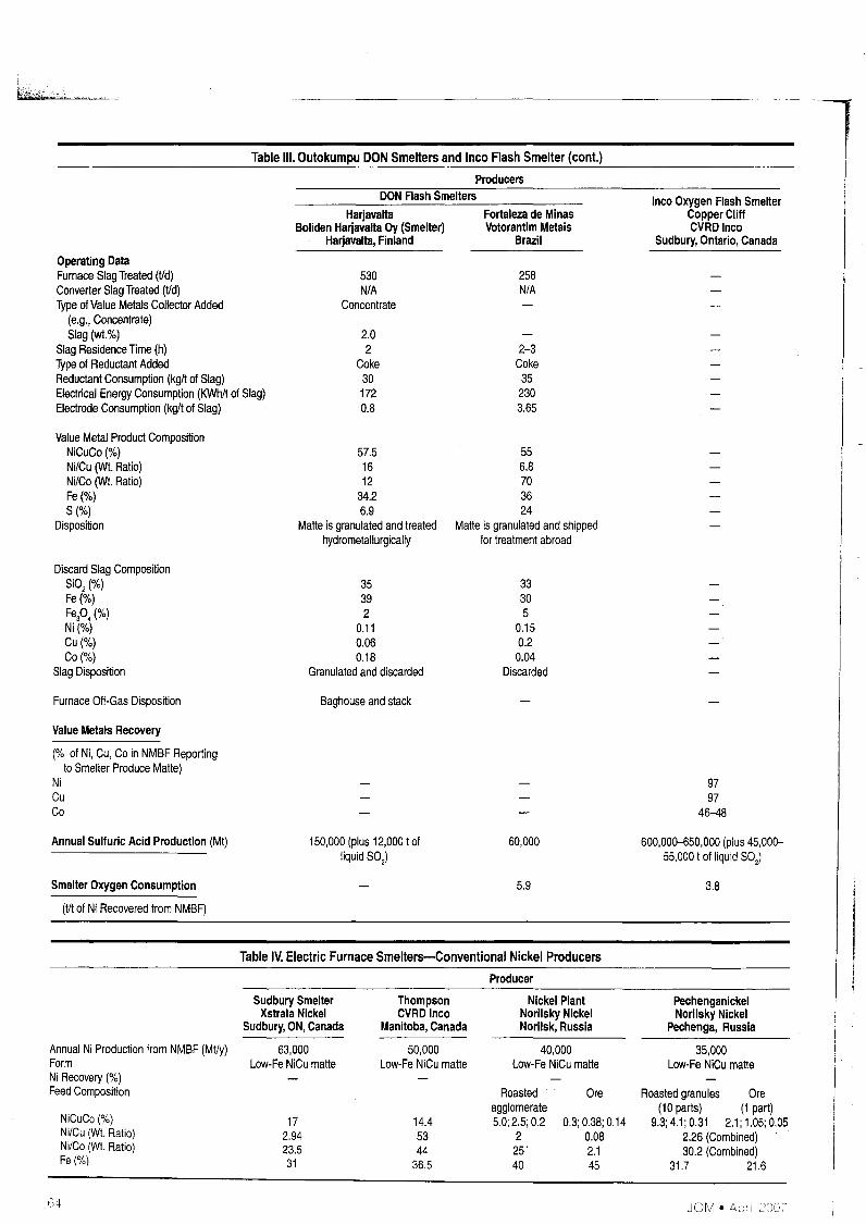
Table IV. Electric Furnace Smelters-Conventional Nickel Producers
Table Ill. Outokumpu DON Smelters and Inco Flash Smelter (cont.)
9797
46-48
3.8
PechenganickelNorilsky Nickel
Pechenga, Russia
35,000Low-Fe NiCu matte
Inco Oxygen Flash SmelterCopper CliffCVRD Inco
SUdbury, Ontario, Canada
600,00CHJ50,000 (plus 45,00055,000 t of liquid S02)
Roasted granules Ore(10 parts) (1 part)
9.3; 4.1; 0.31 2.1; 1.05; 0.052.26 (Combined)30.2 (Combined)
31.7 21.6
Ore
0.3; 0.38; 0.140.082.145
258N/A
2-3Coke352303.65
Nickel PlantNorilsky NickelNorilsk, Russia
40,000Low-Fe NiCu matte
60,000
5.9
33305
0.150.20.04
Discarded
Roastedagglomerate5.0; 2.5; 0.2
225'40
Producer
Fortaleza de MinasVotorantim Metais
Brazil
556.8703624
Matte is granulated and shippedfor treatment abroad
14.45344
36.5
ThompsonCVRD Inco
Manitoba, Canada
50,000Low-Fe NiCu matte
DON Flash Smelters
2.02
Coke301720.8
530N/A
Concentrate
Baghouse and stack
35392
0.110.060.18
Granulated and discarded
150,000 (plus 12,000 t ofliqUid SO)
57.51612
34.26.9
Matte is granulated and treatedhydrometallurgically
HarjavaltaBoliden Harjavalta Oy (Smelter)
Harjavalta, Finland
172.9423.531
Sudbury SmelterXstrata Nickel
Sudbury, ON, Canada
63,000Low-Fe NiCu matte
NiCuCo (%)Ni/Cu (WI. Ratio)Ni/Co (WI. Ratio)Fe(%)
Value Metal Product CompositionNiCuCo(%)Ni/Cu (WI. Ratio)Ni/Co (WI. Ratio)Fe(%)S(%)
Disposition
Operating DataFurnace Slag Treated (Vd)Converter Slag Treated (t/d)Type of Value Metals Collector Added
(e.g., Concentrate)81ag (wt.%)
81ag Residence Time (h)Type of Reductant AddedReductant Consumption (kglt of Slag)Electrical Energy Consumption (KWhIt of Slag)Electrode Consumption (kglt of Slag)
Discard Slag Composition8i02 (%)Fe(%)Fep. (%)Ni(%)Cu(%)Co(%)
Slag Disposition
Furnace Off-Gas Disposition
Value Metals Recovery
(% of Ni, Cu, Co in NMBF Reportingto Smelter Produce Matte)
NiCuCo
Annual Sulfuric Acid Production (Mt)
Smelter Oxygen Consumption
(tit of Ni Recovered from NMBF)
Annual Ni Production from NMBF (Mt/y)FormNi Recovery (%)Feed Composition
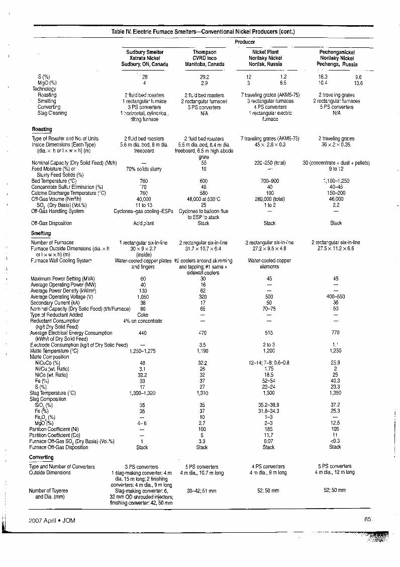
Table IV. Electric Furnace Smelters-Conventional Nickel Producers (cont.)
Producer
Sudbury SmelterXstrata Nickel
Sudbury, ON, Canada
ThompsonCVRD Inco
Manitoba, Canada
Nickel PlantNorilsky NickelNorilsk, Russia
PechenganickelNorilsky Nickel
Pechenga, Russia
7 traveling grates (AKM5-75)3 rectangular furnaces
4 PS converters1 rectangular electric
furnace
S(%)MgO(%)
-TechnologyRoastingSmeltingConvertingSlag Cleaning
284
2 fluid bed roasters1 rectangular furnace
3 PS converters1 horizontal, cylindrical,
tilting furnace
29.22.9
2 fluid bed roasters2 rectangular furnaces
5 PS convertersN/A
123
1.28.5
16.3 9.610.4 13.6
2 traveling grates2 rectangular furnaces
5 PS convertersN/A
Stack
2 traveling grates36 x 2 x 0.35,
1.11,250
25.92
2540.323.31,350
37.225.3
12.510511
<0.3Stack
45
52;50 mm
400-5503650
1,100-1,25040-45
150-20046,000
2.2
770
5 PS converters4 mdia., 12 mlong
2 rectangular six-in-line27.5 x 11.2 x 6.6
30 (concentrate +dust +pellets)9 to 12
52;50 mm
2 to 31,200
12-14; 7-8; 0.6-0.81.7518.5
52-5422-241,300
35.2-38.931.8-34.3
1-32-318511.70.07Stack
4 PS converters4 mdia., 9 m long
45
Water-cooled copperelements
220-250 (total)
Stack
515
700-90040100
280,000 (total)1 to 2
50050
70-75
3 rectangular six-In-line27.2 x 9.5 x 4.8
7 traveling grates (AKM5-75)45 x 2.8 xO.3
470
3.51,190
32.226323727
1,310
3537102.71005
3.3Stack
30-42;51 mm
5 PS converters4 mdia" 10.7 mlong
2 rectangular six-in-line31.7 x 10.7 x 6.4
2 fluid bed roasters5.5 mdia. bed, 6.4 mdia.
freeboard, 6.5 mhigh abodegrate
5510
60040
58048,000 at 530'C
25Cyclones to balloon flue
to ESP to stackStack
3535
440
4-6
1Stack
Acid plant
483.1
32.23317
1,300-1,320
70% solids slurry
6040
1301,050
3880
Coke4% on concentrate
2 fluid bed roasters5.6 mdia. bed, 8 mdia.
freeboard
1 rectangular six-in-line30x9x2.7
(inside)Water-cooled copper plates #2 coolers around skimming
and fingers and tapping; #1 same +sidewall coolers
3016623201765
760-70760
40,00011 to 13
Cyclones-gas cooling-ESPs
3 PS converters1 slag-making converter: 4 m
dia. 15 m long; 2 finishingconverters: 4 mdia., 9 mlong
Slag-making converter: 6,32 mm OD shrouded injectors;finishing converter: 42, 50 mm
Roasting
Type of Roaster and No. of UnitsInside Dimensions (Each Type)
(dla. x hor I x wx h) (m)
Nominal Capacity (Dry Solid Feed) (Mt/h)Feed Moisture (%) or
Slurry Feed Solids (%)Bed Temperature ('C)Concentrate Sulfur Elimination (%)Calcine Discharge Temperature ('C)Off-Gas Volume (Nm3/h)
S02 (Dry Basis) (Vol.%)Off-Gas Handling System
Off-Gas Disposition
Smelting
Number of FurnacesFurnace Outside Dimensions (dia. x h
or I x w x h) (m)Furnace Wall Cooling System
Maximum Power Setting (MVA)Average Operating Power (MW)Average Power Density (kW/m2)Average Operating Voltage (V)Secondary Current (kA)Nominal Capacity (Dry Solid Feed) (t/h/Furnace)Type of Reductant AddedReductant Consumption
(kg/t Dry Solid Feed)Average Electrical Energy Consumption
(kWh/t of Dry Solid Feed)Electrode Consumption (kglt of Dry Solid Feed)Matte Temperature ('C) 1,250-1,275Matte Composition
NiCuCo (%)Ni/Cu (wt. Ratio)NiCo (wt. Ratio)Fe(%)S(%)
Slag Temperature ('C)Slag Composition
SI0,j,(%)Fe rYo)Fep.(%)MgO(%)
Partition Coefficient (Ni)Partition Coefficient (Co)Furnace Off-Gas S02 (Dry Basis) (Vol.%)Furnace Off-Gas Disposition
Converting
Type and Number of ConvertersOutside Dimensions
Number of Tuyeresand Dia. (mm)
2007 April • JOM 65
Table IV. Electric Furnace Smelters-Conventional Nickel Producers (cont.)
75,000
3.6
Not applicable
PechenganickelNorilsky Nickel
Pechenga, Russia
9796.474.8
64,000
180,000
2.5
To acid plant
36,00021
72.61.6553
24.3Slow cooling; ingots to
customer
2045
Recycled to electric furnace
Nickel PlantNorilsky NickelNorilsk, Russia
Ore
82
Coal50295
181.277.855
23.4To converters
97.996.865.7
Not applicable
3441
1.5-20.060.2
0.08To dump
Stack
Stack
1855
To slag cleaning electricfurnace140,000
1-2.5
800
1rectangular furnace with3 self-baking electrodes
19.1 x9.7x5.72538030
Not applicable
36,00021
67.81.1463.2
22.9Cast, slow cooling, milling,
Cu/Ni separation by flotation
Producer
About 60021
80261090.618.7
Cast as anodes;electrorefining
Not applicable
989751
Not applicable
ThompsonCVRD Inco
Manitoba, Canada
2650
Recycled to electric furnace
SUdbury SmelterXstrata Nickel
Sudbury, ON, Canada
6,450 and 30,000 respectively33-43 and 21 respectively
Finishing converter75.53.130
2-2.521
Granulated and shipped toXstrata's Norway
RefinerySlag making converter
2148
To slag cleaning vessel
Off-gases from slag-cleaning Stackvessel, slag-making converter, and
finish converter to stack
Converting (cont.)
Average Blowing Rate (Nm3/h)Blast O2(Vol.%)Product Matte Composition
NiCuCo (%)Ni/Cu (Wt. Ratio)Ni/Co (Wt. Ratio)Fe(%)S(%)
Matte Processing Technology
Slag CompositionSiO;,(%)Fe (%)
Slag Disposition
Converter Off-Gas DilutedVolume (Nm3/h)
Converter Diluted Off-Gas S02(Dry Basis) (vol.%)
Off-Gas Disposition
Slag Cleaning
Electric Furnace (# of units)
Outside Dimensions (I x wx h) (m)Maximum Power Setting (MVA)Average Operating Voltage (V)Secondary Current (kA)Other Furnace (Type and Rotary, horizontal, tilting
Number of Units) furnaceOperating DataConverter Slag Treated (Mtld)Solid Reverts Addition (wt.% of Slag)Type of Value Metals Collector Added
(e.g., Concentrate)Slag (wt.%)
Slag Residence Time (h)Type of Reductant Added FerrosiliconReductant Consumption (kg/t of Slag)Electrical Energy Consumption
(kWh/t of slag)Value Metal Product Composition
NiCuCo(%)Ni/Cu (Wt. Ratio)Ni/Co (Wt. Ratio)Fe(%)S(%)
Disposition Slag making converterDiscard Slag Composition
SiO;,(%)Fe\%)Fep,\(%)Ni(%)Cu(%)Co(%)
Slag Disposition DiscardedFurnace Off-Gas Disposition Stack
Value Metals Recovery
(Ni, Cu, Co in NMBF Reporting toSmelter Product Matte) (%)NiCuCo
Annual Sulfuric Acid Production (Mt) 320,000
Table V. Electric Furnace Smelters-PGMProducers A
Producer
Union-Mortimer Waterval ImpalaAnglo Platinum Limited Anglo Platinum Limited Polokwane Impala Platinum
South Africa South Africa South Africa South Africa
Annual Ni Production from 2,500 22,000 (includes Union and 6,000 12,700NMBF (Vy) Polokwane)
Form Electric furnace matte Low-Fe Ni matte Electric furnace matte Low-Fe Ni matteconverted at Waterval converted at Waterval
Ni Recovery (%)Feed Composition
NiCuCo (%) 3.34 5.78 2.5-4 2.87NiCu (Wt. Ratio) 2 1.7 1.6-1.9 1.59Ni/Co (Wt. Ratio) 55 45 40-60 35.3Fe(%) 11.7 15.6 10-13.5 12.3S (%) 5 9 3-6 4.5MgO(%) 20 15 16-20 18.12
TechnologyDrying 1Flash dryer 2 Flash dryers 2 Flash dryers 4 Niro spray dryersSmelting 1rectangular furnace 2 rectangular furnaces 1 rectangular furnace 2 rectangular furnacesConverting Not applicable 2 Ausmelt converters Not applicable 6 PS convertersSlag Cleaning 1 round electric furnace Converter slag milling and
flotation
Drying--Type of Dryer and Number of Units 1Flash dryer 3 Flash dryers 2 Flash dryers 4 Niro spray dryersNominal Capacity (Dry t Feed/h/Dryer) 2x35 @18% moisture; 78.5@ 10% moisture 25, 25, 45, 60, respectively
1x57.8 @22% moistureFeed Moisture (%) 12 to 22 12t022 10to 16 42.7Product Moisture (%) <0.5 <0.5 <0.5 <1Fossil Fuel (Type) Coal Coal Coal CoalAverage Fuel Consumption (L or kg or 128.31
Nm3/h/Dry t Feed)
Smelting
Number of Furnaces 1 rectangular six-in-Iine 2 rectangular six-in-line 1 rectangular six-in-line 2 rectangular six-in-lineFurnace Outside Dimensions 25.3 mlong, 7 mwide 25.8 m long, 8mwide 28.7 m long, 9.6 mwide 25.9 mlong, 8.2 mwide
(dia. x hor I x wx h) (m)Furnace Wall Cooling System Water-cooled copper plates Water-cooled copper plates Copper waffle coolers Water-cooled copper plates
and platesMaximum Power Setting (MVA) 19.5 39Average Operating Power (MW) 19 32-34 68 (max.80) #338, #5 35Average Power Density (kW/m2) 110 160 250 180Average Operating Voltage (V) 300-340 300-800 500Secondary Current (kA) 25-29 40-75 26.8Nominal Capacity (Dry Solid Feed) 23 Vh, max. 35 Vh 40 Vh, max. 50 Vh 82.5 Vh, max 106 Vh 54Vh
(Vh/furnace)Type of Reductant Added Nil Nil Nil N/AAverage Electrical Energy 820-850 750-850 750-850 680
Consumption-(kWh/t of Feed)Electrode Consumption-(kg/t of Feed) 2 3 1.5-2.0Matte Temperature (CC) 1,550 1,350-1,450 1,400-1 ,500 1,260Matte Composition
NiCuCo (%) 19.3 26.5 22.3 23.4Ni/Cu (Wt. Ratio) 1.71 1.89 1.75 1.6Ni/Co (Wt. Ratio) 40 34 47 44.4Fe(%) 37 41 40 44.5S(%) 25 27 30 29.8
Slag Temperature (CC) 1,650 1,500-1,550 1,600-1,750 1,460Slag Composition
Si02(%) 41 46 45-50 46.8Fe(%) 15.6 24.1 8 11.4 (FeO)Fep,(%)MgO(%) 13 15 20 21.1
Partition Coefficient (Ni) 75 89.5 100 98Partition Coefficient (Co) 10 15 60Furnace Off-Gas S02 0.5-1.0 0.5-1.3 (combined 2 0.5-1.0 0.9
(Dry Basis) (Vol.%) furnaces)
2007 April • JOM 67
J... --_._--~-_._-- ..-
-1Table V. Electric Furnace Smelters-PGMProducers A (cont.)
Producer
Union-Mortimer Waterval ImpalaAnglo Platinum Limited Anglo Platinum Limited Polokwane Impala Platinum
South Africa South Africa South Africa South Africa
Smelting
Furnace Off-Gas Disposition Stack To nitrification-type "tower Stack ESP followed by Sulphacid™plant:' Weak acid produced technology
blended with strong acid fromconverter gas
Converting
Number and Type 2 Ausmelt converters 6 PS convertersOutside Dimensions (m) 4.5 minner dia., 4 mhigh 2 @ 3.6 mx 7.3 m;
4 @ 3 mx4.5 mNumber ofTuyeres and Dia. (mm) 26 (small); 32(large); 51 mmLance Outer Tube Dia. (cm) 45Average Blowing Rate (Nm3/h) 25,000 max (including all air) 11,000 and 22,000Blast 02 (Vol.%) Up to 40% enrichment Air, no additionProduct Matte Composition
NiCuCo(%) 73.5 78.0Ni/Cu (Wt. Ratio) 1.81 1.6Ni/Co (Wt. Ratio) 94 160Fe(%) 2.9 0.6S(%) 21.7 20.3
Slag CompositionSi02("Io) 24-28 27Fe(%) 42-48 64.45 (FeO)
Slag Disposition Granulated to slag cleaning furnace Granulated to millinglflotationConverter Diluted Off-Gas S02 12 to 16 3-8% (no dilution)
(Dry Basis) (vol.%)Off-Gas Disposition To acid plant Single contact acid plant
Slag Cleaning Milling/flotation of converted slag
Electric Furnace (Number of Units) 1 round furnace(3 S6derberg electrodes)
Outside Dimensions (dia.) (m) 12Maximum Power Selling (MVA) 30Average Operating Voltage (V) 200-800Secondary Current (kA) 45-60Operating DataConverter Slag Treated (MVd) About 450Solid Reverts Addition-Slag (wt.%)Type of Value Metals Collector Added Concentrate
(e.g., Concentrate)Slag (wt.%) About 40"10
Slag Residence Time (h)Type of Reductant AddedReductant Consumption-(kg/t of slag)Electrical Energy Consumption-(kWh/t of slag) About 600
Slag DispositionFurnace Off-gas Disposition
Value Metals Recovery
(in NMBF Reportingto Smelter Product Matte) (%)Ni 90 93 94 92Cu 89 89 91 90Co 30 35 35 30
Annual Sulfuric Acid Production (Mt) Max.920 Vd 50,000Current average 400 Vd
l;H JOM • Aplll ,'()ll,'
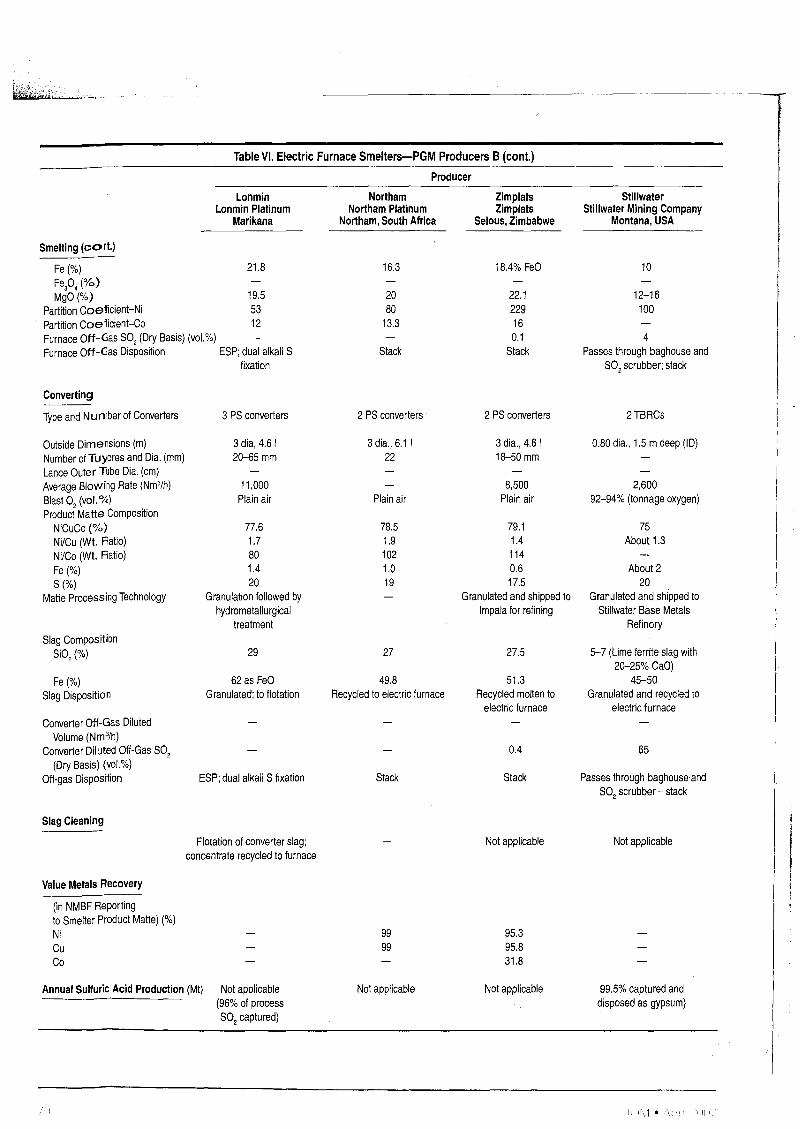
Table VI. Electric Furnace Smelters-PGMProducers B
Producer
Lonmin Northam Zimplats StillwaterLonmin Platinum Northam Platinum Zimplats Stillwater Mining Company
Marikana Northam, South Africa Selous, Zimbabwe Montana, USA
Annual Ni Production from NMBF (tly) 3,700 1,500 1,600 112Feed Composition
NiCuCo (%) 4.1 3.85 3.55 8-9Ni/Cu (Wt. Ratio) 1.7 1.92 1.39 1.5-1.8Ni/Co (Wt. Ratio) 20 50 30Fe(%) 17.1 13.2 13.2 14-16S (%) 5.5 5.4 5.9 11-14MgO(%) 16.7 18 24 10-14
TechnologyDrying 1 Flash dryer 1Flash dryer 1 Flash dryer 1fluid bed dryerSmelling 4 round electric furnaces 1rectangular electric furnace 1 round electric furnace 1rectangular electric furnaceConverting 3 PS converters 2 PS converters 2 PS converters 2 top-blown rotary
converters (TBRCs)Slag Cleaning Flotation (converter slag)
Drying
Type of Dryer and Number of Units 1 Flash dryer 1 Flash dryer 1 Flash dryer 1fluid bed dryerOutside Dimensions (Each Type) (dia. Approx. 2 x 2 (inner dia.) 4.3 mdia., 9.0 mhigh
x I or dia. x h or I x wx h) (m)Nominal Capacity (Dry t Feed/h/Dryer) 30 18 25 6.5Feed Moisture (%) 12-15 20 17.5 10Product Moisture (%) <0.5 Bone dry <0.5 <0.1Fossil Fuel Type Coal Pea coal Coal Natural gasAverage Fuel Consumption (L or kg or 50 78 kg
Nm3/t of Dry Feed)
Smelting
Number of Furnaces 4 Round three-electrode 1 Rectangular six-in-line 1 Round three-electrode 1Rectangular three-In-linefurnaces furnace furnace with circular endwalls
Furnace Outside Dimensions 1 @ 11.8 mdia; 25.9 x 8.7 x 5.6 12 mdia. 7.5 x 2.6 x 2.1(dia. x h or Ix wx h) (m) 3 @ 6.2 mdia. 5
Furnace Wall Cooling System Copper waffle coolers; No coolers Copper plate coolers Water-cooled copperwater-cooled shell plates
Maximum Power Setting (MVA) 28 and 5, respectively 13.5 5MWAverage Operating Power (MW) 20 and 4.2, respectively 15 12.5 1.4 (1.2-1.6)Average Power Density (kW/m2) 225 and 198, respectively 90 131 140Average Operating Voltage (V) 300 and 150, respectively 200 125 160-200Secondary Current (kA) 62 and 19, respectively 18 4-5Nominal Capacity-Dry Solid Feed 26 and 5, respectively 10-12 13.8 1.1-1.5
(tlh/Furnace)Type of Reductant Added Nil Nil CokeReductant Consumption-(kg/t of 3.5
Dry Solid Feed)Average Electrical Energy 700 and 900, respectively 1,044 kWh/t of conc. 850-950 900
Consumption-(kWh/t ofDry Solid Feed)
Electrode Consumption- (kg/t 2.6 (large furnace) 2.6 3.1 3.5of Dry Solid Feed)
Matte Temperature (0C) 1,500-1,580 1,385 1,330-1 ,450 1,200-1,300; matte isgranulated for feeding TBRC
Matte CompositionNiCuCo (%) 25 24.3 25.3 26-30Ni/Cu (Wt. Ratio) 1.67 2.03 1.59 1.5-1.8Ni/Co (Wt. Ratio) 32 40 20.7Fe(%) 43 41 40-46 40-45S(%) 28 27 25-30 26-28
Slag Temperature (0C) 1,600-1,650 1,580 1,400-1 ,550
Slag CompositionSi02 (%) 45 44 53.8 42-48
!j 2007 April • JOM 69-
-----------------------.---~. --
Table VI. Electric Furnace Smelters-PGMProducers B (cont.)
Producer
LonminLonmin Platinum
Marikana
Smelting (cont.)
Fe (%) 21.8Fep4(%)MgO (%) 19.5
Partition Coefficient-Ni 53Partition Coefficient-Co 12Furnace Off-Gas S02 (Dry Basis) (vol.%)Furnace Off-Gas Disposition ESP; dual alkali S
fixation
NorthamNortham Platinum
Northam, South Africa
16.3
2080
13.3
Stack
ZimplatsZimplats
Selous, Zimbabwe
18.4% FeO
22.1229160.1
Stack
StillwaterStillwater Mining Company
Montana, USA
10
12-16100
4Passes through baghouse and
SO2scrubber; stack
Converting
Type and Number of Converters
Outside Dimensions (m)Number of Tuyeres and Dia. (mm)Lance Outer Tube Dia. (cm)Average Blowing Rate (Nm3/h)Blast 02 (vol.%)Product Matte Composition
NiCuCo (%)Ni/Cu (Wt. Ratio)Ni/Co (Wt. Ratio)Fe(%)S(%)
Matte Processing Technology
Slag CompositionSi02(%)
Fe(%)Slag Disposition
Converter Off-Gas DilutedVolume (Nm3/h)
Converter Diluted Off-Gas S02(Dry Basis) (vol.%)
Off-gas Disposition
Slag Cleaning
Value Metals Recovery
(in NMBF Reportingto Smelter Product Matte) (%)NiCuCo
3 PS converters
3 dia, 4.6/2(H)5 mm
11,000Plain air
77.61.7801.420
Granulation followed byhydrometallurgical
treatment
29
62 as FeOGranulated; to flotation
ESP; dual alkali S fixation
Flotation of converter slag;concentrate recycled to furnace
2 PS converters
3 dia., 6.1122
Plain air
78.51.91021.019
27
49.8Recycled to electric furnace
Stack
9999
2 PS converters
3 dia., 4.6118-50 mm
8,500Plain air
79.11.41140.617.5
Granulated and shipped toImpala for refining
27.5
51.3Recycled molten to
electric furnace
0.4
Stack
Not applicable
95.395.831.8
2TBRCs
0.80 dia., 1.5 mdeep (ID)
2,60092-94% (tonnage oxygen)
75About 1.3
About 220
Granulated and shipped toStillwater Base Metals
Refinery
5-7 (Lime ferrite slag with20--25% CaO)
45-50Granulated and recycled to
electric furnace
65
Passes through baghouse'andS02 scrubber - stack
Not applicable
Annual Sulfuric Acid Production (Mt) Not applicable(96% of processS02 captured)
Not applicable Not applicable 99.5% captured anddisposed as gypsum)
II 1rv1. " " 'ill 1
II-
However, Norilsk is the world's largestsingle producer of palladium, and alsoan important producer of other PGMs.
Nickel sulfide minerals are amenableto concentration by milling and flotation,with rejection of a high proportion ofore rock and pyrrhotite prior to smelting.In fact, substantial pyrrhotite rejectionfrom the ore is practiced to reduce S02emissions from nickel sulfide smelters.However, increased nickel losses havedemonstrated the limitations of thistechnique. In some operations, flotationcircuits are designed to produce separatecopper and nickel concentrates. Thebroad range of compositions of nickelconcentrates in this survey (Tables IT-VI)is a reflection of the chemical and mineralogical variability of ores and also ofdifferences in milling-flotation practices.
Although the proportion of worldprimary nickel production from sulfidedeposits has always been substantiallyhigher than from laterites, the latter isincreasing at a faster rate. It is expectedthat by 2012 half of the primary nickelwill beproduced from laterites.3 At present, it is estimated that lateritic oresaccount for 72% and sulfide ores for 28%of world's land-based nickel reserves.
TECHNOLOGY
The output of flash smelters accountsfor nearly 70% of the primary metalproduced from nickel sulfide sources(see Table I). Electric furnace smeltersproduce the balance. The key merits offlash smelting are very low electrical andfossil fuel energy consumption andgeneration ofa continuous, low-volume,S02-rich process gas stream amenabletoprocessing in an acidplant. It should benoted, however, that fluid bed roastingas practiced in some electric furnacesmelters also produces a gas well suitedfor acid production. The ensuing discussion shows that there is hardly a standardflowsheet for either technology. Factorssuch as feed'Ni/Cu and Ni/Co wt. ratio,concentrate PGM content, MgO contentof the gangue, and recycling of nickeland cobalt-richexternal reverts influencesmelting flowsheet design. Nevertheless,in nickel sulfide smelting the final product always consists of low iron matte,also referred to as BessemerMatte (BM).The desired iron contentof BM, generally in the range 0.5-4.0%, depends on
2007 April • JOM
the refining technology later used toprocess this intermediate material tomarket products. This in turn has implications for the finishing stage ofconvertmg.
Smelter Feed
The data in Tables II-VI show that,with the exception of PGM-Ni concentrates, the combined NiCuCo grade ofconcentrates are in the range of about8% to slightly above 20%, with an Ni/Cuweight ratio varying from about 1 toabout 50. However, Ni/Cu weight ratiosover 3 are rather the exception. TheNi/Co weight ratio of these concentratesis in general within the range of 25 to40.
The African PGM-Ni concentrateshave a lower NiCuCo content of about3-4%, with Ni/Cu and Ni/Co weightratios of 1.5-2 and 20-50, respectively.The true value ofthese materials are theirhigh content of PGMs that varies fromabout 100 g/t to about 400 g/t.2
Flash Smelting
All flash smelters use Outokumputechnology with the exception ofInco'sCopper Cliff Smelter that practices Incooxygen flash smelting. The flowsheet ofconventional flash smelters (see TableIT), including Copper Cliff (Table Ill),consists of bone drying the concentrate,flash smelting, and converting the primary smelting matte to a low iron matte.Dry solid feed flash furnace throughputsare normally 100-150t/h. In Outokumpufurnaces, the oxygen content ofthe reaction gas varies from 30-40 vol.% to 70vol. %, while the Inco furnace operateswith 100% tonnage oxygen. Matte grades(NiCuCo%) are usually in the upper 40s.A nickel partition (Ni% lNi% I ) of
matte sag
about 50 is observed in Nadezda andCopper Cliff. Higher nickel partitions,70 and 116, respectively, characterizethe Kalgoorlie and Jinchuan operationswhere the flash furnace has an electricfurnace appendix. Primary smeltingmatte is converted in Peirce Smith converters. The iron content of BessemerMatte (converter product) varies fromabout 0.5% to about 4%. This materialis further treated by either controlledcooling-milling-physical separation intonickel and copper intermediateproducts,or hydrometallurgical processing andelectrowinning. With the exception of
Kalgoorlie and Copper Cliff, whereconverter slag is recycled to the flashfurnace, other smelters recover valuemetals from flash furnace and converterslag in dedicated slag cleaning units,normally electric furnaces. Smelternickel recovery from NMBF is 9497%.
An important variation of the Outokumpu technology is the direct Outokumpu nickel (DON) process, in whichthe concentrate is directly flash smeltedto about 5% iron matte, thus eliminatingseparate converting and associatedmolten transfers.4,5 This process is practiced at the Harjavalta and the Fortalezasmelters (see Table Ill). A substantialproportion of nickel reports to the flashfurnace slag, This is recovered as ahighlymetallized matte in a dedicated slagcleaning electric furnace. Followinggranulation, the flash furnace and theelectric furnace mattes are treated inseparate hydrometallurgical installations.
The majority ofthe nickel sulfide flashsmelters capture most or part of theprocess S02 in acid plants, Only in theBCL and Norilsk smelters do all of theprocess S02 go up the stack.
Electric Furnace Smelting
In this survey, the data for the 12smelters using electric furnaces havebeen organized in two groups, The fourstraight nickel producers are called"conventional smelters." The corresponding data are presented in Table IV.The data of the smelters processingPGM-Ni feed are presented in Tables Vand VI.
Conventional Smelters
Two of the conventional smelters,Falconbridge and Thompson, are locatedin Canada, and the other two, NorilskNickel Plant and Pechenganickel, are inRussia. Their combined output accountsfor 80% of primary nickel productionby electric furnace smelting of sulfidefeed. The flowsheet of these plants consists of roasting, smelting, and converting. Separate converter slag cleaning ispracticed in Falconbridge and in theNorilsk Nickel Plant. Process S02 ispartially captured in Falconbridge andPechenganickel. In Falconbridge, thefluid bed roasters' off-gas is processedin an acid plant. At roaster sulfur elimi-
71
< ',+., .
nation of 75%, emissions amount toabout 10% of concentrate su1fur.
Electric furnace nominal capacityvaries from 50 t to 80 t dry solid feedlh,and energy consumption from 440 kWhltto 770 kWhIt. Matte grade varies withina wide range, 21-48% NiCuCo. TheFalconbridge Smelterproduces the highest-grade matte, a material that is alsohighly metallized due to high sulfurelimination in the roasters. Nickel partitions of 100 and higher are typical ofelectric furnace smelting. The electricfurnace matte is converted in PeirceSmith converters to a <1.0% to about3% iron matte. The practice of furtherprocessing this material to market products varies from plant to plant. A highnickel recovery of 97-98% is observedin all these operations.
Falconbridge in 1994 changed froma two-furnace operation into a singlefurnace operation while maintainingnickel production rates.6 New furnacetransformers andimproved water-cooledrefractory protection elements were laterinstalled. At present, the SudburySmelteris operating atan average calcinesmelting rate of 300 kg/hlm2 of furnacehearth, at a nominal power of 40 MW.A 4 m diameter, 17 m long PS converter,blowing at 40% oxygen enrichment, isused for slag making and for processingnickel- and cobalt-containing scrap,while matte finishing to Bessemer isdone in conventional converters.7 Theconverter slag value metals are recoveredin Falconbridge's slag cleaning vessel.The clean, molten slag is discarded.
PGM-Ni Smelters
The Bessemermatte produced in theseplants account for only 6% of primarynickel from sulfide sources (see TableI). As shown in Tables V and VI, thesmelter flowsheet generally consists ofconcentrate drying, smelting, and converting. Due to the high MgO contentof most of these concentrates, smeltingtemperatures are substantially higherthan in straight nickel smelting. Slagtemperature is usually about 1,600°C.Energy consumption is also higher,and varies between 700 kWhlt and 900kWhlt of dry furnace feed. Convertingof primary smelting matte normallytakes place in PS converters, except inWaterval and Stillwater, where Ausmeltconverters and top-blownrotary converters are respectively used. As in straightnickel sulfide smelters, the technologylater used for processing the converterproduct determines the desired ironcontent of this material. The reader isreferred to an earlier paper by one of thepresent authors for a detailed review ofthe South African PGM-Ni smelters.2
ACKNOWLEDGEMENTS
The authors express theirappreciationto the smelters that directly or indirectlyparticipated in this survey; without theircooperation this survey could not havebeen conducted. Thanks are also dueto CVRD Inco (formerly Inco Ltd.),Xstrata (formerly FalconbridgeLimited),the Russian State Research Instituteof Non-Ferrous Metals (Gintsvetmet),
Worley-Parsons HGE and Mintek forsupporting this work.
References
1. A.E.M. Warner et aI., "JOM World NonferrousSmelter Survey Part Ill: Nickel: Sulfide;' JOM, 58 (4)(2006), pp. 11-20.2. R.T. Jones, "Platinum Smelting in South Africa;' SouthAfrican Journal of Science, 95 (November/December1999), pp. 525-534.3. A.D. Dalvi, WG. Bacon, and R.C. Osborne, "Past andthe Future of Nickel Laterite Projects:' Laterite Nickel2004, ed. WP. Imrie and D.M. Lane (Warrendale, PA:TMS, 2004), p.23.4. I.v. Kojo, T. Miikinen, and P. Hanniala, "DirectOutokumpu Nickel Flash Smelting Process (DON)High Metal Recoveries with Minimum Emissions;'Nickel-Cobalt 97, Vol. Ill, PyrometallurgicalOperations,the Environment, and Vessel Integrity in NonferrousSmelting and Converting, ed. C. Diaz et al. (Montreal,Canada: MetSoc of CIM, 1997), pp. 25-34.5. T. Miikinen and P. Taskinen, "Physical Chemistry ofDirect Nickel Matte Smelting;' Sulfide Smelting '98:Current and Future Practices, ed. J.A. Asteljoki and R.L.Stephens (Warrendale, PA: TMS, 1998), pp. 59-68.6. D.G. Tisdale and C.G. Ransom, "Adapting to OneFurnace at Falconbridge;' Nickel-Cobalt 97, Vol. Ill,Pyrometallurgical Operations, the Environment, andVessel Integrity in Nonferrous Smelting andConverting,ed. C. Draz et al. (Montreal, Canada: MetSoc of CIM,1997), pp. 35-43.7. SW. Marcuson and C.M. Draz, ''The ChangingCanadian Nickel Smelting Landscape-Late 19thCentury to Early 21 st Century: Nickel and Cobalt 2005:Challenges in Extraction and Production, ed. J. Donaldand R. Schonewille (Montreal, Canada: MetSoc of CIM,2005), pp. 179-207.
A.E.M. Warner is Senior Consultant with WorleyParsons HGE in Toronto, ON, Canada; C.M. Diaz isan independent consultant in Mississauga, ON,Canada; A.D. Dalvi is with Inco Technical ServicesLimited, asubsidiary of CVRD Inco in Mississauga,ON, Canada; P.J. Mackey is with Xstrata ProcessSupport (formerly FalconbridgeTechnology Centre)in Falconbridge, ON, Canada; A.V. Tarasov is withthe State Research Institute of Non-Ferrous Metals"Gintsvetmet" in Moscow, Russia; and R.T. Jones iswith the Pyrometallurgy Division at Mintek in Randburg, South Africa. A. E.M. Warner can be reached at(905) 637·8699; e-mail [email protected].
HOW TO SUBMIT A PAPER TO JOMJOM offers its contributors a variety of formats for articles that fall within the technical calendar topics.
These formats include, but are not limited to: .
• Overview: 4-8 printed pages (3,200-6,400 words). A well-referenced andwell-illustrated introduction to the issues affecting and recent developmentsoccurring in a topical technology. The purpose is to thoroughly introduce thegeneral reader to the specifics of the field.
• Research Summary: 3-5 printed pages (2,400-4,000 words). Thesepapers outline recent, technically in-depth investigations in materials scienceand technology.
• Applied Technology: 2-4 printed pages (1,600-3,200 words). These articles communicate information about advancements in commercial products orprocesses and are typically submitted by industrial sources.
• Nontechnical Feature: 2-4 printedpages (1,600-3,200 words). These articles examine pertinent issues in education, professional affairs, and industryeconomics.
• Conference Reviews: 1-4 printedpages (800-3,200 words). These articlesare synopses of technical presentations at major conferences or symposia.
• Industrial Insight: 2-5printedpages (1,600-3,200 words). An experiencedriven description of the economic, managerial, environmental, engineering,scientific, governmental, international, competitive, etc., factors that influencetechnology on an industrial scale.
• Archaeotechnology: 2-4printedpages (1, 600-3,200 words). These articlesexplore materials usage and development throughout history.
Authors should formally notify the editor of their publishing intent by submitting a300-word abstract by completing the on-line form. An electronic abstract submission form is available at www.tms.orglpubs/journa/sIJOMlabstract-author.html.Anyone wishing to publish in JOM should follow the guidelines established in theJOM Author Kit. This material, supplied on request, features detailed informationon communication, manuscript preparation, and publication procedures. Aslightlyabridged version of the Author Kit is available on the World Wide Web at www.tms.orglpubs/journals/jomlauthorguide.html.
For more information [email protected].
,I( JM. /\1'111.'1111