Embed Size (px)
Citation preview
" X-721-66-77
4e
NIKE TOMAHAWK
PRELIMINARY PERFORMANCE STUDIES
I
= o
I
|OD NUOal A.LI'IlOY,I[
GPO PRICE $
CFSTI PRICE(S) $
BY
Hard copy (HC)
Microfiche (MF)
ff853 July65
EDWARD E. MAYO
b
FEBRUARY1966
GODDARD SPACE FLIGHT CENTERGREENBELT, MARYLAND
https://ntrs.nasa.gov/search.jsp?R=19660010190 2020-07-19T00:36:05+00:00Z

X-721-66-77
NIKE TOMAHAWK
PRELIMINARY PERFORMANCE STUDIES
by
Edward E. Mayo
Goddard Space Flight Center
Greenbelt, Maryland

NIKE TOMAHAWK
PRELIMINARY PERFORMANCE STUDIES
By
Edward E. Mayo
February 1966
ABSTRACT
In_ouse studies concerning the performance of the Nike Tomahawk
are compiled. The following areas are investigated, i) Nike Tomahawk
particle trajectory characteristics. 2) Effect of payload weight on the
Tomahawk mass, static margin, s_tlc stability, and natural frequency
characteristics. 3) Tomahawk dynamic motions, and 4) Aerodynamic
running load distribution over the Tomahawk body. The predictions
should be updated as the vehicle properties and aerodynamic charac-teristics are refined.
iii

CONTENTS
Page
NIKE TOMAHAWKPARTICLETRAJECTORY.......
EFFECTOFPAYLOADWEIGHTONTHETOMAHAWKMASS,STATICMARGIN,STATICSTABILITY,ANDNATURALFREQUENCYCHARACTERISTICS..... 20
TOMAHAWKDYNAMICMOTIONSTUDY ........ 51
APPROXIMATESECONDORDERSHOCKEXPANSIONMETHOD.................... 104
V

OPTIONAL FORM NO 10 5010-107
MAY 1942 (DITLON
GSA GEt4. REG. NO, 27
UNITH) STATES GOVERNMEN'I
Memoran m
TO : Flight Performance Section Files DATE: 15 March 1965
FROM :
SUBJECT:
Mr. Edward E. Mayo
Flight Performance Section
NIKE-TOMAHAWK PARTICLE TRAJECTORY
REFERENCE: (a)
(b)
Stone i G. W., and Connell i G.M.: Range Safety for the Nike-Tomahawk
Rocket System With a Nine-Inch Diameter Payload, April 1964.
Letter of 21 January 1965 to Mr, John Lane from Sandia Corporation.
Subject: Performance and Aerodynamic Data for the Nike-Tomahawk
Rocket System.
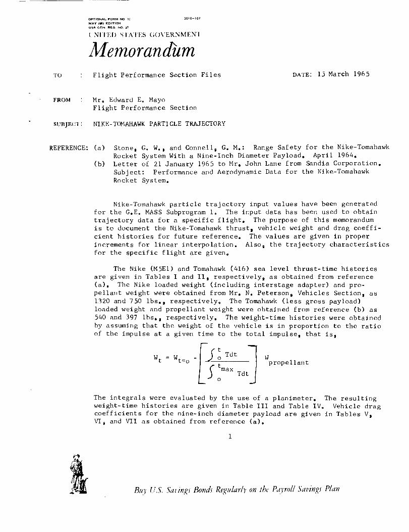
Nike-Tomahawk particle trajectory input values have been generated
for the G.E. MASS Subprogram io The input data has been used to obtain
trajectory data for a specific flight. The purpose of this memorandum
is to document the Nike-Tomahawk thrust 9 vehicle weight and drag coeffi-
cient histories for future reference. The values are given in proper
increments for linear interpolation. Also 9 the trajectory characteristics
for the specific flight are given.
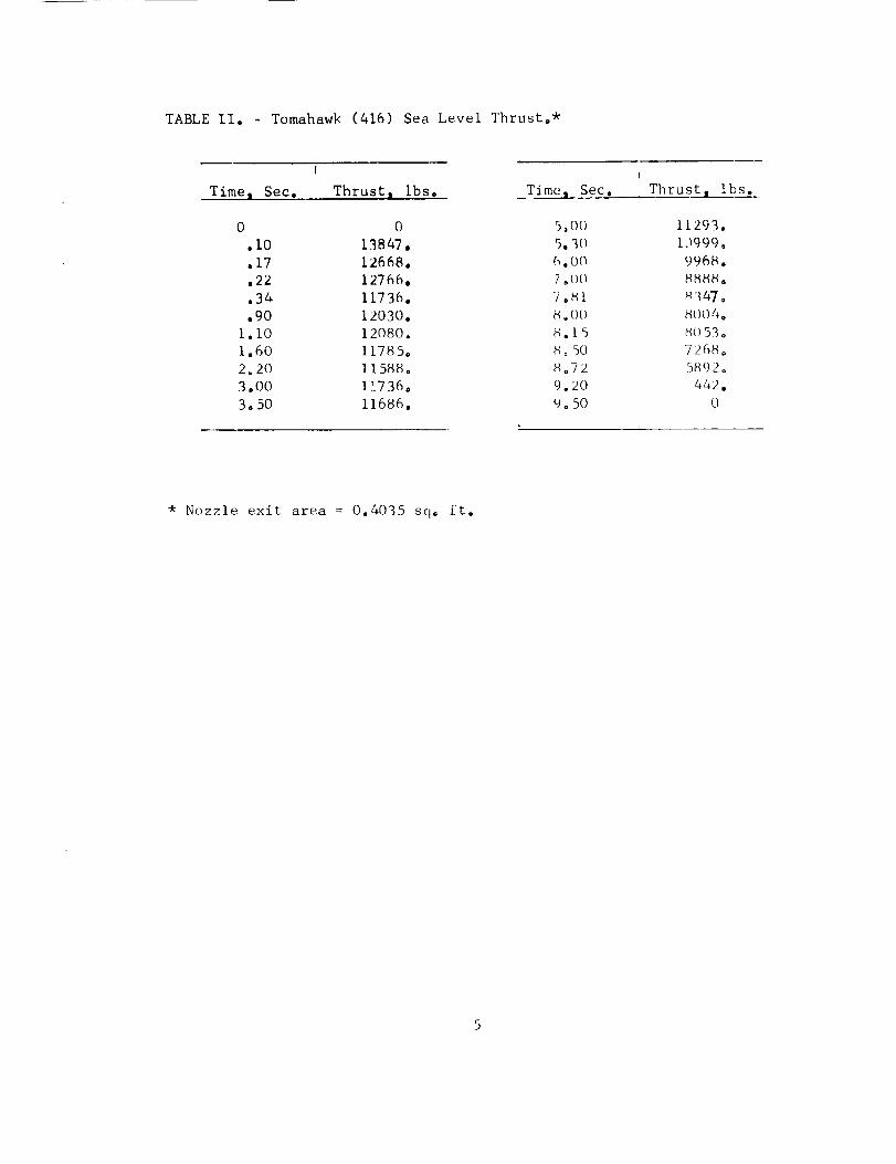
The Nike (M5EI) and Tomahawk (416) sea level thrust-time histories
are given in Tables I and If, respectively s as obtained from reference
(a). The Nike loaded weight (including interstage adapter) and pro-
pellant weight were obtained from Mr. N. Peterson i Vehicles Section, as
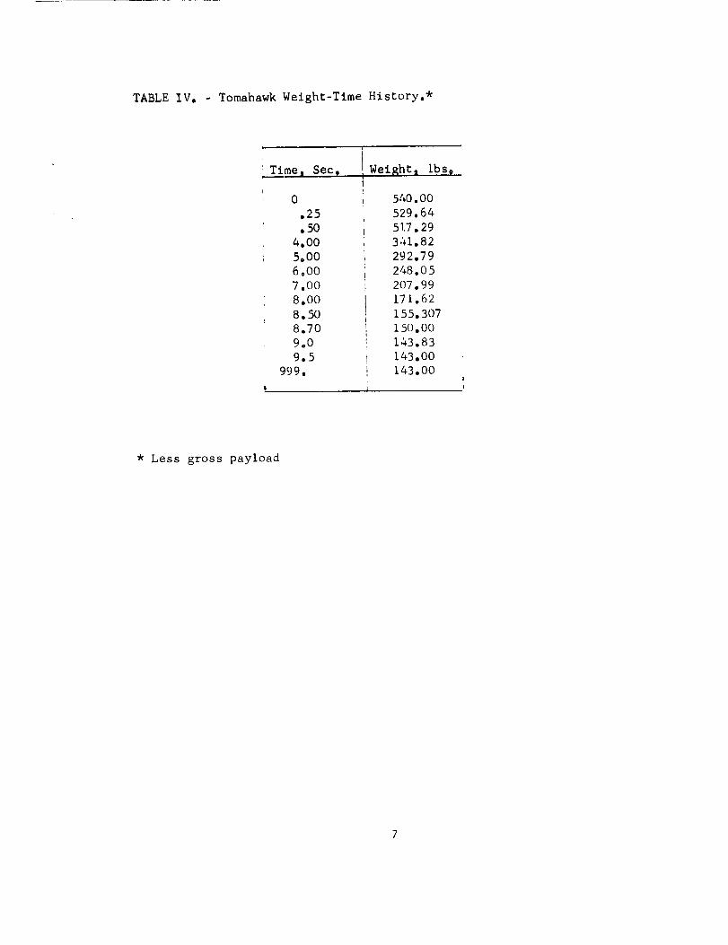
1320 and 750 ibs., respectively. The Tomahawk (less gross payload)
loaded weight and propellant weight were obtained from reference (b) as
540 and 397 ibs., respectively. The weight-time histories were obtained
by assuming that the weight of the vehicle is in proportion to the ratio
of the impulse at a given time to the total impulse, that is I
I_ tTdt
W t = Wt= ° - Wpropellant
_max Tdt5
The integrals were evaluated by the use of a planimeter. The resulting
weight-time histories are given in Table III and Table IV° Vehicle drag
coefficients for the nine-inch diameter payload are given in Tables V,
VI I and VII as obtained from reference (a).
Bt O' U.S. Savin_s Bondr Regular/), on the Pad, roll Savings P/an
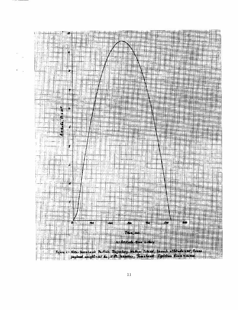
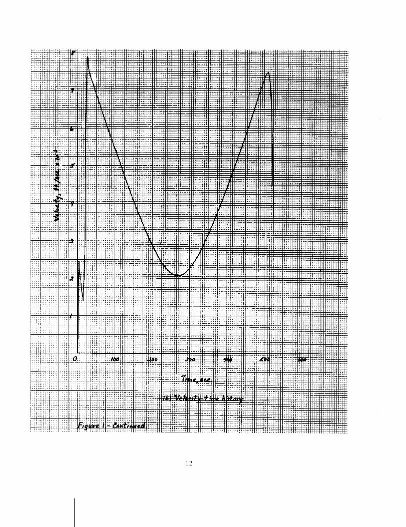
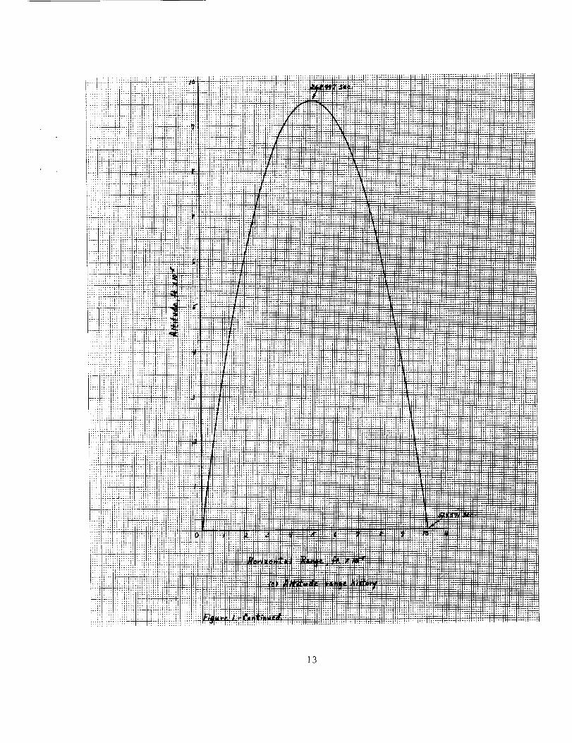
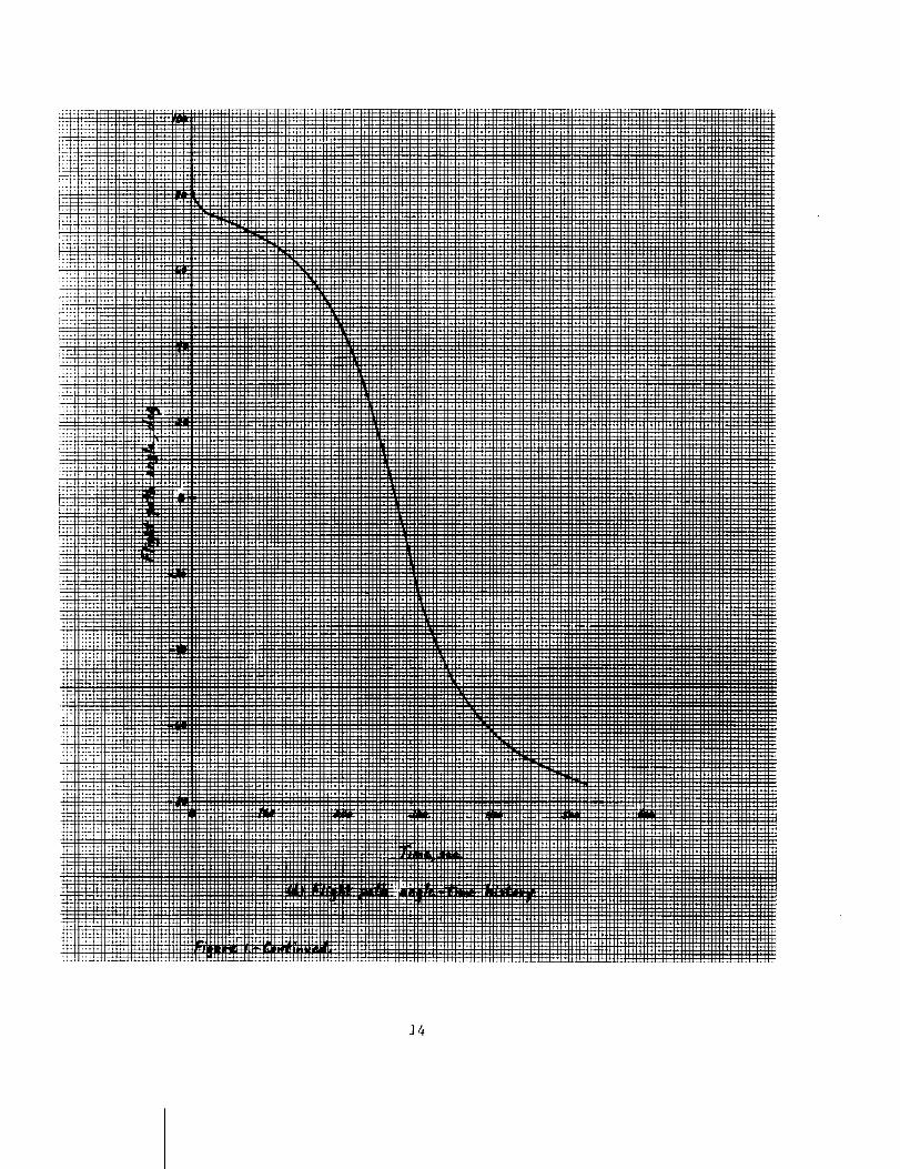
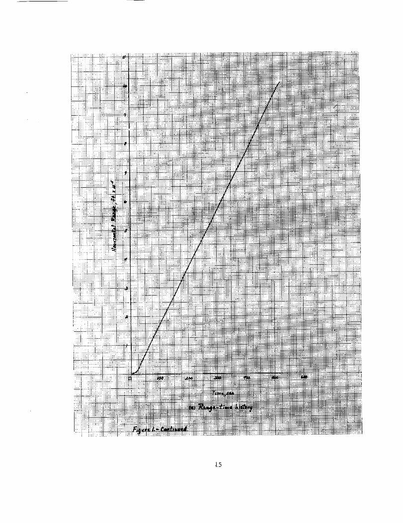
Flight characteristics for a Wallops Islandj 125 lb. nine-inch
diameter payload i 15 foot length launcher, 80 ° elevation launch, are
given in figure I. The initial conditions for the flight are as
follows:
Run:
Launch Site:
Launcher Length:
L_ngitude:
Latitude:
Launch Altitude:
Launch Attitude:
Launch Azimuth:
Initial Velocity:
Tomahawk Ignition Time:
OJ8
Wallops Island
15 ft.
-75°480 dego
37.830 deg.
12o81 fto
80.0 deg.
-80.44 deg. (Inadvertent value)
1.0 fps
16.0 seeo
The effects of varying gross payload weight and Tomahawk ignition time
on the Nike-Tomahawk system performance are given in figures 2 and 31
respectively.
Ill summary s we now have the capability of simulating the Nike-
Tomahawk flight with a particle trajectory° Efforts are underway to
determine the vehicle inertial and aerodynamic stability characteris-
tics as a function of payload weight°
Enclosures:
(i) Table Io
(2) Table II.
(3) T_ble III.
(4) Table IVo
(5) Table Vo
(6) Table VI.
(7) Table VII.
(_) Figure i.
<s<'/.......... P4' 7.,,<
Edward E. Mayo
(9)
Nike (M5EI) Sea Level Thrust.
Tomahawk (416) Sea Level Thrust°
Nike-Tomahawk Weight-Time History°
Tomahawk Weight-Time History°
Nike-Tomahawk Thrusting Drag Coefficient.
Tomahawk Thrusting Drag Coefficient.
Tomahawk Coasting Drag Coefficient.
Nike-Tomahawk Particle Trajectory° Wallops Island;
Gross Payload Weight : 125 Ibs°; Launch Attitude = 80 deg.;
15 foot Launcher; Tomahawk Ignition Time = 16 seco
Figure 2o The Effects of Gross Payload Weight on the Nike-
Tomahawk Apogee Altitude, Range at Impactl Time to Apogee
and Time to Impact. Wallops Island; Launch Attitude = 80o;
15 foot Launcher; Tomahawk Ignition Time = 16 sec.
(LO) Figure 3. - Effects of Tomahawk Ignition Time on the Nike-
Tomahawk Apogee Altitude, Wallops Island; Gross Payload
Weight = 125 ibs,; Launch Attitude = 800; 15 foot Launcher,
cc: Mr, K. R. Medrow
EI_M:skd
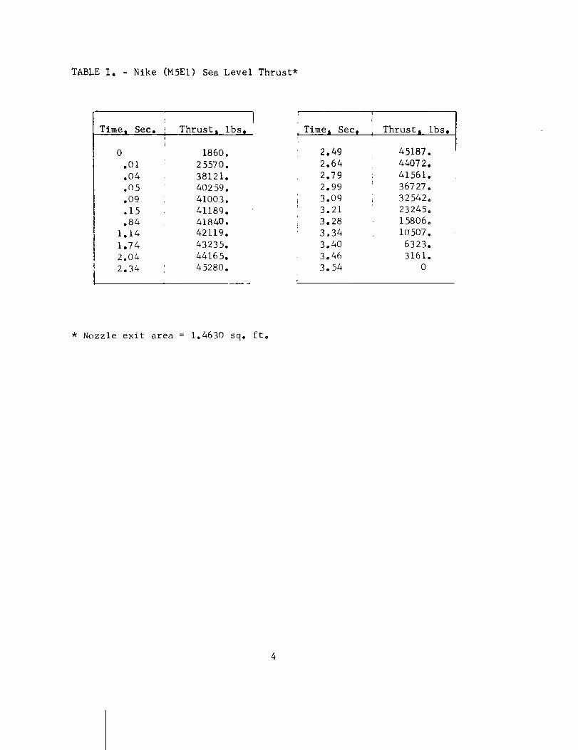
TABLE I. - Nike (M5EI) Sea Level Thrust*
Timej Sec,
0
.01
.04
.05
.09
o15
.84
1.14
1.74
2.04
2.34
Thrust_ ibs,
1860.
25570.
38121.
40259.
410O3°
41189.
41840.
42119.
43235.
44165°
45280.
Time_ Sec,
2.49
2.64
2.79
2.99
3.09
3.21
3.28
3.34
3.40
3°46
3.54
II Thrust_ ibs.
45187. I
44072.
41561.
36727.
32542.
23245.
15806.
10507.
6323.
3161.
0
* Nozzle exit area = 1.4630 sq. fto
TABLEII. - Tomahawk(416) SeaLevel Thrust.*
ITime I Sec. Thrust I ibso
0 0
.I0 13847,
.17 12668.
,22 12766,
.34 11736.
.90 12030.
i.i0 12080.
1.60 11785°
2.20 11588°
3°00 11736o
3.50 11686.
Time I Sec,
I
Thrust _ Ibs.
5,00
5.30
6°00
7 _()()
/ 0MI
8.00
80 50
8°72
9.20
9° 50
11293.
13999,
9968.
8_88o
a'_47.
8004°
8o 53 o
7268°
5892o
442.
O
* Nozzle exit area = 0.4035 Sqo ft.
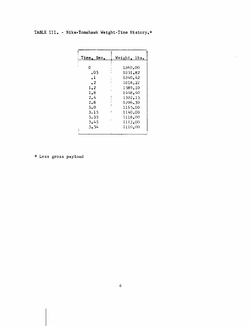
TABLE III. - Nike-Tomahawk Weight-Time History.*
_Times Sec,
0
.05
.I
.2
1.2
1.8
2.4
2.8
3,0
3o15
3°35
3.45
3o54
JI Weight, ibs.!
1860.00
1851.82
1840.42
1818.22
1589. i0
1448.40
1302.15
1206.30
1165.00
1140.00
1118.00
1112.00
iii0.00
* Less gross payload
TABLEIV, - TomahawkWelght-Time History.*
Time i Seco)
0
.25
.50
4.00
5.00
6.00
7.00
8.00
8.50
8.70
9°0
9.5
999.
Welght a ibso
540.00
529.64
51.7.29
341.82
292,79
248.05
207.99
171.62
155,307
150.00
143.83
143.00
143.00
* Less gross payload
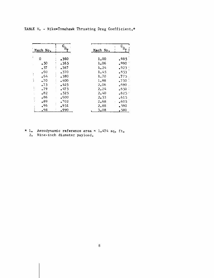
TABLEV. - Nike-TomahawkThrusting Drag Coefficient.*
Math No. CDT
0
.50
.57
.60
.64
.70
.73
.79
.82
.86
.89
.96
.98
Mach No.L
.360 1.00
.365 1.06
.367 1.24
.370 1.45
.380 1.70
.400 1,88
,425 2.06
.475 2.24
.525 2.40
.600 2.53
,702 2.68
.951 2.88
.990 _ 3,08
f
i CDT i
i
.995
.q90
.923
.853
.775
.730
.690
.650
.625
.615
.605
.590
.580
* I. Aerodynamic reference area = 1.474 sq. ft.
2. Nine-inch diameter payload.
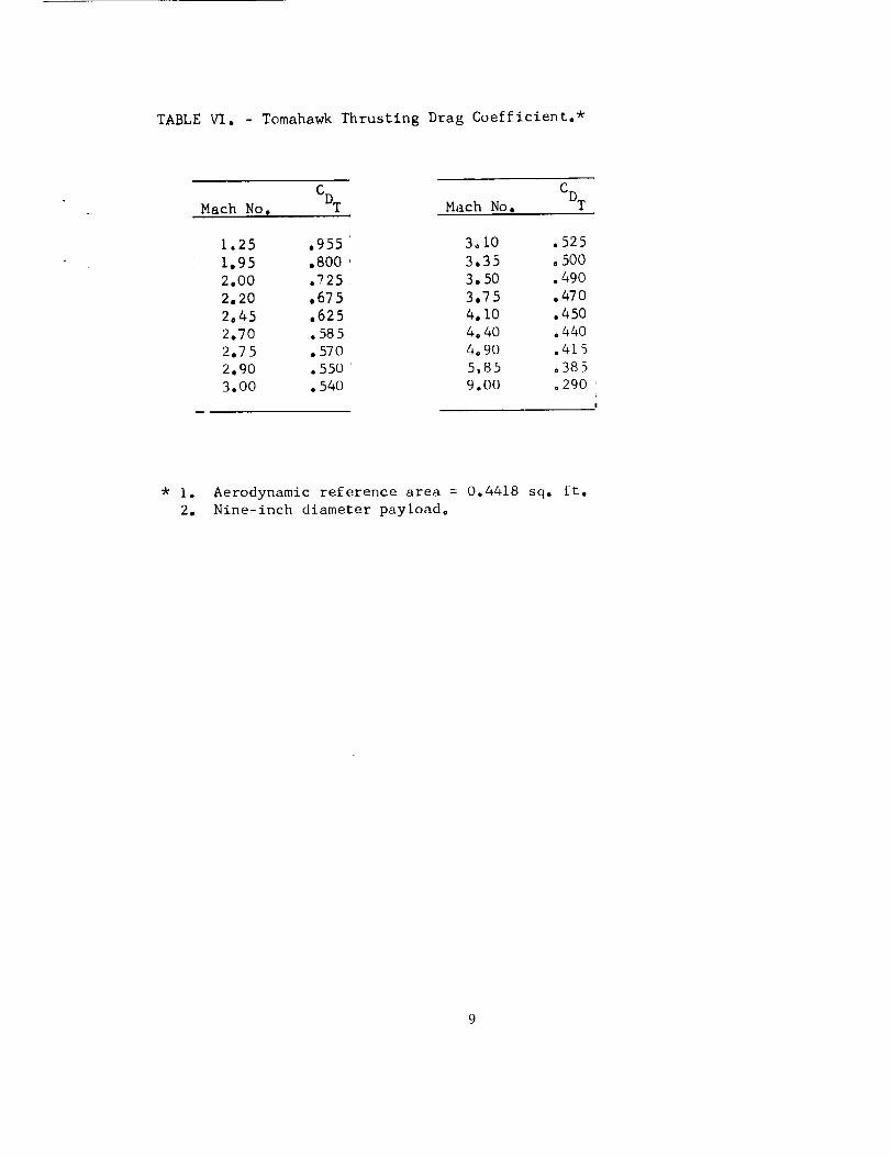
TABLEVI. - TomahawkThrusting Drag Coefficient°*
Mach No. CDT Mach No. CDT
1.25 .955
1.95 .800
2.00 .725
2.20 .675
2.45 .625
2.70 .585
2.75 °570
2.90 .550
3.00 .540
3o10 .525
3.35 °500
3.50 .490
3.75 °470
4.10 .450
4.40 .440
4°90 .415
5.85 o385
9.00 °290
!
* I. Aerodynamic reference area = 0.4418 sq. ft.
2. Nine-inch diameter payload°
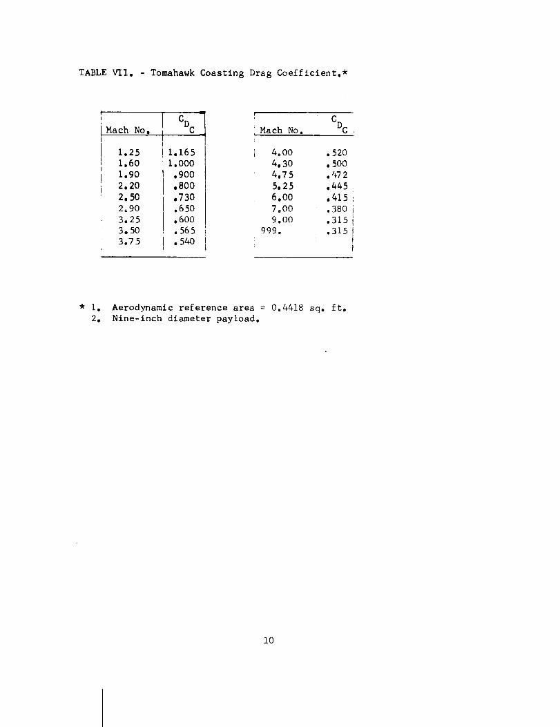
TABLEVII. - TomahawkCoasting Drag Coefficient.*
MachNo,
1.251.601.902•202.502_903.253,503.75
CDC
1.1651.000.900•800•730.650,600.565.540
Mach No. CDc
4.00
4• 30
4.75
5•25
6.00
7.00
9.00
999 o
.520
.500
.472
•445
.415
.380
.315
.315
* I. Aerodynamic reference area = 0.4418 sq. ft,
2. Nine-inch diameter payload.
i0
11
ii!ttt!*J4_;:_
!if:, !litF.i*;
i J L i ; ;
:;;: ....... ,q
t:il; 1222 2;;_:i,;
i_4;. .....
ii::i }::i :ii!:ttt:! _:_ "*+ ::
..............il....... + ,,_,
-:!ii !!f_ 55f!!f5..i! :!! !ii! !i
t_iff....................... !!":::: rr_Tt_.Jt:
:_ili iili _:::!::i!
!i!!i i!i! i':!ii:i
III;: Hi: IH;I" ,t
12
iii!!!i__Eii!!iiii!i_!ii!ii!
!ii:li
7t .+.,
:!,'+
!!ill!!!:i!i! il_i_!il
....... F_
!ii ..... i!i iili
ii!ii!/_ !::i ::!ii!i::::::
.......... iil ili,:i! ii
_+S:t!:!!;:! rl
ii :l:::' ili Ei:;_: 77
_:,i!!i!?ii!i: i! ili!_._,!ii
_:;::_::; :;1 FiT
i!??!i!i: ::; ;-'*:N!!........... H::lil: :_
!!!!iil !!! i_!_i!_: _i
.......... i:!
....... ::'.l _:: H
_!!iii '_!i7 777t_i:7!......... 77!
1i:ii!i!:_ii
tl _t
_iIii
_i :il
:I5!
T=
• r Tv
t_:iH
;* tt:
:!I
T;L
"i _i i
77 )!}_
17,_,i
:! t_.
,::ttii4 _44
13
14
_iii:!:!i!
I:::1
;:;:t
liiiiEiii!!i!!iiii:ii
1S

_F. -
. !._
.i
--,-_N
} :i
F- -4"_
_.--:
::!t_ii!., i!_..:[_,i
_' ill:2:T?:. _
16
++_
!!!! _i _!
-t-H 'H_
t!l
:il
IL
i :t
ru+ +ql
+++ +
+;+; J+;,;
IT?:
I It++_
il
FT 7+-
i:i--iii_,i!:
17
Launch Attitude = 80 deg.;Launcher Length = 15 ft.;Tomahawk Ignition Time = 16 sec.
i .......
..... _J
| .... & .... % i _ .
Gross.. Payload Weight. (ibs.) i
FIGURE 2. - The effects of gross payload weight
on the Nike-Tomahawk apogee altitude,
range at impact, time to apogee and
time to i_m_@ctu__
18
Launch Site = Wallops Island;
Gross Payload Weight = 125 ibs.
Launch Attitude = 80 deg.;
Launcher Length = 15 ft.;
'o,-4
k_
!
OT
t Or,-_
@ OC
G oO
_C
IO
if,!,
" I
Tomahawk Ignition Time (sec)
"FIGURE 3. - Effect of Tomahawk Ignition Time on
the Nike-Tomahawk apogee altitude.
19
F]I_.; :- P_rformance Section Files 29 June 1965
P, EFE!< _I>_CE :
Mr. Edward E. Mayo
Flight Performance Section
EFFI'LT OF PAYLOAD WEIGHT ON THE TOMAHAWK MASS, STATIC MARGIN, STATIC
STABILITY, AND NATURAL FREQUENCY CHARACTERISTICS
(a)
(b
(c
(d
(e
Memo of 3 ,June 1964, Mr. Mayo to Mr. Sorgnit, Subject: Weight,
Center of Gravity, Pitch and Roll Moment of Inertia Determination
Program.
Memo of 9 July 1964, Mr. Mayo to 671.2 Files, Subject: Static
Stability and Natural Frequency Program.
Stone, C. W., and Connell, G. M.: Range Safety for the Nike-
Tomahawk Rocket System With a Nine-lnch Diameter Payload. April1964.
Letter of 21 January 1965 to Mr. John Lane from Sandia Corporation.
Subject: Performance and Aerodynamic Data for the Nike-Tomahawk
Rocket System.
Memo of 15 March 1965, Mr. Mayo to Flight Performance Section Files,
Subject: Nike-Tomahawk Particle Trajectory.
A brief study has been conducted to define the effect of payload
weight on the Tomahawk mass, static margin, static stability, and
natural frequency characteristics. The computer programs developed in
references (a) and (b) were utilized in the study. The program input
characteristics were determined through the use of references (c)
through (e). The study was conducted for the Aurora Nitehawk configu-
ration shown in figures 1 and 2. A uniform density payload, as illus-
trated by the cross hatched region in figure 2, was assumed. The purpose
of this memorandum is to document the results of the study.
Computations were performed for gross payload weights of 50, 75,
i00, 125, 150, 175 and 200 pounds. The vehicle aerodynamic characteris-
tics were determined for launch angles of 75, 80 and 85 ° . The assump-
tions used in determining the mass characteristics were:
1. Propellant center-of-gravity location is constant.
2. Nose weight distribution is conical as illustrated by
the cross hatch in figure 2.
3. Payload is of uniform density.
4. Pitch and roll moments of inertia vary linearly with
burning time.
20
Tomahawk weight and inertia input characteristics are presented in
Table I. The resulting weight, center-of-gravity location, and pitch and
roll moment of inertia characteristics are presented in figures 3 through
6, respectively. Tomahawk aerodynamic input characteristics are presented
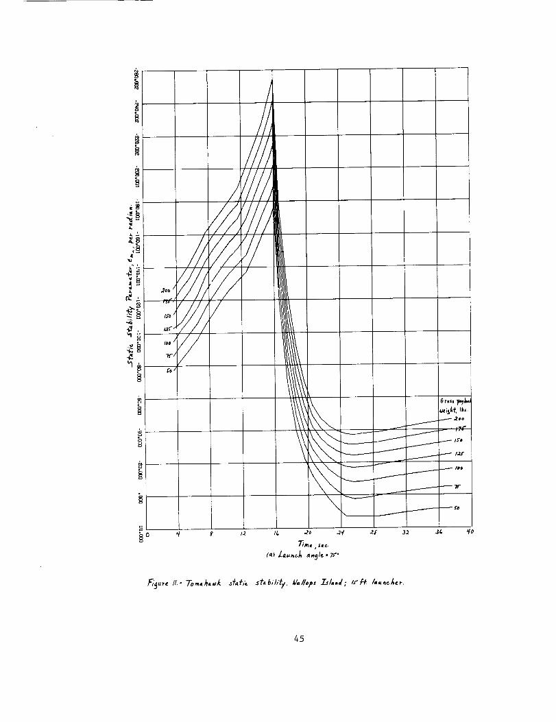
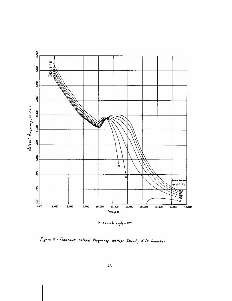
in Table II. The resulting static margin, static stability, and natural
frequency characteristics are presented in figures i0 through 12, respec-
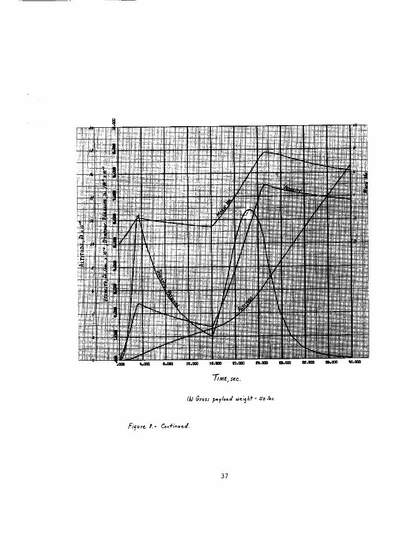
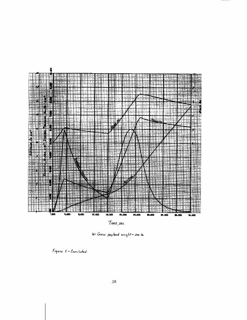
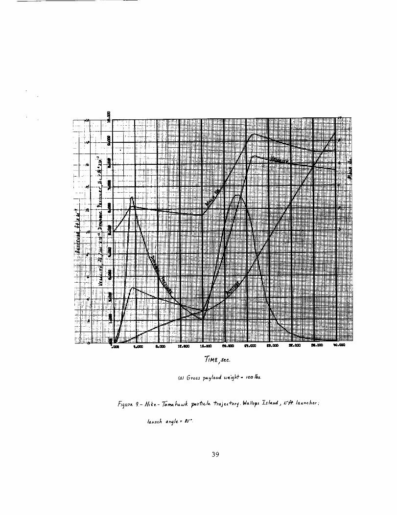
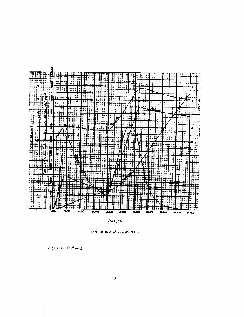
tively. The velocity, altitude, Mach number and dynamic pressure histories
for the i00, 150 and 200 pound gross payload weights at launch angles of
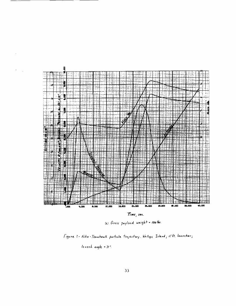
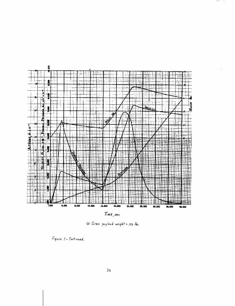
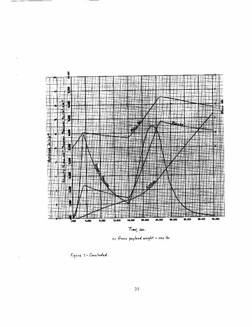
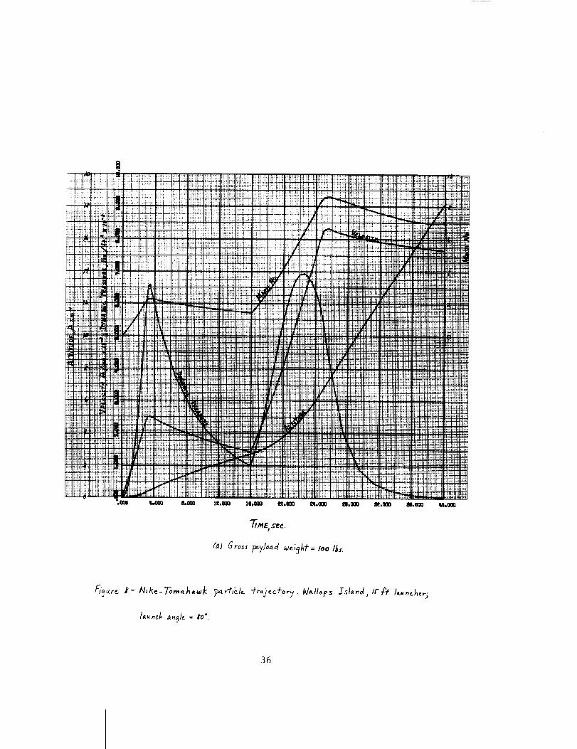
75, 80 and 85 degrees are presented in figures 7 through 9 as obtained from
the GE MASS particle subprogram using the vehicle characteristics presented
in reference (e). The 50, 75, 125 and 175 pound gross payload weight tra-
Jectory characteristics are not presented in figures 7 through 9; however,
they are on file within the Flight Performance Section for future reference.
The characteristics are presented herein without discussion; however,
several important points are:
1. The vehicle characteristics are only as valid as the afore-
mentioned assumptions.
, From stability considerations, a gross payload weight of
around 80 pounds is the minimum flyable payload weight.
This weight corresponds to a maximum peak altitude of 224
statute miles or 360 kilometers. (Based on a nominal 80 °
launch angle.) However, based on the recommended minimum
static margin of 2 calibers, the maximum attainable alti-tude is about 200 statute miles.
. The variation of the static margin, static stability and
natural frequency characteristics is insensitive to
launch angle.
Edward E. Mayo
Enclosures: (4)
(i) Symbols
(2) List of Figures
(3) Tables (2)
(4) Figures (12)
ce: Mr. K. R. Medrow
Mr. G. E. MacVeigh
Mr. E. E. Bissell
Miss E. C. Pressly
21
CN_
CM_
Ixx
Iyy
t
W
X
CO
Subscripts
b,o,
c.g.
c.p.
i
M.E.F.
M.L.F.
P.A.
P.L.
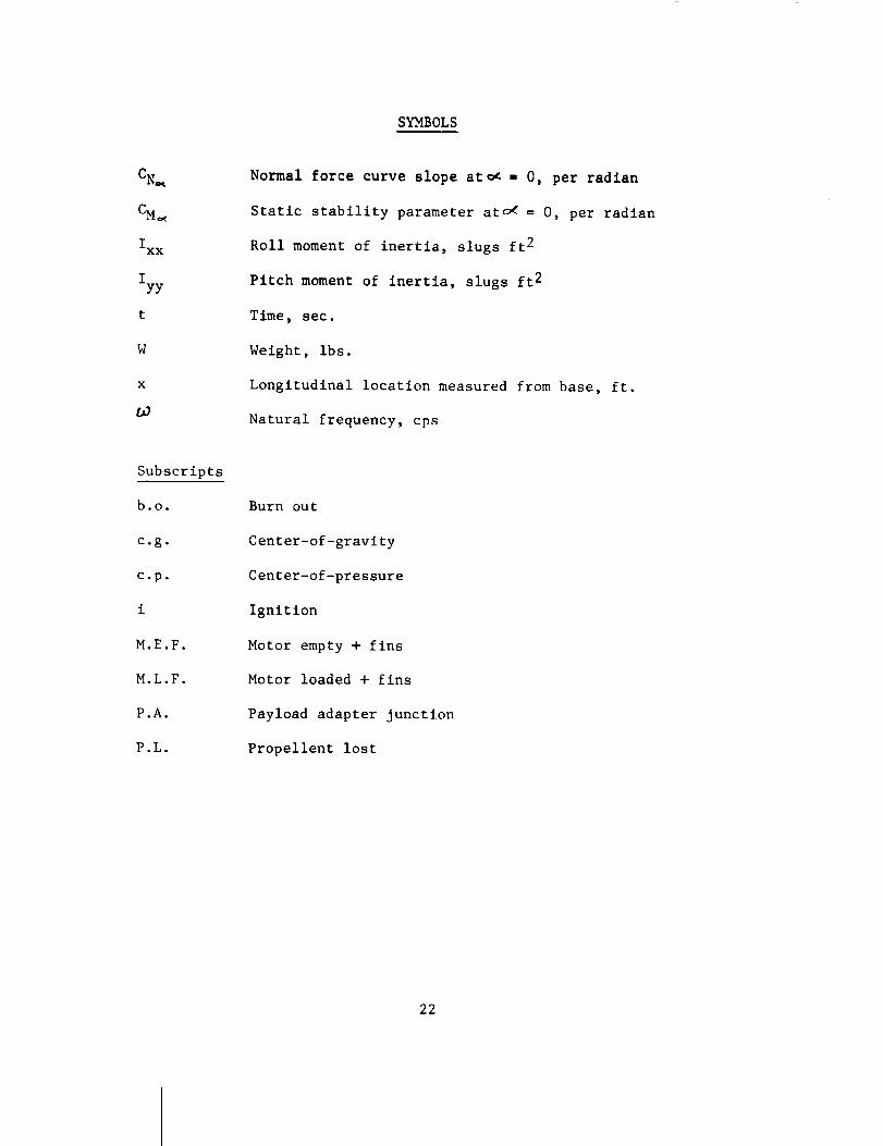
SYMBOLS
Normal force curve slope at_ - 0, per radian
Static stability parameter at o_ = 0, per radian
Roll moment of inertia, slugs ft 2
Pitch moment of inertia, slugs ft 2
Time, sec.
Weight, ibs.
Longitudinal location measured from base, ft.
Natural frequency, cps
Burn out
Center-of-gravity
Center-of-pressure
Ignition
Motor empty + fins
Motor loaded + fins
Payload adapter junction
Propellent lost
22
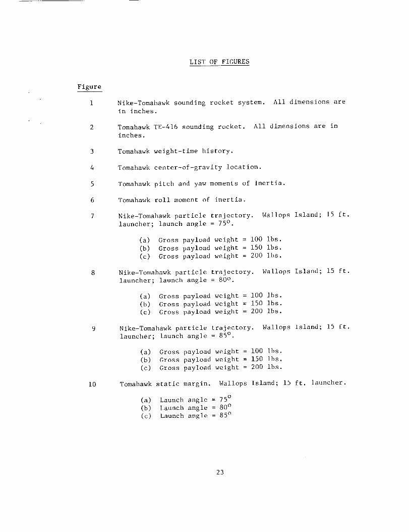
LIST OF FIGURES
Figure
3
4
5
6
7
i0
Nike-Tomahawk sounding rocket system. All dimensions arein inches.
Tomahawk TE-416 sounding rocket. All dimensions are ininches.
Tomahawk weight-time history.
Tomahawk center-of-gravity location.
Tomahawk pitch and yaw moments of inertia.
Tomahawk roll moment of inertia.
Nike-Tomahawk particle trajectory. Wallops Island; 15 ft.
launcher; launch angle = 75° .
(a) Gross payload weight = i00 ibs.
(b) Gross payload weight = 150 ibs.
(c) Gross payload weight = 200 ibs.
Nike-Tomahawk particle trajectory. Wallops Island; 15 ft.
launcher; launch angle = 80 ° .
(a) Gross payload weight = lO0 ibs.
(b) Gross payload weight = 150 ibs.
(c) Gross payload weight = 200 ibs.
Nike-Tomahawk particle trajectory. Wallops Island; 15 ft.
launcher; launch angle = 85 ° .
(a) Gross payload weight = i00 ibs.
(b) Cross payload weight = 150 ibs.
(c) Gross payload weight = 200 ibs.
Tomahawk static margin. Wallops Island; 15 ft. launcher.
(a) Launch angle = 75 °
(b) Launch angle = 80 °
(c) Launch angle = 85 °
23
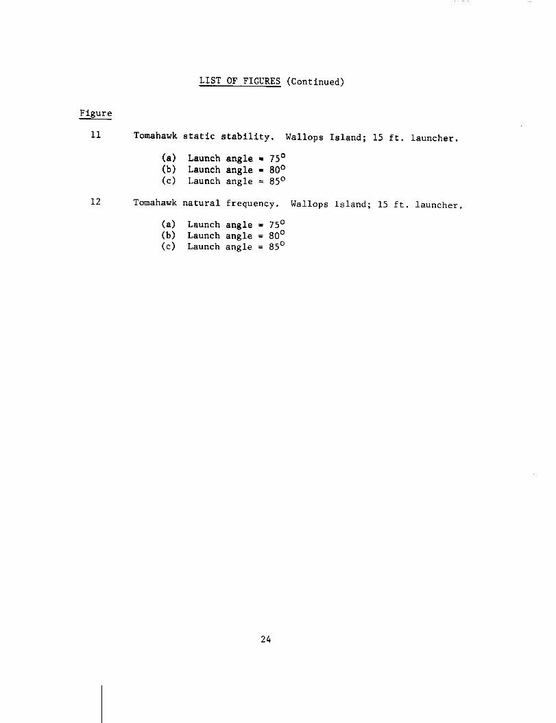
LIST OF FIGURES (Continued)
Figure
ii
12
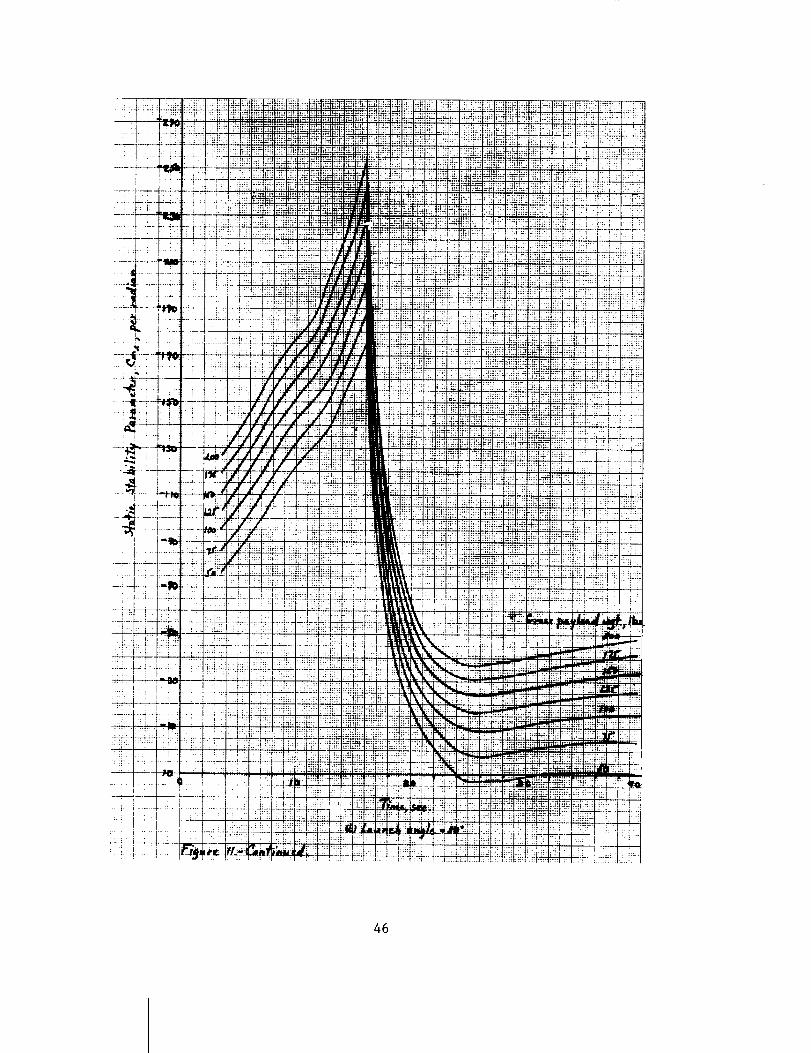
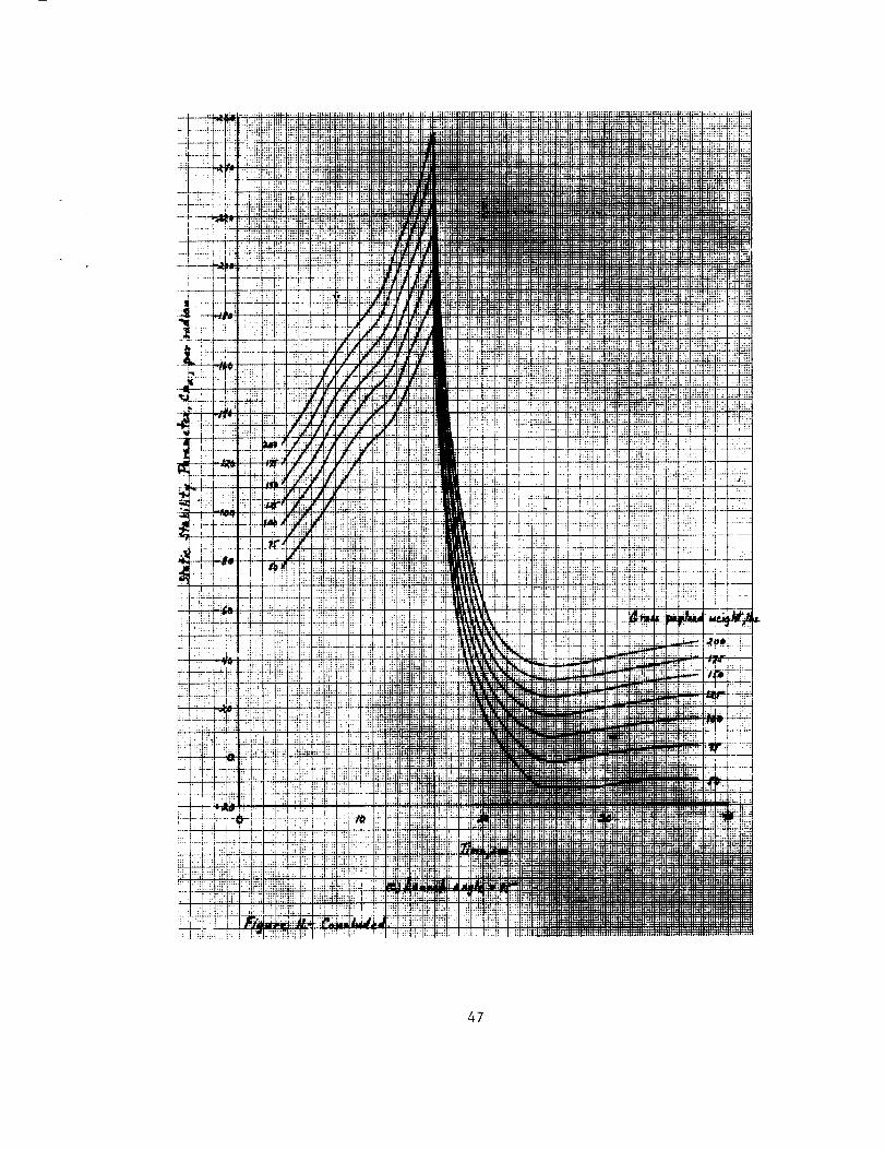
Tomahawk static stability. Wallops Island; 15 ft. launcher.
(a) Launch angle = 75 o
(b) Launch angle = 80 °
(c) Launch angle = 85 °
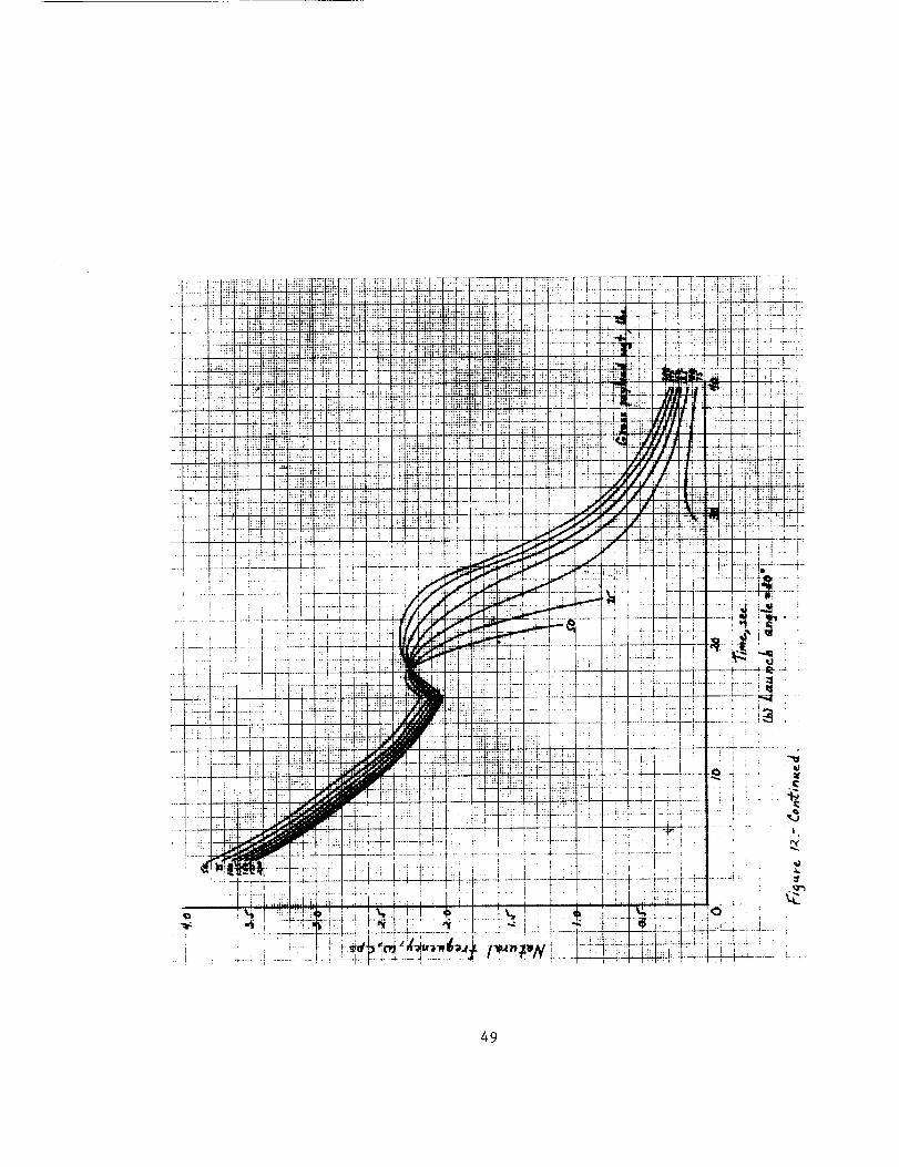
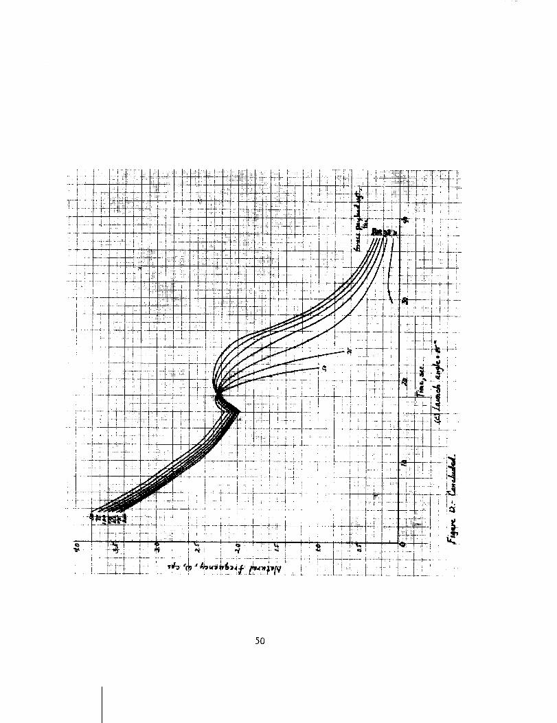
Tomahawk natural frequency. Wallops Island; 15 ft. launcher.
(a) Launch angle - 75°
(b) Launch angle = 80 °
(c) Launch angle = 85 °
24
Table I. - TomahawkWeight and Inertial Input Characteristics
WM.E.F.
WM.L.F.
(Xc.g.)M.E.F.
(Xc.g.)M.L.F .
(Xc.g.)p.L.
Xp.A.
m 143 ibs.
540 ibs.
3.46 ft.
© 5.88 ft.
6.75 ft.
= 11.87 ft.
(Iyy)M.E.F ' = 63.2 slugs ft. 2
(Iyy)M.L.F. = 207 slugs ft. 2
(Ixx)M.E.F. = 1.70 slugs ft. 2
(Ixx)M.L.F ' = 2.59 slugs ft.2
ti = 16 sec.
tb.o. = 25.5 sec.
t. sec. Wp.L., ibs. t. sec. Wp.L., ibs.
16.00
16.25
16.50
16.75
17.00
18.00
19.00
20.00
0
10.36
22.71
35.69
48.36
98.66
148.5
198.2
21.00
22.00
23.00
24.00
24.25
24.50
25.00
25.50
247.2
292.0
332.0
368.4
376.3
384.7
396.2
397.0
25
Table II. - TomahawkAerodynamic Input
M Xc.p.
1.2 1.523
2.30 3.192
2.75 3.718
3.00 4.002
3.50 4.468
4.00 4.865
4.50 5.218
Characteristics*
M Xc.p.
5.00 5.518
5.80 5.930
6.40 6.230
7.00 6.510
8.00 6.905
9.00 7.258
i0.0 7.258
M CN_ M CN_ M CN= _ M CN= /
1.20
1.43
1.60
1.80
2.00
2.25
38.96
28.19
23.66
22.00
19.60
17.88
2.50
3.00
3.40
3.75
4.10
4.45
16.44
14.10
12.95
12.03
11.34
10.77
4.80
5.15
5.60
6.00
6.55
7.00
10.43
10.08
9.74
9.51
9.28
9.11
7.50
8.00
8.50
9.85
i0.00
9.00
8.94
8.82
8.82
8.82
*i. Aerodynamic reference length = 0.75 ft.
2. Aerodynamic reference area = 0.4418 ft.2
26
m
C_
©
r_
I---
Ac©
L_ _
V
o
i
27
L_
\\\
\
\
\ t_
\
\
\
28
f
• o.
v_
_J
I
£
I
LL_
29
T ;:;:_'-'- !iiiii!iiiliilqL:i !i!!!iiiiiL
.... iiii!iii iiiii_ii ::::
::;;I_ ::_ !H::
"--!_, t/!ih!!_ii!_:-_i! !_+4_ _{_!_ !i_':
!i.i !ili ! :m-:¢._ .....
....... i]i]]]_ ......................... 1..........
............... T........
]!: I::.:i : :: ::::
.... ii ::
ii i]]!l!i]!_.]]::"_.....:::
_ii_! ii [] ]]L IjLL ii:c
: I t ] : _ :
.... _ t:;:t::: ::;]
__ . ii_21t::ilii:iii! iiiii2 _iiiillii._,:
i !i!!
;;: tti:b: .n_
ill !]]:__,]]
m_r. _!ii:: !i!
ttt
!i! _iti! :::
": i!i 1!!
!i) :::::: :;:
ii i,li::il i:,::
iF
;:i :ii!
!ili 22::;22i2_
ili!!!,_:
4_S*
_:I1_
,+
]:,.
._t::ITT...t...
N_
_N
.... !::,!
|;;:i :|:::::
'l:i
I!
:: |
i_q:,i
X:
31
g.tt
32
"_ M L" ..,t',l_c,
(_.) C---r+.+,_D_y/oc_<_weijJ+'l"= Iool_.
33
IioOOQ _.0_ lt.O00 Ii,000 _0,000 21,0130 _,000 _,000 mS.O00 _10,000
34
i:!ii!!!i_ii!!!!_:!_iiiili:: I: :|i ¸ '
:_:___,:,::..,:,_,_'i_if!I
'_:'_ +*il :AA !i]i
I::!! _. :
- " :!]i:_11,, H"
.... ill! :_!
...... .... ,-., :;|
,ml
35
(a3 _ross _yload _o_igM-=/ao I_s.
36
37
iii ;4,!.I_:,$&_
:j! H:t++_q;_ti|1::tm_,:l_'h_"bti*l+'+[ii .....................
: : = r--
ili:: l!!l!i!tiltitt_
_i" " ::h 'hr:_::]
i!i iiiti:;iiliiii|!:;!tilH; ; IIFlt I1+1_÷ q_t ff++t+4
,. :_!!!!!_
+.++
I_0,000 _.llO0 9@,000
38
lt,O00 tl,OIlO B.O00 a,O00
(_.) _ross p_ylo_d _ei_h-/-= leo Ibm.
_O.O00 _t,O00 m,O00 'lOgO00
39
_!!i!iii:_Fi!i iili :if!
ii! t_i iili
..... :iI:
_i!i1_!iii!
i].-'.!ii
i[ x,
7! :_ i!;-
,:_ .° :,q
if! i_ _iii!
_iii:
_I fill iiii_
!ifi i!ili_iff;I: :::_ ::[_
tM:H
i:i
:H
i:ii
!L
;ki
tt:_
i
ii!i _!!i!
'-Ti !i!:.i!i: ]ii:
iii iF
I::
:ii :)!;e.f_
!=
H: : :
.... :;L
:ti
_ :_?
*:: ?Y!!:
:H
_LH:
_244?4"
1
I_
::::F :}_ '=L_t•. :.', ::it
:ii[ Jt
il!il !i i::2: -
ii.' i_i _it:;i!i:Hii
"_/W IE:$,z¢.
i: ii
_4
iN
iii iiiii
'[ : :Yr:
i_ii ii:i
iii :_
N :!i_
/:-9,_,e_.-G,,÷i,,,ed.
40
+ _ .......
: =: ;; :; :
=[;,:;L ;; :
__.-_:i;i I _i_i
i_iiiiiii_.iii:i
_T_n:/;!!!!.!!!:_!
[:_ !!!ff! !!fH-,lr ffi.f+_l+H
L_L;::;_-Hi!+!:
41
cJ
,..i
++
o'i
++t_
3++
c_
§
t.-,
+t
_o
i/
"//
I//___ _ Gro_ p,_Ho,3
__._oo
/oo
i --7+-
(,'-J]+.++4 ,+,,_],_: 7J-"
42
i !i if:: i::i
i;i • J :i x!
-qiil i_-
iil ii_; :,_;ii
: :: x ,• : :::
:: !_i iil i
£ i;:! .!]i]!_ !;i ;: :'
,t
:: : : :
_F ::.:
=:: ii::!:
ii_:!!!
..... :4
-:]II:: ]
st
:-t
_5 N} t
_N
#J
43
...... T!L' !t i'2 "
•_,I_!._. 2: ,;_ T_ _-
P:Il;_::Im. ....i::i:::i_:!i:J
• .,, ii_iiii!ii_i;i!:,ii! ;_i;ii<_
i: _ilti "T "
iil, .iT:.i! £ i :
_rI I!;_! !_t: t!:I;_ ;:
:: iFi_i[../_!iii:.
:::2it_:i .....
_: i[:i
44
]t; i ....
-2t._
% t% - :
•._ \
i:'g
: i
....!... L-.ii
....... ii
!!!_:dt !]i
.: | HI
d:i:_m-t_
%1,,
' I I
....,; :4-:1' i J
;.i. _: '' "
I'
t2±:£Ji_
_" I---- _
• a.-_II:q ;; i m,,.!
45
46
_:. i!i
fit H_
_. L.
:r; •2..:-
L_
-:!- N I
. _
£_
i;i:
!:
I:Li
[:i i
i _i :'I
k:!_ :e
i::ii )_i!ili :*
!
i ....
_ Ze/Z.i
_ ;._
#, i:
_ !i -_
:i:, _lii: ;il
-2 ::;.
i!! _L!
!i_2 _
L
!:
ii!-÷ _
47
xJ
'lO(_ q.otI_ 9.(x_ l_.(]oo
/\''/
16.0(_ 20,Q(]O 2q.[]_
'7"i_ e. a,s _,,. '
/i.__ -
ca)_,uneh ,._/e - 7_"°
48
i
49
T
i •
50
TO
OPTIGq_tJ. FORM NO. 10 SOI0-107
MAY I1_1 arD|TI_4
alia GIN. 11116, NO. IT
UNITED STATES GOVERNMENT
Memorandum: Flight Performance Section Files
DATE: 9 February 1966
FROM :
SU BJECT:
Mr. Edward E. Mayo
Flight Performance Section
TOMAHAWK DYNAMIC MOTION STUDY
REFERENCE: (a) Nicolaldes 0 Dr, John D,: Stability of Free Flight Missiles. October
1964,
(b) Memo of 15 March 1965 t Mr. Edward E. Mayo to Flight Performance Section
Files m Subject: Nike-Tomahawk Particle Trajectory
(c) Ston% G. W, s and Connell s G. M.: Range Safety for the Nike-Tomahawk
Rocket System with a Nine-Inch Diameter Payload, April s 1964.
(d) Memo of 29 June 1965 s Mr, Edward Eo Mayo to Flight Performance Section
Files s Subject: Effect of Payload Weight on the Tomahawk Mass s Static
Margin s Static Stability and Natural Frequency Characteristics
(e) Memo of i0 September 1964 s Mr, Edward E. Mayo to Flight Performance
Section Files t Subject: Effects of Payload Weight and Length on the
Cajun Massy Static Margin I Static Stabilitys and Natural Frequency
Characteristics,
(f) Memo of Ii August 1964_ Mr, Edward E. Mayo to Flight Performance Section
Files s Subject: Effects of Payload Weight and Length on the Apache
Mass s Static Margin_ Static Stability 9 and Natural Frequency Character-
istics,
(g) Stoney George W.: The Magnus Instability of a Sounding Rocket, AIAA
Paper No, 66-62, AIAA 3_d Aerospace Science Meeting, January 24-26_
1966,
(h) Price i D. A. s Jr. s and Nelson s Eo O.: Final Report for Aerobee 350
Lock-ln Study, Lockheed Missiles and Space Company. 1965,
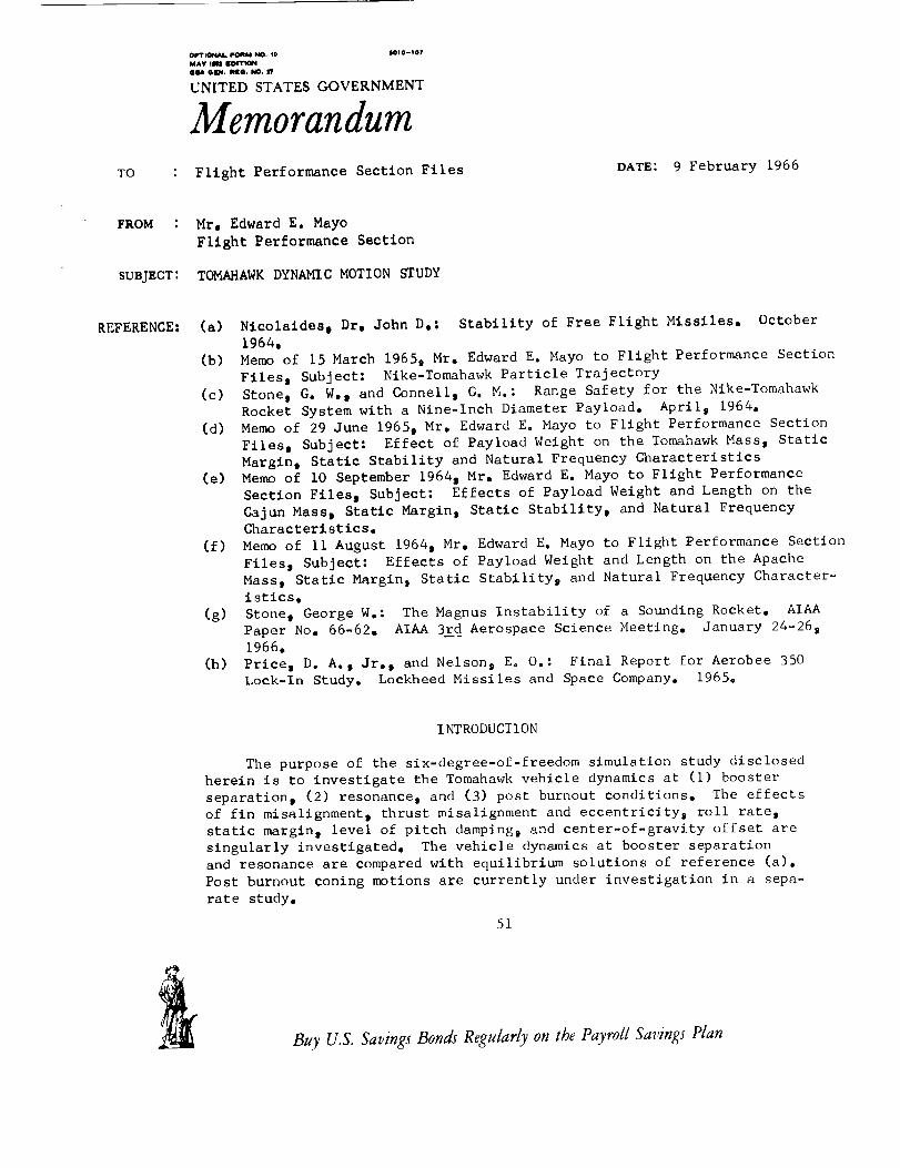
INTRODUCTION
The purpose of the six-degree-of-freedom simulation study disclosed
herein is to investigate the Tomahawk vehicle dynamics at (i) booster
separation t (2) resonance s and (3) post burnout conditions. The effects
of fin misalignment s thrust misalignment and eecentricityj roll ratep
static margin s level of pitch damping_ and center-of-gravity offset are
singularly investigated, The vehicle dynamics at booster separation
and resonance are compared with equilibrium solutions of reference (a).
Post burnout coning motions are currently under investigation in a sepa-
rate study,
51
Buy U.S. Savings Bonds Regularly on the Payroll Savings Plan
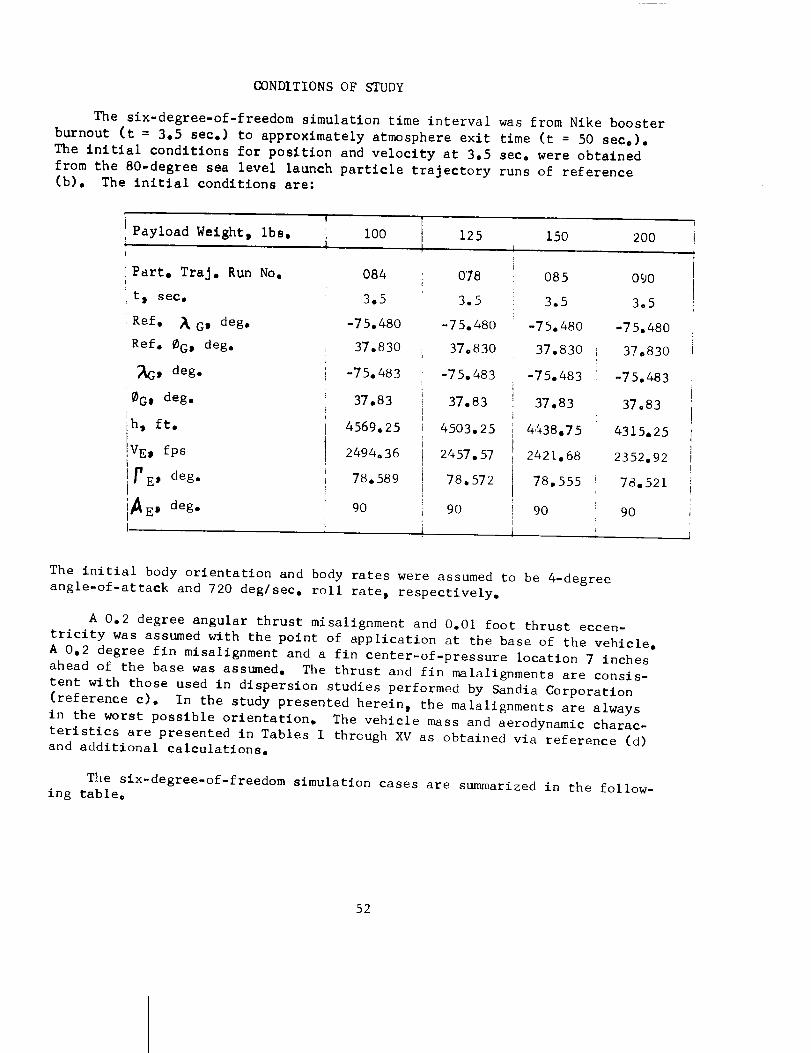
CONDITIONS OF STUDY
The six-degree-of-freedom simulation time interval was from Nike booster
burnout (t = 3.5 see.) to approximately atmosphere exit time (t = 50 sec.).
The initial conditions for position and velocity at 3.5 see. were obtained
from the 80-degree sea level launch particle trajectory runs of reference
(b). The initial conditions are:
Payload Weight, ibs.
Part, TraJ, Run No.
t_ see,
Ref. _ Gi deg,
Ref. @G_ deg.
_G, deg.
_G, deg.
h, ft.
VEj fps
r E' deg.
A E s deg.
i00
084
3.5
-75.480
37.830
-75.483
37.83
4569.25
2494.36
780589
9O
125 150 200
078
3.5
-75,480
37.830
-750483
37,83
4503.25
2457 o57
78. 572
9O
O85
3.5
-75.480
37.830
-75.483
37.83
4.%38.7 5
2421.68
78.555
9O
09O
305
-75.480
37.830
-75.483
37.83
4315.25
2352.92;
78.521
90
The initial body orientation and body rates were assumed to be 4-degree
angle-of-attack and 720 deg/sec, roll rate t respectively,
A 0.2 degree angular thrust misalignment and 0.01 foot thrust eccen-
tricity was assumed with the point of application at the base of the vehicle.
A 0.2 degree fin misalignment and a fin center-of-pressure location 7 inches
ahead of the base was assumed. The thrust and fin malalignments are consis-
tent with those used in dispersion studies performed by Sandia Corporation
(reference c). In the study presented herein, the malalignments are always
in the worst possible orientation. The vehicle mass and aerodynamic charac-
teristics are presented in Tables I through XV as obtained via reference (d)
and additional calculations.
The slx-degree-of-freedom simulation cases are summarized in the follow-
ing table,
52
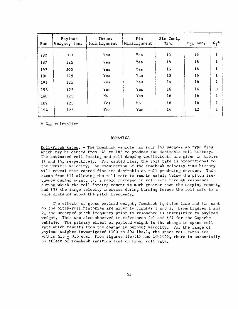
Ruin PayloadWeightt Ibs.
192
187
193190191
195i 188
189194
i00
125
200
125
125
i 125125
125
! 125
Thrust
Malalignment
Yes
Yes
Yes
Yes
Yes
Yes
No
Yes
Yes
Fin
Misa lignment
Yes
Yes
Yes
Yes
Yes
Yes
Yes
No
Yes
Fin Cant i
Min. t21 see.
16 16
16 16
16 16
18 16
14 16
16 16
16 16
16 I 1616 12
l__L
I
i
I
i
i
0
1
1
1
* Cmq multiplier
DYNAMI CS
Roll-Pitch Rates. - The Tomahawk vehicle has four (4) wedge-slab type fins
which may be canted from 14' to 18' to produce the desirable roll history.
The estimated roll forcing and roll damping coefficients are given in tables
13 and 14_ respectively. For canted fins s the roll rate is proportional to
the vehicle velocity. An examination of the Tomahawk velocity-time history
will reveal that canted fins are desirable as roll producing devices. This
stems from Cl) allowing the roll rate to remain safely below the pitch fre-
quency during coast t (2) a rapid increase in roll rate through resonance
during which the roll forcing moment is much greater than the damping moment_
and (3) the large velocity increase during burning forces the roll rate to a
safe distance above the pitch frequency°
The effects of gross payload weight_ Tomahawk ignition time and fin cant
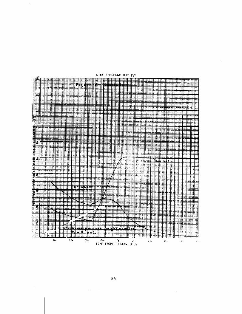
on the pitch-roll histories are given in figures i and 2. From figures I and
2_ the undamped pitch frequency prior to resonance is insensitive to payload
weight. This was also observed in references (e) and (f) for the Capache
vehicle. The primary effect of payload weight is the change in space roll
rate which results from the change in burnout velocity. For the range of
payload weights investigated (i00 to 200 Ibs.), the space roll rates are
within 5.5 _ 0.5 CpSo From figures l(b)(1) and l(b)(2) t there is essentially
no effect of Tomahawk ignition time on final roll rate.
53
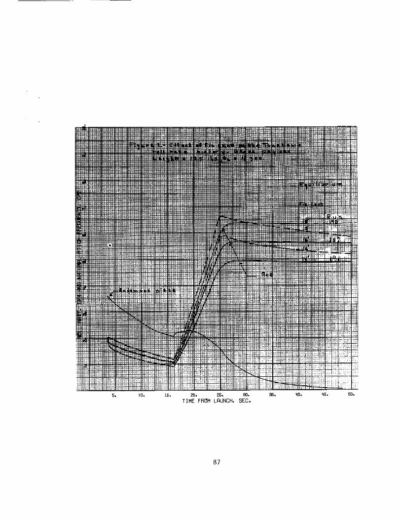
The effect of fin cant on the roll rate history is given in figure 2
for a nominal payload weight of 125 ibs. and a Tomahawk ignition time of
16 seconds. Also shown on figure 2 are equilibrium roll rates computed by
Pss =(1)
Initially_ at t = 3e5 sec._ the actual roll rate value is the assumed 2 cps
initial condition. The roll rate reaches the steady state value within
about 0.2 see. and remains nearly equal to the steady state value until
Tomahawk ignition. There is considerable lag during thrusting which is
attributed to vehicle longitudinal acceleration coupled with roll inertia
effects. After burnout t the actual roll rate overshoots the equilibrium
value by approximately 0.5 cps at t = 50 seco The space roll rate is pro-
portional to the fin cant and the roll rate for all fin cants investigated
is within 5.6 + 0.75 cps.
Booster Separation. - The initial disturbance at booster separation damps
from 4° to i° in approximately I.i second. See figures 3 and 4. This is
in agreement with the 0.57 second Nutation and Precession Arm half life
time computed from the equilibrium solutions given in reference (a). Hence_
the disturbances of the Tomahawk at booster separation are heavily damped
and should not impose any serious flight abnormality.
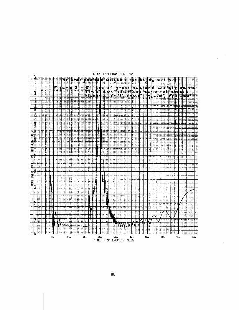
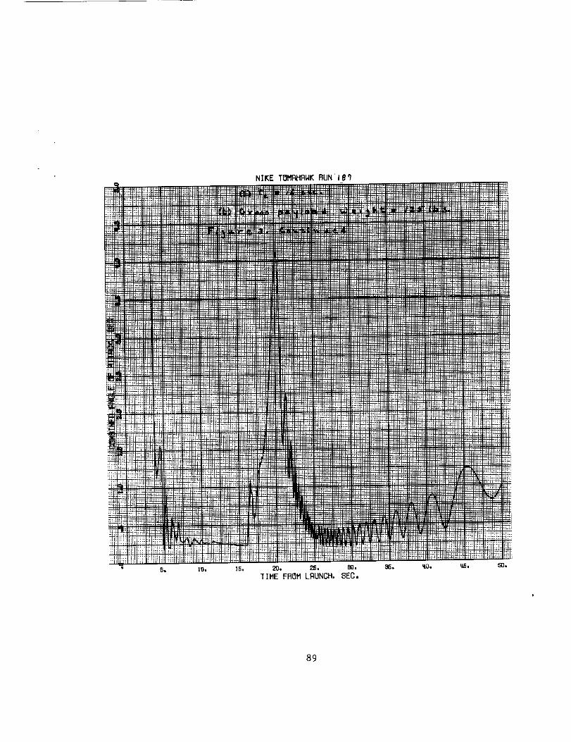
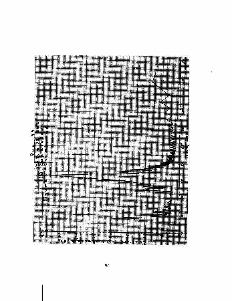
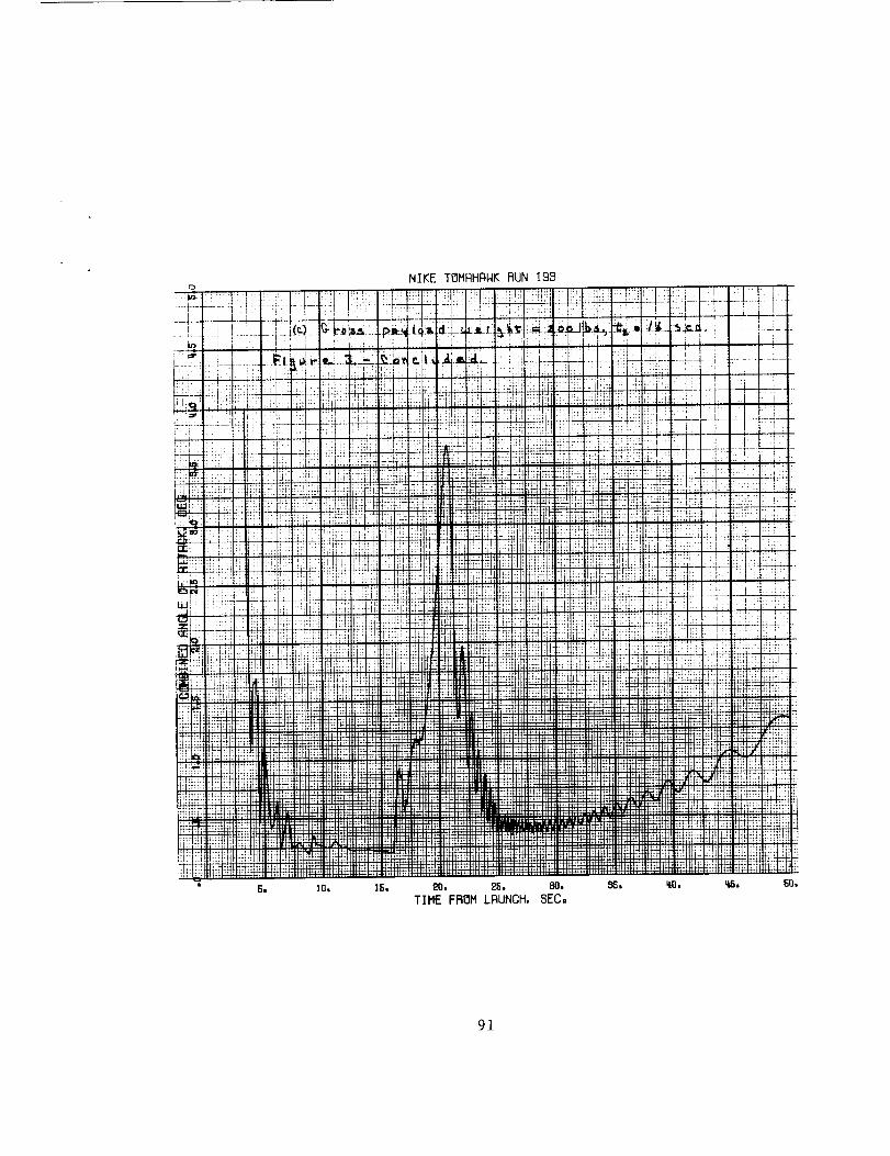
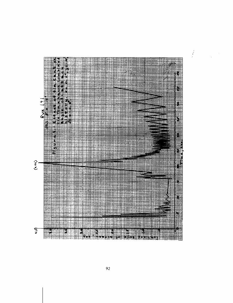
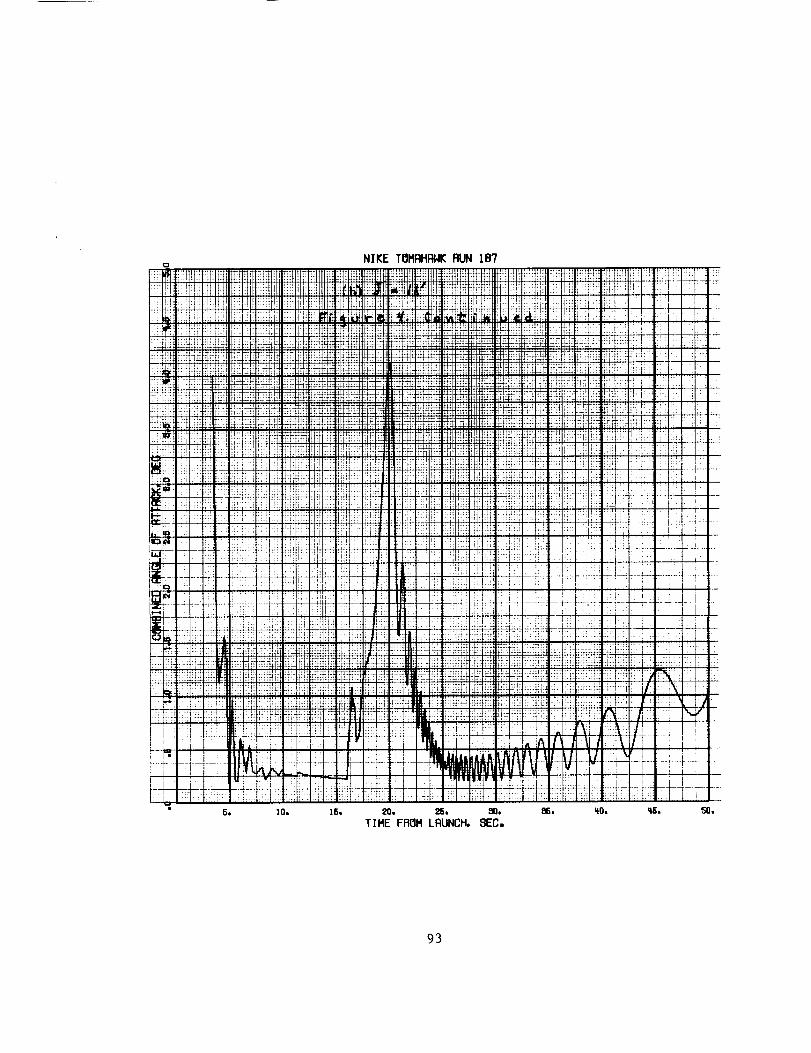
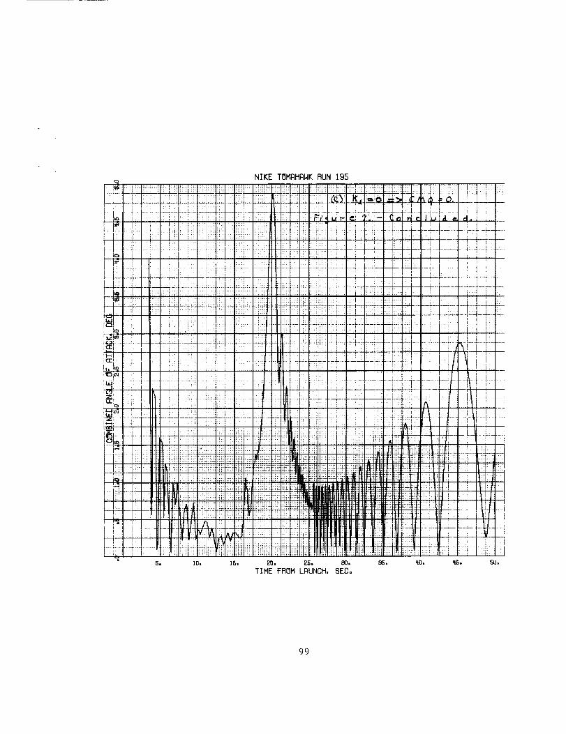
Resonance. - The effects of gross payload weight and fin cant on the com-
bined angle-of-attack build-up at resonance are given in figures 3 and 4_
respectively; and the maximum combined angle-of-attack is compared with
equilibrium solutions of reference (a) in figures 5 and 6. The maximum
combined angle-of-attack is approximately 4 degrees and is within i degree
of the equilibrium value. From figure 5, the effect of varying payload
weight (and, thus s minimum static margin) has a relatively small effect on
the maximum combined angle-of-attack. This can be explained by referring
to the static margin histories given in reference (d)o The resonance time
for the Tomahawk is approximately 20 seconds; whereas_ minimum static mar-
gin occurs at burnout (25.5 sec.). In going from a gross payload weight of
200 Ibso to iO0 ibso, the minimum static margin decreases from 4 calibers
to 1 caliber; whereas t at resonance time s the static margin decreases from
5.25 to approximately 3o25 calibers. Similarly 0 for the case of zero mini-
mum static marginp a static margin of over 2 calibers exists at the resonance
time. The small change in _ max with varying fin cant exhibited in figure 6
is expected since_ referring to figure 2_ the resonance time spread for ex-
treme fin cants is only 1.25 seconds.
54
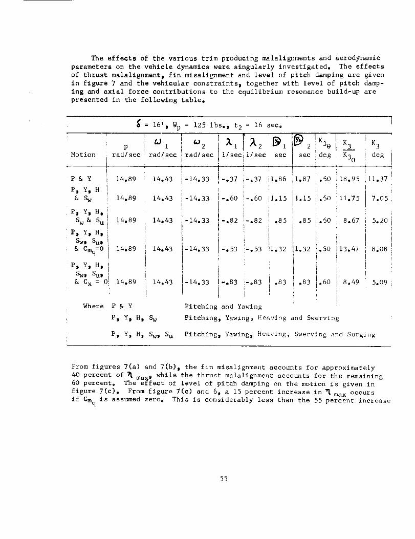
_e effects of the various trim producing malallgnments and aerodynamic
parameters on the vehicle dynamics were singularly investigated. The effects
of thrust malalignment_ fin misalignment and level of pitch damping are given
in figure 7 and the vehicular constraints, together with level of pitch damp-
ing and axial force contributions to the equilibrium resonance build-up are
presented in the following table.
P
= 16's Wp = 125 ibs., t2 = 16 sec.
Motion
P
rad/sec
P & Y 14.89
P, Y, H
& Sw 14,89
P, Y, H,
Sw & Su
P, Y_ Hs
s_, Su, 1
& Cmq=O I 14.89
P, Y, Hi iS ISw, u, i
& Cx = 01 14.89
14.89
&)1
rad/sec
14.43
14.43
14.43
14.43
14.43
AJ2
rad/sec
-14.33
-14.33
-14.33
-14.33
i/see
Where P & Y
P, Y, H, Sw
-°37
-.60
-.82
1/see sec
-.37 '_1.86
-.60 '_io 15
-,82 ,85
-.53 -.53 11.32
-14.33 -.83 i-083
I
Pitching and Yawing
.83
K.,
I_2 : °O
sec ideg
1.87 .60
1.15 .60
.85 .60
1.32 .50
.83 .60
Pitching, Yawing, Heaving and Swerving
K 3 K 3
K30 degi
18.95 11.37
11.75 7.05
8.67 5.2O
13.47 8.08
8.49 5.09
P, Ym H, Sw, Su Pitching, Yawing, Heaving, Swerving and Surglng
From figures 7(a) and 7(b) i the fin misalignment accounts for approximately
40 percent of _ max0 while the thrust malalignment accounts for the remaining
60 percent. The effect of level of pitch damping on the motion is given in
figure 7(c). From figure 7(c) and 6, a 15 percent increase in _ max occurs
if Cmq is assumed zero° This is considerably less than the 55 percent increase
55
predicted from equilibrium solutions, See above table, The level of
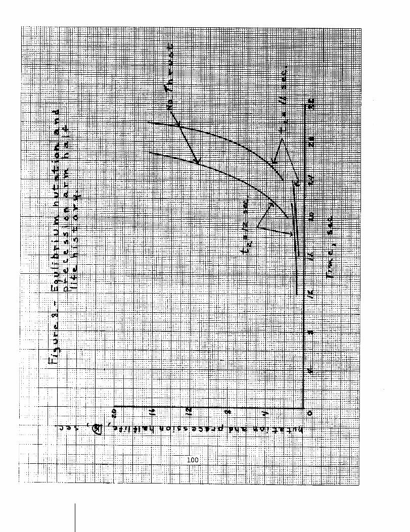
pitch damping had a pronounced effect on the post burnout coning motion.
As seen from figure 8 s the Nutatlon and Precession Arm damping rates
after burnout decrease exponentially with time. (Figure 8 is for full
estimated Cm .) Hences the degradation in damping due to decreasing
density_ aerodynamic coefficient degradation and post resonance residual
motions can result in large post burnout coning mot_ons. It _hnuld be
noted that the poet burnout conln_ buiLd-up exhibited _n t1_.r, 7(c)
mary., only ae an indicator that the dampin_ rate o[ tl_u Nut,_t_on _m, ltur
_rocee,lon Arm te sour, In the ,tudy herein o the Ma&nus _urm (wl_lcl, _p-
pears with Cm_ in determining the Nutatlon and Precession Arm dampln_
rates) was neglected. In reference (g)_ the Magnus moment coefficients
were extracted from divergent flight characteristics of the Tomahawk w_hi-
cle and were shown to be large, highly non-llnear and to vary rapidly with
Reynolds number. The post burnout coning motion of sounding rockets is
currently under investigation in a separate study by Mr. James McGarvey.a Fairchild-Hiller employee.
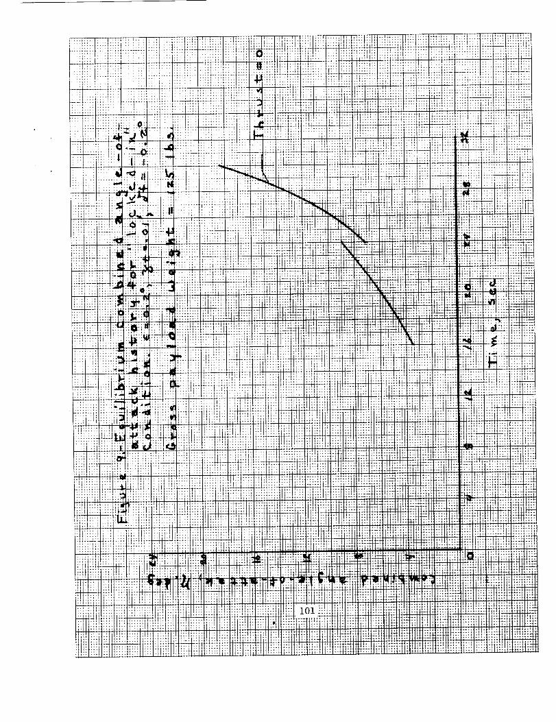
Lateral Center-of-Gravity Limit. - As noted previously, the Nutation and
Precession Arms are heavily damped prior to resonance, and _max at reso-
nance is in agreement with equilibrium values predicted by resonance
instability theory. Thus, _ max can be estimated by procedures such as
described in the Appendix, The resulting _ max versus time is given in
figure 9 (p = &2 ). Figure 9 illustrates that if "lock-in" occurs, "_maxwill grow exponentially until flight failure. The allowable center-of-
gravity offset (or induced rolling moment) to insure a break-out of
"lock-in" was estimated according to the procedures of reference (h)°
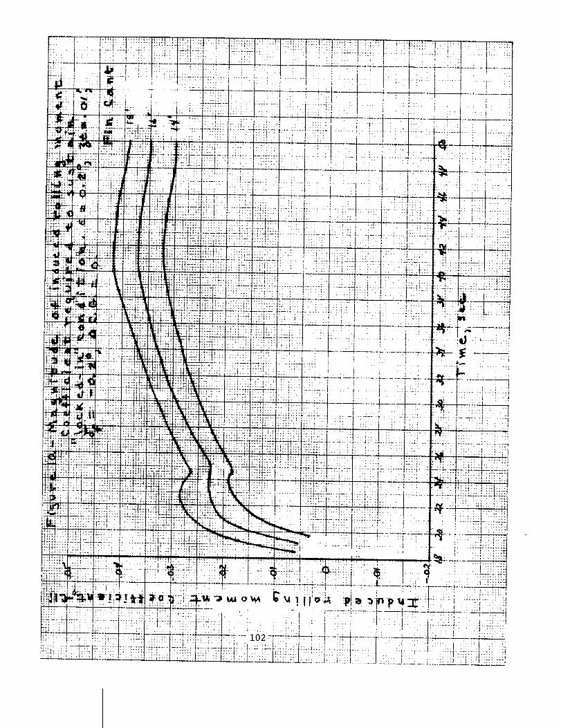
Considering _C.G. = 0 i then the induced rolling moment required
to maintain "lock-in" may be approximated by
= +C- /&_d" C1 i _CI_ lp_ W ) (2)
The resulting C1 values are given in figure I0 as a function of time
and fin cant angle. Figure I0 is interpreted as follows. If an induced
rolling moment of -0.015 exists, then for _ = 16' roll "lock-in" will
be maintained until 20 sec. (_ max _6 ° from figure 9) at which time
break-out occurs. If for the same cant angle, an induced rolling moment
coefficient of -0.030 exists, then roll "lock-in" will be maintained
until 30.5 seconds (_max = 20o from figure 9) at which time break-out
occurs. From equation 2 and as seen in figure i0, the allowable induced
moment is a direct function of the fin cant angle.
56
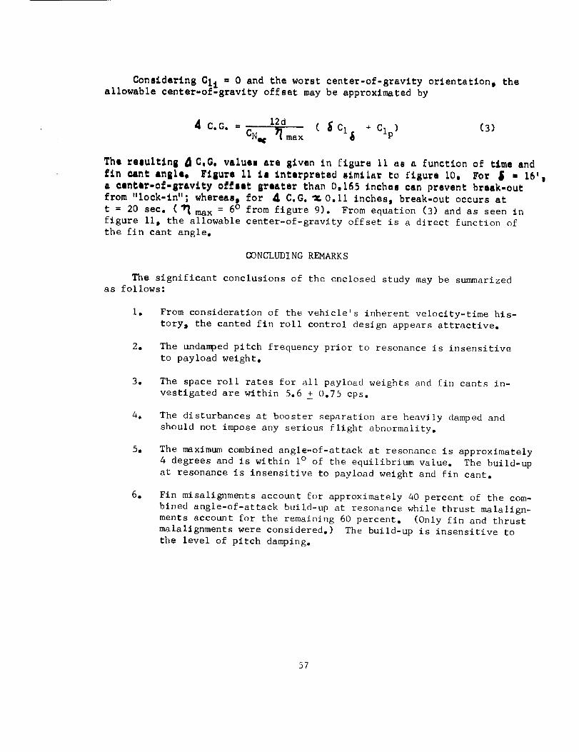
Conalderlng Cli = 0 and the worst center-of-gravlty orlentatlon t the
a11owable center-of=gravity offset may be approximated by
12dA C.G. = ( _ + Clp) (3)
CN,c _ max Cl$
The reeultin 8 _C.G. valuee are given in llgura II aa a function of tlme end
_In =ant angle, F_sure ii le interpreted llmilar to figure LO, For S • 16'i
& eentar=of=Bravlty effect greater than 0,165 inchee can prevent break=out
from "lock-in"; whereas i for _ C.G. _O.11 Inches s break-out occurs at
t = 20 sec. (_ max = 6o from figure 9). From equation (3) and as seen in
figure II t the allowable center-of-gravity offset is a direct function of
the fin cant angle,
CONCLUDING REMARKS
The significant conclusions of the enclosed study may be summarized
as follows:
. From consideration of the vehicle's inherent velocity-time his-
tory, the canted fin roll control design appears attractive.
28 The undanped pitch frequency prior to resonance is insensitive
to payload weighto
o The space roll rates for all payload weights and fin cants in-
vestigated are within 5.6 Z 0.75 cps.
e The disturbances at booster separation are heavily damped and
should not impose any serious flight abnormality.
5o The maximum combined angle-of-attack at resonance is approximately
4 degrees and is within 1° of the equilibrium value. The build-up
at resonance is insensitive to payload weight and fin cant.
0 Fin misalignments account for approximately 40 percent of the com-
bined angle-of-attack build-up at resonance while thrust malalign-
ments account for the remaining 60 percent. (Only fin and thrust
malalignments were considered.) The build-up is insensitive to
the level of pitch damping.
57
e
8.
The degradation in damping due to decreasing density i aerodynamic
coefficient degradation and post resonance residual motions can
result in large post burnout coning motions,
Conslderln 8 6 = 16' m _ C,@. = 0p an induced rolling moment
coefflclent I Cll I of -0,030 is sufficient to sustain roll "Iock-iu" until t = 30.5 seconds ( _ max = 20°), C°nslderlng _ = 16'B
Cli = 0 t a center-of-gravity offset i _ C.G._ greater than 0.165inches can prevent break-out from roll "lock-in" andj thus, flight
failure,
cc: Mr, Ko R. Medrow
Mr, G. E. MacVeigh
Mr. E. E. Bissell
Miss E. C. Pressly
Mr. N. E. Peterson
Mr. J. S. Barrowman
Mr. J. F. McGarvey
Mr. C. G. Thomas
EEM: skd
Edward E. Mayo
58
AI_PENDIX
RESONANCEINSTABILITYTHEORY
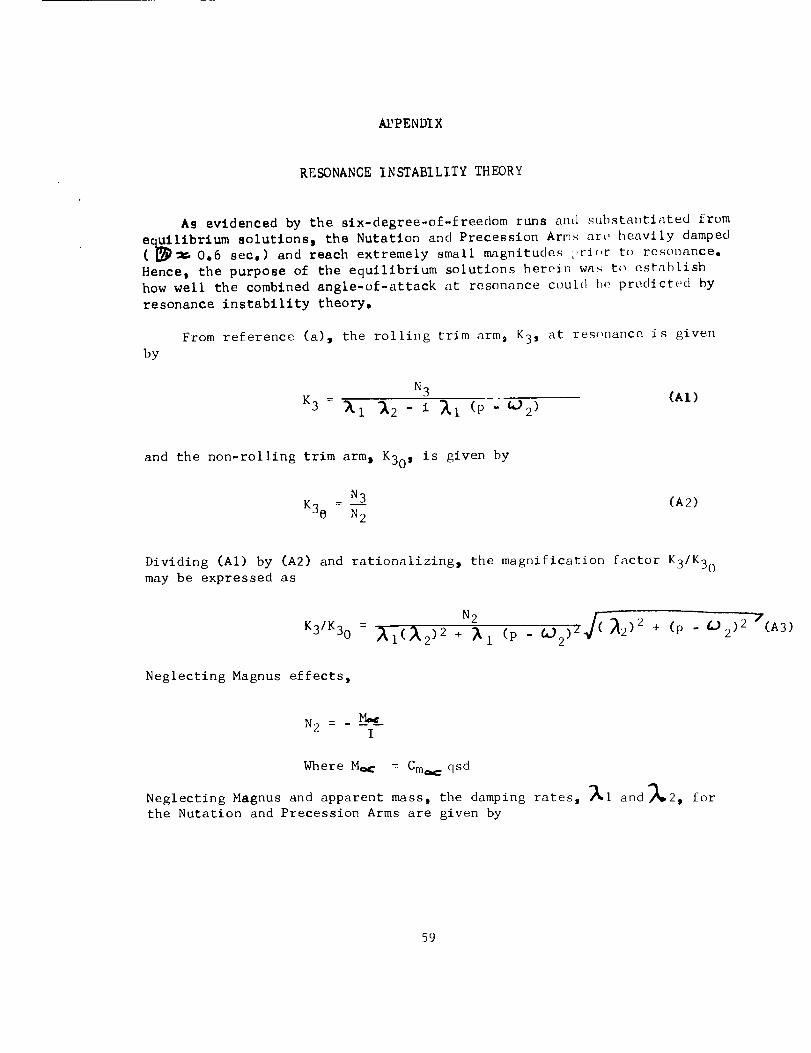
As evidenced by the six-degree-of-freedom runs and substantiated from
librium solutions_ the Nutatlon and Precession Arms ar_ heavily damped0o6 sec,) and reach extremely small magnitude,_i>r_c,r to resonance.HenceI the purpose of the equillhrium solutions herein wa,_to establishhowwell the combinedangle-of-attack at resonance could b_ predict_,d byresonance instability theory.
From reference (a) 3 the rolling trim arm9 K3_ at resonance is givenby
N3K3 = _i _2 - i _I (p " _2 ) (A1)
and the non-rolling trim arm_ K30 _ is given by
N3
K30 - N2(A2)
Dividing (AI) by (A2) and rationalizing_ the magnification factor K3/K30may be expressed as
K3/K30 = 'AI(_2 )2 + _l (p - _2 )Z _2)2 + (p " g'_2)2 7(A3)
Neglecting Magnus effects_
N2 = . _M_cI
Where Mac : Cm_qsd
Neglecting Magnus and apparent mass_ the damping rates_ _i and_2_ for
the Nutation and Precession Arms are given by
59
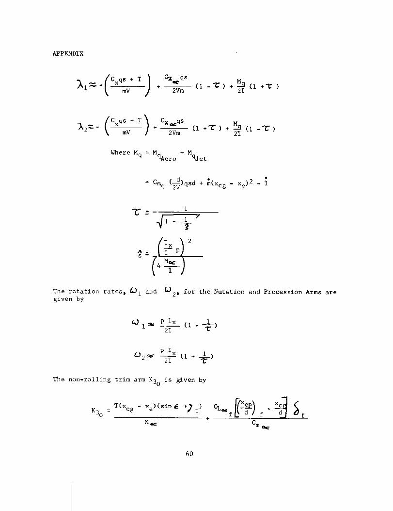
APPENDIX
-_ Cxqs + T I Cz_qsi "_" k" mV + 2Vm
M_C1 -_) + "'_ (1 +'r )
2I
Cxqs + T) CB_qs M__2--_'" mV" + _ (I +'_ ) + (i -'_)21
Where Mq = MqAer ° + Mqjet
c_.d +_(XcgXe)2 {= Cmq ~_, - .
i"C---
. i "i _f
ix ) 2_s--- I--P
The rotation rates_ _i and
given by
21 for the Nutation and Precession Arms are
iV ira= P Ix (i - --_-)
2I
P Ix_2 _= 2I (i + ____i)
The non-rolling trim arm K30 is given by
K30 =T(xcg - Xe)(Sin _ +) t)
Mg_: Cm o,=
60
APPENDIX
and the magnitude of the rolling trim at resonance m_y be determined from
= ( K-/-3K30 ) (K30)K3
The Nutatlon and Precession half lives are given by
I in(i/2)
1
_2 = _2 In(I/2)
The foregoing equations were progra_ed by C. Hutton to yield the
equilibrium solutions enclosed herein.
61
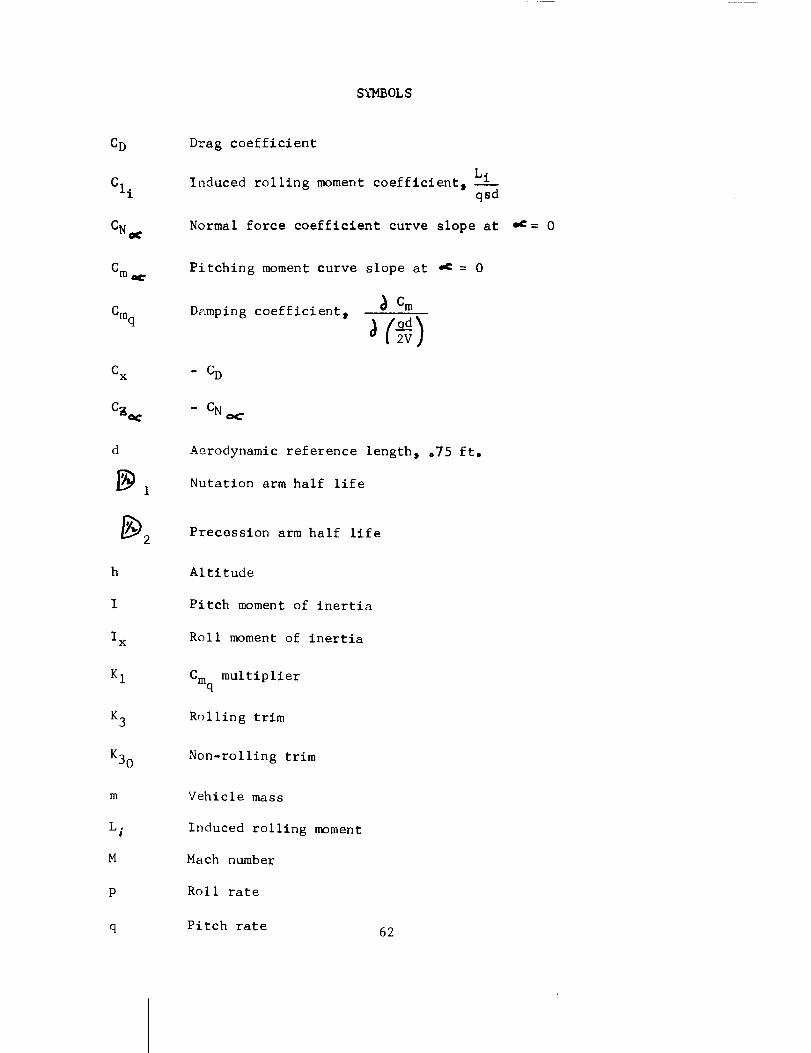
S_IBOL S
CD
CI i
CN_
Cm_
Cmq
d
h
I
Ix
K 1
K3
K30
m
L.#
M
P
Drag coefficient
Induced rolling moment coefficient 0 Liqsd
Normal force coefficient curve slope at ,c= 0
Pitching moment curve slope at "_ = 0
Damping coefficient,Cm
Aerodynamic reference length, °75 ft.
Nutation arm half life
Precession arm half life
Altitude
Pitch moment of inertia
Roll moment of inertia
Cmq multiplier
Rolling trim
Non-rolling trim
Vehicle mass
Induced rolling moment
Mach number
Roll rate
q Pitch rate 62
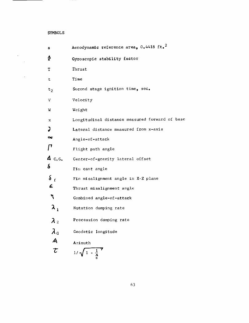
SYMBOLS
S
T
t
t 2
V
W
x
F
CoG.
_2
IG
Aerodynamic reference area, 0.4418 ft. 2
Gyroscopic stability factor
lhrust
Time
Second stage ignition time_ sec.
Velocity
Weight
Longitudinal distance measured forward of base
Lateral distance measured from x-axis
Angle-of-attack
Flight path angle
Center-of-gravity lateral offset
Fin cant angle
Fin misalignment angle in X-Z plane
Thrust misalignment angle
Combined angle-of-attack
Nutation damping rate
Precession damping rate
Geodetic longitude
Azimuth
/
i! I - Es
63
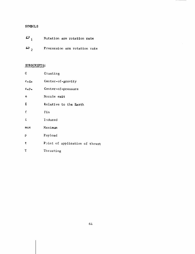
SYMBOLS
I
2
Nutation arm rotation rate
Precession arm rotation rate
SUBSCRIPTS:
C
Cogo
cop,
e
E
f
i
max
P
t
T
Coasting
Center-of-gravity
Center-of-pressure
Nozzle exit
Relative to the Earth
Fin
Induced
Maximum
Payload
P3int of application of thrust
Thrusting
64
LIST OF TABLES
Tabi e
I
2
3
4
5
6
7
8
9
iO
II
12
13
14
15
TomahawkCoasting Drag Coefficient
TomahawkThrusting Drag Coefficient
TomahawkNormal Force Coefficient Curve Slope
TomahawkPitch DampingCoefficient
TomahawkPitching MomentCurve Slope
TomahawkSea-Level Thrust
TomahawkCenter-of-Gravity Location
TomahawkGross Weight
TomahawkRoll Momentof Inertia
TomahawkPitch and YawMomentsof Inertia
TomahawkCenter-of-Pressure Location
TomahawkFin Lift Coefficient
TomahawkRoll Forcing Coefficient
TomahawkRoll DampingCoefficient
TomahawkJet Damping
65

LIST OFFIGURES
Figure
I
4
Effects of gross payload weight on the Tomahawk undamped pitch
rate and roll rate histories.
(_) Gross payload weight = I00 Ibs., t2 = 16 sec.
(b) Gross payload weight = 125 Ibs.
(I) t2 = 16 sec.
(2) t2 = 12 sec.
(c) Gross payload weight = 200 Ibs., t2 = 16 sec.
Effect of fin cant on the Tomahawk roll rate history. Gross
payload weight = 125 ibs., t2 = 16 sec.
Effect of gross payload weight on the Tomahawk combined angle-
of-attack history. _ = 16' 6 = 0.2°p ) t, = .01 ft.jf = -O.2 deg.
(a) Gross payload weight = I00 Ibs., t2 = 16 sec.
(b) Gross payload weight = 125 ibs.
(l) t2 = 16 sec.
(2) t2 = 12 sec.
(c) Gross payload weight = 200 Ibs., t2 = 16 sec.
Effect of fin cant on the Tomahawk combined angle-of-attack
history, _ = 0.2 deg., _ t = .01 ft., _f = -0.2 deg.
(a) _ = 14'
(b) _ = 16'
Cc) _ = 18'
66
LIST OF FIGURES
Figure
Effect of gross payload weight on the Tomahawk maximum combined
angle-of-attack at resonance, 6 = 16', 6 = 0"2o' 2 t = .01,
f = -0.2 deg.
Effect of fin cant on the Tomahawk maximum combined angle-of-
attack at resonance, _ = 0"2°, 2 t = .01 ft., _f = -0.2 deg.
Effect of thrust malalignment, fin misalignment, and level of
pitch damping on the Tomahawk combined angle-of-attack history.
= 16' _ = 0"2o 5t = 01 ft _f -0.2 ° , K 1 = i 0* D e "' = "
t2 = 16 sec. except as noted.
(a) _ = 0 deg., 2t = 0 ft.
(b) _f = 0 deg.
(c) K I = 0 _Cmq = 0
Equilibrium Nutation and Precession Arm half life history.
Equilibrium combined angle-of-attack history for "locked-in"
condition. E = 002 deg._ 2 t = .01 fto_ _f = -0.2 °.
i0 Magnitude of induced rolling moment coefficient required to sus-
tain "locked-in" condition. _ = 0"20* _t = .O1 ft.,Sf = -0°2 ° , _ C. Go = O.
ii Magnitude of center-of-gravity offset required to sustain
"locked-in" condition. _ = 0.2 ° , 2t = .01 ft., _f = -0.2°_Cli = O.
67
IABLE I
TOMAHAWKCOASTINGDRAGCOEFFICIENT*
!
M
1.25
1.6
1.9
2.2
2.5
2.9
3.25
3,5
3.75
4.
4°3
4.75
5,25
6.
7.
9.
9990
1.165
I,
.9
o8
.73
.65
.6
o565
.54
.52
.5
.472
.445
.415
.38
.315
.315
*Aerodynamic reference area = 0.4418 ft 2
68
TABLEII
TOMAHAWKTHRUSTINGDRAGCOEFFICIENT*
M CDT
1,25 °955
io95 .8
20 .725
2.2 0675
2.45 .625
2.7 .585
2.75 .57
2,9 .55
3. .54
3,I °525
3.35 .5
3.5 .49
3.75 .47
4. I .45
4.4 .44
4.9 .415
5.85 .385
9.0 .29
*Aerodynamic reference area = 0.4418 ft 2
69
TABLEIII
TOMAHAWKNORMALFORCECOEFFICIENTCURVESLOPE*
M CN
1.2
1.43
1.6
]o8
?,,0
2.25
2,5
3.0
3.4
3°75
4.]
4,45
38°96
2_Io19
23.66
22.0
19.6
17o88
16.44
14, 1
12.95
12,03
11.34
10.77
M CN_
4.8 10.43
5.15 10.O8
5,6 9.74
6.0 9.51
6.55 9.28
7.0 9ol]
7°5 9.0
8,0 8°94
8°5 8.82
8.85 8.82
I0o0 8,82
* 1. per radian
2. Aerodynamic reference area = 0.4418 ft 2
70
J
fl
•-I o0 _ _ _ o_, t'_ o_
CO oO0 u_ CO _ 0 oO r_. _D _C, I'_ _ I_.
I I ! I I I i i I I I I I
o _
I-.4
i-I
0.,-i
oO
l-I
OJ
.IJcO
oJ
v
_O
II
0.PI4.J.pl
OD
aD
_4
II ,._
U U
_J _J
0 '_0 _ oo _ CO ,,@ _D ,._0 _ oo ,-n I_ _ oO _ "_D _ 00
I I l I I I I l I I
0 • 0 i"_0 _ •
',.0 O0 '_00 o4e _ _ 0 0 _ • •_ _ _ J " _ _ _ _ o
I I I I I I I I I I I I
u_ u'%
U"l
"El
II I-I
ID" I-I
e_
.1<
E.,.4
IJr-
L_
71
u'_
!
m/
/// :
eooooooeooeooooe$oooooooooeeo
llllJllll|l|lll|lllll|l||lll|
J I ! I t ! ! I ! ! ! ! ! ! I I ! ! ! ! ! I I I ! I ! ! ! I !
,--I
0
I-4
0(_)
Z
Z
M
1
©
r%l
i ¢ I II I I I I ! t I l I 1 8 I I i I ! I I I I ! 1 I I i I
0
,,--I
0
0
0
-M
¸¸
.: ......I I I I I I I I I I I I I I I I I 1 I I I I I I
0
II
C_
F-,n
0_0_00_0000_00_00_0000
ll|l|llllllilJllliilllll
oh 0h ¢_ on o'1 c-_ I_l 4._0
I I ! J I ! J_
....... 1-10.) _)
_ 0 _
o° __o,_o-__''"'_"• • • _ ___%_.• • __o _o"! I I | I I I 1 I I I I I I I I I ii I | I I I I I IL I I I I
• Q.)m _ ._
_.o o o o o _._ o _ _0_ _ _. _% _ _._ o_. _. _ _ _. _ _.
0
72
TABLE V_
TOMAHAWK SEA-LEVEL THRUST
t u sec*
0
.i
.17
.22
.34
o9
i°I
1.6
2.2
3.
3.5
Thrust, ibs, _it, sec*
0 5°
13847 5o3
12668 6o
12766 7o
11736 7.81
12030 8o
12080 8o 15
11785 8o 5
11588 8°72
11736 9°2
11686 9.5
I
Thrust, ibs.
11293
10999
9968
8888
8347
8004
8053
7268
5892
442
0
* Phase time
73
%
O
00
H
_DB.,,4
O
0,D
_Da0
0
!
M
O
_o
_P
_DE.,-I
O
r_
.._, /
o_ _ _ _ I_ • o_, O _ o"1 _'_
o_
_D
O ._
,,_
74
5
5
U
_9
Jl
0
.rlr_aOH
aO
j+
o_
+
0
o
_0 Oq O0 I_. 0 _ MD _ 0 O0 0 0• • • o
_D _D MID _0 _ 0"I I_ Oq O_ O_ _N IN 04
0IZ_ 0 0.I IZ_ 0 0 0 0 0 IZ_ I_. 0 I_I
• • •
• " " _ _ o _o o o_ _ _ _ _ _-_- _ o_ _._ _ o_ _ 0 l_ _ u-_ _
u_cq
J• --
_o
II I 00
•! . //
_ _ o_ _ _ _ _ o _ o o• _ _ _ _ _ = _
MD MO u_ _a_ _D I'_
_ 0 0_ __ _ _ _ g _ o _ o o
• W.
00 o..I _ 0 0 0 0 0 _ _ 0 Lr_ 0
_ _ ,_ - • _ ,_ ._ _ ._ _ ,_ •
0
.I.I
,i-I
I-i
:::1
75
H
0
aO
aO
.#
Z
oZ
o_
0
H
r"0
c_
00
0
...I" -4r u_ uho_ o_ 0 0
o_ o'_ 0 000 00 0 0
00 GO c_.
0 _ _ 0 00 I_ r_ _ _'_
r_
76
_D
Ir
_DE
O
a0
_D
,-._p
_D
O
Z
1
M _
I ®
II
0.r4
t-t
I1)
ff'l
O O
O
77
TABLE XI
TOMAHAWK CENTER-OF-PRESSURE LOCATION*
M
1.2
2.3
2.75
3.0
3.5
4.0
4.5
5,0
5.8
6.4
7.0
8.0
9.0
i0.0
Xcp I ft.
1.523
3.192
3.718
4,002
4,468
4.865
5.218
5.518
5.93
6,23
6.51
6.905
7.258
7.258
* Measured forward from base
78
TOMAHAWK
M CL_F
0 15,563
.2 15.659
.4 15.958
.6 16,51
,8 17.42
1.0 18o946
io2 20,555
1.4 18.899
1.6 17.266
1.8 15.369
2.0 13.814
2°25 12.144
TABLEXII
FIN LIFT COEFFICIENT*
M
2,5
2o75
3.0
3.5
4.0
4.5
5,0
6.0
7,O
8.0
i0,0
15.0
!
CL_F
i0o815
9.748
8.924
7. 583
6. 567
5.842
5.252
4.382
3.742
3=266
2,606
I,732
* i. per radian
2, Aerodynamic reference area = 0.4418 ft 2
79
TABLE XIll
TOMAHAWK ROLL FORCING COEFFICIENT*
M
0
.2
.4
.6
.8
1.0
1.2
1.4
1.6
1.8
2.0
2.25
ci_ M ell
31,977 2,5
32.174 2,75
32.789 3.0
33.922 3.5
35.792 4.0
38.926 4°5
42,233 5.0
38.831 6.O
35.476 7,0
31.5V8 8.0
28.382 lO,O
24,952 15.0
22,221
20.028
18.335
15.58
13.492
12.004
10.79
9.003
7.689
6.711
5,354
3. 558
i. per radian
2. Aerodynamic reference area = 0.4418 ft 2
3. Aerodynamic reference length = 0.75 ft.
80
TABLEXIV
TOMAHAWKROLL DAMPING COEFFICIENT*
M
0
,2
.4
.6
.8
I.O
1.2
1.4
I.6
lo8
2.0
2.25
MC1,F
"84,805 2,5
"85,327 2.75
-86.959 3.0
-89°963 3°5
-94.924 4.0
-103.236 4.5
-112.004 5.0
-102.982 6.0
- 94.085 7o0
- 83.748 8.0
-75.272 i0.0
- 66. 175 15.0
-58,931
- 53, ]I_,
-48.626
-41.318
-35.782
-31o835
-28.617
-23.877
-20.391
-17.798
-14o198
- 90437
w . :I Clt _ _ _ _v)
2° per radian
3. Aerodynamic reference area = 0°4418 ft 2
4° Aerodynamic reference length = .75 ft
81
II
_°_
Z
H
"0
v
o,J
II
.,.4
r"0
.,-I
a-I
"0
II
.,-I
0
.,-I
O_
I-I
aO
,.-0 !
/ Z
8
I_, .,I" _ _ _ I_
o o _ _ _ _ _ _ _" _ _ o oi ! I ! I ! ! I I
o _ _ _ ._ _ _ _o o_ " "
o o _ J _ ,_ _ _ - " _ o o_ _ _ oO oo _ 0 0
! I ! I I 1 ! I I
o o _ _ oo _ _ " _ '_ _ o o| I I | I I I I I
o o _ ,_ _ _ _ _ _ _ _ o oI I ! I I I ! I I
e_ r_
o o _ o_ _ 2 _ _ _ _. o0I I I I I I I I "I
o o _ _¢ _ g _ o . g g o oI I I I I I I I |
o = _ _ _ o_ _ _ _ _ 4 4
E
82
NIKE T_MRHRWK RUN 192
6m 10,
TIME FRBM LRUNCH, 8EC._0o
83
NIKE TOMAHRWK BUN 18_
_m I0o 15, _, _o _.
TIME FROM LAUNCH, 8EC,
_s _t
84
iiiF
I:H:
,444_
"3" :;1:1
o--i_
- l;il
2111
ii:II
I:R
i!!i!;:I
I÷:,+
H_b
HI:
"t:t Itt_• _4. 4*H
i'H
ii!{ !i_{X:[ H::
:I:: ;:;1:it: _T
.... U,I
;:'J, it:!
F.:I :li:
;.t¢&
i:il 'd:!
r'_: ill:
i:Ji !_!_i'!!ii!_:iiii!,_i:H! !!i!
',!ii_;u:il: !i!l_ Ld;:;; H::
!! ....Hft
_+ _-÷,
_ +.+÷
N, ifil
,Hi ;.;;
rHl Nit
ii_i!ii':
i:il I!ii
!!q hU
4;a::!; I:H
:!! iiH
i_il....
t!N ,
?:i:
11:1
ihl
_fH
UI;
k!!
.u;
;:t;
ii!i
ti;!
ill:
ItH
i:t!I:H
Hft
!tH
ttt.
lrr,
_JIF!
!q-
H:,!!d
!!H1111
,H::r;-ttt
!:d_:.
H:
i;i
iii_;_:t#
_U
T:
i !
i:;i u
UI
!!i
tff.
i;it:Itfitq
If!
UII
Hi:
_tt
J;H
85
NIKE TOMAHAWKBUN 198
:i.i
rT"
iii!!!!
:1.
i:
) L:z
ii: _4ii[ '_'+
.,i __!!! _:
i:,i
86
87
_4
¢1.....
!!iF¢!il
2: .! :
,,,n 1. -
[ ;:Jl:
? i :/i.<
::i_<!'t
'][i:i! !'|!:
i!_i#:[!i__-2 ii!-I!2
_]1iWI&TIT
.....i!_ E-
._H"
i}l: :! m
; :X ]
---I
i] i
!ii :
/ !i/i ,7,2 _ < ' i
T: :: i: :T
i{i ,i _ ::ii
]i[ [ L£
:: h: 2X {h:
$0,
88
15,
NIKE TOMRHRWK RUN' 18 9
TIHE FROM LFIUNCH,8EC.
89
90
J.......
F-Tk_T-.
b"P i i
NIKE TgMRHAWK RUN 193
20, 25, 80.TIME FRITH LQUNCH. 8EC,,
r
I •
:r _
I:
i:
!:
li il
gN:f_ :ffi
._* i21:i [!:!
:: Zt"
_2_J
i!i .....
91
92
NIKE TI_RHFINK RUN 1B?
6m ZO. IS,
TIHE FROM LRUNCH. 8EC.
!=_,= _0o _t
93

IO.
NIKE TOMAHAWK RUN 190
TIME FROM LgUNCH, 8EC.
t_.J.
::: _7_T
_- :}_ii" ii
i: i)
ii :'i: .i: !i
if! :i
NI.
94
,. i4 ,
i!it_i!!t
t::iit!!iit
:: ...... :[i:"
z_i!.
i
;:i:m
i!iiiii ::':::,,:
: ::'I:'
:'!!i::i: :':i:-
!iitiiii i!i!!!ii!Iiill iilii!
........ :::t::
!iii'iill_ii!771!!
:::!:::
::::1:::
i!:ili!::T:_tT
,I,:.H
!!ti_1 :::
_s
t:
I!:
at
!ii:!i Ii-...... !!i:HH:
":TTt: ? :::
::iii
i: ti
:i::[
i! iil!i_i !iI
:: !it
:_1 ::!:._i ::_
ii"
i: i!it:_
:t I:IIH: !:-
N -"" !:ii
Iii. !:::
i_ ,i!!t_..!i_. !ii!!':! _::
:il
:!i . 111
•. _+÷2:
i: :::
Ti:!Ft
?i _...L_I [[
2& 22;; ;2: ._-
i 2kk_, 41:'" Jii!i_: ::i
' i!TtTTT
i:..lli ii.
ft.,
ii!i
i!• :2._
if:ii
ii ii__i::
' ilit! i! ii_
i!i[: :i ::[
:i :: :::
i;: ii:
!1:I _Ii!;
i!
i1
i :il _
!i: iti_
Ttl :,+tI ;'.
...... : Ii;:q4t: ti_
...... ::i ::[
iiiti: :i _
ii!t!il ._t_
...... !* "i!:ii:dl; _
!!!!:: ill!II: i!l
....... t!!i!!
!i!ti:i !?iili...... : !!:
!!i:I11
i:_:iii ii?ilii'*,!:: It :ii;
, ., r!
!I t_ :;HI:: _::
I, I! :i
,: iil!tii !i
ii ,i it }!! T;IdU .
ht_tt ;,i;k +.
i tHH;
i! !i _i::' ::i:
::: :: :.r:ii !i31 ::I
:_i' _'it! iit! : i_
tiiiii _i:,Z! u:
ii
::!!I:
"! "'I11_
:: ',:: IzH:t li
ii ' i:_,fi,, !i:',ttl
!! !i:,_t_t',tt
:: ?i i!l ::I
ii ; 5-ii ':i
i:! !ii:l:i
iil:!
::H ::[;÷t "r,:!i
_:1.ii
::_i
i!!::!:rm[;
!iii!ii_iiiitlIrlttt'
..... i!r,tt_
::t_" 22
ti:_ }i
:i
H
i! l!ii i::
!iij iiiii:i_!tI::!T
i::: :1
::Ii ii
÷+fi _:
i!ii ::::[ t;
_i!:1:I
!i_!ltt
ti_!i:: iiTT ,
u iit¢
2_ -s
_k ;a
+.
_i i:i
:,I m
!k "t
" IT
.£
u __t
i
7:5
22
:i ;r:: i!
" !i:i
_i J2
ii :If
!:
ii : ti:HH
:tl :.*:
i?_ ii
:_. ![
i!: ]]
ti: tiII !t
tt
i!' ,
q: H
• _I:: iJ
t- !!!T!iilil_T
M ii !]![:i:ii! it! 'i :u,:::,11 !1: [* :11''tt
,,. i !!if!iii ii '"
i _+t_: H:ttttt
.... ::tT:;:_
" NTi', ii.!:I!:
_1¢ ]_::]: ..... "1,
:" :: !i ii
'' :" !:t
:: _:.'_i! i :
tt 11
ti :ii i_::i:i_H :_ }i
:t! i:!t' _.i* I,, 44 f_¢
r:T t ::;ill!:I:::H;:[:-! !] t;::bq:t:+ :] T3 _!_i;j
_TT _: il F:t_T:',
F! :? ,_,:I[[i
tti_ "' .....
li:. :! ......_ttt t'
t-.t -*t _1.,-.t ......
i::i.,.til i!iitt!i_11_ !_ ......
t:: :::: :: iiii'.ill
_+ _
_--, l:t_ +
i!:_iiiii
7T-- _-- I I
,. -i:i: ¸
!i ......
i! __ _'_
ili _ i.:._!_=_
:il :IN :iil!:.!!:! ....
:i*k11!1:;_
:_ .... .
:!!i i!!:}ii!
i 12:.2_-2 t::_2;;!!!;;!!!:!!
!i.............2ii ;;!il::_iti;i:::,
!!i$!i!lii!iii_
!i!:_!iiit:!i
::::I .... !i[i::i_i1_]i!....
!i..............i ii!!li_"t_
i! .........:i:!!?ii! ....
ii!:![[ :I :II
ttT _ttt ,ttt!_r
_t -ttt bt_'T?
i!!-,: i_!!
.............iit!, .tit ,ttl
J:i !!:i !!!!
i,_ii!i! ![_i ":',,,-
...........iii!tl
._:7 :Lt: t!;; :L;
...........)ii?_. _,tlIiiii_ii ....... ii[i', !:[[ ...."::!!
:_ itt' '!" t_
i:_!ii}: '.i:!
:T
!:!i !!:: i:!:
t
............;2
............ii:x- ::c ::': !:.
' ' ......... i
:![ ii', :i[ :i
,++.
:;U
i222
;!!i
i:;]!
;;t!i
:_!!:
:_tr
2!z:
_i!?!1:;i
[r;i
v:U
4zz
1:7[
[]::
I:::
_2
!_;))
!_ii!
!:iil
li_!i
ii!.:
L_Ii i:lI ,_
dI:J:!U:
_'.L.....
:1:1
-_:: : ;
::!_|itIiiii
IHIH_It!:f
!i!.........
:l!I_!l!I41
T_._r!TI ;I
5_
NIKE TOMFIHRIJK RUN 188
TIHE FFI_ LFIUNCH, 8EC.
97
NIKE TOMRHAWK RUN 189
TIME FRSM LRUNCH, 8EC.
98
NIKE TOMRHRWK BUN 195
51 I0° 2I), 2K, BO,
TIME FFII3MLFIUNCH, SECo
51],
99
: ...*'_I_!LIL_
:_ ::: FV _-
:,: !:; l'.7!F=i
!I':!!!:,_
:: :: ! :.:!!:*
.._._']iiii]illh
i
..... !i_i ii: !!!!l!i!:
:1
_ i i':: :::: ::_:liiii i!!!i!ili! I i i!: _ !i!! ii:! i_!!l!i!! fill ii!!li!i! !iii....... !!_! i'I_ ...... i!!i i!!i ;;::_.
ii_ _ iii:' :_ii__ iii! iiii_:::: !iiil:::; i ::::;i:: :_;: ....i!i! _' ......... :_ .... _"l:!:i!ili i:,_ l!il !i!;::!i:::i
: : ::: : iii :iii ::11 i::;iiii: iiii ii:i;iill :ili "_i_Iii;: T_:I _ill !iii_: ili! :_:::i_ ................................... ::_ ......... _: !!if i: :
............................. I::ii :::: :::: _ .......... _"_'' :::_ --.; _,., _i_-
:_ :::: -o:_ :_/,:,:_,.L:;::-::_-:iiii '::::
!!iii! .... ii!i"...... ii ¸¸: .... '.... !iii ......... ::::....
_!_i -'"....::':.... i:_ :::_ iiii .... i::i Fii iii! f_:_!i!ii ;;_-,-*"::iT:,,,'........ ::.... w:.... _:::: .... !id .... :ill .... i_ii_ "' ,,i: i"':i i:i! iii: 'd!!
iiii ....:::::_::::: . .:'_iiii :::::i!!iiii:!ii!!iii!iiii "'_:::x_i:'.*:':- .... X::
' :::i
................. i!i_ ill! v''! ;u" .;_--;
::::1111 :::: i_,i i171 • l_li: TTI_? _ ........
.... ii:i:i!!i !i??:fl_:.... i!_! :if! ,,,. liili!iii i:_! .... " u::
!iii :J !i;: :',,,i..... iii' " !ii: ::_ :I!;: _I: i:.i!
:::: :::: '.',::: ............. il;: +,!I: ::!', i::: ',::i
4112!-_ ':"_:+'_ :::T '::_li'!_::i_ liii! .... Ir:+:::1_._-_iiii iLi._ :lit
!iii i(_ i_ ;_:: iiii_i!i ii:¢:_T;-iiil lili ,,,_ .,,_ .+_ ::_,.,,,,t!', ii!i i_'iiii !iii !'.!i !!!! i!!i iii! i_::11',',: :'._; :_;!i :::'I .... _::_ _i:: ....
.... ..................... :.: i::: -.f
...... ' :'_f 1_:: HN !11_ !fit
....... i?ii ...........
i :_._:!m ::_t ii_:[ ii!! ',::I !!ii? !E!i::::: ;:_t:,_;_:,m+_.+: _ii_t!11]l]i :_:, ' "'+'..... :iii ;;'I ii;_ t111 ilil tllJ ;ttll]T![ ÷_t_ ',,,_ ...........
]'_]:[111'.i::_,.::_::_1i!t ........ ',:_ i:lti::i!
ili i!!! i?ii iF! iiil ,t; !iti !i}t ,,:::_tu:._,..tu_:._i!tt::_: ,.*tti!_*rq....!it tttt [!]:!ttt" f11! tftl :_t_ ''l'.t! ¢
l!i_lil:!i!i::!iiii
:.GJ
i: ::!;
"]]:
":111_:::;'_
H
iiil
.....ii
iiiii_l
2!!II
::111!iiiiM
!!g!!u..... tl
;+Lt:H _*
liIIu
.....ii
.....ti
tttC!
i_F+!t'::
t_t?tt ttH.,
b:_i!::
ii!i :i!!
!::t it:'
ili! _!:;÷_+..,.+
Htt :':T
=:_:::t_:" !!TI
!,
! ii.1
_-_
::'t ;:::
T;:: H::
o.++ ....
"_ fiX:
i!!i ::_!!!:i i:!!
:::_ i!iliiF _._: !!!!F÷+, ..++
H!! T:T!
i;:: H::
]]][ tt tt
CtTT iT+T
iii!....
....iiH
_Ni i;;
i;i1 iL;
TT!T TT!!
++.+ ++,i
t_1# *++*::11
+*+*
:TT ..TTT: _ ::R" "'_ .....
17" Tit* "Tit "'t: ::_:L_::.
,.. ++.. + .... _ .... +_ ......... t .... t ........ ' .....,*- ++, ............ * .....
' .... t ..... :::: .... :it:
!iii!!ii!iiii:!ii!!'iiiii:::
'.:: "*: !i_i!E!i_iiiili_!; ::T?:t_ T"_ t!:" ,,,
_:: +qz .... ::t_, "
ii:: :ili i!_i .... '::_,.. ,.;, ......... ÷H ***, _ ......
....... ;-.'_ ili[; _!t: ..._ :::_ i,._,l,.;'.:'.,
_:_ :::: I::: _:: :,-
!I;T t'.i: :_t_ ....
!:i u" F!
iii .....................!11::' :::: _ !::i u.i:
• *+ ttl-t_tt t_"N_ "!f!
.. ii!*_;;T7::iT_m:
i;I .................... ::,; ;::t
11i;-: !I....:HI ::tl ....
........ i!_'t' ::;!
_:;]iT.."!i._i]]]!HIi!7!!
17 ttt! _ !!:" _.T71 TTT! _tt!
• ++ t1!_ tttt +_4' tttt tttl
_*++_ *+++ tt!f "'_+ '**+
:::t ::'_ ;TI
:::: t::: +,T_
..LI 1ii; !H
,! ..... ÷ I,,
''" .... N;:::i II:T !:_
::_i 22
i2.tH: H;:
;Tf;-;F:iTT+_::T t..+tttt t:t: ,
-,_, :HT ::: t
Jill iiF."ii'i
'tl _tt_;t
_[t;l t_bt ....
!i:_i!!ii!i
:!i! :t:: II:
:.u :;i; !_ii_!ii!i ;:;_"t '.:r4 ""
;_:t H:: _::
"-_iTTl:t:,1:: +.+÷ +"I
flit :_t ,,
"'I _:tl--+_ :;if "+
_::T T..'+.!_::
::¢_ilt_ +"
::II .......
LH; 1111 _
ili4 iiii i1i
+÷++ 11H tit
_+*+ :t_ft lt!
I

TO
S010-;07OPTIONAL. FORM NO 10
MAY Âl_ I[DITION
GSLA GE_N. RIZG. NO. 27
UNITED STATES GOVERNMENT
Memorandum
: Flight Performance Section Files DATE: 25 August 1965
FROM :
SUBJECT :
Mr. Edward E. Mayo
Flight Performance Section
APPROXIMATE SECOND ORDER SHOCK EXPANSION METHOD
REFERENCE: (a) Memorandum of 23 March 19651 Mr. E. E. Mayo to Flight Performance
Section Files I Subject: Capache Running Load Distribution
(b) Syverston s Clarence A. and Dennist David Ho: A Second-Order
Shock-Expanslon Method Applicable to Bodies of Revolution Near
Zero Lift. NACA Report 1328 s 1957.
(c) Memorandum of 7 July 19659 Mr. E. E. Mayo to Flight Performance
Section Files, Subject: Tangent Oglve Geometric and MASS Char-
acteristic Equations
(d) Ames Research Staff: Equations s Tables and Charts for Compressible
Flow. NASA Report 1135
INTRODUCTION
In reference (a) I a method is given whereby the running 13ad distri-
bution for a cone-cylinder configuration may be calculated. For ogive-
cylinder configurations s the second-order shock expansion method of
reference (b) is the best practicle theory for determining the running
load distribution. At present i a computer program is being developed
for the second-order shock expansion method in which the program input
will consist of the Mach number, body coordinates and tangency points.
To satisfy current needs until the program is developed, the pro-
cedures for application of the approximate second-order expansion theory
have been established. The purpose of this memorandum is to outline
the procedures for determining the running load distribution for both
the cone-cylinder and ogive-cylinder configuration via the approximate
second-order shock expansion method given in reference (b). As an ex-
ample of application of the procedures, the running load for a cone-
cylinder and ogive-cylinder configuration are presented in the appendixes.
104
Buy U.S. Savings Bonds Regularly on the Payroll Savings Plan
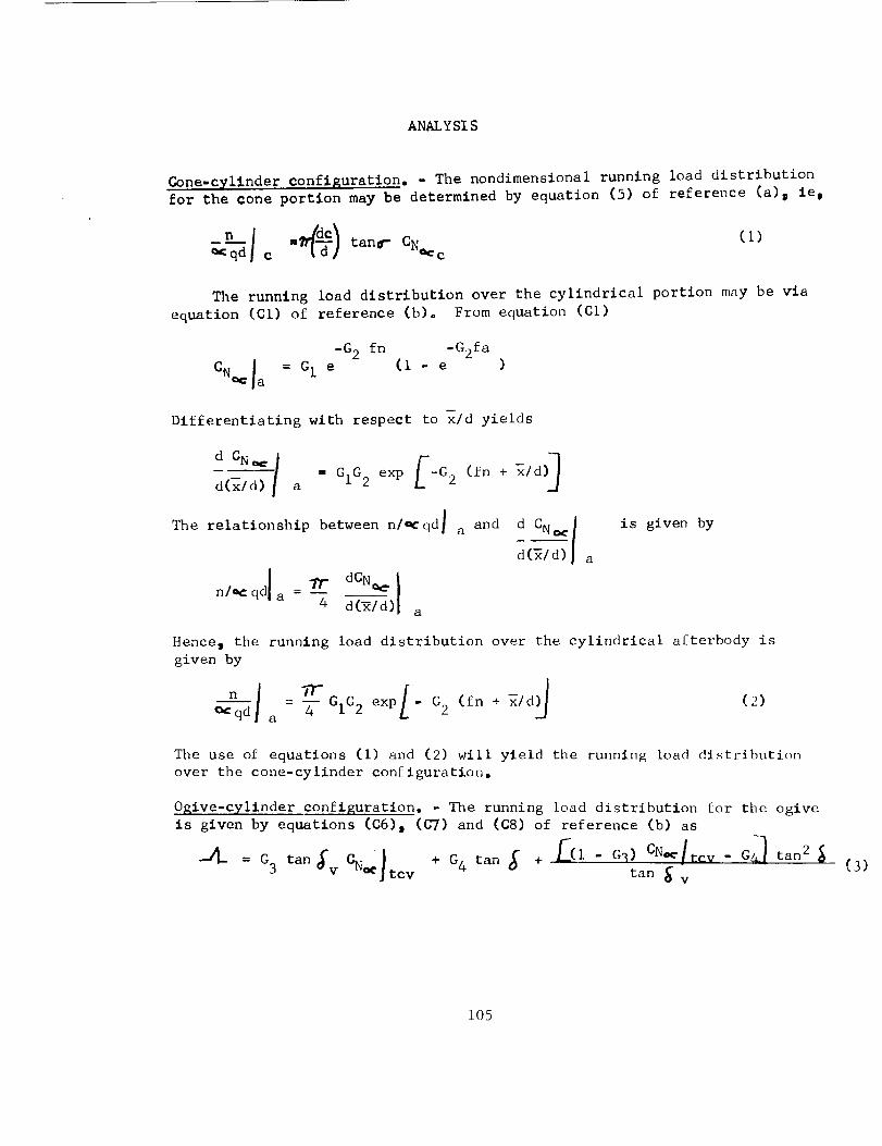
ANALYSIS
Gone-cyllnder confi_uratlon. - The nondimensional running load distribution
for the cone portion may be determined by equation (5) of reference (a)_ ie,
_n-_I c -_) tan_- CN_ c(1)
The running load distribution over the cylindrical portion may be via
equation (CI) of reference (b). From equation (CI)
-G 2 fn -G2fa
I = GI e (i - e )CN_ a
Differentiating with respect to x/d yields
_(_/_/ a = G1G2 exp _--G 2 (fn + _/d
The relationship between nlQrqd] a and d CN_ ]
d(_| a
n/_:qdl - _" dCN_ I
a 4 d--_Tx/d)I a
is given by
Hence, the running load distribution over the cylindrical afterbody is
given by
n I - _-GIG2 exp,- G2 (fn + x/d)_ (2)_-_d a 4
The use of equations (i) and (2) will yield the running load distribution
over the cone-cylinder configuration.
Ogive-cylinder configuration. - The running load distribution for the ogive
is given by equations (C6). (C7) and (C8) of reference (b) as
+ G4 tan _ + C(I - G_) CN_!tcv - G_ tan 2--_- = G3 tan ;v CNoc_tcv tan _ v (3)
105
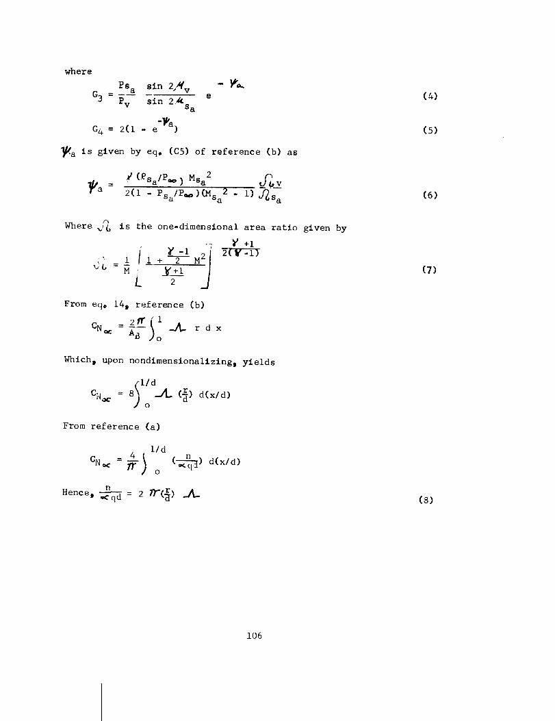
where
Psa sin 2,_ v
G3 = Pv sin 2,_S a
G4 = 2(I - e"_a)
e
_-a is given by eq. (C5) of reference (b) as
(Psa/Pw) Msa 2 _v
_a = 2(1 - Ps /P.=)_Sa2 - i)J_sa
(4)
(5)
(6)
Where _,% is the one-dimenslonal area ratio given by
--; _ +I
'" 1 1 + 2 M
[ 2
From eqo 14, reference (b)
2fril- __ r d x
CN _ AB o
Which, upon nondimensionallzing s yields
(lid
CN_r = 8)0 _2_ (_) d(xld)
From reference (a)
i/d_ 4 ( n
-- ) (__-yr-c_.)d(x/d)CN _ _ o
n Tr(_)Hence t _ = 2
(7)
(8)
106
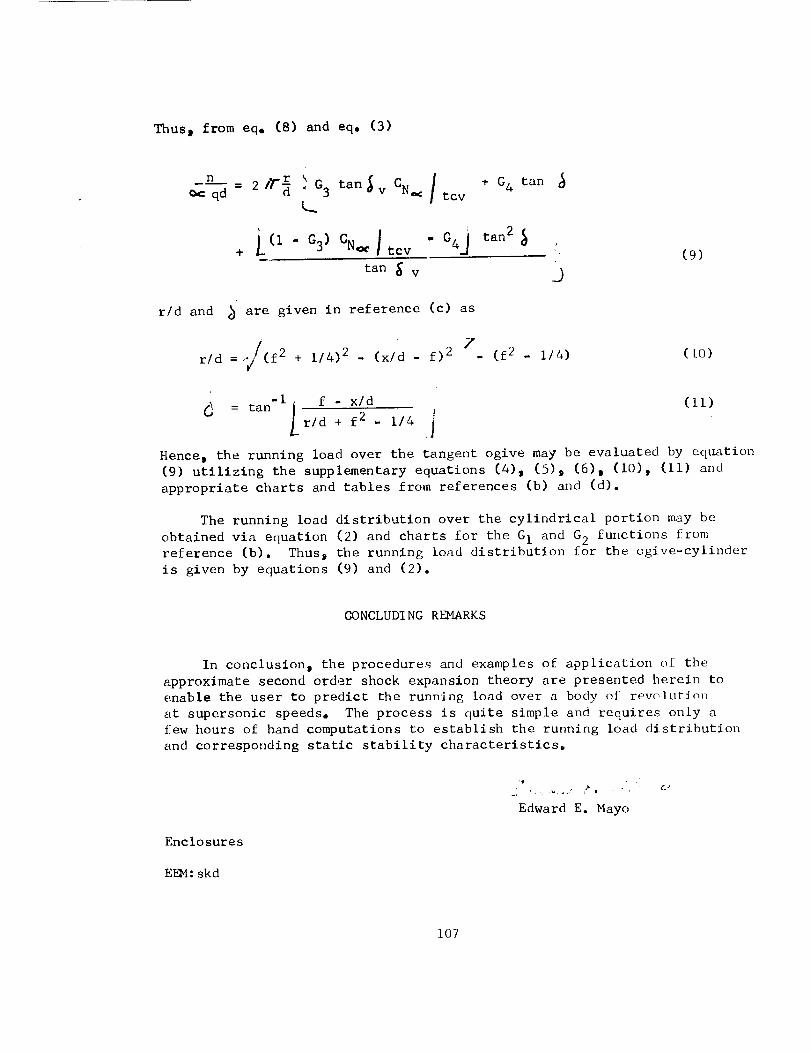
Thus_ from eq, (8) and eqo (3)
¢_: qd - 2 + G 4 tan
<_
+ L (I-G 3) CN_ I tcv " G4J tan2_ '.
tan _ v O
(9)
r/d and b are given in reference (c) as
F. . f)2 . (f2 . 1/4)
r/d = _/(f2 + 1/4)2 (x/d(LO)
-i f - x/d : (ii)
= tan j jr/d + f2 . 1/4 i
Hence, the running load over the tangent ogive may be evaluated by eqL_tion
(9) utilizing the supplementary equations (4), (5)9 (6), (i0), (ii) and
appropriate charts and tables from references (b) and (d).
The running load distribution over the cylindrical portion may be
obtained via equation (2) and charts for the G I and G 2 functions from
reference (b). Thusj the running load distribution for the ogive-cylinder
is given by equations (9) and (2).
CONCLUDI NG REMARKS
In conclusion, the procedures and examples of application of the
approximate second order shock expansion theory are presented herein to
enable the user to predict the running load over a body of revolution
at supersonic speeds, The process is quite simple and requires only a
few hours of hand computations to establish the running load distribution
and corresponding static stability characteristics.
Enclosures
EI_4: skd
J_
Edward E. Mayo
107
Distribution List:
Mr. K. R. Medrow
Mr. G. E. MacVeighMr. E. E. Bissell
Miss E. C. Pressly
108
AB
CN
Cm N
d
dc
f
Glo G2s G3s G 4
I
M
n
P
Pt
q
r
x
1/
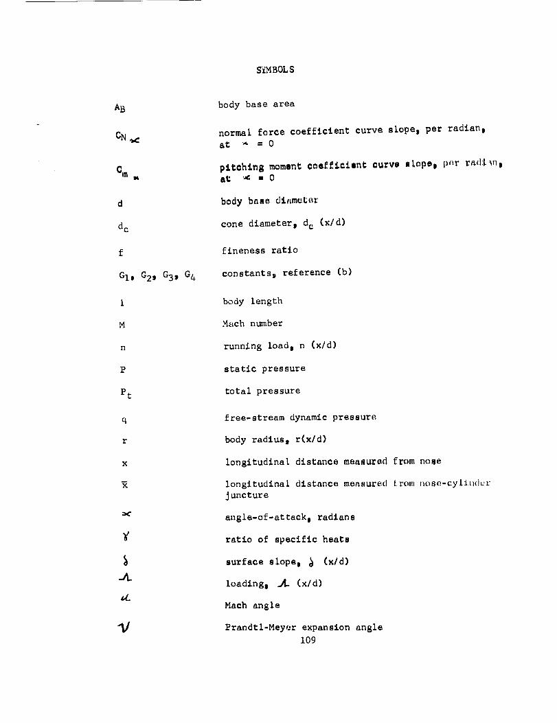
SiM B0L S
body base area
normal force coefficient curve slopej per radlanl
at; _" -- 0
p_tah:In8 moment coefficient curvo s_ope0 p_r ra(hl_nl
at "_: ,, 0
body base diameter
cone diametert d c (x/d)
fineness ratio
constants i reference (b)
body length
Mach number
running load i n (x/d)
static pressure
total pressure
free-stream dynamic pressure
body radlus e r(x/d)
longitudinal distance measured from nose
longitudinal distance measured [rom nose-cylJ**dc'r
Jsncture
angle-of-attack s radlan s
ratio of specific heats
surface slope e _ (x/d)
loading i ._- (x/d)
Mach angle
Prandtl-Meyer expansion angle
109
_a
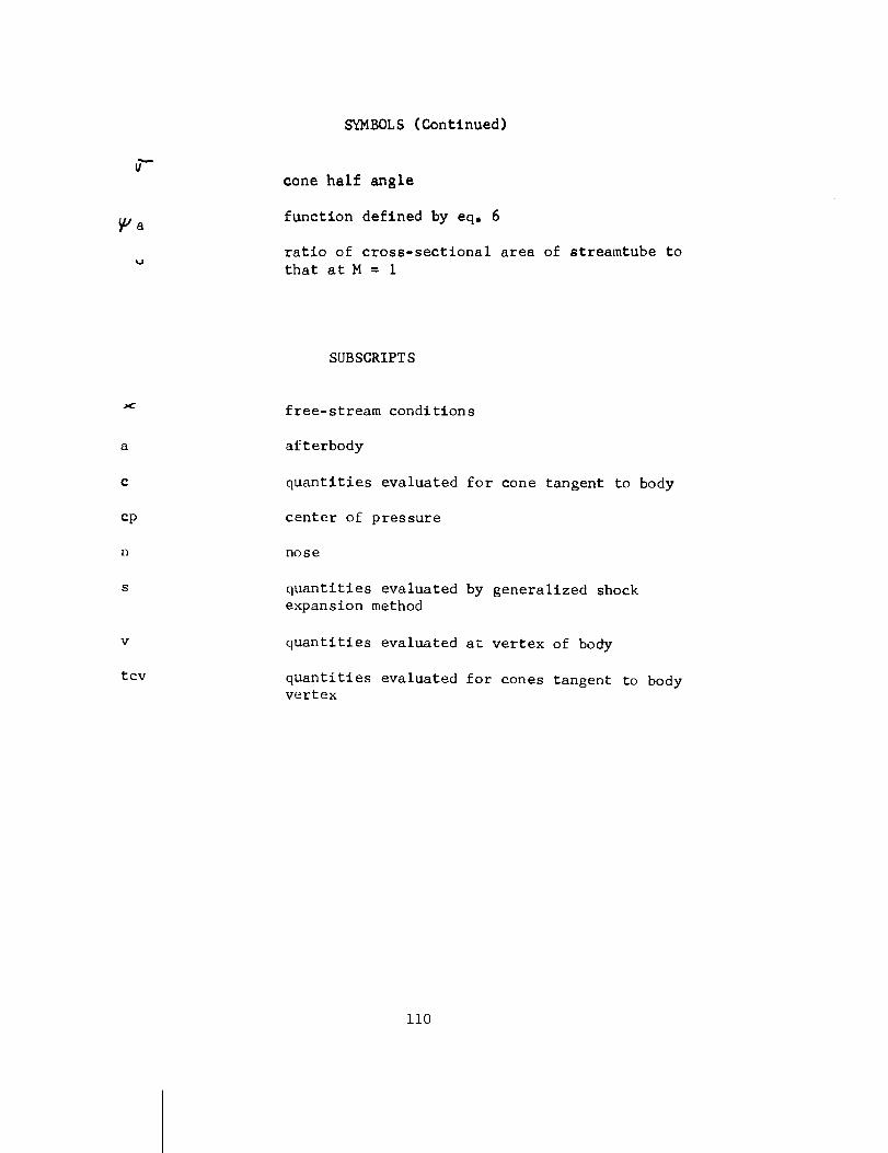
SYMBOLS (Continued)
cone half anRle
function defined by eq, 6
ratio of cross-sectional area of streamtube to
that at M = 1
a
c
cp
n
s
v
tcv
SUBSCRIPT S
free-stream conditions
afterbody
quantities evaluated for cone tangent to body
center of pressure
nose
quantities evaluated by generalized shock
expansion method
quantities evaluated at vertex of body
quantities evaluated for cones tangent to body
vertex
ii0
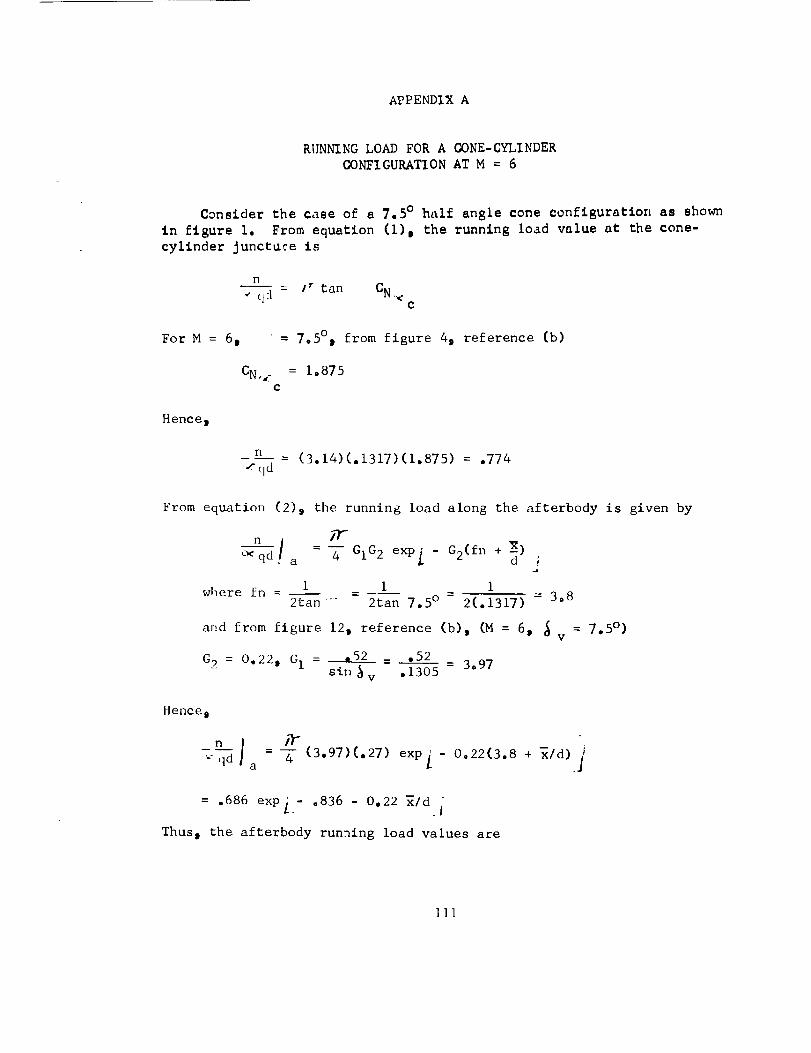
APPENDIXA
RUNNINGLOADFORA CONE-CYLINDERCONFIGURATIONATM = 6
Consider the case of a 7.5 ° half angle cone configuration as shown
in figure i. From equation (I) 0 the running load value at the cone-
cylinder Junctuce is
n_ /r tan C_,
•,,e' C] [1 .l_ "v."
c
For M = 6 t = 7.5°t from figure 4, reference (b)
CN_ _ = 1o875c
Hence,
_" qd- (3.14)(.1317)(1.875) = .774
From equation (2), the running load along the afterbody is given by
fF
_qd a - 4 GIG2 exp L " G2(fn + -_)dJ
where fn - 1 i 12tan ....- 2tan 7.5 ° - 2(.1317) - 3.8
and from figure 12, reference (b), (M = 6, _ v = 7"5o)
G 2 = 0.22, G I = _ - .52 - 3.97sin _ v .1305
Hence D
qd a 4 (3.97)(.27) expL 0022(3.8 + x/d)
= .686 exp_ - .836 - 0.22 _Id j"
Thus i the afterbody running load values are
Iii
APPENDIX A
"_/d
0
.5
1.0
1.5
2
3
I x/d
3.8
4.3
4.8
503
5.8
6.8
n
_qd
.297
.266
.239
.214
.191
.154
xld
4
5
6
7
8
x/d
7.8
8.8
9.8
10.8
11.8
.123
.099
.080
.064
.O51
The running load distribution is plotted in figure i. The normal force
curve slope t CN <; pitching moment, Cm _ and center-of-pressure location,
Xcp/d; are determined from the running load distribution as follows:
CN 4 I/d_ ) (___q_n) d(x/d) (AI)I_ _ qd
0
lid
Cm _ 4 (-n)(x/d) d(x/d) (A2)1)" ) _qd
0
d - CN (.%3)
Integration of the load distribution in figure 1 for i/d = 11.8 (fa = 8)
according to equations (AI)D (A2) and (A3) yields
CN = 3.28 per radlan
C_,:< = 14.22 per radian
Xcp/d = 4033
112
APPENDIXB
RUNNINGLOADFORANOGIVE-CYLINDERCONFIGURATION AT M = 6
Gonslder the case of a 3 to i fineness ratio nose oglve-cyllnder
configuration ao shown in figure 2. The load distribution for the oglve
is given by eq, (9) as
_qd " 217"d}G3 tan_v C_ tcv
+ /_(I - G3) CN_ ] tcv
From eq. II b v
+ G4 tan
- G43 tan2
tan _ v ._2
= tan'I/ f2 _ f 4j = tan'l (.3'+3) =18"93°II
From figures 3 and 41 reference (b), Mv Pv- .649; - 6.8
M_ P_
= 1o774CN _ tcv
Hence, Mv = 6(.649) = 3.894 and from reference (d)
ev
pq m .OO7635, "_/V = 64.302, z4tv: 14.90,
= 9.7bv
S a _ V + _/v = 18.93 + 64.3 = 83.23
Msa = 5,76 i Psa/Pt = .000813_ ._Sa = 9.9980
c sa 44.7
Ps a Psa Pt .000813
Pv - (_)(_v) - .007635-.1065
113
APPENDIX B
P _ PvPsa Sa = (.1065)(6,8) = ,724
G 3 is given by equation (4)
sin 2Ps a v _a
G 3 = - -- _s a ePv sin 2
where _a is given by equation (6) as
¢ (Psa/P _ ) Ms a2
_a = _ v
Psa sa
2(1 - _--_)(Msa2 - i) ....
(1.4)(.724)(5.76) 2 9.7
_a = 2(1 - .724)(5.76) 2 - I 44,7- 0.413
Hence m
= (.497)(.662) = .1024G 3 (. 1065)
G 4 is given by equation (5) o_
G& = 2(1 - e "_a)
= 2(1 - .662) = .676
Thus_ substitution into eq. (9) yields
r
n - 2_ .0623 + 676 tan (_ + 2.67 tan2_ (BI)qd " I& i_
r
where _ and _ are given by equations (i0) and (ii) as functions of the
fineness ratio and x/d°
114
APPENDIX B
The solution of (BI) yields
xld rld tan ¢ nl_qd
0
.5
.7
1.0
1.2
1.5
2.0
2.5
3.0
0
,16
,21
,28
,32
,38
.45
.49
.50
.343
o280
.257
.221
.198
.164
.109
.054
0
0
.462
•544
.602
.605
,585
.474
.327
.196
The above table gives the running load values over the ogive nose portion.
The running load values along the afterbody are given by equation (2) as
n j it" ,_qd_a = -4--GIG2 exp [-G 2 (fn + x)d j
where fm_= 3 and from figure 12o reference (b) (M = 6, _ = 18.93 ° )v
G2 = .28; G1 =.66
= 2,034
Hence s
nj_qd a = -_(2.034)(.28) exPL (-.28)(3 + _/d)__
= ,447 exp L-.84- .28 _/d
Thus o the afterbody running load values are
115
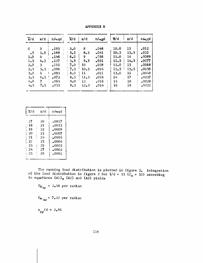
_ld x/d n_qd
0.5
I•01.52.02.53.03°54.04.5
33.544•555,566.577.5
.193
.168• 146.127.II0.096.083.072.063.055
_/d
APPENDIX B
ITxl d n/_qd ] _l d
J
5.0
5,5
6,0
6.5
7.0
7.5
8.0
8.5
9.0
9.5
8
8,5
9
9,5
I0
10.5
ii
11.5
12
12.5
.048
.041
.036
,031
.028
.024
.021
.018
.016
.014
i0.0
I0o 5
II.0
11.5
12.0
12.5
13.0
14
15
16
!
[ x/dI
13
13.5
14
14,5
15
15.5
16
17
18
19
n_qd
.012
•010
,0089
,0077
.0068
.0059
.0049
.OO37
.0028
.0022
_/d x/d n/_cqd
17
18
19
2O
21
22
23
24
25
20
21
22
23
24
25
26
27
28
.OOl7
.oo13
°0009
°0007
•0005
.0004
.0003
.o002
=0002
The running load distribution is plotted in figure 2. Integration
of the load distribution in figure 2 for I/d = 13 (fa = I0) according
to equations (AI), (A2) and (A3) yields
CN_ = 2,48 per radlan
Cm _ 7.22 per radlan
x /d = 2.91cp
116
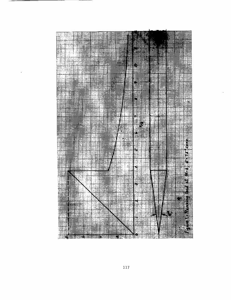
117
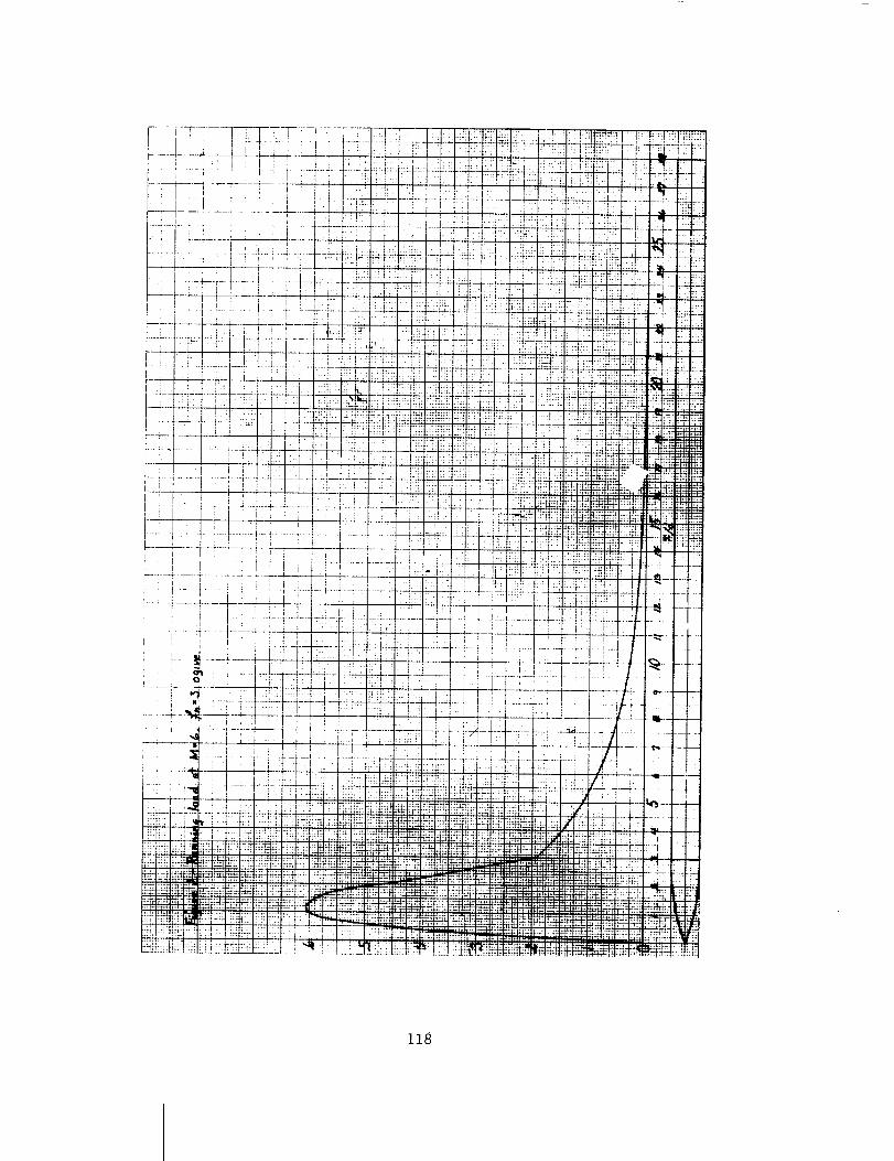
z_8