Embed Size (px)
Citation preview
Nickel-borate oxygen-evolving catalyst thatfunctions under benign conditionsMircea Dincă, Yogesh Surendranath, and Daniel G. Nocera1
Department of Chemistry, Massachusetts Institute of Technology, 77 Massachusetts Avenue, Cambridge, MA 02139-4307
This contribution is part of the special series of Inaugural Articles by members of the National Academy of Sciences elected in 2009.
Contributed by Daniel George Nocera, April 8, 2010 (sent for review December 26, 2009)
Thin catalyst films with electrocatalytic water oxidation propertiessimilar to those of a recently reported Co-based catalyst can beelectrodeposited from dilute Ni2þ solutions in borate electrolyteat pH 9.2 (Bi). The Ni-Bi films can be prepared with precise thicknesscontrol and operate at modest overpotential providing an alterna-tive to the Co catalyst for applications in solar energy conversion.
artificial photosynthesis ∣ nonlegacy ∣ personalized energy ∣ water splitting ∣energy storage
Global energy need will roughly double by midcentury and tri-ple by 2100. Most of that demand is driven by 3 billion low-
energy users in the nonlegacy world and by 3 billion people yet toinhabit the planet over the next half century (1). Research targetsthat meet the energy need of these 6 billion new energy usersprovide global society with a direct path to providing a solutionfor a sustainable and carbon-neutral energy future. Moreover,because energy use scales with wealth (2), geopolitical and eco-nomic stability is greatly enhanced by abundant and clean energyas it enables individuals in the smallest village in the nonlegacyworld and in the largest city of the legacy world to coexist moreequitably. However, the task of supplying energy to the nonlegacyworld will not be an easy one. To achieve the target of a carbon-neutral energy supply for the nonlegacy world will require thedelivery of energy on a scale commensurate with, or largerthan, the entire present-day energy supply from all sourcescombined (3).
The success in meeting the energy challenge in the nonlegacyworld will largely depend on the design, research, and develop-ment of new technologies that are at odds with energy systems ofthe legacy world. Energy systems of the past and present operateat large scale, they are centralized, and energy is distributed to themasses. Such infrastructure is not compatible to the near-termneeds of the nonlegacy world where it is cost prohibitive to buildcentralized energy and distribution systems. An alternative strat-egy that is better adapted to making energy available to the 6 bil-lion new energy users is highly distributed energy systems for theindividual—a personalized energy (PE) (4, 5)—that places a pre-mium on low cost, even if efficiency must be sacrificed up front.
Low cost in a manufacturing environment is most profoundlyaffected by materials goods of the system (most generalized bythe weight of the system) and the production volume (6, 7). Hereagain, the nonlegacy and legacy worlds diverge. Large, cen-tralized, and efficient energy systems come with significantbalance-of-system (BOS) costs. Down-scaling such technologydoes not scale economically because the BOS costs do not scalecommensurately. Thus, off-the-shelf technologies will be difficultto adapt to low-cost energy systems. Rather, the disruptive energytechnologies of the future will be those that conform to the mes-sage of lightweight and high-volume manufacturing. Simply put,new research and development are needed to provide the non-legacy world with the “fast food” equivalent of energy systems.
Solar PE is particularly well adapted to meeting the energyneeds of the nonlegacy world. It is highly distributed and availableto all. And low-cost and large-scale manufacturing are already an
emerging trend in the deployment of photovoltaics (8). However,low-cost photovoltaics are not enough. Because local insolation isdiurnal, solar energy cannot be used as a large-scale energysupply unless it can be stored. Most current methods of solar stor-age are characterized by low-energy densities and consequentlythey present formidable challenges for large-scale solar imple-mentation. This includes batteries, which have low-energy density(0.5 MJ∕kg with a ceiling of ∼3.0 MJ∕kg). Conversely, the energydensity of fuels is ≥102 larger and H2 is ≥103 larger than theupper limit of battery storage capacity. Indeed, society hasintuitively understood this disparity in energy density as alllarge-scale energy storage is in the form of fuels. But these fuelsare carbon based. An imperative for our research has been todevelop fuel storage methods that are carbon-neutral, sustain-able, easily scalable, and inexpensive.
We have taken important steps towards meeting this impera-tive by developing a cobalt oxygen-evolving catalyst (Co-OEC)(9, 10) that can use an energy input from a photoanode or photo-voltaic to split water into hydrogen and oxygen. Co-OEC isunique because it (i) is a functional model of the oxygen-evolvingcomplex of Photosystem II (11), (ii) operates safely with highactivity under benign conditions (room temperature and pH 7)(9, 10), (iii) is comprised of inexpensive, Earth-abundant materi-als and is easy to manufacture (9, 10), (iv) is self-healing (12), (v)is functional in natural, waste, and salt water (10, 11), (vi) canform on diverse conducting surfaces of varying geometry andbe easily interfaced with a variety of light-absorbing andcharge-separating materials (11), and (vii) may be activated bysolar-derived electricity or directly by sunlight mediated by asemiconductor (13, 14). The simple operation of the catalyst fromimpure water sets a path to providing distributed solar and cleandrinking water (5).
We now report that thin catalyst films with O2 evolution pro-perties can be electrodeposited from dilute Ni2þ solutions inborate electrolyte at pH 9.2 (Bi). The Ni-Bi films can be preparedwith precise thickness control and operate at modest overpoten-tial providing an alternative to the Co-OEC catalyst for applica-tions in solar energy storage and water purification.
ResultsFig. 1 shows the onset of a catalytic wave at 1.2 V [vs. normalhydrogen electrode (NHE)] on the first anodic sweep of a glassycarbon electrode immersed in a 0.1 M H2BO−
3 ∕H3BO3 electro-lyte (Bi electrolyte) solution at pH 9.2 containing 1 mM of Ni2þion. The cathodic return scan exhibits a broad feature atEp;c ¼ 0.87 V, attributed to the reduction of a surface adsorbedspecies formed during the initial sweep through the catalyticwave. Subsequent cyclic voltammetry (CV) scans display a sharp
Author contributions: D.G.N. designed research; M.D. and Y.S. performed research; andM.D., Y.S., and D.G.N. wrote the paper.
The authors declare no conflict of interest.1To whom correspondence should be addressed. E-mail: [email protected].
This article contains supporting information online at www.pnas.org/lookup/suppl/doi:10.1073/pnas.1001859107/-/DCSupplemental.
www.pnas.org/cgi/doi/10.1073/pnas.1001859107 PNAS ∣ June 8, 2010 ∣ vol. 107 ∣ no. 23 ∣ 10337–10341
SUSTAINABILITY
SCIENCE
INAUGURA
LART
ICLE
Dow
nloa
ded
by g
uest
on
Mar
ch 9
, 202
0

anodic prefeature centered at Ep;a ¼ 1.02 V and a cathodicallyshifted catalytic wave with an onset potential of 1.15 V. As shownin Fig. 1, the anodic and the cathodic prefeatures increase inamplitude with scanning, suggesting the growth of a surface-deposited material. By integration of the anodic prefeature, weestimate that a monolayer of catalyst is deposited after a singleCV scan at 50 mV∕s, whereas a film of 10–12 layers thick is pro-duced after 20 scans, thus attesting to the controlled nature of theelectrodeposition. Neither film formation nor catalysis is ob-served in the absence of the Bi electrolyte. Indeed, a CV of a1 mM aqueous solution of Ni2þ in 0.1 M NaNO3 electrolyteat pH 9.2 is indistinguishable from the electrode backgroundin the absence of Ni2þ (Fig. S1). As was the case with Co-OEC (10), this suggests that a proton-accepting electrolyte, suchas borate, is essential for facile electrodeposition and catalysis.
The CV features observed for the Ni-Bi system are similar tothose observed of Ni oxide thin films (15–22). For instance,electrodeposited NiðOHÞ2 films display an anodic prefeaturecentered at ∼0.65–1.25 V, depending on pH, which is typicallyassigned to a 1e−-1Hþ redox couple, NiIIðOHÞ2∕NiIIIOðOHÞ(23–26). To examine if proton-coupled electron transfer is opera-tional in our system, (27, 28) we measured the pH dependence ofthe anodic prefeature (see Fig. 2). Surprisingly, CV experimentsconducted at a scan rate of 50 mV∕s give rise to a plot of Ep;a vs.pH with a slope of −96 mV∕pH unit. Similar slopes, −91 and−89 mV∕pH unit, were obtained at scan rates of 10 and5 mV∕s, respectively (Fig. S2). These values are much higherthan the theoretical value of −59 mV expected for the1e−-1Hþ oxidation of NiIIðOHÞ2 to NiIIIOðOHÞ. Rather, a slopeof −90 mV∕pH unit corresponds to the loss of 1e− accompaniedby the transfer of ∼1.5 protons. This suggests that a 2e−-3Hþcouple may be operative, as has been proposed for the dimeriza-tion of IrIV hydro-hydroxo species to form iridium oxide:2½IrO2ðOHÞ2�2− þ 2e− þ 3H2O ↔ ½Ir2O3ðOHÞ3 • 2H2O�3− þ3OH− (29, 30), which exhibits an observed slope of −88 mV∕pHunit.
To further probe the morphology, composition, and structureof the electrodeposited material, thicker films of Ni-Bi were elec-trodeposited onto indium-tin oxide (ITO) covered glass slides bysubjecting 1 mM Ni2þ solutions in Bi electrolyte to bulk electro-lysis at 1.3 V. During electrodeposition, the current densityrapidly attains a plateau value of ∼1.4 mA∕cm2, as shown inFig. 3. A 3–4-μm-thick film is grown by passing 10 C∕cm2
at 1.3 V. Scanning electron microscopy and powder X-ray dif-fraction of this film reveal that it is relatively smooth and amor-phous (see Fig. 3 Inset and Figs. S3 and S4, respectively). Tointerrogate the catalyst composition, thick films were grown onlarge surface area electrodes, and then dried in the air.Elemental analysis of the dried material revealed a formula ofNiIIIOðOHÞ2∕3ðH2BO3Þ1∕3 • 1.5H2O, which we understand maydiffer from that of the catalyst under wet and operational condi-tions. Nevertheless, the formula of Ni-Bi is reminiscent of NiO(OH), which exhibits O2 evolution under similar pH conditionsand is an effective water oxidation catalyst in concentrated alkalisolution (24).
The potential-dependent O2 evolution activity of Ni-Bi, eval-uated in Ni2þ-free Bi electrolyte at pH 9.2, is in line with thatobserved for NiO(OH) under highly alkaline conditions. Faradaicefficiency for O2 evolution, as measured by fluorescence detec-
Fig. 1. CVs using a glassy carbon working electrode, 50 mV∕s scan rate, ofaqueous 1 mM Ni2þ in 0.1 M Bi electrolyte, pH 9.2. Successive scans show anincrease of the anodic peak current for the redox event centered at ∼1.0 e.(Inset) First (- - -) and second (─) CV scans using a glassy carbon working elec-trode, 50 mV∕s scan rate, of aqueous 1 mM Ni2þ solutions in 0.1 M Bi elec-trolyte, pH 9.2. CV trace in the absence of Ni2þ is shown as a black trace.
Fig. 2. CVs scans of a Ni borate catalyst film at pH values of 7.82, 8.30, 8.68,8.88, 9.16, 9.42, 9.72, and 9.98 in. going from left to right, respectively. Theinset shows a linear fit for the 8.7–10.0 pH region, with a slope of 96 mV∕pHunit. The CVs were taken at scan rates of 50 mV∕s.
Fig. 3. Current density trace for bulk electrolysis at 1.30 V in 0.1 M Bi
electrolyte, pH 9.2, 1 mM Ni2þ using an ITO anode. Irregularities are dueto bubble formation and to stirring. The inset shows an SEM photographof a film obtained by passing 10 C∕cm2 at 1.30 V.
10338 ∣ www.pnas.org/cgi/doi/10.1073/pnas.1001859107 Dincă et al.
Dow
nloa
ded
by g
uest
on
Mar
ch 9
, 202
0
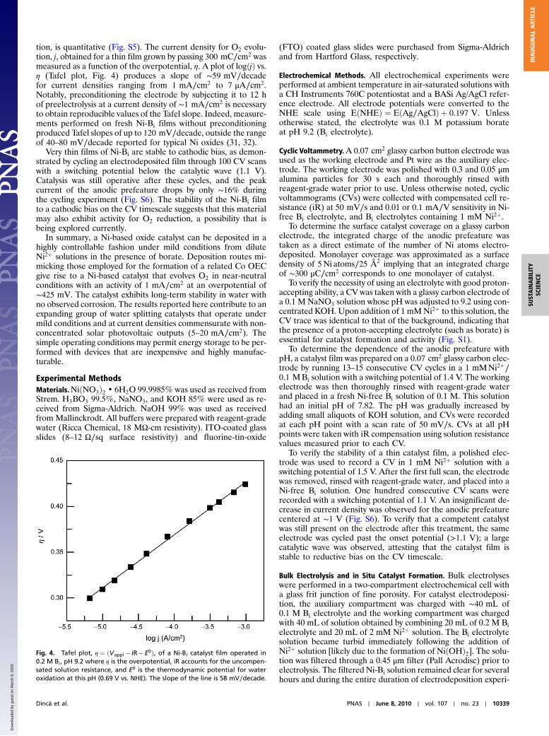
tion, is quantitative (Fig. S5). The current density for O2 evolu-tion, j, obtained for a thin film grown by passing 300 mC∕cm2 wasmeasured as a function of the overpotential, η. A plot of logðjÞ vs.η (Tafel plot, Fig. 4) produces a slope of ∼59 mV∕decadefor current densities ranging from 1 mA∕cm2 to 7 μA∕cm2.Notably, preconditioning the electrode by subjecting it to 12 hof preelectrolysis at a current density of ∼1 mA∕cm2 is necessaryto obtain reproducible values of the Tafel slope. Indeed, measure-ments performed on fresh Ni-Bi films without preconditioningproduced Tafel slopes of up to 120 mV∕decade, outside the rangeof 40–80 mV∕decade reported for typical Ni oxides (31, 32).
Very thin films of Ni-Bi are stable to cathodic bias, as demon-strated by cycling an electrodeposited film through 100 CV scanswith a switching potential below the catalytic wave (1.1 V).Catalysis was still operative after these cycles, and the peakcurrent of the anodic prefeature drops by only ∼16% duringthe cycling experiment (Fig. S6). The stability of the Ni-Bi filmto a cathodic bias on the CV timescale suggests that this materialmay also exhibit activity for O2 reduction, a possibility that isbeing explored currently.
In summary, a Ni-based oxide catalyst can be deposited in ahighly controllable fashion under mild conditions from diluteNi2þ solutions in the presence of borate. Deposition routes mi-micking those employed for the formation of a related Co OECgive rise to a Ni-based catalyst that evolves O2 in near-neutralconditions with an activity of 1 mA∕cm2 at an overpotential of∼425 mV. The catalyst exhibits long-term stability in water withno observed corrosion. The results reported here contribute to anexpanding group of water splitting catalysts that operate undermild conditions and at current densities commensurate with non-concentrated solar photovoltaic outputs (5–20 mA∕cm2). Thesimple operating conditions may permit energy storage to be per-formed with devices that are inexpensive and highly manufac-turable.
Experimental MethodsMaterials.NiðNO3Þ2 • 6H2O 99.9985% was used as received fromStrem. H3BO3 99.5%, NaNO3, and KOH 85% were used as re-ceived from Sigma-Aldrich. NaOH 99% was used as receivedfrom Mallinckrodt. All buffers were prepared with reagent-gradewater (Ricca Chemical, 18 MΩ-cm resistivity). ITO-coated glassslides (8–12 Ω∕sq surface resistivity) and fluorine-tin-oxide
(FTO) coated glass slides were purchased from Sigma-Aldrichand from Hartford Glass, respectively.
Electrochemical Methods. All electrochemical experiments wereperformed at ambient temperature in air-saturated solutions witha CH Instruments 760C potentiostat and a BASi Ag/AgCl refer-ence electrode. All electrode potentials were converted to theNHE scale using EðNHEÞ ¼ EðAg∕AgClÞ þ 0.197 V. Unlessotherwise stated, the electrolyte was 0.1 M potassium borateat pH 9.2 (Bi electrolyte).
Cyclic Voltammetry.A 0.07 cm2 glassy carbon button electrode wasused as the working electrode and Pt wire as the auxiliary elec-trode. The working electrode was polished with 0.3 and 0.05 μmalumina particles for 30 s each and thoroughly rinsed withreagent-grade water prior to use. Unless otherwise noted, cyclicvoltammograms (CVs) were collected with compensated cell re-sistance (iR) at 50 mV∕s and 0.01 or 0.1 mA∕V sensitivity in Ni-free Bi electrolyte, and Bi electrolytes containing 1 mM Ni2þ.
To determine the surface catalyst coverage on a glassy carbonelectrode, the integrated charge of the anodic prefeature wastaken as a direct estimate of the number of Ni atoms electro-deposited. Monolayer coverage was approximated as a surfacedensity of 5Ni atoms∕25 Å2 implying that an integrated chargeof ∼300 μC∕cm2 corresponds to one monolayer of catalyst.
To verify the necessity of using an electrolyte with good proton-accepting ability, a CV was taken with a glassy carbon electrode ofa 0.1 M NaNO3 solution whose pH was adjusted to 9.2 using con-centrated KOH. Upon addition of 1 mMNi2þ to this solution, theCV trace was identical to that of the background, indicating thatthe presence of a proton-accepting electrolyte (such as borate) isessential for catalyst formation and activity (Fig. S1).
To determine the dependence of the anodic prefeature withpH, a catalyst film was prepared on a 0.07 cm2 glassy carbon elec-trode by running 13–15 consecutive CV cycles in a 1 mMNi2þ∕0.1 MBi solution with a switching potential of 1.4 V. The workingelectrode was then thoroughly rinsed with reagent-grade waterand placed in a fresh Ni-free Bi solution of 0.1 M. This solutionhad an initial pH of 7.82. The pH was gradually increased byadding small aliquots of KOH solution, and CVs were recordedat each pH point with a scan rate of 50 mV∕s. CVs at all pHpoints were taken with iR compensation using solution resistancevalues measured prior to each CV.
To verify the stability of a thin catalyst film, a polished elec-trode was used to record a CV in 1 mM Ni2þ solution with aswitching potential of 1.5 V. After the first full scan, the electrodewas removed, rinsed with reagent-grade water, and placed into aNi-free Bi solution. One hundred consecutive CV scans wererecorded with a switching potential of 1.1 V. An insignificant de-crease in current density was observed for the anodic prefeaturecentered at ∼1 V (Fig. S6). To verify that a competent catalystwas still present on the electrode after this treatment, the sameelectrode was cycled past the onset potential (>1.1 V); a largecatalytic wave was observed, attesting that the catalyst film isstable to reductive bias on the CV timescale.
Bulk Electrolysis and in Situ Catalyst Formation. Bulk electrolyseswere performed in a two-compartment electrochemical cell witha glass frit junction of fine porosity. For catalyst electrodeposi-tion, the auxiliary compartment was charged with ∼40 mL of0.1 M Bi electrolyte and the working compartment was chargedwith 40 mL of solution obtained by combining 20 mL of 0.2 M Bielectrolyte and 20 mL of 2 mM Ni2þ solution. The Bi electrolytesolution became turbid immediately following the addition ofNi2þ solution [likely due to the formation of NiðOHÞ2]. The solu-tion was filtered through a 0.45 μm filter (Pall Acrodisc) prior toelectrolysis. The filtered Ni-Bi solution remained clear for severalhours and during the entire duration of electrodeposition experi-
Fig. 4. Tafel plot, η ¼ ðVappl − iR − E0Þ, of a Ni-Bi catalyst film operated in0.2 M Bi, pH 9.2 where η is the overpotential, iR accounts for the uncompen-sated solution resistance, and E0 is the thermodynamic potential for wateroxidation at this pH (0.69 V vs. NHE). The slope of the line is 58 mV∕decade.
Dincă et al. PNAS ∣ June 8, 2010 ∣ vol. 107 ∣ no. 23 ∣ 10339
SUSTAINABILITY
SCIENCE
INAUGURA
LART
ICLE
Dow
nloa
ded
by g
uest
on
Mar
ch 9
, 202
0
ments. The working electrode was a 1 × 2.5 cm piece of ITO-coated glass cut from a commercially available slide. Typically,a 1 cm2 area of the electrode was exposed to the solution. Ptmesh was used as the auxiliary electrode. Electrolysis was carriedout at 1.30 V with stirring and without iR compensation and withthe reference electrode placed 2–3 mm from the ITO surface.
Tafel Plot Data Collection. Current-potential data were obtained byperforming controlled potential electrolyses in Bi electrolytes at avariety of applied potentials in two-compartment cells containing∼40 mL of fresh electrolyte on each side. Prior to data collection,the solution resistance was measured with a clean ITO workingelectrode using the iR test function. The working ITO electrodeand the Ag/AgCl reference electrode were kept in the same con-figuration while the electrolysis cell was replaced with one con-taining Ni2þ in the working compartment, as described above. A1 cm2 catalyst film was prepared via an electrodeposition thatpassed 300 mC∕cm2. Working and reference electrodes were sub-sequently rinsed in reagent-grade water and all electrodes werereimmersed in a two-compartment electrochemical cell contain-ing fresh Bi electrolyte in both compartments. A current of950 μA∕cm2 was applied for ∼12 h prior to collecting data forthe Tafel plot. Steady-state currents were measured at a varietyof applied potentials while the solution was stirred, proceeding in10–25 mV steps between 1.15 and 0.99 V. Typically, the currentreached a steady-state at a particular potential in 2–5 min andcurrent values were read after 7–10 min. Measurements weremade twice. The variation in steady-state current between tworuns at a particular potential was <5%. The solution resistancemeasured prior to the data collection (36 Ω) was used to correctthe Tafel plot for iR drop (Fig. 4).
Elemental Analyses. Microanalyses were performed by ColumbiaAnalytics. The Ni-Bi catalyst was prepared on large surfacearea (∼25 × 25 cm) FTO-coated glass slides using filtered1 mMNi2þ∕0.1 MBi solutions. Upon termination of the electro-lyses, the slides were immediately removed from the solution,rinsed with reagent-grade water, and allowed to dry in air. Theelectrodeposited material was carefully scraped off using a razorblade and the material was submitted for microanalysis. Theelemental composition for a sample prepared as above was asfollows: Ni, 43.6 wt. %; H, 2.16 wt. %; B, 2.7 wt. %; and K,1.1 wt. %. Although an idealized catalyst formula of NiIIIOðOHÞ2∕3ðH2BO3Þ1∕3 • 1.5H2Omatches these values, it is unlikelythat the composition of a dry film corresponds exactly to that of afilm under operational conditions.
Scanning Electron Microscopy. SEM micrographs were obtainedwith a JSM-5910 microscope (JEOL). Following electrodeposi-tion, catalyst samples were rinsed with deionized water andallowed to dry in air before loading into the instrument. Imageswere obtained with an acceleration voltage of 5–10 kV. Fig. S3displays SEM images of a catalyst prepared by passing10 C∕cm2 at 1.3 V.
Powder X-Ray Diffraction.A powder X-ray diffraction pattern for afilm grown by passing 10 C∕cm2 was obtained with a RigakuRU300 rotating anode X-ray diffractometer (185 mm) using
Cu Kα radiation (λ ¼ 1.5405 Å). As shown in Fig. S4, the onlypeaks in the diffraction pattern correspond to those pertainingto the ITO background, indicating that the electrodepositednickel oxide catalyst is amorphous.
Spectroelectrochemistry. Spectra were recorded on a SpectralInstruments 400 series diode array spectrometer. The workingelectrode consisted of a 2 × 0.8 cm piece of ITO-coated quartzcut from a commercially available slide (Delta Technologies,Inc.). Working, reference, and Pt auxiliary electrodes were fittedinto a standard 1-cm path-length UV-Vis cuvette to comprise aone compartment electrolysis cell. The spectrometer was blankedagainst a filtered solution of Bi electrolyte containing Ni2þ(1 mM) and spectra were collected periodically while 1.2 Vwas applied. The spectrum recorded after 9 min of electrolysisis shown in Fig. S7.
Determination of Faradaic Efficiency. An Ocean Optics oxygen sen-sor system was used to detect O2 quantitatively. The experimentwas performed in a custom-built two-compartment gas-tight elec-trochemical cell with a 14/20 port on each compartment and aSchlenk connection with a Teflon valve on the working compart-ment. The Bi electrolyte was degassed by bubbling with high pur-ity N2 for 12 h with vigorous stirring, and it was transferred to theelectrochemical cell under N2. One compartment contained a Nifoam auxiliary electrode and the other compartment containedthe working and Ag/AgCl reference electrodes. The Ni catalystwas prepared from an electrodeposition as described above.The reference electrode was positioned several millimeters fromthe surface of the catalyst. The 14/20 port of the working com-partment was fitted with a FOXY OR125–73 mm O2 sensingprobe connected to a MultiFrequency Phase Fluorometer. Thephase shift of the O2 sensor on the FOXY probe, recorded at10 s intervals, was converted into the partial pressure of O2 inthe headspace using a two-point calibration curve (air, 20.9%O2, and high purity N2, 0% O2). After recording the partialpressure of O2 for 1 h in the absence of an applied potential,electrolysis was initiated at 1.3 V without iR compensation.
For determination of Faradic efficiency in the Bi buffer, elec-trolysis with O2 sensing was continued until 53.5 C passed. Uponterminating the electrolysis, the O2 signal reached a plateau overthe course of the next 3 h. During this time, the O2 level had risenfrom 0% to 6.98%. At the conclusion of the experiment, thevolume of the solution (59.5 mL) and the volume of the head-space (48.0 mL) in the working compartment were measured.The total charge passed in the electrolysis was divided by 4 Fto get a theoretical O2 yield of 138.3 μmol. The measured partialpressure of O2 was corrected for dissolved O2 in solution usingHenry’s Law and converted, using the ideal gas law, into ameasured O2 yield of 143.4 μmol (103.7%� 5%) (Fig. S5).
ACKNOWLEDGMENTS. This work was supported by a National Science Founda-tion (NSF) Center for Chemical Innovation (CCI Powering the Planet, GrantsCHE-0802907 and CHE-0947829), Air Force Office of Scientific ResearchFA9550-09-1-0689, and a grant from The Chesonis Family Foundation. Y.S.gratefully acknowledges the NSF Graduate Research Fellowship Programfor a predoctoral fellowship.
1. Lewis NS, Nocera DG (2006) Powering the planet: Chemical challenges in solar energyutilization. Proc Natl Acad Sci USA 103:15729–15735.
2. Hoffert MI, et al. (1998) Energy implications of future stabilization of atmospheric CO2
content. Nature 395:881–884.3. Nocera DG (2006) On the future of global energy. Daedalus 135:112–115.4. Nocera DG (2009) Personalized energy: The home as a solar power station and solar
gas station. ChemSusChem 2:387–390.5. Nocera DG (2009) Chemistry of personalized solar energy. Inorg Chem
48:10001–10007.6. Malstrom EM (1981) What Every Engineer Should Know About Manufacturing Cost
Estimating (Dekker, New York), Chap 2.
7. Swamidass PM (2000) Encyclopedia of Production and Manufacturing Management
(Kluwer, Boston).
8. Ginley D, Green MA, Collins R (2008) Solar energy conversion toward 1 terawatt. MRS
Bull 33:355–364.
9. Kanan MW, Nocera DG (2008) In situ formation of an oxygen-evolving catalyst in
neutral water containing phosphate and Co2þ. Science 321:1072–1075.
10. Surendranath Y, Dincă M, Nocera DG (2009) Electrolyte-dependent electrosynthesis
and activity of cobalt based water oxidation catalysts. J Am Chem Soc 131:2615–2620.
11. Kanan MW, Surendranath Y, Nocera DG (2009) Cobalt-phosphate oxygen-evolving
compound. Chem Soc Rev 38:109–114.
10340 ∣ www.pnas.org/cgi/doi/10.1073/pnas.1001859107 Dincă et al.
Dow
nloa
ded
by g
uest
on
Mar
ch 9
, 202
0
12. Lutterman DA, Surendranath Y, Nocera DG (2009) A self-healing oxygen-evolvingcatalyst. J Am Chem Soc 131:3838–3839.
13. Zhong DK, Sun J, Inumaru H, Gamelin DR (2009) Solar water oxidation by compositecatalyst∕α-Fe2O3 photoanodes. J Am Chem Soc 131:6086–6087.
14. Steinmiller EMP, Choi KS (2009) Photochemical deposition of cobalt-based oxygenevolving catalyst on a semiconductor photoanode for solar oxygen production. ProcNatl Acad Sci USA 106:20633–20636.
15. Macdougall B, Graham MJ (1981) Growth of thick anodic oxide-films on nickel inborate buffer solution. J Electrochem Soc 128:2321–2325.
16. Gassa LM, Vilche JR, Arvía AJ (1983) A potentiodynamic study of anodic film formationon nickel in borate solutions. J Appl Electrochem 13:135–145.
17. Abd El, Aal EE (2003) Anodic oxide films on nickel electrode in borate solutions. CorrosSci 45:641–658.
18. Tench D, Warren LF (1983) Electrodeposition of conducting transition-metal oxidehydroxide films from aqueous-solution. J Electrochem Soc 130:869–872.
19. Chen YWD, Noufi RN (1984) Electrodeposition of nickel and cobalt oxides ontoplatinum and graphite-electrodes for alkaline water electrolysis. J Electrochem Soc131:1447–1451.
20. Morisaki S, Kawakami K, Baba N (1988) Formation of nickel oxyhydroxide thin-films byelectrodeposition and their electrochromic characteristics. Jpn J Appl Phys 27:314–318.
21. Chigane M, Ishikawa M (1992) Characterization of electrochromic nickel-oxidethin-films prepared by anodic deposition. J Chem Soc Faraday T 88:2203–2205.
22. Chigane M, Ishikawa M, Inoue H (2000) Further XRD characterization of electrochro-mic nickel oxide thin films prepared by anodic deposition. Sol Energ Mat Sol C64:65–72.
23. Oliva P, et al. (1982) Review of the structure and the electrochemistry of nickelhydroxides and oxy-hydroxides. J Power Sources 8:229–255.
24. Corrigan DA, Bendert RM (1989) Effect of coprecipitated metal-ions on theelectrochemistry of nickel-hydroxide thin-films—cyclic voltammetry in 1 M KOH.J Electrochem Soc 136:723–728.
25. Lyons MEG, Brandon MP (2008) The oxygen evolution reaction on passive oxidecovered transition metal electrodes in aqueous alkaline solution. Part 1—nickel. IntJ Electrochem Sci 3:1386–1424.
26. Wruck DA, Rubin M (1993) Structure and electronic-properties of electrochromic NiOfilms. J Electrochem Soc 140:1097–1104.
27. Cukier RI, Nocera DG (1998) Proton-coupled electron transfer. Annu Rev Phys Chem49:337–369.
28. Reece SY, Nocera DG (2009) Proton-coupled electron transfer in biology: Results fromsynergistic studies in natural and model systems. Annu Rev Biochem 78:673–699.
29. Burke LD, Whelan DP (1984) A voltammetric investigation of the charge storagereactions of hydrous iridium oxide layers. J Electroanal Chem 162:121–141.
30. Burke LD,Whelan DP (1981) A new interpretation of the charge storage and electrical-conductivity behavior of hydrous iridium oxide. J Electroanal Chem 124:333–337.
31. de Chialvo MRG, Chialvo AC (1988) Oxygen evolution reaction on thick hydrousnickel-oxide electrodes. Electrochim Acta 33:825–830.
32. Wang XY, Luo H, Yang HP, Sebastian PJ, Gamboa SA (2004) Oxygen catalytic evolutionreaction on nickel hydroxide electrode modified by electroless cobalt coating. Int JHydrogen Energy 29:967–972.
Dincă et al. PNAS ∣ June 8, 2010 ∣ vol. 107 ∣ no. 23 ∣ 10341
SUSTAINABILITY
SCIENCE
INAUGURA
LART
ICLE
Dow
nloa
ded
by g
uest
on
Mar
ch 9
, 202
0